EP3227880B1 - Injection training tool emitting omnidirectional light - Google Patents
Injection training tool emitting omnidirectional lightDownload PDFInfo
- Publication number
- EP3227880B1 EP3227880B1EP15828554.4AEP15828554AEP3227880B1EP 3227880 B1EP3227880 B1EP 3227880B1EP 15828554 AEP15828554 AEP 15828554AEP 3227880 B1EP3227880 B1EP 3227880B1
- Authority
- EP
- European Patent Office
- Prior art keywords
- light
- needle tip
- testing tool
- needle
- tip
- Prior art date
- Legal status (The legal status is an assumption and is not a legal conclusion. Google has not performed a legal analysis and makes no representation as to the accuracy of the status listed.)
- Active
Links
- 238000002347injectionMethods0.000titledescription95
- 239000007924injectionSubstances0.000titledescription95
- 238000012549trainingMethods0.000titledescription30
- 239000000463materialSubstances0.000claimsdescription53
- 238000012360testing methodMethods0.000claimsdescription45
- 239000013307optical fiberSubstances0.000claimsdescription26
- 239000011521glassSubstances0.000claimsdescription7
- 239000003795chemical substances by applicationSubstances0.000claimsdescription6
- 230000004044responseEffects0.000claimsdescription6
- 239000011343solid materialSubstances0.000claimsdescription5
- GWEVSGVZZGPLCZ-UHFFFAOYSA-NTitan oxideChemical compoundO=[Ti]=OGWEVSGVZZGPLCZ-UHFFFAOYSA-N0.000claimsdescription4
- 239000011344liquid materialSubstances0.000claimsdescription3
- 229910052751metalInorganic materials0.000claimsdescription2
- 239000002184metalSubstances0.000claimsdescription2
- 239000002245particleSubstances0.000claimsdescription2
- 239000000843powderSubstances0.000claimsdescription2
- 239000004408titanium dioxideSubstances0.000claimsdescription2
- 238000000034methodMethods0.000description29
- 239000007787solidSubstances0.000description11
- 230000001225therapeutic effectEffects0.000description9
- 239000002537cosmeticSubstances0.000description8
- 239000000945fillerSubstances0.000description6
- 230000008569processEffects0.000description6
- 230000002500effect on skinEffects0.000description5
- 230000004888barrier functionEffects0.000description4
- 230000008901benefitEffects0.000description4
- 238000001514detection methodMethods0.000description4
- 239000007788liquidSubstances0.000description4
- 241001465754MetazoaSpecies0.000description3
- 230000006378damageEffects0.000description3
- 210000003128headAnatomy0.000description3
- 239000002858neurotransmitter agentSubstances0.000description3
- 238000012545processingMethods0.000description3
- 230000000069prophylactic effectEffects0.000description3
- 239000000126substanceSubstances0.000description3
- 210000001835visceraAnatomy0.000description3
- 208000002193PainDiseases0.000description2
- 108010057266Type A Botulinum ToxinsProteins0.000description2
- 238000010521absorption reactionMethods0.000description2
- 238000001467acupunctureMethods0.000description2
- 210000003484anatomyAnatomy0.000description2
- 229940089093botoxDrugs0.000description2
- 210000000038chestAnatomy0.000description2
- 239000011248coating agentSubstances0.000description2
- 238000000576coating methodMethods0.000description2
- 238000009792diffusion processMethods0.000description2
- 230000001815facial effectEffects0.000description2
- 229910052500inorganic mineralInorganic materials0.000description2
- 230000000670limiting effectEffects0.000description2
- 238000004519manufacturing processMethods0.000description2
- 239000011707mineralSubstances0.000description2
- 210000003205muscleAnatomy0.000description2
- 239000004033plasticSubstances0.000description2
- 238000012797qualificationMethods0.000description2
- 239000010979rubySubstances0.000description2
- 229910001750rubyInorganic materials0.000description2
- 238000002560therapeutic procedureMethods0.000description2
- 210000001519tissueAnatomy0.000description2
- 238000011282treatmentMethods0.000description2
- 201000004569BlindnessDiseases0.000description1
- 206010007882CellulitisDiseases0.000description1
- 208000000094Chronic PainDiseases0.000description1
- 208000034656ContusionsDiseases0.000description1
- 206010018691GranulomaDiseases0.000description1
- 206010019233HeadachesDiseases0.000description1
- 208000032843HemorrhageDiseases0.000description1
- 241000282412HomoSpecies0.000description1
- 229920001954RestylanePolymers0.000description1
- 206010067868Skin massDiseases0.000description1
- 206010040893Skin necrosisDiseases0.000description1
- 206010042674SwellingDiseases0.000description1
- 208000027418Wounds and injuryDiseases0.000description1
- 108010079650abobotulinumtoxinAProteins0.000description1
- 238000013459approachMethods0.000description1
- 210000001367arteryAnatomy0.000description1
- 230000002238attenuated effectEffects0.000description1
- 230000032770biofilm formationEffects0.000description1
- 208000034158bleedingDiseases0.000description1
- 230000000740bleeding effectEffects0.000description1
- 210000001185bone marrowAnatomy0.000description1
- 201000008247brain infarctionDiseases0.000description1
- 210000001217buttockAnatomy0.000description1
- 230000008859changeEffects0.000description1
- 238000006243chemical reactionMethods0.000description1
- 210000000795conjunctivaAnatomy0.000description1
- 230000001419dependent effectEffects0.000description1
- 239000003814drugSubstances0.000description1
- 229940079593drugDrugs0.000description1
- 229940098753dysportDrugs0.000description1
- 230000000694effectsEffects0.000description1
- 206010014801endophthalmitisDiseases0.000description1
- 238000011156evaluationMethods0.000description1
- 239000000835fiberSubstances0.000description1
- 230000003176fibrotic effectEffects0.000description1
- GNBHRKFJIUUOQI-UHFFFAOYSA-NfluoresceinChemical compoundO1C(=O)C2=CC=CC=C2C21C1=CC=C(O)C=C1OC1=CC(O)=CC=C21GNBHRKFJIUUOQI-UHFFFAOYSA-N0.000description1
- 239000007850fluorescent dyeSubstances0.000description1
- 230000006870functionEffects0.000description1
- 231100000869headacheToxicity0.000description1
- 230000036541healthEffects0.000description1
- 108010024001incobotulinumtoxinAProteins0.000description1
- 208000015181infectious diseaseDiseases0.000description1
- 230000002757inflammatory effectEffects0.000description1
- 230000002401inhibitory effectEffects0.000description1
- 208000014674injuryDiseases0.000description1
- 238000003780insertionMethods0.000description1
- 230000037431insertionEffects0.000description1
- 239000007925intracardiac injectionSubstances0.000description1
- 230000002427irreversible effectEffects0.000description1
- 238000010999medical injectionMethods0.000description1
- 238000002324minimally invasive surgeryMethods0.000description1
- 210000005036nerveAnatomy0.000description1
- FEMOMIGRRWSMCU-UHFFFAOYSA-NninhydrinChemical compoundC1=CC=C2C(=O)C(O)(O)C(=O)C2=C1FEMOMIGRRWSMCU-UHFFFAOYSA-N0.000description1
- 230000000474nursing effectEffects0.000description1
- 210000003200peritoneal cavityAnatomy0.000description1
- 210000003281pleural cavityAnatomy0.000description1
- 238000003825pressingMethods0.000description1
- 230000002829reductive effectEffects0.000description1
- 210000003625skullAnatomy0.000description1
- 210000001562sternumAnatomy0.000description1
- 238000006467substitution reactionMethods0.000description1
- 230000008961swellingEffects0.000description1
- 230000002792vascularEffects0.000description1
- 210000003462veinAnatomy0.000description1
- 238000001429visible spectrumMethods0.000description1
- 230000000007visual effectEffects0.000description1
- 230000004393visual impairmentEffects0.000description1
- 229940018272xeominDrugs0.000description1
Images


Classifications
- G—PHYSICS
- G09—EDUCATION; CRYPTOGRAPHY; DISPLAY; ADVERTISING; SEALS
- G09B—EDUCATIONAL OR DEMONSTRATION APPLIANCES; APPLIANCES FOR TEACHING, OR COMMUNICATING WITH, THE BLIND, DEAF OR MUTE; MODELS; PLANETARIA; GLOBES; MAPS; DIAGRAMS
- G09B23/00—Models for scientific, medical, or mathematical purposes, e.g. full-sized devices for demonstration purposes
- G09B23/28—Models for scientific, medical, or mathematical purposes, e.g. full-sized devices for demonstration purposes for medicine
- G09B23/285—Models for scientific, medical, or mathematical purposes, e.g. full-sized devices for demonstration purposes for medicine for injections, endoscopy, bronchoscopy, sigmoidscopy, insertion of contraceptive devices or enemas
- G—PHYSICS
- G09—EDUCATION; CRYPTOGRAPHY; DISPLAY; ADVERTISING; SEALS
- G09B—EDUCATIONAL OR DEMONSTRATION APPLIANCES; APPLIANCES FOR TEACHING, OR COMMUNICATING WITH, THE BLIND, DEAF OR MUTE; MODELS; PLANETARIA; GLOBES; MAPS; DIAGRAMS
- G09B5/00—Electrically-operated educational appliances
Definitions
- injectionsmay be administered in various locations on the body, such as under the conjunctiva, into arteries, bone marrow, the spine, the sternum, the pleural space of the chest region, the peritoneal cavity, joint spaces, and internal organs. Injections can also be helpful in administering medication directly into anatomic locations that are generating pain. These injections may be administered intravenously (through the vein), intramuscularly (into the muscle), intradermally (beneath the skin), subcutaneously (into the fatty layer of skin), or intraperitoneally (into the body cavity). Injections can be performed on humans as well as on animals. The methods of administering injections typically vary for different procedures and may depend on the substance being injected, needle size, or area of injection.
- Injectionsare not limited to treating medical conditions, but may be expanded to treating aesthetic imperfections or restorative cosmetic procedures. Many of these procedures are performed through injections of various products into different parts of the body.
- the aesthetics and therapeutic industrycomprises two main categories of injectable products: neuromodulators and dermal fillers.
- the neuromodulator industrycommonly uses nerve-inhibiting products such as Botox®, Dysport®, and Xeomin®.
- the dermal filler industryuses products administered by providers to patients for both cosmetic and therapeutic reasons, such as, for example, Juvederm®, Restylane®, Belotero®, Sculptra®, Artefill®, and others.
- These providers or injectorsmay include plastic surgeons, facial plastic surgeons, oculoplastic surgeons, dermatologists, nurse practitioners, dentists and nurses.
- a problem in the administration of injectionsis that there is no official certification or training process.
- anyone with a minimal medically-related licensemay inject a patient.
- injectorsmay include primary care physicians, dentists, veterinarians, nurse practitioners, nurses, physician's assistants, or aesthetic spa physicians.
- the qualifications and training requirements for injectorsvary by country, state, and county. For example, in most states in the United States, the only requirement to be permitted to inject patients with neuromodulators and/or fillers is to have a nursing degree or medical degree. Accordingly, there is a lack of uniformity and expertise in administering such injections.
- the drawbacks with this lack of uniformity in training and expertiseare widespread throughout the medical industry. Doctors and practitioners often are not well-trained in administering injections of diagnostic, therapeutic, and cosmetic chemical substances. This lack of training has led to instances of chronic pain, headaches, bruising, swelling, or bleeding in patients.
- live modelsare limited in the number and types of injections they may receive.
- the need for live modelsis restrictive because injectors are unable to be exposed to a wide and diverse range of situations and anatomies in which to practice. For example, it may be difficult to find live models with different skin tones or densities. This makes the training process less effective because patients have diverse anatomical features as well as varying prophylactic, curative, therapeutic, or cosmetic needs.
- Live modelsare also restrictive because injectors are unable to practice injection methods on the internal organs of a live model due to safety and health considerations.
- US 2014/120505 A1describes an injectable apparatus which may contain a camera that is configured to detect the intensity and color of light attenuated from a testing tool after it is injected into a simulated human or animal body parts.
- US 4 311 138 A1describes a needle which is used in conjunction with a portable light source, such as a battery handle and lamp, and includes a bundle of optical fibers that transmits light from the lamp to the distal end of the needle.
- the present disclosuregenerally relates to systems, methods, and apparatuses for training and certification for prophylactic, curative, therapeutic, acupuncture, or cosmetic injection. Aspects of this technology are described in U.S. Patent No. 8,764,449 , entitled SYSTEM FOR COSMETIC AND THERAPEUTIC TRAINING; US. Patent No. 8,961,189 , entitled SYSTEM FOR COSMETIC AND THERAPEUTIC TRAINING; and U.S. Patent App. Ser. No. 14/598,614 , entitled INJECTION SITE TRAINING SYSTEM, each of which is assigned to the assignee of the present application.
- the present applicationdiscloses injection training systems, methods, and apparatuses for radiating or reflecting light energy from a tip of an injection testing tool, such as syringe needle, to facilitate detection of the needle's position in an artificial injection apparatus (for example, an artificial face).
- an injection testing toolsuch as syringe needle
- the systems, methods, and/or apparatusesmay be used for training caregivers on performing injections where accurate positioning is important, such as in facial/Botox injections and/or spinal injections, to name a few.
- an injection apparatusfor example, which is used with an artificial injection site, such as, for example, an artificial face
- a testing toolsuch as a needle mounted to a syringe.
- the position of the needle tip in the artificial injection siteis an important piece of information to determine the skill level of the trainee.
- One way to track the needle tip positionrelies on a sensor interior to the artificial face configured to detect through a clear interior space of the artificial face emitted or reflected light from the needle tip as it penetrates the artificial face.
- a testing tool systemcomprises a needle having a central lumen, a distal end, a proximal end, and a tip at the distal end of the needle.
- the testing tool systemincludes a barrel cooperating with the proximal end of the needle and a light source, configured to emit light, positioned in the barrel.
- the systemalso includes an optical fiber positioned inside the central lumen of the needle and configured to receive the emitted light from the light source and to transmit the emitted light through the needle from the proximal end to the distal end so that the light is emitted from the needle tip, which is configured to radiate the emitted light.
- the needle tipis configured to radiate the emitted light uniformly.
- the needle tipcomprises a fluorescent material configured to radiate the emitted light.
- the fluorescent materialcomprises one of a liquid material, a solid material, and a gaseous material, and in some embodiments, the fluorescent material comprises a combination of at least two of a liquid material, a solid material, and a gaseous material.
- the emitted lightmay be one or more of visible light, non-visible light, ultraviolet light, polarized light, infrared light, and fluorescent light.
- the testing toolcomprises a transparent barrier positioned between the optical fiber and the needle tip, where the transparent barrier is filled or coated with a fluorescent material.
- a system for training clinicians to provide injectionscomprising a testing tool having a needle tip configured to absorb light and to emit light.
- the systemalso includes an injection apparatus having an internal portion, where the injection apparatus is configured to receive a simulated injection by the testing tool.
- a light emitteris also included in the system. The light emitter is positioned within the internal portion of the injection apparatus, and is configured to illuminate the needle tip of the testing tool in response to the injection apparatus receiving the simulated injection by the testing tool.
- the systemalso comprises a light detector, positioned in the internal portion of the injection apparatus. The light detector is configured to detect a light emitted from the illuminated needle tip.
- the light emitteremits a first light having a first wavelength
- the illuminated needle tipemits a second light having a second wavelength
- the needle tipis configured to absorb the first light, and in response to absorbing the first light, emit the second light.
- the light detectorcomprises a filter configured to prevent the first light from being detected by the light detector.
- the first lightmay comprise ultraviolet light and the second light may comprise visible light.
- the needle tipcomprises fluorescent material configured to uniformly radiate the emitted light.
- the fluorescent materialmay be a liquid, a solid or a gaseous, and in some embodiments, the fluorescent material comprises a combination of at least two of a liquid, a solid, and a gaseous material.
- an injection training systemcomprises a testing tool having a needle and a needle tip.
- the needle tipcomprises a fluorescent material.
- the injection training systemalso includes an injection apparatus having an interior. The injection apparatus is configured to receive a simulated injection by the testing tool wherein the needle tip penetrates the injection apparatus.
- the injection training systemalso includes a light emitter positioned in the interior of the injection apparatus and configured to emit light in a general direction of the simulated injection.
- a light detectoris also included. The light detector is positioned in the interior of the injection apparatus and configured to detect light emitted from the needle tip of the testing tool.
- the needle tipcomprises a solid fluorescent material.
- the light emittermay be configured to emit a first light having a first wavelength
- the needle tipmay be configured to absorb the first light, and in response to absorbing the first light, emit a second light having a second wavelength.
- the light detectorincludes a filter configured to block the first light from being detected by the light detector.
- the light emitteremits ultraviolet light and the needle tip emits visible light.
- the light emitterincludes a light reflector configured to reflect the emitted light in the general direction of the simulated injection.
- an injection apparatusfor example, an artificial face
- an injection testing toolsuch as for example, a needle mounted to a syringe to simulate a patient injection.
- the position of the needle tip in the injection apparatusreveals useful information regarding the skill level of the trainee.
- One method of tracking the needle tip positionuses a sensor (such as, for example, a camera, a light detector, and the like) positioned in a clear interior of the injection apparatus. The sensor detects, through the clear interior of the injection apparatus, light emitted from the needle tip as the needle tip penetrates the injection apparatus during the simulated injection.
- One embodiment of needle tip location technologyutilizes light emitted from a light source, such as a light-emitting diode or a laser, through a needle tip, by means of an optical fiber positioned within the needle lumen.
- the emitted lightis detectable by one or more sensors placed distal to the needle tip, such as sensors positioned within the interior of the injection apparatus.
- the light emitted from the exposed end of the optical fibertravels substantially along the axis of the optical fiber. This axial light bias restricts the detectability of the emitted light to a limited angular range away from the axis of the optical fiber.
- An important requirement of the training systems discussed hereinis the ability to detect the needle tip as it travels along a path close to tangent with the external surface of the injection apparatus. Such a needle path is typical in many injection training scenarios, such as, for example, training to inject dermal filler material.
- the present applicationdiscloses systems, methods, and apparatuses for providing omnidirectional light emission from the tip of the needle for use with injection training systems.
- the omnidirectional light emissionimproves the angular range of detection of the emitted light.
- the approachuses principles of fluorescence and/or diffusion to emit light in a substantially omnidirectional pattern from the needle tip in order to improve the detectability of the emitted light.
- FIGS 1A, 1B , and 2illustrate a testing tool 100 in accordance with an embodiment of the present disclosure.
- the testing tool 100contains a battery-powered light source (not shown) that emits light through the needle portion 116 of the testing tool 100.
- the light sourcemay be configured to emit any type of light, including without limitation, one or more of visible light, non-visible light, ultraviolet light, polarized light, infrared light, and fluorescent light.
- the light sourceis used to aid in obtaining visual indications detectable by a light detector, such as a camera.
- the resulting light detected by the light detectorcan be used to determine many critical parameters associated with the injection such as, for example, the location of the injection, the pressure exerted by the user, the angle of the injection, the depth of the injection, and the like. This information can be detected by a light detector, for example by a camera, and communicated to a processing system and/or a user interface device or a display device for testing evaluation, display, and/or certification purposes.
- the testing tool 100includes a plunger 110, a barrel 112, a needle assembly 114, a needle, 116, and a needle tip 118.
- the testing tool 100may be activated by pressing a switch (not shown) which activates a light source, such as a light-emitting diode (LED) or laser diode, to emit a source of light.
- a light sourcesuch as a light-emitting diode (LED) or laser diode
- the driving light(which may also be referred to herein as the "driving light”) then travels through an optical fiber 124 positioned within a central lumen 122 of the needle 116.
- the optical fiber 124entrains the driving light from the light source and directs the driving light in the longitudinal axis of the needle 116.
- the driving lighttravels through the optical fiber 124 and is delivered as a focused driving light to a distal portion of the needle tip 118.
- a light-transmissible barrier 126Between the optical fiber 124 and the needle tip 118 is a light-transmissible barrier 126 which forms a sealed transparent enclosure 120 at the needle tip118.
- the sealed transparent enclosureis filled and/or coated with a fluorescent material.
- the optic fiber 124 positioned in the needle's central lumen 122delivers the driving light at a wavelength that stimulates a fluorescing process in the fluorescent material located in the sealed transparent enclosure 120.
- Fluorescenceis a process by which a driving light having a first wavelength is absorbed by a fluorescent material, and in response to the absorption, the fluorescent material emits a second light (referred to herein as a "fluorescent light") at a second wavelength that is typically at a lower energy level than the first, absorbed light.
- the fluorescent lightis then emitted from the needle tip 118, which is surrounded by the transparent enclosure 120 having a closed point at a distal end of the needle tip 118.
- the transparent enclosure 120is a glass structure.
- the transparent enclosure 120, including the light-transmissible barrier 126may be made of many materials capable of containing the fluorescent material and permitting the fluorescent light to radiate through it.
- a property of fluorescent lightis that it radiates substantially uniformly in all directions (also referred to herein as "omnidirectional") and is therefore detectable over a much broader angular range than that of the driving light emitted by means of an optical fiber 124 alone.
- the fluorescent light emitted by the fluorescent materialcan be detected by sensors 140 lateral to the testing tool's 100 (syringe's) axis.
- Figure 3is a sectional schematic view, cut along line 2-2, of an embodiment of needle tip 118 of Figure 1B in which the needle tip is made of solid fluorescing material.
- the optical fiber 124abuts to the needle tip 118 made of the solid fluorescent material.
- the solid tipmay be made of ruby, treated glass, or other fluorescing materials.
- the needle tip 118absorbs the high-energy driving light from the optical fiber 124 and emits a lower-energy fluorescent light that radiates substantially uniformly from the needle tip 118.
- this embodimentis simple to manufacture because it has fewer components than the embodiments described above with respect to Figure 2 .
- the transparent enclosure 120can be challenging and/or costly to manufacture, fill with fluorescent material, seal, and test as compared to the solid-tip embodiment.
- the solid needle tip 118 embodiment disclosed in Figure 3also provides an improved durability, as the solid fluorescent material may be more robust than a hollow transparent enclosure 120.
- the solid needle tip 118may resist damage from both normal use and accidental impact.
- the solid-tip embodimentalso provides improved needle tip 118 sharpness.
- the solid-tip fluorescent materialmay be precision ground to a point, while a hollow tip transparent enclosure 120 has comparatively thin walls and may frequently break when ground to a sharp point. Additionally, the solid-tip embodiment eliminates the risk of leaks of fluorescing liquid or gaseous materials that may be contained in the embodiments using a transparent enclosure 120.
- the fluorescent material used in the present embodimentsmay be liquid, solid, gaseous, or a combination such materials.
- fluorescent materials that may be used in the disclosed embodimentsinclude ruby, ninhydrin, and fluorescein.
- rubyninhydrin
- fluoresceinfluorescein
- a skilled artisanwill appreciate that there are numerous fluorescent materials that may be used to implement the disclosed embodiments.
- a database of fluorescent dyes along with their properties and applicationscan be accessed at http://www.fluorophores.tuqraz.at/.
- the improved detection range resulting from use of fluorescent light emitting from the needle tip 118can support use of this technology in living tissue.
- the frequency of light from the fluorescing materialcan be tuned so as to pass through living tissue and allow detection from sensors that are positioned outside of the body. This can provide a source of information that can be used to perform improved needle placement during actual injection procedures as well as simulated procedures during training sessions.
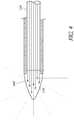
- Figure 4is a schematic sectional view of an embodiment of a needle tip118 that diffuses light emitted from the testing tool 100.
- Light diffusionis a process by which photons travel though a material without being absorbed; instead, the photons undergo a series of repeated scattering events which change the direction of the photons' paths. Thus, light-diffusing materials cause the light to radiate in a more omnidirectional manner.
- the optical fiber 124is positioned within the central lumen 122 of the needle 116. The optical fiber 124 entrains the driving light from the light source and directs the driving light in the longitudinal axis of the needle 116.
- the lighttravels through the optical fiber 124 and is delivered as a focused driving light to a distal portion of the needle tip 118.
- the optical fiber 124is configured to abut the distal end of the needle tip 118.
- the distal end of the needle tip 118may be constructed of a light-diffusing material.
- One such light-diffusing materialis glass having a diffusing agent 402 added.
- the diffusing agent 402may be particles of white titanium dioxide, reflective metal powder, or other such agents.
- the needle tip 118may be coated with a light-diffusing material. Provision of light-diffusing material at the needle tip 118 enables the conversion of the narrow and intense straight driving light path exiting the optical fiber 124 to one that is substantially omnidirectional, at reduced intensity. The result is that the needle tip 118 is observable at high angles off of the needle axis.
- the needle tip 118includes both fluorescent material and light-diffusing material.
- the transparent enclosure 120may be filled with a fluorescent material and have a light-diffusing coating on an interior surface, an exterior surface, or both an interior and exterior surface of the transparent enclosure 120.
- the transparent enclosure 120may be made of glass having a light-diffusing agent added to the glass.
- the optical fiber 124extends beyond the distal end of the needle to form the needle tip 118, having a point.
- the needle tip 118 formed by the optical fiber 124may have a light-diffusing coating, or it may contain a light-diffusing material. In other embodiments, the needle tip 118 formed by the optical fiber 124 may be coated with a fluorescent material.
- Figure 5is a sectional view of a surface fluorescing tip with an external source for driving light.
- Figure 5illustrates an injection training system 500 according to an embodiment of the present disclosure.
- the system 500includes an injection apparatus 502 having a clear interior space 504 and configured to receive a simulated injection by a testing tool 100.
- the injection apparatus 502is a synthetic anatomical structure that can be used for any type of injection training involved with administering diagnostic and therapeutic chemical substances.
- injection trainingcan be provided for epidural techniques and for intra-cardiac injections.
- the injection apparatus 502can anatomically model the face, neck, and head of a human.
- the injection apparatus 502can model other injection sites including the chest, arms, mouth, back, buttocks, etc.
- the injection apparatus 502may also represent any body part of a human or animal, including internal organs.
- the injection apparatus 502may include a simulated skull and layers of muscle and skin.
- the injection apparatus 502can be positioned on a base to facilitate use on flat surfaces, such as a table or desk.
- a light source 506Positioned within the interior 504 of the injection apparatus 502 is a light source 506 having one or more light reflectors 508. As illustrated in Figure 5 , the light source 506 is positioned within the interior 504 of the injection apparatus 502 so as to emit a driving light 520 generally in a direction of the simulated injection. Accordingly, the light source 506 and reflectors 508 are positioned toward a back portion of the head of the injection apparatus 502 and configured to emit the driving light 520 toward a face portion of the injection apparatus 502 where a simulated injection is performed.
- a light detector 510is also positioned within the interior 504 of the injection apparatus 502.
- the light detector 510is positioned toward the back portion of the head of the injection apparatus 502 near the light source 506 and configured to detect fluorescent light 530 emitted from the tip 118 of testing tool 100 used to perform the simulated injection.
- the light detector 510includes a filter 512 configured to block one or more wavelengths of light from being detected by the light detector 510.
- the filter 512may be configured to block the driving light 520 emitted from the light source 506 so as to ensure that the light detector only detects the fluorescent light 530 emitted from the needle tip 118.
- the needle tip 118 of the testing tool 100includes fluorescent material.
- the light source 506emits a driving light 520 that is delivered by, for example, a high-energy light emitter.
- the light source 506emits ultraviolet light 520 as the driving light.
- the fluorescent needle tip 118which has penetrated into the interior 504 of the injection apparatus 502, absorbs the emitted driving ultraviolet light 520, and in response to the absorption, emits fluorescent light 530 having a wavelength in the visible spectrum.
- the filter 512can block the driving light 520 and pass only the fluorescent light 530 radiated by the fluorescent needle tip 118.
- This embodimentprovides several benefits including eliminating the optical fiber 124 light path in the testing tool 100, offloading the power required for driving a light source 506 from the testing tool 100, extending battery life of the testing tool 100, and reducing the complexity of the testing tool 100.
- An injection training systemhas been disclosed in detail in connection with various embodiments.
- injectionincludes it usual and customary meaning of an injection, but is also to be interpreted broad enough to encompass, for example, the insertion of a catheter device or the use of simple needles, such as would be used in an acupuncture therapy.
- the techniques involved, particularly a camera embedded in a model of a living subject and a tool with a light emittercan be applied to any therapeutic procedure.
- the toolcan be a catheter and the procedure can be a minimally invasive procedure requiring the catheter to be located in a particular location.
- acts, events, or functions of any of the methods described hereincan be performed in a different sequence, can be added, merged, or left out altogether (for example, not all described acts or events are necessary for the practice of the method).
- acts or eventscan be performed concurrently, for example, through multi-threaded processing, interrupt processing, or multiple processors or processor cores, rather than sequentially.
Landscapes
- Engineering & Computer Science (AREA)
- Physics & Mathematics (AREA)
- General Physics & Mathematics (AREA)
- Health & Medical Sciences (AREA)
- Theoretical Computer Science (AREA)
- Educational Technology (AREA)
- Educational Administration (AREA)
- Business, Economics & Management (AREA)
- Computational Mathematics (AREA)
- Pure & Applied Mathematics (AREA)
- Medicinal Chemistry (AREA)
- Medical Informatics (AREA)
- Mathematical Analysis (AREA)
- Mathematical Optimization (AREA)
- Mathematical Physics (AREA)
- Algebra (AREA)
- General Health & Medical Sciences (AREA)
- Chemical & Material Sciences (AREA)
- Radiology & Medical Imaging (AREA)
- Pulmonology (AREA)
- Infusion, Injection, And Reservoir Apparatuses (AREA)
- Investigating, Analyzing Materials By Fluorescence Or Luminescence (AREA)
- Measurement Of The Respiration, Hearing Ability, Form, And Blood Characteristics Of Living Organisms (AREA)
Description
- A variety of medical injection procedures are often performed in prophylactic, curative, therapeutic, or cosmetic treatments. Injections may be administered in various locations on the body, such as under the conjunctiva, into arteries, bone marrow, the spine, the sternum, the pleural space of the chest region, the peritoneal cavity, joint spaces, and internal organs. Injections can also be helpful in administering medication directly into anatomic locations that are generating pain. These injections may be administered intravenously (through the vein), intramuscularly (into the muscle), intradermally (beneath the skin), subcutaneously (into the fatty layer of skin), or intraperitoneally (into the body cavity). Injections can be performed on humans as well as on animals. The methods of administering injections typically vary for different procedures and may depend on the substance being injected, needle size, or area of injection.
- Injections are not limited to treating medical conditions, but may be expanded to treating aesthetic imperfections or restorative cosmetic procedures. Many of these procedures are performed through injections of various products into different parts of the body. The aesthetics and therapeutic industry comprises two main categories of injectable products: neuromodulators and dermal fillers. The neuromodulator industry commonly uses nerve-inhibiting products such as Botox®, Dysport®, and Xeomin®. The dermal filler industry uses products administered by providers to patients for both cosmetic and therapeutic reasons, such as, for example, Juvederm®, Restylane®, Belotero®, Sculptra®, Artefill®, and others. These providers or injectors may include plastic surgeons, facial plastic surgeons, oculoplastic surgeons, dermatologists, nurse practitioners, dentists and nurses.
- A problem in the administration of injections is that there is no official certification or training process. Anyone with a minimal medically-related license may inject a patient. These "injectors" may include primary care physicians, dentists, veterinarians, nurse practitioners, nurses, physician's assistants, or aesthetic spa physicians. However, the qualifications and training requirements for injectors vary by country, state, and county. For example, in most states in the United States, the only requirement to be permitted to inject patients with neuromodulators and/or fillers is to have a nursing degree or medical degree. Accordingly, there is a lack of uniformity and expertise in administering such injections. The drawbacks with this lack of uniformity in training and expertise are widespread throughout the medical industry. Doctors and practitioners often are not well-trained in administering injections of diagnostic, therapeutic, and cosmetic chemical substances. This lack of training has led to instances of chronic pain, headaches, bruising, swelling, or bleeding in patients.
- Current injection training options are classroom-based, with hands-on training performed on live models. The availability of models is limited. Moreover, even when available, live models are limited in the number and types of injections they may receive. The need for live models is restrictive because injectors are unable to be exposed to a wide and diverse range of situations and anatomies in which to practice. For example, it may be difficult to find live models with different skin tones or densities. This makes the training process less effective because patients have diverse anatomical features as well as varying prophylactic, curative, therapeutic, or cosmetic needs. Live models are also restrictive because injectors are unable to practice injection methods on the internal organs of a live model due to safety and health considerations.
- As a result of these limited training scenarios, individuals seeking treatments involving injections have a much higher risk of being treated by an inexperienced injector. This may result in low patient satisfaction with the results, or in failed procedures. In many instances, patients have experienced lumpiness from incorrect dermal filler injections. Some failed procedures may result in irreversible problems and permanent damage to a patient's body. For example, patients have experienced vision loss, direct injury to the globe of the eye, and brain infarctions where injectors have incorrectly performed dermal filler procedures. Additional examples of side effects include inflammatory granuloma, skin necrosis, endophthalmitis, injectable-related vascular compromise, cellulitis, biofilm formation, subcutaneous nodules, fibrotic nodules, and other infections.
US 2014/120505 A1 describes an injectable apparatus which may contain a camera that is configured to detect the intensity and color of light attenuated from a testing tool after it is injected into a simulated human or animal body parts.US 4 311 138 A1 describes a needle which is used in conjunction with a portable light source, such as a battery handle and lamp, and includes a bundle of optical fibers that transmits light from the lamp to the distal end of the needle.- There is currently no standard to train, educate, and certify providers on the proper and accurate process of various injection techniques. Patients seeking injections also have few resources for determining the qualifications or experience of a care practitioner.
- The present disclosure generally relates to systems, methods, and apparatuses for training and certification for prophylactic, curative, therapeutic, acupuncture, or cosmetic injection. Aspects of this technology are described in
U.S. Patent No. 8,764,449 , entitled SYSTEM FOR COSMETIC AND THERAPEUTIC TRAINING;US. Patent No. 8,961,189 , entitled SYSTEM FOR COSMETIC AND THERAPEUTIC TRAINING; andU.S. Patent App. Ser. No. 14/598,614 , entitled INJECTION SITE TRAINING SYSTEM, each of which is assigned to the assignee of the present application. - The invention is defined by the features of the independent claim. Preferred embodiments are defined by the features of the dependent claims.
- In particular, the present application discloses injection training systems, methods, and apparatuses for radiating or reflecting light energy from a tip of an injection testing tool, such as syringe needle, to facilitate detection of the needle's position in an artificial injection apparatus (for example, an artificial face). The systems, methods, and/or apparatuses may be used for training caregivers on performing injections where accurate positioning is important, such as in facial/Botox injections and/or spinal injections, to name a few.
- According to an embodiment of the present disclosure, an injection apparatus (for example, which is used with an artificial injection site, such as, for example, an artificial face) is penetrated by a testing tool, such as a needle mounted to a syringe. The position of the needle tip in the artificial injection site is an important piece of information to determine the skill level of the trainee. One way to track the needle tip position relies on a sensor interior to the artificial face configured to detect through a clear interior space of the artificial face emitted or reflected light from the needle tip as it penetrates the artificial face.
- In one aspect of the present disclosure, a testing tool system comprises a needle having a central lumen, a distal end, a proximal end, and a tip at the distal end of the needle. The testing tool system includes a barrel cooperating with the proximal end of the needle and a light source, configured to emit light, positioned in the barrel. The system also includes an optical fiber positioned inside the central lumen of the needle and configured to receive the emitted light from the light source and to transmit the emitted light through the needle from the proximal end to the distal end so that the light is emitted from the needle tip, which is configured to radiate the emitted light. According to certain embodiments, the needle tip is configured to radiate the emitted light uniformly. In some embodiments, the needle tip comprises a fluorescent material configured to radiate the emitted light. The fluorescent material comprises one of a liquid material, a solid material, and a gaseous material, and in some embodiments, the fluorescent material comprises a combination of at least two of a liquid material, a solid material, and a gaseous material. The emitted light may be one or more of visible light, non-visible light, ultraviolet light, polarized light, infrared light, and fluorescent light. In an embodiment, the testing tool comprises a transparent barrier positioned between the optical fiber and the needle tip, where the transparent barrier is filled or coated with a fluorescent material.
- In another aspect of the present disclosure, a system for training clinicians to provide injections is provided, the system comprising a testing tool having a needle tip configured to absorb light and to emit light. The system also includes an injection apparatus having an internal portion, where the injection apparatus is configured to receive a simulated injection by the testing tool. A light emitter is also included in the system. The light emitter is positioned within the internal portion of the injection apparatus, and is configured to illuminate the needle tip of the testing tool in response to the injection apparatus receiving the simulated injection by the testing tool. The system also comprises a light detector, positioned in the internal portion of the injection apparatus. The light detector is configured to detect a light emitted from the illuminated needle tip. In some embodiments, the light emitter emits a first light having a first wavelength, and the illuminated needle tip emits a second light having a second wavelength. In some embodiments the needle tip is configured to absorb the first light, and in response to absorbing the first light, emit the second light. According to certain embodiments, the light detector comprises a filter configured to prevent the first light from being detected by the light detector. The first light may comprise ultraviolet light and the second light may comprise visible light. In some embodiments, the needle tip comprises fluorescent material configured to uniformly radiate the emitted light. The fluorescent material may be a liquid, a solid or a gaseous, and in some embodiments, the fluorescent material comprises a combination of at least two of a liquid, a solid, and a gaseous material.
- In yet another aspect of the present disclosure, an injection training system is provided. The injection training system comprises a testing tool having a needle and a needle tip. The needle tip comprises a fluorescent material. The injection training system also includes an injection apparatus having an interior. The injection apparatus is configured to receive a simulated injection by the testing tool wherein the needle tip penetrates the injection apparatus. The injection training system also includes a light emitter positioned in the interior of the injection apparatus and configured to emit light in a general direction of the simulated injection. A light detector is also included. The light detector is positioned in the interior of the injection apparatus and configured to detect light emitted from the needle tip of the testing tool. In accordance with some embodiments, the needle tip comprises a solid fluorescent material. The light emitter may be configured to emit a first light having a first wavelength, and the needle tip may be configured to absorb the first light, and in response to absorbing the first light, emit a second light having a second wavelength. In some embodiments, the light detector includes a filter configured to block the first light from being detected by the light detector. In some embodiments, the light emitter emits ultraviolet light and the needle tip emits visible light. In certain embodiments the light emitter includes a light reflector configured to reflect the emitted light in the general direction of the simulated injection.
- For purposes of summarizing the disclosure, certain aspects, advantages, and novel features have been described herein. Of course, it is to be understood that not necessarily all such aspects, advantages, or features will be embodied in any particular embodiment.
- The following drawings and the associated descriptions are provided to illustrate embodiments of the present disclosure and do not limit the scope of the claims.
Figure 1A is a perspective schematic view of a needle tip emitting omnidirectional injection light according to an embodiment of the present disclosure.Figure 1B is a magnified perspective schematic view of the needle tip ofFigure 1A .Figure 2 is a sectional schematic view, cut along line 2-2, of an embodiment of the needle tip ofFigure 1B .Figure 3 is a sectional schematic view, cut along line 2-2, of an embodiment of needle tip ofFigure 1B in which the needle tip is made of solid fluorescing material.Figure 4 is a schematic sectional view of an embodiment of a needle tip that diffuses light emitted from the testing tool.Figure 5 is a sectional view of a surface fluorescing tip with an external source for driving light.- Embodiments will now be described with reference to the accompanying figures. The following description is merely illustrative in nature and is in no way intended to limit the disclosure, its application, or its uses. For purposes of clarity, the same reference numbers will be used in the drawings to identify similar elements. The terminology used in the description presented herein is not intended to be interpreted in any limited or restrictive manner, simply because it is being used in conjunction with a detailed description of certain specific embodiments of the disclosure. Furthermore, embodiments of the disclosure may include several novel features, no single one of which is solely responsible for its desirable attributes or which is essential to practicing the present disclosure. It should be understood that steps within a method may be executed in different order without altering the principles of the present disclosure.
- According to injection training systems disclosed herein, an injection apparatus (for example, an artificial face) is penetrated by an injection testing tool, such as for example, a needle mounted to a syringe to simulate a patient injection. The position of the needle tip in the injection apparatus reveals useful information regarding the skill level of the trainee. One method of tracking the needle tip position uses a sensor (such as, for example, a camera, a light detector, and the like) positioned in a clear interior of the injection apparatus. The sensor detects, through the clear interior of the injection apparatus, light emitted from the needle tip as the needle tip penetrates the injection apparatus during the simulated injection.
- One embodiment of needle tip location technology utilizes light emitted from a light source, such as a light-emitting diode or a laser, through a needle tip, by means of an optical fiber positioned within the needle lumen. The emitted light is detectable by one or more sensors placed distal to the needle tip, such as sensors positioned within the interior of the injection apparatus. However, the light emitted from the exposed end of the optical fiber (radiating outwardly from the needle tip) travels substantially along the axis of the optical fiber. This axial light bias restricts the detectability of the emitted light to a limited angular range away from the axis of the optical fiber.
- An important requirement of the training systems discussed herein is the ability to detect the needle tip as it travels along a path close to tangent with the external surface of the injection apparatus. Such a needle path is typical in many injection training scenarios, such as, for example, training to inject dermal filler material.
- The present application discloses systems, methods, and apparatuses for providing omnidirectional light emission from the tip of the needle for use with injection training systems. The omnidirectional light emission improves the angular range of detection of the emitted light. The approach uses principles of fluorescence and/or diffusion to emit light in a substantially omnidirectional pattern from the needle tip in order to improve the detectability of the emitted light.
Figures 1A, 1B , and2 illustrate atesting tool 100 in accordance with an embodiment of the present disclosure. Thetesting tool 100 contains a battery-powered light source (not shown) that emits light through theneedle portion 116 of thetesting tool 100. The light source may be configured to emit any type of light, including without limitation, one or more of visible light, non-visible light, ultraviolet light, polarized light, infrared light, and fluorescent light. The light source is used to aid in obtaining visual indications detectable by a light detector, such as a camera. The resulting light detected by the light detector can be used to determine many critical parameters associated with the injection such as, for example, the location of the injection, the pressure exerted by the user, the angle of the injection, the depth of the injection, and the like. This information can be detected by a light detector, for example by a camera, and communicated to a processing system and/or a user interface device or a display device for testing evaluation, display, and/or certification purposes.- The
testing tool 100 includes aplunger 110, abarrel 112, aneedle assembly 114, a needle, 116, and aneedle tip 118. Thetesting tool 100 may be activated by pressing a switch (not shown) which activates a light source, such as a light-emitting diode (LED) or laser diode, to emit a source of light. The emitted light - (which may also be referred to herein as the "driving light") then travels through an
optical fiber 124 positioned within acentral lumen 122 of theneedle 116. Theoptical fiber 124 entrains the driving light from the light source and directs the driving light in the longitudinal axis of theneedle 116. The driving light travels through theoptical fiber 124 and is delivered as a focused driving light to a distal portion of theneedle tip 118. Between theoptical fiber 124 and theneedle tip 118 is a light-transmissible barrier 126 which forms a sealedtransparent enclosure 120 at the needle tip118. The sealed transparent enclosure is filled and/or coated with a fluorescent material. Theoptic fiber 124 positioned in the needle'scentral lumen 122 delivers the driving light at a wavelength that stimulates a fluorescing process in the fluorescent material located in the sealedtransparent enclosure 120. Fluorescence is a process by which a driving light having a first wavelength is absorbed by a fluorescent material, and in response to the absorption, the fluorescent material emits a second light (referred to herein as a "fluorescent light") at a second wavelength that is typically at a lower energy level than the first, absorbed light. - The fluorescent light is then emitted from the
needle tip 118, which is surrounded by thetransparent enclosure 120 having a closed point at a distal end of theneedle tip 118. In one embodiment, thetransparent enclosure 120 is a glass structure. One skilled in the art will appreciate that thetransparent enclosure 120, including the light-transmissible barrier 126, may be made of many materials capable of containing the fluorescent material and permitting the fluorescent light to radiate through it. Advantageously, a property of fluorescent light is that it radiates substantially uniformly in all directions (also referred to herein as "omnidirectional") and is therefore detectable over a much broader angular range than that of the driving light emitted by means of anoptical fiber 124 alone. Thus, the fluorescent light emitted by the fluorescent material can be detected bysensors 140 lateral to the testing tool's 100 (syringe's) axis. Figure 3 is a sectional schematic view, cut along line 2-2, of an embodiment ofneedle tip 118 ofFigure 1B in which the needle tip is made of solid fluorescing material. In this embodiment, theoptical fiber 124 abuts to theneedle tip 118 made of the solid fluorescent material. The solid tip may be made of ruby, treated glass, or other fluorescing materials. In use, theneedle tip 118 absorbs the high-energy driving light from theoptical fiber 124 and emits a lower-energy fluorescent light that radiates substantially uniformly from theneedle tip 118. Advantageously, this embodiment is simple to manufacture because it has fewer components than the embodiments described above with respect toFigure 2 . In particular, thetransparent enclosure 120 can be challenging and/or costly to manufacture, fill with fluorescent material, seal, and test as compared to the solid-tip embodiment. Thesolid needle tip 118 embodiment disclosed inFigure 3 also provides an improved durability, as the solid fluorescent material may be more robust than a hollowtransparent enclosure 120. Thesolid needle tip 118 may resist damage from both normal use and accidental impact. The solid-tip embodiment also providesimproved needle tip 118 sharpness. The solid-tip fluorescent material may be precision ground to a point, while a hollow tiptransparent enclosure 120 has comparatively thin walls and may frequently break when ground to a sharp point. Additionally, the solid-tip embodiment eliminates the risk of leaks of fluorescing liquid or gaseous materials that may be contained in the embodiments using atransparent enclosure 120.- The fluorescent material used in the present embodiments may be liquid, solid, gaseous, or a combination such materials. Illustratively, by way of non-limiting example, fluorescent materials that may be used in the disclosed embodiments include ruby, ninhydrin, and fluorescein. A skilled artisan will appreciate that there are numerous fluorescent materials that may be used to implement the disclosed embodiments. For example, the International Mineralogist Association lists 989 luminescent minerals and varieties of such minerals along with their properties which may be found athttp://www.fluomin.org/uk/list.php?liste=1. Similarly, a database of fluorescent dyes along with their properties and applications can be accessed athttp://www.fluorophores.tuqraz.at/.
- Advantageously, in certain embodiments, the improved detection range resulting from use of fluorescent light emitting from the
needle tip 118 can support use of this technology in living tissue. Illustratively, the frequency of light from the fluorescing material can be tuned so as to pass through living tissue and allow detection from sensors that are positioned outside of the body. This can provide a source of information that can be used to perform improved needle placement during actual injection procedures as well as simulated procedures during training sessions. Figure 4 is a schematic sectional view of an embodiment of a needle tip118 that diffuses light emitted from thetesting tool 100. Light diffusion is a process by which photons travel though a material without being absorbed; instead, the photons undergo a series of repeated scattering events which change the direction of the photons' paths. Thus, light-diffusing materials cause the light to radiate in a more omnidirectional manner. As described above, theoptical fiber 124 is positioned within thecentral lumen 122 of theneedle 116. Theoptical fiber 124 entrains the driving light from the light source and directs the driving light in the longitudinal axis of theneedle 116. The light travels through theoptical fiber 124 and is delivered as a focused driving light to a distal portion of theneedle tip 118. Theoptical fiber 124 is configured to abut the distal end of theneedle tip 118. The distal end of theneedle tip 118 may be constructed of a light-diffusing material. One such light-diffusing material is glass having a diffusingagent 402 added. The diffusingagent 402 may be particles of white titanium dioxide, reflective metal powder, or other such agents. In some embodiments, theneedle tip 118 may be coated with a light-diffusing material. Provision of light-diffusing material at theneedle tip 118 enables the conversion of the narrow and intense straight driving light path exiting theoptical fiber 124 to one that is substantially omnidirectional, at reduced intensity. The result is that theneedle tip 118 is observable at high angles off of the needle axis.- In certain embodiments, the
needle tip 118 includes both fluorescent material and light-diffusing material. For example, thetransparent enclosure 120 may be filled with a fluorescent material and have a light-diffusing coating on an interior surface, an exterior surface, or both an interior and exterior surface of thetransparent enclosure 120. In an embodiment, thetransparent enclosure 120 may be made of glass having a light-diffusing agent added to the glass. - In some embodiments, the
optical fiber 124 extends beyond the distal end of the needle to form theneedle tip 118, having a point. Theneedle tip 118 formed by theoptical fiber 124 may have a light-diffusing coating, or it may contain a light-diffusing material. In other embodiments, theneedle tip 118 formed by theoptical fiber 124 may be coated with a fluorescent material. Figure 5 is a sectional view of a surface fluorescing tip with an external source for driving light.Figure 5 illustrates aninjection training system 500 according to an embodiment of the present disclosure. Thesystem 500 includes aninjection apparatus 502 having a clearinterior space 504 and configured to receive a simulated injection by atesting tool 100. Theinjection apparatus 502 is a synthetic anatomical structure that can be used for any type of injection training involved with administering diagnostic and therapeutic chemical substances. Illustratively, by way of non-limiting example, injection training can be provided for epidural techniques and for intra-cardiac injections. In one embodiment, as illustrated inFigure 5 , theinjection apparatus 502 can anatomically model the face, neck, and head of a human. Although not shown in the accompanying drawings, theinjection apparatus 502 can model other injection sites including the chest, arms, mouth, back, buttocks, etc. Theinjection apparatus 502 may also represent any body part of a human or animal, including internal organs. In some embodiments, theinjection apparatus 502 may include a simulated skull and layers of muscle and skin. Theinjection apparatus 502 can be positioned on a base to facilitate use on flat surfaces, such as a table or desk.- Positioned within the
interior 504 of theinjection apparatus 502 is alight source 506 having one or morelight reflectors 508. As illustrated inFigure 5 , thelight source 506 is positioned within theinterior 504 of theinjection apparatus 502 so as to emit a driving light 520 generally in a direction of the simulated injection. Accordingly, thelight source 506 andreflectors 508 are positioned toward a back portion of the head of theinjection apparatus 502 and configured to emit the driving light 520 toward a face portion of theinjection apparatus 502 where a simulated injection is performed. - A
light detector 510 is also positioned within theinterior 504 of theinjection apparatus 502. Thelight detector 510 is positioned toward the back portion of the head of theinjection apparatus 502 near thelight source 506 and configured to detect fluorescent light 530 emitted from thetip 118 oftesting tool 100 used to perform the simulated injection. In some embodiments, thelight detector 510 includes afilter 512 configured to block one or more wavelengths of light from being detected by thelight detector 510. For example, thefilter 512 may be configured to block the driving light 520 emitted from thelight source 506 so as to ensure that the light detector only detects thefluorescent light 530 emitted from theneedle tip 118. - As described above, the
needle tip 118 of thetesting tool 100 includes fluorescent material. During a simulated injection, thelight source 506 emits a driving light 520 that is delivered by, for example, a high-energy light emitter. In some embodiments, thelight source 506 emitsultraviolet light 520 as the driving light. Advantageously, thefluorescent needle tip 118, which has penetrated into theinterior 504 of theinjection apparatus 502, absorbs the emitted drivingultraviolet light 520, and in response to the absorption, emitsfluorescent light 530 having a wavelength in the visible spectrum. Since thefluorescent needle tip 118 radiatesfluorescent light 530 at a different frequency (and corresponding wavelength) than the driving light 520 provided by thelight source 506, thefilter 512 can block the driving light 520 and pass only thefluorescent light 530 radiated by thefluorescent needle tip 118. This embodiment provides several benefits including eliminating theoptical fiber 124 light path in thetesting tool 100, offloading the power required for driving alight source 506 from thetesting tool 100, extending battery life of thetesting tool 100, and reducing the complexity of thetesting tool 100. - An injection training system has been disclosed in detail in connection with various embodiments.
- The term "injection" as used herein includes it usual and customary meaning of an injection, but is also to be interpreted broad enough to encompass, for example, the insertion of a catheter device or the use of simple needles, such as would be used in an acupuncture therapy. The techniques involved, particularly a camera embedded in a model of a living subject and a tool with a light emitter can be applied to any therapeutic procedure. For example, the tool can be a catheter and the procedure can be a minimally invasive procedure requiring the catheter to be located in a particular location.
- Conditional language used herein, such as, among others, "can," "could," "might," "may," "e.g.," and the like, unless specifically stated otherwise, or otherwise understood within the context as used, is generally intended to convey that certain embodiments include, while other embodiments do not include, certain features, elements and/or states. Thus, such conditional language is not generally intended to imply that features, elements and/or states are in any way required for one or more embodiments or that one or more embodiments necessarily include logic for deciding, with or without author input or prompting, whether these features, elements and/or states are included or are to be performed in any particular embodiment.
- Depending on the embodiment, certain acts, events, or functions of any of the methods described herein can be performed in a different sequence, can be added, merged, or left out altogether (for example, not all described acts or events are necessary for the practice of the method). Moreover, in certain embodiments, acts or events can be performed concurrently, for example, through multi-threaded processing, interrupt processing, or multiple processors or processor cores, rather than sequentially.
- While the above detailed description has shown, described, and pointed out novel features as applied to various embodiments, it will be understood that various omissions, substitutions, and changes in the form and details of the devices or algorithms illustrated can be made without departing from the disclosure. As will be recognized, certain embodiments of the disclosures described herein can be embodied within a form that does not provide all of the features and benefits set forth herein, as some features can be used or practiced separately from others. The scope of certain disclosures disclosed herein is indicated by the appended claims rather than by the foregoing description. All changes which come within the meaning and range of equivalency of the claims are to be embraced within their scope.
Claims (14)
- A testing tool (100) comprising:a needle (116) having a central lumen (122), a distal end, a proximal end, and a tip (118) at the distal end of the needle (116);a barrel (112) cooperating with the proximal end of the needle (116);a light source, positioned in the barrel (112), the light source configured to emit light; andan optical fiber (124) located inside the central lumen (122) of the needle (116), the optical fiber (124) configured to receive the emitted light from the light source and to transmit the emitted light through the needle (116) from the proximal end to the distal end so that the light is emitted to the tip (118) of the needle (116),characterized in thatthe needle tip (118) comprising a fluorescent material andthe needle tip (118) is configured to radiate light in a substantially omnidirectional pattern.
- The testing tool (100) of Claim 1, wherein the needle tip (118) is configured to radiate light in a substantially uniform pattern.
- The testing tool (100) of any one of the preceding claims, wherein the light source emits a first light having a first wavelength, and the needle tip (118) emits a second light having a second wavelength.
- The testing tool (100) of Claim 3, wherein the needle tip (118) is configured to absorb the first light, and in response to absorbing the first light, emit the second light.
- The testing tool (100) of any one of the preceding claims, wherein the needle tip (118) comprises a transparent enclosure (120) filled with the fluorescent material.
- The testing tool (100) of Claim 5, wherein the transparent enclosure (120) comprises a distal end having a point.
- The testing tool (100) of any one of the preceding claims, wherein the needle tip (118) comprises glass having a light-diffusing agent (402) mixed into the glass.
- The testing tool (100) of Claim 7, wherein the light-diffusing agent (402) comprises particles of white titanium dioxide or reflective metal powder.
- The testing tool (100) of any one of the preceding claims, wherein the fluorescent material comprises at least one of a liquid material, a solid material, and a gaseous material.
- The testing tool (100) of Claim 10, wherein the fluorescent material comprises the solid material, the solid material comprising a point.
- The testing tool (100) of any one of the preceding claims, wherein the needle tip (118) comprises a light-diffusing material.
- The testing tool (100) of Claim 11, wherein the needle tip (118) is coated with the light-diffusing material.
- The testing tool (100) of any one of the preceding claims, wherein the optical fiber (124) comprises a distal end forming the needle tip (118).
- The testing tool (100) of any one of the preceding claims, wherein the needle tip (118) is coated with the fluorescent material.
Applications Claiming Priority (2)
| Application Number | Priority Date | Filing Date | Title |
|---|---|---|---|
| US201462085935P | 2014-12-01 | 2014-12-01 | |
| PCT/US2015/062798WO2016089706A1 (en) | 2014-12-01 | 2015-11-25 | Injection training tool emitting omnidirectional light |
Publications (2)
| Publication Number | Publication Date |
|---|---|
| EP3227880A1 EP3227880A1 (en) | 2017-10-11 |
| EP3227880B1true EP3227880B1 (en) | 2018-09-26 |
Family
ID=55229788
Family Applications (1)
| Application Number | Title | Priority Date | Filing Date |
|---|---|---|---|
| EP15828554.4AActiveEP3227880B1 (en) | 2014-12-01 | 2015-11-25 | Injection training tool emitting omnidirectional light |
Country Status (6)
| Country | Link |
|---|---|
| US (1) | US10235904B2 (en) |
| EP (1) | EP3227880B1 (en) |
| KR (1) | KR20170102233A (en) |
| CN (1) | CN107111963B (en) |
| BR (1) | BR112017011443A2 (en) |
| WO (1) | WO2016089706A1 (en) |
Cited By (1)
| Publication number | Priority date | Publication date | Assignee | Title |
|---|---|---|---|---|
| US12236801B2 (en) | 2020-04-16 | 2025-02-25 | Janssen Biotech, Inc. | Injection training device and method for using same |
Families Citing this family (15)
| Publication number | Priority date | Publication date | Assignee | Title |
|---|---|---|---|---|
| US9792836B2 (en) | 2012-10-30 | 2017-10-17 | Truinject Corp. | Injection training apparatus using 3D position sensor |
| EP2915157B1 (en) | 2012-10-30 | 2019-05-08 | Truinject Corp. | System for injection training |
| WO2015109251A1 (en) | 2014-01-17 | 2015-07-23 | Truinject Medical Corp. | Injection site training system |
| US10290231B2 (en) | 2014-03-13 | 2019-05-14 | Truinject Corp. | Automated detection of performance characteristics in an injection training system |
| KR20170102233A (en) | 2014-12-01 | 2017-09-08 | 트루인젝트 코프 | Injection training tool emitting omnidirectional light |
| WO2017070391A2 (en) | 2015-10-20 | 2017-04-27 | Truinject Medical Corp. | Injection system |
| WO2017151441A2 (en) | 2016-02-29 | 2017-09-08 | Truinject Medical Corp. | Cosmetic and therapeutic injection safety systems, methods, and devices |
| WO2017151963A1 (en) | 2016-03-02 | 2017-09-08 | Truinject Madical Corp. | Sensory enhanced environments for injection aid and social training |
| WO2017151716A1 (en) | 2016-03-02 | 2017-09-08 | Truinject Medical Corp. | System for determining a three-dimensional position of a testing tool |
| US10650703B2 (en) | 2017-01-10 | 2020-05-12 | Truinject Corp. | Suture technique training system |
| US10269266B2 (en) | 2017-01-23 | 2019-04-23 | Truinject Corp. | Syringe dose and position measuring apparatus |
| JP7165936B2 (en)* | 2018-04-13 | 2022-11-07 | 国立研究開発法人理化学研究所 | TRAINING DEVICE, IMAGE PROCESSING METHOD, PROGRAM, AND INFORMATION RECORDING MEDIUM |
| US11373551B2 (en) | 2018-05-11 | 2022-06-28 | The Penn State Research Foundation | Low cost haptic force medical instrument insertion simulator |
| KR102083613B1 (en)* | 2018-10-29 | 2020-03-02 | 상지대학교산학협력단 | Human model system for evaluation of acupoint position education achievement and method for determinating of acupuncture using it |
| CN113450637B (en)* | 2021-07-12 | 2023-08-11 | 浙江欧健医用器材有限公司 | Intravenous infusion apparatus for nursing and teaching |
Family Cites Families (254)
| Publication number | Priority date | Publication date | Assignee | Title |
|---|---|---|---|---|
| US3237340A (en) | 1963-10-30 | 1966-03-01 | Philip H Knott | Toy "blood sampling" syringe simulator |
| JPS5221420Y2 (en) | 1973-12-26 | 1977-05-17 | ||
| US3941121A (en) | 1974-12-20 | 1976-03-02 | The University Of Cincinnati | Focusing fiber-optic needle endoscope |
| US4142517A (en) | 1976-07-23 | 1979-03-06 | Contreras Guerrero De Stavropo | Apparatus for extracting bone marrow specimens |
| US4356828A (en) | 1980-03-03 | 1982-11-02 | Khosrow Jamshidi | Bone marrow aspiration needle |
| US4311138A (en)* | 1980-03-10 | 1982-01-19 | Sugarman Edward D | Illuminated hypodermic needle |
| ATE3371T1 (en) | 1980-04-23 | 1983-06-15 | Contraves Ag | SENSOR CANNULES. |
| US4515168A (en) | 1983-07-22 | 1985-05-07 | Chester Martin H | Clamp-on nerve stimulator and locator |
| US4566438A (en) | 1984-10-05 | 1986-01-28 | Liese Grover J | Fiber-optic stylet for needle tip localization |
| US4815313A (en) | 1987-11-16 | 1989-03-28 | Abbott Laboratories | Syringe pressure calibration reference |
| US4880971A (en) | 1988-02-17 | 1989-11-14 | Danisch Lee A | Fiber optic liquid level sensor |
| US4836632A (en) | 1988-05-16 | 1989-06-06 | National Magnetic Sensors Inc. | Fiber optic liquid level sensor |
| US5197476A (en) | 1989-03-16 | 1993-03-30 | Christopher Nowacki | Locating target in human body |
| US5295483A (en) | 1990-05-11 | 1994-03-22 | Christopher Nowacki | Locating target in human body |
| US5198877A (en) | 1990-10-15 | 1993-03-30 | Pixsys, Inc. | Method and apparatus for three-dimensional non-contact shape sensing |
| US6564087B1 (en) | 1991-04-29 | 2003-05-13 | Massachusetts Institute Of Technology | Fiber optic needle probes for optical coherence tomography imaging |
| US5249581A (en) | 1991-07-15 | 1993-10-05 | Horbal Mark T | Precision bone alignment |
| CA2073162C (en) | 1991-07-31 | 1999-06-29 | Lee A. Danisch | Fiber optic bending and positioning sensor |
| US5241184A (en) | 1991-09-26 | 1993-08-31 | Electric Power Research Institute | Apparatus and method for quantizing remaining lifetime of transmission cable insulation |
| US5391081A (en) | 1992-05-13 | 1995-02-21 | University Of Florida Research Foundation, Incorporated | Method and apparatus for simulating neuromuscular stimulation during medical surgery |
| US5584701A (en) | 1992-05-13 | 1996-12-17 | University Of Florida Research Foundation, Incorporated | Self regulating lung for simulated medical procedures |
| EP0700269B1 (en) | 1993-04-22 | 2002-12-11 | Image Guided Technologies, Inc. | System for locating relative positions of objects |
| CN2175451Y (en)* | 1993-09-06 | 1994-08-24 | 锦州医学院 | Medical model of human's head for education with sound and light |
| US5518407A (en) | 1993-11-02 | 1996-05-21 | Greenfield; Cathy L. | Anatomically correct artificial organ replicas for use as teaching aids |
| GB9407936D0 (en) | 1994-04-21 | 1994-06-15 | Univ Bristol | Training device |
| US5899692A (en) | 1995-05-10 | 1999-05-04 | Davis; Warren | Illuminated syringe tip and handpiece assembly |
| GB2309644B (en) | 1995-05-22 | 2000-05-31 | Wolfgang Wagner | A method and device for diagnosis and injection |
| US5651783A (en) | 1995-12-20 | 1997-07-29 | Reynard; Michael | Fiber optic sleeve for surgical instruments |
| IL116685A (en) | 1996-01-05 | 2000-07-16 | Vascular Technologies Ltd | Blood vessel entry indicator |
| US5828770A (en) | 1996-02-20 | 1998-10-27 | Northern Digital Inc. | System for determining the spatial position and angular orientation of an object |
| DE59706099D1 (en) | 1996-03-27 | 2002-02-28 | Mednetix Ag Villigen | DEVICE AND METHOD FOR DETERMINING THE POSITION |
| WO1997040763A1 (en) | 1996-04-29 | 1997-11-06 | Philips Electronics N.V. | Image guided surgery system |
| EP0847253B1 (en) | 1996-05-29 | 2003-03-26 | Northern Digital Inc. | Image-guided surgery system |
| US6064749A (en) | 1996-08-02 | 2000-05-16 | Hirota; Gentaro | Hybrid tracking for augmented reality using both camera motion detection and landmark tracking |
| US5727948A (en) | 1996-09-05 | 1998-03-17 | Jordan; Lynette S. | Syringe injection practice device |
| US6024576A (en) | 1996-09-06 | 2000-02-15 | Immersion Corporation | Hemispherical, high bandwidth mechanical interface for computer systems |
| US6127672A (en) | 1997-05-23 | 2000-10-03 | Canadian Space Agency | Topological and motion measuring tool |
| US5923417A (en) | 1997-09-26 | 1999-07-13 | Northern Digital Incorporated | System for determining the spatial position of a target |
| US6061644A (en) | 1997-12-05 | 2000-05-09 | Northern Digital Incorporated | System for determining the spatial position and orientation of a body |
| US6353226B1 (en) | 1998-11-23 | 2002-03-05 | Abbott Laboratories | Non-invasive sensor capable of determining optical parameters in a sample having multiple layers |
| US6217558B1 (en) | 1998-12-17 | 2001-04-17 | Filiberto P. Zadini | Apparatus for blood vessel type differentiation for syringes and guidewires placement devices |
| DE29904018U1 (en) | 1999-03-05 | 1999-06-02 | Bodenseewerk Gerätetechnik GmbH, 88662 Überlingen | Active instrument for determining the position of navigation systems to support surgical interventions |
| US20020168618A1 (en) | 2001-03-06 | 2002-11-14 | Johns Hopkins University School Of Medicine | Simulation system for image-guided medical procedures |
| US20030031993A1 (en) | 1999-08-30 | 2003-02-13 | Carla Pugh | Medical examination teaching and measurement system |
| US6288785B1 (en) | 1999-10-28 | 2001-09-11 | Northern Digital, Inc. | System for determining spatial position and/or orientation of one or more objects |
| DE10029529A1 (en) | 1999-12-23 | 2001-06-28 | Rohwedder Visotech Gmbh | Reflector system for position determination in navigation system, has spherical reflectors whose refraction index is determined with respect to desired incident angle of light beam |
| CN1212805C (en) | 2000-02-02 | 2005-08-03 | 北方数字公司 | Device for localization of body parts |
| US6553326B1 (en) | 2000-04-07 | 2003-04-22 | Northern Digital Inc. | Errors in systems using magnetic fields to locate objects |
| AU2001260559A1 (en) | 2000-05-19 | 2001-11-26 | Simbionics Ltd. | Endoscopic tutorial system for the pancreatic system |
| CA2441226C (en) | 2000-07-26 | 2013-03-12 | Northern Digital, Inc. | Method for determining the position of a sensor element |
| CA2423513C (en) | 2000-08-04 | 2007-05-22 | West Virginia University | Computer based instrumentation and sensing for physical examination training |
| US8556635B2 (en) | 2000-10-23 | 2013-10-15 | Christopher C. Toly | Physiological simulator for use as a brachial plexus nerve block trainer |
| US7665995B2 (en) | 2000-10-23 | 2010-02-23 | Toly Christopher C | Medical training simulator including contact-less sensors |
| US7857626B2 (en) | 2000-10-23 | 2010-12-28 | Toly Christopher C | Medical physiological simulator including a conductive elastomer layer |
| US7194296B2 (en) | 2000-10-31 | 2007-03-20 | Northern Digital Inc. | Flexible instrument with optical sensors |
| US8046057B2 (en) | 2001-04-11 | 2011-10-25 | Clarke Dana S | Tissue structure identification in advance of instrument |
| US6625563B2 (en) | 2001-06-26 | 2003-09-23 | Northern Digital Inc. | Gain factor and position determination system |
| US6485308B1 (en) | 2001-07-09 | 2002-11-26 | Mark K. Goldstein | Training aid for needle biopsy |
| NO20013450L (en) | 2001-07-11 | 2003-01-13 | Simsurgery As | Systems and methods for interactive training of procedures |
| US6908460B2 (en) | 2001-08-28 | 2005-06-21 | Joseph Distefano | Apparatus for conveying a light source to an intravenous needle to kill blood pathogens |
| US20030055380A1 (en) | 2001-09-19 | 2003-03-20 | Flaherty J. Christopher | Plunger for patient infusion device |
| US6769286B2 (en) | 2001-09-27 | 2004-08-03 | The Johns Hopkins University | Instrumented torso model |
| US7247149B2 (en) | 2001-12-20 | 2007-07-24 | Advanced Cardiovascular Systems, Inc. | Contact and penetration depth sensor for a needle assembly |
| US8277411B2 (en) | 2002-01-31 | 2012-10-02 | Boston Scientific Scimed, Inc. | Needle device |
| US6774624B2 (en) | 2002-03-27 | 2004-08-10 | Ge Medical Systems Global Technology Company, Llc | Magnetic tracking system |
| AU2003232063A1 (en) | 2002-05-06 | 2003-11-11 | Institute For Infocomm Research | Simulation system for medical procedures |
| IES20030352A2 (en) | 2002-05-10 | 2003-10-15 | Haptica Ltd | A surgical training simulator |
| PT1944322E (en)* | 2002-07-19 | 2015-07-01 | Abbvie Biotechnology Ltd | Treatment of tnf alpha related disorders |
| US6702790B1 (en) | 2002-10-31 | 2004-03-09 | Chauncey F. Ross | Hypodermic needle |
| US7697972B2 (en) | 2002-11-19 | 2010-04-13 | Medtronic Navigation, Inc. | Navigation system for cardiac therapies |
| US6931951B2 (en) | 2002-12-20 | 2005-08-23 | Kimberly-Clark Worldwide, Inc. | Mechanical device with simulated skin substrate |
| CA2514189A1 (en) | 2003-01-24 | 2004-08-12 | The General Hospital Corporation | System and method for identifying tissue using low-coherence interferometry |
| US20060264745A1 (en) | 2003-03-17 | 2006-11-23 | Da Silva Luiz B | Optical biopsy system with single use needle probe |
| CA2433205A1 (en) | 2003-03-18 | 2004-09-18 | James Alexander Keenan | Drug delivery, bodily fluid drainage, and biopsy device with enhanced ultrasonic visibility |
| GB0308938D0 (en) | 2003-04-17 | 2003-05-28 | Limbs And Things Ltd | Medical training system |
| US7783441B2 (en) | 2003-04-17 | 2010-08-24 | Northern Digital Inc. | Eddy current detection and compensation |
| US7158754B2 (en) | 2003-07-01 | 2007-01-02 | Ge Medical Systems Global Technology Company, Llc | Electromagnetic tracking system and method using a single-coil transmitter |
| US6888341B2 (en) | 2003-09-16 | 2005-05-03 | Snap-On Incorporated | Dual voltage circuit tester |
| US7594815B2 (en) | 2003-09-24 | 2009-09-29 | Toly Christopher C | Laparoscopic and endoscopic trainer including a digital camera |
| US8007281B2 (en) | 2003-09-24 | 2011-08-30 | Toly Christopher C | Laparoscopic and endoscopic trainer including a digital camera with multiple camera angles |
| US7015859B2 (en) | 2003-11-14 | 2006-03-21 | General Electric Company | Electromagnetic tracking system and method using a three-coil wireless transmitter |
| US20060084050A1 (en) | 2004-01-12 | 2006-04-20 | Haluck Randy S | Portable virtual reality medical demonstration and training apparatus |
| WO2005083653A1 (en) | 2004-02-24 | 2005-09-09 | Cedars-Sinai Medical Center | Laparoscopic surgery training device with adjustable instrument placement |
| CN103143079B (en) | 2004-03-03 | 2016-09-28 | 株式会社根本杏林堂 | Chemical liquid infusion system |
| US8131342B2 (en) | 2004-08-24 | 2012-03-06 | General Electric Company | Method and system for field mapping using integral methodology |
| CN2751386Y (en) | 2004-11-25 | 2006-01-11 | 刘霄飞 | Intracutaneous injection training model |
| US10026338B2 (en) | 2004-11-30 | 2018-07-17 | The Regents Of The University Of California | Embedded motion sensing technology for integration within commercial ultrasound probes |
| US7383728B2 (en) | 2005-07-13 | 2008-06-10 | Ultimate Balance, Inc. | Orientation and motion sensing in athletic training systems, physical rehabilitation and evaluation systems, and hand-held devices |
| US8382485B2 (en) | 2005-09-29 | 2013-02-26 | The General Hospital Corporation | Methods and apparatus for providing realistic medical training |
| NL1030440C2 (en) | 2005-11-16 | 2007-05-21 | Univ Twente | Motion tracking system. |
| US20090046140A1 (en) | 2005-12-06 | 2009-02-19 | Microvision, Inc. | Mobile Virtual Reality Projector |
| DE202005021286U1 (en) | 2005-12-23 | 2007-08-09 | Burgkart, Rainer, Dr. med. | Simulation device for simulating intrusions |
| WO2007073733A1 (en) | 2005-12-23 | 2007-07-05 | Rainer Burgkart | Simulation device for simulating penetration processes |
| CN101379412B (en) | 2006-02-09 | 2011-08-10 | 北方数字股份有限公司 | Retroreflective marker-tracking systems |
| US20070238981A1 (en) | 2006-03-13 | 2007-10-11 | Bracco Imaging Spa | Methods and apparatuses for recording and reviewing surgical navigation processes |
| IL177080A0 (en) | 2006-03-15 | 2007-08-19 | Israel Aerospace Ind Ltd | Combat training system and method |
| WO2007109540A2 (en) | 2006-03-17 | 2007-09-27 | The General Hospital Corporation | Arrangement, method and computer-accessible medium for identifying characteristics of at least a portion of a blood vessel contained within a tissue using spectral domain low coherence interferometry |
| AU2011218649B8 (en) | 2006-03-29 | 2015-11-19 | Kaleo, Inc. | Devices, systems and methods for medicament delivery |
| US7553159B1 (en) | 2006-05-12 | 2009-06-30 | Ams Research Corporation | Abdominopelvic region surgical training model |
| KR101396797B1 (en) | 2006-06-30 | 2014-05-26 | 애브비 바이오테크놀로지 리미티드 | Automatic injection device |
| US20080097378A1 (en) | 2006-08-02 | 2008-04-24 | Zuckerman Stephen D | Optical device for needle placement into a joint |
| US8376754B2 (en) | 2006-08-14 | 2013-02-19 | Brigitte Segal | Training aid for a dental injection |
| US8040127B2 (en) | 2006-08-15 | 2011-10-18 | General Electric Company | Multi-sensor distortion mapping method and system |
| US8442619B2 (en) | 2006-08-30 | 2013-05-14 | General Electric Company | System and method for detecting errors in position tracking systems used for medical applications |
| US20100120006A1 (en) | 2006-09-15 | 2010-05-13 | The Trustees Of Tufts College | Dynamic Minimally Invasive Training and Testing Environments |
| US20080107305A1 (en) | 2006-11-02 | 2008-05-08 | Northern Digital Inc. | Integrated mapping system |
| FR2909001B1 (en) | 2006-11-24 | 2009-12-18 | Bernard Perriere | MINIATURIZED AND AUTOMATIC INJECTION AND SAMPLING DEVICE FOR MEDICAL USE. |
| US20080138781A1 (en) | 2006-12-08 | 2008-06-12 | Warsaw Orthopedic, Inc. | Surgical training model and method for use in facilitating training of a surgical procedure |
| US20090265671A1 (en) | 2008-04-21 | 2009-10-22 | Invensense | Mobile devices with motion gesture recognition |
| US20100071467A1 (en) | 2008-09-24 | 2010-03-25 | Invensense | Integrated multiaxis motion sensor |
| US8462109B2 (en) | 2007-01-05 | 2013-06-11 | Invensense, Inc. | Controlling and accessing content using motion processing on mobile devices |
| US8250921B2 (en) | 2007-07-06 | 2012-08-28 | Invensense, Inc. | Integrated motion processing unit (MPU) with MEMS inertial sensing and embedded digital electronics |
| US20080176198A1 (en) | 2007-01-19 | 2008-07-24 | Murtuza Ansari | System and method for dental education simulation |
| EP2125075A2 (en) | 2007-01-22 | 2009-12-02 | Intelliject, Inc. | Medical injector with compliance tracking and monitoring |
| EP1970005B1 (en) | 2007-03-15 | 2012-10-03 | Xsens Holding B.V. | A system and a method for motion tracking using a calibration unit |
| WO2008122006A1 (en) | 2007-04-02 | 2008-10-09 | Mountaintop Technologies, Inc. | Computer-based virtual medical training method and apparatus |
| US8203487B2 (en) | 2009-08-03 | 2012-06-19 | Xsens Holding, B.V. | Tightly coupled UWB/IMU pose estimation system and method |
| US20110046915A1 (en) | 2007-05-15 | 2011-02-24 | Xsens Holding B.V. | Use of positioning aiding system for inertial motion capture |
| US8408918B2 (en) | 2007-06-27 | 2013-04-02 | Energid Technologies Corporation | Method and apparatus for haptic simulation |
| CA2695996A1 (en) | 2007-08-16 | 2009-02-19 | East Carolina University | Smart injection syringe systems providing real-time user feedback of correct needle position |
| DK2200684T3 (en) | 2007-08-17 | 2016-12-12 | Medtronic Minimed Inc | Injection device for making an injection in a pre-determined depth in the skin |
| KR100918480B1 (en) | 2007-09-03 | 2009-09-28 | 한국전자통신연구원 | Stereo vision system and its processing method |
| US7912662B2 (en) | 2007-09-24 | 2011-03-22 | General Electric Company | System and method for improving the distortion tolerance of an electromagnetic tracking system |
| US8469715B2 (en) | 2007-09-26 | 2013-06-25 | Rose Marie Ambrozio | Dynamic human model |
| US8454368B2 (en) | 2007-11-29 | 2013-06-04 | Cedars-Sinai Medical Center | Medical training methods and devices |
| WO2009094646A2 (en) | 2008-01-24 | 2009-07-30 | The University Of North Carolina At Chapel Hill | Methods, systems, and computer readable media for image guided ablation |
| US8764450B2 (en) | 2008-02-15 | 2014-07-01 | Carla M. Pugh | Clinical assessment and training system |
| WO2009117419A2 (en) | 2008-03-17 | 2009-09-24 | Worcester Polytechnic Institute | Virtual interactive system for ultrasound training |
| CN201213049Y (en) | 2008-03-19 | 2009-03-25 | 天津市天堰医教科技开发有限公司 | Exercise model for intradermal injection |
| WO2009132067A1 (en) | 2008-04-22 | 2009-10-29 | Immersion Medical | Systems and methods for surgical simulation and training |
| WO2009141769A1 (en) | 2008-05-19 | 2009-11-26 | Koninklijke Philips Electronics N.V. | Reproducible positioning of sensing and/or treatment devices |
| US20110071419A1 (en) | 2008-05-26 | 2011-03-24 | Koninklijke Philips Electronics N.V. | Location indicating device |
| JP4517004B2 (en) | 2008-06-16 | 2010-08-04 | ノリー株式会社 | Injection needle guidance device |
| US8257250B2 (en) | 2008-06-23 | 2012-09-04 | Intubrite, Llc | Laryngoscope and method of use |
| US8864652B2 (en) | 2008-06-27 | 2014-10-21 | Intuitive Surgical Operations, Inc. | Medical robotic system providing computer generated auxiliary views of a camera instrument for controlling the positioning and orienting of its tip |
| US8655622B2 (en) | 2008-07-05 | 2014-02-18 | Ailive, Inc. | Method and apparatus for interpreting orientation invariant motion |
| US9280913B2 (en) | 2009-07-10 | 2016-03-08 | Lincoln Global, Inc. | Systems and methods providing enhanced education and training in a virtual reality environment |
| US9017080B1 (en) | 2008-08-29 | 2015-04-28 | Otto J. Placik | System and method for teaching injection techniques of the human head and face |
| US8437833B2 (en) | 2008-10-07 | 2013-05-07 | Bard Access Systems, Inc. | Percutaneous magnetic gastrostomy |
| US20100099066A1 (en) | 2008-10-21 | 2010-04-22 | Warsaw Orthopedics, Inc. | Surgical Training System and Model With Simulated Neural Responses and Elements |
| WO2010056538A1 (en) | 2008-10-29 | 2010-05-20 | Tim Maguire | An automated vessel puncture device using three-dimensional(3d) near infrared (nir) imaging and a robotically driven needle |
| US8535062B2 (en) | 2008-12-23 | 2013-09-17 | Simskin, Llc | Cutaneous surgical training model of the head, neck and shoulders |
| US20100167249A1 (en) | 2008-12-31 | 2010-07-01 | Haptica Ltd. | Surgical training simulator having augmented reality |
| TWI399532B (en) | 2009-01-20 | 2013-06-21 | Nat Chung Cheng University Inv | Optical fiber type localized plasma resonance sensing device and its system |
| WO2010084440A1 (en) | 2009-01-22 | 2010-07-29 | Koninklijke Philips Electronics N.V. | Interpreting angular orientation data |
| US8218142B2 (en) | 2009-02-17 | 2012-07-10 | The Boeing Company | Fiber optic probe scatterometer for spectroscopy measurements |
| JP5221420B2 (en) | 2009-03-06 | 2013-06-26 | テルモ株式会社 | Syringe, mock arm for practicing injection, and injection practicing record reproducing |
| BRPI1014540A2 (en) | 2009-04-09 | 2016-04-05 | Dalhouse University | method and system for measuring curing energy delivered during simulated dental restorations. |
| US8945147B2 (en) | 2009-04-27 | 2015-02-03 | Smith & Nephew, Inc. | System and method for identifying a landmark |
| US8450997B2 (en) | 2009-04-28 | 2013-05-28 | Brown University | Electromagnetic position and orientation sensing system |
| US8342853B2 (en) | 2009-04-28 | 2013-01-01 | Immersion Corporation | System for displaying and interacting with palpatable feature |
| US20110027767A1 (en) | 2009-07-29 | 2011-02-03 | Divinagracia Glenn J | Anthropomorphic mannequin |
| RU2012116894A (en) | 2009-10-06 | 2013-11-20 | Смит Энд Нефью, Инк. | GUIDANCE ON ORTHOPEDIC DEVICES |
| WO2011043645A1 (en) | 2009-10-08 | 2011-04-14 | Personal Space Technologies | Display system and method for displaying a three dimensional model of an object |
| EP2489028A1 (en) | 2009-10-15 | 2012-08-22 | Douglas W. Miyazaki | Pelvic surgery training model |
| EP2497077A1 (en) | 2009-11-02 | 2012-09-12 | Bangor University | Haptic needle as part of medical training simulator. |
| US9486162B2 (en) | 2010-01-08 | 2016-11-08 | Ultrasonix Medical Corporation | Spatial needle guidance system and associated methods |
| KR101250796B1 (en) | 2010-02-02 | 2013-04-04 | 한국과학기술연구원 | injection simulation system and method |
| US8500452B2 (en) | 2010-02-19 | 2013-08-06 | Gaumard Scientific Company, Inc. | Interactive education system for teaching patient care |
| DE102011013398A1 (en) | 2010-03-10 | 2011-09-15 | Northern Digital Inc. | Magnetic location system |
| US20110236866A1 (en) | 2010-03-25 | 2011-09-29 | Psaltis Gregory L | Anesthetic Injection Training and Testing System |
| WO2011127379A2 (en) | 2010-04-09 | 2011-10-13 | University Of Florida Research Foundation Inc. | Interactive mixed reality system and uses thereof |
| CA2736841C (en) | 2010-04-15 | 2014-02-18 | Teneo Innovations Inc. | Device and electronic controller for syringe piston control |
| WO2011136778A1 (en) | 2010-04-29 | 2011-11-03 | Dermsurg Scientific, Llc | Cutaneous surgical training model of the head, neck and shoulders |
| US9031314B2 (en) | 2010-05-03 | 2015-05-12 | Northern Digital Inc. | Establishing coordinate systems for measurement |
| US8480630B2 (en) | 2010-05-19 | 2013-07-09 | Allergan, Inc. | Modular injection device |
| EP2912999B1 (en) | 2010-05-28 | 2022-06-29 | C. R. Bard, Inc. | Apparatus for use with needle insertion guidance system |
| US8714984B2 (en) | 2010-07-16 | 2014-05-06 | One World Design and Manufacturing Group, LTD | Injection simulator |
| KR101202848B1 (en) | 2010-07-21 | 2012-11-20 | 주식회사 비티 | simulator for injection training applied virtual reality and haptic technology |
| US8319182B1 (en) | 2010-07-27 | 2012-11-27 | The Boeing Company | Methods and systems for using IR spectroscopy to quantify degradation of wiring insulation |
| TW201207785A (en) | 2010-08-13 | 2012-02-16 | Eped Inc | Dental anesthesia injection training simulation system and evaluation method thereof |
| US20120251987A1 (en) | 2010-10-28 | 2012-10-04 | Ta-Ko Huang | System and method for virtual reality simulation of local dental anesthesiological techniques and skills training |
| WO2012067879A1 (en) | 2010-11-19 | 2012-05-24 | Neural Pathways, Llc | Integrated nerve stimulation and skin marking device and methods of using same |
| WO2012075166A1 (en) | 2010-11-30 | 2012-06-07 | Cae Healthcare Inc. | Patient simulating mannequin eye module |
| JP5550050B2 (en) | 2010-12-14 | 2014-07-16 | 株式会社ティー・エム・シー | Partial model of human body |
| US20120171652A1 (en) | 2010-12-15 | 2012-07-05 | Sparks Jessica L | Pressure Ulcer Simulator and Related Methods |
| US9364171B2 (en) | 2010-12-22 | 2016-06-14 | Veebot Systems, Inc. | Systems and methods for autonomous intravenous needle insertion |
| AU2015255197B2 (en) | 2011-01-26 | 2019-03-28 | Kaleo, Inc. | Medicament delivery devices for administration of a medicament within a prefilled syringe |
| WO2012101286A1 (en) | 2011-01-28 | 2012-08-02 | Virtual Proteins B.V. | Insertion procedures in augmented reality |
| US9318032B2 (en) | 2011-02-04 | 2016-04-19 | University of Pittsburgh—of the Commonwealth System of Higher Education | Hybrid physical-virtual reality simulation for clinical training capable of providing feedback to a physical anatomic model |
| US8632498B2 (en) | 2011-02-11 | 2014-01-21 | TauTona Group Research and Development Company, L.L.C. | Tissue transfer systems |
| US8517740B2 (en) | 2011-02-18 | 2013-08-27 | Gaumard Scientific Company, Inc. | Lung compliance simulation system and associated methods |
| US10354555B2 (en) | 2011-05-02 | 2019-07-16 | Simbionix Ltd. | System and method for performing a hybrid simulation of a medical procedure |
| WO2012155056A1 (en) | 2011-05-11 | 2012-11-15 | Isto Technologies, Inc. | Injection pressure monitoring device and system |
| PL2538398T3 (en) | 2011-06-19 | 2016-03-31 | Centrum Transferu Tech Medycznych Park Tech Sp Z O O | System and method for transesophageal echocardiography simulations |
| US8843345B2 (en) | 2011-06-20 | 2014-09-23 | Invensense, Inc. | Motion determination |
| US20130018494A1 (en) | 2011-07-14 | 2013-01-17 | Alexander Andre Amini | System and method for motion analysis and feedback with ongoing dynamic training orientation determination |
| JP5520263B2 (en) | 2011-08-05 | 2014-06-11 | 株式会社坂本モデル | Vascular injection simulator |
| WO2013025639A1 (en) | 2011-08-17 | 2013-02-21 | Invensense, Inc. | Magnetometer bias and anomaly detector |
| US8577640B2 (en) | 2011-08-17 | 2013-11-05 | Invensense, Inc. | Magnetometer bias and anomaly detector |
| JP2013088898A (en) | 2011-10-14 | 2013-05-13 | Sony Corp | Device, method and program for 3d data analysis, and microparticle analysis system |
| US9098908B2 (en) | 2011-10-21 | 2015-08-04 | Microsoft Technology Licensing, Llc | Generating a depth map |
| GB201118773D0 (en) | 2011-10-31 | 2011-12-14 | Univ Bristol | Probe |
| CA2856519C (en) | 2011-11-22 | 2020-11-03 | Ascension Technology Corporation | Tracking a guidewire |
| US9439653B2 (en) | 2011-12-07 | 2016-09-13 | Traumatek Solutions B.V. | Devices and methods for endovascular access and therapy |
| US11026600B2 (en) | 2012-01-09 | 2021-06-08 | Invensense, Inc. | Activity classification in a multi-axis activity monitor device |
| US9683865B2 (en) | 2012-01-26 | 2017-06-20 | Invensense, Inc. | In-use automatic calibration methodology for sensors in mobile devices |
| US20130198625A1 (en) | 2012-01-26 | 2013-08-01 | Thomas G Anderson | System For Generating Haptic Feedback and Receiving User Inputs |
| ES2587993T3 (en) | 2012-03-02 | 2016-10-28 | Abbvie Inc. | Automatic injection learning device |
| US20130267838A1 (en) | 2012-04-09 | 2013-10-10 | Board Of Regents, The University Of Texas System | Augmented Reality System for Use in Medical Procedures |
| US20130296691A1 (en) | 2012-05-04 | 2013-11-07 | Ascension Technology Corporation | Magnetically tracked surgical needle assembly |
| CN102708745B (en) | 2012-05-17 | 2015-09-16 | 徐州医学院 | A kind of puncture procedure trainer |
| JP5380579B2 (en) | 2012-05-31 | 2014-01-08 | 学校法人東日本学園・北海道医療大学 | Injection simulator |
| EP2674184A1 (en) | 2012-06-15 | 2013-12-18 | Ares Trading S.A. | Injection device with needle sensor |
| EP2698180A1 (en) | 2012-08-15 | 2014-02-19 | Sanofi-Aventis Deutschland GmbH | Autoinjector |
| US20140102167A1 (en) | 2012-10-12 | 2014-04-17 | Northern Digital, Inc. | Force platform |
| KR101397522B1 (en) | 2012-10-15 | 2014-05-27 | 건국대학교 산학협력단 | An intravenous injection simulator system and method using augmented reality |
| US9629963B2 (en) | 2012-10-30 | 2017-04-25 | Elwha Llc | Systems and methods for generating an injection guide |
| EP2915157B1 (en) | 2012-10-30 | 2019-05-08 | Truinject Corp. | System for injection training |
| US9792836B2 (en) | 2012-10-30 | 2017-10-17 | Truinject Corp. | Injection training apparatus using 3D position sensor |
| US9384680B2 (en) | 2012-12-06 | 2016-07-05 | Bt Inc. | Intramuscular injection training model |
| US8994366B2 (en) | 2012-12-12 | 2015-03-31 | Ascension Technology Corporation | Magnetically tracked sensor |
| WO2014090252A1 (en) | 2012-12-13 | 2014-06-19 | Bang & Olufsen Medicom A/S | Detection device and injection device comprising it |
| BR122016030041B1 (en) | 2012-12-21 | 2022-07-12 | Deka Products Limited Partnership | SYRINGE PUMP FOR ADMINISTERING AN AGENT TO A PATIENT |
| WO2014106008A1 (en) | 2012-12-28 | 2014-07-03 | Gambro Renal Products, Inc. | Syringe pump engagement detection apparatus and methods |
| JP5649676B2 (en) | 2013-02-06 | 2015-01-07 | 株式会社ケー・シー・シー・商会 | Injection practice tool |
| US20140244209A1 (en) | 2013-02-22 | 2014-08-28 | InvenSense, Incorporated | Systems and Methods for Activity Recognition Training |
| US10034658B2 (en) | 2013-03-05 | 2018-07-31 | Koninklijke Philips N.V. | Consistent sequential ultrasound acquisitions for intra-cranial monitoring |
| US20140278205A1 (en) | 2013-03-12 | 2014-09-18 | Invensense, Inc. | Embedded processor on an integrated mems sensor chip autonomously managing external sensor |
| US10132829B2 (en) | 2013-03-13 | 2018-11-20 | Invensense, Inc. | Heading confidence interval estimation |
| US20140260704A1 (en) | 2013-03-15 | 2014-09-18 | Invensense, Inc. | Device and system for integrated sensor system (iss) |
| US10247748B2 (en) | 2013-03-15 | 2019-04-02 | Invensense, Inc. | Method to reduce data rates and power consumption using device based attitude generation |
| EP2784766A1 (en) | 2013-03-28 | 2014-10-01 | F. Hoffmann-La Roche AG | Training device for medicine injection devices and reset device for resetting such a training device |
| KR102401954B1 (en) | 2013-08-02 | 2022-05-25 | 유니온 메디코 에이피에스 | Device for injecting a hypodermic syringe into a patient |
| US20150079545A1 (en) | 2013-09-16 | 2015-03-19 | Thomas R. Kurtz | Systems and methods for automated flight instruction and certification |
| WO2015109251A1 (en) | 2014-01-17 | 2015-07-23 | Truinject Medical Corp. | Injection site training system |
| KR101879521B1 (en) | 2014-01-21 | 2018-07-17 | 케어베이 유럽 리미티드 | Injector training device |
| WO2015136564A1 (en) | 2014-03-10 | 2015-09-17 | Osvaldo Tufi | Add-on module for monitoring and control of compliance to therapy for injectable drugs contained in pre-filled syringes |
| US10290231B2 (en) | 2014-03-13 | 2019-05-14 | Truinject Corp. | Automated detection of performance characteristics in an injection training system |
| EP3138091B1 (en) | 2014-03-13 | 2020-06-10 | Truinject Corp. | Automated detection of performance characteristics in an injection training system |
| US10083630B2 (en) | 2014-04-17 | 2018-09-25 | University of Pittsburgh—of the Commonwealth System of Higher Education | Modular, wireless, drug simulant injection sensor system and methods of employing |
| WO2015171778A1 (en) | 2014-05-06 | 2015-11-12 | The University Of North Carolina At Chapel Hill | Devices, systems, and methods for volumetrically measuring syringe fluid |
| US9460638B2 (en) | 2014-06-30 | 2016-10-04 | Jeff Baker | Smart injection training device and system |
| KR20170102233A (en) | 2014-12-01 | 2017-09-08 | 트루인젝트 코프 | Injection training tool emitting omnidirectional light |
| CN107430827B (en) | 2015-01-26 | 2021-02-05 | 杰夫·贝克 | Injection simulation device and method |
| WO2016122974A1 (en) | 2015-01-26 | 2016-08-04 | Becton, Dickinson And Company | Dose capture device for syringes |
| WO2016162298A1 (en) | 2015-04-07 | 2016-10-13 | Albert Sinfreu Alay | Portable module for detecting an infusion of the contents of a syringe |
| US10209446B2 (en) | 2015-05-22 | 2019-02-19 | Afl Telecommunications Llc | Optical fiber assemblies and methods for forming same |
| CN105118350B (en) | 2015-07-31 | 2017-06-23 | 大连理工大学 | One kind is new to be quantified to be injected intravenously and puncture analog training device |
| WO2017048929A1 (en) | 2015-09-15 | 2017-03-23 | University Of Florida Research Foundation, Incorporated | Ultrasound-guided medical tool insertion simulators |
| WO2017048931A1 (en) | 2015-09-15 | 2017-03-23 | University Of Florida Research Foundation, Incorporated | Ultrasound-guided medical tool insertion simulators |
| DK3352818T3 (en) | 2015-09-23 | 2020-03-16 | Sanofi Aventis Deutschland | DEVICE FOR FIXING TO AN INJECTION DEVICE |
| US11087640B2 (en) | 2015-10-05 | 2021-08-10 | Shl Medical Ag | Medicament delivery training device |
| WO2017070391A2 (en) | 2015-10-20 | 2017-04-27 | Truinject Medical Corp. | Injection system |
| US20170178540A1 (en) | 2015-12-22 | 2017-06-22 | Truinject Medical Corp. | Injection training with modeled behavior |
| CN205541594U (en) | 2016-02-05 | 2016-08-31 | 上海市杨浦区市东医院 | Intravenous route practises model |
| WO2017151441A2 (en) | 2016-02-29 | 2017-09-08 | Truinject Medical Corp. | Cosmetic and therapeutic injection safety systems, methods, and devices |
| WO2017151716A1 (en) | 2016-03-02 | 2017-09-08 | Truinject Medical Corp. | System for determining a three-dimensional position of a testing tool |
| WO2017151963A1 (en) | 2016-03-02 | 2017-09-08 | Truinject Madical Corp. | Sensory enhanced environments for injection aid and social training |
| EP3427244B1 (en) | 2016-03-07 | 2020-09-09 | SHL Medical AG | Automatic injection training device |
| CN107067856B (en) | 2016-12-31 | 2020-03-27 | 歌尔科技有限公司 | Medical simulation training system and method |
| US10650703B2 (en) | 2017-01-10 | 2020-05-12 | Truinject Corp. | Suture technique training system |
| US10269266B2 (en) | 2017-01-23 | 2019-04-23 | Truinject Corp. | Syringe dose and position measuring apparatus |
| CN106710413A (en) | 2017-02-21 | 2017-05-24 | 上海市同仁医院 | Face injection simulation head portrait instrument for medical training and working method thereof |
- 2015
- 2015-11-25KRKR1020177016412Apatent/KR20170102233A/ennot_activeWithdrawn
- 2015-11-25EPEP15828554.4Apatent/EP3227880B1/enactiveActive
- 2015-11-25USUS14/952,809patent/US10235904B2/enactiveActive
- 2015-11-25CNCN201580072045.2Apatent/CN107111963B/enactiveActive
- 2015-11-25WOPCT/US2015/062798patent/WO2016089706A1/enactiveApplication Filing
- 2015-11-25BRBR112017011443Apatent/BR112017011443A2/ennot_activeApplication Discontinuation
Non-Patent Citations (1)
| Title |
|---|
| None* |
Cited By (1)
| Publication number | Priority date | Publication date | Assignee | Title |
|---|---|---|---|---|
| US12236801B2 (en) | 2020-04-16 | 2025-02-25 | Janssen Biotech, Inc. | Injection training device and method for using same |
Also Published As
| Publication number | Publication date |
|---|---|
| WO2016089706A1 (en) | 2016-06-09 |
| CN107111963A (en) | 2017-08-29 |
| BR112017011443A2 (en) | 2018-02-27 |
| US10235904B2 (en) | 2019-03-19 |
| US20160155363A1 (en) | 2016-06-02 |
| CN107111963B (en) | 2020-11-17 |
| EP3227880A1 (en) | 2017-10-11 |
| KR20170102233A (en) | 2017-09-08 |
Similar Documents
| Publication | Publication Date | Title |
|---|---|---|
| EP3227880B1 (en) | Injection training tool emitting omnidirectional light | |
| US11854426B2 (en) | System for cosmetic and therapeutic training | |
| US12217626B2 (en) | Injection training apparatus using 3D position sensor | |
| US10743942B2 (en) | Cosmetic and therapeutic injection safety systems, methods, and devices | |
| US10648790B2 (en) | System for determining a three-dimensional position of a testing tool | |
| US10143809B2 (en) | Systems and methods for guiding injections | |
| US10046119B2 (en) | Systems and methods for generating an injection guide | |
| US9149651B2 (en) | Non-invasive vascular treatment systems, devices, and methods of using the same | |
| CN203898267U (en) | A hand-held venous blood vessel finder | |
| Ahn et al. | Singular entry point technique for forehead and temple filler augmentation: Anatomical and clinical perspectives | |
| CN102889537A (en) | Lateral light-emitting device capable of being jointed with medullary cavity guide needle | |
| JP2004187936A (en) | Biological tissue search device | |
| GB2519637A (en) | System for injection training |
Legal Events
| Date | Code | Title | Description |
|---|---|---|---|
| STAA | Information on the status of an ep patent application or granted ep patent | Free format text:STATUS: THE INTERNATIONAL PUBLICATION HAS BEEN MADE | |
| PUAI | Public reference made under article 153(3) epc to a published international application that has entered the european phase | Free format text:ORIGINAL CODE: 0009012 | |
| STAA | Information on the status of an ep patent application or granted ep patent | Free format text:STATUS: REQUEST FOR EXAMINATION WAS MADE | |
| 17P | Request for examination filed | Effective date:20170612 | |
| AK | Designated contracting states | Kind code of ref document:A1 Designated state(s):AL AT BE BG CH CY CZ DE DK EE ES FI FR GB GR HR HU IE IS IT LI LT LU LV MC MK MT NL NO PL PT RO RS SE SI SK SM TR | |
| AX | Request for extension of the european patent | Extension state:BA ME | |
| DAV | Request for validation of the european patent (deleted) | ||
| DAX | Request for extension of the european patent (deleted) | ||
| GRAP | Despatch of communication of intention to grant a patent | Free format text:ORIGINAL CODE: EPIDOSNIGR1 | |
| STAA | Information on the status of an ep patent application or granted ep patent | Free format text:STATUS: GRANT OF PATENT IS INTENDED | |
| INTG | Intention to grant announced | Effective date:20180404 | |
| GRAS | Grant fee paid | Free format text:ORIGINAL CODE: EPIDOSNIGR3 | |
| GRAA | (expected) grant | Free format text:ORIGINAL CODE: 0009210 | |
| STAA | Information on the status of an ep patent application or granted ep patent | Free format text:STATUS: THE PATENT HAS BEEN GRANTED | |
| AK | Designated contracting states | Kind code of ref document:B1 Designated state(s):AL AT BE BG CH CY CZ DE DK EE ES FI FR GB GR HR HU IE IS IT LI LT LU LV MC MK MT NL NO PL PT RO RS SE SI SK SM TR | |
| REG | Reference to a national code | Ref country code:GB Ref legal event code:FG4D | |
| REG | Reference to a national code | Ref country code:CH Ref legal event code:EP | |
| REG | Reference to a national code | Ref country code:AT Ref legal event code:REF Ref document number:1046947 Country of ref document:AT Kind code of ref document:T Effective date:20181015 | |
| REG | Reference to a national code | Ref country code:IE Ref legal event code:FG4D | |
| REG | Reference to a national code | Ref country code:DE Ref legal event code:R096 Ref document number:602015017290 Country of ref document:DE | |
| RAP2 | Party data changed (patent owner data changed or rights of a patent transferred) | Owner name:TRUINJECT CORP. | |
| REG | Reference to a national code | Ref country code:NL Ref legal event code:MP Effective date:20180926 | |
| PG25 | Lapsed in a contracting state [announced via postgrant information from national office to epo] | Ref country code:GR Free format text:LAPSE BECAUSE OF FAILURE TO SUBMIT A TRANSLATION OF THE DESCRIPTION OR TO PAY THE FEE WITHIN THE PRESCRIBED TIME-LIMIT Effective date:20181227 Ref country code:SE Free format text:LAPSE BECAUSE OF FAILURE TO SUBMIT A TRANSLATION OF THE DESCRIPTION OR TO PAY THE FEE WITHIN THE PRESCRIBED TIME-LIMIT Effective date:20180926 Ref country code:NO Free format text:LAPSE BECAUSE OF FAILURE TO SUBMIT A TRANSLATION OF THE DESCRIPTION OR TO PAY THE FEE WITHIN THE PRESCRIBED TIME-LIMIT Effective date:20181226 Ref country code:RS Free format text:LAPSE BECAUSE OF FAILURE TO SUBMIT A TRANSLATION OF THE DESCRIPTION OR TO PAY THE FEE WITHIN THE PRESCRIBED TIME-LIMIT Effective date:20180926 Ref country code:FI Free format text:LAPSE BECAUSE OF FAILURE TO SUBMIT A TRANSLATION OF THE DESCRIPTION OR TO PAY THE FEE WITHIN THE PRESCRIBED TIME-LIMIT Effective date:20180926 Ref country code:BG Free format text:LAPSE BECAUSE OF FAILURE TO SUBMIT A TRANSLATION OF THE DESCRIPTION OR TO PAY THE FEE WITHIN THE PRESCRIBED TIME-LIMIT Effective date:20181226 Ref country code:LT Free format text:LAPSE BECAUSE OF FAILURE TO SUBMIT A TRANSLATION OF THE DESCRIPTION OR TO PAY THE FEE WITHIN THE PRESCRIBED TIME-LIMIT Effective date:20180926 | |
| REG | Reference to a national code | Ref country code:LT Ref legal event code:MG4D | |
| PG25 | Lapsed in a contracting state [announced via postgrant information from national office to epo] | Ref country code:AL Free format text:LAPSE BECAUSE OF FAILURE TO SUBMIT A TRANSLATION OF THE DESCRIPTION OR TO PAY THE FEE WITHIN THE PRESCRIBED TIME-LIMIT Effective date:20180926 Ref country code:LV Free format text:LAPSE BECAUSE OF FAILURE TO SUBMIT A TRANSLATION OF THE DESCRIPTION OR TO PAY THE FEE WITHIN THE PRESCRIBED TIME-LIMIT Effective date:20180926 Ref country code:HR Free format text:LAPSE BECAUSE OF FAILURE TO SUBMIT A TRANSLATION OF THE DESCRIPTION OR TO PAY THE FEE WITHIN THE PRESCRIBED TIME-LIMIT Effective date:20180926 | |
| REG | Reference to a national code | Ref country code:AT Ref legal event code:MK05 Ref document number:1046947 Country of ref document:AT Kind code of ref document:T Effective date:20180926 | |
| PG25 | Lapsed in a contracting state [announced via postgrant information from national office to epo] | Ref country code:PL Free format text:LAPSE BECAUSE OF FAILURE TO SUBMIT A TRANSLATION OF THE DESCRIPTION OR TO PAY THE FEE WITHIN THE PRESCRIBED TIME-LIMIT Effective date:20180926 Ref country code:NL Free format text:LAPSE BECAUSE OF FAILURE TO SUBMIT A TRANSLATION OF THE DESCRIPTION OR TO PAY THE FEE WITHIN THE PRESCRIBED TIME-LIMIT Effective date:20180926 Ref country code:AT Free format text:LAPSE BECAUSE OF FAILURE TO SUBMIT A TRANSLATION OF THE DESCRIPTION OR TO PAY THE FEE WITHIN THE PRESCRIBED TIME-LIMIT Effective date:20180926 Ref country code:EE Free format text:LAPSE BECAUSE OF FAILURE TO SUBMIT A TRANSLATION OF THE DESCRIPTION OR TO PAY THE FEE WITHIN THE PRESCRIBED TIME-LIMIT Effective date:20180926 Ref country code:IS Free format text:LAPSE BECAUSE OF FAILURE TO SUBMIT A TRANSLATION OF THE DESCRIPTION OR TO PAY THE FEE WITHIN THE PRESCRIBED TIME-LIMIT Effective date:20190126 Ref country code:ES Free format text:LAPSE BECAUSE OF FAILURE TO SUBMIT A TRANSLATION OF THE DESCRIPTION OR TO PAY THE FEE WITHIN THE PRESCRIBED TIME-LIMIT Effective date:20180926 Ref country code:CZ Free format text:LAPSE BECAUSE OF FAILURE TO SUBMIT A TRANSLATION OF THE DESCRIPTION OR TO PAY THE FEE WITHIN THE PRESCRIBED TIME-LIMIT Effective date:20180926 Ref country code:RO Free format text:LAPSE BECAUSE OF FAILURE TO SUBMIT A TRANSLATION OF THE DESCRIPTION OR TO PAY THE FEE WITHIN THE PRESCRIBED TIME-LIMIT Effective date:20180926 Ref country code:IT Free format text:LAPSE BECAUSE OF FAILURE TO SUBMIT A TRANSLATION OF THE DESCRIPTION OR TO PAY THE FEE WITHIN THE PRESCRIBED TIME-LIMIT Effective date:20180926 | |
| PG25 | Lapsed in a contracting state [announced via postgrant information from national office to epo] | Ref country code:PT Free format text:LAPSE BECAUSE OF FAILURE TO SUBMIT A TRANSLATION OF THE DESCRIPTION OR TO PAY THE FEE WITHIN THE PRESCRIBED TIME-LIMIT Effective date:20190126 Ref country code:SM Free format text:LAPSE BECAUSE OF FAILURE TO SUBMIT A TRANSLATION OF THE DESCRIPTION OR TO PAY THE FEE WITHIN THE PRESCRIBED TIME-LIMIT Effective date:20180926 Ref country code:SK Free format text:LAPSE BECAUSE OF FAILURE TO SUBMIT A TRANSLATION OF THE DESCRIPTION OR TO PAY THE FEE WITHIN THE PRESCRIBED TIME-LIMIT Effective date:20180926 | |
| REG | Reference to a national code | Ref country code:DE Ref legal event code:R097 Ref document number:602015017290 Country of ref document:DE | |
| REG | Reference to a national code | Ref country code:CH Ref legal event code:PL | |
| PG25 | Lapsed in a contracting state [announced via postgrant information from national office to epo] | Ref country code:LU Free format text:LAPSE BECAUSE OF NON-PAYMENT OF DUE FEES Effective date:20181125 Ref country code:DK Free format text:LAPSE BECAUSE OF FAILURE TO SUBMIT A TRANSLATION OF THE DESCRIPTION OR TO PAY THE FEE WITHIN THE PRESCRIBED TIME-LIMIT Effective date:20180926 Ref country code:MC Free format text:LAPSE BECAUSE OF FAILURE TO SUBMIT A TRANSLATION OF THE DESCRIPTION OR TO PAY THE FEE WITHIN THE PRESCRIBED TIME-LIMIT Effective date:20180926 | |
| PLBE | No opposition filed within time limit | Free format text:ORIGINAL CODE: 0009261 | |
| STAA | Information on the status of an ep patent application or granted ep patent | Free format text:STATUS: NO OPPOSITION FILED WITHIN TIME LIMIT | |
| REG | Reference to a national code | Ref country code:BE Ref legal event code:MM Effective date:20181130 | |
| REG | Reference to a national code | Ref country code:IE Ref legal event code:MM4A | |
| PG25 | Lapsed in a contracting state [announced via postgrant information from national office to epo] | Ref country code:LI Free format text:LAPSE BECAUSE OF NON-PAYMENT OF DUE FEES Effective date:20181130 Ref country code:CH Free format text:LAPSE BECAUSE OF NON-PAYMENT OF DUE FEES Effective date:20181130 | |
| 26N | No opposition filed | Effective date:20190627 | |
| PG25 | Lapsed in a contracting state [announced via postgrant information from national office to epo] | Ref country code:SI Free format text:LAPSE BECAUSE OF FAILURE TO SUBMIT A TRANSLATION OF THE DESCRIPTION OR TO PAY THE FEE WITHIN THE PRESCRIBED TIME-LIMIT Effective date:20180926 Ref country code:IE Free format text:LAPSE BECAUSE OF NON-PAYMENT OF DUE FEES Effective date:20181125 Ref country code:FR Free format text:LAPSE BECAUSE OF NON-PAYMENT OF DUE FEES Effective date:20181126 | |
| PG25 | Lapsed in a contracting state [announced via postgrant information from national office to epo] | Ref country code:BE Free format text:LAPSE BECAUSE OF NON-PAYMENT OF DUE FEES Effective date:20181130 | |
| PG25 | Lapsed in a contracting state [announced via postgrant information from national office to epo] | Ref country code:MT Free format text:LAPSE BECAUSE OF NON-PAYMENT OF DUE FEES Effective date:20181125 | |
| PG25 | Lapsed in a contracting state [announced via postgrant information from national office to epo] | Ref country code:TR Free format text:LAPSE BECAUSE OF FAILURE TO SUBMIT A TRANSLATION OF THE DESCRIPTION OR TO PAY THE FEE WITHIN THE PRESCRIBED TIME-LIMIT Effective date:20180926 | |
| PG25 | Lapsed in a contracting state [announced via postgrant information from national office to epo] | Ref country code:CY Free format text:LAPSE BECAUSE OF FAILURE TO SUBMIT A TRANSLATION OF THE DESCRIPTION OR TO PAY THE FEE WITHIN THE PRESCRIBED TIME-LIMIT Effective date:20180926 Ref country code:MK Free format text:LAPSE BECAUSE OF NON-PAYMENT OF DUE FEES Effective date:20180926 Ref country code:HU Free format text:LAPSE BECAUSE OF FAILURE TO SUBMIT A TRANSLATION OF THE DESCRIPTION OR TO PAY THE FEE WITHIN THE PRESCRIBED TIME-LIMIT; INVALID AB INITIO Effective date:20151125 | |
| PGFP | Annual fee paid to national office [announced via postgrant information from national office to epo] | Ref country code:DE Payment date:20241014 Year of fee payment:10 | |
| PGFP | Annual fee paid to national office [announced via postgrant information from national office to epo] | Ref country code:GB Payment date:20241007 Year of fee payment:10 |