EP3227815B1 - Using sensor data to authenticate a user for a computer device - Google Patents
Using sensor data to authenticate a user for a computer deviceDownload PDFInfo
- Publication number
- EP3227815B1 EP3227815B1EP15804464.4AEP15804464AEP3227815B1EP 3227815 B1EP3227815 B1EP 3227815B1EP 15804464 AEP15804464 AEP 15804464AEP 3227815 B1EP3227815 B1EP 3227815B1
- Authority
- EP
- European Patent Office
- Prior art keywords
- sensor data
- user
- access control
- control device
- data
- Prior art date
- Legal status (The legal status is an assumption and is not a legal conclusion. Google has not performed a legal analysis and makes no representation as to the accuracy of the status listed.)
- Active
Links
Images


Classifications
- G—PHYSICS
- G06—COMPUTING OR CALCULATING; COUNTING
- G06F—ELECTRIC DIGITAL DATA PROCESSING
- G06F21/00—Security arrangements for protecting computers, components thereof, programs or data against unauthorised activity
- G06F21/30—Authentication, i.e. establishing the identity or authorisation of security principals
- G06F21/31—User authentication
- G06F21/34—User authentication involving the use of external additional devices, e.g. dongles or smart cards
- G—PHYSICS
- G06—COMPUTING OR CALCULATING; COUNTING
- G06F—ELECTRIC DIGITAL DATA PROCESSING
- G06F21/00—Security arrangements for protecting computers, components thereof, programs or data against unauthorised activity
- G06F21/30—Authentication, i.e. establishing the identity or authorisation of security principals
- G06F21/31—User authentication
- G06F21/32—User authentication using biometric data, e.g. fingerprints, iris scans or voiceprints
- G—PHYSICS
- G06—COMPUTING OR CALCULATING; COUNTING
- G06F—ELECTRIC DIGITAL DATA PROCESSING
- G06F3/00—Input arrangements for transferring data to be processed into a form capable of being handled by the computer; Output arrangements for transferring data from processing unit to output unit, e.g. interface arrangements
- G06F3/01—Input arrangements or combined input and output arrangements for interaction between user and computer
- G06F3/017—Gesture based interaction, e.g. based on a set of recognized hand gestures
Definitions
- the inventionrelates to conditionally authenticating a user for access to a computer device.
- sensor datais used for the authentication.
- Authentication for computer devicescan occur in many different ways. Still today, authentication using a username and password is most common. While this type of authentication still works, it is often complicated and cumbersome to enter a username and password which is secure enough to be difficult to break.
- US-2010/218249presents a system and/or a method that facilitates authentication of a user in a surface computing environment.
- a device or authentication objectcan be carried by a user and employed to retain authentication information.
- An authentication componentcan obtain the authentication information from the device and analyze the information to verify an identity of the user.
- a touch input componentcan ascertain if a touch input is authentication by associating touch input with the user.
- authentication informationcan be employed to establish a secure communications channel for transfer of user data.
- access control to computersalways benefit from improved usability with the same or higher security.
- EP-2 395 446presents a method for pairing a first device (such as a handset) with a second device (such as a personal computer), said first and second devices being linked to a remote server, said first device comprising an accelerometer and said second device being linked to a third device.
- the methodcomprises the following steps: the first device and the second device capture a common movement respectively to the first and to the third devices; the first device and the second device send data resulting from the common movement to the remote server so as to create a unique identifier of the movement; the remote server compares the identifier of the movement of the first device and the identifier of the movement of the second device, and if the identifiers match, the remote server pairs operations performed from the first and the second devices.
- this methodrequires the user to hold the first device while performing a movement using e.g. a mouse or a touchpad which can be correlated. Such a correlation is cumbersome and resource demanding.
- US2008136678anticipates an authentication method. Z
- a method for conditionally authenticating a user for access to a computer devicethe method being performed in an access control device connected to the computer device.
- the methodcomprises the steps of: obtaining first sensor data being based on a mobile device sensing a physical movement of a user; obtaining second sensor data being based on a user input device detecting user input from a user; determining whether the first sensor data matches the second sensor data by determining whether the first sensor data reflects two taps of the user and corresponds to two taps of the user reflected in the second sensor data, and wherein the first sensor data and the second sensor data are determined to match only when the time difference between the two taps of the first sensor data corresponds to the time difference between the two taps of the second sensor data; and sending a match signal to the computer device when the first sensor data matches the second sensor data.
- the methodmay further comprise the steps of: exchanging digital authentication data with the mobile device; determining whether the mobile device is authenticated based on the digital authentication data; and wherein the step of sending a match signal is only performed when the mobile device is authenticated.
- the step of determining whether the first sensor data matches the second datamay comprise determining that the first sensor data matches the second data only when a time difference between corresponding a physical movement is less than a threshold time difference.
- the first sensor datamay be based on accelerometer data.
- an access control devicearranged to conditionally authenticate a user for access to a computer device.
- the access control devicecomprises: a processor; and a memory storing instructions that, when executed by the processor, causes the access control device to: obtain first sensor data being based on a mobile device sensing a physical movement of a user; obtain second sensor data being based on a user input device detecting user input of a user; determine whether the first sensor data matches the second sensor data by determining whether the first sensor data reflects two taps of the user and corresponds to two taps of the user reflected in the second sensor data, and wherein the first sensor data and the second sensor data are determined to match only when the time difference between the two taps of the first sensor data corresponds to the time difference between the two taps of the second sensor data; and send a match signal to the computer device, connected to the access control device, when the first sensor data matches the second sensor data.
- the memorymay further store instructions that, when executed by the processor, causes the access control device to: exchange digital authentication data with the mobile device; determine whether the mobile device is authenticated based on the digital authentication data; and wherein the instructions to send a match signal comprise instructions that, when executed by the processor, causes the access control device to only send the match signal when the mobile device is authenticated.
- the instructions to determine whether the first sensor data matches the second datamay comprise instructions that, when executed by the processor, causes the access control device to determine that the first sensor data matches the second data only when a time difference between a corresponding physical movement is less than a threshold time difference.
- the instructions to obtain first sensor datamay comprise instructions that, when executed by the processor, causes the access control device to obtain the first sensor data based on accelerometer data.
- a computer devicecomprising the access control device according to the second aspect.
- a computer programfor conditionally authenticating a user for access to a computer device.
- the computer programcomprises computer program code which, when run on a access control device causes the access control device to: obtain first sensor data being based on a mobile device sensing a physical movement of a user; obtain second sensor data being based on a user input device detecting user input from a user; determine whether the first sensor data matches the second sensor data by determining whether the first sensor data reflects two taps of the user and corresponds to two taps of the user reflected in the second sensor data, and wherein the first sensor data and the second sensor data are determined to match only when the time difference between the two taps of the first sensor data corresponds to the time difference between the two taps of the second sensor data; and send a match signal to the computer device, connected to the access control device, when the first sensor data matches the second sensor data.
- a computer program productcomprising a computer program according to the fourth aspect and a computer readable means on which the computer program is stored.
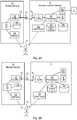
- Figs 1A-Care schematic diagrams showing environments in which embodiments presented herein can be applied.
- the computer device 1can be any type of electronic device with a user interface, including but not limited to a stationary computer, a laptop computer, a tablet computer, a smartphone, a mobile phone, a special purpose electronic device (such as an automatic teller machine, vending machine.), etc.
- the computer device 1can be a standalone computer or a network connected computer.
- an access control device 3is provided. As explained in more detail below, the access control device 3 is connected to the computer device 1, which is thus controllable by the access control device 3 to be set in an unlocked state or locked state. In this embodiment, the access control device 3 is provided close to the computer device 1.
- a mobile device 10comprises a sensor to detect taps by a user 9. Moreover, there is a user input device to detect the same taps of the user 9. Based on data from the sensor and the user input device, the access control device 3 can authenticate the user and thus grant or deny access. Once authenticated, valid authorisation can optionally be a condition to grant access.
- the access control device 3When access is granted, the access control device 3 sends a match signal to the computer device 1, whereby the computer device 1 is set in an unlocked state.
- thiscan e.g. imply a signal over a wire-based communication, e.g. using Universal Serial Bus (USB), Ethernet, a serial interface (such as RS-232, RS-485, etc.), a parallel interface (such as Centronics) or even a simple electric connection or alternatively a wireless interface.
- USBUniversal Serial Bus
- Ethernetsuch as RS-232, RS-485, etc.
- a parallel interfacesuch as Centronics
- the access control device 3can be located in the vicinity of the computer device 1 or it can be located remotely (e.g. in or in the vicinity of a network authentication node), in communication with the computer device over a network.
- the user 9can interact with the computer device 1 as desired. In this way, access to the computer device 1 is controlled by the access control device 3.
- access to the computer device 1may also include access to the connected network.
- Fig 1BThe embodiment shown in Fig 1B is similar to the embodiment of Fig 1A and only differences will be explained now.
- the access control device 3is included in the mobile device 10 in the form of software and/or hardware.
- the access control device 3obtains sensor data from both the user input device and the mobile device sensor to determine whether to grant access. If access is granted, the access control device 3 sends a match signal to the computer device 1 over the wireless interface between the mobile device 10 and the computer device 1.
- Fig 1CThe embodiment shown in Fig 1C is similar to the embodiment of Fig 1A and only differences will be explained now.
- the access control device 3is included in the computer device 1 in the form of software and/or hardware.
- Figs 2A-Care schematic diagrams illustrating some components of the mobile device 10, the access control device and the computer device 1 of Figs 1A-C and how these interact according to different embodiments.
- the mobile device 10 and the access control device 3interact using a wireless interface 17 so that the access control device 3 can determine whether to grant or deny access.
- the wireless interface 17is any suitable current or future wireless interface allowing communication between the mobile device 10 and the access control device 3 and can e.g. be based on Bluetooth, Bluetooth Low Energy (BLE), Radio Frequency Identification (RFID), Near Field Communication (NFC), any of the IEEE 802.11 standards, etc.
- the mobile device 10comprises a transceiver 12 connected to an antenna 13 for the wireless interface 17. Furthermore, the mobile device 10 comprises a controller 11 which can be any combination of one or more of a suitable central processing unit (CPU), multiprocessor, microcontroller unit (MCU), digital signal processor (DSP), application specific integrated circuit etc., capable of executing software instructions or otherwise controllable to behave according to predetermined logic.
- the mobile device 10may be implemented as a mobile phone, a smartphone, a key fob, credit card shaped device, etc.
- a memory 18is provided which can optionally store credential data of the mobile device 10.
- the credential datacan be used in an authentication process to determine whether the mobile device is authenticated as a condition to be granted access to the computer device.
- the memory 18can be any combination of read and write memory (RAM) and read only memory (ROM).
- the memory 18may also comprise persistent storage, which, for example, can be any single one or combination of solid state memory, magnetic memory, or optical memory storing a computer program with software instructions.
- a mobile device sensor 29detects taps of the user 9 of the mobile device 10.
- the mobile device sensor 29is implemented using an accelerometer.
- the accelerometercan detect acceleration, and thus movement, in at least one dimension, and optionally in three dimensions.
- the mobile device sensor 29is implemented using a camera.
- the cameracan detect movement by capturing images of the user 9 and/or capturing images of the surroundings, and analysing differences in these images over time.
- the mobile device sensor 29generates sensor data of which at least a subset is transmitted to the access control device 3 over the wireless interface 17.
- the sensor datais transformed by the processor prior to transmission, e.g. to compress data, to filter the sensor data and/or to transform the data in a suitable format for transmission.
- the mobile device 10is a wearable device, such as an armband, a watch or a ring.
- a wearable devicesuch as an armband, a watch or a ring.
- the access control device 3comprises a transceiver 7 with a connected antenna 6.
- the transceiver 7 and the mobile device 10interact over a wireless interface 17 for sending sensor data from the mobile device 10 and optionally to exchange digital authentication data with the mobile device 10.
- the transceiver 7 and antenna 6are provided externally from the access control device 3.
- a processor 60controls the general operation of access control device 3.
- the processor 60can be any combination of one or more of a suitable central processing unit (CPU), multiprocessor, microcontroller unit (MCU), digital signal processor (DSP), application specific integrated circuit (ASIC) etc., capable of executing software instructions or otherwise configured to behave according to predetermined logic.
- the processor 60can be capable of executing software instructions 65 stored in a memory 64, which can thus be a computer program product.
- the processor 60can be configured to execute the method described with reference to Fig 3 below.
- the memory 64can be any combination of read and write memory (RAM) and read only memory (ROM).
- the memory 64also comprises persistent storage, which, for example, can be any single one or combination of magnetic memory, optical memory, solid state memory or even remotely mounted memory.
- a data memory 66is also provided for reading and/or storing data during execution of software instructions in the processor 60, for instance digital authentication data.
- the data memory 66can be any combination of read and write memory (RAM) and read only memory (ROM).
- the access control device 3further comprises an I/O interface 63 for communicating with other external entities such as the computer device 1.
- Such communicationmay be wire-based, e.g. using Universal Serial Bus (USB), Ethernet, or a serial interface (such as RS-232, RS-485, etc.), a parallel interface (such as Centronics) even a simple electric connection (e.g. to the computer device 1).
- the connectioncan be wireless, e.g. using Bluetooth, BLE, any of the IEEE 802. 11 standards, wireless USB, etc.
- the access control device 3also includes a user interface, e.g. comprising any one or more of a keypad, light emitting diodes (LED) or other lights, a display (optionally touch sensitive), etc.
- a user input device 19detects taps of the user 9 of the mobile device 10.
- the user input device 19is not carried by the user and is instead stationary.
- the user input device 19can be loosely placed on a surface such as a table, or could be mounted to a fixed physical structure.
- the user input device 19can form part of the access control device 3 (as shown) or can be external to the access control device and connected to the access control device 3 (not shown).
- the user input device 19can e.g. be a key, button, keyboard, mouse button, touchpad button, etc.
- the tapis to be interpreted as any distinct user input, such as a key press, a button press, a touchpad tap, etc. and can be thought of as an actuation of a user interface element by the user, in contrast with directional user input such as mouse movement, touch pad finger movement, etc.
- the analysis of the tapsis more distinct and computationally less demanding compared to analysis of directional movement.
- Fig 2Ban embodiment is shown which is similar to the embodiment of Fig 2A .
- the access control device 3is included as part of the computer device 1.
- the components shown in Fig 2A of the access control deviceare then completely or partly shared between the access control device and the computer device.
- the user input device 19can then form part of a regular user interface of the computer device 1, such as a keyboard, a touchpad button, etc.
- the operation of the access control device 3is then controlled by software instructions 3 stored in the persistent memory 64 of the host device, in this case the computer device 1.
- the access control device 3is implemented using software instructions 3 stored in the persistent memory 18 of the mobile device. This embodiment corresponds to the embodiment shown in Fig 1B .
- the mobile device 10communicates with the computer device 1 e.g. to be able to send a match signal when access is granted.
- the access control device 3obtains sensor data from both the mobile device sensor 29 and the user input device 19 and matches the sensor data as part of the process to grant access.
- the user input device 19can communicate with the mobile device 10 and thus the access control device 3 over the wireless interface either as shown, via the computer device 1, or using a direct wireless link between the user input device 19 and the mobile device 10.
- Fig 3is a flow chart illustrating embodiments of methods performed in the access control device 3 of Figs 1A-C or Figs 2A-C for conditionally authenticating a user for access to a computer device.
- the methodcan be started periodically or when proximity of a user or computer device is detected.
- the wireless interface (17 of Fig 2B )is established.
- the wireless interfacehas been set up prior to starting the method, in which case this step does not need to be performed.
- digital authentication datais exchanged between the access control device and the mobile device (when the access control device is not in the mobile device) or the computer device (when the access control device is in the mobile device).
- This exchange of authentication datacan e.g. comprise a challenge and response communication, where the access control device sends a challenge to the other device (mobile device/computer device) and the other device sends a response.
- the challenge and response communicationcould also occur in the reverse direction.
- conditional first authentication ok step 42the access control device determines whether the mobile device is authenticated based on the digital authentication data. For instance, this can comprise the checking of the response with an expected result in a challenge and response procedure.
- the authenticationis performed using resources in the computer device or an authentication node in a network connected to the computer device.
- the methodproceeds to the synchronise clocks step 43. Otherwise, the method ends.
- step 43the time lines of sensor data from the user input device and sensor data from the mobile device sensor are synchronised. This can e.g. involve finding a common time reference.
- the time synchronisationcan occur by process where the two sides exchange their times to thereby obtain cross references to the corresponding times.
- first sensor datais obtained.
- the first sensor datais based on the mobile device sensing a physical movement of a user using the mobile device sensor, e.g. a tap.
- the first sensor datacan e.g. contain samples of an analogue signal detected by the mobile device sensor.
- the first sensor datais based on accelerometer data.
- the obtaining of first sensor datacomprises receiving the first sensor data from the mobile device over the wireless interface (17 of Figs 2A-B ).
- the obtaining of first sensor datacomprises receiving the first sensor data from the mobile device sensor 29.
- the first sensor datacan then be received as a signal from the mobile device sensor or by reading a memory accessible to both the mobile device sensor and the access control device, implemented using software instructions executing in the processor.
- second sensor datais obtained.
- the second sensor datais based on a user input device detecting user input from a user.
- the second sensor datacan e.g. contain time of actuations/taps detected by the user input device.
- the obtaining of second sensor datacomprises receiving the second sensor data from the user input device 19.
- the second sensor datacan then be received as a signal from the user input device or by reading a memory accessible to both the user input device and the access control device.
- the obtaining of second sensor datacomprises receiving the second sensor data from the user input device over the wireless interface (17 of Figs 2C ).
- first sensor data and the second sensor dataoverlap in time to allow matching to be performed.
- the access control device 3determines whether the first sensor data matches the second sensor data by determining whether the first sensor data reflects a tap of the user and corresponds to a tap of the user also reflected in the second sensor data.
- the first sensor data and the second sensor dataare determined to match only when the time difference between the two taps of the first sensor data corresponds to the time difference between the two taps of the second sensor data.
- Correspondsis here to be interpreted to be the same within a margin of error (of e.g. 10 ms).
- a matchis determined when the same taps are found in the first sensor data and the second sensor data, which is determined by comparing the respective time differences between the two taps.
- a time differenceis considered, such that a match between the first sensor data matches the second data only occurs when a time difference between a corresponding physical movement (i.e. one or both taps) is less than a threshold time difference, indicating concurrency of an event.
- a time differencecan e.g. be 100 milliseconds.
- the time differencemay require a synchronisation of a time scale for the first sensor data and for the second sensor data as explained above.
- the times at which the first sensor data and the second sensor data is obtainedare used as reference points for the comparison in time.
- the intent of authenticationis better controlled than if e.g. only radio frequency (RF) communication is used for authentication, e.g. using BLE, NFC, RFID, etc.
- RFradio frequency
- received signal strengthis sometimes used to control range, but this is unreliable and depends on knowledge of transmitter strength.
- intentis better verified. For instance, intent in embodiments herein is shown by two actuations of the user input device, whereby the intent is clear.
- Inadvertent authenticationcan be a significant security risk e.g. in office environments where there are many people moving around.
- Fig 4illustrates an embodiment of this matching and is described in more detail below.
- the methodproceeds to a send match signal step 49.
- the methodproceeds to a send match signal step 49.
- the methodends.
- a match signalis sent to the computer device.
- the match signalindicates the determined match. This can be a sufficient condition to unlock the computer device or other conditions may also need to be fulfilled. In this way, the computer device is set into an unlocked state, allowing access for the user to the computer device.
- a user movementis detected using both the mobile device sensor and the user input device and access is only granted if the movement matches.
- the order in which the first sensor data and the second data is obtainedis not important.
- the first sensor data and the second dataneed to relate to overlapping time periods in order to perform the matching.
- the first sensor data and the second sensor dataare both provided to the access control device in parallel.
- the matchingis performed in parallel with the obtaining of sensor data (steps 44 and 46).
- the matchingcan be performed repetitively on chunks of the first sensor data and the second sensor data, optionally combined with a certain amount of historic data.
- the mobile deviceis a wearable device, e.g. in the form of an armband, watch or a ring.
- the mobile device sensoris an accelerometer and the user input device is a keyboard or a touchpad. To gain access, the user taps a hand or finger located on the same limb as the mobile device twice on the user input device.
- the mobile device sensorsenses the vibrations propagated trough the body and the user input device also detects the taps.
- the mobile device sensordetects the taps as peaks in vibration which, when the duration between the taps detected by the mobile device and the user input device are compared, results in a positive match between the first sensor data and the second sensor data.
- the sensor data of the mobile device sensoris only used in one dimension to focus the motion detection. This one dimension can be the dimension where the vibration is strongest.
- the mobile deviceis a mobile phone or key fob.
- the mobile device sensoris an accelerometer and the user input device is a keyboard or a touchpad. To gain access, the user simply taps the mobile phone twice on the user input device.
- the mobile device sensordetects the taps as peaks in vibration which, when the duration between the taps detected by the mobile device and the user input device are compared, results in a positive match between the first sensor data and the second sensor data.
- conditional predefined movement step 48When the conditional predefined movement step 48 is performed, only predefined movements result in a positive match, which increases the sense of control of the user. For instance, when the predefined movement is three taps within a certain amount of time, the user needs to perform this action to unlock the computer device.
- the first authenticationcan e.g. be implemented with automatic authentication and the matching is performed based on movement. In this way, the user can unlock the computer device by making a suitable body movement to prevent inadvertent unlocking, while great security is provided using the automatic authentication.
- Fig 4is a schematic diagram illustrating embodiments of how the matching performed in the conditional match step 47 of the flow chart of Fig 3 can be implemented.
- a first signal 81plotted comprising the first sensor data, originating from the mobile device sensor
- a second signal 82plotted for the second sensor data, originating from the user input device. It is to be noted that it is not important here which signal is which as long as they are matched.
- the horizontal axisrepresents time and the vertical axis represents an amplitude of the respective signal levels.
- the two peaks 83a-b in the first signal 81correspond to respective taps of the user.
- the two peaks 84a-b of the second signal 82correspond to respective taps of the user.
- a first time difference 85 between the two peaks 83a-b of the first signalis determined.
- a second time difference 86 between the two peaks 84a-b of the second signalis determined.
- the presence of a match or notcan then be determined by comparing the first time difference 85 and the second time difference 86. These are considered to correspond to each other when they are equal, within a margin of error.
- the margin of errorcan e.g. be +-10 ms or even less, such as 1 ms.
- the time difference between the first peaks of the first signal 81 and the second signal 82also need to be within a threshold, to further increase security.
- each time difference 85, 86can be calculated with great accuracy since it only depends on a single respective signal 81, 82.
- Fig 5shows one example of a computer program product comprising computer readable means.
- a computer program 91can be stored, which computer program can cause a processor to execute a method according to embodiments described herein.
- the computer program productis an optical disc, such as a CD (compact disc) or a DVD (digital versatile disc) or a Blu-Ray disc.
- the computer program productcould also be embodied in a memory of a device, such as the computer program product 64 of Figs 2A-B or the computer program product 18 of Fig 2C .
- While the computer program 91is here schematically shown as a track on the depicted optical disk, the computer program can be stored in any way which is suitable for the computer program product, such as a removable solid state memory, e.g. a Universal Serial Bus (USB) drive.
- a removable solid state memorye.g. a Universal Serial Bus (USB) drive.
- USBUniversal Serial Bus
Landscapes
- Engineering & Computer Science (AREA)
- Theoretical Computer Science (AREA)
- Computer Security & Cryptography (AREA)
- General Engineering & Computer Science (AREA)
- Physics & Mathematics (AREA)
- General Physics & Mathematics (AREA)
- Computer Hardware Design (AREA)
- Software Systems (AREA)
- Human Computer Interaction (AREA)
- Telephone Function (AREA)
Description
- The invention relates to conditionally authenticating a user for access to a computer device. In particular, sensor data is used for the authentication.
- Authentication for computer devices can occur in many different ways. Still today, authentication using a username and password is most common. While this type of authentication still works, it is often complicated and cumbersome to enter a username and password which is secure enough to be difficult to break.
US-2010/218249 presents a system and/or a method that facilitates authentication of a user in a surface computing environment. A device or authentication object can be carried by a user and employed to retain authentication information. An authentication component can obtain the authentication information from the device and analyze the information to verify an identity of the user. A touch input component can ascertain if a touch input is authentication by associating touch input with the user. In addition, authentication information can be employed to establish a secure communications channel for transfer of user data. However, access control to computers always benefit from improved usability with the same or higher security.EP-2 395 446 presents a method for pairing a first device (such as a handset) with a second device (such as a personal computer), said first and second devices being linked to a remote server, said first device comprising an accelerometer and said second device being linked to a third device. The method comprises the following steps: the first device and the second device capture a common movement respectively to the first and to the third devices; the first device and the second device send data resulting from the common movement to the remote server so as to create a unique identifier of the movement; the remote server compares the identifier of the movement of the first device and the identifier of the movement of the second device, and if the identifiers match, the remote server pairs operations performed from the first and the second devices. However, this method requires the user to hold the first device while performing a movement using e.g. a mouse or a touchpad which can be correlated. Such a correlation is cumbersome and resource demanding.US2008136678 anticipates an authentication method. Z- It is an object to improve control of how access control is performed based on correlated movement which is less resource demanding than in the prior art. The invention is as defined in the appended claims.
- According to a first aspect, it is presented a method for conditionally authenticating a user for access to a computer device, the method being performed in an access control device connected to the computer device. The method comprises the steps of: obtaining first sensor data being based on a mobile device sensing a physical movement of a user; obtaining second sensor data being based on a user input device detecting user input from a user; determining whether the first sensor data matches the second sensor data by determining whether the first sensor data reflects two taps of the user and corresponds to two taps of the user reflected in the second sensor data, and wherein the first sensor data and the second sensor data are determined to match only when the time difference between the two taps of the first sensor data corresponds to the time difference between the two taps of the second sensor data; and sending a match signal to the computer device when the first sensor data matches the second sensor data.
- The method may further comprise the steps of: exchanging digital authentication data with the mobile device; determining whether the mobile device is authenticated based on the digital authentication data; and wherein the step of sending a match signal is only performed when the mobile device is authenticated.
- The step of determining whether the first sensor data matches the second data may comprise determining that the first sensor data matches the second data only when a time difference between corresponding a physical movement is less than a threshold time difference.
- In the step of obtaining first sensor data, the first sensor data may be based on accelerometer data.
- According to a second aspect, it is presented an access control device arranged to conditionally authenticate a user for access to a computer device. The access control device comprises: a processor; and a memory storing instructions that, when executed by the processor, causes the access control device to: obtain first sensor data being based on a mobile device sensing a physical movement of a user; obtain second sensor data being based on a user input device detecting user input of a user; determine whether the first sensor data matches the second sensor data by determining whether the first sensor data reflects two taps of the user and corresponds to two taps of the user reflected in the second sensor data, and wherein the first sensor data and the second sensor data are determined to match only when the time difference between the two taps of the first sensor data corresponds to the time difference between the two taps of the second sensor data; and send a match signal to the computer device, connected to the access control device, when the first sensor data matches the second sensor data.
- The memory may further store instructions that, when executed by the processor, causes the access control device to: exchange digital authentication data with the mobile device; determine whether the mobile device is authenticated based on the digital authentication data; and wherein the instructions to send a match signal comprise instructions that, when executed by the processor, causes the access control device to only send the match signal when the mobile device is authenticated.
- The instructions to determine whether the first sensor data matches the second data may comprise instructions that, when executed by the processor, causes the access control device to determine that the first sensor data matches the second data only when a time difference between a corresponding physical movement is less than a threshold time difference.
- The instructions to obtain first sensor data may comprise instructions that, when executed by the processor, causes the access control device to obtain the first sensor data based on accelerometer data.
- According to a third aspect, it is presented a computer device comprising the access control device according to the second aspect.
- According to a fourth aspect, it is presented a computer program for conditionally authenticating a user for access to a computer device. The computer program comprises computer program code which, when run on a access control device causes the access control device to: obtain first sensor data being based on a mobile device sensing a physical movement of a user; obtain second sensor data being based on a user input device detecting user input from a user; determine whether the first sensor data matches the second sensor data by determining whether the first sensor data reflects two taps of the user and corresponds to two taps of the user reflected in the second sensor data, and wherein the first sensor data and the second sensor data are determined to match only when the time difference between the two taps of the first sensor data corresponds to the time difference between the two taps of the second sensor data; and send a match signal to the computer device, connected to the access control device, when the first sensor data matches the second sensor data.
- According to a fifth aspect, it is presented a computer program product comprising a computer program according to the fourth aspect and a computer readable means on which the computer program is stored.
- Generally, all terms used in the claims are to be interpreted according to their ordinary meaning in the technical field, unless explicitly defined otherwise herein. All references to "a/an/the element, apparatus, component, means, step, etc." are to be interpreted openly as referring to at least one instance of the element, apparatus, component, means, step, etc., unless explicitly stated otherwise. The steps of any method disclosed herein do not have to be performed in the exact order disclosed, unless explicitly stated.
- The invention is now described, by way of example, with reference to the accompanying drawings, in which:
Figs 1A-C are schematic diagrams showing environments in which embodiments presented herein can be applied;Figs 2A-C are schematic diagrams illustrating some components of the mobile device, the access control device and computer device ofFig 1 and how these interact according to different embodiments;Fig 3 is a flow chart illustrating embodiments of methods performed in the access control device ofFigs 1A-C orFigs 2A-C for conditionally authenticating a user for access to a computer device;Fig 4 is a schematic diagrams illustrating embodiments of how the matching performed in the flow chart ofFig 3 can be implemented; andFig 5 shows one example of a computer program product comprising computer readable means.- The invention will now be described more fully hereinafter with reference to the accompanying drawings, in which certain embodiments of the invention are shown. This invention may, however, be embodied in many different forms and should not be construed as limited to the embodiments set forth herein; rather, these embodiments are provided by way of example so that this disclosure will be thorough and complete, and will fully convey the scope of the invention to those skilled in the art. Like numbers refer to like elements throughout the description.
Figs 1A-C are schematic diagrams showing environments in which embodiments presented herein can be applied.- Looking first to
Fig 1A , access to acomputer device 1 is restricted. Thecomputer device 1 can be any type of electronic device with a user interface, including but not limited to a stationary computer, a laptop computer, a tablet computer, a smartphone, a mobile phone, a special purpose electronic device (such as an automatic teller machine, vending machine.), etc. Thecomputer device 1 can be a standalone computer or a network connected computer. - In order to unlock the
computer device 1, anaccess control device 3 is provided. As explained in more detail below, theaccess control device 3 is connected to thecomputer device 1, which is thus controllable by theaccess control device 3 to be set in an unlocked state or locked state. In this embodiment, theaccess control device 3 is provided close to thecomputer device 1. - As explained in more detail below, a
mobile device 10 comprises a sensor to detect taps by auser 9. Moreover, there is a user input device to detect the same taps of theuser 9. Based on data from the sensor and the user input device, theaccess control device 3 can authenticate the user and thus grant or deny access. Once authenticated, valid authorisation can optionally be a condition to grant access. - When access is granted, the
access control device 3 sends a match signal to thecomputer device 1, whereby thecomputer device 1 is set in an unlocked state. In this embodiment, this can e.g. imply a signal over a wire-based communication, e.g. using Universal Serial Bus (USB), Ethernet, a serial interface (such as RS-232, RS-485, etc.), a parallel interface (such as Centronics) or even a simple electric connection or alternatively a wireless interface. It is to be noted that theaccess control device 3 can be located in the vicinity of thecomputer device 1 or it can be located remotely (e.g. in or in the vicinity of a network authentication node), in communication with the computer device over a network. When thecomputer device 1 is in an unlocked state, theuser 9 can interact with thecomputer device 1 as desired. In this way, access to thecomputer device 1 is controlled by theaccess control device 3. When thecomputer device 1 is a network connected computer, access to thecomputer device 1 may also include access to the connected network. - The embodiment shown in
Fig 1B is similar to the embodiment ofFig 1A and only differences will be explained now. InFig 1B , theaccess control device 3 is included in themobile device 10 in the form of software and/or hardware. - Again, the
access control device 3 obtains sensor data from both the user input device and the mobile device sensor to determine whether to grant access. If access is granted, theaccess control device 3 sends a match signal to thecomputer device 1 over the wireless interface between themobile device 10 and thecomputer device 1. - The embodiment shown in
Fig 1C is similar to the embodiment ofFig 1A and only differences will be explained now. InFig 1C , theaccess control device 3 is included in thecomputer device 1 in the form of software and/or hardware. Figs 2A-C are schematic diagrams illustrating some components of themobile device 10, the access control device and thecomputer device 1 ofFigs 1A-C and how these interact according to different embodiments.- The
mobile device 10 and theaccess control device 3 interact using awireless interface 17 so that theaccess control device 3 can determine whether to grant or deny access. Thewireless interface 17 is any suitable current or future wireless interface allowing communication between themobile device 10 and theaccess control device 3 and can e.g. be based on Bluetooth, Bluetooth Low Energy (BLE), Radio Frequency Identification (RFID), Near Field Communication (NFC), any of the IEEE 802.11 standards, etc. - The
mobile device 10 comprises atransceiver 12 connected to anantenna 13 for thewireless interface 17. Furthermore, themobile device 10 comprises acontroller 11 which can be any combination of one or more of a suitable central processing unit (CPU), multiprocessor, microcontroller unit (MCU), digital signal processor (DSP), application specific integrated circuit etc., capable of executing software instructions or otherwise controllable to behave according to predetermined logic. Themobile device 10 may be implemented as a mobile phone, a smartphone, a key fob, credit card shaped device, etc. - A
memory 18 is provided which can optionally store credential data of themobile device 10. The credential data can be used in an authentication process to determine whether the mobile device is authenticated as a condition to be granted access to the computer device. Thememory 18 can be any combination of read and write memory (RAM) and read only memory (ROM). Thememory 18 may also comprise persistent storage, which, for example, can be any single one or combination of solid state memory, magnetic memory, or optical memory storing a computer program with software instructions. - A
mobile device sensor 29 detects taps of theuser 9 of themobile device 10. - In one embodiment, the
mobile device sensor 29 is implemented using an accelerometer. The accelerometer can detect acceleration, and thus movement, in at least one dimension, and optionally in three dimensions. - In one embodiment, the
mobile device sensor 29 is implemented using a camera. The camera can detect movement by capturing images of theuser 9 and/or capturing images of the surroundings, and analysing differences in these images over time. Themobile device sensor 29 generates sensor data of which at least a subset is transmitted to theaccess control device 3 over thewireless interface 17. Optionally, the sensor data is transformed by the processor prior to transmission, e.g. to compress data, to filter the sensor data and/or to transform the data in a suitable format for transmission. - Optionally, the
mobile device 10 is a wearable device, such as an armband, a watch or a ring. When themobile device 10 is fixed to theuser 9, this improves the capability of themobile device sensor 29 to detect movement of a body part of theuser 9, especially when fixed to a limb (e.g. arm) of theuser 9. - Other components of the
mobile device 10, such as user interface components, etc. are omitted here for reasons of clarity. - Looking now to the
access control device 3, this comprises atransceiver 7 with aconnected antenna 6. Thetransceiver 7 and themobile device 10 interact over awireless interface 17 for sending sensor data from themobile device 10 and optionally to exchange digital authentication data with themobile device 10. Optionally, thetransceiver 7 andantenna 6 are provided externally from theaccess control device 3. - A
processor 60 controls the general operation ofaccess control device 3. Theprocessor 60 can be any combination of one or more of a suitable central processing unit (CPU), multiprocessor, microcontroller unit (MCU), digital signal processor (DSP), application specific integrated circuit (ASIC) etc., capable of executing software instructions or otherwise configured to behave according to predetermined logic. Hence, theprocessor 60 can be capable of executingsoftware instructions 65 stored in amemory 64, which can thus be a computer program product. Theprocessor 60 can be configured to execute the method described with reference toFig 3 below. - The
memory 64 can be any combination of read and write memory (RAM) and read only memory (ROM). Thememory 64 also comprises persistent storage, which, for example, can be any single one or combination of magnetic memory, optical memory, solid state memory or even remotely mounted memory. - A
data memory 66 is also provided for reading and/or storing data during execution of software instructions in theprocessor 60, for instance digital authentication data. Thedata memory 66 can be any combination of read and write memory (RAM) and read only memory (ROM). - The
access control device 3 further comprises an I/O interface 63 for communicating with other external entities such as thecomputer device 1. Such communication may be wire-based, e.g. using Universal Serial Bus (USB), Ethernet, or a serial interface (such as RS-232, RS-485, etc.), a parallel interface (such as Centronics) even a simple electric connection (e.g. to the computer device 1). Alternatively or additionally, the connection can be wireless, e.g. using Bluetooth, BLE, any of the IEEE 802. 11 standards, wireless USB, etc. Optionally, theaccess control device 3 also includes a user interface, e.g. comprising any one or more of a keypad, light emitting diodes (LED) or other lights, a display (optionally touch sensitive), etc. - A
user input device 19 detects taps of theuser 9 of themobile device 10. Theuser input device 19 is not carried by the user and is instead stationary. Theuser input device 19 can be loosely placed on a surface such as a table, or could be mounted to a fixed physical structure. Theuser input device 19 can form part of the access control device 3 (as shown) or can be external to the access control device and connected to the access control device 3 (not shown). Theuser input device 19 can e.g. be a key, button, keyboard, mouse button, touchpad button, etc. The tap is to be interpreted as any distinct user input, such as a key press, a button press, a touchpad tap, etc. and can be thought of as an actuation of a user interface element by the user, in contrast with directional user input such as mouse movement, touch pad finger movement, etc. The analysis of the taps is more distinct and computationally less demanding compared to analysis of directional movement. - Other components of the
access control device 3 are omitted in order not to obscure the concepts presented herein. - In
Fig 2B , an embodiment is shown which is similar to the embodiment ofFig 2A . Here, however, theaccess control device 3 is included as part of thecomputer device 1. The components shown inFig 2A of the access control device are then completely or partly shared between the access control device and the computer device. For instance, theuser input device 19 can then form part of a regular user interface of thecomputer device 1, such as a keyboard, a touchpad button, etc. The operation of theaccess control device 3 is then controlled bysoftware instructions 3 stored in thepersistent memory 64 of the host device, in this case thecomputer device 1. - In
Fig 2C , theaccess control device 3 is implemented usingsoftware instructions 3 stored in thepersistent memory 18 of the mobile device. This embodiment corresponds to the embodiment shown inFig 1B . - Here, the
mobile device 10 communicates with thecomputer device 1 e.g. to be able to send a match signal when access is granted. - The
access control device 3 obtains sensor data from both themobile device sensor 29 and theuser input device 19 and matches the sensor data as part of the process to grant access. - The
user input device 19 can communicate with themobile device 10 and thus theaccess control device 3 over the wireless interface either as shown, via thecomputer device 1, or using a direct wireless link between theuser input device 19 and themobile device 10. Fig 3 is a flow chart illustrating embodiments of methods performed in theaccess control device 3 ofFigs 1A-C orFigs 2A-C for conditionally authenticating a user for access to a computer device.- The method can be started periodically or when proximity of a user or computer device is detected.
- In an optionalset up
communication step 40, the wireless interface (17 ofFig 2B ) is established. Alternatively, the wireless interface has been set up prior to starting the method, in which case this step does not need to be performed. - In an optionalexchange authentication data step 41, digital authentication data is exchanged between the access control device and the mobile device (when the access control device is not in the mobile device) or the computer device (when the access control device is in the mobile device). This exchange of authentication data can e.g. comprise a challenge and response communication, where the access control device sends a challenge to the other device (mobile device/computer device) and the other device sends a response. The challenge and response communication could also occur in the reverse direction.
- In an optional conditionalfirst authentication
ok step 42, the access control device determines whether the mobile device is authenticated based on the digital authentication data. For instance, this can comprise the checking of the response with an expected result in a challenge and response procedure. Optionally, the authentication is performed using resources in the computer device or an authentication node in a network connected to the computer device. When the other device is authenticated, the method proceeds to thesynchronise clocks step 43. Otherwise, the method ends. - In an optional
synchronise clocks step 43, the time lines of sensor data from the user input device and sensor data from the mobile device sensor are synchronised. This can e.g. involve finding a common time reference. - Alternatively, the time synchronisation can occur by process where the two sides exchange their times to thereby obtain cross references to the corresponding times.
- In theobtain first
sensor data step 44, first sensor data is obtained. The first sensor data is based on the mobile device sensing a physical movement of a user using the mobile device sensor, e.g. a tap. The first sensor data can e.g. contain samples of an analogue signal detected by the mobile device sensor. In one embodiment, the first sensor data is based on accelerometer data. - When the access control device is implemented on the stationary side, the obtaining of first sensor data comprises receiving the first sensor data from the mobile device over the wireless interface (17 of
Figs 2A-B ). - When the access control device is implemented on the mobile device side, the obtaining of first sensor data comprises receiving the first sensor data from the
mobile device sensor 29. The first sensor data can then be received as a signal from the mobile device sensor or by reading a memory accessible to both the mobile device sensor and the access control device, implemented using software instructions executing in the processor. - In anobtain second
sensor data step 46, second sensor data is obtained. The second sensor data is based on a user input device detecting user input from a user. The second sensor data can e.g. contain time of actuations/taps detected by the user input device. - When the access control device is implemented on the stationary side, the obtaining of second sensor data comprises receiving the second sensor data from the
user input device 19. The second sensor data can then be received as a signal from the user input device or by reading a memory accessible to both the user input device and the access control device. - When the access control device is implemented on the mobile device side, the obtaining of second sensor data comprises receiving the second sensor data from the user input device over the wireless interface (17 of
Figs 2C ). - It is to be noted that the first sensor data and the second sensor data overlap in time to allow matching to be performed.
- In a
conditionalmatch step 47, theaccess control device 3 determines whether the first sensor data matches the second sensor data by determining whether the first sensor data reflects a tap of the user and corresponds to a tap of the user also reflected in the second sensor data. The first sensor data and the second sensor data are determined to match only when the time difference between the two taps of the first sensor data corresponds to the time difference between the two taps of the second sensor data. Corresponds is here to be interpreted to be the same within a margin of error (of e.g. 10 ms). In other words, a match is determined when the same taps are found in the first sensor data and the second sensor data, which is determined by comparing the respective time differences between the two taps. - Optionally, a time difference is considered, such that a match between the first sensor data matches the second data only occurs when a time difference between a corresponding physical movement (i.e. one or both taps) is less than a threshold time difference, indicating concurrency of an event. Such a time difference can e.g. be 100 milliseconds. The time difference may require a synchronisation of a time scale for the first sensor data and for the second sensor data as explained above. Alternatively, the times at which the first sensor data and the second sensor data is obtained are used as reference points for the comparison in time.
- Using this method, the intent of authentication is better controlled than if e.g. only radio frequency (RF) communication is used for authentication, e.g. using BLE, NFC, RFID, etc. In RF based communication, received signal strength is sometimes used to control range, but this is unreliable and depends on knowledge of transmitter strength. Using the user input device in the authentication process, the intent is better verified. For instance, intent in embodiments herein is shown by two actuations of the user input device, whereby the intent is clear.
- By controlling the operative range better, the risk of inadvertent authentication is decreased. Inadvertent authentication can be a significant security risk e.g. in office environments where there are many people moving around.
Fig 4 illustrates an embodiment of this matching and is described in more detail below.- When a match is determined, the method proceeds to asend
match signal step 49. Alternatively, when a match is determined, the method proceeds to asendmatch signal step 49. When no match is determined, the method ends. - In thesend
match signal step 49, a match signal is sent to the computer device. The match signal indicates the determined match. This can be a sufficient condition to unlock the computer device or other conditions may also need to be fulfilled. In this way, the computer device is set into an unlocked state, allowing access for the user to the computer device. - Using this method, a user movement is detected using both the mobile device sensor and the user input device and access is only granted if the movement matches.
- It is to be noted that the order in which the first sensor data and the second data is obtained (in
steps 44 and 46) is not important. However, the first sensor data and the second data need to relate to overlapping time periods in order to perform the matching. In one embodiment, the first sensor data and the second sensor data are both provided to the access control device in parallel. Optionally, the matching (step 47) is performed in parallel with the obtaining of sensor data (steps 44 and 46). Alternatively, the matching can be performed repetitively on chunks of the first sensor data and the second sensor data, optionally combined with a certain amount of historic data. - A number of embodiments will now be described to illustrate the flexibility and applicability of embodiments of the method of
Fig 3 . Each one of these embodiments can optionally be combined with additional authentication (steps 41 and 42). - In one embodiment, the mobile device is a wearable device, e.g. in the form of an armband, watch or a ring. The mobile device sensor is an accelerometer and the user input device is a keyboard or a touchpad. To gain access, the user taps a hand or finger located on the same limb as the mobile device twice on the user input device. The mobile device sensor senses the vibrations propagated trough the body and the user input device also detects the taps. The mobile device sensor detects the taps as peaks in vibration which, when the duration between the taps detected by the mobile device and the user input device are compared, results in a positive match between the first sensor data and the second sensor data. Optionally, the sensor data of the mobile device sensor is only used in one dimension to focus the motion detection. This one dimension can be the dimension where the vibration is strongest.
- In one embodiment, the mobile device is a mobile phone or key fob. The mobile device sensor is an accelerometer and the user input device is a keyboard or a touchpad. To gain access, the user simply taps the mobile phone twice on the user input device. The mobile device sensor detects the taps as peaks in vibration which, when the duration between the taps detected by the mobile device and the user input device are compared, results in a positive match between the first sensor data and the second sensor data.
- When the conditionalpredefined movement step 48 is performed, only predefined movements result in a positive match, which increases the sense of control of the user. For instance, when the predefined movement is three taps within a certain amount of time, the user needs to perform this action to unlock the computer device.
- When the
steps Fig 4 is a schematic diagram illustrating embodiments of how the matching performed in theconditionalmatch step 47 of the flow chart ofFig 3 can be implemented. There is here a first signal 81 plotted comprising the first sensor data, originating from the mobile device sensor, and a second signal 82 plotted for the second sensor data, originating from the user input device. It is to be noted that it is not important here which signal is which as long as they are matched. The horizontal axis represents time and the vertical axis represents an amplitude of the respective signal levels.- There are two
peaks 83a-b in the first signal 81. The twopeaks 83a-b of the first signal 81 correspond to respective taps of the user. Also, there are two peaks 84a-b in the second signal 82. The two peaks 84a-b of the second signal 82 correspond to respective taps of the user. Afirst time difference 85 between the twopeaks 83a-b of the first signal is determined. A second time difference 86 between the two peaks 84a-b of the second signal is determined. - The presence of a match or not can then be determined by comparing the
first time difference 85 and the second time difference 86. These are considered to correspond to each other when they are equal, within a margin of error. The margin of error can e.g. be +-10 ms or even less, such as 1 ms. - Optionally, the time difference between the first peaks of the first signal 81 and the second signal 82 also need to be within a threshold, to further increase security.
- When the first peaks are not compared in time, , the time base of the two signals do not need to be synchronised, since only the peak time difference is compared between signals, not the timings themselves. Also, each
time difference 85, 86 can be calculated with great accuracy since it only depends on a single respective signal 81, 82. Fig 5 shows one example of a computer program product comprising computer readable means. On this computer readable means acomputer program 91 can be stored, which computer program can cause a processor to execute a method according to embodiments described herein. In this example, the computer program product is an optical disc, such as a CD (compact disc) or a DVD (digital versatile disc) or a Blu-Ray disc. As explained above, the computer program product could also be embodied in a memory of a device, such as thecomputer program product 64 ofFigs 2A-B or thecomputer program product 18 ofFig 2C . While thecomputer program 91 is here schematically shown as a track on the depicted optical disk, the computer program can be stored in any way which is suitable for the computer program product, such as a removable solid state memory, e.g. a Universal Serial Bus (USB) drive.
Claims (11)
- A method for conditionally determining intent of authenticating a user for access to a computer device (1), the method being performed in an access control device (3) connected to the computer device (1), the method comprising the steps of:obtaining (44) first sensor data being based on a mobile device (10) sensing a physical movement of a user;obtaining (46) second sensor data being based on a user input device detecting user input from a user of the physical movement, wherein the first sensor data and the second data relate to overlapping time periods;determining (47) whether the first sensor data matches the second sensor data by determining whether the first sensor data reflects two taps of the user and corresponds to two taps of the user reflected in the second sensor data, and wherein the first sensor data and the second sensor data are determined to match only when the time difference between the two taps of the first sensor data corresponds to the time difference between the two taps of the second sensor data; andsending (49) a match signal to the computer device (1) when the first sensor data matches the second sensor data to authenticate the user and permit access with the access control device.
- The method according to claim 1, further comprising the steps of:exchanging (41) digital authentication data with the mobile device (10);determining (42) whether the mobile device (10) is authenticated based on the digital authentication data; andwherein the step of sending (46) a match signal is only performed when the mobile device (10) is authenticated.
- The method according to claim 1 or 2, wherein the step of determining (47) whether the first sensor data matches the second data comprises determining that the first sensor data matches the second data only when a time difference between corresponding a physical movement is less than a threshold time difference.
- The method according to any one of the preceding claims, wherein in the step of obtaining (44) first sensor data, the first sensor data is based on accelerometer data.
- An access control device (3) arranged to conditionally authenticate a user for access to a computer device (1), the access control device comprising:a processor (60); anda memory (64) storing instructions (66) that, when executed by the processor, causes the access control device (3) to:obtain first sensor data being based on a mobile device (10) sensing a physical movement of a user;obtain second sensor data being based on a user input device (19) detecting user input of a user of the physical movement, wherein the first sensor data and the second data relate to overlapping time periods;determine whether the first sensor data matches the second sensor data by determining whether the first sensor data reflects two taps of the user and corresponds to two taps of the user reflected in the second sensor data, and wherein the first sensor data and the second sensor data are determined to match only when the time difference between the two taps of the first sensor data corresponds to the time difference between the two taps of the second sensor data; andsend a match signal to the computer device (1), connected to the access control device, when the first sensor data matches the second sensor data to authenticate the user and permit access with the access control device.
- The access control device (3) according to claim 5, wherein the memory (64) further stores instructions (66) that, when executed by the processor, causes the access control device (3) to:exchange digital authentication data with the mobile device (10);determine whether the mobile device (10) is authenticated based on the digital authentication data; andwherein the instructions to send a match signal comprise instructions that, when executed by the processor, causes the access control device (3) to only send the match signal when the mobile device (10) is authenticated.
- The access control device (3) according to claim 5 or 6, wherein the instructions to determine whether the first sensor data matches the second data comprise instructions that, when executed by the processor, causes the access control device (3) to determine that the first sensor data matches the second data only when a time difference between a corresponding physical movement is less than a threshold time difference.
- The access control device (3) according to any one of claims 5 to 7, wherein the instructions to obtain first sensor data comprise instructions that, when executed by the processor, causes the access control device (3) to obtain the first sensor data based on accelerometer data.
- A computer device (1) comprising the access control device (3) according to any one of claims 5 to 8.
- A computer program (90) for conditionally authenticating a user for access to a computer device (1), the computer program comprising computer program code which, when run on a access control device (3) causes the access control device (3) to:obtain first sensor data being based on a mobile device (10) sensing a physical movement of a user;obtain second sensor data being based on a user input device detecting user input from a user of the physical movement, wherein the first sensor data and the second data relate to overlapping time periods;determine whether the first sensor data matches the second sensor data by determining whether the first sensor data reflects two taps of the user and corresponds to two taps of the user reflected in the second sensor data, and wherein the first sensor data and the second sensor data are determined to match only when the time difference between the two taps of the first sensor data corresponds to the time difference between the two taps of the second sensor data; andsend a match signal to the computer device (1), connected to the access control device, when the first sensor data matches the second sensor data to authenticate the user and permit access with the access control device.
- A computer program product (91) comprising a computer program according to claim 10 and a computer readable means on which the computer program is stored.
Applications Claiming Priority (2)
| Application Number | Priority Date | Filing Date | Title |
|---|---|---|---|
| EP14196313 | 2014-12-04 | ||
| PCT/EP2015/078401WO2016087541A1 (en) | 2014-12-04 | 2015-12-02 | Using sensor data to authenticate a user for a computer device |
Publications (2)
| Publication Number | Publication Date |
|---|---|
| EP3227815A1 EP3227815A1 (en) | 2017-10-11 |
| EP3227815B1true EP3227815B1 (en) | 2020-10-14 |
Family
ID=52015918
Family Applications (1)
| Application Number | Title | Priority Date | Filing Date |
|---|---|---|---|
| EP15804464.4AActiveEP3227815B1 (en) | 2014-12-04 | 2015-12-02 | Using sensor data to authenticate a user for a computer device |
Country Status (3)
| Country | Link |
|---|---|
| US (1) | US10152584B2 (en) |
| EP (1) | EP3227815B1 (en) |
| WO (1) | WO2016087541A1 (en) |
Families Citing this family (16)
| Publication number | Priority date | Publication date | Assignee | Title |
|---|---|---|---|---|
| US10444908B2 (en)* | 2016-12-31 | 2019-10-15 | Innoventions, Inc. | Virtual touchpads for wearable and portable devices |
| WO2018160254A1 (en)* | 2017-02-28 | 2018-09-07 | Carrier Corporation | Body-worn device for capturing user intent when interacting with multiple access controls |
| US10664579B2 (en)* | 2017-05-10 | 2020-05-26 | Haptic One, Inc. | Programmable rhythm detection locking system and method thereof |
| US11455382B2 (en) | 2018-03-26 | 2022-09-27 | Sony Corporation | Methods and apparatuses for proximity detection |
| CN110400396B (en) | 2018-04-25 | 2023-08-22 | 开利公司 | System and method for seamless entry and intent recognition using a mobile phone |
| CN110415389B (en) | 2018-04-27 | 2024-02-23 | 开利公司 | Gesture access control system and method for predicting location of mobile device relative to user |
| CN110415386A (en) | 2018-04-27 | 2019-11-05 | 开利公司 | Modeling of preprogrammed scene data for gesture-based entry control systems |
| CN110415391B (en) | 2018-04-27 | 2024-03-05 | 开利公司 | Seamless entry control system using wearable devices |
| CN110415392B (en) | 2018-04-27 | 2023-12-12 | 开利公司 | Entry control system based on early posture |
| CN110415390A (en) | 2018-04-27 | 2019-11-05 | 开利公司 | Gesture entry control system using device gestures performed by a user of a mobile device |
| CN110415387A (en) | 2018-04-27 | 2019-11-05 | 开利公司 | Gesture entry control system comprising a mobile device disposed in a receptacle carried by a user |
| CN110515035B (en) | 2018-05-21 | 2025-01-21 | 开利公司 | Method for learning deployment environment specific characteristics for seamless access |
| CN110517370B (en) | 2018-05-21 | 2023-09-19 | 开利公司 | How to debug the door recognition system using fingerprints |
| US11027822B2 (en)* | 2018-06-21 | 2021-06-08 | Rockwell Collins, Inc. | Control system for touchless operation of mechanical input devices |
| CN110634205A (en) | 2018-06-21 | 2019-12-31 | 开利公司 | Destination recognition for frictionless building interaction |
| DE102021005350A1 (en)* | 2021-10-27 | 2023-04-27 | Giesecke+Devrient Mobile Security Gmbh | Authorize an application on a security element |
Family Cites Families (17)
| Publication number | Priority date | Publication date | Assignee | Title |
|---|---|---|---|---|
| SE530279C8 (en) | 2005-03-18 | 2008-06-03 | Phoniro Ab | Method of unlocking a lock with a locking device capable of wireless short distance data communication in accordance with a communication standard, and an associated locking device |
| US20080136678A1 (en) | 2006-12-11 | 2008-06-12 | International Business Machines Corporation | Data input using knocks |
| CN101355746B (en)* | 2007-07-27 | 2012-05-16 | 深圳富泰宏精密工业有限公司 | Radio communication device |
| EP2034389A1 (en) | 2007-09-07 | 2009-03-11 | Nederlandse Organisatie voor toegepast- natuurwetenschappelijk onderzoek TNO | Method and system for linking appliances |
| KR20200090943A (en)* | 2007-09-24 | 2020-07-29 | 애플 인크. | Embedded authentication systems in an electronic device |
| US8040218B2 (en)* | 2007-12-31 | 2011-10-18 | Utc Fire & Security Americas Corporation, Inc. | GPS enabled key management system |
| US20100218249A1 (en) | 2009-02-25 | 2010-08-26 | Microsoft Corporation | Authentication via a device |
| EP2395446A1 (en) | 2010-06-14 | 2011-12-14 | Gemalto SA | Method for pairing a first device with a second device |
| GB201109311D0 (en)* | 2011-06-03 | 2011-07-20 | Avimir Ip Ltd | Method and computer program for providing authentication to control access to a computer system |
| US20130127591A1 (en) | 2011-11-20 | 2013-05-23 | International Business Machines Corporation | Secure facilities access |
| EP2600319A1 (en) | 2011-11-29 | 2013-06-05 | Gemalto SA | Pairing system between a terminal and an eGo-type element worn on the wrist or the hand of a user and corresponding method |
| US9245100B2 (en)* | 2013-03-14 | 2016-01-26 | Google Technology Holdings LLC | Method and apparatus for unlocking a user portable wireless electronic communication device feature |
| US9832206B2 (en) | 2013-03-21 | 2017-11-28 | The Trustees Of Dartmouth College | System, method and authorization device for biometric access control to digital devices |
| US9450682B2 (en)* | 2013-10-07 | 2016-09-20 | International Business Machines Corporation | Method and system using vibration signatures for pairing master and slave computing devices |
| US9223955B2 (en)* | 2014-01-30 | 2015-12-29 | Microsoft Corporation | User-authentication gestures |
| WO2015149882A1 (en)* | 2014-04-01 | 2015-10-08 | Sony Corporation | Authentication with ultrasound |
| KR20160136013A (en)* | 2015-05-19 | 2016-11-29 | 엘지전자 주식회사 | Mobile terminal and method for controlling the same |
- 2015
- 2015-12-02EPEP15804464.4Apatent/EP3227815B1/enactiveActive
- 2015-12-02WOPCT/EP2015/078401patent/WO2016087541A1/enactiveApplication Filing
- 2015-12-02USUS15/532,674patent/US10152584B2/enactiveActive
Non-Patent Citations (1)
| Title |
|---|
| None* |
Also Published As
| Publication number | Publication date |
|---|---|
| US20170357791A1 (en) | 2017-12-14 |
| EP3227815A1 (en) | 2017-10-11 |
| WO2016087541A1 (en) | 2016-06-09 |
| US10152584B2 (en) | 2018-12-11 |
Similar Documents
| Publication | Publication Date | Title |
|---|---|---|
| EP3227815B1 (en) | Using sensor data to authenticate a user for a computer device | |
| US10152838B2 (en) | Using sensor data to authenticate a user | |
| EP3192292B1 (en) | Automatic authorization for access to electronic device | |
| EP3289789B1 (en) | Wearable discovery for authentication | |
| KR101977845B1 (en) | Mobile device to provide continuous and discrete user authentication | |
| CA2900762C (en) | Control system and method | |
| CN107408169B (en) | Portable electronic device for remote control | |
| US10409975B2 (en) | Short-range communication device, function control method and function control system | |
| EP3122018B1 (en) | Mobile terminal and method of controlling the same | |
| EP3094122A1 (en) | Systems and methods for protecting sensitive information stored on a mobile device | |
| EP3175635B1 (en) | Device activity control | |
| KR102545375B1 (en) | Electronic device for performing authorization using accessory and method for the same | |
| KR102442779B1 (en) | User authentication methods and devices | |
| EP2908225A1 (en) | Methods and systems for connecting a process based on motion detection | |
| KR20230070216A (en) | Relay attack detection on interfaces using command-response pairs | |
| CN114902610A (en) | Credential Gateway | |
| CN115001817A (en) | Offline identity recognition method, device and equipment | |
| TW201518978A (en) | Unlocking system and method thereof | |
| JP2015090650A (en) | Terminal device, authentication method, and program | |
| WO2014045860A1 (en) | Information device, partner device, communication system, and information device control method and program | |
| WO2024253770A1 (en) | Systems and methods for selective engagement with readers in multi-reader environment | |
| US20210192041A1 (en) | Information processing device, information processing system and program | |
| CN111868721A (en) | Electronic device and method of operating the same | |
| KR20200009614A (en) | Control apparatus for certicification, and control method thereof |
Legal Events
| Date | Code | Title | Description |
|---|---|---|---|
| STAA | Information on the status of an ep patent application or granted ep patent | Free format text:STATUS: THE INTERNATIONAL PUBLICATION HAS BEEN MADE | |
| PUAI | Public reference made under article 153(3) epc to a published international application that has entered the european phase | Free format text:ORIGINAL CODE: 0009012 | |
| STAA | Information on the status of an ep patent application or granted ep patent | Free format text:STATUS: REQUEST FOR EXAMINATION WAS MADE | |
| 17P | Request for examination filed | Effective date:20170518 | |
| AK | Designated contracting states | Kind code of ref document:A1 Designated state(s):AL AT BE BG CH CY CZ DE DK EE ES FI FR GB GR HR HU IE IS IT LI LT LU LV MC MK MT NL NO PL PT RO RS SE SI SK SM TR | |
| AX | Request for extension of the european patent | Extension state:BA ME | |
| DAV | Request for validation of the european patent (deleted) | ||
| DAX | Request for extension of the european patent (deleted) | ||
| STAA | Information on the status of an ep patent application or granted ep patent | Free format text:STATUS: EXAMINATION IS IN PROGRESS | |
| 17Q | First examination report despatched | Effective date:20190502 | |
| GRAP | Despatch of communication of intention to grant a patent | Free format text:ORIGINAL CODE: EPIDOSNIGR1 | |
| STAA | Information on the status of an ep patent application or granted ep patent | Free format text:STATUS: GRANT OF PATENT IS INTENDED | |
| INTG | Intention to grant announced | Effective date:20200527 | |
| GRAS | Grant fee paid | Free format text:ORIGINAL CODE: EPIDOSNIGR3 | |
| GRAA | (expected) grant | Free format text:ORIGINAL CODE: 0009210 | |
| STAA | Information on the status of an ep patent application or granted ep patent | Free format text:STATUS: THE PATENT HAS BEEN GRANTED | |
| AK | Designated contracting states | Kind code of ref document:B1 Designated state(s):AL AT BE BG CH CY CZ DE DK EE ES FI FR GB GR HR HU IE IS IT LI LT LU LV MC MK MT NL NO PL PT RO RS SE SI SK SM TR | |
| REG | Reference to a national code | Ref country code:GB Ref legal event code:FG4D | |
| REG | Reference to a national code | Ref country code:AT Ref legal event code:REF Ref document number:1324277 Country of ref document:AT Kind code of ref document:T Effective date:20201015 Ref country code:CH Ref legal event code:EP | |
| REG | Reference to a national code | Ref country code:DE Ref legal event code:R096 Ref document number:602015060527 Country of ref document:DE | |
| REG | Reference to a national code | Ref country code:IE Ref legal event code:FG4D | |
| REG | Reference to a national code | Ref country code:FI Ref legal event code:FGE | |
| REG | Reference to a national code | Ref country code:AT Ref legal event code:MK05 Ref document number:1324277 Country of ref document:AT Kind code of ref document:T Effective date:20201014 | |
| REG | Reference to a national code | Ref country code:NL Ref legal event code:MP Effective date:20201014 | |
| PG25 | Lapsed in a contracting state [announced via postgrant information from national office to epo] | Ref country code:NO Free format text:LAPSE BECAUSE OF FAILURE TO SUBMIT A TRANSLATION OF THE DESCRIPTION OR TO PAY THE FEE WITHIN THE PRESCRIBED TIME-LIMIT Effective date:20210114 Ref country code:NL Free format text:LAPSE BECAUSE OF FAILURE TO SUBMIT A TRANSLATION OF THE DESCRIPTION OR TO PAY THE FEE WITHIN THE PRESCRIBED TIME-LIMIT Effective date:20201014 Ref country code:RS Free format text:LAPSE BECAUSE OF FAILURE TO SUBMIT A TRANSLATION OF THE DESCRIPTION OR TO PAY THE FEE WITHIN THE PRESCRIBED TIME-LIMIT Effective date:20201014 Ref country code:PT Free format text:LAPSE BECAUSE OF FAILURE TO SUBMIT A TRANSLATION OF THE DESCRIPTION OR TO PAY THE FEE WITHIN THE PRESCRIBED TIME-LIMIT Effective date:20210215 Ref country code:GR Free format text:LAPSE BECAUSE OF FAILURE TO SUBMIT A TRANSLATION OF THE DESCRIPTION OR TO PAY THE FEE WITHIN THE PRESCRIBED TIME-LIMIT Effective date:20210115 | |
| REG | Reference to a national code | Ref country code:LT Ref legal event code:MG4D | |
| PG25 | Lapsed in a contracting state [announced via postgrant information from national office to epo] | Ref country code:LV Free format text:LAPSE BECAUSE OF FAILURE TO SUBMIT A TRANSLATION OF THE DESCRIPTION OR TO PAY THE FEE WITHIN THE PRESCRIBED TIME-LIMIT Effective date:20201014 Ref country code:IS Free format text:LAPSE BECAUSE OF FAILURE TO SUBMIT A TRANSLATION OF THE DESCRIPTION OR TO PAY THE FEE WITHIN THE PRESCRIBED TIME-LIMIT Effective date:20210214 Ref country code:SE Free format text:LAPSE BECAUSE OF FAILURE TO SUBMIT A TRANSLATION OF THE DESCRIPTION OR TO PAY THE FEE WITHIN THE PRESCRIBED TIME-LIMIT Effective date:20201014 Ref country code:PL Free format text:LAPSE BECAUSE OF FAILURE TO SUBMIT A TRANSLATION OF THE DESCRIPTION OR TO PAY THE FEE WITHIN THE PRESCRIBED TIME-LIMIT Effective date:20201014 Ref country code:BG Free format text:LAPSE BECAUSE OF FAILURE TO SUBMIT A TRANSLATION OF THE DESCRIPTION OR TO PAY THE FEE WITHIN THE PRESCRIBED TIME-LIMIT Effective date:20210114 Ref country code:AT Free format text:LAPSE BECAUSE OF FAILURE TO SUBMIT A TRANSLATION OF THE DESCRIPTION OR TO PAY THE FEE WITHIN THE PRESCRIBED TIME-LIMIT Effective date:20201014 Ref country code:ES Free format text:LAPSE BECAUSE OF FAILURE TO SUBMIT A TRANSLATION OF THE DESCRIPTION OR TO PAY THE FEE WITHIN THE PRESCRIBED TIME-LIMIT Effective date:20201014 | |
| PG25 | Lapsed in a contracting state [announced via postgrant information from national office to epo] | Ref country code:HR Free format text:LAPSE BECAUSE OF FAILURE TO SUBMIT A TRANSLATION OF THE DESCRIPTION OR TO PAY THE FEE WITHIN THE PRESCRIBED TIME-LIMIT Effective date:20201014 | |
| REG | Reference to a national code | Ref country code:DE Ref legal event code:R097 Ref document number:602015060527 Country of ref document:DE | |
| PG25 | Lapsed in a contracting state [announced via postgrant information from national office to epo] | Ref country code:EE Free format text:LAPSE BECAUSE OF FAILURE TO SUBMIT A TRANSLATION OF THE DESCRIPTION OR TO PAY THE FEE WITHIN THE PRESCRIBED TIME-LIMIT Effective date:20201014 Ref country code:CZ Free format text:LAPSE BECAUSE OF FAILURE TO SUBMIT A TRANSLATION OF THE DESCRIPTION OR TO PAY THE FEE WITHIN THE PRESCRIBED TIME-LIMIT Effective date:20201014 Ref country code:SM Free format text:LAPSE BECAUSE OF FAILURE TO SUBMIT A TRANSLATION OF THE DESCRIPTION OR TO PAY THE FEE WITHIN THE PRESCRIBED TIME-LIMIT Effective date:20201014 Ref country code:LT Free format text:LAPSE BECAUSE OF FAILURE TO SUBMIT A TRANSLATION OF THE DESCRIPTION OR TO PAY THE FEE WITHIN THE PRESCRIBED TIME-LIMIT Effective date:20201014 Ref country code:SK Free format text:LAPSE BECAUSE OF FAILURE TO SUBMIT A TRANSLATION OF THE DESCRIPTION OR TO PAY THE FEE WITHIN THE PRESCRIBED TIME-LIMIT Effective date:20201014 Ref country code:RO Free format text:LAPSE BECAUSE OF FAILURE TO SUBMIT A TRANSLATION OF THE DESCRIPTION OR TO PAY THE FEE WITHIN THE PRESCRIBED TIME-LIMIT Effective date:20201014 | |
| REG | Reference to a national code | Ref country code:CH Ref legal event code:PL | |
| PLBE | No opposition filed within time limit | Free format text:ORIGINAL CODE: 0009261 | |
| STAA | Information on the status of an ep patent application or granted ep patent | Free format text:STATUS: NO OPPOSITION FILED WITHIN TIME LIMIT | |
| PG25 | Lapsed in a contracting state [announced via postgrant information from national office to epo] | Ref country code:DK Free format text:LAPSE BECAUSE OF FAILURE TO SUBMIT A TRANSLATION OF THE DESCRIPTION OR TO PAY THE FEE WITHIN THE PRESCRIBED TIME-LIMIT Effective date:20201014 Ref country code:MC Free format text:LAPSE BECAUSE OF FAILURE TO SUBMIT A TRANSLATION OF THE DESCRIPTION OR TO PAY THE FEE WITHIN THE PRESCRIBED TIME-LIMIT Effective date:20201014 | |
| REG | Reference to a national code | Ref country code:BE Ref legal event code:MM Effective date:20201231 | |
| 26N | No opposition filed | Effective date:20210715 | |
| PG25 | Lapsed in a contracting state [announced via postgrant information from national office to epo] | Ref country code:IE Free format text:LAPSE BECAUSE OF NON-PAYMENT OF DUE FEES Effective date:20201202 Ref country code:IT Free format text:LAPSE BECAUSE OF FAILURE TO SUBMIT A TRANSLATION OF THE DESCRIPTION OR TO PAY THE FEE WITHIN THE PRESCRIBED TIME-LIMIT Effective date:20201014 Ref country code:AL Free format text:LAPSE BECAUSE OF FAILURE TO SUBMIT A TRANSLATION OF THE DESCRIPTION OR TO PAY THE FEE WITHIN THE PRESCRIBED TIME-LIMIT Effective date:20201014 Ref country code:LU Free format text:LAPSE BECAUSE OF NON-PAYMENT OF DUE FEES Effective date:20201202 | |
| PG25 | Lapsed in a contracting state [announced via postgrant information from national office to epo] | Ref country code:CH Free format text:LAPSE BECAUSE OF NON-PAYMENT OF DUE FEES Effective date:20201231 Ref country code:SI Free format text:LAPSE BECAUSE OF FAILURE TO SUBMIT A TRANSLATION OF THE DESCRIPTION OR TO PAY THE FEE WITHIN THE PRESCRIBED TIME-LIMIT Effective date:20201014 Ref country code:LI Free format text:LAPSE BECAUSE OF NON-PAYMENT OF DUE FEES Effective date:20201231 | |
| PG25 | Lapsed in a contracting state [announced via postgrant information from national office to epo] | Ref country code:IS Free format text:LAPSE BECAUSE OF FAILURE TO SUBMIT A TRANSLATION OF THE DESCRIPTION OR TO PAY THE FEE WITHIN THE PRESCRIBED TIME-LIMIT Effective date:20210214 Ref country code:TR Free format text:LAPSE BECAUSE OF FAILURE TO SUBMIT A TRANSLATION OF THE DESCRIPTION OR TO PAY THE FEE WITHIN THE PRESCRIBED TIME-LIMIT Effective date:20201014 Ref country code:MT Free format text:LAPSE BECAUSE OF FAILURE TO SUBMIT A TRANSLATION OF THE DESCRIPTION OR TO PAY THE FEE WITHIN THE PRESCRIBED TIME-LIMIT Effective date:20201014 Ref country code:CY Free format text:LAPSE BECAUSE OF FAILURE TO SUBMIT A TRANSLATION OF THE DESCRIPTION OR TO PAY THE FEE WITHIN THE PRESCRIBED TIME-LIMIT Effective date:20201014 | |
| PG25 | Lapsed in a contracting state [announced via postgrant information from national office to epo] | Ref country code:MK Free format text:LAPSE BECAUSE OF FAILURE TO SUBMIT A TRANSLATION OF THE DESCRIPTION OR TO PAY THE FEE WITHIN THE PRESCRIBED TIME-LIMIT Effective date:20201014 | |
| PG25 | Lapsed in a contracting state [announced via postgrant information from national office to epo] | Ref country code:BE Free format text:LAPSE BECAUSE OF NON-PAYMENT OF DUE FEES Effective date:20201231 | |
| P01 | Opt-out of the competence of the unified patent court (upc) registered | Effective date:20230530 | |
| PGFP | Annual fee paid to national office [announced via postgrant information from national office to epo] | Ref country code:DE Payment date:20241112 Year of fee payment:10 | |
| PGFP | Annual fee paid to national office [announced via postgrant information from national office to epo] | Ref country code:FI Payment date:20241219 Year of fee payment:10 | |
| PGFP | Annual fee paid to national office [announced via postgrant information from national office to epo] | Ref country code:GB Payment date:20241107 Year of fee payment:10 | |
| PGFP | Annual fee paid to national office [announced via postgrant information from national office to epo] | Ref country code:FR Payment date:20241121 Year of fee payment:10 |