EP3226781B1 - Robot assisted volume removal during surgery - Google Patents
Robot assisted volume removal during surgeryDownload PDFInfo
- Publication number
- EP3226781B1 EP3226781B1EP15816096.0AEP15816096AEP3226781B1EP 3226781 B1EP3226781 B1EP 3226781B1EP 15816096 AEP15816096 AEP 15816096AEP 3226781 B1EP3226781 B1EP 3226781B1
- Authority
- EP
- European Patent Office
- Prior art keywords
- surgical instrument
- instrument holder
- holder
- surgical
- robot
- Prior art date
- Legal status (The legal status is an assumption and is not a legal conclusion. Google has not performed a legal analysis and makes no representation as to the accuracy of the status listed.)
- Active
Links
- 238000001356surgical procedureMethods0.000titleclaimsdescription44
- 230000033001locomotionEffects0.000claimsdescription42
- 239000012636effectorSubstances0.000claimsdescription16
- 238000003801millingMethods0.000claimsdescription9
- 230000008878couplingEffects0.000claimsdescription7
- 238000010168coupling processMethods0.000claimsdescription7
- 238000005859coupling reactionMethods0.000claimsdescription7
- 238000005259measurementMethods0.000claimsdescription7
- 238000000034methodMethods0.000description48
- 230000015654memoryEffects0.000description35
- 239000003550markerSubstances0.000description17
- 230000007246mechanismEffects0.000description17
- 238000005516engineering processMethods0.000description15
- 238000004891communicationMethods0.000description13
- 230000008569processEffects0.000description13
- 210000000988bone and boneAnatomy0.000description12
- 230000011218segmentationEffects0.000description9
- 230000000087stabilizing effectEffects0.000description9
- 210000003484anatomyAnatomy0.000description8
- 210000001519tissueAnatomy0.000description8
- 230000003287optical effectEffects0.000description7
- 238000012512characterization methodMethods0.000description6
- 238000005553drillingMethods0.000description6
- 238000004590computer programMethods0.000description4
- 230000003993interactionEffects0.000description4
- 238000012545processingMethods0.000description4
- 230000001413cellular effectEffects0.000description3
- 238000010586diagramMethods0.000description3
- 230000006870functionEffects0.000description3
- 206010028980NeoplasmDiseases0.000description2
- 230000009471actionEffects0.000description2
- 230000004913activationEffects0.000description2
- 230000006399behaviorEffects0.000description2
- 230000008901benefitEffects0.000description2
- 230000008859changeEffects0.000description2
- 239000003086colorantSubstances0.000description2
- 238000012937correctionMethods0.000description2
- 238000007428craniotomyMethods0.000description2
- 230000006378damageEffects0.000description2
- 238000001514detection methodMethods0.000description2
- 238000003384imaging methodMethods0.000description2
- 239000004973liquid crystal related substanceSubstances0.000description2
- 238000012544monitoring processMethods0.000description2
- 230000000399orthopedic effectEffects0.000description2
- 230000003252repetitive effectEffects0.000description2
- 210000000278spinal cordAnatomy0.000description2
- 208000005198spinal stenosisDiseases0.000description2
- 230000006641stabilisationEffects0.000description2
- 238000011105stabilizationMethods0.000description2
- 238000012546transferMethods0.000description2
- 238000009966trimmingMethods0.000description2
- 208000012514Cumulative Trauma diseaseDiseases0.000description1
- 241000761557LaminaSpecies0.000description1
- 206010044565TremorDiseases0.000description1
- 238000013459approachMethods0.000description1
- 238000004883computer applicationMethods0.000description1
- 238000012790confirmationMethods0.000description1
- 230000003247decreasing effectEffects0.000description1
- 238000003745diagnosisMethods0.000description1
- 238000002059diagnostic imagingMethods0.000description1
- 238000006073displacement reactionMethods0.000description1
- 210000001951dura materAnatomy0.000description1
- 230000003670easy-to-cleanEffects0.000description1
- 238000003708edge detectionMethods0.000description1
- 230000000694effectsEffects0.000description1
- 238000002594fluoroscopyMethods0.000description1
- 238000003709image segmentationMethods0.000description1
- 239000007943implantSubstances0.000description1
- 230000006872improvementEffects0.000description1
- 238000003780insertionMethods0.000description1
- 230000037431insertionEffects0.000description1
- 238000013507mappingMethods0.000description1
- 239000000463materialSubstances0.000description1
- 239000011159matrix materialSubstances0.000description1
- 238000010295mobile communicationMethods0.000description1
- 238000012806monitoring deviceMethods0.000description1
- 210000000653nervous systemAnatomy0.000description1
- 230000006855networkingEffects0.000description1
- 238000010422paintingMethods0.000description1
- 238000003825pressingMethods0.000description1
- 230000000644propagated effectEffects0.000description1
- 230000001012protectorEffects0.000description1
- 230000004044responseEffects0.000description1
- 230000001953sensory effectEffects0.000description1
- 239000007787solidSubstances0.000description1
- 210000000273spinal nerve rootAnatomy0.000description1
- 230000001954sterilising effectEffects0.000description1
- 238000004659sterilization and disinfectionMethods0.000description1
- 239000013589supplementSubstances0.000description1
- 238000013519translationMethods0.000description1
- 230000014616translationEffects0.000description1
- 230000005945translocationEffects0.000description1
- 238000002604ultrasonographyMethods0.000description1
- 230000000007visual effectEffects0.000description1
- 210000002517zygapophyseal jointAnatomy0.000description1
Images


Classifications
- A—HUMAN NECESSITIES
- A61—MEDICAL OR VETERINARY SCIENCE; HYGIENE
- A61B—DIAGNOSIS; SURGERY; IDENTIFICATION
- A61B34/00—Computer-aided surgery; Manipulators or robots specially adapted for use in surgery
- A61B34/30—Surgical robots
- A—HUMAN NECESSITIES
- A61—MEDICAL OR VETERINARY SCIENCE; HYGIENE
- A61B—DIAGNOSIS; SURGERY; IDENTIFICATION
- A61B17/00—Surgical instruments, devices or methods
- A61B17/16—Instruments for performing osteoclasis; Drills or chisels for bones; Trepans
- A61B17/1662—Instruments for performing osteoclasis; Drills or chisels for bones; Trepans for particular parts of the body
- A61B17/1671—Instruments for performing osteoclasis; Drills or chisels for bones; Trepans for particular parts of the body for the spine
- A—HUMAN NECESSITIES
- A61—MEDICAL OR VETERINARY SCIENCE; HYGIENE
- A61B—DIAGNOSIS; SURGERY; IDENTIFICATION
- A61B90/00—Instruments, implements or accessories specially adapted for surgery or diagnosis and not covered by any of the groups A61B1/00 - A61B50/00, e.g. for luxation treatment or for protecting wound edges
- A61B90/50—Supports for surgical instruments, e.g. articulated arms
- A—HUMAN NECESSITIES
- A61—MEDICAL OR VETERINARY SCIENCE; HYGIENE
- A61B—DIAGNOSIS; SURGERY; IDENTIFICATION
- A61B17/00—Surgical instruments, devices or methods
- A61B17/16—Instruments for performing osteoclasis; Drills or chisels for bones; Trepans
- A61B17/17—Guides or aligning means for drills, mills, pins or wires
- A61B17/1739—Guides or aligning means for drills, mills, pins or wires specially adapted for particular parts of the body
- A61B17/1757—Guides or aligning means for drills, mills, pins or wires specially adapted for particular parts of the body for the spine
- A—HUMAN NECESSITIES
- A61—MEDICAL OR VETERINARY SCIENCE; HYGIENE
- A61B—DIAGNOSIS; SURGERY; IDENTIFICATION
- A61B17/00—Surgical instruments, devices or methods
- A61B17/34—Trocars; Puncturing needles
- A61B17/3403—Needle locating or guiding means
- A—HUMAN NECESSITIES
- A61—MEDICAL OR VETERINARY SCIENCE; HYGIENE
- A61B—DIAGNOSIS; SURGERY; IDENTIFICATION
- A61B17/00—Surgical instruments, devices or methods
- A61B2017/00017—Electrical control of surgical instruments
- A—HUMAN NECESSITIES
- A61—MEDICAL OR VETERINARY SCIENCE; HYGIENE
- A61B—DIAGNOSIS; SURGERY; IDENTIFICATION
- A61B17/00—Surgical instruments, devices or methods
- A61B2017/00017—Electrical control of surgical instruments
- A61B2017/00115—Electrical control of surgical instruments with audible or visual output
- A61B2017/00119—Electrical control of surgical instruments with audible or visual output alarm; indicating an abnormal situation
- A61B2017/00123—Electrical control of surgical instruments with audible or visual output alarm; indicating an abnormal situation and automatic shutdown
- A—HUMAN NECESSITIES
- A61—MEDICAL OR VETERINARY SCIENCE; HYGIENE
- A61B—DIAGNOSIS; SURGERY; IDENTIFICATION
- A61B17/00—Surgical instruments, devices or methods
- A61B2017/00017—Electrical control of surgical instruments
- A61B2017/00203—Electrical control of surgical instruments with speech control or speech recognition
- A—HUMAN NECESSITIES
- A61—MEDICAL OR VETERINARY SCIENCE; HYGIENE
- A61B—DIAGNOSIS; SURGERY; IDENTIFICATION
- A61B17/00—Surgical instruments, devices or methods
- A61B2017/00017—Electrical control of surgical instruments
- A61B2017/00207—Electrical control of surgical instruments with hand gesture control or hand gesture recognition
- A—HUMAN NECESSITIES
- A61—MEDICAL OR VETERINARY SCIENCE; HYGIENE
- A61B—DIAGNOSIS; SURGERY; IDENTIFICATION
- A61B17/00—Surgical instruments, devices or methods
- A61B2017/00477—Coupling
- A—HUMAN NECESSITIES
- A61—MEDICAL OR VETERINARY SCIENCE; HYGIENE
- A61B—DIAGNOSIS; SURGERY; IDENTIFICATION
- A61B34/00—Computer-aided surgery; Manipulators or robots specially adapted for use in surgery
- A61B34/10—Computer-aided planning, simulation or modelling of surgical operations
- A61B2034/107—Visualisation of planned trajectories or target regions
- A—HUMAN NECESSITIES
- A61—MEDICAL OR VETERINARY SCIENCE; HYGIENE
- A61B—DIAGNOSIS; SURGERY; IDENTIFICATION
- A61B34/00—Computer-aided surgery; Manipulators or robots specially adapted for use in surgery
- A61B34/20—Surgical navigation systems; Devices for tracking or guiding surgical instruments, e.g. for frameless stereotaxis
- A61B2034/2046—Tracking techniques
- A61B2034/2059—Mechanical position encoders
- A—HUMAN NECESSITIES
- A61—MEDICAL OR VETERINARY SCIENCE; HYGIENE
- A61B—DIAGNOSIS; SURGERY; IDENTIFICATION
- A61B34/00—Computer-aided surgery; Manipulators or robots specially adapted for use in surgery
- A61B34/20—Surgical navigation systems; Devices for tracking or guiding surgical instruments, e.g. for frameless stereotaxis
- A61B2034/2068—Surgical navigation systems; Devices for tracking or guiding surgical instruments, e.g. for frameless stereotaxis using pointers, e.g. pointers having reference marks for determining coordinates of body points
- A—HUMAN NECESSITIES
- A61—MEDICAL OR VETERINARY SCIENCE; HYGIENE
- A61B—DIAGNOSIS; SURGERY; IDENTIFICATION
- A61B90/00—Instruments, implements or accessories specially adapted for surgery or diagnosis and not covered by any of the groups A61B1/00 - A61B50/00, e.g. for luxation treatment or for protecting wound edges
- A61B90/06—Measuring instruments not otherwise provided for
- A61B2090/064—Measuring instruments not otherwise provided for for measuring force, pressure or mechanical tension
- A61B2090/066—Measuring instruments not otherwise provided for for measuring force, pressure or mechanical tension for measuring torque
- A—HUMAN NECESSITIES
- A61—MEDICAL OR VETERINARY SCIENCE; HYGIENE
- A61B—DIAGNOSIS; SURGERY; IDENTIFICATION
- A61B90/00—Instruments, implements or accessories specially adapted for surgery or diagnosis and not covered by any of the groups A61B1/00 - A61B50/00, e.g. for luxation treatment or for protecting wound edges
- A61B90/50—Supports for surgical instruments, e.g. articulated arms
- A61B2090/508—Supports for surgical instruments, e.g. articulated arms with releasable brake mechanisms
- A—HUMAN NECESSITIES
- A61—MEDICAL OR VETERINARY SCIENCE; HYGIENE
- A61B—DIAGNOSIS; SURGERY; IDENTIFICATION
- A61B2576/00—Medical imaging apparatus involving image processing or analysis
- A—HUMAN NECESSITIES
- A61—MEDICAL OR VETERINARY SCIENCE; HYGIENE
- A61B—DIAGNOSIS; SURGERY; IDENTIFICATION
- A61B34/00—Computer-aided surgery; Manipulators or robots specially adapted for use in surgery
- A61B34/25—User interfaces for surgical systems
- A—HUMAN NECESSITIES
- A61—MEDICAL OR VETERINARY SCIENCE; HYGIENE
- A61B—DIAGNOSIS; SURGERY; IDENTIFICATION
- A61B34/00—Computer-aided surgery; Manipulators or robots specially adapted for use in surgery
- A61B34/70—Manipulators specially adapted for use in surgery
- A61B34/76—Manipulators having means for providing feel, e.g. force or tactile feedback
Definitions
- Spinal stenosis(narrowing of the spinal canal) is the single most common diagnosis that leads to spinal surgery.
- a laminotomymay be performed to alleviate pain associated with spinal stenosis by partially removing/trimming the vertebra lamina shown in Fig. 1 , thereby decompressing the corresponding spinal cord and/or spinal nerve root.
- a surgeonmanually removes portions of the lamina.
- the surgical instruments used for this taskinclude surgical pliers and a high-speed burr as shown in Figs. 2A and 2B , respectively.
- Described hereinis a device and method used to effectively remove volume inside a patient in various types of surgeries, such as spinal surgeries (e.g. laminotomy), neurosurgeries (various types of craniotomy), ENT surgeries (e.g. tumor removal), and orthopedic surgeries (bone removal).
- spinal surgeriese.g. laminotomy
- neurosurgeriesvarious types of craniotomy
- ENT surgeriese.g. tumor removal
- orthopedic surgeriesbone removal.
- the disclosed technologyprovides robotic assistance linked with a navigation system and medical imaging to shorten surgery time, make the surgery safer and free surgeons from doing repetitive and laborious tasks.
- the disclosed technologyis also compatible with robotic surgical system described in U.S. Patent Application No. 2015/0100066, filed April 30, 2014 , and entitled "Apparatus, Systems, and Methods for Precise Guidance of Surgical Tool", thereby, for example, allowing the same robotic surgical system to assist with different aspects of spinal surgery.
- the inventionrelates to a surgical instrument holder for use with a robotic surgical system.
- the holdercan be attached to or is part of an end effector of a robotic arm, and provides a rigid structure that can be used with a surgical tool to affect precise removal of a target volume in a patient.
- the holderhas a tubular shape with a longitudinal notch along a portion of its length.
- the holderis sized to allow a surgical instrument to slide through the holder in a fixed orientation while the holder is held by the robotic arm.
- the surgical instrumentin certain examples is fitted with a tool support having a peg sized to fit the notch.
- a navigational marker(e.g., a multipoint, planar marker) may be attached thereto via the peg.
- the navigation markercan be tracked (e.g., and hence the location of a surgical instrument connected to the navigation marker) when the surgical instrument is fully inserted and secured in the holder (e.g., in part by a locking mechanism). This facilitates and simplifies tracking of the marker, for example, via a remote tracking system that displays real-time tracking of the surgical instrument during the surgical procedure.
- the inventionrelates to an instrument holder with a rigid hollow tubular structure having a proximal open end and a distal open end, said structure defining an axis along which movement of a surgical instrument sliding through the structure is restricted, wherein the tubular structure has an interior surface shaped and sized to accommodate the surgical instrument sliding through the surgical instrument holder such that movement of the surgical instrument is constrained to move along the axis defined by the surgical instrument holder (e.g., thereby allowing rapid exchange of surgical instruments held by the surgical instrument holder); and a connector element attached to the holder that, when engaged (e.g., mated with) a corresponding connector element associated with a surgical instrument, provides power to the surgical instrument (e.g., and receives measurement information from a force sensor in the surgical instrument).
- a connector elementattached to the holder that, when engaged (e.g., mated with) a corresponding connector element associated with a surgical instrument, provides power to the surgical instrument (e.g., and receives measurement information from
- the tubular structurehas an exterior surface including at least one flange that is sized and shaped to secure coupling of the surgical instrument holder to an end effector of the robotic surgical system.
- the tubular structureincludes a longitudinal notch along its length, wherein the longitudinal notch (e.g., slot) is sized in relation to a peg on (e.g., directly or indirectly) the surgical instrument to permit the surgical instrument to slide along the axis defined by the surgical instrument holder.
- the longitudinal notchis sized in relation to a peg to (i) permit a navigation marker attached to the surgical instrument at least in part via the peg to be viewable by a navigation camera along an entire range of movement of the surgical instrument through the surgical instrument holder, and (ii) constrain movement of the marker in a fixed orientation along the axis defined by the surgical instrument holder.
- navigation markeris used by navigation camera to track the surgical instrument.
- a lockthat, when engaged, restricts (e.g., prevents) movement of a surgical instrument within the rigid hollow tubular structure (e.g., such that the surgical instrument is constrained within the tubular structure in all directions).
- the lockwhen engaged, prevents removal of the surgical instrument from the surgical instrument holder.
- a force sensormeasures one or more forces and/or torques (e.g., 1 to 3 forces and 1 to 3 torques) applied to at least a portion of the surgical instrument.
- the surgical instrumentincludes a force sensor that measures one or more forces and/or torques (e.g., 1 to 3 forces and 1 to 3 torques) applied to at least a portion of the surgical instrument, and the measurement information provided to the surgical instrument holder via the connector comprises the one or more forces and/or torques.
- the surgical instrumentis a drill (e.g., with a drill bit). In some implementations, the portion of the surgical instrument to which the one or more forces and/or torques are applied is the drill bit. In certain embodiments, the surgical instrument is a drill (e.g., for preparing a hole for receiving a screw). In certain embodiments, the surgical instrument is a milling device, shaver, laser, or ultrasonic scalpel. In certain embodiments, the surgical instrument holder is for use in spinal surgery. In certain embodiments, the surgical instrument is a screw driver (e.g., for placing a screw in a hole). There can be a user interface (e.g., touch screen, one or more buttons, and/or a display).
- a user interfacee.g., touch screen, one or more buttons, and/or a display.
- the tubular structurehas an interior surface sized and shaped to accommodate a tool support (e.g., sliding surface) of the surgical instrument.
- a second connector associated with the surgical instrument holdercommunicates with a sensor (e.g., the force sensor(s)) measuring the position of the surgical instrument.
- the second connectoris one or more brushes (e.g., that physically contact the surgical instrument).
- the rigid hollow tubular structureis a cylindrical structure.
- the disclosed technologyrelates to a robotic surgical system for performing surgery.
- a robotic arm with an end effectorcomprising a surgical instrument holder sized and shaped to hold and/or restrict movement of a surgical instrument therethrough
- the surgical instrument holdercomprising: a rigid hollow tubular structure having a proximal open end and a distal open end, said structure defining an axis along which movement of a surgical instrument (e.g., fitted with a tool support) sliding through the structure is restricted, wherein the tubular structure has an interior surface shaped and sized to accommodate the surgical instrument sliding through the surgical instrument holder such that movement of the tool support is constrained to move along the axis defined by the surgical instrument holder, wherein the tubular structure has an exterior surface comprising at least one flange that is sized and shaped to securely couple of the surgical instrument holder to an end effector of the robotic surgical system, and wherein the tubular structure comprises a longitudinal notch along its length, wherein the longitudinal notch is sized in relation to a peg on
- the disclosed technollogyrelates to a manipulator that allows robotically-assisted or unassisted positioning and/or movement of the surgical instrument holder by a user with at least four degrees of freedom to align an axis defined by the instrument holder at a desired trajectory in relation to a patient situation.
- the surgical instrument holderincludes a rigid hollow tubular structure having a proximal open end and a distal open end, said structure defining an axis along which movement of a surgical instrument (e.g., fitted with a tool support) sliding through the structure is restricted, wherein the tubular structure has an interior surface shaped and sized to accommodate the surgical instrument sliding through the surgical instrument holder such that movement of the tool support is constrained to move along the axis defined by the surgical instrument holder, wherein the tubular structure has an exterior surface comprising at least one flange that is sized and shaped to securely couple the surgical instrument holder to an end effector of the robotic surgical system, and wherein the tubular structure comprises a longitudinal notch along its length, wherein the longitudinal notch is sized in relation to a peg on the tool support to permit the tool support to slide along the axis defined by the surgical instrument holder; and a lock that, when engaged, restricts
- a force sensor for measuring one or more forces and/or torquescan be applied to at least a portion of the surgical instrument.
- the surgical instrumentmay comprise a force sensor for measuring one or more forces and/or torques (e.g., 1 to 3 forces and 1 to 3 torques) applied to at least a portion of the surgical instrument.
- the disclosed technologyrelates to a surgical instrument for preparing a hole in bone tissue of a patient.
- the surgical instrumentincludes an elongate structure having a proximal end with at least one of a drilling, milling, or shaving surface and a distal end with a shank sized and shaped to be grasped by a drill; and a force sensor integrated directly in the elongate structure for measuring one or more forces and/or torques (e.g., 1 to 3 forces and 1 to 3 torques) applied to at least a portion of the surgical instrument.
- forces and/or torquese.g., 1 to 3 forces and 1 to 3 torques
- the surgical instrumentincludes an elongate structure having a proximal end with a milling surface and a distal end with a shank sized and shaped to be grasped by a drill, wherein the proximal end of the surgical instrument is flat and substantially perpendicular to the axis of the elongate structure, thereby reducing skidding (e.g., unintentional lateral movement of the surgical instrument) of the surgical instrument upon contact of the milling surface with the bone tissue; and a force sensor integrated directly in the elongate structure for measuring one or more forces and/or torques (e.g., 1 to 3 forces and 1 to 3 torques) applied to at least a portion of the surgical instrument.
- forces and/or torquese.g., 1 to 3 forces and 1 to 3 torques
- a portion of the structure of the surgical instrument closest to the milling surfaceis for milling (e.g., rather than drilling) and the remaining portion of the surgical instrument is for drilling.
- the surgical instrumentis an anti-skip surgical instrument.
- the surgical instrumentis for use in spinal surgery. The surgical instrument is insertable into the surgical instrument holder such that the surgical instrument is constrained by the surgical instrument holder.
- the surgical instrument holdercomprises a rigid hollow tubular structure having a proximal open end and a distal open end, said structure defining an axis of the tubular structure along which movement of a surgical instrument sliding through the structure is restricted, wherein the tubular structure has an interior surface shaped and sized to accommodate the surgical instrument sliding through the surgical instrument holder such that movement of the surgical instrument (e.g., fitted with a tool support) is constrained to move along the axis defined by the surgical instrument holder.
- the surgical instrumentis fitted with a tool support shaped and sized to slide through the surgical instrument holder along the axis defined by the surgical instrument holder.
- the surgical instrumentis a drill bit and the surgical instrument holder is a drill bit guide holder.
- the surgical instrumentis held by a robotic surgical system comprising a robotic arm.
- the robotic armhas an end effector comprising a surgical instrument holder attached thereto, the surgical instrument holder sized and shaped to hold and/or restrict movement of a surgical instrument therethrough (e.g., via a lock).
- a navigation markeris used by a navigation camera to track the surgical instrument. Also disclosed is a method of performing surgery with a robotic surgical system.
- the methodincludes moving a mobile cart transporting a robotic surgical system comprising a robotic arm in proximity to an operating table, wherein the robotic arm has an end effector comprising a surgical instrument guide attached thereto, the surgical instrument guide sized and shaped to hold and/or restrict movement of one of a plurality of surgical instruments therethrough, wherein the plurality of surgical instruments comprises a first surgical instrument (e.g., for removing tissue from the body) and a second surgical instrument (e.g., for preparing a screw placement in a vertebra); stabilizing the mobile cart; maneuvering the first surgical instrument in a manner that is constrained by a surgical instrument guide comprising a rigid hollow tubular structure having a proximal open end and a distal open end, said structure defining the axis along which movement of a surgical instrument (e.g., fitted with a tool support) sliding through the structure is restricted, wherein: the tubular structure of the surgical instrument guide has an interior surface shaped and sized to accommodate the surgical instrument sliding through the guide such
- the first surgical instrumentis a drill (e.g., with a drill bit). In certain embodiments, the first surgical instrument is a milling device, shaver, laser, and ultrasonic scalpel.
- the second surgical instrumentis a screw driver (e.g., for placing a screw in a hole).
- the second surgical instrumentis a drill (e.g., for preparing a hole for receiving a screw).
- the tubular structurehas an exterior surface comprising at least one flange that is sized and shaped to securely couple the surgical instrument holder to an end effector of the robotic surgical system.
- the robotic surgical systemis for use in spinal surgery.
- the rigid hollow tubular structureis a cylindrical structure.
- the longitudinal notchis a slot.
- the navigation markeris used by a navigation camera to track the surgical instrument.
- the second surgical instrumentis used to guide a screw implant and a tissue protector.
- the robotic armcomprises a manipulator attached to the robotic arm.
- the robotic armcomprises a manipulator molded into the robotic arm.
- stabilizing the mobile cartcomprises extracting one or more rigid legs on the mobile cart such that the mobile cart rests on the one or more rigid legs of the mobile cart. In certain embodiments, stabilizing the mobile cart comprises retracting one or more wheels on the mobile cart such that the mobile cart rests on one or more rigid legs of the mobile cart. Also disclosed is a method of performing surgery with a robotic surgical system.
- the methodincludes identifying a volume to be removed , wherein medical images (e.g., obtained intraoperatively or pre-operatively) of the patient situation displayed on a display (e.g., on the robotic surgical system) are automatically updated to show feedback about the planning (e.g., displaying the volume identified for removal by shading); removing the planned volume using robotic assistance, the removing comprising: storing, by a processor of the robotic surgical system, a location of the volume to be removed as "stay-in zone", and storing, by the processor, a location of a second volume to protect from removal, wherein the location of the second volume defines a "no-go zone"; maintaining, by the processor, the surgical instrument in the "stay-in zone” and/or out of the "no-go zone", thereby removing the volume; after removing at least a portion of the volume, moving at least a portion of the robotic surgical system away from the patient; and manually completing the surgery.
- medical imagese.g., obtained intraoperatively or pre-operatively
- the methodincludes identifying a volume to be removed , wherein medical images (e.g., obtained intraoperatively or pre-operatively) of the patient situation displayed on a display (e.g., on the robotic surgical system) are automatically updated to show feedback about the planning (e.g., displaying the volume identified for removal by shading); removing the planned volume using robotic assistance, the removing comprising: preventing, by the robotic surgical system, a surgical instrument from leaving the volume until the volume is completely removed or the surgeon voluntarily wants to leave the volume; after removing at least a portion of the volume, moving at least a portion of the robotic surgical system away from the patient; and manually completing the surgery.
- medical imagese.g., obtained intraoperatively or pre-operatively
- the methodincludes identifying a volume to be removed , wherein medical images (e.g., obtained intraoperatively or pre-operatively) of the patient situation displayed on a display (e.g., on the robotic surgical system) are automatically updated to show feedback about the planning (e.g.,
- the volumeis identified by identifying (e.g., using a navigation system) a plurality of points on the patient anatomy.
- the plurality of pointsare identified by a surgeon point to a plurality of points on the patient anatomy (e.g., using a pointer tracked by a navigation system).
- the plurality of pointsare identified by following a path identified by a surgeon (e.g., via a pointer tracked by a navigation system) such that the plurality of points are automatically collected.
- the volumecan be identified using a navigation system.
- volumecan be identified using automatic segmentation, semi-automatic segmentation (e.g., using surgeon-defined points or corrections), or fully manual when surgeon/assistant/neurologist defines volume by manually selecting etc. the "pixels"/"voxels" to be removed.
- the methodincludes manually completing the surgery includes removing, by the surgeon, a portion of the volume to be removed. In certain embodiments, manually completing the surgery includes removing, by the surgeon, a portion of a second volume adjacent the volume removed with assistance of the robotic surgical system.
- repulsive/wall-like forcesprevent the surgeon from moving a position of the surgical instrument into the second volume.
- the methodincludes triggering a dead-man switch (e.g., via voice recognition, a gesture, presence or absence of physical contact with a portion of the robotic surgical system), thereby causing the robotic surgical system to stop.
- a dead-man switche.g., via voice recognition, a gesture, presence or absence of physical contact with a portion of the robotic surgical system
- the methodincludes, upon receiving a trigger signal (e.g., from a volume removal force sensor, a bio-sensing device such as PediGuard® by SpineGuard S.A. of Vincennes, France, and/or a neuro-monitoring device), preventing movement of the surgical instrument further in a forbidden direction.
- a trigger signale.g., from a volume removal force sensor, a bio-sensing device such as PediGuard® by SpineGuard S.A. of Vincennes, France, and/or a neuro-monitoring device
- the methodincludes, after identifying the volume to be removed, bringing the robot to the volume (e.g., automatically or using hands-on control).
- the identification of the volumeis performed using a navigation system pointer.
- the identification of the volumeis performed using the robotic surgical system in a force control mode.
- the methodincludes maneuvering a surgical instrument to make an incision, thereby exposing a vertebra; and attaching a frame of a navigation system to the patient.
- the methodincludes moving a mobile cart transporting a robotic surgical system comprising a robotic arm in proximity to an operating table, wherein the robotic arm has an end effector comprising a surgical instrument holder attached thereto, the surgical instrument holder sized and shaped to hold and/or restrict movement of a surgical instrument therethrough; and stabilizing the mobile cart.
- the methodincludes removing a least a portion of the spinous process, discs, facets, facet joints, pedicles, and/or vertebral bodies.
- the methodincludes a first force sensor and a second force sensor, each of the first and second force sensors for measuring one or more forces and/or torques (e.g., 1 to 3 forces and 1 to 3 torques) applied to at least a portion of the surgical instrument.
- the surgical instrument holder, surgical instrument, and/or robotic surgical systemis for use in at least one of spinal surgery (e.g. laminotomy), neurosurgery (various types of craniotomy), ENT surgery (e.g. tumor removal), and orthopedic surgery (bone removal).
- spinal surgerye.g. laminotomy
- neurosurgeryvarious types of craniotomy
- ENT surgerye.g. tumor removal
- orthopedic surgerybone removal
- the disclosed technologyincludes a tool attachment device for attaching a tool to a robotic surgical arm, the tool attachment device including: a lever for transmitting a fixation force to a quick lock latch via a plurality of links; and the quick lock latch for releasably securing a tool to the robot when an activation force is applied to the lever (e.g., the lever pulling the tool tight against a robot flange).
- the leveris activated by pushing the lever toward a robot flange such that quick lock latch pulls the tool tight against the robot flange.
- the quick lock latchcomprises a quick lock hook that engages a pin head on the tool when the tool is inserted fully into the robot flange.
- a positioning modulefor precisely positioning the surgical instrument holder relative to the robotic surgical arm (e.g., restricting orientation of the tool when mounting the tool to the robot).
- the positioning modulecomprises one or more pins on the robot flange, wherein, upon mechanically coupling the tool to the robotic surgical arm, the each pin of the one or more pins engage an opening in the tool thereby precisely positioning the tool relative to the robotic surgical arm.
- the positioning modulecomprises one or more openings on the robot flange, wherein, upon mechanically coupling the tool to the robotic surgical arm, the each opening of the one or more opening engages a pin on the tool thereby precisely positioning the tool relative to the robotic surgical arm.
- the disclosed technologyincludes a tool attachment device for attaching a tool to a robotic surgical arm, the tool attachment device including: a robot flange on the robotic surgical arm, the robot flange comprising (i) an open portion to receive a protrusion of a tool and (ii) a notch that permits a width of the opening to be at least partially decreased; and a lever connected to the robot flange that causes the width of the open portion of the robot flange to decrease when the lever is engaged, thereby securing the tool with the protrusion positioned in the opening to the robot flange.
- the disclosed technologyincludes a tool attachment device for attaching a tool to a robotic surgical arm, the tool attachment device including: a robot flange on the robotic surgical arm, the robot flange comprising a shape lock (e.g., bayonet mount) having at least two or more openings each arranged to receive and secure a protrusion on the tool or at least two or more protrusions each arranged to engage and secure an opening on the tool.
- a shape locke.g., bayonet mount
- the disclosed technologyincludes a drill for use with a surgical robotic arm, the drill including: a chuck for securely holding a drill bit; and a body comprising a positioning module for precisely positioning the drill relative to the robotic surgical arm.
- the body of the drillcomprises a protrusion and the protrusion comprises a pin head.
- the positioning modulecomprises one or more pins on the body, wherein, upon mechanically coupling the drill to the robotic surgical arm, each pin of the one or more pins engages an opening in the surgical robotic arm thereby precisely positioning the drill relative to the robotic surgical arm.
- the positioning modulecomprises one or more openings on the body, wherein, upon mechanically coupling the drill to the robotic surgical arm, the each opening of the one or more opening engages a pin on the robot thereby precisely positioning the drill relative to the robotic surgical arm.
- the positioning modulecomprising a hole that passes from a first side of the body to a second side of the body (e.g., such that the body can be mounted on the robot (e.g., by a bolt extending from the robotic surgical arm that slides through the hole and a nut that securely holds the body on the robotic surgical arm)).
- the positioning moduleis a friction based module and comprises a protrusion that fits into a portion of the robot flange and is secured therein by a force applied by a lever attached to the robot flange.
- the disclosed technologyincludes the robotic surgical system used to remove a target volume from a patient. Initially, an incision is made and the vertebra is exposed. In some implementations, the frame of a navigation system is attached to the patient in the place selected by the surgeon. Intra-operative medical images of the target anatomy may be obtained. Alternatively, images are acquired pre-operatively. Once the images are obtained, the images must be matched to the actual patient position by a process called registration. For intra-operative images, an automatic algorithm may be used to register the actual patient position with the intra-operative images. Alternatively, point-to-point registration or surface matching may be used. The disclosed technology provides an effective and quick way for the surgeon to define volume to be removed and thereafter remove the volume.
- the robotic surgical systemmay be used to place a screw in a vertebra by assisting in drilling a hole and inserting the screw in the hole as described in U.S. Patent Application No. 2005/0100066 filed April 30, 2014 , and entitled "Apparatus, Systems, and Methods for Precise Guidance of Surgical Tool".
- FIG. 3illustrates an example robotic surgical system in an operating room 300.
- one or more surgeons, surgical assistants, surgical technologists and/or other technicians, (306a-c)perform an operation on a patient 304 using a robotic-assisted surgical system. In the operating room the surgeon may be assisted by the robotic system to accurately execute an operation.
- the surgical robotic systemincludes a surgical robot 302 on a mobile cart.
- the surgical robot 302may be positioned in proximity to an operating table 312 without being attached to the operating table itself, thereby providing maximum operating area and mobility to surgeons around the operating table and reducing clutter on the operating table.
- the surgical robot (or cart)is securable to the operating table.
- both the operating table and the cartare secured to a common base to prevent any movement of the cart or table in relation to each other, even in the event of an earth tremor.
- the mobile cartmay permit a user (operator) 306a, such as a technician, nurse, surgeon, or any other medical personnel in the operating room, to move the surgical robot 302 to different locations before, during, and/or after a surgical procedure.
- the mobile cartenables the surgical robot 302 to be easily transported into and out of the operating room 300.
- a user 306amay move the surgical robot into the operating room from a storage location.
- the mobile cartmay include wheels, a track system, such as a continuous track propulsion system, or other similar mobility systems for translocation of the cart.
- the mobile cartmay include an attached or embedded handle for locomotion of the mobile cart by an operator.
- the mobile cartmay be provided with a stabilization system that may be used during a surgical procedure performed with a surgical robot.
- the stabilization mechanismincreases the global stiffness of the mobile cart relative to the floor in order to ensure the accuracy of the surgical procedure.
- the wheelsinclude a locking mechanism that prevents the cart from moving.
- the stabilizing, braking, and/or locking mechanismmay be activated when the machine is turned on.
- the mobile cartincludes multiple stabilizing, braking, and/or locking mechanisms.
- the stabilizing mechanismis electro-mechanical with electronic activation.
- the stabilizing, braking, and/or locking mechanism(s)may be entirely mechanical.
- the stabilizing, braking, and/or locking mechanism(s)may be electronically activated and deactivated.
- the surgical robot 302includes a robotic arm mounted on a mobile cart.
- An actuatormay move the robotic arm.
- the robotic armmay include a force control end-effector configured to hold a surgical tool.
- the robotmay be configured to control and/or allow positioning and/or movement of the end-effector with at least four degrees of freedom (e.g., six degrees of freedom, three translations and three rotations).
- the surgical systemincludes a tracking detector 308 that captures the position of the patient and different components of the surgical robot 302, and a display screen 310 that displays, for example, real time patient data and/or real time surgical robot trajectories.
- a tracking detector 308monitors the location of patient 304 and the surgical robot 302.
- the tracking detectormay be a camera, a video camera, an infrared detector, field generator and sensors for electro-magnetic tracking or any other motion detecting apparatus.
- the display screendisplays the target volume to be removed and/or the volume already removed. These different volumes may be differentiated on the display using various colors or shading.
- the surgical systemcan visually display the target and/or removed volume on display screen 310 to inform and guide surgeons and/or technicians in the operating room using the surgical robot. For instance, the location of the end-effector can be automatically adjusted in real time to account for movement of the vertebrae or other part of the patient during the surgical procedure.
- FIG. 4illustrates an example configuration 400 of a robotic arm for performing a surgical operation involving the removal of a volume from a patient.
- a surgical tool holder 408, in some implementations,is connected (e.g., removably; e.g., directly or indirectly) to the robot arm 404.
- the surgical tool holder 408is removably connected to the robotic arm 404 via connector 406 and a force sensor 430 as shown in FIG. 4 .
- the robot arm 414is extended so that a tool holder 408 may be placed on the robot arm connector 406.
- a robot arm connector 406is located at the end of the robot manipulator 404.
- a surgical drapemay be placed over the robot arm 414 and cart 402 when the tool holder 408 is inserted into, or otherwise attached to, the connector 406.
- the connector 406may be configured to at least partially protrude from the surgical drape, such that a sterile cap, collar, or other covering of the connector may be installed prior to attachment of the tool holder 408 into the connector 406 to maintain sterile seal.
- the robot arm connector 406is configured to pass electrical signals from the rest of robot arm 414 to the tool holder 408.
- the electrical signalsmay be passed by a separate cable that passes through the sterile drape.
- the cablemay be integrated with the sterile drape to simplify handling for the user.
- An operatorattaches the tool holder 408 to the robot arm connector 406.
- the tool holder 408is a drill holder for securely holding a drill.
- the tool holder 408, in some implementations,is a surgical tool holder that may be used to hold various surgical tools and/or allow insertion of one or more surgical tools/implements therethrough.
- the surgical tool 410in some implementations, provides an accurate tool guide for surgical bone drilling, e.g., by providing a precisely aligned shaft through which a drill bit or drill may be inserted.
- Surgical tool 410is used in spinal surgeries to allow for accurate surgical instrument placement.
- the surgical tool 410is a drill that is directly connected to the tool holder 408, thereby securely holding a drill for removing a volume from a patient.
- the surgical toolmay be any instrument which can be used for removing tissues.
- the surgical tool 410may be a drill, mill, shaver, laser, or ultrasonic scalpels.
- the tool holder 408may be used both to securely hold a tool for removing a volume from a patient and placing a screw in a vertebra.
- a force sensor 430in some implementations, is placed between the robot arm connector 406 and the tool holder 408.
- the force sensor 430measures forces applied to a surgical instrument 410 held by the tool holder 408.
- the force sensor 430may be placed in a variety of locations. In some implementations, multiple force sensors 430 are used. For example, multiple force sensors 430 may be used to provide redundant measurements for safety reasons. Additionally, multiple force sensors 430 may be used to extract additional force information (e.g., determining where the forces are applied).
- the robot arm manipulator 404includes an emergency stop switch 412. The emergency stop switch may be placed on the robot arm, robot cart, or on the operator's panel.
- a user interface 436is integrated into the surgical instrument 410 to allow a user quick and easy interaction with the system.
- a sterile user interfaceis placed on the surgical instrument or tool holder.
- the interfacecan be placed on the robot arm as described in U.S. Patent Application No. US2016/0081753, filed September 18, 2015 , and entitled "Robot-Mounted User Interface For Interacting with Operation Room Equipment".
- user interfacesare provided in multiple locations, such as on the robot arm, the surgical instrument, tool holder, and/or manipulator (e.g., handle) as described in U.S. Patent Application No. US2015/0223897, filed February 11, 2015 , and entitled "Sterile Handle for Controlling a Robotic Surgical System from a Sterile Field".
- the sterile interfacescan be reusable or disposable.
- FIGS. 5A-Cillustrate example locations for mounting a force sensor (e.g., force/torque sensor 430).
- the force sensor 502ais located between the tool holder 506a and robot 504a.
- the sterile cover 508amay be wrapped around the robot arm and between the force sensor and the tool holder to ensure sterilization.
- the force sensor 502amay provide for direct measurement of forces (e.g., forces and/or torques) on the tool.
- the force sensor 502amay be designed to resist flexing.
- the force sensor 502amay be designed to flex under the stress of certain external forces. The displacement caused when an external force is applied may be calculated based on the force and/or torque applied to the tool, radial force stiffness, axial torque stiffness, and the diameter of the holder to which the tool is attached.
- the force sensor(e.g., 502b in FIG. 5B or 502c in FIG. 5C ) may be located on the robot or the tool holder, respectively. These configurations may exclusively measure the forces and/or torques applied by the user.
- the force sensor 508may be connected to the robot with an intermediary analog box which measures forces and torques and transmits them via a network (e.g., Ethernet, CAN, wireless, internet, private LAN, public LAN, etc.). Combinations of the above mentioned force sensor positions are possible to achieve pre-defined behavior (e.g. the first sensor in the base FIG. 5A and the second one in the handle FIG. 5B may be positioned to allow the feedback control system to decouple forces applied to the surgical tool from forces and/or torque applied by a user).
- a networke.g., Ethernet, CAN, wireless, internet, private LAN, public LAN, etc.
- the force sensoris integrated directly in the surgical instrument.
- the force sensormay be integrated directly in the surgical drill bit as illustrated in FIG. 6 .
- the force sensor 604may be similarly integrated in other surgical instruments. Integrating the force sensor 604 in a surgical instrument, such as a drill bit 602, may be more robust as it minimizes the impact of external disturbances for measuring forces applied to the drill bit.
- the force sensor 604is integrated in the shaft of the drill bit 602.
- the force sensor 604in some implementations, is located on the drill bit 602 outside of the body 610 of the drill as shown in FIG. 6 . In other implementations, the force sensor 604 is located inside the body 610 of the drill, thereby better protecting the force sensor 604 from external influences. Force sensor can have multiple degrees of freedom and measure, for example, 1 to 3 forces and/or 1 to 3 torques. Forces are transmitted from the rotating shaft through a connector 606.
- the connectorin some implementations, is one or more brushes that provide an electrical connection to the force sensor 604. If the force sensor is an optical sensor, the connector may be an optical transmitter (e.g.
- the brushescontact the drill bit thereby forming an electrical connection with the force sensor 604.
- the brushestouch one or more contacts on the drill bit to form the electrical connection.
- An electric or pneumatic motor 608rotates the drill bit 602 shaft.
- a sensor 612e.g., an encoder
- the sensor 612measures position of the shaft.
- the sensor 612measures the position of the shaft in order to correlate forces measured by the force sensor to the relative position of the shaft. For example, if the force sensor is located in a drill bit, the measurement of the direction of the force will vary as the drill bit rotates. Specifically, the force sensor measures force and the direction of the force periodically (e.g., every millisecond, every microsecond, or somewhere therebetween).
- the drill bitrotates as the surgeon pushes it into bone. When the drill contacts the bone, the force sensor will indicate some force (F1) in a direction (D1).
- the drill bitwill rotate slightly so the force sensor will indicate force of the same value (F1) (assuming a constant force is applied) in a different direction (D2).
- the direction of the forcewill continue to change relative to a single perspective as the drill bit rotates even if surgeon pushes into the bone with a constant force.
- a constantly changing force directionis not acceptable.
- the positions of the drill in the global spacemust be calculated as the drill bit rotates.
- the sensor 612is used to measure the position of the shaft and thus determine the global direction of the force (D).
- the sensor 612may be located on the back of the motor 608 as shown in FIG. 6 .
- the sensor 612may be located in other locations relative to the motor 608 as well.
- the force sensor 604may be provided in various configurations as shown in FIGS. 7A-D . In each configuration, the goal is to measure forces on the tip of the tool (e.g., drill bit ultrasound bit, etc.). In the example shown in FIG. 7A the force sensor 604 is integrated in the shaft of the drill bit 602 as described in relation to FIG. 6 . The force sensor 604 may communicate with a connector 606 (shown in FIG. 6 ) via a sensor cable 702. The sensor cable 702, in some implementations, is routed inside the drill bit 602. In some implementations, the connector 606 (shown in FIG. 6 ) is electrically connected to the sensor cable 702 via one or more connection pads.
- the connector 606shown in FIG. 6
- the connector 606is electrically connected to the sensor cable 702 via one or more connection pads.
- the force sensor 604 in this examplemay be a miniaturized industrial sensor (e.g., the multi-axis force/torque sensor from ATI Industrial Automation, Inc. of Apex, NC) that measures, for example, all six components of force and torque using a transducer.
- the force sensor 604may be an optical sensor.
- the force sensor 604may comprise a strain gauge 706 integrated directly into the shaft of the drill bit 602 as shown in FIG. 7B .
- the force sensor 604measures forces on the motor instead of measuring forces on the drill bit 602 itself.
- the shaft of the drill bit 602in some implementations, includes a flexible element 708 that allows the drill bit 602 to bend (e.g., only slightly) such that after deflection of the shaft of the drill bit 602, forces can be measured by the force sensor 604.
- the measurement of shaft positionse.g., by sensor 612 as shown in FIG. 6
- the tool holder 408 as shown in FIG. 4may have different implementations.
- the tool holder 408is a flange that a surgical instrument tool may be secured to via, for example, bolts.
- the tool holderincludes a rapid connection mechanism allowing for quick interchange of surgical instruments. In particular it may allow for attaching different surgical instruments/guides necessary for pedicle screw placement as described in U.S. Patent Application No. US2015/0100066, filed April 30, 2014 , and entitled "Apparatus, Systems, and Methods for Precise Guidance of Surgical Tool" and U.S. Patent Application No.
- US2015/0196365filed January 15, 2015 , and entitled “Notched Apparatus for Guidance of an Insertable Instrument Along an Axis During Spinal Surgery”.
- An example implementation of the tool holder with a rapid connection mechanismis shown in Fig. 8 .
- the tool holder 802has similar form to the one described in U.S. Patent Application No. US2015/0196365, filed January 15, 2015 , and entitled “Notched Apparatus for Guidance of an Insertable Instrument Along an Axis During Spinal Surgery”.
- the tubular structure of the tool holder 802in some implementations, has one or more flanges that are configured for secure coupling of the holder 802 to an end effector of the robotic surgical system.
- the tubular structuredefines an axis along which movement of a surgical instrument (fitted with a tool support) sliding through the structure is restricted.
- the tubular structureis configured (e.g., an interior surface of the structure is shaped and sized) to permit a tool support to slide through the holder 802 such that movement of the tool support is constrained to move along the axis (e.g., constrained in all directions except along the axis) defined by the holder 802.
- the surgical instrument 816can be locked in place using a lock 804. This allows the surgical instrument 816 to be rigidly fixed to the robotic surgical system.
- the tool holder 802has a longitudal notch 806 which is interfaced with peg 808.
- the peg 808is a single pin as shown in FIG. 8 .
- the peg 808supports a navigation tracker such the navigation marker is viewable by a navigation camera along an entire range of movement of the tool support through the holder 802.
- the navigation markermay be used by navigation camera to track the surgical instrument.
- the navigation markermay be, for example, navigation tracker such as the Dedicated NavLockTM tracker from Medtronic, Inc. of Minneapolis, MN.
- the intra-operative imaging system(not shown) may be, for example, the O-Arm from Medtronic, Inc. of Minneapolis, MN, the Airo from Mobius Imaging of Ayer, MA, or the BodyTom® from Neurologica Corp. of Danvers, MA.
- the longitudinal notch 806is sized in relation to a peg 808.
- the surgical drill 816has a sliding surface on the tool support 814 which interface with internal diameter of the holder 802. Sliding surface slides along the interior surface of the holder 802 and permits the tool 816 to slide into the holder such that movement of the tool 816 is constrained in all directions except along the axis defined by the holder 802.
- the sliding surface 814is designed in order to slide into the holder 802 allowing the surgeon to achieve a linear motion of the instrument along the holder's 802 axis such that the tool 816 is fixedly attached to the robotic surgical system when fully inserted into the tool holder 802 and the lock 804 is engaged.
- the sliding surface 814comprises more than one interface band.
- Connectors 810 and 812can be used to transmit power to the drill 816 and for transmitting information, such as forces measured by a force sensor as described above, between the instrument and the robotic surgical system.
- the connectors 810 and 812in some implementations, are positioned such that when the drill 816 is slide completely into the holder 802 the connectors 810 and 812 are electrically engaged.
- fixationhas high rigidity
- fixation of the instrumentshall be done without the need of additional tools
- the external part of the robot-side fixation (flange)shall be easy to clean
- the instrument-side of the fixationshall be sterilizable in an autoclave.
- the instrumente.g., drill
- the instrumentcan be secured to the robot using a bolt and pin based fixation system, such as the system described in U.S. Patent Application US2015/0305817, filed April 24, 2015 , entitled "Surgical Instrument Holder for Use with a Robotic Surgical System".
- a bolt and pin based fixation systemsuch as the system described in U.S. Patent Application US2015/0305817, filed April 24, 2015 , entitled "Surgical Instrument Holder for Use with a Robotic Surgical System".
- the instrument holder base 1012 in U.S. Patent Application No. US2015/0305817is integrated into the surgical drill.
- the drillcan slide onto a protruding bolt and be secured by a nut, similar to the instrument holder base described in U.S. Patent Application No. US2015/0305817 .
- FIGS. 11A through 11Fillustrate an example lever system for securing an instrument to a robot.
- Robot flange 1152is fixed to the robot. It contains the lever system 1102 used to generate fixation force through the lever 1102a.
- Instrument 1150is shown as a surgical instrument holder, such as that described in U.S. Patent Application No. US2015/0305817 . However, this can be adapted to other instruments, such as a surgical drill.
- FIG. 11Cshows the lever system in more detail. It includes a lever system 1102 (including components 1102a, 1102b, 1102c, and 1102d), quick lock mechanism 1104 (including components 1104a and 1104b) and positioning pins 1106 (including 1106a, 1106b, and 1106c).
- the lever system 1102is used to generate high forces. User pushes the lever 1102a in the direction of the arrow. Thanks to the level ratio the forces are increased and transmitted through the intermediate elements (1102b, 1102c, and 1102d) to the rod (1102e). On the rod, the quick lock mechanism 1104 is mounted.
- the guide plate 1108allows the pin head 1104b to pass therethrough and also allows the positioning pins 1106 (such as those described in U.S. Patent Application No. US2015/0305817 ) to interface with the guide plate 1108 to ensure proper alignment of the instrument 1150.
- the quick lock mechanismpulls the surgical instrument tight against the flange 1152.
- the locked position of the mechanismis shown in FIGS. 11B and 11D .
- joint 1120eis on the left side of the line L going through the joints 1120a and 1120c. Thanks to this configuration, a bi-stable behavior is achieved and the lever remains closed until being slightly raised. In this configuration very high forces are achieved because of alignment of intermediate elements 1102c and 1102d (illustrated by the bold line L). This configuration is called a toggle mechanism.
- the lever system 1102is activated by being pushed in the direction of the arrow, element 1102b rotates around pin 1120b, lever 1102a rotates about pin 1120a, element 1102c rotates about pin 1120c, and pin 1120d connects elements 1102b, 1102c, and 1102c.
- the quick lock hook 1104acan be released (e.g., by pressing tab 1124 directly or indirectly be a separate lever or button) such that the instrument 1150 can be removed.
- the linkageis arranged such that the bold line L is straight.
- FIG. 12illustrates an example system for securing an instrument to a robot.
- FIG. 12illustrates a friction based system.
- the instrument 1250is blocked in robot flange 1252 due to the friction between the two parts.
- the forceis applied by the lever 1202 and thanks to the material compliance achieved by adding a notch (grey) the instrument part is tightly blocked inside. It is similar mechanism to the one known in bicycles seats.
- FIG. 13illustrates an example system for securing an instrument to a robot.
- a shape lock systemis used to secure the instrument to the robot.
- Shape lockscan be achieved between two elements having specific forms.
- An exampleis a Bayonet mount shown in this example.
- the robot flange 1352includes a pair of shape lock cutouts 1354a and 1354b (two cutouts are shown here, however, more cutouts may be used, such as 4, 5, or 6 cutouts) and the instrument 1350 includes a pair of protrusions 1356 (only one is shown in this illustration).
- the protrusions 1356engage the cutouts 1354a and 1354b when the instrument 1350 slides into the flange 1352.
- the instrument 1350can be twisted such that is it locked to the flange 1352 by the protrusions 1356 and the cutouts 1354a and 1354b
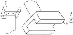
- FIG. 14illustrates an example system for securing an instrument to a robot.
- Linear guidessuch as guide 1454, can be used to lock the instrument in the robot flange.
- a spring or other devicecan be used to remove any mechanical backlash such that the instrument cannot be removed after being inserted into the guide until the spring or other mechanism is released.
- a corresponding member 1456is attached to the instrument and engages the guide 1454 which is attached to the robot flange.
- a method of performing surgeryInitially, an incision is made and the vertebra is exposed. In some implementations, the frame of the navigation system is attached to the patient in the place selected by the surgeon. Intra-operative medical images of the target anatomy may be obtained. Alternatively, images are acquired pre-operatively.
- FIG. 9is an illustration of volumetric planning.
- volumetric planningis linked with registration precision improvement algorithms.
- the surgeonmay use the navigation system pointer to measure points or follow a path traced by the surgeon using the pointer, thereby generating a set of points that identify (e.g., outline) the volume to be removed.
- the surgeonuses robot end effector in force control mode (e.g., as described in U.S. Patent Application No. US2015/0100066, filed April 30, 2014 , and entitled "Apparatus, Systems, and Methods for Precise Guidance of Surgical Tool", to identify the points (e.g., the points identifying the volume to be removed).
- the position of the robot end effectormay be tracked by the navigation system using a navigation marker fixed in relation to the surgical instrument Additionally, the volume can be identified using automatic segmentation, semi-automatic segmentation (e.g., using surgeon-defined points or corrections), or fully manual when surgeon/assistant/neurologist defines volume by manually selecting etc. the "pixels"/"voxels" to be removed.
- a surgeonfirst removes the spinous process 902 using, for example, pliers and cutting along the red zigzag line as shown in FIG. 9 .
- the surgeonidentifies the extremities of the volume to be removed (shown in blue and labeled as 904.
- the surgeoncan do this by using a navigation pointer and pointing to separate points (e.g. points (1), (2), (3), (4), (5), (6), and (7)) on the patient anatomy or, alternatively, the navigation system may follow a path identified by the surgeon and automatically collect of points.
- the systemgenerates the volume to be removed by taking a set of points (e.g., identified by the surgeon) and/or patient volumetric information (e.g., medical images) and identifying parts of the vertebrae to be removed.
- the systemin some implementations, combines the points identified by the surgeon and the patient volumetric information to identify the volume to be removed.
- the systemutilizes medical image segmentation (e.g., statistical shape modeling) to identify the volume.
- the navigation systemmay track the points identified by the surgeon and medical images on the navigation screen, in some implementations, are automatically updated to show feedback about the planning. This can be achieved, for example, using different colors on several views of medical images (e.g., the blue section shown in FIG. 9 ).
- the planning algorithmsrecognize which part of the spinous process was removed. In some implementations, this is achieved if the surgeon shows a point on the patient anatomy which normally should be inside bone. If surgeon is able to point there, it demonstrates that this part of the bone was removed and it should be tagged and shown on a display (e.g., using different color such as red as shown in FIG. 9 ).
- the precisionis crucial.
- the relative positions of the vertebraemay change due to forces applied by the surgeon.
- precision pointse.g. points (1), (2), (3), (4), (5), (6), and (7)
- a pathmay be followed to collect a plurality of points that identify the volume to be removed.
- points identified by the surgeon and the patient volumetric informatione.g., medical images
- the combination of the points identified by the surgeon and the patient volumetric informationallows for a more precise mapping of the volume to be removed.
- these pointsare collected using the robot in manual or lose control as described in relation to FIG. 9 .
- the force sensorcan be used to automatically detect bone versus tissue, something that is difficult to do manually.
- automatic and semi-automatic segmentation algorithms for usevan be used to plan a volume to be removed as well as other surgeries.
- FIG. 15is an illustration of an example method for volume definition.
- Object characterization as shown in FIG. 15defines the object to be removed.
- the characterizationcan be identified spatially, such as set of points delimiting the volume to be removed, or by identifying the type of surgery or volume to remove, e.g. spinous process, lamina, etc.
- the object characterizationcan be the set of points identified by the surgeon (e.g., using a pointer) to delineate the area to remove (or operate on in another example), the operation being performed, the specific area to be removed (e.g., identification of a specific portion of the body (e.g., lamina of c7 vertebrae), or a set of the above.
- Patient images as shown in FIG. 15represents the set of images for which the actual volume definition should apply. These images can be CT, MRI, X-ray and/or fluoroscopy images.
- the segmentation algorithmtakes the object characterization and patient images as an input and gives on the output an exact volume definition which in objective, measurable terms specifying the volume to be removed (e.g. series of spatial coordinates, volume mesh, voxel data etc.).
- the object characterizationis not an input into the algorithm.
- the patient images and the specific area to be removede.g., identification of a specific portion of the body (e.g., lamina of c7 vertebrae) can be the input to the algorithm and the algorithm can determine the area to be removed.
- the area identified for removal by the algorithmis displayed back to the user (e.g., via a display on the robot) for confirmation by the surgeon.
- Atlas based segmentatione.g. Expectation-Maximization algorithm or Statistical Shape Modelling algorithm.
- SSMStatistical Shape Modelling
- a segmentation algorithm kernele.g. Gaussian kernel or multi-scale Gaussian kernel, transforms the atlas to fulfill the constraints of the object definition and patient images.
- a volume definitionis obtained and can be reused in further algorithm steps.
- the robotcan be automatically brought to the volume or a surgeon may move the robot to the arm using the hands-on control mode as described in U.S. Patent Application No. US2015/0100066, filed April 30, 2014 , and entitled "Apparatus, Systems, and Methods for Precise Guidance of Surgical Tool”.
- the planned volumemay be removed using robotic assistance in several ways. In some implementations, the volume may be removed based on stay-in/no-go zones as described in U.S. Patent Application No. US2014/0121676, filed April, 2, 2012 , and entitled "Robotic System and Method for Spinal and Other Surgeries".
- the removing toolstays blocked inside virtual volume (constrained movement) as long as it is not completely removed or the surgeon voluntarily wants to quit the volume.
- FIG. 10An alternative approach for removing the appropriate volume is shown in FIG. 10 .
- the robotautomatically moves the drilling/milling/erasing instrument 1002 in a type of "painting" trajectory while being supervised by the surgeon. It is important to indicate to user the volume that has be removed 1004 and remaining volume 1006. This may be shown on a display of the robot or on a display separate from the robot.
- a surgeoncan supervise the robot by looking at the actual position on the navigation screen.
- the surgeoncan stop the robot movement at any time, for example, if the surgeon is concerned about the position of the removal instrument.
- a dead-man switchis used.
- the switchmay be activated if the surgeon places his/her hands on the tool holder interface or if the surgeon removes his/her hands from the tool holder interface.
- presence detection switchesmay be used and/or voice recognition may be used to recognize gestures and voice commands, respectively.
- a force sensor signalcan be used to detect if the surgical instrument goes across the edge of the vertebra and, in response, the robotic surgical system can prevent movement of the surgical instrument and destruction of surrounding tissue. This is achieved, for example, using edge detection algorithms which use relative changes in force. Additionally, in some implementations, neuro-monitoring may be used for detection of nervous system infraction.
- the robotmay be used to partially remove the target volume, thereby leaving the most difficult and less laborious parts of the tissue to be removed manually by the surgeon.
- the amount of the target volume removed by the robotis controlled during the volume planning phase.
- the robotAfter the robot finishes removing the target volume (e.g., the entire volume or a portion of the volume), the robot is moved away from the patient. In some implementations, this is done automatically by the robot itself. In other implementations, the robotic end effect is manually moved using the hands-on control mode. In some implementations, after moving the robot away the surgeon may inspect the removal of the volume by the robot and/or complete the surgery manually.
- the target volumee.g., the entire volume or a portion of the volume
- the robotis moved away from the patient. In some implementations, this is done automatically by the robot itself. In other implementations, the robotic end effect is manually moved using the hands-on control mode. In some implementations, after moving the robot away the surgeon may inspect the removal of the volume by the robot and/or complete the surgery manually.
- the cloud computing environment 1600may include one or more resource providers 1602a, 1602b, 1602c (collectively, 1602).
- Each resource provider 1602may include computing resources.
- computing resourcesmay include any hardware and/or software used to process data.
- computing resourcesmay include hardware and/or software capable of executing algorithms, computer programs, and/or computer applications.
- exemplary computing resourcesmay include application servers and/or databases with storage and retrieval capabilities.
- Each resource provider 1602may be connected to any other resource provider 1602 in the cloud computing environment 1600.
- the resource providers 1602may be connected over a computer network 1608.
- Each resource provider 1602may be connected to one or more computing device 1604a, 1604b, 1604c (collectively, 1604), over the computer network 1608.
- the cloud computing environment 1600may include a resource manager 1606.
- the resource manager 1606may be connected to the resource providers 1602 and the computing devices 1604 over the computer network 1608.
- the resource manager 1606may facilitate the provision of computing resources by one or more resource providers 1602 to one or more computing devices 1604.
- the resource manager 1606may receive a request for a computing resource from a particular computing device 1604.
- the resource manager 1606may identify one or more resource providers 1602 capable of providing the computing resource requested by the computing device 1604.
- the resource manager 1606may select a resource provider 1602 to provide the computing resource.
- the resource manager 1606may facilitate a connection between the resource provider 1602 and a particular computing device 1604.
- the resource manager 1606may establish a connection between a particular resource provider 1602 and a particular computing device 1604. In some implementations, the resource manager 1606 may redirect a particular computing device 1604 to a particular resource provider 1602 with the requested computing resource.
- FIG. 17shows an example of a computing device 1700 and a mobile computing device 1750 that can be used to implement the techniques described in this disclosure.
- the computing device 1700is intended to represent various forms of digital computers, such as laptops, desktops, workstations, personal digital assistants, servers, blade servers, mainframes, and other appropriate computers.
- the mobile computing device 1750is intended to represent various forms of mobile devices, such as personal digital assistants, cellular telephones, smart-phones, and other similar computing devices.
- the components shown here, their connections and relationships, and their functions,are meant to be examples only, and are not meant to be limiting.
- the computing device 1700includes a processor 1702, a memory 1704, a storage device 1706, a high-speed interface 1708 connecting to the memory 1704 and multiple high-speed expansion ports 1710, and a low-speed interface 1712 connecting to a low-speed expansion port 1714 and the storage device 1706.
- Each of the processor 1702, the memory 1704, the storage device 1706, the high-speed interface 1708, the high-speed expansion ports 1710, and the low-speed interface 1712are interconnected using various busses, and may be mounted on a common motherboard or in other manners as appropriate.
- the processor 1702can process instructions for execution within the computing device 1700, including instructions stored in the memory 1704 or on the storage device 1706 to display graphical information for a GUI on an external input/output device, such as a display 1716 coupled to the high-speed interface 1708.
- an external input/output devicesuch as a display 1716 coupled to the high-speed interface 1708.
- multiple processors and/or multiple busesmay be used, as appropriate, along with multiple memories and types of memory.
- multiple computing devicesmay be connected, with each device providing portions of the necessary operations (e.g., as a server bank, a group of blade servers, or a multi-processor system).
- the memory 1704stores information within the computing device 1700.
- the memory 1704is a volatile memory unit or units.
- the memory 1704is a non-volatile memory unit or units.
- the memory 1704may also be another form of computer-readable medium, such as a magnetic or optical disk.
- the storage device 1706is capable of providing mass storage for the computing device 1700.
- the storage device 1706may be or contain a computer-readable medium, such as a floppy disk device, a hard disk device, an optical disk device, or a tape device, a flash memory or other similar solid state memory device, or an array of devices, including devices in a storage area network or other configurations.
- Instructionscan be stored in an information carrier.
- the instructionswhen executed by one or more processing devices (for example, processor 1702), perform one or more methods, such as those described above.
- the instructionscan also be stored by one or more storage devices such as computer- or machine-readable mediums (for example, the memory 1704, the storage device 1706, or memory on the processor 1702).
- the high-speed interface 1708manages bandwidth-intensive operations for the computing device 1700, while the low-speed interface 1712 manages lower bandwidth-intensive operations. Such allocation of functions is an example only.
- the high-speed interface 1708is coupled to the memory 1704, the display 1716 (e.g., through a graphics processor or accelerator), and to the high-speed expansion ports 1710, which may accept various expansion cards (not shown).
- the low-speed interface 1712is coupled to the storage device 1706 and the low-speed expansion port 1714.
- the low-speed expansion port 1714which may include various communication ports (e.g., USB, Bluetooth®, Ethernet, wireless Ethernet) may be coupled to one or more input/output devices, such as a keyboard, a pointing device, a scanner, or a networking device such as a switch or router, e.g., through a network adapter.
- input/output devicessuch as a keyboard, a pointing device, a scanner, or a networking device such as a switch or router, e.g., through a network adapter.
- the computing device 1700may be implemented in a number of different forms, as shown in the figure. For example, it may be implemented as a standard server 1720, or multiple times in a group of such servers. In addition, it may be implemented in a personal computer such as a laptop computer 1722. It may also be implemented as part of a rack server system 1724. Alternatively, components from the computing device 1700 may be combined with other components in a mobile device (not shown), such as a mobile computing device 1750. Each of such devices may contain one or more of the computing device 1700 and the mobile computing device 1750, and an entire system may be made up of multiple computing devices communicating with each other.
- the mobile computing device 1750includes a processor 1752, a memory 1764, an input/output device such as a display 1754, a communication interface 1766, and a transceiver 1768, among other components.
- the mobile computing device 1750may also be provided with a storage device, such as a micro-drive or other device, to provide additional storage.
- a storage devicesuch as a micro-drive or other device, to provide additional storage.
- Each of the processor 1752, the memory 1764, the display 1754, the communication interface 1766, and the transceiver 1768,are interconnected using various buses, and several of the components may be mounted on a common motherboard or in other manners as appropriate.
- the processor 1752can execute instructions within the mobile computing device 1750, including instructions stored in the memory 1764.
- the processor 1752may be implemented as a chipset of chips that include separate and multiple analog and digital processors.
- the processor 1752may provide, for example, for coordination of the other components of the mobile computing device 1750, such as control of user interfaces, applications run by the mobile computing device 1750, and wireless communication by the mobile computing device 1750.
- the processor 1752may communicate with a user through a control interface 1758 and a display interface 1756 coupled to the display 1754.
- the display 1754may be, for example, a TFT (Thin-Film-Transistor Liquid Crystal Display) display or an OLED (Organic Light Emitting Diode) display, or other appropriate display technology.
- the display interface 1756may comprise appropriate circuitry for driving the display 1754 to present graphical and other information to a user.
- the control interface 1758may receive commands from a user and convert them for submission to the processor 1752.
- an external interface 1762may provide communication with the processor 1752, so as to enable near area communication of the mobile computing device 1750 with other devices.
- the external interface 1762may provide, for example, for wired communication in some implementations, or for wireless communication in other implementations, and multiple interfaces may also be used.
- the memory 1764stores information within the mobile computing device 1750.
- the memory 1764can be implemented as one or more of a computer-readable medium or media, a volatile memory unit or units, or a non-volatile memory unit or units.
- An expansion memory 1774may also be provided and connected to the mobile computing device 1750 through an expansion interface 1772, which may include, for example, a SIMM (Single In Line Memory Module) card interface.
- SIMMSingle In Line Memory Module
- the expansion memory 1774may provide extra storage space for the mobile computing device 1750, or may also store applications or other information for the mobile computing device 1750.
- the expansion memory 1774may include instructions to carry out or supplement the processes described above, and may include secure information also.
- the expansion memory 1774may be provide as a security module for the mobile computing device 1750, and may be programmed with instructions that permit secure use of the mobile computing device 1750.
- secure applicationsmay be provided via the SIMM cards, along with additional information, such as placing identifying information on the SIMM card in a non-hackable manner.
- the memorymay include, for example, flash memory and/or NVRAM memory (non-volatile random access memory), as discussed below.
- instructionsare stored in an information carrier. that the instructions, when executed by one or more processing devices (for example, processor 1752), perform one or more methods, such as those described above.
- the instructionscan also be stored by one or more storage devices, such as one or more computer- or machine-readable mediums (for example, the memory 1764, the expansion memory 1774, or memory on the processor 1752).
- the instructionscan be received in a propagated signal, for example, over the transceiver 1768 or the external interface 1762.
- the mobile computing device 1750may communicate wirelessly through the communication interface 1766, which may include digital signal processing circuitry where necessary.
- the communication interface 1766may provide for communications under various modes or protocols, such as GSM voice calls (Global System for Mobile communications), SMS (Short Message Service), EMS (Enhanced Messaging Service), or MMS messaging (Multimedia Messaging Service), CDMA (code division multiple access), TDMA (time division multiple access), PDC (Personal Digital Cellular), WCDMA (Wideband Code Division Multiple Access), CDMA2000, or GPRS (General Packet Radio Service), among others.
- GSM voice callsGlobal System for Mobile communications
- SMSShort Message Service
- EMSEnhanced Messaging Service
- MMS messagingMultimedia Messaging Service
- CDMAcode division multiple access
- TDMAtime division multiple access
- PDCPersonal Digital Cellular
- WCDMAWideband Code Division Multiple Access
- CDMA2000Code Division Multiple Access
- GPRSGeneral Packet Radio Service
- a GPS (Global Positioning System) receiver module 1770may provide additional navigation- and location-related wireless data to the mobile computing device 1750, which may be used as appropriate by applications running on the mobile computing device 1750.
- the mobile computing device 1750may also communicate audibly using an audio codec 1760, which may receive spoken information from a user and convert it to usable digital information.
- the audio codec 1760may likewise generate audible sound for a user, such as through a speaker, e.g., in a handset of the mobile computing device 1750.
- Such soundmay include sound from voice telephone calls, may include recorded sound (e.g., voice messages, music files, etc.) and may also include sound generated by applications operating on the mobile computing device 1750.
- the mobile computing device 1750may be implemented in a number of different forms, as shown in the figure. For example, it may be implemented as a cellular telephone 1780. It may also be implemented as part of a smart-phone 1782, personal digital assistant, or other similar mobile device.
- implementations of the systems and techniques described herecan be realized in digital electronic circuitry, integrated circuitry, specially designed ASICs (application specific integrated circuits), computer hardware, firmware, software, and/or combinations thereof.
- ASICsapplication specific integrated circuits
- These various implementationscan include implementation in one or more computer programs that are executable and/or interpretable on a programmable system including at least one programmable processor, which may be special or general purpose, coupled to receive data and instructions from, and to transmit data and instructions to, a storage system, at least one input device, and at least one output device.
- machine-readable medium and computer-readable mediumrefer to any computer program product, apparatus and/or device (e.g., magnetic discs, optical disks, memory, Programmable Logic Devices (PLDs)) used to provide machine instructions and/or data to a programmable processor, including a machine-readable medium that receives machine instructions as a machine-readable signal.
- machine-readable signalrefers to any signal used to provide machine instructions and/or data to a programmable processor.
- the systems and techniques described herecan be implemented on a computer having a display device (e.g., a CRT (cathode ray tube) or LCD (liquid crystal display) monitor) for displaying information to the user and a keyboard and a pointing device (e.g., a mouse or a trackball) by which the user can provide input to the computer.
- a display devicee.g., a CRT (cathode ray tube) or LCD (liquid crystal display) monitor
- a keyboard and a pointing devicee.g., a mouse or a trackball
- Other kinds of devicescan be used to provide for interaction with a user as well; for example, feedback provided to the user can be any form of sensory feedback (e.g., visual feedback, auditory feedback, or tactile feedback); and input from the user can be received in any form, including acoustic, speech, or tactile input.
Landscapes
- Health & Medical Sciences (AREA)
- Surgery (AREA)
- Life Sciences & Earth Sciences (AREA)
- Engineering & Computer Science (AREA)
- Molecular Biology (AREA)
- Animal Behavior & Ethology (AREA)
- Veterinary Medicine (AREA)
- Biomedical Technology (AREA)
- Heart & Thoracic Surgery (AREA)
- Medical Informatics (AREA)
- Nuclear Medicine, Radiotherapy & Molecular Imaging (AREA)
- Public Health (AREA)
- General Health & Medical Sciences (AREA)
- Oral & Maxillofacial Surgery (AREA)
- Robotics (AREA)
- Dentistry (AREA)
- Orthopedic Medicine & Surgery (AREA)
- Pathology (AREA)
- Manipulator (AREA)
- Surgical Instruments (AREA)
Description
- Spinal stenosis (narrowing of the spinal canal) is the single most common diagnosis that leads to spinal surgery. A laminotomy may be performed to alleviate pain associated with spinal stenosis by partially removing/trimming the vertebra lamina shown in
Fig. 1 , thereby decompressing the corresponding spinal cord and/or spinal nerve root. During this type of surgery, after obtaining access to the vertebrae, a surgeon manually removes portions of the lamina. The surgical instruments used for this task include surgical pliers and a high-speed burr as shown inFigs. 2A and 2B , respectively. - Removal/trimming of the lamina is a difficult process. The surgeon must be particularly careful not to damage spinal dura mater (tissue protecting spinal cord) which would lead to serious complications. This is a lengthy process which may take around 20 min per vertebra (e.g., 60 minutes for three vertebra). Furthermore, removing bony tissue requires repetitive movements which are tiring and may lead to repetitive motion disorders for surgeons performing these surgeries daily. The document
US2008/0147089 discloses the preamble of claim 1. - Described herein is a device and method used to effectively remove volume inside a patient in various types of surgeries, such as spinal surgeries (e.g. laminotomy), neurosurgeries (various types of craniotomy), ENT surgeries (e.g. tumor removal), and orthopedic surgeries (bone removal). The disclosed technology provides robotic assistance linked with a navigation system and medical imaging to shorten surgery time, make the surgery safer and free surgeons from doing repetitive and laborious tasks. The disclosed technology is also compatible with robotic surgical system described in
U.S. Patent Application No. 2015/0100066, filed April 30, 2014 , and entitled "Apparatus, Systems, and Methods for Precise Guidance of Surgical Tool", thereby, for example, allowing the same robotic surgical system to assist with different aspects of spinal surgery. The invention relates to a surgical instrument holder for use with a robotic surgical system. The holder can be attached to or is part of an end effector of a robotic arm, and provides a rigid structure that can be used with a surgical tool to affect precise removal of a target volume in a patient. According to the invention, the holder has a tubular shape with a longitudinal notch along a portion of its length. The holder is sized to allow a surgical instrument to slide through the holder in a fixed orientation while the holder is held by the robotic arm. The surgical instrument, in certain examples is fitted with a tool support having a peg sized to fit the notch. A navigational marker (e.g., a multipoint, planar marker) may be attached thereto via the peg. Thus, because of the notch, movement of the surgical instrument is constrained in a fixed orientation as it slides along the axis defined by the holder. When a navigation marker is coupled to the peg, the navigation marker can be tracked (e.g., and hence the location of a surgical instrument connected to the navigation marker) when the surgical instrument is fully inserted and secured in the holder (e.g., in part by a locking mechanism). This facilitates and simplifies tracking of the marker, for example, via a remote tracking system that displays real-time tracking of the surgical instrument during the surgical procedure. - The invention relates to an instrument holder with a rigid hollow tubular structure having a proximal open end and a distal open end, said structure defining an axis along which movement of a surgical instrument sliding through the structure is restricted, wherein the tubular structure has an interior surface shaped and sized to accommodate the surgical instrument sliding through the surgical instrument holder such that movement of the surgical instrument is constrained to move along the axis defined by the surgical instrument holder (e.g., thereby allowing rapid exchange of surgical instruments held by the surgical instrument holder); and a connector element attached to the holder that, when engaged (e.g., mated with) a corresponding connector element associated with a surgical instrument, provides power to the surgical instrument (e.g., and receives measurement information from a force sensor in the surgical instrument).
- In certain embodiments, the tubular structure has an exterior surface including at least one flange that is sized and shaped to secure coupling of the surgical instrument holder to an end effector of the robotic surgical system. According to the invention, the tubular structure includes a longitudinal notch along its length, wherein the longitudinal notch (e.g., slot) is sized in relation to a peg on (e.g., directly or indirectly) the surgical instrument to permit the surgical instrument to slide along the axis defined by the surgical instrument holder. In certain embodiments, the longitudinal notch is sized in relation to a peg to (i) permit a navigation marker attached to the surgical instrument at least in part via the peg to be viewable by a navigation camera along an entire range of movement of the surgical instrument through the surgical instrument holder, and (ii) constrain movement of the marker in a fixed orientation along the axis defined by the surgical instrument holder. In certain embodiments, navigation marker is used by navigation camera to track the surgical instrument.
- In certain embodiments, a lock that, when engaged, restricts (e.g., prevents) movement of a surgical instrument within the rigid hollow tubular structure (e.g., such that the surgical instrument is constrained within the tubular structure in all directions). In certain embodiments, the lock, when engaged, prevents removal of the surgical instrument from the surgical instrument holder.
- In certain embodiments, a force sensor measures one or more forces and/or torques (e.g., 1 to 3 forces and 1 to 3 torques) applied to at least a portion of the surgical instrument. In certain embodiments, the surgical instrument includes a force sensor that measures one or more forces and/or torques (e.g., 1 to 3 forces and 1 to 3 torques) applied to at least a portion of the surgical instrument, and the measurement information provided to the surgical instrument holder via the connector comprises the one or more forces and/or torques.
- In certain embodiments, the surgical instrument is a drill (e.g., with a drill bit). In some implementations, the portion of the surgical instrument to which the one or more forces and/or torques are applied is the drill bit. In certain embodiments, the surgical instrument is a drill (e.g., for preparing a hole for receiving a screw). In certain embodiments, the surgical instrument is a milling device, shaver, laser, or ultrasonic scalpel. In certain embodiments, the surgical instrument holder is for use in spinal surgery. In certain embodiments, the surgical instrument is a screw driver (e.g., for placing a screw in a hole). There can be a user interface (e.g., touch screen, one or more buttons, and/or a display). The tubular structure has an interior surface sized and shaped to accommodate a tool support (e.g., sliding surface) of the surgical instrument. In certain embodiments, a second connector associated with the surgical instrument holder communicates with a sensor (e.g., the force sensor(s)) measuring the position of the surgical instrument. In certain embodiments, the second connector is one or more brushes (e.g., that physically contact the surgical instrument). In certain embodiments, the rigid hollow tubular structure is a cylindrical structure.
- The disclosed technology relates to a robotic surgical system for performing surgery. Disclosed is a robotic arm with an end effector comprising a surgical instrument holder sized and shaped to hold and/or restrict movement of a surgical instrument therethrough, the surgical instrument holder comprising: a rigid hollow tubular structure having a proximal open end and a distal open end, said structure defining an axis along which movement of a surgical instrument (e.g., fitted with a tool support) sliding through the structure is restricted, wherein the tubular structure has an interior surface shaped and sized to accommodate the surgical instrument sliding through the surgical instrument holder such that movement of the tool support is constrained to move along the axis defined by the surgical instrument holder, wherein the tubular structure has an exterior surface comprising at least one flange that is sized and shaped to securely couple of the surgical instrument holder to an end effector of the robotic surgical system, and wherein the tubular structure comprises a longitudinal notch along its length, wherein the longitudinal notch is sized in relation to a peg on the tool support to permit the tool support to slide along the axis defined by the surgical instrument holder; a lock that, when engaged, restricts (e.g., prevents) movement of a surgical instrument within the rigid hollow tubular structure (e.g., such that the surgical instrument is constrained within the tubular structure in all directions); and a connector element associated with (e.g., attached to) the surgical instrument holder that, when engaged with (e.g., mated with) a corresponding connector associated with the surgical instrument connector, provides power to the surgical instrument (e.g., and information transfer, e.g., information concerning measured forces).
- The disclosed technollogy relates to a manipulator that allows robotically-assisted or unassisted positioning and/or movement of the surgical instrument holder by a user with at least four degrees of freedom to align an axis defined by the instrument holder at a desired trajectory in relation to a patient situation.
- The invention relates to a surgical instrument holder for use with a robotic surgical system. In certain embodiments, the surgical instrument holder includes a rigid hollow tubular structure having a proximal open end and a distal open end, said structure defining an axis along which movement of a surgical instrument (e.g., fitted with a tool support) sliding through the structure is restricted, wherein the tubular structure has an interior surface shaped and sized to accommodate the surgical instrument sliding through the surgical instrument holder such that movement of the tool support is constrained to move along the axis defined by the surgical instrument holder, wherein the tubular structure has an exterior surface comprising at least one flange that is sized and shaped to securely couple the surgical instrument holder to an end effector of the robotic surgical system, and wherein the tubular structure comprises a longitudinal notch along its length, wherein the longitudinal notch is sized in relation to a peg on the tool support to permit the tool support to slide along the axis defined by the surgical instrument holder; and a lock that, when engaged, restricts (e.g., prevents) movement of a surgical instrument within the rigid hollow tubular structure (e.g., such that the surgical instrument is constrained within the tubular structure in all directions); a connector element associated with (e.g., attached to) the surgical instrument holder that, when engaged with (e.g., mated with) a corresponding connected associated with the surgical instrument, provides power to the surgical instrument (e.g., and information transfer, e.g., information concerning measured forces). A force sensor for measuring one or more forces and/or torques (e.g., 1 to 3 forces and 1 to 3 torques) can be applied to at least a portion of the surgical instrument. The surgical instrument may comprise a force sensor for measuring one or more forces and/or torques (e.g., 1 to 3 forces and 1 to 3 torques) applied to at least a portion of the surgical instrument.
- The disclosed technology relates to a surgical instrument for preparing a hole in bone tissue of a patient.
- In certain examples, the surgical instrument includes an elongate structure having a proximal end with at least one of a drilling, milling, or shaving surface and a distal end with a shank sized and shaped to be grasped by a drill; and a force sensor integrated directly in the elongate structure for measuring one or more forces and/or torques (e.g., 1 to 3 forces and 1 to 3 torques) applied to at least a portion of the surgical instrument.
- In certain examples, the surgical instrument includes an elongate structure having a proximal end with a milling surface and a distal end with a shank sized and shaped to be grasped by a drill, wherein the proximal end of the surgical instrument is flat and substantially perpendicular to the axis of the elongate structure, thereby reducing skidding (e.g., unintentional lateral movement of the surgical instrument) of the surgical instrument upon contact of the milling surface with the bone tissue; and a force sensor integrated directly in the elongate structure for measuring one or more forces and/or torques (e.g., 1 to 3 forces and 1 to 3 torques) applied to at least a portion of the surgical instrument.
- In certain examples, a portion of the structure of the surgical instrument closest to the milling surface is for milling (e.g., rather than drilling) and the remaining portion of the surgical instrument is for drilling. In certain examples, the surgical instrument is an anti-skip surgical instrument. In certain examples, the surgical instrument is for use in spinal surgery. The surgical instrument is insertable into the surgical instrument holder such that the surgical instrument is constrained by the surgical instrument holder. The surgical instrument holder comprises a rigid hollow tubular structure having a proximal open end and a distal open end, said structure defining an axis of the tubular structure along which movement of a surgical instrument sliding through the structure is restricted, wherein the tubular structure has an interior surface shaped and sized to accommodate the surgical instrument sliding through the surgical instrument holder such that movement of the surgical instrument (e.g., fitted with a tool support) is constrained to move along the axis defined by the surgical instrument holder. The surgical instrument is fitted with a tool support shaped and sized to slide through the surgical instrument holder along the axis defined by the surgical instrument holder. In certain embodiments, the surgical instrument is a drill bit and the surgical instrument holder is a drill bit guide holder. In certain examples, the surgical instrument is held by a robotic surgical system comprising a robotic arm.
- In certain examples, the robotic arm has an end effector comprising a surgical instrument holder attached thereto, the surgical instrument holder sized and shaped to hold and/or restrict movement of a surgical instrument therethrough (e.g., via a lock). In certain examples, a navigation marker is used by a navigation camera to track the surgical instrument. Also disclosed is a method of performing surgery with a robotic surgical system. The method, in certain examples, includes moving a mobile cart transporting a robotic surgical system comprising a robotic arm in proximity to an operating table, wherein the robotic arm has an end effector comprising a surgical instrument guide attached thereto, the surgical instrument guide sized and shaped to hold and/or restrict movement of one of a plurality of surgical instruments therethrough, wherein the plurality of surgical instruments comprises a first surgical instrument (e.g., for removing tissue from the body) and a second surgical instrument (e.g., for preparing a screw placement in a vertebra); stabilizing the mobile cart; maneuvering the first surgical instrument in a manner that is constrained by a surgical instrument guide comprising a rigid hollow tubular structure having a proximal open end and a distal open end, said structure defining the axis along which movement of a surgical instrument (e.g., fitted with a tool support) sliding through the structure is restricted, wherein: the tubular structure of the surgical instrument guide has an interior surface shaped and sized to accommodate the surgical instrument sliding through the guide such that movement of the surgical instrument is constrained to move along the axis defined by the guide, and the tubular structure comprises a longitudinal notch along its length, wherein the longitudinal notch is sized in relation to a peg to (i) permit a marker attached to the surgical instrument at least in part via the peg to be viewable by a navigation camera along an entire range of movement of the surgical instrument through the guide, (ii) constrain movement of the navigation marker in a fixed orientation along the axis defined by the guide, and/or (iii) permit the surgical instrument to slide along the axis defined by the guide while the guide is held in a fixed position by the robotic surgical system; removing the first surgical instrument from the surgical instrument guide, wherein the surgical instrument guide facilitates rapid exchange of surgical instruments (e.g., without requiring reregistration); and maneuvering the second surgical instrument in a manner that is constrained by a surgical instrument guide.
- In certain examples, the first surgical instrument is a drill (e.g., with a drill bit). In certain embodiments, the first surgical instrument is a milling device, shaver, laser, and ultrasonic scalpel.
- In certain examples, the second surgical instrument is a screw driver (e.g., for placing a screw in a hole). In certain examples, the second surgical instrument is a drill (e.g., for preparing a hole for receiving a screw). In certain examples, the tubular structure has an exterior surface comprising at least one flange that is sized and shaped to securely couple the surgical instrument holder to an end effector of the robotic surgical system. In certain examples, the robotic surgical system is for use in spinal surgery. The rigid hollow tubular structure is a cylindrical structure. In certain embodiments, the longitudinal notch is a slot. In certain examples, the navigation marker is used by a navigation camera to track the surgical instrument. In certain examples, the second surgical instrument is used to guide a screw implant and a tissue protector. In certain examples, the robotic arm comprises a manipulator attached to the robotic arm. In certain examples, the robotic arm comprises a manipulator molded into the robotic arm.
- In certain examples, stabilizing the mobile cart comprises extracting one or more rigid legs on the mobile cart such that the mobile cart rests on the one or more rigid legs of the mobile cart. In certain embodiments, stabilizing the mobile cart comprises retracting one or more wheels on the mobile cart such that the mobile cart rests on one or more rigid legs of the mobile cart. Also disclosed is a method of performing surgery with a robotic surgical system. In certain examples, the method includes identifying a volume to be removed , wherein medical images (e.g., obtained intraoperatively or pre-operatively) of the patient situation displayed on a display (e.g., on the robotic surgical system) are automatically updated to show feedback about the planning (e.g., displaying the volume identified for removal by shading); removing the planned volume using robotic assistance, the removing comprising: storing, by a processor of the robotic surgical system, a location of the volume to be removed as "stay-in zone", and storing, by the processor, a location of a second volume to protect from removal, wherein the location of the second volume defines a "no-go zone"; maintaining, by the processor, the surgical instrument in the "stay-in zone" and/or out of the "no-go zone", thereby removing the volume; after removing at least a portion of the volume, moving at least a portion of the robotic surgical system away from the patient; and manually completing the surgery. Also disclosed is a method of performing surgery with a robotic surgical system. The method, in certain examples, includes identifying a volume to be removed , wherein medical images (e.g., obtained intraoperatively or pre-operatively) of the patient situation displayed on a display (e.g., on the robotic surgical system) are automatically updated to show feedback about the planning (e.g., displaying the volume identified for removal by shading); removing the planned volume using robotic assistance, the removing comprising: preventing, by the robotic surgical system, a surgical instrument from leaving the volume until the volume is completely removed or the surgeon voluntarily wants to leave the volume; after removing at least a portion of the volume, moving at least a portion of the robotic surgical system away from the patient; and manually completing the surgery.
- In certain examples, the volume is identified by identifying (e.g., using a navigation system) a plurality of points on the patient anatomy. In certain examples, the plurality of points are identified by a surgeon point to a plurality of points on the patient anatomy (e.g., using a pointer tracked by a navigation system). In certain examples, the plurality of points are identified by following a path identified by a surgeon (e.g., via a pointer tracked by a navigation system) such that the plurality of points are automatically collected. The volume can be identified using a navigation system. Additionally, the volume can be identified using automatic segmentation, semi-automatic segmentation (e.g., using surgeon-defined points or corrections), or fully manual when surgeon/assistant/neurologist defines volume by manually selecting etc. the "pixels"/"voxels" to be removed.
- In certain examples, the method includes manually completing the surgery includes removing, by the surgeon, a portion of the volume to be removed. In certain embodiments, manually completing the surgery includes removing, by the surgeon, a portion of a second volume adjacent the volume removed with assistance of the robotic surgical system.
- In certain examples, repulsive/wall-like forces prevent the surgeon from moving a position of the surgical instrument into the second volume.
- In certain examples, the method includes triggering a dead-man switch (e.g., via voice recognition, a gesture, presence or absence of physical contact with a portion of the robotic surgical system), thereby causing the robotic surgical system to stop.
- In certain examples, the method includes, upon receiving a trigger signal (e.g., from a volume removal force sensor, a bio-sensing device such as PediGuard® by SpineGuard S.A. of Vincennes, France, and/or a neuro-monitoring device), preventing movement of the surgical instrument further in a forbidden direction.
- In certain examples, the method includes, after identifying the volume to be removed, bringing the robot to the volume (e.g., automatically or using hands-on control). In certain embodiments, the identification of the volume is performed using a navigation system pointer. In certain examples, the identification of the volume is performed using the robotic surgical system in a force control mode.
- In certain examples, the method includes maneuvering a surgical instrument to make an incision, thereby exposing a vertebra; and attaching a frame of a navigation system to the patient.
- In certain examples, the method includes moving a mobile cart transporting a robotic surgical system comprising a robotic arm in proximity to an operating table, wherein the robotic arm has an end effector comprising a surgical instrument holder attached thereto, the surgical instrument holder sized and shaped to hold and/or restrict movement of a surgical instrument therethrough; and stabilizing the mobile cart.
- In certain examples, the method includes removing a least a portion of the spinous process, discs, facets, facet joints, pedicles, and/or vertebral bodies. In certain embodiments, the method includes a first force sensor and a second force sensor, each of the first and second force sensors for measuring one or more forces and/or torques (e.g., 1 to 3 forces and 1 to 3 torques) applied to at least a portion of the surgical instrument.
- In certain examples, the surgical instrument holder, surgical instrument, and/or robotic surgical system is for use in at least one of spinal surgery (e.g. laminotomy), neurosurgery (various types of craniotomy), ENT surgery (e.g. tumor removal), and orthopedic surgery (bone removal).
- In another aspect, not according to the invention, the disclosed technology includes a tool attachment device for attaching a tool to a robotic surgical arm, the tool attachment device including: a lever for transmitting a fixation force to a quick lock latch via a plurality of links; and the quick lock latch for releasably securing a tool to the robot when an activation force is applied to the lever (e.g., the lever pulling the tool tight against a robot flange).
- In certain examples, the lever is activated by pushing the lever toward a robot flange such that quick lock latch pulls the tool tight against the robot flange.
- In certain examples, the quick lock latch comprises a quick lock hook that engages a pin head on the tool when the tool is inserted fully into the robot flange.
- In certain examples, a positioning module for precisely positioning the surgical instrument holder relative to the robotic surgical arm (e.g., restricting orientation of the tool when mounting the tool to the robot).
- In certain examples, the positioning module comprises one or more pins on the robot flange, wherein, upon mechanically coupling the tool to the robotic surgical arm, the each pin of the one or more pins engage an opening in the tool thereby precisely positioning the tool relative to the robotic surgical arm.
- In certain examples, the positioning module comprises one or more openings on the robot flange, wherein, upon mechanically coupling the tool to the robotic surgical arm, the each opening of the one or more opening engages a pin on the tool thereby precisely positioning the tool relative to the robotic surgical arm.
- In another aspect, not according to the invention, the disclosed technology includes a tool attachment device for attaching a tool to a robotic surgical arm, the tool attachment device including: a robot flange on the robotic surgical arm, the robot flange comprising (i) an open portion to receive a protrusion of a tool and (ii) a notch that permits a width of the opening to be at least partially decreased; and a lever connected to the robot flange that causes the width of the open portion of the robot flange to decrease when the lever is engaged, thereby securing the tool with the protrusion positioned in the opening to the robot flange.
- In another aspect, not according to the invention, the disclosed technology includes a tool attachment device for attaching a tool to a robotic surgical arm, the tool attachment device including: a robot flange on the robotic surgical arm, the robot flange comprising a shape lock (e.g., bayonet mount) having at least two or more openings each arranged to receive and secure a protrusion on the tool or at least two or more protrusions each arranged to engage and secure an opening on the tool.
- In another aspect, not according to the invention, the disclosed technology includes a drill for use with a surgical robotic arm, the drill including: a chuck for securely holding a drill bit; and a body comprising a positioning module for precisely positioning the drill relative to the robotic surgical arm.
- In certain examples, the body of the drill comprises a protrusion and the protrusion comprises a pin head.
- In certain examples, the positioning module comprises one or more pins on the body, wherein, upon mechanically coupling the drill to the robotic surgical arm, each pin of the one or more pins engages an opening in the surgical robotic arm thereby precisely positioning the drill relative to the robotic surgical arm.
- In certain examples, the positioning module comprises one or more openings on the body, wherein, upon mechanically coupling the drill to the robotic surgical arm, the each opening of the one or more opening engages a pin on the robot thereby precisely positioning the drill relative to the robotic surgical arm.
- In certain examples, the positioning module comprising a hole that passes from a first side of the body to a second side of the body (e.g., such that the body can be mounted on the robot (e.g., by a bolt extending from the robotic surgical arm that slides through the hole and a nut that securely holds the body on the robotic surgical arm)).
- In certain examples, the positioning module is a friction based module and comprises a protrusion that fits into a portion of the robot flange and is secured therein by a force applied by a lever attached to the robot flange.
- The foregoing and other objects, aspects, features, and advantages of the present disclosure will become more apparent and better understood by referring to the following description taken in conjunction with the accompanying drawings, in which:
FIG. 1 is a superior view and left posterolateral view of articulated vertebrae;FIGS. 2A and 2B are illustrations of surgical pliers and a high-speed burr, respectively;FIG. 3 is an illustration of an example robotic surgical system in an operating room;FIG. 4 is an illustration of an example robotic surgical system;FIGS. 5A through 5C are illustrations of an example force sensor implementations;FIG. 6 is an illustration of an example surgical instrument;FIGS. 7A through 7D are illustrations of an example implementations of a force sensor integrated in a surgical drill;FIG. 8 is an illustration of an example surgical instrument holder;FIG. 9 is an illustration of volumetric planning;FIG. 10 is an illustration of volume removal;FIGS. 11A through 11F illustrate an example system for securing an instrument to a robot;FIG. 12 illustrates an example system for securing an instrument to a robot;FIG. 13 illustrates an example system for securing an instrument to a robot;FIG. 14 illustrates an example system for securing an instrument to a robot;FIG. 15 is an illustration of an example method for volume definition;FIG. 16 shows a block diagram of an exemplary cloud computing environment; andFIG. 17 is a block diagram of a computing device and a mobile computing device.- The features and advantages of the present disclosure will become more apparent from the detailed description set forth below when taken in conjunction with the drawings, in which like reference characters identify corresponding elements throughout. In the drawings, like reference numbers generally indicate identical, functionally similar, and/or structurally similar elements.
- The disclosed technology includes the robotic surgical system used to remove a target volume from a patient. Initially, an incision is made and the vertebra is exposed. In some implementations, the frame of a navigation system is attached to the patient in the place selected by the surgeon. Intra-operative medical images of the target anatomy may be obtained. Alternatively, images are acquired pre-operatively. Once the images are obtained, the images must be matched to the actual patient position by a process called registration. For intra-operative images, an automatic algorithm may be used to register the actual patient position with the intra-operative images. Alternatively, point-to-point registration or surface matching may be used. The disclosed technology provides an effective and quick way for the surgeon to define volume to be removed and thereafter remove the volume. In another example, the robotic surgical system may be used to place a screw in a vertebra by assisting in drilling a hole and inserting the screw in the hole as described in
U.S. Patent Application No. 2005/0100066 filed April 30, 2014 , and entitled "Apparatus, Systems, and Methods for Precise Guidance of Surgical Tool".FIG. 3 illustrates an example robotic surgical system in anoperating room 300. In some implementations, one or more surgeons, surgical assistants, surgical technologists and/or other technicians, (306a-c) perform an operation on apatient 304 using a robotic-assisted surgical system. In the operating room the surgeon may be assisted by the robotic system to accurately execute an operation. - In some implementations, the surgical robotic system includes a
surgical robot 302 on a mobile cart. Thesurgical robot 302 may be positioned in proximity to an operating table 312 without being attached to the operating table itself, thereby providing maximum operating area and mobility to surgeons around the operating table and reducing clutter on the operating table. In alternative examples, the surgical robot (or cart) is securable to the operating table. In certain examples, both the operating table and the cart are secured to a common base to prevent any movement of the cart or table in relation to each other, even in the event of an earth tremor. - The mobile cart may permit a user (operator) 306a, such as a technician, nurse, surgeon, or any other medical personnel in the operating room, to move the
surgical robot 302 to different locations before, during, and/or after a surgical procedure. The mobile cart enables thesurgical robot 302 to be easily transported into and out of theoperating room 300. For example, auser 306a may move the surgical robot into the operating room from a storage location. In some implementations, the mobile cart may include wheels, a track system, such as a continuous track propulsion system, or other similar mobility systems for translocation of the cart. The mobile cart may include an attached or embedded handle for locomotion of the mobile cart by an operator. - For safety reasons, the mobile cart may be provided with a stabilization system that may be used during a surgical procedure performed with a surgical robot. The stabilization mechanism increases the global stiffness of the mobile cart relative to the floor in order to ensure the accuracy of the surgical procedure. In some implementations, the wheels include a locking mechanism that prevents the cart from moving. The stabilizing, braking, and/or locking mechanism may be activated when the machine is turned on. In some implementations, the mobile cart includes multiple stabilizing, braking, and/or locking mechanisms. In some implementations, the stabilizing mechanism is electro-mechanical with electronic activation. The stabilizing, braking, and/or locking mechanism(s) may be entirely mechanical. The stabilizing, braking, and/or locking mechanism(s) may be electronically activated and deactivated.
- In some implementations, the
surgical robot 302 includes a robotic arm mounted on a mobile cart. An actuator may move the robotic arm. The robotic arm may include a force control end-effector configured to hold a surgical tool. The robot may be configured to control and/or allow positioning and/or movement of the end-effector with at least four degrees of freedom (e.g., six degrees of freedom, three translations and three rotations). - In some implementations, the surgical system includes a
tracking detector 308 that captures the position of the patient and different components of thesurgical robot 302, and adisplay screen 310 that displays, for example, real time patient data and/or real time surgical robot trajectories. - For example, a
tracking detector 308 monitors the location ofpatient 304 and thesurgical robot 302. The tracking detector may be a camera, a video camera, an infrared detector, field generator and sensors for electro-magnetic tracking or any other motion detecting apparatus. In some implementation, based on the patient and robot position, the display screen displays the target volume to be removed and/or the volume already removed. These different volumes may be differentiated on the display using various colors or shading. By continuously monitoring the patient and robotic arm positions usingtracking detector 308, the surgical system can visually display the target and/or removed volume ondisplay screen 310 to inform and guide surgeons and/or technicians in the operating room using the surgical robot. For instance, the location of the end-effector can be automatically adjusted in real time to account for movement of the vertebrae or other part of the patient during the surgical procedure. FIG. 4 illustrates anexample configuration 400 of a robotic arm for performing a surgical operation involving the removal of a volume from a patient. Asurgical tool holder 408, in some implementations, is connected (e.g., removably; e.g., directly or indirectly) to therobot arm 404. For example, thesurgical tool holder 408 is removably connected to therobotic arm 404 viaconnector 406 and aforce sensor 430 as shown inFIG. 4 . In some implementations, therobot arm 414 is extended so that atool holder 408 may be placed on therobot arm connector 406. In some embodiments, arobot arm connector 406 is located at the end of therobot manipulator 404. Although not shown inFIG. 4 , a surgical drape may be placed over therobot arm 414 andcart 402 when thetool holder 408 is inserted into, or otherwise attached to, theconnector 406. Theconnector 406 may be configured to at least partially protrude from the surgical drape, such that a sterile cap, collar, or other covering of the connector may be installed prior to attachment of thetool holder 408 into theconnector 406 to maintain sterile seal.- The
robot arm connector 406 is configured to pass electrical signals from the rest ofrobot arm 414 to thetool holder 408. The electrical signals may be passed by a separate cable that passes through the sterile drape. The cable may be integrated with the sterile drape to simplify handling for the user. An operator attaches thetool holder 408 to therobot arm connector 406. In the embodiment shown inFIG. 4 , thetool holder 408 is a drill holder for securely holding a drill. - The
tool holder 408, in some implementations, is a surgical tool holder that may be used to hold various surgical tools and/or allow insertion of one or more surgical tools/implements therethrough. Thesurgical tool 410, in some implementations, provides an accurate tool guide for surgical bone drilling, e.g., by providing a precisely aligned shaft through which a drill bit or drill may be inserted.Surgical tool 410 is used in spinal surgeries to allow for accurate surgical instrument placement. In some implementations, thesurgical tool 410 is a drill that is directly connected to thetool holder 408, thereby securely holding a drill for removing a volume from a patient. The surgical tool may be any instrument which can be used for removing tissues. For example, thesurgical tool 410 may be a drill, mill, shaver, laser, or ultrasonic scalpels. In some implementations, thetool holder 408 may be used both to securely hold a tool for removing a volume from a patient and placing a screw in a vertebra. - A
force sensor 430, in some implementations, is placed between therobot arm connector 406 and thetool holder 408. Theforce sensor 430 measures forces applied to asurgical instrument 410 held by thetool holder 408. Theforce sensor 430 may be placed in a variety of locations. In some implementations,multiple force sensors 430 are used. For example,multiple force sensors 430 may be used to provide redundant measurements for safety reasons. Additionally,multiple force sensors 430 may be used to extract additional force information (e.g., determining where the forces are applied).In some implementations, therobot arm manipulator 404 includes anemergency stop switch 412. The emergency stop switch may be placed on the robot arm, robot cart, or on the operator's panel. Auser interface 436, in some implementations, is integrated into thesurgical instrument 410 to allow a user quick and easy interaction with the system. Several placements of user interfaces can be used. For direct and immediate interaction a sterile user interface is placed on the surgical instrument or tool holder. In other implementations, the interface can be placed on the robot arm as described in U.S. Patent Application No.US2016/0081753, filed September 18, 2015 , and entitled "Robot-Mounted User Interface For Interacting with Operation Room Equipment". In some implementations, user interfaces are provided in multiple locations, such as on the robot arm, the surgical instrument, tool holder, and/or manipulator (e.g., handle) as described in U.S. Patent Application No.US2015/0223897, filed February 11, 2015 , and entitled "Sterile Handle for Controlling a Robotic Surgical System from a Sterile Field". The sterile interfaces can be reusable or disposable. FIGS. 5A-C illustrate example locations for mounting a force sensor (e.g., force/torque sensor 430). In some implementations, as shown inFIG. 5A , theforce sensor 502a is located between thetool holder 506a androbot 504a. Using this configuration, thesterile cover 508a may be wrapped around the robot arm and between the force sensor and the tool holder to ensure sterilization. Theforce sensor 502a may provide for direct measurement of forces (e.g., forces and/or torques) on the tool. Theforce sensor 502a may be designed to resist flexing. Theforce sensor 502a may be designed to flex under the stress of certain external forces. The displacement caused when an external force is applied may be calculated based on the force and/or torque applied to the tool, radial force stiffness, axial torque stiffness, and the diameter of the holder to which the tool is attached.- As shown in
FIGS. 5B and 5C , respectively, the force sensor (e.g., 502b inFIG. 5B or 502c inFIG. 5C ) may be located on the robot or the tool holder, respectively. These configurations may exclusively measure the forces and/or torques applied by the user. The force sensor 508 may be connected to the robot with an intermediary analog box which measures forces and torques and transmits them via a network (e.g., Ethernet, CAN, wireless, internet, private LAN, public LAN, etc.). Combinations of the above mentioned force sensor positions are possible to achieve pre-defined behavior (e.g. the first sensor in the baseFIG. 5A and the second one in the handleFIG. 5B may be positioned to allow the feedback control system to decouple forces applied to the surgical tool from forces and/or torque applied by a user). - Additionally, in some implementations the force sensor is integrated directly in the surgical instrument. For example, the force sensor may be integrated directly in the surgical drill bit as illustrated in
FIG. 6 . While the implementation of theforce sensor 604 is described in relation to adrill bit 602 as shown inFIG. 6 , theforce sensor 604 may be similarly integrated in other surgical instruments. Integrating theforce sensor 604 in a surgical instrument, such as adrill bit 602, may be more robust as it minimizes the impact of external disturbances for measuring forces applied to the drill bit. - In the example configuration shown in
FIG. 6 , theforce sensor 604 is integrated in the shaft of thedrill bit 602. Theforce sensor 604, in some implementations, is located on thedrill bit 602 outside of thebody 610 of the drill as shown inFIG. 6 . In other implementations, theforce sensor 604 is located inside thebody 610 of the drill, thereby better protecting theforce sensor 604 from external influences. Force sensor can have multiple degrees of freedom and measure, for example, 1 to 3 forces and/or 1 to 3 torques. Forces are transmitted from the rotating shaft through aconnector 606. The connector, in some implementations, is one or more brushes that provide an electrical connection to theforce sensor 604. If the force sensor is an optical sensor, the connector may be an optical transmitter (e.g. LED) and/or optical receiver (e.g., photodiode). In this example, the brushes contact the drill bit thereby forming an electrical connection with theforce sensor 604. In some implementations, the brushes touch one or more contacts on the drill bit to form the electrical connection. - An electric or
pneumatic motor 608 rotates thedrill bit 602 shaft. In some implementations, a sensor 612 (e.g., an encoder) measures position of the shaft. Thesensor 612 measures the position of the shaft in order to correlate forces measured by the force sensor to the relative position of the shaft. For example, if the force sensor is located in a drill bit, the measurement of the direction of the force will vary as the drill bit rotates. Specifically, the force sensor measures force and the direction of the force periodically (e.g., every millisecond, every microsecond, or somewhere therebetween). The drill bit rotates as the surgeon pushes it into bone. When the drill contacts the bone, the force sensor will indicate some force (F1) in a direction (D1). One period later (e.g., one millisecond), the drill bit will rotate slightly so the force sensor will indicate force of the same value (F1) (assuming a constant force is applied) in a different direction (D2). The direction of the force will continue to change relative to a single perspective as the drill bit rotates even if surgeon pushes into the bone with a constant force. A constantly changing force direction is not acceptable. In order to correlate the directions (e.g., D1, D2) with the global direction of the force (D) coming from the bone (seen by the surgeon, robotic system etc.) the position of the drill in the global space must be calculated as the drill bit rotates. Thesensor 612 is used to measure the position of the shaft and thus determine the global direction of the force (D). Thesensor 612 may be located on the back of themotor 608 as shown inFIG. 6 . Thesensor 612 may be located in other locations relative to themotor 608 as well. - The
force sensor 604 may be provided in various configurations as shown inFIGS. 7A-D . In each configuration, the goal is to measure forces on the tip of the tool (e.g., drill bit ultrasound bit, etc.). In the example shown inFIG. 7A theforce sensor 604 is integrated in the shaft of thedrill bit 602 as described in relation toFIG. 6 . Theforce sensor 604 may communicate with a connector 606 (shown inFIG. 6 ) via asensor cable 702. Thesensor cable 702, in some implementations, is routed inside thedrill bit 602. In some implementations, the connector 606 (shown inFIG. 6 ) is electrically connected to thesensor cable 702 via one or more connection pads. - The
force sensor 604 in this example may be a miniaturized industrial sensor (e.g., the multi-axis force/torque sensor from ATI Industrial Automation, Inc. of Apex, NC) that measures, for example, all six components of force and torque using a transducer. Alternatively, theforce sensor 604 may be an optical sensor. Alternatively, theforce sensor 604 may comprise astrain gauge 706 integrated directly into the shaft of thedrill bit 602 as shown inFIG. 7B . - As shown in
FIG. 7C , theforce sensor 604, in some implementations, measures forces on the motor instead of measuring forces on thedrill bit 602 itself. As shown inFIG. 7D , the shaft of thedrill bit 602, in some implementations, includes aflexible element 708 that allows thedrill bit 602 to bend (e.g., only slightly) such that after deflection of the shaft of thedrill bit 602, forces can be measured by theforce sensor 604. In some implementations, for the configuration shown inFIGS. 7C and 7D , the measurement of shaft positions (e.g., bysensor 612 as shown inFIG. 6 ) may be omitted as the forces are measured directly in the instrument coordinate frame. - The
tool holder 408 as shown inFIG. 4 may have different implementations. In certain embodiments thetool holder 408 is a flange that a surgical instrument tool may be secured to via, for example, bolts. In some implementations, the tool holder includes a rapid connection mechanism allowing for quick interchange of surgical instruments. In particular it may allow for attaching different surgical instruments/guides necessary for pedicle screw placement as described in U.S. Patent Application No.US2015/0100066, filed April 30, 2014 , and entitled "Apparatus, Systems, and Methods for Precise Guidance of Surgical Tool" and U.S. Patent Application No.US2015/0196365, filed January 15, 2015 , and entitled "Notched Apparatus for Guidance of an Insertable Instrument Along an Axis During Spinal Surgery". An example implementation of the tool holder with a rapid connection mechanism is shown inFig. 8 . Thetool holder 802 has similar form to the one described in U.S. Patent Application No.US2015/0196365, filed January 15, 2015 , and entitled "Notched Apparatus for Guidance of an Insertable Instrument Along an Axis During Spinal Surgery". The tubular structure of thetool holder 802, in some implementations, has one or more flanges that are configured for secure coupling of theholder 802 to an end effector of the robotic surgical system. The tubular structure, according to the invention, defines an axis along which movement of a surgical instrument (fitted with a tool support) sliding through the structure is restricted. The tubular structure is configured (e.g., an interior surface of the structure is shaped and sized) to permit a tool support to slide through theholder 802 such that movement of the tool support is constrained to move along the axis (e.g., constrained in all directions except along the axis) defined by theholder 802. Once the surgical instrument with the tool support is fully inserted into thetool holder 802, thesurgical instrument 816 can be locked in place using alock 804. This allows thesurgical instrument 816 to be rigidly fixed to the robotic surgical system. According to the invention, thetool holder 802 has alongitudal notch 806 which is interfaced withpeg 808. In some implementations, thepeg 808 is a single pin as shown inFIG. 8 . In other implementations, thepeg 808 supports a navigation tracker such the navigation marker is viewable by a navigation camera along an entire range of movement of the tool support through theholder 802. The navigation marker may be used by navigation camera to track the surgical instrument. The navigation marker may be, for example, navigation tracker such as the Dedicated NavLock™ tracker from Medtronic, Inc. of Minneapolis, MN. The intra-operative imaging system (not shown) may be, for example, the O-Arm from Medtronic, Inc. of Minneapolis, MN, the Airo from Mobius Imaging of Ayer, MA, or the BodyTom® from Neurologica Corp. of Danvers, MA. - The
longitudinal notch 806 is sized in relation to apeg 808. In some implementations, thesurgical drill 816 has a sliding surface on thetool support 814 which interface with internal diameter of theholder 802. Sliding surface slides along the interior surface of theholder 802 and permits thetool 816 to slide into the holder such that movement of thetool 816 is constrained in all directions except along the axis defined by theholder 802. The slidingsurface 814 is designed in order to slide into theholder 802 allowing the surgeon to achieve a linear motion of the instrument along the holder's 802 axis such that thetool 816 is fixedly attached to the robotic surgical system when fully inserted into thetool holder 802 and thelock 804 is engaged. In some implementations, the slidingsurface 814 comprises more than one interface band. Connectors 810 and 812 can be used to transmit power to thedrill 816 and for transmitting information, such as forces measured by a force sensor as described above, between the instrument and the robotic surgical system. Theconnectors 810 and 812, in some implementations, are positioned such that when thedrill 816 is slide completely into theholder 802 theconnectors 810 and 812 are electrically engaged.- Several system can be used for attachment of a drill to the robot. In each instance, for example, the following requirements should be met: (i) fixation has high rigidity, (ii) fixation of the instrument shall be done without the need of additional tools, (iii) the external part of the robot-side fixation (flange) shall be easy to clean, and (iv) the instrument-side of the fixation shall be sterilizable in an autoclave.
- In certain examples, the instrument (e.g., drill) can be secured to the robot using a bolt and pin based fixation system, such as the system described in U.S. Patent Application
US2015/0305817, filed April 24, 2015 , entitled "Surgical Instrument Holder for Use with a Robotic Surgical System". In order to use this type of system for rigidly fixing a surgical drill to the robot flange, the part referred to as the instrument holder base 1012 in U.S. Patent Application No.US2015/0305817 is integrated into the surgical drill. Thus, the drill can slide onto a protruding bolt and be secured by a nut, similar to the instrument holder base described in U.S. Patent Application No.US2015/0305817 . FIGS. 11A through 11F illustrate an example lever system for securing an instrument to a robot.Robot flange 1152 is fixed to the robot. It contains the lever system 1102 used to generate fixation force through thelever 1102a.Instrument 1150 is shown as a surgical instrument holder, such as that described in U.S. Patent Application No.US2015/0305817 . However, this can be adapted to other instruments, such as a surgical drill.FIG. 11C shows the lever system in more detail. It includes a lever system 1102 (includingcomponents components lever 1102a in the direction of the arrow. Thanks to the level ratio the forces are increased and transmitted through the intermediate elements (1102b, 1102c, and 1102d) to the rod (1102e). On the rod, thequick lock mechanism 1104 is mounted. It has aquick lock hook 1104a which automatically captures apin head 1104b which is part of the attached instrument 1150 (e.g., including pins 1106 andpin head 1104b). The guide plate 1108 allows thepin head 1104b to pass therethrough and also allows the positioning pins 1106 (such as those described in U.S. Patent Application No.US2015/0305817 ) to interface with the guide plate 1108 to ensure proper alignment of theinstrument 1150.- As the lever system 1102 is activated by being pushed in the direction of the arrow, the quick lock mechanism pulls the surgical instrument tight against the
flange 1152. The locked position of the mechanism is shown inFIGS. 11B and11D . When the lever is in the closed position, joint 1120e is on the left side of the line L going through thejoints intermediate elements element 1102b rotates aroundpin 1120b,lever 1102a rotates aboutpin 1120a,element 1102c rotates aboutpin 1120c, andpin 1120d connectselements lever 1102a is released, thequick lock hook 1104a can be released (e.g., by pressingtab 1124 directly or indirectly be a separate lever or button) such that theinstrument 1150 can be removed. In some embodiments, the linkage is arranged such that the bold line L is straight. FIG. 12 illustrates an example system for securing an instrument to a robot.FIG. 12 illustrates a friction based system. Theinstrument 1250 is blocked inrobot flange 1252 due to the friction between the two parts. The force is applied by thelever 1202 and thanks to the material compliance achieved by adding a notch (grey) the instrument part is tightly blocked inside. It is similar mechanism to the one known in bicycles seats.FIG. 13 illustrates an example system for securing an instrument to a robot. In this example, a shape lock system is used to secure the instrument to the robot. Shape locks can be achieved between two elements having specific forms. An example is a Bayonet mount shown in this example. Therobot flange 1352 includes a pair ofshape lock cutouts instrument 1350 includes a pair of protrusions 1356 (only one is shown in this illustration). Theprotrusions 1356 engage thecutouts instrument 1350 slides into theflange 1352. Theinstrument 1350 can be twisted such that is it locked to theflange 1352 by theprotrusions 1356 and thecutouts FIG. 14 illustrates an example system for securing an instrument to a robot. Linear guides, such asguide 1454, can be used to lock the instrument in the robot flange. A spring or other device can be used to remove any mechanical backlash such that the instrument cannot be removed after being inserted into the guide until the spring or other mechanism is released. A correspondingmember 1456 is attached to the instrument and engages theguide 1454 which is attached to the robot flange. Also disclosed is a method of performing surgery. Initially, an incision is made and the vertebra is exposed. In some implementations, the frame of the navigation system is attached to the patient in the place selected by the surgeon. Intra-operative medical images of the target anatomy may be obtained. Alternatively, images are acquired pre-operatively. Once the images are obtained, the images must be matched to the actual patient position by a process called registration. For intra-operative images, an automatic algorithm may be used to register the actual patient position with the intra-operative images. Alternatively, point-to-point registration or surface matching may be used. During the surgery, if the surgeon decides to perform fixation of the spine using pedicle screws, he can place them with assistance of the robotic system as described in U.S. Patent Application No.US2015/0100066 filed April 30, 2014 , and entitled "Apparatus, Systems, and Methods for Precise Guidance of Surgical Tool". Some surgeries require the surgeon to remove vertebrae volume. The disclosed technology provides an effective and quick way for the surgeon to define volume to be removed.FIG. 9 is an illustration of volumetric planning. In some implementations, volumetric planning is linked with registration precision improvement algorithms. For example, the surgeon may use the navigation system pointer to measure points or follow a path traced by the surgeon using the pointer, thereby generating a set of points that identify (e.g., outline) the volume to be removed. Alternatively, in some implementations, the surgeon uses robot end effector in force control mode (e.g., as described in U.S. Patent Application No.US2015/0100066, filed April 30, 2014 , and entitled "Apparatus, Systems, and Methods for Precise Guidance of Surgical Tool", to identify the points (e.g., the points identifying the volume to be removed). The position of the robot end effector may be tracked by the navigation system using a navigation marker fixed in relation to the surgical instrument Additionally, the volume can be identified using automatic segmentation, semi-automatic segmentation (e.g., using surgeon-defined points or corrections), or fully manual when surgeon/assistant/neurologist defines volume by manually selecting etc. the "pixels"/"voxels" to be removed.- In some implementations, a surgeon first removes the
spinous process 902 using, for example, pliers and cutting along the red zigzag line as shown inFIG. 9 . Next, the surgeon identifies the extremities of the volume to be removed (shown in blue and labeled as 904. The surgeon can do this by using a navigation pointer and pointing to separate points (e.g. points (1), (2), (3), (4), (5), (6), and (7)) on the patient anatomy or, alternatively, the navigation system may follow a path identified by the surgeon and automatically collect of points. In some implementations, the system generates the volume to be removed by taking a set of points (e.g., identified by the surgeon) and/or patient volumetric information (e.g., medical images) and identifying parts of the vertebrae to be removed. The system, in some implementations, combines the points identified by the surgeon and the patient volumetric information to identify the volume to be removed. In some implementations, the system utilizes medical image segmentation (e.g., statistical shape modeling) to identify the volume. The navigation system may track the points identified by the surgeon and medical images on the navigation screen, in some implementations, are automatically updated to show feedback about the planning. This can be achieved, for example, using different colors on several views of medical images (e.g., the blue section shown inFIG. 9 ). - The planning algorithms recognize which part of the spinous process was removed. In some implementations, this is achieved if the surgeon shows a point on the patient anatomy which normally should be inside bone. If surgeon is able to point there, it demonstrates that this part of the bone was removed and it should be tagged and shown on a display (e.g., using different color such as red as shown in
FIG. 9 ). - In this type of surgery the precision is crucial. Usually after screw placement the relative positions of the vertebrae may change due to forces applied by the surgeon. In order to improve precision points (e.g. points (1), (2), (3), (4), (5), (6), and (7)) on the patient anatomy or a path may be followed to collect a plurality of points that identify the volume to be removed. By matching these points and medical images (e.g. using surface matching algorithms and initial registration as a starting point) an updated, more precise position of the vertebra can be found and used in the next steps of the surgery. In particular, in some implementations, the combination of the points identified by the surgeon and the patient volumetric information (e.g., medical images) allows for a more precise mapping of the volume to be removed. In certain embodiments, these points are collected using the robot in manual or lose control as described in relation to
FIG. 9 . The force sensor can be used to automatically detect bone versus tissue, something that is difficult to do manually. In certain embodiments, automatic and semi-automatic segmentation algorithms for use van be used to plan a volume to be removed as well as other surgeries.FIG. 15 is an illustration of an example method for volume definition. - Object characterization as shown in
FIG. 15 defines the object to be removed. The characterization can be identified spatially, such as set of points delimiting the volume to be removed, or by identifying the type of surgery or volume to remove, e.g. spinous process, lamina, etc. As such, the object characterization can be the set of points identified by the surgeon (e.g., using a pointer) to delineate the area to remove (or operate on in another example), the operation being performed, the specific area to be removed (e.g., identification of a specific portion of the body (e.g., lamina of c7 vertebrae), or a set of the above. - Patient images as shown in
FIG. 15 represents the set of images for which the actual volume definition should apply. These images can be CT, MRI, X-ray and/or fluoroscopy images. - The segmentation algorithm takes the object characterization and patient images as an input and gives on the output an exact volume definition which in objective, measurable terms specifying the volume to be removed (e.g. series of spatial coordinates, volume mesh, voxel data etc.). In some implementations, the object characterization is not an input into the algorithm. For example, the patient images and the specific area to be removed (e.g., identification of a specific portion of the body (e.g., lamina of c7 vertebrae) can be the input to the algorithm and the algorithm can determine the area to be removed. In some implementations, the area identified for removal by the algorithm is displayed back to the user (e.g., via a display on the robot) for confirmation by the surgeon.
- Good results of the automatic or semi-automatic segmentation in medical domain were obtained using atlas based segmentation, e.g. Expectation-Maximization algorithm or Statistical Shape Modelling algorithm. In Statistical Shape Modelling (SSM) a statistical atlas of the segmented anatomy is created. For example, in the case of the vertebrae lamina, it would require analyzing e.g. 30 representative laminas on medical images and defining a probabilistic representative of the shape called atlas. Once the atlas is generated, its relative position to the patient images and object characterization can be found (this step is called registration). Most often it is defined as a registration matrix. Next, a segmentation algorithm kernel, e.g. Gaussian kernel or multi-scale Gaussian kernel, transforms the atlas to fulfill the constraints of the object definition and patient images. As a result a volume definition is obtained and can be reused in further algorithm steps.
- Next, the robot can be automatically brought to the volume or a surgeon may move the robot to the arm using the hands-on control mode as described in U.S. Patent Application No.
US2015/0100066, filed April 30, 2014 , and entitled "Apparatus, Systems, and Methods for Precise Guidance of Surgical Tool". The planned volume may be removed using robotic assistance in several ways. In some implementations, the volume may be removed based on stay-in/no-go zones as described in U.S. Patent Application No.US2014/0121676, filed April, 2, 2012 , and entitled "Robotic System and Method for Spinal and Other Surgeries". The removing tool stays blocked inside virtual volume (constrained movement) as long as it is not completely removed or the surgeon voluntarily wants to quit the volume. - An alternative approach for removing the appropriate volume is shown in
FIG. 10 . In this implementation, the robot automatically moves the drilling/milling/erasinginstrument 1002 in a type of "painting" trajectory while being supervised by the surgeon. It is important to indicate to user the volume that has be removed 1004 and remainingvolume 1006. This may be shown on a display of the robot or on a display separate from the robot. - A surgeon can supervise the robot by looking at the actual position on the navigation screen. The surgeon can stop the robot movement at any time, for example, if the surgeon is concerned about the position of the removal instrument. In some implementations, a dead-man switch is used. The switch may be activated if the surgeon places his/her hands on the tool holder interface or if the surgeon removes his/her hands from the tool holder interface. Alternatively, or in addition, presence detection switches may be used and/or voice recognition may be used to recognize gestures and voice commands, respectively.
- During volume removal a force sensor signal can be used to detect if the surgical instrument goes across the edge of the vertebra and, in response, the robotic surgical system can prevent movement of the surgical instrument and destruction of surrounding tissue. This is achieved, for example, using edge detection algorithms which use relative changes in force. Additionally, in some implementations, neuro-monitoring may be used for detection of nervous system infraction.
- In some implementations, it is not necessary for a robotic system to completely remove the volume. In the clinical scenario the robot may be used to partially remove the target volume, thereby leaving the most difficult and less laborious parts of the tissue to be removed manually by the surgeon. The amount of the target volume removed by the robot, in some implementations, is controlled during the volume planning phase.
- After the robot finishes removing the target volume (e.g., the entire volume or a portion of the volume), the robot is moved away from the patient. In some implementations, this is done automatically by the robot itself. In other implementations, the robotic end effect is manually moved using the hands-on control mode. In some implementations, after moving the robot away the surgeon may inspect the removal of the volume by the robot and/or complete the surgery manually.
- As shown in
FIG. 16 , an implementation of anetwork environment 1600 for use with the robotic surgical system is shown and described. In brief overview, referring now toFIG. 16 , a block diagram of an exemplarycloud computing environment 1600 is shown and described. Thecloud computing environment 1600 may include one ormore resource providers cloud computing environment 1600. In some implementations, the resource providers 1602 may be connected over acomputer network 1608. Each resource provider 1602 may be connected to one ormore computing device computer network 1608. - The
cloud computing environment 1600 may include aresource manager 1606. Theresource manager 1606 may be connected to the resource providers 1602 and the computing devices 1604 over thecomputer network 1608. In some implementations, theresource manager 1606 may facilitate the provision of computing resources by one or more resource providers 1602 to one or more computing devices 1604. Theresource manager 1606 may receive a request for a computing resource from a particular computing device 1604. Theresource manager 1606 may identify one or more resource providers 1602 capable of providing the computing resource requested by the computing device 1604. Theresource manager 1606 may select a resource provider 1602 to provide the computing resource. Theresource manager 1606 may facilitate a connection between the resource provider 1602 and a particular computing device 1604. In some implementations, theresource manager 1606 may establish a connection between a particular resource provider 1602 and a particular computing device 1604. In some implementations, theresource manager 1606 may redirect a particular computing device 1604 to a particular resource provider 1602 with the requested computing resource. FIG. 17 shows an example of a computing device 1700 and amobile computing device 1750 that can be used to implement the techniques described in this disclosure. The computing device 1700 is intended to represent various forms of digital computers, such as laptops, desktops, workstations, personal digital assistants, servers, blade servers, mainframes, and other appropriate computers. Themobile computing device 1750 is intended to represent various forms of mobile devices, such as personal digital assistants, cellular telephones, smart-phones, and other similar computing devices. The components shown here, their connections and relationships, and their functions, are meant to be examples only, and are not meant to be limiting.- The computing device 1700 includes a
processor 1702, amemory 1704, astorage device 1706, a high-speed interface 1708 connecting to thememory 1704 and multiple high-speed expansion ports 1710, and a low-speed interface 1712 connecting to a low-speed expansion port 1714 and thestorage device 1706. Each of theprocessor 1702, thememory 1704, thestorage device 1706, the high-speed interface 1708, the high-speed expansion ports 1710, and the low-speed interface 1712, are interconnected using various busses, and may be mounted on a common motherboard or in other manners as appropriate. Theprocessor 1702 can process instructions for execution within the computing device 1700, including instructions stored in thememory 1704 or on thestorage device 1706 to display graphical information for a GUI on an external input/output device, such as adisplay 1716 coupled to the high-speed interface 1708. In other implementations, multiple processors and/or multiple buses may be used, as appropriate, along with multiple memories and types of memory. Also, multiple computing devices may be connected, with each device providing portions of the necessary operations (e.g., as a server bank, a group of blade servers, or a multi-processor system). - The
memory 1704 stores information within the computing device 1700. In some implementations, thememory 1704 is a volatile memory unit or units. In some implementations, thememory 1704 is a non-volatile memory unit or units. Thememory 1704 may also be another form of computer-readable medium, such as a magnetic or optical disk. - The
storage device 1706 is capable of providing mass storage for the computing device 1700. In some implementations, thestorage device 1706 may be or contain a computer-readable medium, such as a floppy disk device, a hard disk device, an optical disk device, or a tape device, a flash memory or other similar solid state memory device, or an array of devices, including devices in a storage area network or other configurations. Instructions can be stored in an information carrier. The instructions, when executed by one or more processing devices (for example, processor 1702), perform one or more methods, such as those described above. The instructions can also be stored by one or more storage devices such as computer- or machine-readable mediums (for example, thememory 1704, thestorage device 1706, or memory on the processor 1702). - The high-
speed interface 1708 manages bandwidth-intensive operations for the computing device 1700, while the low-speed interface 1712 manages lower bandwidth-intensive operations. Such allocation of functions is an example only. In some implementations, the high-speed interface 1708 is coupled to thememory 1704, the display 1716 (e.g., through a graphics processor or accelerator), and to the high-speed expansion ports 1710, which may accept various expansion cards (not shown). In the implementation, the low-speed interface 1712 is coupled to thestorage device 1706 and the low-speed expansion port 1714. The low-speed expansion port 1714, which may include various communication ports (e.g., USB, Bluetooth®, Ethernet, wireless Ethernet) may be coupled to one or more input/output devices, such as a keyboard, a pointing device, a scanner, or a networking device such as a switch or router, e.g., through a network adapter. - The computing device 1700 may be implemented in a number of different forms, as shown in the figure. For example, it may be implemented as a
standard server 1720, or multiple times in a group of such servers. In addition, it may be implemented in a personal computer such as a laptop computer 1722. It may also be implemented as part of arack server system 1724. Alternatively, components from the computing device 1700 may be combined with other components in a mobile device (not shown), such as amobile computing device 1750. Each of such devices may contain one or more of the computing device 1700 and themobile computing device 1750, and an entire system may be made up of multiple computing devices communicating with each other. - The
mobile computing device 1750 includes aprocessor 1752, amemory 1764, an input/output device such as adisplay 1754, acommunication interface 1766, and atransceiver 1768, among other components. Themobile computing device 1750 may also be provided with a storage device, such as a micro-drive or other device, to provide additional storage. Each of theprocessor 1752, thememory 1764, thedisplay 1754, thecommunication interface 1766, and thetransceiver 1768, are interconnected using various buses, and several of the components may be mounted on a common motherboard or in other manners as appropriate. - The
processor 1752 can execute instructions within themobile computing device 1750, including instructions stored in thememory 1764. Theprocessor 1752 may be implemented as a chipset of chips that include separate and multiple analog and digital processors. Theprocessor 1752 may provide, for example, for coordination of the other components of themobile computing device 1750, such as control of user interfaces, applications run by themobile computing device 1750, and wireless communication by themobile computing device 1750. - The
processor 1752 may communicate with a user through acontrol interface 1758 and adisplay interface 1756 coupled to thedisplay 1754. Thedisplay 1754 may be, for example, a TFT (Thin-Film-Transistor Liquid Crystal Display) display or an OLED (Organic Light Emitting Diode) display, or other appropriate display technology. Thedisplay interface 1756 may comprise appropriate circuitry for driving thedisplay 1754 to present graphical and other information to a user. Thecontrol interface 1758 may receive commands from a user and convert them for submission to theprocessor 1752. In addition, anexternal interface 1762 may provide communication with theprocessor 1752, so as to enable near area communication of themobile computing device 1750 with other devices. Theexternal interface 1762 may provide, for example, for wired communication in some implementations, or for wireless communication in other implementations, and multiple interfaces may also be used. - The
memory 1764 stores information within themobile computing device 1750. Thememory 1764 can be implemented as one or more of a computer-readable medium or media, a volatile memory unit or units, or a non-volatile memory unit or units. Anexpansion memory 1774 may also be provided and connected to themobile computing device 1750 through anexpansion interface 1772, which may include, for example, a SIMM (Single In Line Memory Module) card interface. Theexpansion memory 1774 may provide extra storage space for themobile computing device 1750, or may also store applications or other information for themobile computing device 1750. Specifically, theexpansion memory 1774 may include instructions to carry out or supplement the processes described above, and may include secure information also. Thus, for example, theexpansion memory 1774 may be provide as a security module for themobile computing device 1750, and may be programmed with instructions that permit secure use of themobile computing device 1750. In addition, secure applications may be provided via the SIMM cards, along with additional information, such as placing identifying information on the SIMM card in a non-hackable manner. - The memory may include, for example, flash memory and/or NVRAM memory (non-volatile random access memory), as discussed below. In some implementations, instructions are stored in an information carrier. that the instructions, when executed by one or more processing devices (for example, processor 1752), perform one or more methods, such as those described above. The instructions can also be stored by one or more storage devices, such as one or more computer- or machine-readable mediums (for example, the
memory 1764, theexpansion memory 1774, or memory on the processor 1752). In some implementations, the instructions can be received in a propagated signal, for example, over thetransceiver 1768 or theexternal interface 1762. - The
mobile computing device 1750 may communicate wirelessly through thecommunication interface 1766, which may include digital signal processing circuitry where necessary. Thecommunication interface 1766 may provide for communications under various modes or protocols, such as GSM voice calls (Global System for Mobile communications), SMS (Short Message Service), EMS (Enhanced Messaging Service), or MMS messaging (Multimedia Messaging Service), CDMA (code division multiple access), TDMA (time division multiple access), PDC (Personal Digital Cellular), WCDMA (Wideband Code Division Multiple Access), CDMA2000, or GPRS (General Packet Radio Service), among others. Such communication may occur, for example, through thetransceiver 1768 using a radio-frequency. In addition, short-range communication may occur, such as using a Bluetooth®, Wi-Fi™, or other such transceiver (not shown). In addition, a GPS (Global Positioning System)receiver module 1770 may provide additional navigation- and location-related wireless data to themobile computing device 1750, which may be used as appropriate by applications running on themobile computing device 1750. - The
mobile computing device 1750 may also communicate audibly using anaudio codec 1760, which may receive spoken information from a user and convert it to usable digital information. Theaudio codec 1760 may likewise generate audible sound for a user, such as through a speaker, e.g., in a handset of themobile computing device 1750. Such sound may include sound from voice telephone calls, may include recorded sound (e.g., voice messages, music files, etc.) and may also include sound generated by applications operating on themobile computing device 1750. - The
mobile computing device 1750 may be implemented in a number of different forms, as shown in the figure. For example, it may be implemented as a cellular telephone 1780. It may also be implemented as part of a smart-phone 1782, personal digital assistant, or other similar mobile device. - Various implementations of the systems and techniques described here can be realized in digital electronic circuitry, integrated circuitry, specially designed ASICs (application specific integrated circuits), computer hardware, firmware, software, and/or combinations thereof. These various implementations can include implementation in one or more computer programs that are executable and/or interpretable on a programmable system including at least one programmable processor, which may be special or general purpose, coupled to receive data and instructions from, and to transmit data and instructions to, a storage system, at least one input device, and at least one output device.
- These computer programs (also known as programs, software, software applications or code) include machine instructions for a programmable processor, and can be implemented in a high-level procedural and/or object-oriented programming language, and/or in assembly/machine language. As used herein, the terms machine-readable medium and computer-readable medium refer to any computer program product, apparatus and/or device (e.g., magnetic discs, optical disks, memory, Programmable Logic Devices (PLDs)) used to provide machine instructions and/or data to a programmable processor, including a machine-readable medium that receives machine instructions as a machine-readable signal. The term machine-readable signal refers to any signal used to provide machine instructions and/or data to a programmable processor.
- To provide for interaction with a user, the systems and techniques described here can be implemented on a computer having a display device (e.g., a CRT (cathode ray tube) or LCD (liquid crystal display) monitor) for displaying information to the user and a keyboard and a pointing device (e.g., a mouse or a trackball) by which the user can provide input to the computer. Other kinds of devices can be used to provide for interaction with a user as well; for example, feedback provided to the user can be any form of sensory feedback (e.g., visual feedback, auditory feedback, or tactile feedback); and input from the user can be received in any form, including acoustic, speech, or tactile input.
- In view of the structure, functions and apparatus of the systems and methods described here, in some implementations, a system and method for performing surgery with a robotic surgical system are provided. Having described certain implementations of methods and apparatus for supporting a robotic surgical system, it will now become apparent to one of skill in the art that other implementations incorporating the concepts of the disclosure may be used. The invention should not be limited to certain implementations, but rather should be limited only by the scope of the following claims.
- The various described embodiments of the invention may be used in conjunction with one or more other embodiments unless technically incompatible.
- Throughout the description, where apparatus and systems are described as having, including, or comprising specific components, or where processes and methods are described as having, including, or comprising specific steps, it is contemplated that, additionally, there are apparatus, and systems of the disclosed technology that consist essentially of, or consist of, the recited components, and that there are processes and methods according to the disclosed technology that consist essentially of, or consist of, the recited processing steps.
- It should be understood that the order of steps or order for performing certain action is immaterial so long as the disclosed technology remains operable. Moreover, two or more steps or actions may be conducted simultaneously.
Claims (15)
- A surgical instrument holder for use with a robotic surgical system, the surgical instrument holder comprising:a rigid hollow tubular structure having a proximal open end and a distal open end, said structure defining an axis along which movement of a surgical instrument sliding through the structure is restricted, wherein the tubular structure has an interior surface shaped and sized to accommodate the surgical instrument sliding through the surgical instrument holder such that movement of the surgical instrument is constrained to move along the axis defined by the surgical instrument holder; anda connector element attached to the holder that, when engaged a corresponding connector element associated with a surgical instrument, provides power to the surgical instrument,characterised in that the tubular structure comprises a longitudinal notch along its length, wherein the longitudinal notch is sized in relation to a peg on the surgical instrument to permit the surgical instrument to slide along the axis defined by the surgical instrument holder.
- The surgical instrument holder of claim 1, wherein the tubular structure has an exterior surface comprising at least one flange that is sized and shaped to secure coupling of the surgical instrument holder to an end effector of the robotic surgical system.
- The surgical instrument holder of claim 1 or claim 2, comprising a lock that, when engaged, restricts movement of a surgical instrument within the rigid hollow tubular structure.
- The surgical instrument holder of claim 3, wherein the lock, when engaged, prevents removal of the surgical instrument from the surgical instrument holder.
- The surgical instrument holder of any one of the preceding claims, comprising a force sensor that measures one or more forces and/or torques applied to at least a portion of the surgical instrument.
- The surgical instrument holder of any one of the preceding claims, wherein:the surgical instrument holder comprises a force sensor that measures one or more forces and/or torques applied to at least a portion of the surgical instrument, andthe measurement information provided to the surgical instrument holder via the connector comprises the one or more forces and/or torques.
- The surgical instrument holder of any one of the preceding claims, wherein the surgical instrument holder is configured to hold a drill.
- The surgical instrument holder of any one of the preceding claims, wherein the surgical instrument holder is configured to hold a drill with a drill bit.
- The surgical instrument holder according to claim 8, wherein the portion of the surgical instrument to which the one or more forces and/or torques are applied is the drill bit.
- The surgical instrument holder of any one of the preceding claims, wherein the surgical instrument holder is configured to hold a milling device.
- The surgical instrument holder of any one of the preceding claims, wherein the surgical instrument holder is configured to hold a shaver.
- The surgical instrument holder of any one of the preceding claims, wherein the surgical instrument holder is configured to hold a laser.
- The surgical instrument holder of any one of the preceding claims, wherein the surgical instrument holder is configured to hold an ultrasonic scalpel.
- The surgical instrument holder of any one of the preceding claims, wherein the surgical instrument holder is for use in spinal surgery.
- The surgical instrument holder of any one of the preceding claims, wherein the surgical instrument holder is configured to hold a screw driver.
Applications Claiming Priority (2)
| Application Number | Priority Date | Filing Date | Title |
|---|---|---|---|
| US201462086677P | 2014-12-02 | 2014-12-02 | |
| PCT/EP2015/078398WO2016087539A2 (en) | 2014-12-02 | 2015-12-02 | Robot assisted volume removal during surgery |
Publications (2)
| Publication Number | Publication Date |
|---|---|
| EP3226781A2 EP3226781A2 (en) | 2017-10-11 |
| EP3226781B1true EP3226781B1 (en) | 2018-08-01 |
Family
ID=55022419
Family Applications (1)
| Application Number | Title | Priority Date | Filing Date |
|---|---|---|---|
| EP15816096.0AActiveEP3226781B1 (en) | 2014-12-02 | 2015-12-02 | Robot assisted volume removal during surgery |
Country Status (4)
| Country | Link |
|---|---|
| US (3) | US11103316B2 (en) |
| EP (1) | EP3226781B1 (en) |
| JP (1) | JP6731920B2 (en) |
| WO (1) | WO2016087539A2 (en) |
Families Citing this family (96)
| Publication number | Priority date | Publication date | Assignee | Title |
|---|---|---|---|---|
| US9155544B2 (en)* | 2002-03-20 | 2015-10-13 | P Tech, Llc | Robotic systems and methods |
| US10779957B2 (en) | 2010-09-03 | 2020-09-22 | Globus Medical, Inc. | Expandable fusion device and method of installation thereof |
| US11135026B2 (en) | 2012-05-11 | 2021-10-05 | Peter L. Bono | Robotic surgical system |
| US11857266B2 (en) | 2012-06-21 | 2024-01-02 | Globus Medical, Inc. | System for a surveillance marker in robotic-assisted surgery |
| US11793570B2 (en) | 2012-06-21 | 2023-10-24 | Globus Medical Inc. | Surgical robotic automation with tracking markers |
| US11864839B2 (en) | 2012-06-21 | 2024-01-09 | Globus Medical Inc. | Methods of adjusting a virtual implant and related surgical navigation systems |
| US10842461B2 (en) | 2012-06-21 | 2020-11-24 | Globus Medical, Inc. | Systems and methods of checking registrations for surgical systems |
| US11786324B2 (en) | 2012-06-21 | 2023-10-17 | Globus Medical, Inc. | Surgical robotic automation with tracking markers |
| US11253327B2 (en) | 2012-06-21 | 2022-02-22 | Globus Medical, Inc. | Systems and methods for automatically changing an end-effector on a surgical robot |
| US11589771B2 (en)* | 2012-06-21 | 2023-02-28 | Globus Medical Inc. | Method for recording probe movement and determining an extent of matter removed |
| US11317971B2 (en) | 2012-06-21 | 2022-05-03 | Globus Medical, Inc. | Systems and methods related to robotic guidance in surgery |
| US10799298B2 (en) | 2012-06-21 | 2020-10-13 | Globus Medical Inc. | Robotic fluoroscopic navigation |
| US12004905B2 (en) | 2012-06-21 | 2024-06-11 | Globus Medical, Inc. | Medical imaging systems using robotic actuators and related methods |
| US11399900B2 (en) | 2012-06-21 | 2022-08-02 | Globus Medical, Inc. | Robotic systems providing co-registration using natural fiducials and related methods |
| US11045267B2 (en) | 2012-06-21 | 2021-06-29 | Globus Medical, Inc. | Surgical robotic automation with tracking markers |
| US10624710B2 (en) | 2012-06-21 | 2020-04-21 | Globus Medical, Inc. | System and method for measuring depth of instrumentation |
| US11857149B2 (en) | 2012-06-21 | 2024-01-02 | Globus Medical, Inc. | Surgical robotic systems with target trajectory deviation monitoring and related methods |
| US11963755B2 (en) | 2012-06-21 | 2024-04-23 | Globus Medical Inc. | Apparatus for recording probe movement |
| US11298196B2 (en) | 2012-06-21 | 2022-04-12 | Globus Medical Inc. | Surgical robotic automation with tracking markers and controlled tool advancement |
| US11974822B2 (en) | 2012-06-21 | 2024-05-07 | Globus Medical Inc. | Method for a surveillance marker in robotic-assisted surgery |
| US10874466B2 (en) | 2012-06-21 | 2020-12-29 | Globus Medical, Inc. | System and method for surgical tool insertion using multiaxis force and moment feedback |
| US10646280B2 (en) | 2012-06-21 | 2020-05-12 | Globus Medical, Inc. | System and method for surgical tool insertion using multiaxis force and moment feedback |
| US10758315B2 (en) | 2012-06-21 | 2020-09-01 | Globus Medical Inc. | Method and system for improving 2D-3D registration convergence |
| US11864745B2 (en) | 2012-06-21 | 2024-01-09 | Globus Medical, Inc. | Surgical robotic system with retractor |
| US9241771B2 (en)* | 2014-01-15 | 2016-01-26 | KB Medical SA | Notched apparatus for guidance of an insertable instrument along an axis during spinal surgery |
| US10765438B2 (en) | 2014-07-14 | 2020-09-08 | KB Medical SA | Anti-skid surgical instrument for use in preparing holes in bone tissue |
| US10357257B2 (en) | 2014-07-14 | 2019-07-23 | KB Medical SA | Anti-skid surgical instrument for use in preparing holes in bone tissue |
| WO2016131903A1 (en) | 2015-02-18 | 2016-08-25 | KB Medical SA | Systems and methods for performing minimally invasive spinal surgery with a robotic surgical system using a percutaneous technique |
| AU2016243292B2 (en) | 2015-03-27 | 2020-12-24 | Sonitrack Systems, Inc. | Rapidly repositionable powered support arm |
| US11883217B2 (en) | 2016-02-03 | 2024-01-30 | Globus Medical, Inc. | Portable medical imaging system and method |
| US10078333B1 (en)* | 2016-04-17 | 2018-09-18 | X Development Llc | Efficient mapping of robot environment |
| US10413371B2 (en)* | 2016-06-03 | 2019-09-17 | Rubicon Spine, LLC | Dynamic feedback end effector |
| US11141229B2 (en)* | 2016-06-03 | 2021-10-12 | Rubicon Spine Llc | Dynamic feedback end effector |
| US11925431B2 (en) | 2016-07-29 | 2024-03-12 | Cmr Surgical Limited | Motion feedthrough |
| GB2552553B (en)* | 2016-07-29 | 2022-03-16 | Cmr Surgical Ltd | Motion feedthrough |
| GB2552540B (en) | 2016-07-29 | 2021-11-24 | Cmr Surgical Ltd | Interface structure |
| CN110062608B (en)* | 2016-11-11 | 2023-04-25 | 直观外科手术操作公司 | Teleoperated surgical system with scan-based positioning |
| US12408984B2 (en) | 2016-11-17 | 2025-09-09 | Globus Medical, Inc. | Surgical image system and method |
| US10568706B2 (en) | 2016-12-15 | 2020-02-25 | Ethicon Llc | Trocar Simulation |
| JP7063629B2 (en)* | 2017-01-13 | 2022-05-09 | ケービー メディカル エスアー | Non-slip surgical instrument to prepare holes in bone tissue |
| JP7233841B2 (en)* | 2017-01-18 | 2023-03-07 | ケービー メディカル エスアー | Robotic Navigation for Robotic Surgical Systems |
| GB2552855B (en)* | 2017-01-31 | 2019-02-13 | Cmr Surgical Ltd | Surgical instrument engagement detection |
| US11071594B2 (en)* | 2017-03-16 | 2021-07-27 | KB Medical SA | Robotic navigation of robotic surgical systems |
| US10349986B2 (en) | 2017-04-20 | 2019-07-16 | Warsaw Orthopedic, Inc. | Spinal implant system and method |
| US11864958B2 (en)* | 2017-05-03 | 2024-01-09 | Lsi Solutions, Inc. | Surgical equipment holder |
| WO2018209042A2 (en) | 2017-05-10 | 2018-11-15 | Mako Surgical Corp. | Robotic spine surgery system and methods |
| US11033341B2 (en) | 2017-05-10 | 2021-06-15 | Mako Surgical Corp. | Robotic spine surgery system and methods |
| EP3431025B1 (en)* | 2017-07-18 | 2023-06-21 | Globus Medical, Inc. | System for surgical tool insertion using multiaxis force and moment feedback |
| WO2019083983A2 (en) | 2017-10-23 | 2019-05-02 | Bono Peter L | Rotary oscillating/reciprocating surgical tool |
| US10987175B2 (en) | 2017-12-06 | 2021-04-27 | Medtech S.A. | Robotic shoulder repair and reconstruction |
| NL2020243B1 (en)* | 2018-01-08 | 2019-07-15 | Slam Ortho B V | A system and a drill bit for drilling a bore in a bone and measuring a depth of the bore during surgery |
| CA3088304A1 (en) | 2018-01-12 | 2019-07-18 | Peter L. BONO | Robotic surgical control system |
| AU2019208033A1 (en) | 2018-01-12 | 2020-09-03 | Capstone Surgical Technologies, Llc | Surgical sensor anchor system |
| CN118662240A (en) | 2018-01-26 | 2024-09-20 | 马科外科公司 | End effector, system, and method for impacting a prosthesis guided by a surgical robot |
| USD878585S1 (en) | 2018-03-12 | 2020-03-17 | Zimmer Biomet CMF and Thoracic, LLC | End effector coupler stem |
| US10835345B2 (en) | 2018-03-12 | 2020-11-17 | Zimmer Biomet CMF and Thoracic, LLC | End effector coupler for surgical arm |
| WO2019177569A1 (en)* | 2018-03-12 | 2019-09-19 | Zimmer Biomet CMF and Thoracic, LLC | End effector coupler for surgical arm |
| US10687792B2 (en) | 2018-03-12 | 2020-06-23 | Zimmer Biomet CMF and Thoracic, LLC | End effector coupler for surgical arm |
| US10772704B2 (en) | 2018-03-12 | 2020-09-15 | Zimmer Biomet CMF and Thoracic, LLC | End effector coupler for surgical arm |
| EP3773300A1 (en)* | 2018-04-12 | 2021-02-17 | Eindhoven Medical Robotics B.V. | Robotic instrument for bone removal |
| US10746525B2 (en)* | 2018-04-20 | 2020-08-18 | The Boeing Company | Capacitive-sensing paint borer |
| US11103256B2 (en) | 2018-05-21 | 2021-08-31 | Acclarent, Inc. | Shaver with blood vessel and nerve monitoring features |
| CN108652591A (en)* | 2018-05-22 | 2018-10-16 | 张清娟 | A kind of ear nose larynx assisted care somascope |
| EP3574853B1 (en)* | 2018-05-28 | 2020-12-02 | DePuy Ireland Unlimited Company | Robotic system for removing bony material from an anatomical structure |
| WO2019243597A1 (en)* | 2018-06-22 | 2019-12-26 | Universität Basel | Force sensing device, medical endodevice and process of using such endodevice |
| WO2020020898A1 (en)* | 2018-07-23 | 2020-01-30 | Universiteit Gent | Bone cutter and soft tissue protector |
| US10945806B2 (en)* | 2018-09-07 | 2021-03-16 | Warsaw Orthopedic, Inc. | Surgical guide and methods of use |
| US11819424B2 (en) | 2018-09-24 | 2023-11-21 | Simplify Medical Pty Ltd | Robot assisted intervertebral disc prosthesis selection and implantation system |
| US11160672B2 (en) | 2018-09-24 | 2021-11-02 | Simplify Medical Pty Ltd | Robotic systems and methods for distraction in intervertebral disc prosthesis implantation |
| US11648058B2 (en)* | 2018-09-24 | 2023-05-16 | Simplify Medical Pty Ltd | Robotic system and method for bone preparation for intervertebral disc prosthesis implantation |
| EP3873369A1 (en)* | 2018-10-31 | 2021-09-08 | Intuitive Surgical Operations, Inc. | System and method for assisting tool exchange |
| US11857351B2 (en) | 2018-11-06 | 2024-01-02 | Globus Medical, Inc. | Robotic surgical system and method |
| US11065065B2 (en)* | 2019-02-22 | 2021-07-20 | Warsaw Orthopedic, Inc. | Spinal implant system and methods of use |
| KR102269772B1 (en)* | 2019-03-13 | 2021-06-28 | 큐렉소 주식회사 | End effector for surgical robot |
| US11045179B2 (en)* | 2019-05-20 | 2021-06-29 | Global Medical Inc | Robot-mounted retractor system |
| US11628023B2 (en)* | 2019-07-10 | 2023-04-18 | Globus Medical, Inc. | Robotic navigational system for interbody implants |
| US20210038211A1 (en)* | 2019-08-05 | 2021-02-11 | Zimmer Biomet Spine, Inc. | Smart retractor blade |
| US11832865B2 (en)* | 2019-10-22 | 2023-12-05 | Warsaw Orthopedic, Inc. | Surgical guide and methods of use |
| USD940736S1 (en)* | 2019-11-20 | 2022-01-11 | Titan Medical Inc. | Display screen or portion thereof with a graphical user interface |
| WO2021118454A1 (en)* | 2019-12-13 | 2021-06-17 | Amarasinghe Sanjay | Spinal fixation device |
| US12213682B2 (en) | 2019-12-27 | 2025-02-04 | Integrity Implants Inc. | Anti-skive bone drill |
| CN111035452B (en)* | 2019-12-27 | 2021-07-02 | 苏州微创畅行机器人有限公司 | Positioning tool, mechanical arm system, surgical system and registration method |
| US12076006B2 (en)* | 2019-12-30 | 2024-09-03 | Cilag Gmbh International | Surgical instrument comprising an orientation detection system |
| EP4090264A4 (en) | 2020-01-16 | 2024-01-17 | Spinal Innovations, LLC | PRESSURE ACTIVATED SURGICAL INSTRUMENT FOR USE IN SPINAL DECOMPRESSION PROCEDURES AND METHOD OF USE THEREOF |
| JP2023528960A (en)* | 2020-06-12 | 2023-07-06 | コーニンクレッカ フィリップス エヌ ヴェ | Automatic selection of collaborative robot control parameters based on tool and user interaction forces |
| US11806095B2 (en) | 2020-06-17 | 2023-11-07 | Mazor Robotics Ltd. | Torque sensor with decision support and related systems and methods |
| CN112674875B (en)* | 2020-12-24 | 2022-06-07 | 上海交通大学医学院附属第九人民医院 | Mechanical arm force feedback system, method, control method and control terminal |
| US12150728B2 (en) | 2021-04-14 | 2024-11-26 | Globus Medical, Inc. | End effector for a surgical robot |
| US11925426B2 (en) | 2021-07-16 | 2024-03-12 | DePuy Synthes Products, Inc. | Surgical robot with anti-skive feature |
| CN113813005B (en)* | 2021-08-20 | 2023-01-24 | 中国科学院深圳先进技术研究院 | Robot for cutting vertebral plate of spine |
| IL313601A (en)* | 2021-12-20 | 2024-08-01 | Lem Surgical Ag | Synchronized robotic bone milling |
| CN115670675B (en)* | 2022-10-12 | 2025-06-24 | 武汉大学 | A dual-arm puncture robot system integrating ultrasound and tactile information |
| US20240423734A1 (en)* | 2023-06-26 | 2024-12-26 | Cilag Gmbh International | System and method to restrict range of motion of robotic surgical system |
| WO2025042978A2 (en)* | 2023-08-21 | 2025-02-27 | Genesis Software Innovations | Techniques for improved three-dimensional (3d) model reconstruction |
| KR20250071602A (en)* | 2023-11-15 | 2025-05-22 | 경북대학교 산학협력단 | Surgical drilling apparatus and system |
| WO2025172998A1 (en)* | 2024-02-12 | 2025-08-21 | Mazor Robotics Ltd. | Adaptive bone removal system and method |
Family Cites Families (634)
| Publication number | Priority date | Publication date | Assignee | Title |
|---|---|---|---|---|
| DE2614083B2 (en) | 1976-04-01 | 1979-02-08 | Siemens Ag, 1000 Berlin Und 8000 Muenchen | X-ray film device for the production of transverse slice images |
| US4166602A (en) | 1978-05-18 | 1979-09-04 | Pennwalt Corporation | Counterbalancing mechanism for X-ray tubeheads |
| US4799779A (en) | 1988-03-22 | 1989-01-24 | Mesmer Jeffrey C | Microscope drape |
| US5354314A (en) | 1988-12-23 | 1994-10-11 | Medical Instrumentation And Diagnostics Corporation | Three-dimensional beam localization apparatus and microscope for stereotactic diagnoses or surgery mounted on robotic type arm |
| US5086401A (en) | 1990-05-11 | 1992-02-04 | International Business Machines Corporation | Image-directed robotic system for precise robotic surgery including redundant consistency checking |
| US5246010A (en) | 1990-12-11 | 1993-09-21 | Biotrine Corporation | Method and apparatus for exhalation analysis |
| US5417210A (en) | 1992-05-27 | 1995-05-23 | International Business Machines Corporation | System and method for augmentation of endoscopic surgery |
| US5631973A (en) | 1994-05-05 | 1997-05-20 | Sri International | Method for telemanipulation with telepresence |
| US6963792B1 (en) | 1992-01-21 | 2005-11-08 | Sri International | Surgical method |
| US5762458A (en) | 1996-02-20 | 1998-06-09 | Computer Motion, Inc. | Method and apparatus for performing minimally invasive cardiac procedures |
| US5657429A (en) | 1992-08-10 | 1997-08-12 | Computer Motion, Inc. | Automated endoscope system optimal positioning |
| US5397323A (en) | 1992-10-30 | 1995-03-14 | International Business Machines Corporation | Remote center-of-motion robot for surgery |
| EP0699053B1 (en) | 1993-05-14 | 1999-03-17 | Sri International | Surgical apparatus |
| JP3378401B2 (en) | 1994-08-30 | 2003-02-17 | 株式会社日立メディコ | X-ray equipment |
| US6646541B1 (en) | 1996-06-24 | 2003-11-11 | Computer Motion, Inc. | General purpose distributed operating room control system |
| US6978166B2 (en) | 1994-10-07 | 2005-12-20 | Saint Louis University | System for use in displaying images of a body part |
| ATE228338T1 (en) | 1994-10-07 | 2002-12-15 | Univ St Louis | SURGICAL NAVIGATION ARRANGEMENT INCLUDING REFERENCE AND LOCATION SYSTEMS |
| US5882206A (en) | 1995-03-29 | 1999-03-16 | Gillio; Robert G. | Virtual surgery system |
| US5887121A (en) | 1995-04-21 | 1999-03-23 | International Business Machines Corporation | Method of constrained Cartesian control of robotic mechanisms with active and passive joints |
| US6122541A (en) | 1995-05-04 | 2000-09-19 | Radionics, Inc. | Head band for frameless stereotactic registration |
| US5649956A (en)* | 1995-06-07 | 1997-07-22 | Sri International | System and method for releasably holding a surgical instrument |
| US5825982A (en) | 1995-09-15 | 1998-10-20 | Wright; James | Head cursor control interface for an automated endoscope system for optimal positioning |
| US5772594A (en) | 1995-10-17 | 1998-06-30 | Barrick; Earl F. | Fluoroscopic image guided orthopaedic surgery system with intraoperative registration |
| US5855583A (en) | 1996-02-20 | 1999-01-05 | Computer Motion, Inc. | Method and apparatus for performing minimally invasive cardiac procedures |
| SG64340A1 (en) | 1996-02-27 | 1999-04-27 | Inst Of Systems Science Nation | Curved surgical instruments and methods of mapping a curved path for stereotactic surgery |
| US6167145A (en) | 1996-03-29 | 2000-12-26 | Surgical Navigation Technologies, Inc. | Bone navigation system |
| US5792135A (en) | 1996-05-20 | 1998-08-11 | Intuitive Surgical, Inc. | Articulated surgical instrument for performing minimally invasive surgery with enhanced dexterity and sensitivity |
| US6167296A (en) | 1996-06-28 | 2000-12-26 | The Board Of Trustees Of The Leland Stanford Junior University | Method for volumetric image navigation |
| US5873814A (en) | 1996-07-12 | 1999-02-23 | Adair; Edwin L. | Sterile encapsulated endoscopic video monitor and method |
| US5948002A (en) | 1996-11-15 | 1999-09-07 | Bonutti; Peter M. | Apparatus and method for use in positioning a suture anchor |
| US7302288B1 (en) | 1996-11-25 | 2007-11-27 | Z-Kat, Inc. | Tool position indicator |
| US6132368A (en) | 1996-12-12 | 2000-10-17 | Intuitive Surgical, Inc. | Multi-component telepresence system and method |
| US8182469B2 (en) | 1997-11-21 | 2012-05-22 | Intuitive Surgical Operations, Inc. | Surgical accessory clamp and method |
| US9050119B2 (en) | 2005-12-20 | 2015-06-09 | Intuitive Surgical Operations, Inc. | Cable tensioning in a robotic surgical system |
| US7727244B2 (en) | 1997-11-21 | 2010-06-01 | Intuitive Surgical Operation, Inc. | Sterile surgical drape |
| US7666191B2 (en) | 1996-12-12 | 2010-02-23 | Intuitive Surgical, Inc. | Robotic surgical system with sterile surgical adaptor |
| US8529582B2 (en) | 1996-12-12 | 2013-09-10 | Intuitive Surgical Operations, Inc. | Instrument interface of a robotic surgical system |
| US6205411B1 (en) | 1997-02-21 | 2001-03-20 | Carnegie Mellon University | Computer-assisted surgery planner and intra-operative guidance system |
| US6012216A (en) | 1997-04-30 | 2000-01-11 | Ethicon, Inc. | Stand alone swage apparatus |
| US5820559A (en) | 1997-03-20 | 1998-10-13 | Ng; Wan Sing | Computerized boundary estimation in medical images |
| US5911449A (en) | 1997-04-30 | 1999-06-15 | Ethicon, Inc. | Semi-automated needle feed method and apparatus |
| US6231565B1 (en) | 1997-06-18 | 2001-05-15 | United States Surgical Corporation | Robotic arm DLUs for performing surgical tasks |
| EP2362286B1 (en) | 1997-09-19 | 2015-09-02 | Massachusetts Institute Of Technology | Robotic apparatus |
| US6226548B1 (en) | 1997-09-24 | 2001-05-01 | Surgical Navigation Technologies, Inc. | Percutaneous registration apparatus and method for use in computer-assisted surgical navigation |
| US5951475A (en) | 1997-09-25 | 1999-09-14 | International Business Machines Corporation | Methods and apparatus for registering CT-scan data to multiple fluoroscopic images |
| US5987960A (en) | 1997-09-26 | 1999-11-23 | Picker International, Inc. | Tool calibrator |
| US6212419B1 (en) | 1997-11-12 | 2001-04-03 | Walter M. Blume | Method and apparatus using shaped field of repositionable magnet to guide implant |
| US6157853A (en) | 1997-11-12 | 2000-12-05 | Stereotaxis, Inc. | Method and apparatus using shaped field of repositionable magnet to guide implant |
| US6031888A (en) | 1997-11-26 | 2000-02-29 | Picker International, Inc. | Fluoro-assist feature for a diagnostic imaging device |
| US6165170A (en) | 1998-01-29 | 2000-12-26 | International Business Machines Corporation | Laser dermablator and dermablation |
| US6949106B2 (en) | 1998-02-24 | 2005-09-27 | Endovia Medical, Inc. | Surgical instrument |
| FR2779339B1 (en) | 1998-06-09 | 2000-10-13 | Integrated Surgical Systems Sa | MATCHING METHOD AND APPARATUS FOR ROBOTIC SURGERY, AND MATCHING DEVICE COMPRISING APPLICATION |
| US6477400B1 (en) | 1998-08-20 | 2002-11-05 | Sofamor Danek Holdings, Inc. | Fluoroscopic image guided orthopaedic surgery system with intraoperative registration |
| DE19839825C1 (en) | 1998-09-01 | 1999-10-07 | Siemens Ag | Diagnostic X=ray device |
| US6033415A (en) | 1998-09-14 | 2000-03-07 | Integrated Surgical Systems | System and method for performing image directed robotic orthopaedic procedures without a fiducial reference system |
| DE19842798C1 (en) | 1998-09-18 | 2000-05-04 | Howmedica Leibinger Gmbh & Co | Calibration device |
| WO2000021442A1 (en) | 1998-10-09 | 2000-04-20 | Surgical Navigation Technologies, Inc. | Image guided vertebral distractor |
| US6659939B2 (en) | 1998-11-20 | 2003-12-09 | Intuitive Surgical, Inc. | Cooperative minimally invasive telesurgical system |
| US8527094B2 (en) | 1998-11-20 | 2013-09-03 | Intuitive Surgical Operations, Inc. | Multi-user medical robotic system for collaboration or training in minimally invasive surgical procedures |
| US7125403B2 (en) | 1998-12-08 | 2006-10-24 | Intuitive Surgical | In vivo accessories for minimally invasive robotic surgery |
| US6325808B1 (en) | 1998-12-08 | 2001-12-04 | Advanced Realtime Control Systems, Inc. | Robotic system, docking station, and surgical tool for collaborative control in minimally invasive surgery |
| US6322567B1 (en) | 1998-12-14 | 2001-11-27 | Integrated Surgical Systems, Inc. | Bone motion tracking system |
| US6451027B1 (en) | 1998-12-16 | 2002-09-17 | Intuitive Surgical, Inc. | Devices and methods for moving an image capture device in telesurgical systems |
| US7016457B1 (en) | 1998-12-31 | 2006-03-21 | General Electric Company | Multimode imaging system for generating high quality images |
| DE19905974A1 (en) | 1999-02-12 | 2000-09-07 | Siemens Ag | Computer tomography scanning method using multi-line detector |
| US6560354B1 (en) | 1999-02-16 | 2003-05-06 | University Of Rochester | Apparatus and method for registration of images to physical space using a weighted combination of points and surfaces |
| US6501981B1 (en) | 1999-03-16 | 2002-12-31 | Accuray, Inc. | Apparatus and method for compensating for respiratory and patient motions during treatment |
| US6144875A (en) | 1999-03-16 | 2000-11-07 | Accuray Incorporated | Apparatus and method for compensating for respiratory and patient motion during treatment |
| US6778850B1 (en) | 1999-03-16 | 2004-08-17 | Accuray, Inc. | Frameless radiosurgery treatment system and method |
| US6470207B1 (en) | 1999-03-23 | 2002-10-22 | Surgical Navigation Technologies, Inc. | Navigational guidance via computer-assisted fluoroscopic imaging |
| JP2000271110A (en) | 1999-03-26 | 2000-10-03 | Hitachi Medical Corp | Medical x-ray system |
| US6424885B1 (en) | 1999-04-07 | 2002-07-23 | Intuitive Surgical, Inc. | Camera referenced control in a minimally invasive surgical apparatus |
| US6594552B1 (en) | 1999-04-07 | 2003-07-15 | Intuitive Surgical, Inc. | Grip strength with tactile feedback for robotic surgery |
| US6565554B1 (en) | 1999-04-07 | 2003-05-20 | Intuitive Surgical, Inc. | Friction compensation in a minimally invasive surgical apparatus |
| US6301495B1 (en) | 1999-04-27 | 2001-10-09 | International Business Machines Corporation | System and method for intra-operative, image-based, interactive verification of a pre-operative surgical plan |
| US6685632B1 (en) | 1999-05-04 | 2004-02-03 | Cardiothoracic Systems, Inc. | Surgical instruments for accessing and stabilizing a localized portion of a beating heart |
| DE19927953A1 (en) | 1999-06-18 | 2001-01-11 | Siemens Ag | X=ray diagnostic apparatus |
| US6314311B1 (en) | 1999-07-28 | 2001-11-06 | Picker International, Inc. | Movable mirror laser registration system |
| US6788018B1 (en) | 1999-08-03 | 2004-09-07 | Intuitive Surgical, Inc. | Ceiling and floor mounted surgical robot set-up arms |
| US8271130B2 (en) | 2009-03-09 | 2012-09-18 | Intuitive Surgical Operations, Inc. | Master controller having redundant degrees of freedom and added forces to create internal motion |
| US7594912B2 (en) | 2004-09-30 | 2009-09-29 | Intuitive Surgical, Inc. | Offset remote center manipulator for robotic surgery |
| US8004229B2 (en) | 2005-05-19 | 2011-08-23 | Intuitive Surgical Operations, Inc. | Software center and highly configurable robotic systems for surgery and other uses |
| US6312435B1 (en) | 1999-10-08 | 2001-11-06 | Intuitive Surgical, Inc. | Surgical instrument with extended reach for use in minimally invasive surgery |
| US6235038B1 (en) | 1999-10-28 | 2001-05-22 | Medtronic Surgical Navigation Technologies | System for translation of electromagnetic and optical localization systems |
| US7366562B2 (en) | 2003-10-17 | 2008-04-29 | Medtronic Navigation, Inc. | Method and apparatus for surgical navigation |
| US6499488B1 (en) | 1999-10-28 | 2002-12-31 | Winchester Development Associates | Surgical sensor |
| US6379302B1 (en) | 1999-10-28 | 2002-04-30 | Surgical Navigation Technologies Inc. | Navigation information overlay onto ultrasound imagery |
| US8239001B2 (en) | 2003-10-17 | 2012-08-07 | Medtronic Navigation, Inc. | Method and apparatus for surgical navigation |
| US8644907B2 (en) | 1999-10-28 | 2014-02-04 | Medtronic Navigaton, Inc. | Method and apparatus for surgical navigation |
| US20010036302A1 (en) | 1999-12-10 | 2001-11-01 | Miller Michael I. | Method and apparatus for cross modality image registration |
| US7635390B1 (en) | 2000-01-14 | 2009-12-22 | Marctec, Llc | Joint replacement component having a modular articulating surface |
| DE10003051C2 (en) | 2000-01-25 | 2002-03-28 | Copf Jun | Instruments for lumbar spine surgery |
| US6377011B1 (en) | 2000-01-26 | 2002-04-23 | Massachusetts Institute Of Technology | Force feedback user interface for minimally invasive surgical simulator and teleoperator and other similar apparatus |
| AU2001233019A1 (en) | 2000-01-28 | 2001-08-07 | Intersense, Inc. | Self-referenced tracking |
| US6725080B2 (en) | 2000-03-01 | 2004-04-20 | Surgical Navigation Technologies, Inc. | Multiple cannula image guided tool for image guided procedures |
| JP2003534035A (en) | 2000-03-15 | 2003-11-18 | オーソソフト インコーポレイテッド | Automatic calibration system for computer assisted surgical instruments |
| US6535756B1 (en) | 2000-04-07 | 2003-03-18 | Surgical Navigation Technologies, Inc. | Trajectory storage apparatus and method for surgical navigation system |
| US6856826B2 (en) | 2000-04-28 | 2005-02-15 | Ge Medical Systems Global Technology Company, Llc | Fluoroscopic tracking and visualization system |
| US6484049B1 (en) | 2000-04-28 | 2002-11-19 | Ge Medical Systems Global Technology Company, Llc | Fluoroscopic tracking and visualization system |
| US6856827B2 (en) | 2000-04-28 | 2005-02-15 | Ge Medical Systems Global Technology Company, Llc | Fluoroscopic tracking and visualization system |
| US6614453B1 (en) | 2000-05-05 | 2003-09-02 | Koninklijke Philips Electronics, N.V. | Method and apparatus for medical image display for surgical tool planning and navigation in clinical environments |
| US6645196B1 (en) | 2000-06-16 | 2003-11-11 | Intuitive Surgical, Inc. | Guided tool change |
| US6782287B2 (en) | 2000-06-27 | 2004-08-24 | The Board Of Trustees Of The Leland Stanford Junior University | Method and apparatus for tracking a medical instrument based on image registration |
| US6837892B2 (en) | 2000-07-24 | 2005-01-04 | Mazor Surgical Technologies Ltd. | Miniature bone-mounted surgical robot |
| US6902560B1 (en) | 2000-07-27 | 2005-06-07 | Intuitive Surgical, Inc. | Roll-pitch-roll surgical tool |
| DE10037491A1 (en) | 2000-08-01 | 2002-02-14 | Stryker Leibinger Gmbh & Co Kg | Process for three-dimensional visualization of structures inside the body |
| US6823207B1 (en) | 2000-08-26 | 2004-11-23 | Ge Medical Systems Global Technology Company, Llc | Integrated fluoroscopic surgical navigation and imaging workstation with command protocol |
| US7139418B2 (en) | 2000-09-25 | 2006-11-21 | Z-Kat, Inc. | Fluoroscopic registration artifact with optical and/or magnetic markers |
| WO2002034152A1 (en) | 2000-10-23 | 2002-05-02 | Deutsches Krebsforschungszentrum Stiftung des öffentlichen Rechts | Method, device and navigation aid for navigation during medical interventions |
| US6718194B2 (en) | 2000-11-17 | 2004-04-06 | Ge Medical Systems Global Technology Company, Llc | Computer assisted intramedullary rod surgery system with enhanced features |
| US6666579B2 (en) | 2000-12-28 | 2003-12-23 | Ge Medical Systems Global Technology Company, Llc | Method and apparatus for obtaining and displaying computed tomography images using a fluoroscopy imaging system |
| US6840938B1 (en) | 2000-12-29 | 2005-01-11 | Intuitive Surgical, Inc. | Bipolar cauterizing instrument |
| USD456080S1 (en) | 2001-01-11 | 2002-04-23 | Medical Robotics I Stockholm Ab | Surgical robot |
| ES2304430T3 (en) | 2001-01-29 | 2008-10-16 | The Acrobot Company Limited | ROBOTS WITH ACTIVE LIMITATION. |
| EP1364183B1 (en) | 2001-01-30 | 2013-11-06 | Mako Surgical Corp. | Tool calibrator and tracker system |
| US7220262B1 (en) | 2001-03-16 | 2007-05-22 | Sdgi Holdings, Inc. | Spinal fixation system and related methods |
| FR2822674B1 (en) | 2001-04-03 | 2003-06-27 | Scient X | STABILIZED INTERSOMATIC MELTING SYSTEM FOR VERTEBERS |
| US8046057B2 (en) | 2001-04-11 | 2011-10-25 | Clarke Dana S | Tissue structure identification in advance of instrument |
| US6783524B2 (en) | 2001-04-19 | 2004-08-31 | Intuitive Surgical, Inc. | Robotic surgical tool with ultrasound cauterizing and cutting instrument |
| US6994708B2 (en) | 2001-04-19 | 2006-02-07 | Intuitive Surgical | Robotic tool with monopolar electro-surgical scissors |
| US7824401B2 (en) | 2004-10-08 | 2010-11-02 | Intuitive Surgical Operations, Inc. | Robotic tool with wristed monopolar electrosurgical end effectors |
| US8398634B2 (en) | 2002-04-18 | 2013-03-19 | Intuitive Surgical Operations, Inc. | Wristed robotic surgical tool for pluggable end-effectors |
| US6636757B1 (en) | 2001-06-04 | 2003-10-21 | Surgical Navigation Technologies, Inc. | Method and apparatus for electromagnetic navigation of a surgical probe near a metal object |
| US7607440B2 (en) | 2001-06-07 | 2009-10-27 | Intuitive Surgical, Inc. | Methods and apparatus for surgical planning |
| ES2292593T3 (en) | 2001-06-13 | 2008-03-16 | Volume Interactions Pte. Ltd. | GUIDING SYSTEM |
| US6604021B2 (en) | 2001-06-21 | 2003-08-05 | Advanced Telecommunications Research Institute International | Communication robot |
| US6584339B2 (en) | 2001-06-27 | 2003-06-24 | Vanderbilt University | Method and apparatus for collecting and processing physical space data for use while performing image-guided surgery |
| AU2002322374B2 (en) | 2001-06-29 | 2006-10-26 | Intuitive Surgical, Inc. | Platform link wrist mechanism |
| US7063705B2 (en) | 2001-06-29 | 2006-06-20 | Sdgi Holdings, Inc. | Fluoroscopic locator and registration device |
| US20040243147A1 (en) | 2001-07-03 | 2004-12-02 | Lipow Kenneth I. | Surgical robot and robotic controller |
| ITMI20011759A1 (en) | 2001-08-09 | 2003-02-09 | Nuovo Pignone Spa | SCRAPER DEVICE FOR PISTON ROD OF ALTERNATIVE COMPRESSORS |
| US7708741B1 (en) | 2001-08-28 | 2010-05-04 | Marctec, Llc | Method of preparing bones for knee replacement surgery |
| US6728599B2 (en) | 2001-09-07 | 2004-04-27 | Computer Motion, Inc. | Modularity system for computer assisted surgery |
| US6587750B2 (en) | 2001-09-25 | 2003-07-01 | Intuitive Surgical, Inc. | Removable infinite roll master grip handle and touch sensor for robotic surgery |
| USD461484S1 (en) | 2001-10-05 | 2002-08-13 | Kraft Telerobotics, Inc. | Robotic controller |
| US6619840B2 (en) | 2001-10-15 | 2003-09-16 | Koninklijke Philips Electronics N.V. | Interventional volume scanner |
| US6785572B2 (en) | 2001-11-21 | 2004-08-31 | Koninklijke Philips Electronics, N.V. | Tactile feedback and display in a CT image guided robotic system for interventional procedures |
| US6839612B2 (en) | 2001-12-07 | 2005-01-04 | Institute Surgical, Inc. | Microwrist system for surgical procedures |
| US6947786B2 (en) | 2002-02-28 | 2005-09-20 | Surgical Navigation Technologies, Inc. | Method and apparatus for perspective inversion |
| US8010180B2 (en) | 2002-03-06 | 2011-08-30 | Mako Surgical Corp. | Haptic guidance system and method |
| US8996169B2 (en) | 2011-12-29 | 2015-03-31 | Mako Surgical Corp. | Neural monitor-based dynamic haptics |
| TW200304608A (en) | 2002-03-06 | 2003-10-01 | Z Kat Inc | System and method for using a haptic device in combination with a computer-assisted surgery system |
| AU2003224711A1 (en) | 2002-03-19 | 2003-10-08 | Breakaway Imaging, Llc | Computer tomograph with a detector following the movement of a pivotable x-ray source |
| AU2003224882A1 (en) | 2002-04-05 | 2003-10-27 | The Trustees Of Columbia University In The City Of New York | Robotic scrub nurse |
| US7099428B2 (en) | 2002-06-25 | 2006-08-29 | The Regents Of The University Of Michigan | High spatial resolution X-ray computed tomography (CT) system |
| US7248914B2 (en) | 2002-06-28 | 2007-07-24 | Stereotaxis, Inc. | Method of navigating medical devices in the presence of radiopaque material |
| US7630752B2 (en) | 2002-08-06 | 2009-12-08 | Stereotaxis, Inc. | Remote control of medical devices using a virtual device interface |
| US6922632B2 (en) | 2002-08-09 | 2005-07-26 | Intersense, Inc. | Tracking, auto-calibration, and map-building system |
| US7231063B2 (en) | 2002-08-09 | 2007-06-12 | Intersense, Inc. | Fiducial detection system |
| AU2003257309A1 (en) | 2002-08-13 | 2004-02-25 | Microbotics Corporation | Microsurgical robot system |
| US6892090B2 (en) | 2002-08-19 | 2005-05-10 | Surgical Navigation Technologies, Inc. | Method and apparatus for virtual endoscopy |
| US7331967B2 (en) | 2002-09-09 | 2008-02-19 | Hansen Medical, Inc. | Surgical instrument coupling mechanism |
| ES2204322B1 (en) | 2002-10-01 | 2005-07-16 | Consejo Sup. De Invest. Cientificas | FUNCTIONAL BROWSER. |
| JP3821435B2 (en) | 2002-10-18 | 2006-09-13 | 松下電器産業株式会社 | Ultrasonic probe |
| US7318827B2 (en) | 2002-12-02 | 2008-01-15 | Aesculap Ag & Co. Kg | Osteotomy procedure |
| US7319897B2 (en) | 2002-12-02 | 2008-01-15 | Aesculap Ag & Co. Kg | Localization device display method and apparatus |
| US8814793B2 (en) | 2002-12-03 | 2014-08-26 | Neorad As | Respiration monitor |
| US7386365B2 (en) | 2004-05-04 | 2008-06-10 | Intuitive Surgical, Inc. | Tool grip calibration for robotic surgery |
| US7945021B2 (en) | 2002-12-18 | 2011-05-17 | Varian Medical Systems, Inc. | Multi-mode cone beam CT radiotherapy simulator and treatment machine with a flat panel imager |
| US7505809B2 (en) | 2003-01-13 | 2009-03-17 | Mediguide Ltd. | Method and system for registering a first image with a second image relative to the body of a patient |
| US7542791B2 (en) | 2003-01-30 | 2009-06-02 | Medtronic Navigation, Inc. | Method and apparatus for preplanning a surgical procedure |
| US7660623B2 (en) | 2003-01-30 | 2010-02-09 | Medtronic Navigation, Inc. | Six degree of freedom alignment display for medical procedures |
| US6988009B2 (en) | 2003-02-04 | 2006-01-17 | Zimmer Technology, Inc. | Implant registration device for surgical navigation system |
| WO2004069040A2 (en) | 2003-02-04 | 2004-08-19 | Z-Kat, Inc. | Method and apparatus for computer assistance with intramedullary nail procedure |
| US7083615B2 (en) | 2003-02-24 | 2006-08-01 | Intuitive Surgical Inc | Surgical tool having electrocautery energy supply conductor with inhibited current leakage |
| USD528216S1 (en) | 2003-04-29 | 2006-09-12 | Trumpf Kreuzer Medizin System Gmbh + Co Kg | Ceiling mounted medical apparatus |
| JP4163991B2 (en) | 2003-04-30 | 2008-10-08 | 株式会社モリタ製作所 | X-ray CT imaging apparatus and imaging method |
| US9060770B2 (en) | 2003-05-20 | 2015-06-23 | Ethicon Endo-Surgery, Inc. | Robotically-driven surgical instrument with E-beam driver |
| US7194120B2 (en) | 2003-05-29 | 2007-03-20 | Board Of Regents, The University Of Texas System | Methods and systems for image-guided placement of implants |
| US7171257B2 (en) | 2003-06-11 | 2007-01-30 | Accuray Incorporated | Apparatus and method for radiosurgery |
| US9002518B2 (en) | 2003-06-30 | 2015-04-07 | Intuitive Surgical Operations, Inc. | Maximum torque driving of robotic surgical tools in robotic surgical systems |
| US7960935B2 (en) | 2003-07-08 | 2011-06-14 | The Board Of Regents Of The University Of Nebraska | Robotic devices with agent delivery components and related methods |
| US7042184B2 (en) | 2003-07-08 | 2006-05-09 | Board Of Regents Of The University Of Nebraska | Microrobot for surgical applications |
| WO2005004722A2 (en) | 2003-07-15 | 2005-01-20 | Koninklijke Philips Electronics N.V. | Computed tomography scanner with large gantry bore |
| US7313430B2 (en) | 2003-08-28 | 2007-12-25 | Medtronic Navigation, Inc. | Method and apparatus for performing stereotactic surgery |
| US7835778B2 (en) | 2003-10-16 | 2010-11-16 | Medtronic Navigation, Inc. | Method and apparatus for surgical navigation of a multiple piece construct for implantation |
| US20050171558A1 (en) | 2003-10-17 | 2005-08-04 | Abovitz Rony A. | Neurosurgery targeting and delivery system for brain structures |
| US7840253B2 (en) | 2003-10-17 | 2010-11-23 | Medtronic Navigation, Inc. | Method and apparatus for surgical navigation |
| US20050096502A1 (en) | 2003-10-29 | 2005-05-05 | Khalili Theodore M. | Robotic surgical device |
| USD506257S1 (en) | 2003-10-31 | 2005-06-14 | Reliance Medical Products, Inc. | Ophthalmological instrument arm |
| US9393039B2 (en) | 2003-12-17 | 2016-07-19 | Brainlab Ag | Universal instrument or instrument set for computer guided surgery |
| US7466303B2 (en) | 2004-02-10 | 2008-12-16 | Sunnybrook Health Sciences Center | Device and process for manipulating real and virtual objects in three-dimensional space |
| TW200531420A (en) | 2004-02-20 | 2005-09-16 | Zyvex Corp | Positioning device for microscopic motion |
| US20060100610A1 (en) | 2004-03-05 | 2006-05-11 | Wallace Daniel T | Methods using a robotic catheter system |
| WO2005086062A2 (en) | 2004-03-05 | 2005-09-15 | Depuy International Limited | Registration methods and apparatus |
| US20080269596A1 (en) | 2004-03-10 | 2008-10-30 | Ian Revie | Orthpaedic Monitoring Systems, Methods, Implants and Instruments |
| US7657298B2 (en) | 2004-03-11 | 2010-02-02 | Stryker Leibinger Gmbh & Co. Kg | System, device, and method for determining a position of an object |
| US8475495B2 (en) | 2004-04-08 | 2013-07-02 | Globus Medical | Polyaxial screw |
| WO2005112563A2 (en) | 2004-04-13 | 2005-12-01 | The University Of Georgia Research Foundation, Inc. | Virtual surgical system and methods |
| KR100617974B1 (en) | 2004-04-22 | 2006-08-31 | 한국과학기술원 | Laparoscopic device capable of command following |
| US7567834B2 (en) | 2004-05-03 | 2009-07-28 | Medtronic Navigation, Inc. | Method and apparatus for implantation between two vertebral bodies |
| US7379790B2 (en) | 2004-05-04 | 2008-05-27 | Intuitive Surgical, Inc. | Tool memory-based software upgrades for robotic surgery |
| US7974674B2 (en) | 2004-05-28 | 2011-07-05 | St. Jude Medical, Atrial Fibrillation Division, Inc. | Robotic surgical system and method for surface modeling |
| US8528565B2 (en) | 2004-05-28 | 2013-09-10 | St. Jude Medical, Atrial Fibrillation Division, Inc. | Robotic surgical system and method for automated therapy delivery |
| FR2871363B1 (en) | 2004-06-15 | 2006-09-01 | Medtech Sa | ROBOTIZED GUIDING DEVICE FOR SURGICAL TOOL |
| US7327865B2 (en) | 2004-06-30 | 2008-02-05 | Accuray, Inc. | Fiducial-less tracking with non-rigid image registration |
| ITMI20041448A1 (en) | 2004-07-20 | 2004-10-20 | Milano Politecnico | APPARATUS FOR THE MERGER AND NAVIGATION OF ECOGRAPHIC AND VOLUMETRIC IMAGES OF A PATIENT USING A COMBINATION OF ACTIVE AND PASSIVE OPTICAL MARKERS FOR THE LOCALIZATION OF ECHOGRAPHIC PROBES AND SURGICAL INSTRUMENTS COMPARED TO THE PATIENT |
| US7440793B2 (en) | 2004-07-22 | 2008-10-21 | Sunita Chauhan | Apparatus and method for removing abnormal tissue |
| CA2513202C (en) | 2004-07-23 | 2015-03-31 | Mehran Anvari | Multi-purpose robotic operating system and method |
| US9072535B2 (en) | 2011-05-27 | 2015-07-07 | Ethicon Endo-Surgery, Inc. | Surgical stapling instruments with rotatable staple deployment arrangements |
| GB2422759B (en) | 2004-08-05 | 2008-07-16 | Elekta Ab | Rotatable X-ray scan apparatus with cone beam offset |
| US8016835B2 (en)* | 2004-08-06 | 2011-09-13 | Depuy Spine, Inc. | Rigidly guided implant placement with control assist |
| US8182491B2 (en) | 2004-08-06 | 2012-05-22 | Depuy Spine, Inc. | Rigidly guided implant placement |
| US7702379B2 (en) | 2004-08-25 | 2010-04-20 | General Electric Company | System and method for hybrid tracking in surgical navigation |
| US7555331B2 (en) | 2004-08-26 | 2009-06-30 | Stereotaxis, Inc. | Method for surgical navigation utilizing scale-invariant registration between a navigation system and a localization system |
| DE102004042489B4 (en) | 2004-08-31 | 2012-03-29 | Siemens Ag | Medical examination or treatment facility with associated method |
| US7726171B2 (en) | 2004-09-15 | 2010-06-01 | Ao Technology Ag | Device and process for calibrating geometrical measurements of surgical tools and orienting the same in space |
| WO2006038145A1 (en) | 2004-10-06 | 2006-04-13 | Philips Intellectual Property & Standards Gmbh | Computed tomography method |
| US7831294B2 (en) | 2004-10-07 | 2010-11-09 | Stereotaxis, Inc. | System and method of surgical imagining with anatomical overlay for navigation of surgical devices |
| US7983733B2 (en) | 2004-10-26 | 2011-07-19 | Stereotaxis, Inc. | Surgical navigation using a three-dimensional user interface |
| US20090264939A9 (en) | 2004-12-16 | 2009-10-22 | Martz Erik O | Instrument set and method for performing spinal nuclectomy |
| US7153085B2 (en) | 2004-12-22 | 2006-12-26 | Aidco International, Inc. | Multi-modal package handling tool and system |
| US7062006B1 (en) | 2005-01-19 | 2006-06-13 | The Board Of Trustees Of The Leland Stanford Junior University | Computed tomography with increased field of view |
| US7837674B2 (en) | 2005-01-24 | 2010-11-23 | Intuitive Surgical Operations, Inc. | Compact counter balance for robotic surgical systems |
| US7763015B2 (en) | 2005-01-24 | 2010-07-27 | Intuitive Surgical Operations, Inc. | Modular manipulator support for robotic surgery |
| US20060184396A1 (en) | 2005-01-28 | 2006-08-17 | Dennis Charles L | System and method for surgical navigation |
| US7231014B2 (en) | 2005-02-14 | 2007-06-12 | Varian Medical Systems Technologies, Inc. | Multiple mode flat panel X-ray imaging system |
| EP1693011A1 (en) | 2005-02-22 | 2006-08-23 | Depuy International Limited | An instrument for implanting a sensor |
| WO2006091494A1 (en) | 2005-02-22 | 2006-08-31 | Mako Surgical Corp. | Haptic guidance system and method |
| US7623902B2 (en) | 2005-03-07 | 2009-11-24 | Leucadia 6, Llc | System and methods for improved access to vertebral bodies for kyphoplasty, vertebroplasty, vertebral body biopsy or screw placement |
| US8465771B2 (en) | 2005-03-30 | 2013-06-18 | The University Of Western Ontario | Anisotropic hydrogels |
| US8375808B2 (en) | 2005-12-30 | 2013-02-19 | Intuitive Surgical Operations, Inc. | Force sensing for surgical instruments |
| US8496647B2 (en) | 2007-12-18 | 2013-07-30 | Intuitive Surgical Operations, Inc. | Ribbed force sensor |
| US9421019B2 (en)* | 2005-04-07 | 2016-08-23 | Omnilife Science, Inc. | Robotic guide assembly for use in computer-aided surgery |
| US7720523B2 (en) | 2005-04-20 | 2010-05-18 | General Electric Company | System and method for managing power deactivation within a medical imaging system |
| US8208988B2 (en) | 2005-05-13 | 2012-06-26 | General Electric Company | System and method for controlling a medical imaging device |
| US8398541B2 (en) | 2006-06-06 | 2013-03-19 | Intuitive Surgical Operations, Inc. | Interactive user interfaces for robotic minimally invasive surgical systems |
| JP4999012B2 (en) | 2005-06-06 | 2012-08-15 | インチュイティブ サージカル,インコーポレイテッド | Laparoscopic ultrasonic robotic surgical system |
| JP2007000406A (en) | 2005-06-24 | 2007-01-11 | Ge Medical Systems Global Technology Co Llc | X-ray ct method and x-ray ct apparatus |
| US7840256B2 (en) | 2005-06-27 | 2010-11-23 | Biomet Manufacturing Corporation | Image guided tracking array and method |
| JP4845431B2 (en) | 2005-06-30 | 2011-12-28 | 澁谷工業株式会社 | Robot control system |
| US8273076B2 (en)* | 2005-06-30 | 2012-09-25 | Intuitive Surgical Operations, Inc. | Indicator for tool state and communication in multi-arm robotic telesurgery |
| US20070005002A1 (en) | 2005-06-30 | 2007-01-04 | Intuitive Surgical Inc. | Robotic surgical instruments for irrigation, aspiration, and blowing |
| US20070038059A1 (en) | 2005-07-07 | 2007-02-15 | Garrett Sheffer | Implant and instrument morphing |
| US20080302950A1 (en) | 2005-08-11 | 2008-12-11 | The Brigham And Women's Hospital, Inc. | System and Method for Performing Single Photon Emission Computed Tomography (Spect) with a Focal-Length Cone-Beam Collimation |
| US7787699B2 (en) | 2005-08-17 | 2010-08-31 | General Electric Company | Real-time integration and recording of surgical image data |
| USD553655S1 (en) | 2005-08-23 | 2007-10-23 | Motoman, Inc. | Display panel head and arms for a robot |
| US8800838B2 (en) | 2005-08-31 | 2014-08-12 | Ethicon Endo-Surgery, Inc. | Robotically-controlled cable-based surgical end effectors |
| DE102005044033B4 (en) | 2005-09-14 | 2010-11-18 | Cas Innovations Gmbh & Co. Kg | Positioning system for percutaneous interventions |
| US7643862B2 (en) | 2005-09-15 | 2010-01-05 | Biomet Manufacturing Corporation | Virtual mouse for use in surgical navigation |
| US20070073133A1 (en) | 2005-09-15 | 2007-03-29 | Schoenefeld Ryan J | Virtual mouse for use in surgical navigation |
| US7835784B2 (en) | 2005-09-21 | 2010-11-16 | Medtronic Navigation, Inc. | Method and apparatus for positioning a reference frame |
| US8079950B2 (en) | 2005-09-29 | 2011-12-20 | Intuitive Surgical Operations, Inc. | Autofocus and/or autoscaling in telesurgery |
| EP1946243A2 (en) | 2005-10-04 | 2008-07-23 | Intersense, Inc. | Tracking objects with markers |
| US8945164B2 (en)* | 2005-10-27 | 2015-02-03 | Medtronic Xomed, Inc. | Guard device for surgical cutting and evoked potential monitoring system |
| WO2007061890A2 (en) | 2005-11-17 | 2007-05-31 | Calypso Medical Technologies, Inc. | Apparatus and methods for using an electromagnetic transponder in orthopedic procedures |
| US7711406B2 (en) | 2005-11-23 | 2010-05-04 | General Electric Company | System and method for detection of electromagnetic radiation by amorphous silicon x-ray detector for metal detection in x-ray imaging |
| DE602005007509D1 (en) | 2005-11-24 | 2008-07-24 | Brainlab Ag | Medical referencing system with gamma camera |
| US8182470B2 (en) | 2005-12-20 | 2012-05-22 | Intuitive Surgical Operations, Inc. | Telescoping insertion axis of a robotic surgical system |
| KR101337278B1 (en)* | 2005-12-20 | 2013-12-09 | 인튜어티브 서지컬 인코포레이티드 | Instrument interface of a robotic surgical system |
| US7762825B2 (en) | 2005-12-20 | 2010-07-27 | Intuitive Surgical Operations, Inc. | Electro-mechanical interfaces to mount robotic surgical arms |
| US7689320B2 (en) | 2005-12-20 | 2010-03-30 | Intuitive Surgical Operations, Inc. | Robotic surgical system with joint motion controller adapted to reduce instrument tip vibrations |
| US7819859B2 (en) | 2005-12-20 | 2010-10-26 | Intuitive Surgical Operations, Inc. | Control system for reducing internally generated frictional and inertial resistance to manual positioning of a surgical manipulator |
| US8672922B2 (en) | 2005-12-20 | 2014-03-18 | Intuitive Surgical Operations, Inc. | Wireless communication in a robotic surgical system |
| US8054752B2 (en) | 2005-12-22 | 2011-11-08 | Intuitive Surgical Operations, Inc. | Synchronous data communication |
| ES2292327B1 (en) | 2005-12-26 | 2009-04-01 | Consejo Superior Investigaciones Cientificas | MINI CAMERA GAMMA AUTONOMA AND WITH LOCATION SYSTEM, FOR INTRACHIRURGICAL USE. |
| US7930065B2 (en) | 2005-12-30 | 2011-04-19 | Intuitive Surgical Operations, Inc. | Robotic surgery system including position sensors using fiber bragg gratings |
| US7907166B2 (en) | 2005-12-30 | 2011-03-15 | Intuitive Surgical Operations, Inc. | Stereo telestration for robotic surgery |
| EP2289455B1 (en) | 2005-12-30 | 2019-11-13 | Intuitive Surgical Operations, Inc. | Modular force sensor |
| US7533892B2 (en) | 2006-01-05 | 2009-05-19 | Intuitive Surgical, Inc. | Steering system for heavy mobile medical equipment |
| KR100731052B1 (en) | 2006-01-23 | 2007-06-22 | 한양대학교 산학협력단 | Computer Integrated Surgery Support System for Microinvasive Surgery |
| US8162926B2 (en) | 2006-01-25 | 2012-04-24 | Intuitive Surgical Operations Inc. | Robotic arm with five-bar spherical linkage |
| US8142420B2 (en) | 2006-01-25 | 2012-03-27 | Intuitive Surgical Operations Inc. | Robotic arm with five-bar spherical linkage |
| US20110295295A1 (en) | 2006-01-31 | 2011-12-01 | Ethicon Endo-Surgery, Inc. | Robotically-controlled surgical instrument having recording capabilities |
| US7845537B2 (en) | 2006-01-31 | 2010-12-07 | Ethicon Endo-Surgery, Inc. | Surgical instrument having recording capabilities |
| EP1815950A1 (en) | 2006-02-03 | 2007-08-08 | The European Atomic Energy Community (EURATOM), represented by the European Commission | Robotic surgical system for performing minimally invasive medical procedures |
| US8219178B2 (en) | 2007-02-16 | 2012-07-10 | Catholic Healthcare West | Method and system for performing invasive medical procedures using a surgical robot |
| US8219177B2 (en) | 2006-02-16 | 2012-07-10 | Catholic Healthcare West | Method and system for performing invasive medical procedures using a surgical robot |
| US10357184B2 (en) | 2012-06-21 | 2019-07-23 | Globus Medical, Inc. | Surgical tool systems and method |
| US8526688B2 (en) | 2006-03-09 | 2013-09-03 | General Electric Company | Methods and systems for registration of surgical navigation data and image data |
| WO2007113703A2 (en) | 2006-03-30 | 2007-10-11 | Koninklijke Philips Electronics N. V. | Targeting method, targeting device, computer readable medium and program element |
| US20070233238A1 (en) | 2006-03-31 | 2007-10-04 | Medtronic Vascular, Inc. | Devices for Imaging and Navigation During Minimally Invasive Non-Bypass Cardiac Procedures |
| WO2007120744A2 (en) | 2006-04-14 | 2007-10-25 | William Beaumont Hospital | Scanning slot cone-beam computed tomography and scanning focus spot cone-beam computed tomography |
| US8021310B2 (en) | 2006-04-21 | 2011-09-20 | Nellcor Puritan Bennett Llc | Work of breathing display for a ventilation system |
| US8112292B2 (en) | 2006-04-21 | 2012-02-07 | Medtronic Navigation, Inc. | Method and apparatus for optimizing a therapy |
| US7940999B2 (en) | 2006-04-24 | 2011-05-10 | Siemens Medical Solutions Usa, Inc. | System and method for learning-based 2D/3D rigid registration for image-guided surgery using Jensen-Shannon divergence |
| US20090259123A1 (en) | 2006-05-16 | 2009-10-15 | Surgiceye Gmbh | Method and device for 3d acquisition, 3d visualization and computer guided surgery using nuclear probes |
| WO2007136769A2 (en) | 2006-05-19 | 2007-11-29 | Mako Surgical Corp. | Method and apparatus for controlling a haptic device |
| USD545334S1 (en) | 2006-05-31 | 2007-06-26 | Kraft Telebobotics, Inc. | Robotic master controller |
| US20080004523A1 (en) | 2006-06-29 | 2008-01-03 | General Electric Company | Surgical tool guide |
| DE102006032127B4 (en) | 2006-07-05 | 2008-04-30 | Aesculap Ag & Co. Kg | Calibration method and calibration device for a surgical referencing unit |
| US20080013809A1 (en) | 2006-07-14 | 2008-01-17 | Bracco Imaging, Spa | Methods and apparatuses for registration in image guided surgery |
| DE502006005408D1 (en) | 2006-08-08 | 2009-12-31 | Brainlab Ag | Planning procedure and system for free-form implant adaptation |
| RU2452385C2 (en) | 2006-08-17 | 2012-06-10 | Конинклейке Филипс Электроникс Н.В. | Obtaining computer-tomographic images |
| DE102006041033B4 (en) | 2006-09-01 | 2017-01-19 | Siemens Healthcare Gmbh | Method for reconstructing a three-dimensional image volume |
| US8231610B2 (en) | 2006-09-06 | 2012-07-31 | National Cancer Center | Robotic surgical system for laparoscopic surgery |
| US8532741B2 (en) | 2006-09-08 | 2013-09-10 | Medtronic, Inc. | Method and apparatus to optimize electrode placement for neurological stimulation |
| US8150497B2 (en) | 2006-09-08 | 2012-04-03 | Medtronic, Inc. | System for navigating a planned procedure within a body |
| US8150498B2 (en) | 2006-09-08 | 2012-04-03 | Medtronic, Inc. | System for identification of anatomical landmarks |
| WO2008031077A2 (en) | 2006-09-08 | 2008-03-13 | Hansen Medical, Inc. | Robotic surgical system with forward-oriented field of view guide instrument navigation |
| US8248413B2 (en) | 2006-09-18 | 2012-08-21 | Stryker Corporation | Visual navigation system for endoscopic surgery |
| JP5609112B2 (en) | 2006-09-25 | 2014-10-22 | メイザー ロボティックス リミテッド | How to create 3D image data |
| US8660635B2 (en) | 2006-09-29 | 2014-02-25 | Medtronic, Inc. | Method and apparatus for optimizing a computer assisted surgical procedure |
| US8052688B2 (en) | 2006-10-06 | 2011-11-08 | Wolf Ii Erich | Electromagnetic apparatus and method for nerve localization during spinal surgery |
| US20080144906A1 (en) | 2006-10-09 | 2008-06-19 | General Electric Company | System and method for video capture for fluoroscopy and navigation |
| WO2008052581A1 (en) | 2006-10-31 | 2008-05-08 | Force Dimension S.A.R.L. | Parallel kinematic structure |
| US20080109012A1 (en) | 2006-11-03 | 2008-05-08 | General Electric Company | System, method and apparatus for tableside remote connections of medical instruments and systems using wireless communications |
| US8551114B2 (en) | 2006-11-06 | 2013-10-08 | Human Robotics S.A. De C.V. | Robotic surgical device |
| US20080108912A1 (en) | 2006-11-07 | 2008-05-08 | General Electric Company | System and method for measurement of clinical parameters of the knee for use during knee replacement surgery |
| US20080108991A1 (en) | 2006-11-08 | 2008-05-08 | General Electric Company | Method and apparatus for performing pedicle screw fusion surgery |
| US8682413B2 (en) | 2006-11-15 | 2014-03-25 | General Electric Company | Systems and methods for automated tracker-driven image selection |
| US7935130B2 (en) | 2006-11-16 | 2011-05-03 | Intuitive Surgical Operations, Inc. | Two-piece end-effectors for robotic surgical tools |
| EP2081494B1 (en) | 2006-11-16 | 2018-07-11 | Vanderbilt University | System and method of compensating for organ deformation |
| US8727618B2 (en) | 2006-11-22 | 2014-05-20 | Siemens Aktiengesellschaft | Robotic device and method for trauma patient diagnosis and therapy |
| US7835557B2 (en) | 2006-11-28 | 2010-11-16 | Medtronic Navigation, Inc. | System and method for detecting status of imaging device |
| US8320991B2 (en) | 2006-12-01 | 2012-11-27 | Medtronic Navigation Inc. | Portable electromagnetic navigation system |
| US7683332B2 (en) | 2006-12-08 | 2010-03-23 | Rush University Medical Center | Integrated single photon emission computed tomography (SPECT)/transmission computed tomography (TCT) system for cardiac imaging |
| US7683331B2 (en) | 2006-12-08 | 2010-03-23 | Rush University Medical Center | Single photon emission computed tomography (SPECT) system for cardiac imaging |
| US8556807B2 (en) | 2006-12-21 | 2013-10-15 | Intuitive Surgical Operations, Inc. | Hermetically sealed distal sensor endoscope |
| US20080177203A1 (en) | 2006-12-22 | 2008-07-24 | General Electric Company | Surgical navigation planning system and method for placement of percutaneous instrumentation and implants |
| DE102006061178A1 (en) | 2006-12-22 | 2008-06-26 | Siemens Ag | Medical system for carrying out and monitoring a minimal invasive intrusion, especially for treating electro-physiological diseases, has X-ray equipment and a control/evaluation unit |
| US20080161680A1 (en) | 2006-12-29 | 2008-07-03 | General Electric Company | System and method for surgical navigation of motion preservation prosthesis |
| US9220573B2 (en) | 2007-01-02 | 2015-12-29 | Medtronic Navigation, Inc. | System and method for tracking positions of uniform marker geometries |
| US8684253B2 (en) | 2007-01-10 | 2014-04-01 | Ethicon Endo-Surgery, Inc. | Surgical instrument with wireless communication between a control unit of a robotic system and remote sensor |
| US8374673B2 (en) | 2007-01-25 | 2013-02-12 | Warsaw Orthopedic, Inc. | Integrated surgical navigational and neuromonitoring system having automated surgical assistance and control |
| CA2920567C (en) | 2007-02-01 | 2019-03-05 | Ravish V. Patwardhan | Surgical navigation system for guiding an access member |
| US20090036900A1 (en) | 2007-02-02 | 2009-02-05 | Hansen Medical, Inc. | Surgery methods using a robotic instrument system |
| US8233963B2 (en) | 2007-02-19 | 2012-07-31 | Medtronic Navigation, Inc. | Automatic identification of tracked surgical devices using an electromagnetic localization system |
| US8600478B2 (en) | 2007-02-19 | 2013-12-03 | Medtronic Navigation, Inc. | Automatic identification of instruments used with a surgical navigation system |
| DE102007009017B3 (en) | 2007-02-23 | 2008-09-25 | Siemens Ag | Arrangement for supporting a percutaneous procedure |
| US10039613B2 (en) | 2007-03-01 | 2018-08-07 | Surgical Navigation Technologies, Inc. | Method for localizing an imaging device with a surgical navigation system |
| US8098914B2 (en) | 2007-03-05 | 2012-01-17 | Siemens Aktiengesellschaft | Registration of CT volumes with fluoroscopic images |
| US20080228068A1 (en) | 2007-03-13 | 2008-09-18 | Viswanathan Raju R | Automated Surgical Navigation with Electro-Anatomical and Pre-Operative Image Data |
| US8821511B2 (en) | 2007-03-15 | 2014-09-02 | General Electric Company | Instrument guide for use with a surgical navigation system |
| US20080235052A1 (en) | 2007-03-19 | 2008-09-25 | General Electric Company | System and method for sharing medical information between image-guided surgery systems |
| US8150494B2 (en) | 2007-03-29 | 2012-04-03 | Medtronic Navigation, Inc. | Apparatus for registering a physical space to image space |
| US7879045B2 (en) | 2007-04-10 | 2011-02-01 | Medtronic, Inc. | System for guiding instruments having different sizes |
| WO2009044287A2 (en) | 2007-04-16 | 2009-04-09 | The Governors Of The University Of Calgary | Methods, devices, and systems for automated movements involving medical robots |
| US8560118B2 (en) | 2007-04-16 | 2013-10-15 | Neuroarm Surgical Ltd. | Methods, devices, and systems for non-mechanically restricting and/or programming movement of a tool of a manipulator along a single axis |
| US20090012509A1 (en) | 2007-04-24 | 2009-01-08 | Medtronic, Inc. | Navigated Soft Tissue Penetrating Laser System |
| US8108025B2 (en) | 2007-04-24 | 2012-01-31 | Medtronic, Inc. | Flexible array for use in navigated surgery |
| US8010177B2 (en) | 2007-04-24 | 2011-08-30 | Medtronic, Inc. | Intraoperative image registration |
| US8301226B2 (en) | 2007-04-24 | 2012-10-30 | Medtronic, Inc. | Method and apparatus for performing a navigated procedure |
| US8311611B2 (en) | 2007-04-24 | 2012-11-13 | Medtronic, Inc. | Method for performing multiple registrations in a navigated procedure |
| US8062364B1 (en) | 2007-04-27 | 2011-11-22 | Knee Creations, Llc | Osteoarthritis treatment and device |
| DE102007022122B4 (en) | 2007-05-11 | 2019-07-11 | Deutsches Zentrum für Luft- und Raumfahrt e.V. | Gripping device for a surgery robot arrangement |
| US8057397B2 (en) | 2007-05-16 | 2011-11-15 | General Electric Company | Navigation and imaging system sychronized with respiratory and/or cardiac activity |
| US20080287771A1 (en) | 2007-05-17 | 2008-11-20 | General Electric Company | Surgical navigation system with electrostatic shield |
| US8934961B2 (en) | 2007-05-18 | 2015-01-13 | Biomet Manufacturing, Llc | Trackable diagnostic scope apparatus and methods of use |
| EP3375479B1 (en) | 2007-05-18 | 2023-03-22 | Boston Scientific Scimed, Inc. | Medical drive systems |
| US20080300477A1 (en) | 2007-05-30 | 2008-12-04 | General Electric Company | System and method for correction of automated image registration |
| US20080300478A1 (en) | 2007-05-30 | 2008-12-04 | General Electric Company | System and method for displaying real-time state of imaged anatomy during a surgical procedure |
| US9089256B2 (en) | 2008-06-27 | 2015-07-28 | Intuitive Surgical Operations, Inc. | Medical robotic system providing an auxiliary view including range of motion limitations for articulatable instruments extending out of a distal end of an entry guide |
| US9096033B2 (en) | 2007-06-13 | 2015-08-04 | Intuitive Surgical Operations, Inc. | Surgical system instrument sterile adapter |
| FR2917598B1 (en) | 2007-06-19 | 2010-04-02 | Medtech | MULTI-APPLICATIVE ROBOTIC PLATFORM FOR NEUROSURGERY AND METHOD OF RECALING |
| US9468412B2 (en) | 2007-06-22 | 2016-10-18 | General Electric Company | System and method for accuracy verification for image based surgical navigation |
| US8343171B2 (en) | 2007-07-12 | 2013-01-01 | Board Of Regents Of The University Of Nebraska | Methods and systems of actuation in robotic devices |
| US7834484B2 (en) | 2007-07-16 | 2010-11-16 | Tyco Healthcare Group Lp | Connection cable and method for activating a voltage-controlled generator |
| JP2009045428A (en) | 2007-07-25 | 2009-03-05 | Terumo Corp | Operating mechanism, medical manipulator and surgical robot system |
| WO2009018086A2 (en) | 2007-07-27 | 2009-02-05 | The Cleveland Clinic Foundation | Oblique lumbar interbody fusion |
| US8035685B2 (en) | 2007-07-30 | 2011-10-11 | General Electric Company | Systems and methods for communicating video data between a mobile imaging system and a fixed monitor system |
| US8328818B1 (en) | 2007-08-31 | 2012-12-11 | Globus Medical, Inc. | Devices and methods for treating bone |
| CA2737938C (en) | 2007-09-19 | 2016-09-13 | Walter A. Roberts | Direct visualization robotic intra-operative radiation therapy applicator device |
| US20090080737A1 (en) | 2007-09-25 | 2009-03-26 | General Electric Company | System and Method for Use of Fluoroscope and Computed Tomography Registration for Sinuplasty Navigation |
| US9050120B2 (en) | 2007-09-30 | 2015-06-09 | Intuitive Surgical Operations, Inc. | Apparatus and method of user interface with alternate tool mode for robotic surgical tools |
| US9522046B2 (en) | 2010-08-23 | 2016-12-20 | Gip | Robotic surgery system |
| WO2009060394A1 (en) | 2007-11-05 | 2009-05-14 | Ecole Polytechnique Federale De Lausanne (Epfl) | Adjustable stereotactic device and method for frameless neurosurgical stereotaxy |
| JP2011502567A (en) | 2007-11-06 | 2011-01-27 | コーニンクレッカ フィリップス エレクトロニクス エヌ ヴィ | Nuclear medicine SPECT-CT apparatus with integrated asymmetric flat panel cone beam CT and SPECT system |
| DE102007055203A1 (en) | 2007-11-19 | 2009-05-20 | Kuka Roboter Gmbh | A robotic device, medical workstation and method for registering an object |
| US8561473B2 (en) | 2007-12-18 | 2013-10-22 | Intuitive Surgical Operations, Inc. | Force sensor temperature compensation |
| US8400094B2 (en) | 2007-12-21 | 2013-03-19 | Intuitive Surgical Operations, Inc. | Robotic surgical system with patient support |
| JP2011507581A (en) | 2007-12-21 | 2011-03-10 | コーニンクレッカ フィリップス エレクトロニクス エヌ ヴィ | Synchronous interventional scanner |
| US8864798B2 (en) | 2008-01-18 | 2014-10-21 | Globus Medical, Inc. | Transverse connector |
| EP2244784A2 (en) | 2008-01-30 | 2010-11-03 | The Trustees of Columbia University in the City of New York | Systems, devices, and methods for robot-assisted micro-surgical stenting |
| US20090198121A1 (en) | 2008-02-01 | 2009-08-06 | Martin Hoheisel | Method and apparatus for coordinating contrast agent injection and image acquisition in c-arm computed tomography |
| US8573465B2 (en) | 2008-02-14 | 2013-11-05 | Ethicon Endo-Surgery, Inc. | Robotically-controlled surgical end effector system with rotary actuated closure systems |
| US8696458B2 (en) | 2008-02-15 | 2014-04-15 | Thales Visionix, Inc. | Motion tracking system and method using camera and non-camera sensors |
| US7925653B2 (en) | 2008-02-27 | 2011-04-12 | General Electric Company | Method and system for accessing a group of objects in an electronic document |
| US20090228019A1 (en) | 2008-03-10 | 2009-09-10 | Yosef Gross | Robotic surgical system |
| US8282653B2 (en) | 2008-03-24 | 2012-10-09 | Board Of Regents Of The University Of Nebraska | System and methods for controlling surgical tool elements |
| US8808164B2 (en) | 2008-03-28 | 2014-08-19 | Intuitive Surgical Operations, Inc. | Controlling a robotic surgical tool with a display monitor |
| WO2009117836A1 (en)* | 2008-03-28 | 2009-10-01 | Quanser Consulting Inc. | Drill assembly and method to reduce drill bit plunge |
| DK2255560T3 (en) | 2008-03-28 | 2016-06-06 | ERICSSON TELEFON AB L M (publ) | Identification of a manipulated or defect base station during a handover |
| US7886743B2 (en) | 2008-03-31 | 2011-02-15 | Intuitive Surgical Operations, Inc. | Sterile drape interface for robotic surgical instrument |
| US7843158B2 (en) | 2008-03-31 | 2010-11-30 | Intuitive Surgical Operations, Inc. | Medical robotic system adapted to inhibit motions resulting in excessive end effector forces |
| US8333755B2 (en) | 2008-03-31 | 2012-12-18 | Intuitive Surgical Operations, Inc. | Coupler to transfer controller motion from a robotic manipulator to an attached instrument |
| US9002076B2 (en) | 2008-04-15 | 2015-04-07 | Medtronic, Inc. | Method and apparatus for optimal trajectory planning |
| US9345875B2 (en) | 2008-04-17 | 2016-05-24 | Medtronic, Inc. | Method and apparatus for cannula fixation for an array insertion tube set |
| US8169468B2 (en) | 2008-04-26 | 2012-05-01 | Intuitive Surgical Operations, Inc. | Augmented stereoscopic visualization for a surgical robot |
| US8364243B2 (en) | 2008-04-30 | 2013-01-29 | Nanosys, Inc. | Non-fouling surfaces for reflective spheres |
| US9579161B2 (en) | 2008-05-06 | 2017-02-28 | Medtronic Navigation, Inc. | Method and apparatus for tracking a patient |
| WO2009151206A1 (en) | 2008-06-09 | 2009-12-17 | (주)미래컴퍼니 | Master interface for surgical robot and control method |
| JP2011527611A (en)* | 2008-07-08 | 2011-11-04 | パワー メディカル インターベンションズ, エルエルシー | Surgical attachment for use with robotic surgical systems |
| TW201004607A (en) | 2008-07-25 | 2010-02-01 | Been-Der Yang | Image guided navigation system and method thereof |
| FR2934487B1 (en) | 2008-07-29 | 2010-08-27 | Univ Joseph Fourier Grenoble I | DEVICE FOR POSITIONING A SURGICAL TOOL IN THE BODY OF A PATIENT |
| US8054184B2 (en) | 2008-07-31 | 2011-11-08 | Intuitive Surgical Operations, Inc. | Identification of surgical instrument attached to surgical robot |
| US8771170B2 (en) | 2008-08-01 | 2014-07-08 | Microaccess, Inc. | Methods and apparatus for transesophageal microaccess surgery |
| JP2010035984A (en) | 2008-08-08 | 2010-02-18 | Canon Inc | X-ray imaging apparatus |
| ES2608820T3 (en) | 2008-08-15 | 2017-04-17 | Stryker European Holdings I, Llc | System and method of visualization of the inside of a body |
| US8500728B2 (en) | 2008-08-18 | 2013-08-06 | Encision, Inc. | Enhanced control systems including flexible shielding and support systems for electrosurgical applications |
| DE102008041813B4 (en) | 2008-09-04 | 2013-06-20 | Carl Zeiss Microscopy Gmbh | Method for the depth analysis of an organic sample |
| US7900524B2 (en) | 2008-09-09 | 2011-03-08 | Intersense, Inc. | Monitoring tools |
| US8165658B2 (en) | 2008-09-26 | 2012-04-24 | Medtronic, Inc. | Method and apparatus for positioning a guide relative to a base |
| US8073335B2 (en) | 2008-09-30 | 2011-12-06 | Intuitive Surgical Operations, Inc. | Operator input device for a robotic surgical system |
| WO2010041193A2 (en) | 2008-10-10 | 2010-04-15 | Koninklijke Philips Electronics N.V. | Method and apparatus to improve ct image acquisition using a displaced geometry |
| KR100944412B1 (en) | 2008-10-13 | 2010-02-25 | (주)미래컴퍼니 | Surgical slave robot |
| WO2010044852A2 (en) | 2008-10-14 | 2010-04-22 | University Of Florida Research Foundation, Inc. | Imaging platform to provide integrated navigation capabilities for surgical guidance |
| WO2010048160A2 (en) | 2008-10-20 | 2010-04-29 | The Johns Hopkins University | Environment property estimation and graphical display |
| EP2179703B1 (en) | 2008-10-21 | 2012-03-28 | BrainLAB AG | Integration of surgical instrument and display device for supporting image-based surgery |
| US8784385B2 (en) | 2008-10-31 | 2014-07-22 | The Invention Science Fund I, Llc | Frozen piercing implements and methods for piercing a substrate |
| KR101075363B1 (en) | 2008-10-31 | 2011-10-19 | 정창욱 | Surgical Robot System Having Tool for Minimally Invasive Surgery |
| US9033958B2 (en) | 2008-11-11 | 2015-05-19 | Perception Raisonnement Action En Medecine | Surgical robotic system |
| TWI435705B (en) | 2008-11-20 | 2014-05-01 | Been Der Yang | Surgical position device and image guided navigation system using the same |
| US8787520B2 (en) | 2008-11-27 | 2014-07-22 | Hitachi Medical Corporation | Radiation imaging device |
| US8483800B2 (en) | 2008-11-29 | 2013-07-09 | General Electric Company | Surgical navigation enabled imaging table environment |
| US8992580B2 (en) | 2008-12-01 | 2015-03-31 | Mazor Robotics Ltd. | Robot guided oblique spinal stabilization |
| ES2341079B1 (en) | 2008-12-11 | 2011-07-13 | Fundacio Clinic Per A La Recerca Biomedica | EQUIPMENT FOR IMPROVED VISION BY INFRARED VASCULAR STRUCTURES, APPLICABLE TO ASSIST PHYTOSCOPIC, LAPAROSCOPIC AND ENDOSCOPIC INTERVENTIONS AND SIGNAL TREATMENT PROCESS TO IMPROVE SUCH VISION. |
| US8021393B2 (en) | 2008-12-12 | 2011-09-20 | Globus Medical, Inc. | Lateral spinous process spacer with deployable wings |
| CN102256555B (en) | 2008-12-23 | 2015-09-09 | 马科外科公司 | End effector with release actuator |
| US8184880B2 (en) | 2008-12-31 | 2012-05-22 | Intuitive Surgical Operations, Inc. | Robust sparse image matching for robotic surgery |
| US8374723B2 (en) | 2008-12-31 | 2013-02-12 | Intuitive Surgical Operations, Inc. | Obtaining force information in a minimally invasive surgical procedure |
| US8594841B2 (en) | 2008-12-31 | 2013-11-26 | Intuitive Surgical Operations, Inc. | Visual force feedback in a minimally invasive surgical procedure |
| US8830224B2 (en) | 2008-12-31 | 2014-09-09 | Intuitive Surgical Operations, Inc. | Efficient 3-D telestration for local robotic proctoring |
| EP2389114A1 (en) | 2009-01-21 | 2011-11-30 | Koninklijke Philips Electronics N.V. | Method and apparatus for large field of view imaging and detection and compensation of motion artifacts |
| US8611985B2 (en) | 2009-01-29 | 2013-12-17 | Imactis | Method and device for navigation of a surgical tool |
| KR101038417B1 (en) | 2009-02-11 | 2011-06-01 | 주식회사 이턴 | Surgical Robot System and Its Control Method |
| US8120301B2 (en) | 2009-03-09 | 2012-02-21 | Intuitive Surgical Operations, Inc. | Ergonomic surgeon control console in robotic surgical systems |
| US9737235B2 (en) | 2009-03-09 | 2017-08-22 | Medtronic Navigation, Inc. | System and method for image-guided navigation |
| US8918207B2 (en) | 2009-03-09 | 2014-12-23 | Intuitive Surgical Operations, Inc. | Operator input device for a robotic surgical system |
| US8418073B2 (en) | 2009-03-09 | 2013-04-09 | Intuitive Surgical Operations, Inc. | User interfaces for electrosurgical tools in robotic surgical systems |
| US20120053597A1 (en) | 2009-03-10 | 2012-03-01 | Mcmaster University | Mobile robotic surgical system |
| US8335552B2 (en) | 2009-03-20 | 2012-12-18 | Medtronic, Inc. | Method and apparatus for instrument placement |
| CN107510506A (en) | 2009-03-24 | 2017-12-26 | 伊顿株式会社 | Utilize the surgical robot system and its control method of augmented reality |
| US20100249571A1 (en) | 2009-03-31 | 2010-09-30 | General Electric Company | Surgical navigation system with wireless magnetoresistance tracking sensors |
| US8882803B2 (en) | 2009-04-01 | 2014-11-11 | Globus Medical, Inc. | Orthopedic clamp and extension rod |
| EP2429438A1 (en) | 2009-04-24 | 2012-03-21 | Medtronic, Inc. | Electromagnetic navigation of medical instruments for cardiothoracic surgery |
| CA2876807C (en) | 2009-05-18 | 2016-07-12 | Teleflex Medical Incorporated | Method and devices for performing minimally invasive surgery |
| ES2388029B1 (en) | 2009-05-22 | 2013-08-13 | Universitat Politècnica De Catalunya | ROBOTIC SYSTEM FOR LAPAROSCOPIC SURGERY. |
| CN101897593B (en) | 2009-05-26 | 2014-08-13 | 清华大学 | A computer tomography device and method |
| US8121249B2 (en) | 2009-06-04 | 2012-02-21 | Virginia Tech Intellectual Properties, Inc. | Multi-parameter X-ray computed tomography |
| EP2445439A4 (en) | 2009-06-22 | 2015-09-23 | Contour Fabricators Inc | Surgical drape and method providing a sterile surface therewith |
| WO2011013164A1 (en) | 2009-07-27 | 2011-02-03 | 株式会社島津製作所 | Radiographic apparatus |
| WO2011015957A1 (en) | 2009-08-06 | 2011-02-10 | Koninklijke Philips Electronics N.V. | Method and apparatus for generating computed tomography images with offset detector geometries |
| EP2467798B1 (en) | 2009-08-17 | 2020-04-15 | Mazor Robotics Ltd. | Device for improving the accuracy of manual operations |
| US9844414B2 (en) | 2009-08-31 | 2017-12-19 | Gregory S. Fischer | System and method for robotic surgical intervention in a magnetic resonance imager |
| EP2298223A1 (en) | 2009-09-21 | 2011-03-23 | Stryker Leibinger GmbH & Co. KG | Technique for registering image data of an object |
| US8465476B2 (en) | 2009-09-23 | 2013-06-18 | Intuitive Surgical Operations, Inc. | Cannula mounting fixture |
| WO2011038759A1 (en) | 2009-09-30 | 2011-04-07 | Brainlab Ag | Two-part medical tracking marker |
| KR101680132B1 (en)* | 2009-10-01 | 2016-11-28 | 마코 서지컬 코포레이션 | Tool, kit-of-parts for multi-functional tool, and robotic system for same |
| NL1037348C2 (en) | 2009-10-02 | 2011-04-05 | Univ Eindhoven Tech | Surgical robot, instrument manipulator, combination of an operating table and a surgical robot, and master-slave operating system. |
| US8685098B2 (en) | 2010-06-25 | 2014-04-01 | Globus Medical, Inc. | Expandable fusion device and method of installation thereof |
| US8556979B2 (en) | 2009-10-15 | 2013-10-15 | Globus Medical, Inc. | Expandable fusion device and method of installation thereof |
| US8679183B2 (en) | 2010-06-25 | 2014-03-25 | Globus Medical | Expandable fusion device and method of installation thereof |
| US8062375B2 (en) | 2009-10-15 | 2011-11-22 | Globus Medical, Inc. | Expandable fusion device and method of installation thereof |
| US20110098553A1 (en) | 2009-10-28 | 2011-04-28 | Steven Robbins | Automatic registration of images for image guided surgery |
| USD631966S1 (en) | 2009-11-10 | 2011-02-01 | Globus Medical, Inc. | Basilar invagination implant |
| US8521331B2 (en) | 2009-11-13 | 2013-08-27 | Intuitive Surgical Operations, Inc. | Patient-side surgeon interface for a minimally invasive, teleoperated surgical instrument |
| US20120059378A1 (en) | 2009-11-25 | 2012-03-08 | James David Farrell | Efficient Sculpting System |
| US20110137152A1 (en) | 2009-12-03 | 2011-06-09 | General Electric Company | System and method for cooling components of a surgical navigation system |
| US8277509B2 (en) | 2009-12-07 | 2012-10-02 | Globus Medical, Inc. | Transforaminal prosthetic spinal disc apparatus |
| US9750465B2 (en) | 2009-12-10 | 2017-09-05 | Koninklijke Philips N.V. | Scanning system for differential phase contrast imaging |
| US8694075B2 (en) | 2009-12-21 | 2014-04-08 | General Electric Company | Intra-operative registration for navigated surgical procedures |
| US8353963B2 (en) | 2010-01-12 | 2013-01-15 | Globus Medical | Expandable spacer and method for use thereof |
| US9381045B2 (en) | 2010-01-13 | 2016-07-05 | Jcbd, Llc | Sacroiliac joint implant and sacroiliac joint instrument for fusing a sacroiliac joint |
| CN102711650B (en) | 2010-01-13 | 2015-04-01 | 皇家飞利浦电子股份有限公司 | Image integration based registration and navigation for endoscopic surgery |
| WO2011085814A1 (en) | 2010-01-14 | 2011-07-21 | Brainlab Ag | Controlling and/or operating a medical device by means of a light pointer |
| US9039769B2 (en) | 2010-03-17 | 2015-05-26 | Globus Medical, Inc. | Intervertebral nucleus and annulus implants and method of use thereof |
| US20140330288A1 (en) | 2010-03-25 | 2014-11-06 | Precision Automation And Robotics India Ltd. | Articulating Arm for a Robotic Surgical Instrument System |
| US20110238080A1 (en) | 2010-03-25 | 2011-09-29 | Date Ranjit | Robotic Surgical Instrument System |
| IT1401669B1 (en) | 2010-04-07 | 2013-08-02 | Sofar Spa | ROBOTIC SURGERY SYSTEM WITH PERFECT CONTROL. |
| US8870880B2 (en) | 2010-04-12 | 2014-10-28 | Globus Medical, Inc. | Angling inserter tool for expandable vertebral implant |
| US8717430B2 (en) | 2010-04-26 | 2014-05-06 | Medtronic Navigation, Inc. | System and method for radio-frequency imaging, registration, and localization |
| IT1399603B1 (en) | 2010-04-26 | 2013-04-26 | Scuola Superiore Di Studi Universitari E Di Perfez | ROBOTIC SYSTEM FOR MINIMUM INVASIVE SURGERY INTERVENTIONS |
| CA2797302C (en) | 2010-04-28 | 2019-01-15 | Ryerson University | System and methods for intraoperative guidance feedback |
| USD646703S1 (en) | 2010-04-30 | 2011-10-11 | Abb Research Ltd. | Dual arm robot |
| USD655324S1 (en) | 2010-04-30 | 2012-03-06 | Abb Research Ltd. | Dual arm robot |
| JP2013530028A (en) | 2010-05-04 | 2013-07-25 | パスファインダー セラピューティクス,インコーポレイテッド | System and method for abdominal surface matching using pseudo features |
| US8738115B2 (en) | 2010-05-11 | 2014-05-27 | Siemens Aktiengesellschaft | Method and apparatus for selective internal radiation therapy planning and implementation |
| DE102010020284A1 (en) | 2010-05-12 | 2011-11-17 | Siemens Aktiengesellschaft | Determination of 3D positions and orientations of surgical objects from 2D X-ray images |
| US8603077B2 (en) | 2010-05-14 | 2013-12-10 | Intuitive Surgical Operations, Inc. | Force transmission for robotic surgical instrument |
| US8883210B1 (en) | 2010-05-14 | 2014-11-11 | Musculoskeletal Transplant Foundation | Tissue-derived tissuegenic implants, and methods of fabricating and using same |
| KR101181569B1 (en) | 2010-05-25 | 2012-09-10 | 정창욱 | Surgical robot system capable of implementing both of single port surgery mode and multi-port surgery mode and method for controlling same |
| US20110295370A1 (en) | 2010-06-01 | 2011-12-01 | Sean Suh | Spinal Implants and Methods of Use Thereof |
| DE102010026674B4 (en) | 2010-07-09 | 2012-09-27 | Siemens Aktiengesellschaft | Imaging device and radiotherapy device |
| US8675939B2 (en) | 2010-07-13 | 2014-03-18 | Stryker Leibinger Gmbh & Co. Kg | Registration of anatomical data sets |
| EP2593922A1 (en) | 2010-07-14 | 2013-05-22 | BrainLAB AG | Method and system for determining an imaging direction and calibration of an imaging apparatus |
| US20120035507A1 (en) | 2010-07-22 | 2012-02-09 | Ivan George | Device and method for measuring anatomic geometries |
| US8740882B2 (en) | 2010-07-30 | 2014-06-03 | Lg Electronics Inc. | Medical robotic system and method of controlling the same |
| CN103037799B (en)* | 2010-08-02 | 2016-03-09 | 约翰霍普金斯大学 | For tool changing interface and the control algolithm of the operating robot that cooperates |
| FR2963693B1 (en) | 2010-08-04 | 2013-05-03 | Medtech | PROCESS FOR AUTOMATED ACQUISITION AND ASSISTED ANATOMICAL SURFACES |
| EP3659490B1 (en) | 2010-08-20 | 2025-10-01 | Veran Medical Technologies, Inc. | Apparatus and method for four dimensional soft tissue navigation |
| JP2012045278A (en) | 2010-08-30 | 2012-03-08 | Fujifilm Corp | X-ray imaging apparatus and x-ray imaging method |
| WO2012030304A1 (en) | 2010-09-01 | 2012-03-08 | Agency For Science, Technology And Research | A robotic device for use in image-guided robot assisted surgical training |
| KR20120030174A (en) | 2010-09-17 | 2012-03-28 | 삼성전자주식회사 | Surgery robot system and surgery apparatus and method for providing tactile feedback |
| EP2431003B1 (en) | 2010-09-21 | 2018-03-21 | Medizinische Universität Innsbruck | Registration device, system, kit and method for a patient registration |
| US8679125B2 (en) | 2010-09-22 | 2014-03-25 | Biomet Manufacturing, Llc | Robotic guided femoral head reshaping |
| US8657809B2 (en) | 2010-09-29 | 2014-02-25 | Stryker Leibinger Gmbh & Co., Kg | Surgical navigation system |
| US8526700B2 (en) | 2010-10-06 | 2013-09-03 | Robert E. Isaacs | Imaging system and method for surgical and interventional medical procedures |
| US8718346B2 (en) | 2011-10-05 | 2014-05-06 | Saferay Spine Llc | Imaging system and method for use in surgical and interventional medical procedures |
| US9913693B2 (en) | 2010-10-29 | 2018-03-13 | Medtronic, Inc. | Error correction techniques in surgical navigation |
| US8876866B2 (en) | 2010-12-13 | 2014-11-04 | Globus Medical, Inc. | Spinous process fusion devices and methods thereof |
| CA2821110A1 (en) | 2010-12-13 | 2012-06-21 | Ortho Kinematics, Inc. | Methods, systems and devices for clinical data reporting and surgical navigation |
| EP3266381B1 (en) | 2010-12-22 | 2022-01-05 | ViewRay Technologies, Inc. | System and method for image guidance during medical procedures |
| EP2663252A1 (en) | 2011-01-13 | 2013-11-20 | Koninklijke Philips N.V. | Intraoperative camera calibration for endoscopic surgery |
| KR101181613B1 (en) | 2011-02-21 | 2012-09-10 | 윤상진 | Surgical robot system for performing surgery based on displacement information determined by user designation and control method therefor |
| US20120226145A1 (en) | 2011-03-03 | 2012-09-06 | National University Of Singapore | Transcutaneous robot-assisted ablation-device insertion navigation system |
| USD679016S1 (en) | 2011-03-21 | 2013-03-26 | Planmeca Oy | Arm for a dental X-ray apparatus |
| US9026247B2 (en) | 2011-03-30 | 2015-05-05 | University of Washington through its Center for Communication | Motion and video capture for tracking and evaluating robotic surgery and associated systems and methods |
| JP5820601B2 (en) | 2011-03-31 | 2015-11-24 | オリンパス株式会社 | Master manipulator |
| US9308050B2 (en) | 2011-04-01 | 2016-04-12 | Ecole Polytechnique Federale De Lausanne (Epfl) | Robotic system and method for spinal and other surgeries |
| US20150213633A1 (en) | 2011-04-06 | 2015-07-30 | The Trustees Of Columbia University In The City Of New York | System, method and computer-accessible medium for providing a panoramic cone beam computed tomography (cbct) |
| US20120256092A1 (en) | 2011-04-06 | 2012-10-11 | General Electric Company | Ct system for use in multi-modality imaging system |
| USD660845S1 (en) | 2011-04-13 | 2012-05-29 | GCX Corporation | Wall mounted extension arm |
| WO2012149548A2 (en) | 2011-04-29 | 2012-11-01 | The Johns Hopkins University | System and method for tracking and navigation |
| JP5816457B2 (en)* | 2011-05-12 | 2015-11-18 | オリンパス株式会社 | Surgical device |
| US20140096369A1 (en) | 2011-06-06 | 2014-04-10 | Ono & Co., Ltd. | Method for manufacturing registration template |
| USD654503S1 (en) | 2011-06-08 | 2012-02-21 | Knoll, Inc. | Support arm |
| US8498744B2 (en) | 2011-06-30 | 2013-07-30 | Mako Surgical Corporation | Surgical robotic systems with manual and haptic and/or active control modes |
| WO2013009887A1 (en) | 2011-07-11 | 2013-01-17 | Board Of Regents Of The University Of Nebraska | Robotic surgical devices, systems and related methods |
| US8818105B2 (en) | 2011-07-14 | 2014-08-26 | Accuray Incorporated | Image registration for image-guided surgery |
| KR20130015146A (en) | 2011-08-02 | 2013-02-13 | 삼성전자주식회사 | Method and apparatus for processing medical image, robotic surgery system using image guidance |
| WO2013018908A1 (en)* | 2011-08-04 | 2013-02-07 | オリンパス株式会社 | Manipulator for medical use and surgery support device |
| US10866783B2 (en) | 2011-08-21 | 2020-12-15 | Transenterix Europe S.A.R.L. | Vocally activated surgical control system |
| US9707043B2 (en)* | 2011-09-02 | 2017-07-18 | Stryker Corporation | Surgical instrument including housing, a cutting accessory that extends from the housing and actuators that establish the position of the cutting accessory relative to the housing |
| US9427330B2 (en) | 2011-09-06 | 2016-08-30 | Globus Medical, Inc. | Spinal plate |
| US8864833B2 (en) | 2011-09-30 | 2014-10-21 | Globus Medical, Inc. | Expandable fusion device and method of installation thereof |
| EP3120799B8 (en) | 2011-10-02 | 2025-08-27 | pro med instruments GmbH, part of Black Forest Medical Group | Head fixation device and apparatus for securing components thereto |
| US9060794B2 (en) | 2011-10-18 | 2015-06-23 | Mako Surgical Corp. | System and method for robotic surgery |
| US8894688B2 (en) | 2011-10-27 | 2014-11-25 | Globus Medical Inc. | Adjustable rod devices and methods of using the same |
| DE102011054910B4 (en) | 2011-10-28 | 2013-10-10 | Ovesco Endoscopy Ag | Magnetic end effector and means for guiding and positioning same |
| US8693730B2 (en) | 2011-11-15 | 2014-04-08 | Macdonald Dettwiler & Associates Inc. | Method of real-time tracking of moving/flexible surfaces |
| FR2983059B1 (en) | 2011-11-30 | 2014-11-28 | Medtech | ROBOTIC-ASSISTED METHOD OF POSITIONING A SURGICAL INSTRUMENT IN RELATION TO THE BODY OF A PATIENT AND DEVICE FOR CARRYING OUT SAID METHOD |
| WO2013084221A1 (en) | 2011-12-05 | 2013-06-13 | Mazor Robotics Ltd. | Active bed mount for surgical robot |
| KR101901580B1 (en) | 2011-12-23 | 2018-09-28 | 삼성전자주식회사 | Surgical robot and control method thereof |
| FR2985167A1 (en) | 2011-12-30 | 2013-07-05 | Medtech | ROBOTISE MEDICAL METHOD FOR MONITORING PATIENT BREATHING AND CORRECTION OF ROBOTIC TRAJECTORY. |
| US9265583B2 (en) | 2011-12-30 | 2016-02-23 | Mako Surgical Corp. | Method for image-based robotic surgery |
| CN106923903B (en) | 2011-12-30 | 2020-09-29 | 玛口外科股份有限公司 | System for image-based robotic surgery |
| KR20130080909A (en) | 2012-01-06 | 2013-07-16 | 삼성전자주식회사 | Surgical robot and method for controlling the same |
| USD707359S1 (en) | 2012-01-20 | 2014-06-17 | Samsung Electronics Co., Ltd. | Medical ultrasound device |
| US9138297B2 (en) | 2012-02-02 | 2015-09-22 | Intuitive Surgical Operations, Inc. | Systems and methods for controlling a robotic surgical system |
| EP2816966B1 (en) | 2012-02-22 | 2023-10-25 | Veran Medical Technologies, Inc. | Steerable surgical catheter comprising a biopsy device at the distal end portion thereof |
| US11207132B2 (en) | 2012-03-12 | 2021-12-28 | Nuvasive, Inc. | Systems and methods for performing spinal surgery |
| WO2013142119A1 (en) | 2012-03-20 | 2013-09-26 | Trustees Of Tufts College | Silk reservoirs for drug delivery |
| US8855822B2 (en) | 2012-03-23 | 2014-10-07 | Innovative Surgical Solutions, Llc | Robotic surgical system with mechanomyography feedback |
| KR101946000B1 (en) | 2012-03-28 | 2019-02-08 | 삼성전자주식회사 | Robot system and Control Method thereof for surgery |
| US8888821B2 (en) | 2012-04-05 | 2014-11-18 | Warsaw Orthopedic, Inc. | Spinal implant measuring system and method |
| WO2013158640A1 (en) | 2012-04-16 | 2013-10-24 | Neurologica Corp. | Wireless imaging system |
| JP6338570B2 (en) | 2012-04-16 | 2018-06-06 | ニューロロジカ・コーポレーション | Imaging system with fixedly mounted reference markers |
| US10383765B2 (en) | 2012-04-24 | 2019-08-20 | Auris Health, Inc. | Apparatus and method for a global coordinate system for use in robotic surgery |
| US20140142591A1 (en) | 2012-04-24 | 2014-05-22 | Auris Surgical Robotics, Inc. | Method, apparatus and a system for robotic assisted surgery |
| DE102012207060A1 (en) | 2012-04-27 | 2013-10-31 | Deutsches Zentrum für Luft- und Raumfahrt e.V. | Robot assembly for use in medical fields |
| WO2013166098A1 (en) | 2012-05-01 | 2013-11-07 | The Johns Hopkins University | Improved method and apparatus for robotically assisted cochlear implant surgery |
| JP2015519108A (en) | 2012-05-02 | 2015-07-09 | 医百科技股▲ふん▼有限公司 | Auxiliary guide method during intraoral surgery |
| US9125556B2 (en) | 2012-05-14 | 2015-09-08 | Mazor Robotics Ltd. | Robotic guided endoscope |
| WO2013173666A1 (en) | 2012-05-18 | 2013-11-21 | Carestream Health, Inc. | Cone beam computed tomography volumetric imaging system |
| US10945801B2 (en) | 2012-05-22 | 2021-03-16 | Mako Surgical Corp. | Soft tissue cutting instrument and method of use |
| KR20130132109A (en) | 2012-05-25 | 2013-12-04 | 삼성전자주식회사 | Supporting device and surgical robot system adopting the same |
| EP4070755A1 (en) | 2012-06-01 | 2022-10-12 | Intuitive Surgical Operations, Inc. | Multi-port surgical robotic system architecture |
| CN107595392B (en) | 2012-06-01 | 2020-11-27 | 直观外科手术操作公司 | Avoidance of manipulator arm collisions with patient using null space |
| EP2863827B1 (en) | 2012-06-21 | 2022-11-16 | Globus Medical, Inc. | Surgical robot platform |
| US11786324B2 (en)* | 2012-06-21 | 2023-10-17 | Globus Medical, Inc. | Surgical robotic automation with tracking markers |
| US20150032164A1 (en) | 2012-06-21 | 2015-01-29 | Globus Medical, Inc. | Methods for Performing Invasive Medical Procedures Using a Surgical Robot |
| EP3189948B1 (en) | 2012-06-22 | 2018-10-17 | Board of Regents of the University of Nebraska | Local control robotic surgical devices |
| US20130345757A1 (en) | 2012-06-22 | 2013-12-26 | Shawn D. Stad | Image Guided Intra-Operative Contouring Aid |
| US9408606B2 (en) | 2012-06-28 | 2016-08-09 | Ethicon Endo-Surgery, Llc | Robotically powered surgical device with manually-actuatable reversing system |
| US8880223B2 (en) | 2012-07-16 | 2014-11-04 | Florida Institute for Human & Maching Cognition | Anthro-centric multisensory interface for sensory augmentation of telesurgery |
| US20140031664A1 (en) | 2012-07-30 | 2014-01-30 | Mako Surgical Corp. | Radiographic imaging device |
| US9820818B2 (en)* | 2012-08-03 | 2017-11-21 | Stryker Corporation | System and method for controlling a surgical manipulator based on implant parameters |
| KR101997566B1 (en) | 2012-08-07 | 2019-07-08 | 삼성전자주식회사 | Surgical robot system and control method thereof |
| EP2882331A4 (en) | 2012-08-08 | 2016-03-23 | Univ Nebraska | ROBOTIC SURGICAL SYSTEMS AND DEVICES, AND ASSOCIATED METHODS |
| US9770305B2 (en) | 2012-08-08 | 2017-09-26 | Board Of Regents Of The University Of Nebraska | Robotic surgical devices, systems, and related methods |
| US10110785B2 (en) | 2012-08-10 | 2018-10-23 | Karl Storz Imaging, Inc. | Deployable imaging system equipped with solid state imager |
| KR102109594B1 (en) | 2012-08-15 | 2020-05-12 | 인튜어티브 서지컬 오퍼레이션즈 인코포레이티드 | Systems and methods for cancellation of joint motion using the null-space |
| EP2884936A4 (en) | 2012-08-15 | 2016-04-27 | Intuitive Surgical Operations | Phantom degrees of freedom for manipulating the movement of surgical systems |
| HK1211820A1 (en) | 2012-08-24 | 2016-06-03 | University Of Houston | Robotic device and systems for image-guided and robot-assisted surgery |
| US20140080086A1 (en) | 2012-09-20 | 2014-03-20 | Roger Chen | Image Navigation Integrated Dental Implant System |
| US8892259B2 (en) | 2012-09-26 | 2014-11-18 | Innovative Surgical Solutions, LLC. | Robotic surgical system with mechanomyography feedback |
| US9757160B2 (en) | 2012-09-28 | 2017-09-12 | Globus Medical, Inc. | Device and method for treatment of spinal deformity |
| US10842357B2 (en)* | 2012-10-10 | 2020-11-24 | Moskowitz Family Llc | Endoscopic surgical system |
| KR102038632B1 (en) | 2012-11-06 | 2019-10-30 | 삼성전자주식회사 | surgical instrument, supporting device, and surgical robot system adopting the same |
| WO2014078425A1 (en) | 2012-11-14 | 2014-05-22 | Intuitive Surgical Operations, Inc. | Smart drapes for collision avoidance |
| KR102079945B1 (en) | 2012-11-22 | 2020-02-21 | 삼성전자주식회사 | Surgical robot and method for controlling the surgical robot |
| USD685479S1 (en) | 2012-12-05 | 2013-07-02 | Donald Charles | Articulated MRI device |
| USD692139S1 (en) | 2012-12-05 | 2013-10-22 | Donald Charles | Articulated imaging device |
| US9393361B2 (en) | 2012-12-14 | 2016-07-19 | Medtronic, Inc. | Method to determine a material distribution |
| US9008752B2 (en) | 2012-12-14 | 2015-04-14 | Medtronic, Inc. | Method to determine distribution of a material by an infused magnetic resonance image contrast agent |
| US9001962B2 (en) | 2012-12-20 | 2015-04-07 | Triple Ring Technologies, Inc. | Method and apparatus for multiple X-ray imaging applications |
| US20150005784A2 (en) | 2012-12-20 | 2015-01-01 | avateramedical GmBH | Device for Supporting and Positioning of a Surgical Instrument and/or an Endoscope for Use in Minimal-Invasive Surgery and a Surgical Robotic System |
| DE102012025101A1 (en) | 2012-12-20 | 2014-06-26 | avateramedical GmBH | Active positioning device of a surgical instrument and a surgical robotic system comprising it |
| US9002437B2 (en) | 2012-12-27 | 2015-04-07 | General Electric Company | Method and system for position orientation correction in navigation |
| US10028788B2 (en) | 2012-12-31 | 2018-07-24 | Mako Surgical Corp. | System for image-based robotic surgery |
| KR20140090374A (en) | 2013-01-08 | 2014-07-17 | 삼성전자주식회사 | Single port surgical robot and control method thereof |
| CN103969269B (en) | 2013-01-31 | 2018-09-18 | Ge医疗系统环球技术有限公司 | Method and apparatus for geometric calibration CT scanner |
| US20140221819A1 (en) | 2013-02-01 | 2014-08-07 | David SARMENT | Apparatus, system and method for surgical navigation |
| EP2951743B1 (en) | 2013-02-04 | 2020-04-29 | Children's National Medical Center | Hybrid control surgical robotic system |
| KR20140102465A (en) | 2013-02-14 | 2014-08-22 | 삼성전자주식회사 | Surgical robot and method for controlling the same |
| KR102117270B1 (en) | 2013-03-06 | 2020-06-01 | 삼성전자주식회사 | Surgical robot system and method for controlling the same |
| KR20140110685A (en) | 2013-03-08 | 2014-09-17 | 삼성전자주식회사 | Method for controlling of single port surgical robot |
| KR20140110620A (en) | 2013-03-08 | 2014-09-17 | 삼성전자주식회사 | surgical robot system and operating method thereof |
| US9314308B2 (en) | 2013-03-13 | 2016-04-19 | Ethicon Endo-Surgery, Llc | Robotic ultrasonic surgical device with articulating end effector |
| KR102119534B1 (en) | 2013-03-13 | 2020-06-05 | 삼성전자주식회사 | Surgical robot and method for controlling the same |
| KR20140112207A (en) | 2013-03-13 | 2014-09-23 | 삼성전자주식회사 | Augmented reality imaging display system and surgical robot system comprising the same |
| CA2905948C (en) | 2013-03-14 | 2022-01-11 | Board Of Regents Of The University Of Nebraska | Methods, systems, and devices relating to robotic surgical devices, end effectors, and controllers |
| US9629595B2 (en) | 2013-03-15 | 2017-04-25 | Hansen Medical, Inc. | Systems and methods for localizing, tracking and/or controlling medical instruments |
| CA2906772C (en) | 2013-03-15 | 2021-09-21 | Board Of Regents Of The University Of Nebraska | Robotic surgical devices, systems and related methods |
| KR102117273B1 (en) | 2013-03-21 | 2020-06-01 | 삼성전자주식회사 | Surgical robot system and method for controlling the same |
| KR20140121581A (en) | 2013-04-08 | 2014-10-16 | 삼성전자주식회사 | Surgical robot system |
| CA150532S (en) | 2013-04-09 | 2014-02-03 | Cindy Wyrozub | Surgical arm support |
| KR20140123122A (en) | 2013-04-10 | 2014-10-22 | 삼성전자주식회사 | Surgical Robot and controlling method of thereof |
| US9414859B2 (en) | 2013-04-19 | 2016-08-16 | Warsaw Orthopedic, Inc. | Surgical rod measuring system and method |
| US8964934B2 (en) | 2013-04-25 | 2015-02-24 | Moshe Ein-Gal | Cone beam CT scanning |
| KR20140129702A (en) | 2013-04-30 | 2014-11-07 | 삼성전자주식회사 | Surgical robot system and method for controlling the same |
| US20140364720A1 (en) | 2013-06-10 | 2014-12-11 | General Electric Company | Systems and methods for interactive magnetic resonance imaging |
| DE102013012397B4 (en) | 2013-07-26 | 2018-05-24 | Rg Mechatronics Gmbh | Surgical robot system |
| US10786283B2 (en) | 2013-08-01 | 2020-09-29 | Musc Foundation For Research Development | Skeletal bone fixation mechanism |
| US20150085970A1 (en) | 2013-09-23 | 2015-03-26 | General Electric Company | Systems and methods for hybrid scanning |
| US9283048B2 (en) | 2013-10-04 | 2016-03-15 | KB Medical SA | Apparatus and systems for precise guidance of surgical tools |
| CN105813585B (en) | 2013-10-07 | 2020-01-10 | 泰克尼恩研究和发展基金有限公司 | Needle steering by lever manipulation |
| US10561465B2 (en) | 2013-10-09 | 2020-02-18 | Nuvasive, Inc. | Surgical spinal correction |
| US9848922B2 (en) | 2013-10-09 | 2017-12-26 | Nuvasive, Inc. | Systems and methods for performing spine surgery |
| ITBO20130599A1 (en) | 2013-10-31 | 2015-05-01 | Cefla Coop | METHOD AND APPARATUS TO INCREASE THE FIELD OF VIEW IN A COMPUTERIZED TOMOGRAPHIC ACQUISITION WITH CONE-BEAM TECHNIQUE |
| US20150146847A1 (en) | 2013-11-26 | 2015-05-28 | General Electric Company | Systems and methods for providing an x-ray imaging system with nearly continuous zooming capability |
| EP3089691B1 (en)* | 2013-12-31 | 2021-02-17 | Mako Surgical Corp. | Systems for implantation of a spinal plate |
| US9241771B2 (en) | 2014-01-15 | 2016-01-26 | KB Medical SA | Notched apparatus for guidance of an insertable instrument along an axis during spinal surgery |
| US20150202009A1 (en) | 2014-01-22 | 2015-07-23 | KB Medical SA | Sterile drape and adapter for covering a robotic surgical arm and preventing contamination of a sterile field |
| WO2015121311A1 (en) | 2014-02-11 | 2015-08-20 | KB Medical SA | Sterile handle for controlling a robotic surgical system from a sterile field |
| EP4248901A3 (en) | 2014-03-17 | 2023-11-29 | Intuitive Surgical Operations, Inc. | System and method for breakaway clutching in an articulated arm |
| EP3134022B1 (en) | 2014-04-24 | 2018-01-10 | KB Medical SA | Surgical instrument holder for use with a robotic surgical system |
| KR101570857B1 (en)* | 2014-04-29 | 2015-11-24 | 큐렉소 주식회사 | Apparatus for adjusting robot surgery plans |
| USD724738S1 (en) | 2014-04-29 | 2015-03-17 | Margaret O'Mahoney Dorris | Dual monitor portable X-ray system |
| US10709509B2 (en) | 2014-06-17 | 2020-07-14 | Nuvasive, Inc. | Systems and methods for planning, performing, and assessing spinal correction during surgery |
| CN106687062B (en) | 2014-09-17 | 2019-11-22 | 直观外科手术操作公司 | System and method for controlling movement of manipulator joints using augmented Jacobian matrix |
| WO2016088130A1 (en) | 2014-12-04 | 2016-06-09 | Mazor Robotics Ltd. | Shaper for vertebral fixation rods |
| US20160166329A1 (en) | 2014-12-15 | 2016-06-16 | General Electric Company | Tomographic imaging for interventional tool guidance |
| US10959783B2 (en) | 2015-04-15 | 2021-03-30 | Mobius Imaging, Llc | Integrated medical imaging and surgical robotic system |
| US10180404B2 (en) | 2015-04-30 | 2019-01-15 | Shimadzu Corporation | X-ray analysis device |
| US20170143284A1 (en) | 2015-11-25 | 2017-05-25 | Carestream Health, Inc. | Method to detect a retained surgical object |
| US10070939B2 (en) | 2015-12-04 | 2018-09-11 | Zaki G. Ibrahim | Methods for performing minimally invasive transforaminal lumbar interbody fusion using guidance |
| WO2017127838A1 (en) | 2016-01-22 | 2017-07-27 | Nuvasive, Inc. | Systems and methods for facilitating spine surgery |
| US11058378B2 (en) | 2016-02-03 | 2021-07-13 | Globus Medical, Inc. | Portable medical imaging system |
| US10842453B2 (en) | 2016-02-03 | 2020-11-24 | Globus Medical, Inc. | Portable medical imaging system |
| US10448910B2 (en) | 2016-02-03 | 2019-10-22 | Globus Medical, Inc. | Portable medical imaging system |
| US9962133B2 (en) | 2016-03-09 | 2018-05-08 | Medtronic Navigation, Inc. | Transformable imaging system |
| US9931025B1 (en) | 2016-09-30 | 2018-04-03 | Auris Surgical Robotics, Inc. | Automated calibration of endoscopes with pull wires |
- 2015
- 2015-12-02EPEP15816096.0Apatent/EP3226781B1/enactiveActive
- 2015-12-02JPJP2017530186Apatent/JP6731920B2/enactiveActive
- 2015-12-02WOPCT/EP2015/078398patent/WO2016087539A2/enactiveApplication Filing
- 2015-12-02USUS14/957,204patent/US11103316B2/enactiveActive
- 2021
- 2021-07-29USUS17/388,173patent/US12329469B2/enactiveActive
- 2025
- 2025-05-21USUS19/214,309patent/US20250281248A1/enactivePending
Also Published As
| Publication number | Publication date |
|---|---|
| JP6731920B2 (en) | 2020-07-29 |
| WO2016087539A3 (en) | 2016-07-28 |
| US20210353374A1 (en) | 2021-11-18 |
| WO2016087539A2 (en) | 2016-06-09 |
| JP2017536909A (en) | 2017-12-14 |
| EP3226781A2 (en) | 2017-10-11 |
| US12329469B2 (en) | 2025-06-17 |
| US20160151120A1 (en) | 2016-06-02 |
| US20250281248A1 (en) | 2025-09-11 |
| US11103316B2 (en) | 2021-08-31 |
Similar Documents
| Publication | Publication Date | Title |
|---|---|---|
| US12329469B2 (en) | Robot assisted volume removal during surgery | |
| US12114939B2 (en) | Apparatus, systems, and methods for precise guidance of surgical tools | |
| US12042243B2 (en) | Systems and methods for performing minimally invasive surgery | |
| US20240122656A1 (en) | Robotic navigation of robotic surgical systems | |
| Bertelsen et al. | A review of surgical robots for spinal interventions | |
| CN113229938B (en) | Surgical robots for positioning surgery | |
| EP2676101B1 (en) | Tool with integrated navigation and guidance system | |
| JP2017536909A5 (en) | ||
| Bumm et al. | An automated robotic approach with redundant navigation for minimal invasive extended transsphenoidal skull base surgery | |
| WO2025040121A1 (en) | Surgical robot for orthopedic surgery | |
| HK1244413B (en) | Robot assisted volume removal during surgery | |
| HK1244413A1 (en) | Robot assisted volume removal during surgery | |
| US20250082421A1 (en) | Systems and methods for adjusting an instrument holder while maintaining a position of a remote center of motion | |
| Karnam et al. | Robot-assisted Neuroendoscopy: Surgeon’s Third Hand–a Proof of Concept Study | |
| Mehbodniya | Design and Development of a Robotic Platform for General Neurosurgical Procedures | |
| WO2024133806A1 (en) | Robotic trajectory axis adjustment interface | |
| HK1261433A1 (en) | Robotic navigation of robotic surgical systems | |
| Vivek et al. | Study of Neuroarm and Force Sensing Grippers in Robo-Assisted Neurosurgery | |
| HK1235252B (en) | Systems for performing minimally invasive surgery | |
| HK1235252A1 (en) | Systems for performing minimally invasive surgery | |
| HK1227664A1 (en) | Apparatus and systems for precise guidance of surgical tools |
Legal Events
| Date | Code | Title | Description |
|---|---|---|---|
| PUAI | Public reference made under article 153(3) epc to a published international application that has entered the european phase | Free format text:ORIGINAL CODE: 0009012 | |
| 17P | Request for examination filed | Effective date:20170620 | |
| AK | Designated contracting states | Kind code of ref document:A2 Designated state(s):AL AT BE BG CH CY CZ DE DK EE ES FI FR GB GR HR HU IE IS IT LI LT LU LV MC MK MT NL NO PL PT RO RS SE SI SK SM TR | |
| AX | Request for extension of the european patent | Extension state:BA ME | |
| DAV | Request for validation of the european patent (deleted) | ||
| DAX | Request for extension of the european patent (deleted) | ||
| GRAP | Despatch of communication of intention to grant a patent | Free format text:ORIGINAL CODE: EPIDOSNIGR1 | |
| INTG | Intention to grant announced | Effective date:20180420 | |
| GRAS | Grant fee paid | Free format text:ORIGINAL CODE: EPIDOSNIGR3 | |
| GRAA | (expected) grant | Free format text:ORIGINAL CODE: 0009210 | |
| AK | Designated contracting states | Kind code of ref document:B1 Designated state(s):AL AT BE BG CH CY CZ DE DK EE ES FI FR GB GR HR HU IE IS IT LI LT LU LV MC MK MT NL NO PL PT RO RS SE SI SK SM TR | |
| REG | Reference to a national code | Ref country code:GB Ref legal event code:FG4D | |
| REG | Reference to a national code | Ref country code:HK Ref legal event code:DE Ref document number:1244413 Country of ref document:HK | |
| REG | Reference to a national code | Ref country code:CH Ref legal event code:EP Ref country code:AT Ref legal event code:REF Ref document number:1023387 Country of ref document:AT Kind code of ref document:T Effective date:20180815 | |
| REG | Reference to a national code | Ref country code:IE Ref legal event code:FG4D | |
| REG | Reference to a national code | Ref country code:DE Ref legal event code:R096 Ref document number:602015014445 Country of ref document:DE | |
| REG | Reference to a national code | Ref country code:NL Ref legal event code:MP Effective date:20180801 | |
| REG | Reference to a national code | Ref country code:LT Ref legal event code:MG4D | |
| REG | Reference to a national code | Ref country code:AT Ref legal event code:MK05 Ref document number:1023387 Country of ref document:AT Kind code of ref document:T Effective date:20180801 | |
| PG25 | Lapsed in a contracting state [announced via postgrant information from national office to epo] | Ref country code:GR Free format text:LAPSE BECAUSE OF FAILURE TO SUBMIT A TRANSLATION OF THE DESCRIPTION OR TO PAY THE FEE WITHIN THE PRESCRIBED TIME-LIMIT Effective date:20181102 Ref country code:FI Free format text:LAPSE BECAUSE OF FAILURE TO SUBMIT A TRANSLATION OF THE DESCRIPTION OR TO PAY THE FEE WITHIN THE PRESCRIBED TIME-LIMIT Effective date:20180801 Ref country code:NL Free format text:LAPSE BECAUSE OF FAILURE TO SUBMIT A TRANSLATION OF THE DESCRIPTION OR TO PAY THE FEE WITHIN THE PRESCRIBED TIME-LIMIT Effective date:20180801 Ref country code:IS Free format text:LAPSE BECAUSE OF FAILURE TO SUBMIT A TRANSLATION OF THE DESCRIPTION OR TO PAY THE FEE WITHIN THE PRESCRIBED TIME-LIMIT Effective date:20181201 Ref country code:SE Free format text:LAPSE BECAUSE OF FAILURE TO SUBMIT A TRANSLATION OF THE DESCRIPTION OR TO PAY THE FEE WITHIN THE PRESCRIBED TIME-LIMIT Effective date:20180801 Ref country code:RS Free format text:LAPSE BECAUSE OF FAILURE TO SUBMIT A TRANSLATION OF THE DESCRIPTION OR TO PAY THE FEE WITHIN THE PRESCRIBED TIME-LIMIT Effective date:20180801 Ref country code:PL Free format text:LAPSE BECAUSE OF FAILURE TO SUBMIT A TRANSLATION OF THE DESCRIPTION OR TO PAY THE FEE WITHIN THE PRESCRIBED TIME-LIMIT Effective date:20180801 Ref country code:NO Free format text:LAPSE BECAUSE OF FAILURE TO SUBMIT A TRANSLATION OF THE DESCRIPTION OR TO PAY THE FEE WITHIN THE PRESCRIBED TIME-LIMIT Effective date:20181101 Ref country code:AT Free format text:LAPSE BECAUSE OF FAILURE TO SUBMIT A TRANSLATION OF THE DESCRIPTION OR TO PAY THE FEE WITHIN THE PRESCRIBED TIME-LIMIT Effective date:20180801 Ref country code:LT Free format text:LAPSE BECAUSE OF FAILURE TO SUBMIT A TRANSLATION OF THE DESCRIPTION OR TO PAY THE FEE WITHIN THE PRESCRIBED TIME-LIMIT Effective date:20180801 Ref country code:BG Free format text:LAPSE BECAUSE OF FAILURE TO SUBMIT A TRANSLATION OF THE DESCRIPTION OR TO PAY THE FEE WITHIN THE PRESCRIBED TIME-LIMIT Effective date:20181101 | |
| PG25 | Lapsed in a contracting state [announced via postgrant information from national office to epo] | Ref country code:AL Free format text:LAPSE BECAUSE OF FAILURE TO SUBMIT A TRANSLATION OF THE DESCRIPTION OR TO PAY THE FEE WITHIN THE PRESCRIBED TIME-LIMIT Effective date:20180801 Ref country code:HR Free format text:LAPSE BECAUSE OF FAILURE TO SUBMIT A TRANSLATION OF THE DESCRIPTION OR TO PAY THE FEE WITHIN THE PRESCRIBED TIME-LIMIT Effective date:20180801 Ref country code:LV Free format text:LAPSE BECAUSE OF FAILURE TO SUBMIT A TRANSLATION OF THE DESCRIPTION OR TO PAY THE FEE WITHIN THE PRESCRIBED TIME-LIMIT Effective date:20180801 | |
| PG25 | Lapsed in a contracting state [announced via postgrant information from national office to epo] | Ref country code:CZ Free format text:LAPSE BECAUSE OF FAILURE TO SUBMIT A TRANSLATION OF THE DESCRIPTION OR TO PAY THE FEE WITHIN THE PRESCRIBED TIME-LIMIT Effective date:20180801 Ref country code:ES Free format text:LAPSE BECAUSE OF FAILURE TO SUBMIT A TRANSLATION OF THE DESCRIPTION OR TO PAY THE FEE WITHIN THE PRESCRIBED TIME-LIMIT Effective date:20180801 Ref country code:RO Free format text:LAPSE BECAUSE OF FAILURE TO SUBMIT A TRANSLATION OF THE DESCRIPTION OR TO PAY THE FEE WITHIN THE PRESCRIBED TIME-LIMIT Effective date:20180801 Ref country code:IT Free format text:LAPSE BECAUSE OF FAILURE TO SUBMIT A TRANSLATION OF THE DESCRIPTION OR TO PAY THE FEE WITHIN THE PRESCRIBED TIME-LIMIT Effective date:20180801 Ref country code:EE Free format text:LAPSE BECAUSE OF FAILURE TO SUBMIT A TRANSLATION OF THE DESCRIPTION OR TO PAY THE FEE WITHIN THE PRESCRIBED TIME-LIMIT Effective date:20180801 | |
| REG | Reference to a national code | Ref country code:DE Ref legal event code:R097 Ref document number:602015014445 Country of ref document:DE | |
| PG25 | Lapsed in a contracting state [announced via postgrant information from national office to epo] | Ref country code:SM Free format text:LAPSE BECAUSE OF FAILURE TO SUBMIT A TRANSLATION OF THE DESCRIPTION OR TO PAY THE FEE WITHIN THE PRESCRIBED TIME-LIMIT Effective date:20180801 Ref country code:SK Free format text:LAPSE BECAUSE OF FAILURE TO SUBMIT A TRANSLATION OF THE DESCRIPTION OR TO PAY THE FEE WITHIN THE PRESCRIBED TIME-LIMIT Effective date:20180801 Ref country code:DK Free format text:LAPSE BECAUSE OF FAILURE TO SUBMIT A TRANSLATION OF THE DESCRIPTION OR TO PAY THE FEE WITHIN THE PRESCRIBED TIME-LIMIT Effective date:20180801 | |
| PLBE | No opposition filed within time limit | Free format text:ORIGINAL CODE: 0009261 | |
| STAA | Information on the status of an ep patent application or granted ep patent | Free format text:STATUS: NO OPPOSITION FILED WITHIN TIME LIMIT | |
| 26N | No opposition filed | Effective date:20190503 | |
| REG | Reference to a national code | Ref country code:CH Ref legal event code:PL | |
| PG25 | Lapsed in a contracting state [announced via postgrant information from national office to epo] | Ref country code:SI Free format text:LAPSE BECAUSE OF FAILURE TO SUBMIT A TRANSLATION OF THE DESCRIPTION OR TO PAY THE FEE WITHIN THE PRESCRIBED TIME-LIMIT Effective date:20180801 Ref country code:MC Free format text:LAPSE BECAUSE OF FAILURE TO SUBMIT A TRANSLATION OF THE DESCRIPTION OR TO PAY THE FEE WITHIN THE PRESCRIBED TIME-LIMIT Effective date:20180801 Ref country code:LU Free format text:LAPSE BECAUSE OF NON-PAYMENT OF DUE FEES Effective date:20181202 | |
| REG | Reference to a national code | Ref country code:IE Ref legal event code:MM4A | |
| REG | Reference to a national code | Ref country code:BE Ref legal event code:MM Effective date:20181231 | |
| PG25 | Lapsed in a contracting state [announced via postgrant information from national office to epo] | Ref country code:IE Free format text:LAPSE BECAUSE OF NON-PAYMENT OF DUE FEES Effective date:20181202 Ref country code:FR Free format text:LAPSE BECAUSE OF NON-PAYMENT OF DUE FEES Effective date:20181231 | |
| PG25 | Lapsed in a contracting state [announced via postgrant information from national office to epo] | Ref country code:BE Free format text:LAPSE BECAUSE OF NON-PAYMENT OF DUE FEES Effective date:20181231 | |
| PG25 | Lapsed in a contracting state [announced via postgrant information from national office to epo] | Ref country code:LI Free format text:LAPSE BECAUSE OF NON-PAYMENT OF DUE FEES Effective date:20181231 Ref country code:CH Free format text:LAPSE BECAUSE OF NON-PAYMENT OF DUE FEES Effective date:20181231 | |
| PG25 | Lapsed in a contracting state [announced via postgrant information from national office to epo] | Ref country code:MT Free format text:LAPSE BECAUSE OF NON-PAYMENT OF DUE FEES Effective date:20181202 | |
| PG25 | Lapsed in a contracting state [announced via postgrant information from national office to epo] | Ref country code:TR Free format text:LAPSE BECAUSE OF FAILURE TO SUBMIT A TRANSLATION OF THE DESCRIPTION OR TO PAY THE FEE WITHIN THE PRESCRIBED TIME-LIMIT Effective date:20180801 | |
| PG25 | Lapsed in a contracting state [announced via postgrant information from national office to epo] | Ref country code:PT Free format text:LAPSE BECAUSE OF FAILURE TO SUBMIT A TRANSLATION OF THE DESCRIPTION OR TO PAY THE FEE WITHIN THE PRESCRIBED TIME-LIMIT Effective date:20180801 | |
| PG25 | Lapsed in a contracting state [announced via postgrant information from national office to epo] | Ref country code:MK Free format text:LAPSE BECAUSE OF NON-PAYMENT OF DUE FEES Effective date:20180801 Ref country code:HU Free format text:LAPSE BECAUSE OF FAILURE TO SUBMIT A TRANSLATION OF THE DESCRIPTION OR TO PAY THE FEE WITHIN THE PRESCRIBED TIME-LIMIT; INVALID AB INITIO Effective date:20151202 Ref country code:CY Free format text:LAPSE BECAUSE OF FAILURE TO SUBMIT A TRANSLATION OF THE DESCRIPTION OR TO PAY THE FEE WITHIN THE PRESCRIBED TIME-LIMIT Effective date:20180801 | |
| PGFP | Annual fee paid to national office [announced via postgrant information from national office to epo] | Ref country code:DE Payment date:20241001 Year of fee payment:10 | |
| PGFP | Annual fee paid to national office [announced via postgrant information from national office to epo] | Ref country code:GB Payment date:20241001 Year of fee payment:10 |