EP3225219B1 - Distal capture device for a self-expanding stent - Google Patents
Distal capture device for a self-expanding stentDownload PDFInfo
- Publication number
- EP3225219B1 EP3225219B1EP17171480.1AEP17171480AEP3225219B1EP 3225219 B1EP3225219 B1EP 3225219B1EP 17171480 AEP17171480 AEP 17171480AEP 3225219 B1EP3225219 B1EP 3225219B1
- Authority
- EP
- European Patent Office
- Prior art keywords
- distal
- capture device
- stent
- elastically deformable
- sleeve
- Prior art date
- Legal status (The legal status is an assumption and is not a legal conclusion. Google has not performed a legal analysis and makes no representation as to the accuracy of the status listed.)
- Active
Links
Images

Classifications
- A—HUMAN NECESSITIES
- A61—MEDICAL OR VETERINARY SCIENCE; HYGIENE
- A61F—FILTERS IMPLANTABLE INTO BLOOD VESSELS; PROSTHESES; DEVICES PROVIDING PATENCY TO, OR PREVENTING COLLAPSING OF, TUBULAR STRUCTURES OF THE BODY, e.g. STENTS; ORTHOPAEDIC, NURSING OR CONTRACEPTIVE DEVICES; FOMENTATION; TREATMENT OR PROTECTION OF EYES OR EARS; BANDAGES, DRESSINGS OR ABSORBENT PADS; FIRST-AID KITS
- A61F2/00—Filters implantable into blood vessels; Prostheses, i.e. artificial substitutes or replacements for parts of the body; Appliances for connecting them with the body; Devices providing patency to, or preventing collapsing of, tubular structures of the body, e.g. stents
- A61F2/95—Instruments specially adapted for placement or removal of stents or stent-grafts
- A61F2/962—Instruments specially adapted for placement or removal of stents or stent-grafts having an outer sleeve
- A61F2/966—Instruments specially adapted for placement or removal of stents or stent-grafts having an outer sleeve with relative longitudinal movement between outer sleeve and prosthesis, e.g. using a push rod
- A61F2002/9665—Instruments specially adapted for placement or removal of stents or stent-grafts having an outer sleeve with relative longitudinal movement between outer sleeve and prosthesis, e.g. using a push rod with additional retaining means
- A—HUMAN NECESSITIES
- A61—MEDICAL OR VETERINARY SCIENCE; HYGIENE
- A61F—FILTERS IMPLANTABLE INTO BLOOD VESSELS; PROSTHESES; DEVICES PROVIDING PATENCY TO, OR PREVENTING COLLAPSING OF, TUBULAR STRUCTURES OF THE BODY, e.g. STENTS; ORTHOPAEDIC, NURSING OR CONTRACEPTIVE DEVICES; FOMENTATION; TREATMENT OR PROTECTION OF EYES OR EARS; BANDAGES, DRESSINGS OR ABSORBENT PADS; FIRST-AID KITS
- A61F2230/00—Geometry of prostheses classified in groups A61F2/00 - A61F2/26 or A61F2/82 or A61F9/00 or A61F11/00 or subgroups thereof
- A61F2230/0063—Three-dimensional shapes
- A61F2230/0093—Umbrella-shaped, e.g. mushroom-shaped
Definitions
- the present inventionrelates to self-expanding intravascular devices for implantation within the vessel of a body.
- the present inventionrelates to an improved distal capture device for use with a self-expanding stent in the treatment of blood vessel disorders.
- Expandable stentsi.e., expandable tubular skeletal structures
- Stents that are expandablemay be classified as either “balloon expandable” or “self-expanding.” Balloon-expandable stents expand upon the inflation of the balloon, whereas self-expanding stents automatically expand upon removal of a force that otherwise retains the stent in an elastically compressed state.
- Different types of self-expanding stentshave been developed, for example, a laser cut stent or a braided stent.
- a catheter-based delivery systemis used to position the expandable stent at a desired location within a blood vessel.
- Many systemsare available for delivering the stent to the desired location.
- Several exemplary delivery system configurationsare disclosed in US Patent Nos. 7,309,351 ; 7,201,769 ; 7,037,331 ; 7,001,422 ; 6,960,228 ; 6,960,227 ; 6,955,685 ; 6,833,003 ; 6,818,013 ; 6,673,106 ; 6,612,012 , all of which are co-owned by the same assignee of the present invention.
- Axial traversal of the stent within the blood vesseloccurs using a delivery catheter having a lumen defined axially therethrough for receiving the stent while in a compressed/unexpanded state having a reduced diameter.
- the catheteris sufficiently flexible, yet rigid, so that it may be pushed distally as it transverses through a blood vessel.
- the stentWhile in a compressed state, the stent is introduced into the lumen via the proximal end of the delivery catheter.
- Conventional self-expanding stentsmay have a pushing surface to aid in advancing the stent distally through the catheter.
- the stentUpon emerging out from the distal end of the delivery catheter, the stent automatically deploys to an expanded state in physical contact with the interior surface of the blood vessel.
- the distal or leading edge of the expandable stentpresses outward against the inner surface of the delivery catheter as it traverses therethrough. Due to its small size and delicate construction, it is desirable to minimize delivery forces required for the stent to transverse axially through the lumen of the catheter.
- the distal or leading edge of a self-expanding stentmay undesirably radially flare open thereby requiring significant supplemental delivery force to push past any obstacle (e.g., features, edges or imperfections) encountered along the way within the lumen of the delivery catheter. It would therefore be desirable to develop an improved delivery system for a self-expanding stent that eliminates or minimizes supplemental delivery forces required to push the distal leading edge of the stent past any obstacle disposed along the lumen of the delivery catheter.
- US2011301702relates to a delivery system for use with a prosthetic heart valve having a stent frame to which a valve structure is attached which includes a shaft assembly including a distal end and a coupling structure disposed near the distal end and configured to be coupled to a distal end of the prosthetic heart valve.
- the coupling structure 122includes a tubular base portion 124, and a plurality of legs 126 that extend radially away from the base portion 124. In the embodiment illustrated in US2011301702 , legs 126 are perpendicular or substantially perpendicular to a longitudinal axis of the tubular base portion 124.
- coupling structure 122is made from a shape memory material, such as Nitinol.
- FIG. 3A and 3B of US2011301702 A1show the coupling structure 122 in its natural state.
- FIG. 1B of US2011301702 A1shows the coupling structure 122 in a compressed state with the legs 126 bent toward the tubular base portion 124.
- coupling structure 122may be formed from a polymer, suture material, or other material.
- Each leg 126includes an end portion 302 that forms a loop configured to be releasably coupled to a hook on the distal inflow end 212 of the prosthetic heart valve 214, as described in further detail in US2011301702 A1 with reference to FIG. 4 of US2011301702 A1 .
- the present inventionis a distal capture device according to claim 1. Further embodiments of the invention are defined in the dependent claims.
- One aspect of the present disclosureis directed to a catheter-based delivery system in which the distal end of the self-expanding stent is constrained radially by plural elastically deformable sections of a distal capture device while in the retracted state proximally deflected thereby eliminating or minimizing the need for supplemental delivery forces required to push the self-expanding stent axially past obstacles disposed within the lumen of the delivery catheter.
- a delivery systemincluding a distal capture device that has a sleeve with a passageway defined axially therethrough and one or more elastically deformable sections.
- Each of the one or more elastically deformable sectionshas a free terminating end and an opposite end mounted to the distal end of the sleeve.
- the elastically deformable sectionstransition between: (i) a fully expanded state in which the elastically deformable section is distally biased in a direction away from the sleeve; and (ii) a retracted state in which the free terminating end of each of the elastically deformable sections is proximally deflected backwards over itself in a direction toward the proximal end of the sleeve.
- proximal and distalrefer to a direction closer to or away from, respectively, an operator (e.g., surgeon, physician, nurse, technician, etc.) who would insert the medical device into the patient, with the tip-end (i.e., distal end or leading end) of the device inserted inside a patient's body.
- an operatore.g., surgeon, physician, nurse, technician, etc.
- tip-endi.e., distal end or leading end
- proximal directionwould refer to the direction towards the operator
- distal directionwould refer to the direction away from the operator towards the leading or tip-end of the medical device.
- tissuerefers to a device or structure that provides or is configured to provide rigidity, expansion force, or support to a body part, for example, a diseased or otherwise compromised body lumen (e.g., blood vessel or coronary arteries).
- a diseased or otherwise compromised body lumene.g., blood vessel or coronary arteries.
- self-expanding stentrefers to a stent having a reduced diameter configuration when subject to an external constraining force and automatically expanding to an enlarged diameter when the external constraining force is withdrawn.
- the present inventive distal capture deviceis used with a self-expanding stent.
- a self-expanding stentAny type of self-expanding stent may be used, for example, a laser cut stent or a braided stent.
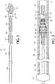
- FIG. 2is an enlarged partial cross-sectional view of an exemplary delivery system 12 without the self-expanding stent or delivery catheter.
- Delivery system 12includes an elongated core member 26 which is a generally a wire, preferably made of Nitinol, but may also be made from other metal alloys or a polymer material.
- the core member 26may be shaped and designed with one or more tapers axially so that proximal section 28 of the core member 26 has a greater diameter than the distal section 30 of the core member 26.
- the diameter of the proximal section 28 of the core member 26is approximately 0.40 mm (0.016 inches) while the diameter of the distal section 30 is approximately 0.05 mm (0.002 inches).
- the greater diameter of the proximal section 28imparts sufficient stiffness to push the core member 26 through the delivery catheter 14, while the smaller diameter of the distal section 30 provides flexibility for the core member 26 to traverse relatively narrow diameter blood vessels.
- Delivery system 12 in Figure 2further includes a proximal cylindrical member 32 disposed about the distal section 30 of the core member 26.
- the proximal cylindrical member 32is a helically wound flexible coil with an outside diameter of approximately 0.40 mm (0.016 inches).
- the coilmay be made of a polymer material, but the preferred material is metal.
- An intermediate cylindrical member 34(about which the stent is mounted) is also disposed about the core member 26 distally from and spaced apart a predetermined distance from the proximal cylindrical member 32 thereby defining a first gap 36.
- the length of the first gapis preferably in a range from approximately 0.48 mm (0.019 inches) to approximately 4.8 mm (0.19 inches), most preferably a length of approximately 1 mm (0.040 inches).
- Intermediate cylindrical member 34may be a cylindrical sleeve or a coil, having a preferred outer diameter of approximately 0.30 mm (0.012 inches).
- the intermediate cylindrical member 34may include a radiopaque portion to serve as a marker and preferably formed from a material such as platinum, gold or tantalum. This radiopaque portion is preferably centered with respect to the self-expanding stent and preferably has a length greater than approximately 10 percent of the length of the self-expanding stent.
- a distal cylindrical member 38is also disposed about the core member 26 distally from and spaced apart from the intermediate cylindrical member 34 defining therebetween a second gap 40.
- a preferred length of the second gap 40may range from approximately 0.48 mm (0.019 inches) to approximately 4.8 mm (0.19 inches), most preferably a length of approximately 1 mm (0.040 inches).
- the distal cylindrical member 38is a helically wound flexible coil with an outside diameter of approximately 0.41 mm (0.016 inches). The coil may be made of a polymer material, but once again the preferred material is metal.
- Distal cylindrical member 38may also be shapeable so that the core member 26 may be used as a guidewire. For example, the distal cylindrical member 38 may be slightly angled to permit the core member 26 to easily navigate through the vasculature of the body.
- the delivery system 12further includes a delivery catheter 14 (an elongated tube) with a lumen 16 defined axially therethrough.
- the lumen 16 of the delivery catheter 14preferably has a diameter in the range of approximately 25.4 mm (0.010 inches) to approximately 6.4 mm (0.25 inches), most preferably having a diameter of approximately 0.53 mm (0.021 inches).
- a proximal section 18 of the delivery catheter 14is formed of a nylon material having a durometer in a range of approximately 60 D to approximately 75 D. Proximal section 18 is sufficiently flexible to traverse a blood vessel, yet sufficiently rigid so that it may be pushed distally through a blood vessel.
- An opposite distal or leading section 22 of the delivery catheter 14is preferably formed of a pellethane material having a durometer of between approximately 25 D and approximately 55 D, most preferably having a durometer of approximately 40 D.
- delivery system 12preferably includes a winged hub 24 coupled to the proximal section 18 of the delivery catheter 14.
- Winged hub 24is preferably made from plastic and configured to be slideably disposed within the lumen 16 of the delivery catheter 14.
- a self-expanding stent 10is mounted on the intermediate cylindrical member 34. Any type of pattern or configuration for the self-expanding stent 10 is contemplated and within the scope of the present invention. Examples of such stents are disclosed in U.S. Patent No. 6,673,106, issued on January 6, 2004 , entitled “Intravascular Stent Device” and in U.S. Patent No. 6,818,013, issued on November 16, 2004 , entitled “Intravascular Stent Device”.
- Self-expanding stent 10is preferably laser cut from a tubular piece of Nitinol and thereafter treated so as to exhibit superelastic properties at body temperature.
- the self-expanding stent 10may include proximal and distal legs 44 and 46 that are attached to the respective proximal and distal ends 48 and 50 of the stent 10 and extend along the longitudinal axis of the stent 10.
- the self-expanding stent 10includes anchor members 52 which may be attached to the proximal end 48 of the stent 10, the proximal legs 44 of the stent 10 and/or at any location along the stent between ends 48 and 50.
- Anchor members 52may be projections made from polymer or metallic material which extend generally parallel to the longitudinal axis the stent 10 and extend downward toward the longitudinal axis of the stent 10.
- the anchor members 52are helically wound flexible coils made of a radiopaque material for use during fluoroscopic visualization.
- anchor members 52 attached to the proximal end 48 or proximal legs 44 of the stent 10align with and are disposed within the first gap 36.
- the proximal end of the self-expanding stent 10is secured in place by anchor members 52 while its opposite distal end by a distal capture device 54.
- the self-expanding stent 10is thus able to be pushed and pulled through the delivery catheter 14 without damaging or deforming the stent 10.
- the distal capture device 54in accordance with the present invention is disposed to constrain radially the distal leading end 46 of stent 10 from flaring open when traversing axially through the lumen 16 of the delivery catheter 14.
- Distal capture device 54is slidably disposed along core member 26 within the second gap 40 between the distal cylindrical member 38 and the intermediate cylindrical member 34.
- the present inventive distal capture device 54comprises a sleeve 56 having a proximal end 58, a distal end 60 and a passageway 62 defined axially therethrough. Passageway 62 has a diameter sufficiently large to allow core member 26 to slidably pass therethrough.
- An outer diameter of the sleeve 56is smaller than the opening 8 defined axially through stent 10. Accordingly, when the self-expanding stent 10 is loaded into the delivery catheter 14 only a portion of the proximal end 58 of sleeve 56 is inserted, starting from the distal leading end 50 of the stent 10, into its opening 8, as depicted in Figure 3 .
- the distal capture device 54also includes a plurality of elastically deformable sections 64 that together represent a distal leaf component.
- the distal capture device 54may be a single integral piece made of a single material (e.g., Nitinol or spring steel).
- the sleeve 56may simply be a weld type feature instead of a discrete piece of material.
- the distal capture device 54be two or more pieces (e.g., a sleeve made of any material suitable for joining and/or holding the plural elastically deformable sections 64 in a distally biased position (e.g., platinum, stainless steel or polyimide) and a distal leaf component preferably made of Nitinol or spring steel). Either configuration may be secured in any way to the core such as, but not limited to, welding, crimping, soldering or an adhesive bond. In yet another configuration, the sleeve 56 may secure the distal leaf component to the core by mounting over a portion of the distal leaf component.
- a sleevemade of any material suitable for joining and/or holding the plural elastically deformable sections 64 in a distally biased position (e.g., platinum, stainless steel or polyimide) and a distal leaf component preferably made of Nitinol or spring steel). Either configuration may be secured in any way to the core such as, but not limited to, welding, crimp
- Each elastically deformable section 64has a free terminating end 68 and an opposite proximal end 66 that is affixed, attached, mounted, connected or otherwise secured to the distal end 60 of sleeve 56.
- the elastically deformable sections 64are closed loops made of an elastically deformable material such as Nitinol or any other material (e.g., metal or polymer) that does not plastically deform/exceed its yield strength when in the proximally biased position. Other configurations may be utilized instead of a loop, such as a flap.
- the present inventionmay be modified to include any number of one or more elastically deformable sections.
- Each elastically deformable section 64is adaptable between two states. While in a fully expanded state, free from any external retractive force, the elastically deformable sections 64 are distally biased in a direction away from sleeve 56 so that its free terminating ends 68 extend beyond the distal end 60 of the sleeve 56, as illustrated in Figure 2 . Upon the free terminating ends 68 being subject to an external retractive force, each elastically deformable section 64 is bendable onto itself to a retracted state in which its associated free terminating ends 68 are proximally deflected (i.e., deflected toward the proximal end 58 of sleeve 56), as shown in Figure 3 .
- the external retractive force(in a proximal direction toward the proximal end 58 of the sleeve 56) is applied to its free terminating end 68 until at least a portion of each elastically deformable section 64 is bent backwards onto itself.
- the external retractive forceis applied at least until the free terminating end 68 of each of the elastically deformable sections 64 are substantially aligned with or extend in a proximal direction past the distal end 60 of the sleeve 56.
- the plural elastically deformable sections 64When loaded into the delivery catheter 14, the plural elastically deformable sections 64 while in the retracted state are prevented from reverting or transitioning back to a fully expanded state by the interior walls of the lumen 16 with which they are physically in contact (as shown in Figure 3 ).
- the elastically deformable sections 64Upon withdrawing the delivery catheter 14 in a proximal direction until its distal end 22 is clear of the free terminating ends 68, the elastically deformable sections 64 automatically revert or transition from the retracted state (the elastically deformable sections proximally deflected) to the fully expanded state (the elastically deformable sections distally biased).
- the distal leading end of the self-expanding stent 10is allowed to expand radially outward until physical contacting the inner wall of the blood vessel.
- the self-expanding stent 10may be anchored or secured in place at the desired location within the blood vessel.
- the maximum outer diameter of all the elastically deformable sections 64 togetheris smaller than the diameter of the axial opening 8 defined in the self-expanding stent 10 so that the core member 26 and distal capture device 54, while in a fully expanded state, may be proximally withdrawn from the lumen 16 of the delivery catheter 14 leaving the expanded stent in place within the blood vessel.
- distal capture device 54is disposed about core member 26 within the second gap 40 between the intermediate cylindrical member 34 and the distal cylindrical section 38 with the proximal end 58 of the sleeve 56 proximate the intermediate cylindrical member 34.
- Stent 10while in a fully expanded state, is slidable along the core member 26 via the axial opening 8.
- the stent 10is slid along the core member 26 until substantially aligned with the intermediate cylindrical member 34 and the distal leading end of the stent 10 overlaps in an axial direction only a portion of the proximal end 58 of the sleeve 56 of the distal capture device 54.
- An external force(axially and/or radially) is applied to stent 10 causing it to transition from a fully expanded state to a compressed state, having a reduced diameter relative to that of the fully expanded state.
- the stent 10is interlocked axially along the core member 26 at its distal leading end by the distal capture device 54, while its opposite proximal end is constrained by anchor members 52.
- the free terminating ends 68 of the elastically deformable sections 64are bent backwards/retracted in a proximal direction onto themselves (e.g., proximally deflected) overlapping with the distal end of the stent 10 and radially constrained.
- proximal directiononto themselves (e.g., proximally deflected) overlapping with the distal end of the stent 10 and radially constrained.
- One way to accomplish thisis by pushing the elastically deformable sections 64 through a tapered tube to bias them proximally and simultaneously radially constrain them.
- Other methodsare contemplated to proximally bias and radially constrain the elastically deformable sections 64 somewhat, if not completely, from flaring open.
- the free terminating ends 68extend in a proximal direction so as to be at least substantially aligned with, if not beyond, the distal end 60 of the sleeve 56; and (ii) the retracted elastically deformable sections 64 all together define a diameter sufficiently small to be received within the lumen 16 of deployment catheter 14.
- the distal capture device 54constrains radially the distal end of the stent 10 prohibiting or minimizing the degree to which the distal end of the stent is able to radially flare open when traversing axially through the lumen 16 of the delivery catheter 14.
- Core member 26 with the stent 10 maintained in a compressed state and the elastically deformable sections 64 in a retracted state (proximally deflected)is then introduced via the proximal end 18 of the delivery catheter 14 into the lumen 16.
- the plural elastically deformable sections 64are in physically contact with the interior walls of the lumen 16 of the deployment catheter 14 thereby retaining them in the retracted state (proximally deflected).
- the loaded delivery system in accordance with the present inventionis then inserted into and traverses axially through the blood vessel to a position proximate the treatment site.
- the distal leading end of the stent 10remains constrained, captured or covered by the plural elastically deformable sections 64 (in a retracted state) thereby minimizing, if not preventing all together, the distal end of the stent 10 from radially flaring open. Accordingly, the distal capture device minimizes, if not eliminates, the need for supplemental delivery forces to advance the stent axially over any obstacles disposed in the lumen 16 of the deployment catheter 14.
- the delivery catheter 14is partially withdrawn in a proximal direction until the free terminating ends 68 of the elastically deformable sections 64 are clear of the deployment catheter 14 (i.e., free terminating end 68 are no longer physically constrained by the interior walls of the lumen 16 of the deployment catheter 14).
- elastically deformable sections 64automatically revert back to their fully expanded state (distally biased) and, in turn, the distal portion of the stent 10 automatically expands until physically contacting the interior wall of the blood vessel 70, as depicted in Figure 4 .
- Delivery catheter 14is again moved further in a proximal direction until the proximal portion of the stent expands and allows the anchor members 52 to become released.
- Stent 10is now fully deployed. While the deployed stent 10 remains in place, core member 26 together with the distal capture device 54 in a fully expanded state (distally biased) may be proximally withdrawn from the blood vessel.
- the present inventive distal capture/release device in accordance with the present inventionis relatively inexpensive to manufacture, suitable for use with conventional self-expanding stent delivery systems without having to alter its design, and extremely reliable.
- the distal end of the self-expanding stentis constrained radially by the plural elastically deformable sections of the distal capture device while in the retracted state thereby minimizing, if not eliminating, the need for supplemental delivery forces required to push the self-expanding stent axially past obstacles disposed within the lumen of the delivery catheter.
Landscapes
- Health & Medical Sciences (AREA)
- Engineering & Computer Science (AREA)
- Biomedical Technology (AREA)
- Cardiology (AREA)
- Oral & Maxillofacial Surgery (AREA)
- Transplantation (AREA)
- Heart & Thoracic Surgery (AREA)
- Vascular Medicine (AREA)
- Life Sciences & Earth Sciences (AREA)
- Animal Behavior & Ethology (AREA)
- General Health & Medical Sciences (AREA)
- Public Health (AREA)
- Veterinary Medicine (AREA)
- Media Introduction/Drainage Providing Device (AREA)
- Surgical Instruments (AREA)
- Prostheses (AREA)
Description
- The present invention relates to self-expanding intravascular devices for implantation within the vessel of a body. In particular, the present invention relates to an improved distal capture device for use with a self-expanding stent in the treatment of blood vessel disorders.
- Expandable stents, i.e., expandable tubular skeletal structures, are commonly used today for such treatments as reinforcing diseased blood vessels, opening occluded blood vessels or relieving pressure in aneurysms. Stents that are expandable may be classified as either "balloon expandable" or "self-expanding." Balloon-expandable stents expand upon the inflation of the balloon, whereas self-expanding stents automatically expand upon removal of a force that otherwise retains the stent in an elastically compressed state. Different types of self-expanding stents have been developed, for example, a laser cut stent or a braided stent. A catheter-based delivery system is used to position the expandable stent at a desired location within a blood vessel. Many systems are available for delivering the stent to the desired location. Several exemplary delivery system configurations are disclosed in
US Patent Nos. 7,309,351 ;7,201,769 ;7,037,331 ;7,001,422 ;6,960,228 ;6,960,227 ;6,955,685 ;6,833,003 ;6,818,013 ;6,673,106 ;6,612,012 , all of which are co-owned by the same assignee of the present invention. - Axial traversal of the stent within the blood vessel occurs using a delivery catheter having a lumen defined axially therethrough for receiving the stent while in a compressed/unexpanded state having a reduced diameter. The catheter is sufficiently flexible, yet rigid, so that it may be pushed distally as it transverses through a blood vessel. While in a compressed state, the stent is introduced into the lumen via the proximal end of the delivery catheter. Conventional self-expanding stents may have a pushing surface to aid in advancing the stent distally through the catheter. Upon emerging out from the distal end of the delivery catheter, the stent automatically deploys to an expanded state in physical contact with the interior surface of the blood vessel.
- The distal or leading edge of the expandable stent presses outward against the inner surface of the delivery catheter as it traverses therethrough. Due to its small size and delicate construction, it is desirable to minimize delivery forces required for the stent to transverse axially through the lumen of the catheter. When traversing axially, the distal or leading edge of a self-expanding stent may undesirably radially flare open thereby requiring significant supplemental delivery force to push past any obstacle (e.g., features, edges or imperfections) encountered along the way within the lumen of the delivery catheter. It would therefore be desirable to develop an improved delivery system for a self-expanding stent that eliminates or minimizes supplemental delivery forces required to push the distal leading edge of the stent past any obstacle disposed along the lumen of the delivery catheter.
US2011301702 relates to a delivery system for use with a prosthetic heart valve having a stent frame to which a valve structure is attached which includes a shaft assembly including a distal end and a coupling structure disposed near the distal end and configured to be coupled to a distal end of the prosthetic heart valve. The coupling structure 122 includes a tubular base portion 124, and a plurality of legs 126 that extend radially away from the base portion 124. In the embodiment illustrated inUS2011301702 , legs 126 are perpendicular or substantially perpendicular to a longitudinal axis of the tubular base portion 124. In one embodiment, coupling structure 122 is made from a shape memory material, such as Nitinol. FIGS. 3A and 3B ofUS2011301702 A1 show the coupling structure 122 in its natural state. In contrast,FIG. 1B ofUS2011301702 A1 shows the coupling structure 122 in a compressed state with the legs 126 bent toward the tubular base portion 124. In other embodiments, coupling structure 122 may be formed from a polymer, suture material, or other material. Each leg 126 includes an end portion 302 that forms a loop configured to be releasably coupled to a hook on the distal inflow end 212 of the prosthetic heart valve 214, as described in further detail inUS2011301702 A1 with reference toFIG. 4 ofUS2011301702 A1 .- The present invention is a distal capture device according to claim 1. Further embodiments of the invention are defined in the dependent claims.
- One aspect of the present disclosure is directed to a catheter-based delivery system in which the distal end of the self-expanding stent is constrained radially by plural elastically deformable sections of a distal capture device while in the retracted state proximally deflected thereby eliminating or minimizing the need for supplemental delivery forces required to push the self-expanding stent axially past obstacles disposed within the lumen of the delivery catheter.
- Another aspect of the present disclosure relates to a delivery system including a distal capture device that has a sleeve with a passageway defined axially therethrough and one or more elastically deformable sections. Each of the one or more elastically deformable sections has a free terminating end and an opposite end mounted to the distal end of the sleeve. The elastically deformable sections transition between: (i) a fully expanded state in which the elastically deformable section is distally biased in a direction away from the sleeve; and (ii) a retracted state in which the free terminating end of each of the elastically deformable sections is proximally deflected backwards over itself in a direction toward the proximal end of the sleeve.
- The foregoing and other features of the present invention will be more readily apparent from the following detailed description and drawings of illustrative embodiments of the invention wherein like reference numbers refer to similar elements throughout the several views and in which:
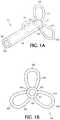
Figure 1A is an enlarged perspective view of an exemplary embodiment of the distal capture device in accordance with the present invention;Figure 1B is an enlarge view of the distal capture device ofFigure 1A from its leading distal end;Figure 2 is an enlarged partial cross-sectional view of the present inventive delivery system including the distal capture device in a full-expanded state (distally biased) without the stent;Figure 3 is an enlarged partial cross-sectional view of the delivery system including the distal capture device in a retracted state (proximally deflected) covering the distal leading end of a self-expanding stent in a compressed state as the delivery system traverses axially through the blood vessel; andFigure 4 is an enlarged partial cross-sectional view of the present inventive delivery system including the distal capture device in a fully expanded state (distally biased) with the distal end of the self-expanding stent in an expanded state deployed at its desired location within the blood vessel.- The terms "proximal"/"proximally" and "distal"/"distally" refer to a direction closer to or away from, respectively, an operator (e.g., surgeon, physician, nurse, technician, etc.) who would insert the medical device into the patient, with the tip-end (i.e., distal end or leading end) of the device inserted inside a patient's body. Thus, for example, a "proximal direction" would refer to the direction towards the operator, whereas "distal direction" would refer to the direction away from the operator towards the leading or tip-end of the medical device.
- The term "stent" refers to a device or structure that provides or is configured to provide rigidity, expansion force, or support to a body part, for example, a diseased or otherwise compromised body lumen (e.g., blood vessel or coronary arteries).
- The term "self-expanding stent" refers to a stent having a reduced diameter configuration when subject to an external constraining force and automatically expanding to an enlarged diameter when the external constraining force is withdrawn.
- The present inventive distal capture device is used with a self-expanding stent. Any type of self-expanding stent may be used, for example, a laser cut stent or a braided stent.
Figure 2 is an enlarged partial cross-sectional view of anexemplary delivery system 12 without the self-expanding stent or delivery catheter.Delivery system 12 includes anelongated core member 26 which is a generally a wire, preferably made of Nitinol, but may also be made from other metal alloys or a polymer material. Thecore member 26 may be shaped and designed with one or more tapers axially so thatproximal section 28 of thecore member 26 has a greater diameter than thedistal section 30 of thecore member 26. Preferably, the diameter of theproximal section 28 of thecore member 26 is approximately 0.40 mm (0.016 inches) while the diameter of thedistal section 30 is approximately 0.05 mm (0.002 inches). The greater diameter of theproximal section 28 imparts sufficient stiffness to push thecore member 26 through thedelivery catheter 14, while the smaller diameter of thedistal section 30 provides flexibility for thecore member 26 to traverse relatively narrow diameter blood vessels.Delivery system 12 inFigure 2 further includes a proximalcylindrical member 32 disposed about thedistal section 30 of thecore member 26. Preferably, the proximalcylindrical member 32 is a helically wound flexible coil with an outside diameter of approximately 0.40 mm (0.016 inches). The coil may be made of a polymer material, but the preferred material is metal. An intermediate cylindrical member 34 (about which the stent is mounted) is also disposed about thecore member 26 distally from and spaced apart a predetermined distance from the proximalcylindrical member 32 thereby defining afirst gap 36. The length of the first gap is preferably in a range from approximately 0.48 mm (0.019 inches) to approximately 4.8 mm (0.19 inches), most preferably a length of approximately 1 mm (0.040 inches). Intermediatecylindrical member 34 may be a cylindrical sleeve or a coil, having a preferred outer diameter of approximately 0.30 mm (0.012 inches). The intermediatecylindrical member 34 may include a radiopaque portion to serve as a marker and preferably formed from a material such as platinum, gold or tantalum. This radiopaque portion is preferably centered with respect to the self-expanding stent and preferably has a length greater than approximately 10 percent of the length of the self-expanding stent.- A distal
cylindrical member 38 is also disposed about thecore member 26 distally from and spaced apart from the intermediatecylindrical member 34 defining therebetween asecond gap 40. A preferred length of thesecond gap 40 may range from approximately 0.48 mm (0.019 inches) to approximately 4.8 mm (0.19 inches), most preferably a length of approximately 1 mm (0.040 inches). Preferably, the distalcylindrical member 38 is a helically wound flexible coil with an outside diameter of approximately 0.41 mm (0.016 inches). The coil may be made of a polymer material, but once again the preferred material is metal. Distalcylindrical member 38 may also be shapeable so that thecore member 26 may be used as a guidewire. For example, the distalcylindrical member 38 may be slightly angled to permit thecore member 26 to easily navigate through the vasculature of the body. - Referring to
Figure 3 , thedelivery system 12 further includes a delivery catheter 14 (an elongated tube) with alumen 16 defined axially therethrough. Thelumen 16 of thedelivery catheter 14 preferably has a diameter in the range of approximately 25.4 mm (0.010 inches) to approximately 6.4 mm (0.25 inches), most preferably having a diameter of approximately 0.53 mm (0.021 inches). Preferably, aproximal section 18 of thedelivery catheter 14 is formed of a nylon material having a durometer in a range of approximately 60 D to approximately 75D. Proximal section 18 is sufficiently flexible to traverse a blood vessel, yet sufficiently rigid so that it may be pushed distally through a blood vessel. An opposite distal or leadingsection 22 of thedelivery catheter 14 is preferably formed of a pellethane material having a durometer of between approximately 25 D and approximately 55 D, most preferably having a durometer of approximately 40 D. - To aid in insertion of the
delivery catheter 14 into a blood vessel,delivery system 12 preferably includes awinged hub 24 coupled to theproximal section 18 of thedelivery catheter 14.Winged hub 24 is preferably made from plastic and configured to be slideably disposed within thelumen 16 of thedelivery catheter 14. - A self-expanding
stent 10 is mounted on the intermediatecylindrical member 34. Any type of pattern or configuration for the self-expandingstent 10 is contemplated and within the scope of the present invention. Examples of such stents are disclosed inU.S. Patent No. 6,673,106, issued on January 6, 2004 , entitled "Intravascular Stent Device" and inU.S. Patent No. 6,818,013, issued on November 16, 2004 , entitled "Intravascular Stent Device". Self-expandingstent 10 is preferably laser cut from a tubular piece of Nitinol and thereafter treated so as to exhibit superelastic properties at body temperature. The self-expandingstent 10 may include proximal anddistal legs distal ends stent 10 and extend along the longitudinal axis of thestent 10. In addition, the self-expandingstent 10 includesanchor members 52 which may be attached to theproximal end 48 of thestent 10, theproximal legs 44 of thestent 10 and/or at any location along the stent between ends 48 and 50.Anchor members 52 may be projections made from polymer or metallic material which extend generally parallel to the longitudinal axis thestent 10 and extend downward toward the longitudinal axis of thestent 10. - Preferably, the
anchor members 52 are helically wound flexible coils made of a radiopaque material for use during fluoroscopic visualization. As the self-expandingstent 10 is positioned and mounted on the intermediatecylindrical member 34,anchor members 52 attached to theproximal end 48 orproximal legs 44 of thestent 10 align with and are disposed within thefirst gap 36. The proximal end of the self-expandingstent 10 is secured in place byanchor members 52 while its opposite distal end by adistal capture device 54. The self-expandingstent 10 is thus able to be pushed and pulled through thedelivery catheter 14 without damaging or deforming thestent 10. Without being secured to thestent 10 in any way (e.g., via wires or sutures), thedistal capture device 54 in accordance with the present invention is disposed to constrain radially the distal leadingend 46 ofstent 10 from flaring open when traversing axially through thelumen 16 of thedelivery catheter 14.Distal capture device 54 is slidably disposed alongcore member 26 within thesecond gap 40 between the distalcylindrical member 38 and the intermediatecylindrical member 34. - Referring to
Figure 1A , the present inventivedistal capture device 54 comprises asleeve 56 having aproximal end 58, adistal end 60 and apassageway 62 defined axially therethrough.Passageway 62 has a diameter sufficiently large to allowcore member 26 to slidably pass therethrough. An outer diameter of thesleeve 56 is smaller than theopening 8 defined axially throughstent 10. Accordingly, when the self-expandingstent 10 is loaded into thedelivery catheter 14 only a portion of theproximal end 58 ofsleeve 56 is inserted, starting from the distal leadingend 50 of thestent 10, into itsopening 8, as depicted inFigure 3 . - The
distal capture device 54 also includes a plurality of elasticallydeformable sections 64 that together represent a distal leaf component. In accordance with the present invention, thedistal capture device 54 may be a single integral piece made of a single material (e.g., Nitinol or spring steel). Alternatively, thesleeve 56 may simply be a weld type feature instead of a discrete piece of material. It is also contemplated that thedistal capture device 54 be two or more pieces (e.g., a sleeve made of any material suitable for joining and/or holding the plural elasticallydeformable sections 64 in a distally biased position (e.g., platinum, stainless steel or polyimide) and a distal leaf component preferably made of Nitinol or spring steel). Either configuration may be secured in any way to the core such as, but not limited to, welding, crimping, soldering or an adhesive bond. In yet another configuration, thesleeve 56 may secure the distal leaf component to the core by mounting over a portion of the distal leaf component. - Each elastically
deformable section 64 has a free terminatingend 68 and an oppositeproximal end 66 that is affixed, attached, mounted, connected or otherwise secured to thedistal end 60 ofsleeve 56. In the exemplary embodiment illustrated in the figures, the elasticallydeformable sections 64 are closed loops made of an elastically deformable material such as Nitinol or any other material (e.g., metal or polymer) that does not plastically deform/exceed its yield strength when in the proximally biased position. Other configurations may be utilized instead of a loop, such as a flap. Despite three elasticallydeformable sections 64 being shown, the present invention may be modified to include any number of one or more elastically deformable sections. - Each elastically
deformable section 64 is adaptable between two states. While in a fully expanded state, free from any external retractive force, the elasticallydeformable sections 64 are distally biased in a direction away fromsleeve 56 so that its free terminating ends 68 extend beyond thedistal end 60 of thesleeve 56, as illustrated inFigure 2 . Upon the free terminating ends 68 being subject to an external retractive force, each elasticallydeformable section 64 is bendable onto itself to a retracted state in which its associated free terminating ends 68 are proximally deflected (i.e., deflected toward theproximal end 58 of sleeve 56), as shown inFigure 3 . Specifically, the external retractive force (in a proximal direction toward theproximal end 58 of the sleeve 56) is applied to its free terminatingend 68 until at least a portion of each elasticallydeformable section 64 is bent backwards onto itself. Preferably, the external retractive force is applied at least until the free terminatingend 68 of each of the elasticallydeformable sections 64 are substantially aligned with or extend in a proximal direction past thedistal end 60 of thesleeve 56. When loaded into thedelivery catheter 14, the plural elasticallydeformable sections 64 while in the retracted state are prevented from reverting or transitioning back to a fully expanded state by the interior walls of thelumen 16 with which they are physically in contact (as shown inFigure 3 ). Upon withdrawing thedelivery catheter 14 in a proximal direction until itsdistal end 22 is clear of the free terminating ends 68, the elasticallydeformable sections 64 automatically revert or transition from the retracted state (the elastically deformable sections proximally deflected) to the fully expanded state (the elastically deformable sections distally biased). As illustrated inFigure 4 , while thedistal capture device 54 is in a fully expanded state (with the elastically deformable sections distally biased), the distal leading end of the self-expandingstent 10 is allowed to expand radially outward until physical contacting the inner wall of the blood vessel. Once deployed, the self-expandingstent 10 may be anchored or secured in place at the desired location within the blood vessel. In its fully expanded state, the maximum outer diameter of all the elasticallydeformable sections 64 together is smaller than the diameter of theaxial opening 8 defined in the self-expandingstent 10 so that thecore member 26 anddistal capture device 54, while in a fully expanded state, may be proximally withdrawn from thelumen 16 of thedelivery catheter 14 leaving the expanded stent in place within the blood vessel. - During manufacture of the
exemplary delivery system 12 illustrated inFigure 2 ,distal capture device 54 is disposed aboutcore member 26 within thesecond gap 40 between the intermediatecylindrical member 34 and the distalcylindrical section 38 with theproximal end 58 of thesleeve 56 proximate the intermediatecylindrical member 34.Stent 10, while in a fully expanded state, is slidable along thecore member 26 via theaxial opening 8. In theexemplary delivery system 12 shown inFigure 3 , thestent 10 is slid along thecore member 26 until substantially aligned with the intermediatecylindrical member 34 and the distal leading end of thestent 10 overlaps in an axial direction only a portion of theproximal end 58 of thesleeve 56 of thedistal capture device 54. An external force (axially and/or radially) is applied tostent 10 causing it to transition from a fully expanded state to a compressed state, having a reduced diameter relative to that of the fully expanded state. Thestent 10 is interlocked axially along thecore member 26 at its distal leading end by thedistal capture device 54, while its opposite proximal end is constrained byanchor members 52. - The free terminating ends 68 of the elastically
deformable sections 64 are bent backwards/retracted in a proximal direction onto themselves (e.g., proximally deflected) overlapping with the distal end of thestent 10 and radially constrained. One way to accomplish this is by pushing the elasticallydeformable sections 64 through a tapered tube to bias them proximally and simultaneously radially constrain them. Other methods are contemplated to proximally bias and radially constrain the elasticallydeformable sections 64 somewhat, if not completely, from flaring open. Preferably, while the elasticallydeformable sections 64 are in this retracted state: (i) the free terminating ends 68 extend in a proximal direction so as to be at least substantially aligned with, if not beyond, thedistal end 60 of thesleeve 56; and (ii) the retracted elasticallydeformable sections 64 all together define a diameter sufficiently small to be received within thelumen 16 ofdeployment catheter 14. In this retracted state (with the free terminating ends 68 deflected proximally) thedistal capture device 54 constrains radially the distal end of thestent 10 prohibiting or minimizing the degree to which the distal end of the stent is able to radially flare open when traversing axially through thelumen 16 of thedelivery catheter 14.Core member 26 with thestent 10 maintained in a compressed state and the elasticallydeformable sections 64 in a retracted state (proximally deflected) is then introduced via theproximal end 18 of thedelivery catheter 14 into thelumen 16. - Once installed in the
deployment catheter 14, the plural elasticallydeformable sections 64 are in physically contact with the interior walls of thelumen 16 of thedeployment catheter 14 thereby retaining them in the retracted state (proximally deflected). The loaded delivery system in accordance with the present invention is then inserted into and traverses axially through the blood vessel to a position proximate the treatment site. As is clearly illustrated inFigure 3 , when loaded into thedelivery catheter 14 the distal leading end of thestent 10 remains constrained, captured or covered by the plural elastically deformable sections 64 (in a retracted state) thereby minimizing, if not preventing all together, the distal end of thestent 10 from radially flaring open. Accordingly, the distal capture device minimizes, if not eliminates, the need for supplemental delivery forces to advance the stent axially over any obstacles disposed in thelumen 16 of thedeployment catheter 14. - Once positioned at the desired location in the blood vessel, while the
core member 26 remains in place, thedelivery catheter 14 is partially withdrawn in a proximal direction until the free terminating ends 68 of the elasticallydeformable sections 64 are clear of the deployment catheter 14 (i.e., free terminatingend 68 are no longer physically constrained by the interior walls of thelumen 16 of the deployment catheter 14). As soon as the free terminating ends 68 are no longer constrained by the interior surface of thelumen 16 of thedelivery catheter 14, elasticallydeformable sections 64 automatically revert back to their fully expanded state (distally biased) and, in turn, the distal portion of thestent 10 automatically expands until physically contacting the interior wall of theblood vessel 70, as depicted inFigure 4 .Delivery catheter 14 is again moved further in a proximal direction until the proximal portion of the stent expands and allows theanchor members 52 to become released.Stent 10 is now fully deployed. While the deployedstent 10 remains in place,core member 26 together with thedistal capture device 54 in a fully expanded state (distally biased) may be proximally withdrawn from the blood vessel. - The present inventive distal capture/release device in accordance with the present invention is relatively inexpensive to manufacture, suitable for use with conventional self-expanding stent delivery systems without having to alter its design, and extremely reliable.
- In accordance with the present invention, the distal end of the self-expanding stent is constrained radially by the plural elastically deformable sections of the distal capture device while in the retracted state thereby minimizing, if not eliminating, the need for supplemental delivery forces required to push the self-expanding stent axially past obstacles disposed within the lumen of the delivery catheter.
- Thus, while there have been shown, described, and pointed out fundamental novel features of the invention as applied to a preferred embodiment thereof, it will be understood that various omissions, substitutions, and changes in the form and details of the devices illustrated, and in their operation, may be made by those skilled in the art without departing from the spirit and scope of the invention. For example, it is expressly intended that all combinations of those elements and/or steps that perform substantially the same function, in substantially the same way, to achieve the same results be within the scope of the invention. Substitutions of elements from one described embodiment to another are also fully intended and contemplated. It is also to be understood that the drawings are not necessarily drawn to scale, but that they are merely conceptual in nature. It is the intention, therefore, to be limited only as indicated by the scope of the claims appended hereto.
Claims (10)
- A distal capture device (54) suitable for use with a self-expanding stent, comprising:a sleeve (56) having a proximal end (58), an opposite distal end (60) and a passageway (62) defined axially therethrough; andat least one elastically deformable section (64), each of the at least one elastically deformable section has a free terminating end (68) and an opposite end (66) mounted to the distal end of the sleeve; wherein the at least one elastically deformable section transitions between: (i) a fully expanded state in which the at least one elastically deformable section is distally biased in a direction away from the sleeve so that its free terminating end extends beyond the distal end of the sleeve in a distal direction; and (ii) a retracted state in which the free terminating end of each of the at least one elastically deformable section is proximally deflected backwards over itself in a direction toward the proximal end of the sleeve;wherein the at least one elastically deformable section transitions from the fully expanded state to the retracted state only when the free terminating end is subject to an external retractive force in a direction towards the proximal end of the sleeve.
- A stent delivery system comprising the distal capture device of claim 1, further comprising a core member (26) slidably receivable within the passageway of the sleeve of the distal capture device.
- The stent delivery system in accordance with claim 2, further comprising a delivery catheter (14) having a proximal end (18), an opposite distal end (22) and a lumen (16) defined axially therethrough for receiving the distal capture device and the core member.
- The stent delivery system in accordance with claim 3, further comprising a self-expanding stent (10) having a proximal end (48) and an opposite distal end (50); the distal end of the stent overlapping with the proximal end of the sleeve of the distal capture device.
- The stent delivery system in accordance with claim 4, wherein the distal capture device is not secured to the stent.
- The distal capture device in accordance with claim 1, wherein the distal capture device has a plurality of elastically deformable sections (64).
- The distal capture device in accordance with claim 6, wherein the distal capture device has three elastically deformable sections (64).
- The distal capture device in accordance with claim 1, wherein the sleeve is made from a non-elastically deformable material.
- The stent delivery system in accordance with claim 4, wherein an outer diameter of the sleeve is smaller than an opening (8) defined axially through the self-expanding stent.
- The distal capture device in accordance with claim 1, wherein the at least one elastic deformable section is a loop or a flap.
Applications Claiming Priority (2)
| Application Number | Priority Date | Filing Date | Title |
|---|---|---|---|
| US13/799,437US9629739B2 (en) | 2013-03-13 | 2013-03-13 | Distal capture device for a self-expanding stent |
| EP14159061.2AEP2777650B1 (en) | 2013-03-13 | 2014-03-12 | Distal capture device for a self-expanding stent |
Related Parent Applications (1)
| Application Number | Title | Priority Date | Filing Date |
|---|---|---|---|
| EP14159061.2ADivisionEP2777650B1 (en) | 2013-03-13 | 2014-03-12 | Distal capture device for a self-expanding stent |
Publications (2)
| Publication Number | Publication Date |
|---|---|
| EP3225219A1 EP3225219A1 (en) | 2017-10-04 |
| EP3225219B1true EP3225219B1 (en) | 2022-11-02 |
Family
ID=50239535
Family Applications (2)
| Application Number | Title | Priority Date | Filing Date |
|---|---|---|---|
| EP17171480.1AActiveEP3225219B1 (en) | 2013-03-13 | 2014-03-12 | Distal capture device for a self-expanding stent |
| EP14159061.2AActiveEP2777650B1 (en) | 2013-03-13 | 2014-03-12 | Distal capture device for a self-expanding stent |
Family Applications After (1)
| Application Number | Title | Priority Date | Filing Date |
|---|---|---|---|
| EP14159061.2AActiveEP2777650B1 (en) | 2013-03-13 | 2014-03-12 | Distal capture device for a self-expanding stent |
Country Status (10)
| Country | Link |
|---|---|
| US (1) | US9629739B2 (en) |
| EP (2) | EP3225219B1 (en) |
| JP (1) | JP6324764B2 (en) |
| KR (1) | KR102228712B1 (en) |
| CN (1) | CN104042378B (en) |
| AU (2) | AU2014201208A1 (en) |
| BR (1) | BR102014005985A2 (en) |
| CA (1) | CA2845552C (en) |
| DK (1) | DK2777650T3 (en) |
| ES (1) | ES2932656T3 (en) |
Families Citing this family (10)
| Publication number | Priority date | Publication date | Assignee | Title |
|---|---|---|---|---|
| CN103945793B (en) | 2011-12-06 | 2016-05-04 | 俄奥梯科创新有限公司 | For device and the using method thereof of repairing in aorta lumen |
| US9877855B2 (en)* | 2014-07-25 | 2018-01-30 | Cook Medical Technologies Llc | Method of loading and delivering a self-expanding stent |
| PL3653177T3 (en) | 2015-01-11 | 2022-01-31 | Ascyrus Medical, Llc | Hybrid device for surgical aortic repair |
| US9375336B1 (en)* | 2015-01-29 | 2016-06-28 | Intact Vascular, Inc. | Delivery device and method of delivery |
| JP6499497B2 (en)* | 2015-04-15 | 2019-04-10 | 株式会社Pentas | Pusher guide wire |
| JP6854282B2 (en)* | 2015-09-18 | 2021-04-07 | テルモ株式会社 | Pressable implant delivery system |
| CN106214297A (en)* | 2016-08-18 | 2016-12-14 | 苏州万斯医疗科技有限公司 | A kind of support recovery system |
| CN107157621B (en)* | 2016-09-23 | 2024-07-30 | 杭州启明医疗器械股份有限公司 | Conveying system capable of recycling and repeatedly positioning interventional instrument |
| US10292851B2 (en)* | 2016-09-30 | 2019-05-21 | DePuy Synthes Products, Inc. | Self-expanding device delivery apparatus with dual function bump |
| US10940030B2 (en) | 2017-03-10 | 2021-03-09 | Serenity Medical, Inc. | Method and system for delivering a self-expanding stent to the venous sinuses |
Citations (1)
| Publication number | Priority date | Publication date | Assignee | Title |
|---|---|---|---|---|
| US5968069A (en)* | 1996-08-23 | 1999-10-19 | Scimed Life Systems, Inc. | Stent delivery system having stent securement apparatus |
Family Cites Families (77)
| Publication number | Priority date | Publication date | Assignee | Title |
|---|---|---|---|---|
| US5344426A (en) | 1990-04-25 | 1994-09-06 | Advanced Cardiovascular Systems, Inc. | Method and system for stent delivery |
| CA2060067A1 (en) | 1991-01-28 | 1992-07-29 | Lilip Lau | Stent delivery system |
| US5380304A (en) | 1991-08-07 | 1995-01-10 | Cook Incorporated | Flexible, kink-resistant, introducer sheath and method of manufacture |
| US5234437A (en) | 1991-12-12 | 1993-08-10 | Target Therapeutics, Inc. | Detachable pusher-vasoocclusion coil assembly with threaded coupling |
| US5261916A (en) | 1991-12-12 | 1993-11-16 | Target Therapeutics | Detachable pusher-vasoocclusive coil assembly with interlocking ball and keyway coupling |
| US5263964A (en) | 1992-05-06 | 1993-11-23 | Coil Partners Ltd. | Coaxial traction detachment apparatus and method |
| US5250071A (en) | 1992-09-22 | 1993-10-05 | Target Therapeutics, Inc. | Detachable embolic coil assembly using interlocking clasps and method of use |
| USRE37117E1 (en) | 1992-09-22 | 2001-03-27 | Target Therapeutics, Inc. | Detachable embolic coil assembly using interlocking clasps and method of use |
| US5312415A (en) | 1992-09-22 | 1994-05-17 | Target Therapeutics, Inc. | Assembly for placement of embolic coils using frictional placement |
| US5800453A (en) | 1993-04-19 | 1998-09-01 | Target Therapeutics, Inc. | Detachable embolic coil assembly using interlocking hooks and slots |
| US5925059A (en) | 1993-04-19 | 1999-07-20 | Target Therapeutics, Inc. | Detachable embolic coil assembly |
| US5417708A (en) | 1994-03-09 | 1995-05-23 | Cook Incorporated | Intravascular treatment system and percutaneous release mechanism therefor |
| US5788707A (en) | 1995-06-07 | 1998-08-04 | Scimed Life Systems, Inc. | Pull back sleeve system with compression resistant inner shaft |
| US5853418A (en) | 1995-06-30 | 1998-12-29 | Target Therapeutics, Inc. | Stretch resistant vaso-occlusive coils (II) |
| US5601600A (en) | 1995-09-08 | 1997-02-11 | Conceptus, Inc. | Endoluminal coil delivery system having a mechanical release mechanism |
| US5762615A (en) | 1996-06-04 | 1998-06-09 | Cordis Corporation | Guideware having a distal tip with variable flexibility |
| US6063100A (en) | 1998-03-10 | 2000-05-16 | Cordis Corporation | Embolic coil deployment system with improved embolic coil |
| US6478773B1 (en) | 1998-12-21 | 2002-11-12 | Micrus Corporation | Apparatus for deployment of micro-coil using a catheter |
| US6179857B1 (en) | 1999-02-22 | 2001-01-30 | Cordis Corporation | Stretch resistant embolic coil with variable stiffness |
| US6612012B2 (en) | 2001-06-11 | 2003-09-02 | Cordis Neurovascular, Inc. | Method of manufacturing small profile medical devices |
| US6673106B2 (en) | 2001-06-14 | 2004-01-06 | Cordis Neurovascular, Inc. | Intravascular stent device |
| US6818013B2 (en) | 2001-06-14 | 2004-11-16 | Cordis Corporation | Intravascular stent device |
| US20040267280A1 (en) | 2001-09-28 | 2004-12-30 | Takuji Nishide | Stent delivery catheter |
| US7147656B2 (en) | 2001-12-03 | 2006-12-12 | Xtent, Inc. | Apparatus and methods for delivery of braided prostheses |
| US6907298B2 (en) | 2002-01-09 | 2005-06-14 | Medtronic, Inc. | Method and apparatus for imparting curves in implantable elongated medical instruments |
| US6866679B2 (en) | 2002-03-12 | 2005-03-15 | Ev3 Inc. | Everting stent and stent delivery system |
| DE10219194B4 (en)* | 2002-04-29 | 2004-06-03 | Qualimed Innovative Medizinprodukte Gmbh | Instrument for implanting expandable cylindrical vascular prostheses |
| US6833003B2 (en) | 2002-06-24 | 2004-12-21 | Cordis Neurovascular | Expandable stent and delivery system |
| US7608058B2 (en) | 2002-07-23 | 2009-10-27 | Micrus Corporation | Stretch resistant therapeutic device |
| US7001422B2 (en) | 2002-09-23 | 2006-02-21 | Cordis Neurovascular, Inc | Expandable stent and delivery system |
| US7942898B2 (en) | 2002-12-11 | 2011-05-17 | Usgi Medical, Inc. | Delivery systems and methods for gastric reduction |
| US7651513B2 (en) | 2003-04-03 | 2010-01-26 | Boston Scientific Scimed, Inc. | Flexible embolic device delivery system |
| US8317859B2 (en) | 2004-06-28 | 2012-11-27 | J.W. Medical Systems Ltd. | Devices and methods for controlling expandable prostheses during deployment |
| DE602005005567T2 (en) | 2004-07-28 | 2009-04-30 | Cordis Corp., Miami Lakes | Insertion device with a low deployment force |
| US20060025802A1 (en) | 2004-07-30 | 2006-02-02 | Sowers William W | Embolic coil delivery system with U-shaped fiber release mechanism |
| US7918872B2 (en) | 2004-07-30 | 2011-04-05 | Codman & Shurtleff, Inc. | Embolic device delivery system with retractable partially coiled-fiber release |
| US7608089B2 (en) | 2004-12-22 | 2009-10-27 | Boston Scientific Scimed, Inc. | Vaso-occlusive device having pivotable coupling |
| AU2005332044B2 (en) | 2005-05-25 | 2012-01-19 | Covidien Lp | System and method for delivering and deploying and occluding device within a vessel |
| US8002789B2 (en) | 2005-05-31 | 2011-08-23 | Stryker Corporation | Stretch-resistant vaso-occlusive devices with flexible detachment junctions |
| US20060276830A1 (en) | 2005-06-02 | 2006-12-07 | Keith Balgobin | Stretch resistant embolic coil delivery system with mechanical release mechanism |
| US20060276833A1 (en) | 2005-06-02 | 2006-12-07 | Keith Balgobin | Stretch resistant embolic coil delivery system with spring assisted release mechanism |
| US7985238B2 (en) | 2005-06-02 | 2011-07-26 | Codman & Shurtleff, Inc. | Embolic coil delivery system with spring wire release mechanism |
| US7371252B2 (en) | 2005-06-02 | 2008-05-13 | Cordis Neurovascular, Inc. | Stretch resistant embolic coil delivery system with mechanical release mechanism |
| US20060276826A1 (en) | 2005-06-02 | 2006-12-07 | Vladimir Mitelberg | Stretch resistant embolic coil delivery system with mechanical release mechanism |
| US7377932B2 (en) | 2005-06-02 | 2008-05-27 | Cordis Neurovascular, Inc. | Embolic coil delivery system with mechanical release mechanism |
| US7371251B2 (en) | 2005-06-02 | 2008-05-13 | Cordis Neurovascular, Inc. | Stretch resistant embolic coil delivery system with mechanical release mechanism |
| US20060276825A1 (en) | 2005-06-02 | 2006-12-07 | Vladimir Mitelberg | Stretch resistant embolic coil delivery system with mechanical release mechanism |
| US7367987B2 (en) | 2005-06-02 | 2008-05-06 | Cordis Neurovascular, Inc. | Stretch resistant embolic coil delivery system with mechanical release mechanism |
| US7799052B2 (en) | 2005-06-02 | 2010-09-21 | Codman & Shurtleff, Inc. | Stretch resistant embolic coil delivery system with mechanical release mechanism |
| US7819891B2 (en) | 2005-06-02 | 2010-10-26 | Codman & Shurtleff, Inc. | Stretch resistant embolic coil delivery system with spring release mechanism |
| US7811305B2 (en) | 2005-06-02 | 2010-10-12 | Codman & Shurtleff, Inc. | Stretch resistant embolic coil delivery system with spring release mechanism |
| US7819892B2 (en) | 2005-06-02 | 2010-10-26 | Codman & Shurtleff, Inc. | Embolic coil delivery system with spring wire release mechanism |
| US7780695B2 (en) | 2005-06-30 | 2010-08-24 | Codman & Shurtleff, Inc. | Chemically based vascular occlusion device deployment |
| US7691124B2 (en) | 2006-01-31 | 2010-04-06 | Codman & Shurtleff, Inc. | Delivery of therapeutic devices |
| US7901444B2 (en) | 2006-09-29 | 2011-03-08 | Codman & Shurtleff, Inc. | Embolic coil delivery system with mechanical release mechanism |
| US20080306503A1 (en) | 2006-11-20 | 2008-12-11 | Boston Scientific Scimed, Inc. | Mechanically detachable vaso-occlusive device |
| US8956381B2 (en) | 2006-11-20 | 2015-02-17 | Boston Scientific Scimed, Inc. | Mechanically detachable vaso-occlusive device |
| US8926650B2 (en) | 2006-11-20 | 2015-01-06 | Boston Scientific Scimed, Inc. | Mechanically detachable vaso-occlusive device |
| WO2008064206A2 (en) | 2006-11-20 | 2008-05-29 | Boston Scientific Scimed, Inc. | Mechanically detachable vaso-occlusive device |
| WO2008066923A1 (en) | 2006-11-30 | 2008-06-05 | William Cook Europe Aps | Implant release mechanism |
| CA2680607C (en) | 2007-03-13 | 2015-07-14 | Microtherapeutics, Inc. | An implant including a coil and a stretch-resistant member |
| JP5623291B2 (en) | 2008-01-04 | 2014-11-12 | ボストン サイエンティフィック サイムド,インコーポレイテッドBoston Scientific Scimed,Inc. | Separation mechanism for implantable devices |
| US8333796B2 (en) | 2008-07-15 | 2012-12-18 | Penumbra, Inc. | Embolic coil implant system and implantation method |
| EP2341872B1 (en) | 2008-10-17 | 2014-08-06 | Cook Medical Technologies LLC | System for deploying and positioning an endovascular device |
| US20100160944A1 (en) | 2008-12-24 | 2010-06-24 | Boston Scientific Scimed, Inc. | Thermally detachable embolic assemblies |
| US8016872B2 (en) | 2009-12-22 | 2011-09-13 | Cook Medical Technologies Llc | Deployment and dilation with an expandable roll sock delivery system |
| US8649871B2 (en) | 2010-04-29 | 2014-02-11 | Cyberonics, Inc. | Validity test adaptive constraint modification for cardiac data used for detection of state changes |
| US9561102B2 (en) | 2010-06-02 | 2017-02-07 | Medtronic, Inc. | Transcatheter delivery system and method with controlled expansion and contraction of prosthetic heart valve |
| US9220506B2 (en) | 2010-06-16 | 2015-12-29 | DePuy Synthes Products, Inc. | Occlusive device with stretch resistant member and anchor filament |
| CN102370532B (en) | 2010-08-13 | 2015-06-17 | 黄连军 | Collateral type tectorial membrane support frame conveyor as well as installing method |
| US20120209310A1 (en) | 2011-02-10 | 2012-08-16 | Stryker Nv Operations Limited | Vaso-occlusive device delivery system |
| US9579104B2 (en) | 2011-11-30 | 2017-02-28 | Covidien Lp | Positioning and detaching implants |
| EP2630936B1 (en) | 2012-02-23 | 2015-06-10 | Covidien LP | Apparatus for luminal stenting |
| US20130226278A1 (en)* | 2012-02-23 | 2013-08-29 | Tyco Healthcare Group Lp | Methods and apparatus for luminal stenting |
| US9980731B2 (en) | 2012-03-30 | 2018-05-29 | DePuy Synthes Products, Inc. | Embolic coil detachment mechanism with flexible distal member and coupling union |
| US9078659B2 (en) | 2012-04-23 | 2015-07-14 | Covidien Lp | Delivery system with hooks for resheathability |
| US9149278B2 (en) | 2013-03-13 | 2015-10-06 | DePuy Synthes Products, Inc. | Occlusive device delivery system with mechanical detachment |
- 2013
- 2013-03-13USUS13/799,437patent/US9629739B2/enactiveActive
- 2014
- 2014-03-05AUAU2014201208Apatent/AU2014201208A1/ennot_activeAbandoned
- 2014-03-11CACA2845552Apatent/CA2845552C/ennot_activeExpired - Fee Related
- 2014-03-11KRKR1020140028069Apatent/KR102228712B1/ennot_activeExpired - Fee Related
- 2014-03-12EPEP17171480.1Apatent/EP3225219B1/enactiveActive
- 2014-03-12ESES17171480Tpatent/ES2932656T3/enactiveActive
- 2014-03-12JPJP2014048693Apatent/JP6324764B2/enactiveActive
- 2014-03-12DKDK14159061.2Tpatent/DK2777650T3/enactive
- 2014-03-12EPEP14159061.2Apatent/EP2777650B1/enactiveActive
- 2014-03-13CNCN201410092239.6Apatent/CN104042378B/enactiveActive
- 2014-03-13BRBR102014005985Apatent/BR102014005985A2/enactiveSearch and Examination
- 2018
- 2018-08-21AUAU2018220002Apatent/AU2018220002B2/ennot_activeCeased
Patent Citations (1)
| Publication number | Priority date | Publication date | Assignee | Title |
|---|---|---|---|---|
| US5968069A (en)* | 1996-08-23 | 1999-10-19 | Scimed Life Systems, Inc. | Stent delivery system having stent securement apparatus |
Also Published As
| Publication number | Publication date |
|---|---|
| US9629739B2 (en) | 2017-04-25 |
| BR102014005985A2 (en) | 2015-10-06 |
| JP2014176662A (en) | 2014-09-25 |
| AU2018220002A1 (en) | 2018-09-06 |
| CA2845552C (en) | 2021-04-06 |
| CA2845552A1 (en) | 2014-09-13 |
| EP3225219A1 (en) | 2017-10-04 |
| JP6324764B2 (en) | 2018-05-16 |
| KR20140112424A (en) | 2014-09-23 |
| US20140277357A1 (en) | 2014-09-18 |
| EP2777650A1 (en) | 2014-09-17 |
| KR102228712B1 (en) | 2021-03-18 |
| CN104042378B (en) | 2018-05-22 |
| DK2777650T3 (en) | 2017-08-28 |
| CN104042378A (en) | 2014-09-17 |
| AU2018220002B2 (en) | 2019-12-19 |
| ES2932656T3 (en) | 2023-01-23 |
| AU2014201208A1 (en) | 2014-10-02 |
| EP2777650B1 (en) | 2017-05-31 |
Similar Documents
| Publication | Publication Date | Title |
|---|---|---|
| AU2018220002B2 (en) | Distal capture device for a self-expanding stent | |
| US11129738B2 (en) | Self-expanding device delivery apparatus with dual function bump | |
| US20240390170A1 (en) | Method And Apparatus For Stent Delivery | |
| JP5945119B2 (en) | Apparatus and method for improved stent deployment | |
| US6955685B2 (en) | Expandable stent with radiopaque markers and stent delivery system | |
| JP4932822B2 (en) | Intravascular filter with centering member | |
| US20070173918A1 (en) | Apparatus and methods for locating an ostium of a vessel | |
| US10932932B2 (en) | Delivery device with an expandable positioner for positioning a prosthesis | |
| CA2609360A1 (en) | Mechanically actuated stents and apparatus and methods for delivering them |
Legal Events
| Date | Code | Title | Description |
|---|---|---|---|
| PUAI | Public reference made under article 153(3) epc to a published international application that has entered the european phase | Free format text:ORIGINAL CODE: 0009012 | |
| STAA | Information on the status of an ep patent application or granted ep patent | Free format text:STATUS: THE APPLICATION HAS BEEN PUBLISHED | |
| AC | Divisional application: reference to earlier application | Ref document number:2777650 Country of ref document:EP Kind code of ref document:P | |
| AK | Designated contracting states | Kind code of ref document:A1 Designated state(s):AL AT BE BG CH CY CZ DE DK EE ES FI FR GB GR HR HU IE IS IT LI LT LU LV MC MK MT NL NO PL PT RO RS SE SI SK SM TR | |
| STAA | Information on the status of an ep patent application or granted ep patent | Free format text:STATUS: REQUEST FOR EXAMINATION WAS MADE | |
| 17P | Request for examination filed | Effective date:20180403 | |
| RBV | Designated contracting states (corrected) | Designated state(s):AL AT BE BG CH CY CZ DE DK EE ES FI FR GB GR HR HU IE IS IT LI LT LU LV MC MK MT NL NO PL PT RO RS SE SI SK SM TR | |
| STAA | Information on the status of an ep patent application or granted ep patent | Free format text:STATUS: EXAMINATION IS IN PROGRESS | |
| 17Q | First examination report despatched | Effective date:20201027 | |
| GRAP | Despatch of communication of intention to grant a patent | Free format text:ORIGINAL CODE: EPIDOSNIGR1 | |
| STAA | Information on the status of an ep patent application or granted ep patent | Free format text:STATUS: GRANT OF PATENT IS INTENDED | |
| INTG | Intention to grant announced | Effective date:20220530 | |
| GRAS | Grant fee paid | Free format text:ORIGINAL CODE: EPIDOSNIGR3 | |
| GRAA | (expected) grant | Free format text:ORIGINAL CODE: 0009210 | |
| STAA | Information on the status of an ep patent application or granted ep patent | Free format text:STATUS: THE PATENT HAS BEEN GRANTED | |
| AC | Divisional application: reference to earlier application | Ref document number:2777650 Country of ref document:EP Kind code of ref document:P | |
| AK | Designated contracting states | Kind code of ref document:B1 Designated state(s):AL AT BE BG CH CY CZ DE DK EE ES FI FR GB GR HR HU IE IS IT LI LT LU LV MC MK MT NL NO PL PT RO RS SE SI SK SM TR | |
| REG | Reference to a national code | Ref country code:GB Ref legal event code:FG4D | |
| REG | Reference to a national code | Ref country code:CH Ref legal event code:EP Ref country code:AT Ref legal event code:REF Ref document number:1528220 Country of ref document:AT Kind code of ref document:T Effective date:20221115 | |
| REG | Reference to a national code | Ref country code:DE Ref legal event code:R096 Ref document number:602014085443 Country of ref document:DE | |
| REG | Reference to a national code | Ref country code:IE Ref legal event code:FG4D | |
| REG | Reference to a national code | Ref country code:ES Ref legal event code:FG2A Ref document number:2932656 Country of ref document:ES Kind code of ref document:T3 Effective date:20230123 | |
| REG | Reference to a national code | Ref country code:LT Ref legal event code:MG9D | |
| REG | Reference to a national code | Ref country code:NL Ref legal event code:MP Effective date:20221102 | |
| REG | Reference to a national code | Ref country code:AT Ref legal event code:MK05 Ref document number:1528220 Country of ref document:AT Kind code of ref document:T Effective date:20221102 | |
| PG25 | Lapsed in a contracting state [announced via postgrant information from national office to epo] | Ref country code:SE Free format text:LAPSE BECAUSE OF FAILURE TO SUBMIT A TRANSLATION OF THE DESCRIPTION OR TO PAY THE FEE WITHIN THE PRESCRIBED TIME-LIMIT Effective date:20221102 Ref country code:PT Free format text:LAPSE BECAUSE OF FAILURE TO SUBMIT A TRANSLATION OF THE DESCRIPTION OR TO PAY THE FEE WITHIN THE PRESCRIBED TIME-LIMIT Effective date:20230302 Ref country code:NO Free format text:LAPSE BECAUSE OF FAILURE TO SUBMIT A TRANSLATION OF THE DESCRIPTION OR TO PAY THE FEE WITHIN THE PRESCRIBED TIME-LIMIT Effective date:20230202 Ref country code:LT Free format text:LAPSE BECAUSE OF FAILURE TO SUBMIT A TRANSLATION OF THE DESCRIPTION OR TO PAY THE FEE WITHIN THE PRESCRIBED TIME-LIMIT Effective date:20221102 Ref country code:FI Free format text:LAPSE BECAUSE OF FAILURE TO SUBMIT A TRANSLATION OF THE DESCRIPTION OR TO PAY THE FEE WITHIN THE PRESCRIBED TIME-LIMIT Effective date:20221102 Ref country code:AT Free format text:LAPSE BECAUSE OF FAILURE TO SUBMIT A TRANSLATION OF THE DESCRIPTION OR TO PAY THE FEE WITHIN THE PRESCRIBED TIME-LIMIT Effective date:20221102 | |
| PGFP | Annual fee paid to national office [announced via postgrant information from national office to epo] | Ref country code:IE Payment date:20230209 Year of fee payment:10 Ref country code:FR Payment date:20230208 Year of fee payment:10 | |
| PG25 | Lapsed in a contracting state [announced via postgrant information from national office to epo] | Ref country code:RS Free format text:LAPSE BECAUSE OF FAILURE TO SUBMIT A TRANSLATION OF THE DESCRIPTION OR TO PAY THE FEE WITHIN THE PRESCRIBED TIME-LIMIT Effective date:20221102 Ref country code:PL Free format text:LAPSE BECAUSE OF FAILURE TO SUBMIT A TRANSLATION OF THE DESCRIPTION OR TO PAY THE FEE WITHIN THE PRESCRIBED TIME-LIMIT Effective date:20221102 Ref country code:LV Free format text:LAPSE BECAUSE OF FAILURE TO SUBMIT A TRANSLATION OF THE DESCRIPTION OR TO PAY THE FEE WITHIN THE PRESCRIBED TIME-LIMIT Effective date:20221102 Ref country code:IS Free format text:LAPSE BECAUSE OF FAILURE TO SUBMIT A TRANSLATION OF THE DESCRIPTION OR TO PAY THE FEE WITHIN THE PRESCRIBED TIME-LIMIT Effective date:20230302 Ref country code:HR Free format text:LAPSE BECAUSE OF FAILURE TO SUBMIT A TRANSLATION OF THE DESCRIPTION OR TO PAY THE FEE WITHIN THE PRESCRIBED TIME-LIMIT Effective date:20221102 Ref country code:GR Free format text:LAPSE BECAUSE OF FAILURE TO SUBMIT A TRANSLATION OF THE DESCRIPTION OR TO PAY THE FEE WITHIN THE PRESCRIBED TIME-LIMIT Effective date:20230203 | |
| PGFP | Annual fee paid to national office [announced via postgrant information from national office to epo] | Ref country code:IT Payment date:20230213 Year of fee payment:10 | |
| PG25 | Lapsed in a contracting state [announced via postgrant information from national office to epo] | Ref country code:NL Free format text:LAPSE BECAUSE OF FAILURE TO SUBMIT A TRANSLATION OF THE DESCRIPTION OR TO PAY THE FEE WITHIN THE PRESCRIBED TIME-LIMIT Effective date:20221102 | |
| PG25 | Lapsed in a contracting state [announced via postgrant information from national office to epo] | Ref country code:SM Free format text:LAPSE BECAUSE OF FAILURE TO SUBMIT A TRANSLATION OF THE DESCRIPTION OR TO PAY THE FEE WITHIN THE PRESCRIBED TIME-LIMIT Effective date:20221102 Ref country code:RO Free format text:LAPSE BECAUSE OF FAILURE TO SUBMIT A TRANSLATION OF THE DESCRIPTION OR TO PAY THE FEE WITHIN THE PRESCRIBED TIME-LIMIT Effective date:20221102 Ref country code:EE Free format text:LAPSE BECAUSE OF FAILURE TO SUBMIT A TRANSLATION OF THE DESCRIPTION OR TO PAY THE FEE WITHIN THE PRESCRIBED TIME-LIMIT Effective date:20221102 Ref country code:DK Free format text:LAPSE BECAUSE OF FAILURE TO SUBMIT A TRANSLATION OF THE DESCRIPTION OR TO PAY THE FEE WITHIN THE PRESCRIBED TIME-LIMIT Effective date:20221102 Ref country code:CZ Free format text:LAPSE BECAUSE OF FAILURE TO SUBMIT A TRANSLATION OF THE DESCRIPTION OR TO PAY THE FEE WITHIN THE PRESCRIBED TIME-LIMIT Effective date:20221102 | |
| PGFP | Annual fee paid to national office [announced via postgrant information from national office to epo] | Ref country code:ES Payment date:20230407 Year of fee payment:10 | |
| REG | Reference to a national code | Ref country code:DE Ref legal event code:R097 Ref document number:602014085443 Country of ref document:DE | |
| PG25 | Lapsed in a contracting state [announced via postgrant information from national office to epo] | Ref country code:SK Free format text:LAPSE BECAUSE OF FAILURE TO SUBMIT A TRANSLATION OF THE DESCRIPTION OR TO PAY THE FEE WITHIN THE PRESCRIBED TIME-LIMIT Effective date:20221102 Ref country code:AL Free format text:LAPSE BECAUSE OF FAILURE TO SUBMIT A TRANSLATION OF THE DESCRIPTION OR TO PAY THE FEE WITHIN THE PRESCRIBED TIME-LIMIT Effective date:20221102 | |
| PLBE | No opposition filed within time limit | Free format text:ORIGINAL CODE: 0009261 | |
| STAA | Information on the status of an ep patent application or granted ep patent | Free format text:STATUS: NO OPPOSITION FILED WITHIN TIME LIMIT | |
| 26N | No opposition filed | Effective date:20230803 | |
| PG25 | Lapsed in a contracting state [announced via postgrant information from national office to epo] | Ref country code:MC Free format text:LAPSE BECAUSE OF FAILURE TO SUBMIT A TRANSLATION OF THE DESCRIPTION OR TO PAY THE FEE WITHIN THE PRESCRIBED TIME-LIMIT Effective date:20221102 | |
| REG | Reference to a national code | Ref country code:CH Ref legal event code:PL | |
| GBPC | Gb: european patent ceased through non-payment of renewal fee | Effective date:20230312 | |
| PG25 | Lapsed in a contracting state [announced via postgrant information from national office to epo] | Ref country code:SI Free format text:LAPSE BECAUSE OF FAILURE TO SUBMIT A TRANSLATION OF THE DESCRIPTION OR TO PAY THE FEE WITHIN THE PRESCRIBED TIME-LIMIT Effective date:20221102 | |
| REG | Reference to a national code | Ref country code:BE Ref legal event code:MM Effective date:20230331 | |
| PG25 | Lapsed in a contracting state [announced via postgrant information from national office to epo] | Ref country code:LU Free format text:LAPSE BECAUSE OF NON-PAYMENT OF DUE FEES Effective date:20230312 | |
| PG25 | Lapsed in a contracting state [announced via postgrant information from national office to epo] | Ref country code:GB Free format text:LAPSE BECAUSE OF NON-PAYMENT OF DUE FEES Effective date:20230312 | |
| PG25 | Lapsed in a contracting state [announced via postgrant information from national office to epo] | Ref country code:LI Free format text:LAPSE BECAUSE OF NON-PAYMENT OF DUE FEES Effective date:20230331 Ref country code:GB Free format text:LAPSE BECAUSE OF NON-PAYMENT OF DUE FEES Effective date:20230312 Ref country code:CH Free format text:LAPSE BECAUSE OF NON-PAYMENT OF DUE FEES Effective date:20230331 | |
| PG25 | Lapsed in a contracting state [announced via postgrant information from national office to epo] | Ref country code:BE Free format text:LAPSE BECAUSE OF NON-PAYMENT OF DUE FEES Effective date:20230331 | |
| PG25 | Lapsed in a contracting state [announced via postgrant information from national office to epo] | Ref country code:BG Free format text:LAPSE BECAUSE OF FAILURE TO SUBMIT A TRANSLATION OF THE DESCRIPTION OR TO PAY THE FEE WITHIN THE PRESCRIBED TIME-LIMIT Effective date:20221102 | |
| PG25 | Lapsed in a contracting state [announced via postgrant information from national office to epo] | Ref country code:BG Free format text:LAPSE BECAUSE OF FAILURE TO SUBMIT A TRANSLATION OF THE DESCRIPTION OR TO PAY THE FEE WITHIN THE PRESCRIBED TIME-LIMIT Effective date:20221102 | |
| PG25 | Lapsed in a contracting state [announced via postgrant information from national office to epo] | Ref country code:FR Free format text:LAPSE BECAUSE OF NON-PAYMENT OF DUE FEES Effective date:20240331 | |
| PG25 | Lapsed in a contracting state [announced via postgrant information from national office to epo] | Ref country code:IE Free format text:LAPSE BECAUSE OF NON-PAYMENT OF DUE FEES Effective date:20240312 | |
| PG25 | Lapsed in a contracting state [announced via postgrant information from national office to epo] | Ref country code:IE Free format text:LAPSE BECAUSE OF NON-PAYMENT OF DUE FEES Effective date:20240312 Ref country code:FR Free format text:LAPSE BECAUSE OF NON-PAYMENT OF DUE FEES Effective date:20240331 | |
| PGFP | Annual fee paid to national office [announced via postgrant information from national office to epo] | Ref country code:DE Payment date:20250128 Year of fee payment:12 | |
| PG25 | Lapsed in a contracting state [announced via postgrant information from national office to epo] | Ref country code:IT Free format text:LAPSE BECAUSE OF NON-PAYMENT OF DUE FEES Effective date:20240312 | |
| REG | Reference to a national code | Ref country code:ES Ref legal event code:FD2A Effective date:20250506 | |
| PG25 | Lapsed in a contracting state [announced via postgrant information from national office to epo] | Ref country code:ES Free format text:LAPSE BECAUSE OF NON-PAYMENT OF DUE FEES Effective date:20240313 | |
| PG25 | Lapsed in a contracting state [announced via postgrant information from national office to epo] | Ref country code:CY Free format text:LAPSE BECAUSE OF FAILURE TO SUBMIT A TRANSLATION OF THE DESCRIPTION OR TO PAY THE FEE WITHIN THE PRESCRIBED TIME-LIMIT; INVALID AB INITIO Effective date:20140312 | |
| PG25 | Lapsed in a contracting state [announced via postgrant information from national office to epo] | Ref country code:HU Free format text:LAPSE BECAUSE OF FAILURE TO SUBMIT A TRANSLATION OF THE DESCRIPTION OR TO PAY THE FEE WITHIN THE PRESCRIBED TIME-LIMIT; INVALID AB INITIO Effective date:20140312 |