EP3223651B1 - Oral care implement having multi-component handle - Google Patents
Oral care implement having multi-component handleDownload PDFInfo
- Publication number
- EP3223651B1 EP3223651B1EP14825571.4AEP14825571AEP3223651B1EP 3223651 B1EP3223651 B1EP 3223651B1EP 14825571 AEP14825571 AEP 14825571AEP 3223651 B1EP3223651 B1EP 3223651B1
- Authority
- EP
- European Patent Office
- Prior art keywords
- component
- oral care
- care implement
- handle
- aperture
- Prior art date
- Legal status (The legal status is an assumption and is not a legal conclusion. Google has not performed a legal analysis and makes no representation as to the accuracy of the status listed.)
- Active
Links
Images


Classifications
- A—HUMAN NECESSITIES
- A46—BRUSHWARE
- A46B—BRUSHES
- A46B5/00—Brush bodies; Handles integral with brushware
- A46B5/02—Brush bodies; Handles integral with brushware specially shaped for holding by the hand
- A46B5/026—Grips or handles having a nonslip section
- A—HUMAN NECESSITIES
- A46—BRUSHWARE
- A46B—BRUSHES
- A46B9/00—Arrangements of the bristles in the brush body
- A46B9/02—Position or arrangement of bristles in relation to surface of the brush body, e.g. inclined, in rows, in groups
- A46B9/04—Arranged like in or for toothbrushes
- A—HUMAN NECESSITIES
- A46—BRUSHWARE
- A46B—BRUSHES
- A46B5/00—Brush bodies; Handles integral with brushware
- A46B5/02—Brush bodies; Handles integral with brushware specially shaped for holding by the hand
- B—PERFORMING OPERATIONS; TRANSPORTING
- B29—WORKING OF PLASTICS; WORKING OF SUBSTANCES IN A PLASTIC STATE IN GENERAL
- B29C—SHAPING OR JOINING OF PLASTICS; SHAPING OF MATERIAL IN A PLASTIC STATE, NOT OTHERWISE PROVIDED FOR; AFTER-TREATMENT OF THE SHAPED PRODUCTS, e.g. REPAIRING
- B29C45/00—Injection moulding, i.e. forcing the required volume of moulding material through a nozzle into a closed mould; Apparatus therefor
- B29C45/14—Injection moulding, i.e. forcing the required volume of moulding material through a nozzle into a closed mould; Apparatus therefor incorporating preformed parts or layers, e.g. injection moulding around inserts or for coating articles
- B29C45/14336—Coating a portion of the article, e.g. the edge of the article
- B29C45/14344—Moulding in or through a hole in the article, e.g. outsert moulding
- B—PERFORMING OPERATIONS; TRANSPORTING
- B29—WORKING OF PLASTICS; WORKING OF SUBSTANCES IN A PLASTIC STATE IN GENERAL
- B29C—SHAPING OR JOINING OF PLASTICS; SHAPING OF MATERIAL IN A PLASTIC STATE, NOT OTHERWISE PROVIDED FOR; AFTER-TREATMENT OF THE SHAPED PRODUCTS, e.g. REPAIRING
- B29C45/00—Injection moulding, i.e. forcing the required volume of moulding material through a nozzle into a closed mould; Apparatus therefor
- B29C45/16—Making multilayered or multicoloured articles
- B29C45/1676—Making multilayered or multicoloured articles using a soft material and a rigid material, e.g. making articles with a sealing part
- A—HUMAN NECESSITIES
- A46—BRUSHWARE
- A46B—BRUSHES
- A46B2200/00—Brushes characterized by their functions, uses or applications
- A46B2200/10—For human or animal care
- A46B2200/1066—Toothbrush for cleaning the teeth or dentures
- B—PERFORMING OPERATIONS; TRANSPORTING
- B29—WORKING OF PLASTICS; WORKING OF SUBSTANCES IN A PLASTIC STATE IN GENERAL
- B29C—SHAPING OR JOINING OF PLASTICS; SHAPING OF MATERIAL IN A PLASTIC STATE, NOT OTHERWISE PROVIDED FOR; AFTER-TREATMENT OF THE SHAPED PRODUCTS, e.g. REPAIRING
- B29C45/00—Injection moulding, i.e. forcing the required volume of moulding material through a nozzle into a closed mould; Apparatus therefor
- B29C45/16—Making multilayered or multicoloured articles
- B29C2045/1601—Making multilayered or multicoloured articles the injected materials not being adhered or bonded to each other
- B—PERFORMING OPERATIONS; TRANSPORTING
- B29—WORKING OF PLASTICS; WORKING OF SUBSTANCES IN A PLASTIC STATE IN GENERAL
- B29K—INDEXING SCHEME ASSOCIATED WITH SUBCLASSES B29B, B29C OR B29D, RELATING TO MOULDING MATERIALS OR TO MATERIALS FOR MOULDS, REINFORCEMENTS, FILLERS OR PREFORMED PARTS, e.g. INSERTS
- B29K2009/00—Use of rubber derived from conjugated dienes, as moulding material
- B29K2009/06—SB polymers, i.e. butadiene-styrene polymers
- B—PERFORMING OPERATIONS; TRANSPORTING
- B29—WORKING OF PLASTICS; WORKING OF SUBSTANCES IN A PLASTIC STATE IN GENERAL
- B29K—INDEXING SCHEME ASSOCIATED WITH SUBCLASSES B29B, B29C OR B29D, RELATING TO MOULDING MATERIALS OR TO MATERIALS FOR MOULDS, REINFORCEMENTS, FILLERS OR PREFORMED PARTS, e.g. INSERTS
- B29K2101/00—Use of unspecified macromolecular compounds as moulding material
- B29K2101/12—Thermoplastic materials
- B—PERFORMING OPERATIONS; TRANSPORTING
- B29—WORKING OF PLASTICS; WORKING OF SUBSTANCES IN A PLASTIC STATE IN GENERAL
- B29L—INDEXING SCHEME ASSOCIATED WITH SUBCLASS B29C, RELATING TO PARTICULAR ARTICLES
- B29L2031/00—Other particular articles
- B29L2031/42—Brushes
- B29L2031/425—Toothbrush
Definitions
- toothbrushesare mass-produced articles and must therefore allow cost-effective production. Toothbrushes made of a single plastic material and toothbrushes made of two plastic components, which are produced for example by a two component injection molding process, are known. In the latter case, known toothbrushes generally comprise two parts: a first part made of a hard plastic material, for example polypropylene; and a second part made of a resilient plastic material, for example a thermoplastic elastomer.
- the first partwhich is made of the hard plastic material, forms the structural portion of the handle and has a recess or channel formed therein. This recess is filled with the resilient plastic material, thereby forming the second part which acts as a gripping surface or cover.
- the hard plastic and the resilient soft plasticare selected so that they bond with one another at the surface where the two plastic parts touch. In comparison with a toothbrush made of only one plastic material, this provides greater scope for design. Since, however, the two plastic materials have to bond with one another during the injection-molding operation, there are restrictions in the selection of the plastic materials and consequently in the design of the toothbrush.
- a handlecan be formed by two plastics that do not chemically bond within one another during the injection molding operation but rather utilize a mechanical connection, such as by inter-fitting portions of the two plastic components or by shrinking one plastic component about the other.
- WO 2011/075133 A1forming the basis of the two-part form of claim 1, describes an oral care implement comprising an elongated handle body that is integral/unitary with a head, a core component, a grip cover, and a grip body.
- the elongated handle body and the core componentare formed of hard whereas the grip cover and the grip body are formed of a resilient material such as a thermoplastic elastomer.
- the elongated handle bodyhas a through slot within which the core component is located.
- the elongated handle bodyalso comprises an aperture that extends through the elongated handle body from the top surface to the bottom surface.
- the grip coveris a U-shaped member formed of a resilient material that is fixed to the elongated handle body to provide a gripping surface to improve performance during use.
- the grip covercomprises an opening that is aligned with the aperture in the elongated handle body.
- the grip bodyfills in the aperture of the elongated handle body and extends into the opening in the grip cover.
- Exemplary embodiments according to the present disclosureare directed to oral care implements having a multi-component handle.
- the inventionis provided in claim 1.
- An example useful for understanding the inventioncan be an oral care implement comprising: a handle extending along a longitudinal axis; a head coupled to the handle; at least one tooth cleaning element extending from the head; the handle comprising: a first component constructed of a first hard material, the first component comprising a first component aperture; a second component constructed of a second hard material, the second component comprising the head and an anchor, the anchor located within the first component aperture and comprising a second component aperture; and a third component disposed within the second component aperture.
- Another example useful for understanding the inventioncan be a method of forming an oral care implement comprising: forming a first component of a first hard plastic, the first component having a first component aperture; forming a second component of a second hard plastic on the first component so that an anchor of the second component is located within the first component aperture, the anchor comprising a second component aperture; and forming a third component of a first elastomeric material in the second component aperture.
- a further example useful for understanding the inventionmay be an oral care implement comprising: a handle extending along a longitudinal axis; a head at the distal end of the handle; at least one tooth cleaning element extending from the head; the handle comprising: a first component constructed of a first hard plastic; and a second component constructed of a second hard plastic, the second component comprising a body portion and a plurality of strips extending from the body portion and forming a strap network that wraps around the first component.
- An even further example useful for understanding the inventioncan be an oral care implement comprising: a handle; a head coupled to the handle; at least one tooth cleaning element extending from the head; the handle comprising: a first component constructed of a first material; and a second component constructed of a second material, the second component comprising a plurality of strips that collectively form a strap network that wraps around the first component.
- a still further example useful for understanding the inventioncan be a method of forming an oral care implement comprising: forming a first component of a first hard plastic; and forming a second component of a second hard plastic on the first component, the second component comprising: a plurality of strips that form a strap network that wraps around the first component; and a portion extending from a distal end of the first component, the portion comprising a head of the oral care implement.
- the inventionis discussed in terms of a manual toothbrush, and method of manufacturing the same, having the inventive multi-component handle.
- the inventioncould be in the form of other oral care implements including a soft-tissue cleansing implement, an inter-proximal pick, a flossing tool, a plaque scraper, a powered toothbrush, or other ansate implement designed for oral care.
- a soft-tissue cleansing implementincluding a soft-tissue cleansing implement, an inter-proximal pick, a flossing tool, a plaque scraper, a powered toothbrush, or other ansate implement designed for oral care.
- the toothbrush 100generally comprises a handle 110 and a head 120.
- the handle 110provides the user with a mechanism by which he/she can readily grip and manipulate the toothbrush 100.
- the handle 110includes ergonomic features which provide a high degree of control for the user while maintaining comfort.
- the head 120is connected to a distal end 102 of the handle 110 and includes a set of teeth cleaning elements 130, which are generically illustrated.
- the toothbrush 100extends from a proximal end 101 (which is also the proximal end of the handle 110) to a distal end 103 along a longitudinal axis A-A (illustrated in FIG. 3 ).
- the longitudinal axis A-Ais a reference line that is generally coextensive with the three-dimensional center line of the handle 110 (and the body of the head 120).
- the handle 110is a non-linear structure (as can be seen in FIGS. 1 and 2 ) in the illustrated embodiment, the longitudinal axis A-A for the handle 110 (and the toothbrush 100) is also non-linear in the illustrated embodiment.
- the toothbrushmay have a simple linear arrangement and thus a substantially linear longitudinal axis A-A.
- the handle 110has a generally elliptical transverse cross-sectional shape along its longitudinal length. Other transverse cross-sectional shapes can be used in other embodiments.
- the head 120is connected to the distal end 102 of the handle 110.
- the head 120 and at least a portion of the handle 110 of the toothbrush 100are preferably formed as a single-component integral structure using an injection molding process, which in the exemplified embodiment is the second component 300. More specifically, in the exemplified embodiment, the head 120 is integrally formed as part of the second component 300 of the handle 110.
- the second component 300also comprises the neck 104 of the toothbrush 100. As exemplified, the neck is a portion of the handle 110 of the toothbrush 100 that is narrowed relative to the head 120 and the gripping portion of the handle 110.
- the handle 110 and the head 120may be formed as separate components which are operably connected at a later stage of the manufacturing process by any suitable technique known in the art, including without limitation thermal welding, sonic welding, a tight-fit assembly, a coupling sleeve, adhesion, or fasteners.
- a suitable techniqueknown in the art, including without limitation thermal welding, sonic welding, a tight-fit assembly, a coupling sleeve, adhesion, or fasteners.
- the head 120is integrally formed as part of the second component 300 of the handle 110 or is a multi-piece assembly (including connection techniques) is not limiting of the present invention in all embodiments.
- other manufacturing techniquesmay be used in place of and/or in addition to injection molding to create the handle 110 and/or the head 120 (or components thereof), such as milling and/or machining.
- the head 120generally comprises a front surface 121 and a rear surface 122.
- the front surface 121 and the rear surface 122 of the head 120can take on a wide variety of shapes and contours, none of which are limiting of the present invention unless specifically recited in the claims.
- the front and rear surfaces 121, 122can be planar, contoured or combinations thereof.
- the front surface 121 and rear surface 122are bound by a peripheral surface 123.
- the set of tooth cleaning elements 130which are generically illustrated as a block, are provided on and extend outward from the front surface 121 of the head 120 for cleaning contact with an oral surface, preferably teeth. While the set of tooth cleaning elements 130 is particularly suited for brushing teeth, the set of tooth cleaning elements 130 can also be used to clean oral soft tissue, such as a tongue, gums, or cheeks instead of or in addition to teeth.
- teeth cleaning elementsinclude, without limitation, filament bristles, fiber bristles, nylon bristles, spiral bristles, core-sheath bristles, rubber bristles, elastomeric protrusions, flexible polymer protrusions, co-extruded filaments, flag bristles, crimped bristles, anti-bacterial bristles and combinations thereof and/or structures containing such materials or combinations.
- the set of tooth cleaning elements 130can be connected to the head 120 in any manner known in the art.
- anchor free tuftingAFT
- the body of the head 120comprises a depression (or basin) 125 for receiving a cleaning element assembly that comprises a carrier plate to which the tooth cleaning elements 130 are connected prior to being coupled to the body of the head 120.
- the carrier plateis then positioned within the depression 125 and secured to the body of the head 120, such as by ultrasonic welding, thermal fusion, mechanical fit or adhesion.
- the bristles (or other elastomeric elements) of the set of tooth cleaning elements 130extend through the carrier.
- the free ends of the set of tooth cleaning elements 130 on one side of the carrier plateperform the cleaning function.
- the ends of the set of tooth cleaning elements 130 on the other side of the carrier plateare melted together by heat, thereby retaining the set of tooth cleaning elements 130 in place.
- the set of tooth cleaning elements 130can be mounted to tuft blocks or sections by extending through suitable openings in the tuft blocks so that the base of the bristles is mounted within or below the tuft block.
- tuft holesmay be formed in the body of the head and staples, or other anchors, can be sued to secure the bristles tufts therein.
- the rear surface 122 of the head 120may also comprise additional structures for oral cleaning, such as a soft tissue cleanser, in other embodiments.
- a soft tissue cleansersare typically constructed of a TPE and include one or more projections, such as nubs and/or ridges, for engaging and massaging soft oral tissue, such as the tongue.
- the handle 110can be conceptually delineated in longitudinal sections comprising a proximal section 115, a middle section 116 and a neck section 117.
- the proximal section 115is the portion or segment of the handle 110 that generally fits comfortably within the palm of the user.
- the middle section 116forms the portion or segment of the handle 110 that generally fits comfortably between the user's thumb and index finger.
- the neck portion 117forms the portion or segment of the handle 110 that connects to the head 120.
- the proximal section 115longitudinally extends from the proximal end 101 of the toothbrush 100 to the middle section 116.
- the middle section 116longitudinally extends from the proximal section 115 to the neck section 117.
- the neck section 117extends from the middle section 116 to the head 120. While the head 120 is illustrated as being widened relative to the neck section 117 of the handle 110, the head 120 could in some constructions simply be a continuous extension or narrowing of the neck section 117 of the handle 110.
- the first component 200is located within (and forms a part of) both the proximal section 115 and the middle section 116.
- the second component 300is located within (and forms part of) each of the proximal section 115, the middle section 116 and the neck section 117.
- the first and third components 200, 400are not located within the neck section 117.
- the third component 400is located (and forms part of) the middle section 116. As exemplified, the third component is only located (and forms part of) in the middle section 116.
- the handle 110is illustrated in an exploded state so that its three components are visible.
- the three components of the handle 110include a first component 200, a second component 300 and a third component 400.
- the first component 200can be considered a core structure
- the second componentcan be considered an elongated handle body
- the third componentcan be considered a grip body.
- the multi-component handle 110 of the toothbrush 100may further comprise an additional component (in addition to the first, second and third components 200, 300, 400), such as a thermoplastic elastomer overlay, which is commonly referred to in the art as a grip cover.
- each of the first, second and third components 200, 300, 400is an integrally formed single-component structure.
- One suitable forming method for forming the first, second and third components 200, 300, 400is injection molding. Of course, in certain other embodiments, other forming techniques may be utilized, such as machining and/or milling.
- the first component 300is formed of a first hard plastic
- the second component 400is formed of a second hard plastic
- the third component 400is formed of an elastomeric material.
- Suitable first hard plastics for formation of the first component 200include polyethylene, polyethylene terephthalate, polypropylene (PP), polyamide, polyester, cellulosics, SAN, acrylic, ABS, BR or any other of the hard plastics used in toothbrush manufacture.
- Suitable second hard plasticsinclude polyethylene, polypropylene (PP), polyamide, polyester, cellulosics, SAN, acrylic, ABS, BR or any other of the hard plastics used in toothbrush manufacture.
- the term "plastic”may include a blend of different plastics or a copolymer.
- the third component 400is constructed of a first elastomeric material, such as a thermoplastic elastomer (TPE).
- TPEthermoplastic elastomer
- the first elastomeric material of the third componentmay have a hardness durometer in a range of A11 to A15 Shore hardness. Of course, materials outside this hardness range could be used.
- one potential first elastomeric material for the third component 400can be styrene-ethylene/butylene-styrene (SEBS) manufactured by GLS Corporation. Nevertheless, other manufacturers can supply the SEBS material and other materials could be used.
- SEBSstyrene-ethylene/butylene-styrene
- the first hard plasticis different than the second hard plastic.
- the first hard plastic and the second hard plasticare different hard plastics that are chemically incompatible with one another such that they do not form a chemical bond with each other during an injection molding process.
- the hard plastic that forms one of the first and second componentsis an opaque hard plastic while the hard plastic that forms the other one of the first and second components is a transparent (or light transmissive) hard plastic.
- transparent hard plasticincludes hard plastics that are color tinted but still allow light to transmit therethrough.
- Suitable transparent hard plasticsinclude without limitation clarified PP and clear polyesters, such as polyethylene terephthalate or a copolyester, such as poly-cyclohexylene dimethylene terephthalate, acid modified, polyester (PCTA) or styrene acrylonitrile (SAN), acrylonitrile butadiene styrene (ABS), polymethyl methacrylate (PMMA) or a cellulosic plastic, such as cellulose acetate propionate (CAP).
- One suitable opaque hard plasticis opaque PP. However, opaque versions of the hard plastics listed above for the first and second hard plastics may also be used.
- the first hard plastic of the first component 200is a transparent hard plastic while the second hard plastic of the second component 300 is an opaque hard plastic.
- the first hard plastic of the first component 200can be a transparent BR while the second hard plastic of the second component 300 can be an opaque PP.
- the first elastomeric material of the third component 400 and the second hard plastic of the second component 300are selected so as to be chemically compatible with one another such that so that a chemical bond is formed between the first elastomeric material and the second hard plastic during an injection molding process.
- the first elastomeric materialcan be a TPE while the second hard plastic can be PP.
- the first component 200is an elongated structure that, when assembled within the handle 110 of the toothbrush, extends along the longitudinal axis A-A (see FIG. 3 ).
- the first component 200extends longitudinally from a proximal end 201 to a distal end 202.
- the first component 200comprises a front outer surface 203, a rear outer surface 204, a left-side outer surface 205, and a right-side outer surface 206.
- a first window 250may be formed through the handle 110 via exposed portions 207, 208 of the first component 200 from the first and second opposing outer surfaces 111, 112 of the handle 110 (which are the lateral surfaces) (see FIG. 13 ).
- a second window 260may be formed through the handle 110 via exposed portions 209, 210 of the first component 200 from the third and fourth opposing outer surfaces 113, 114 of the handle 110 (which are the front and rear surfaces) (see FIG. 13 ).
- the first component 200comprises a first component aperture 211.
- the first component aperture 211is provided to receive an anchor 303 of the second component 300 when the handle 110 is assembled.
- the mechanical cooperation between the anchor 303 of the second component 300 and a sidewall 212 that defines the first component aperture 211assists in ensuring a secure coupling between the first and second components 200, 300, especially when the first and second components 200, 300 are formed of chemically incompatible hard plastics as described above.
- the first component aperture 211is a through-hole that extends between the front outer surface 203 and the rear outer surface 204 of the first component 200.
- the first component aperture 211may be a blind hole extending into the front outer surface 203 of the first component 200 or a blind hole extending into the rear outer surface 204 of the first component 200.
- the first component aperture 211extends along a first axis B-B.
- the first axis B-Bis transverse to the longitudinal axis A-A.
- the first axis B-Bmay be substantially orthogonal to the longitudinal axis A-A.
- the sidewall 212comprises an annular structure that circumferentially surrounds the first component aperture 211 about the first axis B-B. This annular structure terminates in an upper annular surface 216 that remains exposed when the handle 110 is assembled.
- the sidewall 212 of the first component 200comprises a first transverse protuberance 213 and a second transverse protuberance 214 located adjacent the first component aperture 211 and extending from the rear outer surface 204 of the first component 200.
- the first and second transverse protuberances 213, 214are circumferentially spaced apart from one another about the first axis B-B.
- the first and second transverse protuberances 213, 214are located on opposite sides of the first component aperture 211 but may be at other locations in other embodiments.
- the first and second transverse protuberances 213, 214respectively extend into first and second transverse openings 313, 314 of the anchor 303 (shown in FIG. 11 ).
- the first and second transverse protuberances 213, 214are located on opposite sides of the second component aperture 304 of the second component 300. As seen in FIG. 11 , the first and second transverse protuberances 213, 214 extend through the first and second transverse openings 313, 314 to form portions of an inner surface that defines the second component aperture 304 (discussed in greater detail below). As a result of the above mechanical cooperation, the first and second transverse protuberances 213, 214 further assist in ensuring a secure coupling between the first and second components 200, 300. While in the exemplified embodiment, two transverse protuberances 213, 214 are exemplified, in other embodiments more or less than two transverse protuberances may be used.
- the sidewall 212 of the first componentnests within a groove 310 formed in an outer surface 309 of the anchor 303 of the second component 300, thereby further assisting in ensuring a secure coupling between the first and second components 200, 300.
- the first component 200further comprises a longitudinal protuberance 215 extending from the distal end 202 of the first component 200.
- the longitudinal protuberance 215extends into a longitudinal recess 316 formed in a transverse wall 315 of the second component 300 (see FIG. 11 ).
- the longitudinal protuberance 215is embedded within the second component 300.
- the second component 300is an elongated handle structure that generally comprises a body portion 301 and a strap network 302 extending longitudinally from the body portion 301.
- the body portion 301further comprises an anchor 303 which, as discussed above, extends into the first component opening 211 when the handle 110 is assembled.
- the body portion 301is located within (and forms part of) the middle section 116 and neck section 117 of the handle 110 while the strap network 302 is located within (and forms part of) the proximal middle section 115 of the handle 110 (see FIG. 3 ).
- the body portion 301also comprises the head 120 of the toothbrush 110 in the exemplified embodiment as discussed above.
- the anchor of the second component 300comprises a second component aperture 304.
- the second component aperture 304is a through-hole that extends between a front outer surface 305 and a rear outer surface 306 of the second component 300.
- the second component aperture 304may be a blind hole extending into the front outer surface 305 of the second component 300 or a blind hole extending into the rear outer surface 306 of the second component 300.
- the second component aperture 304extends along a second axis C-C.
- the second axis C-Cis transverse to the longitudinal axis A-A.
- the second axis C-Cmay be substantially orthogonal to the longitudinal axis A-A.
- the first and second axes B-B, C-Cmay be substantially parallel to one another and/or substantially coextensive.
- the second component aperture 304has a cross-sectional area (measured transverse to the second axis B-B) that tapers with increasing depth from the opposing front and rear outer surfaces 305, 306 of the second component 300. As a result an apex edge 311 is formed that is embedded by the third component 400 within the handle 100. This structure assists with retaining the third component 400 within the second component aperture 304.
- the cross-sectional area of the second component aperture 304may be substantially constant, may be stepped, or may increase and decrease in a repetitive manner.
- the anchor 304comprises a sidewall 307 that defines an annular structure that circumferentially surrounds the second component aperture 304 about the second axis C-C.
- the sidewall 307comprises an inner surface 308 that defines the second component aperture 304 and an outer surface 309.
- a groove 310(or channel) is formed into the outer surface 309 of the anchor 304.
- the sidewall 212 of the first component 200nests within the groove 310 when the handle 110 is assembled.
- the sidewall 307(which defines an annular structure in the exemplified embodiment) comprises an upper surface 312 that remains exposed on the front outer surface 104 of the handle 110. Additionally, when the handle 110 is assembled, the sidewall 307 of the anchor 303 isolates the third component 400 from the first component 200 (best shown in FIG. 11-12 ), with the exception of the terminal surfaces of the transverse protuberances 213, 214 of the first component 200.
- the sidewall 307 of the anchor 303comprises first and second transverse openings 313, 314 that extend from the inner surface 308 to the outer surface 309. These first and second transverse openings 313, 314 are provided to receive the first and second transverse protuberances 213, 214 of the first component 200 when the handle 110 is assembled (see FIG. 11 ). As can be seen, in this embodiment, the terminal surface of the first and second transverse protuberances 213, 214 form portions of the inner surface that defines the second component aperture 304 of the anchor 303. While in the exemplified embodiment, two transverse openings 313, 314 are exemplified, in other embodiments more or less than two transverse openings may be used.
- the second component 300further comprises an internal transverse wall 315.
- a longitudinal recess 316is formed into the transverse wall 315 of the second component 300.
- the longitudinal protuberance 215 of the first component 200extends into and is located within the longitudinal recess 316, thereby assisting in ensuring a secure coupling between the first and second components 200, 300.
- the longitudinal protuberance 215is embedded within the handle 110.
- the second component 300further comprises the strap network 302.
- the strap network 302is formed by a plurality of strips that, when the handle is assembled, wraps around the first component 200 to assist with ensuring that first and second components 200, 300 are securely coupled together.
- the strap network 302comprises a first longitudinal strip 321, a second longitudinal strip 322 and a third longitudinal strip 323.
- first, second and third longitudinal strips 321, 322, 333are arranged about the first component 200 in a circumferentially spaced-apart manner about the longitudinal axis A-A.
- the first, second and third strips 321, 322, 323may be substantially equi-spaced from one another. In another embodiment, the spacing between first, second and third strips 321, 322, 323 may not be substantially equal.
- the first strip 321extends longitudinally from the body portion 301 of the second component 300 toward the proximal end 101 of the handle 110 until it joins with the second strip 322 at the proximal end 101.
- the second strip 322extends longitudinally from the body portion 301 of the second component 300 toward the proximal end 101 of the handle 110 until it joins with the first strip 321 at the proximal end 101.
- the first and second strips 321, 322collectively form a first strap 324 that wraps around the proximal end 201 of the first component 200, and also forms a portion of the proximal end 101 of the handle 110.
- the third strip 323also extends longitudinally from the body portion 301 of the second component 300 toward the proximal end 101 of the handle 110. However, as a distance from the proximal end 101 of the handle, the third strip divides/branches into a first branch 325 and a second branch 326. The first branch 325 of the third strip 323 converges with the first strip 321 at a first strap node 327. As a result, the third strip 323 and the first strip 321 collectively form a second strap 328 that forms a loop (in conjunction with the body portion 301) on a first lateral surface 111 of the handle 110. Similarly, the second branch 326 of the third strip 323 converges with the second strip 322 at a second strap node 329.
- the third strip 323 and the first strip 321collectively form a third strap 330 that forms a loop (in conjunction with the body portion 301) on a second lateral surface 112 of the handle 110.
- the first, second and third straps 321, 322, 323also collectively form a loop 331 on the rear outer surface 114 of the handle 110. It is to be noted that while one embodiment of a strap network 302 is exemplified, the strap network 302 can take on a wide range of potential structural manifestations.
- the plurality of strips 321, 322, 323define a first window 250 through the first component 200 from first and second lateral surfaces 111, 112 of the handle 110 and a second window 260 through the front and rear surfaces 113, 114 of the handle 110.
- the first component 200is provided with a plurality of grooves 250 that are formed into the outer surface of the first component 200. These grooves 250 are provided so that when the handle 110 is assembled, the plurality of strips 321, 322, 323 are located therein, thereby further assisting with ensuring that secure coupling is achieved between the first and second components 200, 300, even when chemically incompatible materials are used.
- toothbrush 100has a second component 300 that comprises both the anchor 303 and the strap network 302, in certain embodiments the strap network 302 may be omitted.
- the third component 400is a generally bulbous shaped body that bulges out of the apertures 211, 304 of the first and second components 200, 300.
- the third component 400fills the second component aperture 304 of the second component 300 and, thus, takes on the shape of the second component aperture 304.
- the third component 400has a convex front surface 471 and a convex rear surface 472, which resemble an oval or elliptical shape.
- the bulbous shape of the third component 400enables the user to reliably roll and control the handle 110 between the thumb and index fingers during use.
- the third component 400may also be non-bulging or have any number of shapes, such as circular, a true oval shape and the like.
- the third component 400has a multiplicity of finger grip protrusions 473 projecting from the front and rear surfaces 471, 472.
- the finger grip protrusions 473provide a tactile feature to increase the friction on the user's finger surfaces and thus enhance the user's ability to grip the handle 110, particularly under wet conditions.
- the finger grip protrusions 473are preferably provided in a desired conical or frusto-conical shape for improved grip performance. In other embodiments, other roughened surfaces and geometries could be used.
- the first component created in manufacturing the toothbrush 100is the first component 200.
- a first moldis provided having a first mold cavity and at least one port/nozzle for injecting the first hard plastic in a liquefied state into the first mold cavity.
- a single portis used to inject the liquefied first hard plastic, which may be BR.
- the first mold cavityhas a volume that is sized and shaped to correspond to the first component 200 as described above and illustrated herein.
- the first moldmay be two-part mold, as is known in the art.
- the first component 200is supported by one or more clamping members that engage one or more points of contact on first component 200 with at least one set of arms.
- the first component 200is positioned within a second mold cavity of a second mold.
- This positioningcan be effectuated by either moving the first component 200 into the second mold cavity or by creating the second mold cavity about the first component 200 while supporting the first component 200 in a stationary manner, which can be accomplished by translating and mating multiple pieces of the second mold into position so that the second mold cavity is formed about the first component 200.
- the second mold cavityhas a volume that is sized and shaped to correspond to the second component 300.
- One or more portsare present in the second mold for injecting the second hard plastic in a liquefied state into the second mold cavity. In one embodiment, a single port is used to inject the liquefied PP.
- the liquefied second hard plastic(which may be PP) is injected into the second mold cavity so as to fill the remaining volume of the second mold cavity that is not occupied by the first component 200.
- the liquefied second hard plasticforms the strap network 302 about the first component 200 and the anchor 303 within the first component aperture 211 (as described above).
- the liquefied second hard plasticis then allowed to cool to an appropriate temperature, thereby forming the second component 300 about the first component 200, as described above.
- the first component 200 and second component 300collectively form a handle assembly. If the first and second plastics are selected so as to be chemically incompatible with one another, the second hard plastic of second component 300 does not chemically bond with the first hard plastic of the first component 400 during the injection molding process.
- the middle section 116is positioned within a third mold cavity of a third mold.
- the first elastomeric material in a liquefied stateis injected therein to fill the second component aperture 304, which is enclosed by an appropriate mold, via a port.
- the first elastomeric materialin one embodiment, chemically bonds with the second hard plastic of the second component 300 during this injection molding process.
- the inventive aspects discussed abovemay be practiced for a manual toothbrush or a powered toothbrush.
- the previously described featuresmay improve the control, grip performance, aesthetics and cost point of oral implements.
- Other constructions of toothbrushare possible.
- the head 120may be replaceable or interchangeable on the handle 110.
- the head 120may include various oral surface engaging elements, such as inter-proximal picks, brushes, flossing element, plaque scrapper, tongue cleansers and soft tissue massages. While the various features of the toothbrush 100 work together to achieve the advantages previously described, it is recognized that individual features and sub-combinations of these features can be used to obtain some of the aforementioned advantages without the necessity to adopt all of these features in an oral care implement.
Landscapes
- Engineering & Computer Science (AREA)
- Manufacturing & Machinery (AREA)
- Mechanical Engineering (AREA)
- Brushes (AREA)
Description
- Oral care implements, such as toothbrushes, are mass-produced articles and must therefore allow cost-effective production. Toothbrushes made of a single plastic material and toothbrushes made of two plastic components, which are produced for example by a two component injection molding process, are known. In the latter case, known toothbrushes generally comprise two parts: a first part made of a hard plastic material, for example polypropylene; and a second part made of a resilient plastic material, for example a thermoplastic elastomer. Typically, the first part, which is made of the hard plastic material, forms the structural portion of the handle and has a recess or channel formed therein. This recess is filled with the resilient plastic material, thereby forming the second part which acts as a gripping surface or cover.
- The hard plastic and the resilient soft plastic are selected so that they bond with one another at the surface where the two plastic parts touch. In comparison with a toothbrush made of only one plastic material, this provides greater scope for design. Since, however, the two plastic materials have to bond with one another during the injection-molding operation, there are restrictions in the selection of the plastic materials and consequently in the design of the toothbrush.
- One solution to the limitation that two plastic materials must bond with one another during the injection molding operation has been introduced by which a handle can be formed by two plastics that do not chemically bond within one another during the injection molding operation but rather utilize a mechanical connection, such as by inter-fitting portions of the two plastic components or by shrinking one plastic component about the other.
- A need exists for an oral care implement, and method of manufacturing the same, that has a handle having greater design flexibility, is more cost-effective to mass produce, and/or affords comfort and control to the user during use.
WO 2011/075133 A1 , forming the basis of the two-part form of claim 1, describes an oral care implement comprising an elongated handle body that is integral/unitary with a head, a core component, a grip cover, and a grip body. The elongated handle body and the core component are formed of hard whereas the grip cover and the grip body are formed of a resilient material such as a thermoplastic elastomer. The elongated handle body has a through slot within which the core component is located. The elongated handle body also comprises an aperture that extends through the elongated handle body from the top surface to the bottom surface. The grip cover is a U-shaped member formed of a resilient material that is fixed to the elongated handle body to provide a gripping surface to improve performance during use. The grip cover comprises an opening that is aligned with the aperture in the elongated handle body. The grip body fills in the aperture of the elongated handle body and extends into the opening in the grip cover. Further prior art can be found inUS 2012/255136 A1 andUS 2010/101037 A1 .- Exemplary embodiments according to the present disclosure are directed to oral care implements having a multi-component handle.
- The invention is provided in claim 1.
- An example useful for understanding the invention can be an oral care implement comprising: a handle extending along a longitudinal axis; a head coupled to the handle; at least one tooth cleaning element extending from the head; the handle comprising: a first component constructed of a first hard material, the first component comprising a first component aperture; a second component constructed of a second hard material, the second component comprising the head and an anchor, the anchor located within the first component aperture and comprising a second component aperture; and a third component disposed within the second component aperture.
- Another example useful for understanding the invention can be a method of forming an oral care implement comprising: forming a first component of a first hard plastic, the first component having a first component aperture; forming a second component of a second hard plastic on the first component so that an anchor of the second component is located within the first component aperture, the anchor comprising a second component aperture; and forming a third component of a first elastomeric material in the second component aperture.
- A further example useful for understanding the invention may be an oral care implement comprising: a handle extending along a longitudinal axis; a head at the distal end of the handle; at least one tooth cleaning element extending from the head; the handle comprising: a first component constructed of a first hard plastic; and a second component constructed of a second hard plastic, the second component comprising a body portion and a plurality of strips extending from the body portion and forming a strap network that wraps around the first component.
- An even further example useful for understanding the invention can be an oral care implement comprising: a handle; a head coupled to the handle; at least one tooth cleaning element extending from the head; the handle comprising: a first component constructed of a first material; and a second component constructed of a second material, the second component comprising a plurality of strips that collectively form a strap network that wraps around the first component.
- A still further example useful for understanding the invention can be a method of forming an oral care implement comprising: forming a first component of a first hard plastic; and forming a second component of a second hard plastic on the first component, the second component comprising: a plurality of strips that form a strap network that wraps around the first component; and a portion extending from a distal end of the first component, the portion comprising a head of the oral care implement.
- Further areas of applicability of the present invention will become apparent from the detailed description provided hereinafter. It should be understood that the detailed description and specific examples, while indicating the preferred embodiment of the invention, are intended for purposes of illustration only and are not intended to limit the scope of the invention.
- The present invention will become more fully understood from the detailed description and the accompanying drawings, wherein:
Figure 1 is a rear perspective view of an oral care implement according to an embodiment of the present invention;Figure 2 is a front perspective view of the oral care implement ofFIG. 1 ;Figure 3 is a front view of the oral care implement ofFIG. 1 ;Figure 4 is a front perspective of the oral care implement ofFIG. 1 with the handle in an exploded state;Figure 5 is a rear perspective of the oral care implement ofFIG. 1 with the handle in an exploded state;Figure 6 is a front perspective view of a first component of the handle of the oral care implement ofFIG. 1 ;Figure 7 is a rear perspective view of the first component ofFIG. 6 ;Figure 8 is a left-side view of the first component ofFIG. 6 , wherein the right-side view is a mirror image;Figure 9 is a front perspective view of a second component of the handle of the oral care implement ofFIG. 1 ;Figure 10 is a rear perspective view of the second component ofFIG. 9 ;Figure 11 is longitudinal cross-sectional view of the oral care implement ofFIG. 1 taken along view XI-XI ofFIG. 3 , wherein the tooth cleaning element assembly has been omitted;Figure 12 is transverse cross-sectional view of the oral care implement ofFIG. 1 taken along view XII-XII ofFIG. 3 ;Figure 13 is transverse cross-sectional view of the oral care implement ofFIG. 1 taken along view XIII-XIII ofFIG. 3 ;Figure 14 is transverse cross-sectional view of the oral care implement ofFIG. 1 taken along view XIV-XIV ofFIG. 3 ; andFigure 15 is transverse cross-sectional view of the oral care implement ofFIG. 1 taken along view XV-XV ofFIG. 3 .- The following description of the preferred embodiment(s) is merely exemplary in nature and is in no way intended to limit the invention, its application, or uses.
- The description of illustrative embodiments according to principles of the present invention is intended to be read in connection with the accompanying drawings, which are to be considered part of the entire written description. In the description of embodiments of the invention disclosed herein, any reference to direction or orientation is merely intended for convenience of description and is not intended in any way to limit the scope of the present invention. Relative terms such as "lower," "upper," "horizontal," "vertical," "above," "below," "up," "down," "top" and "bottom" as well as derivatives thereof (e.g., "horizontally," "downwardly," "upwardly," etc.) should be construed to refer to the orientation as then described or as shown in the drawing under discussion. These relative terms are for convenience of description only and do not require that the apparatus be constructed or operated in a particular orientation unless explicitly indicated as such. Terms such as "attached," "affixed," "connected," "coupled," "interconnected," and similar refer to a relationship wherein structures are secured or attached to one another either directly or indirectly through intervening structures, as well as both movable or rigid attachments or relationships, unless expressly described otherwise. Moreover, the features and benefits of the invention are illustrated by reference to the exemplified embodiments. Accordingly, the invention expressly should not be limited to such exemplary embodiments illustrating some possible non-limiting combination of features that may exist alone or in other combinations of features; the scope of the invention being defined by the claims appended hereto.
- In the following description, the invention is discussed in terms of a manual toothbrush, and method of manufacturing the same, having the inventive multi-component handle. However, in other forms, the invention could be in the form of other oral care implements including a soft-tissue cleansing implement, an inter-proximal pick, a flossing tool, a plaque scraper, a powered toothbrush, or other ansate implement designed for oral care. It is also to be understood that other embodiments may be utilized, and that structural and functional modifications may be made without departing from the scope of the present invention.
- Referring first to
Figures 1-3 concurrently, atoothbrush 100 is illustrated according to one embodiment of the present invention. Thetoothbrush 100 generally comprises ahandle 110 and ahead 120. Thehandle 110 provides the user with a mechanism by which he/she can readily grip and manipulate thetoothbrush 100. Thehandle 110 includes ergonomic features which provide a high degree of control for the user while maintaining comfort. Thehead 120 is connected to adistal end 102 of thehandle 110 and includes a set ofteeth cleaning elements 130, which are generically illustrated. - Generally, the
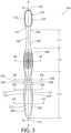
toothbrush 100 extends from a proximal end 101 (which is also the proximal end of the handle 110) to adistal end 103 along a longitudinal axis A-A (illustrated inFIG. 3 ). Conceptually, the longitudinal axis A-A is a reference line that is generally coextensive with the three-dimensional center line of the handle 110 (and the body of the head 120). Because thehandle 110 is a non-linear structure (as can be seen inFIGS. 1 and2 ) in the illustrated embodiment, the longitudinal axis A-A for the handle 110 (and the toothbrush 100) is also non-linear in the illustrated embodiment. However, the invention is not so limited, and in certain embodiments, the toothbrush may have a simple linear arrangement and thus a substantially linear longitudinal axis A-A. As best visible inFIG. 12-15 , thehandle 110 has a generally elliptical transverse cross-sectional shape along its longitudinal length. Other transverse cross-sectional shapes can be used in other embodiments. - The
head 120 is connected to thedistal end 102 of thehandle 110. As discussed in greater detail below, thehead 120 and at least a portion of thehandle 110 of thetoothbrush 100 are preferably formed as a single-component integral structure using an injection molding process, which in the exemplified embodiment is thesecond component 300. More specifically, in the exemplified embodiment, thehead 120 is integrally formed as part of thesecond component 300 of thehandle 110. Thesecond component 300 also comprises theneck 104 of thetoothbrush 100. As exemplified, the neck is a portion of thehandle 110 of thetoothbrush 100 that is narrowed relative to thehead 120 and the gripping portion of thehandle 110. - In other embodiments, the
handle 110 and thehead 120 may be formed as separate components which are operably connected at a later stage of the manufacturing process by any suitable technique known in the art, including without limitation thermal welding, sonic welding, a tight-fit assembly, a coupling sleeve, adhesion, or fasteners. Whether thehead 120 is integrally formed as part of thesecond component 300 of thehandle 110 or is a multi-piece assembly (including connection techniques) is not limiting of the present invention in all embodiments. Furthermore, in other embodiments, other manufacturing techniques may be used in place of and/or in addition to injection molding to create thehandle 110 and/or the head 120 (or components thereof), such as milling and/or machining. - The
head 120 generally comprises afront surface 121 and arear surface 122. Thefront surface 121 and therear surface 122 of thehead 120 can take on a wide variety of shapes and contours, none of which are limiting of the present invention unless specifically recited in the claims. For example, the front andrear surfaces front surface 121 andrear surface 122 are bound by aperipheral surface 123. - The set of
tooth cleaning elements 130, which are generically illustrated as a block, are provided on and extend outward from thefront surface 121 of thehead 120 for cleaning contact with an oral surface, preferably teeth. While the set oftooth cleaning elements 130 is particularly suited for brushing teeth, the set oftooth cleaning elements 130 can also be used to clean oral soft tissue, such as a tongue, gums, or cheeks instead of or in addition to teeth. Common examples of "tooth cleaning elements" include, without limitation, filament bristles, fiber bristles, nylon bristles, spiral bristles, core-sheath bristles, rubber bristles, elastomeric protrusions, flexible polymer protrusions, co-extruded filaments, flag bristles, crimped bristles, anti-bacterial bristles and combinations thereof and/or structures containing such materials or combinations. - The set of
tooth cleaning elements 130 can be connected to thehead 120 in any manner known in the art. In the exemplified embodiment (seeFIGS. 9-11 ), anchor free tufting (AFT) is used to mount the cleaning elements. In this embodiment, the body of thehead 120 comprises a depression (or basin) 125 for receiving a cleaning element assembly that comprises a carrier plate to which thetooth cleaning elements 130 are connected prior to being coupled to the body of thehead 120. The carrier plate is then positioned within thedepression 125 and secured to the body of thehead 120, such as by ultrasonic welding, thermal fusion, mechanical fit or adhesion. The bristles (or other elastomeric elements) of the set oftooth cleaning elements 130 extend through the carrier. The free ends of the set oftooth cleaning elements 130 on one side of the carrier plate perform the cleaning function. The ends of the set oftooth cleaning elements 130 on the other side of the carrier plate are melted together by heat, thereby retaining the set oftooth cleaning elements 130 in place. - In other embodiments, the set of
tooth cleaning elements 130 can be mounted to tuft blocks or sections by extending through suitable openings in the tuft blocks so that the base of the bristles is mounted within or below the tuft block. In still another embodiment, tuft holes may be formed in the body of the head and staples, or other anchors, can be sued to secure the bristles tufts therein. - While not in the exemplified embodiment, the
rear surface 122 of thehead 120 may also comprise additional structures for oral cleaning, such as a soft tissue cleanser, in other embodiments. Such soft tissue cleansers are typically constructed of a TPE and include one or more projections, such as nubs and/or ridges, for engaging and massaging soft oral tissue, such as the tongue. - As shown in
FIG. 3 , thehandle 110 can be conceptually delineated in longitudinal sections comprising aproximal section 115, amiddle section 116 and aneck section 117. Theproximal section 115 is the portion or segment of thehandle 110 that generally fits comfortably within the palm of the user. Themiddle section 116 forms the portion or segment of thehandle 110 that generally fits comfortably between the user's thumb and index finger. Theneck portion 117 forms the portion or segment of thehandle 110 that connects to thehead 120. - The
proximal section 115 longitudinally extends from theproximal end 101 of thetoothbrush 100 to themiddle section 116. Themiddle section 116 longitudinally extends from theproximal section 115 to theneck section 117. Theneck section 117 extends from themiddle section 116 to thehead 120. While thehead 120 is illustrated as being widened relative to theneck section 117 of thehandle 110, thehead 120 could in some constructions simply be a continuous extension or narrowing of theneck section 117 of thehandle 110. - As discussed in greater detail below, the
first component 200 is located within (and forms a part of) both theproximal section 115 and themiddle section 116. Thesecond component 300 is located within (and forms part of) each of theproximal section 115, themiddle section 116 and theneck section 117. Moreover, in the exemplified embodiment, the first andthird components neck section 117. Thethird component 400 is located (and forms part of) themiddle section 116. As exemplified, the third component is only located (and forms part of) in themiddle section 116. - Referring now to
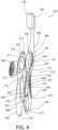
FIGS. 7-8 concurrently, thehandle 110 is illustrated in an exploded state so that its three components are visible. The three components of thehandle 110 include afirst component 200, asecond component 300 and athird component 400. In certain embodiments, thefirst component 200 can be considered a core structure, the second component can be considered an elongated handle body, and the third component can be considered a grip body. In other embodiments, themulti-component handle 110 of thetoothbrush 100 may further comprise an additional component (in addition to the first, second andthird components - In one embodiment, each of the first, second and
third components third components first component 300 is formed of a first hard plastic, thesecond component 400 is formed of a second hard plastic, and thethird component 400 is formed of an elastomeric material. - Suitable first hard plastics for formation of the
first component 200 include polyethylene, polyethylene terephthalate, polypropylene (PP), polyamide, polyester, cellulosics, SAN, acrylic, ABS, BR or any other of the hard plastics used in toothbrush manufacture. Suitable second hard plastics include polyethylene, polypropylene (PP), polyamide, polyester, cellulosics, SAN, acrylic, ABS, BR or any other of the hard plastics used in toothbrush manufacture. As used herein, the term "plastic" may include a blend of different plastics or a copolymer. Thethird component 400 is constructed of a first elastomeric material, such as a thermoplastic elastomer (TPE). In certain embodiments, the first elastomeric material of the third component may have a hardness durometer in a range of A11 to A15 Shore hardness. Of course, materials outside this hardness range could be used. As an example, one potential first elastomeric material for thethird component 400 can be styrene-ethylene/butylene-styrene (SEBS) manufactured by GLS Corporation. Nevertheless, other manufacturers can supply the SEBS material and other materials could be used. - In one embodiment, the first hard plastic is different than the second hard plastic. In an even more specific embodiment, the first hard plastic and the second hard plastic are different hard plastics that are chemically incompatible with one another such that they do not form a chemical bond with each other during an injection molding process.
- In certain embodiments, the hard plastic that forms one of the first and second components is an opaque hard plastic while the hard plastic that forms the other one of the first and second components is a transparent (or light transmissive) hard plastic. As used herein, the term "transparent hard plastic" includes hard plastics that are color tinted but still allow light to transmit therethrough. Suitable transparent hard plastics include without limitation clarified PP and clear polyesters, such as polyethylene terephthalate or a copolyester, such as poly-cyclohexylene dimethylene terephthalate, acid modified, polyester (PCTA) or styrene acrylonitrile (SAN), acrylonitrile butadiene styrene (ABS), polymethyl methacrylate (PMMA) or a cellulosic plastic, such as cellulose acetate propionate (CAP). One suitable opaque hard plastic is opaque PP. However, opaque versions of the hard plastics listed above for the first and second hard plastics may also be used.
- In one specific embodiment, the first hard plastic of the
first component 200 is a transparent hard plastic while the second hard plastic of thesecond component 300 is an opaque hard plastic. In one such embodiment, the first hard plastic of thefirst component 200 can be a transparent BR while the second hard plastic of thesecond component 300 can be an opaque PP. - In one embodiment, the first elastomeric material of the
third component 400 and the second hard plastic of thesecond component 300 are selected so as to be chemically compatible with one another such that so that a chemical bond is formed between the first elastomeric material and the second hard plastic during an injection molding process. In one such specific embodiment, the first elastomeric material can be a TPE while the second hard plastic can be PP. - Referring now to
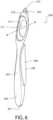
FIGS. 4-8 concurrently, thefirst component 200 and its structural cooperation with the second andthird components first component 200 is an elongated structure that, when assembled within thehandle 110 of the toothbrush, extends along the longitudinal axis A-A (seeFIG. 3 ). Thefirst component 200 extends longitudinally from aproximal end 201 to adistal end 202. Thefirst component 200 comprises a frontouter surface 203, a rearouter surface 204, a left-sideouter surface 205, and a right-sideouter surface 206. As will be discussed in greater detail below, when thehandle 110 of thetoothbrush 100 is fully assembled (as shown inFIGS. 1-3 ) portions of each of the frontouter surface 203, the rearouter surface 204, the left-sideouter surface 205, and the right-sideouter surface 206 remain exposed. Moreover, in certain embodiments where the first hard plastic is a transparent hard plastic, afirst window 250 may be formed through thehandle 110 via exposedportions first component 200 from the first and second opposingouter surfaces FIG. 13 ). Additionally, asecond window 260 may be formed through thehandle 110 via exposedportions first component 200 from the third and fourth opposingouter surfaces FIG. 13 ). - The
first component 200 comprises afirst component aperture 211. As discussed in greater detail below, thefirst component aperture 211 is provided to receive ananchor 303 of thesecond component 300 when thehandle 110 is assembled. As will become apparent from the below discussion, the mechanical cooperation between theanchor 303 of thesecond component 300 and asidewall 212 that defines thefirst component aperture 211 assists in ensuring a secure coupling between the first andsecond components second components - In the exemplified embodiment, the
first component aperture 211 is a through-hole that extends between the frontouter surface 203 and the rearouter surface 204 of thefirst component 200. In other embodiments, thefirst component aperture 211 may be a blind hole extending into the frontouter surface 203 of thefirst component 200 or a blind hole extending into the rearouter surface 204 of thefirst component 200. - The
first component aperture 211 extends along a first axis B-B. When thehandle 110 is assembled, the first axis B-B is transverse to the longitudinal axis A-A. In one specific embodiment, the first axis B-B may be substantially orthogonal to the longitudinal axis A-A. In the exemplified embodiment, thesidewall 212 comprises an annular structure that circumferentially surrounds thefirst component aperture 211 about the first axis B-B. This annular structure terminates in an upperannular surface 216 that remains exposed when thehandle 110 is assembled. - The
sidewall 212 of thefirst component 200 comprises a firsttransverse protuberance 213 and a secondtransverse protuberance 214 located adjacent thefirst component aperture 211 and extending from the rearouter surface 204 of thefirst component 200. The first and secondtransverse protuberances transverse protuberances first component aperture 211 but may be at other locations in other embodiments. When thehandle 110 is assembled, the first and secondtransverse protuberances transverse openings FIG. 11 ). Moreover, when thehandle 110 the first and secondtransverse protuberances second component aperture 304 of thesecond component 300. As seen inFIG. 11 , the first and secondtransverse protuberances transverse openings transverse protuberances second components transverse protuberances - As can also be seen in
FIGS. 11 and12 , thesidewall 212 of the first component nests within agroove 310 formed in anouter surface 309 of theanchor 303 of thesecond component 300, thereby further assisting in ensuring a secure coupling between the first andsecond components - The
first component 200 further comprises alongitudinal protuberance 215 extending from thedistal end 202 of thefirst component 200. When thehandle 110 is assembled, thelongitudinal protuberance 215 extends into alongitudinal recess 316 formed in atransverse wall 315 of the second component 300 (seeFIG. 11 ). When thehandle 110 is assembled, thelongitudinal protuberance 215 is embedded within thesecond component 300. - Referring now to
FIGS. 4-5 and9-12 , certain structural details of thesecond component 300 will be described, along with its structural cooperation with the first andthird components second component 300 is an elongated handle structure that generally comprises abody portion 301 and astrap network 302 extending longitudinally from thebody portion 301. Thebody portion 301 further comprises ananchor 303 which, as discussed above, extends into thefirst component opening 211 when thehandle 110 is assembled. - The
body portion 301 is located within (and forms part of) themiddle section 116 andneck section 117 of thehandle 110 while thestrap network 302 is located within (and forms part of) the proximalmiddle section 115 of the handle 110 (seeFIG. 3 ). Thebody portion 301 also comprises thehead 120 of thetoothbrush 110 in the exemplified embodiment as discussed above. - The anchor of the
second component 300 comprises asecond component aperture 304. In the exemplified embodiment, thesecond component aperture 304 is a through-hole that extends between a frontouter surface 305 and a rearouter surface 306 of thesecond component 300. In other embodiments, thesecond component aperture 304 may be a blind hole extending into the frontouter surface 305 of thesecond component 300 or a blind hole extending into the rearouter surface 306 of thesecond component 300. - The
second component aperture 304 extends along a second axis C-C. When thehandle 110 is assembled, the second axis C-C is transverse to the longitudinal axis A-A. In one specific embodiment, the second axis C-C may be substantially orthogonal to the longitudinal axis A-A. In certain embodiments, when thehandle 100 is assembled, the first and second axes B-B, C-C may be substantially parallel to one another and/or substantially coextensive. - In the exemplified embodiment, the
second component aperture 304 has a cross-sectional area (measured transverse to the second axis B-B) that tapers with increasing depth from the opposing front and rearouter surfaces second component 300. As a result anapex edge 311 is formed that is embedded by thethird component 400 within thehandle 100. This structure assists with retaining thethird component 400 within thesecond component aperture 304. In other embodiments, however, the cross-sectional area of the second component aperture 304 (measured transverse to the second axis B-B) may be substantially constant, may be stepped, or may increase and decrease in a repetitive manner. - In the exemplified embodiment, the
anchor 304 comprises asidewall 307 that defines an annular structure that circumferentially surrounds thesecond component aperture 304 about the second axis C-C. Thesidewall 307 comprises aninner surface 308 that defines thesecond component aperture 304 and anouter surface 309. A groove 310 (or channel) is formed into theouter surface 309 of theanchor 304. As discussed above, thesidewall 212 of thefirst component 200 nests within thegroove 310 when thehandle 110 is assembled. - The sidewall 307 (which defines an annular structure in the exemplified embodiment) comprises an
upper surface 312 that remains exposed on the frontouter surface 104 of thehandle 110. Additionally, when thehandle 110 is assembled, thesidewall 307 of theanchor 303 isolates thethird component 400 from the first component 200 (best shown inFIG. 11-12 ), with the exception of the terminal surfaces of thetransverse protuberances first component 200. - As mentioned above, the
sidewall 307 of theanchor 303 comprises first and secondtransverse openings inner surface 308 to theouter surface 309. These first and secondtransverse openings transverse protuberances first component 200 when thehandle 110 is assembled (seeFIG. 11 ). As can be seen, in this embodiment, the terminal surface of the first and secondtransverse protuberances second component aperture 304 of theanchor 303. While in the exemplified embodiment, twotransverse openings - As shown in
FIG. 11 , thesecond component 300 further comprises an internaltransverse wall 315. Alongitudinal recess 316 is formed into thetransverse wall 315 of thesecond component 300. When thehandle 110 is assembled, thelongitudinal protuberance 215 of thefirst component 200 extends into and is located within thelongitudinal recess 316, thereby assisting in ensuring a secure coupling between the first andsecond components longitudinal protuberance 215 is embedded within thehandle 110. - Referring now to
FIGS. 4-5 and9-15 , thesecond component 300 further comprises thestrap network 302. Thestrap network 302 is formed by a plurality of strips that, when the handle is assembled, wraps around thefirst component 200 to assist with ensuring that first andsecond components - In the exemplified embodiment of the
strap network 302, thestrap network 302 comprises a firstlongitudinal strip 321, a secondlongitudinal strip 322 and a thirdlongitudinal strip 323. As can best be seen inFIGS. 13-14 , when thehandle 110 is assembled the first, second and thirdlongitudinal strips first component 200 in a circumferentially spaced-apart manner about the longitudinal axis A-A. In one embodiment, the first, second andthird strips third strips - The
first strip 321 extends longitudinally from thebody portion 301 of thesecond component 300 toward theproximal end 101 of thehandle 110 until it joins with thesecond strip 322 at theproximal end 101. Similarly, thesecond strip 322 extends longitudinally from thebody portion 301 of thesecond component 300 toward theproximal end 101 of thehandle 110 until it joins with thefirst strip 321 at theproximal end 101. As a result, the first andsecond strips first strap 324 that wraps around theproximal end 201 of thefirst component 200, and also forms a portion of theproximal end 101 of thehandle 110. - The
third strip 323 also extends longitudinally from thebody portion 301 of thesecond component 300 toward theproximal end 101 of thehandle 110. However, as a distance from theproximal end 101 of the handle, the third strip divides/branches into afirst branch 325 and asecond branch 326. Thefirst branch 325 of thethird strip 323 converges with thefirst strip 321 at afirst strap node 327. As a result, thethird strip 323 and thefirst strip 321 collectively form asecond strap 328 that forms a loop (in conjunction with the body portion 301) on a firstlateral surface 111 of thehandle 110. Similarly, thesecond branch 326 of thethird strip 323 converges with thesecond strip 322 at asecond strap node 329. As a result, thethird strip 323 and thefirst strip 321 collectively form athird strap 330 that forms a loop (in conjunction with the body portion 301) on a secondlateral surface 112 of thehandle 110. Additionally, as can be seen, the first, second andthird straps loop 331 on the rearouter surface 114 of thehandle 110. It is to be noted that while one embodiment of astrap network 302 is exemplified, thestrap network 302 can take on a wide range of potential structural manifestations. - Referring now to
FIGS. 13 and15 concurrently, when thefirst component 200 is constructed of a first hard plastic that is substantially transparent and thesecond component 300 is constructed of a second hard plastic that is substantially opaque, the plurality ofstrips first window 250 through thefirst component 200 from first and second lateral surfaces 111, 112 of thehandle 110 and asecond window 260 through the front andrear surfaces handle 110. - Referring now to
FIGS. 13 and14 concurrently, thefirst component 200 is provided with a plurality ofgrooves 250 that are formed into the outer surface of thefirst component 200. Thesegrooves 250 are provided so that when thehandle 110 is assembled, the plurality ofstrips second components - While the exemplified embodiment of the
toothbrush 100 has asecond component 300 that comprises both theanchor 303 and thestrap network 302, in certain embodiments thestrap network 302 may be omitted. - Turning now to
FIGS. 1-2 ,5 and11-12 concurrently, thethird component 400 will be described in greater detail. Thethird component 400 is a generally bulbous shaped body that bulges out of theapertures second components third component 400 fills thesecond component aperture 304 of thesecond component 300 and, thus, takes on the shape of thesecond component aperture 304. Thethird component 400 has a convexfront surface 471 and a convexrear surface 472, which resemble an oval or elliptical shape. The bulbous shape of thethird component 400 enables the user to reliably roll and control thehandle 110 between the thumb and index fingers during use. Thethird component 400 may also be non-bulging or have any number of shapes, such as circular, a true oval shape and the like. - In one preferred construction, the
third component 400 has a multiplicity offinger grip protrusions 473 projecting from the front andrear surfaces finger grip protrusions 473 provide a tactile feature to increase the friction on the user's finger surfaces and thus enhance the user's ability to grip thehandle 110, particularly under wet conditions. Thefinger grip protrusions 473 are preferably provided in a desired conical or frusto-conical shape for improved grip performance. In other embodiments, other roughened surfaces and geometries could be used. - A method of manufacturing the
toothbrush 100 according to one embodiment of the present invention will be described. The first component created in manufacturing thetoothbrush 100 is thefirst component 200. To create thefirst component 200, a first mold is provided having a first mold cavity and at least one port/nozzle for injecting the first hard plastic in a liquefied state into the first mold cavity. In one embodiment, a single port is used to inject the liquefied first hard plastic, which may be BR. The first mold cavity has a volume that is sized and shaped to correspond to thefirst component 200 as described above and illustrated herein. The first mold may be two-part mold, as is known in the art. Once the first mold cavity is created/provided, liquefied first hard plastic is injected into the first mold so as to fill the first mold cavity. The liquefied first hard plastic is allowed to cool to an appropriate temperature so as to form thefirst component 200, as described above and illustrated herein, for further handling. - Once the
first component 200 is created (and allowed to adequately cool for further handling), thefirst component 200 is supported by one or more clamping members that engage one or more points of contact onfirst component 200 with at least one set of arms. - Once the clamping member is properly supporting the
first component 200, thefirst component 200 is positioned within a second mold cavity of a second mold. This positioning can be effectuated by either moving thefirst component 200 into the second mold cavity or by creating the second mold cavity about thefirst component 200 while supporting thefirst component 200 in a stationary manner, which can be accomplished by translating and mating multiple pieces of the second mold into position so that the second mold cavity is formed about thefirst component 200. The second mold cavity has a volume that is sized and shaped to correspond to thesecond component 300. One or more ports are present in the second mold for injecting the second hard plastic in a liquefied state into the second mold cavity. In one embodiment, a single port is used to inject the liquefied PP. - Once the
first component 200 is in proper position within the second mold cavity (and the second mold cavity is adequately sealed), the liquefied second hard plastic (which may be PP) is injected into the second mold cavity so as to fill the remaining volume of the second mold cavity that is not occupied by thefirst component 200. The liquefied second hard plastic forms thestrap network 302 about thefirst component 200 and theanchor 303 within the first component aperture 211 (as described above). - The liquefied second hard plastic is then allowed to cool to an appropriate temperature, thereby forming the
second component 300 about thefirst component 200, as described above. Thefirst component 200 andsecond component 300 collectively form a handle assembly. If the first and second plastics are selected so as to be chemically incompatible with one another, the second hard plastic ofsecond component 300 does not chemically bond with the first hard plastic of thefirst component 400 during the injection molding process. - Once the handle assembly is sufficiently cool for further handling, at least the
middle section 116 is positioned within a third mold cavity of a third mold. When in the third mold cavity, the first elastomeric material in a liquefied state is injected therein to fill thesecond component aperture 304, which is enclosed by an appropriate mold, via a port. The first elastomeric material, in one embodiment, chemically bonds with the second hard plastic of thesecond component 300 during this injection molding process. - The inventive aspects discussed above may be practiced for a manual toothbrush or a powered toothbrush. In operation, the previously described features, individually and/or in any combination, may improve the control, grip performance, aesthetics and cost point of oral implements. Other constructions of toothbrush are possible. For example, the
head 120 may be replaceable or interchangeable on thehandle 110. Thehead 120 may include various oral surface engaging elements, such as inter-proximal picks, brushes, flossing element, plaque scrapper, tongue cleansers and soft tissue massages. While the various features of thetoothbrush 100 work together to achieve the advantages previously described, it is recognized that individual features and sub-combinations of these features can be used to obtain some of the aforementioned advantages without the necessity to adopt all of these features in an oral care implement.
Claims (14)
- An oral care implement (100) comprising:a handle (110) extending along a longitudinal axis (A-A);a head (120) at a distal end (102) of the handle (110);at least one tooth cleaning element (130) extending from the head (120);the handle (110) comprising:a first component (200) constructed of a first hard plastic, the first component (200) comprising a first component aperture (211);a second component (300) constructed of a second hard plastic, the second component (300) comprising the head (120) and an anchor (303), the anchor (303) located within the first component aperture (211) and comprising a second component aperture (304); anda third component (400) constructed of a first elastomeric material, the third component (400) located within the second component aperture (304);characterized in thatthe first component (200) comprises two transverse protuberances (213, 214) located on opposite sides of the second component aperture (304), the second component (300) comprising first and second transverse openings (313, 314), and the first and second transverse protuberances (213, 214) located within the first and second transverse openings (313, 314), and,when the handle (110) is assembled, a sidewall (307) of the anchor (303) isolates the third component (400) from the first component (200), with the exception of the terminal surfaces of the transverse protuberances (213, 214) of the first component (200).
- The oral care implement (100) according to claim 1 wherein the first component aperture (211) is a through-hole that extends between opposing outer surfaces (203, 204) of the first component (200).
- The oral care implement (100) according to claim 2 wherein the second component aperture (304) is a through-hole that extends between opposing outer surfaces (305, 306) of the second component (300).
- The oral care implement (100) according to claim 3 wherein the second component aperture (304) has a cross-sectional area that tapers with increasing depth from the opposing outer surfaces (305, 306) of the second component (300) to form an apex edge (311).
- The oral care implement (100) according to any one of claims 1 to 4 wherein the anchor (303) comprises an annular structure that defines the second component aperture (304), and optionally wherein the annular structure comprises an upper surface (312) that remains exposed.
- The oral care implement (100) according to any one of claims 1 to 5 wherein the first component aperture (211) extends along a first axis (B-B), the first axis (B-B) being transverse to the longitudinal axis (A-A).
- The oral care implement (100) according to any one of claims 1 to 6 wherein the second component aperture (304) extends along a second axis (C-C), the second axis (C-C) being transverse to the longitudinal axis (A-A).
- The oral care implement (100) according to any one of claims 1 to 7 wherein the first component (200) comprises a longitudinal protuberance (215) extending from a distal end (202) of the first component (200), the second component (300) comprising a longitudinal recess (316) in a transverse wall (315) of the second component (300), and the longitudinal protuberance (215) being located within the longitudinal recess (316).
- The oral care implement (100) according to any one of claims 1 to 8 wherein the third component (400) has first and second opposing grip surfaces that remain exposed.
- The oral care implement (100) according to any one of claims 1 to 9 wherein the first hard plastic and the second hard plastic do not form a chemical bond with each other during an injection molding process.
- The oral care implement (100) according to any one of claims 1 to 10 wherein the first elastomeric material and the second hard plastic form a chemical bond with each other during an injection molding process.
- The oral care implement (100) according to any one of claims 1 to 11 wherein the second component (300) further comprises a strap network (302) wrapping around the first component (200).
- The oral care implement (100) according to any one of claims 1 to 12 wherein one of the first or second hard plastics is substantially transparent and the other one of the first or second hard plastics is substantially opaque.
- The oral care implement (100) according to any one of claims 1 to 13 wherein the first component (200) comprises an annular structure that defines the first component aperture (211), and wherein the anchor (303) comprises an annular structure having an outer surface having an annular groove (310), the annular structure of the first component (200) nesting in the annular groove (310) of the anchor (303).
Applications Claiming Priority (1)
| Application Number | Priority Date | Filing Date | Title |
|---|---|---|---|
| PCT/US2014/072057WO2016105364A1 (en) | 2014-12-23 | 2014-12-23 | Oral care implement having multi-component handle |
Publications (2)
| Publication Number | Publication Date |
|---|---|
| EP3223651A1 EP3223651A1 (en) | 2017-10-04 |
| EP3223651B1true EP3223651B1 (en) | 2023-05-31 |
Family
ID=52345581
Family Applications (1)
| Application Number | Title | Priority Date | Filing Date |
|---|---|---|---|
| EP14825571.4AActiveEP3223651B1 (en) | 2014-12-23 | 2014-12-23 | Oral care implement having multi-component handle |
Country Status (10)
| Country | Link |
|---|---|
| US (1) | US10660430B2 (en) |
| EP (1) | EP3223651B1 (en) |
| CN (2) | CN107105873B (en) |
| AU (1) | AU2014414815B2 (en) |
| BR (1) | BR112017012630A2 (en) |
| CA (1) | CA2970625C (en) |
| MX (1) | MX384552B (en) |
| RU (1) | RU2672953C1 (en) |
| TW (1) | TW201635948A (en) |
| WO (1) | WO2016105364A1 (en) |
Families Citing this family (32)
| Publication number | Priority date | Publication date | Assignee | Title |
|---|---|---|---|---|
| EP2886289B1 (en)* | 2013-12-19 | 2016-08-03 | The Gillette Company | Method to manufacture an injection molded component and injection molded component |
| US11291293B2 (en) | 2014-12-23 | 2022-04-05 | Colgate-Palmolive Company | Oral care implement |
| EP3219226A1 (en)* | 2016-03-15 | 2017-09-20 | Trisa Holding AG | Mouth hygiene handle device |
| US10807261B2 (en) | 2017-06-21 | 2020-10-20 | Harry's, Inc. | Razor handle |
| EP3501336B1 (en) | 2017-12-20 | 2024-09-18 | The Gillette Company LLC | Oral care implement |
| EP3501334B1 (en) | 2017-12-20 | 2020-06-24 | The Gillette Company LLC | Oral care implement |
| EP3501335B1 (en) | 2017-12-20 | 2020-06-17 | The Gillette Company LLC | Oral care implement |
| EP3501333B1 (en) | 2017-12-20 | 2020-06-24 | The Gillette Company LLC | Oral care implement |
| EP3524091B1 (en) | 2018-02-09 | 2025-04-09 | The Gillette Company LLC | Manual oral care implement |
| US11388985B2 (en) | 2018-02-09 | 2022-07-19 | The Gillette Company Llc | Connector for a manual oral care implement |
| US11400627B2 (en) | 2018-02-09 | 2022-08-02 | The Gillette Company Llc | Method for manufacturing an oral care implement |
| EP3524092B1 (en) | 2018-02-09 | 2025-10-01 | The Gillette Company LLC | Connector for a manual oral care implement |
| USD960581S1 (en) | 2018-02-09 | 2022-08-16 | The Gillette Company Llc | Toothbrush head |
| EP3524093A1 (en) | 2018-02-09 | 2019-08-14 | The Gillette Company LLC | A method for manufacturing an oral care implement |
| US10925384B2 (en) | 2018-04-16 | 2021-02-23 | Colgate-Palmolive Company | Oral care implement |
| EP3616561B1 (en) | 2018-09-03 | 2022-09-28 | The Gillette Company LLC | Head for an oral care implement and a kit comprising such head |
| US11659922B2 (en) | 2018-09-03 | 2023-05-30 | The Gillette Company, LLC. | Head for an oral-care implement and a kit comprising such head |
| EP3714732B1 (en) | 2019-03-29 | 2024-11-20 | The Gillette Company LLC | Head for an oral care implement and oral care implement |
| EP3818904B1 (en) | 2019-11-06 | 2024-12-18 | The Gillette Company LLC | Handle for an electrically operated personal care implement |
| EP3854346B1 (en) | 2020-01-22 | 2022-09-21 | The Gillette Company LLC | Method for making a handle for an electrically operated personal care implement |
| EP3995282B1 (en) | 2020-11-06 | 2025-08-20 | The Gillette Company LLC | A method for manufacturing a handle for a personal care implement |
| EP3995041A1 (en)* | 2020-11-06 | 2022-05-11 | The Gillette Company LLC | Polymeric handle material and use thereof |
| EP3995040B1 (en)* | 2020-11-06 | 2025-05-14 | The Gillette Company LLC | Handle for a personal care implement and personal care implement |
| EP3912512A1 (en)* | 2020-05-20 | 2021-11-24 | Trisa Holding AG | Hygiene product, in particular oral hygiene product |
| USD957135S1 (en) | 2020-07-02 | 2022-07-12 | The Gillette Company Llc | Toothbrush head |
| USD1014095S1 (en) | 2020-07-02 | 2024-02-13 | The Gillette Company Llc. | Toothbrush |
| PL3995042T3 (en)* | 2020-11-06 | 2025-07-21 | The Gillette Company Llc | Handle for a personal care implement and personal care implement |
| PL3995037T3 (en) | 2020-11-06 | 2025-06-02 | The Gillette Company Llc | Handle for a personal care implement and personal care implement |
| PL3995038T3 (en)* | 2020-11-06 | 2025-06-16 | The Gillette Company Llc | PERSONAL HYGIENE DEVICE HANDLE AND PERSONAL HYGIENE DEVICE |
| ES2967286T3 (en)* | 2020-11-06 | 2024-04-29 | Gillette Co Llc | Handle for a personal care utensil and personal care utensil |
| CA218833S (en) | 2020-11-06 | 2023-11-08 | Gillette Co Llc | Toothbrush head |
| USD1051608S1 (en) | 2021-05-04 | 2024-11-19 | The Gillette Company Llc | Handle for battery operated toothbrush |
Family Cites Families (263)
| Publication number | Priority date | Publication date | Assignee | Title |
|---|---|---|---|---|
| US758764A (en) | 1901-12-21 | 1904-05-03 | William A Macleod | Tooth-brush. |
| US846900A (en) | 1906-02-06 | 1907-03-12 | William O Bloom | Tooth-brush. |
| US1125532A (en) | 1913-02-03 | 1915-01-19 | Earl Himmel | Tooth-brush. |
| US1924152A (en) | 1931-11-02 | 1933-08-29 | David M Coney | Toothbrush |
| US1901230A (en) | 1932-04-05 | 1933-03-14 | Duey Harold Palmer | Toothbrush |
| US2161349A (en) | 1937-01-06 | 1939-06-06 | Gilbert E Hadden | Tooth brush |
| CH215110A (en) | 1938-12-09 | 1941-06-15 | Spyra Paul | Toothbrush. |
| US2305461A (en) | 1938-12-09 | 1942-12-15 | Spyra Paul | Toothbrush |
| US2186005A (en) | 1939-04-25 | 1940-01-09 | Glenn L Casto | Tooth brush |
| CA1134317A (en) | 1978-01-16 | 1982-10-26 | Sylvia Martin | Zinc electroplating bath |
| USD273635S (en) | 1981-05-15 | 1984-05-01 | Avantgarde S.P.A. | Toothbrush |
| US4517701A (en) | 1983-04-25 | 1985-05-21 | Stanford Roy E Jr | Toothbrushes for cleaning sulcular areas of the teeth |
| DE3717475A1 (en) | 1987-05-23 | 1988-12-08 | Schlerf Coronet Werke | BRISTLE PRODUCT AND METHOD FOR THEIR PRODUCTION |
| US5862559A (en) | 1988-09-23 | 1999-01-26 | Hunter; Frank | Toothbrush for interproximal and periodontal pocket cleaning |
| GB9106511D0 (en) | 1991-03-27 | 1991-05-15 | Lingner & Fischer Gmbh | Novel article |
| US5144712A (en) | 1991-05-06 | 1992-09-08 | Hansel Gail W | Disposable toothbrush |
| US6178582B1 (en) | 1992-03-25 | 2001-01-30 | Smithkline Beecham Consumer Healthcare Gmbh | Toothbrush comprising a resilient flex region |
| US5339482A (en) | 1992-07-21 | 1994-08-23 | Johnson & Johnson Consumer Products, Inc. | Toothbrush having non-slip surface |
| AU685493B2 (en) | 1993-09-02 | 1998-01-22 | Lingner & Fischer Gmbh | Bristle arrangement for a toothbrush |
| GB2282959B (en) | 1993-10-19 | 1998-06-17 | Addis Ltd | Improvements in or relating to toothbrushes |
| US5392483A (en) | 1994-07-07 | 1995-02-28 | Chesebrough-Pond's Usa Co., Division Of Conopco, Inc. | Multi-level bristle tuft toothbrush |
| GB9414140D0 (en) | 1994-07-13 | 1994-08-31 | Procter & Gamble | Toothbrush |
| ATE207321T1 (en) | 1994-12-01 | 2001-11-15 | Procter & Gamble | TOOTHBRUSH WITH EXTENDED BRISTLES |
| JPH08164025A (en) | 1994-12-14 | 1996-06-25 | Lion Corp | toothbrush |
| DE4444926A1 (en) | 1994-12-16 | 1996-06-27 | Coronet Werke Gmbh | Brush for dental and personal care |
| US5604951A (en) | 1994-12-30 | 1997-02-25 | Shipp; Anthony D. | Prophy toothbrush |
| US5628082A (en) | 1995-03-22 | 1997-05-13 | Colgate-Palmolive Company | Toothbrush with improved efficacy |
| US6032313A (en) | 1995-05-26 | 2000-03-07 | Tsang; Koon Keung | Household appliance having plural coaxially rotatable or parallel linearly movable heads or tools |
| US5584690A (en) | 1995-10-12 | 1996-12-17 | Maassarani; Sami | Dental cleaning assembly |
| GB9524580D0 (en) | 1995-12-01 | 1996-01-31 | Unilever Plc | A toothbrush with flexibly mounted bristles |
| JP3528378B2 (en) | 1995-12-01 | 2004-05-17 | サンスター株式会社 | toothbrush |
| US6996870B2 (en) | 1995-12-29 | 2006-02-14 | Colgate-Palmolive Company | Contouring toothbrush head |
| USD456139S1 (en) | 2001-09-14 | 2002-04-30 | Colgate-Palmolive Company | Toothbrush with a combination of filaments and elastomeric tufts |
| TW384214B (en) | 1995-12-29 | 2000-03-11 | Colgate Palmolive Co | Contouring toothbrush head |
| US6408476B1 (en) | 1996-01-18 | 2002-06-25 | The Procter & Gamble Company | Toothbrush with elastomer filled flexible head |
| US5781958A (en) | 1996-02-14 | 1998-07-21 | Gillette Canada Inc. | Brush handle |
| US5930860A (en) | 1996-03-27 | 1999-08-03 | Shipp; Anthony D. | Prophy bristle toothbrush |
| JPH1042957A (en) | 1996-08-06 | 1998-02-17 | Lion Corp | toothbrush |
| US5839149A (en) | 1996-08-26 | 1998-11-24 | Scheier; Paul A. | Toothbrush with resilient flexible bristle support |
| GB9620092D0 (en) | 1996-09-26 | 1996-11-13 | Unilever Plc | A brush and method for producing same |
| US5746532A (en) | 1996-10-01 | 1998-05-05 | Megill; Joseph M. | Toothbrush assembly |
| USD390706S (en) | 1996-10-24 | 1998-02-17 | Colgate-Palmolive Company | Toothbrush |
| US5735012A (en) | 1997-04-01 | 1998-04-07 | Chesebrough-Pond's Usa Co., Division Of Conopco, Inc. | Resiliently flexible toothbrush |
| US6886207B1 (en) | 1999-06-14 | 2005-05-03 | The Procter & Gamble Company | Toothbrush |
| US5908038A (en) | 1997-06-16 | 1999-06-01 | Chesebrough-Pond's Usa Co. | Unitarily molded toothbrush |
| US5863102A (en) | 1997-06-24 | 1999-01-26 | Colgate-Palmolive Company | Method and apparatus to permit attachment of bristles to toothbrushes with resiliently flexible heads and to thereafter permit the trimming and end rounding of such bristles |
| US5946758A (en) | 1997-06-24 | 1999-09-07 | Colgate-Palmolive Company | Toothbrush having contouring multi-component head with peel-resistant joint and limited flexibility |
| DE19734287A1 (en) | 1997-08-07 | 1999-02-11 | Coronet Werke Gmbh | Brush, especially for an electric toothbrush |
| RU2228129C2 (en) | 1997-11-12 | 2004-05-10 | ДЖИЛЛЕТ КАНАДА Инк. | Tooth-brush (variants) |
| US6015293A (en) | 1997-12-31 | 2000-01-18 | Amtec Products, Inc. | Oral cleaning apparatus |
| US5967152A (en) | 1997-12-31 | 1999-10-19 | Amtec Products, Inc. | Oral cleaning apparatus |
| FR2773961B1 (en) | 1998-01-26 | 2000-03-10 | Synthelabo | TOOTHBRUSH COMPRISING IMPROVED MEANS FOR FIXING FRICTION ELEMENTS |
| BR9908513A (en) | 1998-03-06 | 2000-11-21 | Gillette Canada | Toothbrush, and, process for using the same |
| US6041468A (en) | 1998-03-12 | 2000-03-28 | Colgate-Palmolive Company | Prophy toothbrush |
| USD404206S (en) | 1998-04-17 | 1999-01-19 | Colgate-Palmolive Company | Toothbrush |
| USD404205S (en) | 1998-04-17 | 1999-01-19 | Colgate-Palmolive Company | Toothbrush |
| EP1075374B1 (en) | 1998-04-28 | 2003-11-19 | Gillette Canada Company | Apparatus for substantially simultaneously forming multiple articles having different properties |
| US5915868A (en) | 1998-05-07 | 1999-06-29 | Frazell; Dale M. | Portable toothbrush with dentifrice |
| US6601272B2 (en) | 1998-05-08 | 2003-08-05 | John O. Butler Company | Dental hygiene system handle |
| DE19827009A1 (en) | 1998-06-17 | 1999-12-23 | Coronet Werke Gmbh | Toothbrush with a replaceable brush part |
| US5984935A (en) | 1998-07-10 | 1999-11-16 | Welt; Teodor | Tongue cleaner |
| US6131228A (en) | 1998-09-17 | 2000-10-17 | Chen; Joseph | Brush for cleaning the tongue root |
| DE29817994U1 (en)* | 1998-10-08 | 1999-04-22 | Trisa Holding Ag, Triengen | toothbrush |
| CA2253042C (en) | 1998-11-05 | 2007-04-17 | Jobst Ulrich Gellert | Method of three layer injection molding with sequential and simultaneous coinjection |
| WO2000034022A1 (en) | 1998-12-10 | 2000-06-15 | Trisa Holding Ag | Plastic object for use in personal hygiene |
| DE19858102A1 (en) | 1998-12-16 | 2000-06-21 | Zahoransky Anton Gmbh & Co | Multi-component brush body, especially for tooth brush comprises thin walled basic body and additional material areas whose cooling times after injection run simultaneously |
| US6088870A (en) | 1999-02-10 | 2000-07-18 | Colgate-Palmolive Company | Toothbrush head with flexibly mounted bristles |
| WO2000049911A1 (en) | 1999-02-24 | 2000-08-31 | Susumu Inoue | Rubber-nylon-mixture bristle toothbrush |
| US20050015907A1 (en) | 1999-04-22 | 2005-01-27 | Glaxosmithkline Consumer Healthcare Gmbh & Co. Kg | Toothbrush |
| US6292973B1 (en) | 1999-04-29 | 2001-09-25 | Robert Moskovich | Toothbrush having controlled head movement |
| US6859969B2 (en) | 1999-06-11 | 2005-03-01 | James A. Gavney, Jr. | Multi-directional wiping elements and device using the same |
| US7814603B2 (en) | 1999-06-11 | 2010-10-19 | Gavney Jr James A | Powered toothbrush with polishing elements |
| US6319332B1 (en) | 1999-06-11 | 2001-11-20 | James Albert Gavney, Jr. | Squeegee device and system |
| US7877833B2 (en) | 1999-06-11 | 2011-02-01 | Gavney Jr James A | Oral-care device and system |
| US6571417B1 (en) | 1999-06-11 | 2003-06-03 | James Albert Gavney, Jr. | Dentition cleaning device and system |
| US7181799B2 (en) | 1999-06-11 | 2007-02-27 | Eegee, Llc | Oral-care device and system |
| CN1142737C (en) | 1999-07-02 | 2004-03-24 | 荷兰联合利华有限公司 | Electric tooth brush |
| AU141876S (en) | 1999-07-06 | 2000-09-21 | Unilever Plc | Toothbrush |
| USD464428S1 (en) | 1999-08-10 | 2002-10-15 | Respironics, Inc. | Nasal mask cushion |
| US6397425B1 (en) | 1999-08-31 | 2002-06-04 | Gillette Canada Company | Polypropylene brush body |
| WO2001017391A1 (en) | 1999-09-08 | 2001-03-15 | The Procter & Gamble Company | A handle for a toothbrush |
| USD451286S1 (en) | 1999-10-08 | 2001-12-04 | Colgate-Palmolive Company | Set of toothbrush bristles |
| US6276021B1 (en) | 1999-10-08 | 2001-08-21 | Colgate-Palmolive Company | Toothbrush having a bristle pattern providing enhanced cleaning |
| CN1184255C (en) | 1999-10-20 | 2005-01-12 | 宝洁公司 | Flexible brush comprising a mixture of polymers |
| WO2001045573A1 (en) | 1999-12-22 | 2001-06-28 | The Procter & Gamble Company | Tongue cleaning device |
| US6370726B1 (en) | 2000-02-11 | 2002-04-16 | Lata R Kini | Dynamic toothbrush |
| JP4429471B2 (en) | 2000-04-27 | 2010-03-10 | ライオン株式会社 | toothbrush |
| US6564416B1 (en) | 2000-05-22 | 2003-05-20 | Gillette Canada Company | Toothbrush |
| DE10034839A1 (en) | 2000-07-18 | 2002-01-31 | Schiffer Fa M & C | Process for the production of thick-walled brushes, in particular toothbrushes |
| USD486649S1 (en) | 2000-09-11 | 2004-02-17 | Colgate-Palmolive Company | Toothbrush |
| DE10046536A1 (en) | 2000-09-19 | 2002-03-28 | Coronet Werke Gmbh | Brushware-production method involves assembling single bristles or in groups on supports and structuring their ends by laser treatment. |
| US6749788B1 (en) | 2000-10-26 | 2004-06-15 | The Gillette Company | Method and apparatus for making a shaving razor handle |
| EP1339346B1 (en) | 2000-12-07 | 2006-05-17 | GlaxoSmithKline Consumer Healthcare GmbH & Co.KG. | Brush part for an electric toothbrush |
| DE10065517A1 (en) | 2000-12-28 | 2002-07-04 | Trisa Holding Ag Triengen | Method of making a toothbrush |
| GB2371217B (en) | 2001-01-08 | 2004-04-28 | Mcdougall Gregory J | Toothbrush |
| USD450457S1 (en) | 2001-01-09 | 2001-11-20 | Colgate-Palmolive Company | Set of toothbrush bristles |
| USD457323S1 (en) | 2001-01-09 | 2002-05-21 | Colgate-Palmolive Company | Toothbrush handle |
| USD461313S1 (en) | 2001-01-09 | 2002-08-13 | Colgate-Palmolive Company | Toothbrush handle |
| US6596213B2 (en) | 2001-04-06 | 2003-07-22 | Kortec, Inc. | Method of molding multi-layer polymer plastic articles with control of relative shifting of the core layer |
| US6766549B2 (en) | 2001-04-20 | 2004-07-27 | Michael F. Klupt | Toothbrush system with a three-dimensional brushing action and fluid irrigation |
| USD456138S1 (en) | 2001-06-19 | 2002-04-30 | Colgate-Palmolive Company | Toothbrush head |
| US7143462B2 (en) | 2002-09-20 | 2006-12-05 | Colgate-Palmolive Company | Oral care implement |
| USD517812S1 (en) | 2003-09-10 | 2006-03-28 | Colgate-Palmolive Company | Toothbrush |
| US7908699B2 (en) | 2001-07-03 | 2011-03-22 | Colgate-Palmolive Company | Oral care implement |
| USD474608S1 (en) | 2001-09-20 | 2003-05-20 | Colgate-Palmolive Company | Toothbrush |
| US6599048B2 (en) | 2001-10-18 | 2003-07-29 | Youti Kuo | Toothbrush for massaging and protecting gums |
| US6595087B2 (en) | 2001-11-21 | 2003-07-22 | Snap-On Technologies, Inc. | Encapsulated dead blow hammer with improved skeleton |
| US6792642B2 (en) | 2001-12-21 | 2004-09-21 | Dr. Bob's Ltd. | Tongue cleaning device |
| DE10164336A1 (en) | 2001-12-28 | 2003-07-17 | Trisa Holding Ag Triengen | Toothbrush and method of making such a toothbrush |
| DE10209320A1 (en) | 2002-03-02 | 2003-09-25 | Braun Gmbh | Toothbrush head of an electric toothbrush |
| EP1482821B1 (en) | 2002-03-14 | 2010-05-05 | Unilever N.V. | Toothbrush |
| ITMI20020593A1 (en) | 2002-03-20 | 2003-09-22 | Enrico Scarabelli | PROCEDURE FOR INJECTION MOLDING OF PRODUCTS IN AT LEAST TWO DISTINCT MATERIALS |
| US7614111B2 (en) | 2002-08-09 | 2009-11-10 | Colgate-Palmolive Company | Oral care implement |
| US6817054B2 (en) | 2002-08-09 | 2004-11-16 | Colgate-Palmolive Company | Toothbrush |
| US7721376B2 (en) | 2002-09-20 | 2010-05-25 | Colgate-Palmolive Company | Oral care implement |
| US7841041B2 (en) | 2002-08-09 | 2010-11-30 | Colgate-Palmolive Company | Oral care implement |
| US7047591B2 (en) | 2002-09-20 | 2006-05-23 | Colgate-Palmolive Company | Oral care implement |
| US7845042B2 (en) | 2002-08-09 | 2010-12-07 | Colgate-Palmolive Company | Oral care implement |
| DE10238672C1 (en) | 2002-08-23 | 2003-12-24 | Rueb F A Holding Gmbh | Toothbrush with bristle field |
| CN100473304C (en) | 2002-08-27 | 2009-04-01 | 高露洁-棕榄公司 | Toothbrush |
| USD528803S1 (en) | 2005-06-06 | 2006-09-26 | Colgate-Palmolive Company | Head for a toothbrush |
| USD532607S1 (en) | 2003-09-04 | 2006-11-28 | Colgate-Palmolive Company | Set of bristles for a toothbrush |
| US7478959B2 (en) | 2002-09-05 | 2009-01-20 | Colgate-Palmolive Company | Oral care toothbrush |
| US7331731B2 (en) | 2002-09-05 | 2008-02-19 | Colgate-Palmolive Company | Oral care toothbrush |
| CN100475085C (en) | 2002-09-05 | 2009-04-08 | 高露洁-棕榄公司 | disposable toothbrush |
| RU2321374C2 (en) | 2002-09-12 | 2008-04-10 | Колгейт-Палмолив Компани | Electrical toothbrush |
| US7089621B2 (en) | 2002-09-20 | 2006-08-15 | Colgate-Palmolive Company | Toothbrush |
| US7975343B2 (en) | 2002-09-20 | 2011-07-12 | Colgate-Palmolive Company | Toothbrush |
| BR0314745A (en) | 2002-09-27 | 2005-07-26 | Colgate Palmolive Co | Toothbrush |
| DE10245086A1 (en) | 2002-09-27 | 2004-04-08 | Trisa Holding Ag | Method of making a toothbrush |
| KR20030023590A (en) | 2002-10-08 | 2003-03-19 | 최장호 | Choi ducce |
| MXPA05004281A (en) | 2002-10-25 | 2005-08-03 | Colgate Palmolive Co | Toothbrush with adjustable hand grip. |
| US7386909B2 (en) | 2002-10-28 | 2008-06-17 | Colgate-Palmolive Company | Toothbrush |
| WO2004041025A1 (en) | 2002-11-06 | 2004-05-21 | Unilever N.V. | Toothbrush |
| DE10252163A1 (en) | 2002-11-09 | 2004-05-27 | Braun Gmbh | Injection-molded component comprises a plastic base element provided with an areal decoration which is covered by a further element produced by a subsequent injection |
| DE10253532A1 (en) | 2002-11-16 | 2004-05-27 | Braun Gmbh | Electric toothbrush, comprising two individually moving bristle carrying areas, driven by shared mechanism |
| US20040107521A1 (en) | 2002-12-06 | 2004-06-10 | The Procter & Gamble Company | Electric toothbrushes |
| AR043336A1 (en) | 2003-01-20 | 2005-07-27 | Glaxosmithkline Consumer Healt | TOOTHBRUSH HEAD WITH TRIANGULAR PIGS AND WAVES |
| US6889405B2 (en) | 2003-02-07 | 2005-05-10 | Ames True Temper, Inc. | Dual material tool handle |
| USD612611S1 (en) | 2003-02-11 | 2010-03-30 | The Gillette Company | Head of a toothbrush |
| US7934284B2 (en) | 2003-02-11 | 2011-05-03 | Braun Gmbh | Toothbrushes |
| US20040177462A1 (en) | 2003-03-14 | 2004-09-16 | The Gillette Company | Toothbrush head |
| US20060272112A9 (en) | 2003-03-14 | 2006-12-07 | The Gillette Company | Toothbrush |
| US8032991B2 (en) | 2003-05-05 | 2011-10-11 | Mayhew Steel Products, Inc. | Pry bar ergonomic handle |
| US7073225B1 (en) | 2003-06-17 | 2006-07-11 | Stephen C Ford | Plaque eradicating system utilizing a plurality of double-sided toothbrushes or toothbrush heads |
| US7273327B2 (en) | 2003-06-20 | 2007-09-25 | Colgate-Palmolive Company | Oral care implement |
| DE10331369B4 (en) | 2003-07-11 | 2010-09-16 | Braun Gmbh | toothbrush |
| DE10332872A1 (en) | 2003-07-19 | 2005-02-17 | Braun Gmbh | manual toothbrush |
| US7540844B2 (en) | 2003-08-20 | 2009-06-02 | Becton, Dickinson And Company | Cell scraper |
| USD557504S1 (en) | 2003-09-04 | 2007-12-18 | Colgate-Palmolive Company | Handle for a toothbrush |
| USD527528S1 (en) | 2003-09-04 | 2006-09-05 | Colgate-Palmolive Company | Toothbrush |
| USD562560S1 (en) | 2003-09-10 | 2008-02-26 | Colgate-Palmolive Company | Set of bristles for a toothbrush |
| USD526487S1 (en) | 2003-09-19 | 2006-08-15 | The Gillette Company | Head and neck unit of a toothbrush |
| US7941886B2 (en) | 2003-09-19 | 2011-05-17 | Braun Gmbh | Toothbrushes |
| ATE499860T1 (en) | 2003-11-18 | 2011-03-15 | Trisa Holding Ag | TOOTHBRUSH BODY |
| AU158094S (en) | 2003-11-26 | 2005-06-08 | Unilever Plc | Toothbrush |
| DE10360102A1 (en) | 2003-12-20 | 2005-07-21 | Braun Gmbh | manual toothbrush |
| JP4558384B2 (en) | 2004-06-15 | 2010-10-06 | ライオン株式会社 | toothbrush |
| DE502004009613D1 (en) | 2004-07-31 | 2009-07-30 | Trisa Holding Ag | Toothbrush with recesses |
| ES2421557T3 (en) | 2004-09-27 | 2013-09-03 | Procter & Gamble | Electric toothbrush comprising an elastomer |
| CN2732059Y (en) | 2004-10-16 | 2005-10-12 | 周武强 | Toothbrush |
| US8042217B2 (en) | 2004-11-02 | 2011-10-25 | Colgate-Palmolive Company | Toothbrush and method of making the same |
| US7415788B2 (en) | 2005-04-13 | 2008-08-26 | Pearl-Tek, Inc. | Souvenir toothbrush, holder and soap dish |
| DE202005009026U1 (en) | 2005-06-01 | 2005-10-20 | Bürstenmann GmbH | Cleaning device for tongue, located a back of toothbrush and comprising elevations of different levels of rigidity |
| GB0511778D0 (en) | 2005-06-09 | 2005-07-20 | Glaxosmithkline Consumer Healt | Toothbrush |
| GB0513537D0 (en) | 2005-07-01 | 2005-08-10 | Glaxosmithkline Consumer Healt | Toothbrush |
| US8239996B2 (en) | 2005-08-08 | 2012-08-14 | Gaba International Ag | Toothbrush comprising inclined and tapered bristles |
| US7712175B2 (en) | 2005-08-23 | 2010-05-11 | Mcneil-Ppc, Inc. | Toothbrush with polishing member |
| CN103005843B (en) | 2005-09-09 | 2015-03-11 | 高露洁-棕榄公司 | Toothbrush |
| US8382208B2 (en) | 2005-09-16 | 2013-02-26 | Trisa Holding | Handle for a brush, in particular a toothbrush |
| DE102006016939A1 (en) | 2005-11-08 | 2007-05-24 | Synpart Ag | Toothbrush has elongated with bristles and supplementary massage elements |
| JP4816037B2 (en) | 2005-12-02 | 2011-11-16 | サンスター株式会社 | toothbrush |
| DE102006005616A1 (en) | 2006-02-06 | 2007-08-09 | Synpart Ag | Cleaning- or application-appliance for oral hygiene and cosmetics, has brush or application appliance fixed in support and retention-structure |
| RU55985U1 (en) | 2006-03-09 | 2006-08-27 | Олег Михайлович Качанов | DEVICE FOR MEASURING THE DENSITY OF A FLUID WATER OIL MIXTURE |
| EP1836923B1 (en) | 2006-03-24 | 2011-05-18 | Trisa Holding AG | Toothbrush having faceted handle |
| US20070265555A1 (en) | 2006-05-12 | 2007-11-15 | Deng Connie Z | Hand tool for enhancing blood circulation of tooth root and gum |
| DE102006024874A1 (en) | 2006-05-24 | 2007-11-29 | Bürstenmann GmbH | Toothbrush for operating a multipart brush head has an elongated brush handle verging into a tapering brush neck holding the brush head |
| DE102006025825A1 (en) | 2006-06-02 | 2007-12-06 | Braun Gmbh | Oral hygiene device |
| US20070283517A1 (en) | 2006-06-08 | 2007-12-13 | Stephen John Blanchard | Toothbrush head |
| US8631534B2 (en) | 2006-06-08 | 2014-01-21 | Dr. Fresh, Llc | Toothbrush |
| ES1063617Y (en) | 2006-07-04 | 2007-02-16 | Sp Bernert Plastic Group S L | TOOTHBRUSH |
| ITMI20061617A1 (en) | 2006-08-10 | 2008-02-11 | Ponzini Spa | DEBI BRUSH WITH TORSION OSCILLATING HEAD |
| EP1927454A1 (en) | 2006-11-29 | 2008-06-04 | Trisa Holding AG | Toothbrush with partially coated surface |
| US7735174B2 (en) | 2007-01-19 | 2010-06-15 | Colgate-Palmolive Company | Powered toothbrush with multi-action movement |
| US8056176B2 (en) | 2007-01-25 | 2011-11-15 | The Procter & Gamble Company | Toothbrushes |
| EP1958534A1 (en) | 2007-02-14 | 2008-08-20 | Trisa Holding AG | Toothbrush |
| DE102007017869A1 (en) | 2007-04-13 | 2008-10-16 | Braun Gmbh | toothbrush |
| DE102007019908A1 (en) | 2007-04-27 | 2008-10-30 | Braun Gmbh | Device for tooth and / or mouth cleaning |
| US20090007357A1 (en) | 2007-05-07 | 2009-01-08 | The Gillette Company | Oral Hygiene Implements |
| KR100838174B1 (en) | 2007-06-08 | 2008-06-13 | 애경산업(주) | toothbrush |
| EP2164362A1 (en) | 2007-06-28 | 2010-03-24 | GlaxoSmithKline Consumer Healthcare GmbH & Co.KG. | Toothbrush with long tapered bristles and short non-tapered bristles |
| KR100937829B1 (en) | 2007-12-21 | 2010-01-20 | 이병택 | toothbrush |
| USD598199S1 (en) | 2008-02-15 | 2009-08-18 | Colgate-Palmolive Company | Set of bristles for a toothbrush |
| USD599556S1 (en) | 2008-02-15 | 2009-09-08 | Colgate-Palmolive Co. | Set of bristles for a toothbrush |
| EP2285220B1 (en) | 2008-03-10 | 2015-01-21 | Basf Se | Herbicidal compositions comprising pyroxasulfone |
| EP2526815B1 (en) | 2008-06-07 | 2018-04-18 | Trisa Holding AG | Tooth brush with mixed bristle bundles and method for its manufacture |
| RU79787U1 (en) | 2008-08-12 | 2009-01-20 | Открытое акционерное общество "Научно-исследовательский институт полупроводниковых приборов" (ОАО "НИИПП") | PHYSIOTHERAPEUTIC DEVICE FOR LIGHT AND COLOR THERAPY |
| US8776302B2 (en) | 2008-08-29 | 2014-07-15 | Colgate-Palmolive Company | Oral care implement |
| RU80086U1 (en) | 2008-09-16 | 2009-01-20 | Государственное образовательное учреждение высшего профессионального образования "Московский энергетический институт (технический университет)" (ГОУВПО "МЭИ(ТУ)") | DEVICE FOR CONTROL OF EVAPORATION PROCESS IN ELECTRON BEAM INSTALLATION |
| RU81915U1 (en) | 2008-10-14 | 2009-04-10 | Николай Васильевич Свищев | DEVICE FOR FINISHING THE MIRROR OF THE INTERNAL COMBUSTION ENGINE CYLINDER |
| EP2181621A1 (en) | 2008-10-28 | 2010-05-05 | Braun Gmbh | Toothbrush |
| CN201294969Y (en) | 2008-10-28 | 2009-08-26 | 龙昌兄弟股份有限公司 | Toothbrush head |
| EP2184032A1 (en) | 2008-11-05 | 2010-05-12 | Braun Gmbh | Electric toothbrush and brush head therefor |
| US20100115724A1 (en) | 2008-11-13 | 2010-05-13 | Acumen Co., Ltd. | Brush head of a toothbrush |
| DE202008016004U1 (en) | 2008-11-28 | 2009-02-19 | ACUMEN CO., LTD., Sanchung City | Brush head of a toothbrush |
| GB0822855D0 (en) | 2008-12-15 | 2009-01-21 | Glaxosmithkline Consumer Health | Novel device |
| USD598654S1 (en) | 2009-02-20 | 2009-08-25 | Acumen Co., Ltd. | Toothbrush |
| EP2759227B1 (en) | 2009-03-18 | 2016-10-05 | Braun GmbH | Toothbrush |
| GB2469688B (en) | 2009-04-24 | 2013-10-09 | Hani Mostafa Awadalla Mostafa | Dental cleaning device |
| AU329187S (en) | 2009-05-20 | 2010-01-08 | Glaxosmithkline Consumer Healthcare Gmbh & Co Kg | Toothbrush head |
| USD609915S1 (en) | 2009-06-03 | 2010-02-16 | Hayco Manufacturing Limited | Toothbrush |
| US20100306941A1 (en) | 2009-06-03 | 2010-12-09 | Hayco Manufacturing Limited | Toothbrush |
| US20110030160A1 (en) | 2009-08-06 | 2011-02-10 | Mcneil-Ppc, Inc. | Bristle configuration |
| US20110047736A1 (en) | 2009-08-26 | 2011-03-03 | Colgate Palmolive | Oral Care Implement Having Diverging Cleaning Elements |
| CN201518877U (en) | 2009-11-04 | 2010-07-07 | 韩信 | Toothbrush with geometric pattern injection modeling |
| CN201518880U (en) | 2009-11-04 | 2010-07-07 | 韩信 | Skidproof toothbrush |
| CN201528796U (en) | 2009-11-04 | 2010-07-21 | 韩信 | toothbrush |
| CN201541995U (en) | 2009-11-04 | 2010-08-11 | 韩信 | Toothbrush with plastic injection molded geometrical pattern |
| CN201541997U (en) | 2009-11-04 | 2010-08-11 | 韩信 | Novel toothbrush |
| CN201541996U (en) | 2009-11-04 | 2010-08-11 | 韩信 | Novel toothbrush |
| CN201518876U (en) | 2009-11-04 | 2010-07-07 | 韩信 | Multifunctional toothbrush |
| CN201550827U (en) | 2009-11-05 | 2010-08-18 | 韩信 | Toothbrush |
| US20110138560A1 (en) | 2009-12-10 | 2011-06-16 | Martin Vitt | Toothbrush |
| CN102946758B (en) | 2009-12-10 | 2016-07-06 | 博朗有限公司 | toothbrush |
| EP2509463B8 (en) | 2009-12-10 | 2019-09-04 | Braun GmbH | Toothbrush |
| US8500766B2 (en) | 2009-12-18 | 2013-08-06 | Colgate-Palmolive Company | Oral care implement multiple soft tissue cleaner components |
| BR112012014998A2 (en)* | 2009-12-18 | 2018-05-08 | Colgate Palmolive Co | oral care implement that has a dispsoto body inside the handle |
| CN102651983B (en)* | 2009-12-18 | 2014-10-29 | 高露洁-棕榄公司 | Oral care implement with multi-component handle |
| CN201611702U (en) | 2010-01-27 | 2010-10-20 | 华为终端有限公司 | Data card |
| AU2011247997A1 (en) | 2010-05-07 | 2012-11-29 | The Gillette Company | Toothbrush |
| CA2801207A1 (en) | 2010-06-17 | 2011-12-22 | Mcneil-Ppc, Inc. | Bristle configuration |
| CN201814085U (en) | 2010-07-23 | 2011-05-04 | 龙昌兄弟股份有限公司 | toothbrush |
| JP5947480B2 (en) | 2010-08-06 | 2016-07-06 | ライオン株式会社 | toothbrush |
| EP2420157B1 (en) | 2010-08-18 | 2016-03-30 | Trisa Holding AG | Toothbrush with brush topography structuring |
| EP2436283B1 (en) | 2010-09-29 | 2016-08-24 | Braun GmbH | Brush head manufacturing method |
| US8448287B2 (en) | 2010-10-22 | 2013-05-28 | Mcneil-Ppc, Inc. | Replaceable toothbrush head |
| MX336035B (en) | 2010-11-22 | 2016-01-07 | Braun Gmbh | Toothbrush. |
| US8732890B2 (en) | 2010-11-22 | 2014-05-27 | Braun Gmbh | Toothbrush |
| JP6027017B2 (en) | 2010-12-20 | 2016-11-16 | コーニンクレッカ フィリップス エヌ ヴェKoninklijke Philips N.V. | Oral hygiene equipment with hair properties for effective cleaning |
| RU2549669C2 (en) | 2010-12-23 | 2015-04-27 | Колгейт-Палмолив Компани | Device for oral care |
| EP3831242B1 (en) | 2011-01-04 | 2022-11-16 | Trisa Holding AG | Toothbrush with injection-moulded bristles |
| CN201986933U (en) | 2011-01-13 | 2011-09-28 | 龙昌兄弟股份有限公司 | toothbrush |
| KR20120005449U (en) | 2011-01-19 | 2012-07-27 | (주)아모레퍼시픽 | toothbrush |
| DE102011011323A1 (en) | 2011-02-16 | 2012-08-16 | Interbros Gmbh | Mouth or tooth cleaning device |
| JP5948019B2 (en) | 2011-02-25 | 2016-07-06 | ライオン株式会社 | toothbrush |
| JP5830277B2 (en) | 2011-06-20 | 2015-12-09 | ライオン株式会社 | toothbrush |
| CA2840474A1 (en) | 2011-07-06 | 2013-01-10 | Braun Gmbh | Cleaning section for an electric oral hygiene device |
| CN202143509U (en)* | 2011-07-21 | 2012-02-15 | 叶青 | Toothbrush with embedded handle |
| EP2554353B1 (en) | 2011-08-05 | 2017-06-07 | Trisa Holding AG | Tooth brush and method for the manufacture of a tooth brush |
| US9011032B2 (en) | 2011-08-12 | 2015-04-21 | Gary Schlatter | Miniature brush for oral hygiene |
| JP5785820B2 (en) | 2011-08-26 | 2015-09-30 | ライオン株式会社 | toothbrush |
| DE202011106118U1 (en) | 2011-09-26 | 2011-11-25 | Gb Boucherie Nv | Brush, in particular toothbrush, with soft elastic element |
| EP2770871B1 (en) | 2011-10-27 | 2019-12-04 | GlaxoSmithKline Consumer Healthcare GmbH & Co.KG. | Toothbrush |
| CA2856427A1 (en) | 2011-11-22 | 2013-05-30 | Cathy Wen | Method for producing a toothbrush having an inner cavity |
| CN202800555U (en) | 2012-07-23 | 2013-03-20 | 王素 | Novel massaging toothbrush |
| US9131765B2 (en) | 2012-12-20 | 2015-09-15 | Brushpoint Innovations Inc | Brush head for an electric toothbrush |
| BR302013000448S1 (en) | 2013-02-04 | 2014-06-17 | Marcos Amoroso Da Cruz | CONFIGURATION APPLIED ON DENTAL BRUSH |
| CN203220069U (en) | 2013-02-05 | 2013-10-02 | 好来化工(中山)有限公司 | Toothbrush |
| CN203220073U (en) | 2013-02-06 | 2013-10-02 | 武汉今晨集团有限公司 | Toothbrush |
| US8955190B2 (en) | 2013-04-05 | 2015-02-17 | Brian Ivory | Combined self-cleaning toothbrush and tongue scraper |
| CN203252150U (en) | 2013-04-17 | 2013-10-30 | 苏州华策纺织科技有限公司 | Multifunctional toothbrush |
| CN203194906U (en) | 2013-05-05 | 2013-09-18 | 钟文彬 | Toothbrush |
| EP2810581B1 (en) | 2013-06-06 | 2018-04-18 | The Gillette Company LLC | Head for an oral care implement |
- 2014
- 2014-12-23EPEP14825571.4Apatent/EP3223651B1/enactiveActive
- 2014-12-23CACA2970625Apatent/CA2970625C/enactiveActive
- 2014-12-23CNCN201480084146.7Apatent/CN107105873B/enactiveActive
- 2014-12-23BRBR112017012630-3Apatent/BR112017012630A2/ennot_activeApplication Discontinuation
- 2014-12-23RURU2017121682Apatent/RU2672953C1/enactive
- 2014-12-23WOPCT/US2014/072057patent/WO2016105364A1/enactiveApplication Filing
- 2014-12-23MXMX2017008012Apatent/MX384552B/enunknown
- 2014-12-23CNCN201911279258.9Apatent/CN111067240B/enactiveActive
- 2014-12-23USUS15/539,388patent/US10660430B2/enactiveActive
- 2014-12-23AUAU2014414815Apatent/AU2014414815B2/enactiveActive
- 2015
- 2015-11-25TWTW104139069Apatent/TW201635948A/enunknown
Also Published As
| Publication number | Publication date |
|---|---|
| AU2014414815A1 (en) | 2017-06-08 |
| US10660430B2 (en) | 2020-05-26 |
| CA2970625A1 (en) | 2016-06-30 |
| CN107105873A (en) | 2017-08-29 |
| AU2014414815B2 (en) | 2018-08-09 |
| US20170347782A1 (en) | 2017-12-07 |
| CN111067240A (en) | 2020-04-28 |
| CN111067240B (en) | 2022-05-27 |
| RU2672953C1 (en) | 2018-11-21 |
| CN107105873B (en) | 2020-01-14 |
| MX2017008012A (en) | 2017-10-20 |
| EP3223651A1 (en) | 2017-10-04 |
| WO2016105364A1 (en) | 2016-06-30 |
| BR112017012630A2 (en) | 2018-04-24 |
| CA2970625C (en) | 2023-08-15 |
| TW201635948A (en) | 2016-10-16 |
| MX384552B (en) | 2025-03-11 |
Similar Documents
| Publication | Publication Date | Title |
|---|---|---|
| EP3223651B1 (en) | Oral care implement having multi-component handle | |
| EP3903634B1 (en) | Oral care implement having multi-component handle | |
| US8813296B2 (en) | Oral care implement having multi-component handle | |
| AU2009356689B2 (en) | Oral care implement having multi-component handle | |
| EP3223653B1 (en) | Oral care implement having multi-component handle |
Legal Events
| Date | Code | Title | Description |
|---|---|---|---|
| STAA | Information on the status of an ep patent application or granted ep patent | Free format text:STATUS: THE INTERNATIONAL PUBLICATION HAS BEEN MADE | |
| PUAI | Public reference made under article 153(3) epc to a published international application that has entered the european phase | Free format text:ORIGINAL CODE: 0009012 | |
| STAA | Information on the status of an ep patent application or granted ep patent | Free format text:STATUS: REQUEST FOR EXAMINATION WAS MADE | |
| 17P | Request for examination filed | Effective date:20170609 | |
| AK | Designated contracting states | Kind code of ref document:A1 Designated state(s):AL AT BE BG CH CY CZ DE DK EE ES FI FR GB GR HR HU IE IS IT LI LT LU LV MC MK MT NL NO PL PT RO RS SE SI SK SM TR | |
| AX | Request for extension of the european patent | Extension state:BA ME | |
| RIN1 | Information on inventor provided before grant (corrected) | Inventor name:KIRCHHOFER, ROGER Inventor name:JIMENEZ, EDUARDO J. Inventor name:WECHSLER, ANDREAS Inventor name:MOSKOVICH, ROBERT Inventor name:WAGUESPACK, KENNETH Inventor name:STORZ, JOACHIM Inventor name:BIERI, KURT | |
| DAX | Request for extension of the european patent (deleted) | ||
| STAA | Information on the status of an ep patent application or granted ep patent | Free format text:STATUS: EXAMINATION IS IN PROGRESS | |
| 17Q | First examination report despatched | Effective date:20200313 | |
| GRAP | Despatch of communication of intention to grant a patent | Free format text:ORIGINAL CODE: EPIDOSNIGR1 | |
| STAA | Information on the status of an ep patent application or granted ep patent | Free format text:STATUS: GRANT OF PATENT IS INTENDED | |
| INTG | Intention to grant announced | Effective date:20221216 | |
| GRAS | Grant fee paid | Free format text:ORIGINAL CODE: EPIDOSNIGR3 | |
| GRAA | (expected) grant | Free format text:ORIGINAL CODE: 0009210 | |
| STAA | Information on the status of an ep patent application or granted ep patent | Free format text:STATUS: THE PATENT HAS BEEN GRANTED | |
| AK | Designated contracting states | Kind code of ref document:B1 Designated state(s):AL AT BE BG CH CY CZ DE DK EE ES FI FR GB GR HR HU IE IS IT LI LT LU LV MC MK MT NL NO PL PT RO RS SE SI SK SM TR | |
| REG | Reference to a national code | Ref country code:GB Ref legal event code:FG4D Ref country code:CH Ref legal event code:EP | |
| REG | Reference to a national code | Ref country code:AT Ref legal event code:REF Ref document number:1570454 Country of ref document:AT Kind code of ref document:T Effective date:20230615 Ref country code:DE Ref legal event code:R096 Ref document number:602014087082 Country of ref document:DE | |
| REG | Reference to a national code | Ref country code:IE Ref legal event code:FG4D | |
| P01 | Opt-out of the competence of the unified patent court (upc) registered | Effective date:20230526 | |
| REG | Reference to a national code | Ref country code:LT Ref legal event code:MG9D | |
| REG | Reference to a national code | Ref country code:NL Ref legal event code:MP Effective date:20230531 | |
| REG | Reference to a national code | Ref country code:AT Ref legal event code:MK05 Ref document number:1570454 Country of ref document:AT Kind code of ref document:T Effective date:20230531 | |
| PG25 | Lapsed in a contracting state [announced via postgrant information from national office to epo] | Ref country code:SE Free format text:LAPSE BECAUSE OF FAILURE TO SUBMIT A TRANSLATION OF THE DESCRIPTION OR TO PAY THE FEE WITHIN THE PRESCRIBED TIME-LIMIT Effective date:20230531 Ref country code:NO Free format text:LAPSE BECAUSE OF FAILURE TO SUBMIT A TRANSLATION OF THE DESCRIPTION OR TO PAY THE FEE WITHIN THE PRESCRIBED TIME-LIMIT Effective date:20230831 Ref country code:ES Free format text:LAPSE BECAUSE OF FAILURE TO SUBMIT A TRANSLATION OF THE DESCRIPTION OR TO PAY THE FEE WITHIN THE PRESCRIBED TIME-LIMIT Effective date:20230531 Ref country code:AT Free format text:LAPSE BECAUSE OF FAILURE TO SUBMIT A TRANSLATION OF THE DESCRIPTION OR TO PAY THE FEE WITHIN THE PRESCRIBED TIME-LIMIT Effective date:20230531 | |
| PG25 | Lapsed in a contracting state [announced via postgrant information from national office to epo] | Ref country code:RS Free format text:LAPSE BECAUSE OF FAILURE TO SUBMIT A TRANSLATION OF THE DESCRIPTION OR TO PAY THE FEE WITHIN THE PRESCRIBED TIME-LIMIT Effective date:20230531 Ref country code:PL Free format text:LAPSE BECAUSE OF FAILURE TO SUBMIT A TRANSLATION OF THE DESCRIPTION OR TO PAY THE FEE WITHIN THE PRESCRIBED TIME-LIMIT Effective date:20230531 Ref country code:NL Free format text:LAPSE BECAUSE OF FAILURE TO SUBMIT A TRANSLATION OF THE DESCRIPTION OR TO PAY THE FEE WITHIN THE PRESCRIBED TIME-LIMIT Effective date:20230531 Ref country code:LV Free format text:LAPSE BECAUSE OF FAILURE TO SUBMIT A TRANSLATION OF THE DESCRIPTION OR TO PAY THE FEE WITHIN THE PRESCRIBED TIME-LIMIT Effective date:20230531 Ref country code:LT Free format text:LAPSE BECAUSE OF FAILURE TO SUBMIT A TRANSLATION OF THE DESCRIPTION OR TO PAY THE FEE WITHIN THE PRESCRIBED TIME-LIMIT Effective date:20230531 Ref country code:IS Free format text:LAPSE BECAUSE OF FAILURE TO SUBMIT A TRANSLATION OF THE DESCRIPTION OR TO PAY THE FEE WITHIN THE PRESCRIBED TIME-LIMIT Effective date:20230930 Ref country code:HR Free format text:LAPSE BECAUSE OF FAILURE TO SUBMIT A TRANSLATION OF THE DESCRIPTION OR TO PAY THE FEE WITHIN THE PRESCRIBED TIME-LIMIT Effective date:20230531 Ref country code:GR Free format text:LAPSE BECAUSE OF FAILURE TO SUBMIT A TRANSLATION OF THE DESCRIPTION OR TO PAY THE FEE WITHIN THE PRESCRIBED TIME-LIMIT Effective date:20230901 | |
| PG25 | Lapsed in a contracting state [announced via postgrant information from national office to epo] | Ref country code:FI Free format text:LAPSE BECAUSE OF FAILURE TO SUBMIT A TRANSLATION OF THE DESCRIPTION OR TO PAY THE FEE WITHIN THE PRESCRIBED TIME-LIMIT Effective date:20230531 | |
| PG25 | Lapsed in a contracting state [announced via postgrant information from national office to epo] | Ref country code:SK Free format text:LAPSE BECAUSE OF FAILURE TO SUBMIT A TRANSLATION OF THE DESCRIPTION OR TO PAY THE FEE WITHIN THE PRESCRIBED TIME-LIMIT Effective date:20230531 | |
| PG25 | Lapsed in a contracting state [announced via postgrant information from national office to epo] | Ref country code:SM Free format text:LAPSE BECAUSE OF FAILURE TO SUBMIT A TRANSLATION OF THE DESCRIPTION OR TO PAY THE FEE WITHIN THE PRESCRIBED TIME-LIMIT Effective date:20230531 Ref country code:SK Free format text:LAPSE BECAUSE OF FAILURE TO SUBMIT A TRANSLATION OF THE DESCRIPTION OR TO PAY THE FEE WITHIN THE PRESCRIBED TIME-LIMIT Effective date:20230531 Ref country code:RO Free format text:LAPSE BECAUSE OF FAILURE TO SUBMIT A TRANSLATION OF THE DESCRIPTION OR TO PAY THE FEE WITHIN THE PRESCRIBED TIME-LIMIT Effective date:20230531 Ref country code:PT Free format text:LAPSE BECAUSE OF FAILURE TO SUBMIT A TRANSLATION OF THE DESCRIPTION OR TO PAY THE FEE WITHIN THE PRESCRIBED TIME-LIMIT Effective date:20231002 Ref country code:EE Free format text:LAPSE BECAUSE OF FAILURE TO SUBMIT A TRANSLATION OF THE DESCRIPTION OR TO PAY THE FEE WITHIN THE PRESCRIBED TIME-LIMIT Effective date:20230531 Ref country code:DK Free format text:LAPSE BECAUSE OF FAILURE TO SUBMIT A TRANSLATION OF THE DESCRIPTION OR TO PAY THE FEE WITHIN THE PRESCRIBED TIME-LIMIT Effective date:20230531 Ref country code:CZ Free format text:LAPSE BECAUSE OF FAILURE TO SUBMIT A TRANSLATION OF THE DESCRIPTION OR TO PAY THE FEE WITHIN THE PRESCRIBED TIME-LIMIT Effective date:20230531 | |
| REG | Reference to a national code | Ref country code:DE Ref legal event code:R097 Ref document number:602014087082 Country of ref document:DE | |
| PLBE | No opposition filed within time limit | Free format text:ORIGINAL CODE: 0009261 | |
| STAA | Information on the status of an ep patent application or granted ep patent | Free format text:STATUS: NO OPPOSITION FILED WITHIN TIME LIMIT | |
| PG25 | Lapsed in a contracting state [announced via postgrant information from national office to epo] | Ref country code:SI Free format text:LAPSE BECAUSE OF FAILURE TO SUBMIT A TRANSLATION OF THE DESCRIPTION OR TO PAY THE FEE WITHIN THE PRESCRIBED TIME-LIMIT Effective date:20230531 | |
| 26N | No opposition filed | Effective date:20240301 | |
| PG25 | Lapsed in a contracting state [announced via postgrant information from national office to epo] | Ref country code:SI Free format text:LAPSE BECAUSE OF FAILURE TO SUBMIT A TRANSLATION OF THE DESCRIPTION OR TO PAY THE FEE WITHIN THE PRESCRIBED TIME-LIMIT Effective date:20230531 Ref country code:IT Free format text:LAPSE BECAUSE OF FAILURE TO SUBMIT A TRANSLATION OF THE DESCRIPTION OR TO PAY THE FEE WITHIN THE PRESCRIBED TIME-LIMIT Effective date:20230531 | |
| PG25 | Lapsed in a contracting state [announced via postgrant information from national office to epo] | Ref country code:LU Free format text:LAPSE BECAUSE OF NON-PAYMENT OF DUE FEES Effective date:20231223 | |
| PG25 | Lapsed in a contracting state [announced via postgrant information from national office to epo] | Ref country code:MC Free format text:LAPSE BECAUSE OF FAILURE TO SUBMIT A TRANSLATION OF THE DESCRIPTION OR TO PAY THE FEE WITHIN THE PRESCRIBED TIME-LIMIT Effective date:20230531 | |
| REG | Reference to a national code | Ref country code:BE Ref legal event code:MM Effective date:20231231 | |
| PG25 | Lapsed in a contracting state [announced via postgrant information from national office to epo] | Ref country code:MC Free format text:LAPSE BECAUSE OF FAILURE TO SUBMIT A TRANSLATION OF THE DESCRIPTION OR TO PAY THE FEE WITHIN THE PRESCRIBED TIME-LIMIT Effective date:20230531 Ref country code:LU Free format text:LAPSE BECAUSE OF NON-PAYMENT OF DUE FEES Effective date:20231223 | |
| REG | Reference to a national code | Ref country code:IE Ref legal event code:MM4A | |
| PG25 | Lapsed in a contracting state [announced via postgrant information from national office to epo] | Ref country code:IE Free format text:LAPSE BECAUSE OF NON-PAYMENT OF DUE FEES Effective date:20231223 | |
| PG25 | Lapsed in a contracting state [announced via postgrant information from national office to epo] | Ref country code:BE Free format text:LAPSE BECAUSE OF NON-PAYMENT OF DUE FEES Effective date:20231231 | |
| PG25 | Lapsed in a contracting state [announced via postgrant information from national office to epo] | Ref country code:IE Free format text:LAPSE BECAUSE OF NON-PAYMENT OF DUE FEES Effective date:20231223 Ref country code:BE Free format text:LAPSE BECAUSE OF NON-PAYMENT OF DUE FEES Effective date:20231231 | |
| PG25 | Lapsed in a contracting state [announced via postgrant information from national office to epo] | Ref country code:BG Free format text:LAPSE BECAUSE OF FAILURE TO SUBMIT A TRANSLATION OF THE DESCRIPTION OR TO PAY THE FEE WITHIN THE PRESCRIBED TIME-LIMIT Effective date:20230531 | |
| PG25 | Lapsed in a contracting state [announced via postgrant information from national office to epo] | Ref country code:BG Free format text:LAPSE BECAUSE OF FAILURE TO SUBMIT A TRANSLATION OF THE DESCRIPTION OR TO PAY THE FEE WITHIN THE PRESCRIBED TIME-LIMIT Effective date:20230531 | |
| PGFP | Annual fee paid to national office [announced via postgrant information from national office to epo] | Ref country code:GB Payment date:20241227 Year of fee payment:11 | |
| PGFP | Annual fee paid to national office [announced via postgrant information from national office to epo] | Ref country code:FR Payment date:20241226 Year of fee payment:11 | |
| PGFP | Annual fee paid to national office [announced via postgrant information from national office to epo] | Ref country code:DE Payment date:20241227 Year of fee payment:11 | |
| PGFP | Annual fee paid to national office [announced via postgrant information from national office to epo] | Ref country code:CH Payment date:20250108 Year of fee payment:11 | |
| PG25 | Lapsed in a contracting state [announced via postgrant information from national office to epo] | Ref country code:CY Free format text:LAPSE BECAUSE OF FAILURE TO SUBMIT A TRANSLATION OF THE DESCRIPTION OR TO PAY THE FEE WITHIN THE PRESCRIBED TIME-LIMIT; INVALID AB INITIO Effective date:20141223 | |
| PG25 | Lapsed in a contracting state [announced via postgrant information from national office to epo] | Ref country code:HU Free format text:LAPSE BECAUSE OF FAILURE TO SUBMIT A TRANSLATION OF THE DESCRIPTION OR TO PAY THE FEE WITHIN THE PRESCRIBED TIME-LIMIT; INVALID AB INITIO Effective date:20141223 |