EP3219451B1 - Method of assembling an electronic subassembly for a personal care product - Google Patents
Method of assembling an electronic subassembly for a personal care productDownload PDFInfo
- Publication number
- EP3219451B1 EP3219451B1EP16160243.8AEP16160243AEP3219451B1EP 3219451 B1EP3219451 B1EP 3219451B1EP 16160243 AEP16160243 AEP 16160243AEP 3219451 B1EP3219451 B1EP 3219451B1
- Authority
- EP
- European Patent Office
- Prior art keywords
- housing
- circuit board
- adapter
- opening
- anyone
- Prior art date
- Legal status (The legal status is an assumption and is not a legal conclusion. Google has not performed a legal analysis and makes no representation as to the accuracy of the status listed.)
- Active
Links
Images


Classifications
- B—PERFORMING OPERATIONS; TRANSPORTING
- B26—HAND CUTTING TOOLS; CUTTING; SEVERING
- B26B—HAND-HELD CUTTING TOOLS NOT OTHERWISE PROVIDED FOR
- B26B21/00—Razors of the open or knife type; Safety razors or other shaving implements of the planing type; Hair-trimming devices involving a razor-blade; Equipment therefor
- B26B21/40—Details or accessories
- B26B21/4068—Mounting devices; Manufacture of razors or cartridges
- B—PERFORMING OPERATIONS; TRANSPORTING
- B26—HAND CUTTING TOOLS; CUTTING; SEVERING
- B26B—HAND-HELD CUTTING TOOLS NOT OTHERWISE PROVIDED FOR
- B26B21/00—Razors of the open or knife type; Safety razors or other shaving implements of the planing type; Hair-trimming devices involving a razor-blade; Equipment therefor
- B26B21/40—Details or accessories
- B26B21/405—Electric features; Charging; Computing devices
- H—ELECTRICITY
- H01—ELECTRIC ELEMENTS
- H01R—ELECTRICALLY-CONDUCTIVE CONNECTIONS; STRUCTURAL ASSOCIATIONS OF A PLURALITY OF MUTUALLY-INSULATED ELECTRICAL CONNECTING ELEMENTS; COUPLING DEVICES; CURRENT COLLECTORS
- H01R43/00—Apparatus or processes specially adapted for manufacturing, assembling, maintaining, or repairing of line connectors or current collectors or for joining electric conductors
- H01R43/26—Apparatus or processes specially adapted for manufacturing, assembling, maintaining, or repairing of line connectors or current collectors or for joining electric conductors for engaging or disengaging the two parts of a coupling device
- Y—GENERAL TAGGING OF NEW TECHNOLOGICAL DEVELOPMENTS; GENERAL TAGGING OF CROSS-SECTIONAL TECHNOLOGIES SPANNING OVER SEVERAL SECTIONS OF THE IPC; TECHNICAL SUBJECTS COVERED BY FORMER USPC CROSS-REFERENCE ART COLLECTIONS [XRACs] AND DIGESTS
- Y10—TECHNICAL SUBJECTS COVERED BY FORMER USPC
- Y10T—TECHNICAL SUBJECTS COVERED BY FORMER US CLASSIFICATION
- Y10T29/00—Metal working
- Y10T29/49—Method of mechanical manufacture
- Y10T29/49002—Electrical device making
- Y10T29/49117—Conductor or circuit manufacturing
- Y10T29/49169—Assembling electrical component directly to terminal or elongated conductor
Definitions
- the present inventionrelates to electronic personal care products and more particularly to heated razors for wet shaving.
- Personal care productssuch as shown for example in US 2015/0197019 A are becoming more advanced and thus often require the incorporation of electronic components to deliver new and/or improved consumer benefits.
- Electronic componentsare subject to failure when exposed to a wet environment, such as the bathroom.
- electronic componentsmust be small to fit within a personal care product, such as a razor or a toothbrush. Accordingly, electrical components and fittings are typically very delicate and can break easily. In order to provide a safe and functional personal care product, the electrical components must be assembled and sealed against water ingress in a reliable cost effective manner.
- the inventionfeatures, in general, a simple, efficient method of assembling an electronic subassembly for a personal care product by providing an adapter having a body with a tapered guide surface.
- a first circuit boardis positioned within the adapter.
- a flexible portion of the first circuit boardextends from one end of the adapter and a rigid end of the first circuit board extends from the other end of the adapter.
- a housingis provided with a first opening and a second opening and a chamber between the first and second openings.
- a second circuit boardhaving an electrical connector into the chamber thru the first opening.
- the tapered surface of the adapterengages a corresponding tapered guide surface of the housing.
- the rigid end of the first circuit boardis connected to the electrical connector.
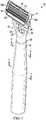
- FIG. 1one possible embodiment of the present disclosure is shown illustrating a personal care product 10 having an electronic subassembly 12.
- the personal care product 10 shownis a wet shaving razor system, it is understood that other personal care products may include, but are not limited to a foil type shaving razor, a toothbrush, a shaving brush, a powered cleansing apparatus, an epilator, and other powered personal care products. These products may be used in a wet environment, such as the bathroom.
- the personal care product 10may include a cartridge 14 (e.g., a shaving razor cartridge) mounted to a housing 16.
- the housing 16may act as a handle for a consumer to hold the personal care product 10.
- the housing 16may be injection molded, machined or extruded.
- the electronic subassembly 12comprises a first circuit board subassembly 18 and a second circuit board subassembly (not shown) positioned within the housing 16.
- the first circuit board subassembly 18includes a first circuit board 22 having a flexible portion 24 and that is mounted to an adapter 26.
- the adapter 26is mounted to the housing 16. At least a portion of the first circuit board 22 may be positioned inside the housing 16 and at least a portion of the first circuit board 22 (e.g., the flexible portion 24) may be positioned outside the housing 16.
- the adapter 26may facilitate aligning, coupling and/or securing a portion of the first circuit board 22 within the housing 16.
- the adapter 26may be manufactured and secured to the first circuit board 22 as part of an injection molding process or another assembly process.
- the second circuit board subassembly(not shown) may be completely contained within the housing 16.
- Various electrical componentsmay be contained within the housing 16 as part of the second circuit board subassembly (not shown).
- the housing 16may hold a power source, such as one or more batteries (not shown) that supply power from the second circuit board subassembly (not shown), to the first circuit board subassembly 18 and then to an electrical component 28 located outside the housing 16.
- the electrical component 28may be a heating element located on a surface of the cartridge 14 or the housing 16 to deliver heat to the skin during shaving.
- the batteryin addition to, or alternatively, may supply power to other electrical components including, but not limited to motors, cooling systems and/or lights.
- the cartridge 14may be permanently attached or removably mounted to the housing 16, thus allowing the cartridge 14 to be replaced.
- the cartridge 14may have a guard 30, a cap 32 and one or more blades 34 mounted to the cartridge 14 between the cap 32 and the guard 30.
- the guard 30may be toward a front portion of the cartridge 14 and the cap 30 may be toward a rear portion of the cartridge 14 (i.e., the guard 30 is in front of the blades 34 and the cap 32 is behind the blades 34).
- the guard 30 and the cap 32may define a shaving plane that is tangent to the guard 30 and the cap 32.
- the guard 30may be a solid or segmented bar that extends generally parallel to the blades 34.
- the guard 30may comprise a skin-engaging member 36 (e.g., a plurality of fins) in front of the blades 34 for stretching the skin during a shaving stroke.
- the skin-engaging member 36may be insert injection molded or co-injection molded to the cartridge 14.
- other known assembly methodsmay also be used such as adhesives, ultrasonic welding, or mechanical fasteners.
- the skin engaging member 36may be molded from a softer material (i.e., lower durometer hardness) than the cartridge 14.
- the skin engaging member 36may have a Shore A hardness of about 20, 30, or 40 to about 50, 60, or 70.
- a softer materialmay enhance skin stretching, as well as provide a more pleasant tactile feel against the skin of the user during shaving.
- a softer materialmay also aid in masking the less pleasant feel of the harder material of the cartridge 14 against the skin of the user during shaving.
- the blades 34may be mounted to the cartridge 14 and secured by one or more clips 38a and 38b.
- Other assembly methods known to those skilled in the artmay also be used to secure and/or mount the blades 34 to the cartridge 14 including, but not limited to, wire wrapping, cold forming, hot staking, insert molding, ultrasonic welding, and adhesives.
- the clips 38a and 38bmay comprise a metal, such as aluminum for acting as a sacrificial anode to help prevent corrosion of the blades 34.
- the cartridge 14may have more or fewer blades depending on the desired performance and cost of the cartridge 14.
- the heating element 28may be positioned in front of the guard 30 and/or the skin engaging member 36.
- the heating element 28may comprise a skin contacting surface (e.g., a face plate) that delivers heat to a consumer's skin during a shaving stroke for an improved shaving experience.
- the heating element 28may in addition to or alternatively supply heat to the blades 34, either directly or indirectly.
- the heating element 28may be mounted to either the cartridge 14 or to a portion of the housing 16.
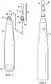
- the first circuit board assemblycomprises the adapter 26 and the first circuit board 22.
- the first circuit board 22has a rigid end 40 at one end of the flexible portion 24.
- the rigid end 40may be a separate component that is mounted to the flexible portion 24 to add stiffness and rigidity for improved assembly.
- the adapter 26may be secured to the first circuit board 22 between the rigid end 40 and the flexible portion 24.
- the rigid end 40may be suspended (e.g., unsupported) and extend from an end 42 of the adapter 26 to facilitate the coupling of the rigid end 40 to the second circuit board (not shown).
- the rigid end 40may be sufficiently stiff such that it does not deflect during assembly.
- the rigid end 40may have an unsupported length that extends about 2mm to about 12mm from the end 42 of the adapter 26 to allow for proper connection to other electrical components.
- the adapter 26 and the first circuit board 22may be interconnected as part of a manufacturing operation (e.g., insert injection molding).
- a portion of the first circuit board 22e.g., part of the rigid end 40
- an injection and plastice.g., that forms the adapter 26
- the adapter 26has a tapered guide surface 44 that tapers from a thicker region 46 to a thinner region 48 nearer the end 42.
- the adapter 26may have a sealing surface 45 (e.g., on the thicker region 46) to provide a fluid seal after the adapter 26 is assembled to the housing 16.
- the sealing surface 45may include a sealing member 47, such as an O-ring, between the adapter 26 and the housing.
- a sealing member 47such as an O-ring
- the second circuit board subassembly 20may include a second circuit board 52 supported by a chassis 54, which are positioned within the housing 16.
- the chassis 54may have a first end 56 and a second end 58.
- the first end 56may include a platform 60 and the second end 58 may include a battery housing 62.
- the platform 60may be flat such that the second circuit board 52 can be securely mounted to the chassis 54 (i.e., the platform 60).
- the battery housing 62may be generally cylindrical and define an opening 64 dimensioned to receive one or more batteries 66.
- the battery 66may include a rechargeable battery.
- One or more electrical connectors 68, 70may be used to transfer current from the battery 66 to the second circuit board 52.
- the one or more electrical connectors 68, 70may include power rails, clips and/or wires.
- An electrical connector 84may be mounted on the second circuit board 52 to facilitate connection between the first circuit board 22 (not shown) and the second circuit board.
- the housing 16has an opening 72 at one end and a second opening 102 at an opposing end.
- the first opening 72is configured to receive the adapter 26 and a second opening 102 is configured to receive the second circuit board 52.
- the second circuit board subassembly 20is inserted into the opening 72 of the housing 16.
- an end notch 130may extend into the second circuit board 52.
- An end notch 132may also extend into the chassis 54 such that the two end notches 130 and 132 are generally aligned (e.g., overlapping). The end notches 130 and 132 may facilitate proper positioning of the second circuit board subassembly 20 within the housing 16. An end cap 76 may then be positioned over the opening 72 to seal the housing 16 from water ingress. The end cap 76 may be secured to the housing 16 with adhesive, ultrasonic welding, press fit or many other known assembly methods.
- FIG. 4is a partial cross section view of the personal care product 10, taken generally along the line 4-4 of FIG. 1 .
- the housing 16defines a chamber 74 dimensioned to receive the second circuit board subassembly 20.
- the chamber 74is positioned between and in communication with the opening 72 and 102 of the housing (see FIG. 3 ).
- the chassis 54may be dimensioned to allow for easy insertion of the second circuit board subassembly 20 into an opening 72 of the housing 16 (see FIG. 3 ).
- the chassis 54(e.g., the second circuit board 52 and/or the platform 60) may include one or more guide members 94, 96, such as rails and/or grooves to facilitate the precise positioning of the chassis 54, and thus the connector 84 (not shown) within the housing 16.
- the guide members 94 and 96may engage a pair of respective guide members 98 and 100, such as channels defined by an inner surface of the housing 16.
- the channels 98 and 100may provide sufficient clearance to allow the chassis 54 to easily slide within the housing 16 and guide the connector 84 (see FIG. 3 ) in a final resting position.
- the accurate placement of the chassis 54 and the connector 84facilitates proper alignment and positioning of the chassis 54 within the housing 16.
- the proper positioning of the chassis 54 (and second circuit board 52) within the housingfacilitates the later connection between the rigid end 40 (see FIG. 2 ) of the first circuit board 22 (see FIG. 2 ) to the electrical connector 84.
- guide members 98 and 100facilitate the self alignment of the second circuit board 52 and the connector 84 (see FIG. 2 ) within the chamber 74 of the housing 16.
- the final position of the connector 84 within the housing 16may also be facilitated by other features of the housing 16 and/or the adapter 26.
- the housing 16has an opening 102 dimensioned to receive the adapter 26.
- the second circuit board 52 and the chassis 54may be positioned within the housing 16 prior to inserting the adapter 26 of the first circuit board assembly 18 into the housing 16.
- the end cap 76may also be secured to the housing 16 to help limit movement of the second circuit board 54 within the housing 16 as the adapter 26 is mounted to the housing 16 and provide a fluid seal to prevent water ingress into the housing 16.
- the adapter 26may be mounted within the opening 102 of the housing 16 such that the sealing surface 45 of the adapter 26 engages a sealing surface 78 of the housing 16 to provide a fluid seal.
- FIG. 6a side view of the first circuit board assembly 18 connected to the second circuit board assembly 20 is illustrated.
- the flexible portion 24 of the first circuit board assembly 18may extend outside of the housing 16 to allow for attachment to other electrical components.
- the rigid end 40may be sealed within the housing 16.
- FIG. 7illustrates a cross section view of the electronic sub assembly of FIG. 6 taken generally along the line 7-7 of FIG. 6 .
- the second circuit board 52may be positioned within the chamber 74 of the housing 16 by sliding it in through the second opening 72 (e.g., see FIG. 3 ) and along the guide members 98 and 100 (e.g., see FIG. 4 ).
- the housing 16 and the second circuit board 52may self align during assembly such that the connector 84 is placed in close proximity with a slot 110 in communication with the opening 102 defined by the housing 16.
- the adapter 26is received within the opening 102 of the housing 16.
- the sealing surface 45 of the adapter 26engages against the sealing surface 78 of the housing 16 and the sealing member 47 is positioned between the adapter 26 and the housing 16 to help prevent water ingress into the housing 16.
- the tapered guide surface 44 of the adapter 26engages the corresponding tapered guide surface 104 of the housing 16 to facilitate the alignment of the rigid end 40 of the first circuit board 22 with the connector 84 of the second circuit board 54.
- the rigid end 40 of the first circuit board 22may be positioned within the housing 16 and the flexible portion 24 of the first circuit board 22 may be positioned outside of the housing 16. Accordingly, the flexible portion 24 may be coupled to other electrical components outside of the housing 16, such as the heating element 28 shown in FIG. 1 .
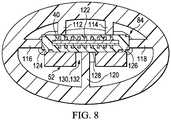
- the housing 16may have a plurality of ribs 112, 114, 116, 118 and 120 that support and guide the final connection of the second circuit board 52 (i.e., the connector 84) to the rigid end 40 of the first circuit board 22.
- the ribs 112 and 114may guide a top surface 122 of the connector 84.
- the ribs 116 and 118may guide a pair of side surfaces 124, 126 of the connector 84 and the rib 120 may guide a bottom surface 128 of the connector 84.
- the ribs 112, 114, 116, 118 and 120facilitate precise alignment of the opening of the connector 84 with the rigid end 40.
- the end notch 130may extend into the second circuit board 52.
- the end notch 132may also extend into the chassis 54 such that the two end notches 130 and 132 are generally aligned (e.g., overlapping). At least one of the end notches 130 and 132 may be dimensioned to receive the alignment rib 120 of the housing.
- the alignment rib 120may extend into one or more of the end notches 130, 132 to directly support the electrical connector 84.
- the engagement of the end notch 130, 132 of the second circuit board 52 with the alignment rib 120 of the housing 16may facilitate precise positioning of the second circuit board 52 and/or chassis 54 within the housing 16.
- the alignment rib 120may provide support to help prevent damage for the second circuit board 52 during assembly or if the housing 16 is dropped.
- the ribs 112, 114, 116, 118 and 120allow a technician to easily place the second circuit board 52 in close proximity to the slot 110 located within the housing (see FIG. 7 ) without any visual aids (i.e., seeing the final placement of the second circuit board 52 during the assembly process).
- the technician or assembly machinesimply inserts chassis 54 having the second circuit board 52 into the chamber 74 of the housing 16 through the second opening 72 thus putting the connector 84 in the precise position to be able to receive the rigid end 40.
- the adapter 26self aligns itself and connects to the electrical connector 84 positioned within the housing 16.
- the second circuit board subassembly 20may be inserted within the housing 16 prior to inserting the first circuit board assembly 18 into the housing 16.
- the electronic subassembly 12also eliminates the need to utilize a more complex and costly clam shell type housing, i.e. in two halves, to connect the electronic components because a technician does not need to see the first circuit board and the second circuit board in order to properly connect the two components.
- first circuit board assembly 150is shown being assembled to an alternative embodiment second circuit board assembly 152.
- the first circuit board assembly 150may be similar to the first circuit board assembly 18 that has been previously described.
- the first circuit board assembly 150may include the first circuit board 22 having the flexible portion 24 and the rigid end 40.
- the first circuit board assembly 150may have a modified adapter 154 with a recessed surface 156 at one end 158 and a recessed surface 160 at an opposing end 162.
- the flexible portion 24may extend out of the recessed surfaced 156 and the rigid end 40 may be positioned within the recessed surface 160 at the opposing end 162.
- the recessed surface 156may be filled with a sealant 164 (e.g., a polymeric material) to prevent water ingress into the rigid end 40 and/or the second circuit board assembly 152.
- a sealant 164e.g., a polymeric material
- the second circuit board assembly 152may include a modified housing 166 that contains the second circuit board 54.
- the housing 166may have an opening 168 at a first end 170 that is aligned and in communication with the opening 86 of the electrical connector 84.
- the first end 170 of the second circuit board 54may be positioned within the end 162 (e.g., recessed surface 160) of the adapter 154.
- the adapter 154may have a tapered guide surface 172 that engages a corresponding tapered guide surface 174 on the housing 166.
- the tapered guide surfaces 172 and 174may facilitate the assembly of the adapter 154 and the housing 166, as well as, provide for proper alignment of the rigid end 40 and the opening 86 of the connector 84.
- a sealing member 47such as an O-ring may be positioned between the housing 166 and the adapter 154 to prevent water ingress.
Landscapes
- Engineering & Computer Science (AREA)
- Life Sciences & Earth Sciences (AREA)
- Forests & Forestry (AREA)
- Mechanical Engineering (AREA)
- Manufacturing & Machinery (AREA)
- Connector Housings Or Holding Contact Members (AREA)
- Manufacturing Of Electrical Connectors (AREA)
- Casings For Electric Apparatus (AREA)
- Coupling Device And Connection With Printed Circuit (AREA)
- Combinations Of Printed Boards (AREA)
Description
- The present invention relates to electronic personal care products and more particularly to heated razors for wet shaving.
- Personal care products such as shown for example in
US 2015/0197019 A are becoming more advanced and thus often require the incorporation of electronic components to deliver new and/or improved consumer benefits. Electronic components are subject to failure when exposed to a wet environment, such as the bathroom. Furthermore, electronic components must be small to fit within a personal care product, such as a razor or a toothbrush. Accordingly, electrical components and fittings are typically very delicate and can break easily. In order to provide a safe and functional personal care product, the electrical components must be assembled and sealed against water ingress in a reliable cost effective manner. - Accordingly, there is a need to efficiently assemble and seal the electronic components of a personal care product in a simple and reliable manner.
- The invention features, in general, a simple, efficient method of assembling an electronic subassembly for a personal care product by providing an adapter having a body with a tapered guide surface. A first circuit board is positioned within the adapter. A flexible portion of the first circuit board extends from one end of the adapter and a rigid end of the first circuit board extends from the other end of the adapter. A housing is provided with a first opening and a second opening and a chamber between the first and second openings. A second circuit board having an electrical connector into the chamber thru the first opening. The tapered surface of the adapter engages a corresponding tapered guide surface of the housing. The rigid end of the first circuit board is connected to the electrical connector.
- While the specification concludes with claims particularly pointing out and distinctly claiming the subject matter that is regarded as the present invention, it is believed that the invention will be more fully understood from the following description taken in conjunction with the accompanying drawings.
FIG. 1 is a perspective view of one possible embodiment of a personal care product.FIG. 2 is a perspective view of one possible embodiment of a first circuit board assembly that may be incorporated into the personal care product ofFIG. 1 .FIG. 3 is an assembly view of one possible embodiment of a second circuit board that may be incorporated into the personal care product ofFIG. 1 .FIG. 4 is a partial cross section view of the personal care product, taken generally along the line 4-4 ofFIG. 1 .FIG. 5 is an assembly view of the first and second electronic subassembly.FIG. 6 is a side view of the first and second electronic subassembly.FIG. 7 is a partial cross section view of the first and second electronic subassembly, taken generally along the line 7-7 ofFIG. 6 .FIG. 8 is a partial cross section assembly view of the personal care product, taken generally along the line 8-8 ofFIG. 1 .FIG. 9 is a partial cross section view of a second possible embodiment of an electronic subassembly not according to the present invention.- Referring to
FIG. 1 , one possible embodiment of the present disclosure is shown illustrating apersonal care product 10 having an electronic subassembly 12. Although thepersonal care product 10 shown is a wet shaving razor system, it is understood that other personal care products may include, but are not limited to a foil type shaving razor, a toothbrush, a shaving brush, a powered cleansing apparatus, an epilator, and other powered personal care products. These products may be used in a wet environment, such as the bathroom. In certain embodiments, thepersonal care product 10 may include a cartridge 14 (e.g., a shaving razor cartridge) mounted to ahousing 16. Thehousing 16 may act as a handle for a consumer to hold thepersonal care product 10. Thehousing 16 may be injection molded, machined or extruded. - As will be described in further detail below, the electronic subassembly 12 comprises a first
circuit board subassembly 18 and a second circuit board subassembly (not shown) positioned within thehousing 16. The firstcircuit board subassembly 18 includes afirst circuit board 22 having aflexible portion 24 and that is mounted to anadapter 26. Theadapter 26 is mounted to thehousing 16. At least a portion of thefirst circuit board 22 may be positioned inside thehousing 16 and at least a portion of the first circuit board 22 (e.g., the flexible portion 24) may be positioned outside thehousing 16. Theadapter 26 may facilitate aligning, coupling and/or securing a portion of thefirst circuit board 22 within thehousing 16. As will be explained in greater detail below, theadapter 26 may be manufactured and secured to thefirst circuit board 22 as part of an injection molding process or another assembly process. The second circuit board subassembly (not shown) may be completely contained within thehousing 16. Various electrical components may be contained within thehousing 16 as part of the second circuit board subassembly (not shown). For example, thehousing 16 may hold a power source, such as one or more batteries (not shown) that supply power from the second circuit board subassembly (not shown), to the firstcircuit board subassembly 18 and then to anelectrical component 28 located outside thehousing 16. In certain embodiments, theelectrical component 28 may be a heating element located on a surface of thecartridge 14 or thehousing 16 to deliver heat to the skin during shaving. However, the battery in addition to, or alternatively, may supply power to other electrical components including, but not limited to motors, cooling systems and/or lights. - The
cartridge 14 may be permanently attached or removably mounted to thehousing 16, thus allowing thecartridge 14 to be replaced. Thecartridge 14 may have a guard 30, acap 32 and one ormore blades 34 mounted to thecartridge 14 between thecap 32 and the guard 30. The guard 30 may be toward a front portion of thecartridge 14 and the cap 30 may be toward a rear portion of the cartridge 14 (i.e., the guard 30 is in front of theblades 34 and thecap 32 is behind the blades 34). The guard 30 and thecap 32 may define a shaving plane that is tangent to the guard 30 and thecap 32. The guard 30 may be a solid or segmented bar that extends generally parallel to theblades 34. - In certain embodiments, the guard 30 may comprise a skin-engaging member 36 (e.g., a plurality of fins) in front of the
blades 34 for stretching the skin during a shaving stroke. The skin-engaging member 36 may be insert injection molded or co-injection molded to thecartridge 14. However, other known assembly methods may also be used such as adhesives, ultrasonic welding, or mechanical fasteners. The skinengaging member 36 may be molded from a softer material (i.e., lower durometer hardness) than thecartridge 14. For example, theskin engaging member 36 may have a Shore A hardness of about 20, 30, or 40 to about 50, 60, or 70. A softer material may enhance skin stretching, as well as provide a more pleasant tactile feel against the skin of the user during shaving. A softer material may also aid in masking the less pleasant feel of the harder material of thecartridge 14 against the skin of the user during shaving. - In certain embodiments, the
blades 34 may be mounted to thecartridge 14 and secured by one ormore clips blades 34 to thecartridge 14 including, but not limited to, wire wrapping, cold forming, hot staking, insert molding, ultrasonic welding, and adhesives. Theclips blades 34. Although fiveblades 34 are shown, thecartridge 14 may have more or fewer blades depending on the desired performance and cost of thecartridge 14. - In certain embodiments, it may be desirable to provide heat in front of the
blades 34. For example, theheating element 28 may be positioned in front of the guard 30 and/or the skinengaging member 36. Theheating element 28 may comprise a skin contacting surface (e.g., a face plate) that delivers heat to a consumer's skin during a shaving stroke for an improved shaving experience. However, it is understood theheating element 28 may in addition to or alternatively supply heat to theblades 34, either directly or indirectly. Theheating element 28 may be mounted to either thecartridge 14 or to a portion of thehousing 16. - Referring to
FIG. 2 , a perspective view of the firstcircuit board assembly 18 is shown. The first circuit board assembly comprises theadapter 26 and thefirst circuit board 22. Thefirst circuit board 22 has arigid end 40 at one end of theflexible portion 24. In certain embodiments, therigid end 40 may be a separate component that is mounted to theflexible portion 24 to add stiffness and rigidity for improved assembly. Theadapter 26 may be secured to thefirst circuit board 22 between therigid end 40 and theflexible portion 24. Therigid end 40 may be suspended (e.g., unsupported) and extend from anend 42 of theadapter 26 to facilitate the coupling of therigid end 40 to the second circuit board (not shown). Therigid end 40 may be sufficiently stiff such that it does not deflect during assembly. If therigid end 40 deflects, it may be difficult to align and/or connect other electrical components to firstcircuit board assembly 18. In certain embodiments, therigid end 40 may have an unsupported length that extends about 2mm to about 12mm from theend 42 of theadapter 26 to allow for proper connection to other electrical components. - The
adapter 26 and thefirst circuit board 22 may be interconnected as part of a manufacturing operation (e.g., insert injection molding). A portion of the first circuit board 22 (e.g., part of the rigid end 40) may be placed in an injection and plastic (e.g., that forms the adapter 26) may be injected around a portion (e.g., the rigid end 40) of thefirst circuit board 22. Theadapter 26 has a taperedguide surface 44 that tapers from athicker region 46 to athinner region 48 nearer theend 42. Theadapter 26 may have a sealing surface 45 (e.g., on the thicker region 46) to provide a fluid seal after theadapter 26 is assembled to thehousing 16. In certain embodiments, the sealingsurface 45 may include a sealingmember 47, such as an O-ring, between theadapter 26 and the housing. As will be explained in greater detail below, molding of theadapter 26 around a portion of therigid end 40 may allow not only for sealing therigid end 40 from water ingress, but may also allow for the precise positioning of therigid end 40 within the housing 16 (not shown). - Referring to
FIG. 3 , an assembly view of the secondcircuit board subassembly 20 is illustrated. The secondcircuit board subassembly 20 may include asecond circuit board 52 supported by achassis 54, which are positioned within thehousing 16. Thechassis 54 may have afirst end 56 and asecond end 58. Thefirst end 56 may include aplatform 60 and thesecond end 58 may include abattery housing 62. Theplatform 60 may be flat such that thesecond circuit board 52 can be securely mounted to the chassis 54 (i.e., the platform 60). Thebattery housing 62 may be generally cylindrical and define anopening 64 dimensioned to receive one ormore batteries 66. In certain embodiments, thebattery 66 may include a rechargeable battery. One or moreelectrical connectors battery 66 to thesecond circuit board 52. The one or moreelectrical connectors electrical connector 84 may be mounted on thesecond circuit board 52 to facilitate connection between the first circuit board 22 (not shown) and the second circuit board. Thehousing 16 has anopening 72 at one end and asecond opening 102 at an opposing end. Thefirst opening 72 is configured to receive theadapter 26 and asecond opening 102 is configured to receive thesecond circuit board 52. The secondcircuit board subassembly 20 is inserted into theopening 72 of thehousing 16. As will be described in greater detail below, an end notch 130 may extend into thesecond circuit board 52. An end notch 132 may also extend into thechassis 54 such that the two end notches 130 and 132 are generally aligned (e.g., overlapping). The end notches 130 and 132 may facilitate proper positioning of the secondcircuit board subassembly 20 within thehousing 16. Anend cap 76 may then be positioned over theopening 72 to seal thehousing 16 from water ingress. Theend cap 76 may be secured to thehousing 16 with adhesive, ultrasonic welding, press fit or many other known assembly methods. FIG. 4 is a partial cross section view of thepersonal care product 10, taken generally along the line 4-4 ofFIG. 1 . Thehousing 16 defines achamber 74 dimensioned to receive the secondcircuit board subassembly 20. Thechamber 74 is positioned between and in communication with theopening FIG. 3 ). Thechassis 54 may be dimensioned to allow for easy insertion of the secondcircuit board subassembly 20 into anopening 72 of the housing 16 (seeFIG. 3 ). The chassis 54 (e.g., thesecond circuit board 52 and/or the platform 60) may include one ormore guide members chassis 54, and thus the connector 84 (not shown) within thehousing 16. Theguide members respective guide members housing 16. Thechannels chassis 54 to easily slide within thehousing 16 and guide the connector 84 (seeFIG. 3 ) in a final resting position. The accurate placement of thechassis 54 and theconnector 84 facilitates proper alignment and positioning of thechassis 54 within thehousing 16. The proper positioning of the chassis 54 (and second circuit board 52) within the housing facilitates the later connection between the rigid end 40 (seeFIG. 2 ) of the first circuit board 22 (seeFIG. 2 ) to theelectrical connector 84. Accordingly, guidemembers second circuit board 52 and the connector 84 (seeFIG. 2 ) within thechamber 74 of thehousing 16. As will be explained in greater detail below, the final position of theconnector 84 within thehousing 16 may also be facilitated by other features of thehousing 16 and/or theadapter 26.- Referring to
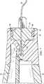
FIG. 5 , an assembly view of the firstcircuit board assembly 18 and the secondcircuit board assembly 20 is shown. Thehousing 16 has anopening 102 dimensioned to receive theadapter 26. In certain embodiments, thesecond circuit board 52 and thechassis 54 may be positioned within thehousing 16 prior to inserting theadapter 26 of the firstcircuit board assembly 18 into thehousing 16. Theend cap 76 may also be secured to thehousing 16 to help limit movement of thesecond circuit board 54 within thehousing 16 as theadapter 26 is mounted to thehousing 16 and provide a fluid seal to prevent water ingress into thehousing 16. Theadapter 26 may be mounted within theopening 102 of thehousing 16 such that the sealingsurface 45 of theadapter 26 engages a sealingsurface 78 of thehousing 16 to provide a fluid seal. - Referring to
FIG. 6 , a side view of the firstcircuit board assembly 18 connected to the secondcircuit board assembly 20 is illustrated. Theflexible portion 24 of the firstcircuit board assembly 18 may extend outside of thehousing 16 to allow for attachment to other electrical components. As shown inFIG. 7 , therigid end 40 may be sealed within thehousing 16.FIG. 7 illustrates a cross section view of the electronic sub assembly ofFIG. 6 taken generally along the line 7-7 ofFIG. 6 . As previously described, thesecond circuit board 52 may be positioned within thechamber 74 of thehousing 16 by sliding it in through the second opening 72 (e.g., seeFIG. 3 ) and along theguide members 98 and 100 (e.g., seeFIG. 4 ). Thehousing 16 and thesecond circuit board 52 may self align during assembly such that theconnector 84 is placed in close proximity with aslot 110 in communication with theopening 102 defined by thehousing 16. Theadapter 26 is received within theopening 102 of thehousing 16. The sealingsurface 45 of theadapter 26 engages against the sealingsurface 78 of thehousing 16 and the sealingmember 47 is positioned between theadapter 26 and thehousing 16 to help prevent water ingress into thehousing 16. The taperedguide surface 44 of theadapter 26 engages the corresponding taperedguide surface 104 of thehousing 16 to facilitate the alignment of therigid end 40 of thefirst circuit board 22 with theconnector 84 of thesecond circuit board 54. After theadapter 26 is mounted to thehousing 16, therigid end 40 of thefirst circuit board 22 may be positioned within thehousing 16 and theflexible portion 24 of thefirst circuit board 22 may be positioned outside of thehousing 16. Accordingly, theflexible portion 24 may be coupled to other electrical components outside of thehousing 16, such as theheating element 28 shown inFIG. 1 . - As shown in
FIG. 8 , thehousing 16 may have a plurality ofribs rigid end 40 of thefirst circuit board 22. The ribs 112 and 114 may guide atop surface 122 of theconnector 84. Theribs connector 84 and therib 120 may guide abottom surface 128 of theconnector 84. Theribs connector 84 with therigid end 40. In certain embodiments, the end notch 130 may extend into thesecond circuit board 52. The end notch 132 may also extend into thechassis 54 such that the two end notches 130 and 132 are generally aligned (e.g., overlapping). At least one of the end notches 130 and 132 may be dimensioned to receive thealignment rib 120 of the housing. For example, thealignment rib 120 may extend into one or more of the end notches 130, 132 to directly support theelectrical connector 84. The engagement of the end notch 130, 132 of thesecond circuit board 52 with thealignment rib 120 of thehousing 16 may facilitate precise positioning of thesecond circuit board 52 and/orchassis 54 within thehousing 16. Furthermore, thealignment rib 120 may provide support to help prevent damage for thesecond circuit board 52 during assembly or if thehousing 16 is dropped. - The
ribs second circuit board 52 in close proximity to theslot 110 located within the housing (seeFIG. 7 ) without any visual aids (i.e., seeing the final placement of thesecond circuit board 52 during the assembly process). The technician or assembly machine simply insertschassis 54 having thesecond circuit board 52 into thechamber 74 of thehousing 16 through thesecond opening 72 thus putting theconnector 84 in the precise position to be able to receive therigid end 40. Accordingly, theadapter 26 self aligns itself and connects to theelectrical connector 84 positioned within thehousing 16. In certain embodiments, the secondcircuit board subassembly 20 may be inserted within thehousing 16 prior to inserting the firstcircuit board assembly 18 into thehousing 16. No special fixtures or equipment are needed to aid in the assembly and connection of the firstcircuit board subassembly 18 to the secondcircuit board subassembly 20 within thehousing 16. The electronic subassembly 12 also eliminates the need to utilize a more complex and costly clam shell type housing, i.e. in two halves, to connect the electronic components because a technician does not need to see the first circuit board and the second circuit board in order to properly connect the two components. - Referring to
FIG. 9 , an alternative embodiment first circuit board assembly 150 is shown being assembled to an alternative embodiment second circuit board assembly 152. The first circuit board assembly 150 may be similar to the firstcircuit board assembly 18 that has been previously described. For example, the first circuit board assembly 150 may include thefirst circuit board 22 having theflexible portion 24 and therigid end 40. However, the first circuit board assembly 150 may have a modifiedadapter 154 with a recessedsurface 156 at oneend 158 and a recessedsurface 160 at anopposing end 162. Theflexible portion 24 may extend out of the recessed surfaced 156 and therigid end 40 may be positioned within the recessedsurface 160 at theopposing end 162. The recessedsurface 156 may be filled with a sealant 164 (e.g., a polymeric material) to prevent water ingress into therigid end 40 and/or the second circuit board assembly 152. - The second circuit board assembly 152 may include a modified
housing 166 that contains thesecond circuit board 54. Thehousing 166 may have anopening 168 at afirst end 170 that is aligned and in communication with theopening 86 of theelectrical connector 84. Thefirst end 170 of thesecond circuit board 54 may be positioned within the end 162 (e.g., recessed surface 160) of theadapter 154. Theadapter 154 may have a taperedguide surface 172 that engages a corresponding taperedguide surface 174 on thehousing 166. The tapered guide surfaces 172 and 174 may facilitate the assembly of theadapter 154 and thehousing 166, as well as, provide for proper alignment of therigid end 40 and theopening 86 of theconnector 84. In certain embodiments, a sealingmember 47, such as an O-ring may be positioned between thehousing 166 and theadapter 154 to prevent water ingress. - The dimensions and values disclosed herein are not to be understood as being strictly limited to the exact numerical values recited. Instead, unless otherwise specified, each such dimension is intended to mean both the recited value and a functionally equivalent range surrounding that value. For example, a dimension disclosed as "40 mm" is intended to mean "about 40 mm".
Claims (15)
- A method of assembling an electronic subassembly for a personal care product comprising:providing an adapter (26) having a body with a tapered guide surface (44);positioning a first circuit board (22) within the adapter, wherein a flexible portion (24) of the first circuit board extends from one end of the adapter and a rigid end (40) of the first circuit board extends from the other end of the adapter;providing a housing (16) with a first opening (72) and a second opening (102) and a chamber (74) between the first and second openings;inserting a second circuit board (52) having an electrical connector (84) into the chamber thru the opening (72);engaging the tapered surface of the adapter with a corresponding tapered guide surface (104) of the housing; andconnecting the rigid end of the first circuit board to the electrical connector.
- The method of claim 1 further comprising inserting the body of the adapter (26) into the second opening (102) of the housing (16).
- The method of claim 1 further comprising inserting a first end of the housing (16) into an opening (168) of the adapter (26).
- The method according to anyone of the preceding claims further comprising securing the adapter (26) to the housing (16).
- The method according to anyone of the preceding claims further comprising forming a water tight seal between the housing (16) and the adapter (26).
- The method according to anyone of the preceding claims further comprising positioning a sealing member (47) between the adapter (26) and the housing (16).
- The method according to anyone of the preceding claims further comprising sealing the first circuit board (22) to the adapter (26).
- The method of claim 7 wherein said sealing comprises insert molding the adapter (26) around a portion of the first circuit board (22).
- The method of claim 7 wherein said sealing comprises filling a recess (156) defined by the adapter (26) with a sealant (164).
- The method according to anyone of the preceding claims further comprising connecting the flexible portion (24) to an electrical component (28).
- The method of claim 10 wherein the electrical component (28) is a heating element.
- The method according to anyone of the preceding claims further comprising securing an end cap (76) to the housing (16).
- The method of claim 12 further comprising positioning a sealing member (47) between the end cap (76) and the housing (16).
- The method according to anyone of the preceding claims further comprising engaging an end notch (130) of the second circuit board (52) with an alignment rib (120) of the housing (16).
- The method according to anyone of the preceding claims wherein the second circuit board (52) is inserted into the chamber (74) prior to engaging the tapered guide surface (44) of the adapter (26) with the corresponding tapered guide surface (104) of the housing (16).
Priority Applications (8)
| Application Number | Priority Date | Filing Date | Title |
|---|---|---|---|
| EP16160243.8AEP3219451B1 (en) | 2016-03-14 | 2016-03-14 | Method of assembling an electronic subassembly for a personal care product |
| MX2018011158AMX2018011158A (en) | 2016-03-14 | 2017-03-09 | Method of assembling an electronic subassembly for a personal care product. |
| JP2018548144AJP6823073B2 (en) | 2016-03-14 | 2017-03-09 | How to assemble electronic subassemblies for personal care products |
| BR112018068432ABR112018068432A2 (en) | 2016-03-14 | 2017-03-09 | method of mounting an electronic subset for a personal care product |
| CN201780011668.8ACN108698242B (en) | 2016-03-14 | 2017-03-09 | Method of assembling consumer appliances |
| US15/453,985US9950436B2 (en) | 2016-03-14 | 2017-03-09 | Method of assembling an electronic subassembly for a personal care product |
| PCT/US2017/021511WO2017160576A1 (en) | 2016-03-14 | 2017-03-09 | Method of assembling an electronic subassembly for a personal care product |
| SG11201807015YASG11201807015YA (en) | 2016-03-14 | 2017-03-09 | Method of assembling an electronic subassembly for a personal care product |
Applications Claiming Priority (1)
| Application Number | Priority Date | Filing Date | Title |
|---|---|---|---|
| EP16160243.8AEP3219451B1 (en) | 2016-03-14 | 2016-03-14 | Method of assembling an electronic subassembly for a personal care product |
Publications (2)
| Publication Number | Publication Date |
|---|---|
| EP3219451A1 EP3219451A1 (en) | 2017-09-20 |
| EP3219451B1true EP3219451B1 (en) | 2019-11-13 |
Family
ID=55650115
Family Applications (1)
| Application Number | Title | Priority Date | Filing Date |
|---|---|---|---|
| EP16160243.8AActiveEP3219451B1 (en) | 2016-03-14 | 2016-03-14 | Method of assembling an electronic subassembly for a personal care product |
Country Status (8)
| Country | Link |
|---|---|
| US (1) | US9950436B2 (en) |
| EP (1) | EP3219451B1 (en) |
| JP (1) | JP6823073B2 (en) |
| CN (1) | CN108698242B (en) |
| BR (1) | BR112018068432A2 (en) |
| MX (1) | MX2018011158A (en) |
| SG (1) | SG11201807015YA (en) |
| WO (1) | WO2017160576A1 (en) |
Families Citing this family (17)
| Publication number | Priority date | Publication date | Assignee | Title |
|---|---|---|---|---|
| US10652956B2 (en) | 2016-06-22 | 2020-05-12 | The Gillette Company Llc | Personal consumer product with thermal control circuitry and methods thereof |
| BR112020020132A2 (en) | 2018-03-30 | 2021-01-05 | The Gillette Company Llc | HANDLE OF SHAVING OR DEVILING APPLIANCE WITH MOBILE LIMBS |
| WO2019191163A1 (en) | 2018-03-30 | 2019-10-03 | The Gillette Company Llc | Razor handle with a pivoting portion |
| EP3546156B1 (en) | 2018-03-30 | 2021-03-10 | The Gillette Company LLC | Razor handle with a pivoting portion |
| US10773408B2 (en) | 2018-03-30 | 2020-09-15 | The Gillette Company Llc | Shaving razor cartridge |
| EP3774227A1 (en) | 2018-03-30 | 2021-02-17 | The Gillette Company LLC | Razor handle with movable members |
| WO2019190962A1 (en) | 2018-03-30 | 2019-10-03 | The Gillette Company Llc | Razor handle with a pivoting portion |
| US11607820B2 (en) | 2018-03-30 | 2023-03-21 | The Gillette Company Llc | Razor handle with movable members |
| CA3092879A1 (en) | 2018-03-30 | 2019-10-03 | The Gillette Company Llc | Razor handle with movable members |
| EP3774215B1 (en) | 2018-03-30 | 2024-03-13 | The Gillette Company LLC | Razor handle with a pivoting portion |
| USD874061S1 (en) | 2018-03-30 | 2020-01-28 | The Gillette Company Llc | Shaving razor cartridge |
| CN111801205B (en) | 2018-03-30 | 2022-08-23 | 吉列有限责任公司 | Razor handle with pivoting portion |
| CN111819048A (en) | 2018-03-30 | 2020-10-23 | 吉列有限责任公司 | Razor handle with pivoting portion |
| JP2021515672A (en) | 2018-03-30 | 2021-06-24 | ザ ジレット カンパニー リミテッド ライアビリティ カンパニーThe Gillette Company Llc | Razor system for shaving |
| JP7104168B2 (en) | 2018-03-30 | 2022-07-20 | ザ ジレット カンパニー リミテッド ライアビリティ カンパニー | Razor handle with pivot part |
| US12005596B2 (en)* | 2021-04-07 | 2024-06-11 | The Gillette Company Llc | Personal care appliance and a method of assembling |
| US12233566B2 (en)* | 2021-04-07 | 2025-02-25 | The Gillette Company Llc | Personal care appliance |
Family Cites Families (15)
| Publication number | Priority date | Publication date | Assignee | Title |
|---|---|---|---|---|
| JPH0642340B2 (en)* | 1985-01-19 | 1994-06-01 | 三洋電機株式会社 | Small electrical equipment |
| JPH0338867Y2 (en)* | 1985-04-01 | 1991-08-15 | ||
| JPH08117258A (en)* | 1994-10-24 | 1996-05-14 | Purakon:Kk | electric toothbrush |
| JP2003260071A (en)* | 2002-03-11 | 2003-09-16 | Fukoku Co Ltd | electric toothbrush |
| JP2004111595A (en)* | 2002-09-18 | 2004-04-08 | Tdk Corp | Wall waterproof structure and waterproof type electronic apparatus |
| EP1563967A1 (en)* | 2004-02-11 | 2005-08-17 | Eveready Battery Company, Inc. | Shaver and method of manufacturing a shaver |
| US20060070242A1 (en)* | 2004-10-01 | 2006-04-06 | Szczepanowski Andrew A | Shaving razors and razor cartridges |
| US8230600B2 (en)* | 2007-09-17 | 2012-07-31 | The Gillette Company | Cartridge detachment sensor |
| US20110041347A1 (en)* | 2008-05-13 | 2011-02-24 | Wang Hou-Pia | Pet hair trimming cutter |
| US20100031510A1 (en)* | 2008-08-06 | 2010-02-11 | Matthias Gester | Heated shaving razor |
| DE102010006747A1 (en)* | 2009-02-04 | 2011-03-24 | Edmund Galster | Electric razor, has blade unit supported in housing element such that blades are moved to and fro perpendicular to cutting edges of blades in operating condition, where housing element has frame with attachment edge |
| JP2011114721A (en)* | 2009-11-27 | 2011-06-09 | Kyocera Corp | Portable electronic device |
| US8516706B2 (en)* | 2010-01-08 | 2013-08-27 | Syneron Medical Ltd | Skin-heating shaving apparatus and method |
| RU2674051C2 (en)* | 2013-05-30 | 2018-12-04 | Конинклейке Филипс Н.В. | Personal care device such as shaving device, head structure and base structure for such device, as well as coupling structure |
| US9908250B2 (en)* | 2014-01-14 | 2018-03-06 | The Gillette Company Llc | Heated shaving razors |
- 2016
- 2016-03-14EPEP16160243.8Apatent/EP3219451B1/enactiveActive
- 2017
- 2017-03-09SGSG11201807015YApatent/SG11201807015YA/enunknown
- 2017-03-09CNCN201780011668.8Apatent/CN108698242B/enactiveActive
- 2017-03-09USUS15/453,985patent/US9950436B2/enactiveActive
- 2017-03-09JPJP2018548144Apatent/JP6823073B2/enactiveActive
- 2017-03-09MXMX2018011158Apatent/MX2018011158A/enunknown
- 2017-03-09BRBR112018068432Apatent/BR112018068432A2/ennot_activeApplication Discontinuation
- 2017-03-09WOPCT/US2017/021511patent/WO2017160576A1/ennot_activeCeased
Non-Patent Citations (1)
| Title |
|---|
| None* |
Also Published As
| Publication number | Publication date |
|---|---|
| EP3219451A1 (en) | 2017-09-20 |
| BR112018068432A2 (en) | 2019-01-29 |
| MX2018011158A (en) | 2019-01-10 |
| US20170259440A1 (en) | 2017-09-14 |
| WO2017160576A1 (en) | 2017-09-21 |
| US9950436B2 (en) | 2018-04-24 |
| JP6823073B2 (en) | 2021-01-27 |
| CN108698242B (en) | 2020-09-01 |
| JP2019508160A (en) | 2019-03-28 |
| SG11201807015YA (en) | 2018-09-27 |
| CN108698242A (en) | 2018-10-23 |
Similar Documents
| Publication | Publication Date | Title |
|---|---|---|
| CA3015257C (en) | Electronic subassembly for a personal care product | |
| EP3219451B1 (en) | Method of assembling an electronic subassembly for a personal care product | |
| US10334744B2 (en) | Electronic subassembly for a personal care product | |
| US12280513B2 (en) | Shaving razor system | |
| ES2670033T3 (en) | Heating element for a shaver | |
| EP3157311B1 (en) | Method of assembling an electronic subassembly for a personal care product |
Legal Events
| Date | Code | Title | Description |
|---|---|---|---|
| PUAI | Public reference made under article 153(3) epc to a published international application that has entered the european phase | Free format text:ORIGINAL CODE: 0009012 | |
| STAA | Information on the status of an ep patent application or granted ep patent | Free format text:STATUS: THE APPLICATION HAS BEEN PUBLISHED | |
| AK | Designated contracting states | Kind code of ref document:A1 Designated state(s):AL AT BE BG CH CY CZ DE DK EE ES FI FR GB GR HR HU IE IS IT LI LT LU LV MC MK MT NL NO PL PT RO RS SE SI SK SM TR | |
| AX | Request for extension of the european patent | Extension state:BA ME | |
| STAA | Information on the status of an ep patent application or granted ep patent | Free format text:STATUS: REQUEST FOR EXAMINATION WAS MADE | |
| 17P | Request for examination filed | Effective date:20180208 | |
| RBV | Designated contracting states (corrected) | Designated state(s):AL AT BE BG CH CY CZ DE DK EE ES FI FR GB GR HR HU IE IS IT LI LT LU LV MC MK MT NL NO PL PT RO RS SE SI SK SM TR | |
| GRAP | Despatch of communication of intention to grant a patent | Free format text:ORIGINAL CODE: EPIDOSNIGR1 | |
| STAA | Information on the status of an ep patent application or granted ep patent | Free format text:STATUS: GRANT OF PATENT IS INTENDED | |
| INTG | Intention to grant announced | Effective date:20190528 | |
| GRAS | Grant fee paid | Free format text:ORIGINAL CODE: EPIDOSNIGR3 | |
| GRAA | (expected) grant | Free format text:ORIGINAL CODE: 0009210 | |
| STAA | Information on the status of an ep patent application or granted ep patent | Free format text:STATUS: THE PATENT HAS BEEN GRANTED | |
| AK | Designated contracting states | Kind code of ref document:B1 Designated state(s):AL AT BE BG CH CY CZ DE DK EE ES FI FR GB GR HR HU IE IS IT LI LT LU LV MC MK MT NL NO PL PT RO RS SE SI SK SM TR | |
| REG | Reference to a national code | Ref country code:CH Ref legal event code:EP Ref country code:AT Ref legal event code:REF Ref document number:1201183 Country of ref document:AT Kind code of ref document:T Effective date:20191115 | |
| REG | Reference to a national code | Ref country code:DE Ref legal event code:R096 Ref document number:602016024128 Country of ref document:DE | |
| REG | Reference to a national code | Ref country code:IE Ref legal event code:FG4D | |
| REG | Reference to a national code | Ref country code:NL Ref legal event code:MP Effective date:20191113 | |
| REG | Reference to a national code | Ref country code:LT Ref legal event code:MG4D | |
| PG25 | Lapsed in a contracting state [announced via postgrant information from national office to epo] | Ref country code:NO Free format text:LAPSE BECAUSE OF FAILURE TO SUBMIT A TRANSLATION OF THE DESCRIPTION OR TO PAY THE FEE WITHIN THE PRESCRIBED TIME-LIMIT Effective date:20200213 Ref country code:GR Free format text:LAPSE BECAUSE OF FAILURE TO SUBMIT A TRANSLATION OF THE DESCRIPTION OR TO PAY THE FEE WITHIN THE PRESCRIBED TIME-LIMIT Effective date:20200214 Ref country code:BG Free format text:LAPSE BECAUSE OF FAILURE TO SUBMIT A TRANSLATION OF THE DESCRIPTION OR TO PAY THE FEE WITHIN THE PRESCRIBED TIME-LIMIT Effective date:20200213 Ref country code:LT Free format text:LAPSE BECAUSE OF FAILURE TO SUBMIT A TRANSLATION OF THE DESCRIPTION OR TO PAY THE FEE WITHIN THE PRESCRIBED TIME-LIMIT Effective date:20191113 Ref country code:PL Free format text:LAPSE BECAUSE OF FAILURE TO SUBMIT A TRANSLATION OF THE DESCRIPTION OR TO PAY THE FEE WITHIN THE PRESCRIBED TIME-LIMIT Effective date:20191113 Ref country code:SE Free format text:LAPSE BECAUSE OF FAILURE TO SUBMIT A TRANSLATION OF THE DESCRIPTION OR TO PAY THE FEE WITHIN THE PRESCRIBED TIME-LIMIT Effective date:20191113 Ref country code:LV Free format text:LAPSE BECAUSE OF FAILURE TO SUBMIT A TRANSLATION OF THE DESCRIPTION OR TO PAY THE FEE WITHIN THE PRESCRIBED TIME-LIMIT Effective date:20191113 Ref country code:FI Free format text:LAPSE BECAUSE OF FAILURE TO SUBMIT A TRANSLATION OF THE DESCRIPTION OR TO PAY THE FEE WITHIN THE PRESCRIBED TIME-LIMIT Effective date:20191113 Ref country code:PT Free format text:LAPSE BECAUSE OF FAILURE TO SUBMIT A TRANSLATION OF THE DESCRIPTION OR TO PAY THE FEE WITHIN THE PRESCRIBED TIME-LIMIT Effective date:20200313 Ref country code:NL Free format text:LAPSE BECAUSE OF FAILURE TO SUBMIT A TRANSLATION OF THE DESCRIPTION OR TO PAY THE FEE WITHIN THE PRESCRIBED TIME-LIMIT Effective date:20191113 | |
| PGFP | Annual fee paid to national office [announced via postgrant information from national office to epo] | Ref country code:GB Payment date:20200304 Year of fee payment:5 | |
| PG25 | Lapsed in a contracting state [announced via postgrant information from national office to epo] | Ref country code:IS Free format text:LAPSE BECAUSE OF FAILURE TO SUBMIT A TRANSLATION OF THE DESCRIPTION OR TO PAY THE FEE WITHIN THE PRESCRIBED TIME-LIMIT Effective date:20200313 Ref country code:HR Free format text:LAPSE BECAUSE OF FAILURE TO SUBMIT A TRANSLATION OF THE DESCRIPTION OR TO PAY THE FEE WITHIN THE PRESCRIBED TIME-LIMIT Effective date:20191113 Ref country code:RS Free format text:LAPSE BECAUSE OF FAILURE TO SUBMIT A TRANSLATION OF THE DESCRIPTION OR TO PAY THE FEE WITHIN THE PRESCRIBED TIME-LIMIT Effective date:20191113 | |
| PG25 | Lapsed in a contracting state [announced via postgrant information from national office to epo] | Ref country code:AL Free format text:LAPSE BECAUSE OF FAILURE TO SUBMIT A TRANSLATION OF THE DESCRIPTION OR TO PAY THE FEE WITHIN THE PRESCRIBED TIME-LIMIT Effective date:20191113 | |
| PG25 | Lapsed in a contracting state [announced via postgrant information from national office to epo] | Ref country code:ES Free format text:LAPSE BECAUSE OF FAILURE TO SUBMIT A TRANSLATION OF THE DESCRIPTION OR TO PAY THE FEE WITHIN THE PRESCRIBED TIME-LIMIT Effective date:20191113 Ref country code:CZ Free format text:LAPSE BECAUSE OF FAILURE TO SUBMIT A TRANSLATION OF THE DESCRIPTION OR TO PAY THE FEE WITHIN THE PRESCRIBED TIME-LIMIT Effective date:20191113 Ref country code:DK Free format text:LAPSE BECAUSE OF FAILURE TO SUBMIT A TRANSLATION OF THE DESCRIPTION OR TO PAY THE FEE WITHIN THE PRESCRIBED TIME-LIMIT Effective date:20191113 Ref country code:RO Free format text:LAPSE BECAUSE OF FAILURE TO SUBMIT A TRANSLATION OF THE DESCRIPTION OR TO PAY THE FEE WITHIN THE PRESCRIBED TIME-LIMIT Effective date:20191113 Ref country code:EE Free format text:LAPSE BECAUSE OF FAILURE TO SUBMIT A TRANSLATION OF THE DESCRIPTION OR TO PAY THE FEE WITHIN THE PRESCRIBED TIME-LIMIT Effective date:20191113 | |
| REG | Reference to a national code | Ref country code:DE Ref legal event code:R097 Ref document number:602016024128 Country of ref document:DE | |
| REG | Reference to a national code | Ref country code:AT Ref legal event code:MK05 Ref document number:1201183 Country of ref document:AT Kind code of ref document:T Effective date:20191113 | |
| PG25 | Lapsed in a contracting state [announced via postgrant information from national office to epo] | Ref country code:SM Free format text:LAPSE BECAUSE OF FAILURE TO SUBMIT A TRANSLATION OF THE DESCRIPTION OR TO PAY THE FEE WITHIN THE PRESCRIBED TIME-LIMIT Effective date:20191113 Ref country code:SK Free format text:LAPSE BECAUSE OF FAILURE TO SUBMIT A TRANSLATION OF THE DESCRIPTION OR TO PAY THE FEE WITHIN THE PRESCRIBED TIME-LIMIT Effective date:20191113 | |
| PLBE | No opposition filed within time limit | Free format text:ORIGINAL CODE: 0009261 | |
| STAA | Information on the status of an ep patent application or granted ep patent | Free format text:STATUS: NO OPPOSITION FILED WITHIN TIME LIMIT | |
| 26N | No opposition filed | Effective date:20200814 | |
| PG25 | Lapsed in a contracting state [announced via postgrant information from national office to epo] | Ref country code:MC Free format text:LAPSE BECAUSE OF FAILURE TO SUBMIT A TRANSLATION OF THE DESCRIPTION OR TO PAY THE FEE WITHIN THE PRESCRIBED TIME-LIMIT Effective date:20191113 | |
| REG | Reference to a national code | Ref country code:CH Ref legal event code:PL | |
| PG25 | Lapsed in a contracting state [announced via postgrant information from national office to epo] | Ref country code:AT Free format text:LAPSE BECAUSE OF FAILURE TO SUBMIT A TRANSLATION OF THE DESCRIPTION OR TO PAY THE FEE WITHIN THE PRESCRIBED TIME-LIMIT Effective date:20191113 Ref country code:SI Free format text:LAPSE BECAUSE OF FAILURE TO SUBMIT A TRANSLATION OF THE DESCRIPTION OR TO PAY THE FEE WITHIN THE PRESCRIBED TIME-LIMIT Effective date:20191113 | |
| REG | Reference to a national code | Ref country code:BE Ref legal event code:MM Effective date:20200331 | |
| PG25 | Lapsed in a contracting state [announced via postgrant information from national office to epo] | Ref country code:LU Free format text:LAPSE BECAUSE OF NON-PAYMENT OF DUE FEES Effective date:20200314 | |
| PG25 | Lapsed in a contracting state [announced via postgrant information from national office to epo] | Ref country code:LI Free format text:LAPSE BECAUSE OF NON-PAYMENT OF DUE FEES Effective date:20200331 Ref country code:IE Free format text:LAPSE BECAUSE OF NON-PAYMENT OF DUE FEES Effective date:20200314 Ref country code:CH Free format text:LAPSE BECAUSE OF NON-PAYMENT OF DUE FEES Effective date:20200331 Ref country code:IT Free format text:LAPSE BECAUSE OF FAILURE TO SUBMIT A TRANSLATION OF THE DESCRIPTION OR TO PAY THE FEE WITHIN THE PRESCRIBED TIME-LIMIT Effective date:20191113 Ref country code:FR Free format text:LAPSE BECAUSE OF NON-PAYMENT OF DUE FEES Effective date:20200331 | |
| PG25 | Lapsed in a contracting state [announced via postgrant information from national office to epo] | Ref country code:BE Free format text:LAPSE BECAUSE OF NON-PAYMENT OF DUE FEES Effective date:20200331 | |
| GBPC | Gb: european patent ceased through non-payment of renewal fee | Effective date:20210314 | |
| PG25 | Lapsed in a contracting state [announced via postgrant information from national office to epo] | Ref country code:GB Free format text:LAPSE BECAUSE OF NON-PAYMENT OF DUE FEES Effective date:20210314 | |
| PG25 | Lapsed in a contracting state [announced via postgrant information from national office to epo] | Ref country code:TR Free format text:LAPSE BECAUSE OF FAILURE TO SUBMIT A TRANSLATION OF THE DESCRIPTION OR TO PAY THE FEE WITHIN THE PRESCRIBED TIME-LIMIT Effective date:20191113 Ref country code:MT Free format text:LAPSE BECAUSE OF FAILURE TO SUBMIT A TRANSLATION OF THE DESCRIPTION OR TO PAY THE FEE WITHIN THE PRESCRIBED TIME-LIMIT Effective date:20191113 Ref country code:CY Free format text:LAPSE BECAUSE OF FAILURE TO SUBMIT A TRANSLATION OF THE DESCRIPTION OR TO PAY THE FEE WITHIN THE PRESCRIBED TIME-LIMIT Effective date:20191113 | |
| PG25 | Lapsed in a contracting state [announced via postgrant information from national office to epo] | Ref country code:MK Free format text:LAPSE BECAUSE OF FAILURE TO SUBMIT A TRANSLATION OF THE DESCRIPTION OR TO PAY THE FEE WITHIN THE PRESCRIBED TIME-LIMIT Effective date:20191113 | |
| P01 | Opt-out of the competence of the unified patent court (upc) registered | Effective date:20230430 | |
| PGFP | Annual fee paid to national office [announced via postgrant information from national office to epo] | Ref country code:DE Payment date:20250204 Year of fee payment:10 |