EP3219282B1 - Metal detector for detecting insertion of a surgical device into a hollow tube - Google Patents
Metal detector for detecting insertion of a surgical device into a hollow tubeDownload PDFInfo
- Publication number
- EP3219282B1 EP3219282B1EP17160304.6AEP17160304AEP3219282B1EP 3219282 B1EP3219282 B1EP 3219282B1EP 17160304 AEP17160304 AEP 17160304AEP 3219282 B1EP3219282 B1EP 3219282B1
- Authority
- EP
- European Patent Office
- Prior art keywords
- hollow tube
- surgical device
- robot
- metal detector
- controller
- Prior art date
- Legal status (The legal status is an assumption and is not a legal conclusion. Google has not performed a legal analysis and makes no representation as to the accuracy of the status listed.)
- Active
Links
- 229910052751metalInorganic materials0.000titleclaimsdescription91
- 239000002184metalSubstances0.000titleclaimsdescription91
- 238000003780insertionMethods0.000titleclaimsdescription25
- 230000037431insertionEffects0.000titleclaimsdescription25
- 239000012636effectorSubstances0.000claimsdescription72
- 230000033001locomotionEffects0.000claimsdescription26
- 239000003990capacitorSubstances0.000claimsdescription22
- 238000001356surgical procedureMethods0.000claimsdescription7
- 230000000630rising effectEffects0.000claimsdescription2
- 238000000034methodMethods0.000description43
- 230000004913activationEffects0.000description30
- 238000003384imaging methodMethods0.000description20
- 238000001514detection methodMethods0.000description19
- 239000000463materialSubstances0.000description19
- 230000005484gravityEffects0.000description15
- 230000006870functionEffects0.000description14
- 229920000049Carbon (fiber)Polymers0.000description9
- 230000008859changeEffects0.000description9
- VNWKTOKETHGBQD-UHFFFAOYSA-NmethaneChemical compoundCVNWKTOKETHGBQD-UHFFFAOYSA-N0.000description9
- 239000004033plasticSubstances0.000description9
- 229920003023plasticPolymers0.000description9
- RTAQQCXQSZGOHL-UHFFFAOYSA-NTitaniumChemical compound[Ti]RTAQQCXQSZGOHL-UHFFFAOYSA-N0.000description8
- 239000004917carbon fiberSubstances0.000description8
- 238000004891communicationMethods0.000description8
- 229910001220stainless steelInorganic materials0.000description8
- 239000010935stainless steelSubstances0.000description8
- 239000010936titaniumSubstances0.000description8
- 229910052782aluminiumInorganic materials0.000description7
- XAGFODPZIPBFFR-UHFFFAOYSA-NaluminiumChemical compound[Al]XAGFODPZIPBFFR-UHFFFAOYSA-N0.000description7
- 239000011152fibreglassSubstances0.000description7
- 229910052719titaniumInorganic materials0.000description7
- 238000002591computed tomographyMethods0.000description4
- 238000010586diagramMethods0.000description4
- 230000001953sensory effectEffects0.000description4
- 238000013500data storageMethods0.000description3
- 230000000881depressing effectEffects0.000description3
- 230000000994depressogenic effectEffects0.000description3
- 230000004907fluxEffects0.000description3
- 230000008569processEffects0.000description3
- 230000005855radiationEffects0.000description3
- 230000035945sensitivityEffects0.000description3
- 238000003491arrayMethods0.000description2
- 230000009286beneficial effectEffects0.000description2
- 238000012986modificationMethods0.000description2
- 230000004048modificationEffects0.000description2
- 229920001084poly(chloroprene)Polymers0.000description2
- 239000007787solidSubstances0.000description2
- 229910001200FerrotitaniumInorganic materials0.000description1
- 230000009471actionEffects0.000description1
- 210000003484anatomyAnatomy0.000description1
- 210000000988bone and boneAnatomy0.000description1
- -1but not limited toSubstances0.000description1
- 238000004364calculation methodMethods0.000description1
- 238000012512characterization methodMethods0.000description1
- 230000001276controlling effectEffects0.000description1
- 238000007796conventional methodMethods0.000description1
- 230000002596correlated effectEffects0.000description1
- 230000000875corresponding effectEffects0.000description1
- 238000013016dampingMethods0.000description1
- 230000001419dependent effectEffects0.000description1
- 230000000694effectsEffects0.000description1
- 229920001971elastomerPolymers0.000description1
- 230000005284excitationEffects0.000description1
- 238000002474experimental methodMethods0.000description1
- 239000004744fabricSubstances0.000description1
- 239000000499gelSubstances0.000description1
- 238000005286illuminationMethods0.000description1
- 230000001939inductive effectEffects0.000description1
- 230000002452interceptive effectEffects0.000description1
- 238000013152interventional procedureMethods0.000description1
- 230000004807localizationEffects0.000description1
- 238000012423maintenanceMethods0.000description1
- 238000005259measurementMethods0.000description1
- 230000007246mechanismEffects0.000description1
- 230000005055memory storageEffects0.000description1
- 210000000056organAnatomy0.000description1
- 230000002980postoperative effectEffects0.000description1
- 238000012545processingMethods0.000description1
- 230000010349pulsationEffects0.000description1
- 239000011347resinSubstances0.000description1
- 229920005989resinPolymers0.000description1
- 230000006641stabilisationEffects0.000description1
- 238000011105stabilizationMethods0.000description1
- 238000013519translationMethods0.000description1
- 239000002699waste materialSubstances0.000description1
- 229910000859α-FeInorganic materials0.000description1
Images


Classifications
- G—PHYSICS
- G01—MEASURING; TESTING
- G01D—MEASURING NOT SPECIALLY ADAPTED FOR A SPECIFIC VARIABLE; ARRANGEMENTS FOR MEASURING TWO OR MORE VARIABLES NOT COVERED IN A SINGLE OTHER SUBCLASS; TARIFF METERING APPARATUS; MEASURING OR TESTING NOT OTHERWISE PROVIDED FOR
- G01D5/00—Mechanical means for transferring the output of a sensing member; Means for converting the output of a sensing member to another variable where the form or nature of the sensing member does not constrain the means for converting; Transducers not specially adapted for a specific variable
- G01D5/12—Mechanical means for transferring the output of a sensing member; Means for converting the output of a sensing member to another variable where the form or nature of the sensing member does not constrain the means for converting; Transducers not specially adapted for a specific variable using electric or magnetic means
- G01D5/14—Mechanical means for transferring the output of a sensing member; Means for converting the output of a sensing member to another variable where the form or nature of the sensing member does not constrain the means for converting; Transducers not specially adapted for a specific variable using electric or magnetic means influencing the magnitude of a current or voltage
- G01D5/20—Mechanical means for transferring the output of a sensing member; Means for converting the output of a sensing member to another variable where the form or nature of the sensing member does not constrain the means for converting; Transducers not specially adapted for a specific variable using electric or magnetic means influencing the magnitude of a current or voltage by varying inductance, e.g. by a movable armature
- A—HUMAN NECESSITIES
- A61—MEDICAL OR VETERINARY SCIENCE; HYGIENE
- A61B—DIAGNOSIS; SURGERY; IDENTIFICATION
- A61B17/00—Surgical instruments, devices or methods
- A61B17/16—Instruments for performing osteoclasis; Drills or chisels for bones; Trepans
- A61B17/17—Guides or aligning means for drills, mills, pins or wires
- A61B17/1703—Guides or aligning means for drills, mills, pins or wires using imaging means, e.g. by X-rays
- A—HUMAN NECESSITIES
- A61—MEDICAL OR VETERINARY SCIENCE; HYGIENE
- A61B—DIAGNOSIS; SURGERY; IDENTIFICATION
- A61B34/00—Computer-aided surgery; Manipulators or robots specially adapted for use in surgery
- A61B34/20—Surgical navigation systems; Devices for tracking or guiding surgical instruments, e.g. for frameless stereotaxis
- A—HUMAN NECESSITIES
- A61—MEDICAL OR VETERINARY SCIENCE; HYGIENE
- A61B—DIAGNOSIS; SURGERY; IDENTIFICATION
- A61B34/00—Computer-aided surgery; Manipulators or robots specially adapted for use in surgery
- A61B34/70—Manipulators specially adapted for use in surgery
- A—HUMAN NECESSITIES
- A61—MEDICAL OR VETERINARY SCIENCE; HYGIENE
- A61B—DIAGNOSIS; SURGERY; IDENTIFICATION
- A61B6/00—Apparatus or devices for radiation diagnosis; Apparatus or devices for radiation diagnosis combined with radiation therapy equipment
- A61B6/02—Arrangements for diagnosis sequentially in different planes; Stereoscopic radiation diagnosis
- A61B6/03—Computed tomography [CT]
- A61B6/032—Transmission computed tomography [CT]
- A—HUMAN NECESSITIES
- A61—MEDICAL OR VETERINARY SCIENCE; HYGIENE
- A61B—DIAGNOSIS; SURGERY; IDENTIFICATION
- A61B34/00—Computer-aided surgery; Manipulators or robots specially adapted for use in surgery
- A61B34/20—Surgical navigation systems; Devices for tracking or guiding surgical instruments, e.g. for frameless stereotaxis
- A61B2034/2046—Tracking techniques
- A61B2034/2051—Electromagnetic tracking systems
- A—HUMAN NECESSITIES
- A61—MEDICAL OR VETERINARY SCIENCE; HYGIENE
- A61B—DIAGNOSIS; SURGERY; IDENTIFICATION
- A61B34/00—Computer-aided surgery; Manipulators or robots specially adapted for use in surgery
- A61B34/20—Surgical navigation systems; Devices for tracking or guiding surgical instruments, e.g. for frameless stereotaxis
- A61B2034/2046—Tracking techniques
- A61B2034/2055—Optical tracking systems
- A61B2034/2057—Details of tracking cameras
- A—HUMAN NECESSITIES
- A61—MEDICAL OR VETERINARY SCIENCE; HYGIENE
- A61B—DIAGNOSIS; SURGERY; IDENTIFICATION
- A61B34/00—Computer-aided surgery; Manipulators or robots specially adapted for use in surgery
- A61B34/20—Surgical navigation systems; Devices for tracking or guiding surgical instruments, e.g. for frameless stereotaxis
- A61B2034/2046—Tracking techniques
- A61B2034/2065—Tracking using image or pattern recognition
- A—HUMAN NECESSITIES
- A61—MEDICAL OR VETERINARY SCIENCE; HYGIENE
- A61B—DIAGNOSIS; SURGERY; IDENTIFICATION
- A61B34/00—Computer-aided surgery; Manipulators or robots specially adapted for use in surgery
- A61B34/30—Surgical robots
- A61B2034/301—Surgical robots for introducing or steering flexible instruments inserted into the body, e.g. catheters or endoscopes
- A—HUMAN NECESSITIES
- A61—MEDICAL OR VETERINARY SCIENCE; HYGIENE
- A61B—DIAGNOSIS; SURGERY; IDENTIFICATION
- A61B34/00—Computer-aided surgery; Manipulators or robots specially adapted for use in surgery
- A61B34/30—Surgical robots
- A61B2034/305—Details of wrist mechanisms at distal ends of robotic arms
- A—HUMAN NECESSITIES
- A61—MEDICAL OR VETERINARY SCIENCE; HYGIENE
- A61B—DIAGNOSIS; SURGERY; IDENTIFICATION
- A61B90/00—Instruments, implements or accessories specially adapted for surgery or diagnosis and not covered by any of the groups A61B1/00 - A61B50/00, e.g. for luxation treatment or for protecting wound edges
- A61B90/06—Measuring instruments not otherwise provided for
- A61B2090/062—Measuring instruments not otherwise provided for penetration depth
- A—HUMAN NECESSITIES
- A61—MEDICAL OR VETERINARY SCIENCE; HYGIENE
- A61B—DIAGNOSIS; SURGERY; IDENTIFICATION
- A61B90/00—Instruments, implements or accessories specially adapted for surgery or diagnosis and not covered by any of the groups A61B1/00 - A61B50/00, e.g. for luxation treatment or for protecting wound edges
- A61B90/08—Accessories or related features not otherwise provided for
- A61B2090/0804—Counting number of instruments used; Instrument detectors
- A—HUMAN NECESSITIES
- A61—MEDICAL OR VETERINARY SCIENCE; HYGIENE
- A61B—DIAGNOSIS; SURGERY; IDENTIFICATION
- A61B90/00—Instruments, implements or accessories specially adapted for surgery or diagnosis and not covered by any of the groups A61B1/00 - A61B50/00, e.g. for luxation treatment or for protecting wound edges
- A61B90/36—Image-producing devices or illumination devices not otherwise provided for
- A61B90/37—Surgical systems with images on a monitor during operation
- A61B2090/376—Surgical systems with images on a monitor during operation using X-rays, e.g. fluoroscopy
- A—HUMAN NECESSITIES
- A61—MEDICAL OR VETERINARY SCIENCE; HYGIENE
- A61B—DIAGNOSIS; SURGERY; IDENTIFICATION
- A61B90/00—Instruments, implements or accessories specially adapted for surgery or diagnosis and not covered by any of the groups A61B1/00 - A61B50/00, e.g. for luxation treatment or for protecting wound edges
- A61B90/39—Markers, e.g. radio-opaque or breast lesions markers
- A61B2090/3966—Radiopaque markers visible in an X-ray image
- A—HUMAN NECESSITIES
- A61—MEDICAL OR VETERINARY SCIENCE; HYGIENE
- A61B—DIAGNOSIS; SURGERY; IDENTIFICATION
- A61B34/00—Computer-aided surgery; Manipulators or robots specially adapted for use in surgery
- A61B34/30—Surgical robots
Definitions
- the present inventionrelates to metal detectors, systems, and in particular, metal detectors for detecting a metallic surgical instrument.
- Conventional metal detectorsuse a power-consuming resonance circuit which is always turned on, and detects the change in electromagnetic properties, e.g., a Q value, of an inductor in the resonance circuit. When a piece of metal is near the resonance circuit, the metal detector will detect the change in Q-value to determine whether a metal has been found.
- electromagnetic propertiese.g., a Q value
- a method of detecting insertion of a metallic surgical device into a hollow tubeis provided. Initially, a power supply is connected to a resonant circuit having a capacitor and an inductor mounted to the hollow tube. After a preselected time period, the power supply is disconnected from the resonant circuit. Once the power supply is disconnected, the resonant circuit generates a decaying waveform. The decaying waveform has a different shape depending on whether a metallic surgical device has been inserted into the hollow tube or not. The presence of the metallic surgical device in the hollow tube is then determined based on the generated decaying waveform.
- a method of detecting insertion of a metallic surgical device into a hollow tubecomprises: connecting a power supply to a resonant circuit having a capacitor and an inductor mounted to the hollow tube; disconnecting the power supply from the resonant circuit after a preselected time period to generate a decaying waveform from the resonant circuit; detecting the presence of the metallic surgical device in the hollow tube based on the generated decaying waveform.
- the methodfurther comprises clamping the decaying waveform to prevent the voltage of the decaying waveform from falling substantially below ground.
- the methodfurther comprises clamping the decaying waveform to prevent the voltage of the decaying waveform from rising substantially past a reference voltage.
- the methodfurther comprises the presence of the metallic surgical device inside the hollow tube is detected by determining a Q value from the decaying voltage waveform.
- the methodfurther comprises the presence of the metallic surgical device is determined by determining the times at which the waves in the decaying waveform cross a preselected voltage value.
- the presence of the metallic surgical deviceis determined by determining an integral of the decaying waveform over a preselected time window.
- the controllerdetermines the longitudinal position of the metallic surgical device inside the hollow tube from the decaying waveform.
- the methodfurther comprises calibrating an initial Q value of the resonant circuit without any metal object in the hollow tube.
- the present inventionadvantageously saves power. Moreover, the ability to adjust the switch-on period allows for various pre-charge levels of the inductor, or the volt-second product, or the flux.
- the metal detection system of the present inventionswitches on a resonant circuit for a very short period of time to provide current to the inductor positioned around the hollow tube and then analyzes the resulting decaying waveform once the current to the inductor is shut off.
- the naturally oscillating decaying waveformcan be analyzed to detect whether a metal object is inside the hollow tube.
- the decaying waveformcan also be used to determine the depth of insertion of the metal object inside the hollow tube.
- the present techniquehas several advantages over conventional methods. First, very little energy is required since a small initial energy is required to obtain a relatively high signal-to-noise ratio (SNR) and inductance sensitivity. Second, the initial energy is easily adjusted by adjusting the on-time of the switch SW1. This sets the initial flux in the inductor L, which in turn, allows for variable sensitivities. This can dynamically change any required inductive sensitivity, should the resonant circuit be in an electrically harsh environment. The frequency of the excitation, or ringing of the coil, may also dynamically be adjusted so that more samples can be taken. These values can then be averaged to obtain better SNR.
- FIGS. 1-14describe robotic systems that can incorporate the present metal detector which will be described with reference to FIGS. 15-22 .
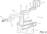
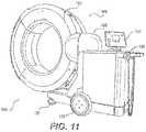
- FIG. 1illustrates an embodiment of an automated medical system 2.
- a three-dimensional (“3D") image scanmay be taken of a desired surgical area of a patient and sent to a computer platform in communication with an automated medical system 2.
- a physicianmay then program a desired point of insertion and trajectory for a surgical instrument to reach a desired anatomical target within or upon the body of the patient.
- the desired point of insertion and trajectorymay be planned on the 3D image scan, which in some embodiments, may be displayed on a display.
- a physicianmay plan the trajectory and desired insertion point (if any) on a computed tomography scan (hereinafter referred to as "CT scan") of the patient.
- CT scancomputed tomography scan
- the CT scanmay be an isocentric C-arm type scan, or any other similar type scan, or intraoperative CT scan as is known in the art.
- any known 3D image scanmay be used in accordance with the embodiments of automated medical system 2.
- Automated medical system 2may assist surgeons and doctors during medical procedures. Automated medical system 2 may assist surgeons and doctors by holding tools, aligning tools, using tools, guiding tools, and/or positioning tools for use.
- automated medical system 2may comprise of a robot support system 4 and a camera tracking system 6. Both systems may be coupled together by any suitable means. Suitable means may be, but are not limited to mechanical latches, ties, clamps, buttresses, magnetic and/or magnetic surfaces. The ability to combine robot support system 4 and camera tracking system 6 may allow for automated medical system 2 to maneuver and move as a single unit. This combination may allow automated medical system 2 to have a small footprint in an area, allow easier movement through narrow passages and around turns, and allow and storage within a smaller area.
- Robot support system 4may be used to assist a surgeon by orienting, positioning, holding and/or using tools during a medical procedure. To properly utilize, position, and/or hold tools, robot support system 4 may rely on a plurality of motors, computers, and/or actuators to function properly. Illustrated in FIG. 1 , robot body 8 may act as the structure in which the plurality of motors, computers, and/or actuators may be secured within robot support system 4. Robot body 8 may also provide support for robot telescoping support arm 16. In embodiments, robot body 8 may be made of any suitable material. Suitable material may be, but is not limited to, metal such as titanium, aluminum, or stainless steel, carbon fiber, fiberglass, or heavy-duty plastic. The size of robot body 8 may provide a solid platform on which other components may connect and operate. Robot body 8 may house, conceal, and protect the plurality of motors, computers, and/or actuators that may operate attached components.
- Robot base 10may act as a lower support for robot support system 4.
- robot base 10may support robot body 8 and may attach robot body 8 to a plurality of powered wheels 12. This attachment to the wheels may allow robot body 8 to move in space efficiently.
- Robot base 10may run the length and width of robot body 8.
- Robot base 10may be about an two inches to about ten inches tall.
- Robot base 10may be made of any suitable material. Suitable material may be, but is not limited to, metal such as titanium, aluminum, or stainless steel, carbon fiber, fiberglass, or heavy-duty plastic or resin.
- Robot base 10may cover, protect, and support powered wheels 12.
- At least one powered wheel 12may be attached to robot base 10.
- Powered wheels 12may attach to robot base 10 at any location.
- Each individual powered wheel 12may rotate about a vertical axis in any direction.
- a motormay be disposed above, within, or adjacent to powered wheel 12. This motor may allow for automated medical system 2 to maneuver into any location and stabilize and/or level automated medical system 2.
- a rod, located within or adjacent to powered wheel 12,may be pressed into a surface by the motor.
- the rodnot pictured, may be made of any suitable metal to lift automated medical system 2. Suitable metal may be, but is not limited to, stainless steel, aluminum, or titanium.
- the rodmay comprise at the contact surface-side end a buffer, not pictured, which may prevent the rod from slipping and/or create a suitable contact surface.
- the materialmay be any suitable material to act as a buffer. Suitable material may be, but is not limited to, a plastic, neoprene, rubber, or textured metal.
- the rodmay lift powered wheel 10, which may lift automated medical system 2, to any height required to level or otherwise fix the orientation of the automated medical system 2 in relation to a patient.
- the weight of automated medial system 2supported through small contact areas by the rod on each wheel, prevents automated medical system 2 from moving during a medical procedure. This rigid positioning may prevent objects and/or people from moving automated medical system 2 by accident.
- Robot railing 14provides a person with the ability to move automated medical system 2 without grasping robot body 8. As illustrated in FIG. 1 , robot railing 14 may run the length of robot body 8, shorter than robot body 8, and/or may run longer the length of robot body 8. Robot railing 14 may be made of any suitable material, but is not limited to, metal such as titanium, aluminum, or stainless steel, carbon fiber, fiberglass, or heavy-duty plastic. Robot railing 14 may further provide protection to robot body 8, preventing objects and or personnel from touching, hitting, or bumping into robot body 8.
- Robot body 8may provide support for a Selective Compliance Articulated Robot Arm, hereafter referred to as a "SCARA."
- a SCARA 24may be beneficial to use within the automated medical system due to the repeatability and compactness of the robotic arm. The compactness of a SCARA may provide additional space within a medical procedure, which may allow medical professionals to perform medical procedures free of excess clutter and confining areas.
- SCARA 24may comprise robot telescoping support 16, robot support arm 18, and/or robot arm 20.
- Robot telescoping support 16may be disposed along robot body 8. As illustrated in FIG. 1 , robot telescoping support 16 may provide support for the SCARA 24 and display 34. In embodiments, robot telescoping support 16 may extend and contract in a vertical direction.
- Robot telescoping support 16may be made of any suitable material, but not limited to, metal such as titanium or stainless steel, carbon fiber, fiberglass, or heavy-duty plastic.
- the body of robot telescoping support 16may be any width and/or height in which to support the stress and weight placed upon it.
- medical personnelmay move SCARA 24 through a command submitted by the medical personnel.
- the commandmay originate from input received on display 34 and/or a tablet.
- the commandmay come from the depression of a switch and/or the depression of a plurality of switches. Best illustrated in FIGS. 4 and 5 , an activation assembly 60 may comprise a switch and/or a plurality of switches.
- the activation assembly 60may be operable to transmit a move command to the SCARA 24 allowing an operator to manually manipulate the SCARA 24.
- the switch, or plurality of switchesWhen the switch, or plurality of switches, is depressed the medical personnel may have the ability to move SCARA 24 easily. Additionally, when the SCARA 24 is not receiving a command to move, the SCARA 24 may lock in place to prevent accidental movement by personnel and/or other objects. By locking in place, the SCARA 24 provides a solid platform upon which an end effector 22 and end effector tool 26 may be used during a medical operation.
- Robot support arm 18may be disposed on robot telescoping support 16 by any suitable means. Suitable means may be, but is not limited to, nuts and bolts, ball and socket fitting, press fitting, weld, adhesion, screws, rivets, clamps, latches and/or any combination thereof. In embodiments, best seen in FIGS. 1 and 2 , robot support arm 18 may rotate in any direction in regard to robot telescoping support 16. Robot support arm 18 may rotate three hundred and sixty degrees around robot telescoping support 16. Robot arm 20 may connect to robot support arm 18 at any suitable location. Robot arm 20 may attach to robot support arm 16 by any suitable means.
- End effector 22may attach to robot arm 20 in any suitable location. End effector 22 may attach to robot arm 20 by any suitable means. Suitable means may be, but is not limited to, latch, clamp, nuts and bolts, ball and socket fitting, press fitting, weld, screws, and/or any combination thereof. End effector 22 may move in any direction in relation to robot arm 20. This may allow a user to move end effector 22 to a desired area.
- An end effector tool 26, as illustrated in FIG. 4may attach to end effector 22. End effector tool 26 may be any tool selected for a medical procedure. In some embodiments, the end effector tool 26 includes a tube portion have a hollow tube 27 extending therethrough. The hollow tube 27 is sized and configured to receive at least a portion of a surgical instrument.
- the hollow tube 27is configured to be oriented by the robot arm 20 such that insertion and trajectory for the surgical instrument is able to reach a desired anatomical target within or upon the body of the patient.
- the surgical instrumentmay include at least a portion of a generally cylindrical instrument.
- the surgical instrumentmay include one or more of a guide wire, cannula, a retractor, a drill, a reamer, a screw driver, an insertion tool, a removal tool, or the like.
- the hollow tube 27is generally shown as having a cylindrical configuration, it will be appreciated by those of skill in the art that the hollow tube 27 may have any suitable shape, size and configuration desired to accommodate the surgical instrument and access the surgical site.
- End effector tool 26may be disposed and removed from end effector 22.
- a light indicator 28may be positioned on top of the SCARA 24.
- Light indicator 28may illuminate as any type of light to indicate "conditions" in which automated medical system 2 is currently operating. For example, the illumination of green may indicate that all systems are normal. Illuminating red may indicate that automated medical system 2 is not operating normally.
- a pulsating lightmay mean automated medical system 2 is performing a function. Combinations of light and pulsation may create a nearly limitless amount of combinations in which to communicate the current operating "conditions.”
- the lightmay be produced by LED bulbs, which may form a ring around light indicator 28.
- Light indicator 28may comprise a fully permeable material that may let light shine through the entirety of light indicator 28. In embodiments, light indicator 28 may only allow a ring and/or designated sections of light indicator 28 to allow light to pass through.
- Light indicator 28may be attached to lower display support 30.
- Lower display support 30, as illustrated in FIG. 2may allow an operator to maneuver display 34 to any suitable location.
- Lower display support 30may attach to light indicator 28 by any suitable means. Suitable means may be but is not limited to, latch, clamp, nuts and bolts, ball and socket fitting, press fitting, weld, adhesion, screws, rivets, and/or any combination thereof.
- lower display support 30may rotate about light indicator 28.
- lower display support 30may attach rigidly to light indicator 28.
- Light indicator 28may then rotate three hundred and sixty degrees about robot support arm 18.
- Lower display support 30may be of any suitable length, a suitable length may be about eight inches to about thirty four inches.
- Lower display support 30may act as a base for upper display support 32.
- Upper display support 32may attach to lower display support 30 by any suitable means. Suitable means may be, but are not limited to, latch, clamp, nuts and bolts, ball and socket fitting, press fitting, weld, adhesion, screws, rivets, and/or any combination thereof. Upper display support 32 may be of any suitable length, a suitable length may be about eight inches to about thirty four inches. In embodiments, as illustrated in FIG. 1 , upper display support 32 may allow display 34 to rotate three hundred and sixty degrees in relation to upper display support 32. Likewise, upper display support 32 may rotate three hundred and sixty degrees in relation to lower display support 30.
- Display 34may be any device which may be supported by upper display support 32. In embodiments, as illustrated in FIG. 2 , display 34 may produce color and/or black and white images.
- the width of display 34may be about 20,32 cm (eight inches) to about 76,2 cm (thirty inches) wide.
- the height of display 34may be about 15,24 cm (six inches) to about 55,88 cm (twenty two inches) wide.
- the depth of display 34may be about 1,27 cm (one half inch) to about four inches (10,16 cm).
- a tabletmay be used in conjunction with display 34 and/or without display 34.
- the tablemay be disposed on upper display support 32, in place of display 34, and may be removable from upper display support 32 during a medical operation.
- the tabletmay communicate with display 34.
- the tablemay be able to connect to robot support system 4 by any suitable wireless and/or wired connection.
- the tabletmay be able to program and/or control automated medical system 2 during a medical operation. When controlling automated medical system 2 with the tablet, all input and output commands may be duplicated on display 34.
- the use of a tabletmay allow an operator to manipulate robot support system 4 without having to move around patient 50 and/or to robot support system 4.
- camera tracking system 6may work in conjunction with robot support system 4. Described above, camera tracking system 6 and robot support system 4 may be able to attach to each other.
- Camera tracking system 6, now referring to FIG. 1may comprise similar components of robot support system 4.
- camera body 36may provide the functionality found in robot body 8.
- Robot body 8may provide the structure upon which camera 46 may be mounted. The structure within robot body 8 may also provide support for the electronics, communication devices, and power supplies used to operate camera tracking system 6.
- Camera body 36may be made of the same material as robot body 8.
- Camera tracking system 6may also communicate with robot support system 4 by any suitable means. Suitable means may be, but are not limited to, a wired or wireless connection. Additionally, camera tracking system 6 may communicate directly to the table by a wireless and/or wired connection. This communication may allow the tablet to control the functions of camera tracking system 6.
- Camera body 36may rest upon camera base 38.
- Camera base 38may function as robot base 10.
- camera base 38may be wider than robot base 10.
- the width of camera base 38may allow for camera tracking system 6 to connect with robot support system 4.
- the width of camera base 38may be large enough to fit outside robot base 10.
- the additional width of camera base 38may allow automated medical system 2 additional maneuverability and support for automated medical system 2.
- a plurality of powered wheels 12may attach to camera base 38.
- Powered wheel 12may allow camera tracking system 6 to stabilize and level or set fixed orientation in regards to patient 50, similar to the operation of robot base 10 and powered wheels 12. This stabilization may prevent camera tracking system 6 from moving during a medical procedure and may keep camera 46 from losing track of DRA 52 within a designated area. This stability and maintenance of tracking may allow robot support system 4 to operate effectively with camera tracking system 6.
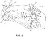
- the wide camera base 38may provide additional support to camera tracking system 6. Specifically, a wide camera base 38 may prevent camera tracking system 6 from tipping over when camera 46 is disposed over a patient, as illustrated in FIG. 5 . Without the wide camera base 38, the outstretched camera 46 may unbalance camera tracking system 6, which may result in camera tracking system 6 falling over.
- Camera telescoping support 40may support camera 46. In embodiments, telescoping support 40 may move camera 46 higher or lower in the vertical direction. Telescoping support 40 may be made of any suitable material in which to support camera 46. Suitable material may be, but is not limited to, metal such as titanium, aluminum, or stainless steel, carbon fiber, fiberglass, or heavy-duty plastic. Camera handle 48 may be attached to camera telescoping support 40 at any suitable location. Cameral handle 48 may be any suitable handle configuration. A suitable configuration may be, but is not limited to, a bar, circular, triangular, square, and/or any combination thereof. As illustrated in FIG. 1 , camera handle 48 may be triangular, allowing an operator to move camera tracking system 6 into a desired position before a medical operation. In embodiments, camera handle 48 may be used to lower and raise camera telescoping support 40. Camera handle 48 may perform the raising and lowering of camera telescoping support 40 through the depression of a button, switch, lever, and/or any combination thereof.
- Lower camera support arm 42may attach to camera telescoping support 40 at any suitable location, in embodiments, as illustrated in FIG. 1 , lower camera support arm 42 may rotate three hundred and sixty degrees around telescoping support 40. This free rotation may allow an operator to position camera 46 in any suitable location.
- Lower camera support arm 42may be made of any suitable material in which to support camera 46. Suitable material may be, but is not limited to, metal such as titanium, aluminum, or stainless steel, carbon fiber, fiberglass, or heavy-duty plastic.
- Cross-section of lower camera support arm 42may be any suitable shape. Suitable cross-sectional shape may be, but is not limited to, circle, square, rectangle, hexagon, octagon, or i-beam. The cross-sectional length and width may be about one to ten inches.
- Length of the lower camera support armmay be about 10,16 cm (four inches) to about 91,44 cm (thirty-six inches).
- Lower camera support arm 42may connect to telescoping support 40 by any suitable means. Suitable means may be, but is not limited to, nuts and bolts, ball and socket fitting, press fitting, weld, screws, and/or any combination thereof.
- Lower camera support arm 42may be used to provide support for camera 46.
- Camera 46may be attached to lower camera support arm 42 by any suitable means. Suitable means may be, but is not limited to, nuts and bolts, ball and socket fitting, press fitting, weld, screws, and/or any combination thereof.
- Camera 46may pivot in any direction at the attachment area between camera 46 and lower camera support arm 42. In embodiments a curved rail 44 may be disposed on lower camera support arm 42.
- Curved rail 44may be disposed at any suitable location on lower camera support arm 42. As illustrated in FIG. 3 , curved rail 44 may attach to lower camera support arm 42 by any suitable means. Suitable means may be, but are not limited to nuts and bolts, ball and socket fitting, press fitting, weld, adhesion, screws, rivets, clamps, latches, and/or any combination thereof. Curved rail 44 may be of any suitable shape, a suitable shape may be a crescent, circular, oval, elliptical and/or any combination thereof. In embodiments, curved rail 44 may be any appropriate length. An appropriate length may be about one foot to about six feet. Camera 46 may be moveably disposed along curved rail 44. Camera 46 may attach to curved rail 44 by any suitable means.
- Suitable meansmay be, but are not limited to rollers, brackets, braces, motors, and/or any combination thereof.
- Motors and rollersmay be used to move camera 46 along curved rail 44.
- the motorsmay move camera 46 along curved rail 44 using rollers. This motorized movement may allow camera 46 to move to a new position that is no longer obstructed by the object without moving camera tracking system 6.
- camera tracking system 6may send a stop signal to robot support system 4, display 34, and/or a tablet.
- the stop signalmay prevent SCARA 24 from moving until camera 46 has reacquired DRAs 52. This stoppage may prevent SCARA 24 and/or end effector 22 from moving and/or using medical tools without being tracked by automated medical system 2.
- End effector 22may be used to connect surgical tools to robot support system 4.
- End effector 22may comprise a saddle joint 62, an activation assembly 60, a load cell 64, and a tool connection 66.
- Saddle joint 62may attach end effector 22 to SCARA 24.
- Saddle joint 62may be made of any suitable material. Suitable material may be, but is not limited to metal such as titanium, aluminum, or stainless steel, carbon fiber, fiberglass, or heavy-duty plastic. Saddle joint 62 may be made of a single piece of metal which may provide end effector with additional strength and durability.
- saddle joint 62may attach to SCARA 24 by an attachment point 68. There may be a plurality of attachment points 68 disposed about saddle joint 62.
- Attachment points 68may be sunk, flush, and/or disposed upon saddle joint 62.
- screws, nuts and bolts, and/or any combination thereofmay pass through attachment point 68 and secure saddle joint 62 to SCARA 24.
- the nuts and boltsmay connect saddle joint 62 to a motor, not illustrated, within SCARA 24.
- the motormay move saddle joint 62 in any direction.
- the motormay further prevent saddle joint 62 from moving from accidental bumps and/or accidental touches by actively servoing at the current location or passively by applying spring actuated brakes.
- Saddle joint 62may provide the base upon which a load cell 64 and a tool connection 66 may be disposed.
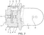
- Load cell 64may attach to saddle joint 62 by any suitable means. Suitable means may be, but is not limited to, screws, nuts and bolts, threading, press fitting, and/or any combination thereof. Load cell 64 may be any suitable instrument used to detect and measurement movement. In examples, load cell 64 may be a six axis load cell, a three-axis load cell or a uniaxial load cell. Load cell 64 may be used to track the force applied to end effector 22. As illustrated in FIG. 17 , a schematic may show the communication between load cell 64 and a motor 120. In embodiments a load cell 64 may communicate with a plurality of motors 120.
- Microcontroller unit 124may take the force information from load cell 64 and process it with a switch algorithm.
- the switch algorithmmay allow microcontroller unit 124 to communicate with a motor driver 126.
- a motor driver 126may control the function of a motor 120, with which motor driver 126 may communicate with.
- Motor driver 126may direct specific motors 120 to produce an equal amount of force measured by load cell 64 through motor 120.
- the force producedmay come from a plurality of motors 120, as directed by microcontroller unit 124. Additionally, motor driver 126 may receive input from motion controller 128.
- Motion controller 128may receive information from load cell 64 as to the direction of force sensed by load cell 64. Motion controller 128 may process this information using a motion controller algorithm. The algorithm may be used to provide information to specific motor drivers 126. To replicate the direction of force, motion controller 128 may activate and/or deactivate certain motor drivers 126. Working in unison and/or separately, microcontroller unit 124 and motion controller 128 may control motor 120 (or a plurality of motors 120) to induce in the direction the motion and direction of force sensed by load cell 64. This force-controlled motion may allow an operator to move SCARA 24 and end effector 22 effortlessly and/or with very little resistance. Movement of end effector 22 may position tool connection 66 in any suitable location for use by medical personnel.
- Tool connection 66may attach to load cell 64.
- Tool connection 66may comprise attachment points 68, a sensory button 70, tool guides 72, and/or tool connections 74. Best illustrated in FIGS. 6 and 8 , there may be a plurality of attachment points 68.
- Attachment points 68may connect tool connection 66 to load cell 64.
- Attachment points 68may be sunk, flush, and/or disposed upon tool connection 66.
- Connectors 76may use attachment points 68 to attach tool connection 66 to load cell 64.
- connectors 76may be screws, nuts and bolts, press fittings, and/or any combination thereof.
- a sensory button 70may be disposed about center of tool connection 66. Sensory button 70 may be depressed when an end effector tool 26, best illustrated in FIG. 4 , is connected to end effector 22. Depression of sensory button 70 may alert robot support system 4, and in turn medical personnel, that an end effector tool 26 has been attached to end effector 22.
- tool guides 72may be used to facilitate proper attachment of end effector tool 26 to end effector 22. Tool guides 72 may be sunk, flush, and/or disposed upon tool connection 66. In examples there may be a plurality of tool guides 72 and may have any suitable patterns and may be oriented in any suitable direction.
- Tool guides 72may be any suitable shape to facilitate attachment of end effector tool 26 to end effector 22.
- a suitable shapemay be, but is not limited to, circular, oval, square, polyhedral, and/or any combination thereof. Additionally, tool guides 72 may be cut with a bevel, straight, and/or any combination thereof.
- Tool connection 66may have attachment points 74. As illustrated in FIG. 6 , attachment points 74 may form a ledge and/or a plurality of ledges. Attachment points 74 may provide end effector tool 26 a surface upon which end effector tool 26 may clamp. In examples, attachment points 74 may be disposed about any surface of tool connection 66 and oriented in any suitable manner in relation to tool connection 66.
- Tool connection 66may further serve as a platform for activation assembly 60.
- Activation assembly 60may encircle tool connection 66.
- activation assembly 60may take the form of a bracelet. As bracelet, activation assembly 60 may wrap around tool connection 66.
- activation assembly 60may be located in any suitable area within automated medical system 2.
- activation assembly 60may be located on any part of SCARA 24, any part of end effector 22, may be worn by medical personnel (and communicate wirelessly), and/or any combination thereof.
- Activation assembly 60may be made of any suitable material. Suitable material may be, but is not limited to neoprene, plastic, rugger, gel, carbon fiber, fabric and/or any combination thereof.
- Activation assembly 60may comprise of a primary button 78 and a secondary button 80.
- Primary button 78 and secondary button 80may encircle the entirety of tool connection 66.
- Primary button 78may be a single ridge, as illustrated in FIG. 6 , which may encircle tool connection 66.
- primary button 78may be disposed upon activation assembly 60 along the end farthest away from saddle joint 62.
- Primary button 78may be disposed upon primary activation switch 82, best illustrated on FIG. 7 .
- Primary activation switch 82may be disposed between tool connection 66 and activation assembly 60.
- there may be a plurality of primary activation switches 82which may be disposed adjacent and beneath primary button 78 along the entire length of primary button 78.
- Depressing primary button 78 upon primary activation switch 82may allow an operator to move SCARA 24 and end effector 22. As discussed above, once set in place, SCARA 24 and end effector 22 may not move until an operator programs robot support system 4 to move SCARA 24 and end effector 22, or is moved using primary button 78 and primary activation switch 82. In examples, it may require the depression of at least two non-adjacent primary activation switches 82 before SCARA 24 and end effector 22 will respond to commands. Depression of at least two primary activation switches 82 may prevent the accidental movement of SCARA 24 and end effector 22 during a medical procedure.
- Secondary button 80may be disposed upon the end of activation assembly 60 closest to saddle joint 62.
- secondary button 80may comprise a plurality of ridges. The plurality of ridges may be disposed adjacent to each other and may encircle tool connection 66.
- secondary button 80may be disposed upon secondary activation switch 84.
- Secondary activation switch 84as illustrated in FIG. 7 , may be disposed between secondary button 80 and tool connection 66.
- secondary button 80may be used by an operator as a "selection" device. During a medical operation, robot support system 4 may notify medical personnel to certain conditions by display 34 and/or light indicator 28.
- Medical personnelmay be prompted by robot support system 4 to select a function, mode, and/or asses the condition of automated medical system 2.
- Depressing secondary button 80 upon secondary activation switch 84 a single timemay activate certain functions, modes, and/or acknowledge information communicated to medical personnel through display 34 and/or light indicator 28.
- depressing secondary button 80 upon secondary activation switch 84 multiple times in rapid successionmay activate additional functions, modes, and/or select information communicated to medical personnel through display 34 and/or light indicator 28.
- at least two non-adjacent secondary activation switches 84may be depressed before secondary button 80 may function properly. This requirement may prevent unintended use of secondary button 80 from accidental bumping by medical personnel upon activation assembly 60.
- Primary button 78 and secondary button 80may use software architecture 86 to communicate commands of medical personnel to automated medical system 2.
- FIG. 9illustrates a flow chart of software architecture 86 which may be used within automated medical system 2.
- Software architecture 86may be used to automated robot support system 4 and camera tracking system 6. Additionally, software architecture 86 may allow an operator to manipulate automated medical system 2 based upon commands given from the operator.
- operator commandsmay comprise Picture Archival and Communication Systems (PACS) 88 (which may communicate with automated imaging system 104, discussed below), USB Devices 90, and commands from tablet 54.
- PPSPicture Archival and Communication Systems
- Computer processor 92may be able to receive all commands and manipulate automated medical system 2 accordingly.
- computer processor 92may be able to control and identify the location of individual parts that comprise automated medical system 2.
- computer processor 92may be able to locate a patient, end effector 22, and robot support system 4 in a defined space (e.g., illustrated in FIG. 5 ). Additionally, computer processor 92 may be able to use commands from display 34 and camera tracking system 6 to alter the positions of SCARA 24.
- Information from load cell 64based upon measured force magnitude and direction, may be processed by computer processor 92 and sent to motors within SACARA 24, as discussed above.
- a General Algebraic Modeling System (GAMS) 94may translate information regarding force magnitude from load cell 64 to electronic signals which may be useable by computer processor 92.
- GAMSGeneral Algebraic Modeling System
- This translationmay allow computer processor 92 to track the location and movement of robot support system 4 in a defined space when SCARA 24 and end effector 22 are moving.
- Computer processor 92may further use firmware 96 to control commands and signals from robot body 8.
- Firmware 96may comprise commands that are hardwired to automated medical system 2.
- computer processor 92may require power from power supply 98 to operate.
- Firmware 96may control the distribution of power from power supply 98 to automated medical system 2.
- computer processor 92may control firmware 96 and the power distribution based on operator commands.
- firmware 96may communicate with light indicator 28, powered wheels 12, and platform interface 100.
- Platform interface 100may be a series of hardwired button commands that directly control automated medical system 2.
- Automated imaging system 104may be used in conjunction with automated medical system 2 to acquire pre-operative, intra-operative, post-operative, and/or real-time image data of patient 50. Any appropriate subject matter may be imaged for any appropriate procedure using automated imaging system 104.
- automated imaging system 104may be an any imaging device such as imaging device 106 and/or a C-arm 108 device. It may be desirable to take x-rays of patient 50 from a number of different positions, without the need for frequent manual repositioning of patient 50 which may be required in an x-ray system.
- C-arm 108 x-ray diagnostic equipmentmay solve the problems of frequent manual repositioning and may be well known in the medical art of surgical and other interventional procedures. As illustrated in FIG.
- C-arm 108may be mounted to enable rotational movement of the arm in two degrees of freedom, (i.e. about two perpendicular axes in a spherical motion).
- C-arm 108may be slidably mounted to x-ray support structure 118, which may allow orbiting rotational movement of C-arm 108 about its center of curvature, which may permit selective orientation of x-ray source 114 and image receptor 116 vertically and/or horizontally.
- C-arm 108may also be laterally rotatable, (i.e. in a perpendicular direction relative to the orbiting direction to enable selectively adjustable positioning of x-ray source 114 and image receptor 116 relative to both the width and length of patient 50).
- C-arm 108 apparatusmay allow physicians to take x-rays of patient 50 at an optimal angle as determined with respect to the particular anatomical condition being imaged.
- a C-arm 108may be supported on a wheeled support cart 120.
- imaging device106may be used separately and/or in conjunction with C-arm 108.
- imaging device 106may comprises a gantry housing 124 having a central opening 126 for positioning around an object to be imaged, a source of radiation that is rotatable around the interior of gantry housing 124, which may be adapted to project radiation from a plurality of different projection angles.
- a detector systemmay be adapted to detect the radiation at each projection angle to acquire object images from multiple projection planes in a quasi-simultaneous manner.
- a gantrymay be attached to a support structure imaging device support structure 128, such as a wheeled mobile cart 130 with wheels 132, in a cantilevered fashion.
- a positioning unit 134may translate and/or tilt the gantry to a desired position and orientation, preferably under control of a computerized motion control system.
- the gantrymay include a source and detector disposed opposite one another on the gantry.
- the source and detectormay be secured to a motorized rotor, which may rotate the source and detector around the interior of the gantry in coordination with one another.
- the sourcemay be pulsed at multiple positions and orientations over a partial and/or full three hundred and sixty degree rotation for multi-planar imaging of a targeted object located inside the gantry.
- the gantrymay further comprise a rail and bearing system for guiding the rotor as it rotates, which may carry the source and detector.
- Both and/or either imaging device 106 and C-arm 108may be used as automated imaging system 104 to scan patient 50 and send information to automated medical system 2.
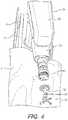
- a patient 50may have a medical procedure performed upon the spine. Medical personnel may use imaging equipment to locate and find the spine, as detailed above. Using the images, an operator may upload the information regarding the location of the spine into automated medical system 2. Automated medical system 2 may then track, locate, and move end effector tools 26 to areas specified by the operator. In an example, a gravity well 102 and/or a plurality of gravity wells 102 may be mapped onto the spine of patient 50, as illustrated in FIG. 12 . Gravity wells 102 may be areas, programmed by an operator, to attract end effector tools 26. These areas may cause SCARA 24 and end effector 22 to move toward the direction, angle, and location programmed by medical personnel.
- a gravity well 102indicates, in a virtual space, the angle and location end effector tool 26 may need to be positioned for a medical procedure.
- End effector tool 26, as illustratedmay be moved by an operator using activation assembly 60, discussed above.
- the operatormay feel the motors in SCARA 24 being to move end effector tool 26 into the programmed position of gravity well 102.
- gravity well 102may maneuver end effector tool 26 into the programmed position. In an example, if the operator begins to move end effector tool 26 using activation assembly 60, the operator may feel the motors provide resistance against the movement.
- the resistance from the motorsmay not be strong enough resistance to keep end effector tool 26 within gravity well 102. This may be beneficial as it may allow the operator to maneuver end effector tool 26 to additional gravity wells 102.
- Gravity well 102may be programmed into automated medical system 2 before the medical operation and/or during the medical operation. This may allow medical personnel to move a gravity well 102 based on the changing conditions of the medical procedure. Gravity wells 102 may allow automated medical system 2 to place end effector tools 26 in the required area quickly, easily, and correctly.
- FIG. 15illustrates a portion of the robot's end effector 22 including the tool portion 26 defining hollow tube 202.
- a metal objectsuch as a metallic surgical instrument 204
- the hollow tube 202is sized and configured to receive at least a portion of the metallic surgical instrument 204.
- the metal objectmay include any suitable surgical instrument 204 known in the art including, but not limited to, a guide wire, a cannula, a retractor, a drill, a reamer, a driver, an insertion tool, a removal tool, or the like.
- the hollow tube 202is generally shown as having a cylindrical configuration, it will be appreciated by those of skill in the art that the hollow tube 202 may have any suitable shape, size and configuration desired to accommodate the surgical instrument 204 and access the surgical site.
- the hollow tube 202is configured to be aligned and/or oriented by the robot arm 20 such that insertion and/or trajectory for the surgical instrument 204 is able to reach a desired anatomical target within or upon the body of the patient.
- the surgical instrument 204may be inserted into the hollow tube 202 after operating the robot 4 to achieve this desired alignment and/or orientation for the desired surgical procedure.
- the robotic systemis shut down once the metal surgical instrument 204 is inserted through a portion of the hollow tube 202 or through the entire hollow tube 202.
- the presence of the instrument 204 and/or insertion of the instrument 204should be detected in order to shut off one or more electronic components of the robot 4, such as cameras, infrared detectors, or the like for safety reasons.
- This safety mechanismensures that the robot 4, in particular, the robot arm 20, and more particularly, end effector 22, does not move when the metallic surgical instrument 204 is present in the end effector 22.
- this automatic shut off systemensures the safety of the patient because the trajectory and orientation of the surgical instrument 204 positioned through tube 202 cannot change during the operation.
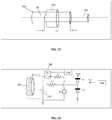
- FIG. 16is a schematic diagram of a decaying waveform generator 208 according to an aspect of the present invention.
- a capacitor 210 connected in parallel with the inductor 206define a resonance circuit of the generator 208.
- a voltage source Vsprovides current to the resonance circuit through a current limiting resistor R1 which is connected in series with a switch SW1.
- a second resistor R2is connected between the resonant circuit and an output terminal Vout.
- the switch SW1when the controller 240 turns on the switch SW1 for a predetermined time period ⁇ , the switch SW1 connects the voltage source Vs to the resonant circuit (206, 210) to allow current from the voltage source Vs to flow into the coil 206 and place an initial voltage Vc across the capacitor 210. This action also sets the initial charge in the inductor L to a value (Vs ⁇ ⁇ ), where ⁇ is the switch on time.
- the voltage source Vsis disconnected from the resonant circuit (206, 210) and the voltage across the capacitor 210 starts to oscillate in a decaying manner.
- the resistor R2sets the current being provided to the output terminal Vo.
- the clamping diode D1ensures that the voltage at the output terminal Vout does not fall substantially below ground. If the capacitor 210 tries to pull the output voltage below zero, the diode D1 turns on and forces the output terminal Vout to ground voltage less the forward biasing voltage (e.g., 0.3 V) of the diode such that the minimum voltage at the output terminal Vout is -0.3 Volt. In effect, the clamping diode D1 acts as a rectifier to provide only a positive voltage to the output terminal Vout.
- the clamping diode D2turns on and clamps the output voltage to Vcmp plus the forward biasing voltage (e.g., 0.3 V) of the diode.
- the reference voltage Vcmpcan be set to the maximum voltage permissible (e.g., 5 V) for the controller 240 to make the waveform generator 208 suitable for any number of microcontroller units on the market.
- the maximum voltage at the output terminal Voutis 5.3 Volt.
- the current limiting resistor R1ensures that the coil 206 does not become damaged.
- the resulting decaying waveform at the output terminal Voutis stored in the controller 240.
- the stored decaying waveformcan then be analyzed to determine the effective Q-value of the resonant circuit.
- the Q valuecan change depending on both the inductance of the coil, and its ESR, and it is this change in Q that is responsible for the change in decay of the waveform.
- the effective Q valuecan be used to determine the presence of a metal object 204 inside the hollow tube 202 and the depth of insertion to determine, for example, whether the metal object has been fully inserted as will be explained in more detail below.
- FIG. 17is a schematic diagram of a controller 240 for detecting the presence of or insertion of a metal object 204 in tube 202 according to an aspect of the present invention.
- the controller 240 of the present inventionis connected to the output terminal Vout and switch SW1 through a communication link 252 which is connected to an I/O interface 242, which receives information from and sends information over the communication link 252.
- the controller 240includes memory storage 244 such as RAM (random access memory), processor (CPU) 246, program storage 248 such as FPGA, ROM or EEPROM, and data storage 250 such as a hard disk, all commonly connected to each other through a bus 253.
- the program storage 248stores, among others, metal detection module 254 containing software to be executed by the processor 246.
- the metal detection module 254executed by the processor 246 controls the switch SW1.
- the module 254can also control the inductor 206 and capacitor 210 if variable inductor or capacitor were used in order to control the frequency of the decaying waveform.
- the metal detection module 254includes a user interface module that interacts with the user through the display device 211 and input devices such as keyboard 212 and pointing device 214 such as arrow keys, mouse or track ball.
- the user interface moduleassists the user in programming the programmable components in the waveform generator 208 and calibration of data as will be explained in more detail herein. Any of the software program modules in the program storage 248 and data from the data storage 250 can be transferred to the memory 244 as needed and is executed by the CPU 246.
- An analog-to-digital (A/D) converter 243is connected to the I/O interface 242.
- the A/D converter 243converts the analog decaying waveform at the output terminal Vout into digital data to be stored in the storage 250 by the processor 246.
- One exemplary controller 240may be 8051 microcontroller from Intel Corporation of Santa Clara, CA. However, any processor or microcontroller that offers an A/D converter can be used.
- parts of or the entire the controller 240 including the input devices 212, 214 and display device 211can be incorporated into the automated medical system 2 of FIG. 1 .
- the display 211can be the same as display 34.
- step 256the user interface of the metal detection module 254 interacts with the user in selecting the switch-on time ⁇ , metal detection calculation method, and calibration mode, which are stored in the data storage 250. If the user or the module 254 itself selects the calibration mode, then all of the steps are used to determine an initial Q value (and initial inductance value) without any metal object for storage in the storage 250 for later use in determining the presence and depth of the metal object 204 inside the hollow tube 202.
- step 258the controller 240 sends a signal through the link 252 to turn on the switch SW1 for a preselected time (e.g., 100 microseconds).
- the switch SW1connects the voltage source Vs to the resonant circuit (6,10) and current I e flows through R1. This places an initial voltage Vs across the capacitor 210, and pre-charges the coil 206 to an initial flux level of (Vs ⁇ ⁇ ). This magnetic charge is then built up in the coil 206 until the switch SW1 turns off. Once the switch SW1 turns off, the resonating current in the resonant circuit outputs a decaying waveform.
- step 260the decaying waveform at the output terminal Vout is converted into digital data and stored in the storage 250.
- a Q value of the inductor 206is calculated by the following methods.
- the initial current in the coil 206may be set by two different methods.
- the first methodis by keeping the switch SW1 closed for a sufficiently long time, allowing I e to settle to v R 1 + ESR .
- the other methodis to keep the switch SW1 on for a "short time" ⁇ setting the initial current to v L ⁇ ⁇ , where L is the inductance of the coil 206.
- SW1opens and the circuit is allowed to resonate at its own natural frequency as a decaying voltage waveform at the capacitor 210.
- the voltage across the capacitor 210may be monitored to calculate what the Q value of the coil 206 is.
- V c tv ⁇ ⁇ 0 2 ⁇ e ⁇ ⁇ ⁇ t ⁇ 2 + ⁇ n 2 ⁇ ⁇ ⁇ ⁇ ⁇ 2 ⁇ ⁇ ⁇ ⁇ n 2 ⁇ sin ⁇ n ⁇ t + ⁇ n ⁇ cos ⁇ n ⁇ t ⁇ v ⁇ ⁇ 0 2 ⁇ ⁇ 2 ⁇ ⁇ n 2 ⁇ 2 + ⁇ n 2
- ⁇1 2 ⁇ R ESR L
- ⁇ 01 L ⁇ C
- ⁇ n⁇ 0 2 ⁇ ⁇ 2
- the voltage across the capacitor 210produces a current in R2 and a typical waveform produced at the output terminal Vout is shown in FIG. 18 .
- the switch SW1shuts off.
- FIG. 18only the first three waves (t2 to t4, t5 to t7 and t8 to t10) in the waveform are shown.
- the decaying waveformmay be used in many ways to calculate what the Q value of the coil 206 is.
- a first method to determine the Q valueis to measure the "average value" of the waveform.
- An average valuecan be realized by calculating the integral of the area under the waveform over a predetermined number of waves or time period and then dividing by the time interval where the voltage is present.
- a relationship between the average value and Q valuecan be determined empirically or by equation (1).
- Another way to determine the Q valueis to measure the zero crossing voltages that occur at times t2, t4, t5, t7, t8 and t10. From these values, the Q value may be computed from equation (1).
- Yet another way to determine the Q valueis to measure the signal energy of the waveform over a time "window" by computing the integral of the waveform in the time t 0 - t n , such that t n > 3 ⁇ where ⁇ is the time constant of the resonant circuit. From these values, the Q value may be computed from equation (1).
- one exemplary embodimentuses the fourth method of integrating over a time window.
- the metal detection module 254 of the controller 240can compute a sum of the sampled signals as a way to integrate the signal. That sum can be compared or characterized to different values of Q by equation (1) above or empirically.
- the characterizationcan be stored in storage as a lookup table which can then be retrieved and used by the metal detection module 254 with interpolation.
- the metal detection module 254determines whether the metal object 204 is present in the hollow tube 202. As an example, in one embodiment, assume that the user has selected the first peak voltage determination as the method of obtaining a Q value in step 256. Once the Q value has been obtained from the first peak voltage and t3 values, the metal detection module 254 compares it to a threshold value which has been preselected.
- the threshold inductance valuecan be set at 50 ⁇ H below which the metal detection module 254 considers the metal object to be present (e.g., metal object is substantially fully inserted into the tube 202).
- Another way to detect the presenceis to empirically obtain a threshold Q value (or inductance value) under which the module 254 determines that the metal object 204 is present in the hollow tube 202. This can be done by inserting the metal object 204 into the hollow tube 202 at a user-selected depth and determining the Q value (or inductance value) based on a decaying waveform.
- the metal detection module 254determines how deep the metal object 204 is inside the hollow tube 202.
- One way to determine the depthis to empirically obtain a lookup table of Q values (or inductance values) at various depths for a given metal object 204.
- FIG. 19illustrates several decaying waveforms from the waveform generator 208 which represent the depth of insertion of the metal object 204 into the hollow tube 202.
- Waveform 270represents one in which no metal object is present.
- Waveform 270equates to the original Q value of Q1 without any metal object insertion.
- Waveform 272represent one in which the metal object 204 has been inserted half way, i.e., the distal end of the metal object 204 is at a midpoint between the center of the tube 202 and proximal end of the tube.
- Waveform 72equates to Q value of Q2 which is less than Q1.
- a lookup tablecan be prepared.
- the tableequates various Q values to respective distance ⁇ x (i.e., depth).
- ⁇ xi.e., depth
- FIG. 22shows a graph of Q values as a function of the depth of insertion of the metal object into the hollow tube (distance ⁇ x).
- the experimentwas performed with a 6 mm diameter Ferrite metal object (cylinder) and a 15 mm diameter by 8 mm length coil.
- the distance ⁇ xrepresents the distance from the distal end of the metal cylinder and the center of the coil.
- the graph of FIG. 22can be stored in the storage 250 as a lookup table for retrieval by the metal detection module 254. Interpolation may need to be used if the lookup table is stored as a set of discrete points, rather than an equation.
- step 266the metal detection module 254 looks up the depth value from the lookup table stored in the storage 250 for a given Q value which was found in step 262.
- the depth value from the lookup tableis generated as the output from the metal detection module 254.
- a rectified decaying waveformhas been used because it is relatively simple to integrate over the waveform. If a full non-rectified decaying waveform is used, more components will be needed as a simple method of integrating will not work because of the symmetry of the waves.
- the present inventionhas been described above with the coil which is positioned at the center of the tube 202, it is possible to position the coil at the proximal end, distal end or anywhere along the tube. It is also possible to use multiple coils that are spaced apart. For example, three coils (respectively positioned at the proximal end, center and distal end) that are uniformly spaced from each other can be used to detect the presence and depth of the metal object inside the hollow tube 202. As can be appreciated, this embodiment can be particularly useful when determining the depth of the metal object (e.g., surgical instrument 204) in the hollow tube 202.
- the metal objecte.g., surgical instrument 204
- the on time of the switch SW1 for each inductor coile.g., turning on and off the resonant circuit and measuring the inductance value prior to turning on the next resonant circuit
- it is preferable to separate the on time of the switch SW1 for each inductor coile.g., turning on and off the resonant circuit and measuring the inductance value prior to turning on the next resonant circuit
- the present inventionuses minimum number of components by utilizing the power of a processor such as a microcontroller for the processing of waveforms.
- a processorsuch as a microcontroller for the processing of waveforms.
- the circuit in the form of a waveform generator 208requires only the switch SW1, capacitor 210 and inductor 206.
- the hollow tube 202is aligned and/or oriented by the robot 4 in order to obtain a desired insertion angle and/or trajectory for the surgical instrument 204.
- the surgical instrument 204may be inserted into the hollow tube 202.
- the robotic systemis shut down by the presence of the surgical instrument 204 in the tube 202 or at a certain depth therein.
- the mere presence of the instrument 204triggers an automatic shut off of certain robotic components (e.g., those the control or allow for movement of the robotic arm 20. This automatic shut off ensures the trajectory and orientation of the surgical instrument 204, and thus cannot change during the operation.
- the robot arm 20the instrument 204 must be removed from the tube 202, thereby ensuring safety of the patient.
Landscapes
- Health & Medical Sciences (AREA)
- Life Sciences & Earth Sciences (AREA)
- Engineering & Computer Science (AREA)
- Surgery (AREA)
- Medical Informatics (AREA)
- Nuclear Medicine, Radiotherapy & Molecular Imaging (AREA)
- Public Health (AREA)
- Heart & Thoracic Surgery (AREA)
- Biomedical Technology (AREA)
- Molecular Biology (AREA)
- Animal Behavior & Ethology (AREA)
- General Health & Medical Sciences (AREA)
- Veterinary Medicine (AREA)
- Robotics (AREA)
- Pathology (AREA)
- Radiology & Medical Imaging (AREA)
- Physics & Mathematics (AREA)
- Oral & Maxillofacial Surgery (AREA)
- Orthopedic Medicine & Surgery (AREA)
- Pulmonology (AREA)
- Theoretical Computer Science (AREA)
- Dentistry (AREA)
- Biophysics (AREA)
- High Energy & Nuclear Physics (AREA)
- Optics & Photonics (AREA)
- General Physics & Mathematics (AREA)
- Manipulator (AREA)
Description
- The present invention relates to metal detectors, systems, and in particular, metal detectors for detecting a metallic surgical instrument.
- Conventional metal detectors use a power-consuming resonance circuit which is always turned on, and detects the change in electromagnetic properties, e.g., a Q value, of an inductor in the resonance circuit. When a piece of metal is near the resonance circuit, the metal detector will detect the change in Q-value to determine whether a metal has been found.
- One problem with such a conventional metal detector is that because the resonant circuit is always on, the detector can waste a substantial amount of power. In the context of performing medical procedures using a portable robot, it is important to use as little power as possible. Therefore, there is a need to provide a device and method for more efficiently detecting the presence of metal.
- According to one aspect of the present invention, a metal detector for detecting insertion of a metallic surgical device into a hollow tube is provided. The metal detector includes a switch, resonant circuit and a controller. The resonant circuit includes a capacitor and a coil connected to the capacitor in parallel. The coil is mounted to the hollow tube. The controller is adapted to turn on the switch for a preselected time to temporarily provide a current to the resonant circuit and analyzes a resulting decaying voltage waveform originating from the resonant circuit when the switch is turned off in order to determine the presence of the metallic surgical device in the hollow tube. The hollow tube is defined by a tool portion of an end-effector configured for use in a robot-assisted surgery. A determination of the the presence of the metallic surgical device prevents the movement of the end-effector.
- According to an illustrative example, a method of detecting insertion of a metallic surgical device into a hollow tube is provided. Initially, a power supply is connected to a resonant circuit having a capacitor and an inductor mounted to the hollow tube. After a preselected time period, the power supply is disconnected from the resonant circuit. Once the power supply is disconnected, the resonant circuit generates a decaying waveform. The decaying waveform has a different shape depending on whether a metallic surgical device has been inserted into the hollow tube or not. The presence of the metallic surgical device in the hollow tube is then determined based on the generated decaying waveform.
- According to a further illustrative example, a method of detecting insertion of a metallic surgical device into a hollow tube, comprises: connecting a power supply to a resonant circuit having a capacitor and an inductor mounted to the hollow tube; disconnecting the power supply from the resonant circuit after a preselected time period to generate a decaying waveform from the resonant circuit; detecting the presence of the metallic surgical device in the hollow tube based on the generated decaying waveform.
- In a version the method further comprises clamping the decaying waveform to prevent the voltage of the decaying waveform from falling substantially below ground.
- In another version, the method further comprises clamping the decaying waveform to prevent the voltage of the decaying waveform from rising substantially past a reference voltage.
- In another version, the method further comprises the presence of the metallic surgical device inside the hollow tube is detected by determining a Q value from the decaying voltage waveform.
- In another version, the method further comprises the presence of the metallic surgical device is determined by determining the times at which the waves in the decaying waveform cross a preselected voltage value.
- In another version, the presence of the metallic surgical device is determined by determining an integral of the decaying waveform over a preselected time window.
- In a version, the controller determines the longitudinal position of the metallic surgical device inside the hollow tube from the decaying waveform.
- In another version, the method further comprises calibrating an initial Q value of the resonant circuit without any metal object in the hollow tube.
- By providing current to the resonant circuit for only a short period of time, the present invention advantageously saves power. Moreover, the ability to adjust the switch-on period allows for various pre-charge levels of the inductor, or the volt-second product, or the flux.
FIG. 1 illustrates an embodiment of an automated medical system.FIG. 2 illustrates an embodiment of a robot support system.FIG. 3 illustrates an embodiment of a camera tracking system.FIG. 4 illustrates an embodiment of a SCARA with end effector.FIG. 5 illustrates an embodiment of a medical operation in which a robot support system and a camera system are disposed around a patient.FIG. 6 illustrates an embodiment of an end effector.FIG. 7 illustrates an embodiment of a cut away of an end effector.FIG. 8 illustrates an embodiment of a perspective view of an end effector cut away.FIG. 9 illustrates an embodiment of a schematic of software architecture used in an automated medical system.FIG. 10 illustrates an embodiment of a C-Arm imaging device.FIG. 11 illustrates an embodiment of an imaging device.FIG. 12 illustrates an embodiment of a gravity well for a medical procedure.FIG. 13 illustrates an embodiment of an end effector tool moving toward a gravity well.FIG. 14 illustrates an embodiment of an end effector tool positioned along a gravity well.FIG. 15 illustrates a portion of the end effector tool having a hollow tube and positioning of a coil in a metal detector according to one aspect of the present invention.FIG. 16 is a schematic diagram of a waveform generator according to an aspect of the present invention.FIG. 17 is a schematic diagram of a controller for detecting a metal object, such as an instrument positioned in the tube portion of the end effector tool according to an aspect of the present invention.FIG. 18 is an exemplary decaying waveform of the waveform generator.FIG. 19 illustrates several decaying waveforms from the waveform generator which may represent the depth of insertion of the metal object into the hollow tube.FIG. 20 is a graph of inductance values as a function of the first peak voltage of several decaying waveforms.FIG. 21 is a flowchart of a method of performing metal detection and depth determination according to one aspect of the present invention.FIG. 22 is a graph of Q values as a function of the depth of insertion of the metal object into the hollow tube.- The invention is defined by the apended independent claim. Preferred embodiments of the invention are illustrated in the dependent claims.
- Briefly, the metal detection system of the present invention switches on a resonant circuit for a very short period of time to provide current to the inductor positioned around the hollow tube and then analyzes the resulting decaying waveform once the current to the inductor is shut off. The naturally oscillating decaying waveform can be analyzed to detect whether a metal object is inside the hollow tube. Moreover, the decaying waveform can also be used to determine the depth of insertion of the metal object inside the hollow tube.
- The present technique has several advantages over conventional methods. First, very little energy is required since a small initial energy is required to obtain a relatively high signal-to-noise ratio (SNR) and inductance sensitivity. Second, the initial energy is easily adjusted by adjusting the on-time of the switch SW1. This sets the initial flux in the inductor L, which in turn, allows for variable sensitivities. This can dynamically change any required inductive sensitivity, should the resonant circuit be in an electrically harsh environment. The frequency of the excitation, or ringing of the coil, may also dynamically be adjusted so that more samples can be taken. These values can then be averaged to obtain better SNR.
FIGS. 1-14 describe robotic systems that can incorporate the present metal detector which will be described with reference toFIGS. 15-22 .FIG. 1 illustrates an embodiment of an automated medical system 2. Prior to performance of an invasive medical procedure, a three-dimensional ("3D") image scan may be taken of a desired surgical area of a patient and sent to a computer platform in communication with an automated medical system 2. In some embodiments, a physician may then program a desired point of insertion and trajectory for a surgical instrument to reach a desired anatomical target within or upon the body of the patient. In some embodiments, the desired point of insertion and trajectory may be planned on the 3D image scan, which in some embodiments, may be displayed on a display. In some embodiments, a physician may plan the trajectory and desired insertion point (if any) on a computed tomography scan (hereinafter referred to as "CT scan") of the patient. In some embodiments, the CT scan may be an isocentric C-arm type scan, or any other similar type scan, or intraoperative CT scan as is known in the art. However, in some embodiments, any known 3D image scan may be used in accordance with the embodiments of automated medical system 2.- A medical procedure may begin with automated medical system 2 moving from medical storage to a medical procedure room. Automated medical system 2 may be maneuvered through doorways, halls, and elevators to reach a medical procedure room. Within the room, automated medical system 2 may be physically separated into two separate and distinct systems, a
robot support system 4 and acamera tracking system 6.Robot support system 4 may be positioned adjacent the patient at any suitable location to properly assist medical personnel.Camera tracking system 6 may be positioned at the base of the patient or any other location suitable to track movement ofrobot support system 4 and the patient.Robot support system 4 andcamera tracking system 6 may be powered by an onboard power source and/or plugged into an external wall outlet. - Automated medical system 2, as illustrated in
FIG. 1 , may assist surgeons and doctors during medical procedures. Automated medical system 2 may assist surgeons and doctors by holding tools, aligning tools, using tools, guiding tools, and/or positioning tools for use. In embodiments, as illustrated inFIG. 1 , automated medical system 2 may comprise of arobot support system 4 and acamera tracking system 6. Both systems may be coupled together by any suitable means. Suitable means may be, but are not limited to mechanical latches, ties, clamps, buttresses, magnetic and/or magnetic surfaces. The ability to combinerobot support system 4 andcamera tracking system 6 may allow for automated medical system 2 to maneuver and move as a single unit. This combination may allow automated medical system 2 to have a small footprint in an area, allow easier movement through narrow passages and around turns, and allow and storage within a smaller area. Robot support system 4 may be used to assist a surgeon by orienting, positioning, holding and/or using tools during a medical procedure. To properly utilize, position, and/or hold tools,robot support system 4 may rely on a plurality of motors, computers, and/or actuators to function properly. Illustrated inFIG. 1 ,robot body 8 may act as the structure in which the plurality of motors, computers, and/or actuators may be secured withinrobot support system 4.Robot body 8 may also provide support for robottelescoping support arm 16. In embodiments,robot body 8 may be made of any suitable material. Suitable material may be, but is not limited to, metal such as titanium, aluminum, or stainless steel, carbon fiber, fiberglass, or heavy-duty plastic. The size ofrobot body 8 may provide a solid platform on which other components may connect and operate.Robot body 8 may house, conceal, and protect the plurality of motors, computers, and/or actuators that may operate attached components.Robot base 10 may act as a lower support forrobot support system 4. In embodiments,robot base 10 may supportrobot body 8 and may attachrobot body 8 to a plurality ofpowered wheels 12. This attachment to the wheels may allowrobot body 8 to move in space efficiently.Robot base 10 may run the length and width ofrobot body 8.Robot base 10 may be about an two inches to about ten inches tall.Robot base 10 may be made of any suitable material. Suitable material may be, but is not limited to, metal such as titanium, aluminum, or stainless steel, carbon fiber, fiberglass, or heavy-duty plastic or resin.Robot base 10 may cover, protect, and support poweredwheels 12.- In embodiments, as illustrated in
FIG. 1 , at least onepowered wheel 12 may be attached torobot base 10.Powered wheels 12 may attach torobot base 10 at any location. Each individual poweredwheel 12 may rotate about a vertical axis in any direction. A motor may be disposed above, within, or adjacent topowered wheel 12. This motor may allow for automated medical system 2 to maneuver into any location and stabilize and/or level automated medical system 2. A rod, located within or adjacent topowered wheel 12, may be pressed into a surface by the motor. The rod, not pictured, may be made of any suitable metal to lift automated medical system 2. Suitable metal may be, but is not limited to, stainless steel, aluminum, or titanium. Additionally, the rod may comprise at the contact surface-side end a buffer, not pictured, which may prevent the rod from slipping and/or create a suitable contact surface. The material may be any suitable material to act as a buffer. Suitable material may be, but is not limited to, a plastic, neoprene, rubber, or textured metal. The rod may lift poweredwheel 10, which may lift automated medical system 2, to any height required to level or otherwise fix the orientation of the automated medical system 2 in relation to a patient. The weight of automated medial system 2, supported through small contact areas by the rod on each wheel, prevents automated medical system 2 from moving during a medical procedure. This rigid positioning may prevent objects and/or people from moving automated medical system 2 by accident. - Moving automated medical system 2 may be facilitated using
robot railing 14.Robot railing 14 provides a person with the ability to move automated medical system 2 without graspingrobot body 8. As illustrated inFIG. 1 ,robot railing 14 may run the length ofrobot body 8, shorter thanrobot body 8, and/or may run longer the length ofrobot body 8.Robot railing 14 may be made of any suitable material, but is not limited to, metal such as titanium, aluminum, or stainless steel, carbon fiber, fiberglass, or heavy-duty plastic.Robot railing 14 may further provide protection torobot body 8, preventing objects and or personnel from touching, hitting, or bumping intorobot body 8. Robot body 8 may provide support for a Selective Compliance Articulated Robot Arm, hereafter referred to as a "SCARA." ASCARA 24 may be beneficial to use within the automated medical system due to the repeatability and compactness of the robotic arm. The compactness of a SCARA may provide additional space within a medical procedure, which may allow medical professionals to perform medical procedures free of excess clutter and confining areas.SCARA 24 may compriserobot telescoping support 16,robot support arm 18, and/orrobot arm 20.Robot telescoping support 16 may be disposed alongrobot body 8. As illustrated inFIG. 1 ,robot telescoping support 16 may provide support for theSCARA 24 anddisplay 34. In embodiments,robot telescoping support 16 may extend and contract in a vertical direction.Robot telescoping support 16 may be made of any suitable material, but not limited to, metal such as titanium or stainless steel, carbon fiber, fiberglass, or heavy-duty plastic. The body ofrobot telescoping support 16 may be any width and/or height in which to support the stress and weight placed upon it. In embodiments, medical personnel may moveSCARA 24 through a command submitted by the medical personnel. The command may originate from input received ondisplay 34 and/or a tablet. The command may come from the depression of a switch and/or the depression of a plurality of switches. Best illustrated inFIGS. 4 and5 , anactivation assembly 60 may comprise a switch and/or a plurality of switches. Theactivation assembly 60 may be operable to transmit a move command to theSCARA 24 allowing an operator to manually manipulate theSCARA 24. When the switch, or plurality of switches, is depressed the medical personnel may have the ability to moveSCARA 24 easily. Additionally, when theSCARA 24 is not receiving a command to move, theSCARA 24 may lock in place to prevent accidental movement by personnel and/or other objects. By locking in place, theSCARA 24 provides a solid platform upon which anend effector 22 andend effector tool 26 may be used during a medical operation.Robot support arm 18 may be disposed onrobot telescoping support 16 by any suitable means. Suitable means may be, but is not limited to, nuts and bolts, ball and socket fitting, press fitting, weld, adhesion, screws, rivets, clamps, latches and/or any combination thereof. In embodiments, best seen inFIGS. 1 and2 ,robot support arm 18 may rotate in any direction in regard torobot telescoping support 16.Robot support arm 18 may rotate three hundred and sixty degrees aroundrobot telescoping support 16.Robot arm 20 may connect torobot support arm 18 at any suitable location.Robot arm 20 may attach torobot support arm 16 by any suitable means. Suitable means may be, but is not limited to, nuts and bolts, ball and socket fitting, press fitting, weld, adhesion, screws, rivets, clamps, latches and/or any combination thereof.Robot arm 20 may rotate in any direction in regards torobot support arm 18, in embodiments,robot arm 20 may rotate three hundred and sixty degrees in regards torobot support arm 18. This may allow an operator to positionrobot arm 20 as desired.End effector 22 may attach torobot arm 20 in any suitable location.End effector 22 may attach torobot arm 20 by any suitable means. Suitable means may be, but is not limited to, latch, clamp, nuts and bolts, ball and socket fitting, press fitting, weld, screws, and/or any combination thereof.End effector 22 may move in any direction in relation torobot arm 20. This may allow a user to moveend effector 22 to a desired area. Anend effector tool 26, as illustrated inFIG. 4 may attach to endeffector 22.End effector tool 26 may be any tool selected for a medical procedure. In some embodiments, theend effector tool 26 includes a tube portion have ahollow tube 27 extending therethrough. Thehollow tube 27 is sized and configured to receive at least a portion of a surgical instrument. Thehollow tube 27 is configured to be oriented by therobot arm 20 such that insertion and trajectory for the surgical instrument is able to reach a desired anatomical target within or upon the body of the patient. The surgical instrument may include at least a portion of a generally cylindrical instrument. By way of example, the surgical instrument may include one or more of a guide wire, cannula, a retractor, a drill, a reamer, a screw driver, an insertion tool, a removal tool, or the like. Although thehollow tube 27 is generally shown as having a cylindrical configuration, it will be appreciated by those of skill in the art that thehollow tube 27 may have any suitable shape, size and configuration desired to accommodate the surgical instrument and access the surgical site.End effector tool 26 may be disposed and removed fromend effector 22. In embodiments,end effector tool 26 may have adynamic reference array 52.Dynamic reference arrays 52, herein referred to as "DRAs", are rigid bodies which may be disposed on a patient and/or tool in a navigated surgical procedure. Their purpose may be to allow 3D localization systems to track the positions of tracking markers that are embedded in theDRA 52, and thereby track the real-time position of relevant anatomy. Radio-opaque markers may be seen, recorded, and/or processed bycamera 46. This tracking of 3D coordinates of tracking markers may allow automated medical system 2 to find theDRA 52 in any space in relation to apatient 50.- As illustrated in
FIG. 1 , alight indicator 28 may be positioned on top of theSCARA 24.Light indicator 28 may illuminate as any type of light to indicate "conditions" in which automated medical system 2 is currently operating. For example, the illumination of green may indicate that all systems are normal. Illuminating red may indicate that automated medical system 2 is not operating normally. A pulsating light may mean automated medical system 2 is performing a function. Combinations of light and pulsation may create a nearly limitless amount of combinations in which to communicate the current operating "conditions." In embodiments, the light may be produced by LED bulbs, which may form a ring aroundlight indicator 28.Light indicator 28 may comprise a fully permeable material that may let light shine through the entirety oflight indicator 28. In embodiments,light indicator 28 may only allow a ring and/or designated sections oflight indicator 28 to allow light to pass through. Light indicator 28 may be attached tolower display support 30.Lower display support 30, as illustrated inFIG. 2 may allow an operator to maneuverdisplay 34 to any suitable location.Lower display support 30 may attach tolight indicator 28 by any suitable means. Suitable means may be but is not limited to, latch, clamp, nuts and bolts, ball and socket fitting, press fitting, weld, adhesion, screws, rivets, and/or any combination thereof. In embodiments,lower display support 30 may rotate aboutlight indicator 28. In embodiments,lower display support 30 may attach rigidly tolight indicator 28.Light indicator 28 may then rotate three hundred and sixty degrees aboutrobot support arm 18.Lower display support 30 may be of any suitable length, a suitable length may be about eight inches to about thirty four inches.Lower display support 30 may act as a base forupper display support 32.Upper display support 32 may attach tolower display support 30 by any suitable means. Suitable means may be, but are not limited to, latch, clamp, nuts and bolts, ball and socket fitting, press fitting, weld, adhesion, screws, rivets, and/or any combination thereof.Upper display support 32 may be of any suitable length, a suitable length may be about eight inches to about thirty four inches. In embodiments, as illustrated inFIG. 1 ,upper display support 32 may allowdisplay 34 to rotate three hundred and sixty degrees in relation toupper display support 32. Likewise,upper display support 32 may rotate three hundred and sixty degrees in relation tolower display support 30.Display 34 may be any device which may be supported byupper display support 32. In embodiments, as illustrated inFIG. 2 ,display 34 may produce color and/or black and white images. The width ofdisplay 34 may be about 20,32 cm (eight inches) to about 76,2 cm (thirty inches) wide. The height ofdisplay 34 may be about 15,24 cm (six inches) to about 55,88 cm (twenty two inches) wide. The depth ofdisplay 34 may be about 1,27 cm (one half inch) to about four inches (10,16 cm).- In embodiments, a tablet may be used in conjunction with
display 34 and/or withoutdisplay 34. In embodiments, the table may be disposed onupper display support 32, in place ofdisplay 34, and may be removable fromupper display support 32 during a medical operation. In addition the tablet may communicate withdisplay 34. The table may be able to connect torobot support system 4 by any suitable wireless and/or wired connection. In embodiments, the tablet may be able to program and/or control automated medical system 2 during a medical operation. When controlling automated medical system 2 with the tablet, all input and output commands may be duplicated ondisplay 34. The use of a tablet may allow an operator to manipulaterobot support system 4 without having to move aroundpatient 50 and/or torobot support system 4. - As illustrated in
FIG. 5 ,camera tracking system 6 may work in conjunction withrobot support system 4. Described above,camera tracking system 6 androbot support system 4 may be able to attach to each other.Camera tracking system 6, now referring toFIG. 1 , may comprise similar components ofrobot support system 4. For example,camera body 36 may provide the functionality found inrobot body 8.Robot body 8 may provide the structure upon whichcamera 46 may be mounted. The structure withinrobot body 8 may also provide support for the electronics, communication devices, and power supplies used to operatecamera tracking system 6.Camera body 36 may be made of the same material asrobot body 8.Camera tracking system 6 may also communicate withrobot support system 4 by any suitable means. Suitable means may be, but are not limited to, a wired or wireless connection. Additionally,camera tracking system 6 may communicate directly to the table by a wireless and/or wired connection. This communication may allow the tablet to control the functions ofcamera tracking system 6. Camera body 36 may rest uponcamera base 38.Camera base 38 may function asrobot base 10. In embodiments, as illustrated inFIG. 1 ,camera base 38 may be wider thanrobot base 10. The width ofcamera base 38 may allow forcamera tracking system 6 to connect withrobot support system 4. As illustrated inFIG. 1 , the width ofcamera base 38 may be large enough to fitoutside robot base 10. Whencamera tracking system 6 androbot support system 4 are connected, the additional width ofcamera base 38 may allow automated medical system 2 additional maneuverability and support for automated medical system 2.- As with
robot base 10, a plurality ofpowered wheels 12 may attach tocamera base 38.Powered wheel 12 may allowcamera tracking system 6 to stabilize and level or set fixed orientation in regards topatient 50, similar to the operation ofrobot base 10 andpowered wheels 12. This stabilization may preventcamera tracking system 6 from moving during a medical procedure and may keepcamera 46 from losing track ofDRA 52 within a designated area. This stability and maintenance of tracking may allowrobot support system 4 to operate effectively withcamera tracking system 6. Additionally, thewide camera base 38 may provide additional support tocamera tracking system 6. Specifically, awide camera base 38 may preventcamera tracking system 6 from tipping over whencamera 46 is disposed over a patient, as illustrated inFIG. 5 . Without thewide camera base 38, theoutstretched camera 46 may unbalancecamera tracking system 6, which may result incamera tracking system 6 falling over. Camera telescoping support 40 may supportcamera 46. In embodiments, telescopingsupport 40 may movecamera 46 higher or lower in the vertical direction. Telescopingsupport 40 may be made of any suitable material in which to supportcamera 46. Suitable material may be, but is not limited to, metal such as titanium, aluminum, or stainless steel, carbon fiber, fiberglass, or heavy-duty plastic. Camera handle 48 may be attached tocamera telescoping support 40 at any suitable location. Cameral handle 48 may be any suitable handle configuration. A suitable configuration may be, but is not limited to, a bar, circular, triangular, square, and/or any combination thereof. As illustrated inFIG. 1 , camera handle 48 may be triangular, allowing an operator to movecamera tracking system 6 into a desired position before a medical operation. In embodiments, camera handle 48 may be used to lower and raisecamera telescoping support 40. Camera handle 48 may perform the raising and lowering ofcamera telescoping support 40 through the depression of a button, switch, lever, and/or any combination thereof.- Lower
camera support arm 42 may attach tocamera telescoping support 40 at any suitable location, in embodiments, as illustrated inFIG. 1 , lowercamera support arm 42 may rotate three hundred and sixty degrees around telescopingsupport 40. This free rotation may allow an operator to positioncamera 46 in any suitable location. Lowercamera support arm 42 may be made of any suitable material in which to supportcamera 46. Suitable material may be, but is not limited to, metal such as titanium, aluminum, or stainless steel, carbon fiber, fiberglass, or heavy-duty plastic. Cross-section of lowercamera support arm 42 may be any suitable shape. Suitable cross-sectional shape may be, but is not limited to, circle, square, rectangle, hexagon, octagon, or i-beam. The cross-sectional length and width may be about one to ten inches. Length of the lower camera support arm may be about 10,16 cm (four inches) to about 91,44 cm (thirty-six inches). Lowercamera support arm 42 may connect to telescopingsupport 40 by any suitable means. Suitable means may be, but is not limited to, nuts and bolts, ball and socket fitting, press fitting, weld, screws, and/or any combination thereof. Lowercamera support arm 42 may be used to provide support forcamera 46.Camera 46 may be attached to lowercamera support arm 42 by any suitable means. Suitable means may be, but is not limited to, nuts and bolts, ball and socket fitting, press fitting, weld, screws, and/or any combination thereof.Camera 46 may pivot in any direction at the attachment area betweencamera 46 and lowercamera support arm 42. In embodiments acurved rail 44 may be disposed on lowercamera support arm 42. Curved rail 44 may be disposed at any suitable location on lowercamera support arm 42. As illustrated inFIG. 3 ,curved rail 44 may attach to lowercamera support arm 42 by any suitable means. Suitable means may be, but are not limited to nuts and bolts, ball and socket fitting, press fitting, weld, adhesion, screws, rivets, clamps, latches, and/or any combination thereof.Curved rail 44 may be of any suitable shape, a suitable shape may be a crescent, circular, oval, elliptical and/or any combination thereof. In embodiments,curved rail 44 may be any appropriate length. An appropriate length may be about one foot to about six feet.Camera 46 may be moveably disposed alongcurved rail 44.Camera 46 may attach tocurved rail 44 by any suitable means. Suitable means may be, but are not limited to rollers, brackets, braces, motors, and/or any combination thereof. Motors and rollers, not illustrated, may be used to movecamera 46 alongcurved rail 44. As illustrated inFIG. 3 , during a medical procedure, if an object preventscamera 46 from viewing one or more DRAs 52, the motors may movecamera 46 alongcurved rail 44 using rollers. This motorized movement may allowcamera 46 to move to a new position that is no longer obstructed by the object without movingcamera tracking system 6. Whilecamera 46 is obstructed from viewing DRAs 52,camera tracking system 6 may send a stop signal torobot support system 4,display 34, and/or a tablet. The stop signal may preventSCARA 24 from moving untilcamera 46 has reacquired DRAs 52. This stoppage may preventSCARA 24 and/orend effector 22 from moving and/or using medical tools without being tracked by automated medical system 2.End effector 22, as illustrated inFIG. 6 , may be used to connect surgical tools torobot support system 4.End effector 22 may comprise a saddle joint 62, anactivation assembly 60, aload cell 64, and atool connection 66. Saddle joint 62 may attachend effector 22 toSCARA 24. Saddle joint 62 may be made of any suitable material. Suitable material may be, but is not limited to metal such as titanium, aluminum, or stainless steel, carbon fiber, fiberglass, or heavy-duty plastic. Saddle joint 62 may be made of a single piece of metal which may provide end effector with additional strength and durability. In examples saddle joint 62 may attach toSCARA 24 by anattachment point 68. There may be a plurality of attachment points 68 disposed about saddle joint 62. Attachment points 68 may be sunk, flush, and/or disposed upon saddle joint 62. In examples, screws, nuts and bolts, and/or any combination thereof may pass throughattachment point 68 and secure saddle joint 62 toSCARA 24. The nuts and bolts may connect saddle joint 62 to a motor, not illustrated, withinSCARA 24. The motor may move saddle joint 62 in any direction. The motor may further prevent saddle joint 62 from moving from accidental bumps and/or accidental touches by actively servoing at the current location or passively by applying spring actuated brakes. Saddle joint 62 may provide the base upon which aload cell 64 and atool connection 66 may be disposed.Load cell 64, as illustrated inFIGS. 7 and8 may attach to saddle joint 62 by any suitable means. Suitable means may be, but is not limited to, screws, nuts and bolts, threading, press fitting, and/or any combination thereof.Load cell 64 may be any suitable instrument used to detect and measurement movement. In examples,load cell 64 may be a six axis load cell, a three-axis load cell or a uniaxial load cell.Load cell 64 may be used to track the force applied to endeffector 22. As illustrated inFIG. 17 , a schematic may show the communication betweenload cell 64 and amotor 120. In embodiments aload cell 64 may communicate with a plurality ofmotors 120. Asload cell 64 senses pressure, information as to the amount of force applied may be distributed from aswitch array 122 and/or a plurality of switch arrays to amicrocontroller unit 122.Microcontroller unit 124 may take the force information fromload cell 64 and process it with a switch algorithm. The switch algorithm may allowmicrocontroller unit 124 to communicate with a motor driver 126. A motor driver 126 may control the function of amotor 120, with which motor driver 126 may communicate with. Motor driver 126 may directspecific motors 120 to produce an equal amount of force measured byload cell 64 throughmotor 120. In embodiments, the force produced may come from a plurality ofmotors 120, as directed bymicrocontroller unit 124. Additionally, motor driver 126 may receive input frommotion controller 128.Motion controller 128 may receive information fromload cell 64 as to the direction of force sensed byload cell 64.Motion controller 128 may process this information using a motion controller algorithm. The algorithm may be used to provide information to specific motor drivers 126. To replicate the direction of force,motion controller 128 may activate and/or deactivate certain motor drivers 126. Working in unison and/or separately,microcontroller unit 124 andmotion controller 128 may control motor 120 (or a plurality of motors 120) to induce in the direction the motion and direction of force sensed byload cell 64. This force-controlled motion may allow an operator to moveSCARA 24 andend effector 22 effortlessly and/or with very little resistance. Movement ofend effector 22 may positiontool connection 66 in any suitable location for use by medical personnel.Tool connection 66 may attach to loadcell 64.Tool connection 66 may comprise attachment points 68, asensory button 70, tool guides 72, and/ortool connections 74. Best illustrated inFIGS. 6 and8 , there may be a plurality of attachment points 68. Attachment points 68 may connecttool connection 66 to loadcell 64. Attachment points 68 may be sunk, flush, and/or disposed upontool connection 66.Connectors 76 may use attachment points 68 to attachtool connection 66 to loadcell 64. In examples,connectors 76 may be screws, nuts and bolts, press fittings, and/or any combination thereof.- As illustrated in
FIG. 6 , asensory button 70 may be disposed about center oftool connection 66.Sensory button 70 may be depressed when anend effector tool 26, best illustrated inFIG. 4 , is connected to endeffector 22. Depression ofsensory button 70 may alertrobot support system 4, and in turn medical personnel, that anend effector tool 26 has been attached to endeffector 22. As illustrated inFIG. 6 , tool guides 72 may be used to facilitate proper attachment ofend effector tool 26 to endeffector 22. Tool guides 72 may be sunk, flush, and/or disposed upontool connection 66. In examples there may be a plurality of tool guides 72 and may have any suitable patterns and may be oriented in any suitable direction. Tool guides 72 may be any suitable shape to facilitate attachment ofend effector tool 26 to endeffector 22. A suitable shape may be, but is not limited to, circular, oval, square, polyhedral, and/or any combination thereof. Additionally, tool guides 72 may be cut with a bevel, straight, and/or any combination thereof. Tool connection 66 may have attachment points 74. As illustrated inFIG. 6 , attachment points 74 may form a ledge and/or a plurality of ledges. Attachment points 74 may provide end effector tool 26 a surface upon whichend effector tool 26 may clamp. In examples, attachment points 74 may be disposed about any surface oftool connection 66 and oriented in any suitable manner in relation totool connection 66.Tool connection 66 may further serve as a platform foractivation assembly 60.Activation assembly 60, best illustrated inFIGS. 6 and8 , may encircletool connection 66. In embodiments,activation assembly 60 may take the form of a bracelet. As bracelet,activation assembly 60 may wrap aroundtool connection 66. In embodiments,activation assembly 60, may be located in any suitable area within automated medical system 2. In examples,activation assembly 60 may be located on any part ofSCARA 24, any part ofend effector 22, may be worn by medical personnel (and communicate wirelessly), and/or any combination thereof.Activation assembly 60 may be made of any suitable material. Suitable material may be, but is not limited to neoprene, plastic, rugger, gel, carbon fiber, fabric and/or any combination thereof.Activation assembly 60 may comprise of aprimary button 78 and asecondary button 80.Primary button 78 andsecondary button 80 may encircle the entirety oftool connection 66.Primary button 78 may be a single ridge, as illustrated inFIG. 6 , which may encircletool connection 66. In examples,primary button 78 may be disposed uponactivation assembly 60 along the end farthest away from saddle joint 62.Primary button 78 may be disposed uponprimary activation switch 82, best illustrated onFIG. 7 .Primary activation switch 82 may be disposed betweentool connection 66 andactivation assembly 60. In examples, there may be a plurality of primary activation switches 82, which may be disposed adjacent and beneathprimary button 78 along the entire length ofprimary button 78. Depressingprimary button 78 uponprimary activation switch 82 may allow an operator to moveSCARA 24 andend effector 22. As discussed above, once set in place,SCARA 24 andend effector 22 may not move until an operator programsrobot support system 4 to moveSCARA 24 andend effector 22, or is moved usingprimary button 78 andprimary activation switch 82. In examples, it may require the depression of at least two non-adjacent primary activation switches 82 beforeSCARA 24 andend effector 22 will respond to commands. Depression of at least two primary activation switches 82 may prevent the accidental movement ofSCARA 24 andend effector 22 during a medical procedure.- Activated by
primary button 78 andprimary activation switch 82,load cell 64 may measure the force magnitude and/or direction of force exerted uponend effector 22 by medical personnel. This information may be transferred to motors withinSCARA 24 that may be used to moveSCARA 24 andend effector 22. Information as to the magnitude and direction of force measured byload cell 64 may cause the motors to moveSCARA 24 andend effector 22 in the same direction as sensed byload cell 64. This force controlled movement may allow the operator to moveSCARA 24 andend effector 22 easily and without large amounts of exertion due to themotors moving SCARA 24 andend effector 22 at the same time the operator is movingSCARA 24 andend effector 22. Secondary button 80, as illustrated inFIG. 6 , may be disposed upon the end ofactivation assembly 60 closest to saddle joint 62. In examplessecondary button 80 may comprise a plurality of ridges. The plurality of ridges may be disposed adjacent to each other and may encircletool connection 66. Additionally,secondary button 80 may be disposed uponsecondary activation switch 84.Secondary activation switch 84, as illustrated inFIG. 7 , may be disposed betweensecondary button 80 andtool connection 66. In examples,secondary button 80 may be used by an operator as a "selection" device. During a medical operation,robot support system 4 may notify medical personnel to certain conditions bydisplay 34 and/orlight indicator 28. Medical personnel may be prompted byrobot support system 4 to select a function, mode, and/or asses the condition of automated medical system 2. Depressingsecondary button 80 upon secondary activation switch 84 a single time may activate certain functions, modes, and/or acknowledge information communicated to medical personnel throughdisplay 34 and/orlight indicator 28. Additionally, depressingsecondary button 80 uponsecondary activation switch 84 multiple times in rapid succession may activate additional functions, modes, and/or select information communicated to medical personnel throughdisplay 34 and/orlight indicator 28. In examples, at least two non-adjacent secondary activation switches 84 may be depressed beforesecondary button 80 may function properly. This requirement may prevent unintended use ofsecondary button 80 from accidental bumping by medical personnel uponactivation assembly 60.Primary button 78 andsecondary button 80 may usesoftware architecture 86 to communicate commands of medical personnel to automated medical system 2.FIG. 9 illustrates a flow chart ofsoftware architecture 86 which may be used within automated medical system 2.Software architecture 86 may be used to automatedrobot support system 4 andcamera tracking system 6. Additionally,software architecture 86 may allow an operator to manipulate automated medical system 2 based upon commands given from the operator. In examples, operator commands may comprise Picture Archival and Communication Systems (PACS) 88 (which may communicate withautomated imaging system 104, discussed below),USB Devices 90, and commands fromtablet 54. These operator commands may be received and transferred throughout automated medical system 2 by acomputer processor 92.Computer processor 92 may be able to receive all commands and manipulate automated medical system 2 accordingly. In examples,computer processor 92 may be able to control and identify the location of individual parts that comprise automated medical system 2. Communicating withcamera tracking system 6 anddisplay 34,computer processor 92 may be able to locate a patient,end effector 22, androbot support system 4 in a defined space (e.g., illustrated inFIG. 5 ). Additionally,computer processor 92 may be able to use commands fromdisplay 34 andcamera tracking system 6 to alter the positions ofSCARA 24. Information fromload cell 64, based upon measured force magnitude and direction, may be processed bycomputer processor 92 and sent to motors withinSACARA 24, as discussed above. A General Algebraic Modeling System (GAMS) 94 may translate information regarding force magnitude fromload cell 64 to electronic signals which may be useable bycomputer processor 92. This translation may allowcomputer processor 92 to track the location and movement ofrobot support system 4 in a defined space whenSCARA 24 andend effector 22 are moving.Computer processor 92 may further usefirmware 96 to control commands and signals fromrobot body 8.Firmware 96 may comprise commands that are hardwired to automated medical system 2. For example,computer processor 92 may require power frompower supply 98 to operate.Firmware 96 may control the distribution of power frompower supply 98 to automated medical system 2. Additionally,computer processor 92 may controlfirmware 96 and the power distribution based on operator commands. In examples,firmware 96 may communicate withlight indicator 28, poweredwheels 12, andplatform interface 100.Platform interface 100 may be a series of hardwired button commands that directly control automated medical system 2. Buttons commands are not limited to but may comprise functions that may move automated medical system 2 in any direction, initiate an emergency stop, initiate movement ofSCARA 24, and/or communicate current system functionality to medical personnel.Computer processor 92 may process and distribute all operator commends to perform programmed tasks by medical personnel.Automated imaging system 104 may be used in conjunction with automated medical system 2 to acquire pre-operative, intra-operative, post-operative, and/or real-time image data ofpatient 50. Any appropriate subject matter may be imaged for any appropriate procedure usingautomated imaging system 104. In embodiments, automatedimaging system 104 may be an any imaging device such asimaging device 106 and/or a C-arm 108 device. It may be desirable to take x-rays ofpatient 50 from a number of different positions, without the need for frequent manual repositioning ofpatient 50 which may be required in an x-ray system. C-arm 108 x-ray diagnostic equipment may solve the problems of frequent manual repositioning and may be well known in the medical art of surgical and other interventional procedures. As illustrated inFIG. 10 , a C-arm 108 may comprise an elongated C-shaped member 110 terminating in opposing distal ends 112 of the "C" shape. C-shaped member 110 may further comprise anx-ray source 114 and animage receptor 116, which may be mounted at or near distal ends 112, respectively, of C-arm 108 in opposing orientation, with C-arm 108 supported in a suspended position. The space within C-arm 108 of the arm may provide room for the physician to attend to the patient substantially free of interference fromx-ray support structure 118.X-ray support structure 118 may rest uponwheels 120, which may enable C-arm 108 to be wheeled from room to room and further along the length ofpatient 50 during a medical procedure. X-ray images produced from C-arm 108 may be used in an operating room environment to help ensure that automated medial system 2 may be properly positioned during a medical procedure.- C-
arm 108 may be mounted to enable rotational movement of the arm in two degrees of freedom, (i.e. about two perpendicular axes in a spherical motion). C-arm 108 may be slidably mounted to x-raysupport structure 118, which may allow orbiting rotational movement of C-arm 108 about its center of curvature, which may permit selective orientation ofx-ray source 114 andimage receptor 116 vertically and/or horizontally. C-arm 108 may also be laterally rotatable, (i.e. in a perpendicular direction relative to the orbiting direction to enable selectively adjustable positioning ofx-ray source 114 andimage receptor 116 relative to both the width and length of patient 50). Spherically rotational aspects of C-arm 108 apparatus may allow physicians to take x-rays ofpatient 50 at an optimal angle as determined with respect to the particular anatomical condition being imaged. In embodiments a C-arm 108 may be supported on awheeled support cart 120. In embodiments imaging device106 may be used separately and/or in conjunction with C-arm 108. - An
imaging device 106, as illustrated inFIG. 11 , may comprise agantry housing 124, which may enclose an image capturing portion, not illustrated. The image capturing portion may include an x-ray source and/or emission portion and an x-ray receiving and/or image receiving portion, which may be disposed about one hundred and eighty degrees from each other and mounted on a rotor (not illustrated) relative to a track of the image capturing portion. The image capturing portion may be operable to rotate three hundred and sixty degrees during image acquisition. The image capturing portion may rotate around a central point and/or axis, allowing image data ofpatient 50 to be acquired from multiple directions or in multiple planes. - In
embodiments imaging device 106 may comprises agantry housing 124 having a central opening 126 for positioning around an object to be imaged, a source of radiation that is rotatable around the interior ofgantry housing 124, which may be adapted to project radiation from a plurality of different projection angles. A detector system may be adapted to detect the radiation at each projection angle to acquire object images from multiple projection planes in a quasi-simultaneous manner. In embodiments, a gantry may be attached to a support structure imagingdevice support structure 128, such as a wheeledmobile cart 130 withwheels 132, in a cantilevered fashion. Apositioning unit 134 may translate and/or tilt the gantry to a desired position and orientation, preferably under control of a computerized motion control system. The gantry may include a source and detector disposed opposite one another on the gantry. The source and detector may be secured to a motorized rotor, which may rotate the source and detector around the interior of the gantry in coordination with one another. The source may be pulsed at multiple positions and orientations over a partial and/or full three hundred and sixty degree rotation for multi-planar imaging of a targeted object located inside the gantry. The gantry may further comprise a rail and bearing system for guiding the rotor as it rotates, which may carry the source and detector. Both and/or eitherimaging device 106 and C-arm 108 may be used asautomated imaging system 104 to scanpatient 50 and send information to automated medical system 2. Automated imaging system 104 may communicate with automated medical system 2 before, during, and/or after imaging has taken place. Communication may be performed through hard wire connections and/or wireless connections. Imaging may be produced and sent to automated medical system 2 in real time. Images captured byautomated imaging system 104 may be displayed ondisplay 34, which may allow medical personal to locate bone and organs within a patient. This may further allow medical personnel to program automated medial system 2 to assist during a medical operation.- During a medical operation, medical personnel may program
robot support system 4 to operate within defined specifications. For examples, as illustrated inFIG. 12 , apatient 50 may have a medical procedure performed upon the spine. Medical personnel may use imaging equipment to locate and find the spine, as detailed above. Using the images, an operator may upload the information regarding the location of the spine into automated medical system 2. Automated medical system 2 may then track, locate, and moveend effector tools 26 to areas specified by the operator. In an example, a gravity well 102 and/or a plurality ofgravity wells 102 may be mapped onto the spine ofpatient 50, as illustrated inFIG. 12 .Gravity wells 102 may be areas, programmed by an operator, to attractend effector tools 26. These areas may causeSCARA 24 andend effector 22 to move toward the direction, angle, and location programmed by medical personnel. - As illustrated in
FIG. 13 , agravity well 102 indicates, in a virtual space, the angle and locationend effector tool 26 may need to be positioned for a medical procedure.End effector tool 26, as illustrated, may be moved by an operator usingactivation assembly 60, discussed above. Asend effector tool 26 moves within the area of gravity well 102, the operator may feel the motors inSCARA 24 being to moveend effector tool 26 into the programmed position ofgravity well 102. As illustrated inFIG. 14 , gravity well 102 may maneuverend effector tool 26 into the programmed position. In an example, if the operator begins to moveend effector tool 26 usingactivation assembly 60, the operator may feel the motors provide resistance against the movement. The resistance from the motors may not be strong enough resistance to keepend effector tool 26 withingravity well 102. This may be beneficial as it may allow the operator to maneuverend effector tool 26 toadditional gravity wells 102. Gravity well 102 may be programmed into automated medical system 2 before the medical operation and/or during the medical operation. This may allow medical personnel to move a gravity well 102 based on the changing conditions of the medical procedure.Gravity wells 102 may allow automated medical system 2 to placeend effector tools 26 in the required area quickly, easily, and correctly. FIG. 15 illustrates a portion of the robot'send effector 22 including thetool portion 26 defininghollow tube 202. In a robot-assisted surgery, a metal object, such as a metallicsurgical instrument 204, is inserted into thehollow tube 202. Thehollow tube 202 is sized and configured to receive at least a portion of the metallicsurgical instrument 204. The metal object may include any suitablesurgical instrument 204 known in the art including, but not limited to, a guide wire, a cannula, a retractor, a drill, a reamer, a driver, an insertion tool, a removal tool, or the like. Although thehollow tube 202 is generally shown as having a cylindrical configuration, it will be appreciated by those of skill in the art that thehollow tube 202 may have any suitable shape, size and configuration desired to accommodate thesurgical instrument 204 and access the surgical site.- Before the surgical procedure takes place, the
hollow tube 202 is configured to be aligned and/or oriented by therobot arm 20 such that insertion and/or trajectory for thesurgical instrument 204 is able to reach a desired anatomical target within or upon the body of the patient. Thus, thesurgical instrument 204 may be inserted into thehollow tube 202 after operating therobot 4 to achieve this desired alignment and/or orientation for the desired surgical procedure. Preferably, the robotic system is shut down once the metalsurgical instrument 204 is inserted through a portion of thehollow tube 202 or through the entirehollow tube 202. Thus, when the metallicsurgical instrument 204 is inserted into thetube 202, the presence of theinstrument 204 and/or insertion of theinstrument 204 should be detected in order to shut off one or more electronic components of therobot 4, such as cameras, infrared detectors, or the like for safety reasons. This safety mechanism ensures that therobot 4, in particular, therobot arm 20, and more particularly,end effector 22, does not move when the metallicsurgical instrument 204 is present in theend effector 22. Thus, this automatic shut off system ensures the safety of the patient because the trajectory and orientation of thesurgical instrument 204 positioned throughtube 202 cannot change during the operation. - In order to detect the presence of a metallic
surgical instrument 204 within thetube 202, a sensor may be used. For example, the sensor may be in the form of aninductor coil 206. As shown inFIG. 15 , aninductor coil 206 is positioned around thehollow tube 204. Theinductor coil 206 may be positioned either inside or outside of thetube 204. In addition, theinductor coil 206 may be positioned at a suitable location along the length of thetube 202. For example, thecoil 206 may be positioned substantially at the longitudinal center of thetube 202. It may be appreciated that thecoil 206 may be positioned at another location along the length of thetube 202, e.g., proximate the distal or proximal end. FIG. 16 is a schematic diagram of a decayingwaveform generator 208 according to an aspect of the present invention. Acapacitor 210 connected in parallel with theinductor 206 define a resonance circuit of thegenerator 208. A voltage source Vs provides current to the resonance circuit through a current limiting resistor R1 which is connected in series with a switch SW1. A second resistor R2 is connected between the resonant circuit and an output terminal Vout.- A first clamp diode D1 has an anode connected to ground and a cathode connected to the output terminal Vout. A second clamp diode D2 has an anode connected to the output terminal Vout and a cathode connected to a reference voltage source Vcmp. The switch SW1 is under the control of a
controller 240 as shown inFIG. 17 . - Briefly, in operation, when the
controller 240 turns on the switch SW1 for a predetermined time periodτ, the switch SW1 connects the voltage source Vs to the resonant circuit (206, 210) to allow current from the voltage source Vs to flow into thecoil 206 and place an initial voltage Vc across thecapacitor 210. This action also sets the initial charge in the inductor L to a value (Vs·τ), whereτ is the switch on time. - When the
controller 240 turns off the switch SW1, the voltage source Vs is disconnected from the resonant circuit (206, 210) and the voltage across thecapacitor 210 starts to oscillate in a decaying manner. The resistor R2 sets the current being provided to the output terminal Vo. The clamping diode D1 ensures that the voltage at the output terminal Vout does not fall substantially below ground. If thecapacitor 210 tries to pull the output voltage below zero, the diode D1 turns on and forces the output terminal Vout to ground voltage less the forward biasing voltage (e.g., 0.3 V) of the diode such that the minimum voltage at the output terminal Vout is -0.3 Volt. In effect, the clamping diode D1 acts as a rectifier to provide only a positive voltage to the output terminal Vout. - If, on the other hand, the voltage at the output terminal Vout tries to go above the reference voltage Vcmp, the clamping diode D2 turns on and clamps the output voltage to Vcmp plus the forward biasing voltage (e.g., 0.3 V) of the diode. The reference voltage Vcmp can be set to the maximum voltage permissible (e.g., 5 V) for the
controller 240 to make thewaveform generator 208 suitable for any number of microcontroller units on the market. Thus, the maximum voltage at the output terminal Vout is 5.3 Volt. - In case the
controller 240 fails to turn off the switch SW1, e.g., thecontroller 240 becomes frozen, the current limiting resistor R1 (e.g., 330 Ohms) ensures that thecoil 206 does not become damaged. - Immediately after the switch SW1 is turned off, the resulting decaying waveform at the output terminal Vout is stored in the
controller 240. The stored decaying waveform can then be analyzed to determine the effective Q-value of the resonant circuit. In the present configuration, the Q value of the circuit is
metal object 204 inside thehollow tube 202 and the depth of insertion to determine, for example, whether the metal object has been fully inserted as will be explained in more detail below. FIG. 17 is a schematic diagram of acontroller 240 for detecting the presence of or insertion of ametal object 204 intube 202 according to an aspect of the present invention.- The
controller 240 of the present invention is connected to the output terminal Vout and switch SW1 through acommunication link 252 which is connected to an I/O interface 242, which receives information from and sends information over thecommunication link 252. Thecontroller 240 includesmemory storage 244 such as RAM (random access memory), processor (CPU) 246,program storage 248 such as FPGA, ROM or EEPROM, anddata storage 250 such as a hard disk, all commonly connected to each other through abus 253. Theprogram storage 248 stores, among others,metal detection module 254 containing software to be executed by theprocessor 246. - The
metal detection module 254 executed by theprocessor 246 controls the switch SW1. Themodule 254 can also control theinductor 206 andcapacitor 210 if variable inductor or capacitor were used in order to control the frequency of the decaying waveform. - The
metal detection module 254 includes a user interface module that interacts with the user through thedisplay device 211 and input devices such as keyboard 212 and pointing device 214 such as arrow keys, mouse or track ball. The user interface module assists the user in programming the programmable components in thewaveform generator 208 and calibration of data as will be explained in more detail herein. Any of the software program modules in theprogram storage 248 and data from thedata storage 250 can be transferred to thememory 244 as needed and is executed by theCPU 246. - An analog-to-digital (A/D) converter 243 is connected to the I/
O interface 242. The A/D converter 243 converts the analog decaying waveform at the output terminal Vout into digital data to be stored in thestorage 250 by theprocessor 246. - One
exemplary controller 240 may be 8051 microcontroller from Intel Corporation of Santa Clara, CA. However, any processor or microcontroller that offers an A/D converter can be used. - In one embodiment, parts of or the entire the
controller 240 including the input devices 212, 214 anddisplay device 211 can be incorporated into the automated medical system 2 ofFIG. 1 . For example, thedisplay 211 can be the same asdisplay 34. - A method of performing metal detection and/or depth determination (e.g., of surgical instrument 204) by the
metal detection module 254 will now be explained with reference toFIG. 21 . Instep 256, the user interface of themetal detection module 254 interacts with the user in selecting the switch-on timeτ, metal detection calculation method, and calibration mode, which are stored in thedata storage 250. If the user or themodule 254 itself selects the calibration mode, then all of the steps are used to determine an initial Q value (and initial inductance value) without any metal object for storage in thestorage 250 for later use in determining the presence and depth of themetal object 204 inside thehollow tube 202. - In
step 258, thecontroller 240 sends a signal through thelink 252 to turn on the switch SW1 for a preselected time (e.g., 100 microseconds). The switch SW1 connects the voltage source Vs to the resonant circuit (6,10) and currentIe flows through R1. This places an initial voltage Vs across thecapacitor 210, and pre-charges thecoil 206 to an initial flux level of (Vs·τ). This magnetic charge is then built up in thecoil 206 until the switch SW1 turns off. Once the switch SW1 turns off, the resonating current in the resonant circuit outputs a decaying waveform. - In
step 260, the decaying waveform at the output terminal Vout is converted into digital data and stored in thestorage 250. - In
step 262, a Q value of theinductor 206 is calculated by the following methods. - The initial current in the
coil 206 may be set by two different methods. The first method is by keeping the switch SW1 closed for a sufficiently long time, allowingIe to settle to
- The other method is to keep the switch SW1 on for a "short time"τ setting the initial current to

coil 206. - After such initial current is established in the
coil 206 and initial voltage across thecapacitor 210, SW1 opens and the circuit is allowed to resonate at its own natural frequency as a decaying voltage waveform at thecapacitor 210. The voltage across thecapacitor 210 may be monitored to calculate what the Q value of thecoil 206 is. The relationship between the time domain voltage across the capacitor (Vc(t)) and the coil's inductance L is realized in equation 1:


- v = source voltage Vs,
- ω0 = natural undamped resonant frequency of
coil 206 andcapacitor 210, - γ = damping coefficient of
coil 206 andcapacitor 210, which includes the ESR (Effective Series Resistance) of the coil, - τ = on time of the switch SW1, and
- ωn = natural resonant frequency.
- Note thatγ defined above contains both the ESR and the coil's inductance L, and is therefore directly related to the Q value. The relationship is:

- The voltage across the
capacitor 210 produces a current in R2 and a typical waveform produced at the output terminal Vout is shown inFIG. 18 . At t=0, the switch SW1 shuts off. As shown inFIG. 18 , only the first three waves (t2 to t4, t5 to t7 and t8 to t10) in the waveform are shown. The waveform has a first peak voltage at t=t3, second peak at t=t6 and third peak at t=t9. - The decaying waveform may be used in many ways to calculate what the Q value of the
coil 206 is. A first method to determine the Q value is to measure the "average value" of the waveform. An average value can be realized by calculating the integral of the area under the waveform over a predetermined number of waves or time period and then dividing by the time interval where the voltage is present. A relationship between the average value and Q value can be determined empirically or by equation (1). - Another way to determine the Q value is to measure one or more of the peak voltages Vout1, Vout2 and Vout3 and their corresponding times t3, t6 and t9. For example, the voltage value at the first peak (i.e., Vout1 in
FIG. 17 ) and t=t3 can be determined. From these values, the Q value may be computed from equation (1). - Another way to determine the Q value is to measure the zero crossing voltages that occur at times t2, t4, t5, t7, t8 and t10. From these values, the Q value may be computed from equation (1).
- Yet another way to determine the Q value is to measure the signal energy of the waveform over a time "window" by computing the integral of the waveform in the time t0 - tn, such that tn > 3τ where τ is the time constant of the resonant circuit. From these values, the Q value may be computed from equation (1).
- Among those described above, one exemplary embodiment uses the fourth method of integrating over a time window. As the waveform signal is sampled by the A/D converter 243 over some time t, the
metal detection module 254 of thecontroller 240 can compute a sum of the sampled signals as a way to integrate the signal. That sum can be compared or characterized to different values of Q by equation (1) above or empirically. The characterization can be stored in storage as a lookup table which can then be retrieved and used by themetal detection module 254 with interpolation. - In
step 264, themetal detection module 254 determines whether themetal object 204 is present in thehollow tube 202. As an example, in one embodiment, assume that the user has selected the first peak voltage determination as the method of obtaining a Q value instep 256. Once the Q value has been obtained from the first peak voltage and t3 values, themetal detection module 254 compares it to a threshold value which has been preselected. - In some cases, the ESR doesn't change much. If this is the case, the Q value is purely a function of the inductance only.
FIG. 20 shows a graph of the computed inductance values vs. the voltage values at the first peak value (i.e., Vout1 at t=t3 inFIG. 17 ) once the initial voltage at t=0 falls to ground. Based on the graph, the threshold inductance value can be set at 50 µH below which themetal detection module 254 considers the metal object to be present (e.g., metal object is substantially fully inserted into the tube 202). Alternatively, the graph ofFIG. 20 can be converted to a graph of Q values vs. first peak voltage and a Q-value threshold value equivalent to L=50 µH can be stored as the threshold Qvalue. - Another way to detect the presence is to empirically obtain a threshold Q value (or inductance value) under which the
module 254 determines that themetal object 204 is present in thehollow tube 202. This can be done by inserting themetal object 204 into thehollow tube 202 at a user-selected depth and determining the Q value (or inductance value) based on a decaying waveform. - In
step 266, themetal detection module 254 determines how deep themetal object 204 is inside thehollow tube 202. One way to determine the depth is to empirically obtain a lookup table of Q values (or inductance values) at various depths for a givenmetal object 204. FIG. 19 illustrates several decaying waveforms from thewaveform generator 208 which represent the depth of insertion of themetal object 204 into thehollow tube 202.Waveform 270 represents one in which no metal object is present.Waveform 270 equates to the original Q value of Q1 without any metal object insertion.Waveform 272 represent one in which themetal object 204 has been inserted half way, i.e., the distal end of themetal object 204 is at a midpoint between the center of thetube 202 and proximal end of the tube.Waveform 72 equates to Q value of Q2 which is less than Q1.Waveform 274 represent one in which themetal object 204 has been inserted fully, i.e., the distal end of themetal object 204 is at the center of thecoil 206.Waveform 274 equates to Q value of Q3 which is less than Q2. Thus, the insertion depth of themetal object 204 is negatively correlated to the Q value.- Based on such empirical data, a lookup table can be prepared. The table equates various Q values to respective distance Δx (i.e., depth). Once the table is obtained, it is stored in the
storage 250 and is used by themetal detection module 254 to obtain the depth of insertion of themetal object 204 based on the Q value fromstep 262. - Another example of a lookup table is shown in
FIG. 22. FIG. 22 shows a graph of Q values as a function of the depth of insertion of the metal object into the hollow tube (distance Δx). The experiment was performed with a 6 mm diameter Ferrite metal object (cylinder) and a 15 mm diameter by 8 mm length coil. The distance Δx represents the distance from the distal end of the metal cylinder and the center of the coil. As can be seen, as themetal cylinder 204 is inserted into thehollow tube 202, the Q value changes. The graph ofFIG. 22 can be stored in thestorage 250 as a lookup table for retrieval by themetal detection module 254. Interpolation may need to be used if the lookup table is stored as a set of discrete points, rather than an equation. - In
step 266, themetal detection module 254 looks up the depth value from the lookup table stored in thestorage 250 for a given Q value which was found instep 262. The depth value from the lookup table is generated as the output from themetal detection module 254. - In the embodiment shown, a rectified decaying waveform has been used because it is relatively simple to integrate over the waveform. If a full non-rectified decaying waveform is used, more components will be needed as a simple method of integrating will not work because of the symmetry of the waves.
- Although the present invention has been described above with the coil which is positioned at the center of the
tube 202, it is possible to position the coil at the proximal end, distal end or anywhere along the tube. It is also possible to use multiple coils that are spaced apart. For example, three coils (respectively positioned at the proximal end, center and distal end) that are uniformly spaced from each other can be used to detect the presence and depth of the metal object inside thehollow tube 202. As can be appreciated, this embodiment can be particularly useful when determining the depth of the metal object (e.g., surgical instrument 204) in thehollow tube 202. If multiple coils are used, it is preferable to separate the on time of the switch SW1 for each inductor coil (e.g., turning on and off the resonant circuit and measuring the inductance value prior to turning on the next resonant circuit) so as to prevent one resonant circuit from interfering with another. - Advantageously, the present invention uses minimum number of components by utilizing the power of a processor such as a microcontroller for the processing of waveforms. The circuit in the form of a
waveform generator 208 requires only the switch SW1,capacitor 210 andinductor 206. - Accordingly, before the surgical procedure takes place, the
hollow tube 202 is aligned and/or oriented by therobot 4 in order to obtain a desired insertion angle and/or trajectory for thesurgical instrument 204. After properly positioned, thesurgical instrument 204 may be inserted into thehollow tube 202. In order to ensure the desired alignment, the robotic system is shut down by the presence of thesurgical instrument 204 in thetube 202 or at a certain depth therein. Thus, when thesurgical instrument 204 is inserted into thetube 202, the mere presence of theinstrument 204 triggers an automatic shut off of certain robotic components (e.g., those the control or allow for movement of therobotic arm 20. This automatic shut off ensures the trajectory and orientation of thesurgical instrument 204, and thus cannot change during the operation. In order to move, therobot arm 20, theinstrument 204 must be removed from thetube 202, thereby ensuring safety of the patient. - Although the invention has been described in detail and with reference to specific embodiments, it will be apparent to one skilled in the art that various changes and modifications can be made without departing from the scope of the invention. Thus, it is intended that the invention covers the modifications and variations of this invention provided they come within the scope of the appended claims. It is expressly intended, for example, that all ranges broadly recited in this document include within their scope all narrower ranges which fall within the broader ranges.


Claims (11)
- A metal detector for detecting insertion of a metallic surgical device (204) into a hollow tube (202), comprising:a coil (206) mounted to the hollow tube (202);a capacitor (210) coupled to and defining a resonant circuit with the coil (206);a switch (SW1) adapted to couple a voltage source (Vs) to the resonant circuit (210,206);a controller (240) connected to the switch (SW1) and the resonant circuit (210, 206), and operable to turn on the switch (SW1) for a preselected time period to temporarily provide a current to the resonant circuit (210, 206) and analyze a decaying voltage waveform originating from the resonant circuit (210, 206) when the switch (SW1) is turned off to determine a presence of the metallic surgical device (204) in the hollow tube (202) and a depth of insertion of the metallic surgical device (204) in the hollow tube (202),wherein the hollow tube (202) is defined by a tool portion (26) of an end-effector (22) configured for use in a robot-assisted surgery, andwherein a determination of the presence of the metallic surgical device (204) in the hollow tube (202) prevents movement of the end-effector (22).
- The metal detector of claim 1, further comprising a first clamp diode (D1) having an anode connected to ground and a cathode connected to the output terminal to prevent the voltage at the capacitor (210) from falling substantially below ground.
- The metal detector of claim 1, further comprising a second clamp diode (D2) having an anode connected to an output terminal and a cathode connected to a reference voltage source to prevent the voltage at the capacitor (210) from rising substantially past the reference voltage.
- The metal detector of claim 1, wherein the controller (240) detects the presence of the metallic surgical device (204) inside the hollow tube (202) by determining a Q value from the decaying voltage waveform.
- The metal detector of claim 1, wherein the controller (240) determines the presence of the metallic surgical device (204) by determining an average value of the waveform.
- The metal detector of claim 1, wherein the controller determines the presence of the metallic surgical device (204) by determining the peak value of at least one of the waves in the decaying waveform.
- The metal detector of claim 1, wherein the controller (240) determines the presence of the metallic surgical device (204) by determining the times at which the waves in the decaying waveform cross a preselected voltage value.
- The metal detector of claim 1, wherein the controller (240) determines the presence of the metallic surgical device (204) by determining a signal energy of the decaying waveform over a preselected time window.
- The metal detector of claim 8, wherein the controller (240) determines the presence of the metallic surgical device (204) by determining an integral of the decaying waveform over the preselected time window.
- The metal detector of claim 1, wherein the controller (240) determines the longitudinal position of the metallic surgical device (202) inside the hollow tube from the decaying waveform.
- The metal detector of claim 1, wherein the controller (240) calibrates an initial Q value without any metal object in the hollow tube (202).
Applications Claiming Priority (1)
| Application Number | Priority Date | Filing Date | Title |
|---|---|---|---|
| US15/068,845US10866119B2 (en) | 2016-03-14 | 2016-03-14 | Metal detector for detecting insertion of a surgical device into a hollow tube |
Publications (2)
| Publication Number | Publication Date |
|---|---|
| EP3219282A1 EP3219282A1 (en) | 2017-09-20 |
| EP3219282B1true EP3219282B1 (en) | 2019-11-20 |
Family
ID=58277180
Family Applications (1)
| Application Number | Title | Priority Date | Filing Date |
|---|---|---|---|
| EP17160304.6AActiveEP3219282B1 (en) | 2016-03-14 | 2017-03-10 | Metal detector for detecting insertion of a surgical device into a hollow tube |
Country Status (3)
| Country | Link |
|---|---|
| US (5) | US10866119B2 (en) |
| EP (1) | EP3219282B1 (en) |
| JP (1) | JP6879792B2 (en) |
Families Citing this family (6)
| Publication number | Priority date | Publication date | Assignee | Title |
|---|---|---|---|---|
| US10751551B2 (en)* | 2010-04-16 | 2020-08-25 | James P. Bennett | Integrated imaging-cancer treatment apparatus and method of use thereof |
| US11135024B2 (en)* | 2017-05-09 | 2021-10-05 | Asensus Surgical Us, Inc. | System and method for verifying end effector/instrument engagement to a robotic manipulator |
| WO2018209042A2 (en) | 2017-05-10 | 2018-11-15 | Mako Surgical Corp. | Robotic spine surgery system and methods |
| US11033341B2 (en) | 2017-05-10 | 2021-06-15 | Mako Surgical Corp. | Robotic spine surgery system and methods |
| CN118662240A (en) | 2018-01-26 | 2024-09-20 | 马科外科公司 | End effector, system, and method for impacting a prosthesis guided by a surgical robot |
| CN109884443B (en)* | 2019-01-21 | 2021-05-11 | 海宁联丰东进电子有限公司 | Common mode inductance test mechanism |
Family Cites Families (568)
| Publication number | Priority date | Publication date | Assignee | Title |
|---|---|---|---|---|
| US3035685A (en) | 1960-03-28 | 1962-05-22 | Mathews Conveyer Co | Conveyer roller support assembly |
| US3820605A (en) | 1971-02-16 | 1974-06-28 | Upjohn Co | Apparatus and method for thermally insulating an oil well |
| DE2614083B2 (en) | 1976-04-01 | 1979-02-08 | Siemens Ag, 1000 Berlin Und 8000 Muenchen | X-ray film device for the production of transverse slice images |
| DE2940201A1 (en)* | 1979-10-04 | 1981-05-07 | Claas Ohg, 4834 Harsewinkel | FIELD CHOPPER WITH METAL DETECTOR |
| DE3741734C2 (en)* | 1987-12-09 | 1996-09-26 | Herion Werke Kg | Device for measuring the inductance of a coil, in particular for measuring the armature position of a coil / armature magnet system |
| JPH0250521A (en)* | 1988-08-10 | 1990-02-20 | Asutetsukusu Kk | Contactless switch |
| US5354314A (en) | 1988-12-23 | 1994-10-11 | Medical Instrumentation And Diagnostics Corporation | Three-dimensional beam localization apparatus and microscope for stereotactic diagnoses or surgery mounted on robotic type arm |
| JPH03252191A (en) | 1990-03-01 | 1991-11-11 | Matsushita Electric Ind Co Ltd | Metal base material insulating board |
| US5246010A (en) | 1990-12-11 | 1993-09-21 | Biotrine Corporation | Method and apparatus for exhalation analysis |
| US5417210A (en) | 1992-05-27 | 1995-05-23 | International Business Machines Corporation | System and method for augmentation of endoscopic surgery |
| US6963792B1 (en) | 1992-01-21 | 2005-11-08 | Sri International | Surgical method |
| US5631973A (en) | 1994-05-05 | 1997-05-20 | Sri International | Method for telemanipulation with telepresence |
| US5657429A (en) | 1992-08-10 | 1997-08-12 | Computer Motion, Inc. | Automated endoscope system optimal positioning |
| US5397323A (en) | 1992-10-30 | 1995-03-14 | International Business Machines Corporation | Remote center-of-motion robot for surgery |
| EP0699053B1 (en) | 1993-05-14 | 1999-03-17 | Sri International | Surgical apparatus |
| JP3378401B2 (en) | 1994-08-30 | 2003-02-17 | 株式会社日立メディコ | X-ray equipment |
| US6646541B1 (en) | 1996-06-24 | 2003-11-11 | Computer Motion, Inc. | General purpose distributed operating room control system |
| ATE228338T1 (en) | 1994-10-07 | 2002-12-15 | Univ St Louis | SURGICAL NAVIGATION ARRANGEMENT INCLUDING REFERENCE AND LOCATION SYSTEMS |
| US6978166B2 (en) | 1994-10-07 | 2005-12-20 | Saint Louis University | System for use in displaying images of a body part |
| US5882206A (en) | 1995-03-29 | 1999-03-16 | Gillio; Robert G. | Virtual surgery system |
| US5887121A (en) | 1995-04-21 | 1999-03-23 | International Business Machines Corporation | Method of constrained Cartesian control of robotic mechanisms with active and passive joints |
| US6122541A (en) | 1995-05-04 | 2000-09-19 | Radionics, Inc. | Head band for frameless stereotactic registration |
| US5649956A (en) | 1995-06-07 | 1997-07-22 | Sri International | System and method for releasably holding a surgical instrument |
| US5825982A (en) | 1995-09-15 | 1998-10-20 | Wright; James | Head cursor control interface for an automated endoscope system for optimal positioning |
| US5772594A (en) | 1995-10-17 | 1998-06-30 | Barrick; Earl F. | Fluoroscopic image guided orthopaedic surgery system with intraoperative registration |
| US5855583A (en) | 1996-02-20 | 1999-01-05 | Computer Motion, Inc. | Method and apparatus for performing minimally invasive cardiac procedures |
| SG64340A1 (en) | 1996-02-27 | 1999-04-27 | Inst Of Systems Science Nation | Curved surgical instruments and methods of mapping a curved path for stereotactic surgery |
| US6167145A (en) | 1996-03-29 | 2000-12-26 | Surgical Navigation Technologies, Inc. | Bone navigation system |
| US5792135A (en) | 1996-05-20 | 1998-08-11 | Intuitive Surgical, Inc. | Articulated surgical instrument for performing minimally invasive surgery with enhanced dexterity and sensitivity |
| US6167296A (en) | 1996-06-28 | 2000-12-26 | The Board Of Trustees Of The Leland Stanford Junior University | Method for volumetric image navigation |
| US7302288B1 (en) | 1996-11-25 | 2007-11-27 | Z-Kat, Inc. | Tool position indicator |
| US7727244B2 (en) | 1997-11-21 | 2010-06-01 | Intuitive Surgical Operation, Inc. | Sterile surgical drape |
| US9050119B2 (en) | 2005-12-20 | 2015-06-09 | Intuitive Surgical Operations, Inc. | Cable tensioning in a robotic surgical system |
| US8529582B2 (en) | 1996-12-12 | 2013-09-10 | Intuitive Surgical Operations, Inc. | Instrument interface of a robotic surgical system |
| US6205411B1 (en) | 1997-02-21 | 2001-03-20 | Carnegie Mellon University | Computer-assisted surgery planner and intra-operative guidance system |
| US6012216A (en) | 1997-04-30 | 2000-01-11 | Ethicon, Inc. | Stand alone swage apparatus |
| US5820559A (en) | 1997-03-20 | 1998-10-13 | Ng; Wan Sing | Computerized boundary estimation in medical images |
| US5911449A (en) | 1997-04-30 | 1999-06-15 | Ethicon, Inc. | Semi-automated needle feed method and apparatus |
| US6231565B1 (en) | 1997-06-18 | 2001-05-15 | United States Surgical Corporation | Robotic arm DLUs for performing surgical tasks |
| EP2362286B1 (en) | 1997-09-19 | 2015-09-02 | Massachusetts Institute Of Technology | Robotic apparatus |
| US6226548B1 (en) | 1997-09-24 | 2001-05-01 | Surgical Navigation Technologies, Inc. | Percutaneous registration apparatus and method for use in computer-assisted surgical navigation |
| US5951475A (en) | 1997-09-25 | 1999-09-14 | International Business Machines Corporation | Methods and apparatus for registering CT-scan data to multiple fluoroscopic images |
| US5987960A (en) | 1997-09-26 | 1999-11-23 | Picker International, Inc. | Tool calibrator |
| US6157853A (en) | 1997-11-12 | 2000-12-05 | Stereotaxis, Inc. | Method and apparatus using shaped field of repositionable magnet to guide implant |
| US6212419B1 (en) | 1997-11-12 | 2001-04-03 | Walter M. Blume | Method and apparatus using shaped field of repositionable magnet to guide implant |
| US6031888A (en) | 1997-11-26 | 2000-02-29 | Picker International, Inc. | Fluoro-assist feature for a diagnostic imaging device |
| US6165170A (en) | 1998-01-29 | 2000-12-26 | International Business Machines Corporation | Laser dermablator and dermablation |
| US6949106B2 (en) | 1998-02-24 | 2005-09-27 | Endovia Medical, Inc. | Surgical instrument |
| FR2779339B1 (en) | 1998-06-09 | 2000-10-13 | Integrated Surgical Systems Sa | MATCHING METHOD AND APPARATUS FOR ROBOTIC SURGERY, AND MATCHING DEVICE COMPRISING APPLICATION |
| US6477400B1 (en) | 1998-08-20 | 2002-11-05 | Sofamor Danek Holdings, Inc. | Fluoroscopic image guided orthopaedic surgery system with intraoperative registration |
| DE19839825C1 (en) | 1998-09-01 | 1999-10-07 | Siemens Ag | Diagnostic X=ray device |
| US6033415A (en) | 1998-09-14 | 2000-03-07 | Integrated Surgical Systems | System and method for performing image directed robotic orthopaedic procedures without a fiducial reference system |
| DE19842798C1 (en) | 1998-09-18 | 2000-05-04 | Howmedica Leibinger Gmbh & Co | Calibration device |
| WO2000021442A1 (en) | 1998-10-09 | 2000-04-20 | Surgical Navigation Technologies, Inc. | Image guided vertebral distractor |
| US6659939B2 (en) | 1998-11-20 | 2003-12-09 | Intuitive Surgical, Inc. | Cooperative minimally invasive telesurgical system |
| US8527094B2 (en) | 1998-11-20 | 2013-09-03 | Intuitive Surgical Operations, Inc. | Multi-user medical robotic system for collaboration or training in minimally invasive surgical procedures |
| US6325808B1 (en) | 1998-12-08 | 2001-12-04 | Advanced Realtime Control Systems, Inc. | Robotic system, docking station, and surgical tool for collaborative control in minimally invasive surgery |
| US7125403B2 (en) | 1998-12-08 | 2006-10-24 | Intuitive Surgical | In vivo accessories for minimally invasive robotic surgery |
| US6322567B1 (en) | 1998-12-14 | 2001-11-27 | Integrated Surgical Systems, Inc. | Bone motion tracking system |
| US6451027B1 (en) | 1998-12-16 | 2002-09-17 | Intuitive Surgical, Inc. | Devices and methods for moving an image capture device in telesurgical systems |
| US7016457B1 (en) | 1998-12-31 | 2006-03-21 | General Electric Company | Multimode imaging system for generating high quality images |
| DE19905974A1 (en) | 1999-02-12 | 2000-09-07 | Siemens Ag | Computer tomography scanning method using multi-line detector |
| US6560354B1 (en) | 1999-02-16 | 2003-05-06 | University Of Rochester | Apparatus and method for registration of images to physical space using a weighted combination of points and surfaces |
| US6778850B1 (en) | 1999-03-16 | 2004-08-17 | Accuray, Inc. | Frameless radiosurgery treatment system and method |
| US6501981B1 (en) | 1999-03-16 | 2002-12-31 | Accuray, Inc. | Apparatus and method for compensating for respiratory and patient motions during treatment |
| US6144875A (en) | 1999-03-16 | 2000-11-07 | Accuray Incorporated | Apparatus and method for compensating for respiratory and patient motion during treatment |
| US6470207B1 (en) | 1999-03-23 | 2002-10-22 | Surgical Navigation Technologies, Inc. | Navigational guidance via computer-assisted fluoroscopic imaging |
| JP2000271110A (en) | 1999-03-26 | 2000-10-03 | Hitachi Medical Corp | Medical x-ray system |
| US6424885B1 (en) | 1999-04-07 | 2002-07-23 | Intuitive Surgical, Inc. | Camera referenced control in a minimally invasive surgical apparatus |
| US6565554B1 (en) | 1999-04-07 | 2003-05-20 | Intuitive Surgical, Inc. | Friction compensation in a minimally invasive surgical apparatus |
| US6594552B1 (en) | 1999-04-07 | 2003-07-15 | Intuitive Surgical, Inc. | Grip strength with tactile feedback for robotic surgery |
| US6301495B1 (en) | 1999-04-27 | 2001-10-09 | International Business Machines Corporation | System and method for intra-operative, image-based, interactive verification of a pre-operative surgical plan |
| DE19927953A1 (en) | 1999-06-18 | 2001-01-11 | Siemens Ag | X=ray diagnostic apparatus |
| US6314311B1 (en) | 1999-07-28 | 2001-11-06 | Picker International, Inc. | Movable mirror laser registration system |
| US6788018B1 (en) | 1999-08-03 | 2004-09-07 | Intuitive Surgical, Inc. | Ceiling and floor mounted surgical robot set-up arms |
| US8271130B2 (en) | 2009-03-09 | 2012-09-18 | Intuitive Surgical Operations, Inc. | Master controller having redundant degrees of freedom and added forces to create internal motion |
| US7594912B2 (en) | 2004-09-30 | 2009-09-29 | Intuitive Surgical, Inc. | Offset remote center manipulator for robotic surgery |
| US8004229B2 (en) | 2005-05-19 | 2011-08-23 | Intuitive Surgical Operations, Inc. | Software center and highly configurable robotic systems for surgery and other uses |
| US6312435B1 (en) | 1999-10-08 | 2001-11-06 | Intuitive Surgical, Inc. | Surgical instrument with extended reach for use in minimally invasive surgery |
| US7366562B2 (en) | 2003-10-17 | 2008-04-29 | Medtronic Navigation, Inc. | Method and apparatus for surgical navigation |
| US8644907B2 (en) | 1999-10-28 | 2014-02-04 | Medtronic Navigaton, Inc. | Method and apparatus for surgical navigation |
| US6379302B1 (en) | 1999-10-28 | 2002-04-30 | Surgical Navigation Technologies Inc. | Navigation information overlay onto ultrasound imagery |
| US6235038B1 (en) | 1999-10-28 | 2001-05-22 | Medtronic Surgical Navigation Technologies | System for translation of electromagnetic and optical localization systems |
| US8239001B2 (en) | 2003-10-17 | 2012-08-07 | Medtronic Navigation, Inc. | Method and apparatus for surgical navigation |
| US6499488B1 (en) | 1999-10-28 | 2002-12-31 | Winchester Development Associates | Surgical sensor |
| US20010036302A1 (en) | 1999-12-10 | 2001-11-01 | Miller Michael I. | Method and apparatus for cross modality image registration |
| US7635390B1 (en) | 2000-01-14 | 2009-12-22 | Marctec, Llc | Joint replacement component having a modular articulating surface |
| US6377011B1 (en) | 2000-01-26 | 2002-04-23 | Massachusetts Institute Of Technology | Force feedback user interface for minimally invasive surgical simulator and teleoperator and other similar apparatus |
| AU2001233019A1 (en) | 2000-01-28 | 2001-08-07 | Intersense, Inc. | Self-referenced tracking |
| US6725080B2 (en) | 2000-03-01 | 2004-04-20 | Surgical Navigation Technologies, Inc. | Multiple cannula image guided tool for image guided procedures |
| JP2003534035A (en) | 2000-03-15 | 2003-11-18 | オーソソフト インコーポレイテッド | Automatic calibration system for computer assisted surgical instruments |
| US6535756B1 (en) | 2000-04-07 | 2003-03-18 | Surgical Navigation Technologies, Inc. | Trajectory storage apparatus and method for surgical navigation system |
| US6856826B2 (en) | 2000-04-28 | 2005-02-15 | Ge Medical Systems Global Technology Company, Llc | Fluoroscopic tracking and visualization system |
| US6484049B1 (en) | 2000-04-28 | 2002-11-19 | Ge Medical Systems Global Technology Company, Llc | Fluoroscopic tracking and visualization system |
| US6856827B2 (en) | 2000-04-28 | 2005-02-15 | Ge Medical Systems Global Technology Company, Llc | Fluoroscopic tracking and visualization system |
| US6614453B1 (en) | 2000-05-05 | 2003-09-02 | Koninklijke Philips Electronics, N.V. | Method and apparatus for medical image display for surgical tool planning and navigation in clinical environments |
| US6645196B1 (en) | 2000-06-16 | 2003-11-11 | Intuitive Surgical, Inc. | Guided tool change |
| US6782287B2 (en) | 2000-06-27 | 2004-08-24 | The Board Of Trustees Of The Leland Stanford Junior University | Method and apparatus for tracking a medical instrument based on image registration |
| US6837892B2 (en) | 2000-07-24 | 2005-01-04 | Mazor Surgical Technologies Ltd. | Miniature bone-mounted surgical robot |
| US6902560B1 (en) | 2000-07-27 | 2005-06-07 | Intuitive Surgical, Inc. | Roll-pitch-roll surgical tool |
| DE10037491A1 (en) | 2000-08-01 | 2002-02-14 | Stryker Leibinger Gmbh & Co Kg | Process for three-dimensional visualization of structures inside the body |
| US6823207B1 (en) | 2000-08-26 | 2004-11-23 | Ge Medical Systems Global Technology Company, Llc | Integrated fluoroscopic surgical navigation and imaging workstation with command protocol |
| US7139418B2 (en) | 2000-09-25 | 2006-11-21 | Z-Kat, Inc. | Fluoroscopic registration artifact with optical and/or magnetic markers |
| WO2002034152A1 (en) | 2000-10-23 | 2002-05-02 | Deutsches Krebsforschungszentrum Stiftung des öffentlichen Rechts | Method, device and navigation aid for navigation during medical interventions |
| US6718194B2 (en) | 2000-11-17 | 2004-04-06 | Ge Medical Systems Global Technology Company, Llc | Computer assisted intramedullary rod surgery system with enhanced features |
| US6666579B2 (en) | 2000-12-28 | 2003-12-23 | Ge Medical Systems Global Technology Company, Llc | Method and apparatus for obtaining and displaying computed tomography images using a fluoroscopy imaging system |
| US6840938B1 (en) | 2000-12-29 | 2005-01-11 | Intuitive Surgical, Inc. | Bipolar cauterizing instrument |
| EP1364183B1 (en) | 2001-01-30 | 2013-11-06 | Mako Surgical Corp. | Tool calibrator and tracker system |
| US7220262B1 (en) | 2001-03-16 | 2007-05-22 | Sdgi Holdings, Inc. | Spinal fixation system and related methods |
| FR2822674B1 (en) | 2001-04-03 | 2003-06-27 | Scient X | STABILIZED INTERSOMATIC MELTING SYSTEM FOR VERTEBERS |
| US8046057B2 (en) | 2001-04-11 | 2011-10-25 | Clarke Dana S | Tissue structure identification in advance of instrument |
| US6783524B2 (en) | 2001-04-19 | 2004-08-31 | Intuitive Surgical, Inc. | Robotic surgical tool with ultrasound cauterizing and cutting instrument |
| US7824401B2 (en) | 2004-10-08 | 2010-11-02 | Intuitive Surgical Operations, Inc. | Robotic tool with wristed monopolar electrosurgical end effectors |
| US8398634B2 (en) | 2002-04-18 | 2013-03-19 | Intuitive Surgical Operations, Inc. | Wristed robotic surgical tool for pluggable end-effectors |
| US6994708B2 (en) | 2001-04-19 | 2006-02-07 | Intuitive Surgical | Robotic tool with monopolar electro-surgical scissors |
| US6636757B1 (en) | 2001-06-04 | 2003-10-21 | Surgical Navigation Technologies, Inc. | Method and apparatus for electromagnetic navigation of a surgical probe near a metal object |
| US7607440B2 (en) | 2001-06-07 | 2009-10-27 | Intuitive Surgical, Inc. | Methods and apparatus for surgical planning |
| ES2292593T3 (en) | 2001-06-13 | 2008-03-16 | Volume Interactions Pte. Ltd. | GUIDING SYSTEM |
| US6584339B2 (en) | 2001-06-27 | 2003-06-24 | Vanderbilt University | Method and apparatus for collecting and processing physical space data for use while performing image-guided surgery |
| AU2002322374B2 (en) | 2001-06-29 | 2006-10-26 | Intuitive Surgical, Inc. | Platform link wrist mechanism |
| US7063705B2 (en) | 2001-06-29 | 2006-06-20 | Sdgi Holdings, Inc. | Fluoroscopic locator and registration device |
| US20040243147A1 (en) | 2001-07-03 | 2004-12-02 | Lipow Kenneth I. | Surgical robot and robotic controller |
| ITMI20011759A1 (en) | 2001-08-09 | 2003-02-09 | Nuovo Pignone Spa | SCRAPER DEVICE FOR PISTON ROD OF ALTERNATIVE COMPRESSORS |
| US7708741B1 (en) | 2001-08-28 | 2010-05-04 | Marctec, Llc | Method of preparing bones for knee replacement surgery |
| US6728599B2 (en) | 2001-09-07 | 2004-04-27 | Computer Motion, Inc. | Modularity system for computer assisted surgery |
| US6587750B2 (en) | 2001-09-25 | 2003-07-01 | Intuitive Surgical, Inc. | Removable infinite roll master grip handle and touch sensor for robotic surgery |
| US6619840B2 (en) | 2001-10-15 | 2003-09-16 | Koninklijke Philips Electronics N.V. | Interventional volume scanner |
| US6839612B2 (en) | 2001-12-07 | 2005-01-04 | Institute Surgical, Inc. | Microwrist system for surgical procedures |
| US6947786B2 (en) | 2002-02-28 | 2005-09-20 | Surgical Navigation Technologies, Inc. | Method and apparatus for perspective inversion |
| TW200304608A (en)* | 2002-03-06 | 2003-10-01 | Z Kat Inc | System and method for using a haptic device in combination with a computer-assisted surgery system |
| US8996169B2 (en) | 2011-12-29 | 2015-03-31 | Mako Surgical Corp. | Neural monitor-based dynamic haptics |
| AU2003224711A1 (en) | 2002-03-19 | 2003-10-08 | Breakaway Imaging, Llc | Computer tomograph with a detector following the movement of a pivotable x-ray source |
| AU2003224882A1 (en) | 2002-04-05 | 2003-10-27 | The Trustees Of Columbia University In The City Of New York | Robotic scrub nurse |
| US7099428B2 (en) | 2002-06-25 | 2006-08-29 | The Regents Of The University Of Michigan | High spatial resolution X-ray computed tomography (CT) system |
| US7248914B2 (en) | 2002-06-28 | 2007-07-24 | Stereotaxis, Inc. | Method of navigating medical devices in the presence of radiopaque material |
| US7630752B2 (en) | 2002-08-06 | 2009-12-08 | Stereotaxis, Inc. | Remote control of medical devices using a virtual device interface |
| US6922632B2 (en) | 2002-08-09 | 2005-07-26 | Intersense, Inc. | Tracking, auto-calibration, and map-building system |
| US7231063B2 (en) | 2002-08-09 | 2007-06-12 | Intersense, Inc. | Fiducial detection system |
| AU2003257309A1 (en) | 2002-08-13 | 2004-02-25 | Microbotics Corporation | Microsurgical robot system |
| US6892090B2 (en) | 2002-08-19 | 2005-05-10 | Surgical Navigation Technologies, Inc. | Method and apparatus for virtual endoscopy |
| US7331967B2 (en) | 2002-09-09 | 2008-02-19 | Hansen Medical, Inc. | Surgical instrument coupling mechanism |
| ES2204322B1 (en) | 2002-10-01 | 2005-07-16 | Consejo Sup. De Invest. Cientificas | FUNCTIONAL BROWSER. |
| JP3821435B2 (en) | 2002-10-18 | 2006-09-13 | 松下電器産業株式会社 | Ultrasonic probe |
| US7319897B2 (en) | 2002-12-02 | 2008-01-15 | Aesculap Ag & Co. Kg | Localization device display method and apparatus |
| US7318827B2 (en) | 2002-12-02 | 2008-01-15 | Aesculap Ag & Co. Kg | Osteotomy procedure |
| US8814793B2 (en) | 2002-12-03 | 2014-08-26 | Neorad As | Respiration monitor |
| US7386365B2 (en) | 2004-05-04 | 2008-06-10 | Intuitive Surgical, Inc. | Tool grip calibration for robotic surgery |
| US7945021B2 (en) | 2002-12-18 | 2011-05-17 | Varian Medical Systems, Inc. | Multi-mode cone beam CT radiotherapy simulator and treatment machine with a flat panel imager |
| US7505809B2 (en) | 2003-01-13 | 2009-03-17 | Mediguide Ltd. | Method and system for registering a first image with a second image relative to the body of a patient |
| US7660623B2 (en) | 2003-01-30 | 2010-02-09 | Medtronic Navigation, Inc. | Six degree of freedom alignment display for medical procedures |
| US7542791B2 (en) | 2003-01-30 | 2009-06-02 | Medtronic Navigation, Inc. | Method and apparatus for preplanning a surgical procedure |
| WO2004069040A2 (en) | 2003-02-04 | 2004-08-19 | Z-Kat, Inc. | Method and apparatus for computer assistance with intramedullary nail procedure |
| US6988009B2 (en) | 2003-02-04 | 2006-01-17 | Zimmer Technology, Inc. | Implant registration device for surgical navigation system |
| US7083615B2 (en) | 2003-02-24 | 2006-08-01 | Intuitive Surgical Inc | Surgical tool having electrocautery energy supply conductor with inhibited current leakage |
| JP4163991B2 (en) | 2003-04-30 | 2008-10-08 | 株式会社モリタ製作所 | X-ray CT imaging apparatus and imaging method |
| US9060770B2 (en) | 2003-05-20 | 2015-06-23 | Ethicon Endo-Surgery, Inc. | Robotically-driven surgical instrument with E-beam driver |
| US7194120B2 (en) | 2003-05-29 | 2007-03-20 | Board Of Regents, The University Of Texas System | Methods and systems for image-guided placement of implants |
| US7171257B2 (en) | 2003-06-11 | 2007-01-30 | Accuray Incorporated | Apparatus and method for radiosurgery |
| US9002518B2 (en) | 2003-06-30 | 2015-04-07 | Intuitive Surgical Operations, Inc. | Maximum torque driving of robotic surgical tools in robotic surgical systems |
| US7960935B2 (en) | 2003-07-08 | 2011-06-14 | The Board Of Regents Of The University Of Nebraska | Robotic devices with agent delivery components and related methods |
| US7042184B2 (en) | 2003-07-08 | 2006-05-09 | Board Of Regents Of The University Of Nebraska | Microrobot for surgical applications |
| WO2005004722A2 (en) | 2003-07-15 | 2005-01-20 | Koninklijke Philips Electronics N.V. | Computed tomography scanner with large gantry bore |
| US7313430B2 (en) | 2003-08-28 | 2007-12-25 | Medtronic Navigation, Inc. | Method and apparatus for performing stereotactic surgery |
| US7835778B2 (en) | 2003-10-16 | 2010-11-16 | Medtronic Navigation, Inc. | Method and apparatus for surgical navigation of a multiple piece construct for implantation |
| US20050171558A1 (en) | 2003-10-17 | 2005-08-04 | Abovitz Rony A. | Neurosurgery targeting and delivery system for brain structures |
| US7840253B2 (en) | 2003-10-17 | 2010-11-23 | Medtronic Navigation, Inc. | Method and apparatus for surgical navigation |
| US20050096502A1 (en) | 2003-10-29 | 2005-05-05 | Khalili Theodore M. | Robotic surgical device |
| US9393039B2 (en) | 2003-12-17 | 2016-07-19 | Brainlab Ag | Universal instrument or instrument set for computer guided surgery |
| US7466303B2 (en) | 2004-02-10 | 2008-12-16 | Sunnybrook Health Sciences Center | Device and process for manipulating real and virtual objects in three-dimensional space |
| US20060100610A1 (en) | 2004-03-05 | 2006-05-11 | Wallace Daniel T | Methods using a robotic catheter system |
| WO2005086062A2 (en) | 2004-03-05 | 2005-09-15 | Depuy International Limited | Registration methods and apparatus |
| US20080269596A1 (en) | 2004-03-10 | 2008-10-30 | Ian Revie | Orthpaedic Monitoring Systems, Methods, Implants and Instruments |
| US7657298B2 (en) | 2004-03-11 | 2010-02-02 | Stryker Leibinger Gmbh & Co. Kg | System, device, and method for determining a position of an object |
| US8475495B2 (en) | 2004-04-08 | 2013-07-02 | Globus Medical | Polyaxial screw |
| WO2005112563A2 (en) | 2004-04-13 | 2005-12-01 | The University Of Georgia Research Foundation, Inc. | Virtual surgical system and methods |
| KR100617974B1 (en) | 2004-04-22 | 2006-08-31 | 한국과학기술원 | Laparoscopic device capable of command following |
| US7567834B2 (en) | 2004-05-03 | 2009-07-28 | Medtronic Navigation, Inc. | Method and apparatus for implantation between two vertebral bodies |
| US7379790B2 (en) | 2004-05-04 | 2008-05-27 | Intuitive Surgical, Inc. | Tool memory-based software upgrades for robotic surgery |
| US8528565B2 (en) | 2004-05-28 | 2013-09-10 | St. Jude Medical, Atrial Fibrillation Division, Inc. | Robotic surgical system and method for automated therapy delivery |
| US7974674B2 (en) | 2004-05-28 | 2011-07-05 | St. Jude Medical, Atrial Fibrillation Division, Inc. | Robotic surgical system and method for surface modeling |
| FR2871363B1 (en) | 2004-06-15 | 2006-09-01 | Medtech Sa | ROBOTIZED GUIDING DEVICE FOR SURGICAL TOOL |
| US7327865B2 (en) | 2004-06-30 | 2008-02-05 | Accuray, Inc. | Fiducial-less tracking with non-rigid image registration |
| ITMI20041448A1 (en) | 2004-07-20 | 2004-10-20 | Milano Politecnico | APPARATUS FOR THE MERGER AND NAVIGATION OF ECOGRAPHIC AND VOLUMETRIC IMAGES OF A PATIENT USING A COMBINATION OF ACTIVE AND PASSIVE OPTICAL MARKERS FOR THE LOCALIZATION OF ECHOGRAPHIC PROBES AND SURGICAL INSTRUMENTS COMPARED TO THE PATIENT |
| US7440793B2 (en) | 2004-07-22 | 2008-10-21 | Sunita Chauhan | Apparatus and method for removing abnormal tissue |
| CA2513202C (en) | 2004-07-23 | 2015-03-31 | Mehran Anvari | Multi-purpose robotic operating system and method |
| US9072535B2 (en) | 2011-05-27 | 2015-07-07 | Ethicon Endo-Surgery, Inc. | Surgical stapling instruments with rotatable staple deployment arrangements |
| GB2422759B (en) | 2004-08-05 | 2008-07-16 | Elekta Ab | Rotatable X-ray scan apparatus with cone beam offset |
| US8182491B2 (en)* | 2004-08-06 | 2012-05-22 | Depuy Spine, Inc. | Rigidly guided implant placement |
| US7702379B2 (en) | 2004-08-25 | 2010-04-20 | General Electric Company | System and method for hybrid tracking in surgical navigation |
| US7555331B2 (en) | 2004-08-26 | 2009-06-30 | Stereotaxis, Inc. | Method for surgical navigation utilizing scale-invariant registration between a navigation system and a localization system |
| DE102004042489B4 (en) | 2004-08-31 | 2012-03-29 | Siemens Ag | Medical examination or treatment facility with associated method |
| US7726171B2 (en) | 2004-09-15 | 2010-06-01 | Ao Technology Ag | Device and process for calibrating geometrical measurements of surgical tools and orienting the same in space |
| WO2006038145A1 (en) | 2004-10-06 | 2006-04-13 | Philips Intellectual Property & Standards Gmbh | Computed tomography method |
| US7831294B2 (en) | 2004-10-07 | 2010-11-09 | Stereotaxis, Inc. | System and method of surgical imagining with anatomical overlay for navigation of surgical devices |
| US7983733B2 (en) | 2004-10-26 | 2011-07-19 | Stereotaxis, Inc. | Surgical navigation using a three-dimensional user interface |
| US7062006B1 (en) | 2005-01-19 | 2006-06-13 | The Board Of Trustees Of The Leland Stanford Junior University | Computed tomography with increased field of view |
| US7763015B2 (en) | 2005-01-24 | 2010-07-27 | Intuitive Surgical Operations, Inc. | Modular manipulator support for robotic surgery |
| US7837674B2 (en) | 2005-01-24 | 2010-11-23 | Intuitive Surgical Operations, Inc. | Compact counter balance for robotic surgical systems |
| US20060184396A1 (en) | 2005-01-28 | 2006-08-17 | Dennis Charles L | System and method for surgical navigation |
| US20060241399A1 (en)* | 2005-02-10 | 2006-10-26 | Fabian Carl E | Multiplex system for the detection of surgical implements within the wound cavity |
| US7231014B2 (en) | 2005-02-14 | 2007-06-12 | Varian Medical Systems Technologies, Inc. | Multiple mode flat panel X-ray imaging system |
| US7623902B2 (en) | 2005-03-07 | 2009-11-24 | Leucadia 6, Llc | System and methods for improved access to vertebral bodies for kyphoplasty, vertebroplasty, vertebral body biopsy or screw placement |
| US8496647B2 (en) | 2007-12-18 | 2013-07-30 | Intuitive Surgical Operations, Inc. | Ribbed force sensor |
| US8465771B2 (en) | 2005-03-30 | 2013-06-18 | The University Of Western Ontario | Anisotropic hydrogels |
| US8375808B2 (en) | 2005-12-30 | 2013-02-19 | Intuitive Surgical Operations, Inc. | Force sensing for surgical instruments |
| US7720523B2 (en) | 2005-04-20 | 2010-05-18 | General Electric Company | System and method for managing power deactivation within a medical imaging system |
| US8208988B2 (en) | 2005-05-13 | 2012-06-26 | General Electric Company | System and method for controlling a medical imaging device |
| US8398541B2 (en) | 2006-06-06 | 2013-03-19 | Intuitive Surgical Operations, Inc. | Interactive user interfaces for robotic minimally invasive surgical systems |
| JP4999012B2 (en) | 2005-06-06 | 2012-08-15 | インチュイティブ サージカル,インコーポレイテッド | Laparoscopic ultrasonic robotic surgical system |
| JP2007000406A (en) | 2005-06-24 | 2007-01-11 | Ge Medical Systems Global Technology Co Llc | X-ray ct method and x-ray ct apparatus |
| US7840256B2 (en) | 2005-06-27 | 2010-11-23 | Biomet Manufacturing Corporation | Image guided tracking array and method |
| US20070005002A1 (en) | 2005-06-30 | 2007-01-04 | Intuitive Surgical Inc. | Robotic surgical instruments for irrigation, aspiration, and blowing |
| US20070038059A1 (en) | 2005-07-07 | 2007-02-15 | Garrett Sheffer | Implant and instrument morphing |
| US20080302950A1 (en) | 2005-08-11 | 2008-12-11 | The Brigham And Women's Hospital, Inc. | System and Method for Performing Single Photon Emission Computed Tomography (Spect) with a Focal-Length Cone-Beam Collimation |
| US7787699B2 (en) | 2005-08-17 | 2010-08-31 | General Electric Company | Real-time integration and recording of surgical image data |
| US8800838B2 (en) | 2005-08-31 | 2014-08-12 | Ethicon Endo-Surgery, Inc. | Robotically-controlled cable-based surgical end effectors |
| US20070073133A1 (en) | 2005-09-15 | 2007-03-29 | Schoenefeld Ryan J | Virtual mouse for use in surgical navigation |
| US7643862B2 (en) | 2005-09-15 | 2010-01-05 | Biomet Manufacturing Corporation | Virtual mouse for use in surgical navigation |
| US7835784B2 (en) | 2005-09-21 | 2010-11-16 | Medtronic Navigation, Inc. | Method and apparatus for positioning a reference frame |
| US8079950B2 (en) | 2005-09-29 | 2011-12-20 | Intuitive Surgical Operations, Inc. | Autofocus and/or autoscaling in telesurgery |
| EP1946243A2 (en) | 2005-10-04 | 2008-07-23 | Intersense, Inc. | Tracking objects with markers |
| WO2007061890A2 (en) | 2005-11-17 | 2007-05-31 | Calypso Medical Technologies, Inc. | Apparatus and methods for using an electromagnetic transponder in orthopedic procedures |
| US7711406B2 (en) | 2005-11-23 | 2010-05-04 | General Electric Company | System and method for detection of electromagnetic radiation by amorphous silicon x-ray detector for metal detection in x-ray imaging |
| DE602005007509D1 (en) | 2005-11-24 | 2008-07-24 | Brainlab Ag | Medical referencing system with gamma camera |
| US8672922B2 (en) | 2005-12-20 | 2014-03-18 | Intuitive Surgical Operations, Inc. | Wireless communication in a robotic surgical system |
| US8182470B2 (en) | 2005-12-20 | 2012-05-22 | Intuitive Surgical Operations, Inc. | Telescoping insertion axis of a robotic surgical system |
| US7762825B2 (en) | 2005-12-20 | 2010-07-27 | Intuitive Surgical Operations, Inc. | Electro-mechanical interfaces to mount robotic surgical arms |
| US7819859B2 (en) | 2005-12-20 | 2010-10-26 | Intuitive Surgical Operations, Inc. | Control system for reducing internally generated frictional and inertial resistance to manual positioning of a surgical manipulator |
| US7689320B2 (en) | 2005-12-20 | 2010-03-30 | Intuitive Surgical Operations, Inc. | Robotic surgical system with joint motion controller adapted to reduce instrument tip vibrations |
| US8054752B2 (en) | 2005-12-22 | 2011-11-08 | Intuitive Surgical Operations, Inc. | Synchronous data communication |
| ES2292327B1 (en) | 2005-12-26 | 2009-04-01 | Consejo Superior Investigaciones Cientificas | MINI CAMERA GAMMA AUTONOMA AND WITH LOCATION SYSTEM, FOR INTRACHIRURGICAL USE. |
| US7930065B2 (en) | 2005-12-30 | 2011-04-19 | Intuitive Surgical Operations, Inc. | Robotic surgery system including position sensors using fiber bragg gratings |
| US7907166B2 (en) | 2005-12-30 | 2011-03-15 | Intuitive Surgical Operations, Inc. | Stereo telestration for robotic surgery |
| EP2289455B1 (en) | 2005-12-30 | 2019-11-13 | Intuitive Surgical Operations, Inc. | Modular force sensor |
| US7533892B2 (en) | 2006-01-05 | 2009-05-19 | Intuitive Surgical, Inc. | Steering system for heavy mobile medical equipment |
| DE102006001677B3 (en)* | 2006-01-12 | 2007-05-03 | Gebr. Brasseler Gmbh & Co. Kg | Surgical connection device e.g. for removable connection of hand piece to surgical instrument, has recess in which coupling part of instrument can be inserted and at wall on inside of recess resting recess is provided |
| KR100731052B1 (en) | 2006-01-23 | 2007-06-22 | 한양대학교 산학협력단 | Computer Integrated Surgery Support System for Microinvasive Surgery |
| US8162926B2 (en) | 2006-01-25 | 2012-04-24 | Intuitive Surgical Operations Inc. | Robotic arm with five-bar spherical linkage |
| US8142420B2 (en) | 2006-01-25 | 2012-03-27 | Intuitive Surgical Operations Inc. | Robotic arm with five-bar spherical linkage |
| US20110295295A1 (en) | 2006-01-31 | 2011-12-01 | Ethicon Endo-Surgery, Inc. | Robotically-controlled surgical instrument having recording capabilities |
| US7845537B2 (en) | 2006-01-31 | 2010-12-07 | Ethicon Endo-Surgery, Inc. | Surgical instrument having recording capabilities |
| EP1815950A1 (en) | 2006-02-03 | 2007-08-08 | The European Atomic Energy Community (EURATOM), represented by the European Commission | Robotic surgical system for performing minimally invasive medical procedures |
| US8219178B2 (en) | 2007-02-16 | 2012-07-10 | Catholic Healthcare West | Method and system for performing invasive medical procedures using a surgical robot |
| US8219177B2 (en) | 2006-02-16 | 2012-07-10 | Catholic Healthcare West | Method and system for performing invasive medical procedures using a surgical robot |
| US10357184B2 (en)* | 2012-06-21 | 2019-07-23 | Globus Medical, Inc. | Surgical tool systems and method |
| US8526688B2 (en) | 2006-03-09 | 2013-09-03 | General Electric Company | Methods and systems for registration of surgical navigation data and image data |
| WO2007113703A2 (en) | 2006-03-30 | 2007-10-11 | Koninklijke Philips Electronics N. V. | Targeting method, targeting device, computer readable medium and program element |
| US20070233238A1 (en) | 2006-03-31 | 2007-10-04 | Medtronic Vascular, Inc. | Devices for Imaging and Navigation During Minimally Invasive Non-Bypass Cardiac Procedures |
| WO2007120744A2 (en) | 2006-04-14 | 2007-10-25 | William Beaumont Hospital | Scanning slot cone-beam computed tomography and scanning focus spot cone-beam computed tomography |
| US8112292B2 (en) | 2006-04-21 | 2012-02-07 | Medtronic Navigation, Inc. | Method and apparatus for optimizing a therapy |
| US8021310B2 (en) | 2006-04-21 | 2011-09-20 | Nellcor Puritan Bennett Llc | Work of breathing display for a ventilation system |
| US7940999B2 (en) | 2006-04-24 | 2011-05-10 | Siemens Medical Solutions Usa, Inc. | System and method for learning-based 2D/3D rigid registration for image-guided surgery using Jensen-Shannon divergence |
| US20090259123A1 (en) | 2006-05-16 | 2009-10-15 | Surgiceye Gmbh | Method and device for 3d acquisition, 3d visualization and computer guided surgery using nuclear probes |
| US20080004523A1 (en) | 2006-06-29 | 2008-01-03 | General Electric Company | Surgical tool guide |
| DE102006032127B4 (en) | 2006-07-05 | 2008-04-30 | Aesculap Ag & Co. Kg | Calibration method and calibration device for a surgical referencing unit |
| US20080013809A1 (en) | 2006-07-14 | 2008-01-17 | Bracco Imaging, Spa | Methods and apparatuses for registration in image guided surgery |
| DE502006005408D1 (en) | 2006-08-08 | 2009-12-31 | Brainlab Ag | Planning procedure and system for free-form implant adaptation |
| RU2452385C2 (en) | 2006-08-17 | 2012-06-10 | Конинклейке Филипс Электроникс Н.В. | Obtaining computer-tomographic images |
| DE102006041033B4 (en) | 2006-09-01 | 2017-01-19 | Siemens Healthcare Gmbh | Method for reconstructing a three-dimensional image volume |
| US8231610B2 (en) | 2006-09-06 | 2012-07-31 | National Cancer Center | Robotic surgical system for laparoscopic surgery |
| US8150498B2 (en) | 2006-09-08 | 2012-04-03 | Medtronic, Inc. | System for identification of anatomical landmarks |
| US8532741B2 (en) | 2006-09-08 | 2013-09-10 | Medtronic, Inc. | Method and apparatus to optimize electrode placement for neurological stimulation |
| WO2008031077A2 (en) | 2006-09-08 | 2008-03-13 | Hansen Medical, Inc. | Robotic surgical system with forward-oriented field of view guide instrument navigation |
| US8150497B2 (en) | 2006-09-08 | 2012-04-03 | Medtronic, Inc. | System for navigating a planned procedure within a body |
| US8248413B2 (en) | 2006-09-18 | 2012-08-21 | Stryker Corporation | Visual navigation system for endoscopic surgery |
| JP5609112B2 (en) | 2006-09-25 | 2014-10-22 | メイザー ロボティックス リミテッド | How to create 3D image data |
| US8660635B2 (en) | 2006-09-29 | 2014-02-25 | Medtronic, Inc. | Method and apparatus for optimizing a computer assisted surgical procedure |
| US8052688B2 (en) | 2006-10-06 | 2011-11-08 | Wolf Ii Erich | Electromagnetic apparatus and method for nerve localization during spinal surgery |
| US20080144906A1 (en) | 2006-10-09 | 2008-06-19 | General Electric Company | System and method for video capture for fluoroscopy and navigation |
| US20080109012A1 (en) | 2006-11-03 | 2008-05-08 | General Electric Company | System, method and apparatus for tableside remote connections of medical instruments and systems using wireless communications |
| US8551114B2 (en) | 2006-11-06 | 2013-10-08 | Human Robotics S.A. De C.V. | Robotic surgical device |
| US20080108912A1 (en) | 2006-11-07 | 2008-05-08 | General Electric Company | System and method for measurement of clinical parameters of the knee for use during knee replacement surgery |
| US20080108991A1 (en) | 2006-11-08 | 2008-05-08 | General Electric Company | Method and apparatus for performing pedicle screw fusion surgery |
| US8682413B2 (en) | 2006-11-15 | 2014-03-25 | General Electric Company | Systems and methods for automated tracker-driven image selection |
| EP2081494B1 (en) | 2006-11-16 | 2018-07-11 | Vanderbilt University | System and method of compensating for organ deformation |
| US7935130B2 (en) | 2006-11-16 | 2011-05-03 | Intuitive Surgical Operations, Inc. | Two-piece end-effectors for robotic surgical tools |
| US8727618B2 (en) | 2006-11-22 | 2014-05-20 | Siemens Aktiengesellschaft | Robotic device and method for trauma patient diagnosis and therapy |
| US7835557B2 (en) | 2006-11-28 | 2010-11-16 | Medtronic Navigation, Inc. | System and method for detecting status of imaging device |
| US8320991B2 (en) | 2006-12-01 | 2012-11-27 | Medtronic Navigation Inc. | Portable electromagnetic navigation system |
| US7683332B2 (en) | 2006-12-08 | 2010-03-23 | Rush University Medical Center | Integrated single photon emission computed tomography (SPECT)/transmission computed tomography (TCT) system for cardiac imaging |
| US7683331B2 (en) | 2006-12-08 | 2010-03-23 | Rush University Medical Center | Single photon emission computed tomography (SPECT) system for cardiac imaging |
| US8556807B2 (en) | 2006-12-21 | 2013-10-15 | Intuitive Surgical Operations, Inc. | Hermetically sealed distal sensor endoscope |
| US20080177203A1 (en) | 2006-12-22 | 2008-07-24 | General Electric Company | Surgical navigation planning system and method for placement of percutaneous instrumentation and implants |
| DE102006061178A1 (en) | 2006-12-22 | 2008-06-26 | Siemens Ag | Medical system for carrying out and monitoring a minimal invasive intrusion, especially for treating electro-physiological diseases, has X-ray equipment and a control/evaluation unit |
| US20080161680A1 (en) | 2006-12-29 | 2008-07-03 | General Electric Company | System and method for surgical navigation of motion preservation prosthesis |
| US9220573B2 (en) | 2007-01-02 | 2015-12-29 | Medtronic Navigation, Inc. | System and method for tracking positions of uniform marker geometries |
| US8684253B2 (en) | 2007-01-10 | 2014-04-01 | Ethicon Endo-Surgery, Inc. | Surgical instrument with wireless communication between a control unit of a robotic system and remote sensor |
| US8374673B2 (en) | 2007-01-25 | 2013-02-12 | Warsaw Orthopedic, Inc. | Integrated surgical navigational and neuromonitoring system having automated surgical assistance and control |
| CA2920567C (en) | 2007-02-01 | 2019-03-05 | Ravish V. Patwardhan | Surgical navigation system for guiding an access member |
| US20090036900A1 (en) | 2007-02-02 | 2009-02-05 | Hansen Medical, Inc. | Surgery methods using a robotic instrument system |
| US8600478B2 (en) | 2007-02-19 | 2013-12-03 | Medtronic Navigation, Inc. | Automatic identification of instruments used with a surgical navigation system |
| US8233963B2 (en) | 2007-02-19 | 2012-07-31 | Medtronic Navigation, Inc. | Automatic identification of tracked surgical devices using an electromagnetic localization system |
| DE102007009017B3 (en) | 2007-02-23 | 2008-09-25 | Siemens Ag | Arrangement for supporting a percutaneous procedure |
| US10039613B2 (en) | 2007-03-01 | 2018-08-07 | Surgical Navigation Technologies, Inc. | Method for localizing an imaging device with a surgical navigation system |
| US8098914B2 (en) | 2007-03-05 | 2012-01-17 | Siemens Aktiengesellschaft | Registration of CT volumes with fluoroscopic images |
| US20080228068A1 (en) | 2007-03-13 | 2008-09-18 | Viswanathan Raju R | Automated Surgical Navigation with Electro-Anatomical and Pre-Operative Image Data |
| US8821511B2 (en) | 2007-03-15 | 2014-09-02 | General Electric Company | Instrument guide for use with a surgical navigation system |
| US20080235052A1 (en) | 2007-03-19 | 2008-09-25 | General Electric Company | System and method for sharing medical information between image-guided surgery systems |
| US8150494B2 (en) | 2007-03-29 | 2012-04-03 | Medtronic Navigation, Inc. | Apparatus for registering a physical space to image space |
| US7879045B2 (en) | 2007-04-10 | 2011-02-01 | Medtronic, Inc. | System for guiding instruments having different sizes |
| US8560118B2 (en) | 2007-04-16 | 2013-10-15 | Neuroarm Surgical Ltd. | Methods, devices, and systems for non-mechanically restricting and/or programming movement of a tool of a manipulator along a single axis |
| WO2009044287A2 (en) | 2007-04-16 | 2009-04-09 | The Governors Of The University Of Calgary | Methods, devices, and systems for automated movements involving medical robots |
| US8301226B2 (en) | 2007-04-24 | 2012-10-30 | Medtronic, Inc. | Method and apparatus for performing a navigated procedure |
| US8108025B2 (en) | 2007-04-24 | 2012-01-31 | Medtronic, Inc. | Flexible array for use in navigated surgery |
| US8311611B2 (en) | 2007-04-24 | 2012-11-13 | Medtronic, Inc. | Method for performing multiple registrations in a navigated procedure |
| US20090012509A1 (en) | 2007-04-24 | 2009-01-08 | Medtronic, Inc. | Navigated Soft Tissue Penetrating Laser System |
| US8010177B2 (en) | 2007-04-24 | 2011-08-30 | Medtronic, Inc. | Intraoperative image registration |
| US8062364B1 (en) | 2007-04-27 | 2011-11-22 | Knee Creations, Llc | Osteoarthritis treatment and device |
| DE102007022122B4 (en) | 2007-05-11 | 2019-07-11 | Deutsches Zentrum für Luft- und Raumfahrt e.V. | Gripping device for a surgery robot arrangement |
| US8057397B2 (en) | 2007-05-16 | 2011-11-15 | General Electric Company | Navigation and imaging system sychronized with respiratory and/or cardiac activity |
| US20080287771A1 (en) | 2007-05-17 | 2008-11-20 | General Electric Company | Surgical navigation system with electrostatic shield |
| US8934961B2 (en) | 2007-05-18 | 2015-01-13 | Biomet Manufacturing, Llc | Trackable diagnostic scope apparatus and methods of use |
| US20080300478A1 (en) | 2007-05-30 | 2008-12-04 | General Electric Company | System and method for displaying real-time state of imaged anatomy during a surgical procedure |
| US20080300477A1 (en) | 2007-05-30 | 2008-12-04 | General Electric Company | System and method for correction of automated image registration |
| US9096033B2 (en) | 2007-06-13 | 2015-08-04 | Intuitive Surgical Operations, Inc. | Surgical system instrument sterile adapter |
| US9468412B2 (en) | 2007-06-22 | 2016-10-18 | General Electric Company | System and method for accuracy verification for image based surgical navigation |
| US8343171B2 (en) | 2007-07-12 | 2013-01-01 | Board Of Regents Of The University Of Nebraska | Methods and systems of actuation in robotic devices |
| US7834484B2 (en) | 2007-07-16 | 2010-11-16 | Tyco Healthcare Group Lp | Connection cable and method for activating a voltage-controlled generator |
| JP2009045428A (en) | 2007-07-25 | 2009-03-05 | Terumo Corp | Operating mechanism, medical manipulator and surgical robot system |
| WO2009018086A2 (en) | 2007-07-27 | 2009-02-05 | The Cleveland Clinic Foundation | Oblique lumbar interbody fusion |
| US8035685B2 (en) | 2007-07-30 | 2011-10-11 | General Electric Company | Systems and methods for communicating video data between a mobile imaging system and a fixed monitor system |
| US8328818B1 (en) | 2007-08-31 | 2012-12-11 | Globus Medical, Inc. | Devices and methods for treating bone |
| CA2737938C (en) | 2007-09-19 | 2016-09-13 | Walter A. Roberts | Direct visualization robotic intra-operative radiation therapy applicator device |
| US20090080737A1 (en) | 2007-09-25 | 2009-03-26 | General Electric Company | System and Method for Use of Fluoroscope and Computed Tomography Registration for Sinuplasty Navigation |
| US9050120B2 (en) | 2007-09-30 | 2015-06-09 | Intuitive Surgical Operations, Inc. | Apparatus and method of user interface with alternate tool mode for robotic surgical tools |
| US9522046B2 (en) | 2010-08-23 | 2016-12-20 | Gip | Robotic surgery system |
| JP2011502567A (en) | 2007-11-06 | 2011-01-27 | コーニンクレッカ フィリップス エレクトロニクス エヌ ヴィ | Nuclear medicine SPECT-CT apparatus with integrated asymmetric flat panel cone beam CT and SPECT system |
| DE102007055203A1 (en) | 2007-11-19 | 2009-05-20 | Kuka Roboter Gmbh | A robotic device, medical workstation and method for registering an object |
| US8561473B2 (en) | 2007-12-18 | 2013-10-22 | Intuitive Surgical Operations, Inc. | Force sensor temperature compensation |
| US8400094B2 (en) | 2007-12-21 | 2013-03-19 | Intuitive Surgical Operations, Inc. | Robotic surgical system with patient support |
| JP2011507581A (en) | 2007-12-21 | 2011-03-10 | コーニンクレッカ フィリップス エレクトロニクス エヌ ヴィ | Synchronous interventional scanner |
| US8864798B2 (en) | 2008-01-18 | 2014-10-21 | Globus Medical, Inc. | Transverse connector |
| EP2244784A2 (en) | 2008-01-30 | 2010-11-03 | The Trustees of Columbia University in the City of New York | Systems, devices, and methods for robot-assisted micro-surgical stenting |
| US20090198121A1 (en) | 2008-02-01 | 2009-08-06 | Martin Hoheisel | Method and apparatus for coordinating contrast agent injection and image acquisition in c-arm computed tomography |
| US8573465B2 (en) | 2008-02-14 | 2013-11-05 | Ethicon Endo-Surgery, Inc. | Robotically-controlled surgical end effector system with rotary actuated closure systems |
| US8696458B2 (en) | 2008-02-15 | 2014-04-15 | Thales Visionix, Inc. | Motion tracking system and method using camera and non-camera sensors |
| US7925653B2 (en) | 2008-02-27 | 2011-04-12 | General Electric Company | Method and system for accessing a group of objects in an electronic document |
| US20090228019A1 (en) | 2008-03-10 | 2009-09-10 | Yosef Gross | Robotic surgical system |
| US8282653B2 (en) | 2008-03-24 | 2012-10-09 | Board Of Regents Of The University Of Nebraska | System and methods for controlling surgical tool elements |
| DK2255560T3 (en) | 2008-03-28 | 2016-06-06 | ERICSSON TELEFON AB L M (publ) | Identification of a manipulated or defect base station during a handover |
| US8808164B2 (en) | 2008-03-28 | 2014-08-19 | Intuitive Surgical Operations, Inc. | Controlling a robotic surgical tool with a display monitor |
| US7886743B2 (en) | 2008-03-31 | 2011-02-15 | Intuitive Surgical Operations, Inc. | Sterile drape interface for robotic surgical instrument |
| US7843158B2 (en) | 2008-03-31 | 2010-11-30 | Intuitive Surgical Operations, Inc. | Medical robotic system adapted to inhibit motions resulting in excessive end effector forces |
| US8333755B2 (en) | 2008-03-31 | 2012-12-18 | Intuitive Surgical Operations, Inc. | Coupler to transfer controller motion from a robotic manipulator to an attached instrument |
| US9002076B2 (en) | 2008-04-15 | 2015-04-07 | Medtronic, Inc. | Method and apparatus for optimal trajectory planning |
| US9345875B2 (en) | 2008-04-17 | 2016-05-24 | Medtronic, Inc. | Method and apparatus for cannula fixation for an array insertion tube set |
| US8169468B2 (en) | 2008-04-26 | 2012-05-01 | Intuitive Surgical Operations, Inc. | Augmented stereoscopic visualization for a surgical robot |
| US8364243B2 (en) | 2008-04-30 | 2013-01-29 | Nanosys, Inc. | Non-fouling surfaces for reflective spheres |
| US9579161B2 (en) | 2008-05-06 | 2017-02-28 | Medtronic Navigation, Inc. | Method and apparatus for tracking a patient |
| WO2009151206A1 (en) | 2008-06-09 | 2009-12-17 | (주)미래컴퍼니 | Master interface for surgical robot and control method |
| WO2011156870A1 (en)* | 2010-06-18 | 2011-12-22 | Minelab Electronics Pty Limited | A metal detector with at least one transmit-receive switch |
| TW201004607A (en) | 2008-07-25 | 2010-02-01 | Been-Der Yang | Image guided navigation system and method thereof |
| US8054184B2 (en) | 2008-07-31 | 2011-11-08 | Intuitive Surgical Operations, Inc. | Identification of surgical instrument attached to surgical robot |
| US8771170B2 (en) | 2008-08-01 | 2014-07-08 | Microaccess, Inc. | Methods and apparatus for transesophageal microaccess surgery |
| JP2010035984A (en) | 2008-08-08 | 2010-02-18 | Canon Inc | X-ray imaging apparatus |
| ES2608820T3 (en) | 2008-08-15 | 2017-04-17 | Stryker European Holdings I, Llc | System and method of visualization of the inside of a body |
| US8500728B2 (en) | 2008-08-18 | 2013-08-06 | Encision, Inc. | Enhanced control systems including flexible shielding and support systems for electrosurgical applications |
| DE102008041813B4 (en) | 2008-09-04 | 2013-06-20 | Carl Zeiss Microscopy Gmbh | Method for the depth analysis of an organic sample |
| US7900524B2 (en) | 2008-09-09 | 2011-03-08 | Intersense, Inc. | Monitoring tools |
| US8165658B2 (en) | 2008-09-26 | 2012-04-24 | Medtronic, Inc. | Method and apparatus for positioning a guide relative to a base |
| US8073335B2 (en) | 2008-09-30 | 2011-12-06 | Intuitive Surgical Operations, Inc. | Operator input device for a robotic surgical system |
| WO2010041193A2 (en) | 2008-10-10 | 2010-04-15 | Koninklijke Philips Electronics N.V. | Method and apparatus to improve ct image acquisition using a displaced geometry |
| KR100944412B1 (en) | 2008-10-13 | 2010-02-25 | (주)미래컴퍼니 | Surgical slave robot |
| WO2010044852A2 (en) | 2008-10-14 | 2010-04-22 | University Of Florida Research Foundation, Inc. | Imaging platform to provide integrated navigation capabilities for surgical guidance |
| WO2010048160A2 (en) | 2008-10-20 | 2010-04-29 | The Johns Hopkins University | Environment property estimation and graphical display |
| EP2179703B1 (en) | 2008-10-21 | 2012-03-28 | BrainLAB AG | Integration of surgical instrument and display device for supporting image-based surgery |
| KR101075363B1 (en) | 2008-10-31 | 2011-10-19 | 정창욱 | Surgical Robot System Having Tool for Minimally Invasive Surgery |
| US8784385B2 (en) | 2008-10-31 | 2014-07-22 | The Invention Science Fund I, Llc | Frozen piercing implements and methods for piercing a substrate |
| US9033958B2 (en) | 2008-11-11 | 2015-05-19 | Perception Raisonnement Action En Medecine | Surgical robotic system |
| TWI435705B (en) | 2008-11-20 | 2014-05-01 | Been Der Yang | Surgical position device and image guided navigation system using the same |
| US8787520B2 (en) | 2008-11-27 | 2014-07-22 | Hitachi Medical Corporation | Radiation imaging device |
| US8483800B2 (en) | 2008-11-29 | 2013-07-09 | General Electric Company | Surgical navigation enabled imaging table environment |
| US8992580B2 (en) | 2008-12-01 | 2015-03-31 | Mazor Robotics Ltd. | Robot guided oblique spinal stabilization |
| ES2341079B1 (en) | 2008-12-11 | 2011-07-13 | Fundacio Clinic Per A La Recerca Biomedica | EQUIPMENT FOR IMPROVED VISION BY INFRARED VASCULAR STRUCTURES, APPLICABLE TO ASSIST PHYTOSCOPIC, LAPAROSCOPIC AND ENDOSCOPIC INTERVENTIONS AND SIGNAL TREATMENT PROCESS TO IMPROVE SUCH VISION. |
| US8021393B2 (en) | 2008-12-12 | 2011-09-20 | Globus Medical, Inc. | Lateral spinous process spacer with deployable wings |
| US8830224B2 (en) | 2008-12-31 | 2014-09-09 | Intuitive Surgical Operations, Inc. | Efficient 3-D telestration for local robotic proctoring |
| US8184880B2 (en) | 2008-12-31 | 2012-05-22 | Intuitive Surgical Operations, Inc. | Robust sparse image matching for robotic surgery |
| US8374723B2 (en) | 2008-12-31 | 2013-02-12 | Intuitive Surgical Operations, Inc. | Obtaining force information in a minimally invasive surgical procedure |
| US8594841B2 (en) | 2008-12-31 | 2013-11-26 | Intuitive Surgical Operations, Inc. | Visual force feedback in a minimally invasive surgical procedure |
| EP2389114A1 (en) | 2009-01-21 | 2011-11-30 | Koninklijke Philips Electronics N.V. | Method and apparatus for large field of view imaging and detection and compensation of motion artifacts |
| US8611985B2 (en) | 2009-01-29 | 2013-12-17 | Imactis | Method and device for navigation of a surgical tool |
| KR101038417B1 (en) | 2009-02-11 | 2011-06-01 | 주식회사 이턴 | Surgical Robot System and Its Control Method |
| US8918207B2 (en) | 2009-03-09 | 2014-12-23 | Intuitive Surgical Operations, Inc. | Operator input device for a robotic surgical system |
| US9737235B2 (en) | 2009-03-09 | 2017-08-22 | Medtronic Navigation, Inc. | System and method for image-guided navigation |
| US8418073B2 (en) | 2009-03-09 | 2013-04-09 | Intuitive Surgical Operations, Inc. | User interfaces for electrosurgical tools in robotic surgical systems |
| US8120301B2 (en) | 2009-03-09 | 2012-02-21 | Intuitive Surgical Operations, Inc. | Ergonomic surgeon control console in robotic surgical systems |
| US20120053597A1 (en) | 2009-03-10 | 2012-03-01 | Mcmaster University | Mobile robotic surgical system |
| US8335552B2 (en) | 2009-03-20 | 2012-12-18 | Medtronic, Inc. | Method and apparatus for instrument placement |
| CN107510506A (en) | 2009-03-24 | 2017-12-26 | 伊顿株式会社 | Utilize the surgical robot system and its control method of augmented reality |
| US20100249571A1 (en) | 2009-03-31 | 2010-09-30 | General Electric Company | Surgical navigation system with wireless magnetoresistance tracking sensors |
| US8882803B2 (en) | 2009-04-01 | 2014-11-11 | Globus Medical, Inc. | Orthopedic clamp and extension rod |
| EP2429438A1 (en) | 2009-04-24 | 2012-03-21 | Medtronic, Inc. | Electromagnetic navigation of medical instruments for cardiothoracic surgery |
| CA2876807C (en) | 2009-05-18 | 2016-07-12 | Teleflex Medical Incorporated | Method and devices for performing minimally invasive surgery |
| ES2388029B1 (en) | 2009-05-22 | 2013-08-13 | Universitat Politècnica De Catalunya | ROBOTIC SYSTEM FOR LAPAROSCOPIC SURGERY. |
| CN101897593B (en) | 2009-05-26 | 2014-08-13 | 清华大学 | A computer tomography device and method |
| US8121249B2 (en) | 2009-06-04 | 2012-02-21 | Virginia Tech Intellectual Properties, Inc. | Multi-parameter X-ray computed tomography |
| WO2011013164A1 (en) | 2009-07-27 | 2011-02-03 | 株式会社島津製作所 | Radiographic apparatus |
| WO2011015957A1 (en) | 2009-08-06 | 2011-02-10 | Koninklijke Philips Electronics N.V. | Method and apparatus for generating computed tomography images with offset detector geometries |
| EP2467798B1 (en) | 2009-08-17 | 2020-04-15 | Mazor Robotics Ltd. | Device for improving the accuracy of manual operations |
| US9844414B2 (en) | 2009-08-31 | 2017-12-19 | Gregory S. Fischer | System and method for robotic surgical intervention in a magnetic resonance imager |
| EP2298223A1 (en) | 2009-09-21 | 2011-03-23 | Stryker Leibinger GmbH & Co. KG | Technique for registering image data of an object |
| US8465476B2 (en) | 2009-09-23 | 2013-06-18 | Intuitive Surgical Operations, Inc. | Cannula mounting fixture |
| WO2011038759A1 (en) | 2009-09-30 | 2011-04-07 | Brainlab Ag | Two-part medical tracking marker |
| NL1037348C2 (en) | 2009-10-02 | 2011-04-05 | Univ Eindhoven Tech | Surgical robot, instrument manipulator, combination of an operating table and a surgical robot, and master-slave operating system. |
| US8062375B2 (en) | 2009-10-15 | 2011-11-22 | Globus Medical, Inc. | Expandable fusion device and method of installation thereof |
| US8679183B2 (en) | 2010-06-25 | 2014-03-25 | Globus Medical | Expandable fusion device and method of installation thereof |
| US8685098B2 (en) | 2010-06-25 | 2014-04-01 | Globus Medical, Inc. | Expandable fusion device and method of installation thereof |
| US8556979B2 (en) | 2009-10-15 | 2013-10-15 | Globus Medical, Inc. | Expandable fusion device and method of installation thereof |
| US20110098553A1 (en) | 2009-10-28 | 2011-04-28 | Steven Robbins | Automatic registration of images for image guided surgery |
| USD631966S1 (en) | 2009-11-10 | 2011-02-01 | Globus Medical, Inc. | Basilar invagination implant |
| US8521331B2 (en) | 2009-11-13 | 2013-08-27 | Intuitive Surgical Operations, Inc. | Patient-side surgeon interface for a minimally invasive, teleoperated surgical instrument |
| US20110137152A1 (en) | 2009-12-03 | 2011-06-09 | General Electric Company | System and method for cooling components of a surgical navigation system |
| US8277509B2 (en) | 2009-12-07 | 2012-10-02 | Globus Medical, Inc. | Transforaminal prosthetic spinal disc apparatus |
| US9750465B2 (en) | 2009-12-10 | 2017-09-05 | Koninklijke Philips N.V. | Scanning system for differential phase contrast imaging |
| US8694075B2 (en) | 2009-12-21 | 2014-04-08 | General Electric Company | Intra-operative registration for navigated surgical procedures |
| US8353963B2 (en) | 2010-01-12 | 2013-01-15 | Globus Medical | Expandable spacer and method for use thereof |
| US9381045B2 (en) | 2010-01-13 | 2016-07-05 | Jcbd, Llc | Sacroiliac joint implant and sacroiliac joint instrument for fusing a sacroiliac joint |
| CN102711650B (en) | 2010-01-13 | 2015-04-01 | 皇家飞利浦电子股份有限公司 | Image integration based registration and navigation for endoscopic surgery |
| WO2011085814A1 (en) | 2010-01-14 | 2011-07-21 | Brainlab Ag | Controlling and/or operating a medical device by means of a light pointer |
| US9039769B2 (en) | 2010-03-17 | 2015-05-26 | Globus Medical, Inc. | Intervertebral nucleus and annulus implants and method of use thereof |
| US20140330288A1 (en) | 2010-03-25 | 2014-11-06 | Precision Automation And Robotics India Ltd. | Articulating Arm for a Robotic Surgical Instrument System |
| US20110238080A1 (en) | 2010-03-25 | 2011-09-29 | Date Ranjit | Robotic Surgical Instrument System |
| IT1401669B1 (en) | 2010-04-07 | 2013-08-02 | Sofar Spa | ROBOTIC SURGERY SYSTEM WITH PERFECT CONTROL. |
| US8870880B2 (en) | 2010-04-12 | 2014-10-28 | Globus Medical, Inc. | Angling inserter tool for expandable vertebral implant |
| US8717430B2 (en) | 2010-04-26 | 2014-05-06 | Medtronic Navigation, Inc. | System and method for radio-frequency imaging, registration, and localization |
| IT1399603B1 (en) | 2010-04-26 | 2013-04-26 | Scuola Superiore Di Studi Universitari E Di Perfez | ROBOTIC SYSTEM FOR MINIMUM INVASIVE SURGERY INTERVENTIONS |
| CA2797302C (en) | 2010-04-28 | 2019-01-15 | Ryerson University | System and methods for intraoperative guidance feedback |
| JP2013530028A (en) | 2010-05-04 | 2013-07-25 | パスファインダー セラピューティクス,インコーポレイテッド | System and method for abdominal surface matching using pseudo features |
| US8738115B2 (en) | 2010-05-11 | 2014-05-27 | Siemens Aktiengesellschaft | Method and apparatus for selective internal radiation therapy planning and implementation |
| DE102010020284A1 (en) | 2010-05-12 | 2011-11-17 | Siemens Aktiengesellschaft | Determination of 3D positions and orientations of surgical objects from 2D X-ray images |
| US8883210B1 (en) | 2010-05-14 | 2014-11-11 | Musculoskeletal Transplant Foundation | Tissue-derived tissuegenic implants, and methods of fabricating and using same |
| US8603077B2 (en) | 2010-05-14 | 2013-12-10 | Intuitive Surgical Operations, Inc. | Force transmission for robotic surgical instrument |
| KR101181569B1 (en) | 2010-05-25 | 2012-09-10 | 정창욱 | Surgical robot system capable of implementing both of single port surgery mode and multi-port surgery mode and method for controlling same |
| US20110295370A1 (en) | 2010-06-01 | 2011-12-01 | Sean Suh | Spinal Implants and Methods of Use Thereof |
| DE102010026674B4 (en) | 2010-07-09 | 2012-09-27 | Siemens Aktiengesellschaft | Imaging device and radiotherapy device |
| US8675939B2 (en) | 2010-07-13 | 2014-03-18 | Stryker Leibinger Gmbh & Co. Kg | Registration of anatomical data sets |
| EP2593922A1 (en) | 2010-07-14 | 2013-05-22 | BrainLAB AG | Method and system for determining an imaging direction and calibration of an imaging apparatus |
| US20120035507A1 (en) | 2010-07-22 | 2012-02-09 | Ivan George | Device and method for measuring anatomic geometries |
| US8740882B2 (en) | 2010-07-30 | 2014-06-03 | Lg Electronics Inc. | Medical robotic system and method of controlling the same |
| EP3659490B1 (en) | 2010-08-20 | 2025-10-01 | Veran Medical Technologies, Inc. | Apparatus and method for four dimensional soft tissue navigation |
| JP2012045278A (en) | 2010-08-30 | 2012-03-08 | Fujifilm Corp | X-ray imaging apparatus and x-ray imaging method |
| WO2012030304A1 (en) | 2010-09-01 | 2012-03-08 | Agency For Science, Technology And Research | A robotic device for use in image-guided robot assisted surgical training |
| KR20120030174A (en) | 2010-09-17 | 2012-03-28 | 삼성전자주식회사 | Surgery robot system and surgery apparatus and method for providing tactile feedback |
| EP2431003B1 (en) | 2010-09-21 | 2018-03-21 | Medizinische Universität Innsbruck | Registration device, system, kit and method for a patient registration |
| US8679125B2 (en) | 2010-09-22 | 2014-03-25 | Biomet Manufacturing, Llc | Robotic guided femoral head reshaping |
| US8657809B2 (en) | 2010-09-29 | 2014-02-25 | Stryker Leibinger Gmbh & Co., Kg | Surgical navigation system |
| US8718346B2 (en) | 2011-10-05 | 2014-05-06 | Saferay Spine Llc | Imaging system and method for use in surgical and interventional medical procedures |
| US8526700B2 (en) | 2010-10-06 | 2013-09-03 | Robert E. Isaacs | Imaging system and method for surgical and interventional medical procedures |
| US9913693B2 (en) | 2010-10-29 | 2018-03-13 | Medtronic, Inc. | Error correction techniques in surgical navigation |
| US8876866B2 (en) | 2010-12-13 | 2014-11-04 | Globus Medical, Inc. | Spinous process fusion devices and methods thereof |
| CA2821110A1 (en) | 2010-12-13 | 2012-06-21 | Ortho Kinematics, Inc. | Methods, systems and devices for clinical data reporting and surgical navigation |
| EP3266381B1 (en) | 2010-12-22 | 2022-01-05 | ViewRay Technologies, Inc. | System and method for image guidance during medical procedures |
| EP2663252A1 (en) | 2011-01-13 | 2013-11-20 | Koninklijke Philips N.V. | Intraoperative camera calibration for endoscopic surgery |
| KR101181613B1 (en) | 2011-02-21 | 2012-09-10 | 윤상진 | Surgical robot system for performing surgery based on displacement information determined by user designation and control method therefor |
| US20120226145A1 (en) | 2011-03-03 | 2012-09-06 | National University Of Singapore | Transcutaneous robot-assisted ablation-device insertion navigation system |
| US9026247B2 (en) | 2011-03-30 | 2015-05-05 | University of Washington through its Center for Communication | Motion and video capture for tracking and evaluating robotic surgery and associated systems and methods |
| US9308050B2 (en) | 2011-04-01 | 2016-04-12 | Ecole Polytechnique Federale De Lausanne (Epfl) | Robotic system and method for spinal and other surgeries |
| US20120256092A1 (en) | 2011-04-06 | 2012-10-11 | General Electric Company | Ct system for use in multi-modality imaging system |
| US20150213633A1 (en) | 2011-04-06 | 2015-07-30 | The Trustees Of Columbia University In The City Of New York | System, method and computer-accessible medium for providing a panoramic cone beam computed tomography (cbct) |
| JP4902001B2 (en)* | 2011-04-07 | 2012-03-21 | 株式会社マコメ研究所 | Inductance change detection circuit, displacement detection device, and metal detection device |
| WO2012149548A2 (en) | 2011-04-29 | 2012-11-01 | The Johns Hopkins University | System and method for tracking and navigation |
| US20140096369A1 (en) | 2011-06-06 | 2014-04-10 | Ono & Co., Ltd. | Method for manufacturing registration template |
| US8498744B2 (en) | 2011-06-30 | 2013-07-30 | Mako Surgical Corporation | Surgical robotic systems with manual and haptic and/or active control modes |
| WO2013009887A1 (en) | 2011-07-11 | 2013-01-17 | Board Of Regents Of The University Of Nebraska | Robotic surgical devices, systems and related methods |
| US8818105B2 (en) | 2011-07-14 | 2014-08-26 | Accuray Incorporated | Image registration for image-guided surgery |
| KR20130015146A (en) | 2011-08-02 | 2013-02-13 | 삼성전자주식회사 | Method and apparatus for processing medical image, robotic surgery system using image guidance |
| US10866783B2 (en) | 2011-08-21 | 2020-12-15 | Transenterix Europe S.A.R.L. | Vocally activated surgical control system |
| US9427330B2 (en) | 2011-09-06 | 2016-08-30 | Globus Medical, Inc. | Spinal plate |
| US8864833B2 (en) | 2011-09-30 | 2014-10-21 | Globus Medical, Inc. | Expandable fusion device and method of installation thereof |
| US9060794B2 (en) | 2011-10-18 | 2015-06-23 | Mako Surgical Corp. | System and method for robotic surgery |
| US8894688B2 (en) | 2011-10-27 | 2014-11-25 | Globus Medical Inc. | Adjustable rod devices and methods of using the same |
| DE102011054910B4 (en) | 2011-10-28 | 2013-10-10 | Ovesco Endoscopy Ag | Magnetic end effector and means for guiding and positioning same |
| US8693730B2 (en) | 2011-11-15 | 2014-04-08 | Macdonald Dettwiler & Associates Inc. | Method of real-time tracking of moving/flexible surfaces |
| FR2983059B1 (en) | 2011-11-30 | 2014-11-28 | Medtech | ROBOTIC-ASSISTED METHOD OF POSITIONING A SURGICAL INSTRUMENT IN RELATION TO THE BODY OF A PATIENT AND DEVICE FOR CARRYING OUT SAID METHOD |
| WO2013084221A1 (en) | 2011-12-05 | 2013-06-13 | Mazor Robotics Ltd. | Active bed mount for surgical robot |
| KR101901580B1 (en) | 2011-12-23 | 2018-09-28 | 삼성전자주식회사 | Surgical robot and control method thereof |
| FR2985167A1 (en) | 2011-12-30 | 2013-07-05 | Medtech | ROBOTISE MEDICAL METHOD FOR MONITORING PATIENT BREATHING AND CORRECTION OF ROBOTIC TRAJECTORY. |
| US9265583B2 (en) | 2011-12-30 | 2016-02-23 | Mako Surgical Corp. | Method for image-based robotic surgery |
| CN106923903B (en) | 2011-12-30 | 2020-09-29 | 玛口外科股份有限公司 | System for image-based robotic surgery |
| KR20130080909A (en) | 2012-01-06 | 2013-07-16 | 삼성전자주식회사 | Surgical robot and method for controlling the same |
| US9138297B2 (en) | 2012-02-02 | 2015-09-22 | Intuitive Surgical Operations, Inc. | Systems and methods for controlling a robotic surgical system |
| EP2816966B1 (en) | 2012-02-22 | 2023-10-25 | Veran Medical Technologies, Inc. | Steerable surgical catheter comprising a biopsy device at the distal end portion thereof |
| US11207132B2 (en) | 2012-03-12 | 2021-12-28 | Nuvasive, Inc. | Systems and methods for performing spinal surgery |
| US8855822B2 (en) | 2012-03-23 | 2014-10-07 | Innovative Surgical Solutions, Llc | Robotic surgical system with mechanomyography feedback |
| KR101946000B1 (en) | 2012-03-28 | 2019-02-08 | 삼성전자주식회사 | Robot system and Control Method thereof for surgery |
| US8888821B2 (en) | 2012-04-05 | 2014-11-18 | Warsaw Orthopedic, Inc. | Spinal implant measuring system and method |
| JP6338570B2 (en) | 2012-04-16 | 2018-06-06 | ニューロロジカ・コーポレーション | Imaging system with fixedly mounted reference markers |
| WO2013158640A1 (en) | 2012-04-16 | 2013-10-24 | Neurologica Corp. | Wireless imaging system |
| US20140142591A1 (en) | 2012-04-24 | 2014-05-22 | Auris Surgical Robotics, Inc. | Method, apparatus and a system for robotic assisted surgery |
| US10383765B2 (en) | 2012-04-24 | 2019-08-20 | Auris Health, Inc. | Apparatus and method for a global coordinate system for use in robotic surgery |
| WO2013166098A1 (en) | 2012-05-01 | 2013-11-07 | The Johns Hopkins University | Improved method and apparatus for robotically assisted cochlear implant surgery |
| JP2015519108A (en) | 2012-05-02 | 2015-07-09 | 医百科技股▲ふん▼有限公司 | Auxiliary guide method during intraoral surgery |
| US9125556B2 (en) | 2012-05-14 | 2015-09-08 | Mazor Robotics Ltd. | Robotic guided endoscope |
| WO2013173666A1 (en) | 2012-05-18 | 2013-11-21 | Carestream Health, Inc. | Cone beam computed tomography volumetric imaging system |
| KR20130132109A (en) | 2012-05-25 | 2013-12-04 | 삼성전자주식회사 | Supporting device and surgical robot system adopting the same |
| EP4070755A1 (en) | 2012-06-01 | 2022-10-12 | Intuitive Surgical Operations, Inc. | Multi-port surgical robotic system architecture |
| CN107595392B (en) | 2012-06-01 | 2020-11-27 | 直观外科手术操作公司 | Avoidance of manipulator arm collisions with patient using null space |
| EP3189948B1 (en) | 2012-06-22 | 2018-10-17 | Board of Regents of the University of Nebraska | Local control robotic surgical devices |
| US20130345757A1 (en) | 2012-06-22 | 2013-12-26 | Shawn D. Stad | Image Guided Intra-Operative Contouring Aid |
| US9408606B2 (en) | 2012-06-28 | 2016-08-09 | Ethicon Endo-Surgery, Llc | Robotically powered surgical device with manually-actuatable reversing system |
| US8880223B2 (en) | 2012-07-16 | 2014-11-04 | Florida Institute for Human & Maching Cognition | Anthro-centric multisensory interface for sensory augmentation of telesurgery |
| US20140031664A1 (en) | 2012-07-30 | 2014-01-30 | Mako Surgical Corp. | Radiographic imaging device |
| KR101997566B1 (en) | 2012-08-07 | 2019-07-08 | 삼성전자주식회사 | Surgical robot system and control method thereof |
| US9770305B2 (en) | 2012-08-08 | 2017-09-26 | Board Of Regents Of The University Of Nebraska | Robotic surgical devices, systems, and related methods |
| EP2882331A4 (en) | 2012-08-08 | 2016-03-23 | Univ Nebraska | ROBOTIC SURGICAL SYSTEMS AND DEVICES, AND ASSOCIATED METHODS |
| US10110785B2 (en) | 2012-08-10 | 2018-10-23 | Karl Storz Imaging, Inc. | Deployable imaging system equipped with solid state imager |
| KR102109594B1 (en) | 2012-08-15 | 2020-05-12 | 인튜어티브 서지컬 오퍼레이션즈 인코포레이티드 | Systems and methods for cancellation of joint motion using the null-space |
| HK1211820A1 (en) | 2012-08-24 | 2016-06-03 | University Of Houston | Robotic device and systems for image-guided and robot-assisted surgery |
| US20140080086A1 (en) | 2012-09-20 | 2014-03-20 | Roger Chen | Image Navigation Integrated Dental Implant System |
| US8892259B2 (en) | 2012-09-26 | 2014-11-18 | Innovative Surgical Solutions, LLC. | Robotic surgical system with mechanomyography feedback |
| US9757160B2 (en) | 2012-09-28 | 2017-09-12 | Globus Medical, Inc. | Device and method for treatment of spinal deformity |
| KR102038632B1 (en) | 2012-11-06 | 2019-10-30 | 삼성전자주식회사 | surgical instrument, supporting device, and surgical robot system adopting the same |
| WO2014078425A1 (en) | 2012-11-14 | 2014-05-22 | Intuitive Surgical Operations, Inc. | Smart drapes for collision avoidance |
| KR102079945B1 (en) | 2012-11-22 | 2020-02-21 | 삼성전자주식회사 | Surgical robot and method for controlling the surgical robot |
| US9393361B2 (en) | 2012-12-14 | 2016-07-19 | Medtronic, Inc. | Method to determine a material distribution |
| US9008752B2 (en) | 2012-12-14 | 2015-04-14 | Medtronic, Inc. | Method to determine distribution of a material by an infused magnetic resonance image contrast agent |
| DE102012025101A1 (en) | 2012-12-20 | 2014-06-26 | avateramedical GmBH | Active positioning device of a surgical instrument and a surgical robotic system comprising it |
| US9001962B2 (en) | 2012-12-20 | 2015-04-07 | Triple Ring Technologies, Inc. | Method and apparatus for multiple X-ray imaging applications |
| US20150005784A2 (en) | 2012-12-20 | 2015-01-01 | avateramedical GmBH | Device for Supporting and Positioning of a Surgical Instrument and/or an Endoscope for Use in Minimal-Invasive Surgery and a Surgical Robotic System |
| US9002437B2 (en) | 2012-12-27 | 2015-04-07 | General Electric Company | Method and system for position orientation correction in navigation |
| US10028788B2 (en) | 2012-12-31 | 2018-07-24 | Mako Surgical Corp. | System for image-based robotic surgery |
| KR20140090374A (en) | 2013-01-08 | 2014-07-17 | 삼성전자주식회사 | Single port surgical robot and control method thereof |
| CN103969269B (en) | 2013-01-31 | 2018-09-18 | Ge医疗系统环球技术有限公司 | Method and apparatus for geometric calibration CT scanner |
| US20140221819A1 (en) | 2013-02-01 | 2014-08-07 | David SARMENT | Apparatus, system and method for surgical navigation |
| EP2951743B1 (en) | 2013-02-04 | 2020-04-29 | Children's National Medical Center | Hybrid control surgical robotic system |
| KR20140102465A (en) | 2013-02-14 | 2014-08-22 | 삼성전자주식회사 | Surgical robot and method for controlling the same |
| KR102117270B1 (en) | 2013-03-06 | 2020-06-01 | 삼성전자주식회사 | Surgical robot system and method for controlling the same |
| KR20140110620A (en) | 2013-03-08 | 2014-09-17 | 삼성전자주식회사 | surgical robot system and operating method thereof |
| KR20140110685A (en) | 2013-03-08 | 2014-09-17 | 삼성전자주식회사 | Method for controlling of single port surgical robot |
| KR102119534B1 (en) | 2013-03-13 | 2020-06-05 | 삼성전자주식회사 | Surgical robot and method for controlling the same |
| US9314308B2 (en) | 2013-03-13 | 2016-04-19 | Ethicon Endo-Surgery, Llc | Robotic ultrasonic surgical device with articulating end effector |
| KR20140112207A (en) | 2013-03-13 | 2014-09-23 | 삼성전자주식회사 | Augmented reality imaging display system and surgical robot system comprising the same |
| CA2905948C (en) | 2013-03-14 | 2022-01-11 | Board Of Regents Of The University Of Nebraska | Methods, systems, and devices relating to robotic surgical devices, end effectors, and controllers |
| CA2906772C (en) | 2013-03-15 | 2021-09-21 | Board Of Regents Of The University Of Nebraska | Robotic surgical devices, systems and related methods |
| US9629595B2 (en) | 2013-03-15 | 2017-04-25 | Hansen Medical, Inc. | Systems and methods for localizing, tracking and/or controlling medical instruments |
| KR102117273B1 (en) | 2013-03-21 | 2020-06-01 | 삼성전자주식회사 | Surgical robot system and method for controlling the same |
| KR20140121581A (en) | 2013-04-08 | 2014-10-16 | 삼성전자주식회사 | Surgical robot system |
| KR20140123122A (en) | 2013-04-10 | 2014-10-22 | 삼성전자주식회사 | Surgical Robot and controlling method of thereof |
| US9414859B2 (en) | 2013-04-19 | 2016-08-16 | Warsaw Orthopedic, Inc. | Surgical rod measuring system and method |
| US8964934B2 (en) | 2013-04-25 | 2015-02-24 | Moshe Ein-Gal | Cone beam CT scanning |
| KR20140129702A (en) | 2013-04-30 | 2014-11-07 | 삼성전자주식회사 | Surgical robot system and method for controlling the same |
| US20140364720A1 (en) | 2013-06-10 | 2014-12-11 | General Electric Company | Systems and methods for interactive magnetic resonance imaging |
| DE102013012397B4 (en) | 2013-07-26 | 2018-05-24 | Rg Mechatronics Gmbh | Surgical robot system |
| US10786283B2 (en) | 2013-08-01 | 2020-09-29 | Musc Foundation For Research Development | Skeletal bone fixation mechanism |
| US20150085970A1 (en) | 2013-09-23 | 2015-03-26 | General Electric Company | Systems and methods for hybrid scanning |
| CN105813585B (en) | 2013-10-07 | 2020-01-10 | 泰克尼恩研究和发展基金有限公司 | Needle steering by lever manipulation |
| US9848922B2 (en) | 2013-10-09 | 2017-12-26 | Nuvasive, Inc. | Systems and methods for performing spine surgery |
| US10561465B2 (en) | 2013-10-09 | 2020-02-18 | Nuvasive, Inc. | Surgical spinal correction |
| ITBO20130599A1 (en) | 2013-10-31 | 2015-05-01 | Cefla Coop | METHOD AND APPARATUS TO INCREASE THE FIELD OF VIEW IN A COMPUTERIZED TOMOGRAPHIC ACQUISITION WITH CONE-BEAM TECHNIQUE |
| US20150146847A1 (en) | 2013-11-26 | 2015-05-28 | General Electric Company | Systems and methods for providing an x-ray imaging system with nearly continuous zooming capability |
| AU2014274608B2 (en)* | 2013-12-12 | 2016-07-07 | Minelab Electronics Pty Limited | Improvements to a metal detector |
| US9241771B2 (en)* | 2014-01-15 | 2016-01-26 | KB Medical SA | Notched apparatus for guidance of an insertable instrument along an axis during spinal surgery |
| EP4248901A3 (en) | 2014-03-17 | 2023-11-29 | Intuitive Surgical Operations, Inc. | System and method for breakaway clutching in an articulated arm |
| US10709509B2 (en) | 2014-06-17 | 2020-07-14 | Nuvasive, Inc. | Systems and methods for planning, performing, and assessing spinal correction during surgery |
| JP2016007275A (en)* | 2014-06-23 | 2016-01-18 | オリンパス株式会社 | Surgical system, medical device, and control method for surgical system |
| CN106687062B (en) | 2014-09-17 | 2019-11-22 | 直观外科手术操作公司 | System and method for controlling movement of manipulator joints using augmented Jacobian matrix |
| WO2016088130A1 (en) | 2014-12-04 | 2016-06-09 | Mazor Robotics Ltd. | Shaper for vertebral fixation rods |
| US20160166329A1 (en) | 2014-12-15 | 2016-06-16 | General Electric Company | Tomographic imaging for interventional tool guidance |
| US10959783B2 (en) | 2015-04-15 | 2021-03-30 | Mobius Imaging, Llc | Integrated medical imaging and surgical robotic system |
| US10180404B2 (en) | 2015-04-30 | 2019-01-15 | Shimadzu Corporation | X-ray analysis device |
| US20170143284A1 (en) | 2015-11-25 | 2017-05-25 | Carestream Health, Inc. | Method to detect a retained surgical object |
| US10070939B2 (en) | 2015-12-04 | 2018-09-11 | Zaki G. Ibrahim | Methods for performing minimally invasive transforaminal lumbar interbody fusion using guidance |
| WO2017127838A1 (en) | 2016-01-22 | 2017-07-27 | Nuvasive, Inc. | Systems and methods for facilitating spine surgery |
| US10448910B2 (en) | 2016-02-03 | 2019-10-22 | Globus Medical, Inc. | Portable medical imaging system |
| US10842453B2 (en) | 2016-02-03 | 2020-11-24 | Globus Medical, Inc. | Portable medical imaging system |
| US11058378B2 (en) | 2016-02-03 | 2021-07-13 | Globus Medical, Inc. | Portable medical imaging system |
| US9962133B2 (en) | 2016-03-09 | 2018-05-08 | Medtronic Navigation, Inc. | Transformable imaging system |
| US9931025B1 (en) | 2016-09-30 | 2018-04-03 | Auris Surgical Robotics, Inc. | Automated calibration of endoscopes with pull wires |
- 2016
- 2016-03-14USUS15/068,845patent/US10866119B2/enactiveActive
- 2017
- 2017-03-10EPEP17160304.6Apatent/EP3219282B1/enactiveActive
- 2017-03-14JPJP2017048213Apatent/JP6879792B2/enactiveActive
- 2020
- 2020-11-11USUS17/095,143patent/US11668588B2/enactiveActive
- 2023
- 2023-03-24USUS18/189,635patent/US11920957B2/enactiveActive
- 2023-04-27USUS18/308,281patent/US12044552B2/enactiveActive
- 2024
- 2024-06-27USUS18/756,457patent/US20240344853A1/enactivePending
Non-Patent Citations (1)
| Title |
|---|
| None* |
Also Published As
| Publication number | Publication date |
|---|---|
| US20230228596A1 (en) | 2023-07-20 |
| US11668588B2 (en) | 2023-06-06 |
| EP3219282A1 (en) | 2017-09-20 |
| JP2017185211A (en) | 2017-10-12 |
| US20240344853A1 (en) | 2024-10-17 |
| US20170261348A1 (en) | 2017-09-14 |
| US20230258475A1 (en) | 2023-08-17 |
| JP6879792B2 (en) | 2021-06-02 |
| US20210063205A1 (en) | 2021-03-04 |
| US12044552B2 (en) | 2024-07-23 |
| US11920957B2 (en) | 2024-03-05 |
| US10866119B2 (en) | 2020-12-15 |
Similar Documents
| Publication | Publication Date | Title |
|---|---|---|
| US11920957B2 (en) | Metal detector for detecting insertion of a surgical device into a hollow tube | |
| US11672622B2 (en) | Robot arm and methods of use | |
| US20210228288A1 (en) | Surgical robotic systems and methods thereof | |
| US10925681B2 (en) | Robot arm and methods of use | |
| JP7025134B2 (en) | Surgical tool system | |
| JP7094660B2 (en) | Infrared signal-based position recognition system for use with robot-assisted surgery | |
| US20240180637A1 (en) | Surgical robot with passive end effector | |
| US20220401161A1 (en) | Gravity compensation of end effector arm for robotic surgical system | |
| CN110575235A (en) | puncture surgery system, puncture surgery performing tip, and computer-readable storage medium | |
| HK1254283B (en) | Robot arm | |
| US20250288372A1 (en) | Surgical robotic system |
Legal Events
| Date | Code | Title | Description |
|---|---|---|---|
| PUAI | Public reference made under article 153(3) epc to a published international application that has entered the european phase | Free format text:ORIGINAL CODE: 0009012 | |
| STAA | Information on the status of an ep patent application or granted ep patent | Free format text:STATUS: THE APPLICATION HAS BEEN PUBLISHED | |
| AK | Designated contracting states | Kind code of ref document:A1 Designated state(s):AL AT BE BG CH CY CZ DE DK EE ES FI FR GB GR HR HU IE IS IT LI LT LU LV MC MK MT NL NO PL PT RO RS SE SI SK SM TR | |
| AX | Request for extension of the european patent | Extension state:BA ME | |
| STAA | Information on the status of an ep patent application or granted ep patent | Free format text:STATUS: REQUEST FOR EXAMINATION WAS MADE | |
| 17P | Request for examination filed | Effective date:20180214 | |
| RBV | Designated contracting states (corrected) | Designated state(s):AL AT BE BG CH CY CZ DE DK EE ES FI FR GB GR HR HU IE IS IT LI LT LU LV MC MK MT NL NO PL PT RO RS SE SI SK SM TR | |
| GRAP | Despatch of communication of intention to grant a patent | Free format text:ORIGINAL CODE: EPIDOSNIGR1 | |
| STAA | Information on the status of an ep patent application or granted ep patent | Free format text:STATUS: GRANT OF PATENT IS INTENDED | |
| RIC1 | Information provided on ipc code assigned before grant | Ipc:A61B 34/30 20160101ALN20190628BHEP Ipc:A61B 34/20 20160101ALN20190628BHEP Ipc:A61B 34/00 20160101AFI20190628BHEP Ipc:G01R 27/26 20060101ALI20190628BHEP Ipc:A61B 90/00 20160101ALN20190628BHEP | |
| RIC1 | Information provided on ipc code assigned before grant | Ipc:A61B 90/00 20160101ALN20190708BHEP Ipc:A61B 34/30 20160101ALN20190708BHEP Ipc:A61B 34/00 20160101AFI20190708BHEP Ipc:G01R 27/26 20060101ALI20190708BHEP Ipc:A61B 34/20 20160101ALN20190708BHEP | |
| INTG | Intention to grant announced | Effective date:20190723 | |
| RIC1 | Information provided on ipc code assigned before grant | Ipc:A61B 34/20 20160101ALN20190715BHEP Ipc:G01R 27/26 20060101ALI20190715BHEP Ipc:A61B 34/00 20160101AFI20190715BHEP Ipc:A61B 34/30 20160101ALN20190715BHEP Ipc:A61B 90/00 20160101ALN20190715BHEP | |
| GRAS | Grant fee paid | Free format text:ORIGINAL CODE: EPIDOSNIGR3 | |
| GRAA | (expected) grant | Free format text:ORIGINAL CODE: 0009210 | |
| STAA | Information on the status of an ep patent application or granted ep patent | Free format text:STATUS: THE PATENT HAS BEEN GRANTED | |
| AK | Designated contracting states | Kind code of ref document:B1 Designated state(s):AL AT BE BG CH CY CZ DE DK EE ES FI FR GB GR HR HU IE IS IT LI LT LU LV MC MK MT NL NO PL PT RO RS SE SI SK SM TR | |
| REG | Reference to a national code | Ref country code:GB Ref legal event code:FG4D | |
| REG | Reference to a national code | Ref country code:CH Ref legal event code:EP | |
| REG | Reference to a national code | Ref country code:IE Ref legal event code:FG4D | |
| REG | Reference to a national code | Ref country code:DE Ref legal event code:R096 Ref document number:602017008787 Country of ref document:DE | |
| REG | Reference to a national code | Ref country code:AT Ref legal event code:REF Ref document number:1203292 Country of ref document:AT Kind code of ref document:T Effective date:20191215 | |
| REG | Reference to a national code | Ref country code:NL Ref legal event code:MP Effective date:20191120 | |
| REG | Reference to a national code | Ref country code:LT Ref legal event code:MG4D | |
| PG25 | Lapsed in a contracting state [announced via postgrant information from national office to epo] | Ref country code:NL Free format text:LAPSE BECAUSE OF FAILURE TO SUBMIT A TRANSLATION OF THE DESCRIPTION OR TO PAY THE FEE WITHIN THE PRESCRIBED TIME-LIMIT Effective date:20191120 Ref country code:LV Free format text:LAPSE BECAUSE OF FAILURE TO SUBMIT A TRANSLATION OF THE DESCRIPTION OR TO PAY THE FEE WITHIN THE PRESCRIBED TIME-LIMIT Effective date:20191120 Ref country code:SE Free format text:LAPSE BECAUSE OF FAILURE TO SUBMIT A TRANSLATION OF THE DESCRIPTION OR TO PAY THE FEE WITHIN THE PRESCRIBED TIME-LIMIT Effective date:20191120 Ref country code:LT Free format text:LAPSE BECAUSE OF FAILURE TO SUBMIT A TRANSLATION OF THE DESCRIPTION OR TO PAY THE FEE WITHIN THE PRESCRIBED TIME-LIMIT Effective date:20191120 Ref country code:GR Free format text:LAPSE BECAUSE OF FAILURE TO SUBMIT A TRANSLATION OF THE DESCRIPTION OR TO PAY THE FEE WITHIN THE PRESCRIBED TIME-LIMIT Effective date:20200221 Ref country code:NO Free format text:LAPSE BECAUSE OF FAILURE TO SUBMIT A TRANSLATION OF THE DESCRIPTION OR TO PAY THE FEE WITHIN THE PRESCRIBED TIME-LIMIT Effective date:20200220 Ref country code:BG Free format text:LAPSE BECAUSE OF FAILURE TO SUBMIT A TRANSLATION OF THE DESCRIPTION OR TO PAY THE FEE WITHIN THE PRESCRIBED TIME-LIMIT Effective date:20200220 Ref country code:FI Free format text:LAPSE BECAUSE OF FAILURE TO SUBMIT A TRANSLATION OF THE DESCRIPTION OR TO PAY THE FEE WITHIN THE PRESCRIBED TIME-LIMIT Effective date:20191120 | |
| PG25 | Lapsed in a contracting state [announced via postgrant information from national office to epo] | Ref country code:HR Free format text:LAPSE BECAUSE OF FAILURE TO SUBMIT A TRANSLATION OF THE DESCRIPTION OR TO PAY THE FEE WITHIN THE PRESCRIBED TIME-LIMIT Effective date:20191120 Ref country code:RS Free format text:LAPSE BECAUSE OF FAILURE TO SUBMIT A TRANSLATION OF THE DESCRIPTION OR TO PAY THE FEE WITHIN THE PRESCRIBED TIME-LIMIT Effective date:20191120 Ref country code:IS Free format text:LAPSE BECAUSE OF FAILURE TO SUBMIT A TRANSLATION OF THE DESCRIPTION OR TO PAY THE FEE WITHIN THE PRESCRIBED TIME-LIMIT Effective date:20200320 | |
| PG25 | Lapsed in a contracting state [announced via postgrant information from national office to epo] | Ref country code:AL Free format text:LAPSE BECAUSE OF FAILURE TO SUBMIT A TRANSLATION OF THE DESCRIPTION OR TO PAY THE FEE WITHIN THE PRESCRIBED TIME-LIMIT Effective date:20191120 | |
| PG25 | Lapsed in a contracting state [announced via postgrant information from national office to epo] | Ref country code:CZ Free format text:LAPSE BECAUSE OF FAILURE TO SUBMIT A TRANSLATION OF THE DESCRIPTION OR TO PAY THE FEE WITHIN THE PRESCRIBED TIME-LIMIT Effective date:20191120 Ref country code:RO Free format text:LAPSE BECAUSE OF FAILURE TO SUBMIT A TRANSLATION OF THE DESCRIPTION OR TO PAY THE FEE WITHIN THE PRESCRIBED TIME-LIMIT Effective date:20191120 Ref country code:PT Free format text:LAPSE BECAUSE OF FAILURE TO SUBMIT A TRANSLATION OF THE DESCRIPTION OR TO PAY THE FEE WITHIN THE PRESCRIBED TIME-LIMIT Effective date:20200412 Ref country code:DK Free format text:LAPSE BECAUSE OF FAILURE TO SUBMIT A TRANSLATION OF THE DESCRIPTION OR TO PAY THE FEE WITHIN THE PRESCRIBED TIME-LIMIT Effective date:20191120 Ref country code:EE Free format text:LAPSE BECAUSE OF FAILURE TO SUBMIT A TRANSLATION OF THE DESCRIPTION OR TO PAY THE FEE WITHIN THE PRESCRIBED TIME-LIMIT Effective date:20191120 Ref country code:ES Free format text:LAPSE BECAUSE OF FAILURE TO SUBMIT A TRANSLATION OF THE DESCRIPTION OR TO PAY THE FEE WITHIN THE PRESCRIBED TIME-LIMIT Effective date:20191120 | |
| REG | Reference to a national code | Ref country code:AT Ref legal event code:MK05 Ref document number:1203292 Country of ref document:AT Kind code of ref document:T Effective date:20191120 | |
| REG | Reference to a national code | Ref country code:DE Ref legal event code:R097 Ref document number:602017008787 Country of ref document:DE | |
| PG25 | Lapsed in a contracting state [announced via postgrant information from national office to epo] | Ref country code:SK Free format text:LAPSE BECAUSE OF FAILURE TO SUBMIT A TRANSLATION OF THE DESCRIPTION OR TO PAY THE FEE WITHIN THE PRESCRIBED TIME-LIMIT Effective date:20191120 Ref country code:SM Free format text:LAPSE BECAUSE OF FAILURE TO SUBMIT A TRANSLATION OF THE DESCRIPTION OR TO PAY THE FEE WITHIN THE PRESCRIBED TIME-LIMIT Effective date:20191120 | |
| PLBE | No opposition filed within time limit | Free format text:ORIGINAL CODE: 0009261 | |
| STAA | Information on the status of an ep patent application or granted ep patent | Free format text:STATUS: NO OPPOSITION FILED WITHIN TIME LIMIT | |
| 26N | No opposition filed | Effective date:20200821 | |
| PG25 | Lapsed in a contracting state [announced via postgrant information from national office to epo] | Ref country code:MC Free format text:LAPSE BECAUSE OF FAILURE TO SUBMIT A TRANSLATION OF THE DESCRIPTION OR TO PAY THE FEE WITHIN THE PRESCRIBED TIME-LIMIT Effective date:20191120 | |
| REG | Reference to a national code | Ref country code:CH Ref legal event code:PL | |
| PG25 | Lapsed in a contracting state [announced via postgrant information from national office to epo] | Ref country code:AT Free format text:LAPSE BECAUSE OF FAILURE TO SUBMIT A TRANSLATION OF THE DESCRIPTION OR TO PAY THE FEE WITHIN THE PRESCRIBED TIME-LIMIT Effective date:20191120 Ref country code:PL Free format text:LAPSE BECAUSE OF FAILURE TO SUBMIT A TRANSLATION OF THE DESCRIPTION OR TO PAY THE FEE WITHIN THE PRESCRIBED TIME-LIMIT Effective date:20191120 Ref country code:SI Free format text:LAPSE BECAUSE OF FAILURE TO SUBMIT A TRANSLATION OF THE DESCRIPTION OR TO PAY THE FEE WITHIN THE PRESCRIBED TIME-LIMIT Effective date:20191120 | |
| REG | Reference to a national code | Ref country code:BE Ref legal event code:MM Effective date:20200331 | |
| PG25 | Lapsed in a contracting state [announced via postgrant information from national office to epo] | Ref country code:LU Free format text:LAPSE BECAUSE OF NON-PAYMENT OF DUE FEES Effective date:20200310 | |
| PG25 | Lapsed in a contracting state [announced via postgrant information from national office to epo] | Ref country code:IT Free format text:LAPSE BECAUSE OF FAILURE TO SUBMIT A TRANSLATION OF THE DESCRIPTION OR TO PAY THE FEE WITHIN THE PRESCRIBED TIME-LIMIT Effective date:20191120 Ref country code:IE Free format text:LAPSE BECAUSE OF NON-PAYMENT OF DUE FEES Effective date:20200310 Ref country code:LI Free format text:LAPSE BECAUSE OF NON-PAYMENT OF DUE FEES Effective date:20200331 Ref country code:CH Free format text:LAPSE BECAUSE OF NON-PAYMENT OF DUE FEES Effective date:20200331 | |
| PG25 | Lapsed in a contracting state [announced via postgrant information from national office to epo] | Ref country code:BE Free format text:LAPSE BECAUSE OF NON-PAYMENT OF DUE FEES Effective date:20200331 | |
| PG25 | Lapsed in a contracting state [announced via postgrant information from national office to epo] | Ref country code:TR Free format text:LAPSE BECAUSE OF FAILURE TO SUBMIT A TRANSLATION OF THE DESCRIPTION OR TO PAY THE FEE WITHIN THE PRESCRIBED TIME-LIMIT Effective date:20191120 Ref country code:MT Free format text:LAPSE BECAUSE OF FAILURE TO SUBMIT A TRANSLATION OF THE DESCRIPTION OR TO PAY THE FEE WITHIN THE PRESCRIBED TIME-LIMIT Effective date:20191120 Ref country code:CY Free format text:LAPSE BECAUSE OF FAILURE TO SUBMIT A TRANSLATION OF THE DESCRIPTION OR TO PAY THE FEE WITHIN THE PRESCRIBED TIME-LIMIT Effective date:20191120 | |
| PG25 | Lapsed in a contracting state [announced via postgrant information from national office to epo] | Ref country code:MK Free format text:LAPSE BECAUSE OF FAILURE TO SUBMIT A TRANSLATION OF THE DESCRIPTION OR TO PAY THE FEE WITHIN THE PRESCRIBED TIME-LIMIT Effective date:20191120 | |
| PG25 | Lapsed in a contracting state [announced via postgrant information from national office to epo] | Ref country code:FR Free format text:LAPSE BECAUSE OF NON-PAYMENT OF DUE FEES Effective date:20200331 | |
| PGFP | Annual fee paid to national office [announced via postgrant information from national office to epo] | Ref country code:DE Payment date:20241231 Year of fee payment:9 | |
| PGFP | Annual fee paid to national office [announced via postgrant information from national office to epo] | Ref country code:GB Payment date:20250102 Year of fee payment:9 |