EP3219272B1 - Load distributor for a sternum closure device - Google Patents
Load distributor for a sternum closure deviceDownload PDFInfo
- Publication number
- EP3219272B1 EP3219272B1EP16000665.6AEP16000665AEP3219272B1EP 3219272 B1EP3219272 B1EP 3219272B1EP 16000665 AEP16000665 AEP 16000665AEP 3219272 B1EP3219272 B1EP 3219272B1
- Authority
- EP
- European Patent Office
- Prior art keywords
- wire
- section
- load distributor
- load
- sternum
- Prior art date
- Legal status (The legal status is an assumption and is not a legal conclusion. Google has not performed a legal analysis and makes no representation as to the accuracy of the status listed.)
- Active
Links
- 210000001562sternumAnatomy0.000titleclaimsdescription86
- 238000007373indentationMethods0.000claimsdescription9
- 239000000463materialSubstances0.000claimsdescription7
- 230000005484gravityEffects0.000claimsdescription5
- 238000005520cutting processMethods0.000description31
- 238000002788crimpingMethods0.000description17
- 210000000988bone and boneAnatomy0.000description10
- 230000001681protective effectEffects0.000description5
- 230000001012protectorEffects0.000description5
- 230000004048modificationEffects0.000description4
- 238000012986modificationMethods0.000description4
- 230000006835compressionEffects0.000description3
- 238000007906compressionMethods0.000description3
- 239000012634fragmentSubstances0.000description3
- 238000000034methodMethods0.000description3
- 238000000465mouldingMethods0.000description3
- 238000001356surgical procedureMethods0.000description3
- 230000007704transitionEffects0.000description3
- 239000000853adhesiveSubstances0.000description2
- 230000001070adhesive effectEffects0.000description2
- 238000006073displacement reactionMethods0.000description2
- 238000004519manufacturing processMethods0.000description2
- 239000002184metalSubstances0.000description2
- 230000000284resting effectEffects0.000description2
- 230000011218segmentationEffects0.000description2
- 238000004026adhesive bondingMethods0.000description1
- 230000000295complement effectEffects0.000description1
- 230000035876healingEffects0.000description1
- 239000007943implantSubstances0.000description1
- 238000002513implantationMethods0.000description1
- 238000001746injection mouldingMethods0.000description1
- 238000003780insertionMethods0.000description1
- 230000037431insertionEffects0.000description1
- 239000000203mixtureSubstances0.000description1
- 229920003023plasticPolymers0.000description1
- 239000004033plasticSubstances0.000description1
- 238000002360preparation methodMethods0.000description1
- 239000011241protective layerSubstances0.000description1
- 238000009877renderingMethods0.000description1
- 230000003746surface roughnessEffects0.000description1
Images


Classifications
- A—HUMAN NECESSITIES
- A61—MEDICAL OR VETERINARY SCIENCE; HYGIENE
- A61B—DIAGNOSIS; SURGERY; IDENTIFICATION
- A61B17/00—Surgical instruments, devices or methods
- A61B17/56—Surgical instruments or methods for treatment of bones or joints; Devices specially adapted therefor
- A61B17/58—Surgical instruments or methods for treatment of bones or joints; Devices specially adapted therefor for osteosynthesis, e.g. bone plates, screws or setting implements
- A61B17/68—Internal fixation devices, including fasteners and spinal fixators, even if a part thereof projects from the skin
- A61B17/82—Internal fixation devices, including fasteners and spinal fixators, even if a part thereof projects from the skin for bone cerclage
- A61B17/823—Internal fixation devices, including fasteners and spinal fixators, even if a part thereof projects from the skin for bone cerclage for the sternum
- A—HUMAN NECESSITIES
- A61—MEDICAL OR VETERINARY SCIENCE; HYGIENE
- A61B—DIAGNOSIS; SURGERY; IDENTIFICATION
- A61B17/00—Surgical instruments, devices or methods
- A61B17/56—Surgical instruments or methods for treatment of bones or joints; Devices specially adapted therefor
- A61B17/58—Surgical instruments or methods for treatment of bones or joints; Devices specially adapted therefor for osteosynthesis, e.g. bone plates, screws or setting implements
- A61B17/88—Osteosynthesis instruments; Methods or means for implanting or extracting internal or external fixation devices
- A61B17/8861—Apparatus for manipulating flexible wires or straps
- A—HUMAN NECESSITIES
- A61—MEDICAL OR VETERINARY SCIENCE; HYGIENE
- A61B—DIAGNOSIS; SURGERY; IDENTIFICATION
- A61B17/00—Surgical instruments, devices or methods
- A61B17/56—Surgical instruments or methods for treatment of bones or joints; Devices specially adapted therefor
- A61B17/58—Surgical instruments or methods for treatment of bones or joints; Devices specially adapted therefor for osteosynthesis, e.g. bone plates, screws or setting implements
- A61B17/88—Osteosynthesis instruments; Methods or means for implanting or extracting internal or external fixation devices
- A61B17/8863—Apparatus for shaping or cutting osteosynthesis equipment by medical personnel
Definitions
- the present disclosuregenerally relates to surgical devices.
- a load distributor for a sternum closure device and a sternum closure devicecomprising the load distributor.
- the sternum boneis often cut into two halves by means of a longitudinal section to obtain access to the heart.
- the sternum halveslater need to be fixedly joined again. This can be done by arranging a wire around the sternum halves in a circumferential manner so as to surround a cross-sectional area thereof. Said cross-sectional area extends typically transverse to the longitudinal section through the sternum. Afterwards, the wire is tensioned and fixed by connecting and twisting the free ends thereof.
- protector padsbetween the wire and an adjacent surface of the respective bone fragments.
- the protector padsavoid that the wire cuts into the bone surface when tensioning it, thus causing damage to the bone.
- US 6,287,307 B1discloses an apparatus and a method for clamping the split bone sections of a sternum. For doing so, protector pads in form of sternal plates are arranged in opposite configuration at the split sternum halves. The sternum plates are provided with spikes which are driven into outer side surfaces of the sternum halves by means of a forceps. The sternum plates are hence directly fixed at the bone fragments in a first step. Afterwards, a surgeon can guide and tension a circumferential wire around the sternum plates and the bone fragments arranged therebetween.
- US 8,597,327 B2teaches a method and apparatus for securing a fractured or sectioned sternum by means of a flexible member construct forming circumferential loops around the sternum halves.
- protector membersare provided for guiding and fixing said flexible member construct around the sternum halves.
- WO 2012/027025 A2discloses a method for closing a sternum with help of adhesives.
- the adhesivesmay also be applied in contact regions between the sternum halves and an additionally provided circumferential wire to form a protective layer similar to the known protector pads.
- WO 2014/149244 A1relates to protective sleeve.
- a guide wireis movable within the protective sleeve and comprises a stop, such that it can abut on the protective sleeve in order to advance the protective sleeve to a desired resting position. Once this resting position is reached, the guide wire is pulled from the protective sleeve.
- US 2003/078585 A1discloses a hollow cylindrical sleeve with a suture receiving section on its inside and bone contacting section on its outside.
- US 2015/038969 A1discloses a bracket with a channel for receiving a band to be fixed therein by crimping.
- a load distributor for a sternum closure devicecomprises a wire receiving section configured to be attached to a wire of the sternum closure device, the wire receiving section having a first cross-sectional dimension.
- the load distributorfurther comprises a load distributing section configured to extend between a sternum bone and the wire, the load distributing section having a bone-contacting region and being made from a flexible material to conform to an outer surface of the sternum bone upon tightening of the wire, wherein the bone-contacting region has a second extension substantially perpendicular to the wire receiving section that exceeds the first cross-sectional dimension.
- the wire receiving sectionmay be configured to be attached to the wire such that it cannot be removed from the wire under regular operational conditions (e.g., without rendering one or both of the wire and the wire receiving section functionally inoperable). For example, when attached to the wire the wire receiving section may not be movable in any way relative to the wire.
- the attachmentmay be performed using one or more of molding, crimping, gluing, using a form-fit, and so on.
- the first cross-sectional dimension of the wire receiving sectionmay essentially be defined by a portion of the wire receiving section intended to receive the wire (e.g., by an internal opening of the wire receiving section intended to accommodate the wire). As such, the first cross-sectional dimension may essentially correspond to a diameter of the wire.
- the wire receiving section and the load distributing sectionare separately formed and then joined to each other.
- the wire receiving section and the load distributing sectionmay be spaced apart along an extension of the wire.
- the wire receiving section and the load distributing sectionmay at least partially (e.g., fully) overlap along the extension of the wire.
- the wire receiving sectioncomprises at least one crimpable sleeve defining the first cross-sectional dimension.
- the sleeveis intended for being crimped around a wire so as to attach the wire receiving section to the wire.
- the sleevemay be made from a plastically deformable material, such as metal.
- the wire receiving section(e.g., the sleeve) may be circumferentially closed (e.g., it may have a cross-sectional form of an O).
- the wire receiving section(e.g., the sleeve) may be partially open (e.g., it may have a cross-sectional form of a C).
- the sleevemay define an opening for receiving the wire
- the load distributing sectionmay have a wire receiving region that forms an extension of the opening of the sleeve.
- the wire receiving region of the load distributing sectionmay in such a case be provided in addition to the wire receiving section.
- the sleeveis molded to the load distributing section.
- Such moldingmay be realized by injection molding.
- the load distributing sectionmay be made from a moldable material, such as any polymeric material (e.g., plastics).
- a center of gravity of the load distributor in a cross-section orthogonal to its longitudinal extensionmay be off-centered from a center of the wire receiving section.
- the center of gravitymay be off-centered in a direction away from the bone-contacting region.
- the off-centered center of gravitymay be achieved by the provision of an ⁇ -shaped cross-section of the load distributor.
- the cross-sectionmay have smoothened transitions and rounded edges, and may further be closed at its basis.
- the load distributing sectionmay comprise segments defining the bone-contacting region.
- the segmentsmay define a segment row.
- the segmentsmay be spaced apart from each other along an extension of the load distributing section (i.e., along an extension of the wire).
- the segmentsmay be separated from each other by indentations in the load distributing section.
- At least some of the segmentsmay have a substantially rectangular shape, preferably with rounded corners.
- the segmentsmay define a segment row with two opposite end segments, wherein segments having the same distance from their next end segment may have an identical marking, and segments having different distances from their next end segment may have different markings. These markings may be in form of a consecutive numbering and/or a color-coding.
- One or both of the end segments of the segment rowmay have pointed shape (e.g., a V-shape) at their side facing away from the adjacent segment.
- the pointed shapemay facilitate the placement of the sternum closure device around sternum bone.
- a sternum closure devicecomprises a wire essentially defining the first cross-sectional dimension, and a load distributor as presented herein.
- the wire receiving section of the load distributormay already be attached to the wire upon production of the sternum closure device or may be provided as a separate component for being attached to the wire by surgical personal prior to implantation of the sternum closure device.
- the wiremay be provided with a surface feature for engagement by the wire receiving section upon attachment to the wire.
- This surface featuremay take any form, such as a roughened a surface of the wire, one or more indentations in and/or protrusions from the wire surface, and so on.
- the wire receiving sectioncomprises at least one crimpable sleeve that is crimped (e.g., upon production) or provided for being crimped (e.g., by surgical personal) around the wire.
- This sleevemay be placed in the middle of the load distributor.
- the load distributoris molded around the wire.
- the portion of the load distributor molded around the wirethis defines the wire receiving section of the load distributor.
- the load distributormay only be partially molded around the wire. This partial molding may be in the middle or at least at one of the two ends of the load distributor.
- a tool for cutting a load distributorcomprises a pair of jaws movable between a first load distributor receiving position and a second load distributor cutting position, wherein, in the second position, the jaws overlap in a longitudinal extension of the tool, and wherein the overlapping jaws define substantially V-shaped cutting edges that taper at an angle along the longitudinal extension of the tool.
- the longitudinal extension of the toolmay correspond to the extension of the load distributor when arranged between the two jaws for cutting.
- the wiremay or may not be attached thereto.
- the jawsmay leave a clearance hole.
- the clearance holemay be dimensioned to essentially correspond to or slightly exceed the first cross-sectional dimension (e.g., a diameter of the wire). In such a case, the clearance hole may prevent a cutting or damaging of the wire upon cutting the load distributor (i.e., may enable a skinning of the wire in relation to a portion of the load distributor).
- the V-shaped cutting edgesmay be defined by at least one of the jaws.
- the V-shaped cutting edgesmay be defined by one jaw or by each jaw.
- a first cutting edgemay be defined by one jaw and a second cutting edge may be defined by the other jaw, wherein the first and second cutting edges together are arranged in the form of a V.
- the toolmay have an additional crimping section comprising a recess on one jaw and a protrusion on the other jaw, such that the protrusion reaches into the recess in the second position of the jaws.
- the crimping sectionmay be dimensioned in accordance with the crimpable sleeve of the wire receiving section.
- the recessmay comprise at least one tapered end part having the same inclination as the pair of cutting edges in the second position of the jaws along the longitudinal extension of the tool.
- the jaws of the toolmay be L-shaped in the longitudinal extension of the tool. Furthermore, the cutting section and the crimping section of the tool may be arranged on different flanks of the L-shaped tool, such that they are at an angle with regard to each other.
- a sternum closure systemcomprises the load distributor or the sternum closure device presented herein, and the tool presented herein.
- the clearance holemay substantially corresponds to the first cross-sectional dimension of the wire receiving section or the wire.
- Figs. 1 to 3show a sternum closure device 2 having a load distributor 10 and a wire 12 according to an example useful for understanding the invention.
- Figs. 4 to 8show a sternum closure device 2 according to a modification of the first embodiment. The two variants essentially differ in the shape of the wire 12.
- the sternum closure device 2is configured to be utilized in surgical procedures in which the parts of the segmented sternum are to be fixed together by arranging the sternum closure device 2 in a circumferential manner around the sternum parts so as to achieve a compression force.
- the free ends of the wire 12may be fixed relative to each other (e.g, by a knot or a further implant component). In this state, the load distributor 10 prevents a cutting of the wire into the sternum bone as the force exerted by the wire is applied over a larger area.
- the wire 12has in the example of Figs. 1 to 3 a uniform cross-section and is passing through the load distributor 10.
- the load distributor 10has a wire receiving section 14 (see Figs. 5 and 6 , but in a similar manner for the variant in Figs. 1 to 3 ), which in this case is a cylindrical inner wall 16 having a first cross-sectional dimension and forming a through hole in the longitudinal direction of the load distributor 10.
- the first cross-sectional extensionsubstantially corresponds to the cross-section of the wire 12.
- the wire receiving section 14 of the example in Figs. 1 to 6basically corresponds to the one shown by a side cross-section of a load distributor 100 shown in Fig. 10 and described further below. However, in Fig. 1 , the wire receiving section 14 is configured to be attached to the wire 12 by being molded over the wire 12. In order to improve the engagement by the wire receiving section 14 with the wire 12, the wire 12 may be provided with a surface feature such as an increased surface roughness, protrusions, indentations (see Figs. 7 and 8 ) or the like.
- the load distributor 10has a load distributing section 28 configured to extend between a sternum bone and the wire 12.
- the load distributing section 28has a substantially flat bone-contacting region 30 (see Fig. 3 ).
- the load distributing section 28has a substantially rectangular shape with two straight sides parallel to an extension of the wire 12.
- the load distributing section 28has optional segments 20, 22i-22n, 24, which define a segment row. In between these segments 20, 22i-22n, 24 there are indentations 26.
- the segmentation of the load distributor 10may, for example, be provided to increase the flexibility of the load distributor 10 to conform to the outer surface of sternum bone upon tightening of the wire 12. Of course, this flexibility may additionally or alternatively (i.e., in the absence of a segmentation) be defined by suitably selecting the material or material composition of the load distributor 10.
- the two respective outermost of the segmentsare defined as opposite end segments 20 and 24.
- the end segments 20 and 24are tapered from their middle portion in a direction away from the inner segments 22i-22n. Such tapering permits an easier placement of the sternum closure device 2 between a patient's ribs around the sternum bone that is to be fixed and is an optional feature of the device 2.
- segments having the same distance from their next end segment 20, 24 hmay ave an identical marking (not shown), and segments having different distances from their next end segment 20, 24 have different markings (not shown).
- the markingsmay take the form of printed identifiers (such as numbers) and/or a segment color coding. The markings may be used to symmetrically cut away the same number of segments at opposite ends of the segment row as will be explained below in greater detail.
- Figs. 2 and 3show, respectively, a top and a bottom view of the sternum closure device in Fig. 1 .
- the segments 20, 22i-22n, 24 and their indentations 26are better visible than in Fig. 1 .
- Fig. 3further shows the bone-contacting region 30 of the load distributing section 28 of the load distributor 10 defined by the bottom surface of the segments 20, 22i-22n, 24.
- the load distributing section 28has a second extension substantially perpendicular to the wire receiving section 14 that exceeds the first cross-sectional dimension (i.e., the diameter of the wire 12). As such, a cutting of the wire 12 into the sternum bone upon final placement of the sternum closure device 2 can be prevented.
- both the minimum second extension in the region of the indentations 26 and the maximum second extension in the region of the segments 20, 22i-22n, 24exceed the first cross-sectional extension. It will be appreciated that in many situations it will be sufficient if the maximum section extension exceeds the first cross-sectional extension.
- Fig. 4shows a longitudinal cross-section of a sternum closure device 2 according to a modification of the example.
- This modificationrelates to the wire 12, which now has a non-uniform cross-section within the segments 20, 22i-22n, 24.
- Such a non-uniform cross-sectionresults in a better attachment of the wire 12 to the load distributor 10 in general and to the wire receiving section 14 in particular as the wire cannot easily slip through the wire receiving section 14 in this case.
- Figs. 5 and 6show, respectively, a cross-section A-A in between segments and a cross-section B-B through the center of a segment of the sternum closure device 2 as shown in Fig. 4 .
- the cross-section of the wire 12 in between segmentsis uniform and corresponds to the cross-section of the wire 12 extending beyond the load distributor 10.
- the wire 12becomes narrow in the sides and, as can be seen in Fig. 6 , extends in a top-bottom direction further than the cross-section of the uniform sections of the wire 12.
- the wire 12may be locally deformed (e.g., stamped) to achieve a rectangular (or other non-circular) cross-section in a central segment region.
- a center of gravity of the load distributor 10 in a cross-section orthogonal to its longitudinal extensionis off-centered from a center of the wire receiving section 14. This is achieved by the shown ⁇ -shaped cross-section of the load distributor 10, wherein the cross-section has smoothened transitions and rounded edges, and is closed at its basis.
- the ⁇ -shapeensures a flat surface in form of the basis, which can be brought into contact with the sternum bone and distribute a compression force more evenly. Also, the smoothened transitions and rounded edges make an insertion of the load distributor 10 easier and safer, and the off-centered basis can be easily cut into a tapered V-shape at each end of the load distributor 10 without damaging the wire receiving section 14, which is further described below.
- Figs. 7 and 8show, respectively, a top and a side view of only the wire 12 used in the sternum closure device in Figs. 4 to 6 .
- the protrusions of the wire 12 in the top-bottom direction and the indentations of the wire 12 in the sides within the segmentsform features 32, which serve to better hold the segments 20, 22i-22n, 24 thereon and avoid a displacement of the load distributor 10 on the wire 12, regardless of whether the load distributor 10 is molded over the wire 12 or the wire 12 inserted through the load distributor 10 in order to frictionally or adhesively engage with the wire receiving section 14.
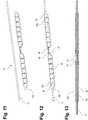
- Fig. 9shows a perspective top view of a crimpable load distributor 100 according to an embodiment of the invention.
- This load distributor 100has a crimpable sleeve 34 substantially defining the first cross-sectional dimension.
- the sleeve 34is arranged in between two equally long portions of a segment row (as explained above with reference to Figs. 1 to 8 ).
- the sleeve 34is overmolded by the segment rows at their respective innermost segments. These overmolded segments are tapered towards each other towards the sleeve 34.
- the particular shape of the sleeve 34 and interconnection with the respective segments of the segment rowwill become apparent from the following description of Fig. 10 in conjunction with Fig. 9 .
- Fig. 10shows a longitudinal side cross-section of the sleeve 34 and load distributor 100 in Fig. 9 .
- the load distributor 10 discussed above in connection with Figs. 1 to 8has a similar cross-sectional appearance.
- the sleeve 34 in the load distributor 100 illustrated in Figs. 9 and 10comprises an elongated C-shaped part 36 having a slit or gap 38 extending along the longitudinal direction of the load distributor 100.
- the C-shaped part 36lies between two rings 40 having openings 42 which in the variant shown in Fig. 10 are equally distanced from each other. Only two opposite openings 42 are visible in Fig. 10 , the top and the bottom opening 42.
- the C-shaped part 36 and the rings 40are connected by a bridge part 44 formed only on a portion of the C-shaped part 36 over less than 180° and symmetrically opposite the gap of the C-shaped part 36.
- the sleeve 34is offset from the bone-contacting region 30 of the load distributing section 28 towards the inside of the load distributor 100. At least one of the cylinders 40 of the sleeve 34 defines the through hole 18 as an opening for receiving the wire 12, and the load distributing section 28 has the through hole 19 as a wire receiving region 19 that forms an extension of the opening 18 of the sleeve 34.
- Figs. 11 to 13show, respectively, a sternum closure device 2 with the crimpable load distributor 100 in Fig. 9 and a uniform cross-section wire 12, an assembled state of the sternum closure device 2, and a longitudinal side cross-section of the assembled sternum closure device 2. While the wire 12 is shown to have a uniform cross-section, it will be appreciated that non-uniform cross-sections could be used as well (e.g., as shown in Figs. 7 and 8 ).
- Figs. 12 and 13show the sternum closure device with the load distributor 100 having the sleeve 34 of the wire receiving section 14 crimped around the wire 12.
- the crimpingmay be performed by surgical personal (e.g., a surgeon) in preparation of or during a surgical procedure in which the sternum closure device 2 is implanted.
- the surgical personalmay first thread the wire 12 through the load distributor 100 and then crimp the load distributor 100 to the wire 12 by locally exerting pressure on the load distributor 100 in the region the crimpable sleeve 34 using a suitable tool.
- Fig. 14shows a perspective view of a tool 50 according to another example useful for understanding the invention.
- the tool 50has a pair of riffled handles 52, a pivot 54, and a pair of L-shaped jaws 56, 58.
- the tool 50will be used by surgical personal to cut the load distributor 10, 100 (e.g., to "skin" on or more load distributor segments from the wire 12) and/or to crimp the sleeve 34 onto the wire 12.
- Fig. 15shows an enlarged perspective view of a jaw section of the tool 50 in Fig. 14 .
- the jaw sectionhas a cutting and skinning section 60 and a crimping section 62.
- the crimping section 62has a symmetrical recess 68a on one jaw 56 and a complementary protrusion 68b on the other jaw 58.
- the recess 68ahas tapered end parts 70 such that it corresponds to the outer shape of the sleeve 34 and the tapered segments of the load distributor 100 closest to the sleeve 34 (see, e.g., Figs. 1 , 4 , and 9 ).
- the pair of jaws 56, 58is movable between a first load distributor receiving position and a second load distributor cutting position, wherein, in the second position, the jaws 56, 58 overlap in a longitudinal extension of the tool 50 and leave a clearance hole 64.
- Both jaws 56, 58have substantially V-shaped cutting edges 66 which are tapered towards the other jaw 58, 56 at an angle along the longitudinal extension of the tool 50, see Fig. 17 .
- Fig. 16shows a top view of the tool 50 in Fig. 14 . This view particularly shows that the jaws 56, 58 are L-shaped in the longitudinal extension of the tool 50.
- Figs. 17 and 18show, respectively, a top cross-section C-C through the jaw section of the tool 50 in Fig. 14 without the crimping section 6, and a side cross-section D-D through the skinning and cutting section 60 of the jaw section in Fig. 15 .
- the above-mentioned tapered V-shape of the cutting edges 66is shown by the combination of Figs. 17 and 18 .
- Fig. 19shows a perspective view of a sternum closure system with the tool 50 in Fig. 14 and a sternum closure device placed in the crimping section 62 of the tool 50.
- the crimping section 62is located on the jaws 56, 58 and between the pivot 54 and the cutting and skinning section 60.
- the crimping section 62further extends in parallel to the pivot 54 and is located along the main longitudinal extension of the tool 50.
- Figs. 20 and 21show, respectively, an enlarged perspective view of the jaw section of the sternum closure system in Fig. 19 , and a side cross-section E-E through the jaw section with only the crimping section 62 of the tool 50 in Fig. 20 .
- Fig. 20shows that the load distributor 100 fits into the recess 68a with the tapered end parts 70, which are indicated in Fig. 15 .
- the tapered end parts 70have the same inclination as the pair of cutting edges 66 in the second position of the jaws 56, 58 along the longitudinal extension of the tool 50.
- Fig. 21shows the sleeve 34 placed inside the recess 68a, such that the C-shaped part 36 is abutted by the recess 68a with the gap 38 pointing to the bottom of the recess 68a and enclosing a central trapezoid protrusion 72, which becomes narrow in a direction away from the bottom of the recess 68a and towards the protrusion 68b on the other jaw 58.
- the trapezoid protrusion 72fixes the sleeve 34 in the shown position and further improves the crimpability of the sleeve 34.
- Fig. 22shows a perspective view of the sternum closure system in Fig. 19 with a sternum closure device 2 placed in the cutting and skinning section 60 of the tool 50.
- the cutting and skinning section 60is off-centered from the longitudinal extension direction of the tool 50.
- Figs. 23 and 24show, respectively, an enlarged top view of the sternum closure system in Fig. 22 , and a top view of the sternum closure device in Fig. 22 with the left end, i.e., segments 20 and 22i, of the load distributor 100 cut and skinned from the wire 12, such that a V-shaped tapered segment is formed and remains as the outermost segment to the left.
- a suitable segment marking the outermost segment to the rightcan easily be identified and cut as well to achieve a symmetric cutting of the load distributor 100 at its two opposite ends.
- Fig. 23shows that the displacement of the jaws 56, 58 allow the user to better recognize the place of cutting, such that equal lengths of segments on both sides of the sleeve 34 can be achieved. Also, the indentations 26 between the (optional) segments 20, 22i-22n, 24 allow an easier, more precise and fixed placement of any one of the load distributors 10, 100 into the cutting edges 66 of one jaw 56, such that each rectangular segment 20, 22i-22n, 24 is cut into the same tapered shape shown in Fig 24 .
- Fig. 24shows a state in which the left part of the left half of the load distributor 100 has been cut and skinned from the wire 12, such that the outermost left segment is cut in a tapered shape, similar to the initial tapered shape of the segment 20.
- the right part of the right half of the load distributor 100will be cut and skinned from the wire 12 at the same distance from the sleeve 34 as the left half previously in order to shorten the load distributor 100 and adjust its length to the sternum bone, but still keep it symmetrical with regard to the sleeve 34.
Landscapes
- Health & Medical Sciences (AREA)
- Orthopedic Medicine & Surgery (AREA)
- Life Sciences & Earth Sciences (AREA)
- Surgery (AREA)
- Medical Informatics (AREA)
- Engineering & Computer Science (AREA)
- Biomedical Technology (AREA)
- Heart & Thoracic Surgery (AREA)
- Nuclear Medicine, Radiotherapy & Molecular Imaging (AREA)
- Molecular Biology (AREA)
- Animal Behavior & Ethology (AREA)
- General Health & Medical Sciences (AREA)
- Public Health (AREA)
- Veterinary Medicine (AREA)
- Neurology (AREA)
- Surgical Instruments (AREA)
- Scissors And Nippers (AREA)
Description
- The present disclosure generally relates to surgical devices. In particular, a load distributor for a sternum closure device and a sternum closure device comprising the load distributor.
- To promote the healing process of fragmented or cut bone, it has been known to exert an external force on bone parts by tightly clamping them together. To this end, flexible elongated members such as wires can be used which are tensioned around the bone parts.
- For example, prior to heart surgery, the sternum bone is often cut into two halves by means of a longitudinal section to obtain access to the heart. The sternum halves later need to be fixedly joined again. This can be done by arranging a wire around the sternum halves in a circumferential manner so as to surround a cross-sectional area thereof. Said cross-sectional area extends typically transverse to the longitudinal section through the sternum. Afterwards, the wire is tensioned and fixed by connecting and twisting the free ends thereof.
- Furthermore, it has been known to arrange protector pads between the wire and an adjacent surface of the respective bone fragments. The protector pads avoid that the wire cuts into the bone surface when tensioning it, thus causing damage to the bone.
US 6,287,307 B1 discloses an apparatus and a method for clamping the split bone sections of a sternum. For doing so, protector pads in form of sternal plates are arranged in opposite configuration at the split sternum halves. The sternum plates are provided with spikes which are driven into outer side surfaces of the sternum halves by means of a forceps. The sternum plates are hence directly fixed at the bone fragments in a first step. Afterwards, a surgeon can guide and tension a circumferential wire around the sternum plates and the bone fragments arranged therebetween.US 8,597,327 B2 teaches a method and apparatus for securing a fractured or sectioned sternum by means of a flexible member construct forming circumferential loops around the sternum halves. In addition, protector members are provided for guiding and fixing said flexible member construct around the sternum halves.WO 2012/027025 A2 discloses a method for closing a sternum with help of adhesives. The adhesives may also be applied in contact regions between the sternum halves and an additionally provided circumferential wire to form a protective layer similar to the known protector pads.WO 2014/149244 A1 relates to protective sleeve. A guide wire is movable within the protective sleeve and comprises a stop, such that it can abut on the protective sleeve in order to advance the protective sleeve to a desired resting position. Once this resting position is reached, the guide wire is pulled from the protective sleeve.US 2003/078585 A1 discloses a hollow cylindrical sleeve with a suture receiving section on its inside and bone contacting section on its outside.US 2015/038969 A1 discloses a bracket with a channel for receiving a band to be fixed therein by crimping.- There is a need for a sternum closure device and associated parts which can be reliably operated and limit unnecessary damage to the sternum bone.
- According to one aspect of the present disclosure, a load distributor for a sternum closure device is presented. The load distributor comprises a wire receiving section configured to be attached to a wire of the sternum closure device, the wire receiving section having a first cross-sectional dimension. The load distributor further comprises a load distributing section configured to extend between a sternum bone and the wire, the load distributing section having a bone-contacting region and being made from a flexible material to conform to an outer surface of the sternum bone upon tightening of the wire, wherein the bone-contacting region has a second extension substantially perpendicular to the wire receiving section that exceeds the first cross-sectional dimension.
- The wire receiving section may be configured to be attached to the wire such that it cannot be removed from the wire under regular operational conditions (e.g., without rendering one or both of the wire and the wire receiving section functionally inoperable). For example, when attached to the wire the wire receiving section may not be movable in any way relative to the wire. The attachment may be performed using one or more of molding, crimping, gluing, using a form-fit, and so on.
- The first cross-sectional dimension of the wire receiving section may essentially be defined by a portion of the wire receiving section intended to receive the wire (e.g., by an internal opening of the wire receiving section intended to accommodate the wire). As such, the first cross-sectional dimension may essentially correspond to a diameter of the wire.
- The wire receiving section and the load distributing section are separately formed and then joined to each other.
- The wire receiving section and the load distributing section may be spaced apart along an extension of the wire. Alternatively, the wire receiving section and the load distributing section may at least partially (e.g., fully) overlap along the extension of the wire.
- The wire receiving section comprises at least one crimpable sleeve defining the first cross-sectional dimension. The sleeve is intended for being crimped around a wire so as to attach the wire receiving section to the wire. The sleeve may be made from a plastically deformable material, such as metal.
- The wire receiving section (e.g., the sleeve) may be circumferentially closed (e.g., it may have a cross-sectional form of an O). Alternatively, the wire receiving section (e.g., the sleeve) may be partially open (e.g., it may have a cross-sectional form of a C).
- The sleeve may define an opening for receiving the wire, and the load distributing section may have a wire receiving region that forms an extension of the opening of the sleeve. The wire receiving region of the load distributing section may in such a case be provided in addition to the wire receiving section.
- Alternatively, or in addition, the sleeve is molded to the load distributing section. Such molding may be realized by injection molding. In such a case the load distributing section may be made from a moldable material, such as any polymeric material (e.g., plastics).
- A center of gravity of the load distributor in a cross-section orthogonal to its longitudinal extension may be off-centered from a center of the wire receiving section. As an example, the center of gravity may be off-centered in a direction away from the bone-contacting region. In certain variants, the off-centered center of gravity may be achieved by the provision of an Ω-shaped cross-section of the load distributor. The cross-section may have smoothened transitions and rounded edges, and may further be closed at its basis.
- The load distributing section may comprise segments defining the bone-contacting region. The segments may define a segment row. For example, the segments may be spaced apart from each other along an extension of the load distributing section (i.e., along an extension of the wire). The segments may be separated from each other by indentations in the load distributing section. At least some of the segments may have a substantially rectangular shape, preferably with rounded corners.
- The segments may define a segment row with two opposite end segments, wherein segments having the same distance from their next end segment may have an identical marking, and segments having different distances from their next end segment may have different markings. These markings may be in form of a consecutive numbering and/or a color-coding.
- One or both of the end segments of the segment row may have pointed shape (e.g., a V-shape) at their side facing away from the adjacent segment. The pointed shape may facilitate the placement of the sternum closure device around sternum bone.
- According to a further aspect, a sternum closure device is provided. The device comprises a wire essentially defining the first cross-sectional dimension, and a load distributor as presented herein. The wire receiving section of the load distributor may already be attached to the wire upon production of the sternum closure device or may be provided as a separate component for being attached to the wire by surgical personal prior to implantation of the sternum closure device.
- The wire may be provided with a surface feature for engagement by the wire receiving section upon attachment to the wire. This surface feature may take any form, such as a roughened a surface of the wire, one or more indentations in and/or protrusions from the wire surface, and so on.
- The wire receiving section comprises at least one crimpable sleeve that is crimped (e.g., upon production) or provided for being crimped (e.g., by surgical personal) around the wire. This sleeve may be placed in the middle of the load distributor.
- Alternatively, the load distributor is molded around the wire. The portion of the load distributor molded around the wire this defines the wire receiving section of the load distributor. The load distributor may only be partially molded around the wire. This partial molding may be in the middle or at least at one of the two ends of the load distributor.
- According to a further aspect, a tool for cutting a load distributor is provided. The tool comprises a pair of jaws movable between a first load distributor receiving position and a second load distributor cutting position, wherein, in the second position, the jaws overlap in a longitudinal extension of the tool, and wherein the overlapping jaws define substantially V-shaped cutting edges that taper at an angle along the longitudinal extension of the tool.
- The longitudinal extension of the tool may correspond to the extension of the load distributor when arranged between the two jaws for cutting. Upon cutting the load distributor, the wire may or may not be attached thereto. In the second position, the jaws may leave a clearance hole. The clearance hole may be dimensioned to essentially correspond to or slightly exceed the first cross-sectional dimension (e.g., a diameter of the wire). In such a case, the clearance hole may prevent a cutting or damaging of the wire upon cutting the load distributor (i.e., may enable a skinning of the wire in relation to a portion of the load distributor).
- The V-shaped cutting edges may be defined by at least one of the jaws. For example, the V-shaped cutting edges may be defined by one jaw or by each jaw. Alternatively, a first cutting edge may be defined by one jaw and a second cutting edge may be defined by the other jaw, wherein the first and second cutting edges together are arranged in the form of a V.
- The tool may have an additional crimping section comprising a recess on one jaw and a protrusion on the other jaw, such that the protrusion reaches into the recess in the second position of the jaws. The crimping section may be dimensioned in accordance with the crimpable sleeve of the wire receiving section.
- The recess may comprise at least one tapered end part having the same inclination as the pair of cutting edges in the second position of the jaws along the longitudinal extension of the tool.
- The jaws of the tool may be L-shaped in the longitudinal extension of the tool. Furthermore, the cutting section and the crimping section of the tool may be arranged on different flanks of the L-shaped tool, such that they are at an angle with regard to each other.
- According to a still further aspect, a sternum closure system is provided. The system comprises the load distributor or the sternum closure device presented herein, and the tool presented herein. In such a case the clearance hole may substantially corresponds to the first cross-sectional dimension of the wire receiving section or the wire.
- Further details, advantages and aspects of the present disclosure will become apparent from the following embodiments taken in conjunction with the drawings, wherein:
- Fig. 1
- shows a perspective top view of the sternum closure device according to a example useful for understanding the invention;
- Figs. 2 and 3
- show, respectively, a top, and a bottom view of the sternum closure device in
Fig. 1 ; - Fig. 4
- shows a longitudinal cross-section of a sternum closure device according to a modification of the example;
- Figs. 5 and 6
- show, respectively, a cross-section A-A in between segments and a cross-section B-B through the center of a segment of the sternum closure device in
Fig. 4 ; - Figs. 7 and 8
- show, respectively, a top, and a side view of only the wire used in the sternum closure device in
Fig. 4 ; - Fig. 9
- shows a perspective top view of a crimpable load distributor according to an embodiment of the invention;
- Fig. 10
- shows a longitudinal side cross-section of the load distributor in
Fig. 9 ; - Figs. 11 to 13
- show, respectively, a sternum closure device with the crimpable load distributor in
Fig. 9 and a uniform cross-section wire, an assembled state of the sternum closure device, and a longitudinal side cross-section of the assembled sternum closure device; - Fig. 14
- shows a perspective view of a tool according to a further example useful for understanding the invention;
- Fig. 15
- shows an enlarged perspective view of a jaw section of the tool in
Fig. 14 ; - Fig. 16
- shows a top view of the tool in
Fig. 14 ; - Figs. 17 and 18
- show, respectively, a top cross-section C-C through the jaw section of the tool in
Fig. 14 without the crimping section and a side cross-section D-D through a cutting section of the jaw section inFig. 15 ; - Fig. 19
- shows a perspective view of a sternum closure system with the tool in
Fig. 14 and a sternum closure device placed in a crimping section of the tool; - Figs. 20 and 21
- show, respectively, an enlarged perspective view of the jaw section of the sternum closure system in
Fig. 19 and a side cross-section E-E through the jaw section with only the crimping section of the tool inFig. 20 ; - Fig. 22
- shows a perspective view of the sternum closure system in
Fig. 19 with a sternum closure device placed in the cutting section of the tool; and - Figs. 23 and 24
- show, respectively, an enlarged top view of the sternum closure system in
Fig. 22 , and a top view of the sternum closure device inFig. 22 with the left end of the left half of the load distributor cut and skinned from the wire, such that a V-shaped tapered segment is formed. - In the following, the same reference numerals will be used to denote the same or similar structural features.
Figs. 1 to 3 show asternum closure device 2 having aload distributor 10 and awire 12 according to an example useful for understanding the invention.Figs. 4 to 8 show asternum closure device 2 according to a modification of the first embodiment. The two variants essentially differ in the shape of thewire 12.- The
sternum closure device 2 is configured to be utilized in surgical procedures in which the parts of the segmented sternum are to be fixed together by arranging thesternum closure device 2 in a circumferential manner around the sternum parts so as to achieve a compression force. To maintain a compression force, the free ends of thewire 12 may be fixed relative to each other (e.g, by a knot or a further implant component). In this state, theload distributor 10 prevents a cutting of the wire into the sternum bone as the force exerted by the wire is applied over a larger area. - The
wire 12 has in the example ofFigs. 1 to 3 a uniform cross-section and is passing through theload distributor 10. For this purpose theload distributor 10 has a wire receiving section 14 (seeFigs. 5 and 6 , but in a similar manner for the variant inFigs. 1 to 3 ), which in this case is a cylindricalinner wall 16 having a first cross-sectional dimension and forming a through hole in the longitudinal direction of theload distributor 10. The first cross-sectional extension substantially corresponds to the cross-section of thewire 12. - The
wire receiving section 14 of the example inFigs. 1 to 6 basically corresponds to the one shown by a side cross-section of aload distributor 100 shown inFig. 10 and described further below. However, inFig. 1 , thewire receiving section 14 is configured to be attached to thewire 12 by being molded over thewire 12. In order to improve the engagement by thewire receiving section 14 with thewire 12, thewire 12 may be provided with a surface feature such as an increased surface roughness, protrusions, indentations (seeFigs. 7 and 8 ) or the like. - The
load distributor 10 has aload distributing section 28 configured to extend between a sternum bone and thewire 12. Theload distributing section 28 has a substantially flat bone-contacting region 30 (seeFig. 3 ). - In one variant, the
load distributing section 28 has a substantially rectangular shape with two straight sides parallel to an extension of thewire 12. In the present example, theload distributing section 28 hasoptional segments segments indentations 26. The segmentation of theload distributor 10 may, for example, be provided to increase the flexibility of theload distributor 10 to conform to the outer surface of sternum bone upon tightening of thewire 12. Of course, this flexibility may additionally or alternatively (i.e., in the absence of a segmentation) be defined by suitably selecting the material or material composition of theload distributor 10. - The two respective outermost of the segments are defined as
opposite end segments inner segments 22i-22n, in this example i=1 and n=5, have a substantially rectangular outer shape with rounded corners, when viewed from the top or bottom, seeFigs. 2 and 3 . Theend segments inner segments 22i-22n. Such tapering permits an easier placement of thesternum closure device 2 between a patient's ribs around the sternum bone that is to be fixed and is an optional feature of thedevice 2. - Further, segments having the same distance from their
next end segment next end segment Figs. 2 and 3 show, respectively, a top and a bottom view of the sternum closure device inFig. 1 . Here, thesegments indentations 26 are better visible than inFig. 1 .Fig. 3 further shows the bone-contactingregion 30 of theload distributing section 28 of theload distributor 10 defined by the bottom surface of thesegments load distributing section 28 has a second extension substantially perpendicular to thewire receiving section 14 that exceeds the first cross-sectional dimension (i.e., the diameter of the wire 12). As such, a cutting of thewire 12 into the sternum bone upon final placement of thesternum closure device 2 can be prevented.- As shown in
Fig. 3 , both the minimum second extension in the region of theindentations 26 and the maximum second extension in the region of thesegments Fig. 4 shows a longitudinal cross-section of asternum closure device 2 according to a modification of the example. This modification relates to thewire 12, which now has a non-uniform cross-section within thesegments wire 12 to theload distributor 10 in general and to thewire receiving section 14 in particular as the wire cannot easily slip through thewire receiving section 14 in this case.Figs. 5 and 6 show, respectively, a cross-section A-A in between segments and a cross-section B-B through the center of a segment of thesternum closure device 2 as shown inFig. 4 .- As can be seen in
Fig. 5 , the cross-section of thewire 12 in between segments is uniform and corresponds to the cross-section of thewire 12 extending beyond theload distributor 10. However, towards the segment center, thewire 12 becomes narrow in the sides and, as can be seen inFig. 6 , extends in a top-bottom direction further than the cross-section of the uniform sections of thewire 12. As an example, thewire 12 may be locally deformed (e.g., stamped) to achieve a rectangular (or other non-circular) cross-section in a central segment region. - Further, it becomes apparent from
Fig. 6 that a center of gravity of theload distributor 10 in a cross-section orthogonal to its longitudinal extension is off-centered from a center of thewire receiving section 14. This is achieved by the shown Ω-shaped cross-section of theload distributor 10, wherein the cross-section has smoothened transitions and rounded edges, and is closed at its basis. - The Ω-shape ensures a flat surface in form of the basis, which can be brought into contact with the sternum bone and distribute a compression force more evenly. Also, the smoothened transitions and rounded edges make an insertion of the
load distributor 10 easier and safer, and the off-centered basis can be easily cut into a tapered V-shape at each end of theload distributor 10 without damaging thewire receiving section 14, which is further described below. Figs. 7 and 8 show, respectively, a top and a side view of only thewire 12 used in the sternum closure device inFigs. 4 to 6 . The protrusions of thewire 12 in the top-bottom direction and the indentations of thewire 12 in the sides within the segments form features 32, which serve to better hold thesegments load distributor 10 on thewire 12, regardless of whether theload distributor 10 is molded over thewire 12 or thewire 12 inserted through theload distributor 10 in order to frictionally or adhesively engage with thewire receiving section 14.Fig. 9 shows a perspective top view of acrimpable load distributor 100 according to an embodiment of the invention. Thisload distributor 100 has acrimpable sleeve 34 substantially defining the first cross-sectional dimension. Thesleeve 34 is arranged in between two equally long portions of a segment row (as explained above with reference toFigs. 1 to 8 ). Thesleeve 34 is overmolded by the segment rows at their respective innermost segments. These overmolded segments are tapered towards each other towards thesleeve 34. The particular shape of thesleeve 34 and interconnection with the respective segments of the segment row will become apparent from the following description ofFig. 10 in conjunction withFig. 9 .Fig. 10 shows a longitudinal side cross-section of thesleeve 34 andload distributor 100 inFig. 9 . Theload distributor 10 discussed above in connection withFigs. 1 to 8 has a similar cross-sectional appearance.- The
sleeve 34 in theload distributor 100 illustrated inFigs. 9 and 10 comprises an elongated C-shapedpart 36 having a slit orgap 38 extending along the longitudinal direction of theload distributor 100. The C-shapedpart 36 lies between tworings 40 havingopenings 42 which in the variant shown inFig. 10 are equally distanced from each other. Only twoopposite openings 42 are visible inFig. 10 , the top and thebottom opening 42. The C-shapedpart 36 and therings 40 are connected by abridge part 44 formed only on a portion of the C-shapedpart 36 over less than 180° and symmetrically opposite the gap of the C-shapedpart 36. While thebridge part 44 is arranged closest to the bone-contactingregion 30, thegap 38 is opposite and furthest away from the bone-contactingregion 30. In order to avoid direct contact of themetal sleeve 34 and the sternum bone, thesleeve 34 is offset from the bone-contactingregion 30 of theload distributing section 28 towards the inside of theload distributor 100. At least one of thecylinders 40 of thesleeve 34 defines the throughhole 18 as an opening for receiving thewire 12, and theload distributing section 28 has the throughhole 19 as awire receiving region 19 that forms an extension of theopening 18 of thesleeve 34. Figs. 11 to 13 show, respectively, asternum closure device 2 with thecrimpable load distributor 100 inFig. 9 and auniform cross-section wire 12, an assembled state of thesternum closure device 2, and a longitudinal side cross-section of the assembledsternum closure device 2. While thewire 12 is shown to have a uniform cross-section, it will be appreciated that non-uniform cross-sections could be used as well (e.g., as shown inFigs. 7 and 8 ).Figs. 12 and 13 show the sternum closure device with theload distributor 100 having thesleeve 34 of thewire receiving section 14 crimped around thewire 12. The crimping may be performed by surgical personal (e.g., a surgeon) in preparation of or during a surgical procedure in which thesternum closure device 2 is implanted. As such, the surgical personal may first thread thewire 12 through theload distributor 100 and then crimp theload distributor 100 to thewire 12 by locally exerting pressure on theload distributor 100 in the region thecrimpable sleeve 34 using a suitable tool.Fig. 14 shows a perspective view of atool 50 according to another example useful for understanding the invention. Thetool 50 has a pair of riffled handles 52, apivot 54, and a pair of L-shapedjaws tool 50 will be used by surgical personal to cut theload distributor 10, 100 (e.g., to "skin" on or more load distributor segments from the wire 12) and/or to crimp thesleeve 34 onto thewire 12.Fig. 15 shows an enlarged perspective view of a jaw section of thetool 50 inFig. 14 . In this view it is visible that the jaw section has a cutting and skinningsection 60 and a crimpingsection 62. The crimpingsection 62 has asymmetrical recess 68a on onejaw 56 and acomplementary protrusion 68b on theother jaw 58. Therecess 68a has taperedend parts 70 such that it corresponds to the outer shape of thesleeve 34 and the tapered segments of theload distributor 100 closest to the sleeve 34 (see, e.g.,Figs. 1 ,4 , and9 ).- The pair of
jaws jaws tool 50 and leave aclearance hole 64. Bothjaws other jaw tool 50, seeFig. 17 . Fig. 16 shows a top view of thetool 50 inFig. 14 . This view particularly shows that thejaws tool 50.Figs. 17 and 18 show, respectively, a top cross-section C-C through the jaw section of thetool 50 inFig. 14 without the crimping section 6, and a side cross-section D-D through the skinning and cuttingsection 60 of the jaw section inFig. 15 . Particularly, the above-mentioned tapered V-shape of the cutting edges 66 is shown by the combination ofFigs. 17 and 18 .- Next, the crimping
section 62 will be explained in greater detail. Fig. 19 shows a perspective view of a sternum closure system with thetool 50 inFig. 14 and a sternum closure device placed in the crimpingsection 62 of thetool 50. The crimpingsection 62 is located on thejaws pivot 54 and the cutting and skinningsection 60. The crimpingsection 62 further extends in parallel to thepivot 54 and is located along the main longitudinal extension of thetool 50.Figs. 20 and 21 show, respectively, an enlarged perspective view of the jaw section of the sternum closure system inFig. 19 , and a side cross-section E-E through the jaw section with only the crimpingsection 62 of thetool 50 inFig. 20 .Fig. 20 shows that theload distributor 100 fits into therecess 68a with thetapered end parts 70, which are indicated inFig. 15 . Thetapered end parts 70 have the same inclination as the pair of cuttingedges 66 in the second position of thejaws tool 50.Fig. 21 shows thesleeve 34 placed inside therecess 68a, such that the C-shapedpart 36 is abutted by therecess 68a with thegap 38 pointing to the bottom of therecess 68a and enclosing acentral trapezoid protrusion 72, which becomes narrow in a direction away from the bottom of therecess 68a and towards theprotrusion 68b on theother jaw 58. Thetrapezoid protrusion 72 fixes thesleeve 34 in the shown position and further improves the crimpability of thesleeve 34.- Now, the cutting and skinning
section 60 will be explained in greater detail. Fig. 22 shows a perspective view of the sternum closure system inFig. 19 with asternum closure device 2 placed in the cutting and skinningsection 60 of thetool 50. The cutting and skinningsection 60 is off-centered from the longitudinal extension direction of thetool 50.Figs. 23 and 24 show, respectively, an enlarged top view of the sternum closure system inFig. 22 , and a top view of the sternum closure device inFig. 22 with the left end, i.e.,segments load distributor 100 cut and skinned from thewire 12, such that a V-shaped tapered segment is formed and remains as the outermost segment to the left. Using a suitable segment marking the outermost segment to the right can easily be identified and cut as well to achieve a symmetric cutting of theload distributor 100 at its two opposite ends.Fig. 23 shows that the displacement of thejaws sleeve 34 can be achieved. Also, theindentations 26 between the (optional)segments load distributors jaw 56, such that eachrectangular segment Fig 24 .Fig. 24 shows a state in which the left part of the left half of theload distributor 100 has been cut and skinned from thewire 12, such that the outermost left segment is cut in a tapered shape, similar to the initial tapered shape of thesegment 20. In a next step, the right part of the right half of theload distributor 100 will be cut and skinned from thewire 12 at the same distance from thesleeve 34 as the left half previously in order to shorten theload distributor 100 and adjust its length to the sternum bone, but still keep it symmetrical with regard to thesleeve 34.- The previously described embodiment/examples of a
load distributor - While the present disclosure has been described with reference to exemplary embodiments, it will be appreciated that the present invention is not limited to what has been described above. For example, it will be appreciated that the dimensions of the parts may be varied as needed. Accordingly, it is intended that the present invention may be limited only by the scope of the claims appended hereto.
Claims (12)
- A load distributor (100) for a sternum closure device (2), the load distributor (100) comprising:a wire receiving section (14) configured to be attached to a wire (12) of the sternum closure device, the wire receiving section (14) having a first cross-sectional dimension; anda load distributing section (28) configured to extend between a sternum bone and the wire (12), the load distributing section (28) having a bone-contacting region (30) and being made from a flexible material to conform to an outer surface of the sternum bone upon tightening of the wire (12), wherein the bone-contacting region (30) has a second extension substantially perpendicular to the wire receiving section (14) that exceeds the first cross-sectional dimension,wherein the wire receiving section (14) comprises at least one crimpable sleeve (34) defining the first cross-sectional dimension, wherein the sleeve (34) is configured to be crimped around the wire (12) so as to attach the wire receiving section (14) to the wire (12),
characterized in that
the wire receiving section (14) and the load distributing section (28) are separately formed and joined to each other. - The load distributor (100) according to claim 1, wherein
the sleeve (34) defines an opening (18) for receiving the wire (12), and wherein the load distributing section (28) has a wire receiving region (19) that forms an extension of the opening (18) of the sleeve (34). - The load distributor (100) according to claim 1 or 2, wherein
the sleeve (34) is molded to the load distributing section (28). - The load distributor (100) according to any one of the preceding claims, wherein
a center of gravity of the load distributor (100) in a cross-section orthogonal to its longitudinal extension is off-centered from a center of the wire receiving section (14). - The load distributor (100) according to any one of the preceding claims,
wherein the load distributing section (28) comprises segments (20, 22i-22n, 24) defining the bone-contacting region (30). - The load distributor (100) according to claim 5, wherein
the segments (20, 22i-22n, 24) are separated from each other by indentations (26) in the load distributing section (28). - The load distributor (100) according to claim 5 or 6, wherein
at least some of the segments (22i-22n) have a rectangular shape. - The load distributor (100) according to any one of claims 5 to 7, wherein
the segments (20, 22i-22n, 24) define a segment row with two opposite end segments (20, 24), wherein segments having the same distance from their next end segment (20, 24) have an identical marking, and segments having different distances from their next end segment (20, 24) have different markings. - A sternum closure device (2), comprising:a wire (12) essentially defining the first cross-sectional dimension; anda load distributor (100) according to any one of the preceding claims.
- The sternum closure device according to claim 9, wherein
the wire (12) is provided with a surface feature for engagement by the wire receiving section (14) upon attachment to the wire (12). - Sternum closure device according to claim 9 or 10, wherein
the at least one crimpable sleeve (34) is crimped around the wire (12). - Sternum closure device according to claim 9 or 10, wherein
the load distributor (100) is molded around the wire (12).
Priority Applications (5)
| Application Number | Priority Date | Filing Date | Title |
|---|---|---|---|
| EP16000665.6AEP3219272B1 (en) | 2016-03-18 | 2016-03-18 | Load distributor for a sternum closure device |
| EP20182144.4AEP3750498B1 (en) | 2016-03-18 | 2016-03-18 | Load distributor for a sternum closure device and tool for cutting the load distributor |
| EP18169717.8AEP3378424B1 (en) | 2016-03-18 | 2016-03-18 | Load distributor for a sternum closure device |
| US15/461,626US10716608B2 (en) | 2016-03-18 | 2017-03-17 | Load distributor for a sternum closure device and tool for cutting the load distributor |
| US16/896,355US11534217B2 (en) | 2016-03-18 | 2020-06-09 | Load distributor for a sternum closure device and tool for cutting the load distributor |
Applications Claiming Priority (1)
| Application Number | Priority Date | Filing Date | Title |
|---|---|---|---|
| EP16000665.6AEP3219272B1 (en) | 2016-03-18 | 2016-03-18 | Load distributor for a sternum closure device |
Related Child Applications (3)
| Application Number | Title | Priority Date | Filing Date |
|---|---|---|---|
| EP20182144.4ADivisionEP3750498B1 (en) | 2016-03-18 | 2016-03-18 | Load distributor for a sternum closure device and tool for cutting the load distributor |
| EP18169717.8ADivisionEP3378424B1 (en) | 2016-03-18 | 2016-03-18 | Load distributor for a sternum closure device |
| EP18169717.8ADivision-IntoEP3378424B1 (en) | 2016-03-18 | 2016-03-18 | Load distributor for a sternum closure device |
Publications (2)
| Publication Number | Publication Date |
|---|---|
| EP3219272A1 EP3219272A1 (en) | 2017-09-20 |
| EP3219272B1true EP3219272B1 (en) | 2020-07-15 |
Family
ID=55646209
Family Applications (3)
| Application Number | Title | Priority Date | Filing Date |
|---|---|---|---|
| EP16000665.6AActiveEP3219272B1 (en) | 2016-03-18 | 2016-03-18 | Load distributor for a sternum closure device |
| EP20182144.4AActiveEP3750498B1 (en) | 2016-03-18 | 2016-03-18 | Load distributor for a sternum closure device and tool for cutting the load distributor |
| EP18169717.8AActiveEP3378424B1 (en) | 2016-03-18 | 2016-03-18 | Load distributor for a sternum closure device |
Family Applications After (2)
| Application Number | Title | Priority Date | Filing Date |
|---|---|---|---|
| EP20182144.4AActiveEP3750498B1 (en) | 2016-03-18 | 2016-03-18 | Load distributor for a sternum closure device and tool for cutting the load distributor |
| EP18169717.8AActiveEP3378424B1 (en) | 2016-03-18 | 2016-03-18 | Load distributor for a sternum closure device |
Country Status (2)
| Country | Link |
|---|---|
| US (2) | US10716608B2 (en) |
| EP (3) | EP3219272B1 (en) |
Families Citing this family (5)
| Publication number | Priority date | Publication date | Assignee | Title |
|---|---|---|---|---|
| US9597132B2 (en) | 2013-01-12 | 2017-03-21 | Louis Houff | Sternum fixation device and method |
| US12290295B2 (en) | 2020-06-19 | 2025-05-06 | Circumfix Solutions, Inc. | Bone repair devices and methods |
| MX2024001359A (en) | 2021-07-29 | 2024-04-30 | Circumfix Solutions Inc | BONE REPAIR DEVICES AND METHODS. |
| EP4238518A1 (en) | 2022-03-02 | 2023-09-06 | iAccess MedTec GmbH | Bone fixation device |
| WO2023229839A1 (en)* | 2022-05-27 | 2023-11-30 | Circumfix Solutions, Inc. | Sheath assembly for sternal wire |
Citations (1)
| Publication number | Priority date | Publication date | Assignee | Title |
|---|---|---|---|---|
| US20150038969A1 (en)* | 2013-03-15 | 2015-02-05 | Biomet Microfixation, Llc | Sternal Closure Cerclage, Plate Implant And Instrumentation |
Family Cites Families (14)
| Publication number | Priority date | Publication date | Assignee | Title |
|---|---|---|---|---|
| US2279068A (en)* | 1940-12-11 | 1942-04-07 | John R Siebrandt | Wire crimping and twisting tool |
| US5997542A (en)* | 1997-11-18 | 1999-12-07 | Biomet, Inc. | Surgical wire assembly and method of use |
| US5993452A (en)* | 1998-08-24 | 1999-11-30 | Biomet Inc. | Cerclage system |
| US6485504B1 (en)* | 2000-06-22 | 2002-11-26 | James A. Magovern | Hard or soft tissue closure |
| US6287307B1 (en) | 2000-07-31 | 2001-09-11 | Shalom Y. Abboudi | Apparatus and methods for clamping split bone sections |
| DE10128596A1 (en)* | 2001-06-08 | 2002-12-12 | Advanced Med Tech | Implant-cutter has cutter-blade with sloping edge moved by control, thrust piece, housing and opening |
| DE20207785U1 (en)* | 2002-05-17 | 2003-09-25 | GEOMED Medizin-Technik GmbH & Co., 78532 Tuttlingen | Surgical cutter, has cavities in opposing cutting edges forming locating cavity for object being cut |
| US7905904B2 (en)* | 2006-02-03 | 2011-03-15 | Biomet Sports Medicine, Llc | Soft tissue repair device and associated methods |
| US8597327B2 (en)* | 2006-02-03 | 2013-12-03 | Biomet Manufacturing, Llc | Method and apparatus for sternal closure |
| US20120109129A1 (en)* | 2010-11-02 | 2012-05-03 | Bernstein Oren S | Replacement system for a surgical wire |
| US10010954B2 (en)* | 2008-11-05 | 2018-07-03 | Hubbell Incorporated | Cutter |
| US20100313428A1 (en)* | 2009-06-12 | 2010-12-16 | Osteomed L.P. | Multifunctional Plate Cutter |
| US8668697B2 (en) | 2009-10-07 | 2014-03-11 | Abyrx, Inc. | Methods and devices for sternal closure |
| WO2014149244A1 (en) | 2013-02-07 | 2014-09-25 | Houff Louis | Sternum fixation device and method |
- 2016
- 2016-03-18EPEP16000665.6Apatent/EP3219272B1/enactiveActive
- 2016-03-18EPEP20182144.4Apatent/EP3750498B1/enactiveActive
- 2016-03-18EPEP18169717.8Apatent/EP3378424B1/enactiveActive
- 2017
- 2017-03-17USUS15/461,626patent/US10716608B2/ennot_activeExpired - Fee Related
- 2020
- 2020-06-09USUS16/896,355patent/US11534217B2/enactiveActive
Patent Citations (1)
| Publication number | Priority date | Publication date | Assignee | Title |
|---|---|---|---|---|
| US20150038969A1 (en)* | 2013-03-15 | 2015-02-05 | Biomet Microfixation, Llc | Sternal Closure Cerclage, Plate Implant And Instrumentation |
Also Published As
| Publication number | Publication date |
|---|---|
| US11534217B2 (en) | 2022-12-27 |
| EP3378424A1 (en) | 2018-09-26 |
| US10716608B2 (en) | 2020-07-21 |
| US20200297402A1 (en) | 2020-09-24 |
| EP3378424B1 (en) | 2020-07-15 |
| EP3219272A1 (en) | 2017-09-20 |
| US20170265919A1 (en) | 2017-09-21 |
| EP3750498A3 (en) | 2021-03-17 |
| EP3750498B1 (en) | 2022-08-17 |
| EP3750498A2 (en) | 2020-12-16 |
Similar Documents
| Publication | Publication Date | Title |
|---|---|---|
| US11534217B2 (en) | Load distributor for a sternum closure device and tool for cutting the load distributor | |
| US12059185B2 (en) | Bone plating system and method | |
| US5797916A (en) | Trochanteric reattachment cerclage device | |
| US5127413A (en) | Sinous suture | |
| EP2320818B1 (en) | Crimp with an insert to hold a cable | |
| US20130165978A1 (en) | Fixation device for the fixation of bone fragments | |
| US20120041441A1 (en) | Cable tie system for stabilizing bone | |
| US11331129B2 (en) | Contourable plate | |
| JP2000320730A (en) | Wire clamp assembly | |
| US10517658B2 (en) | Bone plate with elongated guiding channels | |
| US9554836B2 (en) | Intramedullary bone stent | |
| US20110053109A1 (en) | Orthodontic anchoring screw | |
| CN110559068A (en) | Flexible upper and lower jaw fixing device | |
| EP1477144B1 (en) | Tool for corrective treatment of onychocryptosis | |
| EP2271393A1 (en) | A suture sleeve and a method for positioning a suture sleeve and a lead in relation to each other | |
| AU2012348164A1 (en) | Self holding feature for a screw | |
| CN211156315U (en) | Soft tissue protective sleeve screwed by vertebra posterior pedicle screw | |
| JP2025507013A (en) | Bone Fixation Device | |
| KR20240123088A (en) | Nail correction device and correction method | |
| JP2007519455A (en) | Fixing device |
Legal Events
| Date | Code | Title | Description |
|---|---|---|---|
| PUAI | Public reference made under article 153(3) epc to a published international application that has entered the european phase | Free format text:ORIGINAL CODE: 0009012 | |
| STAA | Information on the status of an ep patent application or granted ep patent | Free format text:STATUS: REQUEST FOR EXAMINATION WAS MADE | |
| 17P | Request for examination filed | Effective date:20170622 | |
| AK | Designated contracting states | Kind code of ref document:A1 Designated state(s):AL AT BE BG CH CY CZ DE DK EE ES FI FR GB GR HR HU IE IS IT LI LT LU LV MC MK MT NL NO PL PT RO RS SE SI SK SM TR | |
| AX | Request for extension of the european patent | Extension state:BA ME | |
| STAA | Information on the status of an ep patent application or granted ep patent | Free format text:STATUS: EXAMINATION IS IN PROGRESS | |
| 17Q | First examination report despatched | Effective date:20171114 | |
| GRAP | Despatch of communication of intention to grant a patent | Free format text:ORIGINAL CODE: EPIDOSNIGR1 | |
| STAA | Information on the status of an ep patent application or granted ep patent | Free format text:STATUS: GRANT OF PATENT IS INTENDED | |
| INTG | Intention to grant announced | Effective date:20191216 | |
| GRAJ | Information related to disapproval of communication of intention to grant by the applicant or resumption of examination proceedings by the epo deleted | Free format text:ORIGINAL CODE: EPIDOSDIGR1 | |
| STAA | Information on the status of an ep patent application or granted ep patent | Free format text:STATUS: EXAMINATION IS IN PROGRESS | |
| INTC | Intention to grant announced (deleted) | ||
| GRAR | Information related to intention to grant a patent recorded | Free format text:ORIGINAL CODE: EPIDOSNIGR71 | |
| GRAS | Grant fee paid | Free format text:ORIGINAL CODE: EPIDOSNIGR3 | |
| STAA | Information on the status of an ep patent application or granted ep patent | Free format text:STATUS: GRANT OF PATENT IS INTENDED | |
| GRAA | (expected) grant | Free format text:ORIGINAL CODE: 0009210 | |
| STAA | Information on the status of an ep patent application or granted ep patent | Free format text:STATUS: THE PATENT HAS BEEN GRANTED | |
| INTG | Intention to grant announced | Effective date:20200603 | |
| AK | Designated contracting states | Kind code of ref document:B1 Designated state(s):AL AT BE BG CH CY CZ DE DK EE ES FI FR GB GR HR HU IE IS IT LI LT LU LV MC MK MT NL NO PL PT RO RS SE SI SK SM TR | |
| REG | Reference to a national code | Ref country code:CH Ref legal event code:EP Ref country code:GB Ref legal event code:FG4D | |
| REG | Reference to a national code | Ref country code:IE Ref legal event code:FG4D | |
| REG | Reference to a national code | Ref country code:DE Ref legal event code:R096 Ref document number:602016039824 Country of ref document:DE | |
| REG | Reference to a national code | Ref country code:AT Ref legal event code:REF Ref document number:1290108 Country of ref document:AT Kind code of ref document:T Effective date:20200815 | |
| REG | Reference to a national code | Ref country code:CH Ref legal event code:NV Representative=s name:VALIPAT S.A. C/O BOVARD SA NEUCHATEL, CH | |
| REG | Reference to a national code | Ref country code:LT Ref legal event code:MG4D | |
| REG | Reference to a national code | Ref country code:AT Ref legal event code:MK05 Ref document number:1290108 Country of ref document:AT Kind code of ref document:T Effective date:20200715 | |
| REG | Reference to a national code | Ref country code:NL Ref legal event code:MP Effective date:20200715 | |
| PG25 | Lapsed in a contracting state [announced via postgrant information from national office to epo] | Ref country code:ES Free format text:LAPSE BECAUSE OF FAILURE TO SUBMIT A TRANSLATION OF THE DESCRIPTION OR TO PAY THE FEE WITHIN THE PRESCRIBED TIME-LIMIT Effective date:20200715 Ref country code:BG Free format text:LAPSE BECAUSE OF FAILURE TO SUBMIT A TRANSLATION OF THE DESCRIPTION OR TO PAY THE FEE WITHIN THE PRESCRIBED TIME-LIMIT Effective date:20201015 Ref country code:SE Free format text:LAPSE BECAUSE OF FAILURE TO SUBMIT A TRANSLATION OF THE DESCRIPTION OR TO PAY THE FEE WITHIN THE PRESCRIBED TIME-LIMIT Effective date:20200715 Ref country code:AT Free format text:LAPSE BECAUSE OF FAILURE TO SUBMIT A TRANSLATION OF THE DESCRIPTION OR TO PAY THE FEE WITHIN THE PRESCRIBED TIME-LIMIT Effective date:20200715 Ref country code:NO Free format text:LAPSE BECAUSE OF FAILURE TO SUBMIT A TRANSLATION OF THE DESCRIPTION OR TO PAY THE FEE WITHIN THE PRESCRIBED TIME-LIMIT Effective date:20201015 Ref country code:GR Free format text:LAPSE BECAUSE OF FAILURE TO SUBMIT A TRANSLATION OF THE DESCRIPTION OR TO PAY THE FEE WITHIN THE PRESCRIBED TIME-LIMIT Effective date:20201016 Ref country code:FI Free format text:LAPSE BECAUSE OF FAILURE TO SUBMIT A TRANSLATION OF THE DESCRIPTION OR TO PAY THE FEE WITHIN THE PRESCRIBED TIME-LIMIT Effective date:20200715 Ref country code:PT Free format text:LAPSE BECAUSE OF FAILURE TO SUBMIT A TRANSLATION OF THE DESCRIPTION OR TO PAY THE FEE WITHIN THE PRESCRIBED TIME-LIMIT Effective date:20201116 Ref country code:HR Free format text:LAPSE BECAUSE OF FAILURE TO SUBMIT A TRANSLATION OF THE DESCRIPTION OR TO PAY THE FEE WITHIN THE PRESCRIBED TIME-LIMIT Effective date:20200715 Ref country code:LT Free format text:LAPSE BECAUSE OF FAILURE TO SUBMIT A TRANSLATION OF THE DESCRIPTION OR TO PAY THE FEE WITHIN THE PRESCRIBED TIME-LIMIT Effective date:20200715 | |
| PG25 | Lapsed in a contracting state [announced via postgrant information from national office to epo] | Ref country code:LV Free format text:LAPSE BECAUSE OF FAILURE TO SUBMIT A TRANSLATION OF THE DESCRIPTION OR TO PAY THE FEE WITHIN THE PRESCRIBED TIME-LIMIT Effective date:20200715 Ref country code:PL Free format text:LAPSE BECAUSE OF FAILURE TO SUBMIT A TRANSLATION OF THE DESCRIPTION OR TO PAY THE FEE WITHIN THE PRESCRIBED TIME-LIMIT Effective date:20200715 Ref country code:RS Free format text:LAPSE BECAUSE OF FAILURE TO SUBMIT A TRANSLATION OF THE DESCRIPTION OR TO PAY THE FEE WITHIN THE PRESCRIBED TIME-LIMIT Effective date:20200715 Ref country code:IS Free format text:LAPSE BECAUSE OF FAILURE TO SUBMIT A TRANSLATION OF THE DESCRIPTION OR TO PAY THE FEE WITHIN THE PRESCRIBED TIME-LIMIT Effective date:20201115 | |
| PG25 | Lapsed in a contracting state [announced via postgrant information from national office to epo] | Ref country code:NL Free format text:LAPSE BECAUSE OF FAILURE TO SUBMIT A TRANSLATION OF THE DESCRIPTION OR TO PAY THE FEE WITHIN THE PRESCRIBED TIME-LIMIT Effective date:20200715 | |
| REG | Reference to a national code | Ref country code:DE Ref legal event code:R097 Ref document number:602016039824 Country of ref document:DE | |
| PG25 | Lapsed in a contracting state [announced via postgrant information from national office to epo] | Ref country code:IT Free format text:LAPSE BECAUSE OF FAILURE TO SUBMIT A TRANSLATION OF THE DESCRIPTION OR TO PAY THE FEE WITHIN THE PRESCRIBED TIME-LIMIT Effective date:20200715 Ref country code:DK Free format text:LAPSE BECAUSE OF FAILURE TO SUBMIT A TRANSLATION OF THE DESCRIPTION OR TO PAY THE FEE WITHIN THE PRESCRIBED TIME-LIMIT Effective date:20200715 Ref country code:CZ Free format text:LAPSE BECAUSE OF FAILURE TO SUBMIT A TRANSLATION OF THE DESCRIPTION OR TO PAY THE FEE WITHIN THE PRESCRIBED TIME-LIMIT Effective date:20200715 Ref country code:SM Free format text:LAPSE BECAUSE OF FAILURE TO SUBMIT A TRANSLATION OF THE DESCRIPTION OR TO PAY THE FEE WITHIN THE PRESCRIBED TIME-LIMIT Effective date:20200715 Ref country code:RO Free format text:LAPSE BECAUSE OF FAILURE TO SUBMIT A TRANSLATION OF THE DESCRIPTION OR TO PAY THE FEE WITHIN THE PRESCRIBED TIME-LIMIT Effective date:20200715 Ref country code:EE Free format text:LAPSE BECAUSE OF FAILURE TO SUBMIT A TRANSLATION OF THE DESCRIPTION OR TO PAY THE FEE WITHIN THE PRESCRIBED TIME-LIMIT Effective date:20200715 | |
| PLBE | No opposition filed within time limit | Free format text:ORIGINAL CODE: 0009261 | |
| STAA | Information on the status of an ep patent application or granted ep patent | Free format text:STATUS: NO OPPOSITION FILED WITHIN TIME LIMIT | |
| PG25 | Lapsed in a contracting state [announced via postgrant information from national office to epo] | Ref country code:AL Free format text:LAPSE BECAUSE OF FAILURE TO SUBMIT A TRANSLATION OF THE DESCRIPTION OR TO PAY THE FEE WITHIN THE PRESCRIBED TIME-LIMIT Effective date:20200715 | |
| 26N | No opposition filed | Effective date:20210416 | |
| PG25 | Lapsed in a contracting state [announced via postgrant information from national office to epo] | Ref country code:SK Free format text:LAPSE BECAUSE OF FAILURE TO SUBMIT A TRANSLATION OF THE DESCRIPTION OR TO PAY THE FEE WITHIN THE PRESCRIBED TIME-LIMIT Effective date:20200715 | |
| PG25 | Lapsed in a contracting state [announced via postgrant information from national office to epo] | Ref country code:SI Free format text:LAPSE BECAUSE OF FAILURE TO SUBMIT A TRANSLATION OF THE DESCRIPTION OR TO PAY THE FEE WITHIN THE PRESCRIBED TIME-LIMIT Effective date:20200715 | |
| PG25 | Lapsed in a contracting state [announced via postgrant information from national office to epo] | Ref country code:MC Free format text:LAPSE BECAUSE OF FAILURE TO SUBMIT A TRANSLATION OF THE DESCRIPTION OR TO PAY THE FEE WITHIN THE PRESCRIBED TIME-LIMIT Effective date:20200715 | |
| REG | Reference to a national code | Ref country code:GB Ref legal event code:732E Free format text:REGISTERED BETWEEN 20211111 AND 20211117 | |
| REG | Reference to a national code | Ref country code:BE Ref legal event code:MM Effective date:20210331 | |
| REG | Reference to a national code | Ref country code:DE Ref legal event code:R081 Ref document number:602016039824 Country of ref document:DE Owner name:STRYKER EUROPEAN OPERATIONS HOLDINGS LLC (N.D., US Free format text:FORMER OWNER: STRYKER EUROPEAN HOLDINGS I, LLC, KALAMAZOO, MICH., US | |
| PG25 | Lapsed in a contracting state [announced via postgrant information from national office to epo] | Ref country code:LU Free format text:LAPSE BECAUSE OF NON-PAYMENT OF DUE FEES Effective date:20210318 Ref country code:IE Free format text:LAPSE BECAUSE OF NON-PAYMENT OF DUE FEES Effective date:20210318 | |
| PG25 | Lapsed in a contracting state [announced via postgrant information from national office to epo] | Ref country code:BE Free format text:LAPSE BECAUSE OF NON-PAYMENT OF DUE FEES Effective date:20210331 | |
| PGFP | Annual fee paid to national office [announced via postgrant information from national office to epo] | Ref country code:FR Payment date:20230110 Year of fee payment:8 | |
| PG25 | Lapsed in a contracting state [announced via postgrant information from national office to epo] | Ref country code:HU Free format text:LAPSE BECAUSE OF FAILURE TO SUBMIT A TRANSLATION OF THE DESCRIPTION OR TO PAY THE FEE WITHIN THE PRESCRIBED TIME-LIMIT; INVALID AB INITIO Effective date:20160318 | |
| PGFP | Annual fee paid to national office [announced via postgrant information from national office to epo] | Ref country code:GB Payment date:20230126 Year of fee payment:8 Ref country code:DE Payment date:20230125 Year of fee payment:8 | |
| P01 | Opt-out of the competence of the unified patent court (upc) registered | Effective date:20230522 | |
| PG25 | Lapsed in a contracting state [announced via postgrant information from national office to epo] | Ref country code:CY Free format text:LAPSE BECAUSE OF FAILURE TO SUBMIT A TRANSLATION OF THE DESCRIPTION OR TO PAY THE FEE WITHIN THE PRESCRIBED TIME-LIMIT Effective date:20200715 | |
| PGFP | Annual fee paid to national office [announced via postgrant information from national office to epo] | Ref country code:CH Payment date:20230401 Year of fee payment:8 | |
| PG25 | Lapsed in a contracting state [announced via postgrant information from national office to epo] | Ref country code:MK Free format text:LAPSE BECAUSE OF FAILURE TO SUBMIT A TRANSLATION OF THE DESCRIPTION OR TO PAY THE FEE WITHIN THE PRESCRIBED TIME-LIMIT Effective date:20200715 | |
| PG25 | Lapsed in a contracting state [announced via postgrant information from national office to epo] | Ref country code:TR Free format text:LAPSE BECAUSE OF FAILURE TO SUBMIT A TRANSLATION OF THE DESCRIPTION OR TO PAY THE FEE WITHIN THE PRESCRIBED TIME-LIMIT Effective date:20200715 | |
| PG25 | Lapsed in a contracting state [announced via postgrant information from national office to epo] | Ref country code:MT Free format text:LAPSE BECAUSE OF FAILURE TO SUBMIT A TRANSLATION OF THE DESCRIPTION OR TO PAY THE FEE WITHIN THE PRESCRIBED TIME-LIMIT Effective date:20200715 | |
| REG | Reference to a national code | Ref country code:DE Ref legal event code:R119 Ref document number:602016039824 Country of ref document:DE | |
| REG | Reference to a national code | Ref country code:CH Ref legal event code:PL | |
| GBPC | Gb: european patent ceased through non-payment of renewal fee | Effective date:20240318 | |
| PG25 | Lapsed in a contracting state [announced via postgrant information from national office to epo] | Ref country code:DE Free format text:LAPSE BECAUSE OF NON-PAYMENT OF DUE FEES Effective date:20241001 | |
| PG25 | Lapsed in a contracting state [announced via postgrant information from national office to epo] | Ref country code:GB Free format text:LAPSE BECAUSE OF NON-PAYMENT OF DUE FEES Effective date:20240318 | |
| PG25 | Lapsed in a contracting state [announced via postgrant information from national office to epo] | Ref country code:FR Free format text:LAPSE BECAUSE OF NON-PAYMENT OF DUE FEES Effective date:20240331 | |
| PG25 | Lapsed in a contracting state [announced via postgrant information from national office to epo] | Ref country code:GB Free format text:LAPSE BECAUSE OF NON-PAYMENT OF DUE FEES Effective date:20240318 Ref country code:FR Free format text:LAPSE BECAUSE OF NON-PAYMENT OF DUE FEES Effective date:20240331 Ref country code:DE Free format text:LAPSE BECAUSE OF NON-PAYMENT OF DUE FEES Effective date:20241001 Ref country code:CH Free format text:LAPSE BECAUSE OF NON-PAYMENT OF DUE FEES Effective date:20240331 |