EP3218783B1 - Covered multi-pivot hinge - Google Patents
Covered multi-pivot hingeDownload PDFInfo
- Publication number
- EP3218783B1 EP3218783B1EP15797753.9AEP15797753AEP3218783B1EP 3218783 B1EP3218783 B1EP 3218783B1EP 15797753 AEP15797753 AEP 15797753AEP 3218783 B1EP3218783 B1EP 3218783B1
- Authority
- EP
- European Patent Office
- Prior art keywords
- hinge
- covers
- individual
- computing device
- rotation
- Prior art date
- Legal status (The legal status is an assumption and is not a legal conclusion. Google has not performed a legal analysis and makes no representation as to the accuracy of the status listed.)
- Active
Links
Images


Classifications
- G—PHYSICS
- G06—COMPUTING OR CALCULATING; COUNTING
- G06F—ELECTRIC DIGITAL DATA PROCESSING
- G06F1/00—Details not covered by groups G06F3/00 - G06F13/00 and G06F21/00
- G06F1/16—Constructional details or arrangements
- G06F1/1613—Constructional details or arrangements for portable computers
- G06F1/1633—Constructional details or arrangements of portable computers not specific to the type of enclosures covered by groups G06F1/1615 - G06F1/1626
- G06F1/1675—Miscellaneous details related to the relative movement between the different enclosures or enclosure parts
- G06F1/1681—Details related solely to hinges
- G—PHYSICS
- G06—COMPUTING OR CALCULATING; COUNTING
- G06F—ELECTRIC DIGITAL DATA PROCESSING
- G06F1/00—Details not covered by groups G06F3/00 - G06F13/00 and G06F21/00
- G06F1/16—Constructional details or arrangements
- G06F1/1613—Constructional details or arrangements for portable computers
- G06F1/1615—Constructional details or arrangements for portable computers with several enclosures having relative motions, each enclosure supporting at least one I/O or computing function
- G06F1/1616—Constructional details or arrangements for portable computers with several enclosures having relative motions, each enclosure supporting at least one I/O or computing function with folding flat displays, e.g. laptop computers or notebooks having a clamshell configuration, with body parts pivoting to an open position around an axis parallel to the plane they define in closed position
- H—ELECTRICITY
- H04—ELECTRIC COMMUNICATION TECHNIQUE
- H04M—TELEPHONIC COMMUNICATION
- H04M1/00—Substation equipment, e.g. for use by subscribers
- H04M1/02—Constructional features of telephone sets
- H04M1/0202—Portable telephone sets, e.g. cordless phones, mobile phones or bar type handsets
- H04M1/0206—Portable telephones comprising a plurality of mechanically joined movable body parts, e.g. hinged housings
- H04M1/0208—Portable telephones comprising a plurality of mechanically joined movable body parts, e.g. hinged housings characterized by the relative motions of the body parts
- H04M1/0214—Foldable telephones, i.e. with body parts pivoting to an open position around an axis parallel to the plane they define in closed position
- H04M1/0216—Foldable in one direction, i.e. using a one degree of freedom hinge
- H04M1/022—The hinge comprising two parallel pivoting axes
Definitions
- US 2010/232100 A1describes an electronic apparatus that includes a display portion, a main body portion, an articulated coupling mechanism, and an interlock mechanism.
- the display portionincludes a display screen.
- the main body portionis coupled to the display portion.
- the articulated coupling mechanismincludes, at each of end portions, a plurality of coupling members each having a rotation axis and being rotatably coupled to one another in series about the rotation axis, the plurality of coupling members coupled in series having one end coupled to the main body portion side and the other end coupled to the display portion side.
- the interlock mechanisminterlocks rotations of the plurality of coupling members with one another in the articulated coupling mechanism.
- EP 2 765 478 A2describes a portable electronic device that includes first and second device units and at least one hinge assembly configured to pivotably connect the second device unit to the first device unit.
- the hinge assemblyincludes a first fixing unit configured to be fixed to the first device unit, a second fixing unit configured to be fixed to the second device unit, a plurality of shaft members configured to be arranged in parallel with one another and to include first and second outer shaft members respectively mounted on the first and second fixing units and a plurality of inner shaft members arranged between the first and second outer shaft members, and a gear unit mounted on the shaft members to connect the plurality of shaft members with one another through a gear mesh.
- the present inventionis defined in independent claim 1. Preferred embodiments are described in dependent claims 2 to 15.
- the present conceptsrelate to computing devices employing multi-axis or multi-pivot hinges to rotatably secure portions of the computing device.
- the multi-pivot hingescan include hinge covers that can function to both protect the hinge from the user and the user from the hinge.
- the hinge coverscan also contribute structurally to the hinge functionality and thus the hinge covers can be thought of as integrated with the multi-pivot hinges in that they (e.g., the hinge covers) can be dual function elements that contribute to both the hinge functionality and the hinge cover functionality.
- some implementationscan control a relative order in which individual hinges rotate. One such case can cause the hinges to operate in a predefined order from first to last (e.g., sequentially).
- FIGS. 1-3collectively show an example of a computing device 100.
- computing device 100has first and second portions 102 and 104 that are rotatably secured together by a covered, sequentially rotating, multi-axis hinge assembly 106 (e.g., CSRMA hinge assembly).
- FIG. 1shows the computing device 100 from the 'front'
- FIG. 2shows the computing device from the 'back.
- FIGS. 1 and 2show the computing device in a 'closed' or 'storage' position where the first and second portions are oriented relatively parallel to one another and juxtaposed relative to one another.
- the second portion 104can be configured to be positioned on a generally horizontal surface (not specifically designated) and the first and second portions are generally parallel to one another and the horizontal surface.
- the CSRMA hinge assembly 106can provide a footprint f c that is compact and easy to carry. The footprint is discussed more below relative to FIG. 3 .
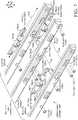
- FIG. 3shows a partial cut-away perspective view of computing device 100 in an 'open' or 'deployed' position.
- the first and second portionsdefine an obtuse angle ⁇ relative to one another, as opposed to an angle close to zero in the closed position of FIGS. 1-2 .
- the CSRMA hinge assemblycan include a set of integrated hinge covers 302.
- adjacent integrated hinge coverscan overlap one another to obscure the underlying elements during rotation.
- the integrated hinge covers 302are integrated in that they function as hinge covers that are also structural hinge elements. Stated another way, the integrated hinge covers can be integral to the hinge function as well as functioning as hinge covers.
- This exampleincludes four integrated hinge covers 302. Other examples may include two, three, or five or more integrated hinge covers.
- individual integrated hinge covers 302can be generally elongate (e.g., extending along a long axis relative to the y axis).
- Individual integrated hinge coverscan also include a generally convex surface 304 and a generally opposing concave surface 306 (not all of the convex and concave surfaces are designated with particularity).
- the concave and convex surfacescan overlap and can allow rotational interaction between adjacent integrated hinge covers when the concave surface of one cover rotates relative to the convex surface of an adjacent integrated hinge cover.
- the computing device 100can also include an input element or device 308.
- the input device 308is manifest as a keyboard 310.
- the computing devicecan also include a display screen 312, such as a touch sensitive display screen.
- the computing devicecan also include a processor 314, memory/storage 316, and/or a battery 318, among other components. These elements can be positioned in the first portion 102 and/or second portion 104.
- CSRMA hinge assembly 106can be secured to the first and second portions 102 and 104 to allow rotation therebetween.
- the CSRMA hinge assembly 106can be secured to the first and second portions in a relatively permanent manner (e.g., in a manner that is not intended to be readily separable by an end use consumer).
- the CSRMA hinge assembly 106can be secured to the first and second portions in a relatively quickly attachable/detachable manner (e.g., in a manner that is intended to be readily separable by the end use consumer).
- a relatively quickly attachable/detachable mannere.g., in a manner that is intended to be readily separable by the end use consumer.
- this implementation of the CSRMA hinge assembly 106is a progressive or sequential hinge that can increase a footprint of the computing device when the device is transitioned from the closed position of FIGS. 1-2 to the open position of FIG. 3 .
- This extended footprint featurecan be especially valuable in this implementation where some or all of the electronic components, such as the display 312, processor 314, memory/storage 316, and battery 318 are positioned in the first portion 102.
- the extended footprint provided by the CSRMA hinge assemblycan increase stability of the computing device and reduce the likelihood of the device tipping over backward in the deployed position from the weight of these components.
- This progressive or sequential nature of the CSRMA hinge assemblyis described in more detail below relative to FIG. 9 .
- the sequential nature of the CSRMA hinge assembly 106can create a foot 320 in the deployed position that can help stabilize the computing device 100 and decrease tipping (e.g., maintain the center of mass over the footprint).
- FIGS. 4-7collectively show an example CSRMA hinge assembly 106A.
- FIG. 4shows the CSRMA hinge assembly 106A in the opened or deployed position and
- FIG. 5shows the CSRMA hinge assembly 106A in the closed position.
- FIG. 6shows an exploded view of the open position shown in FIG. 4 .
- Three integrated hinge covers 302Aare shown in these FIGS.
- the integrated hinge coverscan be thought of as integrated in that in addition to the cover functionality the covers contribute to the hinge functionality.
- FIGS. 7-8collectively show additional detail of portions of CSRMA hinge assembly 106A.
- FIG. 7shows an enlarged portion of the CSRMA hinge assembly 106A as indicated in FIG. 6 . (Note that it is not practical due to space constraints on the drawing page to designate every instance of every element. Care has been taken to label at least one instance of each element in respect to each cover 302).
- FIG. 8shows a sectional view taken along the xy reference plane.
- the illustrated CSRMA hinge assembly 106Aincludes rotation elements in the form of friction engines 702 for positioning relative to respective covers 302A.
- the friction engines 702can include a friction shaft 704 riding on friction bands 706.
- the friction shaft 704can define the axis of rotation (AoR) (e.g., hinge axis) for the friction engine.
- AoRaxis of rotation
- One such axis of rotationis labeled relative to friction engine 702(3) in FIG. 7 and four axes of rotation are labeled in FIG. 8 . While specific rotation elements are shown and described, other rotation elements that can provide rotation around an axis of rotation and can operate cooperatively with other rotation elements are contemplated.
- the friction shaft 704can include a centering pin 708 (labeled only relative to friction engine 702(1) due to space constraints on the drawing page).
- the centering pin 708can have first and second diameters 710 and 712.
- First fasteners 714can secure the friction bands 706 of the friction engine 702 to a respective integrated hinge cover 302A as indicated by arrow 715.
- a void 716can be formed in the integrated hinge cover behind the friction engine 702 to prevent any portion of the first fastener that passes through the friction engine 702 from binding on the integrated hinge cover 302A behind the friction engine and thereby limiting rotation of the friction engine. This aspect is described in more detail below relative to FIG. 11 .
- Second fasteners 718can secure the friction shaft 704 of friction engine 702 to an adjacent integrated hinge cover 302A (e.g., the second fasteners can rotataby interconnect adjacent integrated hinge covers). For instance, relative to integrated hinge cover 302A(2), the friction shaft 704(2) can be secured to adjacent integrated hinge cover 302A(1) by second fastener 718(1) as indicated by arrow 720.
- the centering pin 708 (only labeled relative to friction engine 702(1)) of friction engine 702(2)can pass through slot 717(2) in integrated hinge cover 302A(2) and orient the friction engine relative to integrated hinge cover 302A(1) by the first diameter 710(2) engaging alignment hole 722(1) in integrated hinge cover 302A(1).
- the transition between the first and second dimensions 710 and 712can create a 'shoulder' that limits compression of the friction shaft 704 against the adjacent integrated hinge cover 302A.
- the relative dimension of the centering pin's second diameter 712(2) to the height of the slot 717(2) in the z reference directioncan define a range of motion of the friction engine 702(2).
- the height of the slot in the z reference direction relative to the second fastener 718(1)can define the range of motion (e.g., degrees of rotation) of the friction engine 702(2) (e.g., the profile of the slot is such that the second fastener 718(1) and the second diameter 712(2) of the centering pin 708 strike the cover 302A(2) at the same time). This aspect is described in more detail below relative to FIG. 9 .
- Sequencing pin 724can ride in a hole 726 in integrated hinge cover 302A and engage cam surfaces 728 and 730 of adjacent integrated hinge cover 302A as indicated by arrow 732. In this view only cam surfaces 728 are visible. However, this aspect is discussed in more detail below relative to FIG. 9 where both cam surfaces 728 and 730 are visible and labeled.
- FIGS. 6 and 7show other hinge elements besides the integrated hinge covers 302A.
- the integrated hinge coverseffectively cover and obscure the other hinge elements. Covering the other hinge elements can protect the other hinge elements from damage, such as from a foreign object like a pen or zipper that might get caught in the hinge elements during rotation and damage the hinge elements. Similarly, without the protection offered by the integrated hinge covers, the user could get pinched by the other hinge elements during hinge rotation. Further, the integrated hinge covers can create a more aesthetically pleasing hinge appearance and thereby an overall aesthetically pleasing computing device appearance.
- the integrated hinge covers 302Acan be combined with the other hinge elements to form the CRSMA hinge assembly 106A.
- the other hinge elementscan be considered as a multi-pivot hinge assembly 734 that when combined with the integrated hinge covers 302A can form the CRSMA hinge assembly 106A.
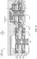
- FIGS. 9-11show sectional views through the xz reference plane as indicated in FIG. 8 , and are discussed collectively below.
- FIG. 9shows two instances of CRSMA hinge assembly 106A.
- Instance Oneshows a partially closed position similar to FIG. 1 .
- Instance Twois a partially deployed position similar to FIG. 3 .
- the point of interest illustrated in FIG. 9is the sequential nature of the CRSMA hinge assembly starting proximate to second portion 104A and progressing toward first portion 102A.
- rotation of the integrated hinge covers 302Astarts with cover 302A(1), which in Instance One has already turned and is oriented parallel to the x reference direction.
- integrated hinge cover 302A(2)can rotate.
- pin 724(2)prevents integrated hinge cover 302A(3) from rotating.
- pin 724(2)is engaging cam surface 728(2) and integrated hinge cover 302A(3) cannot rotate because the pin cannot evacuate away from cam surface 728(2). Since the pin 724(2) cannot move forward (in the positive x reference direction), engagement of the pin in the cam surface 728(2) prevents rotation of integrated hinge cover 302A(3). As integrated hinge cover 302A(2) rotates into the horizontal position (e.g., similar to integrated hinge cover 302A(1)) the pin 724(2) can move forward (e.g., can be cammed forward by cam surface 728(2)) to evacuate away from cam surface 728(2) until the pin engages cam surface 730(1). At this point the pin 724(2) is no longer blocking integrated hinge cover 302A(3) and rotation can continue to the point shown in Instance Two.
- the processcan then repeat with another pin 724 positioned in integrated hinge cover 302A(3) and camming integrated hinge cover 302A(2) and first portion 102A.
- the pins 724 in combination with cam surfaces 728 and 730can be thought of as examples of timing elements or timed link elements 902 that control the sequential nature of the CSRMA hinge assembly (e.g., the order of rotation around the individual hinge axes).
- the integrated hinge covers 302Acan be thought of as hinged or linked elements and the timed link elements 902 can define the relative movements of the linked elements.
- CSRMA hinge assembly 106Aincreases footprint (e.g., length) from f c in the closed position of Instance One to f d in the deployed position of Instance Two. This aspect was introduced above relative to FIGS. 1-3 .
- pin 724(2)can have a shoulder 904 that has an outside diameter that is slightly smaller than a partial counter bore 906 formed in hole 726(2) in integrated hinge cover 302A(2).
- the shoulder and counter borecan prevent pin 724(2) from falling out of the CSRMA hinge assembly 106A during the manufacturing process.
- FIG. 10shows how dimensions of slot 717 formed in integrated hinge cover 302A(1) can define a range of rotation of the friction engine 702.
- the dimensionsare defined by the slot's upper surface 1002 and lower surface 1004.
- second fastener 718is secured to the friction engine's friction shaft 704.
- the friction shaft 704can rotate until the fastener 718 contacts the upper surface 1002 as illustrated.
- the friction shaftcan rotate in the opposite direction through a defined range of motion or defined angle of rotation (e.g., number of degrees) until the fastener 718 contacts the lower surface 1004.
- the defined range of the individual slots multiplied by the number of integrated hinge coverscan define the range of rotation of the CSRMA hinge assembly 106A. For instance, four integrated hinge covers having defined ranges of 45 degrees would provide overall hinge rotation of 180 degrees.
- FIG. 11shows another view of CSRMA hinge assembly 106A.
- This viewshows first fasteners 714 securing friction bands 706 to integrated hinge cover 302A.
- the fastener 714(1)can secure integrated hinge cover 302A(1) to friction bands 706(1) of friction engine 702(1).
- Voids 716(1) formed in line with fasteners 714(1)can avoid situations where the fasteners inadvertently limit rotation of the friction engine relative to integrated hinge cover 302A(2) by the fastener binding on or otherwise contacting integrated hinge cover 302A(2).
- the voids 716 and/or other elementscan be utilized to avoid rigidly (e.g., non-rotatably) fastening integrated hinge cover 302A(1) to integrated hinge cover 302A(2) and/or integrated hinge cover 302A(2) to integrated hinge cover 302A(3).
- individual integrated hinge covers 302Acan define a cavity 1102. As illustrated relative to integrated hinge cover 302A(3), friction engine 702(3) is positioned within the cavity 1102(3). Further, first fastener 714(3) can serve to secure a non-moving portion of the friction engine (e.g., friction bands 706(3)) to integrated hinge cover 302A(3). Second fasteners 718(3) (see FIG. 10 ) can serve to secure a rotating portion (e.g., friction shaft 704(3)) to the adjacent integrated hinge cover 302A(2) to allow rotation between integrated hinge cover 302A(2) and integrated hinge cover 302A(3).
- these hinge componentscan be contained within the integrated hinge covers and/or pass between integrated hinge covers through the overlapping regions (e.g. convex surface of one hinge cover overlapping the concave surface of the adjacent integrated hinge cover).
- CSRMA hinge assembly implementationsthat employ a sequential hinge that uses sliding pins that cam off opposing covers to lock and unlock pins so that a multi-pivot hinge can roll and unroll in a controlled sequential manner that enables the hinge to be used as a foot to support a laptop or other device.
- the unrolling actioncan move the device fulcrum backwards providing a longer wheel base or foot print for the device in turn making the device less likely to tip over when a user interacts with the touch screen, for example.
- some of the present implementationscan be characterized as employing a multi-pivot hinge that includes multiple pivots (e.g., pivot axes) and links between integrated hinge covers.
- a sliding lock between each pivot and linkcan be moved into position via camming action embedded within the link that forces a lock fore and aft (e.g., in the x reference direction) to lock and unlock adjacent links.
- the lockscan be staggered in adjacent integrate hinge covers to enable progressive communication between links.
- this configurationcan provide higher torque when opening a closed device and also when at the working or deployed angle (>90 degrees).
- the display momentis highest when the display is close to horizontal or when a touch force is being applied to it.
- multiple friction hingescan be arranged in series with a staggered formation on either side of the device in a CSRMA hinge assembly.
- Mechanical stopse.g., upper surface 1002 and lower surface 1004 of FIG. 10
- Sliding locking or linking elementse.g., pins 724
- spacerssuch as plastic spacers
- FIG. 12shows a view that is similar to the view of FIG. 3 .
- computing device 100Bincludes first and second portions 102B and 104B that are rotatably secured by CSRMA hinge assembly 106B.
- the CSRMA hinge assembly 106Bis configured to allow an end user consumer to easily detach either or both of the first and second portions 102B and 104B from the CSRMA hinge assembly 106B as indicated by arrow 1202.
- the CSRMA hinge assembly 106Bcan include a quick attach/detach assembly 1204.
- the quick attach/detach assembly 1204may include cooperatively operating elements 1206 and 1208 located on the first portion 102B and the CSRMA hinge assembly 106B, respectively.
- element 1206can be manifest as a latch and element 1208 can be manifest as a receiver.
- the latchcan engage the receiver to removeably couple the first portion 102B with the CSRMA hinge assembly 106B.
- the elements 1206 and 1208may magnetically couple to one another in a manner that can be overcome by the user to separate the first portion from the CSRMA hinge assembly.
- Other quick attach/detach assemblies 1204are contemplated. Note further that alternatively or additionally to mechanically coupling the CSRMA hinge assembly 106B to the first and/or second portions, the quick attach/detach assembly 1204 can detachably electrically couple electronic components of the first and second portions. For instance, the quick attach/detach assembly 1204 may electrically couple processor 314, storage/memory 316, and/or battery 318 from the first portion 102B to a video processor 1210 in the second portion 104B.
- first portion 102Bmay be operated as a stand-alone tablet device, and then may be attached to second portion 104B via CSRMA hinge assembly 106B to form a device more akin to a laptop device.
- a usermay also be able to exchange first portion 102B or second portion 104B for application-specific devices.
- an individual second portionmay include a keyboard and/or a touchscreen.
- the usermay attach a first touchscreen as the first portion and a second touchscreen as second portion, and utilize the device like a book.
- a usermay attach a touchscreen as the first portion and an input device, comprising a keyboard and trackpad, as the second portion, and utilize the device like a laptop.
- Other configurations and implementationsare contemplated.
- Individual elements of the CSRMA hinge assemblycan be made from various materials, such as sheet metals, die cast metals, and/or molded plastics, among others, or any combination of these materials.
- CSRMA hinge assembliescan be utilized with any type of computing device, such as but not limited to notebook computers, smart phones, wearable smart devices, and/or other types of existing, developing, and/or yet to be developed computing devices.
- One exampleis manifest as a first portion and a second portion.
- the examplecan also include a set of rotatably interconnected elongate covers securing the first and second portions, individual elongate covers can define a cavity.
- the examplecan further include a multi-pivot hinge assembly comprising a set of hinge elements. An individual hinge element is positioned within the cavity of a first individual elongate cover and rotatably secured between the first individual elongate cover and a second adjacent elongate cover effective that the individual hinge element pivots around a hinge axis that is parallel to the elongate cover.
- timing elementsare positioned within the first individual elongate cover and extend to the second adjacent elongate cover.
- hinge elementscomprise friction engines.
- the second portiondefines a footprint of the computing device in the storage position as measured transverse the elongate covers and in the deployed position the set of rotatably interconnected elongate covers extends the footprint.
- Another exampleis manifest as a first portion that includes a display screen and a second portion that includes an input device.
- the examplecan include a covered sequentially rotating multi-pivot hinge assembly rotatably securing the first portion and the second portion in a manner that extends a footprint of the computing device as the first portion is rotated away from the second portion.
- the second portionis configured to be positioned on a horizontal surface and the first portion is configured to be rotated relative to the horizontal surface from a storage position to a deployed position.
- the extended footprintmaintains a center of mass of the computing device above the extended footprint in the deployed position.
- the second portionis configured to be positioned on a horizontal surface and the first portion is configured to be positioned over the second portion in a generally horizontal orientation and to be rotated relative to the horizontal surface to a deployed position that is obtuse to the horizontal surface.
- the extended footprintmaintains a center of mass of the computing device above the extended footprint in the deployed position and wherein the covered sequentially rotating multi-pivot hinge assembly rotates around a set of hinge axes when the first portion is rotated from the horizontal orientation starting with a first hinge axis closest to the second portion and sequentially progressing to a second hinge axis farther from the second portion upon completion of a defined angle of rotation by the first hinge axis.
- the covered sequentially rotating multi-pivot hinge assemblyfurther comprises a set of overlapping covers.
- any combination of the above and/or below examples where the overlapping coverscontribute to a rotation functionality of the covered sequentially rotating multi-pivot hinge assembly and a sequential timing functionality of the covered sequentially rotating multi-pivot hinge assembly.
- the exampleis manifest as a first portion and a second portion.
- the examplecan also include a multi-axis hinge assembly securing the first portion and the second portion.
- the multi-axis hinge assemblyincludes overlapping covers and timed link elements positioned in the overlapping covers that define an order of rotation of individual axes of the multi-axis hinge assembly.
- timed link elementsdefine the order of rotation by limiting rotation initially to an individual axis of rotation nearest the second portion as the first and second portions are rotated away from one another and further limiting rotation initially to another individual axis of rotation nearest the first portion as the first and second portions are rotated toward one another.
- first individual timed link elementinteracts with first and second individual covers.
- the first individual timed link elementblocks rotation of the second individual cover until the first individual cover has completed a defined angle of rotation.
- first and second individual coversare adjacent to one another or where a third individual cover is interposed between the first and second individual covers.
- any combination of the above and/or below examplesfurther including a quick attach/detach assembly configured to removably couple the first portion to the multi-axis hinge assembly and/or the second portion to the multi-axis hinge assembly.
Landscapes
- Engineering & Computer Science (AREA)
- Theoretical Computer Science (AREA)
- Computer Hardware Design (AREA)
- Physics & Mathematics (AREA)
- General Physics & Mathematics (AREA)
- General Engineering & Computer Science (AREA)
- Human Computer Interaction (AREA)
- Signal Processing (AREA)
- Mathematical Physics (AREA)
- Casings For Electric Apparatus (AREA)
- Pivots And Pivotal Connections (AREA)
- Telephone Set Structure (AREA)
- Mechanical Engineering (AREA)
Description
US 2010/232100 A1 describes an electronic apparatus that includes a display portion, a main body portion, an articulated coupling mechanism, and an interlock mechanism. The display portion includes a display screen. The main body portion is coupled to the display portion. The articulated coupling mechanism includes, at each of end portions, a plurality of coupling members each having a rotation axis and being rotatably coupled to one another in series about the rotation axis, the plurality of coupling members coupled in series having one end coupled to the main body portion side and the other end coupled to the display portion side. The interlock mechanism interlocks rotations of the plurality of coupling members with one another in the articulated coupling mechanism.EP 2 765 478 A2- The accompanying drawings illustrate implementations of the concepts conveyed in the present document. Features of the illustrated implementations can be more readily understood by reference to the following description taken in conjunction with the accompanying drawings. Like reference numbers in the various drawings are used wherever feasible to indicate like elements. Further, the left-most numeral of each reference number conveys the FIG. and associated discussion where the reference number is first introduced.
FIGS. 1-2 show perspective views of an example device that includes a covered, sequentially rotating, multi-axis hinge assembly example in accordance with some implementations of the present concepts.FIG. 3 shows a partial cut-away perspective view of an example device that includes a covered, sequentially rotating, multi-axis hinge assembly example in accordance with some implementations of the present concepts.FIGS. 4-5 show perspective views of a covered, sequentially rotating, multi-axis hinge assembly example in accordance with some implementations of the present concepts.FIG. 6 shows an exploded perspective view of a covered, sequentially rotating, multi-axis hinge assembly example in accordance with some implementations of the present concepts.FIG. 7 shows an exploded perspective view of a portion of the covered, sequentially rotating, multi-axis hinge assembly example ofFIG. 6 .FIGS. 8-11 are sectional views of covered, sequentially rotating, multi-axis hinge assembly examples in accordance with some implementations of the present concepts.FIG. 12 shows another partial cut-away perspective view of an example device that includes a covered, sequentially rotating, multi-axis hinge assembly example in accordance with some implementations of the present concepts.- The present invention is defined in
independent claim 1. Preferred embodiments are described independent claims 2 to 15. The present concepts relate to computing devices employing multi-axis or multi-pivot hinges to rotatably secure portions of the computing device. The multi-pivot hinges can include hinge covers that can function to both protect the hinge from the user and the user from the hinge. The hinge covers can also contribute structurally to the hinge functionality and thus the hinge covers can be thought of as integrated with the multi-pivot hinges in that they (e.g., the hinge covers) can be dual function elements that contribute to both the hinge functionality and the hinge cover functionality. Further, some implementations can control a relative order in which individual hinges rotate. One such case can cause the hinges to operate in a predefined order from first to last (e.g., sequentially). - Introductory
FIGS. 1-3 collectively show an example of acomputing device 100. In this example,computing device 100 has first andsecond portions FIG. 1 shows thecomputing device 100 from the 'front' andFIG. 2 shows the computing device from the 'back.'FIGS. 1 and 2 show the computing device in a 'closed' or 'storage' position where the first and second portions are oriented relatively parallel to one another and juxtaposed relative to one another. In this case, thesecond portion 104 can be configured to be positioned on a generally horizontal surface (not specifically designated) and the first and second portions are generally parallel to one another and the horizontal surface. Note that in the closed position theCSRMA hinge assembly 106 can provide a footprint fc that is compact and easy to carry. The footprint is discussed more below relative toFIG. 3 . FIG. 3 shows a partial cut-away perspective view ofcomputing device 100 in an 'open' or 'deployed' position. In this example, in the deployed position, the first and second portions define an obtuse angle α relative to one another, as opposed to an angle close to zero in the closed position ofFIGS. 1-2 .- Aspects of the
CSRMA hinge assembly 106 are described in more detail below. The CSRMA hinge assembly can include a set of integrated hinge covers 302. In this implementation, adjacent integrated hinge covers can overlap one another to obscure the underlying elements during rotation. The integratedhinge covers 302 are integrated in that they function as hinge covers that are also structural hinge elements. Stated another way, the integrated hinge covers can be integral to the hinge function as well as functioning as hinge covers. - This example includes four integrated
hinge covers 302. Other examples may include two, three, or five or more integrated hinge covers. In the illustrated configuration, individualintegrated hinge covers 302 can be generally elongate (e.g., extending along a long axis relative to the y axis). Individual integrated hinge covers can also include a generallyconvex surface 304 and a generally opposing concave surface 306 (not all of the convex and concave surfaces are designated with particularity). The concave and convex surfaces can overlap and can allow rotational interaction between adjacent integrated hinge covers when the concave surface of one cover rotates relative to the convex surface of an adjacent integrated hinge cover. - In this case the
computing device 100 can also include an input element or device 308. In this example the input device 308 is manifest as akeyboard 310. Other implementations can employ other input devices. In this example, the computing device can also include adisplay screen 312, such as a touch sensitive display screen. The computing device can also include aprocessor 314, memory/storage 316, and/or abattery 318, among other components. These elements can be positioned in thefirst portion 102 and/orsecond portion 104. CSRMA hinge assembly 106 can be secured to the first andsecond portions CSRMA hinge assembly 106 can be secured to the first and second portions in a relatively permanent manner (e.g., in a manner that is not intended to be readily separable by an end use consumer). Alternatively, theCSRMA hinge assembly 106 can be secured to the first and second portions in a relatively quickly attachable/detachable manner (e.g., in a manner that is intended to be readily separable by the end use consumer). One such example of this latter configuration is described below in more detail relative toFIG. 12 .- Note also, that this implementation of the
CSRMA hinge assembly 106 is a progressive or sequential hinge that can increase a footprint of the computing device when the device is transitioned from the closed position ofFIGS. 1-2 to the open position ofFIG. 3 . For example, compare the closed footprint fc to the open or deployed footprint fd. This extended footprint feature can be especially valuable in this implementation where some or all of the electronic components, such as thedisplay 312,processor 314, memory/storage 316, andbattery 318 are positioned in thefirst portion 102. The extended footprint provided by the CSRMA hinge assembly can increase stability of the computing device and reduce the likelihood of the device tipping over backward in the deployed position from the weight of these components. This progressive or sequential nature of the CSRMA hinge assembly is described in more detail below relative toFIG. 9 . Stated another way, the sequential nature of theCSRMA hinge assembly 106 can create afoot 320 in the deployed position that can help stabilize thecomputing device 100 and decrease tipping (e.g., maintain the center of mass over the footprint). FIGS. 4-7 collectively show an exampleCSRMA hinge assembly 106A.FIG. 4 shows theCSRMA hinge assembly 106A in the opened or deployed position andFIG. 5 shows theCSRMA hinge assembly 106A in the closed position.FIG. 6 shows an exploded view of the open position shown inFIG. 4 . Three integrated hinge covers 302A are shown in these FIGS. The integrated hinge covers can be thought of as integrated in that in addition to the cover functionality the covers contribute to the hinge functionality.FIGS. 7-8 collectively show additional detail of portions ofCSRMA hinge assembly 106A.FIG. 7 shows an enlarged portion of theCSRMA hinge assembly 106A as indicated inFIG. 6 . (Note that it is not practical due to space constraints on the drawing page to designate every instance of every element. Care has been taken to label at least one instance of each element in respect to each cover 302).FIG. 8 shows a sectional view taken along the xy reference plane.- Referring to
FIG. 7 , the illustratedCSRMA hinge assembly 106A includes rotation elements in the form offriction engines 702 for positioning relative torespective covers 302A. Thefriction engines 702 can include afriction shaft 704 riding onfriction bands 706. Thefriction shaft 704 can define the axis of rotation (AoR) (e.g., hinge axis) for the friction engine. One such axis of rotation is labeled relative to friction engine 702(3) inFIG. 7 and four axes of rotation are labeled inFIG. 8 . While specific rotation elements are shown and described, other rotation elements that can provide rotation around an axis of rotation and can operate cooperatively with other rotation elements are contemplated. - In this implementation, the
friction shaft 704 can include a centering pin 708 (labeled only relative to friction engine 702(1) due to space constraints on the drawing page). The centeringpin 708 can have first andsecond diameters First fasteners 714 can secure thefriction bands 706 of thefriction engine 702 to a respectiveintegrated hinge cover 302A as indicated byarrow 715. A void 716 can be formed in the integrated hinge cover behind thefriction engine 702 to prevent any portion of the first fastener that passes through thefriction engine 702 from binding on theintegrated hinge cover 302A behind the friction engine and thereby limiting rotation of the friction engine. This aspect is described in more detail below relative toFIG. 11 . - During assembly, the centering
pin 708 can pass through the respectiveintegrated hinge cover 302A via aslot 717.Second fasteners 718 can secure thefriction shaft 704 offriction engine 702 to an adjacentintegrated hinge cover 302A (e.g., the second fasteners can rotataby interconnect adjacent integrated hinge covers). For instance, relative tointegrated hinge cover 302A(2), the friction shaft 704(2) can be secured to adjacentintegrated hinge cover 302A(1) by second fastener 718(1) as indicated by arrow 720. During this process, the centering pin 708 (only labeled relative to friction engine 702(1)) of friction engine 702(2) can pass through slot 717(2) inintegrated hinge cover 302A(2) and orient the friction engine relative tointegrated hinge cover 302A(1) by the first diameter 710(2) engaging alignment hole 722(1) inintegrated hinge cover 302A(1). The transition between the first andsecond dimensions friction shaft 704 against the adjacentintegrated hinge cover 302A. - The relative dimension of the centering pin's second diameter 712(2) to the height of the slot 717(2) in the z reference direction can define a range of motion of the friction engine 702(2). Similarly, the height of the slot in the z reference direction relative to the second fastener 718(1) can define the range of motion (e.g., degrees of rotation) of the friction engine 702(2) (e.g., the profile of the slot is such that the second fastener 718(1) and the second diameter 712(2) of the centering
pin 708 strike thecover 302A(2) at the same time). This aspect is described in more detail below relative toFIG. 9 . Sequencing pin 724 can ride in ahole 726 inintegrated hinge cover 302A and engagecam surfaces integrated hinge cover 302A as indicated byarrow 732. In this view onlycam surfaces 728 are visible. However, this aspect is discussed in more detail below relative toFIG. 9 where both cam surfaces 728 and 730 are visible and labeled.- Note that the exploded view of
FIGS. 6 and7 show other hinge elements besides the integrated hinge covers 302A. In contrast, in the assembled views ofFIGS. 1-3 , the integrated hinge covers effectively cover and obscure the other hinge elements. Covering the other hinge elements can protect the other hinge elements from damage, such as from a foreign object like a pen or zipper that might get caught in the hinge elements during rotation and damage the hinge elements. Similarly, without the protection offered by the integrated hinge covers, the user could get pinched by the other hinge elements during hinge rotation. Further, the integrated hinge covers can create a more aesthetically pleasing hinge appearance and thereby an overall aesthetically pleasing computing device appearance. - When considering the illustrated elements of
FIG. 7 from one perspective, the integrated hinge covers 302A can be combined with the other hinge elements to form theCRSMA hinge assembly 106A. Thus, the other hinge elements can be considered as amulti-pivot hinge assembly 734 that when combined with the integrated hinge covers 302A can form theCRSMA hinge assembly 106A. FIGS. 9-11 show sectional views through the xz reference plane as indicated inFIG. 8 , and are discussed collectively below.- For purposes of explanation,
FIG. 9 shows two instances ofCRSMA hinge assembly 106A. Instance One shows a partially closed position similar toFIG. 1 . Instance Two is a partially deployed position similar toFIG. 3 . The point of interest illustrated inFIG. 9 is the sequential nature of the CRSMA hinge assembly starting proximate tosecond portion 104A and progressing towardfirst portion 102A. In this case, rotation of the integrated hinge covers 302A starts withcover 302A(1), which in Instance One has already turned and is oriented parallel to the x reference direction. At this point,integrated hinge cover 302A(2) can rotate. However, pin 724(2) prevents integratedhinge cover 302A(3) from rotating. Stated another way, pin 724(2) is engaging cam surface 728(2) andintegrated hinge cover 302A(3) cannot rotate because the pin cannot evacuate away from cam surface 728(2). Since the pin 724(2) cannot move forward (in the positive x reference direction), engagement of the pin in the cam surface 728(2) prevents rotation ofintegrated hinge cover 302A(3). Asintegrated hinge cover 302A(2) rotates into the horizontal position (e.g., similar tointegrated hinge cover 302A(1)) the pin 724(2) can move forward (e.g., can be cammed forward by cam surface 728(2)) to evacuate away from cam surface 728(2) until the pin engages cam surface 730(1). At this point the pin 724(2) is no longer blockingintegrated hinge cover 302A(3) and rotation can continue to the point shown in Instance Two. - While not shown in this view due to the offset nature of the
pins 724, but illustrated relative toFIGS. 8 , the process can then repeat with anotherpin 724 positioned inintegrated hinge cover 302A(3) and camming integratedhinge cover 302A(2) andfirst portion 102A. Thus, from one perspective, thepins 724 in combination withcam surfaces link elements 902 that control the sequential nature of the CSRMA hinge assembly (e.g., the order of rotation around the individual hinge axes). Thus, the integrated hinge covers 302A can be thought of as hinged or linked elements and thetimed link elements 902 can define the relative movements of the linked elements. - Note that the sequential nature of the
CSRMA hinge assembly 106A increases footprint (e.g., length) from fc in the closed position of Instance One to fd in the deployed position of Instance Two. This aspect was introduced above relative toFIGS. 1-3 . - Also note that
FIG. 9 shows that in this implementation, pin 724(2) can have ashoulder 904 that has an outside diameter that is slightly smaller than a partial counter bore 906 formed in hole 726(2) inintegrated hinge cover 302A(2). The shoulder and counter bore can prevent pin 724(2) from falling out of theCSRMA hinge assembly 106A during the manufacturing process. FIG. 10 shows how dimensions ofslot 717 formed inintegrated hinge cover 302A(1) can define a range of rotation of thefriction engine 702. In this case, the dimensions are defined by the slot'supper surface 1002 andlower surface 1004. Recall thatsecond fastener 718 is secured to the friction engine'sfriction shaft 704. Thefriction shaft 704 can rotate until thefastener 718 contacts theupper surface 1002 as illustrated. The friction shaft can rotate in the opposite direction through a defined range of motion or defined angle of rotation (e.g., number of degrees) until thefastener 718 contacts thelower surface 1004. The defined range of the individual slots multiplied by the number of integrated hinge covers can define the range of rotation of theCSRMA hinge assembly 106A. For instance, four integrated hinge covers having defined ranges of 45 degrees would provide overall hinge rotation of 180 degrees.FIG. 11 shows another view ofCSRMA hinge assembly 106A. This view showsfirst fasteners 714 securingfriction bands 706 tointegrated hinge cover 302A. For instance, the fastener 714(1) can secureintegrated hinge cover 302A(1) to friction bands 706(1) of friction engine 702(1). Voids 716(1) formed in line with fasteners 714(1) (e.g. in the x reference direction) can avoid situations where the fasteners inadvertently limit rotation of the friction engine relative tointegrated hinge cover 302A(2) by the fastener binding on or otherwise contactingintegrated hinge cover 302A(2). Stated another way, thevoids 716 and/or other elements can be utilized to avoid rigidly (e.g., non-rotatably) fastening integratedhinge cover 302A(1) to integratedhinge cover 302A(2) and/orintegrated hinge cover 302A(2) to integratedhinge cover 302A(3).- Note that in this implementation, individual integrated hinge covers 302A can define a
cavity 1102. As illustrated relative tointegrated hinge cover 302A(3), friction engine 702(3) is positioned within the cavity 1102(3). Further, first fastener 714(3) can serve to secure a non-moving portion of the friction engine (e.g., friction bands 706(3)) to integratedhinge cover 302A(3). Second fasteners 718(3) (seeFIG. 10 ) can serve to secure a rotating portion (e.g., friction shaft 704(3)) to the adjacentintegrated hinge cover 302A(2) to allow rotation betweenintegrated hinge cover 302A(2) andintegrated hinge cover 302A(3). Thus, these hinge components can be contained within the integrated hinge covers and/or pass between integrated hinge covers through the overlapping regions (e.g. convex surface of one hinge cover overlapping the concave surface of the adjacent integrated hinge cover). - Viewed from one perspective, the above description provides great detail regarding structural elements of CSRMA hinge assembly implementations that employ a sequential hinge that uses sliding pins that cam off opposing covers to lock and unlock pins so that a multi-pivot hinge can roll and unroll in a controlled sequential manner that enables the hinge to be used as a foot to support a laptop or other device. The unrolling action can move the device fulcrum backwards providing a longer wheel base or foot print for the device in turn making the device less likely to tip over when a user interacts with the touch screen, for example.
- Thus, some of the present implementations can be characterized as employing a multi-pivot hinge that includes multiple pivots (e.g., pivot axes) and links between integrated hinge covers. A sliding lock between each pivot and link can be moved into position via camming action embedded within the link that forces a lock fore and aft (e.g., in the x reference direction) to lock and unlock adjacent links. The locks can be staggered in adjacent integrate hinge covers to enable progressive communication between links.
- Having the ability to lock links and to have only one active pivot at a time can allow for different torque values to be enabled at different rotation zones. In some implementations, this configuration can provide higher torque when opening a closed device and also when at the working or deployed angle (>90 degrees). The display moment is highest when the display is close to horizontal or when a touch force is being applied to it. These are the scenarios that tend to require higher torque, while the middle range (36 - 105 degrees) can be low torque zones as the display moment is low and user touch force does not tend to be a factor at these angles.
- From one perspective, multiple friction hinges can be arranged in series with a staggered formation on either side of the device in a CSRMA hinge assembly. Mechanical stops (e.g.,
upper surface 1002 andlower surface 1004 ofFIG. 10 ) can be built in to limit travel in both directions for axis of rotation. Sliding locking or linking elements (e.g., pins 724) can sequentially lock and unlock individual axes or rotation so that only one axis of rotation can rotate at a time. Where additional support is desired, spacers (such as plastic spacers) can be employed between each hinge cover to reduce and/or prevent adjacent integrated hinge covers from rubbing against each other. FIG. 12 shows a view that is similar to the view ofFIG. 3 . In this case,computing device 100B includes first andsecond portions second portions arrow 1202. In this example the CSRMA hinge assembly 106B can include a quick attach/detachassembly 1204. The quick attach/detachassembly 1204 may include cooperatively operatingelements first portion 102B and the CSRMA hinge assembly 106B, respectively.- In one example,
element 1206 can be manifest as a latch andelement 1208 can be manifest as a receiver. The latch can engage the receiver to removeably couple thefirst portion 102B with the CSRMA hinge assembly 106B. In another example, theelements assemblies 1204 are contemplated. Note further that alternatively or additionally to mechanically coupling the CSRMA hinge assembly 106B to the first and/or second portions, the quick attach/detachassembly 1204 can detachably electrically couple electronic components of the first and second portions. For instance, the quick attach/detachassembly 1204 may electrically coupleprocessor 314, storage/memory 316, and/orbattery 318 from thefirst portion 102B to avideo processor 1210 in thesecond portion 104B. - Thus, the quick attach/detach
assembly 1204 can allow the user to be able to detachfirst portion 102B orsecond portion 104B to use either portion independent of the other. For example,first portion 102B may be operated as a stand-alone tablet device, and then may be attached tosecond portion 104B via CSRMA hinge assembly 106B to form a device more akin to a laptop device. A user may also be able to exchangefirst portion 102B orsecond portion 104B for application-specific devices. For example, an individual second portion may include a keyboard and/or a touchscreen. In certain scenarios, the user may attach a first touchscreen as the first portion and a second touchscreen as second portion, and utilize the device like a book. In other scenarios, a user may attach a touchscreen as the first portion and an input device, comprising a keyboard and trackpad, as the second portion, and utilize the device like a laptop. Other configurations and implementations are contemplated. - Individual elements of the CSRMA hinge assembly can be made from various materials, such as sheet metals, die cast metals, and/or molded plastics, among others, or any combination of these materials.
- CSRMA hinge assemblies can be utilized with any type of computing device, such as but not limited to notebook computers, smart phones, wearable smart devices, and/or other types of existing, developing, and/or yet to be developed computing devices.
- Various methods of manufacture, assembly, and use for CSRMA hinge assemblies are contemplated beyond those shown above relative to
FIGS 1-12 . - Various examples are described above. Additional examples are described below. One example is manifest as a first portion and a second portion. The example can also include a set of rotatably interconnected elongate covers securing the first and second portions, individual elongate covers can define a cavity. The example can further include a multi-pivot hinge assembly comprising a set of hinge elements. An individual hinge element is positioned within the cavity of a first individual elongate cover and rotatably secured between the first individual elongate cover and a second adjacent elongate cover effective that the individual hinge element pivots around a hinge axis that is parallel to the elongate cover.
- Any combination of the above and/or below examples where the individual elongate covers have a convex surface and an opposing concave surface that defines the cavity.
- Any combination of the above and/or below examples where the convex surface of the first individual elongate cover is rotatably secured against the concave surface of the second adjacent elongate cover.
- Any combination of the above and/or below examples where the rotation of the set of hinge elements is sequentially controlled by timing elements.
- Any combination of the above and/or below examples where the timing elements are positioned within the first individual elongate cover and extend to the second adjacent elongate cover.
- Any combination of the above and/or below examples where the hinge elements comprise friction engines.
- Any combination of the above and/or below examples where the set of hinge elements is configured to be rotated from a storage position where the first portion is generally parallel to and above the second portion to a deployed position where the first portion is at an obtuse angle relative to the second portion.
- Any combination of the above and/or below examples where the set of hinge elements is configured to sequentially rotate from the storage position to the deployed position starting with a first individual hinge element proximate to the second portion and proceeding only to a second adjacent individual hinge element when the first individual hinge element has completed a defined range of rotation.
- Any combination of the above and/or below examples where the second portion defines a footprint of the computing device in the storage position as measured transverse the elongate covers and in the deployed position the set of rotatably interconnected elongate covers extends the footprint.
- Any combination of the above and/or below examples where electronic components are positioned in the first portion and wherein the extended footprint stabilizes the computing device from tipping in the deployed position.
- Another example is manifest as a first portion that includes a display screen and a second portion that includes an input device. The example can include a covered sequentially rotating multi-pivot hinge assembly rotatably securing the first portion and the second portion in a manner that extends a footprint of the computing device as the first portion is rotated away from the second portion.
- Any combination of the above and/or below examples where the second portion is configured to be positioned on a horizontal surface and the first portion is configured to be rotated relative to the horizontal surface from a storage position to a deployed position. The extended footprint maintains a center of mass of the computing device above the extended footprint in the deployed position.
- Any combination of the above and/or below examples where the second portion is configured to be positioned on a horizontal surface and the first portion is configured to be positioned over the second portion in a generally horizontal orientation and to be rotated relative to the horizontal surface to a deployed position that is obtuse to the horizontal surface. The extended footprint maintains a center of mass of the computing device above the extended footprint in the deployed position and wherein the covered sequentially rotating multi-pivot hinge assembly rotates around a set of hinge axes when the first portion is rotated from the horizontal orientation starting with a first hinge axis closest to the second portion and sequentially progressing to a second hinge axis farther from the second portion upon completion of a defined angle of rotation by the first hinge axis.
- Any combination of the above and/or below examples where the covered sequentially rotating multi-pivot hinge assembly further comprises a set of overlapping covers.
- Any combination of the above and/or below examples where the overlapping covers contribute to a rotation functionality of the covered sequentially rotating multi-pivot hinge assembly and a sequential timing functionality of the covered sequentially rotating multi-pivot hinge assembly.
- Any combination of the above and/or below examples where a battery and a processor are positioned in the first portion.
- Another example is manifest as a first portion and a second portion. The example can also include a multi-axis hinge assembly securing the first portion and the second portion. The multi-axis hinge assembly includes overlapping covers and timed link elements positioned in the overlapping covers that define an order of rotation of individual axes of the multi-axis hinge assembly.
- Any combination of the above and/or below examples where the timed link elements define the order of rotation by limiting rotation initially to an individual axis of rotation nearest the second portion as the first and second portions are rotated away from one another and further limiting rotation initially to another individual axis of rotation nearest the first portion as the first and second portions are rotated toward one another.
- Any combination of the above and/or below examples where a first individual timed link element interacts with first and second individual covers. The first individual timed link element blocks rotation of the second individual cover until the first individual cover has completed a defined angle of rotation.
- Any combination of the above and/or below examples where the first and second individual covers are adjacent to one another or where a third individual cover is interposed between the first and second individual covers.
- Any combination of the above and/or below examples further including a quick attach/detach assembly configured to removably couple the first portion to the multi-axis hinge assembly and/or the second portion to the multi-axis hinge assembly.
- Although techniques, methods, devices, systems, etc., pertaining to covered hinge assemblies are described in language specific to structural features and/or methodological acts, it is to be understood that the subject matter defined in the appended claims is not necessarily limited to the specific features or acts described. Rather, the specific features and acts are disclosed as exemplary forms of implementing the claimed methods, devices, systems, etc.
Claims (15)
- A computing device (100), comprising:a first portion (102) and a second portion (102); anda covered sequentially rotating multi-pivot hinge assembly (106) rotatably securing the first portion (102) and the second portion (102) in a manner that when the first portion (102) is rotated away from the second portion (102), the hinges are configured to rotate in a predefined sequential order thereby extending a footprint of the computing device (100),the hinge assembly (106) including a set of overlapping covers (302), wherein individual covers (302) define cavities (1102), the individual covers (302) having a convex surface (304) and an opposing concave surface (306) that defines the cavities (1102), wherein at least a portion of the hinge assembly (106) is contained in the cavities (1102), andwherein the concave and convex surfaces (304, 306) of adjacent covers (302) overlap such that when the concave surface (306) of one of the covers (302) rotates relative to the convex surface (304) of an adjacent cover (302), rotational interaction between the adjacent covers (302) is caused.
- The computing device (100) of claim 1, wherein the second portion (102) is configured to be positioned on a horizontal surface and wherein when the first portion (102) is rotated relative to the horizontal surface from a storage position to a deployed position, the covered sequentially rotating multi-pivot hinge assembly (106) rotates around a set of hinge axes starting with a first hinge axis closest to the second portion (102) and sequentially progressing to a second hinge axis farther from the second portion (102) upon completion of a defined angle of rotation by the first hinge axis such that the center of mass of the computing device (100) is maintained above the extended footprint in the deployed position.
- The computing device (100) of claim 1, wherein the second portion (102) is configured to be positioned on a horizontal surface and the first portion (102) is configured to be positioned over the second portion (102) in a generally horizontal orientation and to be rotated relative to the horizontal surface to a deployed position that is obtuse to the horizontal surface, and wherein when the first portion (102) is rotated from the horizontal orientation, the covered sequentially rotating multi-pivot hinge assembly (106) rotates around a set of hinge axes starting with a first hinge axis closest to the second portion (102) and sequentially progressing to a second hinge axis farther from the second portion (102) upon completion of a defined angle of rotation by the first hinge axis such that the center of mass of the computing device (100) is maintained above the extended footprint in the deployed position.
- The computing device (100) of claim 1, wherein the overlapping covers (302) contribute to a rotation functionality of the covered sequentially rotating multi-pivot hinge assembly (106) and a sequential timing functionality of the covered sequentially rotating multi-pivot hinge assembly (106).
- The computing device (100) of claim 1, further comprising a battery and a processor positioned in the first portion (102).
- The computing device (100) of claim 1, wherein:
the hinge assembly (106) includes link elements (902), including pins (724) in combination with cam surfaces (728, 730), that are positioned in the overlapping covers (302) and that define the order of rotation of individual axes of the multi-axis hinge assembly (106). - The computing device (100) of claim 6, wherein the link elements are configured to, as the first and second portions (102, 104) are rotated away from one another , define the order of rotation by limiting rotation initially to an individual axis of rotation nearest the second portion (102) and wherein the link elements are further configured to, as the first and second portions (102, 104) are rotated toward one another, limit rotation initially to another individual axis of rotation nearest the first portion (102).
- The computing device (100) of claim 6, wherein a first individual timed link element is configured to interact with first and second individual covers (302) and wherein the first individual timed link element is configured to block rotation of the second individual cover until the first individual cover has completed a defined angle of rotation.
- The computing device (100) of claim 8, wherein the first and second individual covers (302) are adjacent to one another or wherein a third individual cover is interposed between the first and second individual covers (302).
- The computing device (100) of claim 6, wherein individual covers (302) are generally elongate.
- The computing device (100) of claim 6, wherein the convex surface (304) of a first individual cover is configured to articulate over the convex surface (304) of an individual adjacent cover.
- The computing device (100) of claim 6, wherein individual covers (302) are sized to limit degrees of rotation around the individual axes.
- The computing device (100) of claim 6, wherein the pins are sliding pins configured to cam off opposing covers (302) to lock and unlock the pins so that the hinge is configured to roll and unroll in a controlled sequential manner.
- The computing device (100) of any one of claims 1 to 5, further comprising links arranged between the covers (302) and a sliding block arranged between each pivot and link configured to be moved into a position via a camming action embedded within the link that forces a lock fore and aft to lock and unlock adjacent links, wherein the locks are staggered in adjacent covers (302).
- The computing devices (100) of any one of claims 1 to 14, further comprising a first element located on the first portion (102) and a second element located on the second portion (102), wherein first element and the second element are configured to cooperatively operate to removeably mechanically couple the first portion (102) with the hinge assembly (106) and detachably electrically couple the first and second portions (102, 104).
Applications Claiming Priority (2)
| Application Number | Priority Date | Filing Date | Title |
|---|---|---|---|
| US14/538,786US9625953B2 (en) | 2014-11-11 | 2014-11-11 | Covered multi-pivot hinge |
| PCT/US2015/059799WO2016077254A1 (en) | 2014-11-11 | 2015-11-10 | Covered multi-pivot hinge |
Publications (2)
| Publication Number | Publication Date |
|---|---|
| EP3218783A1 EP3218783A1 (en) | 2017-09-20 |
| EP3218783B1true EP3218783B1 (en) | 2018-10-31 |
Family
ID=54608956
Family Applications (1)
| Application Number | Title | Priority Date | Filing Date |
|---|---|---|---|
| EP15797753.9AActiveEP3218783B1 (en) | 2014-11-11 | 2015-11-10 | Covered multi-pivot hinge |
Country Status (6)
| Country | Link |
|---|---|
| US (1) | US9625953B2 (en) |
| EP (1) | EP3218783B1 (en) |
| JP (1) | JP6618533B2 (en) |
| KR (1) | KR102498940B1 (en) |
| CN (1) | CN107003695B (en) |
| WO (1) | WO2016077254A1 (en) |
Families Citing this family (63)
| Publication number | Priority date | Publication date | Assignee | Title |
|---|---|---|---|---|
| USD778865S1 (en)* | 2014-03-26 | 2017-02-14 | Lg Electronics Inc. | Cellular phone |
| USD772835S1 (en)* | 2014-03-26 | 2016-11-29 | Lg Electronics Inc. | Cellular phone |
| USD772188S1 (en)* | 2014-03-26 | 2016-11-22 | Lg Electronics Inc. | Cellular phone including pair of interchangeable components |
| USD778864S1 (en)* | 2014-03-26 | 2017-02-14 | Lg Electronics Inc. | Cellular phone |
| KR101634175B1 (en)* | 2014-10-17 | 2016-07-11 | 주식회사 세네카 | hinge device |
| US9625953B2 (en) | 2014-11-11 | 2017-04-18 | Microsoft Technology Licensing, Llc | Covered multi-pivot hinge |
| US9910465B2 (en) | 2014-11-11 | 2018-03-06 | Microsoft Technology Licensing, Llc | Covered radius hinge |
| US9625954B2 (en)* | 2014-11-26 | 2017-04-18 | Microsoft Technology Licensing, Llc | Multi-pivot hinge |
| US9851759B2 (en) | 2014-12-31 | 2017-12-26 | Microsoft Technology Licensing, Llc | Multi-pivot hinge cover |
| US10174534B2 (en) | 2015-01-27 | 2019-01-08 | Microsoft Technology Licensing, Llc | Multi-pivot hinge |
| US10162389B2 (en)* | 2015-09-25 | 2018-12-25 | Microsoft Technology Licensing, Llc | Covered multi-axis hinge |
| US10227808B2 (en) | 2015-11-20 | 2019-03-12 | Microsoft Technology Licensing, Llc | Hinged device |
| US10296054B2 (en)* | 2016-02-09 | 2019-05-21 | Lenovo (Singapore) Pte. Ltd. | Lobster hinge assembly |
| US10126785B2 (en) | 2016-08-11 | 2018-11-13 | Microsoft Technology Licensing, Llc | Cam lock hinge for determinant movement |
| KR102630498B1 (en)* | 2016-08-12 | 2024-01-31 | 삼성전자주식회사 | Electronic device including flexible display |
| US10474203B2 (en) | 2016-09-01 | 2019-11-12 | Microsoft Technology Licensing, Llc | Hinged device |
| US10067530B2 (en)* | 2016-09-02 | 2018-09-04 | Microsoft Technology Licensing, Llc | Integrated multi-pivot hinge module |
| US10364598B2 (en) | 2016-09-02 | 2019-07-30 | Microsoft Technology Licensing, Llc | Hinged device |
| US10024090B2 (en) | 2016-09-02 | 2018-07-17 | Microsoft Technology Licensing, Llc | Removable couplers for assembly of an integrated multi-pivot hinge module |
| KR102636648B1 (en)* | 2016-09-13 | 2024-02-15 | 삼성전자주식회사 | Flexible Display Electronic device |
| US10437293B2 (en)* | 2016-09-23 | 2019-10-08 | Microsoft Technology Licensing, Llc | Multi-axis hinge |
| US10641318B2 (en) | 2016-12-09 | 2020-05-05 | Microsoft Technology Licensing, Llc | Hinged device |
| US10241548B2 (en) | 2016-12-09 | 2019-03-26 | Microsoft Technology Licensing, Llc | Computing device employing a self-spacing hinge assembly |
| US10253804B2 (en) | 2017-01-24 | 2019-04-09 | Microsoft Technology Licensing, Llc | Hinged device |
| TWI621786B (en)* | 2017-02-18 | 2018-04-21 | 華碩電腦股份有限公司 | Multi-axis hinge and electronic device with the same |
| KR102701604B1 (en)* | 2017-02-23 | 2024-09-03 | 삼성전자주식회사 | Out-foldable electronic apparatus and control method thereof |
| USD901495S1 (en)* | 2017-05-31 | 2020-11-10 | Samsung Display Co., Ltd. | Display device |
| US10296044B2 (en) | 2017-06-08 | 2019-05-21 | Microsoft Technology Licensing, Llc | Hinged device |
| US10344510B2 (en) | 2017-06-16 | 2019-07-09 | Microsoft Technology Licensing, Llc | Hinged device |
| US9964995B1 (en) | 2017-06-21 | 2018-05-08 | Dell Products L.P. | Dynamic antenna orientation with a flexible information handling system display |
| US10015897B1 (en) | 2017-06-21 | 2018-07-03 | Dell Products L.P. | Flexible information handling system display sliding frame |
| US10120421B1 (en) | 2017-06-21 | 2018-11-06 | Dell Products L.P. | Flexible information handling system display |
| US10082839B1 (en) | 2017-06-21 | 2018-09-25 | Dell Products L.P. | Flexible information handling system display hinge and ramp support structure |
| US10082838B1 (en) | 2017-06-21 | 2018-09-25 | Dell Products L.P. | Flexible information handling system display external hinge structure |
| US10223959B2 (en)* | 2017-07-25 | 2019-03-05 | Dell Products L.P. | Information handling system integrated overlapped foldable display |
| KR102369212B1 (en)* | 2017-07-28 | 2022-03-03 | 삼성디스플레이 주식회사 | Display apparatus |
| US11079807B1 (en)* | 2017-08-03 | 2021-08-03 | Apple Inc. | Friction roller hinge for electronic devices and method for making roller and spacer elements |
| JP7024991B2 (en)* | 2017-09-21 | 2022-02-24 | 株式会社ナチュラレーザ・ワン | Switchgear and terminal device |
| USD949147S1 (en)* | 2017-12-27 | 2022-04-19 | Samsung Display Co., Ltd. | Display device |
| KR102414445B1 (en)* | 2017-12-27 | 2022-06-29 | 삼성전자주식회사 | Convertible-type electronic apparatus with dual-axis hinge device |
| CN108089641B (en)* | 2018-01-02 | 2021-04-13 | 联想(北京)有限公司 | Rotating shaft and electronic equipment provided with same |
| TWM563489U (en)* | 2018-03-07 | 2018-07-11 | 富世達股份有限公司 | Linkage positioning mechanism and flexible electronic device |
| US10968673B2 (en)* | 2018-03-21 | 2021-04-06 | Microsoft Technology Licensing, Llc | Low-pressure friction hinge |
| TWI672578B (en)* | 2018-05-30 | 2019-09-21 | 宏碁股份有限公司 | Hinge mechanism |
| KR102512482B1 (en)* | 2018-07-31 | 2023-03-21 | 엘지디스플레이 주식회사 | Foldable Display |
| US10754394B2 (en)* | 2018-10-30 | 2020-08-25 | Microsoft Technology Licensing, Llc | Hinged device |
| USD904331S1 (en)* | 2018-11-29 | 2020-12-08 | Lg Electronics Inc. | Mobile phone |
| US10817030B2 (en) | 2019-01-14 | 2020-10-27 | Dell Products L.P. | Portable information handling system flexible display with alternating slide support frame |
| US10928863B2 (en) | 2019-01-14 | 2021-02-23 | Dell Products L.P. | Portable information handling system midframe to sliding frame assembly |
| US10754395B2 (en) | 2019-01-17 | 2020-08-25 | Dell Products L.P. | Multi-axis hinge translation to adjust housing position relative to flexible display position |
| CN110035144A (en)* | 2019-02-28 | 2019-07-19 | 努比亚技术有限公司 | A kind of shaft |
| CN109889633A (en)* | 2019-02-28 | 2019-06-14 | 努比亚技术有限公司 | A kind of shaft |
| CN110012131A (en)* | 2019-02-28 | 2019-07-12 | 努比亚技术有限公司 | A kind of shaft |
| KR102733499B1 (en)* | 2019-04-29 | 2024-11-26 | 삼성디스플레이 주식회사 | Display device |
| KR102794470B1 (en)* | 2019-05-10 | 2025-04-11 | 삼성전자 주식회사 | Housing, manufacturing method thereof, and electronic device including the same |
| JP6792042B1 (en)* | 2019-10-18 | 2020-11-25 | レノボ・シンガポール・プライベート・リミテッド | Portable information equipment |
| EP4026305B9 (en) | 2019-10-22 | 2025-03-05 | Huawei Technologies Co., Ltd. | Hinge assembly for controlled folding of an electronic device |
| CN114631298B (en)* | 2019-10-22 | 2023-09-29 | 华为技术有限公司 | Bi-directional foldable hinge assembly for electronic devices |
| TWI723702B (en)* | 2019-12-26 | 2021-04-01 | 富世達股份有限公司 | Shaft chain group structure |
| TWI730766B (en)* | 2020-05-15 | 2021-06-11 | 仁寶電腦工業股份有限公司 | Electronic device |
| US11785730B2 (en)* | 2021-07-28 | 2023-10-10 | Tpk Advanced Solutions Inc. | Foldable electronic device including a chain and at least one elastic padding |
| TWI784728B (en)* | 2021-09-24 | 2022-11-21 | 宏碁股份有限公司 | Foldable electronic device |
| CN116136230B (en)* | 2021-11-16 | 2025-08-05 | 北京小米移动软件有限公司 | Support components, foldable displays, and terminal devices |
Family Cites Families (84)
| Publication number | Priority date | Publication date | Assignee | Title |
|---|---|---|---|---|
| NL189245C (en) | 1983-01-14 | 1993-02-16 | Tsubakimoto Chain Co | TRANSPORT CHAIN WITH FLAT TOP. |
| US4711046A (en) | 1985-02-27 | 1987-12-08 | Herrgord Donald E | Lightweight multi-panel display |
| DE3924385C2 (en) | 1989-07-24 | 1997-10-02 | Grass Ag | Cover as anti-trap protection for single or multi-joint hinges |
| DE4113171A1 (en) | 1991-04-23 | 1992-11-05 | Triumph Adler Ag | PORTABLE DATA PROCESSING DEVICE IN THE FORM OF A "LAPTOPS" |
| US5796575A (en) | 1992-12-21 | 1998-08-18 | Hewlett-Packard Company | Portable computer with hinged cover having a window |
| US5509590A (en) | 1994-05-12 | 1996-04-23 | Waco Corporation | Collapsible baby carrier device |
| JP3270334B2 (en) | 1996-07-26 | 2002-04-02 | エヌイーシーアクセステクニカ株式会社 | Hinge structure for portable electronic devices |
| DE19648640C1 (en) | 1996-11-25 | 1998-01-15 | Stein Wolf Dipl Ing Fh | Strip preventing trapping of fingers between door-leaves |
| US7103380B1 (en) | 1997-04-04 | 2006-09-05 | Ditzik Richard J | Wireless handset communication system |
| US5987704A (en) | 1998-04-15 | 1999-11-23 | Apple Computer, Inc. | Dual axis hinge apparatus with braking mechanism |
| US6505382B1 (en) | 1999-05-14 | 2003-01-14 | Apple Computer, Inc. | Hinge apparatus with cam mechanism |
| US6223393B1 (en) | 1999-07-09 | 2001-05-01 | International Business Machines Corporation | Redundant hinge element for a notebook computer |
| US6470532B2 (en) | 2000-02-29 | 2002-10-29 | Torqmaster, Inc. | Cam hinge with controlled friction for improved cam operation |
| US6527036B1 (en) | 2001-06-15 | 2003-03-04 | Thomas M. Welsh | Pinch resistant hinge and joint construction for upward acting sectional doors |
| US6966435B2 (en) | 2001-11-08 | 2005-11-22 | Laitram, L.L.C. | Oriented polymer hinge pins in modular plastic conveyor belts |
| US6754081B2 (en) | 2002-01-22 | 2004-06-22 | Edward Rude | Pop-up friction hinge having multiple levels of torque |
| DE10208857A1 (en) | 2002-03-01 | 2003-09-04 | Hild Tortechnik Gmbh | hinge connection |
| US6757160B2 (en) | 2002-06-06 | 2004-06-29 | Hewlett-Packard Development Company, L.P. | Flexible door for use with an electronic device |
| EP1464784A1 (en) | 2003-04-04 | 2004-10-06 | Groep Stevens International, Naamloze Vennootschap | Strip hinge composed of flexible strips of fiber reinforced synthetic material |
| US6831229B1 (en) | 2003-09-11 | 2004-12-14 | Nokia Corporation | Hinge cover mechanism for folding casings with lift function |
| US20050122671A1 (en) | 2003-12-09 | 2005-06-09 | Homer Steven S. | Electronic device with improved hinge |
| KR101221428B1 (en) | 2004-07-20 | 2013-01-11 | 김시환 | Portable Display Device |
| US7227741B2 (en) | 2004-10-15 | 2007-06-05 | Dell Products L.P. | Composite cover for notebook-type computer |
| US7418766B2 (en) | 2004-12-22 | 2008-09-02 | Xerox Corporation | Hinge with tandem pivot structure motion lock and override |
| TWM278940U (en) | 2005-06-08 | 2005-10-21 | Quanta Comp Inc | Two-way auto-lock tablet PC hinge |
| KR100651497B1 (en) | 2005-08-22 | 2006-11-29 | 삼성전자주식회사 | Hinge device of a portable terminal |
| KR100842530B1 (en) | 2005-08-23 | 2008-07-01 | 삼성전자주식회사 | Portable electronic devices |
| US7293380B2 (en) | 2005-09-19 | 2007-11-13 | Royal Consumer Products Llc | Portable display device with integral support foot |
| US20070117600A1 (en) | 2005-11-21 | 2007-05-24 | Robertson William H Jr | Flexible hinge for portable electronic device |
| KR100849284B1 (en)* | 2006-08-11 | 2008-07-29 | 삼성전자주식회사 | Biaxial rotary folder type mobile communication terminal and its hinge device |
| US20080174089A1 (en) | 2007-01-21 | 2008-07-24 | Lane Ekberg | Apparatus, system, and method for a collapsing approach ski |
| US7584524B2 (en) | 2007-07-25 | 2009-09-08 | Shin Zu Shing Co., Ltd. | Hinge for a notebook extension pad |
| US7520025B2 (en) | 2007-07-31 | 2009-04-21 | Shin Zu Shing Co., Ltd. | Hinge for a notebook extension pad |
| US7636985B2 (en) | 2007-10-30 | 2009-12-29 | Dan Greenbank | Dual stage hidden hinge |
| JP2009236315A (en) | 2008-03-07 | 2009-10-15 | Sony Ericsson Mobilecommunications Japan Inc | Biaxial hinge device and portable terminal device |
| ITVI20080070A1 (en) | 2008-03-21 | 2009-09-22 | Ares Engineering Srl | ARTICULATION MEANS |
| US8624844B2 (en) | 2008-04-01 | 2014-01-07 | Litl Llc | Portable computer with multiple display configurations |
| US8687359B2 (en) | 2008-10-13 | 2014-04-01 | Apple Inc. | Portable computer unified top case |
| US8224405B2 (en) | 2008-12-18 | 2012-07-17 | Motorola Mobility, Inc. | Implementation of friction hinge with a range of motion and detent separation greater than 180 degrees |
| JP2010218102A (en) | 2009-03-16 | 2010-09-30 | Sony Corp | Electronic equipment |
| US8467838B2 (en) | 2009-11-20 | 2013-06-18 | Research In Motion Limited | Portable electronic device |
| US8122970B2 (en) | 2009-12-07 | 2012-02-28 | Agco Corporation | Duplex frame hinge for farm implement |
| US8843183B2 (en) | 2010-01-15 | 2014-09-23 | Blackberry Limited | Mobile communication device having overlapping first and second body members |
| US20110292605A1 (en) | 2010-06-01 | 2011-12-01 | Kuan-Chih Chen | Heat-dissipating hinge and a portable electronic device with the same |
| JP2010190431A (en) | 2010-06-09 | 2010-09-02 | Mitsubishi Steel Mfg Co Ltd | Hinge device |
| WO2012068308A1 (en) | 2010-11-16 | 2012-05-24 | Imerj LLC | Dual screen folding display hinge |
| US8441791B2 (en) | 2010-12-23 | 2013-05-14 | Microsoft Corporation | Double hinge radial cams |
| US8649166B2 (en) | 2011-01-11 | 2014-02-11 | Z124 | Multi-positionable portable computer |
| EP2691662B1 (en) | 2011-03-31 | 2016-10-26 | Intel Corporation | Automatic hinge locking assembly for electronic device |
| US8627548B2 (en) | 2011-05-03 | 2014-01-14 | Expander System Sweden Ab | Aligning multiple pivot pin system and method therefor |
| US8804324B2 (en) | 2011-06-03 | 2014-08-12 | Microsoft Corporation | Flexible display overcenter assembly |
| US8851372B2 (en) | 2011-07-18 | 2014-10-07 | Tiger T G Zhou | Wearable personal digital device with changeable bendable battery and expandable display used as standalone electronic payment card |
| KR101856780B1 (en) | 2011-07-13 | 2018-05-10 | 삼성전자주식회사 | Gear cam mounting device in dual-hinge unit of portable terminal |
| US8797727B2 (en) | 2011-09-15 | 2014-08-05 | Hewlett-Packard Development Company, L.P. | Laptops and methods of protecting electronic components of a laptop |
| US8743538B2 (en) | 2011-10-14 | 2014-06-03 | Hewlett-Packard Development Company, L.P. | Protective hinge cover for a mobile computing device |
| US9201464B2 (en) | 2011-11-28 | 2015-12-01 | Lenovo (Beijing) Co., Ltd. | Terminal apparatus |
| TW201324091A (en) | 2011-12-06 | 2013-06-16 | Compal Electronics Inc | Hinge mechanism and foldable electrinic device |
| KR101958185B1 (en) | 2011-12-14 | 2019-03-18 | 삼성전자주식회사 | Gear hinge device for portable apparatus |
| KR101764109B1 (en) | 2012-02-16 | 2017-08-03 | 애플 인크. | Interlocking flexible segments formed from a rigid material |
| CN103161819B (en) | 2012-02-27 | 2015-04-29 | 联想(北京)有限公司 | Hinge device and electronic device comprising hinge device |
| JP5704613B2 (en)* | 2012-05-30 | 2015-04-22 | 株式会社ナチュラレーザ・ワン | 2-axis hinge |
| KR101389442B1 (en) | 2012-10-18 | 2014-04-30 | 이유구 | Flexible hinge device and flexible hinge device with flexible display devices |
| US8804349B2 (en) | 2012-10-19 | 2014-08-12 | Samsung Display Co., Ltd. | Foldable display device |
| US20140160055A1 (en) | 2012-12-12 | 2014-06-12 | Jeffrey Margolis | Wearable multi-modal input device for augmented reality |
| TWM453755U (en) | 2012-12-21 | 2013-05-21 | First Dome Corp | Synchronous expanding and folding device |
| KR101452869B1 (en)* | 2013-01-11 | 2014-10-22 | (주) 프렉코 | Foldable flexible display device |
| KR101452871B1 (en)* | 2013-01-11 | 2014-10-22 | (주) 프렉코 | Foldable Flexible Display Device |
| KR101452872B1 (en) | 2013-01-11 | 2014-11-03 | (주) 프렉코 | Display Device Hinge |
| KR102089978B1 (en)* | 2013-02-07 | 2020-03-17 | 삼성전자주식회사 | Portable electrnic device |
| US9021657B2 (en) | 2013-02-07 | 2015-05-05 | Samsung Electronics Co., Ltd. | Portable electronic device |
| US9348362B2 (en) | 2013-02-08 | 2016-05-24 | Samsung Electronics Co., Ltd. | Flexible portable terminal |
| KR101469927B1 (en) | 2013-03-04 | 2014-12-05 | 주식회사 세네카 | Hinge device |
| US20150074944A1 (en)* | 2013-09-16 | 2015-03-19 | Marine Town Inc. | Covered hinge assembly |
| JP5814997B2 (en) | 2013-09-27 | 2015-11-17 | レノボ・シンガポール・プライベート・リミテッド | Electronics |
| KR102215597B1 (en) | 2013-12-23 | 2021-02-15 | 삼성전자주식회사 | Electronic apparatus |
| US20150277506A1 (en) | 2014-03-29 | 2015-10-01 | Bok Eng Cheah | Micro-hinge for an electronic device |
| US9684343B2 (en) | 2014-06-12 | 2017-06-20 | Microsoft Technology Licensing, Llc | Radius hinge |
| US10975603B2 (en) | 2014-06-12 | 2021-04-13 | Microsoft Technology Licensing, Llc | Flexible display computing device |
| US9910465B2 (en) | 2014-11-11 | 2018-03-06 | Microsoft Technology Licensing, Llc | Covered radius hinge |
| US9625953B2 (en) | 2014-11-11 | 2017-04-18 | Microsoft Technology Licensing, Llc | Covered multi-pivot hinge |
| US9625954B2 (en) | 2014-11-26 | 2017-04-18 | Microsoft Technology Licensing, Llc | Multi-pivot hinge |
| US9851759B2 (en) | 2014-12-31 | 2017-12-26 | Microsoft Technology Licensing, Llc | Multi-pivot hinge cover |
| US10174534B2 (en) | 2015-01-27 | 2019-01-08 | Microsoft Technology Licensing, Llc | Multi-pivot hinge |
| CN204553530U (en) | 2015-02-15 | 2015-08-12 | 杭州安费诺飞凤通信部品有限公司 | Multi-section type sequential movements friction shaft hinge and mobile electronic product terminal |
- 2014
- 2014-11-11USUS14/538,786patent/US9625953B2/ennot_activeExpired - Fee Related
- 2015
- 2015-11-10EPEP15797753.9Apatent/EP3218783B1/enactiveActive
- 2015-11-10WOPCT/US2015/059799patent/WO2016077254A1/enactiveApplication Filing
- 2015-11-10CNCN201580061294.1Apatent/CN107003695B/enactiveActive
- 2015-11-10JPJP2017519501Apatent/JP6618533B2/enactiveActive
- 2015-11-10KRKR1020177015834Apatent/KR102498940B1/enactiveActive
Also Published As
| Publication number | Publication date |
|---|---|
| EP3218783A1 (en) | 2017-09-20 |
| JP2017537375A (en) | 2017-12-14 |
| US9625953B2 (en) | 2017-04-18 |
| CN107003695A (en) | 2017-08-01 |
| KR102498940B1 (en) | 2023-02-10 |
| US20160132076A1 (en) | 2016-05-12 |
| KR20170082607A (en) | 2017-07-14 |
| JP6618533B2 (en) | 2019-12-11 |
| CN107003695B (en) | 2019-12-03 |
| WO2016077254A1 (en) | 2016-05-19 |
Similar Documents
| Publication | Publication Date | Title |
|---|---|---|
| EP3218783B1 (en) | Covered multi-pivot hinge | |
| EP3353619B1 (en) | Covered multi-axis hinge | |
| CN107209535B (en) | Multi-pivot hinge | |
| JP6671361B2 (en) | Computer device | |
| CN103455101B (en) | Double-shaft hinge | |
| CN109643147B (en) | Integrated multi-pivot hinge module | |
| CN104832531B (en) | Double-shaft hinge and terminal machine using same | |
| US20180066465A1 (en) | Hinged device | |
| CN101451573B (en) | Hinge mechanism | |
| US20180088634A1 (en) | Multi-axis hinge | |
| US20140332418A1 (en) | Shell with kickstand | |
| CN104863956B (en) | Double-shaft hinge and terminal machine using same | |
| TWI500855B (en) | Hinge assembly of sequentially locking type |
Legal Events
| Date | Code | Title | Description |
|---|---|---|---|
| PUAI | Public reference made under article 153(3) epc to a published international application that has entered the european phase | Free format text:ORIGINAL CODE: 0009012 | |
| 17P | Request for examination filed | Effective date:20170329 | |
| AK | Designated contracting states | Kind code of ref document:A1 Designated state(s):AL AT BE BG CH CY CZ DE DK EE ES FI FR GB GR HR HU IE IS IT LI LT LU LV MC MK MT NL NO PL PT RO RS SE SI SK SM TR | |
| AX | Request for extension of the european patent | Extension state:BA ME | |
| DAV | Request for validation of the european patent (deleted) | ||
| DAX | Request for extension of the european patent (deleted) | ||
| GRAP | Despatch of communication of intention to grant a patent | Free format text:ORIGINAL CODE: EPIDOSNIGR1 | |
| INTG | Intention to grant announced | Effective date:20180515 | |
| RIN1 | Information on inventor provided before grant (corrected) | Inventor name:BITZ, BRIAN Inventor name:GAULT, JOE Inventor name:TAZBAZ, ERROL MARK Inventor name:CAMPBELL, JOHN | |
| GRAS | Grant fee paid | Free format text:ORIGINAL CODE: EPIDOSNIGR3 | |
| GRAA | (expected) grant | Free format text:ORIGINAL CODE: 0009210 | |
| AK | Designated contracting states | Kind code of ref document:B1 Designated state(s):AL AT BE BG CH CY CZ DE DK EE ES FI FR GB GR HR HU IE IS IT LI LT LU LV MC MK MT NL NO PL PT RO RS SE SI SK SM TR | |
| REG | Reference to a national code | Ref country code:CH Ref legal event code:EP Ref country code:GB Ref legal event code:FG4D | |
| REG | Reference to a national code | Ref country code:AT Ref legal event code:REF Ref document number:1060158 Country of ref document:AT Kind code of ref document:T Effective date:20181115 | |
| REG | Reference to a national code | Ref country code:IE Ref legal event code:FG4D | |
| REG | Reference to a national code | Ref country code:DE Ref legal event code:R096 Ref document number:602015019244 Country of ref document:DE | |
| REG | Reference to a national code | Ref country code:NL Ref legal event code:FP | |
| REG | Reference to a national code | Ref country code:LT Ref legal event code:MG4D | |
| REG | Reference to a national code | Ref country code:AT Ref legal event code:MK05 Ref document number:1060158 Country of ref document:AT Kind code of ref document:T Effective date:20181031 | |
| PG25 | Lapsed in a contracting state [announced via postgrant information from national office to epo] | Ref country code:ES Free format text:LAPSE BECAUSE OF FAILURE TO SUBMIT A TRANSLATION OF THE DESCRIPTION OR TO PAY THE FEE WITHIN THE PRESCRIBED TIME-LIMIT Effective date:20181031 Ref country code:PL Free format text:LAPSE BECAUSE OF FAILURE TO SUBMIT A TRANSLATION OF THE DESCRIPTION OR TO PAY THE FEE WITHIN THE PRESCRIBED TIME-LIMIT Effective date:20181031 Ref country code:LV Free format text:LAPSE BECAUSE OF FAILURE TO SUBMIT A TRANSLATION OF THE DESCRIPTION OR TO PAY THE FEE WITHIN THE PRESCRIBED TIME-LIMIT Effective date:20181031 Ref country code:HR Free format text:LAPSE BECAUSE OF FAILURE TO SUBMIT A TRANSLATION OF THE DESCRIPTION OR TO PAY THE FEE WITHIN THE PRESCRIBED TIME-LIMIT Effective date:20181031 Ref country code:BG Free format text:LAPSE BECAUSE OF FAILURE TO SUBMIT A TRANSLATION OF THE DESCRIPTION OR TO PAY THE FEE WITHIN THE PRESCRIBED TIME-LIMIT Effective date:20190131 Ref country code:LT Free format text:LAPSE BECAUSE OF FAILURE TO SUBMIT A TRANSLATION OF THE DESCRIPTION OR TO PAY THE FEE WITHIN THE PRESCRIBED TIME-LIMIT Effective date:20181031 Ref country code:FI Free format text:LAPSE BECAUSE OF FAILURE TO SUBMIT A TRANSLATION OF THE DESCRIPTION OR TO PAY THE FEE WITHIN THE PRESCRIBED TIME-LIMIT Effective date:20181031 Ref country code:NO Free format text:LAPSE BECAUSE OF FAILURE TO SUBMIT A TRANSLATION OF THE DESCRIPTION OR TO PAY THE FEE WITHIN THE PRESCRIBED TIME-LIMIT Effective date:20190131 Ref country code:IS Free format text:LAPSE BECAUSE OF FAILURE TO SUBMIT A TRANSLATION OF THE DESCRIPTION OR TO PAY THE FEE WITHIN THE PRESCRIBED TIME-LIMIT Effective date:20190228 Ref country code:AT Free format text:LAPSE BECAUSE OF FAILURE TO SUBMIT A TRANSLATION OF THE DESCRIPTION OR TO PAY THE FEE WITHIN THE PRESCRIBED TIME-LIMIT Effective date:20181031 | |
| PG25 | Lapsed in a contracting state [announced via postgrant information from national office to epo] | Ref country code:RS Free format text:LAPSE BECAUSE OF FAILURE TO SUBMIT A TRANSLATION OF THE DESCRIPTION OR TO PAY THE FEE WITHIN THE PRESCRIBED TIME-LIMIT Effective date:20181031 Ref country code:GR Free format text:LAPSE BECAUSE OF FAILURE TO SUBMIT A TRANSLATION OF THE DESCRIPTION OR TO PAY THE FEE WITHIN THE PRESCRIBED TIME-LIMIT Effective date:20190201 Ref country code:SE Free format text:LAPSE BECAUSE OF FAILURE TO SUBMIT A TRANSLATION OF THE DESCRIPTION OR TO PAY THE FEE WITHIN THE PRESCRIBED TIME-LIMIT Effective date:20181031 Ref country code:PT Free format text:LAPSE BECAUSE OF FAILURE TO SUBMIT A TRANSLATION OF THE DESCRIPTION OR TO PAY THE FEE WITHIN THE PRESCRIBED TIME-LIMIT Effective date:20190301 Ref country code:AL Free format text:LAPSE BECAUSE OF FAILURE TO SUBMIT A TRANSLATION OF THE DESCRIPTION OR TO PAY THE FEE WITHIN THE PRESCRIBED TIME-LIMIT Effective date:20181031 | |
| REG | Reference to a national code | Ref country code:CH Ref legal event code:PL | |
| PG25 | Lapsed in a contracting state [announced via postgrant information from national office to epo] | Ref country code:LU Free format text:LAPSE BECAUSE OF NON-PAYMENT OF DUE FEES Effective date:20181110 Ref country code:DK Free format text:LAPSE BECAUSE OF FAILURE TO SUBMIT A TRANSLATION OF THE DESCRIPTION OR TO PAY THE FEE WITHIN THE PRESCRIBED TIME-LIMIT Effective date:20181031 Ref country code:IT Free format text:LAPSE BECAUSE OF FAILURE TO SUBMIT A TRANSLATION OF THE DESCRIPTION OR TO PAY THE FEE WITHIN THE PRESCRIBED TIME-LIMIT Effective date:20181031 Ref country code:CZ Free format text:LAPSE BECAUSE OF FAILURE TO SUBMIT A TRANSLATION OF THE DESCRIPTION OR TO PAY THE FEE WITHIN THE PRESCRIBED TIME-LIMIT Effective date:20181031 | |
| REG | Reference to a national code | Ref country code:DE Ref legal event code:R097 Ref document number:602015019244 Country of ref document:DE | |
| REG | Reference to a national code | Ref country code:BE Ref legal event code:MM Effective date:20181130 | |
| REG | Reference to a national code | Ref country code:IE Ref legal event code:MM4A | |
| PG25 | Lapsed in a contracting state [announced via postgrant information from national office to epo] | Ref country code:SK Free format text:LAPSE BECAUSE OF FAILURE TO SUBMIT A TRANSLATION OF THE DESCRIPTION OR TO PAY THE FEE WITHIN THE PRESCRIBED TIME-LIMIT Effective date:20181031 Ref country code:RO Free format text:LAPSE BECAUSE OF FAILURE TO SUBMIT A TRANSLATION OF THE DESCRIPTION OR TO PAY THE FEE WITHIN THE PRESCRIBED TIME-LIMIT Effective date:20181031 Ref country code:MC Free format text:LAPSE BECAUSE OF FAILURE TO SUBMIT A TRANSLATION OF THE DESCRIPTION OR TO PAY THE FEE WITHIN THE PRESCRIBED TIME-LIMIT Effective date:20181031 Ref country code:CH Free format text:LAPSE BECAUSE OF NON-PAYMENT OF DUE FEES Effective date:20181130 Ref country code:SM Free format text:LAPSE BECAUSE OF FAILURE TO SUBMIT A TRANSLATION OF THE DESCRIPTION OR TO PAY THE FEE WITHIN THE PRESCRIBED TIME-LIMIT Effective date:20181031 Ref country code:EE Free format text:LAPSE BECAUSE OF FAILURE TO SUBMIT A TRANSLATION OF THE DESCRIPTION OR TO PAY THE FEE WITHIN THE PRESCRIBED TIME-LIMIT Effective date:20181031 Ref country code:LI Free format text:LAPSE BECAUSE OF NON-PAYMENT OF DUE FEES Effective date:20181130 | |
| PLBE | No opposition filed within time limit | Free format text:ORIGINAL CODE: 0009261 | |
| STAA | Information on the status of an ep patent application or granted ep patent | Free format text:STATUS: NO OPPOSITION FILED WITHIN TIME LIMIT | |
| 26N | No opposition filed | Effective date:20190801 | |
| PG25 | Lapsed in a contracting state [announced via postgrant information from national office to epo] | Ref country code:IE Free format text:LAPSE BECAUSE OF NON-PAYMENT OF DUE FEES Effective date:20181110 Ref country code:SI Free format text:LAPSE BECAUSE OF FAILURE TO SUBMIT A TRANSLATION OF THE DESCRIPTION OR TO PAY THE FEE WITHIN THE PRESCRIBED TIME-LIMIT Effective date:20181031 | |
| PG25 | Lapsed in a contracting state [announced via postgrant information from national office to epo] | Ref country code:BE Free format text:LAPSE BECAUSE OF NON-PAYMENT OF DUE FEES Effective date:20181130 | |
| PG25 | Lapsed in a contracting state [announced via postgrant information from national office to epo] | Ref country code:MT Free format text:LAPSE BECAUSE OF NON-PAYMENT OF DUE FEES Effective date:20181110 | |
| PG25 | Lapsed in a contracting state [announced via postgrant information from national office to epo] | Ref country code:TR Free format text:LAPSE BECAUSE OF FAILURE TO SUBMIT A TRANSLATION OF THE DESCRIPTION OR TO PAY THE FEE WITHIN THE PRESCRIBED TIME-LIMIT Effective date:20181031 | |
| PG25 | Lapsed in a contracting state [announced via postgrant information from national office to epo] | Ref country code:MK Free format text:LAPSE BECAUSE OF NON-PAYMENT OF DUE FEES Effective date:20181031 Ref country code:HU Free format text:LAPSE BECAUSE OF FAILURE TO SUBMIT A TRANSLATION OF THE DESCRIPTION OR TO PAY THE FEE WITHIN THE PRESCRIBED TIME-LIMIT; INVALID AB INITIO Effective date:20151110 Ref country code:CY Free format text:LAPSE BECAUSE OF FAILURE TO SUBMIT A TRANSLATION OF THE DESCRIPTION OR TO PAY THE FEE WITHIN THE PRESCRIBED TIME-LIMIT Effective date:20181031 | |
| P01 | Opt-out of the competence of the unified patent court (upc) registered | Effective date:20230512 | |
| PGFP | Annual fee paid to national office [announced via postgrant information from national office to epo] | Ref country code:NL Payment date:20241022 Year of fee payment:10 | |
| PGFP | Annual fee paid to national office [announced via postgrant information from national office to epo] | Ref country code:DE Payment date:20241022 Year of fee payment:10 | |
| PGFP | Annual fee paid to national office [announced via postgrant information from national office to epo] | Ref country code:GB Payment date:20241022 Year of fee payment:10 | |
| PGFP | Annual fee paid to national office [announced via postgrant information from national office to epo] | Ref country code:FR Payment date:20241022 Year of fee payment:10 |