EP3217332A1 - Risk prediction method - Google Patents
Risk prediction methodDownload PDFInfo
- Publication number
- EP3217332A1 EP3217332A1EP17160068.7AEP17160068AEP3217332A1EP 3217332 A1EP3217332 A1EP 3217332A1EP 17160068 AEP17160068 AEP 17160068AEP 3217332 A1EP3217332 A1EP 3217332A1
- Authority
- EP
- European Patent Office
- Prior art keywords
- risk
- area
- neural network
- image
- risk area
- Prior art date
- Legal status (The legal status is an assumption and is not a legal conclusion. Google has not performed a legal analysis and makes no representation as to the accuracy of the status listed.)
- Granted
Links
Images


Classifications
- G—PHYSICS
- G06—COMPUTING OR CALCULATING; COUNTING
- G06V—IMAGE OR VIDEO RECOGNITION OR UNDERSTANDING
- G06V10/00—Arrangements for image or video recognition or understanding
- G06V10/70—Arrangements for image or video recognition or understanding using pattern recognition or machine learning
- G06V10/82—Arrangements for image or video recognition or understanding using pattern recognition or machine learning using neural networks
- G—PHYSICS
- G06—COMPUTING OR CALCULATING; COUNTING
- G06V—IMAGE OR VIDEO RECOGNITION OR UNDERSTANDING
- G06V20/00—Scenes; Scene-specific elements
- G06V20/50—Context or environment of the image
- G06V20/56—Context or environment of the image exterior to a vehicle by using sensors mounted on the vehicle
- G—PHYSICS
- G06—COMPUTING OR CALCULATING; COUNTING
- G06N—COMPUTING ARRANGEMENTS BASED ON SPECIFIC COMPUTATIONAL MODELS
- G06N3/00—Computing arrangements based on biological models
- G06N3/02—Neural networks
- G06N3/04—Architecture, e.g. interconnection topology
- G06N3/045—Combinations of networks
- G—PHYSICS
- G06—COMPUTING OR CALCULATING; COUNTING
- G06N—COMPUTING ARRANGEMENTS BASED ON SPECIFIC COMPUTATIONAL MODELS
- G06N3/00—Computing arrangements based on biological models
- G06N3/02—Neural networks
- G06N3/04—Architecture, e.g. interconnection topology
- G06N3/0464—Convolutional networks [CNN, ConvNet]
- G—PHYSICS
- G06—COMPUTING OR CALCULATING; COUNTING
- G06N—COMPUTING ARRANGEMENTS BASED ON SPECIFIC COMPUTATIONAL MODELS
- G06N3/00—Computing arrangements based on biological models
- G06N3/02—Neural networks
- G06N3/08—Learning methods
- G—PHYSICS
- G06—COMPUTING OR CALCULATING; COUNTING
- G06N—COMPUTING ARRANGEMENTS BASED ON SPECIFIC COMPUTATIONAL MODELS
- G06N3/00—Computing arrangements based on biological models
- G06N3/02—Neural networks
- G06N3/08—Learning methods
- G06N3/09—Supervised learning
- G—PHYSICS
- G06—COMPUTING OR CALCULATING; COUNTING
- G06N—COMPUTING ARRANGEMENTS BASED ON SPECIFIC COMPUTATIONAL MODELS
- G06N5/00—Computing arrangements using knowledge-based models
- G06N5/04—Inference or reasoning models
- G—PHYSICS
- G06—COMPUTING OR CALCULATING; COUNTING
- G06V—IMAGE OR VIDEO RECOGNITION OR UNDERSTANDING
- G06V10/00—Arrangements for image or video recognition or understanding
- G06V10/40—Extraction of image or video features
- G06V10/44—Local feature extraction by analysis of parts of the pattern, e.g. by detecting edges, contours, loops, corners, strokes or intersections; Connectivity analysis, e.g. of connected components
- G06V10/443—Local feature extraction by analysis of parts of the pattern, e.g. by detecting edges, contours, loops, corners, strokes or intersections; Connectivity analysis, e.g. of connected components by matching or filtering
- G06V10/449—Biologically inspired filters, e.g. difference of Gaussians [DoG] or Gabor filters
- G06V10/451—Biologically inspired filters, e.g. difference of Gaussians [DoG] or Gabor filters with interaction between the filter responses, e.g. cortical complex cells
- G06V10/454—Integrating the filters into a hierarchical structure, e.g. convolutional neural networks [CNN]
- G—PHYSICS
- G06—COMPUTING OR CALCULATING; COUNTING
- G06V—IMAGE OR VIDEO RECOGNITION OR UNDERSTANDING
- G06V20/00—Scenes; Scene-specific elements
- G06V20/50—Context or environment of the image
- G06V20/56—Context or environment of the image exterior to a vehicle by using sensors mounted on the vehicle
- G06V20/58—Recognition of moving objects or obstacles, e.g. vehicles or pedestrians; Recognition of traffic objects, e.g. traffic signs, traffic lights or roads
- G—PHYSICS
- G06—COMPUTING OR CALCULATING; COUNTING
- G06V—IMAGE OR VIDEO RECOGNITION OR UNDERSTANDING
- G06V30/00—Character recognition; Recognising digital ink; Document-oriented image-based pattern recognition
- G06V30/10—Character recognition
- G06V30/19—Recognition using electronic means
- G06V30/191—Design or setup of recognition systems or techniques; Extraction of features in feature space; Clustering techniques; Blind source separation
- G06V30/19173—Classification techniques
- G—PHYSICS
- G06—COMPUTING OR CALCULATING; COUNTING
- G06V—IMAGE OR VIDEO RECOGNITION OR UNDERSTANDING
- G06V40/00—Recognition of biometric, human-related or animal-related patterns in image or video data
- G06V40/10—Human or animal bodies, e.g. vehicle occupants or pedestrians; Body parts, e.g. hands
- G06V40/103—Static body considered as a whole, e.g. static pedestrian or occupant recognition
- G—PHYSICS
- G08—SIGNALLING
- G08G—TRAFFIC CONTROL SYSTEMS
- G08G1/00—Traffic control systems for road vehicles
- G08G1/16—Anti-collision systems
- G08G1/166—Anti-collision systems for active traffic, e.g. moving vehicles, pedestrians, bikes
- H—ELECTRICITY
- H04—ELECTRIC COMMUNICATION TECHNIQUE
- H04N—PICTORIAL COMMUNICATION, e.g. TELEVISION
- H04N7/00—Television systems
- H04N7/18—Closed-circuit television [CCTV] systems, i.e. systems in which the video signal is not broadcast
- H04N7/183—Closed-circuit television [CCTV] systems, i.e. systems in which the video signal is not broadcast for receiving images from a single remote source
Definitions
- the present disclosurerelates to a risk prediction method.
- a driving assist apparatus for assisting a driver of a vehicle to confirm safetyis disclosed, for example, in Japanese Patent No. 4967015 .
- This driving assist techniqueis capable of detecting, accurately and with early timing, a high-risk moving object that suddenly changes its moving speed in a manner unpredictable by a driver, which may cause an accident.
- An example of such a high-risk moving objectis a pedestrian who suddenly starts to run when a signal at an intersection is going to turn red from blue.
- the techniques disclosed herefeature a risk prediction method executed by a computer of a risk predictor using a convolutional neural network, the method including making the convolutional neural network acquire an input image taken by an in-vehicle camera installed on a vehicle, making the convolutional neural network estimate a risk area and a feature of the risk area, the risk area being in the acquired input image, the risk area having a possibility that a moving object may appear from the risk area into a travelling path of the vehicle and the moving object may collide with the vehicle in a case where the vehicle simply continues running, and then making the convolutional neural network output the estimated risk area and the estimated feature of the risk area as a risk predicted for the input image.
- the present disclosuremakes it possible to realize a risk prediction method capable of predicting a risk area having a possibility of causing a dangerous situation for a running vehicle.
- the present disclosureprovides a risk prediction method capable of predicting a risk area likely to cause a dangerous situation for a running vehicle.
- the deep learningis known as a method of machine learning using a multilayer neural network.
- a convolutional neural network(CNN) is employed as the multilayer neural network.
- the convolutional neural networkincludes a multilayer neural network that repeatedly performs convolution and pooling on a local area.
- the convolutional neural networkincludes a convolutional layer that extracts a feature by performing a convolution process using a plurality of filters, a pooling layer that ensures local invariance of data by performing a pooling process to group responses together in a particular area, and a fully connected layer that performs recognition based on a probability using a softmax function or the like,
- the image recognition process using such a convolutional neural networkhas a problem that the process cannot be performed on a real-time basis.
- the present disclosureprovides a risk prediction method executed by a computer of a risk predictor using a convolutional neural network, the method including making the convolutional neural network acquire an input image taken by an in-vehicle camera installed on a vehicle, making the convolutional neural network estimate a risk area and a feature of the risk area, the risk area being in the acquired input image, the risk area having a possibility that a moving object may appear from the risk area into a travelling path of the vehicle and the moving object may collide with the vehicle in a case where the vehicle simply continues running, and then making the convolutional neural network output the estimated risk area and the estimated feature of the risk area as a risk predicted for the input image.
- this techniqueit is possible to estimate a risk from an acquired input image, and thus it is possible to realize a risk prediction method capable of predicting a risk area where a dangerous situation for a running vehicle may occur.
- the convolutional neural networkmay be made to estimate a degree of risk of the risk area as the feature of the risk area and output, as the risk, a likelihood map indicating the estimated risk area and the degree of risk of the risk area.
- the convolutional neural networkmay be made to estimate a type of the moving object related to the risk area as the feature of the risk area and output, as the risk, the estimated risk area and the type.
- the risk prediction methodmay further include making the convolutional neural network, before the acquiring of the input image, learn a weight of the convolutional neural network by using a learning image including the risk area and an annotated image generated by adding an annotation indicating the risk area to the learning image such that the weight for estimating the risk area in the learning image and the feature of the risk area is learned.
- the learningmay include making a first neural network, which is a convolutional neural network including a fully connected layer, learn a first weight of the first neural network by using a risk area image and a safe area image which are each a partial area of the learning image, the risk area image being the area added with the annotation indicating the risk area, the safe area image being an area to which the annotation is not added, such that the first weight of the first neural network for determining whether the partial area is a safe area or risk area is learned, assigning the learned first weight as an initial value of a weight of a second neural network having a configuration obtained by changing the fully connected layer of the first neural network to a convolutional layer, and making the second neural network learn a second weight of the second neural network for estimating the risk area in the learning image and the feature of the risk area by using the learning image including the risk area and the annotated image generated by adding the annotation indicating the risk area to the learning image, thereby learning the weight of the convolutional neural network having the same configuration as that of the second neural network.
- the risk prediction methodmay further include acquiring a plurality of temporally successive images taken by an in-vehicle camera installed on a vehicle, determining a risk area included in at least part of the plurality of acquired images and having a possibility that a moving object may appear from the risk area into a travelling path of the vehicle and the moving object may collide with the vehicle in a case where the vehicle simply continues running, and adding an annotation indicating the determined risk area to the at least part of the plurality of images, wherein in the learning, the at least part of the plurality images having the added annotation and images corresponding to the at least part of the plurality of images are acquired as the learning image and the annotated image, and the weight of the convolutional neural network is learned using the acquired learning image and the annotated image.
- the risk areamay be an area including a part of an area of a hiding object existing in the learning image in a state in which the moving object is hidden behind before the moving object appears from the hiding object into the travelling path.
- the risk areamay be an area between two or more moving objects including a person at least one of which has a possibility of moving toward the other one of the moving objects and crossing the travelling path of the vehicle.
- the annotationmay indicate the risk area and a category of the moving object related to the risk area.
- the annotationmay indicate the risk area and control information including information in terms of a brake strength or a steering wheel angle of the vehicle as of when the learning image is taken.
- the annotationmay be segment information on the risk area.
- At least one of the acquiring and the outputtingmay be performed by a processor of the computer.
- a risk prediction method by a risk predictor 10 according to a first embodimentis described below with reference to drawings.
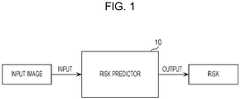
- Fig. 1is a block diagram illustrating an example of a configuration of the risk predictor 10 according to the first embodiment.
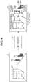
- Fig. 2is a diagram illustrating an outline of a structure of a convolutional neural network used by the risk predictor 10 shown in Fig. 1 .
- Fig. 3is a diagram illustrating an example of a result of a prediction performed by the risk predictor 10 according to the present embodiment.
- the risk predictor 10 shown in Fig. 1is a risk predictor using a convolutional neural network and is realized using a computer or the like.
- the convolutional neural network used in the risk predictor 10includes, for example, as shown in Fig. 2 , a convolutional layer 101 and a convolutional layer 102 wherein a fully connected layer is replaced by the convolutional layer 102.
- the convolutional neural networkis widely used in the field of the image recognition to extract a feature value from a two-dimensional image by performing convolution on the image using a filter.
- the convolutional neural networkincludes a multilayer network configured to repeat convolution and pooling.
- coefficients (weights) of filters of the convolutional layerare learned using a large amount of learning data such as a large number of learning images. These coefficients (weights) are obtained by repeating convolution using the filters and pooling for grouping responses together in a particular area by using a large amount of data thereby achieving invariance for varieties. It is known that the discrimination performance of the convolutional neural network depends on the filters of the convolutional layer.
- the risk predictor 10 shown in Fig. 1receives an input image taken by an in-vehicle camera, the risk predictor 10 estimates, by using the convolutional neural network such as that shown in Fig. 2 , a risk area in the input image and a feature thereof.
- the risk areais an area that may cause a dangerous situation for a running vehicle.
- the risk predictor 10outputs a result as a predicted risk.
- a higher riskis predicted. That is, the higher the similarity of the area in the input image to an area resulting in a past risk, the higher the predicted risk.
- the risk predictor 10 shown in Fig. 1acquires an input image taken by an in-vehicle camera installed on a vehicle.
- the risk predictor 10estimates the acquired input image, by using the convolutional neural network, to detect a risk area and a feature thereof having a possibility that a moving object may appear into a travelling path of the vehicle and if the vehicle simply continues the current travelling, the vehicle may collide with that moving object.
- the risk predictor 10outputs the detected risk area and the feature thereof as a predicted risk associated with the input image.
- the risk predictor 10estimates a degree of risk for the risk area as the feature of this risk area, and outputs, as the predicted risk, a likelihood map indicating the estimated risk area and the degree of risk of the risk area.
- the risk predictor 10acquires an image 50, as the input image, including a bus 501 at rest and persons (pedestrians) 502 and 503.
- the risk predictor 10estimates that an area behind the bus 501 at rest, an area of the person 502, and an area of the person 503 are risk areas in the image 50.
- the risk predictor 10then generates an image 50a on which a degree of risk (likelihood) of each risk area estimated in the image 50 is superimposed, and outputs the resultant image 50a as a predicted risk.
- the image 50aincludes a likelihood map, superimposed thereon, indicating a likelihood 504 for the area behind the bus 501 at rest, a likelihood 505 for the area of the person 502, and a likelihood 506 for the area of the person 503.
- the likelihoodindicates a degree of risk for the vehicle to have a collision. In the present embodiment, even when there is no person seen in an area, if the area is such an area having a high probability that a person may appear suddenly from the area, then the likelihood is set to indicate a high risk.
- the manner of outputting the risk by the risk predictor 10is not limited to the likelihood map such as that shown in Fig. 3 indicating a risk area and a degree of risk thereof. Another example is described below with reference to Fig. 4 .
- Fig. 4is a diagram illustrating an example of a result of a prediction performed by the risk predictor 10 according to the present embodiment.
- similar elements to those in Fig. 3are denoted by similar reference numerals, and a further detailed description thereof is omitted.
- the risk predictor 10estimates that an area 507 behind a bus 501 at rest, an area 508 of a person 502, and an area 509 of a person 503 are risk areas in an image 50 acquired as an input image.
- the risk predictor 10then outputs an image 50b on which the risk areas detected in the image 50 and labels indicating categories thereof are superimposed. That is, the image 50b output by the risk predictor 10 is generated such that the area 507 and a label "risk area (vehicle)" indicating a category of the area 507, the area 508 and a label "risk area (person)” indicating a category of the area 508, and the area 509 and a label "risk area (person)” indicating a category of the area 509 are superimposed on the image 50.
- the type of a moving object related to the area 507 estimated as a risk area in the image 50bis "vehicle”, and thus a label “risk area (vehicle)” is superimposed to indicate the category of the risk area.
- the type of a moving object related to each of the areas 508 and 509 estimated as risk areas in the image 50bis "person”, and thus a label “risk area (person)” is superimposed to indicate the category of these risk areas.
- the risk predictor 10may operate such that the type of the moving object related to the risk area is estimated as the feature of the risk area, and the estimated risk area and the type are output as the risk.
- Fig. 5is a flow chart illustrating an example of the prediction process performed by the risk predictor 10 according to the present embodiment.
- a computer of the risk predictor 10makes the convolutional neural network acquire an input image taken by an in-vehicle camera installed on a vehicle (S1). More specifically, in the present embodiment, the computer of the risk predictor 10 makes the convolutional neural network acquire an image, such as the image 50 shown in Fig. 5 , as the input image.
- the computer of the risk predictor 10makes the convolutional neural network estimate a risk area and a feature thereof, and output them as a predicted risk associated with the input image (S2). More specifically, the computer of the risk predictor 10 makes the convolutional neural network estimate a risk area and a feature thereof in the input image acquired in S1 to detect an area having a possibility that a moving object may appear from the area into a travelling path of the vehicle and if the vehicle simply continues the current travelling, the vehicle may collide with that moving object. The detected risk area and the feature thereof are output as a predicted risk associated with the input image.
- the computer of the risk predictor 10makes the convolutional neural network estimate the degree of risk of the risk area as the feature of this risk area and output, as the predicted risk, a likelihood map indicating the detected risk area and the degree of risk of the risk area.
- the computer of the risk predictor 10makes the convolutional neural network output an image such as the image 50a shown in Fig. 3 as the predicted risk.
- the computer of the risk predictor 10may make the convolutional neural network estimate the type of the moving object related to the risk area as the feature of the risk area, and output the estimated risk area and the type of the risk area as the risk.
- the risk predictor 10is capable of estimating an input image taken by an in-vehicle camera installed on a vehicle to detect a risk area in the input image and a feature of the risk area. More specifically, for example, the risk predictor 10 according to the first embodiment is capable of detecting a risk area where a dangerous situation for the running vehicle may occur, even such an area behind a bus at rest from which a pedestrian, not seen yet, may suddenly appear after getting off the bus.
- the risk predictor 10may be installed, for example, on an automated driving vehicle such that the vehicle is capable of predicting a risk area where a dangerous situation may occur from an image taken by an in-vehicle camera, and is capable of controlling driving of the vehicle so as to avoid the predicted risk area, which makes it possible to perform driving more safely.
- a convolutional neural network 10adenotes a convolutional neural network that is obtained after being trained via a learning process so as to function as the convolutional neural network used in the risk predictor 10.
- Fig. 6is a flow chart illustrating an outline of the learning process performed by the convolutional neural network 10a according to the present embodiment.
- Figs. 7A to 7Dare examples of learning data prepared in step S1.
- Fig. 8is a diagram illustrating an example of a set of a risk area and a feature thereof output as a result of the learning process.
- learning datais prepared (S11). More specifically, a set of a learning image including a risk area and an annotated image generated by adding an annotation indicating the risk area to the learning image is prepared as learning data.
- the learning datais described in further detail below with reference to Figs. 7A to 7D .
- Figs. 7A and 7Billustrate examples of learning images. These are examples of images, extracted from a plurality of images taken in the past by an in-vehicle camera, which actually resulted in dangerous situations.
- An image 52 illustrated in Fig. 7Bincludes a bus 511 at rest, a person (pedestrian) 512, and a person (pedestrian) 513 appearing from an area behind the bus 511.
- An image 51 shown in Fig. 7Aincludes the bus 511 at rest and the person (pedestrian) 512, but the person 513 is not yet seen although the person 513 exists in an area behind the bus 511.
- An image 51a illustrated in Fig. 7Cis an example of an annotated image.
- an annotationis added to the image 51 so as to indicate an area in which the person will appear a particular time later although the person is not yet seen.
- the image 51aincludes the annotation added thereto indicating a risk area where there is a possibility that the person 513 may appear as a moving object into the travelling path of the vehicle, which may collide with the vehicle if the vehicle, having the in-vehicle camera by which the image 51 is taken, simply continues the running.
- the manner of adding the annotation indicating the risk areais not limited to the example described above with reference to Fig. 7C in which the image 51a includes the annotation indicating the area 514 behind the bus 511 where there is the yet unseen person 513 who will suddenly appear soon.
- an annotationmay also be added the area 515 of the seen person 512 to indicate that this area 515 is a risk area, and annotations may be added to other safe areas (for example, an area 516) to indicate that these areas are safe.
- the convolutional neural network 10aperforms the learning process using the image 51 including the risk area shown in Fig. 7A as the learning image and the image 51b shown in Fig. 7D as the annotated image obtained by adding the annotation indicating the risk area to the learning image.
- the convolutional neural network 10alearns the weights for estimating the likelihood map, such as an image 51c shown in Fig. 8 , indicating the risk area and the degree of risk of the risk area.
- an area behind the bus 511 at rest and an area of the person 512are risk areas, and a likelihood 517 for the area behind the bus 511 and a likelihood 518 for the area of the person 512 are superimposed on the image 51c.
- a process of adding an annotation indicating a risk area to the learning imagemay be performed manually, for example, by a cloud sourcing worker, or all or part of the process may be performed by a computer.
- the computer in a learning systemperforms the process of adding the annotation indicating the risk area to the learning image, and, using the resultant learning data, the convolutional neural network 10a performs the learning process as described below.
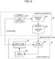
- Fig. 9is a block diagram illustrating an example of a configuration of a learning system according to an example.
- the learning system shown in Fig. 9includes a learning data generator 20 and a learning apparatus 30, and performs a learning process to realize the risk predictor 10.
- the learning data generator 20includes a storage 201, a storage 203, and an annotation adder 202, and the learning data generator 20 generates learning data from video data.
- the storage 201includes a hard disk drive (HDD), a memory, or the like, and stores video data including a series of temporally successive images taken by an in-vehicle camera installed on a vehicle, wherein the video data is also used as learning images.
- the storage 203includes a hard disk drive (HDD), a memory, or the like, and stores annotated data, which is data generated by adding indicating a risk area to the learning image (learning data).
- the annotation adder 202adds at least an annotation indicating a risk area to a learning image (video data) acquired from the storage 201 and stores resultant data in the storage 203.
- the learning apparatus 30includes an error calculator 301 and a weight adjuster 302, and performs a learning process on the convolutional neural network 10a using learning data acquired from the learning data generator 20.
- the convolutional neural network 10ahas the same structure as that of the convolutional neural network used in the risk predictor 10. After the learning process is completed, the convolutional neural network 10a functions as the convolutional neural network used in the risk predictor 10.
- the error calculator 301calculates, using an error function, an error between a value (correct value) indicating a risk area and a feature of this disk area to be estimated correctly by the convolutional neural network 10a and a value (a value indicating a predicted risk) actually output (estimated) by the convolutional neural network 10a.
- the weight adjuster 302adjusts weights of the convolutional neural network 10a so as to obtain a smaller value for the error calculated by the error calculator 301. Operation of learning system
- Fig. 10is a flow chart illustrating a process of generating annotated data performed by the learning data generator 20.
- Fig. 11is a flow chart illustrating a learning process performed by the learning apparatus 30. Note that the process shown in Fig. 10 is an example of a detailed description of S11 shown in Fig. 6 , and the process shown in Fig. 11 is an example of a detailed description of S12 shown in Fig. 6 .
- the learning data generator 20acquires video data stored in the storage 201 (S111). More specifically, the learning data generator 20 acquires, as the video data, a plurality of temporally successive images taken by an in-vehicle camera installed on a vehicle.
- the learning data generator 20determines a risk area included in the video data (S112). More specifically, the learning data generator 20 determines a risk area that is included at least in part of the acquired images (video data) and that is an area where there is a possibility that a moving object may appear into a travelling path of a vehicle and there is a possibility that the vehicle having the in-vehicle camera by which the plurality of images are taken may collide with this moving object if the vehicle simply continues the running.
- the learning data generator 20adds an annotation indicating the risk area to the video data (S113). More specifcally, the learning data generator 20 adds an annotation indicating the determined risk area to at least part of the images.
- the learning data generator 20stores, in the storage 203, the video data (annotated data) at least part of images of which are added with the annotation indicating the risk area.
- the learning data generator 20adds an annotation indicating a risk area to a partial area of an image where a yet unseen person will appear a particular time later.
- the manner of adding an annotationis not limited to this example.
- the learning apparatus 30acquires learning data from the learning data generator 20 (S121). More specifically, the learning apparatus 30 acquires, as the learning image and the annotated image, at least the part of images with the annotation added in S113 and images corresponding to the at least part of images in the plurality of images (video data). More specifically, for example, as described above, the learning apparatus 30 acquires, from the learning data generator 20, the learning image including the risk area shown in Fig. 7A and the annotated image shown in Fig. 7D .
- the learning apparatus 30makes the convolutional neural network 10a output a value indicating the risk estimated using the learning image (S122). More specifically, for example, the learning apparatus 30 makes the convolutional neural network 10a output, as a value indicating a risk estimated for the learning image including the risk area such as that shown in Fig. 7A , values indicating the risk area in the learning image and the feature of this risk area, that is, values indicating the risk area and the degree of risk thereof (the likelihood map).
- the learning apparatus 30calculates a difference (an error) between the value output in the S122 and the value (the correct value) indicating the risk area in the learning image and the feature of this risk area to be estimated by the convolutional neural network 10a (S123).
- the correct valueis the value representing the likelihood map indicating the risk area and the degree of risk of this risk area such as those represented in the image 51c shown in Fig. 8 calculated from the annotated image 51b shown in Fig. 7D having the annotation indicating the risk area.
- the learning apparatus 30changes the weights of the convolutional neural network 10a such that the difference becomes smaller (S125).
- the learning apparatus 30returns to S122 and performs the process described above repeatedly.
- the processis ended. That is, the learning apparatus 30 makes the convolutional neural network 10a learn the weights by adjusting the weights of the convolutional neural network 10a such that the error calculated in S123 becomes equal to the minimum value.
- the learning apparatus 30determines the resultant weights of the convolutional neural network 10a as the weights of the convolutional neural network used in the risk predictor 10.
- the weights of the convolutional neural network 10a in this situationmay be employed as the weights of the convolutional neural network used in the risk predictor 10.
- the minimum errormay be defined such that the maximum number of iterations of the iterative process is determined, and the minimum error is defined by a minimum error obtained during the iterations.
- Fig. 12Ais a diagram illustrating another example of an annotated image prepared in step S1.
- Fig. 12Bis a diagram illustrating another example of a set of a risk area and a feature thereof output as a result of a learning process.
- similar elements to those in Figs. 7A to 7D and Fig. 8are denoted by similar reference numerals, and a further detailed description thereof is omitted.
- the image 51 shown in Fig. 7Ais used as an example of the learning image and the image 51b shown in Fig. 7D is used as an example of the annotated image, and the risk area and the degree of risk thereof represented in the image 51c of Fig. 8 are employed as correct values.
- the image 51 shown in Fig. 7A and the image 51d shown in Fig. 12Amay be respectively employed as the learning image and the annotated image, and the risk area and the value indicating the category thereof represented in the image 51e of Fig. 12B may be correct values.
- an area 514d behind a bus 511 at restis a risk area from which there is a possibility that an unseen person may appear and collide with a vehicle
- "RISK CATEGORY #1"is an annotation indicating a category of the risk area.
- annotationsare added to indicate an area 515d of a seen person 512 and a category thereof, that is, "RISK CATEGORY #2". That is, the area 515d of the person 512 is a risk area having a risk of collision with a vehicle, and the category of this risk area is "RISK CATEGORY #2".
- annotationsare added to other areas (such as an area 516d) to indicate that they are safe areas.
- an area 519 behind a bus at rest 511is a risk area, and a category thereof is a "risk area (vehicle)". Furthermore, an area 520 of a person 512 is a risk area and a category thereof is a "risk area (person)”.
- An annotation added to a learning imageis not limited to information (such as a frame) indicating a risk area such as that according to the example described above or a category of a moving object related to the risk area such as that described above in the first modification.
- vehicle control informationin terms of a handle angle or a brake strength of a vehicle as of when a learning image is taken may be employed as an annotation, or the annotation may be detailed area information, such as that shown in Fig. 13 , other than an object area.
- an annotation added to a learning imagemay indicate a risk area in an input image and control information including information in terms of a brake strength or a handle angle of a vehicle as of when the learning image is taken.
- An annotation added to a learning imagemay be segment information of a risk area in an input image.
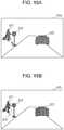
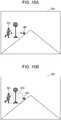
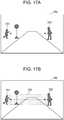
- Fig. 14A , Fig. 15A , Fig. 16A , and Fig. 17Ashow examples of learning images.
- Fig. 14B , Fig. 15B , Fig. 16B , and Fig. 17Bshow examples of annotated images added with annotations indicating risk areas.
- a learning image 56a shown in Fig. 14Aincludes a vehicle 561 parking or at rest and a person 562.
- An annotated image 56b shown in Fig. 14Bincludes an annotation, added to the learning image 56a, to indicate that an area 563 between the vehicle 561 parking or at rest and the person 562 is a risk area.
- a learning image 57a shown in Fig. 15Aincludes a person 571, an object 572 which is a bus stop, and a vehicle 573 parking or at rest.
- An annotated image 57b shown in Fig. 15Bincludes an annotation, added to the learning image 57a, to indicate that an area 574 between the person 571 and the object 572, which is the but stop, is a risk area.
- a learning image 58a shown in Fig. 16Aincludes a person 581 who is a child and an object 582 which is a ball used in playing by the person 581.
- An annotated image 58b shown in Fig. 16Bincludes an annotation, added to the learning image 58a, to indicate that an area 583 between the person 581 and the object 582 used in playing by the person 581 is a risk area.
- a learning image 59a shown in Fig. 17Aincludes a person 591 who is a child and a person 592 who is a child's parent or the like.
- An annotated image 59b shown in Fig. 17Bincludes an annotation, added to the learning image 59a, to indicate that an area 593 between the person 591 and the person 592 is a risk area.
- the risk predictor 10may predict an area between two or more such moving objects as a risk area.
- first-phase learning processmay be performed using a convolutional neural network having a fully connected layer, and then a second-phase learning process may be performed using a convolutional neural network obtained by changing the fully connected layer to a convolutional layer.
- a learning methodis described below as a second embodiment. The following description will focus on differences from the first embodiment.
- the configuration of the risk predictor 10is similar to that according to the first embodiment, and thus a further description thereof is omitted.
- the learning process using learning datais performed by a computer in a different manner from the manner according to the first embodiment.
- Fig. 18is a flow chart illustrating an outline of a two-phase learning process according to the second embodiment.
- Fig. 19is a flow chart illustrating a concept of a first-phase learning process.
- Fig. 20is a flow chart illustrating a concept of a second-phase learning process.
- similar elements to those in Fig. 3 , Fig. 7D , or other figuresare denoted by similar reference numerals, and a further detailed description is omitted.
- the process shown in Fig. 18is an example of a detailed process of step S12 shown in Fig. 6 .
- a first neural network 10b shown in Fig. 19is a convolutional neural network having a fully connected layer used in the first-phase learning process.
- a second neural network 10c shown in Fig. 20is a convolutional neural network used in the second-phase learning process, and this second neural network 10c has a configuration obtained by changing the fully connected layer of the first neural network 10b to a convolutional layer.
- the second neural network 10cis the same in configuration as the convolutional neural network used in the risk predictor 10.
- a computerperforms a first learning process in which the first neural network 10b learns weights using learning data (S221). More specifically, by using partial areas of learning images, that is, a risk area image added with an annotation indicating that this area is a risk area and a safe area image added with no annotation, the computer makes the first neural network 10b, which is a convolutional neural network having a fully connected layer, learn the first weight of the first neural network for determining whether the partial area is a safe area or a risk area.
- the computerinputs a risk area image 61, which is a partial image of the annotated image 51b, to the first neural network 10b and makes the first neural network 10b learn the first weight of the first neural network 10b to determine that this risk area image 61 is a risk area.
- the computerperforms a second learning process in which the second neural network 10c performs learning using learning data (S221 to S224). More specifically, first, the computer generates the second neural network by changing the fully connected layer of the first neural network to a convolutional layer (S222). Next, the computer reads the weight (the first weight) of the first neural network learned in S221 (S223), and changes the initial value of the weight of the second neural network generated in S222 to the first weight.
- the computermakes the second neural network 10c learns the weight (second weight) of the second neural network 10c for estimating the risk area in the learning image and the feature of the risk area (S224).
- the computerinputs the image 50 as the learning image (input image) to the second neural network 10c and makes the second neural network 10c change (learn) the second weight to estimate a risk in the form of a likelihood map indicating the risk area and the degree of the risk of the risk area.
- the first neural network 10blearns the first weight for determining whether the input learning image is safe or risky.
- other imagesmay be used as learning images.
- a partial area of the learning image including the risk area and the annotation indicating the category of the risk areamay be used as the learning image.
- the first neural network 10blearns its first weight to determine whether the input learning image includes a risk area or no risk area, and, in a case where it is determined that the input learning image includes a risk area, further determine the category of the risk area.
- Fig. 21is another diagram illustrating the concept of the first-phase learning process.
- the computerIn the example shown in Fig. 21 , the computer generates a risk area image 63 by extracting an area 514d as a partial area of the image 51 d including a risk area and an annotation indicating the category thereof, and inputs the resultant risk area image 63 to the first neural network 10b. The computer then makes the first neural network 10b learn the first weight thereof to determine that the risk area image 63 is a risk area and determine the category (risk (vehicle) in the example shown in Fig. 21 ) of the risk area image 63.
- the risk categorymay be divided into subcategories depending on appearances of objects or the like.
- the risk output by the risk predictor 10is not limited to the likelihood map such as that shown in Fig. 20 indicating the risk area and the degree of risk thereof. That is, the second learning process is not limited to the learning process in which the second weight is learned to output, as the risk area and the feature thereof, the likelihood map indicating the risk area and the degree of risk. Alternatively, for example, the second weight may be learned to output the risk area and the category thereof.
- the input image used as the learning image or the input image given in the risk prediction processmay be an image (a full image) taken by an in-vehicle camera or a partial image of the full image.
- the partial imagemay be an image of an area to be estimated as a risk area as described above.
- the full imagemay be an image taken as of when, or as of before, a dangerous situation occurs.
- the present disclosurealso includes in its scope the following.
- the present disclosuremay be implemented by transmitting the computer program or the digital signal via a telecommunication line, a wired or wireless communication line, a network typified by the Internet, data broadcasting, or the like.
- the present disclosuremay be implemented by a computer system including a microprocessor and a memory, wherein the computer program is stored in the memory and the microprocessor operates according to the computer program.
- the program or the digital signalmay be stored in the storage medium and may be transferred, or the program or the digital signal may be transferred via the network or the like thereby allowing the present disclosure to be implemented in another computer system.
- the techniques of the present disclosureare applicable, in particular, to the prediction of a risk area where there is a possibility that a dangerous situation occurs, by using a camera installed on an automated driving vehicle or system, or installed in an apparatus or system for assisting driving.
Landscapes
- Engineering & Computer Science (AREA)
- Theoretical Computer Science (AREA)
- Physics & Mathematics (AREA)
- General Physics & Mathematics (AREA)
- Multimedia (AREA)
- Evolutionary Computation (AREA)
- Artificial Intelligence (AREA)
- General Health & Medical Sciences (AREA)
- Health & Medical Sciences (AREA)
- Software Systems (AREA)
- Computing Systems (AREA)
- Molecular Biology (AREA)
- Life Sciences & Earth Sciences (AREA)
- Biomedical Technology (AREA)
- Data Mining & Analysis (AREA)
- Computational Linguistics (AREA)
- General Engineering & Computer Science (AREA)
- Mathematical Physics (AREA)
- Computer Vision & Pattern Recognition (AREA)
- Biophysics (AREA)
- Human Computer Interaction (AREA)
- Biodiversity & Conservation Biology (AREA)
- Medical Informatics (AREA)
- Databases & Information Systems (AREA)
- Signal Processing (AREA)
- Image Analysis (AREA)
- Traffic Control Systems (AREA)
Abstract
Description
- The present disclosure relates to a risk prediction method.
- A driving assist apparatus for assisting a driver of a vehicle to confirm safety is disclosed, for example, in Japanese Patent No.
4967015 - In one general aspect, the techniques disclosed here feature a risk prediction method executed by a computer of a risk predictor using a convolutional neural network, the method including making the convolutional neural network acquire an input image taken by an in-vehicle camera installed on a vehicle, making the convolutional neural network estimate a risk area and a feature of the risk area, the risk area being in the acquired input image, the risk area having a possibility that a moving object may appear from the risk area into a travelling path of the vehicle and the moving object may collide with the vehicle in a case where the vehicle simply continues running, and then making the convolutional neural network output the estimated risk area and the estimated feature of the risk area as a risk predicted for the input image.
- The present disclosure makes it possible to realize a risk prediction method capable of predicting a risk area having a possibility of causing a dangerous situation for a running vehicle.
- It should be noted that general or specific embodiments may be implemented as a system, a method, an integrated circuit, a computer program, a storage medium, or any selective combination thereof.
- Additional benefits and advantages of the disclosed embodiments will become apparent from the specification and drawings. The benefits and/or advantages may be individually obtained by the various embodiments and features of the specification and drawings, which need not all be provided in order to obtain one or more of such benefits and/or advantages.
Fig. 1 is a block diagram illustrating an example of a configuration of a risk predictor according to a first embodiment;Fig. 2 is a diagram illustrating an outline of a structure of a convolutional neural network used by the risk predictor shown inFig. 1 ;Fig. 3 is a diagram illustrating an example of a result of a prediction performed by the risk predictor according to the first embodiment;Fig. 4 is a diagram illustrating another example of a result of a prediction performed by the risk predictor according to the first embodiment;Fig. 5 is a flow chart illustrating an example of a prediction process performed by a risk predictor according to the first embodiment;Fig. 6 is a flow chart illustrating an outline of a learning process performed by a convolutional neural network according to the first embodiment;Fig. 7A is a diagram illustrating learning data prepared in step S1;Fig. 7B is a diagram illustrating learning data prepared in step S1;Fig. 7C is a diagram illustrating learning data prepared in step 81;Fig. 7D is a diagram illustrating learning data prepared in step S1;Fig. 8 is a diagram illustrating an example of a set of a risk area and a feature thereof output as a result of a learning process;Fig. 9 is a block diagram illustrating an example of a configuration of a learning system according to an embodiment;Fig. 10 is a flow chart illustrating a process of generating annotated data performed by a learning data generator;Fig. 11 is a flow chart illustrating a learning process performed by a learning apparatus;Fig. 12A is a diagram illustrating another example of an annotated image prepared in step S1;Fig. 12B is a diagram illustrating another example of a set of a risk area and a feature thereof output as a result of a learning process;Fig. 13 is a diagram illustrating an example of detailed area information;Fig. 14A is a diagram illustrating an example of a learning image;Fig. 14B is a diagram illustrating an example of an annotated image added with an annotation indicating a risk area;Fig. 15A is a diagram illustrating an example of a learning image;Fig. 15B is a diagram illustrating an example of an annotated image added with an annotation indicating a risk area;Fig. 16A is a diagram illustrating an example of a learning image;Fig. 16B is a diagram illustrating an example of an annotated image added with an annotation indicating a risk area;Fig. 17A is a diagram illustrating an example of a learning image;Fig. 17B is a diagram illustrating an example of an annotated image added with an annotation indicating a risk area;Fig. 18 is a flow chart illustrating an outline of a two-phase learning process according to a second embodiment;Fig. 19 is a flow chart illustrating a concept of a first-phase learning process;Fig. 20 is a flow chart illustrating a concept of a second-phase learning process;- and
Fig. 21 is another diagram illustrating the concept of the first-phase learning process.- In the driving assist apparatus disclosed in Japanese Patent No.
4967015 4967015 - In view of the above, the present disclosure provides a risk prediction method capable of predicting a risk area likely to cause a dangerous situation for a running vehicle.
- In recent years, a drastic advance has been achieved in image recognition performance by use of deep learning. The deep learning is known as a method of machine learning using a multilayer neural network. In many cases, a convolutional neural network (CNN) is employed as the multilayer neural network. The convolutional neural network includes a multilayer neural network that repeatedly performs convolution and pooling on a local area.
- The convolutional neural network includes a convolutional layer that extracts a feature by performing a convolution process using a plurality of filters, a pooling layer that ensures local invariance of data by performing a pooling process to group responses together in a particular area, and a fully connected layer that performs recognition based on a probability using a softmax function or the like,
- However, the image recognition process using such a convolutional neural network has a problem that the process cannot be performed on a real-time basis.
- To handle the above-described situation, it has been proposed (see, for example, Jonathan Long, Evan Shelhamer,Trevor Darrell, "Fully Convolutional Networks for Semantic Segmentation", The IEEE Conference on Computer Vision and Pattern Recognition (CVPR), 2015, pp. 3431-3440) to configure a convolutional neural network such that a fully connected layer in the convolutional neural network is replaced with a convolutional layer. By using the convolutional neural network (fully convolutional neural network) configured in this manner, it is possible to perform an image recognition process in real time.
- In view of the above, the inventors of the present disclosure have gotten an idea that the problems described above can be solved using a fully convolutional neural network.
- In an aspect, the present disclosure provides a risk prediction method executed by a computer of a risk predictor using a convolutional neural network, the method including making the convolutional neural network acquire an input image taken by an in-vehicle camera installed on a vehicle, making the convolutional neural network estimate a risk area and a feature of the risk area, the risk area being in the acquired input image, the risk area having a possibility that a moving object may appear from the risk area into a travelling path of the vehicle and the moving object may collide with the vehicle in a case where the vehicle simply continues running, and then making the convolutional neural network output the estimated risk area and the estimated feature of the risk area as a risk predicted for the input image.
- Using this technique according to the present aspect, it is possible to estimate a risk from an acquired input image, and thus it is possible to realize a risk prediction method capable of predicting a risk area where a dangerous situation for a running vehicle may occur.
- In the method, for example, in the outputting, the convolutional neural network may be made to estimate a degree of risk of the risk area as the feature of the risk area and output, as the risk, a likelihood map indicating the estimated risk area and the degree of risk of the risk area.
- In the method, for example, in the outputting, the convolutional neural network may be made to estimate a type of the moving object related to the risk area as the feature of the risk area and output, as the risk, the estimated risk area and the type.
- The risk prediction method may further include making the convolutional neural network, before the acquiring of the input image, learn a weight of the convolutional neural network by using a learning image including the risk area and an annotated image generated by adding an annotation indicating the risk area to the learning image such that the weight for estimating the risk area in the learning image and the feature of the risk area is learned.
- The learning may include making a first neural network, which is a convolutional neural network including a fully connected layer, learn a first weight of the first neural network by using a risk area image and a safe area image which are each a partial area of the learning image, the risk area image being the area added with the annotation indicating the risk area, the safe area image being an area to which the annotation is not added, such that the first weight of the first neural network for determining whether the partial area is a safe area or risk area is learned, assigning the learned first weight as an initial value of a weight of a second neural network having a configuration obtained by changing the fully connected layer of the first neural network to a convolutional layer, and making the second neural network learn a second weight of the second neural network for estimating the risk area in the learning image and the feature of the risk area by using the learning image including the risk area and the annotated image generated by adding the annotation indicating the risk area to the learning image, thereby learning the weight of the convolutional neural network having the same configuration as that of the second neural network.
- The risk prediction method may further include acquiring a plurality of temporally successive images taken by an in-vehicle camera installed on a vehicle, determining a risk area included in at least part of the plurality of acquired images and having a possibility that a moving object may appear from the risk area into a travelling path of the vehicle and the moving object may collide with the vehicle in a case where the vehicle simply continues running, and adding an annotation indicating the determined risk area to the at least part of the plurality of images, wherein in the learning, the at least part of the plurality images having the added annotation and images corresponding to the at least part of the plurality of images are acquired as the learning image and the annotated image, and the weight of the convolutional neural network is learned using the acquired learning image and the annotated image.
- In the method, for example, the risk area may be an area including a part of an area of a hiding object existing in the learning image in a state in which the moving object is hidden behind before the moving object appears from the hiding object into the travelling path.
- In the method, for example, the risk area may be an area between two or more moving objects including a person at least one of which has a possibility of moving toward the other one of the moving objects and crossing the travelling path of the vehicle.
- For example, the annotation may indicate the risk area and a category of the moving object related to the risk area.
- For example, the annotation may indicate the risk area and control information including information in terms of a brake strength or a steering wheel angle of the vehicle as of when the learning image is taken.
- For example, the annotation may be segment information on the risk area.
- For example, at least one of the acquiring and the outputting may be performed by a processor of the computer.
- Note that each embodiment described below is for illustrating a specific example of the present disclosure. That is, in the following embodiments of the present disclosure, values, shapes, constituent elements, steps, the order of steps, and the like are described by way of example but not limitation. Among constituent elements described in the following embodiments, those constituent elements that are not described in independent claims indicating highest-level concepts of the present disclosure are optional. The details of the above-described embodiments may be combined.
- A risk prediction method by a
risk predictor 10 according to a first embodiment is described below with reference to drawings. Fig. 1 is a block diagram illustrating an example of a configuration of therisk predictor 10 according to the first embodiment.Fig. 2 is a diagram illustrating an outline of a structure of a convolutional neural network used by therisk predictor 10 shown inFig. 1 .Fig. 3 is a diagram illustrating an example of a result of a prediction performed by therisk predictor 10 according to the present embodiment.- The
risk predictor 10 shown inFig. 1 is a risk predictor using a convolutional neural network and is realized using a computer or the like. The convolutional neural network used in therisk predictor 10 includes, for example, as shown inFig. 2 , aconvolutional layer 101 and aconvolutional layer 102 wherein a fully connected layer is replaced by theconvolutional layer 102. - The convolutional neural network is widely used in the field of the image recognition to extract a feature value from a two-dimensional image by performing convolution on the image using a filter. As described above, the convolutional neural network includes a multilayer network configured to repeat convolution and pooling. In the convolutional neural network, coefficients (weights) of filters of the convolutional layer are learned using a large amount of learning data such as a large number of learning images. These coefficients (weights) are obtained by repeating convolution using the filters and pooling for grouping responses together in a particular area by using a large amount of data thereby achieving invariance for varieties. It is known that the discrimination performance of the convolutional neural network depends on the filters of the convolutional layer.
- When the
risk predictor 10 shown inFig. 1 receives an input image taken by an in-vehicle camera, therisk predictor 10 estimates, by using the convolutional neural network such as that shown inFig. 2 , a risk area in the input image and a feature thereof. Note that the risk area is an area that may cause a dangerous situation for a running vehicle. Therisk predictor 10 outputs a result as a predicted risk. In the prediction by therisk predictor 10, when an area in the input image has higher similarity to a partial area of an image immediately before an image that caused, in the past, a dangerous situation such as a sudden appearance of a person, a higher risk is predicted. That is, the higher the similarity of the area in the input image to an area resulting in a past risk, the higher the predicted risk. - More specifically, the
risk predictor 10 shown inFig. 1 acquires an input image taken by an in-vehicle camera installed on a vehicle. Therisk predictor 10 estimates the acquired input image, by using the convolutional neural network, to detect a risk area and a feature thereof having a possibility that a moving object may appear into a travelling path of the vehicle and if the vehicle simply continues the current travelling, the vehicle may collide with that moving object. Therisk predictor 10 outputs the detected risk area and the feature thereof as a predicted risk associated with the input image. In this process, therisk predictor 10 estimates a degree of risk for the risk area as the feature of this risk area, and outputs, as the predicted risk, a likelihood map indicating the estimated risk area and the degree of risk of the risk area. - In the specific example described below, it is assumed by way of example that the
risk predictor 10 acquires animage 50, as the input image, including abus 501 at rest and persons (pedestrians) 502 and 503. In this situation, therisk predictor 10 estimates that an area behind thebus 501 at rest, an area of theperson 502, and an area of theperson 503 are risk areas in theimage 50. Therisk predictor 10 then generates animage 50a on which a degree of risk (likelihood) of each risk area estimated in theimage 50 is superimposed, and outputs theresultant image 50a as a predicted risk. Theimage 50a includes a likelihood map, superimposed thereon, indicating alikelihood 504 for the area behind thebus 501 at rest, alikelihood 505 for the area of theperson 502, and alikelihood 506 for the area of theperson 503. The likelihood indicates a degree of risk for the vehicle to have a collision. In the present embodiment, even when there is no person seen in an area, if the area is such an area having a high probability that a person may appear suddenly from the area, then the likelihood is set to indicate a high risk. - The manner of outputting the risk by the
risk predictor 10 is not limited to the likelihood map such as that shown inFig. 3 indicating a risk area and a degree of risk thereof. Another example is described below with reference toFig. 4 . Fig. 4 is a diagram illustrating an example of a result of a prediction performed by therisk predictor 10 according to the present embodiment. InFig. 4 , similar elements to those inFig. 3 are denoted by similar reference numerals, and a further detailed description thereof is omitted.- The
risk predictor 10 estimates that anarea 507 behind abus 501 at rest, anarea 508 of aperson 502, and an area 509 of aperson 503 are risk areas in animage 50 acquired as an input image. Therisk predictor 10 then outputs animage 50b on which the risk areas detected in theimage 50 and labels indicating categories thereof are superimposed. That is, theimage 50b output by therisk predictor 10 is generated such that thearea 507 and a label "risk area (vehicle)" indicating a category of thearea 507, thearea 508 and a label "risk area (person)" indicating a category of thearea 508, and the area 509 and a label "risk area (person)" indicating a category of the area 509 are superimposed on theimage 50. In this case, the type of a moving object related to thearea 507 estimated as a risk area in theimage 50b is "vehicle", and thus a label "risk area (vehicle)" is superimposed to indicate the category of the risk area. Similarly, the type of a moving object related to each of theareas 508 and 509 estimated as risk areas in theimage 50b is "person", and thus a label "risk area (person)" is superimposed to indicate the category of these risk areas. - As described above, the
risk predictor 10 may operate such that the type of the moving object related to the risk area is estimated as the feature of the risk area, and the estimated risk area and the type are output as the risk. - Next, a prediction process by the
risk predictor 10 according to the present embodiment is described below with reference to drawings. Fig. 5 is a flow chart illustrating an example of the prediction process performed by therisk predictor 10 according to the present embodiment.- As shown in
Fig. 5 , first, a computer of therisk predictor 10 makes the convolutional neural network acquire an input image taken by an in-vehicle camera installed on a vehicle (S1). More specifically, in the present embodiment, the computer of therisk predictor 10 makes the convolutional neural network acquire an image, such as theimage 50 shown inFig. 5 , as the input image. - Next, the computer of the
risk predictor 10 makes the convolutional neural network estimate a risk area and a feature thereof, and output them as a predicted risk associated with the input image (S2). More specifically, the computer of therisk predictor 10 makes the convolutional neural network estimate a risk area and a feature thereof in the input image acquired in S1 to detect an area having a possibility that a moving object may appear from the area into a travelling path of the vehicle and if the vehicle simply continues the current travelling, the vehicle may collide with that moving object. The detected risk area and the feature thereof are output as a predicted risk associated with the input image. - In the present embodiment, the computer of the
risk predictor 10 makes the convolutional neural network estimate the degree of risk of the risk area as the feature of this risk area and output, as the predicted risk, a likelihood map indicating the detected risk area and the degree of risk of the risk area. For example, the computer of therisk predictor 10 makes the convolutional neural network output an image such as theimage 50a shown inFig. 3 as the predicted risk. - Alternatively, as described above, the computer of the
risk predictor 10 may make the convolutional neural network estimate the type of the moving object related to the risk area as the feature of the risk area, and output the estimated risk area and the type of the risk area as the risk. - As described above, the
risk predictor 10 according to the first embodiment is capable of estimating an input image taken by an in-vehicle camera installed on a vehicle to detect a risk area in the input image and a feature of the risk area. More specifically, for example, therisk predictor 10 according to the first embodiment is capable of detecting a risk area where a dangerous situation for the running vehicle may occur, even such an area behind a bus at rest from which a pedestrian, not seen yet, may suddenly appear after getting off the bus. - The
risk predictor 10 may be installed, for example, on an automated driving vehicle such that the vehicle is capable of predicting a risk area where a dangerous situation may occur from an image taken by an in-vehicle camera, and is capable of controlling driving of the vehicle so as to avoid the predicted risk area, which makes it possible to perform driving more safely. - A learning process for realizing the
risk predictor 10 is described below. In the following description, a convolutionalneural network 10a denotes a convolutional neural network that is obtained after being trained via a learning process so as to function as the convolutional neural network used in therisk predictor 10. Fig. 6 is a flow chart illustrating an outline of the learning process performed by the convolutionalneural network 10a according to the present embodiment.Figs. 7A to 7D are examples of learning data prepared in step S1.Fig. 8 is a diagram illustrating an example of a set of a risk area and a feature thereof output as a result of the learning process.- First, learning data is prepared (S11). More specifically, a set of a learning image including a risk area and an annotated image generated by adding an annotation indicating the risk area to the learning image is prepared as learning data.
- The learning data is described in further detail below with reference to
Figs. 7A to 7D . Figs. 7A and 7B illustrate examples of learning images. These are examples of images, extracted from a plurality of images taken in the past by an in-vehicle camera, which actually resulted in dangerous situations. Animage 52 illustrated inFig. 7B includes abus 511 at rest, a person (pedestrian) 512, and a person (pedestrian) 513 appearing from an area behind thebus 511. Animage 51 shown inFig. 7A includes thebus 511 at rest and the person (pedestrian) 512, but theperson 513 is not yet seen although theperson 513 exists in an area behind thebus 511.- An
image 51a illustrated inFig. 7C is an example of an annotated image. In this example, an annotation is added to theimage 51 so as to indicate an area in which the person will appear a particular time later although the person is not yet seen. More specifically, theimage 51a includes the annotation added thereto indicating a risk area where there is a possibility that theperson 513 may appear as a moving object into the travelling path of the vehicle, which may collide with the vehicle if the vehicle, having the in-vehicle camera by which theimage 51 is taken, simply continues the running. - The manner of adding the annotation indicating the risk area is not limited to the example described above with reference to
Fig. 7C in which theimage 51a includes the annotation indicating thearea 514 behind thebus 511 where there is the yetunseen person 513 who will suddenly appear soon. For example, as illustrated inFig. 7D , in addition to thearea 514, an annotation may also be added thearea 515 of the seenperson 512 to indicate that thisarea 515 is a risk area, and annotations may be added to other safe areas (for example, an area 516) to indicate that these areas are safe. Referring again toFig. 6 , a further description is given below. - Next, the computer performs the learning process using the learning data such that the convolutional
neural network 10a can function as the risk predictor 10 (S12). More specifically, using the learning image including the risk area and the annotated image obtained by adding the annotation indicating the risk area to the learning image, the convolutionalneural network 10a performs a learning process to learn weights of the convolutionalneural network 10a to estimate the risk area in the learning image and the feature of the risk area. - For example, it is assumed here that the convolutional
neural network 10a performs the learning process using theimage 51 including the risk area shown inFig. 7A as the learning image and theimage 51b shown inFig. 7D as the annotated image obtained by adding the annotation indicating the risk area to the learning image. In this case, the convolutionalneural network 10a learns the weights for estimating the likelihood map, such as animage 51c shown inFig. 8 , indicating the risk area and the degree of risk of the risk area. In theimage 51c shown inFig. 8 , an area behind thebus 511 at rest and an area of theperson 512 are risk areas, and alikelihood 517 for the area behind thebus 511 and alikelihood 518 for the area of theperson 512 are superimposed on theimage 51c. - In preparing learning data, a process of adding an annotation indicating a risk area to the learning image may be performed manually, for example, by a cloud sourcing worker, or all or part of the process may be performed by a computer. In the following description, it is assumed by way of example that the computer in a learning system performs the process of adding the annotation indicating the risk area to the learning image, and, using the resultant learning data, the convolutional
neural network 10a performs the learning process as described below. Fig. 9 is a block diagram illustrating an example of a configuration of a learning system according to an example. The learning system shown inFig. 9 includes a learningdata generator 20 and alearning apparatus 30, and performs a learning process to realize therisk predictor 10.- The learning
data generator 20 includes astorage 201, astorage 203, and anannotation adder 202, and the learningdata generator 20 generates learning data from video data. Thestorage 201 includes a hard disk drive (HDD), a memory, or the like, and stores video data including a series of temporally successive images taken by an in-vehicle camera installed on a vehicle, wherein the video data is also used as learning images. Thestorage 203 includes a hard disk drive (HDD), a memory, or the like, and stores annotated data, which is data generated by adding indicating a risk area to the learning image (learning data). Theannotation adder 202 adds at least an annotation indicating a risk area to a learning image (video data) acquired from thestorage 201 and stores resultant data in thestorage 203. - The
learning apparatus 30 includes anerror calculator 301 and aweight adjuster 302, and performs a learning process on the convolutionalneural network 10a using learning data acquired from the learningdata generator 20. Note that the convolutionalneural network 10a has the same structure as that of the convolutional neural network used in therisk predictor 10. After the learning process is completed, the convolutionalneural network 10a functions as the convolutional neural network used in therisk predictor 10. Theerror calculator 301 calculates, using an error function, an error between a value (correct value) indicating a risk area and a feature of this disk area to be estimated correctly by the convolutionalneural network 10a and a value (a value indicating a predicted risk) actually output (estimated) by the convolutionalneural network 10a. Theweight adjuster 302 adjusts weights of the convolutionalneural network 10a so as to obtain a smaller value for the error calculated by theerror calculator 301. Operation of learning system - An operation of the learning system configured in the above-described manner is described below with reference to
Fig. 10 andFig. 11 .Fig. 10 is a flow chart illustrating a process of generating annotated data performed by the learningdata generator 20.Fig. 11 is a flow chart illustrating a learning process performed by thelearning apparatus 30. Note that the process shown inFig. 10 is an example of a detailed description of S11 shown inFig. 6 , and the process shown inFig. 11 is an example of a detailed description of S12 shown inFig. 6 . - As shown in
Fig. 10 , first, the learningdata generator 20 acquires video data stored in the storage 201 (S111). More specifically, the learningdata generator 20 acquires, as the video data, a plurality of temporally successive images taken by an in-vehicle camera installed on a vehicle. - Next, the learning
data generator 20 determines a risk area included in the video data (S112). More specifically, the learningdata generator 20 determines a risk area that is included at least in part of the acquired images (video data) and that is an area where there is a possibility that a moving object may appear into a travelling path of a vehicle and there is a possibility that the vehicle having the in-vehicle camera by which the plurality of images are taken may collide with this moving object if the vehicle simply continues the running. - Next, the learning
data generator 20 adds an annotation indicating the risk area to the video data (S113). More specifcally, the learningdata generator 20 adds an annotation indicating the determined risk area to at least part of the images. The learningdata generator 20 stores, in thestorage 203, the video data (annotated data) at least part of images of which are added with the annotation indicating the risk area. In the present embodiment, as described above, the learningdata generator 20 adds an annotation indicating a risk area to a partial area of an image where a yet unseen person will appear a particular time later. However, the manner of adding an annotation is not limited to this example. For example, an annotation indicating a risk area may be added to a particular object area of an image such as an area of a ball, an area of a vehicle with a hazard light being lit on, an area of a curve mirror in which a person is seen, or the like, in which a yet unseen person will appear a particular time later. In any case, an annotation is added such that it indicates a risk area having a possibility that aperson 513 appears as a moving object from the risk area into a travelling path of a vehicle having an in-vehicle camera by which the video data is taken and there is a possibility that the vehicle may collide with thisperson 513 if the vehicle runs further without taking any action. - Next, as shown in
Fig. 11 , thelearning apparatus 30 acquires learning data from the learning data generator 20 (S121). More specifically, thelearning apparatus 30 acquires, as the learning image and the annotated image, at least the part of images with the annotation added in S113 and images corresponding to the at least part of images in the plurality of images (video data). More specifically, for example, as described above, thelearning apparatus 30 acquires, from the learningdata generator 20, the learning image including the risk area shown inFig. 7A and the annotated image shown inFig. 7D . - Next, the
learning apparatus 30 makes the convolutionalneural network 10a output a value indicating the risk estimated using the learning image (S122). More specifically, for example, thelearning apparatus 30 makes the convolutionalneural network 10a output, as a value indicating a risk estimated for the learning image including the risk area such as that shown inFig. 7A , values indicating the risk area in the learning image and the feature of this risk area, that is, values indicating the risk area and the degree of risk thereof (the likelihood map). - Next, the
learning apparatus 30 calculates a difference (an error) between the value output in the S122 and the value (the correct value) indicating the risk area in the learning image and the feature of this risk area to be estimated by the convolutionalneural network 10a (S123). Herein the correct value is the value representing the likelihood map indicating the risk area and the degree of risk of this risk area such as those represented in theimage 51c shown inFig. 8 calculated from the annotatedimage 51b shown inFig. 7D having the annotation indicating the risk area. - Next, in a case where the error between the value indicating the risk calculated in S123 and the correct value is not equal to the minimum value (No in S124), the
learning apparatus 30 changes the weights of the convolutionalneural network 10a such that the difference becomes smaller (S125). Thelearning apparatus 30 returns to S122 and performs the process described above repeatedly. - In a case where the difference between the value indicating the risk output in S122 and the correct value is equal to the minimum value, the process is ended. That is, the
learning apparatus 30 makes the convolutionalneural network 10a learn the weights by adjusting the weights of the convolutionalneural network 10a such that the error calculated in S123 becomes equal to the minimum value. When the minimum value is achieved for the error calculated in S123, thelearning apparatus 30 determines the resultant weights of the convolutionalneural network 10a as the weights of the convolutional neural network used in therisk predictor 10. - In the process described above with reference to
Fig. 10 andFig. 11 , for simplicity, it is assumed that the generation process and the learning process are performed for one image. However, the generation process and the learning process may be performed for each of sets of 10 to 20 images. In the process described above, it is assumed by way of example that the weights of theneural network 10a are determined so as to obtain the minimum error, and these weights are used as those of the convolutional neural network used in therisk predictor 10. However, alternatively, the weights may be determined as follows. When the iterative process described above is performed until reaching a situation in which no more change occurs in the weights and the errors, the weights of the convolutionalneural network 10a in this situation may be employed as the weights of the convolutional neural network used in therisk predictor 10. The minimum error may be defined such that the maximum number of iterations of the iterative process is determined, and the minimum error is defined by a minimum error obtained during the iterations. Fig. 12A is a diagram illustrating another example of an annotated image prepared in step S1.Fig. 12B is a diagram illustrating another example of a set of a risk area and a feature thereof output as a result of a learning process. InFigs. 12A and 12B , similar elements to those inFigs. 7A to 7D andFig. 8 are denoted by similar reference numerals, and a further detailed description thereof is omitted.- In the above-described learning process of the
risk predictor 10, theimage 51 shown inFig. 7A is used as an example of the learning image and theimage 51b shown inFig. 7D is used as an example of the annotated image, and the risk area and the degree of risk thereof represented in theimage 51c ofFig. 8 are employed as correct values. However, alternatively, theimage 51 shown inFig. 7A and theimage 51d shown inFig. 12A may be respectively employed as the learning image and the annotated image, and the risk area and the value indicating the category thereof represented in theimage 51e ofFig. 12B may be correct values. - In the
image 51 shown inFig. 12A , anarea 514d behind abus 511 at rest is a risk area from which there is a possibility that an unseen person may appear and collide with a vehicle, and "RISK CATEGORY # 1" is an annotation indicating a category of the risk area. Furthermore, in theimage 51d, annotations are added to indicate anarea 515d of a seenperson 512 and a category thereof, that is, "RISK CATEGORY # 2". That is, thearea 515d of theperson 512 is a risk area having a risk of collision with a vehicle, and the category of this risk area is "RISK CATEGORY # 2". Furthermore, in theimage 51d, annotations are added to other areas (such as anarea 516d) to indicate that they are safe areas. - In the
image 51e shown inFig. 12B , it is indicated that anarea 519 behind a bus atrest 511 is a risk area, and a category thereof is a "risk area (vehicle)". Furthermore, anarea 520 of aperson 512 is a risk area and a category thereof is a "risk area (person)". - An annotation added to a learning image is not limited to information (such as a frame) indicating a risk area such as that according to the example described above or a category of a moving object related to the risk area such as that described above in the first modification. For example, vehicle control information in terms of a handle angle or a brake strength of a vehicle as of when a learning image is taken may be employed as an annotation, or the annotation may be detailed area information, such as that shown in
Fig. 13 , other than an object area. Fig. 13 is a diagram illustrating an example of detailed area information. The detailed area information shown inFig. 13 is, for example,segment information 54 corresponding toFig. 7A . Anarea 541 indicates that the area behind thebus 511 shown inFig. 7A is a risk area, and anarea 542 indicates that the area of theperson 512 shown inFig. 7A is a risk area.- As described above, an annotation added to a learning image may indicate a risk area in an input image and control information including information in terms of a brake strength or a handle angle of a vehicle as of when the learning image is taken. An annotation added to a learning image may be segment information of a risk area in an input image.
- In the first embodiment, the example, the first and second modifications, described above, the risk area likely to have a risk for a vehicle being running is an area including a part of an area of a hiding object existing in a learning image and an unseen moving object existing behind the hiding object will appear later into a travelling path. However, the risk area is not limited to such an area. For example, the risk area may be an area between two or more moving objects including a person at least one of which has a possibility of moving toward the other one of the moving objects and crossing the travelling path of the vehicle.
- Examples of learning images and annotated images used in the learning process on such risk areas are described below.
Fig. 14A ,Fig. 15A ,Fig. 16A , andFig. 17A show examples of learning images.Fig. 14B ,Fig. 15B ,Fig. 16B , andFig. 17B show examples of annotated images added with annotations indicating risk areas.- A
learning image 56a shown inFig. 14A includes avehicle 561 parking or at rest and aperson 562. Anannotated image 56b shown inFig. 14B includes an annotation, added to thelearning image 56a, to indicate that anarea 563 between thevehicle 561 parking or at rest and theperson 562 is a risk area. - A
learning image 57a shown inFig. 15A includes aperson 571, anobject 572 which is a bus stop, and avehicle 573 parking or at rest. Anannotated image 57b shown inFig. 15B includes an annotation, added to thelearning image 57a, to indicate that anarea 574 between theperson 571 and theobject 572, which is the but stop, is a risk area. - A
learning image 58a shown inFig. 16A includes aperson 581 who is a child and anobject 582 which is a ball used in playing by theperson 581. Anannotated image 58b shown inFig. 16B includes an annotation, added to thelearning image 58a, to indicate that anarea 583 between theperson 581 and theobject 582 used in playing by theperson 581 is a risk area. - A
learning image 59a shown inFig. 17A includes aperson 591 who is a child and aperson 592 who is a child's parent or the like. Anannotated image 59b shown inFig. 17B includes an annotation, added to thelearning image 59a, to indicate that anarea 593 between theperson 591 and theperson 592 is a risk area. - In the examples described above, there is a possibility that two or more moving objects including persons may move toward each other. In this case, one or both of the moving objects may cross a vehicle travelling path. Thus, an area between two or more moving objects may be a risk area where a moving object may appear in a vehicle travelling path and thus there is a possibility that the moving object may collide with the vehicle if the vehicle simply continues running. Thus, the
risk predictor 10 may predict an area between two or more such moving objects as a risk area. - In the first embodiment, it is assumed by way of example that learning is performed only using the
neural network 10a having the same configuration as that of the convolutional neural network used in therisk predictor 10. However, the manner of learning is not limited to this. Alternatively, first, a first-phase learning process may be performed using a convolutional neural network having a fully connected layer, and then a second-phase learning process may be performed using a convolutional neural network obtained by changing the fully connected layer to a convolutional layer. Such a learning method is described below as a second embodiment. The following description will focus on differences from the first embodiment. - The configuration of the
risk predictor 10 is similar to that according to the first embodiment, and thus a further description thereof is omitted. In the second embodiment, the learning process using learning data is performed by a computer in a different manner from the manner according to the first embodiment. Fig. 18 is a flow chart illustrating an outline of a two-phase learning process according to the second embodiment.Fig. 19 is a flow chart illustrating a concept of a first-phase learning process.Fig. 20 is a flow chart illustrating a concept of a second-phase learning process. In these figures, similar elements to those inFig. 3 ,Fig. 7D , or other figures are denoted by similar reference numerals, and a further detailed description is omitted. The process shown inFig. 18 is an example of a detailed process of step S12 shown inFig. 6 . A firstneural network 10b shown inFig. 19 is a convolutional neural network having a fully connected layer used in the first-phase learning process. A secondneural network 10c shown inFig. 20 is a convolutional neural network used in the second-phase learning process, and this secondneural network 10c has a configuration obtained by changing the fully connected layer of the firstneural network 10b to a convolutional layer. The secondneural network 10c is the same in configuration as the convolutional neural network used in therisk predictor 10.- First, a computer performs a first learning process in which the first
neural network 10b learns weights using learning data (S221). More specifically, by using partial areas of learning images, that is, a risk area image added with an annotation indicating that this area is a risk area and a safe area image added with no annotation, the computer makes the firstneural network 10b, which is a convolutional neural network having a fully connected layer, learn the first weight of the first neural network for determining whether the partial area is a safe area or a risk area. - For example, in the example shown in
Fig. 19 , the computer inputs arisk area image 61, which is a partial image of the annotatedimage 51b, to the firstneural network 10b and makes the firstneural network 10b learn the first weight of the firstneural network 10b to determine that thisrisk area image 61 is a risk area. - Next, the computer performs a second learning process in which the second
neural network 10c performs learning using learning data (S221 to S224). More specifically, first, the computer generates the second neural network by changing the fully connected layer of the first neural network to a convolutional layer (S222). Next, the computer reads the weight (the first weight) of the first neural network learned in S221 (S223), and changes the initial value of the weight of the second neural network generated in S222 to the first weight. Subsequently, by using the learning image including the risk area and the annotated image generated by adding the annotation indicating the risk area to the learning image, the computer makes the secondneural network 10c learns the weight (second weight) of the secondneural network 10c for estimating the risk area in the learning image and the feature of the risk area (S224). - For example, in the example shown in
Fig. 20 , the computer inputs theimage 50 as the learning image (input image) to the secondneural network 10c and makes the secondneural network 10c change (learn) the second weight to estimate a risk in the form of a likelihood map indicating the risk area and the degree of the risk of the risk area. - By performing the second learning process in the above-described manner, it is possible to learn the weight of the convolutional neural network which has the same configuration as that of the second neural network and which is used in the
risk predictor 10. - In the first learning process described above, it is assumed by way of example that by using the risk area image added with the annotation indicating the risk area and the safe area image having no annotation as the learning images, the first
neural network 10b learns the first weight for determining whether the input learning image is safe or risky. However, other images may be used as learning images. - For example, in the first learning process, as illustrated in
Fig. 21 , a partial area of the learning image including the risk area and the annotation indicating the category of the risk area may be used as the learning image. Using this learning data, the firstneural network 10b learns its first weight to determine whether the input learning image includes a risk area or no risk area, and, in a case where it is determined that the input learning image includes a risk area, further determine the category of the risk area. Fig. 21 is another diagram illustrating the concept of the first-phase learning process.- In the example shown in
Fig. 21 , the computer generates arisk area image 63 by extracting anarea 514d as a partial area of theimage 51 d including a risk area and an annotation indicating the category thereof, and inputs the resultantrisk area image 63 to the firstneural network 10b. The computer then makes the firstneural network 10b learn the first weight thereof to determine that therisk area image 63 is a risk area and determine the category (risk (vehicle) in the example shown inFig. 21 ) of therisk area image 63. There can be many types of risk areas in addition to those described above. Therefore, in the first learning process, to handle such many types of risk areas, the risk category may be divided into subcategories depending on appearances of objects or the like. - The risk output by the
risk predictor 10 is not limited to the likelihood map such as that shown inFig. 20 indicating the risk area and the degree of risk thereof. That is, the second learning process is not limited to the learning process in which the second weight is learned to output, as the risk area and the feature thereof, the likelihood map indicating the risk area and the degree of risk. Alternatively, for example, the second weight may be learned to output the risk area and the category thereof. - In the risk prediction method described above with reference to the first to third embodiments, there is no particular restriction on elements or apparatuses that perform the respective processes described above. The processes may be performed using a processor (such as that described below) or the like disposed in a particular local apparatus or may be performed by a cloud server or the like installed at a location different from the location of the local apparatus.
- The input image used as the learning image or the input image given in the risk prediction process may be an image (a full image) taken by an in-vehicle camera or a partial image of the full image. The partial image may be an image of an area to be estimated as a risk area as described above. The full image may be an image taken as of when, or as of before, a dangerous situation occurs.
- Note that the present disclosure is not limited to the embodiments described above. For example, constituent elements described above may be arbitrarily combined or one or more constituent elements described above may be removed, and a result may be employed as another embodiment according to the present disclosure. Furthermore, it will be apparent to those skilled in the art that various modifications are possible to the embodiments described above without departing from the spirit and the scope according to the present disclosure, that is, without departing from the scope defined in claims.
- The present disclosure also includes in its scope the following.
- (1) A specific example of the apparatus described above is a computer system including a microprocessor, a ROM, a RAM, a hard disk unit, a display unit, a keyboard, a mouse, and the like. A computer program is stored in the RAM or the hard disk unit. In each apparatus, the microprocessor operates according to the computer program thereby achieving the function of the apparatus. The computer program is a combination of a plurality of instruction codes indicating instructions that are given to the computer to achieve a particular function.
- (2) Part or all of the constituent elements of the apparatus described above may be implemented in a single system LSI (Large Scale Integration). The system LSI is a super-multifunction LSI produced such that a plurality of parts are integrated on a single chip. More specifically, the system LSI is a computer system including a microprocessor, a ROM, a RAM, and so on. A computer program is stored in the RAM. In the system LSI, the microprocessor operates according to the computer program thereby achieving the function of the system LSI.
- (3) Part or all of the constituent elements of the apparatus described above may be implemented in the form of an IC card attachable to the apparatus or in the form of a single module. The IC card or the module is a computer system including a microprocessor, a ROM, a RAM, and the like. The IC card or the module may include the super-multifunction LSI described above. In the IC card or the module, the microprocessor operates according to the computer program thereby achieving the function of the IC card or the module. The IC card or the module may be configured so as to be resistant against tampering.
- (4) The present disclosure may be implemented as a method. The method may be realized by a computer program that is to be executed by a computer or the method may be realized by a digital signal associated with the computer program.
- (5) The present disclosure may be implemented by a computer readable storage medium, such as a flexible disk, a hard disk, a CD-ROM, an MO disk, a DVD disk, a DVD-ROM disk, a DVD-RAM disk, a BD (Blu-ray Disc), a semiconductor memory, or the like in which the computer program or the digital signal are stored. The digital signal may be recorded in the storage medium described above.
- The present disclosure may be implemented by transmitting the computer program or the digital signal via a telecommunication line, a wired or wireless communication line, a network typified by the Internet, data broadcasting, or the like.
- The present disclosure may be implemented by a computer system including a microprocessor and a memory, wherein the computer program is stored in the memory and the microprocessor operates according to the computer program.
- The program or the digital signal may be stored in the storage medium and may be transferred, or the program or the digital signal may be transferred via the network or the like thereby allowing the present disclosure to be implemented in another computer system.
- The techniques of the present disclosure are applicable, in particular, to the prediction of a risk area where there is a possibility that a dangerous situation occurs, by using a camera installed on an automated driving vehicle or system, or installed in an apparatus or system for assisting driving.
Claims (12)
- A risk prediction method executed by a computer of a risk predictor using a convolutional neural network, the method comprising:making the convolutional neural network acquire an input image taken by an in-vehicle camera installed on a vehicle;making the convolutional neural network estimate a risk area and a feature of the risk area, the risk area being in the acquired input image, the risk area having a possibility that a moving object may appear from the risk area into a travelling path of the vehicle and the moving object may collide with the vehicle in a case where the vehicle simply continues running, and then making the convolutional neural network output the estimated risk area and the estimated feature of the risk area as a risk predicted for the input image.
- The risk prediction method according to claim 1, wherein in the outputting, the convolutional neural network is made to estimate a degree of risk of the risk area as the feature of the risk area and output, as the risk, a likelihood map indicating the estimated risk area and the degree of risk of the risk area.
- The risk prediction method according to claim 1, wherein in the outputting, the convolutional neural network is made to estimate a type of the moving object related to the risk area as the feature of the risk area and output, as the risk, the estimated risk area and the type.
- The risk prediction method according to any of claims 1 to 3, further comprising making the convolutional neural network, before the acquiring of the input image, learn a weight of the convolutional neural network by using a learning image including the risk area and an annotated image generated by adding an annotation indicating the risk area to the learning image such that the weight for estimating the risk area in the learning image and the feature of the risk area is learned.
- The risk prediction method according to claim 4, wherein the learning includes making a first neural network, which is a convolutional neural network including a fully connected layer, learn a first weight of the first neural network by using a risk area image and a safe area image which are each a partial area of the learning image, the risk area image being the area added with the annotation indicating the risk area, the safe area image being an area to which the annotation is not added, such that the first weight of the first neural network for determining whether the partial area is a safe area or risk area is learned,
assigning the learned first weight as an initial value of a weight of a second neural network having a configuration obtained by changing the fully connected layer of the first neural network to a convolutional layer, and
making the second neural network learn a second weight of the second neural network for estimating the risk area in the learning image and the feature of the risk area by using the learning image including the risk area and the annotated image generated by adding the annotation indicating the risk area to the learning image, thereby learning the weight of the convolutional neural network having the same configuration as that of the second neural network. - The risk prediction method according to claims 4 or 5, further comprising:acquiring a plurality of temporally successive images taken by an in-vehicle camera installed on a vehicle; anddetermining a risk area included in at least part of the plurality of acquired images and having a possibility that a moving object may appear from the risk area into a travelling path of the vehicle and the moving object may collide with the vehicle in a case where the vehicle simply continues running; andadding an annotation indicating the determined risk area to the at least part of the plurality of images,wherein in the learning, the at least part of the plurality images having the added annotation and images corresponding to the at least part of the plurality of images are acquired as the learning image and the annotated image, and the weight of the convolutional neural network is learned using the acquired learning image and the annotated image.
- The risk prediction method according to any of claims 4 to 6, wherein the risk area is an area including a part of an area of a hiding object existing in the learning image in a state in which the moving object is hidden behind before the moving object appears from the hiding object into the travelling path.
- The risk prediction method according to any of claims 4 to 6. wherein the risk area is an area between two or more moving objects including a person at least one of which has a possibility of moving toward the other one of the moving objects and crossing the travelling path of the vehicle.
- The risk prediction method according to any of claims 4 to 6, wherein the annotation indicates the risk area and a category of the moving object related to the risk area.
- The risk prediction method according to any of claims 4 to 6, wherein the annotation indicates the risk area and control information including information in terms of a brake strength or a steering wheel angle of the vehicle as of when the learning image is taken.
- The risk prediction method according to any of claims 4 to 6, wherein the annotation is segment information on the risk area.
- The risk prediction method according to claim 1, wherein at least one of the acquiring and the outputting is performed by a processor of the computer.
Applications Claiming Priority (2)
| Application Number | Priority Date | Filing Date | Title |
|---|---|---|---|
| US201662306720P | 2016-03-11 | 2016-03-11 | |
| JP2016214701AJP2017162438A (en) | 2016-03-11 | 2016-11-01 | Risk prediction method |
Publications (2)
| Publication Number | Publication Date |
|---|---|
| EP3217332A1true EP3217332A1 (en) | 2017-09-13 |
| EP3217332B1 EP3217332B1 (en) | 2022-08-03 |
Family
ID=58277170
Family Applications (1)
| Application Number | Title | Priority Date | Filing Date |
|---|---|---|---|
| EP17160068.7AActiveEP3217332B1 (en) | 2016-03-11 | 2017-03-09 | Risk prediction method |
Country Status (3)
| Country | Link |
|---|---|
| US (1) | US11769321B2 (en) |
| EP (1) | EP3217332B1 (en) |
| CN (1) | CN107180220B (en) |
Cited By (11)
| Publication number | Priority date | Publication date | Assignee | Title |
|---|---|---|---|---|
| CN108773340A (en)* | 2018-04-27 | 2018-11-09 | 李德祥 | A kind of vehicle security system |
| CN110001658A (en)* | 2017-12-11 | 2019-07-12 | 沃尔沃汽车公司 | It predicts in path for vehicle |
| CN110163336A (en)* | 2018-02-14 | 2019-08-23 | 财团法人交大思源基金会 | Immediately training track guiding system and method |
| WO2019221968A1 (en)* | 2018-05-17 | 2019-11-21 | Zoox, Inc. | Vehicle lighting state determination |
| WO2020038657A1 (en)* | 2018-08-20 | 2020-02-27 | Zf Friedrichshafen Ag | Apparatus, method and system for warning a vehicle driver when turning off at a turning-off point |
| EP3627388A1 (en)* | 2018-09-24 | 2020-03-25 | INTEL Corporation | Evaluating risk factors of proposed vehicle maneuvers using external and internal data |
| US10671076B1 (en) | 2017-03-01 | 2020-06-02 | Zoox, Inc. | Trajectory prediction of third-party objects using temporal logic and tree search |
| US10691127B2 (en) | 2017-03-01 | 2020-06-23 | Zoox, Inc. | Trajectory generation using temporal logic and tree search |
| US10955851B2 (en) | 2018-02-14 | 2021-03-23 | Zoox, Inc. | Detecting blocking objects |
| US10981567B2 (en) | 2018-04-06 | 2021-04-20 | Zoox, Inc. | Feature-based prediction |
| CN113449589A (en)* | 2021-05-16 | 2021-09-28 | 桂林电子科技大学 | Method for calculating driving strategy of unmanned automobile in urban traffic scene |
Families Citing this family (47)
| Publication number | Priority date | Publication date | Assignee | Title |
|---|---|---|---|---|
| EP3205540A1 (en)* | 2016-02-09 | 2017-08-16 | Continental Automotive GmbH | Device for assisting a driver and a method for assisting a vehicle driver when driving a vehicle |
| US10281920B2 (en)* | 2017-03-07 | 2019-05-07 | nuTonomy Inc. | Planning for unknown objects by an autonomous vehicle |
| US10095234B2 (en) | 2017-03-07 | 2018-10-09 | nuTonomy Inc. | Planning for unknown objects by an autonomous vehicle |
| US10234864B2 (en) | 2017-03-07 | 2019-03-19 | nuTonomy Inc. | Planning for unknown objects by an autonomous vehicle |
| US9934440B1 (en)* | 2017-10-04 | 2018-04-03 | StradVision, Inc. | Method for monitoring blind spot of monitoring vehicle and blind spot monitor using the same |
| US9947228B1 (en)* | 2017-10-05 | 2018-04-17 | StradVision, Inc. | Method for monitoring blind spot of vehicle and blind spot monitor using the same |
| DE112018004561T5 (en) | 2017-11-17 | 2020-06-04 | Aisin Aw Co., Ltd. | VEHICLE DRIVING SUPPORT SYSTEM, VEHICLE DRIVING SUPPORT PROCEDURE AND VEHICLE DRIVING SUPPORT PROGRAM |
| EP3495992A1 (en)* | 2017-12-07 | 2019-06-12 | IMRA Europe SAS | Danger ranking using end to end deep neural network |
| CN108171129A (en)* | 2017-12-14 | 2018-06-15 | 深圳市易成自动驾驶技术有限公司 | Road information recognition methods, terminal device and readable storage medium storing program for executing |
| JP6917878B2 (en)* | 2017-12-18 | 2021-08-11 | 日立Astemo株式会社 | Mobile behavior prediction device |
| CN112836792A (en)* | 2017-12-29 | 2021-05-25 | 华为技术有限公司 | A kind of training method and device of neural network model |
| DE102018104270A1 (en)* | 2018-02-26 | 2019-08-29 | Connaught Electronics Ltd. | Method for predicting the behavior of at least one pedestrian |
| US10395313B1 (en)* | 2018-03-08 | 2019-08-27 | Capital One Services, Llc | Image analysis and identification using machine learning with output personalization |
| US10430876B1 (en) | 2018-03-08 | 2019-10-01 | Capital One Services, Llc | Image analysis and identification using machine learning with output estimation |
| US20230356728A1 (en)* | 2018-03-26 | 2023-11-09 | Nvidia Corporation | Using gestures to control machines for autonomous systems and applications |
| JP2019179372A (en)* | 2018-03-30 | 2019-10-17 | パナソニック インテレクチュアル プロパティ コーポレーション オブ アメリカPanasonic Intellectual Property Corporation of America | Learning data creation method, learning method, risk prediction method, learning data creation device, learning device, risk prediction device, and program |
| CN108875904A (en)* | 2018-04-04 | 2018-11-23 | 北京迈格威科技有限公司 | Image processing method, image processing apparatus and computer readable storage medium |
| CN108447305B (en)* | 2018-04-21 | 2020-09-04 | 上海交通大学 | Pre-warning method and pre-warning system for courier pedestrian |
| CN109284699A (en)* | 2018-09-04 | 2019-01-29 | 广东翼卡车联网服务有限公司 | A kind of deep learning method being applicable in vehicle collision |
| CN110880250B (en)* | 2018-09-05 | 2022-05-03 | 奥迪股份公司 | Danger early warning system and method |
| DE102018124161A1 (en)* | 2018-10-01 | 2020-04-02 | Daimler Ag | Method for at least partially automated driving of a motor vehicle on a roadway |
| US20200120371A1 (en)* | 2018-10-10 | 2020-04-16 | Rovi Guides, Inc. | Systems and methods for providing ar/vr content based on vehicle conditions |
| CN111186432B (en)* | 2018-11-13 | 2021-05-28 | 杭州海康威视数字技术股份有限公司 | Vehicle blind area early warning method and device |
| JP2020086581A (en)* | 2018-11-16 | 2020-06-04 | 本田技研工業株式会社 | Prediction device, prediction method, and program |
| US10890916B2 (en)* | 2019-01-30 | 2021-01-12 | StradVision, Inc. | Location-specific algorithm selection for optimized autonomous driving |
| DE102019202026A1 (en)* | 2019-02-15 | 2020-08-20 | Zf Friedrichshafen Ag | Method and control device for vehicle collision avoidance |
| DE102019106625A1 (en)* | 2019-03-15 | 2020-09-17 | HELLA GmbH & Co. KGaA | Method and device for determining a source of danger on a roadway |
| CN109740604B (en)* | 2019-04-01 | 2019-07-05 | 深兰人工智能芯片研究院(江苏)有限公司 | A kind of method and apparatus of running region detection |
| CN110177332B (en)* | 2019-04-02 | 2020-09-25 | 西安万像电子科技有限公司 | Data transmission method and device |
| CN112034829B (en)* | 2019-05-15 | 2024-07-19 | 广州汽车集团股份有限公司 | End-to-end autonomous driving method, system and vehicle thereof |
| JP7176478B2 (en) | 2019-06-14 | 2022-11-22 | トヨタ自動車株式会社 | Image recognition device |
| CN110689038B (en)* | 2019-06-25 | 2024-02-02 | 深圳市腾讯计算机系统有限公司 | Training method and device for neural network model and medical image processing system |
| CN114008681A (en) | 2019-07-09 | 2022-02-01 | 三星电子株式会社 | Electronic equipment and control method thereof |
| KR20210061839A (en)* | 2019-11-20 | 2021-05-28 | 삼성전자주식회사 | Electronic apparatus and method for controlling thereof |
| KR102712173B1 (en)* | 2020-01-06 | 2024-10-02 | 주식회사 에이치엘클레무브 | An apparatus for assisting driving of a vehicle and method thereof |
| CN113139559B (en)* | 2020-01-17 | 2022-06-24 | 魔门塔(苏州)科技有限公司 | Training method of target detection model, and data labeling method and device |
| JP7347252B2 (en)* | 2020-02-17 | 2023-09-20 | 株式会社デンソー | Vehicle behavior evaluation device, vehicle behavior evaluation method, and vehicle behavior evaluation program |
| JP2021142788A (en)* | 2020-03-10 | 2021-09-24 | トヨタ自動車株式会社 | Operation support system |
| JP7115502B2 (en) | 2020-03-23 | 2022-08-09 | トヨタ自動車株式会社 | Object state identification device, object state identification method, computer program for object state identification, and control device |
| JP7388971B2 (en) | 2020-04-06 | 2023-11-29 | トヨタ自動車株式会社 | Vehicle control device, vehicle control method, and vehicle control computer program |
| JP7359735B2 (en) | 2020-04-06 | 2023-10-11 | トヨタ自動車株式会社 | Object state identification device, object state identification method, computer program for object state identification, and control device |
| US12221118B2 (en) | 2020-09-04 | 2025-02-11 | Waymo Llc | Knowledge distillation for autonomous vehicles |
| EP3985644A1 (en)* | 2020-10-15 | 2022-04-20 | Volvo Penta Corporation | An unmanned aircraft system, a control system of a marine vessel and a method for controlling a navigation system of a marine vessel |
| US11733054B2 (en) | 2020-12-11 | 2023-08-22 | Motional Ad Llc | Systems and methods for implementing occlusion representations over road features |
| WO2022242842A1 (en)* | 2021-05-19 | 2022-11-24 | Huawei Technologies Co., Ltd. | Apparatus and method for assisting an autonomous vehicle and/or a driver of a vehicle |
| US20240005794A1 (en)* | 2021-09-01 | 2024-01-04 | Autobrains Technologies Ltd | Adaptive perception affected by V2X signal |
| KR20230061665A (en)* | 2021-10-28 | 2023-05-09 | 주식회사 에이치엘클레무브 | Driver assistance system and driver assistance method |
Citations (5)
| Publication number | Priority date | Publication date | Assignee | Title |
|---|---|---|---|---|
| US20100191391A1 (en)* | 2009-01-26 | 2010-07-29 | Gm Global Technology Operations, Inc. | multiobject fusion module for collision preparation system |
| JP4967015B2 (en) | 2007-04-02 | 2012-07-04 | パナソニック株式会社 | Safe driving support device |
| EP2495713A1 (en)* | 2009-10-30 | 2012-09-05 | Toyota Jidosha Kabushiki Kaisha | Driving support device |
| EP2693416A2 (en)* | 2012-07-31 | 2014-02-05 | Denso IT Laboratory, Inc. | Moving object recognition systems, moving object recognition programs, and moving object recognition methods |
| US20140063248A1 (en)* | 2012-09-01 | 2014-03-06 | Honda Motor Co., Ltd. | Vehicle periphery monitoring device |
Family Cites Families (36)
| Publication number | Priority date | Publication date | Assignee | Title |
|---|---|---|---|---|
| JPH0785280B2 (en)* | 1992-08-04 | 1995-09-13 | タカタ株式会社 | Collision prediction judgment system by neural network |
| JP3214122B2 (en)* | 1993-01-19 | 2001-10-02 | 三菱電機株式会社 | Danger situation alarm device |
| US5832187A (en)* | 1995-11-03 | 1998-11-03 | Lemelson Medical, Education & Research Foundation, L.P. | Fire detection systems and methods |
| US7499588B2 (en)* | 2004-05-20 | 2009-03-03 | Microsoft Corporation | Low resolution OCR for camera acquired documents |
| JP4764278B2 (en)* | 2006-07-14 | 2011-08-31 | 株式会社デンソーアイティーラボラトリ | Collision risk determination device, collision risk determination method, and pedestrian identification method |
| PT2145276T (en)* | 2007-04-05 | 2020-07-30 | Fund D Anna Sommer Champalimaud E Dr Carlos Montez Champalimaud | Systems and methods for treating, diagnosing and predicting the occurrence of a medical condition |
| JP5035040B2 (en)* | 2008-03-12 | 2012-09-26 | 株式会社豊田中央研究所 | Driving assistance device |
| CN101723187B (en)* | 2008-10-23 | 2012-07-25 | 宝山钢铁股份有限公司 | Automatic collision avoidance system and method of port cargo ship unloader |
| CN101436264B (en)* | 2008-11-28 | 2012-05-09 | 北京交通大学 | Mine downhole debris flow prediction method based on subsection fuzzy BP neural network |
| JP2010198552A (en)* | 2009-02-27 | 2010-09-09 | Konica Minolta Holdings Inc | Driving state monitoring device |
| JP5210233B2 (en)* | 2009-04-14 | 2013-06-12 | 日立オートモティブシステムズ株式会社 | Vehicle external recognition device and vehicle system using the same |
| US8384534B2 (en)* | 2010-01-14 | 2013-02-26 | Toyota Motor Engineering & Manufacturing North America, Inc. | Combining driver and environment sensing for vehicular safety systems |
| JP5401344B2 (en)* | 2010-01-28 | 2014-01-29 | 日立オートモティブシステムズ株式会社 | Vehicle external recognition device |
| WO2011117974A1 (en)* | 2010-03-23 | 2011-09-29 | パイオニア株式会社 | Dangerous spot warning device and dangerous spot warning method |
| JP5500247B2 (en)* | 2010-04-16 | 2014-05-21 | トヨタ自動車株式会社 | Driving assistance device |
| CN102096803B (en)* | 2010-11-29 | 2013-11-13 | 吉林大学 | Safe state recognition system for people on basis of machine vision |
| CN102571886B (en)* | 2010-12-31 | 2016-04-20 | 上海博泰悦臻电子设备制造有限公司 | The presence detection method of car-mounted terminal and system |
| CN102765365B (en)* | 2011-05-06 | 2014-07-30 | 香港生产力促进局 | Pedestrian detection method and pedestrian anti-collision warning system based on machine vision |
| US8994823B2 (en)* | 2011-07-05 | 2015-03-31 | Toyota Jidosha Kabushiki Kaisha | Object detection apparatus and storage medium storing object detection program |
| JP2013156793A (en)* | 2012-01-30 | 2013-08-15 | Hitachi Consumer Electronics Co Ltd | Collision risk avoidance system for vehicle |
| JP5863481B2 (en)* | 2012-01-30 | 2016-02-16 | 日立マクセル株式会社 | Vehicle collision risk prediction device |
| CN104115199A (en)* | 2012-02-10 | 2014-10-22 | 三菱电机株式会社 | Driving assistance device and driving assistance method |
| JP2014174447A (en)* | 2013-03-12 | 2014-09-22 | Japan Automobile Research Institute | Vehicle dangerous scene reproducer, and method of use thereof |
| JP5950025B2 (en)* | 2013-03-22 | 2016-07-13 | トヨタ自動車株式会社 | Driving support device, driving support method, information providing device, information providing method, navigation device, and navigation method |
| JPWO2014192369A1 (en)* | 2013-05-31 | 2017-02-23 | 日立オートモティブシステムズ株式会社 | Danger notification control device for vehicle |
| KR102111906B1 (en)* | 2013-07-22 | 2020-05-18 | 현대모비스 주식회사 | Apparatus and method for preventing collision of vehicle |
| US9978030B2 (en)* | 2014-06-11 | 2018-05-22 | Hartford Fire Insurance Company | System and method for processing of UAV based data for risk mitigation and loss control |
| JP6282193B2 (en) | 2014-07-28 | 2018-02-21 | クラリオン株式会社 | Object detection device |
| SG10201506012SA (en)* | 2015-07-31 | 2017-02-27 | Accenture Global Services Ltd | Inventory, growth, and risk prediction using image processing |
| US10025983B2 (en)* | 2015-09-21 | 2018-07-17 | The Climate Corporation | Ponding water detection on satellite imagery |
| CN105260712B (en)* | 2015-10-03 | 2019-02-01 | 上海大学 | A kind of vehicle front pedestrian detection method and system |
| KR101824982B1 (en)* | 2015-10-07 | 2018-02-02 | 엘지전자 주식회사 | Vehicle and control method for the same |
| CN105185162B (en)* | 2015-10-26 | 2017-10-17 | 中国电子科技集团公司第二十八研究所 | A kind of multiple target anti-collision early warning method based on AIS information |
| CN105232064B (en)* | 2015-10-30 | 2018-06-26 | 科大讯飞股份有限公司 | A kind of system and method predicted music and influenced on driving behavior |
| KR101916993B1 (en)* | 2015-12-24 | 2018-11-08 | 엘지전자 주식회사 | Display apparatus for vehicle and control method thereof |
| US9924927B2 (en)* | 2016-02-22 | 2018-03-27 | Arizona Board Of Regents On Behalf Of Arizona State University | Method and apparatus for video interpretation of carotid intima-media thickness |
- 2017
- 2017-02-23CNCN201710099249.6Apatent/CN107180220B/enactiveActive
- 2017-03-06USUS15/450,395patent/US11769321B2/enactiveActive
- 2017-03-09EPEP17160068.7Apatent/EP3217332B1/enactiveActive
Patent Citations (5)
| Publication number | Priority date | Publication date | Assignee | Title |
|---|---|---|---|---|
| JP4967015B2 (en) | 2007-04-02 | 2012-07-04 | パナソニック株式会社 | Safe driving support device |
| US20100191391A1 (en)* | 2009-01-26 | 2010-07-29 | Gm Global Technology Operations, Inc. | multiobject fusion module for collision preparation system |
| EP2495713A1 (en)* | 2009-10-30 | 2012-09-05 | Toyota Jidosha Kabushiki Kaisha | Driving support device |
| EP2693416A2 (en)* | 2012-07-31 | 2014-02-05 | Denso IT Laboratory, Inc. | Moving object recognition systems, moving object recognition programs, and moving object recognition methods |
| US20140063248A1 (en)* | 2012-09-01 | 2014-03-06 | Honda Motor Co., Ltd. | Vehicle periphery monitoring device |
Non-Patent Citations (4)
| Title |
|---|
| ANDREJ KARPATHY: "Convolutional Neural Networks for Visual Recognition", 19 April 2015 (2015-04-19), XP055293763, Retrieved from the Internet <URL:https://web.archive.org/web/20150419085557/http://cs231n.github.io/convolutional-networks> [retrieved on 20160805]* |
| DAVID GERONIMO ET AL: "Survey of Pedestrian Detection for Advanced Driver Assistance Systems", IEEE TRANSACTIONS ON PATTERN ANALYSIS AND MACHINE INTELLIGENCE, IEEE COMPUTER SOCIETY, USA, vol. 30, no. 7, 21 May 2009 (2009-05-21), pages 1239 - 1258, XP011293817, ISSN: 0162-8828* |
| JONATHAN LONG ET AL: "Fully convolutional networks for semantic segmentation", 2015 IEEE CONFERENCE ON COMPUTER VISION AND PATTERN RECOGNITION (CVPR), vol. abs/1411.4038v2, 8 March 2015 (2015-03-08), pages 1 - 10, XP055294644, ISBN: 978-1-4673-6964-0, DOI: 10.1109/CVPR.2015.7298965* |
| JONATHAN LONG; EVAN SHELHAMER; TREVOR DARRELL: "Fully Convolutional Networks for Semantic Segmentation", THE IEEE CONFERENCE ON COMPUTER VISION AND PATTERN RECOGNITION (CVPR, 2015, pages 3431 - 3440, XP032793793, DOI: doi:10.1109/CVPR.2015.7298965 |
Cited By (19)
| Publication number | Priority date | Publication date | Assignee | Title |
|---|---|---|---|---|
| US10671076B1 (en) | 2017-03-01 | 2020-06-02 | Zoox, Inc. | Trajectory prediction of third-party objects using temporal logic and tree search |
| US12054176B2 (en) | 2017-03-01 | 2024-08-06 | Zoox, Inc. | Trajectory generation and execution architecture |
| US11360477B2 (en) | 2017-03-01 | 2022-06-14 | Zoox, Inc. | Trajectory generation using temporal logic and tree search |
| US10691127B2 (en) | 2017-03-01 | 2020-06-23 | Zoox, Inc. | Trajectory generation using temporal logic and tree search |
| CN110001658A (en)* | 2017-12-11 | 2019-07-12 | 沃尔沃汽车公司 | It predicts in path for vehicle |
| CN110001658B (en)* | 2017-12-11 | 2022-04-12 | 沃尔沃汽车公司 | Path prediction for vehicles |
| US10955851B2 (en) | 2018-02-14 | 2021-03-23 | Zoox, Inc. | Detecting blocking objects |
| US11763668B2 (en) | 2018-02-14 | 2023-09-19 | Zoox, Inc. | Detecting blocking objects |
| CN110163336A (en)* | 2018-02-14 | 2019-08-23 | 财团法人交大思源基金会 | Immediately training track guiding system and method |
| US12249238B2 (en) | 2018-02-14 | 2025-03-11 | Zoox, Inc. | Detecting vehicle aperture and/or door state |
| US10981567B2 (en) | 2018-04-06 | 2021-04-20 | Zoox, Inc. | Feature-based prediction |
| CN108773340A (en)* | 2018-04-27 | 2018-11-09 | 李德祥 | A kind of vehicle security system |
| US11126873B2 (en) | 2018-05-17 | 2021-09-21 | Zoox, Inc. | Vehicle lighting state determination |
| WO2019221968A1 (en)* | 2018-05-17 | 2019-11-21 | Zoox, Inc. | Vehicle lighting state determination |
| WO2020038657A1 (en)* | 2018-08-20 | 2020-02-27 | Zf Friedrichshafen Ag | Apparatus, method and system for warning a vehicle driver when turning off at a turning-off point |
| EP3627388A1 (en)* | 2018-09-24 | 2020-03-25 | INTEL Corporation | Evaluating risk factors of proposed vehicle maneuvers using external and internal data |
| US11584368B2 (en) | 2018-09-24 | 2023-02-21 | Intel Corporation | Evaluating risk factors of proposed vehicle maneuvers using external and internal data |
| CN113449589A (en)* | 2021-05-16 | 2021-09-28 | 桂林电子科技大学 | Method for calculating driving strategy of unmanned automobile in urban traffic scene |
| CN113449589B (en)* | 2021-05-16 | 2022-11-15 | 桂林电子科技大学 | A driving strategy calculation method for unmanned vehicles in urban traffic scenarios |
Also Published As
| Publication number | Publication date |
|---|---|
| US11769321B2 (en) | 2023-09-26 |
| US20170262750A1 (en) | 2017-09-14 |
| CN107180220B (en) | 2023-10-31 |
| EP3217332B1 (en) | 2022-08-03 |
| CN107180220A (en) | 2017-09-19 |
Similar Documents
| Publication | Publication Date | Title |
|---|---|---|
| EP3217332B1 (en) | Risk prediction method | |
| JP2017162438A (en) | Risk prediction method | |
| EP3144851A1 (en) | Image recognition method | |
| KR20200052444A (en) | Method of outputting prediction result using neural network, method of generating neural network, and apparatuses thereof | |
| CN111008600A (en) | Lane line detection method | |
| CN111267860B (en) | Sensor fusion target prediction device and method for vehicle, and vehicle | |
| CN114972911B (en) | Method and device for collecting and processing output data of autonomous driving perception algorithm model | |
| KR102195317B1 (en) | Method for Predicting Vehicle Collision Using Data Collected from Video Games | |
| CN113935143A (en) | Estimating collision probability by increasing severity level of autonomous vehicle | |
| JP6700373B2 (en) | Apparatus and method for learning object image packaging for artificial intelligence of video animation | |
| KR102545109B1 (en) | Apparatus and method for removing false target in vehicle and vehicle including the same | |
| Saravanarajan et al. | Improving semantic segmentation under hazy weather for autonomous vehicles using explainable artificial intelligence and adaptive dehazing approach | |
| JP6681965B2 (en) | Apparatus and method for extracting learning target image for autonomous driving | |
| CN115165398A (en) | Vehicle driving function test method, device, computing equipment and medium | |
| CN116710732A (en) | Rare Event Simulation in Motion Planning for Autonomous Vehicles | |
| CN113569812A (en) | Method, device and electronic device for identifying unknown obstacles | |
| JP2019003343A (en) | Driving support device and driving support method | |
| CN116385771A (en) | Image processing method, device and storage medium | |
| US20250148757A1 (en) | Self-improving data engine for autonomous vehicles | |
| CN113085861A (en) | Control method and device for automatic driving vehicle and automatic driving vehicle | |
| CN110719487B (en) | Video prediction method and device, electronic equipment and vehicle | |
| CN115631482B (en) | Driving perception information acquisition method and device, electronic equipment and readable medium | |
| CN108960160B (en) | Method and device for predicting structured state quantities based on unstructured prediction model | |
| CN111144361A (en) | Road lane detection method based on binaryzation CGAN network | |
| EP4576011A1 (en) | Method for determining and evaluating a trajectory of a road user |
Legal Events
| Date | Code | Title | Description |
|---|---|---|---|
| PUAI | Public reference made under article 153(3) epc to a published international application that has entered the european phase | Free format text:ORIGINAL CODE: 0009012 | |
| STAA | Information on the status of an ep patent application or granted ep patent | Free format text:STATUS: THE APPLICATION HAS BEEN PUBLISHED | |
| AK | Designated contracting states | Kind code of ref document:A1 Designated state(s):AL AT BE BG CH CY CZ DE DK EE ES FI FR GB GR HR HU IE IS IT LI LT LU LV MC MK MT NL NO PL PT RO RS SE SI SK SM TR | |
| AX | Request for extension of the european patent | Extension state:BA ME | |
| STAA | Information on the status of an ep patent application or granted ep patent | Free format text:STATUS: REQUEST FOR EXAMINATION WAS MADE | |
| 17P | Request for examination filed | Effective date:20180214 | |
| RBV | Designated contracting states (corrected) | Designated state(s):AL AT BE BG CH CY CZ DE DK EE ES FI FR GB GR HR HU IE IS IT LI LT LU LV MC MK MT NL NO PL PT RO RS SE SI SK SM TR | |
| STAA | Information on the status of an ep patent application or granted ep patent | Free format text:STATUS: EXAMINATION IS IN PROGRESS | |
| 17Q | First examination report despatched | Effective date:20200228 | |
| RIC1 | Information provided on ipc code assigned before grant | Ipc:G06K 9/62 20060101ALI20211022BHEP Ipc:G06K 9/46 20060101ALI20211022BHEP Ipc:G06K 9/00 20060101ALI20211022BHEP Ipc:G06N 3/04 20060101AFI20211022BHEP | |
| REG | Reference to a national code | Ref country code:DE Ref legal event code:R079 Ref document number:602017060082 Country of ref document:DE Free format text:PREVIOUS MAIN CLASS: G06N0003040000 Ipc:G06V0010440000 | |
| RIC1 | Information provided on ipc code assigned before grant | Ipc:G06K 9/62 20060101ALI20220124BHEP Ipc:G06K 9/00 20060101ALI20220124BHEP Ipc:G06N 3/04 20060101ALI20220124BHEP Ipc:G06V 40/10 20220101ALI20220124BHEP Ipc:G06V 20/58 20220101ALI20220124BHEP Ipc:G06V 10/82 20220101ALI20220124BHEP Ipc:G06V 10/44 20220101AFI20220124BHEP | |
| GRAP | Despatch of communication of intention to grant a patent | Free format text:ORIGINAL CODE: EPIDOSNIGR1 | |
| STAA | Information on the status of an ep patent application or granted ep patent | Free format text:STATUS: GRANT OF PATENT IS INTENDED | |
| INTG | Intention to grant announced | Effective date:20220310 | |
| GRAS | Grant fee paid | Free format text:ORIGINAL CODE: EPIDOSNIGR3 | |
| GRAA | (expected) grant | Free format text:ORIGINAL CODE: 0009210 | |
| STAA | Information on the status of an ep patent application or granted ep patent | Free format text:STATUS: THE PATENT HAS BEEN GRANTED | |
| AK | Designated contracting states | Kind code of ref document:B1 Designated state(s):AL AT BE BG CH CY CZ DE DK EE ES FI FR GB GR HR HU IE IS IT LI LT LU LV MC MK MT NL NO PL PT RO RS SE SI SK SM TR | |
| REG | Reference to a national code | Ref country code:AT Ref legal event code:REF Ref document number:1509370 Country of ref document:AT Kind code of ref document:T Effective date:20220815 Ref country code:CH Ref legal event code:EP | |
| REG | Reference to a national code | Ref country code:DE Ref legal event code:R096 Ref document number:602017060082 Country of ref document:DE | |
| REG | Reference to a national code | Ref country code:IE Ref legal event code:FG4D | |
| REG | Reference to a national code | Ref country code:LT Ref legal event code:MG9D | |
| REG | Reference to a national code | Ref country code:NL Ref legal event code:MP Effective date:20220803 | |
| PG25 | Lapsed in a contracting state [announced via postgrant information from national office to epo] | Ref country code:SE Free format text:LAPSE BECAUSE OF FAILURE TO SUBMIT A TRANSLATION OF THE DESCRIPTION OR TO PAY THE FEE WITHIN THE PRESCRIBED TIME-LIMIT Effective date:20220803 Ref country code:RS Free format text:LAPSE BECAUSE OF FAILURE TO SUBMIT A TRANSLATION OF THE DESCRIPTION OR TO PAY THE FEE WITHIN THE PRESCRIBED TIME-LIMIT Effective date:20220803 Ref country code:PT Free format text:LAPSE BECAUSE OF FAILURE TO SUBMIT A TRANSLATION OF THE DESCRIPTION OR TO PAY THE FEE WITHIN THE PRESCRIBED TIME-LIMIT Effective date:20221205 Ref country code:NO Free format text:LAPSE BECAUSE OF FAILURE TO SUBMIT A TRANSLATION OF THE DESCRIPTION OR TO PAY THE FEE WITHIN THE PRESCRIBED TIME-LIMIT Effective date:20221103 Ref country code:NL Free format text:LAPSE BECAUSE OF FAILURE TO SUBMIT A TRANSLATION OF THE DESCRIPTION OR TO PAY THE FEE WITHIN THE PRESCRIBED TIME-LIMIT Effective date:20220803 Ref country code:LV Free format text:LAPSE BECAUSE OF FAILURE TO SUBMIT A TRANSLATION OF THE DESCRIPTION OR TO PAY THE FEE WITHIN THE PRESCRIBED TIME-LIMIT Effective date:20220803 Ref country code:LT Free format text:LAPSE BECAUSE OF FAILURE TO SUBMIT A TRANSLATION OF THE DESCRIPTION OR TO PAY THE FEE WITHIN THE PRESCRIBED TIME-LIMIT Effective date:20220803 Ref country code:FI Free format text:LAPSE BECAUSE OF FAILURE TO SUBMIT A TRANSLATION OF THE DESCRIPTION OR TO PAY THE FEE WITHIN THE PRESCRIBED TIME-LIMIT Effective date:20220803 Ref country code:ES Free format text:LAPSE BECAUSE OF FAILURE TO SUBMIT A TRANSLATION OF THE DESCRIPTION OR TO PAY THE FEE WITHIN THE PRESCRIBED TIME-LIMIT Effective date:20220803 | |
| REG | Reference to a national code | Ref country code:AT Ref legal event code:MK05 Ref document number:1509370 Country of ref document:AT Kind code of ref document:T Effective date:20220803 | |
| PG25 | Lapsed in a contracting state [announced via postgrant information from national office to epo] | Ref country code:PL Free format text:LAPSE BECAUSE OF FAILURE TO SUBMIT A TRANSLATION OF THE DESCRIPTION OR TO PAY THE FEE WITHIN THE PRESCRIBED TIME-LIMIT Effective date:20220803 Ref country code:IS Free format text:LAPSE BECAUSE OF FAILURE TO SUBMIT A TRANSLATION OF THE DESCRIPTION OR TO PAY THE FEE WITHIN THE PRESCRIBED TIME-LIMIT Effective date:20221203 Ref country code:HR Free format text:LAPSE BECAUSE OF FAILURE TO SUBMIT A TRANSLATION OF THE DESCRIPTION OR TO PAY THE FEE WITHIN THE PRESCRIBED TIME-LIMIT Effective date:20220803 Ref country code:GR Free format text:LAPSE BECAUSE OF FAILURE TO SUBMIT A TRANSLATION OF THE DESCRIPTION OR TO PAY THE FEE WITHIN THE PRESCRIBED TIME-LIMIT Effective date:20221104 | |
| PG25 | Lapsed in a contracting state [announced via postgrant information from national office to epo] | Ref country code:SM Free format text:LAPSE BECAUSE OF FAILURE TO SUBMIT A TRANSLATION OF THE DESCRIPTION OR TO PAY THE FEE WITHIN THE PRESCRIBED TIME-LIMIT Effective date:20220803 Ref country code:RO Free format text:LAPSE BECAUSE OF FAILURE TO SUBMIT A TRANSLATION OF THE DESCRIPTION OR TO PAY THE FEE WITHIN THE PRESCRIBED TIME-LIMIT Effective date:20220803 Ref country code:DK Free format text:LAPSE BECAUSE OF FAILURE TO SUBMIT A TRANSLATION OF THE DESCRIPTION OR TO PAY THE FEE WITHIN THE PRESCRIBED TIME-LIMIT Effective date:20220803 Ref country code:CZ Free format text:LAPSE BECAUSE OF FAILURE TO SUBMIT A TRANSLATION OF THE DESCRIPTION OR TO PAY THE FEE WITHIN THE PRESCRIBED TIME-LIMIT Effective date:20220803 Ref country code:AT Free format text:LAPSE BECAUSE OF FAILURE TO SUBMIT A TRANSLATION OF THE DESCRIPTION OR TO PAY THE FEE WITHIN THE PRESCRIBED TIME-LIMIT Effective date:20220803 | |
| REG | Reference to a national code | Ref country code:DE Ref legal event code:R097 Ref document number:602017060082 Country of ref document:DE | |
| PG25 | Lapsed in a contracting state [announced via postgrant information from national office to epo] | Ref country code:SK Free format text:LAPSE BECAUSE OF FAILURE TO SUBMIT A TRANSLATION OF THE DESCRIPTION OR TO PAY THE FEE WITHIN THE PRESCRIBED TIME-LIMIT Effective date:20220803 Ref country code:EE Free format text:LAPSE BECAUSE OF FAILURE TO SUBMIT A TRANSLATION OF THE DESCRIPTION OR TO PAY THE FEE WITHIN THE PRESCRIBED TIME-LIMIT Effective date:20220803 | |
| PLBE | No opposition filed within time limit | Free format text:ORIGINAL CODE: 0009261 | |
| STAA | Information on the status of an ep patent application or granted ep patent | Free format text:STATUS: NO OPPOSITION FILED WITHIN TIME LIMIT | |
| PG25 | Lapsed in a contracting state [announced via postgrant information from national office to epo] | Ref country code:AL Free format text:LAPSE BECAUSE OF FAILURE TO SUBMIT A TRANSLATION OF THE DESCRIPTION OR TO PAY THE FEE WITHIN THE PRESCRIBED TIME-LIMIT Effective date:20220803 | |
| 26N | No opposition filed | Effective date:20230504 | |
| PG25 | Lapsed in a contracting state [announced via postgrant information from national office to epo] | Ref country code:SI Free format text:LAPSE BECAUSE OF FAILURE TO SUBMIT A TRANSLATION OF THE DESCRIPTION OR TO PAY THE FEE WITHIN THE PRESCRIBED TIME-LIMIT Effective date:20220803 | |
| PG25 | Lapsed in a contracting state [announced via postgrant information from national office to epo] | Ref country code:MC Free format text:LAPSE BECAUSE OF FAILURE TO SUBMIT A TRANSLATION OF THE DESCRIPTION OR TO PAY THE FEE WITHIN THE PRESCRIBED TIME-LIMIT Effective date:20220803 | |
| REG | Reference to a national code | Ref country code:CH Ref legal event code:PL | |
| GBPC | Gb: european patent ceased through non-payment of renewal fee | Effective date:20230309 | |
| REG | Reference to a national code | Ref country code:BE Ref legal event code:MM Effective date:20230331 | |
| PG25 | Lapsed in a contracting state [announced via postgrant information from national office to epo] | Ref country code:LU Free format text:LAPSE BECAUSE OF NON-PAYMENT OF DUE FEES Effective date:20230309 | |
| REG | Reference to a national code | Ref country code:IE Ref legal event code:MM4A | |
| PG25 | Lapsed in a contracting state [announced via postgrant information from national office to epo] | Ref country code:GB Free format text:LAPSE BECAUSE OF NON-PAYMENT OF DUE FEES Effective date:20230309 | |
| PG25 | Lapsed in a contracting state [announced via postgrant information from national office to epo] | Ref country code:LI Free format text:LAPSE BECAUSE OF NON-PAYMENT OF DUE FEES Effective date:20230331 Ref country code:IE Free format text:LAPSE BECAUSE OF NON-PAYMENT OF DUE FEES Effective date:20230309 Ref country code:GB Free format text:LAPSE BECAUSE OF NON-PAYMENT OF DUE FEES Effective date:20230309 Ref country code:FR Free format text:LAPSE BECAUSE OF NON-PAYMENT OF DUE FEES Effective date:20230331 Ref country code:CH Free format text:LAPSE BECAUSE OF NON-PAYMENT OF DUE FEES Effective date:20230331 | |
| PG25 | Lapsed in a contracting state [announced via postgrant information from national office to epo] | Ref country code:BE Free format text:LAPSE BECAUSE OF NON-PAYMENT OF DUE FEES Effective date:20230331 | |
| PG25 | Lapsed in a contracting state [announced via postgrant information from national office to epo] | Ref country code:IT Free format text:LAPSE BECAUSE OF FAILURE TO SUBMIT A TRANSLATION OF THE DESCRIPTION OR TO PAY THE FEE WITHIN THE PRESCRIBED TIME-LIMIT Effective date:20220803 | |
| PG25 | Lapsed in a contracting state [announced via postgrant information from national office to epo] | Ref country code:BG Free format text:LAPSE BECAUSE OF FAILURE TO SUBMIT A TRANSLATION OF THE DESCRIPTION OR TO PAY THE FEE WITHIN THE PRESCRIBED TIME-LIMIT Effective date:20220803 | |
| PG25 | Lapsed in a contracting state [announced via postgrant information from national office to epo] | Ref country code:BG Free format text:LAPSE BECAUSE OF FAILURE TO SUBMIT A TRANSLATION OF THE DESCRIPTION OR TO PAY THE FEE WITHIN THE PRESCRIBED TIME-LIMIT Effective date:20220803 | |
| PGFP | Annual fee paid to national office [announced via postgrant information from national office to epo] | Ref country code:DE Payment date:20250319 Year of fee payment:9 | |
| PG25 | Lapsed in a contracting state [announced via postgrant information from national office to epo] | Ref country code:CY Free format text:LAPSE BECAUSE OF FAILURE TO SUBMIT A TRANSLATION OF THE DESCRIPTION OR TO PAY THE FEE WITHIN THE PRESCRIBED TIME-LIMIT; INVALID AB INITIO Effective date:20170309 | |
| PG25 | Lapsed in a contracting state [announced via postgrant information from national office to epo] | Ref country code:HU Free format text:LAPSE BECAUSE OF FAILURE TO SUBMIT A TRANSLATION OF THE DESCRIPTION OR TO PAY THE FEE WITHIN THE PRESCRIBED TIME-LIMIT; INVALID AB INITIO Effective date:20170309 |