EP3217077B1 - Led lighting device - Google Patents
Led lighting deviceDownload PDFInfo
- Publication number
- EP3217077B1 EP3217077B1EP17160444.0AEP17160444AEP3217077B1EP 3217077 B1EP3217077 B1EP 3217077B1EP 17160444 AEP17160444 AEP 17160444AEP 3217077 B1EP3217077 B1EP 3217077B1
- Authority
- EP
- European Patent Office
- Prior art keywords
- diffuser
- axis
- leds
- chamber
- equal
- Prior art date
- Legal status (The legal status is an assumption and is not a legal conclusion. Google has not performed a legal analysis and makes no representation as to the accuracy of the status listed.)
- Active
Links
- 238000000576coating methodMethods0.000claimsdescription10
- 239000011248coating agentSubstances0.000claimsdescription8
- 239000000463materialSubstances0.000claimsdescription7
- 230000005540biological transmissionEffects0.000claimsdescription6
- 238000010521absorption reactionMethods0.000claimsdescription4
- 239000012780transparent materialSubstances0.000claimsdescription3
- 230000000694effectsEffects0.000description3
- XAGFODPZIPBFFR-UHFFFAOYSA-NaluminiumChemical compound[Al]XAGFODPZIPBFFR-UHFFFAOYSA-N0.000description2
- 229910052782aluminiumInorganic materials0.000description2
- 239000004411aluminiumSubstances0.000description2
- CETPSERCERDGAM-UHFFFAOYSA-Nceric oxideChemical compoundO=[Ce]=OCETPSERCERDGAM-UHFFFAOYSA-N0.000description2
- 238000004519manufacturing processMethods0.000description2
- 230000003287optical effectEffects0.000description2
- 230000001419dependent effectEffects0.000description1
- 230000002996emotional effectEffects0.000description1
- 230000031700light absorptionEffects0.000description1
- 230000004048modificationEffects0.000description1
- 238000012986modificationMethods0.000description1
- 230000002093peripheral effectEffects0.000description1
Images


Classifications
- F—MECHANICAL ENGINEERING; LIGHTING; HEATING; WEAPONS; BLASTING
- F21—LIGHTING
- F21V—FUNCTIONAL FEATURES OR DETAILS OF LIGHTING DEVICES OR SYSTEMS THEREOF; STRUCTURAL COMBINATIONS OF LIGHTING DEVICES WITH OTHER ARTICLES, NOT OTHERWISE PROVIDED FOR
- F21V3/00—Globes; Bowls; Cover glasses
- F21V3/04—Globes; Bowls; Cover glasses characterised by materials, surface treatments or coatings
- F21V3/06—Globes; Bowls; Cover glasses characterised by materials, surface treatments or coatings characterised by the material
- F—MECHANICAL ENGINEERING; LIGHTING; HEATING; WEAPONS; BLASTING
- F21—LIGHTING
- F21V—FUNCTIONAL FEATURES OR DETAILS OF LIGHTING DEVICES OR SYSTEMS THEREOF; STRUCTURAL COMBINATIONS OF LIGHTING DEVICES WITH OTHER ARTICLES, NOT OTHERWISE PROVIDED FOR
- F21V19/00—Fastening of light sources or lamp holders
- F21V19/001—Fastening of light sources or lamp holders the light sources being semiconductors devices, e.g. LEDs
- F21V19/003—Fastening of light source holders, e.g. of circuit boards or substrates holding light sources
- F—MECHANICAL ENGINEERING; LIGHTING; HEATING; WEAPONS; BLASTING
- F21—LIGHTING
- F21V—FUNCTIONAL FEATURES OR DETAILS OF LIGHTING DEVICES OR SYSTEMS THEREOF; STRUCTURAL COMBINATIONS OF LIGHTING DEVICES WITH OTHER ARTICLES, NOT OTHERWISE PROVIDED FOR
- F21V3/00—Globes; Bowls; Cover glasses
- F21V3/02—Globes; Bowls; Cover glasses characterised by the shape
- F—MECHANICAL ENGINEERING; LIGHTING; HEATING; WEAPONS; BLASTING
- F21—LIGHTING
- F21V—FUNCTIONAL FEATURES OR DETAILS OF LIGHTING DEVICES OR SYSTEMS THEREOF; STRUCTURAL COMBINATIONS OF LIGHTING DEVICES WITH OTHER ARTICLES, NOT OTHERWISE PROVIDED FOR
- F21V3/00—Globes; Bowls; Cover glasses
- F21V3/04—Globes; Bowls; Cover glasses characterised by materials, surface treatments or coatings
- F21V3/10—Globes; Bowls; Cover glasses characterised by materials, surface treatments or coatings characterised by coatings
- F—MECHANICAL ENGINEERING; LIGHTING; HEATING; WEAPONS; BLASTING
- F21—LIGHTING
- F21V—FUNCTIONAL FEATURES OR DETAILS OF LIGHTING DEVICES OR SYSTEMS THEREOF; STRUCTURAL COMBINATIONS OF LIGHTING DEVICES WITH OTHER ARTICLES, NOT OTHERWISE PROVIDED FOR
- F21V7/00—Reflectors for light sources
- F21V7/22—Reflectors for light sources characterised by materials, surface treatments or coatings, e.g. dichroic reflectors
- F—MECHANICAL ENGINEERING; LIGHTING; HEATING; WEAPONS; BLASTING
- F21—LIGHTING
- F21S—NON-PORTABLE LIGHTING DEVICES; SYSTEMS THEREOF; VEHICLE LIGHTING DEVICES SPECIALLY ADAPTED FOR VEHICLE EXTERIORS
- F21S2/00—Systems of lighting devices, not provided for in main groups F21S4/00 - F21S10/00 or F21S19/00, e.g. of modular construction
- F21S2/005—Systems of lighting devices, not provided for in main groups F21S4/00 - F21S10/00 or F21S19/00, e.g. of modular construction of modular construction
- F—MECHANICAL ENGINEERING; LIGHTING; HEATING; WEAPONS; BLASTING
- F21—LIGHTING
- F21V—FUNCTIONAL FEATURES OR DETAILS OF LIGHTING DEVICES OR SYSTEMS THEREOF; STRUCTURAL COMBINATIONS OF LIGHTING DEVICES WITH OTHER ARTICLES, NOT OTHERWISE PROVIDED FOR
- F21V21/00—Supporting, suspending, or attaching arrangements for lighting devices; Hand grips
- F21V21/005—Supporting, suspending, or attaching arrangements for lighting devices; Hand grips for several lighting devices in an end-to-end arrangement, i.e. light tracks
- F—MECHANICAL ENGINEERING; LIGHTING; HEATING; WEAPONS; BLASTING
- F21—LIGHTING
- F21V—FUNCTIONAL FEATURES OR DETAILS OF LIGHTING DEVICES OR SYSTEMS THEREOF; STRUCTURAL COMBINATIONS OF LIGHTING DEVICES WITH OTHER ARTICLES, NOT OTHERWISE PROVIDED FOR
- F21V21/00—Supporting, suspending, or attaching arrangements for lighting devices; Hand grips
- F21V21/08—Devices for easy attachment to any desired place, e.g. clip, clamp, magnet
- F21V21/096—Magnetic devices
- F—MECHANICAL ENGINEERING; LIGHTING; HEATING; WEAPONS; BLASTING
- F21—LIGHTING
- F21Y—INDEXING SCHEME ASSOCIATED WITH SUBCLASSES F21K, F21L, F21S and F21V, RELATING TO THE FORM OR THE KIND OF THE LIGHT SOURCES OR OF THE COLOUR OF THE LIGHT EMITTED
- F21Y2103/00—Elongate light sources, e.g. fluorescent tubes
- F21Y2103/10—Elongate light sources, e.g. fluorescent tubes comprising a linear array of point-like light-generating elements
- F—MECHANICAL ENGINEERING; LIGHTING; HEATING; WEAPONS; BLASTING
- F21—LIGHTING
- F21Y—INDEXING SCHEME ASSOCIATED WITH SUBCLASSES F21K, F21L, F21S and F21V, RELATING TO THE FORM OR THE KIND OF THE LIGHT SOURCES OR OF THE COLOUR OF THE LIGHT EMITTED
- F21Y2107/00—Light sources with three-dimensionally disposed light-generating elements
- F21Y2107/90—Light sources with three-dimensionally disposed light-generating elements on two opposite sides of supports or substrates
- F—MECHANICAL ENGINEERING; LIGHTING; HEATING; WEAPONS; BLASTING
- F21—LIGHTING
- F21Y—INDEXING SCHEME ASSOCIATED WITH SUBCLASSES F21K, F21L, F21S and F21V, RELATING TO THE FORM OR THE KIND OF THE LIGHT SOURCES OR OF THE COLOUR OF THE LIGHT EMITTED
- F21Y2115/00—Light-generating elements of semiconductor light sources
- F21Y2115/10—Light-emitting diodes [LED]
Definitions
- the present inventionrelates to a LED lighting device.
- LED light sourcesare increasingly widespread in the lighting industry.
- the use of LEDsstill has some drawbacks, in particular due to the essentially point-like nature of LEDs and the resulting difficulties to obtain lighting surfaces which are homogeneous and evenly lit, but also with high lighting capacity (intensity).
- US2013/044476A1discloses lighting units including optical elements which may be partially reflective and partially transmissive.
- US 2012281407 A1 , WO 2015066069 A1 and WO 2012073556 A1disclose LED lighting devices with diffusers.
- the present inventiontherefore relates to a lighting device as defined in appended claim 1.
- the inventionprovides a simple and functional solution which, in particular, combines high lighting homogeneity and uniformity with high efficiency and lends itself to the production of lighting devices which can take various shapes and configurations and provide original and attractive luminous effects.
- a LED lighting device 1comprises a support structure 2 and a lighting body 3 supported by the support structure 2.
- the support structure 2, only schematically and partially shown in Figure 1may take various shapes, also depending on the intended purpose of the device 1 (which may serve as a swinging lamp, a floor lamp, etc.).
- the lighting body 3is shaped as a ring about a longitudinal axis A of the device 1 and is a hollow body having an inner annular (toroidal) chamber 4.
- the lighting body 3comprises a LED light source 5, housed in the chamber 4, and a diffuser 6, which constitutes a wall 7 of the chamber 4 and is provided with an outer surface 8 defining an emission surface of the device 1.
- the source 5is shaped as a ring about axis A and comprises a plurality of LEDs 10 angularly spaced apart from one another.
- the LEDs 10are arranged on a LED strip 11 consisting of a flexible band carrying a succession of LEDs 10 connected by a circuit or electronic board.
- the LEDs 10are mounted, via the LED strip 11, on an annular support 13, for example made of aluminium, which also serves as a thermal dissipator and extends along a radially inner lateral edge 14 of the lighting body 3.
- the LEDs 10are positioned on one face 15 of the support 13; the face 15 is substantially parallel to axis A and the LEDs 10 have a radial arrangement (i.e. are radially oriented) with respect to axis A.
- the face 15 from which the LEDs 10 extendis covered by a diffusing coating 16, made of a diffusing white material and having high reflectance, i.e. having a reflection coefficient of at least 95%, preferably greater than or equal to 98%.
- the diffuser 6has the shape of an annular disc about axis A and inferiorly delimits the chamber 4, constituting its bottom wall 7.
- the diffuser 6for example made of a polymeric material, has a transmission coefficient greater than or equal to 50% and a reflection coefficient greater than or equal to 45% (and an absorption coefficient not exceeding 5%).
- the diffuser 6is an opaline diffuser.
- the diffuser 6extends below the source 5 and in general below the support 13 and protrudes radially towards the interior with respect to the source 5 and the support 13.
- the chamber 4is delimited by the diffuser 6 (provided with the emission surface 8) and the edge 14 (which carries the source 5) and also by a further wall 17, which is at least partly transparent.
- the wall 17is a lateral, substantially ring-shaped wall and joins a radially external peripheral edge 18 of the diffuser 6 to the edge 14.
- the wall 17is made of a transparent material, for example a polymeric material, and is provided with an inner reflecting coating 19, facing the chamber 4 and having a reflection coefficient greater than or equal to 80% and a transmission coefficient greater than or equal to 15%.
- the lighting body 3has low light absorption inner surfaces (absorption coefficient not exceeding 5%) and thus exhibits, overall, high optical performance; at the same time, the lighting body 3 has high uniformity of the emission surface, defined by the surface 8 of the diffuser 6 and from which the main fraction of the light emitted by the source 5 comes out.
- the light emitted by the source 5 in the chamberhits the diffuser 6, the reflecting coating 19 of the wall 17 and the diffusing coating 16 on the support 13.
- Each light beam that hits the diffuser 6is in small part absorbed and the rest is transmitted or reflected.
- the light transmitted through the diffuser 6is emitted from the surface 8, the reflected light is however reused in the chamber 4 and is not lost.
- the effectiveness of the device 1is increased by the presence of the coating 16 and the coating 19, which send back the light, after further reflections, onto the diffuser 6.
- part of the light emitted by the source 5exits the wall 17 through an outer surface 20 of the wall 17, creating a further less intense luminous effect with respect to the surface 8.
- the LED lighting device 1has a substantially tubular shape about axis A.
- the lighting body 3is a hollow body that is substantially tubular, which extends along and about the longitudinal axis A of the device 1 and has an inner chamber 4, that is also tubular.
- the lighting body 3further comprises a LED light source 5, housed in the chamber 4, and a diffuser 6, which constitutes a wall 7 of the chamber 4 and is provided with an outer surface 8 defining an emission surface of the device 1.
- the wall 7is a substantially cylindrical lateral wall of the lighting body 3, closed at respective opposite axial ends 23 by two discs 24 joined to respective end edges of the wall 7.
- the source 5extends parallel to axis A and comprises a plurality of LEDs 10 longitudinally spaced apart from one another parallel to axis A.
- the source 5comprises two series of diametrically opposite LEDs 10, arranged on respective LED strips 11.
- the two LED strips 11 and thus the LEDs 10, in particular,are mounted on respective opposite faces 15 of a central longitudinal support 13 which extends along axis A and is supported, for example, by the discs 24.
- the support 13for example made of aluminium, also serves as a thermal dissipator.
- the faces 15are substantially parallel to axis A and the LEDs 10 still have a radial arrangement (i.e. are radially oriented) with respect to axis A.
- the faces 15 from which the LEDs 10 extendare provided with a diffusing coating 16, made of a diffusing white material with high reflectance (reflection coefficient of at least 95%, preferably greater than or equal to 98%).
- the diffuser 6has a tubular shape about axis A and laterally delimits the chamber 4, constituting its lateral wall 7.
- the diffuser 6is an opaline diffuser, for example made of a polymeric material, and has a transmission coefficient greater than or equal to 50% and a reflection coefficient greater than or equal to 45% (and an absorption coefficient not exceeding 5%).
- the diffuser 6has an outer surface 8, which defines the emission surface of the device 1 and is, in this case, a tubular surface.
- the chamber 4is delimited by the diffuser 6 (provided with the surface 8) and also by the discs 24.
- the discs 24are made, at least in part, of a transparent material, for example a polymeric material, and therefore constitute further, at least partly transparent walls 17 of the chamber 4, which are preferably provided with respective inner reflecting coatings 19 facing the chamber 4 and having a reflection coefficient greater than or equal to 80% and a transmission coefficient greater than or equal to 15%.
- a transparent materialfor example a polymeric material
- the device 1 shown in Figures 3-4is particularly suitable to provide a modular sectional system.
- the modular systemcomprises two types of modules: a linear module, as schematically shown in Figure 3 (extending along a rectilinear axis A and having a predetermined length L) and a curved module, not shown (having the shape of an arc of a circle and a radius equal to the length L of the linear module and thus extending along a curvilinear axis A).
- a linear moduleas schematically shown in Figure 3 (extending along a rectilinear axis A and having a predetermined length L)
- a curved modulenot shown (having the shape of an arc of a circle and a radius equal to the length L of the linear module and thus extending along a curvilinear axis A).
- the modulescan be connected to one another by means of the discs 24 located at their ends.
- the discs 24 of each modulei.e. of each lighting body 3 are equipped with male/female mechanically-connecting magnetic elements (each module having male and female elements placed at respective opposite ends 23, i.e. on the discs 24 located at the opposite ends 23); and with electrical contacts, for example spring contacts, for the electrical connection of the modules.
Landscapes
- Engineering & Computer Science (AREA)
- General Engineering & Computer Science (AREA)
- Non-Portable Lighting Devices Or Systems Thereof (AREA)
Description
- The present invention relates to a LED lighting device.
- It is well known that LED light sources are increasingly widespread in the lighting industry. However, the use of LEDs still has some drawbacks, in particular due to the essentially point-like nature of LEDs and the resulting difficulties to obtain lighting surfaces which are homogeneous and evenly lit, but also with high lighting capacity (intensity).
US2013/044476A1 discloses lighting units including optical elements which may be partially reflective and partially transmissive.US 2012281407 A1 ,WO 2015066069 A1 andWO 2012073556 A1 disclose LED lighting devices with diffusers.- On the other hand, in the lighting industry there is a constant search for technical solutions, which also allow obtaining newly-designed shapes and luminous effects, in which field, in addition to the purely functional aspect, also the aesthetic and emotional component has a key role.
- Ultimately, known lighting devices appear to still have room for improvement.
- It is an object of the present invention to provide a LED lighting device, which allows overcoming the drawbacks of the prior art described herein.
- In particular, it is an object of the invention to provide a lighting device, which is easy to manufacture and use and has high lighting homogeneity and uniformity, and high lighting efficiency and intensity.
- The present invention therefore relates to a lighting device as defined in appended claim 1.
- Further preferred features of the invention are defined in the dependent claims.
- Compared to prior art systems, the invention provides a simple and functional solution which, in particular, combines high lighting homogeneity and uniformity with high efficiency and lends itself to the production of lighting devices which can take various shapes and configurations and provide original and attractive luminous effects.
- Further features and advantages of the present invention will be apparent from the following description of a preferred non-limiting embodiment thereof, with reference to the figures of the accompanying drawings, wherein:
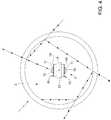
Figure 1 is a partial schematic longitudinal section view of a LED lighting device not according to the invention;Figure 2 is a view in enlarged scale of a detail of the lighting device ofFigure 1 ;Figure 3 is a side view of a lighting device according to the invention;Figure 4 is a cross-sectional view of the lighting device ofFigure 3 .- Referring to
Figure 1 , a LED lighting device 1 comprises asupport structure 2 and alighting body 3 supported by thesupport structure 2. - The
support structure 2, only schematically and partially shown inFigure 1 , may take various shapes, also depending on the intended purpose of the device 1 (which may serve as a swinging lamp, a floor lamp, etc.). - The
lighting body 3 is shaped as a ring about a longitudinal axis A of the device 1 and is a hollow body having an inner annular (toroidal)chamber 4. - Referring also to
Figure 2 , thelighting body 3 comprises aLED light source 5, housed in thechamber 4, and adiffuser 6, which constitutes a wall 7 of thechamber 4 and is provided with anouter surface 8 defining an emission surface of the device 1. - The
source 5 is shaped as a ring about axis A and comprises a plurality ofLEDs 10 angularly spaced apart from one another. - Advantageously, the
LEDs 10 are arranged on aLED strip 11 consisting of a flexible band carrying a succession ofLEDs 10 connected by a circuit or electronic board. - In particular, the
LEDs 10 are mounted, via theLED strip 11, on anannular support 13, for example made of aluminium, which also serves as a thermal dissipator and extends along a radially innerlateral edge 14 of thelighting body 3. - In the example of
Figures 1-2 , theLEDs 10 are positioned on oneface 15 of thesupport 13; theface 15 is substantially parallel to axis A and theLEDs 10 have a radial arrangement (i.e. are radially oriented) with respect to axis A. - Preferably, the
face 15 from which theLEDs 10 extend is covered by adiffusing coating 16, made of a diffusing white material and having high reflectance, i.e. having a reflection coefficient of at least 95%, preferably greater than or equal to 98%. - The
diffuser 6 has the shape of an annular disc about axis A and inferiorly delimits thechamber 4, constituting its bottom wall 7. - The
diffuser 6, for example made of a polymeric material, has a transmission coefficient greater than or equal to 50% and a reflection coefficient greater than or equal to 45% (and an absorption coefficient not exceeding 5%). - In particular, the
diffuser 6 is an opaline diffuser. - Preferably, the
diffuser 6 extends below thesource 5 and in general below thesupport 13 and protrudes radially towards the interior with respect to thesource 5 and thesupport 13. - The
chamber 4 is delimited by the diffuser 6 (provided with the emission surface 8) and the edge 14 (which carries the source 5) and also by afurther wall 17, which is at least partly transparent. - In the example shown in
Figures 1-2 , thewall 17 is a lateral, substantially ring-shaped wall and joins a radially externalperipheral edge 18 of thediffuser 6 to theedge 14. - Preferably, the
wall 17 is made of a transparent material, for example a polymeric material, and is provided with an inner reflectingcoating 19, facing thechamber 4 and having a reflection coefficient greater than or equal to 80% and a transmission coefficient greater than or equal to 15%. - Ultimately, the
lighting body 3 has low light absorption inner surfaces (absorption coefficient not exceeding 5%) and thus exhibits, overall, high optical performance; at the same time, thelighting body 3 has high uniformity of the emission surface, defined by thesurface 8 of thediffuser 6 and from which the main fraction of the light emitted by thesource 5 comes out. - In fact, the light emitted by the
source 5 in the chamber hits thediffuser 6, the reflectingcoating 19 of thewall 17 and thediffusing coating 16 on thesupport 13. - Each light beam that hits the
diffuser 6 is in small part absorbed and the rest is transmitted or reflected. The light transmitted through thediffuser 6 is emitted from thesurface 8, the reflected light is however reused in thechamber 4 and is not lost. - The effectiveness of the device 1 is increased by the presence of the
coating 16 and thecoating 19, which send back the light, after further reflections, onto thediffuser 6. - Instead, part of the light emitted by the
source 5 exits thewall 17 through anouter surface 20 of thewall 17, creating a further less intense luminous effect with respect to thesurface 8. - In the embodiment of
Figures 3-4 , in which any details similar to or identical with those already described are indicated with the same reference numbers, the LED lighting device 1 has a substantially tubular shape about axis A. - In particular, the
lighting body 3 is a hollow body that is substantially tubular, which extends along and about the longitudinal axis A of the device 1 and has aninner chamber 4, that is also tubular. - The
lighting body 3 further comprises aLED light source 5, housed in thechamber 4, and adiffuser 6, which constitutes a wall 7 of thechamber 4 and is provided with anouter surface 8 defining an emission surface of the device 1. - In this embodiment, the wall 7 is a substantially cylindrical lateral wall of the
lighting body 3, closed at respective oppositeaxial ends 23 by twodiscs 24 joined to respective end edges of the wall 7. - The
source 5 extends parallel to axis A and comprises a plurality ofLEDs 10 longitudinally spaced apart from one another parallel to axis A. - Advantageously, the
source 5 comprises two series of diametricallyopposite LEDs 10, arranged onrespective LED strips 11. - The two
LED strips 11 and thus theLEDs 10, in particular, are mounted on respectiveopposite faces 15 of a centrallongitudinal support 13 which extends along axis A and is supported, for example, by thediscs 24. In this case too, thesupport 13, for example made of aluminium, also serves as a thermal dissipator. - In the example of
Figures 3-4 , thefaces 15 are substantially parallel to axis A and theLEDs 10 still have a radial arrangement (i.e. are radially oriented) with respect to axis A. - Preferably, in this case too, the
faces 15 from which theLEDs 10 extend are provided with adiffusing coating 16, made of a diffusing white material with high reflectance (reflection coefficient of at least 95%, preferably greater than or equal to 98%). - The
diffuser 6 has a tubular shape about axis A and laterally delimits thechamber 4, constituting its lateral wall 7. - Also in this case, the
diffuser 6 is an opaline diffuser, for example made of a polymeric material, and has a transmission coefficient greater than or equal to 50% and a reflection coefficient greater than or equal to 45% (and an absorption coefficient not exceeding 5%). - The
diffuser 6 has anouter surface 8, which defines the emission surface of the device 1 and is, in this case, a tubular surface. - The
chamber 4 is delimited by the diffuser 6 (provided with the surface 8) and also by thediscs 24. - The
discs 24 are made, at least in part, of a transparent material, for example a polymeric material, and therefore constitute further, at least partlytransparent walls 17 of thechamber 4, which are preferably provided with respective inner reflectingcoatings 19 facing thechamber 4 and having a reflection coefficient greater than or equal to 80% and a transmission coefficient greater than or equal to 15%. - The device 1 shown in
Figures 3-4 is particularly suitable to provide a modular sectional system. - For example, the modular system comprises two types of modules: a linear module, as schematically shown in
Figure 3 (extending along a rectilinear axis A and having a predetermined length L) and a curved module, not shown (having the shape of an arc of a circle and a radius equal to the length L of the linear module and thus extending along a curvilinear axis A). - By combining two or more linear and/or curved modules, it is possible to form lighting devices of various shapes and sizes and, in particular, having shapes of letters, i.e. create a luminous font (set of writing characters).
- The modules can be connected to one another by means of the
discs 24 located at their ends. For this purpose, thediscs 24 of each module (i.e. of each lighting body 3) are equipped with male/female mechanically-connecting magnetic elements (each module having male and female elements placed at respectiveopposite ends 23, i.e. on thediscs 24 located at the opposite ends 23); and with electrical contacts, for example spring contacts, for the electrical connection of the modules. - Lastly, it is understood that the lighting device as described and illustrated herein can be subject to further modifications and variations that do not depart from the scope of the accompanying claims.
Claims (5)
- A LED lighting device (1), comprising a lighting body (3) extending substantially along an axis (A) and internally provided with a chamber (4) housing a LED light source (5) comprising a plurality of LEDs (10); the chamber (4) being delimited by at least one lateral wall (7) defined by a diffuser (6) having an outer surface (8) defining an emission surface of the device (1); the diffuser (6) having a transmission coefficient greater than or equal to 50% ;
wherein the lighting body (3) is a substantially tubular hollow body, rectilinear or curved, which extends along and about the axis (A); wherein
the diffuser (6) has a tubular shape about the axis (A) and laterally delimits the chamber (4); the light source (5) extending parallel to the axis (A) and comprising a plurality of LEDs (10) longitudinally spaced apart from one another parallel to the axis (A);
the device beingcharacterized in that the diffuser has a reflection coefficient greater than or equal to 45%;
the diffuser (6) defining a lateral wall (7) closed at respective opposite axial ends (23) by two discs (24) joined to respective end edges of the lateral wall (7); and wherein the discs (24) are made, at least in part, of a transparent material, for example a polymeric material, and therefore constitute further, at least partly transparent walls (17) of the chamber (4), which are provided with respective inner reflecting coatings (19) facing the chamber (4) and having a reflection coefficient greater than or equal to 80% and a transmission coefficient greater than or equal to 15%. - A device according to claim 1, wherein the diffuser (6) has an absorption coefficient not exceeding 5%.
- A device according to claim 1 or 2, wherein the LEDs (10) are arranged on one or more LED strips (11).
- A device according to one of the preceding claims, wherein the LEDs (10) extend from a face (15) of a support (13), said face (15) being covered by a diffusing coating (16) having high reflectance, i.e. a reflection coefficient of at least 95%, preferably greater than or equal to 98%.
- A device according to one of the preceding claims, wherein the light source (5) comprises two series of diametrically opposite LEDs (10) which project from respective opposite faces (15) of a central longitudinal support (13) extending along the axis (A).
Applications Claiming Priority (1)
| Application Number | Priority Date | Filing Date | Title |
|---|---|---|---|
| ITUA2016A001589AITUA20161589A1 (en) | 2016-03-11 | 2016-03-11 | LED LIGHTING DEVICE |
Publications (2)
| Publication Number | Publication Date |
|---|---|
| EP3217077A1 EP3217077A1 (en) | 2017-09-13 |
| EP3217077B1true EP3217077B1 (en) | 2020-07-15 |
Family
ID=56203652
Family Applications (1)
| Application Number | Title | Priority Date | Filing Date |
|---|---|---|---|
| EP17160444.0AActiveEP3217077B1 (en) | 2016-03-11 | 2017-03-10 | Led lighting device |
Country Status (3)
| Country | Link |
|---|---|
| US (1) | US10234097B2 (en) |
| EP (1) | EP3217077B1 (en) |
| IT (1) | ITUA20161589A1 (en) |
Citations (2)
| Publication number | Priority date | Publication date | Assignee | Title |
|---|---|---|---|---|
| US20090103296A1 (en)* | 2007-10-17 | 2009-04-23 | Xicato, Inc. | Illumination Device with Light Emitting Diodes |
| US20160033105A1 (en)* | 2014-08-01 | 2016-02-04 | Bridgelux, Inc. | Linear led module |
Family Cites Families (6)
| Publication number | Priority date | Publication date | Assignee | Title |
|---|---|---|---|---|
| US8926127B2 (en)* | 2010-01-15 | 2015-01-06 | Edward Lawrence Sinofsky | Lightweight solid state lighting panel |
| JP4945690B1 (en)* | 2010-11-30 | 2012-06-06 | 株式会社東芝 | Lighting device |
| US9534765B2 (en)* | 2011-07-24 | 2017-01-03 | Cree, Inc. | Light fixture with coextruded components |
| US20130044476A1 (en)* | 2011-08-17 | 2013-02-21 | Eric Bretschneider | Lighting unit with heat-dissipating circuit board |
| US20130155646A1 (en)* | 2011-12-15 | 2013-06-20 | Ningbo Baishi Electric Co., Ltd. | Led tubular lamp |
| WO2015066069A1 (en)* | 2013-10-28 | 2015-05-07 | Next Lighting Corp. | Linear lamp replacement |
- 2016
- 2016-03-11ITITUA2016A001589Apatent/ITUA20161589A1/enunknown
- 2017
- 2017-03-10EPEP17160444.0Apatent/EP3217077B1/enactiveActive
- 2017-03-10USUS15/455,383patent/US10234097B2/enactiveActive
Patent Citations (2)
| Publication number | Priority date | Publication date | Assignee | Title |
|---|---|---|---|---|
| US20090103296A1 (en)* | 2007-10-17 | 2009-04-23 | Xicato, Inc. | Illumination Device with Light Emitting Diodes |
| US20160033105A1 (en)* | 2014-08-01 | 2016-02-04 | Bridgelux, Inc. | Linear led module |
Also Published As
| Publication number | Publication date |
|---|---|
| US20170261177A1 (en) | 2017-09-14 |
| ITUA20161589A1 (en) | 2017-09-11 |
| EP3217077A1 (en) | 2017-09-13 |
| US10234097B2 (en) | 2019-03-19 |
Similar Documents
| Publication | Publication Date | Title |
|---|---|---|
| US6840652B1 (en) | Lighting enhanced by magnified reflective surfaces | |
| EP3097348B1 (en) | Lighting device and luminaire | |
| US8946978B2 (en) | Lighting device with omnidirectional light distribution | |
| US9518705B2 (en) | Lens and an illumination device having the lens | |
| TWI414727B (en) | Light emitting device | |
| TW201504577A (en) | Light emitting diode lamp tube | |
| US10077883B2 (en) | Illumination device with optical units including spiral structure optical unit and illumination device having the same | |
| JP2011508380A (en) | Light emitting diode lighting device | |
| US20130182430A1 (en) | Planar LED Lighting Apparatus | |
| EP2869106A1 (en) | Lens and LED module having same | |
| ITMI20121399A1 (en) | LED LIGHTING LAMP | |
| EP2998638A1 (en) | Method and system for led lamp incorporating internal optics for specific light distribution | |
| US9612001B2 (en) | Lighting arrangement with improved illumination uniformity | |
| JP3151273U (en) | Columnar reflection lens | |
| EP3217077B1 (en) | Led lighting device | |
| RU2576381C2 (en) | Single-chamber lighting device | |
| WO2010094141A1 (en) | Glare reduction in led lighting systems | |
| TWM462330U (en) | Light apparatus with curved surface structure | |
| JP5853128B2 (en) | lighting equipment | |
| CN105222095A (en) | A kind of double LED strip shape lamp | |
| JP2012028254A5 (en) | ||
| JP3176787U (en) | Fluorescent lamp type LED lighting tube | |
| CN204201551U (en) | Large-angle emission LED lamp | |
| JP2013008488A (en) | Lighting fixture | |
| US9213133B2 (en) | LED tube with light guiding plate arranged in a triangle |
Legal Events
| Date | Code | Title | Description |
|---|---|---|---|
| PUAI | Public reference made under article 153(3) epc to a published international application that has entered the european phase | Free format text:ORIGINAL CODE: 0009012 | |
| STAA | Information on the status of an ep patent application or granted ep patent | Free format text:STATUS: THE APPLICATION HAS BEEN PUBLISHED | |
| AK | Designated contracting states | Kind code of ref document:A1 Designated state(s):AL AT BE BG CH CY CZ DE DK EE ES FI FR GB GR HR HU IE IS IT LI LT LU LV MC MK MT NL NO PL PT RO RS SE SI SK SM TR | |
| AX | Request for extension of the european patent | Extension state:BA ME | |
| STAA | Information on the status of an ep patent application or granted ep patent | Free format text:STATUS: REQUEST FOR EXAMINATION WAS MADE | |
| 17P | Request for examination filed | Effective date:20180312 | |
| RBV | Designated contracting states (corrected) | Designated state(s):AL AT BE BG CH CY CZ DE DK EE ES FI FR GB GR HR HU IE IS IT LI LT LU LV MC MK MT NL NO PL PT RO RS SE SI SK SM TR | |
| STAA | Information on the status of an ep patent application or granted ep patent | Free format text:STATUS: EXAMINATION IS IN PROGRESS | |
| 17Q | First examination report despatched | Effective date:20180809 | |
| RIC1 | Information provided on ipc code assigned before grant | Ipc:F21Y 115/10 20160101ALN20191107BHEP Ipc:F21S 2/00 20160101ALN20191107BHEP Ipc:F21Y 103/10 20160101ALN20191107BHEP Ipc:F21V 3/04 20180101AFI20191107BHEP | |
| GRAP | Despatch of communication of intention to grant a patent | Free format text:ORIGINAL CODE: EPIDOSNIGR1 | |
| STAA | Information on the status of an ep patent application or granted ep patent | Free format text:STATUS: GRANT OF PATENT IS INTENDED | |
| INTG | Intention to grant announced | Effective date:20200205 | |
| GRAS | Grant fee paid | Free format text:ORIGINAL CODE: EPIDOSNIGR3 | |
| GRAA | (expected) grant | Free format text:ORIGINAL CODE: 0009210 | |
| STAA | Information on the status of an ep patent application or granted ep patent | Free format text:STATUS: THE PATENT HAS BEEN GRANTED | |
| AK | Designated contracting states | Kind code of ref document:B1 Designated state(s):AL AT BE BG CH CY CZ DE DK EE ES FI FR GB GR HR HU IE IS IT LI LT LU LV MC MK MT NL NO PL PT RO RS SE SI SK SM TR | |
| REG | Reference to a national code | Ref country code:CH Ref legal event code:EP Ref country code:GB Ref legal event code:FG4D | |
| REG | Reference to a national code | Ref country code:DE Ref legal event code:R096 Ref document number:602017019649 Country of ref document:DE | |
| REG | Reference to a national code | Ref country code:IE Ref legal event code:FG4D | |
| REG | Reference to a national code | Ref country code:AT Ref legal event code:REF Ref document number:1291437 Country of ref document:AT Kind code of ref document:T Effective date:20200815 | |
| REG | Reference to a national code | Ref country code:LT Ref legal event code:MG4D | |
| REG | Reference to a national code | Ref country code:AT Ref legal event code:MK05 Ref document number:1291437 Country of ref document:AT Kind code of ref document:T Effective date:20200715 | |
| REG | Reference to a national code | Ref country code:NL Ref legal event code:MP Effective date:20200715 | |
| PG25 | Lapsed in a contracting state [announced via postgrant information from national office to epo] | Ref country code:ES Free format text:LAPSE BECAUSE OF FAILURE TO SUBMIT A TRANSLATION OF THE DESCRIPTION OR TO PAY THE FEE WITHIN THE PRESCRIBED TIME-LIMIT Effective date:20200715 Ref country code:BG Free format text:LAPSE BECAUSE OF FAILURE TO SUBMIT A TRANSLATION OF THE DESCRIPTION OR TO PAY THE FEE WITHIN THE PRESCRIBED TIME-LIMIT Effective date:20201015 Ref country code:PT Free format text:LAPSE BECAUSE OF FAILURE TO SUBMIT A TRANSLATION OF THE DESCRIPTION OR TO PAY THE FEE WITHIN THE PRESCRIBED TIME-LIMIT Effective date:20201116 Ref country code:HR Free format text:LAPSE BECAUSE OF FAILURE TO SUBMIT A TRANSLATION OF THE DESCRIPTION OR TO PAY THE FEE WITHIN THE PRESCRIBED TIME-LIMIT Effective date:20200715 Ref country code:LT Free format text:LAPSE BECAUSE OF FAILURE TO SUBMIT A TRANSLATION OF THE DESCRIPTION OR TO PAY THE FEE WITHIN THE PRESCRIBED TIME-LIMIT Effective date:20200715 Ref country code:AT Free format text:LAPSE BECAUSE OF FAILURE TO SUBMIT A TRANSLATION OF THE DESCRIPTION OR TO PAY THE FEE WITHIN THE PRESCRIBED TIME-LIMIT Effective date:20200715 Ref country code:FI Free format text:LAPSE BECAUSE OF FAILURE TO SUBMIT A TRANSLATION OF THE DESCRIPTION OR TO PAY THE FEE WITHIN THE PRESCRIBED TIME-LIMIT Effective date:20200715 Ref country code:NO Free format text:LAPSE BECAUSE OF FAILURE TO SUBMIT A TRANSLATION OF THE DESCRIPTION OR TO PAY THE FEE WITHIN THE PRESCRIBED TIME-LIMIT Effective date:20201015 Ref country code:GR Free format text:LAPSE BECAUSE OF FAILURE TO SUBMIT A TRANSLATION OF THE DESCRIPTION OR TO PAY THE FEE WITHIN THE PRESCRIBED TIME-LIMIT Effective date:20201016 Ref country code:SE Free format text:LAPSE BECAUSE OF FAILURE TO SUBMIT A TRANSLATION OF THE DESCRIPTION OR TO PAY THE FEE WITHIN THE PRESCRIBED TIME-LIMIT Effective date:20200715 | |
| PG25 | Lapsed in a contracting state [announced via postgrant information from national office to epo] | Ref country code:RS Free format text:LAPSE BECAUSE OF FAILURE TO SUBMIT A TRANSLATION OF THE DESCRIPTION OR TO PAY THE FEE WITHIN THE PRESCRIBED TIME-LIMIT Effective date:20200715 Ref country code:LV Free format text:LAPSE BECAUSE OF FAILURE TO SUBMIT A TRANSLATION OF THE DESCRIPTION OR TO PAY THE FEE WITHIN THE PRESCRIBED TIME-LIMIT Effective date:20200715 Ref country code:PL Free format text:LAPSE BECAUSE OF FAILURE TO SUBMIT A TRANSLATION OF THE DESCRIPTION OR TO PAY THE FEE WITHIN THE PRESCRIBED TIME-LIMIT Effective date:20200715 Ref country code:IS Free format text:LAPSE BECAUSE OF FAILURE TO SUBMIT A TRANSLATION OF THE DESCRIPTION OR TO PAY THE FEE WITHIN THE PRESCRIBED TIME-LIMIT Effective date:20201115 | |
| PG25 | Lapsed in a contracting state [announced via postgrant information from national office to epo] | Ref country code:NL Free format text:LAPSE BECAUSE OF FAILURE TO SUBMIT A TRANSLATION OF THE DESCRIPTION OR TO PAY THE FEE WITHIN THE PRESCRIBED TIME-LIMIT Effective date:20200715 | |
| REG | Reference to a national code | Ref country code:DE Ref legal event code:R097 Ref document number:602017019649 Country of ref document:DE | |
| PG25 | Lapsed in a contracting state [announced via postgrant information from national office to epo] | Ref country code:SM Free format text:LAPSE BECAUSE OF FAILURE TO SUBMIT A TRANSLATION OF THE DESCRIPTION OR TO PAY THE FEE WITHIN THE PRESCRIBED TIME-LIMIT Effective date:20200715 Ref country code:EE Free format text:LAPSE BECAUSE OF FAILURE TO SUBMIT A TRANSLATION OF THE DESCRIPTION OR TO PAY THE FEE WITHIN THE PRESCRIBED TIME-LIMIT Effective date:20200715 Ref country code:RO Free format text:LAPSE BECAUSE OF FAILURE TO SUBMIT A TRANSLATION OF THE DESCRIPTION OR TO PAY THE FEE WITHIN THE PRESCRIBED TIME-LIMIT Effective date:20200715 Ref country code:DK Free format text:LAPSE BECAUSE OF FAILURE TO SUBMIT A TRANSLATION OF THE DESCRIPTION OR TO PAY THE FEE WITHIN THE PRESCRIBED TIME-LIMIT Effective date:20200715 Ref country code:CZ Free format text:LAPSE BECAUSE OF FAILURE TO SUBMIT A TRANSLATION OF THE DESCRIPTION OR TO PAY THE FEE WITHIN THE PRESCRIBED TIME-LIMIT Effective date:20200715 | |
| PLBE | No opposition filed within time limit | Free format text:ORIGINAL CODE: 0009261 | |
| STAA | Information on the status of an ep patent application or granted ep patent | Free format text:STATUS: NO OPPOSITION FILED WITHIN TIME LIMIT | |
| PG25 | Lapsed in a contracting state [announced via postgrant information from national office to epo] | Ref country code:AL Free format text:LAPSE BECAUSE OF FAILURE TO SUBMIT A TRANSLATION OF THE DESCRIPTION OR TO PAY THE FEE WITHIN THE PRESCRIBED TIME-LIMIT Effective date:20200715 | |
| 26N | No opposition filed | Effective date:20210416 | |
| PG25 | Lapsed in a contracting state [announced via postgrant information from national office to epo] | Ref country code:SK Free format text:LAPSE BECAUSE OF FAILURE TO SUBMIT A TRANSLATION OF THE DESCRIPTION OR TO PAY THE FEE WITHIN THE PRESCRIBED TIME-LIMIT Effective date:20200715 | |
| PG25 | Lapsed in a contracting state [announced via postgrant information from national office to epo] | Ref country code:SI Free format text:LAPSE BECAUSE OF FAILURE TO SUBMIT A TRANSLATION OF THE DESCRIPTION OR TO PAY THE FEE WITHIN THE PRESCRIBED TIME-LIMIT Effective date:20200715 | |
| PG25 | Lapsed in a contracting state [announced via postgrant information from national office to epo] | Ref country code:MC Free format text:LAPSE BECAUSE OF FAILURE TO SUBMIT A TRANSLATION OF THE DESCRIPTION OR TO PAY THE FEE WITHIN THE PRESCRIBED TIME-LIMIT Effective date:20200715 | |
| REG | Reference to a national code | Ref country code:CH Ref legal event code:PL | |
| GBPC | Gb: european patent ceased through non-payment of renewal fee | Effective date:20210310 | |
| REG | Reference to a national code | Ref country code:BE Ref legal event code:MM Effective date:20210331 | |
| PG25 | Lapsed in a contracting state [announced via postgrant information from national office to epo] | Ref country code:CH Free format text:LAPSE BECAUSE OF NON-PAYMENT OF DUE FEES Effective date:20210331 Ref country code:LU Free format text:LAPSE BECAUSE OF NON-PAYMENT OF DUE FEES Effective date:20210310 Ref country code:LI Free format text:LAPSE BECAUSE OF NON-PAYMENT OF DUE FEES Effective date:20210331 Ref country code:IE Free format text:LAPSE BECAUSE OF NON-PAYMENT OF DUE FEES Effective date:20210310 Ref country code:GB Free format text:LAPSE BECAUSE OF NON-PAYMENT OF DUE FEES Effective date:20210310 | |
| PG25 | Lapsed in a contracting state [announced via postgrant information from national office to epo] | Ref country code:BE Free format text:LAPSE BECAUSE OF NON-PAYMENT OF DUE FEES Effective date:20210331 | |
| PG25 | Lapsed in a contracting state [announced via postgrant information from national office to epo] | Ref country code:HU Free format text:LAPSE BECAUSE OF FAILURE TO SUBMIT A TRANSLATION OF THE DESCRIPTION OR TO PAY THE FEE WITHIN THE PRESCRIBED TIME-LIMIT; INVALID AB INITIO Effective date:20170310 | |
| PG25 | Lapsed in a contracting state [announced via postgrant information from national office to epo] | Ref country code:CY Free format text:LAPSE BECAUSE OF FAILURE TO SUBMIT A TRANSLATION OF THE DESCRIPTION OR TO PAY THE FEE WITHIN THE PRESCRIBED TIME-LIMIT Effective date:20200715 | |
| PG25 | Lapsed in a contracting state [announced via postgrant information from national office to epo] | Ref country code:MK Free format text:LAPSE BECAUSE OF FAILURE TO SUBMIT A TRANSLATION OF THE DESCRIPTION OR TO PAY THE FEE WITHIN THE PRESCRIBED TIME-LIMIT Effective date:20200715 | |
| PG25 | Lapsed in a contracting state [announced via postgrant information from national office to epo] | Ref country code:TR Free format text:LAPSE BECAUSE OF FAILURE TO SUBMIT A TRANSLATION OF THE DESCRIPTION OR TO PAY THE FEE WITHIN THE PRESCRIBED TIME-LIMIT Effective date:20200715 | |
| PG25 | Lapsed in a contracting state [announced via postgrant information from national office to epo] | Ref country code:MT Free format text:LAPSE BECAUSE OF FAILURE TO SUBMIT A TRANSLATION OF THE DESCRIPTION OR TO PAY THE FEE WITHIN THE PRESCRIBED TIME-LIMIT Effective date:20200715 | |
| PGFP | Annual fee paid to national office [announced via postgrant information from national office to epo] | Ref country code:DE Payment date:20250327 Year of fee payment:9 | |
| PGFP | Annual fee paid to national office [announced via postgrant information from national office to epo] | Ref country code:FR Payment date:20250324 Year of fee payment:9 | |
| PGFP | Annual fee paid to national office [announced via postgrant information from national office to epo] | Ref country code:IT Payment date:20250303 Year of fee payment:9 |