EP3215025B1 - Medical implant delivery system - Google Patents
Medical implant delivery systemDownload PDFInfo
- Publication number
- EP3215025B1 EP3215025B1EP15794758.1AEP15794758AEP3215025B1EP 3215025 B1EP3215025 B1EP 3215025B1EP 15794758 AEP15794758 AEP 15794758AEP 3215025 B1EP3215025 B1EP 3215025B1
- Authority
- EP
- European Patent Office
- Prior art keywords
- fastener
- fluke
- staple
- delivery system
- prongs
- Prior art date
- Legal status (The legal status is an assumption and is not a legal conclusion. Google has not performed a legal analysis and makes no representation as to the accuracy of the status listed.)
- Active
Links
- 239000007943implantSubstances0.000titledescription53
- 241000935974Paralichthys dentatusSpecies0.000claimsdescription86
- 210000002435tendonAnatomy0.000description99
- 210000001519tissueAnatomy0.000description47
- 230000008439repair processEffects0.000description30
- 238000000034methodMethods0.000description23
- 210000002758humerusAnatomy0.000description20
- 230000006378damageEffects0.000description19
- 210000001991scapulaAnatomy0.000description16
- 210000000513rotator cuffAnatomy0.000description14
- 210000000988bone and boneAnatomy0.000description12
- 241000242541TrematodaSpecies0.000description11
- 210000003205muscleAnatomy0.000description11
- 238000003780insertionMethods0.000description10
- 230000037431insertionEffects0.000description10
- 208000027418Wounds and injuryDiseases0.000description9
- 208000014674injuryDiseases0.000description9
- 239000000463materialSubstances0.000description7
- 241001260012BursaSpecies0.000description6
- 239000000835fiberSubstances0.000description6
- 238000011282treatmentMethods0.000description6
- 210000000323shoulder jointAnatomy0.000description5
- 241001653121GlenoidesSpecies0.000description4
- 239000012530fluidSubstances0.000description4
- 208000026137Soft tissue injuryDiseases0.000description3
- 230000013011matingEffects0.000description3
- 208000002193PainDiseases0.000description2
- 229920001247Reticulated foamPolymers0.000description2
- FAPWRFPIFSIZLT-UHFFFAOYSA-MSodium chlorideChemical compound[Na+].[Cl-]FAPWRFPIFSIZLT-UHFFFAOYSA-M0.000description2
- 230000009471actionEffects0.000description2
- 230000001154acute effectEffects0.000description2
- 239000006261foam materialSubstances0.000description2
- 230000007246mechanismEffects0.000description2
- 230000008569processEffects0.000description2
- 239000011780sodium chlorideSubstances0.000description2
- 210000004872soft tissueAnatomy0.000description2
- 230000000472traumatic effectEffects0.000description2
- 208000006820ArthralgiaDiseases0.000description1
- 206010006811BursitisDiseases0.000description1
- 208000000094Chronic PainDiseases0.000description1
- 206010028391Musculoskeletal PainDiseases0.000description1
- 208000007613Shoulder PainDiseases0.000description1
- 208000021945Tendon injuryDiseases0.000description1
- 210000000142acromioclavicular jointAnatomy0.000description1
- 210000002659acromionAnatomy0.000description1
- 210000003484anatomyAnatomy0.000description1
- 230000009286beneficial effectEffects0.000description1
- 238000009954braidingMethods0.000description1
- 238000004891communicationMethods0.000description1
- 230000000295complement effectEffects0.000description1
- 239000002131composite materialSubstances0.000description1
- 230000006835compressionEffects0.000description1
- 238000007906compressionMethods0.000description1
- 230000001419dependent effectEffects0.000description1
- 208000015181infectious diseaseDiseases0.000description1
- 210000001503jointAnatomy0.000description1
- 238000009940knittingMethods0.000description1
- 239000002121nanofiberSubstances0.000description1
- 239000011148porous materialSubstances0.000description1
- 238000003825pressingMethods0.000description1
- 238000005086pumpingMethods0.000description1
- 230000004044responseEffects0.000description1
- 230000000717retained effectEffects0.000description1
- 238000005728strengtheningMethods0.000description1
- 238000001356surgical procedureMethods0.000description1
- 230000001225therapeutic effectEffects0.000description1
- 238000009941weavingMethods0.000description1
Images


Classifications
- A—HUMAN NECESSITIES
- A61—MEDICAL OR VETERINARY SCIENCE; HYGIENE
- A61B—DIAGNOSIS; SURGERY; IDENTIFICATION
- A61B17/00—Surgical instruments, devices or methods
- A61B17/068—Surgical staplers, e.g. containing multiple staples or clamps
- A61B17/0682—Surgical staplers, e.g. containing multiple staples or clamps for applying U-shaped staples or clamps, e.g. without a forming anvil
- A—HUMAN NECESSITIES
- A61—MEDICAL OR VETERINARY SCIENCE; HYGIENE
- A61B—DIAGNOSIS; SURGERY; IDENTIFICATION
- A61B17/00—Surgical instruments, devices or methods
- A61B17/00234—Surgical instruments, devices or methods for minimally invasive surgery
- A—HUMAN NECESSITIES
- A61—MEDICAL OR VETERINARY SCIENCE; HYGIENE
- A61B—DIAGNOSIS; SURGERY; IDENTIFICATION
- A61B17/00—Surgical instruments, devices or methods
- A61B17/064—Surgical staples, i.e. penetrating the tissue
- A—HUMAN NECESSITIES
- A61—MEDICAL OR VETERINARY SCIENCE; HYGIENE
- A61B—DIAGNOSIS; SURGERY; IDENTIFICATION
- A61B17/00—Surgical instruments, devices or methods
- A61B17/064—Surgical staples, i.e. penetrating the tissue
- A61B17/0642—Surgical staples, i.e. penetrating the tissue for bones, e.g. for osteosynthesis or connecting tendon to bone
- A—HUMAN NECESSITIES
- A61—MEDICAL OR VETERINARY SCIENCE; HYGIENE
- A61B—DIAGNOSIS; SURGERY; IDENTIFICATION
- A61B17/00—Surgical instruments, devices or methods
- A61B17/10—Surgical instruments, devices or methods for applying or removing wound clamps, e.g. containing only one clamp or staple; Wound clamp magazines
- A—HUMAN NECESSITIES
- A61—MEDICAL OR VETERINARY SCIENCE; HYGIENE
- A61B—DIAGNOSIS; SURGERY; IDENTIFICATION
- A61B17/00—Surgical instruments, devices or methods
- A61B2017/00526—Methods of manufacturing
- A61B2017/0053—Loading magazines or sutures into applying tools
- A—HUMAN NECESSITIES
- A61—MEDICAL OR VETERINARY SCIENCE; HYGIENE
- A61B—DIAGNOSIS; SURGERY; IDENTIFICATION
- A61B17/00—Surgical instruments, devices or methods
- A61B17/068—Surgical staplers, e.g. containing multiple staples or clamps
- A61B2017/0688—Packages or dispensers for surgical staplers
- A—HUMAN NECESSITIES
- A61—MEDICAL OR VETERINARY SCIENCE; HYGIENE
- A61B—DIAGNOSIS; SURGERY; IDENTIFICATION
- A61B2217/00—General characteristics of surgical instruments
- A61B2217/002—Auxiliary appliance
- A61B2217/005—Auxiliary appliance with suction drainage system
- A—HUMAN NECESSITIES
- A61—MEDICAL OR VETERINARY SCIENCE; HYGIENE
- A61B—DIAGNOSIS; SURGERY; IDENTIFICATION
- A61B2217/00—General characteristics of surgical instruments
- A61B2217/002—Auxiliary appliance
- A61B2217/007—Auxiliary appliance with irrigation system
- A—HUMAN NECESSITIES
- A61—MEDICAL OR VETERINARY SCIENCE; HYGIENE
- A61B—DIAGNOSIS; SURGERY; IDENTIFICATION
- A61B90/00—Instruments, implements or accessories specially adapted for surgery or diagnosis and not covered by any of the groups A61B1/00 - A61B50/00, e.g. for luxation treatment or for protecting wound edges
- A61B90/03—Automatic limiting or abutting means, e.g. for safety
- A—HUMAN NECESSITIES
- A61—MEDICAL OR VETERINARY SCIENCE; HYGIENE
- A61B—DIAGNOSIS; SURGERY; IDENTIFICATION
- A61B90/00—Instruments, implements or accessories specially adapted for surgery or diagnosis and not covered by any of the groups A61B1/00 - A61B50/00, e.g. for luxation treatment or for protecting wound edges
- A61B90/36—Image-producing devices or illumination devices not otherwise provided for
- A61B90/361—Image-producing devices, e.g. surgical cameras
- A—HUMAN NECESSITIES
- A61—MEDICAL OR VETERINARY SCIENCE; HYGIENE
- A61F—FILTERS IMPLANTABLE INTO BLOOD VESSELS; PROSTHESES; DEVICES PROVIDING PATENCY TO, OR PREVENTING COLLAPSING OF, TUBULAR STRUCTURES OF THE BODY, e.g. STENTS; ORTHOPAEDIC, NURSING OR CONTRACEPTIVE DEVICES; FOMENTATION; TREATMENT OR PROTECTION OF EYES OR EARS; BANDAGES, DRESSINGS OR ABSORBENT PADS; FIRST-AID KITS
- A61F2/00—Filters implantable into blood vessels; Prostheses, i.e. artificial substitutes or replacements for parts of the body; Appliances for connecting them with the body; Devices providing patency to, or preventing collapsing of, tubular structures of the body, e.g. stents
- A61F2/02—Prostheses implantable into the body
- A61F2/08—Muscles; Tendons; Ligaments
- A61F2/0805—Implements for inserting tendons or ligaments
Definitions
- the present disclosurepertains generally, but not by way of limitation, to medical devices. More particularly, the present disclosure pertains to devices for introducing and positioning implants within patients.
- US 2012/0211543 A1discloses a device for attaching a sheet-like implant to a target tissue.
- the deviceincludes a fastener push rod including a first portion, a second portion and a force limiting mechanism operably coupled between the first portion and the second portion.
- a fasteneris carried by the second portion of the fastener push rod.
- US 2011/0079627 A1discloses an applicator instrument for dispensing surgical fasteners includes a housing and a curved shaft. Surgical fasteners are disposed within the curved shaft for being dispensed from the distal end of the curved shaft.
- a fastener delivery systemas recited in the independent claim is provided.
- the dependent claimsrecite embodiments.
- the disclosuredescribes various medical devices to assist in delivering, positioning, and securing implants within a body.
- the fastener delivery systemcomprises a fastener and a fastener delivery tool configured to deliver the fastener into tissue of a patient.
- the fastener delivery toolcomprises a shaft, a handle assembly connected to a proximal end of the shaft, one or more prongs connected to a distal end of the shaft, and a fastener push rod received at least partially within the shaft, wherein the fastener push rod is connected to the handle assembly, wherein the fastener push rod is moveable relative to the shaft, and wherein the fastener push rod includes one or more detents configured to be received within a passageway of a fastener and secure the fastener to the fastener push rod with friction.
- the fastener push rodfurther comprises a plurality of arms connected to a distal end of the fastener push rod, and wherein the one or more detents are disposed on the plurality of arms.
- the one or more prongsare formed from the shaft.
- the one or more prongscomprise a concave surface.
- the one or more prongstaper toward a tip of each prong.
- the one or more prongshave a length that is between 50% and 120% the length of the fastener the fastener delivery system is configured to deliver into tissue of the patient.
- a force applied to the handle assemblycauses the fastener push rod to move relative to the shaft.
- the handle assemblymay comprise a housing, a trigger, and a bias member, wherein the bias member is connected to the housing and the trigger, wherein the bias member biases the trigger to a rest position, and wherein the force applied to the handle assembly comprises a force applied to the handle assembly to overcome a biasing force of the bias member.
- a fastener delivery systemmay comprise a fastener delivery tool comprising a pilot member having a distal end and at least a pair of prongs extending from the distal end of the pilot member so that the prongs form pilot holes when the distal end of the pilot member is pressed against target tissue, and a fastener push rod disposed within at least a portion of the pilot member and moveable relative thereto.
- the fastener delivery systemfurther comprises a fastener carried by the fastener push rod, the fastener comprising a first arm having a proximal end and a distal end, and a second arm having a proximal end and distal end with a bridge extending from the proximal end of the first arm to the proximal end of the second arm, a first fluke of the fastener having a proximal end abutting the distal end of the first arm, and a second fluke of the fastener having a proximal end abutting the distal end of the second arm, and wherein each of the at least a pair of prongs may comprise a curved inner surface.
- Each of the first fluke and the second flukedefine a passageway extending at least partially through each fluke, with each passageway defining at least one surface.
- the fastener push rodcomprises at least a pair of arms, and wherein each of the at least a pair of arms is configured to be received within a passageway of the first fluke or the second fluke.
- the pair of armsfurther comprises a detent, and wherein when each arm is received within a passageway, each detent presses against the at least one surface of the passageway and retains the fastener on the fastener push rod by friction.
- each of the first fluke and the second flukehave defined heights, and wherein each of the at least a pair of prongs tapers toward a distal end of the prong such that a width of at least a portion of each prong is less than the defined height of the first fluke or the second fluke.
- a first width of at least a portion of each prongis between 85% and 95% of the defined height of the first fluke or the second fluke.
- a second width of at least a portion of each prongis between 60% and 75% of the defined height of the first fluke or the second fluke.
- each of the at least a pair of prongshave a length that is between 50% and 120% the length of the fastener.
- the one or more prongsare formed from the pilot member.
- a method for deploying a fastener into target tissuemay comprise positioning a fixation tool shaft proximate the target tissue, the fixation tool shaft having one or more prongs disposed proximate a distal end of the fixation tool shaft, wherein a fastener push rod is disposed at least partially within the fixation tool shaft, the fastener push rod comprising one or more arms, each arm having a detent disposed thereon, the fastener push rod further carrying a fastener, wherein the fastener is retained on the one or more arms by friction between the detents and the fastener, and wherein the fixation tool shaft is coupled to a handle assembly, the handle assembly comprising a trigger; applying force to the fixation tool shaft in the direction of the target tissue, causing the prongs to pierce the target tissue creating a pilot holes; applying force to the trigger thereby causing the fastener push rod to move distally relative to the fixation tool shaft and causing the one or more arms and the fastener to
- the one or more prongscomprise a concave surface.
- the one or more prongstaper toward a tip of each prong.
- references in the specification to "an embodiment”, “some embodiments”, “other embodiments”, “an example”, “some examples”, “other examples”, etc.indicate that the embodiments) and/or example(s) described may include a particular feature, structure, or characteristic, but every embodiment may not necessarily include the particular feature, structure, or characteristic. Moreover, such phrases are not necessarily referring to the same embodiment and/or example. Further, when a particular feature, structure, or characteristic is described in connection with an embodiment and/or example, it would be within the knowledge of one skilled in the art to affect such feature, structure, or characteristic in connection with other embodiments and/or examples, whether or not explicitly described, unless clearly stated to the contrary.
- Figure 1illustrates an example of a rotator cuff, including muscles 10 which are a complex of four muscles. These four muscles are the supraspinatus, the infraspinatus, the subscapularis, and the teres minor.
- the four muscles of the rotator cuffarise from the scapula 12.
- the distal tendons of the rotator cuff musclessplay out and interdigitate to form a common continuous insertion on the humerus 14 and humerus head 17.
- the subscapularis 16arises from the anterior aspect of the scapula 12 and attaches over much of the lesser tuberosity of humerus 14.
- the supraspinatus muscle 18arises from the supraspinatus fossa of the posterior scapula, passes beneath the acromion and the acromioclavicular joint, and attaches to the superior aspect of the greater tuberosity 11.
- the infraspinatus muscle 13arises from the infraspinous fossa of the posterior scapula and attaches to the posterolateral aspect of the greater tuberosity 11.
- the teres minor 15arises from the lower lateral aspect of the scapula 12 and attaches to the lower aspect of the greater tuberosity 11.
- the rotator cuff muscles 10are critical elements for maintaining shoulder muscle balance in order to effectuate movement of the shoulder joint. With its complexity, range of motion and extensive use, a fairly common soft tissue injury is damage to the rotator cuff or rotator cuff tendons. Damage to the rotator cuff is a potentially serious medical condition that may occur during hyper-extension, from an acute traumatic tear or from overuse of the joint.
- a tear in the supraspinitus tendon 19is schematically depicted in Figure 2 .
- a tear at the insertion site of the tendon with the humerusmay result in the detachment of the tendon from the bone. This detachment may be partial or full, depending upon the severity of the injury. Additionally, the strain or tear can occur within the tendon itself. Injuries to the supraspinatus tendon 19 and recognized modalities for treatment are defined by the type and degree of tear.
- Current accepted treatment for a full thickness tear or a partial thickness tear greater than 50%includes reconnecting the torn tendon via sutures.
- the proceduregenerally includes completing the tear to a full thickness tear by cutting the tendon prior to reconnection.
- the treatment for a partial thickness tear less than 50%usually involves physical cessation from use of the tendon, i.e., rest.
- Specific exercisescan also be prescribed to strengthen and loosen the shoulder area.
- the shoulderdoes not heal fully and the patient can be left with a source of chronic pain and stiffness, along with preventing the patient from recovering full range of motion.
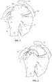
- Figure 3is a stylized anterior view of a patient 20.
- a shoulder 22 of patient 20is shown in cross-section in Figure 3 .
- Shoulder 22includes a humerus 14 and a scapula 12.
- a head 24 of humerus 14can be seen mating with a glenoid fossa of scapula 12 at a glenohumeral joint.
- the glenoid fossacomprises a shallow depression in scapula 12.
- humerus 14relative to scapula 12 is controlled by a number of muscles including: the deltoid, the supraspinatus, the infraspinatus, the subscapularis, and the teres minor.
- the supraspinatus 26is shown in Figure 3 .
- Scapula 12 of shoulder 22includes an acromium 32.
- a subacromial bursa 34is shown extending between acromium 32 of scapula 12 and head 24 of humerus 14.
- subacromial bursa 34is shown overlaying supraspinatus 26.
- Subacromial bursa 34is one of the hundreds of bursae found the human body. Each bursa comprises a fluid filled sac. The presence of these bursae in the body reduces friction between bodily tissues. Injury and/or infection of the bursa can cause it to become inflamed. This condition is sometimes referred to as bursitis.
- a tendon repair implantmay be fixed to one or more tendons associated with an articulating joint, such as the glenohumeral joint.
- the tendons to be treatedmay be torn, partially torn, have internal micro-tears, be un-torn, and/or be thinned due to age, injury or overuse.
- the disclosed methods and apparatus and related devicesmay provide beneficial therapeutic effect on a patient experiencing joint pain believed to be caused by partial thickness tears and/or internal micro-tears.
- Figure 4is a stylized anterior view of a shoulder 22 including a humerus 14 and a scapula 12.
- a head 24 of humerus 14is shown mating with a glenoid fossa of scapula 12 at a glenohumeral joint.
- a supraspinatus 26is also shown in Figure 4 .
- This muscle(along with others) controls the movement of humerus 14 relative to scapula 12.
- a distal tendon 28 of supraspinatus 26meets humerus 14 at an insertion.
- distal tendon 28includes a first damaged portion 36.
- a number of loose tendon fibers 40 in first damaged portion 36are visible in Figure 4 .
- First dam- aged portion 36includes a first tear 42 extending partially through distal tendon 28.
- First tear 42may therefore be referred to as a partial thickness tear.
- first tear 42begins on the side of distal tendon 28 facing the subacromial bursa (shown in the previous Figure) and ends midway through distal tendon 28. Accordingly, first tear 42 may be referred to as a bursal side tear.
- distal tendon 28includes a second damaged portion 38 located near insertion point 30.
- second damaged portion 38 of distal tendon 28has become frayed and a number of loose tendon fibers 41 are visible in Figure 4 .
- Second damaged portion 38 of distal tendon 28includes second tear 44.
- second tear 44begins on the side of distal tendon 28 facing the humerus 14. Accordingly, second damaged portion 38 may be referred to as an articular side tear.
- a sheet-like implant 50has been placed over the bursal side of distal tendon 28.
- sheet-like implant 50extends over insertion point 30, first tear 42, and second tear 44.
- Some useful methods in accordance with this detailed descriptionmay include placing a tendon repair implant on the bursal side of a tendon regardless of whether the tears being treated are on the bursal side, articular side, or within the tendon. In some cases the exact location and nature of the tears being treated may be unknown.
- a tendon repair implantmay be applied to the bursal side of a tendon to treat shoulder pain that is most likely caused by one or more partial thickness tears in the tendon.
- sheet-like implant 50is fixed to distal tendon 28 and to humerus 14 by a plurality of staples 100 as described herein in detail.
- sheet-like implant 50may be fixed only to distal tendon 28 by plurality of staples 100.
- the strain imparted on sheet-like implant 50may differ in examples where sheet-like implant 50 is affixed only to distal tendon 28 and examples where sheet-like implant 50 is affixed to both distal tendon 28 and humerus 14, and some injuries or patients may respond more advantageously to one or the other of these fixation methods.
- Figure 5is a stylized perspective view illustrating an exemplary procedure for treating a shoulder 22 of a patient 20.
- the procedure illustrated in Figure 5may include, for example, fixing tendon repair implants to one or more tendons of shoulder 22.
- the tendons treatedmay be torn, partially torn, have internal micro-tears, be un-torn, and/or be thinned due to age, injury or overuse.
- a fluid supply 52is pumping a continuous flow of saline into the cavity. This flow of saline exits the cavity via a fluid drain 54.
- a camera 56provides images from inside the cavity. The images provided by camera 56 may be viewed on a display 58.
- Camera 56may be used to visually inspect the tendons of shoulder 22 for damage.
- a tendon repair implant in accordance with this disclosuremay be fixed to a bursal surface of the tendon regardless of whether there are visible signs of tendon damage.
- a delivery system 60can be seen extending from shoulder 22 in Figure 5 .
- Delivery system 60comprises a sheath that is fixed to a handle.
- the sheathdefines a lumen and a distal opening fluidly communicating the lumen.
- the distal opening of the sheathhas been placed in fluid communication with the cavity created in shoulder 22.
- a tendon repair implantis at least partially disposed in the lumen defined by the sheath of delivery system 60.
- Delivery system 60can be used to place the tendon repair implant inside shoulder 22. Delivery system 60 can also be used to hold the tendon repair implant against the tendon.
- the tendon repair implantis folded into a compact configuration when inside the lumen of the sheath of delivery system 60. When this is the case, delivery system 60 may be used to unfold the tendon repair implant into an expanded shape.
- the tendon repair implantmay be fixed to the tendon while it is held against the tendon by delivery system 60.
- Various attachment elementsmay be used to fix the tendon repair implant to the tendon. Examples of attachment elements that may be suitable in some applications include sutures, tissue anchors, bone anchors, and staples.
- the shaft of a fixation tool 70is shown extending into shoulder 22.
- fixation tool 70is capable of fixing the tendon repair implant to the tendon with one or more staples while the tendon repair implant is held against the tendon by delivery system 60.
- FIG. 6is a stylized perspective view of a shoulder 22 including a supraspinatus 26 having a distal tendon 28.
- a tendon repair implant 50has been fixed to a surface of distal tendon 28.
- Tendon repair implant 50may comprise, for example, various sheet-like structures without deviating from the present detailed description.
- the sheet-like structuremay comprise a plurality of fibers.
- the fibersmay be interlinked with one another.
- the sheet-like structuremay comprise a plurality of apertures comprising the interstitial spaces between fibers.
- Various processesmay be used to interlink the fibers with one another. Examples of processes that may be suitable in some applications include weaving, knitting, and braiding.
- the sheet-like structuremay comprise a laminate including multiple layers of film with each layer of film defining a plurality of micro-machined or formed holes.
- the sheet-like structure of the tendon repair implantmay also comprise a plurality of electro-spun nanofiber filaments forming a composite sheet.
- the sheet-like structuremay comprise a synthetic sponge material that defines a plurality of pores.
- the sheet-like structuremay also comprise a reticulated foam material. Reticulated foam materials that may be suitable in some applications are available from Biomerix Corporation of Freemont, Calif. which identifies these materials using the trademark BIOMATE- RIALTM.
- attachment elementsmay be used to fix tendon repair implant 50 to distal tendon 28 without deviating from this detailed description.
- attachment elementsthat may be suitable in some applications include sutures, tissue anchors, bone anchors, and staples.
- a plurality of staples 100are fixing tendon repair implant 50 to distal tendon 28.
- a plurality of staples 100may be applied using a fixation tool. The fixation tool may then be withdrawn from the body of the patient.
- Distal tendon 28meets humerus 14 at an insertion point 30.
- sheet-like implant 50extends over insertion point 30.
- Tendon repair implantmay be applied to distal tendon 28, for example, using the procedure illustrated in Figure 5 .
- sheet-like implant 50may not extend over insertion point 30. Rather, the whole of sheet-like implant 50 may generally extend along and over distal tendon 28.
- Figure 7A, Figure 7B, and Figure 7Care multiple plan views illustrating an exemplary staple 100 in accordance with the present disclosure.
- a proximal directionis illustrated with an arrow P in Figures 7A-C .
- a distal directionis illustrated with a second arrow D in Figures 7A-C .
- Staple 100comprises a first arm 102A, a second arm 102B, and a bridge 104 extending from the proximal end of first arm 102A to the proximal end of second arm 102B.
- the distal end of first arm 102Aabuts the proximal end of a first fluke 106A.
- the distal end of second arm 102Babuts the proximal end of a second fluke 106B.
- first fluke 106A and second fluke 106Bare shown extending distally from first arm 102A and second arm 102B, respectively.
- first fluke 106Ahas a lateral extent that is larger than a lateral extent of first arm 102A. Additionally, each fluke has a height dimension as evidenced by height 107.
- First fluke 106Ais mounted eccentrically to first arm 102A in the embodiment of Figures 7A-C .
- Second fluke 106Bis mounted eccentrically to second arm 102B and second fluke 106B has a lateral extent that is larger than a lateral extent of second arm 102B.
- First fluke 106Aincludes a first proximal surface 108A projecting at an outward angle in a proximal direction away from the distal end of first arm 102A.
- Second fluke 106Bincludes a second proximal surface 108B projecting at an outward angle in a proximal direction away from the distal end of second arm 102B.
- first fluke 106Aincludes a first point 120A and a first barb 122A.
- Second fluke 106Bincludes a second point 120B and a second barb 122B.
- first point 120A and second point 120Bare shown generally pointing in the distal direction indicated by arrow D.
- first barb 122A and second barb 122Bare shown generally pointing in the proximal direction indicated by arrow P.
- the tips of first barb 122A and second barb 122Bmay be the outward most portions of staple 100.
- first fluke 106Adefines a first passageway 124A and second fluke 106B defines a second passageway 124B.
- first passageway 124Aextends through first fluke 106A and second passageway 124B extends through second fluke 106B.
- first passageway 124Amay extend through other portions of staple 100 in other examples.
- second passageway 124Bmay extend through other portions of staple 100 in other examples.
- first passageway 124A and second passageway 124Beach have a generally square cross-sectional shape defining multiple opposing surfaces.
- First passageway 124A and second passageway 124Bmay have various cross-sectional shapes in other examples, such as circular or oval cross-sectional shapes, without deviating from the present disclosure. Further, each passageway can extend partially through the length of each fluke rather than all the way through to provide a cavity rather than a passageway.
- first passageway 124A and second passageway 124Balso have a defined cross-sectional width and/or diameter.
- first passageway 124A and second passageway 124Bdefine passageways with rectangular or square cross-sections.
- the rectangular or square cross-sectionshave defined width and height dimensions, where the height dimension may be measured between each of the top and bottom opposing surfaces of first passageway 124A and second passageway 124B, as seen from the perspective of Figure 7C .
- the width dimension of the rectangular or square cross-sectionsmay be measured between each of the left and right opposing faces of first passageway 124A and second passageway 124B, as seen from the perspective of Figure 7C .
- first passageway 124A and second passageway 124Bmay have include dimensions in the range of between 0.0175 inches (0.445 millimeters) and 0.026 inches (0.661 millimeters).
- first barb 122A of first fluke 106Adefines a first notch 126A.
- first notch 126Adivides first barb 122A into a first sub-barb and a second sub-barb.
- Second barb 122B of second fluke 106Bdefines a second notch 126B.
- second notch 126Bdivides second barb 122B into a first sub-barb and a second sub-barb.
- Figure 8is a perspective view showing staple 100 shown in Figures 7A-C . Many of the features of staple 100 described with respect to Figures 7A-C can also be seen in Figure 8 , including first arm 102A, second arm 102B, bridge 104, first fluke 106A, first passageway 124A, among others.
- FIG 9is a perspective view showing a staple push rod 130 that may be used in conjunction with staple 100 shown in Figures 7A-C and 8 .
- Staple push rod 130includes a shaft 132 and a pair of arms 134 extending distally beyond a distal end of shaft 132. The distal direction is indicated with an arrow D in Figure 9 .
- shaft 130 and arms 134may be formed in two separate pieces. For instance, as seen in Figure 9 , arms 130 are attached together as part of distal piece 141. In examples where shaft 130 and arms 134 are formed in separate pieces, distal piece 141 may have a connecting means at the proximal end of distal piece 141, and shaft 130 may have corresponding connecting means 143 attached to the distal end of shaft 130.
- distal piece 141may include a shaped hole or groove and connecting means 143 may have a matching shape that slots into the shaped hole or groove, as in Figure 9 .
- connecting means 143may have a matching shape that slots into the shaped hole or groove, as in Figure 9 .
- various other means and methods for connecting distal piece 141 to shaft 132are contemplated in other examples.
- Arms 134include a first arm 134A and a second arm 134B.
- First arm 134A and second arm 134Bform a fork 136.
- each arm 134A, 134Bhas a distal portion 138 and a proximal portion 140.
- each distal portion 138is dimensioned to extend into a passage defined by a staple, for example first passageway 124A and second passageway 124B of staple 100.
- each arm 134A, 134Bmay additionally have detents 137A, 137B, respectively.
- Detents 137A, 137Bhave a generally circular shape and have a diameter sized appropriately to the height dimensions of first passageway 124A and second passageway 124B.
- the diameter of detents 137A, 137Bis sized to be slightly larger than the height dimension of first passageway 124A and second passageway 124B.
- a small amount of forcemay need to be applied to push detents 137A, 137B into the passageways.
- detents 137A, 137B and/or staple 100may be made from a material that has a level of rigidity where, in response to detents 137A, 137B being pushed into passageways 124A, 124B, detents 137A, 137B and/or passageways 124A, 124B of staple 100 deform slightly. The slight deformation would thereby allow detents 137A, 137B to be pushed into passageways 124A, 124B.
- detents 137A, 137Bpress against the surfaces of passageways 137A, 137B and hold onto staple 100 due to the friction between detents 137A, 137B and passageways 124A, 124B.
- An example range of diameters of detents 137A, 137Bincludes diameters between 0.019 inches (0.483 millimeters) and 0.029 inches (0.737 millimeters).
- detents 137A, 137Bmay be shaped differently yet still allow for a friction fit between detents 137A, 137B and passageways 124A, 124B when disposed therein.
- detents 137A, 137Bmay be half-circular, oval or half oval, triangular, or any other suitable shape.
- detents 137A, 137Bmay generally comprise other shapes.
- detents 137A, 137Bmay have an ovular, triangular, pyramidal, trapezoidal, or other shape.
- detents 137A, 137Band more specifically, the shape of the portion of detents 137A, 137B that contact passageways 124A, 124B may be chosen so that a specific area of detents 137A, 137B contacts passageways 124A, 124B, where a relatively greater area imparts relatively greater friction force between detents 137A, 137B and passageways 124A, 124B, and a relatively lesser area imparts relatively lesser friction force between detents 137A, 137B and passageways 124A, 124B.
- each proximal portion 140has a width larger than a width of each distal portion 138.
- shoulders 142A, 142B of first arm 134A and second arm 134Bmay contact proximal surfaces 108A, 108B of the staple and apply pushing forces thereto.
- shoulders 142A, 142Bare disposed in a more proximal direction such when a staple is disposed on fork 136, bridge 104 of the staple contacts bridge 145 of fork 136 before either of shoulders 142A, 142B contact proximal surfaces 108A, 108B.
- the pushing forces applied to the stapleare applied to bridge 104 of the staple by bridge 145 of fork 136 rather than to proximal surfaces 108A, 108B by shoulders 142A, 142B.
- proximal portion 140 of first arm 134A and the proximal portion 140 of second arm 134Bextend generally parallel in distal direction D away from shaft 132.
- arms 134A, 134Bmay generally act as guides for staple flukes 106A, 106B as staple 100 is advanced into patient tissue.
- FIG 10A and Figure 10Billustrate multiple plan views of an exemplary fixation tool 144 in accordance with the present disclosure.
- Fixation tool 144incorporates staple push rod 130 and may be operated to deliver staple 100 into tissue.
- Figure 10Amay be referred to as a top view of fixation tool 144 and
- Figure 10Bmay be referred to as a side view of fixation tool 144.
- fixation tool 144comprises a pilot member or fixation tool shaft 146 that is attached to a handle 148.
- Fixation tool shaft 146comprises a wall 150 defining a lumen 152.
- fixation tool shaft 146includes a first prong 154 and a second prong 156 that extend distally beyond a distal end 158 of lumen 152.
- a staple 100can be seen residing in lumen 152 of fixation tool shaft 146.
- a distal portion of fixation tool shaft 146is enlarged in Figures 10A-B to better show staple 100.
- Staple 100comprises a first arm 102A, a second arm 102B, and a bridge 104 extending from the proximal end of first arm 102A to the proximal end of second arm 102B. The distal end of first arm 102A abuts the proximal end of a first fluke 106A.
- first fluke 106A and second fluke 106Bare shown extending distally from first arm 102A and second arm 102B, respectively.
- Staple push rod 130includes a shaft 132, bridge 145, and a pair of arms 134 extending distally beyond a distal end of shaft 132. The distal direction is indicated with an arrow D in Figures 10A-B .
- Arms 134include a first arm 134A and a second arm 134B.
- a distal portion of each arm 134can be seen extending through a passageway defined by staple 1 00.
- a trigger 160is pivotably coupled to handle 148 of fixation tool 144.
- Trigger 160is operatively coupled to staple push rod 130. In operation, staple push rod 130 will be advanced and/or retracted in an axial direction when trigger 160 is pivoted relative to handle 148.
- Figure 11is an exploded view of fixation tool 144 showing internal components.
- handle 148may be formed from two separate halves, 148A, 148B.
- fixation tool 144may comprise bias member 165, connecting member 163, and pivoting member 161.
- connecting member 163may connect trigger 160 to pivoting member 161.
- bias member 165may be positioned between and in contact with handle 148 and trigger 160 such that bias member 165 biases trigger 160 to a rest position.
- Fixation tool shaft 146may be fixedly connected to handle 148, while staple push rod 130 (not shown in Figure 11 ) is moveably received within fixation tool shaft 146. Pivoting member 161 may further be connected to staple push rod 130.
- trigger 160When force is applied to trigger 160 in the opposite direction of the force applied by bias member 165, trigger 160 may move in an inward direction toward handle 148. This movement may cause a pivoting action in pivoting member 161 The pivoting action of pivoting member 161 may in turn cause staple push rod 130 to move within fixation tool shaft 146 toward the distal end of fixation tool shaft 146. In some examples, the distance staple push rod 130 moves is enough to move arms 134 past the distal end of fixation tool shaft 146.
- FIG 12is a further enlarged top view of a distal portion of fixation tool shaft 146 shown in the Figures 10A-B .
- fixation tool shaft 146is shown in partial cross-section in Figure 12 so that staple 100 is visible residing in lumen 152.
- staple 100is disposed on a distal portion of staple push rod 130.
- a distal portion 138 of first arm 134A and second arm 134B of staple push rod 130is received within passageways 124A, 124B.
- no part of arms 134A, 134Bextend distally beyond passageways 124A, 124B beyond the distal end of staple 100.
- arms 134A, 134Bmay extend distally beyond passageways 124A, 124B.
- a first shoulder 142A of first arm 134A and a second shoulder 142B of second arm 134Bare shown disposed proximate surfaces 108 of first fluke 106A and second fluke 106B.
- first and second shoulders 142A, 142Bmay be disposed relatively more proximally on arms 134A, 134B such that shoulders 142A, 142B do not contact proximal surfaces 108A, 108B of flukes 106A, 106B.
- pushing forces on staple push rod 130may be transferred to staple 100 primarily by pushing of bridge 104 of staple 100 by bridge 145 of staple push rod 130.
- shoulders 142A, 142Bmay be disposed relatively more distally on arms 134A, 134B such that shoulders 142A, 142B do contact proximal surfaces 108A, 108B of flukes 106A, 106B.
- pushing forces on staple push rod 130may be primarily transferred to staple 100 by shoulders 142A, 142B pushing on proximal surfaces 108 of flukes 106A, 106B. In these examples, a gap may be left between bridge 104 and bridge 145. In still additional examples, pushing forces on staple push rod 130 may be transferred to staple rod both by shoulders 142A, 142B pushing on proximal surfaces 108A, 108B of flukes 106A, 106B and by bridge 145 of staple push rod 130 pushing on bridge 104 of staple 100.
- Figures 13A-Bare plan views illustrating close-ups of prongs 154, 156 of fixation tool shaft 146.
- prongs 154, 156are used to cut patient tissue before deploying a fastener, such as staple 100.
- prongs 154, 156may be positioned proximate target tissue. Force may be applied to prongs 154, 156 in the direction of the tissue. Prongs 154, 156 may cut the tissue as the prongs are advanced into the tissue. In such examples, tips 179 and edges 181 of prongs 154, 156 may be at least sharp enough to cut target tissue.
- prongs 154, 156may be formed integrally from fixation tool shaft 146.
- materialmay be removed from the distal end of fixation tool shaft 146 in order to create prongs 154, 156.
- prongs 154, 156may have curved inner faces 155A, 155B, and curved inner faces 155A, 155B may have a same curvature as the inner surface of fixation tool shaft 146. Accordingly, curved inner faces 155A, 155B may have a concave curvature.
- fixation tool shaft 146 and prongs 154, 156may have a generally ovular curvature. However, in other examples, the curvature may be circular or there may be no curvature at all, for example if a cross section of fixation tool shaft 146 is rectangular or of a similar shape.
- prong 156may have a width 183 and a depth 185.
- the widthmay be measured across prong 156 from a first edge to a second edge.
- width 183may be between 0.05 inches (1.27 millimeters) and 0.07 inches (1.78 millimeters), and in some examples width 183 may be 0.058 inches (1.47 millimeters).
- depth 185may be between 0.02 (0.508 millimeters) inches and 0.04 inches (1.02 millimeters), and in some examples depth 185 may be 0.31 inches (7.87 millimeters).
- prong 156may additionally have a length 177 that prong 156 extends distally beyond the main portion of fixation tool shaft 146, as measured from proximal base 187 of prongs 154, 156.
- Some example values for length 177are between 0.15 inches (3.81 millimeters) and 0.35 inches (8.89 millimeters), and in some examples length 177 may be 0.222 inches (5.64 millimeters).
- prong 156may not extend distally beyond fixation tool shaft 146 at all or only a small amount, for example between 0.01 inches (0.25 mm) and 0.1 inches (2.54mm).
- prongs 154, 156may taper distally toward tips 179.
- widths 171, 173, and 175 of prong 156may become smaller approaching tip 179.
- Some example values for width 171are between 0.045 inches (1.14 millimeters) to 0.065 inches (1.65 millimeters), and in some examples width 171 may be 0.056 inches (1.42 millimeters).
- Width 171may be measured a length 191 from proximal base 187, and some example values for length 191 are between 0.04 inches (1.02 millimeters) and 0.055 inches (1.40 millimeters).
- Example values for width 173may be between 0.035 inches (0.889 millimeters) and 0.055 inches (1.40 millimeters), and in some examples width 173 may be 0.046 inches (1.17 millimeters).
- Width 173may be measured a length 193 from proximal base 187, and some example values for length 193 are between 0.10 inches (2.54 millimeters) and 0.13 inches (3.30 millimeters).
- Example values for width 175may be between 0.03 inches (0.762 millimeters) to 0.05 inches (1.27 millimeters), and in some examples width 175 may be 0.04 inches (1.02 millimeters).
- Width 175may be measured a length 195 from proximal base 187, and some example values for length 195 are between 0.145 inches (3.68 millimeters) and 0.175 inches (4.45 millimeters).
- prongs 154, 156may not be formed integrally from fixation tool shaft 146. In such examples, prongs 154, 156 may be attached to the distal end of fixation tool shaft 146 after being formed. Additionally, in such examples, prongs 154, 156 may not have curved inner faces 155A, 155B. Rather, prongs 154, 156 may take other shapes, such as spikes, rods, or even thin sheets. In such examples, the tips and edges of such shapes may still be sharp enough such that the tips and/or edges may cut through tissue.
- prongs 154, 156may have dimensions that are related to the dimensions of staple 100.
- length 1 77may correspond to a total length of staple 100, as measured from the tips of flukes 106A, 106B and bridge 104.
- length 177may correspond to between 50% and 120% of the length of staple 100, and in some examples length 177 may correspond to 90% the length of staple 100.
- length 177may be chosen such that, when staple 100 is deployed into patient tissue, prongs 154, 156 extend into the tissue at least as much as, or a little more than, barbs 122A, 122B extend into the tissue.
- having length 177 be selected such that prongs 154, 156 extend into patient tissue at least as far as barbs 122A, 122Bmay allow for easier deployment of staple 100 into tissue by pre-cutting the tissue to allow for insertion of the staple into the tissue.
- Widths 171, 173, and 175may also have values that are related to dimensions of staple 100.
- flukes 106A, 106B of staple 100may be modeled generally as cylinders, such as how fluke 106B is depicted in Figure 14 .
- fluke 106Bhas a defined circumference and a diameter, as illustrated by height 107 in Figure 14 .
- Prong 156may have a width 183 such that the arc-length defined by curved inner face 155B at proximal base 187 of prong 156 nearest matches the arc-length of fluke 106B along the same width.
- curved inner face 155B near proximal base 187 of prong 156may define a half-circle and fluke 106B may be modeled as having a circular cross-section.
- width 183 and height 107may be equal.
- variable rwould be half of width 183.
- the arc-length of prong 156would equal half of the circumference of fluke 106B.
- width 171may be a value such that the arc-length defined by curved inner face 155B at width 171 is between 90% and 98% of half the circumference of fluke 106B.
- Width 173may be a value such that the arc-length defined by curved inner face 155B at width 173 is between 70% and 85% of half the circumference of fluke 106B.
- width 175may be a value such that the arc-length defined by curved inner face 155B at width 175 is between 60% and 70% of half the circumference of fluke 106B.
- widths 183, 171, 173, and 175may have proportions relative to height 107 of fluke 106B.
- width 183 of prong 156may be between 90%) and 110% of height 107 of fluke 106.
- Width 171may be between 85% and 95% of height 107.
- Width 173may be between 70% and 85% of height 107, and width 175 may be between 60% and 75% of height 107.
- prong 156 and fluke 106Bmay differ.
- curved inner surface 155B of prong 156may be ovular in shape and fluke 106B may have ovular cross-section.
- curved inner surface 155B of prong 156may be ovular in shape while fluke 106B generally has a circular cross-section.
- the relative dimensions of arc-lengths of prong 156 at widths 171, 173, and 175 of prong 156 to half of the circumference of fluke 106Bmay differ.
- widths 171, 173, and 175 with values such that curved inner face 155B has arc-lengths at those widths smaller than half the circumference of fluke 106Bmay help to retain staple 100 once deployed in tissue.
- the cut tissuewill need to stretch around fluke 106B, as the cut material would not be wide enough to accommodate the width of fluke 106B.
- prong 156is subsequently removed, the stretched tissue may attempt collapse back together which may bring tissue in behind barb 122B of fluke 106B. By stretching the tissue and having the tissue collapse back around fluke 106B, the tissue may be more likely to catch on barb 122B, thereby securing staple 100 in the tissue.
- prong 154may be formed in a similar fashion and/or have similar dimensions.
- Figures 15A-15Care a sequence of plan views illustrating an exemplary method in accordance with the present disclosure.
- the exemplary method illustrated in Figures 15A-Cmay be used, for example, to fix a tendon repair implant 50 to a target tissue T using a staple 100.
- fixation tool 144includes a fixation tool shaft 146 comprising a wall 150 defining a lumen 152.
- fixation tool shaft 146includes a first prong 154 and a second prong 156 that extend distally beyond a distal end 158 of lumen 152.
- first prong 154 and second prong 156have been urged into tissue T to form first pilot hole 162A and second pilot hole 162B.
- a distally directed force F applied to fixation tool shaft 146is illustrated using an arrow.
- Force Fmay be produced, for example, by pushing on a handle that is fixed to a proximal portion of fixation tool shaft 146.
- one of the first and second pilot holesmay be formed through the sheet-like implant and the target tissue, and the other pilot hole may be formed directly in the target tissue without passing through the sheet-like implant.
- staplesmay straddle the perimeter edge of the sheet-like implant (as shown in Figure 6 ).
- both pilot holesmay be formed through the sheet-like implant and the target tissue.
- the staplesmay be applied adjacent to the perimeter, and/or be applied to a central region of the sheet-like implant. In some examples, the staples may be used to attach the implant to soft tissue and/or to bone.
- a staple 100can be seen residing in lumen 152 of fixation tool shaft 146.
- fixation tool shaft 146is shown in partial cross-section in Figure 15A so that staple 100 is visible residing in lumen 152.
- staple 100is carried by a fork 136 comprising a first arm 134A and a second arm 134B.
- first arm 134A of staple push rod 130can be seen extending into a first passageway defined by first arm 106A.
- a distal portion of second arm 134B of staple push rod 130can be seen extending into a second passageway defined by second fluke 106B of staple 100.
- each armis positioned relative to a prong along an inner surface of fixation tool shaft 146 so that the arms advance into the pilot holes when the arms are moved in a distal direction.
- Staple push rod 130is moveably disposed within lumen 152 defined by fixation tool shaft 146.
- Fixation tool 144includes a mechanism that is capable of creating relative axial motion between staple push rod 130 and fixation tool shaft 146 so that staple push rod 130 moves along fixation tool shaft 146.
- first arm 134A and second arm 134Bhave been advanced in a distal direction D.
- first arm 134A and second arm 134Bhave advanced into first pilot hole 162A and second pilot hole 162B, respectively.
- first fluke 106Ais shown residing in first pilot hole 162
- second fluke 106Bis residing in second pilot hole 162.
- first arm 102A of staple 100has been bent and first fluke 106A has been rotated to a toggled position.
- force applied to first fluke 106A by bridge 145, and through arm 102Ahas caused first fluke 106A to rotate.
- second arm 102B of staple 100has been bent and second fluke 106B has been rotated to a toggled position. Again, the force applied to second fluke 106B by bridge 145, and through arm 102B, has caused second fluke 106B to rotate.
- first through hole 164A and a second through hole 164Bhave been formed in tendon repair implant 50.
- first through hole 164A and a second through hole 164Bwere created by urging first prong 154 and second prong 156 of fixation tool shaft 146 through tendon repair implant 50.
- the force of the tissue holding the staple within the tissuemay be greater than the friction force between the detents of arms 134A, 134B of staple push rod 130 and the inner surface of the passageways of the staple, which allows arms 134A, 134B to be withdrawn without also withdrawing the staple from the tissue.
- a staple or fastenersuch as staple 100
- a staple or fastenermay be preloaded for use on arms 134 inside fixation tool shaft 146.
- a usermay deploy multiple fasteners to fix tendon repair implant 50 to the tendon or bone.
- a devicesuch as staple loader 500, as illustrated in Figure 16 , may be useful in assisting a user to load and deploy multiple staples to fix tendon repair implant 50 to the tendon or bone in a time efficient manner.
- FIG 16illustrates an example of staple loader 500.
- staple loader 500may comprise first half 501 and second half 503.
- staplesmay be loaded onto one of halves 501, 503 and halves 501, 503 may then be secured together to hold the staples in place.
- Halves 501, 503may be secured together through any suitable means.
- halves 501, 503may be secured together in a manner such that halves 501, 503 may be detachable to facilitate loading additional staples.
- halves 501, 503are secured together using screws 505, however in other examples other types of fasteners may be used.
- FIG 16also depicts loading channels 507.
- Loading channels 507are holes in staple loader 500 that have been sized appropriately to receive the distal end of fixation tool shaft 146.
- a usermay insert the distal end of fixation tool shaft 146 into one of loading channels 507 which contains a staple. Once received in a loading channel 507, the user may depress trigger 160 to extend a portion of staple push rod 130, including arms 134, beyond the distal end of fixation tool shaft 146.
- the inside of staple loader 500is configured such that when arms 134 extend beyond the distal end of fixation tool shaft 146, arms 134 are received into passageways of the staple.
- Figure 17Amore clearly depicts the internals of staple loader 500. More specifically, Figure 17A shows half 503 of staple loader 500.
- the internals of Figure 17Ainclude staples 100, narrow channel 509 created by angled sides 511, 513, and staple holder 515.
- staples 100When loaded into staple loader 500, staples 100 may be disposed around staple holders 515.
- staple holders 515may have a circular portion and a straight portion jutting off of the circular portion. The end of the straight portion may abut staple 100 proximate bridge 104.
- staple 100 and staple holder 515may be arranged such that staple 100 remains in place by pressing against staple holder 515 when a force is applied to staple 100 in a direction toward the center of staple loader 500.
- the circular portion of staple holder 515may prevent arms 102A, 102B and/or flukes 106A, 106B from compressing inward toward one another.
- Region 520 of Figure 17Acan be seen in close-up in Figure 17B.
- Figure 17Bmore clearly depicts cavity 525 in which staple 100 resides and an example structure of staple holder 515. Additionally, Figure 17B more clearly depicts angled sides 511, 513.
- angled sides 511, 513may angle towards each other as angled sides 511, 513 extend away from cavity 525. In some examples, angled sides 511, 513 may extend at a constant angle away from cavity 525 along their entire length.
- angled sides 511, 513may have a first region and a second region, where the first region is canted at a first angle, and the second region is canted at a second angle that is different than the first angle.
- angled sides 511, 513operate to create an opening at the end of narrow channel 509. The distance across the opening of narrow channel 509 created by angled sides 511, 513 is generally less than the lateral distance between the two outward edges of flukes 106A, 106B of staple 100.
- prongs 154, 156When fixation tool shaft 146 is inserted into loading channel 507 in Figure 17B , prongs 154, 156 may extend into prong cavities 521, 523. Prong cavities 521, 523 and angled sides 511, 513 may be sized relative to prongs 154, 156 such that when prongs 154, 156 reside within prong cavities 521, 523, the opening of narrow channel 509 extends at least partially within lumen 152 of fixation tool shaft 146.
- a usermay depress trigger 160 to extend arms 134. Arms 134 may extend through narrow channel 509 and into cavity 525. When arms 134 are extended, they may extend into the passageways of the flukes of staple 100.
- staple loader 500may comprise any other suitable shape, such as a square or hexagon. Additionally, in the depicted examples, staple loader 500 was shown with a capacity of eight staples. In other examples, staple loader 500 may have room for any suitable number of staples. In at least some examples, staple loader 500 may have a capacity for a number of staples that is slightly more than a user may regularly use during a procedure for affixing implant 50 to tendon or bone. For example, if securing implant 50 to the tendon or bone generally requires eight staples, staple loader 500 may have capacity for ten staples.
- staple loader 500may be configured to hold multiple different types of staples.
- implant 50may be secured to both the tendon and to bone.
- different fasteners or staplesmay be used depending on whether the fastener will be deployed within the tendon or within the bone.
- staple loader 500may be configured to hold one or more of staples that are configured to be deployed into tendon and one or more staples that are configured to be deployed into bone.
- cavities 525 and staple holder 515may be designed slightly differently to accommodate for differences in the sizes and shapes of the staples that are configured to be deployed into tendon and the staples that are configured to be deployed into bone.
Landscapes
- Health & Medical Sciences (AREA)
- Life Sciences & Earth Sciences (AREA)
- Surgery (AREA)
- Molecular Biology (AREA)
- General Health & Medical Sciences (AREA)
- Biomedical Technology (AREA)
- Heart & Thoracic Surgery (AREA)
- Medical Informatics (AREA)
- Nuclear Medicine, Radiotherapy & Molecular Imaging (AREA)
- Animal Behavior & Ethology (AREA)
- Engineering & Computer Science (AREA)
- Public Health (AREA)
- Veterinary Medicine (AREA)
- Orthopedic Medicine & Surgery (AREA)
- Rheumatology (AREA)
- Surgical Instruments (AREA)
- Prostheses (AREA)
Description
- The present disclosure pertains generally, but not by way of limitation, to medical devices. More particularly, the present disclosure pertains to devices for introducing and positioning implants within patients.
- With its complexity, range of motion and extensive use, a common soft tissue injury is damage to the rotator cuff or rotator cuff tendons. Damage to the rotator cuff is a potentially serious medical condition that may occur during hyperextension, from an acute traumatic tear or from overuse of the joint. Adequate procedures do not exist for repairing a partial thickness tear of less than 50% in the supraspinatus tendon. Current procedures attempt to alleviate impingement or make room for movement of the tendon to prevent further damage and relieve discomfort but do not repair or strengthen the tendon. Use of the still damaged tendon can lead to further damage or injury. There is an ongoing need to deliver and adequately position medical implants during an arthroscopic procedure in order to treat injuries to the rotator cuff, rotator cuff tendons, or other soft tissue or tendon injuries throughout a body.
US 2012/0211543 A1 discloses a device for attaching a sheet-like implant to a target tissue. The device includes a fastener push rod including a first portion, a second portion and a force limiting mechanism operably coupled between the first portion and the second portion. A fastener is carried by the second portion of the fastener push rod.US 2011/0079627 A1 discloses an applicator instrument for dispensing surgical fasteners includes a housing and a curved shaft. Surgical fasteners are disposed within the curved shaft for being dispensed from the distal end of the curved shaft.- According to the invention, a fastener delivery system as recited in the independent claim is provided. The dependent claims recite embodiments. The disclosure describes various medical devices to assist in delivering, positioning, and securing implants within a body. The fastener delivery system comprises a fastener and a fastener delivery tool configured to deliver the fastener into tissue of a patient. The fastener delivery tool comprises a shaft, a handle assembly connected to a proximal end of the shaft, one or more prongs connected to a distal end of the shaft, and a fastener push rod received at least partially within the shaft, wherein the fastener push rod is connected to the handle assembly, wherein the fastener push rod is moveable relative to the shaft, and wherein the fastener push rod includes one or more detents configured to be received within a passageway of a fastener and secure the fastener to the fastener push rod with friction.
- The fastener push rod further comprises a plurality of arms connected to a distal end of the fastener push rod, and wherein the one or more detents are disposed on the plurality of arms.
- Alternatively or additionally, in another example, the one or more prongs are formed from the shaft.
- Alternatively or additionally, in another example, the one or more prongs comprise a concave surface.
- Alternatively or additionally, in another example, the one or more prongs taper toward a tip of each prong.
- Alternatively or additionally, in another example, the one or more prongs have a length that is between 50% and 120% the length of the fastener the fastener delivery system is configured to deliver into tissue of the patient.
- Alternatively or additionally, in another example, a force applied to the handle assembly causes the fastener push rod to move relative to the shaft.
- Alternatively or additionally, in another example, the handle assembly may comprise a housing, a trigger, and a bias member, wherein the bias member is connected to the housing and the trigger, wherein the bias member biases the trigger to a rest position, and wherein the force applied to the handle assembly comprises a force applied to the handle assembly to overcome a biasing force of the bias member.
- In another example, a fastener delivery system may comprise a fastener delivery tool comprising a pilot member having a distal end and at least a pair of prongs extending from the distal end of the pilot member so that the prongs form pilot holes when the distal end of the pilot member is pressed against target tissue, and a fastener push rod disposed within at least a portion of the pilot member and moveable relative thereto. The fastener delivery system further comprises a fastener carried by the fastener push rod, the fastener comprising a first arm having a proximal end and a distal end, and a second arm having a proximal end and distal end with a bridge extending from the proximal end of the first arm to the proximal end of the second arm, a first fluke of the fastener having a proximal end abutting the distal end of the first arm, and a second fluke of the fastener having a proximal end abutting the distal end of the second arm, and wherein each of the at least a pair of prongs may comprise a curved inner surface.
- Each of the first fluke and the second fluke define a passageway extending at least partially through each fluke, with each passageway defining at least one surface.
- Alternatively or additionally, in another example, the fastener push rod comprises at least a pair of arms, and wherein each of the at least a pair of arms is configured to be received within a passageway of the first fluke or the second fluke.
- The pair of arms further comprises a detent, and wherein when each arm is received within a passageway, each detent presses against the at least one surface of the passageway and retains the fastener on the fastener push rod by friction.
- Alternatively or additionally, in another example, each of the first fluke and the second fluke have defined heights, and wherein each of the at least a pair of prongs tapers toward a distal end of the prong such that a width of at least a portion of each prong is less than the defined height of the first fluke or the second fluke.
- Alternatively or additionally, in another example, a first width of at least a portion of each prong is between 85% and 95% of the defined height of the first fluke or the second fluke.
- Alternatively or additionally, in another example, a second width of at least a portion of each prong is between 60% and 75% of the defined height of the first fluke or the second fluke.
- Alternatively or additionally, in another example, each of the at least a pair of prongs have a length that is between 50% and 120% the length of the fastener.
- Alternatively or additionally, in another example, the one or more prongs are formed from the pilot member.
- There is also disclosed a method for deploying a fastener into target tissue that may comprise positioning a fixation tool shaft proximate the target tissue, the fixation tool shaft having one or more prongs disposed proximate a distal end of the fixation tool shaft, wherein a fastener push rod is disposed at least partially within the fixation tool shaft, the fastener push rod comprising one or more arms, each arm having a detent disposed thereon, the fastener push rod further carrying a fastener, wherein the fastener is retained on the one or more arms by friction between the detents and the fastener, and wherein the fixation tool shaft is coupled to a handle assembly, the handle assembly comprising a trigger; applying force to the fixation tool shaft in the direction of the target tissue, causing the prongs to pierce the target tissue creating a pilot holes; applying force to the trigger thereby causing the fastener push rod to move distally relative to the fixation tool shaft and causing the one or more arms and the fastener to move into the pilot holes; and removing the one or more arms and the prongs from the pilot holes.
- Alternatively or additionally, in another example, the one or more prongs comprise a concave surface.
- Alternatively or additionally, in another example, the one or more prongs taper toward a tip of each prong.
- The above summary of some examples is not intended to describe each disclosed example device, component, or method or every implementation of the present disclosure. The Brief Description of the Drawings, and Detailed Description, which follow, more particularly exemplify these examples, but are also intended as exemplary and not limiting.
Figure 1 is a simplified perspective view of the human rotator cuff and associated anatomical structure;Figure 2 is a schematic depiction of a full thickness tear in the supraspinatus tendon of the rotator cuff ofFigure 1 ;Figure 3 is a stylized anterior view of a patient with a should of the patient being shown in cross-section;Figure 4 is a stylized anterior view of a shoulder including a humerus and a scapula, with the head of the humerus mating with the glenoid fossa of the scapula at a gleno-humeral joint and a sheet-like material is fixed to the supraspinatus tendon;Figure 5 is a stylized perspective view illustrating an exemplary procedure for treating a shoulder of a patient;Figure 6 is a stylized perspective view of a shoulder including a distal tendon having a tear with a sheet-like material affixed thereto;Figures 7A-7C are multiple plan views illustrating an exemplary fastener or staple in accordance with the present disclosure;Figure 8 is a perspective view further illustrating the fastener or staple shown in the previousFigures 7A-7C ;Figure 9 is a perspective view showing a staple push rod that may be used in conjunction with the fastener or staple shown inFigures 7A-7C andFigure 8 ;Figures 10A-10B illustrate multiple plan views of an exemplary fixation tool in accordance with the present disclosure;Figure 11 is an exploded view illustrating some of the internal components of an exemplary fixation tool in accordance with the present disclosure;Figure 12 is an enlarged partial cross-sectional view of a distal portion of the fixation tool shaft shown inFigures 10A-10B ;Figures 13A-B illustrate a perspective and a plan view of exemplary prongs of the fixation tool shaft shown inFigures 10A-10B andFigure 12 ;Figure 14 is a plan view illustrating an example prong and a cross section of an example fastener or staple adjacent to the prong;Figures 15A-15C are a sequence of plan views illustrating an exemplary method and apparatus in accordance with the present disclosure;Figure 16 is a perspective view of an example staple loader in accordance with the present disclosure; andFigures 17A-17B are views illustrating various internal features of the exemplary staple loader shown inFigure 16 .- The following description should be read with reference to the drawings, which are not necessarily to scale, wherein like reference numerals indicate like elements throughout the several views. The detailed description and drawings are intended to illustrate but not limit the claimed invention. Those skilled in the art will recognize that the various elements described and/or shown may be arranged in various combinations and configurations without departing from the scope of the disclosure. The detailed description and drawings illustrate examples of the claimed invention.
- Definitions of certain terms are provided below and shall be applied, unless a different definition is given in the claims or elsewhere in this specification.
- All numeric values are herein assumed to be modified by the term "about," whether or not explicitly indicated. The term "about" generally refers to a range of numbers that one of skill in the art would consider equivalent to the recited value (i.e., having the same or substantially the same function or result). In many instances, the terms "about" may include numbers that are rounded to the nearest significant Figure. Other uses of the term "about" (i.e., in a context other than numeric values) may be assumed to have their ordinary and customary definition(s), as understood from and consistent with the context of the specification, unless otherwise specified.
- The recitation of numerical ranges by endpoints includes all numbers within that range (e.g., 1 to 5 includes 1, 1.5, 2, 2.75, 3, 3.80, 4, and 5).
- As used in this specification and the appended claims, the singular forms "a," "an," and "the" include or otherwise refer to singular as well as plural referents, unless the content clearly dictates otherwise. As used in this specification and the appended claims, the term "or" is generally employed to include "and/or," unless the content clearly dictates otherwise.
- It is noted that references in the specification to "an embodiment", "some embodiments", "other embodiments", "an example", "some examples", "other examples", etc., indicate that the embodiments) and/or example(s) described may include a particular feature, structure, or characteristic, but every embodiment may not necessarily include the particular feature, structure, or characteristic. Moreover, such phrases are not necessarily referring to the same embodiment and/or example. Further, when a particular feature, structure, or characteristic is described in connection with an embodiment and/or example, it would be within the knowledge of one skilled in the art to affect such feature, structure, or characteristic in connection with other embodiments and/or examples, whether or not explicitly described, unless clearly stated to the contrary. That is, the various individual features described below, even if not explicitly shown in a particular combination, are nevertheless contemplated as being combinable or able to be arranged with each other to form other additional embodiments and/or examples or to complement and/or enrich the described embodiment(s) and/or example(s), as would be understood by one of ordinary skill in the art.
Figure 1 illustrates an example of a rotator cuff, including muscles 10 which are a complex of four muscles. These four muscles are the supraspinatus, the infraspinatus, the subscapularis, and the teres minor. The four muscles of the rotator cuff arise from thescapula 12. The distal tendons of the rotator cuff muscles splay out and interdigitate to form a common continuous insertion on thehumerus 14 andhumerus head 17. Thesubscapularis 16 arises from the anterior aspect of thescapula 12 and attaches over much of the lesser tuberosity ofhumerus 14. Thesupraspinatus muscle 18 arises from the supraspinatus fossa of the posterior scapula, passes beneath the acromion and the acromioclavicular joint, and attaches to the superior aspect of thegreater tuberosity 11. Theinfraspinatus muscle 13 arises from the infraspinous fossa of the posterior scapula and attaches to the posterolateral aspect of thegreater tuberosity 11. Theteres minor 15 arises from the lower lateral aspect of thescapula 12 and attaches to the lower aspect of thegreater tuberosity 11.- The rotator cuff muscles 10 are critical elements for maintaining shoulder muscle balance in order to effectuate movement of the shoulder joint. With its complexity, range of motion and extensive use, a fairly common soft tissue injury is damage to the rotator cuff or rotator cuff tendons. Damage to the rotator cuff is a potentially serious medical condition that may occur during hyper-extension, from an acute traumatic tear or from overuse of the joint. A tear in the supraspinitus tendon 19 is schematically depicted in
Figure 2 . A tear at the insertion site of the tendon with the humerus, may result in the detachment of the tendon from the bone. This detachment may be partial or full, depending upon the severity of the injury. Additionally, the strain or tear can occur within the tendon itself. Injuries to the supraspinatus tendon 19 and recognized modalities for treatment are defined by the type and degree of tear. - Current accepted treatment for a full thickness tear or a partial thickness tear greater than 50% includes reconnecting the torn tendon via sutures. The procedure generally includes completing the tear to a full thickness tear by cutting the tendon prior to reconnection. In contrast to the treatment of a full thickness tear or a partial thickness tear of greater than 50%, the treatment for a partial thickness tear less than 50%) usually involves physical cessation from use of the tendon, i.e., rest. Specific exercises can also be prescribed to strengthen and loosen the shoulder area. However, in many instances, whether after treatment for a partial thickness tear greater than 50%) or less than 50%, the shoulder does not heal fully and the patient can be left with a source of chronic pain and stiffness, along with preventing the patient from recovering full range of motion.
- As described above, current treatments do not currently exist for repairing partial thickness tears of the supraspinatus tendon. The present disclosure details techniques and devices for treating partial thickness tears which help prevent future tendon damage by strengthening or repairing the native tendon having the partial thickness tear.
Figure 3 is a stylized anterior view of apatient 20. For purposes of illustration, a shoulder 22 ofpatient 20 is shown in cross-section inFigure 3 . Shoulder 22 includes ahumerus 14 and ascapula 12. InFigure 3 , ahead 24 ofhumerus 14 can be seen mating with a glenoid fossa ofscapula 12 at a glenohumeral joint. With reference toFigure 3 , it will be appreciated that the glenoid fossa comprises a shallow depression inscapula 12. The movement ofhumerus 14 relative toscapula 12 is controlled by a number of muscles including: the deltoid, the supraspinatus, the infraspinatus, the subscapularis, and the teres minor. For purposes of illustration, only the supraspinatus 26 is shown inFigure 3 .- With reference to
Figure 3 , it will be appreciated that adistal tendon 28 of the supraspinatus 26 meetshumerus 14 at an insertion point.Scapula 12 of shoulder 22 includes anacromium 32. InFigure 3 , asubacromial bursa 34 is shown extending betweenacromium 32 ofscapula 12 andhead 24 ofhumerus 14. InFigure 3 ,subacromial bursa 34 is shown overlayingsupraspinatus 26.Subacromial bursa 34 is one of the hundreds of bursae found the human body. Each bursa comprises a fluid filled sac. The presence of these bursae in the body reduces friction between bodily tissues. Injury and/or infection of the bursa can cause it to become inflamed. This condition is sometimes referred to as bursitis. - The exemplary methods and apparatus described herein may be used to fix tendon repair implants to various target tissues. For example, a tendon repair implant may be fixed to one or more tendons associated with an articulating joint, such as the glenohumeral joint. The tendons to be treated may be torn, partially torn, have internal micro-tears, be un-torn, and/or be thinned due to age, injury or overuse. The disclosed methods and apparatus and related devices may provide beneficial therapeutic effect on a patient experiencing joint pain believed to be caused by partial thickness tears and/or internal micro-tears. By applying a tendon repair implant early before a full tear or other injury develops, the implant may cause the tendon to thicken and/or at least partially repair itself, thereby avoiding more extensive joint damage, pain, and the need for more extensive joint repair surgery.
Figure 4 is a stylized anterior view of a shoulder 22 including ahumerus 14 and ascapula 12. InFigure 4 , ahead 24 ofhumerus 14 is shown mating with a glenoid fossa ofscapula 12 at a glenohumeral joint. A supraspinatus 26 is also shown inFigure 4 . This muscle (along with others) controls the movement ofhumerus 14 relative toscapula 12. Adistal tendon 28 ofsupraspinatus 26 meetshumerus 14 at an insertion.- In the embodiment of
Figure 4 ,distal tendon 28 includes a first damagedportion 36. A number ofloose tendon fibers 40 in first damagedportion 36 are visible inFigure 4 . First dam-aged portion 36 includes a first tear 42 extending partially throughdistal tendon 28. First tear 42 may therefore be referred to as a partial thickness tear. With reference toFigure 4 , it will be appreciated that first tear 42 begins on the side ofdistal tendon 28 facing the subacromial bursa (shown in the previous Figure) and ends midway throughdistal tendon 28. Accordingly, first tear 42 may be referred to as a bursal side tear. - With reference to
Figure 4 , it will be appreciated thatdistal tendon 28 includes a second damagedportion 38 located nearinsertion point 30. In the embodiment ofFigure 4 , second damagedportion 38 ofdistal tendon 28 has become frayed and a number ofloose tendon fibers 41 are visible inFigure 4 . Second damagedportion 38 ofdistal tendon 28 includes second tear 44. With reference toFigure 4 , it will be appreciated that second tear 44 begins on the side ofdistal tendon 28 facing thehumerus 14. Accordingly, second damagedportion 38 may be referred to as an articular side tear. - In the embodiment of
Figure 4 , a sheet-like implant 50 has been placed over the bursal side ofdistal tendon 28. With reference toFigure 4 , it will be appreciated that sheet-like implant 50 extends overinsertion point 30, first tear 42, and second tear 44. Some useful methods in accordance with this detailed description may include placing a tendon repair implant on the bursal side of a tendon regardless of whether the tears being treated are on the bursal side, articular side, or within the tendon. In some cases the exact location and nature of the tears being treated may be unknown. A tendon repair implant may be applied to the bursal side of a tendon to treat shoulder pain that is most likely caused by one or more partial thickness tears in the tendon. In the embodiment ofFigure 4 , sheet-like implant 50 is fixed todistal tendon 28 and tohumerus 14 by a plurality ofstaples 100 as described herein in detail. In alternative examples, sheet-like implant 50 may be fixed only todistal tendon 28 by plurality ofstaples 100. The strain imparted on sheet-like implant 50 may differ in examples where sheet-like implant 50 is affixed only todistal tendon 28 and examples where sheet-like implant 50 is affixed to bothdistal tendon 28 andhumerus 14, and some injuries or patients may respond more advantageously to one or the other of these fixation methods. Figure 5 is a stylized perspective view illustrating an exemplary procedure for treating a shoulder 22 of apatient 20. The procedure illustrated inFigure 5 may include, for example, fixing tendon repair implants to one or more tendons of shoulder 22. The tendons treated may be torn, partially torn, have internal micro-tears, be un-torn, and/or be thinned due to age, injury or overuse.- Shoulder 22 of
Figure 5 has been inflated to create a cavity therein. In the exemplary embodiment ofFigure 5 , afluid supply 52 is pumping a continuous flow of saline into the cavity. This flow of saline exits the cavity via afluid drain 54. A camera 56 provides images from inside the cavity. The images provided by camera 56 may be viewed on a display 58. - Camera 56 may be used to visually inspect the tendons of shoulder 22 for damage. A tendon repair implant in accordance with this disclosure may be fixed to a bursal surface of the tendon regardless of whether there are visible signs of tendon damage.
- A delivery system 60 can be seen extending from shoulder 22 in
Figure 5 . Delivery system 60 comprises a sheath that is fixed to a handle. The sheath defines a lumen and a distal opening fluidly communicating the lumen. In the example ofFigure 5 , the distal opening of the sheath has been placed in fluid communication with the cavity created in shoulder 22. - A tendon repair implant is at least partially disposed in the lumen defined by the sheath of delivery system 60. Delivery system 60 can be used to place the tendon repair implant inside shoulder 22. Delivery system 60 can also be used to hold the tendon repair implant against the tendon. In some embodiments, the tendon repair implant is folded into a compact configuration when inside the lumen of the sheath of delivery system 60. When this is the case, delivery system 60 may be used to unfold the tendon repair implant into an expanded shape.
- The tendon repair implant may be fixed to the tendon while it is held against the tendon by delivery system 60. Various attachment elements may be used to fix the tendon repair implant to the tendon. Examples of attachment elements that may be suitable in some applications include sutures, tissue anchors, bone anchors, and staples. In the example of
Figure 5 , the shaft of a fixation tool 70 is shown extending into shoulder 22. In one example, fixation tool 70 is capable of fixing the tendon repair implant to the tendon with one or more staples while the tendon repair implant is held against the tendon by delivery system 60. Figure 6 is a stylized perspective view of a shoulder 22 including a supraspinatus 26 having adistal tendon 28. With reference toFigure 6 , it will be appreciated that atendon repair implant 50 has been fixed to a surface ofdistal tendon 28.Tendon repair implant 50 may comprise, for example, various sheet-like structures without deviating from the present detailed description. In some useful examples, the sheet-like structure may comprise a plurality of fibers. The fibers may be interlinked with one another. When this is the case, the sheet-like structure may comprise a plurality of apertures comprising the interstitial spaces between fibers. Various processes may be used to interlink the fibers with one another. Examples of processes that may be suitable in some applications include weaving, knitting, and braiding. In some examples, the sheet-like structure may comprise a laminate including multiple layers of film with each layer of film defining a plurality of micro-machined or formed holes. The sheet-like structure of the tendon repair implant may also comprise a plurality of electro-spun nanofiber filaments forming a composite sheet. Additionally, the sheet-like structure may comprise a synthetic sponge material that defines a plurality of pores. The sheet-like structure may also comprise a reticulated foam material. Reticulated foam materials that may be suitable in some applications are available from Biomerix Corporation of Freemont, Calif. which identifies these materials using the trademark BIOMATE- RIAL™.- Various attachment elements may be used to fix
tendon repair implant 50 todistal tendon 28 without deviating from this detailed description. Examples of attachment elements that may be suitable in some applications include sutures, tissue anchors, bone anchors, and staples. In the example ofFigure 6 , a plurality ofstaples 100 are fixingtendon repair implant 50 todistal tendon 28. In some exemplary methods, a plurality ofstaples 100 may be applied using a fixation tool. The fixation tool may then be withdrawn from the body of the patient. Distal tendon 28 meetshumerus 14 at aninsertion point 30. With reference toFigure 6 , it will be appreciated that sheet-like implant 50 extends overinsertion point 30. Tendon repair implant may be applied todistal tendon 28, for example, using the procedure illustrated inFigure 5 . Alternatively, in examples where sheet-like implant 50 is not fixed tohumerus 14, sheet-like implant 50 may not extend overinsertion point 30. Rather, the whole of sheet-like implant 50 may generally extend along and overdistal tendon 28.Figure 7A, Figure 7B, and Figure 7C are multiple plan views illustrating anexemplary staple 100 in accordance with the present disclosure. A proximal direction is illustrated with an arrow P inFigures 7A-C . A distal direction is illustrated with a second arrow D inFigures 7A-C .Staple 100 comprises afirst arm 102A, asecond arm 102B, and abridge 104 extending from the proximal end offirst arm 102A to the proximal end ofsecond arm 102B. The distal end offirst arm 102A abuts the proximal end of afirst fluke 106A. Similarly, the distal end ofsecond arm 102B abuts the proximal end of asecond fluke 106B. InFigures 7A-C ,first fluke 106A andsecond fluke 106B are shown extending distally fromfirst arm 102A andsecond arm 102B, respectively. With reference toFigures 7A-C , it will be appreciated thatfirst fluke 106A has a lateral extent that is larger than a lateral extent offirst arm 102A. Additionally, each fluke has a height dimension as evidenced byheight 107.First fluke 106A is mounted eccentrically tofirst arm 102A in the embodiment ofFigures 7A-C .Second fluke 106B is mounted eccentrically tosecond arm 102B andsecond fluke 106B has a lateral extent that is larger than a lateral extent ofsecond arm 102B.First fluke 106A includes a firstproximal surface 108A projecting at an outward angle in a proximal direction away from the distal end offirst arm 102A.Second fluke 106B includes a secondproximal surface 108B projecting at an outward angle in a proximal direction away from the distal end ofsecond arm 102B.- With reference to
Figure 7A , it will be appreciated thatfirst fluke 106A includes afirst point 120A and afirst barb 122A.Second fluke 106B includes asecond point 120B and asecond barb 122B. InFigures 7A-C ,first point 120A andsecond point 120B are shown generally pointing in the distal direction indicated by arrow D. Also inFigures 7A-C ,first barb 122A andsecond barb 122B are shown generally pointing in the proximal direction indicated by arrow P. Generally, the tips offirst barb 122A andsecond barb 122B may be the outward most portions ofstaple 100. - With reference to
Figure 7A it will be appreciated thatfirst fluke 106A defines afirst passageway 124A andsecond fluke 106B defines asecond passageway 124B. In the examples ofFigures 7A-C ,first passageway 124A extends throughfirst fluke 106A andsecond passageway 124B extends throughsecond fluke 106B. It will be appreciated, however, thatfirst passageway 124A may extend through other portions ofstaple 100 in other examples. Similarly,second passageway 124B may extend through other portions ofstaple 100 in other examples. With reference toFigure 7B it will be appreciated that,first passageway 124A andsecond passageway 124B each have a generally square cross-sectional shape defining multiple opposing surfaces.First passageway 124A andsecond passageway 124B, however, may have various cross-sectional shapes in other examples, such as circular or oval cross-sectional shapes, without deviating from the present disclosure. Further, each passageway can extend partially through the length of each fluke rather than all the way through to provide a cavity rather than a passageway. - Additionally, each of
first passageway 124A andsecond passageway 124B also have a defined cross-sectional width and/or diameter. For example, as illustrated inFigures 7A-C ,first passageway 124A andsecond passageway 124B define passageways with rectangular or square cross-sections. The rectangular or square cross-sections have defined width and height dimensions, where the height dimension may be measured between each of the top and bottom opposing surfaces offirst passageway 124A andsecond passageway 124B, as seen from the perspective ofFigure 7C . The width dimension of the rectangular or square cross-sections may be measured between each of the left and right opposing faces offirst passageway 124A andsecond passageway 124B, as seen from the perspective ofFigure 7C . Some example height dimensions thatfirst passageway 124A andsecond passageway 124B may have include dimensions in the range of between 0.0175 inches (0.445 millimeters) and 0.026 inches (0.661 millimeters). Some example width dimensions thatfirst passageway 124A andsecond passageway 124B may have include dimensions in the range of between 0.0135 inches (0.343 millimeters) and 0.022 inches (0.559 millimeters). - With reference to
Figure 7C , it will be appreciated thatfirst barb 122A offirst fluke 106A defines afirst notch 126A. In the example ofFigures 7A-C ,first notch 126A dividesfirst barb 122A into a first sub-barb and a second sub-barb.Second barb 122B ofsecond fluke 106B defines asecond notch 126B. In the example ofFigures 7A-C ,second notch 126B dividessecond barb 122B into a first sub-barb and a second sub-barb. Figure 8 is a perspectiveview showing staple 100 shown inFigures 7A-C . Many of the features ofstaple 100 described with respect toFigures 7A-C can also be seen inFigure 8 , includingfirst arm 102A,second arm 102B,bridge 104,first fluke 106A,first passageway 124A, among others.Figure 9 is a perspective view showing astaple push rod 130 that may be used in conjunction withstaple 100 shown inFigures 7A-C and8 .Staple push rod 130 includes ashaft 132 and a pair ofarms 134 extending distally beyond a distal end ofshaft 132. The distal direction is indicated with an arrow D inFigure 9 . In some examples,shaft 130 andarms 134 may be formed in two separate pieces. For instance, as seen inFigure 9 ,arms 130 are attached together as part ofdistal piece 141. In examples whereshaft 130 andarms 134 are formed in separate pieces,distal piece 141 may have a connecting means at the proximal end ofdistal piece 141, andshaft 130 may have corresponding connecting means 143 attached to the distal end ofshaft 130. In some examples,distal piece 141 may include a shaped hole or groove and connectingmeans 143 may have a matching shape that slots into the shaped hole or groove, as inFigure 9 . However, various other means and methods for connectingdistal piece 141 toshaft 132 are contemplated in other examples.Arms 134 include afirst arm 134A and asecond arm 134B.First arm 134A andsecond arm 134B form afork 136. In the example ofFigure 9 , eacharm distal portion 138 and aproximal portion 140. In some examples, eachdistal portion 138 is dimensioned to extend into a passage defined by a staple, for examplefirst passageway 124A andsecond passageway 124B ofstaple 100. In some examples, eacharm detents Detents first passageway 124A andsecond passageway 124B. More specifically, the diameter ofdetents first passageway 124A andsecond passageway 124B. In such examples, in order fordetents first passageway 124A andsecond passageway 124B, a small amount of force may need to be applied to pushdetents detents staple 100 may be made from a material that has a level of rigidity where, in response todetents passageways detents passageways staple 100 deform slightly. The slight deformation would thereby allowdetents passageways - Once disposed in
passageways detents passageways staple 100 due to the friction betweendetents passageways detents Figure 9 as generally circular, inother examples detents detents passageways detents - Of course, in other examples,
detents detents detents detents contact passageways detents 137B contacts passageways detents passageways detents passageways - In the example of
Figure 9 , eachproximal portion 140 has a width larger than a width of eachdistal portion 138. In some examples, shoulders 142A, 142B offirst arm 134A andsecond arm 134B, respectively, may contactproximal surfaces fork 136,bridge 104 of the staple contacts bridge 145 offork 136 before either ofshoulders proximal surfaces bridge 145 offork 136 rather than toproximal surfaces shoulders - In the example of
Figure 9 ,proximal portion 140 offirst arm 134A and theproximal portion 140 ofsecond arm 134B extend generally parallel in distal direction D away fromshaft 132. In examples where pushing forces are applied throughbridge 145 rather by throughshoulders arms staple flukes staple 100 is advanced into patient tissue. Figure 10A and Figure 10B illustrate multiple plan views of anexemplary fixation tool 144 in accordance with the present disclosure.Fixation tool 144 incorporatesstaple push rod 130 and may be operated to deliverstaple 100 into tissue.Figure 10A may be referred to as a top view offixation tool 144 andFigure 10B may be referred to as a side view offixation tool 144. In the embodiment ofFigures 10A-B ,fixation tool 144 comprises a pilot member orfixation tool shaft 146 that is attached to ahandle 148.Fixation tool shaft 146 comprises awall 150 defining alumen 152. With reference toFigures 10A-B , it will be appreciated thatfixation tool shaft 146 includes afirst prong 154 and asecond prong 156 that extend distally beyond adistal end 158 oflumen 152.- In
Figures 10A-B , a staple 100 can be seen residing inlumen 152 offixation tool shaft 146. For purposes of illustration, a distal portion offixation tool shaft 146 is enlarged inFigures 10A-B tobetter show staple 100.Staple 100 comprises afirst arm 102A, asecond arm 102B, and abridge 104 extending from the proximal end offirst arm 102A to the proximal end ofsecond arm 102B. The distal end offirst arm 102A abuts the proximal end of afirst fluke 106A. Similarly, the distal end ofsecond arm 102B abuts the proximal end of asecond fluke 106B, InFigures 10A-B ,first fluke 106A andsecond fluke 106B are shown extending distally fromfirst arm 102A andsecond arm 102B, respectively. Staple push rod 130 includes ashaft 132,bridge 145, and a pair ofarms 134 extending distally beyond a distal end ofshaft 132. The distal direction is indicated with an arrow D inFigures 10A-B .Arms 134 include afirst arm 134A and asecond arm 134B. InFigures 10A-B , a distal portion of eacharm 134 can be seen extending through a passageway defined by staple 1 00. In the embodiment ofFigures 10A-B , atrigger 160 is pivotably coupled to handle 148 offixation tool 144.Trigger 160 is operatively coupled tostaple push rod 130. In operation,staple push rod 130 will be advanced and/or retracted in an axial direction whentrigger 160 is pivoted relative to handle 148.Figure 11 is an exploded view offixation tool 144 showing internal components. In some examples, handle 148 may be formed from two separate halves, 148A, 148B. Inside handle 148,fixation tool 144 may comprisebias member 165, connectingmember 163, and pivotingmember 161. When assembled, connectingmember 163 may connecttrigger 160 to pivotingmember 161. Additionally,bias member 165 may be positioned between and in contact withhandle 148 and trigger 160 such thatbias member 165 biases trigger 160 to a rest position.Fixation tool shaft 146 may be fixedly connected to handle 148, while staple push rod 130 (not shown inFigure 11 ) is moveably received withinfixation tool shaft 146. Pivotingmember 161 may further be connected tostaple push rod 130. When force is applied to trigger 160 in the opposite direction of the force applied bybias member 165,trigger 160 may move in an inward direction towardhandle 148. This movement may cause a pivoting action in pivotingmember 161 The pivoting action of pivotingmember 161 may in turn causestaple push rod 130 to move withinfixation tool shaft 146 toward the distal end offixation tool shaft 146. In some examples, the distancestaple push rod 130 moves is enough to movearms 134 past the distal end offixation tool shaft 146.Figure 12 is a further enlarged top view of a distal portion offixation tool shaft 146 shown in theFigures 10A-B . For purposes of illustration,fixation tool shaft 146 is shown in partial cross-section inFigure 12 so thatstaple 100 is visible residing inlumen 152. With reference toFigure 12 , it will be appreciated thatstaple 100 is disposed on a distal portion ofstaple push rod 130. As seen inFigure 12 , adistal portion 138 offirst arm 134A andsecond arm 134B ofstaple push rod 130 is received withinpassageways Figure 12 , no part ofarms passageways staple 100. However, in other examples, at least a portion ofarms passageways Figure 12 , afirst shoulder 142A offirst arm 134A and asecond shoulder 142B ofsecond arm 134B are shown disposedproximate surfaces 108 offirst fluke 106A andsecond fluke 106B.- As described previously, in some examples, as in the example of
Figure 12 , first andsecond shoulders arms proximal surfaces flukes staple push rod 130 may be transferred to staple 100 primarily by pushing ofbridge 104 ofstaple 100 bybridge 145 ofstaple push rod 130. However, in other examples, shoulders 142A, 142B may be disposed relatively more distally onarms proximal surfaces flukes staple push rod 130 may be primarily transferred to staple 100 byshoulders proximal surfaces 108 offlukes bridge 104 andbridge 145. In still additional examples, pushing forces onstaple push rod 130 may be transferred to staple rod both byshoulders proximal surfaces flukes bridge 145 ofstaple push rod 130 pushing onbridge 104 ofstaple 100. Figures 13A-B are plan views illustrating close-ups ofprongs fixation tool shaft 146. In some examples,prongs staple 100. For instance, prongs 154, 156 may be positioned proximate target tissue. Force may be applied toprongs Prongs tips 179 andedges 181 ofprongs - As seen in
Figures 13A-B , prongs 154, 156 may be formed integrally fromfixation tool shaft 146. In such examples, material may be removed from the distal end offixation tool shaft 146 in order to createprongs prongs inner faces fixation tool shaft 146. Accordingly, curved inner faces 155A, 155B may have a concave curvature. As depicted inFigure 13B , in at least some examples,fixation tool shaft 146 andprongs fixation tool shaft 146 is rectangular or of a similar shape. - As seen in
Figure 13B ,prong 156 may have awidth 183 and adepth 185. The width may be measured acrossprong 156 from a first edge to a second edge. In some examples,width 183 may be between 0.05 inches (1.27 millimeters) and 0.07 inches (1.78 millimeters), and in someexamples width 183 may be 0.058 inches (1.47 millimeters). Additionally,depth 185 may be between 0.02 (0.508 millimeters) inches and 0.04 inches (1.02 millimeters), and in someexamples depth 185 may be 0.31 inches (7.87 millimeters). As seen inFigure 13A ,prong 156 may additionally have alength 177 thatprong 156 extends distally beyond the main portion offixation tool shaft 146, as measured fromproximal base 187 ofprongs length 177 are between 0.15 inches (3.81 millimeters) and 0.35 inches (8.89 millimeters), and in someexamples length 177 may be 0.222 inches (5.64 millimeters). Although, in other examples,prong 156 may not extend distally beyondfixation tool shaft 146 at all or only a small amount, for example between 0.01 inches (0.25 mm) and 0.1 inches (2.54mm). - In some examples,
prongs tips 179. For instance, as depicted inFigure 13A ,widths prong 156 may become smaller approachingtip 179. Some example values forwidth 171 are between 0.045 inches (1.14 millimeters) to 0.065 inches (1.65 millimeters), and in someexamples width 171 may be 0.056 inches (1.42 millimeters).Width 171 may be measured alength 191 fromproximal base 187, and some example values forlength 191 are between 0.04 inches (1.02 millimeters) and 0.055 inches (1.40 millimeters). Example values forwidth 173 may be between 0.035 inches (0.889 millimeters) and 0.055 inches (1.40 millimeters), and in someexamples width 173 may be 0.046 inches (1.17 millimeters).Width 173 may be measured alength 193 fromproximal base 187, and some example values forlength 193 are between 0.10 inches (2.54 millimeters) and 0.13 inches (3.30 millimeters). Example values forwidth 175 may be between 0.03 inches (0.762 millimeters) to 0.05 inches (1.27 millimeters), and in someexamples width 175 may be 0.04 inches (1.02 millimeters).Width 175 may be measured alength 195 fromproximal base 187, and some example values forlength 195 are between 0.145 inches (3.68 millimeters) and 0.175 inches (4.45 millimeters). - In other examples,
prongs fixation tool shaft 146. In such examples,prongs fixation tool shaft 146 after being formed. Additionally, in such examples,prongs inner faces - In some examples,
prongs staple 100. For instance, in some examples length 1 77 may correspond to a total length ofstaple 100, as measured from the tips offlukes bridge 104. In other examples,length 177 may correspond to between 50% and 120% of the length ofstaple 100, and in someexamples length 177 may correspond to 90% the length ofstaple 100. In still other examples,length 177 may be chosen such that, whenstaple 100 is deployed into patient tissue, prongs 154, 156 extend into the tissue at least as much as, or a little more than,barbs length 177 be selected such thatprongs barbs staple 100 into tissue by pre-cutting the tissue to allow for insertion of the staple into the tissue. Widths staple 100. For instance, flukes 106A, 106B ofstaple 100 may be modeled generally as cylinders, such as howfluke 106B is depicted inFigure 14 . In such examples,fluke 106B has a defined circumference and a diameter, as illustrated byheight 107 inFigure 14 .Prong 156 may have awidth 183 such that the arc-length defined by curvedinner face 155B atproximal base 187 ofprong 156 nearest matches the arc-length offluke 106B along the same width. As one illustrative example, curvedinner face 155B nearproximal base 187 ofprong 156 may define a half-circle andfluke 106B may be modeled as having a circular cross-section. In such examples,width 183 andheight 107 may be equal. Accordingly, the arc-length of curvedinner face 155B nearproximal base 187 ofprong 156 may be determined according to equation 1, wherer is the radius of the half circle.
- In the foregoing example, variabler would be half of
width 183. In these examples, nearproximal base 187 ofprong 156, the arc-length ofprong 156 would equal half of the circumference offluke 106B. - Continuing the above example, as
widths tip 179, the arc-length defined by curvedinner face 155B at those widths will be smaller than half the circumference offluke 106B. As some examples,width 171 may be a value such that the arc-length defined by curvedinner face 155B atwidth 171 is between 90% and 98% of half the circumference offluke 106B.Width 173 may be a value such that the arc-length defined by curvedinner face 155B atwidth 173 is between 70% and 85% of half the circumference offluke 106B. Additionally,width 175 may be a value such that the arc-length defined by curvedinner face 155B atwidth 175 is between 60% and 70% of half the circumference offluke 106B. - In other examples,
widths height 107 offluke 106B. For instance,width 183 ofprong 156 may be between 90%) and 110% ofheight 107 of fluke 106.Width 171 may be between 85% and 95% ofheight 107.Width 173 may be between 70% and 85% ofheight 107, andwidth 175 may be between 60% and 75% ofheight 107. - Although the above example assumed that curved
inner surface 155B ofprong 156 defined a half circle and thatfluke 106B had a circular cross-section, inother examples prong 156 andfluke 106B may differ. For instance, in some examples, curvedinner surface 155B ofprong 156 may be ovular in shape andfluke 106B may have ovular cross-section. In still other examples, curvedinner surface 155B ofprong 156 may be ovular in shape whilefluke 106B generally has a circular cross-section. In these and other examples, the relative dimensions of arc-lengths ofprong 156 atwidths prong 156 to half of the circumference offluke 106B may differ. - Having
widths inner face 155B has arc-lengths at those widths smaller than half the circumference offluke 106B may help to retainstaple 100 once deployed in tissue. For instance, whenfluke 106B is deployed into the tissue cut byprong 156, the cut tissue will need to stretch aroundfluke 106B, as the cut material would not be wide enough to accommodate the width offluke 106B. Whenprong 156 is subsequently removed, the stretched tissue may attempt collapse back together which may bring tissue in behindbarb 122B offluke 106B. By stretching the tissue and having the tissue collapse back aroundfluke 106B, the tissue may be more likely to catch onbarb 122B, thereby securingstaple 100 in the tissue. Although the above examples were described respect toprong 156,prong 154 may be formed in a similar fashion and/or have similar dimensions. Figures 15A-15C are a sequence of plan views illustrating an exemplary method in accordance with the present disclosure. The exemplary method illustrated inFigures 15A-C may be used, for example, to fix atendon repair implant 50 to a target tissue T using astaple 100.- In the examples of
Figures 15A-C ,fixation tool 144 includes afixation tool shaft 146 comprising awall 150 defining alumen 152. With reference toFigures 15A-C , it will be appreciated thatfixation tool shaft 146 includes afirst prong 154 and asecond prong 156 that extend distally beyond adistal end 158 oflumen 152. In the example ofFigure 15A ,first prong 154 andsecond prong 156 have been urged into tissue T to formfirst pilot hole 162A and second pilot hole 162B. InFigure 15A a distally directed force F applied tofixation tool shaft 146 is illustrated using an arrow. Force F may be produced, for example, by pushing on a handle that is fixed to a proximal portion offixation tool shaft 146. It will be appreciated that in some examples, such as the example depicted inFigure 6 , one of the first and second pilot holes may be formed through the sheet-like implant and the target tissue, and the other pilot hole may be formed directly in the target tissue without passing through the sheet-like implant. In such examples, staples may straddle the perimeter edge of the sheet-like implant (as shown inFigure 6 ). However, in other examples, both pilot holes may be formed through the sheet-like implant and the target tissue. - The staples may be applied adjacent to the perimeter, and/or be applied to a central region of the sheet-like implant. In some examples, the staples may be used to attach the implant to soft tissue and/or to bone. In
Figure 15A , a staple 100 can be seen residing inlumen 152 offixation tool shaft 146. For purposes of illustration,fixation tool shaft 146 is shown in partial cross-section inFigure 15A so thatstaple 100 is visible residing inlumen 152. With reference toFigures 15A-C , it will be appreciated thatstaple 100 is carried by afork 136 comprising afirst arm 134A and asecond arm 134B. InFigure 15A , a distal portion offirst arm 134A ofstaple push rod 130 can be seen extending into a first passageway defined byfirst arm 106A. A distal portion ofsecond arm 134B ofstaple push rod 130 can be seen extending into a second passageway defined bysecond fluke 106B ofstaple 100. - In some examples, each arm is positioned relative to a prong along an inner surface of
fixation tool shaft 146 so that the arms advance into the pilot holes when the arms are moved in a distal direction.Staple push rod 130 is moveably disposed withinlumen 152 defined byfixation tool shaft 146.Fixation tool 144 includes a mechanism that is capable of creating relative axial motion betweenstaple push rod 130 andfixation tool shaft 146 so thatstaple push rod 130 moves alongfixation tool shaft 146. - At
Figure 15B , relative motion has been created betweenstaple push rod 130 andfixation tool shaft 146 while distally directed force F has been continuously applied tofixation tool shaft 146. By comparingFigure 15B and Figure 15A , it will be appreciated thatfirst arm 134A andsecond arm 134B have been advanced in a distal direction D. With reference toFigures 15A-B , it will also be appreciated thatfirst arm 134A andsecond arm 134B have advanced intofirst pilot hole 162A and second pilot hole 162B, respectively. InFigure 15B ,first fluke 106A is shown residing in first pilot hole 162, andsecond fluke 106B is residing in second pilot hole 162. - At
Figure 15C , additional relative motion has been created betweenstaple push rod 130 andfixation tool shaft 146 while distally directed force F has been continuously applied tofixation tool shaft 146. By comparingFigure 15C and Figure 15B , it will be appreciated that the relative motion betweenstaple push rod 130 andfixation tool shaft 146 has movedfixation tool shaft 146 in a proximal direction P. - By comparing
Figure 15C and Figure 15B , it will also be appreciated thatfirst arm 102A ofstaple 100 has been bent andfirst fluke 106A has been rotated to a toggled position. In the exemplary embodiment ofFigure 15C , force applied tofirst fluke 106A bybridge 145, and througharm 102A, has causedfirst fluke 106A to rotate. With continuing reference toFigure 15C and Figure 15B , it will also be appreciated thatsecond arm 102B ofstaple 100 has been bent andsecond fluke 106B has been rotated to a toggled position. Again, the force applied tosecond fluke 106B bybridge 145, and througharm 102B, has causedsecond fluke 106B to rotate. - With reference to
Figure 15C , it will be appreciated that a first throughhole 164A and a second through hole 164B have been formed intendon repair implant 50. In the embodiment ofFigures 15A-C , first throughhole 164A and a second through hole 164B were created by urgingfirst prong 154 andsecond prong 156 offixation tool shaft 146 throughtendon repair implant 50. Once the staple has been deployed into tissue as inFigure 15 , the user may then releasetrigger 160, thereby drawingstaple push rod 130 out of the tissue. In such examples, the force of the tissue holding the staple within the tissue may be greater than the friction force between the detents ofarms staple push rod 130 and the inner surface of the passageways of the staple, which allowsarms - In some examples, a staple or fastener, such as
staple 100, may be preloaded for use onarms 134 insidefixation tool shaft 146. However, in some instances, a user may deploy multiple fasteners to fixtendon repair implant 50 to the tendon or bone. In such examples, a device such asstaple loader 500, as illustrated inFigure 16 , may be useful in assisting a user to load and deploy multiple staples to fixtendon repair implant 50 to the tendon or bone in a time efficient manner. Figure 16 illustrates an example ofstaple loader 500. In some examples,staple loader 500 may comprisefirst half 501 andsecond half 503. In such examples, staples may be loaded onto one ofhalves halves Halves halves halves Figure 16 ,halves screws 505, however in other examples other types of fasteners may be used.Figure 16 also depicts loadingchannels 507.Loading channels 507 are holes instaple loader 500 that have been sized appropriately to receive the distal end offixation tool shaft 146. In order to load a staple, a user may insert the distal end offixation tool shaft 146 into one ofloading channels 507 which contains a staple. Once received in aloading channel 507, the user may depresstrigger 160 to extend a portion ofstaple push rod 130, includingarms 134, beyond the distal end offixation tool shaft 146. The inside ofstaple loader 500, as illustrated in further figures, is configured such that whenarms 134 extend beyond the distal end offixation tool shaft 146,arms 134 are received into passageways of the staple. The friction fit betweendetents arms 134. When the user releases pressure ontrigger 160,staple push rod 130 moves proximally, pullingarms 134 and the staple intolumen 152 offixation tool shaft 146.Figure 17A more clearly depicts the internals ofstaple loader 500. More specifically,Figure 17A showshalf 503 ofstaple loader 500. The internals ofFigure 17A includestaples 100,narrow channel 509 created byangled sides staple holder 515. When loaded intostaple loader 500,staples 100 may be disposed aroundstaple holders 515. In some examples,staple holders 515 may have a circular portion and a straight portion jutting off of the circular portion. The end of the straight portion may abut staple 100proximate bridge 104. Whenstaple 100 is loaded insidestaple loader 500,staple 100 andstaple holder 515 may be arranged such thatstaple 100 remains in place by pressing againststaple holder 515 when a force is applied to staple 100 in a direction toward the center ofstaple loader 500. The circular portion ofstaple holder 515 may preventarms flukes Region 520 ofFigure 17A can be seen in close-up inFigure 17B. Figure 17B more clearly depictscavity 525 in whichstaple 100 resides and an example structure ofstaple holder 515. Additionally,Figure 17B more clearly depicts angledsides sides angled sides cavity 525. In some examples, angledsides cavity 525 along their entire length. However, in other examples, as depicted in the example ofFigure 17B , angledsides sides narrow channel 509. The distance across the opening ofnarrow channel 509 created byangled sides flukes staple 100.- When
fixation tool shaft 146 is inserted intoloading channel 507 inFigure 17B ,prongs prong cavities Prong cavities angled sides prongs prong cavities narrow channel 509 extends at least partially withinlumen 152 offixation tool shaft 146. When received withinloading channel 507 in this manner, as described above, a user may depresstrigger 160 to extendarms 134.Arms 134 may extend throughnarrow channel 509 and intocavity 525. Whenarms 134 are extended, they may extend into the passageways of the flukes ofstaple 100. The friction fit betweendetents arms 134. As the user releases pressure ontrigger 160,arms 134, withstaple 100 secured thereto, may be drawn back withinlumen 152 offixation tool shaft 146. Asstaple 100 is drawn through the opening ofnarrow channel 509,arms flukes staple 100 to advance intolumen 152 offixation tool shaft 146 withoutbarbs prongs fixation tool shaft 146. Oncearms 134 have been fully retracted withinlumen 152 offixation tool shaft 146, the fixation tool containingfixation tool shaft 146 is ready to deploy staple 100 to the target site. - Although depicted in
Figures 16 and17A-B as a generally circular or octagon device, in other examplesstaple loader 500 may comprise any other suitable shape, such as a square or hexagon. Additionally, in the depicted examples,staple loader 500 was shown with a capacity of eight staples. In other examples,staple loader 500 may have room for any suitable number of staples. In at least some examples,staple loader 500 may have a capacity for a number of staples that is slightly more than a user may regularly use during a procedure for affixingimplant 50 to tendon or bone. For example, if securingimplant 50 to the tendon or bone generally requires eight staples,staple loader 500 may have capacity for ten staples. In still additional examples,staple loader 500 may be configured to hold multiple different types of staples. For example, as described with respect to previous figures, in some examples implant 50 may be secured to both the tendon and to bone. In some of these examples, different fasteners or staples may be used depending on whether the fastener will be deployed within the tendon or within the bone. In these examples,staple loader 500 may be configured to hold one or more of staples that are configured to be deployed into tendon and one or more staples that are configured to be deployed into bone. In such examples,cavities 525 andstaple holder 515 may be designed slightly differently to accommodate for differences in the sizes and shapes of the staples that are configured to be deployed into tendon and the staples that are configured to be deployed into bone. - Accordingly, it should be generally understood that even though numerous characteristics of various embodiments have been set forth in the foregoing description, together with details of the structure and function of various embodiments, this detailed description is illustrative only, and changes may be made in detail, especially in matters of structure and arrangements of parts illustrated by the various embodiments to the full extent indicated by the broad general meaning of the terms in which the appended claims are expressed.

Claims (13)
- A fastener delivery system comprising:a fastener (100) comprising a first arm (102A) having a proximal end and a distal end, and a second arm (102B) having a proximal end and a distal end with a bridge (104) extending from the proximal end of the first arm (102A) to the proximal end of the second arm (102B), a first fluke (106A) of the fastener (100) having a proximal end abutting the distal end of the first arm (102A), and a second fluke (106B) of the fastener (100) having a proximal end abutting the distal end of the second arm (102B), wherein each of the first fluke (106A) and the second fluke (106B) define a passageway (124A, 124B) having a height dimension and extending at least partially through each fluke (106A, 106B), with each passageway (124A, 124B) defining at least one surface; anda fastener delivery tool (144) for delivering the fastener (100) into tissue of a patient, the fastener delivery tool (144) comprising:a shaft (146);a handle assembly (148) connected to a proximal end of the shaft (146);one or more prongs (154, 156) connected to a distal end of the shaft (146); anda fastener push rod (130) received at least partially within the shaft (146),wherein the fastener push rod (130) is connected to the handle assembly (148),wherein the fastener push rod (130) is moveable relative to the shaft (146),wherein the fastener push rod (130) further comprises a pair of arms (134A, 134B) connected to a distal end of the fastener push rod (130), andsaid fastener delivery system beingcharacterized in that the fastener push rod (130) includes one or more detents (137A, 137B) disposed on the pair of arms (134A, 134B) and which have a generally circular shape and which have a diameter sized appropriately to the height dimension of the first passageway (124a) and the second passageway (124b) which is slightly larger than the height dimension of the first and second passageway such that each of said detents is configured to press against a surface defined within the passageway (124A, 124B) to frictionally secure the fastener (100) to the fastener push rod (130).
- The fastener delivery system of claim 1, wherein the one or more prongs (154, 156) are formed from the shaft (146).
- The fastener delivery system of claim 1, wherein the one or more prongs (154, 156) comprise a concave surface (155A, 155B).
- The fastener delivery system of claim 1, wherein the one or more prongs (154, 156) taper toward a tip (179) of each prong (154, 156).
- The fastener delivery system of claim 1, wherein the one or more prongs (154, 156) have a length that is between 50% and 120% the length of the fastener (100) the fastener delivery tool (144) is configured to deliver into tissue of the patient.
- The fastener delivery system of claim 1, wherein a force applied to the handle assembly (148) causes the fastener push rod (130) to move relative to the shaft (146).
- The fastener delivery system of claim 6, wherein the handle assembly (148) comprises:a housing (148A, 148B);a trigger (160); anda bias member (165),wherein the bias member (165) is connected to the housing (148A, 148B) and the trigger (160),wherein the bias member (165) biases the trigger (160) to a rest position, andwherein the force applied to the handle assembly (148) comprises a force applied to the handle assembly (148) to overcome a biasing force of the bias member (165).
- The fastener delivery system of claim 1,
wherein each of the one or more prongs (154, 156) comprise a curved inner surface (155A, 155B). - The fastener delivery system of claim 8, wherein the one or more prongs (154, 156) comprise a pair of prongs (154, 156).
- The fastener delivery system of claim 9, wherein each of the first fluke (106A) and the second fluke (106B) have defined heights, and
wherein each of the pair of prongs (154, 156) tapers toward a distal end of the prong (154, 156) such that a width of at least a portion of each prong (154, 156) is less than the defined height of the first fluke (106A) or the second fluke (106B). - The fastener delivery system of claim 10, wherein a first width of at least a portion of each prong (154, 156) is between 85% and 95% of the defined height of the first fluke (106A) or the second fluke (106B).
- The fastener delivery system of claim 11, wherein a second width of at least a portion of each prong (154, 156) is between 60% and 75% of the defined height of the first fluke (106A) or the second fluke (106B).
- The fastener delivery system of claim 9, wherein each of the pair of prongs (154, 156) have a length that is between 50% and 120% the length of the fastener (100).
Applications Claiming Priority (2)
| Application Number | Priority Date | Filing Date | Title |
|---|---|---|---|
| US201462075026P | 2014-11-04 | 2014-11-04 | |
| PCT/US2015/058863WO2016073502A1 (en) | 2014-11-04 | 2015-11-03 | Medical implant delivery system and related methods |
Publications (2)
| Publication Number | Publication Date |
|---|---|
| EP3215025A1 EP3215025A1 (en) | 2017-09-13 |
| EP3215025B1true EP3215025B1 (en) | 2020-12-23 |
Family
ID=54542583
Family Applications (1)
| Application Number | Title | Priority Date | Filing Date |
|---|---|---|---|
| EP15794758.1AActiveEP3215025B1 (en) | 2014-11-04 | 2015-11-03 | Medical implant delivery system |
Country Status (4)
| Country | Link |
|---|---|
| US (3) | US11076851B2 (en) |
| EP (1) | EP3215025B1 (en) |
| CA (1) | CA2965853A1 (en) |
| WO (1) | WO2016073502A1 (en) |
Families Citing this family (6)
| Publication number | Priority date | Publication date | Assignee | Title |
|---|---|---|---|---|
| EP3215025B1 (en)* | 2014-11-04 | 2020-12-23 | Rotation Medical, Inc. | Medical implant delivery system |
| AU2021220864B2 (en)* | 2020-02-11 | 2024-03-07 | Embody, Inc. | Surgical anchoring device, deployment device, and method of use |
| CN116456914A (en)* | 2020-09-10 | 2023-07-18 | 史密夫和内修有限公司 | bone anchor delivery system |
| US12433581B2 (en) | 2021-08-23 | 2025-10-07 | Arthrex, Inc. | Tensionable interconnected anchors with double punch inserter |
| CN115120388A (en)* | 2022-06-01 | 2022-09-30 | 上海以心医疗器械有限公司 | Anchor hook assembly and spiral conveying device thereof |
| US20250281671A1 (en) | 2024-03-05 | 2025-09-11 | Ocean Orthopedics, Inc. | Expandable member and patch system for augmenting tissue |
Family Cites Families (477)
| Publication number | Priority date | Publication date | Assignee | Title |
|---|---|---|---|---|
| US511238A (en) | 1893-12-19 | Half to alfred brown | ||
| US3123077A (en) | 1964-03-03 | Surgical suture | ||
| US765793A (en) | 1903-09-16 | 1904-07-26 | John F Ruckel | Surgical bridge. |
| US1728316A (en) | 1927-07-02 | 1929-09-17 | Kirurgiska Instr Fabriks Aktie | Wound clasp |
| US1868100A (en) | 1929-01-19 | 1932-07-19 | Bella Goodstein | Staple and method of driving the same |
| US1855546A (en) | 1931-04-28 | 1932-04-26 | Norman W File | Surgical appliance |
| US1910688A (en) | 1931-08-03 | 1933-05-23 | Bella Goodstein | Staple |
| US1940351A (en) | 1933-03-22 | 1933-12-19 | Dougald T Mckinnon | Surgical instrument |
| US2075508A (en) | 1934-07-18 | 1937-03-30 | Edward W Davidson | Suture retainer |
| US2034785A (en) | 1935-07-12 | 1936-03-24 | Wappler Frederick Charles | Endoscopic forceps |
| US2154688A (en) | 1936-02-10 | 1939-04-18 | Matthews W N Corp | Fuse |
| US2199025A (en) | 1936-06-08 | 1940-04-30 | Carl E Conn | Means and method of closing surgical incisions |
| US2158242A (en) | 1936-10-08 | 1939-05-16 | Boston Wire Stitcher Co | Staple for blind stitching |
| US2131321A (en) | 1937-10-11 | 1938-09-27 | Hart Wilber | Ligator |
| US2201610A (en) | 1938-05-20 | 1940-05-21 | Jr James C Dawson | Wound clip |
| US2254620A (en) | 1939-11-14 | 1941-09-02 | George I Miller | Clip |
| US2283814A (en) | 1940-07-29 | 1942-05-19 | Bocji Corp | Staple and method of stapling |
| US2397240A (en) | 1940-08-03 | 1946-03-26 | Bakelite Corp | Ester resin compositions |
| US2277931A (en) | 1941-07-03 | 1942-03-31 | Boston Wire Stitcher Co | Staple |
| US2316297A (en) | 1943-01-15 | 1943-04-13 | Beverly A Southerland | Surgical instrument |
| US2421193A (en) | 1943-08-02 | 1947-05-27 | Cleveland Clinic Foundation | Surgical dressing |
| US2390508A (en) | 1943-08-04 | 1945-12-11 | Carleton Henry | Thyratron inverter |
| US2571813A (en) | 1950-08-17 | 1951-10-16 | Clarence L Austin | Hog ringer |
| US2630316A (en) | 1950-09-01 | 1953-03-03 | Edwin E Foster | Constant compression spring |
| US2910067A (en) | 1952-10-13 | 1959-10-27 | Technical Oil Tool Corp | Wound clip and extractor therefor |
| US2684070A (en) | 1953-03-23 | 1954-07-20 | Walter L Kelsey | Surgical clip |
| US2744251A (en) | 1953-06-04 | 1956-05-08 | Vollmer Leonhard | Automatic inserter for suturing clips |
| US2817339A (en) | 1953-08-10 | 1957-12-24 | Norman M Sullivan | Rigid fascial suture |
| US2825162A (en) | 1954-01-18 | 1958-03-04 | Dennison Mfg Co | String tag attachment device |
| US2881762A (en) | 1955-02-09 | 1959-04-14 | Robert J Lowrie | Surgical staple and stapler |
| US2790341A (en) | 1956-04-17 | 1957-04-30 | Francis J Keep | Split shot pliers and dispenser |
| US3077812A (en) | 1958-01-27 | 1963-02-19 | Josef Kihlberg | Staple |
| US3120377A (en) | 1960-01-07 | 1964-02-04 | Emulsol Egg Products Corp | Apparatus for producing dressing |
| US3068870A (en) | 1960-03-18 | 1962-12-18 | Levin Abraham | Wound clip |
| US3209754A (en) | 1961-08-10 | 1965-10-05 | Ernest C Wood | Surgical clip |
| US3103666A (en) | 1961-12-28 | 1963-09-17 | Dennison Mfg Co | Tag attaching apparatus |
| US3221746A (en) | 1963-01-25 | 1965-12-07 | Noble John William | Surgical connecting device |
| US3527223A (en) | 1967-09-01 | 1970-09-08 | Melvin Shein | Ear stud and hollow piercer for insertion thereof |
| US3470834A (en) | 1968-03-08 | 1969-10-07 | Dennison Mfg Co | Fastener attaching device |
| US3577837A (en) | 1968-04-30 | 1971-05-11 | Karl F Bader Jr | Subdermal tendon implant |
| US3570497A (en) | 1969-01-16 | 1971-03-16 | Gerald M Lemole | Suture apparatus and methods |
| US3579831A (en) | 1969-03-05 | 1971-05-25 | Irving J Stevens | Bone implant |
| US3643851A (en) | 1969-08-25 | 1972-02-22 | United States Surgical Corp | Skin stapler |
| US3716058A (en) | 1970-07-17 | 1973-02-13 | Atlanta Res Inst | Barbed suture |
| US3687138A (en) | 1970-08-17 | 1972-08-29 | Robert K Jarvik | Repeating ligature gun |
| US3740994A (en) | 1970-10-13 | 1973-06-26 | Surgical Corp | Three stage medical instrument |
| US3717294A (en) | 1970-12-14 | 1973-02-20 | Surgical Corp | Cartridge and powering instrument for stapling skin and fascia |
| US3837555A (en) | 1970-12-14 | 1974-09-24 | Surgical Corp | Powering instrument for stapling skin and fascia |
| US3757629A (en) | 1971-05-10 | 1973-09-11 | R Schneider | Resilient plastic staple |
| US3777538A (en) | 1972-03-15 | 1973-12-11 | Weck & Co Edward | Surgical clip applicator |
| US3875648A (en) | 1973-04-04 | 1975-04-08 | Dennison Mfg Co | Fastener attachment apparatus and method |
| US3845772A (en) | 1973-09-17 | 1974-11-05 | D Smith | Retention suture device and method |
| US3976079A (en) | 1974-08-01 | 1976-08-24 | Samuels Peter B | Securing devices for sutures |
| US3960147A (en) | 1975-03-10 | 1976-06-01 | Murray William M | Compression bone staples and methods of compressing bone segments |
| US4014492A (en) | 1975-06-11 | 1977-03-29 | Senco Products, Inc. | Surgical staple |
| US4127227A (en) | 1976-10-08 | 1978-11-28 | United States Surgical Corporation | Wide fascia staple cartridge |
| US4259959A (en) | 1978-12-20 | 1981-04-07 | Walker Wesley W | Suturing element |
| US4263903A (en) | 1979-01-08 | 1981-04-28 | Richards Manufacturing Co., Inc. | Medical staple means |
| US4265226A (en) | 1979-03-23 | 1981-05-05 | Cassimally K A I | Incision closing method |
| US4317451A (en) | 1980-02-19 | 1982-03-02 | Ethicon, Inc. | Plastic surgical staple |
| GB2084468B (en) | 1980-09-25 | 1984-06-06 | South African Inventions | Surgical implant |
| US4526174A (en) | 1981-03-27 | 1985-07-02 | Minnesota Mining And Manufacturing Company | Staple and cartridge for use in a tissue stapling device and a tissue closing method |
| US4400833A (en) | 1981-06-10 | 1983-08-30 | Kurland Kenneth Z | Means and method of implanting bioprosthetics |
| US4485816A (en) | 1981-06-25 | 1984-12-04 | Alchemia | Shape-memory surgical staple apparatus and method for use in surgical suturing |
| US4809695A (en) | 1981-10-21 | 1989-03-07 | Owen M. Gwathmey | Suturing assembly and method |
| US4422567A (en) | 1981-11-17 | 1983-12-27 | Haynes Taylor H | Medical suturing device |
| US4480641A (en) | 1982-02-05 | 1984-11-06 | Ethicon, Inc. | Tip configuration for a ligating clip applier |
| US4509518A (en) | 1982-02-17 | 1985-04-09 | United States Surgical Corporation | Apparatus for applying surgical clips |
| US4454875A (en) | 1982-04-15 | 1984-06-19 | Techmedica, Inc. | Osteal medical staple |
| US4741330A (en) | 1983-05-19 | 1988-05-03 | Hayhurst John O | Method and apparatus for anchoring and manipulating cartilage |
| US5601557A (en) | 1982-05-20 | 1997-02-11 | Hayhurst; John O. | Anchoring and manipulating tissue |
| US5417691A (en) | 1982-05-20 | 1995-05-23 | Hayhurst; John O. | Apparatus and method for manipulating and anchoring tissue |
| US4595007A (en) | 1983-03-14 | 1986-06-17 | Ethicon, Inc. | Split ring type tissue fastener |
| US4570623A (en) | 1983-06-02 | 1986-02-18 | Pfizer Hospital Products Group Inc. | Arched bridge staple |
| US4627437A (en) | 1983-06-20 | 1986-12-09 | Ethicon, Inc. | Method of applying a fastener to tissue with a pair of hollow needles |
| US4582237A (en) | 1983-08-26 | 1986-04-15 | Anthony Storace | Surgical stapling system, apparatus and staple |
| US4549545A (en) | 1984-03-05 | 1985-10-29 | Ethicon Inc. | Segmented polyurethane surgical buttressing pledgets |
| US4635637A (en) | 1984-03-29 | 1987-01-13 | Schreiber Saul N | Surgical suture |
| EP0185026A1 (en) | 1984-05-07 | 1986-06-25 | PUCHY, David Peter William | Surgical stapler providing variable degree of staple closure |
| US4586197A (en) | 1985-01-31 | 1986-05-06 | Hubbard Stirling J | Aerodynamically stabilized motorcyclist helmet |
| US4696300A (en) | 1985-04-11 | 1987-09-29 | Dennison Manufacturing Company | Fastener for joining materials |
| US4610251A (en) | 1985-04-19 | 1986-09-09 | Kumar Sarbjeet S | Surgical staple |
| US4635634A (en) | 1985-07-12 | 1987-01-13 | Santos Manuel V | Surgical clip applicator system |
| US4632100A (en) | 1985-08-29 | 1986-12-30 | Marlowe E. Goble | Suture anchor assembly |
| US4669473A (en) | 1985-09-06 | 1987-06-02 | Acufex Microsurgical, Inc. | Surgical fastener |
| USRE34021E (en) | 1985-11-18 | 1992-08-04 | Abbott Laboratories | Percutaneous fixation of hollow organs |
| US4738255A (en) | 1986-04-07 | 1988-04-19 | Biotron Labs, Inc. | Suture anchor system |
| US4884572A (en) | 1986-05-20 | 1989-12-05 | Concept, Inc. | Tack and applicator for treating torn bodily material in vivo |
| GB8620560D0 (en) | 1986-08-23 | 1986-10-01 | Femcare Ltd | Applicator |
| US4762260A (en) | 1986-09-11 | 1988-08-09 | Ophthalmic Ventures Limited Partnership | Surgical microstapler |
| US4719917A (en) | 1987-02-17 | 1988-01-19 | Minnesota Mining And Manufacturing Company | Surgical staple |
| US4799495A (en) | 1987-03-20 | 1989-01-24 | National Standard Company | Localization needle assembly |
| US5174295A (en) | 1987-04-10 | 1992-12-29 | Cardiometrics, Inc. | Apparatus, system and method for measuring spatial average velocity and/or volumetric flow of blood in a vessel and screw joint for use therewith |
| US4898156A (en) | 1987-05-18 | 1990-02-06 | Mitek Surgical Products, Inc. | Suture anchor |
| DE3722538A1 (en) | 1987-07-08 | 1989-01-19 | Wasserstein Isidor | DEVICE FOR FIXING BONE SEGMENTS |
| US5261914A (en) | 1987-09-02 | 1993-11-16 | Russell Warren | Surgical fastener |
| US4887601A (en) | 1987-11-06 | 1989-12-19 | Ophthalmic Ventures Limited Partnership | Adjustable surgical staple and method of using the same |
| US4968315A (en) | 1987-12-15 | 1990-11-06 | Mitek Surgical Products, Inc. | Suture anchor and suture anchor installation tool |
| CA2004658C (en) | 1988-06-03 | 1995-10-10 | Michael A. Oberlander | Arthroscopic clip and insertion tool |
| EP0703757B1 (en) | 1988-06-13 | 2003-08-27 | Karlin Technology, Inc. | Apparatus for inserting spinal implants |
| US4924866A (en) | 1988-10-26 | 1990-05-15 | Inbae Yoon | Wound-closing device |
| US4994073A (en) | 1989-02-22 | 1991-02-19 | United States Surgical Corp. | Skin fastener |
| EP0389102B1 (en) | 1989-02-22 | 1995-05-10 | United States Surgical Corporation | Skin fastener |
| US4930674A (en) | 1989-02-24 | 1990-06-05 | Abiomed, Inc. | Surgical stapler |
| CA2013539C (en) | 1989-03-31 | 1999-07-06 | Thomas W. Sander | Absorbable surgical fastener with bone penetrating elements |
| US5522817A (en) | 1989-03-31 | 1996-06-04 | United States Surgical Corporation | Absorbable surgical fastener with bone penetrating elements |
| US5062563A (en) | 1989-04-10 | 1991-11-05 | United States Surgical Corporation | Fascia stapler |
| US5059206A (en) | 1989-04-12 | 1991-10-22 | Winters Thomas F | Method and apparatus for repairing a tear in a knee meniscus |
| US5441508A (en) | 1989-04-27 | 1995-08-15 | Gazielly; Dominique | Reinforcement and supporting device for the rotator cuff of a shoulder joint of a person |
| US5053047A (en) | 1989-05-16 | 1991-10-01 | Inbae Yoon | Suture devices particularly useful in endoscopic surgery and methods of suturing |
| US6764500B1 (en) | 1989-05-29 | 2004-07-20 | Kensey Nash Corporation | Sealing device |
| US5129906A (en) | 1989-09-08 | 1992-07-14 | Linvatec Corporation | Bioabsorbable tack for joining bodily tissue and in vivo method and apparatus for deploying same |
| US5123913A (en) | 1989-11-27 | 1992-06-23 | Wilk Peter J | Suture device |
| US5015249A (en) | 1989-12-26 | 1991-05-14 | Nakao Naomi L | Endoscopic stapling device and method |
| US5156609A (en) | 1989-12-26 | 1992-10-20 | Nakao Naomi L | Endoscopic stapling device and method |
| US5002563A (en) | 1990-02-22 | 1991-03-26 | Raychem Corporation | Sutures utilizing shape memory alloys |
| US5013316A (en) | 1990-03-26 | 1991-05-07 | Marlowe Goble E | Soft tissue anchor system |
| ATE107150T1 (en) | 1990-04-02 | 1994-07-15 | Kanji Inoue | DEVICE FOR CLOSING A SHUTTLE OPENING BY A NON-OPERATIONAL METHOD. |
| US5102421A (en) | 1990-06-14 | 1992-04-07 | Wm. E. Anpach, III | Suture anchor and method of forming |
| US5041129A (en) | 1990-07-02 | 1991-08-20 | Acufex Microsurgical, Inc. | Slotted suture anchor and method of anchoring a suture |
| US5224946A (en) | 1990-07-02 | 1993-07-06 | American Cyanamid Company | Bone anchor and method of anchoring a suture to a bone |
| US5037422A (en) | 1990-07-02 | 1991-08-06 | Acufex Microsurgical, Inc. | Bone anchor and method of anchoring a suture to a bone |
| US5100417A (en) | 1990-07-13 | 1992-03-31 | American Cyanamid Company | Suture anchor and driver assembly |
| US5725529A (en) | 1990-09-25 | 1998-03-10 | Innovasive Devices, Inc. | Bone fastener |
| US5122155A (en) | 1990-10-11 | 1992-06-16 | Eberbach Mark A | Hernia repair apparatus and method of use |
| US5116357A (en) | 1990-10-11 | 1992-05-26 | Eberbach Mark A | Hernia plug and introducer apparatus |
| US5141515A (en) | 1990-10-11 | 1992-08-25 | Eberbach Mark A | Apparatus and methods for repairing hernias |
| US5203787A (en) | 1990-11-19 | 1993-04-20 | Biomet, Inc. | Suture retaining arrangement |
| WO1992013500A1 (en) | 1991-02-08 | 1992-08-20 | Surgical Innovations, Inc. | Method and apparatus for repair of inguinal hernias |
| CA2063159C (en) | 1991-03-22 | 1999-06-15 | Thomas W. Sander | Orthopedic fastener |
| US5720753A (en) | 1991-03-22 | 1998-02-24 | United States Surgical Corporation | Orthopedic fastener |
| US5174487A (en) | 1991-04-04 | 1992-12-29 | Ethicon, Inc. | Endoscopic stapler and hernia repair mechanism |
| US5217472A (en) | 1991-05-07 | 1993-06-08 | United States Surgical Corporation | Surgical fastening device |
| US5269783A (en) | 1991-05-13 | 1993-12-14 | United States Surgical Corporation | Device and method for repairing torn tissue |
| US5251642A (en) | 1991-06-06 | 1993-10-12 | Baxter International Inc. | Tissue measuring and suturing device |
| EP0525791A1 (en) | 1991-08-02 | 1993-02-03 | DeMatteis, Ralph A. | Method and apparatus for laparoscopic repair of hernias |
| US5282829A (en) | 1991-08-15 | 1994-02-01 | United States Surgical Corporation | Hollow body implants |
| US5538297A (en) | 1991-09-10 | 1996-07-23 | Bundy Corporation | Quick connect tubing connector |
| US5290217A (en) | 1991-10-10 | 1994-03-01 | Earl K. Sipes | Method and apparatus for hernia repair |
| US5497933A (en) | 1991-10-18 | 1996-03-12 | United States Surgical Corporation | Apparatus and method for applying surgical staples to attach an object to body tissue |
| US5289963A (en) | 1991-10-18 | 1994-03-01 | United States Surgical Corporation | Apparatus and method for applying surgical staples to attach an object to body tissue |
| AU662357B2 (en) | 1991-10-18 | 1995-08-31 | Ethicon Inc. | Adhesion barrier applicator |
| US5141520A (en) | 1991-10-29 | 1992-08-25 | Marlowe Goble E | Harpoon suture anchor |
| US5350400A (en) | 1991-10-30 | 1994-09-27 | American Cyanamid Company | Malleable, bioabsorbable, plastic staple; and method and apparatus for deforming such staple |
| US5176692A (en) | 1991-12-09 | 1993-01-05 | Wilk Peter J | Method and surgical instrument for repairing hernia |
| US5167665A (en) | 1991-12-31 | 1992-12-01 | Mckinney William W | Method of attaching objects to bone |
| US5458579A (en) | 1991-12-31 | 1995-10-17 | Technalytics, Inc. | Mechanical trocar insertion apparatus |
| US5156616A (en) | 1992-02-10 | 1992-10-20 | Meadows Bruce F | Apparatus and method for suture attachment |
| US5333624A (en) | 1992-02-24 | 1994-08-02 | United States Surgical Corporation | Surgical attaching apparatus |
| CA2090000A1 (en) | 1992-02-24 | 1993-08-25 | H. Jonathan Tovey | Articulating mesh deployment apparatus |
| CA2089999A1 (en) | 1992-02-24 | 1993-08-25 | H. Jonathan Tovey | Resilient arm mesh deployer |
| GR1002336B (en) | 1992-05-06 | 1996-05-21 | Ethicon Inc. | Endoscopic surgical apparatus capable of ligation and division. |
| US5242457A (en) | 1992-05-08 | 1993-09-07 | Ethicon, Inc. | Surgical instrument and staples for applying purse string sutures |
| US5766246A (en) | 1992-05-20 | 1998-06-16 | C. R. Bard, Inc. | Implantable prosthesis and method and apparatus for loading and delivering an implantable prothesis |
| US5501695A (en) | 1992-05-27 | 1996-03-26 | The Anspach Effort, Inc. | Fastener for attaching objects to bones |
| US5176682A (en) | 1992-06-01 | 1993-01-05 | Chow James C Y | Surgical implement |
| US6312442B1 (en) | 1992-06-02 | 2001-11-06 | General Surgical Innovations, Inc. | Method for developing an anatomic space for laparoscopic hernia repair |
| US5797931A (en) | 1992-06-04 | 1998-08-25 | Olympus Optical Co., Ltd. | Tissue-fixing surgical instrument, tissue-fixing device, and method of fixing tissues |
| US5304187A (en) | 1992-06-30 | 1994-04-19 | United States Surgical Corporation | Surgical element deployment apparatus |
| US5269753A (en) | 1992-07-14 | 1993-12-14 | Wilk Peter J | Method for use in laparoscopic hernia repair |
| US5364408A (en) | 1992-09-04 | 1994-11-15 | Laurus Medical Corporation | Endoscopic suture system |
| CA2100532C (en) | 1992-09-21 | 2004-04-20 | David T. Green | Device for applying a meniscal staple |
| US5464403A (en) | 1992-10-29 | 1995-11-07 | General Surgical Innovations, Inc. | Placement tool and method for laparoscopic hernia repair |
| IL103737A (en) | 1992-11-13 | 1997-02-18 | Technion Res & Dev Foundation | Stapler device particularly useful in medical suturing |
| US5622257A (en) | 1992-12-11 | 1997-04-22 | Avery Dennison Corporation | Fastener for attaching a button to a garment or like material and fastener clip including one or more of said fasteners |
| US5403326A (en) | 1993-02-01 | 1995-04-04 | The Regents Of The University Of California | Method for performing a gastric wrap of the esophagus for use in the treatment of esophageal reflux |
| US5441502A (en) | 1993-02-17 | 1995-08-15 | Mitek Surgical Products, Inc. | System and method for re-attaching soft tissue to bone |
| US5380334A (en) | 1993-02-17 | 1995-01-10 | Smith & Nephew Dyonics, Inc. | Soft tissue anchors and systems for implantation |
| US5342396A (en) | 1993-03-02 | 1994-08-30 | Cook Melvin S | Staples |
| US5354292A (en) | 1993-03-02 | 1994-10-11 | Braeuer Harry L | Surgical mesh introduce with bone screw applicator for the repair of an inguinal hernia |
| US5439468A (en) | 1993-05-07 | 1995-08-08 | Ethicon Endo-Surgery | Surgical clip applier |
| US5352229A (en) | 1993-05-12 | 1994-10-04 | Marlowe Goble E | Arbor press staple and washer and method for its use |
| US5505735A (en) | 1993-06-10 | 1996-04-09 | Mitek Surgical Products, Inc. | Surgical anchor and method for using the same |
| US5372604A (en) | 1993-06-18 | 1994-12-13 | Linvatec Corporation | Suture anchor for soft tissue fixation |
| CA2124996C (en) | 1993-06-21 | 2006-01-31 | Thomas W. Sander | Orthopedic fastener applicator |
| US5500000A (en) | 1993-07-01 | 1996-03-19 | United States Surgical Corporation | Soft tissue repair system and method |
| US5478354A (en) | 1993-07-14 | 1995-12-26 | United States Surgical Corporation | Wound closing apparatus and method |
| CA2124651C (en) | 1993-08-20 | 2004-09-28 | David T. Green | Apparatus and method for applying and adjusting an anchoring device |
| US5507754A (en) | 1993-08-20 | 1996-04-16 | United States Surgical Corporation | Apparatus and method for applying and adjusting an anchoring device |
| US5411522A (en) | 1993-08-25 | 1995-05-02 | Linvatec Corporation | Unitary anchor for soft tissue fixation |
| US5397332A (en) | 1993-09-02 | 1995-03-14 | Ethicon, Inc. | Surgical mesh applicator |
| US5560532A (en) | 1993-10-08 | 1996-10-01 | United States Surgical Corporation | Apparatus and method for applying surgical staples to body tissue |
| US5584835A (en) | 1993-10-18 | 1996-12-17 | Greenfield; Jon B. | Soft tissue to bone fixation device and method |
| US5618314A (en) | 1993-12-13 | 1997-04-08 | Harwin; Steven F. | Suture anchor device |
| US5545180A (en) | 1993-12-13 | 1996-08-13 | Ethicon, Inc. | Umbrella-shaped suture anchor device with actuating ring member |
| AU1011595A (en) | 1994-01-13 | 1995-07-20 | Ethicon Inc. | Spiral surgical tack |
| US5425490A (en) | 1994-01-18 | 1995-06-20 | Goble; E. Marlowe | Instrument with dual holding feature |
| US5363850A (en) | 1994-01-26 | 1994-11-15 | Cardiovascular Imaging Systems, Inc. | Method for recognition and reduction of blood speckle in blood vessel imaging system |
| US5417712A (en) | 1994-02-17 | 1995-05-23 | Mitek Surgical Products, Inc. | Bone anchor |
| US5833700A (en) | 1995-03-15 | 1998-11-10 | Ethicon Endo-Surgery, Inc. | Sterile occlusion fasteners and instrument and method for their placement |
| CA2143560C (en) | 1994-03-02 | 2007-01-16 | Mark Fogelberg | Sterile occlusion fasteners and instrument and method for their placement |
| US5486197A (en) | 1994-03-24 | 1996-01-23 | Ethicon, Inc. | Two-piece suture anchor with barbs |
| US5411523A (en) | 1994-04-11 | 1995-05-02 | Mitek Surgical Products, Inc. | Suture anchor and driver combination |
| US5582616A (en) | 1994-08-05 | 1996-12-10 | Origin Medsystems, Inc. | Surgical helical fastener with applicator |
| US5643321A (en) | 1994-11-10 | 1997-07-01 | Innovasive Devices | Suture anchor assembly and methods |
| US5649963A (en) | 1994-11-10 | 1997-07-22 | Innovasive Devices, Inc. | Suture anchor assembly and methods |
| IL111985A (en) | 1994-12-14 | 1999-04-11 | Medical Influence Technologies | Staple and thread assembly particularly for use in power-driven staplers for medical suturing |
| WO1996025847A1 (en) | 1995-02-22 | 1996-08-29 | Kurt Ilgen | Device for the repair of hoof cracks |
| FR2731343B1 (en) | 1995-03-08 | 1997-08-22 | De La Joliniere Jean H Bouquet | DEVICE FOR LOCATING SUSPECTED BREAST INJURIES AND APPARATUS FOR PLACING SAME |
| US5503623A (en) | 1995-03-17 | 1996-04-02 | Tilton, Jr.; Eugene B. | Instrumentation for laparoscopic insertion and application of sheet like surgical material |
| US5919184A (en) | 1995-03-17 | 1999-07-06 | Tilton, Jr.; Eugene B. | Instrumentation for laparoscopic insertion and application of surgical sheet material |
| US5548893A (en) | 1995-03-20 | 1996-08-27 | Koelfgen; Douglas F. | Spin-on oil filter replacement element |
| US6245072B1 (en) | 1995-03-27 | 2001-06-12 | Sdgi Holdings, Inc. | Methods and instruments for interbody fusion |
| US6123727A (en) | 1995-05-01 | 2000-09-26 | Massachusetts Institute Of Technology | Tissue engineered tendons and ligaments |
| US5702215A (en) | 1995-06-05 | 1997-12-30 | Li Medical Technologies, Inc. | Retractable fixation device |
| US5593421A (en) | 1995-06-06 | 1997-01-14 | Bauer; William | Suture element delivery device and method |
| US5569306A (en) | 1995-06-06 | 1996-10-29 | Thal; Raymond | Knotless suture anchor assembly |
| US5667513A (en) | 1995-06-07 | 1997-09-16 | Smith & Nephew Dyonics Inc. | Soft tissue anchor delivery apparatus |
| US5681342A (en) | 1995-08-17 | 1997-10-28 | Benchetrit; Salomon | Device and method for laparoscopic inguinal hernia repair |
| US5662683A (en) | 1995-08-22 | 1997-09-02 | Ortho Helix Limited | Open helical organic tissue anchor and method of facilitating healing |
| US5997552A (en) | 1995-10-20 | 1999-12-07 | United States Surgical Corporation | Meniscal fastener applying device |
| AU7706196A (en) | 1995-12-13 | 1997-07-03 | Nycomed Arzneimittel Gmbh | An instrument for the application of surgical material |
| US5741282A (en) | 1996-01-22 | 1998-04-21 | The Anspach Effort, Inc. | Soft tissue fastener device |
| US5725541A (en) | 1996-01-22 | 1998-03-10 | The Anspach Effort, Inc. | Soft tissue fastener device |
| US5957953A (en) | 1996-02-16 | 1999-09-28 | Smith & Nephew, Inc. | Expandable suture anchor |
| US5885258A (en) | 1996-02-23 | 1999-03-23 | Memory Medical Systems, Inc. | Medical instrument with slotted memory metal tube |
| US5893856A (en) | 1996-06-12 | 1999-04-13 | Mitek Surgical Products, Inc. | Apparatus and method for binding a first layer of material to a second layer of material |
| US6117162A (en) | 1996-08-05 | 2000-09-12 | Arthrex, Inc. | Corkscrew suture anchor |
| WO1998007375A1 (en) | 1996-08-22 | 1998-02-26 | The Trustees Of Columbia University | Endovascular flexible stapling device |
| US6984241B2 (en) | 1996-09-13 | 2006-01-10 | Tendon Technology, Ltd. | Apparatus and methods for tendon or ligament repair |
| US5830221A (en) | 1996-09-20 | 1998-11-03 | United States Surgical Corporation | Coil fastener applier |
| US5948000A (en) | 1996-10-03 | 1999-09-07 | United States Surgical Corporation | System for suture anchor placement |
| CA2217435C (en) | 1996-10-04 | 2006-08-29 | United States Surgical Corporation | Tissue fastener implantation apparatus and method |
| US6063088A (en) | 1997-03-24 | 2000-05-16 | United States Surgical Corporation | Method and instrumentation for implant insertion |
| FR2758975B1 (en) | 1997-02-05 | 1999-04-30 | Ethnor | MATERIAL FOR FIXING A TENDON OF MUSCLE ON A BONE |
| US5782864A (en) | 1997-04-03 | 1998-07-21 | Mitek Surgical Products, Inc. | Knotless suture system and method |
| US5922026A (en) | 1997-05-01 | 1999-07-13 | Origin Medsystems, Inc. | Surgical method and prosthetic strip therefor |
| US6001110A (en) | 1997-06-20 | 1999-12-14 | Boston Scientific Corporation | Hemostatic clips |
| US6338737B1 (en) | 1997-07-17 | 2002-01-15 | Haviv Toledano | Flexible annular stapler for closed surgery of hollow organs |
| US5957939A (en) | 1997-07-31 | 1999-09-28 | Imagyn Medical Technologies, Inc. | Medical device for deploying surgical fabrics |
| US5885294A (en) | 1997-09-22 | 1999-03-23 | Ethicon, Inc. | Apparatus and method for anchoring a cord-like element to a workpiece |
| US5868762A (en) | 1997-09-25 | 1999-02-09 | Sub-Q, Inc. | Percutaneous hemostatic suturing device and method |
| US5947984A (en) | 1997-10-10 | 1999-09-07 | Ethicon Endo-Surger, Inc. | Ultrasonic clamp coagulator apparatus having force limiting clamping mechanism |
| DE19801219A1 (en) | 1998-01-15 | 1999-07-22 | Holger K Dr Essiger | Bone nail |
| US6096074A (en) | 1998-01-27 | 2000-08-01 | United States Surgical | Stapling apparatus and method for heart valve replacement |
| FR2774277B1 (en) | 1998-02-03 | 2000-06-30 | Cogent Sarl | RESORBABLE PROSTHETIC FASTENING CLIP |
| ATE371409T1 (en) | 1998-05-21 | 2007-09-15 | Christopher J Walshe | SYSTEM FOR FIXING TISSUE |
| US7063711B1 (en) | 1998-05-29 | 2006-06-20 | By-Pass, Inc. | Vascular surgery |
| US6726704B1 (en) | 1998-05-29 | 2004-04-27 | By-Pass, Inc. | Advanced closure device |
| WO2000016701A1 (en) | 1998-09-18 | 2000-03-30 | United States Surgical Corporation | Endovascular fastener applicator |
| US6248112B1 (en) | 1998-09-30 | 2001-06-19 | C. R. Bard, Inc. | Implant delivery system |
| US6458092B1 (en) | 1998-09-30 | 2002-10-01 | C. R. Bard, Inc. | Vascular inducing implants |
| US6318616B1 (en) | 1998-10-23 | 2001-11-20 | United States Surgical | Surgical fastener applier |
| US6193731B1 (en) | 1998-10-27 | 2001-02-27 | Fziomed, Inc. | Laparoscopic insertion and deployment device |
| US6482210B1 (en) | 1998-11-12 | 2002-11-19 | Orthopaedic Biosystems, Ltd., Inc. | Soft tissue/ligament to bone fixation device with inserter |
| CA2358387C (en) | 1998-12-31 | 2007-11-13 | Jeffrey E. Yeung | Tissue fastening devices and delivery means |
| EP1031321B1 (en) | 1999-02-02 | 2008-01-09 | Arthrex Inc | Bioabsorbable tissue tack with oval-shaped head |
| US6387113B1 (en) | 1999-02-02 | 2002-05-14 | Biomet, Inc. | Method and apparatus for repairing a torn meniscus |
| US7226469B2 (en) | 1999-02-02 | 2007-06-05 | Arthrex, Inc. | Insert molded suture anchor |
| US6315789B1 (en) | 1999-02-08 | 2001-11-13 | Andrew H. Cragg | Medical device anchoring system and method |
| US20020090725A1 (en) | 2000-11-17 | 2002-07-11 | Simpson David G. | Electroprocessed collagen |
| US6391333B1 (en) | 1999-04-14 | 2002-05-21 | Collagen Matrix, Inc. | Oriented biopolymeric membrane |
| US6325805B1 (en) | 1999-04-23 | 2001-12-04 | Sdgi Holdings, Inc. | Shape memory alloy staple |
| US6482178B1 (en) | 1999-05-21 | 2002-11-19 | Cook Urological Incorporated | Localization device with anchoring barbs |
| GB9912240D0 (en) | 1999-05-27 | 1999-07-28 | Smith & Nephew | Implantable medical devices |
| US8025199B2 (en) | 2004-02-23 | 2011-09-27 | Tyco Healthcare Group Lp | Surgical cutting and stapling device |
| US6494888B1 (en) | 1999-06-22 | 2002-12-17 | Ndo Surgical, Inc. | Tissue reconfiguration |
| US6835200B2 (en) | 1999-06-22 | 2004-12-28 | Ndo Surgical. Inc. | Method and devices for tissue reconfiguration |
| US20040059416A1 (en) | 1999-06-22 | 2004-03-25 | Murray Martha M. | Biologic replacement for fibrin clot |
| US6964685B2 (en) | 1999-06-22 | 2005-11-15 | The Brigham And Women's Hospital, Inc. | Biologic replacement for fibrin clot |
| US7416554B2 (en) | 2002-12-11 | 2008-08-26 | Usgi Medical Inc | Apparatus and methods for forming and securing gastrointestinal tissue folds |
| US6319252B1 (en) | 1999-07-23 | 2001-11-20 | Mcdevitt Dennis | System and method for attaching soft tissue to bone |
| US6179840B1 (en) | 1999-07-23 | 2001-01-30 | Ethicon, Inc. | Graft fixation device and method |
| US6436110B2 (en) | 1999-07-23 | 2002-08-20 | Ethicon, Inc. | Method of securing a graft using a graft fixation device |
| US7214232B2 (en) | 1999-07-23 | 2007-05-08 | Ethicon, Inc. | Graft fixation device |
| US7972337B2 (en) | 2005-12-28 | 2011-07-05 | Intrinsic Therapeutics, Inc. | Devices and methods for bone anchoring |
| US6554852B1 (en) | 1999-08-25 | 2003-04-29 | Michael A. Oberlander | Multi-anchor suture |
| US6322563B1 (en) | 1999-09-17 | 2001-11-27 | Genzyme Corporation | Small tissue and membrane fixation apparatus and methods for use thereof |
| US6231561B1 (en) | 1999-09-20 | 2001-05-15 | Appriva Medical, Inc. | Method and apparatus for closing a body lumen |
| US6626930B1 (en) | 1999-10-21 | 2003-09-30 | Edwards Lifesciences Corporation | Minimally invasive mitral valve repair method and apparatus |
| US6428548B1 (en) | 1999-11-18 | 2002-08-06 | Russell F. Durgin | Apparatus and method for compressing body tissue |
| FR2801191B1 (en) | 1999-11-19 | 2002-02-15 | Proconcept | PROTECTION DEVICE FOR NERVES AFTER SURGERY |
| US6740100B2 (en) | 1999-12-23 | 2004-05-25 | Omeros Corporation | Tendon repair using adhesive |
| US6524317B1 (en) | 1999-12-30 | 2003-02-25 | Opus Medical, Inc. | Method and apparatus for attaching connective tissues to bone using a knotless suture anchoring device |
| GB2359024A (en) | 2000-02-09 | 2001-08-15 | Anson Medical Ltd | Fixator for arteries |
| US6673094B1 (en) | 2000-02-23 | 2004-01-06 | Ethicon, Inc. | System and method for attaching soft tissue to bone |
| EP1261282B1 (en) | 2000-03-03 | 2013-09-25 | C. R. Bard, Inc. | Endoscopic tissue apposition device with multiple suction ports |
| US6599289B1 (en) | 2000-03-10 | 2003-07-29 | Smith & Nephew, Inc. | Graft anchor |
| ATE493939T1 (en) | 2000-04-11 | 2011-01-15 | United States Surgical Corp | DEVICE FOR REPAIRING THE MENISCUS IN A SINGLE OPERATION |
| US6821298B1 (en) | 2000-04-18 | 2004-11-23 | Roger P. Jackson | Anterior expandable spinal fusion cage system |
| MXPA01013363A (en) | 2000-04-25 | 2002-07-02 | Alcon Universal Ltd | Laser ablation zone restriction system and method. |
| US20050171569A1 (en) | 2000-04-25 | 2005-08-04 | Impres Medical, Inc. | Method and apparatus for creating intrauterine adhesions |
| US6342057B1 (en) | 2000-04-28 | 2002-01-29 | Synthes (Usa) | Remotely aligned surgical drill guide |
| US6478803B1 (en) | 2000-05-19 | 2002-11-12 | Genzyme Corporation | Device for delivery of surgical materials |
| CH694357A5 (en) | 2000-05-31 | 2004-12-15 | M D Supply S A R L | The fastener assembly of a soft tissue to bone |
| US6575976B2 (en) | 2000-06-12 | 2003-06-10 | Arthrex, Inc. | Expandable tissue anchor |
| US6620185B1 (en) | 2000-06-27 | 2003-09-16 | Smith & Nephew, Inc. | Surgical procedures and instruments |
| US7144414B2 (en) | 2000-06-27 | 2006-12-05 | Smith & Nephew, Inc. | Surgical procedures and instruments |
| AU2001288462A1 (en) | 2000-08-30 | 2002-03-13 | Cerebral Vascular Applications Inc. | Medical instrument |
| DE60144328D1 (en) | 2000-09-08 | 2011-05-12 | Abbott Vascular Inc | Surgical clamp |
| US7037324B2 (en) | 2000-09-15 | 2006-05-02 | United States Surgical Corporation | Knotless tissue anchor |
| US6569186B1 (en) | 2000-10-05 | 2003-05-27 | Biomet, Inc. | Soft tissue screw and fixation device |
| US6641596B1 (en) | 2000-10-18 | 2003-11-04 | Ethicon, Inc. | Knotless bioabsorbable suture anchor system and method |
| US6887259B2 (en) | 2000-10-18 | 2005-05-03 | Depuy Mitek, Inc. | Suture anchor system and method of use |
| US6527795B1 (en) | 2000-10-18 | 2003-03-04 | Ethicon, Inc. | Knotless suture anchor system and method of use |
| US6551333B2 (en) | 2000-10-19 | 2003-04-22 | Ethicon Endo-Surgery, Inc. | Method for attaching hernia mesh |
| US6447524B1 (en) | 2000-10-19 | 2002-09-10 | Ethicon Endo-Surgery, Inc. | Fastener for hernia mesh fixation |
| US6425900B1 (en) | 2000-10-19 | 2002-07-30 | Ethicon Endo-Surgery | Method for attaching hernia mesh |
| US7485124B2 (en) | 2000-10-19 | 2009-02-03 | Ethicon Endo-Surgery, Inc. | Surgical instrument having a fastener delivery mechanism |
| CA2692564C (en) | 2000-10-23 | 2013-08-27 | Tyco Healthcare Group Lp | Absorbable fastener and applying apparatus |
| US6648893B2 (en) | 2000-10-27 | 2003-11-18 | Blackstone Medical, Inc. | Facet fixation devices |
| FR2817142B1 (en) | 2000-11-24 | 2003-05-16 | Sofradim Production | PROSTHETIC FASTENER AND TRANSCUTANEOUS INSERTION DEVICE |
| US20020077687A1 (en) | 2000-12-14 | 2002-06-20 | Ahn Samuel S. | Catheter assembly for treating ischemic tissue |
| US7083638B2 (en) | 2001-02-12 | 2006-08-01 | Arthrocare Corporation | Method and apparatus for attaching connective tissues to bone using a knotless suture anchoring device |
| DE10110106B4 (en) | 2001-03-02 | 2007-08-02 | Richard Wolf Gmbh | Surgical forceps |
| DE60223502T2 (en) | 2001-03-09 | 2008-11-13 | Boston Scientific Ltd., St. Michael | MEDICAL SLING |
| JP4181410B2 (en) | 2001-03-09 | 2008-11-12 | ボストン サイエンティフィック リミテッド | System and method for implanting an implant |
| US7144413B2 (en) | 2001-04-20 | 2006-12-05 | Synthes (U.S.A.) | Graft fixation system and method |
| US6503257B2 (en) | 2001-05-07 | 2003-01-07 | Ethicon Endo-Surgery, Inc. | Method for releasing buttress material attached to a surgical fastening device |
| US7033379B2 (en) | 2001-06-08 | 2006-04-25 | Incisive Surgical, Inc. | Suture lock having non-through bore capture zone |
| US20050027307A1 (en) | 2001-07-16 | 2005-02-03 | Schwartz Herbert Eugene | Unitary surgical device and method |
| JP4197158B2 (en) | 2001-07-16 | 2008-12-17 | デピュイ・プロダクツ・インコーポレイテッド | Devices with naturally occurring biologically derived materials |
| IES20010748A2 (en) | 2001-08-09 | 2003-02-19 | Christy Cummins | Surgical Stapling Device and Method |
| IES20010749A2 (en) | 2001-08-09 | 2003-02-19 | Christy Cummins | Surgical Stapling Device |
| US6629988B2 (en) | 2001-08-28 | 2003-10-07 | Ethicon, Inc. | Composite staple for completing an anastomosis |
| US9005245B2 (en) | 2002-08-30 | 2015-04-14 | Arthrex, Inc. | Acromioclavicular joint fixation technique |
| US6893431B2 (en) | 2001-10-15 | 2005-05-17 | Scimed Life Systems, Inc. | Medical device for delivering patches |
| US7819888B2 (en) | 2001-10-23 | 2010-10-26 | Innovasive Devices, Inc. | Method and apparatus for harvesting and implanting bone plugs |
| US6540769B1 (en) | 2001-10-31 | 2003-04-01 | Miller, Iii Archibald S. | Method and apparatus for closing a severed sternum |
| US6986781B2 (en) | 2001-11-08 | 2006-01-17 | Smith & Nephew, Inc. | Tissue repair system |
| US6723099B1 (en) | 2001-11-08 | 2004-04-20 | Biomet, Inc. | Three sided tack for bone fixation |
| WO2003053256A1 (en) | 2001-12-13 | 2003-07-03 | Sumitomo Bakelite Company Limited | Clip device for endoscope and clip for endoscope for use therein |
| WO2003051212A2 (en) | 2001-12-13 | 2003-06-26 | Sdgi Holdings, Inc. | Instrumentation and method for delivering an implant into a vertebral space |
| WO2003105670A2 (en) | 2002-01-10 | 2003-12-24 | Guided Delivery Systems, Inc. | Devices and methods for heart valve repair |
| US7150750B2 (en) | 2002-01-10 | 2006-12-19 | Boston Scientific Scimed, Inc. | Method and device for endoscopic suturing |
| US6869435B2 (en) | 2002-01-17 | 2005-03-22 | Blake, Iii John W | Repeating multi-clip applier |
| US6685728B2 (en) | 2002-01-25 | 2004-02-03 | Stryker Endoscopy | Threaded suture anchor and method of use |
| US7201754B2 (en) | 2002-02-08 | 2007-04-10 | Kenneth Stewart | Device for installing an anchor in a bone |
| CA2476731C (en) | 2002-02-25 | 2007-07-03 | Jeffrey E. Yeung | Expandable fastener with compressive grips |
| FR2836816B1 (en) | 2002-03-08 | 2005-01-28 | Sofradim Production | APPARATUS FOR STORING, DISPENSING AND LAYING SURGICAL I-LAYER FASTENERS |
| DE60336123D1 (en) | 2002-04-17 | 2011-04-07 | Tyco Healthcare | SPECIFICATIONS INSTRUMENT |
| WO2003088846A1 (en) | 2002-04-22 | 2003-10-30 | Tyco Healthcare Group, Lp | Tack and tack applier |
| US7572276B2 (en) | 2002-05-06 | 2009-08-11 | Warsaw Orthopedic, Inc. | Minimally invasive instruments and methods for inserting implants |
| US20030212456A1 (en) | 2002-05-09 | 2003-11-13 | John Lipchitz | Implant for tissue repair |
| US6638297B1 (en) | 2002-05-30 | 2003-10-28 | Ethicon Endo-Surgery, Inc. | Surgical staple |
| US7153829B2 (en) | 2002-06-07 | 2006-12-26 | Dyax Corp. | Kallikrein-inhibitor therapies |
| JP4384033B2 (en) | 2002-06-19 | 2009-12-16 | タイコ ヘルスケア グループ エルピー | Method and apparatus for anastomosis |
| US7112214B2 (en) | 2002-06-25 | 2006-09-26 | Incisive Surgical, Inc. | Dynamic bioabsorbable fastener for use in wound closure |
| US6726705B2 (en) | 2002-06-25 | 2004-04-27 | Incisive Surgical, Inc. | Mechanical method and apparatus for bilateral tissue fastening |
| US6972027B2 (en) | 2002-06-26 | 2005-12-06 | Stryker Endoscopy | Soft tissue repair system |
| US7160326B2 (en) | 2002-06-27 | 2007-01-09 | Depuy Products, Inc. | Method and apparatus for implantation of soft tissue implant |
| US6932834B2 (en) | 2002-06-27 | 2005-08-23 | Ethicon, Inc. | Suture anchor |
| US7048171B2 (en) | 2002-08-29 | 2006-05-23 | Dale H. Kosted | Surgical stapler with removable staple cartridge |
| US6966916B2 (en) | 2002-09-26 | 2005-11-22 | Kumar Sarbjeet S | Device and method for surgical repair of abdominal wall hernias |
| US7087064B1 (en) | 2002-10-15 | 2006-08-08 | Advanced Cardiovascular Systems, Inc. | Apparatuses and methods for heart valve repair |
| US7404824B1 (en) | 2002-11-15 | 2008-07-29 | Advanced Cardiovascular Systems, Inc. | Valve aptation assist device |
| US7517350B2 (en) | 2002-11-20 | 2009-04-14 | Orthopediatrics Corp. | Convertible threaded compression device and method of use |
| US7343920B2 (en) | 2002-12-20 | 2008-03-18 | Toby E Bruce | Connective tissue repair system |
| US8551162B2 (en) | 2002-12-20 | 2013-10-08 | Medtronic, Inc. | Biologically implantable prosthesis |
| US20040138705A1 (en) | 2003-01-09 | 2004-07-15 | Harri Heino | Surgical staple for tissue treatment |
| GB0300786D0 (en) | 2003-01-14 | 2003-02-12 | Barker Stephen G E | Laparoscopic port hernia device |
| US7322935B2 (en) | 2003-01-22 | 2008-01-29 | Medcanica, Llc | Endoscopic retractor |
| US7303577B1 (en) | 2003-02-05 | 2007-12-04 | Dean John C | Apparatus and method for use in repairs of injured soft tissue |
| US7368124B2 (en) | 2003-03-07 | 2008-05-06 | Depuy Mitek, Inc. | Method of preparation of bioabsorbable porous reinforced tissue implants and implants thereof |
| US8197837B2 (en) | 2003-03-07 | 2012-06-12 | Depuy Mitek, Inc. | Method of preparation of bioabsorbable porous reinforced tissue implants and implants thereof |
| US7465308B2 (en) | 2003-04-10 | 2008-12-16 | Smith & Nephew, Inc. | Fixation device |
| EP1617766B1 (en) | 2003-04-22 | 2015-08-05 | Patrick Leahy | A device for use in parietal surgery |
| TW587933B (en) | 2003-04-30 | 2004-05-21 | A Spine Holding Group Corp | Device for anchoring bone tissue |
| US7320701B2 (en) | 2003-06-02 | 2008-01-22 | Linvatec Corporation | Push-in suture anchor, insertion tool, and method for inserting a push-in suture anchor |
| US7104966B2 (en) | 2003-07-16 | 2006-09-12 | Samuel Shiber | Guidewire system with exposed midsection |
| US7104999B2 (en) | 2003-06-28 | 2006-09-12 | Ethicon, Inc. | Surgical anchor inserter |
| US7819880B2 (en) | 2003-06-30 | 2010-10-26 | Depuy Products, Inc. | Implant delivery instrument |
| US7559941B2 (en) | 2003-06-30 | 2009-07-14 | Depuy Products, Inc. | Instrument for delivery of implant |
| WO2005016389A2 (en) | 2003-08-04 | 2005-02-24 | Kelly Jackson | Medical instruments and methods for using the same |
| US7021316B2 (en) | 2003-08-07 | 2006-04-04 | Tools For Surgery, Llc | Device and method for tacking a prosthetic screen |
| US7481832B1 (en) | 2003-09-09 | 2009-01-27 | Biomet Sports Medicine, Llc | Method and apparatus for use of a self-tapping resorbable screw |
| US7547312B2 (en) | 2003-09-17 | 2009-06-16 | Gore Enterprise Holdings, Inc. | Circular stapler buttress |
| US7175648B2 (en)* | 2003-11-18 | 2007-02-13 | Granit Medical Innovations, Llc | Deep endoscopic staple and stapler |
| US8673021B2 (en) | 2003-11-26 | 2014-03-18 | Depuy Mitek, Llc | Arthroscopic tissue scaffold delivery device |
| EP1559379A1 (en) | 2004-01-31 | 2005-08-03 | Labotect Verwaltungs GmbH | Instrument for placing tissue markers |
| US7212869B2 (en) | 2004-02-04 | 2007-05-01 | Medtronic, Inc. | Lead retention means |
| US7846183B2 (en) | 2004-02-06 | 2010-12-07 | Spinal Elements, Inc. | Vertebral facet joint prosthesis and method of fixation |
| GB2429651C (en) | 2004-02-17 | 2009-03-25 | Cook Biotech Inc | Medical devices and methods useful for applying bolster material |
| US7758612B2 (en) | 2004-04-27 | 2010-07-20 | Tyco Healthcare Group Lp | Surgery delivery device and mesh anchor |
| US7390329B2 (en) | 2004-05-07 | 2008-06-24 | Usgi Medical, Inc. | Methods for grasping and cinching tissue anchors |
| US7500972B2 (en) | 2004-05-07 | 2009-03-10 | Ethicon Endo-Surgery, Inc. | Device for alternately holding, or effecting relative longitudinal movement, of members of a medical instrument |
| WO2005110529A1 (en) | 2004-05-10 | 2005-11-24 | Advanced Bionics Corporation | Implantable electrode, insertion tool for use therewith, and insertion method |
| US20070190108A1 (en) | 2004-05-17 | 2007-08-16 | Arindam Datta | High performance reticulated elastomeric matrix preparation, properties, reinforcement, and use in surgical devices, tissue augmentation and/or tissue repair |
| IES20040368A2 (en) | 2004-05-25 | 2005-11-30 | James E Coleman | Surgical stapler |
| AU2005310320B2 (en) | 2004-06-02 | 2012-02-09 | Kfx Medical Corporation | System and method for attaching soft tissue to bone |
| US7500983B1 (en) | 2004-06-09 | 2009-03-10 | Biomet Sports Medicine, Llc | Apparatus for soft tissue attachment |
| EP1784145B1 (en) | 2004-08-30 | 2011-08-10 | Neville Alleyne | Implant for the treatment of ligaments and tendons |
| US7452368B2 (en) | 2004-09-15 | 2008-11-18 | Ethicon, Inc. | System for holding surgical fasteners |
| JP2006081687A (en) | 2004-09-15 | 2006-03-30 | Max Co Ltd | Medical stapler |
| US7807192B2 (en) | 2004-10-22 | 2010-10-05 | Collagen Matrix, Inc. | Biopolymeric membranes |
| US7785255B2 (en) | 2004-10-29 | 2010-08-31 | Howmedica Osteonics Corp. | Ligament protection instruments |
| CA2586043A1 (en) | 2004-11-08 | 2006-05-11 | Endogun Medical Systems Ltd. | Surgical grafts |
| US20070078477A1 (en) | 2005-02-04 | 2007-04-05 | Heneveld Scott H Sr | Anatomical spacer and method to deploy |
| US20090118774A1 (en) | 2005-02-09 | 2009-05-07 | Mavrek Medical, Llc. | Sternal Closure Device with Ratchet Closure Mechanism |
| US7825083B2 (en) | 2005-02-10 | 2010-11-02 | Spine Wave, Inc. | Synovial fluid barrier |
| MX2007010097A (en) | 2005-02-18 | 2007-10-10 | Synthasome Inc | Synthetic structure for soft tissue repair. |
| WO2006100895A1 (en) | 2005-03-23 | 2006-09-28 | Jms Co., Ltd. | Adhesion-preventive film |
| US7344544B2 (en) | 2005-03-28 | 2008-03-18 | Cardica, Inc. | Vascular closure system |
| US7740641B2 (en) | 2005-04-14 | 2010-06-22 | Ethicon Endo-Surgery, Inc. | Clip applier with migrational resistance features |
| US8287535B2 (en) | 2005-05-11 | 2012-10-16 | Mayo Foundation For Medical Education And Research | Apparatus and methods for internal surgical procedures |
| US20070083236A1 (en) | 2005-06-24 | 2007-04-12 | Smith & Nephew, Inc. | Methods and devices for tissue repair |
| US20060293760A1 (en) | 2005-06-24 | 2006-12-28 | Dedeyne Patrick G | Soft tissue implants with improved interfaces |
| ITMI20051461A1 (en) | 2005-07-28 | 2007-01-29 | Gianni Ponte | CAMBRETTA FOR SUTURE OF THE STERNO AND APPARATUS ACTING TO POSITION IT AND TIGHTEN IT |
| GB2442429A (en) | 2005-08-11 | 2008-04-02 | Endogun Medical Systems Ltd | Surgical fasteners and devices for surgical fastening |
| US7771440B2 (en) | 2005-08-18 | 2010-08-10 | Ethicon Endo-Surgery, Inc. | Method and apparatus for endoscopically performing gastric reduction surgery in a single pass |
| WO2007030676A2 (en) | 2005-09-09 | 2007-03-15 | University Of South Florida | Laparoscopic hernia mesh spreader |
| WO2007056297A2 (en) | 2005-11-07 | 2007-05-18 | Csh Innovations, Inc. | Surgical repair systems and methods of using the same |
| EP1971290A2 (en) | 2006-01-12 | 2008-09-24 | Histogenics Corporation | Method for repair and reconstruction of ruptured ligaments or tendons and for treatment of ligament and tendon injuries |
| US9387011B2 (en) | 2006-02-02 | 2016-07-12 | Steven C. Chudik | Acromioclavicular joint repair system |
| US20070219558A1 (en) | 2006-03-15 | 2007-09-20 | Allen Deutsch | Method and apparatus for arthroscopic surgery using suture anchors |
| US20080009900A1 (en) | 2006-06-12 | 2008-01-10 | Kfx Medical Corporation | Surgical grasping device |
| EP2049145B1 (en) | 2006-06-30 | 2018-03-14 | BioMimetic Therapeutics, LLC | Pdgf-biomatrix compositions and methods for treating rotator cuff injuries |
| US20080065153A1 (en) | 2006-09-08 | 2008-03-13 | Warsaw Orthopedic, Inc. | Surgical staple |
| US7506791B2 (en) | 2006-09-29 | 2009-03-24 | Ethicon Endo-Surgery, Inc. | Surgical stapling instrument with mechanical mechanism for limiting maximum tissue compression |
| US7780685B2 (en) | 2006-11-09 | 2010-08-24 | Ethicon Endo-Surgery, Inc. | Adhesive and mechanical fastener |
| EP1927795A1 (en) | 2006-11-28 | 2008-06-04 | Darwind Development & Demonstration BV | Oil seal device |
| EP1929945A3 (en) | 2006-12-07 | 2009-01-14 | Arthrex, Inc. | Measuring device |
| US20080173691A1 (en) | 2007-01-24 | 2008-07-24 | Medtronic Vascular, Inc. | Low-Profile Vascular Closure Systems and Methods of Using Same |
| WO2008097901A1 (en) | 2007-02-02 | 2008-08-14 | Tornier, Inc. | System and method for repairing tendons and ligaments |
| US8753391B2 (en) | 2007-02-12 | 2014-06-17 | The Trustees Of Columbia University In The City Of New York | Fully synthetic implantable multi-phased scaffold |
| US8267943B2 (en) | 2007-02-13 | 2012-09-18 | Anova Corporation | Methods and devices for bone, joint, and ligament reconstruction with bands |
| US20100145367A1 (en) | 2007-02-14 | 2010-06-10 | Anthony Ratcliffe | Synthetic structure for soft tissue repair |
| US7533790B1 (en) | 2007-03-08 | 2009-05-19 | Cardica, Inc. | Surgical stapler |
| WO2008112942A2 (en) | 2007-03-13 | 2008-09-18 | Harris Peter S | Methods and devices for reducing gastric volume |
| PL2124831T3 (en) | 2007-03-15 | 2017-03-31 | Ortho-Space Ltd. | Prosthetic devices |
| CA2680814A1 (en) | 2007-03-15 | 2008-09-18 | Bioprotect Ltd. | Soft tissue fixation devices |
| US7931660B2 (en) | 2007-05-10 | 2011-04-26 | Tyco Healthcare Group Lp | Powered tacker instrument |
| AU2008249584A1 (en) | 2007-05-14 | 2008-11-20 | Bioprotect Ltd. | Delivery device for delivering bioactive agents to internal tissue in a body |
| US8747436B2 (en) | 2007-06-13 | 2014-06-10 | Ethicon, Inc. | Bi-directional barbed suture |
| US8062330B2 (en) | 2007-06-27 | 2011-11-22 | Tyco Healthcare Group Lp | Buttress and surgical stapling apparatus |
| US8821507B2 (en) | 2007-07-06 | 2014-09-02 | Howmedica Osteonics Corp. | Augmentation delivery device |
| US8382761B2 (en) | 2007-08-29 | 2013-02-26 | Covidien Lp | Surgical staple with adjustable width backspan |
| US8366741B2 (en) | 2007-09-13 | 2013-02-05 | Cardia, Inc. | Occlusion device with centering arm |
| US20090112085A1 (en) | 2007-10-30 | 2009-04-30 | University Of Washington | Preoperative localization wire |
| US20090156986A1 (en) | 2007-12-12 | 2009-06-18 | Rockford Orthopaedic Sports Medicine Services, Llc | Rotator cuff patch delivery device |
| US20090157193A1 (en) | 2007-12-18 | 2009-06-18 | Warsaw Orthopedic, Inc. | Tendon and Ligament Repair Sheet and Methods of Use |
| EP2080487B1 (en) | 2008-01-16 | 2010-06-30 | Roberto Zambelli | Guide device for localising a neoplasia to be removed during a surgical procedure |
| US8758373B2 (en) | 2008-02-18 | 2014-06-24 | Covidien Lp | Means and method for reversibly connecting a patch to a patch deployment device |
| US8317808B2 (en) | 2008-02-18 | 2012-11-27 | Covidien Lp | Device and method for rolling and inserting a prosthetic patch into a body cavity |
| US8888810B2 (en) | 2008-02-20 | 2014-11-18 | Covidien Lp | Compound barb medical device and method |
| MX2010009586A (en) | 2008-03-14 | 2011-02-22 | Safestitch Medical Inc | Hernia stapler with integrated mesh manipulator. |
| US20090242609A1 (en) | 2008-03-31 | 2009-10-01 | Medtronic Vascular, Inc. | Vascular Puncture Closure Staple With Tip Protection |
| DE112009001239T5 (en) | 2008-05-21 | 2011-04-07 | Cook Biotech, Inc., West Lafayette | Apparatus and methods for attaching reinforcing materials to surgical fasteners |
| US20100147921A1 (en) | 2008-12-16 | 2010-06-17 | Lee Olson | Surgical Apparatus Including Surgical Buttress |
| US8770460B2 (en) | 2008-12-23 | 2014-07-08 | George E. Belzer | Shield for surgical stapler and method of use |
| CH700154B1 (en) | 2008-12-24 | 2014-03-14 | Complitime Sa | Timepiece including a pivot member. |
| US20110011917A1 (en) | 2008-12-31 | 2011-01-20 | Hansen Medical, Inc. | Methods, devices, and kits for treating valve prolapse |
| WO2010081029A1 (en) | 2009-01-08 | 2010-07-15 | Rotation Medical, Inc. | Implantable tendon protection systems and related kits and methods |
| FR2941144B1 (en) | 2009-01-22 | 2012-04-27 | Sofradim Production | SURGICAL STAPLER FOR PREPOSITIONING AND ATTACHING TEXTILE PROSTHESIS, METHOD OF LOADING THE SAME, AND SELF-AGRIPPTING SURGICAL STRAIN |
| US9179910B2 (en) | 2009-03-20 | 2015-11-10 | Rotation Medical, Inc. | Medical device delivery system and method |
| US8241298B2 (en) | 2009-03-27 | 2012-08-14 | Depuy Mitek, Inc. | Methods and devices for delivering and affixing tissue scaffolds |
| US20100256675A1 (en) | 2009-04-03 | 2010-10-07 | Romans Matthew L | Absorbable surgical staple |
| WO2010124129A1 (en) | 2009-04-22 | 2010-10-28 | Pare Surgical, Inc. | Endoscopic tissue grasping apparatus and method |
| US8920439B2 (en)* | 2009-05-12 | 2014-12-30 | Ethicon, Inc. | Applicator instruments having curved and articulating shafts for deploying surgical fasteners and methods therefor |
| US8894669B2 (en) | 2009-05-12 | 2014-11-25 | Ethicon, Inc. | Surgical fasteners, applicator instruments, and methods for deploying surgical fasteners |
| AU2010256472B2 (en)* | 2009-06-04 | 2015-07-09 | Rotation Medical, Inc. | Apparatus for fixing sheet-like materials to a target tissue |
| CA2763937C (en) | 2009-06-04 | 2017-05-23 | Rotation Medical, Inc. | Methods and apparatus for deploying sheet-like materials |
| US8906045B2 (en) | 2009-08-17 | 2014-12-09 | Covidien Lp | Articulating patch deployment device and method of use |
| WO2011021082A1 (en) | 2009-08-17 | 2011-02-24 | PolyTouch Medical, Inc. | Means and method for reversibly connecting an implant to a deployment device |
| US8672967B2 (en) | 2009-10-30 | 2014-03-18 | Depuy Mitek, Llc | Partial thickness rotator cuff repair system and method |
| US20110114697A1 (en) | 2009-11-19 | 2011-05-19 | Ethicon Endo-Surgery, Inc. | Circular stapler introducer with multi-lumen sheath |
| US10028814B2 (en) | 2010-02-03 | 2018-07-24 | Covidien Lp | X-shaped device and method for deployment and placement of a patch |
| US9198750B2 (en) | 2010-03-11 | 2015-12-01 | Rotation Medical, Inc. | Tendon repair implant and method of arthroscopic implantation |
| EP2558023A2 (en) | 2010-04-14 | 2013-02-20 | Moshe Dudai | Surgical spreadable sheet delivery and positioning system and method |
| EP2563250B1 (en) | 2010-04-27 | 2017-11-15 | Synthes GmbH | Bone fixation system including k-wire compression |
| US8900616B2 (en) | 2010-10-22 | 2014-12-02 | Covidien Lp | System and method for satellite drug delivery |
| WO2012145059A1 (en)* | 2011-02-15 | 2012-10-26 | Rotation Medical, Inc. | Methods and apparatus for fixing sheet-like materials to a target tissue |
| WO2012112565A2 (en) | 2011-02-15 | 2012-08-23 | Rotation Medical, Inc. | Methods and apparatus for delivering and positioning sheet-like materials |
| US10952783B2 (en) | 2011-12-29 | 2021-03-23 | Rotation Medical, Inc. | Guidewire having a distal fixation member for delivering and positioning sheet-like materials in surgery |
| US9283019B2 (en) | 2011-06-08 | 2016-03-15 | Warsaw Orthopedic, Inc. | Flexible guide wire |
| CN103648414A (en) | 2011-07-11 | 2014-03-19 | 意昂外科手术有限公司 | Laparoscopic graspers |
| WO2013021850A1 (en) | 2011-08-05 | 2013-02-14 | オリンパスメディカルシステムズ株式会社 | Therapeutic implement |
| US9271726B2 (en) | 2011-12-19 | 2016-03-01 | Rotation Medical, Inc. | Fasteners and fastener delivery devices for affixing sheet-like materials to bone or tissue |
| AU2012355433B2 (en) | 2011-12-19 | 2016-10-20 | Rotation Medical, Inc. | Apparatus and method for forming pilot holes in bone and delivering fasteners therein for retaining an implant |
| US9107661B2 (en) | 2011-12-19 | 2015-08-18 | Rotation Medical, Inc. | Fasteners and fastener delivery devices for affixing sheet-like materials to bone or tissue |
| EP2793712B1 (en) | 2011-12-19 | 2018-03-28 | Rotation Medical, Inc. | Fasteners for affixing sheet -like materials to bone or tissue |
| EP2797532B1 (en) | 2011-12-29 | 2016-04-06 | Rotation Medical, Inc. | Apparatus for delivering and positioning sheet-like materials in surgery |
| WO2013101641A2 (en) | 2011-12-29 | 2013-07-04 | Rotation Medical, Inc. | Anatomical location markers and methods of use in positioning sheet-like materials during surgery |
| CN106413242B (en) | 2012-07-06 | 2019-08-16 | 乾坤科技股份有限公司 | Network communication device |
| US9192013B1 (en) | 2014-06-06 | 2015-11-17 | Cree, Inc. | Lighting devices with variable gamut |
| US10123796B2 (en) | 2014-11-04 | 2018-11-13 | Rotation Medical, Inc. | Medical implant delivery system and related methods |
| EP3215025B1 (en)* | 2014-11-04 | 2020-12-23 | Rotation Medical, Inc. | Medical implant delivery system |
- 2015
- 2015-11-03EPEP15794758.1Apatent/EP3215025B1/enactiveActive
- 2015-11-03CACA2965853Apatent/CA2965853A1/ennot_activeAbandoned
- 2015-11-03WOPCT/US2015/058863patent/WO2016073502A1/enactiveApplication Filing
- 2018
- 2018-10-25USUS16/170,603patent/US11076851B2/enactiveActive
- 2021
- 2021-06-29USUS17/362,187patent/US12096932B2/enactiveActive
- 2024
- 2024-08-21USUS18/811,232patent/US20240407781A1/enactivePending
Non-Patent Citations (1)
| Title |
|---|
| None* |
Also Published As
| Publication number | Publication date |
|---|---|
| EP3215025A1 (en) | 2017-09-13 |
| US12096932B2 (en) | 2024-09-24 |
| US20190059883A1 (en) | 2019-02-28 |
| US11076851B2 (en) | 2021-08-03 |
| US20210322006A1 (en) | 2021-10-21 |
| WO2016073502A1 (en) | 2016-05-12 |
| US20240407781A1 (en) | 2024-12-12 |
| CA2965853A1 (en) | 2016-05-12 |
Similar Documents
| Publication | Publication Date | Title |
|---|---|---|
| US10123796B2 (en) | Medical implant delivery system and related methods | |
| US12096932B2 (en) | Medical implant delivery system and related methods | |
| US10039544B2 (en) | Fasteners and fastener delivery devices for affixing sheet-like materials to bone or tissue | |
| US10912640B2 (en) | Apparatus and method for forming pilot holes in bone and delivering fasteners therein for retaining an implant | |
| US12414765B2 (en) | Fastener delivery system and related methods | |
| US9955968B2 (en) | Fasteners and fastener delivery devices for affixing sheet-like materials to bone or tissue | |
| US10952783B2 (en) | Guidewire having a distal fixation member for delivering and positioning sheet-like materials in surgery | |
| US12226098B2 (en) | Medical implant delivery system and related methods |
Legal Events
| Date | Code | Title | Description |
|---|---|---|---|
| STAA | Information on the status of an ep patent application or granted ep patent | Free format text:STATUS: THE INTERNATIONAL PUBLICATION HAS BEEN MADE | |
| PUAI | Public reference made under article 153(3) epc to a published international application that has entered the european phase | Free format text:ORIGINAL CODE: 0009012 | |
| STAA | Information on the status of an ep patent application or granted ep patent | Free format text:STATUS: REQUEST FOR EXAMINATION WAS MADE | |
| 17P | Request for examination filed | Effective date:20170602 | |
| AK | Designated contracting states | Kind code of ref document:A1 Designated state(s):AL AT BE BG CH CY CZ DE DK EE ES FI FR GB GR HR HU IE IS IT LI LT LU LV MC MK MT NL NO PL PT RO RS SE SI SK SM TR | |
| AX | Request for extension of the european patent | Extension state:BA ME | |
| DAV | Request for validation of the european patent (deleted) | ||
| DAX | Request for extension of the european patent (deleted) | ||
| STAA | Information on the status of an ep patent application or granted ep patent | Free format text:STATUS: EXAMINATION IS IN PROGRESS | |
| 17Q | First examination report despatched | Effective date:20190612 | |
| GRAP | Despatch of communication of intention to grant a patent | Free format text:ORIGINAL CODE: EPIDOSNIGR1 | |
| STAA | Information on the status of an ep patent application or granted ep patent | Free format text:STATUS: GRANT OF PATENT IS INTENDED | |
| INTG | Intention to grant announced | Effective date:20200630 | |
| GRAS | Grant fee paid | Free format text:ORIGINAL CODE: EPIDOSNIGR3 | |
| GRAA | (expected) grant | Free format text:ORIGINAL CODE: 0009210 | |
| STAA | Information on the status of an ep patent application or granted ep patent | Free format text:STATUS: THE PATENT HAS BEEN GRANTED | |
| AK | Designated contracting states | Kind code of ref document:B1 Designated state(s):AL AT BE BG CH CY CZ DE DK EE ES FI FR GB GR HR HU IE IS IT LI LT LU LV MC MK MT NL NO PL PT RO RS SE SI SK SM TR | |
| REG | Reference to a national code | Ref country code:GB Ref legal event code:FG4D | |
| REG | Reference to a national code | Ref country code:DE Ref legal event code:R096 Ref document number:602015063886 Country of ref document:DE | |
| REG | Reference to a national code | Ref country code:AT Ref legal event code:REF Ref document number:1346925 Country of ref document:AT Kind code of ref document:T Effective date:20210115 | |
| REG | Reference to a national code | Ref country code:IE Ref legal event code:FG4D | |
| PG25 | Lapsed in a contracting state [announced via postgrant information from national office to epo] | Ref country code:NO Free format text:LAPSE BECAUSE OF FAILURE TO SUBMIT A TRANSLATION OF THE DESCRIPTION OR TO PAY THE FEE WITHIN THE PRESCRIBED TIME-LIMIT Effective date:20210323 Ref country code:FI Free format text:LAPSE BECAUSE OF FAILURE TO SUBMIT A TRANSLATION OF THE DESCRIPTION OR TO PAY THE FEE WITHIN THE PRESCRIBED TIME-LIMIT Effective date:20201223 Ref country code:RS Free format text:LAPSE BECAUSE OF FAILURE TO SUBMIT A TRANSLATION OF THE DESCRIPTION OR TO PAY THE FEE WITHIN THE PRESCRIBED TIME-LIMIT Effective date:20201223 Ref country code:GR Free format text:LAPSE BECAUSE OF FAILURE TO SUBMIT A TRANSLATION OF THE DESCRIPTION OR TO PAY THE FEE WITHIN THE PRESCRIBED TIME-LIMIT Effective date:20210324 | |
| REG | Reference to a national code | Ref country code:AT Ref legal event code:MK05 Ref document number:1346925 Country of ref document:AT Kind code of ref document:T Effective date:20201223 | |
| REG | Reference to a national code | Ref country code:NL Ref legal event code:MP Effective date:20201223 | |
| PG25 | Lapsed in a contracting state [announced via postgrant information from national office to epo] | Ref country code:LV Free format text:LAPSE BECAUSE OF FAILURE TO SUBMIT A TRANSLATION OF THE DESCRIPTION OR TO PAY THE FEE WITHIN THE PRESCRIBED TIME-LIMIT Effective date:20201223 Ref country code:SE Free format text:LAPSE BECAUSE OF FAILURE TO SUBMIT A TRANSLATION OF THE DESCRIPTION OR TO PAY THE FEE WITHIN THE PRESCRIBED TIME-LIMIT Effective date:20201223 Ref country code:BG Free format text:LAPSE BECAUSE OF FAILURE TO SUBMIT A TRANSLATION OF THE DESCRIPTION OR TO PAY THE FEE WITHIN THE PRESCRIBED TIME-LIMIT Effective date:20210323 | |
| PG25 | Lapsed in a contracting state [announced via postgrant information from national office to epo] | Ref country code:NL Free format text:LAPSE BECAUSE OF FAILURE TO SUBMIT A TRANSLATION OF THE DESCRIPTION OR TO PAY THE FEE WITHIN THE PRESCRIBED TIME-LIMIT Effective date:20201223 Ref country code:HR Free format text:LAPSE BECAUSE OF FAILURE TO SUBMIT A TRANSLATION OF THE DESCRIPTION OR TO PAY THE FEE WITHIN THE PRESCRIBED TIME-LIMIT Effective date:20201223 | |
| REG | Reference to a national code | Ref country code:LT Ref legal event code:MG9D | |
| PG25 | Lapsed in a contracting state [announced via postgrant information from national office to epo] | Ref country code:CZ Free format text:LAPSE BECAUSE OF FAILURE TO SUBMIT A TRANSLATION OF THE DESCRIPTION OR TO PAY THE FEE WITHIN THE PRESCRIBED TIME-LIMIT Effective date:20201223 Ref country code:EE Free format text:LAPSE BECAUSE OF FAILURE TO SUBMIT A TRANSLATION OF THE DESCRIPTION OR TO PAY THE FEE WITHIN THE PRESCRIBED TIME-LIMIT Effective date:20201223 Ref country code:SM Free format text:LAPSE BECAUSE OF FAILURE TO SUBMIT A TRANSLATION OF THE DESCRIPTION OR TO PAY THE FEE WITHIN THE PRESCRIBED TIME-LIMIT Effective date:20201223 Ref country code:PT Free format text:LAPSE BECAUSE OF FAILURE TO SUBMIT A TRANSLATION OF THE DESCRIPTION OR TO PAY THE FEE WITHIN THE PRESCRIBED TIME-LIMIT Effective date:20210423 Ref country code:SK Free format text:LAPSE BECAUSE OF FAILURE TO SUBMIT A TRANSLATION OF THE DESCRIPTION OR TO PAY THE FEE WITHIN THE PRESCRIBED TIME-LIMIT Effective date:20201223 Ref country code:RO Free format text:LAPSE BECAUSE OF FAILURE TO SUBMIT A TRANSLATION OF THE DESCRIPTION OR TO PAY THE FEE WITHIN THE PRESCRIBED TIME-LIMIT Effective date:20201223 Ref country code:LT Free format text:LAPSE BECAUSE OF FAILURE TO SUBMIT A TRANSLATION OF THE DESCRIPTION OR TO PAY THE FEE WITHIN THE PRESCRIBED TIME-LIMIT Effective date:20201223 | |
| PG25 | Lapsed in a contracting state [announced via postgrant information from national office to epo] | Ref country code:AT Free format text:LAPSE BECAUSE OF FAILURE TO SUBMIT A TRANSLATION OF THE DESCRIPTION OR TO PAY THE FEE WITHIN THE PRESCRIBED TIME-LIMIT Effective date:20201223 Ref country code:PL Free format text:LAPSE BECAUSE OF FAILURE TO SUBMIT A TRANSLATION OF THE DESCRIPTION OR TO PAY THE FEE WITHIN THE PRESCRIBED TIME-LIMIT Effective date:20201223 | |
| REG | Reference to a national code | Ref country code:DE Ref legal event code:R097 Ref document number:602015063886 Country of ref document:DE | |
| PG25 | Lapsed in a contracting state [announced via postgrant information from national office to epo] | Ref country code:IS Free format text:LAPSE BECAUSE OF FAILURE TO SUBMIT A TRANSLATION OF THE DESCRIPTION OR TO PAY THE FEE WITHIN THE PRESCRIBED TIME-LIMIT Effective date:20210423 | |
| PG25 | Lapsed in a contracting state [announced via postgrant information from national office to epo] | Ref country code:IT Free format text:LAPSE BECAUSE OF FAILURE TO SUBMIT A TRANSLATION OF THE DESCRIPTION OR TO PAY THE FEE WITHIN THE PRESCRIBED TIME-LIMIT Effective date:20201223 Ref country code:AL Free format text:LAPSE BECAUSE OF FAILURE TO SUBMIT A TRANSLATION OF THE DESCRIPTION OR TO PAY THE FEE WITHIN THE PRESCRIBED TIME-LIMIT Effective date:20201223 | |
| PLBE | No opposition filed within time limit | Free format text:ORIGINAL CODE: 0009261 | |
| STAA | Information on the status of an ep patent application or granted ep patent | Free format text:STATUS: NO OPPOSITION FILED WITHIN TIME LIMIT | |
| PG25 | Lapsed in a contracting state [announced via postgrant information from national office to epo] | Ref country code:DK Free format text:LAPSE BECAUSE OF FAILURE TO SUBMIT A TRANSLATION OF THE DESCRIPTION OR TO PAY THE FEE WITHIN THE PRESCRIBED TIME-LIMIT Effective date:20201223 | |
| 26N | No opposition filed | Effective date:20210924 | |
| PG25 | Lapsed in a contracting state [announced via postgrant information from national office to epo] | Ref country code:ES Free format text:LAPSE BECAUSE OF FAILURE TO SUBMIT A TRANSLATION OF THE DESCRIPTION OR TO PAY THE FEE WITHIN THE PRESCRIBED TIME-LIMIT Effective date:20201223 | |
| PG25 | Lapsed in a contracting state [announced via postgrant information from national office to epo] | Ref country code:SI Free format text:LAPSE BECAUSE OF FAILURE TO SUBMIT A TRANSLATION OF THE DESCRIPTION OR TO PAY THE FEE WITHIN THE PRESCRIBED TIME-LIMIT Effective date:20201223 | |
| PG25 | Lapsed in a contracting state [announced via postgrant information from national office to epo] | Ref country code:IS Free format text:LAPSE BECAUSE OF FAILURE TO SUBMIT A TRANSLATION OF THE DESCRIPTION OR TO PAY THE FEE WITHIN THE PRESCRIBED TIME-LIMIT Effective date:20210423 | |
| PG25 | Lapsed in a contracting state [announced via postgrant information from national office to epo] | Ref country code:MC Free format text:LAPSE BECAUSE OF FAILURE TO SUBMIT A TRANSLATION OF THE DESCRIPTION OR TO PAY THE FEE WITHIN THE PRESCRIBED TIME-LIMIT Effective date:20201223 | |
| REG | Reference to a national code | Ref country code:CH Ref legal event code:PL | |
| PG25 | Lapsed in a contracting state [announced via postgrant information from national office to epo] | Ref country code:LU Free format text:LAPSE BECAUSE OF NON-PAYMENT OF DUE FEES Effective date:20211103 Ref country code:BE Free format text:LAPSE BECAUSE OF NON-PAYMENT OF DUE FEES Effective date:20211130 | |
| REG | Reference to a national code | Ref country code:BE Ref legal event code:MM Effective date:20211130 | |
| PG25 | Lapsed in a contracting state [announced via postgrant information from national office to epo] | Ref country code:LI Free format text:LAPSE BECAUSE OF NON-PAYMENT OF DUE FEES Effective date:20211130 Ref country code:CH Free format text:LAPSE BECAUSE OF NON-PAYMENT OF DUE FEES Effective date:20211130 | |
| PG25 | Lapsed in a contracting state [announced via postgrant information from national office to epo] | Ref country code:IE Free format text:LAPSE BECAUSE OF NON-PAYMENT OF DUE FEES Effective date:20211103 | |
| PG25 | Lapsed in a contracting state [announced via postgrant information from national office to epo] | Ref country code:HU Free format text:LAPSE BECAUSE OF FAILURE TO SUBMIT A TRANSLATION OF THE DESCRIPTION OR TO PAY THE FEE WITHIN THE PRESCRIBED TIME-LIMIT; INVALID AB INITIO Effective date:20151103 | |
| P01 | Opt-out of the competence of the unified patent court (upc) registered | Effective date:20230508 | |
| PG25 | Lapsed in a contracting state [announced via postgrant information from national office to epo] | Ref country code:CY Free format text:LAPSE BECAUSE OF FAILURE TO SUBMIT A TRANSLATION OF THE DESCRIPTION OR TO PAY THE FEE WITHIN THE PRESCRIBED TIME-LIMIT Effective date:20201223 | |
| PG25 | Lapsed in a contracting state [announced via postgrant information from national office to epo] | Ref country code:MK Free format text:LAPSE BECAUSE OF FAILURE TO SUBMIT A TRANSLATION OF THE DESCRIPTION OR TO PAY THE FEE WITHIN THE PRESCRIBED TIME-LIMIT Effective date:20201223 | |
| PG25 | Lapsed in a contracting state [announced via postgrant information from national office to epo] | Ref country code:TR Free format text:LAPSE BECAUSE OF FAILURE TO SUBMIT A TRANSLATION OF THE DESCRIPTION OR TO PAY THE FEE WITHIN THE PRESCRIBED TIME-LIMIT Effective date:20201223 | |
| PG25 | Lapsed in a contracting state [announced via postgrant information from national office to epo] | Ref country code:MT Free format text:LAPSE BECAUSE OF FAILURE TO SUBMIT A TRANSLATION OF THE DESCRIPTION OR TO PAY THE FEE WITHIN THE PRESCRIBED TIME-LIMIT Effective date:20201223 | |
| PGFP | Annual fee paid to national office [announced via postgrant information from national office to epo] | Ref country code:GB Payment date:20240919 Year of fee payment:10 | |
| PGFP | Annual fee paid to national office [announced via postgrant information from national office to epo] | Ref country code:FR Payment date:20240923 Year of fee payment:10 | |
| PGFP | Annual fee paid to national office [announced via postgrant information from national office to epo] | Ref country code:DE Payment date:20240925 Year of fee payment:10 |