EP3214574B1 - Encoded information reading terminal with locate functionality - Google Patents
Encoded information reading terminal with locate functionalityDownload PDFInfo
- Publication number
- EP3214574B1 EP3214574B1EP17159331.2AEP17159331AEP3214574B1EP 3214574 B1EP3214574 B1EP 3214574B1EP 17159331 AEP17159331 AEP 17159331AEP 3214574 B1EP3214574 B1EP 3214574B1
- Authority
- EP
- European Patent Office
- Prior art keywords
- item
- rfid
- tag
- eir terminal
- identifier
- Prior art date
- Legal status (The legal status is an assumption and is not a legal conclusion. Google has not performed a legal analysis and makes no representation as to the accuracy of the status listed.)
- Active
Links
Images


Classifications
- G—PHYSICS
- G06—COMPUTING OR CALCULATING; COUNTING
- G06K—GRAPHICAL DATA READING; PRESENTATION OF DATA; RECORD CARRIERS; HANDLING RECORD CARRIERS
- G06K17/00—Methods or arrangements for effecting co-operative working between equipments covered by two or more of main groups G06K1/00 - G06K15/00, e.g. automatic card files incorporating conveying and reading operations
- G—PHYSICS
- G06—COMPUTING OR CALCULATING; COUNTING
- G06K—GRAPHICAL DATA READING; PRESENTATION OF DATA; RECORD CARRIERS; HANDLING RECORD CARRIERS
- G06K7/00—Methods or arrangements for sensing record carriers, e.g. for reading patterns
- G06K7/10—Methods or arrangements for sensing record carriers, e.g. for reading patterns by electromagnetic radiation, e.g. optical sensing; by corpuscular radiation
- G06K7/10009—Methods or arrangements for sensing record carriers, e.g. for reading patterns by electromagnetic radiation, e.g. optical sensing; by corpuscular radiation sensing by radiation using wavelengths larger than 0.1 mm, e.g. radio-waves or microwaves
- G06K7/10118—Methods or arrangements for sensing record carriers, e.g. for reading patterns by electromagnetic radiation, e.g. optical sensing; by corpuscular radiation sensing by radiation using wavelengths larger than 0.1 mm, e.g. radio-waves or microwaves the sensing being preceded by at least one preliminary step
- G06K7/10128—Methods or arrangements for sensing record carriers, e.g. for reading patterns by electromagnetic radiation, e.g. optical sensing; by corpuscular radiation sensing by radiation using wavelengths larger than 0.1 mm, e.g. radio-waves or microwaves the sensing being preceded by at least one preliminary step the step consisting of detection of the presence of one or more record carriers in the vicinity of the interrogation device
- G—PHYSICS
- G06—COMPUTING OR CALCULATING; COUNTING
- G06F—ELECTRIC DIGITAL DATA PROCESSING
- G06F16/00—Information retrieval; Database structures therefor; File system structures therefor
- G06F16/90—Details of database functions independent of the retrieved data types
- G06F16/903—Querying
- G—PHYSICS
- G06—COMPUTING OR CALCULATING; COUNTING
- G06K—GRAPHICAL DATA READING; PRESENTATION OF DATA; RECORD CARRIERS; HANDLING RECORD CARRIERS
- G06K17/00—Methods or arrangements for effecting co-operative working between equipments covered by two or more of main groups G06K1/00 - G06K15/00, e.g. automatic card files incorporating conveying and reading operations
- G06K17/0022—Methods or arrangements for effecting co-operative working between equipments covered by two or more of main groups G06K1/00 - G06K15/00, e.g. automatic card files incorporating conveying and reading operations arrangements or provisions for transferring data to distant stations, e.g. from a sensing device
- G—PHYSICS
- G06—COMPUTING OR CALCULATING; COUNTING
- G06K—GRAPHICAL DATA READING; PRESENTATION OF DATA; RECORD CARRIERS; HANDLING RECORD CARRIERS
- G06K19/00—Record carriers for use with machines and with at least a part designed to carry digital markings
- G06K19/06—Record carriers for use with machines and with at least a part designed to carry digital markings characterised by the kind of the digital marking, e.g. shape, nature, code
- G06K19/067—Record carriers with conductive marks, printed circuits or semiconductor circuit elements, e.g. credit or identity cards also with resonating or responding marks without active components
- G06K19/07—Record carriers with conductive marks, printed circuits or semiconductor circuit elements, e.g. credit or identity cards also with resonating or responding marks without active components with integrated circuit chips
- G06K19/0723—Record carriers with conductive marks, printed circuits or semiconductor circuit elements, e.g. credit or identity cards also with resonating or responding marks without active components with integrated circuit chips the record carrier comprising an arrangement for non-contact communication, e.g. wireless communication circuits on transponder cards, non-contact smart cards or RFIDs
- G—PHYSICS
- G06—COMPUTING OR CALCULATING; COUNTING
- G06K—GRAPHICAL DATA READING; PRESENTATION OF DATA; RECORD CARRIERS; HANDLING RECORD CARRIERS
- G06K7/00—Methods or arrangements for sensing record carriers, e.g. for reading patterns
- G06K7/0008—General problems related to the reading of electronic memory record carriers, independent of its reading method, e.g. power transfer
- G—PHYSICS
- G06—COMPUTING OR CALCULATING; COUNTING
- G06K—GRAPHICAL DATA READING; PRESENTATION OF DATA; RECORD CARRIERS; HANDLING RECORD CARRIERS
- G06K7/00—Methods or arrangements for sensing record carriers, e.g. for reading patterns
- G06K7/10—Methods or arrangements for sensing record carriers, e.g. for reading patterns by electromagnetic radiation, e.g. optical sensing; by corpuscular radiation
- G06K7/10009—Methods or arrangements for sensing record carriers, e.g. for reading patterns by electromagnetic radiation, e.g. optical sensing; by corpuscular radiation sensing by radiation using wavelengths larger than 0.1 mm, e.g. radio-waves or microwaves
- G06K7/10019—Methods or arrangements for sensing record carriers, e.g. for reading patterns by electromagnetic radiation, e.g. optical sensing; by corpuscular radiation sensing by radiation using wavelengths larger than 0.1 mm, e.g. radio-waves or microwaves resolving collision on the communication channels between simultaneously or concurrently interrogated record carriers.
- G06K7/10079—Methods or arrangements for sensing record carriers, e.g. for reading patterns by electromagnetic radiation, e.g. optical sensing; by corpuscular radiation sensing by radiation using wavelengths larger than 0.1 mm, e.g. radio-waves or microwaves resolving collision on the communication channels between simultaneously or concurrently interrogated record carriers. the collision being resolved in the spatial domain, e.g. temporary shields for blindfolding the interrogator in specific directions
- G—PHYSICS
- G06—COMPUTING OR CALCULATING; COUNTING
- G06K—GRAPHICAL DATA READING; PRESENTATION OF DATA; RECORD CARRIERS; HANDLING RECORD CARRIERS
- G06K7/00—Methods or arrangements for sensing record carriers, e.g. for reading patterns
- G06K7/10—Methods or arrangements for sensing record carriers, e.g. for reading patterns by electromagnetic radiation, e.g. optical sensing; by corpuscular radiation
- G06K7/14—Methods or arrangements for sensing record carriers, e.g. for reading patterns by electromagnetic radiation, e.g. optical sensing; by corpuscular radiation using light without selection of wavelength, e.g. sensing reflected white light
- G06K7/1404—Methods for optical code recognition
- G06K7/1408—Methods for optical code recognition the method being specifically adapted for the type of code
- G06K7/1413—1D bar codes
- G—PHYSICS
- G06—COMPUTING OR CALCULATING; COUNTING
- G06Q—INFORMATION AND COMMUNICATION TECHNOLOGY [ICT] SPECIALLY ADAPTED FOR ADMINISTRATIVE, COMMERCIAL, FINANCIAL, MANAGERIAL OR SUPERVISORY PURPOSES; SYSTEMS OR METHODS SPECIALLY ADAPTED FOR ADMINISTRATIVE, COMMERCIAL, FINANCIAL, MANAGERIAL OR SUPERVISORY PURPOSES, NOT OTHERWISE PROVIDED FOR
- G06Q10/00—Administration; Management
- G06Q10/08—Logistics, e.g. warehousing, loading or distribution; Inventory or stock management
- G06Q10/087—Inventory or stock management, e.g. order filling, procurement or balancing against orders
- G—PHYSICS
- G08—SIGNALLING
- G08B—SIGNALLING OR CALLING SYSTEMS; ORDER TELEGRAPHS; ALARM SYSTEMS
- G08B13/00—Burglar, theft or intruder alarms
- G08B13/22—Electrical actuation
- G08B13/24—Electrical actuation by interference with electromagnetic field distribution
- G08B13/2402—Electronic Article Surveillance [EAS], i.e. systems using tags for detecting removal of a tagged item from a secure area, e.g. tags for detecting shoplifting
- G08B13/2451—Specific applications combined with EAS
- G08B13/2462—Asset location systems combined with EAS
- H—ELECTRICITY
- H01—ELECTRIC ELEMENTS
- H01Q—ANTENNAS, i.e. RADIO AERIALS
- H01Q1/00—Details of, or arrangements associated with, antennas
- H01Q1/12—Supports; Mounting means
- H01Q1/22—Supports; Mounting means by structural association with other equipment or articles
- H01Q1/24—Supports; Mounting means by structural association with other equipment or articles with receiving set
- H01Q1/241—Supports; Mounting means by structural association with other equipment or articles with receiving set used in mobile communications, e.g. GSM
- H01Q1/242—Supports; Mounting means by structural association with other equipment or articles with receiving set used in mobile communications, e.g. GSM specially adapted for hand-held use
- H01Q1/243—Supports; Mounting means by structural association with other equipment or articles with receiving set used in mobile communications, e.g. GSM specially adapted for hand-held use with built-in antennas
- H—ELECTRICITY
- H01—ELECTRIC ELEMENTS
- H01Q—ANTENNAS, i.e. RADIO AERIALS
- H01Q1/00—Details of, or arrangements associated with, antennas
- H01Q1/36—Structural form of radiating elements, e.g. cone, spiral, umbrella; Particular materials used therewith
- H01Q1/38—Structural form of radiating elements, e.g. cone, spiral, umbrella; Particular materials used therewith formed by a conductive layer on an insulating support
- H—ELECTRICITY
- H01—ELECTRIC ELEMENTS
- H01Q—ANTENNAS, i.e. RADIO AERIALS
- H01Q15/00—Devices for reflection, refraction, diffraction or polarisation of waves radiated from an antenna, e.g. quasi-optical devices
- H01Q15/0006—Devices acting selectively as reflecting surface, as diffracting or as refracting device, e.g. frequency filtering or angular spatial filtering devices
- H01Q15/0086—Devices acting selectively as reflecting surface, as diffracting or as refracting device, e.g. frequency filtering or angular spatial filtering devices said selective devices having materials with a synthesized negative refractive index, e.g. metamaterials or left-handed materials
- H—ELECTRICITY
- H01—ELECTRIC ELEMENTS
- H01Q—ANTENNAS, i.e. RADIO AERIALS
- H01Q21/00—Antenna arrays or systems
- H01Q21/06—Arrays of individually energised antenna units similarly polarised and spaced apart
- H01Q21/08—Arrays of individually energised antenna units similarly polarised and spaced apart the units being spaced along or adjacent to a rectilinear path
Definitions
- the inventionis generally related to encoded information reading (EIR) terminals and is specifically related to EIR terminals equipped with RFID reading devices.
- EIRencoded information reading
- Radio frequency identification (RFID) methodsare widely used in a number of applications, including smart cards, item tracking in manufacturing and retail, etc.
- An RFID tagcan be attached, e.g., to a retail item.
- An EIR terminalcan be equipped with an RFID reader to read and/or modify the memory of an RFID tag attached to a retail item.
- Patent document number US2005/285742A1describes methods and apparatus for locating one among many items equipped with RFID tags.
- the apparatuscomprises a portable system interrogating the RFID tags and receiving responses therefrom that depend at least on their bearing angle.
- a comparatorselects responses from the one item and ignores others.
- An annunciatorindicates the presence of the one item in the interrogator field of view and, desirably but not essentially, its relative proximity.
- a directional antennawhose beam pattern is limited in azimuth and/or elevation provides bearing angle information. Its field of view becomes progressively smaller as the antenna approaches the one item so that a user can substantially pinpoint its location without needing any of the usual RFID infrastructure.
- Tag response hit rate and/or signal strengthprovides range related information to the interrogator.; Optionally, the presence of each new tag is announced until all new tags have been identified.
- Patent document number WO01/52179A2describes a user interface for a radio frequency identification interrogation system.
- the user interfaceincludes graphics, sounds, lights, or combinations of the foregoing that provide information to a user in regard to the materials being interrogated.
- Patent document number WO2009/064926A1describes techniques and apparatus based on metamaterial structures for antenna and transmission line devices, including multilayer metallization metamaterial structures with one or more conductive vias connecting conductive parts in two different metallization layers
- an encoded information reading (EIR) terminalcomprising a radio frequency identifier (RFID) reading device.
- the EIR terminalcan be configured to read RFID tags containing decoded messages.
- the RFID terminalcan be configured to read an RFID tag containing an encoded message and output raw message data containing the encoded message.
- the RFID terminalcan be configured to read an RFID tag containing an encoded message and output decoded message data corresponding to the encoded message.
- EIR terminalscan be used in a numerous applications, including but not limited to, authentication and access control systems (for example, using smart cards), item tracking in manufacturing and retail, etc.
- a smart cardis an identification card (e.g., a credit card, a pass card) which does not need to be swiped or otherwise physically contacted by a card reader.
- This capabilitycan be implemented by placing an RFID tag in the card.
- Item trackingcan be implemented by placing an RFID tag on each individual item.
- Item tracking with RFID tagscan be used in loss prevention systems by placing an RFID tag into merchandise items and placing sensors at exit points. If an exit sensor detects a tagged item with a tag, which was not deactivated at the checkout, an alarm can go off.
- item tracking with RFID tagscan be used in conjunction with other technologies such as bar code scanning and payment terminals.
- a device that reads bar codesmay include a card reader, and/or RFID reader; a device that reads RFID may also be able to read bar codes and/or cards; and a device that reads cards may be able to also read bar codes and/or RFID.
- a device's primary functioninvolve any of these functions in order to be considered such a device; for example, a cellular telephone, smartphone, or PDA that is capable of reading bar codes is referred to as EIR terminal throughout this disclosure.
- RFID technologycan advantageously be used to locate a tagged item.
- a retail customercan use his or her mobile communication device 100 (e.g., a smartphone) to search for an item identifier in a database 151 residing on a remote server 153, and then using the smartphone's built-in RFID reader, locate on the sales floor the item of interest 198 with RFID tag 199 attached to it.
- his or her mobile communication device 100e.g., a smartphone
- the smartphone's built-in RFID readerlocate on the sales floor the item of interest 198 with RFID tag 199 attached to it.
- a retail customer looking to find a particular productcan scan a bar code tag or read RFID tag 155 of any similarly looking product 157 using his or her mobile communication device 100 (e.g., a smartphone).
- Smartphone 100can be programmed, responsive to scanning a product tag, to retrieve the product characteristics from an external database 151 that can be provided by the retailer, the product manufacturer, or by a third party.
- Smartphone 100is further programmed to display the retrieved product characteristics and to accept user's input editing the product characteristics.
- Smartphone 100is further programmed, responsive to accepting the user edited product characteristics, to retrieve the product identifier, optionally accompanied by the product availability and pricing, from external database 151.
- Smartphone 100is further programmed, responsive to retrieving the product identifier, to either locate the desired product 198 within the RFID communication range or display a failure message.
- a retail store sales associatecan use his or her portable data terminal to search for an item identifier in a store database, and then to locate the item on the sales floor or in a stockroom using the terminal's built-in RFID reader.
- a warehouse workercan use his or her portable data terminal to receive an item identifier from a workflow process running on a local or remote server computer, and then to locate the item in the warehouse using the terminal's built-in RFID reader.
- an airline passengercan receive an SMS or an MMS containing a tag identifier of an RFID tag attached to his or her luggage, and then to locate the luggage on or around a luggage distributing belt using the RFID reader built-in into his or her smartphone.
- luggage tag identifierscan be provided to an airline passenger as part of an electronic boarding pass transferred to the passenger's mobile phone, e.g., via SMS or MMS.
- EIR terminal 100comprises at least one microprocessor 310 and a memory 320, both coupled to the system bus 370.
- Microprocessor 310can be provided by a general purpose microprocessor or by a specialized microprocessor (e.g., an ASIC).
- EIR terminal 100can comprise a single microprocessor which can be referred to as a central processing unit (CPU).
- CPUcentral processing unit
- EIR terminal 100can comprise two or more microprocessors, for example a CPU and a specialized microprocessor (e.g., an ASIC).
- memory 320can be provided by RAM, ROM, EPROM, and/or SIM card-based memory.
- the EIR terminal 100can further comprise one or more EIR devices 330, including a bar code reading device, and a card reading device, also coupled to system bus 370.
- an EIR reading devicecan be capable of outputting decoded message data corresponding to an encoded message.
- the EIR reading devicecan output raw message data comprising an encoded message, e.g., raw image data or raw RFID data.
- EIR terminal 100further comprises an interface such as a keyboard interface 354 and a display adapter 355, both also coupled to system bus 370.
- EIR terminal 100can further comprise a battery 356.
- the EIR terminal 100can further comprise an accelerometer 357.
- the EIR terminal 100can further comprise a GPS receiver 380.
- the EIR terminal 100can further comprise at least one connector 390 configured to receive a subscriber identity module (SIM) card.
- SIMsubscriber identity module
- the EIR terminal 100comprises an RFID reading device 333.
- the RFID reading devicecan comprise an antenna 121.
- antenna 121can be provided by a single-cell or multiple-cell transmission line MTM antenna shown in Figs. 3a (top view) and 3b (3D view).
- Antenna 121can comprise one or more conductive cell patches 202a-202z that can be mounted on a dielectric substrate, provided, for example, by a printed circuit board (PCB) 210. Conductive cell patches 202a-202z can be spatially separated so that capacitive couplings between adjacent cell patches can be created.
- Antenna 121can be designed to include a left-hand capacitance of a right-hand inductance.
- a feed pad 214that can be provided, e.g., by a metallic plate and can be connected to a conductive feed line 216.
- Conductive feed line 216can be provided, e.g., by metallic a strip.
- Conductive feed line 216can be located close but separately from conductive cell patches 202a-202b.
- a ground planecan be provided by a metallic layer disposed on the bottom side of PCB 210 (not shown in Fig. 3a ) or/and on the top side of PCB 210.
- each cell patchcan be connected to the ground plane via a zigzag line to create a left-hand inductance.
- each cell patchcan be connected to the ground plane by a via.
- EIR terminal 100can be incorporated into a variety of different housings of various forms factors. As indicated by the embodiment of Figs. 4a and 4b , the components of Fig. 2 can be incorporated into a hand held housing 101. EIR terminal 100 of Figs. 4a and 4b is in the form factor of a hand held portable data terminal. EIR terminal 100 as shown in Figs. 4a and 4b can include a keyboard 1090, a display 504 having an associated touch screen overlay, a card reader 1348, and an imaging module 361. As indicated by the side view of Fig. 4b , the components of the block diagram of Fig. 2 can be supported within housing 101 on a plurality of circuit boards 1077. In one embodiment, schematically shown in Fig.
- EIR terminal 100can be provided by a smartphone.
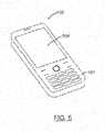
- Smartphone 100can comprise a hand held housing 101, a display 504 having an associated touch screen overlay, and an imaging module (not shown in Fig. 5 ).
- an imaging modulenot shown in Fig. 5 .
- a skilled artisanwould appreciate the fact that other housings and form factors of EIR terminal 100 are within the scope of this disclosure.
- EIR terminal 100can be incorporated in a data collection system.
- the data collection systemschematically shown in Fig. 6 , can include a plurality of EIR terminals 100a-100z in communication with a plurality of interconnected networks 110a-110z.
- the plurality of networks 110a-110zcan include at least one wireless communication network.
- EIR terminal 100can comprise a communication interface 310 which can be used by the terminal to connect to one or more networks 110a-110z.
- the communication interfacecan be provided by a wireless communication interface.
- EIR terminal 100can establish a communication session with external computer 171.
- network framescan be exchanged by the EIR terminal 100 and external computer 171 via one or more routers, base stations, and other infrastructure elements.
- external computer 171can be reachable by the EIR terminal 100 via a local area network (LAN).
- LANlocal area network
- WANwide area network
- a skilled artisanwould appreciate the fact that other methods of providing interconnectivity between EIR terminal 100c and external computer 171 relying upon LANs, WANs, virtual private networks (VPNs), and/or other types of network are within the scope of this disclosure.
- VPNsvirtual private networks
- communications between the EIR terminal 100 and external computer 171can comprise a series of HTTP requests and responses transmitted over one or more TCP connections.
- communications between EIR terminal 100c and external computer 171can comprise VoIP traffic transmitted over one or more TCP and/or UDP ports.
- At least one of the messages transmitted by the EIR terminalcan include decoded message data corresponding to, e.g., a bar code label or an RFID label attached to an item or a product.
- an EIR terminalcan transmit a request to the host computer to retrieve product-related information corresponding to a product identifier encoded by a bar code label attached to the item, or to transmit an item tacking record for an item identified by a bar code label attached to the item.
- the EIR terminalis configured to interrogate RFID tags located within the RFID communications range.
- RFID tag 199can respond to EIR terminal 100 by backscatter-modulating the amplitude and/or phase of the RFID carrier.
- the response signalcan contain useful data, e.g., an Electronic Product Code (EPC) identifier, or a tag identifier (TID).
- EPCElectronic Product Code
- TIDtag identifier
- an RFID tagcan constantly or periodically transmit a signal irrespectively of receiving a query signal from an RFID reader.
- the information in RFID tag 199can be programmed during the manufacturing process (factory programming, typically producing a read-only RFID tag) or after the manufacturing process has been completed (field programming). In a further aspect, the information in RFID tag 199 can be updated dynamically when the tag is in operation.
- the distance at which an RFID tag can be readcan be affected by a number of factors, including the signal frequency, the antenna gain, antenna radiation pattern, the orientation and polarization of the RFID reading device antenna and the RFID tag antenna.
- the signal strength of an RFID signal received by EIR terminal 100 from RFID tag 199combined with some other settings and data, such as reader antenna orientation, reader antenna location, RSSI from other readers, etc., can be indicative of the distance range between EIR terminal 100 and RFID tag 199
- RFID tag 199can be compliant with Generation 2 UHF Air Interface Protocol Standard commonly known as the "Gen 2" standard, which defines physical and logical requirements for a passive-backscatter, Interrogator-talks-first (ITF) RFID system operating in the 860 MHz - 960 MHz frequency range.
- Generation 2 UHF Air Interface Protocol Standardcommonly known as the "Gen 2” standard, which defines physical and logical requirements for a passive-backscatter, Interrogator-talks-first (ITF) RFID system operating in the 860 MHz - 960 MHz frequency range.
- RFID tag 199can be configured to store an Electronic Product Code (EPC) identifier and tag identifier (TID). In one embodiment, RFID tag 199 can implement a "kill" function that permanently disables the tag. In one embodiment, RFID tag 199 can be configured to support password-protected access control. In one embodiment, RFID tag 199 can comprise a memory, including read-only and programmable (user) memory. In one embodiment, RFID tag 199 can comprise a non-volatile memory which retains information without the need to electrically power the memory device.
- EPCElectronic Product Code
- TIDtag identifier
- RFID tag 199can implement a "kill" function that permanently disables the tag.
- RFID tag 199can be configured to support password-protected access control.
- RFID tag 199can comprise a memory, including read-only and programmable (user) memory. In one embodiment, RFID tag 199 can comprise a non-volatile memory which retains information without the need to electrically power the memory device.
- EIR terminal 100can transmit information to a passive RFID tag 199 by modulating an RF signal in the 860-960MHz frequency range.
- RFID 199 tagcan receive both information and operating energy from the RF signal transmitted by EIR terminal 100.
- EIR terminal 100can receive information from RFID 199 tag by transmitting a continuous-wave (CW) RF signal to the RFID tag 199.
- Continuous wavecan refer to any waveform transmitted by an RFID reading device and suitable to power a passive RFID tag, e.g., a sinusoid at a given frequency.
- RFID tag 199can respond by modulating the reflection coefficient of its antenna, thus backscattering an information signal to the EIR terminal 100.
- RFID tag 199can modulate the reflection coefficient of its antenna only responsive to receiving an RFID signal from EIR terminal 100.
- EIR terminal 100can be configured to send information to one or more RFID tags by modulating an RF carrier using double-sideband amplitude shift keying (DSB-ASK), single-sideband amplitude shift keying (DSB-ASK), or phase-reversal amplitude shift-keying (PR-ASK) using a pulse-interval encoding (PIE) format.
- RFID tag 199can be configured to receive its operating energy from the same modulated RF carrier.
- EIR terminal 100can be configured to receive information from RFID tag 199 by transmitting an unmodulated RF carrier and listening for a backscatter reply.
- RFID tag 199can be configured to transmit information by backscatter-modulating the amplitude and/or phase of the RFID carrier.
- RFID tag 199can be configured to encode the backscattered data using, e.g., FM0 baseband or Miller modulation of a subcarrier at the data rate.
- the encoding method to be employed by RFID tag 199can be selected by EIR terminal 100.
- the communication link between EIR terminal 100 and RFID tag 199can be half-duplex, meaning that RFID tag 199 is not required to demodulate EIR terminal's commands while backscattering.
- RFID tag 199can have a memory comprising one or more memory banks. Each of the memory banks can comprise zero or more memory words.
- RFID tag 199can comprise a reserved memory bank containing a kill password and an access password.
- RFID tag 199can comprise an EPC memory bank containing a code (e.g., an EPC code) identifying the object to which the RFID tag is or will be attached.
- RFID tag 199can comprise a TID memory bank containing a tag identifier, tag mode number, tag-specific data, and/or vendor specific data.
- RFID tag 199can comprise a user memory bank containing user-specific data.
- the kill passwordcan be provided by a 32-bit value stored in the reserved memory bank.
- EIR terminal 100use the kill password once for a given RFID tag, to permanently disable the tag.
- RFID tag 199should not execute the kill operation if its kill password has not been initialized.
- the access passwordcan be provided by a 32-bit value stored in the reserved memory bank.
- RFID tag 199 having an initialized (non-zero) access passwordcan require EIR terminal 100 to supply the access password before transitioning to a secured state.
- EIR terminalcan establish one or more sessions with one or more RFID tags.
- RFID tag 199can support at least one session-dependent flag for every session.
- the session-dependent flagcan have two states.
- RFID tag 199can invert a session-dependent flag responsive to receiving a command from EIR terminal 100.
- Tag resources other than session-dependent flagscan be shared among sessions.
- an RFID tagcan support a selected status flag indicating that the tag was selected by EIR terminal 100.
- EIR terminal 100is configured to interrogate RFID tags located within the RFID communications range in order to locate at least one RFID tag transmitting an encoded representation of a binary string, at least part of which is equal to at least part one of the specified one or more target item identifiers.
- the target item identifiercan be in a form of a product code (e.g., an EPC code) or an RFID tag identifier.
- EPC codee.g., an EPC code
- RFID tag identifiere.g., an RFID tag identifier.
- the target item identifiercan be inputted into EIR terminal 100 using numerous methods. In one example (not according to the invention), the target item identifier can be scanned using the terminal's bar code reading device. In another example (not according to the invention), the target item identifier can be keyed-in by a user using the terminal's keyboard or virtual keyboard.
- EIR terminal 100can retrieve the target item identifier by querying external database 151 using search terms (e.g., item description) provided by the user.
- search termse.g., item description
- the external databasecan return two or more item identifiers satisfying the specified search terms, and EIR terminal 100 can prompt the user to select one or more target item identifiers from the list of identifiers returned by database 151.
- EIR terminalcan prompt the user to specify additional search terms and, responsive to receiving the user input, query database 151 using the updated search terms.
- the target item identifiercan be specified by a user employing EIR terminal 100 to scan a bar code or an RFID tag of a sample item having at least some similarity with the target item.
- EIR terminal 100can be configured, responsive to scanning a bar code or reading an RFID tag, to retrieve corresponding sample item description from external database 151.
- the sample item descriptioncan comprise one or more sample item characteristics.
- EIR terminal 100is further configured to display at least part of the item description retrieved from database 151 and to accept user input editing the item description ( e.g ., by modifying one or more sample item characteristics).
- EIR terminal 100is further configured to retrieve the target item identifier satisfying the modified description from external database 151.
- the target item identifier retrieved from external database 151can be accompanied by auxiliary item information, such as item availability, location, pricing, etc.
- database 151can reside on external server 153.
- server 153can be accessed by EIR terminal 100 using the terminal's wireless communication interface.
- server 153can be accessible via the Internet.
- server 153can be accessible via a local network (e.g., a retail store network). A skilled artisan would appreciate the fact that other methods of EIR terminal 100 accessing server 153 are within the scope of this description.
- EIR terminalcan be configured to receive the target item identifier via a messaging service, e.g., SMS or MMS.
- EIR terminalcan be configured to receive the target item identifier via voice command module of the EIR terminal by converting a user voice command into an alphanumeric string containing the target item identifier.
- voice command moduleof the EIR terminal by converting a user voice command into an alphanumeric string containing the target item identifier.
- EIR terminal 100responsive to receiving the target item identifier, is configured to interrogate RFID tags located within the RFID communications range in order to locate at least one RFID tag transmitting an encoded representation of a binary string, at least part of which is equal to at least part one of the specified one or more target item identifiers.
- RFID tag 199can transmit a response signal back to EIR terminal 100.
- the response signalcan contain useful data, e.g., an Electronic Product Code (EPC) identifier, or a tag identifier (TID).
- EPCElectronic Product Code
- TIDtag identifier
- the response signalcan include a representation of a binary string, at least part of which is equal to at least part one of the specified one or more target item identifiers.
- EIR terminalcan be configured to listen to radio signals at one or more pre-defined frequencies before transmitting tag interrogation signals.
- RFID tag 199can constantly or periodically transmit a signal irrespectively of receiving a query signal from an EIR terminal.
- EIR terminalcan implement EPC TM Class-1 Generation-2 UHF RFID Protocol for Communications at 860 MHz - 960 MHz by EPCglobal.
- EIR terminal 100can interrogate RFID tags using the commands described herein infra.
- Select commandcan be used by EIR terminal 100 to select a particular RFID tag population for the subsequent inventory round. Select command can be applied successively to select a particular tag population based on user-specified criteria. Select command can include the following parameters:
- Inventory command setcan be used by EIR terminal 100 to single out one or more individual tags from a group.
- a tagcan maintain up to four simultaneous sessions and a binary Inventoried flag for each session.
- Inventory command setincludes the following commands:
- An RFID tagcan implement a state machine. Once energized, a tag can change its current state to Ready. A selected tag can, responsive to receiving Query command, select a random integer from the range of [0; 2 Q-1 ]. If the value of zero is selected, the tag can transition to Reply state, backscaterring a 16-bit random number. If a non-zero value is selected, the tag can load the selected random integer into its slot counter and change its state to Arbitrate.
- EIR terminalcan acknowledge it with Ack command containing the same random number.
- the tagcan change its state to Acknowledged and backscatter its protocol control (PC) bits, EPC and cyclic redundancy check (CRC) value.
- PCprotocol control
- CRCcyclic redundancy check
- Unacknowledged tagcan select a new random integer from the range of [0; 2 Q-1 ], load the value into its slot counter, and change its state to Arbitrate.
- QueryAdjust commanda tag in the Arbitrate state should decrement the value of its slot counter and backscatter its protocol control (PC) bits, EPC and CRC value if its slot counter is equal to zero.
- EIR terminalcan send a QueryAdjust command causing the tag to invert its Inventoried flag and to transition to Ready state.
- Access command setcan be used by EIR terminal 100 for communicating with (reading from and writing to) a tag. An individual tag must be uniquely identified prior to access. Access command set includes the following commands:
- EIR terminal 100can be configured, responsive to successfully locating at least one RFID tag satisfying the search condition (i.e., a tag transmitting an encoded representation of a binary string, at least part of which is equal to at least part one of the specified one or more target item identifiers), to notify the user of EIR terminal 100 of a successful search via a visual message and/or an audible message.
- a visual Successful Search messagecan be displayed on display 504 of EIR terminal 100.
- An audible Successful Search messagecan be in a form of a generated voice message or a user-configurable sound.
- EIR terminalcan be configured to sense its spatial movement using accelerometer 357. In one embodiment, EIR terminal 100 can be configured, responsive to sensing a spatial movement of said EIR terminal, to repeatedly attempt to locate at least one RFID tag satisfying the search condition.
- EIR terminal 100can be configured, responsive to failing to locate within a pre-defined period of time at least one RFID tag satisfying the search condition, to notify the user of EIR terminal 100 of an unsuccessful search attempt via a visual message and/or an audible message.
- a visual Unsuccessful Search Attempt messagecan be displayed on display 504 of EIR terminal 100.
- the visual messagecan indicate an approximate range within which the target item could not be located.
- An audible successful search messagecan be in a form of a generated voice message or a user-configurable sound.
- At least part of the above described item locate functionalitycan be implemented by one or more computer programs executed by microprocessor 310 of Fig. 2 . In one embodiment, at least part of the above described functionality can be implemented by one or more hardware components of EIR terminal 100 of Fig. 2 . In one embodiment, one or more computer programs implementing the above described item locate functionality can be executed by microprocessor 310 of Fig. 2 in parallel with executing other computer programs, including system and/or application computer programs. In one embodiment, one or more computer programs implementing the above described item locate functionality can be executed by two or more microprocessors.
Landscapes
- Engineering & Computer Science (AREA)
- Physics & Mathematics (AREA)
- Theoretical Computer Science (AREA)
- Business, Economics & Management (AREA)
- General Physics & Mathematics (AREA)
- Economics (AREA)
- Health & Medical Sciences (AREA)
- Toxicology (AREA)
- Computer Networks & Wireless Communication (AREA)
- Artificial Intelligence (AREA)
- Computer Vision & Pattern Recognition (AREA)
- Electromagnetism (AREA)
- Quality & Reliability (AREA)
- Operations Research (AREA)
- General Business, Economics & Management (AREA)
- Tourism & Hospitality (AREA)
- Strategic Management (AREA)
- Marketing (AREA)
- Development Economics (AREA)
- Human Resources & Organizations (AREA)
- Entrepreneurship & Innovation (AREA)
- General Health & Medical Sciences (AREA)
- Databases & Information Systems (AREA)
- Accounting & Taxation (AREA)
- Finance (AREA)
- General Engineering & Computer Science (AREA)
- Automation & Control Theory (AREA)
- Data Mining & Analysis (AREA)
- Computational Linguistics (AREA)
- Computer Hardware Design (AREA)
- Microelectronics & Electronic Packaging (AREA)
- Computer Security & Cryptography (AREA)
- Telephone Function (AREA)
- Mobile Radio Communication Systems (AREA)
- Near-Field Transmission Systems (AREA)
Description
- The invention is generally related to encoded information reading (EIR) terminals and is specifically related to EIR terminals equipped with RFID reading devices.
- Radio frequency identification (RFID) methods are widely used in a number of applications, including smart cards, item tracking in manufacturing and retail,etc. An RFID tag can be attached,e.g., to a retail item. An EIR terminal can be equipped with an RFID reader to read and/or modify the memory of an RFID tag attached to a retail item.
- Patent document number
US2005/285742A1 describes methods and apparatus for locating one among many items equipped with RFID tags. The apparatus comprises a portable system interrogating the RFID tags and receiving responses therefrom that depend at least on their bearing angle. A comparator selects responses from the one item and ignores others. An annunciator indicates the presence of the one item in the interrogator field of view and, desirably but not essentially, its relative proximity. A directional antenna whose beam pattern is limited in azimuth and/or elevation provides bearing angle information. Its field of view becomes progressively smaller as the antenna approaches the one item so that a user can substantially pinpoint its location without needing any of the usual RFID infrastructure. Tag response hit rate and/or signal strength provides range related information to the interrogator.; Optionally, the presence of each new tag is announced until all new tags have been identified. - Patent document number
WO01/52179A2 - Patent document number
WO2009/064926A1 describes techniques and apparatus based on metamaterial structures for antenna and transmission line devices, including multilayer metallization metamaterial structures with one or more conductive vias connecting conductive parts in two different metallization layers - The present invention in its various aspects is as set out in the appended claims..
- For the purpose of illustrating the invention, the drawings show aspects of one or more embodiments of the invention. However, it should be understood that the present invention is not limited to the precise arrangements and instrumentalities shown in the drawings, wherein:
Fig. 1 illustrates use case scenario of an EIR terminal equipped with item locate functionality;Fig. 2 depicts a component level diagram of one embodiment of an EIR terminal equipped with item locate functionality;Figs. 3a-3b illustrate various embodiments of multiple cell metamaterial (MTM) antennas suitable for an EIR terminal equipped with item locate functionality;Figs. 4a-4b and5 illustrate various embodiments of hand held EIR terminal housings;Fig. 6 depicts a network-level layout of a data collection system utilizing EIR terminals equipped with item locate functionality.- The drawings are not necessarily to scale, emphasis instead generally being placed upon illustrating the principles of the invention. In the drawings, like numerals are used to indicate like parts throughout the various views.
- In one embodiment, there is provided an encoded information reading (EIR) terminal comprising a radio frequency identifier (RFID) reading device. The EIR terminal can be configured to read RFID tags containing decoded messages. In one embodiment, the RFID terminal can be configured to read an RFID tag containing an encoded message and output raw message data containing the encoded message. In another embodiment, the RFID terminal can be configured to read an RFID tag containing an encoded message and output decoded message data corresponding to the encoded message.
- Various embodiments of EIR terminals can be used in a numerous applications, including but not limited to, authentication and access control systems (for example, using smart cards), item tracking in manufacturing and retail,etc. A smart card is an identification card (e.g., a credit card, a pass card) which does not need to be swiped or otherwise physically contacted by a card reader. This capability can be implemented by placing an RFID tag in the card. Item tracking can be implemented by placing an RFID tag on each individual item. Item tracking with RFID tags can be used in loss prevention systems by placing an RFID tag into merchandise items and placing sensors at exit points. If an exit sensor detects a tagged item with a tag, which was not deactivated at the checkout, an alarm can go off. In retail, item tracking with RFID tags can be used in conjunction with other technologies such as bar code scanning and payment terminals.
- Of course, devices that read bar codes, read RFID, or read cards bearing encoded information may read more than one of these categories while remaining within the scope of this disclosure. For example, a device that reads bar codes may include a card reader, and/or RFID reader; a device that reads RFID may also be able to read bar codes and/or cards; and a device that reads cards may be able to also read bar codes and/or RFID. For further clarity, it is not necessary that a device's primary function involve any of these functions in order to be considered such a device; for example, a cellular telephone, smartphone, or PDA that is capable of reading bar codes is referred to as EIR terminal throughout this disclosure.
- RFID technology can advantageously be used to locate a tagged item. In one example (not according to the invention), illustrated in
Fig. 1 , a retail customer can use his or her mobile communication device 100 (e.g., a smartphone) to search for an item identifier in a database 151 residing on a remote server 153, and then using the smartphone's built-in RFID reader, locate on the sales floor the item ofinterest 198 withRFID tag 199 attached to it. - In an embodiment of the invention a retail customer looking to find a particular product, can scan a bar code tag or read
RFID tag 155 of any similarly lookingproduct 157 using his or her mobile communication device 100 (e.g., a smartphone). Smartphone 100 can be programmed, responsive to scanning a product tag, to retrieve the product characteristics from an external database 151 that can be provided by the retailer, the product manufacturer, or by a third party. Smartphone 100 is further programmed to display the retrieved product characteristics and to accept user's input editing the product characteristics. Smartphone 100 is further programmed, responsive to accepting the user edited product characteristics, to retrieve the product identifier, optionally accompanied by the product availability and pricing, from external database 151. Smartphone 100 is further programmed, responsive to retrieving the product identifier, to either locate the desiredproduct 198 within the RFID communication range or display a failure message. - In another example (not according to the invention), a retail store sales associate can use his or her portable data terminal to search for an item identifier in a store database, and then to locate the item on the sales floor or in a stockroom using the terminal's built-in RFID reader. In a yet another example (not according to the invention), a warehouse worker can use his or her portable data terminal to receive an item identifier from a workflow process running on a local or remote server computer, and then to locate the item in the warehouse using the terminal's built-in RFID reader. In a yet another example (not according to the invention), an airline passenger can receive an SMS or an MMS containing a tag identifier of an RFID tag attached to his or her luggage, and then to locate the luggage on or around a luggage distributing belt using the RFID reader built-in into his or her smartphone. In a yet another example (not according to the invention), luggage tag identifiers can be provided to an airline passenger as part of an electronic boarding pass transferred to the passenger's mobile phone,e.g., via SMS or MMS.
- Component-level diagram of one embodiment of
EIR terminal 100 is now being described with references toFig. 2 .EIR terminal 100 comprises at least onemicroprocessor 310 and amemory 320, both coupled to thesystem bus 370.Microprocessor 310 can be provided by a general purpose microprocessor or by a specialized microprocessor (e.g., an ASIC). In one embodiment,EIR terminal 100 can comprise a single microprocessor which can be referred to as a central processing unit (CPU). In another embodiment,EIR terminal 100 can comprise two or more microprocessors, for example a CPU and a specialized microprocessor (e.g., an ASIC). In one embodiment,memory 320 can be provided by RAM, ROM, EPROM, and/or SIM card-based memory. - In addition to an RFID reader, the
EIR terminal 100 can further comprise one ormore EIR devices 330, including a bar code reading device, and a card reading device, also coupled tosystem bus 370. In one embodiment, an EIR reading device can be capable of outputting decoded message data corresponding to an encoded message. In another embodiment, the EIR reading device can output raw message data comprising an encoded message, e.g., raw image data or raw RFID data. - EIR terminal 100 further comprises an interface such as a
keyboard interface 354 and adisplay adapter 355, both also coupled tosystem bus 370.EIR terminal 100 can further comprise abattery 356. In one embodiment, theEIR terminal 100 can further comprise an accelerometer 357. In one embodiment, theEIR terminal 100 can further comprise aGPS receiver 380. In one embodiment, theEIR terminal 100 can further comprise at least oneconnector 390 configured to receive a subscriber identity module (SIM) card. - As noted hereinsupra, the
EIR terminal 100 comprises anRFID reading device 333. In a further aspect, the RFID reading device can comprise anantenna 121. In one embodiment,antenna 121 can be provided by a single-cell or multiple-cell transmission line MTM antenna shown inFigs. 3a (top view) and 3b (3D view).Antenna 121 can comprise one or moreconductive cell patches 202a-202z that can be mounted on a dielectric substrate, provided, for example, by a printed circuit board (PCB) 210.Conductive cell patches 202a-202z can be spatially separated so that capacitive couplings between adjacent cell patches can be created.Antenna 121 can be designed to include a left-hand capacitance of a right-hand inductance. Also disposed on thedielectric substrate 210 can be afeed pad 214 that can be provided,e.g., by a metallic plate and can be connected to aconductive feed line 216.Conductive feed line 216 can be provided,e.g., by metallic a strip.Conductive feed line 216 can be located close but separately fromconductive cell patches 202a-202b. A skilled artisan would appreciate the fact that MTM antennas having two or more conductive feed lines are within the scope of this disclosure. A ground plane can be provided by a metallic layer disposed on the bottom side of PCB 210 (not shown inFig. 3a ) or/and on the top side ofPCB 210. In one embodiment, each cell patch can be connected to the ground plane via a zigzag line to create a left-hand inductance. In another embodiment, each cell patch can be connected to the ground plane by a via. - The components of EIR terminal 100 can be incorporated into a variety of different housings of various forms factors. As indicated by the embodiment of
Figs. 4a and 4b , the components ofFig. 2 can be incorporated into a hand heldhousing 101.EIR terminal 100 ofFigs. 4a and 4b is in the form factor of a hand held portable data terminal. EIR terminal 100 as shown inFigs. 4a and 4b can include akeyboard 1090, adisplay 504 having an associated touch screen overlay, acard reader 1348, and animaging module 361. As indicated by the side view ofFig. 4b , the components of the block diagram ofFig. 2 can be supported withinhousing 101 on a plurality ofcircuit boards 1077. In one embodiment, schematically shown inFig. 5 ,EIR terminal 100 can be provided by a smartphone.Smartphone 100 can comprise a hand heldhousing 101, adisplay 504 having an associated touch screen overlay, and an imaging module (not shown inFig. 5 ). A skilled artisan would appreciate the fact that other housings and form factors of EIR terminal 100 are within the scope of this disclosure. - In another aspect,
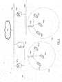
EIR terminal 100 can be incorporated in a data collection system. The data collection system, schematically shown inFig. 6 , can include a plurality ofEIR terminals 100a-100z in communication with a plurality ofinterconnected networks 110a-110z. In one aspect, the plurality ofnetworks 110a-110z can include at least one wireless communication network. In a further aspect,EIR terminal 100 can comprise acommunication interface 310 which can be used by the terminal to connect to one ormore networks 110a-110z. In one embodiment, the communication interface can be provided by a wireless communication interface. EIR terminal 100 can establish a communication session withexternal computer 171. In one embodiment, network frames can be exchanged by theEIR terminal 100 andexternal computer 171 via one or more routers, base stations, and other infrastructure elements. In another embodiment,external computer 171 can be reachable by theEIR terminal 100 via a local area network (LAN). In a yet another embodiment,external computer 171 can be reachable byEIR terminal 100 via a wide area network (WAN). A skilled artisan would appreciate the fact that other methods of providing interconnectivity between EIR terminal 100c andexternal computer 171 relying upon LANs, WANs, virtual private networks (VPNs), and/or other types of network are within the scope of this disclosure.- In one embodiment, communications between the
EIR terminal 100 andexternal computer 171 can comprise a series of HTTP requests and responses transmitted over one or more TCP connections. In one embodiment, communications between EIR terminal 100c andexternal computer 171 can comprise VoIP traffic transmitted over one or more TCP and/or UDP ports. A skilled artisan would appreciate the fact that using other transport and application level protocols is within the scope of this disclosure. - In one aspect, at least one of the messages transmitted by the EIR terminal can include decoded message data corresponding to,e.g., a bar code label or an RFID label attached to an item or a product. For example, an EIR terminal can transmit a request to the host computer to retrieve product-related information corresponding to a product identifier encoded by a bar code label attached to the item, or to transmit an item tacking record for an item identified by a bar code label attached to the item.
- The EIR terminal is configured to interrogate RFID tags located within the RFID communications range. Referring again to
Fig. 1 , responsive to receiving an interrogation signal transmitted byEIR terminal 100,RFID tag 199 can respond toEIR terminal 100 by backscatter-modulating the amplitude and/or phase of the RFID carrier. The response signal can contain useful data,e.g., an Electronic Product Code (EPC) identifier, or a tag identifier (TID). In one embodiment, an RFID tag can constantly or periodically transmit a signal irrespectively of receiving a query signal from an RFID reader. - In another aspect, the information in
RFID tag 199 can be programmed during the manufacturing process (factory programming, typically producing a read-only RFID tag) or after the manufacturing process has been completed (field programming). In a further aspect, the information inRFID tag 199 can be updated dynamically when the tag is in operation. - In another aspect, the distance at which an RFID tag can be read (the read range) can be affected by a number of factors, including the signal frequency, the antenna gain, antenna radiation pattern, the orientation and polarization of the RFID reading device antenna and the RFID tag antenna. In a further aspect, the signal strength of an RFID signal received by EIR terminal 100 from
RFID tag 199, combined with some other settings and data, such as reader antenna orientation, reader antenna location, RSSI from other readers,etc., can be indicative of the distance range between EIR terminal 100 andRFID tag 199 - In one embodiment,
RFID tag 199 can be compliant with Generation 2 UHF Air Interface Protocol Standard commonly known as the "Gen 2" standard, which defines physical and logical requirements for a passive-backscatter, Interrogator-talks-first (ITF) RFID system operating in the 860 MHz - 960 MHz frequency range. - In one embodiment,
RFID tag 199 can be configured to store an Electronic Product Code (EPC) identifier and tag identifier (TID). In one embodiment,RFID tag 199 can implement a "kill" function that permanently disables the tag. In one embodiment,RFID tag 199 can be configured to support password-protected access control. In one embodiment,RFID tag 199 can comprise a memory, including read-only and programmable (user) memory. In one embodiment,RFID tag 199 can comprise a non-volatile memory which retains information without the need to electrically power the memory device. - In one embodiment,
EIR terminal 100 can transmit information to apassive RFID tag 199 by modulating an RF signal in the 860-960MHz frequency range.RFID 199 tag can receive both information and operating energy from the RF signal transmitted byEIR terminal 100.EIR terminal 100 can receive information fromRFID 199 tag by transmitting a continuous-wave (CW) RF signal to theRFID tag 199. "Continuous wave" can refer to any waveform transmitted by an RFID reading device and suitable to power a passive RFID tag,e.g., a sinusoid at a given frequency.RFID tag 199 can respond by modulating the reflection coefficient of its antenna, thus backscattering an information signal to theEIR terminal 100.RFID tag 199 can modulate the reflection coefficient of its antenna only responsive to receiving an RFID signal fromEIR terminal 100. - In a further aspect,
EIR terminal 100 can be configured to send information to one or more RFID tags by modulating an RF carrier using double-sideband amplitude shift keying (DSB-ASK), single-sideband amplitude shift keying (DSB-ASK), or phase-reversal amplitude shift-keying (PR-ASK) using a pulse-interval encoding (PIE) format.RFID tag 199 can be configured to receive its operating energy from the same modulated RF carrier. EIR terminal 100 can be configured to receive information fromRFID tag 199 by transmitting an unmodulated RF carrier and listening for a backscatter reply.RFID tag 199 can be configured to transmit information by backscatter-modulating the amplitude and/or phase of the RFID carrier.RFID tag 199 can be configured to encode the backscattered data using,e.g., FM0 baseband or Miller modulation of a subcarrier at the data rate. The encoding method to be employed byRFID tag 199 can be selected byEIR terminal 100.- In another aspect, the communication link between EIR terminal 100 and
RFID tag 199 can be half-duplex, meaning thatRFID tag 199 is not required to demodulate EIR terminal's commands while backscattering. - In another aspect,
RFID tag 199 can have a memory comprising one or more memory banks. Each of the memory banks can comprise zero or more memory words. In one embodiment,RFID tag 199 can comprise a reserved memory bank containing a kill password and an access password. In one embodiment,RFID tag 199 can comprise an EPC memory bank containing a code (e.g., an EPC code) identifying the object to which the RFID tag is or will be attached. In one embodiment,RFID tag 199 can comprise a TID memory bank containing a tag identifier, tag mode number, tag-specific data, and/or vendor specific data. In one embodiment,RFID tag 199 can comprise a user memory bank containing user-specific data. - In another aspect, the kill password can be provided by a 32-bit value stored in the reserved memory bank. EIR terminal 100 use the kill password once for a given RFID tag, to permanently disable the tag.
RFID tag 199 should not execute the kill operation if its kill password has not been initialized. The access password can be provided by a 32-bit value stored in the reserved memory bank.RFID tag 199 having an initialized (non-zero) access password can require EIR terminal 100 to supply the access password before transitioning to a secured state. - In another aspect, EIR terminal can establish one or more sessions with one or more RFID tags.
RFID tag 199 can support at least one session-dependent flag for every session. The session-dependent flag can have two states.RFID tag 199 can invert a session-dependent flag responsive to receiving a command fromEIR terminal 100. Tag resources other than session-dependent flags can be shared among sessions. In another aspect, an RFID tag can support a selected status flag indicating that the tag was selected byEIR terminal 100. - Referring again to
Fig. 1 ,EIR terminal 100 is configured to interrogate RFID tags located within the RFID communications range in order to locate at least one RFID tag transmitting an encoded representation of a binary string, at least part of which is equal to at least part one of the specified one or more target item identifiers. - The target item identifier can be in a form of a product code (e.g., an EPC code) or an RFID tag identifier. A skilled artisan would appreciate the fact that other methods of specifying the target item identifier are within the scope of this disclosure. The target item identifier can be inputted into
EIR terminal 100 using numerous methods. In one example (not according to the invention), the target item identifier can be scanned using the terminal's bar code reading device. In another example (not according to the invention), the target item identifier can be keyed-in by a user using the terminal's keyboard or virtual keyboard. In a yet another example (not according to the invention),EIR terminal 100 can retrieve the target item identifier by querying external database 151 using search terms (e.g., item description) provided by the user. In one example (not according to the invention), the external database can return two or more item identifiers satisfying the specified search terms, and EIR terminal 100 can prompt the user to select one or more target item identifiers from the list of identifiers returned by database 151. In one example (not according to the invention), EIR terminal can prompt the user to specify additional search terms and, responsive to receiving the user input, query database 151 using the updated search terms. - In an embodiment, according to the present invention, the target item identifier can be specified by a user employing
EIR terminal 100 to scan a bar code or an RFID tag of a sample item having at least some similarity with the target item.EIR terminal 100 can be configured, responsive to scanning a bar code or reading an RFID tag, to retrieve corresponding sample item description from external database 151. The sample item description can comprise one or more sample item characteristics.EIR terminal 100 is further configured to display at least part of the item description retrieved from database 151 and to accept user input editing the item description (e.g., by modifying one or more sample item characteristics).EIR terminal 100 is further configured to retrieve the target item identifier satisfying the modified description from external database 151. In one embodiment, the target item identifier retrieved from external database 151 can be accompanied by auxiliary item information, such as item availability, location, pricing,etc. - In a further aspect, database 151 can reside on external server 153. In one embodiment, server 153 can be accessed by
EIR terminal 100 using the terminal's wireless communication interface. In one embodiment, server 153 can be accessible via the Internet. In another embodiment, server 153 can be accessible via a local network (e.g., a retail store network). A skilled artisan would appreciate the fact that other methods of EIR terminal 100 accessing server 153 are within the scope of this description. - In an example (not according to the invention), EIR terminal can be configured to receive the target item identifier via a messaging service,e.g., SMS or MMS. In another example (not according to the invention), EIR terminal can be configured to receive the target item identifier via voice command module of the EIR terminal by converting a user voice command into an alphanumeric string containing the target item identifier. A skilled artisan would appreciate the fact that other methods of EIR terminal 100 receiving the target item identifier can be provided.
- As noted hereinsupra, responsive to receiving the target item identifier,
EIR terminal 100 is configured to interrogate RFID tags located within the RFID communications range in order to locate at least one RFID tag transmitting an encoded representation of a binary string, at least part of which is equal to at least part one of the specified one or more target item identifiers. - Responsive to receiving an interrogation signal transmitted by
EIR terminal 100,RFID tag 199 can transmit a response signal back toEIR terminal 100. The response signal can contain useful data,e.g., an Electronic Product Code (EPC) identifier, or a tag identifier (TID). The response signal can include a representation of a binary string, at least part of which is equal to at least part one of the specified one or more target item identifiers. - In one embodiment, EIR terminal can be configured to listen to radio signals at one or more pre-defined frequencies before transmitting tag interrogation signals. In one embodiment,
RFID tag 199 can constantly or periodically transmit a signal irrespectively of receiving a query signal from an EIR terminal. - In one embodiment, EIR terminal can implementEPC™Class-1 Generation-2 UHF RFID Protocol for Communications at 860 MHz -960 MHz by EPCglobal.
EIR terminal 100 can interrogate RFID tags using the commands described herein infra. - Select command can be used by
EIR terminal 100 to select a particular RFID tag population for the subsequent inventory round.Select command can be applied successively to select a particular tag population based on user-specified criteria.Select command can include the following parameters: - Target parameter indicates whetherSelect command modifies a tag'sSL flag orInventoried flag, and in the latter case it further specifies one of four available sessions (S0,.., S3);
- Action parameter indicates whether matching tags assert or deassertSL flag, or set theirInventoried flag toA orB state; tags conforming to the contents ofMemBank, Pointer, Length, andMask parameters are considered to be matching;
- Mask parameter contains a bit string that a tag should compare to a memory location specified byMemBank, Pointer, andLength parameters;
- MemBank parameter specifies the memory bank to whichMask parameter refers (EPC, TID, orUser);
- Pointer parameter specifies a memory start location forMask;
- Length parameter specifies the number of bits of memory forMask; ifLength is equal to zero, all tags are considered matching.
- Inventory command set can be used by
EIR terminal 100 to single out one or more individual tags from a group. A tag can maintain up to four simultaneous sessions and a binaryInventoried flag for each session.Inventory command set includes the following commands: - Query command can be used to initiate and specify an inventory round; it contains a slot counter value (Q=0 to 15) determining the number of slots in the round; the command also includesSel parameter specifying which tags should respond to theQuery.
- QueryAdjust command can be used to adjust the value of the tag's slot counterQ without changing any other parameters;
- QueryRep command can be used to repeat the last Query command;
- Ack command can be used to acknowledge a tag's response;
- Nak command can be used to force a tag to change its state toArbitrate.
- An RFID tag can implement a state machine. Once energized, a tag can change its current state toReady. A selected tag can, responsive to receivingQuery command, select a random integer from the range of [0; 2Q-1]. If the value of zero is selected, the tag can transition toReply state, backscaterring a 16-bit random number. If a non-zero value is selected, the tag can load the selected random integer into its slot counter and change its state toArbitrate.
- Responsive to receiving the tag transmission, EIR terminal can acknowledge it withAck command containing the same random number. Responsive to receivingAck command, the tag can change its state toAcknowledged and backscatter its protocol control (PC) bits, EPC and cyclic redundancy check (CRC) value. Unacknowledged tag can select a new random integer from the range of [0; 2Q-1], load the value into its slot counter, and change its state toArbitrate. Responsive to receivingQueryAdjust command, a tag in theArbitrate state should decrement the value of its slot counter and backscatter its protocol control (PC) bits, EPC and CRC value if its slot counter is equal to zero.
- Responsive to receiving the tag's transmission of its PC, EPC and 16-bit CRC value, EIR terminal can send aQueryAdjust command causing the tag to invert itsInventoried flag and to transition toReady state.
- Access command set can be used by
EIR terminal 100 for communicating with (reading from and writing to) a tag. An individual tag must be uniquely identified prior to access. Access command set includes the following commands: - ReqRn command can be used by
EIR terminal 100 to request a handle from a tag; the handle can be used in the subsequentAccess command set commands. Responsive to receiving Req_RN commands, a tag returns a 16-bit random integer (handle) and transitions fromAcknowledged toOpen orSecured state. - Read command can be used by
EIR terminal 100 to read tag'sReserved, EPC, TID andUser memory; - Write command can be used by
EIR terminal 100 to write to tag'sReserved, EPC, TID andUser memory; - Kill command can be used by
EIR terminal 100 to permanently disable a tag; - Lock command can be used by
EIR terminal 100 to lock passwords preventing subsequent read or write operations; lock individual memory banks preventing subsequent write operations; permanently lock the lock status of passwords or memory banks; - Access command can be used by
EIR terminal 100 to cause a tag having a non-zero access password to transition fromOpen toSecured state. - A skilled artisan would appreciate the fact that other methods of interrogating RFID tags by
EIR terminal 100 are within the scope of this disclosure. - In a further aspect,
EIR terminal 100 can be configured, responsive to successfully locating at least one RFID tag satisfying the search condition (i.e., a tag transmitting an encoded representation of a binary string, at least part of which is equal to at least part one of the specified one or more target item identifiers), to notify the user ofEIR terminal 100 of a successful search via a visual message and/or an audible message. A visualSuccessful Search message can be displayed ondisplay 504 ofEIR terminal 100. An audibleSuccessful Search message can be in a form of a generated voice message or a user-configurable sound. - In one embodiment, EIR terminal can be configured to sense its spatial movement using accelerometer 357. In one embodiment,
EIR terminal 100 can be configured, responsive to sensing a spatial movement of said EIR terminal, to repeatedly attempt to locate at least one RFID tag satisfying the search condition. - In one embodiment,
EIR terminal 100 can be configured, responsive to failing to locate within a pre-defined period of time at least one RFID tag satisfying the search condition, to notify the user ofEIR terminal 100 of an unsuccessful search attempt via a visual message and/or an audible message. A visualUnsuccessful Search Attempt message can be displayed ondisplay 504 ofEIR terminal 100. In one embodiment, the visual message can indicate an approximate range within which the target item could not be located. An audible successful search message can be in a form of a generated voice message or a user-configurable sound. - In one embodiment, at least part of the above described item locate functionality can be implemented by one or more computer programs executed by
microprocessor 310 ofFig. 2 . In one embodiment, at least part of the above described functionality can be implemented by one or more hardware components ofEIR terminal 100 ofFig. 2 . In one embodiment, one or more computer programs implementing the above described item locate functionality can be executed bymicroprocessor 310 ofFig. 2 in parallel with executing other computer programs, including system and/or application computer programs. In one embodiment, one or more computer programs implementing the above described item locate functionality can be executed by two or more microprocessors. - While the present invention has been particularly shown and described with reference to certain exemplary embodiments, it will be understood by one skilled in the art that various changes in detail may be affected therein without departing from the scope of the invention as defined by claims.
Claims (4)
- An apparatus (100) including an interface (354,355), a microprocessor (310), a memory (320) and an RFID reader, the interface (354,355) being configured to:display characteristics of a second item, wherein the second item is similar to a first item of interest;receive, user inputs to edit the displayed characteristics; whereinthe microprocessor (310) and the memory (320) are coupled to the interface, and wherein the microprocessor is configured to:request a database (151) for retrieving an item identifier corresponding to the first item of interest, based on the edited displayed characteristics; andin response to the RFID reader receiving the item identifier from the database, the RFID reader is configured to:
transmit an RF interrogation signal to locate one or more RFID tags and activate any RFID tags corresponding to the identifier when such RFID tags are within range of the RF interrogation signal. - The apparatus of claim 1, wherein the identifier is provided by at least one of: a product code, an EPC code, a tag identifier and an alphanumeric string.
- A method employed in an RFID reader apparatus including:displaying characteristics of a second item using an interface, wherein the second item is similar to a first item of interest;receiving, user inputs to edit the displayed characteristic;requesting, by a microprocessor coupled to the interface, a database for retrieving an item identifier corresponding to the first item of interest, based on the edited displayed characteristics;receiving, by the microprocessor coupled to the interface, the item identifier from the database; andtransmitting an RF interrogation signal to locate one or more RFID tags and activate any RFID tag corresponding to the identifier.
- The method of claim 3, wherein the item identifier comprises one of: a product code, an EPC code, a tag identifier and an alphanumeric string.
Applications Claiming Priority (3)
| Application Number | Priority Date | Filing Date | Title |
|---|---|---|---|
| US13/214,512US9507976B2 (en) | 2011-08-22 | 2011-08-22 | Encoded information reading terminal with item locate functionality |
| EP14190366.6AEP2846287B1 (en) | 2011-08-22 | 2012-08-20 | Encoded information reading terminal with item locate functionality |
| EP12181099AEP2562679A1 (en) | 2011-08-22 | 2012-08-20 | Encoded information reading terminal with item locate functionality |
Related Parent Applications (2)
| Application Number | Title | Priority Date | Filing Date |
|---|---|---|---|
| EP14190366.6ADivisionEP2846287B1 (en) | 2011-08-22 | 2012-08-20 | Encoded information reading terminal with item locate functionality |
| EP12181099ADivisionEP2562679A1 (en) | 2011-08-22 | 2012-08-20 | Encoded information reading terminal with item locate functionality |
Publications (2)
| Publication Number | Publication Date |
|---|---|
| EP3214574A1 EP3214574A1 (en) | 2017-09-06 |
| EP3214574B1true EP3214574B1 (en) | 2020-11-04 |
Family
ID=47221087
Family Applications (3)
| Application Number | Title | Priority Date | Filing Date |
|---|---|---|---|
| EP14190366.6AActiveEP2846287B1 (en) | 2011-08-22 | 2012-08-20 | Encoded information reading terminal with item locate functionality |
| EP17159331.2AActiveEP3214574B1 (en) | 2011-08-22 | 2012-08-20 | Encoded information reading terminal with locate functionality |
| EP12181099AWithdrawnEP2562679A1 (en) | 2011-08-22 | 2012-08-20 | Encoded information reading terminal with item locate functionality |
Family Applications Before (1)
| Application Number | Title | Priority Date | Filing Date |
|---|---|---|---|
| EP14190366.6AActiveEP2846287B1 (en) | 2011-08-22 | 2012-08-20 | Encoded information reading terminal with item locate functionality |
Family Applications After (1)
| Application Number | Title | Priority Date | Filing Date |
|---|---|---|---|
| EP12181099AWithdrawnEP2562679A1 (en) | 2011-08-22 | 2012-08-20 | Encoded information reading terminal with item locate functionality |
Country Status (3)
| Country | Link |
|---|---|
| US (2) | US9507976B2 (en) |
| EP (3) | EP2846287B1 (en) |
| CN (2) | CN103198337B (en) |
Families Citing this family (16)
| Publication number | Priority date | Publication date | Assignee | Title |
|---|---|---|---|---|
| US9041518B2 (en) | 2012-01-26 | 2015-05-26 | Hand Held Products, Inc. | Portable RFID reading terminal with visual indication of scan trace |
| US9536219B2 (en) | 2012-04-20 | 2017-01-03 | Hand Held Products, Inc. | System and method for calibration and mapping of real-time location data |
| US8881982B2 (en)* | 2012-04-20 | 2014-11-11 | Honeywell Scanning & Mobility | Portable encoded information reading terminal configured to acquire images |
| US8727225B2 (en)* | 2012-04-20 | 2014-05-20 | Honeywell International Inc. | System and method for calibration and mapping of real-time location data |
| US20140071840A1 (en)* | 2012-09-11 | 2014-03-13 | Hand Held Products, Inc., doing business as Honeywell Scanning & Mobility | Mobile computer configured to select wireless communication network |
| US9697387B1 (en) | 2013-01-14 | 2017-07-04 | Impinj, Inc. | Sequential encoding for RFID tags |
| US9246208B2 (en) | 2013-08-06 | 2016-01-26 | Hand Held Products, Inc. | Electrotextile RFID antenna |
| CN104539700B (en)* | 2014-12-29 | 2018-02-27 | 镇江市高等专科学校 | Tracking location system and information transfer coding method |
| EP3040904B1 (en) | 2014-12-31 | 2021-04-21 | Hand Held Products, Inc. | Portable rfid reading terminal with visual indication of scan trace |
| WO2016131186A1 (en)* | 2015-02-17 | 2016-08-25 | 华为技术有限公司 | Uplink reference signal communication device and method |
| TWI616829B (en)* | 2015-08-21 | 2018-03-01 | 緯創資通股份有限公司 | Method, system, and computer-readable recording medium for object location tracking |
| CN110009067B (en)* | 2018-01-04 | 2022-04-26 | 青岛胶南海尔洗衣机有限公司 | An article information management system and its control method |
| MX2021005774A (en)* | 2018-11-15 | 2021-09-08 | Metrc Llc | METHOD AND APPARATUS FOR MONITORING PLANTS AND/OR PLANT-BASED PRODUCTS AND/OR MONITORING THE SALE OF PRODUCTS DERIVED THEREOF, USING RFID TECHNOLOGY. |
| US10618735B1 (en)* | 2019-03-11 | 2020-04-14 | Coupang Corp. | Computerized systems and methods for assisted picking processes |
| CN110687503B (en)* | 2019-10-31 | 2021-07-09 | 华中科技大学 | A backscatter-based wireless positioning method, device and system |
| GB2630798A (en)* | 2023-06-08 | 2024-12-11 | Rizvi Adam | Device for encoding a chip |
Family Cites Families (72)
| Publication number | Priority date | Publication date | Assignee | Title |
|---|---|---|---|---|
| US5231273A (en)* | 1991-04-09 | 1993-07-27 | Comtec Industries | Inventory management system |
| US5589844A (en)* | 1995-06-06 | 1996-12-31 | Flash Comm, Inc. | Automatic antenna tuner for low-cost mobile radio |
| US5798693A (en)* | 1995-06-07 | 1998-08-25 | Engellenner; Thomas J. | Electronic locating systems |
| JP2001526417A (en)* | 1997-11-03 | 2001-12-18 | ヒル−ロム,インコーポレイティド | Personnel and asset tracking method and apparatus |
| US7844505B1 (en) | 1997-11-21 | 2010-11-30 | Symbol Technologies, Inc. | Automated real-time distributed tag reader network |
| US7190257B2 (en)* | 1999-03-16 | 2007-03-13 | Intermec Ip Corp. | Data encoding in radio frequency identification transponders |
| MXPA02006882A (en) | 2000-01-14 | 2003-01-28 | 3M Innovative Properties Co | User interface for portable rfid reader. |
| US7075412B1 (en) | 2002-05-30 | 2006-07-11 | Thingmagic L.L.C. | Methods and apparatus for operating a radio device |
| US8542717B2 (en)* | 2003-03-03 | 2013-09-24 | Veroscan, Inc. | Interrogator and interrogation system employing the same |
| US8681000B2 (en) | 2003-04-09 | 2014-03-25 | Visible Assets, Inc. | Low frequency inductive tagging for lifecycle management |
| US20110163882A1 (en) | 2003-04-09 | 2011-07-07 | Visible Assets, Inc. | Passive Low Frequency Inductive Tagging |
| US8026819B2 (en) | 2005-10-02 | 2011-09-27 | Visible Assets, Inc. | Radio tag and system |
| US20110163857A1 (en) | 2003-04-09 | 2011-07-07 | Visible Assets, Inc. | Energy Harvesting for Low Frequency Inductive Tagging |
| WO2004104619A1 (en) | 2003-05-14 | 2004-12-02 | Hill-Rom Services, Inc. | Combined locating, tracking and communications system with active radio frequency and infrared id tags |
| US7298264B1 (en)* | 2004-01-20 | 2007-11-20 | Charles A. Eldering | RFID tag filtering and monitoring |
| JP2005233812A (en)* | 2004-02-20 | 2005-09-02 | Matsushita Electric Ind Co Ltd | Search system, search management device, wireless tag detection device, search method, search management method, wireless tag detection method, search management program, and wireless tag detection program |
| US7142120B2 (en)* | 2004-06-29 | 2006-11-28 | Symbol Technologies, Inc. | Item finding using RF signalling |
| US7839289B2 (en) | 2004-08-26 | 2010-11-23 | Avante International Technology, Inc. | Object monitoring, locating, and tracking system and method employing RFID devices |
| US7286835B1 (en)* | 2004-09-10 | 2007-10-23 | Airespace, Inc. | Enhanced wireless node location using differential signal strength metric |
| US7416121B2 (en)* | 2004-12-17 | 2008-08-26 | Intermec Ip Corp. | Stand-alone proxy RFID read/write unit for print label encoding |
| US7570165B2 (en)* | 2005-02-28 | 2009-08-04 | Xterprise, Incorporated | Radio frequency identification application system |
| US7667573B2 (en) | 2005-03-01 | 2010-02-23 | I.D. Systems, Inc. | Mobile portal for RFID applications |
| US7413124B2 (en)* | 2005-07-19 | 2008-08-19 | 3M Innovative Properties Company | RFID reader supporting one-touch search functionality |
| US7931194B2 (en)* | 2005-12-21 | 2011-04-26 | Ncr Corporation | Methods and apparatus for automated document examination for age verification |
| DE102006004023A1 (en) | 2006-01-27 | 2007-08-09 | Siemens Ag | Device and method for multi-dimensional location of target objects, in particular RFID transponders |
| US7916023B2 (en) | 2006-01-31 | 2011-03-29 | Zebra Enterprise Solutions Corp. | System and method for tracking assets within a monitored environment |
| US7932809B2 (en) | 2006-02-23 | 2011-04-26 | Rockwell Automation Technologies, Inc. | RFID/biometric area protection |
| US7899394B2 (en)* | 2006-03-16 | 2011-03-01 | Broadcom Corporation | RFID system with RF bus |
| US7868760B2 (en) | 2006-06-05 | 2011-01-11 | Bp Corporation North America Inc. | Method for accounting for people in emergencies in industrial settings |
| US7570167B2 (en)* | 2006-06-30 | 2009-08-04 | Gene Fein | RFID ionosphere |
| US8287327B1 (en)* | 2006-08-02 | 2012-10-16 | Ghaly Nabil N | Interactive play set |
| CN101135728A (en)* | 2006-08-28 | 2008-03-05 | 西门子(中国)有限公司 | RFID positioning transmitting and receiving device, system and method |
| US8554830B2 (en)* | 2006-09-06 | 2013-10-08 | Devicescape Software, Inc. | Systems and methods for wireless network selection |
| KR101033200B1 (en) | 2006-10-20 | 2011-05-06 | 주식회사 케이티 | Mobile Positioning Service System and Method Using RFI and Communication Network |
| JP5132121B2 (en)* | 2006-10-30 | 2013-01-30 | 株式会社ソニー・コンピュータエンタテインメント | Wireless ID management device, wireless ID management method, and wireless ID recorder |
| US8886174B2 (en)* | 2006-10-31 | 2014-11-11 | Verizon Patent And Licensing Inc. | Method and system for service provider awareness |
| US7916026B2 (en) | 2006-11-15 | 2011-03-29 | Zebra Enterprise Solutions Corp. | Real-time location system using tag interrogator and embedded or fixed tag transmitters |
| US7812725B2 (en) | 2006-12-21 | 2010-10-12 | Tagent 6 Corporation | System for powering and reading RFID tags |
| US7639138B2 (en) | 2007-02-12 | 2009-12-29 | At&T Intellectual Property I, L.P. | Methods and apparatus to visualize locations of radio frequency identification (RFID) tagged items |
| US7859411B2 (en) | 2007-03-30 | 2010-12-28 | Skyetek, Inc. | RFID tagged item trajectory and location estimation system and method |
| US20080278370A1 (en)* | 2007-05-09 | 2008-11-13 | Rudolf Lachner | Rf-frontend for a radar system |
| JP5110425B2 (en)* | 2007-07-18 | 2012-12-26 | ブラザー工業株式会社 | Radio tag information reading apparatus and radio tag information reading system |
| US7916025B2 (en) | 2007-08-10 | 2011-03-29 | Lockwinn Technology | Intelligent luggage tag |
| US7857222B2 (en)* | 2007-08-16 | 2010-12-28 | Hand Held Products, Inc. | Data collection system having EIR terminal interface node |
| US7909248B1 (en)* | 2007-08-17 | 2011-03-22 | Evolution Robotics Retail, Inc. | Self checkout with visual recognition |
| CN101828307A (en)* | 2007-09-11 | 2010-09-08 | Rf控制有限责任公司 | Radiofrequency signal is obtained and source location system |
| US7986227B2 (en) | 2007-09-20 | 2011-07-26 | Cornell Research Foundation, Inc. | System and method for position matching of a patient for medical imaging |
| US20100109971A2 (en) | 2007-11-13 | 2010-05-06 | Rayspan Corporation | Metamaterial structures with multilayer metallization and via |
| WO2009101471A2 (en) | 2007-11-15 | 2009-08-20 | Loc8Tor Ltd | Locating system |
| US8162213B2 (en)* | 2008-07-25 | 2012-04-24 | G&K Services, Inc. | Article identification system with faraday screens |
| US8451183B2 (en)* | 2008-09-05 | 2013-05-28 | Tyco Electronics Services Gmbh | Frequency-tunable metamaterial antenna apparatus |
| CN101685504A (en)* | 2008-09-26 | 2010-03-31 | 深圳富泰宏精密工业有限公司 | RFID signal receiving system and RFID signal receiving method |
| GB2497028B (en) | 2008-10-02 | 2013-07-03 | Certusview Technologies Llc | Methods and apparatus for generating electronic records of locate operations |
| US20110109442A1 (en) | 2009-11-12 | 2011-05-12 | George Pavlov | Passive RFID tag reader/locator |
| US20100201520A1 (en)* | 2009-02-12 | 2010-08-12 | Symbol Technologies, Inc. | System for determining item location based on feedback from fixed radio frequency identification (rfid) readers and/or fixed rfid beacon tags |
| US8633803B2 (en) | 2009-02-25 | 2014-01-21 | Electronics And Telecommunications Research Institute | Apparatus and method for locating RFID tag |
| US8061606B2 (en) | 2009-05-21 | 2011-11-22 | Psion Teklogix, Inc. | Method and system for multiple identifiers association |
| US8248210B2 (en)* | 2009-06-30 | 2012-08-21 | Intermec Ip Corp. | Method and system to determine the position, orientation, size, and movement of RFID tagged objects |
| US8699636B2 (en) | 2009-08-07 | 2014-04-15 | Ben Wild | Long range radio frequency identification system |
| US8334773B2 (en) | 2009-08-28 | 2012-12-18 | Deal Magic, Inc. | Asset monitoring and tracking system |
| US20110050397A1 (en) | 2009-08-28 | 2011-03-03 | Cova Nicholas D | System for generating supply chain management statistics from asset tracking data |
| US8508367B2 (en) | 2009-09-21 | 2013-08-13 | Checkpoint Systems, Inc. | Configurable monitoring device |
| US8514069B2 (en) | 2009-11-12 | 2013-08-20 | MTN Satellite Communications | Tracking passengers on cruise ships |
| US8421604B2 (en) | 2009-11-30 | 2013-04-16 | Symbol Technologies, Inc. | Method and apparatus for identifying read zone of RFID reader |
| GB201000158D0 (en) | 2010-01-07 | 2010-02-24 | Bamidele Michael O | Seeker device and tags - inventory search, identification and cataloguing system |
| US20110309136A1 (en)* | 2010-06-21 | 2011-12-22 | Norik Katsakhyan | System and method for retail store automation |
| US8791795B2 (en)* | 2010-09-28 | 2014-07-29 | Hand Held Products, Inc. | Terminal for line-of-sight RFID tag reading |
| US9038915B2 (en)* | 2011-01-31 | 2015-05-26 | Metrologic Instruments, Inc. | Pre-paid usage system for encoded information reading terminals |
| US8723649B2 (en)* | 2011-02-15 | 2014-05-13 | Raytheon Company | Antenna for protecting radio frequency communications |
| US8596533B2 (en)* | 2011-08-17 | 2013-12-03 | Hand Held Products, Inc. | RFID devices using metamaterial antennas |
| US10013588B2 (en)* | 2011-08-17 | 2018-07-03 | Hand Held Products, Inc. | Encoded information reading terminal with multi-directional antenna |
| US20130054390A1 (en)* | 2011-08-22 | 2013-02-28 | Metrologic Instruments, Inc. | Encoded information reading terminal with nfc payment processing functionality |
- 2011
- 2011-08-22USUS13/214,512patent/US9507976B2/enactiveActive
- 2012
- 2012-08-20EPEP14190366.6Apatent/EP2846287B1/enactiveActive
- 2012-08-20EPEP17159331.2Apatent/EP3214574B1/enactiveActive
- 2012-08-20EPEP12181099Apatent/EP2562679A1/ennot_activeWithdrawn
- 2012-08-22CNCN201210400813.0Apatent/CN103198337B/enactiveActive
- 2012-08-22CNCN201711155617.0Apatent/CN107886276B/enactiveActive
- 2016
- 2016-11-28USUS15/362,329patent/US10049238B2/enactiveActive
Non-Patent Citations (1)
| Title |
|---|
| None* |
Also Published As
| Publication number | Publication date |
|---|---|
| CN103198337B (en) | 2017-12-22 |
| US10049238B2 (en) | 2018-08-14 |
| CN107886276B (en) | 2022-09-09 |
| US9507976B2 (en) | 2016-11-29 |
| US20130049962A1 (en) | 2013-02-28 |
| US20170076118A1 (en) | 2017-03-16 |
| EP3214574A1 (en) | 2017-09-06 |
| EP2846287B1 (en) | 2017-03-22 |
| EP2562679A1 (en) | 2013-02-27 |
| CN107886276A (en) | 2018-04-06 |
| CN103198337A (en) | 2013-07-10 |
| EP2846287A1 (en) | 2015-03-11 |
Similar Documents
| Publication | Publication Date | Title |
|---|---|---|
| US10049238B2 (en) | Encoded information reading terminal with item locate functionality | |
| US10013588B2 (en) | Encoded information reading terminal with multi-directional antenna | |
| US10248817B2 (en) | Reading RFID tags in defined spatial locations | |
| US9652736B2 (en) | Portable RFID reading terminal with visual indication of scan trace | |
| US9183717B1 (en) | RFID loss-prevention using synthesized-beam readers | |
| US8519823B2 (en) | Radio frequency identification (RFID) tag location systems and methods | |
| US10181063B2 (en) | Encoded information reading system including RFID reading device having multiple antennas | |
| US8596533B2 (en) | RFID devices using metamaterial antennas | |
| US20080001725A1 (en) | Read locking of an RFID tag | |
| US10289877B2 (en) | Directional antenna for RFID tag finder | |
| US20090066516A1 (en) | Dual Mode RFID Tag Utilizing Dual Antennas | |
| US10229298B2 (en) | RFID devices using metamaterial antennas | |
| US20100052854A1 (en) | Apparatus and method for action control of rfid system | |
| US20080100452A1 (en) | RFID tag with barcode symbology antenna configuration | |
| EP2631842A1 (en) | RFID reading terminal with directional antenna |
Legal Events
| Date | Code | Title | Description |
|---|---|---|---|
| PUAI | Public reference made under article 153(3) epc to a published international application that has entered the european phase | Free format text:ORIGINAL CODE: 0009012 | |
| STAA | Information on the status of an ep patent application or granted ep patent | Free format text:STATUS: REQUEST FOR EXAMINATION WAS MADE | |
| 17P | Request for examination filed | Effective date:20170306 | |
| AC | Divisional application: reference to earlier application | Ref document number:2846287 Country of ref document:EP Kind code of ref document:P Ref document number:2562679 Country of ref document:EP Kind code of ref document:P | |
| AK | Designated contracting states | Kind code of ref document:A1 Designated state(s):AL AT BE BG CH CY CZ DE DK EE ES FI FR GB GR HR HU IE IS IT LI LT LU LV MC MK MT NL NO PL PT RO RS SE SI SK SM TR | |
| STAA | Information on the status of an ep patent application or granted ep patent | Free format text:STATUS: EXAMINATION IS IN PROGRESS | |
| 17Q | First examination report despatched | Effective date:20181107 | |
| GRAP | Despatch of communication of intention to grant a patent | Free format text:ORIGINAL CODE: EPIDOSNIGR1 | |
| STAA | Information on the status of an ep patent application or granted ep patent | Free format text:STATUS: GRANT OF PATENT IS INTENDED | |
| INTG | Intention to grant announced | Effective date:20200525 | |
| RIC1 | Information provided on ipc code assigned before grant | Ipc:H01Q 1/38 20060101ALI20200508BHEP Ipc:H01Q 1/24 20060101ALI20200508BHEP Ipc:G08B 13/24 20060101ALI20200508BHEP Ipc:G06K 19/07 20060101ALI20200508BHEP Ipc:G06F 16/903 20190101ALI20200508BHEP Ipc:H01Q 21/08 20060101ALI20200508BHEP Ipc:G06K 7/10 20060101AFI20200508BHEP Ipc:H01Q 15/00 20060101ALI20200508BHEP Ipc:G06Q 10/08 20120101ALI20200508BHEP Ipc:G06K 7/14 20060101ALI20200508BHEP Ipc:G06K 17/00 20060101ALI20200508BHEP Ipc:G06K 7/00 20060101ALI20200508BHEP | |
| GRAS | Grant fee paid | Free format text:ORIGINAL CODE: EPIDOSNIGR3 | |
| GRAA | (expected) grant | Free format text:ORIGINAL CODE: 0009210 | |
| STAA | Information on the status of an ep patent application or granted ep patent | Free format text:STATUS: THE PATENT HAS BEEN GRANTED | |
| AC | Divisional application: reference to earlier application | Ref document number:2846287 Country of ref document:EP Kind code of ref document:P Ref document number:2562679 Country of ref document:EP Kind code of ref document:P | |
| AK | Designated contracting states | Kind code of ref document:B1 Designated state(s):AL AT BE BG CH CY CZ DE DK EE ES FI FR GB GR HR HU IE IS IT LI LT LU LV MC MK MT NL NO PL PT RO RS SE SI SK SM TR | |
| REG | Reference to a national code | Ref country code:GB Ref legal event code:FG4D | |
| REG | Reference to a national code | Ref country code:CH Ref legal event code:EP | |
| REG | Reference to a national code | Ref country code:AT Ref legal event code:REF Ref document number:1331743 Country of ref document:AT Kind code of ref document:T Effective date:20201115 | |
| REG | Reference to a national code | Ref country code:DE Ref legal event code:R096 Ref document number:602012073145 Country of ref document:DE | |
| REG | Reference to a national code | Ref country code:IE Ref legal event code:FG4D | |
| REG | Reference to a national code | Ref country code:NL Ref legal event code:MP Effective date:20201104 | |
| REG | Reference to a national code | Ref country code:AT Ref legal event code:MK05 Ref document number:1331743 Country of ref document:AT Kind code of ref document:T Effective date:20201104 | |
| PG25 | Lapsed in a contracting state [announced via postgrant information from national office to epo] | Ref country code:GR Free format text:LAPSE BECAUSE OF FAILURE TO SUBMIT A TRANSLATION OF THE DESCRIPTION OR TO PAY THE FEE WITHIN THE PRESCRIBED TIME-LIMIT Effective date:20210205 Ref country code:FI Free format text:LAPSE BECAUSE OF FAILURE TO SUBMIT A TRANSLATION OF THE DESCRIPTION OR TO PAY THE FEE WITHIN THE PRESCRIBED TIME-LIMIT Effective date:20201104 Ref country code:PT Free format text:LAPSE BECAUSE OF FAILURE TO SUBMIT A TRANSLATION OF THE DESCRIPTION OR TO PAY THE FEE WITHIN THE PRESCRIBED TIME-LIMIT Effective date:20210304 Ref country code:RS Free format text:LAPSE BECAUSE OF FAILURE TO SUBMIT A TRANSLATION OF THE DESCRIPTION OR TO PAY THE FEE WITHIN THE PRESCRIBED TIME-LIMIT Effective date:20201104 Ref country code:NO Free format text:LAPSE BECAUSE OF FAILURE TO SUBMIT A TRANSLATION OF THE DESCRIPTION OR TO PAY THE FEE WITHIN THE PRESCRIBED TIME-LIMIT Effective date:20210204 | |
| PG25 | Lapsed in a contracting state [announced via postgrant information from national office to epo] | Ref country code:SE Free format text:LAPSE BECAUSE OF FAILURE TO SUBMIT A TRANSLATION OF THE DESCRIPTION OR TO PAY THE FEE WITHIN THE PRESCRIBED TIME-LIMIT Effective date:20201104 Ref country code:AT Free format text:LAPSE BECAUSE OF FAILURE TO SUBMIT A TRANSLATION OF THE DESCRIPTION OR TO PAY THE FEE WITHIN THE PRESCRIBED TIME-LIMIT Effective date:20201104 Ref country code:ES Free format text:LAPSE BECAUSE OF FAILURE TO SUBMIT A TRANSLATION OF THE DESCRIPTION OR TO PAY THE FEE WITHIN THE PRESCRIBED TIME-LIMIT Effective date:20201104 Ref country code:BG Free format text:LAPSE BECAUSE OF FAILURE TO SUBMIT A TRANSLATION OF THE DESCRIPTION OR TO PAY THE FEE WITHIN THE PRESCRIBED TIME-LIMIT Effective date:20210204 Ref country code:LV Free format text:LAPSE BECAUSE OF FAILURE TO SUBMIT A TRANSLATION OF THE DESCRIPTION OR TO PAY THE FEE WITHIN THE PRESCRIBED TIME-LIMIT Effective date:20201104 Ref country code:PL Free format text:LAPSE BECAUSE OF FAILURE TO SUBMIT A TRANSLATION OF THE DESCRIPTION OR TO PAY THE FEE WITHIN THE PRESCRIBED TIME-LIMIT Effective date:20201104 Ref country code:IS Free format text:LAPSE BECAUSE OF FAILURE TO SUBMIT A TRANSLATION OF THE DESCRIPTION OR TO PAY THE FEE WITHIN THE PRESCRIBED TIME-LIMIT Effective date:20210304 | |
| REG | Reference to a national code | Ref country code:LT Ref legal event code:MG9D | |
| PG25 | Lapsed in a contracting state [announced via postgrant information from national office to epo] | Ref country code:HR Free format text:LAPSE BECAUSE OF FAILURE TO SUBMIT A TRANSLATION OF THE DESCRIPTION OR TO PAY THE FEE WITHIN THE PRESCRIBED TIME-LIMIT Effective date:20201104 | |
| PG25 | Lapsed in a contracting state [announced via postgrant information from national office to epo] | Ref country code:SK Free format text:LAPSE BECAUSE OF FAILURE TO SUBMIT A TRANSLATION OF THE DESCRIPTION OR TO PAY THE FEE WITHIN THE PRESCRIBED TIME-LIMIT Effective date:20201104 Ref country code:RO Free format text:LAPSE BECAUSE OF FAILURE TO SUBMIT A TRANSLATION OF THE DESCRIPTION OR TO PAY THE FEE WITHIN THE PRESCRIBED TIME-LIMIT Effective date:20201104 Ref country code:CZ Free format text:LAPSE BECAUSE OF FAILURE TO SUBMIT A TRANSLATION OF THE DESCRIPTION OR TO PAY THE FEE WITHIN THE PRESCRIBED TIME-LIMIT Effective date:20201104 Ref country code:EE Free format text:LAPSE BECAUSE OF FAILURE TO SUBMIT A TRANSLATION OF THE DESCRIPTION OR TO PAY THE FEE WITHIN THE PRESCRIBED TIME-LIMIT Effective date:20201104 Ref country code:SM Free format text:LAPSE BECAUSE OF FAILURE TO SUBMIT A TRANSLATION OF THE DESCRIPTION OR TO PAY THE FEE WITHIN THE PRESCRIBED TIME-LIMIT Effective date:20201104 Ref country code:LT Free format text:LAPSE BECAUSE OF FAILURE TO SUBMIT A TRANSLATION OF THE DESCRIPTION OR TO PAY THE FEE WITHIN THE PRESCRIBED TIME-LIMIT Effective date:20201104 | |
| REG | Reference to a national code | Ref country code:DE Ref legal event code:R097 Ref document number:602012073145 Country of ref document:DE | |
| PG25 | Lapsed in a contracting state [announced via postgrant information from national office to epo] | Ref country code:DK Free format text:LAPSE BECAUSE OF FAILURE TO SUBMIT A TRANSLATION OF THE DESCRIPTION OR TO PAY THE FEE WITHIN THE PRESCRIBED TIME-LIMIT Effective date:20201104 | |
| PLBE | No opposition filed within time limit | Free format text:ORIGINAL CODE: 0009261 | |
| STAA | Information on the status of an ep patent application or granted ep patent | Free format text:STATUS: NO OPPOSITION FILED WITHIN TIME LIMIT | |
| 26N | No opposition filed | Effective date:20210805 | |
| PG25 | Lapsed in a contracting state [announced via postgrant information from national office to epo] | Ref country code:AL Free format text:LAPSE BECAUSE OF FAILURE TO SUBMIT A TRANSLATION OF THE DESCRIPTION OR TO PAY THE FEE WITHIN THE PRESCRIBED TIME-LIMIT Effective date:20201104 Ref country code:NL Free format text:LAPSE BECAUSE OF FAILURE TO SUBMIT A TRANSLATION OF THE DESCRIPTION OR TO PAY THE FEE WITHIN THE PRESCRIBED TIME-LIMIT Effective date:20201104 Ref country code:IT Free format text:LAPSE BECAUSE OF FAILURE TO SUBMIT A TRANSLATION OF THE DESCRIPTION OR TO PAY THE FEE WITHIN THE PRESCRIBED TIME-LIMIT Effective date:20201104 | |
| PG25 | Lapsed in a contracting state [announced via postgrant information from national office to epo] | Ref country code:SI Free format text:LAPSE BECAUSE OF FAILURE TO SUBMIT A TRANSLATION OF THE DESCRIPTION OR TO PAY THE FEE WITHIN THE PRESCRIBED TIME-LIMIT Effective date:20201104 | |
| REG | Reference to a national code | Ref country code:CH Ref legal event code:PL | |
| PG25 | Lapsed in a contracting state [announced via postgrant information from national office to epo] | Ref country code:MC Free format text:LAPSE BECAUSE OF FAILURE TO SUBMIT A TRANSLATION OF THE DESCRIPTION OR TO PAY THE FEE WITHIN THE PRESCRIBED TIME-LIMIT Effective date:20201104 | |
| REG | Reference to a national code | Ref country code:BE Ref legal event code:MM Effective date:20210831 | |
| PG25 | Lapsed in a contracting state [announced via postgrant information from national office to epo] | Ref country code:LI Free format text:LAPSE BECAUSE OF NON-PAYMENT OF DUE FEES Effective date:20210831 Ref country code:CH Free format text:LAPSE BECAUSE OF NON-PAYMENT OF DUE FEES Effective date:20210831 | |
| PG25 | Lapsed in a contracting state [announced via postgrant information from national office to epo] | Ref country code:IS Free format text:LAPSE BECAUSE OF FAILURE TO SUBMIT A TRANSLATION OF THE DESCRIPTION OR TO PAY THE FEE WITHIN THE PRESCRIBED TIME-LIMIT Effective date:20210304 Ref country code:LU Free format text:LAPSE BECAUSE OF NON-PAYMENT OF DUE FEES Effective date:20210820 | |
| PG25 | Lapsed in a contracting state [announced via postgrant information from national office to epo] | Ref country code:IE Free format text:LAPSE BECAUSE OF NON-PAYMENT OF DUE FEES Effective date:20210820 Ref country code:BE Free format text:LAPSE BECAUSE OF NON-PAYMENT OF DUE FEES Effective date:20210831 | |
| PG25 | Lapsed in a contracting state [announced via postgrant information from national office to epo] | Ref country code:HU Free format text:LAPSE BECAUSE OF FAILURE TO SUBMIT A TRANSLATION OF THE DESCRIPTION OR TO PAY THE FEE WITHIN THE PRESCRIBED TIME-LIMIT; INVALID AB INITIO Effective date:20120820 Ref country code:CY Free format text:LAPSE BECAUSE OF FAILURE TO SUBMIT A TRANSLATION OF THE DESCRIPTION OR TO PAY THE FEE WITHIN THE PRESCRIBED TIME-LIMIT Effective date:20201104 | |
| PG25 | Lapsed in a contracting state [announced via postgrant information from national office to epo] | Ref country code:MK Free format text:LAPSE BECAUSE OF FAILURE TO SUBMIT A TRANSLATION OF THE DESCRIPTION OR TO PAY THE FEE WITHIN THE PRESCRIBED TIME-LIMIT Effective date:20201104 | |
| PG25 | Lapsed in a contracting state [announced via postgrant information from national office to epo] | Ref country code:MT Free format text:LAPSE BECAUSE OF FAILURE TO SUBMIT A TRANSLATION OF THE DESCRIPTION OR TO PAY THE FEE WITHIN THE PRESCRIBED TIME-LIMIT Effective date:20201104 | |
| PGFP | Annual fee paid to national office [announced via postgrant information from national office to epo] | Ref country code:DE Payment date:20240828 Year of fee payment:13 | |
| PGFP | Annual fee paid to national office [announced via postgrant information from national office to epo] | Ref country code:GB Payment date:20240827 Year of fee payment:13 | |
| PGFP | Annual fee paid to national office [announced via postgrant information from national office to epo] | Ref country code:FR Payment date:20240826 Year of fee payment:13 |