EP3213441B1 - Redundancy for port extender chains - Google Patents
Redundancy for port extender chainsDownload PDFInfo
- Publication number
- EP3213441B1 EP3213441B1EP15791882.2AEP15791882AEP3213441B1EP 3213441 B1EP3213441 B1EP 3213441B1EP 15791882 AEP15791882 AEP 15791882AEP 3213441 B1EP3213441 B1EP 3213441B1
- Authority
- EP
- European Patent Office
- Prior art keywords
- unit
- units
- link
- port
- ring
- Prior art date
- Legal status (The legal status is an assumption and is not a legal conclusion. Google has not performed a legal analysis and makes no representation as to the accuracy of the status listed.)
- Not-in-force
Links
Images


Classifications
- G—PHYSICS
- G06—COMPUTING OR CALCULATING; COUNTING
- G06F—ELECTRIC DIGITAL DATA PROCESSING
- G06F13/00—Interconnection of, or transfer of information or other signals between, memories, input/output devices or central processing units
- G06F13/38—Information transfer, e.g. on bus
- G06F13/40—Bus structure
- G06F13/4004—Coupling between buses
- G06F13/4027—Coupling between buses using bus bridges
- G06F13/4045—Coupling between buses using bus bridges where the bus bridge performs an extender function
- H—ELECTRICITY
- H04—ELECTRIC COMMUNICATION TECHNIQUE
- H04J—MULTIPLEX COMMUNICATION
- H04J3/00—Time-division multiplex systems
- H04J3/02—Details
- H04J3/08—Intermediate station arrangements, e.g. for branching, for tapping-off
- H04J3/085—Intermediate station arrangements, e.g. for branching, for tapping-off for ring networks, e.g. SDH/SONET rings, self-healing rings, meashed SDH/SONET networks
- G—PHYSICS
- G06—COMPUTING OR CALCULATING; COUNTING
- G06F—ELECTRIC DIGITAL DATA PROCESSING
- G06F13/00—Interconnection of, or transfer of information or other signals between, memories, input/output devices or central processing units
- G06F13/14—Handling requests for interconnection or transfer
- G06F13/16—Handling requests for interconnection or transfer for access to memory bus
- G—PHYSICS
- G06—COMPUTING OR CALCULATING; COUNTING
- G06F—ELECTRIC DIGITAL DATA PROCESSING
- G06F13/00—Interconnection of, or transfer of information or other signals between, memories, input/output devices or central processing units
- G06F13/14—Handling requests for interconnection or transfer
- G06F13/36—Handling requests for interconnection or transfer for access to common bus or bus system
- G06F13/362—Handling requests for interconnection or transfer for access to common bus or bus system with centralised access control
- H—ELECTRICITY
- H04—ELECTRIC COMMUNICATION TECHNIQUE
- H04L—TRANSMISSION OF DIGITAL INFORMATION, e.g. TELEGRAPHIC COMMUNICATION
- H04L1/00—Arrangements for detecting or preventing errors in the information received
- H04L1/22—Arrangements for detecting or preventing errors in the information received using redundant apparatus to increase reliability
- H—ELECTRICITY
- H04—ELECTRIC COMMUNICATION TECHNIQUE
- H04L—TRANSMISSION OF DIGITAL INFORMATION, e.g. TELEGRAPHIC COMMUNICATION
- H04L12/00—Data switching networks
- H04L12/28—Data switching networks characterised by path configuration, e.g. LAN [Local Area Networks] or WAN [Wide Area Networks]
- H04L12/40—Bus networks
- H04L12/40006—Architecture of a communication node
- H04L12/40013—Details regarding a bus controller
- H—ELECTRICITY
- H04—ELECTRIC COMMUNICATION TECHNIQUE
- H04L—TRANSMISSION OF DIGITAL INFORMATION, e.g. TELEGRAPHIC COMMUNICATION
- H04L12/00—Data switching networks
- H04L12/28—Data switching networks characterised by path configuration, e.g. LAN [Local Area Networks] or WAN [Wide Area Networks]
- H04L12/42—Loop networks
- H—ELECTRICITY
- H04—ELECTRIC COMMUNICATION TECHNIQUE
- H04J—MULTIPLEX COMMUNICATION
- H04J2203/00—Aspects of optical multiplex systems other than those covered by H04J14/05 and H04J14/07
- H04J2203/0001—Provisions for broadband connections in integrated services digital network using frames of the Optical Transport Network [OTN] or using synchronous transfer mode [STM], e.g. SONET, SDH
- H04J2203/0028—Local loop
- H04J2203/0039—Topology
- H04J2203/0042—Ring
Definitions
- a stacking system or stackis a group of physical network devices that are connected together (via, e.g., external cables) to operate as a single, logical network device.
- Each member network device of a stackis referred to as a unit and includes (1) stacking ports for connecting to other units in the same stack, and (2) data ports for connecting to upstream/downstream hosts and/or networks.
- a stacking system that supports IEEE 802.1BR port extender technology(referred to as an extended bridge) is composed of two types of units: controlling bridge (CB) units and port extender (PE) units.
- the CB unitsprovide control and management plane functions for the extended bridge.
- each CB unitmay be a L2 switch or L2/L3 router with appropriate management plane components (e.g., management CPU, etc.).
- the CB unitsmay be connected to each other via their stacking ports according to a linear or ring topology, thereby forming a core stack.
- each PE unitsimply provides physical data port termination for the extended bridge.
- each PE unitmay be a L2 switch with X number of physical data ports, which appear as virtual data ports on the CB unit to which the PE unit is connected. Since PE units do not need to perform any management plane functionality, such units are typically less complex, and thus lower in cost, than CB units.
- FIG. 1depicts an example extended bridge 100 comprising two CB units CB1 and CB2.
- a PE chain 102is connected as a linear sub-stack to CB1, where PE chain 102 includes PE units PE1, PE2, PE3, PE4, and PE5 (daisy chained in that order from CB1).
- Each stacking link between PE units or between a PE unit and a CB unitcomprises an uplink port (i.e., a port that provides connectivity towards a CB unit) and a cascade port (i.e., a port that provides connectivity down the PE chain).
- uplink porti.e., a port that provides connectivity towards a CB unit
- a cascade porti.e., a port that provides connectivity down the PE chain
- the port on the CB1 side of link 104is a cascade port while the port on the PE1 side of link 104 is an uplink port.
- the port on the PE1 side of link 106is a cascade port while the port on the PE2 side of link 106 is an uplink port.
- the data ports of each PE uniti.e., the ports that connect to other LAN components
- extended portsare referred to as extended ports.
- trunksalso known as link aggregation groups, or LAGs
- LAGslink aggregation groups
- the CB unitcan receive join requests from the plurality of PE units and can determine, based on the join requests, whether the plurality of PE units are physically connected to the CB unit and/or other CB units in the extended bridge according to a ring topology. If the plurality of PE units are physically connected to the CB unit or the other CB units according to a ring topology, the CB unit can select a link in the ring topology as being a standby link.
- Embodiments of the present disclosureprovide techniques for implementing redundancy in an extended bridge comprising a chain of PE units connected to a core stack of CB units.
- these techniquesinvolve physically connecting the PE chain to the core stack as a ring (rather than as a linear sub-stack), such that one end of the PE chain is connected to one CB unit in the core stack and the other end of the PE chain is connected to another CB unit in the core stack.
- FIG. 2depicts an extended bridge 200 with CB units CB1-A, CB2-S, and CB3-M and a PE chain comprising PE units PE17, PE18, PE19, and PE20 according to an embodiment.
- CB1-Ais the active CB unit in bridge 200, while CB2-S is a standby CB unit and CB3-M is a member CB unit.
- PE17is physically connected to CB1-A and PE20 is physically connected to CB2-S, thereby creating a ring topology for the PE chain.
- a CB unit of the extended bridgee.g., the active CB unit
- active CB unit CB1-Acan convert the ring comprising PE units PE17-PE20 into a first logical linear chain including PE17 and PE18 and a second logical linear chain including PE19 and PE20.
- CB1-Acan mark/select link 202 between PE18 and PE19 (i.e., the link connecting the two logical chains) as being a standby link, such that no internal bridge traffic is passed along link 202.
- inter bridge trafficrefers to traffic that is tagged with a header (e.g., an ETAG header) that is understood only by the CB and PE units.
- the CB unitcan then send a message to each PE unit to program their hardware tables in accordance with the determined logical PE chains, and can store information regarding the ring topology and the logical PE chains in one or more local data structures (e.g., a topology database and a ring table).
- the extended bridgecan be configured to carry out its normal runtime operations based on this logical topology.
- the CB unitmay detect a port, link, or unit failure with respect to one of the units in the extended bridge. In response to this failure, the CB unit can leverage the physical ring structure of the bridge and can automatically rearrange the bridge's logical topology in order to ensure that each PE unit still has connectivity to the core stack. For example, returning to the scenario above where link 202 of FIG. 2 is selected to be a standby link, if a port or link failure subsequently occurs on link 204 connecting PE17 and PE18, CB1-A can reconfigure the logical topology such that PE17 forms a first PE chain (connected to CB1-A) and PE18-PE20 form a second PE chain (connected to CB2-S).
- PE units PE17-PE20can continue to communicate with at least one CB unit in the core stack, even though link 204 has gone down.
- FIGS. 3A and 3Bdepict a workflow 300 that can be performed by a CB unit in an extended bridge (e.g., CB1-A of FIG. 2 ) at the time one or more PE units attempt to join the extended bridge according to an embodiment.
- Workflow 300assumes that the PE units are physically connected to the bridge's core stack as a ring, like the example of FIG. 2 .
- the CB unitcan detect the existence of the physical ring and can convert the ring into one or more logical, linear PE chains.
- the CB unitcan receive a join request (formatted according to, e.g., the Link Layer Discovery Protocol, or LLDP) from a PE unit that wishes to join the extended bridge.
- the join requestcan include connection information for the PE unit, such as port(s) through which the unit is connected and authentication metadata.
- the join requestcan also include vendor-specific information, such as the type/model of the unit, the image version it is running, and so on.
- each PE unitsends one join request out of each non-data port (e.g., cascade or uplink port) of the device.
- PE17will send one join request out of its port connected to CB1-A and another join request out of its port connected to PE18 (towards CB2-S).
- a PE unitreceives a join request from another PE unit (e.g., PE18 receives a join request from PE17)
- that PE unitwill forward the join request towards the core stack if it has already joined the extended bridge. If the receiving PE unit has not yet joined the extended bridge, the PE unit will first attempt to join the bridge by sending join requests out of its non-data ports before forwarding on the received join request.
- the CB unitcan establish a Control and Status Protocol (CSP) session with the PE unit and can communicate with the PE unit via this session in order to carry out the join process per the 802.1BR standard.
- CSPControl and Status Protocol
- the CB unitcan update a local topology database with the connection information included in the join request received at block 302.
- the CB unitcan store information regarding the particular port and/or link on which the join request was sent, which indicates how this PE unit is physically connected to the core stack. In this way, the CB unit can keep track of the overall physical topology of the extended bridge.
- the CB unitcan determine, using the topology database, whether the addition of this new PE unit causes a ring to be formed in the physical topology. If no ring has been formed (block 310), the CB unit can monitor for additional join requests from other PE units (block 312) and can loop back to block 302. If all connected PE units have joined the bridge and no ring has been formed, workflow 300 can end.
- the CB unitcan select one link in the physical ring to act as a standby link for separating the ring into one or more logical, linear PE chains. For instance, in the example of FIG. 2 , CB1-A may select link 202 between PE18 and PE19 as being a standby link, thereby splitting the ring into a first logical linear chain comprising PE17 and PE18 and a second logical linear chain comprising PE19 and PE20. As mentioned previously, a link that is selected to be a standby link will not forward any internal (e.g., ETAG-wrapped) bridge traffic within the bridge.
- ETAG-wrappedinternal
- the CB unitcan employ to select the standby link, such as selecting the last link that has joined the ring, selecting the link that splits the ring into evenly-sized chains, and so on.
- select the standby linksuch as selecting the last link that has joined the ring, selecting the link that splits the ring into evenly-sized chains, and so on.
- the CB unitcan update a local ring table with information regarding the PE units that compose the ring (along with other information, such as the selected standby link), and can send a message to each PE ring member to perform hardware programming in accordance with the determined logical linear chains. In this way, each PE ring member can be configured to operate based on this logical topology.
- the ring tablecan comprise one entry per PE ring member, with the following fields:
- the HW programmed flagcan indicate whether this PE unit has been programmed in hardware according to the logical PE chains determined at block 314. Generally speaking, this flag will be initialized to false and then updated to true once an acknowledgement message is received from the PE unit indicating that the hardware programming has been successfully completed (discussed with respect to FIG. 4 below).
- the ring member flagcan indicate whether this PE unit is part of a physical ring (will be initialized to true at block 316).
- the ring ready flagcan indicate whether this ring of PE units is ready to support redundancy in the face of PE port/link/unit failures (i.e., whether all links/units in the ring are operational and are hardware programmed).
- the standby link fieldcan identify the standby link determined at block 314. Since the ring ready and standby link fields will generally contain the same values for every PE ring member, in certain embodiments they may be maintained within the ring table entry of a single PE ring member (e.g., the PE unit with the lowest ID).
- the HW programming messages that are transmitted by the CB unit to each PE ring member at block 318can comprise information indicating what the uplink port and cascade port should be for that unit (based on the logical PE chains determined at block 314), in addition to how to forward data packets based on their E-Channel IDs (ECIDs).
- E-Channel IDsE-Channel IDs
- each PE unitmay be programmed into the hardware of each PE unit:
- CB1-Acan also program itself and the other members of the core stack (CB2-S and CB3-M) as follows:
- the CB unitcan receive an acknowledgement message from a PE unit indicating that the programming on that unit has been successfully completed (block 320).
- the CB unitcan update the HW programmed flag for that PE unit's entry in the ring table to true (block 322) and can check whether all PE ring members have been HW programmed (block 324). If not, workflow 300 can return to block 320 to wait for acknowledgment messages from the other ring members.
- the CB unitdetermines that all PE ring members have been HW programmed at block 324, the CB unit can set the ring ready flag in the ring table to true (block 326). This indicates that hardware programming is complete and the PE ring members are ready to provide redundancy in the case of a PE port/link/unit failure.
- the extended bridgecan then begin its normal forwarding operations and workflow 300 can end.
- the end result of workflow 300is that PE units in the physical ring topology will join the extended bridge, but one link in the ring will be in "standby" mode and thus block internal bridge traffic (resulting in a logical topology comprising two separate linear PE chains).
- the CB unit executing workflow 300can simply select the first link that it determines will cause a ring to be formed as being a standby link.
- the CB unitcan select a particular link to be a standby link based on certain factors, such as balancing load among the active links in the ring. In this latter case, a simple load balancing algorithm is to divide PE ring members into two chains carrying approximately the same load.
- FIG. 4depicts a flowchart 400 for carrying out this processing according to an embodiment.
- the CB unitcan receive a notification of a PE port down event.
- the failed portmay be a physical port or a logical port (e.g., a LAG). In the latter case, the port down notification will typically be generated only when all of the physical ports in the LAG have gone down.
- the CB unitcan search its ring table with the PE ID of the PE unit affected by the port down event in order to determine the status of the ring to which the PE unit belongs. If the ring ready flag is set to false (indicating that redundancy cannot be provided) (block 408), the CB unit can perform non-redundant handling of the failure (block 408) and workflow 400 can end.
- the CB unitcan further check whether the PE link affected by the port down event is the standby link for the ring (block 410). If so, the CB unit can simply update its topology database to indicate that the port/link is down and set the ring ready flag to false (block 418). Note that there is no need to perform any further steps in this scenario because the affected/failed link is already in standby state and thus is not being used in the logical topology.
- the CB unitcan reconfigure the logical topology to mark the affected/failed link as the standby link and to mark the old standby link as now being active (block 412). In this manner, the CB unit can create two new logical, linear PE chains that are not impacted by the port/link failure.
- the CB unitcan send messages to the affected PE ring members to reprogram their respective hardware in accordance with the new logical PE chains created/determined at block 412, and can update its local virtual port (VP) configuration if needed.
- the CB unitcan also update its ring table to identify the affected/failed link as the new standby link (block 416).
- the CB unitcan update the topology database to reflect the current connectivity in the physical topology, set the ring ready flag for the ring to false (since the ring cannot support any further redundancy if a second port/link failure occurs), and workflow 400 can end.
- each operational PE unit in the ringwill still have connectivity to the core stack.
- the only differenceis that the logical topology of the bridge will have changed to use the affected/failed link as the standby link (possibly resulting in different logical PE chains).
- this reconfigurationshould not require any changes to the unit IDs or ECIDs assigned to the PE units; these IDs can remain the same, regardless of how the PE units are logically attached to the core stack.
- workflows 300 and 400 of FIGS. 3A , 3B , and 4are illustrative and not intended to limit embodiments of the present disclosure.
- workflows 300 and 400assume that one link in the physical ring of PE units is initially placed in standby mode, in alternative embodiments no operational links are made standby links. Instead, the available data ports on each PE unit are divided into two sets, and the first set is supported by the first non-data link of the PE unit, while the second set is supported by the second non-data link of the PE unit. In these embodiments, if the path via one link to the core stack fails, the ports supported by that link can be changed to the other link, thereby providing a complete path to the core stack.
- workflows 300 and 400are described as being performed by a single CB unit in the core stack (e.g., the active/master unit), in alternative embodiments this processing can be handled by multiple CB units.
- each CB unitcan maintain a local copy of the topology database and the ring table, which is synchronized across the core stack.
- This sectionlists various possible PE port/link failure scenarios with respect to extended bridge 200 of FIG. 2 and the changes that may be made to the configuration of the CB units and PE units of bridge 200 in order to handle these failures in accordance with workflow 400 of FIG. 4 .
- This sectionrelies on the same port connections described in Section 2 and assumes that link 202 (between 18/2/1 and 19/2/1) is initially selected to be the standby link.
- FIG. 5depicts an example network switch 500 according to an embodiment.
- Network switch 500can be used to implement any of the CB or PE units described in the foregoing disclosure.
- network switch 500includes a management module 502, a switch fabric module 504, and a number of I/O modules 506(1)-506(N).
- Management module 502represents the control plane of network switch 500 and thus includes one or more management CPUs 508 for managing/controlling the operation of the device.
- Each management CPU 508can be a general purpose processor, such as a PowerPC, Intel, AMD, or ARM-based processor, that operates under the control of software stored in an associated memory (not shown).
- Switch fabric module 504 and I/O modules 506(1)-506(N)collectively represent the data, or forwarding, plane of network switch 500.
- Switch fabric module 504is configured to interconnect the various other modules of network switch 500.
- Each I/O module 506(1)-506(N)can include one or more input/output ports 510(1)-510(N) that are used by network switch 500 to send and receive data packets.
- ports 510(1)-510(N)can comprise data ports for communicating with other LAN components, as well as stacking ports for communicating with other units in the same extended bridge.
- Each I/O module 506(1)-506(N)can also include a packet processor 512(1)-512(N).
- Each packet processor 512(1)-512(N)is a hardware processing component (e.g., an FPGA or ASIC) that can make wire speed decisions on how to handle incoming or outgoing data packets.
- network switch 500is illustrative and not intended to limit embodiments of the present invention. Many other configurations having more or fewer components than switch 500 are possible.
Landscapes
- Engineering & Computer Science (AREA)
- Theoretical Computer Science (AREA)
- General Engineering & Computer Science (AREA)
- Physics & Mathematics (AREA)
- General Physics & Mathematics (AREA)
- Computer Networks & Wireless Communication (AREA)
- Signal Processing (AREA)
- Computer Hardware Design (AREA)
- Small-Scale Networks (AREA)
- Data Exchanges In Wide-Area Networks (AREA)
Description
- As known in the field of computer networking, a stacking system or stack is a group of physical network devices that are connected together (via, e.g., external cables) to operate as a single, logical network device. Each member network device of a stack is referred to as a unit and includes (1) stacking ports for connecting to other units in the same stack, and (2) data ports for connecting to upstream/downstream hosts and/or networks.
- A stacking system that supports IEEE 802.1BR port extender technology (referred to as an extended bridge) is composed of two types of units: controlling bridge (CB) units and port extender (PE) units. The CB units provide control and management plane functions for the extended bridge. For example, each CB unit may be a L2 switch or L2/L3 router with appropriate management plane components (e.g., management CPU, etc.). The CB units may be connected to each other via their stacking ports according to a linear or ring topology, thereby forming a core stack.
- In contrast to CB units, each PE unit simply provides physical data port termination for the extended bridge. For example, each PE unit may be a L2 switch with X number of physical data ports, which appear as virtual data ports on the CB unit to which the PE unit is connected. Since PE units do not need to perform any management plane functionality, such units are typically less complex, and thus lower in cost, than CB units.
- Under the existing 802.1BR standard, groups of PE units (referred to as PE chains) can connect to CB units as linear sub-stacks or trees. For example,
FIG. 1 depicts an example extendedbridge 100 comprising two CB units CB1 and CB2. APE chain 102 is connected as a linear sub-stack to CB1, wherePE chain 102 includes PE units PE1, PE2, PE3, PE4, and PE5 (daisy chained in that order from CB1). Each stacking link between PE units or between a PE unit and a CB unit comprises an uplink port (i.e., a port that provides connectivity towards a CB unit) and a cascade port (i.e., a port that provides connectivity down the PE chain). Thus, in the example ofFIG. 1 , the port on the CB1 side oflink 104 is a cascade port while the port on the PE1 side oflink 104 is an uplink port. Similarly, the port on the PE1 side oflink 106 is a cascade port while the port on the PE2 side oflink 106 is an uplink port. The data ports of each PE unit (i.e., the ports that connect to other LAN components) are referred to as extended ports. - One problem with the linear sub-stack configuration shown in
FIG. 1 is that, if there is a link or unit failure alongPE chain 102, several of the PE units can become non-operational. For instance, assume there is a link failure between PE units PE2 and PE3 inextended bridge 100. In this scenario, PE3, PE4, and PE5 will lose connectivity with CB1. If each PE unit includes 48 data ports, this will result in 48 x 3 = 144 data ports going out of service, which can cause significant disruption to the network environment in which the extended bridge is deployed. - The link failure scenario above can be mitigated to an extent by forming trunks (also known as link aggregation groups, or LAGs) comprising multiple physical ports/links between PE units PE1-PE5 and between CB unit CB1 and PE unit PE1. With such trunks in place, even if there is a failure of one physical link, data can continue to flow along the PE chain through the remaining active physical links. However, trunking does not address unit failures (i.e., failures that cause an entire PE unit to go down). For example, if PE unit PE2 fails or otherwise becomes non-operational, PE3-PE5 will lose connectivity with CB1, regardless of any trunking between those units.
- Document
US 2014/0156906 A1 discloses a method for providing redundancy in an extended bridge configuration by providing multiple physical pathways. - Techniques implementing redundancy in an extended bridge comprising a CB unit and a plurality of PE units are provided. In one embodiment, the CB unit can receive join requests from the plurality of PE units and can determine, based on the join requests, whether the plurality of PE units are physically connected to the CB unit and/or other CB units in the extended bridge according to a ring topology. If the plurality of PE units are physically connected to the CB unit or the other CB units according to a ring topology, the CB unit can select a link in the ring topology as being a standby link.
- The following detailed description and accompanying drawings provide a better understanding of the nature and advantages of particular embodiments.
FIG. 1 depicts an example extended bridge.FIG. 2 depicts an extended bridge with a physical PE ring topology according to an embodiment.FIGS. 3A and3B depict a workflow for handling PE unit joins and creating logical PE chains according to an embodiment.FIG. 4 depicts a workflow for handling a PE port/link failure according to an embodiment.FIG. 5 depicts a network switch according to an embodiment.- In the following description, for purposes of explanation, numerous examples and details are set forth in order to provide an understanding of various embodiments. It will be evident, however, to one skilled in the art that certain embodiments can be practiced without some of these details, or can be practiced with modifications or equivalents thereof.
- Embodiments of the present disclosure provide techniques for implementing redundancy in an extended bridge comprising a chain of PE units connected to a core stack of CB units. At a high level, these techniques involve physically connecting the PE chain to the core stack as a ring (rather than as a linear sub-stack), such that one end of the PE chain is connected to one CB unit in the core stack and the other end of the PE chain is connected to another CB unit in the core stack. For example,
FIG. 2 depicts anextended bridge 200 with CB units CB1-A, CB2-S, and CB3-M and a PE chain comprising PE units PE17, PE18, PE19, and PE20 according to an embodiment. CB1-A is the active CB unit inbridge 200, while CB2-S is a standby CB unit and CB3-M is a member CB unit. As shown, PE17 is physically connected to CB1-A and PE20 is physically connected to CB2-S, thereby creating a ring topology for the PE chain. - Upon detecting the existence of the physical ring described above, a CB unit of the extended bridge (e.g., the active CB unit) can convert the ring into one or more logical, linear PE chains. For example, in
FIG. 2 , active CB unit CB1-A can convert the ring comprising PE units PE17-PE20 into a first logical linear chain including PE17 and PE18 and a second logical linear chain including PE19 and PE20. To achieve this, CB1-A can mark/selectlink 202 between PE18 and PE19 (i.e., the link connecting the two logical chains) as being a standby link, such that no internal bridge traffic is passed alonglink 202. As used herein, "internal bridge traffic" refers to traffic that is tagged with a header (e.g., an ETAG header) that is understood only by the CB and PE units. The CB unit can then send a message to each PE unit to program their hardware tables in accordance with the determined logical PE chains, and can store information regarding the ring topology and the logical PE chains in one or more local data structures (e.g., a topology database and a ring table). In this way, the extended bridge can be configured to carry out its normal runtime operations based on this logical topology. - At a later point in time, the CB unit may detect a port, link, or unit failure with respect to one of the units in the extended bridge. In response to this failure, the CB unit can leverage the physical ring structure of the bridge and can automatically rearrange the bridge's logical topology in order to ensure that each PE unit still has connectivity to the core stack. For example, returning to the scenario above where
link 202 ofFIG. 2 is selected to be a standby link, if a port or link failure subsequently occurs onlink 204 connecting PE17 and PE18, CB1-A can reconfigure the logical topology such that PE17 forms a first PE chain (connected to CB1-A) and PE18-PE20 form a second PE chain (connected to CB2-S). This can involve,inter alia, changinglink 202 from a standby link to an active (i.e., operational) link, changinglink 204 to be the new standby link, and reprogramming the affected PE units (in this case, PE18 and PE19) to reflect the changes. With this reconfiguration of the logical topology, PE units PE17-PE20 can continue to communicate with at least one CB unit in the core stack, even thoughlink 204 has gone down. - These and other aspects of the present disclosure are described in further detail in the sections that follow.
FIGS. 3A and3B depict aworkflow 300 that can be performed by a CB unit in an extended bridge (e.g., CB1-A ofFIG. 2 ) at the time one or more PE units attempt to join the extended bridge according to an embodiment.Workflow 300 assumes that the PE units are physically connected to the bridge's core stack as a ring, like the example ofFIG. 2 . Withworkflow 300, the CB unit can detect the existence of the physical ring and can convert the ring into one or more logical, linear PE chains.- Starting with
block 302 ofFIG. 3A , the CB unit can receive a join request (formatted according to, e.g., the Link Layer Discovery Protocol, or LLDP) from a PE unit that wishes to join the extended bridge. The join request can include connection information for the PE unit, such as port(s) through which the unit is connected and authentication metadata. The join request can also include vendor-specific information, such as the type/model of the unit, the image version it is running, and so on. - It is assumed that each PE unit sends one join request out of each non-data port (e.g., cascade or uplink port) of the device. Thus, in
extended bridge 200 ofFIG. 2 , PE17 will send one join request out of its port connected to CB1-A and another join request out of its port connected to PE18 (towards CB2-S). It is also assumed that that if a PE unit receives a join request from another PE unit (e.g., PE18 receives a join request from PE17), that PE unit will forward the join request towards the core stack if it has already joined the extended bridge. If the receiving PE unit has not yet joined the extended bridge, the PE unit will first attempt to join the bridge by sending join requests out of its non-data ports before forwarding on the received join request. - At
block 304, in response to receiving the join request, the CB unit can establish a Control and Status Protocol (CSP) session with the PE unit and can communicate with the PE unit via this session in order to carry out the join process per the 802.1BR standard. - At
block 306, the CB unit can update a local topology database with the connection information included in the join request received atblock 302. For example, the CB unit can store information regarding the particular port and/or link on which the join request was sent, which indicates how this PE unit is physically connected to the core stack. In this way, the CB unit can keep track of the overall physical topology of the extended bridge. - Further, at
block 308, the CB unit can determine, using the topology database, whether the addition of this new PE unit causes a ring to be formed in the physical topology. If no ring has been formed (block 310), the CB unit can monitor for additional join requests from other PE units (block 312) and can loop back to block 302. If all connected PE units have joined the bridge and no ring has been formed,workflow 300 can end. - However, if the CB unit determines that a ring has been formed at
block 310, the CB unit can select one link in the physical ring to act as a standby link for separating the ring into one or more logical, linear PE chains. For instance, in the example ofFIG. 2 , CB1-A may select link 202 between PE18 and PE19 as being a standby link, thereby splitting the ring into a first logical linear chain comprising PE17 and PE18 and a second logical linear chain comprising PE19 and PE20. As mentioned previously, a link that is selected to be a standby link will not forward any internal (e.g., ETAG-wrapped) bridge traffic within the bridge. There are various techniques that the CB unit can employ to select the standby link, such as selecting the last link that has joined the ring, selecting the link that splits the ring into evenly-sized chains, and so on. One of ordinary skill in the art will recognize other variations, modifications, and alternatives. - Then, at
blocks - In one embodiment, the ring table can comprise one entry per PE ring member, with the following fields:
- PE unit ID
- HW programmed flag (true/false)
- Ring member flag (true/false)
- Ring ready flag (true/false)
- Standby link (port1 - port2)
- The HW programmed flag can indicate whether this PE unit has been programmed in hardware according to the logical PE chains determined at
block 314. Generally speaking, this flag will be initialized to false and then updated to true once an acknowledgement message is received from the PE unit indicating that the hardware programming has been successfully completed (discussed with respect toFIG. 4 below). The ring member flag can indicate whether this PE unit is part of a physical ring (will be initialized to true at block 316). The ring ready flag can indicate whether this ring of PE units is ready to support redundancy in the face of PE port/link/unit failures (i.e., whether all links/units in the ring are operational and are hardware programmed). And the standby link field can identify the standby link determined atblock 314. Since the ring ready and standby link fields will generally contain the same values for every PE ring member, in certain embodiments they may be maintained within the ring table entry of a single PE ring member (e.g., the PE unit with the lowest ID). - The HW programming messages that are transmitted by the CB unit to each PE ring member at
block 318 can comprise information indicating what the uplink port and cascade port should be for that unit (based on the logical PE chains determined at block 314), in addition to how to forward data packets based on their E-Channel IDs (ECIDs). For example, with respect toextended bridge 200 ofFIG. 2 , assume that CB1-A selectslink 202 as the standby link, thereby splitting the ring into one logical linear chain with PE17 and PE18 and another logical linear chain with PE18 and PE20. Further assume the following port connections in bridge 200 (note that the value x in port identifier x/y/z corresponds to the CB/PE ID): - 1/1/1 to 17/2/1
- 17/2/3 to 18/2/3
- 18/2/1 to 19/2/1
- 19/2/3 to 20/2/3
- 20/2/1 to 2/1/1
- In this scenario, the following information may be programmed into the hardware of each PE unit:
- PE17
- ∘ Uplink port: 17/2/1 (toward CB1-A)
- ∘ Cascade port: 17/2/3 (toward PE18)
- ∘ For all ECIDs directed to PE17, forwarding port will be corresponding data (i.e., extended port) on PE17
- ∘ For all ECIDs directed to PE18, forwarding port will be 17/2/3
- ∘ For all ECIDs directed to PE19, forwarding port will be 17/2/3
- ∘ For all ECIDs directed to PE20, forwarding port will be 17/2/3
- PE18
- ∘ Uplink port: 18/2/3 (toward CB1-A)
- ∘ Cascade port: none
- ∘ For all ECIDs directed to PE18, forwarding port will be corresponding data (i.e., extended port) on PE18
- ∘ For all ECIDs directed to PE17, forwarding port will be 18/2/3
- ∘ For all ECIDs directed to PE19, forwarding port will be 18/2/1
- ∘ For all ECIDs directed to PE20, forwarding port will be 18/2/1
- PE19
- ∘ Uplink port: 19/2/3 (toward CB2-S)
- ∘ Cascade port: none
- ∘ For all ECIDs directed to PE19, forwarding port will be corresponding data (i.e., extended port) on PE19
- ∘ For all ECIDs directed to PE17, forwarding port will be 19/2/1
- ∘ For all ECIDs directed to PE18, forwarding port will be 19/2/1
- ∘ For all ECIDs directed to PE20, forwarding port will be 19/2/3
- PE20
- ∘ Uplink port: 20/2/1 (toward CB2-S)
- ∘ Cascade port: 20/2/3 (toward PE19)
- ∘ For all ECIDs directed to PE20, forwarding port will be corresponding data (i.e., extended port) on PE20
- ∘ For all ECIDs directed to PE17, forwarding port will be 20/2/3
- ∘ For all ECIDs directed to PE18, forwarding port will be 20/2/3
- ∘ For all ECIDs directed to PE19, forwarding port will be 20/2/3
- In addition to the above, CB1-A can also program itself and the other members of the core stack (CB2-S and CB3-M) as follows:
- Cascade ports: 1/1/1 and 2/1/1
- Virtual ports (VPs) for PE17 and PE18 created on 1/1/1
- VPs for PE19 and PE20 created on 2/1/1
- Note that all created VPs can be replicated on all CB units in core stack
- Turning now to
FIG. 3B (which continuesworkflow 300 fromFIG. 3A ), after sending out the HW programming messages to the PE ring members atblock 318, the CB unit can receive an acknowledgement message from a PE unit indicating that the programming on that unit has been successfully completed (block 320). In response, the CB unit can update the HW programmed flag for that PE unit's entry in the ring table to true (block 322) and can check whether all PE ring members have been HW programmed (block 324). If not,workflow 300 can return to block 320 to wait for acknowledgment messages from the other ring members. - On the other hand, if the CB unit determines that all PE ring members have been HW programmed at
block 324, the CB unit can set the ring ready flag in the ring table to true (block 326). This indicates that hardware programming is complete and the PE ring members are ready to provide redundancy in the case of a PE port/link/unit failure. The extended bridge can then begin its normal forwarding operations andworkflow 300 can end. - The end result of
workflow 300 is that PE units in the physical ring topology will join the extended bridge, but one link in the ring will be in "standby" mode and thus block internal bridge traffic (resulting in a logical topology comprising two separate linear PE chains). As mentioned previously, in one embodiment, the CBunit executing workflow 300 can simply select the first link that it determines will cause a ring to be formed as being a standby link. In other embodiments, the CB unit can select a particular link to be a standby link based on certain factors, such as balancing load among the active links in the ring. In this latter case, a simple load balancing algorithm is to divide PE ring members into two chains carrying approximately the same load. - When any of the PE ports or links in the bridge subsequently fail, one or more CB units in the bridge (e.g., CB1-A of
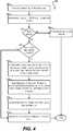
FIG. 2 ) can automatically reconfigure the logical topology and thereby ensure that each operational PE unit still has connectivity to the core stack.FIG. 4 depicts aflowchart 400 for carrying out this processing according to an embodiment. - At
block 402, the CB unit can receive a notification of a PE port down event. The failed port may be a physical port or a logical port (e.g., a LAG). In the latter case, the port down notification will typically be generated only when all of the physical ports in the LAG have gone down. - At
block 404, the CB unit can search its ring table with the PE ID of the PE unit affected by the port down event in order to determine the status of the ring to which the PE unit belongs. If the ring ready flag is set to false (indicating that redundancy cannot be provided) (block 408), the CB unit can perform non-redundant handling of the failure (block 408) andworkflow 400 can end. - If the ring ready flag is determined to be true at
block 408, the CB unit can further check whether the PE link affected by the port down event is the standby link for the ring (block 410). If so, the CB unit can simply update its topology database to indicate that the port/link is down and set the ring ready flag to false (block 418). Note that there is no need to perform any further steps in this scenario because the affected/failed link is already in standby state and thus is not being used in the logical topology. - However, if the affected/failed link is not currently the standby link for the ring, the CB unit can reconfigure the logical topology to mark the affected/failed link as the standby link and to mark the old standby link as now being active (block 412). In this manner, the CB unit can create two new logical, linear PE chains that are not impacted by the port/link failure.
- At
block 414, the CB unit can send messages to the affected PE ring members to reprogram their respective hardware in accordance with the new logical PE chains created/determined atblock 412, and can update its local virtual port (VP) configuration if needed. The CB unit can also update its ring table to identify the affected/failed link as the new standby link (block 416). - Finally, at
block 418, the CB unit can update the topology database to reflect the current connectivity in the physical topology, set the ring ready flag for the ring to false (since the ring cannot support any further redundancy if a second port/link failure occurs), andworkflow 400 can end. - The end result of
workflow 400 is that each operational PE unit in the ring will still have connectivity to the core stack. The only difference is that the logical topology of the bridge will have changed to use the affected/failed link as the standby link (possibly resulting in different logical PE chains). Generally speaking, this reconfiguration should not require any changes to the unit IDs or ECIDs assigned to the PE units; these IDs can remain the same, regardless of how the PE units are logically attached to the core stack. - It should be appreciated that
workflows FIGS. 3A ,3B , and4 are illustrative and not intended to limit embodiments of the present disclosure. For example, whileworkflows - Further, while
workflows - This section lists various possible PE port/link failure scenarios with respect to
extended bridge 200 ofFIG. 2 and the changes that may be made to the configuration of the CB units and PE units ofbridge 200 in order to handle these failures in accordance withworkflow 400 ofFIG. 4 . This section relies on the same port connections described in Section 2 and assumes that link 202 (between 18/2/1 and 19/2/1) is initially selected to be the standby link. - One of
ports 1/1/1 or 17/2/1 goes down- ∘ PE ring is converted into a single logical linear PE chain comprising PE units PE20, PE19, PE18, PE17
- ∘ Port 17/2/1 is no longer set to be an uplink port
- ∘ Port 17/2/3 becomes an uplink port and 18/2/3 becomes a cascade port
- ∘ Port 18/2/1 becomes an uplink port and 19/2/1 becomes a cascade port
- ∘ VPs for PE17 and PE18 move from 1/1/1 to 2/1/1
∘ Link 1/1/1-17/2/1 becomes the new standby link and the ring ready flag is set to false- ∘ The topology database is updated to reflect the current physical topology
- One of ports 17/2/3 or 18/2/3 goes down
- ∘ PE ring is divided into two logical linear PE chains: one consisting of just PE17, and another consisting of PE20, PE19, PE18
- ∘ Port 18/2/1 becomes an uplink port and port 19/2/1 becomes a cascade port
- ∘ VPs for PE 18 move from 1/1/1 to 2/1/1
- ∘ Link 17/2/3-18/2/3 becomes the new standby link and the ring ready flag is set to false
- ∘ The topology database is updated to reflect the current physical topology
- One of ports 18/2/1 or 19/2/1 goes down
- ∘ Link 18/2/1-19/2/1 remains the standby link and the ring ready flag is set to false
- ∘ The topology database is updated to reflect the current physical topology
- One of ports 19/2/3 or 20/2/3 goes down
- ∘ PE ring is divided into two logical linear PE chains: one consisting of just PE20, and another consisting of PE17, PE18, PE19
- ∘ Port 19/2/1 becomes an uplink port and port 18/2/1 becomes a cascade port
- ∘ VPs for PE19 move from 2/1/1 to 1/1/1
- ∘ Link 19/2/3-20/2/3 becomes the new standby link and the ring ready flag is set to false
- ∘ The topology database is updated to reflect the current physical topology
- One of ports 20/2/1 or 2/1/1 goes down
- ∘ PE ring is converted into a single logical linear PE chain comprising PE units PE17, PE18, PE19, PE20
- ∘ Port 20/2/1 is no longer set to be an uplink port
- ∘ Port 20/2/3 becomes an uplink port and 19/2/3 becomes a cascade port
- ∘ Port 19/2/1 becomes an uplink port and 18/2/1 becomes a cascade port
- ∘ VPs for PE19 and PE20 move from 2/1/1 to 1/1/1
- ∘ Link 20/2/1-2/1/1 becomes the new standby link and the ring ready flag is set to false
- ∘ The topology database is updated to reflect the current physical topology
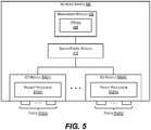
FIG. 5 depicts anexample network switch 500 according to an embodiment.Network switch 500 can be used to implement any of the CB or PE units described in the foregoing disclosure.- As shown,
network switch 500 includes amanagement module 502, a switch fabric module 504, and a number of I/O modules 506(1)-506(N).Management module 502 represents the control plane ofnetwork switch 500 and thus includes one ormore management CPUs 508 for managing/controlling the operation of the device. Eachmanagement CPU 508 can be a general purpose processor, such as a PowerPC, Intel, AMD, or ARM-based processor, that operates under the control of software stored in an associated memory (not shown). - Switch fabric module 504 and I/O modules 506(1)-506(N) collectively represent the data, or forwarding, plane of
network switch 500. Switch fabric module 504 is configured to interconnect the various other modules ofnetwork switch 500. Each I/O module 506(1)-506(N) can include one or more input/output ports 510(1)-510(N) that are used bynetwork switch 500 to send and receive data packets. As noted previously, ports 510(1)-510(N) can comprise data ports for communicating with other LAN components, as well as stacking ports for communicating with other units in the same extended bridge. Each I/O module 506(1)-506(N) can also include a packet processor 512(1)-512(N). Each packet processor 512(1)-512(N) is a hardware processing component (e.g., an FPGA or ASIC) that can make wire speed decisions on how to handle incoming or outgoing data packets. - It should be appreciated that
network switch 500 is illustrative and not intended to limit embodiments of the present invention. Many other configurations having more or fewer components thanswitch 500 are possible. - The above description illustrates various embodiments of the present invention along with examples of how aspects of the present invention may be implemented. The above examples and embodiments should not be deemed to be the only embodiments, and are presented to illustrate the flexibility and advantages of the present invention as defined by the following claims. For example, although certain embodiments have been described with respect to particular process flows and steps, it should be apparent to those skilled in the art that the scope of the present invention is not strictly limited to the described flows and steps. Steps described as sequential may be executed in parallel, order of steps may be varied, and steps may be modified, combined, added, or omitted. As another example, although certain embodiments have been described using a particular combination of hardware and software, it should be recognized that other combinations of hardware and software are possible, and that specific operations described as being implemented in software can also be implemented in hardware and vice versa.
- The specification and drawings are, accordingly, to be regarded in an illustrative rather than restrictive sense.
Claims (15)
- A method performed by a controller bridge, CB, unit in an extended bridge, the method comprising:receiving, (302) by the CB unit, join requests from a plurality of port extender, PE, units;determining, (308) by the CB unit based on the join requests, whether the plurality of PE units are physically connected to the CB unit or other CB units in the extended bridge according to a ring topology; andif the plurality of PE units are physically connected to the CB unit or the other CB units according to a ring topology, selecting (314) a link in the ring topology as being a standby link.
- The method of claim 1 wherein the standby link does not forward traffic internal to the extended bridge.
- The method of claim 1 wherein the selecting causes the plurality of PE units to be divided into one or more logical linear PE chains.
- The method of claim 2 further comprising:
updating a ring table local to the CB unit to include:an indication of the selected standby link;a first flag that is initialized to false; andan entry for each of the plurality of PE units, each entry comprising a second flag that is initialized to false. - The method of claim 4 further comprising:
transmitting a message to each of the plurality of PE units, the message including instructions for programming hardware of the PE unit in accordance with the one or more logical linear PE chains. - The method of claim 5 wherein the message includes instructions for setting an uplink port, a cascade port, and one or more forwarding ports of the PE unit.
- The method of claim 5 further comprising:receiving, from each of the plurality of PE units, an acknowledgement message indicating that the hardware for the PE unit has been successfully programmed;setting the first flag in the ring table to true; andsetting the second flag in each entry of the ring table to true.
- The method of claim 7 further comprising, upon detecting a port down event with respect to a first PE unit in the plurality of PE units:checking whether the first flag in the ring table is set to true; andif the first flag is set to true:determining a link affected by the port down event; andchecking whether the affected link is the standby link.
- The method of claim 8 further comprising, if the affected link is the standby link:
setting the first flag in the ring table to false. - The method of claim 8 further comprising, if the affected link is not the standby link:updating the ring table to indicate that the affected link is now the standby link, thereby creating one or more new logical linear PE chains;setting the first flag in the ring table to false; andsending a message to each of the plurality of PE units that includes instructions for programming the hardware of the PE unit in accordance with the one or more new logical linear PE chains.
- The method of claim 10 further comprising, if the affected link is not the standby link:
updating a local virtual port, VP, configuration of the CB unit in accordance with the one or more new logical linear CB chains. - The method of claim 10 further comprising, if the affected link is not the standby link:
updating a local topology database of the CB unit to indicate that the affected link is nonoperational. - The method of claim 1 wherein the CB unit is a master or active unit in the extended bridge.
- A non-transitory computer readable storage medium having stored thereon program code executable by a controller bridge, CB, unit in an extended bridge, the program code causing the CB unit to:receive (302) join requests from a plurality of port extender, PE, units; determine, (308) based on the join requests, whether the plurality of PE units are physically connected to the CB unit or other CB units in the extended bridge according to a ring topology; andif the plurality of PE units are physically connected to the CB unit or the other CB units according to a ring topology, select (314) a link in the ring topology as being a standby link.
- A network device operable to act as a controller bridge, CB, unit in an extended bridge, the network device comprising:a processor; anda memory having stored thereon program code executable by the processor, the program code causing the processor to:receive (302) join requests from a plurality of port extender, PE, units;determine, (308) based on the join requests, whether the plurality of PE units are physically connected to the network device or other CB units in the extended bridge according to a ring topology; andif the plurality of PE units are physically connected to the network device or the other CB units according to a ring topology, select (314) a link in the ring topology as being a standby link.
Applications Claiming Priority (3)
| Application Number | Priority Date | Filing Date | Title |
|---|---|---|---|
| US201462073832P | 2014-10-31 | 2014-10-31 | |
| US14/926,822US9984028B2 (en) | 2014-10-31 | 2015-10-29 | Redundancy for port extender chains |
| PCT/US2015/058258WO2016070010A1 (en) | 2014-10-31 | 2015-10-30 | Redundancy for port extender chains |
Publications (2)
| Publication Number | Publication Date |
|---|---|
| EP3213441A1 EP3213441A1 (en) | 2017-09-06 |
| EP3213441B1true EP3213441B1 (en) | 2018-08-22 |
Family
ID=55852814
Family Applications (1)
| Application Number | Title | Priority Date | Filing Date |
|---|---|---|---|
| EP15791882.2ANot-in-forceEP3213441B1 (en) | 2014-10-31 | 2015-10-30 | Redundancy for port extender chains |
Country Status (4)
| Country | Link |
|---|---|
| US (1) | US9984028B2 (en) |
| EP (1) | EP3213441B1 (en) |
| CN (1) | CN105765889B (en) |
| WO (1) | WO2016070010A1 (en) |
Families Citing this family (6)
| Publication number | Priority date | Publication date | Assignee | Title |
|---|---|---|---|---|
| US9792242B2 (en)* | 2014-12-09 | 2017-10-17 | Dell Products Lp | Systems and methods for non-unicast/destination lookup fail (DLF) load balancing |
| WO2018129523A1 (en) | 2017-01-09 | 2018-07-12 | Marvell World Trade Ltd. | Port extender with local switching |
| CN108259296B (en)* | 2017-03-31 | 2020-12-04 | 新华三技术有限公司 | Message forwarding method and device |
| CN108259633B (en) | 2017-05-31 | 2020-05-12 | 新华三技术有限公司 | Method, system and device for realizing management message three-layer communication |
| CN108259453B (en) | 2017-05-31 | 2020-03-06 | 新华三技术有限公司 | Message forwarding method and device |
| CN107547410B (en)* | 2017-06-29 | 2020-05-12 | 新华三技术有限公司 | Method and device for automatic cascade of multi-stage PE |
Family Cites Families (25)
| Publication number | Priority date | Publication date | Assignee | Title |
|---|---|---|---|---|
| US6657951B1 (en)* | 1998-11-30 | 2003-12-02 | Cisco Technology, Inc. | Backup CRF VLAN |
| US6480473B1 (en)* | 1998-12-29 | 2002-11-12 | Koninklijke Philips Electronics N.V. | Verification of active nodes in an open network |
| US6760838B2 (en)* | 2001-01-31 | 2004-07-06 | Advanced Micro Devices, Inc. | System and method of initializing and determining a bootstrap processor [BSP] in a fabric of a distributed multiprocessor computing system |
| US7768904B2 (en)* | 2004-04-22 | 2010-08-03 | At&T Intellectual Property I, L.P. | Method and system for fail-safe renaming of logical circuit identifiers for rerouted logical circuits in a data network |
| EP1854250B1 (en)* | 2005-02-28 | 2011-09-21 | International Business Machines Corporation | Blade server system with at least one rack-switch having multiple switches interconnected and configured for management and operation as a single virtual switch |
| JP4760504B2 (en)* | 2006-04-12 | 2011-08-31 | 株式会社日立製作所 | Network system and communication device |
| JP2009188673A (en)* | 2008-02-05 | 2009-08-20 | Fujitsu Ltd | Transmission apparatus and path setting method |
| JP2009205333A (en)* | 2008-02-27 | 2009-09-10 | Hitachi Ltd | Computer system, storage device, and data management method |
| CN101272352B (en)* | 2008-05-20 | 2012-01-04 | 杭州华三通信技术有限公司 | Looped network routing method and looped network node |
| US9032057B2 (en)* | 2009-04-06 | 2015-05-12 | Brocade Communications Systems, Inc. | Secure stacking setup implementing user interface of stacking device |
| CN101938395B (en)* | 2009-07-03 | 2014-08-13 | 中兴通讯股份有限公司 | Method and system for refreshing single ring address of Ethernet ring network |
| JP5521663B2 (en)* | 2010-03-15 | 2014-06-18 | 富士通株式会社 | COMMUNICATION DEVICE, COMMUNICATION SYSTEM, AND COMMUNICATION METHOD |
| CN102684979B (en)* | 2011-03-11 | 2018-08-14 | 中兴通讯股份有限公司 | A kind of multicast data forwarding method and device for supporting virtual terminal |
| US20130100808A1 (en)* | 2011-10-24 | 2013-04-25 | Kaminario Technologies Ltd. | Managing Utilization Of A Logical Communication Path In A Multi-Path Channel |
| WO2012167569A1 (en)* | 2011-11-23 | 2012-12-13 | 华为技术有限公司 | Method, node and system for link switching in ethernet ring |
| CN103297257B (en)* | 2012-02-27 | 2016-10-19 | 北京东土科技股份有限公司 | A Realization Method of Redundant Network |
| US9077650B2 (en)* | 2012-05-31 | 2015-07-07 | Broadcom Corporation | Multi-homing in an extended bridge |
| CN103795518B (en) | 2012-10-31 | 2017-04-05 | 杭州华三通信技术有限公司 | A kind of equipment room port mode synchronous method, equipment and system |
| US20140156906A1 (en) | 2012-11-30 | 2014-06-05 | Broadcom Corporation | Virtual Trunking Over Physical Links |
| JP5944537B2 (en)* | 2013-01-31 | 2016-07-05 | 株式会社日立製作所 | Communication path management method |
| CN103220218B (en)* | 2013-04-28 | 2016-03-30 | 杭州华三通信技术有限公司 | The method and apparatus of anti-loops in vertical stack networking |
| CN104427012B (en)* | 2013-09-04 | 2018-12-11 | 新华三技术有限公司 | Port negotiation method and apparatus |
| CN104468854B (en)* | 2013-09-13 | 2017-10-27 | 新华三技术有限公司 | A kind of longitudinal fusion architecture VCF construction method and equipment |
| CN103873374B (en) | 2014-03-27 | 2017-08-11 | 新华三技术有限公司 | Message processing method and device in virtualization system |
| US9703747B2 (en)* | 2014-05-21 | 2017-07-11 | Dell Products Lp | Remote console access of port extenders using protocol extension |
- 2015
- 2015-10-29USUS14/926,822patent/US9984028B2/enactiveActive
- 2015-10-30WOPCT/US2015/058258patent/WO2016070010A1/enactiveApplication Filing
- 2015-10-30CNCN201580002350.4Apatent/CN105765889B/enactiveActive
- 2015-10-30EPEP15791882.2Apatent/EP3213441B1/ennot_activeNot-in-force
Non-Patent Citations (1)
| Title |
|---|
| None* |
Also Published As
| Publication number | Publication date |
|---|---|
| CN105765889B (en) | 2018-05-29 |
| US9984028B2 (en) | 2018-05-29 |
| CN105765889A (en) | 2016-07-13 |
| US20160124884A1 (en) | 2016-05-05 |
| EP3213441A1 (en) | 2017-09-06 |
| WO2016070010A1 (en) | 2016-05-06 |
Similar Documents
| Publication | Publication Date | Title |
|---|---|---|
| US10868757B2 (en) | Efficient routing in software defined networks | |
| EP3213441B1 (en) | Redundancy for port extender chains | |
| US10164782B2 (en) | Method and system for constructing a loop free multicast tree in a data-center fabric | |
| US7639605B2 (en) | System and method for detecting and recovering from virtual switch link failures | |
| JP5361794B2 (en) | Method and apparatus for maintaining a port state table in the forwarding plane of a network element | |
| US8654630B2 (en) | Techniques for link redundancy in layer 2 networks | |
| JP6283361B2 (en) | Systems and methods for supporting degraded fat tree discovery and routing in a middleware machine environment | |
| US9385944B2 (en) | Communication system, path switching method and communication device | |
| US9509561B2 (en) | System and method for determining the configuration of switches in virtual link trunking environments | |
| CN108512751B (en) | A port state processing method and network device | |
| EP3316555B1 (en) | Mac address synchronization method, device and system | |
| WO2017113929A1 (en) | Method and controller for controlling forwarding device cluster in software-defined networking | |
| US9985928B2 (en) | Dynamic link aggregation | |
| WO2016153506A1 (en) | Fast failover recovery in software defined networks | |
| US8625407B2 (en) | Highly available virtual packet network device | |
| CN104427012A (en) | Port Negotiation Method and Device | |
| US9590893B2 (en) | System and method for management of network links by traffic type | |
| WO2020156355A1 (en) | Load sharing method, device, system, single board and storage medium | |
| WO2023065750A1 (en) | State synchronization method and apparatus, and device |
Legal Events
| Date | Code | Title | Description |
|---|---|---|---|
| PUAI | Public reference made under article 153(3) epc to a published international application that has entered the european phase | Free format text:ORIGINAL CODE: 0009012 | |
| 17P | Request for examination filed | Effective date:20160519 | |
| AK | Designated contracting states | Kind code of ref document:A1 Designated state(s):AL AT BE BG CH CY CZ DE DK EE ES FI FR GB GR HR HU IE IS IT LI LT LU LV MC MK MT NL NO PL PT RO RS SE SI SK SM TR | |
| AX | Request for extension of the european patent | Extension state:BA ME | |
| DAV | Request for validation of the european patent (deleted) | ||
| DAX | Request for extension of the european patent (deleted) | ||
| GRAP | Despatch of communication of intention to grant a patent | Free format text:ORIGINAL CODE: EPIDOSNIGR1 | |
| INTG | Intention to grant announced | Effective date:20180403 | |
| RAP1 | Party data changed (applicant data changed or rights of an application transferred) | Owner name:ARRIS INTERNATIONAL IP LTD. | |
| GRAS | Grant fee paid | Free format text:ORIGINAL CODE: EPIDOSNIGR3 | |
| GRAA | (expected) grant | Free format text:ORIGINAL CODE: 0009210 | |
| AK | Designated contracting states | Kind code of ref document:B1 Designated state(s):AL AT BE BG CH CY CZ DE DK EE ES FI FR GB GR HR HU IE IS IT LI LT LU LV MC MK MT NL NO PL PT RO RS SE SI SK SM TR | |
| REG | Reference to a national code | Ref country code:GB Ref legal event code:FG4D | |
| REG | Reference to a national code | Ref country code:CH Ref legal event code:EP | |
| REG | Reference to a national code | Ref country code:AT Ref legal event code:REF Ref document number:1033714 Country of ref document:AT Kind code of ref document:T Effective date:20180915 | |
| REG | Reference to a national code | Ref country code:IE Ref legal event code:FG4D | |
| REG | Reference to a national code | Ref country code:DE Ref legal event code:R096 Ref document number:602015015235 Country of ref document:DE | |
| REG | Reference to a national code | Ref country code:NL Ref legal event code:MP Effective date:20180822 | |
| REG | Reference to a national code | Ref country code:LT Ref legal event code:MG4D | |
| PG25 | Lapsed in a contracting state [announced via postgrant information from national office to epo] | Ref country code:SE Free format text:LAPSE BECAUSE OF FAILURE TO SUBMIT A TRANSLATION OF THE DESCRIPTION OR TO PAY THE FEE WITHIN THE PRESCRIBED TIME-LIMIT Effective date:20180822 Ref country code:BG Free format text:LAPSE BECAUSE OF FAILURE TO SUBMIT A TRANSLATION OF THE DESCRIPTION OR TO PAY THE FEE WITHIN THE PRESCRIBED TIME-LIMIT Effective date:20181122 Ref country code:NL Free format text:LAPSE BECAUSE OF FAILURE TO SUBMIT A TRANSLATION OF THE DESCRIPTION OR TO PAY THE FEE WITHIN THE PRESCRIBED TIME-LIMIT Effective date:20180822 Ref country code:GR Free format text:LAPSE BECAUSE OF FAILURE TO SUBMIT A TRANSLATION OF THE DESCRIPTION OR TO PAY THE FEE WITHIN THE PRESCRIBED TIME-LIMIT Effective date:20181123 Ref country code:NO Free format text:LAPSE BECAUSE OF FAILURE TO SUBMIT A TRANSLATION OF THE DESCRIPTION OR TO PAY THE FEE WITHIN THE PRESCRIBED TIME-LIMIT Effective date:20181122 Ref country code:IS Free format text:LAPSE BECAUSE OF FAILURE TO SUBMIT A TRANSLATION OF THE DESCRIPTION OR TO PAY THE FEE WITHIN THE PRESCRIBED TIME-LIMIT Effective date:20181222 Ref country code:LT Free format text:LAPSE BECAUSE OF FAILURE TO SUBMIT A TRANSLATION OF THE DESCRIPTION OR TO PAY THE FEE WITHIN THE PRESCRIBED TIME-LIMIT Effective date:20180822 Ref country code:FI Free format text:LAPSE BECAUSE OF FAILURE TO SUBMIT A TRANSLATION OF THE DESCRIPTION OR TO PAY THE FEE WITHIN THE PRESCRIBED TIME-LIMIT Effective date:20180822 Ref country code:RS Free format text:LAPSE BECAUSE OF FAILURE TO SUBMIT A TRANSLATION OF THE DESCRIPTION OR TO PAY THE FEE WITHIN THE PRESCRIBED TIME-LIMIT Effective date:20180822 | |
| REG | Reference to a national code | Ref country code:AT Ref legal event code:MK05 Ref document number:1033714 Country of ref document:AT Kind code of ref document:T Effective date:20180822 | |
| PG25 | Lapsed in a contracting state [announced via postgrant information from national office to epo] | Ref country code:LV Free format text:LAPSE BECAUSE OF FAILURE TO SUBMIT A TRANSLATION OF THE DESCRIPTION OR TO PAY THE FEE WITHIN THE PRESCRIBED TIME-LIMIT Effective date:20180822 Ref country code:AL Free format text:LAPSE BECAUSE OF FAILURE TO SUBMIT A TRANSLATION OF THE DESCRIPTION OR TO PAY THE FEE WITHIN THE PRESCRIBED TIME-LIMIT Effective date:20180822 Ref country code:HR Free format text:LAPSE BECAUSE OF FAILURE TO SUBMIT A TRANSLATION OF THE DESCRIPTION OR TO PAY THE FEE WITHIN THE PRESCRIBED TIME-LIMIT Effective date:20180822 | |
| PG25 | Lapsed in a contracting state [announced via postgrant information from national office to epo] | Ref country code:RO Free format text:LAPSE BECAUSE OF FAILURE TO SUBMIT A TRANSLATION OF THE DESCRIPTION OR TO PAY THE FEE WITHIN THE PRESCRIBED TIME-LIMIT Effective date:20180822 Ref country code:EE Free format text:LAPSE BECAUSE OF FAILURE TO SUBMIT A TRANSLATION OF THE DESCRIPTION OR TO PAY THE FEE WITHIN THE PRESCRIBED TIME-LIMIT Effective date:20180822 Ref country code:IT Free format text:LAPSE BECAUSE OF FAILURE TO SUBMIT A TRANSLATION OF THE DESCRIPTION OR TO PAY THE FEE WITHIN THE PRESCRIBED TIME-LIMIT Effective date:20180822 Ref country code:ES Free format text:LAPSE BECAUSE OF FAILURE TO SUBMIT A TRANSLATION OF THE DESCRIPTION OR TO PAY THE FEE WITHIN THE PRESCRIBED TIME-LIMIT Effective date:20180822 Ref country code:AT Free format text:LAPSE BECAUSE OF FAILURE TO SUBMIT A TRANSLATION OF THE DESCRIPTION OR TO PAY THE FEE WITHIN THE PRESCRIBED TIME-LIMIT Effective date:20180822 Ref country code:CZ Free format text:LAPSE BECAUSE OF FAILURE TO SUBMIT A TRANSLATION OF THE DESCRIPTION OR TO PAY THE FEE WITHIN THE PRESCRIBED TIME-LIMIT Effective date:20180822 Ref country code:PL Free format text:LAPSE BECAUSE OF FAILURE TO SUBMIT A TRANSLATION OF THE DESCRIPTION OR TO PAY THE FEE WITHIN THE PRESCRIBED TIME-LIMIT Effective date:20180822 | |
| REG | Reference to a national code | Ref country code:DE Ref legal event code:R097 Ref document number:602015015235 Country of ref document:DE | |
| PG25 | Lapsed in a contracting state [announced via postgrant information from national office to epo] | Ref country code:DK Free format text:LAPSE BECAUSE OF FAILURE TO SUBMIT A TRANSLATION OF THE DESCRIPTION OR TO PAY THE FEE WITHIN THE PRESCRIBED TIME-LIMIT Effective date:20180822 Ref country code:SM Free format text:LAPSE BECAUSE OF FAILURE TO SUBMIT A TRANSLATION OF THE DESCRIPTION OR TO PAY THE FEE WITHIN THE PRESCRIBED TIME-LIMIT Effective date:20180822 Ref country code:SK Free format text:LAPSE BECAUSE OF FAILURE TO SUBMIT A TRANSLATION OF THE DESCRIPTION OR TO PAY THE FEE WITHIN THE PRESCRIBED TIME-LIMIT Effective date:20180822 | |
| REG | Reference to a national code | Ref country code:CH Ref legal event code:PL | |
| REG | Reference to a national code | Ref country code:BE Ref legal event code:MM Effective date:20181031 | |
| PG25 | Lapsed in a contracting state [announced via postgrant information from national office to epo] | Ref country code:MC Free format text:LAPSE BECAUSE OF FAILURE TO SUBMIT A TRANSLATION OF THE DESCRIPTION OR TO PAY THE FEE WITHIN THE PRESCRIBED TIME-LIMIT Effective date:20180822 Ref country code:LU Free format text:LAPSE BECAUSE OF NON-PAYMENT OF DUE FEES Effective date:20181030 | |
| PLBE | No opposition filed within time limit | Free format text:ORIGINAL CODE: 0009261 | |
| STAA | Information on the status of an ep patent application or granted ep patent | Free format text:STATUS: NO OPPOSITION FILED WITHIN TIME LIMIT | |
| REG | Reference to a national code | Ref country code:IE Ref legal event code:MM4A | |
| 26N | No opposition filed | Effective date:20190523 | |
| PG25 | Lapsed in a contracting state [announced via postgrant information from national office to epo] | Ref country code:BE Free format text:LAPSE BECAUSE OF NON-PAYMENT OF DUE FEES Effective date:20181031 Ref country code:FR Free format text:LAPSE BECAUSE OF NON-PAYMENT OF DUE FEES Effective date:20181031 Ref country code:LI Free format text:LAPSE BECAUSE OF NON-PAYMENT OF DUE FEES Effective date:20181031 Ref country code:SI Free format text:LAPSE BECAUSE OF FAILURE TO SUBMIT A TRANSLATION OF THE DESCRIPTION OR TO PAY THE FEE WITHIN THE PRESCRIBED TIME-LIMIT Effective date:20180822 Ref country code:CH Free format text:LAPSE BECAUSE OF NON-PAYMENT OF DUE FEES Effective date:20181031 | |
| PG25 | Lapsed in a contracting state [announced via postgrant information from national office to epo] | Ref country code:IE Free format text:LAPSE BECAUSE OF NON-PAYMENT OF DUE FEES Effective date:20181030 | |
| PG25 | Lapsed in a contracting state [announced via postgrant information from national office to epo] | Ref country code:MT Free format text:LAPSE BECAUSE OF NON-PAYMENT OF DUE FEES Effective date:20181030 | |
| PG25 | Lapsed in a contracting state [announced via postgrant information from national office to epo] | Ref country code:TR Free format text:LAPSE BECAUSE OF FAILURE TO SUBMIT A TRANSLATION OF THE DESCRIPTION OR TO PAY THE FEE WITHIN THE PRESCRIBED TIME-LIMIT Effective date:20180822 | |
| PG25 | Lapsed in a contracting state [announced via postgrant information from national office to epo] | Ref country code:PT Free format text:LAPSE BECAUSE OF FAILURE TO SUBMIT A TRANSLATION OF THE DESCRIPTION OR TO PAY THE FEE WITHIN THE PRESCRIBED TIME-LIMIT Effective date:20180822 | |
| PG25 | Lapsed in a contracting state [announced via postgrant information from national office to epo] | Ref country code:CY Free format text:LAPSE BECAUSE OF FAILURE TO SUBMIT A TRANSLATION OF THE DESCRIPTION OR TO PAY THE FEE WITHIN THE PRESCRIBED TIME-LIMIT Effective date:20180822 Ref country code:HU Free format text:LAPSE BECAUSE OF FAILURE TO SUBMIT A TRANSLATION OF THE DESCRIPTION OR TO PAY THE FEE WITHIN THE PRESCRIBED TIME-LIMIT; INVALID AB INITIO Effective date:20151030 Ref country code:MK Free format text:LAPSE BECAUSE OF NON-PAYMENT OF DUE FEES Effective date:20180822 | |
| P01 | Opt-out of the competence of the unified patent court (upc) registered | Effective date:20230530 | |
| PGFP | Annual fee paid to national office [announced via postgrant information from national office to epo] | Ref country code:GB Payment date:20231027 Year of fee payment:9 | |
| PGFP | Annual fee paid to national office [announced via postgrant information from national office to epo] | Ref country code:DE Payment date:20231027 Year of fee payment:9 | |
| REG | Reference to a national code | Ref country code:DE Ref legal event code:R081 Ref document number:602015015235 Country of ref document:DE Owner name:ANDREW WIRELESS SYSTEMS UK LIMITED, GB Free format text:FORMER OWNER: ARRIS INTERNATIONAL IP LTD., SALTAIRE, WEST YORKSHIRE, GB Ref country code:DE Ref legal event code:R081 Ref document number:602015015235 Country of ref document:DE Owner name:ANDREW WIRELESS SYSTEMS UK LIMITED,, GB Free format text:FORMER OWNER: ARRIS INTERNATIONAL IP LTD., SALTAIRE, WEST YORKSHIRE, GB | |
| REG | Reference to a national code | Ref country code:GB Ref legal event code:732E Free format text:REGISTERED BETWEEN 20240418 AND 20240424 | |
| REG | Reference to a national code | Ref country code:DE Ref legal event code:R119 Ref document number:602015015235 Country of ref document:DE | |
| GBPC | Gb: european patent ceased through non-payment of renewal fee | Effective date:20241030 | |
| PG25 | Lapsed in a contracting state [announced via postgrant information from national office to epo] | Ref country code:DE Free format text:LAPSE BECAUSE OF NON-PAYMENT OF DUE FEES Effective date:20250501 | |
| PG25 | Lapsed in a contracting state [announced via postgrant information from national office to epo] | Ref country code:GB Free format text:LAPSE BECAUSE OF NON-PAYMENT OF DUE FEES Effective date:20241030 |