EP3212269B1 - Device for controlled delivery of medical devices - Google Patents
Device for controlled delivery of medical devicesDownload PDFInfo
- Publication number
- EP3212269B1 EP3212269B1EP15855436.0AEP15855436AEP3212269B1EP 3212269 B1EP3212269 B1EP 3212269B1EP 15855436 AEP15855436 AEP 15855436AEP 3212269 B1EP3212269 B1EP 3212269B1
- Authority
- EP
- European Patent Office
- Prior art keywords
- shaft
- cap
- lumen
- needle
- receiving channel
- Prior art date
- Legal status (The legal status is an assumption and is not a legal conclusion. Google has not performed a legal analysis and makes no representation as to the accuracy of the status listed.)
- Active
Links
- 230000007246mechanismEffects0.000claimsdescription15
- 230000008878couplingEffects0.000claimsdescription9
- 238000010168coupling processMethods0.000claimsdescription9
- 238000005859coupling reactionMethods0.000claimsdescription9
- 210000003423ankleAnatomy0.000claimsdescription4
- 230000001154acute effectEffects0.000claimsdescription2
- 239000000853adhesiveSubstances0.000claimsdescription2
- 230000001070adhesive effectEffects0.000claimsdescription2
- 210000002683footAnatomy0.000claimsdescription2
- 238000001467acupunctureMethods0.000description10
- 230000000638stimulationEffects0.000description7
- 210000001519tissueAnatomy0.000description6
- 230000007383nerve stimulationEffects0.000description4
- 238000011282treatmentMethods0.000description4
- 238000000034methodMethods0.000description3
- 210000003205muscleAnatomy0.000description3
- 210000002972tibial nerveAnatomy0.000description3
- 238000010276constructionMethods0.000description2
- 239000012530fluidSubstances0.000description2
- 210000005036nerveAnatomy0.000description2
- 230000008035nerve activityEffects0.000description2
- 230000004007neuromodulationEffects0.000description2
- 238000002560therapeutic procedureMethods0.000description2
- 238000002646transcutaneous electrical nerve stimulationMethods0.000description2
- 241001631457CannulaSpecies0.000description1
- 208000000094Chronic PainDiseases0.000description1
- 206010063782Implant site painDiseases0.000description1
- 206010021639IncontinenceDiseases0.000description1
- 208000005615Interstitial CystitisDiseases0.000description1
- 208000002193PainDiseases0.000description1
- 208000018737Parkinson diseaseDiseases0.000description1
- 208000000450Pelvic PainDiseases0.000description1
- 206010036018PollakiuriaDiseases0.000description1
- 208000000921Urge Urinary IncontinenceDiseases0.000description1
- 206010046555Urinary retentionDiseases0.000description1
- 230000009471actionEffects0.000description1
- 239000002390adhesive tapeSubstances0.000description1
- 210000003484anatomyAnatomy0.000description1
- 230000008901benefitEffects0.000description1
- 210000004556brainAnatomy0.000description1
- 244000309466calfSpecies0.000description1
- 230000001684chronic effectEffects0.000description1
- 230000001419dependent effectEffects0.000description1
- 238000013461designMethods0.000description1
- 208000037265diseases, disorders, signs and symptomsDiseases0.000description1
- 208000035475disorderDiseases0.000description1
- 230000000694effectsEffects0.000description1
- 210000000474heelAnatomy0.000description1
- 238000002675image-guided surgeryMethods0.000description1
- 239000007943implantSubstances0.000description1
- 238000003780insertionMethods0.000description1
- 230000037431insertionEffects0.000description1
- 238000007917intracranial administrationMethods0.000description1
- 230000007794irritationEffects0.000description1
- 210000002414legAnatomy0.000description1
- 210000001699lower legAnatomy0.000description1
- 210000002988lumbosacral plexusAnatomy0.000description1
- 230000013011matingEffects0.000description1
- 238000005259measurementMethods0.000description1
- 208000018360neuromuscular diseaseDiseases0.000description1
- 230000000414obstructive effectEffects0.000description1
- 230000003287optical effectEffects0.000description1
- 210000003903pelvic floorAnatomy0.000description1
- 230000037368penetrate the skinEffects0.000description1
- 230000001141propulsive effectEffects0.000description1
- 210000003625skullAnatomy0.000description1
- 230000001225therapeutic effectEffects0.000description1
- 210000002303tibiaAnatomy0.000description1
- 238000013519translationMethods0.000description1
- 206010046494urge incontinenceDiseases0.000description1
- 208000022934urinary frequencyDiseases0.000description1
- 230000036318urination frequencyEffects0.000description1
Images


Classifications
- A—HUMAN NECESSITIES
- A61—MEDICAL OR VETERINARY SCIENCE; HYGIENE
- A61B—DIAGNOSIS; SURGERY; IDENTIFICATION
- A61B17/00—Surgical instruments, devices or methods
- A61B17/34—Trocars; Puncturing needles
- A61B17/3468—Trocars; Puncturing needles for implanting or removing devices, e.g. prostheses, implants, seeds, wires
- A—HUMAN NECESSITIES
- A61—MEDICAL OR VETERINARY SCIENCE; HYGIENE
- A61B—DIAGNOSIS; SURGERY; IDENTIFICATION
- A61B17/00—Surgical instruments, devices or methods
- A61B17/34—Trocars; Puncturing needles
- A61B17/3403—Needle locating or guiding means
- A—HUMAN NECESSITIES
- A61—MEDICAL OR VETERINARY SCIENCE; HYGIENE
- A61H—PHYSICAL THERAPY APPARATUS, e.g. DEVICES FOR LOCATING OR STIMULATING REFLEX POINTS IN THE BODY; ARTIFICIAL RESPIRATION; MASSAGE; BATHING DEVICES FOR SPECIAL THERAPEUTIC OR HYGIENIC PURPOSES OR SPECIFIC PARTS OF THE BODY
- A61H39/00—Devices for locating or stimulating specific reflex points of the body for physical therapy, e.g. acupuncture
- A61H39/08—Devices for applying needles to such points, i.e. for acupuncture ; Acupuncture needles or accessories therefor
- A61H39/083—Needle tubes
- A—HUMAN NECESSITIES
- A61—MEDICAL OR VETERINARY SCIENCE; HYGIENE
- A61H—PHYSICAL THERAPY APPARATUS, e.g. DEVICES FOR LOCATING OR STIMULATING REFLEX POINTS IN THE BODY; ARTIFICIAL RESPIRATION; MASSAGE; BATHING DEVICES FOR SPECIAL THERAPEUTIC OR HYGIENIC PURPOSES OR SPECIFIC PARTS OF THE BODY
- A61H39/00—Devices for locating or stimulating specific reflex points of the body for physical therapy, e.g. acupuncture
- A61H39/08—Devices for applying needles to such points, i.e. for acupuncture ; Acupuncture needles or accessories therefor
- A61H39/086—Acupuncture needles
- A—HUMAN NECESSITIES
- A61—MEDICAL OR VETERINARY SCIENCE; HYGIENE
- A61B—DIAGNOSIS; SURGERY; IDENTIFICATION
- A61B17/00—Surgical instruments, devices or methods
- A61B17/34—Trocars; Puncturing needles
- A61B17/3403—Needle locating or guiding means
- A61B2017/3405—Needle locating or guiding means using mechanical guide means
- A61B2017/3407—Needle locating or guiding means using mechanical guide means including a base for support on the body
- A—HUMAN NECESSITIES
- A61—MEDICAL OR VETERINARY SCIENCE; HYGIENE
- A61B—DIAGNOSIS; SURGERY; IDENTIFICATION
- A61B17/00—Surgical instruments, devices or methods
- A61B17/34—Trocars; Puncturing needles
- A61B17/3403—Needle locating or guiding means
- A61B2017/3405—Needle locating or guiding means using mechanical guide means
- A61B2017/3409—Needle locating or guiding means using mechanical guide means including needle or instrument drives
- A—HUMAN NECESSITIES
- A61—MEDICAL OR VETERINARY SCIENCE; HYGIENE
- A61B—DIAGNOSIS; SURGERY; IDENTIFICATION
- A61B90/00—Instruments, implements or accessories specially adapted for surgery or diagnosis and not covered by any of the groups A61B1/00 - A61B50/00, e.g. for luxation treatment or for protecting wound edges
- A61B90/03—Automatic limiting or abutting means, e.g. for safety
- A61B2090/033—Abutting means, stops, e.g. abutting on tissue or skin
- A61B2090/034—Abutting means, stops, e.g. abutting on tissue or skin abutting on parts of the device itself
- A—HUMAN NECESSITIES
- A61—MEDICAL OR VETERINARY SCIENCE; HYGIENE
- A61B—DIAGNOSIS; SURGERY; IDENTIFICATION
- A61B90/00—Instruments, implements or accessories specially adapted for surgery or diagnosis and not covered by any of the groups A61B1/00 - A61B50/00, e.g. for luxation treatment or for protecting wound edges
- A61B90/10—Instruments, implements or accessories specially adapted for surgery or diagnosis and not covered by any of the groups A61B1/00 - A61B50/00, e.g. for luxation treatment or for protecting wound edges for stereotaxic surgery, e.g. frame-based stereotaxis
- A61B90/11—Instruments, implements or accessories specially adapted for surgery or diagnosis and not covered by any of the groups A61B1/00 - A61B50/00, e.g. for luxation treatment or for protecting wound edges for stereotaxic surgery, e.g. frame-based stereotaxis with guides for needles or instruments, e.g. arcuate slides or ball joints
- A—HUMAN NECESSITIES
- A61—MEDICAL OR VETERINARY SCIENCE; HYGIENE
- A61H—PHYSICAL THERAPY APPARATUS, e.g. DEVICES FOR LOCATING OR STIMULATING REFLEX POINTS IN THE BODY; ARTIFICIAL RESPIRATION; MASSAGE; BATHING DEVICES FOR SPECIAL THERAPEUTIC OR HYGIENIC PURPOSES OR SPECIFIC PARTS OF THE BODY
- A61H2201/00—Characteristics of apparatus not provided for in the preceding codes
- A61H2201/01—Constructive details
- A61H2201/0192—Specific means for adjusting dimensions
- A—HUMAN NECESSITIES
- A61—MEDICAL OR VETERINARY SCIENCE; HYGIENE
- A61H—PHYSICAL THERAPY APPARATUS, e.g. DEVICES FOR LOCATING OR STIMULATING REFLEX POINTS IN THE BODY; ARTIFICIAL RESPIRATION; MASSAGE; BATHING DEVICES FOR SPECIAL THERAPEUTIC OR HYGIENIC PURPOSES OR SPECIFIC PARTS OF THE BODY
- A61H2201/00—Characteristics of apparatus not provided for in the preceding codes
- A61H2201/12—Driving means
- A61H2201/1238—Driving means with hydraulic or pneumatic drive
- A61H2201/1246—Driving means with hydraulic or pneumatic drive by piston-cylinder systems
- A—HUMAN NECESSITIES
- A61—MEDICAL OR VETERINARY SCIENCE; HYGIENE
- A61H—PHYSICAL THERAPY APPARATUS, e.g. DEVICES FOR LOCATING OR STIMULATING REFLEX POINTS IN THE BODY; ARTIFICIAL RESPIRATION; MASSAGE; BATHING DEVICES FOR SPECIAL THERAPEUTIC OR HYGIENIC PURPOSES OR SPECIFIC PARTS OF THE BODY
- A61H2201/00—Characteristics of apparatus not provided for in the preceding codes
- A61H2201/16—Physical interface with patient
- A61H2201/1602—Physical interface with patient kind of interface, e.g. head rest, knee support or lumbar support
- A61H2201/164—Feet or leg, e.g. pedal
- A—HUMAN NECESSITIES
- A61—MEDICAL OR VETERINARY SCIENCE; HYGIENE
- A61H—PHYSICAL THERAPY APPARATUS, e.g. DEVICES FOR LOCATING OR STIMULATING REFLEX POINTS IN THE BODY; ARTIFICIAL RESPIRATION; MASSAGE; BATHING DEVICES FOR SPECIAL THERAPEUTIC OR HYGIENIC PURPOSES OR SPECIFIC PARTS OF THE BODY
- A61H2201/00—Characteristics of apparatus not provided for in the preceding codes
- A61H2201/50—Control means thereof
- A61H2201/5053—Control means thereof mechanically controlled
- A—HUMAN NECESSITIES
- A61—MEDICAL OR VETERINARY SCIENCE; HYGIENE
- A61H—PHYSICAL THERAPY APPARATUS, e.g. DEVICES FOR LOCATING OR STIMULATING REFLEX POINTS IN THE BODY; ARTIFICIAL RESPIRATION; MASSAGE; BATHING DEVICES FOR SPECIAL THERAPEUTIC OR HYGIENIC PURPOSES OR SPECIFIC PARTS OF THE BODY
- A61H2205/00—Devices for specific parts of the body
- A61H2205/10—Leg
- A61H2205/106—Leg for the lower legs
- A—HUMAN NECESSITIES
- A61—MEDICAL OR VETERINARY SCIENCE; HYGIENE
- A61N—ELECTROTHERAPY; MAGNETOTHERAPY; RADIATION THERAPY; ULTRASOUND THERAPY
- A61N1/00—Electrotherapy; Circuits therefor
- A61N1/02—Details
- A61N1/04—Electrodes
- A61N1/05—Electrodes for implantation or insertion into the body, e.g. heart electrode
- A61N1/0551—Spinal or peripheral nerve electrodes
Definitions
- the present inventionrelates generally to a device for the controlled delivery of medical devices. More specifically, the present invention relates to a device for controlling the percutaneous delivery of needles, fine wires, electrodes, trocars or cannulas to a target location in a patient.
- Physicians like neurologists and urologists, physiatrists, physical therapists, chiropractors, and other medical providershave used nerve and muscle stimulation to treat a variety of ailments. These medical providers have used various methods of neurostimulation and neuromodulation such as implanted electrical and optical devices and external electrical, magnetic and ultrasonic devices for treatments such as deep brain stimulation for Parkinson's disease and electronic muscle stimulation (EMS) and transcutaneous electrical nerve stimulation (TENS) for muscle and joint rehabilitation as well as chronic pain.
- EMSelectronic muscle stimulation
- TENStranscutaneous electrical nerve stimulation
- Urologists and obstetrician/gynecologistshave used a form of TENS for pelvic floor stimulation to treat urge incontinence, urinary frequency, non-obstructive urinary retention, interstitial cystitis, chronic pelvic pain, anal incontinence and other pelvic neuromuscular disorders.
- Transcutaneous stimulatorsi.e., stimulators which do not physically penetrate the skin surface
- transcutaneous stimulatorsoften require higher current levels than percutaneous and implantable stimulators. Higher current levels can cause irritation and discomfort when used for extended periods.
- transcutaneous stimulatorsstimulate on the skin surface, their target site usually covers a large area. Thus, transcutaneous stimulators may not be highly effective for direct nerve stimulation. This is especially true for stimulation targets that are deep to the skin surface and that may be shielded by overlying hard tissue.
- Implantable stimulatorscan free a patient from the need for constant and frequent manual treatment. However, implantable stimulators can cause mild discomfort, and often cause more severe implant-site pain.
- Percutaneous stimulatorsprovide direct nerve stimulation without the invasiveness of an implant.
- a conducting needleis inserted to provide electrical stimulation to a target nerve.
- the needleis electrically connected to a controller by a series of leads, often bound together at one end as a cable that connects to the controller.
- the needlewhich includes a receiver/electrode assembly
- the needlemust be precisely and accurately positioned to achieve the maximum heath benefit.
- a devicethat uses an anatomic landmark or fiduciary point to establish a point of origin for device orientation in space.
- a devicethat can control the direction and depth of delivery of the needle, wire, trocar or cannula that is part of the diagnostic or therapeutic intervention.
- US2006/089626discloses a device and method for guiding insertion of a surgical device with image guided surgery.
- the deviceincludes a base that may be connected to a fixation device to hold the device in place, and a guide for the surgical device.
- the guideis connected to the base by a semispherical ball joint, which allows the trajectory of the guide to be adjusted.
- US2004/260312discloses a puncturing guide for guiding a puncturing needle into a target site within the body of a patient.
- the puncturing guidecomprises a base plate, a needle guide, a retainer for securing the needle guide to the base plate, a first segment of a first semi-sphere, a second segment of a second semi-sphere, and a needle guide attached to the second segment.
- US3457922discloses a stereotaxic surgical instrument having a base element.
- US5116345discloses an apparatus and method for implanting an intracranial device along a predetermined axis into the skull.
- the present inventionprecisely and accurately guides the percutaneous delivery of a needle, wire, trocar or cannula to a target spatial location on or within tissue.
- the delivery deviceuses an anatomic landmark or fiduciary point to establish a point of origin for device orientation in space.
- the present inventioncontrols the direction and depth of the delivery and placement of the needle, wire, trocar or cannula on or into tissue.
- the delivery device 10in accordance with the invention broadly includes circular positioning ring 12, rotational element 14, directional element 16 and coupling mechanism 18.
- Circular positioning ringis configured to circumscribe the medial malleolus, the bony prominence on the inner side of the ankle formed by the lower end of the tibia, at a preferred height.
- Circular positioning ring 12includes one or more vertical receiving channels 20, 22 operably coupled to lower horizontal receiving channel 24.
- Cone-shaped rotational element 14includes one or more flanges 26, 28 that are received by vertical receiving channels 20, 22 in mating relationship and operably engage with lower horizontal receiving channel 24.
- a manual rotational force applied to rotational element 14will cause flanges 26, 28 to travel in lower horizontal receiving channel 24 until a stop is encountered, causing the rotational element to cease rotation at that position, with the possible additional feature of being locked into the circular ring.
- Rotational element 14includes a cap portion 38 having an internal threaded lumen 40.
- Circular positioning ringincludes a base 11.
- Base 11may incorporate the use of a sheet or ring of adhesive tape to removably secure the device 10 over the medial malleolus while in use.
- a band or collar(not shown) may extend from the circular ring 12 and circumscribe the surface of the foot, ankle and heel such that the entire device 10 assembly is centered on the medial malleolus.
- the band or collarmay be held in place by fastening means known to those of skill in the art such as Velcro, adhesives, mechanical fasteners and combinations thereof.
- Coupling mechanism 18includes cone-shaped base 30 and shaft 32.
- cone-shaped base 30is configured to be positioned externally over the medial malleolus.
- Shaft 32may be integrally formed with or threadably received by base 30. If threadably received by base 30, shaft may be dimensioned such that the outer diameter of shaft 32 is less that the inner diameter of threaded lumen 40.
- Shaft 32includes a needle, or needle guide and driver device, receiving lumen therethrough 34 and a threaded top portion 36. In one aspect of the invention, threaded top portion 36 is threadably received by threaded cap 38 operably coupling rotational element 14 with coupling mechanism 18.
- Directional element 16broadly includes vertical shaft 42, adjustable positioning arm 44 and needle guide assembly 48.
- Vertical shaftincludes a lumen 50 whose inner diameter is greater than the outer diameter of cap portion 38. Lumen 50 is pivotably received by cap portion 38. Those of skill in the art will appreciate that the lumen 50 may extend the length of shaft 42 or in other embodiments may be slightly greater than or equal to the vertical depth of cap portion 38.
- Adjustable positioning arm 44includes a right angle adjustable construction. To accommodate different patient anatomies, adjustable positioning arm 44 may be adjusted to a plurality of different acute angles, preferably from 30-60 degrees offset from the longitudinal axis of shaft 42, by a ratcheting mechanism (not shown).
- Guide tube 48is operably coupled to adjustable arm 44.
- Guide tube 48operates to position a thin gauge, non-hypodermic needle to the target location near the tibial nerve which enable the neurostimulation therapy to be delivered.
- FIGS. 3A - 5various aspects of guide tube geometry are illustrated.
- Guide tube 48operably receives a PTNS needle advance device 60 as best seen in FIGS. 3A - 5 .
- the PTNS needle advancement deviceenables the controlled advancement and delivery of a needle.
- the PTNS needle advance device 60is designed to linearly and controllably advance a PTNS needle electrode through the surface of the skin of the lower leg proximate the medial malleolus to a target depth within the tissue to enable the clinically effective delivery of tibial neuromodulation.
- Needle advance device 60broadly includes acupuncture needle 62 housed within cylindrical sheath 64.
- the needle advance device 60includes the ability to translate the acupuncture needle 62 linearly through the inner diameter (ID) of the sheath or tube.
- Cap 70 of the needle advance device 60fits over the proximal end of the cylindrical sheath 64.
- Cap 70includes a double-headed piston with one piston head that has a diameter greater than the I.D. of the guide tube and another piston head that has a diameter that is less than the I.D. of the guide tube.
- the length of the piston shaftwhich also has an O.D. smaller than the I.D.
- a locking mechanism 66may be incorporated into the cap 70 or into the guide tube/needle holder element 48 to prevent undesired needle translation or movement within the cylindrical sheath 64.
- Cap 70is rotatably or threadably received on cylindrical sheath 64.
- Spring 72has a spring constant that allows spring to advance needle 62 as rotational or other force is applied by cap 70.
- the locking mechanism 66may be contained within a single component or may be contained in separate components of the controlled advancement and delivery device.
- Locking mechanism 66may be a simple interference fit of a removable component that is insertable between the ID of the cap (or the guide tube / needle holder) and the OD of the needle. When the locking component is in place, the interference fit keeps the needle from moving freely. Once it is removed, the needle is free to move within the guide tube or cap plus guide tube construct.
- a 34 gauge acupuncture needle 62is received in a cylindrical sheath 64 of uniform or varying cross section area.
- the cylindrical sheath 64may be opaque and includes inner cross-sectional dimensions larger than the maximum outer cross-sectional dimension of the acupuncture needle along its entire length or along only a portion of its length.
- the 34 gauge acupuncture needle 62is placed in a cylindrical sheath 64 with a uniform circular cross-section.
- the sheath 64has an inner diameter that is larger than the maximum outer diameter of the acupuncture needle.
- Tabs 84are interposed between the outer surface of the acupuncture needle and the inner surface of the cylindrical sheath and serve to lock and/or controllably advance the position of the needle by means of a frictional or interference fit. Tabs 84 may be juxtaposed in a parallel relationship or may alternatively be staggered. Tabs 74 may be broken or retracted which in turn allows the acupuncture needle to advance freely within the cylindrical sheath 62 to the next set of tabs 74. The tabs can be broken or retracted via the linear advance of a cap feature that progresses along the outside of the sheath / needle holder element. This is a feasible design but not our first choice due to cost reasons.
- Cap 70 including a controlled advancement mechanism 75fits over one end of the cylindrical sheath 64.
- Controlled advancement mechanism 75broadly includes first and second piston heads 92, 94 and spring 72 interposed therebetween or between cap 70 and first piston head 92.
- First piston head 92has a diameter greater than the I.D. of the cylindrical sheath 64 and second piston head 94 has a diameter that is less than the I.D. of the cylindrical sheath 64.
- the length of the piston shafti.e. the length extending from the proximal tip of the first piston head 92 to the distal tip of the second piston head 94, which also has an O.D.
- first and/or second piston headmay be propelled within cap 70 by means of spring 72.
- spring 72Those of skill in the art will appreciate that other means of propulsion may be employed such as hydraulic, percussive, magnetic, electromagnetic, compressed fluids and the like.
- the double headed piston 92, 94may be propelled by compressing spring 72, which is then allowed to elongate in stages, driving the second and or first and second piston heads forward in stages.
- the second and/or first and second piston headsthus advance in a controlled fashion until the outer diameter of the piston head cannot pass the point of interference or the smaller I.D. of the cylindrical sheath 64.
- the pistonis a unitary double headed construction, and both heads undergo movement under the action of the propulsive mechanism, which acts against the first piston head and causes the entire unit to move forward.
- the piston head with the diameter that is smaller than the I.D. of the cylindrical sheath 64is in contact with the head of the acupuncture needle, ensuring that the movement of the double headed piston also results in linear and controlled advancement of the acupuncture needle to a desired depth.
- the cap or the outer telescoping headalso incorporates a means to specify the maximum distance of advancement of the piston and, thus, of the needle electrode that is driven by the piston.
- the maximum distance of advancement required for the accurate positioning of the needle electrode for PTNScan be determined from anatomical measurements; for example, it can be based on the medio-lateral diameter of the lower calf of the human leg, just above the ankle.
- FIGS. 6A and 6Bperspective views of one aspect of a needle advancement device are illustrated.
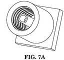
- FIGS. 7A and 7Bperspective views of another aspect of a needle advancement device are illustrated.
- FIGS. 8A and 8Bperspective views of a further aspect of a needle advancement device illustrating a wedged collar and a wedged pusher, respectively, are illustrated.
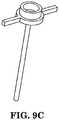
- FIGS. 9A through 9Eperspective views of a further aspect of a needle advancement device are shown. Illustrated in FIG. 9A is the completed assembly of the device and the various component parts in FIGS. 9B through 9E .
Landscapes
- Health & Medical Sciences (AREA)
- Life Sciences & Earth Sciences (AREA)
- Surgery (AREA)
- Animal Behavior & Ethology (AREA)
- Public Health (AREA)
- Veterinary Medicine (AREA)
- General Health & Medical Sciences (AREA)
- Rehabilitation Therapy (AREA)
- Biomedical Technology (AREA)
- Engineering & Computer Science (AREA)
- Heart & Thoracic Surgery (AREA)
- Nuclear Medicine, Radiotherapy & Molecular Imaging (AREA)
- Molecular Biology (AREA)
- Pathology (AREA)
- Medical Informatics (AREA)
- Pain & Pain Management (AREA)
- Physical Education & Sports Medicine (AREA)
- Epidemiology (AREA)
- Finger-Pressure Massage (AREA)
- Neurology (AREA)
- Neurosurgery (AREA)
- Orthopedic Medicine & Surgery (AREA)
- Cardiology (AREA)
- Radiology & Medical Imaging (AREA)
- Infusion, Injection, And Reservoir Apparatuses (AREA)
Description
- The present invention relates generally to a device for the controlled delivery of medical devices. More specifically, the present invention relates to a device for controlling the percutaneous delivery of needles, fine wires, electrodes, trocars or cannulas to a target location in a patient.
- Physicians like neurologists and urologists, physiatrists, physical therapists, chiropractors, and other medical providers have used nerve and muscle stimulation to treat a variety of ailments. These medical providers have used various methods of neurostimulation and neuromodulation such as implanted electrical and optical devices and external electrical, magnetic and ultrasonic devices for treatments such as deep brain stimulation for Parkinson's disease and electronic muscle stimulation (EMS) and transcutaneous electrical nerve stimulation (TENS) for muscle and joint rehabilitation as well as chronic pain. Urologists and obstetrician/gynecologists have used a form of TENS for pelvic floor stimulation to treat urge incontinence, urinary frequency, non-obstructive urinary retention, interstitial cystitis, chronic pelvic pain, anal incontinence and other pelvic neuromuscular disorders.
- Transcutaneous stimulators, i.e., stimulators which do not physically penetrate the skin surface, are less invasive than percutaneous and implantable stimulators. However, transcutaneous stimulators often require higher current levels than percutaneous and implantable stimulators. Higher current levels can cause irritation and discomfort when used for extended periods. Also, since transcutaneous stimulators stimulate on the skin surface, their target site usually covers a large area. Thus, transcutaneous stimulators may not be highly effective for direct nerve stimulation. This is especially true for stimulation targets that are deep to the skin surface and that may be shielded by overlying hard tissue.
- More typically, providers use implantable stimulators when there is a need for direct nerve stimulation or continuous stimulation. Implantable stimulators can free a patient from the need for constant and frequent manual treatment. However, implantable stimulators can cause mild discomfort, and often cause more severe implant-site pain.
- Percutaneous stimulators provide direct nerve stimulation without the invasiveness of an implant. During treatment, a conducting needle is inserted to provide electrical stimulation to a target nerve. The needle is electrically connected to a controller by a series of leads, often bound together at one end as a cable that connects to the controller. When positioned properly, the needle (which includes a receiver/electrode assembly) stimulates the tibial nerve thereby modulating nerve activity in the sacral plexus. Modulation or interruption of sacral nerve activity is useful in the treatment of the pelvic heath disorders enumerated above.
- However, the needle must be precisely and accurately positioned to achieve the maximum heath benefit. There are currently no devices that facilitate or guide accurate percutaneous delivery of a needle, wire, trocar or cannula to a target spatial location on or within tissue that can be utilized by both medical personnel and patients.
- Therefore, what is needed is a device that uses an anatomic landmark or fiduciary point to establish a point of origin for device orientation in space. What is also needed is a device that can control the direction and depth of delivery of the needle, wire, trocar or cannula that is part of the diagnostic or therapeutic intervention.
US2006/089626 discloses a device and method for guiding insertion of a surgical device with image guided surgery. The device includes a base that may be connected to a fixation device to hold the device in place, and a guide for the surgical device. The guide is connected to the base by a semispherical ball joint, which allows the trajectory of the guide to be adjusted.US2004/260312 discloses a puncturing guide for guiding a puncturing needle into a target site within the body of a patient. The puncturing guide comprises a base plate, a needle guide, a retainer for securing the needle guide to the base plate, a first segment of a first semi-sphere, a second segment of a second semi-sphere, and a needle guide attached to the second segment.US3457922 discloses a stereotaxic surgical instrument having a base element.US5116345 discloses an apparatus and method for implanting an intracranial device along a predetermined axis into the skull.- The problems associated with conventional means of delivering and guiding a needle to an anatomic site are addressed by the present invention, as claimed in
claim 1. Preferred embodiments of the invention are defined in the dependent claims. - In certain aspects the present invention, precisely and accurately guides the percutaneous delivery of a needle, wire, trocar or cannula to a target spatial location on or within tissue.
- In other aspects, the delivery device uses an anatomic landmark or fiduciary point to establish a point of origin for device orientation in space. In other aspects the present invention controls the direction and depth of the delivery and placement of the needle, wire, trocar or cannula on or into tissue.
- For a better understanding of the invention, and to show how the same may be carried into effect, reference will now be made, by way of example, to the accompanying drawings, in which:
FIG. 1 is a perspective view of an exemplary delivery device in accordance with the invention.FIG. 2A is an exploded view of the exemplary device illustrated inFIG. 1 .FIGS. 2B through 2E show various aspects of the exemplary device illustrated inFIG. 2A andFIG. 1 .FIG. 3A is a side view of a needle advancement device.FIG. 3B is a side detailed view of the needle advancement device ofFIG. 3A .FIG. 4 is a side view of one aspect of a needle advancement device.FIG. 5 is a side view of another aspect of a needle advancement device.FIGS. 6A and6B are perspective views of one aspect of a needle advancement device.FIGS. 7A and7B are perspective views of one aspect of a needle advancement device.FIGS. 8A and8B are perspective views of one aspect of a needle advancement device illustrating a wedged collar and a wedged pusher, respectively.FIGS. 9A through 9E are perspective views of one aspect of a needle advancement device illustrating the complete assembly of the device inFIG. 9A and the various component parts inFIGS. 9B through 9E .- Unless defined otherwise, all technical and scientific terms used herein have the same meaning as is commonly understood by one of skill in the art to which this invention belongs.
- Referring now to
FIGS. 1-2E thedelivery device 10 in accordance with the invention broadly includescircular positioning ring 12,rotational element 14,directional element 16 andcoupling mechanism 18. - Circular positioning ring is configured to circumscribe the medial malleolus, the bony prominence on the inner side of the ankle formed by the lower end of the tibia, at a preferred height.
Circular positioning ring 12 includes one or more vertical receivingchannels horizontal receiving channel 24. Cone-shapedrotational element 14 includes one ormore flanges channels horizontal receiving channel 24. A manual rotational force applied torotational element 14 will causeflanges horizontal receiving channel 24 until a stop is encountered, causing the rotational element to cease rotation at that position, with the possible additional feature of being locked into the circular ring.Rotational element 14 includes acap portion 38 having an internal threadedlumen 40. - Circular positioning ring includes a
base 11.Base 11 may incorporate the use of a sheet or ring of adhesive tape to removably secure thedevice 10 over the medial malleolus while in use. In alternative aspects of the invention a band or collar (not shown) may extend from thecircular ring 12 and circumscribe the surface of the foot, ankle and heel such that theentire device 10 assembly is centered on the medial malleolus. The band or collar may be held in place by fastening means known to those of skill in the art such as Velcro, adhesives, mechanical fasteners and combinations thereof. Coupling mechanism 18 includes cone-shapedbase 30 andshaft 32. In operation, cone-shapedbase 30 is configured to be positioned externally over the medial malleolus.Shaft 32 may be integrally formed with or threadably received bybase 30. If threadably received bybase 30, shaft may be dimensioned such that the outer diameter ofshaft 32 is less that the inner diameter of threadedlumen 40.Shaft 32 includes a needle, or needle guide and driver device, receiving lumen therethrough 34 and a threadedtop portion 36. In one aspect of the invention, threadedtop portion 36 is threadably received by threadedcap 38 operably couplingrotational element 14 withcoupling mechanism 18.Directional element 16 broadly includesvertical shaft 42,adjustable positioning arm 44 andneedle guide assembly 48. Vertical shaft includes alumen 50 whose inner diameter is greater than the outer diameter ofcap portion 38.Lumen 50 is pivotably received bycap portion 38. Those of skill in the art will appreciate that thelumen 50 may extend the length ofshaft 42 or in other embodiments may be slightly greater than or equal to the vertical depth ofcap portion 38.Adjustable positioning arm 44 includes a right angle adjustable construction. To accommodate different patient anatomies,adjustable positioning arm 44 may be adjusted to a plurality of different acute angles, preferably from 30-60 degrees offset from the longitudinal axis ofshaft 42, by a ratcheting mechanism (not shown).Guide tube 48 is operably coupled toadjustable arm 44.Guide tube 48 operates to position a thin gauge, non-hypodermic needle to the target location near the tibial nerve which enable the neurostimulation therapy to be delivered. Referring now toFIGS. 3A - 5 various aspects of guide tube geometry are illustrated.Guide tube 48 operably receives a PTNSneedle advance device 60 as best seen inFIGS. 3A - 5 . The PTNS needle advancement device enables the controlled advancement and delivery of a needle. In one aspect for the delivery of percutaneous tibial nerve stimulation (PTNS) therapy, the PTNSneedle advance device 60 is designed to linearly and controllably advance a PTNS needle electrode through the surface of the skin of the lower leg proximate the medial malleolus to a target depth within the tissue to enable the clinically effective delivery of tibial neuromodulation.- As best seen in
FIGS. 3A and 3B one aspect of a PTNS needle advancement device is illustrated.Needle advance device 60 broadly includesacupuncture needle 62 housed withincylindrical sheath 64. Theneedle advance device 60 includes the ability to translate theacupuncture needle 62 linearly through the inner diameter (ID) of the sheath or tube.Cap 70 of theneedle advance device 60 fits over the proximal end of thecylindrical sheath 64.Cap 70 includes a double-headed piston with one piston head that has a diameter greater than the I.D. of the guide tube and another piston head that has a diameter that is less than the I.D. of the guide tube. The length of the piston shaft, which also has an O.D. smaller than the I.D. of the guide tube, between the two piston heads determines the maximum length of advancement of the piston through the I.D. or lumen of the guide tube. The piston is propelled within the cap by means ofspring 72. Those of skill in the art will appreciate that other means of propulsion may be incorporated into the device such as hydraulic, percussive, magnetic, electromagnetic, compressed fluids and the like. Alocking mechanism 66 may be incorporated into thecap 70 or into the guide tube/needle holder element 48 to prevent undesired needle translation or movement within thecylindrical sheath 64.Cap 70 is rotatably or threadably received oncylindrical sheath 64.Spring 72 has a spring constant that allows spring to advanceneedle 62 as rotational or other force is applied bycap 70. Thelocking mechanism 66 may be contained within a single component or may be contained in separate components of the controlled advancement and delivery device. Lockingmechanism 66 may be a simple interference fit of a removable component that is insertable between the ID of the cap (or the guide tube / needle holder) and the OD of the needle. When the locking component is in place, the interference fit keeps the needle from moving freely. Once it is removed, the needle is free to move within the guide tube or cap plus guide tube construct. - Referring now to
FIG. 4 , with like elements being labeled with like reference numerals, one aspect of a controlled advancement anddelivery device 80 for a PTNS needle electrode is illustrated. A 34gauge acupuncture needle 62 is received in acylindrical sheath 64 of uniform or varying cross section area. Thecylindrical sheath 64 may be opaque and includes inner cross-sectional dimensions larger than the maximum outer cross-sectional dimension of the acupuncture needle along its entire length or along only a portion of its length. In one aspect of the controlled advancement and delivery device for aPTNS needle electrode 80, the 34gauge acupuncture needle 62 is placed in acylindrical sheath 64 with a uniform circular cross-section. Thesheath 64 has an inner diameter that is larger than the maximum outer diameter of the acupuncture needle.Tabs 84 are interposed between the outer surface of the acupuncture needle and the inner surface of the cylindrical sheath and serve to lock and/or controllably advance the position of the needle by means of a frictional or interference fit.Tabs 84 may be juxtaposed in a parallel relationship or may alternatively be staggered. Tabs 74 may be broken or retracted which in turn allows the acupuncture needle to advance freely within thecylindrical sheath 62 to the next set of tabs 74.The tabs can be broken or retracted via the linear advance of a cap feature that progresses along the outside of the sheath / needle holder element. This is a feasible design but not our first choice due to cost reasons. - Referring now to
FIG. 5 another aspect of a controlled advancement anddelivery device 90 for aPTNS needle electrode 92 is illustrated.Cap 70 including a controlledadvancement mechanism 75 fits over one end of thecylindrical sheath 64.Controlled advancement mechanism 75 broadly includes first and second piston heads 92, 94 andspring 72 interposed therebetween or betweencap 70 andfirst piston head 92.First piston head 92 has a diameter greater than the I.D. of thecylindrical sheath 64 andsecond piston head 94 has a diameter that is less than the I.D. of thecylindrical sheath 64. The length of the piston shaft, i.e. the length extending from the proximal tip of thefirst piston head 92 to the distal tip of thesecond piston head 94, which also has an O.D. smaller than the I.D. of thecylindrical sheath 64, between the first and second piston heads determines the maximum length of advancement of the piston through the I.D. or lumen of thecylindrical sheath 64. The first and/or second piston head may be propelled withincap 70 by means ofspring 72. Those of skill in the art will appreciate that other means of propulsion may be employed such as hydraulic, percussive, magnetic, electromagnetic, compressed fluids and the like. In one aspect the double headedpiston spring 72, which is then allowed to elongate in stages, driving the second and or first and second piston heads forward in stages. The second and/or first and second piston heads thus advance in a controlled fashion until the outer diameter of the piston head cannot pass the point of interference or the smaller I.D. of thecylindrical sheath 64. Those of skill in the art will appreciate that the piston is a unitary double headed construction, and both heads undergo movement under the action of the propulsive mechanism, which acts against the first piston head and causes the entire unit to move forward. The piston head with the diameter that is smaller than the I.D. of thecylindrical sheath 64 is in contact with the head of the acupuncture needle, ensuring that the movement of the double headed piston also results in linear and controlled advancement of the acupuncture needle to a desired depth. The cap or the outer telescoping head also incorporates a means to specify the maximum distance of advancement of the piston and, thus, of the needle electrode that is driven by the piston. The maximum distance of advancement required for the accurate positioning of the needle electrode for PTNS can be determined from anatomical measurements; for example, it can be based on the medio-lateral diameter of the lower calf of the human leg, just above the ankle. After theneedle electrode 62 has reached the target tissue location, thecylindrical sheath 64 and the cap or telescopingouter tube 70 can be withdrawn, leaving the needle electrode accessible for making the electrical connections required to deliver PTNS. - Referring now to
FIGS. 6A and6B , perspective views of one aspect of a needle advancement device are illustrated. - Referring now to
FIGS. 7A and7B , perspective views of another aspect of a needle advancement device are illustrated. - Referring now to
FIGS. 8A and8B , perspective views of a further aspect of a needle advancement device illustrating a wedged collar and a wedged pusher, respectively, are illustrated. - Referring now to
FIGS. 9A through 9E , perspective views of a further aspect of a needle advancement device are shown. Illustrated inFIG. 9A is the completed assembly of the device and the various component parts inFIGS. 9B through 9E . - Although the present invention has been described with reference to certain aspects and embodiments, those of ordinary skill in the art will appreciate that changes may be made in form and detail without departing from the scope of the invention as claimed.
Claims (14)
- A device (10) that guides the percutaneous delivery of a medical device to a target spatial location on or within tissue, the device comprising:a circular positioning ring (12) having at least one vertical receiving channel (20) and having a lower horizontal receiving channel (24) operably coupled to said vertical receiving channel (20);a rotational element (14) including at least one flange (28) matingly received by said vertical receiving channel (20) and operably engaged with said lower horizontal receiving channel (24);a directional element (16) for guiding delivery of the medical device and operably coupled to said circular positioning ring (12); anda coupling mechanism (18) including:a base portion (30) circumscribed by the circular positioning ring (12); anda shaft (32) having first and second ends, said first end operably coupled to saidbase portion (30) and said second end received by said rotational element (14)wherein a rotational force applied to said rotational element (14) will cause said at least one flange (28) to rotate in lower horizontal receiving channel (24).
- The device of claim 1 wherein said horizontal receiving channel (24) includes at least one stop configured to stop said at least one flange (28) from further rotation.
- The device of claim 1 wherein said circular positioning ring (12) is configured to circumscribe a medial malleolus of a patient.
- The device of claim 1 wherein said rotational element (14) is cone-shaped or includes a cap portion (38) having an internal threaded lumen (40).
- The device of claim 3 wherein said circular positioning ring (12) includes a base (11) having an adhesive thereon configured to secure the device over the medial malleolus.
- The device of claim 3 wherein a collar extends radially from said circular positioning ring (12), said collar configured to circumscribe a surface of a foot, an ankle or a heel to center said device on the medial malleolus.
- The device of claim 1 wherein said coupling mechanism base (30) is cone-shaped and configured to be positioned externally over a medial malleolus.
- The device of claim 1 wherein said shaft (32) is integrally formed with said coupling mechanism base (30) or is threadably received by said coupling mechanism base (30).
- The device of claim 8 wherein said rotational element (14) includes a cap (38) having an internal threaded lumen (40).
- The device of claim 9 wherein said shaft (32) is dimensioned such that an outer diameter is less than an inner diameter of said cap (38), preferably second end of said shaft (32) includes a threaded top portion (36) threadably received by said threaded cap (38).
- The device of claim 1 wherein said coupling mechanism shaft (32) includes a receiving lumen (34) there through configured to receive a needle, needle guide or driver device.
- The device of claim 9 wherein said directional element (16) includes a vertical shaft (42), an adjustable positioning arm (44) and a needle guide assembly (48), preferably said vertical shaft (42) defines a lumen (50) there through, said lumen (50) having an inner diameter that is greater than an outer diameter of said cap (38).
- The device of claim 12 wherein said vertical shaft lumen (50) is pivotally received by said cap (38), or said lumen (50) is configured to extend a length of said vertical shaft (42), or said lumen (50) is configured to be greater than or equal to the vertical depth of said cap (38).
- The device of claim 12 wherein said adjustable positioning arm (44) is perpendicular to a longitudinal axis of said vertical shaft (42), or said adjustable positioning arm (44) is configured to be positioned to a plurality of acute angle offset from a longitudinal axis of the shaft (42).
Priority Applications (1)
| Application Number | Priority Date | Filing Date | Title |
|---|---|---|---|
| EP19209418.3AEP3626297B1 (en) | 2014-10-28 | 2015-10-22 | Device for controlled delivery of medical devices |
Applications Claiming Priority (2)
| Application Number | Priority Date | Filing Date | Title |
|---|---|---|---|
| US201462069597P | 2014-10-28 | 2014-10-28 | |
| PCT/US2015/056836WO2016069364A1 (en) | 2014-10-28 | 2015-10-22 | Method and device for controlled delivery of medical devices |
Related Child Applications (2)
| Application Number | Title | Priority Date | Filing Date |
|---|---|---|---|
| EP19209418.3ADivisionEP3626297B1 (en) | 2014-10-28 | 2015-10-22 | Device for controlled delivery of medical devices |
| EP19209418.3ADivision-IntoEP3626297B1 (en) | 2014-10-28 | 2015-10-22 | Device for controlled delivery of medical devices |
Publications (3)
| Publication Number | Publication Date |
|---|---|
| EP3212269A1 EP3212269A1 (en) | 2017-09-06 |
| EP3212269A4 EP3212269A4 (en) | 2018-04-18 |
| EP3212269B1true EP3212269B1 (en) | 2020-01-01 |
Family
ID=55791034
Family Applications (2)
| Application Number | Title | Priority Date | Filing Date |
|---|---|---|---|
| EP15855436.0AActiveEP3212269B1 (en) | 2014-10-28 | 2015-10-22 | Device for controlled delivery of medical devices |
| EP19209418.3AActiveEP3626297B1 (en) | 2014-10-28 | 2015-10-22 | Device for controlled delivery of medical devices |
Family Applications After (1)
| Application Number | Title | Priority Date | Filing Date |
|---|---|---|---|
| EP19209418.3AActiveEP3626297B1 (en) | 2014-10-28 | 2015-10-22 | Device for controlled delivery of medical devices |
Country Status (3)
| Country | Link |
|---|---|
| US (2) | US10537363B2 (en) |
| EP (2) | EP3212269B1 (en) |
| WO (1) | WO2016069364A1 (en) |
Families Citing this family (4)
| Publication number | Priority date | Publication date | Assignee | Title |
|---|---|---|---|---|
| EP3212269B1 (en) | 2014-10-28 | 2020-01-01 | Cogentix Medical, Inc. | Device for controlled delivery of medical devices |
| CN207024260U (en)* | 2016-11-29 | 2018-02-23 | 深圳市易特科信息技术有限公司 | Chinese medicine acupoint acupuncture servicing unit |
| US11241573B2 (en)* | 2017-11-16 | 2022-02-08 | Ebt Medical, Inc. | Percutaneous and transcutaneous peripheral neuromodulation |
| CN116407741A (en)* | 2021-12-30 | 2023-07-11 | 先健科技(深圳)有限公司 | Adjustable Bend Catheter |
Family Cites Families (37)
| Publication number | Priority date | Publication date | Assignee | Title |
|---|---|---|---|---|
| US3457922A (en) | 1966-12-13 | 1969-07-29 | Charles D Ray | Stereotaxic surgical instrument and method |
| DE2657053C3 (en)* | 1975-12-19 | 1980-01-31 | Societe D'etudes Et D'applications Techniques S.E.D.A.T., Irigny, Rhone (Frankreich) | Device comprising an acupuncture needle and a device for piercing the same |
| DE3108766C2 (en)* | 1981-03-07 | 1983-12-15 | GMS, Gesellschaft für medizinische Sondentechnik mbH, 2300 Kiel | Medical stick probe measuring device |
| US5116345A (en)* | 1990-11-28 | 1992-05-26 | Ohio Medical Instrument Co., Inc. | Stereotactically implanting an intracranial device |
| KR970050978U (en)* | 1996-02-23 | 1997-09-08 | 유태우 | Bleeding needle |
| US6298262B1 (en)* | 1998-04-21 | 2001-10-02 | Neutar, Llc | Instrument guidance for stereotactic surgery |
| US6371904B1 (en) | 1998-12-24 | 2002-04-16 | Vivant Medical, Inc. | Subcutaneous cavity marking device and method |
| US6447443B1 (en) | 2001-01-13 | 2002-09-10 | Medtronic, Inc. | Method for organ positioning and stabilization |
| US7660621B2 (en)* | 2000-04-07 | 2010-02-09 | Medtronic, Inc. | Medical device introducer |
| GB0021431D0 (en)* | 2000-08-31 | 2000-10-18 | Oxford Instuments Medical Ltd | Intramuscular stimulation apparatus and method |
| US7118555B2 (en) | 2000-09-21 | 2006-10-10 | Meagan Medical, Inc. | Method and apparatus for repositioning a percutaneous probe |
| CN1245226C (en) | 2000-12-14 | 2006-03-15 | 控制释放系统公司 | Implantable refillable and rate controlled drug delivery device |
| US20030055436A1 (en)* | 2001-09-14 | 2003-03-20 | Wolfgang Daum | Navigation of a medical instrument |
| FR2839440B1 (en)* | 2002-05-13 | 2005-03-25 | Perception Raisonnement Action | POSITIONING SYSTEM ON A PATIENT OF AN OBSERVATION AND / OR INTERVENTION DEVICE |
| US7824417B2 (en)* | 2002-09-05 | 2010-11-02 | Aprio Medical Ab | Guide for a medical device |
| US8162897B2 (en)* | 2003-12-19 | 2012-04-24 | Ethicon Endo-Surgery, Inc. | Audible and tactile feedback |
| US20050182420A1 (en)* | 2004-02-13 | 2005-08-18 | Schulte Gregory T. | Low profile apparatus for securing a therapy delivery device within a burr hole |
| US20060089626A1 (en)* | 2004-10-22 | 2006-04-27 | Vlegele James W | Surgical device guide for use with an imaging system |
| KR200404886Y1 (en)* | 2005-10-05 | 2006-01-11 | 김용필 | Disposable needle acupuncture instruments |
| US9486238B2 (en)* | 2006-03-13 | 2016-11-08 | Teleflex Medical Incorporated | Minimally invasive surgical clamps, assemblies and methods |
| US8216211B2 (en)* | 2006-10-09 | 2012-07-10 | Brianlab Ag | Holding device for medical instruments |
| EP1958588A3 (en)* | 2007-02-19 | 2010-09-22 | Radi Medical Devices AB | Medical guide for guiding a medical instrument |
| WO2008149332A1 (en)* | 2007-06-05 | 2008-12-11 | Atropos Limited | An instrument access device |
| CA2700523A1 (en)* | 2007-09-24 | 2009-04-02 | Surgivision, Inc. | Mri-guided medical interventional systems and methods |
| US8801664B1 (en)* | 2008-02-04 | 2014-08-12 | Robert J. Perry | Medical procedure kit |
| NL2003831C2 (en)* | 2009-11-19 | 2011-05-23 | Neurendo B V | A shaft connector. |
| US20110196205A1 (en)* | 2010-02-05 | 2011-08-11 | Tyco Healthcare Group Lp | Surgical portal locking system |
| CN101829016B (en)* | 2010-03-18 | 2011-08-10 | 董建波 | Fully-automatic fire needle therapeutic apparatus and using method thereof |
| US10105485B2 (en)* | 2010-04-16 | 2018-10-23 | MRI Interventions, Inc. | MRI surgical systems including MRI-compatible surgical cannulae for transferring a substance to and/or from a patient |
| WO2011156701A2 (en)* | 2010-06-10 | 2011-12-15 | C2C Development, Llc | Trajectory guide, access port, and fiducial marker alignment |
| WO2012075479A2 (en) | 2010-12-03 | 2012-06-07 | Shifamed Holdings, Llc | Systems and methods for deep vascular access |
| GB2489492B (en)* | 2011-03-31 | 2017-09-06 | Surgical Innovations Ltd | Surgical positioning assembly and surgical instrument |
| US20130197534A1 (en)* | 2011-08-04 | 2013-08-01 | Crosstrees Medical, Inc. | Apparatus and method for restricting movement of a cannula during a surgical procedure |
| US9486193B2 (en)* | 2012-01-24 | 2016-11-08 | St. Jude Medical Puerto Rico Llc | Procedural sheath securement device and methods |
| EP2866723A4 (en)* | 2012-06-27 | 2016-12-14 | Monteris Medical Corp | GUIDED THERAPY BY IMAGE OF A FABRIC |
| US9629659B2 (en)* | 2014-07-09 | 2017-04-25 | Covidien Lp | Instrument fixation device for depth and angle fixation |
| EP3212269B1 (en) | 2014-10-28 | 2020-01-01 | Cogentix Medical, Inc. | Device for controlled delivery of medical devices |
- 2015
- 2015-10-22EPEP15855436.0Apatent/EP3212269B1/enactiveActive
- 2015-10-22WOPCT/US2015/056836patent/WO2016069364A1/enactiveApplication Filing
- 2015-10-22USUS14/920,521patent/US10537363B2/enactiveActive
- 2015-10-22EPEP19209418.3Apatent/EP3626297B1/enactiveActive
- 2019
- 2019-12-13USUS16/713,512patent/US11589898B2/enactiveActive
Non-Patent Citations (1)
| Title |
|---|
| None* |
Also Published As
| Publication number | Publication date |
|---|---|
| EP3212269A1 (en) | 2017-09-06 |
| EP3626297B1 (en) | 2022-04-13 |
| US11589898B2 (en) | 2023-02-28 |
| US20160113678A1 (en) | 2016-04-28 |
| EP3212269A4 (en) | 2018-04-18 |
| US10537363B2 (en) | 2020-01-21 |
| EP3626297A1 (en) | 2020-03-25 |
| WO2016069364A1 (en) | 2016-05-06 |
| US20200121362A1 (en) | 2020-04-23 |
Similar Documents
| Publication | Publication Date | Title |
|---|---|---|
| US11589898B2 (en) | Method and device for controlled delivery of medical devices | |
| US10987134B2 (en) | Introduction and anchoring tool for an implantable medical device element | |
| JP5922817B2 (en) | Methods, systems, and devices for neuromodulating spinal cord tissue | |
| US5255691A (en) | Percutaneous epidural lead introducing system and method | |
| US10413736B2 (en) | Cannula configured to deliver test stimulation | |
| JP6231384B2 (en) | Method, system and device for suppressing misalignment | |
| US8014873B2 (en) | Apparatus for implanting an electrical stimulation lead | |
| US6847849B2 (en) | Minimally invasive apparatus for implanting a sacral stimulation lead | |
| US8337511B2 (en) | Electrical stimulation system and associated apparatus for securing an electrical stimulation lead in position in a persons brain | |
| US6533732B1 (en) | Nerve stimulator needle guidance system | |
| US20080103572A1 (en) | Implantable medical lead with threaded fixation | |
| US20050288758A1 (en) | Methods and apparatuses for implanting and removing an electrical stimulation lead | |
| US20140257240A1 (en) | Articulable introducer sheath | |
| US9993639B2 (en) | Implantable medical elongated member including a tissue receiving fixation cavity | |
| US20210016099A1 (en) | Minimally invasive neurostimulation device | |
| US20060052765A1 (en) | Percutaneous lead for neurostimulation having a fluid delivery lumen | |
| US10245435B1 (en) | Wireless neural stimulator implantation |
Legal Events
| Date | Code | Title | Description |
|---|---|---|---|
| STAA | Information on the status of an ep patent application or granted ep patent | Free format text:STATUS: THE INTERNATIONAL PUBLICATION HAS BEEN MADE | |
| PUAI | Public reference made under article 153(3) epc to a published international application that has entered the european phase | Free format text:ORIGINAL CODE: 0009012 | |
| STAA | Information on the status of an ep patent application or granted ep patent | Free format text:STATUS: REQUEST FOR EXAMINATION WAS MADE | |
| 17P | Request for examination filed | Effective date:20170518 | |
| AK | Designated contracting states | Kind code of ref document:A1 Designated state(s):AL AT BE BG CH CY CZ DE DK EE ES FI FR GB GR HR HU IE IS IT LI LT LU LV MC MK MT NL NO PL PT RO RS SE SI SK SM TR | |
| AX | Request for extension of the european patent | Extension state:BA ME | |
| DAV | Request for validation of the european patent (deleted) | ||
| DAX | Request for extension of the european patent (deleted) | ||
| A4 | Supplementary search report drawn up and despatched | Effective date:20180319 | |
| RIC1 | Information provided on ipc code assigned before grant | Ipc:A61B 17/34 20060101ALI20180313BHEP Ipc:A61M 31/00 20060101ALI20180313BHEP Ipc:A61M 25/00 20060101AFI20180313BHEP | |
| RIC1 | Information provided on ipc code assigned before grant | Ipc:A61B 17/34 20060101ALI20190529BHEP Ipc:A61M 31/00 20060101ALI20190529BHEP Ipc:A61M 25/00 20060101AFI20190529BHEP | |
| GRAP | Despatch of communication of intention to grant a patent | Free format text:ORIGINAL CODE: EPIDOSNIGR1 | |
| STAA | Information on the status of an ep patent application or granted ep patent | Free format text:STATUS: GRANT OF PATENT IS INTENDED | |
| INTG | Intention to grant announced | Effective date:20190716 | |
| GRAS | Grant fee paid | Free format text:ORIGINAL CODE: EPIDOSNIGR3 | |
| GRAA | (expected) grant | Free format text:ORIGINAL CODE: 0009210 | |
| STAA | Information on the status of an ep patent application or granted ep patent | Free format text:STATUS: THE PATENT HAS BEEN GRANTED | |
| AK | Designated contracting states | Kind code of ref document:B1 Designated state(s):AL AT BE BG CH CY CZ DE DK EE ES FI FR GB GR HR HU IE IS IT LI LT LU LV MC MK MT NL NO PL PT RO RS SE SI SK SM TR | |
| REG | Reference to a national code | Ref country code:GB Ref legal event code:FG4D | |
| REG | Reference to a national code | Ref country code:CH Ref legal event code:EP Ref country code:AT Ref legal event code:REF Ref document number:1219006 Country of ref document:AT Kind code of ref document:T Effective date:20200115 | |
| REG | Reference to a national code | Ref country code:IE Ref legal event code:FG4D | |
| REG | Reference to a national code | Ref country code:DE Ref legal event code:R096 Ref document number:602015044897 Country of ref document:DE | |
| REG | Reference to a national code | Ref country code:NL Ref legal event code:FP | |
| REG | Reference to a national code | Ref country code:LT Ref legal event code:MG4D | |
| PG25 | Lapsed in a contracting state [announced via postgrant information from national office to epo] | Ref country code:NO Free format text:LAPSE BECAUSE OF FAILURE TO SUBMIT A TRANSLATION OF THE DESCRIPTION OR TO PAY THE FEE WITHIN THE PRESCRIBED TIME-LIMIT Effective date:20200401 Ref country code:LT Free format text:LAPSE BECAUSE OF FAILURE TO SUBMIT A TRANSLATION OF THE DESCRIPTION OR TO PAY THE FEE WITHIN THE PRESCRIBED TIME-LIMIT Effective date:20200101 Ref country code:PT Free format text:LAPSE BECAUSE OF FAILURE TO SUBMIT A TRANSLATION OF THE DESCRIPTION OR TO PAY THE FEE WITHIN THE PRESCRIBED TIME-LIMIT Effective date:20200527 Ref country code:FI Free format text:LAPSE BECAUSE OF FAILURE TO SUBMIT A TRANSLATION OF THE DESCRIPTION OR TO PAY THE FEE WITHIN THE PRESCRIBED TIME-LIMIT Effective date:20200101 Ref country code:CZ Free format text:LAPSE BECAUSE OF FAILURE TO SUBMIT A TRANSLATION OF THE DESCRIPTION OR TO PAY THE FEE WITHIN THE PRESCRIBED TIME-LIMIT Effective date:20200101 Ref country code:RS Free format text:LAPSE BECAUSE OF FAILURE TO SUBMIT A TRANSLATION OF THE DESCRIPTION OR TO PAY THE FEE WITHIN THE PRESCRIBED TIME-LIMIT Effective date:20200101 | |
| PG25 | Lapsed in a contracting state [announced via postgrant information from national office to epo] | Ref country code:LV Free format text:LAPSE BECAUSE OF FAILURE TO SUBMIT A TRANSLATION OF THE DESCRIPTION OR TO PAY THE FEE WITHIN THE PRESCRIBED TIME-LIMIT Effective date:20200101 Ref country code:IS Free format text:LAPSE BECAUSE OF FAILURE TO SUBMIT A TRANSLATION OF THE DESCRIPTION OR TO PAY THE FEE WITHIN THE PRESCRIBED TIME-LIMIT Effective date:20200501 Ref country code:SE Free format text:LAPSE BECAUSE OF FAILURE TO SUBMIT A TRANSLATION OF THE DESCRIPTION OR TO PAY THE FEE WITHIN THE PRESCRIBED TIME-LIMIT Effective date:20200101 Ref country code:HR Free format text:LAPSE BECAUSE OF FAILURE TO SUBMIT A TRANSLATION OF THE DESCRIPTION OR TO PAY THE FEE WITHIN THE PRESCRIBED TIME-LIMIT Effective date:20200101 Ref country code:GR Free format text:LAPSE BECAUSE OF FAILURE TO SUBMIT A TRANSLATION OF THE DESCRIPTION OR TO PAY THE FEE WITHIN THE PRESCRIBED TIME-LIMIT Effective date:20200402 Ref country code:BG Free format text:LAPSE BECAUSE OF FAILURE TO SUBMIT A TRANSLATION OF THE DESCRIPTION OR TO PAY THE FEE WITHIN THE PRESCRIBED TIME-LIMIT Effective date:20200401 | |
| REG | Reference to a national code | Ref country code:DE Ref legal event code:R097 Ref document number:602015044897 Country of ref document:DE | |
| PG25 | Lapsed in a contracting state [announced via postgrant information from national office to epo] | Ref country code:RO Free format text:LAPSE BECAUSE OF FAILURE TO SUBMIT A TRANSLATION OF THE DESCRIPTION OR TO PAY THE FEE WITHIN THE PRESCRIBED TIME-LIMIT Effective date:20200101 Ref country code:ES Free format text:LAPSE BECAUSE OF FAILURE TO SUBMIT A TRANSLATION OF THE DESCRIPTION OR TO PAY THE FEE WITHIN THE PRESCRIBED TIME-LIMIT Effective date:20200101 Ref country code:EE Free format text:LAPSE BECAUSE OF FAILURE TO SUBMIT A TRANSLATION OF THE DESCRIPTION OR TO PAY THE FEE WITHIN THE PRESCRIBED TIME-LIMIT Effective date:20200101 Ref country code:SM Free format text:LAPSE BECAUSE OF FAILURE TO SUBMIT A TRANSLATION OF THE DESCRIPTION OR TO PAY THE FEE WITHIN THE PRESCRIBED TIME-LIMIT Effective date:20200101 Ref country code:SK Free format text:LAPSE BECAUSE OF FAILURE TO SUBMIT A TRANSLATION OF THE DESCRIPTION OR TO PAY THE FEE WITHIN THE PRESCRIBED TIME-LIMIT Effective date:20200101 Ref country code:DK Free format text:LAPSE BECAUSE OF FAILURE TO SUBMIT A TRANSLATION OF THE DESCRIPTION OR TO PAY THE FEE WITHIN THE PRESCRIBED TIME-LIMIT Effective date:20200101 | |
| PLBE | No opposition filed within time limit | Free format text:ORIGINAL CODE: 0009261 | |
| STAA | Information on the status of an ep patent application or granted ep patent | Free format text:STATUS: NO OPPOSITION FILED WITHIN TIME LIMIT | |
| REG | Reference to a national code | Ref country code:AT Ref legal event code:MK05 Ref document number:1219006 Country of ref document:AT Kind code of ref document:T Effective date:20200101 | |
| 26N | No opposition filed | Effective date:20201002 | |
| PG25 | Lapsed in a contracting state [announced via postgrant information from national office to epo] | Ref country code:AT Free format text:LAPSE BECAUSE OF FAILURE TO SUBMIT A TRANSLATION OF THE DESCRIPTION OR TO PAY THE FEE WITHIN THE PRESCRIBED TIME-LIMIT Effective date:20200101 Ref country code:IT Free format text:LAPSE BECAUSE OF FAILURE TO SUBMIT A TRANSLATION OF THE DESCRIPTION OR TO PAY THE FEE WITHIN THE PRESCRIBED TIME-LIMIT Effective date:20200101 | |
| PG25 | Lapsed in a contracting state [announced via postgrant information from national office to epo] | Ref country code:SI Free format text:LAPSE BECAUSE OF FAILURE TO SUBMIT A TRANSLATION OF THE DESCRIPTION OR TO PAY THE FEE WITHIN THE PRESCRIBED TIME-LIMIT Effective date:20200101 Ref country code:PL Free format text:LAPSE BECAUSE OF FAILURE TO SUBMIT A TRANSLATION OF THE DESCRIPTION OR TO PAY THE FEE WITHIN THE PRESCRIBED TIME-LIMIT Effective date:20200101 | |
| REG | Reference to a national code | Ref country code:CH Ref legal event code:PL | |
| PG25 | Lapsed in a contracting state [announced via postgrant information from national office to epo] | Ref country code:MC Free format text:LAPSE BECAUSE OF FAILURE TO SUBMIT A TRANSLATION OF THE DESCRIPTION OR TO PAY THE FEE WITHIN THE PRESCRIBED TIME-LIMIT Effective date:20200101 Ref country code:LU Free format text:LAPSE BECAUSE OF NON-PAYMENT OF DUE FEES Effective date:20201022 | |
| REG | Reference to a national code | Ref country code:BE Ref legal event code:MM Effective date:20201031 | |
| PG25 | Lapsed in a contracting state [announced via postgrant information from national office to epo] | Ref country code:LI Free format text:LAPSE BECAUSE OF NON-PAYMENT OF DUE FEES Effective date:20201031 Ref country code:BE Free format text:LAPSE BECAUSE OF NON-PAYMENT OF DUE FEES Effective date:20201031 Ref country code:CH Free format text:LAPSE BECAUSE OF NON-PAYMENT OF DUE FEES Effective date:20201031 | |
| PG25 | Lapsed in a contracting state [announced via postgrant information from national office to epo] | Ref country code:IE Free format text:LAPSE BECAUSE OF NON-PAYMENT OF DUE FEES Effective date:20201022 | |
| PG25 | Lapsed in a contracting state [announced via postgrant information from national office to epo] | Ref country code:TR Free format text:LAPSE BECAUSE OF FAILURE TO SUBMIT A TRANSLATION OF THE DESCRIPTION OR TO PAY THE FEE WITHIN THE PRESCRIBED TIME-LIMIT Effective date:20200101 Ref country code:MT Free format text:LAPSE BECAUSE OF FAILURE TO SUBMIT A TRANSLATION OF THE DESCRIPTION OR TO PAY THE FEE WITHIN THE PRESCRIBED TIME-LIMIT Effective date:20200101 Ref country code:CY Free format text:LAPSE BECAUSE OF FAILURE TO SUBMIT A TRANSLATION OF THE DESCRIPTION OR TO PAY THE FEE WITHIN THE PRESCRIBED TIME-LIMIT Effective date:20200101 | |
| PG25 | Lapsed in a contracting state [announced via postgrant information from national office to epo] | Ref country code:MK Free format text:LAPSE BECAUSE OF FAILURE TO SUBMIT A TRANSLATION OF THE DESCRIPTION OR TO PAY THE FEE WITHIN THE PRESCRIBED TIME-LIMIT Effective date:20200101 Ref country code:AL Free format text:LAPSE BECAUSE OF FAILURE TO SUBMIT A TRANSLATION OF THE DESCRIPTION OR TO PAY THE FEE WITHIN THE PRESCRIBED TIME-LIMIT Effective date:20200101 | |
| PGFP | Annual fee paid to national office [announced via postgrant information from national office to epo] | Ref country code:NL Payment date:20241026 Year of fee payment:10 | |
| PGFP | Annual fee paid to national office [announced via postgrant information from national office to epo] | Ref country code:DE Payment date:20241029 Year of fee payment:10 | |
| PGFP | Annual fee paid to national office [announced via postgrant information from national office to epo] | Ref country code:GB Payment date:20241028 Year of fee payment:10 | |
| PGFP | Annual fee paid to national office [announced via postgrant information from national office to epo] | Ref country code:FR Payment date:20241025 Year of fee payment:10 |