EP3210636B1 - Variable rate controlled delivery drive mechanisms for drug delivery pumps - Google Patents
Variable rate controlled delivery drive mechanisms for drug delivery pumpsDownload PDFInfo
- Publication number
- EP3210636B1 EP3210636B1EP17163810.9AEP17163810AEP3210636B1EP 3210636 B1EP3210636 B1EP 3210636B1EP 17163810 AEP17163810 AEP 17163810AEP 3210636 B1EP3210636 B1EP 3210636B1
- Authority
- EP
- European Patent Office
- Prior art keywords
- gear
- drug
- drive mechanism
- drive
- piston
- Prior art date
- Legal status (The legal status is an assumption and is not a legal conclusion. Google has not performed a legal analysis and makes no representation as to the accuracy of the status listed.)
- Active
Links
Images


Classifications
- A—HUMAN NECESSITIES
- A61—MEDICAL OR VETERINARY SCIENCE; HYGIENE
- A61M—DEVICES FOR INTRODUCING MEDIA INTO, OR ONTO, THE BODY; DEVICES FOR TRANSDUCING BODY MEDIA OR FOR TAKING MEDIA FROM THE BODY; DEVICES FOR PRODUCING OR ENDING SLEEP OR STUPOR
- A61M5/00—Devices for bringing media into the body in a subcutaneous, intra-vascular or intramuscular way; Accessories therefor, e.g. filling or cleaning devices, arm-rests
- A61M5/14—Infusion devices, e.g. infusing by gravity; Blood infusion; Accessories therefor
- A61M5/142—Pressure infusion, e.g. using pumps
- A61M5/145—Pressure infusion, e.g. using pumps using pressurised reservoirs, e.g. pressurised by means of pistons
- A61M5/1452—Pressure infusion, e.g. using pumps using pressurised reservoirs, e.g. pressurised by means of pistons pressurised by means of pistons
- A61M5/1454—Pressure infusion, e.g. using pumps using pressurised reservoirs, e.g. pressurised by means of pistons pressurised by means of pistons spring-actuated, e.g. by a clockwork
- A—HUMAN NECESSITIES
- A61—MEDICAL OR VETERINARY SCIENCE; HYGIENE
- A61M—DEVICES FOR INTRODUCING MEDIA INTO, OR ONTO, THE BODY; DEVICES FOR TRANSDUCING BODY MEDIA OR FOR TAKING MEDIA FROM THE BODY; DEVICES FOR PRODUCING OR ENDING SLEEP OR STUPOR
- A61M5/00—Devices for bringing media into the body in a subcutaneous, intra-vascular or intramuscular way; Accessories therefor, e.g. filling or cleaning devices, arm-rests
- A61M5/14—Infusion devices, e.g. infusing by gravity; Blood infusion; Accessories therefor
- A61M5/142—Pressure infusion, e.g. using pumps
- A61M5/145—Pressure infusion, e.g. using pumps using pressurised reservoirs, e.g. pressurised by means of pistons
- A61M5/1452—Pressure infusion, e.g. using pumps using pressurised reservoirs, e.g. pressurised by means of pistons pressurised by means of pistons
- A61M5/14546—Front-loading type injectors
- A—HUMAN NECESSITIES
- A61—MEDICAL OR VETERINARY SCIENCE; HYGIENE
- A61M—DEVICES FOR INTRODUCING MEDIA INTO, OR ONTO, THE BODY; DEVICES FOR TRANSDUCING BODY MEDIA OR FOR TAKING MEDIA FROM THE BODY; DEVICES FOR PRODUCING OR ENDING SLEEP OR STUPOR
- A61M5/00—Devices for bringing media into the body in a subcutaneous, intra-vascular or intramuscular way; Accessories therefor, e.g. filling or cleaning devices, arm-rests
- A61M5/14—Infusion devices, e.g. infusing by gravity; Blood infusion; Accessories therefor
- A61M5/142—Pressure infusion, e.g. using pumps
- A61M5/145—Pressure infusion, e.g. using pumps using pressurised reservoirs, e.g. pressurised by means of pistons
- A61M5/1452—Pressure infusion, e.g. using pumps using pressurised reservoirs, e.g. pressurised by means of pistons pressurised by means of pistons
- A61M5/14566—Pressure infusion, e.g. using pumps using pressurised reservoirs, e.g. pressurised by means of pistons pressurised by means of pistons with a replaceable reservoir for receiving a piston rod of the pump
- A—HUMAN NECESSITIES
- A61—MEDICAL OR VETERINARY SCIENCE; HYGIENE
- A61M—DEVICES FOR INTRODUCING MEDIA INTO, OR ONTO, THE BODY; DEVICES FOR TRANSDUCING BODY MEDIA OR FOR TAKING MEDIA FROM THE BODY; DEVICES FOR PRODUCING OR ENDING SLEEP OR STUPOR
- A61M5/00—Devices for bringing media into the body in a subcutaneous, intra-vascular or intramuscular way; Accessories therefor, e.g. filling or cleaning devices, arm-rests
- A61M5/14—Infusion devices, e.g. infusing by gravity; Blood infusion; Accessories therefor
- A61M5/168—Means for controlling media flow to the body or for metering media to the body, e.g. drip meters, counters ; Monitoring media flow to the body
- A61M5/16804—Flow controllers
- A—HUMAN NECESSITIES
- A61—MEDICAL OR VETERINARY SCIENCE; HYGIENE
- A61M—DEVICES FOR INTRODUCING MEDIA INTO, OR ONTO, THE BODY; DEVICES FOR TRANSDUCING BODY MEDIA OR FOR TAKING MEDIA FROM THE BODY; DEVICES FOR PRODUCING OR ENDING SLEEP OR STUPOR
- A61M5/00—Devices for bringing media into the body in a subcutaneous, intra-vascular or intramuscular way; Accessories therefor, e.g. filling or cleaning devices, arm-rests
- A61M5/14—Infusion devices, e.g. infusing by gravity; Blood infusion; Accessories therefor
- A61M5/168—Means for controlling media flow to the body or for metering media to the body, e.g. drip meters, counters ; Monitoring media flow to the body
- A61M5/172—Means for controlling media flow to the body or for metering media to the body, e.g. drip meters, counters ; Monitoring media flow to the body electrical or electronic
- A—HUMAN NECESSITIES
- A61—MEDICAL OR VETERINARY SCIENCE; HYGIENE
- A61M—DEVICES FOR INTRODUCING MEDIA INTO, OR ONTO, THE BODY; DEVICES FOR TRANSDUCING BODY MEDIA OR FOR TAKING MEDIA FROM THE BODY; DEVICES FOR PRODUCING OR ENDING SLEEP OR STUPOR
- A61M5/00—Devices for bringing media into the body in a subcutaneous, intra-vascular or intramuscular way; Accessories therefor, e.g. filling or cleaning devices, arm-rests
- A61M5/14—Infusion devices, e.g. infusing by gravity; Blood infusion; Accessories therefor
- A61M5/142—Pressure infusion, e.g. using pumps
- A61M2005/14208—Pressure infusion, e.g. using pumps with a programmable infusion control system, characterised by the infusion program
- A—HUMAN NECESSITIES
- A61—MEDICAL OR VETERINARY SCIENCE; HYGIENE
- A61M—DEVICES FOR INTRODUCING MEDIA INTO, OR ONTO, THE BODY; DEVICES FOR TRANSDUCING BODY MEDIA OR FOR TAKING MEDIA FROM THE BODY; DEVICES FOR PRODUCING OR ENDING SLEEP OR STUPOR
- A61M5/00—Devices for bringing media into the body in a subcutaneous, intra-vascular or intramuscular way; Accessories therefor, e.g. filling or cleaning devices, arm-rests
- A61M5/14—Infusion devices, e.g. infusing by gravity; Blood infusion; Accessories therefor
- A61M5/142—Pressure infusion, e.g. using pumps
- A61M5/14244—Pressure infusion, e.g. using pumps adapted to be carried by the patient, e.g. portable on the body
- A61M5/14248—Pressure infusion, e.g. using pumps adapted to be carried by the patient, e.g. portable on the body of the skin patch type
- A61M2005/14252—Pressure infusion, e.g. using pumps adapted to be carried by the patient, e.g. portable on the body of the skin patch type with needle insertion means
- A—HUMAN NECESSITIES
- A61—MEDICAL OR VETERINARY SCIENCE; HYGIENE
- A61M—DEVICES FOR INTRODUCING MEDIA INTO, OR ONTO, THE BODY; DEVICES FOR TRANSDUCING BODY MEDIA OR FOR TAKING MEDIA FROM THE BODY; DEVICES FOR PRODUCING OR ENDING SLEEP OR STUPOR
- A61M2202/00—Special media to be introduced, removed or treated
- A61M2202/0007—Special media to be introduced, removed or treated introduced into the body
- A—HUMAN NECESSITIES
- A61—MEDICAL OR VETERINARY SCIENCE; HYGIENE
- A61M—DEVICES FOR INTRODUCING MEDIA INTO, OR ONTO, THE BODY; DEVICES FOR TRANSDUCING BODY MEDIA OR FOR TAKING MEDIA FROM THE BODY; DEVICES FOR PRODUCING OR ENDING SLEEP OR STUPOR
- A61M2205/00—General characteristics of the apparatus
- A61M2205/33—Controlling, regulating or measuring
- A61M2205/3331—Pressure; Flow
- A61M2205/3334—Measuring or controlling the flow rate
Definitions
- THIS INVENTIONrelates to drug delivery pumps. More particularly, this invention relates to drive mechanisms for the variable rate controlled delivery of drug substances and drug delivery pumps with variable rate drive mechanisms. Methods of operating such devices, and methods of assembling such devices are also described.
- Parenteral delivery of various drugsi.e., delivery by means other than through the digestive track, has become a desired method of drug delivery for a number of reasons.
- This form of drug delivery by injectionmay enhance the effect of the substance being delivered and ensure that the unaltered medicine reaches its intended site at a significant concentration.
- undesired side effects associated with other routes of deliverysuch as systemic toxicity, can potentially be avoided through parenteral delivery.
- By bypassing the digestive system of a mammalian patientone can avoid degradation of the active ingredients caused by the catalytic enzymes in the digestive tract and liver and ensure that a necessary amount of drug, at a desired concentration, reaches the targeted site.
- parenteral delivery of liquid medicines into the bodyhas been accomplished by administering bolus injections using a needle and reservoir, continuously by gravity driven dispensers, or via transdermal patch technologies.
- Bolus injectionsoften imperfectly match the clinical needs of the patient, and usually require larger individual doses than are desired at the specific time they are given.
- Continuous delivery of medicine through gravity-feed systemscompromises the patient's mobility and lifestyle, and limits the therapy to simplistic flow rates and profiles.
- Another form of drug delivery, transdermal patchessimilarly has its restrictions. Transdermal patches often require specific molecular drug structures for efficacy, and the control of the drug administration through a transdermal patch is severely limited.
- Ambulatory infusion pumpshave been developed for delivering liquid medicaments to a patient. These infusion devices have the ability to offer sophisticated fluid delivery profiles accomplishing bolus requirements, continuous infusion and variable flow rate delivery. These infusion capabilities usually result in better efficacy of the drug and therapy and less toxicity to the patient's system.
- ambulatory infusion devicesare expensive, difficult to program and prepare for infusion, and tend to be bulky, heavy and very fragile. Filling these devices can be difficult and require the patient to carry both the intended medication as well as filling accessories. The devices often require specialized care, maintenance, and cleaning to assure proper functionality and safety for their intended long-term use, and are not cost-effective for patients or healthcare providers.
- pump type delivery devicescan be significantly more convenient to a patient, in that doses of the drug may be calculated and delivered automatically to a patient at any time during the day or night.
- pumpsmay be automatically controlled to provide appropriate doses of a fluidic medium at appropriate times of need, based on sensed or monitored metabolic levels.
- pump type delivery deviceshave become an important aspect of modern medical treatments of various types of medical conditions, such as diabetes, and the like.
- the present inventionprovides drive mechanisms for the variable rate controlled delivery of drug substances and drug delivery pumps with variable rate drive mechanisms. Methods of operating such devices, and methods of assembling such devices are also described.
- variable rate controlled delivery drive mechanismhaving the features of claim 1.
- drug delivery pumphaving the features of claim 12.
- the drive mechanisms of the present inventioncontrol the rate of drug delivery by metering, providing resistance, or otherwise preventing free axial translation of the plunger seal utilized to force a drug substance out of a drug container.
- the novel embodiments of the present inventionthus are capable of delivering drug substances at variable rates.
- the variable rate drive mechanisms of the present inventionmay be pre-configurable or dynamically configurable, such as by control by the power and control system, to meet desired delivery rates or profiles, as explained in detail below.
- the drive mechanisms of the present inventionprovide integrated status indication features which provide feedback to the user before, during, and after drug delivery. For example, the user may be provided with an initial feedback to identify that the system is operational and ready for drug delivery.
- the systemmay then provide one or more drug delivery status indications to the user.
- the drive mechanism and drug pumpmay provide an end-of-dose indication. Because the end-of-dose indication is related to the physical end of axial translation of one or more components of the drive mechanism, the drive mechanism and drug pump provide a true end-of-dose indication to the user. Through these mechanisms, confirmation of drug dose delivery can accurately be provided to the user or administrator. Accordingly, the novel devices of the present invention alleviate one or more of the problems associated with prior art devices, such as those referred to above.
- a variable rate controlled delivery drive mechanismwhich includes a drive mechanism housing, at least partially within which initially resides a biasing member positioned in an initially energized state within an inner cavity of a piston.
- the drive mechanismfurther include a gear drive having a gear and a substantially axial internal pass-through; a first screw which at least partially resides within the axial internal pass-through, said first screw also having a substantially axial pass-through and an external first pitch wherein the external first pitch is configured to engage a first nut which also resides within the internal pass-through of the gear drive; a second nut configured to engage a second screw having an external second pitch, said second nut positioned within an axial post of a piston, said axial post and second nut positioned to reside at least partially within the axial pass-through of the first screw.
- the pistonhas an interface surface adjacent to a plunger seal and is configured to axially translate the plunger seal, by the force exerted upon it by the biasing member, from a first position to a second position within a drug container for drug delivery.
- the biasing memberis metered or otherwise restrained from free expansion from its energized state.
- the first nutis rotationally constrained (i.e. keyed) to the gear drive, while the second nut is rotationally constrained to the piston.
- a variable rate controlled delivery drive mechanismhaving a drive mechanism housing, at least partially within which initially resides a biasing member positioned in an initially energized state within an inner cavity of a piston.
- a gearis connected to the proximal end of a drive screw having an external pitch configured to engage a nut.
- the nutis rotationally constrained (i.e., keyed) to the piston.
- the pistonhas an interface surface adjacent to a plunger seal and is configured to axially translate the plunger seal, by the force exerted upon it by the biasing member, from a first position to a second position within a drug container for drug delivery.
- the biasing memberis metered or otherwise restrained from free expansion from its energized state.
- the drive mechanismmay further include a gear assembly mechanism having a motor, the gear assembly mechanism being configured to engage a gear to meter the free expansion of the biasing member from its energized state.
- the gear assembly mechanism having a motormay further include a pinion extending from the motor; one or more compound gears each having a first gear and a second gear; and a trigger gear; wherein the pinion contacts the one or more compound gears which contacts the trigger gear, and the trigger gear contacts a gear to relay motion to the drive mechanism.
- the metering of the biasing member by the motorcontrols the rate or profile of drug delivery to a user.
- the drive mechanismincludes a status reader configured to read or recognize one or more corresponding status triggers, wherein, during operation of the drive mechanism, interaction between the status reader and the status triggers transmits a signal to a power and control system to provide feedback to a user.
- the status readermay be, for example, an optical status reader and the corresponding status triggers are gear teeth of the trigger gear, a mechanical status reader and the corresponding status triggers are gear teeth of the trigger gear, a mechanical status reader and the corresponding status triggers are external features of the piston and/or an optional sleeve, or an optical status reader and the corresponding status triggers are external features of the piston and/or an optional sleeve.
- the function of the gear assembly mechanism having a motormay be pre-programmed or dynamically controlled by a power and control system to meet a desired drug delivery rate or profile.
- the drug pumpmay further include a gear assembly mechanism having a motor, the gear assembly mechanism being configured to engage a gear to meter the free expansion of the biasing member from its energized state.
- the gear assembly mechanism having a motormay further include a pinion extending from the motor; one or more compound gears each having a first gear and a second gear; and a trigger gear; wherein the pinion contacts the one or more compound gears which contacts the trigger gear, and the trigger gear contacts a gear to relay motion to the drive mechanism.
- the metering of the biasing member by the motorcontrols the rate or profile of drug delivery to a user.
- the drug pumpincludes a status reader configured to read or recognize one or more corresponding status triggers, wherein, during operation of the drive mechanism, interaction between the status reader and the status triggers transmits a signal to a power and control system to provide feedback to a user.
- the status readermay be, for example, an optical status reader and the corresponding status triggers are gear teeth of the trigger gear, a mechanical status reader and the corresponding status triggers are gear teeth of the trigger gear, a mechanical status reader and the corresponding status triggers are external features of the piston and/or an optional sleeve, or an optical status reader and the corresponding status triggers are external features of the piston and/or an optional sleeve.
- the function of the gear assembly mechanism having a motormay be pre-programmed or dynamically controlled by a power and control system to meet a desired drug delivery rate or profile.
- the novel embodiments of the present inventionprovide drive mechanisms which are capable of metering, providing resistance, or otherwise preventing free axial translation of a plunger seal utilized to force a drug substance out of a drug container and, thereby, controlling the rate of delivery of drug substances.
- the novel control delivery drive mechanismsare additionally capable of providing the incremental status of the drug delivery before, during, and after operation of the device.
- “comprise,” “comprises,” and “comprising,” or related terms such as “includes” or “consists of,”are used inclusively rather than exclusively, so that a stated integer or group of integers may include one or more other non-stated integers or groups of integers.
- the embodiments of the present inventionmay include one or more additional components which may be considered standard components in the industry of medical devices.
- the embodimentsmay include one or more batteries utilized to power the motor, drive mechanisms, and drug pumps of the present invention.
- variable rate drive mechanismsfor the controlled delivery of drug substances and drug delivery pumps which incorporate such variable rate drive mechanisms.
- the variable rate drive mechanisms of the present inventioncontrol the rate of drug delivery by metering, providing resistance, or otherwise preventing free axial translation of the plunger seal utilized to force a drug substance out of a drug container and, thus, are capable of delivering drug substances at variable rates and/or delivery profiles.
- the variable rate drive mechanisms of the present inventionprovide integrated status indication features which provide feedback to the user before, during, and after drug delivery. For example, the user may be provided an initial feedback to identify that the system is operational and ready for drug delivery. Upon activation, the system may then provide one or more drug delivery status indications to the user. At completion of drug delivery, the variable rate drive mechanism and drug pump may provide an end-of-dose indication.
- axialrefers generally to a longitudinal axis "A” around which the drive mechanisms are preferably positioned, although not necessarily symmetrically there-around.
- radialrefers generally to a direction normal to axis A.
- proximalrefers generally to an axial direction in the direction "P”.
- distalrefer generally to an axial direction in the direction "D”.
- glassshould be understood to include other similarly non-reactive materials suitable for use in a pharmaceutical grade application that would normally require glass, including but not limited to certain non-reactive polymers such as cyclic olefin copolymers (COC) and cyclic olefin polymers (COP).
- non-reactive polymerssuch as cyclic olefin copolymers (COC) and cyclic olefin polymers (COP).
- COCcyclic olefin copolymers
- COPcyclic olefin polymers
- the term "plastic”may include both thermoplastic and thermosetting polymers. Thermoplastic polymers can be re-softened to their original condition by heat; thermosetting polymers cannot.
- plasticrefers primarily to moldable thermoplastic polymers such as, for example, polyethylene and polypropylene, or an acrylic resin, that also typically contain other ingredients such as curatives, fillers, reinforcing agents, colorants, and/or plasticizers, etc., and that can be formed or molded under heat and pressure.
- plasticis not meant to include glass, non-reactive polymers, or elastomers that are approved for use in applications where they are in direct contact with therapeutic liquids that can interact with plastic or that can be degraded by substituents that could otherwise enter the liquid from plastic.
- elastomerrefers primarily to cross-linked thermosetting rubbery polymers that are more easily deformable than plastics but that are approved for use with pharmaceutical grade fluids and are not readily susceptible to leaching or gas migration under ambient temperature and pressure.
- Fluidrefers primarily to liquids, but can also include suspensions of solids dispersed in liquids, and gasses dissolved in or otherwise present together within liquids inside the fluid-containing portions of the drug pumps. According to various aspects and embodiments described herein, reference is made to a "biasing member”, such as in the context of one or more biasing members for asserting force on a plunger seal.
- the biasing membermay be any member that is capable of storing and releasing energy.
- Non-limiting examplesinclude a spring, such as for example a coiled spring, a compression or extension spring, a torsional spring, or a leaf spring, a resiliently compressible or elastic band, or any other member with similar functions.
- the biasing memberis a spring, preferably a compression spring.
- the novel devices of the present inventionprovide variable rate controlled delivery drive mechanisms with integrated status indication and drug delivery pumps which incorporate such drive mechanisms. Such devices are safe and easy to use, and are aesthetically and ergonomically appealing for self-administering patients.
- the devices described hereinincorporate features which make activation, operation, and lock-out of the device simple for even untrained users.
- the novel devices of the present inventionprovide these desirable features without any of the problems associated with known prior art devices. Certain non-limiting embodiments of the novel drug delivery pumps, drive mechanisms, and their respective components are described further herein with reference to the accompanying figures.
- FIGS. 1A-1Cshow an exemplary drug delivery device or drug pump according to at least one embodiment of the present invention.
- the drug delivery devicemay be utilized to administer delivery of a drug treatment into a body of a user.
- the drug pump 10includes a pump housing 12.
- Pump housing 12may include one or more housing subcomponents which are fixedly engageable to facilitate easier manufacturing, assembly, and operation of the drug pump.
- drug pump 10includes a pump housing 12 which includes an upper housing 12A and a lower housing 12B.
- the drug pumpmay further include an activation mechanism 14, a status indicator 16, and a window 18.
- Window 18may be any translucent or transmissive surface through which the operation of the drug pump may be viewed.
- the drug pumpfurther includes assembly platform 20, sterile fluid conduit 30, drive mechanism 100 having drug container 50, insertion mechanism 200, fluid pathway connection 300, and power and control system 400.
- One or more of the components of such drug pumpsmay be modular in that they may be, for example, pre-assembled as separate components and configured into position onto the assembly platform 20 of the drug pump 10 during manufacturing.
- the pump housing 12contains all of the device components and provides a means of removably attaching the device 10 to the skin of the user.
- the pump housing 12also provides protection to the interior components of the device 10 against environmental influences.
- the pump housing 12is ergonomically and aesthetically designed in size, shape, and related features to facilitate easy packaging, storage, handling, and use by users who may be untrained and/or physically impaired.
- the external surface of the pump housing 12may be utilized to provide product labeling, safety instructions, and the like.
- housing 12may include certain components, such as status indicator 16 and window 18, which may provide operation feedback to the user.
- the drug pump 10provides an activation mechanism 14 that is displaced by the user to trigger the start command to the power and control system 400.
- the activation mechanismis a start button 14 that is located through the pump housing 12, such as through an aperture between upper housing 12A and lower housing 12B, and which contacts a control arm 40 of the power and control system 400.
- the start button 14may be a push button, and in other embodiments, may be an on/off switch, a toggle, or any similar activation feature known in the art.
- the pump housing 12also provides a status indicator 16 and a window 18.
- one or more of the activation mechanism 14, the status indicator 16, the window 18, and combinations thereofmay be provided on the upper housing 12A or the lower housing 12B such as, for example, on a side visible to the user when the drug pump 10 is placed on the body of the user.
- Housing 12is described in further detail hereinafter with reference to other components and embodiments of the present invention.
- the drug pumpis configured such that, upon activation by a user by depression of the activation mechanism, the drug pump is initiated to: insert a fluid pathway into the user; enable, connect, or open necessary connections between a drug container, a fluid pathway, and a sterile fluid conduit; and force drug fluid stored in the drug container through the fluid pathway and fluid conduit for delivery into a user.
- One or more optional safety mechanismsmay be utilized, for example, to prevent premature activation of the drug pump.
- an optional on-body sensor 24shown in FIG. 1C ) may be provided in one embodiment as a safety feature to ensure that the power and control system 400, or the activation mechanism, cannot be engaged unless the drug pump 10 is in contact with the body of the user.
- the on-body sensor 24is located on the bottom of lower housing 12B where it may come in contact with the user's body. Upon displacement of the on-body sensor 24, depression of the activation mechanism is permitted. Accordingly, in at least one embodiment the on-body sensor 24 is a mechanical safety mechanism, such as for example a mechanical lock out, that prevents triggering of the drug pump 10 by the activation mechanism 14. In another embodiment, the on-body sensor may be an electro-mechanical sensor such as a mechanical lock out that sends a signal to the power and control system 400 to permit activation.
- the on-body sensorcan be electrically based such as, for example, a capacitive- or impedance-based sensor which must detect tissue before permitting activation of the power and control system 400.
- the drug pump 10utilizes one or more mechanical on-body sensors. Additional integrated safety mechanisms are described herein with reference to other components of the novel drug pumps.
- the power and control system 400includes a power source, which provides the energy for various electrical components within the drug pump, one or more feedback mechanisms, a microcontroller, a circuit board, one or more conductive pads, and one or more interconnects. Other components commonly used in such electrical systems may also be included, as would be appreciated by one having ordinary skill in the art.
- the one or more feedback mechanismsmay include, for example, audible alarms such as piezo alarms and/or light indicators such as light emitting diodes (LEDs).
- the microcontrollermay be, for example, a microprocessor.
- the power and control system 400controls several device interactions with the user and interfaces with the drive mechanism 100.
- the power and control system 400interfaces with the control arm 40 to identify when the on-body sensor 24 and/or the activation mechanism 14 have been activated.
- the power and control system 400may also interface with the status indicator 16 of the pump housing 12, which may be a transmissive or translucent material which permits light transfer, to provide visual feedback to the user.
- the power and control system 400interfaces with the drive mechanism 100 through one or more interconnects to relay status indication, such as activation, drug delivery, and end-of-dose, to the user.
- Such status indicationmay be presented to the user via auditory tones, such as through the audible alarms, and/or via visual indicators, such as through the LEDs.
- control interfaces between the power and control system and the other components of the drug pumpare not engaged or connected until activation by the user. This is a desirable safety feature that prevents accidental operation of the drug pump and may additionally maintain the energy contained in the power source during storage, transportation, and the like.
- the power and control system 400may be configured to provide a number of different status indicators to the user.
- the power and control system 400may be configured such that after the on-body sensor and/or trigger mechanism have been pressed, the power and control system 400 provides a ready-to-start status signal via the status indicator 16 if device start-up checks provide no errors. After providing the ready-to-start status signal and, in an embodiment with the optional on-body sensor, if the on-body sensor remains in contact with the body of the user, the power and control system 400 will power the drive mechanism 100 to begin delivery of the drug treatment through the fluid pathway connection 300 and sterile fluid conduit 30.
- the insertion mechanism 200 and the fluid pathway connection 300may be caused to activate directly by user operation of the activation mechanism 14.
- the power and control system 400is configured to provide a dispensing status signal via the status indicator 16. After the drug has been administered into the body of the user and after the end of any additional dwell time, to ensure that substantially the entire dose has been delivered to the user, the power and control system 400 may provide an okay-to-remove status signal via the status indicator 16. This may be independently verified by the user by viewing the drive mechanism and drug dose delivery through the window 18 of the pump housing 12. Additionally, the power and control system 400 may be configured to provide one or more alert signals via the status indicator 16, such as for example alerts indicative of fault or operation failure situations.
- the power and control system 400may additionally be configured to accept various inputs from the user to dynamically control the drive mechanisms 100 to meet a desired drug delivery rate or profile.
- the power and control system 400may receive inputs, such as from partial or full activation, depression, and/or release of the activation mechanism 14, to set, initiate, stop, or otherwise adjust the control of the drive mechanism 100 via the power and control system 400 to meet the desired drug delivery rate or profile.
- the power and control system 400may be configured to receive such inputs to adjust the drug dose volume; to prime the drive mechanism, fluid pathway connection, and fluid conduit; and/or to start, stop, or pause operation of the drive mechanism 100.
- Such inputsmay be received by the user directly acting on the drug pump 10, such as by use of the activation mechanism 14 or a different control interface, or the system 400 may be configured to receive such inputs from a remote device. Additionally or alternatively, such inputs may be pre-programmed.
- activation delaysmay be utilized during drug delivery.
- one such delay optionally included within the system configurationis a dwell time which ensures that substantially the entire drug dose has been delivered before signaling completion to the user.
- activation of the devicemay require a delayed depression (i.e., pushing) of the activation mechanism 14 of the drug pump 10 prior to drug pump activation.
- the systemmay include a feature which permits the user to respond to the end-of-dose signals and to deactivate or power-down the drug pump. Such a feature may similarly require a delayed depression of the activation mechanism, to prevent accidental deactivation of the device.
- An additional safety featuremay be integrated into the activation mechanism to prevent partial depression and, therefore, partial activation of the drug pumps.
- the activation mechanism and/or power and control systemmay be configured such that the device is either completely off or completely on, to prevent partial activation.
- a suitable fluid pathway connectionincludes a sterile fluid conduit, a piercing member, and a sterile sleeve attached to a drug container or a sliding pierceable seal integrated within a drug container.
- the fluid pathway connectionmay further include one or more flow restrictors.
- the fluid pathway connection 300is enabled to connect the sterile fluid conduit 30 to the drug container of the drive mechanism 100.
- a connectionmay be facilitated by a piercing member, such as a needle, penetrating a pierceable seal of the drug container of the drive mechanism 100.
- connectionmay be maintained by performing the connection within a flexible sterile sleeve.
- insertion mechanismUpon substantially simultaneous activation of the insertion mechanism, the fluid pathway between the drug container and the insertion mechanism is complete to permit drug delivery into the body of the user.
- the piercing member of the fluid pathway connectionis caused to penetrate the pierceable seal of the drug container of the drive mechanism by direct action of the user, such as by depression of the activation mechanism by the user.
- the activation mechanismitself may bear on the fluid pathway connection such that displacement of the activation mechanism from its original position also causes displacement of the fluid pathway connection.
- the fluid pathway connectionmay be substantially similar to that described in International Patent Publication No. WO 2013/040032 .
- the connectionis enabled by the user depressing the activation mechanism and, thereby, driving the piercing member through the pierceable seal, because this prevents fluid flow from the drug container until desired by the user.
- a compressible sterile sleevemay be fixedly attached between the cap of the drug container and the connection hub of the fluid pathway connection.
- the piercing membermay reside within the sterile sleeve until a connection between the fluid connection pathway and the drug container is desired.
- the sterile sleevemay be sterilized to ensure the sterility of the piercing member and the fluid pathway prior to activation.
- a drug containermay have a drug chamber within a barrel between a pierceable seal and a plunger seal.
- a drug fluidis contained in the drug chamber.
- a drive mechanismUpon activation of the device by the user, a drive mechanism asserts a force on a plunger seal contained in the drug container.
- a combination of pneumatic and hydraulic pressurebuilds by compression of the air/gas and drug fluid and the force is relayed to the sliding pierceable seal.
- the integrated sterile fluid pathway connectionis connected (i.e., the fluid pathway is opened) by the combination pneumatic/hydraulic force of the air/gas and drug fluid within the drug chamber created by activation of a drive mechanism.
- drug fluidis permitted to flow from the drug container, through the integrated sterile fluid pathway connection, sterile fluid conduit, and insertion mechanism, and into the body of the user for drug delivery.
- the fluidflows through only a manifold and a cannula and/or needle of the insertion mechanism, thereby maintaining the sterility of the fluid pathway before and during drug delivery.
- the drug pumpis capable of delivering a range of drugs with different viscosities and volumes.
- the drug pumpis capable of delivering a drug at a controlled flow rate (speed) and/or of a specified volume.
- the drug delivery processis controlled by one or more flow restrictors within the fluid pathway connection and/or the sterile fluid conduit.
- other flow ratesmay be provided by varying the geometry of the fluid flow path or delivery conduit, varying the speed at which a component of the drive mechanism advances into the drug container to dispense the drug therein, or combinations thereof. Still further details about the fluid pathway connection 300 and the sterile fluid conduit 30 are provided hereinafter in later sections in reference to other embodiments.
- a number of insertion mechanismsmay be utilized within the drug pumps of the present invention.
- the pump-type delivery devices of the present inventionmay be connected in fluid flow communication to a patient or user, for example, through any suitable hollow tubing.
- a solid bore needlemay be used to pierce the skin of the patient and place a hollow cannula at the appropriate delivery position, with the solid bore needle being removed or retracted prior to drug delivery to the patient.
- the fluidcan be introduced into the body through any number of means, including but not limited to: an automatically inserted needle, cannula, micro-needle array, or infusion set tubing.
- a number of mechanismsmay also be employed to activate the needle insertion into the patient.
- a biasing membersuch as a spring may be employed to provide sufficient force to cause the needle and cannula to pierce the skin of the patient.
- the same spring, an additional spring, or another similar mechanismmay be utilized to retract the needle from the patient.
- the insertion mechanismmay generally be as described in International Patent Publication WO 2013/033421 .
- Such a configurationmay be utilized for insertion of the drug delivery pathway into, or below, the skin (or muscle) of the patient in a manner that minimizes pain to the patient.
- Other known methods for insertion of a fluid pathwaymay be utilized and are contemplated within the bounds of the present invention.
- the insertion mechanism 200includes an insertion mechanism housing having one or more lockout windows, and a base for connection to the assembly platform and/or pump housing (as shown in FIG. 1B and FIG. 1C ).
- the connection of the base to the assembly platform 20may be, for example, such that the bottom of the base is permitted to pass-through a hole in the assembly platform to permit direct contact of the base to the body of the user.
- the bottom of the basemay include a sealing membrane that is removable prior to use of the drug pump 10.
- the insertion mechanismmay further include one or more insertion biasing members, a needle, a retraction biasing member, a cannula, and a manifold.
- the manifoldmay connect to sterile fluid conduit 30 to permit fluid flow through the manifold, cannula, and into the body of the user during drug delivery.
- needleis intended to refer to a variety of needles including but not limited to conventional hollow needles, such as a rigid hollow steel needles, and solid core needles more commonly referred to as “trocars.”
- the needleis a 27 gauge solid core trocar and in other embodiments, the needle may be any size needle suitable to insert the cannula for the type of drug and drug administration (e.g., subcutaneous, intramuscular, intradermal, etc.) intended.
- a sterile bootmay be utilized within the needle insertion mechanism.
- the sterile bootis a collapsible sterile membrane that is in fixed engagement at a proximal end with the manifold and at a distal end with the base.
- the sterile bootis maintained in fixed engagement at a distal end between the base and the insertion mechanism housing.
- the baseincludes a base opening through which the needle and cannula may pass-through during operation of the insertion mechanism, as will be described further below. Sterility of the cannula and needle are maintained by their initial positioning within the sterile portions of the insertion mechanism. Specifically, as described above, the needle and cannula are maintained in the sterile environment of the manifold and sterile boot.
- the base opening of the basemay be closed from non-sterile environments as well, such as by for example a sealing membrane 254 (shown in FIG. 1C ).
- the insertion mechanismis initially locked into a ready-to-use stage by lockout pin(s) which are initially positioned within lockout windows of the insertion mechanism housing.
- lockout pin(s)which are initially positioned within lockout windows of the insertion mechanism housing.
- an insertion biasing member and retraction biasing memberare each retained in their compressed, energized states.
- the lockout pin(s) 208may be directly displaced by user depression of the activation mechanism 14.
- the activation mechanism 14may be depressed to initiate the drug pump.
- Depression of the activation mechanism 14may directly cause translation or displacement of control arm 40 and directly or indirectly cause displacement of lockout pin(s) 208 from their initial position within locking windows 202A of insertion mechanism housing 202.
- Displacement of the lockout pin(s) 208permits the insertion biasing member to decompress from its initial compressed, energized state. This decompression of the insertion biasing member drives the needle and the cannula into the body of the user.
- the retraction biasing memberis permitted to expand in the proximal direction from its initial energized state. This axial expansion in the proximal direction of the retraction biasing member retracts the needle, while maintaining the cannula in fluid communication with the body of the user.
- the insertion mechanismmay be used to insert a needle and cannula into the user and, subsequently, retract the needle while retaining the cannula in position for drug delivery to the body of the user.
- drive mechanism 100includes a drive housing 130, and a drug container 50 having a cap 52, a pierceable seal 56, a barrel 58, and a plunger seal 60.
- a drug chamber 21, located within the barrel 58 between the pierceable seal and the plunger seal 60,may contain a drug fluid for delivery through the insertion mechanism and drug pump into the body of the user.
- the seals described hereinmay be comprised of a number of materials but are, in one example, comprised of one or more elastomers or rubbers.
- the drive mechanismmay further include a connection mount 54 to guide the insertion of the piercing member of the fluid pathway connection into the barrel 58 of the drug container 50.
- the drive mechanism 100may further contain one or more drive biasing members, one or more release mechanisms, and one or more guides, as are described further herein.
- the components of the drive mechanismfunction to force a fluid from the drug container out through the pierceable seal, or preferably through the piercing member of the fluid pathway connection, for delivery through the fluid pathway connection, sterile fluid conduit, and insertion mechanism into the body of the user.
- the drive mechanism 100employs one or more compression springs as the biasing member(s).
- the power and control systemmay be actuated to directly or indirectly release the compression spring(s) from an energized state.
- the compression spring(s)may bear against and act upon the plunger seal to force the fluid drug out of the drug container.
- the compression springmay bear against and act upon a piston which, in turn, acts upon the plunger seal to force the fluid drug out of the drug container.
- the fluid pathway connectionmay be connected through the pierceable seal prior to, concurrently with, or after activation of the drive mechanism to permit fluid flow from the drug container, through the fluid pathway connection, sterile fluid conduit, and insertion mechanism, and into the body of the user for drug delivery.
- the fluidflows through only a manifold and a cannula of the insertion mechanism, thereby maintaining the sterility of the fluid pathway before and during drug delivery.
- the drive mechanism 100includes a drug container 50 having a cap 52, a pierceable seal 56, a barrel 58, and a plunger seal 60, and optionally a connection mount 54.
- the drug container 50is mounted to a distal end of a drive housing 130.
- a cover sleeve 140may be utilized to engage the piston 110 and cover the drive biasing member 122 to hide the biasing member 122 from user view upon expansion from its initial energized state.
- the cover sleeve 140may be configured to engage and slide upon the piston 110, between the piston 110 and the distal end of the drive mechanism housing 130 to hide the biasing member 122 from user view upon expansion from its initial energized state.
- variable rate controlled delivery drive mechanism 100may utilize a telescoping drive assembly which incorporates a gear drive 120 having a gear 520 and a substantially axial internal pass-through 120A, within which at least partially resides a first screw 124 having a substantially axial pass-through 124A and an external first pitch 124B.
- the external first pitch 124Bis configured to engage and rotationally translate upon or within a first nut 126 which also resides within the internal pass-through 120A of the gear drive 120 (such as at the distal end of the internal pass-through 120A).
- a second nut 128resides within the axial pass-through 124A of the first screw 124 and is configured to engage and rotationally translate a second screw 132 having an external second pitch 132B. More accurately, the second nut 128 resides within an axial post 110B of the piston 110, which itself resides at least partially within the axial pass-through 124A of the first screw 124. The second nut 128 is configured to engage and rotationally translate upon or around the second screw 132 having the external second pitch 132B.
- variable rate controlled delivery drive mechanism shown in FIGS. 2 , 3 , 4A-4C and 5A-5Cis referred to as a "telescoping" drive mechanism.
- the gear drive 120notably, does not drive the delivery but only controls the delivery motion.
- the gear drive 120controls the motion of the piston 110 and plunger seal 60, but does not apply the force necessary for drug delivery. Instead, the gear drive 120 merely meters or permits translation of the piston 110 and plunger seal 60 which are being driven to axially translate by the biasing member 122.
- the motor 530may, accordingly, be selected from a variety of electromechanical sources capable of incremental motion, such as brushed DC motors, EC motors, stepper motors, solenoids, or other technologies that can produce controlled motion. In at least one example, the motor 530 is a stepper motor.
- the drive mechanism 1100includes a drug container 1050 having a cap 1052, a pierceable seal 1056, a barrel 1058, and a plunger seal 1060, and optionally a connection mount 1054.
- the drug container 1050is mounted to a distal end of a drive housing 1130.
- variable rate controlled delivery drive mechanism 1100 of the present inventionutilizes a non-telescoping drive assembly which incorporates a gear 1520 connected to the proximal end of a drive screw 1124 having an external pitch 1124B.
- the external pitch 1124Bis configured to engage and rotationally translate upon or within a nut 1126.
- the gear 1520 and drive screw 1124are axially rotated, the threaded engagement between the drive screw 1124 and the nut 1126 permits axial translation of the piston 1110 by the biasing member 1122.
- FIGS. 8A-8C and FIGS. 9A-9Care more clearly visible with reference to FIGS. 8A-8C and FIGS. 9A-9C .
- the drive screw 1124directly causes axial translation of the piston 1110, such an arrangement is referred to herein as "non-telescoping".
- the drive screw 1124notably, does not drive the delivery but only controls the delivery motion.
- the drive screw 1124controls the motion of the piston 1110 and plunger seal 1060, but does not apply the force necessary for drug delivery.
- the drive screw 1124merely meters or permits translation of the piston 1110 and plunger seal 1060 which are being driven to axially translate by the biasing member 1122. Because the axial translation of the piston 1110 and plunger seal 1060 are driven by biasing member 1122, and the drive screw 1124 is merely metering or permitting axial translation, the force or power needed to meter the axial translation by the drive screw 1124 is much smaller than that which would be required if the drive screw did drive the delivery. Accordingly, a smaller motor may be utilized.
- the motor 1530may, accordingly, be selected from a variety of electromechanical sources capable of incremental motion, such as brushed DC motors, EC motors, stepper motors, solenoids, or other technologies that can produce controlled motion. In at least one embodiment, the motor 1530 is most preferably a stepper motor.
- FIGS. 4A-4C and FIGS. 5A-5Cshow the progression of the variable rate controlled delivery drive mechanism shown in FIGS. 2-3 having a telescoping drive mechanism configuration, as it progresses through activation, controlled delivery of a drug substance, and completion of drug delivery.
- a gear transmission assembly 500 having a motor 530may be utilized to meter or otherwise prevent free axial translation of the biasing member 122 used to push a plunger seal 60 for the delivery of a drug substance out of drug chamber 21.
- the gear transmission assembly 500is further detailed below with reference to FIGS. 10A-10B .
- the motor 530Upon actuation of the variable rate controlled delivery drive mechanism 100 by the user, such as by activation of the power and control system, the motor 530 is caused to rotate the components of the gear transmission assembly 500 to correspondingly rotate gear 520. Substantially simultaneously or in advance of such activation of the motor 530, the biasing member 122 is unlocked or otherwise permitted to release from its initial energized state. The biasing member 122 is positioned within the drive mechanism housing 130 and held in an initial energized state between the drive mechanism housing 130 and the interior of the interface surface 110C of piston 110.
- the biasing member 122Upon such unlocking or release the biasing member 122 will act upon and push the piston 110 (and the plunger seal 60 located substantially adjacent the piston 110 on the other side of the interface surface 110C) to drive the plunger seal 60 for drug delivery, if the biasing member 122 is unrestrained or not otherwise metered.
- the variable rate controlled delivery drive mechanismis configured to provide such restraint or metering on the expansion of the biasing member 122.
- the motor 530 of the gear assembly mechanism 500may function to incrementally permit axial expansion of the biasing member 122 and, thus, axial translation of the piston 110 and plunger seal 60.
- gear 520is caused to rotate.
- a gear drive 120is connected to, or formed as part of, gear 520 such that axial rotation of the gear 520 causes axial rotation of the gear drive 120.
- Gear drive 120has an internal pass-through 120A that is substantially axial, within which at least partially resides a first screw 124 having a substantially axial pass-through 124A and an external first pitch 124B.
- the external first pitch 124Bis configured to engage and rotationally translate upon or within a first nut 126 which also resides within the internal pass-through 120A of the gear drive 120 (such as at the distal end of the internal pass-through 120A).
- the first nut 126is rotationally keyed (i.e., constrained) or otherwise held in position (but permitted to axially translate) within the internal pass-through 120A of gear drive 120.
- biasing member 122upon activation of the drive mechanism by the user, biasing member 122 will apply a force to piston 110 which is metered or restrained by the drive mechanism.
- the gear drive 120is caused to axially rotate, the keyed engagement of the first nut 126 with the gear drive 120 and the movable engagement between corresponding gear teeth of the first screw 124 (at the external first pitch 124B) with the first nut 126 permits axial translation of the first screw 124.
- a second nut 128resides within the axial pass-through 124A of the first screw 124 and is configured to engage and rotationally translate a second screw 132 having an external second pitch 132B. More accurately, the second nut 128 resides within an axial post 110B of the piston 110, which itself resides at least partially within the axial pass-through 124A of the first screw 124. The second nut 128 is configured to engage and rotationally translate upon or around the second screw 132 having the external second pitch 132B. Accordingly, axial rotation (and translation) of the first screw 124 permits axial rotation and axial translation of the second screw 132. Accordingly, axial rotation of the gear 520 and gear drive 120 causes axial rotation and axial translation of the first screw 124.
- variable rate controlled delivery drive mechanismcan, of course, be configured such that both the first screw and second screw are caused to axially translate simultaneously, such as by manipulating the pitch ratio of the external first pitch 124B to the external second pitch 132B and their respective interactions with first nut 126 and second nut 128.
- the gear drive 120notably does not drive the delivery but only controls the delivery motion.
- the gear drive 120controls the motion of the piston 110 and plunger seal 60, but does not apply the force necessary for drug delivery. Instead, the gear drive 120 merely meters or permits translation of the piston 110 and plunger seal 60 which are being driven to axially translate by the biasing member 122.
- a cover sleeve 140may be utilized to hide the visibility of the biasing member 122 and other internal components from the user as the piston 110 is axially translated by the biasing member 122.
- the cover sleeve 140may also assist in maintaining a rotationally fixed relationship between the non-rotating (relative to gear drive 120) components of the drive mechanism, including for example the drive mechanism housing 130 and the piston 110.
- This rotational constraintpermits the screws and corresponding nuts to axially rotate, while the piston is permitted to axially translate.
- the arrangements shown in these figuresutilize a telescoping drive mechanism configuration to obtain greater available axial translation while maintaining a smaller arrangement or dimensional footprint when in the compressed position.
- FIGS. 8A-8C and FIGS. 9A-9Cshow the progression of the variable rate controlled delivery drive mechanism, according to the embodiment shown in FIGS. 6-7 having a non-telescoping drive mechanism configuration, as it progresses through activation, controlled delivery of a drug substance, and completion of drug delivery.
- a gear transmission assembly 1500 having a motor 1530may be utilized to meter or otherwise prevent free axial translation of the biasing member 1122 used to push a plunger seal 1060 for the delivery of a drug substance out of drug chamber 1021.
- the motor 1530Upon actuation of the variable rate controlled delivery drive mechanism 1100 by the user, such as by activation of the power and control system, the motor 1530 is caused to rotate the components of the gear transmission assembly 1500 to correspondingly rotate gear 1520.
- the biasing member 1122is unlocked or otherwise permitted to release from its initial energized state.
- the biasing member 1122is positioned within the drive mechanism housing 1130 and held in an initial energized state between the drive mechanism housing 1130 and the interior of the interface surface 1110C of piston 1110. Upon such unlocking or release the biasing member 1122 will act upon and push the piston 1110 (and the plunger seal 1060 located substantially adjacent the piston 1110 on the other side of the interface surface 1110C) to drive the plunger seal 1060 for drug delivery, if the biasing member 1122 is unrestrained or not otherwise metered.
- the novel variable rate controlled delivery drive mechanism of the present inventionis configured to provide such restraint or metering on the expansion of the biasing member 1122.
- the motor 1530 of the gear assembly mechanism 1500may function to incrementally permit axial expansion of the biasing member 1122 and, thus, axial translation of the piston 1110 and plunger seal 1060.
- gear 1520is caused to rotate.
- a drive screw 1124 having an external pitch 1124Bis connected to, or formed as part of, gear 1520.
- the external pitch 1124Bis configured to engage and rotationally translate upon or within a nut 1126.
- the piston 1110 of the non-telescoping arrangementis rotationally keyed (i.e., constrained) to the drive housing 1130, relative to the drive screw 1124.
- Nut 1126is likewise keyed to piston 1110, which configuration allows for axial translation of the piston 1110. Because the axial rotation of the drive screw 1124 directly permits axial translation of the piston 1110, such an embodiment of the present invention is referred to herein as "non-telescoping".
- the drive screw 1124notably, does not drive the delivery but only controls the delivery motion.
- the drive screw 1124controls the motion of the piston 1110 and plunger seal 1060, but does not apply the force necessary for drug delivery.
- the drive screw 1124merely meters or permits translation of the piston 1110 and plunger seal 1060 which are being driven to axially translate by the biasing member 1122.
- a washer or bearing 1580may be utilized to facilitate axial rotation of gear 1520 within the drive mechanism housing 1130.
- the drive mechanisms described hereinmay include one or more compliance features which enable additional axial translation of the plunger seal 60, 1060 to, for example, ensure that substantially the entire drug dose has been delivered to the user.
- the plunger seal 60, 1060, itselfmay have some compressibility permitting a compliance push of drug fluid from the drug container.
- the novel variable rate drive mechanism of the present inventionmay optionally integrate status indication into the drug dose delivery.
- status triggers and a corresponding status readerBy use of one or more status triggers and a corresponding status reader, the status of the drive mechanism before, during, and after operation can be relayed to the power and control system to provide feedback to the user.
- Such feedbackmay be tactile, visual, and/or auditory, as described above, and may be redundant such that more than one signal or type of feedback is provided to the user during use of the device.
- the usermay be provided an initial feedback to identify that the system is operational and ready for drug delivery.
- the systemmay then provide one or more drug delivery status indications to the user.
- the drive mechanism and drug pumpmay provide an end-of-dose indication.
- an electromechanical status switch and interconnect assemblymay be utilized to contact, connect, or otherwise enable a transmission to the power and control system to signal end-of-dose to the user.
- the status switchmay be located distal to the pierceable seal 56 and the interconnect located proximal to the plunger seal 60 such that, upon substantially complete axial translation (and the optional compliance push) of the plunger seal 60 within the barrel 58, the status switch and interconnect coordinate to enable a transmission to the power and control system to signal end-of-dose to the user. This configuration further enables true end-of-dose indication to the user.
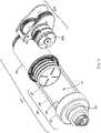
- FIGS. 10A and 10Bshows an isometric view of certain components of a variable rate controlled delivery drive mechanism. While such components are shown with reference to the arrangement detailed in FIGS. 2 , 3 , 4A-4C , and 5A-5C , the same or similar components may be utilized with other arrangements.
- the gear assembly mechanism 500 of the variable rate drive mechanism 100utilizes a motor 530 with pinion 530A.
- the pinion 530Acontacts a first gear 526B of a first compound gear 526.
- a second gear 526A of the first compound gear 526contacts a first gear 528B of a second compound gear 528, and a second gear 528A (not visible) of the second compound gear 528 contacts a trigger gear 524.
- Trigger gear 524contacts gear 520 to relay motion to the remainder of drive mechanism 100.
- the motor 530acts upon the gear assembly mechanism 500, the motion is conveyed by interfacing gear teeth of the pinion 530A, first compound gear 526, second compound gear 528, trigger gear 524, and gear 520.
- such motionis utilized to permit, meter or otherwise restrain the axial translation of the piston 110 by the biasing member 122, thereby driving the plunger seal for drug delivery.
- a status reader 600may read or recognize one or more corresponding status triggers on the trigger gear 524 to provide incremental status indication before, during, and after operation of the variable rate controlled delivery drive mechanism. While the drive mechanism is described with reference to the gear assembly mechanism shown in FIGS.
- the drive mechanism shown in FIG. 10Amay utilize a mechanical status reader 600 which is physically contacted by gear teeth of the trigger gear 524.
- the status reader 600measures the rotational position of the trigger gear 524 and transmits a signal to the power and control system for status indication to the user.
- the drive mechanismmay utilize an optical status reader 1600.
- the optical status reader 1600may be, for example, a light beam that is capable of recognizing a motion and transmitting a signal to the power and control system.
- the drive mechanism shown in FIG. 10Bmay utilize an optical status reader 1600 that is configured to recognize motion of the gear teeth of the trigger gear 524.
- optical status readers and corresponding triggers, electromechanical status readers and corresponding triggers, and/or mechanical status readers and corresponding triggersmay all be utilized by the embodiments of the present invention to provide incremental status indication to the user.
- a fluidsuch as a drug fluid
- a fluidmay be contained within barrel 58, 1058, in a drug chamber 21, 1021 between plunger seal 60, 1060 and pierceable seal 56, 1056, for delivery to a user.
- the pierceable sealis adjacent or retained at least partially within cap 52, 1052.
- a fluid pathway connectionmay be connected to the drug container through the pierceable seal.
- this fluid connectionmay be facilitated by a piercing member of the fluid pathway connection which pierces the pierceable seal and completes the fluid pathway from the drug container, through the fluid pathway connection, the fluid conduit, the insertion mechanism, and the cannula for delivery of the drug fluid to the body of the user.
- one or more locking mechanismsmay retain the biasing member 122, 1122 in an initial energized position within piston 110, 1110. Directly or indirectly upon activation of the device by the user, the locking mechanism may be removed to permit operation of the drive mechanism.
- the piston 110, 1110 and biasing member 122, 1122are both initially in a compressed, energized state behind (i.e., proximal to) the plunger seal 60, 1060.
- biasing member 122, 1122may be maintained in this state until activation of the device between internal features of drive housing 130, 1130 and interface surface 110C, 1110C of piston 110, 1110.
- biasing member 122, 1122is permitted to expand (i.e., decompress) axially in the distal direction (i.e., in the direction of the hatched arrow).
- Such expansioncauses the biasing member 122, 1122 to act upon and distally translate interface surface 110C, 1110C and piston 110, 1110, thereby distally translating plunger seal 60, 1060 to push drug fluid out of the drug chamber 21, 1021 of barrel 58, 1058.
- Distal translation of the piston 110, 1110 and plunger seal 60, 1060continues to force fluid flow out from barrel 58, 1058 through pierceable seal 56, 1056.
- An end-of-dose status indicationmay be provided to the user once the status reader recognizes a status trigger positioned on the trigger gear to substantially correspond with the end of axial travel of the piston 110, 1110 and plunger 60, 1060.
- the gear assembly mechanism 500, 1500 and drive mechanisms 100, 1100thus permit, meter, or otherwise restrain the free axial expansion of the biasing member 122, 1122 to control the rate or profile of drug delivery.
- the arrangementsalso thus provide incremental status indication to the user.
- variable rate controlled delivery drive mechanism 100, 1100, drug delivery pump 10, or any of the individual componentsmay utilize a number of known materials and methodologies in the art.
- a number of known cleaning fluidssuch as isopropyl alcohol and hexane may be used to clean the components and/or the devices.
- a number of known adhesives or gluesmay similarly be employed in the manufacturing process.
- known siliconization and/or lubrication fluids and processesmay be employed during the manufacture of the components and devices.
- known sterilization processesmay be employed at one or more of the manufacturing or assembly stages to ensure the sterility of the final product.
- the drive mechanismmay be assembled in a number of methodologies.
- the drug container 50may first be assembled and filled with a fluid for delivery to the user.
- the drug container 50includes a cap 52, a pierceable seal 56, a barrel 58, and a plunger seal 60.
- the pierceable seal 56may be fixedly engaged between the cap 52 and the barrel 58, at a distal end of the barrel 58.
- the barrel 58may be filled with a drug fluid through the open proximal end prior to insertion of the plunger seal 60 from the proximal end of the barrel 58.
- An optional connection mount 54may be mounted to a distal end of the pierceable seal 56.
- the connection mount 54may guide the insertion of the piercing member of the fluid pathway connection into the barrel 58 of the drug container 50.
- the drug container 50may then be mounted to a distal end of drive housing 130.
- a drive biasing member 122may be inserted into a distal end of the drive housing 130.
- a cover sleeve 140may be inserted into a distal end of the drive housing 130 to substantially cover biasing member 122.
- a pistonmay be inserted into the distal end of the drive housing 130 such that it resides at least partially within an axial pass-through of the biasing member 122 and the biasing member 122 is permitted to contact a piston interface surface 110C of piston 110 at the distal end of the biasing member 122.
- the piston 110 and drive biasing member 122, and optional cover sleeve 140may be compressed into drive housing 130.
- Such assemblypositions the drive biasing member 122 in an initial compressed, energized state and preferably places a piston interface surface 110C in contact with the proximal surface of the plunger seal 60 within the proximal end of barrel 58.
- the piston, piston biasing member, contact sleeve, and optional componentsmay be compressed and locked into the ready-to-actuate state within the drive housing 130 prior to attachment or mounting of the drug container 50.
- the drive screw 1124, or combination of first screw 124 and second screw 132, and their corresponding engagement componentsmay be pre-assembled, connected to the piston 110, mounted into the drive mechanism housing 130 and connected to gear drive 120 and gear 520 (or alternatively connected to gear 1520) which is placed in position through the proximal end of the drive mechanism housing 130 such that it extends proximally therefrom to engage the gear assembly mechanism 500, 1500 for operation.
- a fluid pathway connectionand specifically a sterile sleeve of the fluid pathway connection, may be connected to the cap and/or pierceable seal of the drug container.
- a fluid conduitmay be connected to the other end of the fluid pathway connection which itself is connected to the insertion mechanism such that the fluid pathway, when opened, connected, or otherwise enabled travels directly from the drug container, fluid pathway connection, fluid conduit, insertion mechanism, and through the cannula for drug delivery into the body of a user.
- the components which constitute the pathway for fluid floware now assembled. These components may be sterilized, by a number of known methods, and then mounted either fixedly or removably to an assembly platform or housing of the drug pump, as shown in FIG. 1B .
- drive mechanism 1100, or drug pump 10may include one or more batteries utilized to power the motor, drive mechanisms, and drug pumps of the present invention. A range of batteries known in the art may be utilized for this purpose.
- upper or lower housingsmay optionally contain one or more transparent or translucent windows 18, as shown in FIG. 1A , to enable the user to view the operation of the drug pump 10 or verify that drug dose has completed.
- the drug pump 10may contain an adhesive patch 26 and a patch liner 28 on the bottom surface of the housing 12. The adhesive patch 26 may be utilized to adhere the drug pump 10 to the body of the user for delivery of the drug dose.
- the adhesive patch 26may have an adhesive surface for adhesion of the drug pump to the body of the user.
- the adhesive surface of the adhesive patch 26may initially be covered by a non-adhesive patch liner 28, which is removed from the adhesive patch 26 prior to placement of the drug pump 10 in contact with the body of the user. Removal of the patch liner 28 may further remove the sealing membrane 254 of the insertion mechanism 200, opening the insertion mechanism to the body of the user for drug delivery (as shown in FIG. 1C ).
- variable rate controlled delivery drive mechanism 1100, and drug pump 10may be modified while remaining functionally within the breadth and scope of the present invention.
- the housing of drug pump 10is shown as two separate components upper housing 12A and lower housing 12B, these components may be a single unified component.
- a glue, adhesive, or other known materials or methodsmay be utilized to affix one or more components of the variable rate controlled delivery drive mechanism and/or drug pump to each other.
- one or more components of the variable rate controlled delivery drive mechanism and/or drug pumpmay be a unified component.
- the upper housing and lower housingmay be separate components affixed together by a glue or adhesive, a screw fit connection, an interference fit, fusion joining, welding, ultrasonic welding, and the like; or the upper housing and lower housing may be a single unified component.
- variable rate drive mechanisms and drug pumps disclosed hereinprovide an efficient and easily-operated system for automated drug delivery from a drug container.
- the novel embodiments described hereinprovide drive mechanisms for the controlled delivery of drug substances and drug delivery pumps which incorporate such variable rate drive mechanisms.
- the drive mechanisms of the present inventioncontrol the rate of drug delivery by metering, providing resistance, or otherwise preventing free axial translation of the plunger seal utilized to force a drug substance out of a drug container and, thus, are capable of delivering drug substances at variable rates and/or delivery profiles.
- the drive mechanisms of the present inventionprovide integrated status indication features which provide feedback to the user before, during, and after drug delivery. For example, the user may be provided an initial feedback to identify that the system is operational and ready for drug delivery.
- the systemmay then provide one or more drug delivery status indications to the user.
- the drive mechanism and drug pumpmay provide an end-of-dose indication.
- the novel variable rate drive mechanisms of the present inventionmay be directly or indirectly activated by the user.
- the novel configurations of the variable rate controlled delivery drive mechanism and drug pumps of the present inventionmaintain the sterility of the fluid pathway during storage, transportation, and through operation of the device. Because the path that the drug fluid travels within the device is entirely maintained in a sterile condition, only these components need be sterilized during the manufacturing process. Such components include the drug container of the drive mechanism, the fluid pathway connection, the sterile fluid conduit, and the insertion mechanism.
- the power and control system, the assembly platform, the control arm, the activation mechanism, the housing, and other components of the drug pumpdo not need to be sterilized. This greatly improves the manufacturability of the device and reduces associated assembly costs. Accordingly, the devices of the present invention do not require terminal sterilization upon completion of assembly.
- Manufacturing of the drug pumpincludes the step of attaching both the variable rate controlled delivery drive mechanism and drug container, either separately or as a combined component, to an assembly platform or housing of the drug pump.
- the method of manufacturingfurther includes attachment of the fluid pathway connection, drug container, and insertion mechanism to the assembly platform or housing.
- the additional components of the drug pump, as described above, including the power and control system, the activation mechanism, and the control armmay be attached, preformed, or pre-assembled to the assembly platform or housing.
- An adhesive patch and patch linermay be attached to the housing surface of the drug pump that contacts the user during operation of the device.
- a method of operating the drug pumpincludes the steps of: activating, by a user, the activation mechanism; displacing a control arm to actuate an insertion mechanism; and actuating a power and control system to activate a variable rate controlled delivery drive mechanism to drive fluid drug flow through the drug pump according to a controlled rate or drug delivery profile.
- the methodmay further include the step of: engaging an optional on-body sensor prior to activating the activation mechanism.
- the methodsimilarly may include the step of: establishing a connection between a fluid pathway connection to a drug container.
- the method of operationmay include translating a plunger seal within the variable rate controlled delivery drive mechanism by the expansion of the biasing member acting upon a piston within a drug container to force fluid drug flow through the drug container, the fluid pathway connection, a sterile fluid conduit, and the insertion mechanism for delivery of the fluid drug to the body of a user, wherein a drive gear or screw acting on the piston is utilized to restrain the free axial translation of the piston.
- the method of operation of the insertion mechanism and the drug pumpmay be better appreciated with reference to FIGS. 4A-4C , FIGS. 5A-5C , FIGS. 8A-8C , and FIGS. 9A-9C , as described above.
Landscapes
- Health & Medical Sciences (AREA)
- Vascular Medicine (AREA)
- Engineering & Computer Science (AREA)
- Anesthesiology (AREA)
- Biomedical Technology (AREA)
- Heart & Thoracic Surgery (AREA)
- Hematology (AREA)
- Life Sciences & Earth Sciences (AREA)
- Animal Behavior & Ethology (AREA)
- General Health & Medical Sciences (AREA)
- Public Health (AREA)
- Veterinary Medicine (AREA)
- Infusion, Injection, And Reservoir Apparatuses (AREA)
- Reciprocating Pumps (AREA)
Description
- THIS INVENTION relates to drug delivery pumps. More particularly, this invention relates to drive mechanisms for the variable rate controlled delivery of drug substances and drug delivery pumps with variable rate drive mechanisms. Methods of operating such devices, and methods of assembling such devices are also described.
- Parenteral delivery of various drugs, i.e., delivery by means other than through the digestive track, has become a desired method of drug delivery for a number of reasons. This form of drug delivery by injection may enhance the effect of the substance being delivered and ensure that the unaltered medicine reaches its intended site at a significant concentration. Similarly, undesired side effects associated with other routes of delivery, such as systemic toxicity, can potentially be avoided through parenteral delivery. By bypassing the digestive system of a mammalian patient, one can avoid degradation of the active ingredients caused by the catalytic enzymes in the digestive tract and liver and ensure that a necessary amount of drug, at a desired concentration, reaches the targeted site.
- Traditionally, manually operated syringes and injection pens have been employed for delivering parenteral drugs to a patient. More recently, parenteral delivery of liquid medicines into the body has been accomplished by administering bolus injections using a needle and reservoir, continuously by gravity driven dispensers, or via transdermal patch technologies. Bolus injections often imperfectly match the clinical needs of the patient, and usually require larger individual doses than are desired at the specific time they are given. Continuous delivery of medicine through gravity-feed systems compromises the patient's mobility and lifestyle, and limits the therapy to simplistic flow rates and profiles. Another form of drug delivery, transdermal patches, similarly has its restrictions. Transdermal patches often require specific molecular drug structures for efficacy, and the control of the drug administration through a transdermal patch is severely limited.
- Ambulatory infusion pumps have been developed for delivering liquid medicaments to a patient. These infusion devices have the ability to offer sophisticated fluid delivery profiles accomplishing bolus requirements, continuous infusion and variable flow rate delivery. These infusion capabilities usually result in better efficacy of the drug and therapy and less toxicity to the patient's system. Currently available ambulatory infusion devices are expensive, difficult to program and prepare for infusion, and tend to be bulky, heavy and very fragile. Filling these devices can be difficult and require the patient to carry both the intended medication as well as filling accessories. The devices often require specialized care, maintenance, and cleaning to assure proper functionality and safety for their intended long-term use, and are not cost-effective for patients or healthcare providers.
- As compared to syringes and injection pens, pump type delivery devices can be significantly more convenient to a patient, in that doses of the drug may be calculated and delivered automatically to a patient at any time during the day or night. Furthermore, when used in conjunction with metabolic sensors or monitors, pumps may be automatically controlled to provide appropriate doses of a fluidic medium at appropriate times of need, based on sensed or monitored metabolic levels. As a result, pump type delivery devices have become an important aspect of modern medical treatments of various types of medical conditions, such as diabetes, and the like.
- While pump type delivery systems have been utilized to solve a number of patient needs, manually operated syringes and injection pens often remain a preferred choice for drug delivery as they now provide integrated safety features and can easily be read to identify the status of drug delivery and the end of dose dispensing. However, manually operated syringes and injections pens are not universally applicable and are not preferred for delivery of all drugs. There remains a need for an adjustable (and/or programmable) infusion system that is precise and reliable and can offer clinicians and patients a small, low cost, light weight, simple to use alternative for parenteral delivery of liquid medicines.
- The present invention provides drive mechanisms for the variable rate controlled delivery of drug substances and drug delivery pumps with variable rate drive mechanisms. Methods of operating such devices, and methods of assembling such devices are also described.
- According to the present invention there is provided a variable rate controlled delivery drive mechanism having the features of claim 1. There is also provided a drug delivery pump having the features of
claim 12. - Notably, the drive mechanisms of the present invention control the rate of drug delivery by metering, providing resistance, or otherwise preventing free axial translation of the plunger seal utilized to force a drug substance out of a drug container. The novel embodiments of the present invention thus are capable of delivering drug substances at variable rates. The variable rate drive mechanisms of the present invention may be pre-configurable or dynamically configurable, such as by control by the power and control system, to meet desired delivery rates or profiles, as explained in detail below. Additionally, the drive mechanisms of the present invention provide integrated status indication features which provide feedback to the user before, during, and after drug delivery. For example, the user may be provided with an initial feedback to identify that the system is operational and ready for drug delivery. Upon activation, the system may then provide one or more drug delivery status indications to the user. At completion of drug delivery, the drive mechanism and drug pump may provide an end-of-dose indication. Because the end-of-dose indication is related to the physical end of axial translation of one or more components of the drive mechanism, the drive mechanism and drug pump provide a true end-of-dose indication to the user. Through these mechanisms, confirmation of drug dose delivery can accurately be provided to the user or administrator. Accordingly, the novel devices of the present invention alleviate one or more of the problems associated with prior art devices, such as those referred to above.
- In one arrangement there is described a variable rate controlled delivery drive mechanism which includes a drive mechanism housing, at least partially within which initially resides a biasing member positioned in an initially energized state within an inner cavity of a piston. The drive mechanism further include a gear drive having a gear and a substantially axial internal pass-through; a first screw which at least partially resides within the axial internal pass-through, said first screw also having a substantially axial pass-through and an external first pitch wherein the external first pitch is configured to engage a first nut which also resides within the internal pass-through of the gear drive; a second nut configured to engage a second screw having an external second pitch, said second nut positioned within an axial post of a piston, said axial post and second nut positioned to reside at least partially within the axial pass-through of the first screw. The piston has an interface surface adjacent to a plunger seal and is configured to axially translate the plunger seal, by the force exerted upon it by the biasing member, from a first position to a second position within a drug container for drug delivery. The biasing member is metered or otherwise restrained from free expansion from its energized state. The first nut is rotationally constrained (i.e. keyed) to the gear drive, while the second nut is rotationally constrained to the piston.
- In another arrangement there is described a variable rate controlled delivery drive mechanism having a drive mechanism housing, at least partially within which initially resides a biasing member positioned in an initially energized state within an inner cavity of a piston. A gear is connected to the proximal end of a drive screw having an external pitch configured to engage a nut. The nut is rotationally constrained (i.e., keyed) to the piston. The piston has an interface surface adjacent to a plunger seal and is configured to axially translate the plunger seal, by the force exerted upon it by the biasing member, from a first position to a second position within a drug container for drug delivery. The biasing member is metered or otherwise restrained from free expansion from its energized state.
- In at least one embodiment, the drive mechanism may further include a gear assembly mechanism having a motor, the gear assembly mechanism being configured to engage a gear to meter the free expansion of the biasing member from its energized state. The gear assembly mechanism having a motor may further include a pinion extending from the motor; one or more compound gears each having a first gear and a second gear; and a trigger gear; wherein the pinion contacts the one or more compound gears which contacts the trigger gear, and the trigger gear contacts a gear to relay motion to the drive mechanism. The metering of the biasing member by the motor controls the rate or profile of drug delivery to a user.
- In a further embodiment, the drive mechanism includes a status reader configured to read or recognize one or more corresponding status triggers, wherein, during operation of the drive mechanism, interaction between the status reader and the status triggers transmits a signal to a power and control system to provide feedback to a user. The status reader may be, for example, an optical status reader and the corresponding status triggers are gear teeth of the trigger gear, a mechanical status reader and the corresponding status triggers are gear teeth of the trigger gear, a mechanical status reader and the corresponding status triggers are external features of the piston and/or an optional sleeve, or an optical status reader and the corresponding status triggers are external features of the piston and/or an optional sleeve. The function of the gear assembly mechanism having a motor may be pre-programmed or dynamically controlled by a power and control system to meet a desired drug delivery rate or profile.
- There is also described a drug delivery pump with a variable rate controlled delivery mechanism. The drive mechanism may be as described above. In at least one embodiment, the drug pump may further include a gear assembly mechanism having a motor, the gear assembly mechanism being configured to engage a gear to meter the free expansion of the biasing member from its energized state. The gear assembly mechanism having a motor may further include a pinion extending from the motor; one or more compound gears each having a first gear and a second gear; and a trigger gear; wherein the pinion contacts the one or more compound gears which contacts the trigger gear, and the trigger gear contacts a gear to relay motion to the drive mechanism. The metering of the biasing member by the motor controls the rate or profile of drug delivery to a user.
- In a further embodiment, the drug pump includes a status reader configured to read or recognize one or more corresponding status triggers, wherein, during operation of the drive mechanism, interaction between the status reader and the status triggers transmits a signal to a power and control system to provide feedback to a user. The status reader may be, for example, an optical status reader and the corresponding status triggers are gear teeth of the trigger gear, a mechanical status reader and the corresponding status triggers are gear teeth of the trigger gear, a mechanical status reader and the corresponding status triggers are external features of the piston and/or an optional sleeve, or an optical status reader and the corresponding status triggers are external features of the piston and/or an optional sleeve. The function of the gear assembly mechanism having a motor may be pre-programmed or dynamically controlled by a power and control system to meet a desired drug delivery rate or profile.
- The novel embodiments of the present invention provide drive mechanisms which are capable of metering, providing resistance, or otherwise preventing free axial translation of a plunger seal utilized to force a drug substance out of a drug container and, thereby, controlling the rate of delivery of drug substances. The novel control delivery drive mechanisms are additionally capable of providing the incremental status of the drug delivery before, during, and after operation of the device. Throughout this specification, unless otherwise indicated, "comprise," "comprises," and "comprising," or related terms such as "includes" or "consists of," are used inclusively rather than exclusively, so that a stated integer or group of integers may include one or more other non-stated integers or groups of integers. As will be described further below, the embodiments of the present invention may include one or more additional components which may be considered standard components in the industry of medical devices. For example, the embodiments may include one or more batteries utilized to power the motor, drive mechanisms, and drug pumps of the present invention.
- The following non-limiting embodiments of the invention are described herein with reference to the following drawings, wherein:
FIG. 1A shows an isometric view of a drug delivery pump having a variable rate controlled delivery drive mechanism, according to one embodiment of the present invention;FIG. 1B shows an isometric view of the interior components of the drug delivery pump shown inFIG. 1A (shown without the adhesive patch);FIG. 1C shows an isometric view of the bottom of the drug delivery pump shown inFIG. 1A (shown without the adhesive patch);FIG. 2 shows an isometric view of a variable rate controlled delivery drive mechanism, according to a telescoping design;FIG. 3 shows an exploded view, along an axis "A," of the drive mechanism shown inFIG. 2 ;FIG. 4A shows an isometric cross-sectional view of the drive mechanism shown inFIG. 2 in an initial inactive state;FIG. 4B shows an isometric cross-sectional view of the drive mechanism shown inFIG. 2 in an actuated state as the mechanism controls the rate or profile of drug delivery;FIG. 4C shows an isometric cross-section view of the drive mechanism shown inFIG. 2 as the mechanism completes drug delivery;FIG. 5A shows a cross-sectional view of the drive mechanism shown inFIG. 4A in an initial inactive state;FIG. 5B shows a cross-sectional view of the drive mechanism shown inFIG. 4B in an actuated state as the mechanism controls the rate or profile of drug delivery;FIG. 5C shows a cross-sectional view of the drive mechanism shown inFIG. 4C as the mechanism completes drug delivery and, optionally, performs a compliance push to ensure completion of drug delivery;FIG. 6 shows an isometric view of a variable rate controlled delivery drive mechanism, according a non-telescoping design embodying the present invention;FIG. 7 shows an exploded view, along an axis "A," of the drive mechanism shown inFIG. 6 ;FIG. 8A shows an isometric cross-sectional view of the drive mechanism shown inFIG. 6 in an initial inactive state;FIG. 8B shows an isometric cross-sectional view of the drive mechanism shown inFIG. 6 in an actuated state as the mechanism controls the rate or profile of drug delivery;FIG. 8C shows an isometric cross-sectional view of the drive mechanism shown inFIG. 6 as the mechanism completes drug delivery;FIG. 9A shows a cross-sectional view of the drive mechanism shown inFIG. 8A in an initial inactive state;FIG. 9B shows a cross-sectional view of the drive mechanism shown inFIG. 8B in an actuated state as the mechanism controls the rate or profile of drug delivery;FIG. 9C shows a cross-sectional view of the drive mechanism shown inFIG. 8C as the mechanism completes drug delivery and, optionally, performs a compliance push to ensure completion of drug delivery;FIG. 10A shows an isometric view of a variable rate controlled delivery drive mechanism which incorporates a mechanical status indicator;FIG. 10B shows an isometric view of a variable rate controlled delivery drive mechanism which incorporates an optical status indicator.- The present invention provides variable rate drive mechanisms for the controlled delivery of drug substances and drug delivery pumps which incorporate such variable rate drive mechanisms. The variable rate drive mechanisms of the present invention control the rate of drug delivery by metering, providing resistance, or otherwise preventing free axial translation of the plunger seal utilized to force a drug substance out of a drug container and, thus, are capable of delivering drug substances at variable rates and/or delivery profiles. Additionally, the variable rate drive mechanisms of the present invention provide integrated status indication features which provide feedback to the user before, during, and after drug delivery. For example, the user may be provided an initial feedback to identify that the system is operational and ready for drug delivery. Upon activation, the system may then provide one or more drug delivery status indications to the user. At completion of drug delivery, the variable rate drive mechanism and drug pump may provide an end-of-dose indication.
- As used herein to describe the drive mechanisms, drug delivery pumps, or any of the relative positions of the components of the present invention, the terms "axial" or "axially" refer generally to a longitudinal axis "A" around which the drive mechanisms are preferably positioned, although not necessarily symmetrically there-around. The term "radial" refers generally to a direction normal to axis A. The terms "proximal," "rear," "rearward," "back," or "backward" refer generally to an axial direction in the direction "P". The terms "distal," "front," "frontward," "depressed," or "forward" refer generally to an axial direction in the direction "D". As used herein, the term "glass" should be understood to include other similarly non-reactive materials suitable for use in a pharmaceutical grade application that would normally require glass, including but not limited to certain non-reactive polymers such as cyclic olefin copolymers (COC) and cyclic olefin polymers (COP). The term "plastic" may include both thermoplastic and thermosetting polymers. Thermoplastic polymers can be re-softened to their original condition by heat; thermosetting polymers cannot. As used herein, the term "plastic" refers primarily to moldable thermoplastic polymers such as, for example, polyethylene and polypropylene, or an acrylic resin, that also typically contain other ingredients such as curatives, fillers, reinforcing agents, colorants, and/or plasticizers, etc., and that can be formed or molded under heat and pressure. As used herein, the term "plastic" is not meant to include glass, non-reactive polymers, or elastomers that are approved for use in applications where they are in direct contact with therapeutic liquids that can interact with plastic or that can be degraded by substituents that could otherwise enter the liquid from plastic. The term "elastomer," "elastomeric" or "elastomeric material" refers primarily to cross-linked thermosetting rubbery polymers that are more easily deformable than plastics but that are approved for use with pharmaceutical grade fluids and are not readily susceptible to leaching or gas migration under ambient temperature and pressure. "Fluid" refers primarily to liquids, but can also include suspensions of solids dispersed in liquids, and gasses dissolved in or otherwise present together within liquids inside the fluid-containing portions of the drug pumps. According to various aspects and embodiments described herein, reference is made to a "biasing member", such as in the context of one or more biasing members for asserting force on a plunger seal. It will be appreciated that the biasing member may be any member that is capable of storing and releasing energy. Non-limiting examples include a spring, such as for example a coiled spring, a compression or extension spring, a torsional spring, or a leaf spring, a resiliently compressible or elastic band, or any other member with similar functions. In at least one embodiment of the present invention, the biasing member is a spring, preferably a compression spring.
- The novel devices of the present invention provide variable rate controlled delivery drive mechanisms with integrated status indication and drug delivery pumps which incorporate such drive mechanisms. Such devices are safe and easy to use, and are aesthetically and ergonomically appealing for self-administering patients. The devices described herein incorporate features which make activation, operation, and lock-out of the device simple for even untrained users. The novel devices of the present invention provide these desirable features without any of the problems associated with known prior art devices. Certain non-limiting embodiments of the novel drug delivery pumps, drive mechanisms, and their respective components are described further herein with reference to the accompanying figures.
- As used herein, the term "pump" is intended to include any number of drug delivery systems which are capable of dispensing a fluid to a user upon activation. Such drug delivery systems include, for example, injection systems, infusion pumps, bolus injectors, and the like.
FIGS. 1A-1C show an exemplary drug delivery device or drug pump according to at least one embodiment of the present invention. The drug delivery device may be utilized to administer delivery of a drug treatment into a body of a user. As shown inFIGS. 1A-1C , thedrug pump 10 includes apump housing 12.Pump housing 12 may include one or more housing subcomponents which are fixedly engageable to facilitate easier manufacturing, assembly, and operation of the drug pump. For example,drug pump 10 includes apump housing 12 which includes anupper housing 12A and alower housing 12B. The drug pump may further include anactivation mechanism 14, a status indicator 16, and awindow 18.Window 18 may be any translucent or transmissive surface through which the operation of the drug pump may be viewed. As shown inFIG. 1B , the drug pump further includesassembly platform 20, sterilefluid conduit 30,drive mechanism 100 havingdrug container 50,insertion mechanism 200,fluid pathway connection 300, and power andcontrol system 400. One or more of the components of such drug pumps may be modular in that they may be, for example, pre-assembled as separate components and configured into position onto theassembly platform 20 of thedrug pump 10 during manufacturing. - The
pump housing 12 contains all of the device components and provides a means of removably attaching thedevice 10 to the skin of the user. Thepump housing 12 also provides protection to the interior components of thedevice 10 against environmental influences. Thepump housing 12 is ergonomically and aesthetically designed in size, shape, and related features to facilitate easy packaging, storage, handling, and use by users who may be untrained and/or physically impaired. Furthermore, the external surface of thepump housing 12 may be utilized to provide product labeling, safety instructions, and the like. Additionally, as described above,housing 12 may include certain components, such as status indicator 16 andwindow 18, which may provide operation feedback to the user. - In at least one embodiment, the
drug pump 10 provides anactivation mechanism 14 that is displaced by the user to trigger the start command to the power andcontrol system 400. In a preferred embodiment, the activation mechanism is astart button 14 that is located through thepump housing 12, such as through an aperture betweenupper housing 12A andlower housing 12B, and which contacts acontrol arm 40 of the power andcontrol system 400. In at least one embodiment, thestart button 14 may be a push button, and in other embodiments, may be an on/off switch, a toggle, or any similar activation feature known in the art. Thepump housing 12 also provides a status indicator 16 and awindow 18. In other embodiments, one or more of theactivation mechanism 14, the status indicator 16, thewindow 18, and combinations thereof may be provided on theupper housing 12A or thelower housing 12B such as, for example, on a side visible to the user when thedrug pump 10 is placed on the body of the user.Housing 12 is described in further detail hereinafter with reference to other components and embodiments of the present invention. - The drug pump is configured such that, upon activation by a user by depression of the activation mechanism, the drug pump is initiated to: insert a fluid pathway into the user; enable, connect, or open necessary connections between a drug container, a fluid pathway, and a sterile fluid conduit; and force drug fluid stored in the drug container through the fluid pathway and fluid conduit for delivery into a user. One or more optional safety mechanisms may be utilized, for example, to prevent premature activation of the drug pump. For example, an optional on-body sensor 24 (shown in
FIG. 1C ) may be provided in one embodiment as a safety feature to ensure that the power andcontrol system 400, or the activation mechanism, cannot be engaged unless thedrug pump 10 is in contact with the body of the user. In one such embodiment, the on-body sensor 24 is located on the bottom oflower housing 12B where it may come in contact with the user's body. Upon displacement of the on-body sensor 24, depression of the activation mechanism is permitted. Accordingly, in at least one embodiment the on-body sensor 24 is a mechanical safety mechanism, such as for example a mechanical lock out, that prevents triggering of thedrug pump 10 by theactivation mechanism 14. In another embodiment, the on-body sensor may be an electro-mechanical sensor such as a mechanical lock out that sends a signal to the power andcontrol system 400 to permit activation. In still other embodiments, the on-body sensor can be electrically based such as, for example, a capacitive- or impedance-based sensor which must detect tissue before permitting activation of the power andcontrol system 400. These concepts are not mutually exclusive and one or more combinations may be utilized within the breadth of the present invention to prevent, for example, premature activation of the drug pump. In a preferred embodiment, thedrug pump 10 utilizes one or more mechanical on-body sensors. Additional integrated safety mechanisms are described herein with reference to other components of the novel drug pumps. - The power and
control system 400 includes a power source, which provides the energy for various electrical components within the drug pump, one or more feedback mechanisms, a microcontroller, a circuit board, one or more conductive pads, and one or more interconnects. Other components commonly used in such electrical systems may also be included, as would be appreciated by one having ordinary skill in the art. The one or more feedback mechanisms may include, for example, audible alarms such as piezo alarms and/or light indicators such as light emitting diodes (LEDs). The microcontroller may be, for example, a microprocessor. The power andcontrol system 400 controls several device interactions with the user and interfaces with thedrive mechanism 100. In one embodiment, the power andcontrol system 400 interfaces with thecontrol arm 40 to identify when the on-body sensor 24 and/or theactivation mechanism 14 have been activated. The power andcontrol system 400 may also interface with the status indicator 16 of thepump housing 12, which may be a transmissive or translucent material which permits light transfer, to provide visual feedback to the user. The power andcontrol system 400 interfaces with thedrive mechanism 100 through one or more interconnects to relay status indication, such as activation, drug delivery, and end-of-dose, to the user. Such status indication may be presented to the user via auditory tones, such as through the audible alarms, and/or via visual indicators, such as through the LEDs. In a preferred embodiment, the control interfaces between the power and control system and the other components of the drug pump are not engaged or connected until activation by the user. This is a desirable safety feature that prevents accidental operation of the drug pump and may additionally maintain the energy contained in the power source during storage, transportation, and the like. - The power and
control system 400 may be configured to provide a number of different status indicators to the user. For example, the power andcontrol system 400 may be configured such that after the on-body sensor and/or trigger mechanism have been pressed, the power andcontrol system 400 provides a ready-to-start status signal via the status indicator 16 if device start-up checks provide no errors. After providing the ready-to-start status signal and, in an embodiment with the optional on-body sensor, if the on-body sensor remains in contact with the body of the user, the power andcontrol system 400 will power thedrive mechanism 100 to begin delivery of the drug treatment through thefluid pathway connection 300 and sterilefluid conduit 30. In a preferred embodiment of the present invention, theinsertion mechanism 200 and thefluid pathway connection 300 may be caused to activate directly by user operation of theactivation mechanism 14. During the drug delivery process, the power andcontrol system 400 is configured to provide a dispensing status signal via the status indicator 16. After the drug has been administered into the body of the user and after the end of any additional dwell time, to ensure that substantially the entire dose has been delivered to the user, the power andcontrol system 400 may provide an okay-to-remove status signal via the status indicator 16. This may be independently verified by the user by viewing the drive mechanism and drug dose delivery through thewindow 18 of thepump housing 12. Additionally, the power andcontrol system 400 may be configured to provide one or more alert signals via the status indicator 16, such as for example alerts indicative of fault or operation failure situations. - The power and
control system 400 may additionally be configured to accept various inputs from the user to dynamically control thedrive mechanisms 100 to meet a desired drug delivery rate or profile. For example, the power andcontrol system 400 may receive inputs, such as from partial or full activation, depression, and/or release of theactivation mechanism 14, to set, initiate, stop, or otherwise adjust the control of thedrive mechanism 100 via the power andcontrol system 400 to meet the desired drug delivery rate or profile. Similarly, the power andcontrol system 400 may be configured to receive such inputs to adjust the drug dose volume; to prime the drive mechanism, fluid pathway connection, and fluid conduit; and/or to start, stop, or pause operation of thedrive mechanism 100. Such inputs may be received by the user directly acting on thedrug pump 10, such as by use of theactivation mechanism 14 or a different control interface, or thesystem 400 may be configured to receive such inputs from a remote device. Additionally or alternatively, such inputs may be pre-programmed. - Other power and control system configurations may be utilized with the novel drug pumps of the present invention. For example, certain activation delays may be utilized during drug delivery. As mentioned above, one such delay optionally included within the system configuration is a dwell time which ensures that substantially the entire drug dose has been delivered before signaling completion to the user. Similarly, activation of the device may require a delayed depression (i.e., pushing) of the
activation mechanism 14 of thedrug pump 10 prior to drug pump activation. Additionally, the system may include a feature which permits the user to respond to the end-of-dose signals and to deactivate or power-down the drug pump. Such a feature may similarly require a delayed depression of the activation mechanism, to prevent accidental deactivation of the device. Such features provide desirable safety integration and ease-of-use parameters to the drug pumps. An additional safety feature may be integrated into the activation mechanism to prevent partial depression and, therefore, partial activation of the drug pumps. For example, the activation mechanism and/or power and control system may be configured such that the device is either completely off or completely on, to prevent partial activation. Such features are described in further detail hereinafter with regard to other aspects of the novel drug pumps. - A number of fluid pathway connections may be utilized within the embodiments of the present invention. Generally, a suitable fluid pathway connection includes a sterile fluid conduit, a piercing member, and a sterile sleeve attached to a drug container or a sliding pierceable seal integrated within a drug container. The fluid pathway connection may further include one or more flow restrictors. Upon proper activation of the
device 10, thefluid pathway connection 300 is enabled to connect the sterilefluid conduit 30 to the drug container of thedrive mechanism 100. Such a connection may be facilitated by a piercing member, such as a needle, penetrating a pierceable seal of the drug container of thedrive mechanism 100. The sterility of this connection may be maintained by performing the connection within a flexible sterile sleeve. Upon substantially simultaneous activation of the insertion mechanism, the fluid pathway between the drug container and the insertion mechanism is complete to permit drug delivery into the body of the user. - In at least one embodiment of the present invention, the piercing member of the fluid pathway connection is caused to penetrate the pierceable seal of the drug container of the drive mechanism by direct action of the user, such as by depression of the activation mechanism by the user. For example, the activation mechanism itself may bear on the fluid pathway connection such that displacement of the activation mechanism from its original position also causes displacement of the fluid pathway connection. In one such embodiment, the fluid pathway connection may be substantially similar to that described in International Patent Publication No.
WO 2013/040032 . According to such an embodiment, the connection is enabled by the user depressing the activation mechanism and, thereby, driving the piercing member through the pierceable seal, because this prevents fluid flow from the drug container until desired by the user. In such an embodiment, a compressible sterile sleeve may be fixedly attached between the cap of the drug container and the connection hub of the fluid pathway connection. The piercing member may reside within the sterile sleeve until a connection between the fluid connection pathway and the drug container is desired. The sterile sleeve may be sterilized to ensure the sterility of the piercing member and the fluid pathway prior to activation. - Alternatively, the fluid pathway connection may be integrated into a drug container as described in International Patent Publication No.
WO 2014/116274 for example. According to such an embodiment, a drug container may have a drug chamber within a barrel between a pierceable seal and a plunger seal. A drug fluid is contained in the drug chamber. Upon activation of the device by the user, a drive mechanism asserts a force on a plunger seal contained in the drug container. As the plunger seal asserts a force on the drug fluid and any air/gas gap or bubble, a combination of pneumatic and hydraulic pressure builds by compression of the air/gas and drug fluid and the force is relayed to the sliding pierceable seal. The sliding pierceable seal is caused to slide towards the cap, causing it to be pierced by the piercing member retained within the integrated sterile fluid pathway connection. Accordingly, the integrated sterile fluid pathway connection is connected (i.e., the fluid pathway is opened) by the combination pneumatic/hydraulic force of the air/gas and drug fluid within the drug chamber created by activation of a drive mechanism. Once the integrated sterile fluid pathway connection is connected or opened, drug fluid is permitted to flow from the drug container, through the integrated sterile fluid pathway connection, sterile fluid conduit, and insertion mechanism, and into the body of the user for drug delivery. In at least one embodiment, the fluid flows through only a manifold and a cannula and/or needle of the insertion mechanism, thereby maintaining the sterility of the fluid pathway before and during drug delivery. - Regardless of the fluid pathway connection utilized by the drug pump, the drug pump is capable of delivering a range of drugs with different viscosities and volumes. The drug pump is capable of delivering a drug at a controlled flow rate (speed) and/or of a specified volume. In one embodiment, the drug delivery process is controlled by one or more flow restrictors within the fluid pathway connection and/or the sterile fluid conduit. In other embodiments, other flow rates may be provided by varying the geometry of the fluid flow path or delivery conduit, varying the speed at which a component of the drive mechanism advances into the drug container to dispense the drug therein, or combinations thereof. Still further details about the
fluid pathway connection 300 and the sterilefluid conduit 30 are provided hereinafter in later sections in reference to other embodiments. - A number of insertion mechanisms may be utilized within the drug pumps of the present invention. The pump-type delivery devices of the present invention may be connected in fluid flow communication to a patient or user, for example, through any suitable hollow tubing. A solid bore needle may be used to pierce the skin of the patient and place a hollow cannula at the appropriate delivery position, with the solid bore needle being removed or retracted prior to drug delivery to the patient. As stated above, the fluid can be introduced into the body through any number of means, including but not limited to: an automatically inserted needle, cannula, micro-needle array, or infusion set tubing. A number of mechanisms may also be employed to activate the needle insertion into the patient. For example, a biasing member such as a spring may be employed to provide sufficient force to cause the needle and cannula to pierce the skin of the patient. The same spring, an additional spring, or another similar mechanism may be utilized to retract the needle from the patient. In a preferred embodiment, the insertion mechanism may generally be as described in International Patent Publication
WO 2013/033421 . Such a configuration may be utilized for insertion of the drug delivery pathway into, or below, the skin (or muscle) of the patient in a manner that minimizes pain to the patient. Other known methods for insertion of a fluid pathway may be utilized and are contemplated within the bounds of the present invention. - In at least one embodiment, the
insertion mechanism 200 includes an insertion mechanism housing having one or more lockout windows, and a base for connection to the assembly platform and/or pump housing (as shown inFIG. 1B and FIG. 1C ). The connection of the base to theassembly platform 20 may be, for example, such that the bottom of the base is permitted to pass-through a hole in the assembly platform to permit direct contact of the base to the body of the user. In such configurations, the bottom of the base may include a sealing membrane that is removable prior to use of thedrug pump 10. The insertion mechanism may further include one or more insertion biasing members, a needle, a retraction biasing member, a cannula, and a manifold. The manifold may connect to sterilefluid conduit 30 to permit fluid flow through the manifold, cannula, and into the body of the user during drug delivery. - As used herein, "needle" is intended to refer to a variety of needles including but not limited to conventional hollow needles, such as a rigid hollow steel needles, and solid core needles more commonly referred to as "trocars." In a preferred embodiment, the needle is a 27 gauge solid core trocar and in other embodiments, the needle may be any size needle suitable to insert the cannula for the type of drug and drug administration (e.g., subcutaneous, intramuscular, intradermal, etc.) intended. A sterile boot may be utilized within the needle insertion mechanism. The sterile boot is a collapsible sterile membrane that is in fixed engagement at a proximal end with the manifold and at a distal end with the base. In at least one embodiment, the sterile boot is maintained in fixed engagement at a distal end between the base and the insertion mechanism housing. The base includes a base opening through which the needle and cannula may pass-through during operation of the insertion mechanism, as will be described further below. Sterility of the cannula and needle are maintained by their initial positioning within the sterile portions of the insertion mechanism. Specifically, as described above, the needle and cannula are maintained in the sterile environment of the manifold and sterile boot. The base opening of the base may be closed from non-sterile environments as well, such as by for example a sealing membrane 254 (shown in
FIG. 1C ). - According to at least one embodiment of the present invention, the insertion mechanism is initially locked into a ready-to-use stage by lockout pin(s) which are initially positioned within lockout windows of the insertion mechanism housing. In this initial configuration, an insertion biasing member and retraction biasing member are each retained in their compressed, energized states. As shown in
FIG. 1B , the lockout pin(s) 208 may be directly displaced by user depression of theactivation mechanism 14. As the user disengages any safety mechanisms, such as an optional on-body sensor 24 (shown inFIG. 1C ), theactivation mechanism 14 may be depressed to initiate the drug pump. Depression of theactivation mechanism 14 may directly cause translation or displacement ofcontrol arm 40 and directly or indirectly cause displacement of lockout pin(s) 208 from their initial position within locking windows 202A of insertion mechanism housing 202. Displacement of the lockout pin(s) 208 permits the insertion biasing member to decompress from its initial compressed, energized state. This decompression of the insertion biasing member drives the needle and the cannula into the body of the user. At the end of the insertion stage, the retraction biasing member is permitted to expand in the proximal direction from its initial energized state. This axial expansion in the proximal direction of the retraction biasing member retracts the needle, while maintaining the cannula in fluid communication with the body of the user. Accordingly, the insertion mechanism may be used to insert a needle and cannula into the user and, subsequently, retract the needle while retaining the cannula in position for drug delivery to the body of the user. - With reference to the example shown in
FIGS. 2 and3 ,drive mechanism 100 includes adrive housing 130, and adrug container 50 having acap 52, apierceable seal 56, abarrel 58, and aplunger seal 60. Adrug chamber 21, located within thebarrel 58 between the pierceable seal and theplunger seal 60, may contain a drug fluid for delivery through the insertion mechanism and drug pump into the body of the user. The seals described herein may be comprised of a number of materials but are, in one example, comprised of one or more elastomers or rubbers. The drive mechanism may further include aconnection mount 54 to guide the insertion of the piercing member of the fluid pathway connection into thebarrel 58 of thedrug container 50. Thedrive mechanism 100 may further contain one or more drive biasing members, one or more release mechanisms, and one or more guides, as are described further herein. The components of the drive mechanism function to force a fluid from the drug container out through the pierceable seal, or preferably through the piercing member of the fluid pathway connection, for delivery through the fluid pathway connection, sterile fluid conduit, and insertion mechanism into the body of the user. - In one particular example, the
drive mechanism 100 employs one or more compression springs as the biasing member(s). Upon activation of the drug pump by the user, the power and control system may be actuated to directly or indirectly release the compression spring(s) from an energized state. Upon release, the compression spring(s) may bear against and act upon the plunger seal to force the fluid drug out of the drug container. The compression spring may bear against and act upon a piston which, in turn, acts upon the plunger seal to force the fluid drug out of the drug container. The fluid pathway connection may be connected through the pierceable seal prior to, concurrently with, or after activation of the drive mechanism to permit fluid flow from the drug container, through the fluid pathway connection, sterile fluid conduit, and insertion mechanism, and into the body of the user for drug delivery. In at least one example, the fluid flows through only a manifold and a cannula of the insertion mechanism, thereby maintaining the sterility of the fluid pathway before and during drug delivery. Such components and their functions are described in further detail hereinafter. - Referring now to the drive mechanism shown in
FIG. 2 andFIG. 3 , thedrive mechanism 100 includes adrug container 50 having acap 52, apierceable seal 56, abarrel 58, and aplunger seal 60, and optionally aconnection mount 54. Thedrug container 50 is mounted to a distal end of adrive housing 130. Compressed within thedrive housing 130, between thedrug container 50 and the proximal end of thehousing 130, are adrive biasing member 122 and apiston 110, wherein thedrive biasing member 122 is configured to bear upon aninterface surface 110C of thepiston 110, as described further herein. Optionally, acover sleeve 140 may be utilized to engage thepiston 110 and cover thedrive biasing member 122 to hide the biasingmember 122 from user view upon expansion from its initial energized state. Thecover sleeve 140 may be configured to engage and slide upon thepiston 110, between thepiston 110 and the distal end of thedrive mechanism housing 130 to hide the biasingmember 122 from user view upon expansion from its initial energized state. - As shown in
FIG. 3 , the variable rate controlleddelivery drive mechanism 100 may utilize a telescoping drive assembly which incorporates agear drive 120 having agear 520 and a substantially axial internal pass-through 120A, within which at least partially resides afirst screw 124 having a substantially axial pass-through 124A and an externalfirst pitch 124B. The externalfirst pitch 124B is configured to engage and rotationally translate upon or within afirst nut 126 which also resides within the internal pass-through 120A of the gear drive 120 (such as at the distal end of the internal pass-through 120A). Similarly, asecond nut 128 resides within the axial pass-through 124A of thefirst screw 124 and is configured to engage and rotationally translate asecond screw 132 having an external second pitch 132B. More accurately, thesecond nut 128 resides within anaxial post 110B of thepiston 110, which itself resides at least partially within the axial pass-through 124A of thefirst screw 124. Thesecond nut 128 is configured to engage and rotationally translate upon or around thesecond screw 132 having the external second pitch 132B. These aspects are more clearly visible with reference toFIGS. 4A-4C andFIGS. 5A-5C . Because of this configuration of components, and because the axial rotation of the gear drive 120 indirectly causes axial translation of thepiston 110, the variable rate controlled delivery drive mechanism shown inFIGS. 2 ,3 ,4A-4C and5A-5C is referred to as a "telescoping" drive mechanism. Thegear drive 120, notably, does not drive the delivery but only controls the delivery motion. Thegear drive 120 controls the motion of thepiston 110 andplunger seal 60, but does not apply the force necessary for drug delivery. Instead, thegear drive 120 merely meters or permits translation of thepiston 110 andplunger seal 60 which are being driven to axially translate by the biasingmember 122. Because the axial translation of thepiston 110 andplunger seal 60 are driven by biasingmember 122, and thegear drive 120 is merely metering or permitting axial translation, the force or power needed to meter the axial translation by thegear drive 120 is much smaller than that which would be required if the gear drive did drive the delivery. Accordingly, a smaller motor may be utilized. Themotor 530 may, accordingly, be selected from a variety of electromechanical sources capable of incremental motion, such as brushed DC motors, EC motors, stepper motors, solenoids, or other technologies that can produce controlled motion. In at least one example, themotor 530 is a stepper motor. - Alternatively, a non-telescoping drive mechanism, as shown in
FIGS. 6 ,7 ,8A-8C and9A-9C may be utilized. Referring now to the drive mechanism shown inFIG. 6 andFIG. 7 , thedrive mechanism 1100 includes adrug container 1050 having acap 1052, apierceable seal 1056, abarrel 1058, and aplunger seal 1060, and optionally aconnection mount 1054. Thedrug container 1050 is mounted to a distal end of adrive housing 1130. Compressed within thedrive housing 1130, between thedrug container 1050 and the proximal end of thehousing 1130, are adrive biasing member 1122 and apiston 1110, wherein thedrive biasing member 1122 is configured to bear upon aninterface surface 1110C of thepiston 1110, as described further herein. As shown inFIG. 7 , the variable rate controlleddelivery drive mechanism 1100 of the present invention utilizes a non-telescoping drive assembly which incorporates agear 1520 connected to the proximal end of adrive screw 1124 having an external pitch 1124B. The external pitch 1124B is configured to engage and rotationally translate upon or within anut 1126. As thegear 1520 and drivescrew 1124 are axially rotated, the threaded engagement between thedrive screw 1124 and thenut 1126 permits axial translation of thepiston 1110 by the biasingmember 1122. These aspects are more clearly visible with reference toFIGS. 8A-8C andFIGS. 9A-9C . Because the axial rotation of thedrive screw 1124 directly causes axial translation of thepiston 1110, such an arrangement is referred to herein as "non-telescoping". As stated above with regard to the telescoping arrangement, thedrive screw 1124, notably, does not drive the delivery but only controls the delivery motion. Thedrive screw 1124 controls the motion of thepiston 1110 andplunger seal 1060, but does not apply the force necessary for drug delivery. Instead, thedrive screw 1124 merely meters or permits translation of thepiston 1110 andplunger seal 1060 which are being driven to axially translate by the biasingmember 1122. Because the axial translation of thepiston 1110 andplunger seal 1060 are driven by biasingmember 1122, and thedrive screw 1124 is merely metering or permitting axial translation, the force or power needed to meter the axial translation by thedrive screw 1124 is much smaller than that which would be required if the drive screw did drive the delivery. Accordingly, a smaller motor may be utilized. Themotor 1530 may, accordingly, be selected from a variety of electromechanical sources capable of incremental motion, such as brushed DC motors, EC motors, stepper motors, solenoids, or other technologies that can produce controlled motion. In at least one embodiment, themotor 1530 is most preferably a stepper motor. FIGS. 4A-4C andFIGS. 5A-5C show the progression of the variable rate controlled delivery drive mechanism shown inFIGS. 2-3 having a telescoping drive mechanism configuration, as it progresses through activation, controlled delivery of a drug substance, and completion of drug delivery. As shown, agear transmission assembly 500 having amotor 530 may be utilized to meter or otherwise prevent free axial translation of the biasingmember 122 used to push aplunger seal 60 for the delivery of a drug substance out ofdrug chamber 21. Thegear transmission assembly 500 is further detailed below with reference toFIGS. 10A-10B . Upon actuation of the variable rate controlleddelivery drive mechanism 100 by the user, such as by activation of the power and control system, themotor 530 is caused to rotate the components of thegear transmission assembly 500 to correspondingly rotategear 520. Substantially simultaneously or in advance of such activation of themotor 530, the biasingmember 122 is unlocked or otherwise permitted to release from its initial energized state. The biasingmember 122 is positioned within thedrive mechanism housing 130 and held in an initial energized state between thedrive mechanism housing 130 and the interior of theinterface surface 110C ofpiston 110. Upon such unlocking or release the biasingmember 122 will act upon and push the piston 110 (and theplunger seal 60 located substantially adjacent thepiston 110 on the other side of theinterface surface 110C) to drive theplunger seal 60 for drug delivery, if the biasingmember 122 is unrestrained or not otherwise metered. The variable rate controlled delivery drive mechanism is configured to provide such restraint or metering on the expansion of the biasingmember 122. Depending on a desired drug delivery rate or profile, as may be pre-programmed or dynamically controlled by the power and control system, themotor 530 of thegear assembly mechanism 500 may function to incrementally permit axial expansion of the biasingmember 122 and, thus, axial translation of thepiston 110 andplunger seal 60.- As the components of the
gear assembly mechanism 500 are rotated by function of themotor 530 and corresponding gear interactions,gear 520 is caused to rotate. Agear drive 120 is connected to, or formed as part of,gear 520 such that axial rotation of thegear 520 causes axial rotation of thegear drive 120.Gear drive 120 has an internal pass-through 120A that is substantially axial, within which at least partially resides afirst screw 124 having a substantially axial pass-through 124A and an externalfirst pitch 124B. The externalfirst pitch 124B is configured to engage and rotationally translate upon or within afirst nut 126 which also resides within the internal pass-through 120A of the gear drive 120 (such as at the distal end of the internal pass-through 120A). Thefirst nut 126 is rotationally keyed (i.e., constrained) or otherwise held in position (but permitted to axially translate) within the internal pass-through 120A ofgear drive 120. As stated above, upon activation of the drive mechanism by the user, biasingmember 122 will apply a force topiston 110 which is metered or restrained by the drive mechanism. As thegear drive 120 is caused to axially rotate, the keyed engagement of thefirst nut 126 with thegear drive 120 and the movable engagement between corresponding gear teeth of the first screw 124 (at the externalfirst pitch 124B) with thefirst nut 126 permits axial translation of thefirst screw 124. Similarly, asecond nut 128 resides within the axial pass-through 124A of thefirst screw 124 and is configured to engage and rotationally translate asecond screw 132 having an external second pitch 132B. More accurately, thesecond nut 128 resides within anaxial post 110B of thepiston 110, which itself resides at least partially within the axial pass-through 124A of thefirst screw 124. Thesecond nut 128 is configured to engage and rotationally translate upon or around thesecond screw 132 having the external second pitch 132B. Accordingly, axial rotation (and translation) of thefirst screw 124 permits axial rotation and axial translation of thesecond screw 132. Accordingly, axial rotation of thegear 520 and gear drive 120 causes axial rotation and axial translation of thefirst screw 124. This is shown in the transition fromFIG. 4A to FIG. 4B to FIG. 4C , and in the transition fromFIG. 5A to FIG. 5B to FIG. 5C . Because the biasingmember 122 is applying a force topiston 110, the metering by the components of the drive mechanism permits the biasingmember 122 to axially translate thepiston 110 andplunger seal 60 at variable rates or profiles for controlled drug delivery. - The variable rate controlled delivery drive mechanism can, of course, be configured such that both the first screw and second screw are caused to axially translate simultaneously, such as by manipulating the pitch ratio of the external
first pitch 124B to the external second pitch 132B and their respective interactions withfirst nut 126 andsecond nut 128. As stated above, thegear drive 120 notably does not drive the delivery but only controls the delivery motion. Thegear drive 120 controls the motion of thepiston 110 andplunger seal 60, but does not apply the force necessary for drug delivery. Instead, thegear drive 120 merely meters or permits translation of thepiston 110 andplunger seal 60 which are being driven to axially translate by the biasingmember 122. Because the axial translation of thepiston 110 andplunger seal 60 are driven by biasingmember 122, and thegear drive 120 is merely metering or permitting axial translation, the force or power needed to meter the axial translation by thegear drive 120 is much smaller than that which would be required if the gear drive did drive the delivery. Optionally, acover sleeve 140 may be utilized to hide the visibility of the biasingmember 122 and other internal components from the user as thepiston 110 is axially translated by the biasingmember 122. Thecover sleeve 140 may also assist in maintaining a rotationally fixed relationship between the non-rotating (relative to gear drive 120) components of the drive mechanism, including for example thedrive mechanism housing 130 and thepiston 110. This rotational constraint permits the screws and corresponding nuts to axially rotate, while the piston is permitted to axially translate. The arrangements shown in these figures utilize a telescoping drive mechanism configuration to obtain greater available axial translation while maintaining a smaller arrangement or dimensional footprint when in the compressed position. FIGS. 8A-8C andFIGS. 9A-9C show the progression of the variable rate controlled delivery drive mechanism, according to the embodiment shown inFIGS. 6-7 having a non-telescoping drive mechanism configuration, as it progresses through activation, controlled delivery of a drug substance, and completion of drug delivery. As shown, agear transmission assembly 1500 having amotor 1530 may be utilized to meter or otherwise prevent free axial translation of the biasingmember 1122 used to push aplunger seal 1060 for the delivery of a drug substance out ofdrug chamber 1021. Upon actuation of the variable rate controlleddelivery drive mechanism 1100 by the user, such as by activation of the power and control system, themotor 1530 is caused to rotate the components of thegear transmission assembly 1500 to correspondingly rotategear 1520. Substantially simultaneously or in advance of such activation of themotor 1530, the biasingmember 1122 is unlocked or otherwise permitted to release from its initial energized state. The biasingmember 1122 is positioned within thedrive mechanism housing 1130 and held in an initial energized state between thedrive mechanism housing 1130 and the interior of theinterface surface 1110C ofpiston 1110. Upon such unlocking or release the biasingmember 1122 will act upon and push the piston 1110 (and theplunger seal 1060 located substantially adjacent thepiston 1110 on the other side of theinterface surface 1110C) to drive theplunger seal 1060 for drug delivery, if the biasingmember 1122 is unrestrained or not otherwise metered. The novel variable rate controlled delivery drive mechanism of the present invention is configured to provide such restraint or metering on the expansion of the biasingmember 1122. Depending on a desired drug delivery rate or profile, as may be pre-programmed or dynamically controlled by the power and control system, themotor 1530 of thegear assembly mechanism 1500 may function to incrementally permit axial expansion of the biasingmember 1122 and, thus, axial translation of thepiston 1110 andplunger seal 1060.- As the components of the
gear assembly mechanism 1500 are rotated by function of themotor 1530 and corresponding gear interactions,gear 1520 is caused to rotate. Adrive screw 1124 having an external pitch 1124B is connected to, or formed as part of,gear 1520. The external pitch 1124B is configured to engage and rotationally translate upon or within anut 1126. As thegear 1520 and drivescrew 1124 are axially rotated, the threaded engagement and corresponding interaction between the external pitch 1124B of thedrive screw 1124 and thenut 1126 permits axial translation of thepiston 1110 by the biasingmember 1122. As stated above with reference to the telescoping arrangement, thepiston 1110 of the non-telescoping arrangement is rotationally keyed (i.e., constrained) to thedrive housing 1130, relative to thedrive screw 1124.Nut 1126 is likewise keyed topiston 1110, which configuration allows for axial translation of thepiston 1110. Because the axial rotation of thedrive screw 1124 directly permits axial translation of thepiston 1110, such an embodiment of the present invention is referred to herein as "non-telescoping". As stated above with regard to the telescoping arrangement, thedrive screw 1124, notably, does not drive the delivery but only controls the delivery motion. Thedrive screw 1124 controls the motion of thepiston 1110 andplunger seal 1060, but does not apply the force necessary for drug delivery. Instead, thedrive screw 1124 merely meters or permits translation of thepiston 1110 andplunger seal 1060 which are being driven to axially translate by the biasingmember 1122. Optionally, a washer or bearing 1580 may be utilized to facilitate axial rotation ofgear 1520 within thedrive mechanism housing 1130. Additionally, the drive mechanisms described herein may include one or more compliance features which enable additional axial translation of theplunger seal plunger seal - The novel variable rate drive mechanism of the present invention may optionally integrate status indication into the drug dose delivery. By use of one or more status triggers and a corresponding status reader, the status of the drive mechanism before, during, and after operation can be relayed to the power and control system to provide feedback to the user. Such feedback may be tactile, visual, and/or auditory, as described above, and may be redundant such that more than one signal or type of feedback is provided to the user during use of the device. For example, the user may be provided an initial feedback to identify that the system is operational and ready for drug delivery. Upon activation, the system may then provide one or more drug delivery status indications to the user. At completion of drug delivery, the drive mechanism and drug pump may provide an end-of-dose indication. As the end-of-dose indication is tied to the piston reaching the end of its axial translation, the drive mechanism and drug pump provide a true end-of-dose indication to the user. Additionally or alternatively, an electromechanical status switch and interconnect assembly may be utilized to contact, connect, or otherwise enable a transmission to the power and control system to signal end-of-dose to the user. For example, the status switch may be located distal to the
pierceable seal 56 and the interconnect located proximal to theplunger seal 60 such that, upon substantially complete axial translation (and the optional compliance push) of theplunger seal 60 within thebarrel 58, the status switch and interconnect coordinate to enable a transmission to the power and control system to signal end-of-dose to the user. This configuration further enables true end-of-dose indication to the user. FIGS. 10A and 10B shows an isometric view of certain components of a variable rate controlled delivery drive mechanism. While such components are shown with reference to the arrangement detailed inFIGS. 2 ,3 ,4A-4C , and5A-5C , the same or similar components may be utilized with other arrangements. In at least one arrangement, thegear assembly mechanism 500 of the variablerate drive mechanism 100 utilizes amotor 530 withpinion 530A. Thepinion 530A contacts afirst gear 526B of afirst compound gear 526. Asecond gear 526A of thefirst compound gear 526 contacts afirst gear 528B of asecond compound gear 528, and a second gear 528A (not visible) of thesecond compound gear 528 contacts atrigger gear 524.Trigger gear 524 contacts gear 520 to relay motion to the remainder ofdrive mechanism 100. As themotor 530 acts upon thegear assembly mechanism 500, the motion is conveyed by interfacing gear teeth of thepinion 530A,first compound gear 526,second compound gear 528,trigger gear 524, andgear 520. As detailed above, such motion is utilized to permit, meter or otherwise restrain the axial translation of thepiston 110 by the biasingmember 122, thereby driving the plunger seal for drug delivery. As thetrigger gear 524 rotates, astatus reader 600 may read or recognize one or more corresponding status triggers on thetrigger gear 524 to provide incremental status indication before, during, and after operation of the variable rate controlled delivery drive mechanism. While the drive mechanism is described with reference to the gear assembly mechanism shown inFIGS. 10A and 10B , a range of gear assembly configurations with the appropriate gear reduction based on the load and motor chosen would be acceptable and capable of being employed within the embodiments of the present invention, as would readily be appreciated by an ordinarily skilled artisan. Accordingly, the embodiments of the present invention are not limited to the specific gear assembly mechanism described herein, which is provided as an example of such mechanisms for employment within controlled delivery drive mechanisms and drug delivery pumps.- As described above, a number of status readers may be utilized within the embodiments of the present invention. For example, the drive mechanism shown in
FIG. 10A may utilize amechanical status reader 600 which is physically contacted by gear teeth of thetrigger gear 524. As thestatus reader 600 is contacted by the status trigger(s), which in this example are the gear teeth of thetrigger gear 524, thestatus reader 600 measures the rotational position of thetrigger gear 524 and transmits a signal to the power and control system for status indication to the user. Additionally or alternatively, as shown inFIG. 10B , the drive mechanism may utilize anoptical status reader 1600. Theoptical status reader 1600 may be, for example, a light beam that is capable of recognizing a motion and transmitting a signal to the power and control system. For example, the drive mechanism shown inFIG. 10B may utilize anoptical status reader 1600 that is configured to recognize motion of the gear teeth of thetrigger gear 524. As would be appreciated by one having ordinary skill in the art, optical status readers and corresponding triggers, electromechanical status readers and corresponding triggers, and/or mechanical status readers and corresponding triggers may all be utilized by the embodiments of the present invention to provide incremental status indication to the user. - Returning now to the arrangements shown in
FIGS. 2-3 andFIGS. 6-7 , a fluid, such as a drug fluid, may be contained withinbarrel drug chamber plunger seal pierceable seal cap member piston piston member plunger seal member drive housing interface surface piston member member interface surface piston plunger seal drug chamber barrel piston plunger seal barrel pierceable seal piston plunger gear assembly mechanism mechanisms member - Assembly and/or manufacturing of variable rate controlled
delivery drive mechanism drug delivery pump 10, or any of the individual components may utilize a number of known materials and methodologies in the art. For example, a number of known cleaning fluids such as isopropyl alcohol and hexane may be used to clean the components and/or the devices. A number of known adhesives or glues may similarly be employed in the manufacturing process. Additionally, known siliconization and/or lubrication fluids and processes may be employed during the manufacture of the components and devices. Furthermore, known sterilization processes may be employed at one or more of the manufacturing or assembly stages to ensure the sterility of the final product. - The drive mechanism may be assembled in a number of methodologies. In one method of assembly, the
drug container 50 may first be assembled and filled with a fluid for delivery to the user. Thedrug container 50 includes acap 52, apierceable seal 56, abarrel 58, and aplunger seal 60. Thepierceable seal 56 may be fixedly engaged between thecap 52 and thebarrel 58, at a distal end of thebarrel 58. Thebarrel 58 may be filled with a drug fluid through the open proximal end prior to insertion of theplunger seal 60 from the proximal end of thebarrel 58. Anoptional connection mount 54 may be mounted to a distal end of thepierceable seal 56. Theconnection mount 54 may guide the insertion of the piercing member of the fluid pathway connection into thebarrel 58 of thedrug container 50. Thedrug container 50 may then be mounted to a distal end ofdrive housing 130. - A
drive biasing member 122 may be inserted into a distal end of thedrive housing 130. Optionally, acover sleeve 140 may be inserted into a distal end of thedrive housing 130 to substantially cover biasingmember 122. A piston may be inserted into the distal end of thedrive housing 130 such that it resides at least partially within an axial pass-through of the biasingmember 122 and the biasingmember 122 is permitted to contact apiston interface surface 110C ofpiston 110 at the distal end of the biasingmember 122. Thepiston 110 and drive biasingmember 122, andoptional cover sleeve 140, may be compressed intodrive housing 130. Such assembly positions thedrive biasing member 122 in an initial compressed, energized state and preferably places apiston interface surface 110C in contact with the proximal surface of theplunger seal 60 within the proximal end ofbarrel 58. The piston, piston biasing member, contact sleeve, and optional components, may be compressed and locked into the ready-to-actuate state within thedrive housing 130 prior to attachment or mounting of thedrug container 50. Thedrive screw 1124, or combination offirst screw 124 andsecond screw 132, and their corresponding engagement components may be pre-assembled, connected to thepiston 110, mounted into thedrive mechanism housing 130 and connected to gear drive 120 and gear 520 (or alternatively connected to gear 1520) which is placed in position through the proximal end of thedrive mechanism housing 130 such that it extends proximally therefrom to engage thegear assembly mechanism - A fluid pathway connection, and specifically a sterile sleeve of the fluid pathway connection, may be connected to the cap and/or pierceable seal of the drug container. A fluid conduit may be connected to the other end of the fluid pathway connection which itself is connected to the insertion mechanism such that the fluid pathway, when opened, connected, or otherwise enabled travels directly from the drug container, fluid pathway connection, fluid conduit, insertion mechanism, and through the cannula for drug delivery into the body of a user. The components which constitute the pathway for fluid flow are now assembled. These components may be sterilized, by a number of known methods, and then mounted either fixedly or removably to an assembly platform or housing of the drug pump, as shown in
FIG. 1B . - Certain optional standard components or variations of
drive mechanism 1100, ordrug pump 10 are contemplated while remaining within the breadth and scope of the present invention. For example, the embodiments may include one or more batteries utilized to power the motor, drive mechanisms, and drug pumps of the present invention. A range of batteries known in the art may be utilized for this purpose. Additionally, upper or lower housings may optionally contain one or more transparent ortranslucent windows 18, as shown inFIG. 1A , to enable the user to view the operation of thedrug pump 10 or verify that drug dose has completed. Similarly, thedrug pump 10 may contain an adhesive patch 26 and apatch liner 28 on the bottom surface of thehousing 12. The adhesive patch 26 may be utilized to adhere thedrug pump 10 to the body of the user for delivery of the drug dose. As would be readily understood by one having ordinary skill in the art, the adhesive patch 26 may have an adhesive surface for adhesion of the drug pump to the body of the user. The adhesive surface of the adhesive patch 26 may initially be covered by anon-adhesive patch liner 28, which is removed from the adhesive patch 26 prior to placement of thedrug pump 10 in contact with the body of the user. Removal of thepatch liner 28 may further remove the sealingmembrane 254 of theinsertion mechanism 200, opening the insertion mechanism to the body of the user for drug delivery (as shown inFIG. 1C ). - Similarly, one or more of the components of variable rate controlled
delivery drive mechanism 1100, anddrug pump 10 may be modified while remaining functionally within the breadth and scope of the present invention. For example, as described above, while the housing ofdrug pump 10 is shown as two separate componentsupper housing 12A andlower housing 12B, these components may be a single unified component. As discussed above, a glue, adhesive, or other known materials or methods may be utilized to affix one or more components of the variable rate controlled delivery drive mechanism and/or drug pump to each other. Alternatively, one or more components of the variable rate controlled delivery drive mechanism and/or drug pump may be a unified component. For example, the upper housing and lower housing may be separate components affixed together by a glue or adhesive, a screw fit connection, an interference fit, fusion joining, welding, ultrasonic welding, and the like; or the upper housing and lower housing may be a single unified component. Such standard components and functional variations would be appreciated by one having ordinary skill in the art and are, accordingly, within the breadth and scope of the present invention. - It will be appreciated from the above description that the variable rate drive mechanisms and drug pumps disclosed herein provide an efficient and easily-operated system for automated drug delivery from a drug container. The novel embodiments described herein provide drive mechanisms for the controlled delivery of drug substances and drug delivery pumps which incorporate such variable rate drive mechanisms. The drive mechanisms of the present invention control the rate of drug delivery by metering, providing resistance, or otherwise preventing free axial translation of the plunger seal utilized to force a drug substance out of a drug container and, thus, are capable of delivering drug substances at variable rates and/or delivery profiles. Additionally, the drive mechanisms of the present invention provide integrated status indication features which provide feedback to the user before, during, and after drug delivery. For example, the user may be provided an initial feedback to identify that the system is operational and ready for drug delivery. Upon activation, the system may then provide one or more drug delivery status indications to the user. At completion of drug delivery, the drive mechanism and drug pump may provide an end-of-dose indication. The novel variable rate drive mechanisms of the present invention may be directly or indirectly activated by the user. Furthermore, the novel configurations of the variable rate controlled delivery drive mechanism and drug pumps of the present invention maintain the sterility of the fluid pathway during storage, transportation, and through operation of the device. Because the path that the drug fluid travels within the device is entirely maintained in a sterile condition, only these components need be sterilized during the manufacturing process. Such components include the drug container of the drive mechanism, the fluid pathway connection, the sterile fluid conduit, and the insertion mechanism. In at least one embodiment of the present invention, the power and control system, the assembly platform, the control arm, the activation mechanism, the housing, and other components of the drug pump do not need to be sterilized. This greatly improves the manufacturability of the device and reduces associated assembly costs. Accordingly, the devices of the present invention do not require terminal sterilization upon completion of assembly.
- Manufacturing of the drug pump includes the step of attaching both the variable rate controlled delivery drive mechanism and drug container, either separately or as a combined component, to an assembly platform or housing of the drug pump. The method of manufacturing further includes attachment of the fluid pathway connection, drug container, and insertion mechanism to the assembly platform or housing. The additional components of the drug pump, as described above, including the power and control system, the activation mechanism, and the control arm may be attached, preformed, or pre-assembled to the assembly platform or housing. An adhesive patch and patch liner may be attached to the housing surface of the drug pump that contacts the user during operation of the device.
- A method of operating the drug pump includes the steps of: activating, by a user, the activation mechanism; displacing a control arm to actuate an insertion mechanism; and actuating a power and control system to activate a variable rate controlled delivery drive mechanism to drive fluid drug flow through the drug pump according to a controlled rate or drug delivery profile. The method may further include the step of: engaging an optional on-body sensor prior to activating the activation mechanism. The method similarly may include the step of: establishing a connection between a fluid pathway connection to a drug container. Furthermore, the method of operation may include translating a plunger seal within the variable rate controlled delivery drive mechanism by the expansion of the biasing member acting upon a piston within a drug container to force fluid drug flow through the drug container, the fluid pathway connection, a sterile fluid conduit, and the insertion mechanism for delivery of the fluid drug to the body of a user, wherein a drive gear or screw acting on the piston is utilized to restrain the free axial translation of the piston. The method of operation of the insertion mechanism and the drug pump may be better appreciated with reference to
FIGS. 4A-4C ,FIGS. 5A-5C ,FIGS. 8A-8C , andFIGS. 9A-9C , as described above. - Throughout the specification, the aim has been to describe the preferred embodiments of the invention without limiting the invention to any one embodiment or specific collection of features. Various changes and modifications may be made to the embodiments described and illustrated without departing from the present invention as defined by the appended claims.
Claims (12)
- A variable rate controlled delivery drive mechanism (1100) configured to axially translate a plunger seal (1060) from a first position to a second position within a drug container (1050) for drug delivery, the drive mechanism (1100) comprising:a drive mechanism housing (1130), a biasing member (1122), and a piston (1110), the piston (1110) having an interface surface (1110C) adjacent to the plunger seal (1060) and an inner cavity, the biasing member (1122) being positioned in an initially energized state within the inner cavity of the piston (1110), and both the biasing member (1122) and the piston (1110) initially residing at least partially within the drive mechanism housing (1130); anda gear (1520) connected to a proximal end of a drive screw (1124) having an external pitch (1124B), the external pitch (1124B) being configured to engage a nut (1126) that is rotationally constrained to the piston (1110) such that as the gear (1520) and drive screw (1124) are axially rotated, threaded engagement between the drive screw (1124) and the nut (1126) permits axial translation of the piston (1110) by the biasing member (1122),the piston (1110) being configured to axially translate the plunger seal (1060), by the force exerted upon it by the biasing member (1122), and the biasing member (1122) being metered from free expansion from its energized state by the drive screw (1124).
- The drive mechanism (1100) of claim 1, wherein the drug container (1050) contains a drug fluid within a drug chamber (1021).
- The drive mechanism (1100) of any of claims 1-2 further comprising a gear assembly mechanism (1500) having a motor (1530), the gear assembly mechanism (1500) being configured to engage gear (1520) to meter the free expansion of the biasing member (1122) from its energized state.
- The drive mechanism (1100) of claim 3, wherein the gear assembly mechanism (1500) having a motor (1530) further comprises:a pinion (1530A) extending from the motor (1530);a first compound gear (526) having a first gear (526B) and a second gear (526A);a second compound gear (528) having a first gear (528B) and a second gear (528A); anda trigger gear (524),wherein the pinion (1530A) contacts the first gear (526B) of the first compound gear (526), the second gear (526A) of the first compound gear (526) contacts the first gear (528B) of the second compound gear (528), the second gear (528A) of the second compound gear (528) contacts the trigger gear (524), and the trigger gear (524) contacts gear (520) to relay motion to the drive mechanism (1100).
- The drive mechanism (1100) of claim 3 or claim 4, wherein the metering of the biasing member (1122) by the motor (1530) controls the rate or profile of drug delivery to a user.
- The drive mechanism (1100) of any of claims 1-5, wherein a status reader (600, 1600) may be configured to read or recognize one or more corresponding status triggers, wherein, during operation of the drive mechanism (1100), interaction between the status reader (600, 1600) and the status triggers transmit a signal to a power and control system (400) to provide feedback to a user.
- The drive mechanism (1100) of claim 6 when dependent on claim 4, wherein the status reader (1600) is an optical status reader and the corresponding status triggers are gear teeth of the trigger gear (524).
- The drive mechanism (1100) of claim 6 when dependent on claim 4, wherein the status reader (600) is a mechanical status reader and the corresponding status triggers are gear teeth of the trigger gear (524).
- The drive mechanism (1100) of claim 6, wherein the status reader (600) is a mechanical status reader and the corresponding status triggers are external features of the piston (1110).
- The drive mechanism (1100) of claim 6, wherein the status reader (1600) is an optical status reader and the corresponding status triggers are external features of the piston (1110).
- The drive mechanism (1100) of claim 3 or claim 4, or any of claims 5-10 when dependent on claim 3 or claim 4, wherein the function of the gear assembly mechanism (1500) having a motor (1530) is pre-programmed or dynamically controlled by a power and control system (400) to meet a desired drug delivery rate or profile.
- A drug delivery pump (10) with a variable rate controlled delivery mechanism (1100), wherein the drug delivery pump (10) comprises a housing (12) and an assembly platform (20) upon which are mounted an activation mechanism (14), an insertion mechanism (200), a fluid pathway connection (300), a power and control system (400), the variable rate controlled delivery drive mechanism (1100), and a drug container (50), the variable rate controlled delivery drive mechanism (1100) being in accordance with any of claims 1-11.
Applications Claiming Priority (5)
| Application Number | Priority Date | Filing Date | Title |
|---|---|---|---|
| US201261694534P | 2012-08-29 | 2012-08-29 | |
| US201261731744P | 2012-11-30 | 2012-11-30 | |
| US201361748667P | 2013-01-03 | 2013-01-03 | |
| EP13762339.3AEP2890432B1 (en) | 2012-08-29 | 2013-08-29 | Variable rate controlled delivery drive mechanisms for drug delivery pumps |
| PCT/US2013/057327WO2014036285A2 (en) | 2012-08-29 | 2013-08-29 | Variable rate controlled delivery drive mechanisms for drug delivery pumps |
Related Parent Applications (2)
| Application Number | Title | Priority Date | Filing Date |
|---|---|---|---|
| EP13762339.3ADivisionEP2890432B1 (en) | 2012-08-29 | 2013-08-29 | Variable rate controlled delivery drive mechanisms for drug delivery pumps |
| EP13762339.3ADivision-IntoEP2890432B1 (en) | 2012-08-29 | 2013-08-29 | Variable rate controlled delivery drive mechanisms for drug delivery pumps |
Publications (2)
| Publication Number | Publication Date |
|---|---|
| EP3210636A1 EP3210636A1 (en) | 2017-08-30 |
| EP3210636B1true EP3210636B1 (en) | 2021-02-17 |
Family
ID=49165853
Family Applications (6)
| Application Number | Title | Priority Date | Filing Date |
|---|---|---|---|
| EP13763364.0AActiveEP2890433B1 (en) | 2012-08-29 | 2013-08-29 | Controlled delivery drive mechanisms for drug delivery pumps |
| EP17163810.9AActiveEP3210636B1 (en) | 2012-08-29 | 2013-08-29 | Variable rate controlled delivery drive mechanisms for drug delivery pumps |
| EP13762335.1ANot-in-forceEP2890431B1 (en) | 2012-08-29 | 2013-08-29 | Controlled delivery drive mechanisms for drug delivery pumps |
| EP13762339.3ANot-in-forceEP2890432B1 (en) | 2012-08-29 | 2013-08-29 | Variable rate controlled delivery drive mechanisms for drug delivery pumps |
| EP17162587.4AWithdrawnEP3225265A1 (en) | 2012-08-29 | 2013-08-29 | Controlled delivery drive mechanisms for drug delivery pumps |
| EP16151332.0ANot-in-forceEP3028727B1 (en) | 2012-08-29 | 2013-08-29 | Controlled delivery drive mechanisms for drug delivery pumps |
Family Applications Before (1)
| Application Number | Title | Priority Date | Filing Date |
|---|---|---|---|
| EP13763364.0AActiveEP2890433B1 (en) | 2012-08-29 | 2013-08-29 | Controlled delivery drive mechanisms for drug delivery pumps |
Family Applications After (4)
| Application Number | Title | Priority Date | Filing Date |
|---|---|---|---|
| EP13762335.1ANot-in-forceEP2890431B1 (en) | 2012-08-29 | 2013-08-29 | Controlled delivery drive mechanisms for drug delivery pumps |
| EP13762339.3ANot-in-forceEP2890432B1 (en) | 2012-08-29 | 2013-08-29 | Variable rate controlled delivery drive mechanisms for drug delivery pumps |
| EP17162587.4AWithdrawnEP3225265A1 (en) | 2012-08-29 | 2013-08-29 | Controlled delivery drive mechanisms for drug delivery pumps |
| EP16151332.0ANot-in-forceEP3028727B1 (en) | 2012-08-29 | 2013-08-29 | Controlled delivery drive mechanisms for drug delivery pumps |
Country Status (14)
| Country | Link |
|---|---|
| US (5) | US9987419B2 (en) |
| EP (6) | EP2890433B1 (en) |
| JP (5) | JP6355169B2 (en) |
| KR (3) | KR20150048834A (en) |
| CN (3) | CN104640584B (en) |
| AU (3) | AU2013308699B2 (en) |
| BR (2) | BR112015003422A2 (en) |
| CA (3) | CA2881305C (en) |
| DK (4) | DK3028727T3 (en) |
| ES (3) | ES2637229T3 (en) |
| IL (3) | IL236958B (en) |
| MX (4) | MX354141B (en) |
| PT (4) | PT3028727T (en) |
| WO (3) | WO2014036308A2 (en) |
Families Citing this family (98)
| Publication number | Priority date | Publication date | Assignee | Title |
|---|---|---|---|---|
| EP1762259B2 (en) | 2005-09-12 | 2025-01-01 | Unomedical A/S | Inserter for an infusion set with a first and second spring units |
| KR20130018783A (en) | 2010-03-30 | 2013-02-25 | 우노메디컬 에이/에스 | Medical device |
| WO2012123274A1 (en) | 2011-03-14 | 2012-09-20 | Unomedical A/S | Inserter system with transport protection |
| EP2731641B1 (en) | 2011-09-02 | 2021-09-29 | UNL Holdings LLC | Drive mechanism for drug delivery pumps with integrated status indication |
| US9814832B2 (en) | 2011-09-02 | 2017-11-14 | Unl Holdings Llc | Drive mechanism for drug delivery pumps with integrated status indication |
| US9707335B2 (en) | 2011-09-02 | 2017-07-18 | Unitract Syringe Pty Ltd | Drive mechanism for drug delivery pumps with integrated status indication |
| US11173244B2 (en) | 2011-09-02 | 2021-11-16 | Unl Holdings Llc | Drive mechanism for drug delivery pumps with integrated status indication |
| WO2013050277A1 (en) | 2011-10-05 | 2013-04-11 | Unomedical A/S | Inserter for simultaneous insertion of multiple transcutaneous parts |
| EP2583715A1 (en) | 2011-10-19 | 2013-04-24 | Unomedical A/S | Infusion tube system and method for manufacture |
| ES2637229T3 (en) | 2012-08-29 | 2017-10-11 | Unitract Syringe Pty Ltd | Controlled drive mechanisms for medication delivery pumps |
| GB2526948A (en) | 2012-12-27 | 2015-12-09 | Kaleo Inc | Systems for locating and interacting with medicament delivery devices |
| DE202013000411U1 (en)* | 2013-01-16 | 2013-01-24 | H & B Electronic Gmbh & Co. Kg | Continuous infusion device |
| EP3040094A1 (en)* | 2013-01-25 | 2016-07-06 | Unitract Syringe Pty Ltd | Drive mechanism for drug delivery pumps with integrated status indication |
| US9591740B2 (en) | 2013-03-08 | 2017-03-07 | Tri Alpha Energy, Inc. | Negative ion-based neutral beam injector |
| US10912888B2 (en)* | 2013-07-17 | 2021-02-09 | Sanofi | Driving configuration for a drug delivery device |
| GB2516896B (en)* | 2013-08-05 | 2020-08-12 | Owen Mumford Ltd | Injection devices |
| TWI569832B (en)* | 2013-10-23 | 2017-02-11 | 卡貝歐洲有限公司 | Medicament delivery device |
| US10556059B2 (en)* | 2013-12-31 | 2020-02-11 | Biogen Ma Inc. | Infusion pump drive with compression spring |
| EP3102259B1 (en) | 2014-02-03 | 2020-03-25 | UNL Holdings LLC | Expanding plunger rods for syringes |
| US10881796B2 (en)* | 2014-03-12 | 2021-01-05 | Min Wei | Automatic medication injection device |
| CN106470717B (en)* | 2014-06-03 | 2020-09-11 | 安姆根有限公司 | Drug delivery system and method of use |
| TWI689326B (en)* | 2014-08-06 | 2020-04-01 | 加拿大商複製細胞生命科學公司 | Injection devices |
| WO2016049501A1 (en) | 2014-09-26 | 2016-03-31 | Unitract Syringe Pty Ltd | Concentric barrel drug containers and drug delivery pumps that allow mixing and delivery |
| CN106999655B (en)* | 2014-12-08 | 2021-04-06 | 赛诺菲 | Method for assembling a drug delivery device and drug delivery device |
| WO2016091877A1 (en)* | 2014-12-08 | 2016-06-16 | Sanofi | Drug delivery device with a drive mechanism |
| GB2534599A (en)* | 2015-01-29 | 2016-08-03 | Owen Mumford Ltd | A medicament delivery device |
| US10569014B2 (en) | 2015-03-02 | 2020-02-25 | Amgen Inc. | Device and method for making aseptic connections |
| EA036104B1 (en)* | 2015-03-09 | 2020-09-29 | Эмджен Инк. | Drive mechanisms for drug delivery pumps |
| IL295010B1 (en) | 2015-03-10 | 2025-06-01 | Regeneron Pharma | Pollution-free piercing system and method |
| CN104815369B (en)* | 2015-04-30 | 2017-09-05 | 于振燕 | ICU sections micro-injection pump installation |
| EP3362129B1 (en)* | 2015-10-13 | 2020-12-16 | Eli Lilly and Company | Zero position sensing system for medication delivery device |
| CN105194757B (en)* | 2015-10-27 | 2018-04-03 | 李绪祯 | Full-automatic portable infusion pump and its application method |
| US10449306B2 (en)* | 2015-11-25 | 2019-10-22 | Medtronics Minimed, Inc. | Systems for fluid delivery with wicking membrane |
| KR102751238B1 (en) | 2015-12-08 | 2025-01-07 | 벡톤 디킨슨 프랑스 | medical injector cap |
| US10406282B2 (en)* | 2015-12-10 | 2019-09-10 | Repro-Med Systems, Inc. | System and method for a syringe micro pump with volute spring |
| CN108778370B (en) | 2016-01-19 | 2021-10-08 | 优诺医疗有限公司 | Cannula and infusion set |
| JOP20170042B1 (en) | 2016-02-12 | 2022-09-15 | Amgen Inc | Means of drug delivery, method of manufacture and method of use |
| US10967118B2 (en) | 2016-02-19 | 2021-04-06 | Flex, Ltd. | Automatic injection device having a magnetic drive system |
| CN108697846B (en)* | 2016-02-19 | 2021-09-10 | 伟创力有限责任公司 | Automatic injection device with magnetic drive system |
| WO2017159779A1 (en) | 2016-03-16 | 2017-09-21 | コスメディ製薬株式会社 | Microneedle patch case |
| WO2017177094A2 (en)* | 2016-04-08 | 2017-10-12 | Amgen Inc. | Drug delivery device, method of manufacture, and method of use |
| WO2017181324A1 (en)* | 2016-04-18 | 2017-10-26 | Medtrum Technologies Inc. | A unilateral driving mechanism for a portable infusion system |
| US10549044B2 (en)* | 2016-06-09 | 2020-02-04 | Becton, Dickinson And Company | Spacer assembly for drug delivery system |
| CN106110434A (en)* | 2016-06-22 | 2016-11-16 | 重庆科技学院 | Flow adjustable mechanical automatic infusion instrument |
| WO2018005915A1 (en) | 2016-06-30 | 2018-01-04 | West Pharmaceutical Services, Inc. | Reusable, patient controlled syringe drive device |
| KR101710887B1 (en)* | 2016-07-04 | 2017-03-13 | 박라미 | Skin stimulating apparatus |
| IL264404B (en) | 2016-08-08 | 2022-07-01 | Unitract Syringe Pty Ltd | Drug delivery device and method for connecting a fluid flow path |
| KR101923267B1 (en)* | 2016-08-12 | 2018-11-28 | 주식회사 동방메디컬 | Drug cartridge and drug infusion device including the same |
| US10695487B2 (en)* | 2016-08-30 | 2020-06-30 | Unl Holdings Llc | Controlled delivery drive mechanisms for drug delivery pumps |
| CA3046354A1 (en) | 2017-01-17 | 2018-07-26 | Kaleo, Inc. | Medicament delivery devices with wireless connectivity and event detection |
| US12161838B2 (en) | 2017-01-17 | 2024-12-10 | West Pharma. Services IL, Ltd. | Bent spring powered injector |
| US11179523B2 (en)* | 2017-01-20 | 2021-11-23 | Biogen Ma, Inc. | Smart injector |
| CN106880886B (en)* | 2017-03-30 | 2020-01-10 | 青岛大学附属医院 | Automatic bottle changing device for transfusion |
| AU2018247005B2 (en)* | 2017-03-31 | 2023-09-21 | Becton, Dickinson And Company | Smart wearable injection and/or infusion device |
| FR3065646B1 (en)* | 2017-04-26 | 2019-06-14 | Aptar France Sas | AUTOMATIC FLUID INJECTION DEVICE |
| CN119950880A (en)* | 2017-05-05 | 2025-05-09 | 里珍纳龙药品有限公司 | Auto-injectors and related methods of use |
| CN111032119A (en)* | 2017-06-20 | 2020-04-17 | 瓦莱里塔斯有限公司 | Delay Mechanism of Hydraulic Medicine Delivery Device |
| KR102239217B1 (en)* | 2017-07-11 | 2021-04-12 | 한양대학교 산학협력단 | Medical suction unit with constant suction pressure |
| CA3069538A1 (en) | 2017-07-19 | 2019-01-24 | Smiths Medical Asd, Inc. | Housing arrangements for infusion pumps |
| US11517664B2 (en)* | 2017-07-20 | 2022-12-06 | Flex Ltd. | Wire and pulley clock mechanism flow regulator |
| KR101999364B1 (en)* | 2017-07-21 | 2019-07-12 | 서울대학교병원 | Mechanical apparatus for automatic drug infusion |
| MA49677A (en)* | 2017-07-25 | 2021-04-21 | Amgen Inc | DRUG DELIVERY DEVICE WITH GEAR MODULE AND ASSOCIATED ASSEMBLY PROCESS |
| CA3074354A1 (en)* | 2017-08-30 | 2019-03-07 | Unl Holdings Llc | Controlled delivery drive mechanisms for drug delivery pumps |
| JP7086976B2 (en)* | 2017-09-29 | 2022-06-20 | テルモ株式会社 | Plunger assembly, chemical administration device and method of driving the plunger assembly |
| MA50348A (en)* | 2017-10-09 | 2020-08-19 | Amgen Inc | DRUG ADMINISTRATION DEVICE INCLUDING A TRAINING ASSEMBLY AND ASSOCIATED ASSEMBLY PROCEDURE |
| US10994116B2 (en)* | 2018-06-30 | 2021-05-04 | Bioq Pharma Incorporated | Drug cartridge-based infusion pump |
| US11929160B2 (en) | 2018-07-16 | 2024-03-12 | Kaleo, Inc. | Medicament delivery devices with wireless connectivity and compliance detection |
| DE102018118630A1 (en) | 2018-08-01 | 2020-02-06 | B. Braun Melsungen Ag | Infusion system with infusion pump and pump module that can be coupled with it |
| CN110354338B (en)* | 2018-09-03 | 2024-04-26 | 上海北昂医药科技股份有限公司 | Pump valve integrated device with rotary distribution and injection functions |
| FR3086176B1 (en) | 2018-09-20 | 2022-11-04 | Aptar France Sas | AUTOINJECTOR. |
| DE102019108664A1 (en)* | 2019-04-03 | 2020-10-08 | Sartorius Stedim Biotech Gmbh | Sterile connector for the sterile transfer of a liquid medium |
| US11458292B2 (en) | 2019-05-20 | 2022-10-04 | Unomedical A/S | Rotatable infusion device and methods thereof |
| US20200384184A1 (en)* | 2019-06-06 | 2020-12-10 | Orlando Health, Inc. | Wound irrigation device |
| CA3091601A1 (en) | 2019-09-18 | 2021-03-18 | Heraeus Medical Gmbh | Device for temporarily, locally applying fluids |
| EP3795196B1 (en) | 2019-09-18 | 2022-05-11 | Heraeus Medical GmbH | Device for temporary local application of fluids |
| GB2587804A (en)* | 2019-09-27 | 2021-04-14 | West Pharmaceutical Services Il Ltd | Multi-rate drug delivery device and method of controlling the device |
| CN114502213B (en) | 2019-10-01 | 2024-09-24 | 优诺医疗有限公司 | Connector with a plurality of connectors |
| JP6937396B2 (en)* | 2020-01-31 | 2021-09-22 | セイコーインスツル株式会社 | Metering feed mechanism and discharge device |
| JP6937397B2 (en)* | 2020-01-31 | 2021-09-22 | セイコーインスツル株式会社 | Chemical solution pump and chemical solution administration device |
| JP7411435B2 (en)* | 2020-02-12 | 2024-01-11 | テルモ株式会社 | Liquid drug administration device |
| JP7396920B2 (en)* | 2020-02-12 | 2023-12-12 | テルモ株式会社 | Liquid drug administration device |
| CN111282088B (en)* | 2020-03-01 | 2021-09-03 | 杭州丽脂医疗科技有限公司和兴路医疗美容门诊部 | Accurate autologous fat filling device capable of finely adjusting and quantifying |
| US11980739B2 (en) | 2020-08-18 | 2024-05-14 | Becton, Dickinson And Company | Double-acting, telescoping screw-driven pump mechanism disposed externally to reservoir in fluid delivery device |
| US12329927B2 (en) | 2020-08-18 | 2025-06-17 | Becton, Dickinson And Company | Multiple telescoping screw-driven pump mechanism with anti-rotation of innermost screw keyed to reservoir plunger in fluid delivery device |
| US11120824B1 (en) | 2020-08-26 | 2021-09-14 | Seagate Technology Llc | Bolometric sensor for a heat-assisted magnetic recording device |
| CN216571055U (en)* | 2020-08-31 | 2022-05-24 | 贝克顿·迪金森公司 | Rotary metering pump |
| KR102564963B1 (en)* | 2020-09-07 | 2023-08-09 | 이오플로우(주) | Apparatus for Infusing medical liquid |
| KR102308887B1 (en)* | 2020-09-16 | 2021-10-05 | 부경대학교 산학협력단 | non electric fluid pump |
| WO2022090981A1 (en)* | 2020-10-28 | 2022-05-05 | Patel Karna Nikhil | Device for injecting fluid in a body |
| CN112169068A (en)* | 2020-11-02 | 2021-01-05 | 张超 | Heart blood supply therapeutic equipment |
| EP4304676A1 (en)* | 2021-03-12 | 2024-01-17 | Insulet Corporation | Improved drive mechanisms for positive displacement pumps |
| USD1007676S1 (en) | 2021-11-16 | 2023-12-12 | Regeneron Pharmaceuticals, Inc. | Wearable autoinjector |
| EP4458384A4 (en)* | 2022-01-04 | 2025-04-09 | Eoflow Co., Ltd. | Drug solution injection device |
| WO2023132493A1 (en)* | 2022-01-04 | 2023-07-13 | 이오플로우㈜ | Reservoir assembly and liquid medicine injection device comprising same |
| KR102838258B1 (en)* | 2022-07-15 | 2025-07-24 | 서울대학교산학협력단 | Implantable device for automatic drug administrations |
| CN120225233A (en)* | 2022-09-30 | 2025-06-27 | 英赛罗公司 | Dual wheel actuator |
| CN115779191A (en)* | 2023-01-05 | 2023-03-14 | 深圳力工智能有限公司 | A precise and intelligent liquid pushing device |
| WO2025078373A1 (en)* | 2023-10-09 | 2025-04-17 | Tripenso Ag | Metering device comprising metering piston and pushing or pulling means which are operatively connected thereto |
Family Cites Families (208)
| Publication number | Priority date | Publication date | Assignee | Title |
|---|---|---|---|---|
| US1929774A (en)* | 1929-01-10 | 1933-10-10 | Alemite Corp | Lubricating apparatus |
| US3413974A (en) | 1963-06-26 | 1968-12-03 | Milton J. Cohen | Hypodermic syringes |
| US3336924A (en) | 1964-02-20 | 1967-08-22 | Sarnoff | Two compartment syringe package |
| US3401692A (en) | 1964-06-26 | 1968-09-17 | Micro Tek Instr Corp | Syringe provided with a lateral vent and having high compression seals within the syringe bore |
| US3631847A (en)* | 1966-03-04 | 1972-01-04 | James C Hobbs | Method and apparatus for injecting fluid into the vascular system |
| US3701345A (en)* | 1970-09-29 | 1972-10-31 | Medrad Inc | Angiographic injector equipment |
| US3886938A (en)* | 1973-10-23 | 1975-06-03 | Scala Anthony | Power operated fluid infusion device |
| US3940003A (en) | 1974-05-07 | 1976-02-24 | Pharmaco, Inc. | Safety cap for medicament vial having puncturable seal |
| US4004586A (en) | 1975-03-12 | 1977-01-25 | Baxter Travenol Laboratories, Inc. | Method and apparatus for sealed, sterile connection |
| US4048997A (en) | 1976-11-01 | 1977-09-20 | Mpl, Inc. | Syringe with actinic radiation protection |
| US4313439A (en) | 1980-03-24 | 1982-02-02 | Biotek, Inc. | Automated, spring-powered medicament infusion system |
| ATE23802T1 (en) | 1982-10-27 | 1986-12-15 | Duphar Int Res | AUTOMATIC INJECTION DEVICE. |
| US4685903A (en) | 1984-01-06 | 1987-08-11 | Pacesetter Infusion, Ltd. | External infusion pump apparatus |
| US4602700A (en) | 1984-06-15 | 1986-07-29 | Daltex Medical Sciences, Inc. | Fail-safe mechanical drive for syringe |
| US4676122A (en)* | 1984-06-15 | 1987-06-30 | Daltex Medical Sciences, Inc. | Fail-safe mechanical drive for syringe |
| DE3439322C2 (en) | 1984-10-26 | 1987-01-08 | Infors GmbH, 8000 München | Infusion pump |
| EP0204977A1 (en)* | 1985-05-14 | 1986-12-17 | Ivion Corporation | Syringe drive apparatus |
| JPH0236519Y2 (en)* | 1985-10-25 | 1990-10-04 | ||
| US4673400A (en) | 1986-02-10 | 1987-06-16 | Martin Ivan W | Aseptic connector assembly for conduits for sterile fluids |
| US4755173A (en) | 1986-02-25 | 1988-07-05 | Pacesetter Infusion, Ltd. | Soft cannula subcutaneous injection set |
| JPH072182B2 (en) | 1986-04-07 | 1995-01-18 | テルモ株式会社 | Infusion pump |
| JPH0515956Y2 (en) | 1987-05-27 | 1993-04-27 | ||
| US4755172A (en) | 1987-06-30 | 1988-07-05 | Baldwin Brian E | Syringe holder/driver and syringe arrangement and syringe/holder driver therefor |
| ATA228987A (en) | 1987-09-09 | 1993-07-15 | Pickhard Ewald | INJECTION DEVICE WITH A DEFORMABLE Vial |
| US4921487A (en) | 1988-09-21 | 1990-05-01 | Compagnie Financiere Saint. Nicolas | External device for injecting medicine |
| USD326611S (en) | 1988-12-09 | 1992-06-02 | Euroitalia S.R.L. | Bottle |
| US5167816A (en) | 1990-08-20 | 1992-12-01 | Abbott Laboratories | Sterile coupling device for drug container |
| US5254096A (en) | 1992-09-23 | 1993-10-19 | Becton, Dickinson And Company | Syringe pump with graphical display or error conditions |
| GB2271391B (en)* | 1992-10-12 | 1995-08-02 | Hornche Trading Co Ltd | Automatic grease dispenser |
| DE4310808C2 (en)* | 1993-04-02 | 1995-06-22 | Boehringer Mannheim Gmbh | Liquid dosing system |
| FR2715071B1 (en) | 1994-01-17 | 1996-03-01 | Aguettant Lab | Automatic drug injector. |
| US5637095A (en)* | 1995-01-13 | 1997-06-10 | Minimed Inc. | Medication infusion pump with flexible drive plunger |
| US5795339A (en) | 1995-03-07 | 1998-08-18 | Becton Dickinson And Company | Catheter-advancement actuated needle retraction system |
| US6159161A (en)* | 1995-10-20 | 2000-12-12 | Hodosh; Milton | Microprocessor-controlled fluid dispensing apparatus |
| US5807334A (en)* | 1995-10-20 | 1998-09-15 | Hodosh; Milton | Fluid dispensing apparatus |
| US5800405A (en) | 1995-12-01 | 1998-09-01 | I-Flow Corporation | Syringe actuation device |
| ZA9610374B (en) | 1995-12-11 | 1997-06-23 | Elan Med Tech | Cartridge-based drug delivery device |
| AU729738B2 (en) | 1996-03-19 | 2001-02-08 | I-Flow Corporation | Platen pump |
| US5851197A (en) | 1997-02-05 | 1998-12-22 | Minimed Inc. | Injector for a subcutaneous infusion set |
| US6003736A (en)* | 1997-06-09 | 1999-12-21 | Novo Nordisk A/S | Device for controlled dispensing of a dose of a liquid contained in a cartridge |
| US6019747A (en) | 1997-10-21 | 2000-02-01 | I-Flow Corporation | Spring-actuated infusion syringe |
| US5989237A (en) | 1997-12-04 | 1999-11-23 | Baxter International Inc. | Sliding reconstitution device with seal |
| JP3356679B2 (en)* | 1998-03-19 | 2002-12-16 | 日本サーボ株式会社 | Infusion device |
| JP4425465B2 (en) | 1998-03-23 | 2010-03-03 | エラン コーポレーション ピーエルシー | Drug delivery device |
| US5919167A (en) | 1998-04-08 | 1999-07-06 | Ferring Pharmaceuticals | Disposable micropump |
| DE19840992A1 (en) | 1998-09-08 | 2000-03-09 | Disetronic Licensing Ag | Pressure monitoring of a product fluid to be administered in doses during an infusion or injection |
| US6022339A (en) | 1998-09-15 | 2000-02-08 | Baxter International Inc. | Sliding reconstitution device for a diluent container |
| US6248093B1 (en) | 1998-10-29 | 2001-06-19 | Minimed Inc. | Compact pump drive system |
| US6645177B1 (en)* | 1999-02-09 | 2003-11-11 | Alaris Medical Systems, Inc. | Directly engaged syringe driver system |
| USD430289S (en) | 1999-07-30 | 2000-08-29 | Breg, Inc. | Infusion pump for administering a fluid medication |
| ATE381361T1 (en) | 1999-10-22 | 2008-01-15 | Antares Pharma Inc | MEDICATION CARTRIDGE AND INJECTION DEVICE |
| US7063684B2 (en) | 1999-10-28 | 2006-06-20 | Medtronic Minimed, Inc. | Drive system seal |
| USD457949S1 (en) | 2000-01-11 | 2002-05-28 | John Andrew Krug | Multiple chamber infusion pump |
| GB0006871D0 (en)* | 2000-03-21 | 2000-05-10 | Wymark Ltd | A lubricating device |
| AUPQ867900A0 (en) | 2000-07-10 | 2000-08-03 | Medrad, Inc. | Medical injector system |
| JP3458833B2 (en) | 2000-08-02 | 2003-10-20 | 双葉電子工業株式会社 | Fluorescent display tube |
| US6537251B2 (en) | 2000-10-05 | 2003-03-25 | Novo Nordisk A/S | Medication delivery device with bended piston rod |
| ES2281457T3 (en) | 2000-11-09 | 2007-10-01 | Insulet Corporation | TRANSCUTANEOUS SUPPLY MEDIA. |
| EP1379134A4 (en) | 2001-03-14 | 2006-04-05 | Genteric Inc | Recombinant adeno-assocaited virus-mediated gene transfer via retroductal infusion of virions |
| EP1383560B2 (en) | 2001-04-06 | 2023-04-26 | F. Hoffmann-La Roche AG | Infusion set |
| WO2002083209A1 (en)* | 2001-04-13 | 2002-10-24 | Nipro Diabetes Systems | Drive system for an infusion pump |
| WO2002100467A2 (en) | 2001-06-08 | 2002-12-19 | Eli Lilly And Company | Needle hiding assembly for a medication injector |
| USD461241S1 (en) | 2001-07-31 | 2002-08-06 | Medtronic Minimed, Inc. | Infusion pump for delivery of fluid |
| US20030055380A1 (en) | 2001-09-19 | 2003-03-20 | Flaherty J. Christopher | Plunger for patient infusion device |
| US6830562B2 (en) | 2001-09-27 | 2004-12-14 | Unomedical A/S | Injector device for placing a subcutaneous infusion set |
| US7611503B2 (en) | 2004-04-16 | 2009-11-03 | Medrad, Inc. | Fluid delivery system, fluid path set, sterile connector and improved drip chamber and pressure isolation mechanism |
| US8048031B2 (en) | 2001-10-26 | 2011-11-01 | Retractable Technologies, Inc. | IV catheter introducer |
| EP2319564B1 (en) | 2001-12-13 | 2013-07-17 | Panasonic Corporation | Administration instrument for medical use |
| US8066678B2 (en) | 2001-12-17 | 2011-11-29 | Bard Access Systems, Inc. | Safety needle with collapsible sheath |
| US6786890B2 (en)* | 2002-01-25 | 2004-09-07 | Novo Nordisk A/S | Linear actuator and a medical delivery device comprising such linear actuator |
| US7033338B2 (en) | 2002-02-28 | 2006-04-25 | Smiths Medical Md, Inc. | Cartridge and rod for axially loading medication pump |
| US20030199816A1 (en) | 2002-04-17 | 2003-10-23 | Scott Ramming | Pre-loaded multi-chamber syringe |
| EP1511526A1 (en)* | 2002-05-24 | 2005-03-09 | Eli Lilly And Company | Medical syringe pump with motor driven piston |
| US20080132842A1 (en) | 2002-06-06 | 2008-06-05 | Flaherty J Christopher | Plunger assembly for patient infusion device |
| US7036684B1 (en) | 2002-06-13 | 2006-05-02 | Hantman Ken S | Diagonally divided bottle with curved line of division distinct from edge curve |
| CN100479875C (en) | 2002-07-22 | 2009-04-22 | 贝克顿·迪金森公司 | Patch-like infusion device |
| US20040039344A1 (en) | 2002-08-22 | 2004-02-26 | Baldwin Brian Eugene | System, method and apparatus for administering medical liquids |
| DE10240165A1 (en) | 2002-08-30 | 2004-03-18 | Disetronic Licensing Ag | Dispensing unit for use in infusion pumps comprises reservoir for infusion liquid fitted with spring-loaded piston, toothed wheel cooperating with locking bar to prevent piston moving |
| EP1554000A2 (en)* | 2002-10-15 | 2005-07-20 | Eli Lilly And Company | Medication dispensing apparatus with squeezable actuator |
| WO2004035116A1 (en) | 2002-10-16 | 2004-04-29 | Abbott Laboratories | Medical cassette pump with single force sensor to determine the operating status |
| US7125396B2 (en) | 2002-12-30 | 2006-10-24 | Cardinal Health 303, Inc. | Safety catheter system and method |
| DE10300896A1 (en) | 2003-01-13 | 2004-07-22 | Disetronic Licensing Ag | Automatic delivery device driven by hydrogels with adjustable delivery characteristics to deliver a medium, especially insulin |
| DE602004005597T2 (en) | 2003-07-08 | 2008-02-14 | Novo Nordisk A/S | PORTABLE MEDICAMENT DISPENSER WITH AN ENCAPSULATED NEEDLE |
| US20050033232A1 (en) | 2003-08-05 | 2005-02-10 | Kriesel Marshall S. | Infusion apparatus with modulated flow control |
| WO2005037350A2 (en) | 2003-10-21 | 2005-04-28 | Novo Nordisk A/S | Internal fluid connector for establishing a fluid connection |
| DE10351594A1 (en) | 2003-11-05 | 2005-06-16 | Tecpharma Licensing Ag | Device for the administration of an injectable product |
| WO2005110192A1 (en) | 2004-05-14 | 2005-11-24 | Olympus Corporation | Insertion device |
| US7398802B2 (en)* | 2004-09-02 | 2008-07-15 | Baker James W | System for dispensing biological fluids |
| ATE385425T1 (en) | 2005-03-24 | 2008-02-15 | Disetronic Licensing Ag | DEVICE FOR THE DOSED ADMINISTRATION OF A FLUID PRODUCT |
| FR2884721A1 (en) | 2005-04-20 | 2006-10-27 | Becton Dickinson France Soc Pa | Assistance device for device of injection of a product, comprises hollow body for receiving the product, hollow injection needle for penetrating into injection site, piston placed in the body, hollow sleeve with bearing surface |
| US20080097291A1 (en) | 2006-08-23 | 2008-04-24 | Hanson Ian B | Infusion pumps and methods and delivery devices and methods with same |
| US7905868B2 (en)* | 2006-08-23 | 2011-03-15 | Medtronic Minimed, Inc. | Infusion medium delivery device and method with drive device for driving plunger in reservoir |
| US8920383B2 (en)* | 2005-07-27 | 2014-12-30 | Novo Nordisk A/S | Dose mechanism for an injection device for limiting a dose setting corresponding to the amount of medicament left |
| US7534226B2 (en)* | 2005-09-26 | 2009-05-19 | M2 Group Holdings, Inc. | Dispensing fluid from an infusion pump system |
| US8057436B2 (en) | 2005-09-26 | 2011-11-15 | Asante Solutions, Inc. | Dispensing fluid from an infusion pump system |
| DK1933902T3 (en) | 2005-09-26 | 2015-03-23 | Asante Solutions Inc | Infusion Pump WITH A DRIVE THAT HAVE AN PALLEGEME- AND CONGEST HAGE-COMBINATION |
| DE102005060928A1 (en) | 2005-12-20 | 2007-06-28 | Tecpharma Licensing Ag | Injection device with axially overlapping metering or display element |
| DK1962926T3 (en) | 2005-12-23 | 2009-09-28 | Unomedical As | injection device |
| WO2007126851A2 (en) | 2006-03-29 | 2007-11-08 | Intelliject, Llc | Devices, systems and methods for medicament delivery |
| CN101437560A (en)* | 2006-05-04 | 2009-05-20 | 诺沃-诺迪斯克有限公司 | Injection device with electric motor for filling injection chamber |
| US7815603B2 (en) | 2006-05-17 | 2010-10-19 | Alcon Research, Ltd. | Ophthalmic injection method |
| KR101396797B1 (en) | 2006-06-30 | 2014-05-26 | 애브비 바이오테크놀로지 리미티드 | Automatic injection device |
| US7682338B2 (en) | 2006-08-23 | 2010-03-23 | Medtronic Minimed, Inc. | Infusion medium delivery system, device and method with needle inserter and needle inserter device and method |
| ATE529147T1 (en) | 2006-08-23 | 2011-11-15 | Medtronic Minimed Inc | SYSTEMS AND METHODS FOR FILLING CONTAINERS AND DISPENSING AN INFUSION MEDIA |
| JP2010501211A (en) | 2006-08-24 | 2010-01-21 | エフ.ホフマン−ラ ロシュ アーゲー | Puncture device for puncturing a puncture head such as an infusion set |
| US20080152507A1 (en) | 2006-12-21 | 2008-06-26 | Lifescan, Inc. | Infusion pump with a capacitive displacement position sensor |
| US7803134B2 (en) | 2007-01-10 | 2010-09-28 | Animas Corporation | Syringe assembly and infusion pump assembly incorporating such |
| DE102007013838A1 (en) | 2007-03-22 | 2008-09-25 | Tecpharma Licensing Ag | Injection device with time-constant Ausschüttsignal |
| USD564087S1 (en) | 2007-04-02 | 2008-03-11 | Medingo, Ltd. | Drug delivery pump |
| USD585543S1 (en) | 2007-04-19 | 2009-01-27 | Medingo, Ltd. | Drug delivery pump |
| US8323250B2 (en) | 2007-04-30 | 2012-12-04 | Medtronic Minimed, Inc. | Adhesive patch systems and methods |
| US20100152674A1 (en) | 2007-04-30 | 2010-06-17 | Medtronic Minimed, Inc | Needle inserting and fluid flow connection for infusion medium delivery system |
| US9138534B2 (en)* | 2007-05-11 | 2015-09-22 | Roche Diabetes Care, Inc. | Positive displacement pump |
| GB0709580D0 (en)* | 2007-05-18 | 2007-06-27 | Abbi Lab Ltd | Infusion pump |
| EP2789329B1 (en) | 2007-06-13 | 2016-08-03 | Carmel Pharma AB | A device for providing fluid to a receptacle |
| US8002752B2 (en) | 2007-06-25 | 2011-08-23 | Medingo, Ltd. | Protector apparatus |
| US8277412B2 (en) | 2007-07-06 | 2012-10-02 | Shl Group Ab | One shot injector with dual springs |
| JP2010535039A (en) | 2007-08-01 | 2010-11-18 | アルコン リサーチ, リミテッド | Disposable ophthalmic injection device |
| GB2452286B (en)* | 2007-08-29 | 2012-09-26 | Cilag Gmbh Int | Injection system |
| WO2009039214A2 (en) | 2007-09-17 | 2009-03-26 | Satish Sundar | High precision infusion pumps |
| EP2200677A1 (en) | 2007-09-17 | 2010-06-30 | ICU Medical, Inc. | Insertion devices for infusion devices |
| BRPI0817907B8 (en) | 2007-10-02 | 2021-06-22 | Lamodel Ltd | apparatus for administering a substance to an individual |
| US7967795B1 (en) | 2010-01-19 | 2011-06-28 | Lamodel Ltd. | Cartridge interface assembly with driving plunger |
| DE102007049446A1 (en) | 2007-10-16 | 2009-04-23 | Cequr Aps | Catheter introducer |
| CA2711653C (en) | 2008-01-23 | 2016-07-05 | Novo Nordisk A/S | Device for injecting apportioned doses of liquid drug |
| US20090204077A1 (en) | 2008-02-13 | 2009-08-13 | Hasted Soren B | Moulded Connection Between Cannula and Delivery Part |
| US20110098652A1 (en) | 2008-02-13 | 2011-04-28 | Unomedical A/S | Moulded Connection between Cannula and Delivery Part |
| US8540673B2 (en) | 2008-03-18 | 2013-09-24 | Calibra Medical, Inc. | Disposable infusion device with actuation lock-out |
| USD586463S1 (en) | 2008-04-01 | 2009-02-10 | Smiths Medical Md, Inc. | Ambulatory pump |
| DK3260145T3 (en) | 2008-04-09 | 2020-02-17 | Hoffmann La Roche | Fluid level sensor for a modular, skin adhesive medical fluid delivery system |
| CN103041478B (en)* | 2008-04-10 | 2015-01-21 | 松下健康医疗控股株式会社 | Medication administering device |
| US20090308895A1 (en) | 2008-06-13 | 2009-12-17 | Reynolds David L | Rack and pinon drive for by-pass cartridge |
| US8128597B2 (en) | 2008-06-26 | 2012-03-06 | Calibra Medical, Inc. | Disposable infusion device with cannula port cover |
| GB0909130D0 (en) | 2009-05-28 | 2009-07-01 | L3 Technology Ltd | Assay device |
| US8167844B2 (en) | 2008-08-14 | 2012-05-01 | Protectus Medical Devices, Inc. | Safety IV needle/cannula introducer |
| GB2463034B (en) | 2008-08-28 | 2012-11-07 | Owen Mumford Ltd | Autoinjection devices |
| US8303535B2 (en) | 2008-09-10 | 2012-11-06 | Hoffman-La Roche Inc. | Delivery device for use with a therapeutic drug |
| WO2010030965A2 (en) | 2008-09-15 | 2010-03-18 | Klein, David | Painless injector |
| US9370621B2 (en) | 2008-12-16 | 2016-06-21 | Medtronic Minimed, Inc. | Needle insertion systems and methods |
| WO2010084113A1 (en) | 2009-01-20 | 2010-07-29 | Novo Nordisk A/S | Drug delivery device with reservoir comprising window coverable by needle magazine |
| CA2749528C (en) | 2009-01-21 | 2020-08-18 | Becton, Dickinson And Company | Infusion set |
| NZ594318A (en) | 2009-02-05 | 2012-12-21 | Sanofi Aventis Deutschland | Medicament delivery devices with a telescopic piston rod assembly |
| US9572927B2 (en) | 2009-02-05 | 2017-02-21 | Sanofi-Aventis Deutschland Gmbh | Medicament delivery devices |
| DE202009001836U1 (en) | 2009-02-13 | 2009-05-20 | Dieter Hölzle Technik-Projekte GmbH | Electromechanical injection device |
| SE0900371A1 (en)* | 2009-03-24 | 2010-09-25 | Istvan Bartha | Device for distribution of liquid drugs |
| CA2757134A1 (en)* | 2009-03-31 | 2010-10-07 | Sanofi-Aventis Deutschland Gmbh | Improvements in and relating to medicament delivery devices |
| CA2757136A1 (en)* | 2009-03-31 | 2010-10-07 | Sanofi-Aventis Deutschland Gmbh | Improvements in and relating to a medicament delivery devices |
| US9457148B2 (en)* | 2009-04-01 | 2016-10-04 | Shl Group Ab | Medicament delivery device |
| USD629503S1 (en) | 2009-05-08 | 2010-12-21 | Sean Caffey | Implantable drug-delivery pump |
| TW201109057A (en) | 2009-06-02 | 2011-03-16 | Sanofi Aventis Deutschland | Medicated module with bypass and needle guard |
| JP5636645B2 (en) | 2009-07-03 | 2014-12-10 | ニプロ株式会社 | Chemical liquid transfer device |
| DE202009009602U1 (en) | 2009-07-15 | 2009-12-10 | B. Braun Melsungen Ag | Catheter device with needle guard |
| JP2011045537A (en) | 2009-08-27 | 2011-03-10 | Nipro Corp | Auxiliary tool for insertion device |
| US8157769B2 (en) | 2009-09-15 | 2012-04-17 | Medimop Medical Projects Ltd. | Cartridge insertion assembly for drug delivery system |
| US9101706B2 (en) | 2009-10-13 | 2015-08-11 | Valeritas, Inc. | Fluid delivery device |
| US8998858B2 (en) | 2009-12-29 | 2015-04-07 | Medtronic Minimed, Inc. | Alignment and connection systems and methods |
| US9039653B2 (en) | 2009-12-29 | 2015-05-26 | Medtronic Minimed, Inc. | Retention systems and methods |
| CA2790283A1 (en)* | 2010-02-22 | 2011-08-25 | Sanofi-Aventis Deutschland Gmbh | Force transmission arrangement for auto-injector |
| WO2011101831A2 (en) | 2010-02-22 | 2011-08-25 | Sulur Subramaniam Vanangamudi | A medicinal fusidic acid cream made using sodium fusidate and incorporating a biopolymer, a corticosteroid - clobetasone butyrate, and an antifungal agent -terbinafine hydrochloride and a process to make it |
| DK2538993T3 (en) | 2010-02-22 | 2017-02-06 | Sanofi Aventis Deutschland | Auto injector with gearbox |
| KR20130018783A (en) | 2010-03-30 | 2013-02-25 | 우노메디컬 에이/에스 | Medical device |
| CN103108665A (en) | 2010-04-20 | 2013-05-15 | 迷你泵有限责任公司 | Electrolytically driven drug pump devices |
| NZ702172A (en) | 2010-04-21 | 2016-03-31 | Abbvie Biotechnology Ltd | Wearable automatic injection device for controlled delivery of therapeutic agents |
| BR112012029642B1 (en) | 2010-05-20 | 2020-05-26 | Becton, Dickinson And Company | DRUG ADMINISTRATION DEVICE |
| USD669165S1 (en) | 2010-05-27 | 2012-10-16 | Asante Solutions, Inc. | Infusion pump |
| TWM404020U (en) | 2010-06-24 | 2011-05-21 | Feng-Chyi Duh | Active device for intravenous infusion |
| CN103167887B (en)* | 2010-08-27 | 2015-07-15 | 诺沃—诺迪斯克有限公司 | Medical injection device |
| WO2012032411A2 (en) | 2010-09-07 | 2012-03-15 | Tecpharma Licensing Ag | Automatic injection device |
| US9381300B2 (en) | 2010-09-24 | 2016-07-05 | Perqflo, Llc | Infusion pumps |
| EP2433663A1 (en) | 2010-09-27 | 2012-03-28 | Unomedical A/S | Insertion system |
| US8474332B2 (en) | 2010-10-20 | 2013-07-02 | Medtronic Minimed, Inc. | Sensor assembly and medical device incorporating same |
| US8795234B2 (en) | 2010-11-30 | 2014-08-05 | Becton, Dickinson And Company | Integrated spring-activated ballistic insertion for drug infusion device |
| EP2468338A1 (en)* | 2010-12-21 | 2012-06-27 | Sanofi-Aventis Deutschland GmbH | Auto-injector |
| CN102526833B (en) | 2010-12-30 | 2014-01-01 | 上海交通大学医学院附属瑞金医院 | Infusion Pump |
| US9339639B2 (en) | 2011-02-22 | 2016-05-17 | Medtronic Minimed, Inc. | Sealing assembly for a fluid reservoir of a fluid infusion device |
| GB2488579A (en) | 2011-03-02 | 2012-09-05 | Owen Mumford Ltd | Autoinjector with "injection complete" indicator |
| EP2691144B1 (en) | 2011-03-30 | 2017-11-15 | Unomedical A/S | Subcutaneous inserter device |
| EP2537546A1 (en) | 2011-06-21 | 2012-12-26 | Sanofi-Aventis Deutschland GmbH | Medicament delivery device with dose control mechanism |
| US11173244B2 (en) | 2011-09-02 | 2021-11-16 | Unl Holdings Llc | Drive mechanism for drug delivery pumps with integrated status indication |
| CA2845379C (en) | 2011-09-02 | 2019-08-06 | Unitract Syringe Pty Ltd | Insertion mechanism for a drug delivery pump |
| EP2731641B1 (en) | 2011-09-02 | 2021-09-29 | UNL Holdings LLC | Drive mechanism for drug delivery pumps with integrated status indication |
| US9814832B2 (en) | 2011-09-02 | 2017-11-14 | Unl Holdings Llc | Drive mechanism for drug delivery pumps with integrated status indication |
| US9707335B2 (en) | 2011-09-02 | 2017-07-18 | Unitract Syringe Pty Ltd | Drive mechanism for drug delivery pumps with integrated status indication |
| ES2566179T5 (en) | 2011-09-13 | 2019-11-14 | Unitract Syringe Pty Ltd | Connection of sterile fluid passage to medication containers for medication release pumps |
| EP2766281A4 (en) | 2011-10-13 | 2015-05-27 | Advanced Tech Materials | Liner-based shipping and dispensing containers for the substantially sterile storage, shipment, and dispense of materials |
| US8603027B2 (en) | 2012-03-20 | 2013-12-10 | Medtronic Minimed, Inc. | Occlusion detection using pulse-width modulation and medical device incorporating same |
| US9463280B2 (en) | 2012-03-26 | 2016-10-11 | Medimop Medical Projects Ltd. | Motion activated septum puncturing drug delivery device |
| USD697204S1 (en) | 2012-03-30 | 2014-01-07 | Antisense Pharma Gmbh | Pump for pharmaceutical and cosmetics products |
| KR101666290B1 (en)* | 2012-04-10 | 2016-10-24 | 케어베이 유럽 리미티드 | Infusion device |
| USD684686S1 (en) | 2012-04-13 | 2013-06-18 | Becton, Dickinson And Company | Infusion device button |
| USD684685S1 (en) | 2012-04-13 | 2013-06-18 | Becton, Dickinson And Company | Infusion device button |
| USD685083S1 (en) | 2012-04-13 | 2013-06-25 | Becton, Dickinson And Company | Infusion device |
| US9950118B2 (en) | 2012-04-20 | 2018-04-24 | Novo Nordisk A/S | Medical injection device comprising a secondary safety limiter |
| ES2637229T3 (en) | 2012-08-29 | 2017-10-11 | Unitract Syringe Pty Ltd | Controlled drive mechanisms for medication delivery pumps |
| USD745142S1 (en) | 2012-08-30 | 2015-12-08 | Unitract Syringe Pty Ltd | Drug delivery pump |
| US9522223B2 (en) | 2013-01-18 | 2016-12-20 | Medtronic Minimed, Inc. | Systems for fluid reservoir retention |
| US9802030B2 (en) | 2013-01-25 | 2017-10-31 | Unl Holdings Llc | Integrated sliding seal fluid pathway connection and drug containers for drug delivery pumps |
| USD723157S1 (en) | 2013-03-12 | 2015-02-24 | Unitract Syringe Pty Ltd | Drug delivery pump |
| EP3040094A1 (en) | 2013-01-25 | 2016-07-06 | Unitract Syringe Pty Ltd | Drive mechanism for drug delivery pumps with integrated status indication |
| US9308321B2 (en)* | 2013-02-18 | 2016-04-12 | Medtronic Minimed, Inc. | Infusion device having gear assembly initialization |
| EP3459575A1 (en) | 2013-08-30 | 2019-03-27 | Kpr U.S., Llc | Enteral feeding pump with pump set flushing and flow compensation |
| JP6574772B2 (en) | 2013-12-06 | 2019-09-11 | ユーエヌエル ホールディングス エルエルシーUNL Holdings LLC | Drive mechanism for drug delivery pump with integrated status indication |
| CN104751392A (en) | 2013-12-25 | 2015-07-01 | 昆达电脑科技(昆山)有限公司 | Medical management method |
| USD752442S1 (en) | 2014-06-09 | 2016-03-29 | Bath & Body Works Brand Management, Inc. | Bottle |
| WO2016049501A1 (en) | 2014-09-26 | 2016-03-31 | Unitract Syringe Pty Ltd | Concentric barrel drug containers and drug delivery pumps that allow mixing and delivery |
| WO2017177094A2 (en) | 2016-04-08 | 2017-10-12 | Amgen Inc. | Drug delivery device, method of manufacture, and method of use |
| US10695487B2 (en) | 2016-08-30 | 2020-06-30 | Unl Holdings Llc | Controlled delivery drive mechanisms for drug delivery pumps |
| CA3074354A1 (en) | 2017-08-30 | 2019-03-07 | Unl Holdings Llc | Controlled delivery drive mechanisms for drug delivery pumps |
- 2013
- 2013-08-29ESES16151332.0Tpatent/ES2637229T3/enactiveActive
- 2013-08-29PTPT161513320Tpatent/PT3028727T/enunknown
- 2013-08-29CACA2881305Apatent/CA2881305C/enactiveActive
- 2013-08-29EPEP13763364.0Apatent/EP2890433B1/enactiveActive
- 2013-08-29CNCN201380045200.2Apatent/CN104640584B/ennot_activeExpired - Fee Related
- 2013-08-29ESES13762335.1Tpatent/ES2615903T3/enactiveActive
- 2013-08-29MXMX2015002660Apatent/MX354141B/enactiveIP Right Grant
- 2013-08-29PTPT137623351Tpatent/PT2890431T/enunknown
- 2013-08-29EPEP17163810.9Apatent/EP3210636B1/enactiveActive
- 2013-08-29JPJP2015530031Apatent/JP6355169B2/ennot_activeExpired - Fee Related
- 2013-08-29DKDK16151332.0Tpatent/DK3028727T3/enactive
- 2013-08-29WOPCT/US2013/057367patent/WO2014036308A2/enactiveApplication Filing
- 2013-08-29WOPCT/US2013/057259patent/WO2014036239A2/enactiveApplication Filing
- 2013-08-29ESES13762339.3Tpatent/ES2639096T3/enactiveActive
- 2013-08-29CACA2881306Apatent/CA2881306A1/ennot_activeAbandoned
- 2013-08-29EPEP13762335.1Apatent/EP2890431B1/ennot_activeNot-in-force
- 2013-08-29AUAU2013308699Apatent/AU2013308699B2/ennot_activeCeased
- 2013-08-29JPJP2015530058Apatent/JP6645829B2/ennot_activeExpired - Fee Related
- 2013-08-29EPEP13762339.3Apatent/EP2890432B1/ennot_activeNot-in-force
- 2013-08-29EPEP17162587.4Apatent/EP3225265A1/ennot_activeWithdrawn
- 2013-08-29KRKR1020157007806Apatent/KR20150048834A/ennot_activeCeased
- 2013-08-29PTPT137623393Tpatent/PT2890432T/enunknown
- 2013-08-29DKDK13762335.1Tpatent/DK2890431T3/enactive
- 2013-08-29CNCN201380044522.5Apatent/CN104582755B/ennot_activeExpired - Fee Related
- 2013-08-29DKDK13762339.3Tpatent/DK2890432T3/enactive
- 2013-08-29DKDK13763364.0Tpatent/DK2890433T3/enactive
- 2013-08-29AUAU2013308655Apatent/AU2013308655B2/ennot_activeCeased
- 2013-08-29USUS14/423,529patent/US9987419B2/enactiveActive
- 2013-08-29JPJP2015530048Apatent/JP6388409B2/ennot_activeExpired - Fee Related
- 2013-08-29BRBR112015003422Apatent/BR112015003422A2/ennot_activeApplication Discontinuation
- 2013-08-29AUAU2013308678Apatent/AU2013308678B2/ennot_activeCeased
- 2013-08-29CNCN201380044521.0Apatent/CN104602733B/ennot_activeExpired - Fee Related
- 2013-08-29PTPT137633640Tpatent/PT2890433T/enunknown
- 2013-08-29EPEP16151332.0Apatent/EP3028727B1/ennot_activeNot-in-force
- 2013-08-29KRKR1020157007796Apatent/KR20150050580A/ennot_activeCeased
- 2013-08-29CACA2881839Apatent/CA2881839A1/ennot_activeAbandoned
- 2013-08-29MXMX2015002502Apatent/MX352388B/enactiveIP Right Grant
- 2013-08-29MXMX2015002662Apatent/MX364883B/enactiveIP Right Grant
- 2013-08-29KRKR1020157007798Apatent/KR20150048832A/ennot_activeCeased
- 2013-08-29USUS14/423,565patent/US10251996B2/enactiveActive
- 2013-08-29BRBR112015003694Apatent/BR112015003694A2/ennot_activeApplication Discontinuation
- 2013-08-29WOPCT/US2013/057327patent/WO2014036285A2/enactiveApplication Filing
- 2013-08-29USUS14/423,599patent/US10092693B2/enactiveActive
- 2015
- 2015-01-28ILIL23695815Apatent/IL236958B/ennot_activeIP Right Cessation
- 2015-01-29ILIL23699715Apatent/IL236997B/ennot_activeIP Right Cessation
- 2015-01-29ILIL23699515Apatent/IL236995B/ennot_activeIP Right Cessation
- 2015-02-27MXMX2019005453Apatent/MX2019005453A/enunknown
- 2018
- 2018-04-30USUS15/967,208patent/US11135356B2/enactiveActive
- 2018-05-23USUS15/987,424patent/US10933189B2/enactiveActive
- 2018-08-10JPJP2018151505Apatent/JP6633699B2/ennot_activeExpired - Fee Related
- 2018-08-16JPJP2018153264Apatent/JP2018196761A/enactivePending
Non-Patent Citations (1)
| Title |
|---|
| None* |
Also Published As
Similar Documents
| Publication | Publication Date | Title |
|---|---|---|
| US10933189B2 (en) | Variable rate controlled delivery drive mechanisms for drug delivery pumps | |
| AU2018253571B2 (en) | Drive mechanism for drug delivery pumps with integrated status indication | |
| HK1218725B (en) | Controlled delivery drive mechanisms for drug delivery pumps | |
| HK1211885B (en) | Controlled delivery drive mechanisms for drug delivery pumps |
Legal Events
| Date | Code | Title | Description |
|---|---|---|---|
| PUAI | Public reference made under article 153(3) epc to a published international application that has entered the european phase | Free format text:ORIGINAL CODE: 0009012 | |
| STAA | Information on the status of an ep patent application or granted ep patent | Free format text:STATUS: THE APPLICATION HAS BEEN PUBLISHED | |
| AC | Divisional application: reference to earlier application | Ref document number:2890432 Country of ref document:EP Kind code of ref document:P | |
| AK | Designated contracting states | Kind code of ref document:A1 Designated state(s):AL AT BE BG CH CY CZ DE DK EE ES FI FR GB GR HR HU IE IS IT LI LT LU LV MC MK MT NL NO PL PT RO RS SE SI SK SM TR | |
| RAP1 | Party data changed (applicant data changed or rights of an application transferred) | Owner name:UNL HOLDINGS LLC | |
| STAA | Information on the status of an ep patent application or granted ep patent | Free format text:STATUS: REQUEST FOR EXAMINATION WAS MADE | |
| 17P | Request for examination filed | Effective date:20180228 | |
| RBV | Designated contracting states (corrected) | Designated state(s):AL AT BE BG CH CY CZ DE DK EE ES FI FR GB GR HR HU IE IS IT LI LT LU LV MC MK MT NL NO PL PT RO RS SE SI SK SM TR | |
| GRAP | Despatch of communication of intention to grant a patent | Free format text:ORIGINAL CODE: EPIDOSNIGR1 | |
| STAA | Information on the status of an ep patent application or granted ep patent | Free format text:STATUS: GRANT OF PATENT IS INTENDED | |
| INTG | Intention to grant announced | Effective date:20200915 | |
| GRAS | Grant fee paid | Free format text:ORIGINAL CODE: EPIDOSNIGR3 | |
| GRAA | (expected) grant | Free format text:ORIGINAL CODE: 0009210 | |
| STAA | Information on the status of an ep patent application or granted ep patent | Free format text:STATUS: THE PATENT HAS BEEN GRANTED | |
| AC | Divisional application: reference to earlier application | Ref document number:2890432 Country of ref document:EP Kind code of ref document:P | |
| AK | Designated contracting states | Kind code of ref document:B1 Designated state(s):AL AT BE BG CH CY CZ DE DK EE ES FI FR GB GR HR HU IE IS IT LI LT LU LV MC MK MT NL NO PL PT RO RS SE SI SK SM TR | |
| REG | Reference to a national code | Ref country code:GB Ref legal event code:FG4D | |
| REG | Reference to a national code | Ref country code:CH Ref legal event code:EP | |
| REG | Reference to a national code | Ref country code:DE Ref legal event code:R096 Ref document number:602013075775 Country of ref document:DE | |
| REG | Reference to a national code | Ref country code:AT Ref legal event code:REF Ref document number:1360628 Country of ref document:AT Kind code of ref document:T Effective date:20210315 | |
| REG | Reference to a national code | Ref country code:IE Ref legal event code:FG4D | |
| REG | Reference to a national code | Ref country code:LT Ref legal event code:MG9D | |
| REG | Reference to a national code | Ref country code:NL Ref legal event code:MP Effective date:20210217 | |
| PG25 | Lapsed in a contracting state [announced via postgrant information from national office to epo] | Ref country code:FI Free format text:LAPSE BECAUSE OF FAILURE TO SUBMIT A TRANSLATION OF THE DESCRIPTION OR TO PAY THE FEE WITHIN THE PRESCRIBED TIME-LIMIT Effective date:20210217 Ref country code:GR Free format text:LAPSE BECAUSE OF FAILURE TO SUBMIT A TRANSLATION OF THE DESCRIPTION OR TO PAY THE FEE WITHIN THE PRESCRIBED TIME-LIMIT Effective date:20210518 Ref country code:HR Free format text:LAPSE BECAUSE OF FAILURE TO SUBMIT A TRANSLATION OF THE DESCRIPTION OR TO PAY THE FEE WITHIN THE PRESCRIBED TIME-LIMIT Effective date:20210217 Ref country code:NO Free format text:LAPSE BECAUSE OF FAILURE TO SUBMIT A TRANSLATION OF THE DESCRIPTION OR TO PAY THE FEE WITHIN THE PRESCRIBED TIME-LIMIT Effective date:20210517 Ref country code:PT Free format text:LAPSE BECAUSE OF FAILURE TO SUBMIT A TRANSLATION OF THE DESCRIPTION OR TO PAY THE FEE WITHIN THE PRESCRIBED TIME-LIMIT Effective date:20210617 Ref country code:BG Free format text:LAPSE BECAUSE OF FAILURE TO SUBMIT A TRANSLATION OF THE DESCRIPTION OR TO PAY THE FEE WITHIN THE PRESCRIBED TIME-LIMIT Effective date:20210517 Ref country code:LT Free format text:LAPSE BECAUSE OF FAILURE TO SUBMIT A TRANSLATION OF THE DESCRIPTION OR TO PAY THE FEE WITHIN THE PRESCRIBED TIME-LIMIT Effective date:20210217 | |
| REG | Reference to a national code | Ref country code:AT Ref legal event code:MK05 Ref document number:1360628 Country of ref document:AT Kind code of ref document:T Effective date:20210217 | |
| PG25 | Lapsed in a contracting state [announced via postgrant information from national office to epo] | Ref country code:LV Free format text:LAPSE BECAUSE OF FAILURE TO SUBMIT A TRANSLATION OF THE DESCRIPTION OR TO PAY THE FEE WITHIN THE PRESCRIBED TIME-LIMIT Effective date:20210217 Ref country code:NL Free format text:LAPSE BECAUSE OF FAILURE TO SUBMIT A TRANSLATION OF THE DESCRIPTION OR TO PAY THE FEE WITHIN THE PRESCRIBED TIME-LIMIT Effective date:20210217 Ref country code:RS Free format text:LAPSE BECAUSE OF FAILURE TO SUBMIT A TRANSLATION OF THE DESCRIPTION OR TO PAY THE FEE WITHIN THE PRESCRIBED TIME-LIMIT Effective date:20210217 Ref country code:PL Free format text:LAPSE BECAUSE OF FAILURE TO SUBMIT A TRANSLATION OF THE DESCRIPTION OR TO PAY THE FEE WITHIN THE PRESCRIBED TIME-LIMIT Effective date:20210217 Ref country code:SE Free format text:LAPSE BECAUSE OF FAILURE TO SUBMIT A TRANSLATION OF THE DESCRIPTION OR TO PAY THE FEE WITHIN THE PRESCRIBED TIME-LIMIT Effective date:20210217 | |
| PG25 | Lapsed in a contracting state [announced via postgrant information from national office to epo] | Ref country code:IS Free format text:LAPSE BECAUSE OF FAILURE TO SUBMIT A TRANSLATION OF THE DESCRIPTION OR TO PAY THE FEE WITHIN THE PRESCRIBED TIME-LIMIT Effective date:20210617 | |
| PG25 | Lapsed in a contracting state [announced via postgrant information from national office to epo] | Ref country code:SM Free format text:LAPSE BECAUSE OF FAILURE TO SUBMIT A TRANSLATION OF THE DESCRIPTION OR TO PAY THE FEE WITHIN THE PRESCRIBED TIME-LIMIT Effective date:20210217 Ref country code:AT Free format text:LAPSE BECAUSE OF FAILURE TO SUBMIT A TRANSLATION OF THE DESCRIPTION OR TO PAY THE FEE WITHIN THE PRESCRIBED TIME-LIMIT Effective date:20210217 Ref country code:CZ Free format text:LAPSE BECAUSE OF FAILURE TO SUBMIT A TRANSLATION OF THE DESCRIPTION OR TO PAY THE FEE WITHIN THE PRESCRIBED TIME-LIMIT Effective date:20210217 Ref country code:EE Free format text:LAPSE BECAUSE OF FAILURE TO SUBMIT A TRANSLATION OF THE DESCRIPTION OR TO PAY THE FEE WITHIN THE PRESCRIBED TIME-LIMIT Effective date:20210217 | |
| REG | Reference to a national code | Ref country code:DE Ref legal event code:R097 Ref document number:602013075775 Country of ref document:DE | |
| PG25 | Lapsed in a contracting state [announced via postgrant information from national office to epo] | Ref country code:SK Free format text:LAPSE BECAUSE OF FAILURE TO SUBMIT A TRANSLATION OF THE DESCRIPTION OR TO PAY THE FEE WITHIN THE PRESCRIBED TIME-LIMIT Effective date:20210217 Ref country code:RO Free format text:LAPSE BECAUSE OF FAILURE TO SUBMIT A TRANSLATION OF THE DESCRIPTION OR TO PAY THE FEE WITHIN THE PRESCRIBED TIME-LIMIT Effective date:20210217 Ref country code:DK Free format text:LAPSE BECAUSE OF FAILURE TO SUBMIT A TRANSLATION OF THE DESCRIPTION OR TO PAY THE FEE WITHIN THE PRESCRIBED TIME-LIMIT Effective date:20210217 | |
| PLBE | No opposition filed within time limit | Free format text:ORIGINAL CODE: 0009261 | |
| STAA | Information on the status of an ep patent application or granted ep patent | Free format text:STATUS: NO OPPOSITION FILED WITHIN TIME LIMIT | |
| 26N | No opposition filed | Effective date:20211118 | |
| PG25 | Lapsed in a contracting state [announced via postgrant information from national office to epo] | Ref country code:ES Free format text:LAPSE BECAUSE OF FAILURE TO SUBMIT A TRANSLATION OF THE DESCRIPTION OR TO PAY THE FEE WITHIN THE PRESCRIBED TIME-LIMIT Effective date:20210217 Ref country code:AL Free format text:LAPSE BECAUSE OF FAILURE TO SUBMIT A TRANSLATION OF THE DESCRIPTION OR TO PAY THE FEE WITHIN THE PRESCRIBED TIME-LIMIT Effective date:20210217 | |
| PG25 | Lapsed in a contracting state [announced via postgrant information from national office to epo] | Ref country code:SI Free format text:LAPSE BECAUSE OF FAILURE TO SUBMIT A TRANSLATION OF THE DESCRIPTION OR TO PAY THE FEE WITHIN THE PRESCRIBED TIME-LIMIT Effective date:20210217 | |
| REG | Reference to a national code | Ref country code:CH Ref legal event code:PL | |
| PG25 | Lapsed in a contracting state [announced via postgrant information from national office to epo] | Ref country code:MC Free format text:LAPSE BECAUSE OF FAILURE TO SUBMIT A TRANSLATION OF THE DESCRIPTION OR TO PAY THE FEE WITHIN THE PRESCRIBED TIME-LIMIT Effective date:20210217 | |
| REG | Reference to a national code | Ref country code:BE Ref legal event code:MM Effective date:20210831 | |
| GBPC | Gb: european patent ceased through non-payment of renewal fee | Effective date:20210829 | |
| PG25 | Lapsed in a contracting state [announced via postgrant information from national office to epo] | Ref country code:LI Free format text:LAPSE BECAUSE OF NON-PAYMENT OF DUE FEES Effective date:20210831 Ref country code:IT Free format text:LAPSE BECAUSE OF FAILURE TO SUBMIT A TRANSLATION OF THE DESCRIPTION OR TO PAY THE FEE WITHIN THE PRESCRIBED TIME-LIMIT Effective date:20210217 Ref country code:CH Free format text:LAPSE BECAUSE OF NON-PAYMENT OF DUE FEES Effective date:20210831 | |
| PG25 | Lapsed in a contracting state [announced via postgrant information from national office to epo] | Ref country code:IS Free format text:LAPSE BECAUSE OF FAILURE TO SUBMIT A TRANSLATION OF THE DESCRIPTION OR TO PAY THE FEE WITHIN THE PRESCRIBED TIME-LIMIT Effective date:20210617 Ref country code:LU Free format text:LAPSE BECAUSE OF NON-PAYMENT OF DUE FEES Effective date:20210829 | |
| PG25 | Lapsed in a contracting state [announced via postgrant information from national office to epo] | Ref country code:IE Free format text:LAPSE BECAUSE OF NON-PAYMENT OF DUE FEES Effective date:20210829 Ref country code:GB Free format text:LAPSE BECAUSE OF NON-PAYMENT OF DUE FEES Effective date:20210829 Ref country code:BE Free format text:LAPSE BECAUSE OF NON-PAYMENT OF DUE FEES Effective date:20210831 | |
| PG25 | Lapsed in a contracting state [announced via postgrant information from national office to epo] | Ref country code:HU Free format text:LAPSE BECAUSE OF FAILURE TO SUBMIT A TRANSLATION OF THE DESCRIPTION OR TO PAY THE FEE WITHIN THE PRESCRIBED TIME-LIMIT; INVALID AB INITIO Effective date:20130829 | |
| P01 | Opt-out of the competence of the unified patent court (upc) registered | Effective date:20230515 | |
| PG25 | Lapsed in a contracting state [announced via postgrant information from national office to epo] | Ref country code:CY Free format text:LAPSE BECAUSE OF FAILURE TO SUBMIT A TRANSLATION OF THE DESCRIPTION OR TO PAY THE FEE WITHIN THE PRESCRIBED TIME-LIMIT Effective date:20210217 | |
| PG25 | Lapsed in a contracting state [announced via postgrant information from national office to epo] | Ref country code:MK Free format text:LAPSE BECAUSE OF FAILURE TO SUBMIT A TRANSLATION OF THE DESCRIPTION OR TO PAY THE FEE WITHIN THE PRESCRIBED TIME-LIMIT Effective date:20210217 | |
| PG25 | Lapsed in a contracting state [announced via postgrant information from national office to epo] | Ref country code:TR Free format text:LAPSE BECAUSE OF FAILURE TO SUBMIT A TRANSLATION OF THE DESCRIPTION OR TO PAY THE FEE WITHIN THE PRESCRIBED TIME-LIMIT Effective date:20210217 | |
| PG25 | Lapsed in a contracting state [announced via postgrant information from national office to epo] | Ref country code:MT Free format text:LAPSE BECAUSE OF FAILURE TO SUBMIT A TRANSLATION OF THE DESCRIPTION OR TO PAY THE FEE WITHIN THE PRESCRIBED TIME-LIMIT Effective date:20210217 | |
| PGFP | Annual fee paid to national office [announced via postgrant information from national office to epo] | Ref country code:DE Payment date:20240723 Year of fee payment:12 | |
| PGFP | Annual fee paid to national office [announced via postgrant information from national office to epo] | Ref country code:FR Payment date:20240723 Year of fee payment:12 |