EP3210562A1 - Electrode connections for rotary driven surgical tools - Google Patents
Electrode connections for rotary driven surgical toolsDownload PDFInfo
- Publication number
- EP3210562A1 EP3210562A1EP17165925.3AEP17165925AEP3210562A1EP 3210562 A1EP3210562 A1EP 3210562A1EP 17165925 AEP17165925 AEP 17165925AEP 3210562 A1EP3210562 A1EP 3210562A1
- Authority
- EP
- European Patent Office
- Prior art keywords
- end effector
- drive shaft
- drive
- rotary drive
- assembly
- Prior art date
- Legal status (The legal status is an assumption and is not a legal conclusion. Google has not performed a legal analysis and makes no representation as to the accuracy of the status listed.)
- Granted
Links
Images


Classifications
- A—HUMAN NECESSITIES
- A61—MEDICAL OR VETERINARY SCIENCE; HYGIENE
- A61B—DIAGNOSIS; SURGERY; IDENTIFICATION
- A61B17/00—Surgical instruments, devices or methods
- A61B17/28—Surgical forceps
- A61B17/29—Forceps for use in minimally invasive surgery
- A—HUMAN NECESSITIES
- A61—MEDICAL OR VETERINARY SCIENCE; HYGIENE
- A61B—DIAGNOSIS; SURGERY; IDENTIFICATION
- A61B18/00—Surgical instruments, devices or methods for transferring non-mechanical forms of energy to or from the body
- A61B18/04—Surgical instruments, devices or methods for transferring non-mechanical forms of energy to or from the body by heating
- A61B18/12—Surgical instruments, devices or methods for transferring non-mechanical forms of energy to or from the body by heating by passing a current through the tissue to be heated, e.g. high-frequency current
- A61B18/14—Probes or electrodes therefor
- A61B18/1442—Probes having pivoting end effectors, e.g. forceps
- A61B18/1445—Probes having pivoting end effectors, e.g. forceps at the distal end of a shaft, e.g. forceps or scissors at the end of a rigid rod
- A—HUMAN NECESSITIES
- A61—MEDICAL OR VETERINARY SCIENCE; HYGIENE
- A61B—DIAGNOSIS; SURGERY; IDENTIFICATION
- A61B34/00—Computer-aided surgery; Manipulators or robots specially adapted for use in surgery
- A61B34/30—Surgical robots
- A—HUMAN NECESSITIES
- A61—MEDICAL OR VETERINARY SCIENCE; HYGIENE
- A61B—DIAGNOSIS; SURGERY; IDENTIFICATION
- A61B34/00—Computer-aided surgery; Manipulators or robots specially adapted for use in surgery
- A61B34/30—Surgical robots
- A61B34/37—Leader-follower robots
- A—HUMAN NECESSITIES
- A61—MEDICAL OR VETERINARY SCIENCE; HYGIENE
- A61B—DIAGNOSIS; SURGERY; IDENTIFICATION
- A61B17/00—Surgical instruments, devices or methods
- A61B2017/00477—Coupling
- A—HUMAN NECESSITIES
- A61—MEDICAL OR VETERINARY SCIENCE; HYGIENE
- A61B—DIAGNOSIS; SURGERY; IDENTIFICATION
- A61B17/00—Surgical instruments, devices or methods
- A61B17/28—Surgical forceps
- A61B17/29—Forceps for use in minimally invasive surgery
- A61B2017/2901—Details of shaft
- A61B2017/2902—Details of shaft characterized by features of the actuating rod
- A61B2017/2903—Details of shaft characterized by features of the actuating rod transferring rotary motion
- A—HUMAN NECESSITIES
- A61—MEDICAL OR VETERINARY SCIENCE; HYGIENE
- A61B—DIAGNOSIS; SURGERY; IDENTIFICATION
- A61B18/00—Surgical instruments, devices or methods for transferring non-mechanical forms of energy to or from the body
- A61B2018/00053—Mechanical features of the instrument of device
- A61B2018/00059—Material properties
- A61B2018/00071—Electrical conductivity
- A—HUMAN NECESSITIES
- A61—MEDICAL OR VETERINARY SCIENCE; HYGIENE
- A61B—DIAGNOSIS; SURGERY; IDENTIFICATION
- A61B18/00—Surgical instruments, devices or methods for transferring non-mechanical forms of energy to or from the body
- A61B2018/00053—Mechanical features of the instrument of device
- A61B2018/00172—Connectors and adapters therefor
- A61B2018/00178—Electrical connectors
- A—HUMAN NECESSITIES
- A61—MEDICAL OR VETERINARY SCIENCE; HYGIENE
- A61B—DIAGNOSIS; SURGERY; IDENTIFICATION
- A61B18/00—Surgical instruments, devices or methods for transferring non-mechanical forms of energy to or from the body
- A61B2018/00053—Mechanical features of the instrument of device
- A61B2018/00184—Moving parts
- A61B2018/00196—Moving parts reciprocating lengthwise
- A—HUMAN NECESSITIES
- A61—MEDICAL OR VETERINARY SCIENCE; HYGIENE
- A61B—DIAGNOSIS; SURGERY; IDENTIFICATION
- A61B18/00—Surgical instruments, devices or methods for transferring non-mechanical forms of energy to or from the body
- A61B2018/00053—Mechanical features of the instrument of device
- A61B2018/00184—Moving parts
- A61B2018/00202—Moving parts rotating
- A—HUMAN NECESSITIES
- A61—MEDICAL OR VETERINARY SCIENCE; HYGIENE
- A61B—DIAGNOSIS; SURGERY; IDENTIFICATION
- A61B18/00—Surgical instruments, devices or methods for transferring non-mechanical forms of energy to or from the body
- A61B18/04—Surgical instruments, devices or methods for transferring non-mechanical forms of energy to or from the body by heating
- A61B18/12—Surgical instruments, devices or methods for transferring non-mechanical forms of energy to or from the body by heating by passing a current through the tissue to be heated, e.g. high-frequency current
- A61B18/14—Probes or electrodes therefor
- A61B18/1442—Probes having pivoting end effectors, e.g. forceps
- A61B2018/1452—Probes having pivoting end effectors, e.g. forceps including means for cutting
- A61B2018/1455—Probes having pivoting end effectors, e.g. forceps including means for cutting having a moving blade for cutting tissue grasped by the jaws
- A—HUMAN NECESSITIES
- A61—MEDICAL OR VETERINARY SCIENCE; HYGIENE
- A61B—DIAGNOSIS; SURGERY; IDENTIFICATION
- A61B34/00—Computer-aided surgery; Manipulators or robots specially adapted for use in surgery
- A61B34/30—Surgical robots
- A61B2034/305—Details of wrist mechanisms at distal ends of robotic arms
- A61B2034/306—Wrists with multiple vertebrae
Definitions
- FIGS.Various example embodiments are described herein by way of example in conjunction with the following FIGS. wherein:
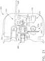
- FIG. 1depicts a master controller 12 that is used in connection with a robotic arm slave cart 20 of the type depicted in FIG. 2 .
- Master controller 12 and robotic arm slave cart 20, as well as their respective components and control systemsare collectively referred to herein as a robotic system 10. Examples of such systems and devices are disclosed in U.S. Patent No. 7,524,320 which has been herein incorporated by reference. Thus, various details of such devices will not be described in detail herein beyond that which may be necessary to understand various example embodiments disclosed herein.
- the master controller 12generally includes master controllers (generally represented as 14 in FIG. 1 ) which are grasped by the surgeon and manipulated in space while the surgeon views the procedure via a stereo display 16.
- the master controllers 12generally comprise manual input devices which preferably move with multiple degrees of freedom, and which often further have an actuatable handle for actuating tools (for example, for closing grasping jaws, applying an electrical potential to an electrode, or the like).
- the robotic arm cart 20is configured to actuate a plurality of surgical tools, generally designated as 30.
- a plurality of surgical toolsgenerally designated as 30.
- Various robotic surgery systems and methods employing master controller and robotic arm cart arrangementsare disclosed in U.S. Patent No. 6,132,368 , entitled “Multi-Component Telepresence System and Method", the full disclosure of which is incorporated herein by reference.
- the robotic arm cart 20includes a base 22 from which, in the illustrated embodiment, three surgical tools 30 are supported.
- the surgical tools 30are each supported by a series of manually articulatable linkages, generally referred to as set-up joints 32, and a robotic manipulator 34.
- set-up joints 32generally referred to as set-up joints
- robotic manipulator 34a series of manually articulatable linkages
- the cart 20generally has dimensions suitable for transporting the cart 20 between operating rooms.
- the cart 20is configured to typically fit through standard operating room doors and onto standard hospital elevators.
- the cart 20would preferably have a weight and include a wheel (or other transportation) system that allows the cart 20 to be positioned adjacent an operating table by a single attendant.
- robotic manipulators 34as shown include a linkage 38 that constrains movement of the surgical tool 30.
- Linkage 38includes rigid links coupled together by rotational joints in a parallelogram arrangement so that the surgical tool 30 rotates around a point in space 40, as more fully described in U.S. Patent No. 5,817,084 , the full disclosure of which is herein incorporated by reference.
- the parallelogram arrangementconstrains rotation to pivoting about an axis 40a, sometimes called the pitch axis.
- the links supporting the parallelogram linkageare pivotally mounted to set-up joints 32 ( FIG. 2 ) so that the surgical tool 30 further rotates about an axis 40b, sometimes called the yaw axis.
- the pitch and yaw axes 40a, 40bintersect at the remote center 42, which is aligned along a shaft 44 of the surgical tool 30.
- the surgical tool 30may have further degrees of driven freedom as supported by manipulator 50, including sliding motion of the surgical tool 30 along the longitudinal tool axis "LT-LT".
- remote center 42remains fixed relative to base 52 of manipulator 50.
- Linkage 54 of manipulator 50is driven by a series of motors 56. These motors actively move linkage 54 in response to commands from a processor of a control system. Motors 56 are also employed to manipulate the surgical tool 30.
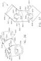
- An alternative set-up joint structureis illustrated in FIG. 4 . In this embodiment, a surgical tool 30 is supported by an alternative manipulator structure 50' between two tissue manipulation tools.
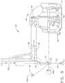
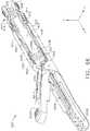
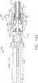
- FIG. 5illustrates an additional embodiment of the surgical tool 100 and electrosurgical end effector 3000.
- the surgical tool 100includes an electrosurgical end effector 3000.
- the electrosurgical end effector 3000may utilize electrical energy to treat and/or destroy tissue.
- the electrosurgical end effector 3000generally comprises first and second jaw members 3008A, 3008B which may be straight, as shown in FIGS. 6-10 , or curved as shown in various other figures described herein.
- One or both of the jaw members 3008A, 3008Bgenerally comprise various electrodes for providing electrosurgical energy to tissue.
- the surgical tool 100generally includes an elongate shaft assembly 200 that is operably coupled to the manipulator 50 by a tool mounting portion, generally designated as 300.
- Electrosurgical toolse.g., surgical tools that include an electrosurgical end effector, such at the tool 100 and end effector 3000
- electrosurgical toolscomprise one or more electrodes for providing electric current.
- the electrodesmay be positioned against and/or positioned relative to tissue such that electrical current can flow through the tissue.
- the electrical currentmay generate heat in the tissue that, in turn, causes one or more hemostatic seals to form within the tissue and/or between tissues.
- tissue heating caused by the electrical currentmay at least partially denature proteins within the tissue.
- proteinssuch as collagen, for example, may be denatured into a proteinaceous amalgam that intermixes and fuses, or "welds", together as the proteins renature. As the treated region heals over time, this biological "weld” may be reabsorbed by the body's wound healing process.
- Electrical energy provided by electrosurgical toolsmay be of any suitable form including, for example, direct or alternating current.
- the electrical energymay include high frequency alternating current such as radio frequency or "RF" energy.
- RF energymay include energy in the range of 300 kilohertz (kHz) to 1 megahertz (MHz).
- kHzkilohertz
- MHzmegahertz
- RF energymay cause ionic agitation or friction, increasing the temperature of the tissue.
- RF energymay provide a sharp boundary between affected tissue and other tissue surrounding it, allowing surgeons to operate with a high level of precision and control.
- the low operating temperatures of RF energyenables surgeons to remove, shrink or sculpt soft tissue while simultaneously sealing blood vessels.
- RF energyworks particularly well on connective tissue, which is primarily comprised of collagen and shrinks when contacted by heat.
- some bi-polar (e.g., two-electrode) electrosurgical toolscan comprise opposing first and second jaw members, where the face of each jaw can comprise a current path and/or electrode.
- the tissuecan be captured between the jaw faces such that electrical current can flow between the electrodes in the opposing jaw members and through the tissue positioned therebetween.
- Such toolsmay have to coagulate, seal or "weld" many types of tissues, such as anatomic structures having walls with irregular or thick fibrous content, bundles of disparate anatomic structures, substantially thick anatomic structures, and/or tissues with thick fascia layers such as large diameter blood vessels, for example.
- Some embodimentsmay include a knife or cutting edge to transect the tissue, for example, during or after the application of electrosurgical energy. With particular regard to cutting and sealing large diameter blood vessels, for example, such applications may require a high strength tissue weld immediately post-treatment.
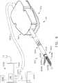
- FIG. 6is a perspective view of one embodiment of the electrosurgical tool 100 in electrical communication with a generator 3002.
- the electrosurgical tool 100 in conjunction with the generator 3002can be configured to supply energy, such as electrical energy, ultrasonic energy, and/or heat energy, for example, to the tissue of a patient.
- the generator 3002is connected to electrosurgical tool 100 via a suitable transmission medium such as a cable 3010.
- the generator 3002is coupled to a controller, such as a control unit 3004, for example.
- the control unit 3004may be formed integrally with the generator 3002 or may be provided as a separate circuit module or device electrically coupled to the generator 3002 (shown in phantom to illustrate this option).
- the generator 3002is shown separate from the electrosurgical tool 100, in one embodiment, the generator 3002 (and/or the control unit 3004) may be formed integrally with the electrosurgical tool 100 to form a unitary electrosurgical system.
- a generator or equivalent circuitmay be present within the tool mounting portion 300 and/or within a handle in suitable manual embodiments (as described herein).
- the generator 3002may comprise an input device 3006 located on a front panel of the generator 3002 console.
- the input device 3006may comprise any suitable device that generates signals suitable for programming the operation of the generator 3002, such as a keyboard, or input port, for example.
- various electrodes in the first jaw member 3008A and the second jaw member 3008Bmay be coupled to the generator 3002.
- a cable 3010 connecting the tool mounting portion 300 to the generator 3002may comprise multiple electrical conductors for the application of electrical energy to positive (+) and negative (-) electrodes of the electrosurgical tool 100.
- the control unit 3004may be used to activate the generator 3002, which may serve as an electrical source.
- the generator 3002may comprise an RF source, an ultrasonic source, a direct current source, and/or any other suitable type of electrical energy source, for example.
- surgical tool 100may comprise at least one supply conductor 3012 and at least one return conductor 3014, wherein current can be supplied to electrosurgical tool 100 via the supply conductor 3012 and wherein the current can flow back to the generator 3002 via return conductor 3014.
- the supply conductor 3012 and the return conductor 3014may comprise insulated wires and/or any other suitable type of conductor.
- the supply conductor 3012 and the return conductor 3014may be contained within and/or may comprise the cable 3010 extending between, or at least partially between, the generator 3002 and the end effector 3000 of the electrosurgical tool 100.
- the generator 3002can be configured to apply a sufficient voltage differential between the supply conductor 3012 and the return conductor 3014 such that sufficient current can be supplied to the end effector 3000.
- the electrosurgical end effector 3000may be adapted for capturing and transecting tissue and for the contemporaneously welding the captured tissue with controlled application of energy (e.g., RF energy).
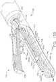
- FIG. 7illustrates one embodiment of the electrosurgical end effector 300 with the jaw members 3008A, 3008B open and an axially movable member 3016 in a proximally retracted position.
- FIG. 8illustrates one embodiment of the electrosurgical end effector 300 with the jaw members 3008A, 3008B closed and the axially movable member 3016 in a partially advanced position.
- the jaw members 3008A, 3008Bclose to thereby capture or engage tissue about a longitudinal tool axis LT-LT defined by the axially moveable member 3016 (or a distal portion thereof).
- the first jaw member 3008A and second jaw member 3008Bmay also apply compression to the tissue.
- the elongate shaft 200, along with first jaw member 3008A and second jaw member 3008B,can be rotated a full 360° degrees, as shown by arrow 3018 (see FIG. 8 ), relative to tool mounting portion 300.
- the first jaw member 3008A and the second jaw member 3008Bmay each comprise an elongate slot or channel 3020A and 3020B ( FIG. 7 ), respectively, disposed outwardly along their respective middle portions. Further, the first jaw member 3008A and second jaw member 3008B may each have tissue-gripping elements, such as teeth 3022, disposed on the inner portions of first jaw member 3008A and second jaw member 3008B.
- the lower jaw member 3008Bmay define a jaw body with an energy delivery surface or electrode 3024B.
- the electrode 3024Bmay be in electrical communication with the generator 3002 via the supply conductor 3012.
- An energy delivery surface 3024A on the upper first jaw member 3008may provide a return path for electrosurgical energy.
- the energy delivery surface 3024Amay be in electrical communication with the return conductor 3014.
- other conductive parts of the surgical tool 100including, for example the jaw members 3008A, 3008B, the shaft 200, etc. may form all or a part of the return path.
- Various configurations of electrodes and various configurations for coupling the energy delivery surfaces 3024A, 3024B to the conductors 3012, 3014are described herein.
- the supply electrode 3024Bmay be provided on the lower jaw member 3008B as shown or on the upper jaw member 3008A.
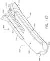
- FIG. 9is a perspective view of one embodiment of the axially moveable member 3016 of the surgical tool 100.
- the axially moveable member 3016may comprise one or several pieces, but in any event, may be movable or translatable with respect to the elongate shaft 200 and/or the jaw members 3008A, 3008B. Also, in at least one embodiment, the axially moveable member 3016 may be made of 17-4 precipitation hardened stainless steel.
- the distal end of axially moveable member 3016may comprise a flanged "I"-beam configured to slide within the channels 3020AA and 3020B in jaw members 3008A and 3008B.
- the axially moveable member 3016may slide within the channels 3020A, 3020B to open and close first jaw member 3008A and second jaw member 3008B.
- the distal end of the axially moveable member 3016may also comprise an upper flange or "c"-shaped portion 3016A and a lower flange or "c"-shaped portion 3016B.
- the flanges 3016A and 3016Brespectively define inner cam surfaces 3026A and 3026B for engaging outward facing surfaces of first jaw member 3008A and second jaw member 3008B.
- jaw members 3008A and 3008Bcan apply very high compressive forces on tissue using cam mechanisms which may include movable "I-beam” axially moveable member 3016 and the outward facing surfaces 3028A, 3028B of jaw members 3008A, 3008B.
- the inner cam surfaces 3026A and 3026B of the distal end of axially moveable member 3016may be adapted to slidably engage the first outward-facing surface 3028A and the second outward-facing surface 3028B of the first jaw member 3008A and the second jaw member 3008B, respectively.
- the channel 3020A within first jaw member 3008A and the channel 3020B within the second jaw member 3008Bmay be sized and configured to accommodate the movement of the axially moveable member 3016, which may comprise a tissue-cutting element 3030, for example, comprising a sharp distal edge.
- the upper first jaw member 3008A and lower second jaw member 3008Bdefine a gap or dimension D between the first energy delivery surface 3024A and second energy delivery surface 3024B of first jaw member 3008A and second jaw member 3008B, respectively.
- dimension Dcan equal from about 0.0005" to about 0.040", for example, and in some embodiments, between about 0.001" to about 0.010", for example.
- the edges ofthe first energy delivery surface 3024A and the second energy delivery surface 3024Bmay be rounded to prevent the dissection of tissue.
- FIG. 10is a section view of one embodiment of the end effector 3000 of the surgical tool 100.
- the engagement, or tissue-contacting, surface 3024B ofthe lower jaw member 3008Bis adapted to deliver energy to tissue, at least in part, through a conductive-resistive matrix, such as a variable resistive positive temperature coefficient (PTC) body, as discussed in more detail below.
- a conductive-resistive matrixsuch as a variable resistive positive temperature coefficient (PTC) body, as discussed in more detail below.
- At least one of the upper and lower jaw members 3008A, 3008Bmay carry at least one electrode 3032 configured to deliver the energy from the generator 3002 to the captured tissue.
- the engagement, or tissue-contacting, surface 3024A of upper jaw member 3008Amay carry a similar conductive-resistive matrix (i.e., a PTC material), or in some embodiments the surface may be a conductive electrode or an insulative layer, for example.
- the engagement surfaces of the jaw memberscan carry any of the energy delivery components disclosed in U.S. Patent No. 6,773,409, filed Oct. 22, 2001 , entitled ELECTROSURGICAL JAW STRUCTURE FOR CONTROLLED ENERGY DELIVERY, the entire disclosure of which is incorporated herein by reference.
- the first energy delivery surface 3024A and the second energy delivery surface 3024Bmay each be in electrical communication with the generator 3002.
- the first energy delivery surface 3024A and the second energy delivery surface 3024Bmay be configured to contact tissue and deliver electro surgical energy to captured tissue which are adapted to seal or weld the tissue.
- the control unit 3004regulates the electrical energy delivered by electrical generator 3002 which in turn delivers electrosurgical energy to the first energy delivery surface 3024A and the second energy delivery surface 3024B.
- the energy deliverymay be initiated in any suitable manner ( e.g ., upon actuation of the robot system 10.
- the electrosurgical tool 100may be energized by the generator 3002 by way of a foot switch 3034 ( FIG. 6 ).
- the foot switch 3034When actuated, the foot switch 3034 triggers the generator 3002 to deliver electrical energy to the end effector 3000, for example.
- the control unit 3004may regulate the power generated by the generator 3002 during activation.
- the foot switch 3034may be suitable in many circumstances, other suitable types of switches can be used.
- the electrosurgical energy delivered by electrical generator 3002 and regulated, or otherwise controlled, by the control unit 3004may comprise radio frequency (RF) energy, or other suitable forms of electrical energy.
- RFradio frequency
- one or both of the opposing first and second energy delivery surfaces 3024A and 3024Bmay carry variable resistive positive temperature coefficient (PTC) bodies that are in electrical communication with the generator 3002 and the control unit 3004. Additional details regarding electrosurgical end effectors, jaw closing mechanisms, and electrosurgical energy-delivery surfaces are described in the following U.S. patents and published patent applications: U.S. Pat. Nos.
- the generator 3002may be implemented as an electrosurgery unit (ESU) capable of supplying power sufficient to perform bipolar electrosurgery using radio frequency (RF) energy.
- ESUelectrosurgery unit
- RFradio frequency
- the ESUcan be a bipolar ERBE ICC 350 sold by ERBE USA, Inc. of Marietta, Georgia.
- a surgical tool having an active electrode and a return electrodecan be utilized, wherein the active electrode and the return electrode can be positioned against, adjacent to and/or in electrical communication with, the tissue to be treated such that current can flow from the active electrode, through the positive temperature coefficient (PTC) bodies and to the return electrode through the tissue.
- PTCpositive temperature coefficient
- the electrosurgical system 150may comprise a supply path and a return path, wherein the captured tissue being treated completes, or closes, the circuit.
- the generator 3002may be a monopolar RF ESU and the electrosurgical tool 100 may comprise a monopolar end effector 3000 in which one or more active electrodes are integrated.
- the generator 3002may require a return pad in intimate contact with the patient at a location remote from the operative site and/or other suitable return path.
- the return padmay be connected via a cable to the generator 3002.
- the clinicianDuring operation of electrosurgical tool 100, the clinician generally grasps tissue, supplies energy to the captured tissue to form a weld or a seal ( e.g., by actuating button 214 and/or pedal 216), and then drives the tissue-cutting element 3030 at the distal end of the axially moveable member 3016 through the captured tissue.
- the translation of the axial movement of the axially moveable member 3016may be paced, or otherwise controlled, to aid in driving the axially moveable member 3016 at a suitable rate of travel. By controlling the rate of the travel, the likelihood that the captured tissue has been properly and functionally sealed prior to transection with the cutting element 3030 is increased.
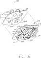
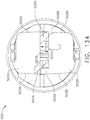
- the tool mounting portion 300includes a tool mounting plate 304 that operably supports a plurality of (four are shown in FIG. 15 ) rotatable body portions, driven discs or elements 306, that each include a pair of pins 308 that extend from a surface of the driven element 306.
- One pin 308is closer to an axis of rotation of each driven elements 306 than the other pin 308 on the same driven element 306, which helps to ensure positive angular alignment of the driven element 306.
- Interface 302may include an adaptor portion 310 that is configured to mountingly engage a mounting plate 304 as will be further discussed below.
- the illustrated adaptor portion 310includes an array of electrical connecting pins 312 ( FIG.
- interface 302is described herein with reference to mechanical, electrical, and magnetic coupling elements, it should be understood that a wide variety of telemetry modalities might be used, including infrared, inductive coupling, or the like in other embodiments.
- the adapter portion 310generally includes a tool side 314 and a holder side 316.
- a plurality of rotatable bodies 320are mounted to a floating plate 318 which has a limited range of movement relative to the surrounding adaptor structure normal to the major surfaces of the adaptor 310.
- Axial movement of the floating plate 318helps decouple the rotatable bodies 320 from the tool mounting portion 300 when levers or other latch formations along the sides of the tool mounting portion housing (not shown) are actuated.
- Other embodimentsmay employ other mechanisms/arrangements for releasably coupling the tool mounting portion 300 to the adaptor 310. In the embodiment of FIGS.
- rotatable bodies 320are resiliently mounted to floating plate 318 by resilient radial members which extend into a circumferential indentation about the rotatable bodies 320.
- the rotatable bodies 320can move axially relative to plate 318 by deflection of these resilient structures.
- tabs 322(extending radially from the rotatable bodies 320) laterally engage detents on the floating plates so as to limit angular rotation of the rotatable bodies 320 about their axes.
- This limited rotationcan be used to help drivingly engage the rotatable bodies 320 with drive pins 332 of a corresponding tool holder portion 330 of the robotic system 10, as the drive pins 332 will push the rotatable bodies 320 into the limited rotation position until the pins 332 are aligned with (and slide into) openings 334'.
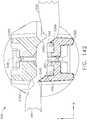
- Openings 334 on the tool side 314 and openings 334' on the holder side 316 of rotatable bodies 320are configured to accurately align the driven elements 306 ( FIG. 15 ) of the tool mounting portion 300 with the drive elements 336 of the tool holder 330.
- each of the openings 304may be slightly radially elongate so as to fittingly receive the pins 308 in the circumferential orientation. This allows the pins 308 to slide radially within the openings 334, 334' and accommodate some axial misalignment between the tool 100 and tool holder 330, while minimizing any angular misalignment and backlash between the drive and driven elements. Openings 334 on the tool side 314 may be offset by about 90 degrees from the openings 334' (shown in broken lines) on the holder side 316, as can be seen most clearly in FIG. 14 .
- an array of electrical connector pins 340are located on holder side 316 of adaptor 310 and the tool side 314 of the adaptor 310 includes slots 342 ( FIG. 14 ) for receiving a pin array (not shown) from the tool mounting portion 300.
- at least some of these electrical connectionsmay be coupled to an adaptor memory device 344 ( FIG. 13 ) by a circuit board of the adaptor 310.
- a detachable latch arrangement 346is employed to releasably affix the adaptor 310 to the tool holder 330.
- the tool holder 330includes a first latch pin arrangement 337 that is sized to be received in corresponding clevis slots 311 provided in the adaptor 310.
- the tool holder 330further has second latch pins 338 that are sized to be retained in corresponding latch clevises 313 in the adaptor 310.
- a latch assembly 315is movably supported on the adapter 310 and has a pair of latch clevises 317 formed therein that is biasable from a first latched position wherein the latch pins 338 are retained within their respective latch clevis 313 and an unlatched position wherein the clevises 317 are aligned with clevises 313 to enable the second latch pins 338 may be inserted into or removed from the latch clevises 313.
- a spring or springs(not shown) are employed to bias the latch assembly into the latched position.
- a lip on the tool side 314 of adaptor 310slidably receives laterally extending tabs of the tool mounting housing (not shown).
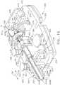
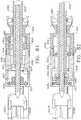
- the tool mounting portion 300operably supports a plurality of drive systems for generating various forms of control motions necessary to operate a particular type of end effector that is coupled to the distal end of the elongate shaft assembly 200.
- the tool mounting portion 300includes a first drive system generally designated as 350 that is configured to receive a corresponding "first" rotary output motion from the tool drive assembly 110 of the robotic system 10 and convert that first rotary output motion to a first rotary control motion to be applied to the surgical end effector.
- the first rotary control motionis employed to rotate the elongate shaft assembly 200 (and surgical end effector 3000) about a longitudinal tool axis LT-LT.
- the first drive system 350includes a tube gear segment 354 that is formed on (or attached to) the proximal end 208 of a proximal tube segment 202 of the elongate shaft assembly 200.
- the proximal end 208 of the proximal tube segment 202is rotatably supported on the tool mounting plate 304 of the tool mounting portion 300 by a forward support cradle 352 that is mounted on the tool mounting plate 304. See FIG. 16 .
- the tube gear segment 354is supported in meshing engagement with a first rotational gear assembly 360 that is operably supported on the tool mounting plate 304. As can be seen in FIG.
- the rotational gear assembly 360comprises a first rotation drive gear 362 that is coupled to a corresponding first one of the driven discs or elements 306 on the holder side 316 of the tool mounting plate 304 when the tool mounting portion 300 is coupled to the tool drive assembly 110. See FIG. 15 .
- the rotational gear assembly 360further comprises a first rotary driven gear 364 that is rotatably supported on the tool mounting plate 304.
- the first rotary driven gear 364is in meshing engagement with a second rotary driven gear 366 which, in turn, is in meshing engagement with the tube gear segment 354.
- Application of a first rotary output motion from the tool drive assembly 110 of the robotic system 10 to the corresponding driven element 306will thereby cause rotation of the rotation drive gear 362.
- Rotation of the rotation drive gear 362ultimately results in the rotation of the elongate shaft assembly 200 (and the surgical end effector 3000) about the longitudinal tool axis LT-LT (represented by arrow "R" in FIG. 5 ).
- the application of a rotary output motion from the tool drive assembly 110 in one directionwill result in the rotation of the elongate shaft assembly 200 and surgical end effector 3000 about the longitudinal tool axis LT-LT in a first rotary direction and an application of the rotary output motion in an opposite direction will result in the rotation of the elongate shaft assembly 200 and surgical end effector 3000 in a second rotary direction that is opposite to the first rotary direction.
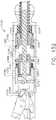
- the tool mounting portion 300further includes a second drive system generally designated as 370 that is configured to receive a corresponding "second" rotary output motion from the tool drive assembly 110 of the robotic system 10 and convert that second rotary output motion to a second rotary control motion for application to the surgical end effector.
- the second drive system 370includes a second rotation drive gear 372 that is coupled to a corresponding second one of the driven discs or elements 306 on the holder side 316 of the tool mounting plate 304 when the tool mounting portion 300 is coupled to the tool drive assembly 110. See FIG. 15 .
- the second drive system 370further comprises a first rotary driven gear 374 that is rotatably supported on the tool mounting plate 304.
- the first rotary driven gear 374is in meshing engagement with a shaft gear 376 that is movably and non-rotatably mounted onto a proximal drive shaft segment 380.
- the shaft gear 376is non-rotatably mounted onto the proximal drive shaft segment 380 by a series of axial keyways 384 that enable the shaft gear 376 to axially move on the proximal drive shaft segment 380 while being non-rotatably affixed thereto.
- Rotation of the proximal drive shaft segment 380results in the transmission of a second rotary control motion to the surgical end effector 3000.
- the second drive system 370 in the embodiment of FIG. 5 and 16-21includes a shifting system 390 for selectively axially shifting the proximal drive shaft segment 380 which moves the shaft gear 376 into and out of meshing engagement with the first rotary driven gear 374.
- the proximal drive shaft segment 380is supported within a second support cradle 382 that is attached to the tool mounting plate 304 such that the proximal drive shaft segment 380 may move axially and rotate relative to the second support cradle 382.
- the shifting system 390further includes a shifter yoke 392 that is slidably supported on the tool mounting plate 304.
- the proximal drive shaft segment 380is supported in the shifter yoke 392 and has a pair of collars 386 thereon such that shifting of the shifter yoke 392 on the tool mounting plate 304 results in the axial movement of the proximal drive shaft segment 380.
- the shifting system 390further includes a shifter solenoid 394 that operably interfaces with the shifter yoke 392.
- the shifter solenoid 394receives control power from the robotic controller 12 such that when the shifter solenoid 394 is activated, the shifter yoke 392 is moved in the distal direction "DD".
- a shaft spring 396is journaled on the proximal drive shaft segment 380 between the shaft gear 376 and the second support cradle 382 to bias the shaft gear 376 in the proximal direction "PD" and into meshing engagement with the first rotary driven gear 374. See FIGS. 16 , 18 and 19 .
- Rotation of the second rotation drive gear 372 in response to rotary output motions generated by the robotic system 10ultimately results in the rotation of the proximal drive shaft segment 380 and other drive shaft components coupled thereto (drive shaft assembly 388) about the longitudinal tool axis LT-LT.
- the shifter solenoid 390may be capable of shifting the proximal drive shaft segment 380 between more than two longitudinal positions.
- some embodimentssuch as those described herein with respect to FIGS. 83-96 , may utilize the rotary drive shaft ( e.g., coupled to the proximal drive shaft segment 380) in more than two longitudinal positions.
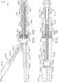
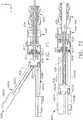
- FIGS. 22-23illustrate another embodiment that employs the same components of the embodiment depicted in FIGS. 5 and 16-21 except that this embodiment employs a battery-powered drive motor 400 for supplying rotary drive motions to the proximal drive shaft segment 380.
- a battery-powered drive motor 400for supplying rotary drive motions to the proximal drive shaft segment 380.
- the motor 400is attached to the tool mounting plate 304 by a support structure 402 such that a driver gear 404 that is coupled to the motor 400 is retained in meshing engagement with the shaft gear 376.
- the support structure 402is configured to removably engage latch notches 303 formed in the tool mounting plate 304 that are designed to facilitate attachment of a housing member (not shown) to the mounting plate 304 when the motor 400 is not employed.
- the clinicianremoves the housing from the tool mounting plate 304 and then inserts the legs 403 of the support structure into the latch notches 303 in the tool mounting plate 304.
- the proximal drive shaft segment 380 and the other drive shaft components attached theretoare rotated about the longitudinal tool axis LT-LT by powering the motor 400.
- the motor 400is battery powered. In such arrangement, however, the motor 400 interface with the robotic controller 12 such that the robotic system 10 controls the activation of the motor 400.
- the motor 400is manually actuatable by an on/off switch (not shown) mounted on the motor 400 itself or on the tool mounting portion 300.
- the motor 400may receive power and control signals from the robotic system.
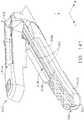
- FIGS. 5 and 16-21includes a manually-actuatable reversing system, generally designated as 410, for manually applying a reverse rotary motion to the proximal drive shaft segment 380 in the event that the motor fails or power to the robotic system is lost or interrupted.
- a manually-actuatable reversing system 410may also be particularly useful, for example, when the drive shaft assembly 388 becomes jammed or otherwise bound in such a way that would prevent reverse rotation of the drive shaft components under the motor power alone.
- the mechanically-actuatable reversing system 410includes a drive gear assembly 412 that is selectively engagable with the second rotary driven gear 376 and is manually actuatable to apply a reversing rotary motion to the proximal drive shaft segment 380.
- the drive gear assembly 412includes a reversing gear 414 that is movably mounted to the tool mounting plate 304.
- the reversing gear 414is rotatably journaled on a pivot shaft 416 that is movably mounted to the tool mounting plate 304 through a slot 418. See FIG. 17 .
- the manually-actuatable reversing system 410further includes a manually actuatable drive gear 420 that includes a body portion 422 that has an arcuate gear segment 424 formed thereon.
- the body portion 422is pivotally coupled to the tool mounting plate 304 for selective pivotal travel about an actuator axis A-A ( FIG. 16 ) that is substantially normal to the tool mounting plate 304.
- FIGS. 16-19depict the manually-actuatable reversing system 410 in a first unactuated position.
- an actuator handle portion 426is formed on or otherwise attached to the body portion 422.
- the actuator handle portion 426is sized relative to the tool mounting plate 304 such that a small amount of interference is established between the handle portion 426 and the tool mounting plate 304 to retain the handle portion 426 in the first unactuated position.
- the cliniciancan easily overcome the interference fit by applying a pivoting motion to the handle portion 426.
- the arcuate gear segment 424is brought into meshing engagement with the reversing gear 414.
- Continued ratcheting of the drive gear 420results in the application of a reverse rotary drive motion to the drive shaft gear 376 and ultimately to the proximal drive shaft segment 380.
- the clinicianmay continue to ratchet the drive gear assembly 412 for as many times as are necessary to fully release or reverse the associated end effector component(s).
- the clinicianreturns the drive gear 420 to the starting or unactuated position wherein the arcuate gear segment 416 is out of meshing engagement with the drive shaft gear 376.
- the shaft spring 396once again biases the shaft gear 376 into meshing engagement with first rotary driven gear 374 of the second drive system 370.
- the clinicianmay input control commands to the controller or control unit of the robotic system 10 which "robotically-generates” output motions that are ultimately transferred to the various components of the second drive system 370.
- the terms “robotically-generates” or “robotically-generated”refer to motions that are created by powering and controlling the robotic system motors and other powered drive components. These terms are distinguishable from the terms “manually-actuatable” or “manually generated” which refer to actions taken by the clinician which result in control motions that are generated independent from those motions that are generated by powering the robotic system motors.
- the axially movable member 3016is driven in the proximal direction "PD" from its ending position toward its starting position in the end effector 3000.
- the drive shaft assembly 388is rotated in the second rotary direction which causes a firing member (e.g., axially translatable member 3016) to move in the proximal direction "PD" in the end effector.
- the drive shaft assembly that is used to fire, close and rotate the end effectorcan be actuated and shifted manually allowing the end effector to release and be extracted from the surgical site as well as the abdomen even in the event that the motor(s) fail, the robotic system loses power or other electronic failure occurs.
- Actuation of the handle portion 426results in the manual generation of actuation or control forces that are applied to the drive shaft assembly 388' by the various components of the manually-actuatable reversing system 410. If the handle portion 426 is in its unactuated state, it is biased out of actuatable engagement with the reversing gear 414. The beginning of the actuation of the handle portion 426 shifts the bias.
- the handle 426is configured for repeated actuation for as many times as are necessary to fully release the axially movable member 3016 and the end effector 3000.
- the tool mounting portion 300includes a third drive system 430 that is configured to receive a corresponding "third" rotary output motion from the tool drive assembly 110 of the robotic system 10 and convert that third rotary output motion to a third rotary control motion.
- the third drive system 430includes a third drive pulley 432 that is coupled to a corresponding third one of the driven discs or elements 306 on the holder side 316 of the tool mounting plate 304 when the tool mounting portion 300 is coupled to the tool drive assembly 110. See FIG. 15 .
- the third drive pulley 432is configured to apply a third rotary control motion (in response to corresponding rotary output motions applied thereto by the robotic system 10) to a corresponding third drive cable 434 that may be used to apply various control or manipulation motions to the end effector that is operably coupled to the shaft assembly 200.
- the third drive cable 434extends around a third drive spindle assembly 436.
- the third drive spindle assembly 436is pivotally mounted to the tool mounting plate 304 and a third tension spring 438 is attached between the third drive spindle assembly 436 and the tool mounting plate 304 to maintain a desired amount of tension in the third drive cable 434.
- cable end portion 434A of the third drive cable 434extends around an upper portion of a pulley block 440 that is attached to the tool mounting plate 304 and cable end portion 434B extends around a sheave pulley or standoff 442 on the pulley block 440. It will be appreciated that the application of a third rotary output motion from the tool drive assembly 110 in one direction will result in the rotation of the third drive pulley 432 in a first direction and cause the cable end portions 434A and 434B to move in opposite directions to apply control motions to the end effector 3000 or elongate shaft assembly 200 as will be discussed in further detail below.
- the tool mounting portion 300 illustrated in FIGS. 5 and 16-21includes a fourth drive system 450 that is configured to receive a corresponding "fourth" rotary output motion from the tool drive assembly 110 of the robotic system 10 and convert that fourth rotary output motion to a fourth rotary control motion.
- the fourth drive system 450includes a fourth drive pulley 452 that is coupled to a corresponding fourth one of the driven discs or elements 306 on the holder side 316 of the tool mounting plate 304 when the tool mounting portion 300 is coupled to the tool drive assembly 110. See FIG. 15 .
- the fourth drive pulley 452is configured to apply a fourth rotary control motion (in response to corresponding rotary output motions applied thereto by the robotic system 10) to a corresponding fourth drive cable 454 that may be used to apply various control or manipulation motions to the end effector that is operably coupled to the shaft assembly 200.
- the fourth drive cable 454extends around a fourth drive spindle assembly 456.
- the fourth drive spindle assembly 456is pivotally mounted to the tool mounting plate 304 and a fourth tension spring 458 is attached between the fourth drive spindle assembly 456 and the tool mounting plate 304 to maintain a desired amount of tension in the fourth drive cable 454.
- Cable end portion 454A of the fourth drive cable 454extends around a bottom portion of the pulley block 440 that is attached to the tool mounting plate 304 and cable end portion 454B extends around a sheave pulley or fourth standoff 462 on the pulley block 440. It will be appreciated that the application of a rotary output motion from the tool drive assembly 110 in one direction will result in the rotation of the fourth drive pulley 452 in a first direction and cause the cable end portions 454A and 454B to move in opposite directions to apply control motions to the end effector or elongate shaft assembly 200 as will be discussed in further detail below.
- the surgical tool 100 as depicted in FIGS. 5-6includes an articulation joint 3500.
- the third drive system 430may also be referred to as a "first articulation drive system” and the fourth drive system 450 may be referred to herein as a "second articulation drive system”.
- the third drive cable 434may be referred to as a "first proximal articulation cable” and the fourth drive cable 454 may be referred to herein as a "second proximal articulation cable”.
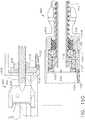
- the tool mounting portion 300 of the embodiment illustrated in FIGS. 5 and 16-21includes a fifth drive system generally designated as 470 that is configured to axially displace a drive rod assembly 490.
- the drive rod assembly 490includes a proximal drive rod segment 492 that extends through the proximal drive shaft segment 380 and the drive shaft assembly 388. See FIG. 18 .
- the fifth drive system 470includes a movable drive yoke 472 that is slidably supported on the tool mounting plate 304.
- the proximal drive rod segment 492is supported in the drive yoke 372 and has a pair of retainer balls 394 thereon such that shifting of the drive yoke 372 on the tool mounting plate 304 results in the axial movement of the proximal drive rod segment 492.
- the fifth drive system 370further includes a drive solenoid 474 that operably interfaces with the drive yoke 472.
- the drive solenoid 474receives control power from the robotic controller 12.
- the end effector 3000includes a jaw members that are movable between open and closed positions upon application of axial closure motions to a closure system.
- the fifth drive system 470is employed to generate such closure motions.
- the fifth drive system 470may also be referred to as a "closure drive”.
- the surgical tool 100 depicted in FIGS. 5 and 16-21includes an articulation joint 3500 that cooperates with the third and fourth drive systems 430, 450, respectively for articulating the end effector 3000 about the longitudinal tool axis "LT".
- the articulation joint 3500includes a proximal socket tube 3502 that is attached to the distal end 233 of the distal outer tube portion 231 and defines a proximal ball socket 3504 therein. See FIG. 24 .
- a proximal ball member 3506is movably seated within the proximal ball socket 3504. As can be seen in FIG. 24 , the proximal ball member 3506 has a central drive passage 3508 that enables the distal drive shaft segment 3740 to extend therethrough.
- the proximal ball member 3506has four articulation passages 3510 therein which facilitate the passage of distal cable segments 444, 445, 446, 447 therethrough.
- distal cable segments 444, 445, 446, 447may be directly or indirectly coupled to proximal cable end portions 434A, 434B, 454A, 454B, respectively, for example, as illustrated by FIG. 24A .
- the articulation joint 3500further includes an intermediate articulation tube segment 3512 that has an intermediate ball socket 3514 formed therein.
- the intermediate ball socket 3514is configured to movably support therein an end effector ball 3522 formed on an end effector connector tube 3520.
- the distal cable segments 444, 445, 446, 447extend through cable passages 3524 formed in the end effector ball 3522 and are attached thereto by lugs 3526 received within corresponding passages 3528 in the end effector ball 3522. Other attachment arrangements may be employed for attaching distal cable segments 444, 445, 446, 447 to the end effector ball 3522.
- the illustrated rotary support joint assembly 3540includes a connector portion 4012 of the end effector drive housing 4010 that is substantially cylindrical in shape.
- a first annular race 4014is formed in the perimeter of the cylindrically-shaped connector portion 4012.
- the rotary support joint assembly 3540further comprises a distal socket portion 3530 that is formed in the end effector connector tube 3520 as shown in FIGS. 25 and 26 .
- the distal socket portion 3530is sized relative to the cylindrical connector portion 4012 such that the connector portion 4012 can freely rotate within the socket portion 3530.
- a second annular race 3532is formed in an inner wall 3531 of the distal socket portion 3530.
- the rotary support joint assembly 3540further includes a ring-like bearing 3534.
- the ring-like bearing 3534comprises a plastic deformable substantially-circular ring that has a cut 3535 therein. The cut forms free ends 3536, 3537 in the ring-like bearing 3534.
- the ring-like bearing 3534has a substantially annular shape in its natural unbiased state.
- the cylindrically shaped connector position 4012is inserted into the distal socket portion 3530 to bring the second annular race 3532 into substantial registry with the first annular race 4014.
- One of the free ends 3536, 3537 of the ring-like bearingis then inserted into the registered annular races 4014, 3532 through the window 3533 in the distal socket portion 3530 of the end effector connector tube 3520.
- the window or opening 3533has a tapered surface 3538 formed thereon. See FIG. 25 .
- the ring-like bearing 3534is essentially rotated into place and, because it tends to form a circle or ring, it does not tend to back out through the window 3533 once installed.
- the end effector connector tube 3520will be rotatably affixed to the connector portion 4012 of the end effector drive housing 4010.
- Such arrangementenables the end effector drive housing 4010 to rotate about the longitudinal tool axis LT-LT relative to the end effector connector tube 3520.
- the ring-like bearing 3534becomes the bearing surface that the end effector drive housing 4010 then rotates on.
- any side loadingtries to deform the ring-like bearing 3534 which is supported and contained by the two interlocking races 4014, 3532 preventing damage to the ring-like bearing 3534.
- Such simple and effective joint assembly employing the ring-like bearing 3534forms a highly lubricious interface between the rotatable portions 4010, 3530.
- the rotary support joint assembly 3540may be disassembled by withdrawing the ring-like bearing member 3532 out through the window 3533.
- the rotary support joint assembly 3540allows for easy assembly and manufacturing while also providing for good end effector support while facilitating rotary manipulation thereof.
- the articulation joint 3500facilitates articulation of the end effector 3000 about the longitudinal tool axis LT.
- the robotic system 10may power the third drive system 430 such that the third drive spindle assembly 436 ( FIGS. 16-18 ) is rotated in a first direction thereby drawing the proximal cable end portion 434A and ultimately distal cable segment 444 in the proximal direction "PD" and releasing the proximal cable end portion 434B and distal cable segment 445 to thereby cause the end effector ball 3522 to rotate within the socket 3514.
- the robotic system 10may power the third drive system 430 such that the third drive spindle assembly 436 is rotated in a second direction thereby drawing the proximal cable end portion 434B and ultimately distal cable segment 445 in the proximal direction "PD" and releasing the proximal cable end portion 434A and distal cable segment 444 to thereby cause the end effector ball 3522 to rotate within the socket 3514.
- the robotic system 10may power the third drive system 430 such that the third drive spindle assembly 436 is rotated in a second direction thereby drawing the proximal cable end portion 434B and ultimately distal cable segment 445 in the proximal direction "PD” and releasing the proximal cable end portion 434A and distal cable segment 444 to thereby cause the end effector ball 3522 to rotate within the socket 3514.
- TDthird direction
- the robotic system 10may power the fourth drive system 450 such that the fourth drive spindle assembly 456 is rotated in a third direction thereby drawing the proximal cable end portion 454A and ultimately distal cable segment 446 in the proximal direction "PD" and releasing the proximal cable end portion 454B and distal cable segment 447 to thereby cause the end effector ball 3522 to rotate within the socket 3514.
- the robotic system 10may power the fourth drive system 450 such that the fourth drive spindle assembly 456 is rotated in a fourth direction thereby drawing the proximal cable end portion 454B and ultimately distal cable segment 447 in the proximal direction "PD" and releasing the proximal cable end portion 454A and distal cable segment 446 to thereby cause the end effector ball 3522 to rotate within the socket 3514.
- FIGS. 5 and 16-21employs rotary and longitudinal motions that are transmitted from the tool mounting portion 300 through the elongate shaft assembly for actuation.
- the drive shaft assembly employed to transmit such rotary and longitudinal motions (e.g., torsion, tension and compression motions) to the end effectoris relatively flexible to facilitate articulation of the end effector about the articulation joint.
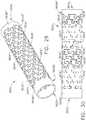
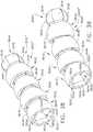
- FIGS. 27-28illustrate an alternative drive shaft assembly 3600 that may be employed in connection with the embodiment illustrated in FIG. 5 and 16-21 or in other embodiments.
- the proximal drive shaft segment 380comprises a segment of drive shaft assembly 3600 and the distal drive shaft segment 3740 similarly comprises another segment of drive shaft assembly 3600.
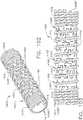
- the drive shaft assembly 3600includes a drive tube 3602 that has a series of annular joint segments 3604 cut therein.
- the drive tube 3602comprises a distal portion of the proximal drive shaft segment 380.
- the shaft assembly 3600, as well as the shaft assemblies 3600', 3600" described herein with respect to FIGS. 27-45may be components of and/or mechanically coupled to various rotary drive shafts described herein including, for example, rotary drive shafts 680, 1270, 1382, etc.
- the drive tube 3602comprises a hollow metal tube (stainless steel, titanium, etc.) that has a series of annular joint segments 3604 formed therein.
- the annular joint segments 3604comprise a plurality of loosely interlocking dovetail shapes 3606 that are, for example, cut into the drive tube 3602 by a laser and serve to facilitate flexible movement between the adjoining joint segments 3604. See FIG. 28 .
- Such laser cutting of a tube stockcreates a flexible hollow drive tube that can be used in compression, tension and torsion.
- Such arrangementemploys a full diametric cut that is interlocked with the adjacent part via a "puzzle piece” configuration. These cuts are then duplicated along the length of the hollow drive tube in an array and are sometimes "clocked” or rotated to change the tension or torsion performance.
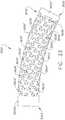
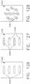
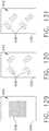
- FIGS. 29-33illustrate alternative example micro-annular joint segments 3604' that comprise plurality of laser cut shapes 3606' that roughly resemble loosely interlocking, opposed "T" shapes and T-shapes with a notched portion therein.
- the annular joint segments 3604, 3604'essentially comprise multiple micro-articulating torsion joints. That is, each joint segment 3604, 3604' can transmit torque while facilitating relative articulation between each annular joint segment.
- the joint segment 3604D' on the distal end 3603 of the drive tube 3602has a distal mounting collar portion 3608D that facilitates attachment to other drive components for actuating the end effector or portions of the quick disconnect joint, etc.
- the joint segment 3604P' on the proximal end 605 of the drive tube 3602has a proximal mounting collar portion 3608P' that facilitates attachment to other proximal drive components or portions of the quick disconnect joint.
- the joint-to joint range of motion for each particular drive shaft assembly 3600can be increased by increasing the spacing in the laser cuts.
- a secondary constraining member 3610is employed.
- the secondary constraining member 3610comprises a spring 3612 or other helically-wound member.
- the distal end 3614 of the spring 3612corresponds to the distal mounting collar portion 3608D and is wound tighter than the central portion 3616 of the spring 3612.
- the proximal end 618 of the spring 3612is wound tighter than the central portion 3616 of the spring 3612.
- the constraining member 3610is installed on the drive tube 3602 with a desired pitch such that the constraining member also functions, for example, as a flexible drive thread for threadably engaging other threaded control components on the end effector and/or the control system.
- the constraining membermay be installed in such a manner as to have a variable pitch to accomplish the transmission of the desired rotary control motions as the drive shaft assembly is rotated.
- the variable pitch arrangement of the constraining membermay be used to enhance open/close and firing motions which would benefit from differing linear strokes from the same rotation motion.
- the drive shaft assemblycomprises a variable pitch thread on a hollow flexible drive shaft that can be pushed and pulled around a ninety degree bend.
- the secondary constraining membercomprises an elastomeric tube or coating 3611 applied around the exterior or perimeter of the drive tube 3602 as illustrated in FIG. 33A .
- the elastomeric tube or coating 3611'is installed in the hollow passageway 613 formed within the drive tube 3602 as shown in FIG. 33B .
- Such drive shaft arrangementscomprise a composite torsional drive axle which allows superior load transmission while facilitating a desirable axial range of articulation. See, e.g., FIGS. 33 and 33A-33B . That is, these composite drive shaft assemblies allow a large range of motion while maintaining the ability to transmit torsion in both directions as well as facilitating the transmission of tension and compression control motions therethrough.
- the hollow nature of such drive shaft arrangementsfacilitate passage of other control components therethrough while affording improved tension loading.
- some other embodimentsinclude a flexible internal cable that extends through the drive shaft assembly which can assist in the alignment of the joint segments while facilitating the ability to apply tension motions through the drive shaft assembly.
- such drive shaft arrangementsare relatively easily to manufacture and assemble.
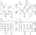
- FIGS. 34-37depict a segment 3620 of a drive shaft assembly 3600'.
- This embodimentincludes joint segments 3622, 3624 that are laser cut out of tube stock material (e.g., stainless steel, titanium, polymer, etc.).
- the joint segments 3622, 3624remain loosely attached together because the cuts 3626 are radial and are somewhat tapered.
- each of the lug portions 3628has a tapered outer perimeter portion 3629 that is received within a socket 3630 that has a tapered inner wall portion. See, e.g., FIGS. 35 and 37 .
- joint segment 3622has opposing pivot lug portions 3628 cut on each end thereof that are pivotally received in corresponding sockets 3630 formed in adjacent joint segments 3624.
- FIGS. 34-37illustrate a small segment of the drive shaft assembly 3600'.
- the lugs/socketsmay be cut throughout the entire length of the drive shaft assembly. That is, the joint segments 3624 may have opposing sockets 3630 cut therein to facilitate linkage with adjoining joint segments 3622 to complete the length of the drive shaft assembly 3600'.
- the joint segments 3624have an angled end portion 3632 cut therein to facilitate articulation of the joint segments 3624 relative to the joint segments 3622 as illustrated in FIGS. 36-37 .
- each lug 3628has an articulation stop portion 3634 that is adapted to contact a corresponding articulation stop 3636 formed in the joint segment 3622. See FIGS. 36-37 .
- Other embodiments, which may otherwise be identical to the segment 3620,are not provided with the articulation stop portions 3634 and stops 3636.
- the joint-to-joint range of motion for each particular drive shaft assemblycan be increased by increasing the spacing in the laser cuts.
- a secondary constraining member in the form of an elastomeric sleeve or coating 3640is employed.
- Other embodimentsemploy other forms of constraining members disclosed herein and their equivalent structures.
- the joint segments 3622, 3624are capable of pivoting about pivot axes "PA-PA" defined by the pivot lugs 3628 and corresponding sockets 3630.
- the drive shaft assembly 3600'may be rotated about the tool axis TL-TL while pivoting about the pivot axes PA-PA.
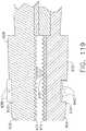
- FIGS. 38-43depict a segment 3640 of another drive shaft assembly 3600".
- the drive shaft assembly 3600"comprises a multi-segment drive system that includes a plurality of interconnected joint segments 3642 that form a flexible hollow drive tube 3602".
- a joint segment 3642includes a ball connector portion 3644 and a socket portion 3648.
- Each joint segment 3642may be fabricated by, for example, metal injection molding "MIM" and be fabricated from 17-4, 17-7, 420 stainless steel. Other embodiments may be machined from 300 or 400 series stainless steel, 6065 or 7071 aluminum or titanium. Still other embodiments could be molded out of plastic infilled or unfilled Nylon, Ultem, ABS, Polycarbonate or Polyethylene, for example.
- the ball connector 3644is hexagonal in shape. That is, the ball connector 3644 has six arcuate surfaces 3646 formed thereon and is adapted to be rotatably received in like-shaped sockets 3650. Each socket 3650 has a hexagonally-shaped outer portion 3652 formed from six flat surfaces 3654 and a radially-shaped inner portion 3656. See FIG. 41 . Each joint segment 3642 is identical in construction, except that the socket portions of the last joint segments forming the distal and proximal ends of the drive shaft assembly 3600 may be configured to operably mate with corresponding control components. Each ball connector 3644 has a hollow passage 3645 therein that cooperate to form a hollow passageway 3603 through the hollow flexible drive tube 3602".
- the interconnected joint segments 3642are contained within a constraining member 3660 which comprises a tube or sleeve fabricated from a flexible polymer material, for example.
- FIG. 44illustrates a flexible inner core member 3662 extending through the interconnected joint segments 3642.
- the inner core member 3662comprises a solid member fabricated from a polymer material or a hollow tube or sleeve fabricated from a flexible polymer material.
- FIG. 45illustrates another embodiment wherein a constraining member 3660 and an inner core member 3662 are both employed.
- Drive shaft assembly 3600facilitates transmission of rotational and translational motion through a variable radius articulation joint.
- the hollow nature of the drive shaft assembly 3600”provides room for additional control components or a tensile element (e.g., a flexible cable) to facilitate tensile and compressive load transmission.
- a tensile elemente.g., a flexible cable
- the joint segments 3624do not afford a hollow passage through the drive shaft assembly.
- the ball connector portionis solid.
- Rotary motionis translated via the edges of the hexagonal surfaces. Tighter tolerances may allow greater load capacity.
- Using a cable or other tensile element through the centerline of the drive shaft assembly 3600"the entire drive shaft assembly 3600” can be rotated bent, pushed and pulled without limiting range of motion.
- the drive shaft assembly 3600"may form an arcuate drive path, a straight drive path, a serpentine drive path, etc.
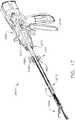
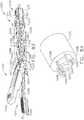
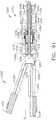
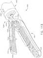
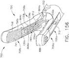
- FIGS. 46-47depict a handheld surgical tool 2400 that may employ various components and systems described above to operably actuate an electrosurgical end effector 3000 coupled thereto.
- the handheld surgical tool 2400may contain and/or be electrically connected to a generator, such as the generator 3002, for generating an electrosurgical drive signal to drive the end effector 300.
- a quick disconnect joint 2210is employed to couple the end effector 3000 to an elongate shaft assembly 2402.
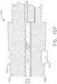
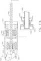
- the quick disconnect joint 2210may operate to remove the end effector 3000 in the manner described herein with reference to FIGS. 106-115 .
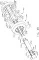
- the proximal portion of the elongate shaft assembly 2402includes an example manually actuatable articulation drive 2410.
- the articulation drive 2410includes four axially movable articulation slides that are movably journaled on the proximal drive shaft segment 380' between the proximal outer tube segment 2214 and the proximal drive shaft segment 380'.
- the articulation cable segment 434A'is attached to a first articulation slide 2420 that has a first articulation actuator rod 2422 protruding therefrom.
- Articulation cable segment 434B'is attached to a second articulation slide 2430 that is diametrically opposite from the first articulation slide 2420.
- the second articulation slide 2430has a second articulation actuator rod 2432 protruding therefrom.
- Articulation cable segment 454A'is attached to a third articulation slide 2440 that has a third articulation actuator rod 2442 protruding therefrom.
- Articulation cable segment 454B'is attached to a fourth articulation slide 2450 that is diametrically opposite to the third articulation slide 2440.
- a fourth articulation actuator rod 2452protrudes from the fourth articulation slide 2450.
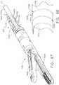
- Articulation actuator rods 2422, 2432, 2442, 2452facilitate the application of articulation control motions to the articulation slides 2420, 2430, 2440, 2450, respectively by an articulation ring assembly 2460.
- the articulation actuator rods 2422, 2432, 2442, 2452movably pass through a mounting ball 2470 that is journaled on a proximal outer tube segment 2404.
- the mounting ball 2470may be manufactured in segments that are attached together by appropriate fastener arrangements (e.g., welding, adhesive, screws, etc.).
- the articulation actuator rods 2422 and 2432extend through slots 2472 in the proximal outer tube segment 2404 and slots 2474 in the mounting ball 2470 to enable the articulation slides 2420, 2430 to axially move relative thereto.
- the articulation actuator rods 2442, 2452extend through similar slots 2472, 2474 in the proximal outer tube segment 2404 and the mounting ball 2470.
- Each of the articulation actuator rods 2422, 2432, 2442, 2452protrude out of the corresponding slots 2474 in the mounting ball 2470 to be operably received within corresponding mounting sockets 2466 in the articulation ring assembly 2460. See FIG. 49 .
- the articulation ring assembly 2460is fabricated from a pair of ring segments 2480, 2490 that are joined together by, for example, welding, adhesive, snap features, screws, etc. to form the articulation ring assembly 2460.
- the ring segments 2480, 2490cooperate to form the mounting sockets 2466.
- Each of the articulation actuator rodshas a mounting ball 2468 formed thereon that are each adapted to be movably received within a corresponding mounting socket 2466 in the articulation ring assembly 2460.
- the articulation drive 2410may further include an example locking system 2486 configured to retain the articulation ring assembly 2460 in an actuated position.
- the locking system 2486comprises a plurality of locking flaps formed on the articulation ring assembly 2460.
- the ring segments 2480, 2490may be fabricated from a somewhat flexible polymer or rubber material. Ring segment 2480 has a series of flexible proximal locking flaps 2488 formed therein and ring segment 2490 has a series of flexible distal locking flaps 2498 formed therein.
- Each locking flap 2388has at least one locking detent 2389 formed thereon and each locking flap 2398 has at least one locking detent 2399 thereon.
- Locking detents 2389, 2399may serve to establish a desired amount of locking friction with the articulation ball so as to retain the articulation ball in position.
- the locking detents 2389, 2390are configured to matingly engage various locking dimples formed in the outer perimeter of the mounting ball 2470.
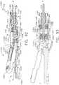
- FIG. 49illustrates the articulation drive 2410 in an unarticulated position.
- the clinicianhas manually tilted the articulation ring assembly 2460 to cause the articulation slide 2420 to move axially in the distal direction "DD" thereby advancing the articulation cable segment 434A' distally.
- Such movement of the articulation ring assembly 2460also results in the axial movement of the articulation slide 2430 in the proximal direction which ultimately pulls the articulation cable 434B in the proximal direction.
- Such pushing and pulling of the articulation cable segments 434A', 434B'will result in articulation of the end effector 3000 relative to the longitudinal tool axis "LT-LT" in the manner described above.
- the cliniciansimply reverses the orientation of the articulation ring assembly 2460 to thereby cause the articulation slide 2430 to move in the distal direction "DD" and the articulation slide 2420 to move in the proximal direction "PD".
- the articulation ring assembly 2460may be similarly actuated to apply desired pushing and pulling motions to the articulation cable segments 454A', 454B'.
- the friction created between the locking detents 2389, 2399 and the outer perimeter of the mounting ballserves to retain the articulation drive 2410 in position after the end effector 3000 has been articulated to the desired position.
- the locking detents 2389, 2399when the locking detents 2389, 2399 are positioned so as to be received in corresponding locking dimples in the mounting ball, the mounting ball will be retained in position.
- the elongate shaft assembly 2402operably interfaces with a handle assembly 2500.
- An example embodiment of handle assembly 2500comprises a pair of handle housing segments 2502, 2504 that are coupled together to form a housing for various drive components and systems as will be discussed in further detail below. See, e.g., FIG. 46 .
- the handle housing segments 2502, 2504may be coupled together by screws, snap features, adhesive, etc. When coupled together, the handle segments 2502, 2504 may form a handle assembly 2500 that includes a pistol grip portion 2506.
- the elongate shaft assembly 2402may interface with a first drive system, generally designated as 2510.
- the drive system 2510includes a manually-actuatable rotation nozzle 2512 that is rotatably supported on the handle assembly 2500 such that it can be rotated relative thereto as well as be axially moved between a locked position and an unlocked position.
- the surgical tool 2400may include a closure system 3670.
- the closure system 3670may be used in some embodiments to bring about distal and proximal motion in the elongate shaft assembly 2402 and end effector 3000.
- the closure system 3670may drive an axially movable member such as 3016.
- the closure system 3670may be used to translate the axially movable member 3016 instead of the various rotary drive shafts described herein with respect to FIGS. 64-82 , 83-91 and 92-96 .
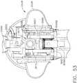
- the closure system 3670is actuated by a closure trigger 2530 that is pivotally mounted to the handle frame assembly 2520 that is supported within the handle housing segments 2502, 2504.
- the closure trigger 2530includes an actuation portion 2532 that is pivotally mounted on a pivot pin 2531 that is supported within the handle frame assembly 2520. See FIG. 51 . Such example arrangement facilitates pivotal travel toward and away from the pistol grip portion 2506 of the handle assembly 2500.
- the closure trigger 2530includes a closure link 2534 that is linked to the first pivot link and gear assembly 3695 by a closure wire 2535.
- the closure link 2534 and closure wire 2535causes the first pivot link and gear assembly 3695 to move in the distal direction "DD" to cause distal motion through the shaft and, in some embodiments, to the end effector.
- the surgical tool 2400may further include a closure trigger locking system 2536 to retain the closure trigger in the actuated position.
- the closure trigger locking system 2536includes a closure lock member 2538 that is pivotally coupled to the handle frame assembly 2520.
- the closure lock member 2538has a lock arm 2539 formed thereon that is configured to ride upon an arcuate portion 2537 of the closure link 2532 as the closure trigger 2530 is actuated toward the pistol grip portion 2506.
- the lock arm 2539drops behind the end of the closure link 2532 and prevents the closure trigger 2530 from returning to its unactuated position.
- the distal motion translated through the shaft assembly to the end effectormay be locked.
- the cliniciansimply pivots the closure lock member 2538 until the lock arm 2539 thereof disengages the end of the closure link 2532 to thereby permit the closure link 2532 to move to the unactuated position.
- the closure trigger 2532is returned to the unactuated position by a closure return system 2540.
- the closure trigger return system 2540includes a closure trigger slide member 2542 that is linked to the closure link 2534 by a closure trigger yoke 2544.
- the closure trigger slide member 2542is slidably supported within a slide cavity 2522 in the handle frame assembly 2520.
- a closure trigger return spring 2546is positioned within the slide cavity 2520 to apply a biasing force to the closure trigger slide member 2542.
- the closure trigger yoke 2544moves the closure trigger slide member 2542 in the distal direction "DD" compressing the closure trigger return spring 2546.
- the closure trigger locking system 2536is disengaged and the closure trigger is released 2530, the closure trigger return spring 2546 moves the closure trigger slide member 2542 in the proximal direction "PD" to thereby pivot the closure trigger 2530 into the starting unactuated position.
- the surgical tool 2400can also employ any of the various example drive shaft assemblies described above.
- the surgical tool 2400employs a second drive system 2550 for applying rotary control motions to a proximal drive shaft assembly 380'. See FIG. 55 .
- the second drive system 2550may include a motor assembly 2552 that is operably supported in the pistol grip portion 2506.
- the motor assembly 2552may be powered by a battery pack 2554 that is removably attached to the handle assembly 2500 or it may be powered by a source of alternating current.
- a second drive gear 2556is operably coupled to the drive shaft 2555 of the motor assembly 2552.
- the second drive gear 2556is supported for meshing engagement with a second rotary driven gear 2558 that is attached to the proximal drive shaft segment 380' of the drive shaft assembly.
- the second drive gear 2556is also axially movable on the motor drive shaft 2555 relative to the motor assembly 2552 in the directions represented by arrow "U" in FIG. 55 .
- a biasing membere.g., a coil spring 2560 or similar member, is positioned between the second drive gear 2556 and the motor housing 2553 and serves to bias the second drive gear 2556 on the motor drive shaft 2555 into meshing engagement with a first gear segment 2559 on the second driven gear 2558.
- the second drive system 2550may further include a firing trigger assembly 2570 that is movably, e.g., pivotally attached to the handle frame assembly 2520.
- the firing trigger assembly 2570includes a first rotary drive trigger 2572 that cooperates with a corresponding switch/contact (not shown) that electrically communicates with the motor assembly 2552 and which, upon activation, causes the motor assembly 2552 to apply a first rotary drive motion to the second driven gear 2558.
- the firing trigger assembly 2570further includes a retraction drive trigger 2574 that is pivotal relative to the first rotary drive trigger.
- the retraction drive trigger 2574operably interfaces with a switch/contact (not shown) that is in electrical communication with the motor assembly 2552 and which, upon activation, causes the motor assembly 2552 to apply a second rotary drive motion to the second driven gear 2558.
- the first rotary drive motionresults in the rotation of the drive shaft assembly and the implement drive shaft in the end effector to cause the firing member to move distally in the end effector 3000.
- the second rotary drive motionis opposite to the first rotary drive motion and will ultimately result in rotation of the drive shaft assembly and the implement drive shaft in a rotary direction which results in the proximal movement or retraction of the firing member in the end effector 3000.
- the illustrated embodimentalso includes a manually actuatable safety member 2580 that is pivotally attached to the closure trigger actuation portion 2532 and is selectively pivotable between a first "safe” position wherein the safety member 2580 physically prevents pivotal travel of the firing trigger assembly 2570 and a second "off" position, wherein the clinician can freely pivot the firing trigger assembly 2570.
- a first dimple 2582is provided in the closure trigger actuation portion 2532 that corresponds to the first position of the safety member 2580. When the safety member 2580 is in the first position, a detent (not shown) on the safety member 2580 is received within the first dimple 2582.
- a second dimple 2584is also provided in the closure trigger actuation portion 2532 that corresponds to the second position of the safety member 2580. When the safety member 2580 is in the second position, the detent on the safety member 2580 is received within the second dimple 2582.
- the surgical tool 2400may include a mechanically actuatable reversing system, generally designated as 2590, for mechanically applying a reverse rotary motion to the proximal drive shaft segment 380' in the event that the motor assembly 2552 fails or battery power is lost or interrupted.
- a mechanically actuatable reversing system 2590may also be particularly useful, for example, when the drive shaft system components operably coupled to the proximal drive shaft segment 380' become jammed or otherwise bound in such a way that would prevent reverse rotation of the drive shaft components under the motor power alone.
- the mechanically actuatable reversing system 2590includes a reversing gear 2592 that is rotatably mounted on a shaft 2524A formed on the handle frame assembly 2520 in meshing engagement with a second gear segment 2562 on the second driven gear 2558. See FIG. 53 .
- the reversing gear 2592freely rotates on shaft 2524A when the second driven gear 2558 rotates the proximal drive shaft segment 380' of the drive shaft assembly.
- the mechanical reversing system 2590further includes a manually actuatable driver 2594 in the form of a lever arm 2596.
- the lever arm 2596includes a yoke portion 2597 that has elongate slots 2598 therethrough.
- the shaft 2524Aextends through slot 2598A and a second opposing shaft 2598B formed on the handle housing assembly 2520 extends through the other elongate slot to movably affix the lever arm 2596 thereto.
- the lever arm 2596has an actuator fin 2597 formed thereon that can meshingly engage the reversing gear 2592.
- Various example embodiments of the mechanical reversing system 2590further includes a knife retractor button 2600 that is movably journaled in the handle frame assembly 2520. As can be seen in FIGS. 56 and 57 , the knife retractor button 2600 includes a disengagement flap 2602 that is configured to engage the top of the second drive gear 2556. The knife retractor button 2600 is biased to a disengaged position by a knife retractor spring 2604.
- the disengagement flap 2602When in the disengaged position, the disengagement flap 2602 is biased out of engagement with the second drive gear 2556. Thus, until the clinician desires to activate the mechanical reversing system 2590 by depressing the knife retractor button 2600, the second drive gear 2556 is in meshing engagement with the first gear segment 2559 of the second driven gear 2558.
- the clinicianWhen the clinician desires to apply a reverse rotary drive motion to the proximal drive shaft segment 380', the clinician depresses the knife retractor button 2600 to disengage the first gear segment 2559 on the second driven gear 2558 from the second drive gear 2556. Thereafter, the clinician begins to apply a pivotal ratcheting motion to the manually actuatable driver 2594 which causes the gear fin 2597 thereon to drive the reversing gear 2592. The reversing gear 2592 is in meshing engagement with the second gear segment 2562 on the second driven gear 2558. Continued ratcheting of the manually actuatable driver 2594 results in the application of a reverse rotary drive motion to the second gear segment 2562 and ultimately to the proximal drive shaft segment 380'.
- the clinicianmay continue to ratchet the driver 2594 for as many times as are necessary to fully release or reverse the associated end effector component(s). Once a desired amount of reverse rotary motion has been applied to the proximal drive shaft segment 380', the clinician releases the knife retractor button 2600 and the driver 2594 to their respective starting or unactuated positions wherein the fin 2597 is out of engagement with the reversing gear 2592 and the second drive gear 2556 is once again in meshing engagement with the first gear segment 2559 on the second driven gear 2558.
- the surgical tool 2400can also be employed with an electrosurgical end effector comprising various rotary drive components that are driven differently with a rotary drive shaft at different axial positions. Examples of such end effectors and drive mechanisms are described herein with respect to FIGS. 64-82 , 83-91 and 92-96 .
- the surgical tool 2400may employ a shifting system 2610 for selectively axially shifting the proximal drive shaft segment 380' which moves the shaft gear 376 into and out of meshing engagement with the first rotary driven gear 374.
- the proximal drive shaft segment 380'is movably supported within the handle frame assembly 2520 such that the proximal drive shaft segment 380' may move axially and rotate therein.
- the shifting system 2610further includes a shifter yoke 2612 that is slidably supported by the handle frame assembly 2520. See FIGS. 51 and 54 .
- the proximal drive shaft segment 380'has a pair of collars 386 (shown in FIGS. 51 and 55 ) thereon such that shifting of the shifter yoke 2612 on the handle frame assembly 2520 results in the axial movement of the proximal drive shaft segment 380'.
- the shifting system 2610further includes a shifter button assembly 2614 operably interfaces with the shifter yoke 2612 and extends through a slot 2505 in the handle housing segment 2504 of the handle assembly 2500. See FIGS. 62 and 63 .
- a shifter spring 2616is mounted with the handle frame assembly 2520 such that it engages the proximal drive shaft segment 380'. See FIGS. 54 and 61 .
- the spring 2616serves to provide the clinician with an audible click and tactile feedback as the shifter button assembly 2614 is slidably positioned between the first axial position depicted in FIG. 62 wherein rotation of the drive shaft assembly results in rotation of the end effector 3000 about the longitudinal tool axis "LT-LT" relative to the articulation joint 3500 (illustrated in FIG. 67 ) and the second axial position depicted in FIG. 63 wherein rotation of the drive shaft assembly results in the axial movement of the firing member in the end effector (illustrated in FIG. 66 ).
- the shifter button assembly 2500may have more than two axial positions, corresponding to more than two desired axial positions of the rotary drive shaft. Examples of such surgical tools are provided herein in conjunction with FIGS. 83-91 and 92-96 .
- a multi-axis articulating and rotating surgical tool 600comprises an end effector 550 comprising a first jaw member 602A and a second jaw member 602B.
- the first jaw member 602Ais movable relative to the second jaw member 602B between an open position ( FIGS. 64 , 66-69 , 71 ) and a closed position ( FIGS. 70 and 72 ) to clamp tissue between the first jaw member 602A and the second jaw member 602B.
- the surgical tool 600is configured to independently articulate about an articulation joint 640 in a vertical direction (labeled direction V in FIGS. 64 and 66-72 ) and a horizontal direction (labeled direction H in FIGS. 64 and 65-68 ).
- Actuation of the articulation joint 640may be brought about in a manner similar to that described above with respect to FIGS. 24-26 .
- the surgical tool 600is configured to independently rotate about a head rotation joint 645 in a longitudinal direction (labeled direction H in FIGS. 64 and 66-72 ).
- the end effector 550comprises an I-beam member 620 and a jaw assembly 555 comprising the first jaw member 602A, the second jaw member 602B, a proximal portion 603 of the second jaw member 602B, and a rotary drive nut 606 seated in the proximal portion 603.
- the I-beam member 620 and jaw assembly 555may operate in a manner described herein and similar to that described above with respect to the axially movable member 3016 and jaw members 3008A, 3008B described herein above.
- the end effector 550is coupled to a shaft assembly 560 comprising an end effector drive housing 608, an end effector connector tube 610, an intermediate articulation tube segment 616, and a distal outer tube portion 642.
- the end effector 550 and the shaft assembly 560together comprise the surgical tool 600.
- the end effector 550may be removably coupled to the end effector drive housing 608 using a mechanism as described, for example, in connection with FIGS. 106-115 .
- the end effector connector tube 610comprises a cylindrical portion 612 and a ball member 614.
- the end effector drive housing 608is coupled to the cylindrical portion 612 of the end effector connector tube 610 through the head rotation joint 645.
- the end effector 550 and the end effector drive housing 608together comprise a head portion 556 of the surgical tool 600.
- the head portion 556 of the surgical tool 600is independently rotatable about the head rotation joint 645, as described in greater detail below.
- the intermediate articulation tube segment 616comprises a ball member 618 and a ball socket 619.
- the end effector connector tube 610is coupled to the intermediate articulation tube segment 616 through a ball-and-socket joint formed by the mutual engagement of the ball member 614 of the end effector connector tube 610 and the ball socket 619 of the intermediate articulation tube segment 616.
- the intermediate articulation tube segment 616is coupled to the distal outer tube portion 642 through a ball-and-socket joint formed by the mutual engagement of the ball member 618 of the intermediate articulation tube segment 616 and a ball socket of the distal outer tube portion 642.
- the articulation joint 640comprises the end effector connector tube 610, the intermediate articulation tube segment 616, and the distal outer tube portion 642.
- the independent vertical articulation and/or horizontal articulation of the surgical tool 600 about the articulation joint 640may be actuated, for example, using independently actuatable cable segments, such as 444, 445, 446, 447 described herein above, connected to the ball member 614 of the end effector connector tube 610.
- This independent articulation functionalityis described, for example, in connection with FIGS. 24 , 24A and 25 .
- Robotic and hand-held apparatuses for allowing a clinician to initiate articulation functionalityare described, for example, in connection with FIGS. 6 , 16-21 and 46-50 .
- the movement of the first jaw member 602A relative to the second jaw member 602B between an open position ( FIGS. 64 , 66-69 , and 71 ) and a closed position ( FIGS. 70 and 72 )may be actuated with a suitable closure actuation mechanism.
- closure of the jaw assembly 555may be actuated by translation of the I-beam member 620.
- the I-beam member 620comprises a first I-beam flange 622A and a second I-beam flange 622B.
- the first I-beam flange 622A and the second I-beam flange 622Bare connected with an intermediate portion 624.
- the intermediate portion 624 of the I-beam member 620comprises a cutting member 625, which is configured to transect tissue clamped between the first jaw member 602A and the second jaw member 602B when the jaw assembly 555 is in a closed position.
- the I-beam member 620is configured to translate within a first channel 601A in the first jaw member 602A and within a second channel 601B in the second jaw member 602B.
- the first channel 601Acomprises a first channel flange 605A
- the second channel 601Bcomprises a second channel flange 605B.
- the first I-beam flange 622Acan define a first cam surface 626A
- the second I-beam flange 622Bcan define a second cam surface 626B.
- the first and second cam surfaces 626A and 626Bcan slidably engage outwardly-facing opposed surfaces of the first and second channel flanges 605A and 605B, respectively.
- first cam surface 626Acan comprise a suitable profile configured to slidably engage the opposed surface of the first channel flange 605A of the first jaw member 602A and, similarly, the second cam surface 626B can comprise a suitable profile configured to slidably engage the opposed surface of the second channel flange 605B of the second jaw member 602B, such that, as the I-beam member 620 is advanced distally, the cam surfaces 626A and 626B can co-operate to cam first jaw member 602A toward second jaw member 602B and move the jaw assembly 555 from an open position to a closed position as indicated by arrow 629 in FIG. 74 .
- FIG. 73shows the I-beam member 620 in a fully proximal position and the jaw assembly 555 in an open position.
- the first cam surface 626Ais engaging a proximal portion of an arcuate-shaped anvil surface 628, which mechanically holds the first jaw member 602A open relative to the second jaw member 602B ( FIGS. 69 and 71 ).
- first cam surface 626Aresults in sliding engagement of the first cam surface 626A with the length of the arcuate-shaped anvil surface 628, which cams first jaw member 602A toward second jaw member 602B until the first cam surface 626A is engaging a distal portion of the arcuate-shaped anvil surface 628.
- the first cam surface 626Aengages a distal portion of the arcuate-shaped anvil surface 628 and the jaw assembly is in the closed position ( FIG. 74 ).
- the I-beam member 620can be further translated distally in order to transect tissue clamped between the first jaw member 602A and the second jaw member 602B when in the closed position.
- the first and second cam surfaces 626A and 626B of the first and second I-beam flanges 622A and 622Bslidably engage the opposed surfaces of the first and second channel flanges 605A and 605B, respectively.
- the I-beam memberis advanced distally through the first and second channels 601A and 601B of the first and second jaw members 602A and 602B.
- the distal, or leading, end of the I-beam member 620comprises a cutting member 625, which may be a sharp edge or blade configured to cut through clamped tissue during a distal translation stroke of the I-beam member, thereby transecting the tissue.
- FIGS. 72 and 70show the I-beam member 620 in a fully distal position after a distal translation stroke. After a distal translation stroke, the I-beam member 620 may be proximally retracted back to the longitudinal position shown in FIG. 74 in which the jaw assembly remains closed, clamping any transected tissue between the first jaw member 602A and the second jaw member 602B. Further retraction of the I-beam member to the fully proximal position ( FIGS.
- electrodeslocated in the first and/or second jaw members 602A and 602B in order to weld/fuse the tissue, as described in greater detail in this specification.
- electrodesmay be configured to deliver RF energy to tissue clamped between the first jaw member 602A and the second jaw member 602B when in a closed position to weld/fuse the tissue.
- Distal and proximal translation of the I-beam member 620 between a proximally retracted position ( FIGS. 64 , 66-69 , 71 , and 73 ), an intermediate position ( FIG. 74 ), and a distally advanced position ( FIGS. 70 and 72 )may be accomplished with a suitable translation actuation mechanism.
- the I-beam member 620is connected to a threaded rotary drive member 604.
- a threaded rotary drive nut 606is threaded onto the threaded rotary drive member 604.
- the threaded rotary drive nut 606is seated in the proximal portion 603 of the second jaw member 602B.
- the threaded rotary drive nut 606is mechanically constrained from translation in any direction, but the threaded rotary drive nut 606 is rotatable within the proximal portion 603 of the second jaw member 602B. Therefore, given the threaded engagement of the rotary drive nut 606 and the threaded rotary drive member 604, rotational motion of the rotary drive nut 606 is transformed into translational motion of the threaded rotary drive member 604 in the longitudinal direction and, in turn, into translational motion of the I-beam member 620 in the longitudinal direction.
- the threaded rotary drive member 604is threaded through the rotary drive nut 606 and is located inside a lumen of a rotary drive shaft 630.
- the threaded rotary drive member 604is not attached or connected to the rotary drive shaft 630.
- the threaded rotary drive member 604is freely movable within the lumen of the rotary drive shaft 630 and will translate within the lumen of the rotary drive shaft 630 when driven by rotation of the rotary drive nut 606.
- the rotary drive shaft 630comprising the threaded rotary drive member 604 located within the lumen of the rotary drive shaft 630 forms a concentric rotary drive shaft/screw assembly that is located in the lumen of the shaft assembly 560.
- the end effector drive housing 608, the end effector connector tube 610, and the intermediate articulation tube segment 616, which together comprise the shaft assembly 560,have open lumens and, therefore, the shaft assembly has a lumen, as shown in FIGS. 66-68 .
- the concentric rotary drive shaft/threaded rotary drive member assemblyis located within the lumen of the shaft assembly 560 and passes through the end effector drive housing 608, the end effector connector tube 610, and the intermediate articulation tube segment 616.
- the rotary drive shaft 630passes through a lumen of the distal outer tube portion 642 and is operably coupled to a driving mechanism that provides rotational and axial translational motion to the rotary drive shaft 630.
- the surgical tool 600may be operably coupled through the shaft assembly 560 to a robotic surgical system that provides rotational motion and axial translational motion to the rotary drive shaft 630, such as, for example, the robotic surgical systems described in connection with FIGS. 5 and 16-21 .
- the rotary drive shaft 630may be operably coupled, through the shaft assembly 560, to the proximal drive shaft segment 380 described herein above.
- the surgical tool 600may be utilized in conjunction with a hand-held surgical device, such as the device described herein above with respect to FIGS. 46-63 .
- the rotary drive shaft 630may be operably coupled, though the shaft assembly 560, to the proximal drive shaft segment 380' described herein above.
- the rotary drive shaft 630comprises a rotary drive head 632.
- the rotary drive head 632comprises a female hex coupling portion 634 on the distal side of the rotary drive head 632, and the rotary drive head 632 comprises a male hex coupling portion 636 on the proximal side of the rotary drive head 632.
- the distal female hex coupling portion 634 of the rotary drive head 632is configured to mechanically engage with a male hex coupling portion 607 of the rotary drive nut 606 located on the proximal side of the rotary drive nut 606.
- the proximal male hex coupling portion 636 of the rotary drive head 632is configured to mechanically engage with a female hex shaft coupling portion 609 of the end effector drive housing 608.
- the rotary drive shaft 630is shown in a fully distal axial position in which the female hex coupling portion 634 of the rotary drive head 632 is mechanically engaged with the male hex coupling portion 607 of the rotary drive nut 606.
- rotation of the rotary drive shaft 630actuates rotation of the rotary drive nut 606, which actuates translation of the threaded rotary drive member 604, which actuates translation of the I-beam member 620.
- the orientation of the threading of the threaded rotary drive member 604 and the rotary drive nut 606may be established so that either clockwise or counterclockwise rotation of the rotary drive shaft 630 will actuate distal or proximal translation of the threaded rotary drive member 604 and I-beam member 620.
- the direction, speed, and duration of rotation of the rotary drive shaft 630can be controlled in order to control the direction, speed, and magnitude of the longitudinal translation of the I-beam member 620 and, therefore, the closing and opening of the jaw assembly and the transection stroke of the I-beam member along the first and second channels 601A and 601B, as described above.
- rotation of the rotary drive shaft 630 in a clockwise directionactuates clockwise rotation of the rotary drive nut 606, which actuates distal translation of the threaded rotary drive member 604, which actuates distal translation of the I-beam member 620, which actuates closure of the jaw assembly and a distal transection stroke of the I-beam member 620/cutting member 625.
- rotation of the rotary drive shaft 630 in a clockwise directionactuates clockwise rotation of the rotary drive nut 606, which actuates distal translation of the threaded rotary drive member 604, which actuates distal translation of the I-beam member 620, which actuates closure of the jaw assembly and a distal transection stroke of the I-beam member 620/cutting member 625.
- rotation of the rotary drive shaft 630 in a counterclockwise directionactuates counterclockwise rotation of the rotary drive nut 606, which actuates proximal translation of the threaded rotary drive member 604, which actuates proximal translation of the I-beam member 620, which actuates a proximal return stroke of the I-beam member 620/cutting member 625 and opening of the jaw assembly.
- the rotary drive shaft 630may be used to independently actuate the opening and closing of the jaw assembly and the proximal-distal transection stroke of the I-beam 620/ cutting member 625.
- the rotary drive shaft 630is shown in a fully proximal axial position in which the male hex coupling portion 636 of the rotary drive head 632 is mechanically engaged with the female hex shaft coupling portion 609 of the end effector drive housing 608.
- rotation of the rotary drive shaft 630actuates rotation of the head portion 556 of the surgical tool 600 about rotation joint 645, including rotation of the end effector 550 and the end effector drive housing 608.
- the portion of the surgical tool 600 that is distal to the head rotation joint 645i.e., the head portion 556 of the surgical tool 600, comprising the end effector 550 and the end effector drive housing 608 rotates with rotation of the rotary drive shaft 630, and the portion of the surgical tool that is proximal to the head rotation joint 645 (e.g., the end effector connector tube 610, the intermediate articulation tube segment 616, and the distal outer tube portion 642) does not rotate with rotation of the rotary drive shaft 630.
- a desired rotation speed of the rotary drive shaft 630 to drive the rotary drive nut 606may be greater than a desired rotational speed for rotating the head portion 556.
- the rotary drive shaft 630may be driven by a motor (not shown) that is operable at different rotary speeds.
- rotation of the rotary drive shaft 630 in a clockwise directionactuates clockwise rotation of the end effector 550 and the end effector drive housing 608 ( i.e., the head portion 556 of the surgical tool 600) with the jaw assembly 555 in an open position.
- Rotation of the rotary drive shaft 630 in a counterclockwise directionactuates counterclockwise rotation of the end effector 550 and the end effector drive housing 608 with the jaw assembly 555 in an open position.
- rotation of the rotary drive shaft 630 in a clockwise directionactuates clockwise rotation of the end effector 550 and the end effector drive housing 608 with the jaw assembly 555 in a closed position.
- Rotation of the rotary drive shaft 630 in a counterclockwise directionactuates counterclockwise rotation of the end effector 550 and the end effector drive housing 608 with the jaw assembly 555 in a closed position.
- the I-beam member 620may be located in an intermediate position where the jaw assembly is closed but the I-beam is not fully distally advanced (see, e.g., FIG. 74 ) when the rotary drive shaft 630 is in a fully proximal axial position and the male hex coupling portion 636 of the rotary drive head 632 is mechanically engaged with the female hex shaft coupling portion 609 of the end effector drive housing 608 to actuate rotation of the head portion of the surgical tool.
- the rotary drive shaft 630may be used to independently actuate the opening and closing of the jaw assembly, the proximal-distal transection stroke of the I-beam 620/cutting member 625, and the rotation of the head portion 556 of the surgical tool 600d.
- a surgical toolmay comprise an end effector, a first actuation mechanism, and a second actuation mechanism.
- the surgical toolmay also comprise a clutch member configured to selectively engage and transmit rotary motion to either the first actuation mechanism or the second actuation mechanism.
- a clutch membermay comprise a rotary drive shaft comprising a rotary drive head as described, for example, in connection with FIGS. 64-72 .
- a first actuation mechanismmay comprise an I-beam member connected to a threaded rotary drive member threaded through a rotary drive nut, as described, for example, in connection with FIGS.
- a second actuation mechanismmay comprise a shaft coupling portion, as described, for example, in connection with FIGS. 64-72 , wherein the shaft coupling portion is configured to actuate rotation of a head portion of a surgical tool.
- a surgical toolmay comprise an end effector comprising a first jaw member, a second jaw member, and a first actuation mechanism configured to move the first jaw member relative to the second jaw member between an open position and a closed position.
- the surgical toolmay also comprise a shaft assembly proximal to the surgical end effector.
- the surgical toolmay also comprise a rotary drive shaft.
- the rotary drive shaftmay be configured to transmit rotary motions and may also be selectively moveable between a first position and a second position relative to the shaft assembly.
- the rotary drive shaftmay be configured to engage and selectively transmit the rotary motions to the first actuation mechanism when in the first position and the rotary drive shaft may be configured to disengage from the actuation mechanism when in the second position.
- the first actuation mechanismmay comprise an I-beam member connected to a threaded rotary drive member threaded through a rotary drive nut, as described, for example, in connection with FIGS. 64-74 , wherein the I-beam, the threaded rotary drive member, and the rotary drive nut are configured to actuate the closing and opening of a jaw assembly when the rotary drive shaft engages and selectively transmits rotary motion to the drive nut.
- a surgical toolmay comprise a surgical end effector comprising a first jaw member, a second jaw member, and a closure mechanism configured to move the first jaw member relative to the second jaw member between an open position and a closed position.
- the surgical toolmay also comprise a shaft assembly proximal to the surgical end effector, wherein the surgical end effector is configured to rotate relative to the shaft assembly.
- the surgical toolmay also comprise a rotary drive shaft configured to transmit rotary motions, the rotary drive shaft selectively movable axially between a first position and a second position relative to the shaft assembly, wherein the rotary drive shaft is configured to apply the rotary motions to the closure mechanism when in the first axial position, and wherein the rotary drive shaft is configured to apply the rotary motions to the surgical end effector when in the second axial position.
- the first axial positionmay correspond to the rotary drive shaft being in a fully distal axial position in which a rotary drive head is mechanically engaged with a rotary drive nut as described, for example, in connection with FIGS. 64-72 .
- the second axial positionmay correspond to the rotary drive shaft being in a fully proximal axial position in which a rotary drive head is mechanically engaged with a shaft coupling portion of a shaft member as described, for example, in connection with FIGS. 64-72 .
- a surgical toolcomprising an end effector, a first actuation mechanism, and a second actuation mechanism, may further comprise a head locking mechanism.
- a multi-axis articulating and rotating surgical tool 650comprises an end effector 570, a shaft assembly 580, and a head locking mechanism 590.
- the end effector 570comprises a first jaw member 652A and a second jaw member 652B.
- the first jaw member 602Ais movable relative to the second jaw member 602B between an open position ( FIGS. 77 and 79 ) and a closed position ( FIGS. 78 and 80 ) to clamp tissue between the first jaw member 652A and the second jaw member 652B.
- the surgical tool 650is configured to independently articulate about an articulation joint in a vertical direction and a horizontal direction like the surgical tool 600 shown in FIGS. 64-72 .
- the surgical tool 650is also configured to independently rotate about a head rotation joint like the surgical tool 600 shown in FIGS. 64-72 .
- the end effector 570comprises an I-beam member 670 and a jaw assembly 575 comprising the first jaw member 652A, the second jaw member 652B, a proximal portion 653 of the second jaw member 652B, and a rotary drive nut 656 seated in the proximal portion 653.
- the end effector 570is coupled to a shaft assembly 580 comprising an end effector drive housing 658, an end effector connector tube 660, an intermediate articulation tube segment 666, and a surgical tool shaft member (not shown).
- the end effector 570 and the shaft assembly 580together comprise the surgical tool 650.
- the end effector 570may be removably coupled to the end effector drive housing 658 using a mechanism as described, for example, in connection with FIGS. 106-115 .
- the end effector drive housing 608is coupled to the end effector connector tube 660 through the head rotation joint.
- the end effector 570 and the end effector drive housing 658together comprise a head portion 578 of the surgical tool 650.
- the head portion 578 of the surgical tool 650is independently rotatable about the head rotation joint, as described in greater detail above in connection FIGS. 64-72 showing the surgical tool 600.
- the end effector connector tube 660is coupled to the intermediate articulation tube segment 666 through a ball-and-socket joint formed by the mutual engagement of the ball member of the end effector connector tube 660 and the ball socket of the intermediate articulation tube segment 666.
- the intermediate articulation tube segment 666is coupled to a surgical tool shaft member through a ball-and-socket joint formed by the mutual engagement of the ball member of the intermediate articulation tube segment 616 and a ball socket of the surgical tool shaft member.
- the articulation jointcomprises the end effector connector tube 660, the intermediate articulation tube segment 666, and the surgical tool shaft member.
- the independent vertical articulation and/or horizontal articulation of the surgical tool 650 about the articulation jointmay be actuated, for example, using independently actuatable drive cables connected to the ball member of the end effector connector tube 660.
- This independent articulation functionalityis described, for example, in connection with FIGS. 24-25 .
- Robotic and hand-held apparatuses for allowing a clinician to initiate articulation functionalityare described, for example, in connection with FIGS. 6 , 16-21 and 46-50 .
- the movement of the first jaw member 652A relative to the second jaw member 652Bis actuated using the same actuation mechanism described above in connection with FIGS. 73 and 74 .
- Distal and proximal translation of the I-beam member 670 between a proximally retracted position ( FIGS. 77 and 79 ), an intermediate position (see FIG. 74 ), and a distally advanced position ( FIGS. 78 and 80 )may be accomplished with a suitable translation actuation mechanism.
- the I-beam member 670is connected to a threaded rotary drive member 654.
- a threaded rotary drive nut 656is threaded onto the threaded rotary drive member 654.
- the threaded rotary drive nut 656is seated in the proximal portion 653 of the second jaw member 652B.
- the threaded rotary drive nut 656is mechanically constrained from translation in any direction, but is rotatable within the proximal portion 653 of the second jaw member 652B. Therefore, given the threaded engagement of the rotary drive nut 656 and the threaded rotary drive member 654, rotational motion of the rotary drive nut 656 is transformed into translational motion of the threaded rotary drive member 654 in the longitudinal direction and, in turn, into translational motion of the I-beam member 670 in the longitudinal direction.
- the threaded rotary drive member 654is threaded through the rotary drive nut 656 and is located inside a lumen of a rotary drive shaft 680.
- the threaded rotary drive member 654is not attached or connected to the rotary drive shaft 680.
- the threaded rotary drive member 654is freely movable within the lumen of the rotary drive shaft 680 and will translate within the lumen of the rotary drive shaft 680 when driven by rotation of the rotary drive nut 656.
- the rotary drive shaft 680comprising the threaded rotary drive member 654 located within the lumen of the rotary drive shaft 680 forms a concentric rotary drive shaft/screw assembly that is located in the lumen of the shaft assembly 580.
- the concentric rotary drive shaft/screw assemblyis located within the lumen of the shaft assembly 560 and passes through the end effector drive housing 658, the end effector connector tube 660, and the intermediate articulation tube segment 666.
- the rotary drive shaft 680passes through a lumen of the surgical tool shaft member and is operably coupled to a driving mechanism that provides rotary motion and axial translational motion to the rotary drive shaft 680.
- the surgical tool 650may be operably coupled through the shaft assembly 580 to a robotic surgical system that provides rotary motion and axial translational motion to the rotary drive shaft 680, such as, for example, the robotic surgical systems described in connection with FIGS. 5 and 16-21 .
- the surgical tool 650may be operably coupled through the shaft assembly 580 to a hand-held surgical device that provides rotary motion and axial translational motion to the rotary drive shaft 680, such as, for example, the hand-held surgical devices described in connection with FIGS. 46-63 .
- the threaded rotary drive member 654has a length that is less than the length of the rotary drive shaft 680 and, therefore, lies within only a distal portion of the rotary drive shaft 680.
- the threaded rotary drive member 654 and the rotary drive shaft 680are flexible so that the portions of the threaded rotary drive member 654 and the rotary drive shaft 680 that are located in the articulation joint can bend without damage or loss of operability during independent articulation of the surgical tool 650 about the articulation joint.
- Example configurations of the rotary drive shaft 680are provided herein with reference to FIGS. 28-45 .
- the rotary drive shaft 680comprises a rotary drive head 682.
- the rotary drive head 682comprises a female hex coupling portion 684 on the distal side of the rotary drive head 682, and the rotary drive head 682 comprises a male hex coupling portion 686 on the proximal side of the rotary drive head 682.
- the distal female hex coupling portion 684 of the rotary drive head 682is configured to mechanically engage with a male hex coupling portion 657 of the rotary drive nut 656 located on the proximal side of the rotary drive nut 656.
- the proximal male hex coupling portion 686 of the rotary drive head 682is configured to mechanically engage with a female hex shaft coupling portion 659 of the end effector drive housing 658.
- the rotary drive shaft 680is shown in a fully distal axial position in which the female hex coupling portion 684 of the rotary drive head 682 is mechanically engaged with the male hex coupling portion 657 of the rotary drive nut 656.
- rotation of the rotary drive shaft 680actuates rotation of the rotary drive nut 656, which actuates translation of the threaded rotary drive member 654, which actuates translation of the I-beam member 670.
- the rotary drive shaft 680is shown in a fully proximal axial position in which the male hex coupling portion 686 of the rotary drive head 682 is mechanically engaged with the female hex shaft coupling portion 659 of the end effector drive housing 658.
- rotation of the rotary drive shaft 680actuates rotation of the head portion 578 of the surgical tool 650 about rotation joint, including rotation of the end effector 570 and the end effector drive housing 658.
- the rotary drive shaft 680also comprises a spline lock 690.
- the spline lock 690is coupled to the rotary drive shaft 680 using shaft flanges 685.
- the spline lock 690is mechanically constrained from translation in any direction by the rotary drive shaft 680 and the shaft flanges 685, but the spline lock 690 is freely rotatable about the rotary drive shaft 680.
- the spline lock 690comprises spline members 692 disposed circumferentially around the external surface of the spline lock 690 and oriented co-axially with the shaft assembly 580. As shown in FIGS.
- the spline lock 690is located at the rotational joint formed by the coupling of the end effector drive housing 658 and the end effector connector tube 660.
- the end effector drive housing 658comprises a spline coupling portion 694 comprising spline members 696 disposed circumferentially around the internal surface of the end effector drive housing 658 and oriented co-axially with the shaft assembly 580.
- the end effector connector tube 660comprises a spline coupling portion 662 comprising spline members 664 disposed circumferentially around the internal surface of the end effector connector tube 660 and oriented co-axially with the shaft assembly 580.
- the spline members 692, 696, and 664 of the spline lock 690, the end effector drive housing 658, and the end effector connector tube 660, respectively,are configured to mechanically engage with each other when the rotary drive shaft 680 is in a fully distal axial position in which the female hex coupling portion 684 of the rotary drive head 682 is mechanically engaged with the male hex coupling portion 657 of the rotary drive nut 656 to drive rotation of the rotary drive nut 656 and translation of the threaded rotary drive member 654 and the I-beam member 670 ( FIGS. 77, 78 , and 82 ).
- the mechanical engagement of the respective spline members 692, 696, and 664locks the end effector drive housing 658 into position with the end effector connector tube 660, thereby locking the rotational joint and preventing rotation of the head portion 578 of the surgical tool 650. Because the spline lock 690 is freely rotatable about the rotary drive shaft 680, the mechanical engagement of the respective spline members 692, 696, and 664 does not prevent the rotary drive shaft 680 from actuating the rotary drive nut 656, the threaded rotary drive member 654, and the I-beam member 670.
- the spline members 692 of the spline lock 690 and the spline members 664 of the end effector connector tube 660are completely engaged, and the spline members 692 of the spline lock 690 and the spline members 696 of the end effector drive housing 658 are completely disengaged.
- the mechanical disengagement of the spline members 692 of the spline lock 690 and the spline members 696 of the end effector drive housing 658 when the rotary drive shaft 680 is in a fully proximal axial positionunlocks the end effector drive housing 658 from the end effector connector tube 660, thereby unlocking the rotational joint and permitting rotation of the head portion 578 of the surgical tool 650.
- the spline lock 690is freely rotatable about the rotary drive shaft 680, the mechanical engagement of spline members 692 of the spline lock 690 and the spline members 664 of the end effector connector tube 660 does not prevent the rotary drive shaft 680 from actuating the rotation of the head portion 578 of the surgical tool 650.
- the head locking mechanism 590ensures that the head portion 578 of the surgical tool 650 does not rotate when the rotary drive shaft 680 is in a fully distal axial position engaging the rotary drive nut 656 to drive actuation of the jaw closure mechanism and/or the I-beam translation mechanism as described above ( FIGS. 77, 78 , and 82 ).
- the head locking mechanism 590ensures that the head portion 578 of the surgical tool 650 is freely rotatable when the rotary drive shaft 680 is in a fully proximal axial position engaging the shaft coupling portion 659 of the end effector drive housing 658 to drive actuation of head rotation as described above ( FIGS. 79, 80 , and 81 ).
- rotation of the rotary drive shaft 680actuates rotation of the rotary drive nut 656, which actuates distal or proximal translation of the threaded rotary drive member 654 (depending on the direction of rotary motion of the rotary drive shaft 680), which actuates distal or proximal translation of the I-beam member 670, which actuates the closing and opening of the jaw assembly 575, and distal and proximal transection strokes of the I-beam member 670/cutting member 675.
- the spline lock 690engages both the end effector drive housing 658 and the end effector connector tube 660 to prevent unintended head rotation.
- rotation of the rotary drive shaft 680actuates rotation of the end effector drive housing 658, which actuates rotation of the end effector 570.
- the spline lock 690is disengaged both the end effector drive housing 658 and does not prevent head rotation.
- the rotary drive shaft 680may be used to independently actuate the opening and closing of the jaw assembly 575, the proximal-distal transection stroke of the I-beam 670/cutting member 675, and the rotation of the head portion 578 of the surgical tool 650.
- an end effectorsuch as the end effectors 550 and 570 shown in FIGS. 64-82 , may comprise first and second jaw members comprising a first and second distal textured portions, respectively.
- the first and second distal textured portions of the first and second jaw members of an end effectormay be opposed and may allow the end effector to grip, pass, and/or manipulate surgical implements such as needles for suturing tissue, in addition to gripping tissue, for example, during dissection operations.
- the distal textured portionsmay also be electrodes configured, for example, to deliver RF energy to tissue during dissection operations. This gripping, passing, manipulating, and/or dissecting functionality is described, for example, in connection with FIGS 153-168 .
- an end effectorsuch as the end effectors 550 and 570 shown in FIGS. 64-82 , may comprise first and second jaw members comprising first and second gripping portions disposed on outwardly facing surfaces of the first and second jaw members.
- the first and second gripping portions of the first and second jaw members of an end effectormay function to aid in tissue dissection as described, for example, in connection with FIGS. 116-131 .
- an end effectorsuch as the end effectors 550 and 570 shown in FIGS. 64-82 , may comprise at least one electrode disposed on at least one tissue-contacting surface of at least one jaw member.
- the electrodesmay be configured, for example, to deliver RF energy to tissue clamped between the jaw members when in a closed position to weld/fuse the tissue, which in some embodiments, may also be transected by translating an I-beam member comprising a cutting member.
- a second jaw membermay also comprises an offset electrode located at the distal tip of the jaw member, the electrode configured to deliver RF energy to tissue during dissection operations, for example. This electrode functionality is described, for example, in connection with 153-168.
- an end effectorsuch as the end effectors 550 and 570 shown in FIGS. 64-82 , may comprise jaw members comprising angled tissue-contacting surfaces as described, for example, in connection with FIGS. 132-142 .
- a multi-axis articulating and rotating surgical tool 1200comprises an end effector 1202 including a jaw assembly 1211 comprising a first jaw member 1204 and a second jaw member 1206.
- the first jaw member 1204is movable relative to the second jaw member 1206 between an open position and a closed position to clamp tissue between the first jaw member 1204 and the second jaw member 1206.
- the surgical tool 1200is configured to independently articulate about an articulation joint 1208.
- the surgical tool 1200is also configured to independently rotate about a head rotation joint 1210.
- the end effector 1202further comprises a proximal shaft portion 1212.
- the end effector 1202is coupled to a shaft assembly 1214 comprising an end effector drive housing 1216, an end effector connector tube 1218, an intermediate articulation tube segment 1220, and a distal outer tube portion (not shown in FIGS. 83-91 ).
- the end effector 1202 and the shaft assembly 1214 togethercan comprise the surgical tool 1200.
- the end effector 1202may be removably coupled to the end effector drive housing 1216 using a mechanism as described, for example, in connection with FIGS. 106-115 .
- the end effector connector tube 1218comprises a cylindrical portion 1222 and a ball portion 1224.
- the end effector drive housing 1216is coupled to the cylindrical portion 1222 of the end effector connector tube 1218 through the head rotation joint 1210.
- the end effector 1202 and the end effector drive housing 1216together comprise a head portion of the surgical tool 1200.
- the head portion of the surgical tool 1200is independently rotatable about the head rotation joint 1210.
- the surgical tool 1200may include a closure mechanism 1226 for moving the first jaw member 1204 relative to the second jaw member 1206 between an open position ( FIG. 86 ) and a closed position ( FIG. 87 ).
- the first jaw member 1204may include first mounting holes 1228
- the second jaw member 1206may include second mounting holes (not shown in FIGS. 83-91 ).
- the first jaw member 1204can be arranged relative to the second jaw member 1206 such that a pivot or trunnion pin (not shown in FIGS.
- first mounting holes 1228 ofthe first jaw member 1204 and the second mounting holes of the second jaw member 1206extends through the first mounting holes 1228 ofthe first jaw member 1204 and the second mounting holes of the second jaw member 1206 to pivotally couple the first jaw member 1204 to the second jaw member 1206.
- Other suitable means for coupling the first jaw member 1204 and the second jaw member 1206are within the scope of this disclosure.
- the closure mechanism 1226may comprise a linkage arrangement which may comprise a first link 1230 and a second link (not shown in FIGS. 83-91 ).
- the closure mechanism 1226may also comprise a closure driver in the form of a closure nut 1232 for example.
- the closure nut 1232( FIG. 84 ) may be at least partially positioned within the end effector drive housing 1216. In use, the closure nut 1232 may translate axially between a first position ( FIG. 86 ) and a second position ( FIG. 87 ) relative to the end effector drive housing 1216 and may include a first arm 1234 and a second arm 1236. Referring primarily to FIG.
- the first arm 1234 and the second arm 1236may extend distally from a distal portion 1238 of the closure nut 1232, wherein the first arm 1234 may comprise a first opening 1240 and the first arm 1234 may be pivotally connected to the first link 1230 by a first pin 1242 through the first opening 1240.
- the second arm 1236may comprise a second opening 1244, wherein the second arm 1236 may be pivotally connected to the second link by a second pin (not shown in FIGS. 83-91 ) through the second opening 1244.
- the first link 1230 and the second link(not shown in FIGS.
- FIG. 85illustrates the closure nut 1232 in a first position and the jaw assembly 1211 in an open position.
- closure nut 1232shows the closure nut 1232 in a second position and the jaw assembly 1211 in a closed position.
- the closure nut 1232may be constrained from rotation relative to the end effector drive housing 1316 by an indexing feature, for example, abutting against the end effector drive housing 11316.
- the surgical tool 1200may include a firing mechanism 1246 having a suitable firing driver.
- the firing mechanism 1246may include an I-beam member 1247, a threaded drive member 1248, and a threaded rotary drive nut 1250.
- the I-beam member 1247may comprise a first I-beam flange 1252 and a second I-beam flange 1254.
- the I-beam member 1247may operate in a manner similar to that described above with respect to the axially movable member 3016 described herein above.
- the first I-beam flange 1252 and the second I-beam flange 1254are connected with an intermediate portion 1256.
- the intermediate portion 1256 of the I-beam member 1247may comprise a cutting member 1258 on a distal or a leading end thereof.
- the I-beam member 1247is configured to translate within a first channel 1260 in the first jaw member 1204 and within a second channel 1262 in the second jaw member 1206.
- FIG. 84shows the I-beam member 1247 in a fully proximal position and the jaw assembly 1211 in an open position.
- the I-beam member 1247may be translated distally in order for the cutting member 1258 to transect tissue clamped between the first jaw member 1204 and the second jaw member 1206 when in the closed position.
- the cutting member 1258which may comprise a sharp edge or blade for example, is configured to cut through clamped tissue during a distal translation (firing) stroke of the I-beam member 1247, thereby transecting the tissue.
- FIG. 88shows the I-beam member 1247 in a fully distal position after a firing stroke.
- electrodeslocated in the first jaw member 1204 and/or second jaw member 1206 in order to weld/fuse the tissue, as described in greater detail in this specification.
- electrodesmay be configured to deliver RF energy to tissue clamped between the first jaw member 1204 and the second jaw member 1206 when in a closed position to weld/fuse the tissue.
- Distal and proximal translation of the I-beam member 1247 between a proximally retracted position and a distally advanced positionmay be accomplished with a suitable firing mechanism 1246.
- the I-beam member 1247is connected to the threaded drive member 1248, wherein the threaded rotary drive nut 1250 is in a threaded engagement with the threaded drive member 1248.
- the threaded rotary drive nut 1250is positioned within in the end effector drive housing 1216 proximal to the closure nut 1232 between a proximal annular flange 1264 and a distal annular flange 1266.
- the threaded rotary drive nut 1250is mechanically constrained from translation in any direction, but is rotatable within the end effector drive housing 1216 around a central axis A. Therefore, given the threaded engagement of the rotary drive nut 1250 and the threaded drive member 1248, rotational motion of the rotary drive nut 1250 is transformed into translational motion of the threaded drive member 1248 along the central axis A and, in turn, into translational motion of the I-beam member 1247 along the central axis A.
- the threaded drive member 1248is threaded through the rotary drive nut 1250 and is located at least partially inside a lumen 1268 of a rotary drive shaft 1270.
- the threaded drive member 1248is not attached or connected to the rotary drive shaft 1270.
- the threaded drive member 1248is freely movable within the lumen of the rotary drive shaft 1270 and will translate within the lumen of the rotary drive shaft 1270 when driven by rotation of the rotary drive nut 1250.
- the rotary drive shaft 1270 and the threaded drive member 1248form a concentric rotary drive shaft /screw assembly that is located in the shaft assembly 1214.
- the threaded drive member 1248extends distally through a lumen 1272 of the closure nut 1232. Similar to the above, the threaded drive member 1248 is freely movable within the lumen 1272 of the closure nut 1232, and, as a result, the threaded drive member 1248 will translate within the lumen 1272 of the closure nut 1232 when driven by rotation of the rotary drive nut 1250.
- the rotary drive nut 1250may comprise a threaded distal portion 1274.
- the closure nut 1232may comprise a threaded proximal portion 1276.
- the threaded distal portion 1274 of the rotary drive nut 1250 and the threaded proximal portion 1276 of the closure nut 1232are in a threaded engagement.
- the threaded rotary drive nut 1250is mechanically constrained from translation in any direction, but is rotatable within the end effector drive housing 1216 around a central axis A.
- the end effector drive housing 1216, the end effector connector tube 1218, and the intermediate articulation tube segment 1220, which together comprise the shaft assembly 1214have open lumens and, therefore, the shaft assembly 1214 comprises a lumen extending longitudinally therethrough, as shown in FIGS. 83 and 85-91 .
- the concentric rotary drive shaft/threaded drive member assemblyis located within the lumen of the shaft assembly 1214 and passes through the end effector drive housing 1216, the end effector connector tube 1218, and the intermediate articulation tube segment 1220.
- the rotary drive shaft 1270passes through a lumen of the shaft assembly 1214 and is operably coupled to a driving mechanism that provides rotational motion and axial translational motion to the rotary drive shaft 1270.
- the surgical tool 1200may be operably coupled through the shaft assembly 1214 to a robotic surgical system that provides rotational motion and axial translational motion to the rotary drive shaft 1270, such as, for example, the robotic surgical systems described in connection with FIGS. 5 and 16-21 .
- the rotary drive shaft 1270may be coupled, through the shaft assembly, to the proximal drive shaft segment 380 described herein above.
- the surgical tool 1200may be operably coupled through the shaft assembly 1214 to a hand-held surgical device, such as the device described herein above with respect to FIGS. 46-63 .
- the rotary drive shaft 1270may be operably coupled, though the shaft assembly 560, to the proximal drive shaft segment 380' described herein above.
- the threaded drive member 1248has a length that is less than the length of the rotary drive shaft 1270 and, therefore, lies within only a distal portion of the rotary drive shaft 1270, for example.
- the threaded drive member 1248 and the rotary drive shaft 1270may be flexible so that the threaded drive member 1248 and the rotary drive shaft 1270 can bend without damage or loss of operability during articulation of the surgical tool 1200 about the articulation joint 1208.
- the rotary drive shaft 1270may comprise a rotary drive head 1278.
- the rotary drive head 1278comprises a female hex coupling portion 1280 on the distal side of the rotary drive head 1278 and the rotary drive head 1278 comprises a male hex coupling portion 1282 on the proximal side of the rotary drive head 1278.
- the distal female hex coupling portion 1280 of the rotary drive head 1278is configured to mechanically engage with a male hex coupling portion 1284 of the rotary drive nut 1250 located on the proximal side of the rotary drive nut 1250.
- proximal male hex coupling portion 1282 of the rotary drive head 1278is configured to mechanically engage with a female hex coupling portion 1286 of the end effector drive housing 1216 in order to rotate the end effector 1202 around the central axis A.
- the rotary drive shaft 1270is shown in a fully proximal axial position in which the hex coupling portion 1282 of the rotary drive head 1278 is mechanically engaged with the female hex shaft coupling portion of the end effector drive housing 1216.
- rotation of the rotary drive shaft 1270causes rotation of the head portion of the surgical tool 1200 about the head rotation joint 1210, including rotation of the end effector 1202 and the end effector drive housing 1216.
- the portion of the surgical tool 1200 that is distal to the head rotation joint 1210rotates with rotation of the rotary drive shaft 1270, and the portion of the surgical tool 1200 that is proximal to the head rotation joint 1210 does not rotate with rotation of the rotary drive shaft 1270.
- An example of a head rotation joint 1210is described in connection with FIGS. 64-82 , 83-91 and 92-96 .
- Other suitable techniques and rotation means for rotating the end effector 1202 relative to the shaft assembly 1214are within the scope of the current disclosure.
- a desired rotation speed of the rotary drive shaft 1270 to drive the rotary drive nut 1250may be greater than a desired rotational speed for rotating the head portion.
- the rotary drive shaft 1270may be driven by a motor (not shown) that is operable at different rotary speeds.
- the orientation of the threading of the threaded drive member 1248 and the rotary drive nut 1250may be established so that either clockwise or counterclockwise rotation of the rotary drive shaft 1270 will cause distal or proximal translation of the threaded drive member 1248 and I-beam member 1247. Stated another way, the rotary drive shaft 1270, and the rotary drive nut 1250 can be rotated in a first direction to advance the threaded drive member 1248 distally and correspondingly, rotated in a second opposite direction to retract the threaded drive member 1248 proximally.
- the pitch and/or number of starts of the threading of the threaded drive member 1248 and the threading of the rotary drive nut 1250may be selected to control the speed and/or duration of the rotation of the rotary drive nut 1250 and, in turn, the translation of the threaded drive member 1248.
- the direction, speed, and/or duration of rotation of the rotary drive shaft 1270can be controlled in order to control the direction, speed, and magnitude of the longitudinal translation of the I-beam member 1247 along the first channel 1260 and second channel 1262, as described above.
- threaded distal portion 1274 of the rotary drive nut 1250 and the threading of the threaded proximal portion 1276 of the closure nut 1232may be established so that either clockwise or counterclockwise rotation of the rotary drive shaft 1270 will cause distal or proximal translation of the closure nut 1232 and in turn closure or opening of the jaw assembly 1211.
- threaded distal portion 1274can be rotated in a first direction to advance the threaded proximal portion 1276 distally and correspondingly, rotated in a second opposite direction to retract the threaded proximal portion 1276 proximally.
- the pitch and/or number of starts of the threading of the threaded distal portion 1274 of the threaded drive member 1248 and the threading of threaded proximal portion 1276 of the closure nut 1232may be selected to control speed and/or duration of the rotation of the rotary drive nut 1250 and translation of the closure nut 1232. In this manner, the direction, speed, and/or duration of rotation of the rotary drive shaft 1270 can be controlled in order to control the direction, speed, and magnitude of the pivoting of the of the jaw assembly 1211.
- the rotary drive shaft 1270is shown in a fully extended distal axial position in which the female hex coupling portion 1280 of the rotary drive head 1278 is mechanically engaged with the male hex coupling portion 1284 of the rotary drive nut 1250.
- rotation of the rotary drive shaft 1270 in a first directionbegins a firing stroke by causing rotation of the rotary drive nut 1250 in the first direction.
- the rotation of the rotary drive nutadvances the threaded drive member 1248, which, in turn, advances the I-beam member 1247 distally.
- the rotation of the rotary drive nut 1250advances the closure nut 1232 distally, which closes the jaw assembly 1211.
- the closure nut 1232 and the threaded drive member 1248are advanced distally until the closure nut 1232 is disengaged from threaded engagement with the rotary drive nut 1250 as illustrated in FIG. 88 .
- the closure nut 1232can be advanced distally until the threads of the threaded distal portion 1274 of the rotary drive nut 1250 are no longer threadedly engaged with the threads of the threaded proximal portion 1276 of the closure nut 1232.
- the surgical tool 1200may comprise a biasing member 1288, a helical spring, and/or a washer spring for example, situated at least partially around the threaded distal portion 1274 of the rotary drive nut 1250.
- the biasing member 1288may include a proximal end abutted against the distal annular flange 1266 of the end effector drive housing 1216, and a distal end abutted against a proximal end 1290 of the closure nut 1232.
- the biasing member 1288can keep the closure nut 1232 from reengaging the rotary drive nut 1250 by pushing the closure nut 1232 axially in a distal direction along the central axis A until the distal portion 1238 of the closure nut 1232 abuts against a terminal wall 1294 of the proximal shaft portion 1212 of the end effector 1202.
- the biasing member 1288also ensures that the jaw assembly 1211 remains under positive closure pressure by biasing the closure nut 1232 abutted against the terminal wall 1294 ofthe proximal shaft portion 1212 of the end effector 1202 as the I-beam member 1247 is being advanced distally through the closed jaw assembly 1211.
- the closure nut 1232may comprise a cam member 1296 extending distally from the closure nut 1232.
- the cam member 1296may extend through an opening 1298 ofthe terminal wall 1294 of the proximal shaft portion 1212 of the end effector 1202 when the distal portion 1238 of the closure nut 1232 is abutted against the terminal wall 1294 of the proximal shaft portion 1212 ofthe end effector 1202 under positive pressure from the biasing member 1288.
- the rotary drive shaft 1270is shown in a fully extended distal axial position in which the female hex coupling portion 1280 of the rotary drive head 1278 is mechanically engaged with the make hex coupling portion 1284 of the rotary drive nut 1250.
- rotation of the rotary drive shaft 1270 in a second direction opposite the first directionbegins a reverse stroke by causing an opposite rotation of the rotary drive nut 1250, which retracts the threaded drive member 1248, which in turn retracts the I-beam member 1247.
- the closure nut 1232remains disengaged from the rotary drive nut 1250.
- the I-beam member 1247when the I-beam member 1247 is being retracted, the I-beam member 1247 can engage the cam member 1296 ofthe closure nut 1232. Any further retraction ofthe I-beam member 1247 can simultaneously open the jaw assembly 1211 by pushing the closure nut 1232 axially in a proximal direction along the central axis A toward the rotary drive nut 1250. In order for the I-beam member 1247 to push the closure nut 1232 proximally, the I-beam member 1247 must compress the biasing member 1288.
- the I-beam member 1247can push the closure nut 1232 proximally until the closure nut is returned into threaded engagement with the rotary drive nut 1250. At such point, the rotary drive nut 1250 can pull the closure nut 1232 proximally owing to the threaded engagement therebetween. As the closure nut 1232 is retracted proximally, the first link 1230, and the second link will cause the jaw assembly 1211 to open. The retraction of the I-beam member 1247 and the opening of the jaw assembly 1211 continue simultaneously during the remainder of the reverse stroke.
- FIGS. 85-91The sequence of events causing the closure of the jaw assembly 1211, the full extension of the I-beam member 1247, the full retraction of the I-beam member 1247, and the reopening of the jaw assembly 1211 is illustrated in FIGS. 85-91 in a chronological order.
- FIG. 85shows the jaw assembly 1211 in a fully open position, the I-beam member 1247 in a fully retracted position, and the rotary drive shaft 1270 in a fully retracted axial position, wherein the female hex coupling portion 1280 of the rotary drive head 1278 is mechanically disengaged from the male hex coupling portion 1284 of the rotary drive nut 1250.
- a first phase of operationreturning to FIG.
- the rotary drive shaft 1270is advanced axially to mechanically engage the female hex coupling portion 1280 of the rotary drive head 1278 with the male hex coupling portion 1284 of the rotary drive nut 1250.
- the rotation of the rotary drive shaft 1270 in a first directioncauses the rotation of the rotary drive nut 1250 in the first direction.
- the closure nut 1232 and the threaded drive member 1248are simultaneously advanced distally by rotation of the rotary drive nut 1250 in the first direction.
- the closure of the jaw assembly 1211 and the initial advancement of the I-beam member 1247occur simultaneously during the first phase of operation.
- a second phase of operationreferring now to FIG. 87 , the closure nut 1232 is disengaged from threaded engagement with the rotary drive nut 1250. During the remainder of the second phase of operation, the rotary drive nut 1250 continues to advance the threaded drive member 1248 independently of the closure nut 1232. As a result, referring primarily to FIG. 88 , the jaw assembly 1211 remains closed and the I-beam member 1247 continues to advance until the end of the second phase of operation.
- a third phase of operationas illustrated in FIG. 89 , the rotary drive shaft 1270 is rotated in a second direction opposite the first direction, which causes the rotation of the rotary drive nut 1250 in the second direction.
- the closure nut 1232remains disengaged from rotary drive nut 1250.
- the rotation of the rotary drive nut 1250retracts the threaded drive member 1248 independent of the closure nut 1232.
- the jaw assembly 1211remains closed, and the I-beam member 1247 is retracted in response to the rotation of the rotary drive.
- a fourth phase of operationreferring primarily to FIG.
- the rotary drive nut 1250continues its rotation in the second direction thereby retracting the threaded drive member 1248 which retracts I-beam member 1247 until the I-beam member 1247 engages the cam member 1296 of closure nut 1232. Any further retraction of the I-beam member 1247 simultaneously opens the jaw assembly 1211 by pushing the closure nut 1232 axially in a proximal direction along the central axis A towards the rotary drive nut 1250 compressing the biasing member 1288. Referring primarily to FIG. 91 , the I-beam member 1247 can continue to push the closure nut 1232 proximally until it is returned into threaded engagement with the rotary drive nut 1250. The retraction of the I-beam member 1247 and the opening of the jaw assembly 1211 continue simultaneously during the remainder of the fourth phase of operation.
- a multi-axis articulating and rotating surgical tool 1300comprises an end effector 1302 including a jaw assembly 1311 comprising a first jaw member 1304 and a second jaw member 1306.
- the first jaw member 1304is movable relative to the second jaw member 1306 between an open position and a closed position to clamp tissue between the first jaw member 1304 and the second jaw member 1306.
- the surgical tool 1300is configured to independently articulate about an articulation joint 1308. As described above, the surgical tool 1300 is also configured to independently rotate about a head rotation joint 1310.
- the end effector 1302is coupled to a shaft assembly 1314 comprising an end effector drive housing 1316, an end effector connector tube 1318, an intermediate articulation tube segment 1320, and a distal outer tube portion (not shown in FIGS. 92-96 ).
- the end effector 1302 and the shaft assembly 1314 togethercan comprise the surgical tool 1300.
- the end effector 1302may be removably coupled to the end effector drive housing 1316 using a mechanism as described, for example, in connection with FIGS. 106-115 .
- the end effector connector tube 1318comprises a cylindrical portion 1322 and a ball portion 1324.
- the end effector drive housing 1316is coupled to the cylindrical portion 1322 of the end effector connector tube 1318 through the head rotation joint 1310.
- the end effector 1302 and the end effector drive housing 1316together comprise a head portion of the surgical tool 1300.
- the head portion of the surgical tool 1300is independently rotatable about the head rotation joint 1310.
- the surgical tool 1300may include a closure mechanism 1326 for moving the first jaw member 1304 relative to the second jaw member 1306 between an open position ( FIG. 93 ) and a closed position ( FIG. 94 ).
- the first jaw member 1304may include first mounting holes 1328
- the second jaw member 1306may include second mounting holes (not shown in FIGS. 92-96 ).
- the first jaw member 1304can be arranged relative to the second jaw member 1306 such that a pivot or trunnion pin (not shown in FIGS.
- first mounting holes 1328 of the first jaw member 1304 and the second mounting holes ofthe secondjaw member 1306extends through the first mounting holes 1328 of the first jaw member 1304 and the second mounting holes ofthe secondjaw member 1306 to pivotally couple the first jaw member 1304 to the second jaw member 1306.
- Other suitable means for coupling the first jaw member 1304 and the second jaw member 1306are within the scope of this disclosure.
- the closure mechanismmay comprise a closure link 1330 which translates axially relative to the end effector drive housing 1316 between a first position and a second position.
- the closure link 1330may comprise a distal end 1332 and a proximal end 1334.
- the distal end 1332may be pivotally connected to a proximal portion 1336 of the first jaw member 1304 such that when the closure link 1330 is translated between the first position and the second position, the first jaw member 1304 is moved relative to the secondjaw member 1306 between an open and a closed position.
- the closure mechanism 1328may also comprise a closure driver in the form of a barrel cam 1338 for example.
- the barrel cam 1338may be positioned within the end effector drive housing 1316.
- the barrel cam 1338may comprise a generally cylindrical shape having a lumen 1340 therethrough.
- the barrel cam 1338may include a first arcuate groove 1346, and a second arcuate groove 1348 defined in a peripheral surface thereof.
- the first arcuate groove 1346may receive a first pin 1350 extending from the end effector drive housing 1316.
- the second arcuate groove 1348may receive a second pin (not shown in FIGS. 92-96 ) extending from the end effector drive housing 1316.
- the first pin 1350 and the second pinmay extend from circumferentially opposite sides of an inner wall of the end effector drive housing 1316.
- the barrel cam 1338may rotate around central axis A, wherein, as the barrel cam 1338 is rotated around central axis A, the first pin 1350 travels along the first arcuate groove 1346, and the second pin travels along the second arcuate groove 1348 thereby translating the barrel cam 1338 axially along central axis A.
- the resultis a conversion of the rotational motion of the barrel cam 1338 into an axial motion of the closure link 1330.
- the rotation of the barrel cam 1338 in a first direction (for example a clockwise direction) around the central axis Amay result in advancing the barrel cam 1338 axially in a distal direction.
- the rotation of the barrel cam 1338 in a second direction (for example a counter clockwise direction) opposite the first directionmay result in retracting the barrel cam 1338 axially in a proximal direction along the central axis A.
- the proximal end 1334 of the closure link 1330may be operatively engaged with the barrel cam 1338 such that the axially advancement of the barrel cam 1338 may cause the closure link 1330 to be advanced axially, and, in turn close the jaw assembly 1311. Similarly, the proximal retraction of the barrel cam 1338 may retract the closure link 1330, which may open the jaw assembly 1311.
- the barrel cam 1338may include a circumferential recess 1354 on the external wall of the barrel cam 1338 at a distal portion thereof.
- the proximal end of the closure link 1330may comprise a connector member 1356.
- the connector member 1356may be operably engaged with the barrel cam 1338 along the recess 1354. As a result, the barrel cam 1338 may translate axial motions to the closure link 1330 through the connector member 1356.
- the surgical tool 1300may include a firing mechanism 1358.
- the firing mechanism 1358may include an I-beam member 1360, a threaded drive member 1362, and a threaded rotary drive nut 1364.
- the I-beam member 1360may operate in a manner similar to that of the axially movable member 3016 described herein above and may comprise a first I-beam flange 1367 and a second I-beam flange 1368.
- the first I-beam flange 1367 and the second I-beam flange 1368are connected with an intermediate portion 1370.
- the intermediate portion 1370 of the I-beam member 1360may comprise a cutting member 1372, which may comprise a sharp edge or blade for example, to transect tissue clamped between the first jaw member 1304 and the secondjaw member 1306 when the jaw assembly 1311 is closed.
- the I-beam member 1360may translate distally within a first channel (not shown in FIGS. 92-96 ) defined in the first jaw member 1304 and within a second channel 1376 defined in the second jaw member 1306 to cut through clamped tissue during a distal translation (firing) stroke.
- FIG. 96illustrates the I-beam member 1360 after a firing stroke.
- electrodes 1378located in the first jaw member 1304 and/or second jaw member 1306 in order to weld/fuse the tissue, as described in greater detail in this specification.
- electrodes 1378may be configured to deliver RF energy to tissue clamped between the first jaw member 1304 and the second jaw member 1306 when in a closed position to weld/fuse the tissue.
- Distal and proximal translation of the I-beam member 1360 between a proximally retracted position and a distally advanced positionmay be accomplished with a suitable firing mechanism 1358.
- the I-beam member 1360is connected to the threaded drive member 1362, wherein the threaded drive member 1362 is threadedly engaged with the rotary drive nut 1364.
- the threaded rotary drive nut 1364is positioned within the end effector drive housing 1316 distal to the barrel cam 1338 between a proximal annular flange 1339A and a distal annular flange 1339B.
- the threaded rotary drive nut 1364is mechanically constrained from translation in any direction, but is rotatable within the end effector drive housing 1316. Therefore, given the threaded engagement of the rotary drive nut 1364 and the threaded drive member 1362, rotational motion of the rotary drive nut 1364 is transformed into translational motion of the threaded drive member 1362 along the central axis A and, in turn, into translational motion of the I-beam member 1360 along the central axis A.
- the threaded drive member 1362is threaded through the rotary drive nut 1364 and is located at least partially inside a lumen 1381 of a rotary drive shaft 1382.
- the threaded drive member 1362is not attached or connected to the rotary drive shaft 1382.
- the threaded drive member 1362is freely movable within the lumen 1381 of the rotary drive shaft 1382 and will translate within the lumen 1381 of the rotary drive shaft 1382 when driven by rotation of the rotary drive nut 1364.
- the rotary drive shaft 1382 and the threaded drive member 1362form a concentric rotary drive shaft /threaded drive member assembly that is located in the shaft assembly 1314.
- the threaded drive member 1362extends distally through a lumen 1384 of the barrel cam 1338 wherein the threaded drive member 1362 is freely movable within the lumen 1384 of the barrel cam 1338 and will translate within the lumen 1384 of the barrel cam 1338 when the threaded drive member is driven by rotation of the rotary drive nut 1364.
- the end effector drive housing 1316, the end effector connector tube 1318, and the intermediate articulation tube segment 1320, which together comprise the shaft assembly 1314have lumens extending therethrough.
- the shaft assembly 1314can comprise a lumen extending therethrough, as illustrated in FIGS. 92-96 .
- the concentric rotary drive shaft/threaded drive member assemblyis located within the lumen of the shaft assembly 1314 and passes through the end effector drive housing 1316, the end effector connector tube 1318, and the intermediate articulation tube segment 1320.
- the rotary drive shaft 1382passes through a lumen of the shaft assembly 1314 and is operably coupled to a driving mechanism that provides rotational and/or axial translational motion to the rotary drive shaft 1382.
- the surgical tool 1300may be operably coupled through the shaft assembly 1314 to a robotic surgical system that provides rotational motion and/or axial translational motion to the rotary drive shaft 1382, such as, for example, the robotic surgical systems described in connection with FIGS. 5 and 16-21 .
- the rotary drive shaft 1382may be operably coupled, though the shaft assembly 1314, to the proximal drive shaft segment 380 described herein above.
- the surgical tool 1300may be utilized in conjunction with a hand-held surgical device, such as the device described herein above with respect to FIGS. 46-63 .
- the rotary drive shaft 1382may be operably coupled, through the shaft assembly 1314, to the proximal drive shaft segment 380' described herein above.
- the threaded drive member 1362has a length that is less than the length of the rotary drive shaft 1382 and, therefore, lies within only a distal portion of the rotary drive shaft 1382, for example.
- the threaded drive member 1362 and the rotary drive shaft 1382may be flexible so that the threaded drive member 1362 and the rotary drive shaft 1382 can bend without damage or loss of operability during articulation of the surgical tool 1300 about the articulation joint 1308.
- the rotary drive shaft 1382may comprise a rotary drive head 1386.
- the rotary drive head 1386may comprise spline members 1388 disposed circumferentially around an external surface of the rotary drive head 1386 and oriented co-axially with the shaft assembly 1314.
- the end effector drive housing 1316may comprise a spline coupling portion 1390 comprising spline members 1392 disposed circumferentially around an internal wall of the end effector drive housing 1316 and oriented co-axially with the shaft assembly 1314.
- the barrel cam 1338may comprise a spline coupling portion 1394 comprising spline members 1396 disposed circumferentially around an internal wall of barrel cam 1338 and oriented co-axially with the shaft assembly 1314.
- the rotary drive nut 1364may also comprise a spline coupling portion 1397 comprising spline members 1398 disposed circumferentially around an internal wall of rotary drive nut 1364 and oriented co-axially with the shaft assembly 1314.
- the rotary drive shaft 1382may be selectively retracted proximally to bring the rotary drive head 1386 into operable engagement with the spline coupling portion 1390 of the end effector drive housing 1316.
- rotation of the rotary drive shaft 1382causes rotation of the head portion of the surgical tool 1300 about the head rotation joint 1310, including rotation of the end effector 1302 and the end effector drive housing 1316.
- a desired rotation speed of the rotary drive shaft 1382 to drive the rotary drive nut 1364may be greater than a desired rotational speed for rotating the head portion.
- the rotary drive shaft 1270may be driven by a motor (not shown) that is operable at different rotary speeds.
- the rotary drive shaft 1382may be selectively advanced distally to bring the rotary drive head 1386 into operable engagement with the spline coupling portion 1394 of the barrel cam 1338.
- rotation of the rotary drive shaft 1382causes rotation of the barrel cam 1338.
- the rotation ofthe barrel cam 1338causes axial motions in the closure link 1330.
- the rotation ofthe rotary drive shaft 1382 in a first direction (for example a clockwise direction) around the central axis Amay cause the closure link 1330 to be advanced distally along the central axis A, which may close the jaw assembly 1311.
- the rotation of the rotary drive shaft 1382 in a second direction (for example a clockwise direction) opposite the first directionmay cause the closure link 1330 to be retracted proximally along the central axis A, which in turn may open the jaw assembly 1311.
- the rotary drive shaft 1382may be selectively advanced distally to pass the rotary drive head 1386 through the lumen of the barrel cam 1338 into a space 1399 in the end effector drive housing 1316 between the barrel cam 1338 and the rotary drive nut 1364 wherein the rotary drive head 1386 is not in operable engagement with any of the spline coupling portions.
- the rotary drive shaft 1382may then be further advanced distally to bring rotary drive head 1386 into operable engagement with the spline coupling portion 1397 of the rotary drive nut 1364 as illustrated in FIG. 96 . In this configuration, rotation of the rotary drive shaft 1382 causes rotation of the rotary drive nut 1364.
- the rotation of the rotary drive nut 1364causes axial motions in the threaded drive member 1362.
- rotation of the rotary drive shaft 1382 in a first directionmay cause the threaded drive member 1362 to be advanced distally, which in turn may advance the I-beam member 1360 distally.
- rotation of the rotary drive shaft 1382 in a second directionmay cause the threaded drive member 1362 to be retracted proximally, which may retract the I-beam member 1360 proximally.
- FIGS. 93-96The sequence of events causing the closure of the jaw assembly 1311, the full extension of the I-beam member 1360, the full retraction of the I-beam member 1360, and the reopening of the jaw assembly 1311 is illustrated in FIGS. 93-96 in a chronological order.
- FIG. 93shows the jaw assembly 1311 in a fully open position, the I-beam member 1360 in a fully retracted position, and the rotary drive shaft 1382 in a retracted axial position, wherein the rotary drive head 1386 is operably engaged with the spline coupling portion 1390 of the end effector drive housing 1316.
- the rotary drive shaft 1382In a first phase of operation, the rotary drive shaft 1382 is rotated to rotate the end effector 1302 into an appropriate orientation, for example relative to a blood vessel. In a second phase of operation, the rotary drive shaft 1382 is advanced axially to bring the rotary drive head 1386 into operable engagement with the spline coupling portion 1394 of the barrel cam 1338. In this configuration, the rotary drive shaft 1382 may be rotated in a first direction (for example a clockwise direction) around the central axis A to close the jaw assembly 1311 around the blood vessel. The electrodes 1378 in the first jaw member 1304 and the second jaw member 1306 may be activated to seal the blood vessel.
- a first directionfor example a clockwise direction
- the rotary drive shaft 1382may then be advanced axially to bring the rotary drive head 1386 into operable engagement with the spline coupling portion 1397 of the rotary drive nut 1364.
- the rotary drive shaft 1382may be rotated in a first direction around the central axis A (for example a clockwise direction) to advance the I-beam member 1360 thereby transecting the sealed blood vessel.
- the rotary drive shaft 1382may be rotated in a second direction (for example a counter clockwise direction) opposite the first direction to retract the I-beam member 1360.
- the rotary drive shaft 1382is retracted axially to bring the rotary drive head 1386 into operable engagement with the spline coupling portion 1394 of the barrel cam 1338.
- the rotary drive shaft 1382may be rotated in a second direction (for example a counter clockwise direction) opposite the first direction to reopen the jaw assembly 1311 thereby releasing the sealed cut blood vessel.
- a surgical toolcan utilize a drive system for translating a drive member distally within an end effector of the surgical tool, to advance a cutting member within the end effector, for example, and for translating the drive tube proximally to retract the drive tube and/or cutting member.
- FIGS. 97 and 98illustrate an example drive shaft assembly 1400 that may be employed in connection with an end effector 1420 and/or any of the end effectors described herein.
- the drive shaft assembly 1400(as well as the assembly 1400') may correspond to various threaded rotary drive members described herein including, for example, the threaded rotary drive members 604, 654, 1040, 1248, 1364, etc.
- the drive shaft assembly 1400can be advanced distally in order to rotate a jaw member 1422 of the end effector 1420 between a closed position and an open position, as illustrated in FIG. 97 , and advance a cutting member between the jaw member 1422 and a jaw member 1424 positioned opposite the jaw member 1422.
- the drive shaft assembly 1400includes a drive member, or tube, 1402 that can comprise a series of annular joint segments 1404 cut therein.
- the drive member 1402can comprise a hollow metal tube comprised of stainless steel, titanium, and/or any other suitable material, for example, that has a series of annular joint segments 1404 formed therein.
- the annular joint segments 1404can comprise a plurality of loosely interlocking dovetail shapes 1406 that are, for example, cut into the drive member 1402 by a laser and serve to facilitate flexible movement between the adjoining joint segments 1404.
- Such laser cutting of a tube stockcan create a flexible hollow drive tube that can be used in compression, tension and/or torsion.
- Such an arrangementcan employ a full diametric cut that is interlocked with the adjacent part via a "puzzle piece" configuration.
- the interlocking dovetails shapes 1406are but one example embodiment and, in various circumstances, the drive member 1402 can comprise any suitable array of articulation joints comprising interlocking drive projections and drive recesses. In various circumstances, the drive member 1402 can comprise an articulation joint lattice comprising operably engaged projections and recesses which can be interlocked to transmit linear and/or rotary motions therebetween. In a sense, in various embodiments, the drive member 1402 can comprise a plurality or a multitude of articulation joints defined within the body of the drive member 1402. The drive member 1402 can include a plurality of articulation joints which are intrinsic to the body of the drive member 1402.
- the drive member 1402can be pushed distally such that a longitudinal force is transmitted through the drive member 1402 and to a cutting member, for example, operably coupled with a distal end of the drive member 1402.
- the drive member 1402can be pulled proximally such that a longitudinal force is transmitted through the drive member 1402 and to the cutting member.
- the interlocking dovetail shapes 1406can be configured to transmit the longitudinal pushing and pulling forces between the joint segments 1404 regardless of whether the joint segments 1404 are longitudinally aligned, as illustrated in FIG. 98 , and/or articulated relative to each other to accommodate the articulation of the articulation joint 1430 which rotatably connects the end effector 1420 to the shaft of the surgical instrument.
- the articulation joint 1430can comprise one or more articulation segments 1434 which can move relative to one another to permit the end effector 1420 to rotate wherein, in order to accommodate the relative movement of the articulation joint segments 1434, the joint segments 1404 of the drive member 1402 can rotate or shift relative to each other.
- the articulation joint segments 1434can define a passage 1435 extending therethrough which can be configured to closely receive the drive tube 1402 and constrain large transverse movements between the joint segments 1404 while concurrently permitting sufficient relative movement between the joint segments 1404 when the articulation joint 1430 has been articulated.
- 99-101illustrate alternative example micro-annular joint segments 1404' of a drive member 1402' that can comprise a plurality of laser cut shapes 1406' that roughly resemble loosely interlocking, opposed "T" shapes and T-shapes with a notched portion therein, for example.
- the laser cut shapes 1406'can also roughly resemble loosely interlocking, opposed "L" shapes and L-shapes defining a notched portion, for example.
- the annular joint segments 1404, 1404'can essentially comprise multiple micro-articulating torsion joints. That is, each joint segment 1404, 1404' can transmit torque while facilitating at least some relative articulation between each annular joint segment. As shown in FIGS.
- the joint segment 1404D' on the distal end 1403' of the drive member 1402'has a distal mounting collar portion 1408D' that facilitates attachment to other drive components for actuating the end effector.
- the joint segment 1404P' on the proximal end 1405' of the drive member 1402'has a proximal mounting collar portion 1408P' that facilitates attachment to other proximal drive components or portions of a quick disconnect joint, for example.
- the joint-to-joint range of motion for each particular joint segment 1404'can be increased by increasing the spacing in the laser cuts. In various circumstances, however, the number and/or density of the laser cuts within any particular region of the drive member 1402' can cause the drive member 1402' to be particularly flexible in that region.
- a secondary constraining membercan be employed to limit or prevent the outward expansion of the joint segments 1404'.
- a secondary constraining member 1410comprises a spring 1412 or an otherwise helically-wound member.
- the distal end 1414 of the spring 1412can correspond to and can be attached to the distal mounting collar portion 1408D' and can be wound tighter than the central portion 1416 of the spring 1412.
- the proximal end 1418 of the spring 1412can correspond to and can be attached to the proximal collar portion 1408P' and can be wound tighter than the central portion 1416 of the spring 1412.
- the distal end 1414 and/or the proximal end 1418can comprise coils which are positioned closer together than the coils of the central portion 1416.
- the coils per unit distance of the distal end 1414 and/or the proximal end 1418can be greater than the coils per unit distance of the central portion 1416.
- the spring 1412can define a longitudinal aperture 1413 within which the drive member 1402', and/or the drive member 1402, for example, can be positioned.
- the longitudinal aperture 1413 and the drive member 1402'can be sized and configured such that the drive member 1402' is closely received within the longitudinal aperture 1413 wherein, in various circumstances, the coils of the spring 1412 can limit the outward movement ofthe joint segments 1404' such that the joint segments 1404' do not become disconnected from one another when they are articulated relative to one other.
- the distal end 1414 of the spring 1412can be fixedly mounted to the distal end 1403' of the drive member 1402' and the proximal end 1418 of the spring 1412 can be fixedly mounted to the proximal end 1405' of the drive member 1402' wherein the movement of the distal tube end 1403' can move the distal spring end 1414 and, correspondingly, the movement of the proximal tube end 1405' can move the proximal spring end 1418.
- the spring ends 1414 and 1418can be welded, for example, to the tube ends 1403' and 1405', respectively.
- the coils of the central portion 1416may not be fixedly mounted to the drive member 1402'.
- the drive member 1402'can be configured to at least partially articulate within the coils of the central portion 1416 until the drive member 1402' contacts the coils wherein, at such point, the coils can be configured to at least partially expand or shift to accommodate the lateral movement of the drive member 1402'.
- at least portions of the coils of the central portion 1416can be fixedly mounted, such as by welding, for example, to the drive member 1402'.
- the constraining member 1410may be installed on the drive member 1402' with a desired pitch such that the constraining member 1410 also functions, for example, as a flexible drive thread 1440 which can be threadably engaged with other threaded drive components on the end effector and/or the drive system, as described above.
- the drive member 1402'can be constrained from being revolved around its longitudinal axis wherein, when a threaded drive input is engaged with the thread 1440 and is rotated in a first direction by a motor, for example, the drive member 1402' can be advanced distally within the end effector 1420.
- the drive member 1402'when the threaded drive input engaged with the thread 1440 is rotated in a second, or opposite, direction, the drive member 1402' can be retracted proximally.
- the constraining member 1410may be installed in such a manner that the thread 1440 includes a constant, or at least substantially constant, pitch along the length thereof.
- the drive member 1402'can be advanced and/or retracted at a constant, or an at least substantially constant, rate for a given rate in which the threaded drive input is rotated.
- the constraining member 1410can be installed in such a manner that the thread 1440 includes a variable pitch, or a pitch which changes along the length of the drive member 1402'.
- variable pitch arrangement of the constraining member 1410may be used to slow the drive assembly 1400' down or speed the drive assembly 1400' up during certain portions of the firing stroke of the drive assembly 1400'.
- a first portion of the thread 1440can include a first pitch which is smaller than the pitch of a second portion of the thread 1440 wherein the first pitch can drive a closing member at a first rate and the second portion can drive a firing member at a second rate, for example.
- the drive shaft assemblycomprises a variable pitch thread on a hollow flexible drive shaft that can be pushed and pulled around a ninety degree bend or greater, for example.
- the drive member 1402'can be constrained from revolving about its longitudinal axis. Moreover, the entire drive shaft assembly 1400' can be constrained from rotating about its longitudinal axis.
- the drive member 1402'can comprise a longitudinal slot defined therein which can be engaged with one or more projections which can extend inwardly from the end effector 1420 and/or the articulation joint members 1434 into the longitudinal slot, for example.
- Such an arrangement of the longitudinal slot and the projectionscan be configured to prevent or at least limit the rotation of the drive shaft assembly 1400' about its own longitudinal axis.
- the longitudinal axis of the drive shaft assembly 1400', and/or the drive member 1402'can extend along the center of the drive shaft assembly 1400' regardless of whether the drive shaft assembly 1400' is in a straight configuration or a bent configuration.
- the path and direction of the longitudinal axis of the drive shaft assembly 1400'may change when the end effector 1420 is articulated and the drive shaft assembly 1400' articulates to accommodate the articulation of the end effector 1420.
- the drive member 1402'can be fixedly mounted to and extend proximally from a cutting member positioned within the end effector 1420.
- the cutting membercan be closely received within various slots and/or channels defined in the end effector which can prevent the cutting member, and the drive shaft assembly 1400' extending therefrom, from being rotated, or at least substantially rotated about its longitudinal axis. While the longitudinal axis of the drive shaft assembly 1400' can be defined by the drive member 1402', the longitudinal axis can be defined by the spring 1412. In at least one such embodiment, the center path of the spring coils can define the longitudinal axis of the drive shaft assembly 1400'. In any event, the drive shaft assembly 1400' can be constrained from revolving around its longitudinal axis.
- the drive shaft assembly 1400'can comprise an internal constraining member, such as a flexible core 1417, for example, which can be configured to limit or prevent the inward movement or collapse of the joint segments 1404' of the drive member 1402'.
- the drive member 1402'can define an internal longitudinal cavity 1415 which can be configured to closely receive the flexible core 1417.
- the internal cavity 1415 defined in the drive member 1402'can comprise a diameter or width which is equal to, or at least substantially equal to, the diameter or width of the flexible core 1417.
- portions of the joint segments 1404'can deflect or be displaced inwardly toward the flexible core 1417 wherein, when the joint segments 1404' contact the flexible core 1417, the core 1417 can inhibit the inward movement ofthe joint segments 1404' and prevent the drive member 1402' from collapsing inwardly.
- the flexible core 1417can be mounted to at least portions of the drive member 1402' such as the distal end 1408D' and/or the proximal end 1408P' thereof, for example. In certain embodiments, the flexible core 1417 may not be fixedly mounted to the drive member 1402' wherein, in such embodiments, the flexible core 1417 can be held in place by the drive member 1402'. In any event, the flexible core 1417 can be sufficiently flexible so as to permit the drive shaft assembly 1400' to bend or articulate as necessary to transmit the pushing and pulling motions applied thereto, as described above.
- the shaft assembly 1400'can be configured to bend or flex to accommodate the articulation of the end effector 1420 about the articulation joint 1430.
- the drive member 1402', the flexible core 1417, and/or the spring 1412can be resilient such that the shaft assembly 1400' can return to its original longitudinal configuration, for example.
- the end effector 1420can be rotated from its articulated position back to its longitudinal, or straight, position and, as such, the shaft assembly 1400' can be configured to bend or flex in order to accommodate the return of the end effector 1420.
- a surgical tool 1000may include a surgical end effector 1001 and a shaft assembly 1003.
- Surgical end effector 1001may be configured to perform surgical activities in response to drive motions applied thereto.
- Shaft assembly 1003may be configured to transmit such drive motions to surgical end effector 1001.
- the surgical end effector 1001may include a first jaw member 1002, and a second jaw member 1004.
- the first jaw member 1002may be movable relative to the second jaw member 1004 between a first position and a second position.
- the first jaw member 1002 and second jaw member 1004may be moveable relative to each other between a first position and a second position.
- the first positionmay be an open position and the second position may be a closed position.
- the first jaw member 1002may be pivotally movable relative to the second jaw member 1004 between a first position and a second position.
- the first jaw member 1002may include mounting holes (not shown), and the second jaw member 1004 may include mounting holes 1008.
- the first jaw member 1002can be arranged relative to the second jaw member 1004 such that a pivot or trunnion pin (not shown) is inserted through the mounting holes of the first jaw member 1002 and the mounting holes 1008 of the second jaw member 1004 to pivotally couple the first jaw member 1002 to the second jaw member 1004.
- Other suitable means for coupling the first jaw member 1002 and the second jaw member 1004are contemplated within the scope of this disclosure.
- surgical end effector 1001may be adapted to perform multiple functions.
- surgical end effector 1001may include gripping portions 1010 disposed on exterior surfaces of the first jaw member 1002 and/or the second jaw member 1004. Gripping portions 1010 may be adapted for contacting and bluntly dissecting tissue. Suitable gripping portions 1010 are described, for example, in connection with FIGS. 116-131 .
- Surgical end effector 1001may also include angled tissue engagement surfaces 1012 for transecting tissue. Suitable angled tissue engagement surfaces 1012 are described, for example, in connection with FIGS. 132-142 .
- the first jaw member 1002may include an interior surface 1014 and the second jaw member 1004 may include an interior surface 1016.
- the first 1014 and second 1016 interior surfacesmay be configured to grip, pass, and/or manipulate tissue and/or surgical implements such as needles 1015 for suturing tissue. This gripping, passing, and/or manipulating functionality is described, for example, in connection with FIGS. 153-168 .
- surgical end effector 1001may also include electrodes 1017 and/or another electrically active surface for sealing blood vessels during a surgical procedure.
- the electrodes 1017may be configured to deliver radio frequency (RF) energy to tissue clamped between the first jaw member 1002 and the second jaw member 1004 when in a closed position to weld/fuse the tissue, which may be transected by translating a cutting member 1018. Suitable electrodes are described, for example, in connection with FIGS. 153-168 .
- RFradio frequency
- surgical end effector 1001may be releasably attached to shaft assembly 1003.
- An operator or a surgeonmay attach surgical end effector 1001 to shaft assembly 1003 to perform a surgical procedure.
- shaft assembly 1003includes a coupling arrangement in the form of a quick disconnect arrangement or joint 1019 that facilitates quick attachment of a distal shaft portion 1020 of the shaft assembly 1003 to a proximal shaft portion 1022 of the surgical end effector 1001.
- the quick disconnect joint 1019may serve to facilitate the quick attachment and detachment of a plurality of drive train components used to provide control motions from a source of drive motions to an end effector that is operably coupled thereto.
- surgical end effector 1001may be interchanged with other surgical end effectors suitable for use with shaft assembly 1003.
- surgical end effector 1001may be detached from shaft assembly 1003 and a second surgical end effector 1024 may be attached to shaft assembly 1003.
- the second surgical end effector 1024may be replaced with a third surgical end effector 1026.
- Surgical end effectors 1001, 1024, and 1026may include common drive train components that are operably engageable with their counter parts in the shaft assembly 1003.
- surgical end effectors 1001, 1024, and 1026may each include unique operational features suitable for certain surgical tasks.
- the surgical end effector 1001may include an actuation mechanism.
- the actuation mechanismmay comprise a closure mechanism for moving the first jaw member 1002 relative to the second jaw member 1004.
- the actuation mechanismmay comprise a firing mechanism for transecting tissue grasped between the first jaw member 1002 and the second jaw member 1004.
- the closure and firingmay be accomplished by separate mechanisms, which may be driven separately or contemporaneously. Alternatively, the closure and firing may be accomplished via a single mechanism. Suitable closure mechanisms and suitable firing mechanisms are described, for example, in connection with FIGS. 64-82 , 83-91 and 92-96 .
- the actuation mechanismmay include a reciprocating member 1030.
- the reciprocating member 1030may define a cam slot 1032 configured to receive a cam pin 1034 coupled to the first jaw member 1002. Distal and proximal movement of the reciprocating member 1030 may cause the cam pin 1032 to translate within the cam slot 1034, which may, in turn, cause the first jaw member 1002 to pivot from an open position (e.g., proximal position of the reciprocating member 1030) to a closed (e.g., distal position of the reciprocating member 1030).
- both jaw members 1002 and 1004may comprise a cam pin and the reciprocating member 1030 may define a pair of cam slots or grooves.
- the reciprocating member 1030may comprise an I-beam member adapted to slide over the jaw members 1002 and 1004 to close the jaw members 1002 and 1004, and/or to provide a clamping force tending to force the jaw members 1002, and 1004 together.
- the reciprocating member 1030may include a cutting blade 1036.
- the cutting blade 1036may be attached to the reciprocating member 1030 and situated such that it can be extended and retracted with the reciprocating member 1030.
- the cutting membermay be extended to transect tissue or material present between the jaw members 1002, and 1004.
- the actuation mechanism 1028may include a rotary drive nut 1038 and a threaded rotary drive member 1040.
- the rotary drive member 1040may extend proximally from the reciprocating member 1030.
- the reciprocating member 1030 and the rotary drive member 1040may be formed together as one piece.
- the reciprocating member 1030 and the rotary drive member 1040may be formed separately and welded together.
- Other techniques for joining the reciprocating member 1030 and the rotary drive member 1040may be employed and are contemplated within the scope of this disclosure.
- the rotary drive nut 1038may be operably supported within the proximal shaft portion 1022 of the surgical end effector 1001, which extends proximally relative to the jaw members 1002, and 1004.
- the rotary drive nut 1038may be rotated around a central axis extending through the proximal shaft portion 1022, for example, as described herein above.
- the rotary drive member 1040may extend proximally from the reciprocating member 1030 along the central axis through the rotary drive nut 1038.
- the rotary drive nut 1038 and the rotary drive member 1040may be arranged in a mating arrangement such that rotation of the rotary drive nut 1038 around the central axis in one direction (e.g.
- the surgical tool 1000may include a rotary drive shaft 1042 disposed longitudinally through shaft assembly 1003.
- the rotary drive shaft 1042may include a rotary drive head 1044 at a distal portion thereof.
- the rotary drive nut 1038may comprise an actuation coupler 1046 for mating arrangement with the rotary drive head 1044 such that when coupled, the rotary drive head 1044 may transmit rotary motions to the actuation coupler 1046.
- the rotary drive shaft 1042may be selectively moved axially between multiple discrete positions. For example, the rotary drive shaft 1042 may be extended axially to bring the rotary drive head 1044 into operable engagement with the actuation coupler 1046 as depicted in FIG. 111 .
- the rotary drive shaft 1042may be retracted axially to disengage the rotary drive head 1044 from the actuation coupler 1046.
- Such arrangementmay allow for a quick and efficient attachment and detachment of a plurality of surgical end effectors to shaft assembly 1003.
- surgical end effector 1001is shown detached from shaft assembly 1003.
- the proximal shaft portion 1022 of surgical end effector 1001is disengaged from the distal shaft portion 1020 of the shaft assembly 1003.
- the proximal shaft portion 1022 of the surgical end effector 1001may include a tapered end for mating arrangement with a funneling end on the distal shaft portion 1020 of the shaft assembly 1003.
- the rotary drive shaft 1042may include a hollow distal portion that extends distally along a central axis through the rotary drive head 1044 and terminates at a distal opening thereof.
- the hollow distal portionmay receive a proximal portion of the rotary drive member 1040 when the surgical end effector 1001 is attached to the shaft assembly 1003.
- the rotary drive member 1040may rotate freely in the hollow distal portion of the rotary drive shaft 1042.
- the surgical end effector 1001is attached to shaft assembly 1003 simply by inserting the proximal portion of the rotary drive member 1040 into the hollow portion of the rotary drive shaft 1042 and guiding the tapered end of the proximal shaft portion 1022 of the surgical end effector 1001 into a mating arrangement with the funneling end of the distal shaft portion 1020 of the shaft assembly 1003.
- FIG. 110the surgical end effector 1001 is attached to shaft assembly 1003 simply by inserting the proximal portion of the rotary drive member 1040 into the hollow portion of the rotary drive shaft 1042 and guiding the tapered end of the proximal shaft portion 1022 of the surgical end effector 1001 into a mating arrangement with the funneling end of the distal shaft portion 1020
- the rotary drive shaft 1042may be advanced to bring the rotary drive head 1044 into operable engagement with the actuation coupler 1046 to transmit rotary motions to the rotary drive nut 1038.
- Other attachment means and techniques for releasably attaching the surgical end effector 1001 to the shaft assembly 1003are contemplated within the scope of this disclosure.
- the proximal shaft portion 1022 of surgical end effector 1001 and the distal shaft portion 1020 of the shaft assembly 1003may have aligning features to ensure that the surgical end effector 1001 and the shaft assembly 1003 are correctly aligned upon attachment.
- the proximal shaft portion 1022 of surgical end effector 1001includes a key feature 1048 and the distal shaft portion 1020 of the shaft assembly 1003 may include a slot 1050 for receiving the key feature.
- Other aligning means and techniques for aligning the surgical end effector 1001 to the shaft assembly 1003are contemplated within the scope of this disclosure.
- the surgical end effector 1001may include an actuation mechanism wherein the firing and closure are performed separately. This actuation mechanism and other suitable actuation mechanisms are described, for example, in connection with FIGS. 83-91 and 92-96 .
- the surgical end effector 1001comprises a closure mechanism 1052 and a firing mechanism 1054 which are driven separately.
- the closure mechanism 1052includes a closure driver 1056 and the firing mechanism 1054 includes a firing driver 1058.
- surgical end effector 1001may be releasably attached to shaft assembly 1003. As depicted in FIG.
- the proximal shaft portion 1022 of surgical end effector 1001may be detached from the distal shaft portion 1020 of the shaft assembly 1003.
- the shaft drive 1042may be extended distally to a first discrete position to be in operable engagement with the closure driver 1056.
- the shaft drivemay be extended distally to a second discrete position distal to the first discrete position to be in operable engagement with the firing driver 1058.
- the surgical tool 1000may include an articulation joint 1060 for articulating the surgical end effector 1001 about a longitudinal tool axis "LT".
- the articulation joint 1060is disposed proximal to the distal portion 1020 of the shaft assembly 1003.
- the articulation joint 1060articulates the distal portion 1020 of the shaft assembly 1003.
- proximal portion 1022 of the surgical end effector 1001is attached to the distal portion 1020 of the shaft assembly 1003
- articulation of the distal portion 1020 of shaft assembly 1003will cause the surgical end effector 1003 to articulate.
- the articulation joint 1060includes a proximal socket tube 1062 that is attached to the shaft assembly 1003 and defines a proximal ball socket therein. See FIG. 115 .
- a proximal ball member 1064is movably seated within the proximal ball socket.
- the proximal ball member 1064has a central drive passage that enables the rotary drive shaft 1042 to extend therethrough.
- the proximal ball member 1064has four articulation passages therein which facilitate the passage of four distal cables 1066 therethrough. As can be further seen in FIG.
- the articulation joint 1060further includes an intermediate articulation tube segment 1068 that has an intermediate ball socket formed therein.
- the intermediate ball socketis configured to movably support therein a distal ball member 1070 formed on a distal connector tube 1072.
- the cables 1066extend through cable passages formed in the distal ball member 1070 and are attached thereto by lugs 1074. Other attachment means suitable for attaching cables to the end effector ball 1070 are contemplated within the scope of this disclosure.
- a surgical tool 900may include a surgical end effector extending from a shaft assembly 903.
- the surgical end effector 901may be configured to perform surgical activities in response to drive motions applied thereto.
- the surgical end effector 901may include a first jaw member 902, and a secondjaw member 904.
- the first jaw member 902may be movable relative to the second jaw member 904 between a first position and a second position.
- the first jaw member 902 and secondjaw member 904may be moveable relative to each other between a first position and a second position.
- the first positionmay be an open position and the second position may be a closed position.
- the first jaw member 902may be pivotally movable relative to the second jaw member 904 between an open position and a closed position.
- the first jaw member 902may include mounting holes 906, and the second jaw member 904 may include mounting holes 908.
- the first jaw member 902can be arranged relative to the second jaw member 904 such that a pivot or trunnion pin (not shown) is inserted through the mounting holes 906 of the first jaw member 902 and the mounting holes 908 of the second jaw member 904 to pivotally couple the first jaw member 902 to the second jaw member 904.
- Other suitable means for coupling the first jaw member 902 and the second jaw member 904are contemplated within the scope of this disclosure.
- surgical end effector 901may be adapted to perform multiple functions.
- surgical end effector 901may include angled tissue engagement surfaces 910 for transecting tissue. Suitable tissue engagement surfaces 910 are described, for example, in connection with FIGS. 132-142 .
- the first jaw member 902may include an interior surface 912 and the second jaw member 904 may include an interior surface 914.
- the first interior surface 912 and the second interior surface 914may be configured to grip, pass, and/or manipulate tissue and/or surgical implements such as needles 915 for suturing tissue. This gripping, passing, and/or manipulating functionality is described, for example, in connection with FIGS. 153-168 .
- the surgical end effector 901may also include electrodes 916 and/or another electrically active surface for sealing blood vessels during a surgical procedure.
- the electrodes 916may be configured to deliver radio frequency (RF) energy to tissue clamped between the first jaw member 902 and the second jaw member 904 when in a closed position to weld/fuse the tissue, which may be transected by translating a cutting member.
- RFradio frequency
- Suitable electrodes 916are described, for example, in connection with FIGS. 6-10 and FIGS. 153-168 .
- the surgical end effector 901may be releasably attached to a shaft assembly 903. An operator or a surgeon may attach surgical end effector 901 to shaft assembly 903 to perform a surgical procedure. Suitable techniques and mechanisms for releasably attaching the surgical end effector 901 to the shaft assembly 903 are described, for example, in connection with FIGS. 106-115 .
- the surgical end effector 901may include an actuation mechanism.
- the actuation mechanismmay comprise a closure mechanism for moving the first jaw member relative to the second jaw member.
- the actuation mechanismmay comprise a firing mechanism for transecting tissue grasped between the first jaw member and the second jaw member.
- the closure and firingmay be accomplished by separate mechanisms, which may be driven separately or contemporaneously. Alternatively, the closure and firing may be accomplished by a single mechanism. Suitable closure mechanisms and suitable firing mechanisms are described, for example, in connection with FIGS. 64-82 , 83-91 and 92-96 .
- the actuation mechanism 920may include a reciprocating member 918 similar to the axially movable member 3016 described herein above.
- the reciprocating member 918, or a cam pin 924 thereof,may be received within a cam slot 922. Distal and proximal movement of the reciprocating member 918 may cause the cam pin 924 to translate within the cam slot 922, which may, in turn, cause the first jaw member 902 to pivot from an open position (e.g., proximal position of the reciprocating member 918) to a closed (e.g., distal position of the reciprocating member 918).
- both jaw membersmay comprise cam slot 922 and the reciprocating member 918 may define a pair of cam pins.
- the reciprocating member 918may comprise an I-beam member adapted to slide over the first jaw member 902 and the second jaw member 904 to close the first jaw member 902 and the second jaw member 904, and/or to provide a clamping force tending to force the first jaw member 902 and the second jaw member 904 together.
- the reciprocating member 918may include a cutting blade 926.
- the cutting blade 926may be attached to the reciprocating member 918 and situated such that it can be extended and retracted with the reciprocating member 918.
- the cutting blade 926may be extended to transect tissue or material present between the first jaw member 902 and the second jaw member 904.
- the first jaw member 902may include an exterior surface 928.
- the exterior surface of first jaw member 902may include a first tissue gripping portion 930.
- the second jaw member 904may also include an exterior surface 932.
- the exterior surface 932 of second jaw member 904may include a second tissue gripping portion 934.
- the first tissue gripping portion 930 and second tissue gripping portion 934may grip tissue by contacting and temporarily adhering to tissue.
- the first gripping portion 930 and the second gripping portion 934may contact and bluntly dissect tissue while the first jaw member 902 and the second jaw member 904 is moving relative to each other from the closed position to the open position.
- the surgical end effector 901may be utilized during a surgical procedure to dissect tissue.
- the first gripping portion 930 and the second gripping portion 934may contact and temporarily adhere to a first and second tissue portions (not shown) respectively such that when the first jaw member 902 is moved relative to the second jaw member 904 from a closed position to an open position, the first tissue portion is separated from the second tissue portion along facial planes while substantially preserving locoregional architecture and structural integrity of vessels and nerves.
- the first gripping portion 930 and the second gripping portion 934may be configured to create operative space during a surgical procedure by bluntly separating (dissecting) tissue layers as the first jaw member 902 is moved relative to the second jaw member 904.
- the first gripping portion 930 and the second gripping portion 934may be formed onto distal sections of the exterior surfaces 928 and 932 of the first and second jaw members 902 and 904 by applying a coating.
- the first and second gripping portions 930 and 934are attached to the exterior surfaces 928 and 932 of their respective jaw members by an adhesive.
- the first and second gripping portions 930 and 934are press fitted onto distal portions of the exterior surfaces 928 and 932.
- Other techniques and attachment means suitable for attaching or forming a gripping portion onto an exterior surfaceare contemplated by the current disclosure.
- the first and second gripping portions 930 and 934may include materials with high coefficient of friction to grip tissue as tissue slides relative to the first and second jaw members 902 and 904 upon moving the first and second jaw members 902 and 904 relative to each other to the open position thereby separating (dissecting) tissue layers along fascial planes while substantially preserving locoregional architecture and structural integrity of vessels and nerves.
- first and second gripping portions 930 and 934examples include but are not limited to Silicone based elastomers, styrenic-based thermoplastic elastomers (TPE), polyisoprene, low density polyethylene, polypropylene, sanoprene, silicone, polyurethane, natural rubber, isoplast, liquid crystal polymer (LCP), etc.
- TPEstyrenic-based thermoplastic elastomers
- polyisoprenelow density polyethylene
- polypropylenepolypropylene
- sanoprenesilicone
- polyurethanesilicone
- natural rubberisoplast
- LCPliquid crystal polymer
- the first and second gripping portions 930 and 934may include a semi-rigid material sufficiently flexible to contour without shearing upon tissue contact.
- the first and second gripping portions 930 and 934may include a non-allergenic biocompatible material.
- the first and second gripping portions 930 and 934may comprise a material with a low Young's modulus and high yield strain such as an elastomer.
- Suitable elastomersinclude but are not limited to Silicone based elastomers, styrenic-based thermoplastic elastomers (TPE), polyisoprene, low density polyethylene, polypropylene, sanoprene, silicone, polyurethane, natural rubber, isoplast, liquid crystal polymer (LCP), etc.
- the first and second gripping portions 930 and 934may include gripping features 936.
- the gripping features 936may be sufficiently flexible to contour without shearing upon tissue contact.
- the gripping features 936may be in the form of protrusions 938.
- the gripping features 936may be in the form of depressions 940.
- the gripping features 936may be spatially arranged in a gripping pattern 942.
- Gripping pattern 942may include a plurality of protrusions 938.
- the gripping patternmay include a plurality of depressions 940.
- the gripping pattern 942may include a plurality of alternating protrusions 938 and depressions 940.
- the gripping pattern 942may include four protrusions 938.
- gripping pattern 942may include a plurality of protrusions 940 spatially arranged in a circle. Other arrangements are possible and within the scope of the present disclosure. As illustrated in FIG. 122 , gripping pattern 942 may include a plurality of protrusions 938 spatially arranged in multiple rows wherein each row includes several protrusions 938 aligned along the length of the row. Each row may include alternating protrusions 938 and depressions 940.
- the gripping pattern 942may include vertical protrusions 938 that extend horizontally on gripping portion 930. As illustrated in FIG., the vertical protrusions 938 may extend in opposing directions. In certain embodiments, as illustrated in FIG. 124 , the protrusions 938 may extend in parallel rows. In at least one embodiment, as illustrated in FIG. 125 , gripping pattern 942 includes a first plurality of parallel protrusions 938a, and a second plurality of parallel protrusions 938b, wherein the first plurality 938a is in a slanted arrangement with the second plurality 938b. In at least one embodiment, as illustrated in FIG. 125 , the gripping portion 930 may include a herringbone pattern.
- the gripping pattern 942may define vertical protrusions 938 that extend horizontally on gripping portion 930 in a non linear fashion.
- the non-linear protrusions 938may extend in a in a zigzag fashion.
- the non-linear protrusions 938may extend in parallel rows.
- the non-linear protrusions 938may extend in opposing directions.
- an end effector 500comprises a first jaw member 502A and a second jaw member 502B.
- the first jaw member 502Ais movable relative to the second jaw member 502B between an open position ( FIGS. 132 and 136 ) and a closed position ( FIGS. 133 , 134 , and 137 ) to clamp tissue between the first jaw member 502A and the second jaw member 502B.
- the first jaw member 502Acomprises angled tissue-contacting surfaces 504A and 506A.
- the second jaw member 502Bcomprises angled tissue-contacting surfaces 504B and 506B.
- the first jaw member 502Acomprises a first positively-angled tissue-contacting surface 504A and a first negatively-angled tissue-contacting surface 506A.
- the second jaw member 502Bcomprises a second positively-angled tissue-contacting surface 504B and a second negatively-angled tissue-contacting surface 506B.
- a first jaw member 502A' and a second jaw member 502B'are shown in a closed position such as to clamp tissue between the opposed jaw members 502A' and 502B'.
- This closed positionis analogous to the closed position shown in FIGS. 133 , 134 , 135 , 137 , and 142 .
- the first jaw member 502A'comprises a first jaw body 503A', a first tissue gripping element 507A', and a first clamping plane 505A.
- the second jaw member 502B'comprises a second jaw body 503B', a second tissue gripping element 507B', and a second clamping plane 505B.
- the tissue gripping elements and the clamping planes of the jaw members of an end effectorare in an opposed orientation when the jaw members are in a closed position such as to clamp tissue between opposed jaw members.
- the first jaw member 502A'comprises a first positively-angled tissue-contacting surface 504A' forming an angle ( ⁇ ) relative to the first clamping plane 505A and away from the first jaw body 503A' at the periphery of the first tissue gripping element 507A' of the first jaw member 502A'.
- the first jaw member 502A'comprises a first negatively-angled tissue-contacting surface 506A' forming an angle ( ⁇ ) relative to the first clamping plane 505A and toward from the first jaw body 503A' at the periphery of the first tissue gripping element 507A' of the jaw member 502A'.
- the term “positively-angled”is used to specify tissue-contacting surfaces that angle away from a clamping plane and that angle away from the jaw body at the periphery of the tissue gripping element of the jaw member comprising the positively-angled tissue-contacting surface.
- the term “negatively-angled”is used to specify tissue-contacting surfaces that angle away from a clamping plane and that angle toward the jaw body at the periphery of the tissue gripping element of the jaw member comprising the negatively-angled tissue-contacting surface.
- the second jaw member 502B'comprises a second positively-angled tissue-contacting surface 504B' forming an angle ( ⁇ ) relative to the second clamping plane 505B and away from the second jaw body 503B' at the periphery of the second tissue gripping element 507B' of the second jaw member 502B'.
- the second jaw member 502B'comprises a second negatively-angled tissue-contacting surface 506A' forming an angle ( ⁇ ) relative to the second clamping plane 505B and toward from the second jaw body 503B' at the periphery of the second tissue gripping element 507B' of the second jaw member 502B'.
- the first jaw member 502Acomprises a first jaw body 503A and a first tissue gripping element 507A
- the second jaw member 502Bcomprises a second jaw body 503B and a second tissue gripping element 507B.
- the first positively-angled tissue-contacting surface 504A of the first jaw member 502Ais angled away from the first jaw body 503A at the periphery of the first tissue gripping element 507A.
- the first negatively-angled tissue-contacting surface 506A of the first jaw member 502Ais angled toward the first jaw body 503A at the periphery of the first tissue gripping element 507A.
- the second positively-angled tissue-contacting surface 504B of the second jaw member 502Bis angled away from the second jaw body 503B at the periphery of the second tissue gripping element 507B.
- the second negatively-angled tissue-contacting surface 506B of the second jaw member 502Bis angled toward the second jaw body 503B at the periphery of the second tissue gripping element 507B.
- first positively-angled tissue-contacting surface 504Aopposes the second negatively-angled tissue-contacting surface 506B.
- first negatively-angled tissue-contacting surface 506Aopposes the second positively-angled tissue-contacting surface 504B.
- the first positively-angled tissue-contacting surface 504A and the first negatively-angled tissue-contacting surface 506Aare disposed along substantially the entire length of the first jaw member 502A.
- the second positively-angled tissue-contacting surface 504B and the second negatively-angled tissue-contacting surface 506Bare disposed along substantially the entire length of the second jaw member 502B.
- the end effector 500comprises an "I-beam" member 508, which in some embodiments, may function as a closure member and/or a tissue-cutting member.
- the I-beam member 508may operate in a manner similar to that described herein above with respect to the axially movable member 3016 described herein above.
- the I-beam member 508may be sized and configured to fit at least partially within channels in the first jaw member 502A and the second jaw member 502B.
- the I-beam member 508may operably translate along the channels in the first jaw member 502A and the second jaw member 502B, for example, between a first, proximally retracted position correlating with the jaw members 502A and 502B being at an open position, and a second, distally advanced position correlating with the jaw members 502A and 502B being at a closed position.
- the I-beam member 508may be configured to operably translate within the channels in the first and second jaw members 502A and 502B to close the jaw members using a camming action and/or to advance a cutting member through the first and second tissue gripping elements 507A and 507B to transect tissue clamped between the first and second jaw members 502A and 502B.
- the movement of the first jaw member 502A relative to the second jaw member 502B between an open position ( FIGS. 132 and 136 ) and a closed position ( FIGS. 133 , 134 , and 137 ) to clamp tissue between the first jaw member 502A and the second jaw member 502Bmay be actuated with a suitable closure actuation mechanism.
- Translation of the I-beam member between a retracted position and an advanced positionmay be actuated with a suitable translation actuation mechanism.
- Suitable closure actuation mechanisms and suitable translation actuation mechanismsare described, for example, in connection with FIGS. 64-82 , 83-91 and 92-96 .
- an end effector 510comprises a first jaw member 512A and a second jaw member 512B.
- the first jaw member 512Ais movable relative to the second jaw member 512B between an open position ( FIGS. 139 and 140 ) and a closed position (no shown) to clamp tissue between the first jaw member 512A and the second jaw member 512B.
- the first jaw member 512Acomprises angled tissue-contacting surfaces 514A and 516A.
- the second jaw member 512Bcomprises angled tissue-contacting surfaces 514B and 516B.
- the first jaw member 512Acomprises a first positively-angled tissue-contacting surface 514A and a first negatively-angled tissue-contacting surface 516A.
- the second jaw member 512Bcomprises a second positively-angled tissue-contacting surface 514B and a second negatively-angled tissue-contacting surface 516B.
- the first jaw member 512Acomprises a first jaw body 513A and a first tissue gripping element 517A
- the second jaw member 512Bcomprises a second jaw body 513B and a second tissue gripping element 517B.
- the first positively-angled tissue-contacting surface 514A of the first jaw member 512Ais angled away from a first jaw body 513A at the periphery of the first tissue gripping element 517A.
- the first negatively-angled tissue-contacting surface 516A of the first jaw member 512Ais angled toward the first jaw body 513A at the periphery of the first tissue gripping element 517A.
- the second positively-angled tissue-contacting surface 514B of the second jaw member 512Bis angled away from a second jaw body 513B at the periphery of the second tissue gripping element 517B.
- the second negatively-angled tissue-contacting surface 516B of the second jaw member 512Bis angled toward the second jaw body 513B at the periphery of the second tissue gripping element 517B.
- first positively-angled tissue-contacting surface 514Aopposes the second negatively-angled tissue-contacting surface 516B.
- first negatively-angled tissue-contacting surface 516Aopposes the second positively-angled tissue-contacting surface 514B.
- the first positively-angled tissue-contacting surface 514Ais disposed along a proximal portion of the length of the first jaw member 512A.
- the second positively-angled tissue-contacting surface 514Bis disposed along a proximal portion of the length of the second jaw member 512B.
- the first negatively-angled tissue-contacting surface 516Ais disposed along substantially the entire length of the first jaw member 512A.
- the second negatively-angled tissue-contacting surface 516Bis disposed along substantially the entire length of the second jaw member 502B.
- the end effector 510comprises an "I-beam" member 518, which in some embodiments, may function as a closure member and/or a tissue-cutting member.
- the I-beam member 518may be sized and configured to fit at least partially within channels in the first jaw member 512A and the second jaw member 512B.
- the I-beam member 518may translate along the channels in the first jaw member 512A and the second jaw member 512B, for example, between a first, proximally retracted position correlating with the jaw members 512A and 512B being at an open position, and a second, distally advanced position correlating with the jaw members 512A and 512B being at a closed position.
- the I-beam member 518may be configured to operably translate within the channels in the first and second jaw members 512A and 512B to close the jaw members using a camming action and/or to advance a cutting member through the first and second tissue gripping elements 517A and 517B to transect tissue clamped between the first and second jaw members 512A and 512B.
- the movement of the first jaw member 512A relative to the second jaw member 512B between an open position ( FIGS. 139 and 140 ) and a closed position (not shown) to clamp tissue between the first jaw member 512A and the second jaw member 512Bmay be actuated with a suitable closure actuation mechanism.
- Translation of the I-beam member between a retracted position and an advanced positionmay be actuated with a suitable translation actuation mechanism.
- Suitable closure actuation mechanisms and suitable translation actuation mechanismsare described, for example, in connection with FIGS. 64-82 , 83-91 and 92-96 ..
- the first jaw member 512A and the second jaw member 512Bcomprise a first distal textured portion 519A and second distal textured portion 519B, respectively.
- the first distal textured portion 519A of the first jaw member 512Ais disposed distal and directly adjacent to the proximal tissue gripping element 517A of the first jaw member 512A comprising the first positively-angled tissue-contacting surface 514A.
- the first positively-angled tissue-contacting surface 514Adoes not extend distally along the length of the first jaw member 512A into the first distal textured portion 519A.
- the second distal textured portion 519B of the second jaw member 512Bis disposed distal and directly adjacent to the proximal tissue gripping element 517B of the second jaw member 512B comprising the second positively-angled tissue-contacting surface 514B.
- the second positively-angled tissue-contacting surface 514Bdoes not extend distally along the length of the second jaw member 512B into the second distal textured portion 519B.
- the first and second distal textured portions 519A and 519B of the first and second jaw members 512A and 512Bmay be opposed and may allow the end effector 510 to grip, pass, and/or manipulate surgical implements such as needles for suturing tissue, in addition to gripping tissue, for example, during dissection operations. This gripping, passing, and/or manipulating functionality is described, for example, in connection with FIGS. 116-131 and 154-164 .
- the first jaw member 512A and the second jaw member 512Bcomprise a first gripping portion 521A and second gripping portion 521B, respectively.
- the first gripping portion 521Ais disposed on an outwardly-facing surface of the first jaw member 512A
- the second gripping portion 521Bis disposed on an outwardly-facing surface of the second jaw member 512B.
- the gripping portions 521A and 521Bmay function to aid in tissue dissection as described, for example, in connection with FIGS. 116-131 and 154-164 .
- FIG. 141is a perspective view of an end effector 510' similar to the end effector 510 shown in FIGS. 139 and 140 , but comprising electrodes 522 located in the second tissue gripping element 517B of the second jaw member 516B and located between the second positively-angled tissue-contacting surface 514B and the second negatively-angled tissue-contacting surface 516B.
- the electrodes 522may be configured to deliver RF energy to tissue clamped between the first jaw member 512A and the second jaw member 512B when in a closed position to weld/fuse the tissue, which may be transected by translating the I-beam member 518 comprising a cutting member.
- an end-effector in accordance with the embodiments described in this specificationmay comprise at least one or more electrodes comprising any suitable shape and orientation, as described, for example, in this specification.
- the secondjaw member 516Balso comprises an offset electrode 524 at the distal tip 525 configured to deliver RF energy to tissue during dissection operations, for example.
- the first distal textured portion 519A and second distal textured portion 519Bmay also be electrodes configured, for example, to deliver RF energy to tissue during dissection operations. This electrode functionality is described, for example, in connection with FIGS. 154-164 .
- an end effector 530comprises a first jaw member 532A and a second jaw member 532B shown in a closed position clamping tissue 545 between the jaw members.
- the first jaw member 532Acomprises a first positively-angled tissue-contacting surface 534A and a first negatively-angled tissue-contacting surface 536A.
- the second jaw member 532Bcomprises a second positively-angled tissue-contacting surface 534B and a second negatively-angled tissue-contacting surface 536B.
- the tissue 545physically contacts the angled tissue-contacting surfaces 534A, 534B, 536A, and 536B.
- the physical contact between the tissue 545 and the angled tissue-contacting surfaces 534A, 534B, 536A, and 536Bcompresses the tissue 545 between the first jaw member 532A and the second jaw member 532B.
- the clamping of the tissue between the first jaw member 532A and the second jaw member 532Bcompresses the tissue 545 between the mutually opposed tissue-contacting surfaces 536A and 534B, and also between the mutually opposed tissue-contacting surfaces 534A and 536B, which establishes a tortuous deformation in the compressed tissue 545.
- the tortuous deformationimproves the clamping action of the end effector 530 on the tissue 545, which in turn, improves the welding/fusion of the tissue 545 and/or the transection of the tissue 545.
- the tissue 545can be welded/fused, for example, by the application of RF energy through electrodes 542 located in the tissue gripping element of the second jaw member 532B and located between the second positively-angled tissue-contacting surface 534B and the second negatively-angled tissue-contacting surface 536B.
- the tissue 545can be transected, for example, by translating the I-beam member 538, which translates the cutting member 541 through the clamped tissue 545.
- an end effectormay comprise a first jaw member comprising a first positively-angled tissue-contacting surface and a first negatively-angled tissue-contacting surface, and a second jaw member comprising a second positively-angled tissue-contacting surface and a second negatively-angled tissue-contacting surface.
- the angled tissue-contacting surfacesmay form angles ( ⁇ ) relative to a clamping plane as described, for example, in connection with FIG. 138 .
- the magnitude of the angle ( ⁇ ) between a tissue contacting surface and a clamping planemay range from 5-degrees to 85-degrees or any sub-range subsumed therein such as, for example, from 10-degrees to 80-degrees, from 20-degrees to 70-degrees, from 30-degrees to 60-degrees, from 40-degrees to 50-degrees, from 25-degrees to 50-degrees, or from 30-degrees to 45-degrees.
- angled tissue-contacting surfacesmay independently form angles relative to respective clamping planes.
- the angle formed by the angled tissue-contacting surfacesmay be substantially the same or different in a given end effector.
- two opposed angled tissue-contacting surfacese.g ., a first positively-angled tissue-contacting surface and an opposed second negatively-angled tissue-contacting surface
- ⁇ 1a common angle relative to respective clamping planes
- two other opposed angled tissue-contacting surfacese.g ., a first negatively-angled tissue-contacting surface and an opposed second positively-angled tissue-contacting surface
- an angled tissue-contacting surfacemay extend a predetermined distance normal to a respective clamping plane coincident with a horizontal tissue contacting portion of a jaw member.
- first positively-angled tissue-contacting surface 504A'extends a distance normal to the first clamping plane 505A
- the second positively-angled tissue-contacting surface 504B'extends a distance normal to the second clamping plane 505B.
- first negatively-angled tissue-contacting surface 506A'extends a distance normal to the first clamping plane 505A
- the second negatively-angled tissue-contacting surface 506B'extends a distance normal to the second clamping plane 505B.
- an angled tissue-contacting surfacemay extend a distance between 0.025 inch to 0.25 inch normal to a respective clamping plane, or any sub-range subsumed therein such as, for example, 0.025 inch to 0.01 inch or 0.025 inch to 0.05 inch.
- angled tissue-contacting surfaces shown in FIGS. 132 through 142are illustrated as being planar surfaces, it is to be appreciated that in some embodiments, the angled tissue-contacting surfaces may be curved surfaces or a combination of planar surfaces and curved surfaces.
- end effectors comprising angled tissue-contacting surfacesmay be configured to operably couple to robotic surgical systems such as, for example, the robotic surgical systems described in connection with, for example, FIGS. 1-45 .
- end effectors having angled tissue-contacting surfacesmay be configured to operably couple to hand-held surgical devices such as, for example, the hand-held surgical devices described in connection with FIGS. 46-63 .
- the angled tissue-contacting surfaces described in connection with FIGS. 132 through 142provide various advantages to end effectors configured to grip/clamp tissue, weld/fuse tissue, transect tissue, or any combination of these operations.
- the positively-angled tissue contacting surfacesare integral with the outer surfaces of the jaw members ( i.e., formed from a single piece of material).
- the positively-angled tissue contacting surfacesprovide for a thicker jaw member structure in the thickness dimension (labeled dimension T in FIGS. 141 and 142 ).
- the thicker jaw member structureincreases the strength and stiffness of the jaw members, which provides improved gripping/clamping load to tissue.
- a thicker jaw member structure provided by positively-angled tissue contacting surfacesmay increase the moment of inertia of the jaw members by 20-30% relative to jaw members comprising co-planar tissue-contacting surfaces.
- An increased moment of inertiamay provide an improved weld zone for fusing and cauterizing tissue clamped in an end effector comprising angled tissue-contacting surfaces by providing a more focused area for RF energy to enter and fuse tissue.
- any of the electrosurgical tools described hereinmay be energized utilizing current/energy paths extending from the generator or other signal source (such as generator 3002) through conductors, such as the supply 3012 and return 3014 conductors (see FIG. 6 ), through the shaft assembly to the electrode or electrodes.
- the current pathsmay be provided by wires that extend through the shaft assembly. Wires, however, must be configured to avoid kinking, twisting or other deformation at the various articulation and rotation joints of the tools, including the articulation joint 3500 described herein.
- an electrosurgical toolmay utilize components of the shaft assembly as current paths for energizing electrosurgical electrodes. This may eliminate the need for wires and simplify articulation and rotation of the surgical tool.
- a rotary connector assemblymay be utilized to allow a rotary drive shaft or other internal component of the shaft assembly to provide an energized current path between a generator and the end effector and/or an electrode thereof.
- the rotary connectormay be configured to maintain a connection between the energized current path and the end effector despite rotation of the shaft and/or end effector.
- a return pathmay be formed by conductive components of the shaft and end effector such as, for example, a skin of the shaft, the I-beam member or other knife, portions of the various jaw members, etc., as described herein
- FIGS. 143-146illustrate one embodiment of a rotary connector assembly 1100 installed in an end effector 550 and shaft assembly 560 as described herein with respect to FIGS. 64-81 .
- FIG. 143is a cross-sectional view of one embodiment of the end effector 550 and shaft assembly 560 illustrating an example installation of the rotary electrode assembly 1100.
- FIG. 144is an exploded view of one embodiment of the end effector 550 and shaft assembly 560 showing the rotary electrode assembly 1100 both installed on the rotary drive shaft 630 (indicated by reference numbers 1100', 1102', 1104') and exploded (indicated by reference numbers 1100, 1102, 1104).
- FIG. 143is a cross-sectional view of one embodiment of the end effector 550 and shaft assembly 560 illustrating an example installation of the rotary electrode assembly 1100.
- FIG. 144is an exploded view of one embodiment of the end effector 550 and shaft assembly 560 showing the rotary electrode assembly 1100 both installed on the rotary
- FIG. 145is a cross-sectional view of one embodiment of the end effector 550 and shaft assembly 560 showing the rotary electrode assembly 1100 with a rotary drive head 632 in a proximal position.
- FIG. 146is a cross-sectional view of one embodiment of the end effector 550 and shaft assembly 560 showing the rotary electrode assembly 1100 with the rotary drive head 632 in a distal position.
- the rotary electrode assembly 1100may be positioned within the end effector drive housing 608 and may comprise an outer contact 1102 and an inner contact 1103.
- the outer contact 1102may be positioned around an inner wall of the end effector drive housing 608.
- the outer contact 1102may be in the shape of a cylinder or other figure of revolution.
- the outer contact 1102may be in electrical communication with one or more electrodes 1112 in the end effector 550 via one or more leads, such as lead 1110.
- the lead 1110may be in physical contact with the outer contact 1102 and may extend through the lower jaw member 602B to the electrode 1112 as shown.
- the lead 1110may be fastened to the electrode 1112 in any suitable manner including, for example, with a solder or other similar joint. For example, multiple energized electrodes may be utilized with one lead 1110 directed to each electrode.
- the lead 1110may be insulated so as to avoid electrical communication with other portions of the end effector 550 and shaft assembly 560.
- the inner contact 1103may be physically coupled to the rotary drive shaft 630, for example, proximal from the hex coupling portion 634, as shown.
- the inner contact 1103may be in electrical contact with the outer contact 1102.
- the inner contact 1103may be in physical contact with the outer contact 1102.
- the inner contact 1103may maintain electrical contact with the outer contact 1102 as the rotary drive shaft 630 and/or the end effector 560 rotates.
- the outer contact 1102may be a figure of revolution such that the inner contact 1103 is in physical contact with the contact 1102 as the rotary drive shaft 630 rotates.
- the inner contact 1103may also be a figure of revolution.
- the inner contact 1103may comprise a ringed brush 1104 and a grooved conductor 1106.
- the grooved conductor 1106may be positioned around the rotary drive shaft 630 proximal from the hex coupling portion 634.
- the grooved conductor 1106may define a groove 1107 to receive the ringed brush 1104.
- the ringed brush 1104may have a diameter larger than that of the groove 1107.
- the ringed brush 1104may define a slot 1105.
- the slot 1105may allow the diameter of the ringed brush 1104 to expand and contract.
- the diameter of the ringed brush 1104may be expanded in order to place it over the remainder of the grooved conductor 1106 and into the slot 1107. Also, when the inner contact 1103 is placed within the outer contact 1102, its diameter may be contracted. In this way, the tendency of the ringed brush 1104 to resume its original diameter may cause the ringed brush 1104 to exert an outward force on the outer contact 1102 tending to keep the ringed brush 1104 and outer contact 1102 in physical and electrical contact with one another.
- the inner contact 1103may be in electrical communication with a suitable shaft component, thus completing the current path from the electrode 1112 to a generator, such as the generator 3002 described herein above with respect to FIG. 6 and/or an internal generator.
- the inner contact 1103, and particularly the grooved conductor 1106,is in physical and electrical contact with a coiled wire component 1114 wrapped around the rotary drive shaft 630.
- the coiled wire component 1114may extend proximally through the shaft where it may be coupled directly or indirectly to the generator.
- the coiled wire component 1114may also act as a spring to provide rigidity to the rotary drive shaft 630 around an articulation joint, for example, as described herein with respect to FIGS. 31-31 and spring 3612.
- the rotary drive shaft 630may comprise an outer insulated sleeve.
- the inner contact 1103may be in electrical contact with the outer insulated sleeve in addition to or instead of the coiled wire component 1114.
- An example insulated sleeve 1166is described herein with respect to FIG. 151 .
- Another example of a potential insulated sleeveis the constraining member 3660 described herein above with respect to FIG. 45 .
- the a current return path from the electrode 1112may be provided by various components of the end effector 550 and shaft assembly 560 including, for example, the jaw members 602A, 602B, the end effector drive housing 608 and other shaft members extending proximally. Accordingly, portions of the energized current path may be electrically isolated from other components of the end effector 550 and shaft assembly 560.
- the lead 1110 between the outer contact 1102 and electrode 1112may be surrounded by an electrical insulator 1111, as shown.
- the outer contact 1102 and inner contact 1103may be isolated from other components of the end effector 550 and shaft assembly 560.
- an insulator 1118may be positioned to electrically isolate the outer contact 1102 from the end effector drive housing 608.
- An insulator 1116may be positioned to isolate the outer contact 1102 and inner contact 1103 from the rotary drive shaft 630.
- the insulator 1118may be an additional component or, in some embodiments, may be provided as a TEFLON or other insulating coating. As illustrated in FIGS. 145-146 , the insulator 1116 may extend proximally, also isolating the coiled wire component 1114 from both the rotary drive shaft 630 and from other components of the shaft assembly 560 such as, for example, the end effector drive housing 608.
- the outer contact 1102may be extended proximally and distally such that electrical contact between the outer contact 1102 and inner contact 1103 is maintained with the rotary drive shaft 630 and rotary drive head 632 in different proximal and distal positions.
- the rotary drive shaft 630 and rotary drive head 632are pulled proximally such that the male hex coupling portion 636 of the drive shaft head 632 is received by hex shaft coupling portion 609 of the end effector drive housing 608.
- rotation of the rotary drive shaft 630may cause rotation of the end effector drive housing 608 and end effector 550, as described herein.
- FIG. 145the rotary drive shaft 630 and rotary drive head 632 are pulled proximally such that the male hex coupling portion 636 of the drive shaft head 632 is received by hex shaft coupling portion 609 of the end effector drive housing 608.
- rotation of the rotary drive shaft 630may cause rotation of the end effector drive housing 608 and end effector 550, as described
- the inner contact 1103may be in physical and electrical contact with the outer contact 1102.
- the rotary drive shaft 630 and rotary drive head 632are pushed distally such that the hex coupling portion 634 of the rotary drive head 632 receives the threaded rotary drive nut 606.
- rotation of the rotary drive shaft 630may cause rotation of the threaded rotary drive nut 606 that, in turn, causes rotation of the threaded rotary drive member 604 and distal and/or proximal translation of the I-beam member 620.
- the inner contact 1103may be in physical and electrical contact with the outer contact 1102.
- FIGS. 147-148are cross-sectional views of one embodiment of the end effector 550 and shaft assembly 560 where a longitudinal length of the outer contact 1108 is selected such that the rotary connector assembly 1100 alternately creates and breaks an electrical connection limited by the longitudinal position of the inner contact 1103.
- the rotary drive shaft 630 and rotary drive head 632are positioned proximally such that the male hex coupling portion 636 is received into the hex shaft coupling portion 609 of the distal shaft portion 608.
- the inner contact 1103(and specifically the ring brush 1104) may contact not the contact 1102, but instead may contact the insulator 1108.
- FIG. 147there may not be a completed electrical connection between the electrode 1112 and the generator when the rotary drive shaft 630 and rotary drive head 632 are in the proximal position shown in FIG. 147 .
- the inner contact 1103may be in electrical (and physical) contact with the contact 1102, completing the current path between the electrode 1112 and generator.
- FIGS. 147-148may be useful in various different contexts. For example, it may be undesirable to energize the electrode 1112 when the jaw members 602A, 602B are open.
- the jaw members 602A, 602Bare closed by the rotary drive shaft 630 when the shaft 630 is positioned distally ( FIG. 148 ) and not when the shaft 630 is positioned proximally ( FIG. 147 ). Accordingly, in the configuration of FIGS. 147-148 , the current path from the generator to the electrode 1112 is complete only when the rotary drive shaft 630 and rotary drive head 632 are positioned distally.
- the end effector 550may be removable from the end effector drive housing 608 and, for example, may be interchangeable with other end effectors (not shown). Examples of mechanisms for implementing interchangeable electrodes are provided herein with respect to FIGS. 106-115 .
- the lead 1110may comprise an end effector portion and a shaft portion connected by a connector assembly.
- FIGS. 149-150illustrate one embodiment ofthe end effector 550 and shaft assembly 560 showing a configuration including the lead portions 1130, 1132 and connector assembly 1120.
- a proximal portion 603 of the jaw member 602Bmay be received within the end effector drive housing 608.
- the proximal portion 603 of the jaw member 602Bis illustrated within the end effector drive housing 608 in FIG. 149 and separated from the end effector drive housing 608 in FIG. 150 .
- the connector assembly 1120may comprise an end effector side-lead 1122 and a shaft-side lead 1124.
- the respective leadsmay be brought into physical and electrical contact with one another when the proximal portion 603 is received into the distal shaft portion 608, as illustrated in FIG. 149 .
- the connector assembly 1120may be configured so as to maintain electrical isolation of the energized current path from other components of the end effector 550 and shaft 560.
- insulation 1126, 1128may electrically isolate the connector leads 1122, 1124.
- the insulation 1126, 1128may take the form of plastic or other insulating shrink tubes positions over all or part of the leads 1122, 1124.
- the insulation 1126, 1128may comprise a TEFLON or other insulating coating applied to portions of the leads 1122, 1124 and/or surrounding material.
- FIG. 151illustrates a cross-sectional view of an alternate embodiment of an end effector 1140 and shaft assembly 1142 showing another context in which a rotary connector assembly 1147 may utilized.
- the end effector 1140may comprise jaw members 1146A, 1146B that may operate similar to the jaw members 3008A, 3008B, 602A, 602B, etc., described herein above.
- the jaw members 1146A, 1146Bmay be actuated by an I-beam member 1156 that, in the illustrated embodiment, may comprise a cutting edge 1148 for severing tissue between the jaw members 1146A, 1146B.
- the I-beam member 1156may be driven distally and proximally by rotation of a threaded I-beam member shaft 1154.
- the I-beam member shaft 1154may be rotated via a main drive shaft 1149.
- the main drive shaft 1149may be coupled to a gear 1150.
- the gear 1150may be in mechanical communication with a gear 1152 coupled to the I-beam member shaft 1154 as illustrated.
- the end effector 1140may comprise an electrode 1158 that may operate in a manner similar to that of electrode 1112, etc., described herein above.
- An insulated lead 1160may be electrically coupled to the electrode 1158 and may extend proximally to an outer contact 1162.
- the outer contact 1162may be positioned on an inner wall of a shaft member 1141 in a manner similar to that in which the contact 1102 is coupled to the inner wall 1108 of the end effector drive housing 608.
- a inner contact 1164(e.g., brush) may be positioned around the main drive shaft 1149 such that the brush 1164 is in electrical contact with the contact 1162.
- the brush 1164may also be in electrical contact with a conductive sleeve 1166 positioned around the main drive shaft 1149.
- the sleeve 1166may be electrically isolated from the main drive shaft 1149 and from the remainder of the shaft 1142, for example, by insulators 1168, 1170.
- FIG. 152illustrates a cross-sectional view of one embodiment of the end effector and shaft assembly of FIGS. 83-91 illustrating another example installation of a rotary electrode assembly 1100 including the outer contact 1102 and inner contact 1103 as described herein.
- FIGS. 153-168illustrate various embodiments of an electrosurgical end effector 700 comprising a proximal tissue treatment zone 706 and a distal tissue treatment zone 708.
- the proximal tissue treatment zone 706utilizes various electrodes and cutting edges to treat tissue, for example, as described herein above with respect to end effector 3000 shown in FIGS. 6-10 .
- Treatment provided by the proximal tissue treatment zone 706may include, for example, clamping, grasping, transsection, coagulation, welding, etc.
- the distal tissue treatment zone 708may also comprise one or more electrodes 742 and may be utilized to apply treatment to tissue and, in some embodiments, to perform other surgical tasks such as grasping and manipulating suturing needles and/or other surgical implements.
- FIG. 153illustrates one embodiment of the end effector 700.
- the end effector 700may be utilized with various surgical tools including those described herein.
- the end effector 700comprises a first jaw member 720 and a second jaw member 710.
- the first jaw member 720may be movable relative to the second jaw member 1004 between open positions (shown in FIGS. 153-156 ) and closed positions (shown in FIGS. 166 and 165 ).
- the jaw members 720, 710may be pivotably coupled at a pivot point 702.
- the jaw members 710, 720may be curved with respect to a longitudinal tool axis "LT," as illustrated.
- the jaw members 710, 720may be instead straight, as illustrated with respect to jaw members 3008A, 3008B shown in FIGS. 6-8 .
- the end effector 700may be transitioned from an open position to a closed position to capture tissue between the jaw members 720, 710.
- the tissue captured between the jaw members 720, 710may be clamped or grasped along portions of the jaw members 710,720 for application of one or more tissue treatments such as transection, welding, dissection, and electrocauterization.
- the proximal tissue treatment zone 706 of the end effector 700may treat tissue in a manner similar to that described above with respect to the end effector 3000. Tissue between the jaw members 720, 710 in the proximal treatment zone may be secured in place, for example, by teeth 734a, 734b. See, e.g., FIGS. 154-159 .
- the jaw members 720, 710may each define respective longitudinal channels 812, 810.
- An I-beam member 820( FIGS. 155 and 159 ) may traverse distally and proximally within the longitudinal channels 812, 810, for example, as described herein above with respect to the end effector 3000 and axially movable member 3016.
- distal and proximal translation of the I-beam member 820may also transition the jaw members 720, 710 between open and closed positions.
- the I-beam member 820may comprise flanges positioned to contact cam surfaces of the respective jaw members 720, 710, similar to the manner in which flanges 3016A, 3016B contact cam surfaces 3026A, 3026B in the embodiment described with respect to FIGS. 6-10 .
- the I-beam member 820may also define a distally directed cutting element 822 that may transect tissue between the jaw members 720, 710 as the I-beam member 820 advances distally.
- the jaw members 720, 710may comprise tissue-contacting surfaces 730a, 730b, 732a, 732b similar to the tissue-contacting surfaces 504A, 504B, 506A, 506B described herein above with respect to FIGS. 132-137 .
- the proximal tissue treatment zone 706may additionally comprise various electrodes and/or current paths for providing electrosurgical (RF) and/or other energy to tissue.
- the second jaw member 710may comprise a supply electrode 848 positioned around the channel 810. See e.g., FIGS. 153-155 and 157 .
- the supply electrode 848may be in electrical communication with a generator for providing RF energy, such as the generator 3002 described herein above.
- the supply electrode 848may be coupled to one or more supply connector leads 846.
- the supply connector leads 846may extend distally through a shaft assembly to a tool interface 302 and/or handle 2500 and ultimately to a generator, such as the generator 3002 or an internal generator, as described herein.
- the supply electrode 848may be electrically insulated from other elements of the end effector 700.
- the supply electrode(indicated on either side ofthe channel 810 by 848a and 848b) may be positioned on an insulating layer 844 (again indicated on either side of the channel 810 by 844a, 844b).
- the insulating layer 844may be made of any suitable insulating material, such as ceramic, TEFLON, etc.
- the insulating layer 844may be applied as a coating to the jaw member 810.
- the supply electrode 848may operate in conjunction with a return path to apply bipolar RF energy to tissue, such as tissue 762 shown in FIG. 159 .
- the return pathmay comprise various electrically conducting components ofthe end effector 700.
- the return pathmay comprise bodies of the first and second jaws 720, 710, the I-beam member 820, the tissue-contacting surfaces 730a, 730b, 732a, 732b, etc.
- the supply electrode 848is offset from the return path.
- the supply electrode 848is positioned such that when the jaw members 720, 710 are in the closed position illustrated in FIG. 159 , the electrode 848 is not in electrical contact (e.g., physical contact) with conductive portions of the end effector 700 that may serve and a return path for RF current.
- the first jaw member 720may comprise an opposing member 878 (indicated in FIG. 159 as 878a and 878b on either side of the channel 812) positioned opposite the electrode 848 such that upon closure ofthe jaw members 720, 710, the electrode 848 is in direct contact with the opposing member 878 and not with any other portions of the end effector 700.
- the opposing member 878may be electrically insulating. In this way, it may be possible to close the jaw members 720, 710 without shorting the supply electrode 848 to the return path.
- the opposing member 878may be selectively insulating.
- the opposing member 878may comprise a positive temperature coefficient (PTC) body, as described above, that is conductive below a temperature threshold (e.g., about 100°C) and insulating at higher temperatures. In this way, the opposing member 878 may form part of the return path, but only until its temperature exceeds the temperature threshold.
- PTCpositive temperature coefficient
- the supply electrode 848were to be electrically shorted to an opposing member 878 comprising PTC or a similar material, the short would quickly drive the temperature of the opposing member 878 about the threshold, thus relieving the short.
- the distal tissue treatment zone 708may define distal grasping surfaces 790a, 790b positioned on jaw members 710, 720, respectively.
- the distal grasping surfaces 790a, 790bmay be positioned distally from the proximally treatment zone 706.
- the distal grasping surfaces 790a, 790bmay, in some embodiments, be configured to grasp and hold tissue.
- the distal grasping surfaces 790a, 790bmay comprise grip elements 741 for increasing friction between the grasping surfaces 790a, 790b and tissue and/or surgical implements, as described herein below.
- the grip elements 741may comprise any suitable texture defined by the surfaces 790a, 790b, a friction enhancing coating applied to the surfaces 790a, 790b, etc.
- the distal tissue treatment zone 708may also be configured to apply monopolar and/or bipolar electrosurgical (e.g ., RF) energy.
- the surface 790amay be and/or comprise a distal supply electrode 742.
- the surface 790aitself may be made from a conductive material and therefore be the distal supply electrode 742.
- the conductive electrode 742may comprise a conductive material coupled to an insulating layer 845.
- the insulating layer 845may be a dielectric layer and/or a coating applied to the jaw member 710.
- the distal supply electrode 742may be in electrical contact with a generator, such as the generator 3002 described herein above and/or an internal generator.
- the distal supply electrode 742may be in electrical contact with the supply electrode 848 of the proximal tissue treatment zone 706. In this way, the distal supply electrode 742 may be energized when the proximal supply electrode 848 is energized. In some embodiments, the distal supply electrode 742 may be energized independent of the proximal supply electrode 848. For example, the distal supply electrode 742 may be coupled to the generator via a dedicated supply line (not shown).
- a return path for electrical energy provided by the distal supply electrode 742may also comprise any suitable conductive portion of the end effector including, for example, the jaw member 710, the jaw member 720, the I-beam member 820, etc.
- the distal grasping surface 790bmay also form a distal return electrode 748 that may be part of the return path from the distal supply electrode 742.
- the distal return electrode 748may be in electrical contact with the jaw member 720 that may, in turn, be in electrical contact with a generator such as the generator 3000.
- the distal return electrode 748may be formed in any suitable manner.
- the surface 790bmay be conductive, thus forming the electrode 748.
- a conductive materialmay be applied to the surface 790b, where the conductive material makes up the electrode 748.
- the distal supply electrode 742is not offset.
- the distal supply electrode 742is aligned with the return electrode 748.
- the end effector 700may be configured such that the distal supply electrode 742 does not come into contact with the return electrode 748 when the jaw members 720, 710 are in the closed position.
- a gap 780may exist between the distal supply electrode 742 and the distal return electrode 748 when the jaw members 720, 710 are in a closed position. The gap 780 is visible in FIGS. 160 , 161 , 162 , 163 , 164 and 165 .
- the gap 780may be generated as a result of the dimensions (e.g., thickness) of various components of the proximal tissue treatment zone 706.
- the opposing member 878 and the proximal supply electrode 848may extend towards the axis LT such that when the electrode 848 and member 878 are in physical contact with one another (e.g., when the jaw members 720, 710 are in the closed position), the distal grasping surfaces 790a,b are not in physical contact with one another. Any suitable combination of the opposing member 878, the supply electrode 848 and the insulating layer 844 may be utilized to bring about this result.
- the insulating layer 844 and the insulating layer 845may be continuous (e.g., form a continuous insulating layer).
- the proximal supply electrode 848 and distal supply electrode 742may be continuous (form a continuous electrode).
- the opposing member 878is also illustrated.
- the electrode 848e.g., the portion of the continuous electrode in the proximal zone 706
- the electrode 848is thicker than the electrode 742. Accordingly, when the electrode 848 contacts the opposing member 878, the thickness of the electrode 848 may prevent the distal grasping surfaces 790a,b from contacting one another, thus forming the gap 780.
- FIG. 161illustrates an alternative embodiment of the end effector 700 where the electrode 742 and the electrode 848 are of the same thickness.
- the thickness of the opposing member 878is selected such that when the electrode 848 contacts the opposing member 878, the distal grasping surfaces 790a,b do not contact one another, forming the gap 780.
- FIG. 162illustrates another embodiment where the insulating layer 844 is thicker than the insulating layer 845, thus preventing contact between the distal grasping surfaces 790a, b and forming the gap 780.
- the distal supply electrode 742may extend distally to a portion of a distal edge 886 of the jaw member 710.
- FIG. 153shows a distal electrode portion 744.
- the distal electrode portion 744may be utilized by a clinician to apply electrosurgical energy to tissue that is not necessarily between the jaw members 720, 710.
- the distal electrode portion 744may be utilized to provide bipolar and/or monopolar cauterization.
- the distal electrode portion 744may utilize a return path similar to the return paths described herein.
- the respective jaw membersmay comprise external depressions and/or protrusions 800, 802 similar to the protrusions described herein with respect to FIGS. 116-131 .
- the depressions and/or protrusions 800, 802may be conductive and may provide possible return paths for current passed via the distal electrode portion 744.
- the insulating layer 845may extend distally under the distal electrode portion, as shown in FIG. 164 .
- FIG. 165shows an embodiment where the distal tissue treatment zone 708 is relatively shorter than the zone 708 shown in the other figures.
- the distal tissue treatment zone 708extends proximally by a lesser distance from the distal tip of the end effector 700 than the zones 708 illustrated elsewhere.
- the distal tissue treatment zone 708may be utilized as a general surgical grasper.
- the distal grasping surfaces 790a,bmay be utilized to grasp and manipulate tissue.
- the distal grasping surfaces 790a,bmay be utilized to grasp and manipulate artificial surgical implements such as needles, clips, staples, etc.
- FIGS. 160 , 161 , 162 and 163show a surgical implement 896 secured between the distal grasping surfaces 790a, b.
- the surgical implement 896has a round cross-section (e.g., a suturing needle).
- the surgical implement 896has a non-round cross-section (e.g., a trailing end of a suturing needle, a clip, etc.).
- the distal treatment zone 708may or may not apply electrosurgical energy to objects between the tissue surfaces 790a,b. For example, it may not be desirable to apply electrosurgical energy to a needle or other surgical implement.
- FIG. 167illustrates one embodiment of the jaw member 710 with the electrodes 878, 742 removed to illustrate the insulating layers 845, 844.
- the insulating layers 845, 844define a common, continuous layer 899. A distal portion of the continuous layer 899 may make up the insulating layer 845 while a proximal portion of the insulating layer 899 may make up the insulating layer 844.
- the insulating layer 844defines a notch 897 corresponding to the channel 810, as shown, such that the I-beam member 820 may traverse the channel 810 without contacting the continuous layer 899.
- the insulating layer 845defines a distal portion 843 that extends over a part of the distal end 886 of the jaw member 710. The distal portion 843, for example, may be positioned under the distal electrode portion 744.
- FIG. 166illustrates an embodiment of the jaw member 710, as illustrated in FIG. 167 , with the electrodes 742, 848 installed.
- the proximal supply electrodemay comprise regions 850a, 850b, 850c. Regions 850a and 850b are positioned on either side of the channel 810. Region 850c is positioned distal from a distal-most portion of the channel 810.
- FIG. 168illustrates an alternate embodiment where the third region 850c is omitted. Accordingly, first and second regions 850a, 850b of the electrode 848 extend distally to the distal supply electrode 742.
- a surgical instrumentcan comprise an end effector and a shaft assembly coupled proximal to the end effector.
- the end effectorcomprises a first jaw member, a second jaw member, and a closure mechanism configured to move the first jaw member relative to the second jaw member between an open position and a closed position.
- the shaft assemblycomprises an articulation joint configured to independently articulate the end effector in a vertical direction and a horizontal direction.
- the surgical instrumentalso comprises at least one active electrode disposed on at least one of the first jaw member and the second jaw member. The at least one active electrode is configured to deliver RF energy to tissue located between the first jaw member and the second jaw member when in the closed position.
- a surgical instrumentcan comprise an end effector and a shaft assembly coupled proximal to the end effector.
- the end effectorcomprises a first jaw member, a second jaw member, and a closure mechanism configured to move the first jaw member relative to the second jaw member between an open position and a closed position.
- the shaft assemblycomprises a head rotation joint configured to independently rotate the end effector.
- the surgical instrumentalso comprises at least one active electrode disposed on at least one of the first jaw member and the second jaw member. The at least one active electrode is configured to deliver RF energy to tissue located between the first jaw member and the second jaw member when in the closed position.
- a surgical toolcan comprise an end effector, comprising a first jaw member, a second jaw member and a closure mechanism configured to move the first jaw member relative to the second jaw member between an open position and a closed position.
- the surgical toolfurther comprises a shaft assembly proximal to the surgical end effector, wherein the surgical end effector is configured to rotate relative to the shaft assembly, and a rotary drive shaft configured to transmit rotary motions.
- the rotary drive shaftis selectively movable axially between a first position and a second position relative to the shaft assembly, wherein the rotary drive shaft is configured to apply the rotary motions to the closure mechanism when in the first axial position, and wherein the rotary drive shaft is configured to apply the rotary motions to the end effector when in the second axial position.
- the closure mechanism of the surgical toolcomprises an I-beam member configured to translate in an axial direction to cam the first jaw member toward to the second jaw member.
- the I-beam memberis connected to a threaded rotary drive member coupled to a rotary drive nut, wherein the rotary drive shaft is configured to engage with the rotary drive nut to transmit rotary motions to the rotary drive nut.
- Rotary motions of the rotary drive nutactuate translation of the threaded rotary drive member and the I-beam in the axial direction.
- first jaw member and the second jaw membercomprise channels configured to slidably engage with the I-beam member, wherein rotary motions of the rotary drive nut actuate translation of the I-beam in the channels between a proximally retracted position and a distally advanced position.
- a surgical toolcan comprise an end effector, comprising a first jaw member, a second jaw member, and a first actuation mechanism configured to move the first jaw member relative to the second jaw member between an open position and a closed position.
- the surgical toolfurther comprises a shaft assembly proximal to the surgical end effector, and a rotary drive shaft configured to transmit rotary motions.
- the rotary drive shaftis selectively moveable between a first position and a second position relative to the shaft assembly, wherein the rotary drive shaft is configured to engage and selectively transmit the rotary motions to the first actuation mechanism when in the first position, and wherein the rotary drive shaft is configured to disengage from the actuation mechanism when in the second position.
- the first actuation mechanismcomprises an I-beam member configured to translate in an axial direction to cam the first jaw member toward to the second jaw member, the I-beam member connected to a threaded rotary drive member coupled to a rotary drive nut, wherein the rotary drive shaft is configured to engage with the rotary drive nut to transmit rotary motions to the rotary drive nut, and wherein rotary motions of the rotary drive nut actuate translation of the threaded rotary drive member and the I-beam in the axial direction.
- first jaw member and the second jaw membercomprise channels configured to slidably engage with the I-beam member, and wherein rotary motions of the rotary drive nut actuate translation of the I-beam in the channels between a proximally retracted position and a distally advanced position.
- a surgical toolcan comprise an end effector comprising a first jaw member, and a second jaw member, wherein the first jaw member is movable relative to the second jaw member between an open position and a closed position.
- the surgical toolalso comprises first and second actuation mechanisms, and a clutch member configured to selectively engage and transmit rotary motion to either the first or the second actuation mechanism.
- the first actuation mechanismcomprises an I-beam member configured to translate in an axial direction to cam the first jaw member toward the second jaw member, the I-beam member connected to a threaded rotary drive member coupled to a rotary drive nut, wherein the clutch member is configured to engage with the rotary drive nut to transmit rotary motions to the rotary drive nut, and wherein rotary motions of the rotary drive nut actuates translation of the threaded rotary drive member and the I-beam in the axial direction.
- first jaw member and the second jaw membercomprise channels configured to slidably engage with the I-beam member, and wherein rotary motions of the rotary drive nut actuate translation of the I-beam in the channels between a proximally retracted position and a distally advanced position.
- a surgical toolcan comprise an interchangeable end effector, a handle assembly and a shaft assembly.
- the interchangeable end effectorcomprises a first jaw member including a first electrode and a second jaw member including a second electrode.
- the first jaw memberis moveable relative to the second jaw member between a first position and a second position.
- the handle assemblyis proximal to said surgical end effector.
- the shaft assemblyextends between the handle assembly and the interchangeable end effector.
- the shaft assemblycomprises a rotary drive shaft configured to transmit rotary motions.
- the rotary drive shaftis selectively axially moveable relative to the shaft assembly between a plurality of discrete positions.
- a coupling arrangementcan releasably attach the interchangeable end effector to the shaft assembly.
- a surgical toolcan comprise an interchangeable end and a shaft assembly.
- the interchangeable endmay comprise a first jaw member including a first electrode, a second jaw member including a second electrode, a closure mechanism configured to move the first jaw member relative to the second jaw member between a first position and a second position, and an actuation driver configured to drive the closure mechanism.
- the shaft assemblyextends proximal to the interchangeable end effector and comprises a rotary drive shaft configured to transmit rotary motions to the actuation driver.
- a coupling arrangementcan releasably attach the interchangeable end effector to the shaft assembly.
- a surgical toolcan comprise, an interchangeable end effector and a shaft assembly.
- the end effectorcomprises a first jaw member including a first electrode, a second jaw member including a second electrode, a closure mechanism configured to move the first jaw member relative to the second jaw member between a first position and a second position, and an actuation driver configured to drive the closure mechanism.
- the shaft assemblyextends proximal to the interchangeable end effector and comprises a rotary drive shaft configured to transmit rotary motions.
- the interchangeable end effectoris releasably attached to the shaft assembly.
- the rotary drive shaftis selectively extendable axially to operably engage and transmit the rotary motions to the actuation driver.
- a surgical end effectorcan comprise a first jaw member and a second jaw member.
- the first jaw memberdefines an exterior surface on a distal portion thereof.
- the second jaw memberdefines an exterior surface on a distal portion thereof.
- the first jaw memberis moveable relative to the second jaw member between a first position and a second position. At least one of the exterior surfaces of the first and second jaw members includes a tissue gripping portion.
- a surgical toolcan comprise a surgical end effector, a handle assembly and a drive shaft.
- the surgical end effectorcomprises a first jaw member defining an exterior surface on a distal portion thereof and a second jaw member defining an exterior surface on a distal portion thereof.
- the first jaw memberis moveable relative to the second jaw member between a first position and a second position. At least one of the exterior surfaces of the first and second jaw members includes a tissue gripping portion.
- the handle assemblyis proximal to said surgical end effector.
- the drive shaftextends between said surgical end effector and said handle assembly and is configured to move the first jaw relative to the second jaw between the first position and the second position in response to actuation motions in the handle.
- a surgical toolcan comprise an actuation system, a surgical end effector and a shaft assembly.
- the actuation systemis for selectively generating a plurality of control motions.
- the surgical end effectoris operably coupled to said actuation system and comprises a first jaw member and a second jaw member.
- the first jaw memberdefines an exterior surface on a distal portion thereof.
- the second jaw memberdefines an exterior surface on a distal portion thereof.
- the first jaw memberis movably supported relative to the second jaw member between an open position and a closed position in response to closure motions generated by said actuation system.
- At least one of the exterior surfaces of the first and second jaw membersincludes a tissue adhering portion.
- the shaft assemblyis for transmitting said plurality of control motions to the surgical end effector.
- An end effectorcan comprise a first jaw member and a second jaw member.
- the first jaw memberis movable relative to the second jaw member between an open position and a closed position.
- the first jaw membercomprises a first positively-angled tissue-contacting surface.
- the second jaw membercomprises a second positively-angled tissue-contacting surface.
- At least one of the first jaw member and the second jaw membercomprises at least one active electrode disposed on the jaw member adjacent to the positively-angled tissue-contacting surface.
- the at least one active electrodeis configured to deliver RF energy to tissue located between the first jaw member and the second jaw member when in the closed position.
- An end effectorcan comprise a first jaw member and a second jaw member.
- the first jaw memberis movable relative to the second jaw member between an open position and a closed position.
- the first jaw membercomprises a first positively-angled tissue-contacting surface and a first negatively-angled tissue-contacting surface.
- the second jaw membercomprises a second positively-angled tissue-contacting surface and a second negatively-angled tissue-contacting surface.
- the first positively-angled tissue-contacting surfaceopposes the second negatively-angled tissue-contacting surface when the first and second jaw members are in the closed position.
- the first negatively-angled tissue-contacting surfaceopposes the second positively-angled tissue-contacting surface when the first and second jaw members are in the closed position.
- An end effectorcan comprise a first jaw member and a second jaw member.
- the first jaw memberis movable relative to the second jaw member between an open position and a closed position.
- the first jaw membercomprises a first proximal tissue-contacting portion, a first distal textured portion adjacent to the first proximal tissue-contacting portion, a first positively-angled tissue-contacting surface disposed along the first proximal tissue-contacting portion, and at least one first electrode located in the first proximal tissue-contacting portion adjacent to the first positively-angled tissue-contacting surface.
- the second jaw membercomprises a second proximal tissue-contacting portion, a second distal textured portion adjacent to the second proximal tissue-contacting portion, a second positively-angled tissue-contacting surface disposed along the second proximal tissue-contacting portion, and at least one second electrode located in the second proximal tissue-contacting portion adjacent to the second positively-angled tissue-contacting surface.
- the at least one first electrode and the at least one second electrodeare in a bipolar configuration to deliver RF energy to tissue located between the first jaw member and the second jaw member when in the closed position.
- a surgical toolcan comprise an end effector.
- the end effectorcan comprise first and second jaw members, a shaft assembly, a rotatable drive shaft, a first electrical contact and a second electrical contact.
- the first and second jaw membersare pivotable relative to one another from an open position to a closed position.
- An electrodeis positioned on the first jaw member.
- the shaft assemblyextends proximally from the end effector, is at least partially hollow, and defines an inner wall.
- the rotatable drive shaftextends proximally within the shaft assembly.
- the first electrical contactis coupled to the inner wall of the shaft assembly and positioned around at least a portion of the drive shaft.
- the second electrical contactis coupled to and rotatable with the drive shaft.
- the second electrical contactis positioned to be electrically connected to the first electrical contact as the drive shaft rotates.
- a surgical end effector for use with a surgical toolcan comprise a first jaw member and a second jaw member.
- the second jaw memberis pivotable relative to the first jaw member from a first open position to a closed position, where the first and second jaw members are substantially parallel in the closed position.
- the second jaw membercomprises an offset proximal supply electrode and a distal supply electrode.
- the offset proximal supply electrodeis positioned to contact an opposing member of the first jaw member when the first and second jaw members are in the closed position.
- the distal supply electrodeis positioned distal of the offset proximal electrode and is aligned with a conductive surface of the first jaw member when the first and second jaw members are in the closed position.
- a surgical end effector for use with a surgical toolcan comprise first and second jaw members pivotable from a first open position to a closed position.
- the first and second jaw membersdefine a proximal tissue treatment region and distal tissue treatment region.
- the second jaw membercomprises, in the proximal tissue treatment region, an offset proximal supply electrode positioned such that when the jaw members are in the closed position the proximal supply electrode is in physical contact with the first jaw member and is not in electrical contact with the first jaw member.
- the second jaw memberfurther comprises, in the distal tissue treatment region, a distal supply electrode positioned such that when the jaw members are in the closed position, the distal supply electrode is aligned with a conductive surface of the first jaw member.
- the jaw membersWhen the jaw members are in the closed position, the jaw members define a physical gap between the distal supply electrode and the conductive surface of the first jaw member.
- the devices disclosed hereincan be designed to be disposed of after a single use, or they can be designed to be used multiple times. In either case, however, the device can be reconditioned for reuse after at least one use. Reconditioning can include any combination of the steps of disassembly of the device, followed by cleaning or replacement of particular pieces, and subsequent reassembly. In particular, the device can be disassembled, and any number of the particular pieces or parts of the device can be selectively replaced or removed in any combination. Upon cleaning and/or replacement of particular parts, the device can be reassembled for subsequent use either at a reconditioning facility, or by a surgical team immediately prior to a surgical procedure.
- reconditioning of a devicecan utilize a variety of techniques for disassembly, cleaning/replacement, and reassembly. Use of such techniques, and the resulting reconditioned device, are all within the scope of the present application.
Landscapes
- Health & Medical Sciences (AREA)
- Life Sciences & Earth Sciences (AREA)
- Surgery (AREA)
- Engineering & Computer Science (AREA)
- Medical Informatics (AREA)
- Veterinary Medicine (AREA)
- Biomedical Technology (AREA)
- Heart & Thoracic Surgery (AREA)
- Nuclear Medicine, Radiotherapy & Molecular Imaging (AREA)
- Molecular Biology (AREA)
- Animal Behavior & Ethology (AREA)
- General Health & Medical Sciences (AREA)
- Public Health (AREA)
- Robotics (AREA)
- Physics & Mathematics (AREA)
- Plasma & Fusion (AREA)
- Otolaryngology (AREA)
- Ophthalmology & Optometry (AREA)
- Surgical Instruments (AREA)
Abstract
Description
- Over the years a variety of minimally invasive robotic (or "telesurgical") systems have been developed to increase surgical dexterity as well as to permit a surgeon to operate on a patient in an intuitive manner. Many of such systems are disclosed in the following U.S. Patents which are each herein incorporated by reference in their respective entirety:
U.S. Pat. No. 5,792,135 , entitled "Articulated Surgical Instrument For Performing Minimally Invasive Surgery With Enhanced Dexterity and Sensitivity",U.S. Patent No. 6,231,565 , entitled "Robotic Arm DLUS For Performing Surgical Tasks",U.S. Patent No. 6,783,524 , entitled "Robotic Surgical Tool With Ultrasound Cauterizing and Cutting Instrument",U.S. Patent No. 6,364,888 , entitled "Alignment of Master and Slave In a Minimally Invasive Surgical Apparatus",U.S. Patent No. 7,524,320 , entitled "Mechanical Actuator Interface System For Robotic Surgical Tools",U.S. Patent No. 7,691,098 , entitled Platform Link Wrist Mechanism",U.S. Patent No. 7,806,891 , entitled "Repositioning and Reorientation of Master/Slave Relationship in Minimally Invasive Telesurgery", andU.S. Patent No. 7,824,401 , entitled "Surgical Tool With Writed Monopolar Electrosurgical End Effectors". Many of such systems, however, have in the past been unable to generate the magnitude of forces required to effectively cut and fasten tissue. In addition, existing robotic surgical systems are limited in the number of different types of surgical devices that they may operate. - The features and advantages of this invention, and the manner of attaining them, will become more apparent and the invention itself will be better understood by reference to the following description of example embodiments of the invention taken in conjunction with the accompanying drawings, wherein:
- Various example embodiments are described herein by way of example in conjunction with the following FIGS. wherein:
FIG. 1 is a perspective view of one embodiment of a robotic controller.FIG. 2 is a perspective view of a robotic surgical arm cart/manipulator of a robotic system operably supporting a plurality of surgical tool embodiments.FIG. 3 is a side view of one embodiment of the robotic surgical arm cart/manipulator depicted inFIG. 2 .FIG. 4 is a perspective view of a cart structure with positioning linkages for operably supporting robotic manipulators that may be used with surgical tool embodiments.FIG. 5 is a perspective view of a surgical tool embodiment and a surgical end effector embodiment.FIG. 6 is a perspective view of one embodiment of an electrosurgical tool in electrical communication with a generatorFIG. 7 shows a perspective view of one embodiment of the end effector of the surgical tool ofFIG. 6 with the jaw members open and the distal end of an axially movable member in a retracted position.FIG. 8 shows a perspective view of one embodiment of the end effector of the surgical tool ofFIG. 6 with the jaw members closed and the distal end of an axially movable member in a partially advanced position.FIG. 9 is a perspective view of one embodiment of the axially moveable member of the surgical tool ofFIG. 6 .FIG. 10 is a section view of one embodiment of the electrosurgical end effector of the surgical tool ofFIG. 6 .FIG. 11 is an exploded assembly view of one embodiment of an adapter and tool holder arrangement for attaching various surgical tool embodiments to a robotic system.FIG. 12 is a side view of one embodiment of the adapter shown inFIG. 11 .FIG. 13 is a bottom view of one embodiment of the adapter shown inFIG. 11 .FIG. 14 is a top view of one embodiment of the adapter ofFIGS. 11 and12 .FIG. 15 is a partial bottom perspective view of one embodiment of a surgical tool.FIG. 16 is a front perspective view of one embodiment of a portion of a surgical tool with some elements thereof omitted for clarity.FIG. 17 is a rear perspective view of one embodiment of the surgical tool ofFIG. 16 .FIG. 18 is a top view of one embodiment of the surgical tool ofFIGS. 16 and17 .FIG. 19 is a partial top view of one embodiment of the surgical tool ofFIGS. 16-18 with the manually actuatable drive gear in an unactuated position.FIG. 20 is another partial top view of one embodiment of the surgical tool ofFIGS. 16-19 with the manually actuatable drive gear in an initially actuated position.FIG. 21 is another partial top view of one embodiment of the surgical tool ofFIGS. 16-20 with the manually actuatable drive gear in an actuated position.FIG. 22 is a rear perspective view of another surgical tool embodiment.FIG. 23 is a side elevational view of one embodiment of the surgical tool ofFIG. 22 .FIG. 24 is a cross-sectional view of one embodiment of a portion of an articulation joint and end effector.FIG. 24A illustrates one embodiment of the shaft assembly and articulation joint ofFIG. 24 showing connections between distal cable sections and proximal cable portions.FIG. 25 is an exploded assembly view of one embodiment of a portion of the articulation joint and end effector ofFIG. 24 .FIG. 26 is a partial cross-sectional perspective view of one embodiment of the articulation joint and end effector portions depicted inFIG. 25 .FIG. 27 is a partial perspective view of an end effector and drive shaft assembly embodiment.FIG. 28 is a partial side view of one embodiment of a drive shaft assembly.FIG. 29 is a perspective view of one embodiment of a drive shaft assembly.FIG. 30 is a side view of one embodiment of the drive shaft assembly ofFIG. 29 .FIG. 31 is a perspective view of one embodiment of a composite drive shaft assembly.FIG. 32 is a side view of one embodiment of the composite drive shaft assembly ofFIG. 31 .FIG. 33 is another view of one embodiment of the drive shaft assembly ofFIGS. 29 and 30 assuming an arcuate or "flexed" configuration.FIG. 33A is a side view of one embodiment of a drive shaft assembly assuming an arcuate or "flexed" configuration.FIG. 33B is a side view of one embodiment of another drive shaft assembly assuming an arcuate or "flexed" configuration.FIG. 34 is a perspective view of a portion of another drive shaft assembly embodiment.FIG. 35 is a top view of the drive shaft assembly embodiment ofFIG. 34 .FIG. 36 is another perspective view of the drive shaft assembly embodiment ofFIGS. 34 and 35 in an arcuate configuration.FIG. 37 is a top view of the drive shaft assembly embodiment depicted inFIG. 36 .FIG. 38 is a perspective view of another drive shaft assembly embodiment.FIG. 39 is another perspective view of the drive shaft assembly embodiment ofFIG. 38 in an arcuate configuration.FIG. 40 is a top view of the drive shaft assembly embodiment ofFIGS. 38 and 39 .FIG. 41 is a cross-sectional view of the drive shaft assembly embodiment ofFIG. 40 .FIG. 42 is a partial cross-sectional view of another drive shaft assembly embodiment.FIG. 43 is another cross-sectional view of the drive shaft assembly embodiment ofFIG. 42 .FIG. 44 is another cross-sectional view of a portion of another drive shaft assembly embodiment.FIG. 45 is another cross-sectional view of one embodiment of the drive shaft assembly ofFIG. 44 .FIG. 46 is a perspective view of another surgical tool embodiment.FIG. 47 is a cross-sectional perspective view of the surgical tool embodiment ofFIG. 46 FIG. 48 is a cross-sectional perspective view of a portion of one embodiment of an articulation system.FIG. 49 is a cross-sectional view of one embodiment of the articulation system ofFIG. 48 in a neutral position.FIG. 50 is another cross-sectional view of one embodiment of the articulation system ofFIGS. 48 and49 in an articulated position.FIG. 51 is a side elevational view of a portion of one embodiment of the surgical tool ofFIGS. 46-47 with portions thereof omitted for clarity.FIG. 52 is a rear perspective view of a portion of one embodiment of the surgical tool ofFIGS. 46-47 with portions thereof omitted for clarity.FIG. 53 is a rear elevational view of a portion of one embodiment of the surgical tool ofFIGS. 46-47 with portions thereof omitted for clarity.FIG. 54 is a front perspective view of a portion of one embodiment of the surgical tool ofFIGS. 46-47 with portions thereof omitted for clarity.FIG. 55 is a side elevational view of a portion of the surgical tool embodiment ofFIGS. 46-47 with portions thereof omitted for clarity.FIG. 56 is an exploded assembly view of an example reversing system embodiment of the surgical tool ofFIGS. 46-47 .FIG. 57 is a perspective view of a lever arm embodiment of the reversing system ofFIG. 56 .FIG. 58 is a perspective view of a knife retractor button of one embodiment of the reversing system ofFIG. 56 .FIG. 59 is a perspective view of a portion of the surgical tool embodiment ofFIGS. 46-47 with portions thereof omitted for clarity and with the lever arm in actuatable engagement with the reversing gear.FIG. 60 is a perspective view of a portion of the surgical tool embodiment ofFIGS. 46-47 with portions thereof omitted for clarity and with the lever arm in an unactuated position.FIG. 61 is another perspective view of a portion of the surgical tool embodiment ofFIGS. 46-47 with portions thereof omitted for clarity and with the lever arm in actuatable engagement with the reversing gear.FIG. 62 is a side elevational view of a portion of a handle assembly portion of the surgical tool embodiment ofFIGS. 46-47 with a shifter button assembly moved into a position which will result in the rotation of the end effector when the drive shaft assembly is actuated.FIG. 63 is another side elevational view of a portion of a handle assembly portion of one embodiment of the surgical tool ofFIGS. 46-47 with the a shifter button assembly moved into another position which will result in the firing of the firing member in the end effector when the drive shaft assembly is actuated.FIG. 64 is a perspective view of an embodiment of a multi-axis articulating and rotating surgical tool.FIG. 65 is an exploded perspective view of various components of one embodiment of the surgical tool shown inFIG. 64 .FIG. 66 is a partial cross-sectional perspective view of one embodiment of the surgical tool shown inFIG. 64 , illustrating a rotary drive shaft engaging a rotary drive nut for actuating translation of an I-beam member and closure of a jaw assembly of an end effector.FIG. 67 is a cross-sectional perspective view of one embodiment of the surgical tool shown inFIG. 64 , illustrating a rotary drive shaft engaging a rotary drive nut for actuating translation of an I-beam member and closure of a jaw assembly of an end effector.FIG. 68 is a partial cross-sectional perspective view of one embodiment of the surgical tool shown inFIG. 64 , illustrating a rotary drive shaft engaging a shaft coupling for actuating rotation of an end effector.FIG. 69 is a side cross-sectional view of one embodiment of the surgical tool shown inFIG. 64 , illustrating the jaw assembly of an end effector in an open position, an I-beam member in a proximally retracted position, and a rotary drive shaft engaging a rotary drive nut for actuating translation of the I-beam member and closure of the jaw assembly of the end effector.FIG. 70 is a side cross-sectional view of one embodiment of the surgical tool shown inFIG. 64 , illustrating the jaw assembly of an end effector in a closed position, an I-beam member in a distally advanced position, and a rotary drive shaft engaging a rotary drive nut for actuating translation of the I-beam member and opening of the jaw assembly of the end effector.FIG. 71 is a side cross-sectional view of one embodiment of the surgical tool shown inFIG. 64 , illustrating the jaw assembly of an end effector in an open position, an I-beam member in a proximally retracted position, and a rotary drive shaft engaging a shaft coupling for actuating rotation of the end effector.FIG. 72 is a side cross-sectional view of one embodiment of the surgical tool shown inFIG. 64 , illustrating the jaw assembly of an end effector in a closed position, an I-beam member in a distally advanced position, and a rotary drive shaft engaging a shaft coupling for actuating rotation of the end effector.FIGS. 73 and 74 are side cross-sectional detail views of one embodiment of the surgical tool shown inFIG. 64 , illustrating the engagement of cam surfaces of an I-beam member with anvil surfaces of a first jaw member to move the first jaw member relative to a second jaw member between an open position and a closed position.FIG. 75 is an exploded view of the components comprising an embodiment of a multi-axis articulating and rotating surgical tool comprising a head locking mechanism.FIG. 76 is an exploded view of spline lock components of one embodiment of the head locking mechanism of the surgical tool illustrated inFIG. 75 .FIG. 77 is a side cross-sectional view of one embodiment of the surgical tool shown inFIG. 75 , illustrating the jaw assembly of an end effector in an open position, an I-beam member in a proximally retracted position, a rotary drive shaft engaging a rotary drive nut for actuating translation of the I-beam member and closure of the jaw assembly of the end effector, and an engaged spline lock preventing rotation of the end effector.FIG. 78 is a side cross-sectional view of one embodiment of the surgical tool shown inFIG. 75 , illustrating the jaw assembly of an end effector in a closed position, an I-beam member in a distally advanced position, a rotary drive shaft engaging a rotary drive nut for actuating translation of the I-beam member and opening of the jaw assembly of the end effector, and an engaged spline lock preventing rotation of the end effector.FIG. 79 is a side cross-sectional view of one embodiment of the surgical tool shown inFIG. 75 , illustrating the jaw assembly of an end effector in an open position, an I-beam member in a proximally retracted position, a rotary drive shaft engaging a shaft coupling for actuating rotation of the end effector, and a disengaged spline lock allowing rotation of the end effector.FIG. 80 is a side cross-sectional view of one embodiment of the surgical tool shown inFIG. 64 , illustrating the jaw assembly of an end effector in a closed position, an I-beam member in a distally advanced position, a rotary drive shaft engaging a shaft coupling for actuating rotation of the end effector, and a disengaged spline lock allowing rotation of the end effector.FIG. 81 is a side cross-sectional detail view of one embodiment of the surgical tool shown inFIG. 80 .FIG. 82 is a side cross-sectional detail view of one embodiment of the surgical tool shown inFIG. 78 .FIG. 83 is a cross sectional perspective view of a surgical tool having first and second jaw members in accordance with certain embodiments described herein.FIG. 84 is prospective view of a closure nut of one embodiment of the surgical tool ofFIG. 83 .FIG. 85 is a cross sectional elevation view of one embodiment of the surgical tool ofFIG. 83 wherein the first jaw member and the second jaw member are in an at least partially open position, and wherein the rotary drive shaft is operably disengaged with the rotary drive nut.FIG. 86 is a cross sectional elevation view of one embodiment of the surgical tool ofFIG. 83 wherein the first jaw member and the second jaw member are in an at least partially open position, and wherein the rotary drive shaft is operably engaged with the rotary drive nut.FIG. 87 is a cross sectional elevation view of one embodiment of the surgical tool ofFIG. 83 wherein the first jaw member and the second jaw member are in an at least partially closed position, wherein the rotary drive shaft is operably engaged with the rotary drive nut, and wherein the closure nut is operably disengaged from the rotary drive nut.FIG. 88 is a cross sectional elevation view of one embodiment of the surgical tool ofFIG. 83 wherein the first jaw member and the second jaw member are in an at least partially closed position, wherein the rotary drive shaft is operably engaged with the rotary drive nut, and wherein the I-beam member is at least partially extended.FIG. 89 is a cross sectional elevation view of one embodiment of the surgical tool ofFIG. 83 wherein the first jaw member and the second jaw member are in an at least partially closed position, wherein the rotary drive shaft is operably engaged with the rotary drive nut, and wherein the I-beam member is at least partially retracted.FIG. 90 is a cross sectional elevation view of one embodiment of the surgical tool ofFIG. 83 wherein the first jaw member and the second jaw member are in an at least partially closed position, wherein the rotary drive shaft is operably engaged with the rotary drive nut, and wherein the I-beam member is at least partially retracted.FIG. 91 is a cross sectional elevation view of one embodiment of the surgical tool ofFIG. 83 wherein the first jaw member and the second jaw member are in an at least partially open position, wherein the rotary drive shaft is operably engaged with the rotary drive nut, and wherein the closure nut is operably engaged from the rotary drive nut.FIG. 92 is a cross sectional perspective view of a surgical tool having first and second jaw members in accordance with certain embodiments described herein.FIG. 93 is a cross sectional elevation view of one embodiment of the surgical tool ofFIG. 92 wherein the first jaw member and the second jaw member are in an at least partially open position, and wherein the rotary drive shaft is operably engaged with spline coupling portion of the end effector drive housing.FIG. 94 is a cross sectional elevation view of one embodiment of the surgical tool ofFIG. 92 wherein the first jaw member and the second jaw member are in an at least partially closed position, and wherein the rotary drive shaft is operably engaged with spline coupling portion of the barrel cam.FIG. 95 is a cross sectional elevation view of one embodiment of the surgical tool ofFIG. 92 wherein the first jaw member and the second jaw member are in an at least partially closed position, and wherein the rotary drive shaft is not operably engaged with any of the spline coupling portions.FIG. 96 is a cross sectional elevation view of one embodiment of the surgical tool ofFIG. 92 wherein the first jaw member and the second jaw member are in an at least partially closed position, and wherein the rotary drive shaft is operably engaged with spline coupling portion of the rotary drive nut.FIG. 97 illustrates a perspective view of an end effector and an articulation joint of a surgical instrument in accordance with at least one embodiment illustrated with portions removed for the purposes of illustration.FIG. 98 illustrates a detail view of a drive shaft in accordance with at least one embodiment configured to be translated within the end effector and the articulation joint ofFIG. 97 .FIG. 99 illustrates a perspective view of a drive shaft in accordance with at least one alternative embodiment.FIG. 100 illustrates an elevational view of one embodiment of the drive shaft ofFIG. 99 .FIG. 101 illustrates an elevational view of one embodiment of the drive shaft ofFIG. 99 illustrated in an articulated condition.FIG. 102 illustrates a perspective view of a drive shaft assembly comprising a drive tube and a thread extending around the drive tube in accordance with at least one alternative embodiment.FIG. 103 illustrates an elevational view of one embodiment of the drive shaft assembly ofFIG. 102 .FIG. 104 illustrates a perspective view of a drive shaft assembly comprising a drive tube, a thread extending around the drive tube, and an inner core extending through the drive tube in accordance with at least one embodiment.FIG. 105 illustrates an elevational view of one embodiment of the drive shaft assembly ofFIG. 104 .FIG. 106 is a perspective view of a surgical tool having first and second jaw members in accordance with certain embodiments described herein.FIG. 107 is cross sectional view of distal portions of one embodiment of the first and second jaw members of the surgical end tool shown inFIG. 106 .FIG. 108 is a perspective view of a surgical end effector and a shaft assembly in accordance with certain embodiments described herein.FIG. 109 is a prospective view of a jaw member of a surgical end effector in accordance with certain embodiments described herein.FIG. 110 is a cross-sectional view of a surgical effector detached from a shaft assembly in accordance with certain embodiments described herein.FIG. 111 is a cross-sectional view of a surgical effector attached to a shaft assembly in accordance with certain embodiments described herein.FIG. 112 is a perspective view of multiple interchangeable surgical end effectors in accordance with certain embodiments described herein.FIG. 113 is a perspective view of a surgical end effector including a cross sectional view of a jaw member in accordance with certain embodiments described herein.FIG. 114 is a cross-sectional view of a surgical effector detached from a shaft assembly in accordance with certain embodiments described herein.FIG. 115 is a cross-sectional view of a surgical effector attached to a shaft assembly in accordance with certain embodiments described herein.FIG. 116 is a perspective view of a surgical end effector having first and second jaws in accordance with certain embodiments described herein.FIG. 117 is another perspective view of the surgical end effector shown inFIG. 116 including a cross sectional perspective view of a jaw member in accordance with certain embodiments described herein.FIG. 118 is cross sectional view of a first jaw member and a second jaw member of a surgical end effector in accordance with certain embodiments described herein.FIG. 119 is cross sectional view of a first jaw member and a second jaw member of a surgical end effector in accordance with certain embodiments described hereinFIG. 120 is a perspective view of a first jaw member and a second jaw member of a surgical end effector in accordance with certain embodiments described herein.FIG. 121 is a prospective view of a distal portion of a jaw member of a surgical end effector in accordance with certain embodiments described herein.FIG. 122 is a top view of a gripping portion in accordance with certain embodiments described herein.FIG. 123 is a top view of a gripping portion in accordance with certain embodiments described herein.FIG. 124 is a top view of a gripping portion in accordance with certain embodiments described herein.FIG. 125 is a top view of a gripping portion in accordance with certain embodiments described herein.FIG. 126 is a top view of a gripping portion in accordance with certain embodiments described herein.FIG. 127 is a top view of a gripping portion in accordance with certain embodiments described herein.FIG. 128 is a top view of a gripping portion in accordance with certain embodiments described herein.FIG. 129 is a top view of a gripping portion in accordance with certain embodiments described herein.FIG. 130 is a top view of a gripping portion in accordance with certain embodiments described herein.FIG. 131 is a top view of a gripping portion in accordance with certain embodiments described herein.FIG. 132 is a perspective view of one embodiment of an end effector having first and second jaw members in an open position and angled tissue-contacting surfaces along substantially the entire length of the jaw members.FIG. 133 is another perspective view of one embodiment of the end effector shown inFIG. 132 with the first and second jaw members in a closed position.FIG. 134 is a front view of one embodiment of the end effector shown inFIG. 133 .FIG. 135 is a cross-sectional view of one embodiment of the end effector shown inFIG. 134 .FIG. 136 is a side view of one embodiment of the end effector shown inFIG. 132 .FIG. 137 is a side view of one embodiment of the end effector shown inFIG. 133 .FIG 138 is a schematic diagram showing a front view of one embodiment of an end effector having first and second jaw members, wherein each jaw member has two oppositely-angled tissue-contacting surfaces.FIG. 139 is a perspective view of one embodiment of an end effector having first and second jaw members in an open position and angled tissue-contacting surfaces along a portion of the length of the jaw members.FIG. 140 is another perspective view of one embodiment of the end effector shown inFIG. 139 .FIG. 141 is a perspective view of one embodiment of an end effector having first and second jaw members in an open position, angled tissue-contacting surfaces along a portion of the length of the jaw members, and electrodes positioned between the two angled tissue-contacting surfaces on the second jaw member.FIG. 142 is a cross-sectional view of one embodiment of an end effector having first and second jaw members in a closed position clamping tissue between the jaw members, wherein the first and second jaw members have opposed angled tissue-contacting surfaces.FIG. 143 is a cross-sectional view of one embodiment of the end effector and shaft assembly ofFIGS. 64-82 illustrating an example installation of a rotary electrode assembly.FIG. 144 is an exploded view of one embodiment of the end effector and shaft assembly ofFIG. 143 showing the rotary electrode assembly both installed and exploded.FIG. 145 is a cross-sectional view of one embodiment of the end effector and shaft assembly ofFIG. 143 showing the rotary electrode assembly with a rotary drive head in a proximal position.FIG. 146 is a cross-sectional view of one embodiment of the end effector and shaft assembly ofFIG. 143 showing the rotary electrode assembly with the rotary drive head in a distal position.FIGS. 147-148 are cross-sectional views of one embodiment of the end effector and shaft assembly ofFIG. 143 where a longitudinal length of the outer contact is selected such that the rotary connector assembly alternately creates and breaks an electrical connection limited by the longitudinal position of the brush assembly.FIGS. 149-150 illustrate one embodiment of the end effector and shaft assembly ofFIG. 143 showing a configuration including lead portions and connector assembly between the end effector and the shaft assembly.FIG. 151 illustrates a cross-sectional view one embodiment of an end effector and shaft assembly showing another context in which a rotary connector assembly may utilized.FIG. 152 illustrates a cross-sectional view of one embodiment of the end effector and shaft assembly ofFIGS. 83-91 illustrating another example installation of a rotary electrode assembly.FIG. 153 illustrates one embodiment of an end effector that may be utilized with various surgical tools, including those described herein.FIG. 154 illustrates one embodiment of the end effector ofFIG. 153 showing a tissue contacting portion adjacent a longitudinal channel of the second jaw member of the end effector.FIG. 155 illustrates one embodiment of the end effector ofFIG. 153 showing an axial cross-section along a midline of the first jaw member showing a tissue-contacting portion disposed adjacent to a longitudinal channel of the first jaw member.FIG. 156 illustrates a perspective view of one embodiment of the end effector ofFIG. 153 in an open position.FIG. 157 illustrates a top view of one embodiment of a second jaw member suitable for use with the end effector ofFIG. 153 .FIG 158 illustrates a bottom view of one embodiment of a first jaw member suitable for use with the end effector ofFIG. 153 .FIG. 159 illustrates a front cross-sectional view of another embodiment of the end effector ofFIG. 153 in a closed position.FIGS. 160-165 illustrates side cross-sectional views of various embodiments of the end effector ofFIG. 153 FIG. 166 illustrates another embodiment of the second jaw member suitable for use with the end effector ofFIG. 153 . in a closed position holding a surgical implement.FIG. 167 illustrates one embodiment of the second jaw member suitable for use with the end effector ofFIG. 153 .FIG. 168 illustrates another embodiment of the second jaw member suitable for use with the end effector ofFIG. 153 .- Applicant of the present application also owns the following patent applications that have been filed on even date herewith and which are each herein incorporated by reference in their respective entireties:
- 1. U.S. Patent Application Serial No. , entitled "Flexible Drive Member," (Attorney Docket No. END7131USNP/120135).
- 2. U.S. Patent Application Serial No. , entitled "Multi-Functional Powered Surgical Device with External Dissection Features," (Attorney Docket No. END7132USNP/120136).
- 3. U.S. Patent Application Serial No. _________, entitled "Coupling Arrangements for Attaching Surgical End Effectors to Drive Systems Therefor," (Attorney Docket No. END7133USNP/120137).
- 4. U.S. Patent Application Serial No. , entitled "Rotary Actuatable Closure Arrangement for Surgical End Effector," (Attorney Docket No. END7134USNP/120138).
- 5. U.S. Patent Application Serial No. , entitled "Surgical End Effectors Having Angled Tissue-Contacting Surfaces," (Attorney Docket No. END7135USNP/1201390.
- 6. U.S. Patent Application Serial No. , entitled "Interchangeable End Effector Coupling Arrangement," (Attorney Docket No. END7136USNP/120140).
- 7. U.S. Patent Application Serial No. _________, entitled "Surgical End Effector Jaw and Electrode Configurations," (Attorney Docket No. END7137USNP/120141.
- 8. U.S. Patent Application Serial No. _________, entitled "Multi-Axis Articulating and Rotating Surgical Tools," (Attorney Docket No. END7138USNP/120142).
- 9. U.S. Patent Application Serial No. _________, entitled "Differential Locking Arrangements for Rotary Powered Surgical Instruments," (Attorney Docket No. END7139USNP/120143).
- 10. U.S. Patent Application Serial No. , entitled "Interchangeable Clip Applier," (Attorney Docket No. END7140USNP/120144).
- 11. U.S. Patent Application Serial No. , entitled "Firing System Lockout Arrangements for Surgical Instruments," (Attorney Docket No. END7141USNP/120145).
- 12. U.S. Patent Application Serial No. _________, entitled "Rotary Drive Shaft Assemblies for Surgical Instruments with Articulatable End Effectors," (Attorney Docket No. END7142USNP/120146).
- 13. U.S. Patent Application Serial No. , entitled "Rotary Drive Arrangements for Surgical Instruments," (Attorney Docket No. END7143USNP/120147).
- 14. U.S. Patent Application Serial No. _________, entitled "Robotically Powered Surgical Device With Manually-Actuatable Reversing System," (Attorney Docket No. END7144USNP/120148).
- 15. U.S. Patent Application Serial No. , entitled "Replaceable Clip Cartridge for a Clip Applier," (Attorney Docket No. END7145USNP/120149).
- 16. U.S. Patent Application Serial No. _________, entitled "Empty Clip Cartridge Lockout," (Attorney Docket No. END7146USNP/120150).
- 17. U.S. Patent Application Serial No. _________, entitled "Surgical Instrument System Including Replaceable End Effectors," (Attorney Docket No. END7147USNP/120151).
- 18. U.S. Patent Application Serial No. _________, entitled "Rotary Support Joint Assemblies for Coupling a First Portion of a Surgical Instrument to a Second Portion of a Surgical Instrument," (Attorney Docket No. END7148USNP/120152).
- Applicant also owns the following patent applications that are each incorporated by reference in their respective entireties:
U.S. Patent Application Serial No. 13/118,259 , entitled "Surgical Instrument With Wireless Communication Between a Control Unit of a Robotic System and Remote Sensor",U.S. Patent Application Publication No. 2011-0295270 A1 ;U.S. Patent Application Serial No. 13/118,210 , entitled "Robotically-Controlled Disposable Motor Driven Loading Unit",U.S. Patent Application Publication No. 2011-0290855 A1 ;U.S. Patent Application Serial No. 13/118,194 , entitled "Robotically-Controlled Endoscopic Accessory Channel",U.S. Patent Application Publication No. 2011-0295242 ;U. S. Patent Application Serial No. 13/118,253 , entitled "Robotically-Controlled Motorized Surgical Instrument",U.S. Patent Application Publication No. 2011-0295269 A1 ;U.S. Patent Application Serial No. 13/118,278 , entitled "Robotically-Controlled Surgical Stapling Devices That Produce Formed Staples Having Different Lengths",U.S. Patent Application Publication No. 2011-0290851 A1 ;U.S. Patent Application Serial No. 13/118,190 , entitled "Robotically-Controlled Motorized Cutting and Fastening Instrument",U.S. Patent Application Publication No. 2011-0288573 A1 U.S. Patent Application Serial No. 13/118,223 , entitled "Robotically-Controlled Shaft Based Rotary Drive Systems For Surgical Instruments",U.S. Patent Application Publication No. 2011-0290854 A1 ;U.S. Patent Application Serial No. 13/118,263 , entitled "Robotically-Controlled Surgical Instrument Having Recording Capabilities",U.S. Patent Application Publication No. 2011-0295295 A1 ;U.S. Patent Application Serial No. 13/118,272 , entitled "Robotically-Controlled Surgical Instrument With Force Feedback Capabilities",U.S. Patent Application Publication No. 2011-0290856 A1 ;U.S. Patent Application Serial No. 13/118,246 , entitled "Robotically-Driven Surgical Instrument With E-Beam Driver",U.S. Patent Application Publication No. 2011-0290853 A1 ; andU.S. Patent Application Serial No. 13/118,241 , entitled "Surgical Stapling Instruments With Rotatable Staple Deployment Arrangements".- Certain example embodiments will now be described to provide an overall understanding of the principles of the structure, function, manufacture, and use of the devices and methods disclosed herein. One or more examples of these example embodiments are illustrated in the accompanying drawings. Those of ordinary skill in the art will understand that the devices and methods specifically described herein and illustrated in the accompanying drawings are non-limiting example embodiments and that the scope of the various example embodiments of the present invention is defined solely by the claims. The features illustrated or described in connection with one example embodiment may be combined with the features of other example embodiments. Such modifications and variations are intended to be included within the scope of the present invention.
FIG. 1 depicts amaster controller 12 that is used in connection with a roboticarm slave cart 20 of the type depicted inFIG. 2 .Master controller 12 and roboticarm slave cart 20, as well as their respective components and control systems are collectively referred to herein as arobotic system 10. Examples of such systems and devices are disclosed inU.S. Patent No. 7,524,320 which has been herein incorporated by reference. Thus, various details of such devices will not be described in detail herein beyond that which may be necessary to understand various example embodiments disclosed herein. As is known, themaster controller 12 generally includes master controllers (generally represented as 14 inFIG. 1 ) which are grasped by the surgeon and manipulated in space while the surgeon views the procedure via astereo display 16. Themaster controllers 12 generally comprise manual input devices which preferably move with multiple degrees of freedom, and which often further have an actuatable handle for actuating tools (for example, for closing grasping jaws, applying an electrical potential to an electrode, or the like).- As can be seen in
FIG. 2 , therobotic arm cart 20 is configured to actuate a plurality of surgical tools, generally designated as 30. Various robotic surgery systems and methods employing master controller and robotic arm cart arrangements are disclosed inU.S. Patent No. 6,132,368 , entitled "Multi-Component Telepresence System and Method", the full disclosure of which is incorporated herein by reference. As shown, therobotic arm cart 20 includes a base 22 from which, in the illustrated embodiment, threesurgical tools 30 are supported. Thesurgical tools 30 are each supported by a series of manually articulatable linkages, generally referred to as set-upjoints 32, and arobotic manipulator 34. These structures are herein illustrated with protective covers extending over much of the robotic linkage. These protective covers may be optional, and may be limited in size or entirely eliminated to minimize the inertia that is encountered by the servo mechanisms used to manipulate such devices, to limit the volume of moving components so as to avoid collisions, and to limit the overall weight of thecart 20. Thecart 20 generally has dimensions suitable for transporting thecart 20 between operating rooms. Thecart 20 is configured to typically fit through standard operating room doors and onto standard hospital elevators. Thecart 20 would preferably have a weight and include a wheel (or other transportation) system that allows thecart 20 to be positioned adjacent an operating table by a single attendant. - Referring now to
FIG. 3 ,robotic manipulators 34 as shown include alinkage 38 that constrains movement of thesurgical tool 30.Linkage 38 includes rigid links coupled together by rotational joints in a parallelogram arrangement so that thesurgical tool 30 rotates around a point inspace 40, as more fully described inU.S. Patent No. 5,817,084 , the full disclosure of which is herein incorporated by reference. The parallelogram arrangement constrains rotation to pivoting about an axis 40a, sometimes called the pitch axis. The links supporting the parallelogram linkage are pivotally mounted to set-up joints 32 (FIG. 2 ) so that thesurgical tool 30 further rotates about anaxis 40b, sometimes called the yaw axis. The pitch andyaw axes 40a, 40b intersect at theremote center 42, which is aligned along ashaft 44 of thesurgical tool 30. Thesurgical tool 30 may have further degrees of driven freedom as supported bymanipulator 50, including sliding motion of thesurgical tool 30 along the longitudinal tool axis "LT-LT". As thesurgical tool 30 slides along the tool axis LT-LT relative to manipulator 50 (arrow 40c),remote center 42 remains fixed relative tobase 52 ofmanipulator 50. Hence, the entire manipulator is generally moved to re-positionremote center 42.Linkage 54 ofmanipulator 50 is driven by a series ofmotors 56. These motors actively movelinkage 54 in response to commands from a processor of a control system.Motors 56 are also employed to manipulate thesurgical tool 30. An alternative set-up joint structure is illustrated inFIG. 4 . In this embodiment, asurgical tool 30 is supported by an alternative manipulator structure 50' between two tissue manipulation tools. - Other embodiments may incorporate a wide variety of alternative robotic structures, including those described in
U.S. Patent No. 5,878,193 , entitled "Automated Endoscope System For Optimal Positioning", the full disclosure of which is incorporated herein by reference. Additionally, while the data communication between a robotic component and the processor of the robotic surgical system is described with reference to communication between thesurgical tool 30 and themaster controller 12, similar communication may take place between circuitry of a manipulator, a set-up joint, an endoscope or other image capture device, or the like, and the processor of the robotic surgical system for component compatibility verification, component-type identification, component calibration (such as off-set or the like) communication, confirmation of coupling of the component to the robotic surgical system, or the like. - A
surgical tool 100 that is well-adapted for use with arobotic system 10 is depicted inFIGS. 5-6 .FIG. 5 illustrates an additional embodiment of thesurgical tool 100 andelectrosurgical end effector 3000. As can be seen inFIG. 5 , thesurgical tool 100 includes anelectrosurgical end effector 3000. Theelectrosurgical end effector 3000 may utilize electrical energy to treat and/or destroy tissue. Theelectrosurgical end effector 3000 generally comprises first andsecond jaw members FIGS. 6-10 , or curved as shown in various other figures described herein. One or both of thejaw members surgical tool 100 generally includes anelongate shaft assembly 200 that is operably coupled to themanipulator 50 by a tool mounting portion, generally designated as 300. Electrosurgical tools (e.g., surgical tools that include an electrosurgical end effector, such at thetool 100 and end effector 3000) may be used in any suitable type of surgical environment including, for example, open, laparoscopic, endoscopic,etc. - Generally, electrosurgical tools comprise one or more electrodes for providing electric current. The electrodes may be positioned against and/or positioned relative to tissue such that electrical current can flow through the tissue. The electrical current may generate heat in the tissue that, in turn, causes one or more hemostatic seals to form within the tissue and/or between tissues. For example, tissue heating caused by the electrical current may at least partially denature proteins within the tissue. Such proteins, such as collagen, for example, may be denatured into a proteinaceous amalgam that intermixes and fuses, or "welds", together as the proteins renature. As the treated region heals over time, this biological "weld" may be reabsorbed by the body's wound healing process.
- Electrical energy provided by electrosurgical tools may be of any suitable form including, for example, direct or alternating current. For example, the electrical energy may include high frequency alternating current such as radio frequency or "RF" energy. RF energy may include energy in the range of 300 kilohertz (kHz) to 1 megahertz (MHz). When applied to tissue, RF energy may cause ionic agitation or friction, increasing the temperature of the tissue. Also, RF energy may provide a sharp boundary between affected tissue and other tissue surrounding it, allowing surgeons to operate with a high level of precision and control. The low operating temperatures of RF energy enables surgeons to remove, shrink or sculpt soft tissue while simultaneously sealing blood vessels. RF energy works particularly well on connective tissue, which is primarily comprised of collagen and shrinks when contacted by heat.
- In certain arrangements, some bi-polar (e.g., two-electrode) electrosurgical tools can comprise opposing first and second jaw members, where the face of each jaw can comprise a current path and/or electrode. In use, the tissue can be captured between the jaw faces such that electrical current can flow between the electrodes in the opposing jaw members and through the tissue positioned therebetween. Such tools may have to coagulate, seal or "weld" many types of tissues, such as anatomic structures having walls with irregular or thick fibrous content, bundles of disparate anatomic structures, substantially thick anatomic structures, and/or tissues with thick fascia layers such as large diameter blood vessels, for example. Some embodiments may include a knife or cutting edge to transect the tissue, for example, during or after the application of electrosurgical energy. With particular regard to cutting and sealing large diameter blood vessels, for example, such applications may require a high strength tissue weld immediately post-treatment.
FIG. 6 is a perspective view of one embodiment of theelectrosurgical tool 100 in electrical communication with agenerator 3002. Theelectrosurgical tool 100 in conjunction with thegenerator 3002 can be configured to supply energy, such as electrical energy, ultrasonic energy, and/or heat energy, for example, to the tissue of a patient. In the illustrated embodiment and in functionally similar embodiments, thegenerator 3002 is connected toelectrosurgical tool 100 via a suitable transmission medium such as a cable 3010. In one embodiment, thegenerator 3002 is coupled to a controller, such as acontrol unit 3004, for example. In various embodiments, thecontrol unit 3004 may be formed integrally with thegenerator 3002 or may be provided as a separate circuit module or device electrically coupled to the generator 3002 (shown in phantom to illustrate this option). Although in the presently disclosed embodiment, thegenerator 3002 is shown separate from theelectrosurgical tool 100, in one embodiment, the generator 3002 (and/or the control unit 3004) may be formed integrally with theelectrosurgical tool 100 to form a unitary electrosurgical system. For example, in some embodiments a generator or equivalent circuit may be present within thetool mounting portion 300 and/or within a handle in suitable manual embodiments (as described herein).- The
generator 3002 may comprise aninput device 3006 located on a front panel of thegenerator 3002 console. Theinput device 3006 may comprise any suitable device that generates signals suitable for programming the operation of thegenerator 3002, such as a keyboard, or input port, for example. In one embodiment, various electrodes in thefirst jaw member 3008A and thesecond jaw member 3008B may be coupled to thegenerator 3002. A cable 3010 connecting thetool mounting portion 300 to thegenerator 3002 may comprise multiple electrical conductors for the application of electrical energy to positive (+) and negative (-) electrodes of theelectrosurgical tool 100. Thecontrol unit 3004 may be used to activate thegenerator 3002, which may serve as an electrical source. In various embodiments, thegenerator 3002 may comprise an RF source, an ultrasonic source, a direct current source, and/or any other suitable type of electrical energy source, for example. - In various embodiments,
surgical tool 100 may comprise at least onesupply conductor 3012 and at least onereturn conductor 3014, wherein current can be supplied toelectrosurgical tool 100 via thesupply conductor 3012 and wherein the current can flow back to thegenerator 3002 viareturn conductor 3014. In various embodiments, thesupply conductor 3012 and thereturn conductor 3014 may comprise insulated wires and/or any other suitable type of conductor. In certain embodiments, as described below, thesupply conductor 3012 and thereturn conductor 3014 may be contained within and/or may comprise the cable 3010 extending between, or at least partially between, thegenerator 3002 and theend effector 3000 of theelectrosurgical tool 100. In any event, thegenerator 3002 can be configured to apply a sufficient voltage differential between thesupply conductor 3012 and thereturn conductor 3014 such that sufficient current can be supplied to theend effector 3000. - The
electrosurgical end effector 3000 may be adapted for capturing and transecting tissue and for the contemporaneously welding the captured tissue with controlled application of energy (e.g., RF energy).FIG. 7 illustrates one embodiment of theelectrosurgical end effector 300 with thejaw members movable member 3016 in a proximally retracted position.FIG. 8 illustrates one embodiment of theelectrosurgical end effector 300 with thejaw members movable member 3016 in a partially advanced position. - In use, the
jaw members first jaw member 3008A andsecond jaw member 3008B may also apply compression to the tissue. In some embodiments, theelongate shaft 200, along withfirst jaw member 3008A andsecond jaw member 3008B, can be rotated a full 360° degrees, as shown by arrow 3018 (seeFIG. 8 ), relative totool mounting portion 300. - The
first jaw member 3008A and thesecond jaw member 3008B may each comprise an elongate slot orchannel FIG. 7 ), respectively, disposed outwardly along their respective middle portions. Further, thefirst jaw member 3008A andsecond jaw member 3008B may each have tissue-gripping elements, such asteeth 3022, disposed on the inner portions offirst jaw member 3008A andsecond jaw member 3008B. Thelower jaw member 3008B may define a jaw body with an energy delivery surface orelectrode 3024B. For example, theelectrode 3024B may be in electrical communication with thegenerator 3002 via thesupply conductor 3012. Anenergy delivery surface 3024A on the upper first jaw member 3008 may provide a return path for electrosurgical energy. For example, theenergy delivery surface 3024A may be in electrical communication with thereturn conductor 3014. In the illustrated embodiment and in functionally similar embodiments, other conductive parts of thesurgical tool 100 including, for example thejaw members shaft 200,etc. may form all or a part of the return path. Various configurations of electrodes and various configurations for coupling the energy delivery surfaces 3024A, 3024B to theconductors supply electrode 3024B may be provided on thelower jaw member 3008B as shown or on theupper jaw member 3008A. - Distal and proximal translation of the axially
moveable member 3016 may serve to open and close thejaw members FIG. 9 is a perspective view of one embodiment of the axiallymoveable member 3016 of thesurgical tool 100. The axiallymoveable member 3016 may comprise one or several pieces, but in any event, may be movable or translatable with respect to theelongate shaft 200 and/or thejaw members moveable member 3016 may be made of 17-4 precipitation hardened stainless steel. The distal end of axiallymoveable member 3016 may comprise a flanged "I"-beam configured to slide within the channels 3020AA and 3020B injaw members moveable member 3016 may slide within thechannels first jaw member 3008A andsecond jaw member 3008B. The distal end of the axiallymoveable member 3016 may also comprise an upper flange or "c"-shapedportion 3016A and a lower flange or "c"-shapedportion 3016B. Theflanges first jaw member 3008A andsecond jaw member 3008B. The opening-closing ofjaw members moveable member 3016 and the outward facing surfaces 3028A, 3028B ofjaw members - More specifically, referring now to
FIGS. 7-9 , collectively, the inner cam surfaces 3026A and 3026B of the distal end of axiallymoveable member 3016 may be adapted to slidably engage the first outward-facingsurface 3028A and the second outward-facingsurface 3028B of thefirst jaw member 3008A and thesecond jaw member 3008B, respectively. Thechannel 3020A withinfirst jaw member 3008A and thechannel 3020B within thesecond jaw member 3008B may be sized and configured to accommodate the movement of the axiallymoveable member 3016, which may comprise a tissue-cuttingelement 3030, for example, comprising a sharp distal edge.FIG. 8 , for example, shows the distal end of the axiallymoveable member 3016 advanced at least partially throughchannels FIG. 7 ). The advancement of the axiallymoveable member 3016 may close theend effector 3000 from the open configuration shown inFIG. 7 . In the closed position shown byFIG. 8 , the upperfirst jaw member 3008A and lowersecond jaw member 3008B define a gap or dimension D between the firstenergy delivery surface 3024A and secondenergy delivery surface 3024B offirst jaw member 3008A andsecond jaw member 3008B, respectively. In various embodiments, dimension D can equal from about 0.0005" to about 0.040", for example, and in some embodiments, between about 0.001" to about 0.010", for example. Also, the edges ofthe firstenergy delivery surface 3024A and the secondenergy delivery surface 3024B may be rounded to prevent the dissection of tissue. FIG. 10 is a section view of one embodiment of theend effector 3000 of thesurgical tool 100. The engagement, or tissue-contacting,surface 3024B ofthelower jaw member 3008B is adapted to deliver energy to tissue, at least in part, through a conductive-resistive matrix, such as a variable resistive positive temperature coefficient (PTC) body, as discussed in more detail below. At least one of the upper andlower jaw members generator 3002 to the captured tissue. The engagement, or tissue-contacting,surface 3024A ofupper jaw member 3008A may carry a similar conductive-resistive matrix (i.e., a PTC material), or in some embodiments the surface may be a conductive electrode or an insulative layer, for example. Alternatively, the engagement surfaces of the jaw members can carry any of the energy delivery components disclosed inU.S. Patent No. 6,773,409, filed Oct. 22, 2001 , entitled ELECTROSURGICAL JAW STRUCTURE FOR CONTROLLED ENERGY DELIVERY, the entire disclosure of which is incorporated herein by reference.- The first
energy delivery surface 3024A and the secondenergy delivery surface 3024B may each be in electrical communication with thegenerator 3002. The firstenergy delivery surface 3024A and the secondenergy delivery surface 3024B may be configured to contact tissue and deliver electro surgical energy to captured tissue which are adapted to seal or weld the tissue. Thecontrol unit 3004 regulates the electrical energy delivered byelectrical generator 3002 which in turn delivers electrosurgical energy to the firstenergy delivery surface 3024A and the secondenergy delivery surface 3024B. The energy delivery may be initiated in any suitable manner (e.g., upon actuation of therobot system 10. In one embodiment, theelectrosurgical tool 100 may be energized by thegenerator 3002 by way of a foot switch 3034 (FIG. 6 ). When actuated, thefoot switch 3034 triggers thegenerator 3002 to deliver electrical energy to theend effector 3000, for example. Thecontrol unit 3004 may regulate the power generated by thegenerator 3002 during activation. Although thefoot switch 3034 may be suitable in many circumstances, other suitable types of switches can be used. - As mentioned above, the electrosurgical energy delivered by
electrical generator 3002 and regulated, or otherwise controlled, by thecontrol unit 3004 may comprise radio frequency (RF) energy, or other suitable forms of electrical energy. Further, one or both of the opposing first and second energy delivery surfaces 3024A and 3024B may carry variable resistive positive temperature coefficient (PTC) bodies that are in electrical communication with thegenerator 3002 and thecontrol unit 3004. Additional details regarding electrosurgical end effectors, jaw closing mechanisms, and electrosurgical energy-delivery surfaces are described in the following U.S. patents and published patent applications:U.S. Pat. Nos. 7,087,054 ;7,083,619 ;7,070,597 ;7,041,102 ;7,011,657 ;6,929,644 ;6,926,716 ;6,913,579 ;6,905,497 ;6,802,843 ;6,770,072 ;6,656,177 ;6,533,784 ; and6,500,176 ; andU.S. Pat. App. Pub. Nos. 2010/0036370 and2009/0076506 , all of which are incorporated herein in their entirety by reference and made a part of this specification. - In one embodiment, the
generator 3002 may be implemented as an electrosurgery unit (ESU) capable of supplying power sufficient to perform bipolar electrosurgery using radio frequency (RF) energy. In one embodiment, the ESU can be abipolar ERBE ICC 350 sold by ERBE USA, Inc. of Marietta, Georgia. In some embodiments, such as for bipolar electrosurgery applications, a surgical tool having an active electrode and a return electrode can be utilized, wherein the active electrode and the return electrode can be positioned against, adjacent to and/or in electrical communication with, the tissue to be treated such that current can flow from the active electrode, through the positive temperature coefficient (PTC) bodies and to the return electrode through the tissue. Thus, in various embodiments, the electrosurgical system 150 may comprise a supply path and a return path, wherein the captured tissue being treated completes, or closes, the circuit. In one embodiment, thegenerator 3002 may be a monopolar RF ESU and theelectrosurgical tool 100 may comprise amonopolar end effector 3000 in which one or more active electrodes are integrated. For such a system, thegenerator 3002 may require a return pad in intimate contact with the patient at a location remote from the operative site and/or other suitable return path. The return pad may be connected via a cable to thegenerator 3002. - During operation of
electrosurgical tool 100, the clinician generally grasps tissue, supplies energy to the captured tissue to form a weld or a seal (e.g., by actuating button 214 and/or pedal 216), and then drives the tissue-cuttingelement 3030 at the distal end of the axiallymoveable member 3016 through the captured tissue. According to various embodiments, the translation of the axial movement of the axiallymoveable member 3016 may be paced, or otherwise controlled, to aid in driving the axiallymoveable member 3016 at a suitable rate of travel. By controlling the rate of the travel, the likelihood that the captured tissue has been properly and functionally sealed prior to transection with thecutting element 3030 is increased. - Referring now to the embodiment depicted in
FIGS. 11-15 , thetool mounting portion 300 includes atool mounting plate 304 that operably supports a plurality of (four are shown inFIG. 15 ) rotatable body portions, driven discs orelements 306, that each include a pair ofpins 308 that extend from a surface of the drivenelement 306. Onepin 308 is closer to an axis of rotation of each drivenelements 306 than theother pin 308 on the same drivenelement 306, which helps to ensure positive angular alignment of the drivenelement 306.Interface 302 may include anadaptor portion 310 that is configured to mountingly engage a mountingplate 304 as will be further discussed below. The illustratedadaptor portion 310 includes an array of electrical connecting pins 312 (FIG. 13 ) which may be coupled to a memory structure by a circuit board within thetool mounting portion 300. Whileinterface 302 is described herein with reference to mechanical, electrical, and magnetic coupling elements, it should be understood that a wide variety of telemetry modalities might be used, including infrared, inductive coupling, or the like in other embodiments. - As can be seen in
FIGS. 11-14 , theadapter portion 310 generally includes atool side 314 and aholder side 316. A plurality ofrotatable bodies 320 are mounted to a floatingplate 318 which has a limited range of movement relative to the surrounding adaptor structure normal to the major surfaces of theadaptor 310. Axial movement of the floatingplate 318 helps decouple therotatable bodies 320 from thetool mounting portion 300 when levers or other latch formations along the sides of the tool mounting portion housing (not shown) are actuated. Other embodiments may employ other mechanisms/arrangements for releasably coupling thetool mounting portion 300 to theadaptor 310. In the embodiment ofFIGS. 11-15 ,rotatable bodies 320 are resiliently mounted to floatingplate 318 by resilient radial members which extend into a circumferential indentation about therotatable bodies 320. Therotatable bodies 320 can move axially relative toplate 318 by deflection of these resilient structures. When disposed in a first axial position (toward tool side 314) therotatable bodies 320 are free to rotate without angular limitation. However, as therotatable bodies 320 move axially towardtool side 314, tabs 322 (extending radially from the rotatable bodies 320) laterally engage detents on the floating plates so as to limit angular rotation of therotatable bodies 320 about their axes. This limited rotation can be used to help drivingly engage therotatable bodies 320 with drive pins 332 of a correspondingtool holder portion 330 of therobotic system 10, as the drive pins 332 will push therotatable bodies 320 into the limited rotation position until thepins 332 are aligned with (and slide into) openings 334'.Openings 334 on thetool side 314 and openings 334' on theholder side 316 ofrotatable bodies 320 are configured to accurately align the driven elements 306 (FIG. 15 ) of thetool mounting portion 300 with the drive elements 336 of thetool holder 330. As described above regarding inner andouter pins 308 of drivenelements 306, theopenings 304, 304' are at differing distances from the axis of rotation on their respectiverotatable bodies 306 so as to ensure that the alignment is not 180 degrees from its intended position. Additionally, each of theopenings 304 may be slightly radially elongate so as to fittingly receive thepins 308 in the circumferential orientation. This allows thepins 308 to slide radially within theopenings 334, 334' and accommodate some axial misalignment between thetool 100 andtool holder 330, while minimizing any angular misalignment and backlash between the drive and driven elements.Openings 334 on thetool side 314 may be offset by about 90 degrees from the openings 334' (shown in broken lines) on theholder side 316, as can be seen most clearly inFIG. 14 . - In the embodiment of
FIGS. 11-15 , an array of electrical connector pins 340 are located onholder side 316 ofadaptor 310 and thetool side 314 of theadaptor 310 includes slots 342 (FIG. 14 ) for receiving a pin array (not shown) from thetool mounting portion 300. In addition to transmitting electrical signals between thesurgical tool 100 and thetool holder 330, at least some of these electrical connections may be coupled to an adaptor memory device 344 (FIG. 13 ) by a circuit board of theadaptor 310. - In the embodiment of
FIGS. 11-15 , adetachable latch arrangement 346 is employed to releasably affix theadaptor 310 to thetool holder 330. As used herein, the term "tool drive assembly" when used in the context of therobotic system 10, at least encompasses theadapter 310 andtool holder 330 and which have been collectively generally designated as 110 inFIG. 11 . As can be seen inFIG. 11 , thetool holder 330 includes a firstlatch pin arrangement 337 that is sized to be received in correspondingclevis slots 311 provided in theadaptor 310. In addition, thetool holder 330 further has second latch pins 338 that are sized to be retained incorresponding latch clevises 313 in theadaptor 310. SeeFIG. 11 . Alatch assembly 315 is movably supported on theadapter 310 and has a pair oflatch clevises 317 formed therein that is biasable from a first latched position wherein the latch pins 338 are retained within theirrespective latch clevis 313 and an unlatched position wherein theclevises 317 are aligned withclevises 313 to enable the second latch pins 338 may be inserted into or removed from thelatch clevises 313. A spring or springs (not shown) are employed to bias the latch assembly into the latched position. A lip on thetool side 314 ofadaptor 310 slidably receives laterally extending tabs of the tool mounting housing (not shown). - Referring now to
FIG. 5 and16-21 , thetool mounting portion 300 operably supports a plurality of drive systems for generating various forms of control motions necessary to operate a particular type of end effector that is coupled to the distal end of theelongate shaft assembly 200. As shown inFIGS. 5 and16-21 , thetool mounting portion 300 includes a first drive system generally designated as 350 that is configured to receive a corresponding "first" rotary output motion from thetool drive assembly 110 of therobotic system 10 and convert that first rotary output motion to a first rotary control motion to be applied to the surgical end effector. In the illustrated embodiment, the first rotary control motion is employed to rotate the elongate shaft assembly 200 (and surgical end effector 3000) about a longitudinal tool axis LT-LT. - In the embodiment of
FIGS. 5 and16-18 , thefirst drive system 350 includes atube gear segment 354 that is formed on (or attached to) theproximal end 208 of aproximal tube segment 202 of theelongate shaft assembly 200. Theproximal end 208 of theproximal tube segment 202 is rotatably supported on thetool mounting plate 304 of thetool mounting portion 300 by aforward support cradle 352 that is mounted on thetool mounting plate 304. SeeFIG. 16 . Thetube gear segment 354 is supported in meshing engagement with a firstrotational gear assembly 360 that is operably supported on thetool mounting plate 304. As can be seen inFIG. 16 , therotational gear assembly 360 comprises a firstrotation drive gear 362 that is coupled to a corresponding first one of the driven discs orelements 306 on theholder side 316 of thetool mounting plate 304 when thetool mounting portion 300 is coupled to thetool drive assembly 110. SeeFIG. 15 . Therotational gear assembly 360 further comprises a first rotary drivengear 364 that is rotatably supported on thetool mounting plate 304. The first rotary drivengear 364 is in meshing engagement with a second rotary drivengear 366 which, in turn, is in meshing engagement with thetube gear segment 354. Application of a first rotary output motion from thetool drive assembly 110 of therobotic system 10 to the corresponding drivenelement 306 will thereby cause rotation of therotation drive gear 362. Rotation of therotation drive gear 362 ultimately results in the rotation of the elongate shaft assembly 200 (and the surgical end effector 3000) about the longitudinal tool axis LT-LT (represented by arrow "R" inFIG. 5 ). It will be appreciated that the application of a rotary output motion from thetool drive assembly 110 in one direction will result in the rotation of theelongate shaft assembly 200 andsurgical end effector 3000 about the longitudinal tool axis LT-LT in a first rotary direction and an application of the rotary output motion in an opposite direction will result in the rotation of theelongate shaft assembly 200 andsurgical end effector 3000 in a second rotary direction that is opposite to the first rotary direction. - In embodiment of
FIGS. 5 and16-21 , thetool mounting portion 300 further includes a second drive system generally designated as 370 that is configured to receive a corresponding "second" rotary output motion from thetool drive assembly 110 of therobotic system 10 and convert that second rotary output motion to a second rotary control motion for application to the surgical end effector. Thesecond drive system 370 includes a secondrotation drive gear 372 that is coupled to a corresponding second one of the driven discs orelements 306 on theholder side 316 of thetool mounting plate 304 when thetool mounting portion 300 is coupled to thetool drive assembly 110. SeeFIG. 15 . Thesecond drive system 370 further comprises a first rotary drivengear 374 that is rotatably supported on thetool mounting plate 304. The first rotary drivengear 374 is in meshing engagement with ashaft gear 376 that is movably and non-rotatably mounted onto a proximaldrive shaft segment 380. In this illustrated embodiment, theshaft gear 376 is non-rotatably mounted onto the proximaldrive shaft segment 380 by a series ofaxial keyways 384 that enable theshaft gear 376 to axially move on the proximaldrive shaft segment 380 while being non-rotatably affixed thereto. Rotation of the proximaldrive shaft segment 380 results in the transmission of a second rotary control motion to thesurgical end effector 3000. - The
second drive system 370 in the embodiment ofFIG. 5 and16-21 includes ashifting system 390 for selectively axially shifting the proximaldrive shaft segment 380 which moves theshaft gear 376 into and out of meshing engagement with the first rotary drivengear 374. For example, as can be seen inFIGS. 16-18 , the proximaldrive shaft segment 380 is supported within asecond support cradle 382 that is attached to thetool mounting plate 304 such that the proximaldrive shaft segment 380 may move axially and rotate relative to thesecond support cradle 382. In at least one form, the shiftingsystem 390 further includes ashifter yoke 392 that is slidably supported on thetool mounting plate 304. The proximaldrive shaft segment 380 is supported in theshifter yoke 392 and has a pair ofcollars 386 thereon such that shifting of theshifter yoke 392 on thetool mounting plate 304 results in the axial movement of the proximaldrive shaft segment 380. In at least one form, the shiftingsystem 390 further includes ashifter solenoid 394 that operably interfaces with theshifter yoke 392. Theshifter solenoid 394 receives control power from therobotic controller 12 such that when theshifter solenoid 394 is activated, theshifter yoke 392 is moved in the distal direction "DD". - In this illustrated embodiment, a
shaft spring 396 is journaled on the proximaldrive shaft segment 380 between theshaft gear 376 and thesecond support cradle 382 to bias theshaft gear 376 in the proximal direction "PD" and into meshing engagement with the first rotary drivengear 374. SeeFIGS. 16 ,18 and19 . Rotation of the secondrotation drive gear 372 in response to rotary output motions generated by therobotic system 10 ultimately results in the rotation of the proximaldrive shaft segment 380 and other drive shaft components coupled thereto (drive shaft assembly 388) about the longitudinal tool axis LT-LT. It will be appreciated that the application of a rotary output motion from thetool drive assembly 110 in one direction will result in the rotation of the proximaldrive shaft segment 380 and ultimately of the other drive shaft components attached thereto in a first direction and an application of the rotary output motion in an opposite direction will result in the rotation of the proximaldrive shaft segment 380 in a second direction that is opposite to the first direction. When it is desirable to shift the proximaldrive shaft segment 380 in the distal direction "DD" as will be discussed in further detail below, therobotic controller 12 activates theshifter solenoid 390 to shift theshifter yoke 392 in the distal direction "DD". IN some embodiments, theshifter solenoid 390 may be capable of shifting the proximaldrive shaft segment 380 between more than two longitudinal positions. For example, some embodiments, such as those described herein with respect toFIGS. 83-96 , may utilize the rotary drive shaft (e.g., coupled to the proximal drive shaft segment 380) in more than two longitudinal positions. FIGS. 22-23 illustrate another embodiment that employs the same components of the embodiment depicted inFIGS. 5 and16-21 except that this embodiment employs a battery-powereddrive motor 400 for supplying rotary drive motions to the proximaldrive shaft segment 380. Such arrangement enables the tool mounting portion to generate higher rotary output motions and torque which may be advantageous when different forms of end effectors are employed. As can be seen in those Figures, themotor 400 is attached to thetool mounting plate 304 by asupport structure 402 such that a driver gear 404 that is coupled to themotor 400 is retained in meshing engagement with theshaft gear 376. In the embodiment ofFIGS. 22-23 , thesupport structure 402 is configured to removably engagelatch notches 303 formed in thetool mounting plate 304 that are designed to facilitate attachment of a housing member (not shown) to the mountingplate 304 when themotor 400 is not employed. Thus, to employ themotor 400, the clinician removes the housing from thetool mounting plate 304 and then inserts the legs 403 of the support structure into thelatch notches 303 in thetool mounting plate 304. The proximaldrive shaft segment 380 and the other drive shaft components attached thereto are rotated about the longitudinal tool axis LT-LT by powering themotor 400. As illustrated, themotor 400 is battery powered. In such arrangement, however, themotor 400 interface with therobotic controller 12 such that therobotic system 10 controls the activation of themotor 400. In alternative embodiments, themotor 400 is manually actuatable by an on/off switch (not shown) mounted on themotor 400 itself or on thetool mounting portion 300. In still other embodiments, themotor 400 may receive power and control signals from the robotic system.- The embodiment illustrated in
FIGS. 5 and16-21 includes a manually-actuatable reversing system, generally designated as 410, for manually applying a reverse rotary motion to the proximaldrive shaft segment 380 in the event that the motor fails or power to the robotic system is lost or interrupted. Such manually-actuatable reversing system 410 may also be particularly useful, for example, when thedrive shaft assembly 388 becomes jammed or otherwise bound in such a way that would prevent reverse rotation of the drive shaft components under the motor power alone. In the illustrated embodiment, the mechanically-actuatable reversing system 410 includes adrive gear assembly 412 that is selectively engagable with the second rotary drivengear 376 and is manually actuatable to apply a reversing rotary motion to the proximaldrive shaft segment 380. Thedrive gear assembly 412 includes a reversinggear 414 that is movably mounted to thetool mounting plate 304. The reversinggear 414 is rotatably journaled on apivot shaft 416 that is movably mounted to thetool mounting plate 304 through aslot 418. SeeFIG. 17 . In the embodiment ofFIGS. 5 and16-21 , the manually-actuatable reversing system 410 further includes a manuallyactuatable drive gear 420 that includes abody portion 422 that has anarcuate gear segment 424 formed thereon. Thebody portion 422 is pivotally coupled to thetool mounting plate 304 for selective pivotal travel about an actuator axis A-A (FIG. 16 ) that is substantially normal to thetool mounting plate 304. FIGS. 16-19 depict the manually-actuatable reversing system 410 in a first unactuated position. In one example form, anactuator handle portion 426 is formed on or otherwise attached to thebody portion 422. Theactuator handle portion 426 is sized relative to thetool mounting plate 304 such that a small amount of interference is established between thehandle portion 426 and thetool mounting plate 304 to retain thehandle portion 426 in the first unactuated position. However, when the clinician desires to manually actuate thedrive gear assembly 412, the clinician can easily overcome the interference fit by applying a pivoting motion to thehandle portion 426. As can also be seen inFIGS. 16-19 , when thedrive gear assembly 412 is in the first unactuated position, thearcuate gear segment 424 is out of meshing engagement with the reversinggear 414. When the clinician desires to apply a reverse rotary drive motion to the proximaldrive shaft segment 380, the clinician begins to apply a pivotal ratcheting motion to drivegear 420. As thedrive gear 420 begins to pivot about the actuation axis A-A, a portion of thebody 422 contacts a portion of the reversinggear 414 and axially moves the reversinggear 414 in the distal direction DD taking thedrive shaft gear 376 out of meshing engagement with the first rotary drivengear 374 of thesecond drive system 370. SeeFIG. 20 . As thedrive gear 420 is pivoted, thearcuate gear segment 424 is brought into meshing engagement with the reversinggear 414. Continued ratcheting of thedrive gear 420 results in the application of a reverse rotary drive motion to thedrive shaft gear 376 and ultimately to the proximaldrive shaft segment 380. The clinician may continue to ratchet thedrive gear assembly 412 for as many times as are necessary to fully release or reverse the associated end effector component(s). Once a desired amount of reverse rotary motion has been applied to the proximaldrive shaft segment 380, the clinician returns thedrive gear 420 to the starting or unactuated position wherein thearcuate gear segment 416 is out of meshing engagement with thedrive shaft gear 376. When in that position, theshaft spring 396 once again biases theshaft gear 376 into meshing engagement with first rotary drivengear 374 of thesecond drive system 370.- In use, the clinician may input control commands to the controller or control unit of the
robotic system 10 which "robotically-generates" output motions that are ultimately transferred to the various components of thesecond drive system 370. As used herein, the terms "robotically-generates" or "robotically-generated" refer to motions that are created by powering and controlling the robotic system motors and other powered drive components. These terms are distinguishable from the terms "manually-actuatable" or "manually generated" which refer to actions taken by the clinician which result in control motions that are generated independent from those motions that are generated by powering the robotic system motors. Application of robotically-generated control motions to the second drive system in a first direction results in the application of a first rotary drive motion to thedrive shaft assembly 388. When thedrive shaft assembly 388 is rotated in a first rotary direction, the axiallymovable member 3016 is driven in the distal direction "DD" from its starting position toward its ending position in theend effector 3000, for example, as described herein with respect toFIGS. 64-96 . Application of robotically-generated control motions to the second drive system in a second direction results in the application of a second rotary drive motion to thedrive shaft assembly 388. When thedrive shaft assembly 388 is rotated in a second rotary direction, the axiallymovable member 3016 is driven in the proximal direction "PD" from its ending position toward its starting position in theend effector 3000. When the clinician desires to manually-apply rotary control motion to thedrive shaft assembly 388, thedrive shaft assembly 388 is rotated in the second rotary direction which causes a firing member (e.g., axially translatable member 3016) to move in the proximal direction "PD" in the end effector. Other embodiments containing the same components are configured such that the manual-application of a rotary control motion to the drive shaft assembly could cause the drive shaft assembly to rotate in the first rotary direction which could be used to assist the robotically-generated control motions to drive the axiallymovable member 3016 in the distal direction. - The drive shaft assembly that is used to fire, close and rotate the end effector can be actuated and shifted manually allowing the end effector to release and be extracted from the surgical site as well as the abdomen even in the event that the motor(s) fail, the robotic system loses power or other electronic failure occurs. Actuation of the
handle portion 426 results in the manual generation of actuation or control forces that are applied to the drive shaft assembly 388' by the various components of the manually-actuatable reversing system 410. If thehandle portion 426 is in its unactuated state, it is biased out of actuatable engagement with the reversinggear 414. The beginning of the actuation of thehandle portion 426 shifts the bias. Thehandle 426 is configured for repeated actuation for as many times as are necessary to fully release the axiallymovable member 3016 and theend effector 3000. - As illustrated in
FIGS. 5 and16-21 , thetool mounting portion 300 includes athird drive system 430 that is configured to receive a corresponding "third" rotary output motion from thetool drive assembly 110 of therobotic system 10 and convert that third rotary output motion to a third rotary control motion. Thethird drive system 430 includes athird drive pulley 432 that is coupled to a corresponding third one of the driven discs orelements 306 on theholder side 316 of thetool mounting plate 304 when thetool mounting portion 300 is coupled to thetool drive assembly 110. SeeFIG. 15 . Thethird drive pulley 432 is configured to apply a third rotary control motion (in response to corresponding rotary output motions applied thereto by the robotic system 10) to a correspondingthird drive cable 434 that may be used to apply various control or manipulation motions to the end effector that is operably coupled to theshaft assembly 200. As can be most particularly seen inFIGS. 16-17 , thethird drive cable 434 extends around a thirddrive spindle assembly 436. The thirddrive spindle assembly 436 is pivotally mounted to thetool mounting plate 304 and athird tension spring 438 is attached between the thirddrive spindle assembly 436 and thetool mounting plate 304 to maintain a desired amount of tension in thethird drive cable 434. As can be seen in the Figures,cable end portion 434A of thethird drive cable 434 extends around an upper portion of apulley block 440 that is attached to thetool mounting plate 304 andcable end portion 434B extends around a sheave pulley or standoff 442 on thepulley block 440. It will be appreciated that the application of a third rotary output motion from thetool drive assembly 110 in one direction will result in the rotation of thethird drive pulley 432 in a first direction and cause thecable end portions end effector 3000 orelongate shaft assembly 200 as will be discussed in further detail below. That is, when thethird drive pulley 432 is rotated in a first rotary direction, thecable end portion 434A moves in a distal direction "DD" andcable end portion 434B moves in a proximal direction "PD". Rotation of thethird drive pulley 432 in an opposite rotary direction result in thecable end portion 434A moving in a proximal direction "PD" andcable end portion 434B moving in a distal direction "DD". - The
tool mounting portion 300 illustrated inFIGS. 5 and16-21 includes afourth drive system 450 that is configured to receive a corresponding "fourth" rotary output motion from thetool drive assembly 110 of therobotic system 10 and convert that fourth rotary output motion to a fourth rotary control motion. Thefourth drive system 450 includes afourth drive pulley 452 that is coupled to a corresponding fourth one of the driven discs orelements 306 on theholder side 316 of thetool mounting plate 304 when thetool mounting portion 300 is coupled to thetool drive assembly 110. SeeFIG. 15 . Thefourth drive pulley 452 is configured to apply a fourth rotary control motion (in response to corresponding rotary output motions applied thereto by the robotic system 10) to a correspondingfourth drive cable 454 that may be used to apply various control or manipulation motions to the end effector that is operably coupled to theshaft assembly 200. As can be most particularly seen inFIGS. 16-17 , thefourth drive cable 454 extends around a fourthdrive spindle assembly 456. The fourthdrive spindle assembly 456 is pivotally mounted to thetool mounting plate 304 and afourth tension spring 458 is attached between the fourthdrive spindle assembly 456 and thetool mounting plate 304 to maintain a desired amount of tension in thefourth drive cable 454.Cable end portion 454A of thefourth drive cable 454 extends around a bottom portion of thepulley block 440 that is attached to thetool mounting plate 304 andcable end portion 454B extends around a sheave pulley or fourth standoff 462 on thepulley block 440. It will be appreciated that the application of a rotary output motion from thetool drive assembly 110 in one direction will result in the rotation of thefourth drive pulley 452 in a first direction and cause thecable end portions elongate shaft assembly 200 as will be discussed in further detail below. That is, when thefourth drive pulley 434 is rotated in a first rotary direction, thecable end portion 454A moves in a distal direction "DD" andcable end portion 454B moves in a proximal direction "PD". Rotation of thefourth drive pulley 452 in an opposite rotary direction result in thecable end portion 454A moving in a proximal direction "PD" andcable end portion 454B to move in a distal direction "DD". - The
surgical tool 100 as depicted inFIGS. 5-6 includes an articulation joint 3500. In such embodiment, thethird drive system 430 may also be referred to as a "first articulation drive system" and thefourth drive system 450 may be referred to herein as a "second articulation drive system". Likewise, thethird drive cable 434 may be referred to as a "first proximal articulation cable" and thefourth drive cable 454 may be referred to herein as a "second proximal articulation cable". - The
tool mounting portion 300 of the embodiment illustrated inFIGS. 5 and16-21 includes a fifth drive system generally designated as 470 that is configured to axially displace adrive rod assembly 490. Thedrive rod assembly 490 includes a proximaldrive rod segment 492 that extends through the proximaldrive shaft segment 380 and thedrive shaft assembly 388. SeeFIG. 18 . Thefifth drive system 470 includes amovable drive yoke 472 that is slidably supported on thetool mounting plate 304. The proximaldrive rod segment 492 is supported in thedrive yoke 372 and has a pair ofretainer balls 394 thereon such that shifting of thedrive yoke 372 on thetool mounting plate 304 results in the axial movement of the proximaldrive rod segment 492. In at least one example form, thefifth drive system 370 further includes adrive solenoid 474 that operably interfaces with thedrive yoke 472. Thedrive solenoid 474 receives control power from therobotic controller 12. Actuation of thedrive solenoid 474 in a first direction will cause thedrive rod assembly 490 to move in the distal direction "DD" and actuation of thedrive solenoid 474 in a second direction will cause thedrive rod assembly 490 to move in the proximal direction "PD". As can be seen inFIG. 5 , theend effector 3000 includes a jaw members that are movable between open and closed positions upon application of axial closure motions to a closure system. In the illustrated embodiment ofFIGS. 5 and16-21 , thefifth drive system 470 is employed to generate such closure motions. Thus, thefifth drive system 470 may also be referred to as a "closure drive". - The
surgical tool 100 depicted inFIGS. 5 and16-21 includes an articulation joint 3500 that cooperates with the third andfourth drive systems end effector 3000 about the longitudinal tool axis "LT". The articulation joint 3500 includes aproximal socket tube 3502 that is attached to thedistal end 233 of the distalouter tube portion 231 and defines aproximal ball socket 3504 therein. SeeFIG. 24 . Aproximal ball member 3506 is movably seated within theproximal ball socket 3504. As can be seen inFIG. 24 , theproximal ball member 3506 has acentral drive passage 3508 that enables the distaldrive shaft segment 3740 to extend therethrough. In addition, theproximal ball member 3506 has fourarticulation passages 3510 therein which facilitate the passage ofdistal cable segments distal cable segments cable end portions FIG. 24A . As can be further seen inFIG. 24 , the articulation joint 3500 further includes an intermediatearticulation tube segment 3512 that has anintermediate ball socket 3514 formed therein. Theintermediate ball socket 3514 is configured to movably support therein anend effector ball 3522 formed on an endeffector connector tube 3520. Thedistal cable segments cable passages 3524 formed in theend effector ball 3522 and are attached thereto bylugs 3526 received withincorresponding passages 3528 in theend effector ball 3522. Other attachment arrangements may be employed for attachingdistal cable segments end effector ball 3522. - A unique and novel rotary support joint assembly, generally designated as 3540, is depicted in
FIGS. 25 and 26 . The illustrated rotary supportjoint assembly 3540 includes aconnector portion 4012 of the endeffector drive housing 4010 that is substantially cylindrical in shape. A firstannular race 4014 is formed in the perimeter of the cylindrically-shapedconnector portion 4012. The rotary supportjoint assembly 3540 further comprises adistal socket portion 3530 that is formed in the endeffector connector tube 3520 as shown inFIGS. 25 and 26 . Thedistal socket portion 3530 is sized relative to thecylindrical connector portion 4012 such that theconnector portion 4012 can freely rotate within thesocket portion 3530. A secondannular race 3532 is formed in aninner wall 3531 of thedistal socket portion 3530. Awindow 3533 is provided through thedistal socket 3530 that communicates with the secondannular race 3532 therein. As can also be seen inFIGS. 25 and 26 , the rotary supportjoint assembly 3540 further includes a ring-like bearing 3534. In various example embodiments, the ring-like bearing 3534 comprises a plastic deformable substantially-circular ring that has a cut 3535 therein. The cut formsfree ends 3536, 3537 in the ring-like bearing 3534. As can be seen inFIG. 25 , the ring-like bearing 3534 has a substantially annular shape in its natural unbiased state. - To couple a surgical end effector 3000 (e.g., a first portion of a surgical tool) to the articulation joint 3500 (e.g., a second portion of a surgical tool), the cylindrically shaped
connector position 4012 is inserted into thedistal socket portion 3530 to bring the secondannular race 3532 into substantial registry with the firstannular race 4014. One of the free ends 3536, 3537 of the ring-like bearing is then inserted into the registeredannular races window 3533 in thedistal socket portion 3530 of the endeffector connector tube 3520. To facilitate easy insertion, the window oropening 3533 has a taperedsurface 3538 formed thereon. SeeFIG. 25 . The ring-like bearing 3534 is essentially rotated into place and, because it tends to form a circle or ring, it does not tend to back out through thewindow 3533 once installed. Once the ring-like bearing 3534 has been inserted into the registeredannular races effector connector tube 3520 will be rotatably affixed to theconnector portion 4012 of the endeffector drive housing 4010. Such arrangement enables the endeffector drive housing 4010 to rotate about the longitudinal tool axis LT-LT relative to the endeffector connector tube 3520. The ring-like bearing 3534 becomes the bearing surface that the endeffector drive housing 4010 then rotates on. Any side loading tries to deform the ring-like bearing 3534 which is supported and contained by the two interlockingraces like bearing 3534. It will be understood that such simple and effective joint assembly employing the ring-like bearing 3534 forms a highly lubricious interface between therotatable portions FIG. 26 ), the rotary supportjoint assembly 3540 may be disassembled by withdrawing the ring-like bearing member 3532 out through thewindow 3533. The rotary supportjoint assembly 3540 allows for easy assembly and manufacturing while also providing for good end effector support while facilitating rotary manipulation thereof. - The articulation joint 3500 facilitates articulation of the
end effector 3000 about the longitudinal tool axis LT. For example, when it is desirable to articulate theend effector 3000 in a first direction "FD" as shown inFIG. 5 , therobotic system 10 may power thethird drive system 430 such that the third drive spindle assembly 436 (FIGS. 16-18 ) is rotated in a first direction thereby drawing the proximalcable end portion 434A and ultimatelydistal cable segment 444 in the proximal direction "PD" and releasing the proximalcable end portion 434B anddistal cable segment 445 to thereby cause theend effector ball 3522 to rotate within thesocket 3514. Likewise, to articulate theend effector 3000 in a second direction "SD" opposite to the first direction FD, therobotic system 10 may power thethird drive system 430 such that the thirddrive spindle assembly 436 is rotated in a second direction thereby drawing the proximalcable end portion 434B and ultimatelydistal cable segment 445 in the proximal direction "PD" and releasing the proximalcable end portion 434A anddistal cable segment 444 to thereby cause theend effector ball 3522 to rotate within thesocket 3514. When it is desirable to articulate theend effector 3000 in a third direction "TD" as shown inFIG. 5 , therobotic system 10 may power thefourth drive system 450 such that the fourthdrive spindle assembly 456 is rotated in a third direction thereby drawing the proximalcable end portion 454A and ultimatelydistal cable segment 446 in the proximal direction "PD" and releasing the proximalcable end portion 454B anddistal cable segment 447 to thereby cause theend effector ball 3522 to rotate within thesocket 3514. Likewise, to articulate theend effector 3000 in a fourth direction "FTH" opposite to the third direction TD, therobotic system 10 may power thefourth drive system 450 such that the fourthdrive spindle assembly 456 is rotated in a fourth direction thereby drawing the proximalcable end portion 454B and ultimatelydistal cable segment 447 in the proximal direction "PD" and releasing the proximalcable end portion 454A anddistal cable segment 446 to thereby cause theend effector ball 3522 to rotate within thesocket 3514. - The end effector embodiment depicted in
FIGS. 5 and16-21 employs rotary and longitudinal motions that are transmitted from thetool mounting portion 300 through the elongate shaft assembly for actuation. The drive shaft assembly employed to transmit such rotary and longitudinal motions (e.g., torsion, tension and compression motions) to the end effector is relatively flexible to facilitate articulation of the end effector about the articulation joint.FIGS. 27-28 illustrate an alternativedrive shaft assembly 3600 that may be employed in connection with the embodiment illustrated inFIG. 5 and16-21 or in other embodiments. In the embodiment depicted inFIG. 5 the proximaldrive shaft segment 380 comprises a segment ofdrive shaft assembly 3600 and the distaldrive shaft segment 3740 similarly comprises another segment ofdrive shaft assembly 3600. Thedrive shaft assembly 3600 includes adrive tube 3602 that has a series of annularjoint segments 3604 cut therein. In that illustrated embodiment, thedrive tube 3602 comprises a distal portion of the proximaldrive shaft segment 380. For example, theshaft assembly 3600, as well as theshaft assemblies 3600', 3600" described herein with respect toFIGS. 27-45 may be components of and/or mechanically coupled to various rotary drive shafts described herein including, for example,rotary drive shafts - The
drive tube 3602 comprises a hollow metal tube (stainless steel, titanium, etc.) that has a series of annularjoint segments 3604 formed therein. The annularjoint segments 3604 comprise a plurality of loosely interlockingdovetail shapes 3606 that are, for example, cut into thedrive tube 3602 by a laser and serve to facilitate flexible movement between the adjoiningjoint segments 3604. SeeFIG. 28 . Such laser cutting of a tube stock creates a flexible hollow drive tube that can be used in compression, tension and torsion. Such arrangement employs a full diametric cut that is interlocked with the adjacent part via a "puzzle piece" configuration. These cuts are then duplicated along the length of the hollow drive tube in an array and are sometimes "clocked" or rotated to change the tension or torsion performance. FIGS. 29-33 illustrate alternative example micro-annularjoint segments 3604' that comprise plurality of laser cut shapes 3606' that roughly resemble loosely interlocking, opposed "T" shapes and T-shapes with a notched portion therein. The annularjoint segments 3604, 3604'essentially comprise multiple micro-articulating torsion joints. That is, eachjoint segment FIGS. 29-30 , thejoint segment 3604D' on thedistal end 3603 of thedrive tube 3602 has a distalmounting collar portion 3608D that facilitates attachment to other drive components for actuating the end effector or portions of the quick disconnect joint, etc. and thejoint segment 3604P' on the proximal end 605 of thedrive tube 3602 has a proximalmounting collar portion 3608P' that facilitates attachment to other proximal drive components or portions of the quick disconnect joint.- The joint-to joint range of motion for each particular
drive shaft assembly 3600 can be increased by increasing the spacing in the laser cuts. For example, to ensure that thejoint segments 3604' remain coupled together without significantly diminishing the drive tube's ability to articulate through desired ranges of motion, a secondary constrainingmember 3610 is employed. In the embodiment depicted inFIGS. 31-32 , the secondary constrainingmember 3610 comprises aspring 3612 or other helically-wound member. In various example embodiments, thedistal end 3614 of thespring 3612 corresponds to the distalmounting collar portion 3608D and is wound tighter than thecentral portion 3616 of thespring 3612. Similarly, theproximal end 618 of thespring 3612 is wound tighter than thecentral portion 3616 of thespring 3612. In other embodiments, the constrainingmember 3610 is installed on thedrive tube 3602 with a desired pitch such that the constraining member also functions, for example, as a flexible drive thread for threadably engaging other threaded control components on the end effector and/or the control system. It will also be appreciated that the constraining member may be installed in such a manner as to have a variable pitch to accomplish the transmission of the desired rotary control motions as the drive shaft assembly is rotated. For example, the variable pitch arrangement of the constraining member may be used to enhance open/close and firing motions which would benefit from differing linear strokes from the same rotation motion. In other embodiments, for example, the drive shaft assembly comprises a variable pitch thread on a hollow flexible drive shaft that can be pushed and pulled around a ninety degree bend. In still other embodiments, the secondary constraining member comprises an elastomeric tube orcoating 3611 applied around the exterior or perimeter of thedrive tube 3602 as illustrated inFIG. 33A . In still another embodiment, for example, the elastomeric tube or coating 3611' is installed in the hollow passageway 613 formed within thedrive tube 3602 as shown inFIG. 33B . - Such drive shaft arrangements comprise a composite torsional drive axle which allows superior load transmission while facilitating a desirable axial range of articulation. See, e.g.,
FIGS. 33 and33A-33B . That is, these composite drive shaft assemblies allow a large range of motion while maintaining the ability to transmit torsion in both directions as well as facilitating the transmission of tension and compression control motions therethrough. In addition, the hollow nature of such drive shaft arrangements facilitate passage of other control components therethrough while affording improved tension loading. For example, some other embodiments include a flexible internal cable that extends through the drive shaft assembly which can assist in the alignment of the joint segments while facilitating the ability to apply tension motions through the drive shaft assembly. Moreover, such drive shaft arrangements are relatively easily to manufacture and assemble. FIGS. 34-37 depict asegment 3620 of a drive shaft assembly 3600'. This embodiment includesjoint segments joint segments cuts 3626 are radial and are somewhat tapered. For example, each of thelug portions 3628 has a taperedouter perimeter portion 3629 that is received within asocket 3630 that has a tapered inner wall portion. See, e.g.,FIGS. 35 and37 . Thus, there is no assembly required to attach thejoint segments joint segment 3622 has opposingpivot lug portions 3628 cut on each end thereof that are pivotally received in correspondingsockets 3630 formed in adjacentjoint segments 3624.FIGS. 34-37 illustrate a small segment of the drive shaft assembly 3600'. Those of ordinary skill in the art will appreciate that the lugs/sockets may be cut throughout the entire length of the drive shaft assembly. That is, thejoint segments 3624 may have opposingsockets 3630 cut therein to facilitate linkage with adjoiningjoint segments 3622 to complete the length of the drive shaft assembly 3600'. In addition, thejoint segments 3624 have anangled end portion 3632 cut therein to facilitate articulation of thejoint segments 3624 relative to thejoint segments 3622 as illustrated inFIGS. 36-37 . In the illustrated embodiment, eachlug 3628 has anarticulation stop portion 3634 that is adapted to contact acorresponding articulation stop 3636 formed in thejoint segment 3622. SeeFIGS. 36-37 . Other embodiments, which may otherwise be identical to thesegment 3620, are not provided with thearticulation stop portions 3634 and stops 3636.- As indicated above, the joint-to-joint range of motion for each particular drive shaft assembly can be increased by increasing the spacing in the laser cuts. In such embodiments, to ensure that the
joint segments coating 3640 is employed. Other embodiments employ other forms of constraining members disclosed herein and their equivalent structures. As can be seen inFIG. 34 , thejoint segments corresponding sockets 3630. To obtain an expanded range of articulation, the drive shaft assembly 3600' may be rotated about the tool axis TL-TL while pivoting about the pivot axes PA-PA. FIGS. 38-43 depict asegment 3640 of anotherdrive shaft assembly 3600". Thedrive shaft assembly 3600" comprises a multi-segment drive system that includes a plurality of interconnectedjoint segments 3642 that form a flexiblehollow drive tube 3602". Ajoint segment 3642 includes aball connector portion 3644 and asocket portion 3648. Eachjoint segment 3642 may be fabricated by, for example, metal injection molding "MIM" and be fabricated from 17-4, 17-7, 420 stainless steel. Other embodiments may be machined from 300 or 400 series stainless steel, 6065 or 7071 aluminum or titanium. Still other embodiments could be molded out of plastic infilled or unfilled Nylon, Ultem, ABS, Polycarbonate or Polyethylene, for example. As can be seen in the Figures, theball connector 3644 is hexagonal in shape. That is, theball connector 3644 has sixarcuate surfaces 3646 formed thereon and is adapted to be rotatably received in like-shapedsockets 3650. Eachsocket 3650 has a hexagonally-shapedouter portion 3652 formed from sixflat surfaces 3654 and a radially-shapedinner portion 3656. SeeFIG. 41 . Eachjoint segment 3642 is identical in construction, except that the socket portions of the last joint segments forming the distal and proximal ends of thedrive shaft assembly 3600 may be configured to operably mate with corresponding control components. Eachball connector 3644 has ahollow passage 3645 therein that cooperate to form ahollow passageway 3603 through the hollowflexible drive tube 3602".- As can be seen in
FIGS. 42 and 43 , the interconnectedjoint segments 3642 are contained within a constrainingmember 3660 which comprises a tube or sleeve fabricated from a flexible polymer material, for example.FIG. 44 illustrates a flexibleinner core member 3662 extending through the interconnectedjoint segments 3642. Theinner core member 3662 comprises a solid member fabricated from a polymer material or a hollow tube or sleeve fabricated from a flexible polymer material.FIG. 45 illustrates another embodiment wherein a constrainingmember 3660 and aninner core member 3662 are both employed. - Drive
shaft assembly 3600" facilitates transmission of rotational and translational motion through a variable radius articulation joint. The hollow nature of thedrive shaft assembly 3600" provides room for additional control components or a tensile element (e.g., a flexible cable) to facilitate tensile and compressive load transmission. In other embodiments, however, thejoint segments 3624 do not afford a hollow passage through the drive shaft assembly. In such embodiments, for example, the ball connector portion is solid. Rotary motion is translated via the edges of the hexagonal surfaces. Tighter tolerances may allow greater load capacity. Using a cable or other tensile element through the centerline of thedrive shaft assembly 3600", the entiredrive shaft assembly 3600" can be rotated bent, pushed and pulled without limiting range of motion. For example, thedrive shaft assembly 3600" may form an arcuate drive path, a straight drive path, a serpentine drive path, etc. - While the various example embodiments described herein are configured to operably interface with and be at least partially actuated by a robotic system, the various end effector and elongate shaft components described herein, may be effectively employed in connection with handheld tools. For example,
FIGS. 46-47 depict a handheldsurgical tool 2400 that may employ various components and systems described above to operably actuate anelectrosurgical end effector 3000 coupled thereto. It will be appreciated that the handheldsurgical tool 2400 may contain and/or be electrically connected to a generator, such as thegenerator 3002, for generating an electrosurgical drive signal to drive theend effector 300. In the example embodiment depicted inFIGS. 46-47 , a quick disconnect joint 2210 is employed to couple theend effector 3000 to anelongate shaft assembly 2402. For example, the quick disconnect joint 2210 may operate to remove theend effector 3000 in the manner described herein with reference toFIGS. 106-115 . To facilitate articulation of theend effector 3000 about the articulation joint 3500, the proximal portion of theelongate shaft assembly 2402 includes an example manuallyactuatable articulation drive 2410. - Referring now to
FIGS. 48-50 , in at least one example form, thearticulation drive 2410 includes four axially movable articulation slides that are movably journaled on the proximal drive shaft segment 380' between the proximal outer tube segment 2214 and the proximal drive shaft segment 380'. For example, thearticulation cable segment 434A' is attached to afirst articulation slide 2420 that has a firstarticulation actuator rod 2422 protruding therefrom.Articulation cable segment 434B' is attached to asecond articulation slide 2430 that is diametrically opposite from thefirst articulation slide 2420. Thesecond articulation slide 2430 has a secondarticulation actuator rod 2432 protruding therefrom.Articulation cable segment 454A' is attached to athird articulation slide 2440 that has a thirdarticulation actuator rod 2442 protruding therefrom.Articulation cable segment 454B' is attached to afourth articulation slide 2450 that is diametrically opposite to thethird articulation slide 2440. A fourtharticulation actuator rod 2452 protrudes from thefourth articulation slide 2450.Articulation actuator rods articulation ring assembly 2460. - As can be seen in
FIG. 48 , thearticulation actuator rods ball 2470 that is journaled on a proximalouter tube segment 2404. In at least one embodiment, the mountingball 2470 may be manufactured in segments that are attached together by appropriate fastener arrangements (e.g., welding, adhesive, screws, etc.). As shown inFIG. 50 , thearticulation actuator rods slots 2472 in the proximalouter tube segment 2404 andslots 2474 in the mountingball 2470 to enable the articulation slides 2420, 2430 to axially move relative thereto. Although not shown, thearticulation actuator rods similar slots outer tube segment 2404 and the mountingball 2470. Each of thearticulation actuator rods slots 2474 in the mountingball 2470 to be operably received within corresponding mountingsockets 2466 in thearticulation ring assembly 2460. SeeFIG. 49 . - In at least one example form, the
articulation ring assembly 2460 is fabricated from a pair ofring segments articulation ring assembly 2460. Thering segments sockets 2466. Each of the articulation actuator rods has a mountingball 2468 formed thereon that are each adapted to be movably received within a corresponding mountingsocket 2466 in thearticulation ring assembly 2460. - Various example embodiments of the
articulation drive 2410 may further include anexample locking system 2486 configured to retain thearticulation ring assembly 2460 in an actuated position. In at least one example form, thelocking system 2486 comprises a plurality of locking flaps formed on thearticulation ring assembly 2460. For example, thering segments Ring segment 2480 has a series of flexible proximal locking flaps 2488 formed therein andring segment 2490 has a series of flexible distal locking flaps 2498 formed therein. Each locking flap 2388 has at least one locking detent 2389 formed thereon and each locking flap 2398 has at least one locking detent 2399 thereon. Locking detents 2389, 2399 may serve to establish a desired amount of locking friction with the articulation ball so as to retain the articulation ball in position. In other example embodiments, the locking detents 2389, 2390 are configured to matingly engage various locking dimples formed in the outer perimeter of the mountingball 2470. - Operation of the
articulation drive 2410 can be understood from reference toFIGS. 49 and50 .FIG. 49 illustrates thearticulation drive 2410 in an unarticulated position. InFIG. 50 , the clinician has manually tilted thearticulation ring assembly 2460 to cause thearticulation slide 2420 to move axially in the distal direction "DD" thereby advancing thearticulation cable segment 434A' distally. Such movement of thearticulation ring assembly 2460 also results in the axial movement of thearticulation slide 2430 in the proximal direction which ultimately pulls thearticulation cable 434B in the proximal direction. Such pushing and pulling of thearticulation cable segments 434A', 434B' will result in articulation of theend effector 3000 relative to the longitudinal tool axis "LT-LT" in the manner described above. To reverse the direction of articulation, the clinician simply reverses the orientation of thearticulation ring assembly 2460 to thereby cause thearticulation slide 2430 to move in the distal direction "DD" and thearticulation slide 2420 to move in the proximal direction "PD". Thearticulation ring assembly 2460 may be similarly actuated to apply desired pushing and pulling motions to thearticulation cable segments 454A', 454B'. The friction created between the locking detents 2389, 2399 and the outer perimeter of the mounting ball serves to retain thearticulation drive 2410 in position after theend effector 3000 has been articulated to the desired position. In alternative example embodiments, when the locking detents 2389, 2399 are positioned so as to be received in corresponding locking dimples in the mounting ball, the mounting ball will be retained in position. - In the illustrated example embodiments and others, the
elongate shaft assembly 2402 operably interfaces with ahandle assembly 2500. An example embodiment ofhandle assembly 2500 comprises a pair ofhandle housing segments FIG. 46 . Thehandle housing segments handle segments handle assembly 2500 that includes apistol grip portion 2506. - To facilitate selective rotation of the
end effector 3000 about the longitudinal tool axis "LT=LT", theelongate shaft assembly 2402 may interface with a first drive system, generally designated as 2510. Thedrive system 2510 includes a manually-actuatable rotation nozzle 2512 that is rotatably supported on thehandle assembly 2500 such that it can be rotated relative thereto as well as be axially moved between a locked position and an unlocked position. - The
surgical tool 2400 may include aclosure system 3670. Theclosure system 3670 may be used in some embodiments to bring about distal and proximal motion in theelongate shaft assembly 2402 andend effector 3000. For example, in some embodiments, theclosure system 3670 may drive an axially movable member such as 3016. For example, theclosure system 3670 may be used to translate the axiallymovable member 3016 instead of the various rotary drive shafts described herein with respect toFIGS. 64-82 ,83-91 and92-96 . In this example embodiment, theclosure system 3670 is actuated by aclosure trigger 2530 that is pivotally mounted to thehandle frame assembly 2520 that is supported within thehandle housing segments closure trigger 2530 includes anactuation portion 2532 that is pivotally mounted on apivot pin 2531 that is supported within thehandle frame assembly 2520. SeeFIG. 51 . Such example arrangement facilitates pivotal travel toward and away from thepistol grip portion 2506 of thehandle assembly 2500. As can be seen inFIG. 51 , theclosure trigger 2530 includes aclosure link 2534 that is linked to the first pivot link andgear assembly 3695 by aclosure wire 2535. Thus, by pivoting theclosure trigger 2530 toward thepistol grip portion 2506 of thehandle assembly 2500 into an actuated position, theclosure link 2534 andclosure wire 2535 causes the first pivot link andgear assembly 3695 to move in the distal direction "DD" to cause distal motion through the shaft and, in some embodiments, to the end effector. - The
surgical tool 2400 may further include a closuretrigger locking system 2536 to retain the closure trigger in the actuated position. In at least one example form, the closuretrigger locking system 2536 includes aclosure lock member 2538 that is pivotally coupled to thehandle frame assembly 2520. As can be seen inFIGS. 52 and53 , theclosure lock member 2538 has alock arm 2539 formed thereon that is configured to ride upon anarcuate portion 2537 of theclosure link 2532 as theclosure trigger 2530 is actuated toward thepistol grip portion 2506. When theclosure trigger 2530 has been pivoted to the fully actuated position, thelock arm 2539 drops behind the end of theclosure link 2532 and prevents theclosure trigger 2530 from returning to its unactuated position. Thus, the distal motion translated through the shaft assembly to the end effector may be locked. To enable theclosure trigger 2530 to return to its unactuated position, the clinician simply pivots theclosure lock member 2538 until thelock arm 2539 thereof disengages the end of theclosure link 2532 to thereby permit theclosure link 2532 to move to the unactuated position. - The
closure trigger 2532 is returned to the unactuated position by aclosure return system 2540. For example, as can be seen inFIG. 51 , one example form of the closuretrigger return system 2540 includes a closuretrigger slide member 2542 that is linked to theclosure link 2534 by aclosure trigger yoke 2544. The closuretrigger slide member 2542 is slidably supported within a slide cavity 2522 in thehandle frame assembly 2520. A closuretrigger return spring 2546 is positioned within theslide cavity 2520 to apply a biasing force to the closuretrigger slide member 2542. Thus, when the clinician actuates theclosure trigger 2530, theclosure trigger yoke 2544 moves the closuretrigger slide member 2542 in the distal direction "DD" compressing the closuretrigger return spring 2546. When the closuretrigger locking system 2536 is disengaged and the closure trigger is released 2530, the closuretrigger return spring 2546 moves the closuretrigger slide member 2542 in the proximal direction "PD" to thereby pivot theclosure trigger 2530 into the starting unactuated position. - The
surgical tool 2400 can also employ any of the various example drive shaft assemblies described above. In at least one example form, thesurgical tool 2400 employs asecond drive system 2550 for applying rotary control motions to a proximal drive shaft assembly 380'. SeeFIG. 55 . Thesecond drive system 2550 may include amotor assembly 2552 that is operably supported in thepistol grip portion 2506. Themotor assembly 2552 may be powered by a battery pack 2554 that is removably attached to thehandle assembly 2500 or it may be powered by a source of alternating current. Asecond drive gear 2556 is operably coupled to thedrive shaft 2555 of themotor assembly 2552. Thesecond drive gear 2556 is supported for meshing engagement with a second rotary drivengear 2558 that is attached to the proximal drive shaft segment 380' of the drive shaft assembly. In at least one form, for example, thesecond drive gear 2556 is also axially movable on themotor drive shaft 2555 relative to themotor assembly 2552 in the directions represented by arrow "U" inFIG. 55 . A biasing member, e.g., a coil spring 2560 or similar member, is positioned between thesecond drive gear 2556 and themotor housing 2553 and serves to bias thesecond drive gear 2556 on themotor drive shaft 2555 into meshing engagement with afirst gear segment 2559 on the second drivengear 2558. - The
second drive system 2550 may further include a firingtrigger assembly 2570 that is movably, e.g., pivotally attached to thehandle frame assembly 2520. In at least one example form, for example, the firingtrigger assembly 2570 includes a firstrotary drive trigger 2572 that cooperates with a corresponding switch/contact (not shown) that electrically communicates with themotor assembly 2552 and which, upon activation, causes themotor assembly 2552 to apply a first rotary drive motion to the second drivengear 2558. In addition, the firingtrigger assembly 2570 further includes aretraction drive trigger 2574 that is pivotal relative to the first rotary drive trigger. Theretraction drive trigger 2574 operably interfaces with a switch/contact (not shown) that is in electrical communication with themotor assembly 2552 and which, upon activation, causes themotor assembly 2552 to apply a second rotary drive motion to the second drivengear 2558. The first rotary drive motion results in the rotation of the drive shaft assembly and the implement drive shaft in the end effector to cause the firing member to move distally in theend effector 3000. Conversely, the second rotary drive motion is opposite to the first rotary drive motion and will ultimately result in rotation of the drive shaft assembly and the implement drive shaft in a rotary direction which results in the proximal movement or retraction of the firing member in theend effector 3000. - The illustrated embodiment also includes a manually
actuatable safety member 2580 that is pivotally attached to the closuretrigger actuation portion 2532 and is selectively pivotable between a first "safe" position wherein thesafety member 2580 physically prevents pivotal travel of the firingtrigger assembly 2570 and a second "off" position, wherein the clinician can freely pivot the firingtrigger assembly 2570. As can be seen inFIG. 51 , afirst dimple 2582 is provided in the closuretrigger actuation portion 2532 that corresponds to the first position of thesafety member 2580. When thesafety member 2580 is in the first position, a detent (not shown) on thesafety member 2580 is received within thefirst dimple 2582. Asecond dimple 2584 is also provided in the closuretrigger actuation portion 2532 that corresponds to the second position of thesafety member 2580. When thesafety member 2580 is in the second position, the detent on thesafety member 2580 is received within thesecond dimple 2582. - In at least some example forms, the
surgical tool 2400 may include a mechanically actuatable reversing system, generally designated as 2590, for mechanically applying a reverse rotary motion to the proximal drive shaft segment 380' in the event that themotor assembly 2552 fails or battery power is lost or interrupted. Such mechanical reversingsystem 2590 may also be particularly useful, for example, when the drive shaft system components operably coupled to the proximal drive shaft segment 380' become jammed or otherwise bound in such a way that would prevent reverse rotation of the drive shaft components under the motor power alone. In at least one example form, the mechanically actuatable reversingsystem 2590 includes a reversinggear 2592 that is rotatably mounted on ashaft 2524A formed on thehandle frame assembly 2520 in meshing engagement with asecond gear segment 2562 on the second drivengear 2558. SeeFIG. 53 . Thus, the reversinggear 2592 freely rotates onshaft 2524A when the second drivengear 2558 rotates the proximal drive shaft segment 380' of the drive shaft assembly. - In various example forms, the mechanical reversing
system 2590 further includes a manuallyactuatable driver 2594 in the form of alever arm 2596. As can be seen inFIGS. 56 and57 , thelever arm 2596 includes ayoke portion 2597 that haselongate slots 2598 therethrough. Theshaft 2524A extends throughslot 2598A and a second opposingshaft 2598B formed on thehandle housing assembly 2520 extends through the other elongate slot to movably affix thelever arm 2596 thereto. In addition, thelever arm 2596 has anactuator fin 2597 formed thereon that can meshingly engage the reversinggear 2592. There is a detent or interference that keeps thelever arm 2596 in the unactuated state until the clinician exerts a substantial force to actuate it. This keeps it from accidentally initiating if inverted. Other embodiments may employ a spring to bias the lever arm into the unactuated state. Various example embodiments of the mechanical reversingsystem 2590 further includes aknife retractor button 2600 that is movably journaled in thehandle frame assembly 2520. As can be seen inFIGS. 56 and57 , theknife retractor button 2600 includes adisengagement flap 2602 that is configured to engage the top of thesecond drive gear 2556. Theknife retractor button 2600 is biased to a disengaged position by aknife retractor spring 2604. When in the disengaged position, thedisengagement flap 2602 is biased out of engagement with thesecond drive gear 2556. Thus, until the clinician desires to activate the mechanical reversingsystem 2590 by depressing theknife retractor button 2600, thesecond drive gear 2556 is in meshing engagement with thefirst gear segment 2559 of the second drivengear 2558. - When the clinician desires to apply a reverse rotary drive motion to the proximal drive shaft segment 380', the clinician depresses the
knife retractor button 2600 to disengage thefirst gear segment 2559 on the second drivengear 2558 from thesecond drive gear 2556. Thereafter, the clinician begins to apply a pivotal ratcheting motion to the manuallyactuatable driver 2594 which causes thegear fin 2597 thereon to drive the reversinggear 2592. The reversinggear 2592 is in meshing engagement with thesecond gear segment 2562 on the second drivengear 2558. Continued ratcheting of the manuallyactuatable driver 2594 results in the application of a reverse rotary drive motion to thesecond gear segment 2562 and ultimately to the proximal drive shaft segment 380'. The clinician may continue to ratchet thedriver 2594 for as many times as are necessary to fully release or reverse the associated end effector component(s). Once a desired amount of reverse rotary motion has been applied to the proximal drive shaft segment 380', the clinician releases theknife retractor button 2600 and thedriver 2594 to their respective starting or unactuated positions wherein thefin 2597 is out of engagement with the reversinggear 2592 and thesecond drive gear 2556 is once again in meshing engagement with thefirst gear segment 2559 on the second drivengear 2558. - The
surgical tool 2400 can also be employed with an electrosurgical end effector comprising various rotary drive components that are driven differently with a rotary drive shaft at different axial positions. Examples of such end effectors and drive mechanisms are described herein with respect toFIGS. 64-82 ,83-91 and92-96 . Thesurgical tool 2400 may employ ashifting system 2610 for selectively axially shifting the proximal drive shaft segment 380' which moves theshaft gear 376 into and out of meshing engagement with the first rotary drivengear 374. For example, the proximal drive shaft segment 380' is movably supported within thehandle frame assembly 2520 such that the proximal drive shaft segment 380' may move axially and rotate therein. In at least one example form, theshifting system 2610 further includes ashifter yoke 2612 that is slidably supported by thehandle frame assembly 2520. SeeFIGS. 51 and54 . The proximal drive shaft segment 380' has a pair of collars 386 (shown inFIGS. 51 and55 ) thereon such that shifting of theshifter yoke 2612 on thehandle frame assembly 2520 results in the axial movement of the proximal drive shaft segment 380'. In at least one form, theshifting system 2610 further includes ashifter button assembly 2614 operably interfaces with theshifter yoke 2612 and extends through aslot 2505 in thehandle housing segment 2504 of thehandle assembly 2500. SeeFIGS. 62 and 63 . Ashifter spring 2616 is mounted with thehandle frame assembly 2520 such that it engages the proximal drive shaft segment 380'. SeeFIGS. 54 and61 . Thespring 2616 serves to provide the clinician with an audible click and tactile feedback as theshifter button assembly 2614 is slidably positioned between the first axial position depicted inFIG. 62 wherein rotation of the drive shaft assembly results in rotation of theend effector 3000 about the longitudinal tool axis "LT-LT" relative to the articulation joint 3500 (illustrated inFIG. 67 ) and the second axial position depicted inFIG. 63 wherein rotation of the drive shaft assembly results in the axial movement of the firing member in the end effector (illustrated inFIG. 66 ). Thus, such arrangement enables the clinician to easily slidably position theshifter button assembly 2614 while holding thehandle assembly 2500. In some embodiments, theshifter button assembly 2500 may have more than two axial positions, corresponding to more than two desired axial positions of the rotary drive shaft. Examples of such surgical tools are provided herein in conjunction withFIGS. 83-91 and92-96 . - Referring to
FIGS. 64-72 , a multi-axis articulating and rotatingsurgical tool 600 comprises anend effector 550 comprising afirst jaw member 602A and asecond jaw member 602B. Thefirst jaw member 602A is movable relative to thesecond jaw member 602B between an open position (FIGS. 64 ,66-69 ,71 ) and a closed position (FIGS. 70 and72 ) to clamp tissue between thefirst jaw member 602A and thesecond jaw member 602B. Thesurgical tool 600 is configured to independently articulate about an articulation joint 640 in a vertical direction (labeled direction V inFIGS. 64 and66-72 ) and a horizontal direction (labeled direction H inFIGS. 64 and65-68 ). Actuation of the articulation joint 640 may be brought about in a manner similar to that described above with respect toFIGS. 24-26 . Thesurgical tool 600 is configured to independently rotate about a head rotation joint 645 in a longitudinal direction (labeled direction H inFIGS. 64 and66-72 ). Theend effector 550 comprises an I-beam member 620 and ajaw assembly 555 comprising thefirst jaw member 602A, thesecond jaw member 602B, aproximal portion 603 of thesecond jaw member 602B, and arotary drive nut 606 seated in theproximal portion 603. The I-beam member 620 andjaw assembly 555 may operate in a manner described herein and similar to that described above with respect to the axiallymovable member 3016 andjaw members - The
end effector 550 is coupled to ashaft assembly 560 comprising an endeffector drive housing 608, an endeffector connector tube 610, an intermediatearticulation tube segment 616, and a distalouter tube portion 642. Theend effector 550 and theshaft assembly 560 together comprise thesurgical tool 600. Theend effector 550 may be removably coupled to the endeffector drive housing 608 using a mechanism as described, for example, in connection withFIGS. 106-115 . The endeffector connector tube 610 comprises acylindrical portion 612 and aball member 614. The endeffector drive housing 608 is coupled to thecylindrical portion 612 of the endeffector connector tube 610 through the head rotation joint 645. Theend effector 550 and the endeffector drive housing 608 together comprise ahead portion 556 of thesurgical tool 600. Thehead portion 556 of thesurgical tool 600 is independently rotatable about the head rotation joint 645, as described in greater detail below. - The intermediate
articulation tube segment 616 comprises aball member 618 and aball socket 619. The endeffector connector tube 610 is coupled to the intermediatearticulation tube segment 616 through a ball-and-socket joint formed by the mutual engagement of theball member 614 of the endeffector connector tube 610 and theball socket 619 of the intermediatearticulation tube segment 616. The intermediatearticulation tube segment 616 is coupled to the distalouter tube portion 642 through a ball-and-socket joint formed by the mutual engagement of theball member 618 of the intermediatearticulation tube segment 616 and a ball socket of the distalouter tube portion 642. The articulation joint 640 comprises the endeffector connector tube 610, the intermediatearticulation tube segment 616, and the distalouter tube portion 642. The independent vertical articulation and/or horizontal articulation of thesurgical tool 600 about the articulation joint 640 may be actuated, for example, using independently actuatable cable segments, such as 444, 445, 446, 447 described herein above, connected to theball member 614 of the endeffector connector tube 610. This independent articulation functionality is described, for example, in connection withFIGS. 24 ,24A and25 . Robotic and hand-held apparatuses for allowing a clinician to initiate articulation functionality are described, for example, in connection withFIGS. 6 ,16-21 and46-50 . - The movement of the
first jaw member 602A relative to thesecond jaw member 602B between an open position (FIGS. 64 ,66-69 , and71 ) and a closed position (FIGS. 70 and72 ) may be actuated with a suitable closure actuation mechanism. Referring toFIGS. 73 and 74 , closure of thejaw assembly 555 may be actuated by translation of the I-beam member 620. The I-beam member 620 comprises a first I-beam flange 622A and a second I-beam flange 622B. The first I-beam flange 622A and the second I-beam flange 622B are connected with anintermediate portion 624. Theintermediate portion 624 of the I-beam member 620 comprises a cuttingmember 625, which is configured to transect tissue clamped between thefirst jaw member 602A and thesecond jaw member 602B when thejaw assembly 555 is in a closed position. The I-beam member 620 is configured to translate within afirst channel 601A in thefirst jaw member 602A and within asecond channel 601B in thesecond jaw member 602B. Thefirst channel 601A comprises afirst channel flange 605A, and thesecond channel 601B comprises asecond channel flange 605B. The first I-beam flange 622A can define afirst cam surface 626A, and the second I-beam flange 622B can define asecond cam surface 626B. The first and second cam surfaces 626A and 626B can slidably engage outwardly-facing opposed surfaces of the first andsecond channel flanges first cam surface 626A can comprise a suitable profile configured to slidably engage the opposed surface of thefirst channel flange 605A of thefirst jaw member 602A and, similarly, thesecond cam surface 626B can comprise a suitable profile configured to slidably engage the opposed surface of thesecond channel flange 605B of thesecond jaw member 602B, such that, as the I-beam member 620 is advanced distally, the cam surfaces 626A and 626B can co-operate to camfirst jaw member 602A towardsecond jaw member 602B and move thejaw assembly 555 from an open position to a closed position as indicated byarrow 629 inFIG. 74 . FIG. 73 shows the I-beam member 620 in a fully proximal position and thejaw assembly 555 in an open position. In the position shown inFIG. 73 , thefirst cam surface 626A is engaging a proximal portion of an arcuate-shapedanvil surface 628, which mechanically holds thefirst jaw member 602A open relative to thesecond jaw member 602B (FIGS. 69 and71 ). Translation of the I-beam member 620 distally in a longitudinal direction (labeled direction L inFIGS. 64 and66-74 ) results in sliding engagement of thefirst cam surface 626A with the length of the arcuate-shapedanvil surface 628, which camsfirst jaw member 602A towardsecond jaw member 602B until thefirst cam surface 626A is engaging a distal portion of the arcuate-shapedanvil surface 628. After the distal translation of the I-beam member 620 for a predetermined distance, thefirst cam surface 626A engages a distal portion of the arcuate-shapedanvil surface 628 and the jaw assembly is in the closed position (FIG. 74 ). Thereafter, the I-beam member 620 can be further translated distally in order to transect tissue clamped between thefirst jaw member 602A and thesecond jaw member 602B when in the closed position.- During distal translation of the I-
beam member 620 after closure of the jaw assembly, the first and second cam surfaces 626A and 626B of the first and second I-beam flanges second channel flanges second channels second jaw members - The distal, or leading, end of the I-
beam member 620 comprises a cuttingmember 625, which may be a sharp edge or blade configured to cut through clamped tissue during a distal translation stroke of the I-beam member, thereby transecting the tissue.FIGS. 72 and70 show the I-beam member 620 in a fully distal position after a distal translation stroke. After a distal translation stroke, the I-beam member 620 may be proximally retracted back to the longitudinal position shown inFIG. 74 in which the jaw assembly remains closed, clamping any transected tissue between thefirst jaw member 602A and thesecond jaw member 602B. Further retraction of the I-beam member to the fully proximal position (FIGS. 69 ,71 , and73 ) will result in engagement of thefirst cam surface 626A and the proximal portion of theanvil surface 628, which cams thefirst jaw member 602A away from thesecond jaw member 602B, opening thejaw assembly 555. - Before, during, and/or after the I-
beam member 620 is advanced through tissue clamped between thefirst jaw member 602A and thesecond jaw member 602B, electrical current can be supplied to electrodes located in the first and/orsecond jaw members first jaw member 602A and thesecond jaw member 602B when in a closed position to weld/fuse the tissue. - Distal and proximal translation of the I-
beam member 620 between a proximally retracted position (FIGS. 64 ,66-69 ,71 , and73 ), an intermediate position (FIG. 74 ), and a distally advanced position (FIGS. 70 and72 ) may be accomplished with a suitable translation actuation mechanism. Referring toFIGS. 65-72 , the I-beam member 620 is connected to a threadedrotary drive member 604. A threadedrotary drive nut 606 is threaded onto the threadedrotary drive member 604. The threadedrotary drive nut 606 is seated in theproximal portion 603 of thesecond jaw member 602B. The threadedrotary drive nut 606 is mechanically constrained from translation in any direction, but the threadedrotary drive nut 606 is rotatable within theproximal portion 603 of thesecond jaw member 602B. Therefore, given the threaded engagement of therotary drive nut 606 and the threadedrotary drive member 604, rotational motion of therotary drive nut 606 is transformed into translational motion of the threadedrotary drive member 604 in the longitudinal direction and, in turn, into translational motion of the I-beam member 620 in the longitudinal direction. - The threaded
rotary drive member 604 is threaded through therotary drive nut 606 and is located inside a lumen of arotary drive shaft 630. The threadedrotary drive member 604 is not attached or connected to therotary drive shaft 630. The threadedrotary drive member 604 is freely movable within the lumen of therotary drive shaft 630 and will translate within the lumen of therotary drive shaft 630 when driven by rotation of therotary drive nut 606. Therotary drive shaft 630 comprising the threadedrotary drive member 604 located within the lumen of therotary drive shaft 630 forms a concentric rotary drive shaft/screw assembly that is located in the lumen of theshaft assembly 560. - As shown in
FIG. 65 , the endeffector drive housing 608, the endeffector connector tube 610, and the intermediatearticulation tube segment 616, which together comprise theshaft assembly 560, have open lumens and, therefore, the shaft assembly has a lumen, as shown inFIGS. 66-68 . Referring again toFIGS. 66-68 , the concentric rotary drive shaft/threaded rotary drive member assembly is located within the lumen of theshaft assembly 560 and passes through the endeffector drive housing 608, the endeffector connector tube 610, and the intermediatearticulation tube segment 616. Although not shown inFIGS. 66-68 , at least therotary drive shaft 630 passes through a lumen of the distalouter tube portion 642 and is operably coupled to a driving mechanism that provides rotational and axial translational motion to therotary drive shaft 630. For example, in some embodiments, thesurgical tool 600 may be operably coupled through theshaft assembly 560 to a robotic surgical system that provides rotational motion and axial translational motion to therotary drive shaft 630, such as, for example, the robotic surgical systems described in connection withFIGS. 5 and16-21 . For example, therotary drive shaft 630 may be operably coupled, through theshaft assembly 560, to the proximaldrive shaft segment 380 described herein above. Also, in some embodiments, thesurgical tool 600 may be utilized in conjunction with a hand-held surgical device, such as the device described herein above with respect toFIGS. 46-63 . For example, therotary drive shaft 630 may be operably coupled, though theshaft assembly 560, to the proximal drive shaft segment 380' described herein above. - The
rotary drive shaft 630 comprises arotary drive head 632. Therotary drive head 632 comprises a femalehex coupling portion 634 on the distal side of therotary drive head 632, and therotary drive head 632 comprises a malehex coupling portion 636 on the proximal side of therotary drive head 632. The distal femalehex coupling portion 634 of therotary drive head 632 is configured to mechanically engage with a malehex coupling portion 607 of therotary drive nut 606 located on the proximal side of therotary drive nut 606. The proximal malehex coupling portion 636 of therotary drive head 632 is configured to mechanically engage with a female hexshaft coupling portion 609 of the endeffector drive housing 608. - Referring to
FIGS. 66 ,67 ,69, and 70 , therotary drive shaft 630 is shown in a fully distal axial position in which the femalehex coupling portion 634 of therotary drive head 632 is mechanically engaged with the malehex coupling portion 607 of therotary drive nut 606. In this configuration, rotation of therotary drive shaft 630 actuates rotation of therotary drive nut 606, which actuates translation of the threadedrotary drive member 604, which actuates translation of the I-beam member 620. The orientation of the threading of the threadedrotary drive member 604 and therotary drive nut 606 may be established so that either clockwise or counterclockwise rotation of therotary drive shaft 630 will actuate distal or proximal translation of the threadedrotary drive member 604 and I-beam member 620. In this manner, the direction, speed, and duration of rotation of therotary drive shaft 630 can be controlled in order to control the direction, speed, and magnitude of the longitudinal translation of the I-beam member 620 and, therefore, the closing and opening of the jaw assembly and the transection stroke of the I-beam member along the first andsecond channels - Referring to
FIG. 69 , for example, rotation of therotary drive shaft 630 in a clockwise direction (as viewed from a proximal-to-distal vantage point) actuates clockwise rotation of therotary drive nut 606, which actuates distal translation of the threadedrotary drive member 604, which actuates distal translation of the I-beam member 620, which actuates closure of the jaw assembly and a distal transection stroke of the I-beam member 620/cuttingmember 625. Referring toFIG. 70 , for example, rotation of therotary drive shaft 630 in a counterclockwise direction (as viewed from a proximal-to-distal vantage point) actuates counterclockwise rotation of therotary drive nut 606, which actuates proximal translation of the threadedrotary drive member 604, which actuates proximal translation of the I-beam member 620, which actuates a proximal return stroke of the I-beam member 620/cuttingmember 625 and opening of the jaw assembly. In this manner, therotary drive shaft 630 may be used to independently actuate the opening and closing of the jaw assembly and the proximal-distal transection stroke of the I-beam 620/ cuttingmember 625. - Referring to
FIGS. 68 ,71, and 72 , therotary drive shaft 630 is shown in a fully proximal axial position in which the malehex coupling portion 636 of therotary drive head 632 is mechanically engaged with the female hexshaft coupling portion 609 of the endeffector drive housing 608. In this configuration, rotation of therotary drive shaft 630 actuates rotation of thehead portion 556 of thesurgical tool 600 about rotation joint 645, including rotation of theend effector 550 and the endeffector drive housing 608. In this configuration, the portion of thesurgical tool 600 that is distal to the head rotation joint 645(i.e., thehead portion 556 of thesurgical tool 600, comprising theend effector 550 and the end effector drive housing 608) rotates with rotation of therotary drive shaft 630, and the portion of the surgical tool that is proximal to the head rotation joint 645 (e.g., the endeffector connector tube 610, the intermediatearticulation tube segment 616, and the distal outer tube portion 642) does not rotate with rotation of therotary drive shaft 630. It will be appreciated that a desired rotation speed of therotary drive shaft 630 to drive therotary drive nut 606 may be greater than a desired rotational speed for rotating thehead portion 556. For example, therotary drive shaft 630 may be driven by a motor (not shown) that is operable at different rotary speeds. - Referring to
FIG. 71 , for example, rotation of therotary drive shaft 630 in a clockwise direction (as viewed from a proximal-to-distal vantage point) actuates clockwise rotation of theend effector 550 and the end effector drive housing 608 (i.e., thehead portion 556 of the surgical tool 600) with thejaw assembly 555 in an open position. Rotation of therotary drive shaft 630 in a counterclockwise direction (as viewed from a proximal-to-distal vantage point) actuates counterclockwise rotation of theend effector 550 and the endeffector drive housing 608 with thejaw assembly 555 in an open position. Referring toFIG. 72 , for example, rotation of therotary drive shaft 630 in a clockwise direction (as viewed from a proximal-to-distal vantage point) actuates clockwise rotation of theend effector 550 and the endeffector drive housing 608 with thejaw assembly 555 in a closed position. Rotation of therotary drive shaft 630 in a counterclockwise direction (as viewed from a proximal-to-distal vantage point) actuates counterclockwise rotation of theend effector 550 and the endeffector drive housing 608 with thejaw assembly 555 in a closed position. Although not shown, it is understood that the I-beam member 620 may be located in an intermediate position where the jaw assembly is closed but the I-beam is not fully distally advanced (see, e.g.,FIG. 74 ) when therotary drive shaft 630 is in a fully proximal axial position and the malehex coupling portion 636 of therotary drive head 632 is mechanically engaged with the female hexshaft coupling portion 609 of the endeffector drive housing 608 to actuate rotation of the head portion of the surgical tool. - Thus, the
rotary drive shaft 630 may be used to independently actuate the opening and closing of the jaw assembly, the proximal-distal transection stroke of the I-beam 620/cuttingmember 625, and the rotation of thehead portion 556 of the surgical tool 600d. - In various embodiments, a surgical tool may comprise an end effector, a first actuation mechanism, and a second actuation mechanism. The surgical tool may also comprise a clutch member configured to selectively engage and transmit rotary motion to either the first actuation mechanism or the second actuation mechanism. For example, in various embodiments, a clutch member may comprise a rotary drive shaft comprising a rotary drive head as described, for example, in connection with
FIGS. 64-72 . In various embodiments, a first actuation mechanism may comprise an I-beam member connected to a threaded rotary drive member threaded through a rotary drive nut, as described, for example, in connection withFIGS. 64-74 , wherein the I-beam, the threaded rotary drive member, and the rotary drive nut are configured to actuate the closing and opening of a jaw assembly and/or the translation of a cutting member. In various embodiments, a second actuation mechanism may comprise a shaft coupling portion, as described, for example, in connection withFIGS. 64-72 , wherein the shaft coupling portion is configured to actuate rotation of a head portion of a surgical tool. - In various embodiments, a surgical tool may comprise an end effector comprising a first jaw member, a second jaw member, and a first actuation mechanism configured to move the first jaw member relative to the second jaw member between an open position and a closed position. The surgical tool may also comprise a shaft assembly proximal to the surgical end effector. The surgical tool may also comprise a rotary drive shaft. The rotary drive shaft may be configured to transmit rotary motions and may also be selectively moveable between a first position and a second position relative to the shaft assembly. The rotary drive shaft may be configured to engage and selectively transmit the rotary motions to the first actuation mechanism when in the first position and the rotary drive shaft may be configured to disengage from the actuation mechanism when in the second position. For example, in various embodiments, the first actuation mechanism may comprise an I-beam member connected to a threaded rotary drive member threaded through a rotary drive nut, as described, for example, in connection with
FIGS. 64-74 , wherein the I-beam, the threaded rotary drive member, and the rotary drive nut are configured to actuate the closing and opening of a jaw assembly when the rotary drive shaft engages and selectively transmits rotary motion to the drive nut. - In various embodiments, a surgical tool may comprise a surgical end effector comprising a first jaw member, a second jaw member, and a closure mechanism configured to move the first jaw member relative to the second jaw member between an open position and a closed position. The surgical tool may also comprise a shaft assembly proximal to the surgical end effector, wherein the surgical end effector is configured to rotate relative to the shaft assembly. The surgical tool may also comprise a rotary drive shaft configured to transmit rotary motions, the rotary drive shaft selectively movable axially between a first position and a second position relative to the shaft assembly, wherein the rotary drive shaft is configured to apply the rotary motions to the closure mechanism when in the first axial position, and wherein the rotary drive shaft is configured to apply the rotary motions to the surgical end effector when in the second axial position. For example, in various embodiments, the first axial position may correspond to the rotary drive shaft being in a fully distal axial position in which a rotary drive head is mechanically engaged with a rotary drive nut as described, for example, in connection with
FIGS. 64-72 . In various embodiments, the second axial position may correspond to the rotary drive shaft being in a fully proximal axial position in which a rotary drive head is mechanically engaged with a shaft coupling portion of a shaft member as described, for example, in connection withFIGS. 64-72 . - In various embodiments, a surgical tool comprising an end effector, a first actuation mechanism, and a second actuation mechanism, may further comprise a head locking mechanism. For example, referring to
FIGS. 75-82 , a multi-axis articulating and rotatingsurgical tool 650 comprises anend effector 570, ashaft assembly 580, and ahead locking mechanism 590. Theend effector 570 comprises afirst jaw member 652A and asecond jaw member 652B. Thefirst jaw member 602A is movable relative to thesecond jaw member 602B between an open position (FIGS. 77 and79 ) and a closed position (FIGS. 78 and80 ) to clamp tissue between thefirst jaw member 652A and thesecond jaw member 652B. Thesurgical tool 650 is configured to independently articulate about an articulation joint in a vertical direction and a horizontal direction like thesurgical tool 600 shown inFIGS. 64-72 . Thesurgical tool 650 is also configured to independently rotate about a head rotation joint like thesurgical tool 600 shown inFIGS. 64-72 . Theend effector 570 comprises an I-beam member 670 and ajaw assembly 575 comprising thefirst jaw member 652A, thesecond jaw member 652B, aproximal portion 653 of thesecond jaw member 652B, and arotary drive nut 656 seated in theproximal portion 653. - The
end effector 570 is coupled to ashaft assembly 580 comprising an endeffector drive housing 658, an endeffector connector tube 660, an intermediatearticulation tube segment 666, and a surgical tool shaft member (not shown). Theend effector 570 and theshaft assembly 580 together comprise thesurgical tool 650. Theend effector 570 may be removably coupled to the endeffector drive housing 658 using a mechanism as described, for example, in connection withFIGS. 106-115 . The endeffector drive housing 608 is coupled to the endeffector connector tube 660 through the head rotation joint. Theend effector 570 and the endeffector drive housing 658 together comprise ahead portion 578 of thesurgical tool 650. Thehead portion 578 of thesurgical tool 650 is independently rotatable about the head rotation joint, as described in greater detail above in connectionFIGS. 64-72 showing thesurgical tool 600. - The end
effector connector tube 660 is coupled to the intermediatearticulation tube segment 666 through a ball-and-socket joint formed by the mutual engagement of the ball member of the endeffector connector tube 660 and the ball socket of the intermediatearticulation tube segment 666. The intermediatearticulation tube segment 666 is coupled to a surgical tool shaft member through a ball-and-socket joint formed by the mutual engagement of the ball member of the intermediatearticulation tube segment 616 and a ball socket of the surgical tool shaft member. The articulation joint comprises the endeffector connector tube 660, the intermediatearticulation tube segment 666, and the surgical tool shaft member. The independent vertical articulation and/or horizontal articulation of thesurgical tool 650 about the articulation joint may be actuated, for example, using independently actuatable drive cables connected to the ball member of the endeffector connector tube 660. This independent articulation functionality is described, for example, in connection withFIGS. 24-25 . Robotic and hand-held apparatuses for allowing a clinician to initiate articulation functionality are described, for example, in connection withFIGS. 6 ,16-21 and46-50 . - The movement of the
first jaw member 652A relative to thesecond jaw member 652B is actuated using the same actuation mechanism described above in connection withFIGS. 73 and 74 . Distal and proximal translation of the I-beam member 670 between a proximally retracted position (FIGS. 77 and79 ), an intermediate position (seeFIG. 74 ), and a distally advanced position (FIGS. 78 and80 ) may be accomplished with a suitable translation actuation mechanism. Referring toFIGS. 75-80 , the I-beam member 670 is connected to a threadedrotary drive member 654. A threadedrotary drive nut 656 is threaded onto the threadedrotary drive member 654. The threadedrotary drive nut 656 is seated in theproximal portion 653 of thesecond jaw member 652B. The threadedrotary drive nut 656 is mechanically constrained from translation in any direction, but is rotatable within theproximal portion 653 of thesecond jaw member 652B. Therefore, given the threaded engagement of therotary drive nut 656 and the threadedrotary drive member 654, rotational motion of therotary drive nut 656 is transformed into translational motion of the threadedrotary drive member 654 in the longitudinal direction and, in turn, into translational motion of the I-beam member 670 in the longitudinal direction. - The threaded
rotary drive member 654 is threaded through therotary drive nut 656 and is located inside a lumen of arotary drive shaft 680. The threadedrotary drive member 654 is not attached or connected to therotary drive shaft 680. The threadedrotary drive member 654 is freely movable within the lumen of therotary drive shaft 680 and will translate within the lumen of therotary drive shaft 680 when driven by rotation of therotary drive nut 656. Therotary drive shaft 680 comprising the threadedrotary drive member 654 located within the lumen of therotary drive shaft 680 forms a concentric rotary drive shaft/screw assembly that is located in the lumen of theshaft assembly 580. - Referring to
FIGS. 77-80 , the concentric rotary drive shaft/screw assembly is located within the lumen of theshaft assembly 560 and passes through the endeffector drive housing 658, the endeffector connector tube 660, and the intermediatearticulation tube segment 666. Although not shown inFIGS. 77-80 , at least therotary drive shaft 680 passes through a lumen of the surgical tool shaft member and is operably coupled to a driving mechanism that provides rotary motion and axial translational motion to therotary drive shaft 680. For example, in some embodiments, thesurgical tool 650 may be operably coupled through theshaft assembly 580 to a robotic surgical system that provides rotary motion and axial translational motion to therotary drive shaft 680, such as, for example, the robotic surgical systems described in connection withFIGS. 5 and16-21 . In some embodiments, for example, thesurgical tool 650 may be operably coupled through theshaft assembly 580 to a hand-held surgical device that provides rotary motion and axial translational motion to therotary drive shaft 680, such as, for example, the hand-held surgical devices described in connection withFIGS. 46-63 . In some embodiments, the threadedrotary drive member 654 has a length that is less than the length of therotary drive shaft 680 and, therefore, lies within only a distal portion of therotary drive shaft 680. - The threaded
rotary drive member 654 and therotary drive shaft 680 are flexible so that the portions of the threadedrotary drive member 654 and therotary drive shaft 680 that are located in the articulation joint can bend without damage or loss of operability during independent articulation of thesurgical tool 650 about the articulation joint. Example configurations of therotary drive shaft 680 are provided herein with reference toFIGS. 28-45 . - The
rotary drive shaft 680 comprises arotary drive head 682. Therotary drive head 682 comprises a femalehex coupling portion 684 on the distal side of therotary drive head 682, and therotary drive head 682 comprises a malehex coupling portion 686 on the proximal side of therotary drive head 682. The distal femalehex coupling portion 684 of therotary drive head 682 is configured to mechanically engage with a malehex coupling portion 657 of therotary drive nut 656 located on the proximal side of therotary drive nut 656. The proximal malehex coupling portion 686 of therotary drive head 682 is configured to mechanically engage with a female hexshaft coupling portion 659 of the endeffector drive housing 658. - Referring to
FIGS. 77 and 78 , therotary drive shaft 680 is shown in a fully distal axial position in which the femalehex coupling portion 684 of therotary drive head 682 is mechanically engaged with the malehex coupling portion 657 of therotary drive nut 656. In this configuration, rotation of therotary drive shaft 680 actuates rotation of therotary drive nut 656, which actuates translation of the threadedrotary drive member 654, which actuates translation of the I-beam member 670. Referring toFIGS. 79 and 80 , therotary drive shaft 680 is shown in a fully proximal axial position in which the malehex coupling portion 686 of therotary drive head 682 is mechanically engaged with the female hexshaft coupling portion 659 of the endeffector drive housing 658. In this configuration, rotation of therotary drive shaft 680 actuates rotation of thehead portion 578 of thesurgical tool 650 about rotation joint, including rotation of theend effector 570 and the endeffector drive housing 658. - The
rotary drive shaft 680 also comprises aspline lock 690. Thespline lock 690 is coupled to therotary drive shaft 680 usingshaft flanges 685. Thespline lock 690 is mechanically constrained from translation in any direction by therotary drive shaft 680 and theshaft flanges 685, but thespline lock 690 is freely rotatable about therotary drive shaft 680. Thespline lock 690 comprisesspline members 692 disposed circumferentially around the external surface of thespline lock 690 and oriented co-axially with theshaft assembly 580. As shown inFIGS. 75 and76 , thespline lock 690 is located at the rotational joint formed by the coupling of the endeffector drive housing 658 and the endeffector connector tube 660. The endeffector drive housing 658 comprises aspline coupling portion 694 comprisingspline members 696 disposed circumferentially around the internal surface of the endeffector drive housing 658 and oriented co-axially with theshaft assembly 580. The endeffector connector tube 660 comprises aspline coupling portion 662 comprisingspline members 664 disposed circumferentially around the internal surface of the endeffector connector tube 660 and oriented co-axially with theshaft assembly 580. - The
spline members spline lock 690, the endeffector drive housing 658, and the endeffector connector tube 660, respectively, are configured to mechanically engage with each other when therotary drive shaft 680 is in a fully distal axial position in which the femalehex coupling portion 684 of therotary drive head 682 is mechanically engaged with the malehex coupling portion 657 of therotary drive nut 656 to drive rotation of therotary drive nut 656 and translation of the threadedrotary drive member 654 and the I-beam member 670 (FIGS. 77, 78 , and82 ). The mechanical engagement of therespective spline members effector drive housing 658 into position with the endeffector connector tube 660, thereby locking the rotational joint and preventing rotation of thehead portion 578 of thesurgical tool 650. Because thespline lock 690 is freely rotatable about therotary drive shaft 680, the mechanical engagement of therespective spline members rotary drive shaft 680 from actuating therotary drive nut 656, the threadedrotary drive member 654, and the I-beam member 670. - When the
rotary drive shaft 680 is in a fully proximal axial position in which the malehex coupling portion 686 of therotary drive head 682 is mechanically engaged with the female hexshaft coupling portion 659 of the endeffector drive housing 658 to drive rotation of thehead portion 578 of thesurgical tool 650, thespline lock 690 is completely retracted into the lumen of the endeffector connector tube 660 and thespline lock 690 is completely disengaged from thespline coupling portion 694 of the endeffector drive housing 658. (FIGS. 79, 80 , and81 ). In this configuration, thespline members 692 of thespline lock 690 and thespline members 664 of the endeffector connector tube 660 are completely engaged, and thespline members 692 of thespline lock 690 and thespline members 696 of the endeffector drive housing 658 are completely disengaged. The mechanical disengagement of thespline members 692 of thespline lock 690 and thespline members 696 of the endeffector drive housing 658 when therotary drive shaft 680 is in a fully proximal axial position unlocks the endeffector drive housing 658 from the endeffector connector tube 660, thereby unlocking the rotational joint and permitting rotation of thehead portion 578 of thesurgical tool 650. Because thespline lock 690 is freely rotatable about therotary drive shaft 680, the mechanical engagement ofspline members 692 of thespline lock 690 and thespline members 664 of the endeffector connector tube 660 does not prevent therotary drive shaft 680 from actuating the rotation of thehead portion 578 of thesurgical tool 650. - The
head locking mechanism 590 ensures that thehead portion 578 of thesurgical tool 650 does not rotate when therotary drive shaft 680 is in a fully distal axial position engaging therotary drive nut 656 to drive actuation of the jaw closure mechanism and/or the I-beam translation mechanism as described above (FIGS. 77, 78 , and82 ). Thehead locking mechanism 590 ensures that thehead portion 578 of thesurgical tool 650 is freely rotatable when therotary drive shaft 680 is in a fully proximal axial position engaging theshaft coupling portion 659 of the endeffector drive housing 658 to drive actuation of head rotation as described above (FIGS. 79, 80 , and81 ). - Referring to
FIGS. 77 and 78 , for example, rotation of therotary drive shaft 680 actuates rotation of therotary drive nut 656, which actuates distal or proximal translation of the threaded rotary drive member 654 (depending on the direction of rotary motion of the rotary drive shaft 680), which actuates distal or proximal translation of the I-beam member 670, which actuates the closing and opening of thejaw assembly 575, and distal and proximal transection strokes of the I-beam member 670/cuttingmember 675. Simultaneously, thespline lock 690 engages both the endeffector drive housing 658 and the endeffector connector tube 660 to prevent unintended head rotation. - Referring to
FIGS. 79 and 80 , for example, rotation of therotary drive shaft 680 actuates rotation of the endeffector drive housing 658, which actuates rotation of theend effector 570. Simultaneously, thespline lock 690 is disengaged both the endeffector drive housing 658 and does not prevent head rotation. Thus, therotary drive shaft 680 may be used to independently actuate the opening and closing of thejaw assembly 575, the proximal-distal transection stroke of the I-beam 670/cuttingmember 675, and the rotation of thehead portion 578 of thesurgical tool 650. - In various embodiments, an end effector, such as the
end effectors FIGS. 64-82 , may comprise first and second jaw members comprising a first and second distal textured portions, respectively. The first and second distal textured portions of the first and second jaw members of an end effector may be opposed and may allow the end effector to grip, pass, and/or manipulate surgical implements such as needles for suturing tissue, in addition to gripping tissue, for example, during dissection operations. In some embodiments, the distal textured portions may also be electrodes configured, for example, to deliver RF energy to tissue during dissection operations. This gripping, passing, manipulating, and/or dissecting functionality is described, for example, in connection withFIGS 153-168 . - In various embodiments, an end effector, such as the
end effectors FIGS. 64-82 , may comprise first and second jaw members comprising first and second gripping portions disposed on outwardly facing surfaces of the first and second jaw members. The first and second gripping portions of the first and second jaw members of an end effector may function to aid in tissue dissection as described, for example, in connection withFIGS. 116-131 . - In various embodiments, an end effector, such as the
end effectors FIGS. 64-82 , may comprise at least one electrode disposed on at least one tissue-contacting surface of at least one jaw member. The electrodes may be configured, for example, to deliver RF energy to tissue clamped between the jaw members when in a closed position to weld/fuse the tissue, which in some embodiments, may also be transected by translating an I-beam member comprising a cutting member. In some embodiments, a second jaw member may also comprises an offset electrode located at the distal tip of the jaw member, the electrode configured to deliver RF energy to tissue during dissection operations, for example. This electrode functionality is described, for example, in connection with 153-168. - In various embodiments, an end effector, such as the
end effectors FIGS. 64-82 , may comprise jaw members comprising angled tissue-contacting surfaces as described, for example, in connection withFIGS. 132-142 . - Referring to
FIGS. 83-91 , a multi-axis articulating and rotatingsurgical tool 1200 comprises anend effector 1202 including ajaw assembly 1211 comprising afirst jaw member 1204 and asecond jaw member 1206. Thefirst jaw member 1204 is movable relative to thesecond jaw member 1206 between an open position and a closed position to clamp tissue between thefirst jaw member 1204 and thesecond jaw member 1206. Thesurgical tool 1200 is configured to independently articulate about an articulation joint 1208. As described above, thesurgical tool 1200 is also configured to independently rotate about a head rotation joint 1210. Referring primarily toFIG. 83 , theend effector 1202 further comprises aproximal shaft portion 1212. - The
end effector 1202 is coupled to ashaft assembly 1214 comprising an endeffector drive housing 1216, an endeffector connector tube 1218, an intermediatearticulation tube segment 1220, and a distal outer tube portion (not shown inFIGS. 83-91 ). Theend effector 1202 and theshaft assembly 1214 together can comprise thesurgical tool 1200. Theend effector 1202 may be removably coupled to the endeffector drive housing 1216 using a mechanism as described, for example, in connection withFIGS. 106-115 . The endeffector connector tube 1218 comprises acylindrical portion 1222 and aball portion 1224. The endeffector drive housing 1216 is coupled to thecylindrical portion 1222 of the endeffector connector tube 1218 through the head rotation joint 1210. Theend effector 1202 and the endeffector drive housing 1216 together comprise a head portion of thesurgical tool 1200. The head portion of thesurgical tool 1200 is independently rotatable about the head rotation joint 1210. - Referring primarily to
FIGS. 85-87 , thesurgical tool 1200 may include aclosure mechanism 1226 for moving thefirst jaw member 1204 relative to thesecond jaw member 1206 between an open position (FIG. 86 ) and a closed position (FIG. 87 ). As illustrated inFIG. 83 , thefirst jaw member 1204 may include first mountingholes 1228, and thesecond jaw member 1206 may include second mounting holes (not shown inFIGS. 83-91 ). Thefirst jaw member 1204 can be arranged relative to thesecond jaw member 1206 such that a pivot or trunnion pin (not shown inFIGS. 83-91 ) extends through the first mountingholes 1228 ofthefirst jaw member 1204 and the second mounting holes of thesecond jaw member 1206 to pivotally couple thefirst jaw member 1204 to thesecond jaw member 1206. Other suitable means for coupling thefirst jaw member 1204 and thesecond jaw member 1206 are within the scope of this disclosure. - Referring to
FIGS. 83-91 , theclosure mechanism 1226 may comprise a linkage arrangement which may comprise afirst link 1230 and a second link (not shown inFIGS. 83-91 ). Theclosure mechanism 1226 may also comprise a closure driver in the form of aclosure nut 1232 for example. The closure nut 1232 (FIG. 84 ) may be at least partially positioned within the endeffector drive housing 1216. In use, theclosure nut 1232 may translate axially between a first position (FIG. 86 ) and a second position (FIG. 87 ) relative to the endeffector drive housing 1216 and may include afirst arm 1234 and asecond arm 1236. Referring primarily toFIG. 84 , thefirst arm 1234 and thesecond arm 1236 may extend distally from adistal portion 1238 of theclosure nut 1232, wherein thefirst arm 1234 may comprise afirst opening 1240 and thefirst arm 1234 may be pivotally connected to thefirst link 1230 by afirst pin 1242 through thefirst opening 1240. Similarly, thesecond arm 1236 may comprise asecond opening 1244, wherein thesecond arm 1236 may be pivotally connected to the second link by a second pin (not shown inFIGS. 83-91 ) through thesecond opening 1244. Thefirst link 1230 and the second link (not shown inFIGS. 83-91 ) are also pivotally connected to thefirst jaw member 1204 such that when theclosure nut 1232 is advanced distally from the first position (FIG. 86 ) to the second position (FIG. 87 ), thefirst jaw member 1204 is pivoted relative to thesecond jaw member 1206 towards a closed position. Correspondingly, when theclosure nut 1232 is retracted proximally from the second position (FIG. 89 ) to the first position (FIG. 91 ), thefirst jaw member 1204 is pivoted relative to thesecondjaw member 1206 towards the open position.FIG. 85 illustrates theclosure nut 1232 in a first position and thejaw assembly 1211 in an open position.FIG. 87 shows theclosure nut 1232 in a second position and thejaw assembly 1211 in a closed position. Theclosure nut 1232, however, may be constrained from rotation relative to the endeffector drive housing 1316 by an indexing feature, for example, abutting against the end effector drive housing 11316. - Referring to
FIGS. 83-91 , thesurgical tool 1200 may include afiring mechanism 1246 having a suitable firing driver. Thefiring mechanism 1246 may include an I-beam member 1247, a threadeddrive member 1248, and a threadedrotary drive nut 1250. The I-beam member 1247 may comprise a first I-beam flange 1252 and a second I-beam flange 1254. The I-beam member 1247 may operate in a manner similar to that described above with respect to the axiallymovable member 3016 described herein above. For example, the first I-beam flange 1252 and the second I-beam flange 1254 are connected with anintermediate portion 1256. Theintermediate portion 1256 of the I-beam member 1247 may comprise a cuttingmember 1258 on a distal or a leading end thereof. The I-beam member 1247 is configured to translate within afirst channel 1260 in thefirst jaw member 1204 and within asecond channel 1262 in thesecond jaw member 1206.FIG. 84 shows the I-beam member 1247 in a fully proximal position and thejaw assembly 1211 in an open position. The I-beam member 1247 may be translated distally in order for the cuttingmember 1258 to transect tissue clamped between thefirst jaw member 1204 and thesecond jaw member 1206 when in the closed position. The cuttingmember 1258, which may comprise a sharp edge or blade for example, is configured to cut through clamped tissue during a distal translation (firing) stroke of the I-beam member 1247, thereby transecting the tissue.FIG. 88 shows the I-beam member 1247 in a fully distal position after a firing stroke. - Before, during, and/or after the I-
beam member 1247 is advanced through tissue clamped between thefirst jaw member 1204 and thesecond jaw member 1206, electrical current can be supplied to electrodes located in thefirst jaw member 1204 and/orsecond jaw member 1206 in order to weld/fuse the tissue, as described in greater detail in this specification. For example, electrodes may be configured to deliver RF energy to tissue clamped between thefirst jaw member 1204 and thesecond jaw member 1206 when in a closed position to weld/fuse the tissue. - Distal and proximal translation of the I-
beam member 1247 between a proximally retracted position and a distally advanced position may be accomplished with asuitable firing mechanism 1246. Referring toFIGS. 83-91 , the I-beam member 1247 is connected to the threadeddrive member 1248, wherein the threadedrotary drive nut 1250 is in a threaded engagement with the threadeddrive member 1248. Referring primarily toFIG. 83 , the threadedrotary drive nut 1250 is positioned within in the endeffector drive housing 1216 proximal to theclosure nut 1232 between a proximalannular flange 1264 and a distalannular flange 1266. The threadedrotary drive nut 1250 is mechanically constrained from translation in any direction, but is rotatable within the endeffector drive housing 1216 around a central axis A. Therefore, given the threaded engagement of therotary drive nut 1250 and the threadeddrive member 1248, rotational motion of therotary drive nut 1250 is transformed into translational motion of the threadeddrive member 1248 along the central axis A and, in turn, into translational motion of the I-beam member 1247 along the central axis A. - The threaded
drive member 1248 is threaded through therotary drive nut 1250 and is located at least partially inside alumen 1268 of arotary drive shaft 1270. The threadeddrive member 1248 is not attached or connected to therotary drive shaft 1270. In use, the threadeddrive member 1248 is freely movable within the lumen of therotary drive shaft 1270 and will translate within the lumen of therotary drive shaft 1270 when driven by rotation of therotary drive nut 1250. Therotary drive shaft 1270 and the threadeddrive member 1248 form a concentric rotary drive shaft /screw assembly that is located in theshaft assembly 1214. In addition, the threadeddrive member 1248 extends distally through alumen 1272 of theclosure nut 1232. Similar to the above, the threadeddrive member 1248 is freely movable within thelumen 1272 of theclosure nut 1232, and, as a result, the threadeddrive member 1248 will translate within thelumen 1272 of theclosure nut 1232 when driven by rotation of therotary drive nut 1250. - Referring to
FIGS. 83-91 , therotary drive nut 1250 may comprise a threadeddistal portion 1274. Theclosure nut 1232 may comprise a threadedproximal portion 1276. The threadeddistal portion 1274 of therotary drive nut 1250 and the threadedproximal portion 1276 of theclosure nut 1232 are in a threaded engagement. As described above, the threadedrotary drive nut 1250 is mechanically constrained from translation in any direction, but is rotatable within the endeffector drive housing 1216 around a central axis A. Therefore, given the threaded engagement of therotary drive nut 1250 and theclosure nut 1232, the rotational motion of therotary drive nut 1250 is transformed into translational motion of theclosure nut 1232 along the central axis A and, in turn, into pivotal motion in thejaw assembly 1211. - As shown in
FIG. 83 , the endeffector drive housing 1216, the endeffector connector tube 1218, and the intermediatearticulation tube segment 1220, which together comprise theshaft assembly 1214, have open lumens and, therefore, theshaft assembly 1214 comprises a lumen extending longitudinally therethrough, as shown inFIGS. 83 and85-91 . Referring again toFIGS. 83 and85-91 , the concentric rotary drive shaft/threaded drive member assembly is located within the lumen of theshaft assembly 1214 and passes through the endeffector drive housing 1216, the endeffector connector tube 1218, and the intermediatearticulation tube segment 1220. Although not shown inFIGS. 83-91 , at least therotary drive shaft 1270 passes through a lumen of theshaft assembly 1214 and is operably coupled to a driving mechanism that provides rotational motion and axial translational motion to therotary drive shaft 1270. For example, in some embodiments, thesurgical tool 1200 may be operably coupled through theshaft assembly 1214 to a robotic surgical system that provides rotational motion and axial translational motion to therotary drive shaft 1270, such as, for example, the robotic surgical systems described in connection withFIGS. 5 and16-21 . For example, therotary drive shaft 1270 may be coupled, through the shaft assembly, to the proximaldrive shaft segment 380 described herein above. In some embodiments, for example, thesurgical tool 1200 may be operably coupled through theshaft assembly 1214 to a hand-held surgical device, such as the device described herein above with respect toFIGS. 46-63 . For example, therotary drive shaft 1270 may be operably coupled, though theshaft assembly 560, to the proximal drive shaft segment 380' described herein above. - In some embodiments, the threaded
drive member 1248 has a length that is less than the length of therotary drive shaft 1270 and, therefore, lies within only a distal portion of therotary drive shaft 1270, for example. The threadeddrive member 1248 and therotary drive shaft 1270 may be flexible so that the threadeddrive member 1248 and therotary drive shaft 1270 can bend without damage or loss of operability during articulation of thesurgical tool 1200 about the articulation joint 1208. - Described in greater detail elsewhere in the specification, the
rotary drive shaft 1270 may comprise arotary drive head 1278. Therotary drive head 1278 comprises a femalehex coupling portion 1280 on the distal side of therotary drive head 1278 and therotary drive head 1278 comprises a malehex coupling portion 1282 on the proximal side of therotary drive head 1278. The distal femalehex coupling portion 1280 of therotary drive head 1278 is configured to mechanically engage with a malehex coupling portion 1284 of therotary drive nut 1250 located on the proximal side of therotary drive nut 1250. As described elsewhere, the proximal malehex coupling portion 1282 of therotary drive head 1278 is configured to mechanically engage with a femalehex coupling portion 1286 of the endeffector drive housing 1216 in order to rotate theend effector 1202 around the central axis A. - Referring to
FIG. 85 , therotary drive shaft 1270 is shown in a fully proximal axial position in which thehex coupling portion 1282 of therotary drive head 1278 is mechanically engaged with the female hex shaft coupling portion of the endeffector drive housing 1216. In this configuration, rotation of therotary drive shaft 1270 causes rotation of the head portion of thesurgical tool 1200 about the head rotation joint 1210, including rotation of theend effector 1202 and the endeffector drive housing 1216. In this configuration, the portion of thesurgical tool 1200 that is distal to the head rotation joint 1210 (e.g., a head portion) rotates with rotation of therotary drive shaft 1270, and the portion of thesurgical tool 1200 that is proximal to the head rotation joint 1210 does not rotate with rotation of therotary drive shaft 1270. An example of a head rotation joint 1210 is described in connection withFIGS. 64-82 ,83-91 and92-96 . Other suitable techniques and rotation means for rotating theend effector 1202 relative to theshaft assembly 1214 are within the scope of the current disclosure. It will be appreciated that a desired rotation speed of therotary drive shaft 1270 to drive therotary drive nut 1250 may be greater than a desired rotational speed for rotating the head portion. For example, therotary drive shaft 1270 may be driven by a motor (not shown) that is operable at different rotary speeds. - The orientation of the threading of the threaded
drive member 1248 and therotary drive nut 1250 may be established so that either clockwise or counterclockwise rotation of therotary drive shaft 1270 will cause distal or proximal translation of the threadeddrive member 1248 and I-beam member 1247. Stated another way, therotary drive shaft 1270, and therotary drive nut 1250 can be rotated in a first direction to advance the threadeddrive member 1248 distally and correspondingly, rotated in a second opposite direction to retract the threadeddrive member 1248 proximally. The pitch and/or number of starts of the threading of the threadeddrive member 1248 and the threading of therotary drive nut 1250 may be selected to control the speed and/or duration of the rotation of therotary drive nut 1250 and, in turn, the translation of the threadeddrive member 1248. In this manner, the direction, speed, and/or duration of rotation of therotary drive shaft 1270 can be controlled in order to control the direction, speed, and magnitude of the longitudinal translation of the I-beam member 1247 along thefirst channel 1260 andsecond channel 1262, as described above. - Similar to the above, the orientation of the threading of the threaded
distal portion 1274 of therotary drive nut 1250 and the threading of the threadedproximal portion 1276 of theclosure nut 1232 may be established so that either clockwise or counterclockwise rotation of therotary drive shaft 1270 will cause distal or proximal translation of theclosure nut 1232 and in turn closure or opening of thejaw assembly 1211. Stated another way, threadeddistal portion 1274 can be rotated in a first direction to advance the threadedproximal portion 1276 distally and correspondingly, rotated in a second opposite direction to retract the threadedproximal portion 1276 proximally. The pitch and/or number of starts of the threading of the threadeddistal portion 1274 of the threadeddrive member 1248 and the threading of threadedproximal portion 1276 of theclosure nut 1232 may be selected to control speed and/or duration of the rotation of therotary drive nut 1250 and translation of theclosure nut 1232. In this manner, the direction, speed, and/or duration of rotation of therotary drive shaft 1270 can be controlled in order to control the direction, speed, and magnitude of the pivoting of the of thejaw assembly 1211. - Referring to
FIGS. 86-88 , therotary drive shaft 1270 is shown in a fully extended distal axial position in which the femalehex coupling portion 1280 of therotary drive head 1278 is mechanically engaged with the malehex coupling portion 1284 of therotary drive nut 1250. In this configuration, rotation of therotary drive shaft 1270 in a first direction (for example a clockwise direction) around the central axis A begins a firing stroke by causing rotation of therotary drive nut 1250 in the first direction. The rotation of the rotary drive nut advances the threadeddrive member 1248, which, in turn, advances the I-beam member 1247 distally. Simultaneously, the rotation of therotary drive nut 1250 advances theclosure nut 1232 distally, which closes thejaw assembly 1211. Theclosure nut 1232 and the threadeddrive member 1248 are advanced distally until theclosure nut 1232 is disengaged from threaded engagement with therotary drive nut 1250 as illustrated inFIG. 88 . Stated another way, theclosure nut 1232 can be advanced distally until the threads of the threadeddistal portion 1274 of therotary drive nut 1250 are no longer threadedly engaged with the threads of the threadedproximal portion 1276 of theclosure nut 1232. Thus, as a result, further rotation of therotary drive nut 1250 in the first direction will not advance theclosure nut 1232 distally. Theclosure nut 1232 will sit idle during the remainder of a firing stroke. Additional rotation of therotary drive nut 1250, in the same direction, continues the distal advancement of the threadeddrive member 1248, which continues the distal advancement of the I-beam member 1247 for the remainder of the firing stroke. - The
surgical tool 1200 may comprise a biasingmember 1288, a helical spring, and/or a washer spring for example, situated at least partially around the threadeddistal portion 1274 of therotary drive nut 1250. As illustrated inFIG. 86 , the biasingmember 1288 may include a proximal end abutted against the distalannular flange 1266 of the endeffector drive housing 1216, and a distal end abutted against aproximal end 1290 of theclosure nut 1232. Once theclosure nut 1232 is released from threaded engagement with therotary drive nut 1250, the biasingmember 1288 can keep theclosure nut 1232 from reengaging therotary drive nut 1250 by pushing theclosure nut 1232 axially in a distal direction along the central axis A until thedistal portion 1238 of theclosure nut 1232 abuts against aterminal wall 1294 of theproximal shaft portion 1212 of theend effector 1202. The biasingmember 1288 also ensures that thejaw assembly 1211 remains under positive closure pressure by biasing theclosure nut 1232 abutted against theterminal wall 1294 oftheproximal shaft portion 1212 of theend effector 1202 as the I-beam member 1247 is being advanced distally through theclosed jaw assembly 1211. - Referring primarily to
FIG. 84 , theclosure nut 1232 may comprise acam member 1296 extending distally from theclosure nut 1232. Referring primarily toFIG. 87 , thecam member 1296 may extend through anopening 1298ofthe terminal wall 1294 of theproximal shaft portion 1212 of theend effector 1202 when thedistal portion 1238 of theclosure nut 1232 is abutted against theterminal wall 1294 of theproximal shaft portion 1212ofthe end effector 1202 under positive pressure from the biasingmember 1288. - Referring to
FIG. 88 , therotary drive shaft 1270 is shown in a fully extended distal axial position in which the femalehex coupling portion 1280 of therotary drive head 1278 is mechanically engaged with the makehex coupling portion 1284 of therotary drive nut 1250. In this configuration, rotation of therotary drive shaft 1270 in a second direction opposite the first direction (for example a counter clockwise direction) begins a reverse stroke by causing an opposite rotation of therotary drive nut 1250, which retracts the threadeddrive member 1248, which in turn retracts the I-beam member 1247. At least during the initial phase of the reverse stroke, theclosure nut 1232 remains disengaged from therotary drive nut 1250. However, when the I-beam member 1247 is being retracted, the I-beam member 1247 can engage thecam member 1296ofthe closure nut 1232. Any further retraction ofthe I-beam member 1247 can simultaneously open thejaw assembly 1211 by pushing theclosure nut 1232 axially in a proximal direction along the central axis A toward therotary drive nut 1250. In order for the I-beam member 1247 to push theclosure nut 1232 proximally, the I-beam member 1247 must compress the biasingmember 1288. As the I-beam member 1247 is retracted, the I-beam member 1247 can push theclosure nut 1232 proximally until the closure nut is returned into threaded engagement with therotary drive nut 1250. At such point, therotary drive nut 1250 can pull theclosure nut 1232 proximally owing to the threaded engagement therebetween. As theclosure nut 1232 is retracted proximally, thefirst link 1230, and the second link will cause thejaw assembly 1211 to open. The retraction of the I-beam member 1247 and the opening of thejaw assembly 1211 continue simultaneously during the remainder of the reverse stroke. - The sequence of events causing the closure of the
jaw assembly 1211, the full extension of the I-beam member 1247, the full retraction of the I-beam member 1247, and the reopening of thejaw assembly 1211 is illustrated inFIGS. 85-91 in a chronological order.FIG. 85 shows thejaw assembly 1211 in a fully open position, the I-beam member 1247 in a fully retracted position, and therotary drive shaft 1270 in a fully retracted axial position, wherein the femalehex coupling portion 1280 of therotary drive head 1278 is mechanically disengaged from the malehex coupling portion 1284 of therotary drive nut 1250. In a first phase of operation, returning toFIG. 86 , therotary drive shaft 1270 is advanced axially to mechanically engage the femalehex coupling portion 1280 of therotary drive head 1278 with the malehex coupling portion 1284 of therotary drive nut 1250. Referring again toFIG. 86 , the rotation of therotary drive shaft 1270 in a first direction (for example a clockwise direction) around the central axis A causes the rotation of therotary drive nut 1250 in the first direction. Theclosure nut 1232 and the threadeddrive member 1248 are simultaneously advanced distally by rotation of therotary drive nut 1250 in the first direction. In turn, the closure of thejaw assembly 1211 and the initial advancement of the I-beam member 1247 occur simultaneously during the first phase of operation. In a second phase of operation, referring now toFIG. 87 , theclosure nut 1232 is disengaged from threaded engagement with therotary drive nut 1250. During the remainder of the second phase of operation, therotary drive nut 1250 continues to advance the threadeddrive member 1248 independently of theclosure nut 1232. As a result, referring primarily toFIG. 88 , thejaw assembly 1211 remains closed and the I-beam member 1247 continues to advance until the end of the second phase of operation. - In a third phase of operation, as illustrated in
FIG. 89 , therotary drive shaft 1270 is rotated in a second direction opposite the first direction, which causes the rotation of therotary drive nut 1250 in the second direction. In the third phase of operation, theclosure nut 1232 remains disengaged fromrotary drive nut 1250. The rotation of therotary drive nut 1250 retracts the threadeddrive member 1248 independent of theclosure nut 1232. In result, thejaw assembly 1211 remains closed, and the I-beam member 1247 is retracted in response to the rotation of the rotary drive. In a fourth phase of operation, referring primarily toFIG. 90 , therotary drive nut 1250 continues its rotation in the second direction thereby retracting the threadeddrive member 1248 which retracts I-beam member 1247 until the I-beam member 1247 engages thecam member 1296 ofclosure nut 1232. Any further retraction of the I-beam member 1247 simultaneously opens thejaw assembly 1211 by pushing theclosure nut 1232 axially in a proximal direction along the central axis A towards therotary drive nut 1250 compressing the biasingmember 1288. Referring primarily toFIG. 91 , the I-beam member 1247 can continue to push theclosure nut 1232 proximally until it is returned into threaded engagement with therotary drive nut 1250. The retraction of the I-beam member 1247 and the opening of thejaw assembly 1211 continue simultaneously during the remainder of the fourth phase of operation. - Referring to
FIGS. 92-96 , a multi-axis articulating and rotatingsurgical tool 1300 comprises anend effector 1302 including ajaw assembly 1311 comprising afirst jaw member 1304 and asecond jaw member 1306. Thefirst jaw member 1304 is movable relative to thesecond jaw member 1306 between an open position and a closed position to clamp tissue between thefirst jaw member 1304 and thesecond jaw member 1306. Thesurgical tool 1300 is configured to independently articulate about an articulation joint 1308. As described above, thesurgical tool 1300 is also configured to independently rotate about a head rotation joint 1310. - The
end effector 1302 is coupled to ashaft assembly 1314 comprising an endeffector drive housing 1316, an endeffector connector tube 1318, an intermediatearticulation tube segment 1320, and a distal outer tube portion (not shown inFIGS. 92-96 ). Theend effector 1302 and theshaft assembly 1314 together can comprise thesurgical tool 1300. Theend effector 1302 may be removably coupled to the endeffector drive housing 1316 using a mechanism as described, for example, in connection withFIGS. 106-115 . The endeffector connector tube 1318 comprises acylindrical portion 1322 and aball portion 1324. The endeffector drive housing 1316 is coupled to thecylindrical portion 1322 of the endeffector connector tube 1318 through the head rotation joint 1310. Theend effector 1302 and the endeffector drive housing 1316 together comprise a head portion of thesurgical tool 1300. The head portion of thesurgical tool 1300 is independently rotatable about the head rotation joint 1310. - Referring primarily to
FIG. 92 , thesurgical tool 1300 may include aclosure mechanism 1326 for moving thefirst jaw member 1304 relative to thesecond jaw member 1306 between an open position (FIG. 93 ) and a closed position (FIG. 94 ). As illustrated inFIG. 83 , thefirst jaw member 1304 may include first mountingholes 1328, and thesecond jaw member 1306 may include second mounting holes (not shown inFIGS. 92-96 ). Thefirst jaw member 1304 can be arranged relative to thesecond jaw member 1306 such that a pivot or trunnion pin (not shown inFIGS. 92-96 ) extends through the first mountingholes 1328 of thefirst jaw member 1304 and the second mounting holes ofthesecondjaw member 1306 to pivotally couple thefirst jaw member 1304 to thesecond jaw member 1306. Other suitable means for coupling thefirst jaw member 1304 and thesecond jaw member 1306 are within the scope of this disclosure. - Referring to
FIGS. 92-96 , the closure mechanism may comprise aclosure link 1330 which translates axially relative to the endeffector drive housing 1316 between a first position and a second position. Theclosure link 1330 may comprise adistal end 1332 and aproximal end 1334. Thedistal end 1332 may be pivotally connected to aproximal portion 1336 of thefirst jaw member 1304 such that when theclosure link 1330 is translated between the first position and the second position, thefirst jaw member 1304 is moved relative to thesecondjaw member 1306 between an open and a closed position. - Referring to
FIGS. 92-96 , theclosure mechanism 1328 may also comprise a closure driver in the form of abarrel cam 1338 for example. Thebarrel cam 1338 may be positioned within the endeffector drive housing 1316. Thebarrel cam 1338 may comprise a generally cylindrical shape having alumen 1340 therethrough. Thebarrel cam 1338 may include a firstarcuate groove 1346, and a secondarcuate groove 1348 defined in a peripheral surface thereof. The firstarcuate groove 1346 may receive a first pin 1350 extending from the endeffector drive housing 1316. The secondarcuate groove 1348 may receive a second pin (not shown inFIGS. 92-96 ) extending from the endeffector drive housing 1316. The first pin 1350 and the second pin (not shown inFIGS. 92-96 ) may extend from circumferentially opposite sides of an inner wall of the endeffector drive housing 1316. Thebarrel cam 1338 may rotate around central axis A, wherein, as thebarrel cam 1338 is rotated around central axis A, the first pin 1350 travels along the firstarcuate groove 1346, and the second pin travels along the secondarcuate groove 1348 thereby translating thebarrel cam 1338 axially along central axis A. The result is a conversion of the rotational motion of thebarrel cam 1338 into an axial motion of theclosure link 1330. Stated another way, the rotation of thebarrel cam 1338 in a first direction (for example a clockwise direction) around the central axis A may result in advancing thebarrel cam 1338 axially in a distal direction. Correspondingly, the rotation of thebarrel cam 1338 in a second direction (for example a counter clockwise direction) opposite the first direction may result in retracting thebarrel cam 1338 axially in a proximal direction along the central axis A. - Referring to
FIGS. 92-96 , theproximal end 1334 of theclosure link 1330 may be operatively engaged with thebarrel cam 1338 such that the axially advancement of thebarrel cam 1338 may cause theclosure link 1330 to be advanced axially, and, in turn close thejaw assembly 1311. Similarly, the proximal retraction of thebarrel cam 1338 may retract theclosure link 1330, which may open thejaw assembly 1311. As illustrated inFIGS. 92-96 , thebarrel cam 1338 may include acircumferential recess 1354 on the external wall of thebarrel cam 1338 at a distal portion thereof. The proximal end of theclosure link 1330 may comprise aconnector member 1356. Theconnector member 1356 may be operably engaged with thebarrel cam 1338 along therecess 1354. As a result, thebarrel cam 1338 may translate axial motions to theclosure link 1330 through theconnector member 1356. - Referring primarily to
FIG. 92 , thesurgical tool 1300 may include a firing mechanism 1358. The firing mechanism 1358 may include an I-beam member 1360, a threadeddrive member 1362, and a threadedrotary drive nut 1364. The I-beam member 1360 may operate in a manner similar to that of the axiallymovable member 3016 described herein above and may comprise a first I-beam flange 1367 and a second I-beam flange 1368. The first I-beam flange 1367 and the second I-beam flange 1368 are connected with an intermediate portion 1370. The intermediate portion 1370 of the I-beam member 1360 may comprise a cuttingmember 1372, which may comprise a sharp edge or blade for example, to transect tissue clamped between thefirst jaw member 1304 and thesecondjaw member 1306 when thejaw assembly 1311 is closed. The I-beam member 1360 may translate distally within a first channel (not shown inFIGS. 92-96 ) defined in thefirst jaw member 1304 and within asecond channel 1376 defined in thesecond jaw member 1306 to cut through clamped tissue during a distal translation (firing) stroke.FIG. 96 illustrates the I-beam member 1360 after a firing stroke. - Before, during, and/or after the I-
beam member 1360 is advanced through tissue clamped between thefirst jaw member 1304 and thesecondjaw member 1306, electrical current can be supplied toelectrodes 1378 located in thefirst jaw member 1304 and/orsecond jaw member 1306 in order to weld/fuse the tissue, as described in greater detail in this specification. For example,electrodes 1378 may be configured to deliver RF energy to tissue clamped between thefirst jaw member 1304 and thesecond jaw member 1306 when in a closed position to weld/fuse the tissue. - Distal and proximal translation of the I-
beam member 1360 between a proximally retracted position and a distally advanced position may be accomplished with a suitable firing mechanism 1358. Referring toFIGS. 92-96 , the I-beam member 1360 is connected to the threadeddrive member 1362, wherein the threadeddrive member 1362 is threadedly engaged with therotary drive nut 1364. The threadedrotary drive nut 1364 is positioned within the endeffector drive housing 1316 distal to thebarrel cam 1338 between a proximalannular flange 1339A and a distalannular flange 1339B. The threadedrotary drive nut 1364 is mechanically constrained from translation in any direction, but is rotatable within the endeffector drive housing 1316. Therefore, given the threaded engagement of therotary drive nut 1364 and the threadeddrive member 1362, rotational motion of therotary drive nut 1364 is transformed into translational motion of the threadeddrive member 1362 along the central axis A and, in turn, into translational motion of the I-beam member 1360 along the central axis A. - The threaded
drive member 1362 is threaded through therotary drive nut 1364 and is located at least partially inside alumen 1381 of arotary drive shaft 1382. The threadeddrive member 1362 is not attached or connected to therotary drive shaft 1382. The threadeddrive member 1362 is freely movable within thelumen 1381 of therotary drive shaft 1382 and will translate within thelumen 1381 of therotary drive shaft 1382 when driven by rotation of therotary drive nut 1364. Therotary drive shaft 1382 and the threadeddrive member 1362 form a concentric rotary drive shaft /threaded drive member assembly that is located in theshaft assembly 1314. In addition, the threadeddrive member 1362 extends distally through alumen 1384 of thebarrel cam 1338 wherein the threadeddrive member 1362 is freely movable within thelumen 1384 of thebarrel cam 1338 and will translate within thelumen 1384 of thebarrel cam 1338 when the threaded drive member is driven by rotation of therotary drive nut 1364. - As shown in
FIG. 92 , the endeffector drive housing 1316, the endeffector connector tube 1318, and the intermediatearticulation tube segment 1320, which together comprise theshaft assembly 1314, have lumens extending therethrough. As a result, theshaft assembly 1314 can comprise a lumen extending therethrough, as illustrated inFIGS. 92-96 . Referring again toFIGS. 92-96 , the concentric rotary drive shaft/threaded drive member assembly is located within the lumen of theshaft assembly 1314 and passes through the endeffector drive housing 1316, the endeffector connector tube 1318, and the intermediatearticulation tube segment 1320. Although not shown inFIGS. 92-96 , at least therotary drive shaft 1382 passes through a lumen of theshaft assembly 1314 and is operably coupled to a driving mechanism that provides rotational and/or axial translational motion to therotary drive shaft 1382. For example, in some embodiments, thesurgical tool 1300 may be operably coupled through theshaft assembly 1314 to a robotic surgical system that provides rotational motion and/or axial translational motion to therotary drive shaft 1382, such as, for example, the robotic surgical systems described in connection withFIGS. 5 and16-21 . For example, therotary drive shaft 1382 may be operably coupled, though theshaft assembly 1314, to the proximaldrive shaft segment 380 described herein above. Also, in some embodiments, thesurgical tool 1300 may be utilized in conjunction with a hand-held surgical device, such as the device described herein above with respect toFIGS. 46-63 . For example, therotary drive shaft 1382 may be operably coupled, through theshaft assembly 1314, to the proximal drive shaft segment 380' described herein above. - In some embodiments, the threaded
drive member 1362 has a length that is less than the length of therotary drive shaft 1382 and, therefore, lies within only a distal portion of therotary drive shaft 1382, for example. The threadeddrive member 1362 and therotary drive shaft 1382 may be flexible so that the threadeddrive member 1362 and therotary drive shaft 1382 can bend without damage or loss of operability during articulation of thesurgical tool 1300 about the articulation joint 1308. - The
rotary drive shaft 1382 may comprise arotary drive head 1386. Therotary drive head 1386 may comprisespline members 1388 disposed circumferentially around an external surface of therotary drive head 1386 and oriented co-axially with theshaft assembly 1314. The endeffector drive housing 1316 may comprise aspline coupling portion 1390 comprisingspline members 1392 disposed circumferentially around an internal wall of the endeffector drive housing 1316 and oriented co-axially with theshaft assembly 1314. Thebarrel cam 1338 may comprise aspline coupling portion 1394 comprisingspline members 1396 disposed circumferentially around an internal wall ofbarrel cam 1338 and oriented co-axially with theshaft assembly 1314. Therotary drive nut 1364 may also comprise aspline coupling portion 1397 comprisingspline members 1398 disposed circumferentially around an internal wall ofrotary drive nut 1364 and oriented co-axially with theshaft assembly 1314. As illustrated inFIG. 93 , therotary drive shaft 1382 may be selectively retracted proximally to bring therotary drive head 1386 into operable engagement with thespline coupling portion 1390 of the endeffector drive housing 1316. In this configuration, rotation of therotary drive shaft 1382 causes rotation of the head portion of thesurgical tool 1300 about the head rotation joint 1310, including rotation of theend effector 1302 and the endeffector drive housing 1316. In this configuration, the portion of thesurgical tool 1300 that is distal to the head rotation joint 1310 rotates with rotation of therotary drive shaft 1382, and the portion ofthesurgical tool 1300 that is proximal to the head rotation joint 1310 does not rotate with rotation of therotary drive shaft 1382. An example of a head rotation joint 1310 is described in connection withFIGS. 64-82 ,83-91 and92-96 . Other suitable techniques and rotation means for rotating theend effector 1302 relative to theshaft assembly 1314 are within the scope of the current disclosure. It will be appreciated that a desired rotation speed of therotary drive shaft 1382 to drive therotary drive nut 1364 may be greater than a desired rotational speed for rotating the head portion. For example, therotary drive shaft 1270 may be driven by a motor (not shown) that is operable at different rotary speeds. - As illustrated in
FIG. 94 , therotary drive shaft 1382 may be selectively advanced distally to bring therotary drive head 1386 into operable engagement with thespline coupling portion 1394 of thebarrel cam 1338. In this configuration, rotation of therotary drive shaft 1382 causes rotation of thebarrel cam 1338. As described above, the rotation ofthebarrel cam 1338 causes axial motions in theclosure link 1330. In result, the rotation oftherotary drive shaft 1382 in a first direction (for example a clockwise direction) around the central axis A may cause theclosure link 1330 to be advanced distally along the central axis A, which may close thejaw assembly 1311. Alternatively, the rotation of therotary drive shaft 1382 in a second direction (for example a clockwise direction) opposite the first direction may cause theclosure link 1330 to be retracted proximally along the central axis A, which in turn may open thejaw assembly 1311. - As illustrated in
FIG. 95 , therotary drive shaft 1382 may be selectively advanced distally to pass therotary drive head 1386 through the lumen of thebarrel cam 1338 into aspace 1399 in the endeffector drive housing 1316 between thebarrel cam 1338 and therotary drive nut 1364 wherein therotary drive head 1386 is not in operable engagement with any of the spline coupling portions. Therotary drive shaft 1382 may then be further advanced distally to bringrotary drive head 1386 into operable engagement with thespline coupling portion 1397 of therotary drive nut 1364 as illustrated inFIG. 96 . In this configuration, rotation of therotary drive shaft 1382 causes rotation of therotary drive nut 1364. As described above, the rotation of therotary drive nut 1364 causes axial motions in the threadeddrive member 1362. In result, rotation of therotary drive shaft 1382 in a first direction (for example a clockwise direction) around the central axis A, may cause the threadeddrive member 1362 to be advanced distally, which in turn may advance the I-beam member 1360 distally. Alternatively, rotation of therotary drive shaft 1382 in a second direction (for example a clockwise direction) opposite the first direction may cause the threadeddrive member 1362 to be retracted proximally, which may retract the I-beam member 1360 proximally. - The sequence of events causing the closure of the
jaw assembly 1311, the full extension of the I-beam member 1360, the full retraction of the I-beam member 1360, and the reopening of thejaw assembly 1311 is illustrated inFIGS. 93-96 in a chronological order.FIG. 93 shows thejaw assembly 1311 in a fully open position, the I-beam member 1360 in a fully retracted position, and therotary drive shaft 1382 in a retracted axial position, wherein therotary drive head 1386 is operably engaged with thespline coupling portion 1390 of the endeffector drive housing 1316. In a first phase of operation, therotary drive shaft 1382 is rotated to rotate theend effector 1302 into an appropriate orientation, for example relative to a blood vessel. In a second phase of operation, therotary drive shaft 1382 is advanced axially to bring therotary drive head 1386 into operable engagement with thespline coupling portion 1394 of thebarrel cam 1338. In this configuration, therotary drive shaft 1382 may be rotated in a first direction (for example a clockwise direction) around the central axis A to close thejaw assembly 1311 around the blood vessel. Theelectrodes 1378 in thefirst jaw member 1304 and thesecond jaw member 1306 may be activated to seal the blood vessel. In a third phase of operation, therotary drive shaft 1382 may then be advanced axially to bring therotary drive head 1386 into operable engagement with thespline coupling portion 1397 of therotary drive nut 1364. In this configuration, therotary drive shaft 1382 may be rotated in a first direction around the central axis A (for example a clockwise direction) to advance the I-beam member 1360 thereby transecting the sealed blood vessel. In a fourth phase of operation, therotary drive shaft 1382 may be rotated in a second direction (for example a counter clockwise direction) opposite the first direction to retract the I-beam member 1360. - In a fifth phase of operation, the
rotary drive shaft 1382 is retracted axially to bring therotary drive head 1386 into operable engagement with thespline coupling portion 1394 of thebarrel cam 1338. In this configuration, therotary drive shaft 1382 may be rotated in a second direction (for example a counter clockwise direction) opposite the first direction to reopen thejaw assembly 1311 thereby releasing the sealed cut blood vessel. - As described above, a surgical tool can utilize a drive system for translating a drive member distally within an end effector of the surgical tool, to advance a cutting member within the end effector, for example, and for translating the drive tube proximally to retract the drive tube and/or cutting member.
FIGS. 97 and 98 illustrate an exampledrive shaft assembly 1400 that may be employed in connection with anend effector 1420 and/or any of the end effectors described herein. For example, the drive shaft assembly 1400 (as well as theassembly 1400') may correspond to various threaded rotary drive members described herein including, for example, the threadedrotary drive members drive shaft assembly 1400 can be advanced distally in order to rotate ajaw member 1422 of theend effector 1420 between a closed position and an open position, as illustrated inFIG. 97 , and advance a cutting member between thejaw member 1422 and a jaw member 1424 positioned opposite thejaw member 1422. In one example form, thedrive shaft assembly 1400 includes a drive member, or tube, 1402 that can comprise a series of annularjoint segments 1404 cut therein. - In various example embodiments, the
drive member 1402 can comprise a hollow metal tube comprised of stainless steel, titanium, and/or any other suitable material, for example, that has a series of annularjoint segments 1404 formed therein. In at least one embodiment, the annularjoint segments 1404 can comprise a plurality of loosely interlockingdovetail shapes 1406 that are, for example, cut into thedrive member 1402 by a laser and serve to facilitate flexible movement between the adjoiningjoint segments 1404. Such laser cutting of a tube stock can create a flexible hollow drive tube that can be used in compression, tension and/or torsion. Such an arrangement can employ a full diametric cut that is interlocked with the adjacent part via a "puzzle piece" configuration. These cuts are then duplicated along the length of the hollow drive tube in an array and are sometimes "clocked" or rotated to change the tension or torsion performance. Further to the above, the interlocking dovetailsshapes 1406 are but one example embodiment and, in various circumstances, thedrive member 1402 can comprise any suitable array of articulation joints comprising interlocking drive projections and drive recesses. In various circumstances, thedrive member 1402 can comprise an articulation joint lattice comprising operably engaged projections and recesses which can be interlocked to transmit linear and/or rotary motions therebetween. In a sense, in various embodiments, thedrive member 1402 can comprise a plurality or a multitude of articulation joints defined within the body of thedrive member 1402. Thedrive member 1402 can include a plurality of articulation joints which are intrinsic to the body of thedrive member 1402. - Further to the above, the
drive member 1402 can be pushed distally such that a longitudinal force is transmitted through thedrive member 1402 and to a cutting member, for example, operably coupled with a distal end of thedrive member 1402. Correspondingly, thedrive member 1402 can be pulled proximally such that a longitudinal force is transmitted through thedrive member 1402 and to the cutting member. The interlockingdovetail shapes 1406 can be configured to transmit the longitudinal pushing and pulling forces between thejoint segments 1404 regardless of whether thejoint segments 1404 are longitudinally aligned, as illustrated inFIG. 98 , and/or articulated relative to each other to accommodate the articulation of the articulation joint 1430 which rotatably connects theend effector 1420 to the shaft of the surgical instrument. More particularly, further to the above, the articulation joint 1430 can comprise one ormore articulation segments 1434 which can move relative to one another to permit theend effector 1420 to rotate wherein, in order to accommodate the relative movement of the articulationjoint segments 1434, thejoint segments 1404 of thedrive member 1402 can rotate or shift relative to each other. In at least the illustrated embodiment ofFIG. 97 , the articulationjoint segments 1434 can define a passage 1435 extending therethrough which can be configured to closely receive thedrive tube 1402 and constrain large transverse movements between thejoint segments 1404 while concurrently permitting sufficient relative movement between thejoint segments 1404 when the articulation joint 1430 has been articulated.FIGS. 99-101 illustrate alternative example micro-annularjoint segments 1404' of a drive member 1402' that can comprise a plurality of laser cut shapes 1406' that roughly resemble loosely interlocking, opposed "T" shapes and T-shapes with a notched portion therein, for example. The laser cut shapes 1406' can also roughly resemble loosely interlocking, opposed "L" shapes and L-shapes defining a notched portion, for example. The annularjoint segments 1404, 1404'can essentially comprise multiple micro-articulating torsion joints. That is, eachjoint segment FIGS. 99 and 100 , thejoint segment 1404D' on thedistal end 1403' of the drive member 1402' has a distalmounting collar portion 1408D' that facilitates attachment to other drive components for actuating the end effector. Similarly, thejoint segment 1404P' on the proximal end 1405' of the drive member 1402' has a proximalmounting collar portion 1408P' that facilitates attachment to other proximal drive components or portions of a quick disconnect joint, for example. - The joint-to-joint range of motion for each particular
joint segment 1404' can be increased by increasing the spacing in the laser cuts. In various circumstances, however, the number and/or density of the laser cuts within any particular region of the drive member 1402' can cause the drive member 1402' to be particularly flexible in that region. To ensure that thejoint segments 1404' remain coupled together without significantly diminishing the drive tube's ability to articulate through desired ranges of motion, a secondary constraining member can be employed to limit or prevent the outward expansion of thejoint segments 1404'. In the example embodiment depicted inFIGS. 102 and 103 , a secondary constrainingmember 1410 comprises aspring 1412 or an otherwise helically-wound member. In various example embodiments, thedistal end 1414 of thespring 1412 can correspond to and can be attached to the distalmounting collar portion 1408D' and can be wound tighter than thecentral portion 1416 of thespring 1412. Similarly, theproximal end 1418 of thespring 1412 can correspond to and can be attached to theproximal collar portion 1408P' and can be wound tighter than thecentral portion 1416 of thespring 1412. As a result of the tighter winding, thedistal end 1414 and/or theproximal end 1418 can comprise coils which are positioned closer together than the coils of thecentral portion 1416. Stated another way, the coils per unit distance of thedistal end 1414 and/or theproximal end 1418 can be greater than the coils per unit distance of thecentral portion 1416. In any event, thespring 1412 can define alongitudinal aperture 1413 within which the drive member 1402', and/or thedrive member 1402, for example, can be positioned. Thelongitudinal aperture 1413 and the drive member 1402' can be sized and configured such that the drive member 1402' is closely received within thelongitudinal aperture 1413 wherein, in various circumstances, the coils of thespring 1412 can limit the outward movement ofthejoint segments 1404' such that thejoint segments 1404' do not become disconnected from one another when they are articulated relative to one other. As outlined above, thedistal end 1414 of thespring 1412 can be fixedly mounted to thedistal end 1403' of the drive member 1402' and theproximal end 1418 of thespring 1412 can be fixedly mounted to the proximal end 1405' of the drive member 1402' wherein the movement of thedistal tube end 1403' can move thedistal spring end 1414 and, correspondingly, the movement of the proximal tube end 1405' can move theproximal spring end 1418. In various circumstances, the spring ends 1414 and 1418 can be welded, for example, to the tube ends 1403' and 1405', respectively. In at least the illustrated embodiment, the coils of thecentral portion 1416 may not be fixedly mounted to the drive member 1402'. In at least one such embodiment, the drive member 1402' can be configured to at least partially articulate within the coils of thecentral portion 1416 until the drive member 1402' contacts the coils wherein, at such point, the coils can be configured to at least partially expand or shift to accommodate the lateral movement of the drive member 1402'. In various other embodiments, at least portions of the coils of thecentral portion 1416 can be fixedly mounted, such as by welding, for example, to the drive member 1402'. - Further to the above, the constraining
member 1410 may be installed on the drive member 1402' with a desired pitch such that the constrainingmember 1410 also functions, for example, as aflexible drive thread 1440 which can be threadably engaged with other threaded drive components on the end effector and/or the drive system, as described above. The drive member 1402' can be constrained from being revolved around its longitudinal axis wherein, when a threaded drive input is engaged with thethread 1440 and is rotated in a first direction by a motor, for example, the drive member 1402' can be advanced distally within theend effector 1420. Correspondingly, when the threaded drive input engaged with thethread 1440 is rotated in a second, or opposite, direction, the drive member 1402' can be retracted proximally. It will be appreciated that the constrainingmember 1410 may be installed in such a manner that thethread 1440 includes a constant, or at least substantially constant, pitch along the length thereof. In such embodiments, the drive member 1402' can be advanced and/or retracted at a constant, or an at least substantially constant, rate for a given rate in which the threaded drive input is rotated. It will also be appreciated that the constrainingmember 1410 can be installed in such a manner that thethread 1440 includes a variable pitch, or a pitch which changes along the length of the drive member 1402'. For example, the variable pitch arrangement of the constrainingmember 1410 may be used to slow thedrive assembly 1400' down or speed thedrive assembly 1400' up during certain portions of the firing stroke of thedrive assembly 1400'. For instance a first portion of thethread 1440 can include a first pitch which is smaller than the pitch of a second portion of thethread 1440 wherein the first pitch can drive a closing member at a first rate and the second portion can drive a firing member at a second rate, for example. In at least some forms, for example, the drive shaft assembly comprises a variable pitch thread on a hollow flexible drive shaft that can be pushed and pulled around a ninety degree bend or greater, for example. - As discussed above, the drive member 1402' can be constrained from revolving about its longitudinal axis. Moreover, the entire
drive shaft assembly 1400' can be constrained from rotating about its longitudinal axis. In various embodiments, the drive member 1402' can comprise a longitudinal slot defined therein which can be engaged with one or more projections which can extend inwardly from theend effector 1420 and/or the articulationjoint members 1434 into the longitudinal slot, for example. Such an arrangement of the longitudinal slot and the projections can be configured to prevent or at least limit the rotation of thedrive shaft assembly 1400' about its own longitudinal axis. As used herein, the longitudinal axis of thedrive shaft assembly 1400', and/or the drive member 1402', can extend along the center of thedrive shaft assembly 1400' regardless of whether thedrive shaft assembly 1400' is in a straight configuration or a bent configuration. As a result, the path and direction of the longitudinal axis of thedrive shaft assembly 1400' may change when theend effector 1420 is articulated and thedrive shaft assembly 1400' articulates to accommodate the articulation of theend effector 1420. Further to the above, the drive member 1402' can be fixedly mounted to and extend proximally from a cutting member positioned within theend effector 1420. As described herein, the cutting member can be closely received within various slots and/or channels defined in the end effector which can prevent the cutting member, and thedrive shaft assembly 1400' extending therefrom, from being rotated, or at least substantially rotated about its longitudinal axis. While the longitudinal axis of thedrive shaft assembly 1400' can be defined by the drive member 1402', the longitudinal axis can be defined by thespring 1412. In at least one such embodiment, the center path of the spring coils can define the longitudinal axis of thedrive shaft assembly 1400'. In any event, thedrive shaft assembly 1400' can be constrained from revolving around its longitudinal axis. - Turning now to
FIGS. 104 and 105 , thedrive shaft assembly 1400' can comprise an internal constraining member, such as aflexible core 1417, for example, which can be configured to limit or prevent the inward movement or collapse of thejoint segments 1404' of the drive member 1402'. The drive member 1402' can define an internallongitudinal cavity 1415 which can be configured to closely receive theflexible core 1417. In at least one such embodiment, theinternal cavity 1415 defined in the drive member 1402' can comprise a diameter or width which is equal to, or at least substantially equal to, the diameter or width of theflexible core 1417. In various circumstances during the articulation of theend effector 1420, for example, portions of thejoint segments 1404' can deflect or be displaced inwardly toward theflexible core 1417 wherein, when thejoint segments 1404' contact theflexible core 1417, thecore 1417 can inhibit the inward movement ofthejoint segments 1404' and prevent the drive member 1402' from collapsing inwardly. Theflexible core 1417 can be mounted to at least portions of the drive member 1402' such as thedistal end 1408D' and/or theproximal end 1408P' thereof, for example. In certain embodiments, theflexible core 1417 may not be fixedly mounted to the drive member 1402' wherein, in such embodiments, theflexible core 1417 can be held in place by the drive member 1402'. In any event, theflexible core 1417 can be sufficiently flexible so as to permit thedrive shaft assembly 1400' to bend or articulate as necessary to transmit the pushing and pulling motions applied thereto, as described above. - As outlined above, the
shaft assembly 1400', for example, can be configured to bend or flex to accommodate the articulation of theend effector 1420 about the articulation joint 1430. The drive member 1402', theflexible core 1417, and/or thespring 1412 can be resilient such that theshaft assembly 1400' can return to its original longitudinal configuration, for example. In various circumstances, theend effector 1420 can be rotated from its articulated position back to its longitudinal, or straight, position and, as such, theshaft assembly 1400' can be configured to bend or flex in order to accommodate the return of theend effector 1420. - Referring to
FIGS. 106-108 , asurgical tool 1000 may include asurgical end effector 1001 and ashaft assembly 1003.Surgical end effector 1001 may be configured to perform surgical activities in response to drive motions applied thereto.Shaft assembly 1003 may be configured to transmit such drive motions tosurgical end effector 1001. Thesurgical end effector 1001 may include afirst jaw member 1002, and asecond jaw member 1004. Thefirst jaw member 1002 may be movable relative to thesecond jaw member 1004 between a first position and a second position. Alternatively, thefirst jaw member 1002 andsecond jaw member 1004 may be moveable relative to each other between a first position and a second position. The first position may be an open position and the second position may be a closed position. - Referring to
FIGS. 106-108 , thefirst jaw member 1002 may be pivotally movable relative to thesecond jaw member 1004 between a first position and a second position. As illustrated inFIG. 108 , thefirst jaw member 1002 may include mounting holes (not shown), and thesecond jaw member 1004 may include mountingholes 1008. Thefirst jaw member 1002 can be arranged relative to thesecond jaw member 1004 such that a pivot or trunnion pin (not shown) is inserted through the mounting holes of thefirst jaw member 1002 and the mountingholes 1008 of thesecond jaw member 1004 to pivotally couple thefirst jaw member 1002 to thesecond jaw member 1004. Other suitable means for coupling thefirst jaw member 1002 and thesecond jaw member 1004 are contemplated within the scope of this disclosure. - Referring to
FIGS. 106-108 ,surgical end effector 1001 may be adapted to perform multiple functions. For example,surgical end effector 1001 may include grippingportions 1010 disposed on exterior surfaces of thefirst jaw member 1002 and/or thesecond jaw member 1004. Grippingportions 1010 may be adapted for contacting and bluntly dissecting tissue. Suitablegripping portions 1010 are described, for example, in connection withFIGS. 116-131 .Surgical end effector 1001 may also include angledtissue engagement surfaces 1012 for transecting tissue. Suitable angledtissue engagement surfaces 1012 are described, for example, in connection withFIGS. 132-142 . Thefirst jaw member 1002 may include aninterior surface 1014 and thesecond jaw member 1004 may include aninterior surface 1016. The first 1014 and second 1016 interior surfaces may be configured to grip, pass, and/or manipulate tissue and/or surgical implements such asneedles 1015 for suturing tissue. This gripping, passing, and/or manipulating functionality is described, for example, in connection withFIGS. 153-168 . Furthermore,surgical end effector 1001 may also includeelectrodes 1017 and/or another electrically active surface for sealing blood vessels during a surgical procedure. Theelectrodes 1017 may be configured to deliver radio frequency (RF) energy to tissue clamped between thefirst jaw member 1002 and thesecond jaw member 1004 when in a closed position to weld/fuse the tissue, which may be transected by translating a cutting member 1018. Suitable electrodes are described, for example, in connection withFIGS. 153-168 . - Referring to
FIGS. 108-111 ,surgical end effector 1001 may be releasably attached toshaft assembly 1003. An operator or a surgeon may attachsurgical end effector 1001 toshaft assembly 1003 to perform a surgical procedure. In the embodiment depicted inFIG. 108 ,shaft assembly 1003 includes a coupling arrangement in the form of a quick disconnect arrangement or joint 1019 that facilitates quick attachment of adistal shaft portion 1020 of theshaft assembly 1003 to aproximal shaft portion 1022 of thesurgical end effector 1001. The quick disconnect joint 1019 may serve to facilitate the quick attachment and detachment of a plurality of drive train components used to provide control motions from a source of drive motions to an end effector that is operably coupled thereto. - As illustrated in
FIG. 112 ,surgical end effector 1001 may be interchanged with other surgical end effectors suitable for use withshaft assembly 1003. For example,surgical end effector 1001 may be detached fromshaft assembly 1003 and a secondsurgical end effector 1024 may be attached toshaft assembly 1003. In another example, the secondsurgical end effector 1024 may be replaced with a thirdsurgical end effector 1026.Surgical end effectors shaft assembly 1003. Yet,surgical end effectors - The
surgical end effector 1001 may include an actuation mechanism. The actuation mechanism may comprise a closure mechanism for moving thefirst jaw member 1002 relative to thesecond jaw member 1004. The actuation mechanism may comprise a firing mechanism for transecting tissue grasped between thefirst jaw member 1002 and thesecond jaw member 1004. The closure and firing may be accomplished by separate mechanisms, which may be driven separately or contemporaneously. Alternatively, the closure and firing may be accomplished via a single mechanism. Suitable closure mechanisms and suitable firing mechanisms are described, for example, in connection withFIGS. 64-82 ,83-91 and92-96 . - Referring to
FIG. 113 , anactuation mechanism 1028 is shown. The actuation mechanism may include areciprocating member 1030. The reciprocatingmember 1030 may define acam slot 1032 configured to receive acam pin 1034 coupled to thefirst jaw member 1002. Distal and proximal movement of thereciprocating member 1030 may cause thecam pin 1032 to translate within thecam slot 1034, which may, in turn, cause thefirst jaw member 1002 to pivot from an open position (e.g., proximal position of the reciprocating member 1030) to a closed (e.g., distal position of the reciprocating member 1030). In embodiments where the first 1002 and the second 1004 jaw members are movable, bothjaw members reciprocating member 1030 may define a pair of cam slots or grooves. The reciprocatingmember 1030 may comprise an I-beam member adapted to slide over thejaw members jaw members jaw members member 1030 may include acutting blade 1036. Thecutting blade 1036 may be attached to thereciprocating member 1030 and situated such that it can be extended and retracted with the reciprocatingmember 1030. The cutting member may be extended to transect tissue or material present between thejaw members - Referring to
FIGS. 108-111 , theactuation mechanism 1028 may include arotary drive nut 1038 and a threadedrotary drive member 1040. Therotary drive member 1040 may extend proximally from the reciprocatingmember 1030. The reciprocatingmember 1030 and therotary drive member 1040 may be formed together as one piece. Alternatively, the reciprocatingmember 1030 and therotary drive member 1040 may be formed separately and welded together. Other techniques for joining thereciprocating member 1030 and therotary drive member 1040 may be employed and are contemplated within the scope of this disclosure. Therotary drive nut 1038 may be operably supported within theproximal shaft portion 1022 of thesurgical end effector 1001, which extends proximally relative to thejaw members rotary drive nut 1038 may be rotated around a central axis extending through theproximal shaft portion 1022, for example, as described herein above. Therotary drive member 1040 may extend proximally from the reciprocatingmember 1030 along the central axis through therotary drive nut 1038. Therotary drive nut 1038 and therotary drive member 1040 may be arranged in a mating arrangement such that rotation of therotary drive nut 1038 around the central axis in one direction (e.g. clockwise direction) may advance therotary drive member 1040, and rotation of therotary drive nut 1038 around the central axis in the opposite direction (e.g. counter clockwise direction) may retract therotary drive member 1040. This actuation mechanism and other suitable actuations mechanisms are described, for example, in connection withFIGS. 64-82 ,83-91 and92-96 . - Referring to
FIGS. 108-111 , thesurgical tool 1000 may include arotary drive shaft 1042 disposed longitudinally throughshaft assembly 1003. Therotary drive shaft 1042 may include arotary drive head 1044 at a distal portion thereof. Therotary drive nut 1038 may comprise anactuation coupler 1046 for mating arrangement with therotary drive head 1044 such that when coupled, therotary drive head 1044 may transmit rotary motions to theactuation coupler 1046. Therotary drive shaft 1042 may be selectively moved axially between multiple discrete positions. For example, therotary drive shaft 1042 may be extended axially to bring therotary drive head 1044 into operable engagement with theactuation coupler 1046 as depicted inFIG. 111 . Alternatively, therotary drive shaft 1042 may be retracted axially to disengage therotary drive head 1044 from theactuation coupler 1046. Such arrangement may allow for a quick and efficient attachment and detachment of a plurality of surgical end effectors toshaft assembly 1003. - Referring to
FIGS. 108-110 ,surgical end effector 1001 is shown detached fromshaft assembly 1003. Theproximal shaft portion 1022 ofsurgical end effector 1001 is disengaged from thedistal shaft portion 1020 of theshaft assembly 1003. As depicted inFIG. 108 , theproximal shaft portion 1022 of thesurgical end effector 1001 may include a tapered end for mating arrangement with a funneling end on thedistal shaft portion 1020 of theshaft assembly 1003. Therotary drive shaft 1042 may include a hollow distal portion that extends distally along a central axis through therotary drive head 1044 and terminates at a distal opening thereof. The hollow distal portion may receive a proximal portion of therotary drive member 1040 when thesurgical end effector 1001 is attached to theshaft assembly 1003. Therotary drive member 1040 may rotate freely in the hollow distal portion of therotary drive shaft 1042. As depicted inFIG. 110 , thesurgical end effector 1001 is attached toshaft assembly 1003 simply by inserting the proximal portion of therotary drive member 1040 into the hollow portion of therotary drive shaft 1042 and guiding the tapered end of theproximal shaft portion 1022 of thesurgical end effector 1001 into a mating arrangement with the funneling end of thedistal shaft portion 1020 of theshaft assembly 1003. As depicted inFIG. 111 , once thesurgical end effector 1001 is attached toshaft assembly 1003, therotary drive shaft 1042 may be advanced to bring therotary drive head 1044 into operable engagement with theactuation coupler 1046 to transmit rotary motions to therotary drive nut 1038. Other attachment means and techniques for releasably attaching thesurgical end effector 1001 to theshaft assembly 1003 are contemplated within the scope of this disclosure. - As illustrated in
FIGS. 108-110 , theproximal shaft portion 1022 ofsurgical end effector 1001 and thedistal shaft portion 1020 of theshaft assembly 1003 may have aligning features to ensure that thesurgical end effector 1001 and theshaft assembly 1003 are correctly aligned upon attachment. In an example embodiment, as illustrated inFIG. 108 , theproximal shaft portion 1022 ofsurgical end effector 1001 includes akey feature 1048 and thedistal shaft portion 1020 of theshaft assembly 1003 may include aslot 1050 for receiving the key feature. Other aligning means and techniques for aligning thesurgical end effector 1001 to theshaft assembly 1003 are contemplated within the scope of this disclosure. - Referring to
FIG. 114 , thesurgical end effector 1001 may include an actuation mechanism wherein the firing and closure are performed separately. This actuation mechanism and other suitable actuation mechanisms are described, for example, in connection withFIGS. 83-91 and92-96 . In an example embodiment, as illustrated inFIG. 114 , thesurgical end effector 1001 comprises aclosure mechanism 1052 and afiring mechanism 1054 which are driven separately. Theclosure mechanism 1052 includes aclosure driver 1056 and thefiring mechanism 1054 includes afiring driver 1058. As described above,surgical end effector 1001 may be releasably attached toshaft assembly 1003. As depicted inFIG. 114 , theproximal shaft portion 1022 ofsurgical end effector 1001 may be detached from thedistal shaft portion 1020 of theshaft assembly 1003. Once theproximal shaft portion 1022 ofsurgical end effector 1001 is attached to thedistal shaft portion 1020 of theshaft assembly 1003, theshaft drive 1042 may be extended distally to a first discrete position to be in operable engagement with theclosure driver 1056. Alternatively, the shaft drive may be extended distally to a second discrete position distal to the first discrete position to be in operable engagement with thefiring driver 1058. - As illustrated in
FIG. 115 , thesurgical tool 1000 may include an articulation joint 1060 for articulating thesurgical end effector 1001 about a longitudinal tool axis "LT". In this example embodiment, the articulation joint 1060 is disposed proximal to thedistal portion 1020 of theshaft assembly 1003. The articulation joint 1060 articulates thedistal portion 1020 of theshaft assembly 1003. When theproximal portion 1022 of thesurgical end effector 1001 is attached to thedistal portion 1020 of theshaft assembly 1003, articulation of thedistal portion 1020 ofshaft assembly 1003 will cause thesurgical end effector 1003 to articulate. - In an example embodiment, as illustrated in
FIG. 115 , the articulation joint 1060 includes aproximal socket tube 1062 that is attached to theshaft assembly 1003 and defines a proximal ball socket therein. SeeFIG. 115 . Aproximal ball member 1064 is movably seated within the proximal ball socket. As can be seen inFIG. 115 , theproximal ball member 1064 has a central drive passage that enables therotary drive shaft 1042 to extend therethrough. In addition, theproximal ball member 1064 has four articulation passages therein which facilitate the passage of fourdistal cables 1066 therethrough. As can be further seen inFIG. 115 , the articulation joint 1060 further includes an intermediatearticulation tube segment 1068 that has an intermediate ball socket formed therein. The intermediate ball socket is configured to movably support therein adistal ball member 1070 formed on adistal connector tube 1072. Thecables 1066 extend through cable passages formed in thedistal ball member 1070 and are attached thereto bylugs 1074. Other attachment means suitable for attaching cables to theend effector ball 1070 are contemplated within the scope of this disclosure. - Referring to
FIGS. 116-120 , asurgical tool 900 may include a surgical end effector extending from ashaft assembly 903. Thesurgical end effector 901 may be configured to perform surgical activities in response to drive motions applied thereto. Thesurgical end effector 901 may include afirst jaw member 902, and asecondjaw member 904. Thefirst jaw member 902 may be movable relative to thesecond jaw member 904 between a first position and a second position. Alternatively, thefirst jaw member 902 andsecondjaw member 904 may be moveable relative to each other between a first position and a second position. The first position may be an open position and the second position may be a closed position. - Referring to
FIGS. 116-120 , thefirst jaw member 902 may be pivotally movable relative to thesecond jaw member 904 between an open position and a closed position. As illustrated inFIG. 120 , thefirst jaw member 902 may include mountingholes 906, and thesecond jaw member 904 may include mountingholes 908. Thefirst jaw member 902 can be arranged relative to thesecond jaw member 904 such that a pivot or trunnion pin (not shown) is inserted through the mountingholes 906 of thefirst jaw member 902 and the mountingholes 908 of thesecond jaw member 904 to pivotally couple thefirst jaw member 902 to thesecond jaw member 904. Other suitable means for coupling thefirst jaw member 902 and thesecond jaw member 904 are contemplated within the scope of this disclosure. - Referring to
FIGS. 116-120 ,surgical end effector 901 may be adapted to perform multiple functions. For example,surgical end effector 901 may include angled tissue engagement surfaces 910 for transecting tissue. Suitable tissue engagement surfaces 910 are described, for example, in connection withFIGS. 132-142 . Thefirst jaw member 902 may include aninterior surface 912 and thesecond jaw member 904 may include aninterior surface 914. The firstinterior surface 912 and the secondinterior surface 914 may be configured to grip, pass, and/or manipulate tissue and/or surgical implements such asneedles 915 for suturing tissue. This gripping, passing, and/or manipulating functionality is described, for example, in connection withFIGS. 153-168 . - Referring to
FIGS. 116-120 , thesurgical end effector 901 may also includeelectrodes 916 and/or another electrically active surface for sealing blood vessels during a surgical procedure. Theelectrodes 916 may be configured to deliver radio frequency (RF) energy to tissue clamped between thefirst jaw member 902 and thesecond jaw member 904 when in a closed position to weld/fuse the tissue, which may be transected by translating a cutting member.Suitable electrodes 916 are described, for example, in connection withFIGS. 6-10 andFIGS. 153-168 . Thesurgical end effector 901 may be releasably attached to ashaft assembly 903. An operator or a surgeon may attachsurgical end effector 901 toshaft assembly 903 to perform a surgical procedure. Suitable techniques and mechanisms for releasably attaching thesurgical end effector 901 to theshaft assembly 903 are described, for example, in connection withFIGS. 106-115 . - Referring to
FIGS. 116-120 , thesurgical end effector 901 may include an actuation mechanism. The actuation mechanism may comprise a closure mechanism for moving the first jaw member relative to the second jaw member. The actuation mechanism may comprise a firing mechanism for transecting tissue grasped between the first jaw member and the second jaw member. The closure and firing may be accomplished by separate mechanisms, which may be driven separately or contemporaneously. Alternatively, the closure and firing may be accomplished by a single mechanism. Suitable closure mechanisms and suitable firing mechanisms are described, for example, in connection withFIGS. 64-82 ,83-91 and92-96 . - As illustrated in
FIG. 117 , anexample actuation mechanism 920 is shown. Theactuation mechanism 920 may include a reciprocatingmember 918 similar to the axiallymovable member 3016 described herein above. The reciprocatingmember 918, or acam pin 924 thereof, may be received within acam slot 922. Distal and proximal movement of the reciprocatingmember 918 may cause thecam pin 924 to translate within thecam slot 922, which may, in turn, cause thefirst jaw member 902 to pivot from an open position (e.g., proximal position of the reciprocating member 918) to a closed (e.g., distal position of the reciprocating member 918). In embodiments where the first 902 and the second 904 jaw members are movable, both jaw members may comprisecam slot 922 and the reciprocatingmember 918 may define a pair of cam pins. The reciprocatingmember 918 may comprise an I-beam member adapted to slide over thefirst jaw member 902 and thesecond jaw member 904 to close thefirst jaw member 902 and thesecond jaw member 904, and/or to provide a clamping force tending to force thefirst jaw member 902 and thesecond jaw member 904 together. The reciprocatingmember 918 may include acutting blade 926. Thecutting blade 926 may be attached to the reciprocatingmember 918 and situated such that it can be extended and retracted with the reciprocatingmember 918. Thecutting blade 926 may be extended to transect tissue or material present between thefirst jaw member 902 and thesecond jaw member 904. - Referring to
FIGS. 116-120 , thefirst jaw member 902 may include anexterior surface 928. The exterior surface offirst jaw member 902 may include a firsttissue gripping portion 930. Thesecond jaw member 904 may also include anexterior surface 932. Theexterior surface 932 ofsecond jaw member 904 may include a secondtissue gripping portion 934. The firsttissue gripping portion 930 and secondtissue gripping portion 934 may grip tissue by contacting and temporarily adhering to tissue. The firstgripping portion 930 and the secondgripping portion 934 may contact and bluntly dissect tissue while thefirst jaw member 902 and thesecond jaw member 904 is moving relative to each other from the closed position to the open position. - In an example embodiment, the
surgical end effector 901 may be utilized during a surgical procedure to dissect tissue. For example, the firstgripping portion 930 and the secondgripping portion 934 may contact and temporarily adhere to a first and second tissue portions (not shown) respectively such that when thefirst jaw member 902 is moved relative to thesecond jaw member 904 from a closed position to an open position, the first tissue portion is separated from the second tissue portion along facial planes while substantially preserving locoregional architecture and structural integrity of vessels and nerves. The firstgripping portion 930 and the secondgripping portion 934 may be configured to create operative space during a surgical procedure by bluntly separating (dissecting) tissue layers as thefirst jaw member 902 is moved relative to thesecond jaw member 904. - As illustrated in
FIG. 121 , the firstgripping portion 930 and the secondgripping portion 934 may be formed onto distal sections of theexterior surfaces second jaw members gripping portions exterior surfaces gripping portions exterior surfaces - The first and second
gripping portions second jaw members second jaw members gripping portions - The first and second
gripping portions gripping portions gripping portions - Referring to
FIGS. 116-120 , the first and secondgripping portions protrusions 938. In at least one embodiment, the grippingfeatures 936 may be in the form ofdepressions 940. - Referring to
FIGS 121-126 ., the grippingfeatures 936 may be spatially arranged in agripping pattern 942.Gripping pattern 942 may include a plurality ofprotrusions 938. The gripping pattern may include a plurality ofdepressions 940. In at least one embodiment, as illustrated inFIG., 127 thegripping pattern 942 may include a plurality of alternatingprotrusions 938 anddepressions 940. In one embodiment, as illustrated inFIG. 123 , thegripping pattern 942 may include fourprotrusions 938. - As illustrated in
FIG. 128 ,gripping pattern 942 may include a plurality ofprotrusions 940 spatially arranged in a circle. Other arrangements are possible and within the scope of the present disclosure. As illustrated inFIG. 122 ,gripping pattern 942 may include a plurality ofprotrusions 938 spatially arranged in multiple rows wherein each row includesseveral protrusions 938 aligned along the length of the row. Each row may include alternatingprotrusions 938 anddepressions 940. - Referring to
FIG. 123-128 , thegripping pattern 942 may includevertical protrusions 938 that extend horizontally on grippingportion 930. As illustrated in FIG., thevertical protrusions 938 may extend in opposing directions. In certain embodiments, as illustrated inFIG. 124 , theprotrusions 938 may extend in parallel rows. In at least one embodiment, as illustrated inFIG. 125 ,gripping pattern 942 includes a first plurality ofparallel protrusions 938a, and a second plurality ofparallel protrusions 938b, wherein thefirst plurality 938a is in a slanted arrangement with thesecond plurality 938b. In at least one embodiment, as illustrated inFIG. 125 , the grippingportion 930 may include a herringbone pattern. - Referring to
FIGS. 129-131 , thegripping pattern 942 may definevertical protrusions 938 that extend horizontally on grippingportion 930 in a non linear fashion. For example, as illustrated inFIG. 129 , thenon-linear protrusions 938 may extend in a in a zigzag fashion. In certain embodiments, as illustrated inFIGS. 130 and 131 , thenon-linear protrusions 938 may extend in parallel rows. In certain embodiments, as illustrated inFIGS. 130, and 131 , thenon-linear protrusions 938 may extend in opposing directions. - Referring to
FIGS. 132 through 137 , anend effector 500 comprises afirst jaw member 502A and asecond jaw member 502B. Thefirst jaw member 502A is movable relative to thesecond jaw member 502B between an open position (FIGS. 132 and136 ) and a closed position (FIGS. 133 ,134 , and137 ) to clamp tissue between thefirst jaw member 502A and thesecond jaw member 502B. Thefirst jaw member 502A comprises angled tissue-contactingsurfaces second jaw member 502B comprises angled tissue-contactingsurfaces first jaw member 502A comprises a first positively-angled tissue-contactingsurface 504A and a first negatively-angled tissue-contactingsurface 506A. Thesecond jaw member 502B comprises a second positively-angled tissue-contactingsurface 504B and a second negatively-angled tissue-contactingsurface 506B. - As used herein, the terms "positively-angled" and "negatively-angled" refer to the direction in which a tissue-contacting surface is angled relative to the body of the jaw member comprising the tissue-contacting surface and a clamping plane of the jaw member. Referring to
FIG. 138 , afirst jaw member 502A' and asecond jaw member 502B' are shown in a closed position such as to clamp tissue between theopposed jaw members 502A' and 502B'. This closed position is analogous to the closed position shown inFIGS. 133 ,134 ,135 ,137 , and142 . Thefirst jaw member 502A' comprises afirst jaw body 503A', a firsttissue gripping element 507A', and afirst clamping plane 505A. Thesecond jaw member 502B' comprises asecond jaw body 503B', a secondtissue gripping element 507B', and asecond clamping plane 505B. Generally, the tissue gripping elements and the clamping planes of the jaw members of an end effector are in an opposed orientation when the jaw members are in a closed position such as to clamp tissue between opposed jaw members. - The
first jaw member 502A' comprises a first positively-angled tissue-contactingsurface 504A' forming an angle (α) relative to thefirst clamping plane 505A and away from thefirst jaw body 503A' at the periphery of the firsttissue gripping element 507A' of thefirst jaw member 502A'. Thefirst jaw member 502A' comprises a first negatively-angled tissue-contactingsurface 506A' forming an angle (α) relative to thefirst clamping plane 505A and toward from thefirst jaw body 503A' at the periphery of the firsttissue gripping element 507A' of thejaw member 502A'. - Accordingly, as used herein, the term "positively-angled" is used to specify tissue-contacting surfaces that angle away from a clamping plane and that angle away from the jaw body at the periphery of the tissue gripping element of the jaw member comprising the positively-angled tissue-contacting surface. Likewise, as used herein, the term "negatively-angled" is used to specify tissue-contacting surfaces that angle away from a clamping plane and that angle toward the jaw body at the periphery of the tissue gripping element of the jaw member comprising the negatively-angled tissue-contacting surface.
- Thus, the
second jaw member 502B' comprises a second positively-angled tissue-contactingsurface 504B' forming an angle (α) relative to thesecond clamping plane 505B and away from thesecond jaw body 503B' at the periphery of the secondtissue gripping element 507B' of thesecond jaw member 502B'. Thesecond jaw member 502B' comprises a second negatively-angled tissue-contactingsurface 506A' forming an angle (α) relative to thesecond clamping plane 505B and toward from thesecond jaw body 503B' at the periphery of the secondtissue gripping element 507B' of thesecond jaw member 502B'. - Referring again to
FIGS. 132-134 , thefirst jaw member 502A comprises afirst jaw body 503A and a firsttissue gripping element 507A, and thesecond jaw member 502B comprises asecond jaw body 503B and a secondtissue gripping element 507B. The first positively-angled tissue-contactingsurface 504A of thefirst jaw member 502A is angled away from thefirst jaw body 503A at the periphery of the firsttissue gripping element 507A. The first negatively-angled tissue-contactingsurface 506A of thefirst jaw member 502A is angled toward thefirst jaw body 503A at the periphery of the firsttissue gripping element 507A. The second positively-angled tissue-contactingsurface 504B of thesecond jaw member 502B is angled away from thesecond jaw body 503B at the periphery of the secondtissue gripping element 507B. The second negatively-angled tissue-contactingsurface 506B of thesecond jaw member 502B is angled toward thesecond jaw body 503B at the periphery of the secondtissue gripping element 507B. - When the
first jaw member 502A and thesecond jaw member 502B are in a closed position, such as to clamp tissue between the first and second jaw members, the first positively-angled tissue-contactingsurface 504A opposes the second negatively-angled tissue-contactingsurface 506B. When thefirst jaw member 502A and thesecond jaw member 502B are in a closed position, such as to clamp tissue between the first and second jaw members, the first negatively-angled tissue-contactingsurface 506A opposes the second positively-angled tissue-contactingsurface 504B. - As shown in
FIGS. 132-133 and136-137 , the first positively-angled tissue-contactingsurface 504A and the first negatively-angled tissue-contactingsurface 506A are disposed along substantially the entire length of thefirst jaw member 502A. The second positively-angled tissue-contactingsurface 504B and the second negatively-angled tissue-contactingsurface 506B are disposed along substantially the entire length of thesecond jaw member 502B. - The
end effector 500 comprises an "I-beam"member 508, which in some embodiments, may function as a closure member and/or a tissue-cutting member. The I-beam member 508 may operate in a manner similar to that described herein above with respect to the axiallymovable member 3016 described herein above. The I-beam member 508 may be sized and configured to fit at least partially within channels in thefirst jaw member 502A and thesecond jaw member 502B. The I-beam member 508 may operably translate along the channels in thefirst jaw member 502A and thesecond jaw member 502B, for example, between a first, proximally retracted position correlating with thejaw members jaw members beam member 508 may be configured to operably translate within the channels in the first andsecond jaw members tissue gripping elements second jaw members - The movement of the
first jaw member 502A relative to thesecond jaw member 502B between an open position (FIGS. 132 and136 ) and a closed position (FIGS. 133 ,134 , and137 ) to clamp tissue between thefirst jaw member 502A and thesecond jaw member 502B may be actuated with a suitable closure actuation mechanism. Translation of the I-beam member between a retracted position and an advanced position may be actuated with a suitable translation actuation mechanism. Suitable closure actuation mechanisms and suitable translation actuation mechanisms are described, for example, in connection withFIGS. 64-82 ,83-91 and92-96 . - Referring to
FIGS. 139 and140 , anend effector 510 comprises afirst jaw member 512A and asecond jaw member 512B. Thefirst jaw member 512A is movable relative to thesecond jaw member 512B between an open position (FIGS. 139 and140 ) and a closed position (no shown) to clamp tissue between thefirst jaw member 512A and thesecond jaw member 512B. Thefirst jaw member 512A comprises angled tissue-contactingsurfaces second jaw member 512B comprises angled tissue-contactingsurfaces first jaw member 512A comprises a first positively-angled tissue-contactingsurface 514A and a first negatively-angled tissue-contactingsurface 516A. Thesecond jaw member 512B comprises a second positively-angled tissue-contactingsurface 514B and a second negatively-angled tissue-contactingsurface 516B. - The
first jaw member 512A comprises afirst jaw body 513A and a firsttissue gripping element 517A, and thesecond jaw member 512B comprises asecond jaw body 513B and a secondtissue gripping element 517B. The first positively-angled tissue-contactingsurface 514A of thefirst jaw member 512A is angled away from afirst jaw body 513A at the periphery of the firsttissue gripping element 517A. The first negatively-angled tissue-contactingsurface 516A of thefirst jaw member 512A is angled toward thefirst jaw body 513A at the periphery of the firsttissue gripping element 517A. The second positively-angled tissue-contactingsurface 514B of thesecond jaw member 512B is angled away from asecond jaw body 513B at the periphery of the secondtissue gripping element 517B. The second negatively-angled tissue-contactingsurface 516B of thesecond jaw member 512B is angled toward thesecond jaw body 513B at the periphery of the secondtissue gripping element 517B. - When the
first jaw member 512A and thesecond jaw member 512B are in a closed position, such as to clamp tissue between the first and second jaw members, the first positively-angled tissue-contactingsurface 514A opposes the second negatively-angled tissue-contactingsurface 516B. When thefirst jaw member 512A and thesecond jaw member 512B are in a closed position, such as to clamp tissue between the first and second jaw members, the first negatively-angled tissue-contactingsurface 516A opposes the second positively-angled tissue-contactingsurface 514B. - The first positively-angled tissue-contacting
surface 514A is disposed along a proximal portion of the length of thefirst jaw member 512A. The second positively-angled tissue-contactingsurface 514B is disposed along a proximal portion of the length of thesecond jaw member 512B. The first negatively-angled tissue-contactingsurface 516A is disposed along substantially the entire length of thefirst jaw member 512A. The second negatively-angled tissue-contactingsurface 516B is disposed along substantially the entire length of thesecond jaw member 502B. - The
end effector 510 comprises an "I-beam"member 518, which in some embodiments, may function as a closure member and/or a tissue-cutting member. The I-beam member 518 may be sized and configured to fit at least partially within channels in thefirst jaw member 512A and thesecond jaw member 512B. The I-beam member 518 may translate along the channels in thefirst jaw member 512A and thesecond jaw member 512B, for example, between a first, proximally retracted position correlating with thejaw members jaw members beam member 518 may be configured to operably translate within the channels in the first andsecond jaw members tissue gripping elements second jaw members - The movement of the
first jaw member 512A relative to thesecond jaw member 512B between an open position (FIGS. 139 and140 ) and a closed position (not shown) to clamp tissue between thefirst jaw member 512A and thesecond jaw member 512B may be actuated with a suitable closure actuation mechanism. Translation of the I-beam member between a retracted position and an advanced position may be actuated with a suitable translation actuation mechanism. Suitable closure actuation mechanisms and suitable translation actuation mechanisms are described, for example, in connection withFIGS. 64-82 ,83-91 and92-96 .. - The
first jaw member 512A and thesecond jaw member 512B comprise a first distaltextured portion 519A and second distaltextured portion 519B, respectively. The first distaltextured portion 519A of thefirst jaw member 512A is disposed distal and directly adjacent to the proximaltissue gripping element 517A of thefirst jaw member 512A comprising the first positively-angled tissue-contactingsurface 514A. The first positively-angled tissue-contactingsurface 514A does not extend distally along the length of thefirst jaw member 512A into the first distaltextured portion 519A. The second distaltextured portion 519B of thesecond jaw member 512B is disposed distal and directly adjacent to the proximaltissue gripping element 517B of thesecond jaw member 512B comprising the second positively-angled tissue-contactingsurface 514B. The second positively-angled tissue-contactingsurface 514B does not extend distally along the length of thesecond jaw member 512B into the second distaltextured portion 519B. The first and second distaltextured portions second jaw members end effector 510 to grip, pass, and/or manipulate surgical implements such as needles for suturing tissue, in addition to gripping tissue, for example, during dissection operations. This gripping, passing, and/or manipulating functionality is described, for example, in connection withFIGS. 116-131 and154-164 . - The
first jaw member 512A and thesecond jaw member 512B comprise a firstgripping portion 521A and secondgripping portion 521B, respectively. The firstgripping portion 521A is disposed on an outwardly-facing surface of thefirst jaw member 512A, and the secondgripping portion 521B is disposed on an outwardly-facing surface of thesecond jaw member 512B. Thegripping portions FIGS. 116-131 and154-164 . FIG. 141 is a perspective view of an end effector 510' similar to theend effector 510 shown inFIGS. 139 and140 , but comprisingelectrodes 522 located in the secondtissue gripping element 517B of thesecond jaw member 516B and located between the second positively-angled tissue-contactingsurface 514B and the second negatively-angled tissue-contactingsurface 516B. Theelectrodes 522 may be configured to deliver RF energy to tissue clamped between thefirst jaw member 512A and thesecond jaw member 512B when in a closed position to weld/fuse the tissue, which may be transected by translating the I-beam member 518 comprising a cutting member. AlthoughFIG. 141 shows twoelectrodes 522, it is understood that an end-effector in accordance with the embodiments described in this specification may comprise at least one or more electrodes comprising any suitable shape and orientation, as described, for example, in this specification. Thesecondjaw member 516B also comprises an offsetelectrode 524 at thedistal tip 525 configured to deliver RF energy to tissue during dissection operations, for example. In some embodiments, the first distaltextured portion 519A and second distaltextured portion 519B may also be electrodes configured, for example, to deliver RF energy to tissue during dissection operations. This electrode functionality is described, for example, in connection withFIGS. 154-164 .- Referring to
FIG. 142 , anend effector 530 comprises afirst jaw member 532A and asecond jaw member 532B shown in a closedposition clamping tissue 545 between the jaw members. Thefirst jaw member 532A comprises a first positively-angled tissue-contactingsurface 534A and a first negatively-angled tissue-contactingsurface 536A. Thesecond jaw member 532B comprises a second positively-angled tissue-contactingsurface 534B and a second negatively-angled tissue-contactingsurface 536B. Thetissue 545 physically contacts the angled tissue-contactingsurfaces tissue 545 and the angled tissue-contactingsurfaces tissue 545 between thefirst jaw member 532A and thesecond jaw member 532B. As shown inFIG. 142 , the clamping of the tissue between thefirst jaw member 532A and thesecond jaw member 532B compresses thetissue 545 between the mutually opposed tissue-contactingsurfaces surfaces compressed tissue 545. The tortuous deformation improves the clamping action of theend effector 530 on thetissue 545, which in turn, improves the welding/fusion of thetissue 545 and/or the transection of thetissue 545. Thetissue 545 can be welded/fused, for example, by the application of RF energy throughelectrodes 542 located in the tissue gripping element of thesecond jaw member 532B and located between the second positively-angled tissue-contactingsurface 534B and the second negatively-angled tissue-contactingsurface 536B. Thetissue 545 can be transected, for example, by translating the I-beam member 538, which translates the cuttingmember 541 through the clampedtissue 545. - In some embodiments, an end effector may comprise a first jaw member comprising a first positively-angled tissue-contacting surface and a first negatively-angled tissue-contacting surface, and a second jaw member comprising a second positively-angled tissue-contacting surface and a second negatively-angled tissue-contacting surface. The angled tissue-contacting surfaces may form angles (α) relative to a clamping plane as described, for example, in connection with
FIG. 138 . The magnitude of the angle (α) between a tissue contacting surface and a clamping plane may range from 5-degrees to 85-degrees or any sub-range subsumed therein such as, for example, from 10-degrees to 80-degrees, from 20-degrees to 70-degrees, from 30-degrees to 60-degrees, from 40-degrees to 50-degrees, from 25-degrees to 50-degrees, or from 30-degrees to 45-degrees. - In some embodiments, angled tissue-contacting surfaces may independently form angles relative to respective clamping planes. The angle formed by the angled tissue-contacting surfaces may be substantially the same or different in a given end effector. For example, two opposed angled tissue-contacting surfaces (e.g., a first positively-angled tissue-contacting surface and an opposed second negatively-angled tissue-contacting surface) may both form a common angle (α1) relative to respective clamping planes, and two other opposed angled tissue-contacting surfaces (e.g., a first negatively-angled tissue-contacting surface and an opposed second positively-angled tissue-contacting surface) may both form a common angle (α2) relative to respective clamping planes, wherein |α1| ≠ |α2|.
- In some embodiments, an angled tissue-contacting surface may extend a predetermined distance normal to a respective clamping plane coincident with a horizontal tissue contacting portion of a jaw member. For example, referring to
FIG. 138 , the first positively-angled tissue-contactingsurface 504A' extends a distance normal to thefirst clamping plane 505A, and the second positively-angled tissue-contactingsurface 504B' extends a distance normal to thesecond clamping plane 505B. Likewise, the first negatively-angled tissue-contactingsurface 506A' extends a distance normal to thefirst clamping plane 505A, and the second negatively-angled tissue-contactingsurface 506B' extends a distance normal to thesecond clamping plane 505B. In some embodiments, an angled tissue-contacting surface may extend a distance between 0.025 inch to 0.25 inch normal to a respective clamping plane, or any sub-range subsumed therein such as, for example, 0.025 inch to 0.01 inch or 0.025 inch to 0.05 inch. - While the angled tissue-contacting surfaces shown in
FIGS. 132 through 142 are illustrated as being planar surfaces, it is to be appreciated that in some embodiments, the angled tissue-contacting surfaces may be curved surfaces or a combination of planar surfaces and curved surfaces. - In some embodiments, end effectors comprising angled tissue-contacting surfaces may be configured to operably couple to robotic surgical systems such as, for example, the robotic surgical systems described in connection with, for example,
FIGS. 1-45 . In some embodiments, end effectors having angled tissue-contacting surfaces may be configured to operably couple to hand-held surgical devices such as, for example, the hand-held surgical devices described in connection withFIGS. 46-63 . - The angled tissue-contacting surfaces described in connection with
FIGS. 132 through 142 provide various advantages to end effectors configured to grip/clamp tissue, weld/fuse tissue, transect tissue, or any combination of these operations. For example, in some embodiments, as illustrated inFIGS. 132 through 142 , the positively-angled tissue contacting surfaces are integral with the outer surfaces of the jaw members (i.e., formed from a single piece of material). As such, the positively-angled tissue contacting surfaces provide for a thicker jaw member structure in the thickness dimension (labeled dimension T inFIGS. 141 and142 ). The thicker jaw member structure increases the strength and stiffness of the jaw members, which provides improved gripping/clamping load to tissue. In some embodiments, for example, a thicker jaw member structure provided by positively-angled tissue contacting surfaces may increase the moment of inertia of the jaw members by 20-30% relative to jaw members comprising co-planar tissue-contacting surfaces. An increased moment of inertia may provide an improved weld zone for fusing and cauterizing tissue clamped in an end effector comprising angled tissue-contacting surfaces by providing a more focused area for RF energy to enter and fuse tissue. - Any of the electrosurgical tools described herein may be energized utilizing current/energy paths extending from the generator or other signal source (such as generator 3002) through conductors, such as the
supply 3012 and return 3014 conductors (seeFIG. 6 ), through the shaft assembly to the electrode or electrodes. Within the shaft assembly, the current paths may be provided by wires that extend through the shaft assembly. Wires, however, must be configured to avoid kinking, twisting or other deformation at the various articulation and rotation joints of the tools, including the articulation joint 3500 described herein. In the illustrated embodiments, an electrosurgical tool may utilize components of the shaft assembly as current paths for energizing electrosurgical electrodes. This may eliminate the need for wires and simplify articulation and rotation of the surgical tool. - In the illustrated embodiments, a rotary connector assembly may be utilized to allow a rotary drive shaft or other internal component of the shaft assembly to provide an energized current path between a generator and the end effector and/or an electrode thereof. The rotary connector may be configured to maintain a connection between the energized current path and the end effector despite rotation of the shaft and/or end effector. In bi-polar configurations, a return path may be formed by conductive components of the shaft and end effector such as, for example, a skin of the shaft, the I-beam member or other knife, portions of the various jaw members,etc., as described herein
FIGS. 143-146 illustrate one embodiment of arotary connector assembly 1100 installed in anend effector 550 andshaft assembly 560 as described herein with respect toFIGS. 64-81 .FIG. 143 is a cross-sectional view of one embodiment of theend effector 550 andshaft assembly 560 illustrating an example installation of therotary electrode assembly 1100.FIG. 144 is an exploded view of one embodiment of theend effector 550 andshaft assembly 560 showing therotary electrode assembly 1100 both installed on the rotary drive shaft 630 (indicated by reference numbers 1100', 1102', 1104') and exploded (indicated byreference numbers FIG. 145 is a cross-sectional view of one embodiment of theend effector 550 andshaft assembly 560 showing therotary electrode assembly 1100 with arotary drive head 632 in a proximal position.FIG. 146 is a cross-sectional view of one embodiment of theend effector 550 andshaft assembly 560 showing therotary electrode assembly 1100 with therotary drive head 632 in a distal position.- The
rotary electrode assembly 1100 may be positioned within the endeffector drive housing 608 and may comprise anouter contact 1102 and aninner contact 1103. Theouter contact 1102 may be positioned around an inner wall of the endeffector drive housing 608. In the illustrated embodiment, and in functionally similar embodiments, theouter contact 1102 may be in the shape of a cylinder or other figure of revolution. Theouter contact 1102 may be in electrical communication with one ormore electrodes 1112 in theend effector 550 via one or more leads, such aslead 1110. Thelead 1110 may be in physical contact with theouter contact 1102 and may extend through thelower jaw member 602B to theelectrode 1112 as shown. Thelead 1110 may be fastened to theelectrode 1112 in any suitable manner including, for example, with a solder or other similar joint. For example, multiple energized electrodes may be utilized with onelead 1110 directed to each electrode. In the illustrated embodiment, thelead 1110 may be insulated so as to avoid electrical communication with other portions of theend effector 550 andshaft assembly 560. - The
inner contact 1103 may be physically coupled to therotary drive shaft 630, for example, proximal from thehex coupling portion 634, as shown. Theinner contact 1103 may be in electrical contact with theouter contact 1102. For example, theinner contact 1103 may be in physical contact with theouter contact 1102. In the illustrated embodiment and in functionally similar embodiments, theinner contact 1103 may maintain electrical contact with theouter contact 1102 as therotary drive shaft 630 and/or theend effector 560 rotates. For example, theouter contact 1102 may be a figure of revolution such that theinner contact 1103 is in physical contact with thecontact 1102 as therotary drive shaft 630 rotates. - In the illustrated embodiment and in functionally similar embodiments, the
inner contact 1103 may also be a figure of revolution. For example, as illustrated, theinner contact 1103 may comprise a ringedbrush 1104 and agrooved conductor 1106. Thegrooved conductor 1106 may be positioned around therotary drive shaft 630 proximal from thehex coupling portion 634. Thegrooved conductor 1106 may define agroove 1107 to receive the ringedbrush 1104. The ringedbrush 1104 may have a diameter larger than that of thegroove 1107. In the illustrated embodiment and in functionally similar embodiments, the ringedbrush 1104 may define aslot 1105. For example, theslot 1105 may allow the diameter of the ringedbrush 1104 to expand and contract. For example, the diameter of the ringedbrush 1104 may be expanded in order to place it over the remainder of thegrooved conductor 1106 and into theslot 1107. Also, when theinner contact 1103 is placed within theouter contact 1102, its diameter may be contracted. In this way, the tendency of the ringedbrush 1104 to resume its original diameter may cause the ringedbrush 1104 to exert an outward force on theouter contact 1102 tending to keep the ringedbrush 1104 andouter contact 1102 in physical and electrical contact with one another. - The
inner contact 1103 may be in electrical communication with a suitable shaft component, thus completing the current path from theelectrode 1112 to a generator, such as thegenerator 3002 described herein above with respect toFIG. 6 and/or an internal generator. In the illustrated embodiment, theinner contact 1103, and particularly thegrooved conductor 1106, is in physical and electrical contact with acoiled wire component 1114 wrapped around therotary drive shaft 630. The coiledwire component 1114 may extend proximally through the shaft where it may be coupled directly or indirectly to the generator. As described herein, the coiledwire component 1114 may also act as a spring to provide rigidity to therotary drive shaft 630 around an articulation joint, for example, as described herein with respect toFIGS. 31-31 andspring 3612. In some embodiments, therotary drive shaft 630 may comprise an outer insulated sleeve. Theinner contact 1103 may be in electrical contact with the outer insulated sleeve in addition to or instead of the coiledwire component 1114. An example insulatedsleeve 1166 is described herein with respect toFIG. 151 . Another example of a potential insulated sleeve is the constrainingmember 3660 described herein above with respect toFIG. 45 . - In the illustrated embodiment, the a current return path from the
electrode 1112 may be provided by various components of theend effector 550 andshaft assembly 560 including, for example, thejaw members effector drive housing 608 and other shaft members extending proximally. Accordingly, portions of the energized current path may be electrically isolated from other components of theend effector 550 andshaft assembly 560. For example, as described above, thelead 1110 between theouter contact 1102 andelectrode 1112 may be surrounded by anelectrical insulator 1111, as shown. Also, theouter contact 1102 andinner contact 1103 may be isolated from other components of theend effector 550 andshaft assembly 560. For example, aninsulator 1118 may be positioned to electrically isolate theouter contact 1102 from the endeffector drive housing 608. Aninsulator 1116 may be positioned to isolate theouter contact 1102 andinner contact 1103 from therotary drive shaft 630. Theinsulator 1118 may be an additional component or, in some embodiments, may be provided as a TEFLON or other insulating coating. As illustrated inFIGS. 145-146 , theinsulator 1116 may extend proximally, also isolating the coiledwire component 1114 from both therotary drive shaft 630 and from other components of theshaft assembly 560 such as, for example, the endeffector drive housing 608. - In the embodiment illustrated in
FIGS. 145-146 , theouter contact 1102 may be extended proximally and distally such that electrical contact between theouter contact 1102 andinner contact 1103 is maintained with therotary drive shaft 630 androtary drive head 632 in different proximal and distal positions. For example, inFIG. 145 , therotary drive shaft 630 androtary drive head 632 are pulled proximally such that the malehex coupling portion 636 of thedrive shaft head 632 is received by hexshaft coupling portion 609 of the endeffector drive housing 608. In this position, rotation of therotary drive shaft 630 may cause rotation of the endeffector drive housing 608 andend effector 550, as described herein. Additionally, as illustrated inFIG. 145 , theinner contact 1103 may be in physical and electrical contact with theouter contact 1102. InFIG. 146 , therotary drive shaft 630 androtary drive head 632 are pushed distally such that thehex coupling portion 634 of therotary drive head 632 receives the threadedrotary drive nut 606. In this position, rotation of therotary drive shaft 630 may cause rotation of the threadedrotary drive nut 606 that, in turn, causes rotation of the threadedrotary drive member 604 and distal and/or proximal translation of the I-beam member 620. Additionally, as illustrated inFIG. 146 , theinner contact 1103 may be in physical and electrical contact with theouter contact 1102. FIGS. 147-148 are cross-sectional views of one embodiment of theend effector 550 andshaft assembly 560 where a longitudinal length of theouter contact 1108 is selected such that therotary connector assembly 1100 alternately creates and breaks an electrical connection limited by the longitudinal position of theinner contact 1103. For example, inFIG. 147 , therotary drive shaft 630 androtary drive head 632 are positioned proximally such that the malehex coupling portion 636 is received into the hexshaft coupling portion 609 of thedistal shaft portion 608. As illustrated, the inner contact 1103 (and specifically the ring brush 1104) may contact not thecontact 1102, but instead may contact theinsulator 1108. In this way, there may not be a completed electrical connection between theelectrode 1112 and the generator when therotary drive shaft 630 androtary drive head 632 are in the proximal position shown inFIG. 147 . When therotary drive shaft 630 androtary drive head 632 are positioned distally to contact the threadeddrive nut 606, as illustrated inFIG. 148 , theinner contact 1103 may be in electrical (and physical) contact with thecontact 1102, completing the current path between theelectrode 1112 and generator. The configuration illustrated inFIGS. 147-148 may be useful in various different contexts. For example, it may be undesirable to energize theelectrode 1112 when thejaw members jaw members rotary drive shaft 630 when theshaft 630 is positioned distally (FIG. 148 ) and not when theshaft 630 is positioned proximally (FIG. 147 ). Accordingly, in the configuration ofFIGS. 147-148 , the current path from the generator to theelectrode 1112 is complete only when therotary drive shaft 630 androtary drive head 632 are positioned distally.- In some of the embodiments described herein, the
end effector 550 may be removable from the endeffector drive housing 608 and, for example, may be interchangeable with other end effectors (not shown). Examples of mechanisms for implementing interchangeable electrodes are provided herein with respect toFIGS. 106-115 . In such implementations, thelead 1110 may comprise an end effector portion and a shaft portion connected by a connector assembly.FIGS. 149-150 illustrate one embodiment oftheend effector 550 andshaft assembly 560 showing a configuration including thelead portions 1130, 1132 andconnector assembly 1120. For example, as illustrated inFIGS. 149-150 and as described herein, aproximal portion 603 of thejaw member 602B may be received within the endeffector drive housing 608. Theproximal portion 603 of thejaw member 602B is illustrated within the endeffector drive housing 608 inFIG. 149 and separated from the endeffector drive housing 608 inFIG. 150 . Theconnector assembly 1120 may comprise an end effector side-lead 1122 and a shaft-side lead 1124. The respective leads may be brought into physical and electrical contact with one another when theproximal portion 603 is received into thedistal shaft portion 608, as illustrated inFIG. 149 . In various embodiments, theconnector assembly 1120 may be configured so as to maintain electrical isolation of the energized current path from other components of theend effector 550 andshaft 560. For example,insulation insulation leads insulation leads FIG. 151 illustrates a cross-sectional view of an alternate embodiment of anend effector 1140 andshaft assembly 1142 showing another context in which arotary connector assembly 1147 may utilized. Theend effector 1140 may comprisejaw members jaw members jaw members beam member 1156 that, in the illustrated embodiment, may comprise acutting edge 1148 for severing tissue between thejaw members beam member 1156 may be driven distally and proximally by rotation of a threaded I-beam member shaft 1154. The I-beam member shaft 1154 may be rotated via amain drive shaft 1149. For example, themain drive shaft 1149 may be coupled to agear 1150. Thegear 1150 may be in mechanical communication with agear 1152 coupled to the I-beam member shaft 1154 as illustrated.- The
end effector 1140 may comprise anelectrode 1158 that may operate in a manner similar to that ofelectrode 1112,etc., described herein above. Aninsulated lead 1160 may be electrically coupled to theelectrode 1158 and may extend proximally to anouter contact 1162. Theouter contact 1162 may be positioned on an inner wall of ashaft member 1141 in a manner similar to that in which thecontact 1102 is coupled to theinner wall 1108 of the endeffector drive housing 608. A inner contact 1164 (e.g., brush) may be positioned around themain drive shaft 1149 such that thebrush 1164 is in electrical contact with thecontact 1162. Thebrush 1164 may also be in electrical contact with aconductive sleeve 1166 positioned around themain drive shaft 1149. Thesleeve 1166 may be electrically isolated from themain drive shaft 1149 and from the remainder of theshaft 1142, for example, byinsulators - It will be appreciated that the
rotary electrode assembly 1100 may be utilized with any of the end effector and/or shaft assembly embodiments described herein. For example,FIG. 152 illustrates a cross-sectional view of one embodiment of the end effector and shaft assembly ofFIGS. 83-91 illustrating another example installation of arotary electrode assembly 1100 including theouter contact 1102 andinner contact 1103 as described herein. FIGS. 153-168 illustrate various embodiments of anelectrosurgical end effector 700 comprising a proximaltissue treatment zone 706 and a distaltissue treatment zone 708. The proximaltissue treatment zone 706 utilizes various electrodes and cutting edges to treat tissue, for example, as described herein above with respect to endeffector 3000 shown inFIGS. 6-10 . Treatment provided by the proximaltissue treatment zone 706 may include, for example, clamping, grasping, transsection, coagulation, welding,etc. The distaltissue treatment zone 708 may also comprise one ormore electrodes 742 and may be utilized to apply treatment to tissue and, in some embodiments, to perform other surgical tasks such as grasping and manipulating suturing needles and/or other surgical implements.FIG. 153 illustrates one embodiment of theend effector 700. Theend effector 700 may be utilized with various surgical tools including those described herein. As illustrated, theend effector 700 comprises afirst jaw member 720 and asecond jaw member 710. Thefirst jaw member 720 may be movable relative to thesecond jaw member 1004 between open positions (shown inFIGS. 153-156 ) and closed positions (shown inFIGS. 166 and165 ). For example, thejaw members pivot point 702. Thejaw members jaw members jaw members FIGS. 6-8 . In use, theend effector 700 may be transitioned from an open position to a closed position to capture tissue between thejaw members jaw members - The proximal
tissue treatment zone 706 of theend effector 700 may treat tissue in a manner similar to that described above with respect to theend effector 3000. Tissue between thejaw members teeth FIGS. 154-159 . In the proximaltissue treatment zone 706, thejaw members longitudinal channels FIGS. 155 and159 ) may traverse distally and proximally within thelongitudinal channels end effector 3000 and axiallymovable member 3016. In some embodiments, distal and proximal translation of the I-beam member 820 may also transition thejaw members beam member 820 may comprise flanges positioned to contact cam surfaces of therespective jaw members flanges FIGS. 6-10 . The I-beam member 820 may also define a distally directed cuttingelement 822 that may transect tissue between thejaw members beam member 820 advances distally. In some embodiments, thejaw members surfaces surfaces FIGS. 132-137 . - The proximal
tissue treatment zone 706 may additionally comprise various electrodes and/or current paths for providing electrosurgical (RF) and/or other energy to tissue. Thesecond jaw member 710 may comprise asupply electrode 848 positioned around thechannel 810. See e.g.,FIGS. 153-155 and157 . Thesupply electrode 848 may be in electrical communication with a generator for providing RF energy, such as thegenerator 3002 described herein above. For example, thesupply electrode 848 may be coupled to one or more supply connector leads 846. The supply connector leads 846 may extend distally through a shaft assembly to atool interface 302 and/or handle 2500 and ultimately to a generator, such as thegenerator 3002 or an internal generator, as described herein. Thesupply electrode 848 may be electrically insulated from other elements of theend effector 700. For example, referring toFIGS. 10 , the supply electrode (indicated on either side ofthechannel 810 by 848a and 848b) may be positioned on an insulating layer 844 (again indicated on either side of thechannel 810 by 844a, 844b). The insulatinglayer 844 may be made of any suitable insulating material, such as ceramic, TEFLON,etc. In some embodiments, the insulatinglayer 844 may be applied as a coating to thejaw member 810. Thesupply electrode 848 may operate in conjunction with a return path to apply bipolar RF energy to tissue, such astissue 762 shown inFIG. 159 . Current provided via thesupply electrode 848 may flow through thetissue 762 and return to the generator via the return path. The return path may comprise various electrically conducting components oftheend effector 700. For example, in some embodiments, the return path may comprise bodies of the first andsecond jaws beam member 820, the tissue-contactingsurfaces - In the illustrated embodiments, the
supply electrode 848 is offset from the return path. For example, thesupply electrode 848 is positioned such that when thejaw members FIG. 159 , theelectrode 848 is not in electrical contact (e.g., physical contact) with conductive portions of theend effector 700 that may serve and a return path for RF current. For example, thefirst jaw member 720 may comprise an opposing member 878 (indicated inFIG. 159 as 878a and 878b on either side of the channel 812) positioned opposite theelectrode 848 such that upon closure ofthejaw members electrode 848 is in direct contact with the opposingmember 878 and not with any other portions of theend effector 700. The opposingmember 878 may be electrically insulating. In this way, it may be possible to close thejaw members supply electrode 848 to the return path. In some embodiments, the opposingmember 878 may be selectively insulating. For example, the opposingmember 878 may comprise a positive temperature coefficient (PTC) body, as described above, that is conductive below a temperature threshold (e.g., about 100°C) and insulating at higher temperatures. In this way, the opposingmember 878 may form part of the return path, but only until its temperature exceeds the temperature threshold. For example, if thesupply electrode 848 were to be electrically shorted to an opposingmember 878 comprising PTC or a similar material, the short would quickly drive the temperature of the opposingmember 878 about the threshold, thus relieving the short. - The distal
tissue treatment zone 708 may define distal graspingsurfaces jaw members grasping surfaces proximally treatment zone 706. The distalgrasping surfaces surfaces grip elements 741 for increasing friction between the graspingsurfaces grip elements 741 may comprise any suitable texture defined by thesurfaces surfaces - In some embodiments, the distal
tissue treatment zone 708 may also be configured to apply monopolar and/or bipolar electrosurgical (e.g., RF) energy. For example, thesurface 790a may be and/or comprise adistal supply electrode 742. For example, thesurface 790a itself may be made from a conductive material and therefore be thedistal supply electrode 742. In some embodiments, as described herein, theconductive electrode 742 may comprise a conductive material coupled to an insulatinglayer 845. The insulatinglayer 845 may be a dielectric layer and/or a coating applied to thejaw member 710. Thedistal supply electrode 742 may be in electrical contact with a generator, such as thegenerator 3002 described herein above and/or an internal generator. In some embodiments, thedistal supply electrode 742 may be in electrical contact with thesupply electrode 848 of the proximaltissue treatment zone 706. In this way, thedistal supply electrode 742 may be energized when theproximal supply electrode 848 is energized. In some embodiments, thedistal supply electrode 742 may be energized independent of theproximal supply electrode 848. For example, thedistal supply electrode 742 may be coupled to the generator via a dedicated supply line (not shown). - A return path for electrical energy provided by the
distal supply electrode 742 may also comprise any suitable conductive portion of the end effector including, for example, thejaw member 710, thejaw member 720, the I-beam member 820,etc. In some embodiments, the distalgrasping surface 790b may also form adistal return electrode 748 that may be part of the return path from thedistal supply electrode 742. For example, thedistal return electrode 748 may be in electrical contact with thejaw member 720 that may, in turn, be in electrical contact with a generator such as thegenerator 3000. Thedistal return electrode 748 may be formed in any suitable manner. For example, thesurface 790b may be conductive, thus forming theelectrode 748. In some embodiments, a conductive material may be applied to thesurface 790b, where the conductive material makes up theelectrode 748. - In the illustrated embodiments, the
distal supply electrode 742 is not offset. For example, thedistal supply electrode 742 is aligned with thereturn electrode 748. Accordingly, theend effector 700 may be configured such that thedistal supply electrode 742 does not come into contact with thereturn electrode 748 when thejaw members gap 780 may exist between thedistal supply electrode 742 and thedistal return electrode 748 when thejaw members gap 780 is visible inFIGS. 160 ,161 ,162 ,163 ,164 and165 . - In various embodiments, the
gap 780 may be generated as a result of the dimensions (e.g., thickness) of various components of the proximaltissue treatment zone 706. For example, when the opposingmember 878 and theproximal supply electrode 848 may extend towards the axis LT such that when theelectrode 848 andmember 878 are in physical contact with one another (e.g., when thejaw members surfaces 790a,b are not in physical contact with one another. Any suitable combination of the opposingmember 878, thesupply electrode 848 and the insulatinglayer 844 may be utilized to bring about this result. - Referring now to
FIGS. 160 ,163 and164 , the insulatinglayer 844 and the insulatinglayer 845 may be continuous (e.g., form a continuous insulating layer). Similarly, theproximal supply electrode 848 anddistal supply electrode 742 may be continuous (form a continuous electrode). The opposingmember 878 is also illustrated. As illustrated, the electrode 848 (e.g., the portion of the continuous electrode in the proximal zone 706) is thicker than theelectrode 742. Accordingly, when theelectrode 848 contacts the opposingmember 878, the thickness of theelectrode 848 may prevent the distal graspingsurfaces 790a,b from contacting one another, thus forming thegap 780.FIG. 161 illustrates an alternative embodiment of theend effector 700 where theelectrode 742 and theelectrode 848 are of the same thickness. The thickness of the opposingmember 878, however, is selected such that when theelectrode 848 contacts the opposingmember 878, the distal graspingsurfaces 790a,b do not contact one another, forming thegap 780.FIG. 162 illustrates another embodiment where the insulatinglayer 844 is thicker than the insulatinglayer 845, thus preventing contact between the distal graspingsurfaces 790a, b and forming thegap 780. - In some embodiments, the
distal supply electrode 742 may extend distally to a portion of adistal edge 886 of thejaw member 710. For example,FIG. 153 shows adistal electrode portion 744. Thedistal electrode portion 744 may be utilized by a clinician to apply electrosurgical energy to tissue that is not necessarily between thejaw members distal electrode portion 744 may be utilized to provide bipolar and/or monopolar cauterization. In bi-polar embodiments, thedistal electrode portion 744 may utilize a return path similar to the return paths described herein. In some embodiments, the respective jaw members may comprise external depressions and/orprotrusions FIGS. 116-131 . The depressions and/orprotrusions distal electrode portion 744. In some embodiments where thedistal electrode portion 744 is present, the insulatinglayer 845 may extend distally under the distal electrode portion, as shown inFIG. 164 . - It will be appreciated that the length of the respective
tissue treatment zones FIG. 165 shows an embodiment where the distaltissue treatment zone 708 is relatively shorter than thezone 708 shown in the other figures. For example, inFIG. 165 , the distaltissue treatment zone 708 extends proximally by a lesser distance from the distal tip of theend effector 700 than thezones 708 illustrated elsewhere. - In some embodiments, the distal
tissue treatment zone 708 may be utilized as a general surgical grasper. For example, the distal graspingsurfaces 790a,b may be utilized to grasp and manipulate tissue. Also, in some embodiments, the distal graspingsurfaces 790a,b, may be utilized to grasp and manipulate artificial surgical implements such as needles, clips, staples, etc. For example,FIGS. 160 ,161 ,162 and163 show a surgical implement 896 secured between the distal graspingsurfaces 790a, b. InFIGS. 160 ,161 and162 the surgical implement 896 has a round cross-section (e.g., a suturing needle). InFIG. 163 , the surgical implement 896 has a non-round cross-section (e.g., a trailing end of a suturing needle, a clip, etc.). When used as a grasper, thedistal treatment zone 708 may or may not apply electrosurgical energy to objects between thetissue surfaces 790a,b. For example, it may not be desirable to apply electrosurgical energy to a needle or other surgical implement. - It will be appreciated that, as described above, some components of the proximal
tissue treatment zone 706 may be common and/or continuous with some components of the distaltissue treatment zone 708. For example,FIG. 167 illustrates one embodiment of thejaw member 710 with theelectrodes layers layers continuous layer 899. A distal portion of thecontinuous layer 899 may make up the insulatinglayer 845 while a proximal portion of the insulatinglayer 899 may make up the insulatinglayer 844. The insulatinglayer 844, as illustrated, defines anotch 897 corresponding to thechannel 810, as shown, such that the I-beam member 820 may traverse thechannel 810 without contacting thecontinuous layer 899. Also, as illustrated, the insulatinglayer 845 defines adistal portion 843 that extends over a part of thedistal end 886 of thejaw member 710. Thedistal portion 843, for example, may be positioned under thedistal electrode portion 744. FIG. 166 illustrates an embodiment of thejaw member 710, as illustrated inFIG. 167 , with theelectrodes regions Regions channel 810.Region 850c is positioned distal from a distal-most portion of thechannel 810.FIG. 168 illustrates an alternate embodiment where thethird region 850c is omitted. Accordingly, first andsecond regions electrode 848 extend distally to thedistal supply electrode 742.- In various embodiments, a surgical instrument can comprise an end effector and a shaft assembly coupled proximal to the end effector. The end effector comprises a first jaw member, a second jaw member, and a closure mechanism configured to move the first jaw member relative to the second jaw member between an open position and a closed position. The shaft assembly comprises an articulation joint configured to independently articulate the end effector in a vertical direction and a horizontal direction. The surgical instrument also comprises at least one active electrode disposed on at least one of the first jaw member and the second jaw member. The at least one active electrode is configured to deliver RF energy to tissue located between the first jaw member and the second jaw member when in the closed position.
- In various embodiments, a surgical instrument can comprise an end effector and a shaft assembly coupled proximal to the end effector. The end effector comprises a first jaw member, a second jaw member, and a closure mechanism configured to move the first jaw member relative to the second jaw member between an open position and a closed position. The shaft assembly comprises a head rotation joint configured to independently rotate the end effector. The surgical instrument also comprises at least one active electrode disposed on at least one of the first jaw member and the second jaw member. The at least one active electrode is configured to deliver RF energy to tissue located between the first jaw member and the second jaw member when in the closed position.
- A surgical tool can comprise an end effector, comprising a first jaw member, a second jaw member and a closure mechanism configured to move the first jaw member relative to the second jaw member between an open position and a closed position. The surgical tool further comprises a shaft assembly proximal to the surgical end effector, wherein the surgical end effector is configured to rotate relative to the shaft assembly, and a rotary drive shaft configured to transmit rotary motions. The rotary drive shaft is selectively movable axially between a first position and a second position relative to the shaft assembly, wherein the rotary drive shaft is configured to apply the rotary motions to the closure mechanism when in the first axial position, and wherein the rotary drive shaft is configured to apply the rotary motions to the end effector when in the second axial position. In addition, the closure mechanism of the surgical tool comprises an I-beam member configured to translate in an axial direction to cam the first jaw member toward to the second jaw member. The I-beam member is connected to a threaded rotary drive member coupled to a rotary drive nut, wherein the rotary drive shaft is configured to engage with the rotary drive nut to transmit rotary motions to the rotary drive nut. Rotary motions of the rotary drive nut actuate translation of the threaded rotary drive member and the I-beam in the axial direction. Furthermore, the first jaw member and the second jaw member comprise channels configured to slidably engage with the I-beam member, wherein rotary motions of the rotary drive nut actuate translation of the I-beam in the channels between a proximally retracted position and a distally advanced position.
- A surgical tool can comprise an end effector, comprising a first jaw member, a second jaw member, and a first actuation mechanism configured to move the first jaw member relative to the second jaw member between an open position and a closed position. The surgical tool further comprises a shaft assembly proximal to the surgical end effector, and a rotary drive shaft configured to transmit rotary motions. The rotary drive shaft is selectively moveable between a first position and a second position relative to the shaft assembly, wherein the rotary drive shaft is configured to engage and selectively transmit the rotary motions to the first actuation mechanism when in the first position, and wherein the rotary drive shaft is configured to disengage from the actuation mechanism when in the second position. In addition, the first actuation mechanism comprises an I-beam member configured to translate in an axial direction to cam the first jaw member toward to the second jaw member, the I-beam member connected to a threaded rotary drive member coupled to a rotary drive nut, wherein the rotary drive shaft is configured to engage with the rotary drive nut to transmit rotary motions to the rotary drive nut, and wherein rotary motions of the rotary drive nut actuate translation of the threaded rotary drive member and the I-beam in the axial direction. Furthermore, the first jaw member and the second jaw member comprise channels configured to slidably engage with the I-beam member, and wherein rotary motions of the rotary drive nut actuate translation of the I-beam in the channels between a proximally retracted position and a distally advanced position.
- A surgical tool can comprise an end effector comprising a first jaw member, and a second jaw member, wherein the first jaw member is movable relative to the second jaw member between an open position and a closed position. The surgical tool also comprises first and second actuation mechanisms, and a clutch member configured to selectively engage and transmit rotary motion to either the first or the second actuation mechanism. In addition, the first actuation mechanism comprises an I-beam member configured to translate in an axial direction to cam the first jaw member toward the second jaw member, the I-beam member connected to a threaded rotary drive member coupled to a rotary drive nut, wherein the clutch member is configured to engage with the rotary drive nut to transmit rotary motions to the rotary drive nut, and wherein rotary motions of the rotary drive nut actuates translation of the threaded rotary drive member and the I-beam in the axial direction. Furthermore, the first jaw member and the second jaw member comprise channels configured to slidably engage with the I-beam member, and wherein rotary motions of the rotary drive nut actuate translation of the I-beam in the channels between a proximally retracted position and a distally advanced position.
- A surgical tool can comprise an interchangeable end effector, a handle assembly and a shaft assembly. The interchangeable end effector comprises a first jaw member including a first electrode and a second jaw member including a second electrode. The first jaw member is moveable relative to the second jaw member between a first position and a second position. The handle assembly is proximal to said surgical end effector. The shaft assembly extends between the handle assembly and the interchangeable end effector. The shaft assembly comprises a rotary drive shaft configured to transmit rotary motions. The rotary drive shaft is selectively axially moveable relative to the shaft assembly between a plurality of discrete positions. A coupling arrangement can releasably attach the interchangeable end effector to the shaft assembly.
- A surgical tool can comprise an interchangeable end and a shaft assembly. The interchangeable end may comprise a first jaw member including a first electrode, a second jaw member including a second electrode, a closure mechanism configured to move the first jaw member relative to the second jaw member between a first position and a second position, and an actuation driver configured to drive the closure mechanism. The shaft assembly extends proximal to the interchangeable end effector and comprises a rotary drive shaft configured to transmit rotary motions to the actuation driver. A coupling arrangement can releasably attach the interchangeable end effector to the shaft assembly.
- A surgical tool can comprise, an interchangeable end effector and a shaft assembly. The end effector comprises a first jaw member including a first electrode, a second jaw member including a second electrode, a closure mechanism configured to move the first jaw member relative to the second jaw member between a first position and a second position, and an actuation driver configured to drive the closure mechanism. The shaft assembly extends proximal to the interchangeable end effector and comprises a rotary drive shaft configured to transmit rotary motions. The interchangeable end effector is releasably attached to the shaft assembly. The rotary drive shaft is selectively extendable axially to operably engage and transmit the rotary motions to the actuation driver.
- A surgical end effector can comprise a first jaw member and a second jaw member. The first jaw member defines an exterior surface on a distal portion thereof. The second jaw member defines an exterior surface on a distal portion thereof. The first jaw member is moveable relative to the second jaw member between a first position and a second position. At least one of the exterior surfaces of the first and second jaw members includes a tissue gripping portion.
- A surgical tool can comprise a surgical end effector, a handle assembly and a drive shaft. The surgical end effector comprises a first jaw member defining an exterior surface on a distal portion thereof and a second jaw member defining an exterior surface on a distal portion thereof. The first jaw member is moveable relative to the second jaw member between a first position and a second position. At least one of the exterior surfaces of the first and second jaw members includes a tissue gripping portion. The handle assembly is proximal to said surgical end effector. The drive shaft extends between said surgical end effector and said handle assembly and is configured to move the first jaw relative to the second jaw between the first position and the second position in response to actuation motions in the handle.
- A surgical tool can comprise an actuation system, a surgical end effector and a shaft assembly. The actuation system is for selectively generating a plurality of control motions. The surgical end effector is operably coupled to said actuation system and comprises a first jaw member and a second jaw member. The first jaw member defines an exterior surface on a distal portion thereof. The second jaw member defines an exterior surface on a distal portion thereof. The first jaw member is movably supported relative to the second jaw member between an open position and a closed position in response to closure motions generated by said actuation system. At least one of the exterior surfaces of the first and second jaw members includes a tissue adhering portion. The shaft assembly is for transmitting said plurality of control motions to the surgical end effector.
- An end effector can comprise a first jaw member and a second jaw member. The first jaw member is movable relative to the second jaw member between an open position and a closed position. The first jaw member comprises a first positively-angled tissue-contacting surface. The second jaw member comprises a second positively-angled tissue-contacting surface. At least one of the first jaw member and the second jaw member comprises at least one active electrode disposed on the jaw member adjacent to the positively-angled tissue-contacting surface. The at least one active electrode is configured to deliver RF energy to tissue located between the first jaw member and the second jaw member when in the closed position.
- An end effector can comprise a first jaw member and a second jaw member. The first jaw member is movable relative to the second jaw member between an open position and a closed position. The first jaw member comprises a first positively-angled tissue-contacting surface and a first negatively-angled tissue-contacting surface. The second jaw member comprises a second positively-angled tissue-contacting surface and a second negatively-angled tissue-contacting surface. The first positively-angled tissue-contacting surface opposes the second negatively-angled tissue-contacting surface when the first and second jaw members are in the closed position. The first negatively-angled tissue-contacting surface opposes the second positively-angled tissue-contacting surface when the first and second jaw members are in the closed position.
- An end effector can comprise a first jaw member and a second jaw member. The first jaw member is movable relative to the second jaw member between an open position and a closed position. The first jaw member comprises a first proximal tissue-contacting portion, a first distal textured portion adjacent to the first proximal tissue-contacting portion, a first positively-angled tissue-contacting surface disposed along the first proximal tissue-contacting portion, and at least one first electrode located in the first proximal tissue-contacting portion adjacent to the first positively-angled tissue-contacting surface. The second jaw member comprises a second proximal tissue-contacting portion, a second distal textured portion adjacent to the second proximal tissue-contacting portion, a second positively-angled tissue-contacting surface disposed along the second proximal tissue-contacting portion, and at least one second electrode located in the second proximal tissue-contacting portion adjacent to the second positively-angled tissue-contacting surface. The at least one first electrode and the at least one second electrode are in a bipolar configuration to deliver RF energy to tissue located between the first jaw member and the second jaw member when in the closed position.
- A surgical tool can comprise an end effector. The end effector can comprise first and second jaw members, a shaft assembly, a rotatable drive shaft, a first electrical contact and a second electrical contact. The first and second jaw members are pivotable relative to one another from an open position to a closed position. An electrode is positioned on the first jaw member. The shaft assembly extends proximally from the end effector, is at least partially hollow, and defines an inner wall. The rotatable drive shaft extends proximally within the shaft assembly. The first electrical contact is coupled to the inner wall of the shaft assembly and positioned around at least a portion of the drive shaft. The second electrical contact is coupled to and rotatable with the drive shaft. The second electrical contact is positioned to be electrically connected to the first electrical contact as the drive shaft rotates.
- A surgical end effector for use with a surgical tool can comprise a first jaw member and a second jaw member. The second jaw member is pivotable relative to the first jaw member from a first open position to a closed position, where the first and second jaw members are substantially parallel in the closed position. The second jaw member comprises an offset proximal supply electrode and a distal supply electrode. The offset proximal supply electrode is positioned to contact an opposing member of the first jaw member when the first and second jaw members are in the closed position. The distal supply electrode is positioned distal of the offset proximal electrode and is aligned with a conductive surface of the first jaw member when the first and second jaw members are in the closed position. When the first and second jaw members are in the closed position, the proximal supply electrode is in contact with the opposing member and the distal supply electrode is not in contact with the conductive surface of the first jaw member.
- A surgical end effector for use with a surgical tool can comprise first and second jaw members pivotable from a first open position to a closed position. The first and second jaw members define a proximal tissue treatment region and distal tissue treatment region. The second jaw member comprises, in the proximal tissue treatment region, an offset proximal supply electrode positioned such that when the jaw members are in the closed position the proximal supply electrode is in physical contact with the first jaw member and is not in electrical contact with the first jaw member. The second jaw member further comprises, in the distal tissue treatment region, a distal supply electrode positioned such that when the jaw members are in the closed position, the distal supply electrode is aligned with a conductive surface of the first jaw member. When the jaw members are in the closed position, the jaw members define a physical gap between the distal supply electrode and the conductive surface of the first jaw member.
- The devices disclosed herein can be designed to be disposed of after a single use, or they can be designed to be used multiple times. In either case, however, the device can be reconditioned for reuse after at least one use. Reconditioning can include any combination of the steps of disassembly of the device, followed by cleaning or replacement of particular pieces, and subsequent reassembly. In particular, the device can be disassembled, and any number of the particular pieces or parts of the device can be selectively replaced or removed in any combination. Upon cleaning and/or replacement of particular parts, the device can be reassembled for subsequent use either at a reconditioning facility, or by a surgical team immediately prior to a surgical procedure. Those skilled in the art will appreciate that reconditioning of a device can utilize a variety of techniques for disassembly, cleaning/replacement, and reassembly. Use of such techniques, and the resulting reconditioned device, are all within the scope of the present application.
- Although the present invention has been described herein in connection with certain disclosed example embodiments, many modifications and variations to those example embodiments may be implemented. For example, different types of end effectors may be employed. Also, where materials are disclosed for certain components, other materials may be used. The foregoing description and following claims are intended to cover all such modification and variations.
- Any patent, publication, or other disclosure material, in whole or in part, that is said to be incorporated by reference herein is incorporated herein only to the extent that the incorporated materials does not conflict with existing definitions, statements, or other disclosure material set forth in this disclosure. As such, and to the extent necessary, the disclosure as explicitly set forth herein supersedes any conflicting material incorporated herein by reference. Any material, or portion thereof, that is said to be incorporated by reference herein, but which conflicts with existing definitions, statements, or other disclosure material set forth herein will only be incorporated to the extent that no conflict arises between that incorporated material and the existing disclosure material.
- The following is a list of embodiments that may or may not be claimed hereinafter:
- 1. A surgical tool, the tool comprising:
- an end effector, the end effector comprising:
- first and second jaw members, wherein the first and second jaw members are pivotable relative to one another from an open position to a closed position;
- an electrode positioned on the first jaw member;
- a shaft assembly extending proximally from the end effector, wherein the shaft assembly is at least partially hollow and defines an inner wall;
- a rotatable drive shaft extending proximally within the shaft assembly;
- a first electrical contact coupled to the inner wall of the shaft assembly and positioned around at least a portion of the drive shaft; and
- a second electrical contact coupled to and rotatable with the drive shaft, wherein the second electrical contact is positioned to be electrically connected to the first electrical contact as the drive shaft rotates.
- an end effector, the end effector comprising:
- 2. The tool of embodiment 1, wherein the first electrical contact is a figure of revolution.
- 3. The tool of embodiment 1, wherein the first electrical contact is substantially cylindrical.
- 4. The tool of embodiment 1, wherein the second electrical contact is a brush member.
- 5. The tool of embodiment 1, further comprising an electrically insulated wire positioned around the drive shaft, wherein the wire is electrically coupled to the second electrical contact.
- 6. The tool of
embodiment 5, wherein the wire is electrically isolated from the drive shaft. - 7. The tool of
embodiment 5, wherein the wire is coiled around the drive shaft. - 8. The tool of embodiment 1, further comprising an electrically insulated sleeve positioned around the drive shaft, wherein the sleeve is electrically coupled to the second electrical contact.
- 9. The tool of embodiment 1, wherein the drive shaft is translatable between a distal position and a proximal position.
- 10. The tool of embodiment 1, further comprising an insulated electric lead extending from the electrode to the first electrical contact.
- 11. The tool of
embodiment 10, further comprising:- a first insulated electric lead extending proximally from the electrode to a first connector; and
- a second insulated electric lead extending distally from the first electrical contact to the first connector.
- 12. The tool of embodiment 1, wherein the second electrical contact comprises:
- a conductor ring positioned around the drive shaft and defining a groove therein; and
- a wire ring positioned within the groove and in electrical communication with the conductor ring.
- 13. The tool of
embodiment 12, wherein the wire ring is discontinuous, defining a slot therein. - 14. The tool of embodiment 1, wherein the first electrical contact is electrically isolated from the hollow shaft.
- 15. The tool of embodiment 1, wherein the second electrical contact is electrically isolated from the drive shaft.
- 16. The tool of embodiment 1, wherein the drive shaft and second electrical contact are translatable from a distal position to a proximal position.
- 17. The tool of
embodiment 16, wherein the first electrical contact is positioned within the shaft assembly such that the second electrical contact is electrically connected to the first electrical contact when the drive shaft and second electrical contact are in the distal position and such that the second electrical contact is not electrically connected to the first electrical contact when the drive shaft and second electrical contact are in the proximal position. - 18. The tool of
embodiment 16, wherein the first electrical contact is positioned within the shaft assembly such that the second electrical contact is electrically connected to the first electrical contact when the drive shaft and the second electrical contact are in the distal position and when the drive shaft and the second electrical contact are in the proximal position. - 19. The tool of embodiment 16:
- wherein the end effector comprises:
- a translatable knife;
- a threaded drive screw rotatably coupled to the translatable knife; and
- a threaded rotary drive nut rotatably coupled to a proximal portion at least one of the first and second jaw members; and
- wherein the drive shaft comprises a distally positioned rotary drive head, wherein the second electrical contact is coupled to the rotary drive head, wherein the rotary drive head defines a hex coupling portion distal from the second electrical contact and a hex coupling portion proximal from the second electrical contact.
- wherein the end effector comprises:
- 20. The tool of embodiment 19, wherein when the drive shaft is in the proximal position, the male hex coupling portion is received into a hex shaft coupling portion of the shaft assembly such that rotation of the drive shaft causes rotation of the end effector and at least a portion of the shaft assembly and wherein when the drive shaft is in the distal position, the hex coupling portion receives the threaded rotary drive nut such that rotation of the drive shaft causes corresponding rotation of the threaded rotary drive nut and the threaded drive screw to drive the translatable knife proximally and distally.
Claims (15)
- A surgical tool (600), the tool (600) comprising:an end effector (550), the end effector (550) comprising:first and second jaw members (3008A, 3008B), wherein the first and second jaw members (602A, 602B) are pivotable relative to one another from an open position to a closed position; andan electrode (1112) positioned on the first jaw member (602B);a shaft assembly (560) extending proximally from the end effector (550), wherein the shaft assembly (560) is at least partially hollow and defines an inner wall (608);a rotatable drive shaft (630) extending proximally within the shaft assembly (560);a first electrical contact (1102) coupled to the inner wall of the shaft assembly and positioned around at least a portion of the drive shaft; anda second electrical contact (1103) coupled to and rotatable with the drive shaft, wherein the second electrical contact is positioned to be electrically connected to the first electrical contact as the drive shaft rotates,wherein the second electrical contact (1103) comprises:a conductor ring (1106) positioned around the drive shaft (630) and defining a groove (1107) therein; anda wire ring (1104) positioned within the groove (1107) and in electrical communication with the conductor ring (1106).
- The tool of claim 1, wherein the first electrical contact is substantially cylindrical.
- The tool of claim 1, wherein the second electrical contact (1103) is a brush member.
- The tool of claim 1, further comprising an electrically insulated wire (1114) positioned around the drive shaft (630), wherein the wire is electrically coupled to the second electrical contact (1103), and wherein the wire is optionally electrically isolated from the drive shaft.
- The tool of claim 1, further comprising an electrically insulated sleeve (1166) positioned around the drive shaft (630), wherein the sleeve is electrically coupled to the second electrical contact (1103).
- The tool of claim 1, further comprising an insulated electric lead (1110) extending from the electrode (1112) to the first electrical contact (1102).
- The tool of claim 6, further comprising:a first insulated electric lead extending proximally from the electrode to a first connector; anda second insulated electric lead extending distally from the first electrical contact to the first connector.
- The tool of claim 1, wherein the wire ring (1104) is discontinuous, defining a slot (1105) therein.
- The tool of claim 1, wherein the first electrical contact (1102) is electrically isolated from the hollow shaft.
- The tool of claim 1, wherein the second electrical contact is electrically isolated from the drive shaft.
- The tool of claim 1, wherein the drive shaft and second electrical contact (1103) are translatable from a distal position to a proximal position.
- The tool of claim 11, wherein the first electrical contact (1102) is positioned within the shaft assembly (560) such that the second electrical contact (1103) is electrically connected to the first electrical contact (1102) when the drive shaft (630) and second electrical contact (1103) are in the distal position and such that the second electrical contact (1103) is not electrically connected to the first electrical contact (1102) when the drive shaft (630) and second electrical contact (1103) are in the proximal position.
- The tool of claim 11, wherein the first electrical contact is positioned within the shaft assembly such that the second electrical contact is electrically connected to the first electrical contact when the drive shaft and the second electrical contact are in the distal position and when the drive shaft and the second electrical contact are in the proximal position.
- The tool of claim 11:wherein the end effector comprises:a translatable knife;a threaded drive screw rotatably coupled to the translatable knife; anda threaded rotary drive nut rotatably coupled to a proximal portion at least one of the first and second jaw members; andwherein the drive shaft comprises a distally positioned rotary drive head (632), wherein the second electrical contact is coupled to the rotary drive head, wherein the rotary drive head defines a female hex coupling portion (634) distal from the second electrical contact and a male hex coupling portion (636) proximal from the second electrical contact.
- The tool of claim 14, wherein when the drive shaft is in the proximal position, the male hex coupling portion is received into a hex shaft coupling portion of the shaft assembly such that rotation of the drive shaft causes rotation of the end effector and at least a portion of the shaft assembly and wherein when the drive shaft is in the distal position, the female hex coupling portion receives the threaded rotary drive nut such that rotation of the drive shaft causes corresponding rotation of the threaded rotary drive nut and the threaded drive screw to drive the translatable knife proximally and distally.
Applications Claiming Priority (3)
| Application Number | Priority Date | Filing Date | Title |
|---|---|---|---|
| US13/536,417US9101385B2 (en) | 2012-06-28 | 2012-06-28 | Electrode connections for rotary driven surgical tools |
| EP13734264.8AEP2866708B8 (en) | 2012-06-28 | 2013-06-21 | Electrode connections for rotary driven surgical tools |
| PCT/US2013/047077WO2014004306A1 (en) | 2012-06-28 | 2013-06-21 | Electrode connections for rotary driven surgical tools |
Related Parent Applications (2)
| Application Number | Title | Priority Date | Filing Date |
|---|---|---|---|
| EP13734264.8ADivision-IntoEP2866708B8 (en) | 2012-06-28 | 2013-06-21 | Electrode connections for rotary driven surgical tools |
| EP13734264.8ADivisionEP2866708B8 (en) | 2012-06-28 | 2013-06-21 | Electrode connections for rotary driven surgical tools |
Publications (2)
| Publication Number | Publication Date |
|---|---|
| EP3210562A1true EP3210562A1 (en) | 2017-08-30 |
| EP3210562B1 EP3210562B1 (en) | 2020-04-15 |
Family
ID=48746682
Family Applications (3)
| Application Number | Title | Priority Date | Filing Date |
|---|---|---|---|
| EP13734264.8AActiveEP2866708B8 (en) | 2012-06-28 | 2013-06-21 | Electrode connections for rotary driven surgical tools |
| EP17165925.3AActiveEP3210562B1 (en) | 2012-06-28 | 2013-06-21 | Electrode connections for rotary driven surgical tools |
| EP17165919.6AActiveEP3210561B1 (en) | 2012-06-28 | 2013-06-21 | Electrode connections for rotary driven surgical tools |
Family Applications Before (1)
| Application Number | Title | Priority Date | Filing Date |
|---|---|---|---|
| EP13734264.8AActiveEP2866708B8 (en) | 2012-06-28 | 2013-06-21 | Electrode connections for rotary driven surgical tools |
Family Applications After (1)
| Application Number | Title | Priority Date | Filing Date |
|---|---|---|---|
| EP17165919.6AActiveEP3210561B1 (en) | 2012-06-28 | 2013-06-21 | Electrode connections for rotary driven surgical tools |
Country Status (8)
| Country | Link |
|---|---|
| US (1) | US9101385B2 (en) |
| EP (3) | EP2866708B8 (en) |
| JP (1) | JP6208231B2 (en) |
| CN (1) | CN104582618B (en) |
| BR (1) | BR112014032722B1 (en) |
| PL (2) | PL3210561T3 (en) |
| RU (1) | RU2659629C2 (en) |
| WO (1) | WO2014004306A1 (en) |
Families Citing this family (715)
| Publication number | Priority date | Publication date | Assignee | Title |
|---|---|---|---|---|
| US11229472B2 (en) | 2001-06-12 | 2022-01-25 | Cilag Gmbh International | Modular battery powered handheld surgical instrument with multiple magnetic position sensors |
| US9060770B2 (en) | 2003-05-20 | 2015-06-23 | Ethicon Endo-Surgery, Inc. | Robotically-driven surgical instrument with E-beam driver |
| US20070084897A1 (en) | 2003-05-20 | 2007-04-19 | Shelton Frederick E Iv | Articulating surgical stapling instrument incorporating a two-piece e-beam firing mechanism |
| US8182501B2 (en) | 2004-02-27 | 2012-05-22 | Ethicon Endo-Surgery, Inc. | Ultrasonic surgical shears and method for sealing a blood vessel using same |
| US9072535B2 (en) | 2011-05-27 | 2015-07-07 | Ethicon Endo-Surgery, Inc. | Surgical stapling instruments with rotatable staple deployment arrangements |
| US11998198B2 (en) | 2004-07-28 | 2024-06-04 | Cilag Gmbh International | Surgical stapling instrument incorporating a two-piece E-beam firing mechanism |
| US11890012B2 (en) | 2004-07-28 | 2024-02-06 | Cilag Gmbh International | Staple cartridge comprising cartridge body and attached support |
| US8215531B2 (en) | 2004-07-28 | 2012-07-10 | Ethicon Endo-Surgery, Inc. | Surgical stapling instrument having a medical substance dispenser |
| US20060079879A1 (en) | 2004-10-08 | 2006-04-13 | Faller Craig N | Actuation mechanism for use with an ultrasonic surgical instrument |
| US10159482B2 (en) | 2005-08-31 | 2018-12-25 | Ethicon Llc | Fastener cartridge assembly comprising a fixed anvil and different staple heights |
| US11246590B2 (en) | 2005-08-31 | 2022-02-15 | Cilag Gmbh International | Staple cartridge including staple drivers having different unfired heights |
| US7669746B2 (en) | 2005-08-31 | 2010-03-02 | Ethicon Endo-Surgery, Inc. | Staple cartridges for forming staples having differing formed staple heights |
| US11484312B2 (en) | 2005-08-31 | 2022-11-01 | Cilag Gmbh International | Staple cartridge comprising a staple driver arrangement |
| US7934630B2 (en) | 2005-08-31 | 2011-05-03 | Ethicon Endo-Surgery, Inc. | Staple cartridges for forming staples having differing formed staple heights |
| US7673781B2 (en) | 2005-08-31 | 2010-03-09 | Ethicon Endo-Surgery, Inc. | Surgical stapling device with staple driver that supports multiple wire diameter staples |
| US9237891B2 (en) | 2005-08-31 | 2016-01-19 | Ethicon Endo-Surgery, Inc. | Robotically-controlled surgical stapling devices that produce formed staples having different lengths |
| US20070191713A1 (en) | 2005-10-14 | 2007-08-16 | Eichmann Stephen E | Ultrasonic device for cutting and coagulating |
| US20070106317A1 (en) | 2005-11-09 | 2007-05-10 | Shelton Frederick E Iv | Hydraulically and electrically actuated articulation joints for surgical instruments |
| US7621930B2 (en) | 2006-01-20 | 2009-11-24 | Ethicon Endo-Surgery, Inc. | Ultrasound medical instrument having a medical ultrasonic blade |
| US20120292367A1 (en) | 2006-01-31 | 2012-11-22 | Ethicon Endo-Surgery, Inc. | Robotically-controlled end effector |
| US8820603B2 (en) | 2006-01-31 | 2014-09-02 | Ethicon Endo-Surgery, Inc. | Accessing data stored in a memory of a surgical instrument |
| US7753904B2 (en) | 2006-01-31 | 2010-07-13 | Ethicon Endo-Surgery, Inc. | Endoscopic surgical instrument with a handle that can articulate with respect to the shaft |
| US20110024477A1 (en) | 2009-02-06 | 2011-02-03 | Hall Steven G | Driven Surgical Stapler Improvements |
| US11793518B2 (en) | 2006-01-31 | 2023-10-24 | Cilag Gmbh International | Powered surgical instruments with firing system lockout arrangements |
| US11278279B2 (en) | 2006-01-31 | 2022-03-22 | Cilag Gmbh International | Surgical instrument assembly |
| US8708213B2 (en) | 2006-01-31 | 2014-04-29 | Ethicon Endo-Surgery, Inc. | Surgical instrument having a feedback system |
| US8186555B2 (en) | 2006-01-31 | 2012-05-29 | Ethicon Endo-Surgery, Inc. | Motor-driven surgical cutting and fastening instrument with mechanical closure system |
| US7845537B2 (en) | 2006-01-31 | 2010-12-07 | Ethicon Endo-Surgery, Inc. | Surgical instrument having recording capabilities |
| US11224427B2 (en) | 2006-01-31 | 2022-01-18 | Cilag Gmbh International | Surgical stapling system including a console and retraction assembly |
| US20110295295A1 (en) | 2006-01-31 | 2011-12-01 | Ethicon Endo-Surgery, Inc. | Robotically-controlled surgical instrument having recording capabilities |
| US9861359B2 (en) | 2006-01-31 | 2018-01-09 | Ethicon Llc | Powered surgical instruments with firing system lockout arrangements |
| US8236010B2 (en) | 2006-03-23 | 2012-08-07 | Ethicon Endo-Surgery, Inc. | Surgical fastener and cutter with mimicking end effector |
| US8992422B2 (en) | 2006-03-23 | 2015-03-31 | Ethicon Endo-Surgery, Inc. | Robotically-controlled endoscopic accessory channel |
| US8322455B2 (en) | 2006-06-27 | 2012-12-04 | Ethicon Endo-Surgery, Inc. | Manually driven surgical cutting and fastening instrument |
| US10130359B2 (en) | 2006-09-29 | 2018-11-20 | Ethicon Llc | Method for forming a staple |
| US10568652B2 (en) | 2006-09-29 | 2020-02-25 | Ethicon Llc | Surgical staples having attached drivers of different heights and stapling instruments for deploying the same |
| US7506791B2 (en) | 2006-09-29 | 2009-03-24 | Ethicon Endo-Surgery, Inc. | Surgical stapling instrument with mechanical mechanism for limiting maximum tissue compression |
| US11980366B2 (en) | 2006-10-03 | 2024-05-14 | Cilag Gmbh International | Surgical instrument |
| US8684253B2 (en) | 2007-01-10 | 2014-04-01 | Ethicon Endo-Surgery, Inc. | Surgical instrument with wireless communication between a control unit of a robotic system and remote sensor |
| US11291441B2 (en) | 2007-01-10 | 2022-04-05 | Cilag Gmbh International | Surgical instrument with wireless communication between control unit and remote sensor |
| US8632535B2 (en) | 2007-01-10 | 2014-01-21 | Ethicon Endo-Surgery, Inc. | Interlock and surgical instrument including same |
| US8459520B2 (en) | 2007-01-10 | 2013-06-11 | Ethicon Endo-Surgery, Inc. | Surgical instrument with wireless communication between control unit and remote sensor |
| US8652120B2 (en) | 2007-01-10 | 2014-02-18 | Ethicon Endo-Surgery, Inc. | Surgical instrument with wireless communication between control unit and sensor transponders |
| US11039836B2 (en) | 2007-01-11 | 2021-06-22 | Cilag Gmbh International | Staple cartridge for use with a surgical stapling instrument |
| US20080169333A1 (en) | 2007-01-11 | 2008-07-17 | Shelton Frederick E | Surgical stapler end effector with tapered distal end |
| US7673782B2 (en) | 2007-03-15 | 2010-03-09 | Ethicon Endo-Surgery, Inc. | Surgical stapling instrument having a releasable buttress material |
| US8057498B2 (en) | 2007-11-30 | 2011-11-15 | Ethicon Endo-Surgery, Inc. | Ultrasonic surgical instrument blades |
| US8911460B2 (en) | 2007-03-22 | 2014-12-16 | Ethicon Endo-Surgery, Inc. | Ultrasonic surgical instruments |
| US8142461B2 (en) | 2007-03-22 | 2012-03-27 | Ethicon Endo-Surgery, Inc. | Surgical instruments |
| US8226675B2 (en) | 2007-03-22 | 2012-07-24 | Ethicon Endo-Surgery, Inc. | Surgical instruments |
| US8893946B2 (en) | 2007-03-28 | 2014-11-25 | Ethicon Endo-Surgery, Inc. | Laparoscopic tissue thickness and clamp load measuring devices |
| US8931682B2 (en) | 2007-06-04 | 2015-01-13 | Ethicon Endo-Surgery, Inc. | Robotically-controlled shaft based rotary drive systems for surgical instruments |
| US11564682B2 (en) | 2007-06-04 | 2023-01-31 | Cilag Gmbh International | Surgical stapler device |
| US7753245B2 (en) | 2007-06-22 | 2010-07-13 | Ethicon Endo-Surgery, Inc. | Surgical stapling instruments |
| US8408439B2 (en) | 2007-06-22 | 2013-04-02 | Ethicon Endo-Surgery, Inc. | Surgical stapling instrument with an articulatable end effector |
| US11849941B2 (en) | 2007-06-29 | 2023-12-26 | Cilag Gmbh International | Staple cartridge having staple cavities extending at a transverse angle relative to a longitudinal cartridge axis |
| US8523889B2 (en) | 2007-07-27 | 2013-09-03 | Ethicon Endo-Surgery, Inc. | Ultrasonic end effectors with increased active length |
| US8882791B2 (en) | 2007-07-27 | 2014-11-11 | Ethicon Endo-Surgery, Inc. | Ultrasonic surgical instruments |
| US8808319B2 (en) | 2007-07-27 | 2014-08-19 | Ethicon Endo-Surgery, Inc. | Surgical instruments |
| US8430898B2 (en) | 2007-07-31 | 2013-04-30 | Ethicon Endo-Surgery, Inc. | Ultrasonic surgical instruments |
| US8512365B2 (en) | 2007-07-31 | 2013-08-20 | Ethicon Endo-Surgery, Inc. | Surgical instruments |
| US9044261B2 (en) | 2007-07-31 | 2015-06-02 | Ethicon Endo-Surgery, Inc. | Temperature controlled ultrasonic surgical instruments |
| EP2217157A2 (en) | 2007-10-05 | 2010-08-18 | Ethicon Endo-Surgery, Inc. | Ergonomic surgical instruments |
| US10010339B2 (en) | 2007-11-30 | 2018-07-03 | Ethicon Llc | Ultrasonic surgical blades |
| US8561870B2 (en) | 2008-02-13 | 2013-10-22 | Ethicon Endo-Surgery, Inc. | Surgical stapling instrument |
| US11986183B2 (en) | 2008-02-14 | 2024-05-21 | Cilag Gmbh International | Surgical cutting and fastening instrument comprising a plurality of sensors to measure an electrical parameter |
| JP5410110B2 (en) | 2008-02-14 | 2014-02-05 | エシコン・エンド−サージェリィ・インコーポレイテッド | Surgical cutting / fixing instrument with RF electrode |
| US8657174B2 (en) | 2008-02-14 | 2014-02-25 | Ethicon Endo-Surgery, Inc. | Motorized surgical cutting and fastening instrument having handle based power source |
| US7866527B2 (en) | 2008-02-14 | 2011-01-11 | Ethicon Endo-Surgery, Inc. | Surgical stapling apparatus with interlockable firing system |
| US9179912B2 (en) | 2008-02-14 | 2015-11-10 | Ethicon Endo-Surgery, Inc. | Robotically-controlled motorized surgical cutting and fastening instrument |
| US8758391B2 (en) | 2008-02-14 | 2014-06-24 | Ethicon Endo-Surgery, Inc. | Interchangeable tools for surgical instruments |
| US8573465B2 (en) | 2008-02-14 | 2013-11-05 | Ethicon Endo-Surgery, Inc. | Robotically-controlled surgical end effector system with rotary actuated closure systems |
| US8636736B2 (en) | 2008-02-14 | 2014-01-28 | Ethicon Endo-Surgery, Inc. | Motorized surgical cutting and fastening instrument |
| US7819298B2 (en) | 2008-02-14 | 2010-10-26 | Ethicon Endo-Surgery, Inc. | Surgical stapling apparatus with control features operable with one hand |
| US20090206131A1 (en) | 2008-02-15 | 2009-08-20 | Ethicon Endo-Surgery, Inc. | End effector coupling arrangements for a surgical cutting and stapling instrument |
| US11272927B2 (en) | 2008-02-15 | 2022-03-15 | Cilag Gmbh International | Layer arrangements for surgical staple cartridges |
| US9585657B2 (en) | 2008-02-15 | 2017-03-07 | Ethicon Endo-Surgery, Llc | Actuator for releasing a layer of material from a surgical end effector |
| US8058771B2 (en) | 2008-08-06 | 2011-11-15 | Ethicon Endo-Surgery, Inc. | Ultrasonic device for cutting and coagulating with stepped output |
| US9089360B2 (en) | 2008-08-06 | 2015-07-28 | Ethicon Endo-Surgery, Inc. | Devices and techniques for cutting and coagulating tissue |
| US7954686B2 (en) | 2008-09-19 | 2011-06-07 | Ethicon Endo-Surgery, Inc. | Surgical stapler with apparatus for adjusting staple height |
| PL3476312T3 (en) | 2008-09-19 | 2024-03-11 | Ethicon Llc | Surgical stapler with apparatus for adjusting staple height |
| US11648005B2 (en) | 2008-09-23 | 2023-05-16 | Cilag Gmbh International | Robotically-controlled motorized surgical instrument with an end effector |
| US9386983B2 (en) | 2008-09-23 | 2016-07-12 | Ethicon Endo-Surgery, Llc | Robotically-controlled motorized surgical instrument |
| US9005230B2 (en) | 2008-09-23 | 2015-04-14 | Ethicon Endo-Surgery, Inc. | Motorized surgical instrument |
| US8210411B2 (en) | 2008-09-23 | 2012-07-03 | Ethicon Endo-Surgery, Inc. | Motor-driven surgical cutting instrument |
| US8608045B2 (en) | 2008-10-10 | 2013-12-17 | Ethicon Endo-Sugery, Inc. | Powered surgical cutting and stapling apparatus with manually retractable firing system |
| US8517239B2 (en) | 2009-02-05 | 2013-08-27 | Ethicon Endo-Surgery, Inc. | Surgical stapling instrument comprising a magnetic element driver |
| US8453907B2 (en) | 2009-02-06 | 2013-06-04 | Ethicon Endo-Surgery, Inc. | Motor driven surgical fastener device with cutting member reversing mechanism |
| RU2525225C2 (en) | 2009-02-06 | 2014-08-10 | Этикон Эндо-Серджери, Инк. | Improvement of drive surgical suturing instrument |
| US8444036B2 (en) | 2009-02-06 | 2013-05-21 | Ethicon Endo-Surgery, Inc. | Motor driven surgical fastener device with mechanisms for adjusting a tissue gap within the end effector |
| US9700339B2 (en) | 2009-05-20 | 2017-07-11 | Ethicon Endo-Surgery, Inc. | Coupling arrangements and methods for attaching tools to ultrasonic surgical instruments |
| US8650728B2 (en) | 2009-06-24 | 2014-02-18 | Ethicon Endo-Surgery, Inc. | Method of assembling a transducer for a surgical instrument |
| US8663220B2 (en) | 2009-07-15 | 2014-03-04 | Ethicon Endo-Surgery, Inc. | Ultrasonic surgical instruments |
| US9050093B2 (en) | 2009-10-09 | 2015-06-09 | Ethicon Endo-Surgery, Inc. | Surgical generator for ultrasonic and electrosurgical devices |
| US10441345B2 (en) | 2009-10-09 | 2019-10-15 | Ethicon Llc | Surgical generator for ultrasonic and electrosurgical devices |
| US11090104B2 (en) | 2009-10-09 | 2021-08-17 | Cilag Gmbh International | Surgical generator for ultrasonic and electrosurgical devices |
| US9168054B2 (en) | 2009-10-09 | 2015-10-27 | Ethicon Endo-Surgery, Inc. | Surgical generator for ultrasonic and electrosurgical devices |
| US10172669B2 (en) | 2009-10-09 | 2019-01-08 | Ethicon Llc | Surgical instrument comprising an energy trigger lockout |
| USRE47996E1 (en) | 2009-10-09 | 2020-05-19 | Ethicon Llc | Surgical generator for ultrasonic and electrosurgical devices |
| US8220688B2 (en) | 2009-12-24 | 2012-07-17 | Ethicon Endo-Surgery, Inc. | Motor-driven surgical cutting instrument with electric actuator directional control assembly |
| US8851354B2 (en) | 2009-12-24 | 2014-10-07 | Ethicon Endo-Surgery, Inc. | Surgical cutting instrument that analyzes tissue thickness |
| US8608046B2 (en) | 2010-01-07 | 2013-12-17 | Ethicon Endo-Surgery, Inc. | Test device for a surgical tool |
| US8486096B2 (en) | 2010-02-11 | 2013-07-16 | Ethicon Endo-Surgery, Inc. | Dual purpose surgical instrument for cutting and coagulating tissue |
| US8579928B2 (en) | 2010-02-11 | 2013-11-12 | Ethicon Endo-Surgery, Inc. | Outer sheath and blade arrangements for ultrasonic surgical instruments |
| US8961547B2 (en) | 2010-02-11 | 2015-02-24 | Ethicon Endo-Surgery, Inc. | Ultrasonic surgical instruments with moving cutting implement |
| US8469981B2 (en) | 2010-02-11 | 2013-06-25 | Ethicon Endo-Surgery, Inc. | Rotatable cutting implement arrangements for ultrasonic surgical instruments |
| US8951272B2 (en) | 2010-02-11 | 2015-02-10 | Ethicon Endo-Surgery, Inc. | Seal arrangements for ultrasonically powered surgical instruments |
| US8696665B2 (en) | 2010-03-26 | 2014-04-15 | Ethicon Endo-Surgery, Inc. | Surgical cutting and sealing instrument with reduced firing force |
| US8709035B2 (en) | 2010-04-12 | 2014-04-29 | Ethicon Endo-Surgery, Inc. | Electrosurgical cutting and sealing instruments with jaws having a parallel closure motion |
| US8834518B2 (en) | 2010-04-12 | 2014-09-16 | Ethicon Endo-Surgery, Inc. | Electrosurgical cutting and sealing instruments with cam-actuated jaws |
| US8685020B2 (en) | 2010-05-17 | 2014-04-01 | Ethicon Endo-Surgery, Inc. | Surgical instruments and end effectors therefor |
| GB2480498A (en) | 2010-05-21 | 2011-11-23 | Ethicon Endo Surgery Inc | Medical device comprising RF circuitry |
| US9005199B2 (en) | 2010-06-10 | 2015-04-14 | Ethicon Endo-Surgery, Inc. | Heat management configurations for controlling heat dissipation from electrosurgical instruments |
| US8795327B2 (en) | 2010-07-22 | 2014-08-05 | Ethicon Endo-Surgery, Inc. | Electrosurgical instrument with separate closure and cutting members |
| US9192431B2 (en) | 2010-07-23 | 2015-11-24 | Ethicon Endo-Surgery, Inc. | Electrosurgical cutting and sealing instrument |
| US8783543B2 (en) | 2010-07-30 | 2014-07-22 | Ethicon Endo-Surgery, Inc. | Tissue acquisition arrangements and methods for surgical stapling devices |
| US8360296B2 (en) | 2010-09-09 | 2013-01-29 | Ethicon Endo-Surgery, Inc. | Surgical stapling head assembly with firing lockout for a surgical stapler |
| US9289212B2 (en) | 2010-09-17 | 2016-03-22 | Ethicon Endo-Surgery, Inc. | Surgical instruments and batteries for surgical instruments |
| US8632525B2 (en) | 2010-09-17 | 2014-01-21 | Ethicon Endo-Surgery, Inc. | Power control arrangements for surgical instruments and batteries |
| US8733613B2 (en) | 2010-09-29 | 2014-05-27 | Ethicon Endo-Surgery, Inc. | Staple cartridge |
| US9364233B2 (en) | 2010-09-30 | 2016-06-14 | Ethicon Endo-Surgery, Llc | Tissue thickness compensators for circular surgical staplers |
| US9629814B2 (en) | 2010-09-30 | 2017-04-25 | Ethicon Endo-Surgery, Llc | Tissue thickness compensator configured to redistribute compressive forces |
| US9314246B2 (en) | 2010-09-30 | 2016-04-19 | Ethicon Endo-Surgery, Llc | Tissue stapler having a thickness compensator incorporating an anti-inflammatory agent |
| US12213666B2 (en) | 2010-09-30 | 2025-02-04 | Cilag Gmbh International | Tissue thickness compensator comprising layers |
| US8893949B2 (en) | 2010-09-30 | 2014-11-25 | Ethicon Endo-Surgery, Inc. | Surgical stapler with floating anvil |
| US9386988B2 (en) | 2010-09-30 | 2016-07-12 | Ethicon End-Surgery, LLC | Retainer assembly including a tissue thickness compensator |
| US9351730B2 (en) | 2011-04-29 | 2016-05-31 | Ethicon Endo-Surgery, Llc | Tissue thickness compensator comprising channels |
| US9301753B2 (en) | 2010-09-30 | 2016-04-05 | Ethicon Endo-Surgery, Llc | Expandable tissue thickness compensator |
| US9277919B2 (en) | 2010-09-30 | 2016-03-08 | Ethicon Endo-Surgery, Llc | Tissue thickness compensator comprising fibers to produce a resilient load |
| RU2013119928A (en) | 2010-09-30 | 2014-11-10 | Этикон Эндо-Серджери, Инк. | A STAPLING SYSTEM CONTAINING A RETAINING MATRIX AND A LEVELING MATRIX |
| US9232941B2 (en) | 2010-09-30 | 2016-01-12 | Ethicon Endo-Surgery, Inc. | Tissue thickness compensator comprising a reservoir |
| US9301752B2 (en) | 2010-09-30 | 2016-04-05 | Ethicon Endo-Surgery, Llc | Tissue thickness compensator comprising a plurality of capsules |
| US9220501B2 (en) | 2010-09-30 | 2015-12-29 | Ethicon Endo-Surgery, Inc. | Tissue thickness compensators |
| US9332974B2 (en) | 2010-09-30 | 2016-05-10 | Ethicon Endo-Surgery, Llc | Layered tissue thickness compensator |
| US11298125B2 (en) | 2010-09-30 | 2022-04-12 | Cilag Gmbh International | Tissue stapler having a thickness compensator |
| US9016542B2 (en) | 2010-09-30 | 2015-04-28 | Ethicon Endo-Surgery, Inc. | Staple cartridge comprising compressible distortion resistant components |
| US11925354B2 (en) | 2010-09-30 | 2024-03-12 | Cilag Gmbh International | Staple cartridge comprising staples positioned within a compressible portion thereof |
| US9307989B2 (en) | 2012-03-28 | 2016-04-12 | Ethicon Endo-Surgery, Llc | Tissue stapler having a thickness compensator incorportating a hydrophobic agent |
| US9788834B2 (en) | 2010-09-30 | 2017-10-17 | Ethicon Llc | Layer comprising deployable attachment members |
| US11812965B2 (en) | 2010-09-30 | 2023-11-14 | Cilag Gmbh International | Layer of material for a surgical end effector |
| US10945731B2 (en) | 2010-09-30 | 2021-03-16 | Ethicon Llc | Tissue thickness compensator comprising controlled release and expansion |
| US9055941B2 (en) | 2011-09-23 | 2015-06-16 | Ethicon Endo-Surgery, Inc. | Staple cartridge including collapsible deck |
| US8695866B2 (en) | 2010-10-01 | 2014-04-15 | Ethicon Endo-Surgery, Inc. | Surgical instrument having a power control circuit |
| US8979890B2 (en) | 2010-10-01 | 2015-03-17 | Ethicon Endo-Surgery, Inc. | Surgical instrument with jaw member |
| US9211122B2 (en) | 2011-03-14 | 2015-12-15 | Ethicon Endo-Surgery, Inc. | Surgical access devices with anvil introduction and specimen retrieval structures |
| AU2012250197B2 (en) | 2011-04-29 | 2017-08-10 | Ethicon Endo-Surgery, Inc. | Staple cartridge comprising staples positioned within a compressible portion thereof |
| US11207064B2 (en) | 2011-05-27 | 2021-12-28 | Cilag Gmbh International | Automated end effector component reloading system for use with a robotic system |
| US9259265B2 (en) | 2011-07-22 | 2016-02-16 | Ethicon Endo-Surgery, Llc | Surgical instruments for tensioning tissue |
| US9044243B2 (en) | 2011-08-30 | 2015-06-02 | Ethcon Endo-Surgery, Inc. | Surgical cutting and fastening device with descendible second trigger arrangement |
| US8833632B2 (en) | 2011-09-06 | 2014-09-16 | Ethicon Endo-Surgery, Inc. | Firing member displacement system for a stapling instrument |
| US9050084B2 (en) | 2011-09-23 | 2015-06-09 | Ethicon Endo-Surgery, Inc. | Staple cartridge including collapsible deck arrangement |
| US9333025B2 (en) | 2011-10-24 | 2016-05-10 | Ethicon Endo-Surgery, Llc | Battery initialization clip |
| WO2013119545A1 (en) | 2012-02-10 | 2013-08-15 | Ethicon-Endo Surgery, Inc. | Robotically controlled surgical instrument |
| US9044230B2 (en) | 2012-02-13 | 2015-06-02 | Ethicon Endo-Surgery, Inc. | Surgical cutting and fastening instrument with apparatus for determining cartridge and firing motion status |
| US9078653B2 (en) | 2012-03-26 | 2015-07-14 | Ethicon Endo-Surgery, Inc. | Surgical stapling device with lockout system for preventing actuation in the absence of an installed staple cartridge |
| JP6224070B2 (en) | 2012-03-28 | 2017-11-01 | エシコン・エンド−サージェリィ・インコーポレイテッドEthicon Endo−Surgery,Inc. | Retainer assembly including tissue thickness compensator |
| BR112014024098B1 (en) | 2012-03-28 | 2021-05-25 | Ethicon Endo-Surgery, Inc. | staple cartridge |
| MX358135B (en) | 2012-03-28 | 2018-08-06 | Ethicon Endo Surgery Inc | Tissue thickness compensator comprising a plurality of layers. |
| US9198662B2 (en) | 2012-03-28 | 2015-12-01 | Ethicon Endo-Surgery, Inc. | Tissue thickness compensator having improved visibility |
| US9241731B2 (en) | 2012-04-09 | 2016-01-26 | Ethicon Endo-Surgery, Inc. | Rotatable electrical connection for ultrasonic surgical instruments |
| US9724118B2 (en) | 2012-04-09 | 2017-08-08 | Ethicon Endo-Surgery, Llc | Techniques for cutting and coagulating tissue for ultrasonic surgical instruments |
| US9237921B2 (en) | 2012-04-09 | 2016-01-19 | Ethicon Endo-Surgery, Inc. | Devices and techniques for cutting and coagulating tissue |
| US9439668B2 (en) | 2012-04-09 | 2016-09-13 | Ethicon Endo-Surgery, Llc | Switch arrangements for ultrasonic surgical instruments |
| US9226766B2 (en) | 2012-04-09 | 2016-01-05 | Ethicon Endo-Surgery, Inc. | Serial communication protocol for medical device |
| US9101358B2 (en) | 2012-06-15 | 2015-08-11 | Ethicon Endo-Surgery, Inc. | Articulatable surgical instrument comprising a firing drive |
| US20140005718A1 (en) | 2012-06-28 | 2014-01-02 | Ethicon Endo-Surgery, Inc. | Multi-functional powered surgical device with external dissection features |
| US9282974B2 (en) | 2012-06-28 | 2016-03-15 | Ethicon Endo-Surgery, Llc | Empty clip cartridge lockout |
| US9289256B2 (en) | 2012-06-28 | 2016-03-22 | Ethicon Endo-Surgery, Llc | Surgical end effectors having angled tissue-contacting surfaces |
| US9028494B2 (en) | 2012-06-28 | 2015-05-12 | Ethicon Endo-Surgery, Inc. | Interchangeable end effector coupling arrangement |
| US9408606B2 (en) | 2012-06-28 | 2016-08-09 | Ethicon Endo-Surgery, Llc | Robotically powered surgical device with manually-actuatable reversing system |
| US9561038B2 (en) | 2012-06-28 | 2017-02-07 | Ethicon Endo-Surgery, Llc | Interchangeable clip applier |
| US20140005640A1 (en) | 2012-06-28 | 2014-01-02 | Ethicon Endo-Surgery, Inc. | Surgical end effector jaw and electrode configurations |
| JP6290201B2 (en) | 2012-06-28 | 2018-03-07 | エシコン・エンド−サージェリィ・インコーポレイテッドEthicon Endo−Surgery,Inc. | Lockout for empty clip cartridge |
| US9119657B2 (en) | 2012-06-28 | 2015-09-01 | Ethicon Endo-Surgery, Inc. | Rotary actuatable closure arrangement for surgical end effector |
| US11278284B2 (en) | 2012-06-28 | 2022-03-22 | Cilag Gmbh International | Rotary drive arrangements for surgical instruments |
| US12383267B2 (en) | 2012-06-28 | 2025-08-12 | Cilag Gmbh International | Robotically powered surgical device with manually-actuatable reversing system |
| BR112014032776B1 (en) | 2012-06-28 | 2021-09-08 | Ethicon Endo-Surgery, Inc | SURGICAL INSTRUMENT SYSTEM AND SURGICAL KIT FOR USE WITH A SURGICAL INSTRUMENT SYSTEM |
| US20140005705A1 (en) | 2012-06-29 | 2014-01-02 | Ethicon Endo-Surgery, Inc. | Surgical instruments with articulating shafts |
| US9125662B2 (en) | 2012-06-28 | 2015-09-08 | Ethicon Endo-Surgery, Inc. | Multi-axis articulating and rotating surgical tools |
| US20140001231A1 (en) | 2012-06-28 | 2014-01-02 | Ethicon Endo-Surgery, Inc. | Firing system lockout arrangements for surgical instruments |
| US9072536B2 (en) | 2012-06-28 | 2015-07-07 | Ethicon Endo-Surgery, Inc. | Differential locking arrangements for rotary powered surgical instruments |
| US9226767B2 (en) | 2012-06-29 | 2016-01-05 | Ethicon Endo-Surgery, Inc. | Closed feedback control for electrosurgical device |
| US20140005702A1 (en) | 2012-06-29 | 2014-01-02 | Ethicon Endo-Surgery, Inc. | Ultrasonic surgical instruments with distally positioned transducers |
| US9393037B2 (en) | 2012-06-29 | 2016-07-19 | Ethicon Endo-Surgery, Llc | Surgical instruments with articulating shafts |
| US9326788B2 (en) | 2012-06-29 | 2016-05-03 | Ethicon Endo-Surgery, Llc | Lockout mechanism for use with robotic electrosurgical device |
| US9408622B2 (en) | 2012-06-29 | 2016-08-09 | Ethicon Endo-Surgery, Llc | Surgical instruments with articulating shafts |
| US9198714B2 (en) | 2012-06-29 | 2015-12-01 | Ethicon Endo-Surgery, Inc. | Haptic feedback devices for surgical robot |
| US9820768B2 (en) | 2012-06-29 | 2017-11-21 | Ethicon Llc | Ultrasonic surgical instruments with control mechanisms |
| US9283045B2 (en) | 2012-06-29 | 2016-03-15 | Ethicon Endo-Surgery, Llc | Surgical instruments with fluid management system |
| US9351754B2 (en) | 2012-06-29 | 2016-05-31 | Ethicon Endo-Surgery, Llc | Ultrasonic surgical instruments with distally positioned jaw assemblies |
| EP2900158B1 (en) | 2012-09-28 | 2020-04-15 | Ethicon LLC | Multi-function bi-polar forceps |
| US8906001B2 (en)* | 2012-10-10 | 2014-12-09 | Covidien Lp | Electromechanical surgical apparatus including wire routing clock spring |
| US9386985B2 (en) | 2012-10-15 | 2016-07-12 | Ethicon Endo-Surgery, Llc | Surgical cutting instrument |
| US9095367B2 (en) | 2012-10-22 | 2015-08-04 | Ethicon Endo-Surgery, Inc. | Flexible harmonic waveguides/blades for surgical instruments |
| US10201365B2 (en) | 2012-10-22 | 2019-02-12 | Ethicon Llc | Surgeon feedback sensing and display methods |
| US20140135804A1 (en) | 2012-11-15 | 2014-05-15 | Ethicon Endo-Surgery, Inc. | Ultrasonic and electrosurgical devices |
| US9386984B2 (en) | 2013-02-08 | 2016-07-12 | Ethicon Endo-Surgery, Llc | Staple cartridge comprising a releasable cover |
| BR112015021082B1 (en) | 2013-03-01 | 2022-05-10 | Ethicon Endo-Surgery, Inc | surgical instrument |
| US9468438B2 (en) | 2013-03-01 | 2016-10-18 | Eticon Endo-Surgery, LLC | Sensor straightened end effector during removal through trocar |
| RU2672520C2 (en) | 2013-03-01 | 2018-11-15 | Этикон Эндо-Серджери, Инк. | Hingedly turnable surgical instruments with conducting ways for signal transfer |
| US9345481B2 (en) | 2013-03-13 | 2016-05-24 | Ethicon Endo-Surgery, Llc | Staple cartridge tissue thickness sensor system |
| US9629629B2 (en) | 2013-03-14 | 2017-04-25 | Ethicon Endo-Surgey, LLC | Control systems for surgical instruments |
| US9808244B2 (en) | 2013-03-14 | 2017-11-07 | Ethicon Llc | Sensor arrangements for absolute positioning system for surgical instruments |
| US10226273B2 (en) | 2013-03-14 | 2019-03-12 | Ethicon Llc | Mechanical fasteners for use with surgical energy devices |
| US9241728B2 (en) | 2013-03-15 | 2016-01-26 | Ethicon Endo-Surgery, Inc. | Surgical instrument with multiple clamping mechanisms |
| US9332984B2 (en) | 2013-03-27 | 2016-05-10 | Ethicon Endo-Surgery, Llc | Fastener cartridge assemblies |
| US9572577B2 (en) | 2013-03-27 | 2017-02-21 | Ethicon Endo-Surgery, Llc | Fastener cartridge comprising a tissue thickness compensator including openings therein |
| US9795384B2 (en) | 2013-03-27 | 2017-10-24 | Ethicon Llc | Fastener cartridge comprising a tissue thickness compensator and a gap setting element |
| BR112015026109B1 (en) | 2013-04-16 | 2022-02-22 | Ethicon Endo-Surgery, Inc | surgical instrument |
| US9826976B2 (en) | 2013-04-16 | 2017-11-28 | Ethicon Llc | Motor driven surgical instruments with lockable dual drive shafts |
| US9574644B2 (en) | 2013-05-30 | 2017-02-21 | Ethicon Endo-Surgery, Llc | Power module for use with a surgical instrument |
| MX369362B (en) | 2013-08-23 | 2019-11-06 | Ethicon Endo Surgery Llc | Firing member retraction devices for powered surgical instruments. |
| US9775609B2 (en) | 2013-08-23 | 2017-10-03 | Ethicon Llc | Tamper proof circuit for surgical instrument battery pack |
| US9295514B2 (en) | 2013-08-30 | 2016-03-29 | Ethicon Endo-Surgery, Llc | Surgical devices with close quarter articulation features |
| US9814514B2 (en) | 2013-09-13 | 2017-11-14 | Ethicon Llc | Electrosurgical (RF) medical instruments for cutting and coagulating tissue |
| US9861428B2 (en) | 2013-09-16 | 2018-01-09 | Ethicon Llc | Integrated systems for electrosurgical steam or smoke control |
| US9265926B2 (en) | 2013-11-08 | 2016-02-23 | Ethicon Endo-Surgery, Llc | Electrosurgical devices |
| US9526565B2 (en) | 2013-11-08 | 2016-12-27 | Ethicon Endo-Surgery, Llc | Electrosurgical devices |
| GB2521228A (en) | 2013-12-16 | 2015-06-17 | Ethicon Endo Surgery Inc | Medical device |
| GB2521229A (en) | 2013-12-16 | 2015-06-17 | Ethicon Endo Surgery Inc | Medical device |
| US9839428B2 (en) | 2013-12-23 | 2017-12-12 | Ethicon Llc | Surgical cutting and stapling instruments with independent jaw control features |
| US20150173749A1 (en) | 2013-12-23 | 2015-06-25 | Ethicon Endo-Surgery, Inc. | Surgical staples and staple cartridges |
| US20150173756A1 (en) | 2013-12-23 | 2015-06-25 | Ethicon Endo-Surgery, Inc. | Surgical cutting and stapling methods |
| US9642620B2 (en) | 2013-12-23 | 2017-05-09 | Ethicon Endo-Surgery, Llc | Surgical cutting and stapling instruments with articulatable end effectors |
| US9724092B2 (en) | 2013-12-23 | 2017-08-08 | Ethicon Llc | Modular surgical instruments |
| US9681870B2 (en) | 2013-12-23 | 2017-06-20 | Ethicon Llc | Articulatable surgical instruments with separate and distinct closing and firing systems |
| US9795436B2 (en) | 2014-01-07 | 2017-10-24 | Ethicon Llc | Harvesting energy from a surgical generator |
| US9408660B2 (en) | 2014-01-17 | 2016-08-09 | Ethicon Endo-Surgery, Llc | Device trigger dampening mechanism |
| US9962161B2 (en) | 2014-02-12 | 2018-05-08 | Ethicon Llc | Deliverable surgical instrument |
| JP6462004B2 (en) | 2014-02-24 | 2019-01-30 | エシコン エルエルシー | Fastening system with launcher lockout |
| US20140166724A1 (en) | 2014-02-24 | 2014-06-19 | Ethicon Endo-Surgery, Inc. | Staple cartridge including a barbed staple |
| US9554854B2 (en) | 2014-03-18 | 2017-01-31 | Ethicon Endo-Surgery, Llc | Detecting short circuits in electrosurgical medical devices |
| US9913642B2 (en) | 2014-03-26 | 2018-03-13 | Ethicon Llc | Surgical instrument comprising a sensor system |
| US10013049B2 (en) | 2014-03-26 | 2018-07-03 | Ethicon Llc | Power management through sleep options of segmented circuit and wake up control |
| US10004497B2 (en) | 2014-03-26 | 2018-06-26 | Ethicon Llc | Interface systems for use with surgical instruments |
| US12232723B2 (en) | 2014-03-26 | 2025-02-25 | Cilag Gmbh International | Systems and methods for controlling a segmented circuit |
| US20150272580A1 (en) | 2014-03-26 | 2015-10-01 | Ethicon Endo-Surgery, Inc. | Verification of number of battery exchanges/procedure count |
| BR112016021943B1 (en) | 2014-03-26 | 2022-06-14 | Ethicon Endo-Surgery, Llc | SURGICAL INSTRUMENT FOR USE BY AN OPERATOR IN A SURGICAL PROCEDURE |
| US10092310B2 (en) | 2014-03-27 | 2018-10-09 | Ethicon Llc | Electrosurgical devices |
| US10463421B2 (en) | 2014-03-27 | 2019-11-05 | Ethicon Llc | Two stage trigger, clamp and cut bipolar vessel sealer |
| US10524852B1 (en) | 2014-03-28 | 2020-01-07 | Ethicon Llc | Distal sealing end effector with spacers |
| US9737355B2 (en) | 2014-03-31 | 2017-08-22 | Ethicon Llc | Controlling impedance rise in electrosurgical medical devices |
| US9913680B2 (en) | 2014-04-15 | 2018-03-13 | Ethicon Llc | Software algorithms for electrosurgical instruments |
| CN106456159B (en) | 2014-04-16 | 2019-03-08 | 伊西康内外科有限责任公司 | Fastener Cartridge Assembly and Nail Retainer Cover Arrangement |
| US20150297225A1 (en) | 2014-04-16 | 2015-10-22 | Ethicon Endo-Surgery, Inc. | Fastener cartridges including extensions having different configurations |
| BR112016023825B1 (en) | 2014-04-16 | 2022-08-02 | Ethicon Endo-Surgery, Llc | STAPLE CARTRIDGE FOR USE WITH A SURGICAL STAPLER AND STAPLE CARTRIDGE FOR USE WITH A SURGICAL INSTRUMENT |
| US10327764B2 (en) | 2014-09-26 | 2019-06-25 | Ethicon Llc | Method for creating a flexible staple line |
| US10470768B2 (en) | 2014-04-16 | 2019-11-12 | Ethicon Llc | Fastener cartridge including a layer attached thereto |
| CN106456176B (en) | 2014-04-16 | 2019-06-28 | 伊西康内外科有限责任公司 | Fastener Cartridge Including Extensions With Different Configurations |
| US9757186B2 (en) | 2014-04-17 | 2017-09-12 | Ethicon Llc | Device status feedback for bipolar tissue spacer |
| US10045781B2 (en) | 2014-06-13 | 2018-08-14 | Ethicon Llc | Closure lockout systems for surgical instruments |
| US9700333B2 (en) | 2014-06-30 | 2017-07-11 | Ethicon Llc | Surgical instrument with variable tissue compression |
| US9730694B2 (en)* | 2014-07-01 | 2017-08-15 | Covidien Lp | Loading unit including shipping assembly |
| US10285724B2 (en) | 2014-07-31 | 2019-05-14 | Ethicon Llc | Actuation mechanisms and load adjustment assemblies for surgical instruments |
| EP3179953B1 (en)* | 2014-08-15 | 2020-03-04 | Intuitive Surgical Operations, Inc. | Force transmission mechanism for surgical instrument |
| US9877776B2 (en) | 2014-08-25 | 2018-01-30 | Ethicon Llc | Simultaneous I-beam and spring driven cam jaw closure mechanism |
| US10194976B2 (en) | 2014-08-25 | 2019-02-05 | Ethicon Llc | Lockout disabling mechanism |
| US10194972B2 (en) | 2014-08-26 | 2019-02-05 | Ethicon Llc | Managing tissue treatment |
| BR112017004361B1 (en) | 2014-09-05 | 2023-04-11 | Ethicon Llc | ELECTRONIC SYSTEM FOR A SURGICAL INSTRUMENT |
| US10135242B2 (en) | 2014-09-05 | 2018-11-20 | Ethicon Llc | Smart cartridge wake up operation and data retention |
| US11311294B2 (en) | 2014-09-05 | 2022-04-26 | Cilag Gmbh International | Powered medical device including measurement of closure state of jaws |
| US10105142B2 (en) | 2014-09-18 | 2018-10-23 | Ethicon Llc | Surgical stapler with plurality of cutting elements |
| CN107427300B (en) | 2014-09-26 | 2020-12-04 | 伊西康有限责任公司 | Surgical suture buttresses and auxiliary materials |
| US11523821B2 (en) | 2014-09-26 | 2022-12-13 | Cilag Gmbh International | Method for creating a flexible staple line |
| US10076325B2 (en) | 2014-10-13 | 2018-09-18 | Ethicon Llc | Surgical stapling apparatus comprising a tissue stop |
| US9924944B2 (en) | 2014-10-16 | 2018-03-27 | Ethicon Llc | Staple cartridge comprising an adjunct material |
| US11141153B2 (en) | 2014-10-29 | 2021-10-12 | Cilag Gmbh International | Staple cartridges comprising driver arrangements |
| US10517594B2 (en) | 2014-10-29 | 2019-12-31 | Ethicon Llc | Cartridge assemblies for surgical staplers |
| US9844376B2 (en) | 2014-11-06 | 2017-12-19 | Ethicon Llc | Staple cartridge comprising a releasable adjunct material |
| US10639092B2 (en) | 2014-12-08 | 2020-05-05 | Ethicon Llc | Electrode configurations for surgical instruments |
| US10736636B2 (en) | 2014-12-10 | 2020-08-11 | Ethicon Llc | Articulatable surgical instrument system |
| US10188385B2 (en) | 2014-12-18 | 2019-01-29 | Ethicon Llc | Surgical instrument system comprising lockable systems |
| MX389118B (en) | 2014-12-18 | 2025-03-20 | Ethicon Llc | SURGICAL INSTRUMENT WITH AN ANVIL THAT CAN BE SELECTIVELY MOVED ON A DISCRETE, NON-MOBILE AXIS RELATIVE TO A STAPLE CARTRIDGE. |
| US9943309B2 (en) | 2014-12-18 | 2018-04-17 | Ethicon Llc | Surgical instruments with articulatable end effectors and movable firing beam support arrangements |
| US10085748B2 (en) | 2014-12-18 | 2018-10-02 | Ethicon Llc | Locking arrangements for detachable shaft assemblies with articulatable surgical end effectors |
| US10117649B2 (en) | 2014-12-18 | 2018-11-06 | Ethicon Llc | Surgical instrument assembly comprising a lockable articulation system |
| US9987000B2 (en) | 2014-12-18 | 2018-06-05 | Ethicon Llc | Surgical instrument assembly comprising a flexible articulation system |
| US9844374B2 (en) | 2014-12-18 | 2017-12-19 | Ethicon Llc | Surgical instrument systems comprising an articulatable end effector and means for adjusting the firing stroke of a firing member |
| US9844375B2 (en) | 2014-12-18 | 2017-12-19 | Ethicon Llc | Drive arrangements for articulatable surgical instruments |
| US10159524B2 (en) | 2014-12-22 | 2018-12-25 | Ethicon Llc | High power battery powered RF amplifier topology |
| US9848937B2 (en) | 2014-12-22 | 2017-12-26 | Ethicon Llc | End effector with detectable configurations |
| US10111699B2 (en) | 2014-12-22 | 2018-10-30 | Ethicon Llc | RF tissue sealer, shear grip, trigger lock mechanism and energy activation |
| US10092348B2 (en) | 2014-12-22 | 2018-10-09 | Ethicon Llc | RF tissue sealer, shear grip, trigger lock mechanism and energy activation |
| US10245095B2 (en) | 2015-02-06 | 2019-04-02 | Ethicon Llc | Electrosurgical instrument with rotation and articulation mechanisms |
| US9993258B2 (en) | 2015-02-27 | 2018-06-12 | Ethicon Llc | Adaptable surgical instrument handle |
| US11154301B2 (en) | 2015-02-27 | 2021-10-26 | Cilag Gmbh International | Modular stapling assembly |
| US10159483B2 (en) | 2015-02-27 | 2018-12-25 | Ethicon Llc | Surgical apparatus configured to track an end-of-life parameter |
| US10180463B2 (en) | 2015-02-27 | 2019-01-15 | Ethicon Llc | Surgical apparatus configured to assess whether a performance parameter of the surgical apparatus is within an acceptable performance band |
| US10548504B2 (en) | 2015-03-06 | 2020-02-04 | Ethicon Llc | Overlaid multi sensor radio frequency (RF) electrode system to measure tissue compression |
| US10245033B2 (en) | 2015-03-06 | 2019-04-02 | Ethicon Llc | Surgical instrument comprising a lockable battery housing |
| US10441279B2 (en) | 2015-03-06 | 2019-10-15 | Ethicon Llc | Multiple level thresholds to modify operation of powered surgical instruments |
| US10687806B2 (en) | 2015-03-06 | 2020-06-23 | Ethicon Llc | Adaptive tissue compression techniques to adjust closure rates for multiple tissue types |
| US9808246B2 (en) | 2015-03-06 | 2017-11-07 | Ethicon Endo-Surgery, Llc | Method of operating a powered surgical instrument |
| US9895148B2 (en) | 2015-03-06 | 2018-02-20 | Ethicon Endo-Surgery, Llc | Monitoring speed control and precision incrementing of motor for powered surgical instruments |
| US10617412B2 (en) | 2015-03-06 | 2020-04-14 | Ethicon Llc | System for detecting the mis-insertion of a staple cartridge into a surgical stapler |
| US9993248B2 (en) | 2015-03-06 | 2018-06-12 | Ethicon Endo-Surgery, Llc | Smart sensors with local signal processing |
| US10045776B2 (en) | 2015-03-06 | 2018-08-14 | Ethicon Llc | Control techniques and sub-processor contained within modular shaft with select control processing from handle |
| US9924961B2 (en) | 2015-03-06 | 2018-03-27 | Ethicon Endo-Surgery, Llc | Interactive feedback system for powered surgical instruments |
| JP2020121162A (en) | 2015-03-06 | 2020-08-13 | エシコン エルエルシーEthicon LLC | Time dependent evaluation of sensor data to determine stability element, creep element and viscoelastic element of measurement |
| US9901342B2 (en) | 2015-03-06 | 2018-02-27 | Ethicon Endo-Surgery, Llc | Signal and power communication system positioned on a rotatable shaft |
| US10342602B2 (en) | 2015-03-17 | 2019-07-09 | Ethicon Llc | Managing tissue treatment |
| US10321950B2 (en) | 2015-03-17 | 2019-06-18 | Ethicon Llc | Managing tissue treatment |
| US10595929B2 (en) | 2015-03-24 | 2020-03-24 | Ethicon Llc | Surgical instruments with firing system overload protection mechanisms |
| US10433844B2 (en) | 2015-03-31 | 2019-10-08 | Ethicon Llc | Surgical instrument with selectively disengageable threaded drive systems |
| US10314638B2 (en) | 2015-04-07 | 2019-06-11 | Ethicon Llc | Articulating radio frequency (RF) tissue seal with articulating state sensing |
| US10117702B2 (en) | 2015-04-10 | 2018-11-06 | Ethicon Llc | Surgical generator systems and related methods |
| US10130410B2 (en) | 2015-04-17 | 2018-11-20 | Ethicon Llc | Electrosurgical instrument including a cutting member decouplable from a cutting member trigger |
| US9872725B2 (en) | 2015-04-29 | 2018-01-23 | Ethicon Llc | RF tissue sealer with mode selection |
| US10034684B2 (en) | 2015-06-15 | 2018-07-31 | Ethicon Llc | Apparatus and method for dissecting and coagulating tissue |
| US11020140B2 (en) | 2015-06-17 | 2021-06-01 | Cilag Gmbh International | Ultrasonic surgical blade for use with ultrasonic surgical instruments |
| US10154841B2 (en) | 2015-06-18 | 2018-12-18 | Ethicon Llc | Surgical stapling instruments with lockout arrangements for preventing firing system actuation when a cartridge is spent or missing |
| US11141213B2 (en) | 2015-06-30 | 2021-10-12 | Cilag Gmbh International | Surgical instrument with user adaptable techniques |
| US11129669B2 (en) | 2015-06-30 | 2021-09-28 | Cilag Gmbh International | Surgical system with user adaptable techniques based on tissue type |
| US10357303B2 (en) | 2015-06-30 | 2019-07-23 | Ethicon Llc | Translatable outer tube for sealing using shielded lap chole dissector |
| US10034704B2 (en) | 2015-06-30 | 2018-07-31 | Ethicon Llc | Surgical instrument with user adaptable algorithms |
| US10898256B2 (en) | 2015-06-30 | 2021-01-26 | Ethicon Llc | Surgical system with user adaptable techniques based on tissue impedance |
| US11051873B2 (en) | 2015-06-30 | 2021-07-06 | Cilag Gmbh International | Surgical system with user adaptable techniques employing multiple energy modalities based on tissue parameters |
| US10154852B2 (en) | 2015-07-01 | 2018-12-18 | Ethicon Llc | Ultrasonic surgical blade with improved cutting and coagulation features |
| US10835249B2 (en) | 2015-08-17 | 2020-11-17 | Ethicon Llc | Implantable layers for a surgical instrument |
| RU2725081C2 (en) | 2015-08-26 | 2020-06-29 | ЭТИКОН ЭлЭлСи | Strips with surgical staples allowing the presence of staples with variable properties and providing simple loading of the cartridge |
| MX2018002392A (en) | 2015-08-26 | 2018-08-01 | Ethicon Llc | Staple cartridge assembly comprising various tissue compression gaps and staple forming gaps. |
| US10980538B2 (en) | 2015-08-26 | 2021-04-20 | Ethicon Llc | Surgical stapling configurations for curved and circular stapling instruments |
| MX2022009705A (en) | 2015-08-26 | 2022-11-07 | Ethicon Llc | Surgical staples comprising hardness variations for improved fastening of tissue. |
| US10238390B2 (en) | 2015-09-02 | 2019-03-26 | Ethicon Llc | Surgical staple cartridges with driver arrangements for establishing herringbone staple patterns |
| MX2022006189A (en) | 2015-09-02 | 2022-06-16 | Ethicon Llc | Surgical staple configurations with camming surfaces located between portions supporting surgical staples. |
| US10238386B2 (en) | 2015-09-23 | 2019-03-26 | Ethicon Llc | Surgical stapler having motor control based on an electrical parameter related to a motor current |
| US10327769B2 (en) | 2015-09-23 | 2019-06-25 | Ethicon Llc | Surgical stapler having motor control based on a drive system component |
| US10076326B2 (en) | 2015-09-23 | 2018-09-18 | Ethicon Llc | Surgical stapler having current mirror-based motor control |
| US10105139B2 (en) | 2015-09-23 | 2018-10-23 | Ethicon Llc | Surgical stapler having downstream current-based motor control |
| US10085751B2 (en) | 2015-09-23 | 2018-10-02 | Ethicon Llc | Surgical stapler having temperature-based motor control |
| US10363036B2 (en) | 2015-09-23 | 2019-07-30 | Ethicon Llc | Surgical stapler having force-based motor control |
| US10299878B2 (en) | 2015-09-25 | 2019-05-28 | Ethicon Llc | Implantable adjunct systems for determining adjunct skew |
| US10478188B2 (en) | 2015-09-30 | 2019-11-19 | Ethicon Llc | Implantable layer comprising a constricted configuration |
| US10433846B2 (en) | 2015-09-30 | 2019-10-08 | Ethicon Llc | Compressible adjunct with crossing spacer fibers |
| US11890015B2 (en) | 2015-09-30 | 2024-02-06 | Cilag Gmbh International | Compressible adjunct with crossing spacer fibers |
| US10980539B2 (en) | 2015-09-30 | 2021-04-20 | Ethicon Llc | Implantable adjunct comprising bonded layers |
| US10194973B2 (en) | 2015-09-30 | 2019-02-05 | Ethicon Llc | Generator for digitally generating electrical signal waveforms for electrosurgical and ultrasonic surgical instruments |
| US10441371B2 (en)* | 2015-10-02 | 2019-10-15 | Vanderbilt University | Concentric tube robot |
| US10959771B2 (en) | 2015-10-16 | 2021-03-30 | Ethicon Llc | Suction and irrigation sealing grasper |
| US10595930B2 (en) | 2015-10-16 | 2020-03-24 | Ethicon Llc | Electrode wiping surgical device |
| US10939952B2 (en)* | 2015-11-06 | 2021-03-09 | Covidien Lp | Adapter, extension, and connector assemblies for surgical devices |
| US10959806B2 (en) | 2015-12-30 | 2021-03-30 | Ethicon Llc | Energized medical device with reusable handle |
| US10368865B2 (en) | 2015-12-30 | 2019-08-06 | Ethicon Llc | Mechanisms for compensating for drivetrain failure in powered surgical instruments |
| US10265068B2 (en) | 2015-12-30 | 2019-04-23 | Ethicon Llc | Surgical instruments with separable motors and motor control circuits |
| US10179022B2 (en) | 2015-12-30 | 2019-01-15 | Ethicon Llc | Jaw position impedance limiter for electrosurgical instrument |
| US10292704B2 (en) | 2015-12-30 | 2019-05-21 | Ethicon Llc | Mechanisms for compensating for battery pack failure in powered surgical instruments |
| US10575892B2 (en) | 2015-12-31 | 2020-03-03 | Ethicon Llc | Adapter for electrical surgical instruments |
| US12193698B2 (en) | 2016-01-15 | 2025-01-14 | Cilag Gmbh International | Method for self-diagnosing operation of a control switch in a surgical instrument system |
| US11229471B2 (en) | 2016-01-15 | 2022-01-25 | Cilag Gmbh International | Modular battery powered handheld surgical instrument with selective application of energy based on tissue characterization |
| US11129670B2 (en) | 2016-01-15 | 2021-09-28 | Cilag Gmbh International | Modular battery powered handheld surgical instrument with selective application of energy based on button displacement, intensity, or local tissue characterization |
| US10716615B2 (en) | 2016-01-15 | 2020-07-21 | Ethicon Llc | Modular battery powered handheld surgical instrument with curved end effectors having asymmetric engagement between jaw and blade |
| US11051840B2 (en) | 2016-01-15 | 2021-07-06 | Ethicon Llc | Modular battery powered handheld surgical instrument with reusable asymmetric handle housing |
| US11213293B2 (en) | 2016-02-09 | 2022-01-04 | Cilag Gmbh International | Articulatable surgical instruments with single articulation link arrangements |
| US10413291B2 (en) | 2016-02-09 | 2019-09-17 | Ethicon Llc | Surgical instrument articulation mechanism with slotted secondary constraint |
| BR112018016098B1 (en) | 2016-02-09 | 2023-02-23 | Ethicon Llc | SURGICAL INSTRUMENT |
| US10448948B2 (en) | 2016-02-12 | 2019-10-22 | Ethicon Llc | Mechanisms for compensating for drivetrain failure in powered surgical instruments |
| US10258331B2 (en) | 2016-02-12 | 2019-04-16 | Ethicon Llc | Mechanisms for compensating for drivetrain failure in powered surgical instruments |
| US11224426B2 (en) | 2016-02-12 | 2022-01-18 | Cilag Gmbh International | Mechanisms for compensating for drivetrain failure in powered surgical instruments |
| US10555769B2 (en) | 2016-02-22 | 2020-02-11 | Ethicon Llc | Flexible circuits for electrosurgical instrument |
| US20170258519A1 (en) | 2016-03-10 | 2017-09-14 | RELIGN Corporation | Arthroscopic devices and methods |
| US11207119B2 (en) | 2016-03-11 | 2021-12-28 | RELIGN Corporation | Arthroscopic devices and methods |
| US11284890B2 (en) | 2016-04-01 | 2022-03-29 | Cilag Gmbh International | Circular stapling system comprising an incisable tissue support |
| US10413297B2 (en) | 2016-04-01 | 2019-09-17 | Ethicon Llc | Surgical stapling system configured to apply annular rows of staples having different heights |
| US10420552B2 (en) | 2016-04-01 | 2019-09-24 | Ethicon Llc | Surgical stapling system configured to provide selective cutting of tissue |
| JP7010838B2 (en) | 2016-04-01 | 2022-01-26 | エシコン エルエルシー | Surgical staple fasteners |
| US10531874B2 (en) | 2016-04-01 | 2020-01-14 | Ethicon Llc | Surgical cutting and stapling end effector with anvil concentric drive member |
| US10617413B2 (en) | 2016-04-01 | 2020-04-14 | Ethicon Llc | Closure system arrangements for surgical cutting and stapling devices with separate and distinct firing shafts |
| US11172953B2 (en) | 2016-04-11 | 2021-11-16 | RELIGN Corporation | Arthroscopic devices and methods |
| US10595889B2 (en) | 2016-04-11 | 2020-03-24 | RELIGN Corporation | Arthroscopic devices and methods |
| US11179150B2 (en) | 2016-04-15 | 2021-11-23 | Cilag Gmbh International | Systems and methods for controlling a surgical stapling and cutting instrument |
| US10335145B2 (en) | 2016-04-15 | 2019-07-02 | Ethicon Llc | Modular surgical instrument with configurable operating mode |
| US10405859B2 (en) | 2016-04-15 | 2019-09-10 | Ethicon Llc | Surgical instrument with adjustable stop/start control during a firing motion |
| US10357247B2 (en) | 2016-04-15 | 2019-07-23 | Ethicon Llc | Surgical instrument with multiple program responses during a firing motion |
| US10828028B2 (en) | 2016-04-15 | 2020-11-10 | Ethicon Llc | Surgical instrument with multiple program responses during a firing motion |
| US11607239B2 (en) | 2016-04-15 | 2023-03-21 | Cilag Gmbh International | Systems and methods for controlling a surgical stapling and cutting instrument |
| US10426467B2 (en) | 2016-04-15 | 2019-10-01 | Ethicon Llc | Surgical instrument with detection sensors |
| US10492783B2 (en) | 2016-04-15 | 2019-12-03 | Ethicon, Llc | Surgical instrument with improved stop/start control during a firing motion |
| US10456137B2 (en) | 2016-04-15 | 2019-10-29 | Ethicon Llc | Staple formation detection mechanisms |
| US11317917B2 (en) | 2016-04-18 | 2022-05-03 | Cilag Gmbh International | Surgical stapling system comprising a lockable firing assembly |
| US10363037B2 (en) | 2016-04-18 | 2019-07-30 | Ethicon Llc | Surgical instrument system comprising a magnetic lockout |
| US20170296173A1 (en) | 2016-04-18 | 2017-10-19 | Ethicon Endo-Surgery, Llc | Method for operating a surgical instrument |
| US10646269B2 (en) | 2016-04-29 | 2020-05-12 | Ethicon Llc | Non-linear jaw gap for electrosurgical instruments |
| US10485607B2 (en) | 2016-04-29 | 2019-11-26 | Ethicon Llc | Jaw structure with distal closure for electrosurgical instruments |
| US10987156B2 (en) | 2016-04-29 | 2021-04-27 | Ethicon Llc | Electrosurgical instrument with electrically conductive gap setting member and electrically insulative tissue engaging members |
| US10856934B2 (en) | 2016-04-29 | 2020-12-08 | Ethicon Llc | Electrosurgical instrument with electrically conductive gap setting and tissue engaging members |
| US10702329B2 (en) | 2016-04-29 | 2020-07-07 | Ethicon Llc | Jaw structure with distal post for electrosurgical instruments |
| US10456193B2 (en) | 2016-05-03 | 2019-10-29 | Ethicon Llc | Medical device with a bilateral jaw configuration for nerve stimulation |
| EP3463143A4 (en)* | 2016-05-26 | 2020-01-22 | Covidien LP | ROBOTIC SURGICAL ARRANGEMENTS |
| USD826405S1 (en) | 2016-06-24 | 2018-08-21 | Ethicon Llc | Surgical fastener |
| USD822206S1 (en) | 2016-06-24 | 2018-07-03 | Ethicon Llc | Surgical fastener |
| USD850617S1 (en) | 2016-06-24 | 2019-06-04 | Ethicon Llc | Surgical fastener cartridge |
| USD847989S1 (en) | 2016-06-24 | 2019-05-07 | Ethicon Llc | Surgical fastener cartridge |
| US10893863B2 (en) | 2016-06-24 | 2021-01-19 | Ethicon Llc | Staple cartridge comprising offset longitudinal staple rows |
| JP6957532B2 (en) | 2016-06-24 | 2021-11-02 | エシコン エルエルシーEthicon LLC | Staple cartridges including wire staples and punched staples |
| JP6980705B2 (en) | 2016-06-24 | 2021-12-15 | エシコン エルエルシーEthicon LLC | Stapling system for use with wire staples and punched staples |
| US10245064B2 (en) | 2016-07-12 | 2019-04-02 | Ethicon Llc | Ultrasonic surgical instrument with piezoelectric central lumen transducer |
| US10893883B2 (en) | 2016-07-13 | 2021-01-19 | Ethicon Llc | Ultrasonic assembly for use with ultrasonic surgical instruments |
| US10842522B2 (en) | 2016-07-15 | 2020-11-24 | Ethicon Llc | Ultrasonic surgical instruments having offset blades |
| US10376305B2 (en) | 2016-08-05 | 2019-08-13 | Ethicon Llc | Methods and systems for advanced harmonic energy |
| US10285723B2 (en) | 2016-08-09 | 2019-05-14 | Ethicon Llc | Ultrasonic surgical blade with improved heel portion |
| US10500000B2 (en) | 2016-08-16 | 2019-12-10 | Ethicon Llc | Surgical tool with manual control of end effector jaws |
| USD847990S1 (en) | 2016-08-16 | 2019-05-07 | Ethicon Llc | Surgical instrument |
| CN106236267A (en)* | 2016-08-18 | 2016-12-21 | 山东大学齐鲁医院 | A kind of assisted minimally invasive surgical operation robot mechanical arm arrangements structure |
| US10952759B2 (en) | 2016-08-25 | 2021-03-23 | Ethicon Llc | Tissue loading of a surgical instrument |
| US10736649B2 (en) | 2016-08-25 | 2020-08-11 | Ethicon Llc | Electrical and thermal connections for ultrasonic transducer |
| US10751117B2 (en) | 2016-09-23 | 2020-08-25 | Ethicon Llc | Electrosurgical instrument with fluid diverter |
| US10617409B2 (en)* | 2016-10-21 | 2020-04-14 | Covidien Lp | Surgical end effectors |
| US10603064B2 (en) | 2016-11-28 | 2020-03-31 | Ethicon Llc | Ultrasonic transducer |
| US11266430B2 (en) | 2016-11-29 | 2022-03-08 | Cilag Gmbh International | End effector control and calibration |
| JP7010957B2 (en) | 2016-12-21 | 2022-01-26 | エシコン エルエルシー | Shaft assembly with lockout |
| US11419606B2 (en) | 2016-12-21 | 2022-08-23 | Cilag Gmbh International | Shaft assembly comprising a clutch configured to adapt the output of a rotary firing member to two different systems |
| US10426471B2 (en) | 2016-12-21 | 2019-10-01 | Ethicon Llc | Surgical instrument with multiple failure response modes |
| MX2019007295A (en) | 2016-12-21 | 2019-10-15 | Ethicon Llc | Surgical instrument system comprising an end effector lockout and a firing assembly lockout. |
| US10485543B2 (en) | 2016-12-21 | 2019-11-26 | Ethicon Llc | Anvil having a knife slot width |
| JP2020501815A (en) | 2016-12-21 | 2020-01-23 | エシコン エルエルシーEthicon LLC | Surgical stapling system |
| US10898186B2 (en) | 2016-12-21 | 2021-01-26 | Ethicon Llc | Staple forming pocket arrangements comprising primary sidewalls and pocket sidewalls |
| US10695055B2 (en) | 2016-12-21 | 2020-06-30 | Ethicon Llc | Firing assembly comprising a lockout |
| US10568625B2 (en) | 2016-12-21 | 2020-02-25 | Ethicon Llc | Staple cartridges and arrangements of staples and staple cavities therein |
| US20180168648A1 (en) | 2016-12-21 | 2018-06-21 | Ethicon Endo-Surgery, Llc | Durability features for end effectors and firing assemblies of surgical stapling instruments |
| US10687810B2 (en) | 2016-12-21 | 2020-06-23 | Ethicon Llc | Stepped staple cartridge with tissue retention and gap setting features |
| CN110087565A (en) | 2016-12-21 | 2019-08-02 | 爱惜康有限责任公司 | Surgical stapling system |
| US10945727B2 (en) | 2016-12-21 | 2021-03-16 | Ethicon Llc | Staple cartridge with deformable driver retention features |
| US10582928B2 (en) | 2016-12-21 | 2020-03-10 | Ethicon Llc | Articulation lock arrangements for locking an end effector in an articulated position in response to actuation of a jaw closure system |
| US20180168625A1 (en) | 2016-12-21 | 2018-06-21 | Ethicon Endo-Surgery, Llc | Surgical stapling instruments with smart staple cartridges |
| US11090048B2 (en) | 2016-12-21 | 2021-08-17 | Cilag Gmbh International | Method for resetting a fuse of a surgical instrument shaft |
| US11134942B2 (en) | 2016-12-21 | 2021-10-05 | Cilag Gmbh International | Surgical stapling instruments and staple-forming anvils |
| US10973516B2 (en) | 2016-12-21 | 2021-04-13 | Ethicon Llc | Surgical end effectors and adaptable firing members therefor |
| US10993715B2 (en) | 2016-12-21 | 2021-05-04 | Ethicon Llc | Staple cartridge comprising staples with different clamping breadths |
| JP7046952B2 (en)* | 2016-12-21 | 2022-04-04 | エシコン エルエルシー | Surgical end effector and its launcher |
| US11684367B2 (en) | 2016-12-21 | 2023-06-27 | Cilag Gmbh International | Stepped assembly having and end-of-life indicator |
| US10813638B2 (en) | 2016-12-21 | 2020-10-27 | Ethicon Llc | Surgical end effectors with expandable tissue stop arrangements |
| JP6983893B2 (en) | 2016-12-21 | 2021-12-17 | エシコン エルエルシーEthicon LLC | Lockout configuration for surgical end effectors and replaceable tool assemblies |
| US10758229B2 (en) | 2016-12-21 | 2020-09-01 | Ethicon Llc | Surgical instrument comprising improved jaw control |
| US10980536B2 (en) | 2016-12-21 | 2021-04-20 | Ethicon Llc | No-cartridge and spent cartridge lockout arrangements for surgical staplers |
| US20180168615A1 (en) | 2016-12-21 | 2018-06-21 | Ethicon Endo-Surgery, Llc | Method of deforming staples from two different types of staple cartridges with the same surgical stapling instrument |
| US10542982B2 (en) | 2016-12-21 | 2020-01-28 | Ethicon Llc | Shaft assembly comprising first and second articulation lockouts |
| JP7010956B2 (en) | 2016-12-21 | 2022-01-26 | エシコン エルエルシー | How to staple tissue |
| US11033325B2 (en) | 2017-02-16 | 2021-06-15 | Cilag Gmbh International | Electrosurgical instrument with telescoping suction port and debris cleaner |
| US10799284B2 (en) | 2017-03-15 | 2020-10-13 | Ethicon Llc | Electrosurgical instrument with textured jaws |
| US11497546B2 (en) | 2017-03-31 | 2022-11-15 | Cilag Gmbh International | Area ratios of patterned coatings on RF electrodes to reduce sticking |
| US11058472B2 (en) | 2017-05-22 | 2021-07-13 | Cilag Gmbh International | Combination ultrasonic and electrosurgical instrument having clamp arm electrode |
| US10881396B2 (en) | 2017-06-20 | 2021-01-05 | Ethicon Llc | Surgical instrument with variable duration trigger arrangement |
| US10368864B2 (en) | 2017-06-20 | 2019-08-06 | Ethicon Llc | Systems and methods for controlling displaying motor velocity for a surgical instrument |
| US10624633B2 (en) | 2017-06-20 | 2020-04-21 | Ethicon Llc | Systems and methods for controlling motor velocity of a surgical stapling and cutting instrument |
| US11071554B2 (en) | 2017-06-20 | 2021-07-27 | Cilag Gmbh International | Closed loop feedback control of motor velocity of a surgical stapling and cutting instrument based on magnitude of velocity error measurements |
| US10307170B2 (en) | 2017-06-20 | 2019-06-04 | Ethicon Llc | Method for closed loop control of motor velocity of a surgical stapling and cutting instrument |
| US10980537B2 (en) | 2017-06-20 | 2021-04-20 | Ethicon Llc | Closed loop feedback control of motor velocity of a surgical stapling and cutting instrument based on measured time over a specified number of shaft rotations |
| US11090046B2 (en) | 2017-06-20 | 2021-08-17 | Cilag Gmbh International | Systems and methods for controlling displacement member motion of a surgical stapling and cutting instrument |
| US11382638B2 (en) | 2017-06-20 | 2022-07-12 | Cilag Gmbh International | Closed loop feedback control of motor velocity of a surgical stapling and cutting instrument based on measured time over a specified displacement distance |
| US11517325B2 (en) | 2017-06-20 | 2022-12-06 | Cilag Gmbh International | Closed loop feedback control of motor velocity of a surgical stapling and cutting instrument based on measured displacement distance traveled over a specified time interval |
| US10779820B2 (en) | 2017-06-20 | 2020-09-22 | Ethicon Llc | Systems and methods for controlling motor speed according to user input for a surgical instrument |
| US10813639B2 (en) | 2017-06-20 | 2020-10-27 | Ethicon Llc | Closed loop feedback control of motor velocity of a surgical stapling and cutting instrument based on system conditions |
| USD890784S1 (en) | 2017-06-20 | 2020-07-21 | Ethicon Llc | Display panel with changeable graphical user interface |
| US10888321B2 (en) | 2017-06-20 | 2021-01-12 | Ethicon Llc | Systems and methods for controlling velocity of a displacement member of a surgical stapling and cutting instrument |
| US11653914B2 (en) | 2017-06-20 | 2023-05-23 | Cilag Gmbh International | Systems and methods for controlling motor velocity of a surgical stapling and cutting instrument according to articulation angle of end effector |
| US10327767B2 (en) | 2017-06-20 | 2019-06-25 | Ethicon Llc | Control of motor velocity of a surgical stapling and cutting instrument based on angle of articulation |
| US10390841B2 (en) | 2017-06-20 | 2019-08-27 | Ethicon Llc | Control of motor velocity of a surgical stapling and cutting instrument based on angle of articulation |
| USD879809S1 (en) | 2017-06-20 | 2020-03-31 | Ethicon Llc | Display panel with changeable graphical user interface |
| USD879808S1 (en) | 2017-06-20 | 2020-03-31 | Ethicon Llc | Display panel with graphical user interface |
| US10881399B2 (en) | 2017-06-20 | 2021-01-05 | Ethicon Llc | Techniques for adaptive control of motor velocity of a surgical stapling and cutting instrument |
| US10646220B2 (en) | 2017-06-20 | 2020-05-12 | Ethicon Llc | Systems and methods for controlling displacement member velocity for a surgical instrument |
| US10856869B2 (en) | 2017-06-27 | 2020-12-08 | Ethicon Llc | Surgical anvil arrangements |
| US11090049B2 (en) | 2017-06-27 | 2021-08-17 | Cilag Gmbh International | Staple forming pocket arrangements |
| US10993716B2 (en) | 2017-06-27 | 2021-05-04 | Ethicon Llc | Surgical anvil arrangements |
| US11266405B2 (en) | 2017-06-27 | 2022-03-08 | Cilag Gmbh International | Surgical anvil manufacturing methods |
| US10772629B2 (en) | 2017-06-27 | 2020-09-15 | Ethicon Llc | Surgical anvil arrangements |
| US11324503B2 (en) | 2017-06-27 | 2022-05-10 | Cilag Gmbh International | Surgical firing member arrangements |
| US11564686B2 (en) | 2017-06-28 | 2023-01-31 | Cilag Gmbh International | Surgical shaft assemblies with flexible interfaces |
| US11246592B2 (en) | 2017-06-28 | 2022-02-15 | Cilag Gmbh International | Surgical instrument comprising an articulation system lockable to a frame |
| US10716614B2 (en) | 2017-06-28 | 2020-07-21 | Ethicon Llc | Surgical shaft assemblies with slip ring assemblies with increased contact pressure |
| USD906355S1 (en) | 2017-06-28 | 2020-12-29 | Ethicon Llc | Display screen or portion thereof with a graphical user interface for a surgical instrument |
| US11484310B2 (en) | 2017-06-28 | 2022-11-01 | Cilag Gmbh International | Surgical instrument comprising a shaft including a closure tube profile |
| US10765427B2 (en) | 2017-06-28 | 2020-09-08 | Ethicon Llc | Method for articulating a surgical instrument |
| US10903685B2 (en) | 2017-06-28 | 2021-01-26 | Ethicon Llc | Surgical shaft assemblies with slip ring assemblies forming capacitive channels |
| USD851762S1 (en) | 2017-06-28 | 2019-06-18 | Ethicon Llc | Anvil |
| US10603117B2 (en) | 2017-06-28 | 2020-03-31 | Ethicon Llc | Articulation state detection mechanisms |
| USD854151S1 (en) | 2017-06-28 | 2019-07-16 | Ethicon Llc | Surgical instrument shaft |
| USD869655S1 (en) | 2017-06-28 | 2019-12-10 | Ethicon Llc | Surgical fastener cartridge |
| US10758232B2 (en) | 2017-06-28 | 2020-09-01 | Ethicon Llc | Surgical instrument with positive jaw opening features |
| EP3420947B1 (en) | 2017-06-28 | 2022-05-25 | Cilag GmbH International | Surgical instrument comprising selectively actuatable rotatable couplers |
| US10211586B2 (en) | 2017-06-28 | 2019-02-19 | Ethicon Llc | Surgical shaft assemblies with watertight housings |
| US11259805B2 (en) | 2017-06-28 | 2022-03-01 | Cilag Gmbh International | Surgical instrument comprising firing member supports |
| US10398434B2 (en) | 2017-06-29 | 2019-09-03 | Ethicon Llc | Closed loop velocity control of closure member for robotic surgical instrument |
| US10932772B2 (en) | 2017-06-29 | 2021-03-02 | Ethicon Llc | Methods for closed loop velocity control for robotic surgical instrument |
| US11007022B2 (en) | 2017-06-29 | 2021-05-18 | Ethicon Llc | Closed loop velocity control techniques based on sensed tissue parameters for robotic surgical instrument |
| US10898183B2 (en) | 2017-06-29 | 2021-01-26 | Ethicon Llc | Robotic surgical instrument with closed loop feedback techniques for advancement of closure member during firing |
| US10258418B2 (en) | 2017-06-29 | 2019-04-16 | Ethicon Llc | System for controlling articulation forces |
| US10820920B2 (en) | 2017-07-05 | 2020-11-03 | Ethicon Llc | Reusable ultrasonic medical devices and methods of their use |
| US11471155B2 (en) | 2017-08-03 | 2022-10-18 | Cilag Gmbh International | Surgical system bailout |
| US11974742B2 (en) | 2017-08-03 | 2024-05-07 | Cilag Gmbh International | Surgical system comprising an articulation bailout |
| US11304695B2 (en) | 2017-08-03 | 2022-04-19 | Cilag Gmbh International | Surgical system shaft interconnection |
| US11944300B2 (en) | 2017-08-03 | 2024-04-02 | Cilag Gmbh International | Method for operating a surgical system bailout |
| JP2020534931A (en)* | 2017-09-26 | 2020-12-03 | リライン コーポレーション | Arthroscopic device and method |
| US10729501B2 (en) | 2017-09-29 | 2020-08-04 | Ethicon Llc | Systems and methods for language selection of a surgical instrument |
| USD907648S1 (en) | 2017-09-29 | 2021-01-12 | Ethicon Llc | Display screen or portion thereof with animated graphical user interface |
| US11490951B2 (en) | 2017-09-29 | 2022-11-08 | Cilag Gmbh International | Saline contact with electrodes |
| USD907647S1 (en) | 2017-09-29 | 2021-01-12 | Ethicon Llc | Display screen or portion thereof with animated graphical user interface |
| US11399829B2 (en) | 2017-09-29 | 2022-08-02 | Cilag Gmbh International | Systems and methods of initiating a power shutdown mode for a surgical instrument |
| US11484358B2 (en) | 2017-09-29 | 2022-11-01 | Cilag Gmbh International | Flexible electrosurgical instrument |
| US10743872B2 (en) | 2017-09-29 | 2020-08-18 | Ethicon Llc | System and methods for controlling a display of a surgical instrument |
| US10765429B2 (en) | 2017-09-29 | 2020-09-08 | Ethicon Llc | Systems and methods for providing alerts according to the operational state of a surgical instrument |
| US11033323B2 (en) | 2017-09-29 | 2021-06-15 | Cilag Gmbh International | Systems and methods for managing fluid and suction in electrosurgical systems |
| US10796471B2 (en) | 2017-09-29 | 2020-10-06 | Ethicon Llc | Systems and methods of displaying a knife position for a surgical instrument |
| USD917500S1 (en) | 2017-09-29 | 2021-04-27 | Ethicon Llc | Display screen or portion thereof with graphical user interface |
| US11364067B2 (en)* | 2017-10-06 | 2022-06-21 | Cilag Gmbh International | Electrical isolation of electrosurgical instruments |
| US11134944B2 (en) | 2017-10-30 | 2021-10-05 | Cilag Gmbh International | Surgical stapler knife motion controls |
| US11090075B2 (en) | 2017-10-30 | 2021-08-17 | Cilag Gmbh International | Articulation features for surgical end effector |
| US10842490B2 (en) | 2017-10-31 | 2020-11-24 | Ethicon Llc | Cartridge body design with force reduction based on firing completion |
| US10779903B2 (en) | 2017-10-31 | 2020-09-22 | Ethicon Llc | Positive shaft rotation lock activated by jaw closure |
| US11197670B2 (en) | 2017-12-15 | 2021-12-14 | Cilag Gmbh International | Surgical end effectors with pivotal jaws configured to touch at their respective distal ends when fully closed |
| US10828033B2 (en) | 2017-12-15 | 2020-11-10 | Ethicon Llc | Handheld electromechanical surgical instruments with improved motor control arrangements for positioning components of an adapter coupled thereto |
| US11033267B2 (en) | 2017-12-15 | 2021-06-15 | Ethicon Llc | Systems and methods of controlling a clamping member firing rate of a surgical instrument |
| US10779826B2 (en) | 2017-12-15 | 2020-09-22 | Ethicon Llc | Methods of operating surgical end effectors |
| US10779825B2 (en) | 2017-12-15 | 2020-09-22 | Ethicon Llc | Adapters with end effector position sensing and control arrangements for use in connection with electromechanical surgical instruments |
| US10869666B2 (en) | 2017-12-15 | 2020-12-22 | Ethicon Llc | Adapters with control systems for controlling multiple motors of an electromechanical surgical instrument |
| US10743875B2 (en) | 2017-12-15 | 2020-08-18 | Ethicon Llc | Surgical end effectors with jaw stiffener arrangements configured to permit monitoring of firing member |
| US10687813B2 (en) | 2017-12-15 | 2020-06-23 | Ethicon Llc | Adapters with firing stroke sensing arrangements for use in connection with electromechanical surgical instruments |
| US11006955B2 (en) | 2017-12-15 | 2021-05-18 | Ethicon Llc | End effectors with positive jaw opening features for use with adapters for electromechanical surgical instruments |
| US11071543B2 (en) | 2017-12-15 | 2021-07-27 | Cilag Gmbh International | Surgical end effectors with clamping assemblies configured to increase jaw aperture ranges |
| US10966718B2 (en) | 2017-12-15 | 2021-04-06 | Ethicon Llc | Dynamic clamping assemblies with improved wear characteristics for use in connection with electromechanical surgical instruments |
| US10743874B2 (en) | 2017-12-15 | 2020-08-18 | Ethicon Llc | Sealed adapters for use with electromechanical surgical instruments |
| US10716565B2 (en) | 2017-12-19 | 2020-07-21 | Ethicon Llc | Surgical instruments with dual articulation drivers |
| US10835330B2 (en) | 2017-12-19 | 2020-11-17 | Ethicon Llc | Method for determining the position of a rotatable jaw of a surgical instrument attachment assembly |
| USD910847S1 (en) | 2017-12-19 | 2021-02-16 | Ethicon Llc | Surgical instrument assembly |
| US11045270B2 (en) | 2017-12-19 | 2021-06-29 | Cilag Gmbh International | Robotic attachment comprising exterior drive actuator |
| US10729509B2 (en) | 2017-12-19 | 2020-08-04 | Ethicon Llc | Surgical instrument comprising closure and firing locking mechanism |
| US11020112B2 (en)* | 2017-12-19 | 2021-06-01 | Ethicon Llc | Surgical tools configured for interchangeable use with different controller interfaces |
| US11311290B2 (en) | 2017-12-21 | 2022-04-26 | Cilag Gmbh International | Surgical instrument comprising an end effector dampener |
| US11076853B2 (en) | 2017-12-21 | 2021-08-03 | Cilag Gmbh International | Systems and methods of displaying a knife position during transection for a surgical instrument |
| US12336705B2 (en) | 2017-12-21 | 2025-06-24 | Cilag Gmbh International | Continuous use self-propelled stapling instrument |
| US11129680B2 (en) | 2017-12-21 | 2021-09-28 | Cilag Gmbh International | Surgical instrument comprising a projector |
| US11179151B2 (en) | 2017-12-21 | 2021-11-23 | Cilag Gmbh International | Surgical instrument comprising a display |
| US10856931B2 (en)* | 2018-05-25 | 2020-12-08 | Ethicon Llc | Compound screw knife drive for electrosurgical shears |
| US11712290B2 (en)* | 2018-06-08 | 2023-08-01 | RELIGN Corporation | Arthroscopic devices and methods |
| US11045192B2 (en) | 2018-08-20 | 2021-06-29 | Cilag Gmbh International | Fabricating techniques for surgical stapler anvils |
| US11083458B2 (en) | 2018-08-20 | 2021-08-10 | Cilag Gmbh International | Powered surgical instruments with clutching arrangements to convert linear drive motions to rotary drive motions |
| USD914878S1 (en) | 2018-08-20 | 2021-03-30 | Ethicon Llc | Surgical instrument anvil |
| US11324501B2 (en) | 2018-08-20 | 2022-05-10 | Cilag Gmbh International | Surgical stapling devices with improved closure members |
| US11039834B2 (en) | 2018-08-20 | 2021-06-22 | Cilag Gmbh International | Surgical stapler anvils with staple directing protrusions and tissue stability features |
| US20200054321A1 (en) | 2018-08-20 | 2020-02-20 | Ethicon Llc | Surgical instruments with progressive jaw closure arrangements |
| US11291440B2 (en) | 2018-08-20 | 2022-04-05 | Cilag Gmbh International | Method for operating a powered articulatable surgical instrument |
| US10912559B2 (en) | 2018-08-20 | 2021-02-09 | Ethicon Llc | Reinforced deformable anvil tip for surgical stapler anvil |
| US10856870B2 (en) | 2018-08-20 | 2020-12-08 | Ethicon Llc | Switching arrangements for motor powered articulatable surgical instruments |
| US10779821B2 (en) | 2018-08-20 | 2020-09-22 | Ethicon Llc | Surgical stapler anvils with tissue stop features configured to avoid tissue pinch |
| US10842492B2 (en) | 2018-08-20 | 2020-11-24 | Ethicon Llc | Powered articulatable surgical instruments with clutching and locking arrangements for linking an articulation drive system to a firing drive system |
| US11207065B2 (en) | 2018-08-20 | 2021-12-28 | Cilag Gmbh International | Method for fabricating surgical stapler anvils |
| US11253256B2 (en) | 2018-08-20 | 2022-02-22 | Cilag Gmbh International | Articulatable motor powered surgical instruments with dedicated articulation motor arrangements |
| PL3639779T3 (en) | 2018-10-16 | 2022-11-21 | Erbe Elektromedizin Gmbh | Instrument for coagulation and dissection of biological tissue |
| EP3669807B1 (en) | 2018-12-20 | 2024-05-01 | Covidien LP | Electrosurgical forceps |
| CA3125981A1 (en)* | 2019-01-22 | 2020-07-30 | Bipad, Inc. | Removable integrated actuator assembly for electrosurgical forceps |
| US11147551B2 (en) | 2019-03-25 | 2021-10-19 | Cilag Gmbh International | Firing drive arrangements for surgical systems |
| US11696761B2 (en) | 2019-03-25 | 2023-07-11 | Cilag Gmbh International | Firing drive arrangements for surgical systems |
| US11147553B2 (en) | 2019-03-25 | 2021-10-19 | Cilag Gmbh International | Firing drive arrangements for surgical systems |
| US11172929B2 (en) | 2019-03-25 | 2021-11-16 | Cilag Gmbh International | Articulation drive arrangements for surgical systems |
| US11432816B2 (en) | 2019-04-30 | 2022-09-06 | Cilag Gmbh International | Articulation pin for a surgical instrument |
| US11253254B2 (en) | 2019-04-30 | 2022-02-22 | Cilag Gmbh International | Shaft rotation actuator on a surgical instrument |
| US11426251B2 (en) | 2019-04-30 | 2022-08-30 | Cilag Gmbh International | Articulation directional lights on a surgical instrument |
| US11648009B2 (en) | 2019-04-30 | 2023-05-16 | Cilag Gmbh International | Rotatable jaw tip for a surgical instrument |
| US11903581B2 (en) | 2019-04-30 | 2024-02-20 | Cilag Gmbh International | Methods for stapling tissue using a surgical instrument |
| US11471157B2 (en) | 2019-04-30 | 2022-10-18 | Cilag Gmbh International | Articulation control mapping for a surgical instrument |
| US11452528B2 (en) | 2019-04-30 | 2022-09-27 | Cilag Gmbh International | Articulation actuators for a surgical instrument |
| US11628020B2 (en) | 2019-06-19 | 2023-04-18 | Virtuoso Surgical, Inc. | Insertable robot for minimally invasive surgery |
| US11376082B2 (en) | 2019-06-27 | 2022-07-05 | Cilag Gmbh International | Robotic surgical system with local sensing of functional parameters based on measurements of multiple physical inputs |
| US11607278B2 (en) | 2019-06-27 | 2023-03-21 | Cilag Gmbh International | Cooperative robotic surgical systems |
| US11547468B2 (en) | 2019-06-27 | 2023-01-10 | Cilag Gmbh International | Robotic surgical system with safety and cooperative sensing control |
| US11723729B2 (en) | 2019-06-27 | 2023-08-15 | Cilag Gmbh International | Robotic surgical assembly coupling safety mechanisms |
| US11612445B2 (en) | 2019-06-27 | 2023-03-28 | Cilag Gmbh International | Cooperative operation of robotic arms |
| US11413102B2 (en) | 2019-06-27 | 2022-08-16 | Cilag Gmbh International | Multi-access port for surgical robotic systems |
| US11376098B2 (en) | 2019-06-28 | 2022-07-05 | Cilag Gmbh International | Surgical instrument system comprising an RFID system |
| US11051807B2 (en) | 2019-06-28 | 2021-07-06 | Cilag Gmbh International | Packaging assembly including a particulate trap |
| US11246678B2 (en) | 2019-06-28 | 2022-02-15 | Cilag Gmbh International | Surgical stapling system having a frangible RFID tag |
| US11627959B2 (en) | 2019-06-28 | 2023-04-18 | Cilag Gmbh International | Surgical instruments including manual and powered system lockouts |
| US11553971B2 (en) | 2019-06-28 | 2023-01-17 | Cilag Gmbh International | Surgical RFID assemblies for display and communication |
| US11478241B2 (en) | 2019-06-28 | 2022-10-25 | Cilag Gmbh International | Staple cartridge including projections |
| US11660163B2 (en) | 2019-06-28 | 2023-05-30 | Cilag Gmbh International | Surgical system with RFID tags for updating motor assembly parameters |
| US11523822B2 (en) | 2019-06-28 | 2022-12-13 | Cilag Gmbh International | Battery pack including a circuit interrupter |
| US11464601B2 (en) | 2019-06-28 | 2022-10-11 | Cilag Gmbh International | Surgical instrument comprising an RFID system for tracking a movable component |
| US12004740B2 (en) | 2019-06-28 | 2024-06-11 | Cilag Gmbh International | Surgical stapling system having an information decryption protocol |
| US11241235B2 (en) | 2019-06-28 | 2022-02-08 | Cilag Gmbh International | Method of using multiple RFID chips with a surgical assembly |
| US11298132B2 (en) | 2019-06-28 | 2022-04-12 | Cilag GmbH Inlernational | Staple cartridge including a honeycomb extension |
| US11259803B2 (en) | 2019-06-28 | 2022-03-01 | Cilag Gmbh International | Surgical stapling system having an information encryption protocol |
| US11399837B2 (en) | 2019-06-28 | 2022-08-02 | Cilag Gmbh International | Mechanisms for motor control adjustments of a motorized surgical instrument |
| US11426167B2 (en) | 2019-06-28 | 2022-08-30 | Cilag Gmbh International | Mechanisms for proper anvil attachment surgical stapling head assembly |
| US11771419B2 (en) | 2019-06-28 | 2023-10-03 | Cilag Gmbh International | Packaging for a replaceable component of a surgical stapling system |
| US11497492B2 (en) | 2019-06-28 | 2022-11-15 | Cilag Gmbh International | Surgical instrument including an articulation lock |
| US11298127B2 (en) | 2019-06-28 | 2022-04-12 | Cilag GmbH Interational | Surgical stapling system having a lockout mechanism for an incompatible cartridge |
| US11638587B2 (en) | 2019-06-28 | 2023-05-02 | Cilag Gmbh International | RFID identification systems for surgical instruments |
| US11224497B2 (en) | 2019-06-28 | 2022-01-18 | Cilag Gmbh International | Surgical systems with multiple RFID tags |
| US11684434B2 (en) | 2019-06-28 | 2023-06-27 | Cilag Gmbh International | Surgical RFID assemblies for instrument operational setting control |
| US11219455B2 (en) | 2019-06-28 | 2022-01-11 | Cilag Gmbh International | Surgical instrument including a lockout key |
| US11291451B2 (en) | 2019-06-28 | 2022-04-05 | Cilag Gmbh International | Surgical instrument with battery compatibility verification functionality |
| US11529137B2 (en) | 2019-12-19 | 2022-12-20 | Cilag Gmbh International | Staple cartridge comprising driver retention members |
| US11844520B2 (en) | 2019-12-19 | 2023-12-19 | Cilag Gmbh International | Staple cartridge comprising driver retention members |
| US11911032B2 (en) | 2019-12-19 | 2024-02-27 | Cilag Gmbh International | Staple cartridge comprising a seating cam |
| US11701111B2 (en) | 2019-12-19 | 2023-07-18 | Cilag Gmbh International | Method for operating a surgical stapling instrument |
| US11446029B2 (en) | 2019-12-19 | 2022-09-20 | Cilag Gmbh International | Staple cartridge comprising projections extending from a curved deck surface |
| US11607219B2 (en) | 2019-12-19 | 2023-03-21 | Cilag Gmbh International | Staple cartridge comprising a detachable tissue cutting knife |
| US12035913B2 (en) | 2019-12-19 | 2024-07-16 | Cilag Gmbh International | Staple cartridge comprising a deployable knife |
| US11234698B2 (en) | 2019-12-19 | 2022-02-01 | Cilag Gmbh International | Stapling system comprising a clamp lockout and a firing lockout |
| US11529139B2 (en) | 2019-12-19 | 2022-12-20 | Cilag Gmbh International | Motor driven surgical instrument |
| US11304696B2 (en) | 2019-12-19 | 2022-04-19 | Cilag Gmbh International | Surgical instrument comprising a powered articulation system |
| US11504122B2 (en) | 2019-12-19 | 2022-11-22 | Cilag Gmbh International | Surgical instrument comprising a nested firing member |
| US11291447B2 (en) | 2019-12-19 | 2022-04-05 | Cilag Gmbh International | Stapling instrument comprising independent jaw closing and staple firing systems |
| US11559304B2 (en) | 2019-12-19 | 2023-01-24 | Cilag Gmbh International | Surgical instrument comprising a rapid closure mechanism |
| US11464512B2 (en) | 2019-12-19 | 2022-10-11 | Cilag Gmbh International | Staple cartridge comprising a curved deck surface |
| US11931033B2 (en) | 2019-12-19 | 2024-03-19 | Cilag Gmbh International | Staple cartridge comprising a latch lockout |
| US11576672B2 (en) | 2019-12-19 | 2023-02-14 | Cilag Gmbh International | Surgical instrument comprising a closure system including a closure member and an opening member driven by a drive screw |
| US11944366B2 (en) | 2019-12-30 | 2024-04-02 | Cilag Gmbh International | Asymmetric segmented ultrasonic support pad for cooperative engagement with a movable RF electrode |
| US12336747B2 (en) | 2019-12-30 | 2025-06-24 | Cilag Gmbh International | Method of operating a combination ultrasonic / bipolar RF surgical device with a combination energy modality end-effector |
| US11696776B2 (en) | 2019-12-30 | 2023-07-11 | Cilag Gmbh International | Articulatable surgical instrument |
| US12064109B2 (en) | 2019-12-30 | 2024-08-20 | Cilag Gmbh International | Surgical instrument comprising a feedback control circuit |
| US12082808B2 (en) | 2019-12-30 | 2024-09-10 | Cilag Gmbh International | Surgical instrument comprising a control system responsive to software configurations |
| US11779387B2 (en) | 2019-12-30 | 2023-10-10 | Cilag Gmbh International | Clamp arm jaw to minimize tissue sticking and improve tissue control |
| US20210196357A1 (en) | 2019-12-30 | 2021-07-01 | Ethicon Llc | Electrosurgical instrument with asynchronous energizing electrodes |
| US11684412B2 (en) | 2019-12-30 | 2023-06-27 | Cilag Gmbh International | Surgical instrument with rotatable and articulatable surgical end effector |
| US11786294B2 (en) | 2019-12-30 | 2023-10-17 | Cilag Gmbh International | Control program for modular combination energy device |
| US11660089B2 (en) | 2019-12-30 | 2023-05-30 | Cilag Gmbh International | Surgical instrument comprising a sensing system |
| US11786291B2 (en) | 2019-12-30 | 2023-10-17 | Cilag Gmbh International | Deflectable support of RF energy electrode with respect to opposing ultrasonic blade |
| US12076006B2 (en) | 2019-12-30 | 2024-09-03 | Cilag Gmbh International | Surgical instrument comprising an orientation detection system |
| US11937863B2 (en) | 2019-12-30 | 2024-03-26 | Cilag Gmbh International | Deflectable electrode with variable compression bias along the length of the deflectable electrode |
| US12343063B2 (en) | 2019-12-30 | 2025-07-01 | Cilag Gmbh International | Multi-layer clamp arm pad for enhanced versatility and performance of a surgical device |
| US11986201B2 (en) | 2019-12-30 | 2024-05-21 | Cilag Gmbh International | Method for operating a surgical instrument |
| US11452525B2 (en) | 2019-12-30 | 2022-09-27 | Cilag Gmbh International | Surgical instrument comprising an adjustment system |
| US12114912B2 (en) | 2019-12-30 | 2024-10-15 | Cilag Gmbh International | Non-biased deflectable electrode to minimize contact between ultrasonic blade and electrode |
| US20210196362A1 (en) | 2019-12-30 | 2021-07-01 | Ethicon Llc | Electrosurgical end effectors with thermally insulative and thermally conductive portions |
| US12053224B2 (en) | 2019-12-30 | 2024-08-06 | Cilag Gmbh International | Variation in electrode parameters and deflectable electrode to modify energy density and tissue interaction |
| US12262937B2 (en) | 2019-12-30 | 2025-04-01 | Cilag Gmbh International | User interface for surgical instrument with combination energy modality end-effector |
| US12023086B2 (en) | 2019-12-30 | 2024-07-02 | Cilag Gmbh International | Electrosurgical instrument for delivering blended energy modalities to tissue |
| US11779329B2 (en) | 2019-12-30 | 2023-10-10 | Cilag Gmbh International | Surgical instrument comprising a flex circuit including a sensor system |
| US11950797B2 (en) | 2019-12-30 | 2024-04-09 | Cilag Gmbh International | Deflectable electrode with higher distal bias relative to proximal bias |
| US11911063B2 (en) | 2019-12-30 | 2024-02-27 | Cilag Gmbh International | Techniques for detecting ultrasonic blade to electrode contact and reducing power to ultrasonic blade |
| US11937866B2 (en) | 2019-12-30 | 2024-03-26 | Cilag Gmbh International | Method for an electrosurgical procedure |
| US11812957B2 (en) | 2019-12-30 | 2023-11-14 | Cilag Gmbh International | Surgical instrument comprising a signal interference resolution system |
| USD967421S1 (en) | 2020-06-02 | 2022-10-18 | Cilag Gmbh International | Staple cartridge |
| USD976401S1 (en) | 2020-06-02 | 2023-01-24 | Cilag Gmbh International | Staple cartridge |
| USD974560S1 (en) | 2020-06-02 | 2023-01-03 | Cilag Gmbh International | Staple cartridge |
| USD975278S1 (en) | 2020-06-02 | 2023-01-10 | Cilag Gmbh International | Staple cartridge |
| USD966512S1 (en) | 2020-06-02 | 2022-10-11 | Cilag Gmbh International | Staple cartridge |
| USD975850S1 (en) | 2020-06-02 | 2023-01-17 | Cilag Gmbh International | Staple cartridge |
| USD975851S1 (en) | 2020-06-02 | 2023-01-17 | Cilag Gmbh International | Staple cartridge |
| US11672590B2 (en) | 2020-07-02 | 2023-06-13 | Covidien Lp | Slip-ring contact assembly for electrosurgical instruments |
| US11871925B2 (en) | 2020-07-28 | 2024-01-16 | Cilag Gmbh International | Surgical instruments with dual spherical articulation joint arrangements |
| US11452526B2 (en) | 2020-10-29 | 2022-09-27 | Cilag Gmbh International | Surgical instrument comprising a staged voltage regulation start-up system |
| US11517390B2 (en) | 2020-10-29 | 2022-12-06 | Cilag Gmbh International | Surgical instrument comprising a limited travel switch |
| USD1013170S1 (en) | 2020-10-29 | 2024-01-30 | Cilag Gmbh International | Surgical instrument assembly |
| USD980425S1 (en) | 2020-10-29 | 2023-03-07 | Cilag Gmbh International | Surgical instrument assembly |
| US11617577B2 (en) | 2020-10-29 | 2023-04-04 | Cilag Gmbh International | Surgical instrument comprising a sensor configured to sense whether an articulation drive of the surgical instrument is actuatable |
| US11534259B2 (en) | 2020-10-29 | 2022-12-27 | Cilag Gmbh International | Surgical instrument comprising an articulation indicator |
| US11779330B2 (en) | 2020-10-29 | 2023-10-10 | Cilag Gmbh International | Surgical instrument comprising a jaw alignment system |
| US11844518B2 (en) | 2020-10-29 | 2023-12-19 | Cilag Gmbh International | Method for operating a surgical instrument |
| US11931025B2 (en) | 2020-10-29 | 2024-03-19 | Cilag Gmbh International | Surgical instrument comprising a releasable closure drive lock |
| US11896217B2 (en) | 2020-10-29 | 2024-02-13 | Cilag Gmbh International | Surgical instrument comprising an articulation lock |
| US11717289B2 (en) | 2020-10-29 | 2023-08-08 | Cilag Gmbh International | Surgical instrument comprising an indicator which indicates that an articulation drive is actuatable |
| US12053175B2 (en) | 2020-10-29 | 2024-08-06 | Cilag Gmbh International | Surgical instrument comprising a stowed closure actuator stop |
| US11653920B2 (en) | 2020-12-02 | 2023-05-23 | Cilag Gmbh International | Powered surgical instruments with communication interfaces through sterile barrier |
| US11744581B2 (en) | 2020-12-02 | 2023-09-05 | Cilag Gmbh International | Powered surgical instruments with multi-phase tissue treatment |
| US11890010B2 (en) | 2020-12-02 | 2024-02-06 | Cllag GmbH International | Dual-sided reinforced reload for surgical instruments |
| US11737751B2 (en) | 2020-12-02 | 2023-08-29 | Cilag Gmbh International | Devices and methods of managing energy dissipated within sterile barriers of surgical instrument housings |
| US11678882B2 (en) | 2020-12-02 | 2023-06-20 | Cilag Gmbh International | Surgical instruments with interactive features to remedy incidental sled movements |
| US11627960B2 (en) | 2020-12-02 | 2023-04-18 | Cilag Gmbh International | Powered surgical instruments with smart reload with separately attachable exteriorly mounted wiring connections |
| US11653915B2 (en) | 2020-12-02 | 2023-05-23 | Cilag Gmbh International | Surgical instruments with sled location detection and adjustment features |
| US11944296B2 (en) | 2020-12-02 | 2024-04-02 | Cilag Gmbh International | Powered surgical instruments with external connectors |
| US11849943B2 (en) | 2020-12-02 | 2023-12-26 | Cilag Gmbh International | Surgical instrument with cartridge release mechanisms |
| US12343065B2 (en) | 2020-12-15 | 2025-07-01 | Covidien Lp | Energy-based surgical instrument for grasping, treating, and/or dividing tissue |
| US12059196B2 (en) | 2020-12-15 | 2024-08-13 | Covidien Lp | Energy-based surgical instrument for grasping, treating, and/or dividing tissue |
| US11806068B2 (en) | 2020-12-15 | 2023-11-07 | Covidien Lp | Energy-based surgical instrument for grasping, treating, and/or dividing tissue |
| US11925349B2 (en) | 2021-02-26 | 2024-03-12 | Cilag Gmbh International | Adjustment to transfer parameters to improve available power |
| US11723657B2 (en) | 2021-02-26 | 2023-08-15 | Cilag Gmbh International | Adjustable communication based on available bandwidth and power capacity |
| US11950777B2 (en) | 2021-02-26 | 2024-04-09 | Cilag Gmbh International | Staple cartridge comprising an information access control system |
| US11701113B2 (en) | 2021-02-26 | 2023-07-18 | Cilag Gmbh International | Stapling instrument comprising a separate power antenna and a data transfer antenna |
| US12108951B2 (en) | 2021-02-26 | 2024-10-08 | Cilag Gmbh International | Staple cartridge comprising a sensing array and a temperature control system |
| US11730473B2 (en) | 2021-02-26 | 2023-08-22 | Cilag Gmbh International | Monitoring of manufacturing life-cycle |
| US11950779B2 (en) | 2021-02-26 | 2024-04-09 | Cilag Gmbh International | Method of powering and communicating with a staple cartridge |
| US11751869B2 (en) | 2021-02-26 | 2023-09-12 | Cilag Gmbh International | Monitoring of multiple sensors over time to detect moving characteristics of tissue |
| US11749877B2 (en) | 2021-02-26 | 2023-09-05 | Cilag Gmbh International | Stapling instrument comprising a signal antenna |
| US11812964B2 (en) | 2021-02-26 | 2023-11-14 | Cilag Gmbh International | Staple cartridge comprising a power management circuit |
| US11744583B2 (en) | 2021-02-26 | 2023-09-05 | Cilag Gmbh International | Distal communication array to tune frequency of RF systems |
| US11980362B2 (en) | 2021-02-26 | 2024-05-14 | Cilag Gmbh International | Surgical instrument system comprising a power transfer coil |
| US12324580B2 (en) | 2021-02-26 | 2025-06-10 | Cilag Gmbh International | Method of powering and communicating with a staple cartridge |
| US11793514B2 (en) | 2021-02-26 | 2023-10-24 | Cilag Gmbh International | Staple cartridge comprising sensor array which may be embedded in cartridge body |
| US11696757B2 (en) | 2021-02-26 | 2023-07-11 | Cilag Gmbh International | Monitoring of internal systems to detect and track cartridge motion status |
| US11806011B2 (en) | 2021-03-22 | 2023-11-07 | Cilag Gmbh International | Stapling instrument comprising tissue compression systems |
| US11737749B2 (en) | 2021-03-22 | 2023-08-29 | Cilag Gmbh International | Surgical stapling instrument comprising a retraction system |
| US11717291B2 (en) | 2021-03-22 | 2023-08-08 | Cilag Gmbh International | Staple cartridge comprising staples configured to apply different tissue compression |
| US11759202B2 (en) | 2021-03-22 | 2023-09-19 | Cilag Gmbh International | Staple cartridge comprising an implantable layer |
| US11826012B2 (en) | 2021-03-22 | 2023-11-28 | Cilag Gmbh International | Stapling instrument comprising a pulsed motor-driven firing rack |
| US11723658B2 (en) | 2021-03-22 | 2023-08-15 | Cilag Gmbh International | Staple cartridge comprising a firing lockout |
| US11826042B2 (en) | 2021-03-22 | 2023-11-28 | Cilag Gmbh International | Surgical instrument comprising a firing drive including a selectable leverage mechanism |
| US11832816B2 (en) | 2021-03-24 | 2023-12-05 | Cilag Gmbh International | Surgical stapling assembly comprising nonplanar staples and planar staples |
| US11903582B2 (en) | 2021-03-24 | 2024-02-20 | Cilag Gmbh International | Leveraging surfaces for cartridge installation |
| US11786243B2 (en) | 2021-03-24 | 2023-10-17 | Cilag Gmbh International | Firing members having flexible portions for adapting to a load during a surgical firing stroke |
| US11793516B2 (en) | 2021-03-24 | 2023-10-24 | Cilag Gmbh International | Surgical staple cartridge comprising longitudinal support beam |
| US11944336B2 (en) | 2021-03-24 | 2024-04-02 | Cilag Gmbh International | Joint arrangements for multi-planar alignment and support of operational drive shafts in articulatable surgical instruments |
| US11744603B2 (en) | 2021-03-24 | 2023-09-05 | Cilag Gmbh International | Multi-axis pivot joints for surgical instruments and methods for manufacturing same |
| US11857183B2 (en) | 2021-03-24 | 2024-01-02 | Cilag Gmbh International | Stapling assembly components having metal substrates and plastic bodies |
| US12102323B2 (en) | 2021-03-24 | 2024-10-01 | Cilag Gmbh International | Rotary-driven surgical stapling assembly comprising a floatable component |
| US11849945B2 (en) | 2021-03-24 | 2023-12-26 | Cilag Gmbh International | Rotary-driven surgical stapling assembly comprising eccentrically driven firing member |
| US11896219B2 (en) | 2021-03-24 | 2024-02-13 | Cilag Gmbh International | Mating features between drivers and underside of a cartridge deck |
| US11849944B2 (en) | 2021-03-24 | 2023-12-26 | Cilag Gmbh International | Drivers for fastener cartridge assemblies having rotary drive screws |
| US11786239B2 (en) | 2021-03-24 | 2023-10-17 | Cilag Gmbh International | Surgical instrument articulation joint arrangements comprising multiple moving linkage features |
| US11896218B2 (en) | 2021-03-24 | 2024-02-13 | Cilag Gmbh International | Method of using a powered stapling device |
| US11826047B2 (en) | 2021-05-28 | 2023-11-28 | Cilag Gmbh International | Stapling instrument comprising jaw mounts |
| US11931026B2 (en) | 2021-06-30 | 2024-03-19 | Cilag Gmbh International | Staple cartridge replacement |
| US12358136B2 (en) | 2021-06-30 | 2025-07-15 | Cilag Gmbh International | Grasping work determination and indications thereof |
| US11974829B2 (en) | 2021-06-30 | 2024-05-07 | Cilag Gmbh International | Link-driven articulation device for a surgical device |
| US11957337B2 (en) | 2021-10-18 | 2024-04-16 | Cilag Gmbh International | Surgical stapling assembly with offset ramped drive surfaces |
| US11877745B2 (en) | 2021-10-18 | 2024-01-23 | Cilag Gmbh International | Surgical stapling assembly having longitudinally-repeating staple leg clusters |
| US12279845B2 (en) | 2021-10-18 | 2025-04-22 | Cilag Gmbh International | Cable-driven actuation system for robotic surgical tool attachment |
| US12239317B2 (en) | 2021-10-18 | 2025-03-04 | Cilag Gmbh International | Anvil comprising an arrangement of forming pockets proximal to tissue stop |
| US11980363B2 (en) | 2021-10-18 | 2024-05-14 | Cilag Gmbh International | Row-to-row staple array variations |
| US12251105B2 (en) | 2021-10-20 | 2025-03-18 | Cilag Gmbh International | Lockout arrangements for surgical instruments |
| US12089841B2 (en) | 2021-10-28 | 2024-09-17 | Cilag CmbH International | Staple cartridge identification systems |
| US12432790B2 (en) | 2021-10-28 | 2025-09-30 | Cilag Gmbh International | Method and device for transmitting UART communications over a security short range wireless communication |
| US11937816B2 (en) | 2021-10-28 | 2024-03-26 | Cilag Gmbh International | Electrical lead arrangements for surgical instruments |
| US11957342B2 (en) | 2021-11-01 | 2024-04-16 | Cilag Gmbh International | Devices, systems, and methods for detecting tissue and foreign objects during a surgical operation |
Citations (42)
| Publication number | Priority date | Publication date | Assignee | Title |
|---|---|---|---|---|
| US5445155A (en)* | 1991-03-13 | 1995-08-29 | Scimed Life Systems Incorporated | Intravascular imaging apparatus and methods for use and manufacture |
| EP0737446A1 (en)* | 1995-04-12 | 1996-10-16 | Ethicon Endo-Surgery, Inc. | Electrosurgical hemostatic device with recessed and deformable electrodes |
| US5792135A (en) | 1996-05-20 | 1998-08-11 | Intuitive Surgical, Inc. | Articulated surgical instrument for performing minimally invasive surgery with enhanced dexterity and sensitivity |
| US5817084A (en) | 1993-05-14 | 1998-10-06 | Sri International | Remote center positioning device with flexible drive |
| US5878193A (en) | 1992-08-10 | 1999-03-02 | Computer Motion, Inc. | Automated endoscope system for optimal positioning |
| US6132368A (en) | 1996-12-12 | 2000-10-17 | Intuitive Surgical, Inc. | Multi-component telepresence system and method |
| US6231565B1 (en) | 1997-06-18 | 2001-05-15 | United States Surgical Corporation | Robotic arm DLUs for performing surgical tasks |
| US6364888B1 (en) | 1996-09-09 | 2002-04-02 | Intuitive Surgical, Inc. | Alignment of master and slave in a minimally invasive surgical apparatus |
| US6500176B1 (en) | 2000-10-23 | 2002-12-31 | Csaba Truckai | Electrosurgical systems and techniques for sealing tissue |
| US6533784B2 (en) | 2001-02-24 | 2003-03-18 | Csaba Truckai | Electrosurgical working end for transecting and sealing tissue |
| US6656177B2 (en) | 2000-10-23 | 2003-12-02 | Csaba Truckai | Electrosurgical systems and techniques for sealing tissue |
| US6770072B1 (en) | 2001-10-22 | 2004-08-03 | Surgrx, Inc. | Electrosurgical jaw structure for controlled energy delivery |
| US6773409B2 (en) | 2001-09-19 | 2004-08-10 | Surgrx Llc | Surgical system for applying ultrasonic energy to tissue |
| US6783524B2 (en) | 2001-04-19 | 2004-08-31 | Intuitive Surgical, Inc. | Robotic surgical tool with ultrasound cauterizing and cutting instrument |
| US6802843B2 (en) | 2001-09-13 | 2004-10-12 | Csaba Truckai | Electrosurgical working end with resistive gradient electrodes |
| US6905497B2 (en) | 2001-10-22 | 2005-06-14 | Surgrx, Inc. | Jaw structure for electrosurgical instrument |
| US6913579B2 (en) | 2001-05-01 | 2005-07-05 | Surgrx, Inc. | Electrosurgical working end and method for obtaining tissue samples for biopsy |
| US6926716B2 (en) | 2001-11-09 | 2005-08-09 | Surgrx Inc. | Electrosurgical instrument |
| US6929644B2 (en) | 2001-10-22 | 2005-08-16 | Surgrx Inc. | Electrosurgical jaw structure for controlled energy delivery |
| US7011657B2 (en) | 2001-10-22 | 2006-03-14 | Surgrx, Inc. | Jaw structure for electrosurgical instrument and method of use |
| US7041102B2 (en) | 2001-10-22 | 2006-05-09 | Surgrx, Inc. | Electrosurgical working end with replaceable cartridges |
| US7070597B2 (en) | 2001-10-18 | 2006-07-04 | Surgrx, Inc. | Electrosurgical working end for controlled energy delivery |
| US7083619B2 (en) | 2001-10-22 | 2006-08-01 | Surgrx, Inc. | Electrosurgical instrument and method of use |
| US7087054B2 (en) | 2002-10-01 | 2006-08-08 | Surgrx, Inc. | Electrosurgical instrument and method of use |
| US20090076506A1 (en) | 2007-09-18 | 2009-03-19 | Surgrx, Inc. | Electrosurgical instrument and method |
| US7524320B2 (en) | 1998-12-08 | 2009-04-28 | Intuitive Surgical, Inc. | Mechanical actuator interface system for robotic surgical tools |
| US20100036370A1 (en) | 2008-08-07 | 2010-02-11 | Al Mirel | Electrosurgical instrument jaw structure with cutting tip |
| US7691098B2 (en) | 2001-06-29 | 2010-04-06 | Intuitive Surgical, Inc. | Platform link wrist mechanism |
| US7806891B2 (en) | 1998-11-20 | 2010-10-05 | Intuitive Surgical Operations, Inc. | Repositioning and reorientation of master/slave relationship in minimally invasive telesurgery |
| US7824401B2 (en) | 2004-10-08 | 2010-11-02 | Intuitive Surgical Operations, Inc. | Robotic tool with wristed monopolar electrosurgical end effectors |
| WO2011008672A2 (en)* | 2009-07-15 | 2011-01-20 | Ethicon Endo-Surgery, Inc. | Electrosurgery generator for ultrasonic surgical instruments |
| US20110196286A1 (en)* | 2010-02-11 | 2011-08-11 | Ethicon Endo-Surgery, Inc. | Ultrasonically powered surgical instruments with rotating cutting implement |
| US20110288573A1 (en) | 2008-02-14 | 2011-11-24 | Ethicon Endo-Surgery, Inc. | Robotically-controlled motorized surgical cutting and fastening instrument |
| US20110295295A1 (en) | 2006-01-31 | 2011-12-01 | Ethicon Endo-Surgery, Inc. | Robotically-controlled surgical instrument having recording capabilities |
| US20110290855A1 (en) | 2008-02-14 | 2011-12-01 | Ethicon Endo-Surgery, Inc. | Robotically-controlled disposable motor-driven loading unit |
| US20110290853A1 (en) | 2003-05-20 | 2011-12-01 | Ethicon Endo-Surgery, Inc. | Robotically-driven surgical instrument with e-beam driver |
| US20110295270A1 (en) | 2007-01-10 | 2011-12-01 | Ethicon Endo-Surgery, Inc. | Surgical instrument with wireless communication between a control unit of a robotic system and remote sensor |
| US20110295269A1 (en) | 2008-09-23 | 2011-12-01 | Ethicon Endo-Surgery, Inc. | Robotically-controlled motorized surgical instrument |
| US20110290854A1 (en) | 2007-06-04 | 2011-12-01 | Ethicon Endo-Surgery, Inc. | Robotically-controlled shaft based rotary drive systems for surgical instruments |
| US20110295242A1 (en) | 2006-03-23 | 2011-12-01 | Ethicon Endo-Surgery, Inc. | Robotically-controlled endoscopic accessory channel |
| US20110290851A1 (en) | 2005-08-31 | 2011-12-01 | Ethicon Endo-Surgery, Inc. | Robotically-controlled surgical stapling devices that produce formed staples having different lengths |
| US20120116388A1 (en)* | 2010-11-05 | 2012-05-10 | Houser Kevin L | Surgical instrument with modular shaft and end effector |
Family Cites Families (2238)
| Publication number | Priority date | Publication date | Assignee | Title |
|---|---|---|---|---|
| US1314601A (en) | 1919-09-02 | Flexible shaft | ||
| DE273689C (en) | 1913-08-07 | 1914-05-08 | ||
| US66052A (en) | 1867-06-25 | smith | ||
| US1306107A (en) | 1919-06-10 | Assigotob to amebxcak | ||
| US662587A (en) | 1900-05-18 | 1900-11-27 | Charles Chandler Blake | Insulated support for electric conductors. |
| US670748A (en) | 1900-10-25 | 1901-03-26 | Paul Weddeler | Flexible shafting. |
| US951393A (en) | 1909-04-06 | 1910-03-08 | John N Hahn | Staple. |
| FR459743A (en) | 1912-09-14 | 1913-11-12 | Bariquant Et Marre Des Atel | Flexible transmission |
| US1677337A (en) | 1924-09-27 | 1928-07-17 | Thomas E Grove | Antrum drill |
| US2037727A (en) | 1934-12-27 | 1936-04-21 | United Shoe Machinery Corp | Fastening |
| US2132295A (en) | 1937-05-05 | 1938-10-04 | Hawkins Earl | Stapling device |
| US2211117A (en) | 1937-09-06 | 1940-08-13 | Rieter Joh Jacob & Cie Ag | Device for drawing rovings in speeders and spinning machines |
| US2161632A (en) | 1937-12-20 | 1939-06-06 | Martin L Nattenheimer | Fastening device |
| US2214870A (en) | 1938-08-10 | 1940-09-17 | William J West | Siding cutter |
| US2441096A (en) | 1944-09-04 | 1948-05-04 | Singer Mfg Co | Control means for portable electric tools |
| US2526902A (en) | 1947-07-31 | 1950-10-24 | Norman C Rublee | Insulating staple |
| FR999646A (en) | 1949-11-16 | 1952-02-04 | Cable clamp device | |
| US2674149A (en) | 1952-03-01 | 1954-04-06 | Jerry S Benson | Multiple pronged fastener device with spreading means |
| US2804848A (en) | 1954-09-30 | 1957-09-03 | Chicago Pneumatic Tool Co | Drilling apparatus |
| FR1112936A (en) | 1954-10-20 | 1956-03-20 | Electric motor and three-speed control enclosed in a sheath | |
| US2808482A (en) | 1956-04-12 | 1957-10-01 | Miniature Switch Corp | Toggle switch construction |
| US2853074A (en) | 1956-06-15 | 1958-09-23 | Edward A Olson | Stapling instrument for surgical purposes |
| US2959974A (en) | 1958-05-28 | 1960-11-15 | Melvin H Emrick | Forward and reverse friction drive tapping attachment |
| DE1775926U (en) | 1958-06-11 | 1958-10-16 | Rudolf W Dipl Ing Ihmig | BALLPOINT REFILL. |
| US3032769A (en) | 1959-08-18 | 1962-05-08 | John R Palmer | Method of making a bracket |
| US3078465A (en) | 1959-09-09 | 1963-02-26 | Bobrov Boris Sergueevitch | Instrument for stitching gastric stump |
| GB939929A (en) | 1959-10-30 | 1963-10-16 | Vasilii Fedotovich Goodov | Instrument for stitching blood vessels, intestines, bronchi and other soft tissues |
| US3079606A (en) | 1960-01-04 | 1963-03-05 | Bobrov Boris Sergeevich | Instrument for placing lateral gastrointestinal anastomoses |
| US3075062A (en) | 1960-02-02 | 1963-01-22 | J B T Instr Inc | Toggle switch |
| US3196869A (en) | 1962-06-13 | 1965-07-27 | William M Scholl | Buttress pad and method of making the same |
| US3166072A (en) | 1962-10-22 | 1965-01-19 | Jr John T Sullivan | Barbed clips |
| US3266494A (en) | 1963-08-26 | 1966-08-16 | Possis Machine Corp | Powered forceps |
| US3317105A (en) | 1964-03-25 | 1967-05-02 | Niiex Khirurgicheskoi Apparatu | Instrument for placing lateral intestinal anastomoses |
| US3269630A (en) | 1964-04-30 | 1966-08-30 | Fleischer Harry | Stapling instrument |
| US3317103A (en) | 1965-05-03 | 1967-05-02 | Cullen | Apparatus for handling hose or similar elongate members |
| US3275211A (en) | 1965-05-10 | 1966-09-27 | United States Surgical Corp | Surgical stapler with replaceable cartridge |
| US3357296A (en) | 1965-05-14 | 1967-12-12 | Keuneth W Lefever | Staple fastener |
| US3490675A (en) | 1966-10-10 | 1970-01-20 | United States Surgical Corp | Instrument for placing lateral gastrointestinal anastomoses |
| US3494533A (en) | 1966-10-10 | 1970-02-10 | United States Surgical Corp | Surgical stapler for stitching body organs |
| GB1210522A (en) | 1966-10-10 | 1970-10-28 | United States Surgical Corp | Instrument for placing lateral gastro-intestinal anastomoses |
| US3499591A (en) | 1967-06-23 | 1970-03-10 | United States Surgical Corp | Instrument for placing lateral gastro-intestinal anastomoses |
| GB1217159A (en) | 1967-12-05 | 1970-12-31 | Coventry Gauge & Tool Co Ltd | Torque limiting device |
| US3551987A (en) | 1968-09-12 | 1971-01-05 | Jack E Wilkinson | Stapling clamp for gastrointestinal surgery |
| US3572159A (en) | 1969-06-12 | 1971-03-23 | Teleflex Inc | Motion transmitting remote control assembly |
| US3643851A (en) | 1969-08-25 | 1972-02-22 | United States Surgical Corp | Skin stapler |
| US3598943A (en) | 1969-12-01 | 1971-08-10 | Illinois Tool Works | Actuator assembly for toggle switch |
| US3744495A (en) | 1970-01-02 | 1973-07-10 | M Johnson | Method of securing prolapsed vagina in cattle |
| US3662939A (en) | 1970-02-26 | 1972-05-16 | United States Surgical Corp | Surgical stapler for skin and fascia |
| FR2084475A5 (en) | 1970-03-16 | 1971-12-17 | Brumlik George | |
| US3740994A (en) | 1970-10-13 | 1973-06-26 | Surgical Corp | Three stage medical instrument |
| US3717294A (en) | 1970-12-14 | 1973-02-20 | Surgical Corp | Cartridge and powering instrument for stapling skin and fascia |
| US3746002A (en) | 1971-04-29 | 1973-07-17 | J Haller | Atraumatic surgical clamp |
| CA960189A (en) | 1971-07-12 | 1974-12-31 | Hilti Aktiengesellschaft | Nail holder assembly |
| US3851196A (en) | 1971-09-08 | 1974-11-26 | Xynetics Inc | Plural axis linear motor structure |
| US3734207A (en) | 1971-12-27 | 1973-05-22 | M Fishbein | Battery powered orthopedic cutting tool |
| US3751902A (en) | 1972-02-22 | 1973-08-14 | Emhart Corp | Apparatus for installing insulation on a staple |
| US3940844A (en) | 1972-02-22 | 1976-03-02 | Pci Group, Inc. | Method of installing an insulating sleeve on a staple |
| US4198734A (en) | 1972-04-04 | 1980-04-22 | Brumlik George C | Self-gripping devices with flexible self-gripping means and method |
| GB1339394A (en) | 1972-04-06 | 1973-12-05 | Vnii Khirurgicheskoi Apparatur | Dies for surgical stapling instruments |
| US3819100A (en) | 1972-09-29 | 1974-06-25 | United States Surgical Corp | Surgical stapling instrument |
| USRE28932E (en) | 1972-09-29 | 1976-08-17 | United States Surgical Corporation | Surgical stapling instrument |
| US3892228A (en) | 1972-10-06 | 1975-07-01 | Olympus Optical Co | Apparatus for adjusting the flexing of the bending section of an endoscope |
| US3821919A (en) | 1972-11-10 | 1974-07-02 | Illinois Tool Works | Staple |
| JPS5033988U (en) | 1973-07-21 | 1975-04-11 | ||
| US3885491A (en) | 1973-12-21 | 1975-05-27 | Illinois Tool Works | Locking staple |
| JPS543B2 (en) | 1974-02-28 | 1979-01-05 | ||
| US4169990A (en) | 1974-06-24 | 1979-10-02 | General Electric Company | Electronically commutated motor |
| US3894174A (en) | 1974-07-03 | 1975-07-08 | Emhart Corp | Insulated staple and method of making the same |
| US3955581A (en) | 1974-10-18 | 1976-05-11 | United States Surgical Corporation | Three-stage surgical instrument |
| US4129059A (en) | 1974-11-07 | 1978-12-12 | Eck William F Van | Staple-type fastener |
| SU566574A1 (en) | 1975-05-04 | 1977-07-30 | Всесоюзный научно-исследовательский и испытательный институт медицинской техники | Apparatus for applying linear agraffe suture on organs and tissue |
| US4060089A (en) | 1975-09-03 | 1977-11-29 | United States Surgical Corporation | Surgical fastening method and device therefor |
| US4054108A (en) | 1976-08-02 | 1977-10-18 | General Motors Corporation | Internal combustion engine |
| US4226242A (en) | 1977-09-13 | 1980-10-07 | United States Surgical Corporation | Repeating hemostatic clip applying instruments and multi-clip cartridges therefor |
| SU674747A1 (en) | 1976-11-24 | 1979-07-25 | Всесоюзный научно-исследовательский и испытательный институт медицинской техники | Apparatus for mechanical suturing of tissues |
| FR2446509A1 (en) | 1977-04-29 | 1980-08-08 | Garret Roger | PROGRAMMER |
| US4573468A (en) | 1977-05-26 | 1986-03-04 | United States Surgical Corporation | Hollow body organ stapling instrument and disposable cartridge employing relief vents |
| CA1124605A (en) | 1977-08-05 | 1982-06-01 | Charles H. Klieman | Surgical stapler |
| US4207898A (en) | 1978-03-27 | 1980-06-17 | Senco Products, Inc. | Intralumenal anastomosis surgical stapling instrument |
| US4321002A (en) | 1978-03-27 | 1982-03-23 | Minnesota Mining And Manufacturing Company | Medical stapling device |
| US4274304A (en) | 1978-03-29 | 1981-06-23 | Cooper Industries, Inc. | In-line reversing mechanism |
| SU1036324A1 (en) | 1978-03-31 | 1983-08-23 | Всесоюзный научно-исследовательский и испытательный институт медицинской техники | Surgical suturing device |
| US4198982A (en) | 1978-03-31 | 1980-04-22 | Memorial Hospital For Cancer And Allied Diseases | Surgical stapling instrument and method |
| GB2024012B (en) | 1978-04-10 | 1982-07-28 | Johnson & Johnson | Oxygen-generating surgical dressing |
| DE2839990C2 (en) | 1978-09-14 | 1980-05-14 | Audi Nsu Auto Union Ag, 7107 Neckarsulm | Method for remelt hardening the surface of a workpiece rotating about its axis of rotation, which surface is at a different distance from the axis of rotation |
| SE419421B (en) | 1979-03-16 | 1981-08-03 | Ove Larson | RESIDENTIAL ARM IN SPECIAL ROBOT ARM |
| US4340331A (en) | 1979-03-26 | 1982-07-20 | Savino Dominick J | Staple and anviless stapling apparatus therefor |
| SU886900A1 (en) | 1979-03-26 | 1981-12-07 | Всесоюзный научно-исследовательский и испытательный институт медицинской техники | Surgical apparatus for applying line sutures |
| US4261244A (en) | 1979-05-14 | 1981-04-14 | Senco Products, Inc. | Surgical staple |
| US4272662A (en) | 1979-05-21 | 1981-06-09 | C & K Components, Inc. | Toggle switch with shaped wire spring contact |
| US4275813A (en) | 1979-06-04 | 1981-06-30 | United States Surgical Corporation | Coherent surgical staple array |
| US4272002A (en) | 1979-07-23 | 1981-06-09 | Lawrence M. Smith | Internal surgical stapler |
| US4250436A (en) | 1979-09-24 | 1981-02-10 | The Singer Company | Motor braking arrangement and method |
| SU1022703A1 (en) | 1979-12-20 | 1983-06-15 | Всесоюзный научно-исследовательский и испытательный институт медицинской техники | Device for correcting and fixing vertebral column of patients ill with scoliosis surgical apparatus for applying compression sutures |
| AU534210B2 (en) | 1980-02-05 | 1984-01-12 | United States Surgical Corporation | Surgical staples |
| US4429695A (en) | 1980-02-05 | 1984-02-07 | United States Surgical Corporation | Surgical instruments |
| US4396139A (en) | 1980-02-15 | 1983-08-02 | Technalytics, Inc. | Surgical stapling system, apparatus and staple |
| US4317451A (en) | 1980-02-19 | 1982-03-02 | Ethicon, Inc. | Plastic surgical staple |
| US4289133A (en) | 1980-02-28 | 1981-09-15 | Senco Products, Inc. | Cut-through backup washer for the scalpel of an intraluminal surgical stapling instrument |
| US4428376A (en) | 1980-05-02 | 1984-01-31 | Ethicon Inc. | Plastic surgical staple |
| US4331277A (en) | 1980-05-23 | 1982-05-25 | United States Surgical Corporation | Self-contained gas powered surgical stapler |
| US4380312A (en) | 1980-07-17 | 1983-04-19 | Minnesota Mining And Manufacturing Company | Stapling tool |
| US4606343A (en) | 1980-08-18 | 1986-08-19 | United States Surgical Corporation | Self-powered surgical fastening instrument |
| US4328839A (en) | 1980-09-19 | 1982-05-11 | Drilling Development, Inc. | Flexible drill pipe |
| US4353371A (en) | 1980-09-24 | 1982-10-12 | Cosman Eric R | Longitudinally, side-biting, bipolar coagulating, surgical instrument |
| DE3036217C2 (en) | 1980-09-25 | 1986-12-18 | Siemens AG, 1000 Berlin und 8000 München | Remote-controlled medical device |
| US4349028A (en) | 1980-10-03 | 1982-09-14 | United States Surgical Corporation | Surgical stapling apparatus having self-contained pneumatic system for completing manually initiated motion sequence |
| AU542936B2 (en) | 1980-10-17 | 1985-03-28 | United States Surgical Corporation | Self centering staple |
| US4500024A (en) | 1980-11-19 | 1985-02-19 | Ethicon, Inc. | Multiple clip applier |
| US4347450A (en) | 1980-12-10 | 1982-08-31 | Colligan Wallace M | Portable power tool |
| US4451743A (en) | 1980-12-29 | 1984-05-29 | Citizen Watch Company Limited | DC-to-DC Voltage converter |
| US4409057A (en) | 1981-01-19 | 1983-10-11 | Minnesota Mining & Manufacturing Company | Staple supporting and removing strip |
| US4382326A (en) | 1981-01-19 | 1983-05-10 | Minnesota Mining & Manufacturing Company | Staple supporting and staple removing strip |
| US4379457A (en) | 1981-02-17 | 1983-04-12 | United States Surgical Corporation | Indicator for surgical stapler |
| SU1009439A1 (en) | 1981-03-24 | 1983-04-07 | Предприятие П/Я Р-6094 | Surgical suturing device for application of anastomosis on digestive tract |
| US4526174A (en) | 1981-03-27 | 1985-07-02 | Minnesota Mining And Manufacturing Company | Staple and cartridge for use in a tissue stapling device and a tissue closing method |
| SU982676A1 (en) | 1981-04-07 | 1982-12-23 | Всесоюзный научно-исследовательский и испытательный институт медицинской техники | Surgical cramp |
| DE3115192C2 (en) | 1981-04-15 | 1983-05-19 | Christian Prof. Dr.med. 2400 Lübeck Krüger | Medical instrument |
| US4383634A (en) | 1981-05-26 | 1983-05-17 | United States Surgical Corporation | Surgical stapler apparatus with pivotally mounted actuator assemblies |
| US4485816A (en) | 1981-06-25 | 1984-12-04 | Alchemia | Shape-memory surgical staple apparatus and method for use in surgical suturing |
| US4486928A (en) | 1981-07-09 | 1984-12-11 | Magnavox Government And Industrial Electronics Company | Apparatus for tool storage and selection |
| FR2509490B1 (en) | 1981-07-09 | 1985-02-22 | Tractel Sa | RELEASE MECHANISM FOR TRACTION EQUIPMENT ACTING ON A CABLE THROUGH IT |
| US4475679A (en) | 1981-08-07 | 1984-10-09 | Fleury Jr George J | Multi-staple cartridge for surgical staplers |
| US4632290A (en) | 1981-08-17 | 1986-12-30 | United States Surgical Corporation | Surgical stapler apparatus |
| US4576167A (en) | 1981-09-03 | 1986-03-18 | United States Surgical Corporation | Surgical stapler apparatus with curved shaft |
| JPS5844033A (en) | 1981-09-11 | 1983-03-14 | 富士写真光機株式会社 | Adaptor type treating tool introducing apparatus for endoscope |
| US4402445A (en) | 1981-10-09 | 1983-09-06 | United States Surgical Corporation | Surgical fastener and means for applying same |
| JPS5861747A (en) | 1981-10-08 | 1983-04-12 | 馬渕 健一 | Beauty tool |
| US4809695A (en) | 1981-10-21 | 1989-03-07 | Owen M. Gwathmey | Suturing assembly and method |
| US4416276A (en) | 1981-10-26 | 1983-11-22 | Valleylab, Inc. | Adaptive, return electrode monitoring system |
| US4415112A (en) | 1981-10-27 | 1983-11-15 | United States Surgical Corporation | Surgical stapling assembly having resiliently mounted anvil |
| US4442964A (en) | 1981-12-07 | 1984-04-17 | Senco Products, Inc. | Pressure sensitive and working-gap controlled surgical stapling instrument |
| DE3204532C2 (en) | 1982-02-10 | 1983-12-08 | B. Braun Melsungen Ag, 3508 Melsungen | Surgical skin staple |
| SU1114405A1 (en) | 1982-02-23 | 1984-09-23 | Всесоюзный научно-исследовательский и испытательный институт медицинской техники | Surgical suturing apparatus for placing compression anastomoses on the organs of digestive tract |
| DE3210466A1 (en) | 1982-03-22 | 1983-09-29 | Peter Dipl.-Kfm. Dr. 6230 Frankfurt Gschaider | Method and device for carrying out handling processes |
| US4408692A (en) | 1982-04-12 | 1983-10-11 | The Kendall Company | Sterile cover for instrument |
| US4664305A (en) | 1982-05-04 | 1987-05-12 | Blake Joseph W Iii | Surgical stapler |
| US4473077A (en) | 1982-05-28 | 1984-09-25 | United States Surgical Corporation | Surgical stapler apparatus with flexible shaft |
| US4467805A (en) | 1982-08-25 | 1984-08-28 | Mamoru Fukuda | Skin closure stapling device for surgical procedures |
| US4488523A (en) | 1982-09-24 | 1984-12-18 | United States Surgical Corporation | Flexible, hydraulically actuated device for applying surgical fasteners |
| US4604786A (en) | 1982-11-05 | 1986-08-12 | The Grigoleit Company | Method of making a composite article including a body having a decorative metal plate attached thereto |
| US4790225A (en) | 1982-11-24 | 1988-12-13 | Panduit Corp. | Dispenser of discrete cable ties provided on a continuous ribbon of cable ties |
| US4676245A (en) | 1983-02-09 | 1987-06-30 | Mamoru Fukuda | Interlocking surgical staple assembly |
| JPS59168848A (en) | 1983-03-11 | 1984-09-22 | エチコン・インコ−ポレ−テツド | Antiseptic surgical apparatus made of nonmetal having affinity to organism |
| US4506671A (en) | 1983-03-30 | 1985-03-26 | United States Surgical Corporation | Apparatus for applying two-part surgical fasteners |
| US4522327A (en) | 1983-05-18 | 1985-06-11 | United States Surgical Corporation | Surgical fastener applying apparatus |
| US4527724A (en) | 1983-06-10 | 1985-07-09 | Senmed, Inc. | Disposable linear surgical stapling instrument |
| US4573469A (en) | 1983-06-20 | 1986-03-04 | Ethicon, Inc. | Two-piece tissue fastener with coinable leg staple and retaining receiver and method and instrument for applying same |
| US4532927A (en) | 1983-06-20 | 1985-08-06 | Ethicon, Inc. | Two-piece tissue fastener with non-reentry bent leg staple and retaining receiver |
| GR81919B (en) | 1983-06-20 | 1984-12-12 | Ethicon Inc | |
| US4548202A (en) | 1983-06-20 | 1985-10-22 | Ethicon, Inc. | Mesh tissue fasteners |
| US4531522A (en) | 1983-06-20 | 1985-07-30 | Ethicon, Inc. | Two-piece tissue fastener with locking top and method for applying same |
| US4693248A (en) | 1983-06-20 | 1987-09-15 | Ethicon, Inc. | Two-piece tissue fastener with deformable retaining receiver |
| SU1175891A1 (en) | 1983-08-16 | 1985-08-30 | Предприятие П/Я А-7840 | Device for moulding articles |
| US4944443A (en) | 1988-04-22 | 1990-07-31 | Innovative Surgical Devices, Inc. | Surgical suturing instrument and method |
| US4669647A (en) | 1983-08-26 | 1987-06-02 | Technalytics, Inc. | Surgical stapler |
| US4589416A (en) | 1983-10-04 | 1986-05-20 | United States Surgical Corporation | Surgical fastener retainer member assembly |
| US4667674A (en) | 1983-10-04 | 1987-05-26 | United States Surgical Corporation | Surgical fastener exhibiting improved hemostasis |
| US4530453A (en) | 1983-10-04 | 1985-07-23 | United States Surgical Corporation | Surgical fastener applying apparatus |
| US4505414A (en) | 1983-10-12 | 1985-03-19 | Filipi Charles J | Expandable anvil surgical stapler |
| US4610383A (en) | 1983-10-14 | 1986-09-09 | Senmed, Inc. | Disposable linear surgical stapler |
| US4571213A (en) | 1983-11-17 | 1986-02-18 | Nikko Co., Ltd. | Direction-converting device for a toy car |
| US4565109A (en) | 1983-12-27 | 1986-01-21 | Tsay Chi Chour | Instantaneous direction changing rotation mechanism |
| JPS60137406U (en) | 1984-02-24 | 1985-09-11 | シ−アイ化成株式会社 | magnetic sheet |
| US4600037A (en) | 1984-03-19 | 1986-07-15 | Texas Eastern Drilling Systems, Inc. | Flexible drill pipe |
| US4612933A (en) | 1984-03-30 | 1986-09-23 | Senmed, Inc. | Multiple-load cartridge assembly for a linear surgical stapling instrument |
| US4619391A (en) | 1984-04-18 | 1986-10-28 | Acme United Corporation | Surgical stapling instrument |
| US4607638A (en) | 1984-04-20 | 1986-08-26 | Design Standards Corporation | Surgical staples |
| US5002553A (en) | 1984-05-14 | 1991-03-26 | Surgical Systems & Instruments, Inc. | Atherectomy system with a clutch |
| US5464013A (en) | 1984-05-25 | 1995-11-07 | Lemelson; Jerome H. | Medical scanning and treatment system and method |
| GB8417562D0 (en) | 1984-07-10 | 1984-08-15 | Surgical Design Services | Fasteners |
| US4605004A (en) | 1984-07-16 | 1986-08-12 | Ethicon, Inc. | Surgical instrument for applying fasteners said instrument including force supporting means (case IV) |
| IN165375B (en) | 1984-07-16 | 1989-10-07 | Ethicon Inc | |
| US4591085A (en) | 1984-07-16 | 1986-05-27 | Ethicon, Inc. | Surgical instrument for applying fasteners, said instrument having an improved trigger interlocking mechanism (Case VI) |
| US4741336A (en) | 1984-07-16 | 1988-05-03 | Ethicon, Inc. | Shaped staples and slotted receivers (case VII) |
| US4585153A (en) | 1984-07-16 | 1986-04-29 | Ethicon, Inc. | Surgical instrument for applying two-piece fasteners comprising frictionally held U-shaped staples and receivers (Case III) |
| US4655222A (en) | 1984-07-30 | 1987-04-07 | Ethicon, Inc. | Coated surgical staple |
| US4754909A (en) | 1984-08-09 | 1988-07-05 | Barker John M | Flexible stapler |
| US4671445A (en) | 1984-08-09 | 1987-06-09 | Baxter Travenol Laboratories, Inc. | Flexible surgical stapler assembly |
| US4580712A (en) | 1984-10-19 | 1986-04-08 | United States Surgical Corporation | Surgical fastener applying apparatus with progressive application of fastener |
| US4608981A (en) | 1984-10-19 | 1986-09-02 | Senmed, Inc. | Surgical stapling instrument with staple height adjusting mechanism |
| US4573622A (en) | 1984-10-19 | 1986-03-04 | United States Surgical Corporation | Surgical fastener applying apparatus with variable fastener arrays |
| US4566620A (en) | 1984-10-19 | 1986-01-28 | United States Surgical Corporation | Articulated surgical fastener applying apparatus |
| US4605001A (en) | 1984-10-19 | 1986-08-12 | Senmed, Inc. | Surgical stapling instrument with dual staple height mechanism |
| US4767044A (en) | 1984-10-19 | 1988-08-30 | United States Surgical Corporation | Surgical fastener applying apparatus |
| US4633874A (en) | 1984-10-19 | 1987-01-06 | Senmed, Inc. | Surgical stapling instrument with jaw latching mechanism and disposable staple cartridge |
| US4787387A (en) | 1984-11-08 | 1988-11-29 | American Cyanamid Company | Surgical closure element |
| US4646722A (en) | 1984-12-10 | 1987-03-03 | Opielab, Inc. | Protective endoscope sheath and method of installing same |
| US4641076A (en) | 1985-01-23 | 1987-02-03 | Hall Surgical-Division Of Zimmer, Inc. | Method and apparatus for sterilizing and charging batteries |
| JPS635697Y2 (en) | 1985-04-04 | 1988-02-17 | ||
| US4665916A (en) | 1985-08-09 | 1987-05-19 | United States Surgical Corporation | Surgical stapler apparatus |
| US4750488A (en) | 1986-05-19 | 1988-06-14 | Sonomed Technology, Inc. | Vibration apparatus preferably for endoscopic ultrasonic aspirator |
| US4750902A (en) | 1985-08-28 | 1988-06-14 | Sonomed Technology, Inc. | Endoscopic ultrasonic aspirators |
| US4728020A (en) | 1985-08-30 | 1988-03-01 | United States Surgical Corporation | Articulated surgical fastener applying apparatus |
| CH670753A5 (en) | 1985-09-10 | 1989-07-14 | Vnii Ispytatel Med Tech | |
| SU1377053A1 (en) | 1985-10-02 | 1988-02-28 | В. Г. Сахаутдинов, Р. А. Талипов, Р. М. Халиков и 3. X. Гарифуллин | Surgical suturing apparatus |
| US4610250A (en) | 1985-10-08 | 1986-09-09 | United States Surgical Corporation | Two-part surgical fastener for fascia wound approximation |
| US4715520A (en) | 1985-10-10 | 1987-12-29 | United States Surgical Corporation | Surgical fastener applying apparatus with tissue edge control |
| US4729260A (en) | 1985-12-06 | 1988-03-08 | Desoutter Limited | Two speed gearbox |
| SU1333319A2 (en) | 1985-12-10 | 1987-08-30 | Петрозаводский государственный университет им.О.В.Куусинена | Suture appliance for hollow organs |
| US4634419A (en) | 1985-12-13 | 1987-01-06 | Cooper Lasersonics, Inc. | Angulated ultrasonic surgical handpieces and method for their production |
| US4728876A (en) | 1986-02-19 | 1988-03-01 | Minnesota Mining And Manufacturing Company | Orthopedic drive assembly |
| US4662555A (en) | 1986-03-11 | 1987-05-05 | Edward Weck & Company, Inc. | Surgical stapler |
| US4903697A (en) | 1986-03-27 | 1990-02-27 | Semion Resnick | Cartridge assembly for a surgical stapling instrument |
| US4700703A (en) | 1986-03-27 | 1987-10-20 | Semion Resnick | Cartridge assembly for a surgical stapling instrument |
| US4827911A (en) | 1986-04-02 | 1989-05-09 | Cooper Lasersonics, Inc. | Method and apparatus for ultrasonic surgical fragmentation and removal of tissue |
| US4988334A (en) | 1986-04-09 | 1991-01-29 | Valleylab, Inc. | Ultrasonic surgical system with aspiration tubulation connector |
| US4747820A (en) | 1986-04-09 | 1988-05-31 | Cooper Lasersonics, Inc. | Irrigation/aspiration manifold and fittings for ultrasonic surgical aspiration system |
| US4817847A (en) | 1986-04-21 | 1989-04-04 | Finanzaktiengesellschaft Globe Control | Instrument and a procedure for performing an anastomosis |
| SU1561964A1 (en) | 1986-04-24 | 1990-05-07 | Благовещенский государственный медицинский институт | Surgical suturing apparatus |
| FR2598905B1 (en) | 1986-05-22 | 1993-08-13 | Chevalier Jean Michel | DEVICE FOR INTERRUPTING THE CIRCULATION OF A FLUID IN A FLEXIBLE WALL CONDUIT, IN PARTICULAR A HOLLOW VISCERE AND CLIP ASSEMBLY COMPRISING THIS DEVICE |
| US4709120A (en) | 1986-06-06 | 1987-11-24 | Pearson Dean C | Underground utility equipment vault |
| US4727308A (en) | 1986-08-28 | 1988-02-23 | International Business Machines Corporation | FET power converter with reduced switching loss |
| US4743214A (en) | 1986-09-03 | 1988-05-10 | Tai Cheng Yang | Steering control for toy electric vehicles |
| US4890613A (en) | 1986-09-19 | 1990-01-02 | Ethicon, Inc. | Two piece internal organ fastener |
| JPH0542934Y2 (en) | 1986-10-09 | 1993-10-28 | ||
| US4752024A (en) | 1986-10-17 | 1988-06-21 | Green David T | Surgical fastener and surgical stapling apparatus |
| US4893622A (en) | 1986-10-17 | 1990-01-16 | United States Surgical Corporation | Method of stapling tubular body organs |
| JPH0755222B2 (en) | 1986-12-12 | 1995-06-14 | オリンパス光学工業株式会社 | Treatment tool |
| US4865030A (en) | 1987-01-21 | 1989-09-12 | American Medical Systems, Inc. | Apparatus for removal of objects from body passages |
| CA1322314C (en) | 1987-02-10 | 1993-09-21 | Paul Mulhauser | Venous cuff applicator |
| US4873977A (en) | 1987-02-11 | 1989-10-17 | Odis L. Avant | Stapling method and apparatus for vesicle-urethral re-anastomosis following retropubic prostatectomy and other tubular anastomosis |
| US4719917A (en) | 1987-02-17 | 1988-01-19 | Minnesota Mining And Manufacturing Company | Surgical staple |
| US5217478A (en) | 1987-02-18 | 1993-06-08 | Linvatec Corporation | Arthroscopic surgical instrument drive system |
| DE3709067A1 (en) | 1987-03-19 | 1988-09-29 | Ewald Hensler | Medical, especially surgical, instrument |
| US4730726A (en) | 1987-04-21 | 1988-03-15 | United States Surgical Corporation | Sealed sterile package |
| US4777780A (en) | 1987-04-21 | 1988-10-18 | United States Surgical Corporation | Method for forming a sealed sterile package |
| US4941623A (en) | 1987-05-12 | 1990-07-17 | United States Surgical Corporation | Stapling process and device for use on the mesentery of the abdomen |
| US5542949A (en) | 1987-05-14 | 1996-08-06 | Yoon; Inbae | Multifunctional clip applier instrument |
| US5285944A (en) | 1987-05-26 | 1994-02-15 | United States Surgical Corporation | Surgical stapler apparatus |
| US4844068A (en) | 1987-06-05 | 1989-07-04 | Ethicon, Inc. | Bariatric surgical instrument |
| US5027834A (en) | 1987-06-11 | 1991-07-02 | United States Surgical Corporation | Stapling process for use on the mesenteries of the abdomen |
| US4930503A (en) | 1987-06-11 | 1990-06-05 | Pruitt J Crayton | Stapling process and device for use on the mesenteries of the abdomen |
| US4848637A (en) | 1987-06-11 | 1989-07-18 | Pruitt J Crayton | Staple device for use on the mesenteries of the abdomen |
| US4773420A (en) | 1987-06-22 | 1988-09-27 | U.S. Surgical Corporation | Purse string applicator |
| US5158567A (en) | 1987-09-02 | 1992-10-27 | United States Surgical Corporation | One-piece surgical staple |
| US4821939A (en) | 1987-09-02 | 1989-04-18 | United States Surgical Corporation | Staple cartridge and an anvilless surgical stapler |
| SU1509051A1 (en) | 1987-09-14 | 1989-09-23 | Институт прикладной физики АН СССР | Appliance for suturing organs |
| US5015227A (en) | 1987-09-30 | 1991-05-14 | Valleylab Inc. | Apparatus for providing enhanced tissue fragmentation and/or hemostasis |
| US4931047A (en) | 1987-09-30 | 1990-06-05 | Cavitron, Inc. | Method and apparatus for providing enhanced tissue fragmentation and/or hemostasis |
| US4805617A (en) | 1987-11-05 | 1989-02-21 | Ethicon, Inc. | Surgical fastening systems made from polymeric materials |
| US5106627A (en) | 1987-11-17 | 1992-04-21 | Brown University Research Foundation | Neurological therapy devices |
| US4834720A (en) | 1987-12-24 | 1989-05-30 | Becton, Dickinson And Company | Implantable port septum |
| US4819853A (en) | 1987-12-31 | 1989-04-11 | United States Surgical Corporation | Surgical fastener cartridge |
| SU1563683A1 (en)* | 1988-01-11 | 1990-05-15 | В.Н.Николаев, О.И.Дулуб, Л.Г.Николаева и Л.В.Дулуб | Forcept |
| US5383881A (en) | 1989-07-18 | 1995-01-24 | United States Surgical Corporation | Safety device for use with endoscopic instrumentation |
| GB8800909D0 (en) | 1988-01-15 | 1988-02-17 | Ethicon Inc | Gas powered surgical stapler |
| US5100420A (en) | 1989-07-18 | 1992-03-31 | United States Surgical Corporation | Apparatus and method for applying surgical clips in laparoscopic or endoscopic procedures |
| US5084057A (en) | 1989-07-18 | 1992-01-28 | United States Surgical Corporation | Apparatus and method for applying surgical clips in laparoscopic or endoscopic procedures |
| JPH01182196A (en) | 1988-01-18 | 1989-07-20 | Sanshin Ind Co Ltd | Auxiliary shift device |
| US4805823A (en) | 1988-03-18 | 1989-02-21 | Ethicon, Inc. | Pocket configuration for internal organ staplers |
| US4880015A (en) | 1988-06-03 | 1989-11-14 | Nierman David M | Biopsy forceps |
| US5444113A (en) | 1988-08-08 | 1995-08-22 | Ecopol, Llc | End use applications of biodegradable polymers |
| US5024671A (en) | 1988-09-19 | 1991-06-18 | Baxter International Inc. | Microporous vascular graft |
| US5071052A (en) | 1988-09-22 | 1991-12-10 | United States Surgical Corporation | Surgical fastening apparatus with activation lockout |
| US4869415A (en) | 1988-09-26 | 1989-09-26 | Ethicon, Inc. | Energy storage means for a surgical stapler |
| CA1308782C (en) | 1988-10-13 | 1992-10-13 | Gyrus Medical Limited | Screening and monitoring instrument |
| US4892244A (en) | 1988-11-07 | 1990-01-09 | Ethicon, Inc. | Surgical stapler cartridge lockout device |
| DE68924692T2 (en) | 1988-11-11 | 1996-04-25 | United States Surgical Corp | Surgical instrument. |
| US5197648A (en) | 1988-11-29 | 1993-03-30 | Gingold Bruce S | Surgical stapling apparatus |
| US4915100A (en) | 1988-12-19 | 1990-04-10 | United States Surgical Corporation | Surgical stapler apparatus with tissue shield |
| US4978333A (en) | 1988-12-20 | 1990-12-18 | Valleylab, Inc. | Resonator for surgical handpiece |
| US4986808A (en) | 1988-12-20 | 1991-01-22 | Valleylab, Inc. | Magnetostrictive transducer |
| US5111987A (en) | 1989-01-23 | 1992-05-12 | Moeinzadeh Manssour H | Semi-disposable surgical stapler |
| US5061269A (en) | 1989-02-07 | 1991-10-29 | Joseph J. Berke | Surgical rongeur power grip structure and method |
| US4930674A (en) | 1989-02-24 | 1990-06-05 | Abiomed, Inc. | Surgical stapler |
| US5186711A (en) | 1989-03-07 | 1993-02-16 | Albert Einstein College Of Medicine Of Yeshiva University | Hemostasis apparatus and method |
| US5522817A (en) | 1989-03-31 | 1996-06-04 | United States Surgical Corporation | Absorbable surgical fastener with bone penetrating elements |
| US5062563A (en) | 1989-04-10 | 1991-11-05 | United States Surgical Corporation | Fascia stapler |
| US5104397A (en) | 1989-04-14 | 1992-04-14 | Codman & Shurtleff, Inc. | Multi-position latching mechanism for forceps |
| US5009661A (en) | 1989-04-24 | 1991-04-23 | Michelson Gary K | Protective mechanism for surgical rongeurs |
| US5222976A (en) | 1989-05-16 | 1993-06-29 | Inbae Yoon | Suture devices particularly useful in endoscopic surgery |
| SU1708312A1 (en) | 1989-05-16 | 1992-01-30 | Всесоюзный научно-исследовательский и испытательный институт медицинской техники | Surgical apparatus for suturing bone tissue |
| US4978049A (en) | 1989-05-26 | 1990-12-18 | United States Surgical Corporation | Three staple drive member |
| US5040715B1 (en) | 1989-05-26 | 1994-04-05 | United States Surgical Corp | Apparatus and method for placing staples in laparoscopic or endoscopic procedures |
| US5106008A (en) | 1989-05-26 | 1992-04-21 | United States Surgical Corporation | Locking mechanism for a surgical fastening apparatus |
| US5505363A (en) | 1989-05-26 | 1996-04-09 | United States Surgical Corporation | Surgical staples with plated anvils |
| US4955959A (en) | 1989-05-26 | 1990-09-11 | United States Surgical Corporation | Locking mechanism for a surgical fastening apparatus |
| US5413268A (en) | 1989-05-26 | 1995-05-09 | United States Surgical Corporation | Apparatus and method for placing stables in laparoscopic or endoscopic procedures |
| US5031814A (en) | 1989-05-26 | 1991-07-16 | United States Surgical Corporation | Locking mechanism for surgical fastening apparatus |
| US5318221A (en) | 1989-05-26 | 1994-06-07 | United States Surgical Corporation | Apparatus and method for placing staples in laparoscopic or endoscopic procedures |
| US4932960A (en) | 1989-09-01 | 1990-06-12 | United States Surgical Corporation | Absorbable surgical fastener |
| US5155941A (en) | 1989-09-18 | 1992-10-20 | Olympus Optical Co., Ltd. | Industrial endoscope system having a rotary treatment member |
| US4965709A (en) | 1989-09-25 | 1990-10-23 | General Electric Company | Switching converter with pseudo-resonant DC link |
| CH677728A5 (en) | 1989-10-17 | 1991-06-28 | Bieffe Medital Sa | |
| US5239981A (en) | 1989-11-16 | 1993-08-31 | Effner Biomet Gmbh | Film covering to protect a surgical instrument and an endoscope to be used with the film covering |
| US5156609A (en) | 1989-12-26 | 1992-10-20 | Nakao Naomi L | Endoscopic stapling device and method |
| US6033378A (en) | 1990-02-02 | 2000-03-07 | Ep Technologies, Inc. | Catheter steering mechanism |
| US5195968A (en) | 1990-02-02 | 1993-03-23 | Ingemar Lundquist | Catheter steering mechanism |
| US5100042A (en) | 1990-03-05 | 1992-03-31 | United States Surgical Corporation | Surgical fastener apparatus |
| US5217457A (en) | 1990-03-15 | 1993-06-08 | Valleylab Inc. | Enhanced electrosurgical apparatus |
| US5088997A (en) | 1990-03-15 | 1992-02-18 | Valleylab, Inc. | Gas coagulation device |
| US5244462A (en) | 1990-03-15 | 1993-09-14 | Valleylab Inc. | Electrosurgical apparatus |
| US5014899A (en) | 1990-03-30 | 1991-05-14 | United States Surgical Corporation | Surgical stapling apparatus |
| SU1722476A1 (en) | 1990-04-02 | 1992-03-30 | Свердловский Филиал Научно-Производственного Объединения "Фтизиопульмонология" | Appliance for temporary occlusion of tubular organs |
| US5002543A (en) | 1990-04-09 | 1991-03-26 | Bradshaw Anthony J | Steerable intramedullary fracture reduction device |
| US5454378A (en) | 1993-02-11 | 1995-10-03 | Symbiosis Corporation | Biopsy forceps having a detachable proximal handle and distal jaws |
| US5116349A (en) | 1990-05-23 | 1992-05-26 | United States Surgical Corporation | Surgical fastener apparatus |
| US5074454A (en) | 1990-06-04 | 1991-12-24 | Peters Ronald L | Surgical stapler |
| US5342395A (en) | 1990-07-06 | 1994-08-30 | American Cyanamid Co. | Absorbable surgical repair devices |
| SU1752361A1 (en) | 1990-07-10 | 1992-08-07 | Производственное Объединение "Челябинский Тракторный Завод Им.В.И.Ленина" | Surgical sutural material |
| RU2008830C1 (en) | 1990-07-13 | 1994-03-15 | Константин Алексеевич Додонов | Electrosurgical apparatus |
| US5163598A (en) | 1990-07-23 | 1992-11-17 | Rudolph Peters | Sternum stapling apparatus |
| US5234447A (en) | 1990-08-28 | 1993-08-10 | Robert L. Kaster | Side-to-end vascular anastomotic staple apparatus |
| US5094247A (en) | 1990-08-31 | 1992-03-10 | Cordis Corporation | Biopsy forceps with handle having a flexible coupling |
| US5253793A (en) | 1990-09-17 | 1993-10-19 | United States Surgical Corporation | Apparatus for applying two-part surgical fasteners |
| US5156315A (en) | 1990-09-17 | 1992-10-20 | United States Surgical Corporation | Arcuate apparatus for applying two-part surgical fasteners |
| US5653373A (en) | 1990-09-17 | 1997-08-05 | United States Surgical Corporation | Arcuate apparatus for applying two-part surgical fasteners |
| US5156614A (en) | 1990-09-17 | 1992-10-20 | United States Surgical Corporation | Apparatus for applying two-part surgical fasteners |
| US5080556A (en) | 1990-09-28 | 1992-01-14 | General Electric Company | Thermal seal for a gas turbine spacer disc |
| US5104025A (en) | 1990-09-28 | 1992-04-14 | Ethicon, Inc. | Intraluminal anastomotic surgical stapler with detached anvil |
| EP0484677B2 (en) | 1990-10-05 | 2000-07-05 | United States Surgical Corporation | Apparatus for placing staples in laparoscopic or endoscopic procedures |
| US5088979A (en) | 1990-10-11 | 1992-02-18 | Wilson-Cook Medical Inc. | Method for esophageal invagination and devices useful therein |
| US5042707A (en) | 1990-10-16 | 1991-08-27 | Taheri Syde A | Intravascular stapler, and method of operating same |
| USD330699S (en) | 1990-10-19 | 1992-11-03 | W. W. Cross, Inc. | Insulated staple |
| FR2668361A1 (en) | 1990-10-30 | 1992-04-30 | Mai Christian | OSTEOSYNTHESIS CLIP AND PLATE WITH SELF-RETENTIVE DYNAMIC COMPRESSION. |
| US5658307A (en) | 1990-11-07 | 1997-08-19 | Exconde; Primo D. | Method of using a surgical dissector instrument |
| US5129570A (en) | 1990-11-30 | 1992-07-14 | Ethicon, Inc. | Surgical stapler |
| US5470009A (en) | 1990-12-06 | 1995-11-28 | United States Surgical Corporation | Surgical fastening apparatus with locking mechanism |
| CA2055943C (en) | 1990-12-06 | 2003-09-23 | Daniel P. Rodak | Surgical fastening apparatus with locking mechanism |
| USRE36720E (en) | 1990-12-13 | 2000-05-30 | United States Surgical Corporation | Apparatus and method for applying latchless surgical clips |
| US5209747A (en) | 1990-12-13 | 1993-05-11 | Knoepfler Dennis J | Adjustable angle medical forceps |
| US5122156A (en) | 1990-12-14 | 1992-06-16 | United States Surgical Corporation | Apparatus for securement and attachment of body organs |
| US5083695A (en) | 1990-12-18 | 1992-01-28 | Minnesota Mining And Manufacturing Company | Stapler and firing device |
| US5141144A (en) | 1990-12-18 | 1992-08-25 | Minnesota Mining And Manufacturing Company | Stapler and firing device |
| BR9107241A (en) | 1990-12-18 | 1994-02-16 | Minnesota Mining & Mfg | CLAMP CARTRIDGE SET ADAPTED FOR USE IN A SURGICAL STAPLER |
| CA2055985A1 (en) | 1990-12-20 | 1992-06-21 | Daniel Shichman | Fascia clip |
| US5354303A (en) | 1991-01-09 | 1994-10-11 | Endomedix Corporation | Devices for enclosing, manipulating, debulking and removing tissue through minimal incisions |
| US5222963A (en) | 1991-01-17 | 1993-06-29 | Ethicon, Inc. | Pull-through circular anastomosic intraluminal stapler with absorbable fastener means |
| US5188111A (en) | 1991-01-18 | 1993-02-23 | Catheter Research, Inc. | Device for seeking an area of interest within a body |
| CA2060635A1 (en) | 1991-02-12 | 1992-08-13 | Keith D'alessio | Bioabsorbable medical implants |
| DE4104755A1 (en) | 1991-02-15 | 1992-08-20 | Heidmueller Harald | SURGICAL INSTRUMENT |
| AU1102192A (en) | 1991-02-19 | 1992-08-27 | Ethicon Inc. | Surgical staple for insertion into tissue |
| US5571285A (en) | 1991-02-19 | 1996-11-05 | Ethicon, Inc. | Surgical staple for insertion into tissue |
| US5219111A (en) | 1991-03-11 | 1993-06-15 | Ethicon, Inc. | Pneumatically actuated linear stapling device |
| CA2061885A1 (en) | 1991-03-14 | 1992-09-15 | David T. Green | Approximating apparatus for surgical jaw structure |
| US5336232A (en) | 1991-03-14 | 1994-08-09 | United States Surgical Corporation | Approximating apparatus for surgical jaw structure and method of using the same |
| US5217453A (en) | 1991-03-18 | 1993-06-08 | Wilk Peter J | Automated surgical system and apparatus |
| US5171253A (en) | 1991-03-22 | 1992-12-15 | Klieman Charles H | Velcro-like closure system with absorbable suture materials for absorbable hemostatic clips and surgical strips |
| US5065929A (en) | 1991-04-01 | 1991-11-19 | Ethicon, Inc. | Surgical stapler with locking means |
| US5470010A (en) | 1991-04-04 | 1995-11-28 | Ethicon, Inc. | Multiple fire endoscopic stapling mechanism |
| US5246156A (en) | 1991-09-12 | 1993-09-21 | Ethicon, Inc. | Multiple fire endoscopic stapling mechanism |
| US5171249A (en) | 1991-04-04 | 1992-12-15 | Ethicon, Inc. | Endoscopic multiple ligating clip applier |
| US5171247A (en) | 1991-04-04 | 1992-12-15 | Ethicon, Inc. | Endoscopic multiple ligating clip applier with rotating shaft |
| US5297714A (en) | 1991-04-17 | 1994-03-29 | Ethicon, Inc. | Surgical staple with modified "B" shaped configuration |
| US5339799A (en) | 1991-04-23 | 1994-08-23 | Olympus Optical Co., Ltd. | Medical system for reproducing a state of contact of the treatment section in the operation unit |
| US5257713A (en) | 1991-05-07 | 1993-11-02 | United States Surgical Corporation | Surgical fastening device |
| US5413267A (en) | 1991-05-14 | 1995-05-09 | United States Surgical Corporation | Surgical stapler with spent cartridge sensing and lockout means |
| US5137198A (en) | 1991-05-16 | 1992-08-11 | Ethicon, Inc. | Fast closure device for linear surgical stapling instrument |
| DE4116343A1 (en) | 1991-05-18 | 1992-11-19 | Bosch Gmbh Robert | HAND-MADE ELECTRIC TOOL, ESPECIALLY DRILLING MACHINE |
| FI93607C (en) | 1991-05-24 | 1995-05-10 | John Koivukangas | Cutting Remedy |
| US5190517A (en) | 1991-06-06 | 1993-03-02 | Valleylab Inc. | Electrosurgical and ultrasonic surgical system |
| US5221036A (en) | 1991-06-11 | 1993-06-22 | Haruo Takase | Surgical stapler |
| US5262678A (en) | 1991-06-21 | 1993-11-16 | Lutron Electronics Co., Inc. | Wallbox-mountable switch and dimmer |
| US5268622A (en) | 1991-06-27 | 1993-12-07 | Stryker Corporation | DC powered surgical handpiece having a motor control circuit |
| US5207697A (en) | 1991-06-27 | 1993-05-04 | Stryker Corporation | Battery powered surgical handpiece |
| US5383888A (en) | 1992-02-12 | 1995-01-24 | United States Surgical Corporation | Articulating endoscopic surgical apparatus |
| US5391180A (en) | 1991-08-05 | 1995-02-21 | United States Surgical Corporation | Articulating endoscopic surgical apparatus |
| US5282829A (en) | 1991-08-15 | 1994-02-01 | United States Surgical Corporation | Hollow body implants |
| US5350104A (en) | 1991-08-23 | 1994-09-27 | Ethicon, Inc. | Sealing means for endoscopic surgical anastomosis stapling instrument |
| GR920100358A (en) | 1991-08-23 | 1993-06-07 | Ethicon Inc | Surgical anastomosis stapling instrument. |
| US5263973A (en) | 1991-08-30 | 1993-11-23 | Cook Melvin S | Surgical stapling method |
| US5142932A (en) | 1991-09-04 | 1992-09-01 | The United States Of America As Represented By The Administrator Of The National Aeronautics And Space Administration | Flexible robotic arm |
| US5200280A (en) | 1991-09-05 | 1993-04-06 | Black & Decker Inc. | Terminal cover for a battery pack |
| IT1251206B (en) | 1991-09-18 | 1995-05-04 | Magneti Marelli Spa | ELECTRICAL SYSTEM OF A MOTOR VEHICLE, INCLUDING AT LEAST A SUPER CAPACITOR. |
| US5476479A (en) | 1991-09-26 | 1995-12-19 | United States Surgical Corporation | Handle for endoscopic surgical instruments and jaw structure |
| US5431654A (en) | 1991-09-30 | 1995-07-11 | Stryker Corporation | Bone cement injector |
| US5275608A (en) | 1991-10-16 | 1994-01-04 | Implemed, Inc. | Generic endoscopic instrument |
| CA2075141C (en) | 1991-10-17 | 1998-06-30 | Donald A. Morin | Anvil for surgical staplers |
| US5395312A (en) | 1991-10-18 | 1995-03-07 | Desai; Ashvin | Surgical tool |
| US5478003A (en) | 1991-10-18 | 1995-12-26 | United States Surgical Corporation | Surgical apparatus |
| US5443198A (en) | 1991-10-18 | 1995-08-22 | United States Surgical Corporation | Surgical fastener applying apparatus |
| US5364001A (en) | 1991-10-18 | 1994-11-15 | United States Surgical Corporation | Self contained gas powered surgical apparatus |
| US5307976A (en) | 1991-10-18 | 1994-05-03 | Ethicon, Inc. | Linear stapling mechanism with cutting means |
| US6250532B1 (en) | 1991-10-18 | 2001-06-26 | United States Surgical Corporation | Surgical stapling apparatus |
| CA2078794C (en) | 1991-10-18 | 1998-10-06 | Frank J. Viola | Locking device for an apparatus for applying surgical fasteners |
| US5579978A (en) | 1991-10-18 | 1996-12-03 | United States Surgical Corporation | Apparatus for applying surgical fasteners |
| AU657364B2 (en) | 1991-10-18 | 1995-03-09 | United States Surgical Corporation | Self contained gas powered surgical apparatus |
| AU660712B2 (en) | 1991-10-18 | 1995-07-06 | United States Surgical Corporation | Apparatus for applying surgical fasteners |
| US5312023A (en) | 1991-10-18 | 1994-05-17 | United States Surgical Corporation | Self contained gas powered surgical apparatus |
| US5326013A (en) | 1991-10-18 | 1994-07-05 | United States Surgical Corporation | Self contained gas powered surgical apparatus |
| US5397046A (en) | 1991-10-18 | 1995-03-14 | United States Surgical Corporation | Lockout mechanism for surgical apparatus |
| US5711472A (en) | 1991-10-18 | 1998-01-27 | United States Surgical Corporation | Self contained gas powered surgical apparatus |
| US5289963A (en) | 1991-10-18 | 1994-03-01 | United States Surgical Corporation | Apparatus and method for applying surgical staples to attach an object to body tissue |
| US5366134A (en) | 1991-10-18 | 1994-11-22 | United States Surgical Corporation | Surgical fastening apparatus |
| CA2075227C (en) | 1991-10-18 | 2004-02-10 | Robert J. Geiste | Surgical fastening apparatus with shipping interlock |
| US5497933A (en) | 1991-10-18 | 1996-03-12 | United States Surgical Corporation | Apparatus and method for applying surgical staples to attach an object to body tissue |
| US5431322A (en) | 1991-10-18 | 1995-07-11 | United States Surgical Corporation | Self contained gas powered surgical apparatus |
| CA2079756A1 (en) | 1991-10-18 | 1993-04-19 | David T. Green | Apparatus for applying surgical fasteners |
| US5332142A (en) | 1991-10-18 | 1994-07-26 | Ethicon, Inc. | Linear stapling mechanism with cutting means |
| US5197649A (en) | 1991-10-29 | 1993-03-30 | The Trustees Of Columbia University In The City Of New York | Gastrointestinal endoscoptic stapler |
| EP0540461A1 (en) | 1991-10-29 | 1993-05-05 | SULZER Medizinaltechnik AG | Sterile puncturing apparatus for blood vessels with non-sterile ultrasound probe and device for preparing the apparatus |
| US5240163A (en) | 1991-10-30 | 1993-08-31 | American Cyanamid Company | Linear surgical stapling instrument |
| US5350400A (en) | 1991-10-30 | 1994-09-27 | American Cyanamid Company | Malleable, bioabsorbable, plastic staple; and method and apparatus for deforming such staple |
| US5531744A (en) | 1991-11-01 | 1996-07-02 | Medical Scientific, Inc. | Alternative current pathways for bipolar surgical cutting tool |
| US5665085A (en) | 1991-11-01 | 1997-09-09 | Medical Scientific, Inc. | Electrosurgical cutting tool |
| US5713896A (en) | 1991-11-01 | 1998-02-03 | Medical Scientific, Inc. | Impedance feedback electrosurgical system |
| US5395034A (en) | 1991-11-07 | 1995-03-07 | American Cyanamid Co. | Linear surgical stapling instrument |
| CA2106410C (en) | 1991-11-08 | 2004-07-06 | Stuart D. Edwards | Ablation electrode with insulated temperature sensing elements |
| US5439467A (en) | 1991-12-03 | 1995-08-08 | Vesica Medical, Inc. | Suture passer |
| US5458579A (en) | 1991-12-31 | 1995-10-17 | Technalytics, Inc. | Mechanical trocar insertion apparatus |
| WO1993013704A1 (en) | 1992-01-09 | 1993-07-22 | Endomedix Corporation | Bi-directional miniscope |
| US5383880A (en) | 1992-01-17 | 1995-01-24 | Ethicon, Inc. | Endoscopic surgical system with sensing means |
| US5433721A (en) | 1992-01-17 | 1995-07-18 | Ethicon, Inc. | Endoscopic instrument having a torsionally stiff drive shaft for applying fasteners to tissue |
| DE9290164U1 (en) | 1992-01-21 | 1994-09-15 | Valleylab, Inc., Boulder, Col. | Electrosurgical control for a trocar |
| US5284128A (en) | 1992-01-24 | 1994-02-08 | Applied Medical Resources Corporation | Surgical manipulator |
| DE9290173U1 (en) | 1992-02-07 | 1994-10-27 | Valleylab, Inc., Boulder, Col. | Ultrasonic surgical device |
| WO1993015648A1 (en) | 1992-02-07 | 1993-08-19 | Wilk Peter J | Endoscope with disposable insertion member |
| US5271543A (en) | 1992-02-07 | 1993-12-21 | Ethicon, Inc. | Surgical anastomosis stapling instrument with flexible support shaft and anvil adjusting mechanism |
| US5348259A (en) | 1992-02-10 | 1994-09-20 | Massachusetts Institute Of Technology | Flexible, articulable column |
| US5514157A (en) | 1992-02-12 | 1996-05-07 | United States Surgical Corporation | Articulating endoscopic surgical apparatus |
| US5626595A (en) | 1992-02-14 | 1997-05-06 | Automated Medical Instruments, Inc. | Automated surgical instrument |
| US5282806A (en) | 1992-08-21 | 1994-02-01 | Habley Medical Technology Corporation | Endoscopic surgical instrument having a removable, rotatable, end effector assembly |
| CA2089999A1 (en) | 1992-02-24 | 1993-08-25 | H. Jonathan Tovey | Resilient arm mesh deployer |
| US5352235A (en) | 1992-03-16 | 1994-10-04 | Tibor Koros | Laparoscopic grasper and cutter |
| US5281216A (en) | 1992-03-31 | 1994-01-25 | Valleylab, Inc. | Electrosurgical bipolar treating apparatus |
| US5484095A (en) | 1992-03-31 | 1996-01-16 | United States Surgical Corporation | Apparatus for endoscopically applying staples individually to body tissue |
| US5223675A (en) | 1992-04-02 | 1993-06-29 | Taft Anthony W | Cable fastener |
| US5314424A (en) | 1992-04-06 | 1994-05-24 | United States Surgical Corporation | Surgical instrument locking mechanism |
| WO1993020886A1 (en) | 1992-04-13 | 1993-10-28 | Ep Technologies, Inc. | Articulated systems for cardiac ablation |
| US5236440A (en) | 1992-04-14 | 1993-08-17 | American Cyanamid Company | Surgical fastener |
| US5355897A (en) | 1992-04-16 | 1994-10-18 | Ethicon, Inc. | Method of performing a pyloroplasty/pylorectomy using a stapler having a shield |
| US5417203A (en) | 1992-04-23 | 1995-05-23 | United States Surgical Corporation | Articulating endoscopic surgical apparatus |
| GR1002336B (en) | 1992-05-06 | 1996-05-21 | Ethicon Inc. | Endoscopic surgical apparatus capable of ligation and division. |
| US5484451A (en) | 1992-05-08 | 1996-01-16 | Ethicon, Inc. | Endoscopic surgical instrument and staples for applying purse string sutures |
| US5211655A (en) | 1992-05-08 | 1993-05-18 | Hasson Harrith M | Multiple use forceps for endoscopy |
| US5242457A (en) | 1992-05-08 | 1993-09-07 | Ethicon, Inc. | Surgical instrument and staples for applying purse string sutures |
| US5344059A (en) | 1992-05-19 | 1994-09-06 | United States Surgical Corporation | Surgical apparatus and anvil delivery system therefor |
| US5389098A (en) | 1992-05-19 | 1995-02-14 | Olympus Optical Co., Ltd. | Surgical device for stapling and/or fastening body tissues |
| US5192288A (en) | 1992-05-26 | 1993-03-09 | Origin Medsystems, Inc. | Surgical clip applier |
| US5906625A (en) | 1992-06-04 | 1999-05-25 | Olympus Optical Co., Ltd. | Tissue-fixing surgical instrument, tissue-fixing device, and method of fixing tissue |
| US5658300A (en) | 1992-06-04 | 1997-08-19 | Olympus Optical Co., Ltd. | Tissue fixing surgical instrument, tissue-fixing device, and method of fixing tissues |
| JPH0647050A (en) | 1992-06-04 | 1994-02-22 | Olympus Optical Co Ltd | Tissue suture and ligature device |
| US5279416A (en) | 1992-06-05 | 1994-01-18 | Edward Weck Incorporated | Ligating device cartridge with separable retainer |
| US5263629A (en) | 1992-06-29 | 1993-11-23 | Ethicon, Inc. | Method and apparatus for achieving hemostasis along a staple line |
| US5221281A (en) | 1992-06-30 | 1993-06-22 | Valleylab Inc. | Electrosurgical tubular trocar |
| US5258012A (en) | 1992-06-30 | 1993-11-02 | Ethicon, Inc. | Surgical fasteners |
| US5258009A (en) | 1992-06-30 | 1993-11-02 | American Cyanamid Company | Malleable, bioabsorbable,plastic staple having a knotted configuration; and method and apparatus for deforming such staple |
| US5368606A (en) | 1992-07-02 | 1994-11-29 | Marlow Surgical Technologies, Inc. | Endoscopic instrument system |
| US5222975A (en) | 1992-07-13 | 1993-06-29 | Lawrence Crainich | Surgical staples |
| US5360428A (en) | 1992-07-22 | 1994-11-01 | Hutchinson Jr William B | Laparoscopic instrument with electrical cutting wires |
| US5511564A (en) | 1992-07-29 | 1996-04-30 | Valleylab Inc. | Laparoscopic stretching instrument and associated method |
| US5762458A (en) | 1996-02-20 | 1998-06-09 | Computer Motion, Inc. | Method and apparatus for performing minimally invasive cardiac procedures |
| US5630782A (en) | 1992-09-01 | 1997-05-20 | Adair; Edwin L. | Sterilizable endoscope with separable auxiliary assembly |
| JP3421038B2 (en) | 1992-09-01 | 2003-06-30 | エドウィン エル アデアー, | Sterilizable endoscope having a detachable disposable tube assembly |
| CA2104345A1 (en) | 1992-09-02 | 1994-03-03 | David T. Green | Surgical clamp apparatus |
| US5368215A (en) | 1992-09-08 | 1994-11-29 | United States Surgical Corporation | Surgical apparatus and detachable anvil rod therefor |
| US5485952A (en) | 1992-09-23 | 1996-01-23 | United States Surgical Corporation | Apparatus for applying surgical fasteners |
| US5465819A (en) | 1992-09-29 | 1995-11-14 | Borg-Warner Automotive, Inc. | Power transmitting assembly |
| US5423471A (en) | 1992-10-02 | 1995-06-13 | United States Surgical Corporation | Apparatus for applying two-part surgical fasteners in laparoscopic or endoscopic procedures |
| US5569161A (en) | 1992-10-08 | 1996-10-29 | Wendell V. Ebling | Endoscope with sterile sleeve |
| US5431323A (en) | 1992-10-09 | 1995-07-11 | Ethicon, Inc. | Endoscopic surgical instrument with pivotable and rotatable staple cartridge |
| US5626587A (en) | 1992-10-09 | 1997-05-06 | Ethicon Endo-Surgery, Inc. | Method for operating a surgical instrument |
| US5662662A (en) | 1992-10-09 | 1997-09-02 | Ethicon Endo-Surgery, Inc. | Surgical instrument and method |
| US5381943A (en) | 1992-10-09 | 1995-01-17 | Ethicon, Inc. | Endoscopic surgical stapling instrument with pivotable and rotatable staple cartridge |
| US5601224A (en) | 1992-10-09 | 1997-02-11 | Ethicon, Inc. | Surgical instrument |
| US5374277A (en) | 1992-10-09 | 1994-12-20 | Ethicon, Inc. | Surgical instrument |
| US5330502A (en) | 1992-10-09 | 1994-07-19 | Ethicon, Inc. | Rotational endoscopic mechanism with jointed drive mechanism |
| US5350391A (en) | 1992-10-19 | 1994-09-27 | Benedetto Iacovelli | Laparoscopic instruments |
| US5718548A (en) | 1992-10-20 | 1998-02-17 | Clipmaster Corporation Pty Ltd | Staple assembly |
| CA2108605A1 (en) | 1992-10-21 | 1994-04-22 | Nagabhushanam Totakura | Bioabsorbable foam pledget |
| US5309927A (en) | 1992-10-22 | 1994-05-10 | Ethicon, Inc. | Circular stapler tissue retention spring method |
| US5259366A (en) | 1992-11-03 | 1993-11-09 | Boris Reydel | Method of using a catheter-sleeve assembly for an endoscope |
| US5409498A (en) | 1992-11-05 | 1995-04-25 | Ethicon, Inc. | Rotatable articulating endoscopic fastening instrument |
| GB2272159A (en) | 1992-11-10 | 1994-05-11 | Andreas G Constantinides | Surgical/diagnostic aid |
| IL103737A (en) | 1992-11-13 | 1997-02-18 | Technion Res & Dev Foundation | Stapler device particularly useful in medical suturing |
| US5441483A (en) | 1992-11-16 | 1995-08-15 | Avitall; Boaz | Catheter deflection control |
| US5389104A (en) | 1992-11-18 | 1995-02-14 | Symbiosis Corporation | Arthroscopic surgical instruments |
| US5346504A (en) | 1992-11-19 | 1994-09-13 | Ethicon, Inc. | Intraluminal manipulator with a head having articulating links |
| AU672227B2 (en) | 1992-11-30 | 1996-09-26 | Sherwood Services Ag | An ultrasonic surgical handpiece and an energy initiator to maintain the vibration and linear dynamics |
| US5372602A (en) | 1992-11-30 | 1994-12-13 | Device For Vascular Intervention, Inc. | Method of removing plaque using catheter cutter with torque control |
| US5333422A (en) | 1992-12-02 | 1994-08-02 | The United States Of America As Represented By The United States Department Of Energy | Lightweight extendable and retractable pole |
| US5356006A (en) | 1992-12-16 | 1994-10-18 | Ethicon, Inc. | Sterile package for surgical devices |
| US5330487A (en) | 1992-12-17 | 1994-07-19 | Tfi Acquistion Corp. | Drive mechanism for surgical instruments |
| US5807393A (en) | 1992-12-22 | 1998-09-15 | Ethicon Endo-Surgery, Inc. | Surgical tissue treating device with locking mechanism |
| US5558671A (en) | 1993-07-22 | 1996-09-24 | Yates; David C. | Impedance feedback monitor for electrosurgical instrument |
| US5403312A (en) | 1993-07-22 | 1995-04-04 | Ethicon, Inc. | Electrosurgical hemostatic device |
| FR2699806B1 (en) | 1992-12-30 | 1995-03-24 | Duthoit Francois | Instrument, intended in particular to allow the extraction of pathological venous sections such as varicose veins. |
| US5468253A (en) | 1993-01-21 | 1995-11-21 | Ethicon, Inc. | Elastomeric medical device |
| US5358510A (en) | 1993-01-26 | 1994-10-25 | Ethicon, Inc. | Two part surgical fastener |
| CA2114282A1 (en) | 1993-01-28 | 1994-07-29 | Lothar Schilder | Multi-layered implant |
| US5304204A (en) | 1993-02-09 | 1994-04-19 | Ethicon, Inc. | Receiverless surgical fasteners |
| US5383895A (en) | 1993-02-10 | 1995-01-24 | Unisurge, Inc. | Endoscopic surgical grasper and method |
| US5342381A (en) | 1993-02-11 | 1994-08-30 | Everest Medical Corporation | Combination bipolar scissors and forceps instrument |
| JPH06237937A (en) | 1993-02-12 | 1994-08-30 | Olympus Optical Co Ltd | Suturing device for surgery |
| JPH08502438A (en) | 1993-02-22 | 1996-03-19 | ヴァリーラブ・インコーポレーテッド | Laparoscopic distraction tension retractor device and method |
| US5342396A (en) | 1993-03-02 | 1994-08-30 | Cook Melvin S | Staples |
| JP2672713B2 (en) | 1993-03-02 | 1997-11-05 | ホロビーム インコーポレイティド | Surgical equipment |
| DE4306786C1 (en) | 1993-03-04 | 1994-02-10 | Wolfgang Daum | Hand-type surgical manipulator for areas hard to reach - has distal components actuated by fingers via Bowden cables |
| US5397324A (en) | 1993-03-10 | 1995-03-14 | Carroll; Brendan J. | Surgical stapler instrument and method for vascular hemostasis |
| US5312329A (en) | 1993-04-07 | 1994-05-17 | Valleylab Inc. | Piezo ultrasonic and electrosurgical handpiece |
| USD352780S (en) | 1993-04-19 | 1994-11-22 | Valleylab Inc. | Combined suction, irrigation and electrosurgical handle |
| US5370645A (en) | 1993-04-19 | 1994-12-06 | Valleylab Inc. | Electrosurgical processor and method of use |
| DE69406845T2 (en) | 1993-04-20 | 1998-04-09 | United States Surgical Corp | Surgical stapling instrument |
| US5540375A (en) | 1993-04-20 | 1996-07-30 | United States Surgical Corporation | Endoscopic stapler |
| DE69403271T2 (en) | 1993-04-27 | 1997-09-18 | American Cyanamid Co | Automatic laparoscopic applicator for ligation clips |
| US5467911A (en) | 1993-04-27 | 1995-11-21 | Olympus Optical Co., Ltd. | Surgical device for stapling and fastening body tissues |
| US5464300A (en) | 1993-04-29 | 1995-11-07 | Crainich; Lawrence | Medical instrument and coupling apparatus for same |
| US5431668A (en) | 1993-04-29 | 1995-07-11 | Ethicon, Inc. | Ligating clip applier |
| US5407293A (en) | 1993-04-29 | 1995-04-18 | Crainich; Lawrence | Coupling apparatus for medical instrument |
| US5447265A (en) | 1993-04-30 | 1995-09-05 | Minnesota Mining And Manufacturing Company | Laparoscopic surgical instrument with a mechanism for preventing its entry into the abdominal cavity once it is depleted and removed from the abdominal cavity |
| US6716232B1 (en) | 1993-04-30 | 2004-04-06 | United States Surgical Corporation | Surgical instrument having an articulated jaw structure and a detachable knife |
| ES2122282T3 (en) | 1993-04-30 | 1998-12-16 | United States Surgical Corp | SURGICAL INSTRUMENT THAT HAS AN ARTICULATED JAW STRUCTURE. |
| GB9309142D0 (en) | 1993-05-04 | 1993-06-16 | Gyrus Medical Ltd | Laparoscopic instrument |
| US5364003A (en) | 1993-05-05 | 1994-11-15 | Ethicon Endo-Surgery | Staple cartridge for a surgical stapler |
| US5415334A (en) | 1993-05-05 | 1995-05-16 | Ethicon Endo-Surgery | Surgical stapler and staple cartridge |
| US5449370A (en) | 1993-05-12 | 1995-09-12 | Ethicon, Inc. | Blunt tipped ultrasonic trocar |
| US5352229A (en) | 1993-05-12 | 1994-10-04 | Marlowe Goble E | Arbor press staple and washer and method for its use |
| US5549621A (en) | 1993-05-14 | 1996-08-27 | Byron C. Sutherland | Apparatus and method for performing vertical banded gastroplasty |
| CA2124109A1 (en) | 1993-05-24 | 1994-11-25 | Mark T. Byrne | Endoscopic surgical instrument with electromagnetic sensor |
| US5341724A (en) | 1993-06-28 | 1994-08-30 | Bronislav Vatel | Pneumatic telescoping cylinder and method |
| GB9314391D0 (en) | 1993-07-12 | 1993-08-25 | Gyrus Medical Ltd | A radio frequency oscillator and an electrosurgical generator incorporating such an oscillator |
| US5478354A (en) | 1993-07-14 | 1995-12-26 | United States Surgical Corporation | Wound closing apparatus and method |
| DE9310601U1 (en) | 1993-07-15 | 1993-09-02 | Siemens AG, 80333 München | Cassette for holding medical, in particular dental, instruments |
| US5792165A (en) | 1993-07-21 | 1998-08-11 | Charles H. Klieman | Endoscopic instrument with detachable end effector |
| ATE209875T1 (en) | 1993-07-21 | 2001-12-15 | Charles H Klieman | SURGICAL INSTRUMENT FOR ENDOSCOPIC AND GENERAL OPERATIONS |
| US5582617A (en) | 1993-07-21 | 1996-12-10 | Charles H. Klieman | Surgical instrument for endoscopic and general surgery |
| GR940100335A (en) | 1993-07-22 | 1996-05-22 | Ethicon Inc. | Electrosurgical device for placing staples. |
| US5688270A (en) | 1993-07-22 | 1997-11-18 | Ethicon Endo-Surgery,Inc. | Electrosurgical hemostatic device with recessed and/or offset electrodes |
| US5817093A (en) | 1993-07-22 | 1998-10-06 | Ethicon Endo-Surgery, Inc. | Impedance feedback monitor with query electrode for electrosurgical instrument |
| US5709680A (en) | 1993-07-22 | 1998-01-20 | Ethicon Endo-Surgery, Inc. | Electrosurgical hemostatic device |
| US5810811A (en) | 1993-07-22 | 1998-09-22 | Ethicon Endo-Surgery, Inc. | Electrosurgical hemostatic device |
| US5372596A (en) | 1993-07-27 | 1994-12-13 | Valleylab Inc. | Apparatus for leakage control and method for its use |
| US5441494A (en) | 1993-07-29 | 1995-08-15 | Ethicon, Inc. | Manipulable hand for laparoscopy |
| US5503320A (en) | 1993-08-19 | 1996-04-02 | United States Surgical Corporation | Surgical apparatus with indicator |
| US5447417A (en) | 1993-08-31 | 1995-09-05 | Valleylab Inc. | Self-adjusting pump head and safety manifold cartridge for a peristaltic pump |
| US5441193A (en) | 1993-09-23 | 1995-08-15 | United States Surgical Corporation | Surgical fastener applying apparatus with resilient film |
| CA2133159A1 (en) | 1993-09-30 | 1995-03-31 | Eric J. Butterfield | Surgical instrument having improved manipulating means |
| US5405344A (en) | 1993-09-30 | 1995-04-11 | Ethicon, Inc. | Articulable socket joint assembly for an endoscopic instrument for surgical fastner track therefor |
| US5542594A (en) | 1993-10-06 | 1996-08-06 | United States Surgical Corporation | Surgical stapling apparatus with biocompatible surgical fabric |
| US5496312A (en) | 1993-10-07 | 1996-03-05 | Valleylab Inc. | Impedance and temperature generator control |
| US6210403B1 (en) | 1993-10-07 | 2001-04-03 | Sherwood Services Ag | Automatic control for energy from an electrosurgical generator |
| CA2132917C (en) | 1993-10-07 | 2004-12-14 | John Charles Robertson | Circular anastomosis device |
| US5439155A (en) | 1993-10-07 | 1995-08-08 | United States Surgical Corporation | Cartridge for surgical fastener applying apparatus |
| US5487499A (en) | 1993-10-08 | 1996-01-30 | United States Surgical Corporation | Surgical apparatus for applying surgical fasteners including a counter |
| US5560532A (en) | 1993-10-08 | 1996-10-01 | United States Surgical Corporation | Apparatus and method for applying surgical staples to body tissue |
| US5725554A (en) | 1993-10-08 | 1998-03-10 | Richard-Allan Medical Industries, Inc. | Surgical staple and stapler |
| US5562682A (en) | 1993-10-08 | 1996-10-08 | Richard-Allan Medical Industries, Inc. | Surgical Instrument with adjustable arms |
| RU2098025C1 (en) | 1993-10-11 | 1997-12-10 | Аркадий Вениаминович Дубровский | Rotary device |
| US5556416A (en) | 1993-10-12 | 1996-09-17 | Valleylab, Inc. | Endoscopic instrument |
| GB9322464D0 (en) | 1993-11-01 | 1993-12-22 | Gyrus Medical Ltd | Electrosurgical apparatus |
| US5571100B1 (en) | 1993-11-01 | 1998-01-06 | Gyrus Medical Ltd | Electrosurgical apparatus |
| JP3414455B2 (en) | 1993-11-02 | 2003-06-09 | オリンパス光学工業株式会社 | Suture device |
| US5376095A (en) | 1993-11-04 | 1994-12-27 | Ethicon Endo-Surgery | Endoscopic multi-fire flat stapler with low profile |
| US5531305A (en) | 1993-11-05 | 1996-07-02 | Borg-Warner Automotive, Inc. | Synchronizer clutch assembly for multiple ratio gearing |
| US5503635A (en) | 1993-11-12 | 1996-04-02 | United States Surgical Corporation | Apparatus and method for performing compressional anastomoses |
| US5562690A (en) | 1993-11-12 | 1996-10-08 | United States Surgical Corporation | Apparatus and method for performing compressional anastomoses |
| US5449355A (en) | 1993-11-24 | 1995-09-12 | Valleylab Inc. | Retrograde tissue splitter and method |
| DE4340707C2 (en) | 1993-11-30 | 1997-03-27 | Wolf Gmbh Richard | manipulator |
| US5514129A (en) | 1993-12-03 | 1996-05-07 | Valleylab Inc. | Automatic bipolar control for an electrosurgical generator |
| US5465894A (en) | 1993-12-06 | 1995-11-14 | Ethicon, Inc. | Surgical stapling instrument with articulated stapling head assembly on rotatable and flexible support shaft |
| US5405073A (en) | 1993-12-06 | 1995-04-11 | Ethicon, Inc. | Flexible support shaft assembly |
| US5743456A (en) | 1993-12-16 | 1998-04-28 | Stryker Corporation | Hand actuable surgical handpiece |
| US5422567A (en) | 1993-12-27 | 1995-06-06 | Valleylab Inc. | High frequency power measurement |
| US5441191A (en) | 1993-12-30 | 1995-08-15 | Linden; Gerald E. | Indicating "staples low" in a paper stapler |
| WO1995017855A1 (en) | 1993-12-30 | 1995-07-06 | Valleylab, Inc. | Bipolar ultrasonic surgery |
| US5782397A (en) | 1994-01-04 | 1998-07-21 | Alpha Surgical Technologies, Inc. | Stapling device |
| US5437681A (en) | 1994-01-13 | 1995-08-01 | Suturtek Inc. | Suturing instrument with thread management |
| US5452837A (en) | 1994-01-21 | 1995-09-26 | Ethicon Endo-Surgery, Inc. | Surgical stapler with tissue gripping ridge |
| US5382247A (en) | 1994-01-21 | 1995-01-17 | Valleylab Inc. | Technique for electrosurgical tips and method of manufacture and use |
| JP2925036B2 (en) | 1994-01-31 | 1999-07-26 | ヴァリーラブ・インコーポレーテッド | Telescopic telescopic bipolar electrode for non-invasive therapy |
| US5487500A (en) | 1994-02-03 | 1996-01-30 | Ethicon Endo-Surgery, Inc. | Surgical stapler instrument |
| US5597107A (en) | 1994-02-03 | 1997-01-28 | Ethicon Endo-Surgery, Inc. | Surgical stapler instrument |
| US5465895A (en) | 1994-02-03 | 1995-11-14 | Ethicon Endo-Surgery, Inc. | Surgical stapler instrument |
| US5452836A (en) | 1994-02-07 | 1995-09-26 | Ethicon Endo-Surgery, Inc. | Surgical stapling instrument with improved jaw closure and staple firing actuator mechanism |
| US5503638A (en) | 1994-02-10 | 1996-04-02 | Bio-Vascular, Inc. | Soft tissue stapling buttress |
| US5527320A (en) | 1994-02-10 | 1996-06-18 | Pilling Weck Inc. | Surgical clip applying instrument |
| US5507773A (en) | 1994-02-18 | 1996-04-16 | Ethicon Endo-Surgery | Cable-actuated jaw assembly for surgical instruments |
| JPH0833642A (en) | 1994-02-25 | 1996-02-06 | Ethicon Endo Surgery Inc | Improved anvil receiving port for surgical stapler |
| WO1995023557A1 (en) | 1994-03-01 | 1995-09-08 | United States Surgical Corporation | Surgical stapler with anvil sensor and lockout |
| DE9404459U1 (en) | 1994-03-16 | 1994-07-14 | Chr. Renz GmbH & Co, 73540 Heubach | Device for packaging binding elements |
| US5484398A (en) | 1994-03-17 | 1996-01-16 | Valleylab Inc. | Methods of making and using ultrasonic handpiece |
| JP3421117B2 (en) | 1994-03-17 | 2003-06-30 | テルモ株式会社 | Surgical instruments |
| RU2052979C1 (en) | 1994-03-22 | 1996-01-27 | Товарищество с ограниченной ответственностью "Дипы" ЛТД | Apparatus for application of clamping clips and magazine for suturing staples or clamping clips |
| US5472442A (en) | 1994-03-23 | 1995-12-05 | Valleylab Inc. | Moveable switchable electrosurgical handpiece |
| US5860581A (en) | 1994-03-24 | 1999-01-19 | United States Surgical Corporation | Anvil for circular stapler |
| US5541376A (en) | 1994-03-28 | 1996-07-30 | Valleylab Inc | Switch and connector |
| CA2145723A1 (en) | 1994-03-30 | 1995-10-01 | Steven W. Hamblin | Surgical stapling instrument with remotely articulated stapling head assembly on rotatable support shaft |
| US5715987A (en) | 1994-04-05 | 1998-02-10 | Tracor Incorporated | Constant width, adjustable grip, staple apparatus and method |
| US5695524A (en) | 1994-04-05 | 1997-12-09 | Tracor Aerospace, Inc. | Constant width, adjustable grip, staple apparatus and method |
| US5415335A (en) | 1994-04-07 | 1995-05-16 | Ethicon Endo-Surgery | Surgical stapler cartridge containing lockout mechanism |
| CA2144818C (en) | 1994-04-07 | 2006-07-11 | Henry Bolanos | Graduated anvil for surgical stapling instruments |
| US5653677A (en) | 1994-04-12 | 1997-08-05 | Fuji Photo Optical Co. Ltd | Electronic endoscope apparatus with imaging unit separable therefrom |
| US5529235A (en) | 1994-04-28 | 1996-06-25 | Ethicon Endo-Surgery, Inc. | Identification device for surgical instrument |
| US5470007A (en) | 1994-05-02 | 1995-11-28 | Minnesota Mining And Manufacturing Company | Laparoscopic stapler with overload sensor and interlock |
| US5489058A (en) | 1994-05-02 | 1996-02-06 | Minnesota Mining And Manufacturing Company | Surgical stapler with mechanisms for reducing the firing force |
| US5474566A (en) | 1994-05-05 | 1995-12-12 | United States Surgical Corporation | Self-contained powered surgical apparatus |
| CA2148667A1 (en) | 1994-05-05 | 1995-11-06 | Carlo A. Mililli | Self-contained powered surgical apparatus |
| US5628446A (en) | 1994-05-05 | 1997-05-13 | United States Surgical Corporation | Self-contained powered surgical apparatus |
| US5843021A (en) | 1994-05-09 | 1998-12-01 | Somnus Medical Technologies, Inc. | Cell necrosis apparatus |
| US5480409A (en) | 1994-05-10 | 1996-01-02 | Riza; Erol D. | Laparoscopic surgical instrument |
| US5782749A (en) | 1994-05-10 | 1998-07-21 | Riza; Erol D. | Laparoscopic surgical instrument with adjustable grip |
| US6704210B1 (en) | 1994-05-20 | 2004-03-09 | Medtronic, Inc. | Bioprothesis film strip for surgical stapler and method of attaching the same |
| US5454827A (en) | 1994-05-24 | 1995-10-03 | Aust; Gilbert M. | Surgical instrument |
| USRE38335E1 (en) | 1994-05-24 | 2003-11-25 | Endius Incorporated | Surgical instrument |
| ES2135012T3 (en) | 1994-05-30 | 1999-10-16 | Canon Kk | RECHARGEABLE BATTERIES. |
| US5814057A (en) | 1994-06-03 | 1998-09-29 | Gunze Limited | Supporting element for staple region |
| US5553675A (en) | 1994-06-10 | 1996-09-10 | Minnesota Mining And Manufacturing Company | Orthopedic surgical device |
| US5473204A (en) | 1994-06-16 | 1995-12-05 | Temple; Thomas D. | Time delay switch |
| US5732872A (en) | 1994-06-17 | 1998-03-31 | Heartport, Inc. | Surgical stapling instrument |
| US5807376A (en) | 1994-06-24 | 1998-09-15 | United States Surgical Corporation | Apparatus and method for performing surgical tasks during laparoscopic procedures |
| US5746224A (en) | 1994-06-24 | 1998-05-05 | Somnus Medical Technologies, Inc. | Method for ablating turbinates |
| US5558665A (en) | 1994-06-24 | 1996-09-24 | Archimedes Surgical, Inc. | Surgical instrument and method for intraluminal retraction of an anatomic structure |
| DE4422621C1 (en) | 1994-06-28 | 1995-08-31 | Aesculap Ag | Surgical instrument for gripping, transporting or fixing objects |
| GB9413070D0 (en) | 1994-06-29 | 1994-08-17 | Gyrus Medical Ltd | Electrosurgical apparatus |
| US5551622A (en) | 1994-07-13 | 1996-09-03 | Yoon; Inbae | Surgical stapler |
| US5833695A (en) | 1994-07-13 | 1998-11-10 | Yoon; Inbae | Surgical stapling system and method of applying staples from multiple staple cartridges |
| US5629577A (en) | 1994-07-15 | 1997-05-13 | Micro Medical Devices | Miniature linear motion actuator |
| US5533521A (en) | 1994-07-15 | 1996-07-09 | United States Surgical Corporation | Interchangeable tissue measuring device |
| DE9412228U1 (en) | 1994-07-28 | 1994-09-22 | Loctite Europa E.E.I.G. (E.W.I.V.), 85748 Garching | Peristaltic pump for precise dosing of small amounts of liquid |
| US5779130A (en) | 1994-08-05 | 1998-07-14 | United States Surgical Corporation | Self-contained powered surgical apparatus |
| US5507426A (en) | 1994-08-05 | 1996-04-16 | United States Surgical Corporation | Apparatus for applying surgical fasteners |
| EP0699418A1 (en) | 1994-08-05 | 1996-03-06 | United States Surgical Corporation | Self-contained powered surgical apparatus |
| US5509916A (en) | 1994-08-12 | 1996-04-23 | Valleylab Inc. | Laser-assisted electrosurgery system |
| US5480089A (en) | 1994-08-19 | 1996-01-02 | United States Surgical Corporation | Surgical stapler apparatus with improved staple pockets |
| CA2146508C (en) | 1994-08-25 | 2006-11-14 | Robert H. Schnut | Anvil for circular stapler |
| US6120433A (en) | 1994-09-01 | 2000-09-19 | Olympus Optical Co., Ltd. | Surgical manipulator system |
| US5569284A (en) | 1994-09-23 | 1996-10-29 | United States Surgical Corporation | Morcellator |
| US5609601A (en) | 1994-09-23 | 1997-03-11 | United States Surgical Corporation | Endoscopic surgical apparatus with rotation lock |
| DE4434864C2 (en) | 1994-09-29 | 1997-06-19 | United States Surgical Corp | Surgical staple applicator with interchangeable staple magazine |
| US5571116A (en) | 1994-10-02 | 1996-11-05 | United States Surgical Corporation | Non-invasive treatment of gastroesophageal reflux disease |
| US5685474A (en) | 1994-10-04 | 1997-11-11 | United States Surgical Corporation | Tactile indicator for surgical instrument |
| US5901895A (en) | 1994-10-05 | 1999-05-11 | United States Surgical Corporation | Articulating apparatus for applying surgical fasteners to body tissue |
| US5797538A (en) | 1994-10-05 | 1998-08-25 | United States Surgical Corporation | Articulating apparatus for applying surgical fasteners to body tissue |
| US5540374A (en) | 1994-10-06 | 1996-07-30 | Minnesota Mining And Manufacturing Company | Bone stapler cartridge |
| US5571090A (en) | 1994-10-07 | 1996-11-05 | United States Surgical Corporation | Vascular suturing apparatus |
| US5575805A (en) | 1994-10-07 | 1996-11-19 | Li Medical Technologies, Inc. | Variable tip-pressure surgical grasper |
| EP0705571A1 (en) | 1994-10-07 | 1996-04-10 | United States Surgical Corporation | Self-contained powered surgical apparatus |
| US5591170A (en) | 1994-10-14 | 1997-01-07 | Genesis Orthopedics | Intramedullary bone cutting saw |
| US5599852A (en) | 1994-10-18 | 1997-02-04 | Ethicon, Inc. | Injectable microdispersions for soft tissue repair and augmentation |
| US5575789A (en) | 1994-10-27 | 1996-11-19 | Valleylab Inc. | Energizable surgical tool safety device and method |
| US5549637A (en) | 1994-11-10 | 1996-08-27 | Crainich; Lawrence | Articulated medical instrument |
| US6206897B1 (en) | 1994-12-02 | 2001-03-27 | Ethicon, Inc. | Enhanced visualization of the latching mechanism of latching surgical devices |
| US7235089B1 (en) | 1994-12-07 | 2007-06-26 | Boston Scientific Corporation | Surgical apparatus and method |
| US5868760A (en) | 1994-12-07 | 1999-02-09 | Mcguckin, Jr.; James F. | Method and apparatus for endolumenally resectioning tissue |
| US5988479A (en) | 1994-12-13 | 1999-11-23 | United States Surgical Corporation | Apparatus for applying surgical fasteners |
| US5569270A (en) | 1994-12-13 | 1996-10-29 | Weng; Edward E. | Laparoscopic surgical instrument |
| US5636779A (en) | 1994-12-13 | 1997-06-10 | United States Surgical Corporation | Apparatus for applying surgical fasteners |
| JPH08164141A (en) | 1994-12-13 | 1996-06-25 | Olympus Optical Co Ltd | Treating tool |
| US5713505A (en) | 1996-05-13 | 1998-02-03 | Ethicon Endo-Surgery, Inc. | Articulation transmission mechanism for surgical instruments |
| US5704534A (en) | 1994-12-19 | 1998-01-06 | Ethicon Endo-Surgery, Inc. | Articulation assembly for surgical instruments |
| US5632432A (en) | 1994-12-19 | 1997-05-27 | Ethicon Endo-Surgery, Inc. | Surgical instrument |
| US5628743A (en) | 1994-12-21 | 1997-05-13 | Valleylab Inc. | Dual mode ultrasonic surgical apparatus |
| US5613966A (en) | 1994-12-21 | 1997-03-25 | Valleylab Inc | System and method for accessory rate control |
| GB9425781D0 (en) | 1994-12-21 | 1995-02-22 | Gyrus Medical Ltd | Electrosurgical instrument |
| US5620452A (en) | 1994-12-22 | 1997-04-15 | Yoon; Inbae | Surgical clip with ductile tissue penetrating members |
| US5695494A (en) | 1994-12-22 | 1997-12-09 | Valleylab Inc | Rem output stage topology |
| AU701320B2 (en) | 1994-12-22 | 1999-01-28 | Ethicon Endo-Surgery, Inc. | Impedance feedback monitor with query electrode for electrosurgical instrument |
| US5466020A (en) | 1994-12-30 | 1995-11-14 | Valleylab Inc. | Bayonet connector for surgical handpiece |
| US5713895A (en) | 1994-12-30 | 1998-02-03 | Valleylab Inc | Partially coated electrodes |
| CA2210517A1 (en) | 1995-02-03 | 1996-08-08 | Valleylab, Inc. | Electrosurgical aspirator combined with a pencil |
| USD372086S (en) | 1995-02-03 | 1996-07-23 | Valleylab Inc. | Aspirator attachment for a surgical device |
| US5669907A (en) | 1995-02-10 | 1997-09-23 | Valleylab Inc. | Plasma enhanced bipolar electrosurgical system |
| US5695504A (en) | 1995-02-24 | 1997-12-09 | Heartport, Inc. | Devices and methods for performing a vascular anastomosis |
| US5669904A (en) | 1995-03-07 | 1997-09-23 | Valleylab Inc. | Surgical gas plasma ignition apparatus and method |
| US6213999B1 (en) | 1995-03-07 | 2001-04-10 | Sherwood Services Ag | Surgical gas plasma ignition apparatus and method |
| US5735445A (en) | 1995-03-07 | 1998-04-07 | United States Surgical Corporation | Surgical stapler |
| DE19509115C2 (en) | 1995-03-16 | 1997-11-27 | Deutsche Forsch Luft Raumfahrt | Surgical device for preparing an anastomosis using minimally invasive surgical techniques |
| DE19509116C2 (en) | 1995-03-16 | 2000-01-05 | Deutsch Zentr Luft & Raumfahrt | Flexible structure |
| US5575799A (en) | 1995-03-30 | 1996-11-19 | United States Surgical Corporation | Articulating surgical apparatus |
| US5618307A (en) | 1995-04-03 | 1997-04-08 | Heartport, Inc. | Clamp assembly and method of use |
| US5599350A (en) | 1995-04-03 | 1997-02-04 | Ethicon Endo-Surgery, Inc. | Electrosurgical clamping device with coagulation feedback |
| US6056735A (en) | 1996-04-04 | 2000-05-02 | Olympus Optical Co., Ltd. | Ultrasound treatment system |
| US5619992A (en) | 1995-04-06 | 1997-04-15 | Guthrie; Robert B. | Methods and apparatus for inhibiting contamination of reusable pulse oximetry sensors |
| US5624452A (en) | 1995-04-07 | 1997-04-29 | Ethicon Endo-Surgery, Inc. | Hemostatic surgical cutting or stapling instrument |
| JPH10513390A (en) | 1995-04-21 | 1998-12-22 | ダブリュ.エル.ゴア アンド アソシエイツ,インコーポレイティド | Surgical pledget dispensing and feeding system |
| US5553765A (en) | 1995-04-28 | 1996-09-10 | Ethicon Endo-Surgery, Inc. | Surgical stapler with improved operating lever mounting arrangement |
| JP3795100B2 (en) | 1995-05-08 | 2006-07-12 | 株式会社伊垣医療設計 | Medical suture material |
| JP3526487B2 (en) | 1995-05-08 | 2004-05-17 | 株式会社伊垣医療設計 | Medical sutures |
| AU5741296A (en) | 1995-05-12 | 1996-11-29 | Rodney C. Perkins | Translumenal circumferential injector |
| US6123241A (en) | 1995-05-23 | 2000-09-26 | Applied Tool Development Corporation | Internal combustion powered tool |
| US5678748A (en) | 1995-05-24 | 1997-10-21 | Vir Engineering | Surgical stapler with improved safety mechanism |
| US5630540A (en) | 1995-05-24 | 1997-05-20 | United States Surgical Corporation | Surgical staple and staple drive member |
| JPH10506564A (en) | 1995-06-06 | 1998-06-30 | ヴァリーラブ・インコーポレーテッド | Digital waveform generation for electrosurgical generators |
| US5599344A (en) | 1995-06-06 | 1997-02-04 | Valleylab Inc. | Control apparatus for electrosurgical generator power output |
| WO1996039086A1 (en) | 1995-06-06 | 1996-12-12 | Valleylab Inc. | Power control for an electrosurgical generator |
| US5628745A (en) | 1995-06-06 | 1997-05-13 | Bek; Robin B. | Exit spark control for an electrosurgical generator |
| US5720744A (en) | 1995-06-06 | 1998-02-24 | Valleylab Inc | Control system for neurosurgery |
| US5814038A (en) | 1995-06-07 | 1998-09-29 | Sri International | Surgical manipulator for a telerobotic system |
| FR2735350B1 (en) | 1995-06-15 | 1997-12-26 | Maurice Lanzoni | DEVICE FOR DEVELOPING EFFORTS OF A CUTTER |
| US5849011A (en) | 1995-06-19 | 1998-12-15 | Vidamed, Inc. | Medical device with trigger actuation assembly |
| EP1025807B1 (en) | 1995-06-23 | 2004-12-08 | Gyrus Medical Limited | An electrosurgical instrument |
| US6293942B1 (en) | 1995-06-23 | 2001-09-25 | Gyrus Medical Limited | Electrosurgical generator method |
| GB9604770D0 (en) | 1995-06-23 | 1996-05-08 | Gyrus Medical Ltd | An electrosurgical generator and system |
| US6780180B1 (en) | 1995-06-23 | 2004-08-24 | Gyrus Medical Limited | Electrosurgical instrument |
| KR19990028365A (en) | 1995-06-23 | 1999-04-15 | 니겔 마크 고블 | Electrosurgical surgical instruments |
| US6015406A (en) | 1996-01-09 | 2000-01-18 | Gyrus Medical Limited | Electrosurgical instrument |
| GB9526627D0 (en) | 1995-12-29 | 1996-02-28 | Gyrus Medical Ltd | An electrosurgical instrument and an electrosurgical electrode assembly |
| GB9600377D0 (en) | 1996-01-09 | 1996-03-13 | Gyrus Medical Ltd | Electrosurgical instrument |
| US5902312A (en) | 1995-07-03 | 1999-05-11 | Frater; Dirk A. | System for mounting bolster material on tissue staplers |
| US5752644A (en) | 1995-07-11 | 1998-05-19 | United States Surgical Corporation | Disposable loading unit for surgical stapler |
| USRE38708E1 (en) | 1995-07-11 | 2005-03-01 | United States Surgical Corporation | Disposable loading unit for surgical stapler |
| US5591187A (en) | 1995-07-14 | 1997-01-07 | Dekel; Moshe | Laparoscopic tissue retrieval device and method |
| US5706998A (en) | 1995-07-17 | 1998-01-13 | United States Surgical Corporation | Surgical stapler with alignment pin locking mechanism |
| AU6499596A (en) | 1995-07-18 | 1997-02-18 | Edwards, Garland U. | Flexible shaft |
| US6447518B1 (en) | 1995-07-18 | 2002-09-10 | William R. Krause | Flexible shaft components |
| US5702409A (en) | 1995-07-21 | 1997-12-30 | W. L. Gore & Associates, Inc. | Device and method for reinforcing surgical staples |
| US5810855A (en) | 1995-07-21 | 1998-09-22 | Gore Enterprise Holdings, Inc. | Endoscopic device and method for reinforcing surgical staples |
| US6023638A (en) | 1995-07-28 | 2000-02-08 | Scimed Life Systems, Inc. | System and method for conducting electrophysiological testing using high-voltage energy pulses to stun tissue |
| US5810846A (en) | 1995-08-03 | 1998-09-22 | United States Surgical Corporation | Vascular hole closure |
| US5611709A (en) | 1995-08-10 | 1997-03-18 | Valleylab Inc | Method and assembly of member and terminal |
| US5715988A (en) | 1995-08-14 | 1998-02-10 | United States Surgical Corporation | Surgical stapler with lockout mechanism |
| US5718359A (en) | 1995-08-14 | 1998-02-17 | United States Of America Surgical Corporation | Surgical stapler with lockout mechanism |
| US5839639A (en) | 1995-08-17 | 1998-11-24 | Lasersurge, Inc. | Collapsible anvil assembly and applicator instrument |
| US5931853A (en) | 1995-08-25 | 1999-08-03 | Mcewen; James A. | Physiologic tourniquet with safety circuit |
| US5762256A (en) | 1995-08-28 | 1998-06-09 | United States Surgical Corporation | Surgical stapler |
| US6032849A (en) | 1995-08-28 | 2000-03-07 | United States Surgical | Surgical stapler |
| US5782396A (en) | 1995-08-28 | 1998-07-21 | United States Surgical Corporation | Surgical stapler |
| US5574431A (en) | 1995-08-29 | 1996-11-12 | Checkpoint Systems, Inc. | Deactivateable security tag |
| US5667526A (en) | 1995-09-07 | 1997-09-16 | Levin; John M. | Tissue retaining clamp |
| DE19534112A1 (en) | 1995-09-14 | 1997-03-20 | Wolf Gmbh Richard | Endoscopic instrument with steerable distal end |
| US5776130A (en) | 1995-09-19 | 1998-07-07 | Valleylab, Inc. | Vascular tissue sealing pressure control |
| US5704087A (en) | 1995-09-19 | 1998-01-06 | Strub; Richard | Dental care apparatus and technique |
| US5827271A (en) | 1995-09-19 | 1998-10-27 | Valleylab | Energy delivery system for vessel sealing |
| US5814055A (en) | 1995-09-19 | 1998-09-29 | Ethicon Endo-Surgery, Inc. | Surgical clamping mechanism |
| US5797959A (en) | 1995-09-21 | 1998-08-25 | United States Surgical Corporation | Surgical apparatus with articulating jaw structure |
| US5772659A (en) | 1995-09-26 | 1998-06-30 | Valleylab Inc. | Electrosurgical generator power control circuit and method |
| US5702387A (en) | 1995-09-27 | 1997-12-30 | Valleylab Inc | Coated electrosurgical electrode |
| US5732821A (en) | 1995-09-28 | 1998-03-31 | Biomet, Inc. | System for sterilizing medical devices |
| US5707392A (en) | 1995-09-29 | 1998-01-13 | Symbiosis Corporation | Hermaphroditic stamped forceps jaw for disposable endoscopic biopsy forceps and method of making the same |
| US5796188A (en) | 1995-10-05 | 1998-08-18 | Xomed Surgical Products, Inc. | Battery-powered medical instrument with power booster |
| US5653721A (en) | 1995-10-19 | 1997-08-05 | Ethicon Endo-Surgery, Inc. | Override mechanism for an actuator on a surgical instrument |
| US5809441A (en) | 1995-10-19 | 1998-09-15 | Case Corporation | Apparatus and method of neutral start control of a power transmission |
| US5697542A (en) | 1995-10-19 | 1997-12-16 | Ethicon Endo-Surgery, Inc. | Endoscopic surgical stapler with compact profile |
| US5997552A (en) | 1995-10-20 | 1999-12-07 | United States Surgical Corporation | Meniscal fastener applying device |
| US5700270A (en) | 1995-10-20 | 1997-12-23 | United States Surgical Corporation | Surgical clip applier |
| GB9521772D0 (en) | 1995-10-24 | 1996-01-03 | Gyrus Medical Ltd | An electrosurgical instrument |
| US5941442A (en) | 1995-10-27 | 1999-08-24 | United States Surgical | Surgical stapler |
| CA2188738A1 (en) | 1995-10-27 | 1997-04-28 | Lisa W. Heaton | Surgical stapler having interchangeable loading units |
| US5651491A (en) | 1995-10-27 | 1997-07-29 | United States Surgical Corporation | Surgical stapler having interchangeable loading units |
| US5827298A (en) | 1995-11-17 | 1998-10-27 | Innovasive Devices, Inc. | Surgical fastening system and method for using the same |
| US5860953A (en) | 1995-11-21 | 1999-01-19 | Catheter Imaging Systems, Inc. | Steerable catheter having disposable module and sterilizable handle and method of connecting same |
| US5658281A (en) | 1995-12-04 | 1997-08-19 | Valleylab Inc | Bipolar electrosurgical scissors and method of manufacture |
| US5971916A (en) | 1995-12-27 | 1999-10-26 | Koren; Arie | Video camera cover |
| BR9612395A (en) | 1995-12-29 | 1999-07-13 | Gyrus Medical Ltd | Electrosurgical instrument and an electrosurgical electrode set |
| US6013076A (en) | 1996-01-09 | 2000-01-11 | Gyrus Medical Limited | Electrosurgical instrument |
| GB9600354D0 (en) | 1996-01-09 | 1996-03-13 | Gyrus Medical Ltd | Electrosurgical instrument |
| US6090106A (en) | 1996-01-09 | 2000-07-18 | Gyrus Medical Limited | Electrosurgical instrument |
| US5755717A (en) | 1996-01-16 | 1998-05-26 | Ethicon Endo-Surgery, Inc. | Electrosurgical clamping device with improved coagulation feedback |
| US5738648A (en) | 1996-01-23 | 1998-04-14 | Valleylab Inc | Method and apparatus for a valve and irrigator |
| US5620289A (en) | 1996-02-09 | 1997-04-15 | Curry; Rinda M. | Colored staples |
| US5749889A (en) | 1996-02-13 | 1998-05-12 | Imagyn Medical, Inc. | Method and apparatus for performing biopsy |
| WO1997029680A1 (en) | 1996-02-13 | 1997-08-21 | Imagyn Medical, Inc. | Surgical access device and method of constructing same |
| US5713128A (en) | 1996-02-16 | 1998-02-03 | Valleylab Inc | Electrosurgical pad apparatus and method of manufacture |
| US5894843A (en) | 1996-02-20 | 1999-04-20 | Cardiothoracic Systems, Inc. | Surgical method for stabilizing the beating heart during coronary artery bypass graft surgery |
| US5855583A (en) | 1996-02-20 | 1999-01-05 | Computer Motion, Inc. | Method and apparatus for performing minimally invasive cardiac procedures |
| US5725536A (en) | 1996-02-20 | 1998-03-10 | Richard-Allen Medical Industries, Inc. | Articulated surgical instrument with improved articulation control mechanism |
| US5762255A (en) | 1996-02-20 | 1998-06-09 | Richard-Allan Medical Industries, Inc. | Surgical instrument with improvement safety lockout mechanisms |
| US6436107B1 (en) | 1996-02-20 | 2002-08-20 | Computer Motion, Inc. | Method and apparatus for performing minimally invasive surgical procedures |
| US5797537A (en) | 1996-02-20 | 1998-08-25 | Richard-Allan Medical Industries, Inc. | Articulated surgical instrument with improved firing mechanism |
| US6010054A (en) | 1996-02-20 | 2000-01-04 | Imagyn Medical Technologies | Linear stapling instrument with improved staple cartridge |
| US5820009A (en) | 1996-02-20 | 1998-10-13 | Richard-Allan Medical Industries, Inc. | Articulated surgical instrument with improved jaw closure mechanism |
| US5800379A (en) | 1996-02-23 | 1998-09-01 | Sommus Medical Technologies, Inc. | Method for ablating interior sections of the tongue |
| US5891160A (en) | 1996-02-23 | 1999-04-06 | Cardiovascular Technologies, Llc | Fastener delivery and deployment mechanism and method for placing the fastener in minimally invasive surgery |
| US6099537A (en) | 1996-02-26 | 2000-08-08 | Olympus Optical Co., Ltd. | Medical treatment instrument |
| US5810721A (en) | 1996-03-04 | 1998-09-22 | Heartport, Inc. | Soft tissue retractor and method for providing surgical access |
| US5673842A (en) | 1996-03-05 | 1997-10-07 | Ethicon Endo-Surgery | Surgical stapler with locking mechanism |
| US5697543A (en) | 1996-03-12 | 1997-12-16 | Ethicon Endo-Surgery, Inc. | Linear stapler with improved firing stroke |
| US5605272A (en) | 1996-03-12 | 1997-02-25 | Ethicon Endo-Surgery, Inc. | Trigger mechanism for surgical instruments |
| IL117607A0 (en) | 1996-03-21 | 1996-07-23 | Dev Of Advanced Medical Produc | Surgical stapler and method of surgical fastening |
| WO1997035533A1 (en) | 1996-03-25 | 1997-10-02 | Enrico Nicolo | Surgical mesh prosthetic material and methods of use |
| US5747953A (en) | 1996-03-29 | 1998-05-05 | Stryker Corporation | Cordless, battery operated surical tool |
| US5785232A (en) | 1996-04-17 | 1998-07-28 | Vir Engineering | Surgical stapler |
| US5728121A (en) | 1996-04-17 | 1998-03-17 | Teleflex Medical, Inc. | Surgical grasper devices |
| US5836503A (en) | 1996-04-22 | 1998-11-17 | United States Surgical Corporation | Insertion device for surgical apparatus |
| US6149660A (en) | 1996-04-22 | 2000-11-21 | Vnus Medical Technologies, Inc. | Method and apparatus for delivery of an appliance in a vessel |
| US6050472A (en) | 1996-04-26 | 2000-04-18 | Olympus Optical Co., Ltd. | Surgical anastomosis stapler |
| DE19618291A1 (en) | 1996-05-07 | 1998-01-29 | Storz Karl Gmbh & Co | Instrument with a bendable handle |
| US5823066A (en) | 1996-05-13 | 1998-10-20 | Ethicon Endo-Surgery, Inc. | Articulation transmission mechanism for surgical instruments |
| US5772379A (en) | 1996-05-24 | 1998-06-30 | Evensen; Kenneth | Self-filling staple fastener |
| US6119913A (en) | 1996-06-14 | 2000-09-19 | Boston Scientific Corporation | Endoscopic stapler |
| GB2314274A (en) | 1996-06-20 | 1997-12-24 | Gyrus Medical Ltd | Electrode construction for an electrosurgical instrument |
| US5735874A (en) | 1996-06-21 | 1998-04-07 | Ethicon Endo-Surgery, Inc. | Variable position handle locking mechanism |
| US5782748A (en) | 1996-07-10 | 1998-07-21 | Symbiosis Corporation | Endoscopic surgical instruments having detachable proximal and distal portions |
| US5702408A (en) | 1996-07-17 | 1997-12-30 | Ethicon Endo-Surgery, Inc. | Articulating surgical instrument |
| US6440146B2 (en) | 1996-07-23 | 2002-08-27 | United States Surgical Corporation | Anastomosis instrument and method |
| US6024748A (en) | 1996-07-23 | 2000-02-15 | United States Surgical Corporation | Singleshot anastomosis instrument with detachable loading unit and method |
| US6083234A (en) | 1996-07-23 | 2000-07-04 | Surgical Dynamics, Inc. | Anastomosis instrument and method |
| US5785647A (en) | 1996-07-31 | 1998-07-28 | United States Surgical Corporation | Surgical instruments useful for spinal surgery |
| US6017354A (en) | 1996-08-15 | 2000-01-25 | Stryker Corporation | Integrated system for powered surgical tools |
| US5830598A (en) | 1996-08-15 | 1998-11-03 | Ericsson Inc. | Battery pack incorporating battery pack contact assembly and method |
| USD393067S (en) | 1996-08-27 | 1998-03-31 | Valleylab Inc. | Electrosurgical pencil |
| US5997528A (en) | 1996-08-29 | 1999-12-07 | Bausch & Lomb Surgical, Inc. | Surgical system providing automatic reconfiguration |
| US5873885A (en) | 1996-08-29 | 1999-02-23 | Storz Instrument Company | Surgical handpiece |
| US5730758A (en) | 1996-09-12 | 1998-03-24 | Allgeyer; Dean O. | Staple and staple applicator for use in skin fixation of catheters |
| US20050143769A1 (en) | 2002-08-19 | 2005-06-30 | White Jeffrey S. | Ultrasonic dissector |
| US5833696A (en) | 1996-10-03 | 1998-11-10 | United States Surgical Corporation | Apparatus for applying surgical clips |
| US6109500A (en) | 1996-10-04 | 2000-08-29 | United States Surgical Corporation | Lockout mechanism for a surgical stapler |
| US5843132A (en) | 1996-10-07 | 1998-12-01 | Ilvento; Joseph P. | Self-contained, self-powered temporary intravenous pacing catheter assembly |
| JP3091420B2 (en) | 1996-10-18 | 2000-09-25 | 株式会社貝印刃物開発センター | Endoscope treatment tool |
| US5752965A (en) | 1996-10-21 | 1998-05-19 | Bio-Vascular, Inc. | Apparatus and method for producing a reinforced surgical fastener suture line |
| US5769892A (en) | 1996-10-22 | 1998-06-23 | Mitroflow International Inc. | Surgical stapler sleeve for reinforcing staple lines |
| US6165184A (en) | 1996-11-18 | 2000-12-26 | Smith & Nephew, Inc. | Systems methods and instruments for minimally invasive surgery |
| BR9714740A (en) | 1996-11-18 | 2002-01-02 | Univ Massachusetts | Systems, methods and instruments for minimized penetration surgery |
| US6159224A (en) | 1996-11-27 | 2000-12-12 | Yoon; Inbae | Multiple needle suturing instrument and method |
| US5899915A (en) | 1996-12-02 | 1999-05-04 | Angiotrax, Inc. | Apparatus and method for intraoperatively performing surgery |
| US6165188A (en) | 1996-12-02 | 2000-12-26 | Angiotrax, Inc. | Apparatus for percutaneously performing myocardial revascularization having controlled cutting depth and methods of use |
| US6162211A (en) | 1996-12-05 | 2000-12-19 | Thermolase Corporation | Skin enhancement using laser light |
| CA2224366C (en) | 1996-12-11 | 2006-10-31 | Ethicon, Inc. | Meniscal repair device |
| GB9626512D0 (en) | 1996-12-20 | 1997-02-05 | Gyrus Medical Ltd | An improved electrosurgical generator and system |
| US6063098A (en) | 1996-12-23 | 2000-05-16 | Houser; Kevin | Articulable ultrasonic surgical apparatus |
| US5849023A (en) | 1996-12-27 | 1998-12-15 | Mericle; Robert William | Disposable remote flexible drive cutting apparatus |
| US6074401A (en) | 1997-01-09 | 2000-06-13 | Coalescent Surgical, Inc. | Pinned retainer surgical fasteners, instruments and methods for minimally invasive vascular and endoscopic surgery |
| US5931847A (en) | 1997-01-09 | 1999-08-03 | Ethicon Endo-Surgery, Inc. | Surgical cutting instrument with improved cutting edge |
| US6485667B1 (en) | 1997-01-17 | 2002-11-26 | Rayonier Products And Financial Services Company | Process for making a soft, strong, absorbent material for use in absorbent articles |
| US5784934A (en) | 1997-01-30 | 1998-07-28 | Shinano Pneumatic Industries, Inc. | Ratchet wrench with pivotable head |
| US5908402A (en) | 1997-02-03 | 1999-06-01 | Valleylab | Method and apparatus for detecting tube occlusion in argon electrosurgery system |
| US6545384B1 (en) | 1997-02-07 | 2003-04-08 | Sri International | Electroactive polymer devices |
| US6376971B1 (en) | 1997-02-07 | 2002-04-23 | Sri International | Electroactive polymer electrodes |
| CA2283392C (en) | 1997-03-05 | 2009-06-30 | The Trustees Of Columbia University In The City Of New York | Electrothermal device for sealing and joining or cutting tissue |
| US5810821A (en) | 1997-03-28 | 1998-09-22 | Biomet Inc. | Bone fixation screw system |
| WO1998043543A1 (en) | 1997-03-31 | 1998-10-08 | Kabushikikaisha Igaki Iryo Sekkei | Suture retaining member for use in medical treatment |
| US6050172A (en) | 1997-04-04 | 2000-04-18 | Emhart Glass S.A. | Pneumatically operated mechanism |
| US5846254A (en) | 1997-04-08 | 1998-12-08 | Ethicon Endo-Surgery, Inc. | Surgical instrument for forming a knot |
| US6033399A (en) | 1997-04-09 | 2000-03-07 | Valleylab, Inc. | Electrosurgical generator with adaptive power control |
| RU2144791C1 (en) | 1997-04-14 | 2000-01-27 | Дубровский Аркадий Вениаминович | Gently sloping turning device |
| US5919198A (en) | 1997-04-17 | 1999-07-06 | Ethicon Endo-Surgery, Inc. | Disposable cartridge with drivers |
| GB9708268D0 (en) | 1997-04-24 | 1997-06-18 | Gyrus Medical Ltd | An electrosurgical instrument |
| US6017358A (en) | 1997-05-01 | 2000-01-25 | Inbae Yoon | Surgical instrument with multiple rotatably mounted offset end effectors |
| US6867248B1 (en) | 1997-05-12 | 2005-03-15 | Metabolix, Inc. | Polyhydroxyalkanoate compositions having controlled degradation rates |
| USH1904H (en) | 1997-05-14 | 2000-10-03 | Ethicon Endo-Surgery, Inc. | Electrosurgical hemostatic method and device |
| USH2037H1 (en) | 1997-05-14 | 2002-07-02 | David C. Yates | Electrosurgical hemostatic device including an anvil |
| DE19721076A1 (en) | 1997-05-20 | 1998-11-26 | Trw Repa Gmbh | Method for producing a rope section with a fastening element for a vehicle occupant restraint system, and rope section produced with this method |
| US5817091A (en) | 1997-05-20 | 1998-10-06 | Medical Scientific, Inc. | Electrosurgical device having a visible indicator |
| US5899914A (en) | 1997-06-11 | 1999-05-04 | Endius Incorporated | Surgical instrument |
| US5947996A (en) | 1997-06-23 | 1999-09-07 | Medicor Corporation | Yoke for surgical instrument |
| US5951552A (en) | 1997-06-30 | 1999-09-14 | Ethicon Endo-Surgery, Inc. | Capacitively coupled cordless electrosurgical instrument |
| US7021878B1 (en) | 1997-07-03 | 2006-04-04 | Trackers Company | Categorizing fasteners and construction connectors using visual identifiers |
| FR2765794B1 (en) | 1997-07-11 | 1999-09-03 | Joel Bardeau | DRAINAGE DEVICE, PARTICULARLY FOR COVERING |
| US6338737B1 (en) | 1997-07-17 | 2002-01-15 | Haviv Toledano | Flexible annular stapler for closed surgery of hollow organs |
| WO1999003408A1 (en) | 1997-07-18 | 1999-01-28 | Gyrus Medical Limited | An electrosurgical instrument |
| GB9900964D0 (en) | 1999-01-15 | 1999-03-10 | Gyrus Medical Ltd | An electrosurgical system |
| WO1999003409A1 (en) | 1997-07-18 | 1999-01-28 | Gyrus Medical Limited | An electrosurgical instrument |
| US6923803B2 (en) | 1999-01-15 | 2005-08-02 | Gyrus Medical Limited | Electrosurgical system and method |
| AU731398B2 (en) | 1997-07-18 | 2001-03-29 | Gyrus Medical Limited | An electrosurgical instrument |
| US7278994B2 (en) | 1997-07-18 | 2007-10-09 | Gyrus Medical Limited | Electrosurgical instrument |
| US5937951A (en) | 1997-07-18 | 1999-08-17 | Ethicon Endo-Surgery, Inc. | Skin stapler with rack and pinion staple feed mechanism |
| GB2327352A (en) | 1997-07-18 | 1999-01-27 | Gyrus Medical Ltd | Electrosurgical instrument |
| AU8586298A (en) | 1997-07-25 | 1999-02-16 | University Of Massachusetts | Designed protein pores as components for biosensors |
| US5948030A (en) | 1997-07-25 | 1999-09-07 | General Motors Corporation | Steering angle determaination method and apparatus |
| DE69824545T2 (en) | 1997-07-29 | 2005-06-16 | Thomas & Betts International, Inc., Wilmington | DEVICE FOR DISTRIBUTING CABLE TIES |
| JP3811291B2 (en) | 1998-07-02 | 2006-08-16 | オリンパス株式会社 | Endoscope system |
| US5878938A (en) | 1997-08-11 | 1999-03-09 | Ethicon Endo-Surgery, Inc. | Surgical stapler with improved locking mechanism |
| US6267761B1 (en) | 1997-09-09 | 2001-07-31 | Sherwood Services Ag | Apparatus and method for sealing and cutting tissue |
| WO1999012488A1 (en) | 1997-09-10 | 1999-03-18 | Sherwood Services Ag | Bipolar instrument for vessel fusion |
| AU9478498A (en) | 1997-09-11 | 1999-03-29 | Genzyme Corporation | Articulating endoscopic implant rotator surgical apparatus and method for using same |
| EP2362286B1 (en) | 1997-09-19 | 2015-09-02 | Massachusetts Institute Of Technology | Robotic apparatus |
| US6017356A (en) | 1997-09-19 | 2000-01-25 | Ethicon Endo-Surgery Inc. | Method for using a trocar for penetration and skin incision |
| US20040236352A1 (en) | 1997-09-22 | 2004-11-25 | Yulun Wang | Method and apparatus for performing minimally invasive cardiac procedures |
| US5865361A (en) | 1997-09-23 | 1999-02-02 | United States Surgical Corporation | Surgical stapling apparatus |
| US5921956A (en) | 1997-09-24 | 1999-07-13 | Smith & Nephew, Inc. | Surgical instrument |
| GB2329840C (en) | 1997-10-03 | 2007-10-05 | Johnson & Johnson Medical | Biopolymer sponge tubes |
| US5944172A (en) | 1997-10-06 | 1999-08-31 | Allen-Bradley Company, Llc | Biasing assembly for a switching device |
| US6293941B1 (en) | 1997-10-06 | 2001-09-25 | Somnus Medical Technologies, Inc. | Method and apparatus for impedance measurement in a multi-channel electro-surgical generator |
| US5984949A (en) | 1997-10-06 | 1999-11-16 | Levin; John M. | Tissue hooks and tools for applying same |
| US5947984A (en) | 1997-10-10 | 1999-09-07 | Ethicon Endo-Surger, Inc. | Ultrasonic clamp coagulator apparatus having force limiting clamping mechanism |
| US6171316B1 (en) | 1997-10-10 | 2001-01-09 | Origin Medsystems, Inc. | Endoscopic surgical instrument for rotational manipulation |
| US5893835A (en) | 1997-10-10 | 1999-04-13 | Ethicon Endo-Surgery, Inc. | Ultrasonic clamp coagulator apparatus having dual rotational positioning |
| US6241723B1 (en) | 1997-10-15 | 2001-06-05 | Team Medical Llc | Electrosurgical system |
| US6224617B1 (en) | 1997-10-17 | 2001-05-01 | Angiotrax, Inc. | Methods and apparatus for defibrillating a heart refractory to electrical stimuli |
| US6117148A (en) | 1997-10-17 | 2000-09-12 | Ravo; Biagio | Intraluminal anastomotic device |
| US6511468B1 (en) | 1997-10-17 | 2003-01-28 | Micro Therapeutics, Inc. | Device and method for controlling injection of liquid embolic composition |
| JP4121615B2 (en) | 1997-10-31 | 2008-07-23 | オリンパス株式会社 | Endoscope |
| US6086600A (en) | 1997-11-03 | 2000-07-11 | Symbiosis Corporation | Flexible endoscopic surgical instrument for invagination and fundoplication |
| US6187003B1 (en) | 1997-11-12 | 2001-02-13 | Sherwood Services Ag | Bipolar electrosurgical instrument for sealing vessels |
| US6050996A (en) | 1997-11-12 | 2000-04-18 | Sherwood Services Ag | Bipolar electrosurgical instrument with replaceable electrodes |
| US6228083B1 (en) | 1997-11-14 | 2001-05-08 | Sherwood Services Ag | Laparoscopic bipolar electrosurgical instrument |
| US6010513A (en) | 1997-11-26 | 2000-01-04 | Bionx Implants Oy | Device for installing a tissue fastener |
| US6273876B1 (en) | 1997-12-05 | 2001-08-14 | Intratherapeutics, Inc. | Catheter segments having circumferential supports with axial projection |
| US6068627A (en) | 1997-12-10 | 2000-05-30 | Valleylab, Inc. | Smart recognition apparatus and method |
| US6171330B1 (en) | 1997-12-15 | 2001-01-09 | Sofradim Production | Pneumatic surgical instrument for the distribution and placement of connecting or fastening means |
| US6472784B2 (en) | 1997-12-16 | 2002-10-29 | Fred N. Miekka | Methods and apparatus for increasing power of permanent magnet motors |
| EP0923907A1 (en) | 1997-12-19 | 1999-06-23 | Gyrus Medical Limited | An electrosurgical instrument |
| US6033427A (en) | 1998-01-07 | 2000-03-07 | Lee; Benjamin I. | Method and device for percutaneous sealing of internal puncture sites |
| US6620166B1 (en) | 1998-01-09 | 2003-09-16 | Ethicon, Inc. | Suture buttress system |
| US6245081B1 (en) | 1998-01-09 | 2001-06-12 | Steven M. Bowman | Suture buttress |
| US6156056A (en) | 1998-01-09 | 2000-12-05 | Ethicon, Inc. | Suture buttress |
| GB2336214A (en) | 1998-01-16 | 1999-10-13 | David William Taylor | Preventionof multiple use of limited use devices |
| US6096074A (en) | 1998-01-27 | 2000-08-01 | United States Surgical | Stapling apparatus and method for heart valve replacement |
| US6165175A (en) | 1999-02-02 | 2000-12-26 | Ethicon Endo-Surgery, Inc. | RF bipolar mesentery takedown device including improved bipolar end effector |
| US6296640B1 (en) | 1998-02-06 | 2001-10-02 | Ethicon Endo-Surgery, Inc. | RF bipolar end effector for use in electrosurgical instruments |
| US6645201B1 (en) | 1998-02-19 | 2003-11-11 | Curon Medical, Inc. | Systems and methods for treating dysfunctions in the intestines and rectum |
| US20020128661A1 (en) | 1998-02-24 | 2002-09-12 | Brock David L. | Surgical instrument |
| US7789875B2 (en) | 1998-02-24 | 2010-09-07 | Hansen Medical, Inc. | Surgical instruments |
| US7090683B2 (en) | 1998-02-24 | 2006-08-15 | Hansen Medical, Inc. | Flexible instrument |
| US20020095175A1 (en) | 1998-02-24 | 2002-07-18 | Brock David L. | Flexible instrument |
| RU2141279C1 (en) | 1998-03-11 | 1999-11-20 | Кондратюк Георгий Константинович | Multipurpose attachment |
| US6099551A (en) | 1998-03-12 | 2000-08-08 | Shelhigh, Inc. | Pericardial strip and stapler assembly for dividing and sealing visceral tissues and method of use thereof |
| US6042601A (en) | 1998-03-18 | 2000-03-28 | United States Surgical Corporation | Apparatus for vascular hole closure |
| US6592538B1 (en) | 1998-03-20 | 2003-07-15 | New York Society For The Ruptured And Crippled Maintaining The Hospital For Special Surgery | Dynamic orthopedic braces |
| GB9807303D0 (en) | 1998-04-03 | 1998-06-03 | Gyrus Medical Ltd | An electrode assembly for an electrosurgical instrument |
| AU3157599A (en) | 1998-03-26 | 1999-10-18 | Gyrus Medical Limited | An electrosurgical instrument |
| GB2335858A (en) | 1998-04-03 | 1999-10-06 | Gyrus Medical Ltd | Resectoscope having pivoting electrode assembly |
| US6249076B1 (en) | 1998-04-14 | 2001-06-19 | Massachusetts Institute Of Technology | Conducting polymer actuator |
| US6047861A (en) | 1998-04-15 | 2000-04-11 | Vir Engineering, Inc. | Two component fluid dispenser |
| US6450989B2 (en) | 1998-04-27 | 2002-09-17 | Artemis Medical, Inc. | Dilating and support apparatus with disease inhibitors and methods for use |
| US6003517A (en) | 1998-04-30 | 1999-12-21 | Ethicon Endo-Surgery, Inc. | Method for using an electrosurgical device on lung tissue |
| US6517566B1 (en) | 1998-05-11 | 2003-02-11 | Surgical Connections, Inc. | Devices and methods for treating e.g. urinary stress incontinence |
| US6062360A (en) | 1998-05-13 | 2000-05-16 | Brunswick Corporation | Synchronizer for a gear shift mechanism for a marine propulsion system |
| US6165929A (en) | 1998-05-18 | 2000-12-26 | Phillips Petroleum Company | Compositions that can produce polymers |
| US20050283188A1 (en) | 1998-05-29 | 2005-12-22 | By-Pass, Inc. | Vascular closure device |
| US6309403B1 (en) | 1998-06-01 | 2001-10-30 | Board Of Trustees Operating Michigan State University | Dexterous articulated linkage for surgical applications |
| US6629630B2 (en) | 1998-06-19 | 2003-10-07 | Scimed Life Systems, Inc. | Non-circular resection device and endoscope |
| US6601749B2 (en) | 1998-06-19 | 2003-08-05 | Scimed Life Systems, Inc. | Multi fire full thickness resectioning device |
| US6585144B2 (en) | 1998-06-19 | 2003-07-01 | Acimed Life Systems, Inc. | Integrated surgical staple retainer for a full thickness resectioning device |
| US6478210B2 (en) | 2000-10-25 | 2002-11-12 | Scimed Life Systems, Inc. | Method and device for full thickness resectioning of an organ |
| US6126058A (en) | 1998-06-19 | 2000-10-03 | Scimed Life Systems, Inc. | Method and device for full thickness resectioning of an organ |
| US6018227A (en) | 1998-06-22 | 2000-01-25 | Stryker Corporation | Battery charger especially useful with sterilizable, rechargeable battery packs |
| US6066132A (en) | 1998-06-30 | 2000-05-23 | Ethicon, Inc. | Articulating endometrial ablation device |
| US6228098B1 (en) | 1998-07-10 | 2001-05-08 | General Surgical Innovations, Inc. | Apparatus and method for surgical fastening |
| JP3806518B2 (en) | 1998-07-17 | 2006-08-09 | オリンパス株式会社 | Endoscopic treatment device |
| US6352503B1 (en) | 1998-07-17 | 2002-03-05 | Olympus Optical Co., Ltd. | Endoscopic surgery apparatus |
| US6818018B1 (en) | 1998-08-14 | 2004-11-16 | Incept Llc | In situ polymerizable hydrogels |
| DE19836950B4 (en) | 1998-08-17 | 2004-09-02 | Deutsches Zentrum für Luft- und Raumfahrt e.V. | Surgical instrument in the form of a suturing device |
| US6554798B1 (en) | 1998-08-18 | 2003-04-29 | Medtronic Minimed, Inc. | External infusion device with remote programming, bolus estimator and/or vibration alarm capabilities |
| US6131790A (en) | 1998-09-02 | 2000-10-17 | Piraka; Hadi A. | Surgical stapler and cartridge |
| FR2783429B1 (en) | 1998-09-18 | 2002-04-12 | Imedex Biomateriaux | BICOMPOSITE COLLAGENIC MATERIAL, ITS OBTAINING PROCESS AND ITS THERAPEUTIC APPLICATIONS |
| JP3766552B2 (en) | 1998-10-01 | 2006-04-12 | 富士写真フイルム株式会社 | Film unit with lens with data imprinting device |
| JP4164235B2 (en) | 1998-10-23 | 2008-10-15 | コビディエン アクチェンゲゼルシャフト | Endoscopic bipolar electrosurgical forceps |
| AU756626B2 (en) | 1998-10-23 | 2003-01-16 | Covidien Ag | Open vessel sealing forceps with disposable electrodes |
| US5951574A (en) | 1998-10-23 | 1999-09-14 | Ethicon Endo-Surgery, Inc. | Multiple clip applier having a split feeding mechanism |
| WO2000024322A1 (en) | 1998-10-23 | 2000-05-04 | Applied Medical Resources Corporation | Surgical grasper with inserts and method of using same |
| US6270508B1 (en) | 1998-10-26 | 2001-08-07 | Charles H. Klieman | End effector and instrument for endoscopic and general surgery needle control |
| DE19851291A1 (en) | 1998-11-06 | 2000-01-05 | Siemens Ag | Data input unit suitable for use in operating theatre |
| US6102271A (en) | 1998-11-23 | 2000-08-15 | Ethicon Endo-Surgery, Inc. | Circular stapler for hemorrhoidal surgery |
| US6200330B1 (en) | 1998-11-23 | 2001-03-13 | Theodore V. Benderev | Systems for securing sutures, grafts and soft tissue to bone and periosteum |
| JP2000171730A (en) | 1998-12-08 | 2000-06-23 | Olympus Optical Co Ltd | Battery type portable endoscopic device |
| JP4233656B2 (en) | 1998-12-11 | 2009-03-04 | ジョンソン・エンド・ジョンソン株式会社 | Automatic anastomosis instrument and guide balloon attachable to the anastomosis instrument |
| US6828902B2 (en) | 1998-12-14 | 2004-12-07 | Soundcraft, Inc. | Wireless data input to RFID reader |
| US6126670A (en) | 1998-12-16 | 2000-10-03 | Medtronic, Inc. | Cordless surgical handpiece with disposable battery; and method |
| DE19858512C1 (en) | 1998-12-18 | 2000-05-25 | Storz Karl Gmbh & Co Kg | Bipolar medical instrument for minimally invasive surgery for endoscopic operations; has mutually insulated leads passing through tubular shaft to conductor elements on linked jaw parts |
| US20040030333A1 (en) | 1999-01-15 | 2004-02-12 | Gyrus Medical Ltd. | Electrosurgical system and method |
| US7001380B2 (en) | 1999-01-15 | 2006-02-21 | Gyrus Medical Limited | Electrosurgical system and method |
| US6554861B2 (en) | 1999-01-19 | 2003-04-29 | Gyrus Ent L.L.C. | Otologic prosthesis |
| US6394998B1 (en) | 1999-01-22 | 2002-05-28 | Intuitive Surgical, Inc. | Surgical tools for use in minimally invasive telesurgical applications |
| US8529588B2 (en) | 1999-01-25 | 2013-09-10 | Applied Medical Resources Corporation | Multiple clip applier apparatus and method |
| DE19905085A1 (en) | 1999-01-29 | 2000-08-03 | Black & Decker Inc N D Ges D S | Battery operated, hand-held power tool |
| US6387113B1 (en) | 1999-02-02 | 2002-05-14 | Biomet, Inc. | Method and apparatus for repairing a torn meniscus |
| US6174309B1 (en) | 1999-02-11 | 2001-01-16 | Medical Scientific, Inc. | Seal & cut electrosurgical instrument |
| DE19906191A1 (en) | 1999-02-15 | 2000-08-17 | Ingo F Herrmann | Mouldable endoscope for transmitting light and images with supplementary device has non-round cross section along longitudinal section for inserting in human or animal body opening |
| US6295888B1 (en) | 1999-02-16 | 2001-10-02 | Shimano Inc. | Gear indicator for a bicycle |
| US6083242A (en) | 1999-02-17 | 2000-07-04 | Holobeam, Inc. | Surgical staples with deformation zones of non-uniform cross section |
| US6065919A (en) | 1999-02-18 | 2000-05-23 | Peck; Philip D. | Self-tapping screw with an improved thread design |
| US6806808B1 (en) | 1999-02-26 | 2004-10-19 | Sri International | Wireless event-recording device with identification codes |
| GB9905210D0 (en) | 1999-03-05 | 1999-04-28 | Gyrus Medical Ltd | Electrosurgical system |
| US6582427B1 (en) | 1999-03-05 | 2003-06-24 | Gyrus Medical Limited | Electrosurgery system |
| US20020022836A1 (en) | 1999-03-05 | 2002-02-21 | Gyrus Medical Limited | Electrosurgery system |
| GB9905209D0 (en) | 1999-03-05 | 1999-04-28 | Gyrus Medical Ltd | Electrosurgery system |
| GB9905211D0 (en) | 1999-03-05 | 1999-04-28 | Gyrus Medical Ltd | Electrosurgery system and instrument |
| US6398781B1 (en) | 1999-03-05 | 2002-06-04 | Gyrus Medical Limited | Electrosurgery system |
| US6666875B1 (en) | 1999-03-05 | 2003-12-23 | Olympus Optical Co., Ltd. | Surgical apparatus permitting recharge of battery-driven surgical instrument in noncontact state |
| US6190386B1 (en) | 1999-03-09 | 2001-02-20 | Everest Medical Corporation | Electrosurgical forceps with needle electrodes |
| US6179776B1 (en) | 1999-03-12 | 2001-01-30 | Scimed Life Systems, Inc. | Controllable endoscopic sheath apparatus and related method of use |
| US6159146A (en) | 1999-03-12 | 2000-12-12 | El Gazayerli; Mohamed Mounir | Method and apparatus for minimally-invasive fundoplication |
| DE19912038C1 (en) | 1999-03-17 | 2001-01-25 | Storz Karl Gmbh & Co Kg | Handle for a medical instrument |
| CA2368470C (en) | 1999-03-25 | 2011-05-17 | Metabolix, Inc. | Medical devices and applications of polyhydroxyalkanoate polymers |
| AU4187800A (en) | 1999-03-31 | 2000-10-16 | Peter L. Rosenblatt | Systems and methods for soft tissue reconstruction |
| US6416486B1 (en) | 1999-03-31 | 2002-07-09 | Ethicon Endo-Surgery, Inc. | Ultrasonic surgical device having an embedding surface and a coagulating surface |
| JP2000287987A (en) | 1999-04-01 | 2000-10-17 | Olympus Optical Co Ltd | Chargeable battery type medical treatment apparatus |
| US6228084B1 (en) | 1999-04-06 | 2001-05-08 | Kirwan Surgical Products, Inc. | Electro-surgical forceps having recessed irrigation channel |
| US6182673B1 (en) | 1999-04-12 | 2001-02-06 | Mike Kindermann Marketing/Vertriebs Gmbh | Dump facility for cassette sewage tanks |
| US6308089B1 (en) | 1999-04-14 | 2001-10-23 | O.B. Scientific, Inc. | Limited use medical probe |
| US6689153B1 (en) | 1999-04-16 | 2004-02-10 | Orthopaedic Biosystems Ltd, Inc. | Methods and apparatus for a coated anchoring device and/or suture |
| US6248117B1 (en) | 1999-04-16 | 2001-06-19 | Vital Access Corp | Anastomosis apparatus for use in intraluminally directed vascular anastomosis |
| US6325805B1 (en) | 1999-04-23 | 2001-12-04 | Sdgi Holdings, Inc. | Shape memory alloy staple |
| US6181105B1 (en) | 1999-04-26 | 2001-01-30 | Exonix Corporation | Self contained transportable power source maintenance and charge |
| US6383201B1 (en) | 1999-05-14 | 2002-05-07 | Tennison S. Dong | Surgical prosthesis for repairing a hernia |
| JP4503725B2 (en) | 1999-05-17 | 2010-07-14 | オリンパス株式会社 | Endoscopic treatment device |
| US6921412B1 (en) | 1999-05-18 | 2005-07-26 | Cryolife, Inc. | Self-supporting, shaped, three-dimensional biopolymeric materials and methods |
| US6547786B1 (en) | 1999-05-21 | 2003-04-15 | Gyrus Medical | Electrosurgery system and instrument |
| GB9911956D0 (en) | 1999-05-21 | 1999-07-21 | Gyrus Medical Ltd | Electrosurgery system and method |
| GB9911954D0 (en) | 1999-05-21 | 1999-07-21 | Gyrus Medical Ltd | Electrosurgery system and instrument |
| US6454781B1 (en) | 1999-05-26 | 2002-09-24 | Ethicon Endo-Surgery, Inc. | Feedback control in an ultrasonic surgical instrument for improved tissue effects |
| DE19924311A1 (en) | 1999-05-27 | 2000-11-30 | Walter A Rau | Clip cutting device to cut body tissue and place staple on at least one side of cut line; has clamp head with staples and pressure plate part, with collagen and fibrin fleece underlay covering staples |
| GB9912627D0 (en) | 1999-05-28 | 1999-07-28 | Gyrus Medical Ltd | An electrosurgical instrument |
| GB9912625D0 (en) | 1999-05-28 | 1999-07-28 | Gyrus Medical Ltd | An electrosurgical generator and system |
| US6409724B1 (en) | 1999-05-28 | 2002-06-25 | Gyrus Medical Limited | Electrosurgical instrument |
| US6716233B1 (en) | 1999-06-02 | 2004-04-06 | Power Medical Interventions, Inc. | Electromechanical driver and remote surgical instrument attachment having computer assisted control capabilities |
| US7695485B2 (en) | 2001-11-30 | 2010-04-13 | Power Medical Interventions, Llc | Surgical device |
| US6981941B2 (en) | 1999-06-02 | 2006-01-03 | Power Medical Interventions | Electro-mechanical surgical device |
| US6793652B1 (en) | 1999-06-02 | 2004-09-21 | Power Medical Interventions, Inc. | Electro-mechanical surgical device |
| US8025199B2 (en) | 2004-02-23 | 2011-09-27 | Tyco Healthcare Group Lp | Surgical cutting and stapling device |
| US6443973B1 (en) | 1999-06-02 | 2002-09-03 | Power Medical Interventions, Inc. | Electromechanical driver device for use with anastomosing, stapling, and resecting instruments |
| US7951071B2 (en) | 1999-06-02 | 2011-05-31 | Tyco Healthcare Group Lp | Moisture-detecting shaft for use with an electro-mechanical surgical device |
| US6264087B1 (en) | 1999-07-12 | 2001-07-24 | Powermed, Inc. | Expanding parallel jaw device for use with an electromechanical driver device |
| US7032798B2 (en) | 1999-06-02 | 2006-04-25 | Power Medical Interventions, Inc. | Electro-mechanical surgical device |
| US8241322B2 (en) | 2005-07-27 | 2012-08-14 | Tyco Healthcare Group Lp | Surgical device |
| US6517565B1 (en) | 1999-06-02 | 2003-02-11 | Power Medical Interventions, Inc. | Carriage assembly for controlling a steering wire steering mechanism within a flexible shaft |
| US6491201B1 (en) | 2000-02-22 | 2002-12-10 | Power Medical Interventions, Inc. | Fluid delivery mechanism for use with anastomosing, stapling, and resecting instruments |
| US6315184B1 (en) | 1999-06-02 | 2001-11-13 | Powermed, Inc. | Stapling device for use with an electromechanical driver device for use with anastomosing, stapling, and resecting instruments |
| US6223833B1 (en) | 1999-06-03 | 2001-05-01 | One World Technologies, Inc. | Spindle lock and chipping mechanism for hammer drill |
| EP1058177A1 (en) | 1999-06-04 | 2000-12-06 | Alps Electric Co., Ltd. | Input device for game machine |
| GB9913652D0 (en) | 1999-06-11 | 1999-08-11 | Gyrus Medical Ltd | An electrosurgical generator |
| US7637905B2 (en) | 2003-01-15 | 2009-12-29 | Usgi Medical, Inc. | Endoluminal tool deployment system |
| FR2795301B1 (en) | 1999-06-25 | 2001-08-31 | Prec | ENDOSCOPIC SURGERY INSTRUMENT |
| US6257351B1 (en) | 1999-06-29 | 2001-07-10 | Microaire Surgical Instruments, Inc. | Powered surgical instrument having locking systems and a clutch mechanism |
| US6355699B1 (en) | 1999-06-30 | 2002-03-12 | Ethicon, Inc. | Process for manufacturing biomedical foams |
| US6333029B1 (en) | 1999-06-30 | 2001-12-25 | Ethicon, Inc. | Porous tissue scaffoldings for the repair of regeneration of tissue |
| US6325810B1 (en) | 1999-06-30 | 2001-12-04 | Ethicon, Inc. | Foam buttress for stapling apparatus |
| US6488196B1 (en) | 1999-06-30 | 2002-12-03 | Axya Medical, Inc. | Surgical stapler and method of applying plastic staples to body tissue |
| US6117158A (en) | 1999-07-07 | 2000-09-12 | Ethicon Endo-Surgery, Inc. | Ratchet release mechanism for hand held instruments |
| JP3293802B2 (en) | 1999-07-07 | 2002-06-17 | エスエムシー株式会社 | Chuck with position detection function |
| US6168605B1 (en) | 1999-07-08 | 2001-01-02 | Ethicon Endo-Surgery, Inc. | Curved laparoscopic scissor having arcs of curvature |
| JP2001035827A (en) | 1999-07-16 | 2001-02-09 | Memc Kk | High concentration ozone water, preparation method thereof and cleaning method using the same |
| US6402766B2 (en) | 1999-07-23 | 2002-06-11 | Ethicon, Inc. | Graft fixation device combination |
| US6436110B2 (en) | 1999-07-23 | 2002-08-20 | Ethicon, Inc. | Method of securing a graft using a graft fixation device |
| US7682368B1 (en) | 1999-07-28 | 2010-03-23 | Cardica, Inc. | Anastomosis tool actuated with stored energy |
| US7285131B1 (en) | 1999-07-28 | 2007-10-23 | Cardica, Inc. | System for performing anastomosis |
| US7766924B1 (en) | 1999-07-28 | 2010-08-03 | Cardica, Inc. | System for performing anastomosis |
| US7303570B2 (en) | 1999-07-28 | 2007-12-04 | Cardica, Inc. | Anastomosis tool having a connector holder |
| US6391038B2 (en) | 1999-07-28 | 2002-05-21 | Cardica, Inc. | Anastomosis system and method for controlling a tissue site |
| US7063712B2 (en) | 2001-04-27 | 2006-06-20 | Cardica, Inc. | Anastomosis method |
| DE19935904C1 (en) | 1999-07-30 | 2001-07-12 | Karlsruhe Forschzent | Applicator tip of a surgical applicator for placing clips / clips for the connection of tissue |
| CA2380111A1 (en) | 1999-08-03 | 2001-02-08 | Smith & Nephew, Inc. | Controlled release implantable devices |
| IT1307263B1 (en) | 1999-08-05 | 2001-10-30 | Sorin Biomedica Cardio Spa | ANGIOPLASTIC STENT WITH RESTENOSIS ANTAGONIST ACTION, RELATED KIT AND COMPONENTS. |
| AU6519100A (en) | 1999-08-05 | 2001-03-05 | Biocardia, Inc. | A system and method for delivering thermally sensitive and reverse-thermal gelation matrials |
| EP1206254A1 (en) | 1999-08-06 | 2002-05-22 | The Board Of Regents, The University Of Texas System | Drug releasing biodegradable fiber implant |
| DE50014373D1 (en) | 1999-09-09 | 2007-07-12 | Tuebingen Scient Medical Gmbh | SURGICAL INSTRUMENT FOR MINIMALLY INVASIVE INTERVENTIONS |
| US7662161B2 (en) | 1999-09-13 | 2010-02-16 | Rex Medical, L.P | Vascular hole closure device |
| US7267679B2 (en) | 1999-09-13 | 2007-09-11 | Rex Medical, L.P | Vascular hole closure device |
| US7075770B1 (en) | 1999-09-17 | 2006-07-11 | Taser International, Inc. | Less lethal weapons and methods for halting locomotion |
| US6636412B2 (en) | 1999-09-17 | 2003-10-21 | Taser International, Inc. | Hand-held stun gun for incapacitating a human target |
| JP2001087272A (en) | 1999-09-24 | 2001-04-03 | Motoko Iwabuchi | Automatic suturing unit for excising living body tissue |
| US6358224B1 (en) | 1999-09-24 | 2002-03-19 | Tyco Healthcare Group Lp | Irrigation system for endoscopic surgery |
| CA2322061A1 (en) | 1999-10-05 | 2001-04-05 | Anil K. Nalagatla | Stapling instrument having two staple forming surfaces |
| US7887535B2 (en) | 1999-10-18 | 2011-02-15 | Covidien Ag | Vessel sealing wave jaw |
| US6320123B1 (en) | 1999-10-20 | 2001-11-20 | Steven S. Reimers | System and method for shielding electrical components from electromagnetic waves |
| US6780151B2 (en) | 1999-10-26 | 2004-08-24 | Acmi Corporation | Flexible ureteropyeloscope |
| US6749560B1 (en) | 1999-10-26 | 2004-06-15 | Circon Corporation | Endoscope shaft with slotted tube |
| EP1095627A1 (en) | 1999-10-27 | 2001-05-02 | Everest Medical Corporation | Electrosurgical probe for surface treatment |
| DE19951940C2 (en) | 1999-10-28 | 2001-11-29 | Karlsruhe Forschzent | Clamping device that can be used endoscopically |
| DE19954497C1 (en) | 1999-11-11 | 2001-04-19 | Norbert Lemke | Electrical apparatus operating device for use in sterile area uses magnetic field device within sterile device cooperating with magnetic field sensor outside sterile area |
| US6666846B1 (en) | 1999-11-12 | 2003-12-23 | Edwards Lifesciences Corporation | Medical device introducer and obturator and methods of use |
| GB9927338D0 (en) | 1999-11-18 | 2000-01-12 | Gyrus Medical Ltd | Electrosurgical system |
| US6324339B1 (en) | 1999-11-29 | 2001-11-27 | Eveready Battery Company, Inc. | Battery pack including input and output waveform modification capability |
| US6494896B1 (en) | 1999-11-30 | 2002-12-17 | Closure Medical Corporation | Applicator for laparoscopic or endoscopic surgery |
| US6184655B1 (en) | 1999-12-10 | 2001-02-06 | Stryker Corporation | Battery charging system with internal power manager |
| US6352532B1 (en) | 1999-12-14 | 2002-03-05 | Ethicon Endo-Surgery, Inc. | Active load control of ultrasonic surgical instruments |
| US6736825B2 (en) | 1999-12-14 | 2004-05-18 | Integrated Vascular Interventional Technologies, L C (Ivit Lc) | Paired expandable anastomosis devices and related methods |
| US6428487B1 (en) | 1999-12-17 | 2002-08-06 | Ethicon Endo-Surgery, Inc. | Surgical biopsy system with remote control for selecting an operational mode |
| TW429637B (en) | 1999-12-17 | 2001-04-11 | Synergy Scientech Corp | Electrical energy storage device |
| US6942674B2 (en) | 2000-01-05 | 2005-09-13 | Integrated Vascular Systems, Inc. | Apparatus and methods for delivering a closure device |
| US6197042B1 (en) | 2000-01-05 | 2001-03-06 | Medical Technology Group, Inc. | Vascular sheath with puncture site closure apparatus and methods of use |
| RU2181566C2 (en) | 2000-01-10 | 2002-04-27 | Дубровский Аркадий Вениаминович | Controllable pivoting mechanism |
| US20030205029A1 (en) | 2000-01-20 | 2003-11-06 | Chapolini Robert J. | Method and apparatus for introducing a non-sterile component into a sterile device |
| HU225908B1 (en) | 2000-01-24 | 2007-12-28 | Ethicon Endo Surgery Europe | Surgical circular stapling head |
| US6193129B1 (en) | 2000-01-24 | 2001-02-27 | Ethicon Endo-Surgery, Inc. | Cutting blade for a surgical anastomosis stapling instrument |
| US6429611B1 (en) | 2000-01-28 | 2002-08-06 | Hui Li | Rotary and linear motor |
| DE10004264C2 (en) | 2000-02-01 | 2002-06-13 | Storz Karl Gmbh & Co Kg | Device for the intracorporeal, minimally invasive treatment of a patient |
| US20040181219A1 (en) | 2000-02-08 | 2004-09-16 | Gyrus Medical Limited | Electrosurgical instrument and an electrosugery system including such an instrument |
| GB0223348D0 (en) | 2002-10-08 | 2002-11-13 | Gyrus Medical Ltd | A surgical instrument |
| US20040068307A1 (en) | 2000-02-08 | 2004-04-08 | Gyrus Medical Limited | Surgical instrument |
| US6758846B2 (en) | 2000-02-08 | 2004-07-06 | Gyrus Medical Limited | Electrosurgical instrument and an electrosurgery system including such an instrument |
| GB0002849D0 (en) | 2000-02-08 | 2000-03-29 | Gyrus Medical Ltd | An electrosurgical instrument and an electosurgery system including such an instrument |
| US7963964B2 (en) | 2000-02-10 | 2011-06-21 | Santilli Albert N | Surgical clamp assembly with electrodes |
| US6911033B2 (en) | 2001-08-21 | 2005-06-28 | Microline Pentax Inc. | Medical clip applying device |
| US6569171B2 (en) | 2001-02-28 | 2003-05-27 | Microline, Inc. | Safety locking mechanism for a medical clip device |
| US6589164B1 (en) | 2000-02-15 | 2003-07-08 | Transvascular, Inc. | Sterility barriers for insertion of non-sterile apparatus into catheters or other medical devices |
| US6306149B1 (en) | 2000-02-15 | 2001-10-23 | Microline, Inc. | Medical clip device with cyclical pusher mechanism |
| DE10007919C2 (en) | 2000-02-21 | 2003-07-17 | Wolf Gmbh Richard | Forceps for free preparation of tissue in a body cavity |
| US7335199B2 (en) | 2000-02-22 | 2008-02-26 | Rhytec Limited | Tissue resurfacing |
| US6629974B2 (en) | 2000-02-22 | 2003-10-07 | Gyrus Medical Limited | Tissue treatment method |
| JP4447196B2 (en) | 2000-02-22 | 2010-04-07 | パワー メディカル インターベンションズ, エルエルシー | Telesurgical instrument attachment with electromechanical driver and computer control capability |
| GB0004179D0 (en) | 2000-02-22 | 2000-04-12 | Gyrus Medical Ltd | Tissue resurfacing |
| US8016855B2 (en) | 2002-01-08 | 2011-09-13 | Tyco Healthcare Group Lp | Surgical device |
| US6533157B1 (en) | 2000-02-22 | 2003-03-18 | Power Medical Interventions, Inc. | Tissue stapling attachment for use with an electromechanical driver device |
| US6723091B2 (en) | 2000-02-22 | 2004-04-20 | Gyrus Medical Limited | Tissue resurfacing |
| US7770773B2 (en) | 2005-07-27 | 2010-08-10 | Power Medical Interventions, Llc | Surgical device |
| US6488197B1 (en) | 2000-02-22 | 2002-12-03 | Power Medical Interventions, Inc. | Fluid delivery device for use with anastomosing resecting and stapling instruments |
| US20010025183A1 (en) | 2000-02-25 | 2001-09-27 | Ramin Shahidi | Methods and apparatuses for maintaining a trajectory in sterotaxi for tracking a target inside a body |
| US6273897B1 (en) | 2000-02-29 | 2001-08-14 | Ethicon, Inc. | Surgical bettress and surgical stapling apparatus |
| DE60136862D1 (en) | 2000-03-06 | 2009-01-15 | Tyco Healthcare | DEVICE FOR IMPLEMENTING A BYPASS IN THE DIGESTING SYSTEM |
| JP4477280B2 (en) | 2000-03-16 | 2010-06-09 | メディガス リミテッド | Gastric fistula wall forming device |
| US6510854B2 (en) | 2000-03-16 | 2003-01-28 | Gyrus Medical Limited | Method of treatment of prostatic adenoma |
| IL139788A (en) | 2000-11-20 | 2006-10-05 | Minelu Zonnenschein | Stapler for endoscopes |
| JP2001276091A (en) | 2000-03-29 | 2001-10-09 | Toshiba Corp | Medical manipulator |
| US6984203B2 (en) | 2000-04-03 | 2006-01-10 | Neoguide Systems, Inc. | Endoscope with adjacently positioned guiding apparatus |
| WO2005018428A2 (en) | 2000-04-03 | 2005-03-03 | Neoguide Systems, Inc. | Activated polymer articulated instruments and methods of insertion |
| US6837846B2 (en) | 2000-04-03 | 2005-01-04 | Neo Guide Systems, Inc. | Endoscope having a guide tube |
| US6858005B2 (en) | 2000-04-03 | 2005-02-22 | Neo Guide Systems, Inc. | Tendon-driven endoscope and methods of insertion |
| US6517528B1 (en) | 2000-04-13 | 2003-02-11 | Scimed Life Systems, Inc. | Magnetic catheter drive shaft clutch |
| RU2187249C2 (en) | 2000-04-27 | 2002-08-20 | Общество с ограниченной ответственностью "ЭНДОМЕДИУМ+" | Surgical instrument |
| DE60111517T2 (en) | 2000-04-27 | 2006-05-11 | Medtronic, Inc., Minneapolis | VIBRATION-SENSITIVE ABLATION DEVICE |
| US6387114B2 (en) | 2000-04-28 | 2002-05-14 | Scimed Life Systems, Inc. | Gastrointestinal compression clips |
| US6305891B1 (en) | 2000-05-15 | 2001-10-23 | Mark S. Burlingame | Fastening device and a spacer, and a method of using the same |
| US6485503B2 (en) | 2000-05-19 | 2002-11-26 | Coapt Systems, Inc. | Multi-point tissue tension distribution device, a brow and face lift variation, and a method of tissue approximation using the device |
| US7510566B2 (en) | 2000-05-19 | 2009-03-31 | Coapt Systems, Inc. | Multi-point tissue tension distribution device and method, a chin lift variation |
| US6419695B1 (en) | 2000-05-22 | 2002-07-16 | Shlomo Gabbay | Cardiac prosthesis for helping improve operation of a heart valve |
| US6805273B2 (en) | 2002-11-04 | 2004-10-19 | Federico Bilotti | Surgical stapling instrument |
| DE10026683C2 (en) | 2000-05-30 | 2003-07-10 | Ethicon Endo Surgery Europe | Surgical stapling device |
| US6602262B2 (en) | 2000-06-02 | 2003-08-05 | Scimed Life Systems, Inc. | Medical device having linear to rotation control |
| US6492785B1 (en) | 2000-06-27 | 2002-12-10 | Deere & Company | Variable current limit control for vehicle electric drive system |
| DE10031436A1 (en) | 2000-06-28 | 2002-01-10 | Alexander Von Fuchs | Anti-slip protection for a housing head of medical instruments |
| US6863694B1 (en) | 2000-07-03 | 2005-03-08 | Osteotech, Inc. | Osteogenic implants derived from bone |
| EP2005914B1 (en) | 2000-07-20 | 2012-04-04 | CareFusion 2200, Inc. | Hand-actuated articulating surgical tool |
| EP1303222A1 (en) | 2000-07-21 | 2003-04-23 | Atropos Limited | A cannula |
| US6494882B1 (en) | 2000-07-25 | 2002-12-17 | Verimetra, Inc. | Cutting instrument having integrated sensors |
| US8366787B2 (en) | 2000-08-04 | 2013-02-05 | Depuy Products, Inc. | Hybrid biologic-synthetic bioabsorbable scaffolds |
| JP2002051974A (en) | 2000-08-14 | 2002-02-19 | Fuji Photo Optical Co Ltd | Endoscope manipulator |
| AU2001288462A1 (en) | 2000-08-30 | 2002-03-13 | Cerebral Vascular Applications Inc. | Medical instrument |
| US20040093024A1 (en) | 2000-09-01 | 2004-05-13 | James Lousararian | Advanced wound site management systems and methods |
| US6767356B2 (en) | 2000-09-01 | 2004-07-27 | Angiolink Corporation | Advanced wound site management systems and methods |
| GB0021799D0 (en) | 2000-09-05 | 2000-10-18 | Gyrus Medical Ltd | Electrosurgery system |
| JP2002078674A (en) | 2000-09-08 | 2002-03-19 | Fuji Photo Optical Co Ltd | Curved surface structure of endoscope |
| DE60144328D1 (en) | 2000-09-08 | 2011-05-12 | Abbott Vascular Inc | Surgical clamp |
| US6712773B1 (en) | 2000-09-11 | 2004-03-30 | Tyco Healthcare Group Lp | Biopsy system |
| JP4297603B2 (en) | 2000-09-19 | 2009-07-15 | 株式会社トップ | Surgical stapler |
| WO2002026143A1 (en) | 2000-09-27 | 2002-04-04 | Applied Medical Resources | Surgical apparatus with detachable handle assembly |
| JP4014792B2 (en) | 2000-09-29 | 2007-11-28 | 株式会社東芝 | manipulator |
| BR0017336B1 (en) | 2000-10-04 | 2008-11-18 | device for supplying electric power to an electric pen, electric pen for use with such a device as well as device with such an electric pen. | |
| US6817508B1 (en) | 2000-10-13 | 2004-11-16 | Tyco Healthcare Group, Lp | Surgical stapling device |
| US7407076B2 (en) | 2000-10-13 | 2008-08-05 | Tyco Healthcare Group Lp | Surgical stapling device |
| US7334717B2 (en) | 2001-10-05 | 2008-02-26 | Tyco Healthcare Group Lp | Surgical fastener applying apparatus |
| US7055730B2 (en) | 2000-10-13 | 2006-06-06 | Tyco Healthcare Group Lp | Surgical fastener applying apparatus |
| WO2003079909A2 (en) | 2002-03-19 | 2003-10-02 | Tyco Healthcare Group, Lp | Surgical fastener applying apparatus |
| US6551333B2 (en) | 2000-10-19 | 2003-04-22 | Ethicon Endo-Surgery, Inc. | Method for attaching hernia mesh |
| US6773438B1 (en) | 2000-10-19 | 2004-08-10 | Ethicon Endo-Surgery | Surgical instrument having a rotary lockout mechanism |
| US7273483B2 (en) | 2000-10-20 | 2007-09-25 | Ethicon Endo-Surgery, Inc. | Apparatus and method for alerting generator functions in an ultrasonic surgical system |
| US20040267310A1 (en) | 2000-10-20 | 2004-12-30 | Racenet David C | Directionally biased staple and anvil assembly for forming the staple |
| AU2002234140A1 (en) | 2000-10-20 | 2002-05-06 | Onux Medical, Inc. | Surgical suturing instrument and method of use |
| US6945981B2 (en) | 2000-10-20 | 2005-09-20 | Ethicon-Endo Surgery, Inc. | Finger operated switch for controlling a surgical handpiece |
| US6908472B2 (en) | 2000-10-20 | 2005-06-21 | Ethicon Endo-Surgery, Inc. | Apparatus and method for altering generator functions in an ultrasonic surgical system |
| US6913608B2 (en) | 2000-10-23 | 2005-07-05 | Viacor, Inc. | Automated annular plication for mitral valve repair |
| US6793661B2 (en) | 2000-10-30 | 2004-09-21 | Vision Sciences, Inc. | Endoscopic sheath assemblies having longitudinal expansion inhibiting mechanisms |
| US6893435B2 (en) | 2000-10-31 | 2005-05-17 | Gyrus Medical Limited | Electrosurgical system |
| US6843789B2 (en) | 2000-10-31 | 2005-01-18 | Gyrus Medical Limited | Electrosurgical system |
| GB0026586D0 (en) | 2000-10-31 | 2000-12-13 | Gyrus Medical Ltd | An electrosurgical system |
| US20030139741A1 (en) | 2000-10-31 | 2003-07-24 | Gyrus Medical Limited | Surgical instrument |
| FR2815842B1 (en) | 2000-10-31 | 2003-05-09 | Assist Publ Hopitaux De Paris | MECHANICAL STAPLER FOR RECTUM SURGERY |
| JP2002143078A (en) | 2000-11-08 | 2002-05-21 | Olympus Optical Co Ltd | Outside tube for endoscope |
| US8286845B2 (en) | 2000-11-27 | 2012-10-16 | Boston Scientific Scimed, Inc. | Full thickness resection device control handle |
| JP2002159500A (en) | 2000-11-28 | 2002-06-04 | Koseki Ika Kk | Ligament fixing system |
| US7081114B2 (en) | 2000-11-29 | 2006-07-25 | St. Jude Medical, Atrial Fibrillation Division, Inc. | Electrophysiology/ablation catheter having lariat configuration of variable radius |
| JP2002170622A (en) | 2000-11-30 | 2002-06-14 | Sumitomo Wiring Syst Ltd | Connector |
| US6398795B1 (en) | 2000-11-30 | 2002-06-04 | Scimed Life Systems, Inc. | Stapling and cutting in resectioning for full thickness resection devices |
| US6439446B1 (en) | 2000-12-01 | 2002-08-27 | Stephen J. Perry | Safety lockout for actuator shaft |
| US6569085B2 (en) | 2001-08-16 | 2003-05-27 | Syntheon, Llc | Methods and apparatus for delivering a medical instrument over an endoscope while the endoscope is in a body lumen |
| ES2326467T3 (en) | 2000-12-08 | 2009-10-13 | Osteotech, Inc. | IMPLANT FOR ORTHOPEDIC APPLICATIONS. |
| US6406440B1 (en) | 2000-12-21 | 2002-06-18 | Ethicon Endo-Surgery, Inc. | Specimen retrieval bag |
| US6503259B2 (en) | 2000-12-27 | 2003-01-07 | Ethicon, Inc. | Expandable anastomotic device |
| US6840938B1 (en)* | 2000-12-29 | 2005-01-11 | Intuitive Surgical, Inc. | Bipolar cauterizing instrument |
| US7041868B2 (en) | 2000-12-29 | 2006-05-09 | Kimberly-Clark Worldwide, Inc. | Bioabsorbable wound dressing |
| US6482200B2 (en) | 2001-01-03 | 2002-11-19 | Ronald D. Shippert | Cautery apparatus and method |
| DE60218814T2 (en) | 2001-01-03 | 2007-12-06 | Santa Fe Science and Technology, Inc., Santa Fe | STABLE, CONJUGATED POLYMER-CONTAINING ELECTROCHROMIC DEVICES WITH IONIC LIQUIDS |
| US20020133131A1 (en) | 2001-01-09 | 2002-09-19 | Krishnakumar Rangachari | Absorbent material incorporating synthetic fibers and process for making the material |
| IL156876A0 (en) | 2001-01-11 | 2004-02-08 | Given Imaging Ltd | Device and system for in-vivo procedures |
| US6439439B1 (en) | 2001-01-12 | 2002-08-27 | Telios Orthopedic Systems, Inc. | Bone cement delivery apparatus and hand-held fluent material dispensing apparatus |
| JP4121730B2 (en) | 2001-01-19 | 2008-07-23 | 富士通コンポーネント株式会社 | Pointing device and portable information device |
| EP1357844B1 (en) | 2001-01-24 | 2008-06-25 | Tyco Healthcare Group Lp | Anastomosis instrument and method for performing same |
| US6626834B2 (en) | 2001-01-25 | 2003-09-30 | Shane Dunne | Spiral scanner with electronic control |
| US20020134811A1 (en) | 2001-01-29 | 2002-09-26 | Senco Products, Inc. | Multi-mode power tool utilizing attachment |
| US20020103494A1 (en) | 2001-01-31 | 2002-08-01 | Pacey John Allen | Percutaneous cannula delvery system for hernia patch |
| US6835199B2 (en) | 2001-01-31 | 2004-12-28 | Rex Medical, L.P. | Apparatus and method for resectioning gastro-esophageal tissue |
| US8313496B2 (en) | 2001-02-02 | 2012-11-20 | Lsi Solutions, Inc. | System for endoscopic suturing |
| US6997931B2 (en) | 2001-02-02 | 2006-02-14 | Lsi Solutions, Inc. | System for endoscopic suturing |
| JP3939158B2 (en) | 2001-02-06 | 2007-07-04 | オリンパス株式会社 | Endoscope device |
| US6723109B2 (en) | 2001-02-07 | 2004-04-20 | Karl Storz Endoscopy-America, Inc. | Deployable surgical clamp with delivery/retrieval device and actuator |
| US7766894B2 (en) | 2001-02-15 | 2010-08-03 | Hansen Medical, Inc. | Coaxial catheter system |
| US7699835B2 (en) | 2001-02-15 | 2010-04-20 | Hansen Medical, Inc. | Robotically controlled surgical instruments |
| DE60224990T2 (en) | 2001-02-27 | 2009-02-05 | Tyco Healthcare Group Lp, Norwalk | EXTERNAL MIXING ARRANGEMENT |
| US6682527B2 (en) | 2001-03-13 | 2004-01-27 | Perfect Surgical Techniques, Inc. | Method and system for heating tissue with a bipolar instrument |
| US7097644B2 (en) | 2001-03-30 | 2006-08-29 | Ethicon Endo-Surgery, Inc. | Medical device with improved wall construction |
| US20030181900A1 (en) | 2002-03-25 | 2003-09-25 | Long Gary L. | Endoscopic ablation system with a plurality of electrodes |
| US6769590B2 (en) | 2001-04-02 | 2004-08-03 | Susan E. Vresh | Luminal anastomotic device and method |
| EP2397080B1 (en) | 2001-04-03 | 2018-08-01 | Covidien LP | Surgical stapling device |
| US6605669B2 (en) | 2001-04-03 | 2003-08-12 | E. I. Du Pont De Nemours And Company | Radiation-curable coating compounds |
| ES2262639T3 (en) | 2001-04-06 | 2006-12-01 | Sherwood Services Ag | SHUTTER AND DIVIDER OF GLASSES WITH BUMPER MEMBERS N OCONDUCTIVES. |
| US7090673B2 (en) | 2001-04-06 | 2006-08-15 | Sherwood Services Ag | Vessel sealer and divider |
| US6638285B2 (en) | 2001-04-16 | 2003-10-28 | Shlomo Gabbay | Biological tissue strip and system and method to seal tissue |
| US6994708B2 (en) | 2001-04-19 | 2006-02-07 | Intuitive Surgical | Robotic tool with monopolar electro-surgical scissors |
| ATE551955T1 (en) | 2001-04-20 | 2012-04-15 | Tyco Healthcare | SURGICAL DEVICE HAVING BIPOLAR OR ULTRASONIC FEATURES |
| WO2002085254A1 (en) | 2001-04-20 | 2002-10-31 | The Research Foundation Of State University Of Newyork | Apparatus and method for fixation of vascular grafts |
| IL158527A0 (en) | 2001-04-26 | 2004-05-12 | Control Delivery Sys Inc | Sustained release drug delivery system containing codrugs |
| US6535764B2 (en) | 2001-05-01 | 2003-03-18 | Intrapace, Inc. | Gastric treatment and diagnosis device and method |
| DE10121305A1 (en) | 2001-05-02 | 2002-12-12 | Ethicon Endo Surgery Europe | Surgical instrument |
| US6656193B2 (en) | 2001-05-07 | 2003-12-02 | Ethicon Endo-Surgery, Inc. | Device for attachment of buttress material to a surgical fastening device |
| US6503257B2 (en) | 2001-05-07 | 2003-01-07 | Ethicon Endo-Surgery, Inc. | Method for releasing buttress material attached to a surgical fastening device |
| US6827725B2 (en) | 2001-05-10 | 2004-12-07 | Gyrus Medical Limited | Surgical instrument |
| US6630047B2 (en) | 2001-05-21 | 2003-10-07 | 3M Innovative Properties Company | Fluoropolymer bonding composition and method |
| DE50214070D1 (en) | 2001-06-07 | 2010-01-21 | Kaltenbach & Voigt | MEDICAL OR DENTAL MEDICINE INSTRUMENT AND / OR SUPPLY APPARATUS AND / OR CARE INSTRUMENT FOR THE MEDICAL OR DENTAL MEDICINE INSTRUMENT |
| IES20010547A2 (en) | 2001-06-07 | 2002-12-11 | Christy Cummins | Surgical Staple |
| DE20121753U1 (en) | 2001-06-15 | 2003-04-17 | BEMA GmbH + Co. KG Endochirurgische Instrumente, 78576 Emmingen-Liptingen | Handle for a surgical instrument comprises a locking device having a sliding element attached to one handle part and axially moving in a clamping housing attached to the other handle part |
| AU2002315397A1 (en) | 2001-06-20 | 2003-01-08 | Power Medical Interventions, Inc. | A method and system for integrated medical tracking |
| CA2814279C (en) | 2001-06-22 | 2015-12-29 | Tyco Healthcare Group Lp | Electro-mechanical surgical device with data memory unit |
| US20060178556A1 (en) | 2001-06-29 | 2006-08-10 | Intuitive Surgical, Inc. | Articulate and swapable endoscope for a surgical robot |
| US6817974B2 (en) | 2001-06-29 | 2004-11-16 | Intuitive Surgical, Inc. | Surgical tool having positively positionable tendon-actuated multi-disk wrist joint |
| US20050182298A1 (en) | 2002-12-06 | 2005-08-18 | Intuitive Surgical Inc. | Cardiac tissue ablation instrument with flexible wrist |
| US20040243147A1 (en) | 2001-07-03 | 2004-12-02 | Lipow Kenneth I. | Surgical robot and robotic controller |
| CN2488482Y (en) | 2001-07-05 | 2002-05-01 | 天津市华志计算机应用有限公司 | Joint locking mechanism for mechanical arm |
| CA2451102C (en) | 2001-07-09 | 2009-09-15 | Tyco Healthcare Group Lp | Right angle clip applier apparatus and method |
| AU2002313694B2 (en) | 2001-07-16 | 2007-08-30 | Depuy Products, Inc. | Cartilage repair apparatus and method |
| DE50109817D1 (en) | 2001-07-19 | 2006-06-22 | Hilti Ag | Bolt setting tool with setting depth control |
| IL144446A0 (en) | 2001-07-19 | 2002-05-23 | Prochon Biotech Ltd | Plasma protein matrices and methods for their preparation |
| DE20112837U1 (en) | 2001-08-02 | 2001-10-04 | Aesculap AG & Co. KG, 78532 Tuttlingen | Forceps or tweezers shaped surgical instrument |
| WO2003013374A1 (en) | 2001-08-06 | 2003-02-20 | Penn State Research Foundation | Multifunctional tool and method for minimally invasive surgery |
| DE60216676T2 (en) | 2001-08-07 | 2007-10-04 | Universitair Medisch Centrum Utrecht | Device for connecting a surgical device with a stable base |
| EP2314233B1 (en) | 2001-08-08 | 2013-06-12 | Stryker Corporation | A surgical tool system with an intermediate attachment located between the handpiece and an accessory or an implant, the attachment able to transmit energy from the handpiece to the accessory or the implant and the transmission of data signals from the accessory or implant to the handpiece |
| DE10139153A1 (en) | 2001-08-09 | 2003-02-27 | Ingo F Herrmann | Disposable endoscope sheath |
| IES20010748A2 (en) | 2001-08-09 | 2003-02-19 | Christy Cummins | Surgical Stapling Device and Method |
| US6592608B2 (en) | 2001-12-07 | 2003-07-15 | Biopsy Sciences, Llc | Bioabsorbable sealant |
| US6705503B1 (en) | 2001-08-20 | 2004-03-16 | Tricord Solutions, Inc. | Electrical motor driven nail gun |
| US6692507B2 (en) | 2001-08-23 | 2004-02-17 | Scimed Life Systems, Inc. | Impermanent biocompatible fastener |
| US7563862B2 (en) | 2001-08-24 | 2009-07-21 | Neuren Pharmaceuticals Limited | Neural regeneration peptides and methods for their use in treatment of brain damage |
| WO2004078051A2 (en) | 2001-08-27 | 2004-09-16 | Gyrus Medial Limited | Electrosurgical system |
| US7282048B2 (en) | 2001-08-27 | 2007-10-16 | Gyrus Medical Limited | Electrosurgical generator and system |
| US6929641B2 (en) | 2001-08-27 | 2005-08-16 | Gyrus Medical Limited | Electrosurgical system |
| US6808525B2 (en) | 2001-08-27 | 2004-10-26 | Gyrus Medical, Inc. | Bipolar electrosurgical hook probe for cutting and coagulating tissue |
| GB0425051D0 (en) | 2004-11-12 | 2004-12-15 | Gyrus Medical Ltd | Electrosurgical generator and system |
| US6966907B2 (en) | 2001-08-27 | 2005-11-22 | Gyrus Medical Limited | Electrosurgical generator and system |
| US7344532B2 (en) | 2001-08-27 | 2008-03-18 | Gyrus Medical Limited | Electrosurgical generator and system |
| EP1287788B1 (en) | 2001-08-27 | 2011-04-20 | Gyrus Medical Limited | Electrosurgical system |
| US6629988B2 (en) | 2001-08-28 | 2003-10-07 | Ethicon, Inc. | Composite staple for completing an anastomosis |
| US6755338B2 (en) | 2001-08-29 | 2004-06-29 | Cerebral Vascular Applications, Inc. | Medical instrument |
| NL1018874C2 (en) | 2001-09-03 | 2003-03-05 | Michel Petronella Hub Vleugels | Surgical instrument. |
| US6747121B2 (en) | 2001-09-05 | 2004-06-08 | Synthes (Usa) | Poly(L-lactide-co-glycolide) copolymers, methods for making and using same, and devices containing same |
| JP2003070804A (en) | 2001-09-05 | 2003-03-11 | Olympus Optical Co Ltd | Remote medical support system |
| GB2379878B (en) | 2001-09-21 | 2004-11-10 | Gyrus Medical Ltd | Electrosurgical system and method |
| DE10147145C2 (en) | 2001-09-25 | 2003-12-18 | Kunz Reiner | Multi-function instrument for micro-invasive surgery |
| US6578751B2 (en) | 2001-09-26 | 2003-06-17 | Scimed Life Systems, Inc. | Method of sequentially firing staples using springs and a rotary or linear shutter |
| JP3557186B2 (en) | 2001-09-26 | 2004-08-25 | 三洋電機株式会社 | DC-DC converter |
| JP4450622B2 (en) | 2001-09-28 | 2010-04-14 | アンジオ ダイナミクス インコーポレイテッド | Impedance-controlled tissue peeling device and method |
| US7108701B2 (en) | 2001-09-28 | 2006-09-19 | Ethicon, Inc. | Drug releasing anastomosis devices and methods for treating anastomotic sites |
| JP4245480B2 (en) | 2001-10-05 | 2009-03-25 | タイコ ヘルスケア グループ エルピー | Surgical stapling apparatus and method |
| EP1434571B1 (en) | 2001-10-05 | 2005-05-11 | SurModics, Inc. | Particle immobilized coatings and uses thereof |
| EP1432358B1 (en) | 2001-10-05 | 2015-08-12 | Covidien LP | Surgical stapling device |
| US7464847B2 (en) | 2005-06-03 | 2008-12-16 | Tyco Healthcare Group Lp | Surgical stapler with timer and feedback display |
| US20030216732A1 (en) | 2002-05-20 | 2003-11-20 | Csaba Truckai | Medical instrument with thermochromic or piezochromic surface indicators |
| US7125409B2 (en) | 2001-10-22 | 2006-10-24 | Surgrx, Inc. | Electrosurgical working end for controlled energy delivery |
| US20060020336A1 (en) | 2001-10-23 | 2006-01-26 | Liddicoat John R | Automated annular plication for mitral valve repair |
| FR2831417B1 (en) | 2001-10-30 | 2004-08-06 | Eurosurgical | SURGICAL INSTRUMENT |
| JP2003135473A (en) | 2001-11-01 | 2003-05-13 | Mizuho Co Ltd | Active forceps for endoscopic surgery |
| US6716223B2 (en) | 2001-11-09 | 2004-04-06 | Micrus Corporation | Reloadable sheath for catheter system for deploying vasoocclusive devices |
| US6471106B1 (en) | 2001-11-15 | 2002-10-29 | Intellectual Property Llc | Apparatus and method for restricting the discharge of fasteners from a tool |
| JP2003164066A (en) | 2001-11-21 | 2003-06-06 | Hitachi Koki Co Ltd | Battery pack |
| US6605078B2 (en) | 2001-11-26 | 2003-08-12 | Scimed Life Systems, Inc. | Full thickness resection device |
| US6671185B2 (en) | 2001-11-28 | 2003-12-30 | Landon Duval | Intelligent fasteners |
| DE10158246C1 (en) | 2001-11-28 | 2003-08-21 | Ethicon Endo Surgery Europe | Surgical stapling instrument |
| DE60238362D1 (en) | 2001-11-29 | 2010-12-30 | Max Co Ltd | Electric stapler |
| EP1453432B1 (en) | 2001-12-04 | 2012-08-01 | Tyco Healthcare Group LP | System and method for calibrating a surgical instrument |
| US7331968B2 (en) | 2004-06-14 | 2008-02-19 | Ethicon Endo-Surgery, Inc. | Endoscopic clip applier with threaded clip |
| GB2383006A (en) | 2001-12-13 | 2003-06-18 | Black & Decker Inc | Mechanism for use in a power tool and a power tool including such a mechanism |
| US6723087B2 (en) | 2001-12-14 | 2004-04-20 | Medtronic, Inc. | Apparatus and method for performing surgery on a patient |
| US6974462B2 (en) | 2001-12-19 | 2005-12-13 | Boston Scientific Scimed, Inc. | Surgical anchor implantation device |
| US7122028B2 (en) | 2001-12-19 | 2006-10-17 | Allegiance Corporation | Reconfiguration surgical apparatus |
| US6939358B2 (en) | 2001-12-20 | 2005-09-06 | Gore Enterprise Holdings, Inc. | Apparatus and method for applying reinforcement material to a surgical stapler |
| EP1465555B1 (en) | 2001-12-21 | 2015-05-06 | QuickRing Medical Technologies Ltd. | Implantation system for annuloplasty rings |
| RU2225170C2 (en) | 2001-12-25 | 2004-03-10 | Дубровский Аркадий Вениаминович | Instrument having rotation device |
| JP4313205B2 (en) | 2001-12-27 | 2009-08-12 | ジラス メディカル リミティド | Surgical instruments |
| GB0130975D0 (en) | 2001-12-27 | 2002-02-13 | Gyrus Group Plc | A surgical instrument |
| GB0425842D0 (en) | 2004-11-24 | 2004-12-29 | Gyrus Group Plc | An electrosurgical instrument |
| US20060264929A1 (en) | 2001-12-27 | 2006-11-23 | Gyrus Group Plc | Surgical system |
| US6942662B2 (en) | 2001-12-27 | 2005-09-13 | Gyrus Group Plc | Surgical Instrument |
| US6729119B2 (en) | 2001-12-28 | 2004-05-04 | The Schnipke Family Limited Liability Company | Robotic loader for surgical stapling cartridge |
| US6913594B2 (en) | 2001-12-31 | 2005-07-05 | Biosense Webster, Inc. | Dual-function catheter handle |
| US6602252B2 (en) | 2002-01-03 | 2003-08-05 | Starion Instruments Corporation | Combined dissecting, cauterizing, and stapling device |
| US6740030B2 (en) | 2002-01-04 | 2004-05-25 | Vision Sciences, Inc. | Endoscope assemblies having working channels with reduced bending and stretching resistance |
| DE60335080D1 (en) | 2002-01-16 | 2011-01-05 | Toyota Motor Co Ltd | TESTING PROCEDURE, STORAGE MEDIUM, PROGRAM, DRIVE |
| AU2003205148A1 (en) | 2002-01-16 | 2003-09-02 | Eva Corporation | Catheter hand-piece apparatus and method of using the same |
| US6869435B2 (en) | 2002-01-17 | 2005-03-22 | Blake, Iii John W | Repeating multi-clip applier |
| US6676660B2 (en) | 2002-01-23 | 2004-01-13 | Ethicon Endo-Surgery, Inc. | Feedback light apparatus and method for use with an electrosurgical instrument |
| DE10203282A1 (en) | 2002-01-29 | 2003-08-21 | Behrens Ag Friedrich Joh | Fasteners and process for its manufacture |
| US7530985B2 (en) | 2002-01-30 | 2009-05-12 | Olympus Corporation | Endoscopic suturing system |
| EP1478263B1 (en) | 2002-01-30 | 2011-03-09 | Tyco Healthcare Group LP | Surgical imaging device |
| US7501198B2 (en) | 2002-02-07 | 2009-03-10 | Linvatec Corporation | Sterile transfer battery container |
| JP2005516714A (en) | 2002-02-13 | 2005-06-09 | アプライド メディカル リソーシーズ コーポレイション | Tissue melting / welding apparatus and method |
| US7494499B2 (en) | 2002-02-15 | 2009-02-24 | Olympus Corporation | Surgical therapeutic instrument |
| US7427607B2 (en) | 2002-02-20 | 2008-09-23 | Next21 K.K. | Drug administration method |
| US6646307B1 (en) | 2002-02-21 | 2003-11-11 | Advanced Micro Devices, Inc. | MOSFET having a double gate |
| GB0206208D0 (en) | 2002-03-15 | 2002-05-01 | Gyrus Medical Ltd | A surgical instrument |
| USD484595S1 (en) | 2002-03-22 | 2003-12-30 | Gyrus Ent L.L.C. | Surgical tool blade holder |
| US7247161B2 (en) | 2002-03-22 | 2007-07-24 | Gyrus Ent L.L.C. | Powered surgical apparatus, method of manufacturing powered surgical apparatus, and method of using powered surgical apparatus |
| USD484243S1 (en) | 2002-03-22 | 2003-12-23 | Gyrus Ent L.L.C. | Surgical tool blade holder |
| USD484596S1 (en) | 2002-03-22 | 2003-12-30 | Gyrus Ent L.L.C. | Surgical tool blade holder |
| USD478986S1 (en) | 2002-03-22 | 2003-08-26 | Gyrus Ent L.L.C. | Surgical tool |
| USD484977S1 (en) | 2002-03-22 | 2004-01-06 | Gyrus Ent L.L.C. | Surgical tool blade holder |
| USD478665S1 (en) | 2002-03-22 | 2003-08-19 | Gyrus Ent L.L.C. | Disposable trigger |
| US7137981B2 (en) | 2002-03-25 | 2006-11-21 | Ethicon Endo-Surgery, Inc. | Endoscopic ablation system with a distally mounted image sensor |
| JP4071642B2 (en) | 2002-03-25 | 2008-04-02 | 株式会社リコー | Paper processing apparatus and image forming system |
| US7128748B2 (en) | 2002-03-26 | 2006-10-31 | Synovis Life Technologies, Inc. | Circular stapler buttress combination |
| US7070083B2 (en) | 2002-04-11 | 2006-07-04 | Tyco Healthcare Group Lp | Surgical stapling apparatus including an anvil and cartridge each having cooperating mating surfaces |
| WO2003088854A1 (en) | 2002-04-15 | 2003-10-30 | Tyco Healthcare Group, Lp | Instrument introducer |
| CA2479765C (en) | 2002-04-15 | 2009-01-27 | Cook Biotech Incorporated | Apparatus and method for producing a reinforced surgical staple line |
| EP2298187B1 (en) | 2002-04-16 | 2017-06-07 | Covidien LP | Surgical stapler and method |
| US8241308B2 (en) | 2002-04-24 | 2012-08-14 | Boston Scientific Scimed, Inc. | Tissue fastening devices and processes that promote tissue adhesion |
| WO2003090630A2 (en) | 2002-04-25 | 2003-11-06 | Tyco Healthcare Group, Lp | Surgical instruments including micro-electromechanical systems (mems) |
| AU2003224567A1 (en) | 2002-05-08 | 2003-11-11 | Radi Medical Systems Ab | Dissolvable medical sealing device |
| EP2292151B1 (en) | 2002-05-10 | 2014-08-27 | Covidien LP | Surgical stapling apparatus having a wound closure material applicator assembly |
| US6736854B2 (en) | 2002-05-10 | 2004-05-18 | C. R. Bard, Inc. | Prosthetic repair fabric with erosion resistant edge |
| JP4316491B2 (en) | 2002-05-10 | 2009-08-19 | タイコ ヘルスケア グループ エルピー | Wound closure material applicator and stapler |
| AU2003230359B2 (en) | 2002-05-10 | 2008-11-13 | Covidien Lp | Electrosurgical stapling apparatus |
| AU2003234551A1 (en) | 2002-05-13 | 2003-11-11 | Tyco Healthcare Group, Lp | Surgical stapler and disposable loading unit having different size staples |
| US7967839B2 (en) | 2002-05-20 | 2011-06-28 | Rocky Mountain Biosystems, Inc. | Electromagnetic treatment of tissues and cells |
| US6638297B1 (en) | 2002-05-30 | 2003-10-28 | Ethicon Endo-Surgery, Inc. | Surgical staple |
| US6543456B1 (en) | 2002-05-31 | 2003-04-08 | Ethicon Endo-Surgery, Inc. | Method for minimally invasive surgery in the digestive system |
| US7004174B2 (en) | 2002-05-31 | 2006-02-28 | Neothermia Corporation | Electrosurgery with infiltration anesthesia |
| US6769594B2 (en) | 2002-05-31 | 2004-08-03 | Tyco Healthcare Group, Lp | End-to-end anastomosis instrument and method for performing same |
| US7056330B2 (en) | 2002-05-31 | 2006-06-06 | Ethicon Endo-Surgery, Inc. | Method for applying tissue fastener |
| US6861142B1 (en) | 2002-06-06 | 2005-03-01 | Hills, Inc. | Controlling the dissolution of dissolvable polymer components in plural component fibers |
| US6790173B2 (en) | 2002-06-13 | 2004-09-14 | Usgi Medical, Inc. | Shape lockable apparatus and method for advancing an instrument through unsupported anatomy |
| US20050137454A1 (en) | 2002-06-13 | 2005-06-23 | Usgi Medical Corp. | Shape lockable apparatus and method for advancing an instrument through unsupported anatomy |
| CA2489727C (en) | 2002-06-14 | 2011-04-26 | Power Medical Interventions, Inc. | Surgical device |
| EP1719461B1 (en) | 2002-06-17 | 2009-06-03 | Tyco Healthcare Group Lp | Annular support structures |
| EP1515645B1 (en) | 2002-06-17 | 2006-08-16 | Tyco Healthcare Group Lp | Annular support structures |
| US7112214B2 (en) | 2002-06-25 | 2006-09-26 | Incisive Surgical, Inc. | Dynamic bioabsorbable fastener for use in wound closure |
| US7699856B2 (en) | 2002-06-27 | 2010-04-20 | Van Wyk Robert A | Method, apparatus, and kit for thermal suture cutting |
| US7220260B2 (en) | 2002-06-27 | 2007-05-22 | Gyrus Medical Limited | Electrosurgical system |
| GB2390024B (en) | 2002-06-27 | 2005-09-21 | Gyrus Medical Ltd | Electrosurgical system |
| US8287561B2 (en) | 2002-06-28 | 2012-10-16 | Boston Scientific Scimed, Inc. | Balloon-type actuator for surgical applications |
| US7033356B2 (en) | 2002-07-02 | 2006-04-25 | Gyrus Medical, Inc. | Bipolar electrosurgical instrument for cutting desiccating and sealing tissue |
| US20040006340A1 (en) | 2002-07-02 | 2004-01-08 | Gyrus Medical, Inc. | Bipolar electrosurgical instrument for cutting, desiccating and sealing tissue |
| US6932218B2 (en) | 2002-07-03 | 2005-08-23 | Monica Rich Kosann Photography Llc | Folding photo case |
| US20040006335A1 (en) | 2002-07-08 | 2004-01-08 | Garrison Lawrence L. | Cauterizing surgical saw |
| US20060089535A1 (en) | 2002-07-11 | 2006-04-27 | Dan Raz | Piston-actuated endoscopic steering system |
| US20040006860A1 (en) | 2002-07-15 | 2004-01-15 | Haytayan Harry M. | Method and apparatus for attaching structural components with fasteners |
| IL150853A0 (en) | 2002-07-22 | 2003-02-12 | Niti Medical Technologies Ltd | Imppoved intussusception and anastomosis apparatus |
| US7074880B2 (en) | 2002-07-22 | 2006-07-11 | Aspen Aerogels, Inc. | Polyimide aerogels, carbon aerogels, and metal carbide aerogels and methods of making same |
| JP4046569B2 (en) | 2002-07-30 | 2008-02-13 | オリンパス株式会社 | Surgical instrument |
| WO2004011037A2 (en) | 2002-07-31 | 2004-02-05 | Tyco Heathcare Group, Lp | Tool member cover and cover deployment device |
| US8016881B2 (en) | 2002-07-31 | 2011-09-13 | Icon Interventional Systems, Inc. | Sutures and surgical staples for anastamoses, wound closures, and surgical closures |
| US7179223B2 (en) | 2002-08-06 | 2007-02-20 | Olympus Optical Co., Ltd. | Endoscope apparatus having an internal channel |
| US9271753B2 (en) | 2002-08-08 | 2016-03-01 | Atropos Limited | Surgical device |
| EP1531750B1 (en) | 2002-08-28 | 2014-08-27 | Heribert Schmid | Dental treatment system |
| US20040044364A1 (en) | 2002-08-29 | 2004-03-04 | Devries Robert | Tissue fasteners and related deployment systems and methods |
| US6981978B2 (en) | 2002-08-30 | 2006-01-03 | Satiety, Inc. | Methods and devices for maintaining a space occupying device in a relatively fixed location within a stomach |
| US7223230B2 (en) | 2002-09-06 | 2007-05-29 | C. R. Bard, Inc. | External endoscopic accessory control system |
| GB0221707D0 (en) | 2002-09-18 | 2002-10-30 | Gyrus Medical Ltd | Electrical system |
| US7001408B2 (en) | 2002-09-20 | 2006-02-21 | Ethicon Endo-Surgery,Inc. | Surgical device with expandable member |
| US7256695B2 (en) | 2002-09-23 | 2007-08-14 | Microstrain, Inc. | Remotely powered and remotely interrogated wireless digital sensor telemetry system |
| WO2004028402A2 (en) | 2002-09-26 | 2004-04-08 | Bioaccess, Inc. | Orthopedic medical device with unitary components |
| AU2002368279A1 (en) | 2002-09-27 | 2004-05-04 | Aesculap Ag And Co. Kg | Set of instruments for performing a surgical operation |
| US7326203B2 (en) | 2002-09-30 | 2008-02-05 | Depuy Acromed, Inc. | Device for advancing a functional element through tissue |
| WO2004028585A2 (en) | 2002-09-30 | 2004-04-08 | Sightline Technologies Ltd. | Piston-actuated endoscopic tool |
| US20040068161A1 (en) | 2002-10-02 | 2004-04-08 | Couvillon Lucien Alfred | Thrombolysis catheter |
| JP4049217B2 (en) | 2002-10-02 | 2008-02-20 | イーメックス株式会社 | Conductive polymer molded article and apparatus using laminate |
| US20040068224A1 (en) | 2002-10-02 | 2004-04-08 | Couvillon Lucien Alfred | Electroactive polymer actuated medication infusion pumps |
| JP4422027B2 (en) | 2002-10-04 | 2010-02-24 | タイコ ヘルスケア グループ エルピー | Surgical stapling device |
| ES2730694T3 (en) | 2002-10-04 | 2019-11-12 | Covidien Lp | Surgical stapler with universal joint and prior tissue support |
| CA2500785C (en) | 2002-10-04 | 2011-04-26 | Philip C. Roy | Pneumatic powered surgical stapling device |
| ES2289334T3 (en) | 2002-10-04 | 2008-02-01 | Tyco Healthcare Group Lp | TOOL ASSEMBLY FOR SURGICAL STAPLING DEVICE. |
| AU2003279854B2 (en) | 2002-10-04 | 2008-12-18 | Covidien Lp | Tool assembly for a surgical stapling device |
| US20040070369A1 (en) | 2002-10-11 | 2004-04-15 | Makita Corporation | Adapters for battery chargers |
| US6958035B2 (en) | 2002-10-15 | 2005-10-25 | Dusa Pharmaceuticals, Inc | Medical device sheath apparatus and method of making and using same |
| US7083620B2 (en) | 2002-10-30 | 2006-08-01 | Medtronic, Inc. | Electrosurgical hemostat |
| US7037344B2 (en) | 2002-11-01 | 2006-05-02 | Valentx, Inc. | Apparatus and methods for treatment of morbid obesity |
| US8070743B2 (en) | 2002-11-01 | 2011-12-06 | Valentx, Inc. | Devices and methods for attaching an endolumenal gastrointestinal implant |
| US20090149871A9 (en) | 2002-11-01 | 2009-06-11 | Jonathan Kagan | Devices and methods for treating morbid obesity |
| US20050256452A1 (en) | 2002-11-15 | 2005-11-17 | Demarchi Thomas | Steerable vascular sheath |
| CN1486667A (en) | 2002-11-22 | 2004-04-07 | Endoscope system with disposable sheath | |
| US20040101822A1 (en) | 2002-11-26 | 2004-05-27 | Ulrich Wiesner | Fluorescent silica-based nanoparticles |
| DE10257760A1 (en) | 2002-11-26 | 2004-06-17 | Stefan Koscher | Surgical instrument |
| US20040102783A1 (en) | 2002-11-27 | 2004-05-27 | Sutterlin Chester E. | Powered Kerrison-like Rongeur system |
| KR100803798B1 (en) | 2002-12-16 | 2008-02-14 | 군제 가부시키가이샤 | Medical film |
| US7343920B2 (en) | 2002-12-20 | 2008-03-18 | Toby E Bruce | Connective tissue repair system |
| US7348763B1 (en) | 2002-12-20 | 2008-03-25 | Linvatec Corporation | Method for utilizing temperature to determine a battery state |
| US20040147909A1 (en) | 2002-12-20 | 2004-07-29 | Gyrus Ent L.L.C. | Surgical instrument |
| GB0230055D0 (en) | 2002-12-23 | 2003-01-29 | Gyrus Medical Ltd | Electrosurgical method and apparatus |
| US6931830B2 (en) | 2002-12-23 | 2005-08-23 | Chase Liao | Method of forming a wire package |
| US7131445B2 (en) | 2002-12-23 | 2006-11-07 | Gyrus Medical Limited | Electrosurgical method and apparatus |
| US7195627B2 (en) | 2003-01-09 | 2007-03-27 | Gyrus Medical Limited | Electrosurgical generator |
| CN1323649C (en) | 2003-01-09 | 2007-07-04 | 盖拉斯医疗有限公司 | electrosurgical generator |
| GB0426648D0 (en) | 2004-12-03 | 2005-01-05 | Gyrus Medical Ltd | An electrosurgical generator |
| US7287682B1 (en) | 2003-01-20 | 2007-10-30 | Hazem Ezzat | Surgical device and method |
| US6821284B2 (en) | 2003-01-22 | 2004-11-23 | Novare Surgical Systems, Inc. | Surgical clamp inserts with micro-tractive surfaces |
| US6960220B2 (en) | 2003-01-22 | 2005-11-01 | Cardia, Inc. | Hoop design for occlusion device |
| US20040225186A1 (en) | 2003-01-29 | 2004-11-11 | Horne Guy E. | Composite flexible endoscope insertion shaft with tubular substructure |
| US7341591B2 (en) | 2003-01-30 | 2008-03-11 | Depuy Spine, Inc. | Anterior buttress staple |
| JP2004229976A (en) | 2003-01-31 | 2004-08-19 | Nippon Zeon Co Ltd | Forceps type electric treatment instrument |
| EP1442720A1 (en) | 2003-01-31 | 2004-08-04 | Tre Esse Progettazione Biomedica S.r.l | Apparatus for the maneuvering of flexible catheters in the human cardiovascular system |
| US7067038B2 (en) | 2003-02-06 | 2006-06-27 | The Procter & Gamble Company | Process for making unitary fibrous structure comprising randomly distributed cellulosic fibers and non-randomly distributed synthetic fibers |
| US7041196B2 (en) | 2003-02-06 | 2006-05-09 | The Procter & Gamble Company | Process for making a fibrous structure comprising cellulosic and synthetic fibers |
| EP2196288B1 (en) | 2003-02-07 | 2011-11-23 | MAX Kabushiki Kaisha | Staple Refill, Stapler |
| DE602004015729D1 (en) | 2003-02-11 | 2008-09-25 | Olympus Corp | ABOUT TUBE |
| CN100442622C (en) | 2003-02-18 | 2008-12-10 | 美商波特-凯博公司 | Over current protective amperage control for battery of electric tool |
| US20040167572A1 (en) | 2003-02-20 | 2004-08-26 | Roth Noah M. | Coated medical devices |
| US7083615B2 (en) | 2003-02-24 | 2006-08-01 | Intuitive Surgical Inc | Surgical tool having electrocautery energy supply conductor with inhibited current leakage |
| WO2004078236A2 (en) | 2003-03-04 | 2004-09-16 | Norton Healthcare Limited | Medicament dispensing device with a display indicative of the state of an internal medicament reservoir |
| AU2004216886B9 (en) | 2003-03-05 | 2010-02-25 | Gyrus Medical Limited | Electrosurgical generator and system |
| IL154814A0 (en) | 2003-03-09 | 2003-10-31 | Edward G Shifrin | Sternal closure system, method and apparatus therefor |
| US20060064086A1 (en) | 2003-03-13 | 2006-03-23 | Darren Odom | Bipolar forceps with multiple electrode array end effector assembly |
| EP1603452B1 (en) | 2003-03-17 | 2017-05-17 | Covidien LP | Endoscopic tissue removal apparatus |
| US20040193189A1 (en) | 2003-03-25 | 2004-09-30 | Kortenbach Juergen A. | Passive surgical clip |
| US20060041188A1 (en) | 2003-03-25 | 2006-02-23 | Dirusso Carlo A | Flexible endoscope |
| US7559449B2 (en) | 2003-03-26 | 2009-07-14 | Tyco Healthcare Group Lp | Energy stored in spring with controlled release |
| DE10314072B4 (en) | 2003-03-28 | 2009-01-15 | Aesculap Ag | Surgical instrument |
| DE10324844A1 (en) | 2003-04-01 | 2004-12-23 | Tuebingen Scientific Surgical Products Gmbh | Surgical instrument with instrument handle and zero point adjustment |
| US7591783B2 (en) | 2003-04-01 | 2009-09-22 | Boston Scientific Scimed, Inc. | Articulation joint for video endoscope |
| DE10330604A1 (en) | 2003-04-01 | 2004-10-28 | Tuebingen Scientific Surgical Products Gmbh | Surgical instrument |
| US20040243163A1 (en) | 2003-04-02 | 2004-12-02 | Gyrus Ent L.L.C | Surgical instrument |
| US20040199181A1 (en) | 2003-04-02 | 2004-10-07 | Knodel Bryan D. | Surgical device for anastomosis |
| US8377029B2 (en) | 2003-04-23 | 2013-02-19 | Otsuka Pharmaceutical Factory, Inc. | Drug solution filling plastic ampoule and process for producing the same |
| CA2523270A1 (en) | 2003-04-25 | 2004-11-11 | Applied Medical Resources Corporation | Steerable kink-resistant sheath |
| US8714429B2 (en) | 2003-04-29 | 2014-05-06 | Covidien Lp | Dissecting tip for surgical stapler |
| US20040243151A1 (en) | 2003-04-29 | 2004-12-02 | Demmy Todd L. | Surgical stapling device with dissecting tip |
| RU32984U1 (en) | 2003-04-30 | 2003-10-10 | Институт экспериментальной ветеринарии Сибири и Дальнего Востока СО РАСХН | CUTIMETER |
| US8128624B2 (en) | 2003-05-01 | 2012-03-06 | Covidien Ag | Electrosurgical instrument that directs energy delivery and protects adjacent tissue |
| US7160299B2 (en) | 2003-05-01 | 2007-01-09 | Sherwood Services Ag | Method of fusing biomaterials with radiofrequency energy |
| JP4391762B2 (en) | 2003-05-08 | 2009-12-24 | オリンパス株式会社 | Surgical instrument |
| AU2003243219B2 (en) | 2003-05-09 | 2009-10-29 | Covidien Lp | Anastomotic staple with fluid dispensing capillary |
| US7615003B2 (en) | 2005-05-13 | 2009-11-10 | Ethicon Endo-Surgery, Inc. | Track for medical devices |
| US7815565B2 (en) | 2003-05-16 | 2010-10-19 | Ethicon Endo-Surgery, Inc. | Endcap for use with an endoscope |
| US7431694B2 (en) | 2003-05-16 | 2008-10-07 | Ethicon Endo-Surgery, Inc. | Method of guiding medical devices |
| US7140528B2 (en) | 2003-05-20 | 2006-11-28 | Ethicon Endo-Surgery, Inc. | Surgical stapling instrument having an electroactive polymer actuated single lockout mechanism for prevention of firing |
| US20070010838A1 (en) | 2003-05-20 | 2007-01-11 | Shelton Frederick E Iv | Surgical stapling instrument having a firing lockout for an unclosed anvil |
| US7380696B2 (en) | 2003-05-20 | 2008-06-03 | Ethicon Endo-Surgery, Inc. | Articulating surgical stapling instrument incorporating a two-piece E-beam firing mechanism |
| US6978921B2 (en) | 2003-05-20 | 2005-12-27 | Ethicon Endo-Surgery, Inc. | Surgical stapling instrument incorporating an E-beam firing mechanism |
| US7143923B2 (en) | 2003-05-20 | 2006-12-05 | Ethicon Endo-Surgery, Inc. | Surgical stapling instrument having a firing lockout for an unclosed anvil |
| US7380695B2 (en) | 2003-05-20 | 2008-06-03 | Ethicon Endo-Surgery, Inc. | Surgical stapling instrument having a single lockout mechanism for prevention of firing |
| US6988649B2 (en) | 2003-05-20 | 2006-01-24 | Ethicon Endo-Surgery, Inc. | Surgical stapling instrument having a spent cartridge lockout |
| US20070084897A1 (en) | 2003-05-20 | 2007-04-19 | Shelton Frederick E Iv | Articulating surgical stapling instrument incorporating a two-piece e-beam firing mechanism |
| US7044352B2 (en) | 2003-05-20 | 2006-05-16 | Ethicon Endo-Surgery, Inc. | Surgical stapling instrument having a single lockout mechanism for prevention of firing |
| US7090637B2 (en) | 2003-05-23 | 2006-08-15 | Novare Surgical Systems, Inc. | Articulating mechanism for remote manipulation of a surgical or diagnostic tool |
| US6921397B2 (en) | 2003-05-27 | 2005-07-26 | Cardia, Inc. | Flexible delivery device |
| US7413563B2 (en) | 2003-05-27 | 2008-08-19 | Cardia, Inc. | Flexible medical device |
| DE10325393B3 (en) | 2003-05-28 | 2005-01-05 | Karl Storz Gmbh & Co. Kg | retractor |
| JP3521910B1 (en) | 2003-05-29 | 2004-04-26 | 清輝 司馬 | External forceps channel device for endoscope |
| US20040247415A1 (en) | 2003-06-04 | 2004-12-09 | Mangone Peter G. | Slotted fastener and fastening method |
| US7043852B2 (en) | 2003-06-09 | 2006-05-16 | Mitutoyo Corporation | Measuring instrument |
| DE10326677A1 (en) | 2003-06-13 | 2005-01-20 | Zf Friedrichshafen Ag | planetary gear |
| US20060052825A1 (en) | 2003-06-16 | 2006-03-09 | Ransick Mark H | Surgical implant alloy |
| US7905902B2 (en) | 2003-06-16 | 2011-03-15 | Ethicon Endo-Surgery, Inc. | Surgical implant with preferential corrosion zone |
| US20040260315A1 (en) | 2003-06-17 | 2004-12-23 | Dell Jeffrey R. | Expandable tissue support member and method of forming the support member |
| EP2474272B1 (en) | 2003-06-17 | 2020-11-04 | Covidien LP | Surgical stapling device |
| US7494039B2 (en) | 2003-06-17 | 2009-02-24 | Tyco Healthcare Group Lp | Surgical stapling device |
| EP1635712B1 (en) | 2003-06-20 | 2015-09-30 | Covidien LP | Surgical stapling device |
| WO2004112652A2 (en) | 2003-06-20 | 2004-12-29 | Medtronic Vascular, Inc. | Device, system, and method for contracting tissue in a mammalian body |
| SE526852C2 (en) | 2003-06-26 | 2005-11-08 | Kongsberg Automotive Ab | Method and arrangement for controlling DC motor |
| US8226715B2 (en) | 2003-06-30 | 2012-07-24 | Depuy Mitek, Inc. | Scaffold for connective tissue repair |
| US20050010213A1 (en) | 2003-07-08 | 2005-01-13 | Depuy Spine, Inc. | Attachment mechanism for surgical instrument |
| US7126303B2 (en) | 2003-07-08 | 2006-10-24 | Board Of Regents Of The University Of Nebraska | Robot for surgical applications |
| US6964363B2 (en) | 2003-07-09 | 2005-11-15 | Ethicon Endo-Surgery, Inc. | Surgical stapling instrument having articulation joint support plates for supporting a firing bar |
| US6786382B1 (en) | 2003-07-09 | 2004-09-07 | Ethicon Endo-Surgery, Inc. | Surgical stapling instrument incorporating an articulation joint for a firing bar track |
| US7213736B2 (en) | 2003-07-09 | 2007-05-08 | Ethicon Endo-Surgery, Inc. | Surgical stapling instrument incorporating an electroactive polymer actuated firing bar track through an articulation joint |
| US7111769B2 (en) | 2003-07-09 | 2006-09-26 | Ethicon Endo-Surgery, Inc. | Surgical instrument incorporating an articulation mechanism having rotation about the longitudinal axis |
| US6981628B2 (en) | 2003-07-09 | 2006-01-03 | Ethicon Endo-Surgery, Inc. | Surgical instrument with a lateral-moving articulation control |
| US7055731B2 (en) | 2003-07-09 | 2006-06-06 | Ethicon Endo-Surgery Inc. | Surgical stapling instrument incorporating a tapered firing bar for increased flexibility around the articulation joint |
| US7931695B2 (en) | 2003-07-15 | 2011-04-26 | Kensey Nash Corporation | Compliant osteosynthesis fixation plate |
| US7066879B2 (en) | 2003-07-15 | 2006-06-27 | The Trustees Of Columbia University In The City Of New York | Insertable device and system for minimal access procedure |
| CA2531909C (en) | 2003-07-16 | 2011-02-15 | Tyco Healthcare Group Lp | Surgical stapling device with tissue tensioner |
| ATE482656T1 (en) | 2003-07-17 | 2010-10-15 | Gunze Kk | SEAM REINFORCEMENT MATERIAL FOR AN AUTOMATIC SEWING DEVICE |
| US7183737B2 (en) | 2003-07-17 | 2007-02-27 | Asmo Co., Ltd. | Motor control device and motor control method |
| US20050032511A1 (en) | 2003-08-07 | 2005-02-10 | Cardiac Pacemakers, Inc. | Wireless firmware download to an external device |
| US7686201B2 (en) | 2003-09-01 | 2010-03-30 | Tyco Healthcare Group Lp | Circular stapler for hemorrhoid operations |
| CA2439536A1 (en) | 2003-09-04 | 2005-03-04 | Jacek Krzyzanowski | Variations of biopsy jaw and clevis and method of manufacture |
| US20050059997A1 (en) | 2003-09-17 | 2005-03-17 | Bauman Ann M. | Circular stapler buttress |
| US7547312B2 (en) | 2003-09-17 | 2009-06-16 | Gore Enterprise Holdings, Inc. | Circular stapler buttress |
| US7083075B2 (en) | 2003-09-29 | 2006-08-01 | Ethicon Endo-Surgery, Inc. | Multi-stroke mechanism with automatic end of stroke retraction |
| US7094202B2 (en) | 2003-09-29 | 2006-08-22 | Ethicon Endo-Surgery, Inc. | Method of operating an endoscopic device with one hand |
| US7000819B2 (en) | 2003-09-29 | 2006-02-21 | Ethicon Endo-Surgery, Inc. | Surgical stapling instrument having multistroke firing incorporating a traction-biased ratcheting mechanism |
| US7434715B2 (en) | 2003-09-29 | 2008-10-14 | Ethicon Endo-Surgery, Inc. | Surgical stapling instrument having multistroke firing with opening lockout |
| US6905057B2 (en) | 2003-09-29 | 2005-06-14 | Ethicon Endo-Surgery, Inc. | Surgical stapling instrument incorporating a firing mechanism having a linked rack transmission |
| US7303108B2 (en) | 2003-09-29 | 2007-12-04 | Ethicon Endo-Surgery, Inc. | Surgical stapling instrument incorporating a multi-stroke firing mechanism with a flexible rack |
| US6959852B2 (en) | 2003-09-29 | 2005-11-01 | Ethicon Endo-Surgery, Inc. | Surgical stapling instrument with multistroke firing incorporating an anti-backup mechanism |
| US7364061B2 (en) | 2003-09-29 | 2008-04-29 | Ethicon Endo-Surgery, Inc. | Surgical stapling instrument incorporating a multistroke firing position indicator and retraction mechanism |
| US20050070929A1 (en) | 2003-09-30 | 2005-03-31 | Dalessandro David A. | Apparatus and method for attaching a surgical buttress to a stapling apparatus |
| US20050075561A1 (en) | 2003-10-01 | 2005-04-07 | Lucent Medical Systems, Inc. | Method and apparatus for indicating an encountered obstacle during insertion of a medical device |
| US7556647B2 (en) | 2003-10-08 | 2009-07-07 | Arbor Surgical Technologies, Inc. | Attachment device and methods of using the same |
| US7097650B2 (en) | 2003-10-14 | 2006-08-29 | Satiety, Inc. | System for tissue approximation and fixation |
| US7914543B2 (en) | 2003-10-14 | 2011-03-29 | Satiety, Inc. | Single fold device for tissue fixation |
| US7029435B2 (en) | 2003-10-16 | 2006-04-18 | Granit Medical Innovation, Llc | Endoscope having multiple working segments |
| US20090090763A1 (en) | 2007-10-05 | 2009-04-09 | Tyco Healthcare Group Lp | Powered surgical stapling device |
| US7296722B2 (en) | 2003-10-17 | 2007-11-20 | Tyco Healthcare Group Lp | Surgical fastener applying apparatus with controlled beam deflection |
| EP1680028B1 (en) | 2003-10-17 | 2012-01-25 | Tyco Healthcare Group LP | Surgical stapling device |
| US9055943B2 (en) | 2007-09-21 | 2015-06-16 | Covidien Lp | Hand held surgical handle assembly, surgical adapters for use between surgical handle assembly and surgical end effectors, and methods of use |
| US8806973B2 (en) | 2009-12-02 | 2014-08-19 | Covidien Lp | Adapters for use between surgical handle assembly and surgical end effector |
| US8770459B2 (en) | 2003-10-17 | 2014-07-08 | Covidien Lp | Surgical stapling device with independent tip rotation |
| US9113880B2 (en) | 2007-10-05 | 2015-08-25 | Covidien Lp | Internal backbone structural chassis for a surgical device |
| US8968276B2 (en) | 2007-09-21 | 2015-03-03 | Covidien Lp | Hand held surgical handle assembly, surgical adapters for use between surgical handle assembly and surgical end effectors, and methods of use |
| US20050090817A1 (en) | 2003-10-22 | 2005-04-28 | Scimed Life Systems, Inc. | Bendable endoscopic bipolar device |
| US20050214318A1 (en) | 2003-10-23 | 2005-09-29 | Nmk Research, Llc | Immunogenic composition and method of developing a vaccine based on fusion protein |
| US7338513B2 (en) | 2003-10-30 | 2008-03-04 | Cambridge Endoscopic Devices, Inc. | Surgical instrument |
| US7147650B2 (en) | 2003-10-30 | 2006-12-12 | Woojin Lee | Surgical instrument |
| DE602004015134D1 (en) | 2003-10-30 | 2008-08-28 | Mcneil Ppc Inc | VACUUM ARTICLES WITH METAL-LOADED NANOTEILES |
| US7686826B2 (en) | 2003-10-30 | 2010-03-30 | Cambridge Endoscopic Devices, Inc. | Surgical instrument |
| US7842028B2 (en) | 2005-04-14 | 2010-11-30 | Cambridge Endoscopic Devices, Inc. | Surgical instrument guide device |
| JP2005131164A (en) | 2003-10-31 | 2005-05-26 | Olympus Corp | External channel for endoscope |
| JP2005131163A (en) | 2003-10-31 | 2005-05-26 | Olympus Corp | External channel for endoscope |
| JP2005131212A (en) | 2003-10-31 | 2005-05-26 | Olympus Corp | External channel for endoscope and endoscope device |
| JP2005131173A (en) | 2003-10-31 | 2005-05-26 | Olympus Corp | Externally mounted channel for endoscope |
| JP2005131211A (en) | 2003-10-31 | 2005-05-26 | Olympus Corp | Externally mounted channel for endoscope |
| US20050096683A1 (en) | 2003-11-01 | 2005-05-05 | Medtronic, Inc. | Using thinner laminations to reduce operating temperature in a high speed hand-held surgical power tool |
| JP2005137423A (en) | 2003-11-04 | 2005-06-02 | Olympus Corp | External channel for endoscope and branch member for external channel |
| US7397364B2 (en) | 2003-11-11 | 2008-07-08 | Biosense Webster, Inc. | Digital wireless position sensor |
| DE10353846A1 (en) | 2003-11-18 | 2005-06-16 | Maquet Gmbh & Co. Kg | Method of preparation of equipment intended for the performance of medical or surgical procedures |
| JP4594612B2 (en) | 2003-11-27 | 2010-12-08 | オリンパス株式会社 | Insertion aid |
| GB0327904D0 (en) | 2003-12-02 | 2004-01-07 | Qinetiq Ltd | Gear change mechanism |
| GB2408936B (en) | 2003-12-09 | 2007-07-18 | Gyrus Group Plc | A surgical instrument |
| US7439354B2 (en) | 2003-12-11 | 2008-10-21 | E.I. Du Pont De Nemours And Company | Process for preparing amide acetals |
| MXPA06006362A (en) | 2003-12-12 | 2006-08-23 | Automated Merchandising System | Adjustable storage rack for a vending machine. |
| US20050131457A1 (en) | 2003-12-15 | 2005-06-16 | Ethicon, Inc. | Variable stiffness shaft |
| US8221424B2 (en) | 2004-12-20 | 2012-07-17 | Spinascope, Inc. | Surgical instrument for orthopedic surgery |
| JP4552435B2 (en) | 2003-12-22 | 2010-09-29 | 住友化学株式会社 | Oxime production method |
| US8590764B2 (en) | 2003-12-24 | 2013-11-26 | Boston Scientific Scimed, Inc. | Circumferential full thickness resectioning device |
| CN1634601A (en) | 2003-12-26 | 2005-07-06 | 吉林省中立实业有限公司 | Method for sterilizing medical appliance |
| US20050143759A1 (en) | 2003-12-30 | 2005-06-30 | Kelly William D. | Curved cutter stapler shaped for male pelvis |
| US20050139636A1 (en) | 2003-12-30 | 2005-06-30 | Schwemberger Richard F. | Replaceable cartridge module for a surgical stapling and cutting instrument |
| US7134587B2 (en) | 2003-12-30 | 2006-11-14 | Ethicon Endo-Surgery, Inc. | Knife retraction arm for a curved cutter stapler |
| US7549563B2 (en) | 2003-12-30 | 2009-06-23 | Ethicon Endo-Surgery, Inc. | Rotating curved cutter stapler |
| US7147140B2 (en) | 2003-12-30 | 2006-12-12 | Ethicon Endo - Surgery, Inc. | Cartridge retainer for a curved cutter stapler |
| US7204404B2 (en) | 2003-12-30 | 2007-04-17 | Ethicon Endo-Surgery, Inc. | Slotted pins guiding knife in a curved cutter stapler |
| US7207472B2 (en) | 2003-12-30 | 2007-04-24 | Ethicon Endo-Surgery, Inc. | Cartridge with locking knife for a curved cutter stapler |
| US6988650B2 (en) | 2003-12-30 | 2006-01-24 | Ethicon Endo-Surgery, Inc. | Retaining pin lever advancement mechanism for a curved cutter stapler |
| US7147139B2 (en) | 2003-12-30 | 2006-12-12 | Ethicon Endo-Surgery, Inc | Closure plate lockout for a curved cutter stapler |
| US6995729B2 (en) | 2004-01-09 | 2006-02-07 | Biosense Webster, Inc. | Transponder with overlapping coil antennas on a common core |
| TWI228850B (en) | 2004-01-14 | 2005-03-01 | Asia Optical Co Inc | Laser driver circuit for burst mode and making method thereof |
| US7219980B2 (en) | 2004-01-21 | 2007-05-22 | Silverbrook Research Pty Ltd | Printhead assembly with removable cover |
| US20050171522A1 (en) | 2004-01-30 | 2005-08-04 | Christopherson Mark A. | Transurethral needle ablation system with needle position indicator |
| US7204835B2 (en) | 2004-02-02 | 2007-04-17 | Gyrus Medical, Inc. | Surgical instrument |
| DE102004005709A1 (en) | 2004-02-05 | 2005-08-25 | Polydiagnost Gmbh | Endoscope with a flexible probe |
| GB0403020D0 (en) | 2004-02-11 | 2004-03-17 | Pa Consulting Services | Portable charging device |
| ES2285586T3 (en) | 2004-02-17 | 2007-11-16 | Tyco Healthcare Group Lp | SURGICAL ENGRAVING DEVICE WITH LOCKING MECHANISM. |
| GB2429651C (en) | 2004-02-17 | 2009-03-25 | Cook Biotech Inc | Medical devices and methods useful for applying bolster material |
| ES2285587T3 (en) | 2004-02-17 | 2007-11-16 | Tyco Healthcare Group Lp | SURGICAL ENGRAVING DEVICE WITH LOCKING MECHANISM. |
| DE602005001328T2 (en) | 2004-02-17 | 2008-02-14 | Tyco Healthcare Group Lp, Norwalk | Surgical stapler |
| US7097089B2 (en) | 2004-02-17 | 2006-08-29 | Tyco Healthcare Group Lp | Surgical stapling apparatus with locking mechanism |
| US7886952B2 (en) | 2004-02-17 | 2011-02-15 | Tyco Healthcare Group Lp | Surgical stapling apparatus with locking mechanism |
| US6953138B1 (en) | 2004-02-18 | 2005-10-11 | Frank W. Dworak | Surgical stapler anvil with nested staple forming pockets |
| US20050187545A1 (en) | 2004-02-20 | 2005-08-25 | Hooven Michael D. | Magnetic catheter ablation device and method |
| US8046049B2 (en) | 2004-02-23 | 2011-10-25 | Biosense Webster, Inc. | Robotically guided catheter |
| JP2005279253A (en) | 2004-03-02 | 2005-10-13 | Olympus Corp | Endoscope |
| US20060100610A1 (en) | 2004-03-05 | 2006-05-11 | Wallace Daniel T | Methods using a robotic catheter system |
| WO2005087128A1 (en) | 2004-03-05 | 2005-09-22 | Hansen Medical, Inc. | Robotic catheter system |
| JP4610934B2 (en) | 2004-06-03 | 2011-01-12 | オリンパス株式会社 | Surgical instrument |
| WO2005084556A1 (en) | 2004-03-10 | 2005-09-15 | Olympus Corporation | Treatment tool for surgery |
| US7066944B2 (en) | 2004-03-11 | 2006-06-27 | Laufer Michael D | Surgical fastening system |
| GB2412232A (en) | 2004-03-15 | 2005-09-21 | Ims Nanofabrication Gmbh | Particle-optical projection system |
| US8181840B2 (en) | 2004-03-19 | 2012-05-22 | Tyco Healthcare Group Lp | Tissue tensioner assembly and approximation mechanism for surgical stapling device |
| ES2400050T3 (en) | 2004-03-19 | 2013-04-05 | Covidien Lp | Anvil set with improved cutting ring |
| JP4727158B2 (en) | 2004-03-23 | 2011-07-20 | オリンパス株式会社 | Endoscope system |
| US7036680B1 (en) | 2004-04-07 | 2006-05-02 | Avery Dennison Corporation | Device for dispensing plastic fasteners |
| JP2005296412A (en) | 2004-04-13 | 2005-10-27 | Olympus Corp | Endoscopic treatment apparatus |
| WO2006033671A2 (en) | 2004-04-15 | 2006-03-30 | Wilson-Cook Medical Inc. | Endoscopic surgical access devices and methods of articulating an external accessory channel |
| US6960107B1 (en) | 2004-04-16 | 2005-11-01 | Brunswick Corporation | Marine transmission with a cone clutch used for direct transfer of torque |
| US7758612B2 (en) | 2004-04-27 | 2010-07-20 | Tyco Healthcare Group Lp | Surgery delivery device and mesh anchor |
| US7377918B2 (en) | 2004-04-28 | 2008-05-27 | Gyrus Medical Limited | Electrosurgical method and apparatus |
| US7098794B2 (en) | 2004-04-30 | 2006-08-29 | Kimberly-Clark Worldwide, Inc. | Deactivating a data tag for user privacy or tamper-evident packaging |
| CA2562096A1 (en) | 2004-05-03 | 2005-11-24 | Ams Research Corporation | Surgical implants and related methods |
| US7736374B2 (en) | 2004-05-07 | 2010-06-15 | Usgi Medical, Inc. | Tissue manipulation and securement system |
| US8333764B2 (en) | 2004-05-12 | 2012-12-18 | Medtronic, Inc. | Device and method for determining tissue thickness and creating cardiac ablation lesions |
| JP2005328882A (en) | 2004-05-18 | 2005-12-02 | Olympus Corp | Treatment instrument for endoscope, and endoscopic system |
| US7260431B2 (en) | 2004-05-20 | 2007-08-21 | Cardiac Pacemakers, Inc. | Combined remodeling control therapy and anti-remodeling therapy by implantable cardiac device |
| GB2414185A (en) | 2004-05-20 | 2005-11-23 | Gyrus Medical Ltd | Morcellating device using cutting electrodes on end-face of tube |
| JP2005335432A (en) | 2004-05-24 | 2005-12-08 | Nissan Motor Co Ltd | Rear wheel steering control device |
| IES20040368A2 (en) | 2004-05-25 | 2005-11-30 | James E Coleman | Surgical stapler |
| US7828808B2 (en) | 2004-06-07 | 2010-11-09 | Novare Surgical Systems, Inc. | Link systems and articulation mechanisms for remote manipulation of surgical or diagnostic tools |
| DE102004027850A1 (en) | 2004-06-08 | 2006-01-05 | Henke-Sass Wolf Gmbh | Bendable section of an introducer tube of an endoscope and method for its manufacture |
| GB2415140A (en) | 2004-06-18 | 2005-12-21 | Gyrus Medical Ltd | A surgical instrument |
| US7059508B2 (en) | 2004-06-30 | 2006-06-13 | Ethicon Endo-Surgery, Inc. | Surgical stapling instrument incorporating an uneven multistroke firing mechanism having a rotary transmission |
| EP1614394A3 (en) | 2004-07-02 | 2006-11-02 | Discus Dental Impressions Inc. | Support system for dentistry |
| US7485133B2 (en) | 2004-07-14 | 2009-02-03 | Warsaw Orthopedic, Inc. | Force diffusion spinal hook |
| US20060020258A1 (en) | 2004-07-20 | 2006-01-26 | Medtronic, Inc. | Surgical apparatus with a manually actuatable assembly and a method of operating same |
| RU42750U1 (en) | 2004-07-26 | 2004-12-20 | Альбертин Сергей Викторович | DEVICE FOR DOSED SUBMISSION OF SUBSTANCES |
| US20090078736A1 (en) | 2004-07-26 | 2009-03-26 | Van Lue Stephen J | Surgical stapler with magnetically secured components |
| US7879070B2 (en) | 2004-07-28 | 2011-02-01 | Ethicon Endo-Surgery, Inc. | Electroactive polymer-based actuation mechanism for grasper |
| US9072535B2 (en) | 2011-05-27 | 2015-07-07 | Ethicon Endo-Surgery, Inc. | Surgical stapling instruments with rotatable staple deployment arrangements |
| US7147138B2 (en) | 2004-07-28 | 2006-12-12 | Ethicon Endo-Surgery, Inc. | Surgical stapling instrument having an electroactive polymer actuated buttress deployment mechanism |
| US8215531B2 (en) | 2004-07-28 | 2012-07-10 | Ethicon Endo-Surgery, Inc. | Surgical stapling instrument having a medical substance dispenser |
| US7143926B2 (en) | 2005-02-07 | 2006-12-05 | Ethicon Endo-Surgery, Inc. | Surgical stapling instrument incorporating a multi-stroke firing mechanism with return spring rotary manual retraction system |
| US7143925B2 (en) | 2004-07-28 | 2006-12-05 | Ethicon Endo-Surgery, Inc. | Surgical instrument incorporating EAP blocking lockout mechanism |
| US7407074B2 (en) | 2004-07-28 | 2008-08-05 | Ethicon Endo-Surgery, Inc. | Electroactive polymer-based actuation mechanism for multi-fire surgical fastening instrument |
| US7407077B2 (en) | 2004-07-28 | 2008-08-05 | Ethicon Endo-Surgery, Inc. | Electroactive polymer-based actuation mechanism for linear surgical stapler |
| US8905977B2 (en) | 2004-07-28 | 2014-12-09 | Ethicon Endo-Surgery, Inc. | Surgical stapling instrument having an electroactive polymer actuated medical substance dispenser |
| CA2512948C (en) | 2004-07-28 | 2013-10-01 | Ethicon Endo-Surgery, Inc. | Surgical stapling instrument having an electroactive polymer actuated medical substance dispenser |
| US7354447B2 (en) | 2005-11-10 | 2008-04-08 | Ethicon Endo-Surgery, Inc. | Disposable loading unit and surgical instruments including same |
| US20060025812A1 (en) | 2004-07-28 | 2006-02-02 | Ethicon Endo-Surgery, Inc. | Surgical instrument incorporating an electrically actuated pivoting articulation mechanism |
| US7857183B2 (en) | 2004-07-28 | 2010-12-28 | Ethicon Endo-Surgery, Inc. | Surgical instrument incorporating an electrically actuated articulation mechanism |
| US7513408B2 (en) | 2004-07-28 | 2009-04-07 | Ethicon Endo-Surgery, Inc. | Multiple firing stroke surgical instrument incorporating electroactive polymer anti-backup mechanism |
| US8057508B2 (en) | 2004-07-28 | 2011-11-15 | Ethicon Endo-Surgery, Inc. | Surgical instrument incorporating an electrically actuated articulation locking mechanism |
| US7506790B2 (en) | 2004-07-28 | 2009-03-24 | Ethicon Endo-Surgery, Inc. | Surgical instrument incorporating an electrically actuated articulation mechanism |
| US7410086B2 (en) | 2004-07-28 | 2008-08-12 | Ethicon Endo-Surgery, Inc. | Electroactive polymer-based actuation mechanism for circular stapler |
| US7487899B2 (en) | 2004-07-28 | 2009-02-10 | Ethicon Endo-Surgery, Inc. | Surgical instrument incorporating EAP complete firing system lockout mechanism |
| US7210609B2 (en) | 2004-07-30 | 2007-05-01 | Tools For Surgery, Llc | Stapling apparatus having a curved anvil and driver |
| EP1774037B1 (en) | 2004-08-06 | 2011-05-11 | Genentech, Inc. | Assays and methods using biomarkers |
| AU2005277448B2 (en) | 2004-08-17 | 2011-04-21 | Covidien Lp | Stapling support structures |
| EP1778752B1 (en) | 2004-08-19 | 2012-02-15 | Tyco Healthcare Group LP | Water-swellable copolymers and articles and coating made therefrom |
| US7182239B1 (en) | 2004-08-27 | 2007-02-27 | Myers Stephan R | Segmented introducer device for a circular surgical stapler |
| DE102004042886A1 (en) | 2004-09-04 | 2006-03-30 | Roche Diagnostics Gmbh | Lancet device for creating a puncture wound |
| US7128254B2 (en) | 2004-09-07 | 2006-10-31 | Ethicon Endo-Surgery, Inc. | Surgical stapling instrument incorporating a multistroke firing mechanism having a rotary slip-clutch transmission |
| KR100646762B1 (en) | 2004-09-10 | 2006-11-23 | 인하대학교 산학협력단 | Surgical staples and surgical anastomosis device having the same |
| CA2579606C (en) | 2004-09-10 | 2012-04-17 | Ethicon Endo-Surgery, Inc. | Surgical stapling instrument |
| JP2006081687A (en) | 2004-09-15 | 2006-03-30 | Max Co Ltd | Medical stapler |
| US7336184B2 (en) | 2004-09-24 | 2008-02-26 | Intel Corporation | Inertially controlled switch and RFID tag |
| FR2876020B1 (en) | 2004-10-06 | 2007-03-09 | Sofradim Production Sa | APPARATUS FOR STORAGE, DISTRIBUTION AND INSTALLATION OF SURGICAL ATTACHES |
| CA2809110A1 (en) | 2004-10-08 | 2006-04-20 | Tyco Healthcare Group Lp | Apparatus for applying surgical clips |
| US7819886B2 (en) | 2004-10-08 | 2010-10-26 | Tyco Healthcare Group Lp | Endoscopic surgical clip applier |
| US8409222B2 (en) | 2004-10-08 | 2013-04-02 | Covidien Lp | Endoscopic surgical clip applier |
| WO2006044581A2 (en) | 2004-10-13 | 2006-04-27 | Medtronic, Inc. | Single-use transurethral needle ablation device |
| US8257356B2 (en) | 2004-10-15 | 2012-09-04 | Baxano, Inc. | Guidewire exchange systems to treat spinal stenosis |
| US7857813B2 (en) | 2006-08-29 | 2010-12-28 | Baxano, Inc. | Tissue access guidewire system and method |
| US8372094B2 (en) | 2004-10-15 | 2013-02-12 | Covidien Lp | Seal element for anastomosis |
| ES2748926T3 (en) | 2004-10-18 | 2020-03-18 | Covidien Lp | Surgical fixings coated with wound treatment materials |
| US7717313B2 (en) | 2004-10-18 | 2010-05-18 | Tyco Healthcare Group Lp | Surgical apparatus and structure for applying sprayable wound treatment material |
| US7845536B2 (en) | 2004-10-18 | 2010-12-07 | Tyco Healthcare Group Lp | Annular adhesive structure |
| US7938307B2 (en) | 2004-10-18 | 2011-05-10 | Tyco Healthcare Group Lp | Support structures and methods of using the same |
| US7823592B2 (en) | 2004-10-18 | 2010-11-02 | Tyco Healthcare Group Lp | Annular adhesive structure |
| US7455682B2 (en) | 2004-10-18 | 2008-11-25 | Tyco Healthcare Group Lp | Structure containing wound treatment material |
| WO2006044799A2 (en) | 2004-10-18 | 2006-04-27 | Tyco Healthcare Group, Lp | Extraluminal sealant applicator and method |
| CN201515238U (en) | 2004-10-18 | 2010-06-23 | 布莱克和戴克公司 | Cordless power tool system and battery pack for cordless power tool system |
| CA2583800C (en) | 2004-10-18 | 2013-12-10 | Tyco Healthcare Group Lp | Apparatus for applying wound treatment material using tissue-penetrating needles |
| US7922743B2 (en) | 2004-10-18 | 2011-04-12 | Tyco Healthcare Group Lp | Structure for applying sprayable wound treatment material |
| CN101137402B (en) | 2004-10-20 | 2012-01-11 | 伊西康公司 | Reinforced absorbable multilayered fabric for use in medical devices and its preparation thereof |
| US20060087746A1 (en) | 2004-10-22 | 2006-04-27 | Kenneth Lipow | Remote augmented motor-sensory interface for surgery |
| US20060086032A1 (en) | 2004-10-27 | 2006-04-27 | Joseph Valencic | Weapon and input device to record information |
| US7182763B2 (en) | 2004-11-23 | 2007-02-27 | Instrasurgical, Llc | Wound closure device |
| GB0425843D0 (en) | 2004-11-24 | 2004-12-29 | Gyrus Group Plc | An electrosurgical instrument |
| CA2526541C (en) | 2004-12-01 | 2013-09-03 | Tyco Healthcare Group Lp | Novel biomaterial drug delivery and surface modification compositions |
| US7328829B2 (en) | 2004-12-13 | 2008-02-12 | Niti Medical Technologies Ltd. | Palm size surgical stapler for single hand operation |
| US7121446B2 (en) | 2004-12-13 | 2006-10-17 | Niti Medical Technologies Ltd. | Palm-size surgical stapler for single hand operation |
| US7568619B2 (en) | 2004-12-15 | 2009-08-04 | Alcon, Inc. | System and method for identifying and controlling ophthalmic surgical devices and components |
| US20060142772A1 (en) | 2004-12-29 | 2006-06-29 | Ralph James D | Surgical fasteners and related implant devices having bioabsorbable components |
| US7611474B2 (en) | 2004-12-29 | 2009-11-03 | Ethicon Endo-Surgery, Inc. | Core sampling biopsy device with short coupled MRI-compatible driver |
| US7419321B2 (en) | 2005-01-05 | 2008-09-02 | Misha Tereschouk | Hand applicator of encapsulated liquids |
| US20060161185A1 (en) | 2005-01-14 | 2006-07-20 | Usgi Medical Inc. | Methods and apparatus for transmitting force to an end effector over an elongate member |
| EP1847225B1 (en) | 2005-01-26 | 2011-12-21 | Suzhou Touchstone International Medical Science Co., Ltd. | Surgical stapler having a stapling head with a rotatable cutter |
| US20060167471A1 (en) | 2005-01-27 | 2006-07-27 | Vector Surgical | Surgical marker |
| US20060173470A1 (en) | 2005-01-31 | 2006-08-03 | Oray B N | Surgical fastener buttress material |
| WO2006085389A1 (en) | 2005-02-09 | 2006-08-17 | Johnson & Johnson Kabushiki Kaisha | Stapling instrument |
| EP1690638A1 (en) | 2005-02-09 | 2006-08-16 | BLACK & DECKER INC. | Power tool gear-train and torque overload clutch therefor |
| GB2423199B (en) | 2005-02-11 | 2009-05-13 | Pa Consulting Services | Power supply systems for electrical devices |
| US20060289602A1 (en) | 2005-06-23 | 2006-12-28 | Ethicon Endo-Surgery, Inc. | Surgical instrument with articulating shaft with double pivot closure and single pivot frame ground |
| US7654431B2 (en) | 2005-02-18 | 2010-02-02 | Ethicon Endo-Surgery, Inc. | Surgical instrument with guided laterally moving articulation member |
| US7559452B2 (en) | 2005-02-18 | 2009-07-14 | Ethicon Endo-Surgery, Inc. | Surgical instrument having fluid actuated opposing jaws |
| US7780054B2 (en) | 2005-02-18 | 2010-08-24 | Ethicon Endo-Surgery, Inc. | Surgical instrument with laterally moved shaft actuator coupled to pivoting articulation joint |
| US7784662B2 (en) | 2005-02-18 | 2010-08-31 | Ethicon Endo-Surgery, Inc. | Surgical instrument with articulating shaft with single pivot closure and double pivot frame ground |
| US7559450B2 (en) | 2005-02-18 | 2009-07-14 | Ethicon Endo-Surgery, Inc. | Surgical instrument incorporating a fluid transfer controlled articulation mechanism |
| US7699846B2 (en) | 2005-03-04 | 2010-04-20 | Gyrus Ent L.L.C. | Surgical instrument and method |
| US7674263B2 (en) | 2005-03-04 | 2010-03-09 | Gyrus Ent, L.L.C. | Surgical instrument and method |
| US20060217729A1 (en) | 2005-03-09 | 2006-09-28 | Brasseler Usa Medical Llc | Surgical apparatus and tools for same |
| US20060201989A1 (en) | 2005-03-11 | 2006-09-14 | Ojeda Herminio F | Surgical anvil and system for deploying the same |
| AU2012200178B2 (en) | 2005-03-15 | 2013-07-11 | Covidien Lp | Anastomosis composite gasket |
| US7942890B2 (en) | 2005-03-15 | 2011-05-17 | Tyco Healthcare Group Lp | Anastomosis composite gasket |
| US20070203510A1 (en) | 2006-02-28 | 2007-08-30 | Bettuchi Michael J | Annular disk for reduction of anastomotic tension and methods of using the same |
| US9364229B2 (en) | 2005-03-15 | 2016-06-14 | Covidien Lp | Circular anastomosis structures |
| US7784663B2 (en) | 2005-03-17 | 2010-08-31 | Ethicon Endo-Surgery, Inc. | Surgical stapling instrument having load sensing control circuitry |
| WO2006100658A2 (en) | 2005-03-22 | 2006-09-28 | Atropos Limited | A surgical instrument |
| US20060252993A1 (en) | 2005-03-23 | 2006-11-09 | Freed David I | Medical devices and systems |
| US7918848B2 (en) | 2005-03-25 | 2011-04-05 | Maquet Cardiovascular, Llc | Tissue welding and cutting apparatus and method |
| JP4857585B2 (en) | 2005-04-04 | 2012-01-18 | 日立工機株式会社 | Cordless power tool |
| US7780055B2 (en) | 2005-04-06 | 2010-08-24 | Tyco Healthcare Group Lp | Loading unit having drive assembly locking mechanism |
| US7731724B2 (en) | 2005-04-14 | 2010-06-08 | Ethicon Endo-Surgery, Inc. | Surgical clip advancement and alignment mechanism |
| US7699860B2 (en) | 2005-04-14 | 2010-04-20 | Ethicon Endo-Surgery, Inc. | Surgical clip |
| US8038686B2 (en) | 2005-04-14 | 2011-10-18 | Ethicon Endo-Surgery, Inc. | Clip applier configured to prevent clip fallout |
| US7297149B2 (en) | 2005-04-14 | 2007-11-20 | Ethicon Endo-Surgery, Inc. | Surgical clip applier methods |
| US9204830B2 (en) | 2005-04-15 | 2015-12-08 | Surgisense Corporation | Surgical instruments with sensors for detecting tissue properties, and system using such instruments |
| US7837694B2 (en) | 2005-04-28 | 2010-11-23 | Warsaw Orthopedic, Inc. | Method and apparatus for surgical instrument identification |
| US20060244460A1 (en) | 2005-04-29 | 2006-11-02 | Weaver Jeffrey S | System and method for battery management |
| US8084001B2 (en) | 2005-05-02 | 2011-12-27 | Cornell Research Foundation, Inc. | Photoluminescent silica-based sensors and methods of use |
| DE102005020377B4 (en) | 2005-05-02 | 2021-08-12 | Robert Bosch Gmbh | Method for operating an electric machine tool |
| US20100100124A1 (en) | 2005-05-05 | 2010-04-22 | Tyco Healthcare Group Lp | Bioabsorbable surgical composition |
| US20090177226A1 (en) | 2005-05-05 | 2009-07-09 | Jon Reinprecht | Bioabsorbable Surgical Compositions |
| US7418078B2 (en) | 2005-05-06 | 2008-08-26 | Siemens Medical Solutions Usa, Inc. | Spot-size effect reduction |
| US7806871B2 (en) | 2005-05-09 | 2010-10-05 | Boston Scientific Scimed, Inc. | Method and device for tissue removal and for delivery of a therapeutic agent or bulking agent |
| US20060258904A1 (en) | 2005-05-13 | 2006-11-16 | David Stefanchik | Feeding tube and track |
| US7648457B2 (en) | 2005-05-13 | 2010-01-19 | Ethicon Endo-Surgery, Inc. | Method of positioning a device on an endoscope |
| US8108072B2 (en) | 2007-09-30 | 2012-01-31 | Intuitive Surgical Operations, Inc. | Methods and systems for robotic instrument tool tracking with adaptive fusion of kinematics information and image information |
| SG127831A1 (en) | 2005-05-17 | 2006-12-29 | Ethicon Endo Surgery Inc | Surgical stapler having a plastic closure plate |
| US8157815B2 (en) | 2005-05-20 | 2012-04-17 | Neotract, Inc. | Integrated handle assembly for anchor delivery system |
| EP1883358B1 (en) | 2005-05-25 | 2009-12-02 | Gyrus Medical, Inc. | A surgical instrument |
| US20060271042A1 (en) | 2005-05-26 | 2006-11-30 | Gyrus Medical, Inc. | Cutting and coagulating electrosurgical forceps having cam controlled jaw closure |
| CA2549209C (en) | 2005-06-02 | 2014-03-25 | Tyco Healthcare Group Lp | Multiple coil staple and staple applier |
| US20060291981A1 (en) | 2005-06-02 | 2006-12-28 | Viola Frank J | Expandable backspan staple |
| US7717312B2 (en) | 2005-06-03 | 2010-05-18 | Tyco Healthcare Group Lp | Surgical instruments employing sensors |
| US7909191B2 (en) | 2005-06-03 | 2011-03-22 | Greatbatch Ltd. | Connectable instrument trays for creating a modular case |
| CA2609970C (en) | 2005-06-03 | 2014-08-12 | Tyco Healthcare Group Lp | Battery powered surgical instrument |
| AU2006344427B2 (en) | 2005-06-03 | 2012-03-01 | Covidien Lp | Surgical stapler with timer and feedback display |
| MX2007015387A (en) | 2005-06-06 | 2008-02-19 | Lutron Electronics Co | Method and apparatus for quiet variable motor speed control. |
| US7265374B2 (en) | 2005-06-10 | 2007-09-04 | Arima Computer Corporation | Light emitting semiconductor device |
| US7295907B2 (en) | 2005-06-14 | 2007-11-13 | Trw Automotive U.S. Llc | Recovery of calibrated center steering position after loss of battery power |
| EP1736112B1 (en) | 2005-06-20 | 2011-08-17 | Heribert Schmid | Medical device |
| EP2241270B1 (en) | 2005-06-28 | 2012-10-10 | Stryker Corporation | Control assembly for a motorized surgical tool that contains a sensor that monitors the state of the motor rotor |
| US20070005002A1 (en) | 2005-06-30 | 2007-01-04 | Intuitive Surgical Inc. | Robotic surgical instruments for irrigation, aspiration, and blowing |
| US8679154B2 (en) | 2007-01-12 | 2014-03-25 | Ethicon Endo-Surgery, Inc. | Adjustable compression staple and method for stapling with adjustable compression |
| US7959050B2 (en) | 2005-07-26 | 2011-06-14 | Ethicon Endo-Surgery, Inc | Electrically self-powered surgical instrument with manual release |
| US8627993B2 (en) | 2007-02-12 | 2014-01-14 | Ethicon Endo-Surgery, Inc. | Active braking electrical surgical instrument and method for braking such an instrument |
| US8579176B2 (en) | 2005-07-26 | 2013-11-12 | Ethicon Endo-Surgery, Inc. | Surgical stapling and cutting device and method for using the device |
| US7479608B2 (en) | 2006-05-19 | 2009-01-20 | Ethicon Endo-Surgery, Inc. | Force switch |
| US8627995B2 (en) | 2006-05-19 | 2014-01-14 | Ethicon Endo-Sugery, Inc. | Electrically self-powered surgical instrument with cryptographic identification of interchangeable part |
| US8573462B2 (en) | 2006-05-19 | 2013-11-05 | Ethicon Endo-Surgery, Inc. | Electrical surgical instrument with optimized power supply and drive |
| CN101495046B (en) | 2005-07-27 | 2012-12-12 | Tyco医疗健康集团 | e.g. shafts for electromechanical surgical equipment |
| WO2007014354A2 (en) | 2005-07-27 | 2007-02-01 | Power Medical Interventions, Inc. | Staple pocket arrangement for surgical stapler |
| US20070027551A1 (en) | 2005-07-29 | 2007-02-01 | Farnsworth Ted R | Composite self-cohered web materials |
| US7655584B2 (en) | 2005-07-29 | 2010-02-02 | Gore Enterprise Holdings, Inc. | Highly porous self-cohered web materials |
| US20070155010A1 (en) | 2005-07-29 | 2007-07-05 | Farnsworth Ted R | Highly porous self-cohered fibrous tissue engineering scaffold |
| US20070026040A1 (en) | 2005-07-29 | 2007-02-01 | Crawley Jerald M | Composite self-cohered web materials |
| US20070026039A1 (en) | 2005-07-29 | 2007-02-01 | Drumheller Paul D | Composite self-cohered web materials |
| US20070027468A1 (en) | 2005-08-01 | 2007-02-01 | Wales Kenneth S | Surgical instrument with an articulating shaft locking mechanism |
| US7641092B2 (en) | 2005-08-05 | 2010-01-05 | Ethicon Endo - Surgery, Inc. | Swing gate for device lockout in a curved cutter stapler |
| US7401721B2 (en) | 2005-08-15 | 2008-07-22 | Tyco Healthcare Group Lp | Surgical stapling instruments including a cartridge having multiple staple sizes |
| US7407075B2 (en) | 2005-08-15 | 2008-08-05 | Tyco Healthcare Group Lp | Staple cartridge having multiple staple sizes for a surgical stapling instrument |
| US7398908B2 (en) | 2005-08-15 | 2008-07-15 | Tyco Healthcare Group Lp | Surgical stapling instruments including a cartridge having multiple staple sizes |
| DE102005038919A1 (en) | 2005-08-17 | 2007-03-15 | BSH Bosch und Siemens Hausgeräte GmbH | Electric motor kitchen appliance with electrical or electronic interlock |
| US8657814B2 (en) | 2005-08-22 | 2014-02-25 | Medtronic Ablation Frontiers Llc | User interface for tissue ablation system |
| US7828794B2 (en) | 2005-08-25 | 2010-11-09 | Covidien Ag | Handheld electrosurgical apparatus for controlling operating room equipment |
| US20070049950A1 (en) | 2005-08-25 | 2007-03-01 | Microline Pentax Inc. | Medical clip applying device |
| US8800838B2 (en) | 2005-08-31 | 2014-08-12 | Ethicon Endo-Surgery, Inc. | Robotically-controlled cable-based surgical end effectors |
| US7500979B2 (en) | 2005-08-31 | 2009-03-10 | Ethicon Endo-Surgery, Inc. | Surgical stapling device with multiple stacked actuator wedge cams for driving staple drivers |
| US7673781B2 (en) | 2005-08-31 | 2010-03-09 | Ethicon Endo-Surgery, Inc. | Surgical stapling device with staple driver that supports multiple wire diameter staples |
| US10159482B2 (en) | 2005-08-31 | 2018-12-25 | Ethicon Llc | Fastener cartridge assembly comprising a fixed anvil and different staple heights |
| US7934630B2 (en) | 2005-08-31 | 2011-05-03 | Ethicon Endo-Surgery, Inc. | Staple cartridges for forming staples having differing formed staple heights |
| US7669746B2 (en) | 2005-08-31 | 2010-03-02 | Ethicon Endo-Surgery, Inc. | Staple cartridges for forming staples having differing formed staple heights |
| US20070051375A1 (en) | 2005-09-06 | 2007-03-08 | Milliman Keith L | Instrument introducer |
| US7778004B2 (en) | 2005-09-13 | 2010-08-17 | Taser International, Inc. | Systems and methods for modular electronic weaponry |
| JP2009507617A (en) | 2005-09-14 | 2009-02-26 | ネオガイド システムズ, インコーポレイテッド | Method and apparatus for performing transluminal and other operations |
| US7407078B2 (en) | 2005-09-21 | 2008-08-05 | Ehthicon Endo-Surgery, Inc. | Surgical stapling instrument having force controlled spacing end effector |
| US7467740B2 (en) | 2005-09-21 | 2008-12-23 | Ethicon Endo-Surgery, Inc. | Surgical stapling instruments having flexible channel and anvil features for adjustable staple heights |
| EP1767163A1 (en) | 2005-09-22 | 2007-03-28 | Sherwood Services AG | Bipolar forceps with multiple electrode array end effector assembly |
| US7451904B2 (en) | 2005-09-26 | 2008-11-18 | Ethicon Endo-Surgery, Inc. | Surgical stapling instrument having end effector gripping surfaces |
| US7357287B2 (en) | 2005-09-29 | 2008-04-15 | Ethicon Endo-Surgery, Inc. | Surgical stapling instrument having preloaded firing assistance mechanism |
| US7722607B2 (en) | 2005-09-30 | 2010-05-25 | Covidien Ag | In-line vessel sealer and divider |
| AU2006222753B2 (en) | 2005-09-30 | 2012-09-27 | Ethicon Endo-Surgery, Inc. | Electroactive polymer-based actuation mechanism for linear surgical stapler |
| US20080190989A1 (en) | 2005-10-03 | 2008-08-14 | Crews Samuel T | Endoscopic plication device and method |
| US20070078484A1 (en) | 2005-10-03 | 2007-04-05 | Joseph Talarico | Gentle touch surgical instrument and method of using same |
| US9055942B2 (en) | 2005-10-03 | 2015-06-16 | Boston Scienctific Scimed, Inc. | Endoscopic plication devices and methods |
| US7635074B2 (en) | 2005-10-04 | 2009-12-22 | Tyco Healthcare Group Lp | Staple drive assembly |
| US7641091B2 (en) | 2005-10-04 | 2010-01-05 | Tyco Healthcare Group Lp | Staple drive assembly |
| CA2563147C (en) | 2005-10-14 | 2014-09-23 | Tyco Healthcare Group Lp | Surgical stapling device |
| US20070244471A1 (en) | 2005-10-21 | 2007-10-18 | Don Malackowski | System and method for managing the operation of a battery powered surgical tool and the battery used to power the tool |
| US7656131B2 (en) | 2005-10-31 | 2010-02-02 | Black & Decker Inc. | Methods of charging battery packs for cordless power tool systems |
| EP2919295B1 (en) | 2005-10-31 | 2018-08-29 | Black & Decker, Inc. | Method of arranging the components of a battery pack |
| CN101030709A (en) | 2005-11-01 | 2007-09-05 | 布莱克和戴克公司 | Recharging battery group and operation system |
| US20070102472A1 (en) | 2005-11-04 | 2007-05-10 | Ethicon Endo-Surgery, Inc. | Electrosurgical stapling instrument with disposable severing / stapling unit |
| US7607557B2 (en) | 2005-11-04 | 2009-10-27 | Ethicon Endo-Surgery, Inc. | Surgical stapling instruments structured for pump-assisted delivery of medical agents |
| US7328828B2 (en) | 2005-11-04 | 2008-02-12 | Ethicon Endo-Surgery, Inc, | Lockout mechanisms and surgical instruments including same |
| US7673783B2 (en) | 2005-11-04 | 2010-03-09 | Ethicon Endo-Surgery, Inc. | Surgical stapling instruments structured for delivery of medical agents |
| US20070106113A1 (en) | 2005-11-07 | 2007-05-10 | Biagio Ravo | Combination endoscopic operative delivery system |
| US7673780B2 (en) | 2005-11-09 | 2010-03-09 | Ethicon Endo-Surgery, Inc. | Articulation joint with improved moment arm extension for articulating an end effector of a surgical instrument |
| US7799039B2 (en) | 2005-11-09 | 2010-09-21 | Ethicon Endo-Surgery, Inc. | Surgical instrument having a hydraulically actuated end effector |
| US20070106317A1 (en) | 2005-11-09 | 2007-05-10 | Shelton Frederick E Iv | Hydraulically and electrically actuated articulation joints for surgical instruments |
| US7651017B2 (en) | 2005-11-23 | 2010-01-26 | Ethicon Endo-Surgery, Inc. | Surgical stapler with a bendable end effector |
| US7246734B2 (en) | 2005-12-05 | 2007-07-24 | Ethicon Endo-Surgery, Inc. | Rotary hydraulic pump actuated multi-stroke surgical instrument |
| US20070135686A1 (en) | 2005-12-14 | 2007-06-14 | Pruitt John C Jr | Tools and methods for epicardial access |
| RU61114U1 (en) | 2005-12-23 | 2007-02-27 | Мирзакарим Санакулович Норбеков | DEVICE FOR THE DEVELOPMENT OF BRAIN ACTIVITY |
| US20100145146A1 (en) | 2005-12-28 | 2010-06-10 | Envisionier Medical Technologies, Inc. | Endoscopic digital recording system with removable screen and storage device |
| US7481824B2 (en) | 2005-12-30 | 2009-01-27 | Ethicon Endo-Surgery, Inc. | Surgical instrument with bending articulation controlled articulation pivot joint |
| US7955257B2 (en) | 2006-01-05 | 2011-06-07 | Depuy Spine, Inc. | Non-rigid surgical retractor |
| US7670334B2 (en) | 2006-01-10 | 2010-03-02 | Ethicon Endo-Surgery, Inc. | Surgical instrument having an articulating end effector |
| CA2574934C (en) | 2006-01-24 | 2015-12-29 | Sherwood Services Ag | System and method for closed loop monitoring of monopolar electrosurgical apparatus |
| US20070173813A1 (en) | 2006-01-24 | 2007-07-26 | Sherwood Services Ag | System and method for tissue sealing |
| CA2854625C (en) | 2006-01-27 | 2017-01-24 | Suturtek Incorporated | Apparatus and method for tissue closure |
| US7568603B2 (en) | 2006-01-31 | 2009-08-04 | Ethicon Endo-Surgery, Inc. | Motor-driven surgical cutting and fastening instrument with articulatable end effector |
| US7644848B2 (en) | 2006-01-31 | 2010-01-12 | Ethicon Endo-Surgery, Inc. | Electronic lockouts and surgical instrument including same |
| US7753904B2 (en) | 2006-01-31 | 2010-07-13 | Ethicon Endo-Surgery, Inc. | Endoscopic surgical instrument with a handle that can articulate with respect to the shaft |
| US9861359B2 (en) | 2006-01-31 | 2018-01-09 | Ethicon Llc | Powered surgical instruments with firing system lockout arrangements |
| US8186555B2 (en) | 2006-01-31 | 2012-05-29 | Ethicon Endo-Surgery, Inc. | Motor-driven surgical cutting and fastening instrument with mechanical closure system |
| US8708213B2 (en) | 2006-01-31 | 2014-04-29 | Ethicon Endo-Surgery, Inc. | Surgical instrument having a feedback system |
| US20110024477A1 (en) | 2009-02-06 | 2011-02-03 | Hall Steven G | Driven Surgical Stapler Improvements |
| US7416101B2 (en) | 2006-01-31 | 2008-08-26 | Ethicon Endo-Surgery, Inc. | Motor-driven surgical cutting and fastening instrument with loading force feedback |
| US7845537B2 (en) | 2006-01-31 | 2010-12-07 | Ethicon Endo-Surgery, Inc. | Surgical instrument having recording capabilities |
| US8820603B2 (en) | 2006-01-31 | 2014-09-02 | Ethicon Endo-Surgery, Inc. | Accessing data stored in a memory of a surgical instrument |
| US20070175951A1 (en) | 2006-01-31 | 2007-08-02 | Shelton Frederick E Iv | Gearing selector for a powered surgical cutting and fastening instrument |
| US7575144B2 (en)* | 2006-01-31 | 2009-08-18 | Ethicon Endo-Surgery, Inc. | Surgical fastener and cutter with single cable actuator |
| US7891531B1 (en) | 2006-01-31 | 2011-02-22 | Ward Gary L | Sub-miniature surgical staple cartridge |
| US7766210B2 (en) | 2006-01-31 | 2010-08-03 | Ethicon Endo-Surgery, Inc. | Motor-driven surgical cutting and fastening instrument with user feedback system |
| US7464846B2 (en) | 2006-01-31 | 2008-12-16 | Ethicon Endo-Surgery, Inc. | Surgical instrument having a removable battery |
| US8763879B2 (en) | 2006-01-31 | 2014-07-01 | Ethicon Endo-Surgery, Inc. | Accessing data stored in a memory of surgical instrument |
| US8161977B2 (en) | 2006-01-31 | 2012-04-24 | Ethicon Endo-Surgery, Inc. | Accessing data stored in a memory of a surgical instrument |
| US7770775B2 (en) | 2006-01-31 | 2010-08-10 | Ethicon Endo-Surgery, Inc. | Motor-driven surgical cutting and fastening instrument with adaptive user feedback |
| US20070175955A1 (en) | 2006-01-31 | 2007-08-02 | Shelton Frederick E Iv | Surgical cutting and fastening instrument with closure trigger locking mechanism |
| US20120292367A1 (en) | 2006-01-31 | 2012-11-22 | Ethicon Endo-Surgery, Inc. | Robotically-controlled end effector |
| US7464849B2 (en) | 2006-01-31 | 2008-12-16 | Ethicon Endo-Surgery, Inc. | Electro-mechanical surgical instrument with closure system and anvil alignment components |
| US7422139B2 (en) | 2006-01-31 | 2008-09-09 | Ethicon Endo-Surgery, Inc. | Motor-driven surgical cutting fastening instrument with tactile position feedback |
| US20070175950A1 (en) | 2006-01-31 | 2007-08-02 | Shelton Frederick E Iv | Disposable staple cartridge having an anvil with tissue locator for use with a surgical cutting and fastening instrument and modular end effector system therefor |
| US9629626B2 (en) | 2006-02-02 | 2017-04-25 | Covidien Lp | Mechanically tuned buttress material to assist with proper formation of surgical element in diseased tissue |
| EP1837041A1 (en) | 2006-03-20 | 2007-09-26 | Tissuemed Limited | Tissue-adhesive materials |
| CN201263101Y (en) | 2006-02-20 | 2009-06-24 | 布莱克和戴克公司 | DC motor with double commutator strip set and selectable series/parallel connection adjacent coil |
| US7771396B2 (en) | 2006-03-22 | 2010-08-10 | Ethicon Endo-Surgery, Inc. | Intubation device for enteral feeding |
| US8236010B2 (en) | 2006-03-23 | 2012-08-07 | Ethicon Endo-Surgery, Inc. | Surgical fastener and cutter with mimicking end effector |
| US20110163146A1 (en) | 2006-03-23 | 2011-07-07 | Ortiz Mark S | Surgical Stapling And Cuttting Device |
| US8721630B2 (en) | 2006-03-23 | 2014-05-13 | Ethicon Endo-Surgery, Inc. | Methods and devices for controlling articulation |
| US9675375B2 (en) | 2006-03-29 | 2017-06-13 | Ethicon Llc | Ultrasonic surgical system and method |
| EP2007466A4 (en) | 2006-03-31 | 2012-01-18 | Automated Medical Instr Inc | System and method for advancing, orienting, and immobilizing on internal body tissue a catheter or other therapeutic device |
| US7836400B2 (en) | 2006-03-31 | 2010-11-16 | Research In Motion Limited | Snooze support for event reminders |
| US20090020958A1 (en) | 2006-03-31 | 2009-01-22 | Soul David F | Methods and apparatus for operating an internal combustion engine |
| JP4102409B2 (en) | 2006-04-03 | 2008-06-18 | オリンパス株式会社 | Suture and ligature applier |
| US20070243227A1 (en) | 2006-04-14 | 2007-10-18 | Michael Gertner | Coatings for surgical staplers |
| US20070246505A1 (en) | 2006-04-24 | 2007-10-25 | Medical Ventures Inc. | Surgical buttress assemblies and methods of uses thereof |
| US7278563B1 (en) | 2006-04-25 | 2007-10-09 | Green David T | Surgical instrument for progressively stapling and incising tissue |
| JP4566943B2 (en) | 2006-04-26 | 2010-10-20 | 株式会社マキタ | Charger |
| EP2015681B1 (en) | 2006-05-03 | 2018-03-28 | Datascope Corp. | Tissue closure device |
| JP4829005B2 (en) | 2006-05-12 | 2011-11-30 | テルモ株式会社 | manipulator |
| EP2486862B1 (en) | 2006-05-19 | 2019-03-27 | Ethicon Endo-Surgery, Inc. | Electrical surgical instrument |
| EP2018248B1 (en) | 2006-05-19 | 2015-11-04 | Applied Medical Resources Corporation | Surgical stapler |
| US8105350B2 (en) | 2006-05-23 | 2012-01-31 | Cambridge Endoscopic Devices, Inc. | Surgical instrument |
| US20070276409A1 (en) | 2006-05-25 | 2007-11-29 | Ethicon Endo-Surgery, Inc. | Endoscopic gastric restriction methods and devices |
| WO2007138571A2 (en) | 2006-06-01 | 2007-12-06 | Mor Research Applications Ltd. | Membrane augmentation, such as of for treatment of cardiac valves, and fastening devices for membrane augmentation |
| US7530984B2 (en) | 2006-06-05 | 2009-05-12 | Medigus Ltd. | Transgastric method for carrying out a partial fundoplication |
| US7615067B2 (en) | 2006-06-05 | 2009-11-10 | Cambridge Endoscopic Devices, Inc. | Surgical instrument |
| KR101477133B1 (en) | 2006-06-13 | 2014-12-29 | 인튜어티브 서지컬 인코포레이티드 | Minimally invasive surgical system |
| US9561045B2 (en) | 2006-06-13 | 2017-02-07 | Intuitive Surgical Operations, Inc. | Tool with rotation lock |
| DE202007003114U1 (en) | 2006-06-13 | 2007-06-21 | Olympus Winter & Ibe Gmbh | Medical forceps has a removable tool that fits into a retaining sleeve that has a snap action element that prevents rotation |
| US20070286892A1 (en) | 2006-06-13 | 2007-12-13 | Uri Herzberg | Compositions and methods for preventing or reducing postoperative ileus and gastric stasis in mammals |
| EP2040635A1 (en) | 2006-06-14 | 2009-04-01 | MacDonald Dettwiler & Associates Inc. | Surgical manipulator with right-angle pulley drive mechanisms |
| EP2035723A4 (en) | 2006-06-20 | 2011-11-30 | Aortx Inc | Torque shaft and torque drive |
| DE502006006482C5 (en) | 2006-06-21 | 2017-08-17 | Steffpa Gmbh | DEVICE FOR INTRODUCING AND POSITIONING SURGICAL INSTRUMENTS |
| US8322455B2 (en) | 2006-06-27 | 2012-12-04 | Ethicon Endo-Surgery, Inc. | Manually driven surgical cutting and fastening instrument |
| US20080200835A1 (en) | 2006-06-30 | 2008-08-21 | Monson Gavin M | Energy Biopsy Device for Tissue Penetration and Hemostasis |
| US7391173B2 (en) | 2006-06-30 | 2008-06-24 | Intuitive Surgical, Inc | Mechanically decoupled capstan drive |
| DE602006010845D1 (en) | 2006-07-07 | 2010-01-14 | Ethicon Endo Surgery Inc | Surgical stapling device |
| DE102006031971A1 (en) | 2006-07-11 | 2008-01-17 | Karl Storz Gmbh & Co. Kg | Medical instrument |
| CA2592221C (en) | 2006-07-11 | 2014-10-07 | Tyco Healthcare Group Lp | Skin staples with thermal properties |
| US7740159B2 (en) | 2006-08-02 | 2010-06-22 | Ethicon Endo-Surgery, Inc. | Pneumatically powered surgical cutting and fastening instrument with a variable control of the actuating rate of firing with mechanical power assist |
| US7431189B2 (en) | 2006-08-02 | 2008-10-07 | Ethicon Endo-Surgery, Inc. | Pneumatically powered surgical cutting and fastening instrument with mechanical linkage coupling end effector and trigger motion |
| US20080029574A1 (en) | 2006-08-02 | 2008-02-07 | Shelton Frederick E | Pneumatically powered surgical cutting and fastening instrument with actuator at distal end |
| US20080030170A1 (en) | 2006-08-03 | 2008-02-07 | Bruno Dacquay | Safety charging system for surgical hand piece |
| WO2008021969A2 (en) | 2006-08-09 | 2008-02-21 | Coherex Medical, Inc. | Methods, systems and devices for reducing the size of an internal tissue opening |
| US7708758B2 (en) | 2006-08-16 | 2010-05-04 | Cambridge Endoscopic Devices, Inc. | Surgical instrument |
| US7674253B2 (en) | 2006-08-18 | 2010-03-09 | Kensey Nash Corporation | Catheter for conducting a procedure within a lumen, duct or organ of a living being |
| US8323789B2 (en) | 2006-08-31 | 2012-12-04 | Cambridge Enterprise Limited | Nanomaterial polymer compositions and uses thereof |
| US8794496B2 (en) | 2006-09-11 | 2014-08-05 | Covidien Lp | Rotating knob locking mechanism for surgical stapling device |
| US7648519B2 (en) | 2006-09-13 | 2010-01-19 | Cambridge Endoscopic Devices, Inc. | Surgical instrument |
| US7780663B2 (en) | 2006-09-22 | 2010-08-24 | Ethicon Endo-Surgery, Inc. | End effector coatings for electrosurgical instruments |
| US10130359B2 (en) | 2006-09-29 | 2018-11-20 | Ethicon Llc | Method for forming a staple |
| US7506791B2 (en) | 2006-09-29 | 2009-03-24 | Ethicon Endo-Surgery, Inc. | Surgical stapling instrument with mechanical mechanism for limiting maximum tissue compression |
| US20080082114A1 (en) | 2006-09-29 | 2008-04-03 | Mckenna Robert H | Adhesive Mechanical Fastener for Lumen Creation Utilizing Tissue Necrosing Means |
| US20110087276A1 (en) | 2009-10-09 | 2011-04-14 | Ethicon Endo-Surgery, Inc. | Method for forming a staple |
| US20100133317A1 (en) | 2006-09-29 | 2010-06-03 | Shelton Iv Frederick E | Motor-Driven Surgical Cutting And Fastening Instrument with Tactile Position Feedback |
| US8708210B2 (en) | 2006-10-05 | 2014-04-29 | Covidien Lp | Method and force-limiting handle mechanism for a surgical instrument |
| JP5481194B2 (en) | 2006-10-05 | 2014-04-23 | コヴィディエン リミテッド パートナーシップ | Flexible endoscopic suturing device |
| US7866525B2 (en) | 2006-10-06 | 2011-01-11 | Tyco Healthcare Group Lp | Surgical instrument having a plastic surface |
| US8475453B2 (en) | 2006-10-06 | 2013-07-02 | Covidien Lp | Endoscopic vessel sealer and divider having a flexible articulating shaft |
| US7481348B2 (en) | 2006-10-06 | 2009-01-27 | Tyco Healthcare Group Lp | Surgical instrument with articulating tool assembly |
| JP5225996B2 (en) | 2006-10-06 | 2013-07-03 | タイコ ヘルスケア グループ リミテッド パートナーシップ | Endoscopic vessel sealer and divider with flexible articulation shaft |
| EP1908422B1 (en) | 2006-10-06 | 2009-07-08 | Ethicon Endo-Surgery, Inc. | Improvements relating to an anastomotic ring applier |
| US20080085296A1 (en) | 2006-10-06 | 2008-04-10 | Powell Darrel M | Methods for reduction of post operative ileus. |
| US20080086078A1 (en) | 2006-10-06 | 2008-04-10 | Powell Darrel M | Devices for reduction of post operative ileus |
| US8584921B2 (en) | 2006-10-06 | 2013-11-19 | Covidien Lp | Surgical instrument with articulating tool assembly |
| ATE470399T1 (en) | 2006-10-13 | 2010-06-15 | Terumo Corp | MANIPULATOR |
| US8157793B2 (en) | 2006-10-25 | 2012-04-17 | Terumo Kabushiki Kaisha | Manipulator for medical use |
| JP5085996B2 (en) | 2006-10-25 | 2012-11-28 | テルモ株式会社 | Manipulator system |
| JP5198014B2 (en) | 2006-10-25 | 2013-05-15 | テルモ株式会社 | Medical manipulator |
| US7845533B2 (en) | 2007-06-22 | 2010-12-07 | Tyco Healthcare Group Lp | Detachable buttress material retention systems for use with a surgical stapling device |
| US8028883B2 (en) | 2006-10-26 | 2011-10-04 | Tyco Healthcare Group Lp | Methods of using shape memory alloys for buttress attachment |
| US20080129253A1 (en) | 2006-11-03 | 2008-06-05 | Advanced Desalination Inc. | Battery energy reclamation apparatus and method thereby |
| US7946453B2 (en) | 2006-11-09 | 2011-05-24 | Ethicon Endo-Surgery, Inc. | Surgical band fluid media dispenser |
| US7708180B2 (en) | 2006-11-09 | 2010-05-04 | Ethicon Endo-Surgery, Inc. | Surgical fastening device with initiator impregnation of a matrix or buttress to improve adhesive application |
| US7780685B2 (en) | 2006-11-09 | 2010-08-24 | Ethicon Endo-Surgery, Inc. | Adhesive and mechanical fastener |
| US8834498B2 (en) | 2006-11-10 | 2014-09-16 | Ethicon Endo-Surgery, Inc. | Method and device for effecting anastomosis of hollow organ structures using adhesive and fasteners |
| US7721930B2 (en) | 2006-11-10 | 2010-05-25 | Thicon Endo-Surgery, Inc. | Disposable cartridge with adhesive for use with a stapling device |
| US8114100B2 (en) | 2006-12-06 | 2012-02-14 | Ethicon Endo-Surgery, Inc. | Safety fastener for tissue apposition |
| WO2008073362A2 (en) | 2006-12-08 | 2008-06-19 | Bovie Medical | Forceps for performing endoscopic surgery |
| US7434716B2 (en) | 2006-12-21 | 2008-10-14 | Tyco Healthcare Group Lp | Staple driver for articulating surgical stapler |
| US20110174861A1 (en) | 2007-01-10 | 2011-07-21 | Shelton Iv Frederick E | Surgical Instrument With Wireless Communication Between Control Unit and Remote Sensor |
| US7900805B2 (en) | 2007-01-10 | 2011-03-08 | Ethicon Endo-Surgery, Inc. | Surgical instrument with enhanced battery performance |
| US7738971B2 (en) | 2007-01-10 | 2010-06-15 | Ethicon Endo-Surgery, Inc. | Post-sterilization programming of surgical instruments |
| US8652120B2 (en) | 2007-01-10 | 2014-02-18 | Ethicon Endo-Surgery, Inc. | Surgical instrument with wireless communication between control unit and sensor transponders |
| US8459520B2 (en) | 2007-01-10 | 2013-06-11 | Ethicon Endo-Surgery, Inc. | Surgical instrument with wireless communication between control unit and remote sensor |
| US7721936B2 (en) | 2007-01-10 | 2010-05-25 | Ethicon Endo-Surgery, Inc. | Interlock and surgical instrument including same |
| US7721931B2 (en) | 2007-01-10 | 2010-05-25 | Ethicon Endo-Surgery, Inc. | Prevention of cartridge reuse in a surgical instrument |
| US7954682B2 (en) | 2007-01-10 | 2011-06-07 | Ethicon Endo-Surgery, Inc. | Surgical instrument with elements to communicate between control unit and end effector |
| US8632535B2 (en) | 2007-01-10 | 2014-01-21 | Ethicon Endo-Surgery, Inc. | Interlock and surgical instrument including same |
| US20080169328A1 (en) | 2007-01-11 | 2008-07-17 | Shelton Frederick E | Buttress material for use with a surgical stapler |
| US20080169333A1 (en) | 2007-01-11 | 2008-07-17 | Shelton Frederick E | Surgical stapler end effector with tapered distal end |
| WO2008089404A2 (en) | 2007-01-19 | 2008-07-24 | Synovis Life Technologies, Inc. | Circular stapler anvil introducer |
| US7789883B2 (en) | 2007-02-14 | 2010-09-07 | Olympus Medical Systems Corp. | Curative treatment system, curative treatment device, and treatment method for living tissue using energy |
| US20080200933A1 (en) | 2007-02-15 | 2008-08-21 | Bakos Gregory J | Surgical devices and methods for forming an anastomosis between organs by gaining access thereto through a natural orifice in the body |
| US20080249536A1 (en) | 2007-02-15 | 2008-10-09 | Hansen Medical, Inc. | Interface assembly for controlling orientation of robotically controlled medical instrument |
| US20080200762A1 (en) | 2007-02-16 | 2008-08-21 | Stokes Michael J | Flexible endoscope shapelock |
| EP3087929B1 (en) | 2007-03-06 | 2020-04-29 | Covidien LP | Surgical stapling apparatus |
| US8011555B2 (en) | 2007-03-06 | 2011-09-06 | Tyco Healthcare Group Lp | Surgical stapling apparatus |
| US20100076489A1 (en) | 2007-03-06 | 2010-03-25 | Joshua Stopek | Wound closure material |
| US9888924B2 (en) | 2007-03-06 | 2018-02-13 | Covidien Lp | Wound closure material |
| US8011550B2 (en) | 2009-03-31 | 2011-09-06 | Tyco Healthcare Group Lp | Surgical stapling apparatus |
| US7422136B1 (en) | 2007-03-15 | 2008-09-09 | Tyco Healthcare Group Lp | Powered surgical stapling device |
| US7431188B1 (en) | 2007-03-15 | 2008-10-07 | Tyco Healthcare Group Lp | Surgical stapling apparatus with powered articulation |
| US7673782B2 (en) | 2007-03-15 | 2010-03-09 | Ethicon Endo-Surgery, Inc. | Surgical stapling instrument having a releasable buttress material |
| CA2681186C (en) | 2007-03-22 | 2015-07-21 | Tyco Healthcare Group Lp | Apparatus for forming variable height surgical fasteners |
| US7490749B2 (en) | 2007-03-28 | 2009-02-17 | Ethicon Endo-Surgery, Inc. | Surgical stapling and cutting instrument with manually retractable firing member |
| US8056787B2 (en) | 2007-03-28 | 2011-11-15 | Ethicon Endo-Surgery, Inc. | Surgical stapling and cutting instrument with travel-indicating retraction member |
| US8893946B2 (en) | 2007-03-28 | 2014-11-25 | Ethicon Endo-Surgery, Inc. | Laparoscopic tissue thickness and clamp load measuring devices |
| US8377044B2 (en) | 2007-03-30 | 2013-02-19 | Ethicon Endo-Surgery, Inc. | Detachable end effectors |
| US8951274B2 (en) | 2007-04-06 | 2015-02-10 | Hologic, Inc. | Methods of high rate, low profile tissue removal |
| EP2144660A4 (en) | 2007-04-09 | 2016-05-04 | Creative Surgical Llc | FRAME DEVICE |
| US8006885B2 (en) | 2007-04-09 | 2011-08-30 | Tyco Healthcare Group Lp | Surgical stapling apparatus with powered retraction |
| US7950560B2 (en) | 2007-04-13 | 2011-05-31 | Tyco Healthcare Group Lp | Powered surgical instrument |
| US8800837B2 (en) | 2007-04-13 | 2014-08-12 | Covidien Lp | Powered surgical instrument |
| US20080255413A1 (en) | 2007-04-13 | 2008-10-16 | Michael Zemlok | Powered surgical instrument |
| US7708182B2 (en) | 2007-04-17 | 2010-05-04 | Tyco Healthcare Group Lp | Flexible endoluminal surgical instrument |
| US7823760B2 (en) | 2007-05-01 | 2010-11-02 | Tyco Healthcare Group Lp | Powered surgical stapling device platform |
| US7931660B2 (en) | 2007-05-10 | 2011-04-26 | Tyco Healthcare Group Lp | Powered tacker instrument |
| JP4348714B2 (en) | 2007-05-10 | 2009-10-21 | シャープ株式会社 | Data transmission system and data transmission method |
| CA2691269C (en) | 2007-05-12 | 2016-04-12 | Barosense, Inc. | Devices and methods for stomach partitioning |
| US7832611B2 (en) | 2007-05-16 | 2010-11-16 | The Invention Science Fund I, Llc | Steerable surgical stapler |
| US7810691B2 (en) | 2007-05-16 | 2010-10-12 | The Invention Science Fund I, Llc | Gentle touch surgical stapler |
| US7823761B2 (en) | 2007-05-16 | 2010-11-02 | The Invention Science Fund I, Llc | Maneuverable surgical stapler |
| US8038045B2 (en) | 2007-05-25 | 2011-10-18 | Tyco Healthcare Group Lp | Staple buttress retention system |
| US20080297287A1 (en) | 2007-05-30 | 2008-12-04 | Magnetecs, Inc. | Magnetic linear actuator for deployable catheter tools |
| US7549564B2 (en) | 2007-06-22 | 2009-06-23 | Ethicon Endo-Surgery, Inc. | Surgical stapling instrument with an articulating end effector |
| US7798386B2 (en) | 2007-05-30 | 2010-09-21 | Ethicon Endo-Surgery, Inc. | Surgical instrument articulation joint cover |
| US7810693B2 (en) | 2007-05-30 | 2010-10-12 | Ethicon Endo-Surgery, Inc. | Surgical stapling and cutting instrument with articulatable end effector |
| US8157145B2 (en) | 2007-05-31 | 2012-04-17 | Ethicon Endo-Surgery, Inc. | Pneumatically powered surgical cutting and fastening instrument with electrical feedback |
| US20080296346A1 (en) | 2007-05-31 | 2008-12-04 | Shelton Iv Frederick E | Pneumatically powered surgical cutting and fastening instrument with electrical control and recording mechanisms |
| US7905380B2 (en) | 2007-06-04 | 2011-03-15 | Ethicon Endo-Surgery, Inc. | Surgical instrument having a multiple rate directional switching mechanism |
| US7832408B2 (en) | 2007-06-04 | 2010-11-16 | Ethicon Endo-Surgery, Inc. | Surgical instrument having a directional switching mechanism |
| US7819299B2 (en) | 2007-06-04 | 2010-10-26 | Ethicon Endo-Surgery, Inc. | Surgical instrument having a common trigger for actuating an end effector closing system and a staple firing system |
| US8534528B2 (en) | 2007-06-04 | 2013-09-17 | Ethicon Endo-Surgery, Inc. | Surgical instrument having a multiple rate directional switching mechanism |
| US7731072B2 (en) | 2007-06-18 | 2010-06-08 | Ethicon Endo-Surgery, Inc. | Surgical stapling and cutting instrument with improved anvil opening features |
| US7665646B2 (en) | 2007-06-18 | 2010-02-23 | Tyco Healthcare Group Lp | Interlocking buttress material retention system |
| US7950561B2 (en) | 2007-06-18 | 2011-05-31 | Tyco Healthcare Group Lp | Structure for attachment of buttress material to anvils and cartridges of surgical staplers |
| US7441685B1 (en) | 2007-06-22 | 2008-10-28 | Ethicon Endo-Surgery, Inc. | Surgical stapling instrument with a return mechanism |
| US7658311B2 (en) | 2007-06-22 | 2010-02-09 | Ethicon Endo-Surgery, Inc. | Surgical stapling instrument with a geared return mechanism |
| US7753245B2 (en) | 2007-06-22 | 2010-07-13 | Ethicon Endo-Surgery, Inc. | Surgical stapling instruments |
| US8408439B2 (en) | 2007-06-22 | 2013-04-02 | Ethicon Endo-Surgery, Inc. | Surgical stapling instrument with an articulatable end effector |
| US7604150B2 (en) | 2007-06-22 | 2009-10-20 | Ethicon Endo-Surgery, Inc. | Surgical stapling instrument with an anti-back up mechanism |
| US7597229B2 (en) | 2007-06-22 | 2009-10-06 | Ethicon Endo-Surgery, Inc. | End effector closure system for a surgical stapling instrument |
| US8062330B2 (en) | 2007-06-27 | 2011-11-22 | Tyco Healthcare Group Lp | Buttress and surgical stapling apparatus |
| US7600663B2 (en) | 2007-07-05 | 2009-10-13 | Green David T | Apparatus for stapling and incising tissue |
| US8758366B2 (en) | 2007-07-09 | 2014-06-24 | Neotract, Inc. | Multi-actuating trigger anchor delivery system |
| US9492278B2 (en) | 2007-07-10 | 2016-11-15 | Warsaw Orthopedic, Inc. | Delivery system |
| US8348972B2 (en) | 2007-07-11 | 2013-01-08 | Covidien Lp | Surgical staple with augmented compression area |
| JP2009028157A (en) | 2007-07-25 | 2009-02-12 | Terumo Corp | Medical manipulator system |
| US8430898B2 (en) | 2007-07-31 | 2013-04-30 | Ethicon Endo-Surgery, Inc. | Ultrasonic surgical instruments |
| WO2009023745A1 (en) | 2007-08-14 | 2009-02-19 | The Regents Of The University Of California | Mesocellular oxide foams as hemostatic compositions and methods of use |
| US20090048589A1 (en) | 2007-08-14 | 2009-02-19 | Tomoyuki Takashino | Treatment device and treatment method for living tissue |
| CA2695619C (en) | 2007-08-15 | 2015-11-24 | Board Of Regents Of The University Of Nebraska | Modular and cooperative medical devices and related systems and methods |
| US7556185B2 (en) | 2007-08-15 | 2009-07-07 | Tyco Healthcare Group Lp | Surgical instrument with flexible drive mechanism |
| US9005238B2 (en) | 2007-08-23 | 2015-04-14 | Covidien Lp | Endoscopic surgical devices |
| US7967181B2 (en) | 2007-08-29 | 2011-06-28 | Tyco Healthcare Group Lp | Rotary knife cutting systems |
| US7624902B2 (en) | 2007-08-31 | 2009-12-01 | Tyco Healthcare Group Lp | Surgical stapling apparatus |
| US8061576B2 (en) | 2007-08-31 | 2011-11-22 | Tyco Healthcare Group Lp | Surgical instrument |
| US7988026B2 (en) | 2007-09-06 | 2011-08-02 | Cardica, Inc. | Endocutter with staple feed |
| US8556151B2 (en) | 2007-09-11 | 2013-10-15 | Covidien Lp | Articulating joint for surgical instruments |
| EP2039302A3 (en) | 2007-09-18 | 2009-06-10 | Ethicon Endo-Surgery, Inc. | Devices for reduction of post operative ileus |
| CN102793571B (en) | 2007-09-21 | 2014-12-17 | 柯惠Lp公司 | Surgical device |
| US9597080B2 (en) | 2007-09-24 | 2017-03-21 | Covidien Lp | Insertion shroud for surgical instrument |
| US8678263B2 (en) | 2007-09-24 | 2014-03-25 | Covidien Lp | Materials delivery system for stapling device |
| US8721666B2 (en) | 2007-09-26 | 2014-05-13 | Ethicon, Inc. | Method of facial reconstructive surgery using a self-anchoring tissue lifting device |
| US7703653B2 (en) | 2007-09-28 | 2010-04-27 | Tyco Healthcare Group Lp | Articulation mechanism for surgical instrument |
| US9050120B2 (en) | 2007-09-30 | 2015-06-09 | Intuitive Surgical Operations, Inc. | Apparatus and method of user interface with alternate tool mode for robotic surgical tools |
| US8285367B2 (en) | 2007-10-05 | 2012-10-09 | The Invention Science Fund I, Llc | Vasculature and lymphatic system imaging and ablation associated with a reservoir |
| US10500309B2 (en) | 2007-10-05 | 2019-12-10 | Cook Biotech Incorporated | Absorbable adhesives and their formulation for use in medical applications |
| US8517241B2 (en) | 2010-04-16 | 2013-08-27 | Covidien Lp | Hand-held surgical devices |
| US20110022032A1 (en) | 2007-10-05 | 2011-01-27 | Tyco Healthcare Group Lp | Battery ejection design for a surgical device |
| EP2044888B1 (en) | 2007-10-05 | 2016-12-07 | Covidien LP | Articulation mechanism for a surgical instrument |
| AU2008311321B2 (en) | 2007-10-08 | 2012-11-08 | W. L. Gore & Associates, Inc. | Apparatus for supplying surgical staple line reinforcement |
| US20120289979A1 (en) | 2007-10-08 | 2012-11-15 | Sherif Eskaros | Apparatus for Supplying Surgical Staple Line Reinforcement |
| US20090099579A1 (en) | 2007-10-16 | 2009-04-16 | Tyco Healthcare Group Lp | Self-adherent implants and methods of preparation |
| EP2995276B1 (en) | 2007-10-17 | 2017-07-05 | Davol, Inc. | Fixating means between a mesh and mesh deployment means especially useful for hernia repair surgeries |
| JP5364255B2 (en) | 2007-10-31 | 2013-12-11 | テルモ株式会社 | Medical manipulator |
| US7922063B2 (en) | 2007-10-31 | 2011-04-12 | Tyco Healthcare Group, Lp | Powered surgical instrument |
| US7954687B2 (en) | 2007-11-06 | 2011-06-07 | Tyco Healthcare Group Lp | Coated surgical staples and an illuminated staple cartridge for a surgical stapling instrument |
| JP2009115640A (en) | 2007-11-07 | 2009-05-28 | Honda Motor Co Ltd | Navigation device |
| RU2010123052A (en) | 2007-11-08 | 2011-12-20 | Сеапро Инк. (Ca) | AVENANTRAMID COMPOSITIONS |
| WO2009067649A2 (en) | 2007-11-21 | 2009-05-28 | Ethicon Endo-Surgery, Inc. | Bipolar forceps having a cutting element |
| US20090143855A1 (en) | 2007-11-29 | 2009-06-04 | Boston Scientific Scimed, Inc. | Medical Device Including Drug-Loaded Fibers |
| JP5377944B2 (en) | 2007-11-30 | 2013-12-25 | 住友ベークライト株式会社 | Gastrostomy sheath, sheathed dilator, gastrostomy sheath with insertion aid, gastrostomy catheter kit |
| US7772720B2 (en) | 2007-12-03 | 2010-08-10 | Spx Corporation | Supercapacitor and charger for secondary power |
| US20090143800A1 (en) | 2007-12-03 | 2009-06-04 | Derek Dee Deville | Cordless Hand-Held Ultrasonic Cautery Cutting Device |
| JP5235394B2 (en) | 2007-12-06 | 2013-07-10 | 株式会社ハーモニック・エイディ | Switchable rotary drive |
| US8319002B2 (en) | 2007-12-06 | 2012-11-27 | Nanosys, Inc. | Nanostructure-enhanced platelet binding and hemostatic structures |
| US8180458B2 (en) | 2007-12-17 | 2012-05-15 | Thermage, Inc. | Method and apparatus for digital signal processing for radio frequency surgery measurements |
| US20090171147A1 (en) | 2007-12-31 | 2009-07-02 | Woojin Lee | Surgical instrument |
| US8727199B2 (en) | 2008-01-03 | 2014-05-20 | Covidien Lp | Surgical stapler |
| US8647258B2 (en) | 2008-01-10 | 2014-02-11 | Covidien Lp | Apparatus for endoscopic procedures |
| WO2009091497A2 (en) | 2008-01-16 | 2009-07-23 | John Hyoung Kim | Minimally invasive surgical instrument |
| US8006365B2 (en) | 2008-01-30 | 2011-08-30 | Easylap Ltd. | Device and method for applying rotary tacks |
| US20090198272A1 (en) | 2008-02-06 | 2009-08-06 | Lawrence Kerver | Method and apparatus for articulating the wrist of a laparoscopic grasping instrument |
| US7766209B2 (en) | 2008-02-13 | 2010-08-03 | Ethicon Endo-Surgery, Inc. | Surgical stapling instrument with improved firing trigger arrangement |
| US8561870B2 (en) | 2008-02-13 | 2013-10-22 | Ethicon Endo-Surgery, Inc. | Surgical stapling instrument |
| US8453908B2 (en) | 2008-02-13 | 2013-06-04 | Ethicon Endo-Surgery, Inc. | Surgical stapling instrument with improved firing trigger arrangement |
| US8540133B2 (en) | 2008-09-19 | 2013-09-24 | Ethicon Endo-Surgery, Inc. | Staple cartridge |
| US7819296B2 (en) | 2008-02-14 | 2010-10-26 | Ethicon Endo-Surgery, Inc. | Surgical stapling apparatus with retractable firing systems |
| US8584919B2 (en) | 2008-02-14 | 2013-11-19 | Ethicon Endo-Sugery, Inc. | Surgical stapling apparatus with load-sensitive firing mechanism |
| US8657174B2 (en) | 2008-02-14 | 2014-02-25 | Ethicon Endo-Surgery, Inc. | Motorized surgical cutting and fastening instrument having handle based power source |
| US20090206133A1 (en) | 2008-02-14 | 2009-08-20 | Ethicon Endo-Surgery, Inc. | Articulatable loading units for surgical stapling and cutting instruments |
| US7866527B2 (en) | 2008-02-14 | 2011-01-11 | Ethicon Endo-Surgery, Inc. | Surgical stapling apparatus with interlockable firing system |
| US8636736B2 (en) | 2008-02-14 | 2014-01-28 | Ethicon Endo-Surgery, Inc. | Motorized surgical cutting and fastening instrument |
| US7793812B2 (en) | 2008-02-14 | 2010-09-14 | Ethicon Endo-Surgery, Inc. | Disposable motor-driven loading unit for use with a surgical cutting and stapling apparatus |
| US7810692B2 (en) | 2008-02-14 | 2010-10-12 | Ethicon Endo-Surgery, Inc. | Disposable loading unit with firing indicator |
| US8622274B2 (en) | 2008-02-14 | 2014-01-07 | Ethicon Endo-Surgery, Inc. | Motorized cutting and fastening instrument having control circuit for optimizing battery usage |
| US7861906B2 (en) | 2008-02-14 | 2011-01-04 | Ethicon Endo-Surgery, Inc. | Surgical stapling apparatus with articulatable components |
| US7819298B2 (en) | 2008-02-14 | 2010-10-26 | Ethicon Endo-Surgery, Inc. | Surgical stapling apparatus with control features operable with one hand |
| JP5496520B2 (en) | 2008-02-14 | 2014-05-21 | エシコン・エンド−サージェリィ・インコーポレイテッド | Motorized cutting and fastening device with control circuit to optimize battery use |
| US7857185B2 (en) | 2008-02-14 | 2010-12-28 | Ethicon Endo-Surgery, Inc. | Disposable loading unit for surgical stapling apparatus |
| US8459525B2 (en) | 2008-02-14 | 2013-06-11 | Ethicon Endo-Sugery, Inc. | Motorized surgical cutting and fastening instrument having a magnetic drive train torque limiting device |
| US8573465B2 (en) | 2008-02-14 | 2013-11-05 | Ethicon Endo-Surgery, Inc. | Robotically-controlled surgical end effector system with rotary actuated closure systems |
| US7913891B2 (en) | 2008-02-14 | 2011-03-29 | Ethicon Endo-Surgery, Inc. | Disposable loading unit with user feedback features and surgical instrument for use therewith |
| US8758391B2 (en) | 2008-02-14 | 2014-06-24 | Ethicon Endo-Surgery, Inc. | Interchangeable tools for surgical instruments |
| US7819297B2 (en) | 2008-02-14 | 2010-10-26 | Ethicon Endo-Surgery, Inc. | Surgical stapling apparatus with reprocessible handle assembly |
| US9585657B2 (en) | 2008-02-15 | 2017-03-07 | Ethicon Endo-Surgery, Llc | Actuator for releasing a layer of material from a surgical end effector |
| US7980443B2 (en) | 2008-02-15 | 2011-07-19 | Ethicon Endo-Surgery, Inc. | End effectors for a surgical cutting and stapling instrument |
| US20090206137A1 (en) | 2008-02-15 | 2009-08-20 | Ethicon Endo-Surgery, Inc. | Disposable loading units for a surgical cutting and stapling instrument |
| US7959051B2 (en) | 2008-02-15 | 2011-06-14 | Ethicon Endo-Surgery, Inc. | Closure systems for a surgical cutting and stapling instrument |
| US8398673B2 (en) | 2008-02-15 | 2013-03-19 | Surgical Innovations V.O.F. | Surgical instrument for grasping and cutting tissue |
| US8608044B2 (en) | 2008-02-15 | 2013-12-17 | Ethicon Endo-Surgery, Inc. | Feedback and lockout mechanism for surgical instrument |
| US20090206131A1 (en) | 2008-02-15 | 2009-08-20 | Ethicon Endo-Surgery, Inc. | End effector coupling arrangements for a surgical cutting and stapling instrument |
| US20090206141A1 (en) | 2008-02-15 | 2009-08-20 | Ethicon Endo-Surgery, Inc. | Buttress material having an activatable adhesive |
| US8020741B2 (en) | 2008-03-18 | 2011-09-20 | Barosense, Inc. | Endoscopic stapling devices and methods |
| US8328802B2 (en) | 2008-03-19 | 2012-12-11 | Covidien Ag | Cordless medical cauterization and cutting device |
| US20090247901A1 (en) | 2008-03-25 | 2009-10-01 | Brian Zimmer | Latching side removal spacer |
| US8136713B2 (en) | 2008-03-25 | 2012-03-20 | Tyco Healthcare Group Lp | Surgical stapling instrument having transducer effecting vibrations |
| US20090242610A1 (en) | 2008-03-26 | 2009-10-01 | Shelton Iv Frederick E | Disposable loading unit and surgical instruments including same |
| US7886743B2 (en) | 2008-03-31 | 2011-02-15 | Intuitive Surgical Operations, Inc. | Sterile drape interface for robotic surgical instrument |
| DE102008018158A1 (en) | 2008-04-10 | 2009-10-15 | Aesculap Ag | Ligature clip magazine and bearing body for use in this |
| US8100310B2 (en) | 2008-04-14 | 2012-01-24 | Tyco Healthcare Group Lp | Variable compression surgical fastener apparatus |
| US7926691B2 (en) | 2008-04-14 | 2011-04-19 | Tyco Healthcare Group, L.P. | Variable compression surgical fastener cartridge |
| US20090255974A1 (en) | 2008-04-14 | 2009-10-15 | Tyco Healthcare Group Lp | Single loop surgical fastener apparatus for applying variable compression |
| US8231040B2 (en) | 2008-04-14 | 2012-07-31 | Tyco Healthcare Group Lp | Variable compression surgical fastener cartridge |
| US8231041B2 (en) | 2008-04-14 | 2012-07-31 | Tyco Healthcare Group Lp | Variable compression surgical fastener cartridge |
| US8021375B2 (en) | 2008-04-21 | 2011-09-20 | Conmed Corporation | Surgical clip applicator |
| US8028884B2 (en) | 2008-04-22 | 2011-10-04 | Tyco Healthcare Group Lp | Cartridge for applying varying amounts of tissue compression |
| US9016541B2 (en) | 2008-05-09 | 2015-04-28 | Covidien Lp | Varying tissue compression with an anvil configuration |
| US8091756B2 (en) | 2008-05-09 | 2012-01-10 | Tyco Healthcare Group Lp | Varying tissue compression using take-up component |
| US8967446B2 (en) | 2008-05-09 | 2015-03-03 | Covidien Lp | Variable compression surgical fastener cartridge |
| US8464922B2 (en) | 2008-05-09 | 2013-06-18 | Covidien Lp | Variable compression surgical fastener cartridge |
| US8308659B2 (en) | 2008-05-09 | 2012-11-13 | Greatbatch Ltd. | Bi-directional sheath deflection mechanism |
| US8795308B2 (en) | 2008-05-09 | 2014-08-05 | Elmer Valin | Laparoscopic gastric and intestinal trocar |
| US8409079B2 (en) | 2008-05-14 | 2013-04-02 | Olympus Medical Systems Corp. | Electric bending operation device and medical treatment system including electric bending operation device |
| DE112009001239T5 (en) | 2008-05-21 | 2011-04-07 | Cook Biotech, Inc., West Lafayette | Apparatus and methods for attaching reinforcing materials to surgical fasteners |
| US7922061B2 (en) | 2008-05-21 | 2011-04-12 | Ethicon Endo-Surgery, Inc. | Surgical instrument with automatically reconfigurable articulating end effector |
| US8016176B2 (en) | 2008-06-04 | 2011-09-13 | Tyco Healthcare Group, Lp | Surgical stapling instrument with independent sequential firing |
| US7942303B2 (en) | 2008-06-06 | 2011-05-17 | Tyco Healthcare Group Lp | Knife lockout mechanisms for surgical instrument |
| US8701959B2 (en) | 2008-06-06 | 2014-04-22 | Covidien Lp | Mechanically pivoting cartridge channel for surgical instrument |
| US8267951B2 (en) | 2008-06-12 | 2012-09-18 | Ncontact Surgical, Inc. | Dissecting cannula and methods of use thereof |
| US8007513B2 (en) | 2008-06-12 | 2011-08-30 | Ethicon Endo-Surgery, Inc. | Partially reusable surgical stapler |
| EP2303353B1 (en) | 2008-06-12 | 2018-01-10 | Ramot at Tel-Aviv University Ltd. | Drug-eluting medical devices |
| US8011551B2 (en) | 2008-07-01 | 2011-09-06 | Tyco Healthcare Group Lp | Retraction mechanism with clutch-less drive for use with a surgical apparatus |
| US8888792B2 (en) | 2008-07-14 | 2014-11-18 | Ethicon Endo-Surgery, Inc. | Tissue apposition clip application devices and methods |
| US20100023024A1 (en) | 2008-07-25 | 2010-01-28 | Zeiner Mark S | Reloadable laparoscopic fastener deploying device with disposable cartridge for use in a gastric volume reduction procedure |
| US8968355B2 (en) | 2008-08-04 | 2015-03-03 | Covidien Lp | Articulating surgical device |
| US8801752B2 (en) | 2008-08-04 | 2014-08-12 | Covidien Lp | Articulating surgical device |
| US8109426B2 (en) | 2008-08-12 | 2012-02-07 | Tyco Healthcare Group Lp | Surgical tilt anvil assembly |
| US8211125B2 (en) | 2008-08-15 | 2012-07-03 | Ethicon Endo-Surgery, Inc. | Sterile appliance delivery device for endoscopic procedures |
| US8532747B2 (en) | 2008-08-22 | 2013-09-10 | Devicor Medical Products, Inc. | Biopsy marker delivery device |
| US9358015B2 (en) | 2008-08-29 | 2016-06-07 | Covidien Lp | Endoscopic surgical clip applier with wedge plate |
| US8113405B2 (en) | 2008-09-03 | 2012-02-14 | Tyco Healthcare Group, Lp | Surgical instrument with indicator |
| US20100051668A1 (en) | 2008-09-03 | 2010-03-04 | Milliman Keith L | Surgical instrument with indicator |
| WO2010028332A2 (en) | 2008-09-08 | 2010-03-11 | Mayo Foundation For Medical Education And Research | Devices, kits and methods for surgical fastening |
| US8047236B2 (en) | 2008-09-12 | 2011-11-01 | Boston Scientific Scimed, Inc. | Flexible conduit with locking element |
| US8083120B2 (en) | 2008-09-18 | 2011-12-27 | Ethicon Endo-Surgery, Inc. | End effector for use with a surgical cutting and stapling instrument |
| US7837080B2 (en) | 2008-09-18 | 2010-11-23 | Ethicon Endo-Surgery, Inc. | Surgical stapling instrument with device for indicating when the instrument has cut through tissue |
| US20100069942A1 (en) | 2008-09-18 | 2010-03-18 | Ethicon Endo-Surgery, Inc. | Surgical instrument with apparatus for measuring elapsed time between actions |
| US7954686B2 (en) | 2008-09-19 | 2011-06-07 | Ethicon Endo-Surgery, Inc. | Surgical stapler with apparatus for adjusting staple height |
| US9050083B2 (en) | 2008-09-23 | 2015-06-09 | Ethicon Endo-Surgery, Inc. | Motorized surgical instrument |
| US7988028B2 (en) | 2008-09-23 | 2011-08-02 | Tyco Healthcare Group Lp | Surgical instrument having an asymmetric dynamic clamping member |
| US8360298B2 (en) | 2008-09-23 | 2013-01-29 | Covidien Lp | Surgical instrument and loading unit for use therewith |
| US9005230B2 (en) | 2008-09-23 | 2015-04-14 | Ethicon Endo-Surgery, Inc. | Motorized surgical instrument |
| US7896214B2 (en) | 2008-09-23 | 2011-03-01 | Tyco Healthcare Group Lp | Tissue stop for surgical instrument |
| US8210411B2 (en) | 2008-09-23 | 2012-07-03 | Ethicon Endo-Surgery, Inc. | Motor-driven surgical cutting instrument |
| JP2010075242A (en) | 2008-09-24 | 2010-04-08 | Terumo Corp | Medical manipulator |
| US8608045B2 (en) | 2008-10-10 | 2013-12-17 | Ethicon Endo-Sugery, Inc. | Powered surgical cutting and stapling apparatus with manually retractable firing system |
| US8020743B2 (en) | 2008-10-15 | 2011-09-20 | Ethicon Endo-Surgery, Inc. | Powered articulatable surgical cutting and fastening instrument with flexible drive member |
| US7918377B2 (en) | 2008-10-16 | 2011-04-05 | Ethicon Endo-Surgery, Inc. | Surgical stapling instrument with apparatus for providing anvil position feedback |
| JP2010098844A (en) | 2008-10-16 | 2010-04-30 | Toyota Motor Corp | Power supply system of vehicle |
| US9889230B2 (en) | 2008-10-17 | 2018-02-13 | Covidien Lp | Hemostatic implant |
| KR101075363B1 (en) | 2008-10-31 | 2011-10-19 | 정창욱 | Surgical Robot System Having Tool for Minimally Invasive Surgery |
| US8231042B2 (en) | 2008-11-06 | 2012-07-31 | Tyco Healthcare Group Lp | Surgical stapler |
| US7934631B2 (en) | 2008-11-10 | 2011-05-03 | Barosense, Inc. | Multi-fire stapling systems and methods for delivering arrays of staples |
| US7886951B2 (en) | 2008-11-24 | 2011-02-15 | Tyco Healthcare Group Lp | Pouch used to deliver medication when ruptured |
| GB0822110D0 (en) | 2008-12-03 | 2009-01-07 | Angiomed Ag | Catheter sheath for implant delivery |
| US8034363B2 (en) | 2008-12-11 | 2011-10-11 | Advanced Technologies And Regenerative Medicine, Llc. | Sustained release systems of ascorbic acid phosphate |
| US20100331856A1 (en) | 2008-12-12 | 2010-12-30 | Hansen Medical Inc. | Multiple flexible and steerable elongate instruments for minimally invasive operations |
| US20100147921A1 (en) | 2008-12-16 | 2010-06-17 | Lee Olson | Surgical Apparatus Including Surgical Buttress |
| US8770460B2 (en) | 2008-12-23 | 2014-07-08 | George E. Belzer | Shield for surgical stapler and method of use |
| JP2010162216A (en)* | 2009-01-16 | 2010-07-29 | Olympus Corp | Ultrasonic treatment apparatus |
| US20110278343A1 (en) | 2009-01-29 | 2011-11-17 | Cardica, Inc. | Clamping of Hybrid Surgical Instrument |
| US8037591B2 (en) | 2009-02-02 | 2011-10-18 | Ethicon Endo-Surgery, Inc. | Surgical scissors |
| US8485413B2 (en) | 2009-02-05 | 2013-07-16 | Ethicon Endo-Surgery, Inc. | Surgical stapling instrument comprising an articulation joint |
| US8397971B2 (en) | 2009-02-05 | 2013-03-19 | Ethicon Endo-Surgery, Inc. | Sterilizable surgical instrument |
| US8517239B2 (en) | 2009-02-05 | 2013-08-27 | Ethicon Endo-Surgery, Inc. | Surgical stapling instrument comprising a magnetic element driver |
| US20100193566A1 (en) | 2009-02-05 | 2010-08-05 | Ethicon Endo-Surgery, Inc. | Surgical stapling instrument |
| US8414577B2 (en) | 2009-02-05 | 2013-04-09 | Ethicon Endo-Surgery, Inc. | Surgical instruments and components for use in sterile environments |
| US20110024478A1 (en) | 2009-02-06 | 2011-02-03 | Shelton Iv Frederick E | Driven Surgical Stapler Improvements |
| US8444036B2 (en) | 2009-02-06 | 2013-05-21 | Ethicon Endo-Surgery, Inc. | Motor driven surgical fastener device with mechanisms for adjusting a tissue gap within the end effector |
| US8453907B2 (en) | 2009-02-06 | 2013-06-04 | Ethicon Endo-Surgery, Inc. | Motor driven surgical fastener device with cutting member reversing mechanism |
| US8245899B2 (en) | 2009-02-06 | 2012-08-21 | Ethicon Endo-Surgery, Inc. | Driven surgical stapler improvements |
| US20100204717A1 (en) | 2009-02-12 | 2010-08-12 | Cardica, Inc. | Surgical Device for Multiple Clip Application |
| US20100298636A1 (en) | 2009-02-19 | 2010-11-25 | Salvatore Castro | Flexible rigidizing instruments |
| US20130066304A1 (en) | 2009-02-27 | 2013-03-14 | Modular Surgical, Inc. | Apparatus and methods for hybrid endoscopic and laparoscopic surgery |
| US7918376B1 (en) | 2009-03-09 | 2011-04-05 | Cardica, Inc. | Articulated surgical instrument |
| US8317071B1 (en) | 2009-03-09 | 2012-11-27 | Cardica, Inc. | Endocutter with auto-feed buttress |
| US8066167B2 (en) | 2009-03-23 | 2011-11-29 | Ethicon Endo-Surgery, Inc. | Circular surgical stapling instrument with anvil locking system |
| US7988027B2 (en) | 2009-03-31 | 2011-08-02 | Tyco Healthcare Group Lp | Crimp and release of suture holding buttress material |
| US8016178B2 (en) | 2009-03-31 | 2011-09-13 | Tyco Healthcare Group Lp | Surgical stapling apparatus |
| US8945163B2 (en) | 2009-04-01 | 2015-02-03 | Ethicon Endo-Surgery, Inc. | Methods and devices for cutting and fastening tissue |
| US8257251B2 (en) | 2009-04-08 | 2012-09-04 | Ethicon Endo-Surgery, Inc. | Methods and devices for providing access into a body cavity |
| US8444549B2 (en) | 2009-04-16 | 2013-05-21 | Covidien Lp | Self-steering endoscopic device |
| US20100274160A1 (en) | 2009-04-22 | 2010-10-28 | Chie Yachi | Switching structure and surgical equipment |
| EP2424448A4 (en) | 2009-04-27 | 2015-03-04 | Intersect Ent Inc | Devices and methods for treating pain associated with tonsillectomies |
| US8167898B1 (en) | 2009-05-05 | 2012-05-01 | Cardica, Inc. | Flexible cutter for surgical stapler |
| US8328064B2 (en) | 2009-05-06 | 2012-12-11 | Covidien Lp | Pin locking mechanism for a surgical instrument |
| US8523881B2 (en) | 2010-07-26 | 2013-09-03 | Valtech Cardio, Ltd. | Multiple anchor delivery tool |
| US20100292540A1 (en) | 2009-05-12 | 2010-11-18 | Hess Christopher J | Surgical retractor and method |
| US8056789B1 (en) | 2009-06-03 | 2011-11-15 | Cardica, Inc. | Staple and feeder belt configurations for surgical stapler |
| US8132706B2 (en) | 2009-06-05 | 2012-03-13 | Tyco Healthcare Group Lp | Surgical stapling apparatus having articulation mechanism |
| US8827134B2 (en) | 2009-06-19 | 2014-09-09 | Covidien Lp | Flexible surgical stapler with motor in the head |
| US9463260B2 (en) | 2009-06-29 | 2016-10-11 | Covidien Lp | Self-sealing compositions |
| US8784404B2 (en) | 2009-06-29 | 2014-07-22 | Carefusion 2200, Inc. | Flexible wrist-type element and methods of manufacture and use thereof |
| CN101940844A (en) | 2009-07-03 | 2011-01-12 | 林翠琼 | Analog dog tail oscillator |
| US8146790B2 (en) | 2009-07-11 | 2012-04-03 | Tyco Healthcare Group Lp | Surgical instrument with safety mechanism |
| US8276802B2 (en) | 2009-07-11 | 2012-10-02 | Tyco Healthcare Group Lp | Surgical instrument with double cartridge and anvil assemblies |
| US20110011916A1 (en) | 2009-07-16 | 2011-01-20 | New York University | Anastomosis device |
| US8328062B2 (en) | 2009-07-21 | 2012-12-11 | Covidien Lp | Surgical instrument with curvilinear tissue-contacting surfaces |
| US8968358B2 (en) | 2009-08-05 | 2015-03-03 | Covidien Lp | Blunt tissue dissection surgical instrument jaw designs |
| US8276801B2 (en) | 2011-02-01 | 2012-10-02 | Tyco Healthcare Group Lp | Surgical stapling apparatus |
| US20110036891A1 (en) | 2009-08-11 | 2011-02-17 | Tyco Healthcare Group Lp | Surgical stapler with visual positional indicator |
| US8360299B2 (en) | 2009-08-11 | 2013-01-29 | Covidien Lp | Surgical stapling apparatus |
| US8733612B2 (en) | 2009-08-17 | 2014-05-27 | Covidien Lp | Safety method for powered surgical instruments |
| US8470355B2 (en) | 2009-10-01 | 2013-06-25 | Covidien Lp | Mesh implant |
| WO2011044343A2 (en) | 2009-10-09 | 2011-04-14 | Ethicon Endo-Surgery, Inc. | Surgical instrument |
| US8152041B2 (en) | 2009-10-14 | 2012-04-10 | Tyco Healthcare Group Lp | Varying tissue compression aided by elastic members |
| US8157151B2 (en) | 2009-10-15 | 2012-04-17 | Tyco Healthcare Group Lp | Staple line reinforcement for anvil and cartridge |
| US8413872B2 (en) | 2009-10-28 | 2013-04-09 | Covidien Lp | Surgical fastening apparatus |
| US8398633B2 (en) | 2009-10-30 | 2013-03-19 | Covidien Lp | Jaw roll joint |
| US8162138B2 (en) | 2009-11-09 | 2012-04-24 | Containmed, Inc. | Universal surgical fastener sterilization caddy |
| EP2498710B1 (en) | 2009-11-13 | 2018-05-16 | Intuitive Surgical Operations, Inc. | Motor interface for parallel drive shafts within an independently rotating member |
| EP2467065B1 (en) | 2009-11-13 | 2020-01-08 | Intuitive Surgical Operations, Inc. | End effector with redundant closing mechanisms |
| US20110114697A1 (en) | 2009-11-19 | 2011-05-19 | Ethicon Endo-Surgery, Inc. | Circular stapler introducer with multi-lumen sheath |
| US8136712B2 (en) | 2009-12-10 | 2012-03-20 | Ethicon Endo-Surgery, Inc. | Surgical stapler with discrete staple height adjustment and tactile feedback |
| US8851354B2 (en) | 2009-12-24 | 2014-10-07 | Ethicon Endo-Surgery, Inc. | Surgical cutting instrument that analyzes tissue thickness |
| US8220688B2 (en) | 2009-12-24 | 2012-07-17 | Ethicon Endo-Surgery, Inc. | Motor-driven surgical cutting instrument with electric actuator directional control assembly |
| US8267300B2 (en) | 2009-12-30 | 2012-09-18 | Ethicon Endo-Surgery, Inc. | Dampening device for endoscopic surgical stapler |
| US8714430B2 (en) | 2009-12-31 | 2014-05-06 | Covidien Lp | Indicator for surgical stapler |
| US8608046B2 (en) | 2010-01-07 | 2013-12-17 | Ethicon Endo-Surgery, Inc. | Test device for a surgical tool |
| US8313509B2 (en) | 2010-01-19 | 2012-11-20 | Covidien Lp | Suture and retainer assembly and SULU |
| US9510925B2 (en) | 2010-02-02 | 2016-12-06 | Covidien Lp | Surgical meshes |
| US8403945B2 (en) | 2010-02-25 | 2013-03-26 | Covidien Lp | Articulating endoscopic surgical clip applier |
| US8696665B2 (en) | 2010-03-26 | 2014-04-15 | Ethicon Endo-Surgery, Inc. | Surgical cutting and sealing instrument with reduced firing force |
| US8348127B2 (en) | 2010-04-07 | 2013-01-08 | Covidien Lp | Surgical fastener applying apparatus |
| EP2377477B1 (en) | 2010-04-14 | 2012-05-30 | Tuebingen Scientific Medical GmbH | Surgical instrument with elastically moveable instrument head |
| US20110276083A1 (en) | 2010-05-07 | 2011-11-10 | Ethicon Endo-Surgery, Inc. | Bendable shaft for handle positioning |
| US20110275901A1 (en) | 2010-05-07 | 2011-11-10 | Ethicon Endo-Surgery, Inc. | Laparoscopic devices with articulating end effectors |
| US8464925B2 (en) | 2010-05-11 | 2013-06-18 | Ethicon Endo-Surgery, Inc. | Methods and apparatus for delivering tissue treatment compositions to stapled tissue |
| US8646674B2 (en) | 2010-05-11 | 2014-02-11 | Ethicon Endo-Surgery, Inc. | Methods and apparatus for delivering tissue treatment compositions to stapled tissue |
| US8685020B2 (en) | 2010-05-17 | 2014-04-01 | Ethicon Endo-Surgery, Inc. | Surgical instruments and end effectors therefor |
| US20110293690A1 (en) | 2010-05-27 | 2011-12-01 | Tyco Healthcare Group Lp | Biodegradable Polymer Encapsulated Microsphere Particulate Film and Method of Making Thereof |
| US8302323B2 (en) | 2010-06-21 | 2012-11-06 | Confluent Surgical, Inc. | Hemostatic patch |
| US8366559B2 (en) | 2010-06-23 | 2013-02-05 | Lenkbar, Llc | Cannulated flexible drive shaft |
| US9028495B2 (en) | 2010-06-23 | 2015-05-12 | Covidien Lp | Surgical instrument with a separable coaxial joint |
| US20120004636A1 (en) | 2010-07-02 | 2012-01-05 | Denny Lo | Hemostatic fibrous material |
| WO2012006306A2 (en) | 2010-07-08 | 2012-01-12 | Ethicon Endo-Surgery, Inc. | Surgical instrument comprising an articulatable end effector |
| US8439246B1 (en) | 2010-07-20 | 2013-05-14 | Cardica, Inc. | Surgical stapler with cartridge-adjustable clamp gap |
| US8789740B2 (en) | 2010-07-30 | 2014-07-29 | Ethicon Endo-Surgery, Inc. | Linear cutting and stapling device with selectively disengageable cutting member |
| US8801734B2 (en) | 2010-07-30 | 2014-08-12 | Ethicon Endo-Surgery, Inc. | Circular stapling instruments with secondary cutting arrangements and methods of using same |
| US8783543B2 (en) | 2010-07-30 | 2014-07-22 | Ethicon Endo-Surgery, Inc. | Tissue acquisition arrangements and methods for surgical stapling devices |
| US8360296B2 (en) | 2010-09-09 | 2013-01-29 | Ethicon Endo-Surgery, Inc. | Surgical stapling head assembly with firing lockout for a surgical stapler |
| US8632525B2 (en) | 2010-09-17 | 2014-01-21 | Ethicon Endo-Surgery, Inc. | Power control arrangements for surgical instruments and batteries |
| US9289212B2 (en) | 2010-09-17 | 2016-03-22 | Ethicon Endo-Surgery, Inc. | Surgical instruments and batteries for surgical instruments |
| US9220559B2 (en) | 2010-09-24 | 2015-12-29 | Ethicon Endo-Surgery, Inc. | Articulation joint features for articulating surgical device |
| US20120078244A1 (en) | 2010-09-24 | 2012-03-29 | Worrell Barry C | Control features for articulating surgical device |
| US8205760B2 (en) | 2010-09-29 | 2012-06-26 | Gatco, Inc. | Curved curtain rod |
| US8733613B2 (en) | 2010-09-29 | 2014-05-27 | Ethicon Endo-Surgery, Inc. | Staple cartridge |
| US8893949B2 (en) | 2010-09-30 | 2014-11-25 | Ethicon Endo-Surgery, Inc. | Surgical stapler with floating anvil |
| US9314246B2 (en) | 2010-09-30 | 2016-04-19 | Ethicon Endo-Surgery, Llc | Tissue stapler having a thickness compensator incorporating an anti-inflammatory agent |
| US9364233B2 (en) | 2010-09-30 | 2016-06-14 | Ethicon Endo-Surgery, Llc | Tissue thickness compensators for circular surgical staplers |
| US9788834B2 (en) | 2010-09-30 | 2017-10-17 | Ethicon Llc | Layer comprising deployable attachment members |
| US9055941B2 (en) | 2011-09-23 | 2015-06-16 | Ethicon Endo-Surgery, Inc. | Staple cartridge including collapsible deck |
| US9307989B2 (en) | 2012-03-28 | 2016-04-12 | Ethicon Endo-Surgery, Llc | Tissue stapler having a thickness compensator incorportating a hydrophobic agent |
| US9016542B2 (en) | 2010-09-30 | 2015-04-28 | Ethicon Endo-Surgery, Inc. | Staple cartridge comprising compressible distortion resistant components |
| US9301752B2 (en) | 2010-09-30 | 2016-04-05 | Ethicon Endo-Surgery, Llc | Tissue thickness compensator comprising a plurality of capsules |
| US9277919B2 (en) | 2010-09-30 | 2016-03-08 | Ethicon Endo-Surgery, Llc | Tissue thickness compensator comprising fibers to produce a resilient load |
| US9332974B2 (en) | 2010-09-30 | 2016-05-10 | Ethicon Endo-Surgery, Llc | Layered tissue thickness compensator |
| US9220501B2 (en) | 2010-09-30 | 2015-12-29 | Ethicon Endo-Surgery, Inc. | Tissue thickness compensators |
| US9113862B2 (en) | 2010-09-30 | 2015-08-25 | Ethicon Endo-Surgery, Inc. | Surgical stapling instrument with a variable staple forming system |
| RU2013119928A (en) | 2010-09-30 | 2014-11-10 | Этикон Эндо-Серджери, Инк. | A STAPLING SYSTEM CONTAINING A RETAINING MATRIX AND A LEVELING MATRIX |
| US9629814B2 (en) | 2010-09-30 | 2017-04-25 | Ethicon Endo-Surgery, Llc | Tissue thickness compensator configured to redistribute compressive forces |
| US9386988B2 (en) | 2010-09-30 | 2016-07-12 | Ethicon End-Surgery, LLC | Retainer assembly including a tissue thickness compensator |
| US9301753B2 (en) | 2010-09-30 | 2016-04-05 | Ethicon Endo-Surgery, Llc | Expandable tissue thickness compensator |
| US20120248169A1 (en) | 2010-09-30 | 2012-10-04 | Ethicon Endo-Surgery, Inc. | Methods for forming tissue thickness compensator arrangements for surgical staplers |
| US9351730B2 (en) | 2011-04-29 | 2016-05-31 | Ethicon Endo-Surgery, Llc | Tissue thickness compensator comprising channels |
| US9232941B2 (en) | 2010-09-30 | 2016-01-12 | Ethicon Endo-Surgery, Inc. | Tissue thickness compensator comprising a reservoir |
| EP2621390A2 (en) | 2010-10-01 | 2013-08-07 | Ethicon Endo-Surgery, Inc. | Surgical instrument with jaw member |
| USD650074S1 (en) | 2010-10-01 | 2011-12-06 | Ethicon Endo-Surgery, Inc. | Surgical instrument |
| US8695866B2 (en) | 2010-10-01 | 2014-04-15 | Ethicon Endo-Surgery, Inc. | Surgical instrument having a power control circuit |
| US20120109186A1 (en) | 2010-10-29 | 2012-05-03 | Parrott David A | Articulating laparoscopic surgical instruments |
| US8568425B2 (en) | 2010-11-01 | 2013-10-29 | Covidien Lp | Wire spool for passing of wire through a rotational coupling |
| US8292150B2 (en) | 2010-11-02 | 2012-10-23 | Tyco Healthcare Group Lp | Adapter for powered surgical devices |
| US20120116261A1 (en)* | 2010-11-05 | 2012-05-10 | Mumaw Daniel J | Surgical instrument with slip ring assembly to power ultrasonic transducer |
| EP2640301B1 (en) | 2010-11-15 | 2016-03-30 | Intuitive Surgical Operations, Inc. | Decoupling instrument shaft roll and end effector actuation in a surgical instrument |
| US8480703B2 (en) | 2010-11-19 | 2013-07-09 | Covidien Lp | Surgical device |
| US20120175398A1 (en) | 2010-11-22 | 2012-07-12 | Mayo Foundation For Medical Education And Research | Stapling apparatus and methods of assembling or operating the same |
| US8523043B2 (en) | 2010-12-07 | 2013-09-03 | Immersion Corporation | Surgical stapler having haptic feedback |
| US8348130B2 (en) | 2010-12-10 | 2013-01-08 | Covidien Lp | Surgical apparatus including surgical buttress |
| US8936614B2 (en) | 2010-12-30 | 2015-01-20 | Covidien Lp | Combined unilateral/bilateral jaws on a surgical instrument |
| US9084602B2 (en) | 2011-01-26 | 2015-07-21 | Covidien Lp | Buttress film with hemostatic action for surgical stapling apparatus |
| US9216062B2 (en) | 2011-02-15 | 2015-12-22 | Intuitive Surgical Operations, Inc. | Seals and sealing methods for a surgical instrument having an articulated end effector actuated by a drive shaft |
| US8479968B2 (en) | 2011-03-10 | 2013-07-09 | Covidien Lp | Surgical instrument buttress attachment |
| US9211122B2 (en) | 2011-03-14 | 2015-12-15 | Ethicon Endo-Surgery, Inc. | Surgical access devices with anvil introduction and specimen retrieval structures |
| US8800841B2 (en) | 2011-03-15 | 2014-08-12 | Ethicon Endo-Surgery, Inc. | Surgical staple cartridges |
| US8926598B2 (en) | 2011-03-15 | 2015-01-06 | Ethicon Endo-Surgery, Inc. | Surgical instruments with articulatable and rotatable end effector |
| US8857693B2 (en) | 2011-03-15 | 2014-10-14 | Ethicon Endo-Surgery, Inc. | Surgical instruments with lockable articulating end effector |
| US8540131B2 (en) | 2011-03-15 | 2013-09-24 | Ethicon Endo-Surgery, Inc. | Surgical staple cartridges with tissue tethers for manipulating divided tissue and methods of using same |
| US9044229B2 (en) | 2011-03-15 | 2015-06-02 | Ethicon Endo-Surgery, Inc. | Surgical fastener instruments |
| US20120234895A1 (en) | 2011-03-15 | 2012-09-20 | Ethicon Endo-Surgery, Inc. | Surgical staple cartridges and end effectors with vessel measurement arrangements |
| US8789737B2 (en) | 2011-04-27 | 2014-07-29 | Covidien Lp | Circular stapler and staple line reinforcement material |
| AU2012201645B2 (en) | 2011-04-29 | 2015-04-16 | Covidien Lp | Surgical stapling apparatus |
| US8852185B2 (en) | 2011-05-19 | 2014-10-07 | Covidien Lp | Apparatus for performing an electrosurgical procedure |
| US9913694B2 (en) | 2011-05-31 | 2018-03-13 | Intuitive Surgical Operations, Inc. | Grip force control in a robotic surgical instrument |
| WO2012166817A2 (en) | 2011-05-31 | 2012-12-06 | Intuitive Surgical Operations, Inc. | Surgical instrument with single drive input for two end effector mechanisms |
| US8758235B2 (en) | 2011-07-13 | 2014-06-24 | Cook Medical Technologies Llc | Foldable surgical retractor |
| US8603135B2 (en) | 2011-07-20 | 2013-12-10 | Covidien Lp | Articulating surgical apparatus |
| US9492170B2 (en) | 2011-08-10 | 2016-11-15 | Ethicon Endo-Surgery, Inc. | Device for applying adjunct in endoscopic procedure |
| US8833632B2 (en) | 2011-09-06 | 2014-09-16 | Ethicon Endo-Surgery, Inc. | Firing member displacement system for a stapling instrument |
| US9999408B2 (en) | 2011-09-14 | 2018-06-19 | Ethicon Endo-Surgery, Inc. | Surgical instrument with fluid fillable buttress |
| US9050084B2 (en) | 2011-09-23 | 2015-06-09 | Ethicon Endo-Surgery, Inc. | Staple cartridge including collapsible deck arrangement |
| US9089326B2 (en) | 2011-10-07 | 2015-07-28 | Ethicon Endo-Surgery, Inc. | Dual staple cartridge for surgical stapler |
| US8585721B2 (en) | 2011-10-12 | 2013-11-19 | Covidien Lp | Mesh fixation system |
| US9333025B2 (en) | 2011-10-24 | 2016-05-10 | Ethicon Endo-Surgery, Llc | Battery initialization clip |
| US8672206B2 (en) | 2011-10-25 | 2014-03-18 | Covidien Lp | Apparatus for endoscopic procedures |
| US20130098970A1 (en) | 2011-10-25 | 2013-04-25 | David Racenet | Surgical Apparatus and Method for Endoluminal Surgery |
| US9486213B2 (en) | 2011-11-14 | 2016-11-08 | Thd Lap Ltd. | Drive mechanism for articulating tacker |
| CN111281457B (en) | 2011-11-15 | 2023-10-20 | 直观外科手术操作公司 | Surgical instrument with retracting blade |
| US9351731B2 (en) | 2011-12-14 | 2016-05-31 | Covidien Lp | Surgical stapling apparatus including releasable surgical buttress |
| US8967448B2 (en) | 2011-12-14 | 2015-03-03 | Covidien Lp | Surgical stapling apparatus including buttress attachment via tabs |
| US9010608B2 (en) | 2011-12-14 | 2015-04-21 | Covidien Lp | Releasable buttress retention on a surgical stapler |
| US9044230B2 (en) | 2012-02-13 | 2015-06-02 | Ethicon Endo-Surgery, Inc. | Surgical cutting and fastening instrument with apparatus for determining cartridge and firing motion status |
| US20130231661A1 (en) | 2012-03-01 | 2013-09-05 | Hasan M. Sh. Sh. Alshemari | Electrosurgical midline clamping scissors |
| US9078653B2 (en) | 2012-03-26 | 2015-07-14 | Ethicon Endo-Surgery, Inc. | Surgical stapling device with lockout system for preventing actuation in the absence of an installed staple cartridge |
| US20130256373A1 (en) | 2012-03-28 | 2013-10-03 | Ethicon Endo-Surgery, Inc. | Devices and methods for attaching tissue thickness compensating materials to surgical stapling instruments |
| US9198662B2 (en) | 2012-03-28 | 2015-12-01 | Ethicon Endo-Surgery, Inc. | Tissue thickness compensator having improved visibility |
| AU2013201994B2 (en) | 2012-04-11 | 2017-09-07 | Covidien Lp | Apparatus for endoscopic procedures |
| US9101358B2 (en) | 2012-06-15 | 2015-08-11 | Ethicon Endo-Surgery, Inc. | Articulatable surgical instrument comprising a firing drive |
| US9282974B2 (en) | 2012-06-28 | 2016-03-15 | Ethicon Endo-Surgery, Llc | Empty clip cartridge lockout |
| US9408606B2 (en) | 2012-06-28 | 2016-08-09 | Ethicon Endo-Surgery, Llc | Robotically powered surgical device with manually-actuatable reversing system |
| US9119657B2 (en) | 2012-06-28 | 2015-09-01 | Ethicon Endo-Surgery, Inc. | Rotary actuatable closure arrangement for surgical end effector |
| US9289256B2 (en) | 2012-06-28 | 2016-03-22 | Ethicon Endo-Surgery, Llc | Surgical end effectors having angled tissue-contacting surfaces |
| US20140005640A1 (en) | 2012-06-28 | 2014-01-02 | Ethicon Endo-Surgery, Inc. | Surgical end effector jaw and electrode configurations |
| US9125662B2 (en) | 2012-06-28 | 2015-09-08 | Ethicon Endo-Surgery, Inc. | Multi-axis articulating and rotating surgical tools |
| US9561038B2 (en) | 2012-06-28 | 2017-02-07 | Ethicon Endo-Surgery, Llc | Interchangeable clip applier |
| US8747238B2 (en) | 2012-06-28 | 2014-06-10 | Ethicon Endo-Surgery, Inc. | Rotary drive shaft assemblies for surgical instruments with articulatable end effectors |
| US9072536B2 (en) | 2012-06-28 | 2015-07-07 | Ethicon Endo-Surgery, Inc. | Differential locking arrangements for rotary powered surgical instruments |
| US20140005718A1 (en) | 2012-06-28 | 2014-01-02 | Ethicon Endo-Surgery, Inc. | Multi-functional powered surgical device with external dissection features |
| US20140001231A1 (en) | 2012-06-28 | 2014-01-02 | Ethicon Endo-Surgery, Inc. | Firing system lockout arrangements for surgical instruments |
| US9028494B2 (en) | 2012-06-28 | 2015-05-12 | Ethicon Endo-Surgery, Inc. | Interchangeable end effector coupling arrangement |
| US20140005702A1 (en) | 2012-06-29 | 2014-01-02 | Ethicon Endo-Surgery, Inc. | Ultrasonic surgical instruments with distally positioned transducers |
| US9408622B2 (en) | 2012-06-29 | 2016-08-09 | Ethicon Endo-Surgery, Llc | Surgical instruments with articulating shafts |
| US20140048580A1 (en) | 2012-08-20 | 2014-02-20 | Covidien Lp | Buttress attachment features for surgical stapling apparatus |
| US20140224857A1 (en) | 2013-02-08 | 2014-08-14 | Ethicon Endo-Surgery, Inc. | Staple cartridge comprising a compressible portion |
| US9386984B2 (en) | 2013-02-08 | 2016-07-12 | Ethicon Endo-Surgery, Llc | Staple cartridge comprising a releasable cover |
| US9468438B2 (en) | 2013-03-01 | 2016-10-18 | Eticon Endo-Surgery, LLC | Sensor straightened end effector during removal through trocar |
| US9345481B2 (en) | 2013-03-13 | 2016-05-24 | Ethicon Endo-Surgery, Llc | Staple cartridge tissue thickness sensor system |
| US9629629B2 (en) | 2013-03-14 | 2017-04-25 | Ethicon Endo-Surgey, LLC | Control systems for surgical instruments |
| US9808244B2 (en) | 2013-03-14 | 2017-11-07 | Ethicon Llc | Sensor arrangements for absolute positioning system for surgical instruments |
| US20140291379A1 (en) | 2013-03-27 | 2014-10-02 | Ethicon Endo-Surgery, Inc. | Tissue thickness compensator comprising a cutting member path |
| US9795384B2 (en) | 2013-03-27 | 2017-10-24 | Ethicon Llc | Fastener cartridge comprising a tissue thickness compensator and a gap setting element |
| US9572577B2 (en) | 2013-03-27 | 2017-02-21 | Ethicon Endo-Surgery, Llc | Fastener cartridge comprising a tissue thickness compensator including openings therein |
| US9332984B2 (en) | 2013-03-27 | 2016-05-10 | Ethicon Endo-Surgery, Llc | Fastener cartridge assemblies |
| US9826976B2 (en) | 2013-04-16 | 2017-11-28 | Ethicon Llc | Motor driven surgical instruments with lockable dual drive shafts |
| US9574644B2 (en) | 2013-05-30 | 2017-02-21 | Ethicon Endo-Surgery, Llc | Power module for use with a surgical instrument |
| US20140166724A1 (en) | 2014-02-24 | 2014-06-19 | Ethicon Endo-Surgery, Inc. | Staple cartridge including a barbed staple |
- 2012
- 2012-06-28USUS13/536,417patent/US9101385B2/enactiveActive
- 2013
- 2013-06-21PLPL17165919Tpatent/PL3210561T3/enunknown
- 2013-06-21EPEP13734264.8Apatent/EP2866708B8/enactiveActive
- 2013-06-21PLPL13734264Tpatent/PL2866708T3/enunknown
- 2013-06-21BRBR112014032722-0Apatent/BR112014032722B1/enactiveIP Right Grant
- 2013-06-21EPEP17165925.3Apatent/EP3210562B1/enactiveActive
- 2013-06-21CNCN201380045250.0Apatent/CN104582618B/enactiveActive
- 2013-06-21WOPCT/US2013/047077patent/WO2014004306A1/enactiveApplication Filing
- 2013-06-21JPJP2015520341Apatent/JP6208231B2/enactiveActive
- 2013-06-21EPEP17165919.6Apatent/EP3210561B1/enactiveActive
- 2013-06-21RURU2015102586Apatent/RU2659629C2/ennot_activeIP Right Cessation
Patent Citations (43)
| Publication number | Priority date | Publication date | Assignee | Title |
|---|---|---|---|---|
| US5445155A (en)* | 1991-03-13 | 1995-08-29 | Scimed Life Systems Incorporated | Intravascular imaging apparatus and methods for use and manufacture |
| US5878193A (en) | 1992-08-10 | 1999-03-02 | Computer Motion, Inc. | Automated endoscope system for optimal positioning |
| US5817084A (en) | 1993-05-14 | 1998-10-06 | Sri International | Remote center positioning device with flexible drive |
| EP0737446A1 (en)* | 1995-04-12 | 1996-10-16 | Ethicon Endo-Surgery, Inc. | Electrosurgical hemostatic device with recessed and deformable electrodes |
| US5792135A (en) | 1996-05-20 | 1998-08-11 | Intuitive Surgical, Inc. | Articulated surgical instrument for performing minimally invasive surgery with enhanced dexterity and sensitivity |
| US6364888B1 (en) | 1996-09-09 | 2002-04-02 | Intuitive Surgical, Inc. | Alignment of master and slave in a minimally invasive surgical apparatus |
| US6132368A (en) | 1996-12-12 | 2000-10-17 | Intuitive Surgical, Inc. | Multi-component telepresence system and method |
| US6231565B1 (en) | 1997-06-18 | 2001-05-15 | United States Surgical Corporation | Robotic arm DLUs for performing surgical tasks |
| US7806891B2 (en) | 1998-11-20 | 2010-10-05 | Intuitive Surgical Operations, Inc. | Repositioning and reorientation of master/slave relationship in minimally invasive telesurgery |
| US7524320B2 (en) | 1998-12-08 | 2009-04-28 | Intuitive Surgical, Inc. | Mechanical actuator interface system for robotic surgical tools |
| US6500176B1 (en) | 2000-10-23 | 2002-12-31 | Csaba Truckai | Electrosurgical systems and techniques for sealing tissue |
| US6656177B2 (en) | 2000-10-23 | 2003-12-02 | Csaba Truckai | Electrosurgical systems and techniques for sealing tissue |
| US6533784B2 (en) | 2001-02-24 | 2003-03-18 | Csaba Truckai | Electrosurgical working end for transecting and sealing tissue |
| US6783524B2 (en) | 2001-04-19 | 2004-08-31 | Intuitive Surgical, Inc. | Robotic surgical tool with ultrasound cauterizing and cutting instrument |
| US6913579B2 (en) | 2001-05-01 | 2005-07-05 | Surgrx, Inc. | Electrosurgical working end and method for obtaining tissue samples for biopsy |
| US7691098B2 (en) | 2001-06-29 | 2010-04-06 | Intuitive Surgical, Inc. | Platform link wrist mechanism |
| US6802843B2 (en) | 2001-09-13 | 2004-10-12 | Csaba Truckai | Electrosurgical working end with resistive gradient electrodes |
| US6773409B2 (en) | 2001-09-19 | 2004-08-10 | Surgrx Llc | Surgical system for applying ultrasonic energy to tissue |
| US7070597B2 (en) | 2001-10-18 | 2006-07-04 | Surgrx, Inc. | Electrosurgical working end for controlled energy delivery |
| US7041102B2 (en) | 2001-10-22 | 2006-05-09 | Surgrx, Inc. | Electrosurgical working end with replaceable cartridges |
| US6905497B2 (en) | 2001-10-22 | 2005-06-14 | Surgrx, Inc. | Jaw structure for electrosurgical instrument |
| US6929644B2 (en) | 2001-10-22 | 2005-08-16 | Surgrx Inc. | Electrosurgical jaw structure for controlled energy delivery |
| US7083619B2 (en) | 2001-10-22 | 2006-08-01 | Surgrx, Inc. | Electrosurgical instrument and method of use |
| US7011657B2 (en) | 2001-10-22 | 2006-03-14 | Surgrx, Inc. | Jaw structure for electrosurgical instrument and method of use |
| US6770072B1 (en) | 2001-10-22 | 2004-08-03 | Surgrx, Inc. | Electrosurgical jaw structure for controlled energy delivery |
| US6926716B2 (en) | 2001-11-09 | 2005-08-09 | Surgrx Inc. | Electrosurgical instrument |
| US7087054B2 (en) | 2002-10-01 | 2006-08-08 | Surgrx, Inc. | Electrosurgical instrument and method of use |
| US20110290853A1 (en) | 2003-05-20 | 2011-12-01 | Ethicon Endo-Surgery, Inc. | Robotically-driven surgical instrument with e-beam driver |
| US7824401B2 (en) | 2004-10-08 | 2010-11-02 | Intuitive Surgical Operations, Inc. | Robotic tool with wristed monopolar electrosurgical end effectors |
| US20110290851A1 (en) | 2005-08-31 | 2011-12-01 | Ethicon Endo-Surgery, Inc. | Robotically-controlled surgical stapling devices that produce formed staples having different lengths |
| US20110290856A1 (en) | 2006-01-31 | 2011-12-01 | Ethicon Endo-Surgery, Inc. | Robotically-controlled surgical instrument with force-feedback capabilities |
| US20110295295A1 (en) | 2006-01-31 | 2011-12-01 | Ethicon Endo-Surgery, Inc. | Robotically-controlled surgical instrument having recording capabilities |
| US20110295242A1 (en) | 2006-03-23 | 2011-12-01 | Ethicon Endo-Surgery, Inc. | Robotically-controlled endoscopic accessory channel |
| US20110295270A1 (en) | 2007-01-10 | 2011-12-01 | Ethicon Endo-Surgery, Inc. | Surgical instrument with wireless communication between a control unit of a robotic system and remote sensor |
| US20110290854A1 (en) | 2007-06-04 | 2011-12-01 | Ethicon Endo-Surgery, Inc. | Robotically-controlled shaft based rotary drive systems for surgical instruments |
| US20090076506A1 (en) | 2007-09-18 | 2009-03-19 | Surgrx, Inc. | Electrosurgical instrument and method |
| US20110288573A1 (en) | 2008-02-14 | 2011-11-24 | Ethicon Endo-Surgery, Inc. | Robotically-controlled motorized surgical cutting and fastening instrument |
| US20110290855A1 (en) | 2008-02-14 | 2011-12-01 | Ethicon Endo-Surgery, Inc. | Robotically-controlled disposable motor-driven loading unit |
| US20100036370A1 (en) | 2008-08-07 | 2010-02-11 | Al Mirel | Electrosurgical instrument jaw structure with cutting tip |
| US20110295269A1 (en) | 2008-09-23 | 2011-12-01 | Ethicon Endo-Surgery, Inc. | Robotically-controlled motorized surgical instrument |
| WO2011008672A2 (en)* | 2009-07-15 | 2011-01-20 | Ethicon Endo-Surgery, Inc. | Electrosurgery generator for ultrasonic surgical instruments |
| US20110196286A1 (en)* | 2010-02-11 | 2011-08-11 | Ethicon Endo-Surgery, Inc. | Ultrasonically powered surgical instruments with rotating cutting implement |
| US20120116388A1 (en)* | 2010-11-05 | 2012-05-10 | Houser Kevin L | Surgical instrument with modular shaft and end effector |
Also Published As
| Publication number | Publication date |
|---|---|
| EP3210561B1 (en) | 2019-01-09 |
| BR112014032722B1 (en) | 2021-12-28 |
| EP2866708B8 (en) | 2017-06-28 |
| BR112014032722A2 (en) | 2017-06-27 |
| CN104582618A (en) | 2015-04-29 |
| EP3210562B1 (en) | 2020-04-15 |
| WO2014004306A1 (en) | 2014-01-03 |
| PL3210561T3 (en) | 2019-06-28 |
| US20140005680A1 (en) | 2014-01-02 |
| US9101385B2 (en) | 2015-08-11 |
| EP3210561A1 (en) | 2017-08-30 |
| PL2866708T3 (en) | 2017-09-29 |
| EP2866708B1 (en) | 2017-04-12 |
| RU2015102586A (en) | 2016-08-20 |
| JP6208231B2 (en) | 2017-10-04 |
| RU2659629C2 (en) | 2018-07-03 |
| JP2015526141A (en) | 2015-09-10 |
| EP2866708A1 (en) | 2015-05-06 |
| CN104582618B (en) | 2017-04-12 |
Similar Documents
| Publication | Publication Date | Title |
|---|---|---|
| US20220218407A1 (en) | Surgical end effector jaw and electrode configurations | |
| US10639115B2 (en) | Surgical end effectors having angled tissue-contacting surfaces | |
| US11007004B2 (en) | Powered multi-axial articulable electrosurgical device with external dissection features | |
| EP3210561B1 (en) | Electrode connections for rotary driven surgical tools | |
| EP3153117B1 (en) | Rotary actuatable closure arrangement for surgical end effector | |
| EP2866712B1 (en) | Interchangebale end effector coupling arrangement | |
| US9125662B2 (en) | Multi-axis articulating and rotating surgical tools |
Legal Events
| Date | Code | Title | Description |
|---|---|---|---|
| PUAI | Public reference made under article 153(3) epc to a published international application that has entered the european phase | Free format text:ORIGINAL CODE: 0009012 | |
| STAA | Information on the status of an ep patent application or granted ep patent | Free format text:STATUS: THE APPLICATION HAS BEEN PUBLISHED | |
| AC | Divisional application: reference to earlier application | Ref document number:2866708 Country of ref document:EP Kind code of ref document:P | |
| AK | Designated contracting states | Kind code of ref document:A1 Designated state(s):AL AT BE BG CH CY CZ DE DK EE ES FI FR GB GR HR HU IE IS IT LI LT LU LV MC MK MT NL NO PL PT RO RS SE SI SK SM TR | |
| STAA | Information on the status of an ep patent application or granted ep patent | Free format text:STATUS: REQUEST FOR EXAMINATION WAS MADE | |
| 17P | Request for examination filed | Effective date:20180228 | |
| RBV | Designated contracting states (corrected) | Designated state(s):AL AT BE BG CH CY CZ DE DK EE ES FI FR GB GR HR HU IE IS IT LI LT LU LV MC MK MT NL NO PL PT RO RS SE SI SK SM TR | |
| GRAP | Despatch of communication of intention to grant a patent | Free format text:ORIGINAL CODE: EPIDOSNIGR1 | |
| STAA | Information on the status of an ep patent application or granted ep patent | Free format text:STATUS: GRANT OF PATENT IS INTENDED | |
| INTG | Intention to grant announced | Effective date:20200107 | |
| GRAS | Grant fee paid | Free format text:ORIGINAL CODE: EPIDOSNIGR3 | |
| GRAA | (expected) grant | Free format text:ORIGINAL CODE: 0009210 | |
| STAA | Information on the status of an ep patent application or granted ep patent | Free format text:STATUS: THE PATENT HAS BEEN GRANTED | |
| AC | Divisional application: reference to earlier application | Ref document number:2866708 Country of ref document:EP Kind code of ref document:P | |
| AK | Designated contracting states | Kind code of ref document:B1 Designated state(s):AL AT BE BG CH CY CZ DE DK EE ES FI FR GB GR HR HU IE IS IT LI LT LU LV MC MK MT NL NO PL PT RO RS SE SI SK SM TR | |
| REG | Reference to a national code | Ref country code:CH Ref legal event code:EP | |
| REG | Reference to a national code | Ref country code:DE Ref legal event code:R096 Ref document number:602013068072 Country of ref document:DE | |
| REG | Reference to a national code | Ref country code:IE Ref legal event code:FG4D | |
| REG | Reference to a national code | Ref country code:AT Ref legal event code:REF Ref document number:1256394 Country of ref document:AT Kind code of ref document:T Effective date:20200515 | |
| REG | Reference to a national code | Ref country code:NL Ref legal event code:MP Effective date:20200415 | |
| REG | Reference to a national code | Ref country code:LT Ref legal event code:MG4D | |
| PG25 | Lapsed in a contracting state [announced via postgrant information from national office to epo] | Ref country code:LT Free format text:LAPSE BECAUSE OF FAILURE TO SUBMIT A TRANSLATION OF THE DESCRIPTION OR TO PAY THE FEE WITHIN THE PRESCRIBED TIME-LIMIT Effective date:20200415 Ref country code:NL Free format text:LAPSE BECAUSE OF FAILURE TO SUBMIT A TRANSLATION OF THE DESCRIPTION OR TO PAY THE FEE WITHIN THE PRESCRIBED TIME-LIMIT Effective date:20200415 Ref country code:PT Free format text:LAPSE BECAUSE OF FAILURE TO SUBMIT A TRANSLATION OF THE DESCRIPTION OR TO PAY THE FEE WITHIN THE PRESCRIBED TIME-LIMIT Effective date:20200817 Ref country code:SE Free format text:LAPSE BECAUSE OF FAILURE TO SUBMIT A TRANSLATION OF THE DESCRIPTION OR TO PAY THE FEE WITHIN THE PRESCRIBED TIME-LIMIT Effective date:20200415 Ref country code:GR Free format text:LAPSE BECAUSE OF FAILURE TO SUBMIT A TRANSLATION OF THE DESCRIPTION OR TO PAY THE FEE WITHIN THE PRESCRIBED TIME-LIMIT Effective date:20200716 Ref country code:FI Free format text:LAPSE BECAUSE OF FAILURE TO SUBMIT A TRANSLATION OF THE DESCRIPTION OR TO PAY THE FEE WITHIN THE PRESCRIBED TIME-LIMIT Effective date:20200415 Ref country code:NO Free format text:LAPSE BECAUSE OF FAILURE TO SUBMIT A TRANSLATION OF THE DESCRIPTION OR TO PAY THE FEE WITHIN THE PRESCRIBED TIME-LIMIT Effective date:20200715 Ref country code:IS Free format text:LAPSE BECAUSE OF FAILURE TO SUBMIT A TRANSLATION OF THE DESCRIPTION OR TO PAY THE FEE WITHIN THE PRESCRIBED TIME-LIMIT Effective date:20200815 | |
| REG | Reference to a national code | Ref country code:AT Ref legal event code:MK05 Ref document number:1256394 Country of ref document:AT Kind code of ref document:T Effective date:20200415 | |
| PG25 | Lapsed in a contracting state [announced via postgrant information from national office to epo] | Ref country code:BG Free format text:LAPSE BECAUSE OF FAILURE TO SUBMIT A TRANSLATION OF THE DESCRIPTION OR TO PAY THE FEE WITHIN THE PRESCRIBED TIME-LIMIT Effective date:20200715 Ref country code:RS Free format text:LAPSE BECAUSE OF FAILURE TO SUBMIT A TRANSLATION OF THE DESCRIPTION OR TO PAY THE FEE WITHIN THE PRESCRIBED TIME-LIMIT Effective date:20200415 Ref country code:HR Free format text:LAPSE BECAUSE OF FAILURE TO SUBMIT A TRANSLATION OF THE DESCRIPTION OR TO PAY THE FEE WITHIN THE PRESCRIBED TIME-LIMIT Effective date:20200415 Ref country code:LV Free format text:LAPSE BECAUSE OF FAILURE TO SUBMIT A TRANSLATION OF THE DESCRIPTION OR TO PAY THE FEE WITHIN THE PRESCRIBED TIME-LIMIT Effective date:20200415 | |
| PG25 | Lapsed in a contracting state [announced via postgrant information from national office to epo] | Ref country code:AL Free format text:LAPSE BECAUSE OF FAILURE TO SUBMIT A TRANSLATION OF THE DESCRIPTION OR TO PAY THE FEE WITHIN THE PRESCRIBED TIME-LIMIT Effective date:20200415 | |
| REG | Reference to a national code | Ref country code:DE Ref legal event code:R097 Ref document number:602013068072 Country of ref document:DE | |
| PG25 | Lapsed in a contracting state [announced via postgrant information from national office to epo] | Ref country code:DK Free format text:LAPSE BECAUSE OF FAILURE TO SUBMIT A TRANSLATION OF THE DESCRIPTION OR TO PAY THE FEE WITHIN THE PRESCRIBED TIME-LIMIT Effective date:20200415 Ref country code:EE Free format text:LAPSE BECAUSE OF FAILURE TO SUBMIT A TRANSLATION OF THE DESCRIPTION OR TO PAY THE FEE WITHIN THE PRESCRIBED TIME-LIMIT Effective date:20200415 Ref country code:AT Free format text:LAPSE BECAUSE OF FAILURE TO SUBMIT A TRANSLATION OF THE DESCRIPTION OR TO PAY THE FEE WITHIN THE PRESCRIBED TIME-LIMIT Effective date:20200415 Ref country code:ES Free format text:LAPSE BECAUSE OF FAILURE TO SUBMIT A TRANSLATION OF THE DESCRIPTION OR TO PAY THE FEE WITHIN THE PRESCRIBED TIME-LIMIT Effective date:20200415 Ref country code:CZ Free format text:LAPSE BECAUSE OF FAILURE TO SUBMIT A TRANSLATION OF THE DESCRIPTION OR TO PAY THE FEE WITHIN THE PRESCRIBED TIME-LIMIT Effective date:20200415 Ref country code:RO Free format text:LAPSE BECAUSE OF FAILURE TO SUBMIT A TRANSLATION OF THE DESCRIPTION OR TO PAY THE FEE WITHIN THE PRESCRIBED TIME-LIMIT Effective date:20200415 Ref country code:SM Free format text:LAPSE BECAUSE OF FAILURE TO SUBMIT A TRANSLATION OF THE DESCRIPTION OR TO PAY THE FEE WITHIN THE PRESCRIBED TIME-LIMIT Effective date:20200415 Ref country code:MC Free format text:LAPSE BECAUSE OF FAILURE TO SUBMIT A TRANSLATION OF THE DESCRIPTION OR TO PAY THE FEE WITHIN THE PRESCRIBED TIME-LIMIT Effective date:20200415 | |
| REG | Reference to a national code | Ref country code:CH Ref legal event code:PL | |
| PLBE | No opposition filed within time limit | Free format text:ORIGINAL CODE: 0009261 | |
| STAA | Information on the status of an ep patent application or granted ep patent | Free format text:STATUS: NO OPPOSITION FILED WITHIN TIME LIMIT | |
| PG25 | Lapsed in a contracting state [announced via postgrant information from national office to epo] | Ref country code:SK Free format text:LAPSE BECAUSE OF FAILURE TO SUBMIT A TRANSLATION OF THE DESCRIPTION OR TO PAY THE FEE WITHIN THE PRESCRIBED TIME-LIMIT Effective date:20200415 Ref country code:PL Free format text:LAPSE BECAUSE OF FAILURE TO SUBMIT A TRANSLATION OF THE DESCRIPTION OR TO PAY THE FEE WITHIN THE PRESCRIBED TIME-LIMIT Effective date:20200415 | |
| 26N | No opposition filed | Effective date:20210118 | |
| PG25 | Lapsed in a contracting state [announced via postgrant information from national office to epo] | Ref country code:LU Free format text:LAPSE BECAUSE OF NON-PAYMENT OF DUE FEES Effective date:20200621 | |
| REG | Reference to a national code | Ref country code:BE Ref legal event code:MM Effective date:20200630 | |
| PG25 | Lapsed in a contracting state [announced via postgrant information from national office to epo] | Ref country code:IE Free format text:LAPSE BECAUSE OF NON-PAYMENT OF DUE FEES Effective date:20200621 Ref country code:CH Free format text:LAPSE BECAUSE OF NON-PAYMENT OF DUE FEES Effective date:20200630 Ref country code:LI Free format text:LAPSE BECAUSE OF NON-PAYMENT OF DUE FEES Effective date:20200630 | |
| PG25 | Lapsed in a contracting state [announced via postgrant information from national office to epo] | Ref country code:BE Free format text:LAPSE BECAUSE OF NON-PAYMENT OF DUE FEES Effective date:20200630 Ref country code:SI Free format text:LAPSE BECAUSE OF FAILURE TO SUBMIT A TRANSLATION OF THE DESCRIPTION OR TO PAY THE FEE WITHIN THE PRESCRIBED TIME-LIMIT Effective date:20200415 | |
| PG25 | Lapsed in a contracting state [announced via postgrant information from national office to epo] | Ref country code:TR Free format text:LAPSE BECAUSE OF FAILURE TO SUBMIT A TRANSLATION OF THE DESCRIPTION OR TO PAY THE FEE WITHIN THE PRESCRIBED TIME-LIMIT Effective date:20200415 Ref country code:MT Free format text:LAPSE BECAUSE OF FAILURE TO SUBMIT A TRANSLATION OF THE DESCRIPTION OR TO PAY THE FEE WITHIN THE PRESCRIBED TIME-LIMIT Effective date:20200415 Ref country code:CY Free format text:LAPSE BECAUSE OF FAILURE TO SUBMIT A TRANSLATION OF THE DESCRIPTION OR TO PAY THE FEE WITHIN THE PRESCRIBED TIME-LIMIT Effective date:20200415 | |
| PG25 | Lapsed in a contracting state [announced via postgrant information from national office to epo] | Ref country code:MK Free format text:LAPSE BECAUSE OF FAILURE TO SUBMIT A TRANSLATION OF THE DESCRIPTION OR TO PAY THE FEE WITHIN THE PRESCRIBED TIME-LIMIT Effective date:20200415 | |
| PGFP | Annual fee paid to national office [announced via postgrant information from national office to epo] | Ref country code:DE Payment date:20250429 Year of fee payment:13 | |
| PGFP | Annual fee paid to national office [announced via postgrant information from national office to epo] | Ref country code:GB Payment date:20250501 Year of fee payment:13 | |
| PGFP | Annual fee paid to national office [announced via postgrant information from national office to epo] | Ref country code:IT Payment date:20250522 Year of fee payment:13 | |
| PGFP | Annual fee paid to national office [announced via postgrant information from national office to epo] | Ref country code:FR Payment date:20250508 Year of fee payment:13 |