EP3209227B1 - Orthopedic tools for implantation - Google Patents
Orthopedic tools for implantationDownload PDFInfo
- Publication number
- EP3209227B1 EP3209227B1EP15853594.8AEP15853594AEP3209227B1EP 3209227 B1EP3209227 B1EP 3209227B1EP 15853594 AEP15853594 AEP 15853594AEP 3209227 B1EP3209227 B1EP 3209227B1
- Authority
- EP
- European Patent Office
- Prior art keywords
- distraction
- blade
- bone pin
- blades
- bone
- Prior art date
- Legal status (The legal status is an assumption and is not a legal conclusion. Google has not performed a legal analysis and makes no representation as to the accuracy of the status listed.)
- Active
Links
- 230000000399orthopedic effectEffects0.000titleclaimsdescription4
- 238000002513implantationMethods0.000title1
- 210000000988bone and boneAnatomy0.000claimsdescription105
- 230000000903blocking effectEffects0.000claimsdescription68
- 230000007704transitionEffects0.000claimsdescription10
- 230000007246mechanismEffects0.000claimsdescription7
- 210000001519tissueAnatomy0.000description35
- 238000000034methodMethods0.000description22
- 230000004927fusionEffects0.000description6
- 208000019505Deglutition diseaseDiseases0.000description4
- 238000001356surgical procedureMethods0.000description4
- 230000006378damageEffects0.000description3
- 239000007943implantSubstances0.000description3
- 239000000463materialSubstances0.000description3
- 238000002224dissectionMethods0.000description2
- 208000014674injuryDiseases0.000description2
- 210000003205muscleAnatomy0.000description2
- 230000008569processEffects0.000description2
- 230000006641stabilisationEffects0.000description2
- 238000011105stabilizationMethods0.000description2
- 208000008930Low Back PainDiseases0.000description1
- 208000027418Wounds and injuryDiseases0.000description1
- 238000000429assemblyMethods0.000description1
- 230000000712assemblyEffects0.000description1
- 230000008901benefitEffects0.000description1
- 230000001934delayEffects0.000description1
- 230000001419dependent effectEffects0.000description1
- 238000000151depositionMethods0.000description1
- 230000004064dysfunctionEffects0.000description1
- 230000000694effectsEffects0.000description1
- 238000009434installationMethods0.000description1
- 210000004705lumbosacral regionAnatomy0.000description1
- 230000037361pathwayEffects0.000description1
- 239000011295pitchSubstances0.000description1
- 238000002360preparation methodMethods0.000description1
- 210000000954sacrococcygeal regionAnatomy0.000description1
- 210000004872soft tissueAnatomy0.000description1
- 125000006850spacer groupChemical group0.000description1
- 230000009747swallowingEffects0.000description1
- 238000010408sweepingMethods0.000description1
- 210000000115thoracic cavityAnatomy0.000description1
- 230000000451tissue damageEffects0.000description1
- 231100000827tissue damageToxicity0.000description1
- 238000002627tracheal intubationMethods0.000description1
- 230000008733traumaEffects0.000description1
Images


Classifications
- A—HUMAN NECESSITIES
- A61—MEDICAL OR VETERINARY SCIENCE; HYGIENE
- A61B—DIAGNOSIS; SURGERY; IDENTIFICATION
- A61B17/00—Surgical instruments, devices or methods
- A61B17/02—Surgical instruments, devices or methods for holding wounds open, e.g. retractors; Tractors
- A61B17/025—Joint distractors
- A—HUMAN NECESSITIES
- A61—MEDICAL OR VETERINARY SCIENCE; HYGIENE
- A61B—DIAGNOSIS; SURGERY; IDENTIFICATION
- A61B17/00—Surgical instruments, devices or methods
- A61B17/02—Surgical instruments, devices or methods for holding wounds open, e.g. retractors; Tractors
- A61B17/0206—Surgical instruments, devices or methods for holding wounds open, e.g. retractors; Tractors with antagonistic arms as supports for retractor elements
- A—HUMAN NECESSITIES
- A61—MEDICAL OR VETERINARY SCIENCE; HYGIENE
- A61B—DIAGNOSIS; SURGERY; IDENTIFICATION
- A61B17/00—Surgical instruments, devices or methods
- A61B17/56—Surgical instruments or methods for treatment of bones or joints; Devices specially adapted therefor
- A61B17/58—Surgical instruments or methods for treatment of bones or joints; Devices specially adapted therefor for osteosynthesis, e.g. bone plates, screws or setting implements
- A61B17/68—Internal fixation devices, including fasteners and spinal fixators, even if a part thereof projects from the skin
- A61B17/70—Spinal positioners or stabilisers, e.g. stabilisers comprising fluid filler in an implant
- A61B17/7074—Tools specially adapted for spinal fixation operations other than for bone removal or filler handling
- A61B17/7076—Tools specially adapted for spinal fixation operations other than for bone removal or filler handling for driving, positioning or assembling spinal clamps or bone anchors specially adapted for spinal fixation
- A61B17/7077—Tools specially adapted for spinal fixation operations other than for bone removal or filler handling for driving, positioning or assembling spinal clamps or bone anchors specially adapted for spinal fixation for moving bone anchors attached to vertebrae, thereby displacing the vertebrae
- A—HUMAN NECESSITIES
- A61—MEDICAL OR VETERINARY SCIENCE; HYGIENE
- A61B—DIAGNOSIS; SURGERY; IDENTIFICATION
- A61B17/00—Surgical instruments, devices or methods
- A61B17/02—Surgical instruments, devices or methods for holding wounds open, e.g. retractors; Tractors
- A61B17/025—Joint distractors
- A61B2017/0256—Joint distractors for the spine
Definitions
- the present applicationis generally directed to improved instruments and instrument features for distraction and tissue retraction.
- a surgeonrestores a disc space back to its original height before inserting an interbody fusion device and graft material into the disc space.
- a surgeonuses a distraction instrument to separate adjacent bones.
- tissue retractionis performed by a retraction instrument that is separate from the distraction instrument.
- the present applicationis generally directed to improved instruments and instrument features for distraction and tissue retraction.
- an orthopedic systemcomprises a first bone pin, wherein the first bone pin comprises a lower threaded portion and an upper threaded portion; a first wide blocking blade delivered over the first bone pin, wherein the first wide blocking blade comprises at least two blocking panels; a first distraction blade delivered over the first bone pin, wherein the first distraction blade includes a slot for receiving the first bone pin therein; a second bone pin, wherein the second bone pin comprises a lower threaded portion and an upper threaded portion; a second wide blocking blade delivered over the second bone pin, wherein the second wide blocking blade comprises at least two blocking panels; a second distraction blade delivered over the second bone pin, wherein the second distraction blade includes a slot for receiving the second bone pin therein; and a frame attached to at least one of either: (i) the first distraction blade and the second distraction blade or (ii) the first wide blocking blade and the second wide blocking blade.
- the present applicationis generally directed to improved instruments and instrument features for distraction and tissue retraction.
- the present applicationdescribes spine surgery instruments that are capable of both distraction and tissue retraction, thereby advantageously removing the need to use multiple instruments during spinal procedures.
- a surgeonrestores a disc space back to its original height before inserting an interbody fusion device and graft material into the disc space.
- a surgeonuses a distraction instrument to separate adjacent bones.
- a surgeonIn order to access the surgical site to perform the distraction, a surgeon must retract tissue to provide a pathway to the site. The tissue retraction is performed using a retraction instrument that is typically separate from the distraction instrument.
- the present applicationis directed to instruments and instrument features that reduce the likelihood of dysphagia and other side-effects that may occur during ACDF procedures.
- the instruments described hereincan be used to both retract tissue and distract vertebral bodies to their original height, thereby reducing the need to use separate instruments and increasing visibility to a surgical site.
- tissuecan be protected during the distraction process, thereby reducing the risk of dysphagia to a patient.
- the instruments described hereinare illustrated with respect to an ACDF procedure, one skilled in the art will appreciate that the instruments can be applied to other vertebral members as well, including in the thoracic, lumbar and sacral regions.
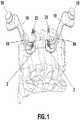
- FIGS. 1 and 2show different views of a surgical system comprising a pair of novel distractor blades that are capable of both bone distraction and tissue retraction in accordance with some embodiments.
- Each of the distraction blades 10is associated with an integrated threaded bone pin 25 that is positioned through a bone member.
- a first bone pin 25is inserted into a first or upper vertebra 2, while the other bone pin 25 is inserted into a second or lower vertebra 3.
- the installation of the bone pins 25 into the bone memberscan occur prior to delivering the distraction blades 10 to the bone pins 25.
- the distraction blades 10can be positioned downwardly over and around the bone pins 25 via slots 18.
- the distraction blades 10can rest on a washer, flange, protrusion or shelf feature 32 (shown in FIG. 7 ) of the bone pins 25, prior to securing the distraction blades to the bone pins 25 via locking nuts 29 (also shown in FIG. 7 ) in preparation for distraction. If some embodiments, the locking nuts 29 can be applied loosely to secure the distraction blades 10 to the bone pins 25, thereby allowing angulation and wanding to provide more room for additional instrumentation during the surgical procedure.
- the distraction blades 10retract tissue as they are being inserted toward the bone pins 25, and can continue to retract tissue once secured to the bone pins.
- the distraction blades 10are capable of distracting the adjacent vertebral bodies to restore disc height. Distraction can occur via hand or via instrument.
- one or more instruments for distractioncan be attached to the attachment portions 19 that are provided on each of the distraction blades 10.
- a frame 50as shown in FIGS. 8A and 8B , can be attached to the distraction blades 10, with a first arm 51 of the frame 50 attached to a first distraction blade 10 and a second arm 52 attached to a second distraction blade 10.
- the frame 50can include a mechanism (e.g., a ratcheting mechanism) that can help the distraction blades 10 to distract the adjacent vertebral bodies.
- the two distraction blades 10can advantageously be used for distraction, while continuing to retract tissue, thereby reducing the need for separate distraction and retraction instruments. Individual components of the surgical system including the distraction blades and integrated pins are discussed in more detail below.
- FIG. 3shows a system including a pair of distraction blades with integrated bone pins in accordance with some embodiments.
- Each of the distraction blades 10includes a body 16 having an upper portion and a lower portion.
- the upper portion of the body 16includes a flattened section from which an attachment portion 19 extends or protrudes.
- the attachment portion 19is capable of attachment to a frame or other instrument for stabilization, retraction and/or distraction.
- the upper portion of the body 16slopes downwardly into a flared lower portion that includes an opening or slot for accepting a bone pin 25 therethrough.
- a hoop or ring element 17(shown better in FIGS. 4 and 6 ) extends outwardly from the flared lower portion.
- the ring element 17can be designed to both receive the integrated bone pin 25 and rest on the bone pin's shelf feature 32, shown in FIG. 7 .
- a locking nut 29(shown in FIG. 7 ) can be downwardly threaded onto the bone pin 25 to secure the distraction blade 10 and bone pin 25.
- the locking nut 29is downwardly threaded but not tightened completely so that the distraction blade 10 is capable of angling or wanding.
- the locking nut 29is downwardly threaded and tightened completely so that the distraction blade 10 is fixed and not capable of wanding.
- either bladecan be fixed and/or capable of wanding.
- the locking nut 29is threaded downwardly and tightened completely or partially, the distraction blade 10 will be attached to the bone pin 25.
- a distraction instrumentcan be attached to both so as to distract a first vertebral body from another.
- FIG. 4shows a distraction blade separated from an integrated bone pin in accordance with some embodiments. From this view, one can see how the body 16 of the distraction blade 10 has an upper portion with a flattened surface from which an attachment portion 19 extends, and a lower flared out portion that extends from the upper portion. The lower flared out portion tapers outwardly such that a distal most end of the distraction blade 10 is the widest portion of the blade 10.
- the flared shape of the distraction blade 10is unique and allows it to contour to the vertebral body, which allows for more secure positioning with the integrated bone pin 25.
- the slot 18 that extends through the body 16 of the bladecan also have a flared portion that gets wider toward a more distal end of the distraction blade 10. This widening of the slot 18 advantageously allows the pin 25 to be easier received within the distraction blade 10.
- the bone pin 25is shown separately from the distraction blade 10.
- the bone pin 25is comprised of two different components - a threaded post 27 and a locking nut 29.
- the threaded post 27can have one or more threads that extend along a length of its body. As shown in FIG. 7 , the threaded post 27 can have multiple threads with different pitches. These threads will be discussed below.
- the threaded post 27can have a washer, flange, protrusion or shelf portion 32 on which the ring element 17 of the distraction blade 10 can reside on prior to downwardly threading the locking nut 29.
- the locking nut 29is a separate component from the threaded post 27, and includes internal threads to thread down the threaded post 27.
- FIG. 5shows an alternative distraction blade and integrated bone pin in accordance with some embodiments
- FIG. 6just shows the distraction blade.
- the distraction blade 10is similar to the blade above and includes a body 16 having an upper flattened portion with an attachment portion 19 extending therefrom; a downwardly flared portion including a slot 18; and a ring element 17 that extends outwardly from the downwardly flared portion.
- the slot 18is not flared open, but rather, maintains a continuous width down the length of the distraction blade 10.
- any of the slots 18 from the different embodimentsadvantageously allow the distraction blade 10 to be side-loaded if desired onto an inserted bone pin 25.
- the distraction blade 10can also be top-loaded if desired onto an inserted bone pin 25 by, for example, depositing the ring element 17 over the bone pin 25. From these views, one can see the distinct contour of the body 16 of the distraction blade 10. As shown in the figures, starting from the top flattened portion of the distraction blade 10, the body 16 is tapered and flares outwardly such that a distal portion 9 of the distraction blade 10 is wider than a proximal portion 7 of the distraction blade.
- FIG. 7shows a bone pin in accordance with some embodiments.
- the bone pin 25can be used with any of the distraction blades described herein.
- the bone pin 25comprises two components - a threaded post 27 and a locking nut 29.
- the threaded post 27comprises an upper section separated from a lower section by flanged shelf portion 32.
- the lower section of the threaded post 27includes lower threads 36 to help drive the threaded post 27 into bone.
- the upper section of the threaded post 27includes a first set of upper threads 35 and a second set of upper threads 38 separated by a smooth break portion 28.
- the first set of upper threads 35is positioned closer to a distal end of the threaded post 27 than the second set of upper threads 38.
- the first set of upper threads 35 and second set of upper threads 38are similar threads that enable the locking nut 29 to be downwardly threaded thereon.
- the first set of upper threads 35 and second set of upper threads 38are separated by a smooth break 28, which helps the locking nut 29 to be downwardly deposited quicker, as it can easily traverse the smooth break 28 without threading.
- a locking nut 29can be downwardly threaded onto the threaded post 29.
- the locking nut 29comprises a drive opening 39 for receiving a drive instrument.
- the drive opening 39comprises a hex opening for receiving a hex screw driver.
- FIGS. 8A and 8Bshow different views of a frame in accordance with some embodiments.
- the frame 50comprises a first arm 51 for gripping an attachment portion 19 of a first distraction blade 10 and a second arm 52 for gripping an attachment portion 19 of a second distraction blade 10.
- the frame 50includes a table mount attachment portion 64 for attaching a table mount thereto.
- the frame 50includes a linearly actuating, ratcheting mechanism 65.
- the knob 61can be rotated (e.g., via optional butterfly key 62).
- the use of the butterfly key 62advantageously allows for controlled movement of the ratcheting mechanism 65 in one direction.
- a surgeoncan press on the latch 67, which releases from the ratcheting teeth and allows for opposite movement.
- the frame 50is capable of applying a force to separate the first distraction blade 10 from the second distraction blade 10, thereby distraction adjacent vertebral bodies.
- two or more frames 50can be stacked on top of another, to cause an incision side to open in 2, 3, 4 or more directions.
- top-loading handheld adaptorscan also be provided to retain the distraction blades 10 prior to or after attachment of the frame 50.
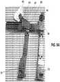
- FIG. 9shows an alternative distraction blade having a ball-socket connection with integrated bone pin in accordance with some embodiments.
- FIG. 10shows a rear view of the distraction blade.
- the distraction blade 110comprises a body 116 having an upper flattened portion with an attachment portion 119 extending therefrom and a lower sweeping portion.
- the distal portion of the distraction blade 110comprises a ball-socket connection 117 for receiving a head of a threaded post 127 therein.
- the threaded post 127can be attached to the ball-socket connection 117 via a snap fit.
- the threaded post 127which is shown with a rounder, more spherical head, can be inserted into a rear opening 113 formed in on a backside of the distraction blade 110, to securely snap into the distraction blade 110.
- the distraction blade 110can be polyaxially adjusted around the threaded post 116, thereby allowing angling and wanding of the blade 110 during distraction and retraction.
- a first distraction blade 110can be snap-fitted to the first threaded post 127, while a second distraction blade 110 can be snap-fitted to the second threaded post 127.
- an instrumente.g., the frame in FIGS. 8A and 8B
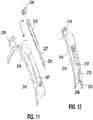
- FIGS. 11 and 12shows an alternative distraction blade and jointed bone pin in accordance with some embodiments.
- the distraction blade 210comprises a body 216 having an upper portion with an attachment portion 219 extending therefrom and a lower portion that is tapered and flares outwardly.
- the lower portion of the blade 210includes a slotted sleeve or shim 217 for receiving a jointed bone pin 225 therethrough.
- the jointed bone pin 225comprises two components - a threaded post 227 and a locking nut 229.
- the threaded post 227comprises a distally threaded portion 236 for threading into bone.
- the threaded post 227advantageously includes a jointed portion 235 that allows the threaded post 227 to bend and angle, even after it has been received through the slotted sleeve 217.
- the distraction blade 210 with the slotted shim 217is top-loaded over the threaded post 227.
- the locking nut 229can be downwardly threaded onto the threaded post 227.
- the downward threading of the locking nut 229causes the distraction blade 210 to compress further down the threaded post 227, and secures the distraction blade 210 to the threaded post 227 by preventing backout of the blade 210.
- the jointed portion 235allows for angling and wanding of the distraction blade 210, thereby accommodating larger or additional instruments during distraction and retraction.
- the distraction blade 210is capable of angling and wanding until the locking nut is tightly threaded 229 down the threaded post 227.
- the slotted shim or sleeve 217can also be jointed to accommodate angling and wanding of the distraction blade 210.
- the threaded post 227 and/or the slotted shim or sleeve 227can be jointed to accommodate angling or wanding of the distraction blade 210.
- the distraction blade 210can include an attachment portion 219 for attaching to a retraction and/or distraction instrument, such as the frame shown in FIGS. 8A and 8B .
- a first distraction blade 210can be positioned over a first jointed post 227 and a second distraction blade 210 can be positioned over a second jointed post 227.
- a first locking nut 229can be downwardly deposited to secure the first distraction blade 210 to the first jointed post 227 in a fixed position, while a second locking nut 229 can be downwardly deposited to secure the second distraction blade 210 to the second jointed post 227.
- a frame 50(as shown in FIGS.
- the frame 50can be linearly ratcheted, thereby causing the first distraction blade 210 to be pulled away from the second distraction blade 210, hence causing distraction of adjacent vertebral bodies.
- the blades 210also retract tissue and maintain an opening for instruments and implants to be inserted between the blades 210 during the surgical process.
- surrounding tissuecan be injured or damaged during both tissue retraction and bone distraction. While the distraction blades 210 described above are designed to perform both distraction and retraction, thereby reducing the need for additional instruments and increasing visibility of a surgical site to prevent tissue damage, additional protection of surrounding tissues may be desired. To provide additional protection to surrounding tissue, one or more wide blocking blades can be provided. These blades can be used advantageously on their own or with the distraction blades described above to provide protection to surrounding tissue.
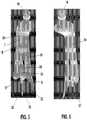
- FIG. 13shows a surgical system comprising a pair of wide blocking blades in accordance with some embodiments.
- FIG. 14shows a top view of the wide blocking blades.
- the wide blocking blades 350advantageously retract tissue and provide protection to surrounding tissue during a surgical procedure, particularly in a medial-to-lateral direction.
- the wide blocking blades 350can be attached to the bone pins 25 described above, such that they can be used in conjunction with any of the distraction blades described above.
- each of the wide blocking blades 350comprises a first blocking panel 354, a transition panel 355 and a second blocking panel 356.
- the first blocking panel 354comprises a substantially flat wall (shown in FIG. 14 ) that is attached to a bone pin receiver 366.
- the bone pin receiver 366comprises a ring or annular member that is capable of sliding along the shaft of the bone pin 25, until it rests on a shelf portion of the bone pin 25 (as shown in FIG. 15 ).
- the first blocking panel 354can protect tissue, particularly in the cephalad-to-caudal direction. Adjacent the first blocking panel 354 is a curved transition panel 355.
- the curved transition panel 355comprises a curved wall that connects the first blocking panel 354 to the second blocking panel 356.
- the curved transition panel 355can also serve as a blocking wall that protects tissue from damage during a surgical procedure.
- On the other side of the curved transition panel 355is a second blocking panel 356, which is wider than the first blocking panel 354.
- the second blocking panel 356can protect tissue, particularly in the medial-to-lateral direction.
- An attachment section 359 for attaching to another instrumente.g., a frame 50
- one or more of the panelscan include openings, windows or fenestrations 377 (shown in FIG. 13 on the second blocking panels 356). These fenestrations 377 are optional and are designed to lessen any potential damage with surrounding tissue. As shown in FIG. 13 , the fenestrations 377 can be formed in an up to down direction along the panel walls; however, in other embodiments, the fenestrations can be formed in a sideways direction or in any other shape or pattern.
- the wide blocking blades 350can advantageously be used on their own, or with any of the distraction blades discussed above. A method of assembling one or more wide blocking blades 350 with one or more distraction blades 10 will now be described.
- FIG. 15shows a pair of wide blocking blades in accordance with some embodiments.
- Each of the wide blocking blades 350comprise a first blocking panel 354, a transition panel 355 and a second blocking panel 356.
- a bone pin receiver 366extends outwardly from the first blocking panel 354. From this view, one can see how the bone pin receiver 366 is slidably received around the bone pin 25 until it resides on a distal portion of the bone pin 25.
- the bone pin receivers 366can be of a certain internal shape (e.g., hexagonal) such that the wide blocking blades 350 do not rotate once they are deposited on the bone pins 25.
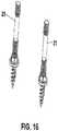
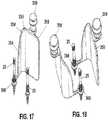
- FIGS. 16-21show a method of assembly of a system of one or more wide blocking blades in conjunction with one or more distraction blades, the method not forming part of the present invention.
- a method of assembly of a system of one or more wide blocking bladescomprises the following:
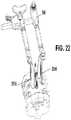
- FIG. 22shows a pair of wide blocking blades 350 without the addition of the distraction blades discussed above.
- the wide blocking blades 350are connected to a frame 50 which can be used to hold the wide blocking blades 350 apart as needed. This creates a space in between the wide blocking blades 350 for surgical instruments to be inserted therethrough.
- the various systems described abovecan assist in various spinal procedures.
- fusion proceduressuch as ACDF procedures
- fusion procedurescan benefit from the use of the systems described above.
- the systems described abovecan provide access to surgical sites such that implants, such as cages and spacers (both expandable and non-expandable), as well as graft material, can be inserted with ease.
- implantssuch as cages and spacers (both expandable and non-expandable), as well as graft material
- the systems described abovecan be used with a number of other implants including, but not limited to, stabilization members (such as rods, hook members and bone screws, including occipital plate systems), prosthetic members (including prosthetic discs), and various other spinal devices.
Landscapes
- Health & Medical Sciences (AREA)
- Surgery (AREA)
- Life Sciences & Earth Sciences (AREA)
- Orthopedic Medicine & Surgery (AREA)
- Neurology (AREA)
- Molecular Biology (AREA)
- Heart & Thoracic Surgery (AREA)
- Medical Informatics (AREA)
- Biomedical Technology (AREA)
- Animal Behavior & Ethology (AREA)
- General Health & Medical Sciences (AREA)
- Public Health (AREA)
- Veterinary Medicine (AREA)
- Engineering & Computer Science (AREA)
- Nuclear Medicine, Radiotherapy & Molecular Imaging (AREA)
- Surgical Instruments (AREA)
- Prostheses (AREA)
Description
- The present application is generally directed to improved instruments and instrument features for distraction and tissue retraction.
- Spinal fusion procedures are performed on patients to treat lower back pain caused by degenerated discs. During spinal fusion procedures, a surgeon restores a disc space back to its original height before inserting an interbody fusion device and graft material into the disc space. To accomplish this, a surgeon uses a distraction instrument to separate adjacent bones. To access the surgical site, a surgeon retracts tissue. The tissue retraction is performed by a retraction instrument that is separate from the distraction instrument.
- An orthopedic system with the features as defined in the preamble of claim 1 is known from
US 2014/194697 A1 . - There is a need for tools to better serve the purpose of both bone distraction and tissue retraction.
- The present application is generally directed to improved instruments and instrument features for distraction and tissue retraction.
- According to the present invention, an orthopedic system comprises a first bone pin, wherein the first bone pin comprises a lower threaded portion and an upper threaded portion; a first wide blocking blade delivered over the first bone pin, wherein the first wide blocking blade comprises at least two blocking panels; a first distraction blade delivered over the first bone pin, wherein the first distraction blade includes a slot for receiving the first bone pin therein; a second bone pin, wherein the second bone pin comprises a lower threaded portion and an upper threaded portion; a second wide blocking blade delivered over the second bone pin, wherein the second wide blocking blade comprises at least two blocking panels; a second distraction blade delivered over the second bone pin, wherein the second distraction blade includes a slot for receiving the second bone pin therein; and a frame attached to at least one of either: (i) the first distraction blade and the second distraction blade or (ii) the first wide blocking blade and the second wide blocking blade. Other advantageous embodiments of the invention are set forth in the dependent claims.
FIG. 1 shows a system including pair of distraction blades attached to vertebral bodies in accordance with some embodiments.FIG. 2 shows a different view of the distraction blades ofFIG. 1 .FIG. 3 shows a system including a pair of distraction blades with integrated bone pins in accordance with some embodiments.FIG. 4 shows a distraction blade separated from an integrated bone pin in accordance with some embodiments.FIG. 5 shows an alternative distraction blade and integrated bone pin in accordance with some embodiments.FIG. 6 shows the distraction blade ofFIG. 5 .FIG. 7 shows a bone pin in accordance with some embodiments.FIGS. 8A and8B show different views of a frame in accordance with some embodiments.FIG. 9 shows an alternative distraction blade having a ball-socket connection with integrated bone pin in accordance with some embodiments.FIG. 10 shows a rear view of a distraction blade having a ball-socket connection with bone pin in accordance with some embodiments.FIG. 11 shows an alternative distraction blade and jointed bone pin in accordance with some embodiments.FIG. 12 shows a distraction blade with integrated jointed bone pin in accordance with some embodiments.FIG. 13 shows a system including a pair of wide blocking blades in accordance with some embodiments.FIG. 14 shows a top view of the system including a pair of wide blocking blades ofFIG. 13 .FIG. 15 shows a pair of wide blocking blades in accordance with some embodiments.FIGS. 16-21 show a method of assembly of one or more wide blocking blades in conjunction with one or more distraction blades, the method not claimed.FIG. 22 shows a pair of wide blocking blades in use with a frame in accordance with an example not claimed.- The present application is generally directed to improved instruments and instrument features for distraction and tissue retraction. In particular, the present application describes spine surgery instruments that are capable of both distractionand tissue retraction, thereby advantageously removing the need to use multiple instruments during spinal procedures.
- During spinal fusion procedures, a surgeon restores a disc space back to its original height before inserting an interbody fusion device and graft material into the disc space. To accomplish this height restoration, a surgeon uses a distraction instrument to separate adjacent bones. In order to access the surgical site to perform the distraction, a surgeon must retract tissue to provide a pathway to the site. The tissue retraction is performed using a retraction instrument that is typically separate from the distraction instrument.
- One common type of spine procedure is an ACDF procedure. In the last ten years, the number of ACDF procedures has more than doubled, with the rate of success being quite high. Despite the high success rate, improvements are still needed. Studies have found that the incidence of dysphagia after ACDF can be quite high, with reports showing that up to 47% of patients experience short-term swallowing dysfunction, with possibly more going unreported. It is believed that the presence of dysphagia is related to the force applied by ACDF retractors against surrounding soft tissue, dissection of the longus coli muscle, as well as intubation tubing. Additional concerns arise during the ACDF procedures themselves, when delays may occur from constant shifting of the typical self-retaining retractors and difficulty in visibility arises from the clutter of retractor frames used alongside separate distracters, all within what is intended to be the smallest incision required.
- The present application is directed to instruments and instrument features that reduce the likelihood of dysphagia and other side-effects that may occur during ACDF procedures. The instruments described herein can be used to both retract tissue and distract vertebral bodies to their original height, thereby reducing the need to use separate instruments and increasing visibility to a surgical site. By providing instruments that can both retract tissue and distract vertebrae, tissue can be protected during the distraction process, thereby reducing the risk of dysphagia to a patient. While the instruments described herein are illustrated with respect to an ACDF procedure, one skilled in the art will appreciate that the instruments can be applied to other vertebral members as well, including in the thoracic, lumbar and sacral regions.
FIGS. 1 and2 show different views of a surgical system comprising a pair of novel distractor blades that are capable of both bone distraction and tissue retraction in accordance with some embodiments. Each of thedistraction blades 10 is associated with an integrated threadedbone pin 25 that is positioned through a bone member. As shown inFIG. 1 , afirst bone pin 25 is inserted into a first orupper vertebra 2, while theother bone pin 25 is inserted into a second orlower vertebra 3. In some embodiments, the installation of thebone pins 25 into the bone members can occurprior to delivering thedistraction blades 10 to thebone pins 25. With thebone pins 25 in place, thedistraction blades 10 can be positioned downwardly over and around thebone pins 25 viaslots 18. Thedistraction blades 10 can rest on a washer, flange, protrusion or shelf feature 32 (shown inFIG. 7 ) of thebone pins 25, prior to securing the distraction blades to thebone pins 25 via locking nuts 29 (also shown inFIG. 7 ) in preparation for distraction. If some embodiments, thelocking nuts 29 can be applied loosely to secure thedistraction blades 10 to thebone pins 25, thereby allowing angulation and wanding to provide more room for additional instrumentation during the surgical procedure. Advantageously, thedistraction blades 10 retract tissue as they are being inserted toward thebone pins 25, and can continue to retract tissue once secured to the bone pins.- With the two
distraction blades 10 in place with the integratedbone pins 25 as shown inFIGS. 1 and2 , thedistraction blades 10 are capable of distracting the adjacent vertebral bodies to restore disc height. Distraction can occur via hand or via instrument. In some embodiments, one or more instruments for distraction can be attached to theattachment portions 19 that are provided on each of thedistraction blades 10. In some embodiments, aframe 50, as shown inFIGS. 8A and8B , can be attached to thedistraction blades 10, with afirst arm 51 of theframe 50 attached to afirst distraction blade 10 and asecond arm 52 attached to asecond distraction blade 10. Theframe 50 can include a mechanism (e.g., a ratcheting mechanism) that can help thedistraction blades 10 to distract the adjacent vertebral bodies. As such, the twodistraction blades 10 can advantageously be used for distraction, while continuing to retract tissue, thereby reducing the need for separate distraction and retraction instruments. Individual components of the surgical system including the distraction blades and integrated pins are discussed in more detail below. FIG. 3 shows a system including a pair of distraction blades with integrated bone pins in accordance with some embodiments. Each of thedistraction blades 10 includes abody 16 having an upper portion and a lower portion. The upper portion of thebody 16 includes a flattened section from which anattachment portion 19 extends or protrudes. Theattachment portion 19 is capable of attachment to a frame or other instrument for stabilization, retraction and/or distraction. The upper portion of thebody 16 slopes downwardly into a flared lower portion that includes an opening or slot for accepting abone pin 25 therethrough. In the present embodiment, a hoop or ring element 17 (shown better inFIGS. 4 and6 ) extends outwardly from the flared lower portion. Thering element 17 can be designed to both receive theintegrated bone pin 25 and rest on the bone pin'sshelf feature 32, shown inFIG. 7 .- Once a
distraction blade 10 receives abone pin 25, a locking nut 29 (shown inFIG. 7 ) can be downwardly threaded onto thebone pin 25 to secure thedistraction blade 10 andbone pin 25. In some embodiments, the lockingnut 29 is downwardly threaded but not tightened completely so that thedistraction blade 10 is capable of angling or wanding. In other embodiments, the lockingnut 29 is downwardly threaded and tightened completely so that thedistraction blade 10 is fixed and not capable of wanding. In some embodiments involving a pair ofdistraction blades 10, either blade can be fixed and/or capable of wanding. Regardless of whether the lockingnut 29 is threaded downwardly and tightened completely or partially, thedistraction blade 10 will be attached to thebone pin 25. At that point, when two ormore distraction blades 10 are attached to their respective bone pins, a distraction instrument can be attached to both so as to distract a first vertebral body from another. FIG. 4 shows a distraction blade separated from an integrated bone pin in accordance with some embodiments. From this view, one can see how thebody 16 of thedistraction blade 10 has an upper portion with a flattened surface from which anattachment portion 19 extends, and a lower flared out portion that extends from the upper portion. The lower flared out portion tapers outwardly such that a distal most end of thedistraction blade 10 is the widest portion of theblade 10. The flared shape of thedistraction blade 10 is unique and allows it to contour to the vertebral body, which allows for more secure positioning with theintegrated bone pin 25. As shown inFIG. 4 , theslot 18 that extends through thebody 16 of the blade can also have a flared portion that gets wider toward a more distal end of thedistraction blade 10. This widening of theslot 18 advantageously allows thepin 25 to be easier received within thedistraction blade 10.- In
FIG. 4 , thebone pin 25 is shown separately from thedistraction blade 10. Thebone pin 25 is comprised of two different components - a threadedpost 27 and a lockingnut 29. In some embodiments, the threadedpost 27 can have one or more threads that extend along a length of its body. As shown inFIG. 7 , the threadedpost 27 can have multiple threads with different pitches. These threads will be discussed below. In addition to the threads, the threadedpost 27 can have a washer, flange, protrusion orshelf portion 32 on which thering element 17 of thedistraction blade 10 can reside on prior to downwardly threading the lockingnut 29. As shown inFIG. 4 , the lockingnut 29 is a separate component from the threadedpost 27, and includes internal threads to thread down the threadedpost 27. FIG. 5 shows an alternative distraction blade and integrated bone pin in accordance with some embodiments, whileFIG. 6 just shows the distraction blade. Thedistraction blade 10 is similar to the blade above and includes abody 16 having an upper flattened portion with anattachment portion 19 extending therefrom; a downwardly flared portion including aslot 18; and aring element 17 that extends outwardly from the downwardly flared portion. In contrast to the prior embodiment, however, theslot 18 is not flared open, but rather, maintains a continuous width down the length of thedistraction blade 10. Regardless of the shape distinction, any of theslots 18 from the different embodiments advantageously allow thedistraction blade 10 to be side-loaded if desired onto an insertedbone pin 25. In addition, thedistraction blade 10 can also be top-loaded if desired onto an insertedbone pin 25 by, for example, depositing thering element 17 over thebone pin 25. From these views, one can see the distinct contour of thebody 16 of thedistraction blade 10. As shown in the figures, starting from the top flattened portion of thedistraction blade 10, thebody 16 is tapered and flares outwardly such that adistal portion 9 of thedistraction blade 10 is wider than aproximal portion 7 of the distraction blade.FIG. 7 shows a bone pin in accordance with some embodiments. Thebone pin 25 can be used with any of the distraction blades described herein. Thebone pin 25 comprises two components - a threadedpost 27 and a lockingnut 29. As shown inFIG. 7 , the threadedpost 27 comprises an upper section separated from a lower section byflanged shelf portion 32. The lower section of the threadedpost 27 includeslower threads 36 to help drive the threadedpost 27 into bone. The upper section of the threadedpost 27 includes a first set ofupper threads 35 and a second set ofupper threads 38 separated by asmooth break portion 28. The first set ofupper threads 35 is positioned closer to a distal end of the threadedpost 27 than the second set ofupper threads 38. The first set ofupper threads 35 and second set ofupper threads 38 are similar threads that enable the lockingnut 29 to be downwardly threaded thereon. Advantageously, the first set ofupper threads 35 and second set ofupper threads 38 are separated by asmooth break 28, which helps the lockingnut 29 to be downwardly deposited quicker, as it can easily traverse thesmooth break 28 without threading.- As shown in
FIG. 7 , a lockingnut 29 can be downwardly threaded onto the threadedpost 29. The lockingnut 29 comprises adrive opening 39 for receiving a drive instrument. In some embodiments, thedrive opening 39 comprises a hex opening for receiving a hex screw driver. FIGS. 8A and8B show different views of a frame in accordance with some embodiments. Theframe 50 comprises afirst arm 51 for gripping anattachment portion 19 of afirst distraction blade 10 and asecond arm 52 for gripping anattachment portion 19 of asecond distraction blade 10. Theframe 50 includes a tablemount attachment portion 64 for attaching a table mount thereto. Theframe 50 includes a linearly actuating,ratcheting mechanism 65. To actuate theratcheting mechanism 65, theknob 61 can be rotated (e.g., via optional butterfly key 62). The use of thebutterfly key 62 advantageously allows for controlled movement of theratcheting mechanism 65 in one direction. To move theratcheting mechanism 65 in an opposite direction, a surgeon can press on thelatch 67, which releases from the ratcheting teeth and allows for opposite movement.- With the
first distraction blade 10 attached to thefirst arm 51 and thesecond distraction blade 10 attached to thesecond arm 52, theframe 50 is capable of applying a force to separate thefirst distraction blade 10 from thesecond distraction blade 10, thereby distraction adjacent vertebral bodies. In some embodiments, two ormore frames 50 can be stacked on top of another, to cause an incision side to open in 2, 3, 4 or more directions. In some embodiments, top-loading handheld adaptors can also be provided to retain thedistraction blades 10 prior to or after attachment of theframe 50. FIG. 9 shows an alternative distraction blade having a ball-socket connection with integrated bone pin in accordance with some embodiments.FIG. 10 shows a rear view of the distraction blade. In these embodiments, thedistraction blade 110 comprises abody 116 having an upper flattened portion with anattachment portion 119 extending therefrom and a lower sweeping portion. The distal portion of thedistraction blade 110 comprises a ball-socket connection 117 for receiving a head of a threadedpost 127 therein. In contrast to embodiments in which thedistraction blade 10 includes aring element 17 and a lockingnut 29 to secure theblade 10 to the threadedpost 27, in the present embodiment, the threadedpost 127 can be attached to the ball-socket connection 117 via a snap fit.- As shown in
FIG. 10 , the threadedpost 127, which is shown with a rounder, more spherical head, can be inserted into arear opening 113 formed in on a backside of thedistraction blade 110, to securely snap into thedistraction blade 110. Advantageously, as the head of the threadedpost 127 is rounded, thedistraction blade 110 can be polyaxially adjusted around the threadedpost 116, thereby allowing angling and wanding of theblade 110 during distraction and retraction. After inserting a first threadedpost 127 into a first vertebral body and a second threadedpost 127 into a second vertebral body, afirst distraction blade 110 can be snap-fitted to the first threadedpost 127, while asecond distraction blade 110 can be snap-fitted to the second threadedpost 127. With the pair of blades in position, an instrument (e.g., the frame inFIGS. 8A and8B ) can be attached to theblades 110 to advantageously retract tissue and distract bone members using the same instrument. FIGS. 11 and 12 shows an alternative distraction blade and jointed bone pin in accordance with some embodiments. Thedistraction blade 210 comprises abody 216 having an upper portion with anattachment portion 219 extending therefrom and a lower portion that is tapered and flares outwardly. The lower portion of theblade 210 includes a slotted sleeve or shim 217 for receiving ajointed bone pin 225 therethrough.- The jointed
bone pin 225 comprises two components - a threadedpost 227 and a lockingnut 229. The threadedpost 227 comprises a distally threadedportion 236 for threading into bone. In a section that is proximal to the distally threadedportion 236, the threadedpost 227 advantageously includes a jointedportion 235 that allows the threadedpost 227 to bend and angle, even after it has been received through the slottedsleeve 217. In some embodiments, thedistraction blade 210 with the slottedshim 217 is top-loaded over the threadedpost 227. Once thedistraction blade 210 is received over the threadedpost 227, the lockingnut 229 can be downwardly threaded onto the threadedpost 227. The downward threading of the lockingnut 229 causes thedistraction blade 210 to compress further down the threadedpost 227, and secures thedistraction blade 210 to the threadedpost 227 by preventing backout of theblade 210. - Advantageously, even after the
distraction blade 210 is attached to the threadedpost 227, the jointedportion 235 allows for angling and wanding of thedistraction blade 210, thereby accommodating larger or additional instruments during distraction and retraction. In some embodiments, thedistraction blade 210 is capable of angling and wanding until the locking nut is tightly threaded 229 down the threadedpost 227. In some embodiments, the slotted shim orsleeve 217 can also be jointed to accommodate angling and wanding of thedistraction blade 210. Accordingly, in some embodiments, the threadedpost 227 and/or the slotted shim orsleeve 227 can be jointed to accommodate angling or wanding of thedistraction blade 210. - As in the embodiments above, the
distraction blade 210 can include anattachment portion 219 for attaching to a retraction and/or distraction instrument, such as the frame shown inFIGS. 8A and8B . In some embodiments, afirst distraction blade 210 can be positioned over a firstjointed post 227 and asecond distraction blade 210 can be positioned over a secondjointed post 227. Afirst locking nut 229 can be downwardly deposited to secure thefirst distraction blade 210 to the firstjointed post 227 in a fixed position, while asecond locking nut 229 can be downwardly deposited to secure thesecond distraction blade 210 to the secondjointed post 227. A frame 50 (as shown inFIGS. 8A and8B ) can be attached to each of thefirst distraction blade 210 and thesecond distraction blade 210. Theframe 50 can be linearly ratcheted, thereby causing thefirst distraction blade 210 to be pulled away from thesecond distraction blade 210, hence causing distraction of adjacent vertebral bodies. Advantageously, theblades 210 also retract tissue and maintain an opening for instruments and implants to be inserted between theblades 210 during the surgical process. - As discussed above, surrounding tissue can be injured or damaged during both tissue retraction and bone distraction. While the
distraction blades 210 described above are designed to perform both distraction and retraction, thereby reducing the need for additional instruments and increasing visibility of a surgical site to prevent tissue damage, additional protection of surrounding tissues may be desired. To provide additional protection to surrounding tissue, one or more wide blocking blades can be provided. These blades can be used advantageously on their own or with the distraction blades described above to provide protection to surrounding tissue. FIG. 13 shows a surgical system comprising a pair of wide blocking blades in accordance with some embodiments.FIG. 14 shows a top view of the wide blocking blades. Thewide blocking blades 350 advantageously retract tissue and provide protection to surrounding tissue during a surgical procedure, particularly in a medial-to-lateral direction. Advantageously, thewide blocking blades 350 can be attached to the bone pins 25 described above, such that they can be used in conjunction with any of the distraction blades described above.- In some embodiments, each of the
wide blocking blades 350 comprises afirst blocking panel 354, atransition panel 355 and asecond blocking panel 356. Thefirst blocking panel 354 comprises a substantially flat wall (shown inFIG. 14 ) that is attached to abone pin receiver 366. Thebone pin receiver 366 comprises a ring or annular member that is capable of sliding along the shaft of thebone pin 25, until it rests on a shelf portion of the bone pin 25 (as shown inFIG. 15 ). In the configuration ofFIG. 14 , thefirst blocking panel 354 can protect tissue, particularly in the cephalad-to-caudal direction. Adjacent thefirst blocking panel 354 is acurved transition panel 355. Thecurved transition panel 355 comprises a curved wall that connects thefirst blocking panel 354 to thesecond blocking panel 356. Advantageously, thecurved transition panel 355 can also serve as a blocking wall that protects tissue from damage during a surgical procedure. On the other side of thecurved transition panel 355 is asecond blocking panel 356, which is wider than thefirst blocking panel 354. In the configuration ofFIG. 14 , thesecond blocking panel 356 can protect tissue, particularly in the medial-to-lateral direction. Anattachment section 359 for attaching to another instrument (e.g., a frame 50) can be found on an upper surface of thesecond blocking panel 356. - In some embodiments, one or more of the panels can include openings, windows or fenestrations 377 (shown in
FIG. 13 on the second blocking panels 356). Thesefenestrations 377 are optional and are designed to lessen any potential damage with surrounding tissue. As shown inFIG. 13 , thefenestrations 377 can be formed in an up to down direction along the panel walls; however, in other embodiments, the fenestrations can be formed in a sideways direction or in any other shape or pattern. - The
wide blocking blades 350 can advantageously be used on their own, or with any of the distraction blades discussed above. A method of assembling one or morewide blocking blades 350 with one ormore distraction blades 10 will now be described. FIG. 15 shows a pair of wide blocking blades in accordance with some embodiments. Each of thewide blocking blades 350 comprise afirst blocking panel 354, atransition panel 355 and asecond blocking panel 356. Abone pin receiver 366 extends outwardly from thefirst blocking panel 354. From this view, one can see how thebone pin receiver 366 is slidably received around thebone pin 25 until it resides on a distal portion of thebone pin 25. In some embodiments, thebone pin receivers 366 can be of a certain internal shape (e.g., hexagonal) such that thewide blocking blades 350 do not rotate once they are deposited on the bone pins 25.FIGS. 16-21 show a method of assembly of a system of one or more wide blocking blades in conjunction with one or more distraction blades, the method not forming part of the present invention. In examples, a method of assembly of a system of one or more wide blocking blades comprises the following:- (i) Begin by forming a slightly off-midline incision. Using a handheld retractor, retract tissue in the medial-lateral direction.
- (ii) Insert first and second bone pins 25 (shown in
FIG. 16 ) into the center of the vertebral body above and below the target disc level. At this point, the locking nuts associated with the bone pins 25 should be removed before inserting the bone pins 25 to enable wide blocking blades and/or distraction blades to be delivered onto the bone pins 25. - (iii) Position a first
wide blocking blade 350 over thefirst bone pin 25 to retract tissue in the medial-to-lateral direction, as shown inFIG. 17 . A secondwide blocking blade 350 can be positioned over thesecond bone pin 25 to retract tissue in the medial-to-lateral direction. If no cephalad-to-caudal tissue retraction is required, first and second locking nuts can be threaded down the bone pins 25 to secure thewide blocking blades 350 in place. In some embodiments, if desired, twowide blocking blades 350 can be placed on thesame bone pin 25 to retract alternate sides. This can be particularly useful for multi-level ACDFs. Advantageously, no longus muscle dissection is required for the procedure described herein, thereby reducing risk of injury or trauma to a patient. - (iv) If desired, a
first distraction blade 10 can also be delivered down thefirst bone pin 25 over the firstwide blocking blade 350, as shown inFIG. 19 . Thedistraction blade 10 can be positioned at a different angle from thewide blocking blade 350. While thewide blocking blade 350 can retract tissue in one direction (e.g., in a medial-to-lateral direction), thedistraction blade 10 can advantageously retract tissue and assist in bone distraction in a different direction (e.g., in a cephalad-to-caudal direction). The same assembly can be formed with respect to thesecond bone pin 25, thereby creating a retraction and distraction system with at least four walls. - (v) With the
distraction blades 10 and wide blockingblades 350 in place over the bone pins 25, lockingnuts 29 can be delivered down the bone pins 25 to secure the assemblies, as shown inFIGS. 20-21 . - (iv) At this point, one or more frames 50 (as shown in
FIGS. 8A and8B ) can be attached to the assembled system of bone pins 25. The one ormore frames 50 are capable of distracting vertebrae in one or more directions. - While the embodiments described above show the
wide blocking blades 350 in use with one or more distraction blades, in some examples not forming part of the present invention, the distraction blades need not be added.FIG. 22 shows a pair ofwide blocking blades 350 without the addition of the distraction blades discussed above. Thewide blocking blades 350 are connected to aframe 50 which can be used to hold thewide blocking blades 350 apart as needed. This creates a space in between thewide blocking blades 350 for surgical instruments to be inserted therethrough. - The various systems described above, including those that comprise one or more distraction blades and wide blocking blades, can assist in various spinal procedures. In particular, fusion procedures, such as ACDF procedures, can benefit from the use of the systems described above. The systems described above can provide access to surgical sites such that implants, such as cages and spacers (both expandable and non-expandable), as well as graft material, can be inserted with ease. In addition, the systems described above can be used with a number of other implants including, but not limited to, stabilization members (such as rods, hook members and bone screws, including occipital plate systems), prosthetic members (including prosthetic discs), and various other spinal devices.
Claims (15)
- An orthopedic system comprising:a first bone pin (25);a first wide blocking blade (350) delivered over the first bone pin (25), wherein the first wide blocking blade (350) comprises at least two blocking panels (354, 356);a first distraction blade (10) delivered over the first bone pin (25), wherein the first distraction blade (10) includes a slot (18) for receiving the first bone pin (25) therein;a second bone pin (25);a second wide blocking blade (350) delivered over the second bone pin (25), wherein the second wide blocking blade (350) comprises at least two blocking panels (354, 356);a second distraction blade (10) delivered over the second bone pin (25), wherein the second distraction blade (10) includes a slot (18) for receiving the second bone pin (25) therein; anda frame (50) attached to at least one of either: (i) the first distraction blade (10) and the second distraction blade (10) or (ii) the first wide blocking blade (350) and the second wide blocking blade (350),characterized in that the first bone pin comprises a lower threaded portion (36) and an upper threaded portion (35) and the second bone pin (25) comprises a lower threaded portion (36) and an upper threaded portion (35).
- The system of claim 1, wherein the frame comprises a ratcheting mechanism.
- The system of claim 1, wherein the first bone pin comprises a shelf portion that separates the lower threaded portion from the upper threaded portion.
- The system of claim 1, wherein the first wide blocking blade comprises a first panel, a second panel and a transition panel between the first panel and the second panel.
- The system of claim 4, wherein the transition panel is curved.
- The system of claim 1, wherein the first distraction blade has a flared out, curved contour.
- The system of claim 1, wherein the first distraction blade has an attachment portion, wherein the attachment portion is connectable to the frame.
- The system of claim 1, wherein the first distraction blade comprises a flattened upper section that transitions downwardly into a flared section.
- The system of claim 1, wherein the slot in the first distraction blade is tapered.
- The system of claim 1, wherein the first bone pin comprises a set of upper threads and a set of lower threads.
- The system of claim 10, wherein the pitch of the upper threads is different from the pitch of the lower threads.
- The system of claim 10, wherein the first wide blocking blade comprises at least two panels.
- The system of claim 12, wherein the first wide blocking blade comprises a first panel separated from a second panel by a transition panel.
- The system of claim 1, wherein the slot of the first distraction blade is part of a shim.
- The system of claim 14, wherein the first bone pin is a jointed bone pin.
Applications Claiming Priority (2)
| Application Number | Priority Date | Filing Date | Title |
|---|---|---|---|
| US14/519,961US10426454B2 (en) | 2014-10-21 | 2014-10-21 | Orthopedic tools for implantation |
| PCT/US2015/056548WO2016064939A1 (en) | 2014-10-21 | 2015-10-21 | Orthopedic tools for implantation |
Publications (3)
| Publication Number | Publication Date |
|---|---|
| EP3209227A1 EP3209227A1 (en) | 2017-08-30 |
| EP3209227A4 EP3209227A4 (en) | 2017-11-15 |
| EP3209227B1true EP3209227B1 (en) | 2019-05-08 |
Family
ID=55748082
Family Applications (1)
| Application Number | Title | Priority Date | Filing Date |
|---|---|---|---|
| EP15853594.8AActiveEP3209227B1 (en) | 2014-10-21 | 2015-10-21 | Orthopedic tools for implantation |
Country Status (4)
| Country | Link |
|---|---|
| US (4) | US10426454B2 (en) |
| EP (1) | EP3209227B1 (en) |
| JP (1) | JP6751085B2 (en) |
| WO (1) | WO2016064939A1 (en) |
Families Citing this family (58)
| Publication number | Priority date | Publication date | Assignee | Title |
|---|---|---|---|---|
| DE10154163A1 (en) | 2001-11-03 | 2003-05-22 | Advanced Med Tech | Device for straightening and stabilizing the spine |
| US8979931B2 (en) | 2006-12-08 | 2015-03-17 | DePuy Synthes Products, LLC | Nucleus replacement device and method |
| US20090088789A1 (en) | 2007-09-28 | 2009-04-02 | O'neil Michael J | Balloon With Shape Control For Spinal Procedures |
| BRPI0818608A2 (en) | 2007-10-05 | 2015-04-22 | Synthes Gmbh | Sequential directional dilatation system for dilating from a nerve of a patient's anatomy, and method for forming an access opening through a psoas muscle to a patient's spine using a dilatation system |
| CN102497828B (en)* | 2009-05-20 | 2015-09-09 | 斯恩蒂斯有限公司 | What patient installed retracts part |
| DE112010004338B4 (en)* | 2009-11-10 | 2019-06-27 | Nuvasive, Inc. | DEVICE FOR IMPLEMENTING SPINE SURGERY |
| US9179903B2 (en)* | 2010-03-11 | 2015-11-10 | Globus Medical, Inc. | Tissue retractor and method of use |
| US9307972B2 (en) | 2011-05-10 | 2016-04-12 | Nuvasive, Inc. | Method and apparatus for performing spinal fusion surgery |
| US9622779B2 (en) | 2011-10-27 | 2017-04-18 | DePuy Synthes Products, Inc. | Method and devices for a sub-splenius / supra-levator scapulae surgical access technique |
| US9808232B2 (en) | 2011-11-01 | 2017-11-07 | DePuy Synthes Products, Inc. | Dilation system |
| US9125703B2 (en)* | 2012-01-16 | 2015-09-08 | K2M, Inc. | Rod reducer, compressor, distractor system |
| US9265490B2 (en) | 2012-04-16 | 2016-02-23 | DePuy Synthes Products, Inc. | Detachable dilator blade |
| US9480855B2 (en) | 2012-09-26 | 2016-11-01 | DePuy Synthes Products, Inc. | NIR/red light for lateral neuroprotection |
| US10278786B2 (en)* | 2014-02-18 | 2019-05-07 | Globus Medical, Inc. | Retracting tissue |
| US9980737B2 (en) | 2014-08-04 | 2018-05-29 | Medos International Sarl | Flexible transport auger |
| US9924979B2 (en) | 2014-09-09 | 2018-03-27 | Medos International Sarl | Proximal-end securement of a minimally invasive working channel |
| US10111712B2 (en) | 2014-09-09 | 2018-10-30 | Medos International Sarl | Proximal-end securement of a minimally invasive working channel |
| US10264959B2 (en) | 2014-09-09 | 2019-04-23 | Medos International Sarl | Proximal-end securement of a minimally invasive working channel |
| US10786264B2 (en) | 2015-03-31 | 2020-09-29 | Medos International Sarl | Percutaneous disc clearing device |
| US11744447B2 (en) | 2015-09-04 | 2023-09-05 | Medos International | Surgical visualization systems and related methods |
| US12150636B2 (en) | 2015-09-04 | 2024-11-26 | Medos International Sárl | Surgical instrument connectors and related methods |
| CN113143355A (en) | 2015-09-04 | 2021-07-23 | 美多斯国际有限公司 | Multi-shield spinal access system |
| US10987129B2 (en) | 2015-09-04 | 2021-04-27 | Medos International Sarl | Multi-shield spinal access system |
| US11439380B2 (en) | 2015-09-04 | 2022-09-13 | Medos International Sarl | Surgical instrument connectors and related methods |
| US11672562B2 (en) | 2015-09-04 | 2023-06-13 | Medos International Sarl | Multi-shield spinal access system |
| US9924932B2 (en)* | 2015-12-01 | 2018-03-27 | Seth K. WILLIAMS | Technique and system for lateral lumbar spine fusion |
| US10617449B2 (en)* | 2016-01-08 | 2020-04-14 | Stryker European Holdings I, Llc | Tap marker |
| US10299838B2 (en) | 2016-02-05 | 2019-05-28 | Medos International Sarl | Method and instruments for interbody fusion and posterior fixation through a single incision |
| CN105982707A (en)* | 2016-05-20 | 2016-10-05 | 上海三友医疗器械股份有限公司 | Wire retractor assembly for lumber interbody fusion and using method thereof |
| EP4368128A3 (en) | 2016-09-07 | 2024-07-17 | Vertos Medical, Inc. | Percutaneous lateral recess resection methods and instruments |
| AU2017235887B2 (en)* | 2016-09-26 | 2021-09-30 | K2M, Inc. | Retraction system and method of use |
| US10779866B2 (en)* | 2016-12-29 | 2020-09-22 | K2M, Inc. | Rod reducer assembly |
| JP7218360B2 (en) | 2017-09-22 | 2023-02-06 | メドス・インターナショナル・エスエイアールエル | patient-worn surgical support |
| US11559372B2 (en) | 2017-09-22 | 2023-01-24 | Medos International Sarl | Patient-mounted surgical retractor |
| EP3626189B1 (en) | 2018-09-21 | 2023-05-24 | Biedermann Technologies GmbH & Co. KG | Instrument for attaching to a bone anchor and instrument for use in distraction and/or retraction, in particular for orthopedic or neurosurgery, more specifically for spinal surgery |
| US11413029B2 (en) | 2018-10-24 | 2022-08-16 | Stryker European Operations Holdings Llc | Anterior to psoas instrumentation |
| US10660631B1 (en)* | 2018-12-13 | 2020-05-26 | Invictus Development & Engineering, Inc. | Pedicle screw mounted retractor system |
| EP3669801B1 (en) | 2018-12-21 | 2024-03-06 | Stryker European Operations Limited | Tap marker with flexible extension and associated instruments |
| US11013530B2 (en) | 2019-03-08 | 2021-05-25 | Medos International Sarl | Surface features for device retention |
| US11241252B2 (en) | 2019-03-22 | 2022-02-08 | Medos International Sarl | Skin foundation access portal |
| US11129727B2 (en) | 2019-03-29 | 2021-09-28 | Medos International Sari | Inflatable non-distracting intervertebral implants and related methods |
| US11813026B2 (en) | 2019-04-05 | 2023-11-14 | Medos International Sarl | Systems, devices, and methods for providing surgical trajectory guidance |
| US11204060B2 (en) | 2019-11-27 | 2021-12-21 | Medos International Sari | Selectively lockable ball and socket joint |
| US11229464B2 (en) | 2019-12-04 | 2022-01-25 | Medos International Sarl | Apparatus for driver-specific backout prevention |
| US12096923B2 (en) | 2020-07-10 | 2024-09-24 | Warsaw Orthopedic, Inc. | Tissue retractor, retraction modules, and associated methods |
| US12383249B2 (en) | 2020-07-10 | 2025-08-12 | Warsaw Orthopedic, Inc. | Tissue retractor, retraction modules, and associated methods |
| US12349889B2 (en) | 2020-07-10 | 2025-07-08 | Warsaw Orthopedic, Inc. | Tissue retractor, retraction modules, and associated methods |
| US11311282B1 (en) | 2020-10-15 | 2022-04-26 | Charles R. Watts | Cervical retractor and method |
| US11826031B2 (en) | 2020-12-09 | 2023-11-28 | Alphatec Spine, Inc. | Surgical retractors and methods of using the same |
| US11350922B1 (en) | 2021-02-03 | 2022-06-07 | Warsaw Orthopedic, Inc. | Modular surgical instrument system and method for shank-based retraction and distraction |
| US11771517B2 (en) | 2021-03-12 | 2023-10-03 | Medos International Sarl | Camera position indication systems and methods |
| US11432852B1 (en) | 2021-03-22 | 2022-09-06 | Warsaw Orthopedic, Inc. | Screw shank based tissue retraction |
| US12171419B2 (en) | 2021-10-06 | 2024-12-24 | K2M, Inc. | Offset Hohmann |
| US11529173B1 (en)* | 2021-11-12 | 2022-12-20 | Spinal Simplicity, Llc | Reduction system for spondylolisthesis |
| US20230404561A1 (en) | 2022-06-16 | 2023-12-21 | Vertos Medical, Inc. | Integrated instrument assembly |
| JP2024079660A (en)* | 2022-11-30 | 2024-06-11 | ニューヴェイジヴ,インコーポレイテッド | Surgical retractor systems and components |
| US12232790B2 (en) | 2022-12-30 | 2025-02-25 | IvyTech Design LLC | Adjustable angle orthopedic distractor, compressor, and distractor-compressor |
| US12433580B1 (en)* | 2024-06-12 | 2025-10-07 | IvyTech Design LLC | Adjustable angle cervical spine distractor |
Family Cites Families (16)
| Publication number | Priority date | Publication date | Assignee | Title |
|---|---|---|---|---|
| US6030162A (en)* | 1998-12-18 | 2000-02-29 | Acumed, Inc. | Axial tension screw |
| US5944658A (en) | 1997-09-23 | 1999-08-31 | Koros; Tibor B. | Lumbar spinal fusion retractor and distractor system |
| US5928139A (en)* | 1998-04-24 | 1999-07-27 | Koros; Tibor B. | Retractor with adjustable length blades and light pipe guides |
| US6139493A (en) | 1998-07-08 | 2000-10-31 | Koros; Tibor B. | Retractor with adjustable length blades and light pipe guides |
| AU2003295934B2 (en) | 2002-11-23 | 2009-02-26 | Frey, George A. | Distraction and retraction system for spinal surgery |
| US20050021040A1 (en)* | 2003-07-21 | 2005-01-27 | Rudolf Bertagnoli | Vertebral retainer-distracter and method of using same |
| CA2597944A1 (en)* | 2004-08-15 | 2006-02-23 | Kevin Seex | Distraction and retraction assemblies |
| WO2006042241A2 (en) | 2004-10-08 | 2006-04-20 | Nuvasive, Inc. | Surgical access system and related methods |
| EP1741396B1 (en) | 2005-07-08 | 2009-09-23 | BIEDERMANN MOTECH GmbH | Bone anchoring device |
| JP4980664B2 (en)* | 2005-07-08 | 2012-07-18 | ビーダーマン・モテーク・ゲゼルシャフト・ミット・ベシュレンクタ・ハフツング | Bone fixation device |
| US8852089B2 (en)* | 2007-08-01 | 2014-10-07 | Warsaw Orthopedic, Inc. | Instrumentation for tissue retraction |
| US9060757B2 (en) | 2008-05-05 | 2015-06-23 | Ranier Limited | Distractor |
| DE112010004338B4 (en)* | 2009-11-10 | 2019-06-27 | Nuvasive, Inc. | DEVICE FOR IMPLEMENTING SPINE SURGERY |
| US9179947B2 (en) | 2012-07-03 | 2015-11-10 | Tedan Surgical Innovations, Llc | Locking distractor with two-start distraction screw |
| EP2705799B1 (en)* | 2012-09-06 | 2015-05-13 | Medacta International S.A. | Surgical device for minimally invasive spinal fusion and surgical system comprising the same |
| US20150230785A1 (en)* | 2014-02-20 | 2015-08-20 | The Little Sandbox, Llc | Surgical pin retractor system |
- 2014
- 2014-10-21USUS14/519,961patent/US10426454B2/enactiveActive
- 2015
- 2015-10-21EPEP15853594.8Apatent/EP3209227B1/enactiveActive
- 2015-10-21JPJP2017521119Apatent/JP6751085B2/enactiveActive
- 2015-10-21WOPCT/US2015/056548patent/WO2016064939A1/enactiveApplication Filing
- 2019
- 2019-08-02USUS16/529,840patent/US11172918B2/enactiveActive
- 2021
- 2021-09-23USUS17/482,963patent/US11730462B2/enactiveActive
- 2023
- 2023-07-31USUS18/228,230patent/US12295560B2/enactiveActive
Non-Patent Citations (1)
| Title |
|---|
| None* |
Also Published As
| Publication number | Publication date |
|---|---|
| JP6751085B2 (en) | 2020-09-02 |
| EP3209227A1 (en) | 2017-08-30 |
| US11730462B2 (en) | 2023-08-22 |
| WO2016064939A1 (en) | 2016-04-28 |
| US20220008055A1 (en) | 2022-01-13 |
| US12295560B2 (en) | 2025-05-13 |
| EP3209227A4 (en) | 2017-11-15 |
| US20160106408A1 (en) | 2016-04-21 |
| US10426454B2 (en) | 2019-10-01 |
| US20240032906A1 (en) | 2024-02-01 |
| US20190350572A1 (en) | 2019-11-21 |
| JP2017535324A (en) | 2017-11-30 |
| US11172918B2 (en) | 2021-11-16 |
Similar Documents
| Publication | Publication Date | Title |
|---|---|---|
| US11730462B2 (en) | Orthopedic tools for implantation | |
| US10603026B2 (en) | Devices and systems for surgical retraction | |
| US7618424B2 (en) | Orthopedic instrument | |
| US7918792B2 (en) | Surgical retractor for use with minimally invasive spinal stabilization systems and methods of minimally invasive surgery | |
| US8246659B2 (en) | Installation systems for spinal stabilization system and related methods | |
| US6902566B2 (en) | Spinal implants, insertion instruments, and methods of use | |
| US20090088604A1 (en) | Vertebrally-mounted tissue retractor and method for use in spinal surgery | |
| US20130012955A1 (en) | System and Method for Pedicle Screw Placement in Vertebral Alignment | |
| US20120035667A1 (en) | Locking mechanisms for pivoting bone anchors | |
| AU2007313090A1 (en) | Orthopedic implant assembly | |
| US20150230785A1 (en) | Surgical pin retractor system | |
| US11109894B2 (en) | Apparatus, system, and method for spinal vertebrae stabilization | |
| WO2004110288A2 (en) | Orthopedic clamps | |
| US9427276B2 (en) | Method of changing position of bones |
Legal Events
| Date | Code | Title | Description |
|---|---|---|---|
| STAA | Information on the status of an ep patent application or granted ep patent | Free format text:STATUS: THE INTERNATIONAL PUBLICATION HAS BEEN MADE | |
| PUAI | Public reference made under article 153(3) epc to a published international application that has entered the european phase | Free format text:ORIGINAL CODE: 0009012 | |
| STAA | Information on the status of an ep patent application or granted ep patent | Free format text:STATUS: REQUEST FOR EXAMINATION WAS MADE | |
| 17P | Request for examination filed | Effective date:20170503 | |
| AK | Designated contracting states | Kind code of ref document:A1 Designated state(s):AL AT BE BG CH CY CZ DE DK EE ES FI FR GB GR HR HU IE IS IT LI LT LU LV MC MK MT NL NO PL PT RO RS SE SI SK SM TR | |
| AX | Request for extension of the european patent | Extension state:BA ME | |
| RIN1 | Information on inventor provided before grant (corrected) | Inventor name:PONMUDI, VARUN Inventor name:KARPOWICZ, EDWARD | |
| A4 | Supplementary search report drawn up and despatched | Effective date:20171012 | |
| RIC1 | Information provided on ipc code assigned before grant | Ipc:A61B 17/70 20060101AFI20171006BHEP Ipc:A61B 17/02 20060101ALI20171006BHEP | |
| DAV | Request for validation of the european patent (deleted) | ||
| DAX | Request for extension of the european patent (deleted) | ||
| REG | Reference to a national code | Ref country code:DE Ref legal event code:R079 Ref document number:602015030119 Country of ref document:DE Free format text:PREVIOUS MAIN CLASS: A61B0017560000 Ipc:A61B0017700000 | |
| GRAP | Despatch of communication of intention to grant a patent | Free format text:ORIGINAL CODE: EPIDOSNIGR1 | |
| STAA | Information on the status of an ep patent application or granted ep patent | Free format text:STATUS: GRANT OF PATENT IS INTENDED | |
| RIC1 | Information provided on ipc code assigned before grant | Ipc:A61B 17/70 20060101AFI20181030BHEP Ipc:A61B 17/02 20060101ALI20181030BHEP | |
| INTG | Intention to grant announced | Effective date:20181205 | |
| GRAS | Grant fee paid | Free format text:ORIGINAL CODE: EPIDOSNIGR3 | |
| GRAA | (expected) grant | Free format text:ORIGINAL CODE: 0009210 | |
| STAA | Information on the status of an ep patent application or granted ep patent | Free format text:STATUS: THE PATENT HAS BEEN GRANTED | |
| AK | Designated contracting states | Kind code of ref document:B1 Designated state(s):AL AT BE BG CH CY CZ DE DK EE ES FI FR GB GR HR HU IE IS IT LI LT LU LV MC MK MT NL NO PL PT RO RS SE SI SK SM TR | |
| REG | Reference to a national code | Ref country code:GB Ref legal event code:FG4D | |
| REG | Reference to a national code | Ref country code:CH Ref legal event code:EP Ref country code:AT Ref legal event code:REF Ref document number:1128958 Country of ref document:AT Kind code of ref document:T Effective date:20190515 | |
| REG | Reference to a national code | Ref country code:DE Ref legal event code:R096 Ref document number:602015030119 Country of ref document:DE Ref country code:IE Ref legal event code:FG4D | |
| REG | Reference to a national code | Ref country code:NL Ref legal event code:MP Effective date:20190508 | |
| REG | Reference to a national code | Ref country code:LT Ref legal event code:MG4D | |
| PG25 | Lapsed in a contracting state [announced via postgrant information from national office to epo] | Ref country code:AL Free format text:LAPSE BECAUSE OF FAILURE TO SUBMIT A TRANSLATION OF THE DESCRIPTION OR TO PAY THE FEE WITHIN THE PRESCRIBED TIME-LIMIT Effective date:20190508 Ref country code:ES Free format text:LAPSE BECAUSE OF FAILURE TO SUBMIT A TRANSLATION OF THE DESCRIPTION OR TO PAY THE FEE WITHIN THE PRESCRIBED TIME-LIMIT Effective date:20190508 Ref country code:SE Free format text:LAPSE BECAUSE OF FAILURE TO SUBMIT A TRANSLATION OF THE DESCRIPTION OR TO PAY THE FEE WITHIN THE PRESCRIBED TIME-LIMIT Effective date:20190508 Ref country code:PT Free format text:LAPSE BECAUSE OF FAILURE TO SUBMIT A TRANSLATION OF THE DESCRIPTION OR TO PAY THE FEE WITHIN THE PRESCRIBED TIME-LIMIT Effective date:20190908 Ref country code:HR Free format text:LAPSE BECAUSE OF FAILURE TO SUBMIT A TRANSLATION OF THE DESCRIPTION OR TO PAY THE FEE WITHIN THE PRESCRIBED TIME-LIMIT Effective date:20190508 Ref country code:NO Free format text:LAPSE BECAUSE OF FAILURE TO SUBMIT A TRANSLATION OF THE DESCRIPTION OR TO PAY THE FEE WITHIN THE PRESCRIBED TIME-LIMIT Effective date:20190808 Ref country code:FI Free format text:LAPSE BECAUSE OF FAILURE TO SUBMIT A TRANSLATION OF THE DESCRIPTION OR TO PAY THE FEE WITHIN THE PRESCRIBED TIME-LIMIT Effective date:20190508 Ref country code:LT Free format text:LAPSE BECAUSE OF FAILURE TO SUBMIT A TRANSLATION OF THE DESCRIPTION OR TO PAY THE FEE WITHIN THE PRESCRIBED TIME-LIMIT Effective date:20190508 Ref country code:NL Free format text:LAPSE BECAUSE OF FAILURE TO SUBMIT A TRANSLATION OF THE DESCRIPTION OR TO PAY THE FEE WITHIN THE PRESCRIBED TIME-LIMIT Effective date:20190508 | |
| PG25 | Lapsed in a contracting state [announced via postgrant information from national office to epo] | Ref country code:LV Free format text:LAPSE BECAUSE OF FAILURE TO SUBMIT A TRANSLATION OF THE DESCRIPTION OR TO PAY THE FEE WITHIN THE PRESCRIBED TIME-LIMIT Effective date:20190508 Ref country code:BG Free format text:LAPSE BECAUSE OF FAILURE TO SUBMIT A TRANSLATION OF THE DESCRIPTION OR TO PAY THE FEE WITHIN THE PRESCRIBED TIME-LIMIT Effective date:20190808 Ref country code:RS Free format text:LAPSE BECAUSE OF FAILURE TO SUBMIT A TRANSLATION OF THE DESCRIPTION OR TO PAY THE FEE WITHIN THE PRESCRIBED TIME-LIMIT Effective date:20190508 Ref country code:GR Free format text:LAPSE BECAUSE OF FAILURE TO SUBMIT A TRANSLATION OF THE DESCRIPTION OR TO PAY THE FEE WITHIN THE PRESCRIBED TIME-LIMIT Effective date:20190809 | |
| REG | Reference to a national code | Ref country code:AT Ref legal event code:MK05 Ref document number:1128958 Country of ref document:AT Kind code of ref document:T Effective date:20190508 | |
| PG25 | Lapsed in a contracting state [announced via postgrant information from national office to epo] | Ref country code:AT Free format text:LAPSE BECAUSE OF FAILURE TO SUBMIT A TRANSLATION OF THE DESCRIPTION OR TO PAY THE FEE WITHIN THE PRESCRIBED TIME-LIMIT Effective date:20190508 Ref country code:DK Free format text:LAPSE BECAUSE OF FAILURE TO SUBMIT A TRANSLATION OF THE DESCRIPTION OR TO PAY THE FEE WITHIN THE PRESCRIBED TIME-LIMIT Effective date:20190508 Ref country code:SK Free format text:LAPSE BECAUSE OF FAILURE TO SUBMIT A TRANSLATION OF THE DESCRIPTION OR TO PAY THE FEE WITHIN THE PRESCRIBED TIME-LIMIT Effective date:20190508 Ref country code:EE Free format text:LAPSE BECAUSE OF FAILURE TO SUBMIT A TRANSLATION OF THE DESCRIPTION OR TO PAY THE FEE WITHIN THE PRESCRIBED TIME-LIMIT Effective date:20190508 Ref country code:RO Free format text:LAPSE BECAUSE OF FAILURE TO SUBMIT A TRANSLATION OF THE DESCRIPTION OR TO PAY THE FEE WITHIN THE PRESCRIBED TIME-LIMIT Effective date:20190508 Ref country code:CZ Free format text:LAPSE BECAUSE OF FAILURE TO SUBMIT A TRANSLATION OF THE DESCRIPTION OR TO PAY THE FEE WITHIN THE PRESCRIBED TIME-LIMIT Effective date:20190508 | |
| REG | Reference to a national code | Ref country code:DE Ref legal event code:R097 Ref document number:602015030119 Country of ref document:DE | |
| PG25 | Lapsed in a contracting state [announced via postgrant information from national office to epo] | Ref country code:SM Free format text:LAPSE BECAUSE OF FAILURE TO SUBMIT A TRANSLATION OF THE DESCRIPTION OR TO PAY THE FEE WITHIN THE PRESCRIBED TIME-LIMIT Effective date:20190508 Ref country code:IT Free format text:LAPSE BECAUSE OF FAILURE TO SUBMIT A TRANSLATION OF THE DESCRIPTION OR TO PAY THE FEE WITHIN THE PRESCRIBED TIME-LIMIT Effective date:20190508 | |
| PLBE | No opposition filed within time limit | Free format text:ORIGINAL CODE: 0009261 | |
| STAA | Information on the status of an ep patent application or granted ep patent | Free format text:STATUS: NO OPPOSITION FILED WITHIN TIME LIMIT | |
| PG25 | Lapsed in a contracting state [announced via postgrant information from national office to epo] | Ref country code:TR Free format text:LAPSE BECAUSE OF FAILURE TO SUBMIT A TRANSLATION OF THE DESCRIPTION OR TO PAY THE FEE WITHIN THE PRESCRIBED TIME-LIMIT Effective date:20190508 | |
| 26N | No opposition filed | Effective date:20200211 | |
| PG25 | Lapsed in a contracting state [announced via postgrant information from national office to epo] | Ref country code:PL Free format text:LAPSE BECAUSE OF FAILURE TO SUBMIT A TRANSLATION OF THE DESCRIPTION OR TO PAY THE FEE WITHIN THE PRESCRIBED TIME-LIMIT Effective date:20190508 | |
| PG25 | Lapsed in a contracting state [announced via postgrant information from national office to epo] | Ref country code:MC Free format text:LAPSE BECAUSE OF FAILURE TO SUBMIT A TRANSLATION OF THE DESCRIPTION OR TO PAY THE FEE WITHIN THE PRESCRIBED TIME-LIMIT Effective date:20190508 Ref country code:SI Free format text:LAPSE BECAUSE OF FAILURE TO SUBMIT A TRANSLATION OF THE DESCRIPTION OR TO PAY THE FEE WITHIN THE PRESCRIBED TIME-LIMIT Effective date:20190508 | |
| REG | Reference to a national code | Ref country code:CH Ref legal event code:PL | |
| PG25 | Lapsed in a contracting state [announced via postgrant information from national office to epo] | Ref country code:LU Free format text:LAPSE BECAUSE OF NON-PAYMENT OF DUE FEES Effective date:20191021 Ref country code:LI Free format text:LAPSE BECAUSE OF NON-PAYMENT OF DUE FEES Effective date:20191031 Ref country code:CH Free format text:LAPSE BECAUSE OF NON-PAYMENT OF DUE FEES Effective date:20191031 | |
| REG | Reference to a national code | Ref country code:BE Ref legal event code:MM Effective date:20191031 | |
| PG25 | Lapsed in a contracting state [announced via postgrant information from national office to epo] | Ref country code:BE Free format text:LAPSE BECAUSE OF NON-PAYMENT OF DUE FEES Effective date:20191031 | |
| PG25 | Lapsed in a contracting state [announced via postgrant information from national office to epo] | Ref country code:IE Free format text:LAPSE BECAUSE OF NON-PAYMENT OF DUE FEES Effective date:20191021 Ref country code:FR Free format text:LAPSE BECAUSE OF NON-PAYMENT OF DUE FEES Effective date:20191031 | |
| PG25 | Lapsed in a contracting state [announced via postgrant information from national office to epo] | Ref country code:CY Free format text:LAPSE BECAUSE OF FAILURE TO SUBMIT A TRANSLATION OF THE DESCRIPTION OR TO PAY THE FEE WITHIN THE PRESCRIBED TIME-LIMIT Effective date:20190508 | |
| PG25 | Lapsed in a contracting state [announced via postgrant information from national office to epo] | Ref country code:IS Free format text:LAPSE BECAUSE OF FAILURE TO SUBMIT A TRANSLATION OF THE DESCRIPTION OR TO PAY THE FEE WITHIN THE PRESCRIBED TIME-LIMIT Effective date:20190908 | |
| PG25 | Lapsed in a contracting state [announced via postgrant information from national office to epo] | Ref country code:HU Free format text:LAPSE BECAUSE OF FAILURE TO SUBMIT A TRANSLATION OF THE DESCRIPTION OR TO PAY THE FEE WITHIN THE PRESCRIBED TIME-LIMIT; INVALID AB INITIO Effective date:20151021 Ref country code:MT Free format text:LAPSE BECAUSE OF FAILURE TO SUBMIT A TRANSLATION OF THE DESCRIPTION OR TO PAY THE FEE WITHIN THE PRESCRIBED TIME-LIMIT Effective date:20190508 | |
| PG25 | Lapsed in a contracting state [announced via postgrant information from national office to epo] | Ref country code:MK Free format text:LAPSE BECAUSE OF FAILURE TO SUBMIT A TRANSLATION OF THE DESCRIPTION OR TO PAY THE FEE WITHIN THE PRESCRIBED TIME-LIMIT Effective date:20190508 | |
| PGFP | Annual fee paid to national office [announced via postgrant information from national office to epo] | Ref country code:GB Payment date:20240829 Year of fee payment:10 | |
| PGFP | Annual fee paid to national office [announced via postgrant information from national office to epo] | Ref country code:DE Payment date:20240828 Year of fee payment:10 |