EP3208808A1 - Electron-coupled transformer - Google Patents
Electron-coupled transformerDownload PDFInfo
- Publication number
- EP3208808A1 EP3208808A1EP16190435.4AEP16190435AEP3208808A1EP 3208808 A1EP3208808 A1EP 3208808A1EP 16190435 AEP16190435 AEP 16190435AEP 3208808 A1EP3208808 A1EP 3208808A1
- Authority
- EP
- European Patent Office
- Prior art keywords
- electron
- grid
- cathode
- energy
- coupled transformer
- Prior art date
- Legal status (The legal status is an assumption and is not a legal conclusion. Google has not performed a legal analysis and makes no representation as to the accuracy of the status listed.)
- Granted
Links
Images


Classifications
- H—ELECTRICITY
- H01—ELECTRIC ELEMENTS
- H01F—MAGNETS; INDUCTANCES; TRANSFORMERS; SELECTION OF MATERIALS FOR THEIR MAGNETIC PROPERTIES
- H01F38/00—Adaptations of transformers or inductances for specific applications or functions
- G—PHYSICS
- G21—NUCLEAR PHYSICS; NUCLEAR ENGINEERING
- G21B—FUSION REACTORS
- G21B1/00—Thermonuclear fusion reactors
- G21B1/03—Thermonuclear fusion reactors with inertial plasma confinement
- G—PHYSICS
- G21—NUCLEAR PHYSICS; NUCLEAR ENGINEERING
- G21B—FUSION REACTORS
- G21B1/00—Thermonuclear fusion reactors
- G—PHYSICS
- G21—NUCLEAR PHYSICS; NUCLEAR ENGINEERING
- G21B—FUSION REACTORS
- G21B1/00—Thermonuclear fusion reactors
- G21B1/11—Details
- G—PHYSICS
- G21—NUCLEAR PHYSICS; NUCLEAR ENGINEERING
- G21B—FUSION REACTORS
- G21B1/00—Thermonuclear fusion reactors
- G21B1/11—Details
- G21B1/23—Optical systems, e.g. for irradiating targets, for heating plasma or for plasma diagnostics
- G—PHYSICS
- G21—NUCLEAR PHYSICS; NUCLEAR ENGINEERING
- G21B—FUSION REACTORS
- G21B3/00—Low temperature nuclear fusion reactors, e.g. alleged cold fusion reactors
- G21B3/008—Fusion by pressure waves
- G—PHYSICS
- G21—NUCLEAR PHYSICS; NUCLEAR ENGINEERING
- G21D—NUCLEAR POWER PLANT
- G21D7/00—Arrangements for direct production of electric energy from fusion or fission reactions
- H—ELECTRICITY
- H05—ELECTRIC TECHNIQUES NOT OTHERWISE PROVIDED FOR
- H05G—X-RAY TECHNIQUE
- H05G2/00—Apparatus or processes specially adapted for producing X-rays, not involving X-ray tubes, e.g. involving generation of a plasma
- Y—GENERAL TAGGING OF NEW TECHNOLOGICAL DEVELOPMENTS; GENERAL TAGGING OF CROSS-SECTIONAL TECHNOLOGIES SPANNING OVER SEVERAL SECTIONS OF THE IPC; TECHNICAL SUBJECTS COVERED BY FORMER USPC CROSS-REFERENCE ART COLLECTIONS [XRACs] AND DIGESTS
- Y02—TECHNOLOGIES OR APPLICATIONS FOR MITIGATION OR ADAPTATION AGAINST CLIMATE CHANGE
- Y02E—REDUCTION OF GREENHOUSE GAS [GHG] EMISSIONS, RELATED TO ENERGY GENERATION, TRANSMISSION OR DISTRIBUTION
- Y02E30/00—Energy generation of nuclear origin
- Y02E30/10—Nuclear fusion reactors
Definitions
- the present inventionrelates to methods and systems for extracting energy from controlled fusion reactions.
- Thermal extractionis a straightforward application of the Rankine Thermal Cycle, which is used in almost every electrical power plant. In this process, a coolant is heated, the heated coolant used to turn a turbine, and the turbine used to turn a generator. This process has a nominal 55% efficiency.
- Hydrodynamic Instabilityis a major problem that the designer of every fusion power system faces.
- Formally known as Rayleigh-Taylor Instabilityit is a problem that arises from non-uniform compression of the fuel pellet.
- Non-uniformities in excess of 1% in compressionresult in the formation of "jets" of energy that surge outward and locally cool the target pellet.
- the current generation of laser driven fusion systemsuse multiple beams (as many as 192 in one system) to attempt to provide a sufficiently uniform compression of the fuel pellet.
- One embodiment of the inventionprovides a system for extracting energy from controlled fusion reactions.
- the systemincludes a central target chamber for receiving fusion target material.
- a plurality of energy driversare arranged around the target chamber so as to supply energy to fusion target material in the chamber to initiate a controlled fusion reaction of the material, releasing energy in the forms of fusion plasma and heat.
- a plurality of means for extracting energy from the fusion reactionare provided, and comprise means to extract high voltage DC power from the fusion plasma, and means to extract thermal energy from the central target chamber.
- the foregoing embodimentincreases efficiency of a fusion power system by extracting both high voltage DC energy and thermal energy.
- Another embodiment of the inventionprovides a system for extracting energy from controlled fusion reactions wherein the plurality of energy drivers are powered by an energy storage means.
- the energy storage meansreceives power from a first power supply and provides start-up and make-up power, and a second power supply derives energy from high voltage DC power extracted from the fusion plasma.
- the "start-up power”is the total energy required for initiate the fusion reaction and the “make-up power” is the energy that is added to the energy from the second power supply to maintain operation of the fusion reaction.
- the foregoing embodimentachieves high efficiency by using the high voltage DC power extracted from the fusion reaction as a source of power for the energy drivers that drive the fusion reactions. This means that most of the energy required to drive the fusion reaction is derived from the (previous) fusion reaction itself.
- a further embodiment of the inventionprovides a system for extracting energy from controlled fusion reactions in which each of the plurality of energy drivers comprises a unitary apparatus.
- the unitary apparatusproduces both (a) an x-ray pulse for causing the fusion target material to undergo a controlled fusion reaction so as to cause energy release in the forms of fusion plasma and heat, and (b) RF energy to simultaneously heat the fusion target material.
- the foregoing embodiment of the inventionhas the ability to produce an RF heating pulse simultaneously with the x-ray drive pulse without reducing efficiency. This allows the use of RF heating to increase the efficiency of the fusion power system at little additional cost and with no energy penalty.
- a still further embodiment of the inventionprovides a fusion power system in which an apodizing structure is associated with each energy driver for reshaping the wavefront of the x-ray pulse to be concave from the perspective of the fusion target material.
- the foregoing embodiment of the inventioncorrects the wavefront errors that give rise to Rayleigh-Taylor Hydrodynamic Instability by means of the mentioned Apodizing Filter.
- the Apodizing filteris used to change the shape of the compression wavefront to a highly concave surface whose radius matches the radius of the target. By this means, the wavefront "wraps around" one face of the target and provides totally uniform compression of the target.
- a direct benefit of the use of Apodizing Filters to correct the compression wavefrontis that the number of beams used to illuminate the target is reduced. Instead of the 192 beams that the National Ignition Facility Fusion Reactor at Lawrence Livermore lab in California uses, the current embodiment of the invention may allow the use of as far fewer beams, such as 6. This directly reduces the cost and size of the reactor, while increasing its reliability.
- FIGS. 1 - 3Main principles of preferred embodiments of the invention are described in connection with FIGS. 1 - 3 .
- FIG. 1shows a reactor for generation of energy by controlled nuclear fusion.
- the systemincludes of a central target chamber or region 10.
- a series six or more of Energy Drivers 12are arranged in symmetrical pairs around the central target region.
- the symmetrical Energy Drivers 12are arranged in symmetrical manner about a target pellet location 22, so as to collectively create a preferably highly spherical wavefront that impinges on target fusion pellet at location 22.
- the energy driversproduce X-ray beams at high fluency which symmetrically compress the target to initiate and sustain a fusion reaction.
- the energy driversare preferably Stimulated X-ray Emitters (SXE) as first described by the inventor of this current invention in U.S. Patent No. 4,723,263 .
- the mentioned SXE driversare fitted with an RF producing means which provides a simultaneous pulse of RF energy to provide additional heat to the reaction. This is described further in the discussion of FIGS. 10-13 .
- a plurality of Energy Extraction Cones 14are disposed around central target region 10. Each of these cones is a portion of a vacuum system. They each contain an energy collection grid 46 which produces a High Voltage DC output which is used to drive the SXE Energy Drivers 6. Energy Extraction Cones 14 may be formed in other shapes, such as cylinders. A detailed discussion of this process is found in the discussion of FIG. 3 below.
- the system of FIGS. 1-3contains a second energy extraction means which may suitably be a standard Rankine Cycle Thermal loop. Coolant is introduced into an inner heat exchange sub-system 24 by an Inlet Pipe 18, circulated through the heat exchanger 24 and then exited from the reactor via pipe 20. The heated coolant is used to drive a turbine which in turn drives a generator to produce electricity. Most of this electricity is available to supply external energy grids. A small portion is used to provide so-called make-up power to the system to compensate for the small inefficiency of the HVDC Energy Extraction Cones 14.
- a Fuel Pellet injection system 16Is used to inject the fusion target pellets into the reactor. In the actual system, pellet injector 16 is oriented vertically as shown in FIG. 2B .
- FIGS. 2A-2Bshow principal internal and external components and their geometric relationship.
- FIG. 2Awe see a cross-section of the reactor.
- the disposition of the Energy Drivers 12 and the Energy Extractor Cones 14is clearly visible.
- the inner structures of the reactorswhich are shown in detail in FIG. 2B .
- the reactor chamber wallis the outermost layer, shown at 10, which provides structural support for the internal structures and also is the vacuum enclosure. While depicted as a spherical object, other shapes may be successfully employed.
- the shape of the chamberhas no impact on the functionality of the system.
- the next innermost layerconsists of magnetic confinement coils 30. These coils create a strong magnetic field that confines the fusion plasma and keeps it from contacting the liner 28 and other internal structures.
- the magnetic field produced by the magnetic confinement coils 30has apertures (low field regions) which correspond to the locations of the energy extractor cones and SXE energy drivers.
- the next innermost layeris the coolant passage layer (heat exchanger) 24. Coolant enters this structure through the coolant inlet 18, circulates through the coolant passages 24 and exits in a superheated state via the coolant outlet 20. This superheated coolant is used to power a turbine & generator to produce electricity. In this view, the pellet injector 16 is seen in its proper vertical orientation.
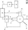
- FIG. 3is a block diagram of energy flow of the reactor system of FIG. 1 .
- the two energy extraction loopsare shown.
- the thermal loopconsists of the thermal coolant inlet 18, the thermal coolant outlet 20, and the coolant passage layer (heat exchanger) 24. The operation of this loop is described above in the discussion of FIG. 2 .
- the High Voltage DC Extraction loopconsists of the Extractor Cone 14, the Extractor Grid 46, the DC return 48, the Energy Storage and Power Conditioning means 38, the Pulse Modulator 34, and its two synchronized outputs (a) 36, HVDC to the SXE Energy Driver 12 and (b) 32, the Magnetic Confinement Drive signal. Fundamental to a preferred embodiment of this invention is the use of directly extracted high voltage DC to driver the SXE energy drivers.
- the SXEruns on high voltage DC, so it is directly compatible with the direct DC output of the energy extractor cones 14.
- the extracted energyis used to recharge the energy storage means 38.
- the energy storage systemcan utilize either a capacitive storage means or an inductive storage means or both, by way of example. The use of capacitive storage is the preferred embodiment for this portion of the system.
- the Energy Storage and Power Conditioning sub-system 38has a second energy input 40 which allows power from external sources (e.g., 42, 44) to be applied to the system.
- External source 42can be an Electron Coupled Transformer as described below, and external source 44 is a high voltage DC power supply.
- the power from second energy input 40is used for system startup and also to provide make-up power during operation. This is to compensate for the inefficiency losses in the described HVDC extraction loop.
- FIGS. 4A and 4Bare cross-sections of the basic SXE Energy Driver, which may be used as energy drivers 12 in FIG. 1 .
- FIG. 4Ais an end view and FIG. 4B is a side view. Visible in these views are an Anode 64, a Grid 66, and a cathode 68.
- the SXEis a triode electron tube. It has a novel electron gun structure, comprised of the cathode 68 and the grid 66. The physical juxtaposition of these elements is such that it forms a circular waveguide.
- a circular waveguidesupports the Transverse Electric Mode (TEM) which always propagates at the Speed of Light ("c").
- TEMTransverse Electric Mode
- This propertyis critical to the function of the SXE in that it ensures that the electron beam, as shown by arrows, sweeps the anode at the speed of light and thus the phase velocity and the group velocity of the wavefront are matched. This is known as the Collapsing Traveling Wave. This is important in the x-ray formation process in that it ensures that the x-rays formed by the beam are always traveling in a highly ionized zone and are therefore not absorbed by self-absorption processes.
- the grid structure(discussed in detail in FIG. 5 ) is highly symmetrical. This ensures that the collapse of the wave towards the anode is perfectly symmetrical. As a result, when the electrons strike the anode, they create a highly ionized region of Bremstrahllüng. There are also a large number of secondary electrons present in such highly ionized region.
- the anodeis filled with a lasing material. The Bremstrahllüng photons strike atoms of the lasing material and, as a result of their being at significantly higher energy than the K-shell ionization potential of the atom, they totally ionize the atom. The resulting repopulation cascade causes the release of photons from each electron shell of the atom.
- the surplus of electronsensures that this process occurs very rapidly.
- a cascade reactionfollows. The radiation is, at first, isotropic. But as it proceeds along the length of the anode, off-axis radiation is either suppressed by the wall of the abode or used to ionize other atoms. All of this is takes place in the ionized zone that sweeps along the anode at " c " .
- the resulting beamis collimated geometrically by the anode and consists mostly of K-shell photons, and L-shell and M-shell photons when they are present.
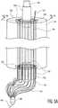
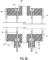
- FIGS. 5A , 5B and 5Cshow details of the Grid and Phase Matching Network of the SXE of FIGS. 4A and 4B .
- FIG. 5Ashows the entire Grid - Phase Matching Network and details of the Grid Insulation. These two elements are actually part of a single structure.
- FIG. 5Bshows details of a preferred Grid Tensioning and insulating means.
- FIG. 5Cshows the electrical schematic of the Phase Matching Network.
- TWEGTraveling Wave Electron Guns
- the Traveling Wave Electron Gunis a unique structure in that it uses the close juxtaposition of the grid 66 and the cathode 68 to produce a Circular Waveguide structure that supports a Transverse Electric Mode (TEM).
- TEMTransverse Electric Mode
- the Transverse Electric Mode in a Circular waveguidealways travels at the speed of light (" c ").
- This aspect of the TWEGaccounts for its extremely fast risetime (one nanosecond for each foot or 30.48 cm of gun length).
- the gridis also used to both produce the electric field necessary to extract electrons from the cathode and to control the flow of such electrons. This is accomplished by selectively biasing the grid relative to the cathode. Both switching and modulation functions can be attained by appropriate biasing of the tube.
- the actual implementation of these design rulesis determined by the size of the grid being built.
- the gridcan be made from a single piece or, more commonly, a series of individual elements constrained by mounting rings on either end 130, 132, provided with suitable electrical insulators 136, 140 to prevent arcing, and a means of maintaining tension on the grid structure.
- each grid elementis provided with a tensioning means in the form of a heavy spring 146, washer 148, and nut 150.
- the nuts of the various grid elementsare tightened with a torque wrench to ensure uniform tension on all elements.
- phase matching network 134136 that is connected to the input end of the grid.
- the phase matching networkconsists of a series of wires 134 of exactly equal length, with a typical tolerance of +/- 0.0005" (+/- 12 microns).
- Each wire of the phase matching networkis connected to the lower grid support ring 132 at a point equidistant from the two adjacent grid elements.
- phase matching network wiresare connected to a common connector element 136.
- Thishas a number of holes on one end equal to the number of phase matching network wires, and a single hole on the opposite end.
- a wireis attached to this hole and runs to the grid vacuum feedthrough.
- the wiresare silver soldered or welded by the Tungsten-Inert Gas method (TIG) as appropriate. TIG welding is preferred but not always possible.
- phase matching networkThe purpose of this phase matching network is to ensure that the entire base of the grid responds to the control signal at the same moment with an accuracy that is preferably in the picosecond range. This results in a highly symmetrical wave propagating in the TWEG structure.
- a radially symmetrical collapsing traveling waveis formed and propagates along the length of the TWEG structure. This is a wave of ground potential and it has the effect of allowing energy stored in the grid-cathode gap and also energy available to the grid to propagate to the anode resulting in conduction of this signal.
- FIG. 6shows the operating principle of the Apodizing Filter, with wavefront movement shown by arrows.
- Optimal performance of any fusion systemdepends on creating a perfectly symmetrical compression of the fuel target pellet.
- the Energy Drivers 12 ( FIG. 1 ) of the current inventionprovides a means of symmetrically illuminating the target. If the wavefronts 60 that impinge on the target are given a concave geometry whose radius matches the radius of the target pellet, then it is possible to create an almost perfectly symmetrical compression wavefront on the fuel target pellet. The reason that this is necessary is to minimize the Rayleigh-Taylor Instability which, if severe enough, can cause the fuel pellet to heat in a non-uniform fashion and thus not ignite in a fusion reaction.
- Additional Energy Drivers 12can be added in symmetrical pairs to increase the uniformity of compression wavefronts. Geometric considerations determine the number of drivers that are added. If six drivers is not sufficient, the next step would preferably be 12 drivers, followed by 14 drivers, followed preferably by 20 drivers. Other numbers of Energy Drivers are possible.
- the Apodizing Filter 58 of FIG. 6consists of an object of varying thickness that is placed in the beam path.
- the cross-sectionis matched in thickness to the radius of the target.
- these filtersare made from thin film materials that are deposited to create the desired cross-section.
- the selection of the materialis determined by the energy drive requirement of the fusion fuel combination. In the case of the Deuterium-Tritium reaction, this is between 250 and 350 electron volts, then materials with a very low atomic number such as Lithium, Beryllium, Boron or Carbon would be used. Higher energy reactions such as Lithium-Boron of Hydrogen-Boron would use either these materials of possibly Magnesium, Aluminum or Silicon. It is important that the Atomic number of the density material not be so high that significant absorption occurs. It is noted that the Apodizing Filter will produce some scatter radiation but that is not a problem in the current invention.
- RTIRayleigh-Taylor Instabilities
- Zone Platesare well known in optical sciences. The extension to the soft x ⁇ ray portion of the spectrum is simple and has already been reported in the literature.
- ICFInertial Confinement
- the implosion process of a typical direct-drive ICF targetis roughly divided into three phases: initial phase, acceleration phase and deceleration phase.
- the presently claimed inventionuses a direct drive system.
- first shock wavetravels in a fuel pellet and the fluid in the pellet is accelerated mainly by the shock wave.
- the outer (or ablative) shellis ablatively accelerated inward in the second phase.
- fuelis compressed heavily in the deceleration phase.
- perturbations on the target surfaceare seeded by initial imprint due to laser irradiation nonuniformity, along with the original target surface roughness.
- the mechanism of Laser driven ICFis premised on light being absorbed at the hohlraum cylinder walls, which converts the laser light into soft x-rays.
- the hohlraumis made of a high atomic number material such as gold, which maximizes the production of x-rays. These x-rays are rapidly absorbed and reemitted by the walls setting up a radiation driven thermal wave diffusing into the walls of the hohlraum. Most of the x-rays are ultimately lost into the walls, some escape out the laser entrance holes, and the rest are absorbed by the target pellet in the center of the hohlraums and drive its implosion. Typically this coupling to the pellet is a less than 1 ⁇ 2 of the total energy, or about 0.2 for a power plant scale laser heated hohlraum. Thus, coupling for indirect drive is relatively poor compared to direct drive. (Rosen Reference.)
- Indirect driveis less efficient at coupling energy to a pellet than direct drive because of the conversion to x ⁇ rays in the hohlraum.
- indirect driveis less sensitive to variations in beam intensity and hydrodynamic instabilities.
- the ignition threshold for directly-driven and indirectly-driven targetsis about the same.
- the gainis calculated to be about a factor of 2 greater in directly driven targets.
- the choice of the x-ray temperatureis crucial because it dictates the material forming the pellet's outer ablator layer, key to the implosion and subsequent ignition reactions. If this layer is smooth enough and bathed uniformly in x rays, its ablation will efficiently force the pellet inward at a velocity of about 400 kilometers per second (more than one-thousandth of the speed of light) and create the pressure and temperature required for fusion reactions to begin. (Haan Reference.)
- an imploded fuel pelletis compressed to conditions of high density and temperature.
- a driveris required to impart energy to the pellet to effect an implosion.
- targetsIn order to achieve conditions for ICF, targets have a spherical shell filled with a low density ( ⁇ 1 mg/cm 3 ) equimolar mixture of deuterium and tritium (DT) gas.
- the spherical shellconsists of an outer ablator and an inner region of frozen or liquid DT. Energy from the driver is delivered to the ablator which heats up and expands. As the ablator expands the rest of the shell is forced inward to conserve momentum.
- the pelletbehaves as a spherical, ablation-driven rocket. As the pellet implodes, the compression wave heats the central region. Electron conduction and radiative losses act to cool the central region. Fuel convergence ratios of 30-40:1 and a central fuel temperature of 10 KeV are required so that ⁇ particle deposition from thermonuclear burn of DT can overcome conduction and radiative losses and a self-sustaining burn wave can be generated.
- the Stimulated X-ray Emitter (SXE) of U.S. Patent 4,723.263is uniquely suited to resolving both the driver and the RTI issues. This system scales efficiently to the sizes necessary to drive fusion reactions. If we take NIF value of 30 KiloJoules of x ⁇ ray flux as being necessary to drive a fusion reaction, we can scale an SXE system accordingly.
- each driverneeds only produce 5 KiloJoules. Twelve drivers scale to 2.5 KiloJoules and 20 drivers scale to 1.5 Kilojoules. The following shows what is necessary to produce a 2.5 KiloJoule (for example) SXE driver.
- an Apodizing filtermeans a quasi-optical element that has a transmission profile which is denser in the center than at the edges, with some controlled attention function from the edge to the center to the edge. This would be the x-ray equivalent of Apodizing filters that are routinely used with optical band lasers to control the wavefront shape.
- the filter for the SXEwould be built to produce a concave wavefront. The symmetrical assembly of concave wavefronts would be highly beneficial in suppressing RTI by increasing the uniformity of the compression wavefront.
- variable density objectas an apodizing filter
- diffractive optical techniquesto construct an apodizing filter for the soft x-ray band.
- a typical form of diffractive opticis the Zone Plate. This device uses Fresnel zones to modify the wavefront. Such a diffractive filter is currently more difficult to manufacture than a variable density type apodizing filter.
- FIG. 7shows a projected view of the SXE driver enhanced with an energy storage capacitor 70 integrated directly into its structure.
- One of the most difficult problems associated with controlled fusion reactionsis getting a sufficient amount of energy into the reaction in a very short period of time. It is necessary to deliver energy on the order of 30 KiloJoules of x-rays into the target in a few nanoseconds. Given that electricity travels at or near the speed of light, which equates to approximately one foot (30.48 cm) per nanosecond, and the time available to do this is only a few nanoseconds, it becomes clear that the energy storage means must be proximate to the means of energy delivery.
- the external surface of the SXEis the outside surface of the cathode 68, so it offers a very large, low inductance means of connection.
- the entire inner surface of the capacitoris bonded in intimate electrical contact to the cathode.
- the capacitoris then wound around the SXE driver until it has a suitable diameter to provide the required capacitance to store the energy necessary for the reaction.
- the cathode - grid interelectrode spaceis a capacitor by itself and stores a considerable amount of energy.
- a three-inch (75 mm) diameter structurestores approximately 200 picofarads per foot (30.48 cm).
- a two foot (61 cm) diameter devicewould store 1.6 nanofarads per foot (30.48 cm) if operated at 500,000 Volts and would store approximately 4 Kilojoules in the cathode - grid interelectrode space.
- the coaxial capacitorwould only have to add one KiloJoule to meet the requirements of the fusion reaction.
- the reason that this enhanced storage means is included in a preferred form of current inventionis for large scale commercial power generation. It also allows for shorter energy drivers 12 to be used if "Fast Fusion" reactions are contemplated.
- the trade-offs in x ⁇ ray pulse width and energysuggest the possible necessity for this enhancement.
- FIG. 8shows a cross-section of an Electron-coupled Transformer.
- the Electron Coupled Transformer(ECT) is a novel electron tube derivative of the SXE.
- the ECTis a pulse amplification device. It utilizes the same style electron gun as the SXE (i.e., cathode 68 and grid 66). The difference lies in the design and installation of the anode 64.
- the anodeIn the SXE, the anode is always hollow and filled with a lasing material. The input end (left, lower, FIG. 8 ) is always connected to ground.
- the inventor of the current inventionrealized that the basic SXE structure was very similar to a class of high speed transformers known as "Linear Adder Transformers".
- the secondaryIn these devices, the secondary is a "stalk" with one end attached to ground and the other end as the high voltage output terminal.
- a series of Toroidal secondariesare stacked on the stalk. These are pulsed in sequence, such that the time between pulses is equal to the propagation time of the pulse up the stalk. Each secondary pulse adds to the energy (voltage) in the secondary.
- the inventor of the current inventionrealized that there was a strong similarity between the Linear Adder Transformer and the SXE.
- the bothincorporated a "stalk. Both used a sequential drive mechanism, but the SXE had a much larger current-handling capacity due to the large current-handling capacity of its cold cathode.
- both ends of the anodewere grounded so no high voltage was observed.
- An experimentwas conducted in late 2006 where a version of the SXE was constructed that had only one end grounded and the other end highly insulated.
- a solid anode 64( FIG. 8 ) was used in this test. A pulse was injected into the cathode and the anode output was measured.
- Linear Adder TransformerA final distinction between the Linear Adder Transformer and the ECT is that in the Linear Adder Transformer, the primaries are separate distinct entities.
- the pulse that resultshas a "staircase" leading edge as a result.
- the ECTin its preferred embodiment, has a continuous primary (cathode) and thus has a smooth leading edge to its pulse.
- the ECTis much lighter than a Linear Adder due to the lack of magnetic cores.
- a 100HV 100KA ECTweighs less than 200 pounds (90.7 kilograms).
- FIG. 9shows the results of the foregoing test.
- the input pulse 86 and output pulse 84were measured with identical voltage dividers on a high speed oscilloscope.
- the output pulsewas several times larger than the input pulse, thus verifying the operational concept of the ECT.
- the design of #1 aboveis the most complex, but in some ways the easiest to implement.
- the individual power supplies 34, 38 for each driver 12would be of "modest size”.
- the high voltage transmission line 36 from the power supplies 34, 38 to the drivers 12would be extremely short, which is preferred.
- Each power supply 34, 38would have to be controlled by its own delay generator and there would be a necessary tuning process where all the drivers 12 are brought into temporal synchronization.
- the physical length of the high voltage input line 36would be adjusted by a small amount (fractions of an inch or millimeters) to achieve temporal synchronization of the drivers 12.
- the ECTis nearly identical in form to the SXE ( FIG. 4 ) but the dimensions, anode, and output are different.
- the ECTis encased in a Glass Vacuum Envelope 76.
- the Grid and cathode signalsare fed in through feedthroughs 74 and 72, respectively.
- the entire deviceis encased in a Lead radiation shield 78 to contain the transverse radiation field that forms.
- the thickness of shield 78is a function of the cathode voltage and is calculated by conventional means for determining a radiation safety shield.
- FIG. 10shows an SXE combined with an RF generating means
- FIG. 11shows the RF generating means
- a separate tubeknown generically as a Virtual Cathode Oscillator (Vircator) is mounted onto the output (right-shown) end of the SXE in FIG. 11 .
- ECTElectron-Coupled Transformer
- the Vircator bodyforms a resonant cavity 98 which oscillates when the cathode fires.
- a grid 92controls the firing of the Vircatron.
- the control signalis obtained from the output terminal 142 of the grid of the SXE, which is located at the opposite end from the phase matching network.
- the trigger pulseis applied to the Vircator sequentially as a result of the Traveling Wave action of the SXE Grid.
- the Cathode and gridcontain an aperture in their center that the x-ray pulse propagates through.
- the novelty of the foregoing systemis that it combines two techniques known by themselves, i.e., Direct x-ray drive and RF Heating, so as to realize increased system efficiency.
- This conceptis practical because the SXE is going to generate a high voltage DC pulse whether it is used or not. However, if the RF heater is not employed, then the SXE output is grounded and no high voltage DC pulse occurs. The electrical energy then leaves the system in the form of a current pulse in the ground return. But, because the HVDC pulse is available, it makes sense to use it, particularly since using it does not affect the x-ray output.
- FIG. 11shows a cross-section of the Vircator RF head.
- the principle componentsare the cathode 90, the grid 92, a mesh anode 94, a resonant cavity 98, and an output window 96.
- the drive pulsecomes directly from the anode of the SXE 12, which is attached directly to the Vircator cathode via the cathode feedthrough 102.
- the Vircatoris triggered by the output signal from the SXE grid 142.
- a burst of RF energyis formed by oscillation in the resonant cavity 98. This energy has a spectral distribution that is determined by the dimensions of the cavity 98.
- this energyis between 200 MHz and 2.5 GHz.
- the energyexits the Vircator and enters the Target Chamber 10 by the output window 96.
- the Vircatoris one type of RF source that can be integrated to the SXE 12 to increase system operating performance.
- the Vircator cathode 90has an aperture 93 in its center through which the x ⁇ ray pulse from the SXE passes into the target chamber 10.
- FIG. 12shows a cross-section of an SXE combined with a Magnetically Insulated Linear Oscillator (MILO) at the output (right-shown) end of the SXE.
- MILOMagnetically Insulated Linear Oscillator
- the MILOis another well known, high power RF source, similar to the Vircator. The significant difference is that it can produce much higher frequencies than the Vircator. Structurally, the major difference is the incorporation of a drift tube 122 of FIG. 14A and use of a Traveling Wave Electron Gun (TWEG) instead of the planar cathode 90 and grid 92 of the Vircatron. There is a resonant cavity 98 and its dimensions in conjunction with the dimensions of the drift tube 122 ( FIG. 14A ) determine the output range.
- TWEGTraveling Wave Electron Gun
- the preferred embodiment of the drift tube gratingis an internal thread as shown in FIGS. 14A and 14B .
- the output frequencyis changed.
- the ends of the Drift Tube 125are radiused to minimize formation of undesirable electric field perturbations inside the Resonant Cavity 98.
- the balance of the SXE-MILO driveris the same as the SXE-Vircator. In fact, the RF heads-Vircator and MILO-can be interchanged.
- the TWEG of the MILOhas a hollow center through which the x-rays pass. The electron output from the TWEG is compressed by the drift tube 122 and oscillates in the resonant cavity 98.
- the SXE-based fusion power generation systemhas a substantially higher efficiency than all other fusion power generation systems. This is due to two factors:
- the NIF baseline designcalls for a pellet injection rate of 5 pellets per second, so it is reasonable to presume that the useful life of the plasma is 200 milliseconds.
- the NIF systemrequires around 400 TeraWatts of power (4 x 10 12 Watts) to accomplish this. If we use the actual x-ray input of 25 KiloJoules, and an output of 25 MegaJoules, the output value times the burn time equals 5 MegaWatts. A system that consumes 400 TeraWatts to produce 5 MegaWatts has an efficiency of 0.00015%. If we were to use the input power to the laser as a multiplier instead of the x-ray input power, the output would only be around 250 GigaWatts. In either case, when compared to the massive input power requirement (400 TeraWatts), it is clear that NIF is only a step in the process, not a system that should achieve breakeven conditions.
- the foregoing calculationdoes not take into account one of the most important characteristics of a preferred embodiment of the current invention:
- the direct extraction processhas a verified efficiency of approximately 85%. This means that 15% of 500 MegaWatts (75 MegaWatts) is drawn from the thermal output leaving over 249 GigaWatts available for output to a power grid.
- This featuremakes the use of SXE systems for maritime applications a practical as the dimension of the system are small enough to allow its incorporation on any ship with a beam of 100 feet (30.5 meters) or more.
- This analysisalso shows that the baseline design system described in this application is more than capable of exceeding breakeven conditions.
- the current inventionis not limited to the use of the SXE and its derivatives as the x-ray source for providing energy to initiate the fusion reaction.
- a prior art deviceknown as a Plasma Focus device. This is an electron tube with a different structure from the SXE. It is capable of producing intense x-ray bursts at the energy levels required for Direct Drive Fusion Applications. It has several disadvantageous attributes which make it less desirable than the SXE for use as a fusion driver.
- the Plasma Focusdoes not produce a collimated beam of x-rays as the SXE does. This is not desirable as there is a need to focus the energy on the target.
- the SXEproduces a collimated beam of the correct diameter.
- the Plasma Focusrequires an off-axis reflector that is curved in 2 dimensions. This reflector can be used to collimate the beam or bring it to a focus on the target pellet.
- the beam qualityis such that it would be necessary to use the Apodizing Filter of a preferred embodiment of this invention to correct the wavefront to a useful shape.
- the Plasma Focusdoes not generate a simultaneous High Voltage DC output pulse as the SXE does. This is a disadvantage as it means that external heating or compression technologies will require a separate power supply and will lower the overall efficiency of the fusion reactor significantly. (Gal Reference.)
- the following list of drawing reference numbershas three columns.
- the first columnincludes drawing reference numbers; the second column specifies the parts associated with the reference numbers; and the third column mentions a preferred material (if applicable) for the parts.
- REFERENCE NUMBER LIST PREFERRED MATERIAL10 Target Chamber Stainless Steel 12 SXE X-ray Driver (6 places) Various 14 Energy Extraction Cones (6 places) Various 16 Target Pellet Injector Various 18 Thermal Coolant Inlet Stainless Steel 20 Thermal Coolant Outlet Stainless Steel 22 Target Pellet Location n/a 24 Coolant Passage Layer n/a 28 Liner Refractory Metal 30 Magnetic Confinement Coils Copper 32 Magnetic Confinement Drive n/a 34 Pulse Modulator Electronics 36 HV DC to SXE Driver Electronics 38 Energy Store & Power Conditioning Electronics 40 Startup & Makeup Power Electronics 42 Electron Coupled Transformer Various 44 HV DC Power Supply Electronics 46 DC Extractor Grid Refractory Metal 48 HV DC recycles to Energy Store n/a 56 Plane Wave X-ray
- the extracted high voltage DC energycan be used as an energy source to sustain controlled fusion reactions.
- High hydrodynamic stability in focusing driving energy onto a target fuel pelletcan be realized with the use of an Apodizing filter to shape the driving energy wavefronts that reach a fuel pellet.
Landscapes
- Engineering & Computer Science (AREA)
- Physics & Mathematics (AREA)
- Plasma & Fusion (AREA)
- General Engineering & Computer Science (AREA)
- High Energy & Nuclear Physics (AREA)
- Power Engineering (AREA)
- Chemical & Material Sciences (AREA)
- Chemical Kinetics & Catalysis (AREA)
- Optics & Photonics (AREA)
- Particle Accelerators (AREA)
- X-Ray Techniques (AREA)
- Microwave Tubes (AREA)
- Optical Modulation, Optical Deflection, Nonlinear Optics, Optical Demodulation, Optical Logic Elements (AREA)
- Electron Tubes For Measurement (AREA)
- Lasers (AREA)
- Physical Or Chemical Processes And Apparatus (AREA)
Abstract
Description
- This application claims priority from U.S. Provisional Patent Application No.
60/809,453 - The present invention relates to methods and systems for extracting energy from controlled fusion reactions.
- It is widely recognized that controlled fusion offers a clean and plentiful energy source. However, despite billions of dollars invested, only limited success has been achieved in creating an efficient, self-sustaining fusion reaction. All prior approaches have been limited by three major factors:
- (a) Only a single means of energy extraction is used.
- (b) instead of focusing on Direct Drive X-ray driven reactions, the bulk of the work has been focused on indirect drive reactions, particularly using large lasers as drivers.
- (c) Hydrodynamic Instability is a serious problem. This occurs when the compression of the target pellet is not sufficiently uniform. It gives rise to local thermal non-uniformity which, in turn, causes local cooling. This results in an unsymmetrical burn of the fuel.
- Energy can be extracted from a fusion reaction by two primary means: Thermal and Electrical. Thermal extraction is a straightforward application of the Rankine Thermal Cycle, which is used in almost every electrical power plant. In this process, a coolant is heated, the heated coolant used to turn a turbine, and the turbine used to turn a generator. This process has a nominal 55% efficiency.
- It is both possible and practical to extract electricity directly from fusion plasma. This has been demonstrated many times, and is a process with an efficiency of about 85%. The disadvantage of this technique to prior art fusion power systems is that it produces high voltage DC. High voltage DC is difficult to work with and, more importantly, not suitable for long distance power transmission and distribution. It cannot be readily or efficiently shifted in voltage as AC power can.
- Hydrodynamic Instability is a major problem that the designer of every fusion power system faces. Formally known as Rayleigh-Taylor Instability, it is a problem that arises from non-uniform compression of the fuel pellet. Non-uniformities in excess of 1% in compression result in the formation of "jets" of energy that surge outward and locally cool the target pellet. The current generation of laser driven fusion systems use multiple beams (as many as 192 in one system) to attempt to provide a sufficiently uniform compression of the fuel pellet.
- It would be desirable to provide a system for extracting energy from controlled fusion reactions in which both thermal energy and high voltage DC energy are extracted.
- It would be desirable if extracted high voltage DC energy can be used as an energy source to sustain controlled fusion reactions.
- It would be further desirable to design a system from extracting energy form controlled fusion reactions, with a high hydrodynamic stability for achieving highly uniform compression of fuel pellets.
- One embodiment of the invention provides a system for extracting energy from controlled fusion reactions. The system includes a central target chamber for receiving fusion target material. A plurality of energy drivers are arranged around the target chamber so as to supply energy to fusion target material in the chamber to initiate a controlled fusion reaction of the material, releasing energy in the forms of fusion plasma and heat. A plurality of means for extracting energy from the fusion reaction are provided, and comprise means to extract high voltage DC power from the fusion plasma, and means to extract thermal energy from the central target chamber.
- The foregoing embodiment increases efficiency of a fusion power system by extracting both high voltage DC energy and thermal energy.
- Another embodiment of the invention provides a system for extracting energy from controlled fusion reactions wherein the plurality of energy drivers are powered by an energy storage means. The energy storage means receives power from a first power supply and provides start-up and make-up power, and a second power supply derives energy from high voltage DC power extracted from the fusion plasma. The "start-up power" is the total energy required for initiate the fusion reaction and the "make-up power" is the energy that is added to the energy from the second power supply to maintain operation of the fusion reaction.
- The foregoing embodiment achieves high efficiency by using the high voltage DC power extracted from the fusion reaction as a source of power for the energy drivers that drive the fusion reactions. This means that most of the energy required to drive the fusion reaction is derived from the (previous) fusion reaction itself.
- A further embodiment of the invention provides a system for extracting energy from controlled fusion reactions in which each of the plurality of energy drivers comprises a unitary apparatus. The unitary apparatus produces both (a) an x-ray pulse for causing the fusion target material to undergo a controlled fusion reaction so as to cause energy release in the forms of fusion plasma and heat, and (b) RF energy to simultaneously heat the fusion target material.
- The foregoing embodiment of the invention has the ability to produce an RF heating pulse simultaneously with the x-ray drive pulse without reducing efficiency. This allows the use of RF heating to increase the efficiency of the fusion power system at little additional cost and with no energy penalty.
- A still further embodiment of the invention provides a fusion power system in which an apodizing structure is associated with each energy driver for reshaping the wavefront of the x-ray pulse to be concave from the perspective of the fusion target material.
- The foregoing embodiment of the invention corrects the wavefront errors that give rise to Rayleigh-Taylor Hydrodynamic Instability by means of the mentioned Apodizing Filter. As the target pellet is a sphere, the Apodizing filter is used to change the shape of the compression wavefront to a highly concave surface whose radius matches the radius of the target. By this means, the wavefront "wraps around" one face of the target and provides totally uniform compression of the target.
- A direct benefit of the use of Apodizing Filters to correct the compression wavefront is that the number of beams used to illuminate the target is reduced. Instead of the 192 beams that the National Ignition Facility Fusion Reactor at Lawrence Livermore lab in California uses, the current embodiment of the invention may allow the use of as far fewer beams, such as 6. This directly reduces the cost and size of the reactor, while increasing its reliability.
FIG. 1 is a simplified, perspective view of a reactor for generation of energy by controlled nuclear fusion.FIGS. 2A and2B are cross sectional view of the reactor ofFIG.1 , withFIG. 2A showing the section indicated as "FIG. 2A - FIG. 2A " inFIG. 1 , andFIG. 2B showing the section indicated as "FIG. 2B - FIG. 2B " inFIG. 1 .FIG. 3 is a block diagram of energy flow of the reactor system ofFIG. 1 , showing the reactor even more simplified than inFIG. 1 FIGS. 4A and4B are simplified end and side cross-sections, respectively, of a basic Stimulated X-ray Emitter (SXE) Energy Driver.FIG. 5A is a perspective view of Grid and Phase Matching Network used with the SXE ofFIGS. 4A and4B .FIG. 5B is a view of the Grid and Phase Matching Network ofFIG. 5A showing the cross section indicated as "FIG. 5A- FIG. 5A ° in that figure.FIG. 5C is a schematic diagram of the Phase Matching Network ofFIG. 5A .FIG. 6 is a sectional view of a planar wavefront impinging on an Apodizing filter and the corrected wavefront produced by passage through the filter.FIG. 7 is a perspective view of a capacitor-enhanced version of the SXE ofFIG. 4 .FIG. 8 is a sectional view along the length of an Electron Coupled Transformer.FIG. 9 shows the typical waveforms of the Electron Coupled Transformer ofFIG. 8 .FIG. 10 is a sectional view along the length of a combined SXE-Vircator driver.FIG. 11 is a partly sectional view along the length of the Vircator RF head ofFIG. 10 .FIG. 12 is a sectional view along the length of a combined SXE-MILO driver.FIG. 13 is a partly sectional view along the length of the MILO RF head ofFIG. 12 .FIG. 14 is a sectional view along the length of a Drift Tube used in the MILO RF head ofFIG. 12 , andFIG. 14B is an enlarged view of the circled region inFIG. 14A entitled "FIG. 14B °.- A list of drawing reference numbers, their associated parts and preferred materials for the parts can be found near the end of this description of the preferred embodiments. Literature references are cited in full after the list of drawing reference numbers. In this description, short literature references for author "Nakai," for instance, are given as follows: (Nakai Reference.)
- Main principles of preferred embodiments of the invention are described in connection with
FIGS. 1 - 3 . FIG. 1 shows a reactor for generation of energy by controlled nuclear fusion. The system includes of a central target chamber orregion 10. A series six or more ofEnergy Drivers 12 are arranged in symmetrical pairs around the central target region. Thesymmetrical Energy Drivers 12 are arranged in symmetrical manner about atarget pellet location 22, so as to collectively create a preferably highly spherical wavefront that impinges on target fusion pellet atlocation 22. The energy drivers produce X-ray beams at high fluency which symmetrically compress the target to initiate and sustain a fusion reaction. The energy drivers are preferably Stimulated X-ray Emitters (SXE) as first described by the inventor of this current invention inU.S. Patent No. 4,723,263 . In the preferred embodiment, the mentioned SXE drivers are fitted with an RF producing means which provides a simultaneous pulse of RF energy to provide additional heat to the reaction. This is described further in the discussion ofFIGS. 10-13 .- With reference to
FIGS. 1-3 , a plurality ofEnergy Extraction Cones 14 are disposed aroundcentral target region 10. Each of these cones is a portion of a vacuum system. They each contain anenergy collection grid 46 which produces a High Voltage DC output which is used to drive theSXE Energy Drivers 6.Energy Extraction Cones 14 may be formed in other shapes, such as cylinders. A detailed discussion of this process is found in the discussionofFIG. 3 below. - The system of
FIGS. 1-3 contains a second energy extraction means which may suitably be a standard Rankine Cycle Thermal loop. Coolant is introduced into an innerheat exchange sub-system 24 by anInlet Pipe 18, circulated through theheat exchanger 24 and then exited from the reactor viapipe 20. The heated coolant is used to drive a turbine which in turn drives a generator to produce electricity. Most of this electricity is available to supply external energy grids. A small portion is used to provide so-called make-up power to the system to compensate for the small inefficiency of the HVDCEnergy Extraction Cones 14. A FuelPellet injection system 16 Is used to inject the fusion target pellets into the reactor. In the actual system,pellet injector 16 is oriented vertically as shown inFIG. 2B . FIGS. 2A-2B show principal internal and external components and their geometric relationship. InFIG. 2A , we see a cross-section of the reactor. The disposition of theEnergy Drivers 12 and theEnergy Extractor Cones 14 is clearly visible. Also visible are the inner structures of the reactors, which are shown in detail inFIG. 2B . The reactor chamber wall is the outermost layer, shown at 10, which provides structural support for the internal structures and also is the vacuum enclosure. While depicted as a spherical object, other shapes may be successfully employed. The shape of the chamber has no impact on the functionality of the system.- The next innermost layer consists of magnetic confinement coils 30. These coils create a strong magnetic field that confines the fusion plasma and keeps it from contacting the
liner 28 and other internal structures. The magnetic field produced by the magnetic confinement coils 30 has apertures (low field regions) which correspond to the locations of the energy extractor cones and SXE energy drivers. - The next innermost layer is the coolant passage layer (heat exchanger) 24. Coolant enters this structure through the
coolant inlet 18, circulates through thecoolant passages 24 and exits in a superheated state via thecoolant outlet 20. This superheated coolant is used to power a turbine & generator to produce electricity. In this view, thepellet injector 16 is seen in its proper vertical orientation. FIG. 3 is a block diagram of energy flow of the reactor system ofFIG. 1 . The two energy extraction loops are shown. The thermal loop consists of thethermal coolant inlet 18, thethermal coolant outlet 20, and the coolant passage layer (heat exchanger) 24. The operation of this loop is described above in the discussion ofFIG. 2 . The High Voltage DC Extraction loop consists of theExtractor Cone 14, theExtractor Grid 46, theDC return 48, the Energy Storage and Power Conditioning means 38, thePulse Modulator 34, and its two synchronized outputs (a) 36, HVDC to theSXE Energy Driver 12 and (b) 32, the Magnetic Confinement Drive signal. Fundamental to a preferred embodiment of this invention is the use of directly extracted high voltage DC to driver the SXE energy drivers. The SXE runs on high voltage DC, so it is directly compatible with the direct DC output of theenergy extractor cones 14. The extracted energy is used to recharge the energy storage means 38. The energy storage system can utilize either a capacitive storage means or an inductive storage means or both, by way of example. The use of capacitive storage is the preferred embodiment for this portion of the system. The Energy Storage andPower Conditioning sub-system 38 has asecond energy input 40 which allows power from external sources (e.g., 42, 44) to be applied to the system.External source 42 can be an Electron Coupled Transformer as described below, andexternal source 44 is a high voltage DC power supply. The power fromsecond energy input 40 is used for system startup and also to provide make-up power during operation. This is to compensate for the inefficiency losses in the described HVDC extraction loop.FIGS. 4A and4B are cross-sections of the basic SXE Energy Driver, which may be used asenergy drivers 12 inFIG. 1 .FIG. 4A is an end view andFIG. 4B is a side view. Visible in these views are anAnode 64, aGrid 66, and acathode 68. The SXE is a triode electron tube. It has a novel electron gun structure, comprised of thecathode 68 and thegrid 66. The physical juxtaposition of these elements is such that it forms a circular waveguide. A circular waveguide supports the Transverse Electric Mode (TEM) which always propagates at the Speed of Light ("c"). This property is critical to the function of the SXE in that it ensures that the electron beam, as shown by arrows, sweeps the anode at the speed of light and thus the phase velocity and the group velocity of the wavefront are matched. This is known as the Collapsing Traveling Wave. This is important in the x-ray formation process in that it ensures that the x-rays formed by the beam are always traveling in a highly ionized zone and are therefore not absorbed by self-absorption processes.- The grid structure (discussed in detail in
FIG. 5 ) is highly symmetrical. This ensures that the collapse of the wave towards the anode is perfectly symmetrical. As a result, when the electrons strike the anode, they create a highly ionized region of Bremstrahllüng. There are also a large number of secondary electrons present in such highly ionized region. The anode is filled with a lasing material. The Bremstrahllüng photons strike atoms of the lasing material and, as a result of their being at significantly higher energy than the K-shell ionization potential of the atom, they totally ionize the atom. The resulting repopulation cascade causes the release of photons from each electron shell of the atom. The surplus of electrons ensures that this process occurs very rapidly. A cascade reaction follows. The radiation is, at first, isotropic. But as it proceeds along the length of the anode, off-axis radiation is either suppressed by the wall of the abode or used to ionize other atoms. All of this is takes place in the ionized zone that sweeps along the anode at "c". The resulting beam is collimated geometrically by the anode and consists mostly of K-shell photons, and L-shell and M-shell photons when they are present. - Referring now to
FIGS. 5A ,5B and5C , these figures show details of the Grid and Phase Matching Network of the SXE ofFIGS. 4A and4B .FIG. 5A shows the entire Grid - Phase Matching Network and details of the Grid Insulation. These two elements are actually part of a single structure.FIG. 5B shows details of a preferred Grid Tensioning and insulating means.FIG. 5C shows the electrical schematic of the Phase Matching Network. Common to all tubes with Traveling Wave Electron Guns (TWEG) are the design requirements for the grid. No matter what scale or power level the tube is designed for, the following characteristics are common and must be present in order for the Traveling Wave Electron Gun to operate. - The Traveling Wave Electron Gun (TWEG) is a unique structure in that it uses the close juxtaposition of the
grid 66 and thecathode 68 to produce a Circular Waveguide structure that supports a Transverse Electric Mode (TEM). The Transverse Electric Mode in a Circular waveguide always travels at the speed of light ("c"). This aspect of the TWEG accounts for its extremely fast risetime (one nanosecond for each foot or 30.48 cm of gun length). - The grid is also used to both produce the electric field necessary to extract electrons from the cathode and to control the flow of such electrons. This is accomplished by selectively biasing the grid relative to the cathode. Both switching and modulation functions can be attained by appropriate biasing of the tube.
- There are several critical conditions that must be met when designing a grid for a TWEG structure. They are:
- (1) The grid-cathode spacing must be constant across the length of the grid. This is usually accomplished by placing the grid under high tension or building it with a rigid structure
- (2)The number of elements in the grid must be high enough to ensure a constant and uniform electric field in the grid-cathode region.
- (3)There must be no sharp edges of burs anywhere on the grid structure. Individual elements can be round, flat or high aspect-ratio elliptical shapes. All edges must be fully radiused. In this context, fully radiused means that the edge in question has a radius equal to half the thickness of the material; an example of fully radiused appears at 125 in
FIG. 14 . - The actual implementation of these design rules is determined by the size of the grid being built. The grid can be made from a single piece or, more commonly, a series of individual elements constrained by mounting rings on either
end electrical insulators heavy spring 146,washer 148, andnut 150. The nuts of the various grid elements are tightened with a torque wrench to ensure uniform tension on all elements. - The electrical connection to the grid is made by means of a
phase matching network wires 134 of exactly equal length, with a typical tolerance of +/- 0.0005" (+/- 12 microns). Each wire of the phase matching network is connected to the lowergrid support ring 132 at a point equidistant from the two adjacent grid elements. There is a plurality of phase matching network wires symmetrically disposed around the grid support ring. - The other ends of the phase matching network wires are connected to a
common connector element 136. This has a number of holes on one end equal to the number of phase matching network wires, and a single hole on the opposite end. A wire is attached to this hole and runs to the grid vacuum feedthrough. The wires are silver soldered or welded by the Tungsten-Inert Gas method (TIG) as appropriate. TIG welding is preferred but not always possible. - The purpose of this phase matching network is to ensure that the entire base of the grid responds to the control signal at the same moment with an accuracy that is preferably in the picosecond range. This results in a highly symmetrical wave propagating in the TWEG structure. When the grid is grounded through the phase matching network, a radially symmetrical collapsing traveling wave is formed and propagates along the length of the TWEG structure. This is a wave of ground potential and it has the effect of allowing energy stored in the grid-cathode gap and also energy available to the grid to propagate to the anode resulting in conduction of this signal.
FIG. 6 shows the operating principle of the Apodizing Filter, with wavefront movement shown by arrows. Optimal performance of any fusion system depends on creating a perfectly symmetrical compression of the fuel target pellet. The Energy Drivers 12 (FIG. 1 ) of the current invention provides a means of symmetrically illuminating the target. If thewavefronts 60 that impinge on the target are given a concave geometry whose radius matches the radius of the target pellet, then it is possible to create an almost perfectly symmetrical compression wavefront on the fuel target pellet. The reason that this is necessary is to minimize the Rayleigh-Taylor Instability which, if severe enough, can cause the fuel pellet to heat in a non-uniform fashion and thus not ignite in a fusion reaction. If necessary,additional Energy Drivers 12 can be added in symmetrical pairs to increase the uniformity of compression wavefronts. Geometric considerations determine the number of drivers that are added. If six drivers is not sufficient, the next step would preferably be 12 drivers, followed by 14 drivers, followed preferably by 20 drivers. Other numbers of Energy Drivers are possible.- The
Apodizing Filter 58 ofFIG. 6 consists of an object of varying thickness that is placed in the beam path. The cross-section is matched in thickness to the radius of the target. In the preferred embodiment, these filters are made from thin film materials that are deposited to create the desired cross-section. The selection of the material is determined by the energy drive requirement of the fusion fuel combination. In the case of the Deuterium-Tritium reaction, this is between 250 and 350 electron volts, then materials with a very low atomic number such as Lithium, Beryllium, Boron or Carbon would be used. Higher energy reactions such as Lithium-Boron of Hydrogen-Boron would use either these materials of possibly Magnesium, Aluminum or Silicon. It is important that the Atomic number of the density material not be so high that significant absorption occurs. It is noted that the Apodizing Filter will produce some scatter radiation but that is not a problem in the current invention. - Fundamental to the process of fusion reactions is the minimization of Rayleigh-Taylor Instabilities (RTI) that occurs during compression of the fusion target material. For spherical target geometries, the ideal compression wavefront is a concentric spherical wave that reduces in diameter with perfect symmetry. In practical equipment for controlled fusion reactions, this is extremely difficult to attain.
- It is important to note that diffractive optical techniques in the form of elements such as Zone Plates can also be used to correct the wavefront. Zone plates are well known in optical sciences. The extension to the soft x∼ray portion of the spectrum is simple and has already been reported in the literature.
- The challenge that faces designers of fusion reactors is how to achieve similar symmetrical compression of the fusion target. A wide range of solutions has produced numerous reactor geometries. The present discussion focuses on the specific case of systems that use fuel pellets as the fusion target material. This class of systems is known as Inertial Confinement ("ICF") systems. Common to all ICF systems is to have the driver energy presented to the target as a collective series of combined synchronous energy beams. The combined synchronous wavefronts of the energy beams approximate a collapsing spherical shell. In general, the more beams utilized, the better (or more spherical) the confinement. This can be appreciated most clearly in the area of Laser driven fusion where the most successful systems have the highest number of beams. Systems such as the NOVA laser have upwards of 50 beams. The new National Ignition Facility (NIF) at Lawrence Livermore National Laboratory (LLNL) has 192 synchronous beams and is expected to have significantly better confinement than predecessor systems such as NOVA (LLNL). OMEGA (LLNL), and GEKKO (Japan).
- The basic principles of ICF described as follows are:
- (1) Confinement times,
- (2) burn fractions, and
- (3) the need for target compression implosion.
- The implosion process of a typical direct-drive ICF target is roughly divided into three phases: initial phase, acceleration phase and deceleration phase. (The presently claimed invention uses a direct drive system.) In the initial phase, first shock wave travels in a fuel pellet and the fluid in the pellet is accelerated mainly by the shock wave. The outer (or ablative) shell is ablatively accelerated inward in the second phase. Then, fuel is compressed heavily in the deceleration phase. In the initial phase, perturbations on the target surface are seeded by initial imprint due to laser irradiation nonuniformity, along with the original target surface roughness. These perturbations are accompanied by rippled shock propagation before the shock breaks out on the inner surface of the fuel pellet, and further accompanied by rippled rarefaction propagation. The perturbations grown on the outer surface due primarily to the R-T instability in the second (acceleration) phase are then fed through on the inner surface. (Nakai Reference.)
- In the mentioned NIF facility. 192 laser beams are utilized to produce 1.8 MegaJoules of energy and consume 500 TeraWatts of power, of which 30 KiloJoules is ultimately transferred as x-rays into the deuterium-tritium fuel in the target fuel pellet. With ignition and successful burn, the fuel can produce some 600 to 1,000 times more energy than is put into it. This produces an intense flux of x rays of almost 1,000 terawatts per square centimeter.
- The large number of beams in the NIF facility will allow the laser illumination to more closely approximate a uniform x∼ray field than did the mentioned NOVA facility. Nevertheless, a basic asymmetry will still exist due to hot spots heated directly by the laser beams and cold spots where heat is lost through the laser holes. Because ignition is dependent upon smooth x∼ray illumination of the pellet, target designers intend to reduce asymmetries in the x-ray flux to less than 1 percent by properly locating the laser-heated hot spots, adjusting the exact length of the hohlraum that contains the pellet, and modifying the laser pulse intensities. Hohlraums are used with indirect drive systems, in contrast to the presently claimed direct x∼ray drive system.
- The mechanism of Laser driven ICF is premised on light being absorbed at the hohlraum cylinder walls, which converts the laser light into soft x-rays. The hohlraum is made of a high atomic number material such as gold, which maximizes the production of x-rays. These x-rays are rapidly absorbed and reemitted by the walls setting up a radiation driven thermal wave diffusing into the walls of the hohlraum. Most of the x-rays are ultimately lost into the walls, some escape out the laser entrance holes, and the rest are absorbed by the target pellet in the center of the hohlraums and drive its implosion. Typically this coupling to the pellet is a less than ½ of the total energy, or about 0.2 for a power plant scale laser heated hohlraum. Thus, coupling for indirect drive is relatively poor compared to direct drive. (Rosen Reference.)
- Indirect drive is less efficient at coupling energy to a pellet than direct drive because of the conversion to x∼rays in the hohlraum. However, indirect drive is less sensitive to variations in beam intensity and hydrodynamic instabilities. The ignition threshold for directly-driven and indirectly-driven targets is about the same. However, the gain is calculated to be about a factor of 2 greater in directly driven targets.
- The choice of the x-ray temperature is crucial because it dictates the material forming the pellet's outer ablator layer, key to the implosion and subsequent ignition reactions. If this layer is smooth enough and bathed uniformly in x rays, its ablation will efficiently force the pellet inward at a velocity of about 400 kilometers per second (more than one-thousandth of the speed of light) and create the pressure and temperature required for fusion reactions to begin. (Haan Reference.)
- One of the key issues in minimizing Rayleigh∼Taylor instabilities concerns the x-ray flux interacting with the ablator surface. At higher fluxes, the ablation of the material also carries off the growing perturbations. Initial perturbations are also minimized by making pellet layers as smooth as possible. Laser-plasma instability and hydrodynamic instabilities are complementary threats to ignition, and the targets are intentionally designed so that the two threats are roughly balanced. Higher temperatures requiring higher laser intensities worsen laser-plasma instabilities but minimize hydrodynamic instabilities. In turn, low temperatures minimize laser∼plasma instabilities but magnify hydrodynamic instabilities. As a result, designers have arrived at low and high x∼ray temperature boundaries, about 250 electron volts and 350 electron volts for the specific case of Deuterium-tritium fuel, beyond which efficient implosion and ignition are difficult to attain (optimum conditions. Other fuels have higher energy requirements.
- The fundamental difference between the dynamics of implosions directly driven by lasers and those driven by x-rays is that lasers absorb at relatively low electron density,n, corresponding to the critical electron density for the wavelength of that laser, whereas x-rays are absorbed deeper into the target at solid material densities, which, when ionized by the x-ray flux, are at very high electron densities. Thus even if the laser is at 1/3 mm light, the typical x∼ray absorption region has electron densities nearly 100 times larger.
- To achieve the conditions under which inertial confinement is sufficient to achieve thermonuclear burn, an imploded fuel pellet is compressed to conditions of high density and temperature. In the laboratory a driver is required to impart energy to the pellet to effect an implosion. There are three drivers currently being considered for ICF in the laboratory:
- (1) High-powered lasers,
- (2) accelerated heavy ions, and
- (3) x-rays resulting from pulsed power machines.
- We define the ablation velocity by rVabl 5dml. We expect a full order of magnitude difference inVabl, between direct and indirect drive. Direct drive, by virtue of its overall better coupling [η̇ τ of order (0.8)(0.1) = 8% versus indirect drive (0.2)(0.2) = 4%] has advantages over indirect drive, both in terms of gain, and in terms of a smaller driver, but is challenged by the RT instability. (Barnes Reference.)
- The pressures, P. will scale asnTάn1/3/2/3. By this scaling we would expect about a factor of 5 difference in pressures between direct and indirect drive, and indeed at equal energy fluxes of 1015 W/cm2, 1/3 mm laser light has a pressure of about 90 MB, whereas x-rays produce an ablation region pressure of about 400 MB. The higher pressure attainable with direct x∼ray drive coupled with the higher coupling effciency make it a more desirable candidate. One of the reasons direct x∼ray drive has not been chosen for large scale experiments to date has been the unavailability of suitable drivers.
- In order to achieve conditions for ICF, targets have a spherical shell filled with a low density (≤ 1 mg/cm3) equimolar mixture of deuterium and tritium (DT) gas. The spherical shell consists of an outer ablator and an inner region of frozen or liquid DT. Energy from the driver is delivered to the ablator which heats up and expands. As the ablator expands the rest of the shell is forced inward to conserve momentum. The pellet behaves as a spherical, ablation-driven rocket. As the pellet implodes, the compression wave heats the central region. Electron conduction and radiative losses act to cool the central region. Fuel convergence ratios of 30-40:1 and a central fuel temperature of 10 KeV are required so that α particle deposition from thermonuclear burn of DT can overcome conduction and radiative losses and a self-sustaining burn wave can be generated.
- An asymmetric implosion will convert less of the available energy into compression. Assuming the available energy is such that a 25% variation in symmetry is tolerable at peak fuel compression, then less than 1% variation in symmetry is acceptable in the precompressed pellet. (Barnes Reference.)
- The preceding discussion explains the dynamics of target implosion physics, the relative efficiencies and trade-offs of the direct and indirect drive schemes and the impact of Rayleigh-Taylor Hydrodynamic Instability (RTI). Prior work has focused on improving the uniformity of laser illumination to minimize the effects of RTI. We note that once the fuel pellet is ignited, there is no difference between direct and indirect drive fusion systems.
- Since lasers are the most prevalent high energy drive source, they have been the focus of most of the research. Heavy ion beams have been used but those systems tend to be less efficient than the laser drive systems. A small percentage of work has been done using direct x-ray drive. This has been mostly done with either Z-pinch or plasma focus drivers. Neither of these systems has demonstrated the reliability or efficiency for practical direct drive x∼ray fusion processes.
- The Stimulated X-ray Emitter (SXE) of
U.S. Patent 4,723.263 is uniquely suited to resolving both the driver and the RTI issues. This system scales efficiently to the sizes necessary to drive fusion reactions. If we take NIF value of 30 KiloJoules of x∼ray flux as being necessary to drive a fusion reaction, we can scale an SXE system accordingly. - If we use 6 drivers, then each driver needs only produce 5 KiloJoules. Twelve drivers scale to 2.5 KiloJoules and 20 drivers scale to 1.5 Kilojoules. The following shows what is necessary to produce a 2.5 KiloJoule (for example) SXE driver.
- Early research with the SXE showed that is has 10% conversion efficiency. Thus, to achieve 2.5 KiloJoules output, 25 KiloJoules DC input per driver are required. Assuming we operate a one foot (30.48 cm) diameter SXE, at 500KV, we get approximately 3.5 KiloJoules per linear foot of driver. Further assuming we want a 20 nanosecond x-ray pulse; this means that a 20 foot long SXE (6.1 meters length) would be required. A 20 foot (6.1 meter) SXE would thus be capable of 7 Kilojoules of x-ray output. So this driver could actually be used in a 6 driver configuration. The use of 20-foot drivers yields a compact system "footprint" of 3,600 square feet (335 square meters) and occupies a cube with 60 feet to a side (216,000 cubic feet or 6,116 cubic meters). Such a system is sufficiently compact to be used in maritime applications, such as in aircraft carriers and other major naval vessels or dedicated floating power plants.
- This is very attractive except when one considers the RTI issue. The SXE produces a nominally planar wavefront in its output pulse. In a 6-driver configuration, it is clear that RTI would probably preclude a successful reaction from occurring.
- If, however, we are willing to accept a small loss of efficiency, it is possible to introduce an Apodizing filter into the x-ray beam, as discussed above in connection with
FIG. 6 . As used herein, "an Apodizing filter" means a quasi-optical element that has a transmission profile which is denser in the center than at the edges, with some controlled attention function from the edge to the center to the edge. This would be the x-ray equivalent of Apodizing filters that are routinely used with optical band lasers to control the wavefront shape. The filter for the SXE would be built to produce a concave wavefront. The symmetrical assembly of concave wavefronts would be highly beneficial in suppressing RTI by increasing the uniformity of the compression wavefront. The use of more than 6 drivers, in configurations such as 12, 14, 20 or more drivers offers the potential for increased uniformity of the compression wavefront. The advantage of using an Apodizing filter is to minimize the number of drivers required which lowers the total cost and complexity of the system and increases the reliability of the system. - This concept can be extended to optical drive fusion systems as well. However, given the advantages of Direct X-ray drive, particularly when one consider the fast reaction group of processes, the use in optical drive systems, while certain to improve performance, is negated by the advantages of X-ray drive.
- While the use of a variable density object as an apodizing filter is considered the preferred embodiment, it is noted that it is possible to use diffractive optical techniques to construct an apodizing filter for the soft x-ray band. A typical form of diffractive optic is the Zone Plate. This device uses Fresnel zones to modify the wavefront. Such a diffractive filter is currently more difficult to manufacture than a variable density type apodizing filter.
FIG. 7 shows a projected view of the SXE driver enhanced with anenergy storage capacitor 70 integrated directly into its structure. One of the most difficult problems associated with controlled fusion reactions is getting a sufficient amount of energy into the reaction in a very short period of time. It is necessary to deliver energy on the order of 30 KiloJoules of x-rays into the target in a few nanoseconds. Given that electricity travels at or near the speed of light, which equates to approximately one foot (30.48 cm) per nanosecond, and the time available to do this is only a few nanoseconds, it becomes clear that the energy storage means must be proximate to the means of energy delivery.- This issue is addressed In the design of the
SXE driver 12 ofFIG. 4 by adding a coaxial capacitor to the external surface of the SXE, as shown inFIG. 7 . The external surface of the SXE is the outside surface of thecathode 68, so it offers a very large, low inductance means of connection. The entire inner surface of the capacitor is bonded in intimate electrical contact to the cathode. The capacitor is then wound around the SXE driver until it has a suitable diameter to provide the required capacitance to store the energy necessary for the reaction. - It should be noted that the cathode - grid interelectrode space is a capacitor by itself and stores a considerable amount of energy. A three-inch (75 mm) diameter structure stores approximately 200 picofarads per foot (30.48 cm). A two foot (61 cm) diameter device would store 1.6 nanofarads per foot (30.48 cm) if operated at 500,000 Volts and would store approximately 4 Kilojoules in the cathode - grid interelectrode space. Thus, the coaxial capacitor would only have to add one KiloJoule to meet the requirements of the fusion reaction. The reason that this enhanced storage means is included in a preferred form of current invention is for large scale commercial power generation. It also allows for
shorter energy drivers 12 to be used if "Fast Fusion" reactions are contemplated. The trade-offs in x∼ray pulse width and energy suggest the possible necessity for this enhancement. FIG. 8 shows a cross-section of an Electron-coupled Transformer. The Electron Coupled Transformer (ECT) is a novel electron tube derivative of the SXE. The ECT is a pulse amplification device. It utilizes the same style electron gun as the SXE (i.e.,cathode 68 and grid 66). The difference lies in the design and installation of theanode 64.- In the SXE, the anode is always hollow and filled with a lasing material. The input end (left, lower,
FIG. 8 ) is always connected to ground. The inventor of the current invention realized that the basic SXE structure was very similar to a class of high speed transformers known as "Linear Adder Transformers". In these devices, the secondary is a "stalk" with one end attached to ground and the other end as the high voltage output terminal. A series of Toroidal secondaries are stacked on the stalk. These are pulsed in sequence, such that the time between pulses is equal to the propagation time of the pulse up the stalk. Each secondary pulse adds to the energy (voltage) in the secondary. - The disadvantage of the Magnetic Linear Adder Transformer is that the Toroidal primaries will go into saturation and collapse the field if they are driven with too large a pulse. This limits the amount of energy that one can extract from this type of transformer.
- The inventor of the current invention realized that there was a strong similarity between the Linear Adder Transformer and the SXE. The both incorporated a "stalk. Both used a sequential drive mechanism, but the SXE had a much larger current-handling capacity due to the large current-handling capacity of its cold cathode. In early SXE experiments, both ends of the anode were grounded so no high voltage was observed. An experiment was conducted in late 2006 where a version of the SXE was constructed that had only one end grounded and the other end highly insulated. A solid anode 64 (
FIG. 8 ) was used in this test. A pulse was injected into the cathode and the anode output was measured. A final distinction between the Linear Adder Transformer and the ECT is that in the Linear Adder Transformer, the primaries are separate distinct entities. The pulse that results has a "staircase" leading edge as a result. The ECT, in its preferred embodiment, has a continuous primary (cathode) and thus has a smooth leading edge to its pulse. The ECT is much lighter than a Linear Adder due to the lack of magnetic cores. A 100HV 100KA ECT weighs less than 200 pounds (90.7 kilograms). FIG. 9 shows the results of the foregoing test. Theinput pulse 86 andoutput pulse 84 were measured with identical voltage dividers on a high speed oscilloscope. The output pulse was several times larger than the input pulse, thus verifying the operational concept of the ECT.- The enormous energy handling capacity of the ECT gives us some options for the power supply design. The basic choices are:
- (1) Individual Isolated Power Supplies 34, 38 (
FIG. 3 ) for each driver 12 (no matter how many are used) which are synchronized by the use of high precision delay generators in each power supply. - (2) Two
large power supplies 34, 38 (FIG. 3 ), one for each half of the total number ofdrivers 12, with a single delay generator to synchronize the two sides. High voltage is distributed by a network similar to thephase matching network 134, 136 (FIGS. 5A-5C ) where thetransmission line 36 lengths are controlled to ensure synchronization of thedrivers 12. - (3) A single
large supply phase matching network transmission line 36 lengths are controlled to ensure synchronization of thedrivers 12 - While theoretically possible, the design of #3 above would not be practical for geometric and safety reasons. The High Voltage transmission lines 36 (
FIG. 3 ) would be very long and there would be constant risk of arc discharge. - The design of #2 above is more practical but still has long transmission lines 36 (
FIG. 3 ), It does, however, have the advantage of reduced system complexity and therefore higher reliability. TheECT 42 andPulse Modulator 38 designs will handle the load imposed by this design. - The design of #1 above is the most complex, but in some ways the easiest to implement. The
individual power supplies driver 12 would be of "modest size". The highvoltage transmission line 36 from the power supplies 34, 38 to thedrivers 12 would be extremely short, which is preferred. Eachpower supply drivers 12 are brought into temporal synchronization. - We note that it is also possible to synchronize the
drivers 12 by mechanical means. In this case, the physical length of the highvoltage input line 36 would be adjusted by a small amount (fractions of an inch or millimeters) to achieve temporal synchronization of thedrivers 12. - Referring back to
FIG. 8 , we see that the ECT is nearly identical in form to the SXE (FIG. 4 ) but the dimensions, anode, and output are different. In the preferred embodiment, the ECT is encased in aGlass Vacuum Envelope 76. There is a robusthigh voltage insulator 80 at the output, which provides a constant impedance electrical connection to the outside world. The Grid and cathode signals are fed in throughfeedthroughs Lead radiation shield 78 to contain the transverse radiation field that forms. The thickness ofshield 78 is a function of the cathode voltage and is calculated by conventional means for determining a radiation safety shield. - We note that it is both possible and practical to utilize the coaxial capacitor energy enhancement scheme described above in the "Energy Storage Enhancement of SXE° with the ECT. This would be a convenient method of making additional energy available to the ECT for extremely high power applications.
FIG. 10 shows an SXE combined with an RF generating means, andFIG. 11 shows the RF generating means. Specifically, a separate tube known generically as a Virtual Cathode Oscillator (Vircator) is mounted onto the output (right-shown) end of the SXE inFIG. 11 . In this configuration, we take advantage of the Electron-Coupled Transformer (ECT) principle to use the high voltage pulse that is created by the SXE process and apply it directly to thecathode 90 of the Vircator. The Vircator body forms aresonant cavity 98 which oscillates when the cathode fires. Agrid 92 controls the firing of the Vircatron. The control signal is obtained from theoutput terminal 142 of the grid of the SXE, which is located at the opposite end from the phase matching network. The trigger pulse is applied to the Vircator sequentially as a result of the Traveling Wave action of the SXE Grid. The Cathode and grid contain an aperture in their center that the x-ray pulse propagates through.- The novelty of the foregoing system is that it combines two techniques known by themselves, i.e., Direct x-ray drive and RF Heating, so as to realize increased system efficiency. This concept is practical because the SXE is going to generate a high voltage DC pulse whether it is used or not. However, if the RF heater is not employed, then the SXE output is grounded and no high voltage DC pulse occurs. The electrical energy then leaves the system in the form of a current pulse in the ground return. But, because the HVDC pulse is available, it makes sense to use it, particularly since using it does not affect the x-ray output.
FIG. 11 shows a cross-section of the Vircator RF head. The principle components are thecathode 90, thegrid 92, amesh anode 94, aresonant cavity 98, and anoutput window 96. The drive pulse comes directly from the anode of theSXE 12, which is attached directly to the Vircator cathode via thecathode feedthrough 102. The Vircator is triggered by the output signal from theSXE grid 142. When the Vircator is triggered, a burst of RF energy is formed by oscillation in theresonant cavity 98. This energy has a spectral distribution that is determined by the dimensions of thecavity 98. Typically, this energy is between 200 MHz and 2.5 GHz. The energy exits the Vircator and enters theTarget Chamber 10 by theoutput window 96. The Vircator is one type of RF source that can be integrated to theSXE 12 to increase system operating performance. TheVircator cathode 90 has anaperture 93 in its center through which the x∼ray pulse from the SXE passes into thetarget chamber 10.FIG. 12 shows a cross-section of an SXE combined with a Magnetically Insulated Linear Oscillator (MILO) at the output (right-shown) end of the SXE. The MILO is another well known, high power RF source, similar to the Vircator. The significant difference is that it can produce much higher frequencies than the Vircator. Structurally, the major difference is the incorporation of adrift tube 122 ofFIG. 14A and use of a Traveling Wave Electron Gun (TWEG) instead of theplanar cathode 90 andgrid 92 of the Vircatron. There is aresonant cavity 98 and its dimensions in conjunction with the dimensions of the drift tube 122 (FIG. 14A ) determine the output range. Conventional MILO devices have outputs between 300 MHz and 3.5 GHz. The inventor of the present invention has experimentally verified that by placing a grating surface on the inner face of the drift tube 122 (FIG. 14A ), as shownFIG. 14B , it is possible to generate RF at much higher frequencies than those available from a smoothbore drift tube 122. The source of this RF is due to the Smith-Purcell effect which describes the interaction of a relativistic electron beam with agrating surface 123. Outputs in the THz range are possible. The grating surface can be formed by many methods. The spacing, face angle and grating geometry all are determinants in the frequency achieved (FIG. 14B ), It has been determined that the preferred embodiment of the drift tube grating is an internal thread as shown inFIGS. 14A and14B . By altering the thread parameters, the output frequency is changed. The ends of theDrift Tube 125 are radiused to minimize formation of undesirable electric field perturbations inside theResonant Cavity 98.- The balance of the SXE-MILO driver is the same as the SXE-Vircator. In fact, the RF heads-Vircator and MILO-can be interchanged. As in the case of the SXE-Vircator, the TWEG of the MILO has a hollow center through which the x-rays pass. The electron output from the TWEG is compressed by the
drift tube 122 and oscillates in theresonant cavity 98. - The SXE-based fusion power generation system has a substantially higher efficiency than all other fusion power generation systems. This is due to two factors:
- (1) Direct x-ray drive is inherently more efficient than any indirect method.
- (2) Multiple Means of Energy Extraction.
- Let us consider what the basic efficiency determinants of the fusion process are. We will first consider the amount of energy required to initiate a fusion reaction.
- Let:
- W = Power input to drivers, (NIF = 400 TeraWatts; SXE = 50 MegaWatts)
- X = Energy required to generate x-rays (NIF=1.5 MegaJoules, SXE= 50 Kilojoules)
- Y = Amount of x-ray required to drive the reaction (25 KiloJoules; either case)
- Z = Total energy output of the fusion, (1000 times the input energy; either case)
- T = Reaction Burn Time (5 Hertz repetition rate = 200 milliseconds; either case)
- In the case of NIF, X = 1.5 MegaJoules, and Y = 25 KiloJoules (for a D-T reaction). According to researchers at NIF, a complete burn of the fuel pellet will produce °somewhere between 600 and 1000 times the amount of energy that is put into it [the target]" (Haan Reference). Dr Haan does not tell us whether he means the laser power input or the x-ray input. If he is referring to the laser power input of 1.5 MegaJoules, this would argue for an output of 1.5 GigaJoules. If he is referring to the x-ray input, then 25 KiloJoules input would yield 25 MegaJoules output.
- The NIF baseline design calls for a pellet injection rate of 5 pellets per second, so it is reasonable to presume that the useful life of the plasma is 200 milliseconds.
- The NIF system requires around 400 TeraWatts of power (4 x 10¹² Watts) to accomplish this. If we use the actual x-ray input of 25 KiloJoules, and an output of 25 MegaJoules, the output value times the burn time equals 5 MegaWatts. A system that consumes 400 TeraWatts to produce 5 MegaWatts has an efficiency of 0.00015%. If we were to use the input power to the laser as a multiplier instead of the x-ray input power, the output would only be around 250 GigaWatts. In either case, when compared to the massive input power requirement (400 TeraWatts), it is clear that NIF is only a step in the process, not a system that should achieve breakeven conditions.
- Let us now consider an SXE based system using the same D-T reaction and fuel pellet as the above analysis of NIF. We have previously shown that the D-T fusion reaction produces 2.5 x 10⁸ watts (250 GigaWatts) per pellet for a period of 200 milliseconds. The SXE driver system will consume 25 MegaJoules which, for the 200 milliseconds time period works out to (2.5 x 108) x (2 × 10-1) = 5 × 10⁷ Watts or 500 MegaWatts. A system that consumes
- 500 MegaWatts to produce the same 250 GigaWatts has an efficiency of 500 % (output input = efficiency). We now take the Rankine cycle loss into account and come up with an efficiency of 250%.
- The foregoing calculation does not take into account one of the most important characteristics of a preferred embodiment of the current invention: The simultaneous use of direct extraction of high voltage DC to run the SXE drivers, which run on high voltage DC. The direct extraction process has a verified efficiency of approximately 85%. This means that 15% of 500 MegaWatts (75 MegaWatts) is drawn from the thermal output leaving over 249 GigaWatts available for output to a power grid. This feature makes the use of SXE systems for maritime applications a practical as the dimension of the system are small enough to allow its incorporation on any ship with a beam of 100 feet (30.5 meters) or more. This analysis also shows that the baseline design system described in this application is more than capable of exceeding breakeven conditions.
- The current invention is not limited to the use of the SXE and its derivatives as the x-ray source for providing energy to initiate the fusion reaction. There is a prior art device known as a Plasma Focus device. This is an electron tube with a different structure from the SXE. It is capable of producing intense x-ray bursts at the energy levels required for Direct Drive Fusion Applications. It has several disadvantageous attributes which make it less desirable than the SXE for use as a fusion driver.
- The Plasma Focus does not produce a collimated beam of x-rays as the SXE does. This is not desirable as there is a need to focus the energy on the target. The SXE produces a collimated beam of the correct diameter. The Plasma Focus requires an off-axis reflector that is curved in 2 dimensions. This reflector can be used to collimate the beam or bring it to a focus on the target pellet. The beam quality is such that it would be necessary to use the Apodizing Filter of a preferred embodiment of this invention to correct the wavefront to a useful shape.
- The Plasma Focus does not generate a simultaneous High Voltage DC output pulse as the SXE does. This is a disadvantage as it means that external heating or compression technologies will require a separate power supply and will lower the overall efficiency of the fusion reactor significantly. (Gal Reference.)
- The following list of drawing reference numbers has three columns. The first column includes drawing reference numbers; the second column specifies the parts associated with the reference numbers; and the third column mentions a preferred material (if applicable) for the parts.
REFERENCE NUMBER LIST PREFERRED MATERIAL 10 Target Chamber Stainless Steel 12 SXE X-ray Driver (6 places) Various 14 Energy Extraction Cones (6 places) Various 16 Target Pellet Injector Various 18 Thermal Coolant Inlet Stainless Steel 20 Thermal Coolant Outlet Stainless Steel 22 Target Pellet Location n/a 24 Coolant Passage Layer n/a 28 Liner Refractory Metal 30 Magnetic Confinement Coils Copper 32 Magnetic Confinement Drive n/a 34 Pulse Modulator Electronics 36 HV DC to SXE Driver Electronics 38 Energy Store & Power Conditioning Electronics 40 Startup & Makeup Power Electronics 42 Electron Coupled Transformer Various 44 HV DC Power Supply Electronics 46 DC Extractor Grid Refractory Metal 48 HV DC recycles to Energy Store n/a 56 Plane Wave X-ray 58 Apodizing Filter Various Low-Z Materials 60 Corrected Wavefront X-ray 62 Collapsing Traveling Wave Electrons 64 Anode Refractory Metal; Hi-Z 66 Grid Refractory Metal 68 Cathode Graphite (Preferred Embodiment) 70 Coaxial Capacitor Dielectric/Metal Layers 72 Cathode Feedthrough Ceramic & Metal 74 Grid Feedthrough Ceramic & Metal 76 Glass Vacuum Envelope Glass (Ceramic, Stainless Steel) 78 Radiation Shield Lead 80 Anode Output Insulator Ceramic 84 ECT Input Waveform n/a 86 ECT Output Waveform n/a 90 Vircator Cathode Graphite 92 Vircator Grid Refractory Metal 93 Aperture in Vircator Cathode n/a 94 Anode Mesh Refractory Metal 96 Output Window RF Transparent Low-Z Ceramic 98 Resonant Circular Cavity Stainless Steel or Copper 100 Mounting Flange Stainless Steel 102 Cathode Feedthrough Ceramic & Metal 104 Cathode Support Refractory Metal 106 Grid Feedthrough Ceramic & Metal 108 Grid Support Refractory Metal 110 Getter Pump n/a 112 Getter Pump Feedthrough Ceramic & Metal 114 MILO Cathode Graphite 116 MILO Cathode Support Refractory Metal 118 MILO Grid Refractory Metal 120 MILO Grid support refractory Metal 122 Drift Tube Refractory Metal 124 Drift Tube Support Ceramic 125 Radiused end of Drift Tube Refractory Material 126 Internal Anode Insulator Ceramic 128 Grid Insulator Ceramic 130 Upper Grid Support Ring Stainless Steel 132 Lower Grid Support Ring Stainless Steel 134 Phase Matching Network Wire Stainless Steel 136 Phase Matching Network Connector Stainless Steel 138 Internal Anode Insulator Ceramic 140 Phase Matching Network End Insulator Ceramic 142 Grid Output Terminal Refractory Metal 144 Wire to Grid Feedthrough Ceramic & Metal 146 Grid Tension Spring Stainless Steel 148 Washer Stainless Steel 150 Hex Nut Stainless Steel 152 Phase Matching Network Insulator Ceramic - The following literature references are cited in short form in the specification. For instance, the short literature reference for author ""Nakai" is given as follows: (Nakai Reference.)
- "On Target Designing for Ignition", Steven Haan, Lawrence Livermore, Science & Technology Review, July/August. 1999
- "The Physics Issues That Determine Inertial Confinement Fusion Target Gain and Driver Requirements: A Tutorial", Mordecai D. Rosen, Lawrence Livermore National Laboratory, Livermore. California 94550 12 November 1998, Physics of Plasmas, Vol. 6, No. 5.
- "Convergent Hydrodynamics of Inertial Confinement Fusion Implosions", C. W. Barnes,
- "Fundamental Experiments on Hydrodynamic Instability in Direct Drive Laser Fusion at Gekko XII", M. Nakai, Institute of Laser Engineering, University of Osaka, Japan.
- "Production of Fast Neutron with a Plasma Focus Device", Moshe Gai, Laboratory for Nuclear Science at Avery Point, University of Connecticut, 5 May 2006
- The foregoing describes fusion power systems in which both high voltage DC energy and thermal energy are extracted. In one embodiment, the extracted high voltage DC energy can be used as an energy source to sustain controlled fusion reactions. High hydrodynamic stability in focusing driving energy onto a target fuel pellet can be realized with the use of an Apodizing filter to shape the driving energy wavefronts that reach a fuel pellet.
- While the invention has been described with respect to specific embodiments by way of illustration, many modifications and changes will occur to those skilled in the art. It is, therefore, to be understood that the appended claims are intended to cover all such modifications and changes as fall within the true scope and spirit of the invention.
Claims (4)
- An electron-coupled transformer for generating a high voltage output pulse as an amplified version of an input pulse, comprising:a) a cylindrical triode electron tube with a central anode (64) along the main axis of the tube and a grid (66) and cathode (68) radially spaced from the anode (64); the anode (64) having a first end directly grounded and a second end insulated from a direct connection to ground; the cathode (68) forming a primary of the transformer and the second end of the anode (64) forming a secondary of the transformer;b) the cathode (68) and the grid (66) forming a traveling wave electron gun that produces a radially symmetrical collapsing traveling wave (62) of ground potential in the Transverse Electromagnetic mode when the grid (66) is grounded through a phase matching network (134, 136);c) the radially symmetrical collapsing traveling wave (62) of ground potential causing a beam of electrons to flow from the cathode (68) to the anode (64) and causing a voltage output pulse to be produced on the second end of the anode, whose magnitude is an amplified version of said input pulse applied to the cathode (68); andd) the energy of the Electron-Coupled Transformer is linearly pumped by at least the energy contained in distributed interelectrode capacitance of the cathode (68) and the grid (66) .
- The electron-coupled transformer of Claim 1, further comprising a coaxial capacitor concentrically wound on an external surface of the cathode for making additional energy available to the Electron-Coupled Transformer.
- The combination of the electron-coupled transformer of Claim 1 and a Virtual Cathode Oscillator, wherein:the grid (66) of the electron-coupled transformer (42) is attached to the phase-matching network (134, 136) at a first longitudinal end of the electron-coupled transformer (42); andthe Virtual Cathode Oscillator is affixed to a second longitudinal end of the electron-coupled transformer and comprises:a cathode (90) that receives the high voltage output pulse from the electron-coupled transformer;a grid (92) for controlling the firing of the Virtual Cathode Oscillator; the foregoing grid receiving a control signal from an end of the grid (66) of the electron-coupled transformer located at a second longitudinal end of the electron-coupled transformer; andthe Virtual Cathode Oscillator providing a burst of RF energy when the grid (92) thereof receives said control signal.
- The combination of the electron-coupled transformer of Claim 1 and a Magnetically Insulated Linear Oscillator, wherein:the grid (66) of the electron-coupled transformer is attached to the phase-matching network (134, 136) at a first longitudinal end of the electron-coupled transformer; andthe Magnetically Insulated Linear Oscillator is affixed to a second longitudinal end of the electron-coupled transformer and comprises:a cathode (114) that receives the high voltage output pulse from the electron-coupled transformer;a grid (118) for controlling the firing of the Magnetically Insulated Linear Oscillator; the foregoing grid (118) receiving a control signal from an end of the grid (66) of the electron-coupled transformer located at a second longitudinal end of the electron-coupled transformer; andthe Magnetically Insulated Linear Oscillator providing RF energy when the grid (118) thereof receives a control signal.
Applications Claiming Priority (4)
| Application Number | Priority Date | Filing Date | Title |
|---|---|---|---|
| US80945306P | 2006-05-30 | 2006-05-30 | |
| US11/754,928US9036765B2 (en) | 2006-05-30 | 2007-05-29 | Method and system for inertial confinement fusion reactions |
| PCT/US2007/069972WO2008033587A2 (en) | 2006-05-30 | 2007-05-30 | Method and system for controlled fusion reactions |
| EP07853488.0AEP2033197B1 (en) | 2006-05-30 | 2007-05-30 | Method and system for inertial confinement fusion reactions |
Related Parent Applications (3)
| Application Number | Title | Priority Date | Filing Date |
|---|---|---|---|
| EP07853488.0ADivision-IntoEP2033197B1 (en) | 2006-05-30 | 2007-05-30 | Method and system for inertial confinement fusion reactions |
| EP07853488.0ADivisionEP2033197B1 (en) | 2006-05-30 | 2007-05-30 | Method and system for inertial confinement fusion reactions |
| PCT/US2007/069972Previously-Filed-ApplicationWO2008033587A2 (en) | 2006-05-30 | 2007-05-30 | Method and system for controlled fusion reactions |
Publications (2)
| Publication Number | Publication Date |
|---|---|
| EP3208808A1true EP3208808A1 (en) | 2017-08-23 |
| EP3208808B1 EP3208808B1 (en) | 2022-03-16 |
Family
ID=39169672
Family Applications (3)
| Application Number | Title | Priority Date | Filing Date |
|---|---|---|---|
| EP16190435.4AActiveEP3208808B1 (en) | 2006-05-30 | 2007-05-30 | Electron-coupled transformer |
| EP15197269.2AActiveEP3007522B9 (en) | 2006-05-30 | 2007-05-30 | System for producing electromagnetic radiation |
| EP07853488.0ANot-in-forceEP2033197B1 (en) | 2006-05-30 | 2007-05-30 | Method and system for inertial confinement fusion reactions |
Family Applications After (2)
| Application Number | Title | Priority Date | Filing Date |
|---|---|---|---|
| EP15197269.2AActiveEP3007522B9 (en) | 2006-05-30 | 2007-05-30 | System for producing electromagnetic radiation |
| EP07853488.0ANot-in-forceEP2033197B1 (en) | 2006-05-30 | 2007-05-30 | Method and system for inertial confinement fusion reactions |
Country Status (12)
| Country | Link |
|---|---|
| US (4) | US9036765B2 (en) |
| EP (3) | EP3208808B1 (en) |
| JP (2) | JP2009539117A (en) |
| KR (6) | KR101564865B1 (en) |
| AU (1) | AU2007294621B2 (en) |
| CA (4) | CA2923259C (en) |
| ES (2) | ES2637019T3 (en) |
| IL (3) | IL195593A (en) |
| NZ (4) | NZ573514A (en) |
| PL (2) | PL3007522T3 (en) |
| RU (1) | RU2008150241A (en) |
| WO (1) | WO2008033587A2 (en) |
Families Citing this family (39)
| Publication number | Priority date | Publication date | Assignee | Title |
|---|---|---|---|---|
| US20090065714A1 (en)* | 2006-11-30 | 2009-03-12 | Keady John P | Eletrofluid collisional accelerator and fusion reactor |
| PL2501437T3 (en)* | 2008-05-16 | 2016-10-31 | Flash X-ray radiator | |
| AU2013202331C1 (en)* | 2008-08-28 | 2014-11-20 | Advanced Fusion Systems Llc | Method for injecting electrons into a fusion-fuel derived plasma |
| JP5580825B2 (en)* | 2008-08-28 | 2014-08-27 | アドバンスド フュージョン システムズ リミテッド ライアビリティー カンパニー | Method for injecting a predetermined energy and quantity of electrons into a plasma derived from an inertial confinement fusion fuel |
| CN102301832B (en) | 2009-02-04 | 2014-07-23 | 全面熔合有限公司 | Systems and methods for compressing plasma |
| US8891719B2 (en) | 2009-07-29 | 2014-11-18 | General Fusion, Inc. | Systems and methods for plasma compression with recycling of projectiles |
| RU2552126C2 (en)* | 2010-02-12 | 2015-06-10 | Эдвансд Фьюжн Системз Ллк | Method and system for detecting materials |
| WO2011146113A1 (en)* | 2010-05-17 | 2011-11-24 | Innoven Energy Partners | Icf targets and chambers |
| CA2814004A1 (en)* | 2010-11-08 | 2012-05-18 | Peter A. Amendt | Indirect drive targets for fusion power |
| CN102486941B (en)* | 2010-12-06 | 2014-03-26 | 中国科学院西安光学精密机械研究所 | Simulated Target Positioning Device |
| EP2668652A2 (en)* | 2011-01-28 | 2013-12-04 | Lawrence Livermore National Security, LLC | Final beam transport system |
| WO2012145534A1 (en)* | 2011-04-20 | 2012-10-26 | Logos Technologies, Inc. | A flexible driver laser for inertial fusion energy |
| US20130120559A1 (en)* | 2011-10-27 | 2013-05-16 | Lawrence Livermore National Security, Llc | Method and system for inspecting surfaces of miniature components |
| US8928168B2 (en)* | 2012-09-19 | 2015-01-06 | Kyli Irene LETANG | Fluid-driven power generating apparatus |
| JP6010438B2 (en) | 2012-11-27 | 2016-10-19 | 浜松ホトニクス株式会社 | Quantum beam generating apparatus, quantum beam generating method, and laser fusion apparatus |
| US20150340104A1 (en)* | 2012-12-31 | 2015-11-26 | Jay R. Yablon | System, Apparatus, Method and Energy Product-by-Process for Resonantly-Catalyzing Nuclear Fusion Energy Release, and the Underlying Scientific Foundation |
| WO2014160128A1 (en)* | 2013-03-14 | 2014-10-02 | Lawrence Livermore National Security, Llc | Friction heat management injection support rings for ife hohlraums |
| US20160064104A1 (en)* | 2014-09-02 | 2016-03-03 | Proton Scientific, Inc. | Relativistic Vacuum Diode for Shock Compression of a Substance |
| JP6343229B2 (en)* | 2014-11-18 | 2018-06-13 | 浜松ホトニクス株式会社 | LASER AMPLIFIER, LASER DEVICE, AND LASER FUSION REACTOR |
| US10115486B2 (en)* | 2015-03-11 | 2018-10-30 | General Fusion Inc. | Modular compression chamber |
| CN105118764B (en)* | 2015-07-18 | 2017-09-19 | 中国人民解放军国防科学技术大学 | A wafer array cathode |
| US10221856B2 (en)* | 2015-08-18 | 2019-03-05 | Bj Services, Llc | Pump system and method of starting pump |
| JP6689646B2 (en)* | 2016-04-01 | 2020-04-28 | 浜松ホトニクス株式会社 | Laser processing equipment |
| WO2018026949A2 (en)* | 2016-08-02 | 2018-02-08 | Lawrence Livermore National Security, Llc | Asymmetric capsule for inertial confinement fusion |
| US10366859B2 (en)* | 2016-08-24 | 2019-07-30 | Varian Medical Systems, Inc. | Electromagnetic interference containment for accelerator systems |
| US10377511B2 (en)* | 2016-10-17 | 2019-08-13 | Jerome Drexler | Interplanetary spacecraft using fusion-powered constant-acceleration thrust |
| AU2018225206A1 (en)* | 2017-02-23 | 2019-09-05 | University Of Washington | Plasma confinement system and methods for use |
| US10784001B2 (en) | 2018-01-17 | 2020-09-22 | Lockheed Martin Corporation | Passive magnetic shielding of structures immersed in plasma using superconductors |
| US11930582B2 (en)* | 2018-05-01 | 2024-03-12 | Sunbeam Technologies, Llc | Method and apparatus for torsional magnetic reconnection |
| US10940931B2 (en) | 2018-11-13 | 2021-03-09 | Jerome Drexler | Micro-fusion-powered unmanned craft |
| US12437883B1 (en) | 2019-03-27 | 2025-10-07 | Consolidated Nuclear Security, LLC | Diode assembly for pulsed fusion events |
| CN110418490B (en)* | 2019-06-18 | 2021-08-03 | 上海克林技术开发有限公司 | Cavity assembly |
| US11437152B1 (en) | 2019-06-27 | 2022-09-06 | Consolidated Nuclear Security, LLC | Diode assembly and method of forming a diode assembly for pulsed fusion events |
| US12148536B2 (en) | 2019-10-11 | 2024-11-19 | Massachusetts Institute Of Technology | Synchronous excitation of multiple shock waves |
| CN112562995B (en)* | 2020-12-10 | 2021-11-05 | 中国人民解放军国防科技大学 | High-power pulse transformer with corrugated winding structure |
| US20220254521A1 (en)* | 2021-02-08 | 2022-08-11 | Qwyit,LLC | Encryption protected plasma compression fusion device |
| EP4494170B1 (en)* | 2022-03-14 | 2025-08-27 | The Trustees of Princeton University | Stellarator with planar shaping coils |
| US12183556B2 (en)* | 2022-05-20 | 2024-12-31 | Zap Energy, Inc. | Methods and systems for increasing energy output in Z-pinch plasma confinement system |
| WO2024226565A2 (en)* | 2023-04-26 | 2024-10-31 | Thea Energy, Inc. | Planar coil stellarator including removable field shaping units |
Citations (6)
| Publication number | Priority date | Publication date | Assignee | Title |
|---|---|---|---|---|
| US3356287A (en)* | 1965-07-28 | 1967-12-05 | Granville Phillips Company | Method and apparatus for ion pumping and pressure measurement |
| US3407991A (en)* | 1966-07-05 | 1968-10-29 | Granville Phillips Company | Apparatus for ion pumping and pressure measurement |
| EP0244769A2 (en)* | 1986-05-07 | 1987-11-11 | Quantum Diagnostics, Ltd. | X-Ray source |
| GB2315363A (en)* | 1996-06-04 | 1998-01-28 | Aea Technology Plc | Microwave pulse generators |
| EP0999619A1 (en)* | 1998-05-20 | 2000-05-10 | Kabushiki Kaisha Toshiba | Pulsed gas laser device |
| US20040245932A1 (en)* | 2001-09-28 | 2004-12-09 | Alain-Joseph Durand | Microwave generator with virtual cathode |
Family Cites Families (92)
| Publication number | Priority date | Publication date | Assignee | Title |
|---|---|---|---|---|
| US437296A (en)* | 1890-09-30 | William f | ||
| US3489645A (en)* | 1967-03-10 | 1970-01-13 | Cornell Aeronautical Labor Inc | Method of creating a controlled nuclear fusion reaction |
| GB1207698A (en) | 1969-10-27 | 1970-10-07 | Arthur Paul Pedrick | Generator of electricity from waves of gaseous plasma, preferably produced by lazer beam initiated nuclear fusion reactions |
| US3663360A (en)* | 1970-08-13 | 1972-05-16 | Atomic Energy Commission | Conversion of high temperature plasma energy into electrical energy |
| US4058486A (en)* | 1972-12-29 | 1977-11-15 | Battelle Memorial Institute | Producing X-rays |
| US3816771A (en)* | 1973-02-09 | 1974-06-11 | Atomic Energy Commission | Plasma energy to electrical energy converter |
| PL93676B1 (en) | 1973-07-25 | 1977-06-30 | ||
| US5015432A (en) | 1973-10-24 | 1991-05-14 | Koloc Paul M | Method and apparatus for generating and utilizing a compound plasma configuration |
| US5041760A (en) | 1973-10-24 | 1991-08-20 | Koloc Paul M | Method and apparatus for generating and utilizing a compound plasma configuration |
| US4010396A (en) | 1973-11-26 | 1977-03-01 | Kreidl Chemico Physical K.G. | Direct acting plasma accelerator |
| US3892970A (en) | 1974-06-11 | 1975-07-01 | Us Energy | Relativistic electron beam device |
| US4057462A (en)* | 1975-02-26 | 1977-11-08 | The United States Of America As Represented By The United States Energy Research And Development Administration | Radio frequency sustained ion energy |
| US5174945A (en) | 1976-12-30 | 1992-12-29 | Fdx Patents Holding Company, N.V. | Controlled thermonuclear fusion power apparatus and method |
| US4363775A (en) | 1976-12-30 | 1982-12-14 | International Nuclear Energy Systems Co. | Controlled nuclear fusion apparatus |
| US5049350A (en) | 1976-12-30 | 1991-09-17 | Fdx Patent Holding Company, N.V. | Controlled thermonuclear fusion power apparatus and method |
| US4836972A (en) | 1976-12-30 | 1989-06-06 | Fdx Patents Holding Company, N.V. | Controlled thermonuclear fusion device and method |
| US4229708A (en)* | 1977-04-08 | 1980-10-21 | Avco Everett Research Laboratory, Inc. | X-ray laser |
| JPS53143894A (en) | 1977-05-21 | 1978-12-14 | Makoto Imamura | Fusion reactor |
| US4859399A (en) | 1977-10-13 | 1989-08-22 | Fdx Patents Holding Company, N.V. | Modular fusion power apparatus using disposable core |
| US5019321A (en) | 1977-10-13 | 1991-05-28 | Fdx Patents Holding Company, N.V. | Modular fusion power apparatus using disposable core |
| US4367193A (en) | 1977-10-13 | 1983-01-04 | International Nuclear Energy Systems Co. | Modular fusion apparatus using disposable core |
| US4347621A (en) | 1977-10-25 | 1982-08-31 | Environmental Institute Of Michigan | Trochoidal nuclear fusion reactor |
| US4244782A (en) | 1977-10-25 | 1981-01-13 | Environmental Research Institute Of Michigan | Nuclear fusion system |
| US4205278A (en)* | 1978-01-11 | 1980-05-27 | The United States Of America As Represented By The United States Department Of Energy | Multiple excitation regenerative amplifier inertial confinement system |
| US4280048A (en)* | 1978-01-30 | 1981-07-21 | Wyoming Mineral Corporation | Neutron activation probe |
| US4202725A (en) | 1978-03-08 | 1980-05-13 | Jarnagin William S | Converging beam fusion system |
| US4370295A (en) | 1978-03-21 | 1983-01-25 | Fdx Associates, L.P. | Fusion-fission power generating device having fissile-fertile material within the region of the toroidal field coils generating means |
| US4370296A (en) | 1978-03-21 | 1983-01-25 | Fdx Associates, L.P. | Toroidal fusion reactor having ohmic heating coil substantially adjacent toroidal fusion region |
| US4267488A (en) | 1979-01-05 | 1981-05-12 | Trisops, Inc. | Containment of plasmas at thermonuclear temperatures |
| US4397810A (en) | 1979-03-16 | 1983-08-09 | Energy Profiles, Inc. | Compressed beam directed particle nuclear energy generator |
| US4314879A (en) | 1979-03-22 | 1982-02-09 | The United States Of America As Represented By The United States Department Of Energy | Production of field-reversed mirror plasma with a coaxial plasma gun |
| US4548782A (en) | 1980-03-27 | 1985-10-22 | The United States Of America As Represented By The Secretary Of The Navy | Tokamak plasma heating with intense, pulsed ion beams |
| SU953967A1 (en) | 1980-07-09 | 1984-07-23 | Московский Ордена Трудового Красного Знамени Инженерно-Физический Институт | Accelerating structure |
| US4392111A (en) | 1980-10-09 | 1983-07-05 | Maxwell Laboratories, Inc. | Method and apparatus for accelerating charged particles |
| US4434130A (en) | 1980-11-03 | 1984-02-28 | Energy Profiles, Inc. | Electron space charge channeling for focusing ion beams |
| US4661783A (en) | 1981-03-18 | 1987-04-28 | The United States Of America As Represented By The Secretary Of The Navy | Free electron and cyclotron resonance distributed feedback lasers and masers |
| US4560528A (en) | 1982-04-12 | 1985-12-24 | Ga Technologies Inc. | Method and apparatus for producing average magnetic well in a reversed field pinch |
| JPS5912544A (en) | 1982-07-12 | 1984-01-23 | Hitachi Ltd | Pulse power supply device |
| US4618470A (en) | 1982-12-01 | 1986-10-21 | Austin N. Stanton | Magnetic confinement nuclear energy generator |
| US4601871A (en) | 1983-05-17 | 1986-07-22 | The United States Of America As Represented By The United States Department Of Energy | Steady state compact toroidal plasma production |
| US4597933A (en)* | 1983-06-01 | 1986-07-01 | The United States Of America As Represented By The Secretary Of The Navy | Radiative opacity and emissivity measuring device |
| US4517472A (en)* | 1983-07-06 | 1985-05-14 | The United States Of America As Represented By The Administrator Of The National Aeronautics And Space Administration | High voltage power supply |
| US4735762A (en)* | 1983-09-29 | 1988-04-05 | The United States Of America As Represented By The United States Department Of Energy | Laser or charged-particle-beam fusion reactor with direct electric generation by magnetic flux compression |
| US4596967A (en)* | 1983-12-29 | 1986-06-24 | The United States Of America As Represented By The United States Department Of Energy | High power microwave generator |
| US4592056A (en)* | 1984-01-10 | 1986-05-27 | The United States Of America As Represented By The Secretary Of The Navy | Resonant photon pumping mechanisms for a plasma x-ray laser |
| US4650631A (en) | 1984-05-14 | 1987-03-17 | The University Of Iowa Research Foundation | Injection, containment and heating device for fusion plasmas |
| US4639348A (en) | 1984-11-13 | 1987-01-27 | Jarnagin William S | Recyclotron III, a recirculating plasma fusion system |
| US4950962A (en) | 1985-05-20 | 1990-08-21 | Quantum Diagnostics, Ltd. | High voltage switch tube |
| US4670894A (en)* | 1985-05-20 | 1987-06-02 | Quantum Diagnostics Ltd. | X-ray source employing cold cathode gas discharge tube with collimated beam |
| SE450060B (en) | 1985-11-27 | 1987-06-01 | Rolf Lennart Stenbacka | PROCEDURE TO ASTAD MERGER REACTIONS, AND MERGER REACTOR DEVICE |
| US4751429A (en) | 1986-05-15 | 1988-06-14 | The United States Of America As Represented By The United States Department Of Energy | High power microwave generator |
| US4894199A (en) | 1986-06-11 | 1990-01-16 | Norman Rostoker | Beam fusion device and method |
| US5152995A (en)* | 1986-12-18 | 1992-10-06 | Syntex (U.S.A.) Inc. | Stable antibiotic ester feed compositions |
| US4825646A (en) | 1987-04-23 | 1989-05-02 | Hughes Aircraft Company | Spacecraft with modulated thrust electrostatic ion thruster and associated method |
| US4731786A (en) | 1987-05-05 | 1988-03-15 | The United States Of America As Represented By The United States Department Of Energy | Method and apparatus for producing durationally short ultraviolet or X-ray laser pulses |
| US4801848A (en) | 1987-05-11 | 1989-01-31 | Quantum Diagnostics Ltd. | Tunable broadband source in millimeter wavelength range of spectrum |
| US4835787A (en)* | 1987-07-31 | 1989-05-30 | The United States Of America As Represented By The United States Department Of Energy | Fusion pumped light source |
| DK556887D0 (en) | 1987-10-23 | 1987-10-23 | Risoe Forskningscenter | PROCEDURE FOR PREPARING A PILL AND INJECTOR FOR INJECTING SUCH PILL |
| US4961195A (en)* | 1988-08-03 | 1990-10-02 | The University Of Rochester | Systems for controlling the intensity variations in a laser beam and for frequency conversion thereof |
| DE69026923T2 (en) | 1990-01-22 | 1996-11-14 | Werner K Steudtner | Nuclear fusion reactor |
| US5160695A (en) | 1990-02-08 | 1992-11-03 | Qed, Inc. | Method and apparatus for creating and controlling nuclear fusion reactions |
| US5202932A (en)* | 1990-06-08 | 1993-04-13 | Catawa Pty. Ltd. | X-ray generating apparatus and associated method |
| US5235248A (en) | 1990-06-08 | 1993-08-10 | The United States Of America As Represented By The United States Department Of Energy | Method and split cavity oscillator/modulator to generate pulsed particle beams and electromagnetic fields |
| US5152955A (en) | 1990-08-09 | 1992-10-06 | Russell Joseph A | Storage ring fusion energy generator |
| US5103452A (en)* | 1991-01-29 | 1992-04-07 | The United States Of America As Represented By The United States Department Of Energy | X-ray laser system, x-ray laser and method |
| US5404364A (en)* | 1993-12-29 | 1995-04-04 | Kepros; John G. | Optically pumped X-ray laser and applications thereof |
| JPH11512820A (en) | 1995-09-25 | 1999-11-02 | エム. コロク、ポール | Composite plasma arrangement, method and apparatus for generating composite plasma arrangement |
| US5682415A (en) | 1995-10-13 | 1997-10-28 | O'hara; David B. | Collimator for x-ray spectroscopy |
| EP1010184A4 (en) | 1996-11-01 | 2001-07-25 | George Miley | SPHERICAL ELECTROSTATIC INERTIA INCLUDING DEVICE AS A TUNABLE X-RADIATION SOURCE |
| US5923716A (en) | 1996-11-07 | 1999-07-13 | Meacham; G. B. Kirby | Plasma extrusion dynamo and methods related thereto |
| JP4102457B2 (en) | 1997-05-09 | 2008-06-18 | 株式会社小松製作所 | Narrow band laser equipment |
| US6894446B2 (en) | 1997-10-17 | 2005-05-17 | The Regents Of The University Of California | Controlled fusion in a field reversed configuration and direct energy conversion |
| US6628740B2 (en) | 1997-10-17 | 2003-09-30 | The Regents Of The University Of California | Controlled fusion in a field reversed configuration and direct energy conversion |
| US6189484B1 (en)* | 1999-03-05 | 2001-02-20 | Applied Materials Inc. | Plasma reactor having a helicon wave high density plasma source |
| CA2392852A1 (en)* | 1998-04-03 | 1999-10-03 | Litton Systems, Inc. | Low impedance grid-anode interaction region for an inductive output amplifier |
| US6259763B1 (en)* | 1999-05-21 | 2001-07-10 | The United States Of America As Represented By The United States Department Of Energy | X-ray imaging crystal spectrometer for extended X-ray sources |
| US6229876B1 (en) | 1999-07-29 | 2001-05-08 | Kevex X-Ray, Inc. | X-ray tube |
| US6496563B1 (en)* | 1999-09-27 | 2002-12-17 | Christopher M Bacon | X-ray tube driver |
| AU3262501A (en) | 1999-11-24 | 2001-06-04 | Impulse Devices, Inc. | Cavitation nuclear reactor and method of operating same |
| US6680480B2 (en) | 2000-11-22 | 2004-01-20 | Neil C. Schoen | Laser accelerator produced colliding ion beams fusion device |
| US6664740B2 (en) | 2001-02-01 | 2003-12-16 | The Regents Of The University Of California | Formation of a field reversed configuration for magnetic and electrostatic confinement of plasma |
| US10079075B2 (en)* | 2001-03-09 | 2018-09-18 | Emilio Panarella | Nuclear fusion system that captures and uses waste heat to increase system efficiency |
| US6611106B2 (en) | 2001-03-19 | 2003-08-26 | The Regents Of The University Of California | Controlled fusion in a field reversed configuration and direct energy conversion |
| US6804327B2 (en) | 2001-04-03 | 2004-10-12 | Lambda Physik Ag | Method and apparatus for generating high output power gas discharge based source of extreme ultraviolet radiation and/or soft x-rays |
| US20040095705A1 (en)* | 2001-11-28 | 2004-05-20 | Mills Randell L. | Plasma-to-electric power conversion |
| US6917162B2 (en) | 2002-02-13 | 2005-07-12 | Genvac Aerospace Corporation | Traveling wave tube |
| US6718012B2 (en)* | 2002-05-30 | 2004-04-06 | Moshe Ein-Gal | Electromagnetic wave energy emitter |
| CA2477960C (en) | 2002-08-14 | 2010-08-03 | Ltd Company "Proton-21" | Method and device for compressing a substance by impact and plasma cathode thereto |
| US20050084054A1 (en) | 2003-09-18 | 2005-04-21 | Franz Dennis L. | Coulomb force neutralized fusion reactor |
| US20060062258A1 (en)* | 2004-07-02 | 2006-03-23 | Vanderbilt University | Smith-Purcell free electron laser and method of operating same |
| US7482607B2 (en) | 2006-02-28 | 2009-01-27 | Lawrenceville Plasma Physics, Inc. | Method and apparatus for producing x-rays, ion beams and nuclear fusion energy |
| RU2006128695A (en) | 2006-08-07 | 2008-02-20 | Андрей Николаевич Дмитриев (RU) | THERMONUCLEAR REACTOR |
- 2007
- 2007-05-29USUS11/754,928patent/US9036765B2/enactiveActive - Reinstated
- 2007-05-30KRKR1020147021529Apatent/KR101564865B1/ennot_activeExpired - Fee Related
- 2007-05-30EPEP16190435.4Apatent/EP3208808B1/enactiveActive
- 2007-05-30NZNZ573514Apatent/NZ573514A/ennot_activeIP Right Cessation
- 2007-05-30NZNZ596167Apatent/NZ596167A/enunknown
- 2007-05-30KRKR1020087031816Apatent/KR20090037865A/ennot_activeCeased
- 2007-05-30WOPCT/US2007/069972patent/WO2008033587A2/enactiveApplication Filing
- 2007-05-30NZNZ596166Apatent/NZ596166A/enunknown
- 2007-05-30EPEP15197269.2Apatent/EP3007522B9/enactiveActive
- 2007-05-30CACA2923259Apatent/CA2923259C/ennot_activeExpired - Fee Related
- 2007-05-30AUAU2007294621Apatent/AU2007294621B2/ennot_activeCeased
- 2007-05-30PLPL15197269Tpatent/PL3007522T3/enunknown
- 2007-05-30NZNZ599154Apatent/NZ599154A/ennot_activeIP Right Cessation
- 2007-05-30KRKR1020137028486Apatent/KR101527310B1/enactiveActive
- 2007-05-30KRKR1020157035061Apatent/KR102093534B1/enactiveActive
- 2007-05-30ESES07853488.0Tpatent/ES2637019T3/enactiveActive
- 2007-05-30PLPL07853488Tpatent/PL2033197T3/enunknown
- 2007-05-30JPJP2009513432Apatent/JP2009539117A/enactivePending
- 2007-05-30CACA2915301Apatent/CA2915301C/enactiveActive
- 2007-05-30ESES15197269.2Tpatent/ES2628579T3/enactiveActive
- 2007-05-30KRKR1020187014945Apatent/KR102018014B1/enactiveActive
- 2007-05-30EPEP07853488.0Apatent/EP2033197B1/ennot_activeNot-in-force
- 2007-05-30CACA002653707Apatent/CA2653707A1/ennot_activeWithdrawn
- 2007-05-30KRKR1020157010778Apatent/KR20150054004A/ennot_activeCeased
- 2007-05-30RURU2008150241/06Apatent/RU2008150241A/enunknown
- 2007-05-30CACA2915298Apatent/CA2915298C/enactiveActive
- 2008
- 2008-11-30ILIL195593Apatent/IL195593A/enactiveIP Right Grant
- 2013
- 2013-03-26USUS13/850,763patent/US20130265130A1/ennot_activeAbandoned
- 2013-03-26USUS13/850,839patent/US9008131B2/enactiveActive
- 2013-11-11JPJP2013232908Apatent/JP2014066712A/ennot_activeAbandoned
- 2015
- 2015-05-21USUS14/718,334patent/US10181376B2/enactiveActive
- 2015-09-21ILIL241799Apatent/IL241799B/enactiveIP Right Grant
- 2015-09-21ILIL241800Apatent/IL241800A/enactiveIP Right Grant
Patent Citations (7)
| Publication number | Priority date | Publication date | Assignee | Title |
|---|---|---|---|---|
| US3356287A (en)* | 1965-07-28 | 1967-12-05 | Granville Phillips Company | Method and apparatus for ion pumping and pressure measurement |
| US3407991A (en)* | 1966-07-05 | 1968-10-29 | Granville Phillips Company | Apparatus for ion pumping and pressure measurement |
| US4723263A (en) | 1985-05-20 | 1988-02-02 | Quantum Diagnostics, Ltd. | X-ray source |
| EP0244769A2 (en)* | 1986-05-07 | 1987-11-11 | Quantum Diagnostics, Ltd. | X-Ray source |
| GB2315363A (en)* | 1996-06-04 | 1998-01-28 | Aea Technology Plc | Microwave pulse generators |
| EP0999619A1 (en)* | 1998-05-20 | 2000-05-10 | Kabushiki Kaisha Toshiba | Pulsed gas laser device |
| US20040245932A1 (en)* | 2001-09-28 | 2004-12-09 | Alain-Joseph Durand | Microwave generator with virtual cathode |
Non-Patent Citations (6)
| Title |
|---|
| C. W. BARNES: "Convergent Hydrodynamics of Inertial Confinement Fusion Implosions", LLNL PHYSICS DIVISION 132 PROGRESS REPORT, 1997 |
| M. NAKAI: "Fundamental Experiments on Hydrodynamic Instability in Direct Drive Laser Fusion at Gekko XII", LASER ENGINEERING |
| MORDECAI D. ROSEN: "The Physics Issues That Determine Inertial Confinement Fusion Target Gain and Driver Requirements: A Tutorial", 12 November 1998, LAWRENCE LIVERMORE NATIONAL LABORATORY |
| MOSHE GAI: "Production of Fast Neutron with a Plasma Focus Device", LABORATORY FOR NUCLEAR SCIENCE AT AVERY POINT, 5 May 2006 (2006-05-05) |
| PHYSICS OF PLASMAS, vol. 6, no. 5 |
| STEVEN HAAN: "On Target Designing for Ignition", LAWRENCE LIVERMORE, SCIENCE & TECHNOLOGY REVIEW, July 1999 (1999-07-01) |
Also Published As
Similar Documents
| Publication | Publication Date | Title |
|---|---|---|
| EP3208808B1 (en) | Electron-coupled transformer | |
| Tabak et al. | Ignition and high gain with ultrapowerful lasers | |
| US7482607B2 (en) | Method and apparatus for producing x-rays, ion beams and nuclear fusion energy | |
| US4263095A (en) | Device and method for imploding a microsphere with a fast liner | |
| CN101496111A (en) | Controlled fusion reaction method and system | |
| US4252607A (en) | Radiation source | |
| Logan et al. | Assessment of potential for ion-driven fast ignition | |
| Le Garrec et al. | HiPER laser: from capsule design to the laser reference design | |
| US4248665A (en) | Device and method for relativistic electron beam heating of a high-density plasma to drive fast liners | |
| Gus' kov | Laser thermonuclear fusion and physics of pulsed plasma with ultrahigh energy density | |
| Kukhlevsky et al. | Double-pulse excitation of x-ray capillary lasers | |
| BRPI0900553A2 (en) | Method and system for controlled fusion reactions | |
| Atzeni | Laser-plasma interaction and high-pressure generation for inertialfusion and basic science1 | |
| Motojima | Review of Japanese fusion program and role of inertial fusion | |
| Slutz et al. | Fast ignition studies at sandia national laboratories | |
| Nishikawa et al. | Progress in fusion research | |
| Branitsky et al. | Z-pinch implosion for ICF physics study on Angara-5-1 | |
| Young et al. | Beamline for a light ion fusion demonstration reactor | |
| Haas | General Principles of Inertial Confinement | |
| Thode | Plasma device | |
| Toepfer | Summary of the Fifth International Conference on High-Power Particle Beams—Beams' 83 | |
| Sweeney | Sandia's particle beam fusion program | |
| Furth | High-temperature plasma physics | |
| Steinhauer | Summary of the 15TH International Conference on Plasma Sciences, Seattle, Washington, June 6–8, 1988 |
Legal Events
| Date | Code | Title | Description |
|---|---|---|---|
| PUAI | Public reference made under article 153(3) epc to a published international application that has entered the european phase | Free format text:ORIGINAL CODE: 0009012 | |
| STAA | Information on the status of an ep patent application or granted ep patent | Free format text:STATUS: REQUEST FOR EXAMINATION WAS MADE | |
| 17P | Request for examination filed | Effective date:20160923 | |
| AC | Divisional application: reference to earlier application | Ref document number:2033197 Country of ref document:EP Kind code of ref document:P | |
| AK | Designated contracting states | Kind code of ref document:A1 Designated state(s):AT BE BG CH CY CZ DE DK EE ES FI FR GB GR HU IE IS IT LI LT LU LV MC MT NL PL PT RO SE SI SK TR | |
| AX | Request for extension of the european patent | Extension state:AL BA HR MK RS | |
| STAA | Information on the status of an ep patent application or granted ep patent | Free format text:STATUS: EXAMINATION IS IN PROGRESS | |
| 17Q | First examination report despatched | Effective date:20210419 | |
| GRAP | Despatch of communication of intention to grant a patent | Free format text:ORIGINAL CODE: EPIDOSNIGR1 | |
| STAA | Information on the status of an ep patent application or granted ep patent | Free format text:STATUS: GRANT OF PATENT IS INTENDED | |
| INTG | Intention to grant announced | Effective date:20211025 | |
| GRAS | Grant fee paid | Free format text:ORIGINAL CODE: EPIDOSNIGR3 | |
| GRAA | (expected) grant | Free format text:ORIGINAL CODE: 0009210 | |
| STAA | Information on the status of an ep patent application or granted ep patent | Free format text:STATUS: THE PATENT HAS BEEN GRANTED | |
| AC | Divisional application: reference to earlier application | Ref document number:2033197 Country of ref document:EP Kind code of ref document:P | |
| AK | Designated contracting states | Kind code of ref document:B1 Designated state(s):AT BE BG CH CY CZ DE DK EE ES FI FR GB GR HU IE IS IT LI LT LU LV MC MT NL PL PT RO SE SI SK TR | |
| REG | Reference to a national code | Ref country code:GB Ref legal event code:FG4D | |
| REG | Reference to a national code | Ref country code:CH Ref legal event code:EP Ref country code:DE Ref legal event code:R096 Ref document number:602007061456 Country of ref document:DE | |
| REG | Reference to a national code | Ref country code:IE Ref legal event code:FG4D Ref country code:NL Ref legal event code:FP | |
| REG | Reference to a national code | Ref country code:AT Ref legal event code:REF Ref document number:1476472 Country of ref document:AT Kind code of ref document:T Effective date:20220415 | |
| REG | Reference to a national code | Ref country code:SE Ref legal event code:TRGR | |
| REG | Reference to a national code | Ref country code:LT Ref legal event code:MG9D | |
| PG25 | Lapsed in a contracting state [announced via postgrant information from national office to epo] | Ref country code:LT Free format text:LAPSE BECAUSE OF FAILURE TO SUBMIT A TRANSLATION OF THE DESCRIPTION OR TO PAY THE FEE WITHIN THE PRESCRIBED TIME-LIMIT Effective date:20220316 Ref country code:BG Free format text:LAPSE BECAUSE OF FAILURE TO SUBMIT A TRANSLATION OF THE DESCRIPTION OR TO PAY THE FEE WITHIN THE PRESCRIBED TIME-LIMIT Effective date:20220616 | |
| REG | Reference to a national code | Ref country code:AT Ref legal event code:MK05 Ref document number:1476472 Country of ref document:AT Kind code of ref document:T Effective date:20220316 | |
| PG25 | Lapsed in a contracting state [announced via postgrant information from national office to epo] | Ref country code:LV Free format text:LAPSE BECAUSE OF FAILURE TO SUBMIT A TRANSLATION OF THE DESCRIPTION OR TO PAY THE FEE WITHIN THE PRESCRIBED TIME-LIMIT Effective date:20220316 Ref country code:GR Free format text:LAPSE BECAUSE OF FAILURE TO SUBMIT A TRANSLATION OF THE DESCRIPTION OR TO PAY THE FEE WITHIN THE PRESCRIBED TIME-LIMIT Effective date:20220617 Ref country code:FI Free format text:LAPSE BECAUSE OF FAILURE TO SUBMIT A TRANSLATION OF THE DESCRIPTION OR TO PAY THE FEE WITHIN THE PRESCRIBED TIME-LIMIT Effective date:20220316 | |
| PG25 | Lapsed in a contracting state [announced via postgrant information from national office to epo] | Ref country code:SK Free format text:LAPSE BECAUSE OF FAILURE TO SUBMIT A TRANSLATION OF THE DESCRIPTION OR TO PAY THE FEE WITHIN THE PRESCRIBED TIME-LIMIT Effective date:20220316 Ref country code:RO Free format text:LAPSE BECAUSE OF FAILURE TO SUBMIT A TRANSLATION OF THE DESCRIPTION OR TO PAY THE FEE WITHIN THE PRESCRIBED TIME-LIMIT Effective date:20220316 Ref country code:PT Free format text:LAPSE BECAUSE OF FAILURE TO SUBMIT A TRANSLATION OF THE DESCRIPTION OR TO PAY THE FEE WITHIN THE PRESCRIBED TIME-LIMIT Effective date:20220718 Ref country code:ES Free format text:LAPSE BECAUSE OF FAILURE TO SUBMIT A TRANSLATION OF THE DESCRIPTION OR TO PAY THE FEE WITHIN THE PRESCRIBED TIME-LIMIT Effective date:20220316 Ref country code:EE Free format text:LAPSE BECAUSE OF FAILURE TO SUBMIT A TRANSLATION OF THE DESCRIPTION OR TO PAY THE FEE WITHIN THE PRESCRIBED TIME-LIMIT Effective date:20220316 Ref country code:CZ Free format text:LAPSE BECAUSE OF FAILURE TO SUBMIT A TRANSLATION OF THE DESCRIPTION OR TO PAY THE FEE WITHIN THE PRESCRIBED TIME-LIMIT Effective date:20220316 Ref country code:AT Free format text:LAPSE BECAUSE OF FAILURE TO SUBMIT A TRANSLATION OF THE DESCRIPTION OR TO PAY THE FEE WITHIN THE PRESCRIBED TIME-LIMIT Effective date:20220316 | |
| PG25 | Lapsed in a contracting state [announced via postgrant information from national office to epo] | Ref country code:PL Free format text:LAPSE BECAUSE OF FAILURE TO SUBMIT A TRANSLATION OF THE DESCRIPTION OR TO PAY THE FEE WITHIN THE PRESCRIBED TIME-LIMIT Effective date:20220316 Ref country code:IS Free format text:LAPSE BECAUSE OF FAILURE TO SUBMIT A TRANSLATION OF THE DESCRIPTION OR TO PAY THE FEE WITHIN THE PRESCRIBED TIME-LIMIT Effective date:20220716 | |
| REG | Reference to a national code | Ref country code:DE Ref legal event code:R097 Ref document number:602007061456 Country of ref document:DE | |
| PLBE | No opposition filed within time limit | Free format text:ORIGINAL CODE: 0009261 | |
| STAA | Information on the status of an ep patent application or granted ep patent | Free format text:STATUS: NO OPPOSITION FILED WITHIN TIME LIMIT | |
| REG | Reference to a national code | Ref country code:BE Ref legal event code:MM Effective date:20220531 | |
| PG25 | Lapsed in a contracting state [announced via postgrant information from national office to epo] | Ref country code:MC Free format text:LAPSE BECAUSE OF FAILURE TO SUBMIT A TRANSLATION OF THE DESCRIPTION OR TO PAY THE FEE WITHIN THE PRESCRIBED TIME-LIMIT Effective date:20220316 Ref country code:LU Free format text:LAPSE BECAUSE OF NON-PAYMENT OF DUE FEES Effective date:20220530 Ref country code:DK Free format text:LAPSE BECAUSE OF FAILURE TO SUBMIT A TRANSLATION OF THE DESCRIPTION OR TO PAY THE FEE WITHIN THE PRESCRIBED TIME-LIMIT Effective date:20220316 | |
| 26N | No opposition filed | Effective date:20221219 | |
| PG25 | Lapsed in a contracting state [announced via postgrant information from national office to epo] | Ref country code:SI Free format text:LAPSE BECAUSE OF FAILURE TO SUBMIT A TRANSLATION OF THE DESCRIPTION OR TO PAY THE FEE WITHIN THE PRESCRIBED TIME-LIMIT Effective date:20220316 | |
| PG25 | Lapsed in a contracting state [announced via postgrant information from national office to epo] | Ref country code:IE Free format text:LAPSE BECAUSE OF NON-PAYMENT OF DUE FEES Effective date:20220530 | |
| PG25 | Lapsed in a contracting state [announced via postgrant information from national office to epo] | Ref country code:BE Free format text:LAPSE BECAUSE OF NON-PAYMENT OF DUE FEES Effective date:20220531 | |
| P01 | Opt-out of the competence of the unified patent court (upc) registered | Effective date:20230606 | |
| PG25 | Lapsed in a contracting state [announced via postgrant information from national office to epo] | Ref country code:HU Free format text:LAPSE BECAUSE OF FAILURE TO SUBMIT A TRANSLATION OF THE DESCRIPTION OR TO PAY THE FEE WITHIN THE PRESCRIBED TIME-LIMIT; INVALID AB INITIO Effective date:20070530 | |
| PG25 | Lapsed in a contracting state [announced via postgrant information from national office to epo] | Ref country code:CY Free format text:LAPSE BECAUSE OF FAILURE TO SUBMIT A TRANSLATION OF THE DESCRIPTION OR TO PAY THE FEE WITHIN THE PRESCRIBED TIME-LIMIT Effective date:20220316 | |
| PG25 | Lapsed in a contracting state [announced via postgrant information from national office to epo] | Ref country code:TR Free format text:LAPSE BECAUSE OF FAILURE TO SUBMIT A TRANSLATION OF THE DESCRIPTION OR TO PAY THE FEE WITHIN THE PRESCRIBED TIME-LIMIT Effective date:20220316 | |
| PG25 | Lapsed in a contracting state [announced via postgrant information from national office to epo] | Ref country code:MT Free format text:LAPSE BECAUSE OF FAILURE TO SUBMIT A TRANSLATION OF THE DESCRIPTION OR TO PAY THE FEE WITHIN THE PRESCRIBED TIME-LIMIT Effective date:20220316 | |
| PGFP | Annual fee paid to national office [announced via postgrant information from national office to epo] | Ref country code:NL Payment date:20250521 Year of fee payment:19 | |
| PGFP | Annual fee paid to national office [announced via postgrant information from national office to epo] | Ref country code:DE Payment date:20250521 Year of fee payment:19 | |
| PGFP | Annual fee paid to national office [announced via postgrant information from national office to epo] | Ref country code:GB Payment date:20250521 Year of fee payment:19 | |
| PGFP | Annual fee paid to national office [announced via postgrant information from national office to epo] | Ref country code:IT Payment date:20250527 Year of fee payment:19 | |
| PGFP | Annual fee paid to national office [announced via postgrant information from national office to epo] | Ref country code:FR Payment date:20250528 Year of fee payment:19 | |
| PGFP | Annual fee paid to national office [announced via postgrant information from national office to epo] | Ref country code:CH Payment date:20250601 Year of fee payment:19 | |
| PGFP | Annual fee paid to national office [announced via postgrant information from national office to epo] | Ref country code:SE Payment date:20250521 Year of fee payment:19 |