EP3206613B1 - Apparatus for rapid and safe pulmonary vein cardiac ablation - Google Patents
Apparatus for rapid and safe pulmonary vein cardiac ablationDownload PDFInfo
- Publication number
- EP3206613B1 EP3206613B1EP15849844.4AEP15849844AEP3206613B1EP 3206613 B1EP3206613 B1EP 3206613B1EP 15849844 AEP15849844 AEP 15849844AEP 3206613 B1EP3206613 B1EP 3206613B1
- Authority
- EP
- European Patent Office
- Prior art keywords
- electrodes
- electrode
- shaft
- catheter
- catheters
- Prior art date
- Legal status (The legal status is an assumption and is not a legal conclusion. Google has not performed a legal analysis and makes no representation as to the accuracy of the status listed.)
- Active
Links
- 210000003492pulmonary veinAnatomy0.000titledescription38
- 238000013153catheter ablationMethods0.000title1
- 230000005291magnetic effectEffects0.000claimsdescription43
- 239000004020conductorSubstances0.000claims1
- 238000004520electroporationMethods0.000description45
- 230000005684electric fieldEffects0.000description29
- 230000002427irreversible effectEffects0.000description29
- 238000002679ablationMethods0.000description28
- 210000001519tissueAnatomy0.000description28
- 238000000034methodMethods0.000description27
- 238000004088simulationMethods0.000description21
- 210000004165myocardiumAnatomy0.000description19
- 230000000747cardiac effectEffects0.000description14
- 238000009413insulationMethods0.000description14
- 239000000463materialSubstances0.000description11
- 239000008280bloodSubstances0.000description10
- 210000004369bloodAnatomy0.000description10
- 230000002051biphasic effectEffects0.000description7
- BASFCYQUMIYNBI-UHFFFAOYSA-NplatinumChemical compound[Pt]BASFCYQUMIYNBI-UHFFFAOYSA-N0.000description6
- 230000015556catabolic processEffects0.000description5
- 210000004027cellAnatomy0.000description5
- 210000002837heart atriumAnatomy0.000description5
- 238000003860storageMethods0.000description5
- 238000010317ablation therapyMethods0.000description4
- 238000010276constructionMethods0.000description4
- 230000015654memoryEffects0.000description4
- 239000011148porous materialSubstances0.000description4
- 230000008569processEffects0.000description4
- 230000001360synchronised effectEffects0.000description4
- 238000002560therapeutic procedureMethods0.000description4
- 208000005228Pericardial EffusionDiseases0.000description3
- 230000001746atrial effectEffects0.000description3
- 210000000170cell membraneAnatomy0.000description3
- 238000002716delivery methodMethods0.000description3
- 230000007831electrophysiologyEffects0.000description3
- 238000002001electrophysiologyMethods0.000description3
- 230000006870functionEffects0.000description3
- 210000005003heart tissueAnatomy0.000description3
- 239000012528membraneSubstances0.000description3
- 229910052751metalInorganic materials0.000description3
- 239000002184metalSubstances0.000description3
- 210000000107myocyteAnatomy0.000description3
- 210000004912pericardial fluidAnatomy0.000description3
- 229910052697platinumInorganic materials0.000description3
- 230000000750progressive effectEffects0.000description3
- 239000004677NylonSubstances0.000description2
- 229920002614Polyether block amidePolymers0.000description2
- 229910001260Pt alloyInorganic materials0.000description2
- 239000004809TeflonSubstances0.000description2
- 229920006362Teflon®Polymers0.000description2
- RTAQQCXQSZGOHL-UHFFFAOYSA-NTitaniumChemical compound[Ti]RTAQQCXQSZGOHL-UHFFFAOYSA-N0.000description2
- 238000013459approachMethods0.000description2
- 206010003119arrhythmiaDiseases0.000description2
- 239000003302ferromagnetic materialSubstances0.000description2
- 238000002955isolationMethods0.000description2
- 230000005415magnetizationEffects0.000description2
- 230000007246mechanismEffects0.000description2
- 150000002739metalsChemical class0.000description2
- 229920001778nylonPolymers0.000description2
- 230000003287optical effectEffects0.000description2
- 239000004033plasticSubstances0.000description2
- 230000001902propagating effectEffects0.000description2
- 230000036279refractory periodEffects0.000description2
- 238000000926separation methodMethods0.000description2
- 230000001225therapeutic effectEffects0.000description2
- 229910052719titaniumInorganic materials0.000description2
- 239000010936titaniumSubstances0.000description2
- 230000002861ventricularEffects0.000description2
- 239000000232Lipid BilayerSubstances0.000description1
- 229910000566Platinum-iridium alloyInorganic materials0.000description1
- 230000009471actionEffects0.000description1
- 210000000577adipose tissueAnatomy0.000description1
- 238000004458analytical methodMethods0.000description1
- 210000003484anatomyAnatomy0.000description1
- 230000006907apoptotic processEffects0.000description1
- 238000005452bendingMethods0.000description1
- 230000008901benefitEffects0.000description1
- 230000005540biological transmissionEffects0.000description1
- -1but not limited toSubstances0.000description1
- 210000005242cardiac chamberAnatomy0.000description1
- 230000030833cell deathEffects0.000description1
- 238000012512characterization methodMethods0.000description1
- 238000004891communicationMethods0.000description1
- 230000008878couplingEffects0.000description1
- 238000010168coupling processMethods0.000description1
- 238000005859coupling reactionMethods0.000description1
- 238000002788crimpingMethods0.000description1
- 230000001934delayEffects0.000description1
- 230000001419dependent effectEffects0.000description1
- 238000013461designMethods0.000description1
- 238000011161developmentMethods0.000description1
- 238000010586diagramMethods0.000description1
- 238000009826distributionMethods0.000description1
- 230000009977dual effectEffects0.000description1
- 230000000694effectsEffects0.000description1
- 230000005284excitationEffects0.000description1
- 238000010304firingMethods0.000description1
- 230000008014freezingEffects0.000description1
- 238000007710freezingMethods0.000description1
- PCHJSUWPFVWCPO-UHFFFAOYSA-NgoldChemical compound[Au]PCHJSUWPFVWCPO-UHFFFAOYSA-N0.000description1
- 229910052737goldInorganic materials0.000description1
- 239000010931goldSubstances0.000description1
- 230000004130lipolysisEffects0.000description1
- 238000005259measurementMethods0.000description1
- 239000000203mixtureSubstances0.000description1
- 238000012544monitoring processMethods0.000description1
- 230000004118muscle contractionEffects0.000description1
- 230000017074necrotic cell deathEffects0.000description1
- 230000000737periodic effectEffects0.000description1
- 230000002093peripheral effectEffects0.000description1
- HWLDNSXPUQTBOD-UHFFFAOYSA-Nplatinum-iridium alloyChemical class[Ir].[Pt]HWLDNSXPUQTBOD-UHFFFAOYSA-N0.000description1
- 238000012545processingMethods0.000description1
- 230000009467reductionEffects0.000description1
- 230000033764rhythmic processEffects0.000description1
- 238000005096rolling processMethods0.000description1
- 239000000523sampleSubstances0.000description1
- 238000012163sequencing techniqueMethods0.000description1
- 229910052709silverInorganic materials0.000description1
- 239000004332silverSubstances0.000description1
- 239000010935stainless steelSubstances0.000description1
- 229910001220stainless steelInorganic materials0.000description1
- 230000001960triggered effectEffects0.000description1
- 238000003466weldingMethods0.000description1
Images


Classifications
- A—HUMAN NECESSITIES
- A61—MEDICAL OR VETERINARY SCIENCE; HYGIENE
- A61B—DIAGNOSIS; SURGERY; IDENTIFICATION
- A61B18/00—Surgical instruments, devices or methods for transferring non-mechanical forms of energy to or from the body
- A61B18/04—Surgical instruments, devices or methods for transferring non-mechanical forms of energy to or from the body by heating
- A61B18/12—Surgical instruments, devices or methods for transferring non-mechanical forms of energy to or from the body by heating by passing a current through the tissue to be heated, e.g. high-frequency current
- A61B18/14—Probes or electrodes therefor
- A61B18/1492—Probes or electrodes therefor having a flexible, catheter-like structure, e.g. for heart ablation
- A—HUMAN NECESSITIES
- A61—MEDICAL OR VETERINARY SCIENCE; HYGIENE
- A61B—DIAGNOSIS; SURGERY; IDENTIFICATION
- A61B18/00—Surgical instruments, devices or methods for transferring non-mechanical forms of energy to or from the body
- A61B18/04—Surgical instruments, devices or methods for transferring non-mechanical forms of energy to or from the body by heating
- A61B18/12—Surgical instruments, devices or methods for transferring non-mechanical forms of energy to or from the body by heating by passing a current through the tissue to be heated, e.g. high-frequency current
- A61B18/1206—Generators therefor
- A—HUMAN NECESSITIES
- A61—MEDICAL OR VETERINARY SCIENCE; HYGIENE
- A61B—DIAGNOSIS; SURGERY; IDENTIFICATION
- A61B17/00—Surgical instruments, devices or methods
- A61B2017/00477—Coupling
- A—HUMAN NECESSITIES
- A61—MEDICAL OR VETERINARY SCIENCE; HYGIENE
- A61B—DIAGNOSIS; SURGERY; IDENTIFICATION
- A61B17/00—Surgical instruments, devices or methods
- A61B2017/00831—Material properties
- A61B2017/00876—Material properties magnetic
- A—HUMAN NECESSITIES
- A61—MEDICAL OR VETERINARY SCIENCE; HYGIENE
- A61B—DIAGNOSIS; SURGERY; IDENTIFICATION
- A61B18/00—Surgical instruments, devices or methods for transferring non-mechanical forms of energy to or from the body
- A61B2018/00315—Surgical instruments, devices or methods for transferring non-mechanical forms of energy to or from the body for treatment of particular body parts
- A61B2018/00345—Vascular system
- A61B2018/00351—Heart
- A61B2018/00363—Epicardium
- A—HUMAN NECESSITIES
- A61—MEDICAL OR VETERINARY SCIENCE; HYGIENE
- A61B—DIAGNOSIS; SURGERY; IDENTIFICATION
- A61B18/00—Surgical instruments, devices or methods for transferring non-mechanical forms of energy to or from the body
- A61B2018/00315—Surgical instruments, devices or methods for transferring non-mechanical forms of energy to or from the body for treatment of particular body parts
- A61B2018/00345—Vascular system
- A61B2018/00351—Heart
- A61B2018/00375—Ostium, e.g. ostium of pulmonary vein or artery
- A—HUMAN NECESSITIES
- A61—MEDICAL OR VETERINARY SCIENCE; HYGIENE
- A61B—DIAGNOSIS; SURGERY; IDENTIFICATION
- A61B18/00—Surgical instruments, devices or methods for transferring non-mechanical forms of energy to or from the body
- A61B2018/00636—Sensing and controlling the application of energy
- A61B2018/00642—Sensing and controlling the application of energy with feedback, i.e. closed loop control
- A—HUMAN NECESSITIES
- A61—MEDICAL OR VETERINARY SCIENCE; HYGIENE
- A61B—DIAGNOSIS; SURGERY; IDENTIFICATION
- A61B18/00—Surgical instruments, devices or methods for transferring non-mechanical forms of energy to or from the body
- A61B2018/00636—Sensing and controlling the application of energy
- A61B2018/00773—Sensed parameters
- A61B2018/00827—Current
- A—HUMAN NECESSITIES
- A61—MEDICAL OR VETERINARY SCIENCE; HYGIENE
- A61B—DIAGNOSIS; SURGERY; IDENTIFICATION
- A61B18/00—Surgical instruments, devices or methods for transferring non-mechanical forms of energy to or from the body
- A61B2018/00636—Sensing and controlling the application of energy
- A61B2018/00773—Sensed parameters
- A61B2018/00839—Bioelectrical parameters, e.g. ECG, EEG
- A—HUMAN NECESSITIES
- A61—MEDICAL OR VETERINARY SCIENCE; HYGIENE
- A61B—DIAGNOSIS; SURGERY; IDENTIFICATION
- A61B18/00—Surgical instruments, devices or methods for transferring non-mechanical forms of energy to or from the body
- A61B2018/00636—Sensing and controlling the application of energy
- A61B2018/00773—Sensed parameters
- A61B2018/00875—Resistance or impedance
- A—HUMAN NECESSITIES
- A61—MEDICAL OR VETERINARY SCIENCE; HYGIENE
- A61B—DIAGNOSIS; SURGERY; IDENTIFICATION
- A61B18/00—Surgical instruments, devices or methods for transferring non-mechanical forms of energy to or from the body
- A61B2018/00636—Sensing and controlling the application of energy
- A61B2018/00773—Sensed parameters
- A61B2018/00892—Voltage
- A—HUMAN NECESSITIES
- A61—MEDICAL OR VETERINARY SCIENCE; HYGIENE
- A61B—DIAGNOSIS; SURGERY; IDENTIFICATION
- A61B18/00—Surgical instruments, devices or methods for transferring non-mechanical forms of energy to or from the body
- A61B18/04—Surgical instruments, devices or methods for transferring non-mechanical forms of energy to or from the body by heating
- A61B18/12—Surgical instruments, devices or methods for transferring non-mechanical forms of energy to or from the body by heating by passing a current through the tissue to be heated, e.g. high-frequency current
- A61B18/1206—Generators therefor
- A61B2018/124—Generators therefor switching the output to different electrodes, e.g. sequentially
- A—HUMAN NECESSITIES
- A61—MEDICAL OR VETERINARY SCIENCE; HYGIENE
- A61B—DIAGNOSIS; SURGERY; IDENTIFICATION
- A61B18/00—Surgical instruments, devices or methods for transferring non-mechanical forms of energy to or from the body
- A61B18/04—Surgical instruments, devices or methods for transferring non-mechanical forms of energy to or from the body by heating
- A61B18/12—Surgical instruments, devices or methods for transferring non-mechanical forms of energy to or from the body by heating by passing a current through the tissue to be heated, e.g. high-frequency current
- A61B18/14—Probes or electrodes therefor
- A61B2018/1405—Electrodes having a specific shape
- A61B2018/1435—Spiral
- A—HUMAN NECESSITIES
- A61—MEDICAL OR VETERINARY SCIENCE; HYGIENE
- A61M—DEVICES FOR INTRODUCING MEDIA INTO, OR ONTO, THE BODY; DEVICES FOR TRANSDUCING BODY MEDIA OR FOR TAKING MEDIA FROM THE BODY; DEVICES FOR PRODUCING OR ENDING SLEEP OR STUPOR
- A61M25/00—Catheters; Hollow probes
- A61M25/01—Introducing, guiding, advancing, emplacing or holding catheters
- A61M25/0105—Steering means as part of the catheter or advancing means; Markers for positioning
- A61M25/0127—Magnetic means; Magnetic markers
Definitions
- the embodiments described hereinrelate generally to medical devices for therapeutic electrical energy delivery, and particularly to systems and methods of high voltage electrical energy delivery in the context of ablating tissue rapidly and selectively by the application of pulsed voltage waveforms to produce exogenous electric fields to cause irreversible electroporation of tissue with the aid of suitably positioned catheter devices with multiple electrodes.
- the electroporationis irreversible and the pores remain open, permitting exchange of material across the membrane and leading to necrosis and/or apoptosis (cell death). Subsequently the tissue heals in a natural process.
- Some known processes of adipose tissue reduction by freezingalso known as cryogenically induced lipolysis, can involve a significant length of therapy time.
- the action of irreversible electroporationcan be much more rapid.
- Some known tissue ablation methods employing irreversible electroporationinvolve destroying a significant mass of tissue, and one concern is the temperature increase in the tissue resulting from this ablation process.
- pulsed DC voltagesare known to drive electroporation under the right circumstances, known approach do not provide for ease of navigation, placement and therapy delivery from one or more devices and for safe energy delivery, especially in the context of ablation therapy for cardiac arrhythmias with epicardial catheter devices.
- US 2012/310230discloses a coaxial dual function probe and method of use.
- US 2009/281477discloses an electroporation device and method.
- WO 2014/025394 A1discloses a percutaneous catheter system for use within the human body and an ablation catheter for ablating a selected tissue region within the body of a subject.
- the percutaneous catheter systemcan include two catheters that are operatively coupled to one another by magnetic coupling through a tissue structure.
- the ablation cathetercan include electrodes positioned within a central portion. The ablation catheter is positioned such that the central portion of a flexible shaft at least partially surrounds the selected tissue region.
- a systemin some examples, includes a generator unit configured for generating pulses, and a controller unit operably coupled to the generator unit, the controller unit configured for triggering the generator unit to generate one or more pulses.
- the systemalso includes a set of pacing leads operably coupled to the controller unit, the controller unit, the generator unit, and the set of pacing leads configured for driving the one or more pulses through the pacing leads.
- the systemalso includes at least two medical devices including a first medical device and a second medical device, each medical device operably coupled to the controller unit, each medical device including a plurality of electrodes.
- the controller unitis further configured for selecting one or more first electrodes from the plurality of electrodes of the first medical device and from the plurality of electrodes of the second medical device as cathodes for applying the one or more pulses.
- the controller unitis further configured for selecting one or more second electrodes from the plurality of electrodes of the first medical device and from the plurality of electrodes of the second medical device as anodes for applying the one or more pulses.
- a devicein some embodiments, includes a primary catheter, including one or more electrodes disposed in an intermediate portion of the primary catheter and one or more electrodes disposed in a distal portion of the primary catheter.
- the primary catheteralso includes two or more channels configured for passage of secondary catheters, each channel continuous from a proximal portion of the primary catheter to a lateral exit position on the primary catheter, and one or more magnetic members disposed in the intermediate portion of the primary catheter.
- the primary catheteralso includes and a magnetic member disposed in the distal portion of the primary catheter.
- the devicefurther includes at least two secondary catheters configured for passage through the primary catheter device, each secondary catheter including one or more electrodes in its respective distal portion, and a magnetic member in its respective distal portion.
- the devicealso includes, for each electrode of the primary catheter and each electrode of the secondary catheter, an electrical lead attached to the corresponding electrode, each lead configured for, during use, being at an electrical voltage potential of at least 1 kV without resulting in dielectric breakdown of the two or more channels of the primary catheter.
- a geometric aspect ratio of at least one of the electrodes of the primary catheter deviceis in the range between about 3 and about 20.
- a systemin some examples, includes a pulse generator unit configured to generated voltage pulses, and a controller unit operably coupled to the pulse generator unit.
- the controller unitis configured for triggering the pulses of the generator unit and for applying voltages of one polarity to a set electrodes of a first medical device and voltages of an opposite polarity to a set electrodes of a second medical device.
- the systemalso includes a set of pacing leads operably coupled to the controller unit, the controller unit further configured for driving pacing signals through the pacing leads.
- the systemalso includes a primary catheter and a secondary catheter operably coupled to the controller unit, the primary catheter including a first set of electrodes, the secondary catheter including a second set of electrodes.
- the controller unitis configured for driving voltages through any electrode of the first set of electrodes and second set of electrode.
- the controller unitis further configured for selecting a sequence of pairs of electrodes from the first set of electrodes and the second set of electrodes. For each pair of electrodes, an electrode of the pair of electrodes has an opposite polarity from the other electrode of the pair of electrodes, and an electrode of the pair of electrodes selected from the primary catheter, the other electrode of the pair of electrodes selected from the secondary catheter.
- the controller unitis further configured for sequential application of voltage pulse trains over the sequence of pairs of electrodes.
- a methodincludes epicardially inserting two primary catheters, each primary catheter including a first set of electrodes disposed along its length. The method also includes positioning the primary catheters in conjoined form so as to substantially wrap around the pulmonary veins epicardially in a single contour. The method also includes passing a secondary catheter through each primary catheter, each secondary catheter extending out from a lateral side of its corresponding primary catheter. Each secondary catheter includes a second set of electrodes.
- the methodalso includes, for each secondary catheter, wrapping the secondary catheter around a portion of a pulmonary vein, and attaching the secondary to an intermediate portion or distal portion of its corresponding primary catheter, such that the secondary catheter epicardially encircles the pulmonary vein with a series of electrodes selected from the first set of electrodes of its corresponding primary catheter, from the second set of electrodes of the secondary catheter, or both.
- the methodalso includes selecting a set of pairs of electrodes from the first set of electrodes of the primary catheters and from the second set of electrodes of the secondary catheters, each electrode of each pair of electrodes having a cathode or an anode assignment.
- the methodalso includes recording electrocardiogram (ECG) signals from at least some electrodes of the first set of electrodes of the primary catheters and the second set of electrodes of the secondary catheters.
- ECGelectrocardiogram
- the methodfurther includes identifying refractory intervals in at least one ECG signal and, in at least one subsequent refractory interval, sequentially applying voltage pulse trains to the set of pairs of electrodes.
- An apparatusincludes a catheter shaft, and a set of flexible electrodes disposed along the length of the catheter shaft.
- Each flexible electrodeis characterized by a geometric aspect ratio of the length of the flexible electrode to the outer diameter of the flexible electrode.
- Each flexible electrodeincludes a set of conducting rings separated by spaces and disposed along the catheter shaft. The set of conducting rings of each flexible electrode are electrically connected together so as to electrically define a common electrical potential for the each electrode.
- the catheter shaftincludes gaps configured for separating adjacent flexible electrodes of the set of flexible electrodes.
- the apparatusalso includes electrical leads attached to each of the flexible electrodes, each electrical lead configured for attaining an electrical voltage potential of at least 1 kV.
- the geometric aspect ratio of at least one of the flexible electrodesis in the range between about 3 and about 20
- an electrodeis intended to mean a single electrode or a plurality/combination of electrodes.
- any of the catheter devices described hereincan be similar to the ablation catheters described in PCT Publication No. WO2014/025394 , entitled “Catheters, Catheter Systems, and Methods for Puncturing Through a Tissue Structure,” filed on March 14, 2013 ("the '394 PCT Application).
- the irreversible electroporation system described hereinincludes a voltage/signal generator and a controller capable of being configured to apply voltages to a selected multiplicity or a subset of electrodes, with anode and cathode subsets being selected independently on distinct medical devices.
- the controlleris additionally capable of applying control inputs whereby selected pairs of anode-cathode subsets of electrodes can be sequentially updated based on a pre-determined sequence.
- FIG. 1is a schematic illustration of a catheter with a multiplicity of flexible electrodes disposed along its shaft, with an electrical lead attached to the inner surface of each electrode, and with a magnetic member located near the distal end of the catheter.
- the catheter shaft 801has a multiplicity of electrodes disposed along an extensive length of catheter at least about 5 cm in extent.
- FIG. 1shows two flexible electrodes 801 and 805 in the form of a coil wound around the catheter shaft; in some examples, the number of electrodes can be in the approximate range from two to six.
- Each electrodeattaches to a lead, so that in FIG. 1 electrodes 801 and 805 respectively attach to leads 814 and 813.
- the distal tip region of the catheterhas a magnetic member 809.
- the magnetic member 809can be in the form of a magnetizable or ferromagnetic material, or it may be a magnetized object, with the poles of the magnetized object being either along a straight line or not.
- at least one of the poles of the magnetrepresents a local magnetization direction that is substantially aligned with the longitudinal axis of the catheter.
- the metallic, flexible coiled electrodescould comprise biocompatible metals such as titanium, platinum or platinum alloys.
- the catheter shaftis made of a flexible polymeric material such as for example Teflon, Nylon or Pebax.
- all the electrodes of a catheterhave the same polarity, in which case the need for high dielectric strength material separating the leads is not a significant constraint, and the catheter can be relatively small in diameter, for instance being in the range of about 3.0 mm (9 French), about 2.7 mm (8 French) or even about 2.0 mm (6 French).
- a higher voltagecan be applied to the electrodes of the catheter as there is no risk of dielectric breakdown; in some instances, this could enhance the efficacy of irreversible electroporation ablation.
- the flexible electrodehas a length 817 (denoted by L ) associated with it, and its diameter 818 corresponds to the catheter diameter (denoted by d ).
- the aspect ratio L / d of each flexible electrodeis a geometric characteristic associated with the flexible electrode.
- the aspect ratio of at least one of the flexible electrodes on the deviceis at least about 3, and at least in the range between about 3 and about 20, and in the range between about 5 and about 10 in some examples.
- FIG. 2shows a pair of Pulmonary Vein isolation (PV isolation) ablation catheter devices, a first device with proximal end 3 and distal end 15, and a second device with proximal end 4 and distal end 16, each with a multiplicity of flexible electrodes disposed along its length.
- the first catheter devicehas two flexible electrodes labeled 5 and 8 disposed along its length, while the second catheter device has two flexible electrodes labeled 6 and 7.
- Each catheteris wrapped in the epicardial space around a portion of the pulmonary veins 10, 11, 12 and 13 of a heart 7 in a subject or patient anatomy, with the proximal portions 3 and 4 of the respective catheters extending out and away to eventually emerge from the patient's chest.
- the distal ends 15 and 16 of the two cathetershave magnetic members that can aid in alignment of the two catheters.
- a puncturing apparatus using a subxiphoid pericardial access location and a guidewire-based delivery method to accomplish the placement of a multi-electrode catheter around the pulmonary veinswas described in PCT Patent Application WO2014025394 ; the same method can be used to deliver and position the two catheters in FIG. 2 . After the ends 3 and 4 of the two respective catheters extend and emerge out of the patient chest they can be cinched together to effectively hold the catheters in place or in stable positions relative to each other.
- a voltage for electroporationcan be applied to subsets of electrodes identified as anodes and cathodes respectively on the two catheters on approximately opposite sides of the closed contour defined by the shapes of the catheters around the pulmonary veins.
- the voltageis applied in brief pulses sufficient to cause irreversible electroporation and can be in the range of 0.5 kV to 10 kV, in the range from about 0.75 kV to about 2.5 kV, and all values and subranges in between, so that a threshold electric field value of about 200 Volts/cm is effectively achieved in the cardiac tissue to be ablated.
- the marked or active electrodes on the two catheterscan be automatically identified, or manually identified by suitable marking, on an X-ray or fluoroscopic image obtained at an appropriate angulation that permits identification of the geometric distance between anode and cathode electrodes, or their respective centroids.
- the voltage generator setting for irreversible electroporationis then automatically identified by the electroporation system based on this distance measure.
- the voltage valueis selected directly by a user from a suitable dial, slider, touch screen, or any other user interface.
- the voltage pulseresults in a current flowing between the anode and cathode electrodes on opposite sides of the contour defined by the conjoint shapes of the two catheters, with said current flowing through the cardiac wall tissue and through the intervening blood in the cardiac chamber, with the current entering the cardiac tissue from the anode electrodes and returning back through the cathode electrodes.
- the forward and return current pathsare respectively inside distinct catheters, since all active electrodes on a given catheter are of like polarity. Areas of cardiac wall tissue where the electric field is sufficiently large for irreversible electroporation are ablated during the voltage pulse application.
- a two dimensional model of a cardiac atrium, with various regions such as a myocardium disposed around an interior region of blood pool, a ring of electrodes around the myocardium representing a catheter shaft, and pericardial fluid in an external regionis shown in FIG. 3 , with which simulation results can be obtained based on realistic values of electrical material properties for the various regions.
- a ring of electrodes 23 comprising a series of cellsis disposed around a myocardium 24 which itself encircles a blood pool region 25.
- An external pericardial fluid region 26surrounds the ring of electrodes.
- individual electrode cellssuch as 27 can be defined or set to be either metal electrodes or insulation (representing catheter shaft regions that do not have electrodes) in terms of electrical properties.
- FIG. 4A simulation result in the form of a shaded contour plot of the electric potential is shown in FIG. 4 for the case where a voltage is applied between a single anode electrode 30 and a single cathode electrode 31 on opposite sides of the blood pool region, with all other electrode cells defined to be insulation in terms of electrical properties.
- a voltage difference of about 1 kVwas used between the anode and cathode electrodes.
- FIG. 5shows the electric field intensity as a contour plot where regions with an electric field strength of magnitude at least about 200 V/cm (generally needed to cause irreversible electroporation ablation of myocytes) are indicated by the darker shaded areas. It is apparent that these ablated regions, indicated by region 35 around the anode electrode and region 34 around the cathode electrode, are quite localized near the electrodes across which a potential difference is applied.
- FIG. 6illustrates a simulation result in the form of a shaded contour plot of the electric potential for the case where a DC voltage is applied between a single anode electrode 37 and a set of three successive cathode electrodes 38, 39 and 40 on opposite sides of the blood pool region, with all other electrode cells defined to be insulation in terms of electrical properties (including cells between electrodes 38 and 39 and between 39 and 40).
- a voltage difference of about 1 kVwas used between the anode and (set of) cathode electrodes.
- FIG. 7shows the electric field intensity as a contour plot where regions with an electric field strength of magnitude at least about 200 V/cm (generally needed to cause irreversible electroporation ablation) are indicated by the darker shaded areas.
- FIG. 8a simulation result is displayed in the form of a shaded contour plot of the electric potential, with a voltage difference set between a set of five contiguous electrodes on one side of the myocardium and a set of five contiguous electrodes on the opposite side of the myocardium, representing respective "long electrodes", and all other electrodes replaced by insulation.
- a voltage difference of about 1 kVwas used between the anode electrode set and the cathode electrode set.
- FIG. 9shows the electric field intensity as a contour plot where regions with electric field strength of magnitude at least about 200 V/cm (generally needed to cause irreversible electroporation ablation in myocytes) are indicated by the darker shaded areas.
- the peak electric field intensity value that occurs for the case of long, flexible electrodes as in FIG. 8is about 2,456 V/cm, demonstrating an advantage of the catheter devices of the present disclosure.
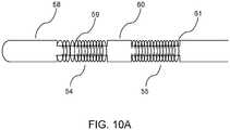
- FIG. 10Ais a schematic illustration of a catheter with a multiplicity of flexible electrodes disposed along its shaft, with the catheter shaft 58 having a stepped construction consisting of higher profile regions such as 60 and lower profile or "stepped down" regions 59 and 61.
- Flexible electrodesare present along the stepped down sections 59 and 61 in the form of metallic coils 54 and 55 respectively, such that the overall diameter profile of the catheter shaft is maintained everywhere along its length in a smooth and continuous manner.
- the thickness of the flexible electrode coils 54 and 55is such that the sum of the stepped down diameter and twice the coil thickness is equal to the outer diameter of the catheter shaft.
- the metallic, flexible coiled electrodescould comprise biocompatible metals such as titanium, platinum or platinum alloys.
- the catheter shaftis made of a flexible polymeric material such as for example Teflon, Nylon or Pebax.
- all the electrodes of a catheterhave the same polarity, in which case the need for high dielectric strength material separating electrode leads (not shown in FIG. 10A ) is not a significant constraint, and the catheter can be relatively small in diameter, for instance being in the range of about 3.0 mm (9 French), about 2.7 mm (8 French) or even about 2.0 mm (6 French).
- a higher DC voltagecan be applied to the electrodes of the catheter as there is no risk of dielectric breakdown; in some instances, this could enhance the efficacy of irreversible electroporation ablation.
- the flexible electrodehas a length 817 (denoted by L ) associated with it, and its diameter 818 corresponds to the catheter diameter (denoted by d ).
- the aspect ratio L / d of each flexible electrodeis a geometric characteristic associated with the flexible electrode.
- the aspect ratio of at least one of the flexible electrodes on the deviceis at least 3, and, in some examples, at least in the range from 5 to 10.
- FIG. 10Ashows two electrodes for purposes of illustration, it should be apparent that the number of flexible electrodes on the catheter can be anywhere from one to fifteen or even greater, depending on the clinical application and convenience of use.
- the cathetercould have a combination of electrodes such that some electrodes are flexible while others are rigid.
- a flexible electrodemay also be constructed in the form of a sequence of thin electrically conducting bands or rings mounted on a flexible catheter shaft, separated by spaces between adjacent rings of the sequence and with the sequence of rings electrically connected together.
- the sequence of ringsforms a single electrode, the entire sequence presenting an isopotential surface across which an electrical current can flow to tissue adjacent to the electrode when the electrode is suitably electrically polarized.
- the electrical connection between the individual rings of the sequencecan be made by several means, such as, for example, attaching a single electrical lead to the inner surface of each ring with one or more spot welds or laser welding, or by crimping each electrode in place over a portion of an exposed electrical lead that runs on the outer surface of the catheter shaft, and so on.
- FIG. 10BThe construction of such a flexible electrode is illustrated in the example in FIG. 10B , where two such electrodes are shown disposed along a length of flexible catheter shaft.
- Each electrode in the figureincludes 3 electrically conducting rings (Rings 1, 2, 3) separated by spaces.
- FIG. 10Bshows 3 rings of widths a 1 , a 2 and a 3 with rings 1 and 2 separated by a space of width b 1 and rings 2 and 3 separated by a space of width b 2 . Since only the flexible catheter shaft is present in the spaces, even though the individual rings may be rigid (for example, the rings can be metallic), the electrode itself is effectively flexible. The adjacent electrodes are separated by a gap. In this manner, the catheter itself can also bend in very flexible fashion.
- each ring of a flexible electrodecan lie in the range between about 0.5 mm and about 6 mm, or in the range between about 1 mm and about 4 mm, including all values and sub ranges in between.
- the spaces between adjacent ringscan lie in the range between about 1 mm and about 4 mm, including all values and sub ranges in between.
- the gaps or separation between adjacent distinct electrodescan lie in the range between about 2 mm and about 12 mm, including all values and sub ranges in between.
- the central or second ring of the flexible electrodeis wider than the end rings (1 and 3). While this example shows a flexible electrode comprising 3 conducting rings, more general constructions with a larger or smaller multiplicity of conducting rings can be built by one skilled in the art following the disclosure herein. Likewise, the separations between adjacent rings can be varied sequentially, as can the width of each individual ring in the sequence. The above example is provided for nonlimiting illustrative purposes only.
- the flexible electrodesare constructed and disposed along the catheter shaft such that about a 2 cm radius of curvature of the shaft is achieved with a minimal amount of applied force or torque.
- a bending moment of about 5 x 10 -3 N-m applied over an approximately 6 cm length of cathetercan result in a bend or end-to-end deflection in the catheter of about 180-degrees or larger.
- each flexible electrodecan be of metallic composition including, but not limited to, stainless steel, silver, gold, any suitable material comprising a significant proportion of platinum such as platinum-iridium alloy, combinations thereof, and/or the like.
- FIG. 11A schematic diagram of the electroporation system, according to some examples, is shown in FIG. 11 .
- a voltage/signal generator 73is driven by a controller unit 71 that interfaces with a computer device 74 by means of a two-way communication link 79.
- the controller interfacecan act as a multiplexer unit and perform channel selection and routing functions for applying voltages to appropriate electrodes that have been selected by a user or by the computer 74.
- the controllercan apply the voltages via a multiplicity of leads to a first catheter device 72, as well as a second catheter device 70.
- Active electrodescan be selected on a first catheter device 72 with one polarity, and likewise active electrodes can be selected on a second catheter device 70 with the opposite polarity.
- Some leads from the controller 71could also carry pacing signals to drive pacing of the heart through a separate pacing device (not shown).
- the catheter devicescan also send back information such as ECG recordings or data from other sensors back to the controller 71, possibly on separate leads.
- the voltage generator 73sends a voltage to the controller 71 through leads 77, the voltage generator is driven by control and timing inputs 78 from the controller unit 71.
- the resulting ECG waveform 82has appropriate respective refractory time intervals 83 and 84 respectively, during which there are suitable time windows for application of irreversible electroporation as indicated by 85 and 86.
- the application of cardiac pacingresults in a periodic, well-controlled sequence of electroporation time windows. Typically, this time window is of the order of hundreds of microseconds to about a millisecond or more. During this window, multiple voltage pulses can be applied to ensure that sufficient tissue ablation has occurred. The user can repeat the delivery of irreversible electroporation over several successive cardiac cycles for further confidence.
- the ablation controller and signal generatorcan be mounted on a rolling trolley, and the user can control the device using a touchscreen interface that is in the sterile field.
- the touchscreencan be for example an LCD touchscreen in a plastic housing mountable to a standard medical rail or post and can be used to select the electrodes for ablation and to ready the device to fire.
- the interfacecan for example be covered with a clear sterile plastic drape.
- the operatorcan select the number of electrodes involved in an automated sequence.
- the touch screengraphically shows the catheters that are attached to the controller. In one example the operator can select electrodes from the touchscreen with appropriate graphical buttons.
- the operatorcan also select the pacing stimulus protocol (either internally generated or externally triggered) from the interface.
- the operatorcan initiate or verify pacing. Once the operator verifies that the heart is being paced, the ablation sequence can be initiated by holding down a hand-held trigger button that is in the sterile field.
- the hand-held trigger buttoncan be illuminated red to indicate that the device is "armed" and ready to ablate.
- the trigger buttoncan be compatible for use in a sterile field and when attached to the controller can be illuminated a different color, for example white.
- the trigger buttonflashes in sequence with the pulse delivery in a specific color such as red.
- the waveform of each delivered pulseis displayed on the touchscreen interface.
- a graphic representation of the pre and post impedance between electrodes involved in the sequencecan also be shown on the interface, and this data can be exported for file storage.
- impedance readingscan be generated based on voltage and current recordings across anode-cathode pairs or sets of electrodes (anodes and cathodes respectively being on distinct catheters), and an appropriate set of electrodes that are best suited for ablation delivery in a given region can be selected based on the impedance map or measurements, either manually by a user or automatically by the system.
- the impedance of the tissue between an anode/cathode combination of electrodesis a relatively low value (for example, less than 25 Ohms)
- the said combinationwould result in relatively large currents in the tissue and power dissipation in tissue; this electrode combination would then be ruled out for ablation due to safety considerations, and alternate electrode combinations could be sought by the user.
- a pre-determined range of impedance valuesfor example 30 Ohms to 300 Ohms, could be used as an allowed impedance range within which it is deemed safe to ablate.
- the waveforms for the various electrodescan be displayed and recorded on the case monitor and simultaneously outputted to a standard connection for any electrophysiology (EP) data acquisition system.
- EPelectrophysiology
- the waveforms acquired internallycan be used to autonomously calculate impedances between each electrode pair.
- the waveform amplitude, period, duty cycle, and delaycan all be modified, for example via a suitable Ethernet connection.
- Pacing for the heartis controlled by the device and outputted to the pacing leads and a protected pacing circuit output for monitoring by a lab.
- the systemcan deliver rectangular-wave pulses with a peak maximum voltage of about 5 kV into a load with an impedance in the range of about 30 Ohm to about 3,000 Ohm for a maximum duration of about 200 ⁇ s, with a maximum duration of about 100 ⁇ s, in some examples.
- Pulsescan be delivered in a multiplexed and synchronized manner to a multi-electrode catheter inside the body with a duty cycle of up to 50 % (for short bursts).
- the pulsescan generally be delivered in bursts, such as for example a sequence of between 2 and 10 pulses interrupted by pauses of between about 1 ms and about 1,000 ms.
- the multiplexer controlleris capable of running an automated sequence to deliver the impulses/impulse trains (from the voltage signal/impulse generator) to the tissue target within the body.
- the controller systemis capable of switching between subsets of electrodes located on the single-use catheters. Further, the controller can measure voltage and current and tabulate impedances of the tissue in each electrode configuration (for display, planning, and internal diagnostic analysis). It can also generate two channels of cardiac pacing stimulus output, and is capable of synchronizing impulse delivery with the internally generated cardiac pacing and/or an external trigger signal. In one example, it can provide sensing output/connection for access to bio potentials emanating from each electrode connected to the system (with connectivity characteristics being compatible with standard electrophysiological laboratory data acquisition equipment).
- the controllercan automatically "recognize” each of the two single-use disposable catheters when it is connected to the controller output (prompting internal diagnostics and user interface configuration options).
- the controllercan have at least two unique output connector ports to accommodate up to at least two catheters at once.
- the controller devicecan function as long as at least two recognized catheters are attached to it.
- the controllercan have several sequence configurations that provide the operator with at least some variety of programming options.
- the controllercan switch electrode configurations of a bipolar set of electrodes (cathodes and anodes respectively on distinct catheters) sequentially, for instance in a clockwise manner (for example, starting at a given step, in the next step of the algorithm, the next cathode electrode on one catheter and the next anode electrode on the other catheter are automatically selected, timed to the synchronizing trigger), with the two catheters and their electrodes arranged in a quasi-circumference around the target.
- pulsed voltage deliveryoccurs as the automated sequencing of the controller switches "on” and "off' between different electrodes surrounding the tissue target.
- the impulsesare delivered to user-selected electrode subsets of catheters that are connected to the device.
- the usercan also configure the controller to deliver up to 2 channels of pacing stimulus to electrodes connected to the device output.
- the usercan control the application of voltage with a single handheld switch.
- a sterile catheter or catheterscan be connected to the voltage output of the generator via a connector cable that can be delivered to the sterile field.
- the useractivates the device with a touch screen interface (that can be protected with a single-use sterile transparent disposable cover commonly available in the catheter lab setting).
- the generatorcan remain in a standby mode until the user is ready to apply pulses at which point the user/assistant can put the generator into a ready mode via the touchscreen interface. Subsequently the user can select the sequence, the active electrodes, and the cardiac pacing parameters.
- the usercan initiate electrically pacing the heart (using a pacing stimulus generated by the ablation controller or an external source synchronized to the ablation system).
- the operatorverifies that the heart is being paced and uses the hand-held trigger button to apply the synchronized bursts of high voltage pulses.
- the systemcan continue delivering the burst pulse train with each cardiac cycle as long as the operator is holding down a suitable "fire" button or switch.
- the generator outputis synchronized with the heart rhythm so that short bursts are delivered at a pre-specified interval from the paced stimulus.
- the train of pulsesis complete, the pacing continues until the operator discontinues pacing.
- the controller and generatorcan output waveforms that can be selected to generate a sequence of voltage pulses in either monophasic or biphasic forms and with either constant or progressively changing amplitudes.
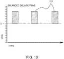
- FIG. 13shows a rectangular wave pulse train where the pulses 101 have a uniform height or maximum voltage.
- FIG. 14shows an example of a balanced biphasic rectangular pulse train, where each positive voltage pulse such as 103 is immediately followed by a negative voltage pulse such as 104 of equal amplitude and opposite sign. While in this example the biphasic pulses are balanced with equal amplitudes of the positive and negative voltages, in other examples an unbalanced biphasic waveform could also be used as may be convenient for a given application.
- FIG. 15shows a progressive balanced rectangular pulse train, where each distinct biphasic pulse has balanced or equal-amplitude positive and negative voltages, but each pulse such as 107 is larger in amplitude than its immediate predecessor 106.
- FIG. 15shows a progressive balanced rectangular pulse train, where each distinct biphasic pulse has balanced or equal-amplitude positive and negative voltages, but each pulse such as 107 is larger in amplitude than its immediate predecessor 106.
- Other variationssuch as a progressive unbalanced rectangular pulse train, or indeed a wide variety of other variations of pulse amplitude with respect to time can be conceived and implemented by those skilled in the art based on the teachings herein.
- the time duration of each irreversible electroporation rectangular voltage pulsecould lie in the range from about 1 nanosecond to about 10 milliseconds, with the range about 10 microseconds to about 1 millisecond in some examples, and the range about 50 microseconds to about 300 microseconds in some examples, including all values and sub ranges in between.
- the time interval between successive pulses of a pulse traincould be in the range of about 10 microseconds to about 1 millisecond, with the range about 50 microseconds to about 300 microseconds in some examples.
- the number of pulses applied in a single pulse train(with delays between individual pulses lying in the ranges just mentioned) can range from 1 to 100, with the range 1 to 10 in some examples.
- a pulse traincan be driven by a user-controlled switch or button or, in some examples, mounted on a hand-held joystick-like device.
- a pulse traincan be generated for every push of such a control button, while in another mode of operation pulse trains can be generated repeatedly during the refractory periods of a set of successive cardiac cycles, for as long as the user-controlled switch or button is engaged by the user.
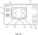
- FIG. 16shows a portion of a user interface of the electroporation system for selection (with graphical buttons 117 and 118) of anode and cathode electrodes, with two catheters connected to the system.
- the proximal leads of the two cathetersare schematically indicated by 110 and 111, which each have two flexible electrodes, respectively 112, 115 and 113, 114.
- the buttons 117 and 118can enable the selection of appropriate electrodes on the catheters as respectively anode or cathode with a "Continue" button 706.
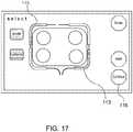
- the appropriate electrodesare colored differently to indicate anode or cathode electrodes as shown marked respectively as anode electrode 115 and cathode electrode 113 on the two catheters in FIG. 17 .
- FIG. 18shows another embodiment of device of the present disclosure, where a first or primary catheter with a multiplicity of flexible electrodes disposed along its shaft (with an electrical lead attached to the inner surface of each electrode) includes multiple lumens through which secondary catheters or microcatheters can be passed to emerge from a lateral surface of the primary catheter, each secondary catheter also having a multiplicity of flexible electrodes disposed along its shaft.
- the primary catheter device 131has flexible electrodes 133, 135, 137 and 139 disposed along the length of its shaft, and the device 131 has lumens 142 and 143 through which secondary catheter devices 145 and 146 are passed.
- the secondary catheterspass through the lumens and emerge from a lateral portion of the primary catheter, in some embodiments on approximately opposite lateral sides of the primary catheter 131.
- the secondary catheters 145 and 146themselves have a multiplicity of flexible electrodes disposed along their lengths, shown in FIG. 18 as electrodes 150 and 151 on secondary catheter 145 and as electrodes 153 and 154 on secondary catheter 146, respectively.
- Electrical leads 180connect to the electrodes 133, 135, 137 and 139 of the primary catheter for delivery of high voltage pulsed signals. In one embodiment the same leads 180 can also serve to record ECG signals.
- electrical leads 171 and 173connect to electrodes 150 and 151 on secondary catheter 145, while electrical leads 175 and 177 connect to electrodes 153 and 154 on secondary catheter 146.
- the distal region of the primary catheter 131comprises a magnetic member 164, and magnetic members such as 166 or 167 are also present within the primary catheter's shaft at an approximately mid-length position.
- the distal regions of the secondary catheters 145 and 146also comprise magnetic members 160 and 162 respectively.
- the magnetic member 164comprises at least one permanent magnet
- the magnetic members 160 and 162comprise magnetizable material such as a ferromagnetic material
- the magnetic members 166 and 167can be either permanent magnets or electromagnets activated by an electrical current, with their magnetic poles oriented laterally with respect to the catheter shaft.
- the primary cathetercan have a through lumen (not shown in FIG. 18 ) for introducing the catheter over a guidewire.
- FIG. 19illustrates, two primary catheters are introduced epicardially via a subxiphoid approach as described for example in PCT Patent Application No. WO2014025394 , where a puncturing apparatus using a subxiphoid pericardial access location and a guidewire-based delivery method to accomplish the placement of a multi-electrode catheter around the pulmonary veins was described in detail.
- the two primary cathetersjointly encircle a set of four pulmonary veins, with two secondary catheters emerging from each primary catheter so as to conjunctively wrap a set of electrodes around each individual pulmonary vein.
- Four pulmonary veins marked A, B, C and Dare shown in FIG. 19 .
- Primary catheter 206wraps around one side (representing an outer contour) of pulmonary veins marked A and C in FIG. 19
- primary catheter 207wraps around one side (representing an outer contour) of pulmonary veins marked B and D in FIG. 19
- Secondary catheter 208branches out from a proximal portion of primary catheter 206, wraps around the inner side of pulmonary vein A and magnetically attaches to the mid-portion of primary catheter 206, with a distal magnetic member 231 on secondary catheter 208 attaching to a mid-portion magnetic member 230 on primary catheter 206.
- secondary catheter electrodes 215 and 216 and primary catheter electrodes 220 and 221collectively are wrapped in a closed contour around pulmonary vein A.
- Secondary catheter 229branches out from a middle portion of primary catheter 206, wraps around the inner side of pulmonary vein C and magnetically attaches to the distal portion of primary catheter 206, with a distal magnetic member 241 on secondary catheter 229 attaching to a distal magnetic member 242 on primary catheter 206.
- secondary catheter electrodes 213 and 214 and primary catheter electrodes 210 and 211collectively are wrapped in a closed contour around pulmonary vein C.
- the distal portion of primary catheter 206also magnetically attaches to the distal portion of primary catheter 207.
- Secondary catheters 224 and 225branch out from primary catheter 207 and wrap around pulmonary veins B and D, with a distal magnetic member 234 on secondary catheter 224 attaching to a mid-portion magnetic member 235 on primary catheter 207 and a distal magnetic member 238 on secondary catheter 225 attaching to a distal magnetic member 239 on primary catheter 207, respectively.
- each pulmonary veinis wrapped by a set of flexible electrodes for effective electroporation voltage delivery.
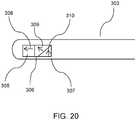
- FIG. 20An example of a magnetic member configuration for the distal magnetic member 164 of the primary catheter device in FIG. 18 (or 239 or 242 in FIG. 19 ) is provided in FIG. 20 .
- the latter figureillustrates a catheter with a magnet assembly in its distal portion, such that a first effective pole of the magnet assembly is oriented longitudinally and a second effective pole of the magnet assembly oriented laterally.
- the catheter 303comprises an assembly of magnetized material in its distal portion comprising magnetic elements 305, 306 and 307 with respective magnetization orientations indicated by arrows 308, 309 and 310.
- the assembly comprising the magnetic elements 305, 306 and 307effectively forms a magnetic member with a longitudinally oriented magnetic pole (denoted by arrow 308) and a laterally oriented magnetic pole (denoted by arrow 310).
- a second primary catheterhas a similar assembly of magnetic elements in its distal portion with an opposite orientation of its longitudinal and lateral magnetic poles, the distal tips of the two primary catheters can attach magnetically.
- magnetic members in the mid-portion of the primary cathetercan for example be in the form of electromagnets, providing a means of attachment of the distal tip of a secondary catheter to the mid-portion of a primary catheter, and this attachment mechanism provides an exemplary means for configuring a set of primary and secondary catheters as shown in FIG. 19 . While the examples and attachment means described herein provides one method of magnetic attachment, other similar methods can be conceived and implemented by one skilled in the art by following the embodiments disclosed herein.
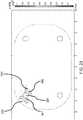
- FIG. 21shows an illustration of a two dimensional model of a cardiac atrium, with an atrial tissue region 320 that has interior "blood pool" regions 321, 322, 323 and 324.
- Each blood pool regionrepresents a pulmonary vein and is surrounded by a thin annular such as for example the ring-shaped region 337 around pulmonary vein 322.
- Four electrodes 331, 332, 333 and 334are shown disposed around pulmonary vein 324 so as to surround it. With a potential difference applied across some of the electrodes, simulation results can be obtained based on realistic values of electrical material properties for the various regions.
- FIG. 22A simulation result in the form of a shaded contour plot of the electric potential is shown in FIG. 22 for the case where a DC voltage is applied across a single anode electrode 332 and a single cathode electrode 334 on opposite sides of the blood pool region 324, with a potential difference of 750 V applied across anode and cathode.
- FIG. 23shows the electric field intensity as a shaded contour plot where regions with an electric field strength of magnitude at least 200 V/cm (generally needed to cause irreversible electroporation ablation of myocytes) are indicated in the shaded areas. It is apparent that these ablated regions, indicated by region 341 around the anode electrode and region 342 around the cathode electrode, cover a significant fraction of a contour around pulmonary vein 324.
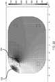
- FIG. 24shows the electric field intensity as a shaded contour plot where regions with an electric field strength of magnitude at least about 200 V/cm are indicated in the shaded areas. It is apparent that in this case, the ablated region encompasses the entire contour around the pulmonary vein 324.
- the catheter devices with flexible electrodescan be effectively utilized for rapid ablation therapy by the application of irreversible electroporation voltages. As can be seen from FIG.
- the areas where electric field intensities are sufficiently large to generate irreversible electroporationoccur substantially in the region between the electrodes, thus minimizing any potential damage to outer areas.
- the applied voltage pulse level that is required to generate effective ablationcan be significantly reduced; in the above simulation a voltage of about 750 V is seen to be sufficient to generate irreversible electroporation everywhere in a region of interest. This further enhances the safety of the procedure by reducing the likelihood of generating local electric fields that may be large enough to generate sparking or local dielectric breakdown as well as reduce the intensity of muscular contractions. The need for precise positioning of the electrodes is also reduced, leading to an overall faster therapeutic procedure.
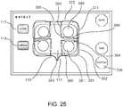
- FIG. 25shows a portion of a user interface of the electroporation system for selection (with graphical buttons 117 and 118) of anode and cathode electrodes, with two catheters connected to the system.
- the proximal leads of the two cathetersare schematically indicated by 110 and 111, which each have four flexible electrodes.
- the catheter 111has flexible electrodes labeled 361, 362, 371 and 372 in FIG. 25 .
- Secondary catheter 360branches out from a proximal portion of catheter 111, while secondary catheter 366 branches out from a mid-portion of catheter 111.
- Secondary catheter 360has flexible electrodes 363 and 364 respectively, while secondary catheter 366 has flexible electrodes 368 and 369 respectively. Electrodes 361, 362, 363 and 364 thus encircle the pulmonary vein labeled 381, while electrodes 368, 369, 372 and 371 encircle the pulmonary vein labeled 380.
- buttons 117 and 118can enable the selection of appropriate electrodes on the catheters as respectively anode or cathode with a "Continue" button 706.
- the appropriate electrodesare colored differently to indicate anode or cathode electrodes as shown in FIG. 17 , where electrodes 372 and 368 have been marked respectively as anode electrode and cathode electrode, respectively on primary catheter 111 and secondary catheter 366.
- This selectionhas been shown for purely illustrative purposes. Other examples of user interface and mode of electrode selection can be implemented by one skilled in the art based on the teachings herein.
- the voltage signals used in the ablation processare DC voltages or DC voltage pulses
- the voltage signalscan be AC voltages, or each voltage pulse can itself include time-varying components.
- the foregoing described a magnet-based scheme for positioning and attachment of catheters to each otherit should be apparent that other methods could be implemented for this purpose, including mechanical means using small manipulator arms or catches, pneumatically driven means, and so on, as can be conceived by those skilled in the art by employing the principles and teachings disclosed herein without departing from the scope of the embodiments disclosed herein.
- Some examples described hereinrelate to a computer storage product with a non-transitory computer-readable medium (also referred to as a non-transitory processor-readable medium) having instructions or computer code thereon for performing various computer-implemented operations.
- the computer-readable mediumor processor-readable medium
- the media and computer codemay be those designed and constructed for the specific purpose or purposes.
- non-transitory computer-readable mediainclude, but are not limited to: flash memory, magnetic storage media such as hard disks, optical storage media such as Compact Disc/Digital Video Discs (CD/DVDs), Compact Disc-Read Only Memories (CD-ROMs), magneto-optical storage media such as optical disks, carrier wave signal processing modules, and hardware devices that are specially configured to store and execute program code, such as Application-Specific Integrated Circuits (ASICs), Programmable Logic Devices (PLDs), Read-Only Memory (ROM) and Random-Access Memory (RAM) devices.
- ASICsApplication-Specific Integrated Circuits
- PLDsProgrammable Logic Devices
- ROMRead-Only Memory
- RAMRandom-Access Memory
- Examples of computer codeinclude, but are not limited to, micro-code or micro-instructions, machine instructions, such as produced by a compiler, code used to produce a web service, and files containing higher-level instructions that are executed by a computer using an interpreter.
- examplesmay be implemented using Java, C++, or other programming languages and/or other development tools.
Landscapes
- Health & Medical Sciences (AREA)
- Surgery (AREA)
- Engineering & Computer Science (AREA)
- Life Sciences & Earth Sciences (AREA)
- Biomedical Technology (AREA)
- Molecular Biology (AREA)
- Nuclear Medicine, Radiotherapy & Molecular Imaging (AREA)
- Plasma & Fusion (AREA)
- Physics & Mathematics (AREA)
- Heart & Thoracic Surgery (AREA)
- Medical Informatics (AREA)
- Otolaryngology (AREA)
- Animal Behavior & Ethology (AREA)
- General Health & Medical Sciences (AREA)
- Public Health (AREA)
- Veterinary Medicine (AREA)
- Cardiology (AREA)
- Measurement And Recording Of Electrical Phenomena And Electrical Characteristics Of The Living Body (AREA)
Description
- The embodiments described herein relate generally to medical devices for therapeutic electrical energy delivery, and particularly to systems and methods of high voltage electrical energy delivery in the context of ablating tissue rapidly and selectively by the application of pulsed voltage waveforms to produce exogenous electric fields to cause irreversible electroporation of tissue with the aid of suitably positioned catheter devices with multiple electrodes.
- In the past two decades, the technique of electroporation has advanced from the laboratory to clinical applications, while the effects of brief pulses of high voltages and large electric fields on tissue has been investigated for the past forty years or more. Application of brief, high DC voltages to tissue, thereby generating locally high electric fields typically in the range of hundreds of Volts/centimeter, can disrupt cell membranes by generating pores in the cell membrane. While the precise mechanism of this electrically-driven pore generation (or electroporation) is not well understood, it is thought that the application of relatively large electric fields generates instabilities in the lipid bilayers in cell membranes, causing the occurrence of a distribution of local gaps or pores in the membrane. If the applied electric field at the membrane is larger than a threshold value, the electroporation is irreversible and the pores remain open, permitting exchange of material across the membrane and leading to necrosis and/or apoptosis (cell death). Subsequently the tissue heals in a natural process.
- Some known processes of adipose tissue reduction by freezing, also known as cryogenically induced lipolysis, can involve a significant length of therapy time. In contrast, the action of irreversible electroporation can be much more rapid. Some known tissue ablation methods employing irreversible electroporation, however, involve destroying a significant mass of tissue, and one concern is the temperature increase in the tissue resulting from this ablation process.
- While pulsed DC voltages are known to drive electroporation under the right circumstances, known approach do not provide for ease of navigation, placement and therapy delivery from one or more devices and for safe energy delivery, especially in the context of ablation therapy for cardiac arrhythmias with epicardial catheter devices.
- Thus, there is a need for devices that can effectively deliver electroporation ablation therapy selectively to tissue in regions of interest while minimizing damage to healthy tissue. In particular, there is a need for devices that can efficiently deliver electroporation therapy to desired tissue regions while at the same time minimizing the occurrence of irreversible electroporation in undesired tissue regions. Such elective and effective electroporation delivery methods with enhanced safety of energy delivery can broaden the areas of clinical application of electroporation including therapeutic treatment of a variety of cardiac arrhythmias.
US 2012/310230 discloses a coaxial dual function probe and method of use.US 2009/281477 discloses an electroporation device and method.WO 2014/025394 A1 discloses a percutaneous catheter system for use within the human body and an ablation catheter for ablating a selected tissue region within the body of a subject. The percutaneous catheter system can include two catheters that are operatively coupled to one another by magnetic coupling through a tissue structure. The ablation catheter can include electrodes positioned within a central portion. The ablation catheter is positioned such that the central portion of a flexible shaft at least partially surrounds the selected tissue region.- In accordance with one aspect of the invention, there is provided an apparatus as defined in
claim 1. In accordance with a second aspect of the invention, there is provided an apparatus as defined inclaim 4. Optional features are defined in the dependent claims. FIG. 1 is a schematic illustration of a catheter with a multiplicity of flexible electrodes disposed along its shaft, with an electrical lead attached to the inner surface of each electrode, and with a magnetic member located near the distal end of the catheter, according to examples.FIG. 2 is an illustration showing two catheters, each with multiple flexible electrodes disposed along its shaft and wrapped around a portion of the pulmonary veins of the heart in a subject body, with the distal ends of the two catheters in close proximity, according to examples. The two catheters together constitute an approximately closed contour around the pulmonary veins and each catheter positioned in the epicardial space around the heart.FIG. 3 is a schematic of a two dimensional model of a cardiac atrium, with various regions such as a myocardium disposed around an interior region of blood pool, a ring of electrodes around the myocardium, and pericardial fluid in an external region.FIG. 4 is a simulation result in the form of a shaded contour plot of the electric potential, with a voltage difference set between two electrodes on opposite sides of the myocardium and all other electrodes replaced by insulation, according to examples.FIG. 5 is a simulation result corresponding to the situation inFIG. 4 , in the form of a shaded contour plot of the electric field magnitude in regions where the latter is at least 200 V/cm, with a voltage difference set between two electrodes on opposite sides of the myocardium and all other electrodes replaced by insulation, according to examples.FIG. 6 is a simulation result in the form of a shaded contour plot of the electric potential, with a voltage difference set between one electrode on one side of the myocardium and a set of three contiguous electrodes (separated by insulation between successive pairs) on the opposite side of the myocardium, and all other electrodes replaced by insulation, according to examples.FIG. 7 is a simulation result corresponding to the situation inFIG. 6 , in the form of a shaded contour plot of the electric field magnitude in regions where the latter is at least 200 V/cm, with a voltage difference set between one electrode on one side of the myocardium and a set of three contiguous electrodes (separated by insulation between successive pairs) on the opposite side of the myocardium, and all other electrodes replaced by insulation, according to examples.FIG. 8 is a simulation result in the form of a shaded contour plot of the electric potential, with a voltage difference set between a set of five contiguous electrodes on one side of the myocardium and a set of five contiguous electrodes on the opposite side of the myocardium, and all other electrodes replaced by insulation, according to examples.FIG. 9 is a simulation result corresponding to the situation inFigure 8 , in the form of a shaded contour plot of the electric field magnitude in regions where the latter is at least 200 V/cm, with a voltage difference set between a set of three contiguous electrodes (separated by insulation between successive pairs) on one side of the myocardium and a set of three contiguous electrodes (separated by insulation between successive pairs) on the opposite side of the myocardium, and all other electrodes replaced by insulation, according to examples.FIG. 10A is an illustration of a catheter with a multiplicity of flexible electrodes disposed along its shaft, each in the form of a coil wound around a stepped structure of the catheter shaft, where the step structure of the shaft and the coil thickness are such that the outer surface of the catheter forms a smooth structure with an even or smooth diameter profile, according to examples.FIG. 10B is an illustration of construction of two flexible electrodes, according to examples.FIG. 11 is a schematic illustration of an irreversible electroporation system that includes a voltage/signal generator, a controller capable of being configured to apply voltages to selected subsets of electrodes with independent subset selections for anode electrodes on one medical device and cathode electrodes on a second medical device and that is connected to a computer, and two or more medical devices connected to the controller, according to examples.FIG. 12 is an illustration of an ECG waveform showing the refractory periods during atrial and ventricular pacing during which a time window for irreversible electroporation ablation can be chosen, according to examples.FIG. 13 is a schematic illustration of a waveform generated by the irreversible electroporation system according to examples, showing a balanced square wave.FIG. 14 is a schematic illustration of a waveform generated by the irreversible electroporation system according to examples, showing a balanced biphasic square wave.FIG. 15 is a schematic illustration of a waveform generated by the irreversible electroporation system according to examples, showing a progressive balanced biphasic square wave.FIG. 16 is a schematic illustration of a user interface according to examples, showing electrodes on two catheters, and buttons for selection or marking of anode electrode subsets and cathode electrode subsets.FIG. 17 is a schematic illustration of a user interface, according to examples, for selection of anode and cathode electrode subsets, showing a single selected anode electrode on one catheter device and a single selected cathode electrode on a second catheter device.FIG. 18 illustrates a first or primary catheter with a multiplicity of flexible electrodes disposed along its shaft with an electrical lead attached to the inner surface of each electrode, and endowed with multiple lumens through which secondary catheters or microcatheters are passed to emerge from a lateral surface of the primary catheter, each secondary catheter also having a multiplicity of flexible electrodes disposed along its shaft, according to embodiments.FIG. 19 provides a schematic illustration of two primary catheters that together encircle a set of four pulmonary veins, with two secondary catheters emerging from each primary catheter so as to conjunctively wrap a set of electrodes around each individual pulmonary vein, according to embodiments.FIG. 20 is an illustration of a catheter with a magnet assembly in its distal portion, such that a first effective pole of the magnet assembly is oriented longitudinally and a second effective pole of the magnet assembly oriented laterally, according to embodiments.FIG. 21 is a schematic illustration of a two dimensional simulation model of a cardiac atrium, with four interior pulmonary vein "blood pool" regions disposed within a region representing the atrium, each pulmonary vein having an annular vessel wall region, and one of the pulmonary veins having four flat electrodes surrounding it, according to examples.FIG. 22 is a simulation result in the form of a shaded contour plot of the electric potential, with a voltage difference set between two electrodes on opposite sides of a pulmonary vein, according to examples.FIG. 23 is a simulation result corresponding to the situation inFigure 6 , in the form of a shaded contour plot of the electric field magnitude, with a voltage difference of 750 V between opposing electrodes around a pulmonary vein, according to examples.FIG. 24 is a simulation result corresponding to the situation inFigure 6 , in the form of a shaded contour plot of the electric field magnitude, with a voltage difference of 750 V between two pairs of opposing electrodes around a pulmonary vein, resulting in the entire peripheral region of the pulmonary vein being exposed to an electric field strength magnitude sufficient to generate irreversible electroporation, according to examples.FIG. 25 is a schematic illustration of a user interface according to examples, showing electrodes on two primary catheters and electrodes on each of two secondary catheters passed through each primary catheter, and with the interface having buttons for selection or marking of anode electrode subsets and cathode electrode subsets.FIG. 26 is a schematic illustration of a user interface, according to examples, for selection of anode and cathode electrode subsets, showing a single selected anode electrode on one primary catheter device and a single selected cathode electrode on a secondary catheter device that is passed through the primary catheter device.- In some examples, a system includes a generator unit configured for generating pulses, and a controller unit operably coupled to the generator unit, the controller unit configured for triggering the generator unit to generate one or more pulses. The system also includes a set of pacing leads operably coupled to the controller unit, the controller unit, the generator unit, and the set of pacing leads configured for driving the one or more pulses through the pacing leads. The system also includes at least two medical devices including a first medical device and a second medical device, each medical device operably coupled to the controller unit, each medical device including a plurality of electrodes. The controller unit is further configured for selecting one or more first electrodes from the plurality of electrodes of the first medical device and from the plurality of electrodes of the second medical device as cathodes for applying the one or more pulses. The controller unit is further configured for selecting one or more second electrodes from the plurality of electrodes of the first medical device and from the plurality of electrodes of the second medical device as anodes for applying the one or more pulses.
- In some embodiments, a device includes a primary catheter, including one or more electrodes disposed in an intermediate portion of the primary catheter and one or more electrodes disposed in a distal portion of the primary catheter. The primary catheter also includes two or more channels configured for passage of secondary catheters, each channel continuous from a proximal portion of the primary catheter to a lateral exit position on the primary catheter, and one or more magnetic members disposed in the intermediate portion of the primary catheter. The primary catheter also includes and a magnetic member disposed in the distal portion of the primary catheter. The device further includes at least two secondary catheters configured for passage through the primary catheter device, each secondary catheter including one or more electrodes in its respective distal portion, and a magnetic member in its respective distal portion. The device also includes, for each electrode of the primary catheter and each electrode of the secondary catheter, an electrical lead attached to the corresponding electrode, each lead configured for, during use, being at an electrical voltage potential of at least 1 kV without resulting in dielectric breakdown of the two or more channels of the primary catheter. A geometric aspect ratio of at least one of the electrodes of the primary catheter device is in the range between about 3 and about 20.
- In some examples, a system includes a pulse generator unit configured to generated voltage pulses, and a controller unit operably coupled to the pulse generator unit. The controller unit is configured for triggering the pulses of the generator unit and for applying voltages of one polarity to a set electrodes of a first medical device and voltages of an opposite polarity to a set electrodes of a second medical device. The system also includes a set of pacing leads operably coupled to the controller unit, the controller unit further configured for driving pacing signals through the pacing leads. The system also includes a primary catheter and a secondary catheter operably coupled to the controller unit, the primary catheter including a first set of electrodes, the secondary catheter including a second set of electrodes. The controller unit is configured for driving voltages through any electrode of the first set of electrodes and second set of electrode. The controller unit is further configured for selecting a sequence of pairs of electrodes from the first set of electrodes and the second set of electrodes. For each pair of electrodes, an electrode of the pair of electrodes has an opposite polarity from the other electrode of the pair of electrodes, and an electrode of the pair of electrodes selected from the primary catheter, the other electrode of the pair of electrodes selected from the secondary catheter. The controller unit is further configured for sequential application of voltage pulse trains over the sequence of pairs of electrodes.
- In some examples, a method includes epicardially inserting two primary catheters, each primary catheter including a first set of electrodes disposed along its length. The method also includes positioning the primary catheters in conjoined form so as to substantially wrap around the pulmonary veins epicardially in a single contour. The method also includes passing a secondary catheter through each primary catheter, each secondary catheter extending out from a lateral side of its corresponding primary catheter. Each secondary catheter includes a second set of electrodes. The method also includes, for each secondary catheter, wrapping the secondary catheter around a portion of a pulmonary vein, and attaching the secondary to an intermediate portion or distal portion of its corresponding primary catheter, such that the secondary catheter epicardially encircles the pulmonary vein with a series of electrodes selected from the first set of electrodes of its corresponding primary catheter, from the second set of electrodes of the secondary catheter, or both. The method also includes selecting a set of pairs of electrodes from the first set of electrodes of the primary catheters and from the second set of electrodes of the secondary catheters, each electrode of each pair of electrodes having a cathode or an anode assignment. The method also includes recording electrocardiogram (ECG) signals from at least some electrodes of the first set of electrodes of the primary catheters and the second set of electrodes of the secondary catheters. The method further includes identifying refractory intervals in at least one ECG signal and, in at least one subsequent refractory interval, sequentially applying voltage pulse trains to the set of pairs of electrodes.
- An apparatus includes a catheter shaft, and a set of flexible electrodes disposed along the length of the catheter shaft. Each flexible electrode is characterized by a geometric aspect ratio of the length of the flexible electrode to the outer diameter of the flexible electrode. Each flexible electrode includes a set of conducting rings separated by spaces and disposed along the catheter shaft. The set of conducting rings of each flexible electrode are electrically connected together so as to electrically define a common electrical potential for the each electrode. The catheter shaft includes gaps configured for separating adjacent flexible electrodes of the set of flexible electrodes. The apparatus also includes electrical leads attached to each of the flexible electrodes, each electrical lead configured for attaining an electrical voltage potential of at least 1 kV. The geometric aspect ratio of at least one of the flexible electrodes is in the range between about 3 and about 20
- The terms "about" and "approximately" when used in connection with a referenced numeric indication means the referenced numeric indication plus or minus up to 10% of that referenced numeric indication. For example, the language "about 50" covers the range of 45 to 55.
- As used in this specification, the singular forms "a," "an" and "the" include plural referents unless the context clearly dictates otherwise. Thus, for example, the term "an electrode" is intended to mean a single electrode or a plurality/combination of electrodes.
- Any of the catheter devices described herein can be similar to the ablation catheters described in PCT Publication No.
WO2014/025394 - Aspects disclosed herein are directed to catheters, systems and methods for the selective and rapid application of DC voltage to drive irreversible electroporation. Catheter devices with flexible electrodes and methods for using a multiplicity of such devices for rapid and effective ablation of cardiac tissue are disclosed. In some examples, the irreversible electroporation system described herein includes a voltage/signal generator and a controller capable of being configured to apply voltages to a selected multiplicity or a subset of electrodes, with anode and cathode subsets being selected independently on distinct medical devices. The controller is additionally capable of applying control inputs whereby selected pairs of anode-cathode subsets of electrodes can be sequentially updated based on a pre-determined sequence.
FIG. 1 is a schematic illustration of a catheter with a multiplicity of flexible electrodes disposed along its shaft, with an electrical lead attached to the inner surface of each electrode, and with a magnetic member located near the distal end of the catheter. Thecatheter shaft 801 has a multiplicity of electrodes disposed along an extensive length of catheter at least about 5 cm in extent. For clarity,FIG. 1 shows twoflexible electrodes FIG. 1 electrodes leads - Further, the distal tip region of the catheter has a
magnetic member 809. Themagnetic member 809 can be in the form of a magnetizable or ferromagnetic material, or it may be a magnetized object, with the poles of the magnetized object being either along a straight line or not. In some examples, at least one of the poles of the magnet represents a local magnetization direction that is substantially aligned with the longitudinal axis of the catheter. - In one example the metallic, flexible coiled electrodes could comprise biocompatible metals such as titanium, platinum or platinum alloys. The catheter shaft is made of a flexible polymeric material such as for example Teflon, Nylon or Pebax.
- In some examples, all the electrodes of a catheter have the same polarity, in which case the need for high dielectric strength material separating the leads is not a significant constraint, and the catheter can be relatively small in diameter, for instance being in the range of about 3.0 mm (9 French), about 2.7 mm (8 French) or even about 2.0 mm (6 French). Likewise, a higher voltage can be applied to the electrodes of the catheter as there is no risk of dielectric breakdown; in some instances, this could enhance the efficacy of irreversible electroporation ablation. The flexible electrode has a length 817 (denoted byL) associated with it, and its
diameter 818 corresponds to the catheter diameter (denoted byd). The aspect ratioL/d of each flexible electrode is a geometric characteristic associated with the flexible electrode. In some examples, the aspect ratio of at least one of the flexible electrodes on the device is at least about 3, and at least in the range between about 3 and about 20, and in the range between about 5 and about 10 in some examples. FIG. 2 shows a pair of Pulmonary Vein isolation (PV isolation) ablation catheter devices, a first device withproximal end 3 anddistal end 15, and a second device withproximal end 4 anddistal end 16, each with a multiplicity of flexible electrodes disposed along its length. The first catheter device has two flexible electrodes labeled 5 and 8 disposed along its length, while the second catheter device has two flexible electrodes labeled 6 and 7. Each catheter is wrapped in the epicardial space around a portion of thepulmonary veins heart 7 in a subject or patient anatomy, with theproximal portions WO2014025394 FIG. 2 . After theends - A voltage for electroporation can be applied to subsets of electrodes identified as anodes and cathodes respectively on the two catheters on approximately opposite sides of the closed contour defined by the shapes of the catheters around the pulmonary veins. The voltage is applied in brief pulses sufficient to cause irreversible electroporation and can be in the range of 0.5 kV to 10 kV, in the range from about 0.75 kV to about 2.5 kV, and all values and subranges in between, so that a threshold electric field value of about 200 Volts/cm is effectively achieved in the cardiac tissue to be ablated. In some examples, the marked or active electrodes on the two catheters can be automatically identified, or manually identified by suitable marking, on an X-ray or fluoroscopic image obtained at an appropriate angulation that permits identification of the geometric distance between anode and cathode electrodes, or their respective centroids. In one example, the voltage generator setting for irreversible electroporation is then automatically identified by the electroporation system based on this distance measure. In some examples, the voltage value is selected directly by a user from a suitable dial, slider, touch screen, or any other user interface. The voltage pulse results in a current flowing between the anode and cathode electrodes on opposite sides of the contour defined by the conjoint shapes of the two catheters, with said current flowing through the cardiac wall tissue and through the intervening blood in the cardiac chamber, with the current entering the cardiac tissue from the anode electrodes and returning back through the cathode electrodes. For the configuration shown in
FIG. 2 , the forward and return current paths (leads) are respectively inside distinct catheters, since all active electrodes on a given catheter are of like polarity. Areas of cardiac wall tissue where the electric field is sufficiently large for irreversible electroporation are ablated during the voltage pulse application. - A two dimensional model of a cardiac atrium, with various regions such as a myocardium disposed around an interior region of blood pool, a ring of electrodes around the myocardium representing a catheter shaft, and pericardial fluid in an external region is shown in
FIG. 3 , with which simulation results can be obtained based on realistic values of electrical material properties for the various regions. A ring ofelectrodes 23 comprising a series of cells is disposed around amyocardium 24 which itself encircles ablood pool region 25. An externalpericardial fluid region 26 surrounds the ring of electrodes. For purposes of simulation, individual electrode cells such as 27 can be defined or set to be either metal electrodes or insulation (representing catheter shaft regions that do not have electrodes) in terms of electrical properties. - A simulation result in the form of a shaded contour plot of the electric potential is shown in
FIG. 4 for the case where a voltage is applied between asingle anode electrode 30 and asingle cathode electrode 31 on opposite sides of the blood pool region, with all other electrode cells defined to be insulation in terms of electrical properties. In the simulation, a voltage difference of about 1 kV was used between the anode and cathode electrodes.FIG. 5 shows the electric field intensity as a contour plot where regions with an electric field strength of magnitude at least about 200 V/cm (generally needed to cause irreversible electroporation ablation of myocytes) are indicated by the darker shaded areas. It is apparent that these ablated regions, indicated byregion 35 around the anode electrode andregion 34 around the cathode electrode, are quite localized near the electrodes across which a potential difference is applied. FIG. 6 illustrates a simulation result in the form of a shaded contour plot of the electric potential for the case where a DC voltage is applied between asingle anode electrode 37 and a set of threesuccessive cathode electrodes electrodes FIG. 7 shows the electric field intensity as a contour plot where regions with an electric field strength of magnitude at least about 200 V/cm (generally needed to cause irreversible electroporation ablation) are indicated by the darker shaded areas. It is apparent that these ablated regions, indicated byregion 44 around the anode electrode andregion 43 around the set of cathode electrodes, are quite localized near the electrodes across which a potential difference is applied. Furthermore, there are gap regions such as 45 in the myocardium where the electric field intensity is not large enough to generate electroporation. In practice, this would mean that repeated applications of pulsed DC voltage may be needed with repositioning of the catheter shaft(s) and electrodes.- In
FIG. 8 , a simulation result is displayed in the form of a shaded contour plot of the electric potential, with a voltage difference set between a set of five contiguous electrodes on one side of the myocardium and a set of five contiguous electrodes on the opposite side of the myocardium, representing respective "long electrodes", and all other electrodes replaced by insulation. In the simulation, a voltage difference of about 1 kV was used between the anode electrode set and the cathode electrode set.FIG. 9 shows the electric field intensity as a contour plot where regions with electric field strength of magnitude at least about 200 V/cm (generally needed to cause irreversible electroporation ablation in myocytes) are indicated by the darker shaded areas. It is apparent that these ablated regions, indicated byregion 50 around the anode electrode andregion 51 around the set of cathode electrodes, constitute continuous, fully ablated sections of myocardium. Thus, with a set of longer, flexible electrodes as described in the present disclosure, a more rapid and effective delivery of ablation therapy may be obtained as repositioning of the catheter shaft will be minimized. Furthermore, the catheter devices, in some examples, with long, flexible electrodes can result in a lower peak value of the electric field. This can minimize or eliminate the possibility of dielectric breakdown or spark generation during high voltage ablation. For instance, while the peak electric field intensity values corresponding to the single cathode and three-cathode situations ofFIG. 5 andFIG. 7 are respectively about 4,458 V/cm and about 3,916 V/cm, the peak electric field intensity value that occurs for the case of long, flexible electrodes as inFIG. 8 is about 2,456 V/cm, demonstrating an advantage of the catheter devices of the present disclosure. FIG. 10A is a schematic illustration of a catheter with a multiplicity of flexible electrodes disposed along its shaft, with thecatheter shaft 58 having a stepped construction consisting of higher profile regions such as 60 and lower profile or "stepped down"regions sections metallic coils FIG. 10A ) is not a significant constraint, and the catheter can be relatively small in diameter, for instance being in the range of about 3.0 mm (9 French), about 2.7 mm (8 French) or even about 2.0 mm (6 French). Likewise, a higher DC voltage can be applied to the electrodes of the catheter as there is no risk of dielectric breakdown; in some instances, this could enhance the efficacy of irreversible electroporation ablation. The flexible electrode has a length 817 (denoted byL) associated with it, and itsdiameter 818 corresponds to the catheter diameter (denoted byd). The aspect ratioL/d of each flexible electrode is a geometric characteristic associated with the flexible electrode. In some examples, the aspect ratio of at least one of the flexible electrodes on the device is at least 3, and, in some examples, at least in the range from 5 to 10. AlthoughFIG. 10A shows two electrodes for purposes of illustration, it should be apparent that the number of flexible electrodes on the catheter can be anywhere from one to fifteen or even greater, depending on the clinical application and convenience of use. In some examples, the catheter could have a combination of electrodes such that some electrodes are flexible while others are rigid.- In some examples, a flexible electrode may also be constructed in the form of a sequence of thin electrically conducting bands or rings mounted on a flexible catheter shaft, separated by spaces between adjacent rings of the sequence and with the sequence of rings electrically connected together. In this manner, the sequence of rings forms a single electrode, the entire sequence presenting an isopotential surface across which an electrical current can flow to tissue adjacent to the electrode when the electrode is suitably electrically polarized. The electrical connection between the individual rings of the sequence can be made by several means, such as, for example, attaching a single electrical lead to the inner surface of each ring with one or more spot welds or laser welding, or by crimping each electrode in place over a portion of an exposed electrical lead that runs on the outer surface of the catheter shaft, and so on.
- The construction of such a flexible electrode is illustrated in the example in
FIG. 10B , where two such electrodes are shown disposed along a length of flexible catheter shaft. Each electrode in the figure includes 3 electrically conducting rings (Rings FIG. 10B shows 3 rings of widthsa1,a2 anda3 withrings - In the example shown in
FIG. 10B , the central or second ring of the flexible electrode is wider than the end rings (1 and 3). While this example shows a flexible electrode comprising 3 conducting rings, more general constructions with a larger or smaller multiplicity of conducting rings can be built by one skilled in the art following the disclosure herein. Likewise, the separations between adjacent rings can be varied sequentially, as can the width of each individual ring in the sequence. The above example is provided for nonlimiting illustrative purposes only. - For epicardial use as disclosed in the present application, it is useful to have a catheter with a certain amount of flexibility. One characterization of flexibility can be made in terms of a radius of curvature. In some examples, the flexible electrodes are constructed and disposed along the catheter shaft such that about a 2 cm radius of curvature of the shaft is achieved with a minimal amount of applied force or torque. In some examples, a bending moment of about 5 x 10⁻³ N-m applied over an approximately 6 cm length of catheter can result in a bend or end-to-end deflection in the catheter of about 180-degrees or larger.
- The rings of each flexible electrode can be of metallic composition including, but not limited to, stainless steel, silver, gold, any suitable material comprising a significant proportion of platinum such as platinum-iridium alloy, combinations thereof, and/or the like.
- A schematic diagram of the electroporation system, according to some examples, is shown in
FIG. 11 . A voltage/signal generator 73 is driven by acontroller unit 71 that interfaces with acomputer device 74 by means of a two-way communication link 79. The controller interface can act as a multiplexer unit and perform channel selection and routing functions for applying voltages to appropriate electrodes that have been selected by a user or by thecomputer 74. The controller can apply the voltages via a multiplicity of leads to afirst catheter device 72, as well as asecond catheter device 70. Active electrodes can be selected on afirst catheter device 72 with one polarity, and likewise active electrodes can be selected on asecond catheter device 70 with the opposite polarity. - Some leads from the
controller 71 could also carry pacing signals to drive pacing of the heart through a separate pacing device (not shown). The catheter devices can also send back information such as ECG recordings or data from other sensors back to thecontroller 71, possibly on separate leads. While thevoltage generator 73 sends a voltage to thecontroller 71 throughleads 77, the voltage generator is driven by control and timinginputs 78 from thecontroller unit 71. - As shown in
FIG. 12 , given atrial or ventricular pacing inputs to the heart, the resultingECG waveform 82 has appropriate respectiverefractory time intervals - In one example, the ablation controller and signal generator can be mounted on a rolling trolley, and the user can control the device using a touchscreen interface that is in the sterile field. The touchscreen can be for example an LCD touchscreen in a plastic housing mountable to a standard medical rail or post and can be used to select the electrodes for ablation and to ready the device to fire. The interface can for example be covered with a clear sterile plastic drape. The operator can select the number of electrodes involved in an automated sequence. The touch screen graphically shows the catheters that are attached to the controller. In one example the operator can select electrodes from the touchscreen with appropriate graphical buttons. The operator can also select the pacing stimulus protocol (either internally generated or externally triggered) from the interface. Once pacing is enabled, and the ablation sequence is selected, the operator can initiate or verify pacing. Once the operator verifies that the heart is being paced, the ablation sequence can be initiated by holding down a hand-held trigger button that is in the sterile field. The hand-held trigger button can be illuminated red to indicate that the device is "armed" and ready to ablate. The trigger button can be compatible for use in a sterile field and when attached to the controller can be illuminated a different color, for example white. When the device is firing, the trigger button flashes in sequence with the pulse delivery in a specific color such as red. The waveform of each delivered pulse is displayed on the touchscreen interface. A graphic representation of the pre and post impedance between electrodes involved in the sequence can also be shown on the interface, and this data can be exported for file storage.
- In one example, impedance readings can be generated based on voltage and current recordings across anode-cathode pairs or sets of electrodes (anodes and cathodes respectively being on distinct catheters), and an appropriate set of electrodes that are best suited for ablation delivery in a given region can be selected based on the impedance map or measurements, either manually by a user or automatically by the system. For example, if the impedance of the tissue between an anode/cathode combination of electrodes is a relatively low value (for example, less than 25 Ohms), at a given voltage the said combination would result in relatively large currents in the tissue and power dissipation in tissue; this electrode combination would then be ruled out for ablation due to safety considerations, and alternate electrode combinations could be sought by the user. In some examples, a pre-determined range of impedance values, for example 30 Ohms to 300 Ohms, could be used as an allowed impedance range within which it is deemed safe to ablate.
- The waveforms for the various electrodes can be displayed and recorded on the case monitor and simultaneously outputted to a standard connection for any electrophysiology (EP) data acquisition system. With the high voltages involved with the device, the outputs to the EP data acquisition system needs to be protected from voltage and/or current surges. The waveforms acquired internally can be used to autonomously calculate impedances between each electrode pair. The waveform amplitude, period, duty cycle, and delay can all be modified, for example via a suitable Ethernet connection. Pacing for the heart is controlled by the device and outputted to the pacing leads and a protected pacing circuit output for monitoring by a lab.
- In some examples, the system (generator and controller) can deliver rectangular-wave pulses with a peak maximum voltage of about 5 kV into a load with an impedance in the range of about 30 Ohm to about 3,000 Ohm for a maximum duration of about 200 µs, with a maximum duration of about 100 µs, in some examples. Pulses can be delivered in a multiplexed and synchronized manner to a multi-electrode catheter inside the body with a duty cycle of up to 50 % (for short bursts). The pulses can generally be delivered in bursts, such as for example a sequence of between 2 and 10 pulses interrupted by pauses of between about 1 ms and about 1,000 ms. The multiplexer controller is capable of running an automated sequence to deliver the impulses/impulse trains (from the voltage signal/impulse generator) to the tissue target within the body. The controller system is capable of switching between subsets of electrodes located on the single-use catheters. Further, the controller can measure voltage and current and tabulate impedances of the tissue in each electrode configuration (for display, planning, and internal diagnostic analysis). It can also generate two channels of cardiac pacing stimulus output, and is capable of synchronizing impulse delivery with the internally generated cardiac pacing and/or an external trigger signal. In one example, it can provide sensing output/connection for access to bio potentials emanating from each electrode connected to the system (with connectivity characteristics being compatible with standard electrophysiological laboratory data acquisition equipment).
- In some examples, the controller can automatically "recognize" each of the two single-use disposable catheters when it is connected to the controller output (prompting internal diagnostics and user interface configuration options). The controller can have at least two unique output connector ports to accommodate up to at least two catheters at once. The controller device can function as long as at least two recognized catheters are attached to it. In some examples, the controller can have several sequence configurations that provide the operator with at least some variety of programming options. In one configuration, the controller can switch electrode configurations of a bipolar set of electrodes (cathodes and anodes respectively on distinct catheters) sequentially, for instance in a clockwise manner (for example, starting at a given step, in the next step of the algorithm, the next cathode electrode on one catheter and the next anode electrode on the other catheter are automatically selected, timed to the synchronizing trigger), with the two catheters and their electrodes arranged in a quasi-circumference around the target. Thus in a first sequence configuration, pulsed voltage delivery occurs as the automated sequencing of the controller switches "on" and "off' between different electrodes surrounding the tissue target. In a second sequence configuration, the impulses are delivered to user-selected electrode subsets of catheters that are connected to the device. The user can also configure the controller to deliver up to 2 channels of pacing stimulus to electrodes connected to the device output. The user can control the application of voltage with a single handheld switch. A sterile catheter or catheters can be connected to the voltage output of the generator via a connector cable that can be delivered to the sterile field. In one example, the user activates the device with a touch screen interface (that can be protected with a single-use sterile transparent disposable cover commonly available in the catheter lab setting). The generator can remain in a standby mode until the user is ready to apply pulses at which point the user/assistant can put the generator into a ready mode via the touchscreen interface. Subsequently the user can select the sequence, the active electrodes, and the cardiac pacing parameters.
- Once the catheters have been advanced to or around the cardiac target, the user can initiate electrically pacing the heart (using a pacing stimulus generated by the ablation controller or an external source synchronized to the ablation system). The operator verifies that the heart is being paced and uses the hand-held trigger button to apply the synchronized bursts of high voltage pulses. The system can continue delivering the burst pulse train with each cardiac cycle as long as the operator is holding down a suitable "fire" button or switch. During the application of the pulses, the generator output is synchronized with the heart rhythm so that short bursts are delivered at a pre-specified interval from the paced stimulus. When the train of pulses is complete, the pacing continues until the operator discontinues pacing.
- The controller and generator can output waveforms that can be selected to generate a sequence of voltage pulses in either monophasic or biphasic forms and with either constant or progressively changing amplitudes.
FIG. 13 shows a rectangular wave pulse train where thepulses 101 have a uniform height or maximum voltage.FIG. 14 shows an example of a balanced biphasic rectangular pulse train, where each positive voltage pulse such as 103 is immediately followed by a negative voltage pulse such as 104 of equal amplitude and opposite sign. While in this example the biphasic pulses are balanced with equal amplitudes of the positive and negative voltages, in other examples an unbalanced biphasic waveform could also be used as may be convenient for a given application. - Yet another example of a waveform or pulse shape that can be generated by the system is illustrated in
FIG. 15 , which shows a progressive balanced rectangular pulse train, where each distinct biphasic pulse has balanced or equal-amplitude positive and negative voltages, but each pulse such as 107 is larger in amplitude than itsimmediate predecessor 106. Other variations such as a progressive unbalanced rectangular pulse train, or indeed a wide variety of other variations of pulse amplitude with respect to time can be conceived and implemented by those skilled in the art based on the teachings herein. - The time duration of each irreversible electroporation rectangular voltage pulse could lie in the range from about 1 nanosecond to about 10 milliseconds, with the range about 10 microseconds to about 1 millisecond in some examples, and the range about 50 microseconds to about 300 microseconds in some examples, including all values and sub ranges in between. The time interval between successive pulses of a pulse train could be in the range of about 10 microseconds to about 1 millisecond, with the range about 50 microseconds to about 300 microseconds in some examples. The number of pulses applied in a single pulse train (with delays between individual pulses lying in the ranges just mentioned) can range from 1 to 100, with the
range 1 to 10 in some examples. - As described in the foregoing, a pulse train can be driven by a user-controlled switch or button or, in some examples, mounted on a hand-held joystick-like device. In one mode of operation a pulse train can be generated for every push of such a control button, while in another mode of operation pulse trains can be generated repeatedly during the refractory periods of a set of successive cardiac cycles, for as long as the user-controlled switch or button is engaged by the user.
- All of these parameters can be determined by the design of the signal generator, and in various examples could also be determined by user control as may be convenient for a given clinical application. The specific examples and descriptions herein are exemplary in nature and variations can be developed by those skilled in the art based on the material taught herein.
FIG. 16 shows a portion of a user interface of the electroporation system for selection (withgraphical buttons 117 and 118) of anode and cathode electrodes, with two catheters connected to the system. The proximal leads of the two catheters are schematically indicated by 110 and 111, which each have two flexible electrodes, respectively 112, 115 and 113, 114. Thebuttons button 706. Once the selection is made, the appropriate electrodes are colored differently to indicate anode or cathode electrodes as shown marked respectively asanode electrode 115 andcathode electrode 113 on the two catheters inFIG. 17 .FIG. 18 shows another embodiment of device of the present disclosure, where a first or primary catheter with a multiplicity of flexible electrodes disposed along its shaft (with an electrical lead attached to the inner surface of each electrode) includes multiple lumens through which secondary catheters or microcatheters can be passed to emerge from a lateral surface of the primary catheter, each secondary catheter also having a multiplicity of flexible electrodes disposed along its shaft. In the illustration, theprimary catheter device 131 hasflexible electrodes device 131 haslumens secondary catheter devices secondary catheters FIG. 18 aselectrodes secondary catheter 145 and aselectrodes secondary catheter 146, respectively. Electrical leads 180 connect to theelectrodes same leads 180 can also serve to record ECG signals. Likewiseelectrical leads electrodes secondary catheter 145, whileelectrical leads electrodes secondary catheter 146. The distal region of theprimary catheter 131 comprises amagnetic member 164, and magnetic members such as 166 or 167 are also present within the primary catheter's shaft at an approximately mid-length position. The distal regions of thesecondary catheters magnetic members magnetic member 164 comprises at least one permanent magnet, while themagnetic members magnetic members FIG. 18 ) for introducing the catheter over a guidewire.- In use, as
FIG. 19 illustrates, two primary catheters are introduced epicardially via a subxiphoid approach as described for example in PCT Patent Application No.WO2014025394 FIG. 19 .Primary catheter 206 wraps around one side (representing an outer contour) of pulmonary veins marked A and C inFIG. 19 , whileprimary catheter 207 wraps around one side (representing an outer contour) of pulmonary veins marked B and D inFIG. 19 .Secondary catheter 208 branches out from a proximal portion ofprimary catheter 206, wraps around the inner side of pulmonary vein A and magnetically attaches to the mid-portion ofprimary catheter 206, with a distalmagnetic member 231 onsecondary catheter 208 attaching to a mid-portionmagnetic member 230 onprimary catheter 206. Thussecondary catheter electrodes primary catheter electrodes Secondary catheter 229 branches out from a middle portion ofprimary catheter 206, wraps around the inner side of pulmonary vein C and magnetically attaches to the distal portion ofprimary catheter 206, with a distalmagnetic member 241 onsecondary catheter 229 attaching to a distalmagnetic member 242 onprimary catheter 206. Thussecondary catheter electrodes primary catheter electrodes primary catheter 206 also magnetically attaches to the distal portion ofprimary catheter 207.Secondary catheters primary catheter 207 and wrap around pulmonary veins B and D, with a distalmagnetic member 234 onsecondary catheter 224 attaching to a mid-portionmagnetic member 235 onprimary catheter 207 and a distalmagnetic member 238 onsecondary catheter 225 attaching to a distalmagnetic member 239 onprimary catheter 207, respectively. In this manner, each pulmonary vein is wrapped by a set of flexible electrodes for effective electroporation voltage delivery. - An example of a magnetic member configuration for the distal
magnetic member 164 of the primary catheter device inFIG. 18 (or 239 or 242 inFIG. 19 ) is provided inFIG. 20 . The latter figure illustrates a catheter with a magnet assembly in its distal portion, such that a first effective pole of the magnet assembly is oriented longitudinally and a second effective pole of the magnet assembly oriented laterally. As shown, thecatheter 303 comprises an assembly of magnetized material in its distal portion comprisingmagnetic elements arrows magnetic elements FIG. 19 . While the examples and attachment means described herein provides one method of magnetic attachment, other similar methods can be conceived and implemented by one skilled in the art by following the embodiments disclosed herein. FIG. 21 shows an illustration of a two dimensional model of a cardiac atrium, with anatrial tissue region 320 that has interior "blood pool"regions region 337 aroundpulmonary vein 322. Fourelectrodes pulmonary vein 324 so as to surround it. With a potential difference applied across some of the electrodes, simulation results can be obtained based on realistic values of electrical material properties for the various regions.- A simulation result in the form of a shaded contour plot of the electric potential is shown in
FIG. 22 for the case where a DC voltage is applied across asingle anode electrode 332 and asingle cathode electrode 334 on opposite sides of theblood pool region 324, with a potential difference of 750 V applied across anode and cathode.FIG. 23 shows the electric field intensity as a shaded contour plot where regions with an electric field strength of magnitude at least 200 V/cm (generally needed to cause irreversible electroporation ablation of myocytes) are indicated in the shaded areas. It is apparent that these ablated regions, indicated byregion 341 around the anode electrode andregion 342 around the cathode electrode, cover a significant fraction of a contour aroundpulmonary vein 324. - Likewise, for the case when
electrodes electrodes FIG. 24 shows the electric field intensity as a shaded contour plot where regions with an electric field strength of magnitude at least about 200 V/cm are indicated in the shaded areas. It is apparent that in this case, the ablated region encompasses the entire contour around thepulmonary vein 324. Thus, the catheter devices with flexible electrodes, according to some examples, can be effectively utilized for rapid ablation therapy by the application of irreversible electroporation voltages. As can be seen fromFIG. 24 , the areas where electric field intensities are sufficiently large to generate irreversible electroporation occur substantially in the region between the electrodes, thus minimizing any potential damage to outer areas. Further, the applied voltage pulse level that is required to generate effective ablation can be significantly reduced; in the above simulation a voltage of about 750 V is seen to be sufficient to generate irreversible electroporation everywhere in a region of interest. This further enhances the safety of the procedure by reducing the likelihood of generating local electric fields that may be large enough to generate sparking or local dielectric breakdown as well as reduce the intensity of muscular contractions. The need for precise positioning of the electrodes is also reduced, leading to an overall faster therapeutic procedure. FIG. 25 shows a portion of a user interface of the electroporation system for selection (withgraphical buttons 117 and 118) of anode and cathode electrodes, with two catheters connected to the system. The proximal leads of the two catheters (and thus the respective catheters themselves) are schematically indicated by 110 and 111, which each have four flexible electrodes. For example, thecatheter 111 has flexible electrodes labeled 361, 362, 371 and 372 inFIG. 25 .Secondary catheter 360 branches out from a proximal portion ofcatheter 111, whilesecondary catheter 366 branches out from a mid-portion ofcatheter 111.Secondary catheter 360 hasflexible electrodes secondary catheter 366 hasflexible electrodes Electrodes electrodes - The
buttons button 706. Once the selection is made, the appropriate electrodes are colored differently to indicate anode or cathode electrodes as shown inFIG. 17 , whereelectrodes primary catheter 111 andsecondary catheter 366. This selection has been shown for purely illustrative purposes. Other examples of user interface and mode of electrode selection can be implemented by one skilled in the art based on the teachings herein. - While various specific examples and embodiments of systems and tools for selective tissue ablation with irreversible electroporation were described in the foregoing for illustrative and exemplary purposes, it should be clear that a wide variety of variations and additional or alternate embodiments could be conceived or constructed by those skilled in the art based on the teachings disclosed herein. While specific methods of control and voltage application from a generator capable of selective excitation of sets of electrodes were disclosed, persons skilled in the art would recognize that any of a wide variety of other control or user input methods and methods of electrode subset selection etc. can be implemented without departing from the scope of the embodiments disclosed herein. Further, while some embodiments the voltage signals used in the ablation process are DC voltages or DC voltage pulses, in other embodiments the voltage signals can be AC voltages, or each voltage pulse can itself include time-varying components. Likewise, while the foregoing described a magnet-based scheme for positioning and attachment of catheters to each other, it should be apparent that other methods could be implemented for this purpose, including mechanical means using small manipulator arms or catches, pneumatically driven means, and so on, as can be conceived by those skilled in the art by employing the principles and teachings disclosed herein without departing from the scope of the embodiments disclosed herein.
- Some examples described herein relate to a computer storage product with a non-transitory computer-readable medium (also referred to as a non-transitory processor-readable medium) having instructions or computer code thereon for performing various computer-implemented operations. The computer-readable medium (or processor-readable medium) is non-transitory in the sense that it does not include transitory propagating signals (e.g., a propagating electromagnetic wave carrying information on a transmission medium such as space or a cable). The media and computer code (also referred to herein as code) may be those designed and constructed for the specific purpose or purposes. Examples of non-transitory computer-readable media include, but are not limited to: flash memory, magnetic storage media such as hard disks, optical storage media such as Compact Disc/Digital Video Discs (CD/DVDs), Compact Disc-Read Only Memories (CD-ROMs), magneto-optical storage media such as optical disks, carrier wave signal processing modules, and hardware devices that are specially configured to store and execute program code, such as Application-Specific Integrated Circuits (ASICs), Programmable Logic Devices (PLDs), Read-Only Memory (ROM) and Random-Access Memory (RAM) devices.
- Examples of computer code include, but are not limited to, micro-code or micro-instructions, machine instructions, such as produced by a compiler, code used to produce a web service, and files containing higher-level instructions that are executed by a computer using an interpreter. For example, examples may be implemented using Java, C++, or other programming languages and/or other development tools.
Claims (6)
- An apparatus, comprising:a shaft including a plurality of stepped sections along the length of the shaft; the, shaft including a magnetic member disposed in a distal portion of the shaft andone or more magnetic members (166, 167) disposed in an intermediate portion of the shaft, wherein at least one of the magnetic members disposed in the intermediate portion of the shaft includes an electromagnet; anda plurality of electrodes (133, 135, 137, 139) disposed along the length of the shaft, each electrodecharacterized by a geometric aspect ratio of the length of the electrode to the outer diameter of the electrode, each electrode located at a different stepped section of the plurality of stepped sections of the shaft, each electrode including a set of leads (180), each lead of the set of leads configured to attain an electrical voltage potential of at least about 1 kV,wherein the geometric aspect ratio of at least one electrode of the plurality of electrodes is in the range between about 3 and about 20.
- The apparatus of claim 1, wherein at least one electrode of the plurality of electrodes includes a coiled length of an electrical conductor.
- The apparatus of claim 1, the shaft further including a lumen formed therein, the apparatus configured for, when a guidewire is disposed in the lumen during use, movement along the guidewire.
- An apparatus, comprising:a shaft including a plurality of stepped sections along the length of the shaft;a magnetic member (164) disposed in a distal portion of the shaft, wherein the magnetic member disposed in the distal portion of the shaft includes one magnetic pole oriented substantially longitudinally (308) and one magnetic pole oriented substantially laterally (310) with respect to the elongate axis of the shaft; and a plurality of electrodes (133, 135, 137, 139) disposed along the length of the shaft, each electrodecharacterized by a geometric aspect ratio of the length of the electrode to the outer diameter of the electrode, each electrode located at a different stepped section of the plurality of stepped sections of the shaft, each electrode including a set of leads (180), each lead of the set of leads configured to attain an electrical voltage potential of at least about 1 kV,wherein the geometric aspect ratio of at least one electrode of the plurality of electrodes is in the range between about 3 and about 20.
- The apparatus of claim 1, the shaft further including two or more channels, each channel continuous from a proximal portion of the shaft to a lateral exit position on the shaft.
- The apparatus of claim 5, wherein the two or more channels are configured for passage of secondary catheters.
Applications Claiming Priority (2)
| Application Number | Priority Date | Filing Date | Title |
|---|---|---|---|
| US201462122152P | 2014-10-14 | 2014-10-14 | |
| PCT/US2015/055105WO2016060983A1 (en) | 2014-10-14 | 2015-10-12 | Method and apparatus for rapid and safe pulmonary vein cardiac ablation |
Publications (3)
| Publication Number | Publication Date |
|---|---|
| EP3206613A1 EP3206613A1 (en) | 2017-08-23 |
| EP3206613A4 EP3206613A4 (en) | 2018-05-30 |
| EP3206613B1true EP3206613B1 (en) | 2019-07-03 |
Family
ID=55747180
Family Applications (1)
| Application Number | Title | Priority Date | Filing Date |
|---|---|---|---|
| EP15849844.4AActiveEP3206613B1 (en) | 2014-10-14 | 2015-10-12 | Apparatus for rapid and safe pulmonary vein cardiac ablation |
Country Status (3)
| Country | Link |
|---|---|
| US (3) | US10835314B2 (en) |
| EP (1) | EP3206613B1 (en) |
| WO (1) | WO2016060983A1 (en) |
Cited By (3)
| Publication number | Priority date | Publication date | Assignee | Title |
|---|---|---|---|---|
| US10702337B2 (en) | 2016-06-27 | 2020-07-07 | Galary, Inc. | Methods, apparatuses, and systems for the treatment of pulmonary disorders |
| EP4018955A1 (en)* | 2020-12-22 | 2022-06-29 | Biosense Webster (Israel) Ltd | Bipolar ablation graphical user interface |
| US12403305B2 (en) | 2016-06-27 | 2025-09-02 | Galvanize Therapeutics, Inc. | Immunostimulation in the treatment of viral infection |
Families Citing this family (52)
| Publication number | Priority date | Publication date | Assignee | Title |
|---|---|---|---|---|
| US11389232B2 (en) | 2006-06-28 | 2022-07-19 | Kardium Inc. | Apparatus and method for intra-cardiac mapping and ablation |
| US9119633B2 (en) | 2006-06-28 | 2015-09-01 | Kardium Inc. | Apparatus and method for intra-cardiac mapping and ablation |
| US8906011B2 (en) | 2007-11-16 | 2014-12-09 | Kardium Inc. | Medical device for use in bodily lumens, for example an atrium |
| US9198592B2 (en) | 2012-05-21 | 2015-12-01 | Kardium Inc. | Systems and methods for activating transducers |
| US10827977B2 (en) | 2012-05-21 | 2020-11-10 | Kardium Inc. | Systems and methods for activating transducers |
| US9017321B2 (en) | 2012-05-21 | 2015-04-28 | Kardium, Inc. | Systems and methods for activating transducers |
| CA2881462C (en) | 2012-08-09 | 2020-07-14 | University Of Iowa Research Foundation | Catheters, catheter systems, and methods for puncturing through a tissue structure |
| EP3091921B1 (en) | 2014-01-06 | 2019-06-19 | Farapulse, Inc. | Apparatus for renal denervation ablation |
| EP3495018B1 (en) | 2014-05-07 | 2023-09-06 | Farapulse, Inc. | Apparatus for selective tissue ablation |
| WO2015175944A1 (en)* | 2014-05-16 | 2015-11-19 | Gary Long | Methods and apparatus for multi-catheter tissue ablation |
| EP3154463B1 (en) | 2014-06-12 | 2019-03-27 | Farapulse, Inc. | Apparatus for rapid and selective transurethral tissue ablation |
| WO2015192018A1 (en) | 2014-06-12 | 2015-12-17 | Iowa Approach Inc. | Method and apparatus for rapid and selective tissue ablation with cooling |
| EP3206613B1 (en) | 2014-10-14 | 2019-07-03 | Farapulse, Inc. | Apparatus for rapid and safe pulmonary vein cardiac ablation |
| US10368936B2 (en) | 2014-11-17 | 2019-08-06 | Kardium Inc. | Systems and methods for selecting, activating, or selecting and activating transducers |
| US10722184B2 (en) | 2014-11-17 | 2020-07-28 | Kardium Inc. | Systems and methods for selecting, activating, or selecting and activating transducers |
| CN107921258B (en) | 2015-08-06 | 2021-09-07 | 美敦力公司 | Cardiac pulse field ablation |
| US10130423B1 (en) | 2017-07-06 | 2018-11-20 | Farapulse, Inc. | Systems, devices, and methods for focal ablation |
| US20170189097A1 (en) | 2016-01-05 | 2017-07-06 | Iowa Approach Inc. | Systems, apparatuses and methods for delivery of ablative energy to tissue |
| US10172673B2 (en) | 2016-01-05 | 2019-01-08 | Farapulse, Inc. | Systems devices, and methods for delivery of pulsed electric field ablative energy to endocardial tissue |
| US10660702B2 (en) | 2016-01-05 | 2020-05-26 | Farapulse, Inc. | Systems, devices, and methods for focal ablation |
| US12144541B2 (en) | 2016-01-05 | 2024-11-19 | Boston Scientific Scimed, Inc. | Systems, apparatuses and methods for delivery of ablative energy to tissue |
| CN108882957B (en)* | 2016-02-10 | 2022-09-16 | 埃米尔·贝尔森 | Personalized atrial fibrillation ablation |
| EP3471631A4 (en) | 2016-06-16 | 2020-03-04 | Farapulse, Inc. | GUIDE WIRE DISTRIBUTION SYSTEMS, APPARATUSES AND METHODS |
| US9987081B1 (en) | 2017-04-27 | 2018-06-05 | Iowa Approach, Inc. | Systems, devices, and methods for signal generation |
| US10617867B2 (en) | 2017-04-28 | 2020-04-14 | Farapulse, Inc. | Systems, devices, and methods for delivery of pulsed electric field ablative energy to esophageal tissue |
| JP7586706B2 (en) | 2017-09-12 | 2024-11-19 | ボストン サイエンティフィック サイムド,インコーポレイテッド | Systems, devices and methods for focal ventricular ablation - Patents.com |
| DK3731772T3 (en)* | 2017-12-26 | 2024-06-03 | Galvanize Therapeutics Inc | SYSTEMS FOR THE TREATMENT OF DISEASE STATES AND DISORDERS |
| EP3749238B1 (en) | 2018-02-08 | 2023-08-16 | Farapulse, Inc. | Apparatus for controlled delivery of pulsed electric field ablative energy to tissue |
| US20190336198A1 (en) | 2018-05-03 | 2019-11-07 | Farapulse, Inc. | Systems, devices, and methods for ablation using surgical clamps |
| CN119074196A (en) | 2018-05-07 | 2024-12-06 | 波士顿科学医学有限公司 | Systems, devices and methods for filtering high voltage noise induced by pulsed electric field ablation |
| CN112087978B (en) | 2018-05-07 | 2023-01-17 | 波士顿科学医学有限公司 | epicardial ablation catheter |
| WO2019217433A1 (en) | 2018-05-07 | 2019-11-14 | Farapulse, Inc. | Systems, apparatuses and methods for delivery of ablative energy to tissue |
| US10687892B2 (en) | 2018-09-20 | 2020-06-23 | Farapulse, Inc. | Systems, apparatuses, and methods for delivery of pulsed electric field ablative energy to endocardial tissue |
| JP2022525823A (en) | 2019-01-10 | 2022-05-20 | アトリキュア, インコーポレイテッド | Surgical forceps |
| US20200397505A1 (en)* | 2019-06-19 | 2020-12-24 | Farapulse, Inc. | Systems, devices, and methods for focal ablation |
| US10625080B1 (en) | 2019-09-17 | 2020-04-21 | Farapulse, Inc. | Systems, apparatuses, and methods for detecting ectopic electrocardiogram signals during pulsed electric field ablation |
| US11065047B2 (en) | 2019-11-20 | 2021-07-20 | Farapulse, Inc. | Systems, apparatuses, and methods for protecting electronic components from high power noise induced by high voltage pulses |
| US11497541B2 (en) | 2019-11-20 | 2022-11-15 | Boston Scientific Scimed, Inc. | Systems, apparatuses, and methods for protecting electronic components from high power noise induced by high voltage pulses |
| US10842572B1 (en) | 2019-11-25 | 2020-11-24 | Farapulse, Inc. | Methods, systems, and apparatuses for tracking ablation devices and generating lesion lines |
| CA3179790A1 (en) | 2020-04-08 | 2021-10-14 | Galvanize Therapeutics, Inc. | Pulsed electric field waveform manipulation and use |
| WO2022020478A1 (en) | 2020-07-24 | 2022-01-27 | Boston Scientific Scimed Inc | Electric field application for single shot cardiac ablation by irreversible electroporation |
| US12310652B2 (en) | 2020-07-24 | 2025-05-27 | Boston Scientific Scimed, Inc. | Hybrid electroporation ablation catheter |
| US12076071B2 (en) | 2020-08-14 | 2024-09-03 | Kardium Inc. | Systems and methods for treating tissue with pulsed field ablation |
| US11793565B2 (en)* | 2020-09-29 | 2023-10-24 | Biosense Webster (Israel) Ltd. | Detecting electrode contact using absolute and relative thresholds |
| WO2022072385A2 (en) | 2020-09-30 | 2022-04-07 | Boston Scientific Scimed Inc | Pretreatment waveform for irreversible electroporation |
| JP2024504184A (en) | 2021-01-27 | 2024-01-30 | ボストン サイエンティフィック サイムド,インコーポレイテッド | Voltage-controlled pulse sequence for irreversible electroporation ablation |
| CR20230475A (en) | 2021-04-07 | 2024-01-19 | Btl Medical Dev A S | Pulsed field ablation device and method |
| WO2022245409A1 (en)* | 2021-05-20 | 2022-11-24 | The Trustees Of Dartmouth College | Radial pulse field ablation catheter system |
| EP4366637B1 (en) | 2021-07-06 | 2025-06-25 | BTL Medical Development A.S. | Pulsed field ablation device |
| CN119730804A (en)* | 2022-06-21 | 2025-03-28 | 阿尔普发医疗股份有限公司 | Apparatus and method for renal denervation |
| WO2024059542A2 (en)* | 2022-09-14 | 2024-03-21 | Northwestern University | Transvenous reversible electroporation |
| IL319700A (en) | 2022-10-05 | 2025-05-01 | Btl Medical Dev A S | Pulsed field ablation device and method |
Family Cites Families (603)
| Publication number | Priority date | Publication date | Assignee | Title |
|---|---|---|---|---|
| US4200104A (en) | 1977-11-17 | 1980-04-29 | Valleylab, Inc. | Contact area measurement apparatus for use in electrosurgery |
| US4470407A (en) | 1982-03-11 | 1984-09-11 | Laserscope, Inc. | Endoscopic device |
| US4739759A (en) | 1985-02-26 | 1988-04-26 | Concept, Inc. | Microprocessor controlled electrosurgical generator |
| US5547467A (en) | 1988-01-21 | 1996-08-20 | Massachusettes Institute Of Technology | Method for rapid temporal control of molecular transport across tissue |
| US5344435A (en) | 1988-07-28 | 1994-09-06 | Bsd Medical Corporation | Urethral inserted applicator prostate hyperthermia |
| FR2639238B1 (en) | 1988-11-21 | 1991-02-22 | Technomed Int Sa | APPARATUS FOR SURGICAL TREATMENT OF TISSUES BY HYPERTHERMIA, PREFERABLY THE PROSTATE, COMPRISING MEANS OF THERMAL PROTECTION COMPRISING PREFERABLY RADIOREFLECTIVE SCREEN MEANS |
| US5257635A (en) | 1988-11-25 | 1993-11-02 | Sensor Electronics, Inc. | Electrical heating catheter |
| US5749914A (en) | 1989-01-06 | 1998-05-12 | Advanced Coronary Intervention | Catheter for obstructed stent |
| US5342301A (en) | 1992-08-13 | 1994-08-30 | Advanced Polymers Incorporated | Multi-lumen balloons and catheters made therewith |
| WO1992021285A1 (en) | 1991-05-24 | 1992-12-10 | Ep Technologies, Inc. | Combination monophasic action potential/ablation catheter and high-performance filter system |
| US6029671A (en) | 1991-07-16 | 2000-02-29 | Heartport, Inc. | System and methods for performing endovascular procedures |
| US5697281A (en) | 1991-10-09 | 1997-12-16 | Arthrocare Corporation | System and method for electrosurgical cutting and ablation |
| US5524338A (en) | 1991-10-22 | 1996-06-11 | Pi Medical Corporation | Method of making implantable microelectrode |
| US5304214A (en) | 1992-01-21 | 1994-04-19 | Med Institute, Inc. | Transurethral ablation catheter |
| US5306296A (en) | 1992-08-21 | 1994-04-26 | Medtronic, Inc. | Annuloplasty and suture rings |
| US5242441A (en) | 1992-02-24 | 1993-09-07 | Boaz Avitall | Deflectable catheter with rotatable tip electrode |
| US5281213A (en) | 1992-04-16 | 1994-01-25 | Implemed, Inc. | Catheter for ice mapping and ablation |
| US5443463A (en) | 1992-05-01 | 1995-08-22 | Vesta Medical, Inc. | Coagulating forceps |
| US20050222632A1 (en) | 1992-05-17 | 2005-10-06 | Obino Stan F | Device and method for the treatment of cardiac disorders |
| US5341807A (en) | 1992-06-30 | 1994-08-30 | American Cardiac Ablation Co., Inc. | Ablation catheter positioning system |
| US5662108A (en) | 1992-09-23 | 1997-09-02 | Endocardial Solutions, Inc. | Electrophysiology mapping system |
| US5700243A (en) | 1992-10-30 | 1997-12-23 | Pdt Systems, Inc. | Balloon perfusion catheter |
| US5334193A (en) | 1992-11-13 | 1994-08-02 | American Cardiac Ablation Co., Inc. | Fluid cooled ablation catheter |
| US6068653A (en) | 1992-11-13 | 2000-05-30 | Scimed Life Systems, Inc. | Electrophysiology catheter device |
| US5545161A (en) | 1992-12-01 | 1996-08-13 | Cardiac Pathways Corporation | Catheter for RF ablation having cooled electrode with electrically insulated sleeve |
| US6749604B1 (en) | 1993-05-10 | 2004-06-15 | Arthrocare Corporation | Electrosurgical instrument with axially-spaced electrodes |
| US5531685A (en) | 1993-06-11 | 1996-07-02 | Catheter Research, Inc. | Steerable variable stiffness device |
| FR2708860B1 (en) | 1993-08-11 | 1995-10-13 | Ela Medical Sa | Protection circuit for implantable electronic device. |
| US5558091A (en) | 1993-10-06 | 1996-09-24 | Biosense, Inc. | Magnetic determination of position and orientation |
| US5545193A (en)* | 1993-10-15 | 1996-08-13 | Ep Technologies, Inc. | Helically wound radio-frequency emitting electrodes for creating lesions in body tissue |
| US5722400A (en) | 1995-02-16 | 1998-03-03 | Daig Corporation | Guiding introducers for use in the treatment of left ventricular tachycardia |
| US5454370A (en) | 1993-12-03 | 1995-10-03 | Avitall; Boaz | Mapping and ablation electrode configuration |
| US5921924A (en) | 1993-12-03 | 1999-07-13 | Avitall; Boaz | Mapping and ablation catheter system utilizing multiple control elements |
| US5928269A (en) | 1994-04-04 | 1999-07-27 | Alt; Eckhard | Apparatus and method for temporary atrial defibrillation with external defibrillator and implanted transvenous catheter and electrodes |
| US5578040A (en) | 1994-06-14 | 1996-11-26 | Smith; Albert C. | Ocular repair system and apparatus |
| US5617854A (en) | 1994-06-22 | 1997-04-08 | Munsif; Anand | Shaped catheter device and method |
| US6071274A (en) | 1996-12-19 | 2000-06-06 | Ep Technologies, Inc. | Loop structures for supporting multiple electrode elements |
| US5885278A (en) | 1994-10-07 | 1999-03-23 | E.P. Technologies, Inc. | Structures for deploying movable electrode elements |
| US5836947A (en) | 1994-10-07 | 1998-11-17 | Ep Technologies, Inc. | Flexible structures having movable splines for supporting electrode elements |
| US5722402A (en) | 1994-10-11 | 1998-03-03 | Ep Technologies, Inc. | Systems and methods for guiding movable electrode elements within multiple-electrode structures |
| US5876336A (en) | 1994-10-11 | 1999-03-02 | Ep Technologies, Inc. | Systems and methods for guiding movable electrode elements within multiple-electrode structure |
| US5624430A (en) | 1994-11-28 | 1997-04-29 | Eton; Darwin | Magnetic device to assist transcorporeal guidewire placement |
| US5647871A (en) | 1995-03-10 | 1997-07-15 | Microsurge, Inc. | Electrosurgery with cooled electrodes |
| US5810762A (en) | 1995-04-10 | 1998-09-22 | Genetronics, Inc. | Electroporation system with voltage control feedback for clinical applications |
| US6090104A (en)* | 1995-06-07 | 2000-07-18 | Cordis Webster, Inc. | Catheter with a spirally wound flat ribbon electrode |
| US20060024359A1 (en) | 1995-06-07 | 2006-02-02 | Walker Jeffrey P | Drug delivery system and method |
| US5702438A (en) | 1995-06-08 | 1997-12-30 | Avitall; Boaz | Expandable recording and ablation catheter system |
| US5788692A (en) | 1995-06-30 | 1998-08-04 | Fidus Medical Technology Corporation | Mapping ablation catheter |
| US6023638A (en) | 1995-07-28 | 2000-02-08 | Scimed Life Systems, Inc. | System and method for conducting electrophysiological testing using high-voltage energy pulses to stun tissue |
| US5706823A (en) | 1995-08-18 | 1998-01-13 | Quinton Instrument Company | Electrophysiology filtering system |
| JP3333520B2 (en) | 1995-10-06 | 2002-10-15 | コーディス ウェブスター,インコーポレイティド | Split tip electrode catheter |
| DE29519651U1 (en) | 1995-12-14 | 1996-02-01 | Muntermann, Axel, 35583 Wetzlar | Device for linear radio frequency catheter ablation of endomyocardial tissue |
| BR9612395A (en) | 1995-12-29 | 1999-07-13 | Gyrus Medical Ltd | Electrosurgical instrument and an electrosurgical electrode set |
| US7141049B2 (en) | 1999-03-09 | 2006-11-28 | Thermage, Inc. | Handpiece for treatment of tissue |
| US5868736A (en) | 1996-04-12 | 1999-02-09 | Ep Technologies, Inc. | Systems and methods to control tissue heating or ablation with porous electrode structures |
| US5836874A (en) | 1996-04-08 | 1998-11-17 | Ep Technologies, Inc. | Multi-function electrode structures for electrically analyzing and heating body tissue |
| US5800482A (en) | 1996-03-06 | 1998-09-01 | Cardiac Pathways Corporation | Apparatus and method for linear lesion ablation |
| US5830224A (en) | 1996-03-15 | 1998-11-03 | Beth Israel Deaconess Medical Center | Catheter apparatus and methodology for generating a fistula on-demand between closely associated blood vessels at a pre-chosen anatomic site in-vivo |
| US5779699A (en) | 1996-03-29 | 1998-07-14 | Medtronic, Inc. | Slip resistant field focusing ablation catheter electrode |
| US5836942A (en) | 1996-04-04 | 1998-11-17 | Minnesota Mining And Manufacturing Company | Biomedical electrode with lossy dielectric properties |
| US5863291A (en) | 1996-04-08 | 1999-01-26 | Cardima, Inc. | Linear ablation assembly |
| US5904709A (en) | 1996-04-17 | 1999-05-18 | The United States Of America As Represented By The Administrator Of The National Aeronautics And Space Administration | Microwave treatment for cardiac arrhythmias |
| US5672170A (en) | 1996-06-20 | 1997-09-30 | Cynosure, Inc. | Laser transmyocardial revascularization arrangement |
| US6006131A (en) | 1996-08-13 | 1999-12-21 | Uab Research Foundation | Dual current pathway atrial defibrillation apparatus |
| DE59610941D1 (en) | 1996-09-27 | 2004-04-22 | Sulzer Osypka Gmbh | Device for performing diagnostic and / or therapeutic cardiac interventions with a catheter |
| US6464697B1 (en) | 1998-02-19 | 2002-10-15 | Curon Medical, Inc. | Stomach and adjoining tissue regions in the esophagus |
| US6805128B1 (en) | 1996-10-22 | 2004-10-19 | Epicor Medical, Inc. | Apparatus and method for ablating tissue |
| US7052493B2 (en) | 1996-10-22 | 2006-05-30 | Epicor Medical, Inc. | Methods and devices for ablation |
| US6311692B1 (en) | 1996-10-22 | 2001-11-06 | Epicor, Inc. | Apparatus and method for diagnosis and therapy of electrophysiological disease |
| US6096036A (en) | 1998-05-05 | 2000-08-01 | Cardiac Pacemakers, Inc. | Steerable catheter with preformed distal shape and method for use |
| US6035238A (en) | 1997-08-13 | 2000-03-07 | Surx, Inc. | Noninvasive devices, methods, and systems for shrinking of tissues |
| US6002955A (en) | 1996-11-08 | 1999-12-14 | Medtronic, Inc. | Stabilized electrophysiology catheter and method for use |
| US6076012A (en) | 1996-12-19 | 2000-06-13 | Ep Technologies, Inc. | Structures for supporting porous electrode elements |
| US5916213A (en) | 1997-02-04 | 1999-06-29 | Medtronic, Inc. | Systems and methods for tissue mapping and ablation |
| US5913854A (en)* | 1997-02-04 | 1999-06-22 | Medtronic, Inc. | Fluid cooled ablation catheter and method for making |
| US6039757A (en) | 1997-03-12 | 2000-03-21 | Cardiosynopsis, Inc. | In situ formed fenestrated stent |
| US6223085B1 (en) | 1997-05-06 | 2001-04-24 | Urologix, Inc. | Device and method for preventing restenosis |
| US6012457A (en) | 1997-07-08 | 2000-01-11 | The Regents Of The University Of California | Device and method for forming a circumferential conduction block in a pulmonary vein |
| US5849028A (en) | 1997-05-16 | 1998-12-15 | Irvine Biomedical, Inc. | Catheter and method for radiofrequency ablation of cardiac tissue |
| US5978704A (en) | 1997-06-03 | 1999-11-02 | Uab Research Foundation | Method and apparatus for treating cardiac arrhythmia |
| US5938660A (en) | 1997-06-27 | 1999-08-17 | Daig Corporation | Process and device for the treatment of atrial arrhythmia |
| US6245064B1 (en) | 1997-07-08 | 2001-06-12 | Atrionix, Inc. | Circumferential ablation device assembly |
| US6164283A (en) | 1997-07-08 | 2000-12-26 | The Regents Of The University Of California | Device and method for forming a circumferential conduction block in a pulmonary vein |
| US6966908B2 (en) | 1997-07-08 | 2005-11-22 | Atrionix, Inc. | Tissue ablation device assembly and method for electrically isolating a pulmonary vein ostium from an atrial wall |
| ATE433306T1 (en) | 1997-07-08 | 2009-06-15 | Univ California | DEVICE FOR CIRCUMFERENTIAL ABLATION |
| US6009351A (en) | 1997-07-14 | 1999-12-28 | Urologix, Inc. | System and method for transurethral heating with rectal cooling |
| US6014579A (en) | 1997-07-21 | 2000-01-11 | Cardiac Pathways Corp. | Endocardial mapping catheter with movable electrode |
| WO1999004851A1 (en) | 1997-07-22 | 1999-02-04 | Emed Corporation | Iontophoretic delivery of an agent into cardiac tissue |
| US6216034B1 (en) | 1997-08-01 | 2001-04-10 | Genetronics, Inc. | Method of programming an array of needle electrodes for electroporation therapy of tissue |
| US5895404A (en) | 1997-09-29 | 1999-04-20 | Ruiz; Carlos E. | Apparatus and methods for percutaneously forming a passageway between adjacent vessels or portions of a vessel |
| US6071281A (en) | 1998-05-05 | 2000-06-06 | Ep Technologies, Inc. | Surgical method and apparatus for positioning a diagnostic or therapeutic element within the body and remote power control unit for use with same |
| US6645200B1 (en) | 1997-10-10 | 2003-11-11 | Scimed Life Systems, Inc. | Method and apparatus for positioning a diagnostic or therapeutic element within the body and tip electrode for use with same |
| US6464699B1 (en) | 1997-10-10 | 2002-10-15 | Scimed Life Systems, Inc. | Method and apparatus for positioning a diagnostic or therapeutic element on body tissue and mask element for use with same |
| JP2001521774A (en) | 1997-10-31 | 2001-11-13 | シー・アール・バード・インコーポレーテッド | Ring-shaped electrode structure for diagnostic and ablation catheters |
| US6120500A (en) | 1997-11-12 | 2000-09-19 | Daig Corporation | Rail catheter ablation and mapping system |
| US5928270A (en) | 1997-12-02 | 1999-07-27 | Cardiocommand, Inc. | Method and apparatus for incremental cardioversion or defibrillation |
| US6517534B1 (en) | 1998-02-11 | 2003-02-11 | Cosman Company, Inc. | Peri-urethral ablation |
| US6447505B2 (en) | 1998-02-11 | 2002-09-10 | Cosman Company, Inc. | Balloon catheter method for intra-urethral radio-frequency urethral enlargement |
| US20020095175A1 (en) | 1998-02-24 | 2002-07-18 | Brock David L. | Flexible instrument |
| US6142993A (en) | 1998-02-27 | 2000-11-07 | Ep Technologies, Inc. | Collapsible spline structure using a balloon as an expanding actuator |
| US6167291A (en) | 1998-03-12 | 2000-12-26 | Cardima, Inc. | Protected pin connector for an electrophysiology catheter |
| DE19817553A1 (en) | 1998-04-15 | 1999-10-21 | Biotronik Mess & Therapieg | Ablation arrangement |
| US6030384A (en) | 1998-05-01 | 2000-02-29 | Nezhat; Camran | Bipolar surgical instruments having focused electrical fields |
| US6045550A (en) | 1998-05-05 | 2000-04-04 | Cardiac Peacemakers, Inc. | Electrode having non-joined thermocouple for providing multiple temperature-sensitive junctions |
| US6592581B2 (en) | 1998-05-05 | 2003-07-15 | Cardiac Pacemakers, Inc. | Preformed steerable catheter with movable outer sleeve and method for use |
| US6146381A (en) | 1998-05-05 | 2000-11-14 | Cardiac Pacemakers, Inc. | Catheter having distal region for deflecting axial forces |
| US6171305B1 (en) | 1998-05-05 | 2001-01-09 | Cardiac Pacemakers, Inc. | RF ablation apparatus and method having high output impedance drivers |
| US6527767B2 (en) | 1998-05-20 | 2003-03-04 | New England Medical Center | Cardiac ablation system and method for treatment of cardiac arrhythmias and transmyocardial revascularization |
| US6231518B1 (en) | 1998-05-26 | 2001-05-15 | Comedicus Incorporated | Intrapericardial electrophysiological procedures |
| US6287306B1 (en) | 1998-06-22 | 2001-09-11 | Daig Corporation | Even temperature linear lesion ablation catheter |
| US6251107B1 (en) | 1998-06-25 | 2001-06-26 | Cardima, Inc. | Ep catheter |
| US6322559B1 (en) | 1998-07-06 | 2001-11-27 | Vnus Medical Technologies, Inc. | Electrode catheter having coil structure |
| US6623480B1 (en) | 1998-07-24 | 2003-09-23 | University Of Kentucky Research Foundation | Flexible recording/high energy electrode catheter with anchor for ablation of atrial flutter by radio frequency energy |
| US7435247B2 (en) | 1998-08-11 | 2008-10-14 | Arthrocare Corporation | Systems and methods for electrosurgical tissue treatment |
| US6251128B1 (en) | 1998-09-01 | 2001-06-26 | Fidus Medical Technology Corporation | Microwave ablation catheter with loop configuration |
| US8308719B2 (en) | 1998-09-21 | 2012-11-13 | St. Jude Medical, Atrial Fibrillation Division, Inc. | Apparatus and method for ablating tissue |
| US6807447B2 (en) | 1998-09-25 | 2004-10-19 | Ep Medsystems, Inc. | Triple array defibrillation catheter and method of using the same |
| US6033403A (en) | 1998-10-08 | 2000-03-07 | Irvine Biomedical, Inc. | Long electrode catheter system and methods thereof |
| US6638278B2 (en) | 1998-11-23 | 2003-10-28 | C. R. Bard, Inc. | Intracardiac grasp catheter |
| IT1302900B1 (en) | 1998-12-04 | 2000-10-10 | Riccardo Fenici | AMAGNETIC CATHETER FOR THE SINGLE-CATHETER REGISTRATION OF MULTIPLE SINGLE-PHASE ACTION POTENTIALS, LOCABLE THREE-DIMENSIONALLY AND |
| US20070066972A1 (en) | 2001-11-29 | 2007-03-22 | Medwaves, Inc. | Ablation catheter apparatus with one or more electrodes |
| US6219582B1 (en) | 1998-12-30 | 2001-04-17 | Daig Corporation | Temporary atrial cardioversion catheter |
| US6206831B1 (en) | 1999-01-06 | 2001-03-27 | Scimed Life Systems, Inc. | Ultrasound-guided ablation catheter and methods of use |
| US6325797B1 (en) | 1999-04-05 | 2001-12-04 | Medtronic, Inc. | Ablation catheter and method for isolating a pulmonary vein |
| US20010007070A1 (en) | 1999-04-05 | 2001-07-05 | Medtronic, Inc. | Ablation catheter assembly and method for isolating a pulmonary vein |
| US6702811B2 (en) | 1999-04-05 | 2004-03-09 | Medtronic, Inc. | Ablation catheter assembly with radially decreasing helix and method of use |
| US6270476B1 (en) | 1999-04-23 | 2001-08-07 | Cryocath Technologies, Inc. | Catheter |
| US6272384B1 (en) | 1999-05-27 | 2001-08-07 | Urologix, Inc. | Microwave therapy apparatus |
| US7171263B2 (en) | 1999-06-04 | 2007-01-30 | Impulse Dynamics Nv | Drug delivery device |
| US6391024B1 (en) | 1999-06-17 | 2002-05-21 | Cardiac Pacemakers, Inc. | RF ablation apparatus and method having electrode/tissue contact assessment scheme and electrocardiogram filtering |
| US6300108B1 (en) | 1999-07-21 | 2001-10-09 | The Regents Of The University Of California | Controlled electroporation and mass transfer across cell membranes |
| DE19938558A1 (en) | 1999-08-17 | 2001-02-22 | Axel Muntermann | Catheters with improved electrical properties and treatment methods for improving the electrical properties of catheters |
| US6607520B2 (en) | 1999-09-15 | 2003-08-19 | The General Hospital Corporation | Coiled ablation catheter system |
| US6370412B1 (en) | 1999-10-07 | 2002-04-09 | Massachusetts Institute Of Technology | Method and apparatus for guiding ablative therapy of abnormal biological electrical excitation |
| US6613062B1 (en) | 1999-10-29 | 2003-09-02 | Medtronic, Inc. | Method and apparatus for providing intra-pericardial access |
| US6529756B1 (en) | 1999-11-22 | 2003-03-04 | Scimed Life Systems, Inc. | Apparatus for mapping and coagulating soft tissue in or around body orifices |
| US6892091B1 (en) | 2000-02-18 | 2005-05-10 | Biosense, Inc. | Catheter, method and apparatus for generating an electrical map of a chamber of the heart |
| DE10008918A1 (en) | 2000-02-25 | 2001-08-30 | Biotronik Mess & Therapieg | Ablation catheter to create linear lesions in cardiac muscle tissue |
| WO2001072368A2 (en) | 2000-03-31 | 2001-10-04 | Medtronic, Inc. | Intralumenal visualization system with deflectable mechanism |
| US7497844B2 (en) | 2000-03-31 | 2009-03-03 | Medtronic, Inc. | System and method for positioning implantable medical devices within coronary veins |
| US6652517B1 (en) | 2000-04-25 | 2003-11-25 | Uab Research Foundation | Ablation catheter, system, and method of use thereof |
| US6932811B2 (en) | 2000-04-27 | 2005-08-23 | Atricure, Inc. | Transmural ablation device with integral EKG sensor |
| US6546935B2 (en) | 2000-04-27 | 2003-04-15 | Atricure, Inc. | Method for transmural ablation |
| US20020107514A1 (en) | 2000-04-27 | 2002-08-08 | Hooven Michael D. | Transmural ablation device with parallel jaws |
| US6743239B1 (en) | 2000-05-25 | 2004-06-01 | St. Jude Medical, Inc. | Devices with a bendable tip for medical procedures |
| JP2004520865A (en) | 2000-07-25 | 2004-07-15 | リタ メディカル システムズ インコーポレイテッド | Apparatus for tumor detection and treatment using localized impedance measurements |
| US8251986B2 (en) | 2000-08-17 | 2012-08-28 | Angiodynamics, Inc. | Method of destroying tissue cells by eletroporation |
| US7081114B2 (en) | 2000-11-29 | 2006-07-25 | St. Jude Medical, Atrial Fibrillation Division, Inc. | Electrophysiology/ablation catheter having lariat configuration of variable radius |
| US6728563B2 (en) | 2000-11-29 | 2004-04-27 | St. Jude Medical, Daig Division, Inc. | Electrophysiology/ablation catheter having “halo” configuration |
| AU2002248196A1 (en) | 2000-12-15 | 2002-08-12 | Tony R. Brown | Atrial fibrillation rf treatment device and method |
| US6620157B1 (en) | 2000-12-28 | 2003-09-16 | Senorx, Inc. | High frequency power source |
| DE10102089C1 (en) | 2001-01-18 | 2002-07-25 | Wolf Gmbh Richard | Surgical instrument |
| DE10102254A1 (en) | 2001-01-19 | 2002-08-08 | Celon Ag Medical Instruments | Device for the electrothermal treatment of the human or animal body |
| US6743226B2 (en) | 2001-02-09 | 2004-06-01 | Cosman Company, Inc. | Adjustable trans-urethral radio-frequency ablation |
| US7229402B2 (en) | 2001-02-09 | 2007-06-12 | Cardiac Output Technologies, Inc. | Minimally invasive ventricular assist technology and method |
| US7137975B2 (en) | 2001-02-13 | 2006-11-21 | Aciont, Inc. | Method for increasing the battery life of an alternating current iontophoresis device using a barrier-modifying agent |
| US6666862B2 (en) | 2001-03-01 | 2003-12-23 | Cardiac Pacemakers, Inc. | Radio frequency ablation system and method linking energy delivery with fluid flow |
| US6666863B2 (en) | 2001-03-01 | 2003-12-23 | Scimed Life Systems, Inc. | Device and method for percutaneous myocardial revascularization |
| US6743225B2 (en) | 2001-03-27 | 2004-06-01 | Uab Research Foundation | Electrophysiologic measure of endpoints for ablation lesions created in fibrillating substrates |
| US6619291B2 (en) | 2001-04-24 | 2003-09-16 | Edwin J. Hlavka | Method and apparatus for catheter-based annuloplasty |
| WO2002087676A2 (en) | 2001-04-27 | 2002-11-07 | C.R. Bard, Inc. | Electrophysiology catheter for mapping and/or ablation |
| US6972016B2 (en) | 2001-05-01 | 2005-12-06 | Cardima, Inc. | Helically shaped electrophysiology catheter |
| US6771996B2 (en)* | 2001-05-24 | 2004-08-03 | Cardiac Pacemakers, Inc. | Ablation and high-resolution mapping catheter system for pulmonary vein foci elimination |
| US6685702B2 (en) | 2001-07-06 | 2004-02-03 | Rodolfo C. Quijano | Device for treating tissue and methods thereof |
| US20030018374A1 (en) | 2001-07-16 | 2003-01-23 | Paulos Lonnie E. | Treatment probe using RF energy |
| US6994706B2 (en) | 2001-08-13 | 2006-02-07 | Minnesota Medical Physics, Llc | Apparatus and method for treatment of benign prostatic hyperplasia |
| US8623012B2 (en)* | 2001-08-15 | 2014-01-07 | Nuortho Surgical, Inc. | Electrosurgical plenum |
| JP2005532832A (en) | 2001-09-24 | 2005-11-04 | ノヴォスト コーポレイション | Method and apparatus using ionizing radiation for the treatment of arrhythmias |
| JP4450622B2 (en) | 2001-09-28 | 2010-04-14 | アンジオ ダイナミクス インコーポレイテッド | Impedance-controlled tissue peeling device and method |
| US7285116B2 (en) | 2004-05-15 | 2007-10-23 | Irvine Biomedical Inc. | Non-contact tissue ablation device and methods thereof |
| US8175680B2 (en) | 2001-11-09 | 2012-05-08 | Boston Scientific Scimed, Inc. | Systems and methods for guiding catheters using registered images |
| US6669693B2 (en) | 2001-11-13 | 2003-12-30 | Mayo Foundation For Medical Education And Research | Tissue ablation device and methods of using |
| US7542807B2 (en) | 2001-12-04 | 2009-06-02 | Endoscopic Technologies, Inc. | Conduction block verification probe and method of use |
| US6740084B2 (en) | 2001-12-18 | 2004-05-25 | Ethicon, Inc. | Method and device to enhance RF electrode performance |
| US7493156B2 (en) | 2002-01-07 | 2009-02-17 | Cardiac Pacemakers, Inc. | Steerable guide catheter with pre-shaped rotatable shaft |
| US8062251B2 (en) | 2002-02-01 | 2011-11-22 | Vascular Designs, Inc. | Multi-function catheter and use thereof |
| US6926714B1 (en) | 2002-02-05 | 2005-08-09 | Jasbir S. Sra | Method for pulmonary vein isolation and catheter ablation of other structures in the left atrium in atrial fibrillation |
| US6932816B2 (en) | 2002-02-19 | 2005-08-23 | Boston Scientific Scimed, Inc. | Apparatus for converting a clamp into an electrophysiology device |
| US6733499B2 (en) | 2002-02-28 | 2004-05-11 | Biosense Webster, Inc. | Catheter having circular ablation assembly |
| US6869414B2 (en) | 2002-03-22 | 2005-03-22 | Cardiac Pacemakers, Inc. | Pre-shaped catheter with proximal articulation and pre-formed distal end |
| US8774913B2 (en) | 2002-04-08 | 2014-07-08 | Medtronic Ardian Luxembourg S.A.R.L. | Methods and apparatus for intravasculary-induced neuromodulation |
| US7653438B2 (en) | 2002-04-08 | 2010-01-26 | Ardian, Inc. | Methods and apparatus for renal neuromodulation |
| US8347891B2 (en) | 2002-04-08 | 2013-01-08 | Medtronic Ardian Luxembourg S.A.R.L. | Methods and apparatus for performing a non-continuous circumferential treatment of a body lumen |
| US7756583B2 (en) | 2002-04-08 | 2010-07-13 | Ardian, Inc. | Methods and apparatus for intravascularly-induced neuromodulation |
| US7617005B2 (en) | 2002-04-08 | 2009-11-10 | Ardian, Inc. | Methods and apparatus for thermally-induced renal neuromodulation |
| DE10218427A1 (en) | 2002-04-24 | 2003-11-06 | Biotronik Mess & Therapieg | Ablation device for cardiac tissue, in particular for creating a circular lesion around a vascular mouth in the heart |
| US6764486B2 (en) | 2002-04-24 | 2004-07-20 | Biotronik Mess- und Therapieger{haeck over (a)}te GmbH & Co. Ingenieurbüro Berlin | Ablation device for cardiac tissue, especially for forming a circular lesion around a vessel orifice in the heart |
| US20030204161A1 (en) | 2002-04-25 | 2003-10-30 | Bozidar Ferek-Petric | Implantable electroporation therapy device and method for using same |
| US6780178B2 (en) | 2002-05-03 | 2004-08-24 | The Board Of Trustees Of The Leland Stanford Junior University | Method and apparatus for plasma-mediated thermo-electrical ablation |
| US8216219B2 (en) | 2002-05-27 | 2012-07-10 | Celon Ag | Device for electrosurgically destroying body tissue |
| US20030229379A1 (en) | 2002-06-06 | 2003-12-11 | Maynard Ramsey | Method for cardioversion or defibrillation using electrical impulses at pacing strength |
| US7367974B2 (en) | 2004-09-20 | 2008-05-06 | Wisconsin Alumni Research Foundation | Electrode array for tissue ablation |
| US20040082859A1 (en) | 2002-07-01 | 2004-04-29 | Alan Schaer | Method and apparatus employing ultrasound energy to treat body sphincters |
| US7001383B2 (en) | 2002-10-21 | 2006-02-21 | Biosense, Inc. | Real-time monitoring and mapping of ablation lesion formation in the heart |
| US20040082947A1 (en) | 2002-10-25 | 2004-04-29 | The Regents Of The University Of Michigan | Ablation catheters |
| US9730100B2 (en) | 2002-10-28 | 2017-08-08 | MeshDynamics | Terse message networks |
| US9819747B2 (en) | 2008-11-24 | 2017-11-14 | MeshDynamics | Chirp networks |
| EP1562506B1 (en) | 2002-11-15 | 2009-05-13 | C.R.Bard, Inc. | Electrophysiology catheter with ablation electrode |
| WO2004045672A2 (en) | 2002-11-15 | 2004-06-03 | The Government Of The United States As Represented By The Secretary Of The Department Of Health And Human Services | Variable curve catheter |
| US7195628B2 (en) | 2002-12-11 | 2007-03-27 | St. Jude Medical, Atrial Fibrillation Division, Inc. | Atrial fibrillation therapy with pulmonary vein support |
| EP1585574A4 (en) | 2002-12-20 | 2006-04-26 | Cardiac Inv S Unltd Inc | Apparatus and method for implanting left ventricular pacing leads within the coronary sinus |
| US6984232B2 (en) | 2003-01-17 | 2006-01-10 | St. Jude Medical, Daig Division, Inc. | Ablation catheter assembly having a virtual electrode comprising portholes |
| US8192425B2 (en) | 2006-09-29 | 2012-06-05 | Baylis Medical Company Inc. | Radiofrequency perforation apparatus |
| US7387629B2 (en) | 2003-01-21 | 2008-06-17 | St. Jude Medical, Atrial Fibrillation Division, Inc. | Catheter design that facilitates positioning at tissue to be diagnosed or treated |
| US6960207B2 (en) | 2003-01-21 | 2005-11-01 | St Jude Medical, Daig Division, Inc. | Ablation catheter having a virtual electrode comprising portholes and a porous conductor |
| US7622172B2 (en)* | 2003-02-19 | 2009-11-24 | Erick Keenan | Composite flexible and conductive catheter electrode |
| WO2004086994A1 (en) | 2003-03-28 | 2004-10-14 | C.R. Bard, Inc. | Method and apparatus for electrosurgical ablation |
| US6985776B2 (en) | 2003-04-25 | 2006-01-10 | Medtronic, Inc. | Method and apparatus for coronary sinus cannulation |
| US6980843B2 (en)* | 2003-05-21 | 2005-12-27 | Stereotaxis, Inc. | Electrophysiology catheter |
| US7163537B2 (en) | 2003-06-02 | 2007-01-16 | Biosense Webster, Inc. | Enhanced ablation and mapping catheter and method for treating atrial fibrillation |
| US7044946B2 (en) | 2003-06-10 | 2006-05-16 | Cryocath Technologies Inc. | Surgical clamp having treatment elements |
| US7540853B2 (en) | 2003-06-30 | 2009-06-02 | Cardiac Pacemakers, Inc. | Method and apparatus for diverting blood flow during ablation procedures |
| US6973339B2 (en) | 2003-07-29 | 2005-12-06 | Biosense, Inc | Lasso for pulmonary vein mapping and ablation |
| US20060009755A1 (en) | 2003-09-04 | 2006-01-12 | Sra Jasbir S | Method and system for ablation of atrial fibrillation and other cardiac arrhythmias |
| US7229437B2 (en) | 2003-09-22 | 2007-06-12 | St. Jude Medical, Atrial Fibrillation Division, Inc. | Medical device having integral traces and formed electrodes |
| US8147486B2 (en) | 2003-09-22 | 2012-04-03 | St. Jude Medical, Atrial Fibrillation Division, Inc. | Medical device with flexible printed circuit |
| US7435248B2 (en) | 2003-09-26 | 2008-10-14 | Boston Scientific Scimed, Inc. | Medical probes for creating and diagnosing circumferential lesions within or around the ostium of a vessel |
| US7179256B2 (en) | 2003-10-24 | 2007-02-20 | Biosense Webster, Inc. | Catheter with ablation needle and mapping assembly |
| US7207989B2 (en) | 2003-10-27 | 2007-04-24 | Biosense Webster, Inc. | Method for ablating with needle electrode |
| US7666203B2 (en) | 2003-11-06 | 2010-02-23 | Nmt Medical, Inc. | Transseptal puncture apparatus |
| FR2861997A1 (en) | 2003-11-06 | 2005-05-13 | Fred Zacouto | Cardiac muscle stimulation device e.g. defibrillator, for use during tachycardia treatment, has impulse generator that sends stimulation pulse without delay at end of refractory period |
| WO2005053555A1 (en) | 2003-12-01 | 2005-06-16 | Biotronik Crm Patent Ag | Electrode catheter for the electrotherapy of cardiac tissue |
| US8048067B2 (en) | 2003-12-24 | 2011-11-01 | The Regents Of The University Of California | Tissue ablation with irreversible electroporation |
| US20050187545A1 (en) | 2004-02-20 | 2005-08-25 | Hooven Michael D. | Magnetic catheter ablation device and method |
| US20060100610A1 (en) | 2004-03-05 | 2006-05-11 | Wallace Daniel T | Methods using a robotic catheter system |
| WO2005087128A1 (en) | 2004-03-05 | 2005-09-22 | Hansen Medical, Inc. | Robotic catheter system |
| US8548583B2 (en) | 2004-03-10 | 2013-10-01 | Impulse Dynamics Nv | Protein activity modification |
| US7282057B2 (en) | 2004-03-30 | 2007-10-16 | Wilson-Cook Medical, Inc. | Pediatric atresia magnets |
| US20050261672A1 (en) | 2004-05-18 | 2005-11-24 | Mark Deem | Systems and methods for selective denervation of heart dysrhythmias |
| US7250049B2 (en) | 2004-05-27 | 2007-07-31 | St. Jude Medical, Atrial Fibrillation Division, Inc. | Ablation catheter with suspension system incorporating rigid and flexible components |
| EP1750607A2 (en) | 2004-06-02 | 2007-02-14 | Medtronic, Inc. | Loop ablation apparatus and method |
| US7527625B2 (en) | 2004-08-04 | 2009-05-05 | Olympus Corporation | Transparent electrode for the radiofrequency ablation of tissue |
| US7556627B2 (en) | 2004-09-13 | 2009-07-07 | Ethicon Endo-Surgery, Inc. | Mucosal ablation device |
| US7282049B2 (en) | 2004-10-08 | 2007-10-16 | Sherwood Services Ag | Electrosurgical system employing multiple electrodes and method thereof |
| US20060089637A1 (en) | 2004-10-14 | 2006-04-27 | Werneth Randell L | Ablation catheter |
| FR2877207B1 (en) | 2004-10-29 | 2007-02-23 | Jacques Hamou | DEVICE FOR RESECTING ORGANIC TISSUE USED IN PARTICULAR IN UROLOGY OR HYSTEROSCOPY |
| US8409191B2 (en) | 2004-11-04 | 2013-04-02 | Boston Scientific Scimed, Inc. | Preshaped ablation catheter for ablating pulmonary vein ostia within the heart |
| US7429261B2 (en) | 2004-11-24 | 2008-09-30 | Ablation Frontiers, Inc. | Atrial ablation catheter and method of use |
| US7468062B2 (en) | 2004-11-24 | 2008-12-23 | Ablation Frontiers, Inc. | Atrial ablation catheter adapted for treatment of septal wall arrhythmogenic foci and method of use |
| US7731715B2 (en) | 2004-12-10 | 2010-06-08 | Edwards Lifesciences Corporation | Ablative treatment of atrial fibrillation via the coronary sinus |
| US7869865B2 (en) | 2005-01-07 | 2011-01-11 | Biosense Webster, Inc. | Current-based position sensing |
| US20070225589A1 (en) | 2005-01-11 | 2007-09-27 | Viswanathan Raju R | Single catheter diagnosis, navigation and treatment of arrhythmias |
| RU2401067C2 (en) | 2005-01-31 | 2010-10-10 | Конинклейке Филипс Электроникс Н.В. | Catheter guide wire and guiding technique in electrophysiological examinations |
| US9821158B2 (en) | 2005-02-17 | 2017-11-21 | Metacure Limited | Non-immediate effects of therapy |
| US7588567B2 (en) | 2005-04-22 | 2009-09-15 | Abl Technologies, Llc | Method and system of stopping energy delivery of an ablation procedure with a computer based device for increasing safety of ablation procedures |
| US7578816B2 (en) | 2005-04-22 | 2009-08-25 | Abl Technologies, Llc | Method and system of increasing safety of cardiac ablation procedures |
| US7512447B2 (en) | 2005-04-25 | 2009-03-31 | Medtronic, Inc. | Medical electrical electrodes with conductive polymer |
| US20060264752A1 (en) | 2005-04-27 | 2006-11-23 | The Regents Of The University Of California | Electroporation controlled with real time imaging |
| US8571635B2 (en) | 2005-04-28 | 2013-10-29 | Boston Scientific Scimed, Inc. | Automated activation/deactivation of imaging device based on tracked medical device position |
| US8932208B2 (en) | 2005-05-26 | 2015-01-13 | Maquet Cardiovascular Llc | Apparatus and methods for performing minimally-invasive surgical procedures |
| US20060270900A1 (en) | 2005-05-26 | 2006-11-30 | Chin Albert K | Apparatus and methods for performing ablation |
| US9861836B2 (en) | 2005-06-16 | 2018-01-09 | Biosense Webster, Inc. | Less invasive methods for ablation of fat pads |
| EP2759276A1 (en) | 2005-06-20 | 2014-07-30 | Medtronic Ablation Frontiers LLC | Ablation catheter |
| US20060293731A1 (en) | 2005-06-24 | 2006-12-28 | Boris Rubinsky | Methods and systems for treating tumors using electroporation |
| US20060293730A1 (en) | 2005-06-24 | 2006-12-28 | Boris Rubinsky | Methods and systems for treating restenosis sites using electroporation |
| US20070005053A1 (en) | 2005-06-30 | 2007-01-04 | Dando Jeremy D | Ablation catheter with contoured openings in insulated electrodes |
| EP1907042B1 (en) | 2005-07-06 | 2009-03-11 | Vascular Pathways Inc. | Intravenous catheter insertion device and method of use |
| US20070021744A1 (en) | 2005-07-07 | 2007-01-25 | Creighton Francis M Iv | Apparatus and method for performing ablation with imaging feedback |
| AU2006268238A1 (en) | 2005-07-11 | 2007-01-18 | Medtronic Ablation Frontiers Llc | Low power tissue ablation system |
| ITBO20050495A1 (en) | 2005-07-22 | 2007-01-23 | Fiab Spa | EXOGUE PIPELINE |
| US7681579B2 (en) | 2005-08-02 | 2010-03-23 | Biosense Webster, Inc. | Guided procedures for treating atrial fibrillation |
| US7416552B2 (en) | 2005-08-22 | 2008-08-26 | St. Jude Medical, Atrial Fibrillation Division, Inc. | Multipolar, multi-lumen, virtual-electrode catheter with at least one surface electrode and method for ablation |
| US8657814B2 (en) | 2005-08-22 | 2014-02-25 | Medtronic Ablation Frontiers Llc | User interface for tissue ablation system |
| JP2009506873A (en) | 2005-09-07 | 2009-02-19 | ザ ファウンドリー, インコーポレイテッド | Apparatus and method for disrupting subcutaneous structures |
| US7623899B2 (en) | 2005-09-16 | 2009-11-24 | Biosense Webster, Inc. | Catheter with flexible pre-shaped tip section |
| WO2007063443A2 (en) | 2005-12-02 | 2007-06-07 | Koninklijke Philips Electronics, N.V. | Automating the ablation procedure to minimize the need for manual intervention |
| US8403925B2 (en) | 2006-12-06 | 2013-03-26 | St. Jude Medical, Atrial Fibrillation Division, Inc. | System and method for assessing lesions in tissue |
| US10362959B2 (en) | 2005-12-06 | 2019-07-30 | St. Jude Medical, Atrial Fibrillation Division, Inc. | System and method for assessing the proximity of an electrode to tissue in a body |
| US9492226B2 (en) | 2005-12-06 | 2016-11-15 | St. Jude Medical, Atrial Fibrillation Division, Inc. | Graphical user interface for real-time RF lesion depth display |
| US8603084B2 (en) | 2005-12-06 | 2013-12-10 | St. Jude Medical, Atrial Fibrillation Division, Inc. | System and method for assessing the formation of a lesion in tissue |
| US8406866B2 (en) | 2005-12-06 | 2013-03-26 | St. Jude Medical, Atrial Fibrillation Division, Inc. | System and method for assessing coupling between an electrode and tissue |
| US8449535B2 (en) | 2005-12-06 | 2013-05-28 | St. Jude Medical, Atrial Fibrillation Division, Inc. | System and method for assessing coupling between an electrode and tissue |
| WO2007076045A2 (en) | 2005-12-24 | 2007-07-05 | Crossman Arthur W | Circumferential ablation guide wire system and related method of using the same |
| US20070167740A1 (en) | 2005-12-30 | 2007-07-19 | Grunewald Debby E | Magnetic stabilization of catheter location sensor |
| US7879029B2 (en) | 2005-12-30 | 2011-02-01 | Biosense Webster, Inc. | System and method for selectively energizing catheter electrodes |
| JP4855482B2 (en) | 2005-12-30 | 2012-01-18 | シー・アール・バード・インコーポレーテッド | Method and apparatus for exfoliating heart tissue |
| US7857809B2 (en) | 2005-12-30 | 2010-12-28 | Biosense Webster, Inc. | Injection molded irrigated tip electrode and catheter having the same |
| US20070156135A1 (en) | 2006-01-03 | 2007-07-05 | Boris Rubinsky | System and methods for treating atrial fibrillation using electroporation |
| US7513896B2 (en) | 2006-01-24 | 2009-04-07 | Covidien Ag | Dual synchro-resonant electrosurgical apparatus with bi-directional magnetic coupling |
| US7374567B2 (en) | 2006-01-25 | 2008-05-20 | Heuser Richard R | Catheter system for connecting adjacent blood vessels |
| US7918850B2 (en) | 2006-02-17 | 2011-04-05 | Biosense Wabster, Inc. | Lesion assessment by pacing |
| EP2007466A4 (en) | 2006-03-31 | 2012-01-18 | Automated Medical Instr Inc | System and method for advancing, orienting, and immobilizing on internal body tissue a catheter or other therapeutic device |
| US7615044B2 (en) | 2006-05-03 | 2009-11-10 | Greatbatch Ltd. | Deflectable sheath handle assembly and method therefor |
| WO2007134039A2 (en) | 2006-05-08 | 2007-11-22 | Medeikon Corporation | Interferometric characterization of ablated tissue |
| US20140276782A1 (en) | 2013-03-15 | 2014-09-18 | Larry D. Paskar | Catheter system |
| US7729752B2 (en) | 2006-06-13 | 2010-06-01 | Rhythmia Medical, Inc. | Non-contact cardiac mapping, including resolution map |
| US7515954B2 (en) | 2006-06-13 | 2009-04-07 | Rhythmia Medical, Inc. | Non-contact cardiac mapping, including moving catheter and multi-beat integration |
| US7783352B1 (en) | 2006-06-23 | 2010-08-24 | Pacesetter, Inc. | Optimizing anti-tachycardia pacing for terminating atrial fibrillation |
| US8920411B2 (en) | 2006-06-28 | 2014-12-30 | Kardium Inc. | Apparatus and method for intra-cardiac mapping and ablation |
| US9119633B2 (en) | 2006-06-28 | 2015-09-01 | Kardium Inc. | Apparatus and method for intra-cardiac mapping and ablation |
| US8328752B2 (en) | 2006-06-30 | 2012-12-11 | Cvdevices, Llc | Devices, systems, and methods for promotion of infarct healing and reinforcement of border zone |
| US8048072B2 (en) | 2006-07-12 | 2011-11-01 | Les Hospitaux Universitaires de Geneva | Medical device for tissue ablation |
| US20080033426A1 (en) | 2006-07-27 | 2008-02-07 | Machell Charles H | Catheter system and method of use thereof |
| US8273081B2 (en) | 2006-09-08 | 2012-09-25 | Stereotaxis, Inc. | Impedance-based cardiac therapy planning method with a remote surgical navigation system |
| CA2666529A1 (en) | 2006-10-13 | 2008-04-24 | Apnex Medical, Inc. | Obstructive sleep apnea treatment devices, systems and methods |
| AU2007231704B2 (en) | 2006-11-29 | 2011-02-24 | Cathrx Ltd | Heat treating a biological site in a patient's body |
| US20080132885A1 (en) | 2006-12-01 | 2008-06-05 | Boris Rubinsky | Methods for treating tissue sites using electroporation |
| US20080132884A1 (en) | 2006-12-01 | 2008-06-05 | Boris Rubinsky | Systems for treating tissue sites using electroporation |
| EP2097762A1 (en) | 2006-12-22 | 2009-09-09 | Philips Intellectual Property & Standards GmbH | Transmission line for use in magnetic resonance system |
| US7883508B2 (en) | 2006-12-29 | 2011-02-08 | St. Jude Medical, Atrial Fibrillation Division, Inc. | Contact-sensitive pressure-sensitive conductive composite electrode and method for ablation |
| US8449537B2 (en) | 2006-12-29 | 2013-05-28 | St. Jude Medical, Atrial Fibrillation Division, Inc. | Ablation catheter with thermally mediated catheter body for mitigating blood coagulation and creating larger lesion |
| US8226648B2 (en) | 2007-12-31 | 2012-07-24 | St. Jude Medical, Atrial Fibrillation Division, Inc. | Pressure-sensitive flexible polymer bipolar electrode |
| US8108069B2 (en) | 2007-01-10 | 2012-01-31 | Hansen Medical, Inc. | Robotic catheter system and methods |
| US9924998B2 (en) | 2007-01-12 | 2018-03-27 | Atricure, Inc. | Ablation system, clamp and method of use |
| US20080200913A1 (en) | 2007-02-07 | 2008-08-21 | Viswanathan Raju R | Single Catheter Navigation for Diagnosis and Treatment of Arrhythmias |
| US7655004B2 (en) | 2007-02-15 | 2010-02-02 | Ethicon Endo-Surgery, Inc. | Electroporation ablation apparatus, system, and method |
| WO2008118737A1 (en) | 2007-03-22 | 2008-10-02 | University Of Virginia Patent Foundation | Electrode catheter for ablation purposes and related method thereof |
| US9468396B2 (en) | 2007-03-19 | 2016-10-18 | University Of Virginia Patent Foundation | Systems and methods for determining location of an access needle in a subject |
| US11058354B2 (en) | 2007-03-19 | 2021-07-13 | University Of Virginia Patent Foundation | Access needle with direct visualization and related methods |
| EP2136702B1 (en) | 2007-03-26 | 2015-07-01 | Boston Scientific Limited | High resolution electrophysiology catheter |
| US8597288B2 (en) | 2008-10-01 | 2013-12-03 | St. Jude Medical, Artial Fibrillation Division, Inc. | Vacuum-stabilized ablation system |
| EP3391844A1 (en) | 2007-04-19 | 2018-10-24 | Miramar Labs, Inc. | Apparatus for reducing sweat production |
| US8224416B2 (en) | 2007-05-09 | 2012-07-17 | St. Jude Medical, Atrial Fibrillation Division, Inc. | Basket catheter having multiple electrodes |
| US8588885B2 (en) | 2007-05-09 | 2013-11-19 | St. Jude Medical, Atrial Fibrillation Division, Inc. | Bendable catheter arms having varied flexibility |
| US8100900B2 (en) | 2007-05-11 | 2012-01-24 | Board Of Trustees Of The Leland Stanford Junior University | System for delivering therapy |
| US8641704B2 (en) | 2007-05-11 | 2014-02-04 | Medtronic Ablation Frontiers Llc | Ablation therapy system and method for treating continuous atrial fibrillation |
| US8216221B2 (en) | 2007-05-21 | 2012-07-10 | Estech, Inc. | Cardiac ablation systems and methods |
| US7742810B2 (en) | 2007-05-23 | 2010-06-22 | Boston Scientific Neuromodulation Corporation | Short duration pre-pulsing to reduce stimulation-evoked side-effects |
| US10220187B2 (en) | 2010-06-16 | 2019-03-05 | St. Jude Medical, Llc | Ablation catheter having flexible tip with multiple flexible electrode segments |
| US8160690B2 (en) | 2007-06-14 | 2012-04-17 | Hansen Medical, Inc. | System and method for determining electrode-tissue contact based on amplitude modulation of sensed signal |
| US20090024084A1 (en) | 2007-07-16 | 2009-01-22 | Peritec Biosciences Ltd. | Multi-lumen catheter assembly and method of providing relative motion thereto |
| US8568410B2 (en) | 2007-08-31 | 2013-10-29 | Ethicon Endo-Surgery, Inc. | Electrical ablation surgical instruments |
| US8579897B2 (en) | 2007-11-21 | 2013-11-12 | Ethicon Endo-Surgery, Inc. | Bipolar forceps |
| US20090062788A1 (en) | 2007-08-31 | 2009-03-05 | Long Gary L | Electrical ablation surgical instruments |
| US20090076500A1 (en) | 2007-09-14 | 2009-03-19 | Lazure Technologies, Llc | Multi-tine probe and treatment by activation of opposing tines |
| US20090076502A1 (en) | 2007-09-14 | 2009-03-19 | Lazure Technologies, Llc. | Prostate cancer ablation |
| US20090118726A1 (en) | 2007-10-05 | 2009-05-07 | Coaptus Medical Corporation | Systems and Methods for Transeptal Cardiac Procedures, Including Tissue Sealing Members Associated Methods |
| US8500697B2 (en) | 2007-10-19 | 2013-08-06 | Pressure Products Medical Supplies, Inc. | Transseptal guidewire |
| US8231618B2 (en) | 2007-11-05 | 2012-07-31 | Stereotaxis, Inc. | Magnetically guided energy delivery apparatus |
| US20100241185A1 (en) | 2007-11-09 | 2010-09-23 | University Of Virginia Patent Foundation | Steerable epicardial pacing catheter system placed via the subxiphoid process |
| US8906011B2 (en) | 2007-11-16 | 2014-12-09 | Kardium Inc. | Medical device for use in bodily lumens, for example an atrium |
| US9717501B2 (en) | 2007-11-21 | 2017-08-01 | St. Jude Medical, Atrial Fibrillation Division, Inc. | Methods and systems for occluding vessels during cardiac ablation including optional electroanatomical guidance |
| US9452288B2 (en) | 2007-12-06 | 2016-09-27 | Boston Scientific Neuromodulation Corporation | Multimodal neurostimulation systems and methods |
| WO2009082710A1 (en) | 2007-12-21 | 2009-07-02 | Endometabolic Solutions, Inc. | Methods and devices for endoscopically creating an anastomosis |
| US8353907B2 (en) | 2007-12-21 | 2013-01-15 | Atricure, Inc. | Ablation device with internally cooled electrodes |
| US8562600B2 (en) | 2007-12-27 | 2013-10-22 | St. Jude Medical, Atrial Fibrillation Division, Inc. | Integration of control software with a medical device and system |
| US9204927B2 (en) | 2009-05-13 | 2015-12-08 | St. Jude Medical, Atrial Fibrillation Division, Inc. | System and method for presenting information representative of lesion formation in tissue during an ablation procedure |
| EP2231002A1 (en) | 2008-01-09 | 2010-09-29 | Mayo Foundation for Medical Education and Research | Mapping and ablation catheter system |
| WO2009092059A2 (en) | 2008-01-16 | 2009-07-23 | Catheter Robotics, Inc. | Remotely controlled catheter insertion system |
| US8235988B2 (en) | 2008-01-24 | 2012-08-07 | Coherex Medical, Inc. | Systems and methods for reduction of atrial fibrillation |
| US8617145B2 (en) | 2008-01-25 | 2013-12-31 | Intrepid Medical, Inc. | Methods of treating a cardiac arrhythmia by thoracoscopic production of a Cox maze III lesion set |
| US20090228003A1 (en) | 2008-03-04 | 2009-09-10 | Prorhythm, Inc. | Tissue ablation device using radiofrequency and high intensity focused ultrasound |
| EP2252226B1 (en) | 2008-03-12 | 2017-11-15 | AFreeze GmbH | Ablation system |
| US20100004623A1 (en) | 2008-03-27 | 2010-01-07 | Angiodynamics, Inc. | Method for Treatment of Complications Associated with Arteriovenous Grafts and Fistulas Using Electroporation |
| US8538509B2 (en) | 2008-04-02 | 2013-09-17 | Rhythmia Medical, Inc. | Intracardiac tracking system |
| US9283051B2 (en)* | 2008-04-29 | 2016-03-15 | Virginia Tech Intellectual Properties, Inc. | System and method for estimating a treatment volume for administering electrical-energy based therapies |
| US8992517B2 (en) | 2008-04-29 | 2015-03-31 | Virginia Tech Intellectual Properties Inc. | Irreversible electroporation to treat aberrant cell masses |
| US9867652B2 (en) | 2008-04-29 | 2018-01-16 | Virginia Tech Intellectual Properties, Inc. | Irreversible electroporation using tissue vasculature to treat aberrant cell masses or create tissue scaffolds |
| US11254926B2 (en) | 2008-04-29 | 2022-02-22 | Virginia Tech Intellectual Properties, Inc. | Devices and methods for high frequency electroporation |
| US8926606B2 (en) | 2009-04-09 | 2015-01-06 | Virginia Tech Intellectual Properties, Inc. | Integration of very short electric pulses for minimally to noninvasive electroporation |
| US9198733B2 (en) | 2008-04-29 | 2015-12-01 | Virginia Tech Intellectual Properties, Inc. | Treatment planning for electroporation-based therapies |
| US10702326B2 (en) | 2011-07-15 | 2020-07-07 | Virginia Tech Intellectual Properties, Inc. | Device and method for electroporation based treatment of stenosis of a tubular body part |
| US10117707B2 (en) | 2008-04-29 | 2018-11-06 | Virginia Tech Intellectual Properties, Inc. | System and method for estimating tissue heating of a target ablation zone for electrical-energy based therapies |
| WO2009137800A2 (en) | 2008-05-09 | 2009-11-12 | Angiodynamics, Inc. | Electroporation device and method |
| US9474574B2 (en) | 2008-05-21 | 2016-10-25 | Atricure, Inc. | Stabilized ablation systems and methods |
| US8206385B2 (en) | 2008-06-09 | 2012-06-26 | St. Jude Medical, Atrial Fibrillation Division, Inc. | Catheter assembly with front-loaded tip and multi-contact connector |
| US20090306651A1 (en) | 2008-06-09 | 2009-12-10 | Clint Schneider | Catheter assembly with front-loaded tip |
| EP2317952A1 (en) | 2008-07-17 | 2011-05-11 | Maestroheart SA | Medical device for tissue ablation |
| US8585695B2 (en) | 2008-07-22 | 2013-11-19 | Hue-Teh Shih | Systems and methods for noncontact ablation |
| US8221411B2 (en) | 2008-07-28 | 2012-07-17 | Medtronic, Inc. | Systems and methods for cardiac tissue electroporation ablation |
| JP4545210B2 (en) | 2008-09-11 | 2010-09-15 | 日本ライフライン株式会社 | Defibrillation catheter |
| US9119533B2 (en) | 2008-10-07 | 2015-09-01 | Mc10, Inc. | Systems, methods, and devices having stretchable integrated circuitry for sensing and delivering therapy |
| US8808281B2 (en) | 2008-10-21 | 2014-08-19 | Microcube, Llc | Microwave treatment devices and methods |
| US8137343B2 (en) | 2008-10-27 | 2012-03-20 | Rhythmia Medical, Inc. | Tracking system using field mapping |
| US9192789B2 (en) | 2008-10-30 | 2015-11-24 | Vytronus, Inc. | System and method for anatomical mapping of tissue and planning ablation paths therein |
| US8414508B2 (en) | 2008-10-30 | 2013-04-09 | Vytronus, Inc. | System and method for delivery of energy to tissue while compensating for collateral tissue |
| US9220924B2 (en) | 2008-10-30 | 2015-12-29 | Vytronus, Inc. | System and method for energy delivery to tissue while monitoring position, lesion depth, and wall motion |
| US9192769B2 (en) | 2008-10-31 | 2015-11-24 | Medtronic, Inc. | Shunt-current reduction techniques for an implantable therapy system |
| US9795442B2 (en) | 2008-11-11 | 2017-10-24 | Shifamed Holdings, Llc | Ablation catheters |
| US8475445B2 (en) | 2008-12-01 | 2013-07-02 | Daniel Soroff | Spectral analysis of intracardiac electrograms to predict identification of radiofrequency ablation sites |
| US8475450B2 (en) | 2008-12-30 | 2013-07-02 | Biosense Webster, Inc. | Dual-purpose lasso catheter with irrigation |
| US8361066B2 (en) | 2009-01-12 | 2013-01-29 | Ethicon Endo-Surgery, Inc. | Electrical ablation devices |
| US20100191232A1 (en)* | 2009-01-27 | 2010-07-29 | Boveda Marco Medical Llc | Catheters and methods for performing electrophysiological interventions |
| US8231603B2 (en) | 2009-02-10 | 2012-07-31 | Angiodynamics, Inc. | Irreversible electroporation and tissue regeneration |
| WO2010093603A1 (en) | 2009-02-11 | 2010-08-19 | Boston Scientific Scimed, Inc. | Insulated ablation catheter devices and methods of use |
| WO2010091701A1 (en) | 2009-02-12 | 2010-08-19 | Umc Utrecht Holding B.V. | Ablation catheter and method for electrically isolating cardiac tissue |
| WO2010096347A1 (en) | 2009-02-20 | 2010-08-26 | Boston Scientific Scimed, Inc. | Asymmetric dual directional steerable catheter sheath |
| US8747297B2 (en) | 2009-03-02 | 2014-06-10 | Olympus Corporation | Endoscopic heart surgery method |
| WO2010117806A1 (en) | 2009-03-31 | 2010-10-14 | Angiodynamics, Inc. | System and method for estimating a treatment region for a medical treatment device and for interactively planning a treatment of a patient |
| US8632534B2 (en) | 2009-04-03 | 2014-01-21 | Angiodynamics, Inc. | Irreversible electroporation (IRE) for congestive obstructive pulmonary disease (COPD) |
| US11638603B2 (en) | 2009-04-09 | 2023-05-02 | Virginia Tech Intellectual Properties, Inc. | Selective modulation of intracellular effects of cells using pulsed electric fields |
| US11382681B2 (en) | 2009-04-09 | 2022-07-12 | Virginia Tech Intellectual Properties, Inc. | Device and methods for delivery of high frequency electrical pulses for non-thermal ablation |
| US8287532B2 (en) | 2009-04-13 | 2012-10-16 | Biosense Webster, Inc. | Epicardial mapping and ablation catheter |
| WO2010120847A1 (en) | 2009-04-14 | 2010-10-21 | Old Dominion University Research Foundation | System and method for applying plasma sparks to tissue |
| US9566107B2 (en) | 2009-04-22 | 2017-02-14 | St. Jude Medical, Atrial Fibrillation Division, Inc. | Method and apparatus for radiofrequency ablation with increased depth and/or decreased volume of ablated tissue |
| US8103338B2 (en) | 2009-05-08 | 2012-01-24 | Rhythmia Medical, Inc. | Impedance based anatomy generation |
| CA2703347C (en) | 2009-05-08 | 2016-10-04 | Endosense Sa | Method and apparatus for controlling lesion size in catheter-based ablation treatment |
| US8571647B2 (en) | 2009-05-08 | 2013-10-29 | Rhythmia Medical, Inc. | Impedance based anatomy generation |
| US8551096B2 (en) | 2009-05-13 | 2013-10-08 | Boston Scientific Scimed, Inc. | Directional delivery of energy and bioactives |
| US8430875B2 (en) | 2009-05-19 | 2013-04-30 | Estech, Inc. (Endoscopic Technologies, Inc.) | Magnetic navigation systems and methods |
| WO2010138919A2 (en) | 2009-05-28 | 2010-12-02 | Angiodynamics, Inc. | System and method for synchronizing energy delivery to the cardiac rhythm |
| WO2010144402A2 (en) | 2009-06-08 | 2010-12-16 | Surgivision, Inc. | Mri-guided surgical systems with preset scan planes |
| GB2472216A (en) | 2009-07-28 | 2011-02-02 | Gyrus Medical Ltd | Bipolar electrosurgical instrument with four electrodes |
| US20110028962A1 (en) | 2009-07-31 | 2011-02-03 | Randell Werneth | Adjustable pulmonary vein ablation catheter |
| US9216055B2 (en) | 2009-08-05 | 2015-12-22 | Scr Inc. | Systems, devices and methods for treating the heart with ablation |
| US9042969B2 (en) | 2009-08-12 | 2015-05-26 | Angel Medical Systems, Inc. | Heart rate correction system and methods for the detection of cardiac events |
| US20110054487A1 (en) | 2009-09-02 | 2011-03-03 | Circulite, Inc. | Coaxial transseptal guide-wire and needle assembly |
| US20150321021A1 (en) | 2009-09-03 | 2015-11-12 | The Johns Hopkins University | Method and device for treating cardiac arrhythmias |
| US9642534B2 (en) | 2009-09-11 | 2017-05-09 | University Of Virginia Patent Foundation | Systems and methods for determining location of an access needle in a subject |
| US20110098694A1 (en) | 2009-10-28 | 2011-04-28 | Ethicon Endo-Surgery, Inc. | Methods and instruments for treating cardiac tissue through a natural orifice |
| US9861438B2 (en) | 2009-12-11 | 2018-01-09 | Biosense Webster (Israel), Ltd. | Pre-formed curved ablation catheter |
| US8608735B2 (en) | 2009-12-30 | 2013-12-17 | Biosense Webster (Israel) Ltd. | Catheter with arcuate end section |
| US9005198B2 (en) | 2010-01-29 | 2015-04-14 | Ethicon Endo-Surgery, Inc. | Surgical instrument comprising an electrode |
| US20110190727A1 (en) | 2010-02-02 | 2011-08-04 | Boston Scientific Scimed, Inc. | Intervascular catheter, system and method |
| US9743980B2 (en)* | 2010-02-24 | 2017-08-29 | Safepass Vascular Ltd | Method and system for assisting a wire guide to cross occluded ducts |
| US8556891B2 (en) | 2010-03-03 | 2013-10-15 | Medtronic Ablation Frontiers Llc | Variable-output radiofrequency ablation power supply |
| US20120046570A1 (en) | 2010-03-08 | 2012-02-23 | Alpha Orthopaedics, Inc. | Methods and devices for real time monitoring of collagen content and for altering collagen status |
| WO2011127211A2 (en) | 2010-04-08 | 2011-10-13 | The Regents Of The University Of California | Methods, system and apparatus for the detection, diagnosis and treatment of biological rhythm disorders |
| CA2796347A1 (en) | 2010-04-13 | 2011-10-20 | Sentreheart, Inc. | Methods and devices for pericardial access |
| AU2011241103A1 (en) | 2010-04-13 | 2012-11-08 | Sentreheart, Inc. | Methods and devices for treating atrial fibrillation |
| US9510894B2 (en) | 2010-04-28 | 2016-12-06 | Biosense Webster (Israel) Ltd. | Irrigated ablation catheter having irrigation ports with reduced hydraulic resistance |
| US9943363B2 (en) | 2010-04-28 | 2018-04-17 | Biosense Webster, Inc. | Irrigated ablation catheter with improved fluid flow |
| US9924997B2 (en) | 2010-05-05 | 2018-03-27 | Ablacor Medical Corporation | Anchored ablation catheter |
| EP4257065A3 (en) | 2010-05-05 | 2023-12-27 | ElectroPhysiology Frontiers S.p.A. | Anchored cardiac ablation catheter |
| US9655677B2 (en) | 2010-05-12 | 2017-05-23 | Shifamed Holdings, Llc | Ablation catheters including a balloon and electrodes |
| RU2531439C2 (en) | 2010-06-08 | 2014-10-20 | Торэй Индастриз, Инк. | Catheter for measuring electrical potential |
| ITRM20100314A1 (en) | 2010-06-09 | 2011-12-10 | Luca Viviana De | CATHETER WITH REVERSIBLE STABILITY, FOR STABILIZATION DURING THE ABLATION TRANSCATETERE BY MEANS OF RADIO FREQUENCY. |
| JP5936610B2 (en)* | 2010-06-28 | 2016-06-22 | コリブリ ハート バルブ エルエルシーColibri Heart Valve Llc | Device for intracavity delivery of an intravascular injection device |
| WO2012013243A1 (en) | 2010-07-30 | 2012-02-02 | Umc Utrecht Holding B.V. | Generator, combination of a generator and a catheter, and method for providing an electrical pulse |
| US20120029512A1 (en) | 2010-07-30 | 2012-02-02 | Willard Martin R | Balloon with surface electrodes and integral cooling for renal nerve ablation |
| JP2012050538A (en) | 2010-08-31 | 2012-03-15 | Terumo Corp | Ablation device |
| US9289606B2 (en) | 2010-09-02 | 2016-03-22 | St. Jude Medical, Atrial Fibrillation Division, Inc. | System for electroporation therapy |
| US20120078320A1 (en) | 2010-09-29 | 2012-03-29 | Medtronic, Inc. | Prioritized programming of multi-electrode pacing leads |
| US20120089089A1 (en) | 2010-10-12 | 2012-04-12 | Ethicon Endo-Surgery, Inc. | Methods of magnetically guiding and axially aligning distal ends of surgical devices |
| EP2627274B1 (en) | 2010-10-13 | 2022-12-14 | AngioDynamics, Inc. | System for electrically ablating tissue of a patient |
| CN202478392U (en) | 2010-10-20 | 2012-10-10 | 美敦力阿迪安卢森堡有限责任公司 | Associated system of catheter device |
| EP2613723B1 (en) | 2010-11-19 | 2017-10-25 | St. Jude Medical Atrial Fibrillation Division Inc. | Electrode catheter device with indifferent electrode for direct current tissue therapies |
| JP6046631B2 (en) | 2010-11-19 | 2016-12-21 | ボストン サイエンティフィック サイムド,インコーポレイテッドBoston Scientific Scimed,Inc. | Renal nerve detection and excision device |
| US20120136349A1 (en) | 2010-11-30 | 2012-05-31 | Roger Hastings | RENAL DENERVATION CATHETER AND METHOD USING pH ALTERATION |
| US20120158021A1 (en) | 2010-12-19 | 2012-06-21 | Mitralign, Inc. | Steerable guide catheter having preformed curved shape |
| WO2012088149A2 (en) | 2010-12-20 | 2012-06-28 | Virginia Tech Intellectual Properties, Inc. | High-frequency electroporation for cancer therapy |
| US9308041B2 (en) | 2010-12-22 | 2016-04-12 | Biosense Webster (Israel) Ltd. | Lasso catheter with rotating ultrasound transducer |
| DE102010064101B4 (en) | 2010-12-23 | 2017-02-23 | Siemens Healthcare Gmbh | Pair of endocardial and epicardial catheters and catheters |
| US20120303019A1 (en) | 2010-12-25 | 2012-11-29 | Xue Zhao | Kind of cardiac ablation catheter with guide-wire |
| EP3482708B1 (en) | 2010-12-27 | 2021-03-10 | St. Jude Medical International Holding S.à r.l. | Prediction of atrial wall electrical reconnection based on contact force measured duing rf ablation |
| US9149327B2 (en) | 2010-12-27 | 2015-10-06 | St. Jude Medical Luxembourg Holding S.À.R.L. | Prediction of atrial wall electrical reconnection based on contact force measured during RF ablation |
| US9572620B2 (en) | 2010-12-29 | 2017-02-21 | Kyungmoo Ryu | System and method for treating arrhythmias in the heart using information obtained from heart wall motion |
| US9095262B2 (en) | 2011-01-05 | 2015-08-04 | Mehdi Razavi | Guided ablation devices, systems, and methods |
| US9044245B2 (en) | 2011-01-05 | 2015-06-02 | Medtronic Ablation Frontiers Llc | Multipolarity epicardial radiofrequency ablation |
| US9002442B2 (en) | 2011-01-13 | 2015-04-07 | Rhythmia Medical, Inc. | Beat alignment and selection for cardiac mapping |
| US9480525B2 (en) | 2011-01-21 | 2016-11-01 | Kardium, Inc. | High-density electrode-based medical device system |
| CA2764494A1 (en) | 2011-01-21 | 2012-07-21 | Kardium Inc. | Enhanced medical device for use in bodily cavities, for example an atrium |
| US9314620B2 (en) | 2011-02-28 | 2016-04-19 | Ethicon Endo-Surgery, Inc. | Electrical ablation devices and methods |
| US9937002B2 (en) | 2011-03-08 | 2018-04-10 | Nexus Control Systems, Llc | Ablation catheter system with safety features |
| CA2842302C (en) | 2011-03-08 | 2019-09-10 | Todd J. Cohen | Ablation catheter system with safety features |
| CN103747756B (en) | 2011-04-13 | 2016-12-07 | 维特罗纳斯有限公司 | integrated ablation and mapping system |
| CN103718191B (en) | 2011-05-02 | 2018-02-02 | 加利福尼亚大学董事会 | Systems and methods for targeting cardiac rhythm disorders using shaping ablation |
| KR101248959B1 (en) | 2011-05-12 | 2013-04-01 | 신경민 | Electrode device having flexible tube for high frequency thermotherapy |
| US9072518B2 (en) | 2011-05-31 | 2015-07-07 | Atricure, Inc. | High-voltage pulse ablation systems and methods |
| US20120310230A1 (en)* | 2011-06-01 | 2012-12-06 | Angiodynamics, Inc. | Coaxial dual function probe and method of use |
| US20120316557A1 (en) | 2011-06-08 | 2012-12-13 | Tyco Healthcare Group Lp | Septoplasty Instrument |
| EP2823857B1 (en) | 2011-06-15 | 2015-08-12 | Max-Planck-Gesellschaft zur Förderung der Wissenschaften e.V. | Apparatus for terminating an atrial fibrillation of an atrium of a heart |
| US10506948B2 (en) | 2011-07-05 | 2019-12-17 | Cardioinsight Technologies, Inc. | Localization for electrocardiographic mapping |
| WO2013013099A1 (en) | 2011-07-19 | 2013-01-24 | Adagio Medical, Inc. | Methods and devices for the treatment of atrial fibrillation |
| US9387031B2 (en) | 2011-07-29 | 2016-07-12 | Medtronic Ablation Frontiers Llc | Mesh-overlayed ablation and mapping device |
| US20130030430A1 (en) | 2011-07-29 | 2013-01-31 | Stewart Mark T | Intracardiac tools and methods for delivery of electroporation therapies |
| EP2765940B1 (en) | 2011-10-11 | 2015-08-26 | Boston Scientific Scimed, Inc. | Off-wall electrode device for nerve modulation |
| US9204916B2 (en) | 2011-10-27 | 2015-12-08 | Medtronic Cryocath Lp | Cryogenic balloon device with radiofrequency tip |
| WO2013096199A1 (en) | 2011-12-20 | 2013-06-27 | Cardiac Pacemakers, Inc. | Ectopic-triggered para-his stimulation |
| US8825130B2 (en) | 2011-12-30 | 2014-09-02 | St. Jude Medical, Atrial Fibrillation Division, Inc. | Electrode support structure assemblies |
| US9687289B2 (en) | 2012-01-04 | 2017-06-27 | Biosense Webster (Israel) Ltd. | Contact assessment based on phase measurement |
| JP2015506234A (en) | 2012-01-10 | 2015-03-02 | ボストン サイエンティフィック サイムド,インコーポレイテッドBoston Scientific Scimed,Inc. | Electrophysiology system |
| US9414881B2 (en) | 2012-02-08 | 2016-08-16 | Angiodynamics, Inc. | System and method for increasing a target zone for electrical ablation |
| US8808273B2 (en) | 2012-02-10 | 2014-08-19 | Biosense Webster (Israel) Ltd. | Electrophysiology catheter with mechanical use limiter |
| US9095350B2 (en) | 2012-05-01 | 2015-08-04 | Medtronic Ablation Frontiers Llc | Impedance detection of venous placement of multi-electrode catheters |
| WO2013165584A1 (en) | 2012-05-04 | 2013-11-07 | St. Jude Medical, Atrial Fibrillation Division, Inc. | System and method for controlling delivery of ablation energy to tissue |
| US9017321B2 (en) | 2012-05-21 | 2015-04-28 | Kardium, Inc. | Systems and methods for activating transducers |
| US9554847B2 (en) | 2012-07-02 | 2017-01-31 | Biosense Webster (Israel) Ltd. | Real time assessment of ablation from electrocardiogram signals |
| US9101374B1 (en) | 2012-08-07 | 2015-08-11 | David Harris Hoch | Method for guiding an ablation catheter based on real time intracardiac electrical signals and apparatus for performing the method |
| CA2881462C (en) | 2012-08-09 | 2020-07-14 | University Of Iowa Research Foundation | Catheters, catheter systems, and methods for puncturing through a tissue structure |
| US9277957B2 (en) | 2012-08-15 | 2016-03-08 | Ethicon Endo-Surgery, Inc. | Electrosurgical devices and methods |
| US20140052216A1 (en) | 2012-08-15 | 2014-02-20 | Ethicon Endo-Surgery, Inc. | Methods for promoting wound healing |
| US9801681B2 (en) | 2012-08-17 | 2017-10-31 | Medtronic Ablation Frontiers Llc | Catheters and methods for intracardiac electrical mapping |
| US9168004B2 (en) | 2012-08-20 | 2015-10-27 | Biosense Webster (Israel) Ltd. | Machine learning in determining catheter electrode contact |
| WO2014031800A1 (en) | 2012-08-22 | 2014-02-27 | Energize Medical Llc | Therapeutic energy systems |
| EP2890292B1 (en) | 2012-08-31 | 2021-01-13 | Acutus Medical, Inc. | Catheter system for the heart |
| US9113911B2 (en) | 2012-09-06 | 2015-08-25 | Medtronic Ablation Frontiers Llc | Ablation device and method for electroporating tissue cells |
| JP2014054430A (en) | 2012-09-13 | 2014-03-27 | Nippon Koden Corp | Catheter |
| US11096741B2 (en) | 2012-10-10 | 2021-08-24 | Biosense Webster (Israel) Ltd. | Ablation power control based on contact force |
| US9827036B2 (en) | 2012-11-13 | 2017-11-28 | Pulnovo Medical (Wuxi) Co., Ltd. | Multi-pole synchronous pulmonary artery radiofrequency ablation catheter |
| US9757185B2 (en) | 2012-11-29 | 2017-09-12 | Gyrus Acmi, Inc. | Quadripolar forceps |
| WO2014089373A1 (en) | 2012-12-05 | 2014-06-12 | University Of Rochester | Catheter with integrated transeptal puncture needle |
| US9023036B2 (en) | 2012-12-07 | 2015-05-05 | Biosense Webster (Israel) Ltd. | Lasso catheter with tip electrode |
| US9474850B2 (en) | 2012-12-11 | 2016-10-25 | Biosense Webster (Israel) Ltd. | Lasso catheter with guide wire |
| US9078667B2 (en) | 2012-12-11 | 2015-07-14 | St. Jude Medical, Atrial Fibrillation Division, Inc. | Catheter having reduced force concentration at tissue contact site |
| WO2014100579A1 (en) | 2012-12-21 | 2014-06-26 | David Anderson | Functional gain measurement technique and representation |
| US9204820B2 (en)* | 2012-12-31 | 2015-12-08 | Biosense Webster (Israel) Ltd. | Catheter with combined position and pressure sensing structures |
| US10537286B2 (en) | 2013-01-08 | 2020-01-21 | Biosense Webster (Israel) Ltd. | Catheter with multiple spines of different lengths arranged in one or more distal assemblies |
| WO2014118734A2 (en) | 2013-01-31 | 2014-08-07 | David Prutchi | Unipolar and/or bipolar ablation catheter |
| US9031642B2 (en) | 2013-02-21 | 2015-05-12 | Medtronic, Inc. | Methods for simultaneous cardiac substrate mapping using spatial correlation maps between neighboring unipolar electrograms |
| US9474486B2 (en) | 2013-03-08 | 2016-10-25 | St. Jude Medical, Atrial Fibrillation Division, Inc. | Basket for a multi-electrode array catheter |
| US9486272B2 (en) | 2013-03-12 | 2016-11-08 | Biosense Webster (Israel) Ltd. | Force feedback device and method for catheters |
| CN105142558A (en) | 2013-03-15 | 2015-12-09 | 美敦力阿迪安卢森堡有限公司 | Treatment device with electrode contact surface configured for enhancing uniformity of electrical energy distribution and associated devices and methods |
| SG11201507936UA (en) | 2013-03-27 | 2015-10-29 | Autonomix Medical Inc | Neurological traffic and receptor evaluation and modification: systems and methods |
| KR20150140760A (en) | 2013-04-08 | 2015-12-16 | 아파마 메디칼, 인크. | Cardiac ablation catheters and methods of use thereof |
| US10575743B2 (en) | 2013-04-11 | 2020-03-03 | Biosense Webster (Israel) Ltd. | High electrode density basket catheter |
| US20160113709A1 (en) | 2013-06-05 | 2016-04-28 | Tel Hashomer Medical Research Infrastructure And Services Ltd | Myocardial ablation by irreversible electroporation |
| EP3030185B1 (en) | 2013-08-06 | 2023-05-10 | Memorial Sloan Kettering Cancer Center | System and computer-accessible medium for in-vivo tissue ablation and/or damage |
| JP6280652B2 (en) | 2013-08-29 | 2018-02-14 | ボストン サイエンティフィック ニューロモデュレイション コーポレイション | System and method for adjusting compliance voltage of neuromodulation device |
| US9931046B2 (en)* | 2013-10-25 | 2018-04-03 | Ablative Solutions, Inc. | Intravascular catheter with peri-vascular nerve activity sensors |
| WO2015066322A1 (en) | 2013-11-01 | 2015-05-07 | Boston Scientific Scimed, Inc. | Cardiac mapping using latency interpolation |
| EP3071137A1 (en) | 2013-11-20 | 2016-09-28 | Boston Scientific Scimed, Inc. | Ablation medical devices and methods for making and using ablation medical devices |
| US10568686B2 (en) | 2013-11-21 | 2020-02-25 | Biosense Webster (Israel) Ltd. | Multi-electrode balloon catheter with circumferential and point electrodes |
| US20150173828A1 (en) | 2013-12-23 | 2015-06-25 | Boaz Avitall | Small loop ablation catheter |
| US20160324564A1 (en) | 2013-12-27 | 2016-11-10 | Empire Technology Development Llc | Devices and techniques for ablative treatment |
| EP3091925A1 (en) | 2014-01-06 | 2016-11-16 | Iowa Approach Inc. | Devices and methods for delivering therapeutic electrical impulses |
| EP3091921B1 (en) | 2014-01-06 | 2019-06-19 | Farapulse, Inc. | Apparatus for renal denervation ablation |
| US20170172654A1 (en) | 2014-02-11 | 2017-06-22 | St. Jude Medical, Cardiology Division, Inc. | Ablation catheter and associated methods |
| AU2015218223B2 (en) | 2014-02-17 | 2019-05-16 | Children's National Medical Center | Delivery tool and method for devices in the pericardial space |
| JP6393768B2 (en) | 2014-02-25 | 2018-09-19 | セント・ジュード・メディカル,カーディオロジー・ディヴィジョン,インコーポレイテッド | System and method for local electrophysiological representation of cardiac matrix characteristics using a multi-electrode catheter |
| GEP20197025B (en) | 2014-03-20 | 2019-10-10 | S P A Atricath | Ablation catheter and ablation apparatus |
| WO2015143327A1 (en) | 2014-03-21 | 2015-09-24 | Mayo Foundation For Medical Education And Research | Multi-electrode epicardial pacing |
| US9956035B2 (en) | 2014-03-27 | 2018-05-01 | Biosense Webster (Israel) Ltd. | Temperature measurement in catheter |
| US20150289923A1 (en) | 2014-04-14 | 2015-10-15 | Virginia Tech Intellectual Properties, Inc. | Treatment planning for electrical-energy based therapies based on cell characteristics |
| US10342606B2 (en) | 2014-05-06 | 2019-07-09 | Cosman Instruments, Llc | Electrosurgical generator |
| EP3495018B1 (en) | 2014-05-07 | 2023-09-06 | Farapulse, Inc. | Apparatus for selective tissue ablation |
| WO2015175944A1 (en) | 2014-05-16 | 2015-11-19 | Gary Long | Methods and apparatus for multi-catheter tissue ablation |
| US9848795B2 (en) | 2014-06-04 | 2017-12-26 | Boston Scientific Scimed Inc. | Electrode assembly |
| WO2015192018A1 (en) | 2014-06-12 | 2015-12-17 | Iowa Approach Inc. | Method and apparatus for rapid and selective tissue ablation with cooling |
| EP3154463B1 (en) | 2014-06-12 | 2019-03-27 | Farapulse, Inc. | Apparatus for rapid and selective transurethral tissue ablation |
| US12114911B2 (en) | 2014-08-28 | 2024-10-15 | Angiodynamics, Inc. | System and method for ablating a tissue site by electroporation with real-time pulse monitoring |
| WO2016059027A1 (en) | 2014-10-13 | 2016-04-21 | Dr Philippe Debruyne Bvba | Limited ablation for the treatment of sick sinus syndrome and other inappropriate sinus bradycardias |
| JP2017529169A (en) | 2014-10-13 | 2017-10-05 | ボストン サイエンティフィック サイムド,インコーポレイテッドBoston Scientific Scimed,Inc. | Tissue diagnosis and treatment using mini-electrodes |
| EP3206613B1 (en) | 2014-10-14 | 2019-07-03 | Farapulse, Inc. | Apparatus for rapid and safe pulmonary vein cardiac ablation |
| US10231778B2 (en) | 2014-10-20 | 2019-03-19 | Biosense Webster (Israel) Ltd. | Methods for contemporaneous assessment of renal denervation |
| WO2016065337A1 (en) | 2014-10-24 | 2016-04-28 | Boston Scientific Scimed Inc. | Medical devices with a flexible electrode assembly coupled to an ablation tip |
| JP6725178B2 (en) | 2014-11-19 | 2020-07-15 | エピックス セラピューティクス,インコーポレイテッド | Ablation apparatus, systems and methods using high resolution electrode assemblies |
| US10271893B2 (en) | 2014-12-15 | 2019-04-30 | Medtronic Ablation Frontiers Llc | Timed energy delivery |
| US9743854B2 (en) | 2014-12-18 | 2017-08-29 | Boston Scientific Scimed, Inc. | Real-time morphology analysis for lesion assessment |
| US9782099B2 (en) | 2014-12-31 | 2017-10-10 | Biosense Webster (Israel) Ltd. | Basket catheter with improved spine flexibility |
| JP2018501874A (en) | 2014-12-31 | 2018-01-25 | セント・ジュード・メディカル,カーディオロジー・ディヴィジョン,インコーポレイテッド | Filter circuit for electrophysiology system |
| WO2016183337A2 (en) | 2015-05-12 | 2016-11-17 | National University Of Ireland Galway | Devices for therapeutic nasal neuromodulation and associated methods and systems |
| WO2016180934A1 (en) | 2015-05-12 | 2016-11-17 | Umc Utrecht Holding B.V. | Asymmetric balanced waveform for ac cardiac irreversible electroporation |
| US20160338770A1 (en) | 2015-05-19 | 2016-11-24 | Biosense Webster (Israel) Ltd. | Woven foldable catheter |
| WO2016201264A1 (en) | 2015-06-11 | 2016-12-15 | Massachusetts Institute Of Technology | Methods for inducing electroporation and tissue ablation |
| US9949656B2 (en) | 2015-06-29 | 2018-04-24 | Biosense Webster (Israel) Ltd. | Catheter with stacked spine electrode assembly |
| US10583294B2 (en) | 2015-07-02 | 2020-03-10 | Dirk De Ridder | Methods and apparatus for sensing cross-frequency coupling and neuromodulation |
| CN107921258B (en) | 2015-08-06 | 2021-09-07 | 美敦力公司 | Cardiac pulse field ablation |
| US9931487B2 (en) | 2015-08-06 | 2018-04-03 | Boston Scientific Scimed, Inc. | Bidirectional steering control apparatus for a catheter |
| US20170071543A1 (en) | 2015-09-14 | 2017-03-16 | Biosense Webster (Israel) Ltd. | Convertible basket catheter |
| CN108472481A (en) | 2015-10-06 | 2018-08-31 | 哈尔西恩医疗有限公司 | Aortorenal ganglions detects |
| US20170105793A1 (en) | 2015-10-15 | 2017-04-20 | Boston Scientific Scimed, Inc. | Energy delivery devices and related methods of use |
| US20180360531A1 (en) | 2015-10-27 | 2018-12-20 | Mayo Foundation For Medical Education And Research | Devices and methods for ablation of tissue |
| JP6785301B2 (en) | 2015-11-04 | 2020-11-18 | ボストン サイエンティフィック サイムド,インコーポレイテッドBoston Scientific Scimed,Inc. | Medical devices and related methods |
| CA3006427A1 (en) | 2015-12-01 | 2017-06-08 | Symap Medical (Suzhou), Ltd | System and method for mapping functional nerves innervating wall of arteries,3-d mapping and catheters for same |
| US10130423B1 (en) | 2017-07-06 | 2018-11-20 | Farapulse, Inc. | Systems, devices, and methods for focal ablation |
| US20170189097A1 (en) | 2016-01-05 | 2017-07-06 | Iowa Approach Inc. | Systems, apparatuses and methods for delivery of ablative energy to tissue |
| US10172673B2 (en) | 2016-01-05 | 2019-01-08 | Farapulse, Inc. | Systems devices, and methods for delivery of pulsed electric field ablative energy to endocardial tissue |
| EP3399933B1 (en) | 2016-01-05 | 2021-09-01 | Farapulse, Inc. | Systems for delivery of pulsed electric field ablative energy to endocardial tissue |
| US10660702B2 (en) | 2016-01-05 | 2020-05-26 | Farapulse, Inc. | Systems, devices, and methods for focal ablation |
| US10548665B2 (en) | 2016-02-29 | 2020-02-04 | Pulse Biosciences, Inc. | High-voltage analog circuit pulser with feedback control |
| US10874451B2 (en) | 2016-02-29 | 2020-12-29 | Pulse Biosciences, Inc. | High-voltage analog circuit pulser and pulse generator discharge circuit |
| WO2017192510A2 (en) | 2016-05-02 | 2017-11-09 | Affera, Inc. | Pulsed radiofrequency ablation |
| CN114191067B (en) | 2016-05-19 | 2024-12-17 | 圣安娜技术有限公司 | Catheter with dual balloon structure for generating and applying ablation regions to tissue |
| GB2551140B (en) | 2016-06-07 | 2022-01-12 | Dot Medical Ltd | Apparatus and method for cardiac ablation |
| EP3471631A4 (en) | 2016-06-16 | 2020-03-04 | Farapulse, Inc. | GUIDE WIRE DISTRIBUTION SYSTEMS, APPARATUSES AND METHODS |
| WO2018005511A1 (en) | 2016-06-27 | 2018-01-04 | Gala Therapeutics, Inc. | Generator and a catheter with an electrode and a method for treating a lung passageway |
| EP3481317A4 (en) | 2016-07-11 | 2020-03-04 | Retrovascular, Inc. | BIPOLAR TISSUE ABLATION DEVICE AND METHOD FOR USE THEREOF |
| AU2017357869B2 (en) | 2016-11-11 | 2023-06-15 | National University Of Ireland, Galway | Devices, systems, and methods for specializing, monitoring, and/or evaluating therapeutic nasal neuromodulation |
| EP3884895B1 (en) | 2016-11-29 | 2022-10-05 | St. Jude Medical, Cardiology Division, Inc. | Electroporation systems and catheters for electroporation systems |
| US20180161093A1 (en) | 2016-12-08 | 2018-06-14 | Biosense Webster (Israel) Ltd. | Irrigated balloon catheter with support spines and variable shape |
| EP4335399A3 (en) | 2016-12-15 | 2024-07-17 | St. Jude Medical, Cardiology Division, Inc. | Pulmonary vein isolation balloon catheter |
| EP3554406A1 (en) | 2016-12-19 | 2019-10-23 | Boston Scientific Scimed Inc. | Distally-facing electrode array with longitudinally mounted splines |
| US20180184982A1 (en) | 2017-01-05 | 2018-07-05 | Biosense Webster (Israel) Ltd. | Hybrid balloon basket catheter |
| US10912609B2 (en) | 2017-01-06 | 2021-02-09 | St. Jude Medical, Cardiology Division, Inc. | Pulmonary vein isolation balloon catheter |
| US11364072B2 (en) | 2017-01-27 | 2022-06-21 | Medtronic, Inc. | Catheter electrodes for energy management |
| US10849677B2 (en) | 2017-01-27 | 2020-12-01 | Medtronic, Inc. | Methods of ensuring pulsed field ablation generator system electrical safety |
| US11229478B2 (en) | 2017-02-08 | 2022-01-25 | Medtronic, Inc. | Profile parameter selection algorithm for electroporation |
| US10946193B2 (en) | 2017-02-28 | 2021-03-16 | Pulse Biosciences, Inc. | Pulse generator with independent panel triggering |
| US10569081B2 (en) | 2017-03-03 | 2020-02-25 | Medtronic, Inc. | Stacked potential electroporation |
| US11116450B2 (en) | 2017-03-09 | 2021-09-14 | Biosense Webster (Israel) Ltd. | Electrode assembly having spines with controlled flexibility |
| US20180280080A1 (en) | 2017-03-31 | 2018-10-04 | Biosense Webster (Israel) Ltd. | Balloon catheter with large area electrodes |
| US11432871B2 (en) | 2017-04-10 | 2022-09-06 | St. Jude Medical, Cardiology Division, Inc. | Electroporation system and method of preconditioning tissue for electroporation therapy |
| EP4005500A1 (en) | 2017-04-20 | 2022-06-01 | Medtronic, Inc. | Stabilization of a transseptal delivery device |
| US20180303543A1 (en) | 2017-04-24 | 2018-10-25 | Medtronic Cryocath Lp | Enhanced electroporation of cardiac tissue |
| US9987081B1 (en) | 2017-04-27 | 2018-06-05 | Iowa Approach, Inc. | Systems, devices, and methods for signal generation |
| US10617867B2 (en) | 2017-04-28 | 2020-04-14 | Farapulse, Inc. | Systems, devices, and methods for delivery of pulsed electric field ablative energy to esophageal tissue |
| US12029545B2 (en) | 2017-05-30 | 2024-07-09 | Biosense Webster (Israel) Ltd. | Catheter splines as location sensors |
| EP3634284A1 (en) | 2017-06-06 | 2020-04-15 | Cardiac Pacemakers, Inc. | Ablation delivery using a catheter having a semi-permeable inflatable balloon structure |
| US20180360534A1 (en) | 2017-06-19 | 2018-12-20 | St. Jude Medical, Cardiology Division, Inc. | Apparatuses and methods for high-density sensing and ablation during a medical procedure |
| US11109788B2 (en) | 2017-07-17 | 2021-09-07 | Biosense Webster (Israel) Ltd. | Catheter with Fibonacci distributed electrodes |
| EP3655085A1 (en) | 2017-07-17 | 2020-05-27 | Boston Scientific Scimed, Inc. | Porous balloon having radiopaque marker |
| US11052246B2 (en) | 2017-07-28 | 2021-07-06 | Medtronic, Inc. | Expandable elements for delivery of electric fields |
| US11633121B2 (en) | 2017-08-04 | 2023-04-25 | Medtronic, Inc. | Ablation check pulse routine and integration for electroporation |
| US10850095B2 (en) | 2017-08-08 | 2020-12-01 | Pulse Biosciences, Inc. | Treatment of tissue by the application of energy |
| US11389642B2 (en) | 2017-08-24 | 2022-07-19 | Cardiac Pacemakers, Inc. | Electroporation delivery systems and methods of using electroporation delivery systems |
| KR102736370B1 (en) | 2017-09-05 | 2024-11-29 | 아다지오 메디컬, 인크. | Ablation catheter with shape memory stylet |
| EP4279004B1 (en) | 2017-10-26 | 2025-08-13 | Boston Scientific Scimed, Inc. | Use of electromagnetic fields in ire device delivery and therapy monitoring |
| US12016879B2 (en) | 2017-10-27 | 2024-06-25 | Boston Scientific Seimed, Inc. | Calcium electroporation delivery apparatus and method |
| US11045648B2 (en) | 2017-11-14 | 2021-06-29 | Boston Scientific Scimed, Inc. | Irreversible electroporation through a combination of substance injection and electrical field application |
| US20190175263A1 (en) | 2017-12-12 | 2019-06-13 | Biosense Webster (Israel) Ltd. | Balloon catheter with reverse spiral guidewire |
| US20190183567A1 (en) | 2017-12-19 | 2019-06-20 | Biosense Webster (Israel) Ltd. | Balloon Catheter with Bulbous Shaped Radiofrequency (RF) Ablation Electrodes |
| JP7106644B2 (en) | 2017-12-19 | 2022-07-26 | セント・ジュード・メディカル,カーディオロジー・ディヴィジョン,インコーポレイテッド | A method for assessing contact between electrodes and tissue using complex impedance measurements |
| DK3731772T3 (en) | 2017-12-26 | 2024-06-03 | Galvanize Therapeutics Inc | SYSTEMS FOR THE TREATMENT OF DISEASE STATES AND DISORDERS |
| JP7667658B2 (en) | 2018-01-02 | 2025-04-23 | セント・ジュード・メディカル,カーディオロジー・ディヴィジョン,インコーポレイテッド | Electroporation Catheter Including a Distal Hoop - Patent application |
| EP3737317A1 (en) | 2018-01-10 | 2020-11-18 | Medtronic, Inc. | Directionally focused ablation device |
| CN111629683A (en) | 2018-01-22 | 2020-09-04 | 美敦力公司 | Energy delivery return path apparatus and method |
| CN111801062B (en) | 2018-02-21 | 2024-12-31 | 美敦力公司 | Focal pulsed field ablation device and method |
| US20190336198A1 (en) | 2018-05-03 | 2019-11-07 | Farapulse, Inc. | Systems, devices, and methods for ablation using surgical clamps |
| WO2019217433A1 (en) | 2018-05-07 | 2019-11-14 | Farapulse, Inc. | Systems, apparatuses and methods for delivery of ablative energy to tissue |
| US20190350647A1 (en) | 2018-05-21 | 2019-11-21 | Medtronic, Inc. | Handheld pulsed field ablation generator |
| EP3768185B1 (en) | 2018-05-21 | 2023-06-14 | St. Jude Medical, Cardiology Division, Inc. | Radio-frequency ablation and direct current electroporation catheters |
| WO2020014182A1 (en) | 2018-07-09 | 2020-01-16 | Boston Scientific Scimed, Inc. | Ablation and occlusive system |
- 2015
- 2015-10-12EPEP15849844.4Apatent/EP3206613B1/enactiveActive
- 2015-10-12WOPCT/US2015/055105patent/WO2016060983A1/enactiveApplication Filing
- 2017
- 2017-04-11USUS15/484,969patent/US10835314B2/enactiveActive
- 2017-10-27USUS15/796,255patent/US9999465B2/enactiveActive
- 2020
- 2020-11-16USUS17/099,272patent/US12295648B2/enactiveActive
Non-Patent Citations (1)
| Title |
|---|
| None* |
Cited By (6)
| Publication number | Priority date | Publication date | Assignee | Title |
|---|---|---|---|---|
| US10702337B2 (en) | 2016-06-27 | 2020-07-07 | Galary, Inc. | Methods, apparatuses, and systems for the treatment of pulmonary disorders |
| US10939958B2 (en) | 2016-06-27 | 2021-03-09 | Galary, Inc. | Methods, apparatuses, and systems for the treatment of pulmonary disorders |
| US11369433B2 (en) | 2016-06-27 | 2022-06-28 | Galvanize Therapeutics, Inc. | Methods, apparatuses, and systems for the treatment of pulmonary disorders |
| US12349967B2 (en) | 2016-06-27 | 2025-07-08 | Galvanize Therapeutics, Inc. | Methods, apparatuses, and systems for the treatment of pulmonary disorders |
| US12403305B2 (en) | 2016-06-27 | 2025-09-02 | Galvanize Therapeutics, Inc. | Immunostimulation in the treatment of viral infection |
| EP4018955A1 (en)* | 2020-12-22 | 2022-06-29 | Biosense Webster (Israel) Ltd | Bipolar ablation graphical user interface |
Also Published As
| Publication number | Publication date |
|---|---|
| US10835314B2 (en) | 2020-11-17 |
| US9999465B2 (en) | 2018-06-19 |
| US20170215953A1 (en) | 2017-08-03 |
| EP3206613A1 (en) | 2017-08-23 |
| WO2016060983A1 (en) | 2016-04-21 |
| US20180064488A1 (en) | 2018-03-08 |
| US20210077188A1 (en) | 2021-03-18 |
| EP3206613A4 (en) | 2018-05-30 |
| US12295648B2 (en) | 2025-05-13 |
Similar Documents
| Publication | Publication Date | Title |
|---|---|---|
| US12295648B2 (en) | Method and apparatus for rapid and safe pulmonary vein cardiac ablation | |
| US12137968B2 (en) | Methods and apparatus for multi-catheter tissue ablation | |
| US20240307116A1 (en) | Methods and apparatus for selective tissue ablation | |
| JP7442076B2 (en) | Systems, devices, and methods for delivering pulsed electric field ablation energy to endocardial tissue | |
| JP7483628B2 (en) | Systems, devices and methods for ablation using surgical clamps - Patents.com | |
| US10569081B2 (en) | Stacked potential electroporation | |
| EP4275738A2 (en) | Apparatus for controlled delivery of pulsed electric field ablative energy to tissue | |
| CN114340535B (en) | Systems, devices and methods for focal ablation | |
| CZ33133U1 (en) | Electroporation generator for cardiac tissue ablation | |
| CZ33134U1 (en) | High voltage AC power supply for electroporation purposes | |
| JP2025146904A (en) | System for localized ablation | |
| WO2025160398A2 (en) | Apparatuses, systems, and methods for control of energy delivery to tissue including waveform examples |
Legal Events
| Date | Code | Title | Description |
|---|---|---|---|
| STAA | Information on the status of an ep patent application or granted ep patent | Free format text:STATUS: THE INTERNATIONAL PUBLICATION HAS BEEN MADE | |
| PUAI | Public reference made under article 153(3) epc to a published international application that has entered the european phase | Free format text:ORIGINAL CODE: 0009012 | |
| STAA | Information on the status of an ep patent application or granted ep patent | Free format text:STATUS: REQUEST FOR EXAMINATION WAS MADE | |
| 17P | Request for examination filed | Effective date:20170512 | |
| AK | Designated contracting states | Kind code of ref document:A1 Designated state(s):AL AT BE BG CH CY CZ DE DK EE ES FI FR GB GR HR HU IE IS IT LI LT LU LV MC MK MT NL NO PL PT RO RS SE SI SK SM TR | |
| AX | Request for extension of the european patent | Extension state:BA ME | |
| RIN1 | Information on inventor provided before grant (corrected) | Inventor name:VISWANATHAN, RAJU Inventor name:LONG, GARY | |
| DAV | Request for validation of the european patent (deleted) | ||
| DAX | Request for extension of the european patent (deleted) | ||
| A4 | Supplementary search report drawn up and despatched | Effective date:20180503 | |
| RIC1 | Information provided on ipc code assigned before grant | Ipc:A61M 25/01 20060101ALI20180425BHEP Ipc:A61B 18/12 20060101ALI20180425BHEP Ipc:A61B 18/14 20060101AFI20180425BHEP Ipc:A61B 17/00 20060101ALI20180425BHEP Ipc:A61B 18/00 20060101ALI20180425BHEP | |
| RAP1 | Party data changed (applicant data changed or rights of an application transferred) | Owner name:FARAPULSE, INC. | |
| GRAP | Despatch of communication of intention to grant a patent | Free format text:ORIGINAL CODE: EPIDOSNIGR1 | |
| STAA | Information on the status of an ep patent application or granted ep patent | Free format text:STATUS: GRANT OF PATENT IS INTENDED | |
| INTG | Intention to grant announced | Effective date:20190107 | |
| GRAJ | Information related to disapproval of communication of intention to grant by the applicant or resumption of examination proceedings by the epo deleted | Free format text:ORIGINAL CODE: EPIDOSDIGR1 | |
| STAA | Information on the status of an ep patent application or granted ep patent | Free format text:STATUS: REQUEST FOR EXAMINATION WAS MADE | |
| GRAR | Information related to intention to grant a patent recorded | Free format text:ORIGINAL CODE: EPIDOSNIGR71 | |
| GRAS | Grant fee paid | Free format text:ORIGINAL CODE: EPIDOSNIGR3 | |
| STAA | Information on the status of an ep patent application or granted ep patent | Free format text:STATUS: GRANT OF PATENT IS INTENDED | |
| GRAA | (expected) grant | Free format text:ORIGINAL CODE: 0009210 | |
| STAA | Information on the status of an ep patent application or granted ep patent | Free format text:STATUS: THE PATENT HAS BEEN GRANTED | |
| INTC | Intention to grant announced (deleted) | ||
| AK | Designated contracting states | Kind code of ref document:B1 Designated state(s):AL AT BE BG CH CY CZ DE DK EE ES FI FR GB GR HR HU IE IS IT LI LT LU LV MC MK MT NL NO PL PT RO RS SE SI SK SM TR | |
| INTG | Intention to grant announced | Effective date:20190528 | |
| REG | Reference to a national code | Ref country code:GB Ref legal event code:FG4D | |
| RIN1 | Information on inventor provided before grant (corrected) | Inventor name:VISWANATHAN, RAJU Inventor name:LONG, GARY | |
| REG | Reference to a national code | Ref country code:CH Ref legal event code:EP Ref country code:AT Ref legal event code:REF Ref document number:1150040 Country of ref document:AT Kind code of ref document:T Effective date:20190715 | |
| REG | Reference to a national code | Ref country code:IE Ref legal event code:FG4D | |
| REG | Reference to a national code | Ref country code:DE Ref legal event code:R096 Ref document number:602015033314 Country of ref document:DE | |
| REG | Reference to a national code | Ref country code:NL Ref legal event code:MP Effective date:20190703 | |
| REG | Reference to a national code | Ref country code:LT Ref legal event code:MG4D | |
| REG | Reference to a national code | Ref country code:AT Ref legal event code:MK05 Ref document number:1150040 Country of ref document:AT Kind code of ref document:T Effective date:20190703 | |
| PG25 | Lapsed in a contracting state [announced via postgrant information from national office to epo] | Ref country code:CZ Free format text:LAPSE BECAUSE OF FAILURE TO SUBMIT A TRANSLATION OF THE DESCRIPTION OR TO PAY THE FEE WITHIN THE PRESCRIBED TIME-LIMIT Effective date:20190703 Ref country code:FI Free format text:LAPSE BECAUSE OF FAILURE TO SUBMIT A TRANSLATION OF THE DESCRIPTION OR TO PAY THE FEE WITHIN THE PRESCRIBED TIME-LIMIT Effective date:20190703 Ref country code:HR Free format text:LAPSE BECAUSE OF FAILURE TO SUBMIT A TRANSLATION OF THE DESCRIPTION OR TO PAY THE FEE WITHIN THE PRESCRIBED TIME-LIMIT Effective date:20190703 Ref country code:LT Free format text:LAPSE BECAUSE OF FAILURE TO SUBMIT A TRANSLATION OF THE DESCRIPTION OR TO PAY THE FEE WITHIN THE PRESCRIBED TIME-LIMIT Effective date:20190703 Ref country code:NO Free format text:LAPSE BECAUSE OF FAILURE TO SUBMIT A TRANSLATION OF THE DESCRIPTION OR TO PAY THE FEE WITHIN THE PRESCRIBED TIME-LIMIT Effective date:20191003 Ref country code:SE Free format text:LAPSE BECAUSE OF FAILURE TO SUBMIT A TRANSLATION OF THE DESCRIPTION OR TO PAY THE FEE WITHIN THE PRESCRIBED TIME-LIMIT Effective date:20190703 Ref country code:NL Free format text:LAPSE BECAUSE OF FAILURE TO SUBMIT A TRANSLATION OF THE DESCRIPTION OR TO PAY THE FEE WITHIN THE PRESCRIBED TIME-LIMIT Effective date:20190703 Ref country code:BG Free format text:LAPSE BECAUSE OF FAILURE TO SUBMIT A TRANSLATION OF THE DESCRIPTION OR TO PAY THE FEE WITHIN THE PRESCRIBED TIME-LIMIT Effective date:20191003 Ref country code:PT Free format text:LAPSE BECAUSE OF FAILURE TO SUBMIT A TRANSLATION OF THE DESCRIPTION OR TO PAY THE FEE WITHIN THE PRESCRIBED TIME-LIMIT Effective date:20191104 Ref country code:AT Free format text:LAPSE BECAUSE OF FAILURE TO SUBMIT A TRANSLATION OF THE DESCRIPTION OR TO PAY THE FEE WITHIN THE PRESCRIBED TIME-LIMIT Effective date:20190703 | |
| PG25 | Lapsed in a contracting state [announced via postgrant information from national office to epo] | Ref country code:ES Free format text:LAPSE BECAUSE OF FAILURE TO SUBMIT A TRANSLATION OF THE DESCRIPTION OR TO PAY THE FEE WITHIN THE PRESCRIBED TIME-LIMIT Effective date:20190703 Ref country code:AL Free format text:LAPSE BECAUSE OF FAILURE TO SUBMIT A TRANSLATION OF THE DESCRIPTION OR TO PAY THE FEE WITHIN THE PRESCRIBED TIME-LIMIT Effective date:20190703 Ref country code:LV Free format text:LAPSE BECAUSE OF FAILURE TO SUBMIT A TRANSLATION OF THE DESCRIPTION OR TO PAY THE FEE WITHIN THE PRESCRIBED TIME-LIMIT Effective date:20190703 Ref country code:IS Free format text:LAPSE BECAUSE OF FAILURE TO SUBMIT A TRANSLATION OF THE DESCRIPTION OR TO PAY THE FEE WITHIN THE PRESCRIBED TIME-LIMIT Effective date:20191103 Ref country code:GR Free format text:LAPSE BECAUSE OF FAILURE TO SUBMIT A TRANSLATION OF THE DESCRIPTION OR TO PAY THE FEE WITHIN THE PRESCRIBED TIME-LIMIT Effective date:20191004 Ref country code:RS Free format text:LAPSE BECAUSE OF FAILURE TO SUBMIT A TRANSLATION OF THE DESCRIPTION OR TO PAY THE FEE WITHIN THE PRESCRIBED TIME-LIMIT Effective date:20190703 | |
| PG25 | Lapsed in a contracting state [announced via postgrant information from national office to epo] | Ref country code:TR Free format text:LAPSE BECAUSE OF FAILURE TO SUBMIT A TRANSLATION OF THE DESCRIPTION OR TO PAY THE FEE WITHIN THE PRESCRIBED TIME-LIMIT Effective date:20190703 | |
| PG25 | Lapsed in a contracting state [announced via postgrant information from national office to epo] | Ref country code:EE Free format text:LAPSE BECAUSE OF FAILURE TO SUBMIT A TRANSLATION OF THE DESCRIPTION OR TO PAY THE FEE WITHIN THE PRESCRIBED TIME-LIMIT Effective date:20190703 Ref country code:PL Free format text:LAPSE BECAUSE OF FAILURE TO SUBMIT A TRANSLATION OF THE DESCRIPTION OR TO PAY THE FEE WITHIN THE PRESCRIBED TIME-LIMIT Effective date:20190703 Ref country code:RO Free format text:LAPSE BECAUSE OF FAILURE TO SUBMIT A TRANSLATION OF THE DESCRIPTION OR TO PAY THE FEE WITHIN THE PRESCRIBED TIME-LIMIT Effective date:20190703 Ref country code:IT Free format text:LAPSE BECAUSE OF FAILURE TO SUBMIT A TRANSLATION OF THE DESCRIPTION OR TO PAY THE FEE WITHIN THE PRESCRIBED TIME-LIMIT Effective date:20190703 Ref country code:DK Free format text:LAPSE BECAUSE OF FAILURE TO SUBMIT A TRANSLATION OF THE DESCRIPTION OR TO PAY THE FEE WITHIN THE PRESCRIBED TIME-LIMIT Effective date:20190703 | |
| PG25 | Lapsed in a contracting state [announced via postgrant information from national office to epo] | Ref country code:SK Free format text:LAPSE BECAUSE OF FAILURE TO SUBMIT A TRANSLATION OF THE DESCRIPTION OR TO PAY THE FEE WITHIN THE PRESCRIBED TIME-LIMIT Effective date:20190703 Ref country code:IS Free format text:LAPSE BECAUSE OF FAILURE TO SUBMIT A TRANSLATION OF THE DESCRIPTION OR TO PAY THE FEE WITHIN THE PRESCRIBED TIME-LIMIT Effective date:20200224 Ref country code:SM Free format text:LAPSE BECAUSE OF FAILURE TO SUBMIT A TRANSLATION OF THE DESCRIPTION OR TO PAY THE FEE WITHIN THE PRESCRIBED TIME-LIMIT Effective date:20190703 Ref country code:MC Free format text:LAPSE BECAUSE OF FAILURE TO SUBMIT A TRANSLATION OF THE DESCRIPTION OR TO PAY THE FEE WITHIN THE PRESCRIBED TIME-LIMIT Effective date:20190703 | |
| REG | Reference to a national code | Ref country code:CH Ref legal event code:PL | |
| REG | Reference to a national code | Ref country code:DE Ref legal event code:R097 Ref document number:602015033314 Country of ref document:DE | |
| PLBE | No opposition filed within time limit | Free format text:ORIGINAL CODE: 0009261 | |
| STAA | Information on the status of an ep patent application or granted ep patent | Free format text:STATUS: NO OPPOSITION FILED WITHIN TIME LIMIT | |
| PG2D | Information on lapse in contracting state deleted | Ref country code:IS | |
| PG25 | Lapsed in a contracting state [announced via postgrant information from national office to epo] | Ref country code:CH Free format text:LAPSE BECAUSE OF NON-PAYMENT OF DUE FEES Effective date:20191031 Ref country code:LI Free format text:LAPSE BECAUSE OF NON-PAYMENT OF DUE FEES Effective date:20191031 Ref country code:LU Free format text:LAPSE BECAUSE OF NON-PAYMENT OF DUE FEES Effective date:20191012 | |
| 26N | No opposition filed | Effective date:20200603 | |
| REG | Reference to a national code | Ref country code:BE Ref legal event code:MM Effective date:20191031 | |
| PG25 | Lapsed in a contracting state [announced via postgrant information from national office to epo] | Ref country code:SI Free format text:LAPSE BECAUSE OF FAILURE TO SUBMIT A TRANSLATION OF THE DESCRIPTION OR TO PAY THE FEE WITHIN THE PRESCRIBED TIME-LIMIT Effective date:20190703 Ref country code:BE Free format text:LAPSE BECAUSE OF NON-PAYMENT OF DUE FEES Effective date:20191031 | |
| PG25 | Lapsed in a contracting state [announced via postgrant information from national office to epo] | Ref country code:IE Free format text:LAPSE BECAUSE OF NON-PAYMENT OF DUE FEES Effective date:20191012 | |
| REG | Reference to a national code | Ref country code:GB Ref legal event code:732E Free format text:REGISTERED BETWEEN 20210311 AND 20210317 | |
| PG25 | Lapsed in a contracting state [announced via postgrant information from national office to epo] | Ref country code:CY Free format text:LAPSE BECAUSE OF FAILURE TO SUBMIT A TRANSLATION OF THE DESCRIPTION OR TO PAY THE FEE WITHIN THE PRESCRIBED TIME-LIMIT Effective date:20190703 | |
| PG25 | Lapsed in a contracting state [announced via postgrant information from national office to epo] | Ref country code:MT Free format text:LAPSE BECAUSE OF FAILURE TO SUBMIT A TRANSLATION OF THE DESCRIPTION OR TO PAY THE FEE WITHIN THE PRESCRIBED TIME-LIMIT Effective date:20190703 Ref country code:HU Free format text:LAPSE BECAUSE OF FAILURE TO SUBMIT A TRANSLATION OF THE DESCRIPTION OR TO PAY THE FEE WITHIN THE PRESCRIBED TIME-LIMIT; INVALID AB INITIO Effective date:20151012 | |
| PG25 | Lapsed in a contracting state [announced via postgrant information from national office to epo] | Ref country code:MK Free format text:LAPSE BECAUSE OF FAILURE TO SUBMIT A TRANSLATION OF THE DESCRIPTION OR TO PAY THE FEE WITHIN THE PRESCRIBED TIME-LIMIT Effective date:20190703 | |
| P01 | Opt-out of the competence of the unified patent court (upc) registered | Effective date:20230522 | |
| P02 | Opt-out of the competence of the unified patent court (upc) changed | Effective date:20230524 | |
| REG | Reference to a national code | Ref country code:DE Ref legal event code:R082 Ref document number:602015033314 Country of ref document:DE Representative=s name:PFENNING, MEINIG & PARTNER MBB PATENTANWAELTE, DE Ref country code:DE Ref legal event code:R081 Ref document number:602015033314 Country of ref document:DE Owner name:BOSTON SCIENTIFIC SCIMED, INC., MAPLE GROVE, US Free format text:FORMER OWNER: FARAPULSE, INC., MENLO PARK, CA, US | |
| REG | Reference to a national code | Ref country code:GB Ref legal event code:732E Free format text:REGISTERED BETWEEN 20240815 AND 20240821 | |
| PGFP | Annual fee paid to national office [announced via postgrant information from national office to epo] | Ref country code:GB Payment date:20240919 Year of fee payment:10 | |
| PGFP | Annual fee paid to national office [announced via postgrant information from national office to epo] | Ref country code:FR Payment date:20240919 Year of fee payment:10 | |
| PGFP | Annual fee paid to national office [announced via postgrant information from national office to epo] | Ref country code:DE Payment date:20240919 Year of fee payment:10 |