EP3205224B1 - Article of footwear incorporating an impact absorber and having an upper decoupled from its sole in a midfoot region - Google Patents
Article of footwear incorporating an impact absorber and having an upper decoupled from its sole in a midfoot regionDownload PDFInfo
- Publication number
- EP3205224B1 EP3205224B1EP17160520.7AEP17160520AEP3205224B1EP 3205224 B1EP3205224 B1EP 3205224B1EP 17160520 AEP17160520 AEP 17160520AEP 3205224 B1EP3205224 B1EP 3205224B1
- Authority
- EP
- European Patent Office
- Prior art keywords
- sole
- width
- medial
- lateral
- footwear
- Prior art date
- Legal status (The legal status is an assumption and is not a legal conclusion. Google has not performed a legal analysis and makes no representation as to the accuracy of the status listed.)
- Active
Links
- 210000000452mid-footAnatomy0.000titleclaimsdescription40
- 239000006096absorbing agentSubstances0.000titledescription67
- 210000004744fore-footAnatomy0.000claimsdescription23
- 239000000463materialSubstances0.000claimsdescription23
- 230000002093peripheral effectEffects0.000claimsdescription11
- 230000007423decreaseEffects0.000claimsdescription7
- 238000000926separation methodMethods0.000claimsdescription2
- 210000002683footAnatomy0.000description32
- 210000000474heelAnatomy0.000description22
- 230000033001locomotionEffects0.000description9
- 229920000642polymerPolymers0.000description7
- 230000000386athletic effectEffects0.000description6
- 238000013461designMethods0.000description5
- 210000003371toeAnatomy0.000description5
- 238000013459approachMethods0.000description4
- 239000006260foamSubstances0.000description4
- 239000006261foam materialSubstances0.000description4
- 238000006243chemical reactionMethods0.000description3
- 239000000853adhesiveSubstances0.000description2
- 230000001070adhesive effectEffects0.000description2
- 239000002537cosmeticSubstances0.000description2
- 230000008878couplingEffects0.000description2
- 238000010168coupling processMethods0.000description2
- 238000005859coupling reactionMethods0.000description2
- 239000012530fluidSubstances0.000description2
- 230000001788irregularEffects0.000description2
- 238000004519manufacturing processMethods0.000description2
- 238000000465mouldingMethods0.000description2
- 238000009958sewingMethods0.000description2
- 238000010521absorption reactionMethods0.000description1
- 210000003423ankleAnatomy0.000description1
- 210000000459calcaneusAnatomy0.000description1
- 230000001419dependent effectEffects0.000description1
- 230000000694effectsEffects0.000description1
- BFMKFCLXZSUVPI-UHFFFAOYSA-Nethyl but-3-enoateChemical compoundCCOC(=O)CC=CBFMKFCLXZSUVPI-UHFFFAOYSA-N0.000description1
- 239000012467final productSubstances0.000description1
- 210000001872metatarsal boneAnatomy0.000description1
- 238000000034methodMethods0.000description1
- 238000012986modificationMethods0.000description1
- 230000004048modificationEffects0.000description1
- 239000002861polymer materialSubstances0.000description1
- 229920002635polyurethanePolymers0.000description1
- 239000004814polyurethaneSubstances0.000description1
- 230000003014reinforcing effectEffects0.000description1
- 238000012552reviewMethods0.000description1
- 239000004753textileSubstances0.000description1
- 238000012549trainingMethods0.000description1
Images


Classifications
- A—HUMAN NECESSITIES
- A43—FOOTWEAR
- A43B—CHARACTERISTIC FEATURES OF FOOTWEAR; PARTS OF FOOTWEAR
- A43B13/00—Soles; Sole-and-heel integral units
- A43B13/28—Soles; Sole-and-heel integral units characterised by their attachment, also attachment of combined soles and heels
- A—HUMAN NECESSITIES
- A43—FOOTWEAR
- A43B—CHARACTERISTIC FEATURES OF FOOTWEAR; PARTS OF FOOTWEAR
- A43B13/00—Soles; Sole-and-heel integral units
- A43B13/14—Soles; Sole-and-heel integral units characterised by the constructive form
- A43B13/18—Resilient soles
- A43B13/187—Resiliency achieved by the features of the material, e.g. foam, non liquid materials
- A—HUMAN NECESSITIES
- A43—FOOTWEAR
- A43B—CHARACTERISTIC FEATURES OF FOOTWEAR; PARTS OF FOOTWEAR
- A43B13/00—Soles; Sole-and-heel integral units
- A43B13/14—Soles; Sole-and-heel integral units characterised by the constructive form
- A43B13/141—Soles; Sole-and-heel integral units characterised by the constructive form with a part of the sole being flexible, e.g. permitting articulation or torsion
- A—HUMAN NECESSITIES
- A43—FOOTWEAR
- A43B—CHARACTERISTIC FEATURES OF FOOTWEAR; PARTS OF FOOTWEAR
- A43B13/00—Soles; Sole-and-heel integral units
- A43B13/14—Soles; Sole-and-heel integral units characterised by the constructive form
- A43B13/143—Soles; Sole-and-heel integral units characterised by the constructive form provided with wedged, concave or convex end portions, e.g. for improving roll-off of the foot
- A43B13/145—Convex portions, e.g. with a bump or projection, e.g. 'Masai' type shoes
- A—HUMAN NECESSITIES
- A43—FOOTWEAR
- A43B—CHARACTERISTIC FEATURES OF FOOTWEAR; PARTS OF FOOTWEAR
- A43B13/00—Soles; Sole-and-heel integral units
- A43B13/38—Built-in insoles joined to uppers during the manufacturing process, e.g. structural insoles; Insoles glued to shoes during the manufacturing process
- A43B13/41—Built-in insoles joined to uppers during the manufacturing process, e.g. structural insoles; Insoles glued to shoes during the manufacturing process combined with heel stiffener, toe stiffener, or shank stiffener
- A—HUMAN NECESSITIES
- A43—FOOTWEAR
- A43B—CHARACTERISTIC FEATURES OF FOOTWEAR; PARTS OF FOOTWEAR
- A43B23/00—Uppers; Boot legs; Stiffeners; Other single parts of footwear
- A43B23/02—Uppers; Boot legs
- A43B23/0205—Uppers; Boot legs characterised by the material
- A43B23/0235—Different layers of different material
- A—HUMAN NECESSITIES
- A43—FOOTWEAR
- A43B—CHARACTERISTIC FEATURES OF FOOTWEAR; PARTS OF FOOTWEAR
- A43B23/00—Uppers; Boot legs; Stiffeners; Other single parts of footwear
- A43B23/02—Uppers; Boot legs
- A43B23/0245—Uppers; Boot legs characterised by the constructive form
- A—HUMAN NECESSITIES
- A43—FOOTWEAR
- A43B—CHARACTERISTIC FEATURES OF FOOTWEAR; PARTS OF FOOTWEAR
- A43B23/00—Uppers; Boot legs; Stiffeners; Other single parts of footwear
- A43B23/02—Uppers; Boot legs
- A43B23/0245—Uppers; Boot legs characterised by the constructive form
- A43B23/028—Resilient uppers, e.g. shock absorbing
- A—HUMAN NECESSITIES
- A43—FOOTWEAR
- A43B—CHARACTERISTIC FEATURES OF FOOTWEAR; PARTS OF FOOTWEAR
- A43B3/00—Footwear characterised by the shape or the use
- A43B3/26—Footwear characterised by the shape or the use adjustable as to length or size
- A—HUMAN NECESSITIES
- A43—FOOTWEAR
- A43B—CHARACTERISTIC FEATURES OF FOOTWEAR; PARTS OF FOOTWEAR
- A43B5/00—Footwear for sporting purposes
- A43B5/06—Running shoes; Track shoes
- A—HUMAN NECESSITIES
- A43—FOOTWEAR
- A43B—CHARACTERISTIC FEATURES OF FOOTWEAR; PARTS OF FOOTWEAR
- A43B7/00—Footwear with health or hygienic arrangements
- A43B7/14—Footwear with health or hygienic arrangements with foot-supporting parts
- A43B7/1495—Footwear with health or hygienic arrangements with foot-supporting parts with arch-supports of the bracelet type
- A—HUMAN NECESSITIES
- A43—FOOTWEAR
- A43B—CHARACTERISTIC FEATURES OF FOOTWEAR; PARTS OF FOOTWEAR
- A43B7/00—Footwear with health or hygienic arrangements
- A43B7/14—Footwear with health or hygienic arrangements with foot-supporting parts
- A43B7/24—Insertions or other supports preventing the foot canting to one side , preventing supination or pronation
Definitions
- Conventional articles of athletic footwearinclude two primary elements, an upper and a sole structure.
- the upperprovides a covering for the foot that comfortably receives and securely positions the foot with respect to the sole structure.
- the sole structureis secured to a lower portion of the upper and is generally positioned between the foot and the ground.
- the sole structuremay provide traction, control foot motions (e.g., by resisting pronation), and impart stability, for example. Accordingly, the upper and the sole structure operate cooperatively to provide a comfortable structure that is suited for a wide variety of athletic activities.
- the sole structuregenerally incorporates multiple layers that are conventionally referred to as a sockliner, a midsole, and an outsole.
- the socklineris a thin, compressible member located within the upper and adjacent to a plantar (i.e., lower) surface of the foot to enhance footwear comfort.
- the midsoleis conventionally secured to a lower surface of the upper and forms a middle layer of the sole structure that is primarily responsible for attenuating ground reaction forces.
- the outsoleforms the ground-contacting element of the footwear and is usually fashioned from a durable, wear-resistant material that includes texturing to improve traction.
- the conventional midsoleis primarily formed from a resilient, polymer foam material, such as polyurethane or ethylvinylacetate, that extends throughout the length of the footwear.
- the properties of the polymer foam material in the midsoleare primarily dependent upon factors that include the dimensional configuration of the midsole and the specific characteristics of the material selected for the polymer foam, including the density of the polymer foam material. By varying these factors throughout the midsole, the relative stiffness and degree of ground reaction force attenuation may be altered to meet the specific demands of the wearer or of the activity for which the footwear is intended to be used.
- conventional midsolesmay include, for example, one or more fluid-filled chambers.
- the fluid-filled chambersare formed from an elastomeric polymer material that is sealed and pressurized. The chambers are then encapsulated in the polymer foam of the midsole such that the combination of the chamber and the encapsulating polymer foam functions as the midsole of the sole structure.
- textile or foam tensile membersmay be located within the chamber or reinforcing structures may be bonded to an exterior or interior of the chamber to impart shape to the chamber.
- Articles of athletic footwearare designed with a particular purpose in mind. Some articles of athletic footwear are designed to withstand jarring impact. Others are designed to withstand lateral impact. Some are designed to enhance stability. Others are designed to provide enhanced cushioning. The purpose for which a shoe will be used informs the design choices made by the designers.
- FIG. 3shows an article of footwear 100 that is typical of a running shoe.
- a runnerwants to make a turn, he or she will plant a foot, which often creates a lateral force on the shoe.
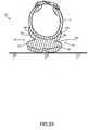
- the midsole of the shoewill absorb some of the impact, but after some impact has been absorbed, the lateral force of the foot within the shoe causes the shoe to tip, as can be seen in FIG. 3 .
- the lateral force absorptionis noticeably lacking when the shoe 300 is examined on a slope, such as is shown in FIG. 4 .
- the terrainis not flat, instead including many irregular surface patterns. When the runner plants a foot on such irregular terrain, the midsole can only deform slightly and does not absorb sufficient lateral forces. This creates strain on the runner's foot and ankle.
- FR 2 422 350 A1discloses an article of footwear with a groove in a sole, which groove extends from a midfoot region on a medial side of the sole around a heel region thereof towards a midfoot region on a lateral side of the sole.
- the inventionis characterized by the features of claim 1.
- the article of footwearcomprises a sole having a top portion and a bottom portion, at least a portion of a periphery of each of the top and bottom portions being separate from the other of the top and bottom portion in at least a midfoot region; and an upper; wherein the top portion of the sole is attached to the upper, thereby allowing rotational freedom between the top and bottom portions of the sole in a peripheral location where the top and bottom portions are separated; wherein the top and bottom portions of the sole are separate from one another on both a lateral side and a medial side of the sole, and wherein the separation of the top and bottom portions of the sole on each of the lateral side and the medial side defines a lateral recess and a medial recess.
- a lateral width of the lateral recessincreases from a first lateral width at a forefoot region to a higher second lateral width at the midfoot region and decreases from the higher second lateral width to a third lateral width at a heel region, wherein the lateral width is defined as a distance generally perpendicular to a longitudinal axis of the sole from the periphery to a lateral attachment boundary spaced from the periphery in a particular location along a length of the sole and wherein the lateral attachment boundary is spaced from the periphery in the midfoot region.
- a medial width of the medial recessincreases from a first medial width at the forefoot region to a higher second medial width at the midfoot region and decreases from the higher second medial width to a third medial width at the heel region, wherein the medial width is defined as a distance generally perpendicular to the longitudinal axis of the sole from the periphery to a medial attachment boundary spaced from the periphery in a particular location along the length of the sole and wherein the medial attachment boundary is spaced from the periphery in the midfoot region.
- the peripheries of the top and bottom portions of the solemay be continuous in at least part of a heel region and a forefoot region.
- the upper and top portion of the solemay be configured to roll to contact the bottom portion of the sole upon lateral impact.
- the medial and lateral recessesmay differ from one another in size and shape.
- the uppermay be coupled to the sole along a periphery of the sole in both a forefoot region and a heel region and at a position spaced from the periphery of the sole in a midfoot region.
- the uppermay be coupled to the sole in a midfoot region in a position at least 10% of the width of the sole away from the periphery of the sole.
- the upper and solemay be coupled asymmetrically.
- An impact absorbermay be attached to the upper.
- the upperis coupled to the sole at a position spaced from the periphery of the sole in a midfoot region on each of a lateral and medial side of the sole.
- the uppermay be coupled to the sole in a midfoot region in a position at least 10% of the width of the sole away from the periphery of the sole on each of the lateral and medial sides of the sole.
- the upper and solemay be coupled asymmetrically.
- a first impact absorbermay be attached to the medial side of the upper and a second impact absorber may be attached to the lateral side of the upper.
- the following discussion and accompanying figuresdisclose an article of footwear.
- Concepts related to the article of footwearare disclosed with reference to footwear having a configuration that is suitable for the sport of running.
- the sole structureis not limited solely to footwear designed for running, however, and may be utilized with a wide range of athletic footwear styles, including basketball shoes, tennis shoes, football shoes, cross-training shoes, walking shoes, soccer shoes, and hiking boots, for example.
- the sole structuremay also be utilized with footwear styles that are generally considered to be non-athletic, including dress shoes, loafers, sandals, and boots.
- An individual skilled in the relevant artwill appreciate, therefore, that the concepts disclosed herein apply to a wide variety of footwear styles, in addition to the specific style discussed in the following material and depicted in the accompanying figures.
- FIGS. 1 and 2An article of footwear 10 is depicted in FIGS. 1 and 2 as including an upper 20 and a sole or sole structure 30.
- footwear 10may be divided into three general regions: a forefoot region 11, a midfoot region 12, and a heel region 13.
- Footwear 10also includes a lateral side 14 and an opposite medial side 15.
- Forefoot region 11generally includes portions of footwear 10 corresponding with the toes and the joints connecting the metatarsals with the phalanges.
- Midfoot region 12generally includes portions of footwear 10 corresponding with the arch area of the foot, and heel region 13 corresponds with rear portions of the foot, including the calcaneus bone.
- Lateral side 14 and medial side 15extend through each of regions 11-13 and correspond with opposite sides of footwear 10.
- Regions 11-13 and sides 14-15are not intended to demarcate precise areas of footwear 10. Rather, regions 11-13 and sides 14-15 are intended to represent general areas of footwear 10 to aid in the following discussion. In addition to footwear 10, regions 11-13 and sides 14-15 may also be applied to upper 20, sole structure 30, and individual elements thereof. These elements of footwear 10 are common to all articles of footwear and are also present in the invention described herein.
- FIGS. 5-7a first aspect of the invention is apparent.
- the upper 20 of the article of footwear 10is attached or coupled to the sole 30 asymmetrically.
- FIG. 7shows the top surface 32 of the sole 30 of the article of footwear 10.
- Axis 31shows an approximate axis along the center of the top surface 32 of the sole 30.
- a first dashed lineis one embodiment of a medial attachment boundary 34 that represents the position on the top surface 32 of the sole 30 where the upper 20 is joined to the sole 30 on the medial side 15 of the article of footwear 10.
- This medial attachment boundary 34is located or spaced inward from the periphery or peripheral edge 36 of the sole 30.
- the medial attachment boundary 34need not be a consistent distance from the periphery 36 of the sole 30.
- the medial attachment boundary 34approaches and then contacts the periphery 36 as the medial attachment boundary 34 nears the forefoot region 11 and heel region 13.
- the medial attachment boundary 34is most clearly spaced from the periphery 36 in the midfoot region 12.
- a second dashed lineis one embodiment of a lateral attachment boundary 38 that represents the position on the top surface 32 of the sole 30 where the upper 20 is joined to the sole 30 on the lateral side 14 of the shoe.
- This lateral attachment boundary 38is located or spaced inward from the periphery or peripheral edge 36 of the sole 30.
- the lateral attachment boundary 38need not be a consistent distance from the periphery 36 of the sole 30. Instead, as shown in FIG. 7 , the lateral attachment boundary 38 approaches and then contacts the periphery 36 as the lateral attachment boundary 38 nears the forefoot region 11 and heel region 13.
- the lateral attachment boundary 38is most clearly spaced from the periphery 36 in the midfoot region 12.
- the upper 20is attached or coupled to the sole 30 along the medial attachment boundary 38 on the medial side 15 of the sole 10, spaced from the periphery 36 of the sole 30 at least in a midfoot region 12.
- the upper 20is attached or coupled to the sole 30 along the lateral attachment boundary 38 on the lateral side 14 of the sole 10, spaced from the periphery 36 of the sole 30 in at least a midfoot region 12.
- the upper 20is attached or coupled to the sole 30 in an area that is along the periphery 36 of the sole 30. While the upper 20 may be attached to the sole 30 a small distance from the periphery 36 of the sole 30 in the toe region 11 and heel region 13, the upper is attached or coupled about at the periphery 36 and along the periphery 36.
- the configuration shown in FIG. 7is one possible configuration of the positioning and attachment and coupling of the upper 20 relative to the sole 30.
- the sole 30has a width 33 at any specific point along the length 39 of the sole 30.
- the width or distance 35represents the distance the medial attachment boundary 34 is positioned from the periphery 36 in a particular location along the length 21 of the sole 30 where the medial attachment boundary 34 is spaced from the periphery 36.
- the width or distance 37represents the distance the lateral attachment boundary 38 is positioned from the periphery 36 in a particular location along the length 23 of the sole 30 where the lateral attachment boundary 38 is spaced from the periphery 36.
- width 35 and the width 37be at least 10% of the width 33 of the sole 30 at some point along its respective length 21, 23.
- the attachment boundaries 34, 38may be positioned on the sole 30 so that the upper 20 and sole 30 are coupled either symmetrically or asymmetrically about axis 31.
- width 37 and width 35could be great enough that the attachment boundaries 34, 38 would be in substantially the same location on the sole 30.
- width 35 and width 37might each have a value of about 50% the value of width 33.
- width 37might have a value of about 60% of width 33 and width 35 might have a value of about 40% of width 33.
- each attachment boundary 34, 38may be tuned for a particular desired footwear application, and the values of width 37 and width 35 can vary widely, except that of course, the values of width 37 and width 35 added together can never exceed the value of width 33 at any given point along the length 39 of the sole 30.
- the value of width 35 or width 37 in a particular casewould be close to zero and that the upper 20 would be attached on one of the medial side 15 or lateral side 14 at an area along the periphery 36 of the sole 30.
- the value of both width 35 and of width 37vary along the length 39 of the sole 30 and their respective lengths 21, 23.
- width 35 and the width 37taper to a zero value in the areas of the forefoot region 11 and the heel region 13. As shown in FIG. 7 , based on the contours of the sole 30 and the attachment boundaries 34, 38, the value of width 35 and width 37 may, but need not, gradually increase to a single high value.
- the area on the top surface 32 of the sole 30 on the lateral side 14 between the lateral attachment boundary 38 and the peripheral edge 36 of the sole 30can be described as the open lateral portion 50.
- the area on the top surface 32 of the sole 30 on the medial side 15 between the medial attachment boundary 34 and the peripheral edge 36 of the sole 30can be described as the open medial portion 51. Either one of these portions 50, 51 can be described as an open portion of the sole.
- FIGS. 5 and 6are cross sections of a shoe with a foot inside taken along line 5-5 of FIG. 8 .
- FIG. 5shows how the footwear 10 will appear in cross-section with a foot having a narrow width 41.
- the upper 20is flexible and tightens to conform to the shape of a user's foot.
- the laces 40are drawn tightly which leaves the lace edges 42, 44 of the medial 15 and lateral 14 sides, respectively, relatively close to one another.
- FIG. 6shows how the footwear 10 will appear in cross section with a foot having a wide width 43.
- the upper 20tightens to conform to the shape of the user's foot.
- the lacesare drawn tightly in this case, the lace edges 42, 44 of the medial 15 and lateral 14 sides, respectively, remain further apart to accommodate the wider width foot.
- Attentionis also directed to the areas marked 46 and 48 on the drawings.
- the amount of upper 20 positioned beneath the footis increased. This changes how the upper 20 appears with respect to the sole 30 to an observer.
- FIGS. 8-10an article of footwear 10 according to the present invention is shown.
- the article of footwear 10includes an upper 20 and a sole 30 coupled or attached to one another.
- FIGS. 8 and 10show the lateral side 14 of the footwear 10. Visible on the lateral side 14 of the footwear 10 is an open lateral portion 50 of the top surface 32 of sole 30. Adjacent the open lateral portion 50 is a lateral impact absorber 52 attached to the lateral side 15 of the upper 20. The lateral impact absorber 52 is attached to the upper 20 at least along the midfoot region 12 of the footwear 10.
- the lateral impact absorber 52has a width 54 that varies along its length 56.
- the lateral impact absorber 52includes various indents 58 that may be included for cosmetic or functional reasons.
- the indents 58correspond in position to various design features of the shoe upper 20.
- the width 54 of the lateral impact absorber 52tapers or decreases to zero in the forefoot region 11 and the heel region 13 of the footwear 10.
- the lateral impact absorber 52may be made of any of a variety of materials. Consideration of an appropriate material for the lateral impact absorber 52 may take into account a variety of factors. First, the material chosen should be sufficiently flexible to allow the upper 20 to be pulled taut without hindrance from the impact absorber 52. The material chosen should also be capable of absorbing impact when compressed. Finally, the material chosen must be capable of being secured or attached to a corresponding upper material. It is preferred that the impact absorber 52 be attached via an adhesive to the upper 20. However, it could alternatively be attached via a mechanical attachment structure, such as sewing. Finally, the material chosen should be selected for its aesthetic properties since it will be positioned visibly on the outside of the footwear and its shape will be a design element of the footwear. The material and its size and shape can be tuned to the desired impact absorbing properties of the footwear.
- a medial impact absorber 60On the medial side 15 of the footwear 10 is positioned a medial impact absorber 60 attached to the upper 20.
- the medial impact absorber 60will be shown in more detail in other Figures.
- the medial impact absorber 60has the same qualities and features as the lateral impact absorber 52.
- the medial impact absorber 60may have a somewhat different size and shape from the lateral impact absorber 52 due, at least in part, to the different countours of the upper 20 and sole 30 as are common in footwear generally and specifically in footwear 10.
- the curvature of the medial side 15 of the footwear 10tends to be concave and the lateral side 14 tends to be convex, as is best seen in FIG. 7 .
- the relative size and shape of the impact absorbers 52, 60may differ for other reasons, such as the amount of impact the impact absorbers are designed to absorb, the position of the attachment boundaries 34, 38, aesthetic reasons, or for any other reason that a designer might consider in designing an article of footwear.
- FIGS. 11-13the footwear 10 is shown when a lateral force, i.e., a force toward the lateral side 14 of the footwear 10, is applied.
- a lateral forcei.e., a force toward the lateral side 14 of the footwear 10.
- Such a forcemight be applied when a user makes a quick turn or is running around a curve.
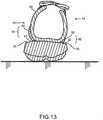
- FIG. 13the motion of the footwear is apparent.
- the upper 20is permitted to rotate or roll slightly towards the lateral side 14.
- the lateral impact absorber 52comes into contact with the top surface 32 of the sole 30, in the open lateral area 50 of the sole 30.
- the lateral force or impact applied to the shoeis thereby absorbed in three ways. First, the upper 20 is permitted to roll. Next, the lateral impact absorber 52 becomes compressed. Finally, elements in the sole 30 compress. These three features combine to absorb a great degree of the impact and reduce the impact that the user's body must absorb.
- FIG. 11shows the medial side 15 of the footwear 10
- FIG. 12shows the lateral side 14 of the footwear 10.
- the lateral impact absorber 52is compressed under the user's foot against the open lateral area 50 on the top surface 32 of the sole 30.
- An observer looking at the footwear 10 from this lateral side 14 as in FIG. 12will observe that the visible area of the lateral impact absorber 52 and the visible portion of the top surface 32 of the sole 30 are reduced relative to the visible portions of those elements in the rest position of the footwear as shown in FIG. 8 .
- the upper 20when the lateral force is applied toward the lateral side 14, the upper 20 is allowed to roll or pivot.
- the medial impact absorber 60is released from under the user's foot and away from the open medial area 51 on the top surface 32 of the sole 30.
- An observer looking at the footwear 10 from this medial side 15 as in FIG. 12will observe that the visible area of the medial impact absorber 60 and the visible portion of the top surface 32 of the sole 30 are increased relative to the visible portions of those elements in the rest position of the footwear 10.
- FIGS. 14-16the footwear 10 is shown when a medial force, i.e., a force toward the medial side 15 of the footwear 10, is applied.
- a medial forcei.e., a force toward the medial side 15 of the footwear 10.
- the motion of the footwear 10is apparent.
- the upper 20is permitted to rotate or roll slightly towards the medial side 14.
- the medial impact absorber 60comes into contact with the top surface 32 of the sole 30, in the open medial area 51 of the sole 30.
- the medial force or impact applied to the shoeis thereby absorbed in three ways. First, the upper 20 is permitted to roll. Next, the medial impact absorber 60 becomes compressed. Finally, elements in the sole 30 compress.
- FIG. 14shows the medial side 15 of the footwear 10
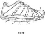
- FIG. 15shows the lateral side 14 of the footwear 10.
- the medial impact absorber 60is compressed under the user's foot against the open medial area 51 on the top surface 32 of the sole 30.
- An observer looking at the footwear 10 from this medial side 15 as in FIG. 14will observe that the visible area of the medial impact absorber 60 and the visible portion of the top surface 32 of the sole 30 are reduced relative to the visible portions of those elements in the rest position of the footwear.
- the upper 20is allowed to roll or pivot.
- the lateral impact absorber 52is released from under the user's foot and away from the open lateral area 50 on the top surface 32 of the sole 30.
- An observer looking at the footwear 10 from this lateral side 14 as in FIG. 15will observe that the visible area of the lateral impact absorber 52 and the visible portion of the top surface 32 of the sole 30 are increased relative to the visible portions of those elements in the rest position of the footwear 10 as seen in FIG. 8 .
- FIGS. 5-16A review of FIGS. 5-16 and particularly the cross sectional views in FIGS. 5, 6 , 13 , and 16 and the rear elevational view of FIG. 9 reveals another feature.
- the upper 20on each of the medial side and the lateral side, there exists a free area 64, 62, respectively, that in a standard article of footwear would be likely attached to the sole. Because the upper 20 is attached to the sole 30 along lateral and medial attachment boundaries 38, 34, the free areas 64, 62 of the upper are able to be positioned in varying angles from the top surface 32 of the sole 30. The free areas 64, 62 are located at least in the midfoot region 12 of the footwear 10. In the embodiment shown in FIGS.
- the impact absorbers 60, 52are attached to the respective free areas 64, 62 of the upper 20.
- the lateral free area 62may differ in size and shape than the medial free area 64 for various reasons, including the standard curvature of the footwear in the midfoot region 12 and the assymetrical attachment of the upper 32 to the sole 30. Also for these reasons, the widths 66, 68 of the free areas 62, 64 vary along their length and taper or decrease to zero at their longitudinal ends in the forefoot and heel regions.
- FIGS. 17-26A second embodiment of the present invention is shown in FIGS. 17-26 .
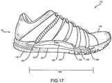
- FIGS. 17-19show an overview of the structure.
- the footwear 110is identical in many respects to the footwear 10 described earlier, including the placement of forefoot, midfoot, and heel regions 11, 12, 13 and lateral and medial sides 14, 15.
- the footwear 110also includes an upper 120 that is substantially the same as that described in relation to the earlier embodiment. Numerals from the first embodiment are used identically in this embodiment to describe the same features.
- FIGS. 17-19a second embodiment of the footwear 110 is shown.
- the footwearincludes an upper 120 and a sole 130 coupled or attached to one another.
- FIGS. 17 and 19show the lateral side 14 of the footwear 110.
- the sole 130defines a lateral recess or undercut 121 at least in a midfoot region 12 of the footwear 110.
- the sole 130is split into a top portion 122 and a lower portion 123 that are separated from each other by the lateral recess 121, particularly along a periphery 36 of the sole 130.
- the use of the lateral and medial recesses 121, 124allows rotational freedom between the top portion 122 and lower portion 123 of the sole 130 in the peripheral areas 36 in the midfoot region 12 where the top and lower portions 122, 123 are separated.
- FIG. 20shows how the recesses 121, 124 can be configured relative to the sole.
- FIG. 20is a view showing the lower portion 123 of the sole 130.
- Axis 131shows an approximate axis along the center of the lower portion 123 of the sole 130.
- a first dashed line 138is one embodiment of the lateral inner limit of the lateral recess 121. This lateral inner limit 138 is located or spaced inward from the periphery or peripheral edge 36 of the sole 130. The lateral inner limit 138 need not be a consistent distance from the periphery 36 of the sole 130. Instead, as shown in FIG.
- the lateral inner limit 138approaches and then contacts the periphery 36 as the lateral inner limit 138 nears the forefoot region 11 and heel region 13.
- the lateral inner limit 138is most clearly spaced from the periphery 36 in the midfoot region 12.
- a second dashed lineis one embodiment of a medial inner limit 134 that represents the inner limit of the medial recess 124.
- This medial inner limit 134is located or spaced inward from the periphery or peripheral edge 36 of the sole 130.
- the medial inner limit 134need not be a consistent distance from the periphery 36 of the sole 130. Instead, as shown in FIG. 20 , the medial inner limit 134 approaches and then contacts the periphery 36 as the medial inner limit 134 nears the forefoot region 11 and heel region 13. The medial inner limit 134 is most clearly spaced from the periphery 36 in the midfoot region 12.
- the sole 130can be formed in a number of ways to create this structure.
- the sole 130can be molded in one piece so that the top portion 122 and the lower portion 123 are integrally formed. If the sole 130 is formed in this manner, the mold can contain inserts to form the recesses 121, 124 in the sole at the time of molding. Alternatively, the recesses 121, 124 can be machined into the sole 130 after molding.
- the top portion 122 and lower portion 123can alternatively be formed separately from one another and then bonded together. Such a configuration would be desirable when, for example, it is desired to use different materials for the top portion 122 and lower portion 123.
- top portion 122 and lower portion 123are formed separately, the medial and lateral sides of the top portion 122 can also be formed separately from one another and separately secured to the lower portion 123.
- the method and structure for securing the parts togethercan be selected by a person having ordinary skill in the art without undue experimentation, and will be based on the materials selected for the portions of the sole 130 and the desired strength of the final product. Regardless of the method of making the sole 130, if both the top portion 122 and the lower portion 123 extend into the forefoot area 11 and heel area 13, the peripheral edges 36 of the two should be continuous.
- the top portion 122 of the sole 130is attached or coupled to the upper 120. Because the top portion 122 of the sole 130 is separate from the lower portion 123 of the sole 130 in at least a midfoot region 12, the top portion 122 and upper 120 are effectively attached to the lower portion 123 of the sole 130 only in an area spaced from the periphery 36 of the lower portion 123 of the sole 130, as is best shown in FIG. 20 . In the toe region 11 and the heel region 13, the upper 120 is attached or coupled to the sole 130 in an area that is along the periphery 36 of the sole 130. While the upper 120 may be spaced a small distance from the periphery 36 of the sole 130 in the toe region 11 and heel region 13, the upper is attached or coupled about at the periphery 36 and along the periphery 36.
- the configuration shown in FIG. 20is one possible configuration of the positioning and attachment and coupling of the upper 120 and top portion 122 of the sole 130 relative to the lower portion 123 of the sole 30.
- the lower portion 123 of the sole 130has a width 133.
- the width or distance 135represents the distance the medial inner limit 134 is positioned from the periphery 36 in a particular location along the length 125 of the medial recess 124.
- the width or distance 137represents the distance the lateral inner limit 138 is positioned from the periphery 36 in a particular location along the length 127 of the lateral recess 121.
- width 135 and the width 137be at least 10% of the width 133 of the lower portion 123 of the sole 130.
- the inner limits 134, 138may be positioned on the sole 130 so that the upper 120 and the lower portion 123 of the sole 130 are effectively coupled either symmetrically or asymmetrically about axis 131.
- width 137 and width 135could be great enough that the inner limits 134, 138 would be in substantially the same location on the sole 130.
- width 135 and width 137might each have a value of about 50% the value of width 133.
- width 137might have a value of about 60% of width 133 and width 135 might have a value of about 40% of width 133.
- the position of each inner limit 134, 138may be tuned for a particular desired footwear application, and the values of width 137 and width 135 can vary widely, except that of course, the values of width 137 and width 135 added together can never exceed the value of width 133 at any given point along the length 139 of the sole 130.
- width 135 or width 137in a particular case would be close to zero and that the top portion 122 and the lower portion 123 of the sole 130 would be attached at one of the medial side 15 or lateral side 14 at an area along the periphery 36 of the sole 130 and their respective lengths 125, 127. It is also to be noted that the value of both width 135 and of width 137 vary along the length 139 of the sole 130. The width 135 and the width 137 taper to a zero value in the areas of the forefoot region 11 and the heel region 13. As shown in FIG. 20 , based on the contours of the sole 130 and the inner limits 134, 138, the value of width 135 and width 137 may, but need not, gradually increase to a single high value.
- the top portion 122 of the sole 130acts as an impact absorber in the area where it is secured or coupled to the upper 120.
- the lateral impact absorber 152has a width 154 that varies along its length 156.
- the lateral impact absorber 152includes various indents 158 that may be included for cosmetic or functional reasons.
- the indents 158correspond in position to various design features of the shoe upper 120.
- the width 154 of the lateral impact absorber 152tapers or decreases to zero in the forefoot region 11 and the heel region 13 of the footwear 110.
- the impact absorbers 152, 160may be made of any of a variety of materials. Consideration of an appropriate material for the impact absorbers 152, 160 may take into account a variety of factors in addition to those discussed above in considering the manufacture of the sole 130 generally. First, the material chosen should be sufficiently flexible to allow the upper 120 to be pulled taut without hindrance from the impact absorbers 152, 160. The material chosen should also be capable of absorbing impact when compressed. Finally, the material chosen must be capable of being secured or attached to a corresponding upper material. It is preferred that the impact absorber 152 be attached via an adhesive to the upper 120. However, it could alternatively be attached via a mechanical attachment structure, such as sewing. Finally, the material chosen should be selected for its aesthetic properties since it will be positioned visibly on the outside of the footwear and its shape will be a design element of the footwear. The material and its size and shape can be tuned to the desired impact absorbing properties of the footwear.
- a medial impact absorber 160attached to the upper 120.
- the medial impact absorber 160will be shown in more detail in other Figures.
- the medial impact absorber 160has the same qualities and features as the lateral impact absorber 152.
- the medial impact absorber 160may have a somewhat different size and shape from the lateral impact absorber 152 due, at least in part, to the different contours of the upper 120 and sole 130 as are common in footwear generally and specifically in footwear 110.
- the curvature of the medial side 15 of the footwear 110tends to be concave and the lateral side 14 tends to be convex, as is best seen in FIG. 20 .
- the relative size and shape of the impact absorbers 152, 160may differ for other reasons, such as the amount of impact the impact absorbers are designed to absorb, the position of the inner limits 134, 138, aesthetic reasons, or for any other reason that a designer might consider in designing an article of footwear.
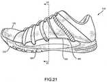
- FIGS. 21-23the footwear 110 is shown when a lateral force, i.e., a force toward the lateral side 14 of the footwear 110, is applied.
- a lateral forcei.e., a force toward the lateral side 14 of the footwear 110
- FIG. 23the motion of the footwear is apparent.
- the upper 120is permitted to rotate or roll slightly towards the lateral side 14.
- the lateral impact absorber 152comes into contact with the top surface 132 of the lower portion 123 of the sole 130.
- the lateral force or impact applied to the shoeis thereby absorbed in three ways. First, the upper 120 is permitted to roll. Next, the lateral impact absorber 152 becomes compressed. Finally, elements in the sole 130 compress. These three features combine to absorb a great degree of the impact and reduce the impact that the user's body must absorb.
- FIG. 21shows the medial side 15 of the footwear 110
- FIG. 22shows the lateral side 14 of the footwear 110.
- the lateral impact absorber 152is compressed under the user's foot against lower portion 123 of the sole 130.
- An observer looking at the footwear 10 from this lateral side 14 as in FIG. 22will observe that the visible area of the lateral impact absorber 52 and the visible portion of the lateral recess 121 of the sole 30 are reduced relative to the visible portions of those elements in the rest position of the footwear as shown in FIG. 17 .
- the upper 120is allowed to roll or pivot.
- the medial impact absorber 160is released from under the user's foot and away from the lower portion 123 of the sole 30.
- An observer looking at the footwear 110 from this medial side 15 as in FIG. 21will observe that the visible area of the medial impact absorber 160 and the visible portion of the medial recess 124 are increased relative to the visible portions of those elements in the rest position of the footwear 110.
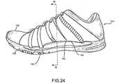
- FIGS. 24-26the footwear 10 is shown when a medial force, i.e., a force toward the medial side 15 of the footwear 10, is applied.
- a medial forcei.e., a force toward the medial side 15 of the footwear 10.
- the motion of the footwearis apparent.
- the upper 120is permitted to rotate or roll slightly towards the medial side 15.
- the medial impact absorber 160comes into contact with the top surface 132 of the lower portion 123 of sole 130.
- the medial force or impact applied to the shoeis thereby absorbed in three ways. First, the upper 120 is permitted to roll. Next, the medial impact absorber 160 becomes compressed. Finally, elements in the sole 130 compress.
- FIG. 24shows the medial side 15 of the footwear 110
- FIG. 25shows the lateral side 14 of the footwear 110.
- the medial impact absorber 160is compressed under the user's foot against the lower portion 123 of the sole 130.
- An observer looking at the footwear 110 from this medial side 15 as in FIG. 24will observe that the visible area of the medial impact absorber 160 and the visible portion of the medial recess 124 are reduced relative to the visible portions of those elements in the rest position of the footwear.
- the upper 120is allowed to roll or pivot.
- the lateral impact absorber 152is released from under the user's foot and away from the lower portion 123 of the sole 130.
- An observer looking at the footwear 110 from this lateral side 14 as in FIG. 24will observe that the visible area of the lateral impact absorber 152 and the visible portion of lateral recess 121 are increased relative to the visible portions of those elements in the rest position of the footwear 110 as seen in FIG. 17 .
- the embodiments detailed aboveinclude medial and lateral impact absorbers attached on the outside of an upper. It is to be appreciated that for aesthetic reasons, reasons of manufacturability, or other reasons deemed important by a designer, the impact absorbers could be attached to the inner surface of the upper adjacent the foot or could be incorporated between various layers of material in the upper. In such an instance, while the impact absorbers would not be visible, they would still be impact absorbers attached to the upper as discussed herein. In still a further embodiment, the impact absorbers can be minimized or eliminated if desirable for a given application.
Landscapes
- Health & Medical Sciences (AREA)
- General Health & Medical Sciences (AREA)
- Chemical & Material Sciences (AREA)
- Engineering & Computer Science (AREA)
- Materials Engineering (AREA)
- Epidemiology (AREA)
- Public Health (AREA)
- Physical Education & Sports Medicine (AREA)
- Footwear And Its Accessory, Manufacturing Method And Apparatuses (AREA)
Description
- Conventional articles of athletic footwear include two primary elements, an upper and a sole structure. The upper provides a covering for the foot that comfortably receives and securely positions the foot with respect to the sole structure. The sole structure is secured to a lower portion of the upper and is generally positioned between the foot and the ground. In addition to attenuating ground reaction forces, the sole structure may provide traction, control foot motions (e.g., by resisting pronation), and impart stability, for example. Accordingly, the upper and the sole structure operate cooperatively to provide a comfortable structure that is suited for a wide variety of athletic activities.
- The sole structure generally incorporates multiple layers that are conventionally referred to as a sockliner, a midsole, and an outsole. The sockliner is a thin, compressible member located within the upper and adjacent to a plantar (i.e., lower) surface of the foot to enhance footwear comfort. The midsole is conventionally secured to a lower surface of the upper and forms a middle layer of the sole structure that is primarily responsible for attenuating ground reaction forces. The outsole forms the ground-contacting element of the footwear and is usually fashioned from a durable, wear-resistant material that includes texturing to improve traction.
- The conventional midsole is primarily formed from a resilient, polymer foam material, such as polyurethane or ethylvinylacetate, that extends throughout the length of the footwear. The properties of the polymer foam material in the midsole are primarily dependent upon factors that include the dimensional configuration of the midsole and the specific characteristics of the material selected for the polymer foam, including the density of the polymer foam material. By varying these factors throughout the midsole, the relative stiffness and degree of ground reaction force attenuation may be altered to meet the specific demands of the wearer or of the activity for which the footwear is intended to be used.
- In addition to polymer foam materials, conventional midsoles may include, for example, one or more fluid-filled chambers. In general, the fluid-filled chambers are formed from an elastomeric polymer material that is sealed and pressurized. The chambers are then encapsulated in the polymer foam of the midsole such that the combination of the chamber and the encapsulating polymer foam functions as the midsole of the sole structure. In some configurations, textile or foam tensile members may be located within the chamber or reinforcing structures may be bonded to an exterior or interior of the chamber to impart shape to the chamber.
- Articles of athletic footwear are designed with a particular purpose in mind. Some articles of athletic footwear are designed to withstand jarring impact. Others are designed to withstand lateral impact. Some are designed to enhance stability. Others are designed to provide enhanced cushioning. The purpose for which a shoe will be used informs the design choices made by the designers.
- Turning to
FIGS. 3 and4 , prior art articles of footwear are shown.FIG. 3 shows an article of footwear 100 that is typical of a running shoe. When a runner wants to make a turn, he or she will plant a foot, which often creates a lateral force on the shoe. The midsole of the shoe will absorb some of the impact, but after some impact has been absorbed, the lateral force of the foot within the shoe causes the shoe to tip, as can be seen inFIG. 3 . In addition, the lateral force absorption is noticeably lacking when theshoe 300 is examined on a slope, such as is shown inFIG. 4 . In some cases, particularly in trail running, the terrain is not flat, instead including many irregular surface patterns. When the runner plants a foot on such irregular terrain, the midsole can only deform slightly and does not absorb sufficient lateral forces. This creates strain on the runner's foot and ankle. - An article of footwear according to the preamble of claim 1 is known from
US 2002/144430 A1 . FR 2 422 350 A1 - The invention is characterized by the features of claim 1.
- According to the invention, the article of footwear comprises a sole having a top portion and a bottom portion, at least a portion of a periphery of each of the top and bottom portions being separate from the other of the top and bottom portion in at least a midfoot region; and an upper; wherein the top portion of the sole is attached to the upper, thereby allowing rotational freedom between the top and bottom portions of the sole in a peripheral location where the top and bottom portions are separated; wherein the top and bottom portions of the sole are separate from one another on both a lateral side and a medial side of the sole, and wherein the separation of the top and bottom portions of the sole on each of the lateral side and the medial side defines a lateral recess and a medial recess.
- Thereby, a lateral width of the lateral recess increases from a first lateral width at a forefoot region to a higher second lateral width at the midfoot region and decreases from the higher second lateral width to a third lateral width at a heel region, wherein the lateral width is defined as a distance generally perpendicular to a longitudinal axis of the sole from the periphery to a lateral attachment boundary spaced from the periphery in a particular location along a length of the sole and wherein the lateral attachment boundary is spaced from the periphery in the midfoot region.
- Further, a medial width of the medial recess increases from a first medial width at the forefoot region to a higher second medial width at the midfoot region and decreases from the higher second medial width to a third medial width at the heel region, wherein the medial width is defined as a distance generally perpendicular to the longitudinal axis of the sole from the periphery to a medial attachment boundary spaced from the periphery in a particular location along the length of the sole and wherein the medial attachment boundary is spaced from the periphery in the midfoot region.
- The peripheries of the top and bottom portions of the sole may be continuous in at least part of a heel region and a forefoot region. The upper and top portion of the sole may be configured to roll to contact the bottom portion of the sole upon lateral impact.
- The medial and lateral recesses may differ from one another in size and shape.
- The upper may be coupled to the sole along a periphery of the sole in both a forefoot region and a heel region and at a position spaced from the periphery of the sole in a midfoot region. The upper may be coupled to the sole in a midfoot region in a position at least 10% of the width of the sole away from the periphery of the sole. The upper and sole may be coupled asymmetrically. An impact absorber may be attached to the upper.
- According to the invention, the upper is coupled to the sole at a position spaced from the periphery of the sole in a midfoot region on each of a lateral and medial side of the sole. The upper may be coupled to the sole in a midfoot region in a position at least 10% of the width of the sole away from the periphery of the sole on each of the lateral and medial sides of the sole. The upper and sole may be coupled asymmetrically. A first impact absorber may be attached to the medial side of the upper and a second impact absorber may be attached to the lateral side of the upper.
- The advantages and features of novelty characterizing various aspects of the invention are pointed out with particularity in the appended claims. To gain an improved understanding of the advantages and features of novelty, however, reference may be made to the following descriptive matter and accompanying drawings that describe and illustrate various embodiments and concepts related to the aspects of the invention.
- The foregoing Summary, as well as the following Detailed Description, will be better understood when read in conjunction with the accompanying drawings.
FIG. 1 is a lateral side elevational view of an article of footwear according to the present invention.FIG. 2 is a bottom view of an article of footwear according to the invention.FIG. 3 is a rear elevational view of a prior art article of footwear.FIG. 4 is a rear elevational view of a prior art article of footwear positioned on a slope.FIG. 5 is a cross sectional view of the first embodiment of the article of footwear taken along line 5-5 ofFIG. 8 showing the article of footwear in use with a narrow foot.FIG. 6 is a cross sectional view of the first embodiment of the article of footwear taken along line 5-5 ofFIG. 8 showing the article of footwear in use with a wide foot.FIG. 7 is a top view of the sole of an article of footwear according to the invention showing the positioning of the upper relative to the sole.FIG. 8 is a lateral side elevational view of a first embodiment of an article of footwear.FIG. 9 is a rear elevational view of the first embodiment of the article of footwear.FIG. 10 is a perspective view of the first embodiment of the article of footwear.FIG. 11 is a medial side elevational view of the first embodiment of the article of footwear when a lateral force is applied to the article of footwear.FIG. 12 is a lateral side elevational view of the first embodiment of the article of footwear when a lateral force is applied to the article of footwear.FIG. 13 is a cross-sectional view of the first embodiment of the article of footwear taken along line 13-13 ofFIG. 11 .FIG. 14 is a medial side elevational view of the first embodiment of the article of footwear when a medial force is applied to the article of footwear.FIG. 15 is a lateral side elevational view of the first embodiment of the article of footwear when a medial force is applied to the article of footwear.FIG. 16 is a cross-sectional view of the first embodiment of the article of footwear taken along line 16-16 ofFIG. 14 .FIG. 17 is a lateral side elevational view of a second embodiment of an article of footwear.FIG. 18 is a rear elevational view of the second embodiment of the article of footwear.FIG. 19 is a perspective view of the second embodiment of the article of footwear.FIG. 20 is a top view of the lower portion of a sole of an article of footwear according to the invention showing the positioning of the top portion of the sole relative to the lower portion of the sole.FIG. 21 is a medial side elevational view of the second embodiment of the article of footwear when a lateral force is applied to the article of footwear.FIG. 22 is a lateral side elevational view of the second embodiment of the article of footwear when a lateral force is applied to the article of footwear.FIG. 23 is a cross-sectional view of the first embodiment of the article of footwear taken along line 23-23 ofFIG. 21 .FIG. 24 is a medial side elevational view of the first embodiment of the article of footwear when a medial force is applied to the article of footwear.FIG. 25 is a lateral side elevational view of the first embodiment of the article of footwear when a medial force is applied to the article of footwear.FIG. 26 is a cross-sectional view of the first embodiment of the article of footwear taken along line 26-26 ofFIG. 24 .- The following discussion and accompanying figures disclose an article of footwear. Concepts related to the article of footwear are disclosed with reference to footwear having a configuration that is suitable for the sport of running. The sole structure is not limited solely to footwear designed for running, however, and may be utilized with a wide range of athletic footwear styles, including basketball shoes, tennis shoes, football shoes, cross-training shoes, walking shoes, soccer shoes, and hiking boots, for example. The sole structure may also be utilized with footwear styles that are generally considered to be non-athletic, including dress shoes, loafers, sandals, and boots. An individual skilled in the relevant art will appreciate, therefore, that the concepts disclosed herein apply to a wide variety of footwear styles, in addition to the specific style discussed in the following material and depicted in the accompanying figures.
- An article of
footwear 10 is depicted inFIGS. 1 and2 as including an upper 20 and a sole orsole structure 30. For reference purposes,footwear 10 may be divided into three general regions: aforefoot region 11, amidfoot region 12, and aheel region 13.Footwear 10 also includes alateral side 14 and an oppositemedial side 15.Forefoot region 11 generally includes portions offootwear 10 corresponding with the toes and the joints connecting the metatarsals with the phalanges.Midfoot region 12 generally includes portions offootwear 10 corresponding with the arch area of the foot, andheel region 13 corresponds with rear portions of the foot, including the calcaneus bone.Lateral side 14 andmedial side 15 extend through each of regions 11-13 and correspond with opposite sides offootwear 10. Regions 11-13 and sides 14-15 are not intended to demarcate precise areas offootwear 10. Rather, regions 11-13 and sides 14-15 are intended to represent general areas offootwear 10 to aid in the following discussion. In addition tofootwear 10, regions 11-13 and sides 14-15 may also be applied to upper 20,sole structure 30, and individual elements thereof. These elements offootwear 10 are common to all articles of footwear and are also present in the invention described herein. - Turning first to
FIGS. 5-7 , a first aspect of the invention is apparent. The upper 20 of the article offootwear 10 is attached or coupled to the sole 30 asymmetrically.FIG. 7 shows thetop surface 32 of the sole 30 of the article offootwear 10.Axis 31 shows an approximate axis along the center of thetop surface 32 of the sole 30. A first dashed line is one embodiment of amedial attachment boundary 34 that represents the position on thetop surface 32 of the sole 30 where the upper 20 is joined to the sole 30 on themedial side 15 of the article offootwear 10. Thismedial attachment boundary 34 is located or spaced inward from the periphery orperipheral edge 36 of the sole 30. Themedial attachment boundary 34 need not be a consistent distance from theperiphery 36 of the sole 30. Instead, as shown inFIG. 7 , themedial attachment boundary 34 approaches and then contacts theperiphery 36 as themedial attachment boundary 34 nears theforefoot region 11 andheel region 13. Themedial attachment boundary 34 is most clearly spaced from theperiphery 36 in themidfoot region 12. - Similarly, a second dashed line is one embodiment of a
lateral attachment boundary 38 that represents the position on thetop surface 32 of the sole 30 where the upper 20 is joined to the sole 30 on thelateral side 14 of the shoe. Thislateral attachment boundary 38 is located or spaced inward from the periphery orperipheral edge 36 of the sole 30. Thelateral attachment boundary 38 need not be a consistent distance from theperiphery 36 of the sole 30. Instead, as shown inFIG. 7 , thelateral attachment boundary 38 approaches and then contacts theperiphery 36 as thelateral attachment boundary 38 nears theforefoot region 11 andheel region 13. Thelateral attachment boundary 38 is most clearly spaced from theperiphery 36 in themidfoot region 12. - The upper 20 is attached or coupled to the sole 30 along the
medial attachment boundary 38 on themedial side 15 of the sole 10, spaced from theperiphery 36 of the sole 30 at least in amidfoot region 12. The upper 20 is attached or coupled to the sole 30 along thelateral attachment boundary 38 on thelateral side 14 of the sole 10, spaced from theperiphery 36 of the sole 30 in at least amidfoot region 12. In thetoe region 11 and theheel region 13, the upper 20 is attached or coupled to the sole 30 in an area that is along theperiphery 36 of the sole 30. While the upper 20 may be attached to the sole 30 a small distance from theperiphery 36 of the sole 30 in thetoe region 11 andheel region 13, the upper is attached or coupled about at theperiphery 36 and along theperiphery 36. - The configuration shown in
FIG. 7 is one possible configuration of the positioning and attachment and coupling of the upper 20 relative to the sole 30. In this configuration, the sole 30 has awidth 33 at any specific point along thelength 39 of the sole 30. The width ordistance 35 represents the distance themedial attachment boundary 34 is positioned from theperiphery 36 in a particular location along thelength 21 of the sole 30 where themedial attachment boundary 34 is spaced from theperiphery 36. The width ordistance 37 represents the distance thelateral attachment boundary 38 is positioned from theperiphery 36 in a particular location along thelength 23 of the sole 30 where thelateral attachment boundary 38 is spaced from theperiphery 36. It is desirable that for any embodiment of thefootwear 10, that at least one of thewidth 35 and thewidth 37 be at least 10% of thewidth 33 of the sole 30 at some point along itsrespective length attachment boundaries axis 31. As an upper limit, it is of course possible thatwidth 37 andwidth 35 could be great enough that theattachment boundaries width 35 andwidth 37 might each have a value of about 50% the value ofwidth 33. Alternatively, if desired,width 37 might have a value of about 60% ofwidth 33 andwidth 35 might have a value of about 40% ofwidth 33. Of course, the position of eachattachment boundary width 37 andwidth 35 can vary widely, except that of course, the values ofwidth 37 andwidth 35 added together can never exceed the value ofwidth 33 at any given point along thelength 39 of the sole 30. Finally, in some cases, it is possible that the value ofwidth 35 orwidth 37 in a particular case would be close to zero and that the upper 20 would be attached on one of themedial side 15 orlateral side 14 at an area along theperiphery 36 of the sole 30. It is also to be noted that the value of bothwidth 35 and ofwidth 37 vary along thelength 39 of the sole 30 and theirrespective lengths width 35 and thewidth 37 taper to a zero value in the areas of theforefoot region 11 and theheel region 13. As shown inFIG. 7 , based on the contours of the sole 30 and theattachment boundaries width 35 andwidth 37 may, but need not, gradually increase to a single high value. - The area on the
top surface 32 of the sole 30 on thelateral side 14 between thelateral attachment boundary 38 and theperipheral edge 36 of the sole 30 can be described as the openlateral portion 50. The area on thetop surface 32 of the sole 30 on themedial side 15 between themedial attachment boundary 34 and theperipheral edge 36 of the sole 30 can be described as the openmedial portion 51. Either one of theseportions - One implication of this configuration of upper 20 being attached or coupled to the sole 30 along the
attachment boundaries FIGS. 5 and 6 , it is shown how thefootwear 10 would appear in cross section when used with feet of varying widths.FIGS. 5 and 6 are cross sections of a shoe with a foot inside taken along line 5-5 ofFIG. 8 .FIG. 5 shows how thefootwear 10 will appear in cross-section with a foot having anarrow width 41. The upper 20 is flexible and tightens to conform to the shape of a user's foot. Thelaces 40 are drawn tightly which leaves the lace edges 42, 44 of the medial 15 and lateral 14 sides, respectively, relatively close to one another.FIG. 6 shows how thefootwear 10 will appear in cross section with a foot having awide width 43. The upper 20 tightens to conform to the shape of the user's foot. When the laces are drawn tightly in this case, the lace edges 42, 44 of the medial 15 and lateral 14 sides, respectively, remain further apart to accommodate the wider width foot. Attention is also directed to the areas marked 46 and 48 on the drawings. When a wider width foot is in the shoe, the amount of upper 20 positioned beneath the foot is increased. This changes how the upper 20 appears with respect to the sole 30 to an observer. - Referring now to
FIGS. 8-10 , an article offootwear 10 according to the present invention is shown. As noted earlier, the article offootwear 10 includes an upper 20 and a sole 30 coupled or attached to one another.FIGS. 8 and10 show thelateral side 14 of thefootwear 10. Visible on thelateral side 14 of thefootwear 10 is an openlateral portion 50 of thetop surface 32 of sole 30. Adjacent the openlateral portion 50 is alateral impact absorber 52 attached to thelateral side 15 of the upper 20. Thelateral impact absorber 52 is attached to the upper 20 at least along themidfoot region 12 of thefootwear 10. Thelateral impact absorber 52 has awidth 54 that varies along itslength 56. For example, thelateral impact absorber 52 includesvarious indents 58 that may be included for cosmetic or functional reasons. In the illustrated embodiment ofFIGS. 8 and10 , theindents 58 correspond in position to various design features of the shoe upper 20. Desirably, thewidth 54 of thelateral impact absorber 52 tapers or decreases to zero in theforefoot region 11 and theheel region 13 of thefootwear 10. - The
lateral impact absorber 52 may be made of any of a variety of materials. Consideration of an appropriate material for thelateral impact absorber 52 may take into account a variety of factors. First, the material chosen should be sufficiently flexible to allow the upper 20 to be pulled taut without hindrance from theimpact absorber 52. The material chosen should also be capable of absorbing impact when compressed. Finally, the material chosen must be capable of being secured or attached to a corresponding upper material. It is preferred that theimpact absorber 52 be attached via an adhesive to the upper 20. However, it could alternatively be attached via a mechanical attachment structure, such as sewing. Finally, the material chosen should be selected for its aesthetic properties since it will be positioned visibly on the outside of the footwear and its shape will be a design element of the footwear. The material and its size and shape can be tuned to the desired impact absorbing properties of the footwear. - On the
medial side 15 of thefootwear 10 is positioned amedial impact absorber 60 attached to the upper 20. Themedial impact absorber 60 will be shown in more detail in other Figures. Themedial impact absorber 60 has the same qualities and features as thelateral impact absorber 52. However, themedial impact absorber 60 may have a somewhat different size and shape from thelateral impact absorber 52 due, at least in part, to the different countours of the upper 20 and sole 30 as are common in footwear generally and specifically infootwear 10. For example, the curvature of themedial side 15 of thefootwear 10 tends to be concave and thelateral side 14 tends to be convex, as is best seen inFIG. 7 . However, the relative size and shape of theimpact absorbers attachment boundaries - The features described above work together when a user is wearing the
footwear 10 to deal with lateral and medial forces differently than prior art footwear. Looking first toFIGS. 11-13 , thefootwear 10 is shown when a lateral force, i.e., a force toward thelateral side 14 of thefootwear 10, is applied. Such a force might be applied when a user makes a quick turn or is running around a curve. Referring first toFIG. 13 , the motion of the footwear is apparent. In such an instance, the upper 20 is permitted to rotate or roll slightly towards thelateral side 14. When the upper 20 rolls towards thelateral side 14, thelateral impact absorber 52 comes into contact with thetop surface 32 of the sole 30, in theopen lateral area 50 of the sole 30. The lateral force or impact applied to the shoe is thereby absorbed in three ways. First, the upper 20 is permitted to roll. Next, thelateral impact absorber 52 becomes compressed. Finally, elements in the sole 30 compress. These three features combine to absorb a great degree of the impact and reduce the impact that the user's body must absorb. - Viewing the
footwear 10 from each of the lateral 14 and medial 15 sides is also illustrative of the movement of thefootwear 10 when a force is applied.FIG. 11 shows themedial side 15 of thefootwear 10 andFIG. 12 shows thelateral side 14 of thefootwear 10. When a lateral force is applied toward thelateral side 14, the upper 20 is allowed to roll or pivot. Thelateral impact absorber 52 is compressed under the user's foot against theopen lateral area 50 on thetop surface 32 of the sole 30. An observer looking at thefootwear 10 from thislateral side 14 as inFIG. 12 will observe that the visible area of thelateral impact absorber 52 and the visible portion of thetop surface 32 of the sole 30 are reduced relative to the visible portions of those elements in the rest position of the footwear as shown inFIG. 8 . - Similarly, referring to
FIG. 11 , when the lateral force is applied toward thelateral side 14, the upper 20 is allowed to roll or pivot. Themedial impact absorber 60 is released from under the user's foot and away from the openmedial area 51 on thetop surface 32 of the sole 30. An observer looking at thefootwear 10 from thismedial side 15 as inFIG. 12 will observe that the visible area of themedial impact absorber 60 and the visible portion of thetop surface 32 of the sole 30 are increased relative to the visible portions of those elements in the rest position of thefootwear 10. - A similar result is seen when a medial force is applied to the
footwear 10. Looking now toFIGS. 14-16 , thefootwear 10 is shown when a medial force, i.e., a force toward themedial side 15 of thefootwear 10, is applied. Such a force might be applied when a user makes a quick turn or is running around a curve. Referring first toFIG. 16 , the motion of thefootwear 10 is apparent. In such an instance, the upper 20 is permitted to rotate or roll slightly towards themedial side 14. When the upper 20 rolls towards themedial side 14, themedial impact absorber 60 comes into contact with thetop surface 32 of the sole 30, in the openmedial area 51 of the sole 30. The medial force or impact applied to the shoe is thereby absorbed in three ways. First, the upper 20 is permitted to roll. Next, themedial impact absorber 60 becomes compressed. Finally, elements in the sole 30 compress. These three features combine to absorb a great degree of the impact and reduce the impact that the user's body must absorb. - Viewing the
footwear 10 from each of the lateral 14 and medial 15 sides is also illustrative of the movement of thefootwear 10 when a force is applied.FIG. 14 shows themedial side 15 of thefootwear 10 andFIG. 15 shows thelateral side 14 of thefootwear 10. When a medial force is applied toward themedial side 15, the upper 20 is allowed to roll or pivot. Themedial impact absorber 60 is compressed under the user's foot against the openmedial area 51 on thetop surface 32 of the sole 30. An observer looking at thefootwear 10 from thismedial side 15 as inFIG. 14 will observe that the visible area of themedial impact absorber 60 and the visible portion of thetop surface 32 of the sole 30 are reduced relative to the visible portions of those elements in the rest position of the footwear. - Similarly, referring to
FIG. 15 , when the medial force is applied toward themedial side 15, the upper 20 is allowed to roll or pivot. Thelateral impact absorber 52 is released from under the user's foot and away from theopen lateral area 50 on thetop surface 32 of the sole 30. An observer looking at thefootwear 10 from thislateral side 14 as inFIG. 15 will observe that the visible area of thelateral impact absorber 52 and the visible portion of thetop surface 32 of the sole 30 are increased relative to the visible portions of those elements in the rest position of thefootwear 10 as seen inFIG. 8 . - A review of
FIGS. 5-16 and particularly the cross sectional views inFIGS. 5, 6 ,13 , and16 and the rear elevational view ofFIG. 9 reveals another feature. Referring to the upper 20, on each of the medial side and the lateral side, there exists afree area medial attachment boundaries free areas top surface 32 of the sole 30. Thefree areas midfoot region 12 of thefootwear 10. In the embodiment shown inFIGS. 5-16 , theimpact absorbers free areas free area 62 may differ in size and shape than the medialfree area 64 for various reasons, including the standard curvature of the footwear in themidfoot region 12 and the assymetrical attachment of the upper 32 to the sole 30. Also for these reasons, thewidths 66, 68 of thefree areas - A second embodiment of the present invention is shown in
FIGS. 17-26 .FIGS. 17-19 show an overview of the structure. Thefootwear 110 is identical in many respects to thefootwear 10 described earlier, including the placement of forefoot, midfoot, andheel regions medial sides footwear 110 also includes an upper 120 that is substantially the same as that described in relation to the earlier embodiment. Numerals from the first embodiment are used identically in this embodiment to describe the same features. - Turning first to
FIGS. 17-19 , a second embodiment of thefootwear 110 is shown. The footwear includes an upper 120 and a sole 130 coupled or attached to one another.FIGS. 17 and19 show thelateral side 14 of thefootwear 110. As particularly seen in these Figs., the sole 130 defines a lateral recess or undercut 121 at least in amidfoot region 12 of thefootwear 110. In the area where there is alateral recess 121, the sole 130 is split into atop portion 122 and alower portion 123 that are separated from each other by thelateral recess 121, particularly along aperiphery 36 of the sole 130. In this embodiment, the use of the lateral andmedial recesses top portion 122 andlower portion 123 of the sole 130 in theperipheral areas 36 in themidfoot region 12 where the top andlower portions FIG. 20 shows how therecesses FIG. 20 is a view showing thelower portion 123 of the sole 130.Axis 131 shows an approximate axis along the center of thelower portion 123 of the sole 130. A first dashedline 138 is one embodiment of the lateral inner limit of thelateral recess 121. This lateralinner limit 138 is located or spaced inward from the periphery orperipheral edge 36 of the sole 130. The lateralinner limit 138 need not be a consistent distance from theperiphery 36 of the sole 130. Instead, as shown inFIG. 20 , the lateralinner limit 138 approaches and then contacts theperiphery 36 as the lateralinner limit 138 nears theforefoot region 11 andheel region 13. The lateralinner limit 138 is most clearly spaced from theperiphery 36 in themidfoot region 12.- Similarly, a second dashed line is one embodiment of a medial
inner limit 134 that represents the inner limit of themedial recess 124. This medialinner limit 134 is located or spaced inward from the periphery orperipheral edge 36 of the sole 130. The medialinner limit 134 need not be a consistent distance from theperiphery 36 of the sole 130. Instead, as shown inFIG. 20 , the medialinner limit 134 approaches and then contacts theperiphery 36 as the medialinner limit 134 nears theforefoot region 11 andheel region 13. The medialinner limit 134 is most clearly spaced from theperiphery 36 in themidfoot region 12. - The sole 130 can be formed in a number of ways to create this structure. The sole 130 can be molded in one piece so that the
top portion 122 and thelower portion 123 are integrally formed. If the sole 130 is formed in this manner, the mold can contain inserts to form therecesses recesses top portion 122 andlower portion 123 can alternatively be formed separately from one another and then bonded together. Such a configuration would be desirable when, for example, it is desired to use different materials for thetop portion 122 andlower portion 123. If thetop portion 122 andlower portion 123 are formed separately, the medial and lateral sides of thetop portion 122 can also be formed separately from one another and separately secured to thelower portion 123. The method and structure for securing the parts together can be selected by a person having ordinary skill in the art without undue experimentation, and will be based on the materials selected for the portions of the sole 130 and the desired strength of the final product. Regardless of the method of making the sole 130, if both thetop portion 122 and thelower portion 123 extend into theforefoot area 11 andheel area 13, theperipheral edges 36 of the two should be continuous. - The
top portion 122 of the sole 130 is attached or coupled to the upper 120. Because thetop portion 122 of the sole 130 is separate from thelower portion 123 of the sole 130 in at least amidfoot region 12, thetop portion 122 and upper 120 are effectively attached to thelower portion 123 of the sole 130 only in an area spaced from theperiphery 36 of thelower portion 123 of the sole 130, as is best shown inFIG. 20 . In thetoe region 11 and theheel region 13, the upper 120 is attached or coupled to the sole 130 in an area that is along theperiphery 36 of the sole 130. While the upper 120 may be spaced a small distance from theperiphery 36 of the sole 130 in thetoe region 11 andheel region 13, the upper is attached or coupled about at theperiphery 36 and along theperiphery 36. - The configuration shown in
FIG. 20 is one possible configuration of the positioning and attachment and coupling of the upper 120 andtop portion 122 of the sole 130 relative to thelower portion 123 of the sole 30. In this configuration, thelower portion 123 of the sole 130 has awidth 133. The width ordistance 135 represents the distance the medialinner limit 134 is positioned from theperiphery 36 in a particular location along thelength 125 of themedial recess 124. The width ordistance 137 represents the distance the lateralinner limit 138 is positioned from theperiphery 36 in a particular location along thelength 127 of thelateral recess 121. It is desirable that for any embodiment of thefootwear 10, that at least one of thewidth 135 and thewidth 137 be at least 10% of thewidth 133 of thelower portion 123 of the sole 130. Theinner limits lower portion 123 of the sole 130 are effectively coupled either symmetrically or asymmetrically aboutaxis 131. As an upper limit, it is of course possible thatwidth 137 andwidth 135 could be great enough that theinner limits width 135 andwidth 137 might each have a value of about 50% the value ofwidth 133. Alternatively, if desired,width 137 might have a value of about 60% ofwidth 133 andwidth 135 might have a value of about 40% ofwidth 133. Of course, the position of eachinner limit width 137 andwidth 135 can vary widely, except that of course, the values ofwidth 137 andwidth 135 added together can never exceed the value ofwidth 133 at any given point along thelength 139 of the sole 130. Finally, in some cases, it is possible that the value ofwidth 135 orwidth 137 in a particular case would be close to zero and that thetop portion 122 and thelower portion 123 of the sole 130 would be attached at one of themedial side 15 orlateral side 14 at an area along theperiphery 36 of the sole 130 and theirrespective lengths width 135 and ofwidth 137 vary along thelength 139 of the sole 130. Thewidth 135 and thewidth 137 taper to a zero value in the areas of theforefoot region 11 and theheel region 13. As shown inFIG. 20 , based on the contours of the sole 130 and theinner limits width 135 andwidth 137 may, but need not, gradually increase to a single high value. - In the present configuration, the
top portion 122 of the sole 130 acts as an impact absorber in the area where it is secured or coupled to the upper 120. Thelateral impact absorber 152 has awidth 154 that varies along itslength 156. For example, thelateral impact absorber 152 includesvarious indents 158 that may be included for cosmetic or functional reasons. In the illustrated embodiment ofFIGS. 17 and19 , theindents 158 correspond in position to various design features of the shoe upper 120. Desirably, thewidth 154 of thelateral impact absorber 152 tapers or decreases to zero in theforefoot region 11 and theheel region 13 of thefootwear 110. - The impact absorbers 152, 160 may be made of any of a variety of materials. Consideration of an appropriate material for the
impact absorbers impact absorbers impact absorber 152 be attached via an adhesive to the upper 120. However, it could alternatively be attached via a mechanical attachment structure, such as sewing. Finally, the material chosen should be selected for its aesthetic properties since it will be positioned visibly on the outside of the footwear and its shape will be a design element of the footwear. The material and its size and shape can be tuned to the desired impact absorbing properties of the footwear. - On the
medial side 15 of thefootwear 110 is positioned amedial impact absorber 160 attached to the upper 120. Themedial impact absorber 160 will be shown in more detail in other Figures. Themedial impact absorber 160 has the same qualities and features as thelateral impact absorber 152. However, themedial impact absorber 160 may have a somewhat different size and shape from thelateral impact absorber 152 due, at least in part, to the different contours of the upper 120 and sole 130 as are common in footwear generally and specifically infootwear 110. For example, the curvature of themedial side 15 of thefootwear 110 tends to be concave and thelateral side 14 tends to be convex, as is best seen inFIG. 20 . However, the relative size and shape of theimpact absorbers inner limits - The features described above work together when a user is wearing the
footwear 110 to deal with lateral and medial forces differently than prior art footwear. Looking first toFIGS. 21-23 , thefootwear 110 is shown when a lateral force, i.e., a force toward thelateral side 14 of thefootwear 110, is applied. Such a force might be applied when a user makes a quick turn or is running around a curve. Referring first toFIG. 23 , the motion of the footwear is apparent. In such an instance, the upper 120 is permitted to rotate or roll slightly towards thelateral side 14. When the upper 120 rolls towards thelateral side 14, thelateral impact absorber 152 comes into contact with thetop surface 132 of thelower portion 123 of the sole 130. The lateral force or impact applied to the shoe is thereby absorbed in three ways. First, the upper 120 is permitted to roll. Next, thelateral impact absorber 152 becomes compressed. Finally, elements in the sole 130 compress. These three features combine to absorb a great degree of the impact and reduce the impact that the user's body must absorb. - Viewing the
footwear 110 from each of the lateral 14 and medial 15 sides is also illustrative of the movement of thefootwear 110 when a force is applied.FIG. 21 shows themedial side 15 of thefootwear 110 andFIG. 22 shows thelateral side 14 of thefootwear 110. When a lateral force is applied toward thelateral side 14, the upper 120 is allowed to roll or pivot. Thelateral impact absorber 152 is compressed under the user's foot againstlower portion 123 of the sole 130. An observer looking at thefootwear 10 from thislateral side 14 as inFIG. 22 will observe that the visible area of thelateral impact absorber 52 and the visible portion of thelateral recess 121 of the sole 30 are reduced relative to the visible portions of those elements in the rest position of the footwear as shown inFIG. 17 . - Similarly, referring to
FIG. 21 , when the lateral force is applied toward thelateral side 14, the upper 120 is allowed to roll or pivot. Themedial impact absorber 160 is released from under the user's foot and away from thelower portion 123 of the sole 30. An observer looking at thefootwear 110 from thismedial side 15 as inFIG. 21 will observe that the visible area of themedial impact absorber 160 and the visible portion of themedial recess 124 are increased relative to the visible portions of those elements in the rest position of thefootwear 110. - A similar result is seen when a medial force is applied to the
footwear 110. Looking now toFIGS. 24-26 , thefootwear 10 is shown when a medial force, i.e., a force toward themedial side 15 of thefootwear 10, is applied. Such a force might be applied when a user makes a quick turn or is running around a curve. Referring first toFIG. 26 , the motion of the footwear is apparent. In such an instance, the upper 120 is permitted to rotate or roll slightly towards themedial side 15. When the upper 120 rolls towards themedial side 15, themedial impact absorber 160 comes into contact with thetop surface 132 of thelower portion 123 of sole 130. The medial force or impact applied to the shoe is thereby absorbed in three ways. First, the upper 120 is permitted to roll. Next, themedial impact absorber 160 becomes compressed. Finally, elements in the sole 130 compress. These three features combine to absorb a great degree of the impact and reduce the impact that the user's body must absorb. - Viewing the
footwear 110 from each of the lateral 14 and medial 15 sides is also illustrative of the movement of thefootwear 110 when a force is applied.FIG. 24 shows themedial side 15 of thefootwear 110 andFIG. 25 shows thelateral side 14 of thefootwear 110. When a medial force is applied toward themedial side 15, the upper 120 is allowed to roll or pivot. Themedial impact absorber 160 is compressed under the user's foot against thelower portion 123 of the sole 130. An observer looking at thefootwear 110 from thismedial side 15 as inFIG. 24 will observe that the visible area of themedial impact absorber 160 and the visible portion of themedial recess 124 are reduced relative to the visible portions of those elements in the rest position of the footwear. - Similarly, referring to
FIG. 24 , when the medial force is applied toward themedial side 15, the upper 120 is allowed to roll or pivot. Thelateral impact absorber 152 is released from under the user's foot and away from thelower portion 123 of the sole 130. An observer looking at thefootwear 110 from thislateral side 14 as inFIG. 24 will observe that the visible area of thelateral impact absorber 152 and the visible portion oflateral recess 121 are increased relative to the visible portions of those elements in the rest position of thefootwear 110 as seen inFIG. 17 . - The embodiments detailed above include medial and lateral impact absorbers attached on the outside of an upper. It is to be appreciated that for aesthetic reasons, reasons of manufacturability, or other reasons deemed important by a designer, the impact absorbers could be attached to the inner surface of the upper adjacent the foot or could be incorporated between various layers of material in the upper. In such an instance, while the impact absorbers would not be visible, they would still be impact absorbers attached to the upper as discussed herein. In still a further embodiment, the impact absorbers can be minimized or eliminated if desirable for a given application.
- The invention is disclosed above and in the accompanying drawings with reference to a variety of embodiments. The purpose served by the disclosure, however, is to provide an example of the various features and concepts related to the invention, not to limit the scope of the invention. One skilled in the relevant art will recognize that numerous variations and modifications may be made to the embodiments described above without departing from the scope of the present invention, as defined by the appended claims.
Claims (14)
- An article of footwear, comprising:a sole (130) having a top portion (122) and a bottom portion (123), at least a portion of a periphery (36) of each of the top and bottom portions (122, 123) being separate from the other of the top and bottom portion (122, 123) in at least a midfoot region (12); andan upper (120);wherein the top portion (122) of the sole (130) is attached to the upper (120), thereby allowing rotational freedom between the top and bottom portions (122, 123) of the sole (130) in a peripheral location where the top and bottom portions (122, 123) are separated;wherein the top and bottom portions (122, 123) of the sole (130) are separate from one another on both a lateral side and a medial side of the sole (130), andwherein the separation of the top and bottom portions (122, 123) of the sole (130) on each of the lateral side and the medial side defines a lateral recess (121) and a medial recess (124),characterized in that a lateral width of the lateral recess (121) increases from a first lateral width at a forefoot region (11) to a higher second lateral width at the midfoot region (12) and decreases from the higher second lateral width to a third lateral width at a heel region (13), wherein the lateral width is defined as a distance (37) generally perpendicular to a longitudinal axis of the sole (130) from the periphery (36) to a lateral attachment boundary (38) spaced from the periphery (36) in a particular location along a length (21) of the sole (30) and wherein the lateral attachment boundary (38) is spaced from the periphery (36) in the midfoot region (12), andin that a medial width of the medial recess (124) increases from a first medial width at the forefoot region (11) to a higher second medial width at the midfoot region (12) and decreases from the higher second medial width to a third medial width at the heel region (13), wherein the medial width is defined as a distance (35) generally perpendicular to the longitudinal axis of the sole (130) from the periphery (36) to a medial attachment boundary (34) spaced from the periphery (36) in a particular location along the length (21) of the sole (30) and wherein the medial attachment boundary (34) is spaced from the periphery (36) in the midfoot region (12).
- The article of footwear according to claim 1, wherein peripheries (36) of the top and bottom portions (122, 123) of the sole (130) are attached along a peripheral edge of the sole (130) at the heel region (13) of the sole (130) and the forefoot region (11) of the sole (130).
- The article of footwear according to claim 1, wherein the upper (120) and the top portion (122) of the sole (130) are configured to roll such that the top portion (122) contacts the bottom portion (123) of the sole (130) upon lateral impact.
- The article of footwear according to claim 1, wherein the medial and lateral recesses (124, 121) differ from one another in size and shape.
- The article of footwear according to claim 1, wherein the medial width of the medial recess (124) or the lateral width of the lateral recess (121) is at least about 10% of a width of the bottom portion (123).
- The article of footwear according to claim 1, wherein the medial width and the lateral width each have a width of about 50% of a width of the bottom portion (123), and a sum of the medial width and the lateral width does not exceed the width of the bottom portion (123).
- The article of footwear according to claim 1, wherein the medial width is about 60% of a width of the bottom portion (123) and the lateral width is about 40% of the width of the bottom portion (123), and a sum of the medial width and the lateral width does not exceed the width of the bottom portion (123).
- The article of footwear according to claim 1, wherein the medial recess (124) tapers from the second medial width in the midfoot region (12) to the first medial width in the forefoot region (11) of the sole (130), wherein the first medial width is zero, and from the second medial width in the midfoot region (12) to the third medial width in the heel region (13) of the sole (130), wherein the third medial width is zero; and wherein the lateral recess (121) tapers from the second lateral width in the midfoot region (12) to the first lateral width in the forefoot region (11), wherein the first lateral width is zero, and from the second lateral width in the midfoot region (12) to the third lateral width in the heel region (13).
- The article of footwear according to claim 8, wherein the medial recess (124) reaches a single high value width in the midfoot region (12) and the lateral recess (121) reaches a single high value width in the midfoot region (12).
- The article of footwear according to claim 9, wherein, on at least one of the medial side and the lateral side of the sole (130), the top portion (122) tapers from a higher width in the midfoot region (12) to a zero value width in the forefoot region (11) and from a higher width in the midfoot region (12) to a zero value width in the heel region (13).
- The article of footwear according to claim 1, wherein the sole (130) is molded as one piece such that the top portion (122) of the sole (130) and the bottom portion (123) of the sole (130) are integrally formed.
- The article of footwear according to claim 11, wherein the lateral recess (121) and the medial recess (124) are molded into the sole (130).
- The article of footwear according to claim 12, wherein the lateral recess (121) and the medial recess (124) are machined into the sole (130) after the sole (130) is molded.
- The article of footwear according to claim 1, wherein the top portion (122) of the sole (130) and the bottom portion (123) of the sole (130) are formed separate from one another and bonded together, wherein the top portion (122) is made from a different material than the bottom portion (123).
Applications Claiming Priority (3)
| Application Number | Priority Date | Filing Date | Title |
|---|---|---|---|
| US12/246,149US9072337B2 (en) | 2008-10-06 | 2008-10-06 | Article of footwear incorporating an impact absorber and having an upper decoupled from its sole in a midfoot region |
| EP09760365.8AEP2369951B1 (en) | 2008-10-06 | 2009-10-01 | Article of footwear incorporating an impact absorber and having an upper decoupled from its sole in a midfoot region |
| PCT/US2009/059189WO2010042381A2 (en) | 2008-10-06 | 2009-10-01 | Article of footwear incorporating an impact absorber and having an upper decoupled from its sole in a midfoot region |
Related Parent Applications (2)
| Application Number | Title | Priority Date | Filing Date |
|---|---|---|---|
| EP09760365.8ADivisionEP2369951B1 (en) | 2008-10-06 | 2009-10-01 | Article of footwear incorporating an impact absorber and having an upper decoupled from its sole in a midfoot region |
| EP09760365.8ADivision-IntoEP2369951B1 (en) | 2008-10-06 | 2009-10-01 | Article of footwear incorporating an impact absorber and having an upper decoupled from its sole in a midfoot region |
Publications (2)
| Publication Number | Publication Date |
|---|---|
| EP3205224A1 EP3205224A1 (en) | 2017-08-16 |
| EP3205224B1true EP3205224B1 (en) | 2021-01-20 |
Family
ID=41682339
Family Applications (2)
| Application Number | Title | Priority Date | Filing Date |
|---|---|---|---|
| EP17160520.7AActiveEP3205224B1 (en) | 2008-10-06 | 2009-10-01 | Article of footwear incorporating an impact absorber and having an upper decoupled from its sole in a midfoot region |
| EP09760365.8AActiveEP2369951B1 (en) | 2008-10-06 | 2009-10-01 | Article of footwear incorporating an impact absorber and having an upper decoupled from its sole in a midfoot region |
Family Applications After (1)
| Application Number | Title | Priority Date | Filing Date |
|---|---|---|---|
| EP09760365.8AActiveEP2369951B1 (en) | 2008-10-06 | 2009-10-01 | Article of footwear incorporating an impact absorber and having an upper decoupled from its sole in a midfoot region |
Country Status (4)
| Country | Link |
|---|---|
| US (3) | US9072337B2 (en) |
| EP (2) | EP3205224B1 (en) |
| CN (4) | CN103720123B (en) |
| WO (1) | WO2010042381A2 (en) |
Families Citing this family (58)
| Publication number | Priority date | Publication date | Assignee | Title |
|---|---|---|---|---|
| US9072337B2 (en) | 2008-10-06 | 2015-07-07 | Nike, Inc. | Article of footwear incorporating an impact absorber and having an upper decoupled from its sole in a midfoot region |
| US8661717B2 (en) | 2010-08-20 | 2014-03-04 | Nike, Inc. | Article of footwear with slots and method of making |
| US8732986B2 (en) | 2010-08-20 | 2014-05-27 | Nike, Inc. | Sole structure comprising a fluid filled member with slots |
| US8689467B2 (en) | 2010-08-20 | 2014-04-08 | Nike, Inc. | Sole structure with visual effects |
| USD659976S1 (en) | 2010-11-12 | 2012-05-22 | Saucony, Inc. | Article of footwear |
| USD634923S1 (en)* | 2010-12-28 | 2011-03-29 | Converse Inc. | Portion of a shoe outsole |
| US8732982B2 (en) | 2011-01-18 | 2014-05-27 | Saucony IP Holdings, LLC | Footwear |
| US8555525B2 (en) | 2011-01-18 | 2013-10-15 | Saucony Ip Holdings Llc | Footwear |
| US9107474B2 (en) | 2011-02-04 | 2015-08-18 | Nike, Inc. | Article of footwear with decoupled upper |
| USD636573S1 (en)* | 2011-02-04 | 2011-04-26 | Nike, Inc. | Shoe outsole |
| USD683118S1 (en)* | 2011-03-10 | 2013-05-28 | New Balance Athletic Shoe, Inc. | Shoe sole |
| USD646873S1 (en)* | 2011-07-18 | 2011-10-18 | Nike, Inc. | Shoe outsole |
| USD646874S1 (en)* | 2011-07-18 | 2011-10-18 | Nike, Inc. | Shoe outsole |
| US8839531B2 (en) | 2011-07-19 | 2014-09-23 | Saucony Ip Holdings Llc | Footwear |
| USD712644S1 (en)* | 2011-10-21 | 2014-09-09 | Columbia Sportswear North America, Inc. | Footwear |
| CZ2012132A3 (en)* | 2012-02-24 | 2013-09-04 | Boty J HANÁK R, s.r.o. | Shoe |
| USD688856S1 (en) | 2012-02-29 | 2013-09-03 | Nike, Inc. | Shoe outsole |
| US20130312292A1 (en) | 2012-05-22 | 2013-11-28 | Sark Ltd. | Sole for a shoe and related methods |
| USD712125S1 (en)* | 2012-07-03 | 2014-09-02 | New Balance Athletic Shoe, Inc. | Shoe sole |
| USD671726S1 (en)* | 2012-09-15 | 2012-12-04 | Nike, Inc. | Shoe outsole |
| US9456653B2 (en)* | 2012-10-12 | 2016-10-04 | Shimano Inc. | Bicycle shoe support and bicycle shoe |
| USD677454S1 (en)* | 2012-10-31 | 2013-03-12 | Nike, Inc. | Shoe outsole |
| KR101426154B1 (en)* | 2012-11-07 | 2014-08-01 | 성호동 | Shoes |
| USD680725S1 (en)* | 2012-11-30 | 2013-04-30 | Nike, Inc. | Shoe outsole |
| US9872535B2 (en)* | 2012-12-20 | 2018-01-23 | Nike, Inc. | Article of footwear with a harness and fluid-filled chamber arrangement |
| USD682524S1 (en)* | 2013-02-13 | 2013-05-21 | Nike, Inc. | Shoe outsole |
| USD734928S1 (en)* | 2013-03-28 | 2015-07-28 | Asics Corporation | Footwear sole |
| USD734927S1 (en)* | 2013-03-28 | 2015-07-28 | Asics Corporation | Footwear sole |
| US20160242498A1 (en)* | 2013-10-09 | 2016-08-25 | Asics Corporation | Athletic shoe |
| AU352046S (en)* | 2013-10-24 | 2013-11-14 | Emu Ridge Holdings Pty Ltd | Footwear sole |
| US9615626B2 (en)* | 2013-12-20 | 2017-04-11 | Nike, Inc. | Sole structure with segmented portions |
| US9565898B2 (en)* | 2014-09-26 | 2017-02-14 | Wolverine Outdoors, Inc. | Footwear including a support cage |
| US9756904B2 (en) | 2015-02-10 | 2017-09-12 | Nike, Inc. | Track-and-field athletic shoes with auto bankable spikes |
| USD765360S1 (en)* | 2015-03-16 | 2016-09-06 | Nike, Inc. | Shoe midsole |
| USD741588S1 (en)* | 2015-04-01 | 2015-10-27 | Skechers U.S.A., Inc. Ii | Shoe outsole bottom |
| USD769596S1 (en)* | 2015-05-17 | 2016-10-25 | Nike, Inc. | Shoe outsole |
| USD775801S1 (en)* | 2015-05-29 | 2017-01-10 | Nike, Inc. | Shoe outsole |
| USD783971S1 (en)* | 2015-08-14 | 2017-04-18 | Nike, Inc. | Shoe outsole |
| USD778562S1 (en)* | 2015-08-14 | 2017-02-14 | Nike, Inc. | Shoe outsole |
| USD796809S1 (en)* | 2015-08-14 | 2017-09-12 | Nike, Inc. | Shoe outsole |
| USD783970S1 (en)* | 2015-08-14 | 2017-04-18 | Nike, Inc. | Shoe outsole |
| USD794931S1 (en)* | 2015-08-18 | 2017-08-22 | Nike, Inc. | Shoe outsole |
| USD788425S1 (en)* | 2015-08-18 | 2017-06-06 | Nike, Inc. | Shoe outsole |
| EP3170419B1 (en)* | 2015-10-08 | 2019-05-15 | ASICS Corporation | Shoe having upper and sole |
| US10602801B2 (en)* | 2016-01-28 | 2020-03-31 | Compuglobalhypermeganet Llc | Adjustable article system |
| US10595584B2 (en)* | 2016-01-28 | 2020-03-24 | Christopher Anthony Silva | Adjustable article system |
| USD785917S1 (en)* | 2016-10-06 | 2017-05-09 | Skechers U.S.A., Inc. Ii | Shoe outsole bottom |
| USD849380S1 (en)* | 2016-12-06 | 2019-05-28 | Under Armour, Inc. | Sole structure |
| CN110799056A (en)* | 2017-06-26 | 2020-02-14 | 耐克创新有限合伙公司 | Articles of footwear with pronation feedback systems |
| USD841951S1 (en)* | 2017-08-14 | 2019-03-05 | Nike, Inc. | Shoe midsole |
| USD855298S1 (en)* | 2017-10-25 | 2019-08-06 | Nike, Inc. | Shoe midsole |
| USD819311S1 (en)* | 2017-10-25 | 2018-06-05 | Nike, Inc. | Shoe midsole |
| US10834998B2 (en)* | 2018-04-13 | 2020-11-17 | Wolverine Outdoors, Inc. | Footwear including a holding cage |
| USD872442S1 (en)* | 2018-05-25 | 2020-01-14 | Nike, Inc. | Shoe |
| CN109008044A (en)* | 2018-08-28 | 2018-12-18 | 湖州练市美琪达鞋材厂(普通合伙) | A kind of shoes adapting to multiway type |
| LT6868B (en)* | 2020-04-17 | 2021-11-25 | REGELSKIS Kęstutis | Shoe sole resizing method and shoes with variable size sole |
| USD1009438S1 (en)* | 2023-03-24 | 2024-01-02 | Nike, Inc. | Shoe |
| USD1009437S1 (en)* | 2023-03-24 | 2024-01-02 | Nike, Inc. | Shoe |
Family Cites Families (58)
| Publication number | Priority date | Publication date | Assignee | Title |
|---|---|---|---|---|
| US337146A (en) | 1885-10-15 | 1886-03-02 | Joseph Gluecksmann | Spring shoe |
| US2048683A (en) | 1934-08-13 | 1936-07-28 | Brockman Oscar | Resilient heel |
| US2299009A (en) | 1941-08-09 | 1942-10-13 | Albert J Denk | Cushioned heel |
| US2814132A (en) | 1953-10-29 | 1957-11-26 | Montoscuro Joseph | Shoe construction |
| US2769251A (en)* | 1955-10-21 | 1956-11-06 | Philip W Smith | Orthopedic shoe |
| DE1797086U (en) | 1959-07-13 | 1959-10-01 | Georg Prosper Thomas Bidegain | CHILDREN'S SHOE. |
| US3377723A (en) | 1966-07-18 | 1968-04-16 | Robert C. England | Adjustable golf shoe heel |
| US3404468A (en) | 1967-01-26 | 1968-10-08 | Rosen Henri Elliott | Moccasin shoe |
| US3586003A (en)* | 1969-04-28 | 1971-06-22 | Walter C Baker | Means for supporting a flat foot |
| US3739500A (en) | 1972-01-12 | 1973-06-19 | Cox Athletics Inc | Exercise shoe |
| US3822490A (en) | 1973-05-02 | 1974-07-09 | S Murawski | Hollow member for shoes |
| FR2422350A1 (en)* | 1978-04-13 | 1979-11-09 | Mephisto Manufacture Chaussure | Rubber sole has top inlay of soft foam glued flush into cut=out recess - and gradually tapering groove from middle of sole around heel to opposite side (NL 16.10.79) |
| FR2462117A1 (en) | 1979-08-01 | 1981-02-13 | Camuset | Contoured sports of leisure shoe - has arch support pad in hollow on exterior between upper and top face of sole |
| US4287631A (en)* | 1979-12-31 | 1981-09-08 | Carl Marrs | Paint remover for paint rollers and paint brushes |
| US4546556A (en) | 1981-04-03 | 1985-10-15 | Pensa, Inc. | Basketball shoe sole |
| US4449307A (en) | 1981-04-03 | 1984-05-22 | Pensa, Inc. | Basketball shoe sole |
| US4550510A (en) | 1981-04-03 | 1985-11-05 | Pensa, Inc. | Basketball shoe sole |
| US4550511A (en)* | 1983-01-14 | 1985-11-05 | Kangaroos U.S.A., Inc. | Instep support for footwear |
| US4492046A (en) | 1983-06-01 | 1985-01-08 | Ghenz Kosova | Running shoe |
| US4484397A (en)* | 1983-06-21 | 1984-11-27 | Curley Jr John J | Stabilization device |
| FR2568455B1 (en) | 1984-08-02 | 1987-08-28 | Noel France | PERFECTED SHOE ESPECIALLY FOR THE PRACTICE OF A SPORT. |
| US4852275A (en) | 1986-09-25 | 1989-08-01 | Highland Import Corporation | Shoe having a rigid back part |
| US4794706A (en)* | 1987-08-03 | 1989-01-03 | Colgate-Palmolive Company | Dynamic transverse girth |
| US4827631A (en) | 1988-06-20 | 1989-05-09 | Anthony Thornton | Walking shoe |
| US4858341A (en) | 1988-07-29 | 1989-08-22 | Rosen Henri E | Adjustable girth shoe constructions |
| US5060402A (en)* | 1989-02-17 | 1991-10-29 | Rosen Henri E | Adjustable girth shoe construction |
| EP0594579B1 (en) | 1990-01-10 | 2001-02-14 | Anatomic Research, Inc. | Shoe sole structures |
| FR2851130B1 (en)* | 2003-02-14 | 2005-06-24 | Salomon Sa | SHOE WEEK |
| AU7324591A (en) | 1990-02-08 | 1991-09-03 | Frampton E. Ellis Iii | Shoe sole structures with deformation sipes |
| US5241762A (en)* | 1992-03-31 | 1993-09-07 | Rosen Henri E | Adjustable fit shoe construction |
| US6145867A (en) | 1993-05-14 | 2000-11-14 | Salomon S.A. | Shoe/shoe retention device assembly on gliding element |
| US5435079A (en) | 1993-12-20 | 1995-07-25 | Gallegos; Alvaro Z. | Spring athletic shoe |
| US5595004A (en) | 1994-03-30 | 1997-01-21 | Nike, Inc. | Shoe sole including a peripherally-disposed cushioning bladder |
| US5678329A (en) | 1996-04-03 | 1997-10-21 | Wilson Sporting Goods Co. | Athletic shoe with midsole side support |
| US5794359A (en) | 1996-07-15 | 1998-08-18 | Energaire Corporation | Sole and heel structure with peripheral fluid filled pockets |
| US6119373A (en)* | 1996-08-20 | 2000-09-19 | Adidas International B.V. | Shoe having an external chassis |
| US5806209A (en) | 1996-08-30 | 1998-09-15 | Fila U.S.A., Inc. | Cushioning system for a shoe |
| JP2002513306A (en) | 1997-01-22 | 2002-05-08 | イアン・ファットレー | Athletic shoe sole |
| US6374514B1 (en) | 2000-03-16 | 2002-04-23 | Nike, Inc. | Footwear having a bladder with support members |
| ES2207610T3 (en) | 2000-03-28 | 2004-06-01 | Helmut Mayer | PALMILLA DE CALZADO AND USING THE SAME FOR THE MANUFACTURE OF A FOOTWEAR. |
| US6948262B2 (en)* | 2001-04-03 | 2005-09-27 | Kerrigan D Casey | Cantilevered shoe construction |
| US6860034B2 (en) | 2001-04-09 | 2005-03-01 | Orthopedic Design | Energy return sole for footwear |
| US7080467B2 (en) | 2003-06-27 | 2006-07-25 | Reebok International Ltd. | Cushioning sole for an article of footwear |
| US20050120592A1 (en) | 2003-12-05 | 2005-06-09 | Hugo Rodriguez | Footwear combining comfort with fashion |
| US20050166422A1 (en) | 2004-02-04 | 2005-08-04 | Puma Aktiengesellschaft Rudolf Dassler Sport | Shoe with an articulated spring-loaded outsole |
| US7634861B2 (en) | 2004-05-21 | 2009-12-22 | Nike, Inc. | Footwear with longitudinally split midsole for dynamic fit adjustment |
| US7204043B2 (en) | 2004-08-11 | 2007-04-17 | Nike, Inc. | Article of footwear with upper support assembly |
| ITTO20050016U1 (en) | 2005-01-25 | 2006-07-26 | Diadora Invicta S P A | SHOE MAKING WITH A WIDTH DIMENSION ADJUSTMENT SYSTEM. |
| WO2006120749A1 (en)* | 2005-05-13 | 2006-11-16 | Asics Corporation | Damping device for shoe sole |
| US20070017123A1 (en) | 2005-07-25 | 2007-01-25 | Rogue Outdoor Brands, Llc | Insert for footwear midsole |
| US7395616B2 (en)* | 2005-10-14 | 2008-07-08 | Nike, Inc. | Article of footwear with a pivoting sole element |
| FR2914156B1 (en) | 2007-03-29 | 2009-11-27 | Salomon Sa | SPORTS SHOE. |
| US8327560B2 (en)* | 2008-04-16 | 2012-12-11 | Nike Inc. | Footwear with support plate assembly |
| US9072337B2 (en) | 2008-10-06 | 2015-07-07 | Nike, Inc. | Article of footwear incorporating an impact absorber and having an upper decoupled from its sole in a midfoot region |
| EP2410886B1 (en)* | 2009-03-23 | 2018-07-18 | New Balance Athletics, Inc. | Shoe sole for increasing instability |
| US8635785B2 (en)* | 2010-07-28 | 2014-01-28 | Jione Frs Corporation | Midsole for a shoe |
| US9107474B2 (en)* | 2011-02-04 | 2015-08-18 | Nike, Inc. | Article of footwear with decoupled upper |
| US9414638B2 (en)* | 2011-08-02 | 2016-08-16 | Nike, Inc. | Golf shoe with natural motion structures |
- 2008
- 2008-10-06USUS12/246,149patent/US9072337B2/enactiveActive
- 2009
- 2009-10-01CNCN201310529410.0Apatent/CN103720123B/enactiveActive
- 2009-10-01CNCN201310529749.0Apatent/CN103704932B/enactiveActive
- 2009-10-01EPEP17160520.7Apatent/EP3205224B1/enactiveActive
- 2009-10-01CNCN200980148856.0Apatent/CN102238882B/enactiveActive
- 2009-10-01WOPCT/US2009/059189patent/WO2010042381A2/enactiveApplication Filing
- 2009-10-01CNCN201310529408.3Apatent/CN103720127B/enactiveActive
- 2009-10-01EPEP09760365.8Apatent/EP2369951B1/enactiveActive
- 2015
- 2015-05-19USUS14/716,008patent/US9781972B2/enactiveActive
- 2017
- 2017-10-06USUS15/727,322patent/US10966485B2/enactiveActive
Non-Patent Citations (1)
| Title |
|---|
| None* |
Also Published As
| Publication number | Publication date |
|---|---|
| EP3205224A1 (en) | 2017-08-16 |
| CN103720127A (en) | 2014-04-16 |
| CN103720123A (en) | 2014-04-16 |
| US9072337B2 (en) | 2015-07-07 |
| US20100083535A1 (en) | 2010-04-08 |
| US9781972B2 (en) | 2017-10-10 |
| US20150313315A1 (en) | 2015-11-05 |
| CN103720123B (en) | 2017-01-18 |
| US10966485B2 (en) | 2021-04-06 |
| WO2010042381A3 (en) | 2010-08-05 |
| CN103720127B (en) | 2017-04-26 |
| CN103704932A (en) | 2014-04-09 |
| EP2369951B1 (en) | 2017-04-19 |
| CN102238882B (en) | 2015-11-25 |
| US20180027924A1 (en) | 2018-02-01 |
| EP2369951A2 (en) | 2011-10-05 |
| CN103704932B (en) | 2017-04-19 |
| WO2010042381A2 (en) | 2010-04-15 |
| CN102238882A (en) | 2011-11-09 |
Similar Documents
| Publication | Publication Date | Title |
|---|---|---|
| US10966485B2 (en) | Article of footwear incorporating an impact absorber and having an upper decoupled from its sole in a midfoot region | |
| EP2779853B1 (en) | Footwear having corresponding outsole and midsole shapes | |
| EP2946681B1 (en) | Article of footwear having a sole structure with an articulated midsole and outsole | |
| US9681701B2 (en) | Outsoles having grooves forming discrete lugs | |
| EP2568839B1 (en) | Article of footwear with multi-part sole assembly | |
| EP2674051B1 (en) | Article of footwear having a polygon lug sole pattern | |
| EP0878142B1 (en) | Athletic shoe midsole design and construction and process for manufacturing the same | |
| AU2014229005B2 (en) | Sole structures and articles of footwear having lightweight midsole members with protective elements |
Legal Events
| Date | Code | Title | Description |
|---|---|---|---|
| PUAI | Public reference made under article 153(3) epc to a published international application that has entered the european phase | Free format text:ORIGINAL CODE: 0009012 | |
| STAA | Information on the status of an ep patent application or granted ep patent | Free format text:STATUS: REQUEST FOR EXAMINATION WAS MADE | |
| 17P | Request for examination filed | Effective date:20170313 | |
| AC | Divisional application: reference to earlier application | Ref document number:2369951 Country of ref document:EP Kind code of ref document:P | |
| AK | Designated contracting states | Kind code of ref document:A1 Designated state(s):AT BE BG CH CY CZ DE DK EE ES FI FR GB GR HR HU IE IS IT LI LT LU LV MC MK MT NL NO PL PT RO SE SI SK SM TR | |
| STAA | Information on the status of an ep patent application or granted ep patent | Free format text:STATUS: EXAMINATION IS IN PROGRESS | |
| 17Q | First examination report despatched | Effective date:20180917 | |
| GRAP | Despatch of communication of intention to grant a patent | Free format text:ORIGINAL CODE: EPIDOSNIGR1 | |
| STAA | Information on the status of an ep patent application or granted ep patent | Free format text:STATUS: GRANT OF PATENT IS INTENDED | |
| RIC1 | Information provided on ipc code assigned before grant | Ipc:A43B 23/02 20060101ALI20200723BHEP Ipc:A43B 13/14 20060101ALI20200723BHEP Ipc:A43B 7/14 20060101AFI20200723BHEP Ipc:A43B 13/41 20060101ALI20200723BHEP Ipc:A43B 13/12 20060101ALI20200723BHEP Ipc:A43B 13/18 20060101ALI20200723BHEP | |
| INTG | Intention to grant announced | Effective date:20200824 | |
| GRAS | Grant fee paid | Free format text:ORIGINAL CODE: EPIDOSNIGR3 | |
| GRAA | (expected) grant | Free format text:ORIGINAL CODE: 0009210 | |
| STAA | Information on the status of an ep patent application or granted ep patent | Free format text:STATUS: THE PATENT HAS BEEN GRANTED | |
| AC | Divisional application: reference to earlier application | Ref document number:2369951 Country of ref document:EP Kind code of ref document:P | |
| AK | Designated contracting states | Kind code of ref document:B1 Designated state(s):AT BE BG CH CY CZ DE DK EE ES FI FR GB GR HR HU IE IS IT LI LT LU LV MC MK MT NL NO PL PT RO SE SI SK SM TR | |
| REG | Reference to a national code | Ref country code:GB Ref legal event code:FG4D | |
| REG | Reference to a national code | Ref country code:CH Ref legal event code:EP | |
| REG | Reference to a national code | Ref country code:DE Ref legal event code:R096 Ref document number:602009063292 Country of ref document:DE | |
| REG | Reference to a national code | Ref country code:AT Ref legal event code:REF Ref document number:1355579 Country of ref document:AT Kind code of ref document:T Effective date:20210215 | |
| REG | Reference to a national code | Ref country code:IE Ref legal event code:FG4D | |
| REG | Reference to a national code | Ref country code:NL Ref legal event code:MP Effective date:20210120 | |
| REG | Reference to a national code | Ref country code:LT Ref legal event code:MG9D | |
| REG | Reference to a national code | Ref country code:AT Ref legal event code:MK05 Ref document number:1355579 Country of ref document:AT Kind code of ref document:T Effective date:20210120 | |
| PG25 | Lapsed in a contracting state [announced via postgrant information from national office to epo] | Ref country code:PT Free format text:LAPSE BECAUSE OF FAILURE TO SUBMIT A TRANSLATION OF THE DESCRIPTION OR TO PAY THE FEE WITHIN THE PRESCRIBED TIME-LIMIT Effective date:20210520 Ref country code:NO Free format text:LAPSE BECAUSE OF FAILURE TO SUBMIT A TRANSLATION OF THE DESCRIPTION OR TO PAY THE FEE WITHIN THE PRESCRIBED TIME-LIMIT Effective date:20210420 Ref country code:GR Free format text:LAPSE BECAUSE OF FAILURE TO SUBMIT A TRANSLATION OF THE DESCRIPTION OR TO PAY THE FEE WITHIN THE PRESCRIBED TIME-LIMIT Effective date:20210421 Ref country code:FI Free format text:LAPSE BECAUSE OF FAILURE TO SUBMIT A TRANSLATION OF THE DESCRIPTION OR TO PAY THE FEE WITHIN THE PRESCRIBED TIME-LIMIT Effective date:20210120 Ref country code:HR Free format text:LAPSE BECAUSE OF FAILURE TO SUBMIT A TRANSLATION OF THE DESCRIPTION OR TO PAY THE FEE WITHIN THE PRESCRIBED TIME-LIMIT Effective date:20210120 Ref country code:BG Free format text:LAPSE BECAUSE OF FAILURE TO SUBMIT A TRANSLATION OF THE DESCRIPTION OR TO PAY THE FEE WITHIN THE PRESCRIBED TIME-LIMIT Effective date:20210420 Ref country code:LT Free format text:LAPSE BECAUSE OF FAILURE TO SUBMIT A TRANSLATION OF THE DESCRIPTION OR TO PAY THE FEE WITHIN THE PRESCRIBED TIME-LIMIT Effective date:20210120 | |
| PG25 | Lapsed in a contracting state [announced via postgrant information from national office to epo] | Ref country code:SE Free format text:LAPSE BECAUSE OF FAILURE TO SUBMIT A TRANSLATION OF THE DESCRIPTION OR TO PAY THE FEE WITHIN THE PRESCRIBED TIME-LIMIT Effective date:20210120 Ref country code:AT Free format text:LAPSE BECAUSE OF FAILURE TO SUBMIT A TRANSLATION OF THE DESCRIPTION OR TO PAY THE FEE WITHIN THE PRESCRIBED TIME-LIMIT Effective date:20210120 Ref country code:LV Free format text:LAPSE BECAUSE OF FAILURE TO SUBMIT A TRANSLATION OF THE DESCRIPTION OR TO PAY THE FEE WITHIN THE PRESCRIBED TIME-LIMIT Effective date:20210120 Ref country code:PL Free format text:LAPSE BECAUSE OF FAILURE TO SUBMIT A TRANSLATION OF THE DESCRIPTION OR TO PAY THE FEE WITHIN THE PRESCRIBED TIME-LIMIT Effective date:20210120 | |
| PG25 | Lapsed in a contracting state [announced via postgrant information from national office to epo] | Ref country code:IS Free format text:LAPSE BECAUSE OF FAILURE TO SUBMIT A TRANSLATION OF THE DESCRIPTION OR TO PAY THE FEE WITHIN THE PRESCRIBED TIME-LIMIT Effective date:20210520 | |
| REG | Reference to a national code | Ref country code:DE Ref legal event code:R097 Ref document number:602009063292 Country of ref document:DE | |
| PG25 | Lapsed in a contracting state [announced via postgrant information from national office to epo] | Ref country code:SM Free format text:LAPSE BECAUSE OF FAILURE TO SUBMIT A TRANSLATION OF THE DESCRIPTION OR TO PAY THE FEE WITHIN THE PRESCRIBED TIME-LIMIT Effective date:20210120 Ref country code:CZ Free format text:LAPSE BECAUSE OF FAILURE TO SUBMIT A TRANSLATION OF THE DESCRIPTION OR TO PAY THE FEE WITHIN THE PRESCRIBED TIME-LIMIT Effective date:20210120 Ref country code:EE Free format text:LAPSE BECAUSE OF FAILURE TO SUBMIT A TRANSLATION OF THE DESCRIPTION OR TO PAY THE FEE WITHIN THE PRESCRIBED TIME-LIMIT Effective date:20210120 | |
| PLBE | No opposition filed within time limit | Free format text:ORIGINAL CODE: 0009261 | |
| STAA | Information on the status of an ep patent application or granted ep patent | Free format text:STATUS: NO OPPOSITION FILED WITHIN TIME LIMIT | |
| PG25 | Lapsed in a contracting state [announced via postgrant information from national office to epo] | Ref country code:SK Free format text:LAPSE BECAUSE OF FAILURE TO SUBMIT A TRANSLATION OF THE DESCRIPTION OR TO PAY THE FEE WITHIN THE PRESCRIBED TIME-LIMIT Effective date:20210120 Ref country code:RO Free format text:LAPSE BECAUSE OF FAILURE TO SUBMIT A TRANSLATION OF THE DESCRIPTION OR TO PAY THE FEE WITHIN THE PRESCRIBED TIME-LIMIT Effective date:20210120 Ref country code:DK Free format text:LAPSE BECAUSE OF FAILURE TO SUBMIT A TRANSLATION OF THE DESCRIPTION OR TO PAY THE FEE WITHIN THE PRESCRIBED TIME-LIMIT Effective date:20210120 | |
| 26N | No opposition filed | Effective date:20211021 | |
| PG25 | Lapsed in a contracting state [announced via postgrant information from national office to epo] | Ref country code:ES Free format text:LAPSE BECAUSE OF FAILURE TO SUBMIT A TRANSLATION OF THE DESCRIPTION OR TO PAY THE FEE WITHIN THE PRESCRIBED TIME-LIMIT Effective date:20210120 | |
| PG25 | Lapsed in a contracting state [announced via postgrant information from national office to epo] | Ref country code:SI Free format text:LAPSE BECAUSE OF FAILURE TO SUBMIT A TRANSLATION OF THE DESCRIPTION OR TO PAY THE FEE WITHIN THE PRESCRIBED TIME-LIMIT Effective date:20210120 | |
| PG25 | Lapsed in a contracting state [announced via postgrant information from national office to epo] | Ref country code:IT Free format text:LAPSE BECAUSE OF FAILURE TO SUBMIT A TRANSLATION OF THE DESCRIPTION OR TO PAY THE FEE WITHIN THE PRESCRIBED TIME-LIMIT Effective date:20210120 | |
| REG | Reference to a national code | Ref country code:CH Ref legal event code:PL | |
| PG25 | Lapsed in a contracting state [announced via postgrant information from national office to epo] | Ref country code:IS Free format text:LAPSE BECAUSE OF FAILURE TO SUBMIT A TRANSLATION OF THE DESCRIPTION OR TO PAY THE FEE WITHIN THE PRESCRIBED TIME-LIMIT Effective date:20210520 | |
| REG | Reference to a national code | Ref country code:BE Ref legal event code:MM Effective date:20211031 | |
| PG25 | Lapsed in a contracting state [announced via postgrant information from national office to epo] | Ref country code:MC Free format text:LAPSE BECAUSE OF FAILURE TO SUBMIT A TRANSLATION OF THE DESCRIPTION OR TO PAY THE FEE WITHIN THE PRESCRIBED TIME-LIMIT Effective date:20210120 | |
| PG25 | Lapsed in a contracting state [announced via postgrant information from national office to epo] | Ref country code:LU Free format text:LAPSE BECAUSE OF NON-PAYMENT OF DUE FEES Effective date:20211001 Ref country code:BE Free format text:LAPSE BECAUSE OF NON-PAYMENT OF DUE FEES Effective date:20211031 | |
| PG25 | Lapsed in a contracting state [announced via postgrant information from national office to epo] | Ref country code:LI Free format text:LAPSE BECAUSE OF NON-PAYMENT OF DUE FEES Effective date:20211031 Ref country code:CH Free format text:LAPSE BECAUSE OF NON-PAYMENT OF DUE FEES Effective date:20211031 | |
| PG25 | Lapsed in a contracting state [announced via postgrant information from national office to epo] | Ref country code:IE Free format text:LAPSE BECAUSE OF NON-PAYMENT OF DUE FEES Effective date:20211001 | |
| PG25 | Lapsed in a contracting state [announced via postgrant information from national office to epo] | Ref country code:HU Free format text:LAPSE BECAUSE OF FAILURE TO SUBMIT A TRANSLATION OF THE DESCRIPTION OR TO PAY THE FEE WITHIN THE PRESCRIBED TIME-LIMIT; INVALID AB INITIO Effective date:20091001 Ref country code:CY Free format text:LAPSE BECAUSE OF FAILURE TO SUBMIT A TRANSLATION OF THE DESCRIPTION OR TO PAY THE FEE WITHIN THE PRESCRIBED TIME-LIMIT Effective date:20210120 | |
| P01 | Opt-out of the competence of the unified patent court (upc) registered | Effective date:20230515 | |
| PG25 | Lapsed in a contracting state [announced via postgrant information from national office to epo] | Ref country code:NL Free format text:LAPSE BECAUSE OF NON-PAYMENT OF DUE FEES Effective date:20210120 | |
| PG25 | Lapsed in a contracting state [announced via postgrant information from national office to epo] | Ref country code:MK Free format text:LAPSE BECAUSE OF FAILURE TO SUBMIT A TRANSLATION OF THE DESCRIPTION OR TO PAY THE FEE WITHIN THE PRESCRIBED TIME-LIMIT Effective date:20210120 | |
| PG25 | Lapsed in a contracting state [announced via postgrant information from national office to epo] | Ref country code:MT Free format text:LAPSE BECAUSE OF FAILURE TO SUBMIT A TRANSLATION OF THE DESCRIPTION OR TO PAY THE FEE WITHIN THE PRESCRIBED TIME-LIMIT Effective date:20210120 | |
| PGFP | Annual fee paid to national office [announced via postgrant information from national office to epo] | Ref country code:GB Payment date:20240808 Year of fee payment:16 | |
| PGFP | Annual fee paid to national office [announced via postgrant information from national office to epo] | Ref country code:FR Payment date:20240808 Year of fee payment:16 | |
| PGFP | Annual fee paid to national office [announced via postgrant information from national office to epo] | Ref country code:DE Payment date:20240806 Year of fee payment:16 |