EP3204082B1 - Supplementary device for attachment to an injection device for determining the set and/or administered dose with ocr image processing including a method for glare reduction - Google Patents
Supplementary device for attachment to an injection device for determining the set and/or administered dose with ocr image processing including a method for glare reductionDownload PDFInfo
- Publication number
- EP3204082B1 EP3204082B1EP15775194.2AEP15775194AEP3204082B1EP 3204082 B1EP3204082 B1EP 3204082B1EP 15775194 AEP15775194 AEP 15775194AEP 3204082 B1EP3204082 B1EP 3204082B1
- Authority
- EP
- European Patent Office
- Prior art keywords
- image
- light sources
- point light
- injection device
- optical sensor
- Prior art date
- Legal status (The legal status is an assumption and is not a legal conclusion. Google has not performed a legal analysis and makes no representation as to the accuracy of the status listed.)
- Active
Links
Images


Classifications
- G—PHYSICS
- G06—COMPUTING OR CALCULATING; COUNTING
- G06V—IMAGE OR VIDEO RECOGNITION OR UNDERSTANDING
- G06V30/00—Character recognition; Recognising digital ink; Document-oriented image-based pattern recognition
- G06V30/10—Character recognition
- G06V30/14—Image acquisition
- G06V30/1434—Special illumination such as grating, reflections or deflections, e.g. for characters with relief
- A—HUMAN NECESSITIES
- A61—MEDICAL OR VETERINARY SCIENCE; HYGIENE
- A61M—DEVICES FOR INTRODUCING MEDIA INTO, OR ONTO, THE BODY; DEVICES FOR TRANSDUCING BODY MEDIA OR FOR TAKING MEDIA FROM THE BODY; DEVICES FOR PRODUCING OR ENDING SLEEP OR STUPOR
- A61M5/00—Devices for bringing media into the body in a subcutaneous, intra-vascular or intramuscular way; Accessories therefor, e.g. filling or cleaning devices, arm-rests
- A61M5/178—Syringes
- A61M5/24—Ampoule syringes, i.e. syringes with needle for use in combination with replaceable ampoules or carpules, e.g. automatic
- A—HUMAN NECESSITIES
- A61—MEDICAL OR VETERINARY SCIENCE; HYGIENE
- A61M—DEVICES FOR INTRODUCING MEDIA INTO, OR ONTO, THE BODY; DEVICES FOR TRANSDUCING BODY MEDIA OR FOR TAKING MEDIA FROM THE BODY; DEVICES FOR PRODUCING OR ENDING SLEEP OR STUPOR
- A61M5/00—Devices for bringing media into the body in a subcutaneous, intra-vascular or intramuscular way; Accessories therefor, e.g. filling or cleaning devices, arm-rests
- A61M5/178—Syringes
- A61M5/31—Details
- A61M5/315—Pistons; Piston-rods; Guiding, blocking or restricting the movement of the rod or piston; Appliances on the rod for facilitating dosing ; Dosing mechanisms
- A61M5/31525—Dosing
- A—HUMAN NECESSITIES
- A61—MEDICAL OR VETERINARY SCIENCE; HYGIENE
- A61M—DEVICES FOR INTRODUCING MEDIA INTO, OR ONTO, THE BODY; DEVICES FOR TRANSDUCING BODY MEDIA OR FOR TAKING MEDIA FROM THE BODY; DEVICES FOR PRODUCING OR ENDING SLEEP OR STUPOR
- A61M5/00—Devices for bringing media into the body in a subcutaneous, intra-vascular or intramuscular way; Accessories therefor, e.g. filling or cleaning devices, arm-rests
- A61M5/178—Syringes
- A61M5/31—Details
- A61M5/315—Pistons; Piston-rods; Guiding, blocking or restricting the movement of the rod or piston; Appliances on the rod for facilitating dosing ; Dosing mechanisms
- A61M5/31565—Administration mechanisms, i.e. constructional features, modes of administering a dose
- A61M5/31566—Means improving security or handling thereof
- A61M5/31568—Means keeping track of the total dose administered, e.g. since the cartridge was inserted
- A—HUMAN NECESSITIES
- A61—MEDICAL OR VETERINARY SCIENCE; HYGIENE
- A61M—DEVICES FOR INTRODUCING MEDIA INTO, OR ONTO, THE BODY; DEVICES FOR TRANSDUCING BODY MEDIA OR FOR TAKING MEDIA FROM THE BODY; DEVICES FOR PRODUCING OR ENDING SLEEP OR STUPOR
- A61M5/00—Devices for bringing media into the body in a subcutaneous, intra-vascular or intramuscular way; Accessories therefor, e.g. filling or cleaning devices, arm-rests
- A61M5/178—Syringes
- A61M5/31—Details
- A61M5/32—Needles; Details of needles pertaining to their connection with syringe or hub; Accessories for bringing the needle into, or holding the needle on, the body; Devices for protection of needles
- A61M5/3202—Devices for protection of the needle before use, e.g. caps
- G—PHYSICS
- G06—COMPUTING OR CALCULATING; COUNTING
- G06T—IMAGE DATA PROCESSING OR GENERATION, IN GENERAL
- G06T5/00—Image enhancement or restoration
- G06T5/50—Image enhancement or restoration using two or more images, e.g. averaging or subtraction
- G—PHYSICS
- G06—COMPUTING OR CALCULATING; COUNTING
- G06V—IMAGE OR VIDEO RECOGNITION OR UNDERSTANDING
- G06V30/00—Character recognition; Recognising digital ink; Document-oriented image-based pattern recognition
- G06V30/10—Character recognition
- G06V30/14—Image acquisition
- G06V30/148—Segmentation of character regions
- G06V30/153—Segmentation of character regions using recognition of characters or words
- A—HUMAN NECESSITIES
- A61—MEDICAL OR VETERINARY SCIENCE; HYGIENE
- A61M—DEVICES FOR INTRODUCING MEDIA INTO, OR ONTO, THE BODY; DEVICES FOR TRANSDUCING BODY MEDIA OR FOR TAKING MEDIA FROM THE BODY; DEVICES FOR PRODUCING OR ENDING SLEEP OR STUPOR
- A61M5/00—Devices for bringing media into the body in a subcutaneous, intra-vascular or intramuscular way; Accessories therefor, e.g. filling or cleaning devices, arm-rests
- A61M5/178—Syringes
- A61M5/31—Details
- A61M2005/3125—Details specific display means, e.g. to indicate dose setting
- A61M2005/3126—Specific display means related to dosing
- A—HUMAN NECESSITIES
- A61—MEDICAL OR VETERINARY SCIENCE; HYGIENE
- A61M—DEVICES FOR INTRODUCING MEDIA INTO, OR ONTO, THE BODY; DEVICES FOR TRANSDUCING BODY MEDIA OR FOR TAKING MEDIA FROM THE BODY; DEVICES FOR PRODUCING OR ENDING SLEEP OR STUPOR
- A61M2205/00—General characteristics of the apparatus
- A61M2205/33—Controlling, regulating or measuring
- A61M2205/3306—Optical measuring means
- G—PHYSICS
- G06—COMPUTING OR CALCULATING; COUNTING
- G06T—IMAGE DATA PROCESSING OR GENERATION, IN GENERAL
- G06T2207/00—Indexing scheme for image analysis or image enhancement
- G06T2207/10—Image acquisition modality
- G06T2207/10141—Special mode during image acquisition
- G06T2207/10152—Varying illumination
- G—PHYSICS
- G06—COMPUTING OR CALCULATING; COUNTING
- G06T—IMAGE DATA PROCESSING OR GENERATION, IN GENERAL
- G06T2207/00—Indexing scheme for image analysis or image enhancement
- G06T2207/20—Special algorithmic details
- G06T2207/20021—Dividing image into blocks, subimages or windows
- G—PHYSICS
- G06—COMPUTING OR CALCULATING; COUNTING
- G06T—IMAGE DATA PROCESSING OR GENERATION, IN GENERAL
- G06T2207/00—Indexing scheme for image analysis or image enhancement
- G06T2207/20—Special algorithmic details
- G06T2207/20212—Image combination
- G06T2207/20221—Image fusion; Image merging
- G—PHYSICS
- G06—COMPUTING OR CALCULATING; COUNTING
- G06T—IMAGE DATA PROCESSING OR GENERATION, IN GENERAL
- G06T2207/00—Indexing scheme for image analysis or image enhancement
- G06T2207/30—Subject of image; Context of image processing
- G06T2207/30004—Biomedical image processing
- G—PHYSICS
- G06—COMPUTING OR CALCULATING; COUNTING
- G06T—IMAGE DATA PROCESSING OR GENERATION, IN GENERAL
- G06T2207/00—Indexing scheme for image analysis or image enhancement
- G06T2207/30—Subject of image; Context of image processing
- G06T2207/30232—Surveillance
- G—PHYSICS
- G06—COMPUTING OR CALCULATING; COUNTING
- G06V—IMAGE OR VIDEO RECOGNITION OR UNDERSTANDING
- G06V2201/00—Indexing scheme relating to image or video recognition or understanding
- G06V2201/02—Recognising information on displays, dials, clocks
- G—PHYSICS
- G06—COMPUTING OR CALCULATING; COUNTING
- G06V—IMAGE OR VIDEO RECOGNITION OR UNDERSTANDING
- G06V30/00—Character recognition; Recognising digital ink; Document-oriented image-based pattern recognition
- G06V30/10—Character recognition
Definitions
- the present inventionrelates to a a system of an injection device and a supplementary device for attachment to said injection device, and in particular to a supplementary device comprising a processor arrangement configured to activate a plurality of light sources sequentially and to combine into a single image multiple images captured by an imaging apparatus under different illumination conditions.
- Such injectioncan be performed by using injection devices, which are applied either by medical personnel or by patients themselves.
- type-1 and type-2 diabetescan be treated by patients themselves by injection of insulin doses, for example once or several times per day.
- a pre-filled disposable insulin pencan be used as an injection device.
- a re-usable penmay be used.
- a re-usable penallows replacement of an empty medicament cartridge by a new one. Either pen may come with a set of one-way needles that are replaced before each use.
- the insulin dose to be injectedcan then for instance be manually selected at the insulin pen by turning a dosage knob and observing the actual dose from a dose window or display of the insulin pen.
- the doseis then injected by inserting the needle into a suited skin portion and pressing an injection button of the insulin pen.
- an injection button of the insulin penTo be able to monitor insulin injection, for instance to prevent false handling of the insulin pen or to keep track of the doses already applied, it is desirable to measure information related to a condition and/or use of the injection device, such as for instance information on the injected insulin type and dose.
- US 2014/194826 A1reports a drug delivery injection pen with add-on dose capturing and display module.
- WO 2013/120777 A1reports a supplemental device for attachment to an injection device.
- a first aspect of the inventionprovides a system as claimed in the appended claims.
- Each illumination sourcewhen activated, may result in one or more reflections from a transparent window of the injection device being visible in a field of view of the imaging apparatus.
- a third aspect of the inventionprovides a method of operating a supplementary device as claimed in the appended claims.
- Fig. 1is an exploded view of an injection device 1 (also referred to herein as a drug delivery device 1, injection pen 1 or pen device 1), which may for instance represent Sanofi's Solostar (R) insulin injection pen.
- injection device 1also referred to herein as a drug delivery device 1, injection pen 1 or pen device 1
- RSolostar
- the injection device 1 of Fig. 1is a pre-filled, disposable injection pen that comprises a housing 10 and contains an insulin container 14, to which a needle 15 can be affixed.
- the needleis protected by an inner needle cap 16 and an outer needle cap 17, which in turn can be covered by a cap 18.
- An insulin dose to be ejected from injection device 1can be selected by turning the dosage knob 12, and the selected dose is then displayed via dosage window 13, for instance in multiples of so-called International Units (IU), wherein one IU is the biological equivalent of about 45.5 micrograms of pure crystalline insulin (1/22 mg).
- An example of a selected dose displayed in dosage window 13may for instance be 30 lUs, as shown in Fig. 1 . It should be noted that the selected dose may equally well be displayed differently.
- a label(not shown) is provided on the housing 10. The label includes information about the medicament included within the injection device, including information identifying the medicament.
- the information identifying the medicamentmay be in the form of text.
- the information identifying the medicamentmay also be in the form of a colour.
- the information identifying the medicamentmay also be encoded into a barcode, QR code or the like.
- the information identifying the medicamentmay also be in the form of a black and white pattern, a colour pattern or shading.
- the dosage knob 12causes a mechanical click sound to provide acoustical feedback to a user.
- the numbers displayed in dosage window 13are printed on a sleeve that is contained in housing 10 and mechanically interacts with a piston in insulin container 14.
- the insulin dose displayed in display window 13will be ejected from injection device 1.
- the needle 15 of injection device 1remains for a certain time in the skin portion after the injection button 11 is pushed, a high percentage of the dose is actually injected into the patient's body. Ejection of the insulin dose also causes a mechanical click sound, which is however different from the sounds produced when using dosage knob 12.
- Injection device 1may be used for several injection processes until either insulin container 14 is empty or the expiration date of injection device 1 (e.g. 28 days after the first use) is reached.
- injection device 1before using injection device 1 for the first time, it may be necessary to perform a so-called "prime shot” to remove air from insulin container 14 and needle 15, for instance by selecting two units of insulin and pressing injection button 11 while holding injection device 1 with the needle 15 upwards.
- a so-called "prime shot”to remove air from insulin container 14 and needle 15, for instance by selecting two units of insulin and pressing injection button 11 while holding injection device 1 with the needle 15 upwards.
- the ejected dosessubstantially correspond to the injected doses, so that, for instance when making a proposal for a dose to be injected next, this dose equals the dose that has to ejected by the injection device. Nevertheless, differences (e.g. losses) between the ejected doses and the injected doses may of course be taken into account.
- Fig. 1bis a close-up of the end of the injection device 1. This Fig. shows a locating rib 70 that is located between the viewing window 13 and the dosage knob 12.
- Fig. 2ais a schematic illustration of an embodiment of a supplementary device 2 (also referred to herein as an additional device 2, clip-on device 2 or sensor device 2) to be releasably attached to injection device 1 of Fig. 1 .
- Supplementary device 2comprises a housing 20 with a mating unit configured and embrace the housing 10 of injection device 1 of Fig. 1 , so that supplementary device 2 sits tightly on housing 10 of injection device 1, but is nevertheless removable from injection device 1, for instance when injection device 1 is empty and has to be replaced.
- Fig. 2ais highly schematic, and details of the physical arrangement are described below with reference to Figure 2b .
- Supplementary device 2contains optical and acoustical sensors for gathering information from injection device 1. At least a part of this information, for instance a selected dose (and optionally a unit of this dose), is displayed via display unit 21 of supplementary device 2. The dosage window 13 of injection device 1 is obstructed by supplementary device 2 when attached to injection device 1.
- Supplementary device 2further comprises at least one user input transducer, illustrated schematically as a button 22.
- These input transducers 22allow a user to turn on/off supplementary device 2, to trigger actions (for instance to cause establishment of a connection to or a pairing with another device, and/or to trigger transmission of information from supplementary device 2 to another device), or to confirm something.
- Fig. 2bis a schematic illustration of a second embodiment of a supplementary device 2 to be releasably attached to injection device 1 of Fig. 1 .
- Supplementary device 2comprises a housing 20 with a mating unit configured and embrace the housing 10 of injection device 1 of Fig. 1 , so that supplementary device 2 sits tightly on housing 10 of injection device 1, but is nevertheless removable from injection device 1.
- Supplementary device 2further comprises three user input buttons or switches.
- a first button 22is a power on/off button, via which the supplementary device 2 may for instance be turned on and off.
- a second button 33is a communications button.
- a third button 34is a confirm or OK button.
- the buttons 22, 33, 34may be any suitable form of mechanical switch. These input buttons 22, 33, 34 allow a user to turn on/off supplementary device 2, to trigger actions (for instance to cause establishment of a connection to or a pairing with another device, and/or to trigger transmission of information from supplementary device 2 to another device), or to confirm something.
- Fig. 2cis a schematic illustration of a third embodiment of a supplementary device 2 to be releasably attached to injection device 1 of Fig. 1 .
- Supplementary device 2comprises a housing 20 with a mating unit configured to embrace the housing 10 of injection device 1 of Fig. 1 , so that supplementary device 2 sits tightly on housing 10 of injection device 1, but is nevertheless removable from injection device 1.
- the dosage window 13 of injection device 1is obstructed by supplementary device 2 when attached to injection device 1.
- Supplementary device 2further comprises a touch-sensitive input transducer 35. It also comprises a single user input button or switch 22.
- the button 22is a power on/off button, via which the supplementary device 2 may for instance be turned on and off.
- the touch sensitive input transducer 35can be used to trigger actions (for instance to cause establishment of a connection to or a pairing with another device, and/or to trigger transmission of information from supplementary device 2 to another device), or to confirm something.
- Fig. 3shows a schematic view of the supplementary device 2 of Fig. 2a in a state where it is attached to injection device 1 of Fig. 1 .
- a processor 24which may for instance be a microprocessor, a Digital Signal Processor (DSP), Application Specific Integrated Circuit (ASIC), Field Programmable Gate Array (FPGA) or the like.
- DSPDigital Signal Processor
- ASICApplication Specific Integrated Circuit
- FPGAField Programmable Gate Array
- Processor 24executes program code (e.g. software or firmware) stored in a program memory 240, and uses a main memory 241, for instance to store intermediate results.
- Main memory 241may also be used to store a logbook on performed ejections/injections.
- Program memory 240may for instance be a Read-Only Memory (ROM), and main memory may for instance be a Random Access Memory (RAM).
- ROMRead-Only Memory
- RAMRandom Access Memory
- processor 24interacts with a first button 22, via which supplementary device 2 may for instance be turned on and off.
- a second button 33is a communications button. The second button may be used to trigger establishment of a connection to another device, or to trigger a transmission of information to another device.
- a third button 34is a confirm or OK button. The third button 34 can be used to acknowledge information presented to a user of supplementary device 2. In embodiments such as those shown in Fig. 2c , two of the buttons 33, 34 may be omitted. Instead, one or more capacitive sensors or other touch sensors are provided.
- Display unit 21is used to display information to a user of supplementary device 2, for instance on present settings of injection device 1, or on a next injection to be given.
- Display unit 21may also be embodied as a touch-screen display, for instance to receive user input.
- Processor 24also controls an optical sensor 25, embodied as an Optical Character Recognition (OCR) reader, that is capable of capturing images of the dosage window 13, in which a currently selected dose is displayed (by way of numbers printed on the sleeve 19 contained in injection device 1, which numbers are visible through the dosage window 13).
- OCR reader 25is further capable of recognizing characters (e.g. numbers) from the captured image and to provide this information to processor 24.
- unit 25 in supplementary device 2may only be an optical sensor, e.g. a camera, for capturing images and providing information on the captured images to processor 24. Then processor 24 is responsible for performing OCR on the captured images.
- Processor 24also controls light-sources such as light emitting diodes (LEDs) 29 to illuminate the dosage window 13, in which a currently selected dose is displayed.
- LEDslight emitting diodes
- a diffusermay be used in front of the light-sources, for instance a diffuser made from a piece of acrylic glass.
- the optical sensormay comprise a lens system, for instance including two aspheric lenses.
- the magnification ratioimage size to object size ratio
- the magnification ratiomay be smaller than 1.
- the magnification ratiomay be in the range of 0.05 to 0.5. In one embodiment the magnification ratio may be 0.15.
- Processor 24further controls a photometer 26, that is configured to determine an optical property of the housing 10 of injection device 1, for example a colour or a shading.
- the optical propertymay only be present in a specific portion of housing 10, for example a colour or colour coding of sleeve 19 or of an insulin container comprised within injection device 1, which colour or colour coding may for instance be visible through a further window in housing 10 (and/or in sleeve 19).
- Information on this colouris then provided to processor 24, which may then determine the type of injection device 1 or the type of insulin contained in injection device 1 (e.g. SoloStar Lantus with purple colour and SoloStar Apidra with blue colour).
- a camera unitmay be used instead of photometer 26, and an image of the housing, sleeve or insulin container may then be provided to processor 24 to determine the colour of the housing, sleeve or insulin container by way of image processing.
- one or more light sourcesmay be provided to improve reading of photometer 26.
- the light sourcemay provide light of a certain wavelength or spectrum to improve colour detection by photometer 26.
- the light sourcemay be arranged in such a way that unwanted reflections, for example by dosage window 13, are avoided or reduced.
- a camera unitinstead of or in addition to photometer 26, a camera unit may be deployed to detect a code (for instance a bar code, which may for instance be a one- or two-dimensional bar code) related to the injection device and/or the medicament contained therein.
- This codemay for instance be located on the housing 10 or on a medicament container contained in injection device 1, to name but a few examples.
- This codemay for instance indicate a type of the injection device and/or the medicament, and/or further properties (for instance
- Processor 24further controls (and/or receives signals from) an acoustic sensor 27, which is configured to sense sounds produced by injection device 1. Such sounds may for instance occur when a dose is dialled by turning dosage knob 12 and/or when a dose is ejected/injected by pressing injection button 11, and/or when a prime shot is performed. These actions are mechanically similar but nevertheless sound differently (this may also be the case for electronic sounds that indicate these actions). Either the acoustic sensor 27 and/or processor 24 may be configured to differentiate these different sounds, for instance to be able to safely recognize that an injection has taken place (rather than a prime shot only).
- Processor 24further controls an acoustical signal generator 23, which is configured to produce acoustical signals that may for instance be related to the operating status of injection device 1, for instance as feedback to the user.
- an acoustical signalmay be launched by acoustical signal generator 23 as a reminder for the next dose to be injected or as a warning signal, for instance in case of misuse.
- Acoustical signal generatormay for instance be embodied as a buzzer or loudspeaker.
- a haptic signal generator(not shown) may be used to provide haptic feedback, for instance by way of vibration.
- Processor 24controls a wireless unit 28, which is configured to transmit and/or receive information to/from another device in a wireless fashion. Such transmission may for instance be based on radio transmission or optical transmission.
- the wireless unit 28is a Bluetooth transceiver.
- wireless unit 28may be substituted or complemented by a wired unit configured to transmit and/or receive information to/from another device in a wire-bound fashion, for instance via a cable or fibre connection.
- the units of the data (values) transferredmay be explicitly or implicitly defined. For instance, in case of an insulin dose, always International Units (IU) may be used, or otherwise, the used unit may be transferred explicitly, for instance in coded form.
- IUInternational Units
- Processor 24receives an input from a pen detection switch 30, which is operable to detect whether the pen 1 is present, i.e. to detect whether the supplementary device 2 is coupled to the injection device 1.
- a battery 32powers the processor 24 and other components by way of a power supply 31.
- the supplementary device 2 of Fig. 3is thus capable of determining information related to a condition and/or use of injection device 1. This information is displayed on the display 21 for use by the user of the device. The information may be either processed by supplementary device 2 itself, or may at least partially be provided to another device (e.g. a blood glucose monitoring system).
- a blood glucose monitoring systeme.g. a blood glucose monitoring system
- Fig. 4shows schematically a cross-section of the injection device 1 and components of the supplementary device 2, including an exemplary position of the LEDs 29 (also referred to herein as illumination sources) with respect to the optical sensor 25 and dose window 13.
- Fig. 4also illustrates the problem caused by reflections from the surface of the dose window 13. Due to manufacturing requirements and costs considerations, the dose window 13 is not usually made of a highly non-reflective material or provided with a non-reflective coating. The dose window may be made of a clear Polycarbonate. Therefore some of the light incident on the dose window 13 will be reflected from the dose window 13, rather than passing through to be incident on the number sleeve 19.
- LEDs 29may be reflected from the lower surface of the dose window 13 towards the optical sensor 25 without reaching the number sleeve 19 of the injection device 1. These reflections lead to glare in the image captured by the optical sensor 25. As the LEDs 29 are point light sources, this glare generally takes the form of bright spots. The glare leads to areas of over exposure and impacts the ability of the optical sensor 25 to capture a high quality image of the numbers printed on the number sleeve 19, which in turn affects the ability of the processor 24 to perform a successful optical character recognition process on the numbers.
- LEDs 29are the preferred choice of illumination because of their small size and cost and their radiation characteristics.
- an alternative sourcesuch as a light bulb, diode laser or an organic LED may be used.
- the supplementary device 2may also comprise a protection window (not shown).
- the primary function of the protection windowis to seal the supplementary device 2 and prevent the ingress of dust and debris.
- the protection windowmay also be shaped to provide magnification and/or focussing for the optical sensor 25.
- Fig. 5ashows a typical field of view 500 of the optical sensor 25.
- the field of view of the optical sensor 25is large enough to capture an image of the entire dose window 13.
- the supplementary device 2is provided with two LEDs 29 located above and below the dose window 13.
- the upper LED 502is activated, a first reflection 504 is seen by the optical sensor 25.
- the lower LED 506is activated, a second reflection 508 is seen by the optical sensor 25.
- the optical sensor 25sees two reflections in its field of view 500. If the reflections are located over a number, then they negatively impact the ability of the optical sensor 25 to capture a high quality image of these numbers. This can make it difficult to perform an accurate OCR process on the captured image, since information about the numbers has effectively been erased through over exposure.
- the number 88is used in this example and in embodiments described herein. In general this number occupies the greatest amount of space and is therefore the best candidate for assessing whether the reflections from the dose window 13 are located over the numbers.
- the numbers printed on the number sleeve 19represent a dose of medicament dialled into the injection device 1 and will therefore be sequential. For example, the numbers printed on the number sleeve 19 may be ascending even numbers. In some embodiments, the maximum dose which can be dialled into the injection device 1 is 80 units.
- the processor 24is configured to divide images captured by the optical sensor 25 into two halves.
- the processor 24is configured to control activation and deactivation of the upper and lower LEDs 502, 506 and to control the image capture process of the optical sensor 25.
- the processor 24first activates the upper LED 502, which in general causes a first reflection 504 from the dose window 13.
- the processor 24controls the optical sensor 25 to capture an image of the number sleeve 19.
- the processor 24then discards the upper half 510 of this image and keeps only the lower half 512 of the image. Due to the position of the upper LED 502 relative to the optical sensor 25 no reflections are seen in the lower half 512 of the captured image.
- the processor 24then deactivates the upper LED 502 and activates the lower LED 506.
- the processor 24again controls the optical sensor 25 to capture an image of the number sleeve 19. In this second image the second reflection 508 in the lower half 512 is visible, but the first reflection 504 does not appear.
- the processor 24keeps the upper half 510 of this second image and discards the lower half 512.
- the processor 24then executes an algorithm to combine the lower half 512 of the first image and upper half 510 of the second image to create a final image 514, illustrated in Fig. 5b .
- the image halves captured in the first and second imagesmay overlap. This may be done to ensure that no image information is lost.
- the processor 24may execute software which uses edge detection techniques to determine the appropriate place in each image for the combination to occur.
- the processor 24then passes the final image 514 to an optical character recognition module, or performs the OCR process itself in order to identify the numbers visible in the image. OCR techniques are in general well known, and the skilled person will be aware of a number of OCR methods which could be applied in this invention.
- Figs. 6a and 6billustrate a second disclosed example.
- the supplementary device 2comprises four LEDs 29, arranged in pairs above and below the dose window 13.
- the position of the lens of the optical sensoris indicated by the dashed circle 602.
- the LEDsare located closer to the dose window 13 than in the first example. Due to the relative position of the LEDs and optical sensor 25, each LED produces two reflections from the dose window 13 which are within the sensor's field of view 600.
- the processor 24divides the field of view of the optical sensor 25 vertically, into a left half 604 and a right half 606.
- the processor 24controls the LEDs to be activated in left and right pairs.
- the processor 24first activates the left LEDs 608. This causes reflections 609 to appear on the left half 604 of the field of view of the optical sensor 25.
- the processor 24controls the optical sensor 25 to capture an image of the number sleeve 19.
- the processor 24discards the left half 604 of this image and keeps the right half 606 of the image. This is illustrated in Fig. 6a by the cross hatching in the right half 606 of the field of view 600.
- the next stepis illustrated in Fig.
- the processor 24deactivates the left LEDs 608 and activates the right LEDs 610. This causes reflections 611 to appear in the right half 606 of the field of view sensor.
- the processor 24again controls the optical sensor 25 to capture an image of the number sleeve 19.
- the processor 24discards the right half 606 of this second image and keeps the left half 604 of the image (this is again illustrated by cross hatching in the left half 604).
- the processor 24then takes the right half 606 of the first image and left half 604 of the second image and combines them into a final image which is free of reflections.
- LEDs 29Having a greater number of LEDs 29 increases the quality and evenness of the illumination. Positioning the LEDs 29 closer to the dose window 13 also improves the illumination of the number sleeve 19 and increases the amount of light reaching the dose window 13 and optical sensor 25 for a given LED light output. In general, it is desirable to position the LEDs 29 such that minimal reflections appear in the illuminated area, while at the same time producing an illumination which is bright and homogeneous. Thus the LEDs 29 are positioned such that the reflections produced appear in a section of the field of view and captured image which is subsequently discarded.
- Dividing the field of view vertically into left and right halves, rather than upper and lower halvesalso increases the quality of the illumination as the part of the image which the processor 24 keeps is closer to a source of illumination.
- Another advantage of the inventionis that it requires no modification of existing injection pen designs to implement.
- Figs. 7a and 7bshow an embodiment of the invention.
- the lens position 702is again illustrated with a dashed circle.
- the LEDsare grouped into an inner pair 704 and an outer pair 706.
- the inner pair 704are located approximately one third of the dose window 13 height from the top and bottom edges of the dose window 13.
- the outer LEDs 706are located at the dose window 13 edges.
- the processor 24divides the field of view 700 into a central section 708 and two peripheral sections 710.
- the central section 708may occupy approximately half of the field of view 700, while the peripheral section 710 each occupy approximately one quarter of the field of view.
- these ratiosmay be adjusted depending on the expected positions of the reflections.
- the processor 24first activates the inner LEDs 704. This produces inner reflections 712 in the central section 708 of the field of view 700 of the optical sensor 25.
- the processor 24controls the optical sensor 25 to capture an image of the number sleeve 19.
- the processor 24keeps the upper and lower peripheral sections 710 of this image and discards the central section 708 of the image.
- the processor 24then deactivates inner LEDs 704 and activates outer LEDs 706. These LEDs cause outer reflections 714 to appear in the upper and lower peripheral section 710 of the field of view 700.
- the processor 24again controls the optical sensor 25 to capture an image of the number sleeve 19.
- the processor 24keeps the central section 708 of this second image and discards the upper and lower peripheral section 710 of the image.
- the processor 24then combines the upper and lower peripheral sections 710 from the first image with the central section 708 from the second image to create a final image which is free of reflections. An OCR process can then be performed on this final image to determine the numbers which are visible
- each of the arrangements shown in Figs. 5a to 7brepresents a situation in which an odd number of units are dialled into the injection device 1. This is because the number of dialled units would normally be displayed centrally within the dose window 13.
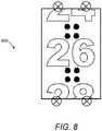
- Fig. 8illustrates an embodiment in which only even numbers are printed on the number sleeve 19 and where a dose of 26 units has been dialled into the injection device 1.
- the number 26appears centrally in the dose window 13.
- the position of the LEDs 29 in Fig. 8is the same as in Figs. 6a and 6b , with a pair of LEDs located at either end of the dose window 13.
- the optical sensor lensis again located centrally above the dose window 13.
- This arrangement of LEDstherefore leads to the same pattern of reflections in the field of view 800 of the optical sensor 25. However since these reflections occur in the upper and lower thirds of the field of view 800, none of the reflections directly overlap with the centrally displayed number. Thus no division of the field of view 800 by the processor 24 is necessary in this situation.
- the processor 24may continue to divide the image as previously described, even if the reflections do not obscure any areas of interest.
- the processor 24may additionally be configured to detect the white spaces between the printed numbers in order to determine whether a number is displayed centrally within the window or not.
Landscapes
- Health & Medical Sciences (AREA)
- Engineering & Computer Science (AREA)
- Life Sciences & Earth Sciences (AREA)
- Animal Behavior & Ethology (AREA)
- Veterinary Medicine (AREA)
- Public Health (AREA)
- General Health & Medical Sciences (AREA)
- Vascular Medicine (AREA)
- Anesthesiology (AREA)
- Biomedical Technology (AREA)
- Heart & Thoracic Surgery (AREA)
- Hematology (AREA)
- Physics & Mathematics (AREA)
- General Physics & Mathematics (AREA)
- Theoretical Computer Science (AREA)
- Computer Vision & Pattern Recognition (AREA)
- Multimedia (AREA)
- Infusion, Injection, And Reservoir Apparatuses (AREA)
Description
- The present invention relates to a a system of an injection device and a supplementary device for attachment to said injection device, and in particular to a supplementary device comprising a processor arrangement configured to activate a plurality of light sources sequentially and to combine into a single image multiple images captured by an imaging apparatus under different illumination conditions.
- A variety of diseases exists that require regular treatment by injection of a medicament. Such injection can be performed by using injection devices, which are applied either by medical personnel or by patients themselves. As an example, type-1 and type-2 diabetes can be treated by patients themselves by injection of insulin doses, for example once or several times per day. For instance, a pre-filled disposable insulin pen can be used as an injection device. Alternatively, a re-usable pen may be used. A re-usable pen allows replacement of an empty medicament cartridge by a new one. Either pen may come with a set of one-way needles that are replaced before each use. The insulin dose to be injected can then for instance be manually selected at the insulin pen by turning a dosage knob and observing the actual dose from a dose window or display of the insulin pen. The dose is then injected by inserting the needle into a suited skin portion and pressing an injection button of the insulin pen. To be able to monitor insulin injection, for instance to prevent false handling of the insulin pen or to keep track of the doses already applied, it is desirable to measure information related to a condition and/or use of the injection device, such as for instance information on the injected insulin type and dose.
US 2009/073307 A1 reports a digital image capture device and method.US 2013/329073 A1 reports creating adjusted digital images with selected pixel values.US 2013/051631 A1 reports systems and methods for capturing artefact free images.US 2014/194826 A1 reports a drug delivery injection pen with add-on dose capturing and display module.WO 2013/120777 A1 reports a supplemental device for attachment to an injection device.US 2008/165266 A1 reports specular reflection reduction using multiple cameras.- A first aspect of the invention provides a system as claimed in the appended claims.
- Each illumination source, when activated, may result in one or more reflections from a transparent window of the injection device being visible in a field of view of the imaging apparatus.
- A third aspect of the invention provides a method of operating a supplementary device as claimed in the appended claims.
- Embodiments of the invention will now be described, by way of example only, with reference to the accompanying drawings.
- The figures show:
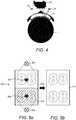
Figure 1a : an exploded view of an drug delivery device;Figure 1b shows a perspective view of some detail of the drug delivery device ofFigure 1a ;Figure 2a : a schematic illustration of a supplementary device to be releasably attached to the drug delivery device ofFigures 1a and1b according to an aspect of the present invention;Figure 2b : a perspective view of a supplementary device to be releasably attached to the drug delivery device ofFigures 1a and1b according to various aspects of the present invention;Figure 2c : a perspective view of a supplementary device to be releasably attached to the drug delivery device ofFigures 1a and1b according to other aspects of the present invention;Figure 3 : a schematic view of a supplementary device attached to a drug delivery device showing components of the supplementary device;Figure 4 : a schematic illustration of the injection device and supplementary device showing reflections from a dose window of the injection device;Figure 5a : an example of a typical field of view of an optical sensor of the supplementary device, showing the position of LEDs and resulting reflections;Figure 5b : a final image created by combining partial images of the field of view ofFigure 5a ;Figures 6a and 6b : a further example of a field of view of an optical sensor of the supplementary device, showing the position of LEDs and resulting reflections;Figures 7a and 7b : an embodiment of a field of view of an optical sensor of the supplementary device, showing the position of LEDs and resulting reflections;Figure 8 : an embodiment in which a number appears in the centre of the field of view of the optical sensor.- In the following, embodiments of the present invention will be described with reference to an insulin injection device. The present invention is however not limited to such application and may equally well be deployed with injection devices that eject other medicaments, or with other types of medical devices.
Fig. 1 is an exploded view of an injection device 1 (also referred to herein as adrug delivery device 1,injection pen 1 or pen device 1), which may for instance represent Sanofi's Solostar (R) insulin injection pen.- The
injection device 1 ofFig. 1 is a pre-filled, disposable injection pen that comprises ahousing 10 and contains aninsulin container 14, to which aneedle 15 can be affixed. The needle is protected by an inner needle cap 16 and anouter needle cap 17, which in turn can be covered by acap 18. An insulin dose to be ejected frominjection device 1 can be selected by turning thedosage knob 12, and the selected dose is then displayed viadosage window 13, for instance in multiples of so-called International Units (IU), wherein one IU is the biological equivalent of about 45.5 micrograms of pure crystalline insulin (1/22 mg). An example of a selected dose displayed indosage window 13 may for instance be 30 lUs, as shown inFig. 1 . It should be noted that the selected dose may equally well be displayed differently. A label (not shown) is provided on thehousing 10. The label includes information about the medicament included within the injection device, including information identifying the medicament. - The information identifying the medicament may be in the form of text. The information identifying the medicament may also be in the form of a colour. The information identifying the medicament may also be encoded into a barcode, QR code or the like. The information identifying the medicament may also be in the form of a black and white pattern, a colour pattern or shading.
- Turning the
dosage knob 12 causes a mechanical click sound to provide acoustical feedback to a user. The numbers displayed indosage window 13 are printed on a sleeve that is contained inhousing 10 and mechanically interacts with a piston ininsulin container 14. Whenneedle 15 is stuck into a skin portion of a patient, and theninjection button 11 is pushed, the insulin dose displayed indisplay window 13 will be ejected frominjection device 1. When theneedle 15 ofinjection device 1 remains for a certain time in the skin portion after theinjection button 11 is pushed, a high percentage of the dose is actually injected into the patient's body. Ejection of the insulin dose also causes a mechanical click sound, which is however different from the sounds produced when usingdosage knob 12. Injection device 1 may be used for several injection processes until eitherinsulin container 14 is empty or the expiration date of injection device 1 (e.g. 28 days after the first use) is reached.- Furthermore, before using
injection device 1 for the first time, it may be necessary to perform a so-called "prime shot" to remove air frominsulin container 14 andneedle 15, for instance by selecting two units of insulin andpressing injection button 11 while holdinginjection device 1 with theneedle 15 upwards. - For simplicity of presentation, in the following, it will be exemplarily assumed that the ejected doses substantially correspond to the injected doses, so that, for instance when making a proposal for a dose to be injected next, this dose equals the dose that has to ejected by the injection device. Nevertheless, differences (e.g. losses) between the ejected doses and the injected doses may of course be taken into account.
Fig. 1b is a close-up of the end of theinjection device 1. This Fig. shows a locatingrib 70 that is located between the viewingwindow 13 and thedosage knob 12.Fig. 2a is a schematic illustration of an embodiment of a supplementary device 2 (also referred to herein as anadditional device 2, clip-ondevice 2 or sensor device 2) to be releasably attached toinjection device 1 ofFig. 1 .Supplementary device 2 comprises ahousing 20 with a mating unit configured and embrace thehousing 10 ofinjection device 1 ofFig. 1 , so thatsupplementary device 2 sits tightly onhousing 10 ofinjection device 1, but is nevertheless removable frominjection device 1, for instance wheninjection device 1 is empty and has to be replaced.Fig. 2a is highly schematic, and details of the physical arrangement are described below with reference toFigure 2b .Supplementary device 2 contains optical and acoustical sensors for gathering information frominjection device 1. At least a part of this information, for instance a selected dose (and optionally a unit of this dose), is displayed viadisplay unit 21 ofsupplementary device 2. Thedosage window 13 ofinjection device 1 is obstructed bysupplementary device 2 when attached toinjection device 1.Supplementary device 2 further comprises at least one user input transducer, illustrated schematically as abutton 22. Theseinput transducers 22 allow a user to turn on/offsupplementary device 2, to trigger actions (for instance to cause establishment of a connection to or a pairing with another device, and/or to trigger transmission of information fromsupplementary device 2 to another device), or to confirm something.Fig. 2b is a schematic illustration of a second embodiment of asupplementary device 2 to be releasably attached toinjection device 1 ofFig. 1 .Supplementary device 2 comprises ahousing 20 with a mating unit configured and embrace thehousing 10 ofinjection device 1 ofFig. 1 , so thatsupplementary device 2 sits tightly onhousing 10 ofinjection device 1, but is nevertheless removable frominjection device 1.- Information is displayed via
display unit 21 ofsupplementary device 2. Thedosage window 13 ofinjection device 1 is obstructed bysupplementary device 2 when attached toinjection device 1. Supplementary device 2 further comprises three user input buttons or switches. Afirst button 22 is a power on/off button, via which thesupplementary device 2 may for instance be turned on and off. Asecond button 33 is a communications button. Athird button 34 is a confirm or OK button. Thebuttons input buttons supplementary device 2, to trigger actions (for instance to cause establishment of a connection to or a pairing with another device, and/or to trigger transmission of information fromsupplementary device 2 to another device), or to confirm something.Fig. 2c is a schematic illustration of a third embodiment of asupplementary device 2 to be releasably attached toinjection device 1 ofFig. 1 .Supplementary device 2 comprises ahousing 20 with a mating unit configured to embrace thehousing 10 ofinjection device 1 ofFig. 1 , so thatsupplementary device 2 sits tightly onhousing 10 ofinjection device 1, but is nevertheless removable frominjection device 1.- Information is displayed via
display unit 21 of thesupplementary device 2. Thedosage window 13 ofinjection device 1 is obstructed bysupplementary device 2 when attached toinjection device 1. Supplementary device 2 further comprises a touch-sensitive input transducer 35. It also comprises a single user input button orswitch 22. Thebutton 22 is a power on/off button, via which thesupplementary device 2 may for instance be turned on and off. The touchsensitive input transducer 35 can be used to trigger actions (for instance to cause establishment of a connection to or a pairing with another device, and/or to trigger transmission of information fromsupplementary device 2 to another device), or to confirm something.Fig. 3 shows a schematic view of thesupplementary device 2 ofFig. 2a in a state where it is attached toinjection device 1 ofFig. 1 .- With the
housing 20 ofsupplementary device 2, a plurality of components are contained. These are controlled by aprocessor 24, which may for instance be a microprocessor, a Digital Signal Processor (DSP), Application Specific Integrated Circuit (ASIC), Field Programmable Gate Array (FPGA) or the like.Processor 24 executes program code (e.g. software or firmware) stored in aprogram memory 240, and uses amain memory 241, for instance to store intermediate results.Main memory 241 may also be used to store a logbook on performed ejections/injections.Program memory 240 may for instance be a Read-Only Memory (ROM), and main memory may for instance be a Random Access Memory (RAM). - In embodiments such as those shown in
Fig. 2b ,processor 24 interacts with afirst button 22, via whichsupplementary device 2 may for instance be turned on and off. Asecond button 33 is a communications button. The second button may be used to trigger establishment of a connection to another device, or to trigger a transmission of information to another device. Athird button 34 is a confirm or OK button. Thethird button 34 can be used to acknowledge information presented to a user ofsupplementary device 2. In embodiments such as those shown inFig. 2c , two of thebuttons Processor 24 controls adisplay unit 21, which is presently embodied as a Liquid Crystal Display (LCD).Display unit 21 is used to display information to a user ofsupplementary device 2, for instance on present settings ofinjection device 1, or on a next injection to be given.Display unit 21 may also be embodied as a touch-screen display, for instance to receive user input.Processor 24 also controls anoptical sensor 25, embodied as an Optical Character Recognition (OCR) reader, that is capable of capturing images of thedosage window 13, in which a currently selected dose is displayed (by way of numbers printed on thesleeve 19 contained ininjection device 1, which numbers are visible through the dosage window 13).OCR reader 25 is further capable of recognizing characters (e.g. numbers) from the captured image and to provide this information toprocessor 24. Alternatively,unit 25 insupplementary device 2 may only be an optical sensor, e.g. a camera, for capturing images and providing information on the captured images toprocessor 24. Thenprocessor 24 is responsible for performing OCR on the captured images.Processor 24 also controls light-sources such as light emitting diodes (LEDs) 29 to illuminate thedosage window 13, in which a currently selected dose is displayed. A diffuser may be used in front of the light-sources, for instance a diffuser made from a piece of acrylic glass. Furthermore, the optical sensor may comprise a lens system, for instance including two aspheric lenses. The magnification ratio (image size to object size ratio) may be smaller than 1. The magnification ratio may be in the range of 0.05 to 0.5. In one embodiment the magnification ratio may be 0.15.Processor 24 further controls aphotometer 26, that is configured to determine an optical property of thehousing 10 ofinjection device 1, for example a colour or a shading. The optical property may only be present in a specific portion ofhousing 10, for example a colour or colour coding ofsleeve 19 or of an insulin container comprised withininjection device 1, which colour or colour coding may for instance be visible through a further window in housing 10 (and/or in sleeve 19). Information on this colour is then provided toprocessor 24, which may then determine the type ofinjection device 1 or the type of insulin contained in injection device 1 (e.g. SoloStar Lantus with purple colour and SoloStar Apidra with blue colour). Alternatively, a camera unit may be used instead ofphotometer 26, and an image of the housing, sleeve or insulin container may then be provided toprocessor 24 to determine the colour of the housing, sleeve or insulin container by way of image processing. Further, one or more light sources may be provided to improve reading ofphotometer 26. The light source may provide light of a certain wavelength or spectrum to improve colour detection byphotometer 26. The light source may be arranged in such a way that unwanted reflections, for example bydosage window 13, are avoided or reduced. In an example embodiment, instead of or in addition tophotometer 26, a camera unit may be deployed to detect a code (for instance a bar code, which may for instance be a one- or two-dimensional bar code) related to the injection device and/or the medicament contained therein. This code may for instance be located on thehousing 10 or on a medicament container contained ininjection device 1, to name but a few examples. This code may for instance indicate a type of the injection device and/or the medicament, and/or further properties (for instance a expiration date).Processor 24 further controls (and/or receives signals from) anacoustic sensor 27, which is configured to sense sounds produced byinjection device 1. Such sounds may for instance occur when a dose is dialled by turningdosage knob 12 and/or when a dose is ejected/injected by pressinginjection button 11, and/or when a prime shot is performed. These actions are mechanically similar but nevertheless sound differently (this may also be the case for electronic sounds that indicate these actions). Either theacoustic sensor 27 and/orprocessor 24 may be configured to differentiate these different sounds, for instance to be able to safely recognize that an injection has taken place (rather than a prime shot only).Processor 24 further controls anacoustical signal generator 23, which is configured to produce acoustical signals that may for instance be related to the operating status ofinjection device 1, for instance as feedback to the user. For example, an acoustical signal may be launched byacoustical signal generator 23 as a reminder for the next dose to be injected or as a warning signal, for instance in case of misuse. Acoustical signal generator may for instance be embodied as a buzzer or loudspeaker. In addition to or as an alternative toacoustical signal generator 23, also a haptic signal generator (not shown) may be used to provide haptic feedback, for instance by way of vibration.Processor 24 controls awireless unit 28, which is configured to transmit and/or receive information to/from another device in a wireless fashion. Such transmission may for instance be based on radio transmission or optical transmission. In some embodiments, thewireless unit 28 is a Bluetooth transceiver. Alternatively,wireless unit 28 may be substituted or complemented by a wired unit configured to transmit and/or receive information to/from another device in a wire-bound fashion, for instance via a cable or fibre connection. When data is transmitted, the units of the data (values) transferred may be explicitly or implicitly defined. For instance, in case of an insulin dose, always International Units (IU) may be used, or otherwise, the used unit may be transferred explicitly, for instance in coded form.Processor 24 receives an input from apen detection switch 30, which is operable to detect whether thepen 1 is present, i.e. to detect whether thesupplementary device 2 is coupled to theinjection device 1. Abattery 32 powers theprocessor 24 and other components by way of apower supply 31.- The
supplementary device 2 ofFig. 3 is thus capable of determining information related to a condition and/or use ofinjection device 1. This information is displayed on thedisplay 21 for use by the user of the device. The information may be either processed bysupplementary device 2 itself, or may at least partially be provided to another device (e.g. a blood glucose monitoring system). Fig. 4 shows schematically a cross-section of theinjection device 1 and components of thesupplementary device 2, including an exemplary position of the LEDs 29 (also referred to herein as illumination sources) with respect to theoptical sensor 25 anddose window 13.Fig. 4 also illustrates the problem caused by reflections from the surface of thedose window 13. Due to manufacturing requirements and costs considerations, thedose window 13 is not usually made of a highly non-reflective material or provided with a non-reflective coating. The dose window may be made of a clear Polycarbonate. Therefore some of the light incident on thedose window 13 will be reflected from thedose window 13, rather than passing through to be incident on thenumber sleeve 19. In particular, it can be seen that light emitted from theLEDs 29 may be reflected from the lower surface of thedose window 13 towards theoptical sensor 25 without reaching thenumber sleeve 19 of theinjection device 1. These reflections lead to glare in the image captured by theoptical sensor 25. As theLEDs 29 are point light sources, this glare generally takes the form of bright spots. The glare leads to areas of over exposure and impacts the ability of theoptical sensor 25 to capture a high quality image of the numbers printed on thenumber sleeve 19, which in turn affects the ability of theprocessor 24 to perform a successful optical character recognition process on the numbers. It can be particularly hard to avoid glare in the captured image because thedose window 13 is curved and so the light is incident on thedose window 13 over a range of angles.LEDs 29 are the preferred choice of illumination because of their small size and cost and their radiation characteristics. However, an alternative source, such as a light bulb, diode laser or an organic LED may be used.- The
supplementary device 2 may also comprise a protection window (not shown). The primary function of the protection window is to seal thesupplementary device 2 and prevent the ingress of dust and debris. However the protection window may also be shaped to provide magnification and/or focussing for theoptical sensor 25. Fig. 5a shows a typical field ofview 500 of theoptical sensor 25. In general the field of view of theoptical sensor 25 is large enough to capture an image of theentire dose window 13. In this example thesupplementary device 2 is provided with twoLEDs 29 located above and below thedose window 13. When theupper LED 502 is activated, afirst reflection 504 is seen by theoptical sensor 25. When thelower LED 506 is activated, asecond reflection 508 is seen by theoptical sensor 25. Thus if both the upper andlower LEDs optical sensor 25 sees two reflections in its field ofview 500. If the reflections are located over a number, then they negatively impact the ability of theoptical sensor 25 to capture a high quality image of these numbers. This can make it difficult to perform an accurate OCR process on the captured image, since information about the numbers has effectively been erased through over exposure.- It should be noted that the
number 88 is used in this example and in embodiments described herein. In general this number occupies the greatest amount of space and is therefore the best candidate for assessing whether the reflections from thedose window 13 are located over the numbers. The skilled person will appreciate that the numbers printed on thenumber sleeve 19 represent a dose of medicament dialled into theinjection device 1 and will therefore be sequential. For example, the numbers printed on thenumber sleeve 19 may be ascending even numbers. In some embodiments, the maximum dose which can be dialled into theinjection device 1 is 80 units. - In order to eliminate the negative effects of the
reflections number sleeve 19 are captured by theoptical sensor 25 under different illumination conditions. These images are then combined to create a final image which is free from reflections. In the example ofFig. 5a , theprocessor 24 is configured to divide images captured by theoptical sensor 25 into two halves. Theprocessor 24 is configured to control activation and deactivation of the upper andlower LEDs optical sensor 25. - The
processor 24 first activates theupper LED 502, which in general causes afirst reflection 504 from thedose window 13. Theprocessor 24 controls theoptical sensor 25 to capture an image of thenumber sleeve 19. Theprocessor 24 then discards theupper half 510 of this image and keeps only thelower half 512 of the image. Due to the position of theupper LED 502 relative to theoptical sensor 25 no reflections are seen in thelower half 512 of the captured image. Theprocessor 24 then deactivates theupper LED 502 and activates thelower LED 506. Theprocessor 24 again controls theoptical sensor 25 to capture an image of thenumber sleeve 19. In this second image thesecond reflection 508 in thelower half 512 is visible, but thefirst reflection 504 does not appear. Thus theprocessor 24 keeps theupper half 510 of this second image and discards thelower half 512. Theprocessor 24 then executes an algorithm to combine thelower half 512 of the first image andupper half 510 of the second image to create afinal image 514, illustrated inFig. 5b . In practice, the image halves captured in the first and second images may overlap. This may be done to ensure that no image information is lost. Theprocessor 24 may execute software which uses edge detection techniques to determine the appropriate place in each image for the combination to occur. Theprocessor 24 then passes thefinal image 514 to an optical character recognition module, or performs the OCR process itself in order to identify the numbers visible in the image. OCR techniques are in general well known, and the skilled person will be aware of a number of OCR methods which could be applied in this invention. Figs. 6a and 6b illustrate a second disclosed example. In this example thesupplementary device 2 comprises fourLEDs 29, arranged in pairs above and below thedose window 13. The position of the lens of the optical sensor is indicated by the dashedcircle 602. As can be seen in these figures, the LEDs are located closer to thedose window 13 than in the first example. Due to the relative position of the LEDs andoptical sensor 25, each LED produces two reflections from thedose window 13 which are within the sensor's field ofview 600.- In this example the
processor 24 divides the field of view of theoptical sensor 25 vertically, into aleft half 604 and aright half 606. Theprocessor 24 controls the LEDs to be activated in left and right pairs. Theprocessor 24 first activates theleft LEDs 608. This causesreflections 609 to appear on theleft half 604 of the field of view of theoptical sensor 25. Theprocessor 24 controls theoptical sensor 25 to capture an image of thenumber sleeve 19. Theprocessor 24 discards theleft half 604 of this image and keeps theright half 606 of the image. This is illustrated inFig. 6a by the cross hatching in theright half 606 of the field ofview 600. The next step is illustrated inFig. 6b , in which theprocessor 24 deactivates theleft LEDs 608 and activates theright LEDs 610. This causesreflections 611 to appear in theright half 606 of the field of view sensor. Theprocessor 24 again controls theoptical sensor 25 to capture an image of thenumber sleeve 19. Theprocessor 24 discards theright half 606 of this second image and keeps theleft half 604 of the image (this is again illustrated by cross hatching in the left half 604). Theprocessor 24 then takes theright half 606 of the first image and lefthalf 604 of the second image and combines them into a final image which is free of reflections. - Having a greater number of
LEDs 29 increases the quality and evenness of the illumination. Positioning theLEDs 29 closer to thedose window 13 also improves the illumination of thenumber sleeve 19 and increases the amount of light reaching thedose window 13 andoptical sensor 25 for a given LED light output. In general, it is desirable to position theLEDs 29 such that minimal reflections appear in the illuminated area, while at the same time producing an illumination which is bright and homogeneous. Thus theLEDs 29 are positioned such that the reflections produced appear in a section of the field of view and captured image which is subsequently discarded. Dividing the field of view vertically into left and right halves, rather than upper and lower halves also increases the quality of the illumination as the part of the image which theprocessor 24 keeps is closer to a source of illumination. Another advantage of the invention is that it requires no modification of existing injection pen designs to implement. Figs. 7a and 7b show an embodiment of the invention. In this embodiment there are again fourLEDs 29 arranged linearly along a centre line of thedose window 13. Thelens position 702 is again illustrated with a dashed circle. In this embodiment the LEDs are grouped into aninner pair 704 and anouter pair 706. Theinner pair 704 are located approximately one third of thedose window 13 height from the top and bottom edges of thedose window 13. Theouter LEDs 706 are located at thedose window 13 edges.- In this embodiment the
processor 24 divides the field ofview 700 into acentral section 708 and twoperipheral sections 710. Thecentral section 708 may occupy approximately half of the field ofview 700, while theperipheral section 710 each occupy approximately one quarter of the field of view. However these ratios may be adjusted depending on the expected positions of the reflections. - The
processor 24 first activates theinner LEDs 704. This producesinner reflections 712 in thecentral section 708 of the field ofview 700 of theoptical sensor 25. Theprocessor 24 controls theoptical sensor 25 to capture an image of thenumber sleeve 19. Theprocessor 24 keeps the upper and lowerperipheral sections 710 of this image and discards thecentral section 708 of the image. Theprocessor 24 then deactivatesinner LEDs 704 and activatesouter LEDs 706. These LEDs causeouter reflections 714 to appear in the upper and lowerperipheral section 710 of the field ofview 700. Theprocessor 24 again controls theoptical sensor 25 to capture an image of thenumber sleeve 19. Theprocessor 24 keeps thecentral section 708 of this second image and discards the upper and lowerperipheral section 710 of the image. Theprocessor 24 then combines the upper and lowerperipheral sections 710 from the first image with thecentral section 708 from the second image to create a final image which is free of reflections. An OCR process can then be performed on this final image to determine the numbers which are visible. - In some embodiments of the invention only even numbers are printed, in ascending order, on the
number sleeve 19. In this case each of the arrangements shown inFigs. 5a to 7b represents a situation in which an odd number of units are dialled into theinjection device 1. This is because the number of dialled units would normally be displayed centrally within thedose window 13. Fig. 8 illustrates an embodiment in which only even numbers are printed on thenumber sleeve 19 and where a dose of 26 units has been dialled into theinjection device 1. Thus thenumber 26 appears centrally in thedose window 13. The position of theLEDs 29 inFig. 8 is the same as inFigs. 6a and 6b , with a pair of LEDs located at either end of thedose window 13. The optical sensor lens is again located centrally above thedose window 13. This arrangement of LEDs therefore leads to the same pattern of reflections in the field ofview 800 of theoptical sensor 25. However since these reflections occur in the upper and lower thirds of the field ofview 800, none of the reflections directly overlap with the centrally displayed number. Thus no division of the field ofview 800 by theprocessor 24 is necessary in this situation. Alternatively, theprocessor 24 may continue to divide the image as previously described, even if the reflections do not obscure any areas of interest. Theprocessor 24 may additionally be configured to detect the white spaces between the printed numbers in order to determine whether a number is displayed centrally within the window or not.
Claims (3)
- A system comprising:a supplementary device (2) for attachment to an injection device (1); andan injection device (1) comprising a moveable number sleeve (19) and a transparent window (13) through which the moveable number sleeve (19) is visible and being configured to have the supplementary device (2) attached thereto, the supplementary device (2) comprising:an optical sensor (25) configured to capture an image of a moveable number sleeve (19) of the injection device (1);four point light sources (29) arranged linearly along a centre line of the dose window (13) and grouped into first and second pairs of light sources (704, 706); anda processor arrangement (24) configured to control operation of the optical sensor (25) and the four point light sources (29) and to receive image data from the optical sensor (25),wherein the processor arrangement (24) is configured to:activate the point light sources (29) sequentially by being configured to activate the first pair of point light sources (704) followed by the second pair of point light sources (706);capture a first image of the moveable number sleeve (19) when the first pair of point light sources (704) are activated;capture a second image of the moveable number sleeve (19) when the second pair of point light sources (706) are activated;divide the field of view of the optical sensor (25) into a central section (708) and two peripheral sections (710) and to associate the central section (708) with a first illumination condition in which the second pair of point light sources (704) are activated and the two peripheral sections (710) with a second illumination condition in which the first pair of point light sources (706) are activated;combine the first image of the moveable number sleeve (19) and the second image of the moveable number sleeve (19) into a final image; andperform an OCR process on the final image to identify the numbers visible in the final image
- A system according to claim 1, wherein each illumination source (29), when activated, results in one or more reflections (712, 714) from the transparent window (13) of the injection device (1) being visible in a field of view of the optical sensor (25).
- A method of operating a supplementary device (2) for attachment to an injection device (1), the injection device (1) having a transparent window (13), and the supplementary device (2) having:an optical sensor (25) configured to capture an image of a moveable number sleeve (19) of the injection device (1), the moveable number sleeve (19) being located behind the transparent window (13) of the injection device (1);four point light sources (29) arranged linearly along a centre line of the dose window (13) and grouped into first and second pairs of light sources (704, 706); anda processor arrangement (24) configured to control operation of the optical sensor (25) and the four point light sources (29), the method comprising:activating the four point light sources (29) sequentially by activating the first pair of point light sources (704) followed by the second pair of point light sources (706);capturing a first image of the moveable number sleeve (19) when the first pair of point light sources (704) are activated;capturing a second image of the moveable number sleeve (19) when the second pair of point light sources (706) are activated;dividing the field of view of the optical sensor (25) into a central section (708) and two peripheral sections (710) and associating the central section (708) with a first illumination condition in which the second pair of point light sources (704) are activated and the two peripheral sections (710) with a second illumination condition in which the first pair of point light sources (704) are activated;combining the first image of the moveable number sleeve (19) and the second image of the moveable number sleeve (19) into a final image; andperforming an OCR process on the final image to identify the numbers visible in the final image.
Applications Claiming Priority (2)
| Application Number | Priority Date | Filing Date | Title |
|---|---|---|---|
| EP14187695 | 2014-10-06 | ||
| PCT/EP2015/072905WO2016055401A1 (en) | 2014-10-06 | 2015-10-05 | A supplementary device for attachment to a drug injection device for monitoring injection doses having ocr imaging system with glare reduction |
Publications (2)
| Publication Number | Publication Date |
|---|---|
| EP3204082A1 EP3204082A1 (en) | 2017-08-16 |
| EP3204082B1true EP3204082B1 (en) | 2020-04-08 |
Family
ID=51660360
Family Applications (1)
| Application Number | Title | Priority Date | Filing Date |
|---|---|---|---|
| EP15775194.2AActiveEP3204082B1 (en) | 2014-10-06 | 2015-10-05 | Supplementary device for attachment to an injection device for determining the set and/or administered dose with ocr image processing including a method for glare reduction |
Country Status (4)
| Country | Link |
|---|---|
| US (1) | US10456530B2 (en) |
| EP (1) | EP3204082B1 (en) |
| DK (1) | DK3204082T3 (en) |
| WO (1) | WO2016055401A1 (en) |
Cited By (1)
| Publication number | Priority date | Publication date | Assignee | Title |
|---|---|---|---|---|
| WO2023208791A1 (en)* | 2022-04-25 | 2023-11-02 | Novo Nordisk A/S | Dose logging device with scale drum scanner |
Families Citing this family (16)
| Publication number | Priority date | Publication date | Assignee | Title |
|---|---|---|---|---|
| EP3407940A4 (en) | 2016-01-29 | 2019-09-04 | Companion Medical, Inc. | AUTOMATIC DRUG DELIVERY MONITORING |
| WO2018015118A1 (en)* | 2016-07-22 | 2018-01-25 | Carebay Europe Ltd. | Device and system for obtaining medicament related information |
| USD870731S1 (en)* | 2017-10-06 | 2019-12-24 | Getac Technology Corporation | Scanner for mobile computer |
| US11083852B2 (en) | 2017-12-12 | 2021-08-10 | Bigfoot Biomedical, Inc. | Insulin injection assistance systems, methods, and devices |
| US11116899B2 (en) | 2017-12-12 | 2021-09-14 | Bigfoot Biomedical, Inc. | User interface for diabetes management systems and devices |
| US11077243B2 (en) | 2017-12-12 | 2021-08-03 | Bigfoot Biomedical, Inc. | Devices, systems, and methods for estimating active medication from injections |
| US11197964B2 (en) | 2017-12-12 | 2021-12-14 | Bigfoot Biomedical, Inc. | Pen cap for medication injection pen having temperature sensor |
| US11464459B2 (en) | 2017-12-12 | 2022-10-11 | Bigfoot Biomedical, Inc. | User interface for diabetes management systems including flash glucose monitor |
| US10987464B2 (en) | 2017-12-12 | 2021-04-27 | Bigfoot Biomedical, Inc. | Pen cap for insulin injection pens and associated methods and systems |
| IL275301B2 (en) | 2017-12-12 | 2024-01-01 | Bigfoot Biomedical Inc | Therapy assist information and/or tracking device and related methods and systems |
| JP7056131B2 (en)* | 2017-12-15 | 2022-04-19 | オムロン株式会社 | Image processing system, image processing program, and image processing method |
| USD870732S1 (en)* | 2018-02-02 | 2019-12-24 | Getac Technology Corporation | Scanner |
| US12205699B1 (en) | 2018-10-30 | 2025-01-21 | Bigfoot Biomedical, Inc. | Method of pairing therapy devices using shared secrets, and related systems, methods and devices |
| US11948671B2 (en) | 2019-04-11 | 2024-04-02 | Medtronic Minimed, Inc. | Intelligent accessories for medicine dispensing device |
| WO2021155981A1 (en)* | 2020-02-07 | 2021-08-12 | Shl Medical Ag | Activation system for a supplemental device attached to a medicament delivery device |
| JP7579961B2 (en)* | 2020-07-28 | 2024-11-08 | イーライ リリー アンド カンパニー | Method and apparatus for embodiments of a dose detection system module for a drug delivery device |
Family Cites Families (14)
| Publication number | Priority date | Publication date | Assignee | Title |
|---|---|---|---|---|
| WO2002081011A1 (en)* | 2001-04-03 | 2002-10-17 | Medrad, Inc. | Encoding and sensing of syringe information |
| US7962192B2 (en)* | 2005-09-30 | 2011-06-14 | Restoration Robotics, Inc. | Systems and methods for aligning a tool with a desired location or object |
| US7630002B2 (en)* | 2007-01-05 | 2009-12-08 | Microsoft Corporation | Specular reflection reduction using multiple cameras |
| US7554740B2 (en)* | 2006-11-22 | 2009-06-30 | Omnitech Partners, Inc. | System and method for optical image generator and injector |
| US20090073307A1 (en)* | 2007-09-14 | 2009-03-19 | Marcus Kramer | Digital image capture device and method |
| WO2009086182A1 (en)* | 2007-12-21 | 2009-07-09 | Carticept Medical, Inc. | Articular injection system |
| KR101939267B1 (en)* | 2010-07-21 | 2019-01-16 | 삼성전자주식회사 | Method and device for measuring dose in injector |
| US20140194826A1 (en)* | 2011-07-07 | 2014-07-10 | Novo Nordisk A/S | Drug delivery injection pen with add-on dose capturing and display module |
| EP2748768A4 (en)* | 2011-08-22 | 2016-05-11 | Eyelock Llc | Systems and methods for capturing artifact free images |
| KR20140122272A (en)* | 2012-02-13 | 2014-10-17 | 사노피-아벤티스 도이칠란트 게엠베하 | Supplemental device for attachment to an injection device |
| US20130329073A1 (en)* | 2012-06-08 | 2013-12-12 | Peter Majewicz | Creating Adjusted Digital Images with Selected Pixel Values |
| US9623191B2 (en)* | 2013-03-01 | 2017-04-18 | Bayer Healthcare Llc | Information sensing syringe |
| US10143830B2 (en)* | 2013-03-13 | 2018-12-04 | Crisi Medical Systems, Inc. | Injection site information cap |
| US9317916B1 (en)* | 2013-04-12 | 2016-04-19 | Aic Innovations Group, Inc. | Apparatus and method for recognition of medication administration indicator |
- 2015
- 2015-10-05EPEP15775194.2Apatent/EP3204082B1/enactiveActive
- 2015-10-05WOPCT/EP2015/072905patent/WO2016055401A1/enactiveApplication Filing
- 2015-10-05DKDK15775194.2Tpatent/DK3204082T3/enactive
- 2015-10-05USUS15/515,942patent/US10456530B2/enactiveActive
Non-Patent Citations (1)
| Title |
|---|
| None* |
Cited By (1)
| Publication number | Priority date | Publication date | Assignee | Title |
|---|---|---|---|---|
| WO2023208791A1 (en)* | 2022-04-25 | 2023-11-02 | Novo Nordisk A/S | Dose logging device with scale drum scanner |
Also Published As
| Publication number | Publication date |
|---|---|
| US10456530B2 (en) | 2019-10-29 |
| WO2016055401A1 (en) | 2016-04-14 |
| US20170312446A1 (en) | 2017-11-02 |
| DK3204082T3 (en) | 2020-07-06 |
| EP3204082A1 (en) | 2017-08-16 |
Similar Documents
| Publication | Publication Date | Title |
|---|---|---|
| EP3204082B1 (en) | Supplementary device for attachment to an injection device for determining the set and/or administered dose with ocr image processing including a method for glare reduction | |
| US10973983B2 (en) | Drug delivery device with at least one transparent region of housing | |
| US11285267B2 (en) | Sensor device with OLED | |
| US10473511B2 (en) | Sensor device for attachment to a drug delivery device | |
| US11179519B2 (en) | Injection device and a supplemental device configured for attachment thereto | |
| US10786627B2 (en) | Device for attachment to a drug delivery device | |
| EP3166492B1 (en) | Apparatus for capturing and processing images | |
| EP3204081B1 (en) | Supplementary device for attachment to an injection device for determining the set and/or administered dose with ocr image processing including a method for glare reduction | |
| HK1214996B (en) | Sensor device with oled | |
| HK1233885B (en) | Apparatus for capturing and processing images | |
| HK1253920B (en) | Sensor device for attachment to a drug delivery device |
Legal Events
| Date | Code | Title | Description |
|---|---|---|---|
| STAA | Information on the status of an ep patent application or granted ep patent | Free format text:STATUS: THE INTERNATIONAL PUBLICATION HAS BEEN MADE | |
| PUAI | Public reference made under article 153(3) epc to a published international application that has entered the european phase | Free format text:ORIGINAL CODE: 0009012 | |
| STAA | Information on the status of an ep patent application or granted ep patent | Free format text:STATUS: REQUEST FOR EXAMINATION WAS MADE | |
| 17P | Request for examination filed | Effective date:20170222 | |
| AK | Designated contracting states | Kind code of ref document:A1 Designated state(s):AL AT BE BG CH CY CZ DE DK EE ES FI FR GB GR HR HU IE IS IT LI LT LU LV MC MK MT NL NO PL PT RO RS SE SI SK SM TR | |
| AX | Request for extension of the european patent | Extension state:BA ME | |
| DAV | Request for validation of the european patent (deleted) | ||
| DAX | Request for extension of the european patent (deleted) | ||
| STAA | Information on the status of an ep patent application or granted ep patent | Free format text:STATUS: EXAMINATION IS IN PROGRESS | |
| 17Q | First examination report despatched | Effective date:20190409 | |
| GRAP | Despatch of communication of intention to grant a patent | Free format text:ORIGINAL CODE: EPIDOSNIGR1 | |
| STAA | Information on the status of an ep patent application or granted ep patent | Free format text:STATUS: GRANT OF PATENT IS INTENDED | |
| INTG | Intention to grant announced | Effective date:20200108 | |
| GRAS | Grant fee paid | Free format text:ORIGINAL CODE: EPIDOSNIGR3 | |
| GRAA | (expected) grant | Free format text:ORIGINAL CODE: 0009210 | |
| STAA | Information on the status of an ep patent application or granted ep patent | Free format text:STATUS: THE PATENT HAS BEEN GRANTED | |
| AK | Designated contracting states | Kind code of ref document:B1 Designated state(s):AL AT BE BG CH CY CZ DE DK EE ES FI FR GB GR HR HU IE IS IT LI LT LU LV MC MK MT NL NO PL PT RO RS SE SI SK SM TR | |
| REG | Reference to a national code | Ref country code:CH Ref legal event code:EP Ref country code:AT Ref legal event code:REF Ref document number:1253475 Country of ref document:AT Kind code of ref document:T Effective date:20200415 | |
| REG | Reference to a national code | Ref country code:DE Ref legal event code:R096 Ref document number:602015050346 Country of ref document:DE | |
| REG | Reference to a national code | Ref country code:IE Ref legal event code:FG4D | |
| REG | Reference to a national code | Ref country code:DK Ref legal event code:T3 Effective date:20200630 | |
| REG | Reference to a national code | Ref country code:NL Ref legal event code:MP Effective date:20200408 | |
| REG | Reference to a national code | Ref country code:LT Ref legal event code:MG4D | |
| PG25 | Lapsed in a contracting state [announced via postgrant information from national office to epo] | Ref country code:SE Free format text:LAPSE BECAUSE OF FAILURE TO SUBMIT A TRANSLATION OF THE DESCRIPTION OR TO PAY THE FEE WITHIN THE PRESCRIBED TIME-LIMIT Effective date:20200408 Ref country code:NO Free format text:LAPSE BECAUSE OF FAILURE TO SUBMIT A TRANSLATION OF THE DESCRIPTION OR TO PAY THE FEE WITHIN THE PRESCRIBED TIME-LIMIT Effective date:20200708 Ref country code:FI Free format text:LAPSE BECAUSE OF FAILURE TO SUBMIT A TRANSLATION OF THE DESCRIPTION OR TO PAY THE FEE WITHIN THE PRESCRIBED TIME-LIMIT Effective date:20200408 Ref country code:IS Free format text:LAPSE BECAUSE OF FAILURE TO SUBMIT A TRANSLATION OF THE DESCRIPTION OR TO PAY THE FEE WITHIN THE PRESCRIBED TIME-LIMIT Effective date:20200808 Ref country code:GR Free format text:LAPSE BECAUSE OF FAILURE TO SUBMIT A TRANSLATION OF THE DESCRIPTION OR TO PAY THE FEE WITHIN THE PRESCRIBED TIME-LIMIT Effective date:20200709 Ref country code:PT Free format text:LAPSE BECAUSE OF FAILURE TO SUBMIT A TRANSLATION OF THE DESCRIPTION OR TO PAY THE FEE WITHIN THE PRESCRIBED TIME-LIMIT Effective date:20200817 Ref country code:LT Free format text:LAPSE BECAUSE OF FAILURE TO SUBMIT A TRANSLATION OF THE DESCRIPTION OR TO PAY THE FEE WITHIN THE PRESCRIBED TIME-LIMIT Effective date:20200408 Ref country code:NL Free format text:LAPSE BECAUSE OF FAILURE TO SUBMIT A TRANSLATION OF THE DESCRIPTION OR TO PAY THE FEE WITHIN THE PRESCRIBED TIME-LIMIT Effective date:20200408 | |
| REG | Reference to a national code | Ref country code:AT Ref legal event code:MK05 Ref document number:1253475 Country of ref document:AT Kind code of ref document:T Effective date:20200408 | |
| PG25 | Lapsed in a contracting state [announced via postgrant information from national office to epo] | Ref country code:LV Free format text:LAPSE BECAUSE OF FAILURE TO SUBMIT A TRANSLATION OF THE DESCRIPTION OR TO PAY THE FEE WITHIN THE PRESCRIBED TIME-LIMIT Effective date:20200408 Ref country code:HR Free format text:LAPSE BECAUSE OF FAILURE TO SUBMIT A TRANSLATION OF THE DESCRIPTION OR TO PAY THE FEE WITHIN THE PRESCRIBED TIME-LIMIT Effective date:20200408 Ref country code:RS Free format text:LAPSE BECAUSE OF FAILURE TO SUBMIT A TRANSLATION OF THE DESCRIPTION OR TO PAY THE FEE WITHIN THE PRESCRIBED TIME-LIMIT Effective date:20200408 Ref country code:BG Free format text:LAPSE BECAUSE OF FAILURE TO SUBMIT A TRANSLATION OF THE DESCRIPTION OR TO PAY THE FEE WITHIN THE PRESCRIBED TIME-LIMIT Effective date:20200708 | |
| PG25 | Lapsed in a contracting state [announced via postgrant information from national office to epo] | Ref country code:AL Free format text:LAPSE BECAUSE OF FAILURE TO SUBMIT A TRANSLATION OF THE DESCRIPTION OR TO PAY THE FEE WITHIN THE PRESCRIBED TIME-LIMIT Effective date:20200408 | |
| REG | Reference to a national code | Ref country code:DE Ref legal event code:R097 Ref document number:602015050346 Country of ref document:DE | |
| PG25 | Lapsed in a contracting state [announced via postgrant information from national office to epo] | Ref country code:IT Free format text:LAPSE BECAUSE OF FAILURE TO SUBMIT A TRANSLATION OF THE DESCRIPTION OR TO PAY THE FEE WITHIN THE PRESCRIBED TIME-LIMIT Effective date:20200408 Ref country code:CZ Free format text:LAPSE BECAUSE OF FAILURE TO SUBMIT A TRANSLATION OF THE DESCRIPTION OR TO PAY THE FEE WITHIN THE PRESCRIBED TIME-LIMIT Effective date:20200408 Ref country code:RO Free format text:LAPSE BECAUSE OF FAILURE TO SUBMIT A TRANSLATION OF THE DESCRIPTION OR TO PAY THE FEE WITHIN THE PRESCRIBED TIME-LIMIT Effective date:20200408 Ref country code:SM Free format text:LAPSE BECAUSE OF FAILURE TO SUBMIT A TRANSLATION OF THE DESCRIPTION OR TO PAY THE FEE WITHIN THE PRESCRIBED TIME-LIMIT Effective date:20200408 Ref country code:AT Free format text:LAPSE BECAUSE OF FAILURE TO SUBMIT A TRANSLATION OF THE DESCRIPTION OR TO PAY THE FEE WITHIN THE PRESCRIBED TIME-LIMIT Effective date:20200408 Ref country code:EE Free format text:LAPSE BECAUSE OF FAILURE TO SUBMIT A TRANSLATION OF THE DESCRIPTION OR TO PAY THE FEE WITHIN THE PRESCRIBED TIME-LIMIT Effective date:20200408 Ref country code:ES Free format text:LAPSE BECAUSE OF FAILURE TO SUBMIT A TRANSLATION OF THE DESCRIPTION OR TO PAY THE FEE WITHIN THE PRESCRIBED TIME-LIMIT Effective date:20200408 | |
| PLBE | No opposition filed within time limit | Free format text:ORIGINAL CODE: 0009261 | |
| STAA | Information on the status of an ep patent application or granted ep patent | Free format text:STATUS: NO OPPOSITION FILED WITHIN TIME LIMIT | |
| PG25 | Lapsed in a contracting state [announced via postgrant information from national office to epo] | Ref country code:SK Free format text:LAPSE BECAUSE OF FAILURE TO SUBMIT A TRANSLATION OF THE DESCRIPTION OR TO PAY THE FEE WITHIN THE PRESCRIBED TIME-LIMIT Effective date:20200408 Ref country code:PL Free format text:LAPSE BECAUSE OF FAILURE TO SUBMIT A TRANSLATION OF THE DESCRIPTION OR TO PAY THE FEE WITHIN THE PRESCRIBED TIME-LIMIT Effective date:20200408 | |
| 26N | No opposition filed | Effective date:20210112 | |
| PG25 | Lapsed in a contracting state [announced via postgrant information from national office to epo] | Ref country code:SI Free format text:LAPSE BECAUSE OF FAILURE TO SUBMIT A TRANSLATION OF THE DESCRIPTION OR TO PAY THE FEE WITHIN THE PRESCRIBED TIME-LIMIT Effective date:20200408 | |
| PG25 | Lapsed in a contracting state [announced via postgrant information from national office to epo] | Ref country code:MC Free format text:LAPSE BECAUSE OF FAILURE TO SUBMIT A TRANSLATION OF THE DESCRIPTION OR TO PAY THE FEE WITHIN THE PRESCRIBED TIME-LIMIT Effective date:20200408 Ref country code:LU Free format text:LAPSE BECAUSE OF NON-PAYMENT OF DUE FEES Effective date:20201005 | |
| REG | Reference to a national code | Ref country code:BE Ref legal event code:MM Effective date:20201031 | |
| PG25 | Lapsed in a contracting state [announced via postgrant information from national office to epo] | Ref country code:BE Free format text:LAPSE BECAUSE OF NON-PAYMENT OF DUE FEES Effective date:20201031 | |
| PG25 | Lapsed in a contracting state [announced via postgrant information from national office to epo] | Ref country code:IE Free format text:LAPSE BECAUSE OF NON-PAYMENT OF DUE FEES Effective date:20201005 | |
| PG25 | Lapsed in a contracting state [announced via postgrant information from national office to epo] | Ref country code:MT Free format text:LAPSE BECAUSE OF FAILURE TO SUBMIT A TRANSLATION OF THE DESCRIPTION OR TO PAY THE FEE WITHIN THE PRESCRIBED TIME-LIMIT Effective date:20200408 Ref country code:CY Free format text:LAPSE BECAUSE OF FAILURE TO SUBMIT A TRANSLATION OF THE DESCRIPTION OR TO PAY THE FEE WITHIN THE PRESCRIBED TIME-LIMIT Effective date:20200408 | |
| PG25 | Lapsed in a contracting state [announced via postgrant information from national office to epo] | Ref country code:MK Free format text:LAPSE BECAUSE OF FAILURE TO SUBMIT A TRANSLATION OF THE DESCRIPTION OR TO PAY THE FEE WITHIN THE PRESCRIBED TIME-LIMIT Effective date:20200408 | |
| PGFP | Annual fee paid to national office [announced via postgrant information from national office to epo] | Ref country code:GB Payment date:20230831 Year of fee payment:9 | |
| PGFP | Annual fee paid to national office [announced via postgrant information from national office to epo] | Ref country code:FR Payment date:20230911 Year of fee payment:9 | |
| PGFP | Annual fee paid to national office [announced via postgrant information from national office to epo] | Ref country code:TR Payment date:20231004 Year of fee payment:9 Ref country code:DK Payment date:20231016 Year of fee payment:9 Ref country code:DE Payment date:20230830 Year of fee payment:9 Ref country code:CH Payment date:20231102 Year of fee payment:9 | |
| REG | Reference to a national code | Ref country code:DE Ref legal event code:R119 Ref document number:602015050346 Country of ref document:DE | |
| REG | Reference to a national code | Ref country code:DK Ref legal event code:EBP Effective date:20241031 | |
| REG | Reference to a national code | Ref country code:CH Ref legal event code:PL | |
| GBPC | Gb: european patent ceased through non-payment of renewal fee | Effective date:20241005 | |
| PG25 | Lapsed in a contracting state [announced via postgrant information from national office to epo] | Ref country code:DE Free format text:LAPSE BECAUSE OF NON-PAYMENT OF DUE FEES Effective date:20250501 | |
| PG25 | Lapsed in a contracting state [announced via postgrant information from national office to epo] | Ref country code:GB Free format text:LAPSE BECAUSE OF NON-PAYMENT OF DUE FEES Effective date:20241005 | |
| PG25 | Lapsed in a contracting state [announced via postgrant information from national office to epo] | Ref country code:FR Free format text:LAPSE BECAUSE OF NON-PAYMENT OF DUE FEES Effective date:20241031 | |
| PG25 | Lapsed in a contracting state [announced via postgrant information from national office to epo] | Ref country code:CH Free format text:LAPSE BECAUSE OF NON-PAYMENT OF DUE FEES Effective date:20241031 |