EP3203814B1 - Light strip system with multiple controllable light strip modules - Google Patents
Light strip system with multiple controllable light strip modulesDownload PDFInfo
- Publication number
- EP3203814B1 EP3203814B1EP17153448.0AEP17153448AEP3203814B1EP 3203814 B1EP3203814 B1EP 3203814B1EP 17153448 AEP17153448 AEP 17153448AEP 3203814 B1EP3203814 B1EP 3203814B1
- Authority
- EP
- European Patent Office
- Prior art keywords
- light strip
- modules
- control unit
- processing
- sensor
- Prior art date
- Legal status (The legal status is an assumption and is not a legal conclusion. Google has not performed a legal analysis and makes no representation as to the accuracy of the status listed.)
- Active
Links
- 238000001514detection methodMethods0.000claimsdescription9
- 238000004891communicationMethods0.000claimsdescription6
- 238000005265energy consumptionMethods0.000claimsdescription6
- 238000000034methodMethods0.000claimsdescription6
- 230000007423decreaseEffects0.000claimsdescription2
- 238000002604ultrasonographyMethods0.000claims1
- 230000001276controlling effectEffects0.000description7
- 238000005259measurementMethods0.000description4
- 230000004913activationEffects0.000description3
- 230000006978adaptationEffects0.000description2
- 230000033001locomotionEffects0.000description2
- 230000005540biological transmissionEffects0.000description1
- 230000003247decreasing effectEffects0.000description1
- 230000001419dependent effectEffects0.000description1
- 230000001105regulatory effectEffects0.000description1
Images

Classifications
- H—ELECTRICITY
- H05—ELECTRIC TECHNIQUES NOT OTHERWISE PROVIDED FOR
- H05B—ELECTRIC HEATING; ELECTRIC LIGHT SOURCES NOT OTHERWISE PROVIDED FOR; CIRCUIT ARRANGEMENTS FOR ELECTRIC LIGHT SOURCES, IN GENERAL
- H05B47/00—Circuit arrangements for operating light sources in general, i.e. where the type of light source is not relevant
- H05B47/10—Controlling the light source
- H05B47/105—Controlling the light source in response to determined parameters
- H05B47/115—Controlling the light source in response to determined parameters by determining the presence or movement of objects or living beings
- H—ELECTRICITY
- H05—ELECTRIC TECHNIQUES NOT OTHERWISE PROVIDED FOR
- H05B—ELECTRIC HEATING; ELECTRIC LIGHT SOURCES NOT OTHERWISE PROVIDED FOR; CIRCUIT ARRANGEMENTS FOR ELECTRIC LIGHT SOURCES, IN GENERAL
- H05B47/00—Circuit arrangements for operating light sources in general, i.e. where the type of light source is not relevant
- H05B47/10—Controlling the light source
- H05B47/105—Controlling the light source in response to determined parameters
- H05B47/11—Controlling the light source in response to determined parameters by determining the brightness or colour temperature of ambient light
- Y—GENERAL TAGGING OF NEW TECHNOLOGICAL DEVELOPMENTS; GENERAL TAGGING OF CROSS-SECTIONAL TECHNOLOGIES SPANNING OVER SEVERAL SECTIONS OF THE IPC; TECHNICAL SUBJECTS COVERED BY FORMER USPC CROSS-REFERENCE ART COLLECTIONS [XRACs] AND DIGESTS
- Y02—TECHNOLOGIES OR APPLICATIONS FOR MITIGATION OR ADAPTATION AGAINST CLIMATE CHANGE
- Y02B—CLIMATE CHANGE MITIGATION TECHNOLOGIES RELATED TO BUILDINGS, e.g. HOUSING, HOUSE APPLIANCES OR RELATED END-USER APPLICATIONS
- Y02B20/00—Energy efficient lighting technologies, e.g. halogen lamps or gas discharge lamps
- Y02B20/40—Control techniques providing energy savings, e.g. smart controller or presence detection
Definitions
- the present inventionrelates to a light band system with several controllable light band modules which are connected to one another in series and form a light band.
- trunking systemswhich include trunking lights which each include a plurality of mostly elongated, one behind the other and electrically and / or mechanically coupled trunking modules.
- US 2012/306377 A1discloses an LED lamp mounted on a lighting fixture with a plurality of LED chips.
- a daylight measuring unitis usually arranged in a suitable external position (mostly on the roof of the building) in order to record the course of daylight.
- a so-called daylight coefficientis determined for each room so that a corresponding light output value can be assigned to the respective light strip modules.
- the present inventionhas the object of providing a light strip system with which the above-mentioned disadvantages can be avoided or reduced.
- a light strip systemis to be provided by means of which the addressing of the light strip modules of a light strip can be as automated as possible, a more efficient and flexible adaptation of the light output of the individual light strip modules to the respective course of daylight is made possible and a presence control that is as much more energy-efficient as possible related to a person is made possible .
- the inventiondiscloses a trunking system according to claim 1.
- the present inventionproposes arranging two sensor units in a light band, these preferably being arranged at the end areas of the light band, in particular in the feed and output modules of the light band, in order to be able to use a first position of the light band and a second position of the (Measurement) parameters (for example daylight parameters, presence parameters, temperature parameters, humidity parameters, etc.) corresponding to the light band and, based on these recorded parameters, determine or calculate (control) values for an individual control of the light band modules arranged between the sensor units in order to be able to individually control these trunking modules according to the determined values.
- the (Measurement) parametersfor example daylight parameters, presence parameters, temperature parameters, humidity parameters, etc.
- a light bandis to be understood as a serial arrangement of the individual light band modules. Although it is preferable, it is not necessary that the individual light strip modules for this purpose are mechanically connected to one another or are arranged in a common lamp housing.
- the sensor unitsare preferably arranged at the end areas of the light band, in particular in the feed and exit modules of the light band, the at least one processing and control unit being arranged on or integrated into one of the sensor units.
- a so-called master modulecan be provided in which not only the corresponding sensor means, but also means for processing the recorded parameters and means for controlling the individual light strip modules are arranged.
- the arrangement on the infeed and outfeed modules of the light runis particularly preferred, since this makes it possible to provide a simple possibility of also determining the energy consumption of the light run.
- consumption recording meansare provided in at least one of the sensor units or in the processing and control unit in order to record the energy consumption of the light strip.
- the processing and control unitis advantageously set up to detect the number of light strip modules arranged between the sensor units and to assign a module address to the respective light strip modules for activation by the processing and control unit. It is particularly preferred that the processing and control unit (or the master module) is arranged at an end area of the light band so that a module address can be assigned to the respective light band modules through automatic further addressing of the light band modules connected in series. For example, the trunking module arranged adjacent to the master module can be addressed with # 1, the trunking module arranged adjacent to the trunking module # 1 can be addressed with # 2, etc. until all the trunking modules arranged between the first and the second sensor unit have been addressed accordingly.
- the processing and control unit or the master modulesends a signal to the respective operating devices of the serially arranged light strip modules, so that on the one hand the number of the connected trunking modules can be determined automatically and, moreover, the respective trunking modules can be addressed or further addressed.
- At least one of the sensor units and / or the at least one processing and control unitadvantageously comprises at least one interface for wireless communication, for example a WLAN module.
- a WLAN modulefor wireless communication
- Such an interfaceallows data to be exchanged with the light strip (for example by means of an app or a tablet) so that, for example, the status of the light strip, energy consumption values or control settings can be transmitted and exchanged.
- the processing and control unitpreferably calculates the values for the individual control of the light strip modules arranged at least between the sensor units by means of an interpolation, preferably a linear interpolation.
- an interpolationpreferably a linear interpolation.
- a linear course of the light output (i.e. a linear dimming course) of the light strip modulescan be set on the basis of recorded daylight parameters. It is also possible, however, for the processing and control unit not to calculate the (control) values, but rather for predefined values to be stored in the processing and control unit.
- the sensor unitspreferably each include at least one daylight sensor in order to detect the daylight or the corresponding amount of daylight that hits them, so that the processing and control unit can determine individual daylight parameters for the respective light strip modules based on the detected daylight values and in the can store the respective trunking modules or take these into account when controlling a trunking module.
- the sensor unitseach include at least one presence sensor in order to detect whether a person is located in the detection area of at least one presence sensor and / or to detect the distance of a person to one of the presence sensors.
- known light line systemsare controlled as a whole when a person is present, that is to say also operated in areas with a high level of light output, in which no people are present, which leads to an unnecessarily high expenditure of energy.
- the arrangement of at least two presence sensorsmakes it possible to control a respective light band in such a way that a high level of light output is provided only in areas in which people are present and the light output is gradually or linearly regulated with increasing distance from the person detected.
- Ultrasonic and / or infrared sensorsare preferably used as presence sensors.
- the light band modulecan be operated with a reverse light output, ie the light band module, which is arranged adjacent to the second sensor unit, is now operated with a light output of 100%, whereas the light band module, which is arranged adjacent to the first presence sensor, is now operated with a light output of 80%.
- a dimming processcan be permanently stored in the processing and control unit, for example as a function of the length of the light strip.
- an input devicefor example a dip switch provided on the light strip or via an app. If the light strip system consists of several light strips, a corresponding control of the light strip modules can be carried out by the respective sensor units of the further light strips, so that control can be provided in which the maximum light output "follows" a moving person.
- At least one further sensor unitis advantageously arranged between the first sensor unit and the second sensor unit.
- a further sensor unitis particularly preferably provided in the middle area of the light band in order to be able to provide the respective parameters for controlling the light band modules with a higher detection density in order to be able to provide a lighting profile better adapted to the respective situation.
- a corresponding sensor unitcan be assigned to each light band module or integrated into a light band module.
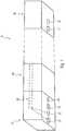
- control units 20, 30are arranged at the respective end regions of the light strip 10, these being particularly preferably arranged on the feed and feed-out modules (not shown) of the light strip 10.
- the sensor units 20, 30each include a presence sensor 21, 31 in order to detect whether there is a person in the detection area of the respective presence sensor 21, 31 and / or to detect the distance of a person to one of the presence sensors 21, 31.
- the sensor units 20, 30each include a daylight sensor 22, 32 in order to detect the daylight hitting them.
- the sensor unit 30is operated as a so-called master module 30, i.
- a processing and control unit for processing the parameters recorded by the sensors and for controlling the respective light strip modules 40is provided in the sensor unit 30.
- FIG 11shows a schematic view of a control of a light strip 10 for the case that one of the presence sensors 21, 31 detects the presence of a person, wherein, in contrast to that in FIG Figure 3 Activation shown is controlled by means of an additional sensor unit 60 which comprises at least one further presence sensor.
- an additional sensor unit 60which comprises at least one further presence sensor.
- the present inventionis not limited to the previously shown embodiment of a light strip system according to the invention, as long as they are covered by the subject matter of the following claims.
- the present inventionis not directed to the use of a certain type of sensors.
- the present inventionis not restricted to the fact that the sensor units or the processing and control unit or the master module is arranged at the end regions of the light strip 10.
Landscapes
- Circuit Arrangement For Electric Light Sources In General (AREA)
Description
Translated fromGermanDie vorliegende Erfindung betrifft ein Lichtbandsystem mit mehreren ansteuerbaren Lichtbandmodulen, die seriell miteinander verbunden sind und ein Lichtband bilden.The present invention relates to a light band system with several controllable light band modules which are connected to one another in series and form a light band.
Im Stand der Technik sind Lichtbandsysteme bekannt, die Lichtbänder umfassen, die jeweils mehrere meist längliche, hintereinander angeordnete und miteinander elektrisch und/oder mechanisch gekoppelte Lichtbandmodule umfassen.In the prior art, trunking systems are known which include trunking lights which each include a plurality of mostly elongated, one behind the other and electrically and / or mechanically coupled trunking modules.
Die einzelnen Lichtbandmodule weisen typischerweise jeweils ein Betriebsgerät auf und sind über dieses ansteuerbar, üblicherweise über eine zentrale Steuereinheit (beispielsweise eine zentrale Lichtsteueranlage). Zur eindeutigen Zuordnung und korrekten Ansteuerung der einzelnen Lichtbandmodule müssen diesen bei Inbetriebnahme des Lichtbandsystems eindeutige Moduladressen bzw. Leuchten-Adressen zugeordnet werden, mit Hilfe derer die Lichtsteueranlage die jeweiligen Lichtbandmodule später ansteuern kann. Typischerweise werden die Lichtbandmodule derartiger Lichtbandsysteme zunächst montiert und in einem nachfolgend Schritt an die elektrische Versorgung und an ein entsprechendes Bus-System (beispielsweise an ein sogenanntes DALI-System ("Digital Addressable Lightning Interface")) angeschlossen. Die Inbetriebnahme derartiger Lichtbandsysteme ist daher ein aufwendiger und kostenintensiver Prozess.The individual trunking modules typically each have an operating device and can be controlled via this, usually via a central control unit (for example a central lighting control system). For clear assignment and correct control of the individual trunking modules, these must be assigned unique module addresses or luminaire addresses when the trunking system is put into operation, with the help of which the lighting control system can later control the respective trunking modules. Typically, the trunking modules of such trunking systems are first mounted and connected in a subsequent step to the electrical supply and to a corresponding bus system (for example to a so-called DALI system ("Digital Addressable Lightning Interface")). The commissioning of such trunking systems is therefore a complex and cost-intensive process.
Darüber hinaus ist bei den bekannten Lichtbandsystemen eine Steuerung der Lichtabgabe durch die einzelnen Lichtbandmodule in Abhängigkeit des Tageslichtverlaufs vergleichsweise aufwendig gelöst. Üblicherweise wird hierfür eine Tageslichtmesseinheit an einer geeigneten Außenposition (meist am Gebäudedach) angeordnet, um den Tageslichtverlauf zu erfassen. Ferner wird für jeden Raum ein sogenannter Tageslichtkoeffizient ermittelt, so dass den jeweiligen Lichtbandmodulen ein korrespondierender Lichtabgabewert zugeordnet werden kann. Neben dem Nachteil, dass eine derartige Anpassung bzw. Einrichtung der einzelnen Lichtbandmodule nur von speziell hierfür ausgebildeten Personen durchgeführt werden kann, besteht der Nachteil, dass ein solches Lichtbandsystem statisch eingerichtet ist, d.h. eine flexible Anpassung der Lichtabgabe in Abhängigkeit der tatsächlichen Beleuchtungssituation ist nicht bzw. nur sehr umständlich möglich. Ferner ist es bekannt, Lichtbandsysteme mit einem sogenannten Anwesenheitssensor oder Bewegungssensor auszustatten, um zu erfassen, ob sich eine Person im Bereich des Lichtbandsystems befindet, so dass dieses eingeschaltet werden kann.In addition, in the known light band systems, controlling the light output by the individual light band modules as a function of the course of daylight is achieved in a comparatively complex manner. For this purpose, a daylight measuring unit is usually arranged in a suitable external position (mostly on the roof of the building) in order to record the course of daylight. In addition, a so-called daylight coefficient is determined for each room so that a corresponding light output value can be assigned to the respective light strip modules. Besides the disadvantage that such an adjustment or setting up the individual light strip modules can only be carried out by specially trained people, there is the disadvantage that such a light strip system is set up statically, ie flexible adaptation of the light output depending on the actual lighting situation is not possible or only possible with great difficulty. It is also known to equip trunking systems with a so-called presence sensor or motion sensor in order to detect whether a person is in the area of the trunking system so that it can be switched on.
Ausgehend von diesem Stand der Technik stellt sich die vorliegende Erfindung die Aufgabe, ein Lichtbandsystem bereitzustellen, mit dem die oben genannten Nachteile vermieden bzw. reduziert werden können. Insbesondere soll ein Lichtbandsystem bereitgestellt werden, durch das eine möglichst automatisierte Adressierung der Lichtbandmodule eines Lichtbands erfolgen kann, eine effizientere und flexiblere Anpassung der Lichtabgabe der einzelnen Lichtbandmodule an den jeweiligen Tageslichtverlauf ermöglicht wird und eine möglichst auf eine Person bezogene und somit wesentlich energieeffizientere Anwesenheitssteuerung ermöglicht wird.Based on this prior art, the present invention has the object of providing a light strip system with which the above-mentioned disadvantages can be avoided or reduced. In particular, a light strip system is to be provided by means of which the addressing of the light strip modules of a light strip can be as automated as possible, a more efficient and flexible adaptation of the light output of the individual light strip modules to the respective course of daylight is made possible and a presence control that is as much more energy-efficient as possible related to a person is made possible .
Diese und andere Aufgabe, die beim Lesen der folgenden Beschreibung nach genannt werden oder vom Fachmann erkannt werden können, werden durch einen Gegenstand der unabhängigen Ansprüche gelöst. Die abhängigen Ansprüche bilden dabei den zentralen Gedanken der vorliegenden Erfindung in besonders vorteilhafter Weise weiter.These and other objects, which are mentioned on reading the following description or can be recognized by the person skilled in the art, are achieved by the subject matter of the independent claims. The dependent claims develop the central concept of the present invention in a particularly advantageous manner.
Die Erfindung offenbart ein Lichtbandsystem gemäß Anspruch 1.The invention discloses a trunking system according to
Mit anderen Worten schlägt die vorliegende Erfindung vor, zwei Sensoreinheiten in einem Lichtband anzuordnen, wobei diese vorzugsweise an den Endbereichen des Lichtbands angeordnet sind, insbesondere in den Einspeise- und Ausspeisemodulen des Lichtbands, um an einer ersten Position des Lichtbands und an einer zweiten Position des Lichtbands entsprechende (Mess-)Parameter (beispielsweise Tageslichtparameter, Anwesenheitsparameter, Temperaturparameter, Feuchtigkeitsparameter, etc.) zu erfassen und basierend auf diesen erfassten Parametern, (Steuer-)Werte für eine individuelle Ansteuerung der zwischen den Sensoreinheiten angeordneten Lichtbandmodulen zu ermitteln bzw. zu berechnen, um diese Lichtbandmodule gemäß der ermittelten Werte individuell ansteuern zu können. Dadurch besteht die Möglichkeit, die jeweiligen Lichtbandmodule individuell an die tatsächliche Beleuchtungssituation bzw. an die tatsächlichen Beleuchtungsanforderungen anzupassen, so dass eine im Vergleich zum Stand der Technik wesentlich flexiblere und energieeffizientere Nutzung eines Lichtbandsystems möglich ist. Unter einem Lichtband im Sinne der vorliegenden Erfindung ist dabei eine serielle Anordnung der einzelnen Lichtbandmodule zu verstehen. Zwar bevorzugt allerdings nicht notwendig ist, dass die einzelnen Lichtbandmodule hierfür mechanisch miteinander verbunden sind oder in einem gemeinsamen Leuchtengehäuse angeordnet sind.In other words, the present invention proposes arranging two sensor units in a light band, these preferably being arranged at the end areas of the light band, in particular in the feed and output modules of the light band, in order to be able to use a first position of the light band and a second position of the (Measurement) parameters (for example daylight parameters, presence parameters, temperature parameters, humidity parameters, etc.) corresponding to the light band and, based on these recorded parameters, determine or calculate (control) values for an individual control of the light band modules arranged between the sensor units in order to be able to individually control these trunking modules according to the determined values. As a result, there is the possibility of adapting the respective trunking modules individually to the actual lighting situation or to the actual lighting requirements, so that a trunking system can be used in a significantly more flexible and energy-efficient manner compared to the prior art. In the context of the present invention, a light band is to be understood as a serial arrangement of the individual light band modules. Although it is preferable, it is not necessary that the individual light strip modules for this purpose are mechanically connected to one another or are arranged in a common lamp housing.
Vorzugsweise sind die Sensoreinheiten an den Endbereichen des Lichtbands angeordnet, insbesondere in den Einspeise- und Ausspeisemodulen des Lichtbands, wobei die zumindest eine Verarbeitungs- und Steuereinheit an einer der Sensoreinheit angeordnet oder in diese integriert ist. Durch die Integration einer Sensoreinheit mit der zumindest eine Verarbeitungs- und Steuereinheit kann ein sogenanntes Master-Modul bereitgestellt werden, in dem nicht nur die entsprechenden Sensormittel, sondern auch Mittel zur Verarbeitung der erfassten Parameter und Mittel zur Steuerung der einzelnen Lichtbandmodule angeordnet sind.The sensor units are preferably arranged at the end areas of the light band, in particular in the feed and exit modules of the light band, the at least one processing and control unit being arranged on or integrated into one of the sensor units. By integrating a sensor unit with the at least one processing and control unit, a so-called master module can be provided in which not only the corresponding sensor means, but also means for processing the recorded parameters and means for controlling the individual light strip modules are arranged.
Die Anordnung an den Einspeise- und Ausspeisemodulen des Lichtbands ist dabei besonders bevorzugt, da dadurch eine einfache Möglichkeit bereitgestellt werden kann, auch den Energieverbrauch des Lichtbands zu ermitteln. Diesbezüglich ist es besonders bevorzugt, dass zumindest in einer der Sensoreinheiten oder in der Verarbeitungs- und Steuereinheit Verbrauchserfassungsmittel vorgesehen sind, um den Energieverbrauch des Lichtbands zu erfassen.The arrangement on the infeed and outfeed modules of the light run is particularly preferred, since this makes it possible to provide a simple possibility of also determining the energy consumption of the light run. In this regard, it is particularly preferred that consumption recording means are provided in at least one of the sensor units or in the processing and control unit in order to record the energy consumption of the light strip.
Vorteilhafterweise ist die Verarbeitungs- und Steuereinheit eingerichtet, um die Anzahl der zwischen den Sensoreinheiten angeordneten Lichtbandmodule zu erfassen und den jeweiligen Lichtbandmodulen eine Moduladresse zur Ansteuerung durch die Verarbeitungs- und Steuereinheit zuzuordnen. Dabei ist es ganz besonders bevorzugt, dass die Verarbeitungs- und Steuereinheit (bzw. das Master-Modul) an einem Endbereich des Lichtbands angeordnet ist, so dass den jeweiligen Lichtbandmodulen eine Moduladresse durch eine automatische Weiteradressierung der seriell aneinander angeschlossenen Lichtbandmodule zugeordnet werden kann. Beispielsweise kann das benachbart zum Master-Module angeordnete Lichtbandmodul mit #1 adressiert werden, das benachbart zum Lichtbandmodul #1 angeordnete Lichtbandmodul mit #2 adressiert werden usw. bis alle Lichtbandmodule, die zwischen der ersten und der zweiten Sensoreinheit angeordnet sind, entsprechend weiteradressiert wurden. Mit anderen Worten ist es bevorzugt, dass die Verarbeitungs- und Steuereinheit bzw. das Master-Modul ein Signal an die jeweiligen Betriebsgeräte der seriell angeordneten Lichtbandmodule sendet, so dass dadurch einerseits die Anzahl der angeschlossenen Lichtbandmodule automatisch ermittelt werden kann und zudem die jeweiligen Lichtbandmodule adressiert bzw. weiteradressiert werden können.The processing and control unit is advantageously set up to detect the number of light strip modules arranged between the sensor units and to assign a module address to the respective light strip modules for activation by the processing and control unit. It is particularly preferred that the processing and control unit (or the master module) is arranged at an end area of the light band so that a module address can be assigned to the respective light band modules through automatic further addressing of the light band modules connected in series. For example, the trunking module arranged adjacent to the master module can be addressed with # 1, the trunking module arranged adjacent to the
Vorteilhafterweise umfasst zumindest eine der Sensoreinheiten und/oder die zumindest eine Verarbeitungs- und Steuereinheit zumindest eine Schnittstelle zur drahtlosen Kommunikation, beispielsweise ein WLAN-Modul. Durch eine solche Schnittstelle können Daten mit dem Lichtband (beispielsweise mittels einer App oder einem Tablet) ausgetauscht werden, so dass beispielsweise der Status des Lichtbands, Energieverbrauchswerte oder Ansteuereinstellungen übermittelt und ausgetauscht werden können.At least one of the sensor units and / or the at least one processing and control unit advantageously comprises at least one interface for wireless communication, for example a WLAN module. Such an interface allows data to be exchanged with the light strip (for example by means of an app or a tablet) so that, for example, the status of the light strip, energy consumption values or control settings can be transmitted and exchanged.
Ferner ist es bevorzugt, dass die Sensoreinheiten und die zumindest eine Verarbeitungs- und Steuereinheit mittels einer DALI-Verbindung ("Digital Addressable Lightning Interface") und/oder einer PLC-Verbindung ("Powerline Communication") miteinander verbunden sind. Dadurch können auf einfache Weise entsprechende Daten zwischen den Sensoreinheiten und der zumindest einen Verarbeitungs- und Steuereinheit bzw. dem Master-Modul ausgetauscht werden.It is further preferred that the sensor units and the at least one processing and control unit are connected to one another by means of a DALI connection (“Digital Addressable Lightning Interface”) and / or a PLC connection (“Powerline Communication”). In this way, corresponding data can be exchanged in a simple manner between the sensor units and the at least one processing and control unit or the master module.
Vorzugsweise berechnet die Verarbeitungs- und Steuereinheit die Werte für die individuelle Ansteuerung der zumindest zwischen den Sensoreinheiten angeordneten Lichtbandmodule mittels einer Interpolation, vorzugsweise einer linearen Interpolation. Beispielsweise kann anhand von erfassten Tageslichtparametern ein linearer Verlauf der Lichtabgabe (d.h. ein linearer Dimmverlauf) der Lichtbandmodule eingestellt werden. Möglich ist allerdings auch, dass die Verarbeitungs- und Steuereinheit die (Ansteuer-)Werte nicht berechnet werden, sondern hierfür vordefinierte Werte in der Verarbeitungs-und Steuereinheit hinterlegt werden.The processing and control unit preferably calculates the values for the individual control of the light strip modules arranged at least between the sensor units by means of an interpolation, preferably a linear interpolation. For example, a linear course of the light output (i.e. a linear dimming course) of the light strip modules can be set on the basis of recorded daylight parameters. It is also possible, however, for the processing and control unit not to calculate the (control) values, but rather for predefined values to be stored in the processing and control unit.
Vorteilhafterweise sind in der Verarbeitungs- und Steuereinheit die jeweiligen Längen der einzelnen adressierten Lichtbandmodule hinterlegt, so dass diese Längen bei der Ermittlung der Werte zu individuellen Ansteuerungen der jeweiligen Lichtbandmodule berücksichtigt werden können. Diesbezüglich ist es möglich, die Längen der Lichtbandmodule manuell einzugeben oder die Längen der Lichtbandmodule aus den Betriebsgeräten auszulesen, soweit diese dort hinterlegt sind.The respective lengths of the individually addressed light strip modules are advantageously stored in the processing and control unit, so that these lengths can be taken into account when determining the values for individual controls of the respective light strip modules. In this regard, it is possible to enter the lengths of the trunking modules manually or to read the lengths of the trunking modules from the operating devices, provided they are stored there.
Wie bereits ausgeführt, umfassen die Sensoreinheiten vorzugsweise jeweils zumindest einen Tageslichtsensor, um das jeweils auf diese treffende Tageslicht bzw. den entsprechenden Tageslichtanteil zu erfassen, so dass die Verarbeitungs- und Steuereinheit basierend auf den erfassten Tageslichtwerten individuelle Tageslichtparameter für das jeweilige Lichtbandmodule ermitteln und in den jeweiligen Lichtbandmodulen hinterlegen bzw. diese bei der Ansteuerung eines Lichtbandmoduls berücksichtigen kann. Dadurch besteht die Möglichkeit eine Ansteuerung der Lichtbandmodule entsprechend der tatsächlichen Tageslichtbedingungen vornehmen zu können, wobei die Lichtabgabe entlang des Lichtbands vorzugsweise durch eine lineare Interpolation ermittelt wird. Somit besteht bei einem solchen Lichtbandsystem auch keine Notwendigkeit mehr, dass eine speziell hierfür ausgebildete Person durch separate Messungen jeweilige Tageslichtkoeffizienten für jeden Raum ermitteln und in die jeweiligen Lichtbandmodule einspeisen muss.As already stated, the sensor units preferably each include at least one daylight sensor in order to detect the daylight or the corresponding amount of daylight that hits them, so that the processing and control unit can determine individual daylight parameters for the respective light strip modules based on the detected daylight values and in the can store the respective trunking modules or take these into account when controlling a trunking module. This makes it possible to control the light band modules in accordance with the actual daylight conditions, the light output along the light band preferably being determined by linear interpolation. With such a trunking system, there is no longer any need for a person specially trained for this to determine respective daylight coefficients for each room by means of separate measurements and to feed them into the respective trunking modules.
Ferner ist es bevorzugt, dass die Sensoreinheiten jeweils zumindest einen Anwesenheitssensor umfassen, um zu erfassen, ob sich im Erfassungsbereich zumindest eines Anwesenheitssensors eine Person befindet und/oder um die Entfernung einer Person zu einem der Anwesenheitssensoren zu erfassen. Wie bereits ausgeführt, werden bekannte Lichtbandsysteme bei Anwesenheit einer Person als Ganzes angesteuert, also auch in Bereichen mit hoher Lichtabgabe betrieben, in denen sich keine Personen aufhalten, was zu einem unnötig hohen Energieaufwand führt. Durch die Anordnung von zumindest zwei Anwesenheitssensoren besteht die Möglichkeit, ein jeweiliges Lichtband derart anzusteuern, dass nur in Bereichen, in denen Personen präsent sind, eine hohe Lichtabgabe bereitgestellt wird und die Lichtabgabe mit zunehmenden Abstand zur erfassten Person stufenweise oder linear abgeregelt wird. Als Anwesenheitssensoren werden dabei vorzugsweise Ultraschall- und/oder Infrarotsensoren eingesetzt.Furthermore, it is preferred that the sensor units each include at least one presence sensor in order to detect whether a person is located in the detection area of at least one presence sensor and / or to detect the distance of a person to one of the presence sensors. As already stated, known light line systems are controlled as a whole when a person is present, that is to say also operated in areas with a high level of light output, in which no people are present, which leads to an unnecessarily high expenditure of energy. The arrangement of at least two presence sensors makes it possible to control a respective light band in such a way that a high level of light output is provided only in areas in which people are present and the light output is gradually or linearly regulated with increasing distance from the person detected. Ultrasonic and / or infrared sensors are preferably used as presence sensors.
Erfasst der Anwesenheitssensor einer der Sensoreinheiten eine Person, kann beispielsweise das Lichtbandmodul, das benachbart zu diesem Anwesenheitssensor angeordnet ist, mit einer Lichtabgabe von 100% (bezogen auf die maximale Standardlichtabgabe) gesteuert werden, wobei die Lichtbandmodule mit zunehmender Entfernung mit geringerer Lichtabgabe betrieben werden, bis beispielsweise am letzten Lichtbandmodul eine Lichtabgabe von nur 80% eingestellt wird. Geht die von einem Anwesenheitssensor erfasste Person nunmehr in Richtung der zweiten Sensoreinheit (d.h. in Richtung des zweiten Anwesenheitssensors) kann das Lichtbandmodul quasi mit einer umgekehrten Lichtabgabe betrieben werden, d.h. das Lichtbandmodul, das benachbart zur zweiten Sensoreinheit angeordnet ist, wird nunmehr mit einer Lichtabgabe von 100% betrieben, wohingegen das Lichtbandmodul, das benachbart zum ersten Anwesenheitssensor angeordnet ist, nunmehr mit einer Lichtabgabe von 80% betrieben wird. Ein solcher Dimmverlauf kann dabei, beispielsweise in Abhängigkeit der Länge des Lichtbands, fest in der Verarbeitungs- und Steuereinheit hinterlegt werden. Ferner besteht auch die Möglichkeit einen jeweiligen Dimmverlauf über ein Eingabemittel (beispielsweise ein am Lichtband vorgesehener Dip-Switch oder über eine App) manuell anzupassen. Besteht das Lichtbandsystem aus mehreren Lichtbändern, kann durch die jeweiligen Sensoreinheiten der weiteren Lichtbänder eine korrespondierende Ansteuerung der Lichtbandmodule erfolgen, so dass eine Ansteuerung bereitgestellt werden kann, bei der die maximale Lichtabgabe einer sich bewegenden Person "folgt".If the presence sensor of one of the sensor units detects a person, the light band module, which is arranged adjacent to this presence sensor, can be controlled with a light output of 100% (based on the maximum standard light output), with the light band modules being operated with less light output as the distance increases, until, for example, a light output of only 80% is set on the last light strip module. It goes from one The presence sensor detected the person now in the direction of the second sensor unit (ie in the direction of the second presence sensor) the light band module can be operated with a reverse light output, ie the light band module, which is arranged adjacent to the second sensor unit, is now operated with a light output of 100%, whereas the light band module, which is arranged adjacent to the first presence sensor, is now operated with a light output of 80%. Such a dimming process can be permanently stored in the processing and control unit, for example as a function of the length of the light strip. Furthermore, there is also the possibility of manually adapting a respective dimming process via an input device (for example a dip switch provided on the light strip or via an app). If the light strip system consists of several light strips, a corresponding control of the light strip modules can be carried out by the respective sensor units of the further light strips, so that control can be provided in which the maximum light output "follows" a moving person.
Die Präsenzsteuerung wird dabei vorzugsweise mit den erfassten Parametern der Tageslichtsensoren gekoppelt, so dass bei der Präsenzsteuerung die Lichtabgabe in den Bereichen entsprechend reduziert werden kann, wenn in diesen Bereichen ausreichend Tageslicht gegeben ist.The presence control is preferably coupled with the recorded parameters of the daylight sensors so that the light output in the areas can be reduced accordingly in the presence control if there is sufficient daylight in these areas.
Vorzugsweise umfassen die Sensoreinheiten weitere Sensoren, beispielsweise Temperatursensoren, Feuchtigkeitssensoren, etc. Durch die Anordnung weiterer Sensoren besteht die Möglichkeit, ein erfindungsgemäßes Lichtbandsystem mehr oder weniger beliebig flexible ansteuern bzw. mehr oder weniger beliebige Beleuchtungsanforderungen erfüllen zu können.The sensor units preferably include further sensors, for example temperature sensors, humidity sensors, etc. By arranging further sensors there is the possibility of controlling a light strip system according to the invention in a more or less flexible manner or being able to meet more or less arbitrary lighting requirements.
Vorteilhafterweise ist zwischen der ersten Sensoreinheit und der zweiten Sensoreinheit zumindest eine weitere Sensoreinheit angeordnet. Eine derartige weitere Sensoreinheit wird besonders bevorzugt im mittleren Bereich des Lichtbands vorgesehen werden, um die jeweiligen Parameter zur Steuerung der Lichtbandmodule mit einer höheren Erfassungsdichte bereitstellen zu können, um dadurch einen besser an die jeweilige Situation angepassten Beleuchtungsverlauf bereitstellen zu können. Im Wesentlichen kann jedem Lichtbandmodul eine entsprechende Sensoreinheit zugeordnet werden bzw. in ein Lichtbandmodul integriert werden.At least one further sensor unit is advantageously arranged between the first sensor unit and the second sensor unit. Such a further sensor unit is particularly preferably provided in the middle area of the light band in order to be able to provide the respective parameters for controlling the light band modules with a higher detection density in order to be able to provide a lighting profile better adapted to the respective situation. Essentially, a corresponding sensor unit can be assigned to each light band module or integrated into a light band module.
Ferner besteht die Möglichkeit, in der weiteren Sensoreinheit nur bestimmte Sensoren vorzusehen (beispielsweise lediglich einen Präsenzsensor), um die Ansteuerung des Lichtbands nur hinsichtlich dieser Beleuchtungssituation zu verbessern.Furthermore, there is the possibility of only providing certain sensors in the further sensor unit (for example only one presence sensor) in order to improve the control of the light strip only with regard to this lighting situation.
Vorteilhafterweise sind die Lichtbandmodule des Lichtbands in einem durchgehenden Lichtbandgehäuse angeordnet, so dass die jeweiligen Lichtbandmodule, die Sensoreinheiten und die zumindest eine Verarbeitungs-und Steuereinheit für einen Betrachter nicht erkennbar sind. Dabei ist es besonders bevorzugt, dass die Sensoreinheiten und die Verarbeitungs- und Steuereinheit in einer Tragschiene des Lichtbandsystems angeordnet sind, vorzugsweise an den Einspeise- und Ausspeisemodulen des Lichtbands.The light band modules of the light band are advantageously arranged in a continuous light band housing so that the respective light band modules, the sensor units and the at least one processing and control unit cannot be seen by a viewer. It is particularly preferred here for the sensor units and the processing and control unit to be arranged in a support rail of the trunking system, preferably on the infeed and output modules of the trunking.
Vorteilhafterweise umfasst das Lichtbandsystem zumindest zwei separate Lichtbänder, die jeweils mit einer zentralen Steuereinheit verbunden sind, wobei den Lichtbändern jeweils eine Lichtbandadresse zur Ansteuerung durch die zentrale Steuereinheit zugeordnet ist. Somit muss die zentrale Steuereinheit nicht mehr die einzelnen Lichtbandmodule ansteuern, sondern nur noch ein jeweiliges Lichtband als Einheit, da eine jeweilige Ansteuerung der einzelnen Lichtbandmodule durch die jeweiligen Verarbeitungs- und Steuereinheiten bereitgestellt werden kann. Dadurch kann ein Lichtbandsystem mit mehreren Lichtbändern auf einfache Weise adressiert werden, da nicht mehr die einzelnen Lichtbandmodule manuell mit einer Moduladresse versehen und diese in der zentralen Steuereinheit hinterlegt werden müssen, sondern nur noch die jeweiligen Lichtbänder als Einheit adressiert und nur diese Lichtbandadressen in der zentralen Steuereinheit hinterlegt werden müssen, da eine Adressierung der jeweiligen Leuchtbandmodule eines Lichtbands automatisch durch die Verarbeitungs- und Steuereinheit erfolgen kann.The light strip system advantageously comprises at least two separate light strips which are each connected to a central control unit, the light strips each being assigned a light strip address for activation by the central control unit. The central control unit no longer has to control the individual light band modules, but only a respective light band as a unit, since a respective control of the individual light band modules can be provided by the respective processing and control units. This allows a trunking system with several trunking to be addressed in a simple manner, since the individual trunking modules no longer have to be manually assigned a module address and this must be stored in the central control unit, but only the respective trunking is addressed as a unit and only these trunking addresses in the central one Control unit must be stored, since an addressing of the respective light strip modules of a light strip can be done automatically by the processing and control unit.
Ein erfindungsgemäßes Lichtbandsystem ist vorzugsweise eingerichtet, um folgende Verfahrensschritte durchzuführen:
- Erfassen zumindest eines Parameters durch die jeweilige Sensoreinheit des Lichtbands;
- Übermitteln der erfassten Parameter an die Verarbeitungs- und Steuereinheit des Lichtbands (insbesondere an das Master-Modul);
- Ermitteln individueller Werte zur Ansteuerung der jeweiligen Lichtbandmodule basierend auf den erfassten und übermittelten Parametern; und
- individuelles Ansteuern der Lichtbandmodule gemäß der ermittelten Werte.
- Detecting at least one parameter by the respective sensor unit of the light strip;
- Transmission of the recorded parameters to the processing and control unit of the light strip (in particular to the master module);
- Determination of individual values for the control of the respective light strip modules based on the recorded and transmitted parameters; and
- Individual control of the trunking modules according to the determined values.
Nachfolgend wird eine detaillierte Beschreibung der Figuren gegeben. Darin zeigt:
Figur 1- eine schematische Ansicht eines Lichtbands;
Figur 2- eine schematische zur Steuerung des Lichtbands in Abhängigkeit des Tageslichts;
Figur 3- eine schematische Ansicht einer Steuerung des Lichtbands in Abhängigkeit einer erfassten Person, die sich unterhalb des Lichtbands bewegt; und
Figur 4- eine schematische Ansicht einer Steuerung des Lichtbands in Abhängigkeit einer erfassten Person, die sich im Bereich des Lichtbands bewegt, wobei in dem gezeigten Lichtband eine weitere Sensoreinheit vorgesehen ist.
- Figure 1
- a schematic view of a light band;
- Figure 2
- a schematic for controlling the light band as a function of daylight;
- Figure 3
- a schematic view of a control of the light band as a function of a detected person who moves below the light band; and
- Figure 4
- a schematic view of a control of the light band as a function of a detected person who is moving in the area of the light band, a further sensor unit being provided in the light band shown.
Wie in
Die Sensoreinheiten 20, 30 umfassen jeweils einen Anwesenheitssensor 21, 31, um zu erfassen, ob sich im Erfassungsbereich des jeweiligen Anwesenheitssensors 21, 31 eine Person befindet und/oder um die Entfernung einer Person zu einem der Anwesenheitssensoren 21, 31 zu erfassen. Darüber hinaus umfassen die Sensoreinheiten 20, 30 jeweils einen Tageslichtsensor 22, 32, um das jeweils auf diesen treffende Tageslicht zu erfassen.The
In der gezeigten bevorzugten Ausführungsform, umfasst die Sensoreinheit 20 weiterhin einen (optionalen) mechanischen Adressschalter 23, mit der eine Lichtbandadresse des Lichtbands 10 manuell eingestellt werden kann. Ferner kann an dieser Position eine (optionale) Stromverbrauchsmessung vorgenommen werden, beispielsweise über entsprechende Anschlüsse. Darüber hinaus umfasst die Sensoreinheit 20 eine (optionale) Schnittstelle zur drahtlosen Kommunikation 24, um beispielsweise Daten (beispielsweise der Status des Lichtbands, Energieverbrauchswerte oder Ansteuereinstellungen) mit einem Tablet oder einem Smartphone austauschen zu können.In the preferred embodiment shown, the
In der gezeigten bevorzugten Ausführungsform wird die Sensoreinheit 30 als sogenanntes Master-Modul 30 betrieben, d.h. in der Sensoreinheit 30 ist eine Verarbeitungs- und Steuereinheit zur Verarbeitung der durch die Sensoren aufgenommenen Parameter und zur Ansteuerung der jeweiligen Lichtbandmodulen 40 vorgesehen.In the preferred embodiment shown, the
Die Sensoreinheiten 20, 30, die Verarbeitungs- und Steuereinheit und die Lichtbandmodule 40 (genauer deren Betriebsgeräte) sind vorzugsweise mittels einer internen Verdrahtung 50, vorzugsweise eine interne DALI-Verdrahtung miteinander verbunden, so dass ein entsprechender Datenaustausch (d.h. zumindest ein Austausch der erfassten Parameter und der Steuersignale) zwischen den Sensoreinheiten 20, 30, der Verarbeitungs- und Steuereinheit und den jeweiligen Lichtbandmodulen 40 erfolgen kann.The
Durch die Verarbeitungs- und Steuereinheit bzw. durch das Master-Modul 30 kann nunmehr eine Adressierung der jeweiligen Lichtbandmodule 40 derart vorgenommen werden, dass eine Verbindung mit den jeweiligen Betriebsgeräten der Lichtbandmodule 40 hergestellt wird und die jeweiligen Lichtbandmodule 40 ausgehend vom Master-Modul 30 automatisch fortlaufend (weiter-)adressiert werden. Beispielsweise kann das Lichtbandmodul 40, das benachbart zum Master-Modul 30 vorliegt mit der Adresse #1 versehen werden, das zu diesem benachbarten Lichtbandmodul 40 mit der Adresse #2, usw. bis das Ende des Lichtbands 10 erreicht ist. Somit können mit Inbetriebnahme des Lichtbands 10 alle jeweiligen Lichtbandmodule 40 automatisch mit einer entsprechenden Moduladresse versehen werden, so dass diese durch die Verarbeitungs- und Steuereinheit bzw. durch das Master-Modul 30 entsprechend ansteuerbar sind.The processing and control unit or the
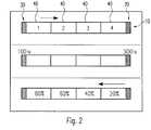
Wie in
Die angegebenen Werte für die Lichtabgabe für die verschiedenen Verläufe sind dabei lediglich beispielhaft und können im Master-Modul 30 fest hinterlegt werden bzw. über Eingabemittel (beispielsweise einen Dip-Switch oder über eine drahtlose Kommunikation, beispielsweise über ein Smartphone oder Tablet) geändert werden. Ferner besteht die Möglichkeit am Master-Modul 30 (d.h. vorzugsweise am Einspeisemodul) einen Überspannungsschutz für das gesamte Lichtband 10 bereitzustellen. Wie oben bereits ausgeführt, besteht die Möglichkeit, dass an einer der Sensoreinheiten 20, 30 ferner Verbrauchserfassungsmittel vorgesehen sind, um den Energieverbrauch des Lichtbands 10 zu erfassen.The specified values for the light output for the various courses are only exemplary and can be permanently stored in the
Die vorliegende Erfindung ist nicht auf das vorhergehend gezeigte Ausführungsbeispiel eines erfindungsgemäßen Lichtbandsystems beschränkt, solange sie vom Gegenstand der folgenden Ansprüche umfasst sind. Insbesondere ist die vorliegende Erfindung nicht auf den Einsatz einer bestimmten Art von Sensoren beschränkt. Darüber hinaus ist die vorliegende Erfindung nicht darauf beschränkt, dass die Sensoreinheiten bzw. die Verarbeitungs- und Steuereinheit oder das Master-Modul an den Endbereichen des Lichtbands 10 angeordnet wird.The present invention is not limited to the previously shown embodiment of a light strip system according to the invention, as long as they are covered by the subject matter of the following claims. In particular, the present invention is not directed to the use of a certain type of sensors. In addition, the present invention is not restricted to the fact that the sensor units or the processing and control unit or the master module is arranged at the end regions of the
Claims (14)
- Light strip system comprising:- multiple controllable light strip modules (40) serially connected to each other to form a light strip (10);- at least one first sensor unit (20) arranged at a first position on the light strip (10) and a second sensor unit (30) arranged at a second position on the light strip (10),characterized in that at least two controllable light strip modules (40) are arranged between the sensor units (20, 30);- at least one processing and control unit which is connected to the sensor units (20, 30) in such a way that at least one parameter respectively detected by the sensor units (20, 30) can be transmitted to the processing and control unit, and wherein the processing and control unit is connected at least to the light strip modules (40) arranged between the sensor units (20, 30) in order to control them;- wherein the at least one processing and control unit determines, on the basis of the parameters detected by the sensor units (20, 30), values for an individual control of at least the light strip modules (40) arranged between the sensor units (20, 30) and individually controls at least these light strip modules (40) according to the determined values,- wherein the at least one processing and control unit is arranged on or integrated into one of the sensor units (20, 30) and forms a master module (30).
- Light strip system according to Claim 1, wherein the sensor units (20, 30) are arranged at the end regions of the light strip (10), in particular on/in the feed and discharge modules of the light strip (10).
- Light strip system according to Claim 1 or 2, wherein the processing and control unit is configured to detect the number of light strip modules (40) arranged between the sensor units (20, 30) and to assign the respective light strip modules (40) a module address for control by the processing and control unit.
- Light strip system according to any one of the preceding claims, wherein at least one of the sensor units (20, 30) and/or the at least one processing and control unit comprises at least one interface for wireless communication (24), and/or
wherein the sensor units (20, 30) and the at least one processing and control unit are connected to each other by means of a DALI connection ("Digitally Addressable Lighting Interface," 50) and/or a PLC connection ("Powerline Communication"). - Light strip system according to any one of the preceding claims, wherein the processing and control unit determines, by means of a linear interpolation, the values for the individual control of at least the light strip modules (40) arranged between the sensor units (20, 30).
- Light strip system according to any one of the preceding claims, wherein the respective lengths of the individual light strip modules (40) are stored in the processing and control unit and are taken into account when the values for the individual control of the respective light strip modules (40) are determined.
- Light strip system according to any one of the preceding claims,• wherein the sensor units (20, 30) each comprise at least one daylight sensor (22, 32) in order to detect the daylight incident thereon in each case so that the processing and control unit can, on the basis of the detected daylight values, determine individual daylight parameters for the respective light strip module (40) and store them in the respective light strip module (40) or take them into account when controlling a respective light strip module (40), and/or• wherein the sensor units (20, 30) each comprise at least one presence sensor (21, 31) in order to detect whether a person is in the detection area of at least one presence sensor (21, 31) and/or to detect the distance of a person from one of the presence sensors (21, 31),∘ wherein the presence sensors (21, 31) are preferably provided by ultrasound and/or infrared sensors, and/or∘ wherein the processing and control unit is preferably configured to control the respective light strip modules (40) in such a way when a person is detected that the light output of the respective light strip modules (40) decreases stepwise or linearly as the distance from the detected person increases.
- Light strip system according to any one of the preceding claims, wherein the sensor units (20, 30) each comprise at least one temperature sensor or one humidity sensor.
- Light strip system according to Claim 7 or 8, wherein the processing and control unit is configured to determine the values for the individual control of the respective light strip modules (40) at least on the basis of the detected parameters of the daylight sensors (22, 32) and of the presence sensors (21, 31).
- Light strip system according to any one of the preceding claims, wherein at least one further sensor unit (60) is arranged between the first sensor unit (20) and the second sensor unit (30).
- Light strip system according to any one of the previous claims, wherein at least one of the sensor units (20, 30, 60) or the processing or control unit comprises consumption detection means for detecting the energy consumption of the light strip (10).
- Light strip system according to any one of the preceding claims, wherein the light strip modules (40) of a light strip (10) are arranged in a continuous light strip housing.
- Light strip system according to any one of the preceding claims, wherein the light strip system comprises at least two separate light strips (10) which are connected to a central control unit, wherein the light strips (10) are each assigned a light strip address for control by the central control unit.
- Light strip system according to any one of the preceding claims, wherein the light strip system is configured to perform the following method steps:- detecting at least one parameter by means of the respective sensor unit (20, 30) of the light strip (10);- transmitting the detected parameters to the processing and control unit of the light strip (10);- determining individual values for controlling the respective light strip modules (40) on the basis of the detected and transmitted parameters; and- individually controlling the light strip modules (40) according to the determined values.
Applications Claiming Priority (1)
| Application Number | Priority Date | Filing Date | Title |
|---|---|---|---|
| DE202016100586.8UDE202016100586U1 (en) | 2016-02-05 | 2016-02-05 | Trunking system with several controllable light band modules |
Publications (2)
| Publication Number | Publication Date |
|---|---|
| EP3203814A1 EP3203814A1 (en) | 2017-08-09 |
| EP3203814B1true EP3203814B1 (en) | 2020-08-19 |
Family
ID=57944287
Family Applications (1)
| Application Number | Title | Priority Date | Filing Date |
|---|---|---|---|
| EP17153448.0AActiveEP3203814B1 (en) | 2016-02-05 | 2017-01-27 | Light strip system with multiple controllable light strip modules |
Country Status (3)
| Country | Link |
|---|---|
| EP (1) | EP3203814B1 (en) |
| AT (1) | AT16240U1 (en) |
| DE (1) | DE202016100586U1 (en) |
Families Citing this family (3)
| Publication number | Priority date | Publication date | Assignee | Title |
|---|---|---|---|---|
| DE102019103889A1 (en)* | 2018-12-06 | 2020-06-10 | Siteco Gmbh | Coupling and uncoupling of data and data transport via electrical supply lines for lighting systems |
| DE202019104854U1 (en) | 2019-09-03 | 2020-12-07 | Zumtobel Lighting Gmbh | Continuous-row lighting system with data transmission function |
| EP3800792B1 (en) | 2019-10-02 | 2022-08-03 | Zumtobel Lighting GmbH | Communication adaptor for a light trunking system, light trunking system comprising at least two such communication adaptors, and method for communicating data over such a light trunking system |
Family Cites Families (13)
| Publication number | Priority date | Publication date | Assignee | Title |
|---|---|---|---|---|
| JPH07263151A (en)* | 1994-03-28 | 1995-10-13 | Matsushita Electric Works Ltd | Lighting control device |
| US5945789A (en)* | 1998-06-01 | 1999-08-31 | Chou; Tsung-Ming | Two-wire display lighting control structure |
| DE50311772D1 (en)* | 2002-10-09 | 2009-09-17 | Manfred Kluth | Lighting device with sensors |
| US7723926B2 (en)* | 2006-05-15 | 2010-05-25 | Supertex, Inc. | Shunting type PWM dimming circuit for individually controlling brightness of series connected LEDS operated at constant current and method therefor |
| JP5295106B2 (en)* | 2006-06-30 | 2013-09-18 | コーニンクレッカ フィリップス エレクトロニクス エヌ ヴィ | Device and method for controlling a lighting system with proximity detection of spotlight control device and spotlight control device |
| DE102010003597A1 (en)* | 2010-04-01 | 2011-10-06 | Tridonic Gmbh & Co Kg | Mains voltage transmission branch of an interface of a control device for lamps |
| JP2012028015A (en)* | 2010-07-20 | 2012-02-09 | Toshiba Corp | Illumination control system and illumination control method |
| JP6113417B2 (en)* | 2011-04-22 | 2017-04-12 | アイリスオーヤマ株式会社 | LED lamp |
| DE102011081097A1 (en)* | 2011-08-17 | 2013-02-21 | Siemens Aktiengesellschaft | Method for controlling and regulating a lighting system |
| US9392651B2 (en)* | 2012-04-11 | 2016-07-12 | Koninklijke Philips N.V. | Lighting methods and apparatus with selectively applied face lighting component |
| US9155166B2 (en)* | 2012-12-18 | 2015-10-06 | Cree, Inc. | Efficient routing tables for lighting networks |
| WO2014108817A1 (en)* | 2013-01-08 | 2014-07-17 | Koninklijke Philips N.V. | Method of assigning lighting devices to a group |
| DE102013203879B4 (en)* | 2013-03-07 | 2025-08-28 | Zumtobel Lighting Gmbh | Method and system for controlling a group of luminaires or controllable sub-units of a luminaire |
- 2016
- 2016-02-05DEDE202016100586.8Upatent/DE202016100586U1/ennot_activeExpired - Lifetime
- 2016-04-07ATATGM76/2016Upatent/AT16240U1/ennot_activeIP Right Cessation
- 2017
- 2017-01-27EPEP17153448.0Apatent/EP3203814B1/enactiveActive
Non-Patent Citations (1)
| Title |
|---|
| None* |
Also Published As
| Publication number | Publication date |
|---|---|
| AT16240U1 (en) | 2019-05-15 |
| EP3203814A1 (en) | 2017-08-09 |
| DE202016100586U1 (en) | 2017-05-10 |
Similar Documents
| Publication | Publication Date | Title |
|---|---|---|
| EP2560464B1 (en) | Method for controlling and regulating a light system | |
| EP3203814B1 (en) | Light strip system with multiple controllable light strip modules | |
| EP2676531B1 (en) | Combined sensor/emergency light unit for a lighting system | |
| DE102004018343B4 (en) | lighting system | |
| DE102008062674B3 (en) | Method for controlling the radiation behavior of luminaires in an arrangement of a plurality of luminaires and arrangement of a plurality of luminaires | |
| AT509035A1 (en) | LIGHTING DEVICE AND LIGHTING SYSTEM | |
| DE102012205964A1 (en) | Lighting system and control unit for this | |
| EP3268823B1 (en) | Device and method for controlling height-adjustable tables | |
| DE202006020968U1 (en) | Dimming of lamp operating devices to predefined levels | |
| DE102004043197A1 (en) | Control process for a lighting unit with many light modules has control units and central control transmitting a control data stream that can be changed individually | |
| DE102014103197A1 (en) | Luminaire for illuminating a building area, in particular an office | |
| DE29818609U1 (en) | Arrangement of boards for the creation of light-emitting diode lighting units | |
| EP2989696B1 (en) | Support rail for forming a lighting strip system and lighting strip system | |
| WO2005023717A1 (en) | Device for the uv treatment of flowing fluids | |
| AT16808U1 (en) | Arrangement for lighting | |
| DE10149261A1 (en) | Control device for flashlight system at airports | |
| EP2779801A2 (en) | Lighting system and method for controlling a lighting system | |
| DE102019009019A1 (en) | Curtain device for a building facade and method for providing a building facade with curtain devices, a building and also a method for operating an assembly of a plurality of curtain devices arranged on a building facade and coupled to one another in pairs | |
| DE2750027C2 (en) | Floor distributors for heating systems | |
| DE102013015814A1 (en) | Method and device for configuring ballasts for lamp modules | |
| AT14574U1 (en) | Sensor for motion detection | |
| DE102012103229B4 (en) | Lighting device with an operating and control device and at least one electronically connected LED light source with at least one LED | |
| DE20300022U1 (en) | lamp | |
| DE102008035785A1 (en) | Actuators e.g. emergency light, addressing method for room of e.g. house, involves identifying selected actuator based on measured line distance regarding position in assembly plan, and transmitting operating address to actuator | |
| DE29701066U1 (en) | Lighting system for a traffic area |
Legal Events
| Date | Code | Title | Description |
|---|---|---|---|
| PUAI | Public reference made under article 153(3) epc to a published international application that has entered the european phase | Free format text:ORIGINAL CODE: 0009012 | |
| STAA | Information on the status of an ep patent application or granted ep patent | Free format text:STATUS: THE APPLICATION HAS BEEN PUBLISHED | |
| AK | Designated contracting states | Kind code of ref document:A1 Designated state(s):AL AT BE BG CH CY CZ DE DK EE ES FI FR GB GR HR HU IE IS IT LI LT LU LV MC MK MT NL NO PL PT RO RS SE SI SK SM TR | |
| AX | Request for extension of the european patent | Extension state:BA ME | |
| STAA | Information on the status of an ep patent application or granted ep patent | Free format text:STATUS: REQUEST FOR EXAMINATION WAS MADE | |
| 17P | Request for examination filed | Effective date:20171208 | |
| RBV | Designated contracting states (corrected) | Designated state(s):AL AT BE BG CH CY CZ DE DK EE ES FI FR GB GR HR HU IE IS IT LI LT LU LV MC MK MT NL NO PL PT RO RS SE SI SK SM TR | |
| REG | Reference to a national code | Ref country code:DE Ref legal event code:R079 Ref document number:502017006775 Country of ref document:DE Free format text:PREVIOUS MAIN CLASS: H05B0037020000 Ipc:H05B0047100000 | |
| RIC1 | Information provided on ipc code assigned before grant | Ipc:H05B 47/10 20200101AFI20200306BHEP | |
| GRAP | Despatch of communication of intention to grant a patent | Free format text:ORIGINAL CODE: EPIDOSNIGR1 | |
| STAA | Information on the status of an ep patent application or granted ep patent | Free format text:STATUS: GRANT OF PATENT IS INTENDED | |
| INTG | Intention to grant announced | Effective date:20200515 | |
| GRAS | Grant fee paid | Free format text:ORIGINAL CODE: EPIDOSNIGR3 | |
| GRAA | (expected) grant | Free format text:ORIGINAL CODE: 0009210 | |
| STAA | Information on the status of an ep patent application or granted ep patent | Free format text:STATUS: THE PATENT HAS BEEN GRANTED | |
| AK | Designated contracting states | Kind code of ref document:B1 Designated state(s):AL AT BE BG CH CY CZ DE DK EE ES FI FR GB GR HR HU IE IS IT LI LT LU LV MC MK MT NL NO PL PT RO RS SE SI SK SM TR | |
| REG | Reference to a national code | Ref country code:CH Ref legal event code:EP | |
| REG | Reference to a national code | Ref country code:DE Ref legal event code:R096 Ref document number:502017006775 Country of ref document:DE | |
| REG | Reference to a national code | Ref country code:AT Ref legal event code:REF Ref document number:1305422 Country of ref document:AT Kind code of ref document:T Effective date:20200915 | |
| REG | Reference to a national code | Ref country code:IE Ref legal event code:FG4D Free format text:LANGUAGE OF EP DOCUMENT: GERMAN | |
| REG | Reference to a national code | Ref country code:LT Ref legal event code:MG4D | |
| REG | Reference to a national code | Ref country code:NL Ref legal event code:MP Effective date:20200819 | |
| PG25 | Lapsed in a contracting state [announced via postgrant information from national office to epo] | Ref country code:HR Free format text:LAPSE BECAUSE OF FAILURE TO SUBMIT A TRANSLATION OF THE DESCRIPTION OR TO PAY THE FEE WITHIN THE PRESCRIBED TIME-LIMIT Effective date:20200819 Ref country code:LT Free format text:LAPSE BECAUSE OF FAILURE TO SUBMIT A TRANSLATION OF THE DESCRIPTION OR TO PAY THE FEE WITHIN THE PRESCRIBED TIME-LIMIT Effective date:20200819 Ref country code:GR Free format text:LAPSE BECAUSE OF FAILURE TO SUBMIT A TRANSLATION OF THE DESCRIPTION OR TO PAY THE FEE WITHIN THE PRESCRIBED TIME-LIMIT Effective date:20201120 Ref country code:FI Free format text:LAPSE BECAUSE OF FAILURE TO SUBMIT A TRANSLATION OF THE DESCRIPTION OR TO PAY THE FEE WITHIN THE PRESCRIBED TIME-LIMIT Effective date:20200819 Ref country code:PT Free format text:LAPSE BECAUSE OF FAILURE TO SUBMIT A TRANSLATION OF THE DESCRIPTION OR TO PAY THE FEE WITHIN THE PRESCRIBED TIME-LIMIT Effective date:20201221 Ref country code:SE Free format text:LAPSE BECAUSE OF FAILURE TO SUBMIT A TRANSLATION OF THE DESCRIPTION OR TO PAY THE FEE WITHIN THE PRESCRIBED TIME-LIMIT Effective date:20200819 Ref country code:BG Free format text:LAPSE BECAUSE OF FAILURE TO SUBMIT A TRANSLATION OF THE DESCRIPTION OR TO PAY THE FEE WITHIN THE PRESCRIBED TIME-LIMIT Effective date:20201119 Ref country code:NO Free format text:LAPSE BECAUSE OF FAILURE TO SUBMIT A TRANSLATION OF THE DESCRIPTION OR TO PAY THE FEE WITHIN THE PRESCRIBED TIME-LIMIT Effective date:20201119 | |
| PG25 | Lapsed in a contracting state [announced via postgrant information from national office to epo] | Ref country code:IS Free format text:LAPSE BECAUSE OF FAILURE TO SUBMIT A TRANSLATION OF THE DESCRIPTION OR TO PAY THE FEE WITHIN THE PRESCRIBED TIME-LIMIT Effective date:20201219 Ref country code:NL Free format text:LAPSE BECAUSE OF FAILURE TO SUBMIT A TRANSLATION OF THE DESCRIPTION OR TO PAY THE FEE WITHIN THE PRESCRIBED TIME-LIMIT Effective date:20200819 Ref country code:RS Free format text:LAPSE BECAUSE OF FAILURE TO SUBMIT A TRANSLATION OF THE DESCRIPTION OR TO PAY THE FEE WITHIN THE PRESCRIBED TIME-LIMIT Effective date:20200819 Ref country code:PL Free format text:LAPSE BECAUSE OF FAILURE TO SUBMIT A TRANSLATION OF THE DESCRIPTION OR TO PAY THE FEE WITHIN THE PRESCRIBED TIME-LIMIT Effective date:20200819 Ref country code:LV Free format text:LAPSE BECAUSE OF FAILURE TO SUBMIT A TRANSLATION OF THE DESCRIPTION OR TO PAY THE FEE WITHIN THE PRESCRIBED TIME-LIMIT Effective date:20200819 | |
| PG25 | Lapsed in a contracting state [announced via postgrant information from national office to epo] | Ref country code:SM Free format text:LAPSE BECAUSE OF FAILURE TO SUBMIT A TRANSLATION OF THE DESCRIPTION OR TO PAY THE FEE WITHIN THE PRESCRIBED TIME-LIMIT Effective date:20200819 Ref country code:EE Free format text:LAPSE BECAUSE OF FAILURE TO SUBMIT A TRANSLATION OF THE DESCRIPTION OR TO PAY THE FEE WITHIN THE PRESCRIBED TIME-LIMIT Effective date:20200819 Ref country code:RO Free format text:LAPSE BECAUSE OF FAILURE TO SUBMIT A TRANSLATION OF THE DESCRIPTION OR TO PAY THE FEE WITHIN THE PRESCRIBED TIME-LIMIT Effective date:20200819 Ref country code:DK Free format text:LAPSE BECAUSE OF FAILURE TO SUBMIT A TRANSLATION OF THE DESCRIPTION OR TO PAY THE FEE WITHIN THE PRESCRIBED TIME-LIMIT Effective date:20200819 Ref country code:CZ Free format text:LAPSE BECAUSE OF FAILURE TO SUBMIT A TRANSLATION OF THE DESCRIPTION OR TO PAY THE FEE WITHIN THE PRESCRIBED TIME-LIMIT Effective date:20200819 | |
| REG | Reference to a national code | Ref country code:DE Ref legal event code:R097 Ref document number:502017006775 Country of ref document:DE | |
| PG25 | Lapsed in a contracting state [announced via postgrant information from national office to epo] | Ref country code:AL Free format text:LAPSE BECAUSE OF FAILURE TO SUBMIT A TRANSLATION OF THE DESCRIPTION OR TO PAY THE FEE WITHIN THE PRESCRIBED TIME-LIMIT Effective date:20200819 Ref country code:ES Free format text:LAPSE BECAUSE OF FAILURE TO SUBMIT A TRANSLATION OF THE DESCRIPTION OR TO PAY THE FEE WITHIN THE PRESCRIBED TIME-LIMIT Effective date:20200819 | |
| PLBE | No opposition filed within time limit | Free format text:ORIGINAL CODE: 0009261 | |
| STAA | Information on the status of an ep patent application or granted ep patent | Free format text:STATUS: NO OPPOSITION FILED WITHIN TIME LIMIT | |
| PG25 | Lapsed in a contracting state [announced via postgrant information from national office to epo] | Ref country code:SK Free format text:LAPSE BECAUSE OF FAILURE TO SUBMIT A TRANSLATION OF THE DESCRIPTION OR TO PAY THE FEE WITHIN THE PRESCRIBED TIME-LIMIT Effective date:20200819 | |
| 26N | No opposition filed | Effective date:20210520 | |
| PG25 | Lapsed in a contracting state [announced via postgrant information from national office to epo] | Ref country code:IT Free format text:LAPSE BECAUSE OF FAILURE TO SUBMIT A TRANSLATION OF THE DESCRIPTION OR TO PAY THE FEE WITHIN THE PRESCRIBED TIME-LIMIT Effective date:20200819 | |
| PG25 | Lapsed in a contracting state [announced via postgrant information from national office to epo] | Ref country code:SI Free format text:LAPSE BECAUSE OF FAILURE TO SUBMIT A TRANSLATION OF THE DESCRIPTION OR TO PAY THE FEE WITHIN THE PRESCRIBED TIME-LIMIT Effective date:20200819 Ref country code:MC Free format text:LAPSE BECAUSE OF FAILURE TO SUBMIT A TRANSLATION OF THE DESCRIPTION OR TO PAY THE FEE WITHIN THE PRESCRIBED TIME-LIMIT Effective date:20200819 | |
| PG25 | Lapsed in a contracting state [announced via postgrant information from national office to epo] | Ref country code:LU Free format text:LAPSE BECAUSE OF NON-PAYMENT OF DUE FEES Effective date:20210127 | |
| REG | Reference to a national code | Ref country code:BE Ref legal event code:MM Effective date:20210131 | |
| PG25 | Lapsed in a contracting state [announced via postgrant information from national office to epo] | Ref country code:IE Free format text:LAPSE BECAUSE OF NON-PAYMENT OF DUE FEES Effective date:20210127 | |
| PG25 | Lapsed in a contracting state [announced via postgrant information from national office to epo] | Ref country code:BE Free format text:LAPSE BECAUSE OF NON-PAYMENT OF DUE FEES Effective date:20210131 | |
| PGFP | Annual fee paid to national office [announced via postgrant information from national office to epo] | Ref country code:AT Payment date:20230118 Year of fee payment:7 | |
| PG25 | Lapsed in a contracting state [announced via postgrant information from national office to epo] | Ref country code:HU Free format text:LAPSE BECAUSE OF FAILURE TO SUBMIT A TRANSLATION OF THE DESCRIPTION OR TO PAY THE FEE WITHIN THE PRESCRIBED TIME-LIMIT; INVALID AB INITIO Effective date:20170127 | |
| PG25 | Lapsed in a contracting state [announced via postgrant information from national office to epo] | Ref country code:CY Free format text:LAPSE BECAUSE OF FAILURE TO SUBMIT A TRANSLATION OF THE DESCRIPTION OR TO PAY THE FEE WITHIN THE PRESCRIBED TIME-LIMIT Effective date:20200819 | |
| P01 | Opt-out of the competence of the unified patent court (upc) registered | Effective date:20230530 | |
| PG25 | Lapsed in a contracting state [announced via postgrant information from national office to epo] | Ref country code:MK Free format text:LAPSE BECAUSE OF FAILURE TO SUBMIT A TRANSLATION OF THE DESCRIPTION OR TO PAY THE FEE WITHIN THE PRESCRIBED TIME-LIMIT Effective date:20200819 | |
| REG | Reference to a national code | Ref country code:AT Ref legal event code:MM01 Ref document number:1305422 Country of ref document:AT Kind code of ref document:T Effective date:20240127 | |
| PG25 | Lapsed in a contracting state [announced via postgrant information from national office to epo] | Ref country code:MT Free format text:LAPSE BECAUSE OF FAILURE TO SUBMIT A TRANSLATION OF THE DESCRIPTION OR TO PAY THE FEE WITHIN THE PRESCRIBED TIME-LIMIT Effective date:20200819 | |
| PG25 | Lapsed in a contracting state [announced via postgrant information from national office to epo] | Ref country code:AT Free format text:LAPSE BECAUSE OF NON-PAYMENT OF DUE FEES Effective date:20240127 | |
| PG25 | Lapsed in a contracting state [announced via postgrant information from national office to epo] | Ref country code:AT Free format text:LAPSE BECAUSE OF NON-PAYMENT OF DUE FEES Effective date:20240127 | |
| REG | Reference to a national code | Ref country code:DE Ref legal event code:R084 Ref document number:502017006775 Country of ref document:DE | |
| PGFP | Annual fee paid to national office [announced via postgrant information from national office to epo] | Ref country code:DE Payment date:20250129 Year of fee payment:9 | |
| PGFP | Annual fee paid to national office [announced via postgrant information from national office to epo] | Ref country code:CH Payment date:20250201 Year of fee payment:9 | |
| PGFP | Annual fee paid to national office [announced via postgrant information from national office to epo] | Ref country code:FR Payment date:20250127 Year of fee payment:9 | |
| PGFP | Annual fee paid to national office [announced via postgrant information from national office to epo] | Ref country code:GB Payment date:20250121 Year of fee payment:9 |