EP3202358B1 - Catheter with irrigated tip electrode with porous substrate and high density surface micro-electrodes - Google Patents
Catheter with irrigated tip electrode with porous substrate and high density surface micro-electrodesDownload PDFInfo
- Publication number
- EP3202358B1 EP3202358B1EP17153207.0AEP17153207AEP3202358B1EP 3202358 B1EP3202358 B1EP 3202358B1EP 17153207 AEP17153207 AEP 17153207AEP 3202358 B1EP3202358 B1EP 3202358B1
- Authority
- EP
- European Patent Office
- Prior art keywords
- catheter
- porous substrate
- electrode
- chamber
- electrodes
- Prior art date
- Legal status (The legal status is an assumption and is not a legal conclusion. Google has not performed a legal analysis and makes no representation as to the accuracy of the status listed.)
- Active
Links
Images


Classifications
- A—HUMAN NECESSITIES
- A61—MEDICAL OR VETERINARY SCIENCE; HYGIENE
- A61B—DIAGNOSIS; SURGERY; IDENTIFICATION
- A61B18/00—Surgical instruments, devices or methods for transferring non-mechanical forms of energy to or from the body
- A61B18/04—Surgical instruments, devices or methods for transferring non-mechanical forms of energy to or from the body by heating
- A61B18/12—Surgical instruments, devices or methods for transferring non-mechanical forms of energy to or from the body by heating by passing a current through the tissue to be heated, e.g. high-frequency current
- A61B18/14—Probes or electrodes therefor
- A61B18/1492—Probes or electrodes therefor having a flexible, catheter-like structure, e.g. for heart ablation
- A—HUMAN NECESSITIES
- A61—MEDICAL OR VETERINARY SCIENCE; HYGIENE
- A61B—DIAGNOSIS; SURGERY; IDENTIFICATION
- A61B18/00—Surgical instruments, devices or methods for transferring non-mechanical forms of energy to or from the body
- A61B18/04—Surgical instruments, devices or methods for transferring non-mechanical forms of energy to or from the body by heating
- A61B18/12—Surgical instruments, devices or methods for transferring non-mechanical forms of energy to or from the body by heating by passing a current through the tissue to be heated, e.g. high-frequency current
- A61B18/14—Probes or electrodes therefor
- A—HUMAN NECESSITIES
- A61—MEDICAL OR VETERINARY SCIENCE; HYGIENE
- A61B—DIAGNOSIS; SURGERY; IDENTIFICATION
- A61B5/00—Measuring for diagnostic purposes; Identification of persons
- A61B5/24—Detecting, measuring or recording bioelectric or biomagnetic signals of the body or parts thereof
- A61B5/25—Bioelectric electrodes therefor
- A61B5/279—Bioelectric electrodes therefor specially adapted for particular uses
- A61B5/28—Bioelectric electrodes therefor specially adapted for particular uses for electrocardiography [ECG]
- A61B5/283—Invasive
- A61B5/287—Holders for multiple electrodes, e.g. electrode catheters for electrophysiological study [EPS]
- A—HUMAN NECESSITIES
- A61—MEDICAL OR VETERINARY SCIENCE; HYGIENE
- A61B—DIAGNOSIS; SURGERY; IDENTIFICATION
- A61B5/00—Measuring for diagnostic purposes; Identification of persons
- A61B5/24—Detecting, measuring or recording bioelectric or biomagnetic signals of the body or parts thereof
- A61B5/316—Modalities, i.e. specific diagnostic methods
- A61B5/318—Heart-related electrical modalities, e.g. electrocardiography [ECG]
- A—HUMAN NECESSITIES
- A61—MEDICAL OR VETERINARY SCIENCE; HYGIENE
- A61B—DIAGNOSIS; SURGERY; IDENTIFICATION
- A61B5/00—Measuring for diagnostic purposes; Identification of persons
- A61B5/68—Arrangements of detecting, measuring or recording means, e.g. sensors, in relation to patient
- A61B5/6846—Arrangements of detecting, measuring or recording means, e.g. sensors, in relation to patient specially adapted to be brought in contact with an internal body part, i.e. invasive
- A61B5/6847—Arrangements of detecting, measuring or recording means, e.g. sensors, in relation to patient specially adapted to be brought in contact with an internal body part, i.e. invasive mounted on an invasive device
- A61B5/6852—Catheters
- A—HUMAN NECESSITIES
- A61—MEDICAL OR VETERINARY SCIENCE; HYGIENE
- A61B—DIAGNOSIS; SURGERY; IDENTIFICATION
- A61B18/00—Surgical instruments, devices or methods for transferring non-mechanical forms of energy to or from the body
- A61B2018/00005—Cooling or heating of the probe or tissue immediately surrounding the probe
- A61B2018/00011—Cooling or heating of the probe or tissue immediately surrounding the probe with fluids
- A61B2018/00029—Cooling or heating of the probe or tissue immediately surrounding the probe with fluids open
- A—HUMAN NECESSITIES
- A61—MEDICAL OR VETERINARY SCIENCE; HYGIENE
- A61B—DIAGNOSIS; SURGERY; IDENTIFICATION
- A61B18/00—Surgical instruments, devices or methods for transferring non-mechanical forms of energy to or from the body
- A61B2018/00005—Cooling or heating of the probe or tissue immediately surrounding the probe
- A61B2018/00041—Heating, e.g. defrosting
- A—HUMAN NECESSITIES
- A61—MEDICAL OR VETERINARY SCIENCE; HYGIENE
- A61B—DIAGNOSIS; SURGERY; IDENTIFICATION
- A61B18/00—Surgical instruments, devices or methods for transferring non-mechanical forms of energy to or from the body
- A61B2018/00053—Mechanical features of the instrument of device
- A61B2018/00059—Material properties
- A61B2018/00065—Material properties porous
- A—HUMAN NECESSITIES
- A61—MEDICAL OR VETERINARY SCIENCE; HYGIENE
- A61B—DIAGNOSIS; SURGERY; IDENTIFICATION
- A61B18/00—Surgical instruments, devices or methods for transferring non-mechanical forms of energy to or from the body
- A61B2018/00053—Mechanical features of the instrument of device
- A61B2018/00107—Coatings on the energy applicator
- A61B2018/00148—Coatings on the energy applicator with metal
- A—HUMAN NECESSITIES
- A61—MEDICAL OR VETERINARY SCIENCE; HYGIENE
- A61B—DIAGNOSIS; SURGERY; IDENTIFICATION
- A61B18/00—Surgical instruments, devices or methods for transferring non-mechanical forms of energy to or from the body
- A61B2018/00315—Surgical instruments, devices or methods for transferring non-mechanical forms of energy to or from the body for treatment of particular body parts
- A61B2018/00345—Vascular system
- A61B2018/00351—Heart
- A—HUMAN NECESSITIES
- A61—MEDICAL OR VETERINARY SCIENCE; HYGIENE
- A61B—DIAGNOSIS; SURGERY; IDENTIFICATION
- A61B18/00—Surgical instruments, devices or methods for transferring non-mechanical forms of energy to or from the body
- A61B2018/00571—Surgical instruments, devices or methods for transferring non-mechanical forms of energy to or from the body for achieving a particular surgical effect
- A61B2018/00577—Ablation
- A—HUMAN NECESSITIES
- A61—MEDICAL OR VETERINARY SCIENCE; HYGIENE
- A61B—DIAGNOSIS; SURGERY; IDENTIFICATION
- A61B18/00—Surgical instruments, devices or methods for transferring non-mechanical forms of energy to or from the body
- A61B2018/00571—Surgical instruments, devices or methods for transferring non-mechanical forms of energy to or from the body for achieving a particular surgical effect
- A61B2018/00595—Cauterization
- A—HUMAN NECESSITIES
- A61—MEDICAL OR VETERINARY SCIENCE; HYGIENE
- A61B—DIAGNOSIS; SURGERY; IDENTIFICATION
- A61B18/00—Surgical instruments, devices or methods for transferring non-mechanical forms of energy to or from the body
- A61B2018/00636—Sensing and controlling the application of energy
- A61B2018/00642—Sensing and controlling the application of energy with feedback, i.e. closed loop control
- A—HUMAN NECESSITIES
- A61—MEDICAL OR VETERINARY SCIENCE; HYGIENE
- A61B—DIAGNOSIS; SURGERY; IDENTIFICATION
- A61B18/00—Surgical instruments, devices or methods for transferring non-mechanical forms of energy to or from the body
- A61B2018/00636—Sensing and controlling the application of energy
- A61B2018/00696—Controlled or regulated parameters
- A61B2018/00702—Power or energy
- A—HUMAN NECESSITIES
- A61—MEDICAL OR VETERINARY SCIENCE; HYGIENE
- A61B—DIAGNOSIS; SURGERY; IDENTIFICATION
- A61B18/00—Surgical instruments, devices or methods for transferring non-mechanical forms of energy to or from the body
- A61B2018/00636—Sensing and controlling the application of energy
- A61B2018/00773—Sensed parameters
- A61B2018/00791—Temperature
- A—HUMAN NECESSITIES
- A61—MEDICAL OR VETERINARY SCIENCE; HYGIENE
- A61B—DIAGNOSIS; SURGERY; IDENTIFICATION
- A61B18/00—Surgical instruments, devices or methods for transferring non-mechanical forms of energy to or from the body
- A61B2018/00636—Sensing and controlling the application of energy
- A61B2018/00773—Sensed parameters
- A61B2018/00839—Bioelectrical parameters, e.g. ECG, EEG
- A—HUMAN NECESSITIES
- A61—MEDICAL OR VETERINARY SCIENCE; HYGIENE
- A61B—DIAGNOSIS; SURGERY; IDENTIFICATION
- A61B18/00—Surgical instruments, devices or methods for transferring non-mechanical forms of energy to or from the body
- A61B18/04—Surgical instruments, devices or methods for transferring non-mechanical forms of energy to or from the body by heating
- A61B18/12—Surgical instruments, devices or methods for transferring non-mechanical forms of energy to or from the body by heating by passing a current through the tissue to be heated, e.g. high-frequency current
- A61B18/14—Probes or electrodes therefor
- A61B2018/1405—Electrodes having a specific shape
- A—HUMAN NECESSITIES
- A61—MEDICAL OR VETERINARY SCIENCE; HYGIENE
- A61B—DIAGNOSIS; SURGERY; IDENTIFICATION
- A61B18/00—Surgical instruments, devices or methods for transferring non-mechanical forms of energy to or from the body
- A61B18/04—Surgical instruments, devices or methods for transferring non-mechanical forms of energy to or from the body by heating
- A61B18/12—Surgical instruments, devices or methods for transferring non-mechanical forms of energy to or from the body by heating by passing a current through the tissue to be heated, e.g. high-frequency current
- A61B18/14—Probes or electrodes therefor
- A61B2018/1467—Probes or electrodes therefor using more than two electrodes on a single probe
- A—HUMAN NECESSITIES
- A61—MEDICAL OR VETERINARY SCIENCE; HYGIENE
- A61B—DIAGNOSIS; SURGERY; IDENTIFICATION
- A61B18/00—Surgical instruments, devices or methods for transferring non-mechanical forms of energy to or from the body
- A61B18/04—Surgical instruments, devices or methods for transferring non-mechanical forms of energy to or from the body by heating
- A61B18/12—Surgical instruments, devices or methods for transferring non-mechanical forms of energy to or from the body by heating by passing a current through the tissue to be heated, e.g. high-frequency current
- A61B18/14—Probes or electrodes therefor
- A61B2018/1472—Probes or electrodes therefor for use with liquid electrolyte, e.g. virtual electrodes
- A—HUMAN NECESSITIES
- A61—MEDICAL OR VETERINARY SCIENCE; HYGIENE
- A61B—DIAGNOSIS; SURGERY; IDENTIFICATION
- A61B18/00—Surgical instruments, devices or methods for transferring non-mechanical forms of energy to or from the body
- A61B18/04—Surgical instruments, devices or methods for transferring non-mechanical forms of energy to or from the body by heating
- A61B18/12—Surgical instruments, devices or methods for transferring non-mechanical forms of energy to or from the body by heating by passing a current through the tissue to be heated, e.g. high-frequency current
- A61B18/14—Probes or electrodes therefor
- A61B2018/1497—Electrodes covering only part of the probe circumference
- A—HUMAN NECESSITIES
- A61—MEDICAL OR VETERINARY SCIENCE; HYGIENE
- A61B—DIAGNOSIS; SURGERY; IDENTIFICATION
- A61B2218/00—Details of surgical instruments, devices or methods for transferring non-mechanical forms of energy to or from the body
- A61B2218/001—Details of surgical instruments, devices or methods for transferring non-mechanical forms of energy to or from the body having means for irrigation and/or aspiration of substances to and/or from the surgical site
- A61B2218/002—Irrigation
- A—HUMAN NECESSITIES
- A61—MEDICAL OR VETERINARY SCIENCE; HYGIENE
- A61B—DIAGNOSIS; SURGERY; IDENTIFICATION
- A61B2562/00—Details of sensors; Constructional details of sensor housings or probes; Accessories for sensors
- A61B2562/02—Details of sensors specially adapted for in-vivo measurements
- A61B2562/0209—Special features of electrodes classified in A61B5/24, A61B5/25, A61B5/283, A61B5/291, A61B5/296, A61B5/053
- A—HUMAN NECESSITIES
- A61—MEDICAL OR VETERINARY SCIENCE; HYGIENE
- A61B—DIAGNOSIS; SURGERY; IDENTIFICATION
- A61B2562/00—Details of sensors; Constructional details of sensor housings or probes; Accessories for sensors
- A61B2562/12—Manufacturing methods specially adapted for producing sensors for in-vivo measurements
- A61B2562/125—Manufacturing methods specially adapted for producing sensors for in-vivo measurements characterised by the manufacture of electrodes
Definitions
- This inventionrelates to catheters and electrophysiologic catheters, in particular, catheters for cardiac tissue ablation and diagnostics.
- Cardiac arrhythmiasuch as atrial fibrillation, occurs when regions of cardiac tissue abnormally conduct electric signals to adjacent tissue, thereby disrupting the normal cardiac cycle and causing asynchronous rhythm.
- Important sources of undesired signalsare located in various tissue regions in or near the heart, for example, the ventricles, the atria and/or and adjacent structures such as areas of the pulmonary veins. Regardless of the sources, unwanted signals are conducted abnormally through heart tissue where they can initiate and/or maintain arrhythmia.
- Procedures for treating arrhythmiainclude surgically disrupting the origin of the signals causing the arrhythmia, as well as disrupting the conducting pathways for such signals. More recently, it has been found that by mapping the electrical properties of the heart muscle in conjunction with the heart anatomy, and selectively ablating cardiac tissue by application of energy, it is possible to cease or modify the propagation of unwanted electrical signals from one portion of the heart to another. The ablation process destroys the unwanted electrical pathways by formation of non-conducting lesions.
- a typical ablation procedureinvolves the insertion of a catheter having a tip electrode at its distal end into a heart chamber.
- a reference electrodeis provided, generally taped to the patient's skin.
- Radio frequency (RF) currentis applied to the tip electrode, and flows through the surrounding media, i.e., blood and tissue, toward the reference electrode.
- the distribution of currentdepends on the amount of electrode surface in contact with the tissue, as compared to blood which has a higher conductivity than the tissue. Heating of the tissue occurs due to its electrical resistivity. If the tissue is heated sufficiently, cellular and other protein destruction ensues; this in turn forms a lesion within the heart muscle which is electrically non-conductive. During this process, heating of the electrode also occurs as a result of conduction from the heated tissue to the electrode itself. If the electrode temperature becomes sufficiently high, possibly above 50 degree C, blood clot could form on the surface of the electrode. If the temperature continues to rise, more blood clot is formed while dehydration ensues.
- the tip temperature increase and the associated clot formationhave two consequences: increased electrical impedance and increased probability for stroke.
- the formerrelates to clot dehydration. Because dehydrated biological material has a higher electrical resistance than heart tissue, impedance to the flow of electrical energy into the tissue also increases. Increased impedance leads to sub-optimal energy delivery to the tissue which results in inadequate lesion formation, reduced ablation efficiency and eventually to sub-optimal clinical outcome.
- the lattera safety hazard, is due to possible dislodgment of the formed clot and relocation in the brain vasculature. It is therefore beneficial from a safety perspective as well as ablation efficiency to minimize the tip temperature increase and clot formation. This should be accomplished without compromising the formation of lesions of appropriate sizes.
- Another methodis to irrigate the ablation electrode, e.g., with physiologic saline at room temperature, to actively cool the ablation electrode instead of relying on the more passive physiological cooling provided by the blood. Additionally, due to the irrigation-mediated dilution of blood around the tip, the probability for clot creation is further reduced. Thus, irrigation tip cooling and blood dilution allow for safer increase of applied RF power. This results in lesions which tend to be larger usually measuring about 10 to 12 mm in depth.
- the clinical effectiveness of irrigating the ablation electrodeis dependent upon the distribution of flow within and around the surface of the tip electrode structure as well as the rate of irrigation flow through the tip. Effectiveness is achieved by reducing the overall electrode temperature and eliminating hot spots in the ablation electrode which can initiate coagulum formation. More channels and higher flows are more effective in reducing overall temperature and temperature variations, i.e., hot spots. Irrigation is utilized during the entire time the catheter resides inside the patient's body. Higher flow rate is used during ablation while lower-maintenance-flow rate is required in order to prevent back flow of blood into the coolant passages during non-ablation time. The coolant flow rate must be balanced against the amount of fluid that can be safely injected into the patient. Thus, reducing coolant flow by utilizing it as efficiently as possible is a desirable design objective.
- One method for designing an ablation electrode which efficiently utilizes coolant flowis the use of a porous material structure.
- Such designshave the advantage of distributing the coolant evenly across the entire electrode structure. This balanced cooling results in a) eradication of possible surface or interior hot spots, and b) uniform dilution of blood at the vicinity of the electrode, thus further minimizing the chance for clot formation.
- Such designsare described in U.S. Pat. Nos. 6,405,078 and 6,466,818 to Moaddeb et al. Moaddeb describes the use of sintered metal particles to create a porous tip electrode.
- Moaddebuses a non-conductive insert implanted into the porous tip electrode for mounting a thermocouple, lead wire and/or irrigation tube within the porous tip electrode.
- the sintered metal particlescan disintegrate and break away from the electrode structure. This-undesirable-particle dislodgement may be further facilitated during ablation.
- the metallic material proposed for such porous tipis not optimal for MRI imaging.
- the proposed tipdoes not allow for high density mapping-a highly desired feature for accurate arrhythmia diagnosis. Consequently, a desire arises for a porous electrode having increased structural integrity, being compatible with the MRI environment, and allowing for high mapping density.
- a porous tip electrode catheteris also described in U.S. Pat. No. 8,262,653 to Plaza .
- the porous tip electrodecomprises a porous material through which fluid can pass.
- the porous tip electrodeis covered with a thin coating of conductive metal having openings (pores) through which fluids can pass.
- poresopenings
- the porosity of such thin conductive coatingis not easily controlled leading to inconsistent pore size and distribution. Therefore, distribution of irrigation fluid around the tip electrode may not be even or uniform.
- RF power deliveryis achieved via direct connection (e.g. by soldering or other similar technique) of the RF power line to the tip's outer conductive coat.
- the presence of the generally non-uniform porous coatingis necessary in order to establish electrical contact of the tip to the heart tissue.
- Safe and efficacious ablationdepends not only on optimal irrigation arrangement for the tip but also on accurate mapping of the electrophysiological behavior of the heart, which would allow for accurate diagnosis and appropriate tissue targeting.
- Improved (high resolution) cardiac mappingrequires the use of a multitude of electrodes in close proximity to sense electrical activity within a small area, for example, a square centimeter or less.
- Metallization of ceramicsis a well-established technique and is widely used in a multitude of electronics and engineering disciplines, including fabrication of RF electronic circuits.
- Metallizationinvolves the application of metal on ceramic substrates, including the formation of conductive regions, such as metallized conductor patterns or uniform metal layers on surfaces of ceramic substrates.
- Common ceramic substratesinclude aluminum oxide, beryllium oxide, ferrite, barium titanate, as well as quartz or borosilicate.
- ceramic metallization processesfall into three categories: thin-film, thick-film, and co-firing techniques. In the thin film approach, a thin layer of metal is deposited by vacuum processes such as sputtering, evaporation, chemical vapor deposition, and laser ablation.
- Electroless and electrolytic platingare also frequently grouped in the thin film category.
- a preliminary adhesion-promoting layersuch as chromium or titanium, is often deposited.
- Thick film methodsinvolve printing metal pastes, typically metal powders mixed with glass frits and organic binders onto ceramic substrates. The printed substrates are fired to form conductive paths on the ceramic. In the co-firing approach, unfired "green" ceramic surfaces are coated with patterned metal paste lines. The printed green ceramic is fired both to sinter the material and form the conductive metal patterns.
- Metallization processesare described, for example, in U.S. Pat. Nos. 4,547,094 to DeLuca, et al. ; 5,096,749 to Harada, et al.
- Metallizationdepending on the type of metallization process and the substrate may include gold, platinum, or other biocompatible metals suitable for intracardial signal acquisitions.
- MRImagnetic resonance imaging
- the ablation catheter and other associated accessory equipmentcan interfere with the imaging process, causing local distortions in the MRI scans.
- Use of appropriate MRI compatible materialsis necessary to minimize these image distortions.
- Safety expertshave cleared some metals for use during MRIs, including titanium, cobalt-chromium, copper, selected stainless steel alloys.
- Non-ferromagnetic metalsare also MRI compatible. Such materials include copper, brass, silver, gold, aluminum, lead, magnesium, platinum and tungsten.
- Ceramic materials as well as other thermoplastic polymersare non-metallic and as such are highly desirable as MRI compatible materials. They not only present minimal image distortion but being electrical insulators they present no heating effects due to absence of internally induced electrical currents. Ceramic materials of porous construction are proposed in the current invention as materials for the construction of the catheter's tip.
- a catheter with a dome tip electrode made of a porous substrate for more uniform irrigationwhere the dome tip electrode incorporates surface electrodes made via a metallization, printing or other process for any desirable surface electrode pattern that provides multiple electrodes in close proximity for high density mapping. It is also desirable to provide a catheter where the substrate and the surface electrodes are MRI compatible so that the physician can conduct lesion assessment in real time during an ablation procedure.
- the inventionis defined by the catheter of independent claim 1. Any disclosed methods are merely exemplary and do not fall within the scope of the present invention.
- the present inventionis directed to a catheter having a multifunctional "virtual" tip electrode with a porous substrate and a multitude of surface microelectrodes.
- the surface microelectrodesin close proximity to each other and in a variety of configurations sense tissue for highly localized intracardiac signal detection, and high density local electrograms and mapping and the porous substrate allows for flow of conductive fluid for ablating tissue.
- the surface microelectrodescan be formed via a metallization process that allows for any shape or size and close proximity, and the fluid "weeping" from the porous substrate provides more uniform irrigation in the form of a thin layer of saline.
- the delivery of RF power to the catheter tipis based on the principle of "virtual electrode,” where the conductive saline flowing through the porous tip acts as the electrical connection between the tip electrode and the heart surface.
- the substrate and the surface electrodesare constructed of MRI compatible materials so that the physician can conduct lesion assessment in real time during an ablation procedure.
- the surface electrodesinclude noble metals, including, for example, platinum, gold and combinations thereof.
- the catheterincludes an elongated catheter body, and a distal electrode member having a porous substrate and a plurality of distinct surface microelectrodes.
- a plurality of lead wiresare connected to the surface microelectrodes for transmitting electrical signals sensed by the microelectrodes.
- the porous substratehas an interior chamber adapted to receive conductive fluid which is in electrical contact with a lead wire that extends into the chamber, wherein such electrified fluid passes from the chamber to outside the substrate for distal irrigation and tissue ablation.
- the porous substrateis comprised of a ceramic material.
- the substratehas a plurality of surface microelectrodes ranging between about one and 20.
- Each surface microelectrodehas a surface area ranging between 0.2 mm 2 and 2 mm 2 .
- the porous substrate and the chamberboth have a generally cylindrical shape, with a generally uniform wall thickness between the chamber and the outer surface of the substrate.
- catheter 10comprises an elongated catheter body 12 having proximal and distal ends, an intermediate deflection section 14 extending from a distal end of the catheter body 12, a tip electrode section 15 extending from a distal end of the catheter body 12, and a control handle 16 at the proximal end of the catheter body 12.
- the catheter body 12comprises an elongated tubular construction having a single, axial or central lumen 18.
- the catheter body 12is flexible, i.e., bendable but substantially non-compressible along its length.
- the catheter body 12can be of any suitable construction and made of any suitable material.
- the catheter body 12comprises an outer wall 22 made of a polyurethane or PEBAX.
- the outer wall 22comprises an imbedded braided mesh of high-strength steel, stainless steel or the like to increase torsional stiffness of the catheter body 12 so that, when the control handle 16 is rotated axially, the rest of the catheter, including the sections 14 and 16, also rotates axially.
- the thickness of the outer wall 22is not critical, but is thin enough so that the central lumen 18 can accommodate an irrigation tube, puller wire(s), lead wires, and any other wires, cables or tubes.
- the inner surface of the outer wall 22is lined with a stiffening tube 20, which can be made of any suitable material, such as polyimide or nylon.
- the stiffening tube 20, along with the braided outer wall 22,provides improved torsional and longitudinal stability.
- the outer diameter of the stiffening tube 20is about the same as or slightly smaller than the inner diameter of the outer wall 22.
- the intermediate deflectable section 14comprises a short section of tubing 19 having multiple lumens, including off-axis lumens 30, 32, 34 and 35.
- the tubing 19is made of a suitable non-toxic material that is preferably more flexible than the catheter body 12.
- the material for the tubing 19is braided polyurethane, i.e., polyurethane with an imbedded mesh of braided high-strength steel, stainless steel or the like.
- the outer diameter of the deflection section 14, like that of the catheter body 12,is preferably no greater than about 8 french, more preferably about 7 french, still more preferably about 5 french.
- the size of the lumensis not critical.
- the deflection section 14has an outer diameter of about 7 french (0.092 inches) and the second lumen 32 and third lumen 34 are generally about the same size, each having a diameter of from about 0.020 inches to about 0.024 inches, preferably about 0.022 inches, with the first and fourth lumens 30 and 35 having a slightly larger diameter of from about 0.032 inches to about 0.038 inches, preferably about 0.036 inches.
- FIGS. 2A and 2BA means for attaching the catheter body 12 to the deflection section 14 is illustrated in FIGS. 2A and 2B .
- the proximal end of the deflection section 14comprises an outer circumferential notch 24 that receives the inner surface of the outer wall 22 of the catheter body 12.
- the deflection section 14 and catheter body 12are attached by adhesive (e.g. polyurethane glue) or the like.
- adhesivee.g. polyurethane glue
- the stiffening tube 20is inserted into the catheter body 12.
- the distal end of the stiffening tube 20is fixedly attached near the distal end of the catheter body 12 by forming a glue joint (not shown) with polyurethane glue or the like.
- a small distancee.g., about 3 mm, is provided between the distal end of the catheter body 12 and the distal end of the stiffening tube 20 to permit room for the catheter body 12 to receive the notch 24 of the deflection section 14.
- a forceis applied to the proximal end of the stiffening tube 20, and, while the stiffening tube 20 is under compression, a first glue joint (not shown) is made between the stiffening tube 20 and the outer wall 22 by a fast drying glue, e.g. Super Glue.RTM.. Thereafter, a second glue joint (not shown) is formed between the proximal ends of the stiffening tube 20 and outer wall 22 using a slower drying but stronger glue, e.g. polyurethane.
- a fast drying gluee.g. Super Glue.RTM.
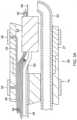
- the distal tip electrode section 15having a connector tube 27 and a tip electrode 36.
- the connector tube 27is a relative short piece of tubing, about 1 cm in length, for example, made of polyetheretherketone (PEEK).
- PEEKpolyetheretherketone
- the proximal end of the connector tube 27has a circumferential notch whose outer surface is surrounded by an inner surface of a circumferential notch formed in the distal end of the tubing 10 of the deflection section 14. The ends are bonded to each other by polyurethane glue or the like.
- the tip electrode 36has a diameter about the same as the outer diameter of the tubing 19 and the connector tube 27.
- the tip electrode 36includes a porous substrate 38 and a plurality of surface electrodes 40.
- the porous substrate 38is formed by porous ceramic material or any other suitable non-conductive polymer, such as polyethylene, or Teflon.
- the substrate 38has an elongated cylindrical shape with a narrower proximal stem portion 38N.
- the substrate 38is formed with an interior chamber 37 that also has a similar elongated cylindrical shape extending longitudinally in the substrate 38.
- the porous substrate 38has a total length ranging from about 6 mm to about 9 mm, more preferably about 7 mm.
- each of the body form 38B and the proximal stem portion 38Nmay have a length of about 3.5 mm.
- the chamber 37has an opening 37P at the proximal end of the substrate 38 and a distal end 37D near the distal end of the substrate. It is understood that the chamber 37 and the substrate need not have the same general shape, and further that depending on the volume of the chamber 37 the thickness T of the wall between the chamber 37 and the outer surface of the substrate may be varied as desired or appropriate.
- a plug member 41seals the proximal face and plugs the opening thus enclosing the chamber 37.
- the plug member 41has a first through-hole 51 for lead wire 48 to pass through and enter into the chamber 37 and a second through-hole 52 for receiving a distal end of an irrigation tubing 50 which supplies fluid, e.g., saline or any electrically conductive fluid, into the chamber 37.
- the proximal stem portion 38Nis received in a distal end of the connector tube 27.
- the stem portion 38N and the connector tube 27are attached by polyurethane glue or the like.
- the porous non-conductive material of the substrate 38can be made using any conventional technique
- the non-conductive materialcomprises sintered ceramic powder, or polymer particles formed from polyethylene or Teflon.
- sinrefers to the process of bonding adjacent particles in a powder mass or compacting the particles by heating them to a temperature below the melting point of the main constituent at a predetermined and closely controlled time-temperature regime, including heating and cooling phases, in a protective atmosphere.
- the porosity of the sintered materialis controlled by the amount of particle compacting in the mold or glue, the particle size, and the particle distribution.
- the sintered particlespermit passage of a cooling fluid through the tip electrode, as described in more detail below.
- the final shape of the tipcan be obtained with a variety of techniques including machining, grinding, etching, or molding.
- a sintering processinvolves providing ceramic, polyethylene or Teflon powder particles in a certain sieve fraction, e.g., in the range of from about 5 microns to about 250 microns.
- the particlesare preferably in the range of from about 10 microns to about 100 microns.
- at least two different sized particlescan be provided. For example, particles in the range of from about 15 microns to about 30 microns, and more preferably about 20 microns, in combination with particles in the range of from about 80 microns to about 110 microns, and more preferably about 100 microns, could be used.
- the larger particlesWhen two different sized particles are used, preferably the larger particles have a mean diameter at least about 2.5 times greater than the mean diameter of the smaller particles, and more preferably at least about 4 times greater.
- a single particle sizecan be used, which can provide a denser packing and result in a higher pressure drop across the porous electrode.
- the particlesare preferably rounded and more preferably spherical, so as to provide a tip electrode surface that is not rough.
- the particlescan be irregularly shaped, i.e. having differing shapes, which is a low cost alternative. Tip surface irregularities could also be smoothed through secondary operations such as mechanical polishing and laser etching.
- the particlesare put into a mold, such as a ceramic mold, having the desired electrode shape.
- the particlescan be mixed with a suitable binder prior to being put into the mold.
- a binderWhen a binder is used, the mold containing the binder and particles is placed into a low temperature oven and heated to a temperature sufficient to evaporate the binder.
- the particlesare then sintered under vacuum or air at a temperature ranging from about 80 degree C to about 160 degree C, although the temperature can vary depending on the composition of the porous polymer. However, the temperature should be below the melting point of the composition.
- the resulting tip electrodeis then removed from the mold and assembled onto the flexible tubing of the tip section.
- the porous substrate 38has a generally cylindrical shape with domed distal end.
- the porous substratemay have different shapes, as desired or appropriate.
- porous substrate 138 of FIG. 6has a bulbous shape and an elongated stem portion 138N, along with a bulbous shaped chamber 137 with an elongated proximal portion137P.
- the wall thickness Tis generally uniform throughout the substrate 138.
- the porous substrate and the chambermay have dissimilar shapes.
- the wall thicknessmay vary throughout the substrate, some portions T1 being thinner and other portions T2 being thicker.
- the one or more sensing microelectrodes 40Disposed over the surface of the porous substrate are the one or more sensing microelectrodes 40 in the form of individual and separate thin metal coatings, as depicted in FIGS. 5A-5D .
- the thin metal coatingsmay be applied in close proximity to each other using any suitable process, including, for example, metallization, core plating, electroplating and/or 3-D printing, and may involve more than one layers, with the outer most layer comprising suitable electrode material (or alloys) known in the art, such as gold, platinum, platinum/iridium.
- the one or more metal coatingsare made of conductive material that is also MRI-compatible, (e.g. platinum or gold).
- the metal coating 40is made of a platinum-iridium alloy, e.g. 90% Platinum/10% Iridium, applied to the surface of the porous substrate 38 by metallization treatment or process impregnating a thin layer of platinum-iridium alloy onto the porous substrate 38, as known in the art.
- a platinum-iridium alloye.g. 90% Platinum/10% Iridium
- the thickness of the metal coatingmay vary as desired.
- the thicknesscan be uniform or not uniform.
- the metal coatingmay have a uniform thickness ranging from 0.2 ⁇ m to about 2.0 ⁇ m.
- coating forming one or more microelectrodes 40Xas shown in FIGS. 5A and 5B , has non-uniform thickness e.g. thicker towards the center and thinner towards the periphery. This allows for a protrusion configuration or a raised profile.
- the ratio of the central thickness H to the thickness at the peripherymay range between about 2 and 20. Such-protruding-shape allows for improved contact with the heart tissue and consequently improved electrogram quality.
- the metal coatingscan be of any desired plurality and of any desired configuration and/or orientation to form individual and separate surface micro-electrodes, for example, circular, oval, rectangular, elongated, ring, axial, radial, and co-centric.
- the metal coatingsprovide axial proximal rectangular surface micro-electrodes 40T, more distal ring surface micro-electrodes 40R, and distal tip circular surface micro-electrode 40C.
- FIG. 5Athe metal coatings provide axial proximal rectangular surface micro-electrodes 40T, more distal ring surface micro-electrodes 40R, and distal tip circular surface micro-electrode 40C.
- the metal coatingsprovide axial proximal rectangular surface micro-electrodes 40TP and axial distal rectangular surface micro-electrodes 40TD that are axially offset from each other.
- the metal coatingsprovide a plurality (four) of rings surface micro-electrodes 40R and a distal tip circular surface micro-electrode 40C.
- the metal coatingsprovide a distal tip circular surface micro-electrode 40C, a plurality of smaller circular micro-electrodes 40C and a proximal ring surface micro-electrode 40R.
- FIG. 5Cthe metal coatings provide axial proximal rectangular surface micro-electrodes 40TP and axial distal rectangular surface micro-electrodes 40TD that are axially offset from each other.
- the metal coatingsprovide a plurality (four) of rings surface micro-electrodes 40R and a distal tip circular surface micro-electrode 40C.
- the metal coatingsprovide
- FIGS. 5A-5Ea series of concentric circular surface micro-electrodes 40C1, 40C2 and 40C3 of different radii is shown on one side of the tip. It is understood that the size of the micro-surface electrodes in the drawings herein, including FIGS. 5A-5E , is not to scale and that their size is exaggerated so as to show their structure with better clarity.
- the surface electrodes 40are sized as micro-electrodes for obtaining highly localized electrograms and providing high density mapping of heart tissue.
- the surface area of each surface electroderanges between about 0.2 mm 2 and 2.0 mm 2 , preferably between about 0.5 mm 2 and 1 mm 2 . In that regard, it is understood that the figures herein are not necessarily to scale.
- the plurality of surface electrodes on the substratemay range between about one and 20, preferably about two and 10.
- Each surface electrode 40is connected to a respective lead wire 46 whose proximal end terminates in the control handle 16 in an input jack (not shown) that may be plugged into an appropriate signal processor (not shown).
- the lead wires 46extend from the control handle 16 and through the central lumen 18 of the catheter body ( FIG.
- the portion of the lead wires 46 extending through at least the catheter body 12 and the deflection section 14may be enclosed within a protective sheath (not shown), which can be made of any suitable material, preferably polyimide.
- the protective sheathmay be anchored at its distal end to the proximal end of the deflection section 14 by gluing it in the first lumen 30 with polyurethane glue or the like.
- the lead wires 46are attached or electrically connected to the surface electrodes 40 through surface electrode leads 60 ( FIGS. 5A-5E ) which may be applied or deposited on the outer surface of the porous substrate 38 and the stem portion 38N in the same manner as the surface microelectrodes 40, as described above. As shown in FIGS. 4 and 4B , distal end portions of lead wires 46 pass between an inner surface of the connector tubing 27 and the peripheral edge of the plug member 41 and the outer surface of the stem portion 38N. These surfaces at and near the proximal end of the substrate 38 may be sealed by glue and the like. Distal ends of the lead wires 46 are attached to respective proximal ends of the surface electrode leads 60 at or near the distal end of the connector tubing 27. Accordingly, electrical signals of the heart tissue sensed by the microelectrodes are transmitted proximally toward the control handle via the surface electrode leads 60 and the lead wires 46.
- selected surface electrode leads 60 and surface sensing microelectrodes 40are insulated from each other where they overlap each other.
- An insulating layermay be placed in between surface electrode leads 60 and surface electrodes 40 and grooves 92 ( FIG. 5A , 5C and 5E ) may be formed on the outer surface of the porous substrate for underpassing surface electrode leads 60 so that overlying surface electrodes 40 can lie flat on the outer surface of the porous substrate 38.
- the porous substrate 38is "energized" by the lead wire 48 which passes into the chamber 37 via the first through-hole 51 in the plug member 41.
- the lead wire 48renders the porous substrate 38 into a "virtual" ablation electrode by conducting the energy through the conductive- irrigation fluid, e.g., saline, delivered by the irrigation tubing 50 which enters the chamber 37 and weeps through the porous substrate 38 in providing a generally uniform thin layer of energized fluid throughout its exposed surfaces 62 (in between the surface microelectrodes 40) to further improve ablation safety.
- ablationmay be accomplished therefrom.
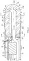
- the distal portion of the lead wire 48 in the chamber 37is elongated and linear. However, it is understood that the distal portion may assume any shape as desired or appropriate.
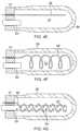
- the distal portion of the lead wire 48 in the chamber 37is configured nonlinearly, wrapped around itself ( FIG. 4D ) or coiled around a support member 53 ( FIG. 4C ) for increased surface area exposure and contact with the fluid in the chamber 37 for greater conduction between the lead wire and the fluid.
- a proximal end of the support member 53may be affixed to and mounted on a distal face of the plug member.
- the distal portion of the lead wire 48may also extend linearly and deeply distally in the chamber 37 along the longitudinal center axis ( FIG. 4E ), spiral widely approaching the inner surface of the chamber 37 ( FIG. 4F ), or be wrapped or coiled around an extended distal portion of the irrigation tubing 40 such that both extend deeply distally in the chamber 37.
- the irrigation tubing 40may be perforated with pores 54 along its length ( FIG. 4G ). Such configuration improves the uniformity of irrigation within the chamber 37 and the tip 36 and allows for even greater exposure of the lead wire to the conductive fluid.
- the catheterincludes three ring electrodes 39 proximal of the distal tip section 15, mounted on the tubing 19 of the deflection section 14 and/or the connector tubing 27, as shown in FIGS. 3A , 3B and 4 .
- ring electrodes 39may vary as desired, likewise their function as monopolar or bipolar electrodes for local electrogram sensing and/or location referencing in relation to the location sensor 64 housed in the connector tubing 27.
- Each ring electrode 39is slid over the tubing 19 and/or 27 and fixed in place by glue or the like.
- the ring electrodes 39can be made of any suitable material, and are preferably machined from platinum-iridium bar (90% platinum/10% iridium), gold, or gold alloys.
- Connection of a lead wire 49 to a ring electrode 39is preferably accomplished by first making a small hole through the tubing 19 and/or 27. Such a hole can be created, for example, by inserting a needle through the tubing and heating the needle sufficiently to form a permanent hole. A lead wire 49 is then drawn through the hole by using a microhook or the like. The ends of the lead wire 49 are then stripped of any coating and soldered or welded to the underside of the ring electrode 39, which is then slid into position over the hole and fixed in place with polyurethane glue or the like.
- the irrigation tubing 50is provided within the catheter body 12 for infusing fluids, e.g. saline, to electrify the porous substrate 38 of the tip electrode 36 and provide cooling during ablation.
- the irrigation tubing 50may be made of any suitable material, and is preferably made of polyimide tubing.
- the irrigation tubinghas an outer diameter of from about 0.032 inches to about 0.036 inches and an inner diameter of from about 0.027 inches to about 0.032 inches.
- the irrigation tubing 50extends from the control handle 16 and through the central lumen 18 of the catheter body 12 ( FIG. 2A ), the lumen 35 of the tubing 19 of the deflection section 14 ( FIG. 3A ), and the connector tube 27 ( FIG. 3A ), and into the second through-hole 52 in the plug member 41 and the chamber 37 of the substrate 38 ( FIG. 4 ).
- the proximal end of the irrigation tubing 50extends through the control handle 16 to a fluid source and a pump (not shown).
- the fluid introduced through the catheteris preferably a biologically compatible fluid such as saline, or water.
- the infused fluidalso forms a buffer layer to maintain biological materials, such as blood, at a distance from the tip electrode, thereby minimizing contact of the tip electrode with the biological material.
- This buffer layerreduces coagulation of biological materials and regulates the impedance or resistance to energy transfer of the tissue near the tip electrode during ablation.
- Saline or any other conductive fluidis preferred where the tip electrode is to function as an ablative electrode.
- the rate of fluid flow through the cathetermay be controlled by any suitable fluid infusion pump or by pressure.
- a suitable infusion pumpis the COOLFLOW available from Biosense Webster, Inc. (Diamond Bar, CA).
- the rate of fluid flow through the catheterpreferably ranges from about 0.5 ml/min to about 30 ml/min, more preferably from about 2 ml/min to about 17 ml/min.
- the fluidis maintained at about room temperature.
- a temperature sensing meansis provided for the tip electrode 36, as known in the art. Any conventional temperature sensing means, e.g., a thermocouple or thermistor, may be used.
- a suitable thermistor for use in the present inventionis Model No. AB6N2-GC14KA143E/37C sold by Thermometrics (New Jersey).
- the temperature sensing meansmay also be used as a feedback system to adjust the RF power delivered to the tissue through the catheter to maintain a desired temperature at the tip electrode.
- a pair of puller wires 70 and 72extend through the catheter body 12 for bidirectional deflection.
- the puller wires 70 and 72are anchored at their proximal end to the control handle 16, and are anchored at their distal ends to the deflection section 14 at or near its the distal end.
- the puller wiresare made of any suitable metal, such as stainless steel or Nitinol, and may be coated with Teflon or the like. The coating imparts lubricity to the puller wires.
- Each of the puller wiresmay have a diameter ranging from about 0.006 inches to about 0.010 inches.
- a compression coil 74is situated within the catheter body 12 in surrounding relation to each puller wire 50 ( FIG. 2B ). Each compression coil 74 extends from the proximal end of the catheter body 12 to about the proximal end of the deflection section 14.
- the compression coilsare made of any suitable metal, preferably stainless steel.
- Each compression coil 52is tightly wound on itself to provide flexibility, i.e., bending, but to resist compression.
- the inner diameter of the compression coilis slightly larger than the diameter of the puller wire.
- the Teflon coating on the puller wires 70 and 72allows them to slide freely within their respective compression coil.
- each compression coilcan be covered by a flexible, non-conductive sheath 76, e.g., made of polyimide tubing, to prevent contact between the compression coil and any other wires within the catheter body 12.
- Each compression coil 74is anchored at its proximal end to the proximal end of the stiffening tube 20 in the catheter body 12 by a glue joint (not shown) and at its distal end to the deflection section 14 by glue joint 73 ( FIG. 2B ).
- Both glue jointsmay comprise polyurethane glue or the like.
- the gluemay be applied by means of a needle or the like through a hole made in the side wall of the respective tubing, which needle is heated sufficiently to form a permanent hole. The glue is then introduced through the hole and wicks around the outer circumference to form a glue joint about the entire circumference of the compression coil.
- the puller wires 70 and 72extend into the lumens 32 and 34 ( FIG. 2C ), respectively, of the deflection section 14.
- the puller wiresare anchored at their distal end to the deflection section 14.
- an anchoris fixedly attached to the distal end of each puller wire, as depicted in FIG. 3B .
- the anchoris preferably formed by a metal tube 77, e.g. a short segment of hypodermic stock, which is fixedly attached, e.g. by crimping, to the distal end of the puller wires 70 and 72.
- the tubes 77have a section that extends a short distance beyond the distal end of the puller wires.
- a cross-piece 83 made of a small section of stainless steel ribbon or the likeis soldered or welded in a transverse arrangement to the distal end of each tube section 77, which is flattened during the operation. This creates a T-bar anchor.
- Two notchesare created in the sidewall of the deflection section 14, resulting in openings into the lumens 32 and 34 into which the puller wires 70 and 72 extend.
- the anchorslie partially within the notches. Because the length of the ribbons forming the cross-pieces 83 are longer than the diameter of the openings into the lumens 32 and 34, the anchors cannot be pulled completely into the lumens 32 and 34.
- the notchesare then sealed with polyurethane glue or the like to give a smooth outer surface.
- each of the puller wires 70 and 72extends through a respective plastic, preferably Teflon sheath 86, which prevents the puller wires from cutting into the wall of the tubing 19 when the deflection section 14 is deflected.
- an electromagnetic sensor 64is provided and housed in the lumen of the connector tube 27.
- a sensor cable 90extends from the control handle 16, and through the central lumen 18 of the catheter body 12 and the lumen 30 of the tubing 19 of deflection section 14 and the lumen of the connector tube 27.
- the sensor cable 90extends out the proximal end of the control handle 16 within an umbilical cord (not shown) to a sensor control module (not shown) that houses a circuit board (not shown).
- the circuit boardcan be housed within the control handle 16, for example, as described in U.S. Pat. No. 5964757 .
- the electromagnetic sensor cable 90comprises multiple wires encased within a plastic covered sheath.
- the wires of the electromagnetic sensor cableare connected to the circuit board.
- the circuit boardamplifies the signal received from the electromagnetic sensor and transmits it to a computer in a form understandable by the computer by means of the sensor connector at the proximal end of the sensor control module.
- the circuit boardpreferably contains an EPROM chip which shuts down the circuit board approximately 24 hours after the catheter has been used. This prevents the catheter, or at least the electromagnetic sensor, from being used twice. Suitable electromagnetic sensors for use with the present invention are described, for example, in U.S. Pat. Nos.
- a preferred electromagnetic sensor 64has a length of from about 6 mm to about 7 mm and a diameter of about 1.3 mm.
- a suitable guiding sheath(not shown) is inserted into the patient with its distal end positioned at or near a desired tissue location for diagnostics such as mapping and/or treatment such as ablation.
- An example of a suitable guiding sheath for use in connection with the present inventionis the Preface Braided Guiding Sheath, commercially available from Biosense Webster, Inc. (Diamond Bar, Calif.).
- the catheter 10is passed through the guiding sheath and advanced therethrough to the desired tissue location.
- the guiding sheathis pulled proximally, exposing the tip electrode section 15 and the deflection section 14.
- the catheter 10is adapted for high density electrode sensing detecting electrical activity in the tissue which is transmitted through the catheter via the lead wires 46 for processing by a signal processor (not shown) for generating high density mapping with highly localized electrograms.
- a signal processornot shown
- the lead wire 48is energized by an energy source, e.g., RF generator (not shown), whose distal end portion in the chamber 37 of the porous substrate 38 electrifies the conductive irrigation fluid delivered into the chamber 37 via irrigation tubing 50.
- the porous substrate 38Passing of such electrified fluid from the chamber to the exposed surfaces of the porous substrate 38 renders the porous substrate 38 into a "virtual" ablation electrode.
- the surface microelectrodes 40 on the porous substrate 38can sense electrical activity at and around the ablated tissue to confirm the formation of electrically blocked tissue regions.
Landscapes
- Health & Medical Sciences (AREA)
- Life Sciences & Earth Sciences (AREA)
- Surgery (AREA)
- Engineering & Computer Science (AREA)
- Physics & Mathematics (AREA)
- General Health & Medical Sciences (AREA)
- Animal Behavior & Ethology (AREA)
- Public Health (AREA)
- Biomedical Technology (AREA)
- Heart & Thoracic Surgery (AREA)
- Medical Informatics (AREA)
- Molecular Biology (AREA)
- Veterinary Medicine (AREA)
- Pathology (AREA)
- Biophysics (AREA)
- Cardiology (AREA)
- Plasma & Fusion (AREA)
- Nuclear Medicine, Radiotherapy & Molecular Imaging (AREA)
- Otolaryngology (AREA)
- Physiology (AREA)
- Surgical Instruments (AREA)
- Measurement And Recording Of Electrical Phenomena And Electrical Characteristics Of The Living Body (AREA)
- Media Introduction/Drainage Providing Device (AREA)
- Magnetic Resonance Imaging Apparatus (AREA)
Description
- This invention relates to catheters and electrophysiologic catheters, in particular, catheters for cardiac tissue ablation and diagnostics.
- Cardiac arrhythmia, such as atrial fibrillation, occurs when regions of cardiac tissue abnormally conduct electric signals to adjacent tissue, thereby disrupting the normal cardiac cycle and causing asynchronous rhythm. Important sources of undesired signals are located in various tissue regions in or near the heart, for example, the ventricles, the atria and/or and adjacent structures such as areas of the pulmonary veins. Regardless of the sources, unwanted signals are conducted abnormally through heart tissue where they can initiate and/or maintain arrhythmia.
- Procedures for treating arrhythmia include surgically disrupting the origin of the signals causing the arrhythmia, as well as disrupting the conducting pathways for such signals. More recently, it has been found that by mapping the electrical properties of the heart muscle in conjunction with the heart anatomy, and selectively ablating cardiac tissue by application of energy, it is possible to cease or modify the propagation of unwanted electrical signals from one portion of the heart to another. The ablation process destroys the unwanted electrical pathways by formation of non-conducting lesions.
- In this two-step procedure--mapping followed by ablation--electrical activity at points in the heart is typically sensed and measured by advancing a catheter containing one or more electrical sensors into the heart, and acquiring data at a multiplicity of points. These data are then utilized to select the target areas at which ablation is to be performed.
- A typical ablation procedure involves the insertion of a catheter having a tip electrode at its distal end into a heart chamber. A reference electrode is provided, generally taped to the patient's skin. Radio frequency (RF) current is applied to the tip electrode, and flows through the surrounding media, i.e., blood and tissue, toward the reference electrode. The distribution of current depends on the amount of electrode surface in contact with the tissue, as compared to blood which has a higher conductivity than the tissue. Heating of the tissue occurs due to its electrical resistivity. If the tissue is heated sufficiently, cellular and other protein destruction ensues; this in turn forms a lesion within the heart muscle which is electrically non-conductive. During this process, heating of the electrode also occurs as a result of conduction from the heated tissue to the electrode itself. If the electrode temperature becomes sufficiently high, possibly above 50 degree C, blood clot could form on the surface of the electrode. If the temperature continues to rise, more blood clot is formed while dehydration ensues.
- The tip temperature increase and the associated clot formation have two consequences: increased electrical impedance and increased probability for stroke. The former relates to clot dehydration. Because dehydrated biological material has a higher electrical resistance than heart tissue, impedance to the flow of electrical energy into the tissue also increases. Increased impedance leads to sub-optimal energy delivery to the tissue which results in inadequate lesion formation, reduced ablation efficiency and eventually to sub-optimal clinical outcome. The latter, a safety hazard, is due to possible dislodgment of the formed clot and relocation in the brain vasculature. It is therefore beneficial from a safety perspective as well as ablation efficiency to minimize the tip temperature increase and clot formation. This should be accomplished without compromising the formation of lesions of appropriate sizes.
- In a typical application of RF current to the endocardium, circulating blood provides some cooling of the ablation electrode. However, there is typically a stagnant area between the electrode and tissue which is susceptible to the formation of dehydrated proteins and coagulum. As power and/or ablation time increases, the likelihood of an impedance rise also increases. As a result of this process, there has been a natural upper bound on the amount of energy which can be delivered to cardiac tissue and therefore the size of RF lesions. In clinical practice, it is desirable to reduce or eliminate impedance rises and, for certain cardiac arrhythmias, to create larger lesions. One method for accomplishing this is to monitor the temperature of the ablation electrode and to control the RF current delivered to the ablation electrode based on this temperature. If the temperature rises above a pre-selected value, the current is reduced until the temperature drops below this value. This method has reduced the number of impedance rises during cardiac ablations but has not significantly increased lesion dimensions. The results are not significantly different because this method continues to rely on the cooling effect of the blood which is dependent on the location within the heart and the orientation of the catheter to the endocardial surface.
- Another method is to irrigate the ablation electrode, e.g., with physiologic saline at room temperature, to actively cool the ablation electrode instead of relying on the more passive physiological cooling provided by the blood. Additionally, due to the irrigation-mediated dilution of blood around the tip, the probability for clot creation is further reduced. Thus, irrigation tip cooling and blood dilution allow for safer increase of applied RF power. This results in lesions which tend to be larger usually measuring about 10 to 12 mm in depth.
- The clinical effectiveness of irrigating the ablation electrode is dependent upon the distribution of flow within and around the surface of the tip electrode structure as well as the rate of irrigation flow through the tip. Effectiveness is achieved by reducing the overall electrode temperature and eliminating hot spots in the ablation electrode which can initiate coagulum formation. More channels and higher flows are more effective in reducing overall temperature and temperature variations, i.e., hot spots. Irrigation is utilized during the entire time the catheter resides inside the patient's body. Higher flow rate is used during ablation while lower-maintenance-flow rate is required in order to prevent back flow of blood into the coolant passages during non-ablation time. The coolant flow rate must be balanced against the amount of fluid that can be safely injected into the patient. Thus, reducing coolant flow by utilizing it as efficiently as possible is a desirable design objective.
- One method for designing an ablation electrode which efficiently utilizes coolant flow is the use of a porous material structure. Such designs have the advantage of distributing the coolant evenly across the entire electrode structure. This balanced cooling results in a) eradication of possible surface or interior hot spots, and b) uniform dilution of blood at the vicinity of the electrode, thus further minimizing the chance for clot formation. Such designs are described in
U.S. Pat. Nos. 6,405,078 and6,466,818 to Moaddeb et al. Moaddeb describes the use of sintered metal particles to create a porous tip electrode. In addition, Moaddeb uses a non-conductive insert implanted into the porous tip electrode for mounting a thermocouple, lead wire and/or irrigation tube within the porous tip electrode. However, during irrigation the sintered metal particles can disintegrate and break away from the electrode structure. This-undesirable-particle dislodgement may be further facilitated during ablation. Additionally, (and in the context of our MRI compatibility claims-see below) the metallic material proposed for such porous tip is not optimal for MRI imaging. Furthermore, the proposed tip does not allow for high density mapping-a highly desired feature for accurate arrhythmia diagnosis. Consequently, a desire arises for a porous electrode having increased structural integrity, being compatible with the MRI environment, and allowing for high mapping density. - A porous tip electrode catheter is also described in
U.S. Pat. No. 8,262,653 to Plaza . The porous tip electrode comprises a porous material through which fluid can pass. The porous tip electrode is covered with a thin coating of conductive metal having openings (pores) through which fluids can pass. However, the porosity of such thin conductive coating is not easily controlled leading to inconsistent pore size and distribution. Therefore, distribution of irrigation fluid around the tip electrode may not be even or uniform. Furthermore, in this design, RF power delivery is achieved via direct connection (e.g. by soldering or other similar technique) of the RF power line to the tip's outer conductive coat. Thus, the presence of the generally non-uniform porous coating is necessary in order to establish electrical contact of the tip to the heart tissue. - Safe and efficacious ablation depends not only on optimal irrigation arrangement for the tip but also on accurate mapping of the electrophysiological behavior of the heart, which would allow for accurate diagnosis and appropriate tissue targeting. The greater the accuracy of the mapping the more accurate the diagnosis and thus the effectiveness of treatment. Improved (high resolution) cardiac mapping requires the use of a multitude of electrodes in close proximity to sense electrical activity within a small area, for example, a square centimeter or less.
- Metallization of ceramics is a well-established technique and is widely used in a multitude of electronics and engineering disciplines, including fabrication of RF electronic circuits. Metallization involves the application of metal on ceramic substrates, including the formation of conductive regions, such as metallized conductor patterns or uniform metal layers on surfaces of ceramic substrates. Common ceramic substrates include aluminum oxide, beryllium oxide, ferrite, barium titanate, as well as quartz or borosilicate. Generally, ceramic metallization processes fall into three categories: thin-film, thick-film, and co-firing techniques. In the thin film approach, a thin layer of metal is deposited by vacuum processes such as sputtering, evaporation, chemical vapor deposition, and laser ablation. Electroless and electrolytic plating are also frequently grouped in the thin film category. To enhance adhesion, a preliminary adhesion-promoting layer, such as chromium or titanium, is often deposited. Thick film methods involve printing metal pastes, typically metal powders mixed with glass frits and organic binders onto ceramic substrates. The printed substrates are fired to form conductive paths on the ceramic. In the co-firing approach, unfired "green" ceramic surfaces are coated with patterned metal paste lines. The printed green ceramic is fired both to sinter the material and form the conductive metal patterns. Metallization processes are described, for example, in
U.S. Pat. Nos. 4,547,094 to DeLuca, et al. ;5,096,749 to Harada, et al. ;5,690,805 to Thorn, et al. ; and5,725,938 Jin, et al. Metallization depending on the type of metallization process and the substrate may include gold, platinum, or other biocompatible metals suitable for intracardial signal acquisitions. - While ablation has revolutionized the treatment of cardiac arrhythmias, ablation can be improved where physicians can assess lesions in real time. The use of magnetic resonance imaging (MRI) during an ablation procedure could enable physicians to assess lesions in real time.; However, the ablation catheter and other associated accessory equipment can interfere with the imaging process, causing local distortions in the MRI scans. Use of appropriate MRI compatible materials is necessary to minimize these image distortions. Safety experts have cleared some metals for use during MRIs, including titanium, cobalt-chromium, copper, selected stainless steel alloys. Non-ferromagnetic metals are also MRI compatible. Such materials include copper, brass, silver, gold, aluminum, lead, magnesium, platinum and tungsten. Ceramic materials as well as other thermoplastic polymers are non-metallic and as such are highly desirable as MRI compatible materials. They not only present minimal image distortion but being electrical insulators they present no heating effects due to absence of internally induced electrical currents. Ceramic materials of porous construction are proposed in the current invention as materials for the construction of the catheter's tip.
- In view of the foregoing, it is desirable to provide a catheter with a dome tip electrode made of a porous substrate for more uniform irrigation, where the dome tip electrode incorporates surface electrodes made via a metallization, printing or other process for any desirable surface electrode pattern that provides multiple electrodes in close proximity for high density mapping. It is also desirable to provide a catheter where the substrate and the surface electrodes are MRI compatible so that the physician can conduct lesion assessment in real time during an ablation procedure.
- The invention is defined by the catheter of
independent claim 1. Any disclosed methods are merely exemplary and do not fall within the scope of the present invention. The present invention is directed to a catheter having a multifunctional "virtual" tip electrode with a porous substrate and a multitude of surface microelectrodes. The surface microelectrodes in close proximity to each other and in a variety of configurations sense tissue for highly localized intracardiac signal detection, and high density local electrograms and mapping and the porous substrate allows for flow of conductive fluid for ablating tissue. The surface microelectrodes can be formed via a metallization process that allows for any shape or size and close proximity, and the fluid "weeping" from the porous substrate provides more uniform irrigation in the form of a thin layer of saline. The delivery of RF power to the catheter tip is based on the principle of "virtual electrode," where the conductive saline flowing through the porous tip acts as the electrical connection between the tip electrode and the heart surface. - Moreover, the substrate and the surface electrodes are constructed of MRI compatible materials so that the physician can conduct lesion assessment in real time during an ablation procedure. The surface electrodes include noble metals, including, for example, platinum, gold and combinations thereof.
- In some embodiments, the catheter includes an elongated catheter body, and a distal electrode member having a porous substrate and a plurality of distinct surface microelectrodes. A plurality of lead wires are connected to the surface microelectrodes for transmitting electrical signals sensed by the microelectrodes. The porous substrate has an interior chamber adapted to receive conductive fluid which is in electrical contact with a lead wire that extends into the chamber, wherein such electrified fluid passes from the chamber to outside the substrate for distal irrigation and tissue ablation.
- In some detailed embodiments, the porous substrate is comprised of a ceramic material. The substrate has a plurality of surface microelectrodes ranging between about one and 20. Each surface microelectrode has a surface area ranging between 0.2 mm2 and 2 mm2.
- In some detailed embodiments, the porous substrate and the chamber both have a generally cylindrical shape, with a generally uniform wall thickness between the chamber and the outer surface of the substrate.
- These and other features and advantages of the present invention will be better understood by reference to the following detailed description when considered in conjunction with the accompanying drawings wherein:
FIG. 1 is a perspective view of a catheter of the present invention, in accordance with one embodiment.FIG. 2A is a side cross-sectional view of the catheter ofFIG. 1 , including a junction between a catheter body and a deflection section, taken along a first diameter.FIG. 2B is a side cross-sectional view of the catheter ofFIG. 1 , including the junction ofFIG. 2A , taken along a second diameter generally perpendicular to the first diameter.FIG. 2C is an end cross-sectional view of the deflection section ofFIGS. 2A and2B , taken along line C-C.FIG. 3A is a side cross-sectional view of the catheter ofFIG. 1 , including a junction between the deflection section and a distal electrode section, taken along a first diameter.FIG. 3B is a side cross-sectional view of the junction ofFIG. 3A , taken along a second diameter generally perpendicular to the first diameter.FIG. 4 is a side cross-sectional view of the catheter ofFIG. 1 , including a distal electrode section.FIG. 4A is an end cross-sectional view of the distal electrode section ofFIG. 4 , taken along line A-A.FIG. 4B is an end cross-sectional view of the distal electrode section ofFIG. 4 , taken along line B-B.FIG. 4C is a side view of a distal portion of a lead wire in a chamber, in accordance with one embodiment.FIG. 4D is a side view of a distal portion of a lead wire in a chamber, in accordance with another embodiment.FIG. 4E is a side view of a distal portion of a lead wire in a chamber, in accordance with another embodiment.FIG. 4F is a side view of a distal portion of a lead wire in a chamber, in accordance with another embodiment.FIG. 4G is a side view of a distal portion of a lead wire and an irrigation tubing in a chamber, in accordance with another embodiment.FIG. 5A is a side view of a tip electrode in accordance with a first embodiment.FIG. 5B is a side view of a tip electrode in accordance with a second embodiment.FIG. 5C is a side view of a tip electrode in accordance with a third embodiment.FIG. 5D is a side view of a tip electrode in accordance with a fourth embodiment.FIG. 5E is a side view of a tip electrode in accordance with a fifth embodiment.FIG. 6 is a side cross-sectional view of a porous substrate, in accordance with another embodiment.FIG. 7 is a side cross-sectional view of a porous substrate, in accordance with yet another embodiment.- In one embodiment of the invention, there is provided a steerable catheter having an irrigated tip adapted for diagnostic and/or therapeutic procedures. As shown in
FIG. 1 ,catheter 10 comprises anelongated catheter body 12 having proximal and distal ends, anintermediate deflection section 14 extending from a distal end of thecatheter body 12, atip electrode section 15 extending from a distal end of thecatheter body 12, and acontrol handle 16 at the proximal end of thecatheter body 12. - With reference to
FIGS. 2A and2B , thecatheter body 12 comprises an elongated tubular construction having a single, axial orcentral lumen 18. Thecatheter body 12 is flexible, i.e., bendable but substantially non-compressible along its length. Thecatheter body 12 can be of any suitable construction and made of any suitable material. In one embodiment, thecatheter body 12 comprises anouter wall 22 made of a polyurethane or PEBAX. Theouter wall 22 comprises an imbedded braided mesh of high-strength steel, stainless steel or the like to increase torsional stiffness of thecatheter body 12 so that, when the control handle 16 is rotated axially, the rest of the catheter, including thesections catheter body 12 is not critical, but is preferably no more than about 8 french (1 french = 1/3 millimeters), more preferably about 7 french, still more preferably about 5 french. Likewise, the thickness of theouter wall 22 is not critical, but is thin enough so that thecentral lumen 18 can accommodate an irrigation tube, puller wire(s), lead wires, and any other wires, cables or tubes. The inner surface of theouter wall 22 is lined with a stiffeningtube 20, which can be made of any suitable material, such as polyimide or nylon. The stiffeningtube 20, along with the braidedouter wall 22, provides improved torsional and longitudinal stability. The outer diameter of the stiffeningtube 20 is about the same as or slightly smaller than the inner diameter of theouter wall 22. Polyimide tubing is presently preferred for the stiffeningtube 20 because it may be very thin walled while still providing very good stiffness. This maximizes the diameter of thecentral lumen 18 without sacrificing strength and stiffness. A particularly preferred catheter has anouter wall 22 with an outer diameter of from about 0.090 inches to about 0.098 inches (1 inch = 2.54 cm) and an inner diameter of from about 0.061 inches to about 0.065 inches and apolyimide stiffening tube 20 having an outer diameter of from about 0.060 inches to about 0.064 inches and an inner diameter of from about 0.051 inches to about 0.056 inches. - As shown in
FIGS. 2A ,2B , and2C , the intermediatedeflectable section 14 comprises a short section oftubing 19 having multiple lumens, including off-axis lumens tubing 19 is made of a suitable non-toxic material that is preferably more flexible than thecatheter body 12. In one embodiment, the material for thetubing 19 is braided polyurethane, i.e., polyurethane with an imbedded mesh of braided high-strength steel, stainless steel or the like. The outer diameter of thedeflection section 14, like that of thecatheter body 12, is preferably no greater than about 8 french, more preferably about 7 french, still more preferably about 5 french. The size of the lumens is not critical. In one embodiment, thedeflection section 14 has an outer diameter of about 7 french (0.092 inches) and thesecond lumen 32 andthird lumen 34 are generally about the same size, each having a diameter of from about 0.020 inches to about 0.024 inches, preferably about 0.022 inches, with the first andfourth lumens - A means for attaching the
catheter body 12 to thedeflection section 14 is illustrated inFIGS. 2A and2B . The proximal end of thedeflection section 14 comprises an outercircumferential notch 24 that receives the inner surface of theouter wall 22 of thecatheter body 12. Thedeflection section 14 andcatheter body 12 are attached by adhesive (e.g. polyurethane glue) or the like. Before thedeflection section 14 andcatheter body 12 are attached, however, the stiffeningtube 20 is inserted into thecatheter body 12. The distal end of the stiffeningtube 20 is fixedly attached near the distal end of thecatheter body 12 by forming a glue joint (not shown) with polyurethane glue or the like. Preferably, a small distance, e.g., about 3 mm, is provided between the distal end of thecatheter body 12 and the distal end of the stiffeningtube 20 to permit room for thecatheter body 12 to receive thenotch 24 of thedeflection section 14. A force is applied to the proximal end of the stiffeningtube 20, and, while the stiffeningtube 20 is under compression, a first glue joint (not shown) is made between the stiffeningtube 20 and theouter wall 22 by a fast drying glue, e.g. Super Glue.RTM.. Thereafter, a second glue joint (not shown) is formed between the proximal ends of the stiffeningtube 20 andouter wall 22 using a slower drying but stronger glue, e.g. polyurethane. - At the distal end of the
deflection section 14 is the distaltip electrode section 15 having aconnector tube 27 and atip electrode 36. In the illustrated embodiment ofFIGS. 3A and3B , theconnector tube 27 is a relative short piece of tubing, about 1 cm in length, for example, made of polyetheretherketone (PEEK). The proximal end of theconnector tube 27 has a circumferential notch whose outer surface is surrounded by an inner surface of a circumferential notch formed in the distal end of thetubing 10 of thedeflection section 14. The ends are bonded to each other by polyurethane glue or the like. - As shown in
FIG. 4 , thetip electrode 36 has a diameter about the same as the outer diameter of thetubing 19 and theconnector tube 27. Thetip electrode 36 includes aporous substrate 38 and a plurality ofsurface electrodes 40. Theporous substrate 38 is formed by porous ceramic material or any other suitable non-conductive polymer, such as polyethylene, or Teflon. In the illustrated embodiment, thesubstrate 38 has an elongated cylindrical shape with a narrowerproximal stem portion 38N. Thesubstrate 38 is formed with aninterior chamber 37 that also has a similar elongated cylindrical shape extending longitudinally in thesubstrate 38. In one embodiment, theporous substrate 38 has a total length ranging from about 6 mm to about 9 mm, more preferably about 7 mm. For a 7 mm long tip electrode, each of thebody form 38B and theproximal stem portion 38N may have a length of about 3.5 mm. - The
chamber 37 has anopening 37P at the proximal end of thesubstrate 38 and adistal end 37D near the distal end of the substrate. It is understood that thechamber 37 and the substrate need not have the same general shape, and further that depending on the volume of thechamber 37 the thickness T of the wall between thechamber 37 and the outer surface of the substrate may be varied as desired or appropriate. - Abutting the proximal face of the
substrate stem portion 38N, aplug member 41 seals the proximal face and plugs the opening thus enclosing thechamber 37. As shown inFIG. 4 , theplug member 41 has a first through-hole 51 forlead wire 48 to pass through and enter into thechamber 37 and a second through-hole 52 for receiving a distal end of anirrigation tubing 50 which supplies fluid, e.g., saline or any electrically conductive fluid, into thechamber 37. - In the embodiment of
FIG. 4 , theproximal stem portion 38N is received in a distal end of theconnector tube 27. Thestem portion 38N and theconnector tube 27 are attached by polyurethane glue or the like. - The porous non-conductive material of the
substrate 38 can be made using any conventional technique In the illustrated embodiment, the non-conductive material comprises sintered ceramic powder, or polymer particles formed from polyethylene or Teflon. As used herein, the term "sinter" refers to the process of bonding adjacent particles in a powder mass or compacting the particles by heating them to a temperature below the melting point of the main constituent at a predetermined and closely controlled time-temperature regime, including heating and cooling phases, in a protective atmosphere. The porosity of the sintered material is controlled by the amount of particle compacting in the mold or glue, the particle size, and the particle distribution. The sintered particles permit passage of a cooling fluid through the tip electrode, as described in more detail below. The final shape of the tip can be obtained with a variety of techniques including machining, grinding, etching, or molding. - In one embodiment, a sintering process involves providing ceramic, polyethylene or Teflon powder particles in a certain sieve fraction, e.g., in the range of from about 5 microns to about 250 microns. The particles are preferably in the range of from about 10 microns to about 100 microns. In a particularly preferred embodiment, at least two different sized particles can be provided. For example, particles in the range of from about 15 microns to about 30 microns, and more preferably about 20 microns, in combination with particles in the range of from about 80 microns to about 110 microns, and more preferably about 100 microns, could be used. When two different sized particles are used, preferably the larger particles have a mean diameter at least about 2.5 times greater than the mean diameter of the smaller particles, and more preferably at least about 4 times greater. Alternatively, a single particle size can be used, which can provide a denser packing and result in a higher pressure drop across the porous electrode. Whatever material is used, the particles are preferably rounded and more preferably spherical, so as to provide a tip electrode surface that is not rough. However, the particles can be irregularly shaped, i.e. having differing shapes, which is a low cost alternative. Tip surface irregularities could also be smoothed through secondary operations such as mechanical polishing and laser etching.
- In one process, the particles are put into a mold, such as a ceramic mold, having the desired electrode shape. If desired, the particles can be mixed with a suitable binder prior to being put into the mold. When a binder is used, the mold containing the binder and particles is placed into a low temperature oven and heated to a temperature sufficient to evaporate the binder. The particles are then sintered under vacuum or air at a temperature ranging from about 80 degree C to about 160 degree C, although the temperature can vary depending on the composition of the porous polymer. However, the temperature should be below the melting point of the composition. The resulting tip electrode is then removed from the mold and assembled onto the flexible tubing of the tip section.
- In the embodiment of
FIG. 4 , theporous substrate 38 has a generally cylindrical shape with domed distal end. However, it is understood that the porous substrate may have different shapes, as desired or appropriate. For example,porous substrate 138 ofFIG. 6 has a bulbous shape and anelongated stem portion 138N, along with a bulbous shapedchamber 137 with an elongated proximal portion137P. The wall thickness T is generally uniform throughout thesubstrate 138. Moreover, it is understood that the porous substrate and the chamber may have dissimilar shapes. For example,substrate 238 ofFIG. 7 is generally cylindrical with a domed distal end, but itschamber 237 is cylindrical with a narroweddistal end 237D which is adapted for receiving and anchoring a distal end of the electrifying lead wire. Likewise, the wall thickness may vary throughout the substrate, some portions T1 being thinner and other portions T2 being thicker. - Disposed over the surface of the porous substrate are the one or
more sensing microelectrodes 40 in the form of individual and separate thin metal coatings, as depicted inFIGS. 5A-5D . It is understood that the thin metal coatings may be applied in close proximity to each other using any suitable process, including, for example, metallization, core plating, electroplating and/or 3-D printing, and may involve more than one layers, with the outer most layer comprising suitable electrode material (or alloys) known in the art, such as gold, platinum, platinum/iridium. In accordance with a feature of the present invention, the one or more metal coatings are made of conductive material that is also MRI-compatible, (e.g. platinum or gold). In some embodiments, themetal coating 40 is made of a platinum-iridium alloy, e.g. 90% Platinum/10% Iridium, applied to the surface of theporous substrate 38 by metallization treatment or process impregnating a thin layer of platinum-iridium alloy onto theporous substrate 38, as known in the art. - The thickness of the metal coating may vary as desired. The thickness can be uniform or not uniform. For example, the metal coating may have a uniform thickness ranging from 0.2 µm to about 2.0 µm. In some embodiments, coating forming one or
more microelectrodes 40X, as shown inFIGS. 5A and 5B , has non-uniform thickness e.g. thicker towards the center and thinner towards the periphery. This allows for a protrusion configuration or a raised profile. The ratio of the central thickness H to the thickness at the periphery may range between about 2 and 20. Such-protruding-shape allows for improved contact with the heart tissue and consequently improved electrogram quality. - As shown in
FIGS. 5A-5E , the metal coatings can be of any desired plurality and of any desired configuration and/or orientation to form individual and separate surface micro-electrodes, for example, circular, oval, rectangular, elongated, ring, axial, radial, and co-centric. For example, inFIG. 5A , the metal coatings provide axial proximal rectangular surface micro-electrodes 40T, more distal ring surface micro-electrodes 40R, and distal tipcircular surface micro-electrode 40C. For example, inFIG. 5B , the metal coatings provide axial proximal rectangular surface micro-electrodes 40TP and axial distal rectangular surface micro-electrodes 40TD that are axially offset from each other. For example, inFIG. 5C , the metal coatings provide a plurality (four) of rings surface micro-electrodes 40R and a distal tipcircular surface micro-electrode 40C. For example, inFIG. 5D , the metal coatings provide a distal tipcircular surface micro-electrode 40C, a plurality of smaller circular micro-electrodes 40C and a proximalring surface micro-electrode 40R. For example, inFIG. 5E , a series of concentric circular surface micro-electrodes 40C1, 40C2 and 40C3 of different radii is shown on one side of the tip. It is understood that the size of the micro-surface electrodes in the drawings herein, includingFIGS. 5A-5E , is not to scale and that their size is exaggerated so as to show their structure with better clarity. - Advantageously, the
surface electrodes 40 are sized as micro-electrodes for obtaining highly localized electrograms and providing high density mapping of heart tissue. The surface area of each surface electrode ranges between about 0.2 mm2 and 2.0 mm2, preferably between about 0.5 mm2 and 1 mm2. In that regard, it is understood that the figures herein are not necessarily to scale. The plurality of surface electrodes on the substrate may range between about one and 20, preferably about two and 10. Eachsurface electrode 40 is connected to arespective lead wire 46 whose proximal end terminates in the control handle 16 in an input jack (not shown) that may be plugged into an appropriate signal processor (not shown). Thelead wires 46 extend from the control handle 16 and through thecentral lumen 18 of the catheter body (FIG. 2A ), thefirst lumen 30 oftubing 19 of the deflection section 14 (FIG. 2A ), and the lumen of the connector tube 27 (FIG. 3A ). The portion of thelead wires 46 extending through at least thecatheter body 12 and thedeflection section 14 may be enclosed within a protective sheath (not shown), which can be made of any suitable material, preferably polyimide. The protective sheath may be anchored at its distal end to the proximal end of thedeflection section 14 by gluing it in thefirst lumen 30 with polyurethane glue or the like. - The
lead wires 46 are attached or electrically connected to thesurface electrodes 40 through surface electrode leads 60 (FIGS. 5A-5E ) which may be applied or deposited on the outer surface of theporous substrate 38 and thestem portion 38N in the same manner as thesurface microelectrodes 40, as described above. As shown inFIGS. 4 and4B , distal end portions oflead wires 46 pass between an inner surface of theconnector tubing 27 and the peripheral edge of theplug member 41 and the outer surface of thestem portion 38N. These surfaces at and near the proximal end of thesubstrate 38 may be sealed by glue and the like. Distal ends of thelead wires 46 are attached to respective proximal ends of the surface electrode leads 60 at or near the distal end of theconnector tubing 27. Accordingly, electrical signals of the heart tissue sensed by the microelectrodes are transmitted proximally toward the control handle via the surface electrode leads 60 and thelead wires 46. - As understood by one of ordinary skill in the art, selected surface electrode leads 60 and
surface sensing microelectrodes 40 are insulated from each other where they overlap each other. An insulating layer may be placed in between surface electrode leads 60 andsurface electrodes 40 and grooves 92 (FIG. 5A ,5C and5E ) may be formed on the outer surface of the porous substrate for underpassing surface electrode leads 60 so thatoverlying surface electrodes 40 can lie flat on the outer surface of theporous substrate 38. - For ablation purposes, the
porous substrate 38 is "energized" by thelead wire 48 which passes into thechamber 37 via the first through-hole 51 in theplug member 41. When energized, thelead wire 48 renders theporous substrate 38 into a "virtual" ablation electrode by conducting the energy through the conductive- irrigation fluid, e.g., saline, delivered by theirrigation tubing 50 which enters thechamber 37 and weeps through theporous substrate 38 in providing a generally uniform thin layer of energized fluid throughout its exposed surfaces 62 (in between the surface microelectrodes 40) to further improve ablation safety. Wherever the fluid is present on or flowing from theporous substrate 38, ablation may be accomplished therefrom. - In the embodiment of
FIG. 4 , the distal portion of thelead wire 48 in thechamber 37 is elongated and linear. However, it is understood that the distal portion may assume any shape as desired or appropriate. The distal portion of thelead wire 48 in thechamber 37 is configured nonlinearly, wrapped around itself (FIG. 4D ) or coiled around a support member 53 (FIG. 4C ) for increased surface area exposure and contact with the fluid in thechamber 37 for greater conduction between the lead wire and the fluid. A proximal end of thesupport member 53 may be affixed to and mounted on a distal face of the plug member. - The distal portion of the
lead wire 48 may also extend linearly and deeply distally in thechamber 37 along the longitudinal center axis (FIG. 4E ), spiral widely approaching the inner surface of the chamber 37 (FIG. 4F ), or be wrapped or coiled around an extended distal portion of theirrigation tubing 40 such that both extend deeply distally in thechamber 37. Theirrigation tubing 40 may be perforated withpores 54 along its length (FIG. 4G ). Such configuration improves the uniformity of irrigation within thechamber 37 and thetip 36 and allows for even greater exposure of the lead wire to the conductive fluid. - In the illustrated embodiment, the catheter includes three
ring electrodes 39 proximal of thedistal tip section 15, mounted on thetubing 19 of thedeflection section 14 and/or theconnector tubing 27, as shown inFIGS. 3A ,3B and4 . It is understood that the presence and number ofring electrodes 39 may vary as desired, likewise their function as monopolar or bipolar electrodes for local electrogram sensing and/or location referencing in relation to thelocation sensor 64 housed in theconnector tubing 27. Eachring electrode 39 is slid over thetubing 19 and/or 27 and fixed in place by glue or the like. Thering electrodes 39 can be made of any suitable material, and are preferably machined from platinum-iridium bar (90% platinum/10% iridium), gold, or gold alloys. - Connection of a
lead wire 49 to aring electrode 39 is preferably accomplished by first making a small hole through thetubing 19 and/or 27. Such a hole can be created, for example, by inserting a needle through the tubing and heating the needle sufficiently to form a permanent hole. Alead wire 49 is then drawn through the hole by using a microhook or the like. The ends of thelead wire 49 are then stripped of any coating and soldered or welded to the underside of thering electrode 39, which is then slid into position over the hole and fixed in place with polyurethane glue or the like. - The
irrigation tubing 50 is provided within thecatheter body 12 for infusing fluids, e.g. saline, to electrify theporous substrate 38 of thetip electrode 36 and provide cooling during ablation. Theirrigation tubing 50 may be made of any suitable material, and is preferably made of polyimide tubing. In one embodiment, the irrigation tubing has an outer diameter of from about 0.032 inches to about 0.036 inches and an inner diameter of from about 0.027 inches to about 0.032 inches. - The
irrigation tubing 50 extends from the control handle 16 and through thecentral lumen 18 of the catheter body 12 (FIG. 2A ), thelumen 35 of thetubing 19 of the deflection section 14 (FIG. 3A ), and the connector tube 27 (FIG. 3A ), and into the second through-hole 52 in theplug member 41 and thechamber 37 of the substrate 38 (FIG. 4 ). The proximal end of theirrigation tubing 50 extends through the control handle 16 to a fluid source and a pump (not shown). The fluid introduced through the catheter is preferably a biologically compatible fluid such as saline, or water. In addition to, or instead of, being used to cool the tip electrode, the infused fluid also forms a buffer layer to maintain biological materials, such as blood, at a distance from the tip electrode, thereby minimizing contact of the tip electrode with the biological material. This buffer layer reduces coagulation of biological materials and regulates the impedance or resistance to energy transfer of the tissue near the tip electrode during ablation. Saline or any other conductive fluid is preferred where the tip electrode is to function as an ablative electrode. - The rate of fluid flow through the catheter may be controlled by any suitable fluid infusion pump or by pressure. A suitable infusion pump is the COOLFLOW available from Biosense Webster, Inc. (Diamond Bar, CA). The rate of fluid flow through the catheter preferably ranges from about 0.5 ml/min to about 30 ml/min, more preferably from about 2 ml/min to about 17 ml/min. Preferably, the fluid is maintained at about room temperature.
- It is understood that a temperature sensing means is provided for the
tip electrode 36, as known in the art. Any conventional temperature sensing means, e.g., a thermocouple or thermistor, may be used. A suitable thermistor for use in the present invention is Model No. AB6N2-GC14KA143E/37C sold by Thermometrics (New Jersey). The temperature sensing means may also be used as a feedback system to adjust the RF power delivered to the tissue through the catheter to maintain a desired temperature at the tip electrode. - As shown in
FIGS. 2B and3B , a pair ofpuller wires catheter body 12 for bidirectional deflection. Thepuller wires deflection section 14 at or near its the distal end. The puller wires are made of any suitable metal, such as stainless steel or Nitinol, and may be coated with Teflon or the like. The coating imparts lubricity to the puller wires. Each of the puller wires may have a diameter ranging from about 0.006 inches to about 0.010 inches. - A
compression coil 74 is situated within thecatheter body 12 in surrounding relation to each puller wire 50 (FIG. 2B ). Eachcompression coil 74 extends from the proximal end of thecatheter body 12 to about the proximal end of thedeflection section 14. The compression coils are made of any suitable metal, preferably stainless steel. Eachcompression coil 52 is tightly wound on itself to provide flexibility, i.e., bending, but to resist compression. The inner diameter of the compression coil is slightly larger than the diameter of the puller wire. The Teflon coating on thepuller wires lead wires non-conductive sheath 76, e.g., made of polyimide tubing, to prevent contact between the compression coil and any other wires within thecatheter body 12. - Each
compression coil 74 is anchored at its proximal end to the proximal end of the stiffeningtube 20 in thecatheter body 12 by a glue joint (not shown) and at its distal end to thedeflection section 14 by glue joint 73 (FIG. 2B ). Both glue joints may comprise polyurethane glue or the like. The glue may be applied by means of a needle or the like through a hole made in the side wall of the respective tubing, which needle is heated sufficiently to form a permanent hole. The glue is then introduced through the hole and wicks around the outer circumference to form a glue joint about the entire circumference of the compression coil. - The
puller wires lumens 32 and 34 (FIG. 2C ), respectively, of thedeflection section 14. The puller wires are anchored at their distal end to thedeflection section 14. In one embodiment, an anchor is fixedly attached to the distal end of each puller wire, as depicted inFIG. 3B . The anchor is preferably formed by ametal tube 77, e.g. a short segment of hypodermic stock, which is fixedly attached, e.g. by crimping, to the distal end of thepuller wires tubes 77 have a section that extends a short distance beyond the distal end of the puller wires. Across-piece 83 made of a small section of stainless steel ribbon or the like is soldered or welded in a transverse arrangement to the distal end of eachtube section 77, which is flattened during the operation. This creates a T-bar anchor. Two notches are created in the sidewall of thedeflection section 14, resulting in openings into thelumens puller wires cross-pieces 83 are longer than the diameter of the openings into thelumens lumens lumens deflection section 14, each of thepuller wires Teflon sheath 86, which prevents the puller wires from cutting into the wall of thetubing 19 when thedeflection section 14 is deflected. - Longitudinal movement of the
puller wires catheter body 12, which results in deflection of thedeflection section 14, is accomplished by suitable manipulation of the control handle 16. A suitable control handle for use with the present invention is described inU.S. Pat. No. 6120476 . - In the illustrated embodiment, an
electromagnetic sensor 64 is provided and housed in the lumen of theconnector tube 27. Asensor cable 90 extends from the control handle 16, and through thecentral lumen 18 of thecatheter body 12 and thelumen 30 of thetubing 19 ofdeflection section 14 and the lumen of theconnector tube 27. Thesensor cable 90 extends out the proximal end of the control handle 16 within an umbilical cord (not shown) to a sensor control module (not shown) that houses a circuit board (not shown). Alternatively, the circuit board can be housed within the control handle 16, for example, as described inU.S. Pat. No. 5964757 . - The
electromagnetic sensor cable 90 comprises multiple wires encased within a plastic covered sheath. In the sensor control module, the wires of the electromagnetic sensor cable are connected to the circuit board. The circuit board amplifies the signal received from the electromagnetic sensor and transmits it to a computer in a form understandable by the computer by means of the sensor connector at the proximal end of the sensor control module. Also, because the catheter is designed for single use only, the circuit board preferably contains an EPROM chip which shuts down the circuit board approximately 24 hours after the catheter has been used. This prevents the catheter, or at least the electromagnetic sensor, from being used twice. Suitable electromagnetic sensors for use with the present invention are described, for example, inU.S. Pat. Nos. 5,558,091 ,5,443,489 ,5,546,951 ,5,568,809 and5,391,199 and International Publication No.WO 95/02995 electromagnetic sensor 64 has a length of from about 6 mm to about 7 mm and a diameter of about 1.3 mm. - In use, a suitable guiding sheath (not shown) is inserted into the patient with its distal end positioned at or near a desired tissue location for diagnostics such as mapping and/or treatment such as ablation. An example of a suitable guiding sheath for use in connection with the present invention is the Preface Braided Guiding Sheath, commercially available from Biosense Webster, Inc. (Diamond Bar, Calif.). The
catheter 10 is passed through the guiding sheath and advanced therethrough to the desired tissue location. The guiding sheath is pulled proximally, exposing thetip electrode section 15 and thedeflection section 14. - The user actuates a thumb knob on the control handle to deflect the catheter and position the
tip electrode 36 on tissue surface. With themultiple surface microelectrodes 40 in contact (or close proximity) with tissue, thecatheter 10 is adapted for high density electrode sensing detecting electrical activity in the tissue which is transmitted through the catheter via thelead wires 46 for processing by a signal processor (not shown) for generating high density mapping with highly localized electrograms. If ablation is desired, thelead wire 48 is energized by an energy source, e.g., RF generator (not shown), whose distal end portion in thechamber 37 of theporous substrate 38 electrifies the conductive irrigation fluid delivered into thechamber 37 viairrigation tubing 50. Passing of such electrified fluid from the chamber to the exposed surfaces of theporous substrate 38 renders theporous substrate 38 into a "virtual" ablation electrode. During and after ablation, thesurface microelectrodes 40 on theporous substrate 38 can sense electrical activity at and around the ablated tissue to confirm the formation of electrically blocked tissue regions. - The preceding description has been presented with reference to presently preferred embodiments of the invention. Workers skilled in the art and technology to which this invention pertains will appreciate that alterations and changes in the described structure may be practiced without meaningfully departing from the scope of this invention. As understood by one of ordinary skill in the art, the drawings are not necessarily to scale. Also, different features of more or more embodiment may be combined as needed or appropriate. Moreover, the catheters described herein may be configured to apply various energy forms, including microwave, laser, RF and/or cryogens. Accordingly, the foregoing description should not be read as pertaining only to the precise structures described and illustrated in the accompanying drawings, but rather should be read consistent with and as support to the following claims.
Claims (8)
- A catheter (10) comprising:an elongated catheter body (12);a distal electrode member (36) having a porous substrate (38) and a plurality of surface electrodes (40), the porous substrate (38) having at least one exposed surface area (62) spanning between at least a pair of surface electrodes (40), the porous substrate (38) having an interior chamber (37) adapted to receive conductive fluid;a plurality of lead wires (46), each connected to a respective surface electrode (40); anda lead wire (48) having a distal portion extending into the interior chamber (37), the lead wire (48) adapted to electrify the conductive fluid in the chamber (37),wherein the porous substrate (38) is adapted to pass the conductive fluid from the chamber (37) to the at least one exposed surface area (62);characterized in that the distal portion of the lead wire (48) extending into the interior chamber (37) is either:i) wrapped around itself,ii) coiled around a distal portion of an irrigation tubing (50), oriii) widely spiraling approaching the inner surface of the interior chamber (37).
- The catheter of claim 1, wherein the porous substrate (38) comprises an MRI-compatible material.
- The catheter of claim 1, wherein the surface electrodes (40) comprise an MRI-compatible material.
- The catheter of claim 2, wherein the porous substrate (38) comprises ceramic material.
- The catheter of claim 1, further comprising an intermediate deflection section (14) between the catheter body (12) and the distal electrode member (36).
- The catheter of claim 1, further comprising an irrigation tubing (50) adapted to deliver fluid to the chamber (37).
- The catheter of claim 1, wherein the plurality of surface electrodes (40) range between about six and twelve.
- The catheter of claim 1, further comprising a plug member (41) at a proximal end of the porous substrate (38).
Priority Applications (1)
| Application Number | Priority Date | Filing Date | Title |
|---|---|---|---|
| EP22152730.2AEP4014910B1 (en) | 2014-12-30 | 2015-12-23 | Catheter with irrigated tip electrode with porous substrate and high density surface micro-electrodes |
Applications Claiming Priority (2)
| Application Number | Priority Date | Filing Date | Title |
|---|---|---|---|
| US14/586,907US10034707B2 (en) | 2014-12-30 | 2014-12-30 | Catheter with irrigated tip electrode with porous substrate and high density surface micro-electrodes |
| EP15202353.7AEP3040043B1 (en) | 2014-12-30 | 2015-12-23 | Catheter with irrigated tip electrode with porous substrate and high density surface micro-electrodes |
Related Parent Applications (2)
| Application Number | Title | Priority Date | Filing Date |
|---|---|---|---|
| EP15202353.7ADivisionEP3040043B1 (en) | 2014-12-30 | 2015-12-23 | Catheter with irrigated tip electrode with porous substrate and high density surface micro-electrodes |
| EP15202353.7ADivision-IntoEP3040043B1 (en) | 2014-12-30 | 2015-12-23 | Catheter with irrigated tip electrode with porous substrate and high density surface micro-electrodes |
Related Child Applications (2)
| Application Number | Title | Priority Date | Filing Date |
|---|---|---|---|
| EP22152730.2ADivision-IntoEP4014910B1 (en) | 2014-12-30 | 2015-12-23 | Catheter with irrigated tip electrode with porous substrate and high density surface micro-electrodes |
| EP22152730.2ADivisionEP4014910B1 (en) | 2014-12-30 | 2015-12-23 | Catheter with irrigated tip electrode with porous substrate and high density surface micro-electrodes |
Publications (3)
| Publication Number | Publication Date |
|---|---|
| EP3202358A1 EP3202358A1 (en) | 2017-08-09 |
| EP3202358B1true EP3202358B1 (en) | 2022-01-26 |
| EP3202358B8 EP3202358B8 (en) | 2022-03-02 |
Family
ID=55069721
Family Applications (3)
| Application Number | Title | Priority Date | Filing Date |
|---|---|---|---|
| EP22152730.2AActiveEP4014910B1 (en) | 2014-12-30 | 2015-12-23 | Catheter with irrigated tip electrode with porous substrate and high density surface micro-electrodes |
| EP17153207.0AActiveEP3202358B8 (en) | 2014-12-30 | 2015-12-23 | Catheter with irrigated tip electrode with porous substrate and high density surface micro-electrodes |
| EP15202353.7AActiveEP3040043B1 (en) | 2014-12-30 | 2015-12-23 | Catheter with irrigated tip electrode with porous substrate and high density surface micro-electrodes |
Family Applications Before (1)
| Application Number | Title | Priority Date | Filing Date |
|---|---|---|---|
| EP22152730.2AActiveEP4014910B1 (en) | 2014-12-30 | 2015-12-23 | Catheter with irrigated tip electrode with porous substrate and high density surface micro-electrodes |
Family Applications After (1)
| Application Number | Title | Priority Date | Filing Date |
|---|---|---|---|
| EP15202353.7AActiveEP3040043B1 (en) | 2014-12-30 | 2015-12-23 | Catheter with irrigated tip electrode with porous substrate and high density surface micro-electrodes |
Country Status (8)
| Country | Link |
|---|---|
| US (4) | US10034707B2 (en) |
| EP (3) | EP4014910B1 (en) |
| JP (1) | JP6716249B2 (en) |
| CN (1) | CN105726118B (en) |
| AU (1) | AU2015268765A1 (en) |
| CA (1) | CA2916105A1 (en) |
| IL (1) | IL243399B (en) |
| RU (1) | RU2015156052A (en) |
Families Citing this family (46)
| Publication number | Priority date | Publication date | Assignee | Title |
|---|---|---|---|---|
| GB2480498A (en) | 2010-05-21 | 2011-11-23 | Ethicon Endo Surgery Inc | Medical device comprising RF circuitry |
| US10034707B2 (en)* | 2014-12-30 | 2018-07-31 | Biosense Webster (Israel) Ltd. | Catheter with irrigated tip electrode with porous substrate and high density surface micro-electrodes |
| ES2768107T3 (en) | 2015-04-29 | 2020-06-19 | Innoblative Designs Inc | Cavity tissue removal |
| US10959771B2 (en) | 2015-10-16 | 2021-03-30 | Ethicon Llc | Suction and irrigation sealing grasper |
| US12207863B2 (en) | 2015-10-29 | 2025-01-28 | Innoblative Designs, Inc. | Screen sphere tissue ablation devices and methods |
| JP6933857B2 (en) | 2015-10-29 | 2021-09-08 | イノブレイティブ デザインズ, インコーポレイテッド | Net spherical tissue ablation device and method |
| EP3359073B1 (en) | 2015-11-20 | 2020-02-12 | St. Jude Medical, Cardiology Division, Inc. | Multi-electrode ablator tip having dual-mode, omni-directional feedback capabilities |
| WO2017136261A1 (en) | 2016-02-02 | 2017-08-10 | Innoblative Designs, Inc. | Cavitary tissue ablation system |
| WO2017151431A1 (en) | 2016-03-01 | 2017-09-08 | Innoblative Designs, Inc. | Resecting and coagulating tissue |
| WO2017192510A2 (en) | 2016-05-02 | 2017-11-09 | Affera, Inc. | Pulsed radiofrequency ablation |
| US10702177B2 (en) | 2016-08-24 | 2020-07-07 | Biosense Webster (Israel) Ltd. | Catheter with bipole electrode spacer and related methods |
| US11911093B2 (en) | 2016-09-12 | 2024-02-27 | Biosense Webster (Israel) Ltd. | Irrigation system for a catheter |
| US11559349B2 (en)* | 2016-09-12 | 2023-01-24 | Biosense Webster (Israel) Ltd. | Ablation catheter with a flexible printed circuit board |
| US10751117B2 (en) | 2016-09-23 | 2020-08-25 | Ethicon Llc | Electrosurgical instrument with fluid diverter |
| WO2018075389A1 (en) | 2016-10-17 | 2018-04-26 | Innoblative Designs, Inc. | Treatment devices and methods |
| JP6875757B2 (en) | 2016-11-08 | 2021-05-26 | イノブレイティブ デザインズ, インコーポレイテッド | Electrosurgical tissue and vascular seal device |
| US11369301B2 (en)* | 2017-01-27 | 2022-06-28 | Medtronic Cryocath Lp | Highly flexible mapping and treatment device |
| US11033325B2 (en) | 2017-02-16 | 2021-06-15 | Cilag Gmbh International | Electrosurgical instrument with telescoping suction port and debris cleaner |
| US10799284B2 (en) | 2017-03-15 | 2020-10-13 | Ethicon Llc | Electrosurgical instrument with textured jaws |
| US11497546B2 (en) | 2017-03-31 | 2022-11-15 | Cilag Gmbh International | Area ratios of patterned coatings on RF electrodes to reduce sticking |
| US11103304B2 (en)* | 2017-06-13 | 2021-08-31 | Biosense Webster (Israel) Ltd. | Catheter with composite insert support member |
| US11284939B2 (en)* | 2017-07-06 | 2022-03-29 | Biosense Webster (Israel) Ltd. | Irrigated catheter with improved ablation tip electrode fluid distribution |
| EP3658053B1 (en) | 2017-07-26 | 2023-09-13 | Innoblative Designs, Inc. | Minimally invasive articulating assembly having ablation capabilities |
| US11484358B2 (en) | 2017-09-29 | 2022-11-01 | Cilag Gmbh International | Flexible electrosurgical instrument |
| US11033323B2 (en) | 2017-09-29 | 2021-06-15 | Cilag Gmbh International | Systems and methods for managing fluid and suction in electrosurgical systems |
| US11490951B2 (en)* | 2017-09-29 | 2022-11-08 | Cilag Gmbh International | Saline contact with electrodes |
| EP3473200B1 (en)* | 2017-10-23 | 2020-10-07 | VascoMed GmbH | Ablation catheter with microelectrode and method for producing an ablation catheter |
| US11033327B2 (en)* | 2017-10-30 | 2021-06-15 | St. Jude Medical, Cardiology Division, Inc. | Electrophysiology catheter with modular electrode structure |
| CN111683716B (en)* | 2018-02-06 | 2023-06-30 | 株式会社钟化 | Catheter and method of manufacturing the same |
| JP7456944B2 (en)* | 2018-02-09 | 2024-03-27 | プレシディオ・メディカル・インコーポレイテッド | Systems and methods for cardiac conduction block |
| US10966783B2 (en)* | 2018-03-19 | 2021-04-06 | Biosense Webster (Israel) Ltd. | Catheter with multifunctional microinjection—molded housing |
| US11058480B2 (en) | 2018-04-27 | 2021-07-13 | RELIGN Corporation | Arthroscopic devices and methods |
| EP3813936A4 (en)* | 2018-06-06 | 2022-03-09 | Robert F. Rioux | PORTABLE WOUND TREATMENT SYSTEM |
| JP7374135B2 (en)* | 2018-07-19 | 2023-11-06 | ザ・ユニバーシティ・オブ・シドニー | Ablation cauterization nest formation device |
| US11737818B2 (en)* | 2018-08-14 | 2023-08-29 | Biosense Webster (Israel) Ltd. | Heat transfer during ablation procedures |
| US11766206B2 (en)* | 2018-12-20 | 2023-09-26 | Biosense Webster (Israel) Ltd. | Electrode arrangement to sense cardiac wave vector |
| US20200205737A1 (en)* | 2018-12-28 | 2020-07-02 | Biosense Webster (Israel) Ltd. | Flexible Nested Sensing Electrodes |
| US11207016B2 (en)* | 2018-12-28 | 2021-12-28 | Biosense Webster (Israel) Ltd. | Mapping ECG signals using a multipole electrode assembly |
| US20220313347A1 (en)* | 2019-05-20 | 2022-10-06 | Innoblative Designs, Inc. | Tissue ablation devices and methods |
| CN114040724B (en)* | 2019-07-02 | 2024-08-13 | 圣犹达医疗用品心脏病学部门有限公司 | Electrode design for reducing impedance |
| WO2021126980A1 (en) | 2019-12-16 | 2021-06-24 | Affera, Inc. | Pulmonary vein isolation catheters and associated devices, systems, and methods |
| USD1014762S1 (en) | 2021-06-16 | 2024-02-13 | Affera, Inc. | Catheter tip with electrode panel(s) |
| WO2023021618A1 (en)* | 2021-08-18 | 2023-02-23 | 日本ライフライン株式会社 | Electrode catheter |
| US11957342B2 (en) | 2021-11-01 | 2024-04-16 | Cilag Gmbh International | Devices, systems, and methods for detecting tissue and foreign objects during a surgical operation |
| CN115517757B (en)* | 2022-11-28 | 2023-03-31 | 成都美创医疗科技股份有限公司 | Outer knife assembly and go out water hemostasis planer tool |
| CN117442325B (en)* | 2023-10-25 | 2024-08-27 | 四川锦江生命科技有限公司 | Multipolar ablation electrode catheter |
Family Cites Families (68)
| Publication number | Priority date | Publication date | Assignee | Title |
|---|---|---|---|---|
| FR92E (en) | 1901-08-19 | 1902-10-20 | Lemaire | New gasifier for gas engine |
| CA962806A (en) | 1970-06-04 | 1975-02-18 | Ontario Research Foundation | Surgical prosthetic device |
| US3890977A (en) | 1974-03-01 | 1975-06-24 | Bruce C Wilson | Kinetic memory electrodes, catheters and cannulae |
| US4101984A (en) | 1975-05-09 | 1978-07-25 | Macgregor David C | Cardiovascular prosthetic devices and implants with porous systems |
| US4934381A (en) | 1975-05-09 | 1990-06-19 | Macgregor David C | Porous carbon pacemaker electrode |
| US4167607A (en) | 1977-12-19 | 1979-09-11 | Diamond Shamrock Technologies S.A. | Halogen electrodes and storage batteries |
| US4506680A (en) | 1983-03-17 | 1985-03-26 | Medtronic, Inc. | Drug dispensing body implantable lead |
| AU570439B2 (en) | 1983-03-28 | 1988-03-17 | Compression Labs, Inc. | A combined intraframe and interframe transform coding system |
| US4574094A (en) | 1983-06-09 | 1986-03-04 | Kollmorgen Technologies Corporation | Metallization of ceramics |
| US4547094A (en) | 1984-01-30 | 1985-10-15 | Kennedy William R | Mine stopping |
| US4844099A (en) | 1986-11-24 | 1989-07-04 | Telectronics, N.V. | Porous pacemaker electrode tip using a porous substrate |
| JP2544398B2 (en) | 1987-08-27 | 1996-10-16 | 富士通株式会社 | Method for metallizing A1N ceramics |
| US4819662A (en) | 1987-10-26 | 1989-04-11 | Cardiac Pacemakers, Inc. | Cardiac electrode with drug delivery capabilities |
| US4917670A (en) | 1988-03-22 | 1990-04-17 | Hurley Ronald J | Continuous spinal anesthesia administering apparatus and method |
| US4984581A (en) | 1988-10-12 | 1991-01-15 | Flexmedics Corporation | Flexible guide having two-way shape memory alloy |
| US5383923A (en) | 1990-10-20 | 1995-01-24 | Webster Laboratories, Inc. | Steerable catheter having puller wire with shape memory |
| US5269752A (en) | 1991-09-12 | 1993-12-14 | Bennett Laurence M | Method of extracorporeal treatment using a kink resistant catheter |
| US5357979A (en) | 1992-12-01 | 1994-10-25 | Intelliwire, Inc. | Flexible elongate device having a distal extremity with current controlled adjustable stiffness and adjustable bend location and method |
| US5336222A (en) | 1993-03-29 | 1994-08-09 | Boston Scientific Corporation | Integrated catheter for diverse in situ tissue therapy |
| US5690805A (en) | 1993-05-17 | 1997-11-25 | Electrochemicals Inc. | Direct metallization process |
| US5391199A (en) | 1993-07-20 | 1995-02-21 | Biosense, Inc. | Apparatus and method for treating cardiac arrhythmias |
| US5558091A (en) | 1993-10-06 | 1996-09-24 | Biosense, Inc. | Magnetic determination of position and orientation |
| US5797903A (en) | 1996-04-12 | 1998-08-25 | Ep Technologies, Inc. | Tissue heating and ablation systems and methods using porous electrode structures with electrically conductive surfaces |
| US5462521A (en) | 1993-12-21 | 1995-10-31 | Angeion Corporation | Fluid cooled and perfused tip for a catheter |
| EP0698590B1 (en) | 1994-08-23 | 2003-10-22 | AT&T Corp. | Metallization of ceramics through application of an adherent reducible layer |
| US5681344A (en) | 1995-02-06 | 1997-10-28 | Wilson-Cook Medical Inc. | Esophageal dilation balloon catheter containing flexible nitinol wire |
| US5688267A (en) | 1995-05-01 | 1997-11-18 | Ep Technologies, Inc. | Systems and methods for sensing multiple temperature conditions during tissue ablation |
| JP3782113B2 (en) | 1995-06-12 | 2006-06-07 | コーディス ウェブスター,インコーポレイティド | Catheter with electromagnetic guidance sensor |
| EP0975386A4 (en) | 1996-01-19 | 2000-02-02 | Ep Technologies | Tissue heating and ablation systems and methods using porous electrode structures |
| US6475213B1 (en)* | 1996-01-19 | 2002-11-05 | Ep Technologies, Inc. | Method of ablating body tissue |
| US5846238A (en) | 1996-01-19 | 1998-12-08 | Ep Technologies, Inc. | Expandable-collapsible electrode structures with distal end steering or manipulation |
| US5868736A (en) | 1996-04-12 | 1999-02-09 | Ep Technologies, Inc. | Systems and methods to control tissue heating or ablation with porous electrode structures |
| JP4361136B2 (en)* | 1996-01-19 | 2009-11-11 | ボストン サイエンティフィック リミテッド | Tissue heat excision system and method using porous electrode structure |
| US6032077A (en)* | 1996-03-06 | 2000-02-29 | Cardiac Pathways Corporation | Ablation catheter with electrical coupling via foam drenched with a conductive fluid |
| US5910129A (en) | 1996-12-19 | 1999-06-08 | Ep Technologies, Inc. | Catheter distal assembly with pull wires |
| US5913856A (en) | 1997-05-19 | 1999-06-22 | Irvine Biomedical, Inc. | Catheter system having a porous shaft and fluid irrigation capabilities |
| US6241666B1 (en)* | 1997-07-03 | 2001-06-05 | Cardiac Pathways Corp. | Ablation catheter tip with a buffer layer covering the electrode |
| US5964757A (en) | 1997-09-05 | 1999-10-12 | Cordis Webster, Inc. | Steerable direct myocardial revascularization catheter |
| US6123699A (en) | 1997-09-05 | 2000-09-26 | Cordis Webster, Inc. | Omni-directional steerable catheter |
| US6120476A (en) | 1997-12-01 | 2000-09-19 | Cordis Webster, Inc. | Irrigated tip catheter |
| US6522930B1 (en)* | 1998-05-06 | 2003-02-18 | Atrionix, Inc. | Irrigated ablation device assembly |
| US6171275B1 (en) | 1998-12-03 | 2001-01-09 | Cordis Webster, Inc. | Irrigated split tip electrode catheter |
| US6466818B1 (en) | 1999-01-15 | 2002-10-15 | Biosense Webster, Inc. | Porous irrigated tip electrode catheter |
| US6405078B1 (en) | 1999-01-15 | 2002-06-11 | Biosense Webster, Inc. | Porous irrigated tip electrode catheter |
| US6363287B1 (en)* | 1999-10-27 | 2002-03-26 | Medtronic, Inc. | Steroid elution electrodes LVCV, left atrial medical/elecrical leads |
| US6458127B1 (en) | 1999-11-22 | 2002-10-01 | Csaba Truckai | Polymer embolic elements with metallic coatings for occlusion of vascular malformations |
| US6458123B1 (en) | 2000-04-27 | 2002-10-01 | Biosense Webster, Inc. | Ablation catheter with positional sensor |
| US6454766B1 (en)* | 2000-05-05 | 2002-09-24 | Scimed Life Systems, Inc. | Microporous electrode structure and method of making the same |
| US6669692B1 (en) | 2000-08-21 | 2003-12-30 | Biosense Webster, Inc. | Ablation catheter with cooled linear electrode |
| US6611699B2 (en)* | 2001-06-28 | 2003-08-26 | Scimed Life Systems, Inc. | Catheter with an irrigated composite tip electrode |
| US20040092806A1 (en)* | 2001-12-11 | 2004-05-13 | Sagon Stephen W | Microelectrode catheter for mapping and ablation |
| AU2002357166A1 (en) | 2001-12-12 | 2003-06-23 | Tissuelink Medical, Inc. | Fluid-assisted medical devices, systems and methods |
| US7967816B2 (en) | 2002-01-25 | 2011-06-28 | Medtronic, Inc. | Fluid-assisted electrosurgical instrument with shapeable electrode |
| US7104989B2 (en) | 2003-09-05 | 2006-09-12 | Medtronic, Inc. | RF ablation catheter including a virtual electrode assembly |
| US8262653B2 (en) | 2004-04-02 | 2012-09-11 | Biosense Webster, Inc. | Irrigated catheter having a porous tip electrode |
| US7066935B2 (en) | 2004-04-30 | 2006-06-27 | Medtronic, Inc. | Ion eluting tuna device |
| US7623899B2 (en) | 2005-09-16 | 2009-11-24 | Biosense Webster, Inc. | Catheter with flexible pre-shaped tip section |
| FR2891954B1 (en)* | 2005-10-12 | 2008-01-04 | Hispano Suiza Sa | ELBOW FITTING FOR MULTIFIL ELECTRIC CABLE |
| US7857809B2 (en) | 2005-12-30 | 2010-12-28 | Biosense Webster, Inc. | Injection molded irrigated tip electrode and catheter having the same |
| EP2136702B1 (en)* | 2007-03-26 | 2015-07-01 | Boston Scientific Limited | High resolution electrophysiology catheter |
| US8734440B2 (en)* | 2007-07-03 | 2014-05-27 | St. Jude Medical, Atrial Fibrillation Division, Inc. | Magnetically guided catheter |
| US8235985B2 (en)* | 2007-08-31 | 2012-08-07 | Voyage Medical, Inc. | Visualization and ablation system variations |
| AU2011252976A1 (en)* | 2010-05-12 | 2012-11-08 | Shifamed Holdings, Llc | Low profile electrode assembly |
| US10201385B2 (en)* | 2011-09-01 | 2019-02-12 | Biosense Webster (Israel) Ltd. | Catheter adapted for direct tissue contact |
| CN102631240A (en) | 2012-04-13 | 2012-08-15 | 上海微创电生理医疗科技有限公司 | Cold brine infusion type radiofrequency ablation catheter |
| US10321946B2 (en)* | 2012-08-24 | 2019-06-18 | Boston Scientific Scimed, Inc. | Renal nerve modulation devices with weeping RF ablation balloons |
| US9370329B2 (en)* | 2012-09-18 | 2016-06-21 | Boston Scientific Scimed, Inc. | Map and ablate closed-loop cooled ablation catheter |
| US10034707B2 (en)* | 2014-12-30 | 2018-07-31 | Biosense Webster (Israel) Ltd. | Catheter with irrigated tip electrode with porous substrate and high density surface micro-electrodes |
- 2014
- 2014-12-30USUS14/586,907patent/US10034707B2/enactiveActive
- 2015
- 2015-12-16AUAU2015268765Apatent/AU2015268765A1/ennot_activeAbandoned
- 2015-12-17ILIL243399Apatent/IL243399B/enactiveIP Right Grant
- 2015-12-22CACA2916105Apatent/CA2916105A1/ennot_activeAbandoned
- 2015-12-23EPEP22152730.2Apatent/EP4014910B1/enactiveActive
- 2015-12-23EPEP17153207.0Apatent/EP3202358B8/enactiveActive
- 2015-12-23EPEP15202353.7Apatent/EP3040043B1/enactiveActive
- 2015-12-28JPJP2015255846Apatent/JP6716249B2/enactiveActive
- 2015-12-28RURU2015156052Apatent/RU2015156052A/ennot_activeApplication Discontinuation
- 2015-12-29CNCN201511009217.XApatent/CN105726118B/enactiveActive
- 2018
- 2018-07-30USUS16/049,737patent/US10390880B2/enactiveActive
- 2019
- 2019-08-26USUS16/551,300patent/US10925668B2/enactiveActive
- 2021
- 2021-02-22USUS17/181,942patent/US12064169B2/enactiveActive
Also Published As
| Publication number | Publication date |
|---|---|
| US10390880B2 (en) | 2019-08-27 |
| EP3202358B8 (en) | 2022-03-02 |
| EP4014910C0 (en) | 2025-04-30 |
| EP4014910A1 (en) | 2022-06-22 |
| US20210177510A1 (en) | 2021-06-17 |
| US10925668B2 (en) | 2021-02-23 |
| EP4014910B1 (en) | 2025-04-30 |
| EP3040043A1 (en) | 2016-07-06 |
| CN105726118B (en) | 2020-11-06 |
| US10034707B2 (en) | 2018-07-31 |
| IL243399B (en) | 2018-12-31 |
| RU2015156052A (en) | 2017-07-05 |
| EP3202358A1 (en) | 2017-08-09 |
| US20190380775A1 (en) | 2019-12-19 |
| JP2016127919A (en) | 2016-07-14 |
| US20180344395A1 (en) | 2018-12-06 |
| US12064169B2 (en) | 2024-08-20 |
| AU2015268765A1 (en) | 2016-07-14 |
| RU2015156052A3 (en) | 2019-06-06 |
| JP6716249B2 (en) | 2020-07-01 |
| CN105726118A (en) | 2016-07-06 |
| US20160184008A1 (en) | 2016-06-30 |
| CA2916105A1 (en) | 2016-06-30 |
| EP3040043B1 (en) | 2018-01-31 |
Similar Documents
| Publication | Publication Date | Title |
|---|---|---|
| US12064169B2 (en) | Catheter with irrigated tip electrode with porous substrate and high density surface micro-electrodes | |
| US6405067B1 (en) | Catheter with tip electrode having a recessed ring electrode mounted thereon | |
| US6477396B1 (en) | Mapping and ablation catheter | |
| US5891138A (en) | Catheter system having parallel electrodes | |
| US20230225792A1 (en) | Catheter with improved temperature response | |
| JP7416759B2 (en) | Flexible circuit tip for split tip catheters | |
| CN106963475B (en) | Multi-layer split type ablation electrode | |
| EP3932354A2 (en) | Electroporation with cooling | |
| US12186012B2 (en) | Flexible circuit for use with a catheter and related manufacturing method | |
| CN112971967B (en) | Flexible circuit for use with catheter and related manufacturing method |
Legal Events
| Date | Code | Title | Description |
|---|---|---|---|
| PUAI | Public reference made under article 153(3) epc to a published international application that has entered the european phase | Free format text:ORIGINAL CODE: 0009012 | |
| STAA | Information on the status of an ep patent application or granted ep patent | Free format text:STATUS: THE APPLICATION HAS BEEN PUBLISHED | |
| AC | Divisional application: reference to earlier application | Ref document number:3040043 Country of ref document:EP Kind code of ref document:P | |
| AK | Designated contracting states | Kind code of ref document:A1 Designated state(s):AL AT BE BG CH CY CZ DE DK EE ES FI FR GB GR HR HU IE IS IT LI LT LU LV MC MK MT NL NO PL PT RO RS SE SI SK SM TR | |
| AX | Request for extension of the european patent | Extension state:BA ME | |
| STAA | Information on the status of an ep patent application or granted ep patent | Free format text:STATUS: REQUEST FOR EXAMINATION WAS MADE | |
| 17P | Request for examination filed | Effective date:20180208 | |
| RBV | Designated contracting states (corrected) | Designated state(s):AL AT BE BG CH CY CZ DE DK EE ES FI FR GB GR HR HU IE IS IT LI LT LU LV MC MK MT NL NO PL PT RO RS SE SI SK SM TR | |
| RIC1 | Information provided on ipc code assigned before grant | Ipc:A61B 18/14 20060101AFI20210422BHEP Ipc:A61B 18/00 20060101ALN20210422BHEP | |
| GRAP | Despatch of communication of intention to grant a patent | Free format text:ORIGINAL CODE: EPIDOSNIGR1 | |
| STAA | Information on the status of an ep patent application or granted ep patent | Free format text:STATUS: GRANT OF PATENT IS INTENDED | |
| RIC1 | Information provided on ipc code assigned before grant | Ipc:A61B 18/14 20060101AFI20210630BHEP Ipc:A61B 18/00 20060101ALN20210630BHEP | |
| INTG | Intention to grant announced | Effective date:20210723 | |
| GRAS | Grant fee paid | Free format text:ORIGINAL CODE: EPIDOSNIGR3 | |
| GRAA | (expected) grant | Free format text:ORIGINAL CODE: 0009210 | |
| STAA | Information on the status of an ep patent application or granted ep patent | Free format text:STATUS: THE PATENT HAS BEEN GRANTED | |
| GRAT | Correction requested after decision to grant or after decision to maintain patent in amended form | Free format text:ORIGINAL CODE: EPIDOSNCDEC | |
| AC | Divisional application: reference to earlier application | Ref document number:3040043 Country of ref document:EP Kind code of ref document:P | |
| AK | Designated contracting states | Kind code of ref document:B1 Designated state(s):AL AT BE BG CH CY CZ DE DK EE ES FI FR GB GR HR HU IE IS IT LI LT LU LV MC MK MT NL NO PL PT RO RS SE SI SK SM TR | |
| REG | Reference to a national code | Ref country code:GB Ref legal event code:FG4D | |
| REG | Reference to a national code | Ref country code:CH Ref legal event code:EP | |
| REG | Reference to a national code | Ref country code:DE Ref legal event code:R081 Ref document number:602015076748 Country of ref document:DE Owner name:BIOSENSE WEBSTER (ISRAEL) LTD., IL Free format text:FORMER OWNER: BIOSENSE WEBSTER (ISRAEL) LTD., YOKNEAM, IL | |
| REG | Reference to a national code | Ref country code:CH Ref legal event code:PK Free format text:BERICHTIGUNG B8 Ref country code:AT Ref legal event code:REF Ref document number:1464671 Country of ref document:AT Kind code of ref document:T Effective date:20220215 | |
| REG | Reference to a national code | Ref country code:IE Ref legal event code:FG4D | |
| REG | Reference to a national code | Ref country code:DE Ref legal event code:R096 Ref document number:602015076748 Country of ref document:DE | |
| RAP4 | Party data changed (patent owner data changed or rights of a patent transferred) | Owner name:BIOSENSE WEBSTER (ISRAEL) LTD. | |
| REG | Reference to a national code | Ref country code:NL Ref legal event code:FP | |
| REG | Reference to a national code | Ref country code:NL Ref legal event code:HC Owner name:BIOSENSE WEBSTER (ISRAEL) LTD.; IL Free format text:DETAILS ASSIGNMENT: CHANGE OF OWNER(S), CHANGE OF OWNER(S) NAME; FORMER OWNER NAME: BIOSENSE WEBSTER (ISRAEL), LTD. Effective date:20220421 | |
| REG | Reference to a national code | Ref country code:LT Ref legal event code:MG9D | |
| REG | Reference to a national code | Ref country code:AT Ref legal event code:MK05 Ref document number:1464671 Country of ref document:AT Kind code of ref document:T Effective date:20220126 | |
| PG25 | Lapsed in a contracting state [announced via postgrant information from national office to epo] | Ref country code:SK Free format text:LAPSE BECAUSE OF FAILURE TO SUBMIT A TRANSLATION OF THE DESCRIPTION OR TO PAY THE FEE WITHIN THE PRESCRIBED TIME-LIMIT Effective date:20220126 Ref country code:SE Free format text:LAPSE BECAUSE OF FAILURE TO SUBMIT A TRANSLATION OF THE DESCRIPTION OR TO PAY THE FEE WITHIN THE PRESCRIBED TIME-LIMIT Effective date:20220126 Ref country code:RS Free format text:LAPSE BECAUSE OF FAILURE TO SUBMIT A TRANSLATION OF THE DESCRIPTION OR TO PAY THE FEE WITHIN THE PRESCRIBED TIME-LIMIT Effective date:20220126 Ref country code:PT Free format text:LAPSE BECAUSE OF FAILURE TO SUBMIT A TRANSLATION OF THE DESCRIPTION OR TO PAY THE FEE WITHIN THE PRESCRIBED TIME-LIMIT Effective date:20220526 Ref country code:NO Free format text:LAPSE BECAUSE OF FAILURE TO SUBMIT A TRANSLATION OF THE DESCRIPTION OR TO PAY THE FEE WITHIN THE PRESCRIBED TIME-LIMIT Effective date:20220426 Ref country code:LT Free format text:LAPSE BECAUSE OF FAILURE TO SUBMIT A TRANSLATION OF THE DESCRIPTION OR TO PAY THE FEE WITHIN THE PRESCRIBED TIME-LIMIT Effective date:20220126 Ref country code:HR Free format text:LAPSE BECAUSE OF FAILURE TO SUBMIT A TRANSLATION OF THE DESCRIPTION OR TO PAY THE FEE WITHIN THE PRESCRIBED TIME-LIMIT Effective date:20220126 Ref country code:ES Free format text:LAPSE BECAUSE OF FAILURE TO SUBMIT A TRANSLATION OF THE DESCRIPTION OR TO PAY THE FEE WITHIN THE PRESCRIBED TIME-LIMIT Effective date:20220126 Ref country code:BG Free format text:LAPSE BECAUSE OF FAILURE TO SUBMIT A TRANSLATION OF THE DESCRIPTION OR TO PAY THE FEE WITHIN THE PRESCRIBED TIME-LIMIT Effective date:20220426 | |
| PG25 | Lapsed in a contracting state [announced via postgrant information from national office to epo] | Ref country code:PL Free format text:LAPSE BECAUSE OF FAILURE TO SUBMIT A TRANSLATION OF THE DESCRIPTION OR TO PAY THE FEE WITHIN THE PRESCRIBED TIME-LIMIT Effective date:20220126 Ref country code:LV Free format text:LAPSE BECAUSE OF FAILURE TO SUBMIT A TRANSLATION OF THE DESCRIPTION OR TO PAY THE FEE WITHIN THE PRESCRIBED TIME-LIMIT Effective date:20220126 Ref country code:GR Free format text:LAPSE BECAUSE OF FAILURE TO SUBMIT A TRANSLATION OF THE DESCRIPTION OR TO PAY THE FEE WITHIN THE PRESCRIBED TIME-LIMIT Effective date:20220427 Ref country code:FI Free format text:LAPSE BECAUSE OF FAILURE TO SUBMIT A TRANSLATION OF THE DESCRIPTION OR TO PAY THE FEE WITHIN THE PRESCRIBED TIME-LIMIT Effective date:20220126 Ref country code:AT Free format text:LAPSE BECAUSE OF FAILURE TO SUBMIT A TRANSLATION OF THE DESCRIPTION OR TO PAY THE FEE WITHIN THE PRESCRIBED TIME-LIMIT Effective date:20220126 | |
| PG25 | Lapsed in a contracting state [announced via postgrant information from national office to epo] | Ref country code:IS Free format text:LAPSE BECAUSE OF FAILURE TO SUBMIT A TRANSLATION OF THE DESCRIPTION OR TO PAY THE FEE WITHIN THE PRESCRIBED TIME-LIMIT Effective date:20220526 | |
| REG | Reference to a national code | Ref country code:DE Ref legal event code:R097 Ref document number:602015076748 Country of ref document:DE | |
| PG25 | Lapsed in a contracting state [announced via postgrant information from national office to epo] | Ref country code:SM Free format text:LAPSE BECAUSE OF FAILURE TO SUBMIT A TRANSLATION OF THE DESCRIPTION OR TO PAY THE FEE WITHIN THE PRESCRIBED TIME-LIMIT Effective date:20220126 Ref country code:RO Free format text:LAPSE BECAUSE OF FAILURE TO SUBMIT A TRANSLATION OF THE DESCRIPTION OR TO PAY THE FEE WITHIN THE PRESCRIBED TIME-LIMIT Effective date:20220126 Ref country code:EE Free format text:LAPSE BECAUSE OF FAILURE TO SUBMIT A TRANSLATION OF THE DESCRIPTION OR TO PAY THE FEE WITHIN THE PRESCRIBED TIME-LIMIT Effective date:20220126 Ref country code:DK Free format text:LAPSE BECAUSE OF FAILURE TO SUBMIT A TRANSLATION OF THE DESCRIPTION OR TO PAY THE FEE WITHIN THE PRESCRIBED TIME-LIMIT Effective date:20220126 Ref country code:CZ Free format text:LAPSE BECAUSE OF FAILURE TO SUBMIT A TRANSLATION OF THE DESCRIPTION OR TO PAY THE FEE WITHIN THE PRESCRIBED TIME-LIMIT Effective date:20220126 | |
| PG25 | Lapsed in a contracting state [announced via postgrant information from national office to epo] | Ref country code:AL Free format text:LAPSE BECAUSE OF FAILURE TO SUBMIT A TRANSLATION OF THE DESCRIPTION OR TO PAY THE FEE WITHIN THE PRESCRIBED TIME-LIMIT Effective date:20220126 | |
| PLBE | No opposition filed within time limit | Free format text:ORIGINAL CODE: 0009261 | |
| STAA | Information on the status of an ep patent application or granted ep patent | Free format text:STATUS: NO OPPOSITION FILED WITHIN TIME LIMIT | |
| 26N | No opposition filed | Effective date:20221027 | |
| PGFP | Annual fee paid to national office [announced via postgrant information from national office to epo] | Ref country code:NL Payment date:20221114 Year of fee payment:8 | |
| PG25 | Lapsed in a contracting state [announced via postgrant information from national office to epo] | Ref country code:SI Free format text:LAPSE BECAUSE OF FAILURE TO SUBMIT A TRANSLATION OF THE DESCRIPTION OR TO PAY THE FEE WITHIN THE PRESCRIBED TIME-LIMIT Effective date:20220126 | |
| REG | Reference to a national code | Ref country code:CH Ref legal event code:PL | |
| REG | Reference to a national code | Ref country code:BE Ref legal event code:MM Effective date:20221231 | |
| PG25 | Lapsed in a contracting state [announced via postgrant information from national office to epo] | Ref country code:LU Free format text:LAPSE BECAUSE OF NON-PAYMENT OF DUE FEES Effective date:20221223 | |
| PG25 | Lapsed in a contracting state [announced via postgrant information from national office to epo] | Ref country code:LI Free format text:LAPSE BECAUSE OF NON-PAYMENT OF DUE FEES Effective date:20221231 Ref country code:IE Free format text:LAPSE BECAUSE OF NON-PAYMENT OF DUE FEES Effective date:20221223 Ref country code:CH Free format text:LAPSE BECAUSE OF NON-PAYMENT OF DUE FEES Effective date:20221231 | |
| PG25 | Lapsed in a contracting state [announced via postgrant information from national office to epo] | Ref country code:BE Free format text:LAPSE BECAUSE OF NON-PAYMENT OF DUE FEES Effective date:20221231 | |
| PG25 | Lapsed in a contracting state [announced via postgrant information from national office to epo] | Ref country code:HU Free format text:LAPSE BECAUSE OF FAILURE TO SUBMIT A TRANSLATION OF THE DESCRIPTION OR TO PAY THE FEE WITHIN THE PRESCRIBED TIME-LIMIT; INVALID AB INITIO Effective date:20151223 | |
| PG25 | Lapsed in a contracting state [announced via postgrant information from national office to epo] | Ref country code:CY Free format text:LAPSE BECAUSE OF FAILURE TO SUBMIT A TRANSLATION OF THE DESCRIPTION OR TO PAY THE FEE WITHIN THE PRESCRIBED TIME-LIMIT Effective date:20220126 | |
| PG25 | Lapsed in a contracting state [announced via postgrant information from national office to epo] | Ref country code:MK Free format text:LAPSE BECAUSE OF FAILURE TO SUBMIT A TRANSLATION OF THE DESCRIPTION OR TO PAY THE FEE WITHIN THE PRESCRIBED TIME-LIMIT Effective date:20220126 | |
| PG25 | Lapsed in a contracting state [announced via postgrant information from national office to epo] | Ref country code:MC Free format text:LAPSE BECAUSE OF FAILURE TO SUBMIT A TRANSLATION OF THE DESCRIPTION OR TO PAY THE FEE WITHIN THE PRESCRIBED TIME-LIMIT Effective date:20220126 | |
| PG25 | Lapsed in a contracting state [announced via postgrant information from national office to epo] | Ref country code:TR Free format text:LAPSE BECAUSE OF FAILURE TO SUBMIT A TRANSLATION OF THE DESCRIPTION OR TO PAY THE FEE WITHIN THE PRESCRIBED TIME-LIMIT Effective date:20220126 Ref country code:MC Free format text:LAPSE BECAUSE OF FAILURE TO SUBMIT A TRANSLATION OF THE DESCRIPTION OR TO PAY THE FEE WITHIN THE PRESCRIBED TIME-LIMIT Effective date:20220126 | |
| REG | Reference to a national code | Ref country code:NL Ref legal event code:MM Effective date:20240101 | |
| PG25 | Lapsed in a contracting state [announced via postgrant information from national office to epo] | Ref country code:NL Free format text:LAPSE BECAUSE OF NON-PAYMENT OF DUE FEES Effective date:20240101 | |
| PG25 | Lapsed in a contracting state [announced via postgrant information from national office to epo] | Ref country code:NL Free format text:LAPSE BECAUSE OF NON-PAYMENT OF DUE FEES Effective date:20240101 Ref country code:MT Free format text:LAPSE BECAUSE OF FAILURE TO SUBMIT A TRANSLATION OF THE DESCRIPTION OR TO PAY THE FEE WITHIN THE PRESCRIBED TIME-LIMIT Effective date:20220126 | |
| PGFP | Annual fee paid to national office [announced via postgrant information from national office to epo] | Ref country code:DE Payment date:20241029 Year of fee payment:10 | |
| PGFP | Annual fee paid to national office [announced via postgrant information from national office to epo] | Ref country code:GB Payment date:20241031 Year of fee payment:10 | |
| PGFP | Annual fee paid to national office [announced via postgrant information from national office to epo] | Ref country code:FR Payment date:20241111 Year of fee payment:10 | |
| PGFP | Annual fee paid to national office [announced via postgrant information from national office to epo] | Ref country code:IT Payment date:20241112 Year of fee payment:10 |