EP3201569B1 - Methods and systems for vertical trajectory determination - Google Patents
Methods and systems for vertical trajectory determinationDownload PDFInfo
- Publication number
- EP3201569B1 EP3201569B1EP15845616.0AEP15845616AEP3201569B1EP 3201569 B1EP3201569 B1EP 3201569B1EP 15845616 AEP15845616 AEP 15845616AEP 3201569 B1EP3201569 B1EP 3201569B1
- Authority
- EP
- European Patent Office
- Prior art keywords
- imu
- baro
- velocity
- vertical position
- kalman filter
- Prior art date
- Legal status (The legal status is an assumption and is not a legal conclusion. Google has not performed a legal analysis and makes no representation as to the accuracy of the status listed.)
- Active
Links
Images
Classifications
- G—PHYSICS
- G01—MEASURING; TESTING
- G01C—MEASURING DISTANCES, LEVELS OR BEARINGS; SURVEYING; NAVIGATION; GYROSCOPIC INSTRUMENTS; PHOTOGRAMMETRY OR VIDEOGRAMMETRY
- G01C21/00—Navigation; Navigational instruments not provided for in groups G01C1/00 - G01C19/00
- G01C21/10—Navigation; Navigational instruments not provided for in groups G01C1/00 - G01C19/00 by using measurements of speed or acceleration
- G01C21/12—Navigation; Navigational instruments not provided for in groups G01C1/00 - G01C19/00 by using measurements of speed or acceleration executed aboard the object being navigated; Dead reckoning
- G01C21/16—Navigation; Navigational instruments not provided for in groups G01C1/00 - G01C19/00 by using measurements of speed or acceleration executed aboard the object being navigated; Dead reckoning by integrating acceleration or speed, i.e. inertial navigation
- G01C21/165—Navigation; Navigational instruments not provided for in groups G01C1/00 - G01C19/00 by using measurements of speed or acceleration executed aboard the object being navigated; Dead reckoning by integrating acceleration or speed, i.e. inertial navigation combined with non-inertial navigation instruments
- A—HUMAN NECESSITIES
- A61—MEDICAL OR VETERINARY SCIENCE; HYGIENE
- A61B—DIAGNOSIS; SURGERY; IDENTIFICATION
- A61B5/00—Measuring for diagnostic purposes; Identification of persons
- A61B5/103—Measuring devices for testing the shape, pattern, colour, size or movement of the body or parts thereof, for diagnostic purposes
- A61B5/11—Measuring movement of the entire body or parts thereof, e.g. head or hand tremor or mobility of a limb
- A61B5/1121—Determining geometric values, e.g. centre of rotation or angular range of movement
- A61B5/1122—Determining geometric values, e.g. centre of rotation or angular range of movement of movement trajectories
- A—HUMAN NECESSITIES
- A63—SPORTS; GAMES; AMUSEMENTS
- A63B—APPARATUS FOR PHYSICAL TRAINING, GYMNASTICS, SWIMMING, CLIMBING, OR FENCING; BALL GAMES; TRAINING EQUIPMENT
- A63B5/00—Apparatus for jumping
- A63B5/16—Training devices for jumping; Devices for balloon-jumping; Jumping aids
- G—PHYSICS
- G01—MEASURING; TESTING
- G01C—MEASURING DISTANCES, LEVELS OR BEARINGS; SURVEYING; NAVIGATION; GYROSCOPIC INSTRUMENTS; PHOTOGRAMMETRY OR VIDEOGRAMMETRY
- G01C5/00—Measuring height; Measuring distances transverse to line of sight; Levelling between separated points; Surveyors' levels
- G01C5/06—Measuring height; Measuring distances transverse to line of sight; Levelling between separated points; Surveyors' levels by using barometric means
- G—PHYSICS
- G06—COMPUTING OR CALCULATING; COUNTING
- G06F—ELECTRIC DIGITAL DATA PROCESSING
- G06F18/00—Pattern recognition
- G06F18/20—Analysing
- G06F18/29—Graphical models, e.g. Bayesian networks
- G06F18/295—Markov models or related models, e.g. semi-Markov models; Markov random fields; Networks embedding Markov models
- G—PHYSICS
- G06—COMPUTING OR CALCULATING; COUNTING
- G06V—IMAGE OR VIDEO RECOGNITION OR UNDERSTANDING
- G06V40/00—Recognition of biometric, human-related or animal-related patterns in image or video data
- G06V40/20—Movements or behaviour, e.g. gesture recognition
- G06V40/23—Recognition of whole body movements, e.g. for sport training
- G—PHYSICS
- G01—MEASURING; TESTING
- G01C—MEASURING DISTANCES, LEVELS OR BEARINGS; SURVEYING; NAVIGATION; GYROSCOPIC INSTRUMENTS; PHOTOGRAMMETRY OR VIDEOGRAMMETRY
- G01C21/00—Navigation; Navigational instruments not provided for in groups G01C1/00 - G01C19/00
- G01C21/24—Navigation; Navigational instruments not provided for in groups G01C1/00 - G01C19/00 specially adapted for cosmonautical navigation
- G—PHYSICS
- G01—MEASURING; TESTING
- G01C—MEASURING DISTANCES, LEVELS OR BEARINGS; SURVEYING; NAVIGATION; GYROSCOPIC INSTRUMENTS; PHOTOGRAMMETRY OR VIDEOGRAMMETRY
- G01C21/00—Navigation; Navigational instruments not provided for in groups G01C1/00 - G01C19/00
- G01C21/26—Navigation; Navigational instruments not provided for in groups G01C1/00 - G01C19/00 specially adapted for navigation in a road network
- G01C21/28—Navigation; Navigational instruments not provided for in groups G01C1/00 - G01C19/00 specially adapted for navigation in a road network with correlation of data from several navigational instruments
- G—PHYSICS
- G01—MEASURING; TESTING
- G01P—MEASURING LINEAR OR ANGULAR SPEED, ACCELERATION, DECELERATION, OR SHOCK; INDICATING PRESENCE, ABSENCE, OR DIRECTION, OF MOVEMENT
- G01P15/00—Measuring acceleration; Measuring deceleration; Measuring shock, i.e. sudden change of acceleration
- G01P15/02—Measuring acceleration; Measuring deceleration; Measuring shock, i.e. sudden change of acceleration by making use of inertia forces using solid seismic masses
- G01P15/08—Measuring acceleration; Measuring deceleration; Measuring shock, i.e. sudden change of acceleration by making use of inertia forces using solid seismic masses with conversion into electric or magnetic values
- G01P15/13—Measuring acceleration; Measuring deceleration; Measuring shock, i.e. sudden change of acceleration by making use of inertia forces using solid seismic masses with conversion into electric or magnetic values by measuring the force required to restore a proofmass subjected to inertial forces to a null position
- G—PHYSICS
- G06—COMPUTING OR CALCULATING; COUNTING
- G06F—ELECTRIC DIGITAL DATA PROCESSING
- G06F2218/00—Aspects of pattern recognition specially adapted for signal processing
- G—PHYSICS
- G06—COMPUTING OR CALCULATING; COUNTING
- G06F—ELECTRIC DIGITAL DATA PROCESSING
- G06F2218/00—Aspects of pattern recognition specially adapted for signal processing
- G06F2218/12—Classification; Matching
Definitions
- the present disclosurerelates to inertial navigation systems including MEMS inertial measurement units, and other systems for capturing and tracking human movement in a vertical direction.
- KPVsKey performance variables are quantitative measurements of an athlete's performance. By accessing and reviewing an athlete's KPVs, the athlete can significantly improve overall performance. KPVs allow the athlete to share performance information with coaches, record and track performance over time, and provide real-time feedback to the athlete.
- MOCAPvideo-based or camera-based "motion capture”
- Inertial navigation systemsare self-contained and thus can provide unconstrained accessibility to advanced motion and location information.
- INSare widely used in various MOCAP applications such as ship and aircraft navigation, fastening tool and pen tracking, and sports analysis to provide information such as attitude, velocity, and position.
- MEMS inertial deviceshave become more common, and the small size of MEMS inertial devices has resulted in the emergence of INS for human body motion tracking using wearable MOCAP technology.
- wearable MOCAP devicesmake use of a MEMS inertial measurement unit (MEMS-IMU) and/or an absolute position sensor to capture motion for indoor/outdoor localization.
- MEMS-IMUMEMS inertial measurement unit
- a MOCAP camera systemcan act as an absolute position sensor and be added to inertial devices for more accurate human body localization in an indoor environment.
- GPSglobal positioning system
- GPS/MEMS-IMU integration approachesA disadvantage in the above mentioned GPS/MEMS-IMU integration approaches is that the consumer grade GPS-derived vertical positional (or altitude) information is typically much less accurate than the horizontal positional information.
- GPS altitude measurement accuraciescan vary up to 40m (with 10m to 20m being common); the most important reasons for this inaccuracy are satellite visibility (i.e. few visible satellites over the horizon) as well as multipath signal effects.
- Real-time GPS technologiessuch as real-time kinematic GPS and differential GPS provide higher positional accuracies but their prohibitive cost is a limiting factor for the sport consumer electronics market.
- WO2010/025294A1relates to a positioning device that records the information about the position and/or rotation of an object or person in at least two dimensions of configuration space.
- This disclosureaddresses a need for improvements in vertical position determination in consumer grade devices.
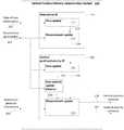
- Fig. 1is a schematic block diagram of an example vertical position and velocity determination system 100 according to an embodiment of the present disclosure.
- the system 100may provide increased computational efficiency in some embodiments, and may be implemented in a wearable electronic device to provide vertical motion information to the wearer of the device.
- the system 100includes inputs for receiving rate of turn information 101, acceleration information 102, and barometric pressure information 103.
- the rate of turn information input 101may, for example, be connected to a gyroscope such as a tri-axial gyroscope (shown in Fig. 3 as part of MEMS-IMU 304).
- the acceleration information input 102may, for example, be connected to an accelerometer such as a tri-axial accelerometer (shown in Fig. 3 as part of MEMS-IMU 304).
- the barometric pressure information input 103may, for example, be connected to a barometric altimeter (shown in Fig. 3 as MEMS Barometric Altimeter 302).
- the system 100may be used in conjunction with an inertial measurement unit (IMU) providing the accelerometer and the gyroscope, and also having a barometric altimeter integrated therewith.
- IMUinertial measurement unit
- the system 100also includes a vertical position estimate output 104 and a vertical velocity estimate output 105.
- the vertical position and velocity determination system 100further includes a cascaded two-step Kalman filter (KF) system including an orientation KF 110 and vertical position/velocity KF 120.
- KFKalman filter
- the output of the first step (orientation KF 110)is provided as an input to the second step (vertical position/velocity KF 120).
- the orientation KF 110includes a gravity vector time-updater 111 and a gravity vector measurement-updater 112.
- the gravity vector time-updater 111generates a prediction 113 of the gravity vector in the sensor frame (the coordinate frame of the IMU-baro) from the rate of turn information input 101.
- the gravity vector measurement-updater 112generates a corrected gravity vector in the sensor frame from a weighted combination of both the gravity vector prediction 113 and the acceleration information input 102. Then, using the corrected gravity vector in the sensor frame, the gravity vector measurement-updater 112 generates roll and pitch angles information 114.
- roll anglerefers to rotation about a horizontal axis along a first (e.g. front-back) direction
- the term “pitch angle”refers to rotation about a horizontal axis along a second (e.g. left-right) direction perpendicular to the first direction.
- the vertical position/velocity KF 120includes a vertical position/velocity time-updater 121, a vertical position/velocity measurement-updater 122, and an optional zero velocity update detector 123.
- the vertical position/velocity time-updater 121generates a vertical position/velocity prediction 124 from the roll and pitch angles information 114 and the acceleration information input 102.
- the vertical position/velocity measurement-updater 122generates a corrected vertical position estimate 104 and a vertical velocity estimate 105 based on a weighted combination of the vertical position/velocity prediction 124 and the barometric pressure information input 103.
- the optional zero velocity update detector 123generates a zero velocity signal 125 from the acceleration information input 102.
- the zero velocity signal 125forces the vertical velocity estimate 105 to zero when still phases are detected by the zero velocity update detector 123.
- An INSestimates navigation parameters including position and velocity by solving strapdown inertial navigation equations though integration of the external acceleration values.
- the INSrequires an accurate estimation of its orientation.
- the embodiment of Fig. 1includes a cascaded KF in the form of an orientation KF cascaded with a vertical position/velocity KF.
- the cascaded KFprovides good computation efficiency.
- the cascaded KFhas much less computational overhead than a global KF because the calculations related to the orientation states are separated from the vertical position/velocity KF.
- the cascaded KFcan be implemented using linear functions whereas the global KF would require non-linear Kalman filtering methods such as those utilzed by an extended Kalman filter (EKF) or an unscented Kalman filter (UKF).
- EKFextended Kalman filter
- UDFunscented Kalman filter
- the cascaded KFallows for increased flexibility and easier implementation and tuning over the global KF.
- the cascaded KFtheoretically produces sub-optimal (less accurate) estimates compared to the global KF, in practice for the purpose of inertial navigation, the performance of the cascaded KF is positively comparable to the global KF.
- Preliminary testing of an example cascaded KF system according to examples disclosed hereinindicates that the vertical trajectory tracking error is about 26.9 cm, 27.2 cm and 28.1 cm for slow motion, vertical jump and step-down jumps vertical trajectory tracking respectively. Details of the experimental setup and further results from the preliminary testing are set forth in the paper attached as Appendix A.
- subscripts 1 and 2refer to the variables of the orientation KF 110 and the vertical position/velocity KF 120, respectively.
- the orientation KF 110generates roll and pitch angles information 114.
- the roll and pitch angles information 114is sufficient for gravitation acceleration compensation and inertial motion tracking in vertical direction. Thus, information of a full three-dimensional orientation is not required.
- Tri-axial gyroscopes and tri-axial accelerometersprovide rate of turn information inputs 101 and acceleration information inputs 102, respectively, to the orientation KF 110.
- the gravity vector time-updater 111performs the function of Equation 1, below, to generate a prediction 113 of the gravity vector in the sensor frame from the rate of turn information input 101.
- x 1 kA 1 k ⁇ 1 x 1 k ⁇ 1 + w 1 k ⁇ 1
- x 1 (k)is the 3 ⁇ 1 state vector for orientation KF 110 at step k; thus, x 1 (k) is the normalized gravity vector in the sensor frame; A 1 is the state transition matrix; and w 1 is the process model noise vector.
- the gravity vector time-updater 111generates the prediction 113 of the gravity vector in the sensor frame, x 1 (k), from a predictive model using a previous gravity vector prediction, x 1 (k-1).
- the gravity vector measurement-updater 112performs the function of Equation 2, below, to the update the gravity vector prediction 113 with measurements from the acceleration information input 102.
- z 1 kC 1 k x 1 k + v 1 k
- Equation 2z 1 is the measurement vector (i.e. the gravity vector measured in the sensor frame of the accelerometers); C 1 is the 3 ⁇ 3 observation matrix; and v 1 is the measurement model noise vector.
- Equations 1 and 2are calculated from Equations 3 to 13, below.
- a 1 k ⁇ 1I 3 ⁇ ⁇ ⁇ t y ⁇ G k ⁇ 1
- the state transition matrix, A 1 (k - 1)is derived from I 3 , which is a 3 ⁇ 3 identity matrix; and ⁇ G , which is the 3 ⁇ 3 skew symmetric matrix of tri-axial gyroscope measurements.
- w 1 k ⁇ 1⁇ ⁇ t ⁇ x ⁇ 1 k n G
- the process model noise vector w 1 (k - 1)is based on x ⁇ 1 , which is a 3 ⁇ 3 skew symmetric matrix of x 1 ; and n G , which is the gyroscope measurement noise vector, and is assumed to be uncorrelated and zero-mean white Gaussian.
- Equations 1, 3 and 4define the gravity vector prediction 113.
- the gravity vector time-updater 111derives x 1 (k), the gravity vector prediction 113, from ⁇ G , the rate of turn information input 101.
- C 1the 3 ⁇ 3 observation matrix, is derived from I 3 , which is a 3 ⁇ 3 identity matrix; and g, which is the norm of gravity vector.
- v 1 k⁇ a ⁇ ⁇ S k + n A
- Equation 6v 1 , the measurement model noise vector, is derived from a ⁇ ⁇ S k , which is the external acceleration error in the sensor frame of the accelerometer; and n A , which is the gyroscope measurement noise vector, and is assumed to be uncorrelated and zero-mean white Gaussian.
- Equations 7 and 8describe the external acceleration error in the sensor frame of the accelerometer.
- the superscripts + and -stand for the "a posteriori” and the "a priori” estimates in the orientation KF 110, respectively; the superscript S denotes that the quantity is in the sensor frame; c a is a dimensionless constant between 0 and 1 that determines the cut-off frequency in the external acceleration model.
- Equation 2The measurement vector, z 1 , in Equation 2 is defined by Equations 9 and 10, where y A (k) is the bias compensated output vector of the accelerometer; and the estimated normalized gravity vector in the sensor frame is x 1 + k .
- Equations 2 and 5-10define the estimated normalized gravity vector in the sensor frame, x 1 + k .
- the gravity vector measurement-updater 112generates an orientation signal 114 indicating roll ( ⁇ ) and pitch ( ⁇ ) angles from y A (k), the acceleration information input 102, and from x 1 (k), the gravity vector prediction 113.
- Q 1 k ⁇ 1⁇ ⁇ t 2 x ⁇ 1 k ⁇ 1 ⁇ G x ⁇ 1 k ⁇ 1
- R 1 k⁇ acc + ⁇ A
- Equations 12 and 13define the process and measurement noise covariance matrices in the orientation KF 110.
- Process noise covariance matrix Q 1 (k - 1)is calculated using the process model noise vector w 1 (k - 1) and is equal to E [ w 1 (k - 1) w 1 (k - 1) T ] where E is the expectation operator.
- ⁇ Gis the covariance matrix of the gyroscope's measurement noise which is defined as E [ n G n G T ]. By assuming that the gyro noise variances are equal to ⁇ G in the three axes, ⁇ G is set to ⁇ G 2 I 3 .
- Measurement noise covariance matrix R 1 (k)is calculated using the measurement model noise vector v 1 (k) and is equal to E [ v 1 (k) v 1 (k) T ].
- ⁇ Awhich is the covariance matrix of accelerometer's measurement noise, is set to ⁇ A 2 I 3 .
- ⁇ accis the covariance of the acceleration model and is set to 3 ⁇ 1 c a 2 ⁇ a + S k ⁇ 1 ⁇ 2 .
- the vertical position/velocity KF 120generates the vertical position estimate 104 and the vertical velocity estimate 105.
- the orientation KF 110, the tri-axial accelerometers, and a barometric altimeterprovide roll ( ⁇ ) and pitch ( ⁇ ) angles (from orientation signal 114), acceleration information (from input 102), and the barometric pressure information (from input 103) respectively, to the vertical position/velocity KF 120.
- the vertical position/velocity time-updater 121performs the function of Equation 14, below, to generate the vertical position/velocity prediction 124 from the roll and pitch angles from orientation signal 114 and the acceleration information from input 102.
- x 2 kA 2 k ⁇ 1 x 2 k ⁇ 1 + B 2 k ⁇ 1 u 2 k ⁇ 1 + w 2 k ⁇ 1
- a 2 k ⁇ 11 ⁇ t 0 1
- B 2 k ⁇ 11 2 ⁇ t 2 ⁇ t
- Equations 15 and 16define the state transition and input matrices A 2 (k - 1) and B 2 (k - 1), respectively.
- u 2 k ⁇ 10 0 1 ⁇ R ⁇ , ⁇ s n y A k ⁇ 1 + 0 0 g T
- Equation 17defines the vertical component of gravity compensated acceleration in the navigation frame.
- the value of the vertical component of gravity compensated acceleration in the navigation frameis based on the rotation matrix, R ⁇ , ⁇ s n which is calculated using roll ( ⁇ ) and pitch ( ⁇ ) angles from the orientation signal114 and the acceleration from input 102, y A k ⁇ 1 .
- R ⁇ , ⁇ s naligns the z-axis of the accelerometer sensor frame to the navigation frame;
- Equations 18 and 19describe the rotation matrix, R ⁇ , ⁇ s n , that aligns the z-axis of the accelerometer sensor frame to the navigation frame; and the 2 ⁇ 1 vector of process noise, w 2 (k - 1), respectively.
- the vertical position/velocity time-updater 121generates x 2 (k), the vertical position/velocity prediction 124, from the roll ( ⁇ ) and pitch ( ⁇ ) angles from the orientation signal 114 and the acceleration information input 102.
- the vertical position/velocity measurement-updater 122performs the function of Equation 20, below, to generate the vertical position estimate 104 and the vertical velocity estimate 105 from the vertical position/velocity prediction 124 and the barometer information input 103.
- z 2 kC 2 k x 2 k + v 2 k
- Equation 20z 2 (k) is the relative height ( ⁇ h baro ), which is calculated from the barometer information input 103; C 2 (k) is the observation matrix; and v 2 (k) is the measurement noise.
- z 2 k ⁇ ⁇ h baro44330 1 ⁇ P P 0 0.19 ⁇ h init
- Equation 21describes how the barometer information input 103, P , is used in the vertical position/velocity measurement-updater 122.
- Equation 22defines the observation matrix C 2 (k).
- Q 2 k ⁇ 1B 2 k ⁇ 1 E w 2 k ⁇ 1 w 2 k ⁇ 1 T
- B 2 k ⁇ 1 T1 2 ⁇ t 2 ⁇ t ⁇ A 2 1 2 ⁇ t 2 ⁇ t T
- Equation 23defines the process noise covariance matrix Q 2 (k - 1) calculated using the process noise vector w 2 (k - 1) and input matrix B 2 (k - 1).
- R 2 k⁇ baro 2
- Equation 24defines the measurement noise covariance matrix R 2 (k), where ⁇ baro 2 is the barometer noise variance.
- the measurement noise covariance matrix R 2 (k)is obtained by E [v 2 (k)v 2 (k) T ].
- the vertical position/velocity determination system of Fig. 1advantageously provides an accurate estimate of a relative height measurement without the use of a GPS. Therefore, the vertical position and velocity determination system 100 can be combined with a GPS/MEMS-IMU to augment the GPS/MEMS-IMU with improved vertical position determination.
- the vertical position and velocity determination system 100is particularly complementary to the GPS/MEMS-IMU since, in a steady state, the GPS can be used to initialize (to an absolute height) the barometric altimeter of the vertical position determination system; whereas, in a dynamic state, the vertical position and velocity determination system 100 can provide an accurate estimate of the relative height measurement, without reliance on the inaccurate dynamic height measurement of the GPS.
- the vertical position and velocity determination system 100optionally includes a zero velocity update detector 123 to limit the drift error in the INS.
- the optional zero velocity update detector 123generates a zero velocity signal 125 from the acceleration information input 102.
- the zero velocity signal 125forces the vertical velocity estimate 105 to zero when still phases are detected by the zero velocity update detector 123.
- still phasesare detected by setting a threshold on the norm of acceleration signal measured by the accelerometers, and determining a still phase when the acceleration signal is below the threshold.
- stationary initializationmay be used to calibrate the vertical position and velocity determination system 100.
- initial attitude and sensor biasesare calculated.
- the tri-axial accelerometer and tri-axial gyroscope dataare used in the orientation KF 110 to calculate the average value of initial tilt angles.
- the external acceleration in the sensor frame, s a + (k)is the by-product of the orientation KF 110. However, since the external acceleration should be zero during the stationary initialization step, the average value of s a + (k) is considered as the accelerometer bias vector in the sensor frame.
- the gyro bias vectoris calculated as the mean value of the tri-axial gyroscope measurement during this stationary initialization step. These bias values are assumed to be constant during the operational periods between stationary initialization procedures.
- the estimated accelerometer and gyroscope biasesare then subtracted from the measured accelerometer and gyroscope signals for vertical trajectory estimation.
- velocityis set to zero and h init in the barometric altimeter is calibrated by initial height obtained from a reference system.
- This reference systemcan provide the actual ellipsoid height for absolute height tracking (such as the one obtained from GPS) or relative height with respect to an arbitarary coordinate system for relative height tracking (such as the one obtained from camera-based MOCAP system).
- the vertical position and velocity determination system 100includes a trajectory smoother (shown in Fig. 3 as RTS 306).
- RTSRauch-Tung-Striebel
- the RTS smootheris a widely used trajectory smoother in navigation applications, for smoothing out position and velocity trajectories.
- the RTS smootherincludes one forward data processing portion and one backward data processing portion.
- the forward processing portion of the RTS smootheris the vertical position/velocity KF 120 of the vertical position and velocity determination system 100.
- the RTS smootherstores the estimate and its covariance from the forward processing portion, and then recursively updates the smoothed estimate and its covariance in a backward sweep using the following Equations 25 to 27:
- K s kP 2 + k A 2 k P 2 ⁇ k + 1 ⁇ 1
- Equations 25 to 27P 2 + and P 2 - are the " a posteriori” and the " a priori” covariance estimates; K s is the smoother gain; x 2 + and x 2 - are the " a posteriori” and the " a priori” state estimates; and x s is the smoothed state vector. All of the above mentioned variables relate to vertical position/velocity KF 120.
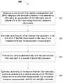
- Fig. 2shows a flow chart diagram of a method 200 of vertical position/velocity determination according to an embodiment of the present disclosure.
- the methodmay be performed by a computer program product tangibly embodied on non-transitory computer readable media.
- the computer program productoperable when executed to perform the method 200.
- the methodmeasures the rate of turn of an inertial measurement unit (IMU) integrated with barometric altimeter in the same device (IMU-baro), an acceleration of the IMU-baro, and an altitude of the IMU-baro using barometric pressure information from the barometric altimeter.
- IMUinertial measurement unit
- these measurementsinclude noisy data; that is, the measurement value inherently includes errors such as errors caused by sensor noise.
- the methodestimates, according to a first Kalman filter operation, a roll and pitch of the IMU-baro based on the rate of turn measurement and the acceleration measurement. In an embodiment, estimating at 202 further includes recursively predicting and correcting steps in a Kalman filter.
- Predictingincludes predicting the gravitational acceleration vector in the IMU-baro sensor frame based on the strapdown integration using rate of turn measurement from gyroscope and the prior gravitational acceleration in the IMU-baro sensor frame. Correcting includes combining the prediction of the gravitational acceleration vector in the sensor frame with the measurement from the accelerometer to generate an estimate of the gravitational acceleration vector in the sensor frame. Finally, roll and pitch angle functions calculate the estimated roll and pitch angles from the estimated gravitational acceleration vector in the sensor frame.
- the methodprovides the roll and pitch estimate from the first Kalman filter operation to a second Kalman filter operation.
- an output of the first Kalman filter operationis an input of the second Kalman filter operation.
- the methodestimates, according to the second Kalman filter operation, vertical position/velocity of the IMU-baro based on the acceleration measurement, the barometric pressure measurement, and the roll and pitch estimate. In an embodiment, estimating at 204 further includes recursively predicting and correcting in a Kalman filter.
- Predictingincludes predicting a vertical position (altitude) and a vertical velocity based on the strapdown integration using acceleration of the IMU-baro and the prior vertical position and vertical velocity.
- Correctingincludes combining, in a Kalman filter, the predicted vertical position and vertical velocity with the measured vertical position (altitude measurement) from the barometric altimeter to generate vertical position and vertical velocity estimates.
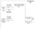
- Fig. 3is a schematic block diagram of an apparatus 300 for vertical trajectory determination in accordance with embodiments of the present disclosure.
- the apparatus 300includes wearable device 302 that can house the various hardware and software components shown in Fig. 1 and Fig. 3 .
- the apparatus 300includes inputs for receiving rate of turn information 101, acceleration information 102, and barometric pressure information 103.
- the apparatus 300may be used in conjunction with an inertial measurement unit (IMU) providing the accelerometer and the gyroscope.
- IMUinertial measurement unit
- the IMUmay also have a barometric altimeter integrated therewith.
- IMU-barois used to refer to such an IMU with an integrated barometric altimeter.
- the rate of turn information input 101may, for example, be connected to a gyroscope such as a tri-axial gyroscope (shown in Fig. 3 as part of MEMS-IMU 304).
- the acceleration information input 102may, for example, be connected to an accelerometer such as a tri-axial accelerometer (shown in Fig. 3 as part of MEMS-IMU 304).
- the barometric pressure information input 103may, for example, be connected to a barometric altimeter (shown in Fig. 3 as MEMS Barometric Altimeter 302).
- the apparatus 300also includes a vertical position estimate output 104 and a vertical velocity estimate output 105.
- the vertical position and velocity determination apparatus 300includes a trajectory smoother 306 (shown in Fig. 3 as RTS 306).
- RTSRauch-Tung-Striebel
- the RTS smoother 306is a widely used trajectory smoother in navigation applications, for smoothing out position and velocity trajectories.
- Embodiments of the disclosurecan be represented as a computer program product stored in a machine-readable medium (also referred to as a computer-readable medium, a processor-readable medium, or a computer usable medium having a computer-readable program code embodied therein).
- the machine-readable mediumcan be any suitable tangible, non-transitory medium, including magnetic, optical, or electrical storage medium including a diskette, compact disk read only memory (CD-ROM), memory device (volatile or non-volatile), or similar storage mechanism.
- the machine-readable mediumcan contain various sets of instructions, code sequences, configuration information, or other data, which, when executed, cause a processor to perform steps in a method according to an embodiment of the disclosure.
- the present disclosureprovides methods and systems for vertical position and velocity determination.
- the vertical position and velocity determinationcombines vertical position information from a vertical position sensor, such as a MEMS barometric altimeter that derives altitude information using pressure measurements, with orientation (tilt angles) and acceleration information derived from a MEMS-IMU.
- the output of the MEMS barometric altimeteris fused with the outputs of a MEMS-IMU using a cascaded two-step Kalman filter (KF) system.
- KFKalman filter
- the proposed processrequires a magnetometer-less MEMS-IMU to provide tilt angles and therefore, the vertical position determination is robust against magnetic disturbances. Additionally, the use of the cascaded KF avoids the need to propagate additional states, improving the computational efficiency of the position determination method. Thus, the position determination method is suitable for small and lightweight battery-powered electronic devices worn by athletes.
- One aspect of the present disclosureprovides a vertical position and velocity determination system for inertial measurement unit (IMU) integrated with a barometric altimeter in the same device (IMU-baro).
- the systemincludes a rate of turn input connected to receive a measured IMU-baro orientation; an acceleration input connected to receive a measured IMU-baro acceleration; a barometric pressure input connected to receive a measured IMU-baro altitude; a first Kalman filter connected to the rate of turn input and to the acceleration input to estimate a roll and pitch of the IMU-baro based on the measured IMU-baro orientation and the measured IMU-baro acceleration; and a second Kalman filter connected to the acceleration input, to the barometric pressure input, and to the first Kalman filter; the second Kalman filter cascaded with the first Kalman filter to receive the estimated roll and pitch angles of the IMU-baro from the first Kalman filter and to estimate vertical position and vertical velocity of the IMU-baro based on the measured IMU-baro acceleration, the measured bar
- the apparatusincludes a first Kalman filter configured to estimate a roll and pitch of the IMU-baro based on a measured IMU-baro rate of turn and based on a measured IMU-baro acceleration, and a second Kalman filter connected to the first Kalman filter in a cascade arrangement to receive the estimated roll and pitch of the IMU-baro.
- the second Kalman filteris configured to estimate a vertical position and vertical velocity of the IMU-baro based on the estimated roll and pitch of the IMU-baro, the measured IMU-baro acceleration, and a measured barometric pressure, and output the estimated vertical position and vertical velocity of the IMU-baro.
- Another aspect of the present disclosureprovides a computer program product tangibly embodied on non-transitory computer readable medium, the computer program product operable when executed to perform a method of determining vertical position and velocity of an IMU-baro.
- the methodincludes measuring a rate of turn of the IMU-baro, an acceleration of the IMU-baro, and a barometric pressure; estimating, according to a first Kalman filter operation, a roll and pitch of the IMU-baro based on the rate of turn measurement and the acceleration measurement; providing the roll and pitch estimate from the first Kalman filter operation to a second Kalman filter operation; estimating, according to the second Kalman filter operation, vertical position and velocity of the IMU-baro based on the acceleration measurement, the barometric pressure measurement, and the roll and pitch estimate; and determining the vertical position and velocity of the IMU-baro based on the estimated vertical position and velocity; and, outputting the determined vertical position and velocity.
Landscapes
- Engineering & Computer Science (AREA)
- Remote Sensing (AREA)
- Radar, Positioning & Navigation (AREA)
- Physics & Mathematics (AREA)
- Health & Medical Sciences (AREA)
- General Physics & Mathematics (AREA)
- Life Sciences & Earth Sciences (AREA)
- General Health & Medical Sciences (AREA)
- Automation & Control Theory (AREA)
- Theoretical Computer Science (AREA)
- Dentistry (AREA)
- Medical Informatics (AREA)
- Veterinary Medicine (AREA)
- Public Health (AREA)
- Animal Behavior & Ethology (AREA)
- Geometry (AREA)
- Surgery (AREA)
- Physiology (AREA)
- Molecular Biology (AREA)
- Oral & Maxillofacial Surgery (AREA)
- Biophysics (AREA)
- Pathology (AREA)
- Biomedical Technology (AREA)
- Heart & Thoracic Surgery (AREA)
- Data Mining & Analysis (AREA)
- Computer Vision & Pattern Recognition (AREA)
- Physical Education & Sports Medicine (AREA)
- Artificial Intelligence (AREA)
- Bioinformatics & Cheminformatics (AREA)
- Evolutionary Biology (AREA)
- Evolutionary Computation (AREA)
- Bioinformatics & Computational Biology (AREA)
- General Engineering & Computer Science (AREA)
- Psychiatry (AREA)
- Social Psychology (AREA)
- Human Computer Interaction (AREA)
- Multimedia (AREA)
- Navigation (AREA)
- Position Fixing By Use Of Radio Waves (AREA)
Description
- This disclosure claims the benefit of
U.S. Provisional Application No. 62/058,517 U.S. Provisional Application No. 62/101,942 - The present disclosure relates to inertial navigation systems including MEMS inertial measurement units, and other systems for capturing and tracking human movement in a vertical direction.
- Key performance variables (KPVs) are quantitative measurements of an athlete's performance. By accessing and reviewing an athlete's KPVs, the athlete can significantly improve overall performance. KPVs allow the athlete to share performance information with coaches, record and track performance over time, and provide real-time feedback to the athlete.
- Currently available video-based or camera-based "motion capture" (MOCAP) approaches provide few quantitative variables. Additionally, these MOCAP techniques are restricted to indoor use or confined areas that are not suitable for motion capture of outdoor sports such as skiing, snowboarding, rollerblading and biking since these activities take place over large distances.
- Inertial navigation systems (INS), on the other hand, are self-contained and thus can provide unconstrained accessibility to advanced motion and location information. INS are widely used in various MOCAP applications such as ship and aircraft navigation, fastening tool and pen tracking, and sports analysis to provide information such as attitude, velocity, and position.
- Recently, miniature micro-electromechanical systems (MEMS) inertial devices have become more common, and the small size of MEMS inertial devices has resulted in the emergence of INS for human body motion tracking using wearable MOCAP technology. Typically, wearable MOCAP devices make use of a MEMS inertial measurement unit (MEMS-IMU) and/or an absolute position sensor to capture motion for indoor/outdoor localization. For example, a MOCAP camera system can act as an absolute position sensor and be added to inertial devices for more accurate human body localization in an indoor environment. For outdoor environments, a global positioning system (GPS) is an exemplary absolute position sensor that can be used to augment an inertial measurement unit for more accurate human body localization.
- A disadvantage in the above mentioned GPS/MEMS-IMU integration approaches is that the consumer grade GPS-derived vertical positional (or altitude) information is typically much less accurate than the horizontal positional information. GPS altitude measurement accuracies can vary up to 40m (with 10m to 20m being common); the most important reasons for this inaccuracy are satellite visibility (i.e. few visible satellites over the horizon) as well as multipath signal effects. Real-time GPS technologies such as real-time kinematic GPS and differential GPS provide higher positional accuracies but their prohibitive cost is a limiting factor for the sport consumer electronics market.
WO2010/025294A1 relates to a positioning device that records the information about the position and/or rotation of an object or person in at least two dimensions of configuration space.- "Cascaded Estimation Architecture for Integration of Foot-Mounted Inertial Sensors" by KRACH BERNHARD ET AL. (PLANS 2008 - PROCEEDINGS OF IEEE/ION PLANS 2008, THE INSTITUTE OF NAVIGATION, 8 May 2008 (2008-05-08), pages 112-119) relates to an algorithm for integrating foot-mounted inertial sensor platforms based on a cascaded estimation architecture. A lower Kalman filter is used to estimate the step-wise change of position and direction of one or optionally both feet respectively. These estimates are used in turn as measurements in an upper particle filter.
- In accordance with the present invention, there is provided a vertical position and velocity determination system as set out in claim 1 and a computer program product as set out in claim 7.
- Embodiments of the present disclosure will now be described, by way of example only, with reference to the attached Figures.
Fig. 1 is a schematic block diagram of a vertical position determination system according to an embodiment of the present disclosure.Fig. 2 is a flow chart diagram of a method of vertical position determination according to an embodiment of the present disclosure.Fig. 3 is a schematic block diagram of an apparatus for vertical trajectory determination in accordance with embodiments of the present disclosure.- This disclosure addresses a need for improvements in vertical position determination in consumer grade devices.
Fig. 1 is a schematic block diagram of an example vertical position andvelocity determination system 100 according to an embodiment of the present disclosure. As described below, thesystem 100 may provide increased computational efficiency in some embodiments, and may be implemented in a wearable electronic device to provide vertical motion information to the wearer of the device.- The
system 100 includes inputs for receiving rate ofturn information 101,acceleration information 102, andbarometric pressure information 103. The rate ofturn information input 101 may, for example, be connected to a gyroscope such as a tri-axial gyroscope (shown inFig. 3 as part of MEMS-IMU 304). Theacceleration information input 102 may, for example, be connected to an accelerometer such as a tri-axial accelerometer (shown inFig. 3 as part of MEMS-IMU 304). The barometricpressure information input 103 may, for example, be connected to a barometric altimeter (shown inFig. 3 as MEMS Barometric Altimeter 302). Thesystem 100 may be used in conjunction with an inertial measurement unit (IMU) providing the accelerometer and the gyroscope, and also having a barometric altimeter integrated therewith. As used herein, the term "IMU-baro" is used to refer to such an IMU with an integrated barometric altimeter. Thesystem 100 also includes a verticalposition estimate output 104 and a verticalvelocity estimate output 105. - The vertical position and
velocity determination system 100 further includes a cascaded two-step Kalman filter (KF) system including anorientation KF 110 and vertical position/velocity KF 120. The output of the first step (orientation KF 110) is provided as an input to the second step (vertical position/velocity KF 120). - The
orientation KF 110 includes a gravity vector time-updater 111 and a gravity vector measurement-updater 112. The gravity vector time-updater 111 generates aprediction 113 of the gravity vector in the sensor frame (the coordinate frame of the IMU-baro) from the rate ofturn information input 101. The gravity vector measurement-updater 112 generates a corrected gravity vector in the sensor frame from a weighted combination of both thegravity vector prediction 113 and theacceleration information input 102. Then, using the corrected gravity vector in the sensor frame, the gravity vector measurement-updater 112 generates roll andpitch angles information 114. As used herein, the term "roll angle" refers to rotation about a horizontal axis along a first (e.g. front-back) direction and the term "pitch angle" refers to rotation about a horizontal axis along a second (e.g. left-right) direction perpendicular to the first direction. - The vertical position/
velocity KF 120 includes a vertical position/velocity time-updater 121, a vertical position/velocity measurement-updater 122, and an optional zerovelocity update detector 123. The vertical position/velocity time-updater 121 generates a vertical position/velocity prediction 124 from the roll andpitch angles information 114 and theacceleration information input 102. - The vertical position/velocity measurement-
updater 122 generates a correctedvertical position estimate 104 and avertical velocity estimate 105 based on a weighted combination of the vertical position/velocity prediction 124 and the barometricpressure information input 103. - The optional zero
velocity update detector 123 generates a zerovelocity signal 125 from theacceleration information input 102. The zerovelocity signal 125 forces thevertical velocity estimate 105 to zero when still phases are detected by the zerovelocity update detector 123. - An INS estimates navigation parameters including position and velocity by solving strapdown inertial navigation equations though integration of the external acceleration values. Thus, it is important for the INS to accurately estimate external acceleration during dynamic conditions by subtracting the gravitational acceleration from the accelerometer signal. To realize this subtraction function, the INS requires an accurate estimation of its orientation.
- The embodiment of
Fig. 1 includes a cascaded KF in the form of an orientation KF cascaded with a vertical position/velocity KF. The cascaded KF provides good computation efficiency. The cascaded KF has much less computational overhead than a global KF because the calculations related to the orientation states are separated from the vertical position/velocity KF. Thus, the cascaded KF can be implemented using linear functions whereas the global KF would require non-linear Kalman filtering methods such as those utilzed by an extended Kalman filter (EKF) or an unscented Kalman filter (UKF). In addition to the improved computational cost, the cascaded KF allows for increased flexibility and easier implementation and tuning over the global KF. - Though the cascaded KF theoretically produces sub-optimal (less accurate) estimates compared to the global KF, in practice for the purpose of inertial navigation, the performance of the cascaded KF is positively comparable to the global KF. Preliminary testing of an example cascaded KF system according to examples disclosed herein indicates that the vertical trajectory tracking error is about 26.9 cm, 27.2 cm and 28.1 cm for slow motion, vertical jump and step-down jumps vertical trajectory tracking respectively. Details of the experimental setup and further results from the preliminary testing are set forth in the paper attached as Appendix A.
- Significant improvement in vertical trajectory tracking accuracy was observed with the use of a Rauch-Tung-Striebel (RTS)-smoother, as discussed below. Additionally, based on the experimental results, the average jump KPVs (height/drop) determination error with the use of an RTS-smoother is about 2.9 cm and 5.8 cm for vertical jump and step-down jump respectively (compared to the -40 m error of the GPS in some spots in the vertical direction). This achieved accuracy should be sufficient for recreational purposes where the magnitude of jump height is small. On the other hand, the magnitude of jump height in athletic sport jumps is much higher than the one in recreational jumps. As a result, the achieved jump KPVs determination accuracy of about 2.9-5.8 cm should also be adequate for outdoor measurement purposes using wearable technologies.
- The structures of the individual filters in the cascaded KF, i.e. the
orientation KF 110 and the vertical position/velocity KF 120, will now be described. In the following description, subscripts 1 and 2 refer to the variables of theorientation KF 110 and the vertical position/velocity KF 120, respectively. - The
orientation KF 110 generates roll and pitch anglesinformation 114. The roll and pitch anglesinformation 114 is sufficient for gravitation acceleration compensation and inertial motion tracking in vertical direction. Thus, information of a full three-dimensional orientation is not required. - Tri-axial gyroscopes and tri-axial accelerometers provide rate of
turn information inputs 101 andacceleration information inputs 102, respectively, to theorientation KF 110. The gravity vector time-updater 111 performs the function of Equation 1, below, to generate aprediction 113 of the gravity vector in the sensor frame from the rate ofturn information input 101.
- In Equation 1,x1(k) is the 3 × 1 state vector for
orientation KF 110 at step k; thus,x1(k) is the normalized gravity vector in the sensor frame;A1 is the state transition matrix; andw1 is the process model noise vector. The gravity vector time-updater 111 generates theprediction 113 of the gravity vector in the sensor frame,x1(k), from a predictive model using a previous gravity vector prediction,x1(k-1). - The gravity vector measurement-
updater 112 performs the function of Equation 2, below, to the update thegravity vector prediction 113 with measurements from theacceleration information input 102.
- In Equation 2,z1 is the measurement vector (i.e. the gravity vector measured in the sensor frame of the accelerometers);C1 is the 3 × 3 observation matrix; andv1 is the measurement model noise vector.
- The matrices of Equations 1 and 2 are calculated from Equations 3 to 13, below.

- The state transition matrix,A1(k - 1), is derived fromI3, which is a 3 × 3 identity matrix; andỹG, which is the 3 × 3 skew symmetric matrix of tri-axial gyroscope measurements.

- The process model noise vectorw1(k - 1), is based onx̃1, which is a 3 × 3 skew symmetric matrix ofx1; andnG, which is the gyroscope measurement noise vector, and is assumed to be uncorrelated and zero-mean white Gaussian.
- Thus, Equations 1, 3 and 4 define the
gravity vector prediction 113. In this way, the gravity vector time-updater 111 derivesx1(k), thegravity vector prediction 113, fromỹG, the rate ofturn information input 101. 
- In Equation 5,C1, the 3 × 3 observation matrix, is derived fromI3, which is a 3 × 3 identity matrix; and g, which is the norm of gravity vector.

- In Equation 6,v1, the measurement model noise vector, is derived from

- Equations 7 and 8 describe the external acceleration error in the sensor frame of the accelerometer.


- In Equation 7,Sa(k) =caSa(k - 1) +ε(k), withε(k) being the time-varying error of the external acceleration process model. In Equations 7 and 8, the superscripts + and - stand for the "aposteriori" and the "apriori" estimates in the
orientation KF 110, respectively; the superscript S denotes that the quantity is in the sensor frame;ca is a dimensionless constant between 0 and 1 that determines the cut-off frequency in the external acceleration model.

- The measurement vector,z1, in Equation 2 is defined by Equations 9 and 10, whereyA(k) is the bias compensated output vector of the accelerometer; and the estimated normalized gravity vector in the sensor frame is


- Equation 11 uses the estimated normalized gravity vector in the sensor frame,

updater 112 generates anorientation signal 114 indicating roll (γ) and pitch (β) angles fromyA(k), theacceleration information input 102, and fromx1(k), thegravity vector prediction 113.

- Equations 12 and 13 define the process and measurement noise covariance matrices in the
orientation KF 110. Process noise covariance matrixQ1(k - 1) is calculated using the process model noise vectorw1(k - 1) and is equal toE[w1 (k - 1)w1(k - 1)T] whereE is the expectation operator.∑G is the covariance matrix of the gyroscope's measurement noise which is defined asE[nGnGT]. By assuming that the gyro noise variances are equal toσG in the three axes,∑G is set to
- Measurement noise covariance matrixR1(k) is calculated using the measurement model noise vectorv1(k) and is equal toE[v1(k)v1(k)T].∑A, which is the covariance matrix of accelerometer's measurement noise, is set to


- The vertical position/
velocity KF 120 generates thevertical position estimate 104 and thevertical velocity estimate 105. Theorientation KF 110, the tri-axial accelerometers, and a barometric altimeter, provide roll (γ) and pitch (β) angles (from orientation signal 114), acceleration information (from input 102), and the barometric pressure information (from input 103) respectively, to the vertical position/velocity KF 120. - The vertical position/velocity time-
updater 121 performs the function of Equation 14, below, to generate the vertical position/velocity prediction 124 from the roll and pitch angles fromorientation signal 114 and the acceleration information frominput 102.
- In Equation 14,x2(k) = [h(k) v(k)]T is the state vector for the vertical position/
velocity KF 120, including vertical position and vertical velocity components;A2(k - 1) andB2(k - 1) are the state transition and input matrices for the vertical position/velocity KF 120; u2(k - 1) is the input vector, which includes the vertical component of gravity compensated acceleration in the navigation frame, and is calculated usinginputs 

- Equations 15 and 16 define the state transition and input matricesA2(k - 1) andB2(k - 1), respectively.

- Equation 17 defines the vertical component of gravity compensated acceleration in the navigation frame. The value of the vertical component of gravity compensated acceleration in the navigation frame is based on the rotation matrix,

input 102,


- Equations 18 and 19 describe the rotation matrix,

- According to Equations 14 to 19, the vertical position/velocity time-
updater 121 generatesx2(k), the vertical position/velocity prediction 124, from the roll (γ) and pitch (β) angles from theorientation signal 114 and theacceleration information input 102. - The vertical position/velocity measurement-
updater 122 performs the function of Equation 20, below, to generate thevertical position estimate 104 and thevertical velocity estimate 105 from the vertical position/velocity prediction 124 and thebarometer information input 103.
- In Equation 20, z2(k) is the relative height (Δhbaro), which is calculated from the
barometer information input 103;C2(k) is the observation matrix; and v2(k) is the measurement noise.
- Equation 21 describes how the
barometer information input 103,P, is used in the vertical position/velocity measurement-updater 122. In Equation 21, Δhbaro is the relative height with respect to the initial height (hinit) of a reference position; hinit is calculated using the initial pressure data at a reference position, (hinit may be calculated, for example using stationary initialization as discussed below; andP0 is the standard pressure equal to 101,325 Pa. Due to the significant quantization noise present in the barometric altimeter, a rolling average filter should be used to increase the accuracy of the barometric height measurement and its remaining residual errors should be taken into account in the measurement noise, v2(k).
- Equation 22 defines the observation matrixC2(k).

- Equation 23 defines the process noise covariance matrixQ2(k - 1) calculated using the process noise vectorw2(k - 1) and input matrixB2(k - 1).

- Equation 24 defines the measurement noise covariance matrix R2(k), where

- According to Equations 20 to 24, the vertical position/velocity measurement-
updater 122 correctsx2(k) = [h(k) v(k)]T, the vertical position/velocity prediction 124, with z2(k), a relative height measurement derived from thebarometer information input 103, to generate thevertical position estimate 104, h(k), and thevertical velocity estimate 105, h(k). - The vertical position/velocity determination system of
Fig. 1 advantageously provides an accurate estimate of a relative height measurement without the use of a GPS. Therefore, the vertical position andvelocity determination system 100 can be combined with a GPS/MEMS-IMU to augment the GPS/MEMS-IMU with improved vertical position determination. The vertical position andvelocity determination system 100 is particularly complementary to the GPS/MEMS-IMU since, in a steady state, the GPS can be used to initialize (to an absolute height) the barometric altimeter of the vertical position determination system; whereas, in a dynamic state, the vertical position andvelocity determination system 100 can provide an accurate estimate of the relative height measurement, without reliance on the inaccurate dynamic height measurement of the GPS. - In a further embodiment of
Fig. 1 , the vertical position andvelocity determination system 100 optionally includes a zerovelocity update detector 123 to limit the drift error in the INS. The optional zerovelocity update detector 123 generates a zerovelocity signal 125 from theacceleration information input 102. The zerovelocity signal 125 forces thevertical velocity estimate 105 to zero when still phases are detected by the zerovelocity update detector 123. In some embodiments, still phases are detected by setting a threshold on the norm of acceleration signal measured by the accelerometers, and determining a still phase when the acceleration signal is below the threshold. - In some embodiments, stationary initialization may be used to calibrate the vertical position and
velocity determination system 100. During stationary initialization, initial attitude and sensor biases are calculated. The tri-axial accelerometer and tri-axial gyroscope data are used in theorientation KF 110 to calculate the average value of initial tilt angles. The external acceleration in the sensor frame,sa+ (k), is the by-product of theorientation KF 110. However, since the external acceleration should be zero during the stationary initialization step, the average value ofsa+ (k) is considered as the accelerometer bias vector in the sensor frame. Assuming that MEMS gyroscopes are not accurate enough to measure earth's rotation rate, the gyro bias vector is calculated as the mean value of the tri-axial gyroscope measurement during this stationary initialization step. These bias values are assumed to be constant during the operational periods between stationary initialization procedures. The estimated accelerometer and gyroscope biases are then subtracted from the measured accelerometer and gyroscope signals for vertical trajectory estimation. During the stationary initialization step, velocity is set to zero and hinit in the barometric altimeter is calibrated by initial height obtained from a reference system. This reference system can provide the actual ellipsoid height for absolute height tracking (such as the one obtained from GPS) or relative height with respect to an arbitarary coordinate system for relative height tracking (such as the one obtained from camera-based MOCAP system). - In yet a further embodiment of the present disclosure, the vertical position and
velocity determination system 100 includes a trajectory smoother (shown inFig. 3 as RTS 306). In applications where real-time data processing is not required, the accuracy of the vertical position estimate can be further improved by smoothing, which combines forward and backward processed data. In an example, the trajectory smoother of the verticalposition determination system 100 is configured as a Rauch-Tung-Striebel (RTS) trajectory smoother. The RTS smoother is a widely used trajectory smoother in navigation applications, for smoothing out position and velocity trajectories. The RTS smoother includes one forward data processing portion and one backward data processing portion. The forward processing portion of the RTS smoother is the vertical position/velocity KF 120 of the vertical position andvelocity determination system 100. The RTS smoother stores the estimate and its covariance from the forward processing portion, and then recursively updates the smoothed estimate and its covariance in a backward sweep using the following Equations 25 to 27:


- In Equations 25 to 27,P2+ andP2- are the "a posteriori" and the "a priori" covariance estimates;Ks is the smoother gain;x2+ andx2- are the "a posteriori" and the "a priori" state estimates; andxs is the smoothed state vector. All of the above mentioned variables relate to vertical position/
velocity KF 120. Fig. 2 shows a flow chart diagram of amethod 200 of vertical position/velocity determination according to an embodiment of the present disclosure. The method may be performed by a computer program product tangibly embodied on non-transitory computer readable media. The computer program product operable when executed to perform themethod 200.- At 201, the method measures the rate of turn of an inertial measurement unit (IMU) integrated with barometric altimeter in the same device (IMU-baro), an acceleration of the IMU-baro, and an altitude of the IMU-baro using barometric pressure information from the barometric altimeter. In an embodiment, these measurements include noisy data; that is, the measurement value inherently includes errors such as errors caused by sensor noise.
- At 202, the method estimates, according to a first Kalman filter operation, a roll and pitch of the IMU-baro based on the rate of turn measurement and the acceleration measurement. In an embodiment, estimating at 202 further includes recursively predicting and correcting steps in a Kalman filter.
- Predicting includes predicting the gravitational acceleration vector in the IMU-baro sensor frame based on the strapdown integration using rate of turn measurement from gyroscope and the prior gravitational acceleration in the IMU-baro sensor frame. Correcting includes combining the prediction of the gravitational acceleration vector in the sensor frame with the measurement from the accelerometer to generate an estimate of the gravitational acceleration vector in the sensor frame. Finally, roll and pitch angle functions calculate the estimated roll and pitch angles from the estimated gravitational acceleration vector in the sensor frame.
- At 203, the method provides the roll and pitch estimate from the first Kalman filter operation to a second Kalman filter operation. In embodiment, an output of the first Kalman filter operation is an input of the second Kalman filter operation.
- At 204, the method estimates, according to the second Kalman filter operation, vertical position/velocity of the IMU-baro based on the acceleration measurement, the barometric pressure measurement, and the roll and pitch estimate. In an embodiment, estimating at 204 further includes recursively predicting and correcting in a Kalman filter.
- Predicting includes predicting a vertical position (altitude) and a vertical velocity based on the strapdown integration using acceleration of the IMU-baro and the prior vertical position and vertical velocity.
- Correcting includes combining, in a Kalman filter, the predicted vertical position and vertical velocity with the measured vertical position (altitude measurement) from the barometric altimeter to generate vertical position and vertical velocity estimates.
Fig. 3 is a schematic block diagram of anapparatus 300 for vertical trajectory determination in accordance with embodiments of the present disclosure. Theapparatus 300 includeswearable device 302 that can house the various hardware and software components shown inFig. 1 andFig. 3 . Theapparatus 300 includes inputs for receiving rate ofturn information 101,acceleration information 102, andbarometric pressure information 103. Theapparatus 300 may be used in conjunction with an inertial measurement unit (IMU) providing the accelerometer and the gyroscope. In some instances, the IMU may also have a barometric altimeter integrated therewith. As used herein, the term "IMU-baro" is used to refer to such an IMU with an integrated barometric altimeter.- The rate of
turn information input 101 may, for example, be connected to a gyroscope such as a tri-axial gyroscope (shown inFig. 3 as part of MEMS-IMU 304). Theacceleration information input 102 may, for example, be connected to an accelerometer such as a tri-axial accelerometer (shown inFig. 3 as part of MEMS-IMU 304). The barometricpressure information input 103 may, for example, be connected to a barometric altimeter (shown inFig. 3 as MEMS Barometric Altimeter 302). Theapparatus 300 also includes a verticalposition estimate output 104 and a verticalvelocity estimate output 105. - In some embodiments of the present disclosure, the vertical position and
velocity determination apparatus 300 includes a trajectory smoother 306 (shown inFig. 3 as RTS 306). In applications where real-time data processing is not required, the accuracy of the vertical position estimate can be further improved by smoothing, which combines forward and backward processed data. In an example, the trajectory smoother of the verticalposition determination apparatus 300 is configured as a Rauch-Tung-Striebel (RTS) trajectory smoother 306. The RTS smoother 306 is a widely used trajectory smoother in navigation applications, for smoothing out position and velocity trajectories. - In the preceding description, for purposes of explanation, numerous details are set forth in order to provide a thorough understanding of the embodiments. However, it will be apparent to one skilled in the art that these specific details are not required. In other instances, well-known electrical structures and circuits are shown in block diagram form in order not to obscure the understanding. For example, specific details are not provided as to whether the embodiments described herein are implemented as a software routine, hardware circuit, firmware, or a combination thereof.
- Embodiments of the disclosure can be represented as a computer program product stored in a machine-readable medium (also referred to as a computer-readable medium, a processor-readable medium, or a computer usable medium having a computer-readable program code embodied therein). The machine-readable medium can be any suitable tangible, non-transitory medium, including magnetic, optical, or electrical storage medium including a diskette, compact disk read only memory (CD-ROM), memory device (volatile or non-volatile), or similar storage mechanism. The machine-readable medium can contain various sets of instructions, code sequences, configuration information, or other data, which, when executed, cause a processor to perform steps in a method according to an embodiment of the disclosure. Those of ordinary skill in the art will appreciate that other instructions and operations necessary to implement the described implementations can also be stored on the machine-readable medium. The instructions stored on the machine-readable medium can be executed by a processor or other suitable processing device, and can interface with circuitry to perform the described tasks.
- The above-described embodiments are intended to be examples only. Alterations, modifications and variations can be effected to the particular embodiments by those of skill in the art. The scope of the claims should not be limited by the particular embodiments set forth herein, but should be construed in a manner consistent with the specification as a whole.
- The present disclosure provides methods and systems for vertical position and velocity determination. The vertical position and velocity determination combines vertical position information from a vertical position sensor, such as a MEMS barometric altimeter that derives altitude information using pressure measurements, with orientation (tilt angles) and acceleration information derived from a MEMS-IMU. The output of the MEMS barometric altimeter is fused with the outputs of a MEMS-IMU using a cascaded two-step Kalman filter (KF) system.
- The proposed process requires a magnetometer-less MEMS-IMU to provide tilt angles and therefore, the vertical position determination is robust against magnetic disturbances. Additionally, the use of the cascaded KF avoids the need to propagate additional states, improving the computational efficiency of the position determination method. Thus, the position determination method is suitable for small and lightweight battery-powered electronic devices worn by athletes.
- One aspect of the present disclosure provides a vertical position and velocity determination system for inertial measurement unit (IMU) integrated with a barometric altimeter in the same device (IMU-baro). The system includes a rate of turn input connected to receive a measured IMU-baro orientation; an acceleration input connected to receive a measured IMU-baro acceleration; a barometric pressure input connected to receive a measured IMU-baro altitude; a first Kalman filter connected to the rate of turn input and to the acceleration input to estimate a roll and pitch of the IMU-baro based on the measured IMU-baro orientation and the measured IMU-baro acceleration; and a second Kalman filter connected to the acceleration input, to the barometric pressure input, and to the first Kalman filter; the second Kalman filter cascaded with the first Kalman filter to receive the estimated roll and pitch angles of the IMU-baro from the first Kalman filter and to estimate vertical position and vertical velocity of the IMU-baro based on the measured IMU-baro acceleration, the measured barometric pressure using barometric altimeter, and the estimated roll and pitch of the IMU-baro.
- Another aspect of the present disclosure provides an apparatus for determining an altitude of IMU-baro. The apparatus includes a first Kalman filter configured to estimate a roll and pitch of the IMU-baro based on a measured IMU-baro rate of turn and based on a measured IMU-baro acceleration, and a second Kalman filter connected to the first Kalman filter in a cascade arrangement to receive the estimated roll and pitch of the IMU-baro. The second Kalman filter is configured to estimate a vertical position and vertical velocity of the IMU-baro based on the estimated roll and pitch of the IMU-baro, the measured IMU-baro acceleration, and a measured barometric pressure, and output the estimated vertical position and vertical velocity of the IMU-baro.
- Another aspect of the present disclosure provides a computer program product tangibly embodied on non-transitory computer readable medium, the computer program product operable when executed to perform a method of determining vertical position and velocity of an IMU-baro. The method includes measuring a rate of turn of the IMU-baro, an acceleration of the IMU-baro, and a barometric pressure; estimating, according to a first Kalman filter operation, a roll and pitch of the IMU-baro based on the rate of turn measurement and the acceleration measurement; providing the roll and pitch estimate from the first Kalman filter operation to a second Kalman filter operation; estimating, according to the second Kalman filter operation, vertical position and velocity of the IMU-baro based on the acceleration measurement, the barometric pressure measurement, and the roll and pitch estimate; and determining the vertical position and velocity of the IMU-baro based on the estimated vertical position and velocity; and,
outputting the determined vertical position and velocity. - Other aspects and features of the present disclosure will become apparent to those ordinarily skilled in the art upon review of the following description of specific embodiments in conjunction with the accompanying figures.


Claims (15)
- A vertical position and velocity determination system (100) for inertial measurement unit, IMU, integrated with a barometric altimeter in the same device, IMU-baro, the system comprising:a rate of turn input (101) connected to receive a measured IMU-baro orientation;an acceleration input (102) connected to receive a measured IMU-baro acceleration;a barometric pressure input (103) connected to receive a measured IMU-baro altitude;a first Kalman filter connected to the rate of turn input and to the acceleration input to estimate a roll and pitch of the IMU-baro based on the measured IMU-baro orientation and the measured IMU-baro acceleration;a second Kalman filter connected to the acceleration input, to the barometric pressure input, and to the first Kalman filter; the second Kalman filter cascaded with the first Kalman filter to receive the estimated roll and pitch angles of the IMU-baro from the first Kalman filter and to estimate vertical position and vertical velocity of the IMU-baro based on the measured IMU-baro acceleration, the measured barometric pressure using barometric altimeter, and the estimated roll and pitch of the IMU-baro.
- The system of claim 1 further comprising a zero velocity update detector (123) connected to both the acceleration input and the second Kalman filter to provide a zero velocity signal (125) to the second Kalman filter when still phases are detected at the acceleration input.
- The system of claim 1 further comprising a Rauch-Tung-Striebel, RTS, trajectory smoother (306), wherein the smoother stores the estimated vertical position and vertical velocity states and a covariance of the estimated states from the second Kalman filter, and recursively updates the estimated vertical position and velocity and the covariance in a backward sweep.
- The system of claim 1 wherein the barometric pressure input is connected to a micro-electromechanical systems barometric altimeter (302) and the rate of turn and acceleration inputs are connected to a micro-electromechanical systems inertial measurement unit, MEMS-IMU, (304).
- The system of claim 4 wherein the MEMS-IMU comprises a tri-axial accelerometer and a tri-axial gyroscope.
- The system of claim 1 wherein the IMU-baro is part of a wearable electronic device.
- A computer program product, comprising a computer usable medium having a computer readable program code embodied therein, said computer readable program code adapted to be executed to implement a method for determining vertical position and velocity of an inertial measurement unit with integrated altimeter barometer, IMU-baro, the method comprising:measuring (201) a rate of turn of the IMU-baro, an acceleration of the IMU-baro, and a barometric pressure;estimating (202), according to a first Kalman filter operation, a roll and pitch of the IMU-baro based on the rate of turn measurement and the acceleration measurement;providing (203) the roll and pitch estimate from the first Kalman filter operation to a second Kalman filter operation;estimating (204), according to the second Kalman filter operation, vertical position and velocity of the IMU-baro based on the acceleration measurement, the barometric pressure measurement, and the roll and pitch estimate; anddetermining the vertical position and velocity of the IMU-baro based on the estimated vertical position and velocity; and,outputting the determined vertical position and velocity.
- The computer program product of claim 7, wherein the method executed by the computer readable program code comprises detecting still phases of the IMU-baro when the acceleration of the IMU-baro is below a threshold and providing a zero velocity signal to the second Kalman filter when still phases are detected.
- The computer program product of claim 7, wherein the method executed by the computer readable program code comprises smoothing the vertical position and velocity by storing the estimated vertical position and vertical velocity states and a covariance of the estimated states from the second Kalman filter, and recursively updating the estimated vertical position and velocity and the covariance in a backward sweep.
- An apparatus (300) for determining an altitude of IMU-baro, the apparatus comprising:
a vertical position and velocity determination system (100) of claim 1. - The apparatus of claim 10, further comprising a zero velocity update detector (123) connected to both the acceleration input and the second Kalman filter to provide a zero velocity signal (125) to the second Kalman filter when still phases are detected at the acceleration input.
- The apparatus of claim 10 wherein the barometric pressure input is connected to a micro-electromechanical systems barometric altimeter (302) and the rate of turn and acceleration inputs are connected to a micro-electromechanical systems inertial measurement unit, MEMS-IMU (304).
- The apparatus of claim 12 wherein the MEMS-IMU comprises a tri-axial accelerometer and a tri-axial gyroscope.
- The apparatus of claim 10 further comprising a Rauch-Tung-Striebel, RTS, trajectory smoother (306), wherein the smoother stores the estimated vertical position and vertical velocity states and a covariance of the estimated states from the second Kalman filter, and recursively updates the estimated vertical position and velocity and the covariance in a backward sweep.
- The apparatus of any one of claims 10-14 wherein the IMU-baro is part of a wearable electronic device.
Applications Claiming Priority (3)
| Application Number | Priority Date | Filing Date | Title |
|---|---|---|---|
| US201462058517P | 2014-10-01 | 2014-10-01 | |
| US201562101942P | 2015-01-09 | 2015-01-09 | |
| PCT/US2015/053517WO2016054390A1 (en) | 2014-10-01 | 2015-10-01 | Methods and systems for vertical trajectory determination |
Publications (3)
| Publication Number | Publication Date |
|---|---|
| EP3201569A1 EP3201569A1 (en) | 2017-08-09 |
| EP3201569A4 EP3201569A4 (en) | 2018-06-20 |
| EP3201569B1true EP3201569B1 (en) | 2020-02-26 |
Family
ID=55631528
Family Applications (2)
| Application Number | Title | Priority Date | Filing Date |
|---|---|---|---|
| EP15846175.6AActiveEP3201633B1 (en) | 2014-10-01 | 2015-10-01 | Methods and systems for vertical trajectory determination and automatic jump detection |
| EP15845616.0AActiveEP3201569B1 (en) | 2014-10-01 | 2015-10-01 | Methods and systems for vertical trajectory determination |
Family Applications Before (1)
| Application Number | Title | Priority Date | Filing Date |
|---|---|---|---|
| EP15846175.6AActiveEP3201633B1 (en) | 2014-10-01 | 2015-10-01 | Methods and systems for vertical trajectory determination and automatic jump detection |
Country Status (4)
| Country | Link |
|---|---|
| US (2) | US10240929B2 (en) |
| EP (2) | EP3201633B1 (en) |
| CN (2) | CN107076554B (en) |
| WO (2) | WO2016054390A1 (en) |
Families Citing this family (18)
| Publication number | Priority date | Publication date | Assignee | Title |
|---|---|---|---|---|
| CN107076554B (en) | 2014-10-01 | 2019-08-20 | 英特尔公司 | Method and system for the determining and automatic jump detection of normal trajectories |
| FR3051373A1 (en)* | 2016-05-23 | 2017-11-24 | Piq | METHOD OF CALCULATING THE HEIGHT OF A JUMP. |
| CN106705936B (en)* | 2016-12-06 | 2019-03-26 | 浙江华飞智能科技有限公司 | A kind of unmanned plane height optimization method and device |
| CN107027157B (en)* | 2017-05-24 | 2020-12-04 | 北京小米移动软件有限公司 | Location update method and device |
| GB2573304A (en)* | 2018-05-01 | 2019-11-06 | Caterpillar Inc | A method of operating a machine comprising am implement |
| US11136040B2 (en)* | 2018-05-21 | 2021-10-05 | Deere & Company | IMU based traction control for wheeled or tracked machine |
| EP3803270B1 (en)* | 2018-05-28 | 2024-12-18 | HERE Global B.V. | Multilevel altitude maps |
| RU2687348C1 (en)* | 2018-06-29 | 2019-05-13 | Общество с ограниченной ответственностью "Научно Инженерная Компания" | Method of monitoring barometric height systematic errors based on speed data |
| CN111664834A (en)* | 2019-03-07 | 2020-09-15 | 中国科学院上海高等研究院 | Method/system for estimating elevation position of indoor moving body, storage medium, and apparatus |
| CN109827577B (en)* | 2019-03-26 | 2020-11-20 | 电子科技大学 | High-precision inertial navigation and positioning algorithm based on motion state detection |
| CN110986895A (en)* | 2019-12-06 | 2020-04-10 | 昆明理工大学 | Method and system for judging the complete entry of lead fish into water based on Kalman filter algorithm |
| CN112504275B (en)* | 2020-11-16 | 2022-09-02 | 哈尔滨工程大学 | Water surface ship horizontal attitude measurement method based on cascade Kalman filtering algorithm |
| CN113057609B (en)* | 2021-04-20 | 2022-02-18 | 吉林大学 | Vital sign monitoring method and system |
| CN113326645B (en)* | 2021-05-28 | 2024-07-30 | 清华大学 | Analysis method for jump dynamics of flexible micro magnetic control robot |
| CN114650089B (en)* | 2022-03-15 | 2023-09-22 | 广东汇天航空航天科技有限公司 | Aircraft positioning and tracking processing method, device and positioning and tracking system |
| US12303742B2 (en)* | 2022-06-30 | 2025-05-20 | Gomore Inc. | Method and device for predicting sports performance, and computer readable storage medium |
| US12307871B2 (en)* | 2023-03-28 | 2025-05-20 | Stmicroelectronics International N.V. | In-sensor fall detection |
| US12337211B2 (en)* | 2023-10-03 | 2025-06-24 | Paul V. Mackovjak | Jump height measuring device and method of use |
Family Cites Families (25)
| Publication number | Priority date | Publication date | Assignee | Title |
|---|---|---|---|---|
| US4882697A (en) | 1987-04-16 | 1989-11-21 | Honeywell Inc. | Stabilization control circuit for vertical position in an inertial navigator |
| US6246960B1 (en)* | 1998-11-06 | 2001-06-12 | Ching-Fang Lin | Enhanced integrated positioning method and system thereof for vehicle |
| US6205400B1 (en)* | 1998-11-27 | 2001-03-20 | Ching-Fang Lin | Vehicle positioning and data integrating method and system thereof |
| EP1136788A1 (en) | 2000-03-22 | 2001-09-26 | Asulab S.A. | Portable GPS receiver using a barometric altimeter |
| US6298287B1 (en)* | 2000-07-24 | 2001-10-02 | Litton Systems, Inc. | System and method of compensating for pressure sensor errors and noise in inertial vertical loop data |
| AU2001214712A1 (en)* | 2000-11-06 | 2002-05-21 | Ching-Fang Lin | Positioning and ground proximity warning method and system thereof for vehicle |
| AU2001225779A1 (en)* | 2000-12-07 | 2002-06-18 | Ching-Fang Lin | Vehicle positioning and data integrating method and system thereof |
| US7970501B2 (en)* | 2005-03-08 | 2011-06-28 | Honeywell International Inc. | Methods and systems utilizing true airspeed to improve vertical velocity accuracy |
| JP2007093433A (en) | 2005-09-29 | 2007-04-12 | Hitachi Ltd | Detector for motion of pedestrian |
| WO2007082389A1 (en) | 2006-01-20 | 2007-07-26 | 6Th Dimension Devices Inc. | Method and system for assessing athletic performance |
| WO2007100337A1 (en)* | 2006-03-03 | 2007-09-07 | Tte Technology, Inc. | Cooling structure for heat generating device |
| EP2025178A2 (en)* | 2006-05-31 | 2009-02-18 | TRX Systems, Inc. | Method and system for locating and monitoring first responders |
| US8250921B2 (en) | 2007-07-06 | 2012-08-28 | Invensense, Inc. | Integrated motion processing unit (MPU) with MEMS inertial sensing and embedded digital electronics |
| US8224575B2 (en) | 2008-04-08 | 2012-07-17 | Ensco, Inc. | Method and computer-readable storage medium with instructions for processing data in an internal navigation system |
| WO2010025294A1 (en)* | 2008-08-27 | 2010-03-04 | Kent Sporting Goods Co., Inc. | Position determination systems and methods for use in sporting and recreational activities |
| US8628453B2 (en)* | 2008-12-05 | 2014-01-14 | Nike, Inc. | Athletic performance monitoring systems and methods in a team sports environment |
| US9354447B2 (en)* | 2010-01-18 | 2016-05-31 | Intel Corporation | Head mounted information systems and related methods |
| US20110238308A1 (en) | 2010-03-26 | 2011-09-29 | Isaac Thomas Miller | Pedal navigation using leo signals and body-mounted sensors |
| US9737261B2 (en)* | 2012-04-13 | 2017-08-22 | Adidas Ag | Wearable athletic activity monitoring systems |
| US9326704B2 (en) | 2012-06-22 | 2016-05-03 | Alpinereplay, Inc. | Method and apparatus for determining sportsman jumps using fuzzy logic |
| JP6035915B2 (en)* | 2012-07-05 | 2016-11-30 | カシオ計算機株式会社 | Direction display device and direction display system |
| US8862394B2 (en) | 2013-01-22 | 2014-10-14 | Ensco, Inc. | System and method for tracking and locating a person, animal, or machine |
| CN203116727U (en)* | 2013-02-04 | 2013-08-07 | 中国科学院自动化研究所北仑科学艺术实验中心 | Ship attitude detection device |
| US9213889B2 (en)* | 2013-03-28 | 2015-12-15 | The Regents Of The University Of Michigan | Athlete speed prediction method using data from attached inertial measurement unit |
| CN107076554B (en) | 2014-10-01 | 2019-08-20 | 英特尔公司 | Method and system for the determining and automatic jump detection of normal trajectories |
- 2015
- 2015-10-01CNCN201580047290.8Apatent/CN107076554B/enactiveActive
- 2015-10-01EPEP15846175.6Apatent/EP3201633B1/enactiveActive
- 2015-10-01USUS15/507,328patent/US10240929B2/ennot_activeExpired - Fee Related
- 2015-10-01WOPCT/US2015/053517patent/WO2016054390A1/enactiveApplication Filing
- 2015-10-01USUS15/507,549patent/US10222213B2/ennot_activeExpired - Fee Related
- 2015-10-01CNCN201580046983.5Apatent/CN106662443B/enactiveActive
- 2015-10-01EPEP15845616.0Apatent/EP3201569B1/enactiveActive
- 2015-10-01WOPCT/US2015/053521patent/WO2016054394A1/enactiveApplication Filing
Non-Patent Citations (1)
| Title |
|---|
| None* |
Also Published As
| Publication number | Publication date |
|---|---|
| WO2016054394A1 (en) | 2016-04-07 |
| EP3201633B1 (en) | 2019-07-03 |
| EP3201569A4 (en) | 2018-06-20 |
| EP3201633A1 (en) | 2017-08-09 |
| CN106662443A (en) | 2017-05-10 |
| WO2016054390A1 (en) | 2016-04-07 |
| US10240929B2 (en) | 2019-03-26 |
| CN107076554B (en) | 2019-08-20 |
| EP3201569A1 (en) | 2017-08-09 |
| CN107076554A (en) | 2017-08-18 |
| US20170307376A1 (en) | 2017-10-26 |
| EP3201633A4 (en) | 2018-05-02 |
| US10222213B2 (en) | 2019-03-05 |
| US20170284805A1 (en) | 2017-10-05 |
| CN106662443B (en) | 2019-07-23 |
Similar Documents
| Publication | Publication Date | Title |
|---|---|---|
| EP3201569B1 (en) | Methods and systems for vertical trajectory determination | |
| Zihajehzadeh et al. | A cascaded Kalman filter-based GPS/MEMS-IMU integration for sports applications | |
| US8676498B2 (en) | Camera and inertial measurement unit integration with navigation data feedback for feature tracking | |
| Zihajehzadeh et al. | Integration of MEMS inertial and pressure sensors for vertical trajectory determination | |
| CA3003298C (en) | Gnss and inertial navigation system utilizing relative yaw as an observable for an ins filter | |
| Diaz et al. | A review of indoor localization methods based on inertial sensors | |
| Diaz et al. | Evaluation of AHRS algorithms for inertial personal localization in industrial environments | |
| CN111024126B (en) | Self-adaptive zero-speed correction method in pedestrian navigation positioning | |
| Benzerrouk et al. | Robust IMU/UWB integration for indoor pedestrian navigation | |
| EP2837911B1 (en) | Method to improve leveling performance in navigation systems | |
| Ayub et al. | Pedestrian direction of movement determination using smartphone | |
| Stančić et al. | The integration of strap-down INS and GPS based on adaptive error damping | |
| US10466054B2 (en) | Method and system for estimating relative angle between headings | |
| Bikonis et al. | Data integration from GPS and inertial navigation systems for Pedestrians in Urban Area | |
| Gong et al. | Airborne earth observation positioning and orientation by SINS/GPS integration using CD RTS smoothing | |
| US8812235B2 (en) | Estimation of N-dimensional parameters while sensing fewer than N dimensions | |
| Nassar et al. | Improving MEMS IMU/GPS systems for accurate land-based navigation applications | |
| Sang et al. | A self-developed indoor three-dimensional pedestrian localization platform based on MEMS sensors | |
| Nabil et al. | A new Kalman filter-based algorithm to improve the indoor positioning | |
| Munoz Diaz et al. | Geographical and Fingerprinting Data for Positioning and Navigation Systems | |
| EP2851652B1 (en) | Systems and methods for a limb strike detector | |
| Yang et al. | Development of a deeply-coupled GPS/INS integration algorithm using quaternions | |
| WO2014152697A1 (en) | Object orientation tracker |
Legal Events
| Date | Code | Title | Description |
|---|---|---|---|
| STAA | Information on the status of an ep patent application or granted ep patent | Free format text:STATUS: THE INTERNATIONAL PUBLICATION HAS BEEN MADE | |
| PUAI | Public reference made under article 153(3) epc to a published international application that has entered the european phase | Free format text:ORIGINAL CODE: 0009012 | |
| STAA | Information on the status of an ep patent application or granted ep patent | Free format text:STATUS: REQUEST FOR EXAMINATION WAS MADE | |
| 17P | Request for examination filed | Effective date:20170303 | |
| AK | Designated contracting states | Kind code of ref document:A1 Designated state(s):AL AT BE BG CH CY CZ DE DK EE ES FI FR GB GR HR HU IE IS IT LI LT LU LV MC MK MT NL NO PL PT RO RS SE SI SK SM TR | |
| AX | Request for extension of the european patent | Extension state:BA ME | |
| DAV | Request for validation of the european patent (deleted) | ||
| DAX | Request for extension of the european patent (deleted) | ||
| A4 | Supplementary search report drawn up and despatched | Effective date:20180523 | |
| RIC1 | Information provided on ipc code assigned before grant | Ipc:G06K 9/00 20060101ALI20180516BHEP Ipc:G01C 21/16 20060101ALI20180516BHEP Ipc:A61B 5/11 20060101ALI20180516BHEP Ipc:G01P 15/13 20060101AFI20180516BHEP Ipc:G01C 5/06 20060101ALI20180516BHEP Ipc:A63B 5/16 20060101ALI20180516BHEP | |
| REG | Reference to a national code | Ref country code:DE Ref legal event code:R079 Ref document number:602015047884 Country of ref document:DE Free format text:PREVIOUS MAIN CLASS: G01C0021200000 Ipc:G01P0015130000 | |
| RIC1 | Information provided on ipc code assigned before grant | Ipc:A61B 5/11 20060101ALI20190611BHEP Ipc:A63B 5/16 20060101ALI20190611BHEP Ipc:G06K 9/00 20060101ALI20190611BHEP Ipc:G01C 5/06 20060101ALI20190611BHEP Ipc:G01C 21/16 20060101ALI20190611BHEP Ipc:G01P 15/13 20060101AFI20190611BHEP | |
| GRAP | Despatch of communication of intention to grant a patent | Free format text:ORIGINAL CODE: EPIDOSNIGR1 | |
| STAA | Information on the status of an ep patent application or granted ep patent | Free format text:STATUS: GRANT OF PATENT IS INTENDED | |
| INTG | Intention to grant announced | Effective date:20190917 | |
| GRAS | Grant fee paid | Free format text:ORIGINAL CODE: EPIDOSNIGR3 | |
| GRAA | (expected) grant | Free format text:ORIGINAL CODE: 0009210 | |
| STAA | Information on the status of an ep patent application or granted ep patent | Free format text:STATUS: THE PATENT HAS BEEN GRANTED | |
| AK | Designated contracting states | Kind code of ref document:B1 Designated state(s):AL AT BE BG CH CY CZ DE DK EE ES FI FR GB GR HR HU IE IS IT LI LT LU LV MC MK MT NL NO PL PT RO RS SE SI SK SM TR | |
| REG | Reference to a national code | Ref country code:GB Ref legal event code:FG4D | |
| REG | Reference to a national code | Ref country code:CH Ref legal event code:EP | |
| REG | Reference to a national code | Ref country code:AT Ref legal event code:REF Ref document number:1238288 Country of ref document:AT Kind code of ref document:T Effective date:20200315 | |
| REG | Reference to a national code | Ref country code:IE Ref legal event code:FG4D | |
| REG | Reference to a national code | Ref country code:DE Ref legal event code:R096 Ref document number:602015047884 Country of ref document:DE | |
| REG | Reference to a national code | Ref country code:NL Ref legal event code:FP | |
| PG25 | Lapsed in a contracting state [announced via postgrant information from national office to epo] | Ref country code:FI Free format text:LAPSE BECAUSE OF FAILURE TO SUBMIT A TRANSLATION OF THE DESCRIPTION OR TO PAY THE FEE WITHIN THE PRESCRIBED TIME-LIMIT Effective date:20200226 Ref country code:NO Free format text:LAPSE BECAUSE OF FAILURE TO SUBMIT A TRANSLATION OF THE DESCRIPTION OR TO PAY THE FEE WITHIN THE PRESCRIBED TIME-LIMIT Effective date:20200526 Ref country code:RS Free format text:LAPSE BECAUSE OF FAILURE TO SUBMIT A TRANSLATION OF THE DESCRIPTION OR TO PAY THE FEE WITHIN THE PRESCRIBED TIME-LIMIT Effective date:20200226 | |
| REG | Reference to a national code | Ref country code:LT Ref legal event code:MG4D | |
| PG25 | Lapsed in a contracting state [announced via postgrant information from national office to epo] | Ref country code:LV Free format text:LAPSE BECAUSE OF FAILURE TO SUBMIT A TRANSLATION OF THE DESCRIPTION OR TO PAY THE FEE WITHIN THE PRESCRIBED TIME-LIMIT Effective date:20200226 Ref country code:SE Free format text:LAPSE BECAUSE OF FAILURE TO SUBMIT A TRANSLATION OF THE DESCRIPTION OR TO PAY THE FEE WITHIN THE PRESCRIBED TIME-LIMIT Effective date:20200226 Ref country code:IS Free format text:LAPSE BECAUSE OF FAILURE TO SUBMIT A TRANSLATION OF THE DESCRIPTION OR TO PAY THE FEE WITHIN THE PRESCRIBED TIME-LIMIT Effective date:20200626 Ref country code:GR Free format text:LAPSE BECAUSE OF FAILURE TO SUBMIT A TRANSLATION OF THE DESCRIPTION OR TO PAY THE FEE WITHIN THE PRESCRIBED TIME-LIMIT Effective date:20200527 Ref country code:HR Free format text:LAPSE BECAUSE OF FAILURE TO SUBMIT A TRANSLATION OF THE DESCRIPTION OR TO PAY THE FEE WITHIN THE PRESCRIBED TIME-LIMIT Effective date:20200226 Ref country code:BG Free format text:LAPSE BECAUSE OF FAILURE TO SUBMIT A TRANSLATION OF THE DESCRIPTION OR TO PAY THE FEE WITHIN THE PRESCRIBED TIME-LIMIT Effective date:20200526 | |
| PG25 | Lapsed in a contracting state [announced via postgrant information from national office to epo] | Ref country code:LT Free format text:LAPSE BECAUSE OF FAILURE TO SUBMIT A TRANSLATION OF THE DESCRIPTION OR TO PAY THE FEE WITHIN THE PRESCRIBED TIME-LIMIT Effective date:20200226 Ref country code:DK Free format text:LAPSE BECAUSE OF FAILURE TO SUBMIT A TRANSLATION OF THE DESCRIPTION OR TO PAY THE FEE WITHIN THE PRESCRIBED TIME-LIMIT Effective date:20200226 Ref country code:SM Free format text:LAPSE BECAUSE OF FAILURE TO SUBMIT A TRANSLATION OF THE DESCRIPTION OR TO PAY THE FEE WITHIN THE PRESCRIBED TIME-LIMIT Effective date:20200226 Ref country code:EE Free format text:LAPSE BECAUSE OF FAILURE TO SUBMIT A TRANSLATION OF THE DESCRIPTION OR TO PAY THE FEE WITHIN THE PRESCRIBED TIME-LIMIT Effective date:20200226 Ref country code:RO Free format text:LAPSE BECAUSE OF FAILURE TO SUBMIT A TRANSLATION OF THE DESCRIPTION OR TO PAY THE FEE WITHIN THE PRESCRIBED TIME-LIMIT Effective date:20200226 Ref country code:PT Free format text:LAPSE BECAUSE OF FAILURE TO SUBMIT A TRANSLATION OF THE DESCRIPTION OR TO PAY THE FEE WITHIN THE PRESCRIBED TIME-LIMIT Effective date:20200719 Ref country code:ES Free format text:LAPSE BECAUSE OF FAILURE TO SUBMIT A TRANSLATION OF THE DESCRIPTION OR TO PAY THE FEE WITHIN THE PRESCRIBED TIME-LIMIT Effective date:20200226 Ref country code:CZ Free format text:LAPSE BECAUSE OF FAILURE TO SUBMIT A TRANSLATION OF THE DESCRIPTION OR TO PAY THE FEE WITHIN THE PRESCRIBED TIME-LIMIT Effective date:20200226 Ref country code:SK Free format text:LAPSE BECAUSE OF FAILURE TO SUBMIT A TRANSLATION OF THE DESCRIPTION OR TO PAY THE FEE WITHIN THE PRESCRIBED TIME-LIMIT Effective date:20200226 | |
| REG | Reference to a national code | Ref country code:AT Ref legal event code:MK05 Ref document number:1238288 Country of ref document:AT Kind code of ref document:T Effective date:20200226 | |
| REG | Reference to a national code | Ref country code:DE Ref legal event code:R097 Ref document number:602015047884 Country of ref document:DE | |
| PLBE | No opposition filed within time limit | Free format text:ORIGINAL CODE: 0009261 | |
| STAA | Information on the status of an ep patent application or granted ep patent | Free format text:STATUS: NO OPPOSITION FILED WITHIN TIME LIMIT | |
| PG25 | Lapsed in a contracting state [announced via postgrant information from national office to epo] | Ref country code:AT Free format text:LAPSE BECAUSE OF FAILURE TO SUBMIT A TRANSLATION OF THE DESCRIPTION OR TO PAY THE FEE WITHIN THE PRESCRIBED TIME-LIMIT Effective date:20200226 Ref country code:IT Free format text:LAPSE BECAUSE OF FAILURE TO SUBMIT A TRANSLATION OF THE DESCRIPTION OR TO PAY THE FEE WITHIN THE PRESCRIBED TIME-LIMIT Effective date:20200226 | |
| 26N | No opposition filed | Effective date:20201127 | |
| PG25 | Lapsed in a contracting state [announced via postgrant information from national office to epo] | Ref country code:SI Free format text:LAPSE BECAUSE OF FAILURE TO SUBMIT A TRANSLATION OF THE DESCRIPTION OR TO PAY THE FEE WITHIN THE PRESCRIBED TIME-LIMIT Effective date:20200226 Ref country code:PL Free format text:LAPSE BECAUSE OF FAILURE TO SUBMIT A TRANSLATION OF THE DESCRIPTION OR TO PAY THE FEE WITHIN THE PRESCRIBED TIME-LIMIT Effective date:20200226 | |
| REG | Reference to a national code | Ref country code:CH Ref legal event code:PL | |
| PG25 | Lapsed in a contracting state [announced via postgrant information from national office to epo] | Ref country code:LU Free format text:LAPSE BECAUSE OF NON-PAYMENT OF DUE FEES Effective date:20201001 Ref country code:MC Free format text:LAPSE BECAUSE OF FAILURE TO SUBMIT A TRANSLATION OF THE DESCRIPTION OR TO PAY THE FEE WITHIN THE PRESCRIBED TIME-LIMIT Effective date:20200226 | |
| REG | Reference to a national code | Ref country code:BE Ref legal event code:MM Effective date:20201031 | |
| PG25 | Lapsed in a contracting state [announced via postgrant information from national office to epo] | Ref country code:LI Free format text:LAPSE BECAUSE OF NON-PAYMENT OF DUE FEES Effective date:20201031 Ref country code:BE Free format text:LAPSE BECAUSE OF NON-PAYMENT OF DUE FEES Effective date:20201031 Ref country code:CH Free format text:LAPSE BECAUSE OF NON-PAYMENT OF DUE FEES Effective date:20201031 | |
| PG25 | Lapsed in a contracting state [announced via postgrant information from national office to epo] | Ref country code:IE Free format text:LAPSE BECAUSE OF NON-PAYMENT OF DUE FEES Effective date:20201001 | |
| PG25 | Lapsed in a contracting state [announced via postgrant information from national office to epo] | Ref country code:TR Free format text:LAPSE BECAUSE OF FAILURE TO SUBMIT A TRANSLATION OF THE DESCRIPTION OR TO PAY THE FEE WITHIN THE PRESCRIBED TIME-LIMIT Effective date:20200226 Ref country code:MT Free format text:LAPSE BECAUSE OF FAILURE TO SUBMIT A TRANSLATION OF THE DESCRIPTION OR TO PAY THE FEE WITHIN THE PRESCRIBED TIME-LIMIT Effective date:20200226 Ref country code:CY Free format text:LAPSE BECAUSE OF FAILURE TO SUBMIT A TRANSLATION OF THE DESCRIPTION OR TO PAY THE FEE WITHIN THE PRESCRIBED TIME-LIMIT Effective date:20200226 | |
| PG25 | Lapsed in a contracting state [announced via postgrant information from national office to epo] | Ref country code:MK Free format text:LAPSE BECAUSE OF FAILURE TO SUBMIT A TRANSLATION OF THE DESCRIPTION OR TO PAY THE FEE WITHIN THE PRESCRIBED TIME-LIMIT Effective date:20200226 Ref country code:AL Free format text:LAPSE BECAUSE OF FAILURE TO SUBMIT A TRANSLATION OF THE DESCRIPTION OR TO PAY THE FEE WITHIN THE PRESCRIBED TIME-LIMIT Effective date:20200226 | |
| P01 | Opt-out of the competence of the unified patent court (upc) registered | Effective date:20230518 | |
| PGFP | Annual fee paid to national office [announced via postgrant information from national office to epo] | Ref country code:GB Payment date:20240919 Year of fee payment:10 | |
| PGFP | Annual fee paid to national office [announced via postgrant information from national office to epo] | Ref country code:FR Payment date:20240923 Year of fee payment:10 | |
| PGFP | Annual fee paid to national office [announced via postgrant information from national office to epo] | Ref country code:NL Payment date:20240926 Year of fee payment:10 | |
| PGFP | Annual fee paid to national office [announced via postgrant information from national office to epo] | Ref country code:DE Payment date:20240925 Year of fee payment:10 |