EP3200126A2 - Biometric information process device, biometric information process method, biometric information process program and distance detection device - Google Patents
Biometric information process device, biometric information process method, biometric information process program and distance detection deviceDownload PDFInfo
- Publication number
- EP3200126A2 EP3200126A2EP17152797.1AEP17152797AEP3200126A2EP 3200126 A2EP3200126 A2EP 3200126A2EP 17152797 AEP17152797 AEP 17152797AEP 3200126 A2EP3200126 A2EP 3200126A2
- Authority
- EP
- European Patent Office
- Prior art keywords
- image
- biometric information
- biometric
- movement amount
- acquired
- Prior art date
- Legal status (The legal status is an assumption and is not a legal conclusion. Google has not performed a legal analysis and makes no representation as to the accuracy of the status listed.)
- Granted
Links
Images


Classifications
- G—PHYSICS
- G06—COMPUTING OR CALCULATING; COUNTING
- G06V—IMAGE OR VIDEO RECOGNITION OR UNDERSTANDING
- G06V40/00—Recognition of biometric, human-related or animal-related patterns in image or video data
- G06V40/10—Human or animal bodies, e.g. vehicle occupants or pedestrians; Body parts, e.g. hands
- G—PHYSICS
- G06—COMPUTING OR CALCULATING; COUNTING
- G06F—ELECTRIC DIGITAL DATA PROCESSING
- G06F21/00—Security arrangements for protecting computers, components thereof, programs or data against unauthorised activity
- G06F21/30—Authentication, i.e. establishing the identity or authorisation of security principals
- G06F21/31—User authentication
- G06F21/32—User authentication using biometric data, e.g. fingerprints, iris scans or voiceprints
- G—PHYSICS
- G06—COMPUTING OR CALCULATING; COUNTING
- G06F—ELECTRIC DIGITAL DATA PROCESSING
- G06F3/00—Input arrangements for transferring data to be processed into a form capable of being handled by the computer; Output arrangements for transferring data from processing unit to output unit, e.g. interface arrangements
- G06F3/01—Input arrangements or combined input and output arrangements for interaction between user and computer
- G06F3/03—Arrangements for converting the position or the displacement of a member into a coded form
- G06F3/041—Digitisers, e.g. for touch screens or touch pads, characterised by the transducing means
- G—PHYSICS
- G06—COMPUTING OR CALCULATING; COUNTING
- G06V—IMAGE OR VIDEO RECOGNITION OR UNDERSTANDING
- G06V40/00—Recognition of biometric, human-related or animal-related patterns in image or video data
- G06V40/10—Human or animal bodies, e.g. vehicle occupants or pedestrians; Body parts, e.g. hands
- G06V40/12—Fingerprints or palmprints
- G06V40/1347—Preprocessing; Feature extraction
- G—PHYSICS
- G06—COMPUTING OR CALCULATING; COUNTING
- G06V—IMAGE OR VIDEO RECOGNITION OR UNDERSTANDING
- G06V40/00—Recognition of biometric, human-related or animal-related patterns in image or video data
- G06V40/10—Human or animal bodies, e.g. vehicle occupants or pedestrians; Body parts, e.g. hands
- G06V40/12—Fingerprints or palmprints
- G06V40/1365—Matching; Classification
- G—PHYSICS
- G06—COMPUTING OR CALCULATING; COUNTING
- G06V—IMAGE OR VIDEO RECOGNITION OR UNDERSTANDING
- G06V40/00—Recognition of biometric, human-related or animal-related patterns in image or video data
- G06V40/20—Movements or behaviour, e.g. gesture recognition
- G06V40/28—Recognition of hand or arm movements, e.g. recognition of deaf sign language
- G—PHYSICS
- G06—COMPUTING OR CALCULATING; COUNTING
- G06V—IMAGE OR VIDEO RECOGNITION OR UNDERSTANDING
- G06V40/00—Recognition of biometric, human-related or animal-related patterns in image or video data
- G06V40/50—Maintenance of biometric data or enrolment thereof
- G—PHYSICS
- G06—COMPUTING OR CALCULATING; COUNTING
- G06V—IMAGE OR VIDEO RECOGNITION OR UNDERSTANDING
- G06V40/00—Recognition of biometric, human-related or animal-related patterns in image or video data
- G06V40/60—Static or dynamic means for assisting the user to position a body part for biometric acquisition
- G06V40/67—Static or dynamic means for assisting the user to position a body part for biometric acquisition by interactive indications to the user
- G—PHYSICS
- G06—COMPUTING OR CALCULATING; COUNTING
- G06V—IMAGE OR VIDEO RECOGNITION OR UNDERSTANDING
- G06V40/00—Recognition of biometric, human-related or animal-related patterns in image or video data
- G06V40/10—Human or animal bodies, e.g. vehicle occupants or pedestrians; Body parts, e.g. hands
- G06V40/107—Static hand or arm
- G06V40/117—Biometrics derived from hands
Definitions
- a certain aspect of embodiments described hereinrelates to a biometric information process device, a biometric information process method, a biometric information process program and a distance detection device.
- a distance between an image device and a biometric body in an enrollment of biometric informationis equal to the distance in an authentication process in order to achieve high authentication accuracy. It is thought that a guide for correcting the position of the biometric body is provided. However in this case, portability is degraded. And so, there is being developed a technology in which a parallax image is acquired and a position of a biometric body is detected (for example, see Japanese Patent Application Publication No. 2010-61639 .
- the present inventionhas been made in view of those circumstances, and an object thereof is to provide a biometric information process device, a biometric information process method, a biometric information process program and a distance detection device that are capable of achieving high authentication accuracy with low cost.
- a biometric information process deviceincluding: a detector configured to detect a touch point of an object with respect to a touch panel; an image device configured to capture an image of the object; an extractor configured to extract a biometric feature from the image of the object that is acquired by the image device; and a corrector configured to correct biometric information acquired from the image of the object based on a movement amount of the object on the touch panel and a movement amount of the biometric feature in the image of the object when the touch point detected by the detector moves.
- FIG. 1Aillustrates a block diagram of an overall structure of a biometric information process device 100 in accordance with a first embodiment.
- FIG. 1Billustrates a plane view of the biometric information process device 100.
- the biometric information process device 100has a display device 10, a touch sensor 20, an image device 30, a process unit 40 and so on.
- the process unit 40controls operations of the display device 10, the touch sensor 20, the image device 30 and so on.
- the process unit 40receives a detection result of the touch sensor 20 and a capture result of the image device 30.
- the process unit 40performs an enrollment process and an authentication process.
- the display device 10has a screen 11 such as a liquid crystal display or an electroluminescence panel, and shows a process result of the process unit 40.
- the screen 11has a region that is smaller than a frame of the display device 10 in a given face of the display device 10.
- the touch sensor 20is provided on the screen 11.
- the screen 11 and the touch sensor 20act as a touch panel.
- the touch sensor 20is capable of detecting a region with which a user tries to touch an object such as a finger of a hand.
- a region of the touch sensor 20 with which the object touchesmay be called a touch region.
- the image device 30is an image sensor for capturing an image of an object such as a palm of a user.
- the image device 30is provided between the frame of the display device 10 and the screen 11.
- the image device 30is an image sensor for capturing an image of the object without touching.
- the image device 30is such as a CMOS (Complementary Metal Oxide Semiconductor) camera.
- the image device 30captures an image of a surface of a palm.
- the image device 30may capture an image of a biometric feature under a skin such as a vein pattern with use of near-infrared ray.
- FIG. 1Cillustrates a hardware structure of the process unit 40.
- the process unit 40has a CPU 101, a RAM (Random Access Memory) 102, a memory device 103, an interface 104 and so on. These components are coupled to each other with a bus or the like.
- RAMRandom Access Memory
- the CPU 101is a central processing unit.
- the CPU 101includes one or more core.
- the RAM 102is a volatile memory temporally storing a program executed by the CPU 101, a data processed by the CPU 101, and so on.
- the memory device 103is a nonvolatile memory device.
- the memory device 103may be a SSD (Solid State Drive) such as a ROM (Read Only Memory) or a flash memory, or a hard disk driven by a hard disk drive.
- the memory device 103stores a biometric information process program in accordance with the first embodiment.
- the interface 104is an interface between the process unit 40 and another device.
- FIG. 2illustrates a block diagram of each function of the process unit 40.
- the process unit 40acts as a touch determiner 41, a movement direction detector 42, a movement amount detector 43, an image acquirer 44, a local feature extractor 45, a feature movement amount detector 46, a distance detector 47, a distance information storage 48 and so on.
- the process unit 40acts as a biometric information detector 49, a corrector 50, a comparer 51, a biometric information storage 52, an output unit 53 and so on.
- FIG. 3illustrates a flowchart of the enrollment process.
- the enrollment processis a process for storing biometric information of a user in the biometric information storage 52 as a biometric template in advance.
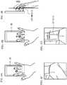
- the display device 10shows an indication to the user
- the usermoves his hand with a finger touching with the screen 1.
- the usertouches his middle finger with the screen 11.
- FIG. 4Bthe user moves his hand in parallel with the screen 11 by a distance in a direction indicated by the display device 10, with the middle finger touching with the screen 11.
- the touch determiner 41detects touching of an object in accordance with a detection result of the touch sensor 20.
- the movement direction detector 42detects a movement direction of the touch region based on a detection result of the touch sensor 20, when the touch of the object is detected.
- the movement amount detector 43detects a movement amount of the touch region based on the detection result of the touch sensor 20 (Step S1). For example, when an output result of the touch sensor 20 is output by millimeters, the movement amount (mm) of the touch region is detected.
- the image acquirer 44captures an image of the object by the image device 30, in synchronization with the detection of touching of the object by the touch determiner 41 (Step S2).
- the local feature extractor 45extracts a local feature from an image captured by the image acquirer 44 (Step S3).
- the local featureis a local biometric feature in the image captured by the image acquirer 44. For example, as illustrated in FIG. 4C , a specific wrinkle that is a part of a palm print is used as a local feature F.
- the local feature extractor 45extracts the local feature F by a pattern matching based on a mutual correlation method, a SIFT (Scale-invariant Feature Transform), GLOH (Gradient Location and Orientation Histogram), or a SURF (Speeded Up Robust Features).
- a SIFTScale-invariant Feature Transform
- GLOHGradient Location and Orientation Histogram
- SURFSpeeded Up Robust Features
- the feature movement amount detector 46detects a movement amount of the local feature F from a start of movement of the touch region as a movement amount of pixel (pix) of the image device 30 (Step S4). As illustrated in FIG. 4D , the feature movement amount detector 46 treats a continuous local feature F as a feature line, and detects a movement amount (pix) of the most reliable pair of feature lines that are a feature line during movement and a feature line after the movement.
- the distance detector 47detects a movement amount per a unit pixel (mm/pix) as a distance parameter (Step S5).
- the movement amount per a unit pixelmay be a ratio between a movement amount (mm) detected by the movement amount detector 43 and a movement amount (pix) detected by the feature movement amount detector 46.
- the distance detector 47detects distance information between the object and the image device 30 based on the ratio (Step S6).
- the distance informationis detected by multiplexing the ratio with a predetermined coefficient.
- the distance parameteris the same as the distance information.
- the biometric information detector 49detects biometric information within a range that is larger than the local feature in the image captured by the image acquirer 44 (Step S7).
- the biometric informationis such as a shape of a palm or a wrinkle.
- the touch determiner 41determines whether the movement of the touch region stops (Step S8). For example, the touch determiner 41 determines that the movement of the touch region stops when the touch of the object is not detected.
- the image acquirer 44stops the capturing (Step S9).
- the movement direction detector 42, the movement amount detector 43, the local feature extractor 45, the feature movement amount detector 46, the distance detector 47 and the biometric information detector 49stop their detecting.
- the distance information storage 48relates the distance information between the object and the image device 30 detected by the distance detector 47 with an ID of the user, and stores the distance information and the ID.
- the biometric information detector 49relates the biometric information detected by the biometric information detector 49 with the ID of the user and stores the biometric information and the ID (Step S10). When it is determined as "No” in Step S8, Step S1 is executed again.
- a movement amount d1r (mm) of the object from the start to the end of the movementis obtained.
- a feature movement amount detector 46stops its detecting, a pixel movement amount x1r (pix) of the image device 30 of the object from the start to the end of the movement is obtained.
- the distance detector 47stops its detecting, a ratio of d1r (mm) with respect to x1r (pix) is detected as distance information z1r (mm/pix) between the object and the image device 30 in the enrollment process. Relative positions of the image device 30 and the touch sensor 20 are fixed with each other. Therefore, when the distance information between the object and the image device 30 is detected, the distance information between the touch sensor 20 and the object is also detected. With the processes, the enrollment process is terminated.
- FIG. 5illustrates a flowchart of the authentication process.
- itis determined whether a comparison between the biometric information of the user detected from the image captured by the image device 30 and the biometric information enrolled in the biometric information storage 52 in advance is succeeded or failed. For example, a similarity of the both biometric information is equal to or more than a threshold, the comparison is succeeded.
- the usertouches his finger with the screen 11 and moves his hand. For example, as illustrated in FIG. 6A , the user touches his middle finger with the screen 11. Next, with the middle finger being touched with the screen 11, the user moves his hand in parallel with the screen 11 by a distance indicated by the display device 10 as illustrated in FIG. 6B .
- the distance indicated by the display device 10is the same as the distance during the enrollment process.
- the touch determiner 41detects the touch of the object based on the detection result of the touch sensor 20.
- the touch determiner 41detects the touch of the object based on the detection result of the touch sensor 20.
- the movement direction detector 42detects the movement direction of the touch region based on the detection result of the touch sensor 20.
- the movement amount detector 43detects a movement amount (mm) of the touch region based on the detection result of the touch sensor 20 (Step S 11).
- the following Steps S12 to S19are the same as Steps S2 to S9 of FIG. 3 .
- FIG. 6Cillustrates a local feature extracted during the enrollment process.
- FIG. 6Dillustrates a local feature extracted in Step S13.
- Step S 14a pixel movement amount x1c (pix) of the image device 30 is detected as a movement amount of a local feature of the touch region from the start to the end of the movement in Step S14.
- FIG. 6Eillustrates the pixel movement amount x1r (pix) of the local feature during the enrollment process.
- FIG. 6Fillustrates the pixel movement amount x1c (pix) detected in Step S14.
- Step S16a ratio of the d1c (mm) with respect to the x1c (pix) is detected as distance information z1c (mm/pix) between the object and the image device 30 during the authentication process.
- the distance information z1c (mm/pix) during the authentication processis smaller than the distance information z1r (mm/pix) during the enrollment process.
- the corrector 50receives the distance information z1r (mm/pix) of the enrollment process from the distance information storage 48.
- the corrector 50enlarges or downsizes the biometric information detected in Step S 17 so that the distance information of the authentication process gets closer to the distance information of the enrollment process (Step S20). That is, the corrector 50 approximates a magnification of the biometric information obtained in the authentication process to a magnification of the biometric information obtained in the enrollment process.
- the comparer 51compares the biometric information stored in the biometric information storage 52 with the biometric information corrected in Step S20 (Step S21). For example, the comparer 51 determines whether a similarity between the biometric information stored in the biometric information storage 52 and the biometric information corrected in Step S20 is equal to or more than a threshold.
- the output unit 53makes the display device 10 show the comparison result of the comparer 51 (Step S22).
- the display device 10shows information of success of the comparison when the similarity is equal to or more than the threshold.
- the display device 10shows information of failure of the comparison when the similarity is less than the threshold.
- the movement amount of the object on the touch sensor 20 and the movement amount of the local feature in the image of the objectare obtained.
- a device having a touch panel and an image device such as a smart phoneis used, it is not necessary to provide a new component. Thus, it is possible to reduce cost.
- mount accuracyinfluences on the optical device.
- the optical device for detecting the distanceis omitted. That is, it is possible to suppress the influence of the mount accuracy of the optical device. Thereby, the accuracy of the distance detection and the correction is improved.
- the biometric information detected from the image of the objectis corrected.
- the structureis not limited.
- the image of the objectmay be corrected, and the biometric information may be detected from the corrected image.
- the biometric information acquired from the image of the objectis corrected.
- the biometric information stored in the biometric information storage 52may be corrected.
- the biometric information stored in the biometric information storage 52may be enlarged or downsized so that the distance in the enrollment process gets closer to the distance in the authentication process. That is, the magnification of the biometric information acquired in the enrollment process may be approximated to the magnification of the biometric information acquired in the authentication process.
- FIG. 7Aillustrates an image example of a scale having a reliable size in a case where a focusing distance from the image device 30 is changed.
- Each image of FIG. 7Ais a partial image of the scale.
- a capturing rangechanges in accordance with the focusing distance.
- the focusing distanceis a distance between the image device 30 and the object.
- the distance detector 47detects a capturing range f (mm/pix) per a unit pixel with respect to each focusing distance.
- the scaleis located on the sensor face of the image device 30 in a longitudinal direction, and the object is captured at the distance of 10 mm.
- the capturing range f (mm/pix) per a unit pixelis 0.0159375.
- the capturing range f (mm/pix) per the unit pixelis detected at the distance of 10 mm to the distance of 50 mm.
- FIG. 7Billustrates a relationship between the capturing range f (mm/pix) per the unit pixel and the focusing distance z (mm) of the object.
- the distance information storage 48stores the relationship as the distance information.
- Step S6 of FIG. 3it is possible to detect the absolute (quantitative) distance from the distance information acquired in Step S5.
- Step S16 of FIG. 5it is possible to detect the absolute (quantitative) distance from the distance information acquired in Step S15.
- the local feature extractor 45may extract at least two local features.
- the distance detector 47can detect an inclination of the object in addition to the distance between the image device 30 and the object. At least two wrinkles of a palm print can be used as the at least two local feature.
- the movement amount of each local featureis detected after movement of the object, it is possible to detect the distance between the object at each position and the image device 30, that is, an inclination.
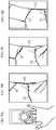
- FIG. 8Aillustrates a case where the touch region moves.
- FIG. 8Billustrates two local features F1 and F2 acquired at the start of the movement.
- FIG. 8Cillustrates the local features F1 and F2 acquired during movement.
- FIG. 8Dillustrates the local features F1 and F2 acquired at the end of the movement.
- the local featureis a specific wrinkle that is a part of the palm print, a continuous local feature is used as a feature line.
- the corrector 50enlarges or downsizes the biometric information detected from the object image so that each distance of the local features F1 and F2 in the authentication process gets closer to the distance in the enrollment process. It is possible to interpolate regions other than the local feature F1 and the local feature F2. It is therefore possible to reduce a difference between the magnification of the biometric information acquired in the authentication process and the magnification of the biometric information acquired in the enrollment process.
- the correction accuracy of the objectis improved when a plurality of local features are used.
- the local feature extractor 45extracts at least two local features as well as the second modified embodiment.
- the display device 10indicates a user two or more movements on the screen 11.
- the display device 10indicates a rotation movement as illustrated in FIG. 9A .
- the movement direction detector 42detects a movement direction of the touch region.
- the movement amount detector 43detects a movement amount of the touch region.
- FIG. 9Cillustrates the local features F1, F2 and F3 during the movement.
- FIG. 9Dillustrates the local features F1, F2 and F3 at the end of the movement.
- the local featureis a specific wrinkle that is a part of the palm print, a continuous local feature is used as the feature line.
- Reliable continuous local featuresare used as the local features F1, F2 and F3.
- wrinkles of a longitudinal direction, a lateral direction and an oblique directionare used as the feature line.
- a plurality of local featuresit is possible to detect each distance at segmentalized positions of a biometric body.
- An alphabet, a number, a unique pattern or the like that are traversablemay be used as the movement in addition to the circle can be used
- a color image sensoris used as the image device 30.
- color informationcan be acquired.
- high accuracy of image capturingis achieved.
- a process speedcan be improved.
- the objectmoves with the touch sensor 20 being touched with the object as illustrated in FIG. 10A .
- the embodimentsare not limited.
- a time point at which the object is in touch with any position of the touch sensor 20may be a start point of movement
- a time point at which the object is in touch with the touch sensor 20 againmay be an end point of movement.
- the objectis not in touch with the touch sensor 20 from the start point to the end point.
- a distance between a local feature detected at the start point of the movement and a local feature detected at the end point of the movementis acquired, it is possible to detect the movement amount of the local feature.
- FIG. 11Aillustrates an overall structure of a biometric information process device 100a in accordance with a second embodiment.
- the biometric information process device 100ais different from the biometric information process device 100 in a point that a near-infrared light source 60 is further provided.
- a near-infrared image sensoris used as the image device 30.
- a near-infrared lightreaches a deep region of a biometric surface. Therefore, when the near-infrared light is used together with a near-infrared image sensor, it is possible to capture vein information inside of biometric body.
- the near-infrared light source 60may be provided near the image device 30 between a frame line of the display device 10 and the screen 11.
- FIG. 12Aillustrates a case where the touch region moves.
- FIG. 12Billustrates a local feature F of a vein acquired at a start of the movement.
- FIG. 12Cillustrates the local feature F of the vein acquired during the movement.
- FIG. 12Dillustrates the local feature F of the vein acquired at an end of the movement.
- acquired distance informationby information inside of a biometric body or acquired information of an inclination.
- the touch sensor 20acts as an example of a detector configured to detect a touch point of an object with respect to a touch panel.
- the image device 30acts as an example of an image device configured to capture an image of the object.
- the local feature extractor 45acts as an example of an extractor configured to extract a biometric feature from the image of the object that is acquired by the image device.
- the corrector 50acts as an example of a corrector configured to correct biometric information acquired from the image of the object based on a movement amount of the object on the touch panel and a movement amount of the biometric feature in the image of the object when the touch point detected by the detector moves.
- the distance detector 47acts as an example of an acquirer configured to acquire distance information between the object and the image device based on the movement amount of the object on the touch panel and the movement amount of the biometric feature on the image of the object when a touch region of the object with respect to the touch panel moves.
- the distance information storage 48acts as an example of a storage configured to store a relationship between a movement amount of a biometric feature in the image captured by the imaged device and distance information between the object and the image device that is acquired by the acquirer, in advance.
- the biometric information storage 52acts as an example of a biometric information storage configured to store biometric information in advance.
- the comparer 51acts as an example of a comparer configure to compares the biometric information corrected by the corrector and the biometric information stored in the biometric information storage.
Landscapes
- Engineering & Computer Science (AREA)
- Theoretical Computer Science (AREA)
- Physics & Mathematics (AREA)
- General Physics & Mathematics (AREA)
- Human Computer Interaction (AREA)
- Multimedia (AREA)
- General Engineering & Computer Science (AREA)
- Computer Security & Cryptography (AREA)
- Computer Vision & Pattern Recognition (AREA)
- Computer Hardware Design (AREA)
- Software Systems (AREA)
- Health & Medical Sciences (AREA)
- General Health & Medical Sciences (AREA)
- Psychiatry (AREA)
- Social Psychology (AREA)
- Collating Specific Patterns (AREA)
- Measurement Of The Respiration, Hearing Ability, Form, And Blood Characteristics Of Living Organisms (AREA)
- Image Input (AREA)
- Position Input By Displaying (AREA)
Abstract


Description
- A certain aspect of embodiments described herein relates to a biometric information process device, a biometric information process method, a biometric information process program and a distance detection device.
- In a biometric authentication, it is preferable that a distance between an image device and a biometric body in an enrollment of biometric information is equal to the distance in an authentication process in order to achieve high authentication accuracy. It is thought that a guide for correcting the position of the biometric body is provided. However in this case, portability is degraded. And so, there is being developed a technology in which a parallax image is acquired and a position of a biometric body is detected (for example, see Japanese Patent Application Publication No.
2010-61639 - The present invention has been made in view of those circumstances, and an object thereof is to provide a biometric information process device, a biometric information process method, a biometric information process program and a distance detection device that are capable of achieving high authentication accuracy with low cost.
- According to an aspect of the present invention, there is provided a biometric information process device including: a detector configured to detect a touch point of an object with respect to a touch panel; an image device configured to capture an image of the object; an extractor configured to extract a biometric feature from the image of the object that is acquired by the image device; and a corrector configured to correct biometric information acquired from the image of the object based on a movement amount of the object on the touch panel and a movement amount of the biometric feature in the image of the object when the touch point detected by the detector moves.
FIG. 1A illustrates a block diagram of an overall structure of a biometric information process device in accordance with a first embodiment;FIG. 1B illustrates a plane view of the biometric information process device;FIG. 1C illustrates a hardware structure of a process unit;FIG. 2 illustrates each function of a process unit;FIG. 3 illustrates a flowchart of an enrollment process;FIG. 4A to FIG. 4E illustrate an enrollment process;FIG. 5 illustrates a flowchart of an authentication process;FIG. 6A to FIG. 6F illustrate an authentication process;FIG. 7A and FIG. 7B illustrate a first modified embodiment;FIG. 8A to FIG. 8D illustrate a second modified embodiment;FIG. 9A to FIG. 9D illustrate a third modified embodiment;FIG. 10A and FIG. 10B illustrate a fifth modified embodiment;FIG. 11A and FIG. 11B illustrate an overall structure of a biometric information process device in accordance with a second embodiment; andFIG. 12A to FIG. 12D illustrate a second embodiment.- The following is a description of embodiments, with reference to the accompanying drawings.
FIG. 1A illustrates a block diagram of an overall structure of a biometricinformation process device 100 in accordance with a first embodiment.FIG. 1B illustrates a plane view of the biometricinformation process device 100. As illustrated inFIG. 1A , the biometricinformation process device 100 has adisplay device 10, atouch sensor 20, animage device 30, aprocess unit 40 and so on.- The
process unit 40 controls operations of thedisplay device 10, thetouch sensor 20, theimage device 30 and so on. Theprocess unit 40 receives a detection result of thetouch sensor 20 and a capture result of theimage device 30. Thus, theprocess unit 40 performs an enrollment process and an authentication process. As illustrated inFIG. 1B , thedisplay device 10 has a screen 11 such as a liquid crystal display or an electroluminescence panel, and shows a process result of theprocess unit 40. The screen 11 has a region that is smaller than a frame of thedisplay device 10 in a given face of thedisplay device 10. - The
touch sensor 20 is provided on the screen 11. Thus, the screen 11 and thetouch sensor 20 act as a touch panel. Thetouch sensor 20 is capable of detecting a region with which a user tries to touch an object such as a finger of a hand. Hereinafter, a region of thetouch sensor 20 with which the object touches may be called a touch region. - The
image device 30 is an image sensor for capturing an image of an object such as a palm of a user. For example, theimage device 30 is provided between the frame of thedisplay device 10 and the screen 11. In the embodiment, theimage device 30 is an image sensor for capturing an image of the object without touching. Theimage device 30 is such as a CMOS (Complementary Metal Oxide Semiconductor) camera. For example, theimage device 30 captures an image of a surface of a palm. Theimage device 30 may capture an image of a biometric feature under a skin such as a vein pattern with use of near-infrared ray. FIG. 1C illustrates a hardware structure of theprocess unit 40. As illustrated inFIG. 1C , theprocess unit 40 has aCPU 101, a RAM (Random Access Memory) 102, amemory device 103, aninterface 104 and so on. These components are coupled to each other with a bus or the like.- The
CPU 101 is a central processing unit. TheCPU 101 includes one or more core. TheRAM 102 is a volatile memory temporally storing a program executed by theCPU 101, a data processed by theCPU 101, and so on. - The
memory device 103 is a nonvolatile memory device. Thememory device 103 may be a SSD (Solid State Drive) such as a ROM (Read Only Memory) or a flash memory, or a hard disk driven by a hard disk drive. Thememory device 103 stores a biometric information process program in accordance with the first embodiment. Theinterface 104 is an interface between theprocess unit 40 and another device. - A biometric information process program stored in the
memory device 103 is developed to theRAM 102. TheCPU 101 executes the biometric information process program developed to theRAM 102. Thus, each unit of theprocess unit 40 illustrated inFIG. 2 is achieved.FIG. 2 illustrates a block diagram of each function of theprocess unit 40. As illustrated inFIG. 2 , theprocess unit 40 acts as atouch determiner 41, a movement direction detector 42, amovement amount detector 43, animage acquirer 44, alocal feature extractor 45, a featuremovement amount detector 46, adistance detector 47, adistance information storage 48 and so on. Moreover, theprocess unit 40 acts as abiometric information detector 49, acorrector 50, acomparer 51, abiometric information storage 52, anoutput unit 53 and so on. - (Enrollment Process) A description will be given of an enrollment process based on
FIG. 3 andFIG. 4A toFIG. 4E .FIG. 3 illustrates a flowchart of the enrollment process. The enrollment process is a process for storing biometric information of a user in thebiometric information storage 52 as a biometric template in advance. When thedisplay device 10 shows an indication to the user, the user moves his hand with a finger touching with thescreen 1. For example, as illustrated inFIG. 4A , the user touches his middle finger with the screen 11. Next, as illustrated inFIG. 4B , the user moves his hand in parallel with the screen 11 by a distance in a direction indicated by thedisplay device 10, with the middle finger touching with the screen 11. - As illustrated in
FIG. 3 , when the user touches his finger with the screen 11, thetouch determiner 41 detects touching of an object in accordance with a detection result of thetouch sensor 20. The movement direction detector 42 detects a movement direction of the touch region based on a detection result of thetouch sensor 20, when the touch of the object is detected. Themovement amount detector 43 detects a movement amount of the touch region based on the detection result of the touch sensor 20 (Step S1). For example, when an output result of thetouch sensor 20 is output by millimeters, the movement amount (mm) of the touch region is detected. - The
image acquirer 44 captures an image of the object by theimage device 30, in synchronization with the detection of touching of the object by the touch determiner 41 (Step S2). Next, thelocal feature extractor 45 extracts a local feature from an image captured by the image acquirer 44 (Step S3). The local feature is a local biometric feature in the image captured by theimage acquirer 44. For example, as illustrated inFIG. 4C , a specific wrinkle that is a part of a palm print is used as a local feature F. For example, thelocal feature extractor 45 extracts the local feature F by a pattern matching based on a mutual correlation method, a SIFT (Scale-invariant Feature Transform), GLOH (Gradient Location and Orientation Histogram), or a SURF (Speeded Up Robust Features). - Next, the feature
movement amount detector 46 detects a movement amount of the local feature F from a start of movement of the touch region as a movement amount of pixel (pix) of the image device 30 (Step S4). As illustrated inFIG. 4D , the featuremovement amount detector 46 treats a continuous local feature F as a feature line, and detects a movement amount (pix) of the most reliable pair of feature lines that are a feature line during movement and a feature line after the movement. - Next, the
distance detector 47 detects a movement amount per a unit pixel (mm/pix) as a distance parameter (Step S5). For example, the movement amount per a unit pixel may be a ratio between a movement amount (mm) detected by themovement amount detector 43 and a movement amount (pix) detected by the featuremovement amount detector 46. Next, thedistance detector 47 detects distance information between the object and theimage device 30 based on the ratio (Step S6). For example, the distance information is detected by multiplexing the ratio with a predetermined coefficient. In the embodiment, the distance parameter is the same as the distance information. - Next, the
biometric information detector 49 detects biometric information within a range that is larger than the local feature in the image captured by the image acquirer 44 (Step S7). For example, the biometric information is such as a shape of a palm or a wrinkle. - Next, the
touch determiner 41 determines whether the movement of the touch region stops (Step S8). For example, thetouch determiner 41 determines that the movement of the touch region stops when the touch of the object is not detected. When it is determined as "Yes" in Step S8, theimage acquirer 44 stops the capturing (Step S9). And, the movement direction detector 42, themovement amount detector 43, thelocal feature extractor 45, the featuremovement amount detector 46, thedistance detector 47 and thebiometric information detector 49 stop their detecting. Thedistance information storage 48 relates the distance information between the object and theimage device 30 detected by thedistance detector 47 with an ID of the user, and stores the distance information and the ID. Thebiometric information detector 49 relates the biometric information detected by thebiometric information detector 49 with the ID of the user and stores the biometric information and the ID (Step S10). When it is determined as "No" in Step S8, Step S1 is executed again. - When the
movement amount detector 43 stops its detecting, a movement amount d1r (mm) of the object from the start to the end of the movement is obtained. When the featuremovement amount detector 46 stops its detecting, a pixel movement amount x1r (pix) of theimage device 30 of the object from the start to the end of the movement is obtained. When thedistance detector 47 stops its detecting, a ratio of d1r (mm) with respect to x1r (pix) is detected as distance information z1r (mm/pix) between the object and theimage device 30 in the enrollment process. Relative positions of theimage device 30 and thetouch sensor 20 are fixed with each other. Therefore, when the distance information between the object and theimage device 30 is detected, the distance information between thetouch sensor 20 and the object is also detected. With the processes, the enrollment process is terminated. - (Authentication Process) Next, a description will be given of the authentication process based on
FIG. 5 andFIG. 6A toFIG. 6F .FIG. 5 illustrates a flowchart of the authentication process. In the authentication process, it is determined whether a comparison between the biometric information of the user detected from the image captured by theimage device 30 and the biometric information enrolled in thebiometric information storage 52 in advance is succeeded or failed. For example, a similarity of the both biometric information is equal to or more than a threshold, the comparison is succeeded. - When the
display device 10 shows an indication to the user, the user touches his finger with the screen 11 and moves his hand. For example, as illustrated inFIG. 6A , the user touches his middle finger with the screen 11. Next, with the middle finger being touched with the screen 11, the user moves his hand in parallel with the screen 11 by a distance indicated by thedisplay device 10 as illustrated inFIG. 6B . As an example, the distance indicated by thedisplay device 10 is the same as the distance during the enrollment process. - As illustrated in
FIG. 5 , when the user touches his finger with the screen 11, thetouch determiner 41 detects the touch of the object based on the detection result of thetouch sensor 20. When the touch of the object is detected, thetouch determiner 41 detects the touch of the object based on the detection result of thetouch sensor 20. Next, when the user moves the finger, the movement direction detector 42 detects the movement direction of the touch region based on the detection result of thetouch sensor 20. Themovement amount detector 43 detects a movement amount (mm) of the touch region based on the detection result of the touch sensor 20 (Step S 11). The following Steps S12 to S19 are the same as Steps S2 to S9 ofFIG. 3 . FIG. 6C illustrates a local feature extracted during the enrollment process.FIG. 6D illustrates a local feature extracted in Step S13. When the object is farer from theimage device 30 during the authentication process more than during the enrollment process, the local feature during the authentication process becomes smaller than during the enrollment process because of optical characteristic. In Step S 14, a pixel movement amount x1c (pix) of theimage device 30 is detected as a movement amount of a local feature of the touch region from the start to the end of the movement in Step S14.FIG. 6E illustrates the pixel movement amount x1r (pix) of the local feature during the enrollment process.FIG. 6F illustrates the pixel movement amount x1c (pix) detected in Step S14. When the object is farer from theimage device 30 during the authentication process than during the enrollment process, the pixel movement amount x1c (pix) during the authentication process is smaller than the pixel movement amount x1r (pix) during the enrollment process because of the optical characteristic.
In Step S16, a ratio of the d1c (mm) with respect to the x1c (pix) is detected as distance information z1c (mm/pix) between the object and theimage device 30 during the authentication process. When the object is farer from theimage device 30 during the authentication process than during the enrollment process, the distance information z1c (mm/pix) during the authentication process is smaller than the distance information z1r (mm/pix) during the enrollment process.- After the execution of Step S19, the
corrector 50 receives the distance information z1r (mm/pix) of the enrollment process from thedistance information storage 48. Next, thecorrector 50 enlarges or downsizes the biometric information detected inStep S 17 so that the distance information of the authentication process gets closer to the distance information of the enrollment process (Step S20). That is, thecorrector 50 approximates a magnification of the biometric information obtained in the authentication process to a magnification of the biometric information obtained in the enrollment process. - Next, the
comparer 51 compares the biometric information stored in thebiometric information storage 52 with the biometric information corrected in Step S20 (Step S21). For example, thecomparer 51 determines whether a similarity between the biometric information stored in thebiometric information storage 52 and the biometric information corrected in Step S20 is equal to or more than a threshold. Next, theoutput unit 53 makes thedisplay device 10 show the comparison result of the comparer 51 (Step S22). Thedisplay device 10 shows information of success of the comparison when the similarity is equal to or more than the threshold. Thedisplay device 10 shows information of failure of the comparison when the similarity is less than the threshold. - In the embodiment, when the touch region of the object with respect to the
touch sensor 20 moves, the movement amount of the object on thetouch sensor 20 and the movement amount of the local feature in the image of the object are obtained. By acquiring both movement amounts, it is possible to acquire the distance between theimage device 30 and the object. By acquiring the distance between theimage device 30 and the object, it is possible to correct the biometric information detected in the authentication process. It is not necessary to use a plurality of image devices. It is therefore possible to reduce cost. When a device having a touch panel and an image device such as a smart phone is used, it is not necessary to provide a new component. Thus, it is possible to reduce cost. When an optical device such as a distance sensor is used, mount accuracy influences on the optical device. It is therefore difficult to achieve the distance detection with high accuracy and accurate correction. On the other hand, when a touch panel is used, the optical device for detecting the distance is omitted. That is, it is possible to suppress the influence of the mount accuracy of the optical device. Thereby, the accuracy of the distance detection and the correction is improved. - In the embodiment, the biometric information detected from the image of the object is corrected. However, the structure is not limited. For example, the image of the object may be corrected, and the biometric information may be detected from the corrected image. In any cases, the biometric information acquired from the image of the object is corrected.
- The biometric information stored in the
biometric information storage 52 may be corrected. For example, the biometric information stored in thebiometric information storage 52 may be enlarged or downsized so that the distance in the enrollment process gets closer to the distance in the authentication process. That is, the magnification of the biometric information acquired in the enrollment process may be approximated to the magnification of the biometric information acquired in the authentication process. - (First Modified Embodiment) An absolute (quantitative) distance difference may be detected between in the enrollment process and in the authentication process.
FIG. 7A illustrates an image example of a scale having a reliable size in a case where a focusing distance from theimage device 30 is changed. Each image ofFIG. 7A is a partial image of the scale. A capturing range changes in accordance with the focusing distance. The focusing distance is a distance between theimage device 30 and the object. Thedistance detector 47 detects a capturing range f (mm/pix) per a unit pixel with respect to each focusing distance. For example, it is possible to capture a range of 10.2 mm of the scale, when theimage device 30 having 640 pixels in a longitudinal direction is used, the scale is located on the sensor face of theimage device 30 in a longitudinal direction, and the object is captured at the distance of 10 mm. In this case, the capturing range f (mm/pix) per a unit pixel is 0.0159375. And, the capturing range f (mm/pix) per the unit pixel is detected at the distance of 10 mm to the distance of 50 mm. FIG. 7B illustrates a relationship between the capturing range f (mm/pix) per the unit pixel and the focusing distance z (mm) of the object. Thedistance information storage 48 stores the relationship as the distance information. When thetouch sensor 20 detects the movement of the object and a unit output by thetouch sensor 20 is a millimeter, it is possible to replace the output of thetouch sensor 20 to the scale at each focusing distance. It is therefore possible to detect the absolute (quantitative) distance when the movement amount of the touch region acquired by thetouch sensor 20 and the movement amount of the local feature extracted from the image captured by theimage device 30 are related with the relationship between the capturing range f (mm/pix) per the unit pixel stored in thedistance information storage 48 and the focusing distance z (mm) to the object. For example, in Step S6 ofFIG. 3 , it is possible to detect the absolute (quantitative) distance from the distance information acquired in Step S5. In Step S16 ofFIG. 5 , it is possible to detect the absolute (quantitative) distance from the distance information acquired in Step S15.- In this manner, it is possible to detect an absolute (quantitative) distance from the movement amount of touch region acquired by the
touch sensor 20, the movement amount of the local feature extracted from the image of theimage device 30 and distance information stored in thedistance information storage 48. - (Second modified embodiment) The
local feature extractor 45 may extract at least two local features. When at least two local features are extracted, thedistance detector 47 can detect an inclination of the object in addition to the distance between theimage device 30 and the object. At least two wrinkles of a palm print can be used as the at least two local feature. When the movement amount of each local feature is detected after movement of the object, it is possible to detect the distance between the object at each position and theimage device 30, that is, an inclination. FIG. 8A illustrates a case where the touch region moves.FIG. 8B illustrates two local features F1 and F2 acquired at the start of the movement.FIG. 8C illustrates the local features F1 and F2 acquired during movement.FIG. 8D illustrates the local features F1 and F2 acquired at the end of the movement. When the local feature is a specific wrinkle that is a part of the palm print, a continuous local feature is used as a feature line.- In the modified embodiment, the
corrector 50 enlarges or downsizes the biometric information detected from the object image so that each distance of the local features F1 and F2 in the authentication process gets closer to the distance in the enrollment process. It is possible to interpolate regions other than the local feature F1 and the local feature F2. It is therefore possible to reduce a difference between the magnification of the biometric information acquired in the authentication process and the magnification of the biometric information acquired in the enrollment process. In the modified embodiment, the correction accuracy of the object is improved when a plurality of local features are used. - (Third modified embodiment) In a third modified embodiment, the
local feature extractor 45 extracts at least two local features as well as the second modified embodiment. In the third modified embodiment, thedisplay device 10 indicates a user two or more movements on the screen 11. For example, thedisplay device 10 indicates a rotation movement as illustrated inFIG. 9A . Thus, the movement direction detector 42 detects a movement direction of the touch region. And, themovement amount detector 43 detects a movement amount of the touch region. When each movement amount of the local features is detected after the movement of the object, it is possible to detect the distance between each position of the object and theimage device 30. The distance corresponds to the inclination of the object.FIG. 9B illustrates local features F1, F2 and F3 acquired at the start of the movement.FIG. 9C illustrates the local features F1, F2 and F3 during the movement.FIG. 9D illustrates the local features F1, F2 and F3 at the end of the movement. When the local feature is a specific wrinkle that is a part of the palm print, a continuous local feature is used as the feature line. - Reliable continuous local features are used as the local features F1, F2 and F3. As an example, wrinkles of a longitudinal direction, a lateral direction and an oblique direction are used as the feature line. When a plurality of local features are used, it is possible to detect each distance at segmentalized positions of a biometric body. Thus, it is possible to detect the distance and the inclination of the biometric body with high accuracy. And, it is possible to detect asperity information of the biometric body. An alphabet, a number, a unique pattern or the like that are traversable may be used as the movement in addition to the circle can be used
- (Fourth modified embodiment) In a fourth modified embodiment, a color image sensor is used as the
image device 30. When the color image sensor is used, color information can be acquired. Thus, high accuracy of image capturing is achieved. As a result, it is easy to detect a palm or a palm print. And, a process speed can be improved. - (Fifth modified embodiment) In the above-mentioned embodiments, the object moves with the
touch sensor 20 being touched with the object as illustrated inFIG. 10A . However, the embodiments are not limited. For example, as illustrated inFIG. 10B , a time point at which the object is in touch with any position of thetouch sensor 20 may be a start point of movement, and a time point at which the object is in touch with thetouch sensor 20 again may be an end point of movement. In this case, the object is not in touch with thetouch sensor 20 from the start point to the end point. However, it is possible to detect the movement amount on thetouch sensor 20. When a distance between a local feature detected at the start point of the movement and a local feature detected at the end point of the movement is acquired, it is possible to detect the movement amount of the local feature. FIG. 11A illustrates an overall structure of a biometricinformation process device 100a in accordance with a second embodiment. As illustrated inFIG. 11A , the biometricinformation process device 100a is different from the biometricinformation process device 100 in a point that a near-infraredlight source 60 is further provided. A near-infrared image sensor is used as theimage device 30. A near-infrared light reaches a deep region of a biometric surface. Therefore, when the near-infrared light is used together with a near-infrared image sensor, it is possible to capture vein information inside of biometric body. For example, as illustrated inFIG. 11B , the near-infraredlight source 60 may be provided near theimage device 30 between a frame line of thedisplay device 10 and the screen 11.- In the embodiment, it is possible to detect a local feature based on vein information. And it is possible to detect distance information.
FIG. 12A illustrates a case where the touch region moves.FIG. 12B illustrates a local feature F of a vein acquired at a start of the movement.FIG. 12C illustrates the local feature F of the vein acquired during the movement.FIG. 12D illustrates the local feature F of the vein acquired at an end of the movement. Thus, it is possible to acquired distance information by information inside of a biometric body or acquired information of an inclination. - In the above-mentioned embodiments, the
touch sensor 20 acts as an example of a detector configured to detect a touch point of an object with respect to a touch panel. Theimage device 30 acts as an example of an image device configured to capture an image of the object. Thelocal feature extractor 45 acts as an example of an extractor configured to extract a biometric feature from the image of the object that is acquired by the image device. Thecorrector 50 acts as an example of a corrector configured to correct biometric information acquired from the image of the object based on a movement amount of the object on the touch panel and a movement amount of the biometric feature in the image of the object when the touch point detected by the detector moves. - The
distance detector 47 acts as an example of an acquirer configured to acquire distance information between the object and the image device based on the movement amount of the object on the touch panel and the movement amount of the biometric feature on the image of the object when a touch region of the object with respect to the touch panel moves. Thedistance information storage 48 acts as an example of a storage configured to store a relationship between a movement amount of a biometric feature in the image captured by the imaged device and distance information between the object and the image device that is acquired by the acquirer, in advance. Thebiometric information storage 52 acts as an example of a biometric information storage configured to store biometric information in advance. Thecomparer 51 acts as an example of a comparer configure to compares the biometric information corrected by the corrector and the biometric information stored in the biometric information storage.
Claims (15)
- A biometric information process device comprising:a detector configured to detect a touch point of an object with respect to a touch panel;an image device configured to capture an image of the object;an extractor configured to extract a biometric feature from the image of the object that is acquired by the image device; anda corrector configured to correct biometric information acquired from the image of the object based on a movement amount of the object on the touch panel and a movement amount of the biometric feature in the image of the object when the touch point detected by the detector moves.
- The biometric information process device as claimed in claim 1, further comprising:an acquirer configured to acquire distance information between the object and the image device based on the movement amount of the object on the touch panel and the movement amount of the biometric feature on the image of the object when a touch region of the object with respect to the touch panel moves,wherein the corrector is configured to correct information acquired from the image of the object by using the distance information acquired by the acquirer.
- The biometric information process device as claimed in claim 2, wherein:the extractor is configured to extract biometric features of at least two points from the image of the object;the acquirer is configured to acquire two or more distance information between the object and the image device based on movement amounts of the biometric features; andthe corrector is configured to correct biometric information acquired from the image of the object by using the two or more distance information acquired by the acquirer.
- The biometric information process device as claimed in claim 2 or 3, further comprising:a storage configured to store a relationship between a movement amount of a biometric feature in the image captured by the imaged device and distance information between the object and the image device that is acquired by the acquirer, in advance,wherein the corrector is configured to correct biometric information acquired from the image of the object based on the distance information acquired by the acquirer and the relationship stored by the storage.
- The biometric information process device as claimed in any of claims 1 to 4, further comprising:a biometric information storage configured to store biometric information in advance; anda comparer configure to compares the biometric information corrected by the corrector and the biometric information stored in the biometric information storage.
- The biometric information process device as claimed in claim 5, wherein:the biometric information stored by the biometric information storage in advance is acquired from the image of the object in a case where a region of the object contacting to the touch panel moves in advance and is related with a ratio between a movement amount of the object on the touch panel and a movement amount of the biometric feature in the image of the object; andthe corrector corrects the biometric information acquired from the image of the object based on the ratio.
- The biometric information process device as claimed in any of claims 1 to 6, further comprising:a light source configured to irradiate a near-infrared light to the object,wherein the extractor extracts a biometric feature under a skin.
- The biometric information process device as claimed in any of claims 1 to 7, wherein:the object is a hand;a body part that is in touch with the touch panel is a finger; anda body part of the object captured by the image device includes a palm.
- A biometric information process method comprising:detecting a touch point of an object with respect to a touch panel;capturing an image of the object by an image device;extracting a biometric feature from the image of the object; andcorrecting biometric information acquired from the image of the object based on a movement amount of the object on the touch panel and a movement amount of the biometric feature in the image of the object when the touch point detected in the detecting moves.
- The biometric information process method as claimed in claim 9, further comprising:acquiring distance information between the object and the image device based on the movement amount of the object on the touch panel and the movement amount of the biometric feature on the image of the object when a touch region of the object with respect to the touch panel moves,wherein information acquired from the image of the object is corrected by using the distance information acquired in the acquiring.
- The biometric information process method as claimed in claim 10, wherein:in the extracting, biometric features of at least two points are extracted from the image of the object;in the acquiring, two or more distance information between the object and the image device are acquired based on movement amounts of the biometric features; andin the correcting, biometric information acquired from the image of the object is corrected by using the two or more distance information acquired in the acquiring.
- The biometric information process method as claimed in claim 10 or 11, further comprising:storing a relationship between a movement amount of a biometric feature in the image captured by the imaged device and distance information between the object and the image device that is acquired in the acquiring, in advance,wherein, in the correcting, biometric information acquired from the image of the object is corrected based on the distance information acquired in the acquiring and the relationship stored in the storing.
- The biometric information process method as claimed in any of claims 9 to 12, further comprising:storing biometric information in advance; andcomparing the biometric information corrected in the correcting and the biometric information stored in the storing of the biometric information.
- A biometric information process program causing a computer to execute a process, the process comprising:detecting a touch point of an object with respect to a touch panel;capturing an image of the object;extracting a biometric feature from the image of the object; andcorrecting biometric information acquired from the image of the object based on a movement amount of the object on the touch panel and a movement amount of the biometric feature in the image of the object when the touch point detected in the detecting moves.
- A distance detection device comprising:a detector configured to detect a touch point of an object with respect to a touch panel;an image device configured to capture an image of the object;an extractor configured to extract a biometric feature from the image of the object that is acquired by the image device; andan acquirer configured to acquirer a distance between the image device and the object based on a movement amount of the object on the touch panel and a movement amount of the biometric feature in the image of the object when the touch point detected by the detector moves.
Applications Claiming Priority (1)
| Application Number | Priority Date | Filing Date | Title |
|---|---|---|---|
| JP2016017531AJP6583025B2 (en) | 2016-02-01 | 2016-02-01 | Biological information processing apparatus, biological information processing method, biological information processing program, and distance detection apparatus |
Publications (3)
| Publication Number | Publication Date |
|---|---|
| EP3200126A2true EP3200126A2 (en) | 2017-08-02 |
| EP3200126A3 EP3200126A3 (en) | 2017-08-30 |
| EP3200126B1 EP3200126B1 (en) | 2023-08-02 |
Family
ID=57909460
Family Applications (1)
| Application Number | Title | Priority Date | Filing Date |
|---|---|---|---|
| EP17152797.1AActiveEP3200126B1 (en) | 2016-02-01 | 2017-01-24 | Biometric information process device, biometric information process method and biometric information process program |
Country Status (3)
| Country | Link |
|---|---|
| US (2) | US10068119B2 (en) |
| EP (1) | EP3200126B1 (en) |
| JP (1) | JP6583025B2 (en) |
Cited By (1)
| Publication number | Priority date | Publication date | Assignee | Title |
|---|---|---|---|---|
| EP3518144A1 (en)* | 2018-01-30 | 2019-07-31 | Fujitsu Limited | Biometric authentication apparatus and biometric authentication method |
Families Citing this family (4)
| Publication number | Priority date | Publication date | Assignee | Title |
|---|---|---|---|---|
| US10931859B2 (en) | 2016-05-23 | 2021-02-23 | InSyte Systems | Light emitter and sensors for detecting biologic characteristics |
| US10713458B2 (en) | 2016-05-23 | 2020-07-14 | InSyte Systems | Integrated light emitting display and sensors for detecting biologic characteristics |
| JP7092984B2 (en)* | 2017-12-01 | 2022-06-29 | 富士通株式会社 | Bioimage processing device, bioimage processing method, and bioimage processing program |
| JP7230337B2 (en) | 2018-04-02 | 2023-03-01 | 富士通株式会社 | Biological image processing device, biological image processing method, and biological image processing program |
Citations (1)
| Publication number | Priority date | Publication date | Assignee | Title |
|---|---|---|---|---|
| JP2010061639A (en) | 2008-08-04 | 2010-03-18 | Sony Corp | Biometrics authentication system |
Family Cites Families (13)
| Publication number | Priority date | Publication date | Assignee | Title |
|---|---|---|---|---|
| US68119A (en)* | 1867-08-27 | Improved apparatus foe supplying gases to furnaces | ||
| JP4169185B2 (en)* | 2002-02-25 | 2008-10-22 | 富士通株式会社 | Image linking method, program, and apparatus |
| ES2331138T3 (en) | 2004-06-28 | 2009-12-22 | Fujitsu Limited | BIOMETRIC AUTHENTICATION SYSTEM AND REGISTRATION METHOD. |
| JP2007236610A (en) | 2006-03-08 | 2007-09-20 | Sony Ericsson Mobilecommunications Japan Inc | Vein authentication device and vein authentication method |
| JP5293950B2 (en)* | 2008-03-04 | 2013-09-18 | 株式会社リコー | Personal authentication device and electronic device |
| JP2010240215A (en) | 2009-04-07 | 2010-10-28 | Sony Corp | Vein depth determination apparatus, vein depth determination method and program |
| JP5451540B2 (en)* | 2009-10-16 | 2014-03-26 | 日立オムロンターミナルソリューションズ株式会社 | Biometric authentication device and biometric authentication method |
| JP5297997B2 (en)* | 2009-12-21 | 2013-09-25 | 株式会社日立メディアエレクトロニクス | Personal authentication device and mobile communication terminal |
| JP5584578B2 (en)* | 2010-10-08 | 2014-09-03 | 富士通株式会社 | Biometric information registration / authentication device and registration / authentication method thereof |
| US8938787B2 (en)* | 2010-11-29 | 2015-01-20 | Biocatch Ltd. | System, device, and method of detecting identity of a user of a mobile electronic device |
| WO2014174674A1 (en)* | 2013-04-26 | 2014-10-30 | 富士通株式会社 | Image processing program, image processing method and information terminal |
| JP6111921B2 (en)* | 2013-07-25 | 2017-04-12 | 富士通株式会社 | Imaging apparatus and imaging method |
| CN105320866A (en)* | 2014-07-25 | 2016-02-10 | 南京瀚宇彩欣科技有限责任公司 | No-blocking touch control type handheld electronic device and unlocking method thereof |
- 2016
- 2016-02-01JPJP2016017531Apatent/JP6583025B2/enactiveActive
- 2017
- 2017-01-20USUS15/411,762patent/US10068119B2/enactiveActive
- 2017-01-24EPEP17152797.1Apatent/EP3200126B1/enactiveActive
- 2018
- 2018-08-07USUS16/057,358patent/US20180349670A1/ennot_activeAbandoned
Patent Citations (1)
| Publication number | Priority date | Publication date | Assignee | Title |
|---|---|---|---|---|
| JP2010061639A (en) | 2008-08-04 | 2010-03-18 | Sony Corp | Biometrics authentication system |
Cited By (2)
| Publication number | Priority date | Publication date | Assignee | Title |
|---|---|---|---|---|
| EP3518144A1 (en)* | 2018-01-30 | 2019-07-31 | Fujitsu Limited | Biometric authentication apparatus and biometric authentication method |
| US10896250B2 (en) | 2018-01-30 | 2021-01-19 | Fujitsu Limited | Biometric authentication apparatus and biometric authentication method |
Also Published As
| Publication number | Publication date |
|---|---|
| JP2017136136A (en) | 2017-08-10 |
| EP3200126B1 (en) | 2023-08-02 |
| EP3200126A3 (en) | 2017-08-30 |
| US10068119B2 (en) | 2018-09-04 |
| JP6583025B2 (en) | 2019-10-02 |
| US20180349670A1 (en) | 2018-12-06 |
| US20170220841A1 (en) | 2017-08-03 |
Similar Documents
| Publication | Publication Date | Title |
|---|---|---|
| US20180349670A1 (en) | Biometric information process device, biometric information process method, computer-readable non-transitory medium and distance detection device | |
| US8565494B2 (en) | Biometric authentication device, biometric authentication method, and computer program for biometric authentication | |
| US9928402B2 (en) | Multi-resolution fingerprint sensor | |
| EP3940583A1 (en) | Methods for fingerprint image enhancement, fingerprint recognition and application startup | |
| US8824746B2 (en) | Biometric information processing device, biometric-information processing method, and computer-readable storage medium | |
| US10878268B2 (en) | Information processing apparatus, control method thereof, and storage medium | |
| US10430678B2 (en) | Biometric information processing device, biometric information processing method and non-transitory computer-readable recording medium | |
| US10452943B2 (en) | Information processing apparatus, control method of information processing apparatus, and storage medium | |
| JP7665078B2 (en) | Slap Segmentation of Contactless Fingerprint Images | |
| JP2018026012A (en) | Palm detection device, palmprint authentication device, palm detection method, and program | |
| US10586099B2 (en) | Information processing apparatus for tracking processing | |
| US20150112853A1 (en) | Online loan application using image capture at a client device | |
| US9392185B1 (en) | Apparatus and method for image mosiacking under low-light conditions | |
| JP5254897B2 (en) | Hand image recognition device | |
| JP2017120455A (en) | Information processing device, program and control method | |
| KR101660596B1 (en) | Method for modifying gradient of facial shape, and system for the same | |
| US10134138B2 (en) | Information processing apparatus, computer-readable storage medium, information processing method | |
| KR20190034812A (en) | Acquisition of images for character recognition | |
| US10643317B2 (en) | Biometric image processing device, biometric image processing method and computer-readable non-transitory medium | |
| JP2017199288A (en) | Image processing apparatus, image processing method, and program | |
| US20220327191A1 (en) | Authentication method, information processing device, and non-transitory computer-readable storage medium for storing authentication program | |
| JP4812743B2 (en) | Face recognition device, face recognition method, face recognition program, and recording medium recording the program | |
| JP7484229B2 (en) | Card cutting device and program | |
| US10620740B2 (en) | Biometric authentication system and method | |
| JP6833324B2 (en) | Information processing equipment, programs and information processing methods |
Legal Events
| Date | Code | Title | Description |
|---|---|---|---|
| PUAI | Public reference made under article 153(3) epc to a published international application that has entered the european phase | Free format text:ORIGINAL CODE: 0009012 | |
| STAA | Information on the status of an ep patent application or granted ep patent | Free format text:STATUS: THE APPLICATION HAS BEEN PUBLISHED | |
| PUAL | Search report despatched | Free format text:ORIGINAL CODE: 0009013 | |
| AK | Designated contracting states | Kind code of ref document:A2 Designated state(s):AL AT BE BG CH CY CZ DE DK EE ES FI FR GB GR HR HU IE IS IT LI LT LU LV MC MK MT NL NO PL PT RO RS SE SI SK SM TR | |
| AX | Request for extension of the european patent | Extension state:BA ME | |
| AK | Designated contracting states | Kind code of ref document:A3 Designated state(s):AL AT BE BG CH CY CZ DE DK EE ES FI FR GB GR HR HU IE IS IT LI LT LU LV MC MK MT NL NO PL PT RO RS SE SI SK SM TR | |
| AX | Request for extension of the european patent | Extension state:BA ME | |
| RIC1 | Information provided on ipc code assigned before grant | Ipc:G06K 9/00 20060101AFI20170724BHEP | |
| STAA | Information on the status of an ep patent application or granted ep patent | Free format text:STATUS: REQUEST FOR EXAMINATION WAS MADE | |
| 17P | Request for examination filed | Effective date:20180220 | |
| RBV | Designated contracting states (corrected) | Designated state(s):AL AT BE BG CH CY CZ DE DK EE ES FI FR GB GR HR HU IE IS IT LI LT LU LV MC MK MT NL NO PL PT RO RS SE SI SK SM TR | |
| STAA | Information on the status of an ep patent application or granted ep patent | Free format text:STATUS: EXAMINATION IS IN PROGRESS | |
| 17Q | First examination report despatched | Effective date:20200819 | |
| REG | Reference to a national code | Ref country code:DE Ref legal event code:R079 Free format text:PREVIOUS MAIN CLASS: G06K0009000000 Ipc:G06V0040200000 Ref country code:DE Ref legal event code:R079 Ref document number:602017072034 Country of ref document:DE Free format text:PREVIOUS MAIN CLASS: G06K0009000000 Ipc:G06V0040200000 | |
| GRAP | Despatch of communication of intention to grant a patent | Free format text:ORIGINAL CODE: EPIDOSNIGR1 | |
| STAA | Information on the status of an ep patent application or granted ep patent | Free format text:STATUS: GRANT OF PATENT IS INTENDED | |
| RIC1 | Information provided on ipc code assigned before grant | Ipc:G06F 21/32 20130101ALI20230209BHEP Ipc:G06V 40/10 20220101ALI20230209BHEP Ipc:G06V 40/50 20220101ALI20230209BHEP Ipc:G06V 40/20 20220101AFI20230209BHEP | |
| INTG | Intention to grant announced | Effective date:20230224 | |
| RAP3 | Party data changed (applicant data changed or rights of an application transferred) | Owner name:FUJITSU LIMITED | |
| GRAS | Grant fee paid | Free format text:ORIGINAL CODE: EPIDOSNIGR3 | |
| GRAA | (expected) grant | Free format text:ORIGINAL CODE: 0009210 | |
| STAA | Information on the status of an ep patent application or granted ep patent | Free format text:STATUS: THE PATENT HAS BEEN GRANTED | |
| AK | Designated contracting states | Kind code of ref document:B1 Designated state(s):AL AT BE BG CH CY CZ DE DK EE ES FI FR GB GR HR HU IE IS IT LI LT LU LV MC MK MT NL NO PL PT RO RS SE SI SK SM TR | |
| REG | Reference to a national code | Ref country code:GB Ref legal event code:FG4D | |
| REG | Reference to a national code | Ref country code:CH Ref legal event code:EP | |
| REG | Reference to a national code | Ref country code:DE Ref legal event code:R096 Ref document number:602017072034 Country of ref document:DE | |
| REG | Reference to a national code | Ref country code:IE Ref legal event code:FG4D | |
| REG | Reference to a national code | Ref country code:LT Ref legal event code:MG9D | |
| REG | Reference to a national code | Ref country code:NL Ref legal event code:MP Effective date:20230802 | |
| REG | Reference to a national code | Ref country code:AT Ref legal event code:MK05 Ref document number:1595679 Country of ref document:AT Kind code of ref document:T Effective date:20230802 | |
| PG25 | Lapsed in a contracting state [announced via postgrant information from national office to epo] | Ref country code:GR Free format text:LAPSE BECAUSE OF FAILURE TO SUBMIT A TRANSLATION OF THE DESCRIPTION OR TO PAY THE FEE WITHIN THE PRESCRIBED TIME-LIMIT Effective date:20231103 | |
| PG25 | Lapsed in a contracting state [announced via postgrant information from national office to epo] | Ref country code:IS Free format text:LAPSE BECAUSE OF FAILURE TO SUBMIT A TRANSLATION OF THE DESCRIPTION OR TO PAY THE FEE WITHIN THE PRESCRIBED TIME-LIMIT Effective date:20231202 | |
| PG25 | Lapsed in a contracting state [announced via postgrant information from national office to epo] | Ref country code:SE Free format text:LAPSE BECAUSE OF FAILURE TO SUBMIT A TRANSLATION OF THE DESCRIPTION OR TO PAY THE FEE WITHIN THE PRESCRIBED TIME-LIMIT Effective date:20230802 Ref country code:RS Free format text:LAPSE BECAUSE OF FAILURE TO SUBMIT A TRANSLATION OF THE DESCRIPTION OR TO PAY THE FEE WITHIN THE PRESCRIBED TIME-LIMIT Effective date:20230802 Ref country code:PT Free format text:LAPSE BECAUSE OF FAILURE TO SUBMIT A TRANSLATION OF THE DESCRIPTION OR TO PAY THE FEE WITHIN THE PRESCRIBED TIME-LIMIT Effective date:20231204 Ref country code:NO Free format text:LAPSE BECAUSE OF FAILURE TO SUBMIT A TRANSLATION OF THE DESCRIPTION OR TO PAY THE FEE WITHIN THE PRESCRIBED TIME-LIMIT Effective date:20231102 Ref country code:NL Free format text:LAPSE BECAUSE OF FAILURE TO SUBMIT A TRANSLATION OF THE DESCRIPTION OR TO PAY THE FEE WITHIN THE PRESCRIBED TIME-LIMIT Effective date:20230802 Ref country code:LV Free format text:LAPSE BECAUSE OF FAILURE TO SUBMIT A TRANSLATION OF THE DESCRIPTION OR TO PAY THE FEE WITHIN THE PRESCRIBED TIME-LIMIT Effective date:20230802 Ref country code:LT Free format text:LAPSE BECAUSE OF FAILURE TO SUBMIT A TRANSLATION OF THE DESCRIPTION OR TO PAY THE FEE WITHIN THE PRESCRIBED TIME-LIMIT Effective date:20230802 Ref country code:IS Free format text:LAPSE BECAUSE OF FAILURE TO SUBMIT A TRANSLATION OF THE DESCRIPTION OR TO PAY THE FEE WITHIN THE PRESCRIBED TIME-LIMIT Effective date:20231202 Ref country code:HR Free format text:LAPSE BECAUSE OF FAILURE TO SUBMIT A TRANSLATION OF THE DESCRIPTION OR TO PAY THE FEE WITHIN THE PRESCRIBED TIME-LIMIT Effective date:20230802 Ref country code:GR Free format text:LAPSE BECAUSE OF FAILURE TO SUBMIT A TRANSLATION OF THE DESCRIPTION OR TO PAY THE FEE WITHIN THE PRESCRIBED TIME-LIMIT Effective date:20231103 Ref country code:FI Free format text:LAPSE BECAUSE OF FAILURE TO SUBMIT A TRANSLATION OF THE DESCRIPTION OR TO PAY THE FEE WITHIN THE PRESCRIBED TIME-LIMIT Effective date:20230802 Ref country code:AT Free format text:LAPSE BECAUSE OF FAILURE TO SUBMIT A TRANSLATION OF THE DESCRIPTION OR TO PAY THE FEE WITHIN THE PRESCRIBED TIME-LIMIT Effective date:20230802 | |
| PG25 | Lapsed in a contracting state [announced via postgrant information from national office to epo] | Ref country code:PL Free format text:LAPSE BECAUSE OF FAILURE TO SUBMIT A TRANSLATION OF THE DESCRIPTION OR TO PAY THE FEE WITHIN THE PRESCRIBED TIME-LIMIT Effective date:20230802 | |
| PG25 | Lapsed in a contracting state [announced via postgrant information from national office to epo] | Ref country code:ES Free format text:LAPSE BECAUSE OF FAILURE TO SUBMIT A TRANSLATION OF THE DESCRIPTION OR TO PAY THE FEE WITHIN THE PRESCRIBED TIME-LIMIT Effective date:20230802 | |
| PG25 | Lapsed in a contracting state [announced via postgrant information from national office to epo] | Ref country code:SM Free format text:LAPSE BECAUSE OF FAILURE TO SUBMIT A TRANSLATION OF THE DESCRIPTION OR TO PAY THE FEE WITHIN THE PRESCRIBED TIME-LIMIT Effective date:20230802 Ref country code:RO Free format text:LAPSE BECAUSE OF FAILURE TO SUBMIT A TRANSLATION OF THE DESCRIPTION OR TO PAY THE FEE WITHIN THE PRESCRIBED TIME-LIMIT Effective date:20230802 Ref country code:ES Free format text:LAPSE BECAUSE OF FAILURE TO SUBMIT A TRANSLATION OF THE DESCRIPTION OR TO PAY THE FEE WITHIN THE PRESCRIBED TIME-LIMIT Effective date:20230802 Ref country code:EE Free format text:LAPSE BECAUSE OF FAILURE TO SUBMIT A TRANSLATION OF THE DESCRIPTION OR TO PAY THE FEE WITHIN THE PRESCRIBED TIME-LIMIT Effective date:20230802 Ref country code:DK Free format text:LAPSE BECAUSE OF FAILURE TO SUBMIT A TRANSLATION OF THE DESCRIPTION OR TO PAY THE FEE WITHIN THE PRESCRIBED TIME-LIMIT Effective date:20230802 Ref country code:CZ Free format text:LAPSE BECAUSE OF FAILURE TO SUBMIT A TRANSLATION OF THE DESCRIPTION OR TO PAY THE FEE WITHIN THE PRESCRIBED TIME-LIMIT Effective date:20230802 Ref country code:SK Free format text:LAPSE BECAUSE OF FAILURE TO SUBMIT A TRANSLATION OF THE DESCRIPTION OR TO PAY THE FEE WITHIN THE PRESCRIBED TIME-LIMIT Effective date:20230802 | |
| REG | Reference to a national code | Ref country code:DE Ref legal event code:R097 Ref document number:602017072034 Country of ref document:DE | |
| PG25 | Lapsed in a contracting state [announced via postgrant information from national office to epo] | Ref country code:IT Free format text:LAPSE BECAUSE OF FAILURE TO SUBMIT A TRANSLATION OF THE DESCRIPTION OR TO PAY THE FEE WITHIN THE PRESCRIBED TIME-LIMIT Effective date:20230802 | |
| PLBE | No opposition filed within time limit | Free format text:ORIGINAL CODE: 0009261 | |
| STAA | Information on the status of an ep patent application or granted ep patent | Free format text:STATUS: NO OPPOSITION FILED WITHIN TIME LIMIT | |
| 26N | No opposition filed | Effective date:20240503 | |
| PG25 | Lapsed in a contracting state [announced via postgrant information from national office to epo] | Ref country code:SI Free format text:LAPSE BECAUSE OF FAILURE TO SUBMIT A TRANSLATION OF THE DESCRIPTION OR TO PAY THE FEE WITHIN THE PRESCRIBED TIME-LIMIT Effective date:20230802 | |
| PG25 | Lapsed in a contracting state [announced via postgrant information from national office to epo] | Ref country code:MC Free format text:LAPSE BECAUSE OF FAILURE TO SUBMIT A TRANSLATION OF THE DESCRIPTION OR TO PAY THE FEE WITHIN THE PRESCRIBED TIME-LIMIT Effective date:20230802 | |
| PG25 | Lapsed in a contracting state [announced via postgrant information from national office to epo] | Ref country code:MC Free format text:LAPSE BECAUSE OF FAILURE TO SUBMIT A TRANSLATION OF THE DESCRIPTION OR TO PAY THE FEE WITHIN THE PRESCRIBED TIME-LIMIT Effective date:20230802 | |
| REG | Reference to a national code | Ref country code:CH Ref legal event code:PL | |
| PG25 | Lapsed in a contracting state [announced via postgrant information from national office to epo] | Ref country code:LU Free format text:LAPSE BECAUSE OF NON-PAYMENT OF DUE FEES Effective date:20240124 | |
| PG25 | Lapsed in a contracting state [announced via postgrant information from national office to epo] | Ref country code:LU Free format text:LAPSE BECAUSE OF NON-PAYMENT OF DUE FEES Effective date:20240124 | |
| PG25 | Lapsed in a contracting state [announced via postgrant information from national office to epo] | Ref country code:BE Free format text:LAPSE BECAUSE OF NON-PAYMENT OF DUE FEES Effective date:20240131 | |
| PG25 | Lapsed in a contracting state [announced via postgrant information from national office to epo] | Ref country code:CH Free format text:LAPSE BECAUSE OF NON-PAYMENT OF DUE FEES Effective date:20240131 | |
| PG25 | Lapsed in a contracting state [announced via postgrant information from national office to epo] | Ref country code:CH Free format text:LAPSE BECAUSE OF NON-PAYMENT OF DUE FEES Effective date:20240131 Ref country code:BE Free format text:LAPSE BECAUSE OF NON-PAYMENT OF DUE FEES Effective date:20240131 | |
| REG | Reference to a national code | Ref country code:BE Ref legal event code:MM Effective date:20240131 | |
| PG25 | Lapsed in a contracting state [announced via postgrant information from national office to epo] | Ref country code:BG Free format text:LAPSE BECAUSE OF FAILURE TO SUBMIT A TRANSLATION OF THE DESCRIPTION OR TO PAY THE FEE WITHIN THE PRESCRIBED TIME-LIMIT Effective date:20230802 | |
| PG25 | Lapsed in a contracting state [announced via postgrant information from national office to epo] | Ref country code:BG Free format text:LAPSE BECAUSE OF FAILURE TO SUBMIT A TRANSLATION OF THE DESCRIPTION OR TO PAY THE FEE WITHIN THE PRESCRIBED TIME-LIMIT Effective date:20230802 | |
| PGFP | Annual fee paid to national office [announced via postgrant information from national office to epo] | Ref country code:GB Payment date:20241219 Year of fee payment:9 | |
| PGFP | Annual fee paid to national office [announced via postgrant information from national office to epo] | Ref country code:FR Payment date:20241219 Year of fee payment:9 | |
| PG25 | Lapsed in a contracting state [announced via postgrant information from national office to epo] | Ref country code:IE Free format text:LAPSE BECAUSE OF NON-PAYMENT OF DUE FEES Effective date:20240124 | |
| PG25 | Lapsed in a contracting state [announced via postgrant information from national office to epo] | Ref country code:IE Free format text:LAPSE BECAUSE OF NON-PAYMENT OF DUE FEES Effective date:20240124 | |
| PGFP | Annual fee paid to national office [announced via postgrant information from national office to epo] | Ref country code:DE Payment date:20241218 Year of fee payment:9 | |
| PG25 | Lapsed in a contracting state [announced via postgrant information from national office to epo] | Ref country code:CY Free format text:LAPSE BECAUSE OF FAILURE TO SUBMIT A TRANSLATION OF THE DESCRIPTION OR TO PAY THE FEE WITHIN THE PRESCRIBED TIME-LIMIT; INVALID AB INITIO Effective date:20170124 | |
| PG25 | Lapsed in a contracting state [announced via postgrant information from national office to epo] | Ref country code:HU Free format text:LAPSE BECAUSE OF FAILURE TO SUBMIT A TRANSLATION OF THE DESCRIPTION OR TO PAY THE FEE WITHIN THE PRESCRIBED TIME-LIMIT; INVALID AB INITIO Effective date:20170124 |