EP3199970B1 - Method of locating a transmitting source in multipath environment and system thereof - Google Patents
Method of locating a transmitting source in multipath environment and system thereofDownload PDFInfo
- Publication number
- EP3199970B1 EP3199970B1EP17150249.5AEP17150249AEP3199970B1EP 3199970 B1EP3199970 B1EP 3199970B1EP 17150249 AEP17150249 AEP 17150249AEP 3199970 B1EP3199970 B1EP 3199970B1
- Authority
- EP
- European Patent Office
- Prior art keywords
- receiver
- location
- samples
- receivers
- potential
- Prior art date
- Legal status (The legal status is an assumption and is not a legal conclusion. Google has not performed a legal analysis and makes no representation as to the accuracy of the status listed.)
- Active
Links
- 238000000034methodMethods0.000titleclaimsdescription32
- 239000011159matrix materialSubstances0.000claimsdescription23
- 230000008569processEffects0.000claimsdescription11
- 238000012545processingMethods0.000claimsdescription8
- 238000004590computer programMethods0.000claimsdescription5
- 238000005070samplingMethods0.000description26
- 238000005259measurementMethods0.000description21
- 230000006870functionEffects0.000description9
- 238000010586diagramMethods0.000description4
- 230000001934delayEffects0.000description3
- 230000000694effectsEffects0.000description2
- 230000033001locomotionEffects0.000description2
- 230000007246mechanismEffects0.000description2
- 238000012986modificationMethods0.000description2
- 230000004048modificationEffects0.000description2
- 230000003068static effectEffects0.000description2
- 230000009471actionEffects0.000description1
- 239000000654additiveSubstances0.000description1
- 230000000996additive effectEffects0.000description1
- 238000003491arrayMethods0.000description1
- 230000008878couplingEffects0.000description1
- 238000010168coupling processMethods0.000description1
- 238000005859coupling reactionMethods0.000description1
- 230000001419dependent effectEffects0.000description1
- 238000001514detection methodMethods0.000description1
- 230000000116mitigating effectEffects0.000description1
- 230000004044responseEffects0.000description1
- 230000008054signal transmissionEffects0.000description1
- 238000012546transferMethods0.000description1
Images


Classifications
- G—PHYSICS
- G01—MEASURING; TESTING
- G01S—RADIO DIRECTION-FINDING; RADIO NAVIGATION; DETERMINING DISTANCE OR VELOCITY BY USE OF RADIO WAVES; LOCATING OR PRESENCE-DETECTING BY USE OF THE REFLECTION OR RERADIATION OF RADIO WAVES; ANALOGOUS ARRANGEMENTS USING OTHER WAVES
- G01S5/00—Position-fixing by co-ordinating two or more direction or position line determinations; Position-fixing by co-ordinating two or more distance determinations
- G01S5/02—Position-fixing by co-ordinating two or more direction or position line determinations; Position-fixing by co-ordinating two or more distance determinations using radio waves
- G01S5/0205—Details
- G01S5/0218—Multipath in signal reception
- G—PHYSICS
- G01—MEASURING; TESTING
- G01S—RADIO DIRECTION-FINDING; RADIO NAVIGATION; DETERMINING DISTANCE OR VELOCITY BY USE OF RADIO WAVES; LOCATING OR PRESENCE-DETECTING BY USE OF THE REFLECTION OR RERADIATION OF RADIO WAVES; ANALOGOUS ARRANGEMENTS USING OTHER WAVES
- G01S5/00—Position-fixing by co-ordinating two or more direction or position line determinations; Position-fixing by co-ordinating two or more distance determinations
- G01S5/02—Position-fixing by co-ordinating two or more direction or position line determinations; Position-fixing by co-ordinating two or more distance determinations using radio waves
- G01S5/0252—Radio frequency fingerprinting
- G01S5/02521—Radio frequency fingerprinting using a radio-map
- G—PHYSICS
- G01—MEASURING; TESTING
- G01S—RADIO DIRECTION-FINDING; RADIO NAVIGATION; DETERMINING DISTANCE OR VELOCITY BY USE OF RADIO WAVES; LOCATING OR PRESENCE-DETECTING BY USE OF THE REFLECTION OR RERADIATION OF RADIO WAVES; ANALOGOUS ARRANGEMENTS USING OTHER WAVES
- G01S5/00—Position-fixing by co-ordinating two or more direction or position line determinations; Position-fixing by co-ordinating two or more distance determinations
- G01S5/02—Position-fixing by co-ordinating two or more direction or position line determinations; Position-fixing by co-ordinating two or more distance determinations using radio waves
- G01S5/0252—Radio frequency fingerprinting
- G01S5/02528—Simulating radio frequency fingerprints
- G—PHYSICS
- G01—MEASURING; TESTING
- G01S—RADIO DIRECTION-FINDING; RADIO NAVIGATION; DETERMINING DISTANCE OR VELOCITY BY USE OF RADIO WAVES; LOCATING OR PRESENCE-DETECTING BY USE OF THE REFLECTION OR RERADIATION OF RADIO WAVES; ANALOGOUS ARRANGEMENTS USING OTHER WAVES
- G01S5/00—Position-fixing by co-ordinating two or more direction or position line determinations; Position-fixing by co-ordinating two or more distance determinations
- G01S5/02—Position-fixing by co-ordinating two or more direction or position line determinations; Position-fixing by co-ordinating two or more distance determinations using radio waves
- G01S5/0278—Position-fixing by co-ordinating two or more direction or position line determinations; Position-fixing by co-ordinating two or more distance determinations using radio waves involving statistical or probabilistic considerations
- G—PHYSICS
- G01—MEASURING; TESTING
- G01S—RADIO DIRECTION-FINDING; RADIO NAVIGATION; DETERMINING DISTANCE OR VELOCITY BY USE OF RADIO WAVES; LOCATING OR PRESENCE-DETECTING BY USE OF THE REFLECTION OR RERADIATION OF RADIO WAVES; ANALOGOUS ARRANGEMENTS USING OTHER WAVES
- G01S5/00—Position-fixing by co-ordinating two or more direction or position line determinations; Position-fixing by co-ordinating two or more distance determinations
- G01S5/02—Position-fixing by co-ordinating two or more direction or position line determinations; Position-fixing by co-ordinating two or more distance determinations using radio waves
- G01S5/12—Position-fixing by co-ordinating two or more direction or position line determinations; Position-fixing by co-ordinating two or more distance determinations using radio waves by co-ordinating position lines of different shape, e.g. hyperbolic, circular, elliptical or radial
- G—PHYSICS
- G01—MEASURING; TESTING
- G01S—RADIO DIRECTION-FINDING; RADIO NAVIGATION; DETERMINING DISTANCE OR VELOCITY BY USE OF RADIO WAVES; LOCATING OR PRESENCE-DETECTING BY USE OF THE REFLECTION OR RERADIATION OF RADIO WAVES; ANALOGOUS ARRANGEMENTS USING OTHER WAVES
- G01S5/00—Position-fixing by co-ordinating two or more direction or position line determinations; Position-fixing by co-ordinating two or more distance determinations
- G01S5/02—Position-fixing by co-ordinating two or more direction or position line determinations; Position-fixing by co-ordinating two or more distance determinations using radio waves
- G01S5/0273—Position-fixing by co-ordinating two or more direction or position line determinations; Position-fixing by co-ordinating two or more distance determinations using radio waves using multipath or indirect path propagation signals in position determination
- G—PHYSICS
- G01—MEASURING; TESTING
- G01S—RADIO DIRECTION-FINDING; RADIO NAVIGATION; DETERMINING DISTANCE OR VELOCITY BY USE OF RADIO WAVES; LOCATING OR PRESENCE-DETECTING BY USE OF THE REFLECTION OR RERADIATION OF RADIO WAVES; ANALOGOUS ARRANGEMENTS USING OTHER WAVES
- G01S5/00—Position-fixing by co-ordinating two or more direction or position line determinations; Position-fixing by co-ordinating two or more distance determinations
- G01S5/02—Position-fixing by co-ordinating two or more direction or position line determinations; Position-fixing by co-ordinating two or more distance determinations using radio waves
- G01S5/04—Position of source determined by a plurality of spaced direction-finders
- G—PHYSICS
- G01—MEASURING; TESTING
- G01S—RADIO DIRECTION-FINDING; RADIO NAVIGATION; DETERMINING DISTANCE OR VELOCITY BY USE OF RADIO WAVES; LOCATING OR PRESENCE-DETECTING BY USE OF THE REFLECTION OR RERADIATION OF RADIO WAVES; ANALOGOUS ARRANGEMENTS USING OTHER WAVES
- G01S5/00—Position-fixing by co-ordinating two or more direction or position line determinations; Position-fixing by co-ordinating two or more distance determinations
- G01S5/02—Position-fixing by co-ordinating two or more direction or position line determinations; Position-fixing by co-ordinating two or more distance determinations using radio waves
- G01S5/06—Position of source determined by co-ordinating a plurality of position lines defined by path-difference measurements
Definitions
- the presently disclosed subject matterrelates to location of a transmitting source and, more particularly, to location of a transmitting source in a multipath environment.
- location techniquesuse the measurements obtained by a plurality of receivers.
- the obtained measurement dataare informative of intensity (signal strength) and/or the phase and/or delay of the transmitted signal, and can be used for estimating distance to the transmitting source in accordance with received signal strength (RSS), time of arrival (TOA) at the receivers, angle of arrival (AOA) of the transmitted signal, time difference of arrival (TDOA) at the receivers, etc.
- RSSreceived signal strength
- TOAtime of arrival
- AOAangle of arrival
- TDOAtime difference of arrival
- the location techniquese.g. radio frequency location
- multipath interferencemakes the location estimation process to become challenging.
- Multipathis characterized by multiple reflections, while reflections power and the reflections delays dependent on the nature of the environment.
- a system for locating a transmitting source in a multipath environmentcomprising a plurality of spatially separated receivers K, each receiver K configured to obtain a sequence of samples of a signal transmitted by the transmitting source and received by the receiver, each sample respectively associated with a time of obtaining said sample, wherein one or more receivers M among the plurality of receivers K are each configured to obtain a respective sequence of samples over a plurality of different receiving positions along a respective trajectory r (t) with respect to the site associated with the respective receiver M; and a processor and memory module operatively connected to the plurality of spatially separated receivers K and configured to process the sequences of samples obtained by the plurality of spatially separated receivers K to identify the most likely location of the transmitting source.
- Said processingincludes: obtaining data indicative of an area of interest divided into a grid of potential locations of the transmitting source; modifying the sequences of samples to generate, for each receiver and for each potential location in the grid, data indicative of an estimated sequence of samples likely to be received by the receiver over a plurality of times, the modifying based on a distance and a direction from the receiver to the potential location and a corresponding line of sight propagation of a signal transmitted from the potential location; generating, for each given potential location in the grid, a matrix corresponding to the given potential location and associating each receiver with the estimated sequence of samples generated for the receiver for the corresponding location in the grid; and comparing the matrices corresponding to different potential locations to identify the matrix corresponding to potential location with the highest likelihood of real location of the transmitting source.
- systemcan comprise one or more of features (i) to (iv) listed below, in any desired combination or permutation which is technically possible:
- a system of locating a transmitting source in a multipath environmentcomprising: a plurality of spatially separated receivers K, each receiver K configured to obtain a sequence of samples of a signal transmitted by the transmitting source and received by the receiver, each sample respectively associated with a time of obtaining said sample, wherein one or more receivers M among the plurality of receivers K are each configured to obtain a respective sequence of samples over a plurality of different receiving positions along a respective trajectory r (t) with respect to the site associated with the respective receiver M; and a processor and memory module operatively connected to the plurality of spatially separated receivers K and configured to process the sequences of samples obtained by the plurality of spatially separated receivers K to identify the most likely location of the transmitting source.
- Said processor and memory moduleis configured to obtain data indicative of an area of interest divided into a grid of potential locations of the transmitting source; modify the sequences of samples to generate, for each receiver and for each potential location in the grid, data indicative of an estimated sequence of samples likely to be received by the receiver over a plurality of times, modifying based on a distance and a direction from the receiver to the potential location and a corresponding line of sight propagation of a signal transmitted from the potential location; generate, for each given potential location in the grid, a matrix corresponding to the given potential location and associating each receiver with the estimated sequence of samples generated for the receiver for the corresponding location in the grid; and compare the matrices corresponding to different potential locations to identify the matrix corresponding to potential location with the highest likelihood of real location of the transmitting source.
- This aspect of the disclosed subject mattercan comprise one or more of features (i) to (iv) listed above with respect to the system, mutatis mutandis, in any desired combination or permutation which is technically possible.
- non-transitory memoryand “non-transitory storage medium” as used herein should be expansively construed to cover any volatile or non-volatile computer memory suitable to the presently disclosed subject matter.
- locationshould be expansively construed to cover any data indicative of a position of a respective object with respect to a relevant reference system.
- Embodiments of the presently disclosed subject matterare not described with reference to any particular programming language. It will be appreciated that a variety of programming languages may be used to implement the teachings of the presently disclosed subject matter as described herein.
- FIG. 1illustrating a functional diagram of a location system (LS) in accordance with certain embodiments of the presently disclosed subject matter.
- the illustrated systemcomprises a plurality of spatially separated hardware-based receivers (denoted 101-1 - 101-N ) operatively connected to the processor and memory module (104).
- the LSis configured to determine the location of a transmitter (102) (referred to hereinafter also as a "source") in the presence of moderate multipath interference (i.e. the received direct-path signal is stronger than the multipath reflections).
- Transmitter (102)is substantially stationary during the radiolocation process, and transmits a modulated, radio frequency (RF) signal throughout the radiolocation process.
- RFradio frequency
- Receivers (101-1) - (101-N)are situated at separate sites, each within the reception range the signal transmission from transmitter (102).
- the operative bandwidth of each receiver (101-1) - (101-N)corresponds to the operative bandwidth of the transmitter (102).
- LSincludes at least N receivers located at N different sites, where N ⁇ 2.
- the different receiver sitescan be positioned with respect to one another in a manner that provides advantageous geometry for locating a transmitter, e.g. by ensuring a large variance in the different directions to the transmitter.
- Receivers (101-1) - (101-N)are configured to enable movable sampling of a signal over a respective trajectory r (t), denoted (103-1) - (103-N), with respect to the site of the receiver.
- at least one of receivers (101-1) - (101-N)is configured to enable movable sampling of a signal over a respective trajectory, while the other receivers may not be configured to enable movable sampling.
- Trajectoriescan be circular, e.g. with typical trajectory diameter in the order of the wavelength of the signal, or can be represented by other shapes or patterns. The trajectory shapes can be different for different receivers. For purpose of illustration only, the description is provided for substantially circular trajectories having minimal diameter equal to the wavelength of the transmitted signal.
- Each of the receiversis configured to obtain a sequence of samples of a signal (also referred to as “sampling") having a given frequency, at a fixed sampling rate for the duration of a predetermined sampling period, each sample associated with a time of obtaining the sample (“time-tagged”), and to provide the sequence of samples to the processor and memory module (104).
- Receivers configured for moveable sampling along a trajectoryobtain the samples of the signal at different positions along the receiver's trajectory.
- Each receiver configured to enable moveable samplingcan perform moveable sampling independently from the moveable sampling performed by other receivers.
- the measuring pattern(s)shall enable a required distribution of respective phase differences (e.g. over the range of 0 to 360 degrees) between the direct path and the multipath signals, thereby reducing the bias created by multipath.
- the measuring positions along its trajectorycan be distributed over its respective trajectory evenly or non-evenly.
- the subject matterdoes not limit the number of measurements taken during a sampling period, however the rate of sampling should be at least equal to the Nyquist rate.
- the number of measurements taken per receivermay or may not be the same for all receivers.
- one or more receiverscan sample the signal repeatedly over a plurality of trajectory cycles during the sampling period.
- a receiver configured for moveable measuringcan include one or more moveable antennas.
- the spatial diversity created by antenna motionreduces the bias created by multipath. This effect can be significant when the antenna moves over a large distance and the angle difference between direct reception and secondary path is large.
- the descriptionis provided for substantially static receivers with movable sampling enabled by a moving antenna.
- movable measuring enabled by other meanse.g. by physical reposition of respective receivers and/or selectable switching of prearranged or selectively deployed sub-receivers (or antennas) along a trajectory, etc.
- Physical reposition of respective receiverscan be achieved, e.g., by using an automatic mechanical device, such as a rotating device that moves the receiver along the trajectory, by coupling the receiver to a mobile platform such as being mounted onto a vehicle or onto a robotic trolley, by movement of a person manually transporting the receiver, etc.
- an automatic mechanical devicesuch as a rotating device that moves the receiver along the trajectory
- a mobile platformsuch as being mounted onto a vehicle or onto a robotic trolley, by movement of a person manually transporting the receiver, etc.
- each sub-receiver or antenna prearranged or selectively deployed at a fixed point along the trajectorycan be switched to take one of the measurements.
- the sub-receiverscan collectively function as a receiver that employs movable measuring.
- a different sub-receiver or antennacan be concurrently repositioned along each part of the trajectory and take measurements along that part (e.g.
- one sub-receivercan take measurements along half of the trajectory and during the same time period the other sub-receiver can take measurements along the other half of the trajectory). In this example, the number of measurements can be increased for the time period.
- the repositioning of the various receivers corresponding to the plurality of transmitterscan be performed by one or more mechanisms such as rotating device(s). In this example the mechanism can rotate at least one receiver in a set, together or separately, along the same of different trajectory.
- Processor & memory module (104)is configured, inter alia, to receive the sequences of samples obtained by the plurality of receivers and to process the sequences of samples to identify the most likely location of the transmitter, as will further be detailed with reference to Figs. 3-5 .
- processor & memory module (104)can also be configured to control the operation of receivers (101-1) - (101-N) (e.g. to enable synchronization of the receivers' clocks, to provide selectable switching if necessary, etc.).
- one or more of the receiverscan, at least partly process the sequence of samples obtained by the receiver, and to transfer the resulting data to the processor & memory module (104) for further processing to identify the most likely location of the transmitter.
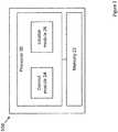
- Fig. 2illustrates a functional diagram of the processor and memory module (104) in accordance with certain embodiments of the disclosed subject matter.
- processor & memory module (104)comprises a processor (20) operatively coupled to a memory (22).
- the processor (20)can be configured to execute several functional modules in accordance with computer-readable instructions implemented on a non-transitory computer-readable storage medium. Such functional modules are referred to hereinafter as comprised in the processor.
- the processorcan comprise a control module (24) configured to control the operation of receivers (101-1) - (101-N) (e.g. by instructing the receivers to begin and/or end sampling, enabling synchronization of the measurement duration and/or the separate receiver's clocks, providing selectable switching if necessary, etc.).
- the processorcan further comprise a locator module (26) configured to perform processing for locating a source based on the measurements provided by the receivers and/or data resulted therefrom, as will be detailed below with reference to Figs. 3-5 .
- Memory (22)can include transitory or non-transitory memory and can be configured to store, inter alia, samples and/or data resulted therefrom for processing by the processor (20).
- substantially circular trajectorieswith typical diameter equal to the wavelength of the transmitted signal.
- Such trajectoriescan enable a uniform span of reflection delays regardless of the constellation of the transmitter and the receivers.
- teachings of the presently disclosed subject matterare, likewise, applicable to other trajectory shapes and/or sampling patterns enabling a sampled diversity of phase differences between the direct-path and reflection signals.
- the location systemcan be a standalone network entity, or integrated, fully or partly, with other network entities.
- FIG. 3illustrates a generalized flow chart of locating a source in accordance with certain embodiments of the presently disclosed subject matter.
- the LSis configured (301) to provide a plurality of spatially separated receivers K, the plurality of receivers K including one or more receivers M capable of movable sampling of a signal over a respective trajectory r (t) with respect to the site of the respective receiver's M location.
- each receiver Kis capable of movable sampling of a signal over a respective trajectory.
- Each receiver Kobtains (302) a sequence of samples of a given signal (e.g. a signal having a given frequency) during a sampling period, each sample associated with a time of obtaining the sample.
- the one or more receivers M of the plurality of receivers Keach obtain respective sequences of samples at different positions along their respective trajectories.
- each receiver of the plurality of receivers Kis configured for moveable sampling along a trajectory (i.e. each receiver K is also a receiver M ), and obtains samples of the signal at different positions along its respective trajectory.
- the plurality of receiverscan each obtain a respective sequence of samples z(t) in response to receiving data from the processor and memory module (104) indicative of an instruction to sample a signal.
- the data received from the processor and memory module (104)can include, e.g., a particular frequency to sample.
- the data indicative of an instructioncan be generated by the processor and memory module (104), e.g., control module (24), and transmitted to the plurality of receivers.
- each receivercan, in coordination with every other receiver, cycle through a predefined list of frequencies, each iteration of the cycle corresponding to a given frequency in the list.
- each receivercan obtain a sequence of samples of the signal having the frequency corresponding to the given iteration.
- each receivercan automatically move to the next iteration of the cycle whereby each receiver obtains samples of a signal having the next frequency in predefined list of frequencies.
- no signal having the given frequencyis detected by a receiver, no samples are obtained and the receiver moves to the next iteration after expiry of the predetermined period of time.
- the sequence of samples obtained by the k-th receiveris denoted zk(t).
- the k -th receiveris a receiver M configured for moveable sampling along a trajectory
- the sequence of samples z k (t) obtained by k -th receivercan be used to determine (e.g. by solving a series of non-linear equations, etc.) the propagation delay of the signal and an angle of arrival of the signal.
- the sequences of samples obtained by the pair of receiverscan be used to estimate the propagation delay and/or angle of arrival of the direct path signal in the presence of multipath reflections, and thereby to identify the most likely location of the transmitter.
- the sequences of samples of a given signal respectively obtained by the plurality of receiversare provided to the processor and memory module (104).
- Processor and memory module (104)e.g. locator module (26)
- Processor and memory module (104)processes the sequences of samples obtained by the plurality of receivers to identify (304) the most likely location of the transmitting source, as will further be detailed below with reference to Fig. 4 illustrating a flow chart of identifying the most likely location of the transmitting source in accordance with a first embodiment, and with reference to Fig. 5 illustrating a flow chart of identifying the most likely location of the transmitting source in accordance with a second embodiment.
- the most likely locationcan be estimated based on a time difference of arrival D of the signal in respect of one or more pairs of receivers K, the pair of receivers including at least one receiver M , and at least one angle of arrival ⁇ of the signal in respect of the at least one receiver M in the pair of receivers.
- FIG. 4there is illustrated a flow chart of identifying the most likely location in accordance with the first embodiment of the disclosed subject matter.
- locator module (26)determines (401), for at least one pair of receivers K, each pair including at least one receiver M, estimates for: i) a time difference of arrival of the received direct path signal with respect to the at least one pair of receivers, and ii) an angle of arrival of the received direct path signal in respect of at least one receiver M in the pair of receivers, thereby giving rise to measurement data.
- determining the measurement datacan be based on maximizing an objective function.
- the time difference of arrival of the signal in respect of the pair of receiversis indicated by the parameter D ki
- the angle of arrival in respect of receiver kis indicated by the parameter ⁇ k
- the angle of arrival of the signal in respect of receiver iis indicated by the parameter ⁇ i .
- Processor and memory module (104)can determine the values for the parameters D k i , ⁇ k and ⁇ i that maximize an objective function J(D ki , ⁇ k , ⁇ i ) over Dki, ⁇ k , ⁇ i .
- "*"is used to indicate the complex conjugate
- z k (t)is the sequence of samples obtained by receiver k
- z i (t)is the sequence of samples obtained by receiver i.
- processor and memory module (104)can determine values for the parameters D ki , ⁇ i that maximize an objective function J(Dki, ⁇ i ) over Dki, ⁇ i .
- the most likely location of the transmitting sourcecan be estimated using a grid of potential locations within an area of interest.
- Processor and memory module (104)obtains (501), e.g. from memory (22), data indicative of a geographical area of interest divided into a grid of potential locations of the transmitter.
- the LScan be preconfigured with the data.
- Processor and memory module (104), e.g. locator module (26),processes the sequences of samples obtained by the plurality of receivers K to generate (502), for each receiver among the plurality of receivers K, and for each potential transmitter location q in the grid of potential locations, data indicative of an estimated sequence of samples V(q) likely to be received by the receiver over a plurality of times, the estimated sequence of samples based on line of sight propagation from a transmitting source located at location q.
- the plurality of times in respect of the estimated sequence of samples for a given receivercorresponds to the plurality of times associated with the samples obtained by the given receiver.
- an estimated sequence of samples for a given receivercan be generated by modifying one or more samples of the sequence of samples actually obtained by the receiver. Such modifications may be made, for example, based on the distance and direction from the receiver to the potential location q.
- Processor and memory module (104), e.g. locator module (26),further generates (503), for each given potential location of transmitter in the grid, a matrix associating each receiver among the plurality of receivers K with the estimated sequence of samples generated for the receiver and corresponding to the given location, as illustrated by way of example in Fig. 6 , showing each location q in the grid (601) of potential locations being associated with a matrix (602), the matrix (602) associating each receiver in the plurality of receivers with each of a plurality of samples taken over a respective plurality of times.
- comparing matricesincludes calculating the norm of each matrix, and comparing the norms of each respective matrix.
- the norm of each matrixcan be determined by maximizing ⁇ V q V q H ⁇ where H indicates a Hermitian transpose. It should be noted that the matrix inside the norm symbol is N ⁇ N.
- the grid location associated with the matrix having highest normis then identified as the potential location with the highest likelihood of real location of the transmitting source.
- the system according to the inventionmay be implemented, at least partly, a suitably programmed computer.
- the inventioncontemplates a computer program being readable by a computer for executing the method of the invention.
- the inventionfurther contemplates a non-transitory machine-readable memory tangibly embodying a program of instructions executable by the computer for executing the method of the invention.
Landscapes
- Physics & Mathematics (AREA)
- Engineering & Computer Science (AREA)
- General Physics & Mathematics (AREA)
- Radar, Positioning & Navigation (AREA)
- Remote Sensing (AREA)
- Probability & Statistics with Applications (AREA)
- Position Fixing By Use Of Radio Waves (AREA)
Description
- The presently disclosed subject matter relates to location of a transmitting source and, more particularly, to location of a transmitting source in a multipath environment.
- In order to determine a location of a transmitting source, location techniques use the measurements obtained by a plurality of receivers. The obtained measurement data are informative of intensity (signal strength) and/or the phase and/or delay of the transmitted signal, and can be used for estimating distance to the transmitting source in accordance with received signal strength (RSS), time of arrival (TOA) at the receivers, angle of arrival (AOA) of the transmitted signal, time difference of arrival (TDOA) at the receivers, etc.
- The location techniques (e.g. radio frequency location) are well-known when assuming free-space propagation, however multipath interference makes the location estimation process to become challenging. Multipath is characterized by multiple reflections, while reflections power and the reflections delays dependent on the nature of the environment.
- Problems of mitigating the effects of multipath propagation in location of a transmitting source have been recognized in the conventional art and various techniques have been developed to provide solutions, for example:
US Patent No. 8,077,091 (Guigne ) discloses a method of determining a position of a mobile device within a surveillance volume. The method comprises synchronizing communications between a phase difference array comprising a spatially diverse array of N sensors and the mobile device, N being greater than 4; acquiring phase difference data as a function of time using the phase difference array and determining phase differences for a plurality of receiver pairs defined for the phase difference array, each receiver pair consisting of a unique pair of the sensors in the spatially diverse array of N sensors; and determining the position of the mobile device from the phase differences.US Patent Application No. 2011/0273328 (Parker ) discloses a method of geolocating a moving transmitter observed by a plurality of fixed or nearly fixed receiver devices, and a moving receiver device. The method includes obtaining wavelength-scaled phase difference measurements from the plurality of fixed or nearly fixed receiver devices to obtain a shape of the transmitter trajectory, measuring the phase difference between the moving receiver device and at least one of the plurality of fixed or nearly fixed receiver devices to obtain a phase error residual, and moving an estimated starting point of the transmitter to obtain a best-fit residual.- International Patent Application No.
WO15/001552A1 (Boker - The references cited above teach background information that may be applicable to the presently disclosed subject matter.
- According to one aspect of the presently disclosed subject matter, there is provided a system for locating a transmitting source in a multipath environment, comprising a plurality of spatially separated receiversK, each receiverK configured to obtain a sequence of samples of a signal transmitted by the transmitting source and received by the receiver, each sample respectively associated with a time of obtaining said sample, wherein one or more receiversM among the plurality of receiversK are each configured to obtain a respective sequence of samples over a plurality of different receiving positions along a respective trajectoryr(t) with respect to the site associated with the respective receiverM; and a processor and memory module operatively connected to the plurality of spatially separated receiversK and configured to process the sequences of samples obtained by the plurality of spatially separated receiversK to identify the most likely location of the transmitting source.
- Said processing includes: obtaining data indicative of an area of interest divided into a grid of potential locations of the transmitting source; modifying the sequences of samples to generate, for each receiver and for each potential location in the grid, data indicative of an estimated sequence of samples likely to be received by the receiver over a plurality of times, the modifying based on a distance and a direction from the receiver to the potential location and a corresponding line of sight propagation of a signal transmitted from the potential location; generating, for each given potential location in the grid, a matrix corresponding to the given potential location and associating each receiver with the estimated sequence of samples generated for the receiver for the corresponding location in the grid; and comparing the matrices corresponding to different potential locations to identify the matrix corresponding to potential location with the highest likelihood of real location of the transmitting source.
- In addition to the above features, the system according to this aspect of the presently disclosed subject matter can comprise one or more of features (i) to (iv) listed below, in any desired combination or permutation which is technically possible:
- (i) the estimated sequence of samplesVkt(q) generated for ak-th receiver for a potential locationq is calculated as:

- (ii) comparing the matrices corresponding to different potential locations comprises calculating the norm of each matrix, wherein the potential location q corresponding to the matrix having the highest norm is identified as the potential location with the highest likelihood of real location of the transmitting source; and
- (iii) at least one receiverM obtains a respective sequence of samples over a plurality of different receiving positions along a trajectory using a moving antenna.
- (iv) obtaining by at least one receiverM a respective sequence of samples over a plurality of different receiving positions along a trajectory comprises physical reposition of the at least one receiverM.
- According to another aspect of the presently disclosed subject matter, there is provided a system of locating a transmitting source in a multipath environment, the system comprising: a plurality of spatially separated receiversK, each receiverK configured to obtain a sequence of samples of a signal transmitted by the transmitting source and received by the receiver, each sample respectively associated with a time of obtaining said sample, wherein one or more receiversM among the plurality of receiversK are each configured to obtain a respective sequence of samples over a plurality of different receiving positions along a respective trajectoryr(t) with respect to the site associated with the respective receiverM; and a processor and memory module operatively connected to the plurality of spatially separated receiversK and configured to process the sequences of samples obtained by the plurality of spatially separated receiversK to identify the most likely location of the transmitting source.
- Said processor and memory module is configured to obtain data indicative of an area of interest divided into a grid of potential locations of the transmitting source; modify the sequences of samples to generate, for each receiver and for each potential location in the grid, data indicative of an estimated sequence of samples likely to be received by the receiver over a plurality of times, modifying based on a distance and a direction from the receiver to the potential location and a corresponding line of sight propagation of a signal transmitted from the potential location; generate, for each given potential location in the grid, a matrix corresponding to the given potential location and associating each receiver with the estimated sequence of samples generated for the receiver for the corresponding location in the grid; and compare the matrices corresponding to different potential locations to identify the matrix corresponding to potential location with the highest likelihood of real location of the transmitting source.
- This aspect of the disclosed subject matter can comprise one or more of features (i) to (iv) listed above with respect to the system,mutatis mutandis, in any desired combination or permutation which is technically possible.
- According to another aspect of the presently disclosed subject matter, there is provided a computer program product according to claim 11.
- Among advantages of certain embodiments of the presently disclosed subject matter is capability of locating a transmitting source with no need for antenna arrays at the sites. Among further advantages of certain embodiments of the presently disclosed subject matter is capability of locating a transmitting source with no need for synchronizing the samples provided by receivers at different sites.
- In order to understand the invention and to see how it can be carried out in practice, embodiments will be described, by way of non-limiting examples, with reference to the accompanying drawings, in which:
Fig. 1 illustrates a functional block diagram of a location system in accordance with certain embodiments of the presently disclosed subject matter;Fig. 2 illustrates a functional block diagram of a processor and memory module in accordance with certain embodiments of the presently disclosed subject matter;Fig. 3 illustrates a generalized flow-chart of locating a transmitter in accordance with certain embodiments of the presently disclosed subject matter;Fig. 4 illustrates a generalized flow-chart of identifying the most likely location of a transmitter in accordance with a first embodiment of the presently disclosed subject matter not forming part of the invention but being useful for understanding the invention;Fig. 5 illustrates a generalized flow-chart of identifying the most likely location of a transmitter in accordance with a second embodiment of the presently disclosed subject matter; andFig. 6 illustrates a grid of potential locations of the transmitter, in accordance with certain embodiments of the presently disclosed subject matter.- In the following detailed description, numerous specific details are set forth in order to provide a thorough understanding of the invention. However, it will be understood by those skilled in the art that the presently disclosed subject matter may be practiced without these specific details. In other instances, well-known methods, procedures, components and circuits have not been described in detail so as not to obscure the presently disclosed subject matter.
- Unless specifically stated otherwise, as apparent from the following discussions, it is appreciated that throughout the specification discussions utilizing terms such as "processing", "calculating", "determining", "comparing", "generating", "estimating", "identifying", "obtaining" or the like, refer to the action(s) and/or process(es) of a computer that manipulate and/or transform data into other data, said data represented as physical, such as electronic, quantities and/or said data representing the physical objects. The term "computer" should be expansively construed to cover any kind of electronic device with data processing capabilities including, by way of non-limiting example, one or more components of radiolocation system disclosed in the present application.
- The terms "non-transitory memory" and "non-transitory storage medium" as used herein should be expansively construed to cover any volatile or non-volatile computer memory suitable to the presently disclosed subject matter.
- The term "location" should be expansively construed to cover any data indicative of a position of a respective object with respect to a relevant reference system.
- The operations in accordance with the teachings herein may be performed by a computer specially constructed for the desired purposes or by a general-purpose computer specially configured for the desired purpose by a computer program stored in a non-transitory computer readable storage medium.
- Embodiments of the presently disclosed subject matter are not described with reference to any particular programming language. It will be appreciated that a variety of programming languages may be used to implement the teachings of the presently disclosed subject matter as described herein.
- Bearing this in mind, attention is drawn to
Fig. 1 illustrating a functional diagram of a location system (LS) in accordance with certain embodiments of the presently disclosed subject matter. The illustrated system comprises a plurality of spatially separated hardware-based receivers (denoted101-1 -101-N) operatively connected to the processor and memory module(104). - The LS is configured to determine the location of a transmitter(102) (referred to hereinafter also as a "source") in the presence of moderate multipath interference (i.e. the received direct-path signal is stronger than the multipath reflections). Transmitter(102) is substantially stationary during the radiolocation process, and transmits a modulated, radio frequency (RF) signal throughout the radiolocation process.
- Receivers(101-1) -(101-N) are situated at separate sites, each within the reception range the signal transmission from transmitter(102). The operative bandwidth of each receiver(101-1) -(101-N) corresponds to the operative bandwidth of the transmitter(102). In certain embodiments, LS includes at least N receivers located at N different sites, where N ≥ 2. In certain embodiments, the different receiver sites can be positioned with respect to one another in a manner that provides advantageous geometry for locating a transmitter, e.g. by ensuring a large variance in the different directions to the transmitter.
- Receivers(101-1) -(101-N) are configured to enable movable sampling of a signal over a respective trajectoryr(t), denoted(103-1) -(103-N), with respect to the site of the receiver. In certain embodiments, at least one of receivers(101-1) -(101-N) is configured to enable movable sampling of a signal over a respective trajectory, while the other receivers may not be configured to enable movable sampling. Trajectories can be circular, e.g. with typical trajectory diameter in the order of the wavelength of the signal, or can be represented by other shapes or patterns. The trajectory shapes can be different for different receivers. For purpose of illustration only, the description is provided for substantially circular trajectories having minimal diameter equal to the wavelength of the transmitted signal. Such trajectories can enable a large span of reflection delays regardless of the constellation of the transmitter and the receivers. Those skilled in the art will readily appreciate that the teachings of the presently disclosed subject matter are, likewise, applicable to other trajectory shapes and/or sampling patterns enabling a sampled diversity of phase differences between the direct-path and reflection signals.
- Each of the receivers is configured to obtain a sequence of samples of a signal (also referred to as "sampling") having a given frequency, at a fixed sampling rate for the duration of a predetermined sampling period, each sample associated with a time of obtaining the sample ("time-tagged"), and to provide the sequence of samples to the processor and memory module(104). Receivers configured for moveable sampling along a trajectory obtain the samples of the signal at different positions along the receiver's trajectory. Each receiver configured to enable moveable sampling can perform moveable sampling independently from the moveable sampling performed by other receivers. The measuring pattern(s) shall enable a required distribution of respective phase differences (e.g. over the range of 0 to 360 degrees) between the direct path and the multipath signals, thereby reducing the bias created by multipath. For a given receiver, the measuring positions along its trajectory can be distributed over its respective trajectory evenly or non-evenly. The subject matter does not limit the number of measurements taken during a sampling period, however the rate of sampling should be at least equal to the Nyquist rate. The number of measurements taken per receiver may or may not be the same for all receivers.
- In certain embodiments of the presently disclosed subject matter, one or more receivers can sample the signal repeatedly over a plurality of trajectory cycles during the sampling period.
- In certain embodiments, a receiver configured for moveable measuring can include one or more moveable antennas. The spatial diversity created by antenna motion reduces the bias created by multipath. This effect can be significant when the antenna moves over a large distance and the angle difference between direct reception and secondary path is large. For purpose of illustration only, the description is provided for substantially static receivers with movable sampling enabled by a moving antenna. Those skilled in the art will readily appreciate that the teachings of the presently disclosed subject matter are, likewise, applicable to movable measuring enabled by other means, e.g. by physical reposition of respective receivers and/or selectable switching of prearranged or selectively deployed sub-receivers (or antennas) along a trajectory, etc. Physical reposition of respective receivers can be achieved, e.g., by using an automatic mechanical device, such as a rotating device that moves the receiver along the trajectory, by coupling the receiver to a mobile platform such as being mounted onto a vehicle or onto a robotic trolley, by movement of a person manually transporting the receiver, etc.
- The rate at which the antenna moves should be sufficient to allow sufficient coverage of relative phase difference between direct path and reflection signals (e.g. during a single traversal of the trajectory or over a plurality of traversals). For another example, each sub-receiver or antenna prearranged or selectively deployed at a fixed point along the trajectory can be switched to take one of the measurements. In this example or in other examples with sub-receivers, the sub-receivers can collectively function as a receiver that employs movable measuring. For another example, for each trajectory a different sub-receiver or antenna can be concurrently repositioned along each part of the trajectory and take measurements along that part (e.g. one sub-receiver can take measurements along half of the trajectory and during the same time period the other sub-receiver can take measurements along the other half of the trajectory). In this example, the number of measurements can be increased for the time period. For another example, if there are two or more transmitters, operating in different frequency ranges, then for each transmitter there can be a set of receivers that can be repositioned in order to detect the signal emitted from the transmitter. The repositioning of the various receivers corresponding to the plurality of transmitters can be performed by one or more mechanisms such as rotating device(s). In this example the mechanism can rotate at least one receiver in a set, together or separately, along the same of different trajectory.
- Processor & memory module(104) is configured,inter alia, to receive the sequences of samples obtained by the plurality of receivers and to process the sequences of samples to identify the most likely location of the transmitter, as will further be detailed with reference to
Figs. 3-5 . In certain embodiments, processor & memory module(104) can also be configured to control the operation of receivers(101-1) -(101-N) (e.g. to enable synchronization of the receivers' clocks, to provide selectable switching if necessary, etc.). In certain embodiments, one or more of the receivers can, at least partly process the sequence of samples obtained by the receiver, and to transfer the resulting data to the processor & memory module(104) for further processing to identify the most likely location of the transmitter. Fig. 2 illustrates a functional diagram of the processor and memory module(104) in accordance with certain embodiments of the disclosed subject matter. In certain embodiments, processor & memory module(104) comprises a processor(20) operatively coupled to a memory(22).- As will be further detailed with reference to
Figs. 3-5 , the processor(20) can be configured to execute several functional modules in accordance with computer-readable instructions implemented on a non-transitory computer-readable storage medium. Such functional modules are referred to hereinafter as comprised in the processor. In certain embodiments, the processor can comprise a control module(24) configured to control the operation of receivers(101-1) -(101-N) (e.g. by instructing the receivers to begin and/or end sampling, enabling synchronization of the measurement duration and/or the separate receiver's clocks, providing selectable switching if necessary, etc.). The processor can further comprise a locator module(26) configured to perform processing for locating a source based on the measurements provided by the receivers and/or data resulted therefrom, as will be detailed below with reference toFigs. 3-5 . - Memory(22) can include transitory or non-transitory memory and can be configured to store,inter alia, samples and/or data resulted therefrom for processing by the processor(20).
- For purpose of illustration only, the description is provided for substantially circular trajectories with typical diameter equal to the wavelength of the transmitted signal. Such trajectories can enable a uniform span of reflection delays regardless of the constellation of the transmitter and the receivers. Those skilled in the art will readily appreciate that the teachings of the presently disclosed subject matter are, likewise, applicable to other trajectory shapes and/or sampling patterns enabling a sampled diversity of phase differences between the direct-path and reflection signals.
- For purpose of illustration only, the description is provided for substantially static receivers with movable sampling enabled by a moving antenna. Those skilled in the art will readily appreciate that the teachings of the presently disclosed subject matter are, likewise, applicable to movable measuring enabled by physical reposition of respective receivers, selectable switching of prearranged sub-receivers along a trajectory, etc.
- It is noted that the teachings of the presently disclosed subject matter are not bound by the location system described with reference to
Figs. 1-2 . Equivalent and/or modified functionality can be consolidated or divided in another manner and can be implemented in any appropriate combination of software, firmware and/or hardware and executed on a suitable device. The location system can be a standalone network entity, or integrated, fully or partly, with other network entities. Fig. 3 illustrates a generalized flow chart of locating a source in accordance with certain embodiments of the presently disclosed subject matter.- The LS is configured(301) to provide a plurality of spatially separated receiversK, the plurality of receiversK including one or more receiversM capable of movable sampling of a signal over a respective trajectoryr(t) with respect to the site of the respective receiver'sM location. In certain embodiments, as detailed above with reference to
Fig. 1 , each receiverK is capable of movable sampling of a signal over a respective trajectory. - Each receiverK obtains(302) a sequence of samples of a given signal (e.g. a signal having a given frequency) during a sampling period, each sample associated with a time of obtaining the sample. The one or more receiversM of the plurality of receiversK each obtain respective sequences of samples at different positions along their respective trajectories. In certain embodiments, as detailed above, each receiver of the plurality of receiversK is configured for moveable sampling along a trajectory (i.e. each receiverK is also a receiverM), and obtains samples of the signal at different positions along its respective trajectory.
- In certain embodiments, the plurality of receivers can each obtain a respective sequence of samplesz(t) in response to receiving data from the processor and memory module(104) indicative of an instruction to sample a signal. In certain embodiments, the data received from the processor and memory module(104) can include, e.g., a particular frequency to sample. The data indicative of an instruction can be generated by the processor and memory module(104), e.g., control module(24), and transmitted to the plurality of receivers.
- In certain other embodiments, each receiver can, in coordination with every other receiver, cycle through a predefined list of frequencies, each iteration of the cycle corresponding to a given frequency in the list. In any given iteration, each receiver can obtain a sequence of samples of the signal having the frequency corresponding to the given iteration. After a predetermined period of time (e.g. the sampling period), each receiver can automatically move to the next iteration of the cycle whereby each receiver obtains samples of a signal having the next frequency in predefined list of frequencies. In any given iteration, if no signal having the given frequency is detected by a receiver, no samples are obtained and the receiver moves to the next iteration after expiry of the predetermined period of time.
- In the description that follows, the sequence of samples obtained by the k-th receiver is denotedzk(t). As will be appreciated a person skilled in the art, the sequence of sampleszk(t) corresponding to a source signals(t) transmitted at a frequency corresponding to wavelength λ and located at direction α from the site of the k-th receiver can be represented mathematically as


- It will further be appreciated by a person skilled in the art that in the case that thek-th receiver is a receiverM configured for moveable sampling along a trajectory, the sequence of sampleszk(t) obtained byk-th receiver can be used to determine (e.g. by solving a series of non-linear equations, etc.) the propagation delay of the signal and an angle of arrival of the signal. As will be further detailed herein with reference to
Figs. 4 - 5 , given a pair of receiversk, i, at least one of which is a receiverM, the sequences of samples obtained by the pair of receivers can be used to estimate the propagation delay and/or angle of arrival of the direct path signal in the presence of multipath reflections, and thereby to identify the most likely location of the transmitter. - In certain embodiments, the sequences of samples of a given signal respectively obtained by the plurality of receivers are provided to the processor and memory module(104). Processor and memory module(104), e.g. locator module(26), processes the sequences of samples obtained by the plurality of receivers to identify(304) the most likely location of the transmitting source, as will further be detailed below with reference to
Fig. 4 illustrating a flow chart of identifying the most likely location of the transmitting source in accordance with a first embodiment, and with reference toFig. 5 illustrating a flow chart of identifying the most likely location of the transmitting source in accordance with a second embodiment. - In accordance with a first embodiment, the most likely location can be estimated based on a time difference of arrivalD of the signal in respect of one or more pairs of receiversK, the pair of receivers including at least one receiverM, and at least one angle of arrivalα of the signal in respect of the at least one receiverM in the pair of receivers.
- Referring now to
Fig. 4 , there is illustrated a flow chart of identifying the most likely location in accordance with the first embodiment of the disclosed subject matter. - Processor and memory module(104), e.g. locator module(26), determines(401), for at least one pair of receiversK, each pair including at least one receiverM, estimates for: i) a time difference of arrival of the received direct path signal with respect to the at least one pair of receivers, and ii) an angle of arrival of the received direct path signal in respect of at least one receiverM in the pair of receivers, thereby giving rise to measurement data.
- In certain embodiments, determining the measurement data can be based on maximizing an objective function. By way of non-limiting example, given one or more pairs of receiversk andi, in which bothk andi are receiversM (i.e. configured for moveable sampling), the time difference of arrival of the signal in respect of the pair of receivers is indicated by the parameterDki, the angle of arrival in respect of receiverk is indicated by the parameterαk, and the angle of arrival of the signal in respect of receiveri is indicated by the parameterαi. Processor and memory module(104) can determine the values for the parametersDki,αk andαi that maximize an objective functionJ(Dki, αk, αi) overDki, αk, αi. By way of non-limiting example, the objective function can be represented as

- By way of a further non-limiting example, in the case that in the pair of receiverk, i, only receiveri is a receiverM (i.e. configured for moveable sampling) and receiverk is not a receiverM (i.e.rk(t) = 0) processor and memory module(104) can determine values for the parametersDki,αi that maximize an objective functionJ(Dki, αi) overDki, αi. By way of non-limiting example, the objective function can be represented as

- Using the measurement data, processor and memory module(104), e.g. locator module(26), identifies(402) the most likely location of the transmitter. For example, as known in the art of radiolocation, given estimated values for the time difference of arrival (DTOA) in respect of pairs of sensors sk, sl, wherek, l = 1..N,k ≠l, and given at least one estimated angle of arrival (AOA) in respect of at least sk, the location of the transmitter can be determined by minimization over a location space of an objective function expressing weighted squared errors for each candidate location x, the objective function represented as:

- In accordance with a second embodiment of the disclosed subject matter, the most likely location of the transmitting source can be estimated using a grid of potential locations within an area of interest.
- Referring now to
Fig. 5 , there is illustrated a flow chart of identifying the most likely location in accordance with the second embodiment of the disclosed subject matter. Processor and memory module(104) obtains(501), e.g. from memory(22), data indicative of a geographical area of interest divided into a grid of potential locations of the transmitter. In certain embodiments, the LS can be preconfigured with the data. - Processor and memory module(104), e.g. locator module(26), processes the sequences of samples obtained by the plurality of receiversK to generate(502), for each receiver among the plurality of receiversK, and for each potential transmitter locationq in the grid of potential locations, data indicative of an estimated sequence of samplesV(q) likely to be received by the receiver over a plurality of times, the estimated sequence of samples based on line of sight propagation from a transmitting source located at locationq. In certain embodiments, the plurality of times in respect of the estimated sequence of samples for a given receiver corresponds to the plurality of times associated with the samples obtained by the given receiver. In embodiments, an estimated sequence of samples for a given receiver can be generated by modifying one or more samples of the sequence of samples actually obtained by the receiver. Such modifications may be made, for example, based on the distance and direction from the receiver to the potential locationq.
- By way of non-limiting example, the estimated sequence of samplesV(q) generated for each receiver corresponding to a given locationq can be represented as:

- Processor and memory module(104), e.g. locator module(26), further generates(503), for each given potential location of transmitter in the grid, a matrix associating each receiver among the plurality of receiversK with the estimated sequence of samples generated for the receiver and corresponding to the given location, as illustrated by way of example in
Fig. 6 , showing each locationq in the grid(601) of potential locations being associated with a matrix(602), the matrix(602) associating each receiver in the plurality of receivers with each of a plurality of samples taken over a respective plurality of times. - Processor and memory module(104), e.g. locator module(26), compares(504) the matrices associated with different potential locations to identify the matrix corresponding to the potential location with the highest likelihood of real location of the transmitting source. In certain embodiments, comparing matrices includes calculating the norm of each matrix, and comparing the norms of each respective matrix.
- By way of non-limiting example, the norm of each matrix can be determined by maximizing

- The grid location associated with the matrix having highest norm is then identified as the potential location with the highest likelihood of real location of the transmitting source.
- It is to be understood that the invention is not limited in its application to the details set forth in the description contained herein or illustrated in the drawings. The invention is capable of other embodiments and of being practiced and carried out in various ways. Hence, it is to be understood that the phraseology and terminology employed herein are for the purpose of description and should not be regarded as limiting. As such, those skilled in the art will appreciate that the conception upon which this disclosure is based may readily be utilized as a basis for designing other structures, methods, and systems for carrying out the several purposes of the presently disclosed subject matter.
- It will also be understood that the system according to the invention may be implemented, at least partly, a suitably programmed computer. Likewise, the invention contemplates a computer program being readable by a computer for executing the method of the invention. The invention further contemplates a non-transitory machine-readable memory tangibly embodying a program of instructions executable by the computer for executing the method of the invention.
- Those skilled in the art will readily appreciate that various modifications and changes can be applied to the embodiments of the invention as hereinbefore described without departing from its scope, defined in and by the appended claims.


Claims (11)
- A method of locating a transmitting source (102) in a multipath environment, the method comprising:obtaining, by each receiverK (101-N) of a plurality of spatially separated receivers, a sequence of samples of a signal transmitted by the transmitting source (102) and received by the receiver (101-N), each sample respectively associated with a time of obtaining said sample, wherein one or more receiversM (101-N) among the plurality of receiversK (101-N) each obtain a respective sequence of samples over a plurality of different receiving positions along a respective trajectoryr(t) with respect to the site associated with the respective receiverM (101-N); andprocessing the obtained sequences of samples to identify the most likely location of the transmitting source (102),characterised in that said processing includes:obtaining (501) data indicative of an area of interest divided into a grid (601) of potential locations of the transmitting source (102);modifying (502) the sequences of samples to generate, for each receiver (101-N) and for each potential location in the grid (601), data indicative of an estimated sequence of samples likely to be received by the receiver (101-N) over a plurality of times, the modifying based on a distance and a direction from the receiver (101-N) to the potential location and a corresponding line of sight propagation of a signal transmitted from the potential location;generating (503), for each given potential location in the grid (601), a matrix (602) corresponding to the given potential location and associating each receiver (101-N) with the estimated sequence of samples generated for the receiver (101-N) for the corresponding location in the grid (601); andcomparing (504) the matrices (602) corresponding to different potential locations to identify the matrix (602) corresponding to potential location with the highest likelihood of real location of the transmitting source (102).
- The method of Claim 1, wherein the estimated sequence of samplesVkt(q) generated for ak-th receiver (101-N) for a potential locationq is calculated as:

- The method of Claim 1 or 2, wherein comparing (504) the matrices (602) corresponding to different potential locations comprises calculating the norm of each matrix (602), wherein the potential locationq corresponding to the matrix (602) having the highest norm is identified as the potential location with the highest likelihood of real location of the transmitting source (102).
- The method of any one of Claims 1 to 3, wherein at least one receiverM (101-N) obtains a respective sequence of samples over a plurality of different receiving positions along a trajectory using a moving antenna.
- The method of any one of claims 1 to 3, wherein obtaining by at least one receiverM (101-N) a respective sequence of samples over a plurality of different receiving positions along a trajectory comprises physical reposition of the at least one receiverM (101-N).
- A system for locating a transmitting source (102) in a multipath environment, comprising:a plurality of spatially separated receiversK (101-N), each receiverK (101-N) configured to obtain a sequence of samples of a signal transmitted by the transmitting source (102) and received by the receiver (101-N), each sample respectively associated with a time of obtaining said sample, wherein one or more receiversM (101-N) among the plurality of receiversK (101-N) are each configured to obtain a respective sequence of samples over a plurality of different receiving positions along a respective trajectoryr(t) with respect to the site associated with the respective receiverM (101-N); anda processor and memory module (104) operatively connected to the plurality of spatially separated receiversK (101-N) and configured to process the sequences of samples obtained by the plurality of spatially separated receiversK (101-N) to identify the most likely location of the transmitting source (102),characterised in that the processor and memory module (104) is configured to:obtain (501) data indicative of an area of interest divided into a grid (601) of potential locations of the transmitting source (102);modify (502) the sequences of samples to generate, for each receiver (101-N) and for each potential location in the grid (601), data indicative of an estimated sequence of samples likely to be received by the receiver (101-N) over a plurality of times, modifying based on a distance and a direction from the receiver (101-N) to the potential location and a corresponding line of sight propagation of a signal transmitted from the potential location;generate (503), for each given potential location in the grid (601), a matrix (602) corresponding to the given potential location and associating each receiver (101-N) with the estimated sequence of samples generated for the receiver (101-N) for the corresponding location in the grid (601); andcompare (504) the matrices (602) corresponding to different potential locations to identify the matrix (602) corresponding to potential location with the highest likelihood of real location of the transmitting source (102).
- The system of Claim 6, wherein the processor and memory module (104) is further configured to calculate the estimated sequence of samplesVkt(q) generated for ak-th receiver (101-N) for a potential locationq as:

- The system of Claim 6, wherein comparing (504) the matrices (602) corresponding to different potential locations comprises calculating the norm of each matrix (602), wherein the potential locationq corresponding to the matrix (602) having the highest norm is identified as the potential location with the highest likelihood of real location of the transmitting source (102).
- The system of any one of Claims 6 - 8, wherein at least one receiverM (101-N) is configured to obtain a respective sequence of samples over a plurality of different receiving positions along a trajectory using a moving antenna.
- The system of any one of Claims 6 - 8, wherein at least one receiverM (101-N) is configured to obtain a respective sequence of samples over a plurality of different receiving positions along a trajectory with the help of physical repositioning.
- A computer program or a computer program product comprising a program of instructions readable by a computer, the program of instructions to cause the system of any of claims 6 to 10 to execute the steps of the method of locating a transmitting source (102) in a multipath environment in accordance with any one of Claims 1 to 5.


Priority Applications (1)
| Application Number | Priority Date | Filing Date | Title |
|---|---|---|---|
| EP19197887.3AEP3637126A1 (en) | 2016-01-05 | 2017-01-04 | Method of locating a transmitting source in multipath environment and system thereof |
Applications Claiming Priority (2)
| Application Number | Priority Date | Filing Date | Title |
|---|---|---|---|
| IL243484AIL243484A0 (en) | 2016-01-05 | 2016-01-05 | Method of locating a transmitting source in multipath environment and system thereof |
| IL246602AIL246602B (en) | 2016-07-04 | 2016-07-04 | Method of locating a transmitting source in multipath environment and system thereof |
Related Child Applications (2)
| Application Number | Title | Priority Date | Filing Date |
|---|---|---|---|
| EP19197887.3ADivisionEP3637126A1 (en) | 2016-01-05 | 2017-01-04 | Method of locating a transmitting source in multipath environment and system thereof |
| EP19197887.3ADivision-IntoEP3637126A1 (en) | 2016-01-05 | 2017-01-04 | Method of locating a transmitting source in multipath environment and system thereof |
Publications (3)
| Publication Number | Publication Date |
|---|---|
| EP3199970A2 EP3199970A2 (en) | 2017-08-02 |
| EP3199970A3 EP3199970A3 (en) | 2017-12-06 |
| EP3199970B1true EP3199970B1 (en) | 2019-12-11 |
Family
ID=57714531
Family Applications (2)
| Application Number | Title | Priority Date | Filing Date |
|---|---|---|---|
| EP17150249.5AActiveEP3199970B1 (en) | 2016-01-05 | 2017-01-04 | Method of locating a transmitting source in multipath environment and system thereof |
| EP19197887.3APendingEP3637126A1 (en) | 2016-01-05 | 2017-01-04 | Method of locating a transmitting source in multipath environment and system thereof |
Family Applications After (1)
| Application Number | Title | Priority Date | Filing Date |
|---|---|---|---|
| EP19197887.3APendingEP3637126A1 (en) | 2016-01-05 | 2017-01-04 | Method of locating a transmitting source in multipath environment and system thereof |
Country Status (3)
| Country | Link |
|---|---|
| US (1) | US10545216B2 (en) |
| EP (2) | EP3199970B1 (en) |
| SG (1) | SG10201700038SA (en) |
Families Citing this family (11)
| Publication number | Priority date | Publication date | Assignee | Title |
|---|---|---|---|---|
| US11187778B2 (en)* | 2016-01-13 | 2021-11-30 | Hoopo Systems Ltd. | Method and system for radiolocation |
| US10171943B1 (en)* | 2017-06-12 | 2019-01-01 | Qualcomm Incorporated | System and method for utilizing an array of mobile devices for imaging and user equipment positioning |
| GB2565106B (en)* | 2017-08-02 | 2022-05-18 | Secr Defence | Apparatus and method of locating a radio emitter |
| KR102428706B1 (en)* | 2017-08-31 | 2022-08-04 | 삼성전자주식회사 | Electronic Device for Identifying Relative Position and the Control Method thereof |
| JP7042623B2 (en)* | 2018-01-05 | 2022-03-28 | キヤノン株式会社 | Information processing equipment, information processing system and storage medium |
| CN110031862B (en)* | 2018-01-10 | 2023-09-29 | 德尔福技术有限责任公司 | Method, apparatus and system for an automated vehicle with target positioning |
| US10921433B2 (en)* | 2018-01-10 | 2021-02-16 | Aptiv Technologies Limited | Method, apparatus and system for automated vehicle with target localization |
| JP6973254B2 (en)* | 2018-04-05 | 2021-11-24 | 日本電信電話株式会社 | Signal analyzer, signal analysis method and signal analysis program |
| EP3874292A4 (en)* | 2018-11-01 | 2022-08-17 | Hoopo Systems Ltd. | Method and system for radiolocation at reduced data transfer |
| JP7401987B2 (en)* | 2019-07-18 | 2023-12-20 | 株式会社光電製作所 | Location estimation device, location estimation system, location estimation method |
| CN114201728B (en)* | 2021-11-30 | 2024-06-28 | 华中科技大学 | A method and system for locating radio frequency interference sources based on multi-shot joint sparse reconstruction |
Family Cites Families (16)
| Publication number | Priority date | Publication date | Assignee | Title |
|---|---|---|---|---|
| US5045860A (en)* | 1990-06-27 | 1991-09-03 | R & D Associates | Method and arrangement for probabilistic determination of a target location |
| US5883598A (en)* | 1995-12-15 | 1999-03-16 | Signatron Technology Corporation | Position location system and method |
| GB9702153D0 (en)* | 1997-02-03 | 1997-03-26 | Nokia Telecommunications Oy | Doppler direction finder and method of location using doppler direction finder |
| DE19936846A1 (en) | 1998-08-06 | 2000-04-06 | Cell Loc Inc | Network-based wireless location method for cellular mobile telephones, involving calling cellular telephone, monitoring paging over control channel, and gathering and processing response via reverse control channel |
| US6407703B1 (en)* | 2000-08-07 | 2002-06-18 | Lockheed Martin Corporation | Multi-platform geolocation method and system |
| US20050105600A1 (en) | 2003-11-14 | 2005-05-19 | Okulus Networks Inc. | System and method for location tracking using wireless networks |
| US8077089B2 (en) | 2006-08-15 | 2011-12-13 | Rincon Research Corporation | Precision geolocation of moving or fixed transmitters using multiple observers |
| FR2924228B1 (en)* | 2007-11-23 | 2009-11-13 | Thales Sa | MULTI-EMITTER AND MULTI-PATH AOA-TDOA LOCATION METHOD COMPRISING A SYNCHRONIZATION AND EQUALIZATION SUB-PROCESS OF RECEPTION STATIONS |
| US8504322B2 (en)* | 2008-12-01 | 2013-08-06 | Agilent Technologies, Inc. | Likelihood map system for localizing an emitter |
| US7911385B2 (en)* | 2009-02-27 | 2011-03-22 | Harris Corporation | RF transmitter geolocation system and related methods |
| WO2011160698A1 (en)* | 2010-06-25 | 2011-12-29 | Innovationszentrum für Telekommunikationstechnik GmbH IZT | System and method for determining a position |
| US8077091B1 (en) | 2010-07-06 | 2011-12-13 | Intelligent Sciences, Ltd. | System and method for determining a position of a mobile device within a surveillance volume in the presence of multipath interference |
| US20120313820A1 (en)* | 2011-06-07 | 2012-12-13 | Raytheon Company | System technique for conical geo-location of radio frequency sources |
| IL227285A0 (en) | 2013-07-01 | 2013-12-31 | Rami Goldreich | Mitigation of multipath distortions for tdoa-based geolocation |
| US9804253B2 (en)* | 2013-07-08 | 2017-10-31 | Rockwell Collins, Inc. | System and methods for non-parametric technique based geolocation and cognitive sensor activation |
| WO2015100237A2 (en)* | 2013-12-27 | 2015-07-02 | Massachusetts Institute Of Technology | Localization with non-synchronous emission and multipath transmission |
- 2017
- 2017-01-04SGSG10201700038SApatent/SG10201700038SA/enunknown
- 2017-01-04EPEP17150249.5Apatent/EP3199970B1/enactiveActive
- 2017-01-04USUS15/398,333patent/US10545216B2/enactiveActive
- 2017-01-04EPEP19197887.3Apatent/EP3637126A1/enactivePending
Non-Patent Citations (1)
| Title |
|---|
| None* |
Also Published As
| Publication number | Publication date |
|---|---|
| SG10201700038SA (en) | 2017-08-30 |
| US20170192083A1 (en) | 2017-07-06 |
| US10545216B2 (en) | 2020-01-28 |
| EP3637126A1 (en) | 2020-04-15 |
| EP3199970A2 (en) | 2017-08-02 |
| EP3199970A3 (en) | 2017-12-06 |
Similar Documents
| Publication | Publication Date | Title |
|---|---|---|
| EP3199970B1 (en) | Method of locating a transmitting source in multipath environment and system thereof | |
| US11824272B2 (en) | In-field millimeter-wave phased array radiation pattern estimation and validation | |
| US9841489B2 (en) | Mitigation of multipath distortions for TDOA-based geolocation | |
| EP3538911B1 (en) | User equipment localization in a mobile communication network based on delays and path strengths | |
| US10955542B2 (en) | Radar apparatus and direction-of-arrival estimation device | |
| EP3005581B1 (en) | A localization-based beamforming scheme for systems with multiple antennas | |
| US9958526B2 (en) | Localization with non-synchronous emission and multipath transmission | |
| US20120328037A1 (en) | Anti-geolocation | |
| JPWO2014199609A1 (en) | Radar equipment | |
| Basak et al. | Passive radio system for real-time drone detection and DoA estimation | |
| Garcia et al. | POLAR: Passive object localization with IEEE 802.11 ad using phased antenna arrays | |
| Cuntz et al. | Field test: jamming the DLR adaptive antenna receiver | |
| Feigl et al. | Robust ToA-estimation using convolutional neural networks on randomized channel models | |
| Aldowesh et al. | A passive bistatic radar experiment for very low radar cross-section target detection | |
| Amjadi et al. | An iterative array signal segregation algorithm: A method for interference cancelation and multipath mitigation in complex environments | |
| WO2022033695A1 (en) | Estimating a location of a user equipment | |
| Dehkordi et al. | Multi-static parameter estimation in the near/far field beam space for integrated sensing and communication applications | |
| Oh et al. | Robust super-resolution TOA estimation against doppler shift for vehicle tracking | |
| EP4214529B1 (en) | Position determination of a wireless device | |
| Wang et al. | Super-resolution localization and tracking in wifi sensing | |
| Steffes et al. | Direct position determination for TDOA-based single sensor localization | |
| Freiman | Enhancing Direction Finding Accuracy in Perturbed Digital Arrays via RF Ranging-Based Self Calibration | |
| Knoedler et al. | Self-calibration of a passive radar system using GSM base stations | |
| Ward et al. | Autonomous navigation to an RF source in multipath environments | |
| Italiano et al. | 5G Vehicle Positioning in Tunnels with Single Anchor TDOA Exploiting Multipath Reflectors |
Legal Events
| Date | Code | Title | Description |
|---|---|---|---|
| PUAI | Public reference made under article 153(3) epc to a published international application that has entered the european phase | Free format text:ORIGINAL CODE: 0009012 | |
| STAA | Information on the status of an ep patent application or granted ep patent | Free format text:STATUS: THE APPLICATION HAS BEEN PUBLISHED | |
| AK | Designated contracting states | Kind code of ref document:A2 Designated state(s):AL AT BE BG CH CY CZ DE DK EE ES FI FR GB GR HR HU IE IS IT LI LT LU LV MC MK MT NL NO PL PT RO RS SE SI SK SM TR | |
| AX | Request for extension of the european patent | Extension state:BA ME | |
| PUAL | Search report despatched | Free format text:ORIGINAL CODE: 0009013 | |
| AK | Designated contracting states | Kind code of ref document:A3 Designated state(s):AL AT BE BG CH CY CZ DE DK EE ES FI FR GB GR HR HU IE IS IT LI LT LU LV MC MK MT NL NO PL PT RO RS SE SI SK SM TR | |
| AX | Request for extension of the european patent | Extension state:BA ME | |
| RIC1 | Information provided on ipc code assigned before grant | Ipc:G01S 3/52 20060101ALI20171031BHEP Ipc:G01S 5/12 20060101ALI20171031BHEP Ipc:G01S 5/02 20100101AFI20171031BHEP Ipc:G01S 5/06 20060101ALI20171031BHEP Ipc:G01S 5/04 20060101ALI20171031BHEP | |
| STAA | Information on the status of an ep patent application or granted ep patent | Free format text:STATUS: REQUEST FOR EXAMINATION WAS MADE | |
| 17P | Request for examination filed | Effective date:20180606 | |
| RBV | Designated contracting states (corrected) | Designated state(s):AL AT BE BG CH CY CZ DE DK EE ES FI FR GB GR HR HU IE IS IT LI LT LU LV MC MK MT NL NO PL PT RO RS SE SI SK SM TR | |
| GRAP | Despatch of communication of intention to grant a patent | Free format text:ORIGINAL CODE: EPIDOSNIGR1 | |
| STAA | Information on the status of an ep patent application or granted ep patent | Free format text:STATUS: GRANT OF PATENT IS INTENDED | |
| INTG | Intention to grant announced | Effective date:20190429 | |
| GRAJ | Information related to disapproval of communication of intention to grant by the applicant or resumption of examination proceedings by the epo deleted | Free format text:ORIGINAL CODE: EPIDOSDIGR1 | |
| STAA | Information on the status of an ep patent application or granted ep patent | Free format text:STATUS: REQUEST FOR EXAMINATION WAS MADE | |
| INTC | Intention to grant announced (deleted) | ||
| GRAP | Despatch of communication of intention to grant a patent | Free format text:ORIGINAL CODE: EPIDOSNIGR1 | |
| GRAS | Grant fee paid | Free format text:ORIGINAL CODE: EPIDOSNIGR3 | |
| STAA | Information on the status of an ep patent application or granted ep patent | Free format text:STATUS: GRANT OF PATENT IS INTENDED | |
| GRAA | (expected) grant | Free format text:ORIGINAL CODE: 0009210 | |
| STAA | Information on the status of an ep patent application or granted ep patent | Free format text:STATUS: THE PATENT HAS BEEN GRANTED | |
| INTG | Intention to grant announced | Effective date:20191022 | |
| AK | Designated contracting states | Kind code of ref document:B1 Designated state(s):AL AT BE BG CH CY CZ DE DK EE ES FI FR GB GR HR HU IE IS IT LI LT LU LV MC MK MT NL NO PL PT RO RS SE SI SK SM TR | |
| REG | Reference to a national code | Ref country code:GB Ref legal event code:FG4D | |
| REG | Reference to a national code | Ref country code:CH Ref legal event code:EP | |
| REG | Reference to a national code | Ref country code:AT Ref legal event code:REF Ref document number:1212736 Country of ref document:AT Kind code of ref document:T Effective date:20191215 | |
| REG | Reference to a national code | Ref country code:DE Ref legal event code:R096 Ref document number:602017009478 Country of ref document:DE | |
| REG | Reference to a national code | Ref country code:IE Ref legal event code:FG4D | |
| REG | Reference to a national code | Ref country code:CH Ref legal event code:NV Representative=s name:SERVOPATENT GMBH, CH | |
| REG | Reference to a national code | Ref country code:NL Ref legal event code:MP Effective date:20191211 | |
| REG | Reference to a national code | Ref country code:LT Ref legal event code:MG4D | |
| PG25 | Lapsed in a contracting state [announced via postgrant information from national office to epo] | Ref country code:LT Free format text:LAPSE BECAUSE OF FAILURE TO SUBMIT A TRANSLATION OF THE DESCRIPTION OR TO PAY THE FEE WITHIN THE PRESCRIBED TIME-LIMIT Effective date:20191211 Ref country code:NO Free format text:LAPSE BECAUSE OF FAILURE TO SUBMIT A TRANSLATION OF THE DESCRIPTION OR TO PAY THE FEE WITHIN THE PRESCRIBED TIME-LIMIT Effective date:20200311 Ref country code:GR Free format text:LAPSE BECAUSE OF FAILURE TO SUBMIT A TRANSLATION OF THE DESCRIPTION OR TO PAY THE FEE WITHIN THE PRESCRIBED TIME-LIMIT Effective date:20200312 Ref country code:LV Free format text:LAPSE BECAUSE OF FAILURE TO SUBMIT A TRANSLATION OF THE DESCRIPTION OR TO PAY THE FEE WITHIN THE PRESCRIBED TIME-LIMIT Effective date:20191211 Ref country code:FI Free format text:LAPSE BECAUSE OF FAILURE TO SUBMIT A TRANSLATION OF THE DESCRIPTION OR TO PAY THE FEE WITHIN THE PRESCRIBED TIME-LIMIT Effective date:20191211 Ref country code:BG Free format text:LAPSE BECAUSE OF FAILURE TO SUBMIT A TRANSLATION OF THE DESCRIPTION OR TO PAY THE FEE WITHIN THE PRESCRIBED TIME-LIMIT Effective date:20200311 Ref country code:SE Free format text:LAPSE BECAUSE OF FAILURE TO SUBMIT A TRANSLATION OF THE DESCRIPTION OR TO PAY THE FEE WITHIN THE PRESCRIBED TIME-LIMIT Effective date:20191211 | |
| PG25 | Lapsed in a contracting state [announced via postgrant information from national office to epo] | Ref country code:RS Free format text:LAPSE BECAUSE OF FAILURE TO SUBMIT A TRANSLATION OF THE DESCRIPTION OR TO PAY THE FEE WITHIN THE PRESCRIBED TIME-LIMIT Effective date:20191211 Ref country code:HR Free format text:LAPSE BECAUSE OF FAILURE TO SUBMIT A TRANSLATION OF THE DESCRIPTION OR TO PAY THE FEE WITHIN THE PRESCRIBED TIME-LIMIT Effective date:20191211 | |
| REG | Reference to a national code | Ref country code:CH Ref legal event code:PCAR Free format text:NEW ADDRESS: WANNERSTRASSE 9/1, 8045 ZUERICH (CH) | |
| PG25 | Lapsed in a contracting state [announced via postgrant information from national office to epo] | Ref country code:AL Free format text:LAPSE BECAUSE OF FAILURE TO SUBMIT A TRANSLATION OF THE DESCRIPTION OR TO PAY THE FEE WITHIN THE PRESCRIBED TIME-LIMIT Effective date:20191211 | |
| PG25 | Lapsed in a contracting state [announced via postgrant information from national office to epo] | Ref country code:PT Free format text:LAPSE BECAUSE OF FAILURE TO SUBMIT A TRANSLATION OF THE DESCRIPTION OR TO PAY THE FEE WITHIN THE PRESCRIBED TIME-LIMIT Effective date:20200506 Ref country code:EE Free format text:LAPSE BECAUSE OF FAILURE TO SUBMIT A TRANSLATION OF THE DESCRIPTION OR TO PAY THE FEE WITHIN THE PRESCRIBED TIME-LIMIT Effective date:20191211 Ref country code:ES Free format text:LAPSE BECAUSE OF FAILURE TO SUBMIT A TRANSLATION OF THE DESCRIPTION OR TO PAY THE FEE WITHIN THE PRESCRIBED TIME-LIMIT Effective date:20191211 Ref country code:RO Free format text:LAPSE BECAUSE OF FAILURE TO SUBMIT A TRANSLATION OF THE DESCRIPTION OR TO PAY THE FEE WITHIN THE PRESCRIBED TIME-LIMIT Effective date:20191211 Ref country code:NL Free format text:LAPSE BECAUSE OF FAILURE TO SUBMIT A TRANSLATION OF THE DESCRIPTION OR TO PAY THE FEE WITHIN THE PRESCRIBED TIME-LIMIT Effective date:20191211 Ref country code:CZ Free format text:LAPSE BECAUSE OF FAILURE TO SUBMIT A TRANSLATION OF THE DESCRIPTION OR TO PAY THE FEE WITHIN THE PRESCRIBED TIME-LIMIT Effective date:20191211 | |
| PG25 | Lapsed in a contracting state [announced via postgrant information from national office to epo] | Ref country code:SM Free format text:LAPSE BECAUSE OF FAILURE TO SUBMIT A TRANSLATION OF THE DESCRIPTION OR TO PAY THE FEE WITHIN THE PRESCRIBED TIME-LIMIT Effective date:20191211 Ref country code:SK Free format text:LAPSE BECAUSE OF FAILURE TO SUBMIT A TRANSLATION OF THE DESCRIPTION OR TO PAY THE FEE WITHIN THE PRESCRIBED TIME-LIMIT Effective date:20191211 Ref country code:IS Free format text:LAPSE BECAUSE OF FAILURE TO SUBMIT A TRANSLATION OF THE DESCRIPTION OR TO PAY THE FEE WITHIN THE PRESCRIBED TIME-LIMIT Effective date:20200411 | |
| REG | Reference to a national code | Ref country code:DE Ref legal event code:R097 Ref document number:602017009478 Country of ref document:DE | |
| PG25 | Lapsed in a contracting state [announced via postgrant information from national office to epo] | Ref country code:MC Free format text:LAPSE BECAUSE OF FAILURE TO SUBMIT A TRANSLATION OF THE DESCRIPTION OR TO PAY THE FEE WITHIN THE PRESCRIBED TIME-LIMIT Effective date:20191211 | |
| REG | Reference to a national code | Ref country code:AT Ref legal event code:MK05 Ref document number:1212736 Country of ref document:AT Kind code of ref document:T Effective date:20191211 Ref country code:BE Ref legal event code:MM Effective date:20200131 | |
| PLBE | No opposition filed within time limit | Free format text:ORIGINAL CODE: 0009261 | |
| STAA | Information on the status of an ep patent application or granted ep patent | Free format text:STATUS: NO OPPOSITION FILED WITHIN TIME LIMIT | |
| PG25 | Lapsed in a contracting state [announced via postgrant information from national office to epo] | Ref country code:LU Free format text:LAPSE BECAUSE OF NON-PAYMENT OF DUE FEES Effective date:20200104 Ref country code:DK Free format text:LAPSE BECAUSE OF FAILURE TO SUBMIT A TRANSLATION OF THE DESCRIPTION OR TO PAY THE FEE WITHIN THE PRESCRIBED TIME-LIMIT Effective date:20191211 | |
| 26N | No opposition filed | Effective date:20200914 | |
| PG25 | Lapsed in a contracting state [announced via postgrant information from national office to epo] | Ref country code:SI Free format text:LAPSE BECAUSE OF FAILURE TO SUBMIT A TRANSLATION OF THE DESCRIPTION OR TO PAY THE FEE WITHIN THE PRESCRIBED TIME-LIMIT Effective date:20191211 Ref country code:AT Free format text:LAPSE BECAUSE OF FAILURE TO SUBMIT A TRANSLATION OF THE DESCRIPTION OR TO PAY THE FEE WITHIN THE PRESCRIBED TIME-LIMIT Effective date:20191211 Ref country code:BE Free format text:LAPSE BECAUSE OF NON-PAYMENT OF DUE FEES Effective date:20200131 | |
| PG25 | Lapsed in a contracting state [announced via postgrant information from national office to epo] | Ref country code:IE Free format text:LAPSE BECAUSE OF NON-PAYMENT OF DUE FEES Effective date:20200104 Ref country code:IT Free format text:LAPSE BECAUSE OF FAILURE TO SUBMIT A TRANSLATION OF THE DESCRIPTION OR TO PAY THE FEE WITHIN THE PRESCRIBED TIME-LIMIT Effective date:20191211 | |
| PG25 | Lapsed in a contracting state [announced via postgrant information from national office to epo] | Ref country code:PL Free format text:LAPSE BECAUSE OF FAILURE TO SUBMIT A TRANSLATION OF THE DESCRIPTION OR TO PAY THE FEE WITHIN THE PRESCRIBED TIME-LIMIT Effective date:20191211 | |
| PGFP | Annual fee paid to national office [announced via postgrant information from national office to epo] | Ref country code:GB Payment date:20210128 Year of fee payment:5 | |
| PG25 | Lapsed in a contracting state [announced via postgrant information from national office to epo] | Ref country code:TR Free format text:LAPSE BECAUSE OF FAILURE TO SUBMIT A TRANSLATION OF THE DESCRIPTION OR TO PAY THE FEE WITHIN THE PRESCRIBED TIME-LIMIT Effective date:20191211 Ref country code:MT Free format text:LAPSE BECAUSE OF FAILURE TO SUBMIT A TRANSLATION OF THE DESCRIPTION OR TO PAY THE FEE WITHIN THE PRESCRIBED TIME-LIMIT Effective date:20191211 Ref country code:CY Free format text:LAPSE BECAUSE OF FAILURE TO SUBMIT A TRANSLATION OF THE DESCRIPTION OR TO PAY THE FEE WITHIN THE PRESCRIBED TIME-LIMIT Effective date:20191211 | |
| PG25 | Lapsed in a contracting state [announced via postgrant information from national office to epo] | Ref country code:MK Free format text:LAPSE BECAUSE OF FAILURE TO SUBMIT A TRANSLATION OF THE DESCRIPTION OR TO PAY THE FEE WITHIN THE PRESCRIBED TIME-LIMIT Effective date:20191211 | |
| GBPC | Gb: european patent ceased through non-payment of renewal fee | Effective date:20220104 | |
| PG25 | Lapsed in a contracting state [announced via postgrant information from national office to epo] | Ref country code:GB Free format text:LAPSE BECAUSE OF NON-PAYMENT OF DUE FEES Effective date:20220104 | |
| PGFP | Annual fee paid to national office [announced via postgrant information from national office to epo] | Ref country code:FR Payment date:20241209 Year of fee payment:9 | |
| PGFP | Annual fee paid to national office [announced via postgrant information from national office to epo] | Ref country code:DE Payment date:20241203 Year of fee payment:9 | |
| PGFP | Annual fee paid to national office [announced via postgrant information from national office to epo] | Ref country code:CH Payment date:20250201 Year of fee payment:9 |