EP3199094B1 - Laryngoscope insertion section - Google Patents
Laryngoscope insertion sectionDownload PDFInfo
- Publication number
- EP3199094B1 EP3199094B1EP17162203.8AEP17162203AEP3199094B1EP 3199094 B1EP3199094 B1EP 3199094B1EP 17162203 AEP17162203 AEP 17162203AEP 3199094 B1EP3199094 B1EP 3199094B1
- Authority
- EP
- European Patent Office
- Prior art keywords
- tube
- insertion section
- superior
- inferior
- tube guiding
- Prior art date
- Legal status (The legal status is an assumption and is not a legal conclusion. Google has not performed a legal analysis and makes no representation as to the accuracy of the status listed.)
- Active
Links
- 238000003780insertionMethods0.000titleclaimsdescription145
- 230000037431insertionEffects0.000titleclaimsdescription145
- 230000000717retained effectEffects0.000claimsdescription52
- 210000000867larynxAnatomy0.000claimsdescription12
- 210000000214mouthAnatomy0.000claimsdescription8
- 238000002627tracheal intubationMethods0.000description7
- 210000003437tracheaAnatomy0.000description6
- 210000003484anatomyAnatomy0.000description3
- 230000008901benefitEffects0.000description3
- 238000013461designMethods0.000description2
- 239000000463materialSubstances0.000description2
- 238000005728strengtheningMethods0.000description2
- QLRRUWXMMVXORS-UHFFFAOYSA-NAugustineNatural productsC12=CC=3OCOC=3C=C2CN2C3CC(OC)C4OC4C31CC2QLRRUWXMMVXORS-UHFFFAOYSA-N0.000description1
- 235000001275Bouea macrophyllaNutrition0.000description1
- 240000001160Bouea macrophyllaSpecies0.000description1
- 241001465754MetazoaSpecies0.000description1
- 229910000831SteelInorganic materials0.000description1
- 238000005452bendingMethods0.000description1
- 210000001124body fluidAnatomy0.000description1
- 230000001419dependent effectEffects0.000description1
- 244000144993groups of animalsSpecies0.000description1
- 238000003384imaging methodMethods0.000description1
- 238000011065in-situ storageMethods0.000description1
- 238000012423maintenanceMethods0.000description1
- 230000014759maintenance of locationEffects0.000description1
- 238000000034methodMethods0.000description1
- 238000012986modificationMethods0.000description1
- 230000004048modificationEffects0.000description1
- 210000003300oropharynxAnatomy0.000description1
- 229920003023plasticPolymers0.000description1
- 239000010959steelSubstances0.000description1
Images


Classifications
- A—HUMAN NECESSITIES
- A61—MEDICAL OR VETERINARY SCIENCE; HYGIENE
- A61B—DIAGNOSIS; SURGERY; IDENTIFICATION
- A61B1/00—Instruments for performing medical examinations of the interior of cavities or tubes of the body by visual or photographical inspection, e.g. endoscopes; Illuminating arrangements therefor
- A61B1/267—Instruments for performing medical examinations of the interior of cavities or tubes of the body by visual or photographical inspection, e.g. endoscopes; Illuminating arrangements therefor for the respiratory tract, e.g. laryngoscopes, bronchoscopes
- A—HUMAN NECESSITIES
- A61—MEDICAL OR VETERINARY SCIENCE; HYGIENE
- A61B—DIAGNOSIS; SURGERY; IDENTIFICATION
- A61B1/00—Instruments for performing medical examinations of the interior of cavities or tubes of the body by visual or photographical inspection, e.g. endoscopes; Illuminating arrangements therefor
- A61B1/00064—Constructional details of the endoscope body
- A61B1/00066—Proximal part of endoscope body, e.g. handles
- A—HUMAN NECESSITIES
- A61—MEDICAL OR VETERINARY SCIENCE; HYGIENE
- A61M—DEVICES FOR INTRODUCING MEDIA INTO, OR ONTO, THE BODY; DEVICES FOR TRANSDUCING BODY MEDIA OR FOR TAKING MEDIA FROM THE BODY; DEVICES FOR PRODUCING OR ENDING SLEEP OR STUPOR
- A61M16/00—Devices for influencing the respiratory system of patients by gas treatment, e.g. ventilators; Tracheal tubes
- A61M16/04—Tracheal tubes
- A61M16/0488—Mouthpieces; Means for guiding, securing or introducing the tubes
Definitions
- the inventionrelates to the field of laryngoscope insertion sections which include a tube guide for detachably retaining an endotracheal tube and guiding a retained endotracheal tube towards a patient's larynx.
- Laryngoscopescomprise insertion sections, which are the elongate part of a laryngoscope which extends towards and into a patient's oral cavity during intubation. Insertion sections may be removably attachable to a laryngoscope body, integral parts of laryngoscopes or themselves function as laryngoscopes. As well as an insertion section, laryngoscopes typically comprises a handle which is usually elongate and which may be arranged at an angle to the proximal end of the insertion section or generally parallel to the proximal end of the insertion section, or at any angle therebetween.
- Some known laryngoscope insertion sectionsare substantially flat. However, the insertion section of a laryngoscope is more commonly bent to better enter through a patient's oropharynx towards their larynx. Some known insertion sections include first and second straight portions, with a bend therebetween, or are curved, at least in part.
- the inferior surfaceis the surface of an insertion section which faces the patient's tongue in use. The opposite surface is referred to as the superior surface. Words such as inferior, inferiorly, superior and superiorly are used in corresponding senses.
- a superior-inferior axisis a virtual axis extending parallel to the superior and inferior directions.
- distal and distallyrefer to being towards the end of the insertion section which extends towards a patient's trachea in use and the words proximal and proximally refer to being towards the person carrying out intubation in use.
- WO 04/073510discloses a laryngoscope insertion section including a tube guide which extends laterally from an elongate member which contains apparatus to provide an image of a patient's larynx in use.
- the tube guidehas inferior and superior walls which extend continuously along the length of the tube guide.
- An endotracheal tubemay be fitted into the tube guide and the insertion of the endotracheal tube into a patient's larynx can be viewed by a user. The endotracheal tube can then be detached from the insertion section whilst the insertion section remains within a patient and the insertion section can be removed, leaving the endotracheal tube in place.
- Tube guidescan facilitate intubation by ensuring that, once an insertion section is in place and the patient's larynx sighted, an endotracheal tube is already in the correct location to be pushed forward and inserted into a patient's larynx.
- a potential disadvantageis that tube guides increase the bulk of the insertion section. Accordingly, the present invention aims to provide an insertion section with a tube guide in which the insertion section is adapted to reduce its bulk, to facilitate introduction of the insertion section into a patient with an endotracheal tube in place within the tube guide.
- insertion sections with tube guidesare typically designed for use with endotracheal tubes of a limited range of sizes.
- Some aspects of the present inventionare directed to providing insertion sections adapted to guide a wider operating range of endotracheal tube sizes than known insertion sections with tube guides.
- the laryngoscope disclosed in WO 04/073510has a generally J-shaped insertion section which retains an endotracheal tube in a generally J-shaped configuration.
- Thishas two significant disadvantages. Firstly, the insertion of a J-shaped insertion section into a patient's oral cavity can be difficult. A J-shaped insertion section must be tilted backwards and forwards during insertion to insert the distal end, manipulate the patient's anatomy and obtain a good view of the patient's larynx. It is preferable to provide a laryngoscope which can be more readily inserted.
- this arrangementmeans that, when the endotracheal tube is pushed forward to advance the tube, a resistive force is developed on the superior side of the tube guide where the endotracheal tube bends from being substantially straight to curved, which increases friction.
- Some embodiments of the present inventionaim to provide an insertion section which is easier to insert into a patient and/or which has a tube guide along which an endotracheal tube can be more readily advanced.
- Some aspects of the present inventionaim to provide an insertion section having a tube guide which is easier to operate, for example because less force is required, than with known insertion sections with tube guides, or to provide improved adjustability.
- US 4 832 020discloses a blind intubation guide.
- WO 01/10293discloses a laryngoscope blade with a channel.
- US 2005/240081discloses a rigid laryngoscope blade having a flange.
- an elongate laryngoscope insertion sectionhaving a proximal end and a distal end for insertion into a patient's oral cavity in use, the insertion section comprising a tube guide for removably retaining an endotracheal tube and guiding a retained endotracheal tube towards a patient's larynx and an elongate member
- the tube guidecomprises a plurality of tube guiding members which extend laterally of the elongate member and have tube guiding surfaces which are arranged to contact and thereby guide the inferior or superior surface of a retained endotracheal tube
- the plurality of tube guiding memberscomprising at least an inferior tube guiding member having a tube guiding surface on a superior side thereof for contacting and thereby guiding the inferior surface of a retained endotracheal tube,and a first superior tube guiding member having a tube guiding surface on an inferior side thereof for contacting and thereby guiding the superior surface of a retained endotracheal
- a laryngoscope insertion sectionfor use with adult humans, shown generally as 1, comprises an elongate member 2 which extends from the proximal end of the insertion section 4 but does not extend as far as the distal end of the insertion section 6.
- the elongate memberhas a light-permeable viewing port 8 at its distal end.
- An elongate bore 10extends along the elongate member from the proximal end of the elongate member for receiving and retaining an insertion section retaining protrusion of a laryngoscope and covering the insertion section retaining protrusion to protect it from bodily fluids in use.
- a retaining portion 12which includes a fixing aperture 14 for engaging with a corresponding protrusion on an insertion section supporting member of a laryngoscope, facilitates the removable attachment of the insertion section to a laryngoscope.
- the insertion sectionmay be used with a laryngoscope including a insertion section retaining member with a video camera and light source which is included in the insertion section retaining member, so that light from the light source can illuminate a patient's trachea and the surrounding region and the video camera can relay images of the patient's trachea and the surrounding region to a display.
- a broad protrusion 16extends from the end of the elongate member, which functions as a blade for contacting and typically lifting a patient's anatomy in use to provide clear access to the larynx.
- a tube guideextends laterally of the elongate member.
- the tube guidecomprises a distal superior tube guiding member 18, located towards the distal end of the insertion section, which extends from the superior side of the elongate member and functions as the first superior tube guiding member.
- the inferior surface of the distal superior tube guiding memberincludes a tube guiding surface 20 which is arranged to contact and thereby guide the superior surface of a retained endotracheal tube.
- a lateral edge 22 of the elongate memberdoes not function as the tube guiding surface as, although it may contact an endotracheal tube in use, it does not contact and thereby guide the superior surface of a retained endotracheal tube.
- the tube guidealso comprises a proximal superior tube guiding member 24, located towards the proximal end of the insertion section, which extends laterally from the elongate member and functions as the second superior tube guiding member.
- the inferior surface of the proximal superior tube guiding memberalso includes a tube guiding surface which is arranged to contact and thereby guide the superior surface of a retained endotracheal tube.
- the tube guiding surfaces of the proximal and distal superior tube guiding membersare generally incurvate.
- the proximal and superior tube guiding membersare of generally even thickness and extend laterally and superiorly from the elongate member, from a location on the lateral side of the elongate member which is near to but not level with the superior surface 25 of the elongate member. They extend superiorly to the superior surface of the elongate member, curve over a retained endotracheal tube in use and then curve laterally and inferiorly to extend over and guide the superior surface of a retained endotracheal tube.
- the tube guiding surface of the proximal superior tube guiding memberextends superiorly relative to the insertion section towards its distal end.
- the tube guiding surface of the distal superior tube guiding memberextends inferiorly relative to the insertion section towards its distal end. This arrangement facilitates the retention of an endotracheal tube with a greater curvature than the insertion section.
- An inferior tube guiding member 26extends from a location which is distal of the proximal superior tube guiding member towards the distal end of the insertion section.
- the inferior tube guiding membercomprises a tube guiding surface which is arranged to contact and thereby guide the inferior surface of a retained endotracheal tube.
- the inferior tube guiding membertapers at a proximal end and so it also comprises an inferior surface portion 28 which does not function as a tube guiding surface because it does not contact and thereby guide the inferior surface of a retained endotracheal tube in use.
- the tube guiding surfaces of the inferior tube guiding memberis also generally incurvate.
- the inferior tube guiding memberis of generally even thickness and extends laterally and inferiorly from the elongate member, from a location on the lateral edge of the elongate member which is near to but not level with the inferior surface 25 of the elongate member.
- the inferior tube guiding memberextends inferiorly to the inferior surface of the elongate member, curves over a retained endotracheal tube in use and then curves laterally and superiorly to extend under and guide the inferior surface of a retained endotracheal tube.
- the tube guideis arranged to leave the inferior and superior surfaces of a retained endotracheal tube exposed along a majority of the length of the insertion section between the most proximal and most distal locations where the endotracheal tube contacts a retained endotracheal tube.
- the length of the proximal superior tube guiding member, along its most superior regionmay be approximately 22mm and the length of the distal superior tube guiding member, along its most superior region, may be approximately 15mm.
- the distance between the distal end of the proximal superior tube guiding member and the proximal end of the distal superior tube guiding member, following the curve of the insertion section, between the most superior regions of the proximal and distal superior tube guiding members,may be approximately 68mm, or 65mm in a direct line.
- the distance between the proximal end of the inferior tube guiding member and the distal end of the proximal superior tube guiding membermay be approximately 25mm and the inferior tube guiding member may extend approximately 45mm proximally of the proximal end of the distal superior tube guiding member.
- the inferior tube guiding member and the distal superior tube guiding memberare arranged to guide a retained endotracheal tube 29 towards a patients' trachea in use.
- the tube guiding surfaces of the proximal and distal superior tube guiding membersare spaced apart because the proximal and distal superior tube guiding members are spaced apart.
- the superior surface of a retained endotracheal tubeis exposed between the tube guiding surfaces of the proximal and distal superior tube guiding members.
- the inferior tube guiding memberextends proximally of the distal superior tube guiding member and so there is a region where a retained endotracheal tube is guided on its inferior side but not its superior side.
- the proximal end 30 of the tube guiding surface inferior tube guiding memberis spaced apart from the distal end 32 of the proximal superior tube guiding member, by a sufficient distance to enable a 12.3mm external diameter endotracheal tube (being the upper end of an operating range of endotracheal tube sizes) to be introduced at an angle to the centre line of the insertion section.
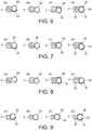
- Figure 6comprises a series of cross-sections through the insertion section of Figure 5 along cut lines A-A, B-B, C-C and D-D.
- the superior surface of the proximal superior tube guiding memberis substantially in line with the superior surface of the elongate member (A-A) and the endotracheal tube (which has a diameter of 12.3mm) has a superior surface which extends superiorly of the superior surface of the adjacent elongate member (C-C).
- the inferior surface of the inferior tube guiding memberextends further in an inferior direction than the inferior surface of the elongate member.
- the superior surface of the distal superior tube guiding memberextends further in a superior direction than the superior surface of the elongate member.
- Figure 7comprises a series of cross-sections through an alternative insertion section along cut lines which are equivalent to A-A, B-B, C-C and D-D.
- the inferior tube guiding memberis not incurvate but has an inferior surface which is level with the inferior surface of the elongate member and the superior surface of the distal superior tube guiding member extends superiorly of the superior surface of the elongate member.
- the superior surface of the proximal superior tube guiding memberextends further in a superior direction than the superior surface of the elongate member (A-A).
- the inferior surface of the a retained endotracheal tube with 12.3mm diameterextends further in an inferior direction than the inferior surface of the elongate member. Further along the inferior tube guiding member, the inferior surface of the inferior tube guiding member extends inferiorly of the inferior surface of the elongate member.
- Figure 8comprises a series of cross-sections through an alternative insertion section along cut lines which are equivalent to A-A, B-B, C-C and D-D.
- no proximal superior tube guiding memberis provided (A-A).
- the inferior tube guiding memberextends further inferiorly than in the previous embodiments to facilitate smooth insertion of the tube when it is pushed along its length by an intubator (C-C).
- the lateral surface of the elongate membercomprises a slight elongate groove (B-B) to better retain an endotracheal tube within the tube guide.
- the inferior surface of the inferior tube guiding memberextends further in an inferior direction than the inferior surface of the elongate member. Furthermore, level with the proximal half distal superior tube guiding member, the superior surface of the distal superior tube guiding member extends further in a superior direction than the superior surface of the elongate member.
- the superior tube guiding memberextends distally of the inferior tube guiding member as illustrated at cross-section D-D.
- Figure 9comprises a series of cross-sections through a still further alternative insertion section along cut lines which are equivalent to A-A, B-B, C-C and D-D.
- the elongate memberis narrower and the tube guiding members extend significantly further in an inferior or superior direction, as appropriate, than the adjacent corresponding surface of the elongate member.
- the retained 12.3mm endotracheal tubeextends superiorly and inferiorly of the superior and inferior surfaces of the elongate member respectively.
- the thickness of the elongate membermay be less than 8mm and perhaps as thin as 3mm or 4mm.
- the insertion sectionis typically moulded in one piece from a transparent plastics material and supplied sterilised within a sealed package.
- the insertion sectionis detachably mounted on an elongate insertion section supporting member (not shown) which fits snugly within the bore.
- the elongate insertion section supporting memberis typically attached to the handle of a laryngoscope body.
- a video camera, functioning as imaging apparatus and a light emitting diode, functioning as light source,are located on the distal tip of the elongate insertion section supporting member, such that they are adjacent to the window in use. Electric wires run down the length of the elongate insertion section supporting member which supply power to the video camera and light source.
- the elongate strengthening sectionis typically fabricated from steel or another rigid material. As well as supporting the video camera and light source and enclosing the electrical connections to the video camera and light source, the elongate strengthening section functions to provide support the insertion section, enabling it to be thinner than would otherwise be the case.
- an endotracheal tube within an operating range of endotracheal tube sizes which can be used reliably with the insertion sectionis inserted into the tube guide, in contact with the tube guiding surfaces of the inferior tube guiding member and the proximal and distal tube guiding members.
- a suitable operating range of external tube diameterswould be 8mm to 12.3mm.
- the laryngoscope with insertion sectionis then introduced into a patient, the blade is used to contact, and perhaps lift, the patient's anatomy to obtain clear access to the larynx.
- the light emitting diodeilluminates the patient's laryngeal area whilst images from the video camera are relayed to a display which might be an integral part of the laryngoscope or may be separate to the laryngoscope.
- the laryngoscopeis inserted fully into a patient, i.e. to the point where an anaesthetist would consider it to be optimally aligned for the introduction of an endotracheal tube.
- the endotracheal tubeis then advanced forward through the insertion section into the patient's larynx. Once the tube has been successfully inserted, it can be detached laterally from the insertion section and separated from the insertion section in situ. The insertion section can then be removed and the endotracheal tube left in place.
- endotracheal tubeswill be retained within the tube guide under flexural tension. Although endotracheal tubes typically have an inherent curvature, the retained endotracheal tubes will be subject to bending forces in the inferior direction at both the proximal and distal superior tube guiding member and a force in the superior direction at at least a portion of the inferior tube guiding member. Endotracheal tubes are resilient and so they exert a force 42 in a superior direction on at least the distal ends of the proximal and distal superior tube guiding members and a further force 44 in an inferior direction on at least a region of (typically towards or at the proximal end) the inferior tube guiding member.
- retained endotracheal tubes of at least some diameterswill typically contact the tube guiding surface of the proximal and distal superior tube guiding members only at the distal ends of these tube guiding members, due to the curved path of the retained tube, whilst the endotracheal tube is at rest within the guide.
- Other tube guiding surfaces of the proximal and distal superior tube guiding membersare relevant during the stage of inserting an endotracheal tube into the tube guide, although they could conceivably be omitted.
- endotracheal tubeswill typically only contact the tube guiding surface of the inferior tube guiding member towards the proximal end of the tube guiding surface, again due to the curved path of the retained endotracheal tube.
- This arrangementin which the endotracheal tubes only contact a limited region of some or all of the tube guiding members reduces friction when the endotracheal tube is advanced into a patient's trachea.
- the insertion sectionhas a number of key advantages which result from features of the design. Firstly, the insertion section is adapted to minimise the risk of damaging a patient's teeth and to facilitate the manoeuvrability of the insertion section in the region of a patient's teeth as there is a substantial narrow region 34, functioning as the first region, where the thickness of the insertion section is less than the external diameter of the largest size of endotracheal tube in an operating range of endotracheal tubes (12.3mm in this example) plus the thickness of the inferior tube contacting member where it contacts the inferior surface of a retained endotracheal tube (at least 0.75mm and typically 1.5mm) plus the thickness of the distal superior tube contacting member where it contacts the superior surface of a retained endotracheal tube (at least 0.75mm and typically 1.5mm).
- the narrow regionextends along the majority of the length of the insertion section in this example, it would be useful to provide a narrow section with a thickness which is less than the abovementioned thickness, even if it only extended along a short portion of the insertion section, such as along a length of 2cm, 1cm or even 0.5cm of the insertion section, close to a patient's teeth when the insertion section is fully inserted into a patient of typical dimensions.
- One feature which enables the thickness of the tube guide to remain less than the said thickness (15.3mm in the present example) proximal of the distal superior tube contacting memberis the arrangement in which the tube guiding surfaces of the proximal and distal superior tube contacting members are spaced apart, leaving the superior surface of a retained endotracheal tube exposed. The presence of an inferior tube guiding member and a distal superior tube guiding member is sufficient to guide the tube.
- the arrangement in which the inferior tube guiding member extends proximally of the tube guiding surface of the distal superior tube guiding member and there is a region where the superior surface of a retained tube is left exposed opposite a first region of tube guiding surface of the inferior tube guiding memberhas the benefit that a retained tube can be accurately guided by the inferior tube guiding member but the bulk of the insertion section is reduced by the omission of the a tube guiding member opposite the said region of the inferior tube guiding member.
- the thickness of the tube guideremains less than the said thickness (15.3mm in the present example) close to a patient's teeth in use.
- this arrangementfacilitates the introduction of an endotracheal tube at the top end of an operating range of tube sizes at an angle to the length of the insertion section.
- Thisis best illustrated in Figure 12 where it will be seen that the centre line 36 of the retained 12.3mm endotracheal tube has a greater radius of curvature than the centre line of the insertion section 38 and, indeed, the most superior point on the retained endotracheal tube is superior of the superior surface of the insertion section.
- the endotracheal tubeextends into the volume which would be occupied by a superior tube guiding member if the superior tube guiding member had extended to the proximal end of the inferior tube guiding member.
- the insertion sectionis thinner from the proximal superior tube guiding member to the distal superior tube guiding member than would have been the case if the tube guide covered both the inferior and superior surface of a retained endotracheal tube along this length.
- An endotracheal tube at the bottom end of the operating range of endotracheal tube sizesmight alternatively have a smaller radius of curvature and may not contact the inferior tube guiding member.
- the thickness of the tube guideis greater level with the distal superior tube guiding member than the thickness of the adjacent elongate member.
- the superior surface of the distal superior tube guiding memberextends further in a superior direction than the superior surface of the adjacent elongate member and the inferior surface of the inferior tube guiding member extends further in an inferior direction than the inferior surface of the elongate member adjacent to the inferior tube guiding member. Accordingly, the overall bulk of the insertion section is less than would be the case if the inferior and superior surfaces of the tube guiding members extended level with the inferior and superior surfaces respectively of the elongate member, along the entire length of the insertion section. This substantially reduces the overall bulk of the insertion section, facilitating rapid intubation.
- a distal superior tube contacting memberwhich has an inferior tube guiding surface which is at an angle to the centre line of the insertion section, such that it extends inferiorly towards its distal end.
- the proximal superior tube contacting memberhas an inferior tube guiding surface which is at an angle to the centre line of the insertion section, such that it extends superiorly towards its distal end.
- the superior surface of the proximal superior tube guiding memberextends further in a superior direction than the superior surface of the elongate member adjacent to the proximal superior tube guiding member which reduces the bulk of the insertion section in the region of a patient's teeth when the insertion section is fully inserted into a patient's oral cavity.
- the proximal superior tube guiding memberis entirely omitted.
- the tube guiding surface of the inferior tube guiding memberdoes not extend to the proximal end of the insertion section. This reduces bulk further and is facilitated by the provision of an inferior tube guiding member having a tube guiding surface which does extend proximally of the proximal end of the tube guiding surface of the distal superior tube guiding member.
- the tube guiding surface of the distal superior tube guiding memberis entirely distal of the portion of the insertion section (which is typically the most curved) which extend around the base of a patient's tongue in use.
- the tube guiding surface of the distal superior tube contacting memberdoes extend to the portion of the insertion section which extends around the base of a patient's tongue in use.
- the thickness of the elongate memberis significantly reduced, to less than the external diameter of the largest endotracheal tube in the operating range of endotracheal tubes, to further reduce the overall bulk of the insertion section.
- a further benefit of arranging the tube guide such that a retained endotracheal tube remains curved between the proximal end of the insertion section and the distal superior tube guiding memberis that, in contrast to J-shaped insertion sections with tube guides, the insertion section can be more naturally introduced into a patient's oral cavity along a curved path. In contrast, J-shaped insertion sections require to be tilted backwards and forward as they inserted in a multi-stage process. Furthermore less force would be required to advance the retained tube into a patient's trachea than with a J-shaped tube guide, where significant force would be exerted on the tube guide where the straight portion began to curve. Endotracheal tubes are typically slightly curved and this arrangement facilitates convenient use of slightly curved endotracheal tubes.
- the insertion sectioncan be made of a size to work with larger diameter endotracheal tubes.
- an insertion sectionwhich can be easily used for rapid insertion of a tube in difficult intubation situations can be provided which can be used with endotracheal tubes with a diameter of up to 12.3mm.
- Alternative insertion sectionsmay be provided for use with infant humans, or specific animals or groups of animals, such as horses.
- the insertion sectionmay be scaled proportionately.
- the length, width and thickness of the insertion section as a wholeare typically scaled proportionately. Nevertheless, some dimensions, such as the thickness of the tube guiding members, may not be scaled proportionately.
- the tube guidehas been arranged to retain an endotracheal tube laterally of the elongate member, fitting better with the general shape of a patient's oral cavity than a tube guide which retain an endotracheal tube inferiorly or superiorly of the insertion section.
- proximal and distal superior tube guiding memberswhich finish abruptly so that the tube guiding surfaces of the proximal and distal superior tube guiding members terminate at the proximal and distal ends of each superior tube guiding member
- either or both of the proximal and distal superior tube guiding memberscould instead taper and include portions which did not function as tube guiding surfaces which contact and thereby guide the superior surface of a retained endotracheal tube.
- a lip extending from the elongate membermay connect the proximal and distal superior tube guiding members, but not affect the function of the invention because the lip does not constitute a tube guiding surface within the meaning of the present invention.
- the insertion sectionmay alternatively be an integral part of a laryngoscope.
Landscapes
- Health & Medical Sciences (AREA)
- Life Sciences & Earth Sciences (AREA)
- Surgery (AREA)
- Radiology & Medical Imaging (AREA)
- Engineering & Computer Science (AREA)
- Veterinary Medicine (AREA)
- Biophysics (AREA)
- Nuclear Medicine, Radiotherapy & Molecular Imaging (AREA)
- Optics & Photonics (AREA)
- Pathology (AREA)
- Public Health (AREA)
- General Health & Medical Sciences (AREA)
- Physics & Mathematics (AREA)
- Biomedical Technology (AREA)
- Heart & Thoracic Surgery (AREA)
- Medical Informatics (AREA)
- Molecular Biology (AREA)
- Animal Behavior & Ethology (AREA)
- Otolaryngology (AREA)
- Physiology (AREA)
- Pulmonology (AREA)
- Endoscopes (AREA)
Description
- The invention relates to the field of laryngoscope insertion sections which include a tube guide for detachably retaining an endotracheal tube and guiding a retained endotracheal tube towards a patient's larynx.
- Laryngoscopes comprise insertion sections, which are the elongate part of a laryngoscope which extends towards and into a patient's oral cavity during intubation. Insertion sections may be removably attachable to a laryngoscope body, integral parts of laryngoscopes or themselves function as laryngoscopes. As well as an insertion section, laryngoscopes typically comprises a handle which is usually elongate and which may be arranged at an angle to the proximal end of the insertion section or generally parallel to the proximal end of the insertion section, or at any angle therebetween.
- Some known laryngoscope insertion sections, such as Miller or Wisconsin insertion sections, are substantially flat. However, the insertion section of a laryngoscope is more commonly bent to better enter through a patient's oropharynx towards their larynx. Some known insertion sections include first and second straight portions, with a bend therebetween, or are curved, at least in part. Within this specification and the appended claims, the inferior surface is the surface of an insertion section which faces the patient's tongue in use. The opposite surface is referred to as the superior surface. Words such as inferior, inferiorly, superior and superiorly are used in corresponding senses. A superior-inferior axis is a virtual axis extending parallel to the superior and inferior directions.
- The words distal and distally refer to being towards the end of the insertion section which extends towards a patient's trachea in use and the words proximal and proximally refer to being towards the person carrying out intubation in use.
- It is known to provide a laryngoscope insertion section including a tube guide which extends along the length of the insertion section. For example,
WO 04/073510 (Gandarias - Tube guides can facilitate intubation by ensuring that, once an insertion section is in place and the patient's larynx sighted, an endotracheal tube is already in the correct location to be pushed forward and inserted into a patient's larynx. However, a potential disadvantage is that tube guides increase the bulk of the insertion section. Accordingly, the present invention aims to provide an insertion section with a tube guide in which the insertion section is adapted to reduce its bulk, to facilitate introduction of the insertion section into a patient with an endotracheal tube in place within the tube guide.
- Another problem with known insertion sections with tube guides is that they are typically designed for use with endotracheal tubes of a limited range of sizes. Some aspects of the present invention are directed to providing insertion sections adapted to guide a wider operating range of endotracheal tube sizes than known insertion sections with tube guides.
- Furthermore, the laryngoscope disclosed in
WO 04/073510 - Some aspects of the present invention aim to provide an insertion section having a tube guide which is easier to operate, for example because less force is required, than with known insertion sections with tube guides, or to provide improved adjustability.
US 4 832 020 (Augustine ) discloses a blind intubation guide.WO 01/10293 (King Leis Peter William et al. US 2005/240081 (Eliachar Isaac ) discloses a rigid laryngoscope blade having a flange.- According to the present invention there is provided an elongate laryngoscope insertion section having a proximal end and a distal end for insertion into a patient's oral cavity in use, the insertion section comprising a tube guide for removably retaining an endotracheal tube and guiding a retained endotracheal tube towards a patient's larynx and an elongate member, wherein the tube guide comprises a plurality of tube guiding members which extend laterally of the elongate member and have tube guiding surfaces which are arranged to contact and thereby guide the inferior or superior surface of a retained endotracheal tube, the plurality of tube guiding members comprising at least an inferior tube guiding member having a tube guiding surface on a superior side thereof for contacting and thereby guiding the inferior surface of a retained endotracheal tube,and a first superior tube guiding member having a tube guiding surface on an inferior side thereof for contacting and thereby guiding the superior surface of a retained endotracheal tube, wherein, at at least one location along the length of the insertion section, the thickness of the elongate member is less than the thickness of the adjacent tube guide.
- Further aspects of the present invention are defined in the dependent claims.
- An example embodiment of the present invention will now be illustrated with reference to the following Figures in which:
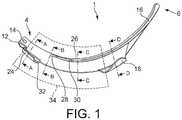
Figure 1 is an orthogonal view from a lateral position of a laryngoscope insertion section according to the present invention;Figures 2 to 4 are perspective views from a range of orientations of the laryngoscope insertion section ofFigure 1 ;Figure 5 is an orthogonal view from a lateral position of the laryngoscope insertion section ofFigure 1 detachably retaining an endotracheal tube with a diameter at the upper end of an operating range of endotracheal tube sizes;Figures 6 is a series of cross-sections through the insertion section and retained endotracheal tube ofFigure 5 along cut lines A-A, B-B, C-C and D-D;Figure 7 is a series of cross-sections through an alternative insertion section and retained endotracheal tube along cut lines equivalent to A-A, B-B, C-C and D-D ofFigure 1 ;Figure 8 is a series of cross-sections through a further insertion section and retained endotracheal tube along cut lines equivalent to A-A, B-B, C-C and D-D ofFigure 1 ;Figure 9 is a series of cross-sections through a still further insertion section and retained endotracheal tube along cut lines equivalent to A-A, B-B, C-C and D-D ofFigure 1 ;Figure 10 is an orthogonal view from a lateral position of the laryngoscope insertion section ofFigure 1 detachably retaining an endotracheal tube with a diameter at the upper end of an operating range of endotracheal tube sizes;Figure 11 is an orthogonal view from a lateral position of the laryngoscope insertion section ofFigure 1 detachably retaining an endotracheal tube with a diameter at the lower end of an operating range of endotracheal tube sizes; andFigure 12 corresponds toFigure 10 including indications of the centre lines of the retained endotracheal tube and the insertion section.- With reference to
Figures 1 to 5 , a laryngoscope insertion section for use with adult humans, shown generally as 1, comprises anelongate member 2 which extends from the proximal end of theinsertion section 4 but does not extend as far as the distal end of theinsertion section 6. The elongate member has a light-permeable viewing port 8 at its distal end. Anelongate bore 10 extends along the elongate member from the proximal end of the elongate member for receiving and retaining an insertion section retaining protrusion of a laryngoscope and covering the insertion section retaining protrusion to protect it from bodily fluids in use. Aretaining portion 12, which includes afixing aperture 14 for engaging with a corresponding protrusion on an insertion section supporting member of a laryngoscope, facilitates the removable attachment of the insertion section to a laryngoscope. The insertion section may be used with a laryngoscope including a insertion section retaining member with a video camera and light source which is included in the insertion section retaining member, so that light from the light source can illuminate a patient's trachea and the surrounding region and the video camera can relay images of the patient's trachea and the surrounding region to a display. Abroad protrusion 16 extends from the end of the elongate member, which functions as a blade for contacting and typically lifting a patient's anatomy in use to provide clear access to the larynx. - A tube guide extends laterally of the elongate member. The tube guide comprises a distal superior
tube guiding member 18, located towards the distal end of the insertion section, which extends from the superior side of the elongate member and functions as the first superior tube guiding member. The inferior surface of the distal superior tube guiding member includes atube guiding surface 20 which is arranged to contact and thereby guide the superior surface of a retained endotracheal tube. Alateral edge 22 of the elongate member does not function as the tube guiding surface as, although it may contact an endotracheal tube in use, it does not contact and thereby guide the superior surface of a retained endotracheal tube. - The tube guide also comprises a proximal superior
tube guiding member 24, located towards the proximal end of the insertion section, which extends laterally from the elongate member and functions as the second superior tube guiding member. The inferior surface of the proximal superior tube guiding member also includes a tube guiding surface which is arranged to contact and thereby guide the superior surface of a retained endotracheal tube. - The tube guiding surfaces of the proximal and distal superior tube guiding members are generally incurvate. The proximal and superior tube guiding members are of generally even thickness and extend laterally and superiorly from the elongate member, from a location on the lateral side of the elongate member which is near to but not level with the
superior surface 25 of the elongate member. They extend superiorly to the superior surface of the elongate member, curve over a retained endotracheal tube in use and then curve laterally and inferiorly to extend over and guide the superior surface of a retained endotracheal tube. The tube guiding surface of the proximal superior tube guiding member extends superiorly relative to the insertion section towards its distal end. The tube guiding surface of the distal superior tube guiding member extends inferiorly relative to the insertion section towards its distal end. This arrangement facilitates the retention of an endotracheal tube with a greater curvature than the insertion section. - An inferior
tube guiding member 26 extends from a location which is distal of the proximal superior tube guiding member towards the distal end of the insertion section. The inferior tube guiding member comprises a tube guiding surface which is arranged to contact and thereby guide the inferior surface of a retained endotracheal tube. The inferior tube guiding member tapers at a proximal end and so it also comprises aninferior surface portion 28 which does not function as a tube guiding surface because it does not contact and thereby guide the inferior surface of a retained endotracheal tube in use. - The tube guiding surfaces of the inferior tube guiding member is also generally incurvate. The inferior tube guiding member is of generally even thickness and extends laterally and inferiorly from the elongate member, from a location on the lateral edge of the elongate member which is near to but not level with the
inferior surface 25 of the elongate member. The inferior tube guiding member extends inferiorly to the inferior surface of the elongate member, curves over a retained endotracheal tube in use and then curves laterally and superiorly to extend under and guide the inferior surface of a retained endotracheal tube. - The tube guide is arranged to leave the inferior and superior surfaces of a retained endotracheal tube exposed along a majority of the length of the insertion section between the most proximal and most distal locations where the endotracheal tube contacts a retained endotracheal tube. In an insertion section for use with adult humans, the length of the proximal superior tube guiding member, along its most superior region, may be approximately 22mm and the length of the distal superior tube guiding member, along its most superior region, may be approximately 15mm. The distance between the distal end of the proximal superior tube guiding member and the proximal end of the distal superior tube guiding member, following the curve of the insertion section, between the most superior regions of the proximal and distal superior tube guiding members, may be approximately 68mm, or 65mm in a direct line. The distance between the proximal end of the inferior tube guiding member and the distal end of the proximal superior tube guiding member may be approximately 25mm and the inferior tube guiding member may extend approximately 45mm proximally of the proximal end of the distal superior tube guiding member.
- The inferior tube guiding member and the distal superior tube guiding member are arranged to guide a retained
endotracheal tube 29 towards a patients' trachea in use. The tube guiding surfaces of the proximal and distal superior tube guiding members are spaced apart because the proximal and distal superior tube guiding members are spaced apart. The superior surface of a retained endotracheal tube is exposed between the tube guiding surfaces of the proximal and distal superior tube guiding members. The inferior tube guiding member extends proximally of the distal superior tube guiding member and so there is a region where a retained endotracheal tube is guided on its inferior side but not its superior side. Theproximal end 30 of the tube guiding surface inferior tube guiding member is spaced apart from thedistal end 32 of the proximal superior tube guiding member, by a sufficient distance to enable a 12.3mm external diameter endotracheal tube (being the upper end of an operating range of endotracheal tube sizes) to be introduced at an angle to the centre line of the insertion section. Figure 6 comprises a series of cross-sections through the insertion section ofFigure 5 along cut lines A-A, B-B, C-C and D-D. Note that in this arrangement the superior surface of the proximal superior tube guiding member is substantially in line with the superior surface of the elongate member (A-A) and the endotracheal tube (which has a diameter of 12.3mm) has a superior surface which extends superiorly of the superior surface of the adjacent elongate member (C-C). Level with the distal superior tube guiding member (D-D), the inferior surface of the inferior tube guiding member extends further in an inferior direction than the inferior surface of the elongate member. Furthermore, level with the distal superior tube guiding member, the superior surface of the distal superior tube guiding member extends further in a superior direction than the superior surface of the elongate member.Figure 7 comprises a series of cross-sections through an alternative insertion section along cut lines which are equivalent to A-A, B-B, C-C and D-D. In this embodiment, the inferior tube guiding member is not incurvate but has an inferior surface which is level with the inferior surface of the elongate member and the superior surface of the distal superior tube guiding member extends superiorly of the superior surface of the elongate member. The superior surface of the proximal superior tube guiding member extends further in a superior direction than the superior surface of the elongate member (A-A). At the proximal end of the inferior tube guiding member, the inferior surface of the a retained endotracheal tube with 12.3mm diameter extends further in an inferior direction than the inferior surface of the elongate member. Further along the inferior tube guiding member, the inferior surface of the inferior tube guiding member extends inferiorly of the inferior surface of the elongate member.Figure 8 comprises a series of cross-sections through an alternative insertion section along cut lines which are equivalent to A-A, B-B, C-C and D-D. In this embodiment, no proximal superior tube guiding member is provided (A-A). The inferior tube guiding member extends further inferiorly than in the previous embodiments to facilitate smooth insertion of the tube when it is pushed along its length by an intubator (C-C). The lateral surface of the elongate member comprises a slight elongate groove (B-B) to better retain an endotracheal tube within the tube guide. Level with the proximal half of the distal superior tube guiding member (C-C), the inferior surface of the inferior tube guiding member extends further in an inferior direction than the inferior surface of the elongate member. Furthermore, level with the proximal half distal superior tube guiding member, the superior surface of the distal superior tube guiding member extends further in a superior direction than the superior surface of the elongate member. The superior tube guiding member extends distally of the inferior tube guiding member as illustrated at cross-section D-D.- The various cross-sections illustrated in
Figures 6 to 8 may be combined in any combination to form a range of insertion sections. Figure 9 comprises a series of cross-sections through a still further alternative insertion section along cut lines which are equivalent to A-A, B-B, C-C and D-D. In this embodiment, which has especially reduced bulk, the elongate member is narrower and the tube guiding members extend significantly further in an inferior or superior direction, as appropriate, than the adjacent corresponding surface of the elongate member. At cross section B-B, the retained 12.3mm endotracheal tube extends superiorly and inferiorly of the superior and inferior surfaces of the elongate member respectively. Accordingly, there is a region of insertion section, between the proximal distal superior tube guiding member and the proximal end of the tube guiding surface of the inferior tube guiding member where the thickness of the insertion section is less than the thickness of the adjacent 12.3mm endotracheal tube. At this location, and proximal of the proximal superior tube guiding member the thickness of the elongate member may be less than 8mm and perhaps as thin as 3mm or 4mm.- The insertion section is typically moulded in one piece from a transparent plastics material and supplied sterilised within a sealed package.
- In use, the insertion section is detachably mounted on an elongate insertion section supporting member (not shown) which fits snugly within the bore. The elongate insertion section supporting member is typically attached to the handle of a laryngoscope body. A video camera, functioning as imaging apparatus and a light emitting diode, functioning as light source, are located on the distal tip of the elongate insertion section supporting member, such that they are adjacent to the window in use. Electric wires run down the length of the elongate insertion section supporting member which supply power to the video camera and light source.
- The elongate strengthening section is typically fabricated from steel or another rigid material. As well as supporting the video camera and light source and enclosing the electrical connections to the video camera and light source, the elongate strengthening section functions to provide support the insertion section, enabling it to be thinner than would otherwise be the case.
- Once the insertion section has been attached to a laryngoscope body, an endotracheal tube within an operating range of endotracheal tube sizes which can be used reliably with the insertion section is inserted into the tube guide, in contact with the tube guiding surfaces of the inferior tube guiding member and the proximal and distal tube guiding members. For an insertion section for use in the intubation of human adults, a suitable operating range of external tube diameters would be 8mm to 12.3mm.
- The laryngoscope with insertion section is then introduced into a patient, the blade is used to contact, and perhaps lift, the patient's anatomy to obtain clear access to the larynx. The light emitting diode illuminates the patient's laryngeal area whilst images from the video camera are relayed to a display which might be an integral part of the laryngoscope or may be separate to the laryngoscope. The laryngoscope is inserted fully into a patient, i.e. to the point where an anaesthetist would consider it to be optimally aligned for the introduction of an endotracheal tube. The endotracheal tube is then advanced forward through the insertion section into the patient's larynx. Once the tube has been successfully inserted, it can be detached laterally from the insertion section and separated from the insertion section in situ. The insertion section can then be removed and the endotracheal tube left in place.
- Note that endotracheal tubes will be retained within the tube guide under flexural tension. Although endotracheal tubes typically have an inherent curvature, the retained endotracheal tubes will be subject to bending forces in the inferior direction at both the proximal and distal superior tube guiding member and a force in the superior direction at at least a portion of the inferior tube guiding member. Endotracheal tubes are resilient and so they exert a
force 42 in a superior direction on at least the distal ends of the proximal and distal superior tube guiding members and afurther force 44 in an inferior direction on at least a region of (typically towards or at the proximal end) the inferior tube guiding member. This improves the grip of the tube guiding members on a retained endotracheal tube enabling the tube guiding members to have lower profiles and to extend less far around retained endotracheal tubes than would otherwise be the case, facilitating the provision of a reliable laterally opening tube guide. - In practice, retained endotracheal tubes of at least some diameters (typically at the upper end of the operating range of endotracheal tube sizes) will typically contact the tube guiding surface of the proximal and distal superior tube guiding members only at the distal ends of these tube guiding members, due to the curved path of the retained tube, whilst the endotracheal tube is at rest within the guide. Other tube guiding surfaces of the proximal and distal superior tube guiding members are relevant during the stage of inserting an endotracheal tube into the tube guide, although they could conceivably be omitted. Similarly, such endotracheal tubes will typically only contact the tube guiding surface of the inferior tube guiding member towards the proximal end of the tube guiding surface, again due to the curved path of the retained endotracheal tube. This arrangement, in which the endotracheal tubes only contact a limited region of some or all of the tube guiding members reduces friction when the endotracheal tube is advanced into a patient's trachea.
- The insertion section has a number of key advantages which result from features of the design. Firstly, the insertion section is adapted to minimise the risk of damaging a patient's teeth and to facilitate the manoeuvrability of the insertion section in the region of a patient's teeth as there is a substantial
narrow region 34, functioning as the first region, where the thickness of the insertion section is less than the external diameter of the largest size of endotracheal tube in an operating range of endotracheal tubes (12.3mm in this example) plus the thickness of the inferior tube contacting member where it contacts the inferior surface of a retained endotracheal tube (at least 0.75mm and typically 1.5mm) plus the thickness of the distal superior tube contacting member where it contacts the superior surface of a retained endotracheal tube (at least 0.75mm and typically 1.5mm). Although the narrow region extends along the majority of the length of the insertion section in this example, it would be useful to provide a narrow section with a thickness which is less than the abovementioned thickness, even if it only extended along a short portion of the insertion section, such as along a length of 2cm, 1cm or even 0.5cm of the insertion section, close to a patient's teeth when the insertion section is fully inserted into a patient of typical dimensions. - One feature which enables the thickness of the tube guide to remain less than the said thickness (15.3mm in the present example) proximal of the distal superior tube contacting member is the arrangement in which the tube guiding surfaces of the proximal and distal superior tube contacting members are spaced apart, leaving the superior surface of a retained endotracheal tube exposed. The presence of an inferior tube guiding member and a distal superior tube guiding member is sufficient to guide the tube. However, the arrangement in which the inferior tube guiding member extends proximally of the tube guiding surface of the distal superior tube guiding member and there is a region where the superior surface of a retained tube is left exposed opposite a first region of tube guiding surface of the inferior tube guiding member, has the benefit that a retained tube can be accurately guided by the inferior tube guiding member but the bulk of the insertion section is reduced by the omission of the a tube guiding member opposite the said region of the inferior tube guiding member.
- Similarly, as no tube guiding surface is provided opposite the tube guiding surface of the proximal superior tube guiding member, the thickness of the tube guide remains less than the said thickness (15.3mm in the present example) close to a patient's teeth in use.
- There is a region between the distal end of the tube guiding surface of the proximal superior tube guiding member and the proximal end of the tube guiding surface of the inferior tube guiding member where a retained endotracheal tube is exposed on both its inferior and superior surfaces. This is advantageous firstly in that the overall bulk of the insertion section has been reduced by omitting tube guiding members in this region. This enables the inferior tube guiding member and a projection of the superior tube guiding member to be spaced apart by less than the external diameter of an endotracheal tube at the top end of an operating range of tube sizes (12.3mm external diameter in the present example). Furthermore, this arrangement facilitates the introduction of an endotracheal tube at the top end of an operating range of tube sizes at an angle to the length of the insertion section. This is best illustrated in
Figure 12 where it will be seen that thecentre line 36 of the retained 12.3mm endotracheal tube has a greater radius of curvature than the centre line of theinsertion section 38 and, indeed, the most superior point on the retained endotracheal tube is superior of the superior surface of the insertion section. Thus, the endotracheal tube extends into the volume which would be occupied by a superior tube guiding member if the superior tube guiding member had extended to the proximal end of the inferior tube guiding member. Accordingly, the insertion section is thinner from the proximal superior tube guiding member to the distal superior tube guiding member than would have been the case if the tube guide covered both the inferior and superior surface of a retained endotracheal tube along this length. An endotracheal tube at the bottom end of the operating range of endotracheal tube sizes might alternatively have a smaller radius of curvature and may not contact the inferior tube guiding member. - It is also notable that the thickness of the tube guide is greater level with the distal superior tube guiding member than the thickness of the adjacent elongate member. Furthermore, the superior surface of the distal superior tube guiding member extends further in a superior direction than the superior surface of the adjacent elongate member and the inferior surface of the inferior tube guiding member extends further in an inferior direction than the inferior surface of the elongate member adjacent to the inferior tube guiding member. Accordingly, the overall bulk of the insertion section is less than would be the case if the inferior and superior surfaces of the tube guiding members extended level with the inferior and superior surfaces respectively of the elongate member, along the entire length of the insertion section. This substantially reduces the overall bulk of the insertion section, facilitating rapid intubation.
- The maintenance of a retained endotracheal tube in a curved path is facilitated by the provision of a distal superior tube contacting member which has an inferior tube guiding surface which is at an angle to the centre line of the insertion section, such that it extends inferiorly towards its distal end. Similarly, the proximal superior tube contacting member has an inferior tube guiding surface which is at an angle to the centre line of the insertion section, such that it extends superiorly towards its distal end.
- In some embodiments, illustrated in
Figure 7 , the superior surface of the proximal superior tube guiding member extends further in a superior direction than the superior surface of the elongate member adjacent to the proximal superior tube guiding member which reduces the bulk of the insertion section in the region of a patient's teeth when the insertion section is fully inserted into a patient's oral cavity. - In some embodiments, illustrated in
Figure 8 , the proximal superior tube guiding member is entirely omitted. The tube guiding surface of the inferior tube guiding member does not extend to the proximal end of the insertion section. This reduces bulk further and is facilitated by the provision of an inferior tube guiding member having a tube guiding surface which does extend proximally of the proximal end of the tube guiding surface of the distal superior tube guiding member. In some embodiments, the tube guiding surface of the distal superior tube guiding member is entirely distal of the portion of the insertion section (which is typically the most curved) which extend around the base of a patient's tongue in use. However, in the embodiment illustrated inFigure 8 , the tube guiding surface of the distal superior tube contacting member does extend to the portion of the insertion section which extends around the base of a patient's tongue in use. - In the embodiment of
Figure 9 , the thickness of the elongate member is significantly reduced, to less than the external diameter of the largest endotracheal tube in the operating range of endotracheal tubes, to further reduce the overall bulk of the insertion section. - A further benefit of arranging the tube guide such that a retained endotracheal tube remains curved between the proximal end of the insertion section and the distal superior tube guiding member is that, in contrast to J-shaped insertion sections with tube guides, the insertion section can be more naturally introduced into a patient's oral cavity along a curved path. In contrast, J-shaped insertion sections require to be tilted backwards and forward as they inserted in a multi-stage process. Furthermore less force would be required to advance the retained tube into a patient's trachea than with a J-shaped tube guide, where significant force would be exerted on the tube guide where the straight portion began to curve. Endotracheal tubes are typically slightly curved and this arrangement facilitates convenient use of slightly curved endotracheal tubes.
- As a result of the design features which reduce the overall bulk of the insertion section, the insertion section can be made of a size to work with larger diameter endotracheal tubes. For example, an insertion section which can be easily used for rapid insertion of a tube in difficult intubation situations can be provided which can be used with endotracheal tubes with a diameter of up to 12.3mm.
- Alternative insertion sections may be provided for use with infant humans, or specific animals or groups of animals, such as horses. In this case, the insertion section may be scaled proportionately. The length, width and thickness of the insertion section as a whole are typically scaled proportionately. Nevertheless, some dimensions, such as the thickness of the tube guiding members, may not be scaled proportionately.
- It will be seen that the tube guide has been arranged to retain an endotracheal tube laterally of the elongate member, fitting better with the general shape of a patient's oral cavity than a tube guide which retain an endotracheal tube inferiorly or superiorly of the insertion section.
- Although the illustrated embodiments show proximal and distal superior tube guiding members which finish abruptly so that the tube guiding surfaces of the proximal and distal superior tube guiding members terminate at the proximal and distal ends of each superior tube guiding member, either or both of the proximal and distal superior tube guiding members could instead taper and include portions which did not function as tube guiding surfaces which contact and thereby guide the superior surface of a retained endotracheal tube. For example, a lip extending from the elongate member may connect the proximal and distal superior tube guiding members, but not affect the function of the invention because the lip does not constitute a tube guiding surface within the meaning of the present invention.
- Although the invention has been illustrated using a detachably retainable insertion section portion, the insertion section may alternatively be an integral part of a laryngoscope.
- Further modifications and variations may be made within the scope of the invention herein disclosed.
Claims (8)
- An elongate laryngoscope insertion section (1) having a proximal end (4) and a distal end (6) for insertion into a patient's oral cavity in use, the insertion section comprising a tube guide (18, 24, 26) for removably retaining an endotracheal tube and guiding a retained endotracheal tube towards a patient's larynx and an elongate member (2), wherein the tube guide comprises a plurality of tube guiding members (18, 24, 26) which extend laterally of the elongate member and have tube guiding surfaces (20, 25) which are arranged to contact and thereby guide the inferior or superior surface of a retained endotracheal tube, the plurality of tube guiding members comprising at least an inferior tube guiding member (26) having a tube guiding surface on a superior side thereof for contacting and thereby guiding the inferior surface of a retained endotracheal tube, and a first superior tube guiding member (18) having a tube guiding surface (20) on an inferior side thereof for contacting and thereby guiding the superior surface of a retained endotracheal tube,characterised in that, at at least one location along the length of the insertion section, the thickness of the elongate member is less than the thickness of the adjacent tube guide.
- An elongate laryngoscope insertion section (1) according to claim 1, wherein the tube guide (18, 24, 26) is arranged such that the retained endotracheal tube can be removed laterally from the tube guide.
- An elongate laryngoscope insertion section (1) according to claim 1 or claim 2, wherein the tube guide (18, 24, 26) is arranged so that, for endotracheal tubes of a range of external diameters, a retained endotracheal tube will be continuously curved from where it extends into a patient's mouth when the insertion section is fully inserted in use to the first superior guiding member (18).
- An elongate laryngoscope insertion section (1) according to any one preceding claim, wherein at at least one location where the tube guide (18, 24, 26) comprises a superior tube guiding member (18), the superior tube guiding member extends further in a superior direction than the elongate member, adjacent to the superior tube guiding member.
- An elongate laryngoscope insertion section (1) according to any one preceding claim, wherein at at least one location where the tube guide (18, 24, 26) comprises an inferior tube guiding member (26), the inferior tube guiding member extends further in an inferior direction than the elongate member, adjacent to the inferior tube guiding member.
- An elongate laryngoscope insertion section (1) according to any one preceding claim, which is a disposable elongate laryngoscope insertion section.
- A laryngoscope comprising a handle, and an insertion section (1) according to any one preceding Claim.
- A laryngoscope according to Claim 7, wherein the insertion section (1) is fixedly attached to the handle.
Applications Claiming Priority (8)
| Application Number | Priority Date | Filing Date | Title |
|---|---|---|---|
| GB0716612AGB0716612D0 (en) | 2007-08-28 | 2007-08-28 | Laryngoscope insertion section |
| GB0716668AGB0716668D0 (en) | 2007-08-28 | 2007-08-28 | Laryngoscope Insertion section |
| GB0716613AGB0716613D0 (en) | 2007-08-28 | 2007-08-28 | Laryngoscope insertion section |
| GB0716671AGB0716671D0 (en) | 2007-08-28 | 2007-08-28 | Laryngoscope insertion section |
| GB0716615AGB0716615D0 (en) | 2007-08-28 | 2007-08-28 | Laryngoscope insertion section |
| GB0716667AGB0716667D0 (en) | 2007-08-28 | 2007-08-28 | Laryngoscope insertion section |
| EP08806188AEP2194837A2 (en) | 2007-08-28 | 2008-08-28 | Laryngoscope insertion section |
| PCT/GB2008/002900WO2009027669A2 (en) | 2007-08-28 | 2008-08-28 | Laryngoscope insertion section |
Related Parent Applications (1)
| Application Number | Title | Priority Date | Filing Date |
|---|---|---|---|
| EP08806188ADivisionEP2194837A2 (en) | 2007-08-28 | 2008-08-28 | Laryngoscope insertion section |
Publications (2)
| Publication Number | Publication Date |
|---|---|
| EP3199094A1 EP3199094A1 (en) | 2017-08-02 |
| EP3199094B1true EP3199094B1 (en) | 2020-10-21 |
Family
ID=39865866
Family Applications (2)
| Application Number | Title | Priority Date | Filing Date |
|---|---|---|---|
| EP17162203.8AActiveEP3199094B1 (en) | 2007-08-28 | 2008-08-28 | Laryngoscope insertion section |
| EP08806188AWithdrawnEP2194837A2 (en) | 2007-08-28 | 2008-08-28 | Laryngoscope insertion section |
Family Applications After (1)
| Application Number | Title | Priority Date | Filing Date |
|---|---|---|---|
| EP08806188AWithdrawnEP2194837A2 (en) | 2007-08-28 | 2008-08-28 | Laryngoscope insertion section |
Country Status (7)
| Country | Link |
|---|---|
| US (5) | US20100256451A1 (en) |
| EP (2) | EP3199094B1 (en) |
| JP (1) | JP5455910B2 (en) |
| AU (1) | AU2008291955B2 (en) |
| CA (1) | CA2735258C (en) |
| GB (7) | GB2452405B (en) |
| WO (1) | WO2009027669A2 (en) |
Families Citing this family (34)
| Publication number | Priority date | Publication date | Assignee | Title |
|---|---|---|---|---|
| GB0716672D0 (en) | 2007-08-28 | 2007-10-03 | Aircraft Medical Ltd | Laryngoscope |
| EP3199094B1 (en) | 2007-08-28 | 2020-10-21 | Aircraft Medical Limited | Laryngoscope insertion section |
| JP2010538217A (en)* | 2007-08-31 | 2010-12-09 | アクティエボラゲット・エスコーエッフ | Bearing and method of handling the bearing |
| US9078615B2 (en) | 2008-10-30 | 2015-07-14 | Indian Ocean Medical Inc. | Guiding device for use with laryngoscope |
| GB0819942D0 (en) | 2008-10-30 | 2008-12-10 | Indian Ocean Medical Inc | Guiding device for use with laryngoscope |
| SE533741C2 (en)* | 2008-10-31 | 2010-12-21 | Safetrach Ab | Device for facilitating tracheotomy |
| GB0903610D0 (en) | 2009-03-03 | 2009-04-08 | Aircraft Medical Ltd | Insertion section for laryngoscope with lateral tube guide |
| GB0903743D0 (en) | 2009-03-03 | 2009-04-15 | Aircraft Medical Ltd | Bougie-guide for use on a laryngoscope |
| GB0906688D0 (en) | 2009-04-17 | 2009-06-03 | Indian Ocean Medical Inc | Laryngoscope |
| GB0915107D0 (en) | 2009-08-28 | 2009-10-07 | Indian Ocean Medical Inc | Laryngoscope |
| CA2781059A1 (en)* | 2009-11-16 | 2011-05-19 | Verathon Inc. | Channel laryngoscopes and systems |
| US9179831B2 (en)* | 2009-11-30 | 2015-11-10 | King Systems Corporation | Visualization instrument |
| WO2011141749A1 (en) | 2010-05-13 | 2011-11-17 | Aircraft Medical Limited | Laryngoscopes, laryngoscope arms and methods of manufacture |
| CA2834319C (en) | 2010-05-13 | 2019-02-19 | Aircraft Medical Limited | Laryngoscope insertion section structure |
| USD659246S1 (en)* | 2010-10-13 | 2012-05-08 | Aircraft Medical Limited | Video laryngoscope blade |
| US9888909B2 (en)* | 2012-11-13 | 2018-02-13 | The Curators Of The University Of Missouri | Endoscopic-enabled tongue depressor and associated method of use |
| USD748255S1 (en)* | 2013-05-30 | 2016-01-26 | Aircraft Medical Limited | Laryngoscope blade |
| GB2518124B (en) | 2013-05-30 | 2018-04-25 | Aircraft Medical Ltd | Video laryngoscope and video laryngoscope insertion section |
| EP3048988A4 (en) | 2013-09-26 | 2017-06-14 | The Curators Of The University Of Missouri | Endoscopic-enabled mouth gag and associated method of use |
| BR112016007593A2 (en)* | 2013-10-08 | 2017-09-12 | Centurion Med Prod Corp | sheath for an endotracheal intubation device |
| US9833587B2 (en) | 2014-10-23 | 2017-12-05 | Cookgas, Llc | Camera tube with guide surface for intubation stylet and method of use |
| US20180064896A1 (en)* | 2014-12-12 | 2018-03-08 | Bruce M. Kleene | Flexible tube holding device |
| US20160166791A1 (en)* | 2014-12-12 | 2016-06-16 | Bruce M. Kleene | Flexible tube holding device and intubation system with methods of use |
| GB2538552B (en) | 2015-05-21 | 2020-03-11 | Intersurgical Ag | Video laryngoscopes |
| CN105231985A (en)* | 2015-11-03 | 2016-01-13 | 舒妮 | Disposable laryngoscope for ventilation laryngoscope |
| CA3008028A1 (en)* | 2016-01-07 | 2017-07-13 | Glenn P. Gardner | Endotracheal tube insertion device |
| IT201700035827A1 (en)* | 2017-03-31 | 2018-10-01 | Alessandro Terrani | Device for optimally positioning a tracheostomy needle with respect to an endotracheal tube, and apparatus comprising said device connected to an endotracheal tube |
| US11051682B2 (en)* | 2017-08-31 | 2021-07-06 | Wm & Dg, Inc. | Medical devices with camera and methods of placement |
| USD863555S1 (en) | 2018-07-30 | 2019-10-15 | Teleflex Medical Incorporated | Laryngoscope blade |
| USD862696S1 (en) | 2018-07-30 | 2019-10-08 | Teleflex Medical Incorporated | Laryngoscope blade |
| CN113329678B (en) | 2019-03-14 | 2024-12-06 | 泰利福医疗公司 | Universal laryngoscope blade |
| JP7369792B2 (en) | 2019-05-15 | 2023-10-26 | テレフレックス、ライフ、サイエンシーズ、アンリミテッド、カンパニー | tracheostomy dilator |
| US10478579B1 (en)* | 2019-05-31 | 2019-11-19 | Richard Elton | Blind intubation device and related methodologies for endotracheal intubation |
| EP4326524A4 (en)* | 2021-04-23 | 2025-05-28 | The Regents of the University of California | ENDOTRACHEAL TUBE SUPPORT DEVICES |
Family Cites Families (70)
| Publication number | Priority date | Publication date | Assignee | Title |
|---|---|---|---|---|
| US2648329A (en) | 1951-10-18 | 1953-08-11 | Morch Ernst Trier | Laryngoscope |
| US3153267A (en) | 1962-09-13 | 1964-10-20 | Jr Roy C Rowland | Oral examination assistance device |
| US3926196A (en)* | 1974-08-05 | 1975-12-16 | Thermo Electron Corp | Airway |
| US3943920A (en) | 1974-12-06 | 1976-03-16 | Ronald E. Kandel | Laryngoscope blade |
| US4067331A (en) | 1976-07-23 | 1978-01-10 | Berman Robert A | Intubating pharyngeal airway |
| US4054135A (en) | 1976-07-23 | 1977-10-18 | Berman Robert A | Intubating pharyngeal airway |
| US4211234A (en)* | 1978-08-24 | 1980-07-08 | Joseph Fisher | Endotracheal tube introducer |
| US4198970A (en) | 1978-09-11 | 1980-04-22 | Raymond Luomanen | Airway for drainage of the nasopharynx |
| US4306547A (en)* | 1979-11-20 | 1981-12-22 | Lowell James R | Rigid fiberoptic laryngoscope |
| US4338930A (en)* | 1980-09-08 | 1982-07-13 | Tudor Williams R | Airway intubator |
| DE3400872A1 (en)* | 1984-01-12 | 1985-07-25 | Christian Prof. Dr.med. 2400 Lübeck Krüger | INSTRUMENT FOR KEEPING UPPER AIRWAYS AND FOR CARRYING OUT INTUBATIONS |
| US5203320A (en)* | 1987-03-24 | 1993-04-20 | Augustine Medical, Inc. | Tracheal intubation guide |
| US5042469A (en) | 1987-03-24 | 1991-08-27 | Augustine Medical, Inc. | Tracheal intubation guide |
| US4832020A (en)* | 1987-03-24 | 1989-05-23 | Augustine Scott D | Tracheal intubation guide |
| US5024218A (en)* | 1987-10-21 | 1991-06-18 | The Kendall Company | Intubating airway |
| US4947896A (en)* | 1988-11-04 | 1990-08-14 | Bartlett Robert L | Laryngoscope |
| US5038766A (en)* | 1989-11-08 | 1991-08-13 | Parker Jeffrey D | Blind orolaryngeal and oroesophageal guiding and aiming device |
| US5174283A (en)* | 1989-11-08 | 1992-12-29 | Parker Jeffrey D | Blind orolaryngeal and oroesophageal guiding and aiming device |
| US5065738A (en) | 1990-01-16 | 1991-11-19 | Dam David J Van | Laryngoscope blade sheath |
| US5261392A (en) | 1992-04-03 | 1993-11-16 | Achi Corporation | Laryngoscope with interchangeable fiberoptic assembly |
| US5349943A (en)* | 1993-08-24 | 1994-09-27 | Hennepin Faculty Associates | Mirror laryngoscope blade |
| US5645519A (en)* | 1994-03-18 | 1997-07-08 | Jai S. Lee | Endoscopic instrument for controlled introduction of tubular members in the body and methods therefor |
| US5651761A (en)* | 1995-04-21 | 1997-07-29 | Upsher Laryngoscope Corp. | Laryngoscope including an endotracheal tube separation mouth and its method of use |
| US5702351A (en) | 1995-08-23 | 1997-12-30 | Bar-Or; David | Laryngoscope and disposable blade therefor |
| US5850832A (en) | 1997-06-23 | 1998-12-22 | Chu; Kyo Y. | Laryngeal mask airway insertion guide |
| US6471643B1 (en)* | 1997-10-11 | 2002-10-29 | Karl Storz Gmbh & Co. Kg | Laryngoscope |
| US6142144A (en) | 1997-12-01 | 2000-11-07 | Pacey; John A. | Intubation instrument |
| US6655377B2 (en)* | 1997-12-01 | 2003-12-02 | Saturn Biomedical Systems Inc. | Intubation instrument |
| US6543447B2 (en) | 1997-12-01 | 2003-04-08 | Saturn Biomedical Systems Inc | Intubation instrument |
| US6053166A (en)* | 1998-02-09 | 2000-04-25 | Gomez; Richard J. | Intubating assembly |
| US5993383A (en) | 1999-05-27 | 1999-11-30 | Haase; Brian J. | Laryngoscope blade with tongue controlling wing sections |
| GB2354948A (en)* | 1999-08-06 | 2001-04-11 | King Lewis Peter William | Laryngoscope blade |
| US6231505B1 (en)* | 1999-09-20 | 2001-05-15 | Tyson Edward Martin | Laryngoscope blade |
| US6666819B2 (en)* | 2000-12-06 | 2003-12-23 | Heine Optotechnik Gmbh & Co. Kg | Laryngoscope |
| US6672305B2 (en) | 2001-02-26 | 2004-01-06 | Parker Medical Limited Partnership | Shallow throat orotracheal intubation guide |
| US7182728B2 (en) | 2002-07-24 | 2007-02-27 | Intubation Plus, Inc. | Laryngoscope with multi-directional eyepiece |
| ES2234387B1 (en)* | 2003-02-24 | 2007-08-01 | Pedro Acha Gandarias | OPTICAL LIGHTING LINGING SCOPE WITH INCORPORATED FLUID EXTRACTION DEVICE. |
| US7946981B1 (en) | 2003-10-23 | 2011-05-24 | Anthony Cubb | Two-piece video laryngoscope |
| US20050090712A1 (en)* | 2003-10-23 | 2005-04-28 | Anthony Cubb | Res-Q-Scope |
| US20050133038A1 (en) | 2003-12-18 | 2005-06-23 | Rutter Michael J. | Adjustable collar and retainer for endotracheal tube |
| US20050240081A1 (en)* | 2004-04-22 | 2005-10-27 | The Cleveland Clinic Foundation | Laryngoscope blade |
| JP3660673B1 (en) | 2004-05-11 | 2005-06-15 | 青木 毅 | Laryngoscope with endoscope |
| JP4814504B2 (en)* | 2004-09-27 | 2011-11-16 | 淳一 小山 | Intubation support tool and intubation support device |
| JP4738893B2 (en) | 2005-05-27 | 2011-08-03 | 大研医器株式会社 | Laryngoscope |
| FR2892290B1 (en) | 2005-10-24 | 2012-08-17 | Pentax Corp | APPARATUS FOR INTUBATION. |
| JP4928860B2 (en)* | 2005-10-24 | 2012-05-09 | Hoya株式会社 | Intubation support device |
| JP4761928B2 (en)* | 2005-10-24 | 2011-08-31 | Hoya株式会社 | Intubation support device |
| WO2007070944A1 (en) | 2005-12-19 | 2007-06-28 | Techmin Pty Limited | Management and indication for medical apparatus |
| WO2007085664A1 (en) | 2006-01-24 | 2007-08-02 | Page 65, S.L. | Luminous optical laryngoscope |
| US7913687B2 (en) | 2006-10-23 | 2011-03-29 | Munn Myron L | Oral airway |
| IL179291A0 (en) | 2006-11-15 | 2007-03-08 | Leonid Lukov | Intubation laryngoscope with two-sided blade |
| DE102007008099B4 (en) | 2007-02-19 | 2021-05-20 | Ingoscope Systems Gmbh | Tube arrangement for an endoscope |
| CA2625548C (en) | 2007-08-04 | 2012-04-10 | John A. Law | An airway intubation device |
| EP3199094B1 (en) | 2007-08-28 | 2020-10-21 | Aircraft Medical Limited | Laryngoscope insertion section |
| GB0716672D0 (en) | 2007-08-28 | 2007-10-03 | Aircraft Medical Ltd | Laryngoscope |
| JP2009117116A (en) | 2007-11-05 | 2009-05-28 | Koito Mfg Co Ltd | Vehicular lamp |
| GB0819942D0 (en) | 2008-10-30 | 2008-12-10 | Indian Ocean Medical Inc | Guiding device for use with laryngoscope |
| US8479625B2 (en) | 2009-01-21 | 2013-07-09 | Mark S. Klepper | Method to manufacture a tube sump with integral clips |
| WO2010083717A1 (en) | 2009-01-22 | 2010-07-29 | Jiang Wenqiang | Video laryngoscope for difficult intubation with tracheal cannula guiding groove and intubation method |
| GB0903612D0 (en) | 2009-03-03 | 2009-04-08 | Aircraft Medical Ltd | Laryngoscope insertion section with tube guide |
| GB0903611D0 (en) | 2009-03-03 | 2009-04-08 | Aircraft Medical Ltd | Laryngoscope insertion section with tube guide for guiding endotracheal tubes having a range of external diameters |
| GB0903610D0 (en) | 2009-03-03 | 2009-04-08 | Aircraft Medical Ltd | Insertion section for laryngoscope with lateral tube guide |
| US8202215B2 (en) | 2010-02-11 | 2012-06-19 | Plastics Industry Development Center | Pharyngeal intubation guiding device |
| US9364140B2 (en) | 2010-05-13 | 2016-06-14 | Covidien Lp | Video laryngoscope |
| WO2011141749A1 (en) | 2010-05-13 | 2011-11-17 | Aircraft Medical Limited | Laryngoscopes, laryngoscope arms and methods of manufacture |
| CA2834319C (en) | 2010-05-13 | 2019-02-19 | Aircraft Medical Limited | Laryngoscope insertion section structure |
| CN102859126A (en) | 2010-05-18 | 2013-01-02 | 日锻汽门株式会社 | Phase variable device for engine |
| TWM429482U (en) | 2011-09-09 | 2012-05-21 | Tien-Sheng Chen | Tracheal intubation device |
| US20140128681A1 (en) | 2012-11-08 | 2014-05-08 | Cook Medical Technologies Llc | Intubation guide assembly |
| WO2021001608A1 (en) | 2019-07-02 | 2021-01-07 | Maurice Granger | Gravitational mechanism, machine and method for implementing same |
- 2008
- 2008-08-28EPEP17162203.8Apatent/EP3199094B1/enactiveActive
- 2008-08-28GBGB0815662Apatent/GB2452405B/enactiveActive
- 2008-08-28AUAU2008291955Apatent/AU2008291955B2/enactiveActive
- 2008-08-28GBGB0815663Apatent/GB2452406B/enactiveActive
- 2008-08-28GBGB0815656Apatent/GB2452400B/enactiveActive
- 2008-08-28EPEP08806188Apatent/EP2194837A2/ennot_activeWithdrawn
- 2008-08-28CACA2735258Apatent/CA2735258C/enactiveActive
- 2008-08-28GBGB0815660Apatent/GB2452403B/enactiveActive
- 2008-08-28GBGB0815658Apatent/GB2452401B/enactiveActive
- 2008-08-28GBGB0815659Apatent/GB2452402B/enactiveActive
- 2008-08-28WOPCT/GB2008/002900patent/WO2009027669A2/enactiveApplication Filing
- 2008-08-28JPJP2010522434Apatent/JP5455910B2/enactiveActive
- 2008-08-28USUS12/675,916patent/US20100256451A1/ennot_activeAbandoned
- 2008-08-28GBGB0815661Apatent/GB2452404B/enactiveActive
- 2013
- 2013-11-06USUS14/073,380patent/US9226651B2/enactiveActive
- 2015
- 2015-11-30USUS14/954,557patent/US9662001B2/enactiveActive
- 2017
- 2017-05-18USUS15/599,116patent/US10194791B2/enactiveActive
- 2019
- 2019-01-15USUS16/248,327patent/US10986989B2/enactiveActive
Non-Patent Citations (1)
| Title |
|---|
| None* |
Also Published As
Similar Documents
| Publication | Publication Date | Title |
|---|---|---|
| EP3199094B1 (en) | Laryngoscope insertion section | |
| US8845525B2 (en) | Laryngoscope insertion section with tube guide for guiding endotracheal tubes having a range of external diameters | |
| US10368732B2 (en) | Airway intubation device | |
| US9414743B2 (en) | Laryngoscope | |
| JP5586617B2 (en) | Laryngoscope | |
| GB2472926A (en) | Laryngoscope insertion section | |
| EP3409186A2 (en) | Laryngoscope handle and retrofittable insufflation module therefor |
Legal Events
| Date | Code | Title | Description |
|---|---|---|---|
| PUAI | Public reference made under article 153(3) epc to a published international application that has entered the european phase | Free format text:ORIGINAL CODE: 0009012 | |
| STAA | Information on the status of an ep patent application or granted ep patent | Free format text:STATUS: THE APPLICATION HAS BEEN PUBLISHED | |
| AC | Divisional application: reference to earlier application | Ref document number:2194837 Country of ref document:EP Kind code of ref document:P | |
| AK | Designated contracting states | Kind code of ref document:A1 Designated state(s):AT BE BG CH CY CZ DE DK EE ES FI FR GB GR HR HU IE IS IT LI LT LU LV MC MT NL NO PL PT RO SE SI SK TR | |
| RIN1 | Information on inventor provided before grant (corrected) | Inventor name:MC GRATH, MATTHEW JOHN ROSS Inventor name:WALKER, MORGAN JAMES | |
| STAA | Information on the status of an ep patent application or granted ep patent | Free format text:STATUS: REQUEST FOR EXAMINATION WAS MADE | |
| 17P | Request for examination filed | Effective date:20180201 | |
| RBV | Designated contracting states (corrected) | Designated state(s):AT BE BG CH CY CZ DE DK EE ES FI FR GB GR HR HU IE IS IT LI LT LU LV MC MT NL NO PL PT RO SE SI SK TR | |
| GRAP | Despatch of communication of intention to grant a patent | Free format text:ORIGINAL CODE: EPIDOSNIGR1 | |
| STAA | Information on the status of an ep patent application or granted ep patent | Free format text:STATUS: GRANT OF PATENT IS INTENDED | |
| INTG | Intention to grant announced | Effective date:20200514 | |
| GRAS | Grant fee paid | Free format text:ORIGINAL CODE: EPIDOSNIGR3 | |
| GRAA | (expected) grant | Free format text:ORIGINAL CODE: 0009210 | |
| STAA | Information on the status of an ep patent application or granted ep patent | Free format text:STATUS: THE PATENT HAS BEEN GRANTED | |
| RBV | Designated contracting states (corrected) | Designated state(s):AT BE BG CH CY CZ DE DK EE ES FI FR GR HR HU IE IS IT LI LT LU LV MC MT NL NO PL PT RO SE SI SK TR | |
| AC | Divisional application: reference to earlier application | Ref document number:2194837 Country of ref document:EP Kind code of ref document:P | |
| AK | Designated contracting states | Kind code of ref document:B1 Designated state(s):AT BE BG CH CY CZ DE DK EE ES FI FR GR HR HU IE IS IT LI LT LU LV MC MT NL NO PL PT RO SE SI SK TR | |
| REG | Reference to a national code | Ref country code:CH Ref legal event code:EP | |
| REG | Reference to a national code | Ref country code:IE Ref legal event code:FG4D | |
| REG | Reference to a national code | Ref country code:DE Ref legal event code:R096 Ref document number:602008063399 Country of ref document:DE | |
| REG | Reference to a national code | Ref country code:AT Ref legal event code:REF Ref document number:1324967 Country of ref document:AT Kind code of ref document:T Effective date:20201115 | |
| REG | Reference to a national code | Ref country code:AT Ref legal event code:MK05 Ref document number:1324967 Country of ref document:AT Kind code of ref document:T Effective date:20201021 | |
| REG | Reference to a national code | Ref country code:NL Ref legal event code:MP Effective date:20201021 | |
| PG25 | Lapsed in a contracting state [announced via postgrant information from national office to epo] | Ref country code:FI Free format text:LAPSE BECAUSE OF FAILURE TO SUBMIT A TRANSLATION OF THE DESCRIPTION OR TO PAY THE FEE WITHIN THE PRESCRIBED TIME-LIMIT Effective date:20201021 Ref country code:GR Free format text:LAPSE BECAUSE OF FAILURE TO SUBMIT A TRANSLATION OF THE DESCRIPTION OR TO PAY THE FEE WITHIN THE PRESCRIBED TIME-LIMIT Effective date:20210122 Ref country code:NO Free format text:LAPSE BECAUSE OF FAILURE TO SUBMIT A TRANSLATION OF THE DESCRIPTION OR TO PAY THE FEE WITHIN THE PRESCRIBED TIME-LIMIT Effective date:20210121 Ref country code:NL Free format text:LAPSE BECAUSE OF FAILURE TO SUBMIT A TRANSLATION OF THE DESCRIPTION OR TO PAY THE FEE WITHIN THE PRESCRIBED TIME-LIMIT Effective date:20201021 Ref country code:PT Free format text:LAPSE BECAUSE OF FAILURE TO SUBMIT A TRANSLATION OF THE DESCRIPTION OR TO PAY THE FEE WITHIN THE PRESCRIBED TIME-LIMIT Effective date:20210222 | |
| REG | Reference to a national code | Ref country code:LT Ref legal event code:MG4D | |
| PG25 | Lapsed in a contracting state [announced via postgrant information from national office to epo] | Ref country code:BG Free format text:LAPSE BECAUSE OF FAILURE TO SUBMIT A TRANSLATION OF THE DESCRIPTION OR TO PAY THE FEE WITHIN THE PRESCRIBED TIME-LIMIT Effective date:20210121 Ref country code:LV Free format text:LAPSE BECAUSE OF FAILURE TO SUBMIT A TRANSLATION OF THE DESCRIPTION OR TO PAY THE FEE WITHIN THE PRESCRIBED TIME-LIMIT Effective date:20201021 Ref country code:PL Free format text:LAPSE BECAUSE OF FAILURE TO SUBMIT A TRANSLATION OF THE DESCRIPTION OR TO PAY THE FEE WITHIN THE PRESCRIBED TIME-LIMIT Effective date:20201021 Ref country code:IS Free format text:LAPSE BECAUSE OF FAILURE TO SUBMIT A TRANSLATION OF THE DESCRIPTION OR TO PAY THE FEE WITHIN THE PRESCRIBED TIME-LIMIT Effective date:20210221 Ref country code:ES Free format text:LAPSE BECAUSE OF FAILURE TO SUBMIT A TRANSLATION OF THE DESCRIPTION OR TO PAY THE FEE WITHIN THE PRESCRIBED TIME-LIMIT Effective date:20201021 Ref country code:AT Free format text:LAPSE BECAUSE OF FAILURE TO SUBMIT A TRANSLATION OF THE DESCRIPTION OR TO PAY THE FEE WITHIN THE PRESCRIBED TIME-LIMIT Effective date:20201021 Ref country code:SE Free format text:LAPSE BECAUSE OF FAILURE TO SUBMIT A TRANSLATION OF THE DESCRIPTION OR TO PAY THE FEE WITHIN THE PRESCRIBED TIME-LIMIT Effective date:20201021 | |
| PG25 | Lapsed in a contracting state [announced via postgrant information from national office to epo] | Ref country code:HR Free format text:LAPSE BECAUSE OF FAILURE TO SUBMIT A TRANSLATION OF THE DESCRIPTION OR TO PAY THE FEE WITHIN THE PRESCRIBED TIME-LIMIT Effective date:20201021 | |
| REG | Reference to a national code | Ref country code:DE Ref legal event code:R097 Ref document number:602008063399 Country of ref document:DE | |
| PG25 | Lapsed in a contracting state [announced via postgrant information from national office to epo] | Ref country code:SK Free format text:LAPSE BECAUSE OF FAILURE TO SUBMIT A TRANSLATION OF THE DESCRIPTION OR TO PAY THE FEE WITHIN THE PRESCRIBED TIME-LIMIT Effective date:20201021 Ref country code:RO Free format text:LAPSE BECAUSE OF FAILURE TO SUBMIT A TRANSLATION OF THE DESCRIPTION OR TO PAY THE FEE WITHIN THE PRESCRIBED TIME-LIMIT Effective date:20201021 Ref country code:EE Free format text:LAPSE BECAUSE OF FAILURE TO SUBMIT A TRANSLATION OF THE DESCRIPTION OR TO PAY THE FEE WITHIN THE PRESCRIBED TIME-LIMIT Effective date:20201021 Ref country code:CZ Free format text:LAPSE BECAUSE OF FAILURE TO SUBMIT A TRANSLATION OF THE DESCRIPTION OR TO PAY THE FEE WITHIN THE PRESCRIBED TIME-LIMIT Effective date:20201021 Ref country code:LT Free format text:LAPSE BECAUSE OF FAILURE TO SUBMIT A TRANSLATION OF THE DESCRIPTION OR TO PAY THE FEE WITHIN THE PRESCRIBED TIME-LIMIT Effective date:20201021 | |
| PLBE | No opposition filed within time limit | Free format text:ORIGINAL CODE: 0009261 | |
| STAA | Information on the status of an ep patent application or granted ep patent | Free format text:STATUS: NO OPPOSITION FILED WITHIN TIME LIMIT | |
| PG25 | Lapsed in a contracting state [announced via postgrant information from national office to epo] | Ref country code:DK Free format text:LAPSE BECAUSE OF FAILURE TO SUBMIT A TRANSLATION OF THE DESCRIPTION OR TO PAY THE FEE WITHIN THE PRESCRIBED TIME-LIMIT Effective date:20201021 | |
| 26N | No opposition filed | Effective date:20210722 | |
| PG25 | Lapsed in a contracting state [announced via postgrant information from national office to epo] | Ref country code:IT Free format text:LAPSE BECAUSE OF FAILURE TO SUBMIT A TRANSLATION OF THE DESCRIPTION OR TO PAY THE FEE WITHIN THE PRESCRIBED TIME-LIMIT Effective date:20201021 | |
| PG25 | Lapsed in a contracting state [announced via postgrant information from national office to epo] | Ref country code:SI Free format text:LAPSE BECAUSE OF FAILURE TO SUBMIT A TRANSLATION OF THE DESCRIPTION OR TO PAY THE FEE WITHIN THE PRESCRIBED TIME-LIMIT Effective date:20201021 | |
| REG | Reference to a national code | Ref country code:CH Ref legal event code:PL | |
| PG25 | Lapsed in a contracting state [announced via postgrant information from national office to epo] | Ref country code:MC Free format text:LAPSE BECAUSE OF FAILURE TO SUBMIT A TRANSLATION OF THE DESCRIPTION OR TO PAY THE FEE WITHIN THE PRESCRIBED TIME-LIMIT Effective date:20201021 | |
| REG | Reference to a national code | Ref country code:BE Ref legal event code:MM Effective date:20210831 | |
| PG25 | Lapsed in a contracting state [announced via postgrant information from national office to epo] | Ref country code:LI Free format text:LAPSE BECAUSE OF NON-PAYMENT OF DUE FEES Effective date:20210831 Ref country code:CH Free format text:LAPSE BECAUSE OF NON-PAYMENT OF DUE FEES Effective date:20210831 | |
| PG25 | Lapsed in a contracting state [announced via postgrant information from national office to epo] | Ref country code:IS Free format text:LAPSE BECAUSE OF FAILURE TO SUBMIT A TRANSLATION OF THE DESCRIPTION OR TO PAY THE FEE WITHIN THE PRESCRIBED TIME-LIMIT Effective date:20210221 Ref country code:LU Free format text:LAPSE BECAUSE OF NON-PAYMENT OF DUE FEES Effective date:20210828 | |
| REG | Reference to a national code | Ref country code:FR Ref legal event code:PLFP Year of fee payment:15 | |
| PG25 | Lapsed in a contracting state [announced via postgrant information from national office to epo] | Ref country code:IE Free format text:LAPSE BECAUSE OF NON-PAYMENT OF DUE FEES Effective date:20210828 Ref country code:BE Free format text:LAPSE BECAUSE OF NON-PAYMENT OF DUE FEES Effective date:20210831 | |
| REG | Reference to a national code | Ref country code:DE Ref legal event code:R081 Ref document number:602008063399 Country of ref document:DE Owner name:COVIDIEN AG, CH Free format text:FORMER OWNER: AIRCRAFT MEDICAL LIMITED, EDINBURGH, GB Ref country code:DE Ref legal event code:R082 Ref document number:602008063399 Country of ref document:DE Representative=s name:POLVERARI, LUCA, DIPL.-ING., LU | |
| PG25 | Lapsed in a contracting state [announced via postgrant information from national office to epo] | Ref country code:HU Free format text:LAPSE BECAUSE OF FAILURE TO SUBMIT A TRANSLATION OF THE DESCRIPTION OR TO PAY THE FEE WITHIN THE PRESCRIBED TIME-LIMIT; INVALID AB INITIO Effective date:20080828 Ref country code:CY Free format text:LAPSE BECAUSE OF FAILURE TO SUBMIT A TRANSLATION OF THE DESCRIPTION OR TO PAY THE FEE WITHIN THE PRESCRIBED TIME-LIMIT Effective date:20201021 | |
| PG25 | Lapsed in a contracting state [announced via postgrant information from national office to epo] | Ref country code:TR Free format text:LAPSE BECAUSE OF FAILURE TO SUBMIT A TRANSLATION OF THE DESCRIPTION OR TO PAY THE FEE WITHIN THE PRESCRIBED TIME-LIMIT Effective date:20201021 | |
| PG25 | Lapsed in a contracting state [announced via postgrant information from national office to epo] | Ref country code:MT Free format text:LAPSE BECAUSE OF FAILURE TO SUBMIT A TRANSLATION OF THE DESCRIPTION OR TO PAY THE FEE WITHIN THE PRESCRIBED TIME-LIMIT Effective date:20201021 | |
| PGFP | Annual fee paid to national office [announced via postgrant information from national office to epo] | Ref country code:DE Payment date:20240723 Year of fee payment:17 | |
| PGFP | Annual fee paid to national office [announced via postgrant information from national office to epo] | Ref country code:FR Payment date:20240723 Year of fee payment:17 |