EP3196463B1 - Improved air compressor - Google Patents
Improved air compressorDownload PDFInfo
- Publication number
- EP3196463B1 EP3196463B1EP17152495.2AEP17152495AEP3196463B1EP 3196463 B1EP3196463 B1EP 3196463B1EP 17152495 AEP17152495 AEP 17152495AEP 3196463 B1EP3196463 B1EP 3196463B1
- Authority
- EP
- European Patent Office
- Prior art keywords
- branch
- neck portion
- root
- branches
- cylinder
- Prior art date
- Legal status (The legal status is an assumption and is not a legal conclusion. Google has not performed a legal analysis and makes no representation as to the accuracy of the status listed.)
- Active
Links
- 230000006835compressionEffects0.000claimsdescription13
- 238000007906compressionMethods0.000claimsdescription13
- 230000001105regulatory effectEffects0.000claimsdescription6
- 230000008878couplingEffects0.000claimsdescription4
- 238000010168coupling processMethods0.000claimsdescription4
- 238000005859coupling reactionMethods0.000claimsdescription4
- 238000007789sealingMethods0.000description5
- 230000002093peripheral effectEffects0.000description3
- 230000003247decreasing effectEffects0.000description1
- 238000005516engineering processMethods0.000description1
- 230000000452restraining effectEffects0.000description1
Images


Classifications
- F—MECHANICAL ENGINEERING; LIGHTING; HEATING; WEAPONS; BLASTING
- F04—POSITIVE - DISPLACEMENT MACHINES FOR LIQUIDS; PUMPS FOR LIQUIDS OR ELASTIC FLUIDS
- F04B—POSITIVE-DISPLACEMENT MACHINES FOR LIQUIDS; PUMPS
- F04B39/00—Component parts, details, or accessories, of pumps or pumping systems specially adapted for elastic fluids, not otherwise provided for in, or of interest apart from, groups F04B25/00 - F04B37/00
- F04B39/12—Casings; Cylinders; Cylinder heads; Fluid connections
- F04B39/122—Cylinder block
- F—MECHANICAL ENGINEERING; LIGHTING; HEATING; WEAPONS; BLASTING
- F04—POSITIVE - DISPLACEMENT MACHINES FOR LIQUIDS; PUMPS FOR LIQUIDS OR ELASTIC FLUIDS
- F04B—POSITIVE-DISPLACEMENT MACHINES FOR LIQUIDS; PUMPS
- F04B39/00—Component parts, details, or accessories, of pumps or pumping systems specially adapted for elastic fluids, not otherwise provided for in, or of interest apart from, groups F04B25/00 - F04B37/00
- F04B39/12—Casings; Cylinders; Cylinder heads; Fluid connections
- F04B39/123—Fluid connections
- F—MECHANICAL ENGINEERING; LIGHTING; HEATING; WEAPONS; BLASTING
- F04—POSITIVE - DISPLACEMENT MACHINES FOR LIQUIDS; PUMPS FOR LIQUIDS OR ELASTIC FLUIDS
- F04B—POSITIVE-DISPLACEMENT MACHINES FOR LIQUIDS; PUMPS
- F04B35/00—Piston pumps specially adapted for elastic fluids and characterised by the driving means to their working members, or by combination with, or adaptation to, specific driving engines or motors, not otherwise provided for
- F04B35/04—Piston pumps specially adapted for elastic fluids and characterised by the driving means to their working members, or by combination with, or adaptation to, specific driving engines or motors, not otherwise provided for the means being electric
- F—MECHANICAL ENGINEERING; LIGHTING; HEATING; WEAPONS; BLASTING
- F04—POSITIVE - DISPLACEMENT MACHINES FOR LIQUIDS; PUMPS FOR LIQUIDS OR ELASTIC FLUIDS
- F04B—POSITIVE-DISPLACEMENT MACHINES FOR LIQUIDS; PUMPS
- F04B39/00—Component parts, details, or accessories, of pumps or pumping systems specially adapted for elastic fluids, not otherwise provided for in, or of interest apart from, groups F04B25/00 - F04B37/00
- F04B39/10—Adaptations or arrangements of distribution members
- F04B39/1073—Adaptations or arrangements of distribution members the members being reed valves
- F—MECHANICAL ENGINEERING; LIGHTING; HEATING; WEAPONS; BLASTING
- F04—POSITIVE - DISPLACEMENT MACHINES FOR LIQUIDS; PUMPS FOR LIQUIDS OR ELASTIC FLUIDS
- F04B—POSITIVE-DISPLACEMENT MACHINES FOR LIQUIDS; PUMPS
- F04B39/00—Component parts, details, or accessories, of pumps or pumping systems specially adapted for elastic fluids, not otherwise provided for in, or of interest apart from, groups F04B25/00 - F04B37/00
- F04B39/12—Casings; Cylinders; Cylinder heads; Fluid connections
- F04B39/125—Cylinder heads
- F—MECHANICAL ENGINEERING; LIGHTING; HEATING; WEAPONS; BLASTING
- F04—POSITIVE - DISPLACEMENT MACHINES FOR LIQUIDS; PUMPS FOR LIQUIDS OR ELASTIC FLUIDS
- F04B—POSITIVE-DISPLACEMENT MACHINES FOR LIQUIDS; PUMPS
- F04B39/00—Component parts, details, or accessories, of pumps or pumping systems specially adapted for elastic fluids, not otherwise provided for in, or of interest apart from, groups F04B25/00 - F04B37/00
- F04B39/14—Provisions for readily assembling or disassembling
- F—MECHANICAL ENGINEERING; LIGHTING; HEATING; WEAPONS; BLASTING
- F04—POSITIVE - DISPLACEMENT MACHINES FOR LIQUIDS; PUMPS FOR LIQUIDS OR ELASTIC FLUIDS
- F04B—POSITIVE-DISPLACEMENT MACHINES FOR LIQUIDS; PUMPS
- F04B41/00—Pumping installations or systems specially adapted for elastic fluids
- F04B41/02—Pumping installations or systems specially adapted for elastic fluids having reservoirs
- F—MECHANICAL ENGINEERING; LIGHTING; HEATING; WEAPONS; BLASTING
- F16—ENGINEERING ELEMENTS AND UNITS; GENERAL MEASURES FOR PRODUCING AND MAINTAINING EFFECTIVE FUNCTIONING OF MACHINES OR INSTALLATIONS; THERMAL INSULATION IN GENERAL
- F16K—VALVES; TAPS; COCKS; ACTUATING-FLOATS; DEVICES FOR VENTING OR AERATING
- F16K15/00—Check valves
- F16K15/02—Check valves with guided rigid valve members
- F16K15/025—Check valves with guided rigid valve members the valve being loaded by a spring
- F—MECHANICAL ENGINEERING; LIGHTING; HEATING; WEAPONS; BLASTING
- F16—ENGINEERING ELEMENTS AND UNITS; GENERAL MEASURES FOR PRODUCING AND MAINTAINING EFFECTIVE FUNCTIONING OF MACHINES OR INSTALLATIONS; THERMAL INSULATION IN GENERAL
- F16K—VALVES; TAPS; COCKS; ACTUATING-FLOATS; DEVICES FOR VENTING OR AERATING
- F16K15/00—Check valves
- F16K15/02—Check valves with guided rigid valve members
- F16K15/03—Check valves with guided rigid valve members with a hinged closure member or with a pivoted closure member
- F—MECHANICAL ENGINEERING; LIGHTING; HEATING; WEAPONS; BLASTING
- F16—ENGINEERING ELEMENTS AND UNITS; GENERAL MEASURES FOR PRODUCING AND MAINTAINING EFFECTIVE FUNCTIONING OF MACHINES OR INSTALLATIONS; THERMAL INSULATION IN GENERAL
- F16K—VALVES; TAPS; COCKS; ACTUATING-FLOATS; DEVICES FOR VENTING OR AERATING
- F16K15/00—Check valves
- F16K15/14—Check valves with flexible valve members
- F16K15/16—Check valves with flexible valve members with tongue-shaped laminae
- F—MECHANICAL ENGINEERING; LIGHTING; HEATING; WEAPONS; BLASTING
- F16—ENGINEERING ELEMENTS AND UNITS; GENERAL MEASURES FOR PRODUCING AND MAINTAINING EFFECTIVE FUNCTIONING OF MACHINES OR INSTALLATIONS; THERMAL INSULATION IN GENERAL
- F16K—VALVES; TAPS; COCKS; ACTUATING-FLOATS; DEVICES FOR VENTING OR AERATING
- F16K27/00—Construction of housing; Use of materials therefor
- F16K27/02—Construction of housing; Use of materials therefor of lift valves
- F16K27/0209—Check valves or pivoted valves
- F—MECHANICAL ENGINEERING; LIGHTING; HEATING; WEAPONS; BLASTING
- F05—INDEXING SCHEMES RELATING TO ENGINES OR PUMPS IN VARIOUS SUBCLASSES OF CLASSES F01-F04
- F05B—INDEXING SCHEME RELATING TO WIND, SPRING, WEIGHT, INERTIA OR LIKE MOTORS, TO MACHINES OR ENGINES FOR LIQUIDS COVERED BY SUBCLASSES F03B, F03D AND F03G
- F05B2210/00—Working fluid
- F05B2210/10—Kind or type
- F05B2210/12—Kind or type gaseous, i.e. compressible
Definitions
- the present inventionrelates to an air compressor and, more particularly, to an improved air compressor which includes a cylinder being fitted with a piston body and defining a plurality of exit holes regulated by a control mechanism that includes a resilient sheet, wherein the resilient sheet has a root and a plurality of branches extending from the root and corresponding to the exit holes, the root and branches being attached to a top wall of the cylinder at separate points, so that each of the branches of the resilient sheet can be moved individually by compressed air without affecting movements of the other branches; therefore, the piston body can conduct reciprocating motion more smoothly, and thus the performance of the air compressor can be increased.
- an air compressorbasically has a cylinder which allows a piston body to conduct reciprocating motion therein to produce compressed air which can overcome a valve mechanism, so that the compressed air can flow through an exit hole of the cylinder to enter the inner space of an air storage container or an air tank.
- the air storage containeris provided with outlets for delivering the compressed air to an object to be inflated.
- a valve mechanismwhich generally includes a plug and a compression spring, so that the exit hole can be opened or closed properly according to the pressure of the compressed air.
- the compressed air produced in the cylindercan overcome the compressive force of the compression spring to enter the inner space of the air compressor.
- the compressed air stored in the air storage containercan exert a back force on the plug, thus restraining the plug from being moved away from the exit hole.
- the piston bodywhich conducts reciprocating motion in relation to the cylinder, will be subjected to greater resistance.
- the piston bodymay not move smoothly in relation to the cylinder, and thus the speed of inflating an object will become slow. Furthermore, the motor of the air compressor may become too hot, thus decreasing the performance of the motor. Even worse, the motor may be under the risk of burning out.
- the applicantintends to develop an improved air compressor which can solve the shortcomings of conventional air compressors.
- One object of the present inventionis to provide an improved air compressor, wherein a cylinder thereof defines a plurality of exit holes, through which a large amount of compressed air produced in the cylinder may enter an air storage container in a short time.
- Another object of the present inventionis to provide an improved air compressor, wherein a cylinder thereof is fitted with a piston body and defines a plurality of exit holes regulated by a control mechanism to be opened or closed.
- the control mechanismincludes a resilient sheet having a root and a plurality of branches extending from the root and corresponding to the exit holes, wherein the root and branches of the resilient sheet are attached to a top wall of the cylinder at separate points, whereby each of the branches of the resilient sheet can be moved individually by compressed air without affecting movements of the other branches, so that the piston body can conduct reciprocating motion more smoothly, and thus the performance of the air compressor and the speed of inflating an object can be increased.
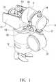
- an improved air compressoraccording to one embodiment of the present invention is shown, which generally comprises a main frame 11 for mounting a motor 12, and a cylinder 2 fitted with a piston body 14.
- the motor 12can rotate a gear 13 to drive the piston body 14 to conduct reciprocating motion in relation to the cylinder 2 so as to produce compressed air, which can enter an air storage container 3 provided with one or more outlets, wherein, for example, the outlet 31 can be connected with a pressure gauge 30; the outlet 33 can be connected with a relief valve 32; the outlet 34 can be connected with a hose (not shown) for inflating an object.
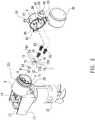
- the cylinder of the present inventionis designed in a way different from conventional technology, wherein the cylinder 2 defines a plurality of exit holes at its top wall 21, and the cylinder 2 is formed integrally with the main frame 11 by plastic material.
- the exit hole 4is defined to have a diameter of X
- the exit hole 5is defined to have a diameter of Y
- the exit holes 4, 5, 6are regulated by a control mechanism to be opened or closed, wherein the control mechanism includes O-rings 41, 51, 61, compression springs 42, 52, 62, and a resilient sheet 7.
- the O-rings 41, 51, 61can be placed around the exit holes 4, 5, 6 respectively.
- the resilient sheet 7has a root 70 and three branches including a first branch 72, a second branch 73, and a third branch 74, which correspond to the exit holes 4, 5, 6 respectively.
- the three branches 72, 73, 74extend from the root 70 to appear as a star configuration.
- the first branch 72has a first neck portion 722 extending from the root 70 and terminating at a first leaf 721, and defines a first positioning hole 723 at one end of the first neck portion 722 close to the root 70.
- the second branch 73has a second neck portion 732 extending from the root 70 and terminating at a second leaf 731, and defines a second positioning hole 733 at one end of the second neck portion 732 close to the root 70.
- the third branch 74has a third neck portion 742 extending from the root 70 and terminating at a third leaf 741, and defines a third positioning hole 743 at one end of the third neck portion 742 close to the root 70. Furthermore, as shown in FIG.
- the central positioning hole 71 of the root 70can be fitted over a main boss 24 provided at the top wall 21 of the cylinder 2, wherein the main boss 24 is located at a central point (P).
- the first positioning hole 723 of the first branch 72can be fitted over a first boss 241 provided at the top wall 21 of the cylinder 2, wherein the first boss 241 is located at a peripheral point (P1) close to the central point (P).
- the second positioning hole 733 of the second branch 73can be fitted over a second boss 242 provided at the top wall 21 of the cylinder 2, wherein the second boss 242 is located at a peripheral point (P2) close to the central point (P).
- the third positioning hole 743 of the third branch 74can be fitted over a third boss 243 provided at the top wall 21 of the cylinder 2, wherein the third boss 243 is located at a peripheral point (P3) close to the central point (P).
- the first, second and third leaves 721, 731, 741 of the branchesare configured to have sizes sufficient for covering the exit holes 4, 5, 6, and thus can seal the exit holes.
- the branches 72, 73, 74are attached to the top wall 21 of the cylinder 2 at separate points (P1, P2, P3), and placed in tight contact with the O-rings 41, 51, 61 to seal the exit holes 4, 5, 6 (see FIGS. 2 and 4 ).
- the air storage container 3is provided with two opposite coupling means 35 at its outer surface (see FIG. 9 ).
- the cylinder 2has a tubular projection 22 formed on the top wall 21.
- the tubular projection 22is provided at its outer surface with a circular flange 221 and defines an annular groove 222 between the circular flange 221 and the top wall 21 for allowing the two coupling means 35 of the air storage container 3 to be inserted into the annular groove 222 and engaged with the circular flange 221.
- the air storage container 3is provided at an inner surface thereof with three columns 37, 38, 39 corresponding to the branches 72, 73, 74 of the resilient sheet 7.
- Each of the compression springs 42, 52, 62has one end forcing against one of the branches 72, 73, 74 of the resilient sheet 7, and has another end being fitted at one end of one of the columns 37, 38, 39, wherein the columns 37, 38, 39 are respectively located above the branches 72, 73, 74 of the resilient sheet 7 at predetermined heights to limit the movements of the branches 72, 73, 74 so that the resilient sheet 7 can be prevented from elastic fatigue.
- the compression springs 42, 52, 62can urge the branches 72, 73, 74 of the resilient sheet 7 against the O-rings 41, 51, 61 to seal the exit holes 4, 5, 6, respectively (see FIGS. 2 and 8 )
- the compressed air produced in the cylinder 2can overcome the force of the compression springs 42, 52, 62 exerted on the branches 72, 73, 74 of the resilient sheet 7, thus pushing the branches 72, 73, 74 away from the equal-diameter exit holes 4, 5, 6, respectively, so that the compressed air can flow into the inner space 36 of the air storage container 3.
- the compressed aircan flow into the inner space 36 of the air storage container 3 simultaneously via the exit holes 4, 5, 6, the air storage container 3 can be filled with a large amount of air in a short time.
- the air contained in the air storage container 3can exert a greater back force on the branches 72, 73, 74 of the resilient sheet 7 compared to the initial air contained in the air storage container 3.
- the piston body 14may experience greater resistance in conducting reciprocating motion, and this may cause the exit holes 4, 5, 6 more difficult to be opened.
- the back force exerted on the branches 72, 73, 74 of the resilient sheet 7will decrease and this allows the compressed air produced in the cylinder 2 to quickly enter the inner space 36 of the air storage container 3.
- first neck portion 722, the second neck portion 732, and the third neck portion 742are attached to the top wall 21 of the cylinder 2 at separate fixed points, so that each of the branches 72, 73, 74 of the resilient sheet 7 can be moved individually by compressed air without affecting movements of the other branches, so that the piston body 14 can conduct reciprocating motion more smoothly and thus the performance of the air compressor and the speed of inflating an object can be increased.
- FIG. 6shows another embodiment of the resilient sheet, wherein the first leaf 721, the second leaf 731, and the third leaf 741 are configured to have sizes sufficient for covering the exit holes 4, 5, 6; the first neck portion 724, the second neck portion 734, and the third neck portion 744 are configured to have different widths.
- the first neck portion 724is configured to have a predetermined width K1 being transverse to the extending direction of the first neck portion
- the second neck portion 734is configured to have a predetermined width K2 being transverse to the extending direction of the second neck portion
- the third neck portion 744is configured to have a predetermined width K3 being transverse to the extending direction of the third neck portion, wherein K1 > K2 > K3 is fulfilled.
- the branches 72, 73, 74 of the resilient sheet 7provide different elastic forces, wherein the first branch 72 can provide a largest elastic force for sealing the exit hole 4 while the third branch 74 can provide a smallest elastic force for sealing the exit hole 6.
- the compressed air in the cylinder 2pushes the third branch 74 away from the exit hole 6 more easily than the other branches of the resilient sheet 7, so that the compressed air enters the inner space 36 of the air storage container 3 via the exit hole 6 as a top priority.
- the piston body 14can conduct reciprocating motion more smoothly, so that the performance of the air compressor and the speed of inflating an object can be increased.
- FIG. 10shows another embodiment of the air compressor of the present invention, wherein a modified embodiment of the resilient sheet is used to seal the exit holes of the cylinder.
- the resilient sheet 8includes a first branch 82, a second branch 83, and a third branch 84, which correspond to the equal-diameter exit holes 4, 5, 6.
- the branches 82, 83, 84extend upwardly from the root 80 to appear as a dendritic configuration.
- the first branch 82has a first neck portion 822 extending from the root 80 and terminating at a first leaf 821.
- the second branch 83has a second neck portion 832 extending from the root 80 and terminating at a second leaf 831.
- the third branch 84has a third neck portion 842 extending from the root 80 and terminating at a third leaf 841.
- the first, second and third leaves 821, 831, 841 of the branches 82, 83, 84are configured to have sizes sufficient for covering the exit holes 4, 5, 6.
- the neck portions 822, 832, 842 of the branches 82, 83, 84can be configured to extend at different lengths, wherein the first neck portion 822 extends at a predetermined length H1; the second neck portion 832 extends at a predetermined length H2; the third neck portion 842 extends at a predetermined length H3; wherein H1 > H3 > H2 is fulfilled.
- the branches 82, 83, 84 of the resilient sheet 8provide different elastic forces, wherein the second branch 83 provides a largest elastic force for sealing the exit hole 5 while the first branch 82 provides a smallest elastic force for sealing the exit hole 4.
- the compressed air in the cylinder 2pushes the first branch 82 away from the exit hole 4 more easily than the other branches of the resilient sheet 8, so that the compressed air enters the inner space 36 of the air storage container 3 via the exit hole 4 as a top priority.
- the piston body 14can conduct reciprocating motion more smoothly, so that the performance of the air compressor and the speed of inflating an object can be increased.
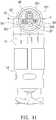
- FIG. 11shows a further embodiment of the air compressor of the present invention, wherein the cylinder 2 defines at its top wall 21 three exit holes 43, 53, 63 having different diameters.
- the exit hole 43is defined to have a diameter of A;
- the exit hole 53is defined to have a diameter of B;
- the exit hole 63is defined to have a diameter of C; wherein A > B > C is fulfilled.
- the exit holes 43, 53, 63are regulated by a control mechanism to be opened or closed.
- the control mechanismincludes a plurality of O-rings, a plurality of compression springs, and a resilient sheet 9 (see FIG.
- the resilient sheet 9includes a first branch 92, a second branch 93, and a third branch 94, which correspond to the exit hole 43, 53, 63.
- the branches 92, 93, 94extend upwardly from the root 90 to appear as a dendritic configuration.
- the first branch 92has a first neck portion 922 extending from the root 90 and terminating at a first leaf 921.
- the second branch 93has a second neck portion 932 extending from the root 90 and terminating at a second leaf 931.
- the third branch 94has a third neck portion 942 extending from the root 90 and terminating at a third leaf 941.
- the first, second and third leaves 921, 931, 941 of the branches 92, 93, 94are configured to have sizes sufficient for covering the exit holes 43, 53, 63.
- the first neck portion 922, the second neck portion 932, the third neck portion 942can be configured to extend at different lengths.
- the root 90 and the neck portions 922, 932, 942each define their positioning holes for being individually attached to the top wall 21, wherein the positioning hole of the root 90 can be fitted over a main boss 25 provided at the top wall 21 of the cylinder 2; the positioning hole of the first branch 92 can be fitted over a first boss 251 provided at the top wall 21 of the cylinder 2; the positioning hole of the second branch 93 can be fitted over a second boss 252 provided at the top wall 21 of the cylinder 2; the positioning hole of the third branch 94 can be fitted over a third boss 253 provided at the top wall 21 of the cylinder 2.
- the first branch 92, the second branch 93, and the third branch 94can seal the exit holes 43, 53, 63 respectively.
- the branches 72, 73, 74 of the resilient sheet 7are respectively subjected to the compressive forces of the compression springs 42, 52, 62, so that the branches 72, 73, 74 can seal the exit holes 4, 5, 6 more quickly.
- the compression springs 42, 52, 62can be dispensed with; namely, the branches 72, 73, 74 can provide compressive forces by themselves without additional springs to be in tight contact with the O-rings 41, 51, 61, thus sealing the exit holes 4, 5, 6.
- the air compressor of the present inventionhas a breakthrough over the prior art in that the top wall 21 of the cylinder 2 defines a plurality of exit holes, which are controlled by the corresponding branches of a resilient sheet to allow the compressed air produced in the cylinder 2 to quickly enter the inner space 36 of the air storage container 3.
- the neck portions 722, 732, 742, 822, 832, 842, 922, 932, 942 of the branches of the resilient sheetare fixed to the top wall 21 at separated points, so that each of the branches of the resilient sheet can be moved individually by compressed air without affecting movements of the other branches, so that the piston body 14 can conduct reciprocating motion more smoothly and thus the performance of the air compressor can be increased.
Landscapes
- Engineering & Computer Science (AREA)
- General Engineering & Computer Science (AREA)
- Mechanical Engineering (AREA)
- Compressor (AREA)
- Check Valves (AREA)
- Compressors, Vaccum Pumps And Other Relevant Systems (AREA)
Description
- The present invention relates to an air compressor and, more particularly, to an improved air compressor which includes a cylinder being fitted with a piston body and defining a plurality of exit holes regulated by a control mechanism that includes a resilient sheet, wherein the resilient sheet has a root and a plurality of branches extending from the root and corresponding to the exit holes, the root and branches being attached to a top wall of the cylinder at separate points, so that each of the branches of the resilient sheet can be moved individually by compressed air without affecting movements of the other branches; therefore, the piston body can conduct reciprocating motion more smoothly, and thus the performance of the air compressor can be increased.
- Currently, an air compressor basically has a cylinder which allows a piston body to conduct reciprocating motion therein to produce compressed air which can overcome a valve mechanism, so that the compressed air can flow through an exit hole of the cylinder to enter the inner space of an air storage container or an air tank. The air storage container is provided with outlets for delivering the compressed air to an object to be inflated.
- In conventional air compressors, there is only one exit hole defined at the cylinder for communicating with the air storage container. The exit hole of the cylinder is controlled by a valve mechanism, which generally includes a plug and a compression spring, so that the exit hole can be opened or closed properly according to the pressure of the compressed air. In operation, the compressed air
produced in the cylinder can overcome the compressive force of the compression spring to enter the inner space of the air compressor. However, the compressed air stored in the air storage container can exert a back force on the plug, thus restraining the plug from being moved away from the exit hole. As a result, the piston body, which conducts reciprocating motion in relation to the cylinder, will be subjected to greater resistance. Therefore, the piston body may not move smoothly in relation to the cylinder, and thus the speed of inflating an object will become slow. Furthermore, the motor of the air compressor may become too hot, thus decreasing the performance of the motor. Even worse, the motor may be under the risk of burning out. DocumentUS 2003/185695 A1 discloses another structure of a conventional air compressor, wherein a plurality of exit holes are defined at a top wall of the cylinder, wherein all the exit holes are regulated by a single control mechanism to be opened or closed, wherein said control mechanism includes a resilient sheet having a root and a plurality of branches extending from the root and corresponding to the exit holes, wherein the resilient sheet is attached to the top wall only at a central point through a positioning hole formed on the root and for that reason still has several shortcomings. - In view of the foregoing, the applicant intends to develop an improved air compressor which can solve the shortcomings of conventional air compressors.
- One object of the present invention is to provide an improved air compressor, wherein a cylinder thereof defines a plurality of exit holes, through which a large amount of compressed air produced in the cylinder may enter an air storage container in a short time.
- Another object of the present invention is to provide an improved air compressor, wherein a cylinder thereof is fitted with a piston body and defines a plurality of exit holes regulated by a control mechanism to be opened or closed. The control mechanism includes a resilient sheet having a root and a plurality of branches extending from the root and corresponding to the exit holes, wherein the root and branches of the resilient sheet are attached to a top wall of the cylinder at separate points, whereby each of the branches of the resilient sheet can be moved individually by compressed air without affecting movements of the other branches, so that the piston body can conduct reciprocating motion more smoothly, and thus the performance of the air compressor and the speed of inflating an object can be increased.
- Other objects, advantages, and novel features of the present invention will become more apparent from the following detailed description when taken in conjunction with the accompanying drawings.
FIG. 1 shows a 3-dimensional view of an air compressor according to one embodiment of the present invention.FIG. 2 shows an exploded view of the air compressor.FIG. 3 shows a plan view of the air compressor, wherein a plurality of equal-diameter exit holes defined at a cylinder thereof are revealed.FIG. 4 shows a plan view of the air compressor, wherein a resilient sheet being used to seal the exit holes is revealed.FIG. 5 shows an enlarged plan view of the resilient sheet being used in the present invention.FIG. 6 shows an enlarged plan view of another embodiment of the resilient sheet being used in the present invention.FIG. 7 shows a plan view of the air compressor, wherein an air storage container is assembled onto the cylinder.FIG. 8 shows a sectional view of the air compressor taken along line A-A inFIG. 7 .FIG. 9 shows a plan view of the air compressor, wherein a gear and a piston body used in the air compressor are revealed.FIG. 10 shows a plan view of an air compressor according to another embodiment of the present invention, wherein a modified embodiment of the resilient sheet is used to seal the exit holes of the cylinder.FIG. 11 shows a plan view of an air compressor according to a further embodiment of the present invention, wherein a cylinder thereof defines a plurality of unequal-diameter exit holes.FIG. 12 shows a plan view of the air compressor, wherein a resilient sheet is used to seal the unequal-diameter exit holes shown inFIG. 11 .FIG. 13 shows an exploded view of an air compressor according to a still further embodiment of the present invention, wherein compression springs are not included.- Referring to
FIGS. 1 and2 , an improved air compressor according to one embodiment of the present invention is shown, which generally comprises amain frame 11 for mounting amotor 12, and acylinder 2 fitted with apiston body 14. Themotor 12 can rotate agear 13 to drive thepiston body 14 to conduct reciprocating motion in relation to thecylinder 2 so as to produce compressed air, which can enter anair storage container 3 provided with one or more outlets, wherein, for example, theoutlet 31 can be connected with apressure gauge 30; theoutlet 33 can be connected with arelief valve 32; theoutlet 34 can be connected with a hose (not shown) for inflating an object. - As shown in
FIGS. 2 through 8 , the cylinder of the present invention is designed in a way different from conventional technology, wherein thecylinder 2 defines a plurality of exit holes at itstop wall 21, and thecylinder 2 is formed integrally with themain frame 11 by plastic material. In this embodiment, theexit hole 4 is defined to have a diameter of X, theexit hole 5 is defined to have a diameter of Y, and theexit hole 6 is defined to have a diameter of Z, wherein X = Y = Z is fulfilled (seeFIG. 3 ); namely, theexit holes exit holes rings compression springs resilient sheet 7. The O-rings exit holes resilient sheet 7 has aroot 70 and three branches including afirst branch 72, asecond branch 73, and athird branch 74, which correspond to theexit holes root 70 of theresilient sheet 7, which is substantially located at a center of theresilient sheet 7, defines acentral positioning hole 71. The threebranches root 70 to appear as a star configuration. Thefirst branch 72 has afirst neck portion 722 extending from theroot 70 and terminating at afirst leaf 721, and defines afirst positioning hole 723 at one end of thefirst neck portion 722 close to theroot 70. Thesecond branch 73 has asecond neck portion 732 extending from theroot 70 and terminating at asecond leaf 731, and defines asecond positioning hole 733 at one end of thesecond neck portion 732 close to theroot 70. Thethird branch 74 has athird neck portion 742 extending from theroot 70 and terminating at athird leaf 741, and defines athird positioning hole 743 at one end of thethird neck portion 742 close to theroot 70. Furthermore, as shown inFIG. 5 , thefirst neck portion 722 is configured to have a predetermined width L1 being transverse to the extending direction of thefirst branch 72; thesecond neck portion 732 is configured to have a predetermined width L2 being transverse to the extending direction of thesecond branch 73; thethird neck portion 742 is configured to have a predetermined width L3 being transverse to the extending direction of thethird branch 74; wherein L1 = L2 = L3 is fulfilled. Thecentral positioning hole 71 of theroot 70 can be fitted over amain boss 24 provided at thetop wall 21 of thecylinder 2, wherein themain boss 24 is located at a central point (P). Thefirst positioning hole 723 of thefirst branch 72 can be fitted over afirst boss 241 provided at thetop wall 21 of thecylinder 2, wherein thefirst boss 241 is located at a peripheral point (P1) close to the central point (P). Thesecond positioning hole 733 of thesecond branch 73 can be fitted over asecond boss 242 provided at thetop wall 21 of thecylinder 2, wherein thesecond boss 242 is located at a peripheral point (P2) close to the central point (P). Thethird positioning hole 743 of thethird branch 74 can be fitted over athird boss 243 provided at thetop wall 21 of thecylinder 2, wherein thethird boss 243 is located at a peripheral point (P3) close to the central point (P). The first, second andthird leaves exit holes branches top wall 21 of thecylinder 2 at separate points (P1, P2, P3), and placed in tight contact with the O-rings exit holes FIGS. 2 and4 ). Theair storage container 3 is provided with two opposite coupling means 35 at its outer surface (seeFIG. 9 ). Thecylinder 2 has atubular projection 22 formed on thetop wall 21. Thetubular projection 22 is provided at its outer surface with acircular flange 221 and defines anannular groove 222 between thecircular flange 221 and thetop wall 21 for allowing the two coupling means 35 of theair storage container 3 to be inserted into theannular groove 222 and engaged with thecircular flange 221. Theair storage container 3 is provided at an inner surface thereof with threecolumns branches resilient sheet 7. Each of thecompression springs branches resilient sheet 7, and has another end being fitted at one end of one of thecolumns columns branches resilient sheet 7 at predetermined heights to limit the movements of thebranches resilient sheet 7 can be prevented from elastic fatigue. As such, thecompression springs branches resilient sheet 7 against the O-rings exit holes FIGS. 2 and8 ) - Referring to
FIGS. 7 and8 , when thepiston body 14 conducts reciprocating motion, the compressed air produced in thecylinder 2 can overcome the force of thecompression springs branches resilient sheet 7, thus pushing thebranches diameter exit holes inner space 36 of theair storage container 3. Initially, since the compressed air can flow into theinner space 36 of theair storage container 3 simultaneously via theexit holes air storage container 3 can be filled with a large amount of air in a short time. Later, since there is a large amount of air having entered theinner space 36 of theair storage container 3, the air contained in theair storage container 3 can exert a greater back force on thebranches resilient sheet 7 compared to the initial air contained in theair storage container 3. In other words, thepiston body 14 may experience greater resistance in conducting reciprocating motion, and this may cause theexit holes air storage container 3, the back force exerted on thebranches resilient sheet 7 will decrease and this allows the compressed air produced in thecylinder 2 to quickly enter theinner space 36 of theair storage container 3. Besides, thefirst neck portion 722, thesecond neck portion 732, and thethird neck portion 742 are attached to thetop wall 21 of thecylinder 2 at separate fixed points, so that each of thebranches resilient sheet 7 can be moved individually by compressed air without affecting movements of the other branches, so that thepiston body 14 can conduct reciprocating motion more smoothly and thus the performance of the air compressor and the speed of inflating an object can be increased. FIG. 6 shows another embodiment of the resilient sheet, wherein thefirst leaf 721, thesecond leaf 731, and thethird leaf 741 are configured to have sizes sufficient for covering the exit holes 4, 5, 6; thefirst neck portion 724, thesecond neck portion 734, and thethird neck portion 744 are configured to have different widths. Specifically, thefirst neck portion 724 is configured to have a predetermined width K1 being transverse to the extending direction of the first neck portion, thesecond neck portion 734 is configured to have a predetermined width K2 being transverse to the extending direction of the second neck portion, and thethird neck portion 744 is configured to have a predetermined width K3 being transverse to the extending direction of the third neck portion, wherein K1 > K2 > K3 is fulfilled. Thus, thebranches resilient sheet 7 provide different elastic forces, wherein thefirst branch 72 can provide a largest elastic force for sealing theexit hole 4 while thethird branch 74 can provide a smallest elastic force for sealing theexit hole 6. As such, the compressed air in thecylinder 2 pushes thethird branch 74 away from theexit hole 6 more easily than the other branches of theresilient sheet 7, so that the compressed air enters theinner space 36 of theair storage container 3 via theexit hole 6 as a top priority. Considering the operation of the air compressor as a whole, thepiston body 14 can conduct reciprocating motion more smoothly, so that the performance of the air compressor and the speed of inflating an object can be increased.FIG. 10 shows another embodiment of the air compressor of the present invention, wherein a modified embodiment of the resilient sheet is used to seal the exit holes of the cylinder. The resilient sheet 8 includes afirst branch 82, asecond branch 83, and athird branch 84, which correspond to the equal-diameter exit holes 4, 5, 6. Thebranches root 80 to appear as a dendritic configuration. Specifically, thefirst branch 82 has afirst neck portion 822 extending from theroot 80 and terminating at afirst leaf 821. Thesecond branch 83 has asecond neck portion 832 extending from theroot 80 and terminating at asecond leaf 831. Thethird branch 84 has athird neck portion 842 extending from theroot 80 and terminating at athird leaf 841. The first, second andthird leaves branches neck portions branches first neck portion 822 extends at a predetermined length H1; thesecond neck portion 832 extends at a predetermined length H2; thethird neck portion 842 extends at a predetermined length H3; wherein H1 > H3 > H2 is fulfilled. Thus, thebranches second branch 83 provides a largest elastic force for sealing theexit hole 5 while thefirst branch 82 provides a smallest elastic force for sealing theexit hole 4. As such, the compressed air in thecylinder 2 pushes thefirst branch 82 away from theexit hole 4 more easily than the other branches of the resilient sheet 8, so that the compressed air enters theinner space 36 of theair storage container 3 via theexit hole 4 as a top priority. Considering the operation of the air compressor as a whole, thepiston body 14 can conduct reciprocating motion more smoothly, so that the performance of the air compressor and the speed of inflating an object can be increased.FIG. 11 shows a further embodiment of the air compressor of the present invention, wherein thecylinder 2 defines at itstop wall 21 threeexit holes exit hole 43 is defined to have a diameter of A; theexit hole 53 is defined to have a diameter of B; theexit hole 63 is defined to have a diameter of C; wherein A > B > C is fulfilled. The exit holes 43, 53, 63 are regulated by a control mechanism to be opened or closed. The control mechanism includes a plurality of O-rings, a plurality of compression springs, and a resilient sheet 9 (seeFIG. 12 ), wherein theresilient sheet 9 includes afirst branch 92, asecond branch 93, and athird branch 94, which correspond to theexit hole branches root 90 to appear as a dendritic configuration. Thefirst branch 92 has afirst neck portion 922 extending from theroot 90 and terminating at afirst leaf 921. Thesecond branch 93 has asecond neck portion 932 extending from theroot 90 and terminating at asecond leaf 931. Thethird branch 94 has athird neck portion 942 extending from theroot 90 and terminating at athird leaf 941. The first, second andthird leaves branches first neck portion 922, thesecond neck portion 932, thethird neck portion 942 can be configured to extend at different lengths. Theroot 90 and theneck portions top wall 21, wherein the positioning hole of theroot 90 can be fitted over amain boss 25 provided at thetop wall 21 of thecylinder 2; the positioning hole of thefirst branch 92 can be fitted over afirst boss 251 provided at thetop wall 21 of thecylinder 2; the positioning hole of thesecond branch 93 can be fitted over asecond boss 252 provided at thetop wall 21 of thecylinder 2; the positioning hole of thethird branch 94 can be fitted over athird boss 253 provided at thetop wall 21 of thecylinder 2. As such, thefirst branch 92, thesecond branch 93, and thethird branch 94 can seal the exit holes 43, 53, 63 respectively.- In the previous embodiment, as shown in
FIG. 2 , thebranches resilient sheet 7 are respectively subjected to the compressive forces of the compression springs 42, 52, 62, so that thebranches FIG. 13 , the compression springs 42, 52, 62 can be dispensed with; namely, thebranches rings - As a summary, the air compressor of the present invention has a breakthrough over the prior art in that the
top wall 21 of thecylinder 2 defines a plurality of exit holes, which are controlled by the corresponding branches of a resilient sheet to allow the compressed air produced in thecylinder 2 to quickly enter theinner space 36 of theair storage container 3. In addition, since theneck portions top wall 21 at separated points, so that each of the branches of the resilient sheet can be moved individually by compressed air without affecting movements of the other branches, so that thepiston body 14 can conduct reciprocating motion more smoothly and thus the performance of the air compressor can be increased. These features render the air compressor of the present invention useful and inventive.
Claims (10)
- An air compressor including a main frame (11) for mounting a motor (12), and a cylinder (2) fitted with a piston body (14), the motor (12) capable of driving the piston body (14) to conduct reciprocating motion to produce in the cylinder (2) compressed air which can enter an air storage container (3) via an exit hole defined at a top wall (21) of the cylinder (2),:wherein the top wall (21) of the cylinder (2) defines additional exit hole, all the exit holes being regulated by a control mechanism to be opened or closed, the control mechanism including a resilient sheet (7)(8)(9) having a root (70)(80)(90) and a plurality of branches (72, 73, 74)(82, 83, 84)(92, 93, 94) extending from the root (70)(80)(90) and corresponding to the exit holes, each branch (72, 73, 74) (82, 83, 84) (92, 93, 94) having a neck portion (722,732, 742) (822, 832, 842) (922, 932, 942) extending from the root (70)(80)(90) and terminating in a leaf (721, 731, 741)(821, 831, 841)(921, 931, 941) configured to have sizes sufficient for covering the exit holes, wherein the root (70)(80)(90) of the resilient sheet defines a positioning hole (71) being attached to the top wall (21) at a central point (P),characterized in thateach of the branches (72, 73, 74) (82, 83, 84)(92, 93, 94) of the resilient sheet defines a positioning hole (723, 733, 743) at one end of its neck portion (722,732, 742) (822, 832, 842) (922, 932, 942) close to the root (70)(80)(90), the positioning holes of the branches (72, 73, 74) (82, 83, 84)(92, 93, 94) being attached to the top wall (21) respectively at separate points (P1, P2, P3) located in the periphery of the central point (P) to which the root (70)(80)(90) of the resilient sheet is attached, so that each of the branches (72, 73, 74)(82, 83, 84)(92, 93, 94) of the resilient sheet can be moved individually by compressed air without affecting movements of the other branches, so that the piston body (14) can conduct reciprocating motion more smoothly and thus the performance of the air compressor can be increased, andthe control mechanism further includes a plurality of O-rings (41, 51, 61)(43, 53, 63), the O-rings (41, 51, 61)(43, 53, 63) being placed around the exit holes respectively, the branches (72, 73, 74)(82, 83, 84)(92, 93, 94) of the resilient sheet (7)(8)(9) having sufficient elastic forces to enable themselves to be in tight contact with the O-rings (41, 51, 61)(43, 53, 63) to seal the exit holes, respectively.
- The air compressor of claim 1, wherein the cylinder (2) defining the exit holes is formed integrally with the main frame (11) by plastic material.
- The air compressor of claim 1, wherein the exit holes are defined to be approximately equal in diameter.
- The air compressor of claim 1, wherein the control mechanism further includes a plurality of O-rings (41, 51, 61) and a plurality of compression springs (42, 52, 62), the O-rings (41, 51, 61) being placed around the exit holes respectively, the compression springs (42, 52, 62) urging the branches (72, 73, 74)(82, 83, 84)(92, 93, 94) of the resilient sheet against the O-rings (41, 51, 61) to seal the exit holes, respectively; the cylinder (2) has a tubular projection (22) formed on the top wall (21), the tubular projection (22) provided at its outer surface with a circular flange (221) and defining an annular groove (222) between the circular flange (221) and the top wall (21); the air storage container (3) is provided at an outer surface thereof with two coupling means (35) and is provided at an inner surface thereof with a plurality of columns (37, 38, 39) corresponding to the branches (72, 73, 74)(82, 83, 84)(92, 93, 94) of the resilient sheet (7)(8)(9); the two coupling means (35) is capable of being inserted into the annular groove (222) and engaged with the circular flange (221) of the cylinder (2); each of the compression springs (42, 52, 62) has one end forcing against one of the branches of the resilient sheet (7)(8)(9), and has another end being fitted at one end of one of the columns (37, 38, 39), wherein each of the columns (37, 38, 39) is located at a predetermined height above the corresponding branch of the resilient sheet (7)(8)(9) to limit the movement of the corresponding branch so that the resilient sheet (7)(8)(9) can be prevented from elastic fatigue.
- The air compressor of claim 4, wherein the root (70) is substantially located at a center of the resilient sheet (7) and defines a central positioning hole (71); the branches (72, 73, 74) extending from the root (70) to appear as a star configuration and includes a first branch (72), a second branch (73), and a third branch (74), the first branch (72) having a first neck portion (722), which extends from the root (70) and terminates at a first leaf (721), and defining a first positioning hole (723) at one end of the first neck portion (722) close to the root (70), the second branch (73) having a second neck portion (732), which extends from the root (70) and terminates at a second leaf (731), and defining a second positioning hole (733) at one end of the second neck portion (732) close to the root (70), the third branch (74) having a third neck portion (742), which extends from the root (70) and terminates at a third leaf (731), and defining a third positioning hole (743) at one end of the third neck portion (742) close to the root (70), the central positioning hole (71) of the root (70) being fitted over a main boss (24) provided at the top wall (21) of the cylinder (2), the first positioning hole (723) of the first branch (72) being fitted over a first boss (241) provided at the top wall (21) of the cylinder (2), the second positioning hole (733) of the second branch (73) being fitted over a second boss (242) provided at the top wall (21) of the cylinder (2), the third positioning hole (743) of the third branch (74) being fitted over a third boss (243) provided at the top wall (21) of the cylinder (2),; whereby the branches (72, 73, 74) are in tight contact with the O-rings (41, 51, 61) to seal the exit holes, respectively.
- The air compressor of claim 5, wherein the first neck portion (722) is configured to have a predetermined width L1 being transverse to the extending direction of the first branch (72), the second neck portion (732) is configured to have a predetermined width L2 being transverse to the extending direction of the second branch (73), and the third neck portion (742) is configured to have a predetermined width L3 being transverse to the extending direction of the third branch (73), wherein L1 = L2 = L3 is fulfilled.
- The air compressor of claim 5, wherein the first neck portion (722) is configured to have a predetermined width K1 being transverse to the extending direction of the first branch (72), the second neck portion (732) is configured to have a predetermined width K2 being transverse to the extending direction of the second branch (73), and the third neck portion (742) is configured to have a predetermined width K3 being transverse to the extending direction of the third branch (74), wherein K1 > K2 > K3 is fulfilled, whereby the compressed air in the cylinder (2) pushes the third branch (74) away from the corresponding exit hole more easily than the other branches of the resilient sheet (7), so that the compressed air enters the inner space (36) of the air storage container (3) via the corresponding exit hole of the third branch (74) as a top priority.
- The air compressor of claim 4, wherein the branches (82, 83, 84)(92, 93, 94) extends upwardly from the root (80)(90) to appear as a dendritic configuration and includes a first branch (82)(92), a second branch (83)(93), and a third branch (84)(94), which correspond to the exit holes.
- The air compressor of claim 8, wherein the first branch (82) has a first neck portion (822) extending from the root (80) and terminates at a first leaf (821), the second branch (83) has a second neck portion (832) extending from the root (80) and terminates at a second leaf (831), and the third branch (84) has a third neck portion (842) extending from the root (80) and terminates at a third leaf (841), the first, second and third leaves (821, 831, 841) of the branches being configured to have sizes sufficient for covering the exit holes, the branches (82, 83, 84) being placed in tight contact with the O-rings (41, 51, 61) to seal the exit holes respectively, the first neck portion (822) extending at a predetermined length H1, the second neck portion (832) extending at a predetermined length H2, the third neck portion (842) extending at a predetermined length H3, wherein H1 > H3 > H2 is fulfilled, whereby the compressed air in the cylinder (2) pushes the first branch (82) away from the corresponding exit hole more easily than the other branches of the resilient sheet (8), so that the compressed air enters the air storage container (3) via the corresponding exit hole of the first branch (82) as a top priority.
- The air compressor of claim 1, wherein the exit holes are defined to have different diameters.
Priority Applications (1)
| Application Number | Priority Date | Filing Date | Title |
|---|---|---|---|
| PL17152495TPL3196463T3 (en) | 2016-01-20 | 2017-01-20 | Improved air compressor |
Applications Claiming Priority (1)
| Application Number | Priority Date | Filing Date | Title |
|---|---|---|---|
| TW105101784ATWI626376B (en) | 2016-01-20 | 2016-01-20 | Improved air compressor |
Publications (2)
| Publication Number | Publication Date |
|---|---|
| EP3196463A1 EP3196463A1 (en) | 2017-07-26 |
| EP3196463B1true EP3196463B1 (en) | 2018-12-12 |
Family
ID=57860773
Family Applications (1)
| Application Number | Title | Priority Date | Filing Date |
|---|---|---|---|
| EP17152495.2AActiveEP3196463B1 (en) | 2016-01-20 | 2017-01-20 | Improved air compressor |
Country Status (11)
| Country | Link |
|---|---|
| US (1) | US10527031B2 (en) |
| EP (1) | EP3196463B1 (en) |
| JP (2) | JP6337161B2 (en) |
| KR (1) | KR20170087405A (en) |
| CN (2) | CN206636742U (en) |
| DE (1) | DE202017100313U1 (en) |
| DK (1) | DK3196463T3 (en) |
| HU (1) | HUE043327T2 (en) |
| PL (1) | PL3196463T3 (en) |
| TR (1) | TR201900365T4 (en) |
| TW (1) | TWI626376B (en) |
Families Citing this family (4)
| Publication number | Priority date | Publication date | Assignee | Title |
|---|---|---|---|---|
| TWI644021B (en)* | 2016-02-26 | 2018-12-11 | 周文三 | Improved air compressor |
| TWI716006B (en)* | 2019-06-20 | 2021-01-11 | 周文三 | Venting structure of cylinder of air compressor |
| TWI716007B (en)* | 2019-06-20 | 2021-01-11 | 周文三 | Venting structure of cylinder of air compressor |
| CN112265044B (en)* | 2020-11-09 | 2022-05-20 | 吉林农业大学 | A kind of mushroom cutting root device and method thereof |
Citations (1)
| Publication number | Priority date | Publication date | Assignee | Title |
|---|---|---|---|---|
| JPS5541663U (en)* | 1978-09-12 | 1980-03-17 |
Family Cites Families (22)
| Publication number | Priority date | Publication date | Assignee | Title |
|---|---|---|---|---|
| US1614124A (en)* | 1926-08-07 | 1927-01-11 | Ingersoll Rand Co | Gas-compressor valve |
| US2935073A (en)* | 1959-01-08 | 1960-05-03 | Clay Adams Inc | Pipette washer |
| US3540470A (en)* | 1968-06-17 | 1970-11-17 | Vilter Manufacturing Corp | Diaphragm valve for compressors |
| US4319452A (en)* | 1978-09-12 | 1982-03-16 | Nissan Motor Company, Limited | Secondary air supply device |
| US4385872A (en)* | 1980-01-22 | 1983-05-31 | Copeland Corporation | Compressor |
| JPS59213956A (en)* | 1983-05-18 | 1984-12-03 | Toyoda Autom Loom Works Ltd | Compressor |
| EP0144547A3 (en)* | 1983-09-16 | 1986-10-15 | Flottmann-Werke GmbH | Piston compressor for gaseous media |
| JPS61197774A (en)* | 1985-02-27 | 1986-09-02 | Sanden Corp | Valve plate for coolant compressor |
| HU198788B (en)* | 1986-04-07 | 1989-11-28 | Finoszerelvenygyar | Pressure valve system of piston cooling compressor |
| US5265646A (en)* | 1993-03-17 | 1993-11-30 | Ingersoll-Rand Company | Valve spacer plate |
| ES2327985T3 (en)* | 1997-11-04 | 2009-11-05 | Smiths Medical Asd, Inc. | INFUSION SYSTEM WITH IMPROVED CONTROL VALVE. |
| JP2003206857A (en)* | 2002-01-10 | 2003-07-25 | Toyota Industries Corp | Piston type compressor |
| EP1490598B1 (en)* | 2002-03-29 | 2006-11-29 | DeVilbiss Air Power Company | Head pressure relief assembly |
| JP4566676B2 (en)* | 2004-09-30 | 2010-10-20 | 日立オートモティブシステムズ株式会社 | air compressor |
| US8282368B2 (en)* | 2007-08-22 | 2012-10-09 | Ford Global Technologies, Llc | Check valve |
| CN101403376B (en)* | 2008-11-10 | 2010-10-20 | 周文三 | air compressor |
| CN101936277A (en)* | 2010-08-03 | 2011-01-05 | 快意(江门)压缩机有限公司 | Compact type environment-protection oil-free air compressor |
| CN201696259U (en)* | 2010-08-03 | 2011-01-05 | 快意(江门)压缩机有限公司 | Air valve plate component of small oil-free air compressor |
| US9284930B2 (en)* | 2011-06-03 | 2016-03-15 | Michael R. Harwood | High pressure piezoelectric fuel injector |
| TWI521139B (en)* | 2012-11-14 | 2016-02-11 | 周文三 | Air compressor |
| TWI545258B (en)* | 2014-04-07 | 2016-08-11 | 周文三 | Air compressor |
| CN104912773B (en)* | 2015-07-01 | 2017-10-24 | 浙江申元机电有限公司 | A kind of air compression plant and air compressor machine |
- 2016
- 2016-01-20TWTW105101784Apatent/TWI626376B/enactive
- 2017
- 2017-01-09KRKR1020170002997Apatent/KR20170087405A/ennot_activeCeased
- 2017-01-13USUS15/405,307patent/US10527031B2/enactiveActive
- 2017-01-17CNCN201720051904.6Upatent/CN206636742U/ennot_activeExpired - Fee Related
- 2017-01-17CNCN201710031619.2Apatent/CN106988997B/enactiveActive
- 2017-01-19JPJP2017007671Apatent/JP6337161B2/enactiveActive
- 2017-01-19JPJP2017000179Upatent/JP3209651U/enactiveActive
- 2017-01-20DKDK17152495.2Tpatent/DK3196463T3/enactive
- 2017-01-20TRTR2019/00365Tpatent/TR201900365T4/enunknown
- 2017-01-20HUHUE17152495Apatent/HUE043327T2/enunknown
- 2017-01-20PLPL17152495Tpatent/PL3196463T3/enunknown
- 2017-01-20DEDE202017100313.2Upatent/DE202017100313U1/ennot_activeExpired - Lifetime
- 2017-01-20EPEP17152495.2Apatent/EP3196463B1/enactiveActive
Patent Citations (1)
| Publication number | Priority date | Publication date | Assignee | Title |
|---|---|---|---|---|
| JPS5541663U (en)* | 1978-09-12 | 1980-03-17 |
Also Published As
| Publication number | Publication date |
|---|---|
| TR201900365T4 (en) | 2019-02-21 |
| JP3209651U (en) | 2017-03-30 |
| KR20170087405A (en) | 2017-07-28 |
| US20170204844A1 (en) | 2017-07-20 |
| CN106988997B (en) | 2019-09-27 |
| TW201727078A (en) | 2017-08-01 |
| PL3196463T3 (en) | 2019-04-30 |
| JP6337161B2 (en) | 2018-06-06 |
| CN106988997A (en) | 2017-07-28 |
| CN206636742U (en) | 2017-11-14 |
| HUE043327T2 (en) | 2019-08-28 |
| TWI626376B (en) | 2018-06-11 |
| US10527031B2 (en) | 2020-01-07 |
| EP3196463A1 (en) | 2017-07-26 |
| DE202017100313U1 (en) | 2017-02-06 |
| JP2017129144A (en) | 2017-07-27 |
| DK3196463T3 (en) | 2019-04-01 |
Similar Documents
| Publication | Publication Date | Title |
|---|---|---|
| US10138878B2 (en) | Air compressor | |
| EP3196463B1 (en) | Improved air compressor | |
| EP2930361B1 (en) | Air compressor | |
| EP3193016B1 (en) | Improved air compressor | |
| EP3056732B1 (en) | Improved air compressor | |
| EP3034285B1 (en) | Sealant dispenser | |
| EP2937568B1 (en) | Air compressor | |
| EP3002458B1 (en) | Improved air compressor | |
| US10132310B2 (en) | Air compressor | |
| EP3214309B1 (en) | Improved air compressor | |
| US20160097383A1 (en) | Air compressor | |
| WO2009079218A3 (en) | Integrated valve regulator assembly and system for the controlled storage and dispensing of a hazardous material | |
| EP3193018B1 (en) | Improved air compressor | |
| EP3211234B1 (en) | Improved air compressor | |
| EP2711160B1 (en) | Valve for producing hollow footwear soles and method for using same | |
| JP6531003B2 (en) | Dispenser | |
| US20040134541A1 (en) | Air pressure and flow regulating valve for pneumatic tool | |
| KR102342613B1 (en) | Pressure reducing valve | |
| KR20110136279A (en) | Constant flow pressure reducing valve | |
| JP5624926B2 (en) | Contents extrusion container | |
| EP3963139B1 (en) | Multi-cartridge drain gun |
Legal Events
| Date | Code | Title | Description |
|---|---|---|---|
| PUAI | Public reference made under article 153(3) epc to a published international application that has entered the european phase | Free format text:ORIGINAL CODE: 0009012 | |
| STAA | Information on the status of an ep patent application or granted ep patent | Free format text:STATUS: THE APPLICATION HAS BEEN PUBLISHED | |
| AK | Designated contracting states | Kind code of ref document:A1 Designated state(s):AL AT BE BG CH CY CZ DE DK EE ES FI FR GB GR HR HU IE IS IT LI LT LU LV MC MK MT NL NO PL PT RO RS SE SI SK SM TR | |
| AX | Request for extension of the european patent | Extension state:BA ME | |
| STAA | Information on the status of an ep patent application or granted ep patent | Free format text:STATUS: REQUEST FOR EXAMINATION WAS MADE | |
| 17P | Request for examination filed | Effective date:20180126 | |
| RBV | Designated contracting states (corrected) | Designated state(s):AL AT BE BG CH CY CZ DE DK EE ES FI FR GB GR HR HU IE IS IT LI LT LU LV MC MK MT NL NO PL PT RO RS SE SI SK SM TR | |
| GRAP | Despatch of communication of intention to grant a patent | Free format text:ORIGINAL CODE: EPIDOSNIGR1 | |
| STAA | Information on the status of an ep patent application or granted ep patent | Free format text:STATUS: GRANT OF PATENT IS INTENDED | |
| INTG | Intention to grant announced | Effective date:20180615 | |
| GRAS | Grant fee paid | Free format text:ORIGINAL CODE: EPIDOSNIGR3 | |
| GRAA | (expected) grant | Free format text:ORIGINAL CODE: 0009210 | |
| STAA | Information on the status of an ep patent application or granted ep patent | Free format text:STATUS: THE PATENT HAS BEEN GRANTED | |
| AK | Designated contracting states | Kind code of ref document:B1 Designated state(s):AL AT BE BG CH CY CZ DE DK EE ES FI FR GB GR HR HU IE IS IT LI LT LU LV MC MK MT NL NO PL PT RO RS SE SI SK SM TR | |
| REG | Reference to a national code | Ref country code:GB Ref legal event code:FG4D | |
| REG | Reference to a national code | Ref country code:CH Ref legal event code:EP | |
| REG | Reference to a national code | Ref country code:AT Ref legal event code:REF Ref document number:1076369 Country of ref document:AT Kind code of ref document:T Effective date:20181215 | |
| REG | Reference to a national code | Ref country code:DE Ref legal event code:R096 Ref document number:602017001224 Country of ref document:DE | |
| REG | Reference to a national code | Ref country code:IE Ref legal event code:FG4D | |
| REG | Reference to a national code | Ref country code:NL Ref legal event code:FP | |
| REG | Reference to a national code | Ref country code:DK Ref legal event code:T3 Effective date:20190325 | |
| REG | Reference to a national code | Ref country code:SE Ref legal event code:TRGR | |
| REG | Reference to a national code | Ref country code:LT Ref legal event code:MG4D | |
| PG25 | Lapsed in a contracting state [announced via postgrant information from national office to epo] | Ref country code:LV Free format text:LAPSE BECAUSE OF FAILURE TO SUBMIT A TRANSLATION OF THE DESCRIPTION OR TO PAY THE FEE WITHIN THE PRESCRIBED TIME-LIMIT Effective date:20181212 Ref country code:FI Free format text:LAPSE BECAUSE OF FAILURE TO SUBMIT A TRANSLATION OF THE DESCRIPTION OR TO PAY THE FEE WITHIN THE PRESCRIBED TIME-LIMIT Effective date:20181212 Ref country code:NO Free format text:LAPSE BECAUSE OF FAILURE TO SUBMIT A TRANSLATION OF THE DESCRIPTION OR TO PAY THE FEE WITHIN THE PRESCRIBED TIME-LIMIT Effective date:20190312 Ref country code:HR Free format text:LAPSE BECAUSE OF FAILURE TO SUBMIT A TRANSLATION OF THE DESCRIPTION OR TO PAY THE FEE WITHIN THE PRESCRIBED TIME-LIMIT Effective date:20181212 Ref country code:BG Free format text:LAPSE BECAUSE OF FAILURE TO SUBMIT A TRANSLATION OF THE DESCRIPTION OR TO PAY THE FEE WITHIN THE PRESCRIBED TIME-LIMIT Effective date:20190312 Ref country code:LT Free format text:LAPSE BECAUSE OF FAILURE TO SUBMIT A TRANSLATION OF THE DESCRIPTION OR TO PAY THE FEE WITHIN THE PRESCRIBED TIME-LIMIT Effective date:20181212 | |
| PG25 | Lapsed in a contracting state [announced via postgrant information from national office to epo] | Ref country code:GR Free format text:LAPSE BECAUSE OF FAILURE TO SUBMIT A TRANSLATION OF THE DESCRIPTION OR TO PAY THE FEE WITHIN THE PRESCRIBED TIME-LIMIT Effective date:20190313 Ref country code:AL Free format text:LAPSE BECAUSE OF FAILURE TO SUBMIT A TRANSLATION OF THE DESCRIPTION OR TO PAY THE FEE WITHIN THE PRESCRIBED TIME-LIMIT Effective date:20181212 Ref country code:RS Free format text:LAPSE BECAUSE OF FAILURE TO SUBMIT A TRANSLATION OF THE DESCRIPTION OR TO PAY THE FEE WITHIN THE PRESCRIBED TIME-LIMIT Effective date:20181212 | |
| PG25 | Lapsed in a contracting state [announced via postgrant information from national office to epo] | Ref country code:PT Free format text:LAPSE BECAUSE OF FAILURE TO SUBMIT A TRANSLATION OF THE DESCRIPTION OR TO PAY THE FEE WITHIN THE PRESCRIBED TIME-LIMIT Effective date:20190412 Ref country code:ES Free format text:LAPSE BECAUSE OF FAILURE TO SUBMIT A TRANSLATION OF THE DESCRIPTION OR TO PAY THE FEE WITHIN THE PRESCRIBED TIME-LIMIT Effective date:20181212 | |
| REG | Reference to a national code | Ref country code:HU Ref legal event code:AG4A Ref document number:E043327 Country of ref document:HU | |
| PG25 | Lapsed in a contracting state [announced via postgrant information from national office to epo] | Ref country code:SM Free format text:LAPSE BECAUSE OF FAILURE TO SUBMIT A TRANSLATION OF THE DESCRIPTION OR TO PAY THE FEE WITHIN THE PRESCRIBED TIME-LIMIT Effective date:20181212 Ref country code:EE Free format text:LAPSE BECAUSE OF FAILURE TO SUBMIT A TRANSLATION OF THE DESCRIPTION OR TO PAY THE FEE WITHIN THE PRESCRIBED TIME-LIMIT Effective date:20181212 Ref country code:SK Free format text:LAPSE BECAUSE OF FAILURE TO SUBMIT A TRANSLATION OF THE DESCRIPTION OR TO PAY THE FEE WITHIN THE PRESCRIBED TIME-LIMIT Effective date:20181212 Ref country code:IS Free format text:LAPSE BECAUSE OF FAILURE TO SUBMIT A TRANSLATION OF THE DESCRIPTION OR TO PAY THE FEE WITHIN THE PRESCRIBED TIME-LIMIT Effective date:20190412 Ref country code:RO Free format text:LAPSE BECAUSE OF FAILURE TO SUBMIT A TRANSLATION OF THE DESCRIPTION OR TO PAY THE FEE WITHIN THE PRESCRIBED TIME-LIMIT Effective date:20181212 | |
| REG | Reference to a national code | Ref country code:DE Ref legal event code:R097 Ref document number:602017001224 Country of ref document:DE | |
| PG25 | Lapsed in a contracting state [announced via postgrant information from national office to epo] | Ref country code:LU Free format text:LAPSE BECAUSE OF NON-PAYMENT OF DUE FEES Effective date:20190120 | |
| PLBE | No opposition filed within time limit | Free format text:ORIGINAL CODE: 0009261 | |
| STAA | Information on the status of an ep patent application or granted ep patent | Free format text:STATUS: NO OPPOSITION FILED WITHIN TIME LIMIT | |
| REG | Reference to a national code | Ref country code:IE Ref legal event code:MM4A | |
| PG25 | Lapsed in a contracting state [announced via postgrant information from national office to epo] | Ref country code:SI Free format text:LAPSE BECAUSE OF FAILURE TO SUBMIT A TRANSLATION OF THE DESCRIPTION OR TO PAY THE FEE WITHIN THE PRESCRIBED TIME-LIMIT Effective date:20181212 Ref country code:MC Free format text:LAPSE BECAUSE OF FAILURE TO SUBMIT A TRANSLATION OF THE DESCRIPTION OR TO PAY THE FEE WITHIN THE PRESCRIBED TIME-LIMIT Effective date:20181212 | |
| 26N | No opposition filed | Effective date:20190913 | |
| PG25 | Lapsed in a contracting state [announced via postgrant information from national office to epo] | Ref country code:IE Free format text:LAPSE BECAUSE OF NON-PAYMENT OF DUE FEES Effective date:20190120 | |
| PG25 | Lapsed in a contracting state [announced via postgrant information from national office to epo] | Ref country code:MT Free format text:LAPSE BECAUSE OF NON-PAYMENT OF DUE FEES Effective date:20190120 | |
| REG | Reference to a national code | Ref country code:CH Ref legal event code:PL | |
| PG25 | Lapsed in a contracting state [announced via postgrant information from national office to epo] | Ref country code:CH Free format text:LAPSE BECAUSE OF NON-PAYMENT OF DUE FEES Effective date:20200131 Ref country code:LI Free format text:LAPSE BECAUSE OF NON-PAYMENT OF DUE FEES Effective date:20200131 | |
| PG25 | Lapsed in a contracting state [announced via postgrant information from national office to epo] | Ref country code:CY Free format text:LAPSE BECAUSE OF FAILURE TO SUBMIT A TRANSLATION OF THE DESCRIPTION OR TO PAY THE FEE WITHIN THE PRESCRIBED TIME-LIMIT Effective date:20181212 | |
| PGFP | Annual fee paid to national office [announced via postgrant information from national office to epo] | Ref country code:CZ Payment date:20211222 Year of fee payment:6 | |
| PGFP | Annual fee paid to national office [announced via postgrant information from national office to epo] | Ref country code:PL Payment date:20211216 Year of fee payment:6 | |
| PGFP | Annual fee paid to national office [announced via postgrant information from national office to epo] | Ref country code:HU Payment date:20220111 Year of fee payment:6 Ref country code:GB Payment date:20220125 Year of fee payment:6 Ref country code:DK Payment date:20220121 Year of fee payment:6 Ref country code:AT Payment date:20220119 Year of fee payment:6 | |
| PGFP | Annual fee paid to national office [announced via postgrant information from national office to epo] | Ref country code:TR Payment date:20220112 Year of fee payment:6 Ref country code:SE Payment date:20220125 Year of fee payment:6 Ref country code:NL Payment date:20220120 Year of fee payment:6 Ref country code:IT Payment date:20220124 Year of fee payment:6 Ref country code:FR Payment date:20220120 Year of fee payment:6 Ref country code:BE Payment date:20220120 Year of fee payment:6 | |
| PG25 | Lapsed in a contracting state [announced via postgrant information from national office to epo] | Ref country code:MK Free format text:LAPSE BECAUSE OF FAILURE TO SUBMIT A TRANSLATION OF THE DESCRIPTION OR TO PAY THE FEE WITHIN THE PRESCRIBED TIME-LIMIT Effective date:20181212 | |
| REG | Reference to a national code | Ref country code:AT Ref legal event code:UEP Ref document number:1076369 Country of ref document:AT Kind code of ref document:T Effective date:20181212 | |
| REG | Reference to a national code | Ref country code:DK Ref legal event code:EBP Effective date:20230131 | |
| REG | Reference to a national code | Ref country code:SE Ref legal event code:EUG | |
| REG | Reference to a national code | Ref country code:NL Ref legal event code:MM Effective date:20230201 | |
| REG | Reference to a national code | Ref country code:AT Ref legal event code:MM01 Ref document number:1076369 Country of ref document:AT Kind code of ref document:T Effective date:20230120 | |
| GBPC | Gb: european patent ceased through non-payment of renewal fee | Effective date:20230120 | |
| REG | Reference to a national code | Ref country code:BE Ref legal event code:MM Effective date:20230131 | |
| PG25 | Lapsed in a contracting state [announced via postgrant information from national office to epo] | Ref country code:SE Free format text:LAPSE BECAUSE OF NON-PAYMENT OF DUE FEES Effective date:20230121 Ref country code:NL Free format text:LAPSE BECAUSE OF NON-PAYMENT OF DUE FEES Effective date:20230201 Ref country code:GB Free format text:LAPSE BECAUSE OF NON-PAYMENT OF DUE FEES Effective date:20230120 Ref country code:CZ Free format text:LAPSE BECAUSE OF NON-PAYMENT OF DUE FEES Effective date:20230120 Ref country code:AT Free format text:LAPSE BECAUSE OF NON-PAYMENT OF DUE FEES Effective date:20230120 | |
| PG25 | Lapsed in a contracting state [announced via postgrant information from national office to epo] | Ref country code:HU Free format text:LAPSE BECAUSE OF NON-PAYMENT OF DUE FEES Effective date:20230121 Ref country code:FR Free format text:LAPSE BECAUSE OF NON-PAYMENT OF DUE FEES Effective date:20230131 Ref country code:BE Free format text:LAPSE BECAUSE OF NON-PAYMENT OF DUE FEES Effective date:20230131 | |
| PG25 | Lapsed in a contracting state [announced via postgrant information from national office to epo] | Ref country code:IT Free format text:LAPSE BECAUSE OF NON-PAYMENT OF DUE FEES Effective date:20230120 Ref country code:DK Free format text:LAPSE BECAUSE OF NON-PAYMENT OF DUE FEES Effective date:20230131 | |
| PG25 | Lapsed in a contracting state [announced via postgrant information from national office to epo] | Ref country code:PL Free format text:LAPSE BECAUSE OF NON-PAYMENT OF DUE FEES Effective date:20230120 | |
| PG25 | Lapsed in a contracting state [announced via postgrant information from national office to epo] | Ref country code:PL Free format text:LAPSE BECAUSE OF NON-PAYMENT OF DUE FEES Effective date:20230120 | |
| PGFP | Annual fee paid to national office [announced via postgrant information from national office to epo] | Ref country code:DE Payment date:20250131 Year of fee payment:9 |