EP3196136B1 - Method and modular, mobile mixing and packaging plant - Google Patents
Method and modular, mobile mixing and packaging plantDownload PDFInfo
- Publication number
- EP3196136B1 EP3196136B1EP16382020.2AEP16382020AEP3196136B1EP 3196136 B1EP3196136 B1EP 3196136B1EP 16382020 AEP16382020 AEP 16382020AEP 3196136 B1EP3196136 B1EP 3196136B1
- Authority
- EP
- European Patent Office
- Prior art keywords
- module
- plant
- mixing
- compartment
- plant according
- Prior art date
- Legal status (The legal status is an assumption and is not a legal conclusion. Google has not performed a legal analysis and makes no representation as to the accuracy of the status listed.)
- Active
Links
Images


Classifications
- B—PERFORMING OPERATIONS; TRANSPORTING
- B65—CONVEYING; PACKING; STORING; HANDLING THIN OR FILAMENTARY MATERIAL
- B65B—MACHINES, APPARATUS OR DEVICES FOR, OR METHODS OF, PACKAGING ARTICLES OR MATERIALS; UNPACKING
- B65B65/00—Details peculiar to packaging machines and not otherwise provided for; Arrangements of such details
- B65B65/003—Packaging lines, e.g. general layout
- B—PERFORMING OPERATIONS; TRANSPORTING
- B65—CONVEYING; PACKING; STORING; HANDLING THIN OR FILAMENTARY MATERIAL
- B65B—MACHINES, APPARATUS OR DEVICES FOR, OR METHODS OF, PACKAGING ARTICLES OR MATERIALS; UNPACKING
- B65B3/00—Packaging plastic material, semiliquids, liquids or mixed solids and liquids, in individual containers or receptacles, e.g. bags, sacks, boxes, cartons, cans, or jars
- B—PERFORMING OPERATIONS; TRANSPORTING
- B65—CONVEYING; PACKING; STORING; HANDLING THIN OR FILAMENTARY MATERIAL
- B65B—MACHINES, APPARATUS OR DEVICES FOR, OR METHODS OF, PACKAGING ARTICLES OR MATERIALS; UNPACKING
- B65B1/00—Packaging fluent solid material, e.g. powders, granular or loose fibrous material, loose masses of small articles, in individual containers or receptacles, e.g. bags, sacks, boxes, cartons, cans, or jars
- B65B1/04—Methods of, or means for, filling the material into the containers or receptacles
- B—PERFORMING OPERATIONS; TRANSPORTING
- B65—CONVEYING; PACKING; STORING; HANDLING THIN OR FILAMENTARY MATERIAL
- B65B—MACHINES, APPARATUS OR DEVICES FOR, OR METHODS OF, PACKAGING ARTICLES OR MATERIALS; UNPACKING
- B65B1/00—Packaging fluent solid material, e.g. powders, granular or loose fibrous material, loose masses of small articles, in individual containers or receptacles, e.g. bags, sacks, boxes, cartons, cans, or jars
- A—HUMAN NECESSITIES
- A23—FOODS OR FOODSTUFFS; TREATMENT THEREOF, NOT COVERED BY OTHER CLASSES
- A23N—MACHINES OR APPARATUS FOR TREATING HARVESTED FRUIT, VEGETABLES OR FLOWER BULBS IN BULK, NOT OTHERWISE PROVIDED FOR; PEELING VEGETABLES OR FRUIT IN BULK; APPARATUS FOR PREPARING ANIMAL FEEDING- STUFFS
- A23N17/00—Apparatus specially adapted for preparing animal feeding-stuffs
- A23N17/007—Apparatus specially adapted for preparing animal feeding-stuffs for mixing feeding-stuff components
- B—PERFORMING OPERATIONS; TRANSPORTING
- B01—PHYSICAL OR CHEMICAL PROCESSES OR APPARATUS IN GENERAL
- B01F—MIXING, e.g. DISSOLVING, EMULSIFYING OR DISPERSING
- B01F23/00—Mixing according to the phases to be mixed, e.g. dispersing or emulsifying
- B01F23/50—Mixing liquids with solids
- B—PERFORMING OPERATIONS; TRANSPORTING
- B01—PHYSICAL OR CHEMICAL PROCESSES OR APPARATUS IN GENERAL
- B01F—MIXING, e.g. DISSOLVING, EMULSIFYING OR DISPERSING
- B01F27/00—Mixers with rotary stirring devices in fixed receptacles; Kneaders
- B01F27/80—Mixers with rotary stirring devices in fixed receptacles; Kneaders with stirrers rotating about a substantially vertical axis
- B01F27/90—Mixers with rotary stirring devices in fixed receptacles; Kneaders with stirrers rotating about a substantially vertical axis with paddles or arms
- B—PERFORMING OPERATIONS; TRANSPORTING
- B01—PHYSICAL OR CHEMICAL PROCESSES OR APPARATUS IN GENERAL
- B01F—MIXING, e.g. DISSOLVING, EMULSIFYING OR DISPERSING
- B01F35/00—Accessories for mixers; Auxiliary operations or auxiliary devices; Parts or details of general application
- B01F35/20—Measuring; Control or regulation
- B01F35/21—Measuring
- B01F35/211—Measuring of the operational parameters
- B01F35/2117—Weight
- B—PERFORMING OPERATIONS; TRANSPORTING
- B01—PHYSICAL OR CHEMICAL PROCESSES OR APPARATUS IN GENERAL
- B01F—MIXING, e.g. DISSOLVING, EMULSIFYING OR DISPERSING
- B01F35/00—Accessories for mixers; Auxiliary operations or auxiliary devices; Parts or details of general application
- B01F35/20—Measuring; Control or regulation
- B01F35/22—Control or regulation
- B01F35/221—Control or regulation of operational parameters, e.g. level of material in the mixer, temperature or pressure
- B01F35/2215—Temperature
- B—PERFORMING OPERATIONS; TRANSPORTING
- B01—PHYSICAL OR CHEMICAL PROCESSES OR APPARATUS IN GENERAL
- B01F—MIXING, e.g. DISSOLVING, EMULSIFYING OR DISPERSING
- B01F35/00—Accessories for mixers; Auxiliary operations or auxiliary devices; Parts or details of general application
- B01F35/20—Measuring; Control or regulation
- B01F35/22—Control or regulation
- B01F35/221—Control or regulation of operational parameters, e.g. level of material in the mixer, temperature or pressure
- B01F35/2218—Weight of at least one component to be mixed
- B—PERFORMING OPERATIONS; TRANSPORTING
- B01—PHYSICAL OR CHEMICAL PROCESSES OR APPARATUS IN GENERAL
- B01F—MIXING, e.g. DISSOLVING, EMULSIFYING OR DISPERSING
- B01F35/00—Accessories for mixers; Auxiliary operations or auxiliary devices; Parts or details of general application
- B01F35/45—Closures or doors specially adapted for mixing receptacles; Operating mechanisms therefor
- B—PERFORMING OPERATIONS; TRANSPORTING
- B01—PHYSICAL OR CHEMICAL PROCESSES OR APPARATUS IN GENERAL
- B01F—MIXING, e.g. DISSOLVING, EMULSIFYING OR DISPERSING
- B01F35/00—Accessories for mixers; Auxiliary operations or auxiliary devices; Parts or details of general application
- B01F35/50—Mixing receptacles
- B01F35/51—Mixing receptacles characterised by their material
- B—PERFORMING OPERATIONS; TRANSPORTING
- B01—PHYSICAL OR CHEMICAL PROCESSES OR APPARATUS IN GENERAL
- B01F—MIXING, e.g. DISSOLVING, EMULSIFYING OR DISPERSING
- B01F35/00—Accessories for mixers; Auxiliary operations or auxiliary devices; Parts or details of general application
- B01F35/71—Feed mechanisms
- B01F35/717—Feed mechanisms characterised by the means for feeding the components to the mixer
- B01F35/7176—Feed mechanisms characterised by the means for feeding the components to the mixer using pumps
- B—PERFORMING OPERATIONS; TRANSPORTING
- B65—CONVEYING; PACKING; STORING; HANDLING THIN OR FILAMENTARY MATERIAL
- B65B—MACHINES, APPARATUS OR DEVICES FOR, OR METHODS OF, PACKAGING ARTICLES OR MATERIALS; UNPACKING
- B65B3/00—Packaging plastic material, semiliquids, liquids or mixed solids and liquids, in individual containers or receptacles, e.g. bags, sacks, boxes, cartons, cans, or jars
- B65B3/04—Methods of, or means for, filling the material into the containers or receptacles
- B65B3/06—Methods of, or means for, filling the material into the containers or receptacles by gravity flow
- B—PERFORMING OPERATIONS; TRANSPORTING
- B65—CONVEYING; PACKING; STORING; HANDLING THIN OR FILAMENTARY MATERIAL
- B65B—MACHINES, APPARATUS OR DEVICES FOR, OR METHODS OF, PACKAGING ARTICLES OR MATERIALS; UNPACKING
- B65B3/00—Packaging plastic material, semiliquids, liquids or mixed solids and liquids, in individual containers or receptacles, e.g. bags, sacks, boxes, cartons, cans, or jars
- B65B3/26—Methods or devices for controlling the quantity of the material fed or filled
- B—PERFORMING OPERATIONS; TRANSPORTING
- B65—CONVEYING; PACKING; STORING; HANDLING THIN OR FILAMENTARY MATERIAL
- B65B—MACHINES, APPARATUS OR DEVICES FOR, OR METHODS OF, PACKAGING ARTICLES OR MATERIALS; UNPACKING
- B65B37/00—Supplying or feeding fluent-solid, plastic, or liquid material, or loose masses of small articles, to be packaged
- B65B37/02—Supplying or feeding fluent-solid, plastic, or liquid material, or loose masses of small articles, to be packaged by gravity flow
- B—PERFORMING OPERATIONS; TRANSPORTING
- B65—CONVEYING; PACKING; STORING; HANDLING THIN OR FILAMENTARY MATERIAL
- B65B—MACHINES, APPARATUS OR DEVICES FOR, OR METHODS OF, PACKAGING ARTICLES OR MATERIALS; UNPACKING
- B65B39/00—Nozzles, funnels or guides for introducing articles or materials into containers or wrappers
- B—PERFORMING OPERATIONS; TRANSPORTING
- B65—CONVEYING; PACKING; STORING; HANDLING THIN OR FILAMENTARY MATERIAL
- B65B—MACHINES, APPARATUS OR DEVICES FOR, OR METHODS OF, PACKAGING ARTICLES OR MATERIALS; UNPACKING
- B65B5/00—Packaging individual articles in containers or receptacles, e.g. bags, sacks, boxes, cartons, cans, jars
- B—PERFORMING OPERATIONS; TRANSPORTING
- B65—CONVEYING; PACKING; STORING; HANDLING THIN OR FILAMENTARY MATERIAL
- B65B—MACHINES, APPARATUS OR DEVICES FOR, OR METHODS OF, PACKAGING ARTICLES OR MATERIALS; UNPACKING
- B65B57/00—Automatic control, checking, warning, or safety devices
- B—PERFORMING OPERATIONS; TRANSPORTING
- B65—CONVEYING; PACKING; STORING; HANDLING THIN OR FILAMENTARY MATERIAL
- B65B—MACHINES, APPARATUS OR DEVICES FOR, OR METHODS OF, PACKAGING ARTICLES OR MATERIALS; UNPACKING
- B65B65/00—Details peculiar to packaging machines and not otherwise provided for; Arrangements of such details
- B—PERFORMING OPERATIONS; TRANSPORTING
- B65—CONVEYING; PACKING; STORING; HANDLING THIN OR FILAMENTARY MATERIAL
- B65G—TRANSPORT OR STORAGE DEVICES, e.g. CONVEYORS FOR LOADING OR TIPPING, SHOP CONVEYOR SYSTEMS OR PNEUMATIC TUBE CONVEYORS
- B65G63/00—Transferring or trans-shipping at storage areas, railway yards or harbours or in opening mining cuts; Marshalling yard installations
Definitions
- the object of the present inventionis a method and a modular and easily transportable plant intended for dosing, mixing and packaging powdery products, granular products and other products having similar characteristics and comprising a carrying structure incorporating a plurality of modules interacting with one another to obtain a mixed and packaged product ready to be sold.
- the present inventionis comprised in the technical field of industrial plants for manufacturing, mixing and packaging powdery products such as those used in the agri-food industry, without this limiting the application thereof to other products having similar characteristics in other industrial manufacturing sectors.
- European patent document EP2465780describes a mobile dosing, mixing and packaging plant which, as it can be a mobile plant capable of dosing, mixing and packaging powdery products, granular products or the like, can be transported in a certified maritime transport container measuring 40 feet, and where its entire structure, including all the necessary machinery, elements and tools, are distributed horizontally. Furthermore, this document describes a mobile plant the operative control of which is done remotely, assuring complete control over the product and the traceability thereof, being provided with real time connection with a control center arranged for such purpose in another location other than that of the mobile plant itself.
- An object of the present inventionis a method and a modular mobile plant which, based on concept described in patent document EP2465780 , improves its functionality and modularity such that possible uses thereof and, therefore, the versatility thereof, are increased.
- a modular, mobile mixing and packaging plant for powdery or granular productscomprising a carrying structure having dimensions suitable for being introduced in a standard maritime container and internally housing a reception and manual weighing module, a material loading module, a mixing module and a packaging module, where there are incorporated automatic dosing modules for the automatic dosing prior to introducing the formula and furthermore incorporating an automatic formula loading module with an automatic bag opening system for automating the loading of raw material into the plant.
- the mobile plantalso incorporates a liquid injection module for injecting liquids into a powder mixture, maintaining a final powder state.
- the moduleis automated, such that it is possible to automatically dose the liquids into the mixture, up to ten liquids, according to what is previously required by the end user, with the ability to inject up to 50% liquid into the powder such that the powdery form is maintained after the injection with the conditions and parameters required by the final formulation, such as temperature, stirring and pre-mixture of liquids.
- the plantincorporates a packaging module depending on the type of packaging the end user requires, including, in a non-limiting manner, a big bag filling module, a European type bag filling module or a module for filling any other type of enclosure (such as sachets, for example).
- the packaging modulecan incorporate an automatic palletizing module for any client needing end of line automation.
- modulesmust be connectable plug and play type modules, i.e., they must be able to be connected with the CPU managing the plant as a whole for immediate use, which includes that the modules must be compatible both electrically and pneumatically.
- the modular mobile plant object of the present inventionessentially comprises a carrying structure (1) and a reception and weighing area (2), a loading area (3), a mixing area (4), a packaging area (5), a sewing and labeling area (6), a metal detection area (7), a palletizing area (8) and a cleaning area (9).
- the carrying structure (1)is formed by various square tubes (11) supported at several height-adjustable support points (12), several hinges (13) and a ladder (14) with a safety railing (15).
- This structurewill have dimensions that are not larger than the measurements of a standard container measuring 40 inches, such that the total dimensions allow the transport thereof in a standard transport container (generally a maritime container measuring 40 feet).
- the structure (1)will be built with square stainless steel tube.
- the ground of the structurewill be formed by rolled carbon steel profiles.
- the profiles and crossbeams of the structurewill be made of square stainless steel tube.
- the structure (1)will be supported by six height-adjustable support points on which there is supported a diamond plate where objects and staff move about.
- One side (16)will fold in three sections and will also be built with square tube and diamond plate.
- the aforementioned hingeswill fold the aforementioned sides using a number of capstans for easy installation and positioning.
- the access ladder (14)will be built with stainless steel, except for the tread of the steps, which will also be built from stainless steel anti-skid plate. A rectangle will be arranged at the end of the ladder to provide access to the upper part of the platform.
- the top of the platform and access ladderhave a protective railing (15) along the entire perimeter, built with square stainless steel tube.
- the automatic dosing modulesperform dosing prior to introducing the formula and furthermore incorporating an automatic formula loading module with an automatic bag opening system to automate the loading of raw material into the plant.
- These automatic dosing modulesare connected in the reception and weighing module (2).
- the mobile plantalso incorporates a liquid injection module for injecting a liquid into a powder mixture ( Figure 3 ), maintaining a final powder state powder.
- the moduleis automated, such that it is possible to automatically dose the liquids into the mixture, up to ten liquids, according to what is previously required by the end user, with the ability to inject up to 50% liquid into the powder such that the powdery form is maintained after the injection with the conditions and parameters required by the final formulation, such as temperature, stirring and pre-mixture of liquids.
- This liquid injection moduleis connected with the stirring tank (41) in the mixing module (4).
- the liquid injection module (300)serves for dosing into the mixer liquid amounts of any viscosity by means of a pump (318), preferably a lobe pump, without ruling out pumps of any other type, where the flow rate is controlled by means of a plurality of loading cells (320).
- the liquid injection moduleperforms the following phases during the process:
- the liquidsare homogenized by means of the stirrer (326, 327) because when there is more than one liquid, the exact amount with the same proportion of each ingredient must be previously homogenized and then dosed in that manner.
- the liquid injection capacityreaches up to a percentage of 50% (it will normally be a lower percentage) with respect to the powder such that the powdery form is maintained after the injection with the conditions and parameters required by the final formulation, such as temperature, stirring and pre-mixture of liquids.
- the liquid injection module (300)comprises the following elements in the particular embodiment non-limiting shown in Figure 3 : Reference Units Characteristic 301 1 Geared motor 302 2 Lifting loops 303 2 Liquid feed nozzles 304 1 Stirrer connection neck 305 1 Liquid compartment 306 3 3000 W resistors 307 2 Covers of the compartment (305) 308 1 Tubular wiring structure 309 1 Main distribution board 310 1 Rectangular structure for board (309) 311 1 Control of loading cells (320) 312 1 Oil compartment 313 1 Oil circuit 314 1 Gear pump support (315) 315 1 Gear pump of the circuit (313) 316 2 Feed hose 317 1 Bottom valve of tank (305) 318 1 Pump 319 1 Mobile structure of the pump (318) 320 3 Loading cells 321 4 Height-adjustable base 322 4 Wheels of the structure 323 1 Safety sensor 324 2 Temperature probe 325 1 Tubular frame 326 1 Rotary support of the scraper 327 8 Scraper
- the liquid compartment (305) or stirring compartmentis a cylindrical type compartment with a frustoconical bottom and dual chamber prepared for introducing thermal oil distributing the heat of the resistors (306), which in this particular embodiment have a power of 3 kW each.
- the compartment (305)has a hygienic gantry where there is supported an anchor scraper (326) with scrapers (327) that are made of white, food-grade plastic and that withstand service temperatures of 60°C and peaks of up to 100°C. Furthermore, it comprises at least one cover (307) in the top part making cleaning and inspections easier, furthermore having a certain inclination as shown in Figure 3 .
- the outlet for the productwith a bottom sanitary valve (317).
- the upper openingswill have safety sensors (323) in the two covers (307).
- Each of the supports of the compartment (305)has a loading cell (320) which allows the reading of the weight of the product.
- the heating systemperforms the function of keeping the product at the desired temperature, if necessary, by means of a dual chamber around the compartment (305) in which the thermal oil will circulate and the resistors (306) will be installed.
- the outside of the compartment (305)is heat-insulated.
- the equipmentTo load the thermal oil, the equipment has a compartment also acting as an expansion vessel.
- the oilenters the dual chamber of the tank where it is heated by means of thermal resistors (306).
- the outlet for the oilis located in the lower part, where there is a gear pump (315) that continuously recirculates the thermal oil while it is hot through the oil circuit (313).
- the dosing systemallows effectively dosing the product contained in the compartment (305) towards the mixing tank (41) of the mixing module of the plant of Figure 1 .
- the dosingis performed by means of a pump (318) controlled by a variable frequency drive.
- the inlet of the pump (318)is connected to the bottom valve (317) of the compartment (305) by means of a flexible and hygienic connection.
- the inlet of the pump (318)is always below the outlet of the bottom valve (317).
- the outlet of the pumpis connected with a feed hose with a connection compatible with an inlet of the mixing tank (41) of the mixing module (4) of the plant of Figure 1 .
- the frameis formed by a tubular structure 325 to prevent flat surfaces and therefore the accumulation of dirt and to make cleaning of all the surfaces easier.
- the structureincorporates wheels 322 with the possibility of fixing and height-adjustable feet 321 to provide stability to the assembly.
- the plantincorporates a packaging module depending on the type of packaging required by the end user, including, in a non-limiting manner, a big bag filling module, a European type bag filling module or a module for filling any other type of enclosure (such as sachets, for example).
- the packaging modulecan incorporate an automatic palletizing module for that client needing end of line automation.
- the plant of Figure 1 packaging large bags(best known as big bags) as can be seen in detail in Figure 4 , which allows the packaging module (5) to be able to fill 500 kg to 1000 kg bags. Nevertheless, in some particular embodiments products can be filled in starting from 100 kg bags, and in some embodiments, also 350 or 400 kg bags.
- the arrangement of this plantis a horizontal container measuring 20 feet which, once at its destination it will be installed vertically and will be located after the mixing module (4).
- the big bag module (400)is made up of three blocks which are placed on top of one another vertically and all the installations are connected with quick connect adaptors without requiring in situ installations, because everything is ready to be assembled and with all installations for starting up in one day.
- the quick connections and electric powerare provided from the general distribution board of the plant of Figure 1 .
- the packaging module (5)which, in this embodiment, comprises a system for taking the powder after mixing to the big bag module (400).
- the capacity to be achievedis approximately 1000 kg/h, depending on the products.
- Packagingis done for four or five 200 kg batches combined with one another.
- the moduleis designed to be contained and transported in a 20" open top container with all the necessary machinery, auxiliary elements and tools included.
- This designis established in order to be divided into three blocks of a height of about 2.3 m each (in any case, less than 2.4 m, which is the maximum height of the containers) and so that they can be handled with an electric fork lift during assembly and installation. Suitable transport and operation is thereby assured, in addition to achieving safety and traceability in the process so that staff working at the plant cannot make mistakes and making it easier to following the manufacturing sequence as it has been projected, and implementing the necessary surveillance and control means from the central office.
- the big bag module (400)comprises the following elements:
- the production parameters to be achievedare 1 Tm/h in 4 or 5 batches per bag.
- the times in the different phasesare 12 minutes at most, so said cycle at most will continue to be maintained to assure the indicated capacity.
- the timeswill be (they logically may vary according to the desired installation):
Landscapes
- Engineering & Computer Science (AREA)
- Mechanical Engineering (AREA)
- Chemical & Material Sciences (AREA)
- Chemical Kinetics & Catalysis (AREA)
- Life Sciences & Earth Sciences (AREA)
- Animal Husbandry (AREA)
- Food Science & Technology (AREA)
- Polymers & Plastics (AREA)
- Dispersion Chemistry (AREA)
- Basic Packing Technique (AREA)
- Accessories For Mixers (AREA)
- Catching Or Destruction (AREA)
- Auxiliary Devices For And Details Of Packaging Control (AREA)
Description
- The object of the present invention is a method and a modular and easily transportable plant intended for dosing, mixing and packaging powdery products, granular products and other products having similar characteristics and comprising a carrying structure incorporating a plurality of modules interacting with one another to obtain a mixed and packaged product ready to be sold.
- The present invention is comprised in the technical field of industrial plants for manufacturing, mixing and packaging powdery products such as those used in the agri-food industry, without this limiting the application thereof to other products having similar characteristics in other industrial manufacturing sectors.
- Conventionally, in plants and machines for mixing powdery products different processing phases the product to be mixed goes through in the vertical direction, i.e., the product goes from one phase to another due to gravity, from the upper part of the plant to the lower part, are described, as is described, for example, in Spanish patent document with application number
P0381423 - To solve this problem, European patent document
EP2465780 describes a mobile dosing, mixing and packaging plant which, as it can be a mobile plant capable of dosing, mixing and packaging powdery products, granular products or the like, can be transported in a certified maritime transport container measuring 40 feet, and where its entire structure, including all the necessary machinery, elements and tools, are distributed horizontally. Furthermore, this document describes a mobile plant the operative control of which is done remotely, assuring complete control over the product and the traceability thereof, being provided with real time connection with a control center arranged for such purpose in another location other than that of the mobile plant itself. - An object of the present invention is a method and a modular mobile plant which, based on concept described in patent document
EP2465780 , improves its functionality and modularity such that possible uses thereof and, therefore, the versatility thereof, are increased. - Therefore, on a modular, mobile mixing and packaging plant for powdery or granular products comprising a carrying structure having dimensions suitable for being introduced in a standard maritime container and internally housing a reception and manual weighing module, a material loading module, a mixing module and a packaging module, where there are incorporated automatic dosing modules for the automatic dosing prior to introducing the formula and furthermore incorporating an automatic formula loading module with an automatic bag opening system for automating the loading of raw material into the plant.
- Furthermore, the mobile plant also incorporates a liquid injection module for injecting liquids into a powder mixture, maintaining a final powder state. The module is automated, such that it is possible to automatically dose the liquids into the mixture, up to ten liquids, according to what is previously required by the end user, with the ability to inject up to 50% liquid into the powder such that the powdery form is maintained after the injection with the conditions and parameters required by the final formulation, such as temperature, stirring and pre-mixture of liquids.
- Finally, the plant incorporates a packaging module depending on the type of packaging the end user requires, including, in a non-limiting manner, a big bag filling module, a European type bag filling module or a module for filling any other type of enclosure (such as sachets, for example). Furthermore, the packaging module can incorporate an automatic palletizing module for any client needing end of line automation.
- In all the described modules a series of basic conditions are met to assure compatibility with the plant as a whole, because all the modules must be transportable in a maritime transport container measuring 20 or 40 feet, depending on the type of module, with all the necessary machinery, auxiliary elements and tools included.
- In addition, the modules must be connectable plug and play type modules, i.e., they must be able to be connected with the CPU managing the plant as a whole for immediate use, which includes that the modules must be compatible both electrically and pneumatically.
- All this is as described in the different aspects indicated in the independent claims attached hereto and incorporated in this description by reference to same. Likewise, the dependent claims show particular practical embodiments of the invention, also being incorporated herein by reference to same.
- Throughout the description and claims the word "comprises" and variants thereof do not seek to exclude other technical features, additives, components or steps. For the persons skilled in the art, other objects, advantages and features of the invention will depend in part on the description and in part on putting the invention into practice. The following examples and drawings are provided by way of illustration and are not intended to limit the present invention. Furthermore, the present invention covers all the possible combinations of particular and preferred embodiments herein indicated.
- A series of drawings which help to better understand the invention and which are expressly related to an embodiment of said invention presented as a non-limiting example thereof is very briefly described below.
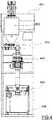
Figure 1 shows a perspective view of the mobile mixing plant for powdery products and of its carrying structure as described in patent documentEP2465780 .Figure 2 shows the plant ofFigure 1 in the transport position.Figure 3 shows a liquid injection module (views in isometric, plan, elevational, profile and internal views inFigures 3a ,3b, 3c, 3d and3e , respectively) which is connected with the mobile mixing plant for powdery products ofFigure 1 Figure 4 shows an isolated view of the big bag packaging module that is connected with the mobile mixing plant for powdery products ofFigure 1 - As can be seen in
Figure 1 , the modular mobile plant object of the present invention essentially comprises a carrying structure (1) and a reception and weighing area (2), a loading area (3), a mixing area (4), a packaging area (5), a sewing and labeling area (6), a metal detection area (7), a palletizing area (8) and a cleaning area (9). - The carrying structure (1) is formed by various square tubes (11) supported at several height-adjustable support points (12), several hinges (13) and a ladder (14) with a safety railing (15). This structure will have dimensions that are not larger than the measurements of a standard container measuring 40 inches, such that the total dimensions allow the transport thereof in a standard transport container (generally a maritime container measuring 40 feet).
- In a practical embodiment, the structure (1) will be built with square stainless steel tube. The ground of the structure will be formed by rolled carbon steel profiles. The profiles and crossbeams of the structure will be made of square stainless steel tube. The structure (1) will be supported by six height-adjustable support points on which there is supported a diamond plate where objects and staff move about. One side (16) will fold in three sections and will also be built with square tube and diamond plate. The aforementioned hinges will fold the aforementioned sides using a number of capstans for easy installation and positioning.
- The access ladder (14) will be built with stainless steel, except for the tread of the steps, which will also be built from stainless steel anti-skid plate. A rectangle will be arranged at the end of the ladder to provide access to the upper part of the platform. The top of the platform and access ladder have a protective railing (15) along the entire perimeter, built with square stainless steel tube.
- The automatic dosing modules perform dosing prior to introducing the formula and furthermore incorporating an automatic formula loading module with an automatic bag opening system to automate the loading of raw material into the plant. These automatic dosing modules are connected in the reception and weighing module (2).
- Furthermore, the mobile plant also incorporates a liquid injection module for injecting a liquid into a powder mixture (
Figure 3 ), maintaining a final powder state powder. The module is automated, such that it is possible to automatically dose the liquids into the mixture, up to ten liquids, according to what is previously required by the end user, with the ability to inject up to 50% liquid into the powder such that the powdery form is maintained after the injection with the conditions and parameters required by the final formulation, such as temperature, stirring and pre-mixture of liquids. This liquid injection module is connected with the stirring tank (41) in the mixing module (4). - More specifically, the liquid injection module (300) serves for dosing into the mixer liquid amounts of any viscosity by means of a pump (318), preferably a lobe pump, without ruling out pumps of any other type, where the flow rate is controlled by means of a plurality of loading cells (320). The liquid injection module performs the following phases during the process:
- i. Loading the stirring tank (305) with the liquid or liquids making up the raw material.
- ii. Stirring the liquid or liquids by means of an anchor-type stirrer (326, 327) incorporating scrapers. The stirring tank (305) maintains or achieves optimal temperatures due to its dual chamber with resistors and temperature control by means of at least one temperature probe (324).
- iii. For controlling the amounts to be dosed, the tank (305) has a plurality of loading cells (320) commanding the pump (318), transferring the exact amounts required for the formula into the stirring tank (41) of the mixing module (4).
- The liquids are homogenized by means of the stirrer (326, 327) because when there is more than one liquid, the exact amount with the same proportion of each ingredient must be previously homogenized and then dosed in that manner. The liquid injection capacity reaches up to a percentage of 50% (it will normally be a lower percentage) with respect to the powder such that the powdery form is maintained after the injection with the conditions and parameters required by the final formulation, such as temperature, stirring and pre-mixture of liquids.
- As can be seen in the following table, the liquid injection module (300) comprises the following elements in the particular embodiment non-limiting shown in
Figure 3 :Reference Units Characteristic 301 1 Geared motor 302 2 Lifting loops 303 2 Liquid feed nozzles 304 1 Stirrer connection neck 305 1 Liquid compartment 306 3 3000 W resistors 307 2 Covers of the compartment (305) 308 1 Tubular wiring structure 309 1 Main distribution board 310 1 Rectangular structure for board (309) 311 1 Control of loading cells (320) 312 1 Oil compartment 313 1 Oil circuit 314 1 Gear pump support (315) 315 1 Gear pump of the circuit (313) 316 2 Feed hose 317 1 Bottom valve of tank (305) 318 1 Pump 319 1 Mobile structure of the pump (318) 320 3 Loading cells 321 4 Height- adjustable base 322 4 Wheels of the structure 323 1 Safety sensor 324 2 Temperature probe 325 1 Tubular frame 326 1 Rotary support of the scraper 327 8 Scraper - In a particular embodiment, the liquid compartment (305) or stirring compartment is a cylindrical type compartment with a frustoconical bottom and dual chamber prepared for introducing thermal oil distributing the heat of the resistors (306), which in this particular embodiment have a power of 3 kW each.
- The compartment (305) has a hygienic gantry where there is supported an anchor scraper (326) with scrapers (327) that are made of white, food-grade plastic and that withstand service temperatures of 60°C and peaks of up to 100°C. Furthermore, it comprises at least one cover (307) in the top part making cleaning and inspections easier, furthermore having a certain inclination as shown in
Figure 3 . - The outlet for the product with a bottom sanitary valve (317). The upper openings will have safety sensors (323) in the two covers (307). Each of the supports of the compartment (305) has a loading cell (320) which allows the reading of the weight of the product.
- The heating system performs the function of keeping the product at the desired temperature, if necessary, by means of a dual chamber around the compartment (305) in which the thermal oil will circulate and the resistors (306) will be installed. The outside of the compartment (305) is heat-insulated.
- To load the thermal oil, the equipment has a compartment also acting as an expansion vessel. The oil enters the dual chamber of the tank where it is heated by means of thermal resistors (306). The outlet for the oil is located in the lower part, where there is a gear pump (315) that continuously recirculates the thermal oil while it is hot through the oil circuit (313).
- Both the temperature of the product inside the compartment (305) and the temperature of the thermal oil are controlled by temperature probes (324).
- The dosing system allows effectively dosing the product contained in the compartment (305) towards the mixing tank (41) of the mixing module of the plant of
Figure 1 . The dosing is performed by means of a pump (318) controlled by a variable frequency drive. The inlet of the pump (318) is connected to the bottom valve (317) of the compartment (305) by means of a flexible and hygienic connection. The inlet of the pump (318) is always below the outlet of the bottom valve (317). The outlet of the pump is connected with a feed hose with a connection compatible with an inlet of the mixing tank (41) of the mixing module (4) of the plant ofFigure 1 . - Finally, the frame is formed by a
tubular structure 325 to prevent flat surfaces and therefore the accumulation of dirt and to make cleaning of all the surfaces easier. The structure incorporateswheels 322 with the possibility of fixing and height-adjustable feet 321 to provide stability to the assembly. - Finally, the plant incorporates a packaging module depending on the type of packaging required by the end user, including, in a non-limiting manner, a big bag filling module, a European type bag filling module or a module for filling any other type of enclosure (such as sachets, for example). Furthermore, the packaging module can incorporate an automatic palletizing module for that client needing end of line automation.
- In a particular embodiment, the plant of
Figure 1 packaging large bags (best known as big bags) as can be seen in detail inFigure 4 , which allows the packaging module (5) to be able to fill 500 kg to 1000 kg bags. Nevertheless, in some particular embodiments products can be filled in starting from 100 kg bags, and in some embodiments, also 350 or 400 kg bags. - The arrangement of this plant is a horizontal container measuring 20 feet which, once at its destination it will be installed vertically and will be located after the mixing module (4). The big bag module (400) is made up of three blocks which are placed on top of one another vertically and all the installations are connected with quick connect adaptors without requiringin situ installations, because everything is ready to be assembled and with all installations for starting up in one day. The quick connections and electric power are provided from the general distribution board of the plant of
Figure 1 . - Therefore, once the mixing of the product in the mixing module (4) has ended, said product goes to the packaging module (5) which, in this embodiment, comprises a system for taking the powder after mixing to the big bag module (400). The capacity to be achieved is approximately 1000 kg/h, depending on the products.
- Packaging is done for four or five 200 kg batches combined with one another. The module is designed to be contained and transported in a 20" open top container with all the necessary machinery, auxiliary elements and tools included.
- It has been designed to be installed vertically, under cover, protected from the elements, in a ventilated site and located on even ground suitable for the described loads.
- This design is established in order to be divided into three blocks of a height of about 2.3 m each (in any case, less than 2.4 m, which is the maximum height of the containers) and so that they can be handled with an electric fork lift during assembly and installation. Suitable transport and operation is thereby assured, in addition to achieving safety and traceability in the process so that staff working at the plant cannot make mistakes and making it easier to following the manufacturing sequence as it has been projected, and implementing the necessary surveillance and control means from the central office.
- The big bag module (400) comprises the following elements:
- (a) A structure (401) capable of being introduced in a 20" container without deformations, protecting and providing support for the different machines and auxiliary equipment for carrying out the different processes.
- (b) Reception of the mixed product in a hopper (402) and dosing for packaging.
- (c) Dosing valve (403) installed after the hopper (402) for dosing the already mixed product.
- (d) In-line metal detector (404) with rejection means.
- (e) Bag filling module (405) for filling bags by batches, with labeling and weight control (406).
- The production parameters to be achieved are 1 Tm/h in 4 or 5 batches per bag. The times in the different phases are 12 minutes at most, so said cycle at most will continue to be maintained to assure the indicated capacity. For complete certification and combination with an existing plant of mixtures, in this non-limiting example the times will be (they logically may vary according to the desired installation):
- Weighing will be done independently.
- Loading.
- ∘ Taking up bags: 1 min.
- ∘ Filling: 10 min.
- ∘ Connection/disconnection: 1 min.
- ∘ Total: 12 minutes.
- Mixing:
- ∘ Machine connection: 1 min.
- ∘ Mixing: 10 min.
- ∘ Disconnection: 1 min.
- ∘ Total: 12 minutes
- Lifting the product from mixing to the feed hopper (402) which complies with cycles that allow the goal of assuring 1000 kg/h
- Bag filling:
- ∘ Continuously connected with the previous phase, packing must be done with each batch of about 200 kg going through a rotary installation and metal detector until amounting to 4-5 batches, depending on densities.
- ∘ This operation must be done in 1 hour.
- ∘ Five container changes (for each batch).
- ∘ Packaging of these five batches in one bag, going through a rotary installation and metal detector. For each bag, there is weight verification, labeling and withdrawal of the bag, placing an empty back to start a new packaging cycle (60 minutes per cycle of 1000 kg for five batches).
- Generally, all the general services of the installation will be connected with those of the plant of
Figure 1 .
Claims (11)
- A modular, mobile mixing and packaging plant for powdery or granular products comprising a carrying structure (1) having dimensions suitable for being introduced in a standard maritime container and internally housing a reception and manual weighing module (2), a material loading module (3), a mixing module (4) and a packaging module (5), characterized that it comprises at least a liquid injection (300) module that is insertable and connectable with a control PLC of the modular plant; and wherein the liquid injection module (300) is configured for dosing into a mixing tank (41) of the mixing module (4) liquid amounts of any viscosity by means of a pump (318) with its flow rate controlled by means of a plurality of loading cells (320).
- The plant according to claim 1, wherein the liquid injection module (300) comprises a stirring compartment (305) that is cylindrical with frustoconical bottom and dual chamber prepared for introducing thermal oil distributing the heat of thermal resistors (306).
- The plant according to claim 2, wherein the compartment (305) has a hygienic gantry where there is supported an anchor scraper (326) with scrapers (327) that are made of white, food-grade plastic and that withstand service temperatures of 60ºC and peaks of up to 100ºC.
- The plant according to any of claims 2-3, wherein the liquid compartment (305) comprises an outlet for the product with a bottom sanitary valve (317); and wherein upper openings will have safety sensors (323) in at least one cover (307) inclined in the top part; and wherein each of the supports of the stirring compartment (305) comprises the loading cell (320) which allows the reading of the weight of the product.
- The plant according to any of claims 1 to 4, where the liquid injection module (300) comprises a heating system that performs the function of keeping the product at the desired temperature, if necessary, by means of a dual chamber around the stirring compartment (305) in which a thermal oil will circulate and thermal resistors (306) will be installed; and wherein the outside of the stirring compartment (305) is heat-insulated.
- The plant according to claim 5, wherein to load the thermal oil, the equipment has a compartment also acting as an expansion vessel, such that the oil enters a dual chamber of the stirring compartment (305) where it is heated by means of the thermal resistors (306); and wherein the outlet for the oil is located in the lower part, where there is a gear pump (315) that continuously recirculates the thermal oil while it is hot through the oil circuit (313).
- The plant according to any of claims 1 to 6, wherein the temperature of the product inside the compartment (305) and the temperature of the thermal oil are controlled by temperature probes (324).
- The plant according to any of claims 1 to 7, wherein the dosing is performed by means of a pump (318) such that the inlet thereof is connected to a bottom valve (317) of the stirring compartment (305); and wherein the inlet of the pump (318) is always below the outlet of the bottom valve (317).
- The plant according to any of claims 1 to 8, wherein it comprises a big bag module (400) which is insertable and connectable with a control PLC of the modular plant and comprises in turn: (a) a structure (401) capable of being introduced in a 20" container without deformations, protecting and providing support for the different machines and auxiliary equipment for carrying out the different processes; (b) reception of the product mixed in a hopper (402) and dosing for packaging; (c) a dosing valve (403) installed after the hopper (402) for dosing the already mixed product; (d) an in-line metal detector (404) with rejection means; and (e) a bag filling module (405) for filling bags by batches, with labeling and weight control (406).
- The plant according to any of claims 1 to 9 wherein it also comprises an automatic dosing module which is insertable and connectable with a control PLC of the modular plant.
- A mixing and packaging method for powdery or granular products in a plant according to any of claims 1 to 10 and comprising the steps of reception and manual weighing, material loading, mixing and packaging, andcharacterized in that said steps are controlled by a PLC remotely connected with a central server providing the end product mixing and configuration instructions and orders, and furthermore comprising at least one additional step selected from: automatic dosing, liquid injection and bag filling; where said additional modules are insertable and connectable with a control PLC of the modular plant.
Priority Applications (10)
| Application Number | Priority Date | Filing Date | Title |
|---|---|---|---|
| DK16382020.2TDK3196136T3 (en) | 2016-01-20 | 2016-01-20 | PROCEDURE AND MODULAR MOBILE MIXING AND PACKAGING SYSTEM |
| EP16382020.2AEP3196136B1 (en) | 2016-01-20 | 2016-01-20 | Method and modular, mobile mixing and packaging plant |
| ES16382020TES2708075T3 (en) | 2016-01-20 | 2016-01-20 | Method and mobile modular mixing and packaging plant |
| PL16382020TPL3196136T3 (en) | 2016-01-20 | 2016-01-20 | Method and modular, mobile mixing and packaging plant |
| US15/403,803US10293961B2 (en) | 2016-01-20 | 2017-01-11 | Method and modular, mobile mixing and packaging plant |
| CN201710037588.1ACN106986072B (en) | 2016-01-20 | 2017-01-18 | Modular mobile mixing packaging method and equipment |
| KR1020170009353AKR102648187B1 (en) | 2016-01-20 | 2017-01-19 | Method and modular, mobile mixing and packaging plant |
| BR102017001149-6ABR102017001149B1 (en) | 2016-01-20 | 2017-01-19 | MODULAR AND MOBILE MIXING AND PACKAGING UNIT FOR GRANULAR OR POWDER PRODUCTS, AND MIXING AND PACKAGING METHOD FOR GRANULAR OR POWDER PRODUCTS IN ONE UNIT |
| JP2017008978AJP6549623B2 (en) | 2016-01-20 | 2017-01-20 | Modular mobile mixing and packaging plant and method |
| MX2017001018AMX386407B (en) | 2016-01-20 | 2017-01-20 | MODULAR MOBILE MIXING AND PACKAGING METHOD AND PLANT. |
Applications Claiming Priority (1)
| Application Number | Priority Date | Filing Date | Title |
|---|---|---|---|
| EP16382020.2AEP3196136B1 (en) | 2016-01-20 | 2016-01-20 | Method and modular, mobile mixing and packaging plant |
Publications (2)
| Publication Number | Publication Date |
|---|---|
| EP3196136A1 EP3196136A1 (en) | 2017-07-26 |
| EP3196136B1true EP3196136B1 (en) | 2018-12-05 |
Family
ID=55442745
Family Applications (1)
| Application Number | Title | Priority Date | Filing Date |
|---|---|---|---|
| EP16382020.2AActiveEP3196136B1 (en) | 2016-01-20 | 2016-01-20 | Method and modular, mobile mixing and packaging plant |
Country Status (10)
| Country | Link |
|---|---|
| US (1) | US10293961B2 (en) |
| EP (1) | EP3196136B1 (en) |
| JP (1) | JP6549623B2 (en) |
| KR (1) | KR102648187B1 (en) |
| CN (1) | CN106986072B (en) |
| BR (1) | BR102017001149B1 (en) |
| DK (1) | DK3196136T3 (en) |
| ES (1) | ES2708075T3 (en) |
| MX (1) | MX386407B (en) |
| PL (1) | PL3196136T3 (en) |
Cited By (1)
| Publication number | Priority date | Publication date | Assignee | Title |
|---|---|---|---|---|
| WO2023099379A1 (en)* | 2021-11-30 | 2023-06-08 | Tetra Laval Holdings & Finance S.A. | Powder intake unit |
Families Citing this family (9)
| Publication number | Priority date | Publication date | Assignee | Title |
|---|---|---|---|---|
| CN108750210A (en)* | 2018-06-15 | 2018-11-06 | 吴昊璋 | A kind of breeding feed batch mixing packing is set |
| CN108889182A (en)* | 2018-07-13 | 2018-11-27 | 安徽康瑞高科新材料技术工程有限公司 | A kind of material-compound tank |
| CN109677691A (en)* | 2019-01-30 | 2019-04-26 | 成秀东 | A method of material packing is carried out using the Intellectualized material packing station with transmitting function |
| CN110194377B (en)* | 2019-06-06 | 2024-05-07 | 张家港市大驿汽配科技有限公司 | Batching metering and adding device for plasticizer |
| CN110235752B (en)* | 2019-07-26 | 2021-09-28 | 广东天濠建设工程有限公司 | Water storage and intelligent irrigation device arranged in garden |
| DE102019214396A1 (en)* | 2019-09-20 | 2021-03-25 | Coperion Gmbh | Mobile dosing unit for a system for dosing and / or mixing bulk goods, dosing station with such a dosing unit and system with such a dosing station |
| CN110975659B (en)* | 2019-12-18 | 2022-02-08 | 中北大学 | Automatic liquid preparation method for liquid medicine |
| CN118788229B (en)* | 2024-09-12 | 2025-09-09 | 常州百利锂电智慧工厂有限公司 | A high-precision storage and batching system |
| CN119701716B (en)* | 2025-02-28 | 2025-05-16 | 浙江威肯特智能机械有限公司 | A mixing and stirring device for rubber asphalt processing |
Family Cites Families (25)
| Publication number | Priority date | Publication date | Assignee | Title |
|---|---|---|---|---|
| US3058272A (en)* | 1960-03-21 | 1962-10-16 | Goodman Mfg Co | Method and apparatus for packaging granular materials |
| FR2052018A5 (en) | 1969-07-04 | 1971-04-09 | Moritz Jean | |
| GB2100014A (en)* | 1981-06-10 | 1982-12-15 | Nat Shipping Bagging Services | Transportation of free-flowing material |
| JPH0628121Y2 (en)* | 1990-11-29 | 1994-08-03 | 株式会社三陽電機製作所 | Powder feeder |
| IT1258959B (en)* | 1992-06-09 | 1996-03-11 | MOBILE MODULES PLANT FOR THE DEVELOPMENT AND PRODUCTION OF BIOTECHNOLOGICAL PRODUCTS ON A PILOT SCALE | |
| FR2730647B1 (en)* | 1995-02-20 | 1997-04-04 | Elf Antar France | LIQUID PRODUCTS MIXING AND PACKAGING PLANT |
| US6506401B1 (en)* | 1999-01-28 | 2003-01-14 | H. J. Heinz Company | Filled edible product, and system and method for production of a filled edible product |
| US6331070B1 (en)* | 2000-10-30 | 2001-12-18 | Reliance Industries, Inc. | Process and apparatus for particle size reduction and homogeneous blending of ingredients in a fluidized change can mixer |
| DE10104311C1 (en)* | 2001-01-22 | 2002-08-14 | Berstorff Gmbh | compounding |
| US6622063B1 (en)* | 2002-04-29 | 2003-09-16 | The United States Of America As Represented By The Secretary Of The Navy | Container-based product dispensing system |
| CN2608500Y (en)* | 2003-03-27 | 2004-03-31 | 张兴权 | Vehicle carried portable multifunction ingredient blending device |
| US7762181B2 (en)* | 2004-10-01 | 2010-07-27 | Fonterra Co-Operative Group Limited | Customised nutritional food and beverage dispensing system |
| JP4804025B2 (en)* | 2005-04-14 | 2011-10-26 | 株式会社イシダ | Production system |
| ES1061700Y (en)* | 2005-11-29 | 2006-07-01 | Valver Air Speed S L | DOSING MACHINE AND MIXER OF LIQUID PRODUCTS IN GENERAL |
| CN100570127C (en)* | 2007-08-14 | 2009-12-16 | 陕西金石混凝土科技发展有限公司 | A Construction Method of Spraying Concrete Using Liquid Accelerator |
| US8302639B2 (en)* | 2008-06-25 | 2012-11-06 | Jorgensen Roy W | Portable blending system |
| CN101481274B (en)* | 2008-12-10 | 2011-07-27 | 常州市荣创自动化设备有限公司 | Mobile mixing fertilizer production vehicle |
| CN101837612B (en)* | 2010-05-31 | 2013-02-20 | 三一重工股份有限公司 | Mobile concrete mixing plant and batching machine thereof |
| ES2425463T3 (en)* | 2010-12-16 | 2013-10-15 | Inversiones Hiki6, S.L. | Mobile dosing, mixing and packaging plant |
| CN202379425U (en)* | 2011-12-26 | 2012-08-15 | 关沧海 | Automatic mixing and quantitative conveying device |
| JP5547787B2 (en)* | 2012-10-25 | 2014-07-16 | 富士夫 堀 | Container rotation device |
| DE102014001420B4 (en)* | 2014-02-03 | 2020-04-09 | Protec Polymer Processing Gmbh | Dosing system for dosing bulk goods, plastic processing system and method for dosing bulk goods |
| JP2015157252A (en)* | 2014-02-24 | 2015-09-03 | シャープ株式会社 | Mixture producing apparatus |
| US11178914B2 (en)* | 2014-05-23 | 2021-11-23 | Revolutionary Electronic Design, LLC | Vaping liquid dispensing and vending |
| JP3201104U (en)* | 2015-09-09 | 2015-11-19 | 株式会社ヤマザキ | Liquid mixer |
- 2016
- 2016-01-20EPEP16382020.2Apatent/EP3196136B1/enactiveActive
- 2016-01-20DKDK16382020.2Tpatent/DK3196136T3/enactive
- 2016-01-20PLPL16382020Tpatent/PL3196136T3/enunknown
- 2016-01-20ESES16382020Tpatent/ES2708075T3/enactiveActive
- 2017
- 2017-01-11USUS15/403,803patent/US10293961B2/enactiveActive
- 2017-01-18CNCN201710037588.1Apatent/CN106986072B/ennot_activeExpired - Fee Related
- 2017-01-19KRKR1020170009353Apatent/KR102648187B1/enactiveActive
- 2017-01-19BRBR102017001149-6Apatent/BR102017001149B1/enactiveIP Right Grant
- 2017-01-20MXMX2017001018Apatent/MX386407B/enunknown
- 2017-01-20JPJP2017008978Apatent/JP6549623B2/ennot_activeExpired - Fee Related
Non-Patent Citations (1)
| Title |
|---|
| None* |
Cited By (2)
| Publication number | Priority date | Publication date | Assignee | Title |
|---|---|---|---|---|
| WO2023099379A1 (en)* | 2021-11-30 | 2023-06-08 | Tetra Laval Holdings & Finance S.A. | Powder intake unit |
| EP4186803A3 (en)* | 2021-11-30 | 2023-08-16 | Tetra Laval Holdings & Finance S.A. | Powder intake unit |
Also Published As
| Publication number | Publication date |
|---|---|
| CN106986072B (en) | 2020-11-03 |
| US20170203858A1 (en) | 2017-07-20 |
| JP6549623B2 (en) | 2019-07-24 |
| CN106986072A (en) | 2017-07-28 |
| JP2017128392A (en) | 2017-07-27 |
| MX2017001018A (en) | 2018-07-19 |
| BR102017001149B1 (en) | 2022-10-11 |
| DK3196136T3 (en) | 2019-03-25 |
| ES2708075T3 (en) | 2019-04-08 |
| KR102648187B1 (en) | 2024-03-18 |
| EP3196136A1 (en) | 2017-07-26 |
| KR20170087420A (en) | 2017-07-28 |
| BR102017001149A2 (en) | 2017-07-25 |
| US10293961B2 (en) | 2019-05-21 |
| PL3196136T3 (en) | 2019-07-31 |
| MX386407B (en) | 2025-03-18 |
Similar Documents
| Publication | Publication Date | Title |
|---|---|---|
| EP3196136B1 (en) | Method and modular, mobile mixing and packaging plant | |
| EP3381821B1 (en) | Method, computer program, and multifunctional, modular and mobile mixing and packaging plant | |
| US11266958B2 (en) | Dry additive and fluid mixing system, assembly and method | |
| CN102556376B (en) | For mobile device and the control method thereof of preparing burden, mixing and packing | |
| EP3113876B1 (en) | Temporary addition or injection system | |
| US3741440A (en) | Modular blending system | |
| HK1256327B (en) | Method, computer program, and multifunctional, modular and mobile mixing and packaging plant | |
| HK1256327A1 (en) | Method, computer program, and multifunctional, modular and mobile mixing and packaging plant | |
| US20220118658A1 (en) | Transportable molding system for forming insulation on long pipes and related methods | |
| JPH09512238A (en) | Equipment for mixing and packaging liquid products | |
| BE1021417B1 (en) | DEVICE FOR DRINK PRODUCTION | |
| ITVI20100023A1 (en) | PLANT FOR SPRAY APPLICATION OF MIXTURES ON SURFACES |
Legal Events
| Date | Code | Title | Description |
|---|---|---|---|
| PUAI | Public reference made under article 153(3) epc to a published international application that has entered the european phase | Free format text:ORIGINAL CODE: 0009012 | |
| STAA | Information on the status of an ep patent application or granted ep patent | Free format text:STATUS: THE APPLICATION HAS BEEN PUBLISHED | |
| AK | Designated contracting states | Kind code of ref document:A1 Designated state(s):AL AT BE BG CH CY CZ DE DK EE ES FI FR GB GR HR HU IE IS IT LI LT LU LV MC MK MT NL NO PL PT RO RS SE SI SK SM TR | |
| AX | Request for extension of the european patent | Extension state:BA ME | |
| STAA | Information on the status of an ep patent application or granted ep patent | Free format text:STATUS: REQUEST FOR EXAMINATION WAS MADE | |
| 17P | Request for examination filed | Effective date:20180110 | |
| RIC1 | Information provided on ipc code assigned before grant | Ipc:B65B 65/00 20060101AFI20180711BHEP Ipc:B65B 1/00 20060101ALI20180711BHEP | |
| GRAP | Despatch of communication of intention to grant a patent | Free format text:ORIGINAL CODE: EPIDOSNIGR1 | |
| STAA | Information on the status of an ep patent application or granted ep patent | Free format text:STATUS: GRANT OF PATENT IS INTENDED | |
| INTG | Intention to grant announced | Effective date:20180823 | |
| GRAS | Grant fee paid | Free format text:ORIGINAL CODE: EPIDOSNIGR3 | |
| GRAA | (expected) grant | Free format text:ORIGINAL CODE: 0009210 | |
| STAA | Information on the status of an ep patent application or granted ep patent | Free format text:STATUS: THE PATENT HAS BEEN GRANTED | |
| AK | Designated contracting states | Kind code of ref document:B1 Designated state(s):AL AT BE BG CH CY CZ DE DK EE ES FI FR GB GR HR HU IE IS IT LI LT LU LV MC MK MT NL NO PL PT RO RS SE SI SK SM TR | |
| REG | Reference to a national code | Ref country code:GB Ref legal event code:FG4D | |
| REG | Reference to a national code | Ref country code:CH Ref legal event code:EP | |
| REG | Reference to a national code | Ref country code:AT Ref legal event code:REF Ref document number:1072747 Country of ref document:AT Kind code of ref document:T Effective date:20181215 | |
| REG | Reference to a national code | Ref country code:IE Ref legal event code:FG4D | |
| REG | Reference to a national code | Ref country code:DE Ref legal event code:R096 Ref document number:602016007827 Country of ref document:DE | |
| REG | Reference to a national code | Ref country code:CH Ref legal event code:NV Representative=s name:BUGNION S.A., CH | |
| REG | Reference to a national code | Ref country code:DK Ref legal event code:T3 Effective date:20190318 | |
| REG | Reference to a national code | Ref country code:ES Ref legal event code:FG2A Ref document number:2708075 Country of ref document:ES Kind code of ref document:T3 Effective date:20190408 | |
| REG | Reference to a national code | Ref country code:NL Ref legal event code:MP Effective date:20181205 | |
| REG | Reference to a national code | Ref country code:AT Ref legal event code:MK05 Ref document number:1072747 Country of ref document:AT Kind code of ref document:T Effective date:20181205 | |
| REG | Reference to a national code | Ref country code:LT Ref legal event code:MG4D | |
| PG25 | Lapsed in a contracting state [announced via postgrant information from national office to epo] | Ref country code:FI Free format text:LAPSE BECAUSE OF FAILURE TO SUBMIT A TRANSLATION OF THE DESCRIPTION OR TO PAY THE FEE WITHIN THE PRESCRIBED TIME-LIMIT Effective date:20181205 Ref country code:BG Free format text:LAPSE BECAUSE OF FAILURE TO SUBMIT A TRANSLATION OF THE DESCRIPTION OR TO PAY THE FEE WITHIN THE PRESCRIBED TIME-LIMIT Effective date:20190305 Ref country code:HR Free format text:LAPSE BECAUSE OF FAILURE TO SUBMIT A TRANSLATION OF THE DESCRIPTION OR TO PAY THE FEE WITHIN THE PRESCRIBED TIME-LIMIT Effective date:20181205 Ref country code:NO Free format text:LAPSE BECAUSE OF FAILURE TO SUBMIT A TRANSLATION OF THE DESCRIPTION OR TO PAY THE FEE WITHIN THE PRESCRIBED TIME-LIMIT Effective date:20190305 Ref country code:LT Free format text:LAPSE BECAUSE OF FAILURE TO SUBMIT A TRANSLATION OF THE DESCRIPTION OR TO PAY THE FEE WITHIN THE PRESCRIBED TIME-LIMIT Effective date:20181205 Ref country code:LV Free format text:LAPSE BECAUSE OF FAILURE TO SUBMIT A TRANSLATION OF THE DESCRIPTION OR TO PAY THE FEE WITHIN THE PRESCRIBED TIME-LIMIT Effective date:20181205 Ref country code:AT Free format text:LAPSE BECAUSE OF FAILURE TO SUBMIT A TRANSLATION OF THE DESCRIPTION OR TO PAY THE FEE WITHIN THE PRESCRIBED TIME-LIMIT Effective date:20181205 | |
| PG25 | Lapsed in a contracting state [announced via postgrant information from national office to epo] | Ref country code:AL Free format text:LAPSE BECAUSE OF FAILURE TO SUBMIT A TRANSLATION OF THE DESCRIPTION OR TO PAY THE FEE WITHIN THE PRESCRIBED TIME-LIMIT Effective date:20181205 Ref country code:SE Free format text:LAPSE BECAUSE OF FAILURE TO SUBMIT A TRANSLATION OF THE DESCRIPTION OR TO PAY THE FEE WITHIN THE PRESCRIBED TIME-LIMIT Effective date:20181205 Ref country code:RS Free format text:LAPSE BECAUSE OF FAILURE TO SUBMIT A TRANSLATION OF THE DESCRIPTION OR TO PAY THE FEE WITHIN THE PRESCRIBED TIME-LIMIT Effective date:20181205 Ref country code:GR Free format text:LAPSE BECAUSE OF FAILURE TO SUBMIT A TRANSLATION OF THE DESCRIPTION OR TO PAY THE FEE WITHIN THE PRESCRIBED TIME-LIMIT Effective date:20190306 | |
| PG25 | Lapsed in a contracting state [announced via postgrant information from national office to epo] | Ref country code:NL Free format text:LAPSE BECAUSE OF FAILURE TO SUBMIT A TRANSLATION OF THE DESCRIPTION OR TO PAY THE FEE WITHIN THE PRESCRIBED TIME-LIMIT Effective date:20181205 | |
| PG25 | Lapsed in a contracting state [announced via postgrant information from national office to epo] | Ref country code:PT Free format text:LAPSE BECAUSE OF FAILURE TO SUBMIT A TRANSLATION OF THE DESCRIPTION OR TO PAY THE FEE WITHIN THE PRESCRIBED TIME-LIMIT Effective date:20190405 Ref country code:CZ Free format text:LAPSE BECAUSE OF FAILURE TO SUBMIT A TRANSLATION OF THE DESCRIPTION OR TO PAY THE FEE WITHIN THE PRESCRIBED TIME-LIMIT Effective date:20181205 | |
| PG25 | Lapsed in a contracting state [announced via postgrant information from national office to epo] | Ref country code:SK Free format text:LAPSE BECAUSE OF FAILURE TO SUBMIT A TRANSLATION OF THE DESCRIPTION OR TO PAY THE FEE WITHIN THE PRESCRIBED TIME-LIMIT Effective date:20181205 Ref country code:IS Free format text:LAPSE BECAUSE OF FAILURE TO SUBMIT A TRANSLATION OF THE DESCRIPTION OR TO PAY THE FEE WITHIN THE PRESCRIBED TIME-LIMIT Effective date:20190405 Ref country code:RO Free format text:LAPSE BECAUSE OF FAILURE TO SUBMIT A TRANSLATION OF THE DESCRIPTION OR TO PAY THE FEE WITHIN THE PRESCRIBED TIME-LIMIT Effective date:20181205 Ref country code:EE Free format text:LAPSE BECAUSE OF FAILURE TO SUBMIT A TRANSLATION OF THE DESCRIPTION OR TO PAY THE FEE WITHIN THE PRESCRIBED TIME-LIMIT Effective date:20181205 Ref country code:SM Free format text:LAPSE BECAUSE OF FAILURE TO SUBMIT A TRANSLATION OF THE DESCRIPTION OR TO PAY THE FEE WITHIN THE PRESCRIBED TIME-LIMIT Effective date:20181205 | |
| REG | Reference to a national code | Ref country code:DE Ref legal event code:R097 Ref document number:602016007827 Country of ref document:DE | |
| PG25 | Lapsed in a contracting state [announced via postgrant information from national office to epo] | Ref country code:LU Free format text:LAPSE BECAUSE OF NON-PAYMENT OF DUE FEES Effective date:20190120 | |
| PLBE | No opposition filed within time limit | Free format text:ORIGINAL CODE: 0009261 | |
| STAA | Information on the status of an ep patent application or granted ep patent | Free format text:STATUS: NO OPPOSITION FILED WITHIN TIME LIMIT | |
| REG | Reference to a national code | Ref country code:BE Ref legal event code:MM Effective date:20190131 | |
| PG25 | Lapsed in a contracting state [announced via postgrant information from national office to epo] | Ref country code:SI Free format text:LAPSE BECAUSE OF FAILURE TO SUBMIT A TRANSLATION OF THE DESCRIPTION OR TO PAY THE FEE WITHIN THE PRESCRIBED TIME-LIMIT Effective date:20181205 Ref country code:MC Free format text:LAPSE BECAUSE OF FAILURE TO SUBMIT A TRANSLATION OF THE DESCRIPTION OR TO PAY THE FEE WITHIN THE PRESCRIBED TIME-LIMIT Effective date:20181205 | |
| 26N | No opposition filed | Effective date:20190906 | |
| PG25 | Lapsed in a contracting state [announced via postgrant information from national office to epo] | Ref country code:BE Free format text:LAPSE BECAUSE OF NON-PAYMENT OF DUE FEES Effective date:20190131 | |
| PG25 | Lapsed in a contracting state [announced via postgrant information from national office to epo] | Ref country code:MT Free format text:LAPSE BECAUSE OF NON-PAYMENT OF DUE FEES Effective date:20190120 | |
| PG25 | Lapsed in a contracting state [announced via postgrant information from national office to epo] | Ref country code:CY Free format text:LAPSE BECAUSE OF FAILURE TO SUBMIT A TRANSLATION OF THE DESCRIPTION OR TO PAY THE FEE WITHIN THE PRESCRIBED TIME-LIMIT Effective date:20181205 | |
| PG25 | Lapsed in a contracting state [announced via postgrant information from national office to epo] | Ref country code:HU Free format text:LAPSE BECAUSE OF FAILURE TO SUBMIT A TRANSLATION OF THE DESCRIPTION OR TO PAY THE FEE WITHIN THE PRESCRIBED TIME-LIMIT; INVALID AB INITIO Effective date:20160120 | |
| PG25 | Lapsed in a contracting state [announced via postgrant information from national office to epo] | Ref country code:MK Free format text:LAPSE BECAUSE OF FAILURE TO SUBMIT A TRANSLATION OF THE DESCRIPTION OR TO PAY THE FEE WITHIN THE PRESCRIBED TIME-LIMIT Effective date:20181205 | |
| PGFP | Annual fee paid to national office [announced via postgrant information from national office to epo] | Ref country code:PL Payment date:20221214 Year of fee payment:8 | |
| PGFP | Annual fee paid to national office [announced via postgrant information from national office to epo] | Ref country code:IE Payment date:20230106 Year of fee payment:8 | |
| P01 | Opt-out of the competence of the unified patent court (upc) registered | Effective date:20230525 | |
| PG25 | Lapsed in a contracting state [announced via postgrant information from national office to epo] | Ref country code:IE Free format text:LAPSE BECAUSE OF NON-PAYMENT OF DUE FEES Effective date:20240120 | |
| PG25 | Lapsed in a contracting state [announced via postgrant information from national office to epo] | Ref country code:IE Free format text:LAPSE BECAUSE OF NON-PAYMENT OF DUE FEES Effective date:20240120 | |
| PGFP | Annual fee paid to national office [announced via postgrant information from national office to epo] | Ref country code:DE Payment date:20250121 Year of fee payment:10 | |
| PGFP | Annual fee paid to national office [announced via postgrant information from national office to epo] | Ref country code:DK Payment date:20250109 Year of fee payment:10 | |
| PGFP | Annual fee paid to national office [announced via postgrant information from national office to epo] | Ref country code:ES Payment date:20250203 Year of fee payment:10 | |
| PGFP | Annual fee paid to national office [announced via postgrant information from national office to epo] | Ref country code:CH Payment date:20250201 Year of fee payment:10 | |
| PG25 | Lapsed in a contracting state [announced via postgrant information from national office to epo] | Ref country code:PL Free format text:LAPSE BECAUSE OF NON-PAYMENT OF DUE FEES Effective date:20240120 | |
| PGFP | Annual fee paid to national office [announced via postgrant information from national office to epo] | Ref country code:FR Payment date:20250116 Year of fee payment:10 | |
| PGFP | Annual fee paid to national office [announced via postgrant information from national office to epo] | Ref country code:IT Payment date:20250129 Year of fee payment:10 Ref country code:GB Payment date:20250109 Year of fee payment:10 | |
| PGFP | Annual fee paid to national office [announced via postgrant information from national office to epo] | Ref country code:TR Payment date:20250114 Year of fee payment:10 |