EP3195810B1 - System for forming barbs on a suture - Google Patents
System for forming barbs on a sutureDownload PDFInfo
- Publication number
- EP3195810B1 EP3195810B1EP16205651.9AEP16205651AEP3195810B1EP 3195810 B1EP3195810 B1EP 3195810B1EP 16205651 AEP16205651 AEP 16205651AEP 3195810 B1EP3195810 B1EP 3195810B1
- Authority
- EP
- European Patent Office
- Prior art keywords
- suture
- assemblies
- sutures
- assembly
- barbs
- Prior art date
- Legal status (The legal status is an assumption and is not a legal conclusion. Google has not performed a legal analysis and makes no representation as to the accuracy of the status listed.)
- Active
Links
Images


Classifications
- A—HUMAN NECESSITIES
- A61—MEDICAL OR VETERINARY SCIENCE; HYGIENE
- A61B—DIAGNOSIS; SURGERY; IDENTIFICATION
- A61B17/00—Surgical instruments, devices or methods
- A61B17/04—Surgical instruments, devices or methods for suturing wounds; Holders or packages for needles or suture materials
- A61B17/06—Needles ; Sutures; Needle-suture combinations; Holders or packages for needles or suture materials
- A61B17/06166—Sutures
- A—HUMAN NECESSITIES
- A61—MEDICAL OR VETERINARY SCIENCE; HYGIENE
- A61B—DIAGNOSIS; SURGERY; IDENTIFICATION
- A61B17/00—Surgical instruments, devices or methods
- A61B17/04—Surgical instruments, devices or methods for suturing wounds; Holders or packages for needles or suture materials
- A—HUMAN NECESSITIES
- A61—MEDICAL OR VETERINARY SCIENCE; HYGIENE
- A61B—DIAGNOSIS; SURGERY; IDENTIFICATION
- A61B17/00—Surgical instruments, devices or methods
- A61B2017/00526—Methods of manufacturing
- A—HUMAN NECESSITIES
- A61—MEDICAL OR VETERINARY SCIENCE; HYGIENE
- A61B—DIAGNOSIS; SURGERY; IDENTIFICATION
- A61B17/00—Surgical instruments, devices or methods
- A61B17/04—Surgical instruments, devices or methods for suturing wounds; Holders or packages for needles or suture materials
- A61B17/06—Needles ; Sutures; Needle-suture combinations; Holders or packages for needles or suture materials
- A61B17/06166—Sutures
- A61B2017/06176—Sutures with protrusions, e.g. barbs
- Y—GENERAL TAGGING OF NEW TECHNOLOGICAL DEVELOPMENTS; GENERAL TAGGING OF CROSS-SECTIONAL TECHNOLOGIES SPANNING OVER SEVERAL SECTIONS OF THE IPC; TECHNICAL SUBJECTS COVERED BY FORMER USPC CROSS-REFERENCE ART COLLECTIONS [XRACs] AND DIGESTS
- Y10—TECHNICAL SUBJECTS COVERED BY FORMER USPC
- Y10T—TECHNICAL SUBJECTS COVERED BY FORMER US CLASSIFICATION
- Y10T29/00—Metal working
- Y10T29/20—Fence barb making
- Y—GENERAL TAGGING OF NEW TECHNOLOGICAL DEVELOPMENTS; GENERAL TAGGING OF CROSS-SECTIONAL TECHNOLOGIES SPANNING OVER SEVERAL SECTIONS OF THE IPC; TECHNICAL SUBJECTS COVERED BY FORMER USPC CROSS-REFERENCE ART COLLECTIONS [XRACs] AND DIGESTS
- Y10—TECHNICAL SUBJECTS COVERED BY FORMER USPC
- Y10T—TECHNICAL SUBJECTS COVERED BY FORMER US CLASSIFICATION
- Y10T29/00—Metal working
- Y10T29/49—Method of mechanical manufacture
- Y10T29/49998—Work holding
- Y—GENERAL TAGGING OF NEW TECHNOLOGICAL DEVELOPMENTS; GENERAL TAGGING OF CROSS-SECTIONAL TECHNOLOGIES SPANNING OVER SEVERAL SECTIONS OF THE IPC; TECHNICAL SUBJECTS COVERED BY FORMER USPC CROSS-REFERENCE ART COLLECTIONS [XRACs] AND DIGESTS
- Y10—TECHNICAL SUBJECTS COVERED BY FORMER USPC
- Y10T—TECHNICAL SUBJECTS COVERED BY FORMER US CLASSIFICATION
- Y10T29/00—Metal working
- Y10T29/53—Means to assemble or disassemble
- Y10T29/53991—Work gripper, anvil, or element
- Y—GENERAL TAGGING OF NEW TECHNOLOGICAL DEVELOPMENTS; GENERAL TAGGING OF CROSS-SECTIONAL TECHNOLOGIES SPANNING OVER SEVERAL SECTIONS OF THE IPC; TECHNICAL SUBJECTS COVERED BY FORMER USPC CROSS-REFERENCE ART COLLECTIONS [XRACs] AND DIGESTS
- Y10—TECHNICAL SUBJECTS COVERED BY FORMER USPC
- Y10T—TECHNICAL SUBJECTS COVERED BY FORMER US CLASSIFICATION
- Y10T83/00—Cutting
- Y10T83/02—Other than completely through work thickness
- Y10T83/0207—Other than completely through work thickness or through work presented
- Y—GENERAL TAGGING OF NEW TECHNOLOGICAL DEVELOPMENTS; GENERAL TAGGING OF CROSS-SECTIONAL TECHNOLOGIES SPANNING OVER SEVERAL SECTIONS OF THE IPC; TECHNICAL SUBJECTS COVERED BY FORMER USPC CROSS-REFERENCE ART COLLECTIONS [XRACs] AND DIGESTS
- Y10—TECHNICAL SUBJECTS COVERED BY FORMER USPC
- Y10T—TECHNICAL SUBJECTS COVERED BY FORMER US CLASSIFICATION
- Y10T83/00—Cutting
- Y10T83/02—Other than completely through work thickness
- Y10T83/0267—Splitting
- Y—GENERAL TAGGING OF NEW TECHNOLOGICAL DEVELOPMENTS; GENERAL TAGGING OF CROSS-SECTIONAL TECHNOLOGIES SPANNING OVER SEVERAL SECTIONS OF THE IPC; TECHNICAL SUBJECTS COVERED BY FORMER USPC CROSS-REFERENCE ART COLLECTIONS [XRACs] AND DIGESTS
- Y10—TECHNICAL SUBJECTS COVERED BY FORMER USPC
- Y10T—TECHNICAL SUBJECTS COVERED BY FORMER US CLASSIFICATION
- Y10T83/00—Cutting
- Y10T83/04—Processes
- Y—GENERAL TAGGING OF NEW TECHNOLOGICAL DEVELOPMENTS; GENERAL TAGGING OF CROSS-SECTIONAL TECHNOLOGIES SPANNING OVER SEVERAL SECTIONS OF THE IPC; TECHNICAL SUBJECTS COVERED BY FORMER USPC CROSS-REFERENCE ART COLLECTIONS [XRACs] AND DIGESTS
- Y10—TECHNICAL SUBJECTS COVERED BY FORMER USPC
- Y10T—TECHNICAL SUBJECTS COVERED BY FORMER US CLASSIFICATION
- Y10T83/00—Cutting
- Y10T83/505—Operation controlled by means responsive to product
Definitions
- the present disclosurerelates to medical sutures having barbs formed thereon. More particularly, the present disclosure relates to a system of forming barbs on sutures.
- Barbed suturesare generally made of the same materials as conventional sutures and offer several advantages for closing wounds compared with conventional sutures.
- a barbed sutureincludes an elongated body that has one or more spaced barbs, that project from the surface of the suture body along the body length. The barbs are arranged to allow passage of the barbed suture in one direction through tissue but resist movement of the barbed suture in the opposite direction.
- one advantage of barbed sutureshas been the provision of a non-slip attribute.
- Barbed suturesare known for use in cosmetic, Iaparoscopic and endoscopic procedures.
- the number of barbs called for on a particular suturemay be influenced by the size of the wound and the strength required to hold the wound closed.
- a barbed suturemay be inserted into tissue using a surgical needle.
- a random configuration of barbs on the exterior surface of the sutureis preferred to achieve optimal wound closure holding for the particular wound.
- a reduced number of barbsmay be desired.
- a two-way barbed sutureis desirable where the barbs permit passing of the suture in one direction over a portion of the suture and barbs permitting passing of the suture in a second direction over another portion of the suture to perform a tight closing stitch.
- a station for cutting a barb sutureis provided as defined in independent claim 1.
- Preferred embodimentsare defined in the dependent claims.
- the methodincludes providing a suture forming station including a suture transport assembly, a first knife assembly, and a first clamp and position assembly.
- the methodfurther includes positioning a suture on the suture transport assembly, aligning the suture transport assembly with the knife assembly, activating the first knife assembly, advancing the suture transport assembly while simultaneously approximating the first clamp and position assembly towards the first knife assembly to engage the suture with the first knife assembly to form a barb, and retracting the first clamp and position assembly away from the first knife assembly. Retraction of the first clamp and position assembly may cause the deflection of the barb away from a longitudinal axis of the suture.
- the barb forming methodmay further include the step of advancing the suture transport assembly relative to the first knife assembly to prepare the suture for a subsequent engagement with the knife assembly.
- the methodmay also include the steps of advancing the suture transport assembly and approximating the first clamp and position assembly towards and away from the knife assembly, one or more times to form additional barbs on the suture.
- the suture transport assembly of the barb forming methodmay be configured to receive a pair of sutures.
- a barbed suture formed in accordance with the method of the present disclosureis shown generally as barbed suture 10.
- Suture 10is formed from a monofilament thread 11, however, it is envisioned that suture 10 may be formed braided threads, multifilament threads and other surgical fibers.
- the cross-sectional geometry of thread 11may be of any suitable shape.
- thread 11may be round, elliptical, square, flat, octagonal, and rectangular.
- Thread 11may be formed of degradable materials, non-degradable materials, and combinations thereof. Thread 11 may be formed using any technique within the purview of those skilled in the art, such as, for example, extrusion, molding and/or solvent casting.
- barbed suture 10includes a loop 12 formed on a distal end 10b thereof. Loop 12 is configured to facilitate attachment of distal end 10b of thread I I with barb cutting station 100 ( FIG. 2 ). Loop 12 may be formed in any manner and may be of any size and configuration. It is envisioned that barb cutting station 100 may be modified such that thread 11 may be attached thereto without loop 12.
- barbed suture 10includes a suture needle 14 attached to a proximal end 10a thereof. Needle 14 may be attached to thread 11 prior to or upon completion of the barb forming process. Formed on thread 11 between loop 12 and suture needle 14 are a plurality of radially spaced barbs 16. As will be discussed in greater detail below, barbs 16 may formed in any number, size, configuration, spacing and/or orientation.
- barb cutting station 100includes a cabinet 102 having a first housing 104, a second housing 106, and a control box 108.
- First housing 104is configured to receive a base panel 110.
- Electric components(not shown) are maintained within second housing 106.
- Control box 108is configured for controlling operation of cutting station 100.
- first and second housings 104, 106 and/or control box 108may arranged independent of one another. In this manner, cutting station 100 may be operated remotely.
- FIG. 3maintained within cabinet 102 ( FIG. 2 ) and mounted on base panel 110 are a suture transport assembly 200, a pair of knife assemblies 300, and a pair of clamp and position assemblies 400.
- a pair of suture cutting mechanisms 600 and/or a pair of visual inspection assemblies 500are mounted to base panel 110.
- suture transport assembly 200is mounted to base panel 110 in an upright position along a track 112. Suture transport assembly 200 is configured to support a pair of sutures 10 during the barb forming process. Suture transport assembly 200 is configured to move linearly along track 112 perpendicular to knife assemblies 300, in the direction of arrows "A".
- suture transport assembly 200includes a base member 202, a fixed upper support member 204 and an adjustable lower support member 206.
- fixed upper support member 204includes a pair of rotary assemblies 210 each including a pin assembly 212 extending therefrom for engaging loops 12 formed on distal ends 10b of respective sutures 10.
- support member 204are configured to engage sutures 10 without the use of loops 12.
- each of support members 204includes a clamp or anchor (not shown) for attachment of distal ends 10b of sutures 10 thereto.
- adjustable lower support member 206includes a pair of rotary assemblies 220 each including a needle holding assembly 222 extending therefrom for engaging proximal ends 10a ( FIG. 1 ) of respective sutures 10.
- Holding assemblies 222may include a clamp, anchor or other fixation device suitable for attachment with proximal ends 10 of sutures 10.
- Rotary assemblies 220each further include a tensioning device 223 for tensioning sutures 10 once sutures 10 have been received between respective pin assemblies 212 and needle holding assemblies 222.
- Tensioning device 223may be hydraulic, pneumatic, gravity operated, spring-load or otherwise configured to provide tension to sutures 10.
- Lower support member 206further includes an adjustment mechanism 225 for adjusting the distance between lower support member 206 and upper support member 204.
- suture transport assembly 200may accommodate sutures 10 of various lengths.
- Each of upper and lower support members 204, 206further includes a rotary motor 224, 226, respectively, operably connected to rotary assemblies 210, 220, respectively, for rotating sutures 10 along longitudinal axis thereof, in the direction of arrows "B".
- knife assemblies 300are fixedly mounted to base panel 110 adjacent suture transport assembly 200. Knife assemblies 300 are configured for cutting barbs 16 ( FIG. 1 ) in sutures 10.
- each of knife assemblies 300includes a base 302 and a cutting assembly 304 operably mounted to base 302.
- Each of cutting assemblies 304include a cutting member 306 extending outwardly therefrom and include a blade 308 for cutting barbs in sutures 10.
- knife assemblies 300include an ultrasonic mechanism 312 for ultrasonically vibrating blade 308.
- knife assemblies 300may include a heating element or other suitable mechanism (not shown) for heating blade 308. By vibrating or heating blade 308, the force necessary to cut barbs 16 may be reduced.
- each of cutting assemblies 304further includes a rotary mechanism 310 for rotating cutting members 306.
- Rotary mechanism 310is configured to index blade 308 during the barb forming process to adjust the angle of cut.
- Blade 308may further be rotated at least one-hundred and eighty degrees (180°) such that each surface of blade 308 may be used. In one embodiment, rotation of blade 308 occurs only after the desired number of barbs 16 have been formed along the desired length of sutures 10.
- Cutting assemblies 304are mounted to bases 302 such that cutting members 306 may be advanced, in the direction of arrows "C". In this manner, cutting assemblies 222 may be retracted once the barb forming process is completed to permit reloading and repositioning of suture transport assembly 200.
- Cutting assemblies 304remain stationary or in a fixed position during the cutting of sutures 10 to form barbs 16. In this manner, blades 308 are not moved into contact with the suture, instead clamp and position assemblies 400 move suture 10 into contact with blades 308.
- clamp and position assemblies 400are securely mounted to base panel 110 adjacent suture transport assembly 200 and respective ultrasonic knife assemblies 300.
- Clamp and position assemblies 400are configured for approximating sutures 10 towards and away from ultrasonic knife assembly 300.
- each of clamp and position assemblies 400includes a stationary base 402 and a moveable carriage 404.
- Carriage 404includes a gripper assembly 406 for selectively gripping suture 10 during the barb forming process.
- Gripper assembly 406includes an anvil portion 408 for supporting suture 10 as carriage 404 is approximated towards cutting member 306 of knife assembly 300 and as suture 10 engages blade 308.
- visual inspection assemblies 500are configured for monitoring the cutting of barbs 16. In the event that a misformed or defective barb is cut, visual inspection assembly 500 is configured to signal cutting mechanism 600 to sever the defective suture, such that that suture may not be used.
- cutting mechanism 600is configured for cutting suture 10 in the event that a defective barb is detected by visual inspection assembly 500.
- Cutting mechanism 600may further be configured for manual actuation by an operator.
- Cutting mechanism 600may include any device capable of selectively severing suture 10 during the barb forming process.
- Cutting mechanism 600may include a blade 602, or a laser, a heating element or other suitable device (not shown).
- suture cutting station 100The operation of the suture cutting station 100 will now be described with reference to FIGS. 2-7 .
- cabinet 102is opened to access base panel 110.
- Suture transport assembly 200is then adjusted using adjustment mechanism 225 to configure upper and lower support members 204, 206 to accommodate sutures 10 of a given length.
- Sutures 10are next secured to suture transport assembly 200 by hooking loops 12 formed on distal ends 10b of sutures 10 about pin assemblies 212 of fixed upper support member 204 and fastening armed proximal ends 10a of sutures 10 within needle holding assemblies 222 of lower support member 206.
- Tensioning cylinders 223 within rotary assemblies 220ensure that sutures 10 are properly tensioned between pin and needle holding assemblies 212,222, respectively.
- Suture transport assembly 200is then positioned such that blades 308 of cutting member 306 are aligned near proximal ends 10a of sutures 10.
- Knife assemblies 300are then activated to cause the ultrasonic vibrating or heating of blades 308. Once knife assemblies 300 have been activated, cutting assembly 304 remains stationary during the barb forming process and suture transport assembly 200 and clamp and position assemblies 400 operate in unison to move sutures 10 relative to blade 308 to form barbs 16 ( FIG. 1 ) along the lengths thereof.
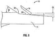
- barbs 16are formed in two steps.
- a first portion 22 of the cutis made at an angle (" ⁇ ") of from about thirty to about forty degrees (30° - 40°) with respect to the surface of the suture to a predetermined depth.
- clamp and position assemblies 400are approximated towards blades 308 (arrow “D") while suture transport assembly 200 advances sutures 10 longitudinally (arrow “A”).
- the angle of cutis then adjusted for the second portion 24 to an angle (" ⁇ ") of from about two to about eight degrees (2° - 10°) with respect to the surface or longitudinal axis of suture 10 by varying the rate of movement of clamp and position assemblies 400 and suture transport assembly 200 relative to each other and blade 308.
- clamp and position assemblies 400are approximated away from cutting assemblies 304 thereby causing blades 308 to engage, and thus, flex barbs 16 outwardly.
- Sutures 10are then released from gripper assemblies 406 as clamp and position assemblies 400 continue to move away from cutting assemblies 304 to permit suture 10 to be repositioned for the next cut.
- Suture transport assembly 200then advances sutures 10 relative to cutting assemblies 306 as rotary assemblies 210, 220 rotate sutures 10 along longitudinal axis thereof to ready sutures 10 for the next cut.
- rotary assemblies 210, 220may be configured to rotate sutures 10 from zero degrees (0°) thru three-hundred sixty degrees (360°) along a length thereof.
- Additional barbs 16are formed in the manner described above. This process continues until barbs 20 are formed along the desired lengths of sutures 10. Knife assemblies 300 are then retracted to permit suture transport assembly 200 to return to an initial position. Sutures 10 are then unloaded and the barb forming process is complete.
- visual inspection assemblies 500monitor the characteristics of barbs 16. In the event a barb is detected that does not conform to the desired configuration, suture cutting mechanism 600 ( FIG. 3 ) is activated, thereby severing suture 10 and terminating the barb forming process.
- Barb cutting station 100may be configured to cut barbs 16 in any suitable pattern, for example, helical, linear, or randomly spaced.
- the patternmay be symmetrical or asymmetrical.
- the number, configuration, spacing and surface area of the barbsmay vary depending upon the tissue in which barbed suture 10 is used, as well as the composition and geometry of the material utilized to form suture 10. Additionally, the proportions of barbs 16 may remain relatively constant while the overall length and spacing thereof may be determined by the tissue being connected. For example, if barbed suture 10 is to be used to connect the edges of a wound in skin or tendon, barbs 16 may be made relatively short and more rigid to facilitate entry into this rather firm tissue. Alternatively, if barbed suture 10 is intended for use in fatty tissue, which is relatively soft, barbs 16 may be made longer and spaced further apart to increase the ability of the suture to grip the soft tissue.
- the surface area of barbs 16may also vary.
- fuller-tipped barbsmay be made of varying sizes designed for specific surgical applications. For joining fat and relatively soft tissues, larger barbs may be desired, whereas smaller barbs may be more suitable for collagen-dense tissues.
- a combination of large and small barbs within the same structuremay be beneficial, for example when a suture is used in tissue repair with differing layer structures. Use of the combination of large and small barbs with the same suture wherein barb sizes are customized for each tissue layer will ensure maximum anchoring properties.
- a single directional suturemay have both large and small barbs; in other embodiments a bi-directional suture may have both large and small barbs.
- the barbs formedmay include geometrical shapes such as round, triangular, square, oblique, elliptical, octagonal, rectangular, and flat
Landscapes
- Health & Medical Sciences (AREA)
- Life Sciences & Earth Sciences (AREA)
- Surgery (AREA)
- Heart & Thoracic Surgery (AREA)
- Engineering & Computer Science (AREA)
- Biomedical Technology (AREA)
- Nuclear Medicine, Radiotherapy & Molecular Imaging (AREA)
- Medical Informatics (AREA)
- Molecular Biology (AREA)
- Animal Behavior & Ethology (AREA)
- General Health & Medical Sciences (AREA)
- Public Health (AREA)
- Veterinary Medicine (AREA)
- Surgical Instruments (AREA)
- Materials For Medical Uses (AREA)
Description
- The present application claims benefit of and priority to
U.S. Provisional Application Serial No. 61/173,723, filed April 29, 2009 - The present disclosure relates to medical sutures having barbs formed thereon. More particularly, the present disclosure relates to a system of forming barbs on sutures.
- Barbed sutures are generally made of the same materials as conventional sutures and offer several advantages for closing wounds compared with conventional sutures. A barbed suture includes an elongated body that has one or more spaced barbs, that project from the surface of the suture body along the body length. The barbs are arranged to allow passage of the barbed suture in one direction through tissue but resist movement of the barbed suture in the opposite direction. Thus, one advantage of barbed sutures has been the provision of a non-slip attribute.
- Barbed sutures are known for use in cosmetic, Iaparoscopic and endoscopic procedures. The number of barbs called for on a particular suture may be influenced by the size of the wound and the strength required to hold the wound closed. Like a conventional suture, a barbed suture may be inserted into tissue using a surgical needle.
- In some circumstances, a random configuration of barbs on the exterior surface of the suture is preferred to achieve optimal wound closure holding for the particular wound.
- However, in other circumstances, where the wound or tissue repair needed is relatively small, a reduced number of barbs may be desired. In other circumstances, a two-way barbed suture is desirable where the barbs permit passing of the suture in one direction over a portion of the suture and barbs permitting passing of the suture in a second direction over another portion of the suture to perform a tight closing stitch.
- Various methods of forming barbs on sutures have been proposed such as mechanical cutting, laser cutting, injection molding, stamping, extrusion and the like. Such methods may be difficult to achieve the desired result with respect to getting the arrangement of barbs in a configuration needed for the appropriate procedure and for doing so in an efficient cost effective manner. Conventional cutting methods of forming barbs have significant drawbacks in their ability to maintain sharpness, move rapidly and have slow manufacturing cycle time.
- Accordingly, there is a continuing need for a system of forming barbs on a suture that is less difficult, more effective and economical.
- According to the invention, a station for cutting a barb suture is provided as defined in independent claim 1. Preferred embodiments are defined in the dependent claims.
- Also provided, but not part of the present invention, is a method of forming a first barbed suture. The method includes providing a suture forming station including a suture transport assembly, a first knife assembly, and a first clamp and position assembly. The method further includes positioning a suture on the suture transport assembly, aligning the suture transport assembly with the knife assembly, activating the first knife assembly, advancing the suture transport assembly while simultaneously approximating the first clamp and position assembly towards the first knife assembly to engage the suture with the first knife assembly to form a barb, and retracting the first clamp and position assembly away from the first knife assembly. Retraction of the first clamp and position assembly may cause the deflection of the barb away from a longitudinal axis of the suture.
- The barb forming method may further include the step of advancing the suture transport assembly relative to the first knife assembly to prepare the suture for a subsequent engagement with the knife assembly. The method may also include the steps of advancing the suture transport assembly and approximating the first clamp and position assembly towards and away from the knife assembly, one or more times to form additional barbs on the suture. The suture transport assembly of the barb forming method may be configured to receive a pair of sutures.
- Various embodiments of the present disclosure will be described herein below with reference to the figures wherein:
FIG. 1 is a side view of a barbed suture formed in accordance with the present disclosure;FIG. 2 is a perspective view of a cabinet of a barb cutting station according to an embodiment of the present disclosure;FIG. 3 is a schematic view of a base panel of the barb cutting station ofFIG. 2 ;FIG. 4 is a perspective view of a suture support assembly of the barb cutting station ofFIG. 2 ;FIG. 5 a schematic view of a pair of clamp and position assemblies of the barb cutting station ofFIG. 2 showing their respective locations on the base panel;FIG. 6 is a perspective view of the clamp and position assembly ofFIG. 5 ;FIG. 7 is a perspective view of a knife assembly of the barb cutting station ofFIG. 2 ; andFIG. 8 is a side sectional view of a barbed portion of the barbed suture ofFIG. 1 .- A system and method for forming a barbed suture is herein described. Referring initially to
FIG. 1 , a barbed suture formed in accordance with the method of the present disclosure is shown generally asbarbed suture 10. Suture 10 is formed from amonofilament thread 11, however, it is envisioned thatsuture 10 may be formed braided threads, multifilament threads and other surgical fibers. Although shown having a circular cross-sectional geometry, the cross-sectional geometry ofthread 11 may be of any suitable shape. For example,thread 11 may be round, elliptical, square, flat, octagonal, and rectangular.Thread 11 may be formed of degradable materials, non-degradable materials, and combinations thereof.Thread 11 may be formed using any technique within the purview of those skilled in the art, such as, for example, extrusion, molding and/or solvent casting. - Still referring to
FIG. 1 ,barbed suture 10 includes aloop 12 formed on adistal end 10b thereof.Loop 12 is configured to facilitate attachment ofdistal end 10b of thread I I with barb cutting station 100 (FIG. 2 ).Loop 12 may be formed in any manner and may be of any size and configuration. It is envisioned thatbarb cutting station 100 may be modified such thatthread 11 may be attached thereto withoutloop 12. Optionally,barbed suture 10 includes asuture needle 14 attached to aproximal end 10a thereof.Needle 14 may be attached tothread 11 prior to or upon completion of the barb forming process. Formed onthread 11 betweenloop 12 andsuture needle 14 are a plurality of radially spacedbarbs 16. As will be discussed in greater detail below,barbs 16 may formed in any number, size, configuration, spacing and/or orientation. - With reference now to
FIGS. 2-7 , a system for formingbarbed suture 10 will be described and is shown generally asbarb cutting station 100. Referring initially toFIG. 2 ,barb cutting station 100 includes acabinet 102 having afirst housing 104, asecond housing 106, and acontrol box 108.First housing 104 is configured to receive abase panel 110. Electric components (not shown) are maintained withinsecond housing 106.Control box 108 is configured for controlling operation ofcutting station 100. Although shown as a single unit, it is envisioned that first andsecond housings control box 108 may arranged independent of one another. In this manner,cutting station 100 may be operated remotely. - Turning now to
FIG. 3 , maintained within cabinet 102 (FIG. 2 ) and mounted onbase panel 110 are asuture transport assembly 200, a pair ofknife assemblies 300, and a pair of clamp andposition assemblies 400. Optionally, mounted tobase panel 110 are a pair ofsuture cutting mechanisms 600 and/or a pair ofvisual inspection assemblies 500. - With reference still to
FIG. 3 ,suture transport assembly 200 is mounted tobase panel 110 in an upright position along atrack 112.Suture transport assembly 200 is configured to support a pair ofsutures 10 during the barb forming process.Suture transport assembly 200 is configured to move linearly alongtrack 112 perpendicular toknife assemblies 300, in the direction of arrows "A". - Turning now to
FIG. 4 ,suture transport assembly 200 includes abase member 202, a fixedupper support member 204 and an adjustablelower support member 206. In one alternative, not part of the present invention, fixedupper support member 204 includes a pair ofrotary assemblies 210 each including apin assembly 212 extending therefrom for engagingloops 12 formed ondistal ends 10b ofrespective sutures 10. As discussed above, in an alternative embodiment,support member 204 are configured to engagesutures 10 without the use ofloops 12. In this manner and according to the invention, each ofsupport members 204 includes a clamp or anchor (not shown) for attachment ofdistal ends 10b ofsutures 10 thereto. - Still referring to
FIG. 4 , adjustablelower support member 206 includes a pair ofrotary assemblies 220 each including aneedle holding assembly 222 extending therefrom for engagingproximal ends 10a (FIG. 1 ) ofrespective sutures 10. Holdingassemblies 222 may include a clamp, anchor or other fixation device suitable for attachment with proximal ends 10 ofsutures 10.Rotary assemblies 220 each further include atensioning device 223 for tensioningsutures 10 oncesutures 10 have been received betweenrespective pin assemblies 212 andneedle holding assemblies 222.Tensioning device 223 may be hydraulic, pneumatic, gravity operated, spring-load or otherwise configured to provide tension to sutures 10.Lower support member 206 further includes anadjustment mechanism 225 for adjusting the distance betweenlower support member 206 andupper support member 204. In this manner,suture transport assembly 200 may accommodatesutures 10 of various lengths. Each of upper andlower support members rotary motor rotary assemblies sutures 10 along longitudinal axis thereof, in the direction of arrows "B". - Referring briefly back to
FIG. 3 ,knife assemblies 300 are fixedly mounted tobase panel 110 adjacentsuture transport assembly 200.Knife assemblies 300 are configured for cutting barbs 16 (FIG. 1 ) insutures 10. Turning now toFIG. 5 , each ofknife assemblies 300 includes abase 302 and a cuttingassembly 304 operably mounted tobase 302. Each of cuttingassemblies 304 include a cuttingmember 306 extending outwardly therefrom and include ablade 308 for cutting barbs insutures 10. As shown,knife assemblies 300 include anultrasonic mechanism 312 for ultrasonically vibratingblade 308. Alternatively,knife assemblies 300 may include a heating element or other suitable mechanism (not shown) forheating blade 308. By vibrating orheating blade 308, the force necessary to cutbarbs 16 may be reduced. - Still referring to
FIG. 3 , each of cuttingassemblies 304 further includes arotary mechanism 310 for rotating cuttingmembers 306.Rotary mechanism 310 is configured toindex blade 308 during the barb forming process to adjust the angle of cut.Blade 308 may further be rotated at least one-hundred and eighty degrees (180°) such that each surface ofblade 308 may be used. In one embodiment, rotation ofblade 308 occurs only after the desired number ofbarbs 16 have been formed along the desired length ofsutures 10. Cuttingassemblies 304 are mounted tobases 302 such that cuttingmembers 306 may be advanced, in the direction of arrows "C". In this manner, cuttingassemblies 222 may be retracted once the barb forming process is completed to permit reloading and repositioning ofsuture transport assembly 200. Cuttingassemblies 304 remain stationary or in a fixed position during the cutting ofsutures 10 to formbarbs 16. In this manner,blades 308 are not moved into contact with the suture, instead clamp andposition assemblies 400move suture 10 into contact withblades 308. - Turning to
FIGS. 3 and6 , clamp andposition assemblies 400 are securely mounted tobase panel 110 adjacentsuture transport assembly 200 and respectiveultrasonic knife assemblies 300. Clamp andposition assemblies 400 are configured for approximatingsutures 10 towards and away fromultrasonic knife assembly 300. Turning now toFIG. 6 , each of clamp andposition assemblies 400 includes astationary base 402 and amoveable carriage 404.Carriage 404 includes agripper assembly 406 for selectively grippingsuture 10 during the barb forming process.Gripper assembly 406 includes ananvil portion 408 for supportingsuture 10 ascarriage 404 is approximated towards cuttingmember 306 ofknife assembly 300 and assuture 10 engagesblade 308. - With reference back to
FIG. 3 ,visual inspection assemblies 500 are configured for monitoring the cutting ofbarbs 16. In the event that a misformed or defective barb is cut,visual inspection assembly 500 is configured to signalcutting mechanism 600 to sever the defective suture, such that that suture may not be used. - With reference still to
FIG. 3 ,cutting mechanism 600 is configured for cuttingsuture 10 in the event that a defective barb is detected byvisual inspection assembly 500.Cutting mechanism 600 may further be configured for manual actuation by an operator.Cutting mechanism 600 may include any device capable of selectively severingsuture 10 during the barb forming process.Cutting mechanism 600 may include ablade 602, or a laser, a heating element or other suitable device (not shown). - The operation of the
suture cutting station 100 will now be described with reference toFIGS. 2-7 . Initially,cabinet 102 is opened to accessbase panel 110.Suture transport assembly 200 is then adjusted usingadjustment mechanism 225 to configure upper andlower support members sutures 10 of a given length.Sutures 10 are next secured to suturetransport assembly 200 by hookingloops 12 formed ondistal ends 10b ofsutures 10 aboutpin assemblies 212 of fixedupper support member 204 and fastening armed proximal ends 10a ofsutures 10 withinneedle holding assemblies 222 oflower support member 206. Tensioningcylinders 223 withinrotary assemblies 220 ensure thatsutures 10 are properly tensioned between pin and needle holding assemblies 212,222, respectively.Suture transport assembly 200 is then positioned such thatblades 308 of cuttingmember 306 are aligned near proximal ends 10a ofsutures 10. - Once
suture transport assembly 200 is properly positioned with respect toultrasonic knife assemblies 300, cuttingassemblies 304 ofknife assemblies 300 are advanced in the direction of arrows "C" (FIG. 3 ), such thatblades 308 of cuttingassemblies 306 are positioned outwards of and in close approximation to (but not in contact with) sutures 10.Knife assemblies 300 are then activated to cause the ultrasonic vibrating or heating ofblades 308. Onceknife assemblies 300 have been activated, cuttingassembly 304 remains stationary during the barb forming process and suturetransport assembly 200 and clamp andposition assemblies 400 operate in unison to movesutures 10 relative toblade 308 to form barbs 16 (FIG. 1 ) along the lengths thereof. - With reference to
FIG. 8 ,barbs 16 are formed in two steps. Afirst portion 22 of the cut is made at an angle ("β") of from about thirty to about forty degrees (30° - 40°) with respect to the surface of the suture to a predetermined depth. In this manner, clamp andposition assemblies 400 are approximated towards blades 308 (arrow "D") whilesuture transport assembly 200 advances sutures 10 longitudinally (arrow "A"). The angle of cut is then adjusted for thesecond portion 24 to an angle ("α") of from about two to about eight degrees (2° - 10°) with respect to the surface or longitudinal axis ofsuture 10 by varying the rate of movement of clamp andposition assemblies 400 andsuture transport assembly 200 relative to each other andblade 308. - Upon completion of the second cut, clamp and
position assemblies 400 are approximated away from cuttingassemblies 304 thereby causingblades 308 to engage, and thus, flexbarbs 16 outwardly.Sutures 10 are then released fromgripper assemblies 406 as clamp andposition assemblies 400 continue to move away from cuttingassemblies 304 to permitsuture 10 to be repositioned for the next cut.Suture transport assembly 200 then advances sutures 10 relative to cuttingassemblies 306 asrotary assemblies sutures 10 along longitudinal axis thereof toready sutures 10 for the next cut. Depending on the desired configuration ofbarbs 16 along a length thereof,rotary assemblies sutures 10 from zero degrees (0°) thru three-hundred sixty degrees (360°) along a length thereof. Additional barbs 16 are formed in the manner described above. This process continues until barbs 20 are formed along the desired lengths ofsutures 10.Knife assemblies 300 are then retracted to permitsuture transport assembly 200 to return to an initial position.Sutures 10 are then unloaded and the barb forming process is complete.- During barb formation, visual inspection assemblies 500 (
FIG. 3 ) monitor the characteristics ofbarbs 16. In the event a barb is detected that does not conform to the desired configuration, suture cutting mechanism 600 (FIG. 3 ) is activated, thereby severingsuture 10 and terminating the barb forming process. Barb cutting station 100 may be configured to cutbarbs 16 in any suitable pattern, for example, helical, linear, or randomly spaced. The pattern may be symmetrical or asymmetrical. The number, configuration, spacing and surface area of the barbs may vary depending upon the tissue in whichbarbed suture 10 is used, as well as the composition and geometry of the material utilized to formsuture 10. Additionally, the proportions ofbarbs 16 may remain relatively constant while the overall length and spacing thereof may be determined by the tissue being connected. For example, ifbarbed suture 10 is to be used to connect the edges of a wound in skin or tendon,barbs 16 may be made relatively short and more rigid to facilitate entry into this rather firm tissue. Alternatively, ifbarbed suture 10 is intended for use in fatty tissue, which is relatively soft,barbs 16 may be made longer and spaced further apart to increase the ability of the suture to grip the soft tissue.- The surface area of
barbs 16 may also vary. For example, fuller-tipped barbs may be made of varying sizes designed for specific surgical applications. For joining fat and relatively soft tissues, larger barbs may be desired, whereas smaller barbs may be more suitable for collagen-dense tissues. In some embodiments, a combination of large and small barbs within the same structure may be beneficial, for example when a suture is used in tissue repair with differing layer structures. Use of the combination of large and small barbs with the same suture wherein barb sizes are customized for each tissue layer will ensure maximum anchoring properties. In particular embodiments, a single directional suture may have both large and small barbs; in other embodiments a bi-directional suture may have both large and small barbs. The barbs formed may include geometrical shapes such as round, triangular, square, oblique, elliptical, octagonal, rectangular, and flat - While the above description contains many specifics, these specifics should not be construed as limitations on the scope of the disclosure, but merely as exemplifications of embodiments thereof. Those skilled in the art will envision many other possibilities, within the scope of the disclosure as defined by the claims appended hereto.
Claims (6)
- A barb cutting station (100) comprising:a base panel (110);a suture transport assembly (200) for supporting first and second sutures (10);first and second knife assemblies (300) for forming barbs on the first and second sutures, respectively;first and second clamp and position assemblies (400) for approximating the first and second sutures towards the first and second knife assemblies, respectively;wherein the first and second knife assemblies (300) and the first and second clamp and position assemblies (400) are fixedly mounted on the base panel (110), and the suture transport assembly (200) is mounted to the base panel in an upright position along a track such that it is configured to move linearly along the track (112) in a direction ("A") perpendicular to the knife assemblies (300);wherein the suture transport assembly comprises:a base member (202),a fixed upper support member (204) including a pair of upper rotary assemblies (210) each including a clamp or anchor configured to attach a distal end of one of the first and second sutures thereto, respectively; andan adjustable lower support member (206) including a pair of lower rotary assemblies (220) each including a holding assembly (222) extending therefrom having a fixation device configured to attach to a proximal end of one of the first and second sutures (10), respectively, and the pair of lower rotary assemblies (220) including each a tensioning device (223) for tensioning the respective suture (10) once the suture has been received between the respective upper and lower rotary assemblies (210, 220); the lower support member further comprising an adjustment mechanism (225) for adjusting a distance between the lower support member (206) and the upper support member (204); andeach of the upper and lower support members (204, 206) further comprising a rotary motor (224, 226), respectively, operably connected to the upper and lower rotary assemblies (210, 220), respectively, for rotating the first and second sutures (10) along the respective longitudinal axis thereof.
- The barb cutting station of claim 1, further comprising first and second suture cutting mechanisms (600) mounted to the base panel (110), configured for severing the first and second sutures, respectively, when a defect is detected.
- The barb cutting station of claim 1 or 2, further comprising first and second visual inspection assemblies (500) mounted to the base panel (110), configured for detecting defective barbs (16) on the first and second sutures, respectively.
- The barb cutting station of any preceding claim, wherein the base panel (11) is mounted within a cabinet (102).
- The barb cutting station of any preceding claim, wherein each knife assembly (300) includes an ultrasonic mechanism (312) for ultrasonically vibrating a blade (308) extending therefrom.
- The barb cutting station of any preceding claim, wherein each clamp and position assembly (400) includes a gripping assembly (406) for selectively gripping the respective first or second suture.
Applications Claiming Priority (3)
| Application Number | Priority Date | Filing Date | Title |
|---|---|---|---|
| US17372309P | 2009-04-29 | 2009-04-29 | |
| US12/726,871US8402621B2 (en) | 2009-04-29 | 2010-03-18 | System and method for forming barbs on a suture |
| EP10250848.8AEP2245992B1 (en) | 2009-04-29 | 2010-04-28 | System for forming barbs on a suture |
Related Parent Applications (1)
| Application Number | Title | Priority Date | Filing Date |
|---|---|---|---|
| EP10250848.8ADivisionEP2245992B1 (en) | 2009-04-29 | 2010-04-28 | System for forming barbs on a suture |
Publications (3)
| Publication Number | Publication Date |
|---|---|
| EP3195810A2 EP3195810A2 (en) | 2017-07-26 |
| EP3195810A3 EP3195810A3 (en) | 2017-09-06 |
| EP3195810B1true EP3195810B1 (en) | 2022-11-02 |
Family
ID=42338225
Family Applications (2)
| Application Number | Title | Priority Date | Filing Date |
|---|---|---|---|
| EP16205651.9AActiveEP3195810B1 (en) | 2009-04-29 | 2010-04-28 | System for forming barbs on a suture |
| EP10250848.8AActiveEP2245992B1 (en) | 2009-04-29 | 2010-04-28 | System for forming barbs on a suture |
Family Applications After (1)
| Application Number | Title | Priority Date | Filing Date |
|---|---|---|---|
| EP10250848.8AActiveEP2245992B1 (en) | 2009-04-29 | 2010-04-28 | System for forming barbs on a suture |
Country Status (7)
| Country | Link |
|---|---|
| US (5) | US8402621B2 (en) |
| EP (2) | EP3195810B1 (en) |
| JP (2) | JP5584514B2 (en) |
| CN (2) | CN104188700B (en) |
| AU (1) | AU2010201323B2 (en) |
| CA (1) | CA2699160C (en) |
| ES (2) | ES2930031T3 (en) |
Families Citing this family (41)
| Publication number | Priority date | Publication date | Assignee | Title |
|---|---|---|---|---|
| ES2398779T3 (en) | 2007-09-27 | 2013-03-21 | Ethicon Llc | Self-retaining sutures that include tissue retention elements with enhanced strength |
| ES2706295T3 (en) | 2008-02-21 | 2019-03-28 | Ethicon Llc | Method and apparatus for raising retainers in self-retaining sutures |
| US8402621B2 (en) | 2009-04-29 | 2013-03-26 | Covidien Lp | System and method for forming barbs on a suture |
| US9044224B2 (en) | 2010-04-12 | 2015-06-02 | Covidien Lp | Barbed medical device and method |
| NZ626274A (en) | 2010-05-04 | 2015-03-27 | Ethicon Llc | Laser cutting system and methods for creating self-retaining sutures |
| JP6013352B2 (en) | 2010-11-09 | 2016-10-25 | エシコン・エルエルシーEthicon LLC | Emergency indwelling suture and package |
| CN103889340B (en) | 2011-03-23 | 2018-09-28 | 伊西康有限责任公司 | Self-retaining variable loop suture |
| US9011133B2 (en) | 2011-04-29 | 2015-04-21 | Covidien Lp | Apparatus and method of forming barbs on a suture |
| US9687227B2 (en) | 2011-04-29 | 2017-06-27 | Covidien Lp | Apparatus and method of forming barbs on a suture |
| US9241709B2 (en) | 2011-05-31 | 2016-01-26 | Covidien Lp | Barbed sutures |
| US8640331B2 (en) | 2011-05-31 | 2014-02-04 | Covidien Lp | Barbed sutures |
| US20130172931A1 (en) | 2011-06-06 | 2013-07-04 | Jeffrey M. Gross | Methods and devices for soft palate tissue elevation procedures |
| US10650177B2 (en) | 2012-12-20 | 2020-05-12 | Comsol Ab | System and method for creating application interfaces for multiphysics modeling |
| US9597426B2 (en) | 2013-01-25 | 2017-03-21 | Covidien Lp | Hydrogel filled barbed suture |
| CN103144131B (en)* | 2013-03-20 | 2015-01-21 | 东华大学 | Self-locking type suture line preparation device and preparation method thereof |
| KR101550103B1 (en)* | 2013-11-07 | 2015-09-03 | 김춘동 | Thread cogs making machine and method for making thereof |
| KR101719256B1 (en)* | 2014-03-21 | 2017-03-23 | 유원석 | Fixed barbed suture and manufacturing method thereof |
| EP3180040B1 (en) | 2014-08-15 | 2020-05-13 | Tepha, Inc. | Self-retaining sutures of poly-4-hydroxybutyrate and copolymers thereof |
| KR101611880B1 (en)* | 2014-11-20 | 2016-04-14 | 이인숙 | Wire cutting equipment |
| CN104608172B (en)* | 2015-02-12 | 2017-07-07 | 刘宁 | A kind of device that unidirectional or two-way hangnail is formed on suture |
| EP3085820B1 (en) | 2015-04-22 | 2017-12-20 | Sofradim Production | A method for forming a barbed suture and the barbed suture thus obtained |
| EP3085332B1 (en) | 2015-04-23 | 2019-02-27 | Sofradim Production | Package for a surgical mesh |
| TWI595866B (en)* | 2016-08-11 | 2017-08-21 | Feather line manufacturing equipment | |
| CN106192122B (en)* | 2016-08-31 | 2018-12-04 | 浙江鸿辰新材料科技有限公司 | Dendritic fiber filament and molding machine |
| CN106725674A (en)* | 2016-12-14 | 2017-05-31 | 天津昕黎科技有限公司 | The device and processing method of a kind of medical treatment device compound barb processing |
| CN107336271B (en)* | 2017-03-09 | 2023-06-23 | 上海英诺伟医疗器械股份有限公司 | Drainage tube intercepting device and method |
| KR101841392B1 (en)* | 2017-06-19 | 2018-05-04 | 박범수 | Tunning device of string for lifting procedure |
| CN107199585B (en)* | 2017-07-31 | 2024-03-12 | 许芮 | Wire rod barb cuts forming device |
| RU2020117389A (en)* | 2017-10-06 | 2022-01-31 | Сред & Лифт | SURGICAL THREAD, MEDICAL DEVICE, METHOD OF PRODUCING SURGICAL THREAD |
| CN108466303A (en)* | 2018-05-25 | 2018-08-31 | 浙江益医疗器械有限公司 | A kind of shaping and beauty jaggies automatic wire cutting machine |
| CN108836408A (en)* | 2018-07-04 | 2018-11-20 | 于云龙 | A kind of zigzag stitched line for lifting of sunkening cord(It is barbed)And preparation method thereof |
| CN110849238B (en)* | 2019-12-05 | 2021-04-09 | 江西龙腾生物高科技有限公司 | Medical collagen suture line body length measuring device |
| CN111134748B (en)* | 2020-01-03 | 2021-06-15 | 浙江微度医疗器械有限公司 | Device and method for forming one-way or two-way barbs on suture |
| CN111184545B (en)* | 2020-01-08 | 2021-04-16 | 浙江微度医疗器械有限公司 | Device and method for forming fishbone on suture |
| CN113069161B (en)* | 2021-03-18 | 2022-10-04 | 南京普立蒙医疗科技有限公司 | Improve barb stylolite cutting equipment of yields |
| CN113413184B (en)* | 2021-06-28 | 2022-07-05 | 梁一凡 | Barb line cutting machine |
| CN115213947B (en)* | 2022-06-07 | 2024-04-19 | 南通华利康医疗器械有限公司 | Suture line barb processing mechanism |
| CN115256524B (en)* | 2022-06-07 | 2024-06-21 | 南通华利康医疗器械有限公司 | Line ball formula suture barb cutting mechanism |
| WO2024033763A1 (en) | 2022-08-10 | 2024-02-15 | Covidien Lp | Looped suture devices and methods of forming looped suture devices |
| WO2024184742A1 (en)* | 2023-03-06 | 2024-09-12 | Covidien Lp | Apparatus and methods for forming barbs on sutures utilizing multiple cutting blades |
| CN117822167A (en)* | 2023-12-23 | 2024-04-05 | 苏州聚点智能科技股份有限公司 | A device for cutting barbs on surgical sutures |
Family Cites Families (36)
| Publication number | Priority date | Publication date | Assignee | Title |
|---|---|---|---|---|
| US6241747B1 (en)* | 1993-05-03 | 2001-06-05 | Quill Medical, Inc. | Barbed Bodily tissue connector |
| US8795332B2 (en) | 2002-09-30 | 2014-08-05 | Ethicon, Inc. | Barbed sutures |
| US5732529A (en)* | 1996-03-29 | 1998-03-31 | Ethicon, Inc. | Apparatus for feeding foil stock in a process for making sealed sterile packages |
| US6270517B1 (en)* | 2000-02-04 | 2001-08-07 | Gregory R. Brotz | Suture assembly and method |
| US7056331B2 (en)* | 2001-06-29 | 2006-06-06 | Quill Medical, Inc. | Suture method |
| US6599310B2 (en)* | 2001-06-29 | 2003-07-29 | Quill Medical, Inc. | Suture method |
| US6848152B2 (en)* | 2001-08-31 | 2005-02-01 | Quill Medical, Inc. | Method of forming barbs on a suture and apparatus for performing same |
| US20030149447A1 (en) | 2002-02-01 | 2003-08-07 | Morency Steven David | Barbed surgical suture |
| US8100940B2 (en) | 2002-09-30 | 2012-01-24 | Quill Medical, Inc. | Barb configurations for barbed sutures |
| US20040088003A1 (en) | 2002-09-30 | 2004-05-06 | Leung Jeffrey C. | Barbed suture in combination with surgical needle |
| US7624487B2 (en) | 2003-05-13 | 2009-12-01 | Quill Medical, Inc. | Apparatus and method for forming barbs on a suture |
| US20050161531A1 (en)* | 2004-01-28 | 2005-07-28 | Greer Lester R.Jr. | Texture material for covering a repaired portion of a textured surface |
| US10548592B2 (en) | 2004-05-14 | 2020-02-04 | Ethicon, Inc. | Suture methods and devices |
| US8267961B2 (en) | 2005-06-29 | 2012-09-18 | Ethicon, Inc. | Barbed suture |
| US20070224237A1 (en) | 2006-03-24 | 2007-09-27 | Julia Hwang | Barbed sutures having a therapeutic agent thereon |
| WO2007131019A2 (en)* | 2006-05-04 | 2007-11-15 | Ethicon, Inc. | Tissue holding devices and methods for making the same |
| CH697273B1 (en) | 2006-07-26 | 2008-07-31 | Detra Sa | An electromechanical escapement and timepiece provided with such a device |
| EP2279700B1 (en) | 2006-09-06 | 2018-10-03 | Covidien LP | Barbed suture with bioactive substance |
| US20080082113A1 (en)* | 2006-10-03 | 2008-04-03 | Alure Medical, Inc. | Minimally invasive tissue support |
| US20080195147A1 (en) | 2007-02-09 | 2008-08-14 | Tyco Healthcare Group Lp | Surface eroding barbed sutures |
| US20080221618A1 (en)* | 2007-03-09 | 2008-09-11 | Gaoyuan Chen | Co-extruded tissue grasping monofilament |
| ITRM20070162A1 (en) | 2007-03-27 | 2008-09-28 | Promoitalia Internat Srl | CARVING APPARATUS FOR SURGICAL THREADS |
| US8915943B2 (en)* | 2007-04-13 | 2014-12-23 | Ethicon, Inc. | Self-retaining systems for surgical procedures |
| KR100880679B1 (en)* | 2007-04-30 | 2009-01-30 | 김종환 | Special yarn manufacturing device for wrinkle removal |
| US20080281357A1 (en)* | 2007-05-09 | 2008-11-13 | An-Min Jason Sung | Looped tissue-grasping device |
| US8747436B2 (en)* | 2007-06-13 | 2014-06-10 | Ethicon, Inc. | Bi-directional barbed suture |
| US8562644B2 (en) | 2007-08-06 | 2013-10-22 | Ethicon, Inc. | Barbed suture with non-symmetric barbs |
| US8161618B2 (en)* | 2007-09-17 | 2012-04-24 | Tyco Healthcare Group Lp | Method of forming barbs on a suture |
| US8273105B2 (en)* | 2008-02-20 | 2012-09-25 | Tyco Healthcare Group Lp | Compound barb medical device and method |
| ES2706295T3 (en)* | 2008-02-21 | 2019-03-28 | Ethicon Llc | Method and apparatus for raising retainers in self-retaining sutures |
| US20090248066A1 (en)* | 2008-03-28 | 2009-10-01 | David Hjalmar Wilkie | Elastic barbed suture and tissue support system |
| SG188784A1 (en) | 2008-04-15 | 2013-04-30 | Ethicon Llc | Self-retaining sutures with bi-directional retainers or uni-directional retainers |
| CA2722455C (en) | 2008-04-24 | 2016-05-31 | Angiotech Pharmaceuticals, Inc. | Shape-memory self-retaining sutures, methods of manufacture, and methods of use |
| US9011489B2 (en)* | 2008-05-14 | 2015-04-21 | Boston Scientific Scimed, Inc. | Surgical composite barbed suture |
| US8821539B2 (en) | 2008-07-23 | 2014-09-02 | Ethicon, Inc. | Collapsible barbed sutures having reduced drag and methods therefor |
| US8402621B2 (en) | 2009-04-29 | 2013-03-26 | Covidien Lp | System and method for forming barbs on a suture |
- 2010
- 2010-03-18USUS12/726,871patent/US8402621B2/enactiveActive
- 2010-04-01AUAU2010201323Apatent/AU2010201323B2/ennot_activeCeased
- 2010-04-07CACA2699160Apatent/CA2699160C/ennot_activeExpired - Fee Related
- 2010-04-16JPJP2010095541Apatent/JP5584514B2/ennot_activeExpired - Fee Related
- 2010-04-28EPEP16205651.9Apatent/EP3195810B1/enactiveActive
- 2010-04-28ESES16205651Tpatent/ES2930031T3/enactiveActive
- 2010-04-28EPEP10250848.8Apatent/EP2245992B1/enactiveActive
- 2010-04-28ESES10250848.8Tpatent/ES2614158T3/enactiveActive
- 2010-04-29CNCN201410412600.9Apatent/CN104188700B/enactiveActive
- 2010-04-29CNCN201010170849.5Apatent/CN101874747B/enactiveActive
- 2013
- 2013-03-19USUS13/847,207patent/US8966728B2/enactiveActive
- 2014
- 2014-03-07JPJP2014044739Apatent/JP5729790B2/ennot_activeExpired - Fee Related
- 2015
- 2015-01-23USUS14/603,487patent/US9572569B2/enactiveActive
- 2017
- 2017-01-31USUS15/420,146patent/US10278693B2/enactiveActive
- 2019
- 2019-03-19USUS16/357,361patent/US11000273B2/enactiveActive
Also Published As
| Publication number | Publication date |
|---|---|
| CA2699160C (en) | 2017-05-16 |
| US20190209169A1 (en) | 2019-07-11 |
| US20130218204A1 (en) | 2013-08-22 |
| US20170135694A1 (en) | 2017-05-18 |
| JP2014158876A (en) | 2014-09-04 |
| CN101874747A (en) | 2010-11-03 |
| ES2614158T3 (en) | 2017-05-29 |
| US9572569B2 (en) | 2017-02-21 |
| EP3195810A3 (en) | 2017-09-06 |
| AU2010201323A1 (en) | 2010-11-18 |
| US20150135928A1 (en) | 2015-05-21 |
| EP3195810A2 (en) | 2017-07-26 |
| AU2010201323B2 (en) | 2014-05-08 |
| US8966728B2 (en) | 2015-03-03 |
| US20100275750A1 (en) | 2010-11-04 |
| CN101874747B (en) | 2014-09-17 |
| EP2245992B1 (en) | 2017-01-04 |
| US10278693B2 (en) | 2019-05-07 |
| CN104188700B (en) | 2016-09-28 |
| JP2010259786A (en) | 2010-11-18 |
| JP5584514B2 (en) | 2014-09-03 |
| ES2930031T3 (en) | 2022-12-05 |
| EP2245992A1 (en) | 2010-11-03 |
| JP5729790B2 (en) | 2015-06-03 |
| CA2699160A1 (en) | 2010-10-29 |
| US11000273B2 (en) | 2021-05-11 |
| CN104188700A (en) | 2014-12-10 |
| US8402621B2 (en) | 2013-03-26 |
Similar Documents
| Publication | Publication Date | Title |
|---|---|---|
| US11000273B2 (en) | System and method for forming barbs on a suture | |
| JP5981349B2 (en) | Tissue repair implant and input device and method | |
| CA2952362C (en) | Apparatus and method for suturing a tissue | |
| EP2245991B1 (en) | System and method for making tapered looped suture |
Legal Events
| Date | Code | Title | Description |
|---|---|---|---|
| PUAI | Public reference made under article 153(3) epc to a published international application that has entered the european phase | Free format text:ORIGINAL CODE: 0009012 | |
| STAA | Information on the status of an ep patent application or granted ep patent | Free format text:STATUS: THE APPLICATION HAS BEEN PUBLISHED | |
| AC | Divisional application: reference to earlier application | Ref document number:2245992 Country of ref document:EP Kind code of ref document:P | |
| AK | Designated contracting states | Kind code of ref document:A2 Designated state(s):AT BE BG CH CY CZ DE DK EE ES FI FR GB GR HR HU IE IS IT LI LT LU LV MC MK MT NL NO PL PT RO SE SI SK SM TR | |
| PUAL | Search report despatched | Free format text:ORIGINAL CODE: 0009013 | |
| AK | Designated contracting states | Kind code of ref document:A3 Designated state(s):AT BE BG CH CY CZ DE DK EE ES FI FR GB GR HR HU IE IS IT LI LT LU LV MC MK MT NL NO PL PT RO SE SI SK SM TR | |
| RIC1 | Information provided on ipc code assigned before grant | Ipc:A61B 17/06 20060101AFI20170728BHEP | |
| STAA | Information on the status of an ep patent application or granted ep patent | Free format text:STATUS: REQUEST FOR EXAMINATION WAS MADE | |
| 17P | Request for examination filed | Effective date:20180305 | |
| RBV | Designated contracting states (corrected) | Designated state(s):AT BE BG CH CY CZ DE DK EE ES FI FR GB GR HR HU IE IS IT LI LT LU LV MC MK MT NL NO PL PT RO SE SI SK SM TR | |
| STAA | Information on the status of an ep patent application or granted ep patent | Free format text:STATUS: EXAMINATION IS IN PROGRESS | |
| 17Q | First examination report despatched | Effective date:20190717 | |
| GRAP | Despatch of communication of intention to grant a patent | Free format text:ORIGINAL CODE: EPIDOSNIGR1 | |
| STAA | Information on the status of an ep patent application or granted ep patent | Free format text:STATUS: GRANT OF PATENT IS INTENDED | |
| INTG | Intention to grant announced | Effective date:20220608 | |
| RIN1 | Information on inventor provided before grant (corrected) | Inventor name:HART, RICHARD CASEY Inventor name:KROEBER, KEITH Inventor name:BUCHTER, MARK Inventor name:KOSA, TIMOTHY Inventor name:MAIORINO, NICHOLAS | |
| GRAS | Grant fee paid | Free format text:ORIGINAL CODE: EPIDOSNIGR3 | |
| GRAA | (expected) grant | Free format text:ORIGINAL CODE: 0009210 | |
| STAA | Information on the status of an ep patent application or granted ep patent | Free format text:STATUS: THE PATENT HAS BEEN GRANTED | |
| AC | Divisional application: reference to earlier application | Ref document number:2245992 Country of ref document:EP Kind code of ref document:P | |
| AK | Designated contracting states | Kind code of ref document:B1 Designated state(s):AT BE BG CH CY CZ DE DK EE ES FI FR GB GR HR HU IE IS IT LI LT LU LV MC MK MT NL NO PL PT RO SE SI SK SM TR | |
| REG | Reference to a national code | Ref country code:GB Ref legal event code:FG4D | |
| REG | Reference to a national code | Ref country code:CH Ref legal event code:EP Ref country code:AT Ref legal event code:REF Ref document number:1528178 Country of ref document:AT Kind code of ref document:T Effective date:20221115 | |
| REG | Reference to a national code | Ref country code:DE Ref legal event code:R096 Ref document number:602010068551 Country of ref document:DE | |
| REG | Reference to a national code | Ref country code:NL Ref legal event code:FP | |
| REG | Reference to a national code | Ref country code:ES Ref legal event code:FG2A Ref document number:2930031 Country of ref document:ES Kind code of ref document:T3 Effective date:20221205 | |
| REG | Reference to a national code | Ref country code:IE Ref legal event code:FG4D | |
| REG | Reference to a national code | Ref country code:LT Ref legal event code:MG9D | |
| REG | Reference to a national code | Ref country code:AT Ref legal event code:MK05 Ref document number:1528178 Country of ref document:AT Kind code of ref document:T Effective date:20221102 | |
| PG25 | Lapsed in a contracting state [announced via postgrant information from national office to epo] | Ref country code:SE Free format text:LAPSE BECAUSE OF FAILURE TO SUBMIT A TRANSLATION OF THE DESCRIPTION OR TO PAY THE FEE WITHIN THE PRESCRIBED TIME-LIMIT Effective date:20221102 Ref country code:PT Free format text:LAPSE BECAUSE OF FAILURE TO SUBMIT A TRANSLATION OF THE DESCRIPTION OR TO PAY THE FEE WITHIN THE PRESCRIBED TIME-LIMIT Effective date:20230302 Ref country code:NO Free format text:LAPSE BECAUSE OF FAILURE TO SUBMIT A TRANSLATION OF THE DESCRIPTION OR TO PAY THE FEE WITHIN THE PRESCRIBED TIME-LIMIT Effective date:20230202 Ref country code:LT Free format text:LAPSE BECAUSE OF FAILURE TO SUBMIT A TRANSLATION OF THE DESCRIPTION OR TO PAY THE FEE WITHIN THE PRESCRIBED TIME-LIMIT Effective date:20221102 Ref country code:FI Free format text:LAPSE BECAUSE OF FAILURE TO SUBMIT A TRANSLATION OF THE DESCRIPTION OR TO PAY THE FEE WITHIN THE PRESCRIBED TIME-LIMIT Effective date:20221102 Ref country code:AT Free format text:LAPSE BECAUSE OF FAILURE TO SUBMIT A TRANSLATION OF THE DESCRIPTION OR TO PAY THE FEE WITHIN THE PRESCRIBED TIME-LIMIT Effective date:20221102 | |
| PG25 | Lapsed in a contracting state [announced via postgrant information from national office to epo] | Ref country code:PL Free format text:LAPSE BECAUSE OF FAILURE TO SUBMIT A TRANSLATION OF THE DESCRIPTION OR TO PAY THE FEE WITHIN THE PRESCRIBED TIME-LIMIT Effective date:20221102 Ref country code:LV Free format text:LAPSE BECAUSE OF FAILURE TO SUBMIT A TRANSLATION OF THE DESCRIPTION OR TO PAY THE FEE WITHIN THE PRESCRIBED TIME-LIMIT Effective date:20221102 Ref country code:IS Free format text:LAPSE BECAUSE OF FAILURE TO SUBMIT A TRANSLATION OF THE DESCRIPTION OR TO PAY THE FEE WITHIN THE PRESCRIBED TIME-LIMIT Effective date:20230302 Ref country code:HR Free format text:LAPSE BECAUSE OF FAILURE TO SUBMIT A TRANSLATION OF THE DESCRIPTION OR TO PAY THE FEE WITHIN THE PRESCRIBED TIME-LIMIT Effective date:20221102 Ref country code:GR Free format text:LAPSE BECAUSE OF FAILURE TO SUBMIT A TRANSLATION OF THE DESCRIPTION OR TO PAY THE FEE WITHIN THE PRESCRIBED TIME-LIMIT Effective date:20230203 | |
| PG25 | Lapsed in a contracting state [announced via postgrant information from national office to epo] | Ref country code:SM Free format text:LAPSE BECAUSE OF FAILURE TO SUBMIT A TRANSLATION OF THE DESCRIPTION OR TO PAY THE FEE WITHIN THE PRESCRIBED TIME-LIMIT Effective date:20221102 Ref country code:RO Free format text:LAPSE BECAUSE OF FAILURE TO SUBMIT A TRANSLATION OF THE DESCRIPTION OR TO PAY THE FEE WITHIN THE PRESCRIBED TIME-LIMIT Effective date:20221102 Ref country code:EE Free format text:LAPSE BECAUSE OF FAILURE TO SUBMIT A TRANSLATION OF THE DESCRIPTION OR TO PAY THE FEE WITHIN THE PRESCRIBED TIME-LIMIT Effective date:20221102 Ref country code:DK Free format text:LAPSE BECAUSE OF FAILURE TO SUBMIT A TRANSLATION OF THE DESCRIPTION OR TO PAY THE FEE WITHIN THE PRESCRIBED TIME-LIMIT Effective date:20221102 Ref country code:CZ Free format text:LAPSE BECAUSE OF FAILURE TO SUBMIT A TRANSLATION OF THE DESCRIPTION OR TO PAY THE FEE WITHIN THE PRESCRIBED TIME-LIMIT Effective date:20221102 | |
| REG | Reference to a national code | Ref country code:DE Ref legal event code:R097 Ref document number:602010068551 Country of ref document:DE | |
| PG25 | Lapsed in a contracting state [announced via postgrant information from national office to epo] | Ref country code:SK Free format text:LAPSE BECAUSE OF FAILURE TO SUBMIT A TRANSLATION OF THE DESCRIPTION OR TO PAY THE FEE WITHIN THE PRESCRIBED TIME-LIMIT Effective date:20221102 | |
| PLBE | No opposition filed within time limit | Free format text:ORIGINAL CODE: 0009261 | |
| STAA | Information on the status of an ep patent application or granted ep patent | Free format text:STATUS: NO OPPOSITION FILED WITHIN TIME LIMIT | |
| 26N | No opposition filed | Effective date:20230803 | |
| PG25 | Lapsed in a contracting state [announced via postgrant information from national office to epo] | Ref country code:SI Free format text:LAPSE BECAUSE OF FAILURE TO SUBMIT A TRANSLATION OF THE DESCRIPTION OR TO PAY THE FEE WITHIN THE PRESCRIBED TIME-LIMIT Effective date:20221102 | |
| REG | Reference to a national code | Ref country code:CH Ref legal event code:PL | |
| PG25 | Lapsed in a contracting state [announced via postgrant information from national office to epo] | Ref country code:LU Free format text:LAPSE BECAUSE OF NON-PAYMENT OF DUE FEES Effective date:20230428 | |
| REG | Reference to a national code | Ref country code:BE Ref legal event code:MM Effective date:20230430 | |
| PG25 | Lapsed in a contracting state [announced via postgrant information from national office to epo] | Ref country code:MC Free format text:LAPSE BECAUSE OF FAILURE TO SUBMIT A TRANSLATION OF THE DESCRIPTION OR TO PAY THE FEE WITHIN THE PRESCRIBED TIME-LIMIT Effective date:20221102 | |
| PG25 | Lapsed in a contracting state [announced via postgrant information from national office to epo] | Ref country code:MC Free format text:LAPSE BECAUSE OF FAILURE TO SUBMIT A TRANSLATION OF THE DESCRIPTION OR TO PAY THE FEE WITHIN THE PRESCRIBED TIME-LIMIT Effective date:20221102 Ref country code:LI Free format text:LAPSE BECAUSE OF NON-PAYMENT OF DUE FEES Effective date:20230430 Ref country code:CH Free format text:LAPSE BECAUSE OF NON-PAYMENT OF DUE FEES Effective date:20230430 | |
| PG25 | Lapsed in a contracting state [announced via postgrant information from national office to epo] | Ref country code:BE Free format text:LAPSE BECAUSE OF NON-PAYMENT OF DUE FEES Effective date:20230430 | |
| PGFP | Annual fee paid to national office [announced via postgrant information from national office to epo] | Ref country code:NL Payment date:20240320 Year of fee payment:15 | |
| PGFP | Annual fee paid to national office [announced via postgrant information from national office to epo] | Ref country code:IT Payment date:20240320 Year of fee payment:15 | |
| PGFP | Annual fee paid to national office [announced via postgrant information from national office to epo] | Ref country code:ES Payment date:20240502 Year of fee payment:15 | |
| PG25 | Lapsed in a contracting state [announced via postgrant information from national office to epo] | Ref country code:BG Free format text:LAPSE BECAUSE OF FAILURE TO SUBMIT A TRANSLATION OF THE DESCRIPTION OR TO PAY THE FEE WITHIN THE PRESCRIBED TIME-LIMIT Effective date:20221102 | |
| PG25 | Lapsed in a contracting state [announced via postgrant information from national office to epo] | Ref country code:BG Free format text:LAPSE BECAUSE OF FAILURE TO SUBMIT A TRANSLATION OF THE DESCRIPTION OR TO PAY THE FEE WITHIN THE PRESCRIBED TIME-LIMIT Effective date:20221102 | |
| PGFP | Annual fee paid to national office [announced via postgrant information from national office to epo] | Ref country code:IE Payment date:20250321 Year of fee payment:16 | |
| PGFP | Annual fee paid to national office [announced via postgrant information from national office to epo] | Ref country code:FR Payment date:20250319 Year of fee payment:16 | |
| PGFP | Annual fee paid to national office [announced via postgrant information from national office to epo] | Ref country code:GB Payment date:20250319 Year of fee payment:16 | |
| PGFP | Annual fee paid to national office [announced via postgrant information from national office to epo] | Ref country code:DE Payment date:20250319 Year of fee payment:16 | |
| PG25 | Lapsed in a contracting state [announced via postgrant information from national office to epo] | Ref country code:CY Free format text:LAPSE BECAUSE OF FAILURE TO SUBMIT A TRANSLATION OF THE DESCRIPTION OR TO PAY THE FEE WITHIN THE PRESCRIBED TIME-LIMIT; INVALID AB INITIO Effective date:20100428 | |
| PG25 | Lapsed in a contracting state [announced via postgrant information from national office to epo] | Ref country code:HU Free format text:LAPSE BECAUSE OF FAILURE TO SUBMIT A TRANSLATION OF THE DESCRIPTION OR TO PAY THE FEE WITHIN THE PRESCRIBED TIME-LIMIT; INVALID AB INITIO Effective date:20100428 |