EP3194853B1 - Domestic appliance, in particular cooking oven, with a camera - Google Patents
Domestic appliance, in particular cooking oven, with a cameraDownload PDFInfo
- Publication number
- EP3194853B1 EP3194853B1EP15725281.8AEP15725281AEP3194853B1EP 3194853 B1EP3194853 B1EP 3194853B1EP 15725281 AEP15725281 AEP 15725281AEP 3194853 B1EP3194853 B1EP 3194853B1
- Authority
- EP
- European Patent Office
- Prior art keywords
- camera
- domestic appliance
- door
- oven
- cooking
- Prior art date
- Legal status (The legal status is an assumption and is not a legal conclusion. Google has not performed a legal analysis and makes no representation as to the accuracy of the status listed.)
- Active
Links
Images


Classifications
- H—ELECTRICITY
- H05—ELECTRIC TECHNIQUES NOT OTHERWISE PROVIDED FOR
- H05B—ELECTRIC HEATING; ELECTRIC LIGHT SOURCES NOT OTHERWISE PROVIDED FOR; CIRCUIT ARRANGEMENTS FOR ELECTRIC LIGHT SOURCES, IN GENERAL
- H05B6/00—Heating by electric, magnetic or electromagnetic fields
- H05B6/64—Heating using microwaves
- H05B6/6447—Method of operation or details of the microwave heating apparatus related to the use of detectors or sensors
- F—MECHANICAL ENGINEERING; LIGHTING; HEATING; WEAPONS; BLASTING
- F24—HEATING; RANGES; VENTILATING
- F24C—DOMESTIC STOVES OR RANGES ; DETAILS OF DOMESTIC STOVES OR RANGES, OF GENERAL APPLICATION
- F24C15/00—Details
- F24C15/02—Doors specially adapted for stoves or ranges
- F24C15/024—Handles
- F—MECHANICAL ENGINEERING; LIGHTING; HEATING; WEAPONS; BLASTING
- F24—HEATING; RANGES; VENTILATING
- F24C—DOMESTIC STOVES OR RANGES ; DETAILS OF DOMESTIC STOVES OR RANGES, OF GENERAL APPLICATION
- F24C7/00—Stoves or ranges heated by electric energy
- F24C7/08—Arrangement or mounting of control or safety devices
- F24C7/082—Arrangement or mounting of control or safety devices on ranges, e.g. control panels, illumination
- F24C7/085—Arrangement or mounting of control or safety devices on ranges, e.g. control panels, illumination on baking ovens
- G—PHYSICS
- G06—COMPUTING OR CALCULATING; COUNTING
- G06T—IMAGE DATA PROCESSING OR GENERATION, IN GENERAL
- G06T7/00—Image analysis
- G06T7/0002—Inspection of images, e.g. flaw detection
- G06T7/0004—Industrial image inspection
- G—PHYSICS
- G06—COMPUTING OR CALCULATING; COUNTING
- G06T—IMAGE DATA PROCESSING OR GENERATION, IN GENERAL
- G06T7/00—Image analysis
- G06T7/50—Depth or shape recovery
- G06T7/55—Depth or shape recovery from multiple images
- G—PHYSICS
- G08—SIGNALLING
- G08C—TRANSMISSION SYSTEMS FOR MEASURED VALUES, CONTROL OR SIMILAR SIGNALS
- G08C17/00—Arrangements for transmitting signals characterised by the use of a wireless electrical link
- G08C17/02—Arrangements for transmitting signals characterised by the use of a wireless electrical link using a radio link
- H—ELECTRICITY
- H04—ELECTRIC COMMUNICATION TECHNIQUE
- H04N—PICTORIAL COMMUNICATION, e.g. TELEVISION
- H04N23/00—Cameras or camera modules comprising electronic image sensors; Control thereof
- H04N23/50—Constructional details
- H04N23/55—Optical parts specially adapted for electronic image sensors; Mounting thereof
- H—ELECTRICITY
- H04—ELECTRIC COMMUNICATION TECHNIQUE
- H04N—PICTORIAL COMMUNICATION, e.g. TELEVISION
- H04N23/00—Cameras or camera modules comprising electronic image sensors; Control thereof
- H04N23/56—Cameras or camera modules comprising electronic image sensors; Control thereof provided with illuminating means
- H—ELECTRICITY
- H04—ELECTRIC COMMUNICATION TECHNIQUE
- H04N—PICTORIAL COMMUNICATION, e.g. TELEVISION
- H04N7/00—Television systems
- H04N7/18—Closed-circuit television [CCTV] systems, i.e. systems in which the video signal is not broadcast
- H04N7/183—Closed-circuit television [CCTV] systems, i.e. systems in which the video signal is not broadcast for receiving images from a single remote source
- H—ELECTRICITY
- H04—ELECTRIC COMMUNICATION TECHNIQUE
- H04Q—SELECTING
- H04Q9/00—Arrangements in telecontrol or telemetry systems for selectively calling a substation from a main station, in which substation desired apparatus is selected for applying a control signal thereto or for obtaining measured values therefrom
- H—ELECTRICITY
- H05—ELECTRIC TECHNIQUES NOT OTHERWISE PROVIDED FOR
- H05B—ELECTRIC HEATING; ELECTRIC LIGHT SOURCES NOT OTHERWISE PROVIDED FOR; CIRCUIT ARRANGEMENTS FOR ELECTRIC LIGHT SOURCES, IN GENERAL
- H05B3/00—Ohmic-resistance heating
- H05B3/84—Heating arrangements specially adapted for transparent or reflecting areas, e.g. for demisting or de-icing windows, mirrors or vehicle windshields
- H—ELECTRICITY
- H05—ELECTRIC TECHNIQUES NOT OTHERWISE PROVIDED FOR
- H05B—ELECTRIC HEATING; ELECTRIC LIGHT SOURCES NOT OTHERWISE PROVIDED FOR; CIRCUIT ARRANGEMENTS FOR ELECTRIC LIGHT SOURCES, IN GENERAL
- H05B6/00—Heating by electric, magnetic or electromagnetic fields
- H05B6/64—Heating using microwaves
- H05B6/647—Aspects related to microwave heating combined with other heating techniques
- H05B6/6473—Aspects related to microwave heating combined with other heating techniques combined with convection heating
- G—PHYSICS
- G06—COMPUTING OR CALCULATING; COUNTING
- G06T—IMAGE DATA PROCESSING OR GENERATION, IN GENERAL
- G06T2207/00—Indexing scheme for image analysis or image enhancement
- G06T2207/30—Subject of image; Context of image processing
- G06T2207/30108—Industrial image inspection
- G06T2207/30128—Food products
- G—PHYSICS
- G08—SIGNALLING
- G08C—TRANSMISSION SYSTEMS FOR MEASURED VALUES, CONTROL OR SIMILAR SIGNALS
- G08C2201/00—Transmission systems of control signals via wireless link
- G08C2201/90—Additional features
- G08C2201/93—Remote control using other portable devices, e.g. mobile phone, PDA, laptop
- H—ELECTRICITY
- H04—ELECTRIC COMMUNICATION TECHNIQUE
- H04N—PICTORIAL COMMUNICATION, e.g. TELEVISION
- H04N23/00—Cameras or camera modules comprising electronic image sensors; Control thereof
- H04N23/60—Control of cameras or camera modules
- H04N23/63—Control of cameras or camera modules by using electronic viewfinders
- H—ELECTRICITY
- H04—ELECTRIC COMMUNICATION TECHNIQUE
- H04Q—SELECTING
- H04Q2209/00—Arrangements in telecontrol or telemetry systems
- H04Q2209/40—Arrangements in telecontrol or telemetry systems using a wireless architecture
- H04Q2209/43—Arrangements in telecontrol or telemetry systems using a wireless architecture using wireless personal area networks [WPAN], e.g. 802.15, 802.15.1, 802.15.4, Bluetooth or ZigBee
- H—ELECTRICITY
- H04—ELECTRIC COMMUNICATION TECHNIQUE
- H04Q—SELECTING
- H04Q2209/00—Arrangements in telecontrol or telemetry systems
- H04Q2209/80—Arrangements in the sub-station, i.e. sensing device
- H04Q2209/84—Measuring functions
- H—ELECTRICITY
- H05—ELECTRIC TECHNIQUES NOT OTHERWISE PROVIDED FOR
- H05B—ELECTRIC HEATING; ELECTRIC LIGHT SOURCES NOT OTHERWISE PROVIDED FOR; CIRCUIT ARRANGEMENTS FOR ELECTRIC LIGHT SOURCES, IN GENERAL
- H05B2203/00—Aspects relating to Ohmic resistive heating covered by group H05B3/00
- H05B2203/013—Heaters using resistive films or coatings
Definitions
- the present inventionrelates to a domestic appliance, in particular cooking oven, with a camera according to the preamble of claim 1.
- a cameraIn a number of modern domestic appliances a camera is often used for monitoring the interior of a treatment chamber. The camera relieves the treatment process, since a direct look by the user into the treatment chamber is not necessary.
- the camerais arranged inside a heated treatment chamber, then the camera requires a special housing and/or a thermal insulation and/or a cooling in order to prevent a destruction of the camera by the heat. Further, it is not easy to transmit the picture signals out of the treatment chamber.
- the cameraIf the camera is arranged outside the treatment chamber, then the camera requires a special holding device in order to guarantee a stable foothold of the camera. Usually, the holding device protrudes the domestic appliance.
- EP 2 515 044 A1discloses a cooking oven with a camera.
- the oven door for closing the oven cavityincludes a transparent portion.
- the camerais arranged at the oven door and outside of the oven cavity, so that pictures of the oven cavity may be detected.
- the camerais arranged in front of the transparent portion.
- the objectis achieved by the domestic appliance according to claim 1.
- the camerais arranged inside the door handle.
- the core of the present inventionis the arrangement of the camera inside the door handle.
- the cameradoes not require any additional thermal insulation or cooling.
- the door handleis a strong component of the domestic appliance, so that a stable foothold of the camera is guaranteed. Since the door handle is already present at the domestic appliance, the arrangement of the camera is realized by low complexity.
- the doorincludes at least one glass panel.
- the glass panelprovides transparency and thermal insulation.
- the picture displaying deviceis a part of the control unit of the domestic appliance, wherein the camera is connected or connectable to said picture displaying device by wire or via a wireless data connection.
- the picture displaying deviceis a part of the external device, wherein the camera is connected or connectable to said picture displaying device via the wireless data connection.
- a transmitteris arranged inside the door handle or in the environment of said door handle, wherein the transmitter is provided for sending the picture signals generated by the camera to the picture displaying device.
- the camerais provided for detecting reflections on an outer side of the door in order to recognize movements in front of the domestic appliance.
- the recognition of movements in front of the domestic applianceis used or usable for an automatic activation of at least one predetermined function of the domestic appliance.
- the domestic appliancecomprises at least one illumination device arranged at an outer side of the door and directed into the interior of the treatment chamber.
- the illumination deviceprovided a sufficient illumination of the treatment chamber.
- the illumination deviceis arranged at and/or inside the door handle.
- the illumination devicecomprises a plurality of light emitting diodes.
- control unit of the domestic appliance or the external deviceincludes or is supported or supportable by application software provided for representing and/or processing the picture signals generated by the camera.
- the application softwareallows a plurality of prospects on the basis of the picture signals.
- the domestic applianceis a cooking oven
- the treatment chamberis a cooking chamber
- the dooris an oven door
- the door handleis an oven door handle
- food stuff disposed on a cooking tray inside the cooking chamberis located within the lens coverage of the camera.
- the oven doorincludes thermal insulation material distributed within outer portions of said oven door, so that the window or transparent part remains in the central portion of the oven door.
- the oven doorincludes shielding metal mesh, preferably at its inner side, wherein the geometric structure of said shielding metal mesh is dimensioned for microwaves.
- the cooking ovenmay comprise a microwave heating function.
- the cameramay comprise a pinhole lens arranged between said camera and the shielding metal mesh, wherein the optical diameter of said pinhole lens is smaller than or equal as the holes of the shielding metal mesh.
- the oven doormay include thermal insulation material distributed within said oven door, so that the part in front of the pinhole lens remains transparent. This is a combination of the embodiments with the shielding metal mesh and the thermal insulation material.
- the cameramay be provided for recording two or more images of the interior of the cooking chamber during opening and/or closing the oven door, so that three-dimensional features of the food stuff inside the cooking chamber are calculated by triangulation of multiple points of said images.
- the three-dimensional features of the food stuffare calculated by triangulation of multiple points of the images.
- Said three-dimensional featuresmay be used as parameter for recognizing said food stuff. Further, the three-dimensional features of the food stuff may be used for the calculation of the temperature distribution inside the food stuff.
- the oven door handle or at least that part of the oven door handle including the cameramay be pivotable, so that the lens coverage of the camera is adjustable, wherein preferably the lens coverage of the camera is directed to the food stuff inside the cooking chamber on the one hand and to a portion in front of the cooking oven on the other hand.
- the camera directed to the front portion of the cooking ovenmay be used as a home surveillance device.
- a metal coatingmay be applied at an inner side of the oven door, wherein said metal coating extends at least over the lens coverage of the camera penetrating the oven door, and wherein preferably the metal coating is applied at an inner side of the inner glass panel of the oven door, and/or wherein preferably the metal coating is directly heated or heatable by an electric current flowing through said metal coating, and/or wherein preferably at least an area of the metal coating penetrated by the lens coverage of the camera is optically transparent in view of at least a part of the frequency spectrum of said camera.
- the high thermal conductivity of the metal coatingprevents condensation at the inner side of the inner glass pane, in particular during baking or steaming.
- the metal coatingguarantees a high visibility through the oven door between the camera and the food stuff.
- the metal coatingmay have a suitable electric conductivity and resistance, so that the metal coating may act as an electric heating element. Further, the optical transparency of the metal coating may be at least partially adapted to the frequency spectrum of the camera, at least in that area of the metal coating, in which said metal coating is penetrated by the lens coverage of the camera.
- FIG 1illustrates a schematic partial sectional side view of a cooking oven 10 with a camera 18 according to a first embodiment of the present invention.
- the cooking oven 10includes a cooking chamber 12 openable and closable by an oven door 14.
- the oven door 14forms the front side of the cooking chamber 12.
- the oven door 14comprises an oven door handle 16 arranged at an upper portion of an outer side of said oven door 14.
- the oven door 14includes a window, so that at least a part of said oven door 14 is transparent.
- the oven door 14includes an outer glass panel 26 and an inner glass panel 28.
- the camera 18is located inside the oven door handle 16.
- a lens coverage 20 of the camera 18is directed from said camera 18 through the oven door 14 to food stuff 24 disposed on a cooking tray 22 inside the cooking chamber 12.
- the camera 18is connected or connectable by wire or wireless to a picture displaying device.
- Said picture displaying devicemay be a part of a user interface or control unit of the cooking oven 10 or an external device.
- said external deviceis a television, a smartphone, a netbook, a notebook or a personal computer.
- the picture of the cooking chamber 12 detected by the camera 18may be used by the user, by the control unit or by the external device for a plurality of functions.
- the picture detected by the camera 18indicates if the cooking chamber 12 is empty in order to perform a treatment by pyrolysis. Further, the picture detected by the camera 18 may indicate if a fan cover is inside the cooking chamber 12. Moreover, the picture detected by the camera 18 may indicate if the fan is turning. Additionally, the picture detected by the camera 18 may indicate if smoke is gathering inside the cooking chamber 12.
- Another group of functionssupports the cooking process.
- the information from the picture detected by the camera 18recognizes the level of the cooking tray 22. Further, the information from the picture detected by the camera 18 recognizes browning of the food stuff 24. Moreover, the information from the picture detected by the camera 18 recognizes the number of the cooking trays 22 inside the cooking chamber 12.
- the control unitmay give advices in view of the heating mode and/or temperature ion the basis of the information mentioned above.
- a further group of functionsrelates to services for the cooking oven 10. For example, the information from the picture detected by the camera 18 recognizes if the illumination of the cooking chamber 12 is defect.
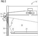
- FIG 2illustrates a schematic partial sectional side view of the cooking oven 10 with the camera 18 according to a second embodiment of the present invention.
- the cooking oven 10includes the cooking chamber 12 openable and closable by the oven door 14 at the front side of said cooking chamber 12.
- the oven door 14comprises the oven door handle 16 arranged at the upper portion of the outer side of said oven door 14.
- the oven door 14includes the outer glass panel 26 and the inner glass panel 28.
- the oven door 14 of the second embodimentincludes a thermal insulation material 30 enclosing outer portions of the outer glass panel 26 and the inner glass panel 28, so that a window remains in the central portion of the oven door 14. Thus, in said central portion the oven door 14 is transparent.
- the thermal insulation material 30allows improved energy efficiency.
- the window in the oven door 14is defined by the thermal insulation material 30.
- the camera 18is located inside the oven door handle 16.
- the lens coverage 20 of the camera 18is directed through the window of the oven door 14 to the food stuff 24 disposed on the cooking tray 22 inside the cooking chamber 12.
- the camera 18is connected or connectable by wire or wireless to the picture displaying device, wherein said picture displaying device may be the user interface of the cooking oven 10 or the external device.
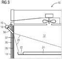
- FIG 3illustrates a schematic partial sectional side view of the cooking oven 10 with the camera 18 according to a third embodiment of the present invention.
- the cooking oven 10includes the cooking chamber 12 openable and closable by the oven door 14 at its front side.
- the oven door 14comprises the oven door handle 16 arranged at the upper portion of the outer side of said oven door 14.
- the oven door 14includes the outer glass panel 26 and the inner glass panel 28.
- the oven door 14 of the third embodimentincludes a shielding metal mesh 32 at an inner side of the inner glass panel 28.
- the geometric structure of the shielding metal mesh 32is dimensioned for microwaves.
- the shielding metal mesh 32includes a plurality of small holes, so that the oven door 14 remains partially transparent.
- the camera 18is located inside the oven door handle 16.
- a pinhole lens 34is arranged between the camera 18 and the shielding metal mesh 32.
- the diameter of said pinhole lens 34is smaller than or equal as the holes of the shielding metal mesh 32.
- the pinhole lens 34allows the camera 18 seeing through the shielding metal mesh 32.
- the lens coverage 20 of the camera 18is directed through the shielding metal mesh 32 to the food stuff 24 disposed on the cooking tray 22 inside the cooking chamber 12.
- the camera 18is connected or connectable by wire or wireless to the picture displaying device, wherein said picture displaying device may be the user interface of the cooking oven 10 or the external device.
- the cooking ovens 10 according to the second and third embodiments of the present inventionmay be combined, so that the oven door 14 includes the thermal insulation material 30 as well as the shielding metal mesh 32.
- the window defined by the thermal insulation material 30is minimized, but sufficient, while the portion covered by the thermal insulation material 30 is maximized, so that the energy efficiency is optimized.
- FIG 4illustrates two schematic sectional side views of the cooking oven 10 with the camera 18 according to a fourth embodiment of the present invention, wherein the oven door 14 is in a partially opened state and in a closed state, respectively.
- multiple images of the cooking chamber 12 and the food stuff 24are recorded by the camera 18. Since the position of the camera 18 at the oven door handle 16 and the movement path of the oven door 14 are known, the position of the camera 18 in relation to the cooking chamber 12 can be calculated. For example, a door switch may be used for identifying certain opening angles and/or the closed state of the oven door 14. Further, known points and/or structures on the recorded image may be used for calculating the position of the camera 18. For example, the position of a fan cover at the rear side of the cooking chamber 12 may be used.
- three-dimensional features of the food stuff 24 inside the cooking chamber 12are calculated by triangulation of multiple points of the images.
- the three-dimensional features of the food stuff 24are used as parameter for recognizing said food stuff 24.
- Such a methodis described in detail by WO 2013/167333 A1 .
- the three-dimensional features of the food stuff 24may be used for the calculation of the temperature distribution inside the food stuff 24.
- Such a methodis described elaborately in EP 1 921 384 A1 .
- the food stuff 24is already placed in the cooking chamber 12.
- a temperature sensormay be already inserted in the food stuff 24, wherein the three-dimensional position of said temperature sensor is recognized.
- a warning signalmay be generated, if the temperature sensor would be inserted in a wrong way.
- the oven door 14 of the fourth embodimentis similar as the oven door 14 of the first embodiment, the triangulation of the fourth embodiment may be also applied to the oven doors 14 according to the second and third embodiments.
- FIG 5illustrates a schematic partial sectional side view of the cooking oven 10 with the camera 18 according to a fifth embodiment of the present invention.
- the oven door handle 16 or at least that part of the oven door handle 16 including the camera 18is pivotable, so that the lens coverage 20 of the camera 18 is adjustable.
- the lens coverage 20 of the camera 18may be directed from said camera 18 to the food stuff 24 disposed on the cooking tray 22 inside the cooking chamber 12.
- the lens coverage 20 of the camera 18may be directed from said camera 18 to the portion in front of the cooking oven 10.
- the camera 18is connected by sliding contacts or wireless to the picture displaying device and/or to a power supply.
- the lens coverage 20 of the camera 18 directed to the front portion of the cooking oven 10may be utilised, when the camera 18 is not used for controlling the cooking process.
- the camera 18 directed to the front portion of the cooking oven 10may be used as a home surveillance device.
- the oven door handle 16 with the camera 18 according to the fifth embodimentcan be combined with each of the oven doors 14 according to the embodiments mentioned above.
- FIG 6illustrates a schematic front view of the inner glass panel 28 for the oven door 14 with the camera 18 according to a preferred embodiment of the present invention.
- the inner glass panel 28is suitable for each of the oven doors 14 according to the embodiments mentioned above.
- the inner glass panel 28includes an outer portion 36 and an inner portion 38.
- the inner portion 38is transparent, while the outer portion 36 is semi-transparent or non-transparent. Alternatively, the inner portion 38 as well as the outer portion 36 may be transparent.
- the inner glass panel 28includes a metal coating 40.
- the metal coating 40extends over a trapezoid area in an upper centre within the inner portion 38 of the inner glass panel 28.
- the metal coating 40is arranged in that section of the inner glass panel 28, which is penetrated by the lens coverage 20 of the camera 18.
- the metal coating 40may extend over the whole area of the inner glass panel 28.
- the metal coating 40may also extend over the inner portion 38 of the inner glass panel 28.
- the metal coating 40extends over an area, which is equal or bigger than the section of the inner glass panel 28 penetrated by the lens coverage 20 of the camera 18.
- the metal coatingmay be used as an electric heating element.
- the metal coatinghas a suitable electric conductivity and resistance, so that the metal coating is heated up by an electric current flowing through said metal coating.
- the optical transparency of the metal coatingmay be adapted to at least a part of the frequency spectrum of the camera, at least in that area of the metal coating, in which said metal coating is penetrated by the lens coverage of the camera.
- the metal coating 40is applied on the inner side of the inner glass panel 28.
- the high thermal conductivity of the metal coating 40prevents condensation at the inner side of the inner glass panel 28, in particular during baking or steaming. This guarantees a high visibility through the oven door 14 between the camera 18 and the food stuff 24.
- the energy supply for the camera 18may be realized by a direct cable connection, by sliding contact elements, by a plug connector, by a wireless inductive power transmission, be a battery or by a rechargeable power pack.
- the cooking oven 10includes an illumination device located at or inside the oven door handle 16.
- said illumination deviceis realized by light emitting diodes (LED).
- the illumination deviceis provided for illuminating the food stuff 24 disposed on the cooking tray 22.
- the temperature in the environment of said camera 18is relative low. Thus, any thermal isolation or cooling is not required for the camera 18. An additional or special housing for the camera 18 is not necessary.
- the cooking oven 10may be connected or connectable to a mobile or stationary computer device via a wireless data connection.
- the mobile computer devicemay be a mobile phone, a smart phone, a tablet personal computer, a netbook or a notebook.
- a transmitter and/or receiver for the wireless data connectionmay be arranged inside the oven door handle 16 or in the environment of said oven door handle 16.
- the wireless data connectionmay be unidirectional, wherein picture signals may be transferred from the camera 18 to the mobile or stationary computer device.
- the useris able to monitor a working process of the cooking oven 10 by the mobile or stationary computer device.
- the wireless data connectionis bidirectional, wherein picture signals may be transferred from the camera 18 to the mobile or stationary computer device as well as from the mobile or stationary computer device to the control unit of the cooking oven 10.
- the useris able to control the cooking process of the cooking oven 10 by the mobile or stationary computer device.
- the usermay control the cooking oven 10 manually by the control unit. If the wireless data connection between the cooking oven 10 and the mobile or stationary computer device is bidirectional, then the user may control the cooking oven 10 by the mobile or stationary computer device and/or the control unit of said cooking oven 10.
- the cooking oven 10 with the camera 18 on the one hand and the mobile or stationary computer device on the other handmay be interconnected or interconnectable via the internet.
- the cooking oven 10is connected or connectable to the internet via a local area network (LAN) or a wireless local area network (WLAN) to the internet.
- the mobile computer devicemay be connected or connectable to the internet via the wireless local area network (WLAN) or a mobile communications network, while the stationary computer device may be connected or connectable to the internet via the local area network (LAN).
- WLANwireless local area network
- LANlocal area network
- the wireless data connection between the cooking oven 10 and the mobile or stationary computer devicemay be realized via a radio contact. Further, the cooking oven 10 and the mobile or stationary computer device may be interconnected or interconnectable via infrared signals. In general, an arbitrary wireless data connection between the cooking oven 10 and the mobile or stationary computer device is possible. Preferably, the selection of the type of the wireless data connection between the cooking oven 10 and the mobile or stationary computer device depends on the favoured operating distance.
- a display and/or a touch screen of the mobile or stationary computer devicemay be provided for indicating current pictures recorded by the camera 18 of the cooking oven 10.
- the wireless data connection from the cooking oven 10 to the mobile or stationary computer deviceis provided for transferring picture signals in real time.
- an external connectionbetween the mobile or stationary computer device and the internet.
- Said external connectionallows communications between the mobile or stationary computer device and the internet.
- the mobile or stationary computer devicemay use applications provided by the internet.
- the useris able to download software for the mobile or stationary computer device from the internet.
- the usercan access to data bases in the internet by the mobile or stationary computer device.
- application softwarefor the mobile or stationary computer device.
- Said application softwarecomprises one or more functions and/or features supporting the operations of the mobile or stationary computer device.
- the application softwarecomprises a viewing function, which allows the representation of the picture signal from the camera 18 of the cooking oven 10 on the display or touch screen of the mobile or stationary computer device.
- the viewing functionallows a current viewing of the food stuff 24 on the cooking tray 22 inside the oven chamber 12 on the display or touch screen of the mobile or stationary computer device.
- a real-time transmission of pictures from the camera 18 of the cooking oven 10 to the display of the mobile or stationary computer deviceis possible.
- the useris able to monitor the food stuff 24 inside the oven chamber 12 of the cooking oven 10 from a distance by the mobile or stationary computer device.
- the useris always able to be informed about the current state of the food stuff 24 inside the cooking chamber 12.
- the camera 18records reflections from the outer side of the oven door 14, e.g. from the outer side of the outer glass panel 26. These reflections can be used to detect movements in front of the cooking oven 10.
- the movement of the user in front of the cooking oven 10can be translated into Cartesian coordinates in order to control a user interface.
- Certain gestures of the usermay be linked to corresponding actions of the user interface, e.g. activating and deactivating the light of the cooking oven 10.
- the light inside the cooking chamber 12is dimmed and/or the light in front of the cooking oven 10 is brightened up, when the presence or an interaction of the user is recognized.
- the present inventionin general relates to a domestic appliance with a treatment chamber.
Landscapes
- Engineering & Computer Science (AREA)
- Physics & Mathematics (AREA)
- General Physics & Mathematics (AREA)
- Combustion & Propulsion (AREA)
- Mechanical Engineering (AREA)
- General Engineering & Computer Science (AREA)
- Chemical & Material Sciences (AREA)
- Computer Networks & Wireless Communication (AREA)
- Multimedia (AREA)
- Signal Processing (AREA)
- Theoretical Computer Science (AREA)
- Electromagnetism (AREA)
- Computer Vision & Pattern Recognition (AREA)
- Quality & Reliability (AREA)
- Electric Ovens (AREA)
- Electric Stoves And Ranges (AREA)
Description
- The present invention relates to a domestic appliance, in particular cooking oven, with a camera according to the preamble of claim 1.
- In a number of modern domestic appliances a camera is often used for monitoring the interior of a treatment chamber. The camera relieves the treatment process, since a direct look by the user into the treatment chamber is not necessary.
- If the camera is arranged inside a heated treatment chamber, then the camera requires a special housing and/or a thermal insulation and/or a cooling in order to prevent a destruction of the camera by the heat. Further, it is not easy to transmit the picture signals out of the treatment chamber.
- If the camera is arranged outside the treatment chamber, then the camera requires a special holding device in order to guarantee a stable foothold of the camera. Usually, the holding device protrudes the domestic appliance.
EP 2 515 044 A1 discloses a cooking oven with a camera. The oven door for closing the oven cavity includes a transparent portion. The camera is arranged at the oven door and outside of the oven cavity, so that pictures of the oven cavity may be detected. In particular, the camera is arranged in front of the transparent portion.- It is an object of the present invention to provide an improved domestic appliance with a camera, which overcomes the disadvantages mentioned above, wherein the camera is installed by low complexity.
- The object is achieved by the domestic appliance according to claim 1.
- According to the present invention the camera is arranged inside the door handle.
- The core of the present invention is the arrangement of the camera inside the door handle. The camera does not require any additional thermal insulation or cooling. The door handle is a strong component of the domestic appliance, so that a stable foothold of the camera is guaranteed. Since the door handle is already present at the domestic appliance, the arrangement of the camera is realized by low complexity.
- Preferably, the door includes at least one glass panel. The glass panel provides transparency and thermal insulation.
- For example, the picture displaying device is a part of the control unit of the domestic appliance, wherein the camera is connected or connectable to said picture displaying device by wire or via a wireless data connection.
- Alternatively, the picture displaying device is a part of the external device, wherein the camera is connected or connectable to said picture displaying device via the wireless data connection.
- In particular, a transmitter is arranged inside the door handle or in the environment of said door handle, wherein the transmitter is provided for sending the picture signals generated by the camera to the picture displaying device.
- According to a further application, the camera is provided for detecting reflections on an outer side of the door in order to recognize movements in front of the domestic appliance.
- For example, the recognition of movements in front of the domestic appliance is used or usable for an automatic activation of at least one predetermined function of the domestic appliance.
- Further, the domestic appliance comprises at least one illumination device arranged at an outer side of the door and directed into the interior of the treatment chamber. The illumination device provided a sufficient illumination of the treatment chamber.
- Preferably, the illumination device is arranged at and/or inside the door handle. For example, the illumination device comprises a plurality of light emitting diodes.
- Moreover, the control unit of the domestic appliance or the external device, respectively, includes or is supported or supportable by application software provided for representing and/or processing the picture signals generated by the camera. The application software allows a plurality of prospects on the basis of the picture signals.
- According to a preferred embodiment of the present invention, the domestic appliance is a cooking oven, wherein the treatment chamber is a cooking chamber, the door is an oven door and the door handle is an oven door handle, and wherein food stuff disposed on a cooking tray inside the cooking chamber is located within the lens coverage of the camera.
- Furthermore, the oven door includes thermal insulation material distributed within outer portions of said oven door, so that the window or transparent part remains in the central portion of the oven door.
- Alternatively, the oven door includes shielding metal mesh, preferably at its inner side, wherein the geometric structure of said shielding metal mesh is dimensioned for microwaves. Thus, the cooking oven may comprise a microwave heating function.
- In this case, the camera may comprise a pinhole lens arranged between said camera and the shielding metal mesh, wherein the optical diameter of said pinhole lens is smaller than or equal as the holes of the shielding metal mesh.
- Further, the oven door may include thermal insulation material distributed within said oven door, so that the part in front of the pinhole lens remains transparent. This is a combination of the embodiments with the shielding metal mesh and the thermal insulation material.
- Moreover, the camera may be provided for recording two or more images of the interior of the cooking chamber during opening and/or closing the oven door, so that three-dimensional features of the food stuff inside the cooking chamber are calculated by triangulation of multiple points of said images. On the basis of the positions of the camera and the images recorded from said positions the three-dimensional features of the food stuff are calculated by triangulation of multiple points of the images. Said three-dimensional features may be used as parameter for recognizing said food stuff. Further, the three-dimensional features of the food stuff may be used for the calculation of the temperature distribution inside the food stuff.
- Additionally, the oven door handle or at least that part of the oven door handle including the camera may be pivotable, so that the lens coverage of the camera is adjustable, wherein preferably the lens coverage of the camera is directed to the food stuff inside the cooking chamber on the one hand and to a portion in front of the cooking oven on the other hand. For example, the camera directed to the front portion of the cooking oven may be used as a home surveillance device.
- At last, a metal coating may be applied at an inner side of the oven door, wherein said metal coating extends at least over the lens coverage of the camera penetrating the oven door, and wherein preferably the metal coating is applied at an inner side of the inner glass panel of the oven door, and/or wherein preferably the metal coating is directly heated or heatable by an electric current flowing through said metal coating, and/or wherein preferably at least an area of the metal coating penetrated by the lens coverage of the camera is optically transparent in view of at least a part of the frequency spectrum of said camera. The high thermal conductivity of the metal coating prevents condensation at the inner side of the inner glass pane, in particular during baking or steaming. The metal coating guarantees a high visibility through the oven door between the camera and the food stuff. The metal coating may have a suitable electric conductivity and resistance, so that the metal coating may act as an electric heating element. Further, the optical transparency of the metal coating may be at least partially adapted to the frequency spectrum of the camera, at least in that area of the metal coating, in which said metal coating is penetrated by the lens coverage of the camera.
- Novel and inventive features of the present invention are set forth in the appended claims.
- The present invention will be described in further detail with reference to the drawing, in which
- FIG 1
- illustrates a schematic partial sectional side view of a cooking oven with a camera according to a first embodiment of the present invention,
- FIG 2
- illustrates a schematic partial sectional side view of the cooking oven with the camera according to a second embodiment of the present invention,
- FIG 3
- illustrates a schematic partial sectional side view of the cooking oven with the camera according to a third embodiment of the present invention,
- FIG 4
- illustrates two schematic sectional side views of the cooking oven with the camera according to a fourth embodiment of the present invention, wherein an oven door is in a partially opened state and in a closed state, respectively,
- FIG 5
- illustrates a schematic partial sectional side view of the cooking oven with the camera according to a fifth embodiment of the present invention, and
- FIG 6
- illustrates a schematic front view of an inner glass panel for the oven door with the camera according to a preferred embodiment of the present invention.
FIG 1 illustrates a schematic partial sectional side view of acooking oven 10 with acamera 18 according to a first embodiment of the present invention.- The
cooking oven 10 includes acooking chamber 12 openable and closable by anoven door 14. In this example, theoven door 14 forms the front side of thecooking chamber 12. Theoven door 14 comprises an oven door handle 16 arranged at an upper portion of an outer side of saidoven door 14. Theoven door 14 includes a window, so that at least a part of saidoven door 14 is transparent. In this example, theoven door 14 includes anouter glass panel 26 and aninner glass panel 28. - The
camera 18 is located inside theoven door handle 16. Alens coverage 20 of thecamera 18 is directed from saidcamera 18 through theoven door 14 tofood stuff 24 disposed on acooking tray 22 inside thecooking chamber 12. Thecamera 18 is connected or connectable by wire or wireless to a picture displaying device. Said picture displaying device may be a part of a user interface or control unit of thecooking oven 10 or an external device. For example, said external device is a television, a smartphone, a netbook, a notebook or a personal computer. - The picture of the
cooking chamber 12 detected by thecamera 18 may be used by the user, by the control unit or by the external device for a plurality of functions. - One group of functions relates to the safety of the
cooking oven 10. For example, the picture detected by thecamera 18 indicates if thecooking chamber 12 is empty in order to perform a treatment by pyrolysis. Further, the picture detected by thecamera 18 may indicate if a fan cover is inside thecooking chamber 12. Moreover, the picture detected by thecamera 18 may indicate if the fan is turning. Additionally, the picture detected by thecamera 18 may indicate if smoke is gathering inside thecooking chamber 12. - Another group of functions supports the cooking process. For example, the information from the picture detected by the
camera 18 recognizes the level of thecooking tray 22. Further, the information from the picture detected by thecamera 18 recognizes browning of thefood stuff 24. Moreover, the information from the picture detected by thecamera 18 recognizes the number of thecooking trays 22 inside thecooking chamber 12. The control unit may give advices in view of the heating mode and/or temperature ion the basis of the information mentioned above. - A further group of functions relates to services for the
cooking oven 10. For example, the information from the picture detected by thecamera 18 recognizes if the illumination of thecooking chamber 12 is defect. FIG 2 illustrates a schematic partial sectional side view of thecooking oven 10 with thecamera 18 according to a second embodiment of the present invention.- The
cooking oven 10 includes thecooking chamber 12 openable and closable by theoven door 14 at the front side of saidcooking chamber 12. Theoven door 14 comprises the oven door handle 16 arranged at the upper portion of the outer side of saidoven door 14. Theoven door 14 includes theouter glass panel 26 and theinner glass panel 28. Further, theoven door 14 of the second embodiment includes athermal insulation material 30 enclosing outer portions of theouter glass panel 26 and theinner glass panel 28, so that a window remains in the central portion of theoven door 14. Thus, in said central portion theoven door 14 is transparent. Thethermal insulation material 30 allows improved energy efficiency. The window in theoven door 14 is defined by thethermal insulation material 30. - The
camera 18 is located inside theoven door handle 16. Thelens coverage 20 of thecamera 18 is directed through the window of theoven door 14 to thefood stuff 24 disposed on thecooking tray 22 inside thecooking chamber 12. Thecamera 18 is connected or connectable by wire or wireless to the picture displaying device, wherein said picture displaying device may be the user interface of thecooking oven 10 or the external device. FIG 3 illustrates a schematic partial sectional side view of thecooking oven 10 with thecamera 18 according to a third embodiment of the present invention.- The
cooking oven 10 includes thecooking chamber 12 openable and closable by theoven door 14 at its front side. Theoven door 14 comprises the oven door handle 16 arranged at the upper portion of the outer side of saidoven door 14. Theoven door 14 includes theouter glass panel 26 and theinner glass panel 28. Further, theoven door 14 of the third embodiment includes a shieldingmetal mesh 32 at an inner side of theinner glass panel 28. The geometric structure of the shieldingmetal mesh 32 is dimensioned for microwaves. Thus, thecooking oven 10 of the third embodiment is suitable for microwave heating means. The shieldingmetal mesh 32 includes a plurality of small holes, so that theoven door 14 remains partially transparent. - The
camera 18 is located inside theoven door handle 16. Apinhole lens 34 is arranged between thecamera 18 and the shieldingmetal mesh 32. The diameter of saidpinhole lens 34 is smaller than or equal as the holes of the shieldingmetal mesh 32. Thepinhole lens 34 allows thecamera 18 seeing through the shieldingmetal mesh 32. - The
lens coverage 20 of thecamera 18 is directed through the shieldingmetal mesh 32 to thefood stuff 24 disposed on thecooking tray 22 inside thecooking chamber 12. Thecamera 18 is connected or connectable by wire or wireless to the picture displaying device, wherein said picture displaying device may be the user interface of thecooking oven 10 or the external device. - Furthermore, the
cooking ovens 10 according to the second and third embodiments of the present invention may be combined, so that theoven door 14 includes thethermal insulation material 30 as well as the shieldingmetal mesh 32. In this case, the window defined by thethermal insulation material 30 is minimized, but sufficient, while the portion covered by thethermal insulation material 30 is maximized, so that the energy efficiency is optimized. FIG 4 illustrates two schematic sectional side views of thecooking oven 10 with thecamera 18 according to a fourth embodiment of the present invention, wherein theoven door 14 is in a partially opened state and in a closed state, respectively.- In this embodiment, during closing and/or opening the
oven door 14 multiple images of thecooking chamber 12 and thefood stuff 24 are recorded by thecamera 18. Since the position of thecamera 18 at theoven door handle 16 and the movement path of theoven door 14 are known, the position of thecamera 18 in relation to thecooking chamber 12 can be calculated. For example, a door switch may be used for identifying certain opening angles and/or the closed state of theoven door 14. Further, known points and/or structures on the recorded image may be used for calculating the position of thecamera 18. For example, the position of a fan cover at the rear side of thecooking chamber 12 may be used. - On the basis of the positions of the
camera 18 and the images recorded from said positions three-dimensional features of thefood stuff 24 inside thecooking chamber 12 are calculated by triangulation of multiple points of the images. In particular, the three-dimensional features of thefood stuff 24 are used as parameter for recognizing saidfood stuff 24. Such a method is described in detail byWO 2013/167333 A1 . Further, the three-dimensional features of thefood stuff 24 may be used for the calculation of the temperature distribution inside thefood stuff 24. Such a method is described elaborately inEP 1 921 384 A1 . - Since the multiple images are recorded during closing and/or opening the
oven door 14, thefood stuff 24 is already placed in thecooking chamber 12. In this situation, a temperature sensor may be already inserted in thefood stuff 24, wherein the three-dimensional position of said temperature sensor is recognized. A warning signal may be generated, if the temperature sensor would be inserted in a wrong way. - Although the
oven door 14 of the fourth embodiment is similar as theoven door 14 of the first embodiment, the triangulation of the fourth embodiment may be also applied to theoven doors 14 according to the second and third embodiments. FIG 5 illustrates a schematic partial sectional side view of thecooking oven 10 with thecamera 18 according to a fifth embodiment of the present invention.- The oven door handle 16 or at least that part of the oven door handle 16 including the
camera 18 is pivotable, so that thelens coverage 20 of thecamera 18 is adjustable. On the one hand, thelens coverage 20 of thecamera 18 may be directed from saidcamera 18 to thefood stuff 24 disposed on thecooking tray 22 inside thecooking chamber 12. On the other hand, thelens coverage 20 of thecamera 18 may be directed from saidcamera 18 to the portion in front of thecooking oven 10. For example, thecamera 18 is connected by sliding contacts or wireless to the picture displaying device and/or to a power supply. - The
lens coverage 20 of thecamera 18 directed to the front portion of thecooking oven 10 may be utilised, when thecamera 18 is not used for controlling the cooking process. For example, thecamera 18 directed to the front portion of thecooking oven 10 may be used as a home surveillance device. - The oven door handle 16 with the
camera 18 according to the fifth embodiment can be combined with each of theoven doors 14 according to the embodiments mentioned above. FIG 6 illustrates a schematic front view of theinner glass panel 28 for theoven door 14 with thecamera 18 according to a preferred embodiment of the present invention. Theinner glass panel 28 is suitable for each of theoven doors 14 according to the embodiments mentioned above.- The
inner glass panel 28 includes anouter portion 36 and aninner portion 38. Theinner portion 38 is transparent, while theouter portion 36 is semi-transparent or non-transparent. Alternatively, theinner portion 38 as well as theouter portion 36 may be transparent. - The
inner glass panel 28 includes ametal coating 40. In this example, themetal coating 40 extends over a trapezoid area in an upper centre within theinner portion 38 of theinner glass panel 28. Themetal coating 40 is arranged in that section of theinner glass panel 28, which is penetrated by thelens coverage 20 of thecamera 18. Alternatively, themetal coating 40 may extend over the whole area of theinner glass panel 28. Further, themetal coating 40 may also extend over theinner portion 38 of theinner glass panel 28. In general, themetal coating 40 extends over an area, which is equal or bigger than the section of theinner glass panel 28 penetrated by thelens coverage 20 of thecamera 18. - Moreover, the metal coating may be used as an electric heating element. In this case, the metal coating has a suitable electric conductivity and resistance, so that the metal coating is heated up by an electric current flowing through said metal coating.
- Furthermore, the optical transparency of the metal coating may be adapted to at least a part of the frequency spectrum of the camera, at least in that area of the metal coating, in which said metal coating is penetrated by the lens coverage of the camera.
- The
metal coating 40 is applied on the inner side of theinner glass panel 28. The high thermal conductivity of themetal coating 40 prevents condensation at the inner side of theinner glass panel 28, in particular during baking or steaming. This guarantees a high visibility through theoven door 14 between thecamera 18 and thefood stuff 24. - The energy supply for the
camera 18 may be realized by a direct cable connection, by sliding contact elements, by a plug connector, by a wireless inductive power transmission, be a battery or by a rechargeable power pack. - Optionally, the
cooking oven 10 includes an illumination device located at or inside theoven door handle 16. Preferably, said illumination device is realized by light emitting diodes (LED). The illumination device is provided for illuminating thefood stuff 24 disposed on thecooking tray 22. - Since the
camera 18 is arranged outside thecooking chamber 12, the temperature in the environment of saidcamera 18 is relative low. Thus, any thermal isolation or cooling is not required for thecamera 18. An additional or special housing for thecamera 18 is not necessary. - Further, the
cooking oven 10 may be connected or connectable to a mobile or stationary computer device via a wireless data connection. For example, the mobile computer device may be a mobile phone, a smart phone, a tablet personal computer, a netbook or a notebook. A transmitter and/or receiver for the wireless data connection may be arranged inside the oven door handle 16 or in the environment of saidoven door handle 16. - According to one example the wireless data connection may be unidirectional, wherein picture signals may be transferred from the
camera 18 to the mobile or stationary computer device. In this case, the user is able to monitor a working process of thecooking oven 10 by the mobile or stationary computer device. - According to another example the wireless data connection is bidirectional, wherein picture signals may be transferred from the
camera 18 to the mobile or stationary computer device as well as from the mobile or stationary computer device to the control unit of thecooking oven 10. In the latter case, the user is able to control the cooking process of thecooking oven 10 by the mobile or stationary computer device. - If the wireless data connection between the
camera 18 and the mobile or stationary computer device is unidirectional, then the user may control thecooking oven 10 manually by the control unit. If the wireless data connection between the cookingoven 10 and the mobile or stationary computer device is bidirectional, then the user may control thecooking oven 10 by the mobile or stationary computer device and/or the control unit of saidcooking oven 10. - The
cooking oven 10 with thecamera 18 on the one hand and the mobile or stationary computer device on the other hand may be interconnected or interconnectable via the internet. For example, thecooking oven 10 is connected or connectable to the internet via a local area network (LAN) or a wireless local area network (WLAN) to the internet. The mobile computer device may be connected or connectable to the internet via the wireless local area network (WLAN) or a mobile communications network, while the stationary computer device may be connected or connectable to the internet via the local area network (LAN). - Alternatively, the wireless data connection between the cooking
oven 10 and the mobile or stationary computer device may be realized via a radio contact. Further, thecooking oven 10 and the mobile or stationary computer device may be interconnected or interconnectable via infrared signals. In general, an arbitrary wireless data connection between the cookingoven 10 and the mobile or stationary computer device is possible. Preferably, the selection of the type of the wireless data connection between the cookingoven 10 and the mobile or stationary computer device depends on the favoured operating distance. - A display and/or a touch screen of the mobile or stationary computer device may be provided for indicating current pictures recorded by the
camera 18 of thecooking oven 10. The wireless data connection from thecooking oven 10 to the mobile or stationary computer device is provided for transferring picture signals in real time. - Optionally, there is an external connection between the mobile or stationary computer device and the internet. Said external connection allows communications between the mobile or stationary computer device and the internet. For example, the mobile or stationary computer device may use applications provided by the internet. Further, the user is able to download software for the mobile or stationary computer device from the internet. Moreover, the user can access to data bases in the internet by the mobile or stationary computer device.
- In particular, application software ("APP") for the mobile or stationary computer device is provided. Said application software comprises one or more functions and/or features supporting the operations of the mobile or stationary computer device. The application software ("APP") comprises a viewing function, which allows the representation of the picture signal from the
camera 18 of thecooking oven 10 on the display or touch screen of the mobile or stationary computer device. The viewing function allows a current viewing of thefood stuff 24 on thecooking tray 22 inside theoven chamber 12 on the display or touch screen of the mobile or stationary computer device. A real-time transmission of pictures from thecamera 18 of thecooking oven 10 to the display of the mobile or stationary computer device is possible. Thus, the user is able to monitor thefood stuff 24 inside theoven chamber 12 of thecooking oven 10 from a distance by the mobile or stationary computer device. The user is always able to be informed about the current state of thefood stuff 24 inside thecooking chamber 12. - According to a special embodiment of the present invention, the
camera 18 records reflections from the outer side of theoven door 14, e.g. from the outer side of theouter glass panel 26. These reflections can be used to detect movements in front of thecooking oven 10. The movement of the user in front of thecooking oven 10 can be translated into Cartesian coordinates in order to control a user interface. Certain gestures of the user may be linked to corresponding actions of the user interface, e.g. activating and deactivating the light of thecooking oven 10. In order to improve the reflections of the user on the outer side of theoven door 14 the light inside thecooking chamber 12 is dimmed and/or the light in front of thecooking oven 10 is brightened up, when the presence or an interaction of the user is recognized. - Although embodiments of the
cooking oven 10 are described above, the present invention in general relates to a domestic appliance with a treatment chamber. - Although illustrative embodiments of the present invention has been described herein with reference to the accompanying drawing, it is to be understood that the present invention is not limited to those precise embodiments, and that various other changes and modifications may be affected therein by one skilled in the art without departing from the scope of the invention. All such changes and modifications are intended to be included within the scope of the invention as defined by the appended claims.
- 10
- cooking oven
- 12
- cooking chamber
- 14
- oven door
- 16
- oven door handle
- 18
- camera
- 20
- lens coverage
- 22
- cooking tray
- 24
- food stuff
- 26
- outer glass panel
- 28
- inner glass panel
- 30
- thermal insulation material
- 32
- shielding metal mesh
- 34
- pinhole lens
- 36
- outer portion
- 38
- inner portion
- 40
- metal coating
Claims (15)
- A domestic appliance, in particular a cooking oven (10), with a camera (18), wherein- the domestic appliance (10) comprises a treatment chamber (12),- the domestic appliance (10) comprises a door (14) for opening and closing the treatment chamber (12),- the door (14) includes a window or a transparent part,- the door (14) includes a door handle (16) arranged at an outer side of said door (14),- the lens coverage (20) of the camera (18) extends from said camera (18) through the window or transparent part of the door (14) into the interior of the treatment chamber (12),- picture signals generated by the camera (18) are represented or representable by a picture displaying device, and- said picture displaying device is a part of the control unit of the domestic appliance (10) and/or a part of an external device connected or connectable to said domestic appliance (10),characterised in that
the camera (18) is arranged inside the door handle (16). - The domestic appliance according to claim 1,
characterized in that
the door (14) includes at least one glass panel (26, 28). - The domestic appliance according to claim 1 or 2,
characterized in that
the picture displaying device is a part of the control unit of the domestic appliance (10), wherein the camera (18) is connected or connectable to said picture displaying device by wire or via a wireless data connection. - The domestic appliance according to claim 1 or 2,
characterized in that
the picture displaying device is a part of the external device, wherein the camera (18) is connected or connectable to said picture displaying device via the wireless data connection. - The domestic appliance according to claim 3 or 4,
characterized in that
a transmitter is arranged inside the door handle (16) or in the environment of said door handle (16), wherein the transmitter is provided for sending the picture signals generated by the camera (18) to the picture displaying device. - The domestic appliance according to any one of the preceding claims,
characterized in that
the camera (18) is provided for detecting reflections on an outer side of the door (14) in order to recognize movements in front of the domestic appliance (10), wherein preferably the recognition of movements in front of the domestic appliance (10) is used for an automatic activation of at least one predetermined function of the domestic appliance (10). - The domestic appliance according to any one of the preceding claims,
characterized in that
the domestic appliance (10) comprises at least one illumination device arranged at an outer side of the door (14) and directed into the interior of the treatment chamber (12), wherein preferably the illumination device is arranged at and/or inside the door handle (16). - The domestic appliance according to any one of the preceding claims,
characterized in that
the control unit of the domestic appliance (10) or the external device, respectively, includes or is supported or supportable by application software provided for representing and/or processing the picture signals generated by the camera (18). - The domestic appliance according to any one of the preceding claims,
characterized in that
the domestic appliance is a cooking oven (10), wherein the treatment chamber is a cooking chamber (12), the door is an oven door (14) and the door handle is an oven door handle (16), and wherein food stuff (24) disposed on a cooking tray (22) inside the cooking chamber (12) is located within the lens coverage (20) of the camera (18). - The domestic appliance according to claim 9,
characterized in that
the oven door (14) includes thermal insulation material (30) distributed within outer portions of said oven door (14), so that the window or transparent part remains in the central portion of the oven door (14). - The domestic appliance according to claim 9,
characterized in that
the oven door (14) includes shielding metal mesh (32), preferably at its inner side, wherein the geometric structure of said shielding metal mesh (32) is dimensioned for microwaves, wherein preferably the camera (18) comprises a pinhole lens (34) arranged between said camera (18) and the shielding metal mesh (32), wherein the optical diameter of said pinhole lens (34) is smaller than or equal as the holes of the shielding metal mesh (32). - The domestic appliance according to claim 11,
characterized in that
the oven door (14) includes thermal insulation material (30) distributed within said oven door (14), so that the part in front of the pinhole lens (34) remains transparent. - The domestic appliance according to any one of the claims 9 to 12,
characterized in that
the camera (18) is provided for recording two or more images of the interior of the cooking chamber (12) during opening and/or closing the oven door (10), so that three-dimensional features of the food stuff (24) inside the cooking chamber (12) are calculated by triangulation of multiple points of said images. - The domestic appliance according to any one of the claims 9 to 13,
characterized in that
the oven door handle (16) or at least that part of the oven door handle (16) including the camera (18) is pivotable, so that the lens coverage (20) of the camera (18) is adjustable, wherein preferably the lens coverage (20) of the camera (18) is directed to the food stuff (24) inside the cooking chamber (12) on the one hand and to a portion in front of the cooking oven (10) on the other hand. - The domestic appliance according to any one of the claims 9 to 14,
characterized in that
a metal coating (40) is applied at an inner side of the oven door (14), wherein said metal coating (40) extends at least over the lens coverage (20) of the camera (18) penetrating the oven door (14), and wherein preferably the metal coating (40) is applied at an inner side of the inner glass panel (28) of the oven door (14), and/or wherein preferably the metal coating (40) is directly heated or heatable by an electric current flowing through said metal coating (40), and/or wherein preferably at least an area of the metal coating (40) penetrated by the lens coverage (20) of the camera (18) is optically transparent in view of at least a part of the frequency spectrum of said camera (18).
Applications Claiming Priority (3)
| Application Number | Priority Date | Filing Date | Title |
|---|---|---|---|
| EP14183303 | 2014-09-03 | ||
| EP14194985 | 2014-11-26 | ||
| PCT/EP2015/061071WO2016034295A1 (en) | 2014-09-03 | 2015-05-20 | Domestic appliance, in particular cooking oven, with a camera |
Publications (2)
| Publication Number | Publication Date |
|---|---|
| EP3194853A1 EP3194853A1 (en) | 2017-07-26 |
| EP3194853B1true EP3194853B1 (en) | 2018-07-11 |
Family
ID=53269462
Family Applications (1)
| Application Number | Title | Priority Date | Filing Date |
|---|---|---|---|
| EP15725281.8AActiveEP3194853B1 (en) | 2014-09-03 | 2015-05-20 | Domestic appliance, in particular cooking oven, with a camera |
Country Status (5)
| Country | Link |
|---|---|
| US (1) | US10674569B2 (en) |
| EP (1) | EP3194853B1 (en) |
| AU (1) | AU2015311260B2 (en) |
| DE (1) | DE202015009620U1 (en) |
| WO (1) | WO2016034295A1 (en) |
Cited By (2)
| Publication number | Priority date | Publication date | Assignee | Title |
|---|---|---|---|---|
| EP3907431A1 (en) | 2020-05-04 | 2021-11-10 | Electrolux Appliances Aktiebolag | Door assembly for an oven appliance |
| US11864669B2 (en) | 2020-11-25 | 2024-01-09 | Hussmann Corporation | Merchandiser including track door system |
Families Citing this family (62)
| Publication number | Priority date | Publication date | Assignee | Title |
|---|---|---|---|---|
| EP4063737A1 (en) | 2014-09-03 | 2022-09-28 | Electrolux Appliances Aktiebolag | Control of an operational feature of a cooking appliance |
| EP3292738B1 (en) | 2015-05-05 | 2020-12-30 | June Life, Inc. | A connected oven |
| KR102362654B1 (en) | 2015-07-03 | 2022-02-15 | 삼성전자주식회사 | Oven |
| US9998639B1 (en)* | 2015-09-21 | 2018-06-12 | The United States Of America As Represented By The Administrator Of The Nasa | Conducting autonomous experiments in space |
| US10398260B2 (en) | 2016-03-11 | 2019-09-03 | Samsung Electronics Co., Ltd. | Oven and control method thereof |
| KR102467319B1 (en)* | 2016-03-11 | 2022-11-16 | 삼성전자주식회사 | Oven and control method thereof |
| CN107296507A (en)* | 2016-04-15 | 2017-10-27 | 松下知识产权经营株式会社 | Cook householder method and cook accessory system |
| WO2017182074A1 (en)* | 2016-04-20 | 2017-10-26 | Vorwerk & Co. Interholding Gmbh | System for the preparation of at least one food product and method for operating the relevant system |
| EP3263992B1 (en)* | 2016-06-27 | 2020-02-05 | Electrolux Appliances Aktiebolag | Domestic appliance with optical monitoring device |
| EP3346190B1 (en) | 2017-01-10 | 2020-05-06 | Electrolux Appliances Aktiebolag | Food preparation entity |
| DE102017209399A1 (en)* | 2017-06-02 | 2018-12-06 | Convotherm-Elektrogeräte Gmbh | Cooking appliance |
| US11698219B2 (en) | 2017-08-10 | 2023-07-11 | Cooler Screens Inc. | Smart movable closure system for cooling cabinet |
| US11763252B2 (en) | 2017-08-10 | 2023-09-19 | Cooler Screens Inc. | Intelligent marketing and advertising platform |
| US11768030B2 (en) | 2017-08-10 | 2023-09-26 | Cooler Screens Inc. | Smart movable closure system for cooling cabinet |
| US12118510B2 (en) | 2017-08-10 | 2024-10-15 | Cooler Screens Inc. | Intelligent marketing and advertising platform |
| EP3665419A4 (en)* | 2017-08-11 | 2021-05-05 | Brava Home, Inc. | CONFIGURABLE COOKING SYSTEMS AND PROCEDURES |
| EP3450853B1 (en) | 2017-08-28 | 2021-02-24 | Electrolux Appliances Aktiebolag | Cooking oven with a camera assembly |
| EP3450854B1 (en) | 2017-08-30 | 2021-07-07 | Electrolux Appliances Aktiebolag | Cooking oven with a reflection shield and a camera |
| DE102017121401A1 (en) | 2017-09-14 | 2019-03-14 | Rational Aktiengesellschaft | Loading and unloading station as well as loading and / or unloading a cooking appliance to determine the loading of the cooking chamber of the cooking appliance |
| EP3460336B1 (en)* | 2017-09-22 | 2021-12-01 | WELBILT Deutschland GmbH | Cooking device, in particular commercial cooking device |
| US11493275B2 (en) | 2017-10-10 | 2022-11-08 | Tps Ip, Llc | Oven with renewable energy capacities |
| US11299925B2 (en) | 2017-10-11 | 2022-04-12 | Tps Ip, Llc | Oven with split doors |
| US11585701B2 (en) | 2017-10-27 | 2023-02-21 | Tps Ip, Llc | Intelligent oven |
| US10605463B2 (en)* | 2017-10-27 | 2020-03-31 | Whirlpool Corporation | Cooking appliance with a user interface |
| US10794508B2 (en) | 2017-11-14 | 2020-10-06 | Tps Ip, Llc | Atmosphere control manifold |
| US10798947B2 (en)* | 2017-12-08 | 2020-10-13 | Tps Ip, Llc | Oven with augmented reality functionality |
| US11346560B2 (en) | 2017-12-29 | 2022-05-31 | Tps Ip, Llc | Oven wall compositions and/or structures |
| MX2020007622A (en) | 2018-01-17 | 2020-09-14 | Anthony Inc | Door for mounting a removable electronic display. |
| CN112203847A (en)* | 2018-03-29 | 2021-01-08 | Agp美洲股份公司 | Automotive laminated glass with invisible heating and high red ratio for camera defroster |
| JP7198972B2 (en) | 2018-04-27 | 2023-01-05 | パナソニックIpマネジメント株式会社 | heating cooker |
| US10440245B1 (en)* | 2018-05-02 | 2019-10-08 | Haier Us Appliance Solutions, Inc. | Oven appliance camera assembly including a light shield |
| WO2019218685A1 (en)* | 2018-05-15 | 2019-11-21 | 上海达显智能科技有限公司 | Smart microwave oven having food material collection function |
| JP7253680B2 (en)* | 2018-05-18 | 2023-04-07 | パナソニックIpマネジメント株式会社 | heating cooker |
| EP3608593B1 (en)* | 2018-08-10 | 2022-03-16 | Electrolux Appliances Aktiebolag | Cooking system comprising an oven and an external computing means, and method of operating such system |
| US11141004B1 (en) | 2018-10-03 | 2021-10-12 | Anthony, Inc. | Display case door with interior facing camera |
| US11301689B1 (en)* | 2018-10-05 | 2022-04-12 | Inteladata, LLC | Real-time consumer goods monitoring |
| DE102018217324A1 (en) | 2018-10-10 | 2020-04-16 | BSH Hausgeräte GmbH | Cooking device with camera and method for operating a cooking device |
| CN109323299A (en)* | 2018-10-16 | 2019-02-12 | 惠而浦(中国)股份有限公司 | Microwave oven with integrated visual display and control |
| US11022322B2 (en) | 2019-01-04 | 2021-06-01 | Whirlpool Corporation | Cooking appliance with an imaging device |
| US11287140B2 (en) | 2019-01-04 | 2022-03-29 | Whirlpool Corporation | Cooking appliance with an imaging device |
| US20200229645A1 (en)* | 2019-01-18 | 2020-07-23 | Gpcp Ip Holdings Llc | Food delivery systems, apparatuses, and methods |
| US10514722B1 (en) | 2019-03-29 | 2019-12-24 | Anthony, Inc. | Door for mounting a removable electronic display |
| DE102019204533A1 (en)* | 2019-04-01 | 2020-10-01 | BSH Hausgeräte GmbH | Method for preparing a product to be cooked with optically indicated cooking product zones, cooking device and computer program product |
| US11680712B2 (en) | 2020-03-13 | 2023-06-20 | June Life, Inc. | Method and system for sensor maintenance |
| US11593717B2 (en) | 2020-03-27 | 2023-02-28 | June Life, Inc. | System and method for classification of ambiguous objects |
| US11340853B2 (en)* | 2020-04-01 | 2022-05-24 | Anova Applied Electronics, Inc. | Appliance handle with automatic shutoff of input interface elements |
| US20220007885A1 (en)* | 2020-07-08 | 2022-01-13 | June Life, Inc. | Method and system for cavity state determination |
| US20220117274A1 (en)* | 2020-10-20 | 2022-04-21 | June Life, Inc. | Intelligent cooking system and method |
| US20220159792A1 (en)* | 2020-11-17 | 2022-05-19 | Haier Us Appliance Solutions, Inc. | Cooking assemblies and methods of operation based on detected cookware |
| US11940153B2 (en) | 2020-12-01 | 2024-03-26 | GMG Products, LLC | Fuel conditioner for grill |
| US11988450B2 (en) | 2020-12-10 | 2024-05-21 | Haier Us Appliance Solutions, Inc. | Cooking appliance having an imaging device for identifying a type of temperature sensing device |
| CN113015278A (en)* | 2021-02-01 | 2021-06-22 | 惠而浦公司 | Transparent metal coating for camera panes in microwave ovens |
| EP4047546A1 (en)* | 2021-02-19 | 2022-08-24 | Electrolux Appliances Aktiebolag | Method, apparatus and computing device for compensating disturbing objects in an image |
| BE1029296B1 (en)* | 2021-04-12 | 2022-11-17 | Miele & Cie | Method for operating a cooking appliance and cooking appliance |
| US20240155217A1 (en)* | 2021-05-26 | 2024-05-09 | Sharp Kabushiki Kaisha | Imaging apparatus |
| JP7705741B2 (en)* | 2021-06-07 | 2025-07-10 | 日立グローバルライフソリューションズ株式会社 | heating cooker |
| CN113225540A (en)* | 2021-06-08 | 2021-08-06 | 西门子(杭州)高压开关有限公司 | Monitoring device |
| EP4487742A1 (en) | 2022-03-03 | 2025-01-08 | Gmg Outdoor Products (Wuhan) Co., Ltd | Grill |
| US12289508B2 (en) | 2022-03-18 | 2025-04-29 | GMG Products, LLC | Detachable camera for a smoker or grill |
| IT202200010652A1 (en)* | 2022-05-23 | 2023-11-23 | Candy Spa | Baking oven |
| US20240392973A1 (en)* | 2023-05-26 | 2024-11-28 | Whirlpool Corporation | Chambered air flow deflector for a door of a cooking oven |
| US12359808B1 (en) | 2024-04-30 | 2025-07-15 | GMG Products, LLC | Variable fuel cooker |
Family Cites Families (61)
| Publication number | Priority date | Publication date | Assignee | Title |
|---|---|---|---|---|
| US2882377A (en)* | 1951-10-24 | 1959-04-14 | Pittsburgh Plate Glass Co | Electrical resistor metal coatings on refractory materials |
| US3388244A (en)* | 1965-08-31 | 1968-06-11 | John H. Castoe | Keyhole area illumination means |
| US3828763A (en)* | 1973-05-14 | 1974-08-13 | Gen Electric | Oven door construction with front glass panel |
| US3892223A (en)* | 1974-12-09 | 1975-07-01 | Shatterproof Glass Corp | Oven doors |
| US5032856A (en)* | 1990-02-15 | 1991-07-16 | Mcminn William O | Mount for pinhole lens camera |
| IT1258067B (en)* | 1992-04-02 | 1996-02-20 | Zeltron Spa | AUTOMATIC CONTROL COOKING SYSTEM |
| JPH05256458A (en)* | 1992-03-13 | 1993-10-05 | Toshiba Corp | Heating cooker |
| JPH05346235A (en)* | 1992-06-16 | 1993-12-27 | Toshiba Corp | Cooking equipment |
| KR0135724B1 (en)* | 1994-02-25 | 1998-04-23 | 김광호 | High frequency heating device |
| US5808278A (en)* | 1995-12-06 | 1998-09-15 | Whirlpool Corporation | Electronic appliance and a sabbath mode therefor |
| KR100212856B1 (en)* | 1996-02-23 | 1999-08-02 | 윤종용 | Microwave leakage preventing device of microwave oven |
| US6326613B1 (en)* | 1998-01-07 | 2001-12-04 | Donnelly Corporation | Vehicle interior mirror assembly adapted for containing a rain sensor |
| US6557756B1 (en)* | 1998-09-04 | 2003-05-06 | Ncr Corporation | Communications, particularly in the domestic environment |
| US6559882B1 (en)* | 1999-09-02 | 2003-05-06 | Ncr Corporation | Domestic appliance |
| AU2001243285A1 (en)* | 2000-03-02 | 2001-09-12 | Donnelly Corporation | Video mirror systems incorporating an accessory module |
| US20020070858A1 (en)* | 2000-12-12 | 2002-06-13 | Philips Electronics North America Corporation | Placement of camera in door for face recognition-based security systems |
| ATE359486T1 (en)* | 2001-10-25 | 2007-05-15 | Bsh Bosch Siemens Hausgeraete | LIGHTING DEVICE FOR OVENS |
| US6736534B1 (en)* | 2002-09-23 | 2004-05-18 | Robin L. Fite | Entry door with illuminated glass insert |
| DE10307217B4 (en)* | 2003-02-20 | 2006-04-13 | Schott Ag | Door with viewing window for microwave ovens |
| US7349104B2 (en)* | 2003-10-23 | 2008-03-25 | Technest Holdings, Inc. | System and a method for three-dimensional imaging systems |
| US7526103B2 (en)* | 2004-04-15 | 2009-04-28 | Donnelly Corporation | Imaging system for vehicle |
| US20060081135A1 (en)* | 2004-08-16 | 2006-04-20 | Britton Douglas F | Industrial overline imaging system and method |
| US20100231506A1 (en)* | 2004-09-07 | 2010-09-16 | Timothy Pryor | Control of appliances, kitchen and home |
| US7723655B2 (en)* | 2005-06-27 | 2010-05-25 | Samsung Electronics Co., Ltd. | Microwave oven using bar code and method for controlling the same |
| KR20070005808A (en)* | 2005-07-06 | 2007-01-10 | 삼성전자주식회사 | Cooking device, cooking system and cooking control method using barcode |
| KR100793794B1 (en)* | 2006-04-20 | 2008-01-11 | 엘지전자 주식회사 | Cooker |
| DE502006003837D1 (en) | 2006-11-02 | 2009-07-09 | Electrolux Home Prod Corp | Apparatus and method for determining the temperature inside a food |
| DE102007015569A1 (en)* | 2007-03-30 | 2008-10-02 | BSH Bosch und Siemens Hausgeräte GmbH | Home appliance device |
| EP2149755B1 (en)* | 2008-07-30 | 2012-12-05 | Electrolux Home Products Corporation N.V. | Oven and method of operating the same |
| DE102008041519B4 (en)* | 2008-08-25 | 2021-07-29 | BSH Hausgeräte GmbH | Door handle for a door of a household appliance and a door for a household appliance |
| DE102008043722A1 (en) | 2008-11-13 | 2010-05-20 | BSH Bosch und Siemens Hausgeräte GmbH | Household appliance e.g. baking oven, operating arrangement, has portable remote operating unit for operating household appliances, and holder for holding remote operating unit, where holder is integrated into appliance door |
| US9297538B2 (en)* | 2008-12-09 | 2016-03-29 | Whirlpool Corporation | Oven door lighting |
| JP5313701B2 (en)* | 2009-01-13 | 2013-10-09 | アイシン精機株式会社 | Vehicle door handle and locking system |
| JP5402212B2 (en)* | 2009-02-13 | 2014-01-29 | パナソニック株式会社 | Cooking device with high frequency generator |
| WO2010128470A1 (en)* | 2009-05-08 | 2010-11-11 | Koninklijke Philips Electronics N.V. | An interactive device adapted to interactively communicate whith a remote device |
| US8342080B2 (en)* | 2009-12-04 | 2013-01-01 | Richardson Steven M | Programmable cooking system and method |
| JP5671349B2 (en)* | 2011-01-06 | 2015-02-18 | 任天堂株式会社 | Image processing program, image processing apparatus, image processing system, and image processing method |
| KR20140051153A (en)* | 2011-02-11 | 2014-04-30 | 고지 엘티디. | An interface for controlling energy application apparatus |
| DE102011002187A1 (en)* | 2011-04-20 | 2012-10-25 | Miele & Cie. Kg | household appliance |
| EP2520169B1 (en)* | 2011-04-29 | 2019-12-04 | Electrolux Home Products Corporation N.V. | Baking oven door and baking oven |
| DE102011103302A1 (en)* | 2011-06-03 | 2012-12-06 | Conti Temic Microelectronic Gmbh | Camera system for a vehicle |
| US20130092032A1 (en)* | 2011-10-18 | 2013-04-18 | Bsh Home Appliances Corporation | Intelligent home cooking appliance, associated systems, and/or methods |
| EP2618634A1 (en)* | 2012-01-23 | 2013-07-24 | Whirlpool Corporation | Microwave heating apparatus |
| DE102012002308A1 (en)* | 2012-02-06 | 2013-08-08 | Frima-T Sas | Cooking appliance for cooking e.g. product, has projection device for projecting image of section of appliance, and timer that is coupled with controller such that timer is started if user interaction is recognized by sensor |
| EP2662628B1 (en) | 2012-05-08 | 2019-11-27 | Electrolux Home Products Corporation N.V. | Appliance for processing food and method of operating the same |
| US9579745B2 (en)* | 2012-08-29 | 2017-02-28 | Apple Inc. | Systems and methods for enhancing performance of a microphone |
| MX380278B (en)* | 2012-12-04 | 2025-03-12 | Genannt Wersborg Ingo Stork | HEAT TREATMENT MONITORING SYSTEM. |
| US8803851B2 (en)* | 2012-12-24 | 2014-08-12 | Cheng Uei Precision Industry Co., Ltd. | Stylus pen |
| US9420641B2 (en)* | 2013-01-23 | 2016-08-16 | Whirlpool Corporation | Microwave oven multiview silhouette volume calculation for mass estimation |
| US20140245905A1 (en)* | 2013-03-01 | 2014-09-04 | Electrolux Home Products, Inc. | Lens and adhesive assembly, and cooking appliance including a lens and adhesive assembly |
| JP6052119B2 (en)* | 2013-09-19 | 2016-12-27 | 株式会社Jvcケンウッド | In-vehicle camera |
| KR102212064B1 (en)* | 2013-12-06 | 2021-02-05 | 삼성전자주식회사 | Method for providing health service and refrigerator therefor |
| DE102014205505B4 (en)* | 2014-03-25 | 2019-05-16 | Mekra Lang Gmbh & Co. Kg | SENSOR ARRANGEMENT |
| US9933165B2 (en)* | 2014-04-07 | 2018-04-03 | Whirlpool Emea S.P.A. | Oven comprising a camera |
| US9933166B2 (en)* | 2014-04-07 | 2018-04-03 | Whirlpool Emea S.P.A. | Oven comprising a scanning system |
| CA2888173A1 (en)* | 2014-04-17 | 2015-10-17 | Navagation Solutions, Llc | Rotatable camera |
| US20150334354A1 (en)* | 2014-05-15 | 2015-11-19 | Magna Mirrors Of America, Inc. | Mirror element for vehicle |
| US9615007B2 (en)* | 2015-06-12 | 2017-04-04 | Haier Us Appliance Solutions, Inc. | Oven camera assembly |
| KR102362654B1 (en)* | 2015-07-03 | 2022-02-15 | 삼성전자주식회사 | Oven |
| EP3136002B1 (en)* | 2015-08-27 | 2019-07-03 | Electrolux Appliances Aktiebolag | Door handle for a door of a domestic appliance |
| US10398260B2 (en)* | 2016-03-11 | 2019-09-03 | Samsung Electronics Co., Ltd. | Oven and control method thereof |
- 2015
- 2015-05-20DEDE202015009620.4Upatent/DE202015009620U1/ennot_activeExpired - Lifetime
- 2015-05-20USUS15/325,852patent/US10674569B2/enactiveActive
- 2015-05-20WOPCT/EP2015/061071patent/WO2016034295A1/enactiveApplication Filing
- 2015-05-20EPEP15725281.8Apatent/EP3194853B1/enactiveActive
- 2015-05-20AUAU2015311260Apatent/AU2015311260B2/enactiveActive
Non-Patent Citations (1)
| Title |
|---|
| None* |
Cited By (3)
| Publication number | Priority date | Publication date | Assignee | Title |
|---|---|---|---|---|
| EP3907431A1 (en) | 2020-05-04 | 2021-11-10 | Electrolux Appliances Aktiebolag | Door assembly for an oven appliance |
| WO2021223957A1 (en) | 2020-05-04 | 2021-11-11 | Electrolux Appliances Aktiebolag | Door assembly for an oven appliance |
| US11864669B2 (en) | 2020-11-25 | 2024-01-09 | Hussmann Corporation | Merchandiser including track door system |
Also Published As
| Publication number | Publication date |
|---|---|
| WO2016034295A1 (en) | 2016-03-10 |
| AU2015311260B2 (en) | 2020-02-20 |
| US10674569B2 (en) | 2020-06-02 |
| EP3194853A1 (en) | 2017-07-26 |
| AU2015311260A1 (en) | 2017-01-12 |
| DE202015009620U1 (en) | 2018-08-30 |
| US20170208652A1 (en) | 2017-07-20 |
Similar Documents
| Publication | Publication Date | Title |
|---|---|---|
| EP3194853B1 (en) | Domestic appliance, in particular cooking oven, with a camera | |
| US11398923B2 (en) | Method for data communication with a domestic appliance by a mobile computer device, mobile computer device and domestic appliance | |
| KR102771865B1 (en) | Cooking appliances with cameras | |
| US9615007B2 (en) | Oven camera assembly | |
| EP3913286B1 (en) | Oven and oven door opening and closing method | |
| EP2444735B1 (en) | Cooker and control method thereof | |
| EP2444734B1 (en) | Cooker and control unit | |
| EP3062500A2 (en) | Oven comprising a camera | |
| EP3354989A1 (en) | Terminal, cooking appliance communicating with same, and method of controlling cooking appliance | |
| US20210360203A1 (en) | Cooking appliance having a camera and method for operating a cooking appliance | |
| KR20180015926A (en) | Cooking apparatus and method of controlling the same | |
| US20220151431A1 (en) | Machine vision cook timer | |
| US20230315384A1 (en) | Safe voice-based remote control of a domestic appliance | |
| CN114513628A (en) | Kitchen appliance system | |
| US11988450B2 (en) | Cooking appliance having an imaging device for identifying a type of temperature sensing device | |
| US20230065308A1 (en) | Cooking appliance with automatic timer and reminder | |
| US20230025683A1 (en) | Optimized cooking method selection | |
| CN209415524U (en) | A kind of micro-wave oven | |
| EP3879182A1 (en) | Camera module | |
| US12281800B2 (en) | Arrangement for regulating a cooking operation | |
| JP6850141B2 (en) | Cooker | |
| KR20170098520A (en) | Device for monitoring function and monitoring device, and operation method thereof | |
| JP7653900B2 (en) | Heating and cooking system | |
| KR20250067625A (en) | Cooking appliance and operational method thereof | |
| JP2024097141A (en) | Cooking device and cooking system |
Legal Events
| Date | Code | Title | Description |
|---|---|---|---|
| REG | Reference to a national code | Ref country code:DE Ref legal event code:R138 Ref document number:202015009620 Country of ref document:DE Free format text:GERMAN DOCUMENT NUMBER IS 602015013431 | |
| STAA | Information on the status of an ep patent application or granted ep patent | Free format text:STATUS: THE INTERNATIONAL PUBLICATION HAS BEEN MADE | |
| PUAI | Public reference made under article 153(3) epc to a published international application that has entered the european phase | Free format text:ORIGINAL CODE: 0009012 | |
| STAA | Information on the status of an ep patent application or granted ep patent | Free format text:STATUS: REQUEST FOR EXAMINATION WAS MADE | |
| 17P | Request for examination filed | Effective date:20170403 | |
| AK | Designated contracting states | Kind code of ref document:A1 Designated state(s):AL AT BE BG CH CY CZ DE DK EE ES FI FR GB GR HR HU IE IS IT LI LT LU LV MC MK MT NL NO PL PT RO RS SE SI SK SM TR | |
| AX | Request for extension of the european patent | Extension state:BA ME | |
| DAV | Request for validation of the european patent (deleted) | ||
| DAX | Request for extension of the european patent (deleted) | ||
| GRAP | Despatch of communication of intention to grant a patent | Free format text:ORIGINAL CODE: EPIDOSNIGR1 | |
| STAA | Information on the status of an ep patent application or granted ep patent | Free format text:STATUS: GRANT OF PATENT IS INTENDED | |
| INTG | Intention to grant announced | Effective date:20180105 | |
| GRAS | Grant fee paid | Free format text:ORIGINAL CODE: EPIDOSNIGR3 | |
| GRAA | (expected) grant | Free format text:ORIGINAL CODE: 0009210 | |
| STAA | Information on the status of an ep patent application or granted ep patent | Free format text:STATUS: THE PATENT HAS BEEN GRANTED | |
| AK | Designated contracting states | Kind code of ref document:B1 Designated state(s):AL AT BE BG CH CY CZ DE DK EE ES FI FR GB GR HR HU IE IS IT LI LT LU LV MC MK MT NL NO PL PT RO RS SE SI SK SM TR | |
| REG | Reference to a national code | Ref country code:GB Ref legal event code:FG4D | |
| REG | Reference to a national code | Ref country code:CH Ref legal event code:EP | |
| REG | Reference to a national code | Ref country code:AT Ref legal event code:REF Ref document number:1017269 Country of ref document:AT Kind code of ref document:T Effective date:20180715 | |
| REG | Reference to a national code | Ref country code:DE Ref legal event code:R096 Ref document number:602015013431 Country of ref document:DE | |
| REG | Reference to a national code | Ref country code:IE Ref legal event code:FG4D | |
| REG | Reference to a national code | Ref country code:NL Ref legal event code:MP Effective date:20180711 | |
| REG | Reference to a national code | Ref country code:LT Ref legal event code:MG4D | |
| REG | Reference to a national code | Ref country code:AT Ref legal event code:MK05 Ref document number:1017269 Country of ref document:AT Kind code of ref document:T Effective date:20180711 | |
| PG25 | Lapsed in a contracting state [announced via postgrant information from national office to epo] | Ref country code:NL Free format text:LAPSE BECAUSE OF FAILURE TO SUBMIT A TRANSLATION OF THE DESCRIPTION OR TO PAY THE FEE WITHIN THE PRESCRIBED TIME-LIMIT Effective date:20180711 | |
| PG25 | Lapsed in a contracting state [announced via postgrant information from national office to epo] | Ref country code:LT Free format text:LAPSE BECAUSE OF FAILURE TO SUBMIT A TRANSLATION OF THE DESCRIPTION OR TO PAY THE FEE WITHIN THE PRESCRIBED TIME-LIMIT Effective date:20180711 Ref country code:BG Free format text:LAPSE BECAUSE OF FAILURE TO SUBMIT A TRANSLATION OF THE DESCRIPTION OR TO PAY THE FEE WITHIN THE PRESCRIBED TIME-LIMIT Effective date:20181011 Ref country code:RS Free format text:LAPSE BECAUSE OF FAILURE TO SUBMIT A TRANSLATION OF THE DESCRIPTION OR TO PAY THE FEE WITHIN THE PRESCRIBED TIME-LIMIT Effective date:20180711 Ref country code:SE Free format text:LAPSE BECAUSE OF FAILURE TO SUBMIT A TRANSLATION OF THE DESCRIPTION OR TO PAY THE FEE WITHIN THE PRESCRIBED TIME-LIMIT Effective date:20180711 Ref country code:PL Free format text:LAPSE BECAUSE OF FAILURE TO SUBMIT A TRANSLATION OF THE DESCRIPTION OR TO PAY THE FEE WITHIN THE PRESCRIBED TIME-LIMIT Effective date:20180711 Ref country code:NO Free format text:LAPSE BECAUSE OF FAILURE TO SUBMIT A TRANSLATION OF THE DESCRIPTION OR TO PAY THE FEE WITHIN THE PRESCRIBED TIME-LIMIT Effective date:20181011 Ref country code:IS Free format text:LAPSE BECAUSE OF FAILURE TO SUBMIT A TRANSLATION OF THE DESCRIPTION OR TO PAY THE FEE WITHIN THE PRESCRIBED TIME-LIMIT Effective date:20181111 Ref country code:AT Free format text:LAPSE BECAUSE OF FAILURE TO SUBMIT A TRANSLATION OF THE DESCRIPTION OR TO PAY THE FEE WITHIN THE PRESCRIBED TIME-LIMIT Effective date:20180711 Ref country code:GR Free format text:LAPSE BECAUSE OF FAILURE TO SUBMIT A TRANSLATION OF THE DESCRIPTION OR TO PAY THE FEE WITHIN THE PRESCRIBED TIME-LIMIT Effective date:20181012 Ref country code:FI Free format text:LAPSE BECAUSE OF FAILURE TO SUBMIT A TRANSLATION OF THE DESCRIPTION OR TO PAY THE FEE WITHIN THE PRESCRIBED TIME-LIMIT Effective date:20180711 | |
| PG25 | Lapsed in a contracting state [announced via postgrant information from national office to epo] | Ref country code:LV Free format text:LAPSE BECAUSE OF FAILURE TO SUBMIT A TRANSLATION OF THE DESCRIPTION OR TO PAY THE FEE WITHIN THE PRESCRIBED TIME-LIMIT Effective date:20180711 Ref country code:AL Free format text:LAPSE BECAUSE OF FAILURE TO SUBMIT A TRANSLATION OF THE DESCRIPTION OR TO PAY THE FEE WITHIN THE PRESCRIBED TIME-LIMIT Effective date:20180711 Ref country code:HR Free format text:LAPSE BECAUSE OF FAILURE TO SUBMIT A TRANSLATION OF THE DESCRIPTION OR TO PAY THE FEE WITHIN THE PRESCRIBED TIME-LIMIT Effective date:20180711 | |
| REG | Reference to a national code | Ref country code:DE Ref legal event code:R097 Ref document number:602015013431 Country of ref document:DE | |
| PG25 | Lapsed in a contracting state [announced via postgrant information from national office to epo] | Ref country code:EE Free format text:LAPSE BECAUSE OF FAILURE TO SUBMIT A TRANSLATION OF THE DESCRIPTION OR TO PAY THE FEE WITHIN THE PRESCRIBED TIME-LIMIT Effective date:20180711 Ref country code:RO Free format text:LAPSE BECAUSE OF FAILURE TO SUBMIT A TRANSLATION OF THE DESCRIPTION OR TO PAY THE FEE WITHIN THE PRESCRIBED TIME-LIMIT Effective date:20180711 Ref country code:CZ Free format text:LAPSE BECAUSE OF FAILURE TO SUBMIT A TRANSLATION OF THE DESCRIPTION OR TO PAY THE FEE WITHIN THE PRESCRIBED TIME-LIMIT Effective date:20180711 Ref country code:ES Free format text:LAPSE BECAUSE OF FAILURE TO SUBMIT A TRANSLATION OF THE DESCRIPTION OR TO PAY THE FEE WITHIN THE PRESCRIBED TIME-LIMIT Effective date:20180711 | |
| PLBE | No opposition filed within time limit | Free format text:ORIGINAL CODE: 0009261 | |
| STAA | Information on the status of an ep patent application or granted ep patent | Free format text:STATUS: NO OPPOSITION FILED WITHIN TIME LIMIT | |
| PG25 | Lapsed in a contracting state [announced via postgrant information from national office to epo] | Ref country code:SM Free format text:LAPSE BECAUSE OF FAILURE TO SUBMIT A TRANSLATION OF THE DESCRIPTION OR TO PAY THE FEE WITHIN THE PRESCRIBED TIME-LIMIT Effective date:20180711 Ref country code:SK Free format text:LAPSE BECAUSE OF FAILURE TO SUBMIT A TRANSLATION OF THE DESCRIPTION OR TO PAY THE FEE WITHIN THE PRESCRIBED TIME-LIMIT Effective date:20180711 Ref country code:DK Free format text:LAPSE BECAUSE OF FAILURE TO SUBMIT A TRANSLATION OF THE DESCRIPTION OR TO PAY THE FEE WITHIN THE PRESCRIBED TIME-LIMIT Effective date:20180711 | |
| 26N | No opposition filed | Effective date:20190412 | |
| PG25 | Lapsed in a contracting state [announced via postgrant information from national office to epo] | Ref country code:SI Free format text:LAPSE BECAUSE OF FAILURE TO SUBMIT A TRANSLATION OF THE DESCRIPTION OR TO PAY THE FEE WITHIN THE PRESCRIBED TIME-LIMIT Effective date:20180711 | |
| REG | Reference to a national code | Ref country code:CH Ref legal event code:PL | |
| GBPC | Gb: european patent ceased through non-payment of renewal fee | Effective date:20190520 | |
| PG25 | Lapsed in a contracting state [announced via postgrant information from national office to epo] | Ref country code:LI Free format text:LAPSE BECAUSE OF NON-PAYMENT OF DUE FEES Effective date:20190531 Ref country code:MC Free format text:LAPSE BECAUSE OF FAILURE TO SUBMIT A TRANSLATION OF THE DESCRIPTION OR TO PAY THE FEE WITHIN THE PRESCRIBED TIME-LIMIT Effective date:20180711 Ref country code:CH Free format text:LAPSE BECAUSE OF NON-PAYMENT OF DUE FEES Effective date:20190531 | |
| REG | Reference to a national code | Ref country code:BE Ref legal event code:MM Effective date:20190531 | |
| PG25 | Lapsed in a contracting state [announced via postgrant information from national office to epo] | Ref country code:LU Free format text:LAPSE BECAUSE OF NON-PAYMENT OF DUE FEES Effective date:20190520 | |
| PG25 | Lapsed in a contracting state [announced via postgrant information from national office to epo] | Ref country code:TR Free format text:LAPSE BECAUSE OF FAILURE TO SUBMIT A TRANSLATION OF THE DESCRIPTION OR TO PAY THE FEE WITHIN THE PRESCRIBED TIME-LIMIT Effective date:20180711 | |
| PG25 | Lapsed in a contracting state [announced via postgrant information from national office to epo] | Ref country code:IE Free format text:LAPSE BECAUSE OF NON-PAYMENT OF DUE FEES Effective date:20190520 Ref country code:GB Free format text:LAPSE BECAUSE OF NON-PAYMENT OF DUE FEES Effective date:20190520 | |
| PG25 | Lapsed in a contracting state [announced via postgrant information from national office to epo] | Ref country code:BE Free format text:LAPSE BECAUSE OF NON-PAYMENT OF DUE FEES Effective date:20190531 | |
| PG25 | Lapsed in a contracting state [announced via postgrant information from national office to epo] | Ref country code:PT Free format text:LAPSE BECAUSE OF FAILURE TO SUBMIT A TRANSLATION OF THE DESCRIPTION OR TO PAY THE FEE WITHIN THE PRESCRIBED TIME-LIMIT Effective date:20181111 | |
| PG25 | Lapsed in a contracting state [announced via postgrant information from national office to epo] | Ref country code:CY Free format text:LAPSE BECAUSE OF FAILURE TO SUBMIT A TRANSLATION OF THE DESCRIPTION OR TO PAY THE FEE WITHIN THE PRESCRIBED TIME-LIMIT Effective date:20180711 | |
| PG25 | Lapsed in a contracting state [announced via postgrant information from national office to epo] | Ref country code:HU Free format text:LAPSE BECAUSE OF FAILURE TO SUBMIT A TRANSLATION OF THE DESCRIPTION OR TO PAY THE FEE WITHIN THE PRESCRIBED TIME-LIMIT; INVALID AB INITIO Effective date:20150520 Ref country code:MT Free format text:LAPSE BECAUSE OF FAILURE TO SUBMIT A TRANSLATION OF THE DESCRIPTION OR TO PAY THE FEE WITHIN THE PRESCRIBED TIME-LIMIT Effective date:20180711 | |
| PG25 | Lapsed in a contracting state [announced via postgrant information from national office to epo] | Ref country code:MK Free format text:LAPSE BECAUSE OF FAILURE TO SUBMIT A TRANSLATION OF THE DESCRIPTION OR TO PAY THE FEE WITHIN THE PRESCRIBED TIME-LIMIT Effective date:20180711 | |
| P01 | Opt-out of the competence of the unified patent court (upc) registered | Effective date:20230625 | |
| PGFP | Annual fee paid to national office [announced via postgrant information from national office to epo] | Ref country code:DE Payment date:20250528 Year of fee payment:11 | |
| PGFP | Annual fee paid to national office [announced via postgrant information from national office to epo] | Ref country code:IT Payment date:20250522 Year of fee payment:11 | |
| PGFP | Annual fee paid to national office [announced via postgrant information from national office to epo] | Ref country code:FR Payment date:20250526 Year of fee payment:11 |