EP3192217B1 - User-defined scenes for home automation - Google Patents
User-defined scenes for home automationDownload PDFInfo
- Publication number
- EP3192217B1 EP3192217B1EP15767643.8AEP15767643AEP3192217B1EP 3192217 B1EP3192217 B1EP 3192217B1EP 15767643 AEP15767643 AEP 15767643AEP 3192217 B1EP3192217 B1EP 3192217B1
- Authority
- EP
- European Patent Office
- Prior art keywords
- user
- states
- devices
- services
- scene
- Prior art date
- Legal status (The legal status is an assumption and is not a legal conclusion. Google has not performed a legal analysis and makes no representation as to the accuracy of the status listed.)
- Active
Links
- 230000004044responseEffects0.000claimsdescription24
- 238000000034methodMethods0.000claimsdescription21
- 238000004891communicationMethods0.000claimsdescription7
- 238000004134energy conservationMethods0.000claimsdescription5
- 230000015654memoryEffects0.000claimsdescription5
- 238000001816coolingMethods0.000claimsdescription4
- 238000010438heat treatmentMethods0.000claimsdescription4
- 238000009423ventilationMethods0.000claimsdescription4
- 230000003213activating effectEffects0.000claims2
- 238000010586diagramMethods0.000description10
- 230000009471actionEffects0.000description6
- 230000000875corresponding effectEffects0.000description6
- 230000004913activationEffects0.000description5
- 238000013507mappingMethods0.000description5
- 230000000694effectsEffects0.000description3
- 230000006870functionEffects0.000description3
- 238000012986modificationMethods0.000description3
- 230000004048modificationEffects0.000description3
- 230000002085persistent effectEffects0.000description3
- 238000012545processingMethods0.000description3
- 230000001276controlling effectEffects0.000description2
- 239000007787solidSubstances0.000description2
- 230000001419dependent effectEffects0.000description1
- 238000009434installationMethods0.000description1
- 230000003993interactionEffects0.000description1
- 238000012423maintenanceMethods0.000description1
- 238000012544monitoring processMethods0.000description1
Images


Classifications
- G—PHYSICS
- G05—CONTROLLING; REGULATING
- G05B—CONTROL OR REGULATING SYSTEMS IN GENERAL; FUNCTIONAL ELEMENTS OF SUCH SYSTEMS; MONITORING OR TESTING ARRANGEMENTS FOR SUCH SYSTEMS OR ELEMENTS
- G05B15/00—Systems controlled by a computer
- G05B15/02—Systems controlled by a computer electric
- H—ELECTRICITY
- H04—ELECTRIC COMMUNICATION TECHNIQUE
- H04L—TRANSMISSION OF DIGITAL INFORMATION, e.g. TELEGRAPHIC COMMUNICATION
- H04L12/00—Data switching networks
- H04L12/28—Data switching networks characterised by path configuration, e.g. LAN [Local Area Networks] or WAN [Wide Area Networks]
- H04L12/2803—Home automation networks
- H04L12/2823—Reporting information sensed by appliance or service execution status of appliance services in a home automation network
- H04L12/2827—Reporting to a device within the home network; wherein the reception of the information reported automatically triggers the execution of a home appliance functionality
- H04L12/2829—Reporting to a device within the home network; wherein the reception of the information reported automatically triggers the execution of a home appliance functionality involving user profiles according to which the execution of a home appliance functionality is automatically triggered
- H—ELECTRICITY
- H04—ELECTRIC COMMUNICATION TECHNIQUE
- H04L—TRANSMISSION OF DIGITAL INFORMATION, e.g. TELEGRAPHIC COMMUNICATION
- H04L12/00—Data switching networks
- H04L12/28—Data switching networks characterised by path configuration, e.g. LAN [Local Area Networks] or WAN [Wide Area Networks]
- H04L12/2803—Home automation networks
- H04L2012/2847—Home automation networks characterised by the type of home appliance used
- H04L2012/285—Generic home appliances, e.g. refrigerators
Definitions
- the present disclosurerelates generally to home automation systems and more specifically to use of scenes in home automation systems.
- Home automation systemsare becoming increasingly popular in both residential and commercial structures. Such systems may be capable of controlling, switching data between, and otherwise interacting with a wide variety of devices, including audio/video devices (A/V) devices, heating ventilation and cooling (HVAC) devices, security devices, energy conservation devices, communications devices, telephony devices, and/or other types of devices.
- A/Vaudio/video devices
- HVACheating ventilation and cooling
- security devicessecurity devices
- energy conservation devicescommunications devices
- communications devicestelephony devices
- a userindicates desired actions in a home automation system by individually selecting devices and indicating actions they should perform. For example, a user may select a light fixture and indicate that it should be switched on. While this type of control may be adequate for home automation systems that include a relatively limited number of devices, it may prove limiting in systems with large numbers of devices. In such systems, users may desire more complex experiences involving the simultaneous control of many devices in response to a single selection or trigger.
- Some systemsmay allow for the creation of macros or "scenes" that, when activated, can control a collection of devices in a predefined manner. For example, a scene may be programmed for walkup conditions in the morning, and when activated cause the home automation system to raise lights in a bedroom, set background music to a low volume, open shades, turning on a bathroom light, etc. Likewise, scenes may be programmed for other types of experiences.
- scenesmay allow for enhanced control in home automation systems, they typically are difficult and time consuming to program in the first place.
- custom codemay need to be written to program certain types of scenes.
- GUIscene creation graphical user interface
- a person programming the scenemay need to have a detailed understanding of the system configuration, understand each device that should take an action and exactly what that action should be, and then manually enter such information. This may be time consuming and error prone.
- the prior art document US 2004/163073 A1a method of managing system components within a controlled environment. The method comprises the steps of detecting an occurrence of a predefined commencement parameter, accessing a sequence of component-specific commands associated with the commencement parameter, sending the sequence to a plurality of system components; and executing each component-specific command from the sequence to control a corresponding system component from the plurality of system components upon receipt of the component-specific command at the corresponding system component.
- Prior art document US 2012/260206 A1discloses a graphical user interface which enables a user to create graphical schedules, as well as modify existing graphical schedules, for a wide variety of devices controlled by a programmable multimedia controller.
- the prior art document US 2010/138007 A1discloses a system for installing and configuring the operations of elements of a home automation system.
- a user-defined sceneis captured from current states of services in the home automation system, to effectively taking a "snapshot" of aspects of the current operating condition of the home automation system.
- a current state of servicesmay be automatically captured to build a set of states.
- one or more last media queriesmay be captured that indicate a currently playing (or last played) media item (e.g., a song, album, playlist, movie, etc.).
- the usermay select one or more rooms of interest and, for each selected room, one or more services of interest.
- a scenemay then be generated from the current states and the last media query for the rooms and/or services of interest. After any necessary modifications are made to the scene in response to user input, the scene may be persistently stored. At a later time, in response to a schedule or user-activation, the user-defined scene may be activated, and the home automation system caused to control the services and play media items to replicate the set of states of the user-defined scene.
- Fig. 1is a block diagram of an example architecture of a home automation system 100 operable to control devices about a structure (e.g., a home or commercial building).
- a structuree.g., a home or commercial building.
- the device controllers 110operate to switch signals between and provide low-level control to a variety of interconnected devices 120-132.
- the host controller 140controls and monitors operations of the device controllers 110, as well as provides user interface (UI) interpretation, system administration and monitoring, and/or other high-level control functions.
- UIs for interacting with the home automation system 100may be displayed to users on a variety of types of control devices 150.
- the device controllers 110may provide N x N switching, audio and video processing, device control, and other management functions to the various device 120-132 that are present.
- the devices 120-132may include A/V devices 120 categorized into source devices that originate audio and/or video signals (such as media servers, cable boxes, digital video disc (DVD) players, media players, etc.), processing devices that manipulate audio and/or video signals (such as pre-amps, digital signal processors, amplifiers, etc.), and output devices that output audio and/or video signals (such as televisions, speakers, projectors, etc.).
- the devices 120-132may also include lighting devices 122, such as lighting controllers, keypads, lamp modules, and the like.
- HVAC devices 124may be provided that include one or more thermostat processing units, thermostats, sensors and the like.
- Security devices 126may also be coupled to the device controllers 110, including motion sensors, security cameras, home healthcare sensors, related controllers, etc.
- shade control devices 128may be provided that include motor operated window shades, motor operated window blinds, related controllers, etc.
- Energy conservation devices 130may be provided that include one or more energy monitors, current transformers, voltage sensors and the like.
- communications devices 132may be present that provide telephony, intercom and other related functions, utilizing one or more private branch exchanges (PBXs), gateways, handsets, and other units.
- PBXsprivate branch exchanges
- the host controller 140typically include a processor configured to execute software and manipulate data from data structures, and a storage device (e.g., a persistent or volatile memory, hard disk, solid state drive (SSD), etc.) including storage locations for storing the software and the data structures.
- the data structuresmay include a configuration database (e.g., structured as a relational database such as a structured query language (SQL) database) 190.
- the configuration database 190may utilize logical representations to describe the configuration of the home automation system 100 and its devices 120-132, as well as to maintain other types of information.
- the software and data structuresmay also include a state center 192 that stores information describing the current operating condition of the home automation system 100.
- the operating conditionmay be represented as a number of discrete states of services provided by devices 120-132, for example, represented as Boolean values indicating information such as on or off, numeric values indicating information such a degree or volume level, or other types of values indicating other types of information.
- the software on the host controller 140may include a scene engine 194 that works in conjunction with control devices 150 and interacts with the configuration database 190 and the state center 192 to manage "user-defined scenes".
- the term "user-defined scene”refers to a multimedia experience within a portion of a structure caused by a plurality of devices that provide services assuming particular states and/or playing certain media times indicated to be desired by an end-user. Further details regarding the creation, maintenance and activation of user-defined scenes may be found below.
- the control devices 150may take a variety of forms, including mobile devices 152, remote control units 154, desktop computers (e.g., PCs), etc.
- mobile devicerefers to a general purpose electronic device that executes a general-purpose operating system and is adapted to be transported on one's person. Devices such as tablet computers (e.g., the iPad® tablet running an iOS® operating system) and smartphones (e.g., the iPhone® smartphone running an iOS® operating system or an Android® smartphone running an Android® operating system) are considered mobile devices. Desktop computers would generally not be considered mobile devices.
- the term “remote control unit”refers to a portable special-purposes electronic device that is configured to control a home automation system, or a portion thereof. Typically a remote control unit is not suited for general-purpose operation, and is instead adapted to operate with one or more types of home automation systems.
- control devices 150typically include a processor configured to execute software and manipulate data from data structures, and a storage device (e.g., a persistent or volatile memory, hard disk, solid state drive (SSD), etc.) including storage locations for storing the software and the data structures. Further, control devices 150 typically include a display screen (e.g., a touch sensitive display screen. Control devices may also include a variety of other types of hardware, including a portable power source (e.g., a battery), a wireless communications interface, input devices (e.g., buttons, a camera, an orientation sensor, etc.), and the like.
- a portable power sourcee.g., a battery
- wireless communications interfacee.g., a wireless communications interface
- input devicese.g., buttons, a camera, an orientation sensor, etc.
- Each control devices 150may execute an application, for example, a control application (app) 160, that presents a UI to a user, and relays control commands back to the host controller 140, for example, over a wireless (e.g., wireless local area network (WLAN) connection.
- the control app 160may utilize a control software development kit (SDK) 162 that, among other functionality, provides methods for querying the configuration database 190 and state center 192, and for interacting with the scene engine 194.
- SDKcontrol software development kit
- local copies of configuration information and/or state informationmay be transferred (e.g., downloaded) and maintained on the control devices 150.
- a local copy of the configuration database 190may be maintained on the control device 150.
- the control SDK 162may be responsible for detecting when the local versions of information are out of date (or no local versions are present), and obtaining updated information from the host controller 140.
- the configuration databasemay utilize a variety of different types of logical representations to describe the configuration of the home automation system 100 and its devices 120-132.
- the logical representationsmay include, "rooms”, “components”, “services”, and “service requests”, among others.
- a “room”refers to a portion of a structure in which a user may participate in one or more home automation activities.
- a “roommay correspond to a physical room within the structure or another region of space.
- a “component”refers to a device under the control of a home automation system.
- a componentmay be associated with a profile, e.g., a machine readable markup language (e.g., XML) description of the device's capabilities and input/output (I/O) interfaces.
- a profilee.g., a machine readable markup language (e.g., XML) description of the device's capabilities and input/output (I/O) interfaces.
- XMLmachine readable markup language
- a “service”refers to an activity a user can participate in one or more rooms involving interaction of a plurality of components to provide a user experience.
- one possible servicemay be a "Cable TV” service in which a user may watch cable television and that utilizes particular components, such as a cable box, television, speakers, media switch, and receiver.
- a “service request”refers to a command supported by a service.
- a request of the above discussed “Cable TV” servicemay be "channel up”, “channel down”, “volume up”, “volume down”, etc.
- service requestsBy using service requests, a service may be controlled.
- a user-defined scenemay be maintained in a "scene object.”
- Fig. 2is a block diagram of an example scene object 200 that may be utilized by the scene engine 194 to maintain a user-defined scene.
- the scene object 200may be identified by a unique scene identifier (ID) 202, as well as a user provided name string 204.
- IDunique scene identifier
- a number of high level data structures(e.g., dictionaries storing key-value pairs) may also be provided.
- the high level data structuresmay include a power data structure (e.g., a power dictionary) 210, a volume data structure (e.g., a volume dictionary) 220, and a services data structure (e.g., a services dictionary) 230, among other data structures.
- the power data structure 210may define whether devices 120-132 should be turned on, turned off, or remain unchanged by the user-defined scene. To that effect, the power data structure 210 may include an A/V rooms structure (e.g., an A/V rooms key) 212 containing a mapping of rooms to services involving A/V devices 120 (e.g., a dictionary of rooms mapped to a dictionary of services involving A/V devices 120) with an indication (e.g., a Boolean) indicating whether the service should be powered on or off in the corresponding room. If a room is mapped to no services, it may be assumed that all A/V devices 120 in that room should be powered off.
- A/V rooms structuree.g., an A/V rooms key
- a mapping of rooms to services involving A/V devices 120e.g., a dictionary of rooms mapped to a dictionary of services involving A/V devices 120
- an indicatione.g., a Boolean
- the power data structure 210may include a lighting off structure (e.g., an array of rooms) 214 indicating rooms in which lighting devices 122 are all powered off by the user-defined scene.
- the power data structure 210may include an HVAC off structure (e.g., an array of rooms) 216 indicating rooms in which HVAC devices 124 are all powered off by the user-defined scene.
- volume data structure 220may define volume levels for rooms. If a room is not specified, it may be assumed that the volume level in that room remains unchanged.
- services data structure 230may define state changes to be provided in connection with services. The services data structure 230 may be keyed by component, and include entries that contain a listing of rooms that are affected, and a list of state changes. If a state is not mentioned in the list of state changes, it may remain unchanged.
- the scene object 200may be responsive to a number of commands, including a remove command which deletes a user-defined scene, an apply command that immediately applies a user-defined scene, an activate schedule command that activates a scheduled user-defined scene, a deactivate schedule command that deactivates a scheduled user-defined scene, a capture command that may be used to create a new user-defined scene from automatic capture of current states, a create command that may be used to create a new user-defined scene from user-supplied states, as well as a variety of other commands.
- commandsincluding a remove command which deletes a user-defined scene, an apply command that immediately applies a user-defined scene, an activate schedule command that activates a scheduled user-defined scene, a deactivate schedule command that deactivates a scheduled user-defined scene, a capture command that may be used to create a new user-defined scene from automatic capture of current states, a create command that may be used to create a new user-defined scene from user-supplied states, as well as a variety of
- User-defined scenes maintained in scene objects 200may be defined in multiple different ways, for example, in connection with the capture and create commands of a scene object 200.
- a user-defined scenein connection with a capture command, may be defined by automatic capture of current states of services, to effectively take a "snapshot" of aspects of the current operating condition of the home automation system.
- the scene engine 194may automatically capture the current state of services to build a set of states, for example, by fetching current states from the state center 192.
- the scene engine 194may also automatically capture one or more last media queries that indicate currently playing (or last played) media items (e.g., a song, album, playlist, movie, etc.), for example, by accessing a saved playback action of an A/V device 120, such as a media server.
- a usermay select one or more rooms of interest and, for each selected room, one or more services of interest, for example, in the UI of the control app 160 on a control device 150.
- the scene engine 194may then generate a user-defined scene from the current states and the last media query for the one or more rooms and/or services. After any necessary modifications are made to the user-defined scene (e.g., in response to further user input in the UI of the control app 160 on the control device 150), the user-defined scene may be persistently stored in its scene object 200 in the configuration database 190.
- a user-defined scenein connection with a create command, may be created based on user-supplied states.
- a usermay select one or more services of interest, and for each selected service, one or more rooms in which it is available, for example, using the UI of the control app 160 on a control device 150.
- the usermay also supply one or more explicit states (e.g., represented as Boolean values indicating information such as on or off, numeric values indicating information such a degree or volume level, or other types of values indicating other types of information).
- the scene engine 194may then generate a user-defined scene from the user-supplied states. After any necessary modifications are made to the user-defined scene (e.g., in response to further user input in the UI of the control app 160), the user-defined scene may be persistently stored in a scene object 200 in the configuration database 190.
- Fig. 3is a flow diagram of an example sequence of steps 300 for automatically capturing a user-defined scene based on current states of services in a home automation system. Such steps may be better understood by reference also to Figs. 4A-4M , which are example screen shots of the UI 400 of the control app 160 on the control device 150.
- selection of UI element 402may start capture of a user-defined scene based on current states.
- the scene engine 194may determine which states to capture.
- Step 315may include sub-steps for states associated services provided by various types of devices of the home automation system.
- the scene engine 194may determine one or more A/V states of services provided by A/V devices 120 to capture.
- the scene engine 194may determine one or more lighting states of services provided by lighting devices 122 to capture.
- the scene engine 194may determine one or more HVAC states of services provided by HVAC devices 124 to capture.
- the scene engine 194may determine one or more other states of services provided by other types devices to capture.
- the scene engine 194may consolidate the states into a set of states. Further, at step 325, the scene engine 194 may determine current states for the set of states by fetching them from the state center 192. At step 330, the scene engine 194 may determine one or more last media queries indicating a currently playing (or last played) item. The scene engine may access one or more saved playback actions of an A/V device 120, such as a media server, to obtain a last media query.
- an A/V device 120such as a media server
- a user selection of one or more rooms of interestmay be received in the UI 400.
- One or more UI elements 404, 406may be displayed that represent rooms.
- indicators 408, 410may confirm room selection.
- the one or more selected roomsmay be a subset of the total number of rooms defined within the structure.
- a user selection of one or more services of interestmay also be received in the UI 400.
- the user selectionmay be of one or more UI elements 412-418 in the UI 400 that represent services available in respective rooms.
- the scene engine 194may generate a user-defined scene from the current states and the last media query for the selected rooms and services.
- a summery 420may be displayed, as shown in Fig. 4E .
- the scene engine 194may store the user-defined scene in the configuration database 190, for example, in response to activation of a UI element 434.
- a name and/or photomay be associated with the user-defined scene in response to user input in a UI element 422.
- the control app 160may modify the user-defined scene in response to user input in the UI 400.
- the user-defined scenemay be scheduled to activate.
- the scenemay be scheduled to activate when a particular time of day has been reached.
- the user-defined scenemay be scheduled to activate when a celestial reference (e.g., dawn, sunset, etc.) has been reached.
- the user-defined scenemay be scheduled to activate when a countdown timer has expired.
- the updated user-defined scenemay be persistently stored in the configuration database 190, for example, in response to activation of a UI element 434.
- a scene UI element 436 for the user-defined scenemay be displayed in the UI 400 of the control app 160.
- the user-defined scenemay be activated in response to selection of a scene UI element 434 or one of the scheduling criteria discussed above.
- Fig. 5is a flow diagram of an example sequence of steps 500 for creating a user-defined scene based on user-supplied states. Such steps may be better understood by reference also to Figs. 6A-6K , which are example screen shots of the UI 400 of the control app 160 on the control device 150.
- a user selection of a UI element 602may start creation of a user-defined scene based on user-supplied states.
- a user selection of a servicemay be received in the UI 400.
- the user selectionmay be of one or more UI elements 605-618 in the UI 400 that represent available services.
- a user selection of a state for a roommay be received in the UI 400.
- the user selectionmay be in a UI element 620 in the UI 400. While only a single UI element 620 is shown in Fig. 6C , it should be understood that if a service is available in multiple rooms, multiple corresponding UI elements 620 may be shown to allow individual selections of states for rooms. Steps 515 and 520 may be repeated until the user has supplied a full set of states.
- a summary 622may be displayed, as shown in Fig. 6D . Further, at sub-step 522 and in reference to Figs.
- UI elements 624may be shown to allow individual refinement.
- the scene engine 194may determine a last media query performed by the home automation system (e.g., the last audio and/or video content accessed). Then, at step 530, the scene engine 194 may generate a user-defined scene from the user-supplied states and the last media query. At step 535 and in reference to Fig. 6G , the scene engine 194 may store the user-defined scene in the configuration database 190, in response to activation of a UI element 634. As part of storing the user-defined scene, a name and/or photo may be associated with the user-defined scene in response to user input in a UI element 626.
- a name and/or photomay be associated with the user-defined scene in response to user input in a UI element 626.
- the control app 160may modify the user-defined scene in response to user input in the UI 400.
- the user-defined scenemay be scheduled to activate at a certain time of certain days of certain months.
- the user-defined scenemay be scheduled to activate when a celestial reference (e.g., dawn, sunset, etc.) has been reached, when a countdown timer has expired, or some other trigger is activated.
- the updated user-defined scenemay be persistently stored in the configuration database 190, for example, in response to selection of a UI element 634.
- a scene UI element for the user-defined scenemay be displayed in the UI 400 of the control app 160.
- the user-defined scenemay be activated in response to selection of the scene UI element or one of the scheduling criteria discussed above.
- the scene engine 194 on the host controller 140may apply the user-defined scene by accessing the user-defined scene, converting the states maintained in the user-defined scene and the stored media query into service requests, and issuing those service requests (e.g., via the device controllers 110) to control devices of the home automation system 100.
- Fig. 7is a flow diagram of an example sequence of steps 700 for applying a user-defined scene.
- the scene engine 194may access the user-defined scene by loading its scene object 200 from the configuration database 190.
- the scene engine 194may convert the states maintained in the user-defined scene into service requests using specialized mapping logic and data tables.
- Step 720may include sub-steps for converting states associated with services provided by various types of devices of the home automation system 100.
- the scene engine 194may convert one or more A/V states of services provided by A/V devices 120 into service requests using specialized mapping logic.
- the scene engine 194may convert one or more lighting states of services provided by lighting devices 122 into service requests using mapping data tables.
- the scene engine 194may convert one or more HVAC states of services provided by HVAC devices 124 into service requests using additional mapping data tables.
- the scene engine 194may convert a stored last media query into a request. Further, at step 740, the scene engine 194 may access any user-specified service requests that may be associated with the user-defined scene. At step 750, all the converted or accessed service requests may be consolidated into a request set. At step 760, the request set may be organized (e.g., ordered) by room. Finally, at step 770, the host controller 140 may issue the organized (e.g., ordered) service requests (e.g., via the device controllers 110) of the request set to control services provided by devices of the home automation system 100.
- the host controller 140may issue the organized (e.g., ordered) service requests (e.g., via the device controllers 110) of the request set to control services provided by devices of the home automation system 100.
- While some of the embodimentsutilize a scene engine 194 to perform various ones of the operations described above, it should be understood that the operations of the scene engine 194 may be implemented by other software and/or hardware. For example, at least some of the operations may be performed by software executing on a control device 150, such as the mobile app 160, by software executing on a device controller 110, and/or by software executing on some other device of the home automation system 100. Similarly, at least some operations may be performed by a personal computer (PC) in communication with the home automation system 100. It should be understood that a variety of different arrangements may be possible.
- PCpersonal computer
- Software implementationsmay include machine-executable instructions (e.g., computer-executable instructions) stored in a non-transitory machine-readable medium (e.g., a non-transitory computer-readable medium), such as a volatile or persistent memory, a hard-disk, a compact disk (CD), or other tangible medium.
- Hardware implementationsmay include configured processors, logic circuits, application specific integrated circuits, and/or other types of hardware components.
- combined software/hardware implementationsmay include both machine - executable instructions stored in a non-transitory machine-readable medium, as well as one or more hardware components, for example, processors, memories, etc.
- machine - executable instructionsstored in a non-transitory machine-readable medium
- hardware componentsfor example, processors, memories, etc.
Landscapes
- Engineering & Computer Science (AREA)
- Automation & Control Theory (AREA)
- Computer Networks & Wireless Communication (AREA)
- Signal Processing (AREA)
- General Engineering & Computer Science (AREA)
- Physics & Mathematics (AREA)
- General Physics & Mathematics (AREA)
- Selective Calling Equipment (AREA)
- Circuit Arrangement For Electric Light Sources In General (AREA)
Description
- The present disclosure relates generally to home automation systems and more specifically to use of scenes in home automation systems.
- Home automation systems are becoming increasingly popular in both residential and commercial structures. Such systems may be capable of controlling, switching data between, and otherwise interacting with a wide variety of devices, including audio/video devices (A/V) devices, heating ventilation and cooling (HVAC) devices, security devices, energy conservation devices, communications devices, telephony devices, and/or other types of devices. Often, a user indicates desired actions in a home automation system by individually selecting devices and indicating actions they should perform. For example, a user may select a light fixture and indicate that it should be switched on. While this type of control may be adequate for home automation systems that include a relatively limited number of devices, it may prove limiting in systems with large numbers of devices. In such systems, users may desire more complex experiences involving the simultaneous control of many devices in response to a single selection or trigger.
- Some systems may allow for the creation of macros or "scenes" that, when activated, can control a collection of devices in a predefined manner. For example, a scene may be programmed for walkup conditions in the morning, and when activated cause the home automation system to raise lights in a bedroom, set background music to a low volume, open shades, turning on a bathroom light, etc. Likewise, scenes may be programmed for other types of experiences.
- While the use of scenes may allow for enhanced control in home automation systems, they typically are difficult and time consuming to program in the first place. In some home automation systems, custom code may need to be written to program certain types of scenes. In other home automation systems that provide some sort of scene creation graphical user interface (GUI), a lengthy series of device and corresponding action selections may need to be manually entered to define a scene. A person programming the scene may need to have a detailed understanding of the system configuration, understand each device that should take an action and exactly what that action should be, and then manually enter such information. This may be time consuming and error prone. As a result, many end-users do not create their own scenes, and may instead rely instead upon a limited set of already available scenes (e.g., predefined in the system or programmed by an installer as part of an initial system installation), or fall back upon controlling devices individually. The prior art document
US 2004/163073 A1 a method of managing system components within a controlled environment. The method comprises the steps of detecting an occurrence of a predefined commencement parameter, accessing a sequence of component-specific commands associated with the commencement parameter, sending the sequence to a plurality of system components; and executing each component-specific command from the sequence to control a corresponding system component from the plurality of system components upon receipt of the component-specific command at the corresponding system component. Prior art documentUS 2012/260206 A1 discloses a graphical user interface which enables a user to create graphical schedules, as well as modify existing graphical schedules, for a wide variety of devices controlled by a programmable multimedia controller.
The prior art documentUS 2010/138007 A1 discloses a system for installing and configuring the operations of elements of a home automation system. - Accordingly, there is a need for improved techniques that may allow end-users to easily define and activate scenes in home automation systems.
- Techniques are provided that may allow an end-user to easily define and activate scenes in a home automation system. The present invention is defined in the appended independent claims. Advantageous features are set out in the appended dependent claims. In one example, a user-defined scene is captured from current states of services in the home automation system, to effectively taking a "snapshot" of aspects of the current operating condition of the home automation system. To define the scene, a current state of services may be automatically captured to build a set of states. Further, one or more last media queries may be captured that indicate a currently playing (or last played) media item (e.g., a song, album, playlist, movie, etc.). The user may select one or more rooms of interest and, for each selected room, one or more services of interest. A scene may then be generated from the current states and the last media query for the rooms and/or services of interest. After any necessary modifications are made to the scene in response to user input, the scene may be persistently stored. At a later time, in response to a schedule or user-activation, the user-defined scene may be activated, and the home automation system caused to control the services and play media items to replicate the set of states of the user-defined scene.
- It should be understood that a variety of additional features and alternative embodiments may be implemented other than those discussed in this Summary. This Summary is intended simply as a brief introduction to the reader, and does not indicate or imply that the examples mentioned herein cover all aspects of the disclosure, or are necessary or essential aspects of the disclosure.
- The description below refers to the accompanying drawings, of which:
Fig. 1 is a block diagram of an example architecture of a home automation system operable to control devices about a structure (e.g., a home or commercial building);Fig. 2 is a block diagram of an example scene object that may be utilized by the scene engine to maintain a scene;Fig. 3 is a flow diagram of an example sequence of steps for automatically capturing a user-defined scene based on current states of services in a home automation system;Figs. 4A-4M are example screen shots of a user interface (UI) of a control application (app) on a control device, relating to automatically capturing a user-defined scene based on current states;Fig. 5 is a flow diagram of an example sequence of steps for creating a user-defined scene based on user-supplied states;Figs. 6A-6K are example screen shots of the UI of the control app on the control device, relating to creating a user-defined scene based on user-supplied states; andFig. 7 is a flow diagram of an example sequence of steps for applying a user-defined scene.Fig. 1 is a block diagram of an example architecture of ahome automation system 100 operable to control devices about a structure (e.g., a home or commercial building). At the core of thesystem 100 are one ormore device controllers 110 and ahost controller 140. Thedevice controllers 110 operate to switch signals between and provide low-level control to a variety of interconnected devices 120-132. The host controller 140 controls and monitors operations of thedevice controllers 110, as well as provides user interface (UI) interpretation, system administration and monitoring, and/or other high-level control functions. UIs for interacting with thehome automation system 100 may be displayed to users on a variety of types ofcontrol devices 150.- More specifically, the
device controllers 110 may provide N x N switching, audio and video processing, device control, and other management functions to the various device 120-132 that are present. The devices 120-132 may include A/V devices 120 categorized into source devices that originate audio and/or video signals (such as media servers, cable boxes, digital video disc (DVD) players, media players, etc.), processing devices that manipulate audio and/or video signals (such as pre-amps, digital signal processors, amplifiers, etc.), and output devices that output audio and/or video signals (such as televisions, speakers, projectors, etc.). The devices 120-132 may also includelighting devices 122, such as lighting controllers, keypads, lamp modules, and the like. In addition, heating ventilation and cooling (HVAC)devices 124 may be provided that include one or more thermostat processing units, thermostats, sensors and the like.Security devices 126 may also be coupled to thedevice controllers 110, including motion sensors, security cameras, home healthcare sensors, related controllers, etc. Further,shade control devices 128 may be provided that include motor operated window shades, motor operated window blinds, related controllers, etc.Energy conservation devices 130 may be provided that include one or more energy monitors, current transformers, voltage sensors and the like. Still further,communications devices 132 may be present that provide telephony, intercom and other related functions, utilizing one or more private branch exchanges (PBXs), gateways, handsets, and other units. - The
host controller 140 typically include a processor configured to execute software and manipulate data from data structures, and a storage device (e.g., a persistent or volatile memory, hard disk, solid state drive (SSD), etc.) including storage locations for storing the software and the data structures. The data structures may include a configuration database (e.g., structured as a relational database such as a structured query language (SQL) database) 190. Theconfiguration database 190 may utilize logical representations to describe the configuration of thehome automation system 100 and its devices 120-132, as well as to maintain other types of information. The software and data structures may also include astate center 192 that stores information describing the current operating condition of thehome automation system 100. The operating condition may be represented as a number of discrete states of services provided by devices 120-132, for example, represented as Boolean values indicating information such as on or off, numeric values indicating information such a degree or volume level, or other types of values indicating other types of information. The software on thehost controller 140 may include ascene engine 194 that works in conjunction withcontrol devices 150 and interacts with theconfiguration database 190 and thestate center 192 to manage "user-defined scenes". As used herein, the term "user-defined scene" refers to a multimedia experience within a portion of a structure caused by a plurality of devices that provide services assuming particular states and/or playing certain media times indicated to be desired by an end-user. Further details regarding the creation, maintenance and activation of user-defined scenes may be found below. - The
control devices 150 may take a variety of forms, includingmobile devices 152,remote control units 154, desktop computers (e.g., PCs), etc. As used herein, the term "mobile device" refers to a general purpose electronic device that executes a general-purpose operating system and is adapted to be transported on one's person. Devices such as tablet computers (e.g., the iPad® tablet running an iOS® operating system) and smartphones (e.g., the iPhone® smartphone running an iOS® operating system or an Android® smartphone running an Android® operating system) are considered mobile devices. Desktop computers would generally not be considered mobile devices. As used herein, the term "remote control unit" refers to a portable special-purposes electronic device that is configured to control a home automation system, or a portion thereof. Typically a remote control unit is not suited for general-purpose operation, and is instead adapted to operate with one or more types of home automation systems. - Regardless of their type,
control devices 150 typically include a processor configured to execute software and manipulate data from data structures, and a storage device (e.g., a persistent or volatile memory, hard disk, solid state drive (SSD), etc.) including storage locations for storing the software and the data structures. Further,control devices 150 typically include a display screen (e.g., a touch sensitive display screen. Control devices may also include a variety of other types of hardware, including a portable power source (e.g., a battery), a wireless communications interface, input devices (e.g., buttons, a camera, an orientation sensor, etc.), and the like. - Each
control devices 150 may execute an application, for example, a control application (app) 160, that presents a UI to a user, and relays control commands back to thehost controller 140, for example, over a wireless (e.g., wireless local area network (WLAN) connection. Thecontrol app 160 may utilize a control software development kit (SDK) 162 that, among other functionality, provides methods for querying theconfiguration database 190 andstate center 192, and for interacting with thescene engine 194. In some cases, local copies of configuration information and/or state information may be transferred (e.g., downloaded) and maintained on thecontrol devices 150. For example, a local copy of theconfiguration database 190 may be maintained on thecontrol device 150. Thecontrol SDK 162 may be responsible for detecting when the local versions of information are out of date (or no local versions are present), and obtaining updated information from thehost controller 140. - The configuration database may utilize a variety of different types of logical representations to describe the configuration of the
home automation system 100 and its devices 120-132. For example, the logical representations may include, "rooms", "components", "services", and "service requests", among others. - In this context, a "room" refers to a portion of a structure in which a user may participate in one or more home automation activities. A "room may correspond to a physical room within the structure or another region of space.
- A "component" refers to a device under the control of a home automation system. A component may be associated with a profile, e.g., a machine readable markup language (e.g., XML) description of the device's capabilities and input/output (I/O) interfaces.
- A "service" refers to an activity a user can participate in one or more rooms involving interaction of a plurality of components to provide a user experience. For example, one possible service may be a "Cable TV" service in which a user may watch cable television and that utilizes particular components, such as a cable box, television, speakers, media switch, and receiver.
- A "service request" (or "request") refers to a command supported by a service. For example, a request of the above discussed "Cable TV" service may be "channel up", "channel down", "volume up", "volume down", etc. By using service requests, a service may be controlled.
- Building upon these logical representations, a user-defined scene may be maintained in a "scene object."
Fig. 2 is a block diagram of anexample scene object 200 that may be utilized by thescene engine 194 to maintain a user-defined scene. Thescene object 200 may be identified by a unique scene identifier (ID) 202, as well as a user providedname string 204. A number of high level data structures (e.g., dictionaries storing key-value pairs) may also be provided. The high level data structures may include a power data structure (e.g., a power dictionary) 210, a volume data structure (e.g., a volume dictionary) 220, and a services data structure (e.g., a services dictionary) 230, among other data structures. - The
power data structure 210 may define whether devices 120-132 should be turned on, turned off, or remain unchanged by the user-defined scene. To that effect, thepower data structure 210 may include an A/V rooms structure (e.g., an A/V rooms key) 212 containing a mapping of rooms to services involving A/V devices 120 (e.g., a dictionary of rooms mapped to a dictionary of services involving A/V devices 120) with an indication (e.g., a Boolean) indicating whether the service should be powered on or off in the corresponding room. If a room is mapped to no services, it may be assumed that all A/V devices 120 in that room should be powered off. If a room is not included in the A/V rooms structure 212, it may be assumed that the power state of A/V devices 120 in the room remain unchanged by the user-defined scene. Further, thepower data structure 210 may include a lighting off structure (e.g., an array of rooms) 214 indicating rooms in whichlighting devices 122 are all powered off by the user-defined scene. Similarly, thepower data structure 210 may include an HVAC off structure (e.g., an array of rooms) 216 indicating rooms in whichHVAC devices 124 are all powered off by the user-defined scene. - Further, the
volume data structure 220 may define volume levels for rooms. If a room is not specified, it may be assumed that the volume level in that room remains unchanged. In addition, theservices data structure 230 may define state changes to be provided in connection with services. Theservices data structure 230 may be keyed by component, and include entries that contain a listing of rooms that are affected, and a list of state changes. If a state is not mentioned in the list of state changes, it may remain unchanged. - The
scene object 200 may be responsive to a number of commands, including a remove command which deletes a user-defined scene, an apply command that immediately applies a user-defined scene, an activate schedule command that activates a scheduled user-defined scene, a deactivate schedule command that deactivates a scheduled user-defined scene, a capture command that may be used to create a new user-defined scene from automatic capture of current states, a create command that may be used to create a new user-defined scene from user-supplied states, as well as a variety of other commands. - User-defined scenes maintained in scene objects 200 may be defined in multiple different ways, for example, in connection with the capture and create commands of a
scene object 200. In one embodiment, in connection with a capture command, a user-defined scene may be defined by automatic capture of current states of services, to effectively take a "snapshot" of aspects of the current operating condition of the home automation system. Thescene engine 194 may automatically capture the current state of services to build a set of states, for example, by fetching current states from thestate center 192. Thescene engine 194 may also automatically capture one or more last media queries that indicate currently playing (or last played) media items (e.g., a song, album, playlist, movie, etc.), for example, by accessing a saved playback action of an A/V device 120, such as a media server. A user may select one or more rooms of interest and, for each selected room, one or more services of interest, for example, in the UI of thecontrol app 160 on acontrol device 150. Thescene engine 194 may then generate a user-defined scene from the current states and the last media query for the one or more rooms and/or services. After any necessary modifications are made to the user-defined scene (e.g., in response to further user input in the UI of thecontrol app 160 on the control device 150), the user-defined scene may be persistently stored in itsscene object 200 in theconfiguration database 190. - In an alternative embodiment, in connection with a create command, a user-defined scene may be created based on user-supplied states. A user may select one or more services of interest, and for each selected service, one or more rooms in which it is available, for example, using the UI of the
control app 160 on acontrol device 150. For each room, the user may also supply one or more explicit states (e.g., represented as Boolean values indicating information such as on or off, numeric values indicating information such a degree or volume level, or other types of values indicating other types of information). Thescene engine 194 may then generate a user-defined scene from the user-supplied states. After any necessary modifications are made to the user-defined scene (e.g., in response to further user input in the UI of the control app 160), the user-defined scene may be persistently stored in ascene object 200 in theconfiguration database 190. - More details regarding these techniques for defining scenes may be found in the following description.
Fig. 3 is a flow diagram of an example sequence ofsteps 300 for automatically capturing a user-defined scene based on current states of services in a home automation system. Such steps may be better understood by reference also toFigs. 4A-4M , which are example screen shots of theUI 400 of thecontrol app 160 on thecontrol device 150. Atstep 310 and in reference toFig. 4A , selection ofUI element 402 may start capture of a user-defined scene based on current states.- At
step 315, thescene engine 194 may determine which states to capture. Step 315 may include sub-steps for states associated services provided by various types of devices of the home automation system. For example, atsub-step 316, thescene engine 194 may determine one or more A/V states of services provided by A/V devices 120 to capture. Atsub-step 317, thescene engine 194 may determine one or more lighting states of services provided bylighting devices 122 to capture. Atsub-step 318, thescene engine 194 may determine one or more HVAC states of services provided byHVAC devices 124 to capture. Likewise, in other sub-steps (not shown), thescene engine 194 may determine one or more other states of services provided by other types devices to capture. Atstep 320, thescene engine 194 may consolidate the states into a set of states. Further, atstep 325, thescene engine 194 may determine current states for the set of states by fetching them from thestate center 192. Atstep 330, thescene engine 194 may determine one or more last media queries indicating a currently playing (or last played) item. The scene engine may access one or more saved playback actions of an A/V device 120, such as a media server, to obtain a last media query. - At
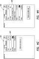
step 335 and in reference toFigs. 4B-4C , a user selection of one or more rooms of interest may be received in theUI 400. One ormore UI elements indicators step 340 and in reference toFig. 4D , a user selection of one or more services of interest may also be received in theUI 400. The user selection may be of one or more UI elements 412-418 in theUI 400 that represent services available in respective rooms. Then atstep 345, thescene engine 194 may generate a user-defined scene from the current states and the last media query for the selected rooms and services. A summery 420 may be displayed, as shown inFig. 4E . Atstep 350, thescene engine 194 may store the user-defined scene in theconfiguration database 190, for example, in response to activation of aUI element 434. As part of storing the user-defined scene, a name and/or photo may be associated with the user-defined scene in response to user input in aUI element 422. - At
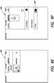
step 355 and in reference toFigs. 4F-K , thecontrol app 160 may modify the user-defined scene in response to user input in theUI 400. For example, in response to user input in UI elements 424-430, the user-defined scene may be scheduled to activate. For example, in response to user input in aUI element 426, the scene may be scheduled to activate when a particular time of day has been reached. Likewise, in response to user input in aUI element 428, the user-defined scene may be scheduled to activate when a celestial reference (e.g., dawn, sunset, etc.) has been reached. Similarly, in response to user input in UI elements 428-432, the user-defined scene may be scheduled to activate when a countdown timer has expired. Atstep 360 and in reference toFig. 4L , the updated user-defined scene may be persistently stored in theconfiguration database 190, for example, in response to activation of aUI element 434. Thereafter, in reference toFig. 4M , ascene UI element 436 for the user-defined scene may be displayed in theUI 400 of thecontrol app 160. The user-defined scene may be activated in response to selection of ascene UI element 434 or one of the scheduling criteria discussed above. Fig. 5 is a flow diagram of an example sequence ofsteps 500 for creating a user-defined scene based on user-supplied states. Such steps may be better understood by reference also toFigs. 6A-6K , which are example screen shots of theUI 400 of thecontrol app 160 on thecontrol device 150. Atstep 510 and in reference toFig. 6A , a user selection of aUI element 602 may start creation of a user-defined scene based on user-supplied states. Atstep 515 and in reference toFig. 6B , a user selection of a service may be received in theUI 400. The user selection may be of one or more UI elements 605-618 in theUI 400 that represent available services. Atstep 520 and in reference toFig. 6C , a user selection of a state for a room may be received in theUI 400. The user selection may be in aUI element 620 in theUI 400. While only asingle UI element 620 is shown inFig. 6C , it should be understood that if a service is available in multiple rooms, multiplecorresponding UI elements 620 may be shown to allow individual selections of states for rooms.Steps summary 622 may be displayed, as shown inFig. 6D . Further, at sub-step 522 and in reference toFigs. 6E-F , for some types of services (e.g., lighting services) in some rooms, user selection of states may be refined to indicate devices (e.g., lighting fixtures) or device groups that provide the service. While only asingle UI element 624 is shown inFig. 6F , it should be understood that when there are multiple devices (e.g., multiple lighting fixtures) or device groups that may provide a service (e.g., a lighting service), multiplecorresponding UI elements 624 may be shown to allow individual refinement.- At
step 525, thescene engine 194 may determine a last media query performed by the home automation system (e.g., the last audio and/or video content accessed). Then, atstep 530, thescene engine 194 may generate a user-defined scene from the user-supplied states and the last media query. Atstep 535 and in reference toFig. 6G , thescene engine 194 may store the user-defined scene in theconfiguration database 190, in response to activation of aUI element 634. As part of storing the user-defined scene, a name and/or photo may be associated with the user-defined scene in response to user input in aUI element 626. - At
step 540 and in reference toFigs. 6H-J , thecontrol app 160 may modify the user-defined scene in response to user input in theUI 400. For example, in response to user input in UI elements 628-642, the user-defined scene may be scheduled to activate at a certain time of certain days of certain months. Alternatively, the user-defined scene may be scheduled to activate when a celestial reference (e.g., dawn, sunset, etc.) has been reached, when a countdown timer has expired, or some other trigger is activated. Atstep 545 and in reference toFig. 6K , the updated user-defined scene may be persistently stored in theconfiguration database 190, for example, in response to selection of aUI element 634. Thereafter, a scene UI element for the user-defined scene may be displayed in theUI 400 of thecontrol app 160. The user-defined scene may be activated in response to selection of the scene UI element or one of the scheduling criteria discussed above. - When it is determined that a user-defined scene is to be activated (e.g., in response to a scheduling criteria or user input selecting the scene for activation), the
scene engine 194 on thehost controller 140 may apply the user-defined scene by accessing the user-defined scene, converting the states maintained in the user-defined scene and the stored media query into service requests, and issuing those service requests (e.g., via the device controllers 110) to control devices of thehome automation system 100.Fig. 7 is a flow diagram of an example sequence ofsteps 700 for applying a user-defined scene. Atstep 710, thescene engine 194 may access the user-defined scene by loading itsscene object 200 from theconfiguration database 190. Atstep 720, thescene engine 194 may convert the states maintained in the user-defined scene into service requests using specialized mapping logic and data tables. Step 720 may include sub-steps for converting states associated with services provided by various types of devices of thehome automation system 100. For example, atsub-step 722, thescene engine 194 may convert one or more A/V states of services provided by A/V devices 120 into service requests using specialized mapping logic. Atsub-step 724, thescene engine 194 may convert one or more lighting states of services provided bylighting devices 122 into service requests using mapping data tables. Atsub-step 726, thescene engine 194 may convert one or more HVAC states of services provided byHVAC devices 124 into service requests using additional mapping data tables. - At
step 730, thescene engine 194 may convert a stored last media query into a request. Further, atstep 740, thescene engine 194 may access any user-specified service requests that may be associated with the user-defined scene. Atstep 750, all the converted or accessed service requests may be consolidated into a request set. Atstep 760, the request set may be organized (e.g., ordered) by room. Finally, atstep 770, thehost controller 140 may issue the organized (e.g., ordered) service requests (e.g., via the device controllers 110) of the request set to control services provided by devices of thehome automation system 100. - While some of the embodiments involve a home automation system that is capable of A/V control, lighting control, HVAC control, security control, shade control, energy conservation, and communications control, it should be understood that the techniques may be applicable to more limited systems that, for example, may control a lesser number of types of devices (e.g., only A/V devices and lighting devices, only lighting and HVAC device, etc.).
- While some of the embodiments utilize a
scene engine 194 to perform various ones of the operations described above, it should be understood that the operations of thescene engine 194 may be implemented by other software and/or hardware. For example, at least some of the operations may be performed by software executing on acontrol device 150, such as themobile app 160, by software executing on adevice controller 110, and/or by software executing on some other device of thehome automation system 100. Similarly, at least some operations may be performed by a personal computer (PC) in communication with thehome automation system 100. It should be understood that a variety of different arrangements may be possible. - In addition, many of the techniques above described as executed in software may be executed in hardware, and vice versa. Depending on the implementation, operations may be performed in software, in hardware, or in various combinations thereof. Software implementations may include machine-executable instructions (e.g., computer-executable instructions) stored in a non-transitory machine-readable medium (e.g., a non-transitory computer-readable medium), such as a volatile or persistent memory, a hard-disk, a compact disk (CD), or other tangible medium. Hardware implementations may include configured processors, logic circuits, application specific integrated circuits, and/or other types of hardware components. Further, combined software/hardware implementations may include both machine - executable instructions stored in a non-transitory machine-readable medium, as well as one or more hardware components, for example, processors, memories, etc. In general, it should be understood that the above descriptions are meant to be taken only by way of example.
Claims (15)
- A method for defining and activating user-defined scenes in a home automation system, comprising:determining services in the home automation system (100) whose states are to be captured;automatically capturing a user-defined scene based on a set of states that describe the current operating condition of the home automation system for the services , the set of states including states of services provided by multiple different types of devices, the multiple different types including two or more of audio/video (A/V) devices (120), lighting devices (122), heating ventilation and cooling (HVAC) devices (124), security devices (126), shade control devices (128), energy conservation devices (130), or communications devices (132);schedule the user-defined scene to activate in response to a trigger;storing the user-defined scene on a storage device of the home automation system;determining the trigger has been reached and the user-defined scene is to be activated; andcontrolling services provided by the multiple different types of devices (120-132) of the home automation system (100) to replicate the set of states of the user-defined scene.
- The method of claim 1, further comprising:determining one or more selected rooms of a plurality of rooms of a structure associated with the home automation system, andwherein the generating generates the user-defined scene for states of the one or more selected rooms from the set of states.
- The method of claim 2, wherein the determining one or more selected rooms comprises:receiving user input entered in a user interface, UI, of a control application (app) (160) executing on a control device (150), the user input including a selection of each room of the one or more selected rooms.
- The method of claim 1, further comprising:determining one or more selected services of the services provided by the home automation system (100), andwherein the generating generates the user-defined scene for states of the one or more selected services.
- The method of claim 4, wherein the determining one or more selected services comprises:receiving user input entered in a user interface, UI, of a control application (app) (160)executing on a control device (150), the user input including a selection of each service of the one or more selected services.
- The method of claim 1, wherein the determining services comprises:
determining one or more A/V services whose A/V states are to be captured. - The method of claim 1, wherein the determining services comprises:
determining one or more lighting services whose lighting states are to be captured. - The method of claim 1, wherein the determining services comprises:
determining one or more HVAC services whose HVAC states are to be captured. - The method of claim 1, wherein the automatically capturing current states in the home automation system for the services comprises:
fetching the current states from a state center (192) maintained by a host controller (140) of the home automation system (100). - The method of claim 1, further comprising:determining a last media query performed by the home automation system, wherein the last media query indicates an audio or video item, andwherein the generating the user-defined scene includes storing the last media query.
- The method of claim 1, wherein the controlling comprises:loading the user-defined scene;converting the states maintained in the user-defined scene into service requests; andissuing the service requests to control the multiple different types of devices of the home automation system.
- The method of claim 11, wherein the converting comprises:
converting one or more A/V states of A/V devices to service requests, converting one or more lighting states of lighting devices to service requests, or converting one or more HVAC states of HVAC devices to service requests. - The method of claim 1, wherein the user-defined scene stores a last media query and the controlling comprises:
issuing a request for the stored last media query to cause playback of audio or video content. - An apparatus for defining and activating user-defined scenes in a home automation system (100), comprising:a processor; anda memory coupled to the processor and configured to store processor-executable instructions for a scene engine (194) that when executed are operable to:automatically capture a user-defined scene based on a set of current states that describes a current operating condition of a home automation system (100) for services, the set of states including states of services provided by multiple different types of devices, the multiple different types including two or more of audio/video (A/V) devices (120), lighting devices (122), heating ventilation and cooling (HVAC) devices (124), security devices (126), shade control devices (128), energy conservation devices (130), or communications devices (132),schedule the user-defined scene to activate in response to a trigger,store the user-defined scene,determine the trigger has been reached, andcontrol services provided by the multiple different types of devices (120-132) of the home automation system (100) to replicate the set of states of the user-defined scene.
- The apparatus of claim 14, wherein the user-defined scene is generated from states of the set of states in one or more user-selected rooms or from states of the set of states for one or more user-selected services.
Applications Claiming Priority (2)
| Application Number | Priority Date | Filing Date | Title |
|---|---|---|---|
| US14/481,575US10042336B2 (en) | 2014-09-09 | 2014-09-09 | User-defined scenes for home automation |
| PCT/US2015/048873WO2016040280A1 (en) | 2014-09-09 | 2015-09-08 | User-defined scenes for home automation |
Publications (2)
| Publication Number | Publication Date |
|---|---|
| EP3192217A1 EP3192217A1 (en) | 2017-07-19 |
| EP3192217B1true EP3192217B1 (en) | 2019-11-06 |
Family
ID=54186290
Family Applications (1)
| Application Number | Title | Priority Date | Filing Date |
|---|---|---|---|
| EP15767643.8AActiveEP3192217B1 (en) | 2014-09-09 | 2015-09-08 | User-defined scenes for home automation |
Country Status (10)
| Country | Link |
|---|---|
| US (1) | US10042336B2 (en) |
| EP (1) | EP3192217B1 (en) |
| JP (2) | JP2017535209A (en) |
| KR (1) | KR102570423B1 (en) |
| CN (1) | CN107078930B (en) |
| AU (2) | AU2015315382A1 (en) |
| CA (1) | CA2960600C (en) |
| ES (1) | ES2767290T3 (en) |
| IL (1) | IL251014B (en) |
| WO (1) | WO2016040280A1 (en) |
Families Citing this family (71)
| Publication number | Priority date | Publication date | Assignee | Title |
|---|---|---|---|---|
| EP2891019B1 (en) | 2012-08-28 | 2020-03-04 | Delos Living, LLC | Systems and methods for enhancing wellness associated with habitable environments |
| EP3754588B1 (en) | 2014-02-28 | 2023-08-16 | Delos Living LLC | Systems, methods, and articles for enhancing wellness associated with habitable environments |
| US10161833B2 (en)* | 2014-08-25 | 2018-12-25 | Battelle Memorial Institute | Building environment data collection systems |
| US10552009B2 (en) | 2014-09-02 | 2020-02-04 | Apple Inc. | Stopwatch and timer user interfaces |
| US20160170389A1 (en)* | 2014-12-12 | 2016-06-16 | Samsung Electro-Mechanics Co., Ltd. | Smart home control apparatus, smart home control method and smart home control system |
| EP3245631A4 (en) | 2015-01-13 | 2018-06-27 | Delos Living, LLC | Systems, methods and articles for monitoring and enhancing human wellness |
| US20160372284A1 (en)* | 2015-06-16 | 2016-12-22 | O Plus Design International Corporation | Circumstances Control Device |
| US10893467B2 (en) | 2015-06-30 | 2021-01-12 | K4Connect Inc. | Home automation system including selective operation of paired device based upon voice commands and related methods |
| WO2017004204A1 (en) | 2015-06-30 | 2017-01-05 | K4Connect Inc. | Home automation (ha) system including desired scene implementation based upon user-selectable list of addressable ha devices and related methods |
| US11227674B2 (en) | 2015-06-30 | 2022-01-18 | K4Connect Inc. | Home automation system generating user health score and related methods |
| US10630649B2 (en) | 2015-06-30 | 2020-04-21 | K4Connect Inc. | Home automation system including encrypted device connection based upon publicly accessible connection file and related methods |
| US9848375B2 (en) | 2015-06-30 | 2017-12-19 | K4Connect Inc. | Home automation system including device signature pairing and related methods |
| WO2017004190A1 (en) | 2015-06-30 | 2017-01-05 | K4Connect Inc. | Home automation system including cloud and home message queue synchronization and related methods |
| WO2017004200A1 (en) | 2015-06-30 | 2017-01-05 | K4Connect Inc. | Home automation system including security controller for terminating communication with abnormally operating addressable devices and related methods |
| US10028225B2 (en)* | 2015-08-26 | 2018-07-17 | International Business Machines Corporation | Efficient usage of internet services on mobile devices |
| US10863267B2 (en) | 2015-11-10 | 2020-12-08 | Savant Systems, Inc. | Volume control for audio/video devices |
| KR101653797B1 (en)* | 2016-04-15 | 2016-09-09 | 스튜디오씨드코리아 주식회사 | Method for prototyping Graphic User Interface and Apparatus thereof |
| CN105807626A (en)* | 2016-05-17 | 2016-07-27 | 郝居杰 | Smart home control method and system |
| US11003147B2 (en) | 2016-06-12 | 2021-05-11 | Apple Inc. | Automatically grouping accessories |
| US10310725B2 (en)* | 2016-06-12 | 2019-06-04 | Apple Inc. | Generating scenes based on accessory state |
| DK179594B1 (en) | 2016-06-12 | 2019-02-25 | Apple Inc. | USER INTERFACE FOR MANAGING CONTROLLABLE EXTERNAL DEVICES |
| US10511456B2 (en) | 2016-06-12 | 2019-12-17 | Apple Inc. | Presenting accessory group controls |
| EP3751405A1 (en)* | 2016-06-12 | 2020-12-16 | Apple Inc. | User interface for managing controllable external devices |
| US10498552B2 (en)* | 2016-06-12 | 2019-12-03 | Apple Inc. | Presenting accessory state |
| US10623250B1 (en) | 2016-06-24 | 2020-04-14 | United Services Automobile Association (Usaa) | Multi-device coordinated user experience |
| US11171800B1 (en) | 2016-06-24 | 2021-11-09 | United Services Automobile Association (Usaa)) | Microservice based multi-device coordinated user experience |
| US10572530B2 (en)* | 2016-07-03 | 2020-02-25 | Apple Inc. | Prefetching accessory data |
| DK201600452A1 (en)* | 2016-08-01 | 2018-03-05 | Bang & Olufsen As | Adaptable audio/visual immersion |
| CN109565456B (en) | 2016-08-19 | 2022-02-08 | Pcms控股公司 | System and method for utilizing device independent scene in smart home environment |
| US20190229943A1 (en)* | 2016-08-22 | 2019-07-25 | Pcms Holdings, Inc. | System and method for crowdsourcing generalized smart home automation scenes |
| EP3504942A4 (en) | 2016-08-24 | 2020-07-15 | Delos Living LLC | SYSTEMS, METHODS AND ARTICLES FOR IMPROVING WELL-BEING IN LIVABLE ENVIRONMENTS |
| US10469281B2 (en) | 2016-09-24 | 2019-11-05 | Apple Inc. | Generating suggestions for scenes and triggers by resident device |
| US10764153B2 (en)* | 2016-09-24 | 2020-09-01 | Apple Inc. | Generating suggestions for scenes and triggers |
| US11038708B2 (en)* | 2017-03-02 | 2021-06-15 | Signify Holding B.V. | Control events in a system of networked home devices |
| WO2018170317A1 (en) | 2017-03-15 | 2018-09-20 | Lutron Electronics Co., Inc. | Configuring a load control system |
| US11431836B2 (en) | 2017-05-02 | 2022-08-30 | Apple Inc. | Methods and interfaces for initiating media playback |
| US10992795B2 (en) | 2017-05-16 | 2021-04-27 | Apple Inc. | Methods and interfaces for home media control |
| US20220279063A1 (en) | 2017-05-16 | 2022-09-01 | Apple Inc. | Methods and interfaces for home media control |
| CN111343060B (en) | 2017-05-16 | 2022-02-11 | 苹果公司 | Method and interface for home media control |
| US20180356946A1 (en)* | 2017-06-12 | 2018-12-13 | Shih Ning CHOU | Scene-mode switching system and state conflict displaying method |
| WO2019046580A1 (en) | 2017-08-30 | 2019-03-07 | Delos Living Llc | Systems, methods and articles for assessing and/or improving health and well-being |
| US10620798B2 (en)* | 2017-10-21 | 2020-04-14 | Mordechai Teicher | Autonomously cooperating smart devices |
| US10742442B2 (en)* | 2017-10-21 | 2020-08-11 | Mordechai Teicher | Cluster of smart devices operable in hub-based and hub-less modes |
| US10637680B2 (en) | 2017-12-06 | 2020-04-28 | K4Connect Inc. | Home automation system including shareable capacity determining hub devices and related methods |
| US10686620B2 (en) | 2017-12-07 | 2020-06-16 | K4Connect Inc. | Home automation system including designated user interface device to push downloaded media content and related methods |
| US10708079B2 (en) | 2017-12-07 | 2020-07-07 | K4Connect Inc. | Home automation system including designated hub device to push downloaded media content and related methods |
| CN114845122B (en) | 2018-05-07 | 2024-04-30 | 苹果公司 | User interface for viewing live video feeds and recording video |
| US10581630B2 (en)* | 2018-06-05 | 2020-03-03 | K4Connect Inc. | Home automation system including autonomous hub determination of wireless communications link failure and related methods |
| GB2577042A (en)* | 2018-09-06 | 2020-03-18 | Centrica Plc | System for Monitoring and Controlling Device Activity |
| US20220053230A1 (en)* | 2018-09-07 | 2022-02-17 | 7Hugs Labs | System and method for smart remote scene creation |
| US11649977B2 (en) | 2018-09-14 | 2023-05-16 | Delos Living Llc | Systems and methods for air remediation |
| EP3732538B1 (en)* | 2018-10-08 | 2022-04-20 | Google LLC | Summarily conveying smart appliance statuses |
| US11844163B2 (en) | 2019-02-26 | 2023-12-12 | Delos Living Llc | Method and apparatus for lighting in an office environment |
| WO2020198183A1 (en) | 2019-03-25 | 2020-10-01 | Delos Living Llc | Systems and methods for acoustic monitoring |
| US11363071B2 (en) | 2019-05-31 | 2022-06-14 | Apple Inc. | User interfaces for managing a local network |
| US10904029B2 (en) | 2019-05-31 | 2021-01-26 | Apple Inc. | User interfaces for managing controllable external devices |
| US10996917B2 (en) | 2019-05-31 | 2021-05-04 | Apple Inc. | User interfaces for audio media control |
| CN115562613A (en) | 2019-05-31 | 2023-01-03 | 苹果公司 | User interface for audio media controls |
| ES3012537T3 (en) | 2019-09-12 | 2025-04-09 | Savant Systems Inc | Circadian lighting in a diverse home automation system |
| US11513667B2 (en) | 2020-05-11 | 2022-11-29 | Apple Inc. | User interface for audio message |
| US12328804B2 (en)* | 2020-09-04 | 2025-06-10 | Signify Holding B.V. | Determining a location for a presence sensor or light switch based on a control history |
| US11392291B2 (en) | 2020-09-25 | 2022-07-19 | Apple Inc. | Methods and interfaces for media control with dynamic feedback |
| WO2022098887A1 (en)* | 2020-11-05 | 2022-05-12 | Schneider Electric Buildings, Llc | A software-defined master system for smart buildings |
| CA3216259A1 (en)* | 2021-04-22 | 2022-10-27 | Horace C. Ho | Configuration and control of load control systems |
| US20220365667A1 (en) | 2021-05-15 | 2022-11-17 | Apple Inc. | User interfaces for managing accessories |
| US12425695B2 (en) | 2021-05-19 | 2025-09-23 | Apple Inc. | Methods and user interfaces for auditory features |
| US11424641B1 (en) | 2021-06-09 | 2022-08-23 | Savant Systems, Inc. | Flexible load management system |
| CN113504766B (en)* | 2021-07-02 | 2023-03-21 | 海尔(深圳)研发有限责任公司 | Method, system, apparatus, server and storage medium for scheduling a scene task |
| US12379827B2 (en) | 2022-06-03 | 2025-08-05 | Apple Inc. | User interfaces for managing accessories |
| WO2024076084A1 (en)* | 2022-10-07 | 2024-04-11 | 삼성전자 주식회사 | Electronic device for providing internet of things service, and operation method therefor |
| CN115542766B (en)* | 2022-11-25 | 2023-04-07 | 苏州金梓树智能科技有限公司 | Data processing method and system for intelligent node control based on mode scene |
Family Cites Families (45)
| Publication number | Priority date | Publication date | Assignee | Title |
|---|---|---|---|---|
| KR100316632B1 (en)* | 1997-06-25 | 2001-12-20 | 윤종용 | Programming tool for home networks |
| JPH11146426A (en)* | 1997-11-06 | 1999-05-28 | Hitachi Ltd | Electronic device, control method of electronic device, and electronic device system |
| AU2295101A (en)* | 1999-12-30 | 2001-07-16 | C-Smart Llc | Method and apparatus for providing distributed control of a home automation system |
| US6834208B2 (en)* | 1999-12-30 | 2004-12-21 | Microsoft Corporation | Method and apparatus for providing distributed control of a home automation and control system |
| US6823223B2 (en)* | 1999-12-30 | 2004-11-23 | Microsoft Corporation | Method and apparatus for providing distributed scene programming of a home automation and control system |
| US6784805B2 (en)* | 2000-03-15 | 2004-08-31 | Intrigue Technologies Inc. | State-based remote control system |
| JP4434424B2 (en)* | 2000-04-18 | 2010-03-17 | 株式会社ルネサステクノロジ | HOME ELECTRONIC SYSTEM, HOME SERVER DEVICE, AND COMPUTER-READABLE RECORDING MEDIUM CONTAINING PROGRAM FOR MAKING COMPUTER TO FUNCTION AS HOME SERVER DEVICE |
| US6756998B1 (en)* | 2000-10-19 | 2004-06-29 | Destiny Networks, Inc. | User interface and method for home automation system |
| AU2003239385A1 (en)* | 2002-05-10 | 2003-11-11 | Richard R. Reisman | Method and apparatus for browsing using multiple coordinated device |
| US7024256B2 (en)* | 2002-06-27 | 2006-04-04 | Openpeak Inc. | Method, system, and computer program product for automatically managing components within a controlled environment |
| JP4579612B2 (en)* | 2003-09-10 | 2010-11-10 | パナソニック株式会社 | Device linkage device |
| US7231375B2 (en)* | 2003-10-10 | 2007-06-12 | Microsoft Corporation | Computer aided query to task mapping |
| US7363028B2 (en)* | 2003-11-04 | 2008-04-22 | Universal Electronics, Inc. | System and method for controlling device location determination |
| US9131272B2 (en)* | 2003-11-04 | 2015-09-08 | Universal Electronics Inc. | System and method for saving and recalling state data for media and home appliances |
| US7155305B2 (en)* | 2003-11-04 | 2006-12-26 | Universal Electronics Inc. | System and methods for home appliance identification and control in a networked environment |
| CN100394383C (en)* | 2003-12-31 | 2008-06-11 | 无极公司 | Method and system for automatically managing components in a controlled environment |
| US9531593B2 (en)* | 2007-06-12 | 2016-12-27 | Icontrol Networks, Inc. | Takeover processes in security network integrated with premise security system |
| US9450776B2 (en)* | 2005-03-16 | 2016-09-20 | Icontrol Networks, Inc. | Forming a security network including integrated security system components |
| US7415310B2 (en)* | 2005-09-15 | 2008-08-19 | Intermatic Incorporated | System for home automation |
| US8042048B2 (en)* | 2005-11-17 | 2011-10-18 | Att Knowledge Ventures, L.P. | System and method for home automation |
| US8683532B2 (en)* | 2005-11-29 | 2014-03-25 | International Business Machines Corporation | Space-shifting media streaming system |
| US8516087B2 (en)* | 2006-02-14 | 2013-08-20 | At&T Intellectual Property I, L.P. | Home automation system and method |
| US8909779B2 (en)* | 2006-05-03 | 2014-12-09 | Cloud Systems, Inc. | System and method for control and monitoring of multiple devices and inter-device connections |
| DE602007010705D1 (en)* | 2006-09-07 | 2011-01-05 | France Telecom | Remote control method and corresponding system for home appliances |
| US7930644B2 (en)* | 2006-09-13 | 2011-04-19 | Savant Systems, Llc | Programming environment and metadata management for programmable multimedia controller |
| US7864043B2 (en)* | 2007-03-28 | 2011-01-04 | Sony Ericsson Mobile Communications Ab | Home locating network |
| US7843333B2 (en)* | 2007-01-26 | 2010-11-30 | Sony Ericsson Mobile Communication Ab | System, methods, devices and computer program products for controlling electronic appliances within a local area |
| US8316309B2 (en)* | 2007-05-31 | 2012-11-20 | International Business Machines Corporation | User-created metadata for managing interface resources on a user interface |
| US8473325B2 (en)* | 2007-10-12 | 2013-06-25 | Pie Digital, Inc. | System and method for automatic configuration and management of home network devices using a hierarchical index model |
| CN101197744B (en)* | 2007-12-21 | 2011-06-08 | 新动力(北京)建筑科技有限公司 | Scene mode switching system and method for Smart Home Network System, lock head detection unit |
| US9088663B2 (en)* | 2008-04-18 | 2015-07-21 | Universal Electronics Inc. | System for appliance control via a network |
| KR101679056B1 (en)* | 2008-08-13 | 2016-11-24 | 코닌클리케 필립스 엔.브이. | Updating scenes in remote controllers of a home control system |
| US20100138007A1 (en)* | 2008-11-21 | 2010-06-03 | Qwebl, Inc. | Apparatus and method for integration and setup of home automation |
| FR2939554B1 (en)* | 2008-12-10 | 2015-08-21 | Somfy Sas | METHOD FOR OPERATING A DOMOTIC SYSTEM |
| CN101540829A (en)* | 2009-04-23 | 2009-09-23 | 中山大学 | Intelligent home control system based on SDF digital home middleware |
| US10775960B2 (en)* | 2009-06-03 | 2020-09-15 | Savant Systems, Inc. | User generated virtual room-based user interface |
| US8296669B2 (en)* | 2009-06-03 | 2012-10-23 | Savant Systems, Llc | Virtual room-based light fixture and device control |
| US8498749B2 (en)* | 2009-08-21 | 2013-07-30 | Allure Energy, Inc. | Method for zone based energy management system with scalable map interface |
| US8914724B2 (en)* | 2011-04-06 | 2014-12-16 | Savant Systems, Llc | Method and apparatus for creating and modifying graphical schedules |
| US20120260206A1 (en)* | 2011-04-06 | 2012-10-11 | Cipollo Nicholas J | Method and apparatus for creating and modifying graphical schedules in conjunction with historical data |
| US20130060357A1 (en)* | 2011-09-01 | 2013-03-07 | Sony Corporation, A Japanese Corporation | Facilitated use of heterogeneous home-automation edge components via a common application programming interface |
| US9397852B2 (en)* | 2012-08-31 | 2016-07-19 | Verizon Patent And Licensing Inc. | Connected home user interface systems and methods |
| US8490006B1 (en)* | 2012-09-04 | 2013-07-16 | State Farm Mutual Automobile Insurance Company | Scene creation for building automation systems |
| US10032364B2 (en)* | 2014-05-15 | 2018-07-24 | Savant Systems, Llc | Standalone wireless lighting application |
| US9876652B2 (en)* | 2014-05-20 | 2018-01-23 | Savant Systems, Llc | Automatic configuration of control device user interface in a home automation system |
- 2014
- 2014-09-09USUS14/481,575patent/US10042336B2/enactiveActive
- 2015
- 2015-09-08WOPCT/US2015/048873patent/WO2016040280A1/enactiveApplication Filing
- 2015-09-08AUAU2015315382Apatent/AU2015315382A1/ennot_activeAbandoned
- 2015-09-08JPJP2017533163Apatent/JP2017535209A/enactivePending
- 2015-09-08KRKR1020177009294Apatent/KR102570423B1/enactiveActive
- 2015-09-08CNCN201580060841.4Apatent/CN107078930B/enactiveActive
- 2015-09-08EPEP15767643.8Apatent/EP3192217B1/enactiveActive
- 2015-09-08CACA2960600Apatent/CA2960600C/enactiveActive
- 2015-09-08ESES15767643Tpatent/ES2767290T3/enactiveActive
- 2017
- 2017-03-08ILIL251014Apatent/IL251014B/enactiveIP Right Grant
- 2019
- 2019-10-08AUAU2019246779Apatent/AU2019246779A1/ennot_activeWithdrawn
- 2020
- 2020-02-26JPJP2020030073Apatent/JP7015333B2/enactiveActive
Non-Patent Citations (1)
| Title |
|---|
| None* |
Also Published As
| Publication number | Publication date |
|---|---|
| IL251014B (en) | 2020-11-30 |
| JP7015333B2 (en) | 2022-02-02 |
| CA2960600A1 (en) | 2016-03-17 |
| KR102570423B1 (en) | 2023-08-25 |
| AU2015315382A1 (en) | 2017-03-30 |
| IL251014A0 (en) | 2017-04-30 |
| AU2019246779A1 (en) | 2019-10-31 |
| US20160070244A1 (en) | 2016-03-10 |
| EP3192217A1 (en) | 2017-07-19 |
| ES2767290T3 (en) | 2020-06-17 |
| CA2960600C (en) | 2023-10-10 |
| US10042336B2 (en) | 2018-08-07 |
| WO2016040280A1 (en) | 2016-03-17 |
| KR20170053176A (en) | 2017-05-15 |
| JP2017535209A (en) | 2017-11-24 |
| CN107078930A (en) | 2017-08-18 |
| CN107078930B (en) | 2020-08-28 |
| JP2020127200A (en) | 2020-08-20 |
Similar Documents
| Publication | Publication Date | Title |
|---|---|---|
| EP3192217B1 (en) | User-defined scenes for home automation | |
| US9876652B2 (en) | Automatic configuration of control device user interface in a home automation system | |
| US10209693B2 (en) | Architecture for providing ubiquitous access to a home automation system | |
| US8725845B2 (en) | Automation control system having a configuration tool | |
| US8001219B2 (en) | User control interface for convergence and automation system | |
| US10338904B2 (en) | Specialized app development and deployment system and method | |
| US20160274556A1 (en) | Systems and methods for monitoring and control of energy consumption systems | |
| WO2017107425A1 (en) | Method and device for controlling smart home appliance | |
| BR112013025793B1 (en) | METHOD AND APPARATUS FOR CREATING AND MODIFYING GRAPHIC PROGRAMS | |
| CN103425483B (en) | Method and storage medium for dynamically customized menus | |
| CN114285688A (en) | Device replacement method, apparatus, gateway, system and medium | |
| JP7681101B2 (en) | Information processing method, information processing program, and information processing device | |
| CN119697227A (en) | Cross-platform interactive control method, electronic device, readable storage medium and program product | |
| WO2007109550A2 (en) | Automation control system having a configuration tool | |
| CN109765854A (en) | The control display methods and device of equipment | |
| Nevado Rodríguez | Home-Automation System |
Legal Events
| Date | Code | Title | Description |
|---|---|---|---|
| STAA | Information on the status of an ep patent application or granted ep patent | Free format text:STATUS: THE INTERNATIONAL PUBLICATION HAS BEEN MADE | |
| PUAI | Public reference made under article 153(3) epc to a published international application that has entered the european phase | Free format text:ORIGINAL CODE: 0009012 | |
| STAA | Information on the status of an ep patent application or granted ep patent | Free format text:STATUS: REQUEST FOR EXAMINATION WAS MADE | |
| 17P | Request for examination filed | Effective date:20170310 | |
| AK | Designated contracting states | Kind code of ref document:A1 Designated state(s):AL AT BE BG CH CY CZ DE DK EE ES FI FR GB GR HR HU IE IS IT LI LT LU LV MC MK MT NL NO PL PT RO RS SE SI SK SM TR | |
| AX | Request for extension of the european patent | Extension state:BA ME | |
| DAV | Request for validation of the european patent (deleted) | ||
| DAX | Request for extension of the european patent (deleted) | ||
| STAA | Information on the status of an ep patent application or granted ep patent | Free format text:STATUS: EXAMINATION IS IN PROGRESS | |
| 17Q | First examination report despatched | Effective date:20180726 | |
| RIC1 | Information provided on ipc code assigned before grant | Ipc:G05B 15/02 20060101ALI20190327BHEP Ipc:H04L 12/28 20060101AFI20190327BHEP | |
| GRAP | Despatch of communication of intention to grant a patent | Free format text:ORIGINAL CODE: EPIDOSNIGR1 | |
| STAA | Information on the status of an ep patent application or granted ep patent | Free format text:STATUS: GRANT OF PATENT IS INTENDED | |
| INTG | Intention to grant announced | Effective date:20190506 | |
| GRAS | Grant fee paid | Free format text:ORIGINAL CODE: EPIDOSNIGR3 | |
| GRAA | (expected) grant | Free format text:ORIGINAL CODE: 0009210 | |
| STAA | Information on the status of an ep patent application or granted ep patent | Free format text:STATUS: THE PATENT HAS BEEN GRANTED | |
| AK | Designated contracting states | Kind code of ref document:B1 Designated state(s):AL AT BE BG CH CY CZ DE DK EE ES FI FR GB GR HR HU IE IS IT LI LT LU LV MC MK MT NL NO PL PT RO RS SE SI SK SM TR | |
| REG | Reference to a national code | Ref country code:GB Ref legal event code:FG4D | |
| REG | Reference to a national code | Ref country code:CH Ref legal event code:EP Ref country code:AT Ref legal event code:REF Ref document number:1200320 Country of ref document:AT Kind code of ref document:T Effective date:20191115 | |
| REG | Reference to a national code | Ref country code:IE Ref legal event code:FG4D | |
| REG | Reference to a national code | Ref country code:DE Ref legal event code:R096 Ref document number:602015041206 Country of ref document:DE | |
| REG | Reference to a national code | Ref country code:NL Ref legal event code:MP Effective date:20191106 | |
| REG | Reference to a national code | Ref country code:LT Ref legal event code:MG4D | |
| PG25 | Lapsed in a contracting state [announced via postgrant information from national office to epo] | Ref country code:FI Free format text:LAPSE BECAUSE OF FAILURE TO SUBMIT A TRANSLATION OF THE DESCRIPTION OR TO PAY THE FEE WITHIN THE PRESCRIBED TIME-LIMIT Effective date:20191106 Ref country code:BG Free format text:LAPSE BECAUSE OF FAILURE TO SUBMIT A TRANSLATION OF THE DESCRIPTION OR TO PAY THE FEE WITHIN THE PRESCRIBED TIME-LIMIT Effective date:20200206 Ref country code:NL Free format text:LAPSE BECAUSE OF FAILURE TO SUBMIT A TRANSLATION OF THE DESCRIPTION OR TO PAY THE FEE WITHIN THE PRESCRIBED TIME-LIMIT Effective date:20191106 Ref country code:SE Free format text:LAPSE BECAUSE OF FAILURE TO SUBMIT A TRANSLATION OF THE DESCRIPTION OR TO PAY THE FEE WITHIN THE PRESCRIBED TIME-LIMIT Effective date:20191106 Ref country code:LV Free format text:LAPSE BECAUSE OF FAILURE TO SUBMIT A TRANSLATION OF THE DESCRIPTION OR TO PAY THE FEE WITHIN THE PRESCRIBED TIME-LIMIT Effective date:20191106 Ref country code:LT Free format text:LAPSE BECAUSE OF FAILURE TO SUBMIT A TRANSLATION OF THE DESCRIPTION OR TO PAY THE FEE WITHIN THE PRESCRIBED TIME-LIMIT Effective date:20191106 Ref country code:PL Free format text:LAPSE BECAUSE OF FAILURE TO SUBMIT A TRANSLATION OF THE DESCRIPTION OR TO PAY THE FEE WITHIN THE PRESCRIBED TIME-LIMIT Effective date:20191106 Ref country code:GR Free format text:LAPSE BECAUSE OF FAILURE TO SUBMIT A TRANSLATION OF THE DESCRIPTION OR TO PAY THE FEE WITHIN THE PRESCRIBED TIME-LIMIT Effective date:20200207 Ref country code:PT Free format text:LAPSE BECAUSE OF FAILURE TO SUBMIT A TRANSLATION OF THE DESCRIPTION OR TO PAY THE FEE WITHIN THE PRESCRIBED TIME-LIMIT Effective date:20200306 Ref country code:NO Free format text:LAPSE BECAUSE OF FAILURE TO SUBMIT A TRANSLATION OF THE DESCRIPTION OR TO PAY THE FEE WITHIN THE PRESCRIBED TIME-LIMIT Effective date:20200206 | |
| PG25 | Lapsed in a contracting state [announced via postgrant information from national office to epo] | Ref country code:IS Free format text:LAPSE BECAUSE OF FAILURE TO SUBMIT A TRANSLATION OF THE DESCRIPTION OR TO PAY THE FEE WITHIN THE PRESCRIBED TIME-LIMIT Effective date:20200306 Ref country code:RS Free format text:LAPSE BECAUSE OF FAILURE TO SUBMIT A TRANSLATION OF THE DESCRIPTION OR TO PAY THE FEE WITHIN THE PRESCRIBED TIME-LIMIT Effective date:20191106 Ref country code:HR Free format text:LAPSE BECAUSE OF FAILURE TO SUBMIT A TRANSLATION OF THE DESCRIPTION OR TO PAY THE FEE WITHIN THE PRESCRIBED TIME-LIMIT Effective date:20191106 | |
| REG | Reference to a national code | Ref country code:ES Ref legal event code:FG2A Ref document number:2767290 Country of ref document:ES Kind code of ref document:T3 Effective date:20200617 | |
| PG25 | Lapsed in a contracting state [announced via postgrant information from national office to epo] | Ref country code:AL Free format text:LAPSE BECAUSE OF FAILURE TO SUBMIT A TRANSLATION OF THE DESCRIPTION OR TO PAY THE FEE WITHIN THE PRESCRIBED TIME-LIMIT Effective date:20191106 | |
| REG | Reference to a national code | Ref country code:DE Ref legal event code:R082 Ref document number:602015041206 Country of ref document:DE Representative=s name:MEISSNER BOLTE PATENTANWAELTE RECHTSANWAELTE P, DE Ref country code:DE Ref legal event code:R081 Ref document number:602015041206 Country of ref document:DE Owner name:SAVANT SYSTEMS, INC., HYANNIS, US Free format text:FORMER OWNER: SAVANT SYSTEMS LLC, HYANNIS, MASS., US | |
| PG25 | Lapsed in a contracting state [announced via postgrant information from national office to epo] | Ref country code:DK Free format text:LAPSE BECAUSE OF FAILURE TO SUBMIT A TRANSLATION OF THE DESCRIPTION OR TO PAY THE FEE WITHIN THE PRESCRIBED TIME-LIMIT Effective date:20191106 Ref country code:EE Free format text:LAPSE BECAUSE OF FAILURE TO SUBMIT A TRANSLATION OF THE DESCRIPTION OR TO PAY THE FEE WITHIN THE PRESCRIBED TIME-LIMIT Effective date:20191106 Ref country code:CZ Free format text:LAPSE BECAUSE OF FAILURE TO SUBMIT A TRANSLATION OF THE DESCRIPTION OR TO PAY THE FEE WITHIN THE PRESCRIBED TIME-LIMIT Effective date:20191106 Ref country code:RO Free format text:LAPSE BECAUSE OF FAILURE TO SUBMIT A TRANSLATION OF THE DESCRIPTION OR TO PAY THE FEE WITHIN THE PRESCRIBED TIME-LIMIT Effective date:20191106 | |
| REG | Reference to a national code | Ref country code:DE Ref legal event code:R097 Ref document number:602015041206 Country of ref document:DE | |
| REG | Reference to a national code | Ref country code:AT Ref legal event code:MK05 Ref document number:1200320 Country of ref document:AT Kind code of ref document:T Effective date:20191106 | |
| PG25 | Lapsed in a contracting state [announced via postgrant information from national office to epo] | Ref country code:SK Free format text:LAPSE BECAUSE OF FAILURE TO SUBMIT A TRANSLATION OF THE DESCRIPTION OR TO PAY THE FEE WITHIN THE PRESCRIBED TIME-LIMIT Effective date:20191106 Ref country code:SM Free format text:LAPSE BECAUSE OF FAILURE TO SUBMIT A TRANSLATION OF THE DESCRIPTION OR TO PAY THE FEE WITHIN THE PRESCRIBED TIME-LIMIT Effective date:20191106 | |
| PLBE | No opposition filed within time limit | Free format text:ORIGINAL CODE: 0009261 | |
| STAA | Information on the status of an ep patent application or granted ep patent | Free format text:STATUS: NO OPPOSITION FILED WITHIN TIME LIMIT | |
| 26N | No opposition filed | Effective date:20200807 | |
| PG25 | Lapsed in a contracting state [announced via postgrant information from national office to epo] | Ref country code:AT Free format text:LAPSE BECAUSE OF FAILURE TO SUBMIT A TRANSLATION OF THE DESCRIPTION OR TO PAY THE FEE WITHIN THE PRESCRIBED TIME-LIMIT Effective date:20191106 Ref country code:SI Free format text:LAPSE BECAUSE OF FAILURE TO SUBMIT A TRANSLATION OF THE DESCRIPTION OR TO PAY THE FEE WITHIN THE PRESCRIBED TIME-LIMIT Effective date:20191106 | |
| PG25 | Lapsed in a contracting state [announced via postgrant information from national office to epo] | Ref country code:MC Free format text:LAPSE BECAUSE OF FAILURE TO SUBMIT A TRANSLATION OF THE DESCRIPTION OR TO PAY THE FEE WITHIN THE PRESCRIBED TIME-LIMIT Effective date:20191106 | |
| REG | Reference to a national code | Ref country code:CH Ref legal event code:PL | |
| REG | Reference to a national code | Ref country code:GB Ref legal event code:732E Free format text:REGISTERED BETWEEN 20210422 AND 20210428 | |
| REG | Reference to a national code | Ref country code:BE Ref legal event code:MM Effective date:20200930 | |
| PG25 | Lapsed in a contracting state [announced via postgrant information from national office to epo] | Ref country code:LU Free format text:LAPSE BECAUSE OF NON-PAYMENT OF DUE FEES Effective date:20200908 | |
| PG25 | Lapsed in a contracting state [announced via postgrant information from national office to epo] | Ref country code:CH Free format text:LAPSE BECAUSE OF NON-PAYMENT OF DUE FEES Effective date:20200930 Ref country code:BE Free format text:LAPSE BECAUSE OF NON-PAYMENT OF DUE FEES Effective date:20200930 Ref country code:LI Free format text:LAPSE BECAUSE OF NON-PAYMENT OF DUE FEES Effective date:20200930 Ref country code:IE Free format text:LAPSE BECAUSE OF NON-PAYMENT OF DUE FEES Effective date:20200908 | |
| PG25 | Lapsed in a contracting state [announced via postgrant information from national office to epo] | Ref country code:TR Free format text:LAPSE BECAUSE OF FAILURE TO SUBMIT A TRANSLATION OF THE DESCRIPTION OR TO PAY THE FEE WITHIN THE PRESCRIBED TIME-LIMIT Effective date:20191106 Ref country code:MT Free format text:LAPSE BECAUSE OF FAILURE TO SUBMIT A TRANSLATION OF THE DESCRIPTION OR TO PAY THE FEE WITHIN THE PRESCRIBED TIME-LIMIT Effective date:20191106 Ref country code:CY Free format text:LAPSE BECAUSE OF FAILURE TO SUBMIT A TRANSLATION OF THE DESCRIPTION OR TO PAY THE FEE WITHIN THE PRESCRIBED TIME-LIMIT Effective date:20191106 | |
| REG | Reference to a national code | Ref country code:ES Ref legal event code:PC2A Owner name:SAVANT SYSTEMS, INC. Effective date:20220530 | |
| PG25 | Lapsed in a contracting state [announced via postgrant information from national office to epo] | Ref country code:MK Free format text:LAPSE BECAUSE OF FAILURE TO SUBMIT A TRANSLATION OF THE DESCRIPTION OR TO PAY THE FEE WITHIN THE PRESCRIBED TIME-LIMIT Effective date:20191106 | |
| P01 | Opt-out of the competence of the unified patent court (upc) registered | Effective date:20230531 | |
| PGFP | Annual fee paid to national office [announced via postgrant information from national office to epo] | Ref country code:DE Payment date:20240927 Year of fee payment:10 | |
| PGFP | Annual fee paid to national office [announced via postgrant information from national office to epo] | Ref country code:GB Payment date:20240927 Year of fee payment:10 | |
| PGFP | Annual fee paid to national office [announced via postgrant information from national office to epo] | Ref country code:FR Payment date:20240925 Year of fee payment:10 | |
| PGFP | Annual fee paid to national office [announced via postgrant information from national office to epo] | Ref country code:IT Payment date:20240919 Year of fee payment:10 | |
| PGFP | Annual fee paid to national office [announced via postgrant information from national office to epo] | Ref country code:ES Payment date:20241001 Year of fee payment:10 |