EP3191175B1 - Apparatus for shielding implantable medical leads and lead extensions - Google Patents
Apparatus for shielding implantable medical leads and lead extensionsDownload PDFInfo
- Publication number
- EP3191175B1 EP3191175B1EP15745714.4AEP15745714AEP3191175B1EP 3191175 B1EP3191175 B1EP 3191175B1EP 15745714 AEP15745714 AEP 15745714AEP 3191175 B1EP3191175 B1EP 3191175B1
- Authority
- EP
- European Patent Office
- Prior art keywords
- lead
- implantable medical
- sheath
- paddle
- shield layer
- Prior art date
- Legal status (The legal status is an assumption and is not a legal conclusion. Google has not performed a legal analysis and makes no representation as to the accuracy of the status listed.)
- Active
Links
Images


Classifications
- A—HUMAN NECESSITIES
- A61—MEDICAL OR VETERINARY SCIENCE; HYGIENE
- A61N—ELECTROTHERAPY; MAGNETOTHERAPY; RADIATION THERAPY; ULTRASOUND THERAPY
- A61N1/00—Electrotherapy; Circuits therefor
- A61N1/18—Applying electric currents by contact electrodes
- A61N1/32—Applying electric currents by contact electrodes alternating or intermittent currents
- A61N1/36—Applying electric currents by contact electrodes alternating or intermittent currents for stimulation
- A61N1/362—Heart stimulators
- A61N1/37—Monitoring; Protecting
- A61N1/3718—Monitoring of or protection against external electromagnetic fields or currents
- A—HUMAN NECESSITIES
- A61—MEDICAL OR VETERINARY SCIENCE; HYGIENE
- A61N—ELECTROTHERAPY; MAGNETOTHERAPY; RADIATION THERAPY; ULTRASOUND THERAPY
- A61N1/00—Electrotherapy; Circuits therefor
- A61N1/02—Details
- A61N1/04—Electrodes
- A61N1/05—Electrodes for implantation or insertion into the body, e.g. heart electrode
- A61N1/0526—Head electrodes
- A61N1/0529—Electrodes for brain stimulation
- A—HUMAN NECESSITIES
- A61—MEDICAL OR VETERINARY SCIENCE; HYGIENE
- A61N—ELECTROTHERAPY; MAGNETOTHERAPY; RADIATION THERAPY; ULTRASOUND THERAPY
- A61N1/00—Electrotherapy; Circuits therefor
- A61N1/02—Details
- A61N1/04—Electrodes
- A61N1/05—Electrodes for implantation or insertion into the body, e.g. heart electrode
- A61N1/0551—Spinal or peripheral nerve electrodes
- A61N1/0553—Paddle shaped electrodes, e.g. for laminotomy
- A—HUMAN NECESSITIES
- A61—MEDICAL OR VETERINARY SCIENCE; HYGIENE
- A61N—ELECTROTHERAPY; MAGNETOTHERAPY; RADIATION THERAPY; ULTRASOUND THERAPY
- A61N1/00—Electrotherapy; Circuits therefor
- A61N1/02—Details
- A61N1/08—Arrangements or circuits for monitoring, protecting, controlling or indicating
- A61N1/086—Magnetic resonance imaging [MRI] compatible leads
Definitions
- Embodimentsrelate to implantable medical leads and implantable medical lead extensions. More particularly, embodiments relate to apparatus for shielding implantable medical leads and implantable medical lead extensions.
- Implantable medical systemsare used to provide stimulation therapy and/or physiological sensing for patients.
- the implantable medical systemincludes a stimulation or sensing device that is implanted at a convenient location.
- Implantable medical leadsare routed between the site of implantation of the device and a target site where stimulation or sensing is to occur. Where the route is lengthy, an implantable medical lead extension is used to traverse a portion of that distance.
- the implantable medical leadsinclude one or more electrical contacts located near a proximal end of the lead. Where no extension is needed, the proximal end of the lead is physically connected to the stimulation or sensing device so that the proximal contacts of the lead are electrically coupled to electrical circuitry of the device. For scenarios where the implantable medical lead extension is used, then the proximal end of the lead is physically connected to a distal end of the extension where electrical connectors of the extension are coupled to the electrical contacts of the lead. The proximal end of the extension is physically connected to the stimulation or sensing device so that the proximal contacts of the extension are electrically coupled to electrical circuitry of the device.
- the leadsalso include one or more electrodes located near a distal end of the leads.
- Electrical conductorsare present within the lead, and each electrical conductor is connected to a respective electrical contact and electrode to provide an electrical path for stimulation and/or sensed signals. Electrical conductors are also present within the extension, and each electrical conductor is connected to a respective electrical contact and distal connector to provide an electrical path for stimulation and/or sensed signals.
- each electrical conductor within the lead and extensionis susceptible to receiving extraneous electromagnetic energy that produces electrical current on the electrical conductor. While most ambient conditions expose the lead and lead extension to insignificant levels of such extraneous electromagnetic energy, certain situations may create levels of extraneous electromagnetic energy that are of concern.
- An example of such a situationis a magnetic resonance imaging (MRI) scan.
- the MRI scanutilizes a high energy radio frequency (RF) electromagnetic signal.
- RFradio frequency
- This RF signalmay produce relatively large levels of electrical current on the electrical conductor of the lead and extension when the patient having the implantable medical system that includes the lead and/or lead extension combination undergoes the MRI scan.
- the relatively large electrical current that results from the high energy RF signalproduces heating at the electrodes that may create discomfort and even dangerous tissue damage at the site within the body where the one or more electrodes of the lead are located.
- a shield layer within the leadreduces the amount of RF energy that reaches the electrical conductors, which in turn reduces the amount of current being coupled onto the electrical conductors and reduces the heating at the electrodes to acceptable levels.
- the manufacturing process of the leadhas been altered to include a shield layer when the lead body is being manufactured by creating an inner jacket over the electrical conductor, then creating the shield layer on the inner jacket, and then creating an outer jacket over the inner jacket.
- the electrical contacts and electrodesare then installed about the inner jacket and are coupled to the electrical conductor to complete the leads.
- leads and extensions that have been constructed without such shield layers or other protective aspectsremain vulnerable to the high levels of RF energy of the MRI scan or other situation.
- patients having leads and/or extensions implanted that are not designed to be safe during an MRI scaneither continue to be ineligible for an MRI scan or must undergo a procedure to replace the lead and/or extension with an MRI compliant version.
- Replacing the existing leadpresents a risk that the new lead will not be positioned in a location that provides therapy that is as effective as with the prior lead.
- some leadsare very difficult to remove, such as leads having a distal paddle that have required surgical procedures for implantation.
- US 2012/0046722 A1relates to shielding an implantable medical lead.
- US 2010/0256696 A1describes anchoring units for implantable electrical stimulation systems and methods of making and using.
- US 6,673,999 B1deals with a magnetically shielded assembly.
- US2010/036466 A1relates to a lead construction.
- US 2008154326 A1relates to a sheath for a lead comprising a radiopaque material.
- Embodimentsaddress issues such as these and others by adding a shielded sheath over an existing lead or extension.
- the shielded sheathmay then be anchored to the existing lead or extension and to the surrounding body tissue.
- the shielded sheathmay be added to newly implanted leads and/or extensions or to leads and/or extensions that have previously been implanted.
- Embodimentsprovide an apparatus that includes an implantable medical lead having a proximal contact and a distal electrode and also includes a sheath containing a shield layer positioned about the implantable medical lead between the proximal contact and the distal electrode.
- the apparatusfurther includes an anchoring structure holding the sheath in a fixed position about the implantable medical lead.
- Embodimentsprovide an implantable medical system that includes an implantable stimulation device and an implantable medical lead having a proximal contact and a distal electrode with the proximal contact being electrically coupled to the implantable stimulation device.
- the systemfurther includes a sheath containing a shield layer positioned about the implantable medical lead between the proximal contact and the distal electrode and an anchoring structure holding the sheath in a fixed position about the implantable medical lead.
- Embodimentsprovide an apparatus that includes an implantable medical lead extension having a proximal contact and a distal connector block and also includes a sheath containing a shield layer positioned about the implantable medical lead between the proximal contact and a distal end of the implantable medical lead extension.
- the apparatusfurther includes an anchoring structure holding the sheath in a fixed position about the implantable medical lead extension.
- Embodimentsprovide an apparatus that includes an implantable medical paddle lead having a proximal contact and a paddle portion that contains at least one distal electrode, the paddle portion having a width greater than a remainder of the implantable medical paddle lead.
- the apparatusfurther includes a sheath containing a shield layer positioned about the implantable medical lead between the proximal contact and the paddle portion, the sheath having an inner diameter that is smaller than a width of the paddle portion of the paddle lead but greater than a diameter of a remainder of the paddle lead such that the sheath is confined by the paddle portion.
- Embodimentsprovide an implantable medical system that includes an implantable stimulation device.
- the systemfurther includes an implantable medical paddle lead having a proximal contact and a paddle portion that contains at least one distal electrode with the proximal contact being electrically coupled to the implantable stimulation device, the paddle portion having a width greater than a remainder of the implantable medical paddle lead.
- the systemadditionally includes a sheath containing a shield layer positioned about the implantable medical lead between the proximal contact and the paddle portion, the sheath having an inner diameter that is smaller than a width of the paddle portion of the paddle lead but greater than a diameter of a remainder of the paddle lead such that the sheath is confined by the paddle portion.
- Embodimentsprovide shielded sheaths that are installed over leads and/or extensions, whether being implanted or already implanted.
- the shielded sheathreduces the amount of RF energy that reaches the conductors of the lead and/or extension.
- FIG. 1shows an example where a shielded sheath may be utilized.
- An implantable medical system 100that includes an implantable medical device 102 which may be an implantable stimulation device that provides electrical stimulation signals and/or senses physiological signals.
- the system 100also includes an implantable medical lead 104 is implanted into a patient 108.
- the implantable medical systemis a spinal cord stimulator where the lead 104 is implanted into a location nearby the spinal cord within the spine 110.
- the implantable medical device 102provides electrical stimulation that is delivered through conductors of the lead 104 to the stimulation site.
- the implantable medical device 102is implanted within a subcutaneous pocket 114 created during implantation while the lead 104 is tunneled through a path 116 created between the pocket 114 and the entry point 112 to an epidural space during implantation.
- FIG. 2shows an implantable medical system 200 which is identical to the system 100 of FIG. 1 except that a shielded sheath 202 has been placed over the lead 104.
- the shielded sheathis positioned between the proximal end where the lead 104 connects to the implantable medical device and the distal end where the electrodes 106 are located.
- the shielded sheath 202has an insulative shield body with a shield layer 204 within the shield body to isolate the shield layer 204 from the external conditions of the body 108.
- the shielded sheathprovides shielding of RF electromagnetic energy to reduce the amount of RF electromagnetic energy that becomes coupled to the conductors that are within the lead 104 and are connected between the implantable medical device 102 and the electrodes 106.
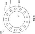
- FIG. 26shows a lateral cross-sectional view of an example 2600 of the shielded sheath 202.
- an insulative shield body 2602that defines a lumen 2606 where the lead 104 or a lead extension may pass through.
- the insulative bodymay be constructed of various biocompatible materials including various polymers, urethanes such as the PurSil ® thermoplastic silicone-polyether-urethane of the Koninklijke DSM N.V. Corporation of the Netherlands, and other silicones.
- a shield layer 2604is also present and is embedded within the insulative layer.
- the wires of the braidmay be a conductor such as a biocompatible metal like tantalum, titanium, and the like.
- the foilmay be a conductor such as a biocompatible metal like titanium, tantalum, stainless steel, MP35N ® alloy of SPS Technologies, Inc. of Jenkintown, PA, and the like.
- the braidmay be created with a variety of shield parameters.
- shield parameterssuch as braid angle, wire cross-sectional shape and diameter, number of braid wires, braid depth, distance from shield termination to closest contact or electrode, and the like that may also be used for the embodiments being disclosed herein are described in published U.S. Patent Application US 2012/0046722 A1 .
- the shielded sheath 202may be installed during a new implantation of the lead 104 or as a retrofit to a lead 104 that has previously been implanted. Examples of procedures for installing the shielded sheath 202 are discussed below, with the procedure for installing during a new spinal implantation of the lead 104 being described with reference to FIGS. 3-11 and the procedure for retrofitting a spinal lead 104 that has previously been implanted with reference to FIGS. 12-17 . An example of a procedure for installing the shielded sheath for a brain lead is discussed below in relation to FIGS. 18-23 .
- the procedure for a new implantation of a lead 104begins at an operation 1102 where a needle 304 as shown in FIG. 3 is being inserted through the spinal structures 308 and into the epidural space between the spinal structures 308 and the spinal cord 306.
- a guide wire 302is then advanced through the needle 304 and into the epidural space at an operation 1104.
- the needle 304is then retracted while the guidewire 302 remains in the epidural space. This is shown in FIG. 4 where it can be seen that the guidewire 302 has maintained a position within the epidural space as the needle 304 has exited the epidural space.
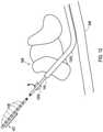
- the shielded sheath 202 having the shield layer 204is advanced over the guidewire 302 and approaches the epidural space through the spinal structures 308. This is shown in FIG. 5 .
- the shielded sheath 202includes a tapered leading edge 206 which allows the shielded sheath 202 to more easily penetrate through the body tissues to reach the epidural space.
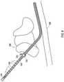
- the guidewire 302is retracted from the epidural space through the shielded sheath 202 while the shielded sheath 202 remains in the epidural space. This is shown in FIG. 6 where it can be seen that the shielded sheath 202 has maintained a position within the epidural space as the guidewire 302 has exited the epidural space.
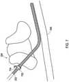
- an anchor 702 as shown in FIG. 7is applied to the shielded sheath 202 to fasten the shield to the surrounding fascia at the spinal structures 308.
- the anchor 702is of the type that forms a sleeve that is then affixed to surrounding tissue via sutures 704.
- other types of anchoringmay also be used.
- the shielded sheath 202may be directly sutured.
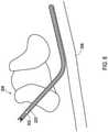
- the distal end of the lead 104is inserted into the lumen of the shielded sheath 202 and is advanced toward the epidural space. This is shown in FIG. 8 .
- the lead 104is advanced through the shielded sheath 202 to the stimulation site. As shown in FIG. 9 , the distal end 105 of the lead 104 exits from the shielded sheath to then reach the stimulation site within the epidural space with the electrodes 106 being exposed to the spinal cord 306.
- an anchor 1002 as shown in FIG. 10is applied to the shielded sheath 202 to further fasten the shield to the surrounding fascia at the spinal structures 308 while also anchoring the lead to the shielded sheath. This, in turn, anchors the lead to the surrounding fascia.
- the anchor 1002is also of the type that forms a sleeve that is then affixed to surrounding tissue via sutures 1004.
- another anchor 1003is also installed at the point where the lead 104 exits the proximal end of the shielded sheath and affixed to surrounding tissue via sutures 1005.
- this anchor 1003is partially directly engaging the lead 104 and partially directly engaging the shielded sheath to further anchor the lead 104 and shielded sheath together and to the tissue.
- anchoringmay also be used for the purpose of anchoring the lead to the shielded sheath.
- the shielded sheathmay be provided with elasticity of the insulative body and a slightly smaller lumen diameter than the lead 104 near the ends such that the compression of the shielded sheath may anchor the sheath to the lead 104.
- Other examples of anchoringinclude utilizing an anchor that is elastic and provides compression to force the sheath tightly against the lead.
- the proximal end 107 of the lead 104 having proximal contacts 109 and the shielded sheath 202are tunneled together to the pocket 114 where the implantable medical device 102 is or will be positioned. This is also shown in FIG. 10 .
- the proximal end 107 of the lead 104is connected to the implantable medical device 102 at the pocket 114.
- the proximal contacts 109 of the lead 104establish electrical connections with corresponding electrical connectors of the implantable medical device 102 to complete the stimulation pathway to the electrodes 106 that are positioned at the stimulation site within the epidural space.
- the procedure for a previously implanted lead 104begins at an operation 1702 where the proximal end of the lead 107 is unplugged from the implantable medical device 102. A spinal incision is then opened nearby the entry site to the epidural space at an operation 1704.
- an anchor 1204 as shown in FIG. 12is being removed from the lead 104. Then, at an operation 1708, the lead 104 is pulled at the incision site to bring the proximal end 107 of the lead 104 to the incision cite. This is also shown in FIG. 12 . It can further be seen in FIG. 12 that the distal end of the lead 104 is present within a scar capsule 1202 that has naturally formed about the distal end of the lead 104.
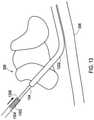
- a shielded sheath 1302is positioned over the lead 104 with the proximal end 107 of the lead 104 entering the lumen of the shielded sheath 202. This is shown in FIG. 13 .
- the shielded sheath 1302may be the same or different construction as the shielded sheath 202 and includes a shield layer 1304 that may be the same or different construction as the shield layer 204.
- the shielded sheath 1302is forced within the scar capsule 1202.
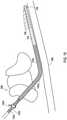
- a tapered leading edge 1306may be included on the shielded sheath 1302 to assist in penetrating into the scar capsule 1202. This is shown in FIG. 14 .
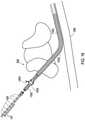
- the shielded sheathis advanced through the scar capsule until reaching a desired position proximal of the electrodes 106 on the distal end 105 of the lead 104 as shown in FIG. 15 .
- an anchor 1402 as also shown in FIG. 15is applied to the shielded sheath 1302 to fasten the shielded sheath 1302 to the surrounding fascia at the spinal structures 308 while also anchoring the lead 104 to the shielded sheath 1302. This, in turn, anchors the lead 104 to the surrounding fascia.
- the anchor 1402is also of the type that forms a sleeve that is then affixed to surrounding tissue via sutures 1404.
- other types of anchoringmay also be used for the purpose of anchoring the lead to the shielded sheath.
- the shielded sheathmay be provided with elasticity of the insulative body and a slightly smaller lumen diameter than the lead 104 near the ends such that the compression of the shielded sheath may anchor the sheath to the lead 104.
- anchoringinclude utilizing an anchor that is elastic and provides compression to force the sheath tightly against the lead.
- the proximal end 107 of the lead 104 having proximal contacts 109 and the shielded sheath 1302are tunneled together to the pocket 114 where the implantable medical device 102 is or will be positioned. This is shown in FIG. 16 .
- the proximal end 107 of the lead 104is connected to the implantable medical device 102 at the pocket 114.
- the proximal contacts 109 of the lead 104establish electrical connections with corresponding electrical connectors of the implantable medical device 102 to complete the stimulation pathway to the electrodes 106 that are positioned at the stimulation site within the epidural space.
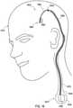
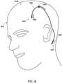
- FIG. 18shows an implantable medical system 1814 which includes an implantable medical device 1802, an implantable medical lead 1804, and a lead extension that is connected between the lead 1804 and the implantable medical device 1802.
- the implantable medical device 1802is positioned within a pocket 1819 formed in the upper torso and the lead extension extends through a subcutaneous tunnel 1820 formed when implanting the extension.
- the proximal end 1805 of the lead 1804passes through the cranium via a hole 1818 to reach a stimulation site within the brain 1816 of the patient 1812.
- the system 1814also includes a first shielded sheath 1808 that has been placed over the lead 1804 and a second shielded sheath 1810 that has been placed over the lead extension.
- the shielded sheath 1808is positioned between the proximal end where the lead 1804 connects to the extension and the distal end 1805 where the electrodes 1806 are located.
- the shielded sheath 1810is positioned between the proximal end where the extension connects to the implantable medical device and the distal end where a connector housing is located.
- the shielded sheathsmay be constructed like the examples discussed above for shielded sheath 202 and 2600.
- a cranial anchormay be installed onto the lead 1804 at the hole 1818 and the sheath 1808 naturally maintains its position between the hole 1818 and the distal connector 2102 of the extension 2104.
- the second sheath 1810naturally maintains its position between the distal end of the distal connector 2102 and the proximal end of the extension 2104.
- anchoringmay be provided on the sheath 1808 and second sheath 1810 in this instance as well in the same manners as discussed above with respect to the spinal implantations.
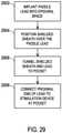
- the procedure for implanting the lead 1804, extension, and shielded sheaths 1808, 1810begins at an operation 2302 where the lead 1804 as shown in FIG. 19 is being inserted through the hole 1818 of the cranium and into the brain 1816.
- the lead 1804may be routed subcutaneously from an area behind the ear of the patient up to the hole 1818.
- the lead 104may be anchored nearby the hole 1818.
- the first shielded sheath 1808is advanced over the lead 104.
- the proximal end of the lead 104is inserted into the lumen of the shielded sheath 1808 and the shielded sheath 1808 is advanced toward the hole 1818.
- the shielded sheath 1808has a tapered leading edge 1803 that assists in passing subcutaneously toward the hole 1818.
- the shielded sheath 1808has a shield layer 1807.
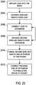
- the proximal end of the lead 1804is connected to the distal end connector 2102 on a distal end 2106 of the lead extension 2104 as shown in FIG. 21 . This occurs via an incision site that has been created when initially tunneling the lead to the hole 1818.
- the second shielded sheath 1810 having a shield layer 1811is advanced over the lead extension 2104 at an operation 2308.
- proximal end 2108 of the extension 2104 having proximal contacts 2110 and the second shielded sheath 1810are tunneled together to the pocket 1819 where the implantable medical device 1802 is or will be positioned. This is shown in FIG. 22 .
- the proximal end 2108 of the extension 2104is connected to the implantable medical device 1802 at the pocket 1819.
- the proximal contacts 2110 of the extension 2104establish electrical connections with corresponding electrical connectors of the implantable medical device 1802 to complete the stimulation pathway to the electrodes 1806 that are positioned at the stimulation site within the brain 1816.
- FIG. 24shows an example of a shielded sheath 2402 that may be placed over a lead or an extension where the proximal end of the shielded sheath 2402 provides connectivity.
- a proximal contact 2406such as a metal ring is positioned on the proximal end. This proximal contact 2406 may be in physical contact with the shield layer of the shielded sheath 2402 to provide an electrical connection from the shield layer to the proximal contact 2406.
- An implantable medical device 2404may receive the proximal end of the shielded sheath 2402 into a bore where the lead or lead extension may also be inserted.
- the implantable medical device 2404may include an electrical connector such as a set screw 2410 and a corresponding set screw bore 2408 that allows a physical connection to be made with the proximal contact.
- This electrical connector 2410then provides an electrical pathway to a grounding surface at the implantable medical device such as a metal housing. This effectively provides a tissue ground at the implantable medical device 2404 for the shield layer of the shielded sheath 2402 such that RF energy coupled to the shield may be diverted to the grounding surface and surrounding tissue of the implantable medical device 2404.
- FIG. 25shows an example of a shielded sheath 2502 that may be placed over a lead or an extension where the proximal end of the shielded sheath 2502 also provides connectivity.
- a proximal contact 2506such as a metal ring is positioned on the proximal end. This proximal contact 2506 may be in physical contact with the shield layer of the shielded sheath 2502 to provide an electrical connection from the shield layer to the proximal contact 2506.
- the proximal contact 2506also includes a smaller diameter region 2507.
- An implantable medical device 2404may receive the proximal end of the shielded sheath 2402 and specifically the smaller diameter region 2507 of the proximal contact 2506 into a bore where the lead or lead extension may also be inserted.
- This boremay have a diameter that is smaller than the larger diameter region of the proximal contact 2506 but large enough to accept the smaller diameter region 2507.
- the implantable medical device 2504may include an electrical connector such as a set screw 2510 and a corresponding set screw bore 2508 that allows a physical connection to be made with the proximal contact region 2507.
- This electrical connector 2510then provides an electrical pathway to a grounding surface at the implantable medical device such as a metal housing.
- This examplealso effectively provides a tissue ground at the implantable medical device 2504 for the shield layer of the shielded sheath 2502 such that RF energy coupled to the shield may be diverted to the grounding surface and surrounding tissue of the implantable medical device 2504.
- FIG. 27shows an implantable medical system 2700 that is implanted into the patient 108 and is similar to the implantable medical system of FIG. 2 except that the implantable medical system 2700 includes an implantable medical paddle lead 2802.
- the paddle lead 2802has been implanted via an entry point 2704, typically created through a surgical procedure to create adequate space for the paddle portion 2806, and extends into the epidural space of the spine 110.
- the paddle lead 2802includes a paddle portion 2804 that includes an array of electrodes 2806.
- the paddle lead 2802is connected to an implantable medical stimulation device 2702 that is located in a pocket 114.
- a shielded sheath 2812 of the same construction as the prior embodiments discussed hereinis positioned over the lead body of the paddle lead 2802.
- the inside diameter of the shielded sheath 2812is large enough to fit over the lead body.
- the width of the paddle portion 2804is larger than the inside diameter of the shielded sheath 2812, which confines the position of the shielded sheath 2812 on the lead 2802.
- FIG. 28further shows that the paddle lead 2802 and the shielded sheath 2812 are positioned within the epidural space by passing through the spinal structures 308 which may be further manipulated surgically when introducing the paddle portion 2804.
- the shielded sheath 2812is being installed at the time of implantation of the lead 2802, various procedures are possible as discussed with reference to FIGS. 29 and 30 .
- the shielded sheath 2812may be added such as by a procedure shown in FIG. 31 .
- the procedure of FIG. 29begins by the paddle lead 2802 being implanted into the epidural space to place the paddle portion 2804 at the target site at operation 2902.
- the shielded sheath 2812is then positioned over the paddle lead 2802 by feeding the proximal end of the paddle lead 2802 into the distal end of the shielded sheath and advancing the shielded sheath 2812 into the epidural space toward the paddle portion 2804 while the position of the lead 2802 is maintained at an operation 2904.
- the shielded sheath 2812may be desirable in some instances to also create a strain relief loop in the combination of the paddle lead 2802 and attached sheath 2812, such that the strain relief loop is shielded, at this intermediate location in the body of the patient near the entry to the epidural space.
- the proximal end of the lead 2802 and the shielded sheath 2812 positioned on the lead 2802are then tunneled to the pocket 114 at an operation 2906.
- the proximal end 2808 of the lead 2802which includes contacts 2810, is then connected to the stimulation device 2702 at an operation 2908.
- strain relief loopin the combination of the paddle lead 2802 and attached sheath 2812, such that the strain relief loop is shielded, at this location near the pocket 114 prior to connecting the proximal end 2808 to the device 2702.
- FIG. 30An alternative procedure as shown in FIG. 30 begins by the shielded sheath 2812 being positioned over the paddle lead 2802.
- the proximal end of the paddle lead 2802is fed into the distal end of the shielded sheath, and the shielded sheath 2812 is advanced toward the paddle portion 2804 prior to implantation of the lead 2802 at an operation 3002.
- the paddle lead 2802 and shielded sheath 218are then implanted into the epidural space to place the paddle portion 2804 at the target site at operation 2902 at an operation 3004.
- the shielded sheath 2812With the shielded sheath 2812 fully advanced onto the lead 2802 and the combination of the shielded sheath 2812 and lead 2802 having been fully advanced to the stimulation site within the epidural space,it may be desirable in some instances to also create a strain relief loop in the combination of the paddle lead 2802 and attached sheath 2812, such that the strain relief loop is shielded, at this intermediate location in the body of the patient near the entry to the epidural space.
- the proximal end of the lead 2802 and the shielded sheath 2812 positioned on the lead 2802are then tunneled to the pocket 114 at an operation 3006.
- the proximal end 2808 of the lead 2802which includes contacts 2810, is then connected to the stimulation device 2702 at an operation 3008.
- strain relief loopin the combination of the paddle lead 2802 and attached sheath 2812, such that the strain relief loop is shielded, at this location near the pocket 114 prior to connecting the proximal end 2808 to the device 2702.
- FIGS. 31A or 31Bmay be used to retrofit an implanted paddle lead 2802 with a shielded sheath 2812.
- the example of FIG. 31Amay be implemented when a strain relief loop is either not already present or is present but not fibrosed and a strain relief loop is not desired upon placing the shielded sheath 2812 onto the lead 2802. This procedure begins by unplugging the proximal end 2808 of the lead 2802 from the stimulation device 2702 at an operation 3101. If there is a strain relief loop that is present but not fibrosed, then the lead may be gently pulled in the proximal direction to straighten the existing strain relief loop.
- the shielded sheath 2812is then positioned over the paddle lead 2802 by feeding the exposed proximal end of the paddle lead 2802 into the distal end of the shielded sheath 2812 and advancing the shielded sheath 2812 into the epidural space toward the paddle portion 2804 while the position of the lead 2802 is maintained at an operation 3103.
- the shielded sheath 2812may be forced into a scar capsule that has formed around the distal area of the lead present in the epidural space in order to fully advance the shielded sheath 2812 to the paddle portion 2804 at an operation 3105.
- the proximal end 2808 of the lead 2802which includes contacts 2810, is then connected to the stimulation device 2702 at an operation 3107.
- FIG. 31Bmay be implemented when one or more strain relief loops are already present and fibrosed and/or are desired upon placing the shielded sheath 2812 onto the lead 2802.
- This procedurebegins by unplugging the proximal end 2808 of the lead 2802 from the stimulation device 2702 at an operation 3102.
- the point of entry 2704typically a surgical incision, of the lead 2802 into the epidural space may be reopened to access the lead 2802 at an operation 3104.
- the lead 2802is then pulled from the pocket 114 to the point of entry 2704 to pull any existing strain relief loop straight and to gain access to the proximal end of the lead 2802 at an operation 3106.
- the shielded sheath 2812is then positioned over the paddle lead 2802 by feeding the exposed proximal end of the paddle lead 2802 into the distal end of the shielded sheath and advancing the shielded sheath 2812 into the epidural space toward the paddle portion 2804 while the position of the lead 2802 is maintained at an operation 3108.
- the shielded sheath 2812may be forced into a scar capsule that has formed around the distal area of the lead present in the epidural space in order to fully advance the shielded sheath 2812 to the paddle portion 2804 at an operation 3110.
- the shielded sheath 2812With the shielded sheath 2812 fully advanced onto the lead 2802 , it may be desirable in some instances to also create a strain relief loop in the combination of the paddle lead 2802 and attached sheath 2812, such that the strain relief loop is shielded, at this intermediate location in the body of the patient near the entry to the epidural space.
- the proximal end of the lead 2802 and the shielded sheath 2812 positioned on the lead 2802are then tunneled to the pocket 114 at an operation 3112.
- the proximal end 2808 of the lead 2802, which includes contacts 2810,is then connected to the stimulation device 2702 at an operation 3114.
- strain relief loopin the combination of the paddle lead 2802 and attached sheath 2812, such that the strain relief loop is shielded, at this location near the pocket 114 prior to connecting the proximal end 2808 to the device 2702.
- FIG. 32shows an example of such a configuration.
- the proximal end 2810 of the lead 2802has been connected to a distal connector block 3208 of connectors of a lead extension 3202.
- the shielded sheath 2812is present on the lead 2802 while a second shielded sheath 3204 is present on the lead extension 3202.
- the second shielded sheath 3204includes a portion 3206 that covers the distal connector block 3208 of the extension 3202.
- the proximal end of the lead 2802includes contacts 3210 that are plugged into the stimulation device 2702.
- the shielded sheath 2812 of FIGS. 27 , 28 , and 32 as well as the second shielded sheath 3204may also include an electrical contact, such as the contact 2406 in FIG. 24 , on the proximal end that can then establish a ground path with the stimulation device 2702.
- the electrical contact of the shielded sheath 2812 or second shielded sheath 3204may have a first portion with a first diameter and a second portion and a second diameter that is smaller than the first, as shown in FIG. 25 .
Landscapes
- Health & Medical Sciences (AREA)
- General Health & Medical Sciences (AREA)
- Animal Behavior & Ethology (AREA)
- Veterinary Medicine (AREA)
- Public Health (AREA)
- Heart & Thoracic Surgery (AREA)
- Engineering & Computer Science (AREA)
- Biomedical Technology (AREA)
- Nuclear Medicine, Radiotherapy & Molecular Imaging (AREA)
- Life Sciences & Earth Sciences (AREA)
- Radiology & Medical Imaging (AREA)
- Cardiology (AREA)
- Neurology (AREA)
- Neurosurgery (AREA)
- Physics & Mathematics (AREA)
- Electromagnetism (AREA)
- Orthopedic Medicine & Surgery (AREA)
- Psychology (AREA)
- Electrotherapy Devices (AREA)
Description
- Embodiments relate to implantable medical leads and implantable medical lead extensions. More particularly, embodiments relate to apparatus for shielding implantable medical leads and implantable medical lead extensions.
- Implantable medical systems are used to provide stimulation therapy and/or physiological sensing for patients. The implantable medical system includes a stimulation or sensing device that is implanted at a convenient location. Implantable medical leads are routed between the site of implantation of the device and a target site where stimulation or sensing is to occur. Where the route is lengthy, an implantable medical lead extension is used to traverse a portion of that distance.
- The implantable medical leads include one or more electrical contacts located near a proximal end of the lead. Where no extension is needed, the proximal end of the lead is physically connected to the stimulation or sensing device so that the proximal contacts of the lead are electrically coupled to electrical circuitry of the device. For scenarios where the implantable medical lead extension is used, then the proximal end of the lead is physically connected to a distal end of the extension where electrical connectors of the extension are coupled to the electrical contacts of the lead. The proximal end of the extension is physically connected to the stimulation or sensing device so that the proximal contacts of the extension are electrically coupled to electrical circuitry of the device. The leads also include one or more electrodes located near a distal end of the leads. Electrical conductors are present within the lead, and each electrical conductor is connected to a respective electrical contact and electrode to provide an electrical path for stimulation and/or sensed signals. Electrical conductors are also present within the extension, and each electrical conductor is connected to a respective electrical contact and distal connector to provide an electrical path for stimulation and/or sensed signals.
- Because the lead and lead-extension combination extends over a significant distance within the body, each electrical conductor within the lead and extension is susceptible to receiving extraneous electromagnetic energy that produces electrical current on the electrical conductor. While most ambient conditions expose the lead and lead extension to insignificant levels of such extraneous electromagnetic energy, certain situations may create levels of extraneous electromagnetic energy that are of concern. An example of such a situation is a magnetic resonance imaging (MRI) scan. The MRI scan utilizes a high energy radio frequency (RF) electromagnetic signal. This RF signal may produce relatively large levels of electrical current on the electrical conductor of the lead and extension when the patient having the implantable medical system that includes the lead and/or lead extension combination undergoes the MRI scan. The relatively large electrical current that results from the high energy RF signal produces heating at the electrodes that may create discomfort and even dangerous tissue damage at the site within the body where the one or more electrodes of the lead are located.
- It has been found that a shield layer within the lead reduces the amount of RF energy that reaches the electrical conductors, which in turn reduces the amount of current being coupled onto the electrical conductors and reduces the heating at the electrodes to acceptable levels. The manufacturing process of the lead has been altered to include a shield layer when the lead body is being manufactured by creating an inner jacket over the electrical conductor, then creating the shield layer on the inner jacket, and then creating an outer jacket over the inner jacket. The electrical contacts and electrodes are then installed about the inner jacket and are coupled to the electrical conductor to complete the leads. However, leads and extensions that have been constructed without such shield layers or other protective aspects remain vulnerable to the high levels of RF energy of the MRI scan or other situation.
- Additionally, patients having leads and/or extensions implanted that are not designed to be safe during an MRI scan either continue to be ineligible for an MRI scan or must undergo a procedure to replace the lead and/or extension with an MRI compliant version. Replacing the existing lead presents a risk that the new lead will not be positioned in a location that provides therapy that is as effective as with the prior lead. Furthermore, some leads are very difficult to remove, such as leads having a distal paddle that have required surgical procedures for implantation.
US 2012/0046722 A1 relates to shielding an implantable medical lead.US 2010/0256696 A1 describes anchoring units for implantable electrical stimulation systems and methods of making and using.US 6,673,999 B1 deals with a magnetically shielded assembly.US2010/036466 A1 relates to a lead construction.US 2008154326 A1 relates to a sheath for a lead comprising a radiopaque material.- The invention is defined in claim 1. Further aspects and preferred embodiments are defined in the appended claims. Aspects, embodiments and examples of the present disclosure which do not fall under the scope of the appended claims do not form part of the invention and are merely provided for illustrative purposes.
- Embodiments address issues such as these and others by adding a shielded sheath over an existing lead or extension. The shielded sheath may then be anchored to the existing lead or extension and to the surrounding body tissue. The shielded sheath may be added to newly implanted leads and/or extensions or to leads and/or extensions that have previously been implanted.
- Embodiments provide an apparatus that includes an implantable medical lead having a proximal contact and a distal electrode and also includes a sheath containing a shield layer positioned about the implantable medical lead between the proximal contact and the distal electrode. The apparatus further includes an anchoring structure holding the sheath in a fixed position about the implantable medical lead.
- Embodiments provide an implantable medical system that includes an implantable stimulation device and an implantable medical lead having a proximal contact and a distal electrode with the proximal contact being electrically coupled to the implantable stimulation device. The system further includes a sheath containing a shield layer positioned about the implantable medical lead between the proximal contact and the distal electrode and an anchoring structure holding the sheath in a fixed position about the implantable medical lead.
- Embodiments provide an apparatus that includes an implantable medical lead extension having a proximal contact and a distal connector block and also includes a sheath containing a shield layer positioned about the implantable medical lead between the proximal contact and a distal end of the implantable medical lead extension. The apparatus further includes an anchoring structure holding the sheath in a fixed position about the implantable medical lead extension.
- Embodiments provide an apparatus that includes an implantable medical paddle lead having a proximal contact and a paddle portion that contains at least one distal electrode, the paddle portion having a width greater than a remainder of the implantable medical paddle lead. The apparatus further includes a sheath containing a shield layer positioned about the implantable medical lead between the proximal contact and the paddle portion, the sheath having an inner diameter that is smaller than a width of the paddle portion of the paddle lead but greater than a diameter of a remainder of the paddle lead such that the sheath is confined by the paddle portion.
- Embodiments provide an implantable medical system that includes an implantable stimulation device. The system further includes an implantable medical paddle lead having a proximal contact and a paddle portion that contains at least one distal electrode with the proximal contact being electrically coupled to the implantable stimulation device, the paddle portion having a width greater than a remainder of the implantable medical paddle lead. The system additionally includes a sheath containing a shield layer positioned about the implantable medical lead between the proximal contact and the paddle portion, the sheath having an inner diameter that is smaller than a width of the paddle portion of the paddle lead but greater than a diameter of a remainder of the paddle lead such that the sheath is confined by the paddle portion.
FIG. 1 shows an implantable medical system including a lead that has been implanted prior to introduction of a shielded sheath.FIG. 2 shows the implantable medical system with the shielded sheath installed over the lead.FIG. 3 shows an example of a procedure that begins with a needle being inserted into an epidural space followed by a guidewire.FIG. 4 shows the needle being removed from the epidural space while the guidewire remains.FIG. 5 shows an example of the shielded sheath being inserted into the epidural space by following along the guidewire.FIG. 6 shows removal of the guidewire from the epidural space while the shielded sheath remains.FIG. 7 shows an anchor being applied to hold the shielded sheath in place relative to the epidural space.FIG. 8 shows an implantable medical lead being inserted into the epidural space by passing through the shield sheath.FIG. 9 shows distal end of the implantable medical lead exiting the distal end of the shielded sheath within the epidural space to reach the stimulation site.FIG. 10 shows an anchor being applied to hold the lead in place with the shielded sheath relative to the epidural space followed by the proximal end of the lead and shielded sheath being tunneled to the pocket for the implantable medical device.FIG. 11 shows a set of operations to implant a shielded sheath and an implantable medical lead according to the aspects shown inFIGS. 3-10 .FIG. 12 shows an example of a procedure that begins with an anchor being removed from a lead that is implanted with a distal end in the epidural space and a proximal end of the lead being pulled to the incision site for entry to the epidural space.FIG. 13 shows an example of the shielded sheath being inserted over the implanted lead.FIG. 14 shows the shield sheath passing through a scar capsule that surrounds the implanted lead and passing into the epidural space.FIG. 15 shows an anchor being applied to hold the shielded sheath and lead in place relative to the epidural space.FIG. 16 shows the proximal end of the lead and shielded sheath being tunneled to the pocket for the implantable medical device.FIG. 17 shows a set of operations to add a shielded sheath over an implanted lead according to the aspects shown inFIGS. 12-16 .FIG. 18 shows another example of an implantable medical system including a lead extension with shielded sheaths installed over a lead and a lead extension.FIG. 19 shows an example of a procedure that begins with a lead being tunneled to a bore hole with a distal end of the lead being inserted into the brain to a stimulation site.FIG. 20 shows an example of a shielded sheath being inserted over the lead.FIG. 21 shows an example of a second shielded sheath being inserted over a lead extension that has been tunneled and connected to a proximal end of the lead.FIG. 22 shows the proximal end of the extension and the second shielded sheath being tunneled to the pocket for the implantable medical device.FIG. 23 shows a set of operations to add a shielded sheath over the implanted lead and to add a second shielded sheath over the implanted extension according to the aspects shown inFIGS. 19-22 .FIG. 24 shows a proximal end of an example of a shielded sheath that may include a connector for engagement with a contact of an implantable medical device.FIG. 25 shows a proximal end of another example of a shielded sheath that may include a connector with a reduced diameter portion for engagement with a contact of an implantable medical device.FIG. 26 shows a lateral cross-sectional view of an example of a shielded sheath.FIG. 27 shows an implantable medical system with the shielded sheath installed over a paddle lead.FIG. 28 shows the shielded sheath positioned over the paddle lead and being positioned within the epidural space.FIG. 29 shows a set of operations for one manner of implanting a shielded sheath and an implantable medical paddle lead.FIG. 30 shows a set of operations for another manner of implanting a shielded sheath and an implantable medical paddle lead.FIGS. 31A and31B show sets of operations for ways of implanting a shielded sheath onto a previously implanted medical paddle lead.FIG. 32 shows an example of an implantable medical system that includes a lead extension, a paddle lead, and first and second shielded sheaths for the paddle lead and lead extension.- Embodiments provide shielded sheaths that are installed over leads and/or extensions, whether being implanted or already implanted. The shielded sheath reduces the amount of RF energy that reaches the conductors of the lead and/or extension.
FIG. 1 shows an example where a shielded sheath may be utilized. An implantablemedical system 100 that includes an implantablemedical device 102 which may be an implantable stimulation device that provides electrical stimulation signals and/or senses physiological signals. Thesystem 100 also includes an implantablemedical lead 104 is implanted into apatient 108. In this particular example, the implantable medical system is a spinal cord stimulator where thelead 104 is implanted into a location nearby the spinal cord within thespine 110. The implantablemedical device 102 provides electrical stimulation that is delivered through conductors of thelead 104 to the stimulation site. The implantablemedical device 102 is implanted within asubcutaneous pocket 114 created during implantation while thelead 104 is tunneled through apath 116 created between thepocket 114 and theentry point 112 to an epidural space during implantation.FIG. 2 shows an implantablemedical system 200 which is identical to thesystem 100 ofFIG. 1 except that a shieldedsheath 202 has been placed over thelead 104. The shielded sheath is positioned between the proximal end where thelead 104 connects to the implantable medical device and the distal end where theelectrodes 106 are located. The shieldedsheath 202 has an insulative shield body with ashield layer 204 within the shield body to isolate theshield layer 204 from the external conditions of thebody 108. The shielded sheath provides shielding of RF electromagnetic energy to reduce the amount of RF electromagnetic energy that becomes coupled to the conductors that are within thelead 104 and are connected between the implantablemedical device 102 and theelectrodes 106.FIG. 26 shows a lateral cross-sectional view of an example 2600 of the shieldedsheath 202. In the shieldedsheath 2600, there is aninsulative shield body 2602 that defines alumen 2606 where thelead 104 or a lead extension may pass through. The insulative body may be constructed of various biocompatible materials including various polymers, urethanes such as the PurSil® thermoplastic silicone-polyether-urethane of the Koninklijke DSM N.V. Corporation of the Netherlands, and other silicones. Ashield layer 2604 is also present and is embedded within the insulative layer. Theshield layer 204 inFIG. 2 as well as theshield layer 2604 ofFIG. 26 is in the form of a tubular structure of braided conductive wires to provide a tubular braided shield layer. However, other forms of shield layers are also possible, for instance, a conductive foil tube. For a braided shield, the wires of the braid may be a conductor such as a biocompatible metal like tantalum, titanium, and the like. For a foil shield, the foil may be a conductor such as a biocompatible metal like titanium, tantalum, stainless steel, MP35N® alloy of SPS Technologies, Inc. of Jenkintown, PA, and the like.- Where the
shield layer 204 is a braided wire shield as shown inFIG. 2 , the braid may be created with a variety of shield parameters. Examples of shield parameters such as braid angle, wire cross-sectional shape and diameter, number of braid wires, braid depth, distance from shield termination to closest contact or electrode, and the like that may also be used for the embodiments being disclosed herein are described in published U.S. Patent ApplicationUS 2012/0046722 A1 . - The shielded
sheath 202 may be installed during a new implantation of thelead 104 or as a retrofit to a lead 104 that has previously been implanted. Examples of procedures for installing the shieldedsheath 202 are discussed below, with the procedure for installing during a new spinal implantation of thelead 104 being described with reference toFIGS. 3-11 and the procedure for retrofitting aspinal lead 104 that has previously been implanted with reference toFIGS. 12-17 . An example of a procedure for installing the shielded sheath for a brain lead is discussed below in relation toFIGS. 18-23 . - In
FIG. 11 , the procedure for a new implantation of alead 104 begins at anoperation 1102 where aneedle 304 as shown inFIG. 3 is being inserted through thespinal structures 308 and into the epidural space between thespinal structures 308 and thespinal cord 306. Aguide wire 302 is then advanced through theneedle 304 and into the epidural space at anoperation 1104. - At an
operation 1106, theneedle 304 is then retracted while theguidewire 302 remains in the epidural space. This is shown inFIG. 4 where it can be seen that theguidewire 302 has maintained a position within the epidural space as theneedle 304 has exited the epidural space. - At an
operation 1108, the shieldedsheath 202 having theshield layer 204 is advanced over theguidewire 302 and approaches the epidural space through thespinal structures 308. This is shown inFIG. 5 . In this example, the shieldedsheath 202 includes a taperedleading edge 206 which allows the shieldedsheath 202 to more easily penetrate through the body tissues to reach the epidural space. - At an
operation 1110, theguidewire 302 is retracted from the epidural space through the shieldedsheath 202 while the shieldedsheath 202 remains in the epidural space. This is shown inFIG. 6 where it can be seen that the shieldedsheath 202 has maintained a position within the epidural space as theguidewire 302 has exited the epidural space. - At an
operation 1112, ananchor 702 as shown inFIG. 7 is applied to the shieldedsheath 202 to fasten the shield to the surrounding fascia at thespinal structures 308. In the example shown inFIG. 7 , theanchor 702 is of the type that forms a sleeve that is then affixed to surrounding tissue viasutures 704. However, other types of anchoring may also be used. For instance, the shieldedsheath 202 may be directly sutured. - At an
operation 1114, the distal end of thelead 104 is inserted into the lumen of the shieldedsheath 202 and is advanced toward the epidural space. This is shown inFIG. 8 . - At an
operation 1116, thelead 104 is advanced through the shieldedsheath 202 to the stimulation site. As shown inFIG. 9 , thedistal end 105 of thelead 104 exits from the shielded sheath to then reach the stimulation site within the epidural space with theelectrodes 106 being exposed to thespinal cord 306. - At an
operation 1118, ananchor 1002 as shown inFIG. 10 is applied to the shieldedsheath 202 to further fasten the shield to the surrounding fascia at thespinal structures 308 while also anchoring the lead to the shielded sheath. This, in turn, anchors the lead to the surrounding fascia. In the example shown inFIG. 10 , theanchor 1002 is also of the type that forms a sleeve that is then affixed to surrounding tissue viasutures 1004. In the example shown inFIG. 10 , anotheranchor 1003 is also installed at the point where thelead 104 exits the proximal end of the shielded sheath and affixed to surrounding tissue viasutures 1005. By overlapping the point where thelead 104 exits the shielded sheath, thisanchor 1003 is partially directly engaging thelead 104 and partially directly engaging the shielded sheath to further anchor thelead 104 and shielded sheath together and to the tissue. However, other types of anchoring may also be used for the purpose of anchoring the lead to the shielded sheath. For instance, the shielded sheath may be provided with elasticity of the insulative body and a slightly smaller lumen diameter than thelead 104 near the ends such that the compression of the shielded sheath may anchor the sheath to thelead 104. Other examples of anchoring include utilizing an anchor that is elastic and provides compression to force the sheath tightly against the lead. - At an
operation 1120, theproximal end 107 of thelead 104 havingproximal contacts 109 and the shieldedsheath 202 are tunneled together to thepocket 114 where the implantablemedical device 102 is or will be positioned. This is also shown inFIG. 10 . - At an
operation 1122, theproximal end 107 of thelead 104 is connected to the implantablemedical device 102 at thepocket 114. Theproximal contacts 109 of thelead 104 establish electrical connections with corresponding electrical connectors of the implantablemedical device 102 to complete the stimulation pathway to theelectrodes 106 that are positioned at the stimulation site within the epidural space. - In
FIG. 17 , the procedure for a previously implantedlead 104 begins at anoperation 1702 where the proximal end of thelead 107 is unplugged from the implantablemedical device 102. A spinal incision is then opened nearby the entry site to the epidural space at anoperation 1704. - At an
operation 1706, ananchor 1204 as shown inFIG. 12 is being removed from thelead 104. Then, at anoperation 1708, thelead 104 is pulled at the incision site to bring theproximal end 107 of thelead 104 to the incision cite. This is also shown inFIG. 12 . It can further be seen inFIG. 12 that the distal end of thelead 104 is present within ascar capsule 1202 that has naturally formed about the distal end of thelead 104. - At an
operation 1710, a shieldedsheath 1302 is positioned over thelead 104 with theproximal end 107 of thelead 104 entering the lumen of the shieldedsheath 202. This is shown inFIG. 13 . The shieldedsheath 1302 may be the same or different construction as the shieldedsheath 202 and includes ashield layer 1304 that may be the same or different construction as theshield layer 204. - At an
operation 1712, the shieldedsheath 1302 is forced within thescar capsule 1202. A tapered leadingedge 1306 may be included on the shieldedsheath 1302 to assist in penetrating into thescar capsule 1202. This is shown inFIG. 14 . The shielded sheath is advanced through the scar capsule until reaching a desired position proximal of theelectrodes 106 on thedistal end 105 of thelead 104 as shown inFIG. 15 . - At an
operation 1714, ananchor 1402 as also shown inFIG. 15 is applied to the shieldedsheath 1302 to fasten the shieldedsheath 1302 to the surrounding fascia at thespinal structures 308 while also anchoring thelead 104 to the shieldedsheath 1302. This, in turn, anchors thelead 104 to the surrounding fascia. In the example shown inFIG. 15 , theanchor 1402 is also of the type that forms a sleeve that is then affixed to surrounding tissue viasutures 1404. However, other types of anchoring may also be used for the purpose of anchoring the lead to the shielded sheath. For instance, the shielded sheath may be provided with elasticity of the insulative body and a slightly smaller lumen diameter than thelead 104 near the ends such that the compression of the shielded sheath may anchor the sheath to thelead 104. Other examples of anchoring include utilizing an anchor that is elastic and provides compression to force the sheath tightly against the lead. - At an
operation 1716, theproximal end 107 of thelead 104 havingproximal contacts 109 and the shieldedsheath 1302 are tunneled together to thepocket 114 where the implantablemedical device 102 is or will be positioned. This is shown inFIG. 16 . - At an
operation 1718, theproximal end 107 of thelead 104 is connected to the implantablemedical device 102 at thepocket 114. Theproximal contacts 109 of thelead 104 establish electrical connections with corresponding electrical connectors of the implantablemedical device 102 to complete the stimulation pathway to theelectrodes 106 that are positioned at the stimulation site within the epidural space. FIG. 18 shows an implantablemedical system 1814 which includes an implantablemedical device 1802, an implantablemedical lead 1804, and a lead extension that is connected between thelead 1804 and the implantablemedical device 1802. The implantablemedical device 1802 is positioned within apocket 1819 formed in the upper torso and the lead extension extends through asubcutaneous tunnel 1820 formed when implanting the extension. Theproximal end 1805 of the lead 1804 passes through the cranium via ahole 1818 to reach a stimulation site within thebrain 1816 of thepatient 1812.- The
system 1814 also includes a first shieldedsheath 1808 that has been placed over thelead 1804 and a second shieldedsheath 1810 that has been placed over the lead extension. The shieldedsheath 1808 is positioned between the proximal end where thelead 1804 connects to the extension and thedistal end 1805 where theelectrodes 1806 are located. The shieldedsheath 1810 is positioned between the proximal end where the extension connects to the implantable medical device and the distal end where a connector housing is located. The shielded sheaths may be constructed like the examples discussed above for shieldedsheath lead 1804 at thehole 1818 and thesheath 1808 naturally maintains its position between thehole 1818 and thedistal connector 2102 of theextension 2104. Likewise, thesecond sheath 1810 naturally maintains its position between the distal end of thedistal connector 2102 and the proximal end of theextension 2104. However, if desired, anchoring may be provided on thesheath 1808 andsecond sheath 1810 in this instance as well in the same manners as discussed above with respect to the spinal implantations. - In
FIG. 23 , the procedure for implanting thelead 1804, extension, and shieldedsheaths operation 2302 where thelead 1804 as shown inFIG. 19 is being inserted through thehole 1818 of the cranium and into thebrain 1816. Thelead 1804 may be routed subcutaneously from an area behind the ear of the patient up to thehole 1818. Thelead 104 may be anchored nearby thehole 1818. - In an
operation 2304, the first shieldedsheath 1808 is advanced over thelead 104. The proximal end of thelead 104 is inserted into the lumen of the shieldedsheath 1808 and the shieldedsheath 1808 is advanced toward thehole 1818. This is shown inFIG. 20 . It can be seen that the shieldedsheath 1808 has a taperedleading edge 1803 that assists in passing subcutaneously toward thehole 1818. It can also be seen that the shieldedsheath 1808 has ashield layer 1807. - In an
operation 2306, the proximal end of thelead 1804 is connected to thedistal end connector 2102 on adistal end 2106 of thelead extension 2104 as shown inFIG. 21 . This occurs via an incision site that has been created when initially tunneling the lead to thehole 1818. As also shown inFIG. 21 , the second shieldedsheath 1810 having ashield layer 1811 is advanced over thelead extension 2104 at anoperation 2308. - In an
operation 2308, theproximal end 2108 of theextension 2104 havingproximal contacts 2110 and the second shieldedsheath 1810 are tunneled together to thepocket 1819 where the implantablemedical device 1802 is or will be positioned. This is shown inFIG. 22 . - At an
operation 2312, theproximal end 2108 of theextension 2104 is connected to the implantablemedical device 1802 at thepocket 1819. Theproximal contacts 2110 of theextension 2104 establish electrical connections with corresponding electrical connectors of the implantablemedical device 1802 to complete the stimulation pathway to theelectrodes 1806 that are positioned at the stimulation site within thebrain 1816. FIG. 24 shows an example of a shieldedsheath 2402 that may be placed over a lead or an extension where the proximal end of the shieldedsheath 2402 provides connectivity. In this example, aproximal contact 2406 such as a metal ring is positioned on the proximal end. Thisproximal contact 2406 may be in physical contact with the shield layer of the shieldedsheath 2402 to provide an electrical connection from the shield layer to theproximal contact 2406. An implantablemedical device 2404 may receive the proximal end of the shieldedsheath 2402 into a bore where the lead or lead extension may also be inserted.- The implantable
medical device 2404 may include an electrical connector such as aset screw 2410 and a corresponding set screw bore 2408 that allows a physical connection to be made with the proximal contact. Thiselectrical connector 2410 then provides an electrical pathway to a grounding surface at the implantable medical device such as a metal housing. This effectively provides a tissue ground at the implantablemedical device 2404 for the shield layer of the shieldedsheath 2402 such that RF energy coupled to the shield may be diverted to the grounding surface and surrounding tissue of the implantablemedical device 2404. FIG. 25 shows an example of a shieldedsheath 2502 that may be placed over a lead or an extension where the proximal end of the shieldedsheath 2502 also provides connectivity. In this example, aproximal contact 2506 such as a metal ring is positioned on the proximal end. Thisproximal contact 2506 may be in physical contact with the shield layer of the shieldedsheath 2502 to provide an electrical connection from the shield layer to theproximal contact 2506. Theproximal contact 2506 also includes asmaller diameter region 2507. An implantablemedical device 2404 may receive the proximal end of the shieldedsheath 2402 and specifically thesmaller diameter region 2507 of theproximal contact 2506 into a bore where the lead or lead extension may also be inserted. This bore may have a diameter that is smaller than the larger diameter region of theproximal contact 2506 but large enough to accept thesmaller diameter region 2507.- The implantable
medical device 2504 may include an electrical connector such as aset screw 2510 and a corresponding set screw bore 2508 that allows a physical connection to be made with theproximal contact region 2507. Thiselectrical connector 2510 then provides an electrical pathway to a grounding surface at the implantable medical device such as a metal housing. This example also effectively provides a tissue ground at the implantablemedical device 2504 for the shield layer of the shieldedsheath 2502 such that RF energy coupled to the shield may be diverted to the grounding surface and surrounding tissue of the implantablemedical device 2504. FIG. 27 shows an implantablemedical system 2700 that is implanted into thepatient 108 and is similar to the implantable medical system ofFIG. 2 except that the implantablemedical system 2700 includes an implantablemedical paddle lead 2802. Thepaddle lead 2802 has been implanted via anentry point 2704, typically created through a surgical procedure to create adequate space for thepaddle portion 2806, and extends into the epidural space of thespine 110. Thepaddle lead 2802 includes apaddle portion 2804 that includes an array ofelectrodes 2806. Thepaddle lead 2802 is connected to an implantablemedical stimulation device 2702 that is located in apocket 114. A shieldedsheath 2812 of the same construction as the prior embodiments discussed herein is positioned over the lead body of thepaddle lead 2802.- As can be seen in
FIG. 27 as well as inFIG. 28 , the inside diameter of the shieldedsheath 2812 is large enough to fit over the lead body. However, the width of thepaddle portion 2804 is larger than the inside diameter of the shieldedsheath 2812, which confines the position of the shieldedsheath 2812 on thelead 2802.FIG. 28 further shows that thepaddle lead 2802 and the shieldedsheath 2812 are positioned within the epidural space by passing through thespinal structures 308 which may be further manipulated surgically when introducing thepaddle portion 2804. Where the shieldedsheath 2812 is being installed at the time of implantation of thelead 2802, various procedures are possible as discussed with reference toFIGS. 29 and30 . Where thelead 2802 is already implanted, then the shieldedsheath 2812 may be added such as by a procedure shown inFIG. 31 . - The procedure of
FIG. 29 begins by thepaddle lead 2802 being implanted into the epidural space to place thepaddle portion 2804 at the target site atoperation 2902. The shieldedsheath 2812 is then positioned over thepaddle lead 2802 by feeding the proximal end of thepaddle lead 2802 into the distal end of the shielded sheath and advancing the shieldedsheath 2812 into the epidural space toward thepaddle portion 2804 while the position of thelead 2802 is maintained at anoperation 2904. Once the shieldedsheath 2812 has been fully advanced onto thelead 2802, it may be desirable in some instances to also create a strain relief loop in the combination of thepaddle lead 2802 and attachedsheath 2812, such that the strain relief loop is shielded, at this intermediate location in the body of the patient near the entry to the epidural space. The proximal end of thelead 2802 and the shieldedsheath 2812 positioned on thelead 2802 are then tunneled to thepocket 114 at anoperation 2906. Theproximal end 2808 of thelead 2802, which includescontacts 2810, is then connected to thestimulation device 2702 at anoperation 2908. It may also be desirable in some instances to create a strain relief loop in the combination of thepaddle lead 2802 and attachedsheath 2812, such that the strain relief loop is shielded, at this location near thepocket 114 prior to connecting theproximal end 2808 to thedevice 2702. - An alternative procedure as shown in
FIG. 30 begins by the shieldedsheath 2812 being positioned over thepaddle lead 2802. The proximal end of thepaddle lead 2802 is fed into the distal end of the shielded sheath, and the shieldedsheath 2812 is advanced toward thepaddle portion 2804 prior to implantation of thelead 2802 at anoperation 3002. Thepaddle lead 2802 and shielded sheath 218 are then implanted into the epidural space to place thepaddle portion 2804 at the target site atoperation 2902 at anoperation 3004. With the shieldedsheath 2812 fully advanced onto thelead 2802 and the combination of the shieldedsheath 2812 and lead 2802 having been fully advanced to the stimulation site within the epidural space,it may be desirable in some instances to also create a strain relief loop in the combination of thepaddle lead 2802 and attachedsheath 2812, such that the strain relief loop is shielded, at this intermediate location in the body of the patient near the entry to the epidural space. The proximal end of thelead 2802 and the shieldedsheath 2812 positioned on thelead 2802 are then tunneled to thepocket 114 at anoperation 3006. Theproximal end 2808 of thelead 2802, which includescontacts 2810, is then connected to thestimulation device 2702 at anoperation 3008. It may also be desirable in some instances to create a strain relief loop in the combination of thepaddle lead 2802 and attachedsheath 2812, such that the strain relief loop is shielded, at this location near thepocket 114 prior to connecting theproximal end 2808 to thedevice 2702. - The procedures of
FIGS. 31A or31B may be used to retrofit an implantedpaddle lead 2802 with a shieldedsheath 2812. The example ofFIG. 31A may be implemented when a strain relief loop is either not already present or is present but not fibrosed and a strain relief loop is not desired upon placing the shieldedsheath 2812 onto thelead 2802. This procedure begins by unplugging theproximal end 2808 of the lead 2802 from thestimulation device 2702 at anoperation 3101. If there is a strain relief loop that is present but not fibrosed, then the lead may be gently pulled in the proximal direction to straighten the existing strain relief loop. The shieldedsheath 2812 is then positioned over thepaddle lead 2802 by feeding the exposed proximal end of thepaddle lead 2802 into the distal end of the shieldedsheath 2812 and advancing the shieldedsheath 2812 into the epidural space toward thepaddle portion 2804 while the position of thelead 2802 is maintained at anoperation 3103. The shieldedsheath 2812 may be forced into a scar capsule that has formed around the distal area of the lead present in the epidural space in order to fully advance the shieldedsheath 2812 to thepaddle portion 2804 at anoperation 3105. Theproximal end 2808 of thelead 2802, which includescontacts 2810, is then connected to thestimulation device 2702 at anoperation 3107. - The example of
FIG. 31B may be implemented when one or more strain relief loops are already present and fibrosed and/or are desired upon placing the shieldedsheath 2812 onto thelead 2802. This procedure begins by unplugging theproximal end 2808 of the lead 2802 from thestimulation device 2702 at anoperation 3102. The point ofentry 2704, typically a surgical incision, of thelead 2802 into the epidural space may be reopened to access thelead 2802 at anoperation 3104. Thelead 2802 is then pulled from thepocket 114 to the point ofentry 2704 to pull any existing strain relief loop straight and to gain access to the proximal end of thelead 2802 at anoperation 3106. The shieldedsheath 2812 is then positioned over thepaddle lead 2802 by feeding the exposed proximal end of thepaddle lead 2802 into the distal end of the shielded sheath and advancing the shieldedsheath 2812 into the epidural space toward thepaddle portion 2804 while the position of thelead 2802 is maintained at anoperation 3108. The shieldedsheath 2812 may be forced into a scar capsule that has formed around the distal area of the lead present in the epidural space in order to fully advance the shieldedsheath 2812 to thepaddle portion 2804 at anoperation 3110. With the shieldedsheath 2812 fully advanced onto thelead 2802 , it may be desirable in some instances to also create a strain relief loop in the combination of thepaddle lead 2802 and attachedsheath 2812, such that the strain relief loop is shielded, at this intermediate location in the body of the patient near the entry to the epidural space. The proximal end of thelead 2802 and the shieldedsheath 2812 positioned on thelead 2802 are then tunneled to thepocket 114 at anoperation 3112. Theproximal end 2808 of thelead 2802, which includescontacts 2810, is then connected to thestimulation device 2702 at anoperation 3114. It may also be desirable in some instances to create a strain relief loop in the combination of thepaddle lead 2802 and attachedsheath 2812, such that the strain relief loop is shielded, at this location near thepocket 114 prior to connecting theproximal end 2808 to thedevice 2702. - Should the
paddle lead 2802 require an extension to reach the target site,FIG. 32 shows an example of such a configuration. Here, theproximal end 2810 of thelead 2802 has been connected to adistal connector block 3208 of connectors of alead extension 3202. The shieldedsheath 2812 is present on thelead 2802 while a second shieldedsheath 3204 is present on thelead extension 3202. The second shieldedsheath 3204 includes aportion 3206 that covers thedistal connector block 3208 of theextension 3202. The proximal end of thelead 2802 includescontacts 3210 that are plugged into thestimulation device 2702. - The shielded
sheath 2812 ofFIGS. 27 ,28 , and32 as well as the second shieldedsheath 3204 may also include an electrical contact, such as thecontact 2406 inFIG. 24 , on the proximal end that can then establish a ground path with thestimulation device 2702. As another example, the electrical contact of the shieldedsheath 2812 or second shieldedsheath 3204 may have a first portion with a first diameter and a second portion and a second diameter that is smaller than the first, as shown inFIG. 25 . - While embodiments have been particularly shown and described, it will be understood by those skilled in the art that various other changes in the form and details may be made therein without departing from the scope of the invention.
Claims (15)
- An apparatus comprising:an implantable medical lead (104) having a proximal contact and a distal electrode (106);a sheath (202) containing a shield layer (204) positioned about the implantable medical lead between the proximal contact and the distal electrode, wherein the shield layer (204) is configured to provide shielding from high energy radio frequency energy during a magnetic resonance imaging; andan anchoring structure holding the sheath (204) in a fixed position about the implantable medical lead (104).
- The apparatus of claim 1, wherein the shield layer comprises braided wires.
- The apparatus of any of claims 1 or 2, wherein the shield layer is encapsulated within a polymer of the sheath.
- The apparatus of any of claims 1 to 3, further comprising an electrical contact on a proximal end of the sheath in electrical contact with the shield layer.
- The apparatus of claim 4, wherein the electrical contact has a first portion with a first diameter and a second portion with a second diameter that is smaller than the first diameter.
- An implantable medical system, comprising:an implantable stimulation device (102);an apparatus according to any of claims 1 to 5, wherein
the proximal contact is electrically coupled to the implantable stimulation device (102) - The system of any of claims 6, wherein the implantable medical lead is physically coupled directly to the implantable stimulation device.
- The system of any of claims 6 or 7, further comprising:an implantable medical lead extension having a proximal contact and a distal connector block, a second sheath containing a shield layer positioned about the implantable medical lead extension between the proximal contact and a distal end of the implantable medical lead extension; andan anchoring structure holding the second sheath in a fixed position about the implantable medical lead extension.
- An apparatus comprising:an implantable medical lead extension having a proximal contact and a distal connector block;a sheath (202) containing a shield layer (204) configured to provide shielding from high energy radio frequency energy during a magnetic resonance imaging and positioned about the implantable medical lead between the proximal contact and a distal end of the implantable medical lead extension; and
an anchoring structure holding the sheath in a fixed position about the implantable medical lead extension. - An apparatus comprising:an implantable medical paddle lead (2802) having a proximal contact and a paddle portion (2804) that contains at least one distal electrode, the paddle portion having a width greater than a remainder of the implantable medical paddle lead;a sheath (2812) containing a shield layer configured to provide shielding from high energy radio frequency energy during a magnetic resonance imaging and positioned about the implantable medical paddle lead between the proximal contact and the paddle portion, the sheath having an inner diameter that is smaller than a width of the paddle portion of the paddle lead but greater than a diameter of a remainder of the paddle lead such that the sheath is confined by the paddle portion.
- The apparatus of claim 10, wherein the shield layer comprises braided wires.
- The apparatus of any of claims 10-11, wherein the shield layer is encapsulated within a polymer of the sheath.
- The apparatus of any of claims 10-12, further comprising an electrical contact on a proximal end of the sheath in electrical contact with the shield layer, specifically wherein the electrical contact has a first portion with a first diameter and a second portion with a second diameter that is smaller than the first diameter.
- An implantable medical system, comprising:an implantable stimulation device (2702);an apparatus of any of claims 10 to 12, wherein the proximal contact is electrically coupled to the implantable stimulation device.
- The system of claim 14, further comprising:
an implantable medical lead extension having a proximal contact and a distal connector block, a second sheath containing a shield layer positioned about the implantable medical lead extension between the proximal contact and a distal end of the implantable medical lead extension, the proximal contact of the implantable medical paddle lead being physically coupled to the distal connector block.
Applications Claiming Priority (2)
| Application Number | Priority Date | Filing Date | Title |
|---|---|---|---|
| US201462028798P | 2014-07-24 | 2014-07-24 | |
| PCT/US2015/041766WO2016014816A1 (en) | 2014-07-24 | 2015-07-23 | Methods of shielding implantable medical leads and implantable medical lead extensions |
Publications (2)
| Publication Number | Publication Date |
|---|---|
| EP3191175A1 EP3191175A1 (en) | 2017-07-19 |
| EP3191175B1true EP3191175B1 (en) | 2022-03-02 |
Family
ID=53783376
Family Applications (1)
| Application Number | Title | Priority Date | Filing Date |
|---|---|---|---|
| EP15745714.4AActiveEP3191175B1 (en) | 2014-07-24 | 2015-07-23 | Apparatus for shielding implantable medical leads and lead extensions |
Country Status (3)
| Country | Link |
|---|---|
| US (2) | US10155111B2 (en) |
| EP (1) | EP3191175B1 (en) |
| WO (1) | WO2016014816A1 (en) |
Families Citing this family (5)
| Publication number | Priority date | Publication date | Assignee | Title |
|---|---|---|---|---|
| US20180369596A1 (en)* | 2017-06-26 | 2018-12-27 | Boston Scientific Neuromodulation Corporation | Systems and methods for providing an auxiliary electrical connection along an electrical stimulation system |
| CN110520042B (en)* | 2019-07-17 | 2022-05-03 | 诺尔医疗(深圳)有限公司 | deep intracranial electrodes |
| CN112190835B (en)* | 2020-09-17 | 2023-04-07 | 北京品驰医疗设备有限公司 | Connecting mechanism of implantable medical device and manufacturing method thereof |
| US12343547B2 (en) | 2021-08-19 | 2025-07-01 | Boston Scientific Neuromodulation Corporation | Connectors for an electrical stimulation system and methods of making and using |
| US20230191142A1 (en)* | 2021-12-20 | 2023-06-22 | Medtronic, Inc. | Implantable medical lead shield |
Citations (2)
| Publication number | Priority date | Publication date | Assignee | Title |
|---|---|---|---|---|
| US20080154326A1 (en)* | 2006-12-21 | 2008-06-26 | Clyne Christopher A | Method and apparatus for providing a radiopaque anchoring sleeve |
| US7822484B1 (en)* | 2007-04-03 | 2010-10-26 | Pacesetter, Inc. | MRI-compatible implantable lead having high impedance electrodes |
Family Cites Families (375)
| Publication number | Priority date | Publication date | Assignee | Title |
|---|---|---|---|---|
| US2487038A (en) | 1944-03-25 | 1949-11-08 | Sonotone Corp | Ear insert for earphones |
| US2433480A (en) | 1946-05-09 | 1947-12-30 | Richard A Rendich | X-ray marker |
| US3788329A (en) | 1972-04-17 | 1974-01-29 | Medtronic Inc | Body implantable lead |
| US3842485A (en) | 1972-11-01 | 1974-10-22 | Nasa | Method of making an explosively welded scarf joint |
| US3915174A (en) | 1972-11-28 | 1975-10-28 | Thomas A Preston | Pacing apparatus and improved catheter |
| US4038990A (en) | 1975-11-19 | 1977-08-02 | Medtronic, Inc. | Cautery protection circuit for a heart pacemaker |
| US4033355A (en) | 1975-11-28 | 1977-07-05 | Cardiac Pacemakers, Inc. | Electrode lead assembly for implantable devices and method of preparing same |
| US4220813A (en) | 1977-09-26 | 1980-09-02 | Medical Components Corp. | Terminal for medical instrument |
| US4214804A (en) | 1978-09-25 | 1980-07-29 | Daig Corporation | Press fit electrical connection apparatus |
| US4350169A (en) | 1979-01-05 | 1982-09-21 | Medtronic, Inc. | Flexible tip stiffening stylet for use with body implantable lead |
| US4280507A (en) | 1979-06-27 | 1981-07-28 | Hewlett-Packard Company | Patient cable with distributed resistance protection in conductors |
| FR2461342A1 (en) | 1979-07-06 | 1981-01-30 | Mayer Ferdy | HIGH IMMUNITY CABLES, AGAINST ELECTROMAGNETIC PULSE (EMP) |
| US4320763A (en) | 1979-10-10 | 1982-03-23 | Telectronics Pty. Limited | Protection device for pacemaker implantees |
| US4852585A (en) | 1980-08-08 | 1989-08-01 | Darox Corporation | Tin-stannous chloride electrode element |
| US4403824A (en) | 1981-03-02 | 1983-09-13 | The Scott & Fetzer Company | Plug connector and receptacle |
| US4411276A (en)* | 1981-04-28 | 1983-10-25 | Medtronic, Inc. | Implantable multiple connector |
| US4441498A (en) | 1982-05-10 | 1984-04-10 | Cardio-Pace Medical, Inc. | Planar receiver antenna coil for programmable electromedical pulse generator |
| US5370675A (en) | 1992-08-12 | 1994-12-06 | Vidamed, Inc. | Medical probe device and method |
| US4711027A (en) | 1983-12-15 | 1987-12-08 | Cordis Corporation | Implantable lead construction |
| US4628942A (en) | 1984-10-11 | 1986-12-16 | Case Western Reserve University | Asymmetric shielded two electrode cuff |
| US4951672A (en) | 1985-07-02 | 1990-08-28 | General Electric Company | Controlled impedance monitoring lead wires |
| US4683895A (en) | 1985-07-25 | 1987-08-04 | Cordis Corporation | Suture sleeve anchoring device |
| US4726379A (en) | 1985-11-14 | 1988-02-23 | Cardiac Control Systems, Inc. | Cardiac pacer with switching circuit for isolation |
| US4991583A (en) | 1986-08-13 | 1991-02-12 | Siemens-Pacesetter, Inc. | Pacemaker having independently programmable electrode configuration for pacing and sensing and method for operation thereof |
| US5036862A (en) | 1987-04-06 | 1991-08-06 | Cordis Corporation | Implantable, self-retaining lead |
| US4920980A (en) | 1987-09-14 | 1990-05-01 | Cordis Corporation | Catheter with controllable tip |
| US4877661A (en) | 1987-10-19 | 1989-10-31 | W. L. Gore & Associates, Inc. | Rapidly recoverable PTFE and process therefore |
| US4934380A (en) | 1987-11-27 | 1990-06-19 | Boston Scientific Corporation | Medical guidewire |
| US4906241A (en) | 1987-11-30 | 1990-03-06 | Boston Scientific Corporation | Dilation balloon |
| US5040544A (en) | 1988-02-16 | 1991-08-20 | Medtronic, Inc. | Medical electrical lead and method of manufacture |
| US4947866A (en) | 1988-02-16 | 1990-08-14 | Medtronic, Inc. | Medical electrical lead |
| JPH0221511A (en) | 1988-03-03 | 1990-01-24 | Sumitomo Electric Ind Ltd | Multi-core cable with bulk shield |
| US4922607A (en) | 1988-05-25 | 1990-05-08 | Medtronic, Inc. | Method of fabrication an in-line, multipolar electrical connector |
| US6120502A (en) | 1988-06-13 | 2000-09-19 | Michelson; Gary Karlin | Apparatus and method for the delivery of electrical current for interbody spinal arthrodesis |
| US4945912A (en) | 1988-11-25 | 1990-08-07 | Sensor Electronics, Inc. | Catheter with radiofrequency heating applicator |
| US5458631A (en) | 1989-01-06 | 1995-10-17 | Xavier; Ravi | Implantable catheter with electrical pulse nerve stimulators and drug delivery system |
| US5003992A (en) | 1989-08-23 | 1991-04-02 | Holleman Timothy W | Atraumatic screw-in lead |
| US5063932A (en) | 1989-10-03 | 1991-11-12 | Mieczyslaw Mirowski | Controlled discharge defibrillation electrode |
| US5020544A (en) | 1989-11-01 | 1991-06-04 | Cardiac Pacemakers, Inc. | Low energy defibrillation electrode |
| US5005587A (en) | 1989-11-13 | 1991-04-09 | Pacing Systems, Inc. | Braid Electrode leads and catheters and methods for using the same |
| US5260128A (en) | 1989-12-11 | 1993-11-09 | Kabushiki Kaisha Riken | Electromagnetic shielding sheet |
| US5111812A (en) | 1990-01-23 | 1992-05-12 | Cardiac Pacemakers, Inc. | Defilbrillation electrode having smooth current distribution |
| US5020545A (en) | 1990-01-23 | 1991-06-04 | Siemens-Pacesetter, Inc. | Cardiac lead assembly and method of attaching a cardiac lead assembly |
| US5271417A (en) | 1990-01-23 | 1993-12-21 | Cardiac Pacemakers, Inc. | Defibrillation electrode having smooth current distribution |
| US5197468A (en) | 1990-02-13 | 1993-03-30 | Proctor Paul W | Device for protecting an electronic prosthesis from adverse effects of RF and/or electrostatic energy |
| US5265608A (en) | 1990-02-22 | 1993-11-30 | Medtronic, Inc. | Steroid eluting electrode for peripheral nerve stimulation |
| US5018523A (en) | 1990-04-23 | 1991-05-28 | Cardiac Pacemakers, Inc. | Apparatus for common mode stimulation with bipolar sensing |
| US5131904A (en) | 1990-05-04 | 1992-07-21 | Richard Markoll | Treatment of arthritis with magnetic field therapy and apparatus therefor |
| US5335657A (en) | 1991-05-03 | 1994-08-09 | Cyberonics, Inc. | Therapeutic treatment of sleep disorder by nerve stimulation |
| US5217010A (en) | 1991-05-28 | 1993-06-08 | The Johns Hopkins University | Ecg amplifier and cardiac pacemaker for use during magnetic resonance imaging |
| US5213111A (en) | 1991-07-10 | 1993-05-25 | Cook Incorporated | Composite wire guide construction |
| US5231078A (en) | 1991-09-05 | 1993-07-27 | Ael Defense Corp. | Thin film superconducting LC network |
| US5500013A (en) | 1991-10-04 | 1996-03-19 | Scimed Life Systems, Inc. | Biodegradable drug delivery vascular stent |
| US5697909A (en) | 1992-01-07 | 1997-12-16 | Arthrocare Corporation | Methods and apparatus for surgical cutting |
| US5524338A (en) | 1991-10-22 | 1996-06-11 | Pi Medical Corporation | Method of making implantable microelectrode |
| US5243996A (en) | 1992-01-03 | 1993-09-14 | Cook, Incorporated | Small-diameter superelastic wire guide |
| US5265623A (en) | 1992-07-16 | 1993-11-30 | Angeion Corporation | Optimized field defibrillation catheter |
| US5466252A (en) | 1992-10-02 | 1995-11-14 | W. L. Gore & Associates, Inc. | Implantable lead |
| US5323776A (en) | 1992-10-15 | 1994-06-28 | Picker International, Inc. | MRI compatible pulse oximetry system |
| US5349133A (en) | 1992-10-19 | 1994-09-20 | Electronic Development, Inc. | Magnetic and electric field shield |
| US5360441A (en) | 1992-10-30 | 1994-11-01 | Medtronic, Inc. | Lead with stylet capture member |
| JPH06150732A (en) | 1992-11-02 | 1994-05-31 | Sumitomo Wiring Syst Ltd | Wire harness |
| CA2152604C (en) | 1993-02-01 | 2000-05-09 | Thomas M. Soukup | An implantable electrode |
| US5374286A (en) | 1993-03-31 | 1994-12-20 | Medtronic, Inc. | Torque indicator for fixed screw leads |
| US5366496A (en) | 1993-04-01 | 1994-11-22 | Cardiac Pacemakers, Inc. | Subcutaneous shunted coil electrode |
| FR2704131B1 (en) | 1993-04-22 | 1995-06-30 | Odam | Sensor device for electrocardiogram. |
| EP0624383A1 (en) | 1993-05-11 | 1994-11-17 | ARIES S.r.l. | A neural stimulator |
| US5476496A (en) | 1993-06-01 | 1995-12-19 | Pacesetter Ab | Implantable medical electrode system having an indifferent electrode formed as a part of the electrode insulator sleeve |
| US5423763A (en) | 1993-06-17 | 1995-06-13 | Pacesetter, Inc. | Protective, visible suture sleeve for anchoring transvenous lead bodies |
| US5523534A (en) | 1993-06-28 | 1996-06-04 | Vital Connections, Inc. | Shielded carbon lead for medical electrodes |
| EP0706345B1 (en) | 1993-07-01 | 2003-02-19 | Boston Scientific Limited | Imaging, electrical potential sensing, and ablation catheters |
| FR2708860B1 (en) | 1993-08-11 | 1995-10-13 | Ela Medical Sa | Protection circuit for implantable electronic device. |
| US5417719A (en) | 1993-08-25 | 1995-05-23 | Medtronic, Inc. | Method of using a spinal cord stimulation lead |
| CA2174129C (en) | 1993-10-14 | 2004-03-09 | Sidney D. Fleischman | Electrode elements for forming lesion patterns |
| WO1995013110A1 (en) | 1993-11-12 | 1995-05-18 | Micro Interventional Systems | Small diameter, high torque catheter |
| US5458629A (en) | 1994-02-18 | 1995-10-17 | Medtronic, Inc. | Implantable lead ring electrode and method of making |
| ATE295127T1 (en) | 1994-03-03 | 2005-05-15 | Boston Scient Ltd | DEVICE FOR DETECTING THE DIVISION OF A VASS OCCLUSION DEVICE |
| US5485667A (en) | 1994-03-03 | 1996-01-23 | Kleshinski; Stephen J. | Method for attaching a marker to a medical instrument |
| US5606981A (en) | 1994-03-11 | 1997-03-04 | C. R. Bard, Inc. | Catheter guidewire with radiopaque markers |
| JPH07255863A (en) | 1994-03-17 | 1995-10-09 | Kaageo P-Shingu Res Lab:Kk | Heart pacemaker |
| US5514172A (en) | 1994-08-31 | 1996-05-07 | Pacesetter, Inc. | Multi-conductor lead including a connector with an interlocking insulator |
| US5504274A (en) | 1994-09-20 | 1996-04-02 | United Technologies Corporation | Lightweight braided shielding for wiring harnesses |
| US5572594A (en) | 1994-09-27 | 1996-11-05 | Devoe; Lambert | Ear canal device holder |
| US5827997A (en) | 1994-09-30 | 1998-10-27 | Chung; Deborah D. L. | Metal filaments for electromagnetic interference shielding |
| US5658264A (en) | 1994-11-10 | 1997-08-19 | Target Therapeutics, Inc. | High performance spiral-wound catheter |
| US5647379A (en) | 1994-11-22 | 1997-07-15 | Ventritex, Inc. | Correlator based electromagnetic interference responsive control system useful in medical devices |
| US5534018A (en) | 1994-11-30 | 1996-07-09 | Medtronic, Inc. | Automatic lead recognition for implantable medical device |
| FR2728799B1 (en) | 1994-12-30 | 1997-03-28 | Ela Medical Sa | ACTIVE IMPLANTABLE DEVICE, IN PARTICULAR STIMULATOR OR CARDIAC DEFIBRILLATOR, PROVIDED WITH MEANS OF PROTECTION AGAINST ELECTROMAGNETIC DISTURBANCES OF EXTERNAL ORIGIN |
| US5527348A (en) | 1995-02-03 | 1996-06-18 | Medtronic, Inc. | Magnetically permeable E-shield and method of connection thereto |
| DE69517501T2 (en) | 1995-03-02 | 2001-03-08 | Schneider (Europe) Gmbh, Buelach | Method of making a guidewire |
| US5584870A (en) | 1995-03-09 | 1996-12-17 | Cochlear Ltd. | Implant ESD protection network |
| US5523578A (en) | 1995-03-22 | 1996-06-04 | Herskovic; Arnold | Electromagnetic radiation shielding arrangement and method for radiation therapy patients |
| US5552565A (en) | 1995-03-31 | 1996-09-03 | Hewlett-Packard Company | Multiconductor shielded transducer cable |
| DE69606845T2 (en) | 1995-04-28 | 2000-06-15 | Target Therapeutics, Inc. | High performance catheter with braided element |
| US5722998A (en) | 1995-06-07 | 1998-03-03 | Intermedics, Inc. | Apparatus and method for the control of an implantable medical device |
| US5697958A (en) | 1995-06-07 | 1997-12-16 | Intermedics, Inc. | Electromagnetic noise detector for implantable medical devices |
| US5629622A (en) | 1995-07-11 | 1997-05-13 | Hewlett-Packard Company | Magnetic field sense system for the protection of connected electronic devices |
| US5571157A (en) | 1995-07-19 | 1996-11-05 | Pacesetter, Inc. | Endocardial lead with reduced diameter tip portion and method for making such lead |
| US5594304A (en) | 1995-07-31 | 1997-01-14 | Woodhead Industries, Inc. | Portable fluorescent lamp for use in special applications |
| US5842986A (en) | 1995-08-16 | 1998-12-01 | Proton Sciences Corp. | Ferromagnetic foreign body screening method and apparatus |
| GB2304580A (en) | 1995-08-31 | 1997-03-26 | Jocelyn Asher Simon Brookes | Magnetic resonance-compatible needle |
| US5662697A (en) | 1995-10-17 | 1997-09-02 | Pacesetter, Inc. | Transvenous internal cardiac defibrillation apparatus having lead and electrode providing even distribution of electrical charge |
| US5620476A (en) | 1995-11-13 | 1997-04-15 | Pacesetter, Inc. | Implantable medical device having shielded and filtered feedthrough assembly and methods for making such assembly |
| US5751539A (en) | 1996-04-30 | 1998-05-12 | Maxwell Laboratories, Inc. | EMI filter for human implantable heart defibrillators and pacemakers |
| US5683444A (en) | 1995-12-11 | 1997-11-04 | Huntley; Steve | Composite electrode |
| US6103037A (en) | 1995-12-12 | 2000-08-15 | Medi-Dyne Inc. | Method for making a catheter having overlapping welds |
| US5727552A (en) | 1996-01-11 | 1998-03-17 | Medtronic, Inc. | Catheter and electrical lead location system |
| US5814076A (en) | 1996-02-09 | 1998-09-29 | Cardiac Control Systems, Inc. | Apparatus for improved cardiac pacing and sensing using extracardiac indifferent electrode configurations |
| US6132390A (en) | 1996-02-28 | 2000-10-17 | Eupalamus Llc | Handle for manipulation of a stylet used for deflecting a tip of a lead or catheter |
| DE19613436C1 (en) | 1996-04-04 | 1997-06-05 | Andre Haake | Box edge securing device |
| US5702437A (en) | 1996-04-10 | 1997-12-30 | Medtronic Inc. | Implantable lead with wires carried by body |
| SE506476C2 (en) | 1996-04-18 | 1997-12-22 | Interconnect Ab | Procedures for the manufacture of shielded cables, as well as cables made according to the procedures |
| US6675033B1 (en) | 1999-04-15 | 2004-01-06 | Johns Hopkins University School Of Medicine | Magnetic resonance imaging guidewire probe |
| US5927345A (en) | 1996-04-30 | 1999-07-27 | Target Therapeutics, Inc. | Super-elastic alloy braid structure |
| US6735471B2 (en) | 1996-04-30 | 2004-05-11 | Medtronic, Inc. | Method and system for endotracheal/esophageal stimulation prior to and during a medical procedure |
| US5817130A (en) | 1996-05-03 | 1998-10-06 | Sulzer Intermedics Inc. | Implantable cardiac cardioverter/defibrillator with EMI suppression filter with independent ground connection |
| US5766232A (en) | 1996-05-10 | 1998-06-16 | Medtronic, Inc. | Method and apparatus for altering the Q of an implantable medical device telemetry antenna |
| US6440088B1 (en) | 1996-05-24 | 2002-08-27 | Precision Vascular Systems, Inc. | Hybrid catheter guide wire apparatus and method |
| US5676694A (en) | 1996-06-07 | 1997-10-14 | Medtronic, Inc. | Medical electrical lead |
| US6033408A (en) | 1996-07-30 | 2000-03-07 | Midas Rex, L.P. | Resecting tool for magnetic field environment |
| US5851226A (en) | 1996-10-22 | 1998-12-22 | Medtronic, Inc. | Temporary transvenous endocardial lead |
| US5830136A (en) | 1996-10-31 | 1998-11-03 | Nellcor Puritan Bennett Incorporated | Gel pad optical sensor |
| US5968087A (en) | 1996-12-19 | 1999-10-19 | Medtronic, Inc. | Multi-component lead body for medical electrical leads |
| US5843141A (en) | 1997-04-25 | 1998-12-01 | Medronic, Inc. | Medical lead connector system |
| US5931861A (en) | 1997-04-25 | 1999-08-03 | Medtronic, Inc. | Medical lead adaptor having rotatable locking clip mechanism |
| US6198972B1 (en) | 1997-04-30 | 2001-03-06 | Medtronic, Inc. | Control of externally induced current in implantable medical devices |
| US6024703A (en) | 1997-05-07 | 2000-02-15 | Eclipse Surgical Technologies, Inc. | Ultrasound device for axial ranging |
| SE9701719D0 (en) | 1997-05-07 | 1997-05-07 | Pacesetter Ab | Helical winding |
| US5970429A (en) | 1997-08-08 | 1999-10-19 | Lucent Technologies, Inc. | Method and apparatus for measuring electrical noise in devices |
| US5964705A (en) | 1997-08-22 | 1999-10-12 | Image-Guided Drug Delivery System, Inc. | MR-compatible medical devices |
| US5905627A (en) | 1997-09-10 | 1999-05-18 | Maxwell Energy Products, Inc. | Internally grounded feedthrough filter capacitor |
| JPH1186641A (en) | 1997-09-10 | 1999-03-30 | Hitachi Metals Ltd | Cable |
| GB2329283A (en) | 1997-09-12 | 1999-03-17 | Itt Mfg Enterprises Inc | Screened cable terminating ferrule |
| US5807258A (en) | 1997-10-14 | 1998-09-15 | Cimochowski; George E. | Ultrasonic sensors for monitoring the condition of a vascular graft |
| WO1999019020A1 (en) | 1997-10-15 | 1999-04-22 | Minrad Inc. | Magnetically compatible peripheral nerve stimulator |
| US6156029A (en) | 1997-11-25 | 2000-12-05 | Eclipse Surgical Technologies, Inc. | Selective treatment of endocardial/myocardial boundary |
| DE19758573C2 (en) | 1997-11-26 | 2001-03-01 | Implex Hear Tech Ag | Fixation element for an implantable microphone |
| US6032063A (en) | 1997-12-09 | 2000-02-29 | Vital Connections, Inc. | Distributed resistance leadwire harness assembly for physiological monitoring during magnetic resonance imaging |
| US6055457A (en) | 1998-03-13 | 2000-04-25 | Medtronic, Inc. | Single pass A-V lead with active fixation device |
| US6348070B1 (en) | 1998-04-17 | 2002-02-19 | Med-El Elektromedizinische Gerate Ges.M.B.H | Magnetic-interference-free surgical prostheses |
| US6101417A (en) | 1998-05-12 | 2000-08-08 | Pacesetter, Inc. | Implantable electrical device incorporating a magnetoresistive magnetic field sensor |
| US6594517B1 (en) | 1998-05-15 | 2003-07-15 | Robin Medical, Inc. | Method and apparatus for generating controlled torques on objects particularly objects inside a living body |
| US6108582A (en) | 1998-07-02 | 2000-08-22 | Intermedics Inc. | Cardiac pacemaker lead with extendable/retractable fixation |
| US6743055B1 (en) | 1998-08-24 | 2004-06-01 | Cardiac Pacemakers, Inc. | Adapter integrated into a lead body |
| US7282260B2 (en) | 1998-09-11 | 2007-10-16 | Unitech, Llc | Electrically conductive and electromagnetic radiation absorptive coating compositions and the like |
| US6424234B1 (en) | 1998-09-18 | 2002-07-23 | Greatbatch-Sierra, Inc. | Electromagnetic interference (emi) filter and process for providing electromagnetic compatibility of an electronic device while in the presence of an electromagnetic emitter operating at the same frequency |
| US6016447A (en) | 1998-10-27 | 2000-01-18 | Medtronic, Inc. | Pacemaker implant recognition |
| US6240322B1 (en) | 1998-11-04 | 2001-05-29 | Cardiac Pacemakers, Inc. | System and apparatus having low profile collapsible tines |
| US8244370B2 (en) | 2001-04-13 | 2012-08-14 | Greatbatch Ltd. | Band stop filter employing a capacitor and an inductor tank circuit to enhance MRI compatibility of active medical devices |
| US6269148B1 (en) | 1998-11-09 | 2001-07-31 | The Suremark Company | Radiographic image marking system |
| US6801809B2 (en) | 2000-02-22 | 2004-10-05 | Medtronic, Inc. | Extractable implantable medical lead |
| US6141593A (en) | 1998-11-10 | 2000-10-31 | Intermedics Inc. | Cardiac lead with ETEE coated DBS coil |
| EP1128764A4 (en) | 1998-11-10 | 2003-06-04 | Compumedics Ltd | fMRI COMPATIBLE ELECTRODE AND ELECTRODE PLACEMENT TECHNIQUES |
| US6708051B1 (en) | 1998-11-10 | 2004-03-16 | Compumedics Limited | FMRI compatible electrode and electrode placement techniques |
| US6284971B1 (en) | 1998-11-25 | 2001-09-04 | Johns Hopkins University School Of Medicine | Enhanced safety coaxial cables |
| US6265466B1 (en) | 1999-02-12 | 2001-07-24 | Eikos, Inc. | Electromagnetic shielding composite comprising nanotubes |
| US6198807B1 (en) | 1999-06-11 | 2001-03-06 | Desena Danforth | X-ray labeling tape |
| US6195267B1 (en) | 1999-06-23 | 2001-02-27 | Ericsson Inc. | Gel structure for combined EMI shielding and thermal control of microelectronic assemblies |
| US6516227B1 (en) | 1999-07-27 | 2003-02-04 | Advanced Bionics Corporation | Rechargeable spinal cord stimulator system |
| US6374141B1 (en) | 1999-10-08 | 2002-04-16 | Microhelix, Inc. | Multi-lead bioelectrical stimulus cable |
| US6520934B1 (en) | 1999-12-29 | 2003-02-18 | Advanced Cardiovascular Systems, Inc. | Catheter assemblies with flexible radiopaque marker |
| US20040068307A1 (en) | 2000-02-08 | 2004-04-08 | Gyrus Medical Limited | Surgical instrument |
| US6414835B1 (en) | 2000-03-01 | 2002-07-02 | Medtronic, Inc. | Capacitive filtered feedthrough array for an implantable medical device |
| US6741892B1 (en) | 2000-03-10 | 2004-05-25 | Advanced Bionics Corporation | Movable contact locking mechanism for spinal cord stimulator lead connector |
| US6795730B2 (en) | 2000-04-20 | 2004-09-21 | Biophan Technologies, Inc. | MRI-resistant implantable device |
| US6925328B2 (en) | 2000-04-20 | 2005-08-02 | Biophan Technologies, Inc. | MRI-compatible implantable device |
| FR2809528B1 (en) | 2000-05-25 | 2002-07-19 | Cit Alcatel | FLEXIBLE COAXIAL CABLE AND MANUFACTURING METHOD THEREOF |
| US6501991B1 (en) | 2000-06-21 | 2002-12-31 | Medtronic, Inc. | Electrically-isolated multiple conductor lead body |
| AUPQ840200A0 (en) | 2000-06-27 | 2000-07-20 | Neopraxis Pty Ltd | Stretchable conducting lead |
| EP1355571A2 (en) | 2000-08-15 | 2003-10-29 | The Regents Of The University Of California | Method and apparatus for reducing contamination of an electrical signal |
| US7149585B2 (en) | 2001-03-30 | 2006-12-12 | Micronet Medical, Inc. | Lead body and method of lead body construction |
| US6845267B2 (en) | 2000-09-28 | 2005-01-18 | Advanced Bionics Corporation | Systems and methods for modulation of circulatory perfusion by electrical and/or drug stimulation |
| US6501992B1 (en) | 2000-10-17 | 2002-12-31 | Medtronic, Inc. | Radiopaque marking of lead electrode zone in a continuous conductor construction |
| US6529774B1 (en) | 2000-11-09 | 2003-03-04 | Neuropace, Inc. | Extradural leads, neurostimulator assemblies, and processes of using them for somatosensory and brain stimulation |
| US6922590B1 (en) | 2000-11-21 | 2005-07-26 | Advanced Bionics Corporation | Systems and methods for treatment of diabetes by electrical brain stimulation and/or drug infusion |
| DE10062236C2 (en) | 2000-12-14 | 2003-11-27 | Phonak Ag Staefa | Fixation element for an implantable microphone |
| US6879861B2 (en) | 2000-12-21 | 2005-04-12 | Medtronic, Inc. | Polymeric materials with improved dielectric breakdown strength |
| US6901289B2 (en) | 2000-12-29 | 2005-05-31 | Medtronic, Inc. | System for providing electrical stimulation to a left chamber of a heart |
| JP3928770B2 (en) | 2001-01-17 | 2007-06-13 | 矢崎総業株式会社 | Terminal processing structure of shielded wire |
| US6901287B2 (en) | 2001-02-09 | 2005-05-31 | Medtronic, Inc. | Implantable therapy delivery element adjustable anchor |
| US6643546B2 (en) | 2001-02-13 | 2003-11-04 | Quetzal Biomedical, Inc. | Multi-electrode apparatus and method for treatment of congestive heart failure |
| US20020116028A1 (en) | 2001-02-20 | 2002-08-22 | Wilson Greatbatch | MRI-compatible pacemaker with pulse carrying photonic catheter providing VOO functionality |
| US6949929B2 (en) | 2003-06-24 | 2005-09-27 | Biophan Technologies, Inc. | Magnetic resonance imaging interference immune device |
| US20020116034A1 (en) | 2001-02-20 | 2002-08-22 | Victor Miller | Controllable, wearable MRI-compatible pacemaker with power carrying photonic catheter and VOO functionality |
| US20020116033A1 (en) | 2001-02-20 | 2002-08-22 | Wilson Greatbatch | Controllable, wearable MRI-compatible cardiac pacemaker with pulse carrying photonic catheter and VOO functionality |
| US6488704B1 (en) | 2001-05-07 | 2002-12-03 | Biomed Solutions, Llc | Implantable particle measuring apparatus |
| US6793642B2 (en) | 2001-05-07 | 2004-09-21 | Biomed Solutions, Llc | Flow cytometer |
| US6750055B1 (en) | 2001-03-07 | 2004-06-15 | Biomed Solutions Llc | Implantable artificial organ and physiological monitoring system |
| US6901292B2 (en) | 2001-03-19 | 2005-05-31 | Medtronic, Inc. | Control of externally induced current in an implantable pulse generator |
| US6503648B1 (en) | 2001-03-26 | 2003-01-07 | Biomed Solutions, Llc | Implantable fuel cell |
| US6689835B2 (en) | 2001-04-27 | 2004-02-10 | General Electric Company | Conductive plastic compositions and method of manufacture thereof |
| JP2002329995A (en) | 2001-05-07 | 2002-11-15 | Shin Etsu Chem Co Ltd | Electromagnetic wave absorber |
| US20030120197A1 (en) | 2001-05-28 | 2003-06-26 | Takashi Kaneko | Composite material for medical applications, tube for medical applications and medical instrument |
| US7257449B2 (en) | 2001-05-30 | 2007-08-14 | Cardiac Pacemakers, Inc. | Extendable/retractable lead having downsized lead body |
| US6712844B2 (en) | 2001-06-06 | 2004-03-30 | Advanced Cardiovascular Systems, Inc. | MRI compatible stent |
| US7828833B2 (en) | 2001-06-11 | 2010-11-09 | Boston Scientific Scimed, Inc. | Composite ePTFE/textile prosthesis |
| US6671544B2 (en) | 2001-06-28 | 2003-12-30 | Medtronic, Inc. | Low impedance implantable extension for a neurological electrical stimulator |
| EP1273922B1 (en) | 2001-07-06 | 2007-05-23 | Max-Planck-Gesellschaft zur Förderung der Wissenschaften e.V. | Methods and devices for measuring electrical currents |
| US6606521B2 (en) | 2001-07-09 | 2003-08-12 | Neuropace, Inc. | Implantable medical lead |
| DE10134515B4 (en) | 2001-07-16 | 2004-05-06 | W.E.T. Automotive Systems Ag | Ladder device with a flat main conductor with a constriction |
| US6968235B2 (en) | 2001-07-17 | 2005-11-22 | Medtronic, Inc. | Enhanced method and apparatus to identify and connect a small diameter lead with a low profile lead connector |
| US7118693B2 (en) | 2001-07-27 | 2006-10-10 | Eikos, Inc. | Conformal coatings comprising carbon nanotubes |
| US6494916B1 (en) | 2001-07-30 | 2002-12-17 | Biomed Solutions, Llc | Apparatus for replacing musculo-skeletal parts |
| US6999819B2 (en) | 2001-08-31 | 2006-02-14 | Medtronic, Inc. | Implantable medical electrical stimulation lead fixation method and apparatus |
| US6671554B2 (en) | 2001-09-07 | 2003-12-30 | Medtronic Minimed, Inc. | Electronic lead for a medical implant device, method of making same, and method and apparatus for inserting same |
| US6538191B1 (en) | 2001-09-26 | 2003-03-25 | Biomed Solutions, Llc | Photocell with fluorescent conversion layer |
| CA2457189C (en) | 2001-09-28 | 2011-08-09 | Boston Scientific Limited | Medical devices comprising nanomaterials and therapeutic methods utilizing the same |
| WO2003041463A2 (en) | 2001-10-17 | 2003-05-15 | Laird Technologies, Inc. | Method and apparatus for emi shielding |
| US7125409B2 (en) | 2001-10-22 | 2006-10-24 | Surgrx, Inc. | Electrosurgical working end for controlled energy delivery |
| US6944489B2 (en) | 2001-10-31 | 2005-09-13 | Medtronic, Inc. | Method and apparatus for shunting induced currents in an electrical lead |
| US6871091B2 (en) | 2001-10-31 | 2005-03-22 | Medtronic, Inc. | Apparatus and method for shunting induced currents in an electrical lead |
| US7076283B2 (en) | 2001-10-31 | 2006-07-11 | Medtronic, Inc. | Device for sensing cardiac activity in an implantable medical device in the presence of magnetic resonance imaging interference |
| AU2002350164A1 (en) | 2001-11-08 | 2003-05-19 | William D. Hare | Rapid exchange catheter with stent deployment, therapeutic infusion, and lesion sampling features |
| US6671562B2 (en) | 2001-11-09 | 2003-12-30 | Oscor Inc. | High impedance drug eluting cardiac lead |
| US20060167527A1 (en) | 2001-11-13 | 2006-07-27 | Femano Philip A | Apparatus and method for repair of spinal cord injury |
| US20030109901A1 (en) | 2001-12-11 | 2003-06-12 | Wilson Greatbatch | Photonic pacemaker-cardiac monitor |
| US6799067B2 (en) | 2001-12-26 | 2004-09-28 | Advanced Cardiovascular Systems, Inc. | MRI compatible guide wire |
| US6768053B1 (en) | 2002-01-09 | 2004-07-27 | Nanoset, Llc | Optical fiber assembly |
| US6506972B1 (en) | 2002-01-22 | 2003-01-14 | Nanoset, Llc | Magnetically shielded conductor |
| US6999821B2 (en) | 2002-01-18 | 2006-02-14 | Pacesetter, Inc. | Body implantable lead including one or more conductive polymer electrodes and methods for fabricating same |
| EP1476882A4 (en) | 2002-01-22 | 2007-01-17 | Nanoset Llc | Nanomagnetically shielded substrate |
| US6844492B1 (en) | 2002-01-22 | 2005-01-18 | Nanoset, Llc | Magnetically shielded conductor |
| US6980865B1 (en) | 2002-01-22 | 2005-12-27 | Nanoset, Llc | Implantable shielded medical device |
| US6846985B2 (en) | 2002-01-22 | 2005-01-25 | Nanoset, Llc | Magnetically shielded assembly |
| US7162302B2 (en) | 2002-03-04 | 2007-01-09 | Nanoset Llc | Magnetically shielded assembly |
| US6906256B1 (en) | 2002-01-22 | 2005-06-14 | Nanoset, Llc | Nanomagnetic shielding assembly |
| US6864418B2 (en) | 2002-12-18 | 2005-03-08 | Nanoset, Llc | Nanomagnetically shielded substrate |
| US7819826B2 (en) | 2002-01-23 | 2010-10-26 | The Regents Of The University Of California | Implantable thermal treatment method and apparatus |
| US6968236B2 (en) | 2002-01-28 | 2005-11-22 | Biophan Technologies, Inc. | Ceramic cardiac electrodes |
| EP1469910B1 (en) | 2002-01-29 | 2006-12-06 | Medtronic, Inc. | Conditioning of coupled electromagnetic signals on a lead |
| US20030144719A1 (en) | 2002-01-29 | 2003-07-31 | Zeijlemaker Volkert A. | Method and apparatus for shielding wire for MRI resistant electrode systems |
| US20030144720A1 (en) | 2002-01-29 | 2003-07-31 | Villaseca Eduardo H. | Electromagnetic trap for a lead |
| US20030144718A1 (en) | 2002-01-29 | 2003-07-31 | Zeijlemaker Volkert A. | Method and apparatus for shielding coating for MRI resistant electrode systems |
| US7050855B2 (en) | 2002-01-29 | 2006-05-23 | Medtronic, Inc. | Medical implantable system for reducing magnetic resonance effects |
| US7082328B2 (en) | 2002-01-29 | 2006-07-25 | Medtronic, Inc. | Methods and apparatus for controlling a pacing system in the presence of EMI |
| US6985775B2 (en) | 2002-01-29 | 2006-01-10 | Medtronic, Inc. | Method and apparatus for shunting induced currents in an electrical lead |
| US6937906B2 (en) | 2002-01-29 | 2005-08-30 | Medtronic, Inc. | Method and apparatus for detecting static magnetic fields |
| US6695761B2 (en) | 2002-01-30 | 2004-02-24 | Biomed Solutions, Llc | Apparatus for assisting a heart |
| GB0206061D0 (en) | 2002-03-14 | 2002-04-24 | Angiomed Ag | Metal structure compatible with MRI imaging, and method of manufacturing such a structure |
| US6640137B2 (en) | 2002-03-15 | 2003-10-28 | Biomed Solutions Llc | Biothermal power source for implantable devices |
| US7904178B2 (en) | 2002-04-11 | 2011-03-08 | Medtronic, Inc. | Medical electrical lead body designs incorporating energy dissipating shunt |
| US6711440B2 (en) | 2002-04-11 | 2004-03-23 | Biophan Technologies, Inc. | MRI-compatible medical device with passive generation of optical sensing signals |
| US8396568B2 (en) | 2002-04-11 | 2013-03-12 | Medtronic, Inc. | Medical electrical lead body designs incorporating energy dissipating shunt |
| AUPS192202A0 (en) | 2002-04-23 | 2002-05-30 | Cochlear Limited | Mri-compatible cochlear implant |
| US6725092B2 (en) | 2002-04-25 | 2004-04-20 | Biophan Technologies, Inc. | Electromagnetic radiation immune medical assist device adapter |
| US20030204217A1 (en) | 2002-04-25 | 2003-10-30 | Wilson Greatbatch | MRI-safe cardiac stimulation device |
| AU2003276809A1 (en) | 2002-06-14 | 2003-12-31 | Laird Technologies, Inc. | Composite emi shield |
| US7789908B2 (en) | 2002-06-25 | 2010-09-07 | Boston Scientific Scimed, Inc. | Elastomerically impregnated ePTFE to enhance stretch and recovery properties for vascular grafts and coverings |
| US7103413B2 (en) | 2002-07-12 | 2006-09-05 | Cardiac Pacemakers, Inc. | Ferrite core telemetry coil for implantable medical device |
| US7115134B2 (en) | 2002-07-22 | 2006-10-03 | Chambers Technology, Llc. | Catheter with flexible tip and shape retention |
| AU2002950769A0 (en) | 2002-08-06 | 2002-09-12 | Neopraxis Pty Ltd | A method and system for inserting an electrode |
| US7292894B2 (en) | 2002-09-27 | 2007-11-06 | Medtronic, Inc. | Methods and apparatus for joining small diameter conductors within medical electrical leads |
| US7076302B2 (en) | 2002-10-10 | 2006-07-11 | Cardiac Pacemakers, Inc. | Connection verification apparatus, systems, and methods |
| US7164950B2 (en) | 2002-10-30 | 2007-01-16 | Pacesetter, Inc. | Implantable stimulation device with isolating system for minimizing magnetic induction |
| US7047084B2 (en) | 2002-11-20 | 2006-05-16 | Advanced Neuromodulation Systems, Inc. | Apparatus for directionally stimulating nerve tissue |
| US7162308B2 (en) | 2002-11-26 | 2007-01-09 | Wilson Greatbatch Technologies, Inc. | Nanotube coatings for implantable electrodes |
| EP1569570B1 (en) | 2002-11-27 | 2006-11-15 | Medical Device Innovations Limited | Tissue ablation apparatus |
| AU2003296341A1 (en) | 2002-12-09 | 2004-06-30 | Northstar Neuroscience, Inc. | System and method for treating parkinson's disease and other movement disorders |
| FR2850029B1 (en) | 2003-01-17 | 2005-11-18 | Ela Medical Sa | ACTIVE IMPLANTABLE MEDICAL DEVICE, IN PARTICULAR A CARDIAC STIMULATOR, COMPRISING MEANS FOR DETERMINING THE PRESENCE AND THE TYPE OF PROBE ASSOCIATED WITH IT |
| US7224560B2 (en) | 2003-02-13 | 2007-05-29 | Medtronic, Inc. | Destructive electrical transient protection |
| US6920361B2 (en) | 2003-02-14 | 2005-07-19 | Medtronic, Inc. | Reverse wound electrodes |
| US7233825B2 (en) | 2003-02-15 | 2007-06-19 | Medtronic, Inc. | Impedance measurement in implanted device |
| US7182735B2 (en) | 2003-02-26 | 2007-02-27 | Scimed Life Systems, Inc. | Elongated intracorporal medical device |
| US6999818B2 (en) | 2003-05-23 | 2006-02-14 | Greatbatch-Sierra, Inc. | Inductor capacitor EMI filter for human implant applications |
| US6982378B2 (en) | 2003-03-07 | 2006-01-03 | Hewlett-Packard Development Company, L.P. | Lossy coating for reducing electromagnetic emissions |
| US7001369B2 (en) | 2003-03-27 | 2006-02-21 | Scimed Life Systems, Inc. | Medical device |
| JP2004304010A (en) | 2003-03-31 | 2004-10-28 | Rubycon Corp | Flat aluminium electrolytic capacitor and its manufacturing method |
| US20040199069A1 (en) | 2003-04-02 | 2004-10-07 | Connelly Patrick R. | Device and method for preventing magnetic resonance imaging induced damage |
| EP1466576A1 (en) | 2003-04-11 | 2004-10-13 | Chen, Yi-Ying | Method and apparatus for using a varying frequency signal to stimulate the human body |
| AU2004229523B2 (en) | 2003-04-14 | 2008-09-25 | Cook Medical Technologies Llc | Large diameter delivery catheter/sheath |
| US7015392B1 (en) | 2003-05-28 | 2006-03-21 | Accellent, Inc. | High torsional ductility wire and methods of making the same |
| EP1488738A1 (en) | 2003-06-19 | 2004-12-22 | Instrumentarium Corporation | Patient cable for medical measurements |
| US20040267328A1 (en) | 2003-06-24 | 2004-12-30 | Medtronic, Inc. | Electrode selection system for medical electrical leads |
| US20050080471A1 (en) | 2003-08-28 | 2005-04-14 | Yougandh Chitre | Lead body construction |
| US20050065587A1 (en) | 2003-09-24 | 2005-03-24 | Mark Gryzwa | Implantable lead with magnetic jacket |
| US20050070972A1 (en) | 2003-09-26 | 2005-03-31 | Wahlstrand Carl D. | Energy shunt for producing an MRI-safe implantable medical device |
| US7930037B2 (en) | 2003-09-30 | 2011-04-19 | Medtronic, Inc. | Field steerable electrical stimulation paddle, lead system, and medical device incorporating the same |
| US7286882B2 (en) | 2003-10-03 | 2007-10-23 | Medtronic, Inc. | Implantable electrical connector system |
| US8382739B2 (en) | 2003-12-02 | 2013-02-26 | Boston Scientific Scimed, Inc. | Composite medical device and method of forming |
| US7082337B2 (en) | 2003-12-18 | 2006-07-25 | Medtronic, Inc. | Suture sleeve |
| CA2800131A1 (en) | 2004-02-04 | 2005-08-18 | Thoratec Corp. | An improved percutaneous lead |
| US7765005B2 (en) | 2004-02-12 | 2010-07-27 | Greatbatch Ltd. | Apparatus and process for reducing the susceptability of active implantable medical devices to medical procedures such as magnetic resonance imaging |
| US8989840B2 (en) | 2004-03-30 | 2015-03-24 | Medtronic, Inc. | Lead electrode for use in an MRI-safe implantable medical device |
| US7174219B2 (en) | 2004-03-30 | 2007-02-06 | Medtronic, Inc. | Lead electrode for use in an MRI-safe implantable medical device |
| US7844343B2 (en) | 2004-03-30 | 2010-11-30 | Medtronic, Inc. | MRI-safe implantable medical device |
| WO2005102447A1 (en) | 2004-03-30 | 2005-11-03 | Medtronic, Inc. | Mri-safe implantable lead |
| US9155877B2 (en) | 2004-03-30 | 2015-10-13 | Medtronic, Inc. | Lead electrode for use in an MRI-safe implantable medical device |
| US7877150B2 (en) | 2004-03-30 | 2011-01-25 | Medtronic, Inc. | Lead electrode for use in an MRI-safe implantable medical device |
| US7844344B2 (en) | 2004-03-30 | 2010-11-30 | Medtronic, Inc. | MRI-safe implantable lead |
| US7389148B1 (en) | 2004-05-05 | 2008-06-17 | Pacesetter, Inc. | Electrode design for defibrillation and/or sensing capabilities |
| US7548788B2 (en) | 2004-08-04 | 2009-06-16 | Boston Scientific Neuromodulation Corporation | Operating room lead connector |
| US20060030204A1 (en) | 2004-08-09 | 2006-02-09 | Advanced Neuromodulation Systems, Inc. | System and method for providing strain relief for medical device leads |
| EP1776040A4 (en) | 2004-08-09 | 2012-02-15 | Univ Johns Hopkins | IMPLANTABLE MRI-COMPATIBLE PACING AND ANTENNAS AND ASSOCIATED SYSTEMS AND METHODS |
| US20060036306A1 (en) | 2004-08-13 | 2006-02-16 | Heist E K | Telescoping, dual-site pacing lead |
| US20060135962A1 (en) | 2004-09-09 | 2006-06-22 | Kick George F | Expandable trans-septal sheath |
| US8535345B2 (en) | 2004-10-07 | 2013-09-17 | DePuy Synthes Products, LLC | Vasoocclusive coil with biplex windings to improve mechanical properties |
| US7283878B2 (en)* | 2004-10-12 | 2007-10-16 | Medtronic, Inc. | Lead stabilizer and extension wire |
| US9079018B2 (en) | 2004-10-21 | 2015-07-14 | Medtronic, Inc. | Implantable medical electrical leads, kits, systems and methods of use thereof |
| US7257445B2 (en) | 2004-10-27 | 2007-08-14 | Medtronic, Inc. | Welded connector attachment |
| US8489189B2 (en) | 2004-10-29 | 2013-07-16 | Medtronic, Inc. | Expandable fixation mechanism |
| US20090240235A1 (en) | 2004-12-09 | 2009-09-24 | Kaneka Corporation | Medical catheter tube and process for producing the same |
| US20060167522A1 (en) | 2005-01-25 | 2006-07-27 | Malinowski Zdzislaw B | Connector for use in an implantable stimulator device |
| US8280526B2 (en) | 2005-02-01 | 2012-10-02 | Medtronic, Inc. | Extensible implantable medical lead |
| US8007440B2 (en) | 2005-02-08 | 2011-08-30 | Volcano Corporation | Apparatus and methods for low-cost intravascular ultrasound imaging and for crossing severe vascular occlusions |
| US7740616B2 (en) | 2005-03-29 | 2010-06-22 | Angiodynamics, Inc. | Implantable catheter and method of using same |
| US20060224206A1 (en) | 2005-03-31 | 2006-10-05 | Dublin Garry L | Optional telemetry antenna for implantable medical devices |
| US8027736B2 (en) | 2005-04-29 | 2011-09-27 | Medtronic, Inc. | Lead electrode for use in an MRI-safe implantable medical device |
| US7853332B2 (en) | 2005-04-29 | 2010-12-14 | Medtronic, Inc. | Lead electrode for use in an MRI-safe implantable medical device |
| WO2007003218A1 (en) | 2005-07-05 | 2007-01-11 | Commissariat A L'energie Atomique | Apparatus for high-resolution nmr spectroscopy and/or imaging with an improved filling factor and rf field amplitude |
| GB2429154B (en) | 2005-07-13 | 2011-06-01 | Sull Ltd | Apparatus for securing a line to a patient |
| US20070021811A1 (en) | 2005-07-19 | 2007-01-25 | Cardiac Pacemakers, Inc. | Medical device including radiopaque polymer coated coil and method therefor |
| CA2623453C (en) | 2005-10-21 | 2016-02-09 | Surgi-Vision, Inc. | Mri-safe high impedance lead systems and related methods |
| US8255054B2 (en) | 2005-11-04 | 2012-08-28 | Kenergy, Inc. | MRI compatible implanted electronic medical device |
| US7917213B2 (en) | 2005-11-04 | 2011-03-29 | Kenergy, Inc. | MRI compatible implanted electronic medical lead |
| US8235916B2 (en)* | 2006-02-03 | 2012-08-07 | Pacesetter, Inc. | System and method for manipulating insertion pathways for accessing target sites |
| AU2007243788B2 (en)* | 2006-04-04 | 2010-10-28 | Ams Research Corporation | A tunneling instrument for and method of subcutaneously passing a medical electrical lead |
| US9549688B2 (en) | 2006-04-24 | 2017-01-24 | Medtronic, Inc. | Implantable medical device detection |
| US7881783B2 (en) | 2006-04-28 | 2011-02-01 | Medtronics, Inc. | Implantable medical electrical stimulation lead, such as a PNE lead, and method of use |
| US9020610B2 (en) | 2006-06-23 | 2015-04-28 | Medtronic, Inc. | Electrode system with shunt electrode |
| US8160710B2 (en)* | 2006-07-10 | 2012-04-17 | Ams Research Corporation | Systems and methods for implanting tissue stimulation electrodes in the pelvic region |
| US8892217B2 (en)* | 2006-08-03 | 2014-11-18 | Medtronic, Inc. | Implantable medical lead with proximal retrieval wire |
| US8246643B2 (en) | 2006-11-07 | 2012-08-21 | Flowcardia, Inc. | Ultrasound catheter having improved distal end |
| EP1935449B1 (en) | 2006-12-19 | 2011-10-19 | Greatbatch Ltd. | Braided electrical lead |
| US8337518B2 (en) | 2006-12-20 | 2012-12-25 | Onset Medical Corporation | Expandable trans-septal sheath |
| US7933652B2 (en) | 2007-01-18 | 2011-04-26 | Medtronic, Inc. | Bi-directional connector assembly for an implantable medical device |
| US7711428B2 (en) | 2007-01-18 | 2010-05-04 | Medtronic, Inc. | Hermetic lead connector assembly |
| US8014875B2 (en) | 2007-01-26 | 2011-09-06 | Medtronic, Inc. | Lead having reinforcing member |
| US7813811B2 (en) | 2007-02-08 | 2010-10-12 | Neuropace, Inc. | Refillable reservoir lead systems |
| US9044593B2 (en) | 2007-02-14 | 2015-06-02 | Medtronic, Inc. | Discontinuous conductive filler polymer-matrix composites for electromagnetic shielding |
| US10537730B2 (en) | 2007-02-14 | 2020-01-21 | Medtronic, Inc. | Continuous conductive materials for electromagnetic shielding |
| US7711436B2 (en) | 2007-03-09 | 2010-05-04 | Medtronic, Inc. | Medical device electrical lead design for preventing transmittance of unsafe currents to a patient |
| WO2008115426A1 (en) | 2007-03-19 | 2008-09-25 | Boston Scientific Neuromodulation Corporation | Mri and rf compatible leads and related methods of operating and fabricating leads |
| ES2605170T3 (en)* | 2007-03-19 | 2017-03-13 | Boston Scientific Neuromodulation Corporation | Cable manufacturing procedures and apparatus with conductors and related flexible cable configurations |
| US20080242944A1 (en) | 2007-03-30 | 2008-10-02 | General Electric Company | Method and system for facilitating error free scan administration |
| WO2008121888A1 (en) | 2007-03-30 | 2008-10-09 | Onset Medical Corporation | Expandable trans-septal sheath |
| EP2155319B1 (en) | 2007-04-20 | 2018-08-08 | Medtronic, Inc. | Implantable medical electrical lead and connector assembly |
| US8483842B2 (en) | 2007-04-25 | 2013-07-09 | Medtronic, Inc. | Lead or lead extension having a conductive body and conductive body contact |
| WO2008133553A1 (en) | 2007-04-27 | 2008-11-06 | St. Jude Medical Ab | A medical implantable lead with, a header at a distal end and a marker thereon |
| WO2008140376A1 (en) | 2007-05-14 | 2008-11-20 | St. Jude Medical Ab | Tantalum electrode |
| TWI473916B (en) | 2007-07-13 | 2015-02-21 | Seiren Co Ltd | A double weft knit fabric having superior run and curl resistant characteristic and a method for treating a double weft knit fabric |
| US7674972B2 (en) | 2007-11-21 | 2010-03-09 | Delphi Technologies, Inc. | Fold-in braided shield |
| US8275464B2 (en) | 2007-12-06 | 2012-09-25 | Cardiac Pacemakers, Inc. | Leads with high surface resistance |
| US9220889B2 (en) | 2008-02-11 | 2015-12-29 | Intelect Medical, Inc. | Directional electrode devices with locating features |
| US8972021B2 (en) | 2008-03-04 | 2015-03-03 | Cardiac Pacemakers, Inc. | Detachable helical antenna for implantable medical device |
| US9037263B2 (en) | 2008-03-12 | 2015-05-19 | Medtronic, Inc. | System and method for implantable medical device lead shielding |
| JP5154692B2 (en) | 2008-04-15 | 2013-02-27 | カーディアック ペースメイカーズ, インコーポレイテッド | His bundle stimulation system |
| US20090270956A1 (en) | 2008-04-25 | 2009-10-29 | Pacesetter, Inc. | Implantable medical lead configured for improved mri safety |
| WO2009134901A1 (en) | 2008-04-30 | 2009-11-05 | Medtronic, Inc. | Magnetic resonance imaging shunt electrodes with self-healing coatings |
| US20090287189A1 (en) | 2008-05-14 | 2009-11-19 | Becton, Dickinson And Company | Optimal radiopaque catheter |
| US20100036466A1 (en)* | 2008-08-11 | 2010-02-11 | Pacesetter, Inc. | Lead construction with composite material shield layer |
| US20110015713A1 (en) | 2008-10-23 | 2011-01-20 | Pacesetter, Inc. | Systems and methods for reducing lead heating and the risks of mri-induced stimulation |
| EP2349453A4 (en) | 2008-10-30 | 2015-07-01 | Greatbatch Ltd | Capacitor and inductor elements physically disposed in series whose lumped parameters are electrically connected in parallel to form a bandstop filter |
| ES2906416T3 (en) | 2008-10-31 | 2022-04-18 | Bard Inc C R | Systems and methods to identify an access road |
| US8712540B2 (en) | 2008-11-26 | 2014-04-29 | Medtronic, Inc. | Patient programmer with automated MRI compatibility verification for active implantable medical device |
| US10363389B2 (en) | 2009-04-03 | 2019-07-30 | Scientia Vascular, Llc | Micro-fabricated guidewire devices having varying diameters |
| US8108054B2 (en) | 2009-02-04 | 2012-01-31 | Pacesetter, Inc. | Active fixation implantable medical lead configured to indicate via fluoroscopy embedment of helical anchor in cardiac tissue |
| US20100256604A1 (en) | 2009-04-03 | 2010-10-07 | Scientia Vascular, Llc | Micro-fabricated Catheter Devices Formed Having Elastomeric Compositions |
| US20100256696A1 (en)* | 2009-04-07 | 2010-10-07 | Boston Scientific Neuromodulation Corporation | Anchoring Units For Implantable Electrical Stimulation Systems And Methods Of Making And Using |
| US8788061B2 (en) | 2009-04-30 | 2014-07-22 | Medtronic, Inc. | Termination of a shield within an implantable medical lead |
| US10035014B2 (en) | 2009-04-30 | 2018-07-31 | Medtronic, Inc. | Steering an implantable medical lead via a rotational coupling to a stylet |
| EP2429396B1 (en) | 2009-04-30 | 2020-04-15 | Medtronic, Inc | Verification that a patient with an implantable medical system can undergo a magnetic resonance imaging scan |
| WO2010135440A1 (en) | 2009-05-22 | 2010-11-25 | Medtronic, Inc. | A cover having self-anchoring protrusions for use with an implantable medical device |
| US8340783B2 (en)* | 2009-06-30 | 2012-12-25 | Medtronic, Inc. | Implantable medical device lead with selectively exposed electrodes and reinforcement member |
| US20110034983A1 (en) | 2009-08-07 | 2011-02-10 | Pacesetter, Inc. | Implantable medical device lead incorporating a conductive sheath surrounding insulated coils to reduce lead heating during mri |
| US8543222B1 (en) | 2009-08-14 | 2013-09-24 | Jerzy Roman Sochor | Implantable lead and accessories |
| US20110112548A1 (en)* | 2009-11-06 | 2011-05-12 | Daniel Fifer | Methods and systems for removal of implantable intravascular devices |
| US8260435B2 (en) | 2010-03-17 | 2012-09-04 | Greatbatch Ltd. | Implantable lead for an active medical device having an inductor design minimizing eddy current losses |
| US20110319905A1 (en) | 2010-06-23 | 2011-12-29 | Palme Robert A | Multiple function vascular device |
| US8880188B2 (en) | 2011-01-28 | 2014-11-04 | Medtronic, Inc. | Implantable medical leads and systems that utilize reflection points to control induced radio frequency energy |
| US8986382B2 (en)* | 2011-05-03 | 2015-03-24 | Boston Scientific Neuromodulation Corporation | Tissue fixation and repair systems and methods |
| US9950158B2 (en)* | 2011-12-21 | 2018-04-24 | Cardiac Pacemakers, Inc. | Directional features for implantable medical leads |
| US9463317B2 (en) | 2012-04-19 | 2016-10-11 | Medtronic, Inc. | Paired medical lead bodies with braided conductive shields having different physical parameter values |
| US9283378B2 (en)* | 2012-05-25 | 2016-03-15 | Boston Scientific Neuromodulation Corporation | Systems and methods for implanting an electrical stimulation lead using a sheath |
| US9993638B2 (en) | 2013-12-14 | 2018-06-12 | Medtronic, Inc. | Devices, systems and methods to reduce coupling of a shield and a conductor within an implantable medical lead |
| US9782581B2 (en)* | 2014-06-27 | 2017-10-10 | Boston Scientific Neuromodulation Corporation | Methods and systems for electrical stimulation including a shielded sheath |
- 2015
- 2015-07-23EPEP15745714.4Apatent/EP3191175B1/enactiveActive
- 2015-07-23USUS14/807,323patent/US10155111B2/enactiveActive
- 2015-07-23WOPCT/US2015/041766patent/WO2016014816A1/enactiveApplication Filing
- 2018
- 2018-10-31USUS16/177,354patent/US11452877B2/enactiveActive
Patent Citations (2)
| Publication number | Priority date | Publication date | Assignee | Title |
|---|---|---|---|---|
| US20080154326A1 (en)* | 2006-12-21 | 2008-06-26 | Clyne Christopher A | Method and apparatus for providing a radiopaque anchoring sleeve |
| US7822484B1 (en)* | 2007-04-03 | 2010-10-26 | Pacesetter, Inc. | MRI-compatible implantable lead having high impedance electrodes |
Also Published As
| Publication number | Publication date |
|---|---|
| US11452877B2 (en) | 2022-09-27 |
| US20160022984A1 (en) | 2016-01-28 |
| US10155111B2 (en) | 2018-12-18 |
| WO2016014816A1 (en) | 2016-01-28 |
| US20190070410A1 (en) | 2019-03-07 |
| EP3191175A1 (en) | 2017-07-19 |
Similar Documents
| Publication | Publication Date | Title |
|---|---|---|
| US11452877B2 (en) | Methods of shielding implantable medical leads and implantable medical lead extensions | |
| US12409320B2 (en) | Termination of a shield within an implantable medical lead | |
| US12064617B2 (en) | Medical leads with segmented electrodes and methods of fabrication thereof | |
| US9724126B2 (en) | Introduction of medical lead into patient | |
| EP3134168B1 (en) | Pre-molded sub-assemblies for implantable medical leads | |
| US8801728B2 (en) | Introduction of medical lead into patient | |
| US9259572B2 (en) | Lead or lead extension having a conductive body and conductive body contact | |
| EP2838609B1 (en) | Paired medical lead bodies with braided conductive shields having different physical parameter values | |
| US9295829B2 (en) | Medical leads having forced strain relief loops | |
| EP2349455B1 (en) | Lead extension | |
| US11534607B2 (en) | Methods of shielding implantable medical leads and implantable medical lead extensions | |
| US20240424288A1 (en) | Injectable self-expanding electrodes with discontinuous elements | |
| EP4037757B1 (en) | Lead for an active implantable medical device | |
| US20120209364A1 (en) | Lead having thin distal end portion |
Legal Events
| Date | Code | Title | Description |
|---|---|---|---|
| STAA | Information on the status of an ep patent application or granted ep patent | Free format text:STATUS: THE INTERNATIONAL PUBLICATION HAS BEEN MADE | |
| PUAI | Public reference made under article 153(3) epc to a published international application that has entered the european phase | Free format text:ORIGINAL CODE: 0009012 | |
| STAA | Information on the status of an ep patent application or granted ep patent | Free format text:STATUS: REQUEST FOR EXAMINATION WAS MADE | |
| 17P | Request for examination filed | Effective date:20170220 | |
| AK | Designated contracting states | Kind code of ref document:A1 Designated state(s):AL AT BE BG CH CY CZ DE DK EE ES FI FR GB GR HR HU IE IS IT LI LT LU LV MC MK MT NL NO PL PT RO RS SE SI SK SM TR | |
| AX | Request for extension of the european patent | Extension state:BA ME | |
| DAV | Request for validation of the european patent (deleted) | ||
| DAX | Request for extension of the european patent (deleted) | ||
| STAA | Information on the status of an ep patent application or granted ep patent | Free format text:STATUS: EXAMINATION IS IN PROGRESS | |
| 17Q | First examination report despatched | Effective date:20181008 | |
| GRAP | Despatch of communication of intention to grant a patent | Free format text:ORIGINAL CODE: EPIDOSNIGR1 | |
| STAA | Information on the status of an ep patent application or granted ep patent | Free format text:STATUS: GRANT OF PATENT IS INTENDED | |
| INTG | Intention to grant announced | Effective date:20200107 | |
| RAP1 | Party data changed (applicant data changed or rights of an application transferred) | Owner name:MEDTRONIC, INC. | |
| GRAJ | Information related to disapproval of communication of intention to grant by the applicant or resumption of examination proceedings by the epo deleted | Free format text:ORIGINAL CODE: EPIDOSDIGR1 | |
| STAA | Information on the status of an ep patent application or granted ep patent | Free format text:STATUS: EXAMINATION IS IN PROGRESS | |
| INTC | Intention to grant announced (deleted) | ||
| GRAP | Despatch of communication of intention to grant a patent | Free format text:ORIGINAL CODE: EPIDOSNIGR1 | |
| STAA | Information on the status of an ep patent application or granted ep patent | Free format text:STATUS: GRANT OF PATENT IS INTENDED | |
| INTG | Intention to grant announced | Effective date:20210810 | |
| GRAJ | Information related to disapproval of communication of intention to grant by the applicant or resumption of examination proceedings by the epo deleted | Free format text:ORIGINAL CODE: EPIDOSDIGR1 | |
| STAA | Information on the status of an ep patent application or granted ep patent | Free format text:STATUS: EXAMINATION IS IN PROGRESS | |
| GRAP | Despatch of communication of intention to grant a patent | Free format text:ORIGINAL CODE: EPIDOSNIGR1 | |
| STAA | Information on the status of an ep patent application or granted ep patent | Free format text:STATUS: GRANT OF PATENT IS INTENDED | |
| INTC | Intention to grant announced (deleted) | ||
| GRAS | Grant fee paid | Free format text:ORIGINAL CODE: EPIDOSNIGR3 | |
| INTG | Intention to grant announced | Effective date:20220111 | |
| GRAA | (expected) grant | Free format text:ORIGINAL CODE: 0009210 | |
| STAA | Information on the status of an ep patent application or granted ep patent | Free format text:STATUS: THE PATENT HAS BEEN GRANTED | |
| AK | Designated contracting states | Kind code of ref document:B1 Designated state(s):AL AT BE BG CH CY CZ DE DK EE ES FI FR GB GR HR HU IE IS IT LI LT LU LV MC MK MT NL NO PL PT RO RS SE SI SK SM TR | |
| REG | Reference to a national code | Ref country code:GB Ref legal event code:FG4D | |
| REG | Reference to a national code | Ref country code:CH Ref legal event code:EP Ref country code:AT Ref legal event code:REF Ref document number:1471756 Country of ref document:AT Kind code of ref document:T Effective date:20220315 | |
| REG | Reference to a national code | Ref country code:DE Ref legal event code:R096 Ref document number:602015077242 Country of ref document:DE | |
| REG | Reference to a national code | Ref country code:IE Ref legal event code:FG4D | |
| REG | Reference to a national code | Ref country code:LT Ref legal event code:MG9D | |
| REG | Reference to a national code | Ref country code:NL Ref legal event code:MP Effective date:20220302 | |
| PG25 | Lapsed in a contracting state [announced via postgrant information from national office to epo] | Ref country code:SE Free format text:LAPSE BECAUSE OF FAILURE TO SUBMIT A TRANSLATION OF THE DESCRIPTION OR TO PAY THE FEE WITHIN THE PRESCRIBED TIME-LIMIT Effective date:20220302 Ref country code:RS Free format text:LAPSE BECAUSE OF FAILURE TO SUBMIT A TRANSLATION OF THE DESCRIPTION OR TO PAY THE FEE WITHIN THE PRESCRIBED TIME-LIMIT Effective date:20220302 Ref country code:NO Free format text:LAPSE BECAUSE OF FAILURE TO SUBMIT A TRANSLATION OF THE DESCRIPTION OR TO PAY THE FEE WITHIN THE PRESCRIBED TIME-LIMIT Effective date:20220602 Ref country code:LT Free format text:LAPSE BECAUSE OF FAILURE TO SUBMIT A TRANSLATION OF THE DESCRIPTION OR TO PAY THE FEE WITHIN THE PRESCRIBED TIME-LIMIT Effective date:20220302 Ref country code:HR Free format text:LAPSE BECAUSE OF FAILURE TO SUBMIT A TRANSLATION OF THE DESCRIPTION OR TO PAY THE FEE WITHIN THE PRESCRIBED TIME-LIMIT Effective date:20220302 Ref country code:ES Free format text:LAPSE BECAUSE OF FAILURE TO SUBMIT A TRANSLATION OF THE DESCRIPTION OR TO PAY THE FEE WITHIN THE PRESCRIBED TIME-LIMIT Effective date:20220302 Ref country code:BG Free format text:LAPSE BECAUSE OF FAILURE TO SUBMIT A TRANSLATION OF THE DESCRIPTION OR TO PAY THE FEE WITHIN THE PRESCRIBED TIME-LIMIT Effective date:20220602 | |
| REG | Reference to a national code | Ref country code:AT Ref legal event code:MK05 Ref document number:1471756 Country of ref document:AT Kind code of ref document:T Effective date:20220302 | |
| PG25 | Lapsed in a contracting state [announced via postgrant information from national office to epo] | Ref country code:PL Free format text:LAPSE BECAUSE OF FAILURE TO SUBMIT A TRANSLATION OF THE DESCRIPTION OR TO PAY THE FEE WITHIN THE PRESCRIBED TIME-LIMIT Effective date:20220302 Ref country code:LV Free format text:LAPSE BECAUSE OF FAILURE TO SUBMIT A TRANSLATION OF THE DESCRIPTION OR TO PAY THE FEE WITHIN THE PRESCRIBED TIME-LIMIT Effective date:20220302 Ref country code:GR Free format text:LAPSE BECAUSE OF FAILURE TO SUBMIT A TRANSLATION OF THE DESCRIPTION OR TO PAY THE FEE WITHIN THE PRESCRIBED TIME-LIMIT Effective date:20220603 Ref country code:FI Free format text:LAPSE BECAUSE OF FAILURE TO SUBMIT A TRANSLATION OF THE DESCRIPTION OR TO PAY THE FEE WITHIN THE PRESCRIBED TIME-LIMIT Effective date:20220302 | |
| PG25 | Lapsed in a contracting state [announced via postgrant information from national office to epo] | Ref country code:NL Free format text:LAPSE BECAUSE OF FAILURE TO SUBMIT A TRANSLATION OF THE DESCRIPTION OR TO PAY THE FEE WITHIN THE PRESCRIBED TIME-LIMIT Effective date:20220302 | |
| PG25 | Lapsed in a contracting state [announced via postgrant information from national office to epo] | Ref country code:SM Free format text:LAPSE BECAUSE OF FAILURE TO SUBMIT A TRANSLATION OF THE DESCRIPTION OR TO PAY THE FEE WITHIN THE PRESCRIBED TIME-LIMIT Effective date:20220302 Ref country code:SK Free format text:LAPSE BECAUSE OF FAILURE TO SUBMIT A TRANSLATION OF THE DESCRIPTION OR TO PAY THE FEE WITHIN THE PRESCRIBED TIME-LIMIT Effective date:20220302 Ref country code:RO Free format text:LAPSE BECAUSE OF FAILURE TO SUBMIT A TRANSLATION OF THE DESCRIPTION OR TO PAY THE FEE WITHIN THE PRESCRIBED TIME-LIMIT Effective date:20220302 Ref country code:PT Free format text:LAPSE BECAUSE OF FAILURE TO SUBMIT A TRANSLATION OF THE DESCRIPTION OR TO PAY THE FEE WITHIN THE PRESCRIBED TIME-LIMIT Effective date:20220704 Ref country code:EE Free format text:LAPSE BECAUSE OF FAILURE TO SUBMIT A TRANSLATION OF THE DESCRIPTION OR TO PAY THE FEE WITHIN THE PRESCRIBED TIME-LIMIT Effective date:20220302 Ref country code:CZ Free format text:LAPSE BECAUSE OF FAILURE TO SUBMIT A TRANSLATION OF THE DESCRIPTION OR TO PAY THE FEE WITHIN THE PRESCRIBED TIME-LIMIT Effective date:20220302 Ref country code:AT Free format text:LAPSE BECAUSE OF FAILURE TO SUBMIT A TRANSLATION OF THE DESCRIPTION OR TO PAY THE FEE WITHIN THE PRESCRIBED TIME-LIMIT Effective date:20220302 | |
| PG25 | Lapsed in a contracting state [announced via postgrant information from national office to epo] | Ref country code:IS Free format text:LAPSE BECAUSE OF FAILURE TO SUBMIT A TRANSLATION OF THE DESCRIPTION OR TO PAY THE FEE WITHIN THE PRESCRIBED TIME-LIMIT Effective date:20220702 Ref country code:AL Free format text:LAPSE BECAUSE OF FAILURE TO SUBMIT A TRANSLATION OF THE DESCRIPTION OR TO PAY THE FEE WITHIN THE PRESCRIBED TIME-LIMIT Effective date:20220302 | |
| REG | Reference to a national code | Ref country code:DE Ref legal event code:R097 Ref document number:602015077242 Country of ref document:DE | |
| PLBE | No opposition filed within time limit | Free format text:ORIGINAL CODE: 0009261 | |
| STAA | Information on the status of an ep patent application or granted ep patent | Free format text:STATUS: NO OPPOSITION FILED WITHIN TIME LIMIT | |
| PG25 | Lapsed in a contracting state [announced via postgrant information from national office to epo] | Ref country code:DK Free format text:LAPSE BECAUSE OF FAILURE TO SUBMIT A TRANSLATION OF THE DESCRIPTION OR TO PAY THE FEE WITHIN THE PRESCRIBED TIME-LIMIT Effective date:20220302 | |
| 26N | No opposition filed | Effective date:20221205 | |
| PG25 | Lapsed in a contracting state [announced via postgrant information from national office to epo] | Ref country code:SI Free format text:LAPSE BECAUSE OF FAILURE TO SUBMIT A TRANSLATION OF THE DESCRIPTION OR TO PAY THE FEE WITHIN THE PRESCRIBED TIME-LIMIT Effective date:20220302 Ref country code:MC Free format text:LAPSE BECAUSE OF FAILURE TO SUBMIT A TRANSLATION OF THE DESCRIPTION OR TO PAY THE FEE WITHIN THE PRESCRIBED TIME-LIMIT Effective date:20220302 | |
| REG | Reference to a national code | Ref country code:CH Ref legal event code:PL | |
| GBPC | Gb: european patent ceased through non-payment of renewal fee | Effective date:20220723 | |
| REG | Reference to a national code | Ref country code:BE Ref legal event code:MM Effective date:20220731 | |
| PG25 | Lapsed in a contracting state [announced via postgrant information from national office to epo] | Ref country code:LU Free format text:LAPSE BECAUSE OF NON-PAYMENT OF DUE FEES Effective date:20220723 Ref country code:LI Free format text:LAPSE BECAUSE OF NON-PAYMENT OF DUE FEES Effective date:20220731 Ref country code:CH Free format text:LAPSE BECAUSE OF NON-PAYMENT OF DUE FEES Effective date:20220731 | |
| PG25 | Lapsed in a contracting state [announced via postgrant information from national office to epo] | Ref country code:GB Free format text:LAPSE BECAUSE OF NON-PAYMENT OF DUE FEES Effective date:20220723 Ref country code:BE Free format text:LAPSE BECAUSE OF NON-PAYMENT OF DUE FEES Effective date:20220731 | |
| PG25 | Lapsed in a contracting state [announced via postgrant information from national office to epo] | Ref country code:IT Free format text:LAPSE BECAUSE OF FAILURE TO SUBMIT A TRANSLATION OF THE DESCRIPTION OR TO PAY THE FEE WITHIN THE PRESCRIBED TIME-LIMIT Effective date:20220302 Ref country code:IE Free format text:LAPSE BECAUSE OF NON-PAYMENT OF DUE FEES Effective date:20220723 | |
| PG25 | Lapsed in a contracting state [announced via postgrant information from national office to epo] | Ref country code:HU Free format text:LAPSE BECAUSE OF FAILURE TO SUBMIT A TRANSLATION OF THE DESCRIPTION OR TO PAY THE FEE WITHIN THE PRESCRIBED TIME-LIMIT; INVALID AB INITIO Effective date:20150723 | |
| PG25 | Lapsed in a contracting state [announced via postgrant information from national office to epo] | Ref country code:MK Free format text:LAPSE BECAUSE OF FAILURE TO SUBMIT A TRANSLATION OF THE DESCRIPTION OR TO PAY THE FEE WITHIN THE PRESCRIBED TIME-LIMIT Effective date:20220302 Ref country code:CY Free format text:LAPSE BECAUSE OF FAILURE TO SUBMIT A TRANSLATION OF THE DESCRIPTION OR TO PAY THE FEE WITHIN THE PRESCRIBED TIME-LIMIT Effective date:20220302 | |
| PG25 | Lapsed in a contracting state [announced via postgrant information from national office to epo] | Ref country code:TR Free format text:LAPSE BECAUSE OF FAILURE TO SUBMIT A TRANSLATION OF THE DESCRIPTION OR TO PAY THE FEE WITHIN THE PRESCRIBED TIME-LIMIT Effective date:20220302 | |
| PGFP | Annual fee paid to national office [announced via postgrant information from national office to epo] | Ref country code:FR Payment date:20240619 Year of fee payment:10 | |
| PG25 | Lapsed in a contracting state [announced via postgrant information from national office to epo] | Ref country code:MT Free format text:LAPSE BECAUSE OF FAILURE TO SUBMIT A TRANSLATION OF THE DESCRIPTION OR TO PAY THE FEE WITHIN THE PRESCRIBED TIME-LIMIT Effective date:20220302 | |
| PGFP | Annual fee paid to national office [announced via postgrant information from national office to epo] | Ref country code:DE Payment date:20240619 Year of fee payment:10 |