EP3191166B1 - Vented connector for medical fluid vessels - Google Patents
Vented connector for medical fluid vesselsDownload PDFInfo
- Publication number
- EP3191166B1 EP3191166B1EP15766316.2AEP15766316AEP3191166B1EP 3191166 B1EP3191166 B1EP 3191166B1EP 15766316 AEP15766316 AEP 15766316AEP 3191166 B1EP3191166 B1EP 3191166B1
- Authority
- EP
- European Patent Office
- Prior art keywords
- connector
- cap
- sidewall
- annular space
- fluid
- Prior art date
- Legal status (The legal status is an assumption and is not a legal conclusion. Google has not performed a legal analysis and makes no representation as to the accuracy of the status listed.)
- Active
Links
- 239000012530fluidSubstances0.000titleclaimsdescription47
- 230000002093peripheral effectEffects0.000claimsdescription14
- 238000007605air dryingMethods0.000claimsdescription6
- 238000001035dryingMethods0.000claimsdescription4
- 230000013011matingEffects0.000description14
- 230000035611feedingEffects0.000description12
- 238000009423ventilationMethods0.000description8
- 241000894006BacteriaSpecies0.000description5
- 238000007792additionMethods0.000description4
- 238000004140cleaningMethods0.000description4
- 238000007689inspectionMethods0.000description4
- 230000001788irregularEffects0.000description4
- 230000008878couplingEffects0.000description3
- 238000010168coupling processMethods0.000description3
- 238000005859coupling reactionMethods0.000description3
- 239000007788liquidSubstances0.000description3
- 230000014759maintenance of locationEffects0.000description3
- 230000000717retained effectEffects0.000description3
- 238000007789sealingMethods0.000description3
- 239000007787solidSubstances0.000description3
- 238000004891communicationMethods0.000description2
- 238000013461designMethods0.000description2
- 229940079593drugDrugs0.000description2
- 239000003814drugSubstances0.000description2
- 239000007789gasSubstances0.000description2
- 239000000463materialSubstances0.000description2
- 238000000034methodMethods0.000description2
- 238000011144upstream manufacturingMethods0.000description2
- 238000013022ventingMethods0.000description2
- 239000000853adhesiveSubstances0.000description1
- 230000001070adhesive effectEffects0.000description1
- QVGXLLKOCUKJST-UHFFFAOYSA-Natomic oxygenChemical compound[O]QVGXLLKOCUKJST-UHFFFAOYSA-N0.000description1
- 210000000481breastAnatomy0.000description1
- 238000011109contaminationMethods0.000description1
- 230000006378damageEffects0.000description1
- 230000034994deathEffects0.000description1
- 231100000517deathToxicity0.000description1
- 238000012217deletionMethods0.000description1
- 230000037430deletionEffects0.000description1
- 238000003780insertionMethods0.000description1
- 230000037431insertionEffects0.000description1
- 238000007913intrathecal administrationMethods0.000description1
- 238000004519manufacturing processMethods0.000description1
- 238000002483medicationMethods0.000description1
- 238000012986modificationMethods0.000description1
- 230000004048modificationEffects0.000description1
- 238000000465mouldingMethods0.000description1
- 235000015097nutrientsNutrition0.000description1
- 239000001301oxygenSubstances0.000description1
- 229910052760oxygenInorganic materials0.000description1
- 229920001296polysiloxanePolymers0.000description1
- 229920002635polyurethanePolymers0.000description1
- 239000004814polyurethaneSubstances0.000description1
- 230000000241respiratory effectEffects0.000description1
- 238000003860storageMethods0.000description1
- 230000002792vascularEffects0.000description1
Images


Classifications
- A—HUMAN NECESSITIES
- A61—MEDICAL OR VETERINARY SCIENCE; HYGIENE
- A61M—DEVICES FOR INTRODUCING MEDIA INTO, OR ONTO, THE BODY; DEVICES FOR TRANSDUCING BODY MEDIA OR FOR TAKING MEDIA FROM THE BODY; DEVICES FOR PRODUCING OR ENDING SLEEP OR STUPOR
- A61M39/00—Tubes, tube connectors, tube couplings, valves, access sites or the like, specially adapted for medical use
- A61M39/10—Tube connectors; Tube couplings
- A—HUMAN NECESSITIES
- A61—MEDICAL OR VETERINARY SCIENCE; HYGIENE
- A61J—CONTAINERS SPECIALLY ADAPTED FOR MEDICAL OR PHARMACEUTICAL PURPOSES; DEVICES OR METHODS SPECIALLY ADAPTED FOR BRINGING PHARMACEUTICAL PRODUCTS INTO PARTICULAR PHYSICAL OR ADMINISTERING FORMS; DEVICES FOR ADMINISTERING FOOD OR MEDICINES ORALLY; BABY COMFORTERS; DEVICES FOR RECEIVING SPITTLE
- A61J1/00—Containers specially adapted for medical or pharmaceutical purposes
- A61J1/14—Details; Accessories therefor
- A61J1/1412—Containers with closing means, e.g. caps
- A—HUMAN NECESSITIES
- A61—MEDICAL OR VETERINARY SCIENCE; HYGIENE
- A61M—DEVICES FOR INTRODUCING MEDIA INTO, OR ONTO, THE BODY; DEVICES FOR TRANSDUCING BODY MEDIA OR FOR TAKING MEDIA FROM THE BODY; DEVICES FOR PRODUCING OR ENDING SLEEP OR STUPOR
- A61M39/00—Tubes, tube connectors, tube couplings, valves, access sites or the like, specially adapted for medical use
- A61M39/20—Closure caps or plugs for connectors or open ends of tubes
- A61M2039/205—Closure caps or plugs for connectors or open ends of tubes comprising air venting means
Definitions
- the present inventionrelates generally to medical devices, and more particularly to connectors for vessels for fluids in the medical field.
- LUER connectorsare one of the most commonly used types of small-bore connectors in healthcare. These connectors are used to couple the tubing of one medical device to another.
- the simple design and ease of use of LUER connectorsallows the tube of the device of one delivery system to be connected to a tube of an unrelated system that has a different intended use (e.g., vascular, enteral, respiratory, epidural, or intrathecal), resulting in healthcare providers inadvertently connecting wrong systems together and thereby causing liquids (e.g., medications or enteral feedings) or gases (e.g., oxygen) to be delivered through the wrong route.
- liquidse.g., medications or enteral feedings
- gasese.g., oxygen
- the new ENFIT connector for enteral feeding tubesincludes an outer housing that could retain feeding liquids and thereby allow for bacteria colonization. This can result in unsanitary conditions that can inadvertently contaminate feeding fluids later delivered to the patient through the degraded ENFIT connector.
- the present inventionrelates to individual connectors as well as connector-sets (of individual connectors) for coupling together two medical-fluid vessels.
- the connectors and connector-setsadvantageously provide for drainage and air-drying of any residual fluid that might otherwise be retained and result in bacteria colonization, as well as for breaking a vacuum to prevent fluid backflow and thus ensure more accurate dosing.
- the present inventionrelates to a connector that includes a fluid-seal fitting such as a male plug for mating with a cooperating connector, a mechanical fastener such as a screw thread for mating with the cooperating connector, and an outer housing positioned around the plug to form an annular space.
- the connector outer housingincludes one or more vent openings for drainage and air-drying of any residual fluid in the annular space when the cap is plugged on.
- the connector vent openingscan be in an endwall of the outer housing, a peripheral sidewall of the outer housing, or both.
- the inventionin another aspect, relates to a sanitary cap that includes a fluid-seal fitting such as a male plug for mating with a lumen of the connector plug.
- the capincludes one or more vent openings for drainage and air-drying of any residual fluid in the annular space when the cap is plugged on.
- the cap vent openingscan be in an endwall body of the cap, a peripheral sidewall of the cap, or both.
- cap vent openingsare in the cap sidewall, they are formed by notches or recesses between segments of the cap sidewall, and in these or other similar embodiments mechanical stop surfaces are provided on the cap and the connector to limit to travel of the cap sidewall relative to the outer-housing sidewall to ensure that the cap vents remain open for ventilation.
- FIGS. 1-9show a vented connector 30 according to a first example embodiment of the invention.
- the connector 30attaches to a medical fluid vessel 10 and mates with a cooperating connector 20 attached to an inline medical fluid vessel 12, with the connectors collectively forming a connector-set or coupling that detachably couples the vessels together for fluid flow therethrough.
- the connectors 20 and 30can be made of conventional materials (e.g., as silicone or polyurethane) by conventional fabrication techniques and equipment (e.g., molding).
- the vented connector 30is attached to a vessel 10 that is a tube, though the term "vessel" is intended to be broadly construed to include any carrier or container for a fluid as well as any fluid-delivery device, and as such in other
- the vented connector 30is attached to a vessel 10 that is a tube, though the term "vessel" is intended to be broadly construed to include any carrier or container for a fluid as well as any fluid-delivery device, and as such in other embodiments the vessel is a catheter, hose, bottle, bag, syringe, pump, or the like.
- the connectors 20 and 30can be used to couple together two vessels (with one vessel in/at the patient and the other vessel connected to an upstream medical fluid-delivery device such as a syringe) or to couple one vessel to a medical device (with one vessel in/at the patient and the other vessel being or a part of an upstream medical fluid-delivery device such as a syringe).
- the vented connector 30is used for a vessel 10 for enteral feeding, with the term "vessel” in the "enteral feeding” context intended to be broadly construed to include not just feeding bags but also breast pumps, food bottles, other food-storage containers, extension sets, and the like.
- the vented connector 30is an ENFIT connector for enteral feeding tubes, though in other embodiments the innovative features are included in connectors for fluid vessels for non-enteral and/or non-small-bore (medical or other) applications.
- the vented connector 30is a male connector and the cooperating connector 20 is a mating female connector, though in other embodiments this is reversed to provide a vented and/or capped female connector with an outer housing defining an annular space.
- the vented connector 30is described herein for use with fluids, which as used herein means liquids and gases.
- the connector 30includes a vessel-attaching portion 32 defining a rear end 34, a coupling-attaching portion 36 defining a front end 38, and a lumen 40 extending longitudinally therethrough from end to end.
- the vessel-attaching portion 32attaches to (e.g., receives and secures) the vessel 10 and secures it in place with a good seal by conventional structures such as crimps or adhesives so that the vessel extends longitudinally from the rear end 34.
- the coupling-attaching portion 36 and the cooperating connector 20detachably couple together mechanically by mating attachment fittings such as the depicted screw threads 42 and 22 (of the connector 30 and the cooperating connector 20, respectively) or other conventional mating mechanical fasteners as are known to persons of ordinary skill in the art such as bayonet fitting, snap-fit couplings, and the like. And the coupling-attaching portion 36 and the cooperating connector 20 sealingly mate together for fluid conveyance by mating male and female fittings such as the depicted male plug 44 and female receptacle 24 (of the connector 30 and the cooperating connector 20, respectively) or other conventional fluid-sealing structures as are known to persons of ordinary skill in the art such other friction fittings.
- mating attachment fittingssuch as the depicted screw threads 42 and 22 (of the connector 30 and the cooperating connector 20, respectively) or other conventional mating mechanical fasteners as are known to persons of ordinary skill in the art such as bayonet fitting, snap-fit couplings, and the like.
- the male plug 44includes a peripheral wall that defines the lumen 40 extending axially all the way through it to convey the fluid through the connector 30.
- the mating male and female seal fittingsare designed to provide sufficient mechanical/frictional retention forces that the connectors 30 and 20 are securely coupled together and the connectors 30 and 20 thus do not include any separate screw threading or other mechanical fasteners.
- the connector 30includes an outer housing 46 surrounding its plug 44, for example including a peripheral sidewall 48 and an endwall 50.
- the outer-housing sidewall 48is arranged coaxially with and surrounding the plug 44 thereby forming an annular space 52 therebetween with an access opening at the front end 38 of the connector 30 (opposite the endwall).
- the connectors 30 and 20can be coupled together by the screw threads 42 being inner threads on the outer-housing sidewall 48 and the mating threads 22 being outer threads on the receptacle sidewall 26, by mating threads between the plug and the receptacle sidewall, or by other threading arrangements.
- the outer-housing sidewall 48 of the connector 30 and the receptacle sidewall 26 of the cooperating connector 20are typically generally cylindrical in shape and solid in structure (i.e., not fluid permeable).
- the outer-housing endwall 50extends at least partially between the outer-housing sidewall 48 and the plug 44, with at least one (e.g., two, as depicted) connecting portion 54 extending inwardly from the outer-housing sidewall to fix the outer-housing sidewall relative to the plug and thereby form the annular space 52.
- each connecting portion 54extends all the way between (e.g., radially, as depicted) and fixes together the outer-housing sidewall 48 and the plug 44.
- the outer-housing endwall 50 of the connector 30includes at least one (e.g., two, as depicted) vent openings 56 providing fluid communication between the annular space 52 and external to the annular space.
- the connector vent openings 56can be in the form of two curved slots extending between two connecting portions 54 in the form of radial spokes, as depicted.
- the connector vent openingscan be in the form of ports (e.g., holes in a circular, polygonal, frusto-conical, or other regular or irregular shape) extending axially through the endwall and/or radially through the outer sidewall, mesh openings in an endwall that is a mesh (e.g., a screen, grate, or lattice), or other types and arrangements of openings that provide for fluid drainage and airflow ventilation for the annular space.
- the outer-housing endwall 50has an inner surface (partially defining the annular space 52) that can be sloped (ramped or taper, all or only part of it) toward the connector vent openings 56 to help direct fluid toward them.
- any residual fluid from the vessels 10 and 12 that might otherwise be retained in the annular space 52 resulting in bacteria colonizationwill instead tend to drain out through the connector vent openings 56 and be dried by airflow in and/or out of the vent openings.
- the connector vent openings 56 in the outer-housing endwall 50provide better access to the annular space 52 for inspection and cleaning.
- a vacuumcan form in the lumen 40 and induce a backflow of the fluid into the connector 30 and/or the cooperating connector 20, resulting in dosing inaccuracies, and the connector vent openings 56 can function to assist in breaking the vacuum to prevent fluid backflow and thus provide for more accurate dosing.
- the connector 30optionally includes a sanitary cap 70 for the lumen 40 at its front end 38 (opposite the attachment of the vessel 10).
- the cap 70can be attached to the connector 30 by a tether 72 such as an integral length of material (as shown) or a cord, string, band, chain, or the like.
- the cap 70can include a handle 73 for gripping to move the cap between its unplugged (see FIGS. 1-7 ) and plugged positions (see FIGS. 8-9 ). In the plugged position the cap 70 seals off the lumen 40 and the vessel 10 from outside contamination, which can be advantageous for example in enteral feeding applications in which the vessel 10 is inserted into the patient and left there for future feedings.
- the cap 70includes a body or endwall 74 with a seal fitting (e.g., a plug) 76 and a peripheral sidewall 78 axially extending from it.
- the cap body/endwall 74is typically a solid member such as a panel for sealing the annular space when capped.
- the cap sidewall 78can be a solid peripheral member such as a collar or flange, or two or more peripherally arranged prongs such as fingers or tabs, for reception and retention in the annular space when capped.
- the cap plug 76is received in the connector-plug lumen 40 at its front end 38 with a snug fit for sealing to prevent the escape of fluids from the vessel 10.
- cap sidewall 78is received in the annular space 52 through its access opening so that it engages the connector 30 with a snug fit for mechanical/frictional retention to removably secure the cap 70 in place in the plugged position.
- the cap seal fittingis a sleeve, recess, or other structural element that mates with the connector seal fitting to seal the lumen closed.
- the cap 70 and the connector 30additionally or alternatively include mating screw threads or other fasteners for removably securing the parts together.
- the capincludes at least one (e.g., three, as depicted) vent openings 80 providing fluid communication between the annular space and external to the annular space.
- the cap vent openings 80can be in the form of one or more notches defined by gaps between one or more segments of the cap sidewall 78, for example the three curved notches between the three segments of the cap sidewall formed by the undulating edge of the cap sidewall, as depicted.
- the cap vent openingscan be in the form of ports (e.g., holes in a circular, polygonal, conical, or other regular or irregular shape) extending axially through the cap body/endwall and/or radially through the cap sidewall, mesh openings in a portion of the cap body that is a mesh (e.g., a screen, grate, or lattice), or other types and arrangements of openings that provide for fluid drainage and airflow ventilation for the annular space with the cap in the plugged position.
- portse.g., holes in a circular, polygonal, conical, or other regular or irregular shape
- mesh openings in a portion of the cap body that is a meshe.g., a screen, grate, or lattice
- any residual fluid from the vessels 10 and 12 that might otherwise be retained in the annular space 52 (upon disconnection of the connectors 30 and 20) resulting in bacteria colonizationwill instead tend to drain out through the cap vent openings 80 and be dried by airflow in and/or out of the vent openings.
- the cap vent openings 80can facilitate better inspection and cleaning of the annular space 52.
- the connector vent openings 56 and the cap vent openings 80in combination with the annular space 52, form a continuous passageway (see FIG. 9 ) for airflow to enter the annular space at one end and exit the other end for enhanced drying and to prevent an airlock that might restrict airflow in and out of the annular space.
- vent openings being "at the outer-housing endwall”includes the vent opening being formed in or by the outer-housing endwall 50 as well as being formed in or by the outer-housing sidewall 48 but immediately adjacent the outer-housing endwall to provide the continuous airflow passageway along substantially the entire length of the annular space 52.
- engaging stop surfaces 58 and 82can be provided on the connector and the cap, respectively, to define (and thus limit) the how far the cap fits onto the connector.
- the connector stop surface 58is formed by a rim of the connector plug 44 defining the lumen 40
- the cap stop surface 82is formed by a base of the cap plug 76.
- the connector and cap stop surfacescan be formed by at least one inward-extending member (e.g., a collar, flange, rib, tab, or the like) of the outer-housing sidewall and by the rear (insertion) ends of the cap sidewall segments, respectively, so the inward-extending members limit how far into the annular space the cap sidewall segments can be inserted.
- the connector stop surfacecan be in the form of an endwall, collar, flange, rib, tab, or the like on or adjacent the connector plug and/or lumen (e.g., within the lumen), and/or the cap stop surface can be in the form of a skirt, collar, flange, rib, tab, wing, or the like on or adjacent the cap plug.
- the depicted embodimentincludes the connector vent openings 56 and the cap vent openings 80 in combination, while other embodiments include only one of these two features.
- some embodimentsinclude connector vent openings in the outer-housing sidewall as an addition or alternate to the depicted connector vent openings 56 in the outer-housing endwall 50, while other embodiments include cap vent openings in the cap endwall as an addition or alternate to the depicted cap vent openings 80 in the cap sidewall 78.
- any of the vent openings disclosed hereincan be implemented individually or in any combination with any other vent opening(s) disclosed herein or not disclosed herein.
- FIG. 10shows a vented connector 130 according to a second example embodiment of the present invention.
- the vented connector 130is substantially similar to that of the first example embodiment described above, with exceptions as noted herein.
- the connector 130includes one or more vent openings 186 formed in the outer-housing sidewall 148, in addition to the one or more vent openings 156 formed in the outer-housing endwall (not shown) described above.
- the connector vent openings 186 in the outer-housing sidewall 148provide for drainage and drying, vacuum breaking, and enhanced inspection and cleaning similarly to the venting in the first example embodiment.
- the connector vent openings 186are generally circular in shape, though in other embodiments the vent openings can have an oval, polygonal, conical, or other regular or irregular shape.
- the depicted connector vent openings 186are positioned sufficiently away from the front/cooperating connector end of the connector 130 that they are not blocked by the cap sidewall segments when the cap 170 is plugged onto the connector (with the cooperating connector detached).
- the vent openingsare provided with deflectors (e.g., V-shaped members extending inward from the inner surface of the outer-housing sidewall and positioned between the vent openings and the front end) that are engaged by and induce rotation of the cap sidewall segments when the cap is plugged onto the connector so that the vent openings align with the cap sidewall vent openings.
- deflectorse.g., V-shaped members extending inward from the inner surface of the outer-housing sidewall and positioned between the vent openings and the front end
- an array or series of the sidewall vent openingsare provided.
- the cap 170can have one or more vent openings 184 axially formed in the cap body or endwall 174.
- the cap vent openings 184are positioned radially outward from the cap plug 176 so that when the cap 170 is plugged onto the connector 130 they provide ventilation to the annular space 152 but they do not provide ventilation to the lumen 140.
- the cap vent openings 184can be in the form of curved slots (as depicted) or they can have a circular, polygonal, conical, or other regular or irregular shape.
- the connector 120includes only the cap vent openings 184 or only the connector vent openings 186.
- FIG. 11shows a vented connector 230 according to a third example embodiment of the present invention.
- the vented connector 230is substantially similar to those of the first and second example embodiments described above, with exceptions as noted herein.
- the connector 230includes the one or more vent openings 286 formed in the outer-housing sidewall 248, but not any vent openings formed in the outer-housing endwall.
- the connector vent openings 286 in the outer-housing sidewall 148provide for drainage and drying, vacuum breaking, and enhanced inspection and cleaning similarly to the venting in the first and second example embodiments.
- the connector 230is depicted without a cap, though in some embodiments a cap is provided, and the cap can include cap vent openings as described herein as an addition or alternate to the connector vent openings 286.
Landscapes
- Health & Medical Sciences (AREA)
- Heart & Thoracic Surgery (AREA)
- Veterinary Medicine (AREA)
- Animal Behavior & Ethology (AREA)
- General Health & Medical Sciences (AREA)
- Public Health (AREA)
- Life Sciences & Earth Sciences (AREA)
- Pulmonology (AREA)
- Engineering & Computer Science (AREA)
- Anesthesiology (AREA)
- Biomedical Technology (AREA)
- Hematology (AREA)
- Pharmacology & Pharmacy (AREA)
- Infusion, Injection, And Reservoir Apparatuses (AREA)
Description
- The present invention relates generally to medical devices, and more particularly to connectors for vessels for fluids in the medical field.
- Healthcare patients are commonly given fluids such as medication and nutrients by being connected to fluid-delivery systems via fluid vessels. Common fluid vessels for delivering such fluids include small-bore tubes and catheters. A problem arises when these fluid tubes are misconnected. That is, when a tube from one fluid delivery system is connected to a tube intended for connection to another fluid delivery system that serves a completely different function, for example, when a feeding administration set is inadvertently connected to a tracheostomy tube. Such tubing misconnections are also referred to as LUER misconnections, small-bore misconnections, and/or wrong-route errors. Tubing misconnections have resulted in patient injuries and/or deaths, and are widely recognized as underreported.
- An underlying cause of these misconnections has been attributed to the universal design of LUER connectors, which are one of the most commonly used types of small-bore connectors in healthcare. These connectors are used to couple the tubing of one medical device to another. However, the simple design and ease of use of LUER connectors allows the tube of the device of one delivery system to be connected to a tube of an unrelated system that has a different intended use (e.g., vascular, enteral, respiratory, epidural, or intrathecal), resulting in healthcare providers inadvertently connecting wrong systems together and thereby causing liquids (e.g., medications or enteral feedings) or gases (e.g., oxygen) to be delivered through the wrong route.
- Efforts are underway to develop standards, such as the ISO 80369 standards, for tubing connections. These standards hold the promise of significantly addressing the tubing-misconnection problem. For example, these standards provide for a new connector for enteral feeding tubes that prevents misconnection to non-enteral connectors. This new enteral-only tube connector is also referred to as the ENFIT connector. Various known devices for tubing connection are described in
GB 2453362 US 2008/128646 ,US 2010/292673 ,EP2583715 andUS 2005/124935 . - Yet there remain other opportunities for improving these and other connectors. For example, the new ENFIT connector for enteral feeding tubes includes an outer housing that could retain feeding liquids and thereby allow for bacteria colonization. This can result in unsanitary conditions that can inadvertently contaminate feeding fluids later delivered to the patient through the degraded ENFIT connector.
- Accordingly, it can be seen that needs exist for improved connectors for fluid tubes to reduce the risk of bacteria colonization. It is to the provision of solutions to this and other needs that the present invention is primarily directed.
- The invention is defined in the attached independent claims to which reference should now be made. Further, optional features may be found in the sub-claims appended thereto.
- In example embodiments, the present invention relates to individual connectors as well as connector-sets (of individual connectors) for coupling together two medical-fluid vessels. The connectors and connector-sets advantageously provide for drainage and air-drying of any residual fluid that might otherwise be retained and result in bacteria colonization, as well as for breaking a vacuum to prevent fluid backflow and thus ensure more accurate dosing.
- In one aspect, the present invention relates to a connector that includes a fluid-seal fitting such as a male plug for mating with a cooperating connector, a mechanical fastener such as a screw thread for mating with the cooperating connector, and an outer housing positioned around the plug to form an annular space. The connector outer housing includes one or more vent openings for drainage and air-drying of any residual fluid in the annular space when the cap is plugged on. For example, the connector vent openings can be in an endwall of the outer housing, a peripheral sidewall of the outer housing, or both.
- In another aspect, the invention relates to a sanitary cap that includes a fluid-seal fitting such as a male plug for mating with a lumen of the connector plug. The cap includes one or more vent openings for drainage and air-drying of any residual fluid in the annular space when the cap is plugged on. For example, the cap vent openings can be in an endwall body of the cap, a peripheral sidewall of the cap, or both. In some embodiments in which the cap vent openings are in the cap sidewall, they are formed by notches or recesses between segments of the cap sidewall, and in these or other similar embodiments mechanical stop surfaces are provided on the cap and the connector to limit to travel of the cap sidewall relative to the outer-housing sidewall to ensure that the cap vents remain open for ventilation.
- These and other aspects, features, and advantages of the invention will be understood with reference to the drawing figures and detailed description herein, and will be realized by means of the various elements and combinations particularly pointed out in the appended claims. It is to be understood that both the foregoing general summary description and the following brief description of the drawings and detailed description of example embodiments are exemplary and explanatory of preferred embodiments of the invention, and are not restrictive of the invention, as claimed.
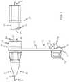
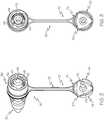
FIG. 1 is a side view of a vented male connector according to a first example embodiment of the present invention, shown with a mating female connector and with its cap unplugged so that it's ready for connection to the mating female connector.FIG. 2 is a front perspective view of the male connector ofFIG. 1 .FIG. 3 is another front perspective view of the male connector ofFIG. 1 .FIG. 4 is a rear perspective view of the male connector ofFIG. 1 .FIG. 5 is another rear perspective view of the male connector ofFIG. 1 .FIG. 6 is a front view of the male connector ofFIG. 1 .FIG. 7 is another side view of the male connector ofFIG. 1 .FIG. 8 shows the male connector ofFIG. 1 with its cap in a plugged position.FIG. 9 is a cross-sectional view of the male connector ofFIG. 8 showing a ventilation passageway for airflow through the connector with its cap in a plugged position.FIG. 10 is a perspective view of a vented connector according to a second example embodiment, shown with its cap unplugged so that it's ready for connection to a mating female connector.FIG. 11 is a perspective view of a vented connector according to a third example embodiment, shown without its cap.- The present invention may be understood more readily by reference to the following detailed description taken in connection with the accompanying drawing figures, which form a part of this disclosure. It is to be understood that this invention is not limited to the specific devices, methods, conditions, or parameters described and/or shown herein, and that the terminology used herein is for the purpose of describing particular embodiments by way of example only and is not intended to be limiting of the claimed invention.
- Also, as used in the specification including the appended claims, the singular forms "a," "an," and "the" include the plural, and reference to a particular numerical value includes at least that particular value, unless the context clearly dictates otherwise. Ranges may be expressed herein as from "about" one particular value and/or to "about" another particular value. When such a range is expressed, another embodiment includes from the one particular value and/or to the other particular value. Similarly, when values are expressed as approximations, by use of the antecedent "about," it will be understood that the particular value forms another embodiment.
- With reference now to the drawing figures, wherein like reference numbers represent corresponding parts throughout the several views,
FIGS. 1-9 show a ventedconnector 30 according to a first example embodiment of the invention. Theconnector 30 attaches to amedical fluid vessel 10 and mates with acooperating connector 20 attached to an inlinemedical fluid vessel 12, with the connectors collectively forming a connector-set or coupling that detachably couples the vessels together for fluid flow therethrough. Theconnectors - In the depicted embodiment, the
vented connector 30 is attached to avessel 10 that is a tube, though the term "vessel" is intended to be broadly construed to include any carrier or container for a fluid as well as any fluid-delivery device, and as such in other - In the depicted embodiment, the
vented connector 30 is attached to avessel 10 that is a tube, though the term "vessel" is intended to be broadly construed to include any carrier or container for a fluid as well as any fluid-delivery device, and as such in other embodiments the vessel is a catheter, hose, bottle, bag, syringe, pump, or the like. As such, theconnectors vented connector 30 is used for avessel 10 for enteral feeding, with the term "vessel" in the "enteral feeding" context intended to be broadly construed to include not just feeding bags but also breast pumps, food bottles, other food-storage containers, extension sets, and the like. In the depicted embodiment, thevented connector 30 is an ENFIT connector for enteral feeding tubes, though in other embodiments the innovative features are included in connectors for fluid vessels for non-enteral and/or non-small-bore (medical or other) applications. And in the depicted embodiment, thevented connector 30 is a male connector and thecooperating connector 20 is a mating female connector, though in other embodiments this is reversed to provide a vented and/or capped female connector with an outer housing defining an annular space. In addition, the ventedconnector 30 is described herein for use with fluids, which as used herein means liquids and gases. - The
connector 30 includes a vessel-attachingportion 32 defining arear end 34, a coupling-attachingportion 36 defining afront end 38, and alumen 40 extending longitudinally therethrough from end to end. The vessel-attachingportion 32 attaches to (e.g., receives and secures) thevessel 10 and secures it in place with a good seal by conventional structures such as crimps or adhesives so that the vessel extends longitudinally from therear end 34. The coupling-attachingportion 36 and the cooperatingconnector 20 detachably couple together mechanically by mating attachment fittings such as the depictedscrew threads 42 and 22 (of theconnector 30 and the cooperatingconnector 20, respectively) or other conventional mating mechanical fasteners as are known to persons of ordinary skill in the art such as bayonet fitting, snap-fit couplings, and the like. And the coupling-attachingportion 36 and the cooperatingconnector 20 sealingly mate together for fluid conveyance by mating male and female fittings such as the depictedmale plug 44 and female receptacle 24 (of theconnector 30 and the cooperatingconnector 20, respectively) or other conventional fluid-sealing structures as are known to persons of ordinary skill in the art such other friction fittings. In the depicted embodiment, themale plug 44 includes a peripheral wall that defines thelumen 40 extending axially all the way through it to convey the fluid through theconnector 30. In some embodiments, the mating male and female seal fittings are designed to provide sufficient mechanical/frictional retention forces that theconnectors connectors - In addition, the
connector 30 includes anouter housing 46 surrounding itsplug 44, for example including aperipheral sidewall 48 and anendwall 50. The outer-housing sidewall 48 is arranged coaxially with and surrounding theplug 44 thereby forming anannular space 52 therebetween with an access opening at thefront end 38 of the connector 30 (opposite the endwall). In this way, when the two connectors are coupled together with themale plug 44 of theconnector 30 inserted into thefemale receptacle 24 of the cooperatingconnector 20, the peripheral sidewall or barrel 26 (defining the receptacle 24) of the cooperatingconnector 20 is coaxially received in the annular space 52 (between the outer-housingperipheral sidewall 48 and the plug 44) of theconnector 30. And theconnectors screw threads 42 being inner threads on the outer-housing sidewall 48 and themating threads 22 being outer threads on thereceptacle sidewall 26, by mating threads between the plug and the receptacle sidewall, or by other threading arrangements. The outer-housing sidewall 48 of theconnector 30 and thereceptacle sidewall 26 of the cooperatingconnector 20 are typically generally cylindrical in shape and solid in structure (i.e., not fluid permeable). - The outer-
housing endwall 50 extends at least partially between the outer-housing sidewall 48 and theplug 44, with at least one (e.g., two, as depicted) connectingportion 54 extending inwardly from the outer-housing sidewall to fix the outer-housing sidewall relative to the plug and thereby form theannular space 52. Typically each connectingportion 54 extends all the way between (e.g., radially, as depicted) and fixes together the outer-housing sidewall 48 and theplug 44. To provide for fluid drainage and airflow ventilation, the outer-housing endwall 50 of theconnector 30 includes at least one (e.g., two, as depicted)vent openings 56 providing fluid communication between theannular space 52 and external to the annular space. Theconnector vent openings 56 can be in the form of two curved slots extending between two connectingportions 54 in the form of radial spokes, as depicted. Alternatively, the connector vent openings can be in the form of ports (e.g., holes in a circular, polygonal, frusto-conical, or other regular or irregular shape) extending axially through the endwall and/or radially through the outer sidewall, mesh openings in an endwall that is a mesh (e.g., a screen, grate, or lattice), or other types and arrangements of openings that provide for fluid drainage and airflow ventilation for the annular space. In addition, the outer-housing endwall 50 has an inner surface (partially defining the annular space 52) that can be sloped (ramped or taper, all or only part of it) toward theconnector vent openings 56 to help direct fluid toward them. - In this way, any residual fluid from the
vessels annular space 52 resulting in bacteria colonization will instead tend to drain out through theconnector vent openings 56 and be dried by airflow in and/or out of the vent openings. Furthermore, theconnector vent openings 56 in the outer-housing endwall 50 provide better access to theannular space 52 for inspection and cleaning. Moreover, when theconnector 30 is disconnected from the cooperatingconnector 20, a vacuum can form in thelumen 40 and induce a backflow of the fluid into theconnector 30 and/or the cooperatingconnector 20, resulting in dosing inaccuracies, and theconnector vent openings 56 can function to assist in breaking the vacuum to prevent fluid backflow and thus provide for more accurate dosing. - In addition, the
connector 30 optionally includes asanitary cap 70 for thelumen 40 at its front end 38 (opposite the attachment of the vessel 10). Thecap 70 can be attached to theconnector 30 by atether 72 such as an integral length of material (as shown) or a cord, string, band, chain, or the like. In addition, thecap 70 can include ahandle 73 for gripping to move the cap between its unplugged (seeFIGS. 1-7 ) and plugged positions (seeFIGS. 8-9 ). In the plugged position thecap 70 seals off thelumen 40 and thevessel 10 from outside contamination, which can be advantageous for example in enteral feeding applications in which thevessel 10 is inserted into the patient and left there for future feedings. - The
cap 70 includes a body orendwall 74 with a seal fitting (e.g., a plug) 76 and aperipheral sidewall 78 axially extending from it. The cap body/endwall 74 is typically a solid member such as a panel for sealing the annular space when capped. And thecap sidewall 78 can be a solid peripheral member such as a collar or flange, or two or more peripherally arranged prongs such as fingers or tabs, for reception and retention in the annular space when capped. In the plugged position, thecap plug 76 is received in the connector-plug lumen 40 at itsfront end 38 with a snug fit for sealing to prevent the escape of fluids from thevessel 10. And thecap sidewall 78 is received in theannular space 52 through its access opening so that it engages theconnector 30 with a snug fit for mechanical/frictional retention to removably secure thecap 70 in place in the plugged position. In other embodiments, the cap seal fitting is a sleeve, recess, or other structural element that mates with the connector seal fitting to seal the lumen closed. And in yet other embodiments, thecap 70 and theconnector 30 additionally or alternatively include mating screw threads or other fasteners for removably securing the parts together. - To provide for fluid drainage and airflow ventilation of the
annular space 52 when thecap 70 is the plugged position, the cap includes at least one (e.g., three, as depicted)vent openings 80 providing fluid communication between the annular space and external to the annular space. Thecap vent openings 80 can be in the form of one or more notches defined by gaps between one or more segments of thecap sidewall 78, for example the three curved notches between the three segments of the cap sidewall formed by the undulating edge of the cap sidewall, as depicted. Alternatively, the cap vent openings can be in the form of ports (e.g., holes in a circular, polygonal, conical, or other regular or irregular shape) extending axially through the cap body/endwall and/or radially through the cap sidewall, mesh openings in a portion of the cap body that is a mesh (e.g., a screen, grate, or lattice), or other types and arrangements of openings that provide for fluid drainage and airflow ventilation for the annular space with the cap in the plugged position. - In this way, any residual fluid from the
vessels connectors 30 and 20) resulting in bacteria colonization will instead tend to drain out through thecap vent openings 80 and be dried by airflow in and/or out of the vent openings. Furthermore, thecap vent openings 80 can facilitate better inspection and cleaning of theannular space 52. Moreover, theconnector vent openings 56 and thecap vent openings 80, in combination with theannular space 52, form a continuous passageway (seeFIG. 9 ) for airflow to enter the annular space at one end and exit the other end for enhanced drying and to prevent an airlock that might restrict airflow in and out of the annular space. As such, as used herein reference to connector outer-housing vent openings being "at the outer-housing endwall" includes the vent opening being formed in or by the outer-housing endwall 50 as well as being formed in or by the outer-housing sidewall 48 but immediately adjacent the outer-housing endwall to provide the continuous airflow passageway along substantially the entire length of theannular space 52. - In addition, to make sure that the
cap vent openings 80 are at least partially exposed and uncovered (sufficiently for functioning for their intended purpose as described herein) when thecap 70 is in the plugged position on theconnector 30, engaging stop surfaces 58 and 82 can be provided on the connector and the cap, respectively, to define (and thus limit) the how far the cap fits onto the connector. In the depicted embodiment, for example, theconnector stop surface 58 is formed by a rim of theconnector plug 44 defining thelumen 40, and thecap stop surface 82 is formed by a base of thecap plug 76. As can be seen for example inFIGS. 8-9 , in the plugged position thecap vent openings 80 are partially covered but still partially exposed to permit fluid flow therethrough. Alternatively, the connector and cap stop surfaces can be formed by at least one inward-extending member (e.g., a collar, flange, rib, tab, or the like) of the outer-housing sidewall and by the rear (insertion) ends of the cap sidewall segments, respectively, so the inward-extending members limit how far into the annular space the cap sidewall segments can be inserted. Further alternatively, the connector stop surface can be in the form of an endwall, collar, flange, rib, tab, or the like on or adjacent the connector plug and/or lumen (e.g., within the lumen), and/or the cap stop surface can be in the form of a skirt, collar, flange, rib, tab, wing, or the like on or adjacent the cap plug. - It should be noted that the depicted embodiment includes the
connector vent openings 56 and thecap vent openings 80 in combination, while other embodiments include only one of these two features. Furthermore, it should be noted that some embodiments include connector vent openings in the outer-housing sidewall as an addition or alternate to the depictedconnector vent openings 56 in the outer-housing endwall 50, while other embodiments include cap vent openings in the cap endwall as an addition or alternate to the depictedcap vent openings 80 in thecap sidewall 78. As such, any of the vent openings disclosed herein can be implemented individually or in any combination with any other vent opening(s) disclosed herein or not disclosed herein. FIG. 10 shows a ventedconnector 130 according to a second example embodiment of the present invention. The ventedconnector 130 is substantially similar to that of the first example embodiment described above, with exceptions as noted herein. In this embodiment, for example, theconnector 130 includes one ormore vent openings 186 formed in the outer-housing sidewall 148, in addition to the one ormore vent openings 156 formed in the outer-housing endwall (not shown) described above. Theconnector vent openings 186 in the outer-housing sidewall 148 provide for drainage and drying, vacuum breaking, and enhanced inspection and cleaning similarly to the venting in the first example embodiment.- In the depicted embodiment, the
connector vent openings 186 are generally circular in shape, though in other embodiments the vent openings can have an oval, polygonal, conical, or other regular or irregular shape. The depictedconnector vent openings 186 are positioned sufficiently away from the front/cooperating connector end of theconnector 130 that they are not blocked by the cap sidewall segments when thecap 170 is plugged onto the connector (with the cooperating connector detached). In other embodiments, the vent openings are provided with deflectors (e.g., V-shaped members extending inward from the inner surface of the outer-housing sidewall and positioned between the vent openings and the front end) that are engaged by and induce rotation of the cap sidewall segments when the cap is plugged onto the connector so that the vent openings align with the cap sidewall vent openings. And in still other embodiments, an array or series of the sidewall vent openings are provided. - In addition, the
cap 170 can have one ormore vent openings 184 axially formed in the cap body orendwall 174. Thecap vent openings 184 are positioned radially outward from thecap plug 176 so that when thecap 170 is plugged onto theconnector 130 they provide ventilation to the annular space 152 but they do not provide ventilation to thelumen 140. Thecap vent openings 184 can be in the form of curved slots (as depicted) or they can have a circular, polygonal, conical, or other regular or irregular shape. In other embodiments, the connector 120 includes only thecap vent openings 184 or only theconnector vent openings 186. FIG. 11 shows a ventedconnector 230 according to a third example embodiment of the present invention. The ventedconnector 230 is substantially similar to those of the first and second example embodiments described above, with exceptions as noted herein. In this embodiment, for example, theconnector 230 includes the one ormore vent openings 286 formed in the outer-housing sidewall 248, but not any vent openings formed in the outer-housing endwall. Theconnector vent openings 286 in the outer-housing sidewall 148 provide for drainage and drying, vacuum breaking, and enhanced inspection and cleaning similarly to the venting in the first and second example embodiments. It should be noted that theconnector 230 is depicted without a cap, though in some embodiments a cap is provided, and the cap can include cap vent openings as described herein as an addition or alternate to theconnector vent openings 286.- While the invention has been described with reference to preferred and example embodiments, it will be understood by those skilled in the art that a variety of modifications, additions and deletions are within the scope of the invention, as defined by the following claims.
Claims (15)
- A connector (30) for connection to a fluid vessel (10) and a cooperating connector (20), the connector (30) comprising:a first end from which the vessel (10) extends, a second end, and a lumen (40) extending therethrough from the first end to the second end; anda fluid-seal fitting that at least partially defines the lumen (40) and sealingly mates with a seal fitting of the cooperating connector (20) to provide conveyance of the fluid;characterized by:an outer housing (46) positioned around the fluid-seal fitting to form an annular space (52) therebetween with an access opening at the second end of the connector (30); andthe outer housing (46) including one or more vent openings (56) extending between the annular space (52) and external to the annular space (52) when the access opening of the annular space (52) is capped, wherein the one or more outer-housing vent openings (56) allow for drainage and air-drying of any residual amount of the fluid in the annular space (52).
- The connector (30) of Claim 1, wherein the outer housing (46) includes a peripheral sidewall and an endwall that cooperate with the fluid-seal fitting to define the annular space (52), and wherein the one or more outer-housing vent openings (56) include at least one vent opening (56) formed in the outer-housing sidewall and/or at least one vent opening formed in the outer-housing endwall.
- The connector (30) of Claim 1, wherein the outer-housing endwall includes one or more connecting portions extending inward from the outer-housing sidewall and defining the at least one vent opening (56) formed in the outer-housing endwall; wherein optionally:
the at least one vent opening (56) formed in the outer-housing endwall is in the form of a curved slot. - The connector (30) of Claim 1, wherein the one or more outer-housing vent openings assist in breaking a vacuum created within the lumen connector (30) to prevent fluid backflow and thereby reduce dosing inaccuracies.
- The connector (30) of Claim 1, wherein the cooperating connector (20) includes a peripheral sidewall defining a female receptacle and includes a mechanical fastener, and wherein the connector (30) includes a mechanical fastener that mechanically couples with the cooperating-connector mechanical fastener, the connector (30) fluid-seal fitting is in the form of a male plug that is received by the female receptacle, and the annular space (52) of the connector (30) at least partially receives the cooperating-connector (20) sidewall.
- The connector (30) of Claim 1, further comprising:
a cap (70, 170) repositionable between a plugged position capping the connector (30) second end and an unplugged position not capping the connector (30) second end, the cap (70, 170) including one or more vent openings (80) extending between the annular space (52) and external to the annular space (52) when the cap is in the plugged position capping the access opening of the annular space (52), wherein the one or more cap vent openings (80) allow for drainage and air-drying of any residual amount of the fluid in the annular space (52); wherein optionally:
the outer-housing vent openings (56) and the cap vent openings (80), in combination with the annular space (52), form a continuous passageway allowing airflow to enter the annular space (52) at one end and exit an opposite end for enhanced drying. - The connector (30) of Claim 6, wherein the cap further includes a peripheral sidewall that extends from the endwall and engages the connector (30) in the plugged position, wherein the one or more cap vent openings include at least one cap vent opening formed in the cap sidewall, the cap sidewall is at least partially received in the connector annular space (52) when the cap is in the plugged position, and the connector (30) and the cap include respective mechanical stop surfaces that engage each other to limit travel of the cap sidewall relative to the outer housing (46) and thereby define the plugged position with the at least one cap sidewall vent opening remaining at least partially exposed.
- A connector (30) for connection to a fluid vessel (10) and a cooperating connector (20), the connector (30) comprising:a first end from which the vessel (10) extends, a second end, and a lumen (40) extending therethrough from the first end to the second end;a fluid-seal fitting that at least partially defines the lumen (40) and sealingly mates with a seal fitting of the cooperating connector (20) to provide conveyance of the fluid; anda cap (70, 170) repositionable between a plugged position capping the connector (30) second end and an unplugged position not capping the connector (30) second end;characterized by:an outer housing (46) positioned around the fluid-seal fitting to form an annular space (52) therebetween with an access opening at the second end of the connector (30); andthe cap (70, 170) including one or more vent openings (80) extending between the annular space (52) and external to the annular space (52) when the cap is in the plugged position capping the access opening of the annular space (52), wherein the one or more cap vent openings (80) allow for drainage and air-drying of any residual amount of the fluid in the annular space (52).
- The connector (30) of Claim 8, wherein the cap includes an endwall and a fluid-seal fitting that sealingly mates with the connector lumen (40) in the plugged position, wherein the one or more cap vent openings include at least one cap vent opening formed in the cap endwall; wherein optionally:
the cap further includes a peripheral sidewall that extends from the endwall and engages the connector (30) in the plugged position, wherein the one or more cap vent openings include at least one cap vent opening formed in the cap sidewall. - The connector (30) of Claim 8, wherein the cap includes an endwall, a fluid-seal fitting that sealingly mates with the connector lumen (40) in the plugged position, and a peripheral sidewall that extends from the endwall and engages the connector (30) in the plugged position, wherein the one or more cap vent openings include at least one cap vent opening formed in the cap sidewall.
- The connector (30) of Claim 8, wherein the cap sidewall includes one or more sidewall segments extending axially from the cap endwall and forming at least one gap that defines the at least one vent opening formed in the cap sidewall; wherein optionally:
the at least one vent opening formed in the cap sidewall is in the form of a notch. - The connector (30) of Claim 8, wherein the cap sidewall is at least partially received in the connector (30) annular space (52) when the cap is in the plugged position.
- The connector (30) of Claim 8, wherein the connector (30) and the cap include respective mechanical stop surfaces that engage each other to limit travel of the cap sidewall relative to the outer housing (46) and thereby define the plugged position with the at least one vent opening formed in the cap sidewall remaining at least partially exposed.
- The connector (30) of Claim 8, wherein the cooperating connector (20) includes a peripheral sidewall defining a female receptacle and includes a mechanical fastener, and wherein the connector (30) includes a mechanical fastener that mechanically couples with the cooperating-connector (20) mechanical fastener, the connector (30) fluid-seal fitting is in the form of a male plug that is received by the female receptacle, and the annular space (52) of the connector (30) at least partially receives the cooperating-connector (20) sidewall.
- A connector-set including the connector (30) of any preceding Claim in combination with the cooperating connector (20).
Applications Claiming Priority (3)
| Application Number | Priority Date | Filing Date | Title |
|---|---|---|---|
| US201462047389P | 2014-09-08 | 2014-09-08 | |
| US201562192614P | 2015-07-15 | 2015-07-15 | |
| PCT/US2015/048382WO2016040127A1 (en) | 2014-09-08 | 2015-09-03 | Vented connector for medical fluid vessels |
Publications (2)
| Publication Number | Publication Date |
|---|---|
| EP3191166A1 EP3191166A1 (en) | 2017-07-19 |
| EP3191166B1true EP3191166B1 (en) | 2019-11-20 |
Family
ID=54147302
Family Applications (1)
| Application Number | Title | Priority Date | Filing Date |
|---|---|---|---|
| EP15766316.2AActiveEP3191166B1 (en) | 2014-09-08 | 2015-09-03 | Vented connector for medical fluid vessels |
Country Status (6)
| Country | Link |
|---|---|
| US (4) | US10668263B2 (en) |
| EP (1) | EP3191166B1 (en) |
| JP (1) | JP6373503B2 (en) |
| AU (1) | AU2015315495B2 (en) |
| CA (1) | CA2959393C (en) |
| WO (1) | WO2016040127A1 (en) |
Cited By (1)
| Publication number | Priority date | Publication date | Assignee | Title |
|---|---|---|---|---|
| DE102022101151A1 (en) | 2022-01-19 | 2023-07-20 | B. Braun Melsungen Aktiengesellschaft | Cap for an enteral conduction set connector and conduction set with a cap |
Families Citing this family (39)
| Publication number | Priority date | Publication date | Assignee | Title |
|---|---|---|---|---|
| US8167847B2 (en) | 2006-06-22 | 2012-05-01 | Excelsior Medical Corporation | Antiseptic cap and antiseptic cap equipped plunger and syringe barrel assembly |
| US11229746B2 (en) | 2006-06-22 | 2022-01-25 | Excelsior Medical Corporation | Antiseptic cap |
| US9259535B2 (en) | 2006-06-22 | 2016-02-16 | Excelsior Medical Corporation | Antiseptic cap equipped syringe |
| WO2012162259A2 (en) | 2011-05-20 | 2012-11-29 | Excelsior Medical Corporation | Caps for cannula access devices |
| US10166381B2 (en) | 2011-05-23 | 2019-01-01 | Excelsior Medical Corporation | Antiseptic cap |
| US9867975B2 (en) | 2011-05-23 | 2018-01-16 | Excelsior Medical Corporation | Antiseptic line cap |
| EP3137122B1 (en) | 2014-05-02 | 2019-09-04 | Excelsior Medical Corporation | Strip package for antiseptic cap |
| US11376409B2 (en) | 2014-09-08 | 2022-07-05 | Avent, Inc. | Hub component for vented connector |
| USD792584S1 (en) | 2014-09-08 | 2017-07-18 | Neomed, Inc. | Male enteral coupling |
| US10576020B2 (en) | 2015-06-18 | 2020-03-03 | Neomed, Inc. | Syringe-to-syringe coupler |
| US10773067B2 (en) | 2014-09-08 | 2020-09-15 | Neomed, Inc. | Enteral connectors having coupling features |
| US11357964B2 (en) | 2014-09-08 | 2022-06-14 | Avent, Inc. | Vented connector for medical fluid vessels and tapered plug |
| CA2961931A1 (en) | 2014-09-25 | 2016-03-31 | Covidien Lp | Enteral feeding connector |
| US10532007B2 (en) | 2014-12-19 | 2020-01-14 | Kpr U.S., Llc | System, apparatus and method employed with enteral systems |
| DK3294404T3 (en) | 2015-05-08 | 2025-09-08 | Icu Medical Inc | MEDICAL CONNECTORS CONFIGURED TO RECEIVE EMISSIONS OF THERAPEUTIC AGENTS |
| US20160361235A1 (en)* | 2015-06-11 | 2016-12-15 | Covidien Lp | Adapter assembly for enteral feeding |
| USD825746S1 (en) | 2015-06-18 | 2018-08-14 | Neomed, Inc. | Syringe-to-syringe coupler |
| EP3424554B1 (en) | 2015-07-15 | 2023-11-22 | Avent, Inc. | Enteral adaptor couplings |
| EP3383478B1 (en)* | 2015-11-30 | 2024-12-11 | Avent, Inc. | Flexible cap for conical connectors |
| CA3015885A1 (en) | 2016-02-24 | 2017-08-31 | Neomed, Inc. | Fluid transfer connector |
| US10842983B2 (en) | 2016-10-06 | 2020-11-24 | Becton, Dickinson And Company | Syringe with enteral connection feature |
| PT3525865T (en) | 2016-10-14 | 2022-11-17 | Icu Medical Inc | Sanitizing caps for medical connectors |
| USD833006S1 (en) | 2016-11-28 | 2018-11-06 | Neomed, Inc. | Fluid transfer connector |
| WO2018204206A2 (en) | 2017-05-01 | 2018-11-08 | Icu Medical, Inc. | Medical fluid connectors and methods for providing additives in medical fluid lines |
| USD861161S1 (en)* | 2017-06-22 | 2019-09-24 | Kpr U.S., Llc | Connector |
| MX2020000823A (en) | 2017-09-15 | 2020-11-06 | Neomed Inc | Hub component for vented connector. |
| JP2021511152A (en) | 2018-01-23 | 2021-05-06 | ネオメッド, インクNeomed, Inc. | Ventilated air exhaust coupler and how to use it |
| JP2021515610A (en)* | 2018-03-01 | 2021-06-24 | ネオメッド, インクNeomed, Inc. | Coupler for cleaning the hub of the feeding tube |
| US11147956B2 (en)* | 2018-06-21 | 2021-10-19 | Becton, Dickinson And Company | Enteral syringe with vented collar |
| DE102019204211A1 (en)* | 2019-03-27 | 2020-10-01 | B. Braun Melsungen Aktiengesellschaft | Medical fluid connector |
| USD925731S1 (en) | 2019-06-20 | 2021-07-20 | Becton, Dickinson And Company | Enteral syringe |
| USD895793S1 (en) | 2019-06-20 | 2020-09-08 | Becton, Dickinson And Company | Enteral syringe |
| USD925730S1 (en) | 2019-06-20 | 2021-07-20 | Becton, Dickinson And Company | Enteral syringe |
| USD893019S1 (en) | 2019-06-20 | 2020-08-11 | Becton, Dickinson And Company | Enteral syringe |
| JP7421722B2 (en)* | 2019-10-11 | 2024-01-25 | 株式会社ジェイ・エム・エス | Gas flow path connector and extrusion device equipped with the same |
| JP7318925B2 (en)* | 2019-10-18 | 2023-08-01 | 株式会社塚田メディカル・リサーチ | medical device cap |
| JP7052849B2 (en)* | 2020-10-22 | 2022-04-12 | 株式会社ジェイ・エム・エス | Cover for male connector |
| US12394964B2 (en) | 2023-01-30 | 2025-08-19 | Banner Engineering Corp. | Self-fitting pressure equalizing waterproof electronics enclosure |
| CN119488658B (en)* | 2025-01-03 | 2025-08-08 | 香港大学深圳医院 | A splash prevention device for tracheotomy patients |
Family Cites Families (45)
| Publication number | Priority date | Publication date | Assignee | Title |
|---|---|---|---|---|
| US4237935A (en) | 1978-12-14 | 1980-12-09 | Eaton Corporation | Hydraulic pressure relief valve and fluid isolator |
| US4416273A (en) | 1981-06-15 | 1983-11-22 | Grimes Jerry L | Connector valve assembly for endotracheal tubes |
| US4904238A (en) | 1987-12-21 | 1990-02-27 | Alcon Laboratories, Inc. | Irrigation/aspiration handpiece |
| US4994068A (en) | 1989-11-24 | 1991-02-19 | Unidex, Inc. | Combination sterile pad support and lancet containing lancet disposal element |
| JP2506804Y2 (en)* | 1989-12-27 | 1996-08-14 | 川澄化学工業株式会社 | Shunt cap for extracorporeal circulation circuit |
| US5385372A (en) | 1993-01-08 | 1995-01-31 | Utterberg; David S. | Luer connector with integral closure |
| US5401255A (en) | 1993-07-20 | 1995-03-28 | Baxter International Inc. | Multi-functional valve with unitary valving member and improved safety |
| US5591344A (en) | 1995-02-13 | 1997-01-07 | Aksys, Ltd. | Hot water disinfection of dialysis machines, including the extracorporeal circuit thereof |
| WO1997022535A1 (en) | 1995-12-15 | 1997-06-26 | Medisystems Technology Corporation | Medical connector with integral closure |
| US6883778B1 (en)* | 1996-11-18 | 2005-04-26 | Nypro Inc. | Apparatus for reducing fluid drawback through a medical valve |
| US5951519A (en) | 1997-04-25 | 1999-09-14 | Dsu Medical Corporation | Aseptic female connector |
| FR2784033B1 (en) | 1998-10-01 | 2000-12-22 | Marc Brunel | SINGLE USE INJECTION DEVICE FOR PRE-FILLED |
| CA2345439C (en) | 1998-10-29 | 2005-08-09 | Minimed, Inc. | Compact pump drive system |
| US20020173748A1 (en) | 1998-10-29 | 2002-11-21 | Mcconnell Susan | Reservoir connector |
| US6595971B1 (en) | 1999-07-28 | 2003-07-22 | Zassi Medical Evolutions, Inc. | Ostomy irrigation system |
| USD463546S1 (en) | 1999-10-14 | 2002-09-24 | Becton Dickinson And Company | Drug container holder |
| US7077829B2 (en) | 2001-01-09 | 2006-07-18 | Rex Medical, L.P. | Dialysis catheter |
| US6745998B2 (en)* | 2001-08-10 | 2004-06-08 | Alaris Medical Systems, Inc. | Valved male luer |
| GB2379253B (en) | 2001-09-04 | 2005-09-14 | Clinical Product Dev Ltd | Couplings for medical fluid delivery systems |
| JP4287273B2 (en) | 2001-09-24 | 2009-07-01 | アプライド メディカル リソーシーズ コーポレイション | Bladeless obturator |
| USD473646S1 (en) | 2001-12-21 | 2003-04-22 | Microsurgical Technology, Inc. | Irrigation/aspiration instrument connector |
| US8932264B2 (en) | 2003-08-11 | 2015-01-13 | Becton, Dickinson And Company | Medication delivery pen assembly with needle locking safety shield |
| US20050124935A1 (en)* | 2003-12-05 | 2005-06-09 | Kimberly-Clark Worldwide, Inc. | Venting adapter for feeding device |
| WO2006013796A1 (en) | 2004-08-04 | 2006-02-09 | Olympus Corporation | Plug body for endoscope |
| US20060161115A1 (en)* | 2004-11-05 | 2006-07-20 | Fangrow Thomas F | Soft-grip medical connector |
| JP4604764B2 (en)* | 2005-02-25 | 2011-01-05 | 東レ株式会社 | Luer lock type fluid connector plug and medical device |
| US9895526B2 (en)* | 2006-03-08 | 2018-02-20 | Ivaxis, Llc | Anti-contamination cover for fluid connections |
| DE102006041414A1 (en) | 2006-09-04 | 2008-03-06 | Fresenius Kabi Deutschland Gmbh | Multipurpose connector for enteral application |
| US8066670B2 (en)* | 2006-11-06 | 2011-11-29 | Becton, Dickinson And Company | Vascular access device septum venting |
| US20080128646A1 (en)* | 2006-12-05 | 2008-06-05 | Humitek, Inc. | Splines and caps for fluid ports |
| US8523830B2 (en)* | 2007-01-16 | 2013-09-03 | Catheter Connections | Disinfecting caps for medical female luer connectors |
| US20080183153A1 (en) | 2007-01-31 | 2008-07-31 | Benlan, Inc. | Enteral Feeding Tube Connector |
| GB2453361A (en) | 2007-10-04 | 2009-04-08 | Smith & Nephew | A cap member for sealing an open orifice |
| DE102009016373A1 (en)* | 2009-04-07 | 2010-10-21 | V. KRÜTTEN MEDIZINISCHE EINMALGERÄTE GmbH | Connector for the probe tube of an enteral feeding tube and assembly of an enteral feeding tube and an enteral transfer system |
| US20110240162A1 (en) | 2010-04-06 | 2011-10-06 | Zeyfang Rederick W | Vented end cap for medical tube |
| WO2011156521A2 (en) | 2010-06-08 | 2011-12-15 | Dotted Intellectual Property, Llc | Connector assembly |
| US20120022468A1 (en)* | 2010-07-23 | 2012-01-26 | Medela Holding Ag | Enteral Feeding Assembly |
| USD665497S1 (en) | 2010-07-28 | 2012-08-14 | Owen Mumford Limited | Torque limiting needle cap |
| US8491535B2 (en) | 2011-04-28 | 2013-07-23 | Becton, Dickinson And Company | Safety pen needle assembly |
| US20120323221A1 (en) | 2011-06-20 | 2012-12-20 | Med-Systems, Inc. | Adapter Cap and Nasal Washing System Using the Cap |
| EP2583715A1 (en) | 2011-10-19 | 2013-04-24 | Unomedical A/S | Infusion tube system and method for manufacture |
| USD737436S1 (en) | 2012-02-13 | 2015-08-25 | Medimop Medical Projects Ltd. | Liquid drug reconstitution assembly |
| US9308362B2 (en) | 2013-03-12 | 2016-04-12 | Carefusion 303, Inc. | Male luer with fluid path and vent path seals |
| US9814871B2 (en) | 2013-03-15 | 2017-11-14 | Bayer Healthcare Llc | Connector assembly for syringe system |
| USD736906S1 (en) | 2014-01-28 | 2015-08-18 | Joseph P. Schultz | Nasal-irrigation cap |
- 2015
- 2015-09-03EPEP15766316.2Apatent/EP3191166B1/enactiveActive
- 2015-09-03JPJP2017531979Apatent/JP6373503B2/enactiveActive
- 2015-09-03USUS14/844,956patent/US10668263B2/enactiveActive
- 2015-09-03AUAU2015315495Apatent/AU2015315495B2/enactiveActive
- 2015-09-03CACA2959393Apatent/CA2959393C/enactiveActive
- 2015-09-03WOPCT/US2015/048382patent/WO2016040127A1/enactiveApplication Filing
- 2019
- 2019-04-24USUS16/393,144patent/US10806917B2/enactiveActive
- 2020
- 2020-09-18USUS17/024,953patent/US11986617B2/enactiveActive
- 2024
- 2024-04-18USUS18/638,802patent/US20240261558A1/enactivePending
Non-Patent Citations (1)
| Title |
|---|
| None* |
Cited By (2)
| Publication number | Priority date | Publication date | Assignee | Title |
|---|---|---|---|---|
| DE102022101151A1 (en) | 2022-01-19 | 2023-07-20 | B. Braun Melsungen Aktiengesellschaft | Cap for an enteral conduction set connector and conduction set with a cap |
| WO2023138979A1 (en) | 2022-01-19 | 2023-07-27 | B. Braun Melsungen Ag | Cap for a connector of an enteral feeding kit, and feeding kit having a cap |
Also Published As
| Publication number | Publication date |
|---|---|
| US11986617B2 (en) | 2024-05-21 |
| US10806917B2 (en) | 2020-10-20 |
| US20190255311A1 (en) | 2019-08-22 |
| CA2959393A1 (en) | 2016-03-17 |
| US20240261558A1 (en) | 2024-08-08 |
| EP3191166A1 (en) | 2017-07-19 |
| AU2015315495A1 (en) | 2017-03-16 |
| CA2959393C (en) | 2020-12-29 |
| JP2017526511A (en) | 2017-09-14 |
| US20210001106A1 (en) | 2021-01-07 |
| US20160067471A1 (en) | 2016-03-10 |
| US10668263B2 (en) | 2020-06-02 |
| WO2016040127A1 (en) | 2016-03-17 |
| JP6373503B2 (en) | 2018-08-15 |
| AU2015315495B2 (en) | 2018-05-31 |
Similar Documents
| Publication | Publication Date | Title |
|---|---|---|
| US11986617B2 (en) | Vented connector for medical fluid vessels | |
| US11065181B2 (en) | Syringe-to-syringe coupler | |
| US11433001B2 (en) | System, apparatus and method employed with enteral systems | |
| US10004889B2 (en) | Enteral feeding connector and assembly | |
| EP2140905B1 (en) | Discriminating Oral Tip Adaptor | |
| US20250161653A1 (en) | Vented connector for medical fluid vessels and tapered plug | |
| EP3500225B1 (en) | Internal bottle adapter for material transfer |
Legal Events
| Date | Code | Title | Description |
|---|---|---|---|
| STAA | Information on the status of an ep patent application or granted ep patent | Free format text:STATUS: THE INTERNATIONAL PUBLICATION HAS BEEN MADE | |
| PUAI | Public reference made under article 153(3) epc to a published international application that has entered the european phase | Free format text:ORIGINAL CODE: 0009012 | |
| STAA | Information on the status of an ep patent application or granted ep patent | Free format text:STATUS: REQUEST FOR EXAMINATION WAS MADE | |
| 17P | Request for examination filed | Effective date:20170308 | |
| AK | Designated contracting states | Kind code of ref document:A1 Designated state(s):AL AT BE BG CH CY CZ DE DK EE ES FI FR GB GR HR HU IE IS IT LI LT LU LV MC MK MT NL NO PL PT RO RS SE SI SK SM TR | |
| AX | Request for extension of the european patent | Extension state:BA ME | |
| DAV | Request for validation of the european patent (deleted) | ||
| DAX | Request for extension of the european patent (deleted) | ||
| REG | Reference to a national code | Ref country code:DE Ref legal event code:R079 Ref document number:602015042104 Country of ref document:DE Free format text:PREVIOUS MAIN CLASS: A61M0039200000 Ipc:A61M0039100000 | |
| GRAP | Despatch of communication of intention to grant a patent | Free format text:ORIGINAL CODE: EPIDOSNIGR1 | |
| STAA | Information on the status of an ep patent application or granted ep patent | Free format text:STATUS: GRANT OF PATENT IS INTENDED | |
| RIC1 | Information provided on ipc code assigned before grant | Ipc:A61M 39/20 20060101ALI20181130BHEP Ipc:A61M 39/10 20060101AFI20181130BHEP Ipc:A61J 1/14 20060101ALI20181130BHEP | |
| INTG | Intention to grant announced | Effective date:20190103 | |
| GRAJ | Information related to disapproval of communication of intention to grant by the applicant or resumption of examination proceedings by the epo deleted | Free format text:ORIGINAL CODE: EPIDOSDIGR1 | |
| STAA | Information on the status of an ep patent application or granted ep patent | Free format text:STATUS: REQUEST FOR EXAMINATION WAS MADE | |
| GRAP | Despatch of communication of intention to grant a patent | Free format text:ORIGINAL CODE: EPIDOSNIGR1 | |
| STAA | Information on the status of an ep patent application or granted ep patent | Free format text:STATUS: GRANT OF PATENT IS INTENDED | |
| INTC | Intention to grant announced (deleted) | ||
| INTG | Intention to grant announced | Effective date:20190606 | |
| GRAS | Grant fee paid | Free format text:ORIGINAL CODE: EPIDOSNIGR3 | |
| GRAA | (expected) grant | Free format text:ORIGINAL CODE: 0009210 | |
| STAA | Information on the status of an ep patent application or granted ep patent | Free format text:STATUS: THE PATENT HAS BEEN GRANTED | |
| AK | Designated contracting states | Kind code of ref document:B1 Designated state(s):AL AT BE BG CH CY CZ DE DK EE ES FI FR GB GR HR HU IE IS IT LI LT LU LV MC MK MT NL NO PL PT RO RS SE SI SK SM TR | |
| REG | Reference to a national code | Ref country code:GB Ref legal event code:FG4D | |
| REG | Reference to a national code | Ref country code:CH Ref legal event code:EP | |
| REG | Reference to a national code | Ref country code:DE Ref legal event code:R096 Ref document number:602015042104 Country of ref document:DE | |
| REG | Reference to a national code | Ref country code:IE Ref legal event code:FG4D | |
| REG | Reference to a national code | Ref country code:AT Ref legal event code:REF Ref document number:1203505 Country of ref document:AT Kind code of ref document:T Effective date:20191215 | |
| REG | Reference to a national code | Ref country code:NL Ref legal event code:MP Effective date:20191120 | |
| REG | Reference to a national code | Ref country code:LT Ref legal event code:MG4D | |
| PG25 | Lapsed in a contracting state [announced via postgrant information from national office to epo] | Ref country code:NO Free format text:LAPSE BECAUSE OF FAILURE TO SUBMIT A TRANSLATION OF THE DESCRIPTION OR TO PAY THE FEE WITHIN THE PRESCRIBED TIME-LIMIT Effective date:20200220 Ref country code:GR Free format text:LAPSE BECAUSE OF FAILURE TO SUBMIT A TRANSLATION OF THE DESCRIPTION OR TO PAY THE FEE WITHIN THE PRESCRIBED TIME-LIMIT Effective date:20200221 Ref country code:LT Free format text:LAPSE BECAUSE OF FAILURE TO SUBMIT A TRANSLATION OF THE DESCRIPTION OR TO PAY THE FEE WITHIN THE PRESCRIBED TIME-LIMIT Effective date:20191120 Ref country code:NL Free format text:LAPSE BECAUSE OF FAILURE TO SUBMIT A TRANSLATION OF THE DESCRIPTION OR TO PAY THE FEE WITHIN THE PRESCRIBED TIME-LIMIT Effective date:20191120 Ref country code:LV Free format text:LAPSE BECAUSE OF FAILURE TO SUBMIT A TRANSLATION OF THE DESCRIPTION OR TO PAY THE FEE WITHIN THE PRESCRIBED TIME-LIMIT Effective date:20191120 Ref country code:SE Free format text:LAPSE BECAUSE OF FAILURE TO SUBMIT A TRANSLATION OF THE DESCRIPTION OR TO PAY THE FEE WITHIN THE PRESCRIBED TIME-LIMIT Effective date:20191120 Ref country code:FI Free format text:LAPSE BECAUSE OF FAILURE TO SUBMIT A TRANSLATION OF THE DESCRIPTION OR TO PAY THE FEE WITHIN THE PRESCRIBED TIME-LIMIT Effective date:20191120 Ref country code:BG Free format text:LAPSE BECAUSE OF FAILURE TO SUBMIT A TRANSLATION OF THE DESCRIPTION OR TO PAY THE FEE WITHIN THE PRESCRIBED TIME-LIMIT Effective date:20200220 | |
| PG25 | Lapsed in a contracting state [announced via postgrant information from national office to epo] | Ref country code:RS Free format text:LAPSE BECAUSE OF FAILURE TO SUBMIT A TRANSLATION OF THE DESCRIPTION OR TO PAY THE FEE WITHIN THE PRESCRIBED TIME-LIMIT Effective date:20191120 Ref country code:IS Free format text:LAPSE BECAUSE OF FAILURE TO SUBMIT A TRANSLATION OF THE DESCRIPTION OR TO PAY THE FEE WITHIN THE PRESCRIBED TIME-LIMIT Effective date:20200320 Ref country code:HR Free format text:LAPSE BECAUSE OF FAILURE TO SUBMIT A TRANSLATION OF THE DESCRIPTION OR TO PAY THE FEE WITHIN THE PRESCRIBED TIME-LIMIT Effective date:20191120 | |
| PG25 | Lapsed in a contracting state [announced via postgrant information from national office to epo] | Ref country code:AL Free format text:LAPSE BECAUSE OF FAILURE TO SUBMIT A TRANSLATION OF THE DESCRIPTION OR TO PAY THE FEE WITHIN THE PRESCRIBED TIME-LIMIT Effective date:20191120 | |
| PG25 | Lapsed in a contracting state [announced via postgrant information from national office to epo] | Ref country code:DK Free format text:LAPSE BECAUSE OF FAILURE TO SUBMIT A TRANSLATION OF THE DESCRIPTION OR TO PAY THE FEE WITHIN THE PRESCRIBED TIME-LIMIT Effective date:20191120 Ref country code:PT Free format text:LAPSE BECAUSE OF FAILURE TO SUBMIT A TRANSLATION OF THE DESCRIPTION OR TO PAY THE FEE WITHIN THE PRESCRIBED TIME-LIMIT Effective date:20200412 Ref country code:EE Free format text:LAPSE BECAUSE OF FAILURE TO SUBMIT A TRANSLATION OF THE DESCRIPTION OR TO PAY THE FEE WITHIN THE PRESCRIBED TIME-LIMIT Effective date:20191120 Ref country code:ES Free format text:LAPSE BECAUSE OF FAILURE TO SUBMIT A TRANSLATION OF THE DESCRIPTION OR TO PAY THE FEE WITHIN THE PRESCRIBED TIME-LIMIT Effective date:20191120 Ref country code:RO Free format text:LAPSE BECAUSE OF FAILURE TO SUBMIT A TRANSLATION OF THE DESCRIPTION OR TO PAY THE FEE WITHIN THE PRESCRIBED TIME-LIMIT Effective date:20191120 Ref country code:CZ Free format text:LAPSE BECAUSE OF FAILURE TO SUBMIT A TRANSLATION OF THE DESCRIPTION OR TO PAY THE FEE WITHIN THE PRESCRIBED TIME-LIMIT Effective date:20191120 | |
| REG | Reference to a national code | Ref country code:AT Ref legal event code:MK05 Ref document number:1203505 Country of ref document:AT Kind code of ref document:T Effective date:20191120 | |
| REG | Reference to a national code | Ref country code:DE Ref legal event code:R097 Ref document number:602015042104 Country of ref document:DE | |
| PG25 | Lapsed in a contracting state [announced via postgrant information from national office to epo] | Ref country code:SM Free format text:LAPSE BECAUSE OF FAILURE TO SUBMIT A TRANSLATION OF THE DESCRIPTION OR TO PAY THE FEE WITHIN THE PRESCRIBED TIME-LIMIT Effective date:20191120 Ref country code:SK Free format text:LAPSE BECAUSE OF FAILURE TO SUBMIT A TRANSLATION OF THE DESCRIPTION OR TO PAY THE FEE WITHIN THE PRESCRIBED TIME-LIMIT Effective date:20191120 | |
| PLBE | No opposition filed within time limit | Free format text:ORIGINAL CODE: 0009261 | |
| STAA | Information on the status of an ep patent application or granted ep patent | Free format text:STATUS: NO OPPOSITION FILED WITHIN TIME LIMIT | |
| 26N | No opposition filed | Effective date:20200821 | |
| PG25 | Lapsed in a contracting state [announced via postgrant information from national office to epo] | Ref country code:SI Free format text:LAPSE BECAUSE OF FAILURE TO SUBMIT A TRANSLATION OF THE DESCRIPTION OR TO PAY THE FEE WITHIN THE PRESCRIBED TIME-LIMIT Effective date:20191120 Ref country code:PL Free format text:LAPSE BECAUSE OF FAILURE TO SUBMIT A TRANSLATION OF THE DESCRIPTION OR TO PAY THE FEE WITHIN THE PRESCRIBED TIME-LIMIT Effective date:20191120 Ref country code:AT Free format text:LAPSE BECAUSE OF FAILURE TO SUBMIT A TRANSLATION OF THE DESCRIPTION OR TO PAY THE FEE WITHIN THE PRESCRIBED TIME-LIMIT Effective date:20191120 | |
| PG25 | Lapsed in a contracting state [announced via postgrant information from national office to epo] | Ref country code:IT Free format text:LAPSE BECAUSE OF FAILURE TO SUBMIT A TRANSLATION OF THE DESCRIPTION OR TO PAY THE FEE WITHIN THE PRESCRIBED TIME-LIMIT Effective date:20191120 | |
| REG | Reference to a national code | Ref country code:DE Ref legal event code:R119 Ref document number:602015042104 Country of ref document:DE | |
| PG25 | Lapsed in a contracting state [announced via postgrant information from national office to epo] | Ref country code:MC Free format text:LAPSE BECAUSE OF FAILURE TO SUBMIT A TRANSLATION OF THE DESCRIPTION OR TO PAY THE FEE WITHIN THE PRESCRIBED TIME-LIMIT Effective date:20191120 | |
| REG | Reference to a national code | Ref country code:CH Ref legal event code:PL | |
| REG | Reference to a national code | Ref country code:BE Ref legal event code:MM Effective date:20200930 | |
| PG25 | Lapsed in a contracting state [announced via postgrant information from national office to epo] | Ref country code:LU Free format text:LAPSE BECAUSE OF NON-PAYMENT OF DUE FEES Effective date:20200903 | |
| PG25 | Lapsed in a contracting state [announced via postgrant information from national office to epo] | Ref country code:DE Free format text:LAPSE BECAUSE OF NON-PAYMENT OF DUE FEES Effective date:20210401 | |
| PG25 | Lapsed in a contracting state [announced via postgrant information from national office to epo] | Ref country code:LI Free format text:LAPSE BECAUSE OF NON-PAYMENT OF DUE FEES Effective date:20200930 Ref country code:IE Free format text:LAPSE BECAUSE OF NON-PAYMENT OF DUE FEES Effective date:20200903 Ref country code:BE Free format text:LAPSE BECAUSE OF NON-PAYMENT OF DUE FEES Effective date:20200930 Ref country code:CH Free format text:LAPSE BECAUSE OF NON-PAYMENT OF DUE FEES Effective date:20200930 | |
| PG25 | Lapsed in a contracting state [announced via postgrant information from national office to epo] | Ref country code:TR Free format text:LAPSE BECAUSE OF FAILURE TO SUBMIT A TRANSLATION OF THE DESCRIPTION OR TO PAY THE FEE WITHIN THE PRESCRIBED TIME-LIMIT Effective date:20191120 Ref country code:MT Free format text:LAPSE BECAUSE OF FAILURE TO SUBMIT A TRANSLATION OF THE DESCRIPTION OR TO PAY THE FEE WITHIN THE PRESCRIBED TIME-LIMIT Effective date:20191120 Ref country code:CY Free format text:LAPSE BECAUSE OF FAILURE TO SUBMIT A TRANSLATION OF THE DESCRIPTION OR TO PAY THE FEE WITHIN THE PRESCRIBED TIME-LIMIT Effective date:20191120 | |
| PG25 | Lapsed in a contracting state [announced via postgrant information from national office to epo] | Ref country code:MK Free format text:LAPSE BECAUSE OF FAILURE TO SUBMIT A TRANSLATION OF THE DESCRIPTION OR TO PAY THE FEE WITHIN THE PRESCRIBED TIME-LIMIT Effective date:20191120 | |
| P01 | Opt-out of the competence of the unified patent court (upc) registered | Effective date:20230518 | |
| REG | Reference to a national code | Ref country code:GB Ref legal event code:732E Free format text:REGISTERED BETWEEN 20230629 AND 20230705 | |
| PGFP | Annual fee paid to national office [announced via postgrant information from national office to epo] | Ref country code:GB Payment date:20240701 Year of fee payment:10 | |
| PGFP | Annual fee paid to national office [announced via postgrant information from national office to epo] | Ref country code:FR Payment date:20240702 Year of fee payment:10 |