EP3189948B1 - Local control robotic surgical devices - Google Patents
Local control robotic surgical devicesDownload PDFInfo
- Publication number
- EP3189948B1 EP3189948B1EP17157604.4AEP17157604AEP3189948B1EP 3189948 B1EP3189948 B1EP 3189948B1EP 17157604 AEP17157604 AEP 17157604AEP 3189948 B1EP3189948 B1EP 3189948B1
- Authority
- EP
- European Patent Office
- Prior art keywords
- gear
- housing
- arm
- motor
- forearm
- Prior art date
- Legal status (The legal status is an assumption and is not a legal conclusion. Google has not performed a legal analysis and makes no representation as to the accuracy of the status listed.)
- Not-in-force
Links
- 210000000245forearmAnatomy0.000claimsdescription102
- 239000012636effectorSubstances0.000claimsdescription56
- 210000000323shoulder jointAnatomy0.000claimsdescription10
- 238000003780insertionMethods0.000description77
- 230000037431insertionEffects0.000description77
- 230000008878couplingEffects0.000description35
- 238000010168coupling processMethods0.000description35
- 238000005859coupling reactionMethods0.000description35
- 238000000034methodMethods0.000description26
- 230000007246mechanismEffects0.000description20
- 230000000712assemblyEffects0.000description17
- 238000000429assemblyMethods0.000description17
- 239000000853adhesiveSubstances0.000description11
- 230000001070adhesive effectEffects0.000description11
- 210000000683abdominal cavityAnatomy0.000description8
- 230000036316preloadEffects0.000description7
- 239000000463materialSubstances0.000description6
- 238000012800visualizationMethods0.000description6
- 238000004891communicationMethods0.000description4
- 238000013519translationMethods0.000description4
- 235000009508confectioneryNutrition0.000description3
- 238000001727in vivoMethods0.000description3
- 230000000717retained effectEffects0.000description3
- 210000001519tissueAnatomy0.000description3
- 0C#*C1C(C2C3C4=NC4*3C2)=NC1Chemical compoundC#*C1C(C2C3C4=NC4*3C2)=NC10.000description2
- JOYRKODLDBILNP-UHFFFAOYSA-NEthyl urethaneChemical compoundCCOC(N)=OJOYRKODLDBILNP-UHFFFAOYSA-N0.000description2
- 238000013461designMethods0.000description2
- 229920001971elastomerPolymers0.000description2
- 210000002310elbow jointAnatomy0.000description2
- 239000012530fluidSubstances0.000description2
- 210000001503jointAnatomy0.000description2
- 238000002357laparoscopic surgeryMethods0.000description2
- 230000014759maintenance of locationEffects0.000description2
- 230000008569processEffects0.000description2
- 229910001285shape-memory alloyInorganic materials0.000description2
- 229910052710siliconInorganic materials0.000description2
- 239000010703siliconSubstances0.000description2
- 125000006850spacer groupChemical group0.000description2
- 238000001356surgical procedureMethods0.000description2
- 238000012546transferMethods0.000description2
- 210000003815abdominal wallAnatomy0.000description1
- 239000012620biological materialSubstances0.000description1
- 210000001124body fluidAnatomy0.000description1
- 239000010839body fluidSubstances0.000description1
- 230000008859changeEffects0.000description1
- 239000003795chemical substances by applicationSubstances0.000description1
- 230000001419dependent effectEffects0.000description1
- 239000000806elastomerSubstances0.000description1
- 230000005611electricityEffects0.000description1
- 238000005516engineering processMethods0.000description1
- 230000006870functionEffects0.000description1
- 238000012966insertion methodMethods0.000description1
- 238000012977invasive surgical procedureMethods0.000description1
- 239000007788liquidSubstances0.000description1
- 230000013011matingEffects0.000description1
- 238000002324minimally invasive surgeryMethods0.000description1
- 238000012986modificationMethods0.000description1
- 230000004048modificationEffects0.000description1
- 210000003200peritoneal cavityAnatomy0.000description1
- 230000004044responseEffects0.000description1
- 238000007789sealingMethods0.000description1
- 230000001953sensory effectEffects0.000description1
- 239000007787solidSubstances0.000description1
- 230000006641stabilisationEffects0.000description1
- 238000011105stabilizationMethods0.000description1
- 229920001169thermoplasticPolymers0.000description1
- 239000004416thermosoftening plasticSubstances0.000description1
- 230000001960triggered effectEffects0.000description1
- 230000000007visual effectEffects0.000description1
Images


Classifications
- A—HUMAN NECESSITIES
- A61—MEDICAL OR VETERINARY SCIENCE; HYGIENE
- A61B—DIAGNOSIS; SURGERY; IDENTIFICATION
- A61B34/00—Computer-aided surgery; Manipulators or robots specially adapted for use in surgery
- A61B34/30—Surgical robots
- A—HUMAN NECESSITIES
- A61—MEDICAL OR VETERINARY SCIENCE; HYGIENE
- A61B—DIAGNOSIS; SURGERY; IDENTIFICATION
- A61B17/00—Surgical instruments, devices or methods
- A61B17/28—Surgical forceps
- A61B17/29—Forceps for use in minimally invasive surgery
- A61B2017/2901—Details of shaft
- A61B2017/2906—Multiple forceps
- A—HUMAN NECESSITIES
- A61—MEDICAL OR VETERINARY SCIENCE; HYGIENE
- A61B—DIAGNOSIS; SURGERY; IDENTIFICATION
- A61B18/00—Surgical instruments, devices or methods for transferring non-mechanical forms of energy to or from the body
- A61B2018/00571—Surgical instruments, devices or methods for transferring non-mechanical forms of energy to or from the body for achieving a particular surgical effect
- A61B2018/00595—Cauterization
- A—HUMAN NECESSITIES
- A61—MEDICAL OR VETERINARY SCIENCE; HYGIENE
- A61B—DIAGNOSIS; SURGERY; IDENTIFICATION
- A61B18/00—Surgical instruments, devices or methods for transferring non-mechanical forms of energy to or from the body
- A61B2018/00982—Surgical instruments, devices or methods for transferring non-mechanical forms of energy to or from the body combined with or comprising means for visual or photographic inspections inside the body, e.g. endoscopes
- A—HUMAN NECESSITIES
- A61—MEDICAL OR VETERINARY SCIENCE; HYGIENE
- A61B—DIAGNOSIS; SURGERY; IDENTIFICATION
- A61B34/00—Computer-aided surgery; Manipulators or robots specially adapted for use in surgery
- A61B34/30—Surgical robots
- A61B2034/302—Surgical robots specifically adapted for manipulations within body cavities, e.g. within abdominal or thoracic cavities
- A—HUMAN NECESSITIES
- A61—MEDICAL OR VETERINARY SCIENCE; HYGIENE
- A61B—DIAGNOSIS; SURGERY; IDENTIFICATION
- A61B90/00—Instruments, implements or accessories specially adapted for surgery or diagnosis and not covered by any of the groups A61B1/00 - A61B50/00, e.g. for luxation treatment or for protecting wound edges
- A61B90/36—Image-producing devices or illumination devices not otherwise provided for
- A61B90/361—Image-producing devices, e.g. surgical cameras
- Y—GENERAL TAGGING OF NEW TECHNOLOGICAL DEVELOPMENTS; GENERAL TAGGING OF CROSS-SECTIONAL TECHNOLOGIES SPANNING OVER SEVERAL SECTIONS OF THE IPC; TECHNICAL SUBJECTS COVERED BY FORMER USPC CROSS-REFERENCE ART COLLECTIONS [XRACs] AND DIGESTS
- Y10—TECHNICAL SUBJECTS COVERED BY FORMER USPC
- Y10T—TECHNICAL SUBJECTS COVERED BY FORMER US CLASSIFICATION
- Y10T74/00—Machine element or mechanism
- Y10T74/20—Control lever and linkage systems
- Y10T74/20207—Multiple controlling elements for single controlled element
- Y10T74/20305—Robotic arm
- Y10T74/20317—Robotic arm including electric motor
- Y—GENERAL TAGGING OF NEW TECHNOLOGICAL DEVELOPMENTS; GENERAL TAGGING OF CROSS-SECTIONAL TECHNOLOGIES SPANNING OVER SEVERAL SECTIONS OF THE IPC; TECHNICAL SUBJECTS COVERED BY FORMER USPC CROSS-REFERENCE ART COLLECTIONS [XRACs] AND DIGESTS
- Y10—TECHNICAL SUBJECTS COVERED BY FORMER USPC
- Y10T—TECHNICAL SUBJECTS COVERED BY FORMER US CLASSIFICATION
- Y10T74/00—Machine element or mechanism
- Y10T74/20—Control lever and linkage systems
- Y10T74/20207—Multiple controlling elements for single controlled element
- Y10T74/20305—Robotic arm
- Y10T74/20329—Joint between elements
Definitions
- inventions and examples disclosed hereinrelate to various medical devices and related components, including robotic and/or in vivo medical devices and related components.
- Certain embodiments and examplesinclude various robotic medical devices, including robotic devices that are disposed within a body cavity and positioned using a support component disposed through an orifice or opening in the body cavity. Further examples relate to methods of operating the above devices.
- Invasive surgical proceduresare essential for addressing various medical conditions. When possible, minimally invasive procedures such as laparoscopy are preferred.
- WO 2011/118646 A1discloses a robot hand and a robot device.
- EP 1 354 670 A1discloses a multi-finger hand device.
- robotic surgical devicesincluding robotic devices configured to be disposed within a cavity of a patient and positioned using a support or positioning component disposed through an orifice or opening in the cavity.
- a robotic devicecomprises a device body, a first arm, and a second arm.
- the device bodyhas a motor housing and a gear housing.
- the motor housingcomprises a first motor and a second motor.
- the gear housinghas a first gear positioned at a distal end of the gear housing, the first gear operably coupled to the first motor, and a second gear positioned at a distal end of the gear housing, the second gear operably coupled to the second motor.
- the first armis operably coupled to the first gear and positioned substantially within a longitudinal cross-section of the device body when the first arm is extended in a straight configuration.
- the second armis operably coupled to the second gear and positioned substantially within the longitudinal cross-section of the device body when the second arm is extended in a straight configuration.
- Example 2relates to the robotic device according to Example 1, wherein the gear housing comprises first, second, and third housing protrusions disposed at the distal end of the gear housing, wherein the first gear is disposed between the first and second housing protrusions and the second gear is disposed between the second and third housing protrusions.
- a robotic devicecomprises a device body, a first arm, and a second arm.
- the device bodyhas a first gear and a second gear.
- the first gearis positioned at a distal end of the device body and configured to rotate around a first axis parallel to a length of the device body.
- the second gearis positioned at the distal end of the device body and configured to rotate around a second axis parallel to the length of the device body.
- the first armis operably coupled to the first gear at a first shoulder joint, wherein the first shoulder Joint is positioned substantially within a longitudinal cross-section of the device body.
- the second armis operably coupled to the second gear at a second shoulder joint, wherein the second shoulder joint is positioned substantially within the longitudinal cross-section of the device body.
- a robotic devicecomprises a device body, a first arm, and a second arm.
- the device bodyhas a motor housing and a gear housing.
- the motor housinghas a first motor and a second motor.
- the gear housinghas a first gear and a second gear.
- the first gearis positioned at a distal end of the gear housing, is operably coupled to the first motor, and is positioned to rotate around a first axis parallel to a length of the device body.
- the second gearis positioned at a distal end of the gear housing, is operably coupled to the second motor, and is positioned to rotate around a second axis parallel to a length of the device body.
- the first armis operably coupled to the first gear and has a first upper arm and a first forearm.
- the first armis positioned substantially within a longitudinal cross-section of the device body when the first arm is extended in a straight configuration such that the first upper arm and the first forearm are collinear.
- the second armis operably coupled to the second gear and has a second upper arm and a second forearm. The second arm is positioned substantially within the longitudinal cross-section of the device body when the second arm is extended in a straight configuration such that the second upper arm and the second forearm are collinear.
- the various systems and devices disclosed hereinrelate to devices for use in medical procedures and systems. More specifically, various embodiments relate to various medical devices, including robotic devices and systems.
- Patents 7,492,116(filed on October 31, 2007 and entitled “Robot for Surgical Applications "), 7,772,796 (filed on April 3, 2007 and entitled “Robot for Surgical Applications "), and 8,179,073 (issued May 15, 2011 , and entitled “Robotic Devices with Agent Delivery Components and Related Methods”).
- an "in vivo device” as used hereinmeans any device that can be positioned, operated, or controlled at least in part by a user while being positioned within a body cavity of a patient, including any device that is coupled to a support component such as a rod or other such component that is disposed through an opening or orifice of the body cavity, also including any device positioned substantially against or adjacent to a wall of a body cavity of a patient, further including any such device that is internally actuated (having no external source of motive force), and additionally including any device that may be used laparoscopically or endoscopically during a surgical procedure.
- the terms "robot,” and “robotic device”shall refer to any device that can perform a task either automatically or in response to a command.
- Certain embodimentsprovide for insertion of the present invention into the cavity while maintaining sufficient insufflation of the cavity. Further embodiments minimize the physical contact of the surgeon or surgical users with the present invention during the insertion process. Other implementations enhance the safety of the insertion process for the patient and the present invention. For example, some examples provide visualization of the present invention as it is being inserted into the patient's cavity to ensure that no damaging contact occurs between the system/device and the patient. In addition, certain embodiments allow for minimization of the incision size/length. Further implementations reduce the complexity of the access/insertion procedure and/or the steps required for the procedure. Other embodiments relate to devices that have minimal profiles, minimal size, or are generally minimal in function and appearance to enhance ease of handling and use.
- robotic devicesalso referred to herein as "platforms ”
- platformsconfigured to be inserted into a patient cavity - such as an insufflated abdominal cavity - and related systems.
- the systemsinclude direct visualization of the device during the procedure.
- Other examplesrelate to various access or insertion devices that can be used to position the above robotic devices in the patient's cavity.
- FIGS. 1A-1C and 2One embodiment of a robotic device 8 is depicted in FIGS. 1A-1C and 2 .
- This embodimenthas a device body 10, a left arm 20, and a right arm 30, as shown in FIGS. 1A and 2 .
- Both the left and right arms 20, 30are each comprised of 2 segments: an upper arm (or "first link ") and a forearm (or “second link ”) .
- the left arm 20has an upper arm 20A and a forearm 20B
- the right arm 30has an upper arm 30A and a forearm 30B.
- the device main body 10can, in some embodiments, be coupled to an insertion rod 40.
- the various joints in the right arm 30provide for various degrees of freedom. More specifically, the right shoulder (the joint at which the upper arm 30A is coupled to the device body 10) provides two degrees of freedom: shoulder pitch 81 and shoulder yaw 82.
- the elbow joint(the joint at which the forearm 30B is coupled to the upper arm 30A) provides elbow yaw 83, and the end effector on the distal end of the forearm 30B provides end effector roll 84.
- the device 8is configured to have a reduced profile and/or cross-section. That is, the shoulder joints (where the upper arms 20A, 30A couple with the body 10), are positioned within the longitudinal cross-section of the body 10 such that shoulder joints and the proximal ends of the upper arms 20A, 30A do not extend beyond or exceed that cross-section. Further, when the arms 20, 30 are positioned in a straight configuration such that the upper arms 20A, 30A and forearms 20B, 30B extend along the same axis (the elbows are not bent), no part of the arms 20, 30 extend beyond the longitudinal cross-section of the body 10. This minimal cross-section greatly simplifies insertion of the device 8 into an incision.
- the "longitudinal cross-section”is the cross-section of the body 10 as viewed when looking at the distal end or the proximal end of the body 10 such that one is looking along the longitudinal axis of the body 10.
- the device body 10has a motor housing 50 that is configured to contain at least one motor (described below) and a master control board (not shown) or other processor configured to control various components and/or actions of the device.
- the device body 10also has a gear housing 62 coupled to the motor housing 50.
- the housing 50has a housing cover 52 that is configured to be coupleable to the housing 50 and to provide access to the at least one motor positioned within an internal portion of the housing 50.
- the housing cover 52has an opening 53 defined in the portion of the housing cover 52 that covers the proximal end of the housing 50.
- the opening 53is configured to receive an insertion rod 54 (also referred to as a "positioning rod” or “positioning component”).
- screws 56 or other fastening componentsare used to couple the rod 54 to the cover 52 as shown.
- the insertion rod 54is used to advance the device 8 during insertion. In other implementations, it can also be used to position the device 8 within the patient's cavity during the procedure.
- the rod 54will have communication and power wires (also referred to herein as “cables” or “connection components”) disposed in one or more lumens defined in the rod 54 that will operably couple the device 8 to an external controller (not shown).
- the external controllercan be a personal computer, a joystick-like controller, or any other known controller that allows a user to operate the device 8.
- the connection componentscan also include one or more camera and/or lighting wires.
- the motor housing 50is coupled to the gear housing 62 such that a portion of each of the motor assemblies 60A, 60B is positioned in the motor housing 50 and a portion is positioned in the gear housing 62.
- the motor housing 50is coupled to the gear housing 62 with screws 44, 46 that are positioned through holes in the motor housing 50 and threadably coupled within holes in the gear housing 62.
- the housing cover 52is removably coupled to the motor housing 50 with screws 48.
- the screws 48are positioned through holes defined in the housing 50 and threadably coupled within holes in the housing cover 52.
- any known coupling mechanismssuch as bolts or snap or friction fit mechanisms, can be used to removably couple the cover 52 to the housing 50.
- the device body 10contains the two motor assemblies 60A, 60B.
- the two motor assemblies 60A, 60Bactuate the movement of the left and right arms 20, 30, as will be described in further detail below.
- the body 10can also contain a master control board (not shown) and a stereoscopic camera (not shown).
- the master control boardcontrols the motors 60A, 60B.
- each of the two motor assemblies 60A, 60Bis the actuator for a drive train with a three stage gear head. That is, the left motor assembly 60A is the actuator for a drive train coupled to the left arm 20, while the right motor assembly 60B is the actuator for a drive train coupled to the right arm 30. While the following description will focus on the right motor 60B and its drive train, it is understood that the left motor assembly 60A and its drive train will have similar components and operate in a similar fashion.
- the first stage of the three stage gear headis the gear head 60B-2 attached to the motor 60B-1 of the motor assembly 60B.
- the second stageis the spur gear set, which is made up of the motor gear 68 and the driven gear 96 as best shown in FIG. 9A .
- the motor gear 68 and the driven gear 96are rotationally coupled to each other in the gear housing 62.
- the motor gear 68 and driven gear 96are spur gears. Alternatively, they can be any known gears.
- the motor gear 68is also known as a "first gear,” “drive gear,” or “driving gear.”
- the driven gear 96is also known as a “second gear” or “coupling gear.”
- the third stageis the bevel gear set, which is made up of the housing bevel gear 92 and the link bevel gear 102.
- the housing bevel gear 92 and the link bevel gear 102are rotationally coupled to each other as best shown in FIG. 9A . These components and gear sets will be discussed in detail below.
- the housing bevel gear 92is also known as the “third gear,” “housing gear,” “second drive gear,” or “first shoulder gear.”
- the link bevel gear 102is also know as the "fourth gear,” “link gear,” or “second shoulder gear.”
- both the right and left motor assemblies 60A, 60Bare positioned at their distal ends into the gear housing 62.
- the right motor assembly 60Bhas a motor 60B-1 and a gearhead 60B-2.
- the gearhead 60B-2is the first stage gear head and is operably coupled to the motor 60B-1.
- the motor assembly 60Bhas a motor shaft 67 operably coupled at the distal end of the assembly 60B.
- the motor shaft 67has a flat surface 67A that creates a "D" configuration that geometrically couples the shaft 67 to the spur gear 68.
- the right motor assembly 60Bis positioned in the right motor gear opening 69 of the gear housing 62, as best shown in FIG.
- the motor assembly 60Bhas a configuration or structure that allows for the assembly 60B to be geometrically coupled within the right motor gear opening 69.
- the gear housing 62has a clamp 70 that can be used to retain the motor assembly 60B within the motor gear opening 69. That is, a threaded screw 66 or other coupling mechanism is positioned in the clamp 70 and threaded into the clamp 70, thereby urging the clamp 70 against the assembly 60B, thereby retaining it in place.
- the assemblies 60A, 60Bcan be secured to the housing 62 via adhesive or any other known coupling or securement mechanisms or methods.
- the gear housing 62is coupled to a bearing housing 64.
- the bearing housing 64is comprised of three housing projections 64A, 64B, 64C.
- the right driven spur gear assembly 96is rotationally coupled to the bearing housing 64. More specifically, the right driven spur gear assembly 96 is rotationally retained in the bearing housing by the bearings 94, 98 as shown in FIG. 9A .
- the bearings 94, 98are positioned in and supported by the bearing housing 64 and the gear housing 62.
- the spur gear assembly 96is operably coupled to the housing bevel gear 92 such that the spur gear 96 drives the bevel gear 92. More specifically, the spur gear 96 is positioned over the proximal portion of the bevel gear 92, with the proximal portion having a flat portion or other configuration that rotationally couples the spur gear 96 to the bevel gear 92 such that the spur gear 96 and bevel gear 92 are not rotatable in relation to each other. Further, the bevel gear 92 is positioned between the first and second housing projections 64A and 64B and supported by bearings 94, 98. As best shown in FIG.
- the bearings 94, 98 and the spur gear 96are secured to the gear 92 by screw 100, which is threadably coupled to the bevel gear 92.
- the bevel gear 92is rotationally coupled to the first and second projections 64A, 64B.
- the spur gear 96 and bevel gear 92are rotationally coupled to housing 62 and housing 64 by screws 80, 82 (as best shown in FIG. 8A ), which are threadably coupled to the housings 62, 64 such that the housings 62, 64 are coupled to each other.
- the bevel gear 92is rotationally coupled to the link 102, which is operably coupled to the right arm 30 of the device 8 as described in further detail below.
- the link 102couples the device body 10 to the right arm 30 such that actuation of the motor 60B results in actuation of some portion or component of the right arm 30.
- the link 102is supported by bearings 90A, 90B, which are coupled to the housing 64 as best shown in FIGS. 9A and 9B .
- the right upper arm 30Ais coupled to the device body 10. And in certain embodiments, the right upper arm 30A is more specifically coupled to the link 102 discussed above. As best shown in FIGS. 10A and 10B , the upper arm 30A is coupled to the device body 10 at the link 102.
- the upper arm 30Ahas a motor housing 128 configured to hold at least one motor and a housing cover 124 coupled to the housing 128.
- the housing cover 124is coupled to the motor housing 128 by screws 126, which are threadably coupled to the motor housing 128 as shown. Alternatively, any mechanical coupling mechanisms can be used.
- the motor housing 128is operably coupled to a spur gear housing 120 at each end of the motor housing 128 such that there are two spur gear housings 120 coupled to the motor housing 128.
- the housing 128contains two motor and gear head assemblies 142, 143 and a local control board 132, which will be described in further detail below.
- the two assemblies 142, 143are secured to the housing 128 with screws 130, which are threadably coupled to motor housing 128 as best shown in FIG. 10B .
- the local control board 132is operably coupled to the motor housing 128 and housing cover 124 and controls the two motor assemblies 142, 143 in the housing 128.
- the board 132is also operably connected to both of the motor assemblies 142, 143 within the housing 128 via flexible electrical ribbon cable (either FFC or FPC) 134, 136.
- the board 132receives communications (such as commands and requests, for example) from the master control board (not shown) located in the device body 10 via the flexible electrical ribbon cable 134. Further, the board 132 also transmits, passes, or relays communications (such as commands and requests) from the master board to the next device component, which - in this embodiment - is the right forearm 30B via the flexible electrical ribbon cable 136.
- each of the local boards disclosed hereinis “daisy chained” or wired together in a sequence in the device 8.
- daisy chainis intended to have its standard definition as understood in the art.
- the local boardsare daisy chained together using flexible ribbon cable such as the cable 134, 136 such that the cable can transmit power, analog signals, and digital data.
- the use of a daisy chain configurationcan create an electrical bus and reduce the number of wires required.
- the two motor assemblies 142, 143are responsible for the right arm 30 shoulder yaw and elbow pitch as best shown in FIG. 1C .
- the two motor assemblies 142, 143 in the upper arm 30A as best shown in FIGS. 11B and 11Care substantially similar, so the right motor assembly 142 will be discussed in detail herein.
- the motor drive trainhas a three stage gear head. The first stage is the gear head 142B attached to the motor 142A in the motor assembly 142 (as best shown in FIG.
- the second stageis a spur gear set made up of the motor spur gear 138 and the driven spur gear 156
- the third stageis a bevel gear set made up of the bevel gear 152 and the driven bevel gear 170. All of these components will be described in further detail below.
- the motor assembly 142has a drive shaft 144 that is operably coupled to the spur gear 138.
- the drive shaft 144has a flat portion 144A that results in a D-shaped shaft, which helps to rotationally couple the spur gear 138 to the shaft 144.
- the spur gear 138can be further coupled to the shaft 144 using a bonding material such as, for example, JB-Weld.
- the spur gear 138can be coupled to the shaft 144 in any known fashion using any known mechanism.
- the motor assembly 142is positioned within a lumen 145 defined in the spur gear housing 120.
- the assembly 142can be coupled or otherwise retained within the lumen 145 using a clamping assembly 146 (as best shown in FIGS. 13C and 13D ). That is, once the motor assembly 142 is positioned within the lumen 145, the screw 140 can be urged into the hole, thereby urging the clamping assembly 146 against the motor assembly 142, thereby frictionally retaining the assembly 142 in the lumen 145.
- the assembly 142can be secured to the housing 120 via adhesive or any other known coupling or securement mechanisms or methods.
- the second stage spur gear setis made up of the motor spur gear 138 and the driven spur gear 156.
- the two gears 138, 156are rotationally coupled to each other within the spur gear housing 120 as shown.
- the driving bevel gear 152is operably coupled with the driven spur gear 156, with bearings 154, 158 positioned on either side of the spur gear 156, thereby creating the spur/bevel assembly 150.
- the spur gear 156is rotationally coupled to the bevel gear 152 such that neither the spur gear 156 nor the bevel gear 152 can rotate in relation to each other.
- the two gears 156, 152are rotationally coupled using a D-shaped geometric feature.
- the spur gear 156is translationally constrained by the supporting bearings 154, 158, which are preloaded through screw 160.
- the fully assembled assembly 150can be positioned in the lumen 151 in motor housing 120.
- the third stage bevel gear setis made up of a drive bevel gear 152 and a link bevel gear 170.
- the drive bevel gear 152is part of the spur/bevel assembly 150 and thus is operably coupled to and driven by the spur gear 156.
- link bevel gears 170A, 170Bpositioned at opposite ends of the upper arm 30A, as best shown in FIGS. 11A, 11B, and 11C .
- the link bevel gear 170Aoperably couples the upper arm 30A to the device body 10
- the link bevel gear 170Boperably couples the upper arm 30A to the forearm 30B.
- the bearings 172, 174support the link bevel gear 170.
- the bearings 172, 174are supported by the bearing housing 176, which is made up of two housing projections 176A, 176B.
- the bearing housing 176can apply a preload force to the bearings 172, 174.
- the housing projections 176A, 176Bare secured to the motor housing 120 by screws 180, 182, which are threadably coupled through the motor housing 120 and into the housing projections 176A, 176B.
- upper arm 30Aalso applies to upper arm 20A as well. That is, in certain embodiments, the upper arm 30A and upper arm 20A are substantially the same.
- FIGS. 18A-21Cdepict one implementation of a grasper forearm component 200 (which could, of course, be the forearm 30B discussed and depicted above) that can be coupled to the upper arm 30A. More specifically, the forearm 30B has an opening 218 defined at a proximal end of the arm 200 that is configured to be coupled to the link bevel gear 170B as discussed above.
- This forearm 200has a grasper end effector (also referred to herein as a "manipulation end effector”) 256 discussed in further detail below.
- the grasper forearm 200has a motor housing 202 coupled to a gear housing 212.
- the two housings 202, 212contain two motor assemblies 206, 208, which actuate rotation of the grasper end effector 256 and opening/closing of the grasper 256, as described in further detail below.
- the motor housing 202also contains the local control board 210 and has a housing cover (also referred to as a "cap") 204 configured to removably cover the opening 205 that provides access to the interior of the motor housing 202.
- the cover 204can be coupled to the housing 202 with screw 216.
- the screw 216is threadably positioned into the opening 218 and thus can be threadably coupled to the link bevel gear 170 as discussed above, thereby rotationally coupling the forearm 200 to the upper arm 30A.
- the motor housing 202 and cover 204are coupled to the gear housing 212 with screws 214, which are threadably coupled through openings in the housing 202 and cover 204 and into the gear housing 212.
- the local control board 210can be the same or similar to the local control board 132 in the upper arm as described above.
- the board 210is coupled to the local control board 132 via the flexible electrical ribbon cable 136 in the upper arm 30A as described above.
- the two motor assemblies 206, 208are coupled to the gear housing 212 via clamps 222, 230. More specifically, the motor assembly 206 is coupled to the housing 212 with the clamp 222 as best shown in FIGS. 19A and 19B , while the motor assembly 208 is coupled to the housing with the clamp 230 as best shown in FIGS. 20A and 20B . Alternatively, the assemblies 206, 208 can be secured to the housing 212 via adhesive or any other known coupling or securement mechanisms or methods.
- the clamp 222is coupled to the gear housing 212 with screws 224, which are threadably positioned through holes in the clamp 222 and into the gear housing 212.
- the clamp 222secures the motor assembly 206 by frictional force applied by urging the clamp 222 against the housing 212 with the screws 224.
- the motor assembly 206contains two parts: a motor 206B and gear head 206A.
- the gear head 206Ais operably coupled to the motor 206B.
- a drive gear (which is also a "spur gear”) 220is operably coupled to the shaft 207 extending from the motor assembly 206.
- the shaft 207has a flat portion resulting in a "D shaped" geometry
- the gear 220has a hole that mates that geometry, thereby ensuring that the shaft 207 and gear 220 are not rotatable in relation to each other when they are coupled.
- the gear 220is also adhesively coupled to the shaft 207 with JB Weld or any known adhesive material.
- the gear 220 and shaft 207can be coupled in any known fashion using any known coupling mechanism or configuration.
- the clamp 230is urged toward the housing 212 with screw 232, thereby creating frictional retention of the motor assembly 208. As such, the clamp 230 can retain the assembly 208 in the housing 212.
- the motor assembly 208has two parts: a motor 208A and a gear head 208B coupled to the motor 208A.
- a drive gear (which is also a "spur gear") 264is operably coupled to the shaft 209 extending from the motor assembly 208.
- the shaft 209has a flat portion resulting in a "d shaped" geometry, and the gear 264 has a hole that mates that geometry, thereby ensuring that the shaft 209 and gear 264 are not rotatable in relation to each other when they are coupled.
- the gear 264is also adhesively coupled to the shaft 209 with JB Weld or any known adhesive material.
- the gear 264 and shaft 209can be coupled in any known fashion using any known coupling mechanism or configuration.
- drive spur gear 264is coupled in the gear housing 212 with driven spur gear 250, and actuation of the drive spur gear 264 (and thus the driven spur gear 250) causes the grasper end effector 256 to rotate.
- the drive spur gear 220is coupled in the gear housing 212 with driven spur gear 248, and actuation of the drive spur gear 220 (and thus the drive spur gear 248) causes the grasper end effector 256 to move between its open and closed positions.
- the gear housing 212has a bearing cover (also referred to as a "cap") 240, which is attached to the gear housing 212 by screws 242 which are threadably coupled through holes in the cover 240 and into the gear housing 212.
- the screws 242can also be configured to apply a preload force to bearings 244, 246, 260, 252.
- the bearings 244, 246, 260, 252are supported within the gear housing 212.
- Bearings 244, 246support the driven spur gear 248 of the end effector actuation spur gear set 220, 248.
- the spur gear 248has a lumen with internal threads formed in the lumen and thus can be threadably coupled to the grasper drive pin 254, which can be positioned at its proximal end in the lumen of the spur gear 248.
- the threads in the lumen of the spur gear 248 coupled to the threads on the drive pin 254cause the drive pin 254 to translate, thereby causing the grasper links 256 to move between open and closed positions.
- translation of the drive pin 254is transferred through a four bar linkage made up of links 262A, 262B and grasper links 256A, 256B.
- this actuation of the grasper 256can be accomplished through any other known mechanisms such as a pin and slot or worm gear drive train.
- a pin 266secures the four bar linkage 262A, 262B, 256A, 256B to the spur gear 250.
- the pin 266is threadably coupled to spur gear 250.
- the bearings 260, 252support the driven spur gear 250.
- the driven spur gear 250is coupled to the grasper 256 such that when spur gear 250 is rotated, the grasper 256 is rotated.
- the spur gear 248To rotate the grasper 256 without also actuating the grasper to move between its open and closed positions, the spur gear 248 must rotate in the same direction and at the same speed as the spur gear 250. That is, as described above, the drive pin 254 is rotationally coupled to spur gear 250 (otherwise translation of the pin 254 is not possible) such that when spur gear 250 is rotated (to cause the end effector to rotate), the drive pin 254 is also rotated.
- spur gear 248if spur gear 248 is not also rotated in the same direction at the same speed as the spur gear 250, the drive pin 254 will translate, thereby causing the grasper 256 to open or close. As a result, to rotate the grasper 256 without opening or closing it, the spur gears 250 and 248 must rotate together.
- the spacer 258can provide spacing between the bearings 246, 260 and can also transfer the preload force through each bearing within the assembly.
- FIGS. 22A-24Cdepict an alternative embodiment relating to a cautery forearm component 300 (which could, of course, be the forearm 30B discussed and depicted above) that can be coupled to the upper arm 30A. More specifically, as best shown in FIG. 22A , the forearm 300 has an opening 306 defined at a proximal end of the arm 300 that is configured to be coupled to the link bevel gear 170B as discussed above. In one implementation, a screw 308 secures or threadably couples the link bevel gear 170B to motor housing 302A.
- This forearm 300has a cautery end effector 332 that can be a monopolar electrocautery device as discussed in further detail below.
- the forearm 300is made up a motor housing 302 that is coupled to a gear housing 304.
- a motor assembly 320is positioned within the motor housing 302 and gear housing 304.
- the motor housing 302is actually made up of two housing components - a first motor housing component 302A and a second motor housing component 302B - that are coupled to each other to make up the housing 302.
- the first component 302A and second component 302Bare secured to each other at least in part by the screw 310, which is inserted through holes in both components 302A, 302B and threadably coupled to both.
- the motor housing 302is secured to the gear housing 304 via screws 312, which are positioned through holes in the motor housing 302 and into the gear housing 304.
- the motor assembly 320is comprised of two parts: a motor 320B and a gear head 320A, which is operably coupled to the motor 320B.
- a drive gear (which is also a "spur gear") 324is operably coupled to the shaft 322 extending from the motor assembly 320.
- the shaft 322has a flat portion resulting in a "d shaped" geometry, and the gear 324 has a hole that mates that geometry, thereby ensuring that the shaft 322 and gear 324 are not rotatable in relation to each other when they are coupled.
- the gear 324is also adhesively coupled to the shaft 322 with JB Weld or any known adhesive material.
- the gear 324 and shaft 322can be coupled in any known fashion using any known coupling mechanism or configuration.
- the gear housing 304has a housing cover (also referred to as a "housing cap”) 326 that is coupled to the distal portion of the gear housing 304 with screws 328 that are threadably coupled through holes in the cover 326 and into the gear housing 304.
- the housing cover 326 and screws 328can, in some embodiments, apply a preload force to bearings 340, 342 positioned inside the housing 304 (as best shown in FIG. 24C ).
- the drive spur gear 324is operably coupled in the gear housing 304 to the driven spur gear 336. As shown in FIG.
- the driven spur gear 336is operably coupled to the cautery end effector 332 and is supported by bearings 340, 342.
- the bearings 340, 342are translationally fixed to the driven spur gear 336 by a nut 338 that is threadably coupled to the spur gear 336.
- the nut 338does not apply a preload to the bearings 340, 342.
- a spacer 344is included to provide bearing spacing.
- the monopolar electrocautery end effector 332is threadably coupled at a proximal end of the end effector 332 to the spur gear 336.
- electricityis transferred from the proximal tip 334 of the end effector 332 to the distal portion of the end effector 332 through a slip ring (not pictured) that is secured to the motor housing 302.
- the slip ringis secured to a configuration 314 formed in the motor housing 302 as shown in FIG. 22B .
- the distal end of the end effector 332is used to cauterize tissue.
- the cautery forearm 300has only one motor assembly 320 that has a two-stage gearhead.
- the first stageis the gear head 320A coupled to the motor 320B, and the second stage is the spur gear set made up of the drive spur gear 324 and the driven spur gear 336.
- the cautery forearm component 300does not contain a local control board. Instead, the component 300 can have a flexible electrical ribbon cable (not shown) operably coupled to the motor that connects to the local control in the upper arm (such as the local control board 132 in FIG. 11A ). In one embodiment, the local control board in the upper arm (such as board 132, for example) can have one or more extra components to facilitate an additional motor. The single motor (not shown) in the cautery forearm component 300 can actuate rotation of the end effector 332.
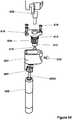
- FIGS. 25-29Bdepict yet another alternative embodiment of a cautery forearm component 400 (which could, of course, be the forearm 30B discussed and depicted above) that can be coupled to the upper arm 30A.
- This forearm 400has a cautery end effector 402 that has an "inline" configuration that minimizes the overall cross-section of the forearm 400 and ultimately the robotic device to which it is coupled, thereby aiding in both surgical visualization and insertion.
- the inline configurationhas a direct-drive configuration that enables the size of the forearm 400 to be reduced by almost half.
- the cautery end effector 402is a removable cautery tip 402.
- the end effector 402is removably coupled to the arm 400 at the drive rod 404. More specifically, in this embodiment, the end effector 402 has a lumen at its proximal end with threads formed on the inside of the lumen such that the threads 404A on the distal portion of the drive rod 404 can be threaded into the lumen in the end effector 402.
- the coupling of the end effector 402 and the drive rod 404results in an electrical connection between the end effector 402 and the drive rod 404.
- a first slip ring 426electrically couples the monopolar cautery generator (the power source for the end effector 402, which is not shown) to the motor coupler 410. More specifically, the first slip ring 426 is coupled to a wire 429 that is coupled to the generator (not shown), thereby electrically coupling the ring 426 to the generator. Further, the slip ring 426 is secured to the body portions 430A, 430B (as best shown in FIG. 25 and discussed in further detail below) such that the ring 426 does not rotate in relation to the body 430.
- the slip ring 426is rotatably coupled to the motor coupler 410 such that the ring 426 and coupler 410 are electrically coupled and can rotate in relation to each other.
- the motor coupler 410is threadably and electrically coupled to the drive rod 404.
- the cautery end effector 402is coupled to the electrical cautery interface (also referred to herein as a "pin") 412.
- This pin 412is coupled to the drive rod 404 via a second slip ring, which is positioned generally in the area identified as 428 in FIG. 26B , thereby ultimately resulting in an electrical connection between the end effector 402 and the first slip ring 426.
- the second slip ring 428is secured to the drive rod 404 or is a part of the drive rod 404.
- the slip ring 428can be a separate component.
- This electrical connection of the first slip ring 426 to the end effector 402 through the motor coupler 410enables transfer of the electrical energy to the end effector 402 that is necessary for cauterization. This is explained further below.
- the coupling of the end effector 402 and the drive rod 404is maintained by the friction of the threadable coupling of the two components, along with the deformability of the end effector 402, which reduces the amount of force applied to that coupling.
- the end effector 402has an o-ring at its distal end that helps to create a seal at the coupling to the drive rod 404 that inhibits inflow of biological material.
- the end effector 402can be non-removable. Instead, the end effector 402 can be integrated into the drive rod such that the need for the removable threaded connection would be eliminated. In such an embodiment, the second slip ring 428 could be replaced with a rigid electrical connection.
- two bearings 408A, 408Bare positioned over a proximal portion of the drive rod 404 and help to provide support to the end effector 402.
- the shoulder 406 on the drive rod 404help to maintain the position of the bearings 408A, 408B in relation to the drive rod 404.
- the motor coupler 410is threadably coupled to threads 404B on the proximal end of the drive rod 404 and thus also helps to retain the bearings 408A, 408B in place on the drive rod 404.
- the electrical connection discussed aboveextends through all three components: the motor coupler 410, the drive rod 404, and the end effector 402.
- the pin 412 extending from the proximal portion of the end effector 402makes the electrical connection of the three components possible.
- This configuration of the three componentsallows for easy removal of one end effector 402 and replacement with another end effector 402 that is positioned such that the electrical connection is re-established by the simple threaded coupling of the new end effector 402 to the drive rod 404.
- bearings 408A, 408Bcan be replaced with other support components.
- One examplewould be bushings.
- the motor coupler 410couples the motor assembly 414 to the end effector 402 through the drive rod 404. More specifically, the motor coupler 410 is coupled with the motor shaft 416 such that the coupler 410 is positioned over the shaft 416.
- the motor shaft 416has a flat portion 416A on the shaft that creates a "D-shaped" configuration and the motor coupler 410 has a corresponding "D-shaped” configuration that mates with the shaft 416 such that the shaft 416 and coupled 410 are not rotatable in relation to each other when they are coupled.
- the motor coupler 410has two portions with different diameters: a large portion 410A and a small portion 410B.
- the small portion 410Bis sized to receive the first slip ring 426 discussed above that creates the necessary electrical connection. That is, as discussed above, when positioned over the small portion 410B of the motor coupler 410, the slip ring 426 can provide a constant clamping force on the motor coupler 410 that maintains the electrical connection between the motor coupler 410 and the motor shaft 416 during rotation.
- This type of connection(the slip ring) allows for infinite rotation without twisting of any wires.
- the coupling in some implementationsis reinforced or further secured with an adhesive.
- the adhesivecould be a Loctite® adhesive or any other known adhesive for use in medical device components.
- the proximal end of the forearm 400has a coupling component 420 that allows for coupling the forearm 400 to the rest of the surgical system with which the forearm is incorporated.
- the coupling component 420would be coupled to the upper arm 30A.
- the coupling component 420is coupled to the proximal portion of the forearm 400 with two screws 424 that are positioned through holes in the forearm 400 and into a portion of the coupling component 420 as shown.
- the coupling component 420has an opening 422 defined in the component 420 (as best shown in FIG. 29B ) that couples to the appropriate component of the surgical system.
- the opening 422is a rectangular-shaped opening 422, but it is understood that it could be any configuration of any type of coupling component or mechanism, depending on the system to which the forearm 400 is being coupled.
- the coupling component 420can be eliminated in those embodiments in which the forearm 400 is an integral part of the upper arm of a device or in any embodiment in which there is no forearm.
- the body 430 of the forearm 400is made up of two body portions (also referred to as "shells") 430A, 430B.
- the two portions 430A, 430Bare coupled together with the screws 432 and the aforementioned screws 424.
- each of the two body portions 430A, 430Bhave internal features as best shown in FIG. 26A that help to retain the motor assembly 414, bearings 408A, 408B, and other internal components in position with respect to each other inside the body 430.
- the interface of the portions 430A, 430Bmay have mating lip and groove configurations to provide a fluidic seal at the coupling of the two portions 430A, 430B.
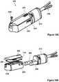
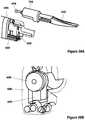
- FIGS. 30-39BAnother embodiment of a robotic device 500 is depicted in FIGS. 30-39B .
- This embodimenthas a device body 510, a left arm 520, and a right arm 530, as shown in Figure 30 .
- Both the left and right arms 520, 530are each comprised of 2 segments: an upper arm (or "first link") and a forearm (or "second link”).
- the left arm 520has an upper arm 520A and a forearm 520B
- the right arm 530has an upper arm 530A and a forearm 530B.
- the robotic device 500is similar in some respects to the device embodiment described above and depicted in FIGS. 1A-2 .
- the current device 500is unique because of its "clutch-like" joint configuration as described in detail below.
- the device 500needs to be very flexible to navigate the natural curvature of the natural orifice.
- the clutch-like joint configuration at each joint in this device 500provides the device 500 with the necessary flexibility.
- this device 500will be locally controlled by a control system similar to the system described above with respect to the previous embodiments.
- the clutch-like configurationis best shown in FIGS. 32A and 32B .
- the overall joint designis fairly similar to the joint design of the embodiments described above.
- the drive bevel gear 560has a portion 562 of the gear 560 that has no teeth.
- the tooth-free portion 562creates the clutch-like configuration. That is, when the drive bevel gear 560 is positioned such that the tooth-free portion 562 is in contact with or adjacent to the driven gear 564 such that no teeth are engaged, the overall joint 566 is free to move and thus has flexibility that can be helpful during insertion.
- this embodimentcan also have one or more rubber band-like components (also referred to herein as “elastomers” or “elastic bands”) 550 that can be used to keep each joint stabilized and thus each arm positioned to keep the robotic device 520 as compact as possible during insertion.
- the band(s) 550can also keep the arms in the correct position for engagement of the bevel gears. More specifically, the device body 510 and the two upper arms 520A, 530A have a channel 552 formed on a top portion of each component as shown in FIG. 31B that is configured to receive the elastic band(s) 550.
- the elastic band (or bands) 550applies forces to the arms 520A, 530A that urge the arms 520A, 530A together as shown by the arrows in FIG. 31B while also urging both arms upward as shown by the arrow in FIG. 31C .
- this clutch-like configurationcould also be used for homing if the positioning of the arms 520, 530 is lost (that is, the joint positions are unknown).
- each of the drive bevel gearscould be positioned so that they are not engaged, whereby the joint positions of the device 500 are known once again. In this embodiment, no additional redundant position sensors would be needed.
- FIG. 31Ddepicts one exemplary embodiment of a mechanically-activated link 556.
- the link 556becomes flexible when a small force F is applied to the cable 558, thereby reducing the friction between the balls 557 and sockets 559 in the link 556 and thus creating flexibility in the link 556. In contrast, when a large force F is applied to the cable 558, friction is increased between the balls 557 and sockets 559 and the link 556 becomes more rigid.
- FIG. 33depicts the various degrees of freedom of the various joints of the two arms 520, 530.
- the left arm 520has four degrees of freedom, while the right arm 530 has five degrees of freedom. More specifically, moving from the proximal end of the right arm 530 to the distal end, the right arm 530 has shoulder pitch ( ⁇ 1), shoulder yaw ( ⁇ 2), elbow roll ( ⁇ 3), elbow yaw ( ⁇ 4), and end effector roll ( ⁇ 5).
- the left arm 520has shoulder pitch, shoulder yaw, elbow yaw, and end effector roll, but no elbow roll.
- any other known kinematic configurationcould also be used.
- the multiple degrees of freedom for each armresults in more dexterous arms for more precision operations.
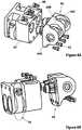
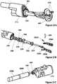
- FIG. 34depicts the key components that make up the joint (also referred to as an "elbow joint") between the upper arm 530A and the forearm 530B of the right arm 530.
- the upper arm 530Ahas a motor assembly 600 that includes a motor, an encoder, and a gearhead.
- the distal end of the motor assembly 600is positioned in and coupled to the gear housing 602.
- the motor assembly 600has a flat portion along an exterior portion of the assembly 600 that creates a "D-shaped" configuration that matches a D-shaped configuration of a lumen in the gear housing 602 such that the assembly 600 and housing 602 cannot rotate in relation to each other when the assembly 600 is positioned in the lumen.
- an adhesivecan also be used to further secure the assembly 600 and housing 602.
- the motor assembly 600has a motor shaft 600A extending from the distal end of the assembly 600.
- the shaft 600Acan be coupled to the motor spur gear 604 such that the spur gear 604 is positioned over the shaft 600A.
- the shaft 600Ahas a flat portion that results in a "D-shaped configuration that matches a "D-shaped" configuration of the lumen in the spur gear 604 such that when the spur gear 604 is positioned over the shaft 600A, neither component can rotate in relation to the other.
- the motor spur gear 604couples or mates with the driven spur gear 606 when the two gears are properly positioned in the gear housing 602 such that rotation of the motor spur gear 604 rotates the driven spur gear 606.
- the driven spur gear 606is coupled to the output link 608 such that actuation of the motor assembly 600 causes the output link 608 to rotate. More specifically, the driven gear 606 is positioned over the proximal end of the output link 608. In one embodiment, a portion of the proximal end of the output link 608 has a flat portion that results in a "D-shaped" configuration as described with respect to other components above, thereby resulting in the output link 608 and spur gear 606 being coupled such that they are not rotatable in relation to each other.
- a screw 610is threadably coupled to the output link 608 and secures the spur gear 606 on the output link 608, along with the bearings 612, 614, while also translationally securing the output link 608.
- the bearings 612, 614can constrain and support the output link 608 and are supported within the gear housing 602.
- the componentsare retained in the gear housing 602 with the help of the housing cover 616, which is secured to the housing 602 with the help of screws 618, which also apply a preload force through the gear housing cover 616.
- the screw 620helps to secure an elastic band between the upper arm 530A and forearm 530B, as described above.
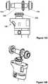
- FIG. 35depicts the forearm 530B and end effector 630 of the right arm 530.
- the end effector 630is another implementation of a monopolar electrocautery device 630.
- the forearm 530Bhas a motor housing 632 that is configured to hold the motor assembly (not shown) and also contains the slip ring 638, which is secured in the housing 632. It is understood that the motor assembly and associated drive train are substantially similar to the same components in the upper arm as described above.
- the motor spur gear 634is operably coupled to the driven spur gear 636 in the motor housing 632.
- the driven gear 636is supported and constrained by bearing 640 and bushing 642, which prevents translation of the driven gear 636.
- the driven gear 636is threadably coupled to the removable end effector 630 via the threads on the distal portion of the gear 636.
- the end effector 630is electrically coupled to the slip ring 638.
- the forearm 530Bis fluidically sealed such that external fluids (such as body fluids, for example) are prevented from entering the internal portions of the forearm 530B.
- One component that helps to fluidically seal the forearm 530Bis a gasket 644, which is positioned between the housing 632 and the housing cover 646 such that the screws 648 that secure the housing cover 646 to the housing 632 also secures the gasket 644 to the bushing 642.
- the gasket 644is made of soft urethane or silicon.
- the gasket 644is made of any material that can help to fluidically seal the housing 632.
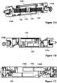
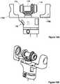
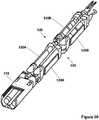
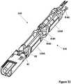
- FIGS. 36-39Bdepict the forearm 520B and end effector 650 of the left arm 520.
- the end effector 650is another implementation of a grasper component (also referred to herein as a "tissue manipulation component” or “tissue manipulator”) 650.
- the forearm 520Bhas two motor assemblies: the rotation motor assembly 652 and the grasper motor assembly 654.
- the rotation motor assembly 652can cause the forearm 520B to rotate.
- the grasper motor assembly 654can cause the grasper 650 to move between its open and closed positions.
- the rotation motor assembly 652has a motor, an encoder, and an integrated gear head. Further, the assembly 652 has a motor shaft 656 that couples to the motor spur gear 658. According to one implementation, the shaft 656 has a flat portion 656A that results in the shaft 656 having a "D-shaped" configuration that mates with a "D-shaped" lumen defined in the spur gear 658. As such, the shaft 656 and gear 658 are coupled such that neither component can rotate in relation to the other.
- a portion of the motor assembly 652 and the motor spur gear 658are positioned in the proximal gear housing 660, which also houses the driven spur gear 662 such that the motor spur gear 658 and driven spur gear 662 are rotatably coupled to each other when positioned in the housing 660.
- the motor assembly 652is coupled to the housing 660, and in certain implementations, the assembly 652 is geometrically and/or adhesively secured to the housing 660. Actuation of the motor assembly 652 causes rotation of the motor spur gear 658, which causes rotation of the driven spur gear 662.
- the driven spur gear 662is operably coupled to the output link 664, which is coupled to the upper arm 520A and thus is part of the joint between the upper arm 520A and forearm 520B. As shown in FIG. 36 , the driven spur gear 662 and two bearings 666, 668 are positioned on the output link 664 such that the bearings 666, 668 are supported within the proximal gear housing 660 and provide some support and constraint to the output link 664.
- a screw 670is coupled to the output link 664 and helps to secure the gear 662 and bearings 666, 668 to the link 664 while also translationally constraining the link 664.
- the output link 664has a flat portion 664A that creates a "D-shaped" configuration that mates with a D-shaped lumen defined in the driven spur gear 662 such that the gear 662 and link 664 cannot rotate in relation to each other when the gear 662 is positioned on the link 664.
- the housing 660also has a housing cover 672 that is positioned over the opening in the housing 660 that contains the gears 658, 662.
- the cover 672is secured in place by screws 674 and thereby applies a preload force to the bearings 666, 668.
- the housingalso has an additional screw 676 that can be used to secure or otherwise constrain an elastic band that is coupled to both the upper arm 520A and the forearm 520B to stabilize the arms as described above.
- the housing 660is configured to be fluidically sealed such that no liquid can gain access to any interior portions of the housing 660.
- the grasper motor assembly 654has a motor, an encoder, and an integrated gear head. Further, the assembly 654 has a motor shaft 680 that couples to the motor spur gear 682. According to one implementation, the shaft 680 has a flat portion 680A that results in the shaft 680 having a "D-shaped" configuration that mates with a "D-shaped" lumen defined in the spur gear 682. As such, the shaft 680 and gear 682 are coupled such that neither component can rotate in relation to the other.
- a portion of the motor assembly 654 and the motor spur gear 682are positioned in the distal gear housing 684, which also houses the driven spur gear 686 such that the motor spur gear 682 and driven spur gear 686 are rotatably coupled to each other when positioned in the housing 684.
- the motor assembly 654is coupled to the housing 684, and in certain implementations, the assembly 654 is geometrically and/or adhesively secured to the housing 684. Actuation of the motor assembly 654 causes the grasper 650 to move between its open and closed positions, as described in detail below.
- the driven spur gear 686is operably coupled to a push/pull mate 688, which is coupled to the grasper 650. More specifically, the driven spur gear 686 and two bearings 690, 692 are positioned on a threaded rod 694 extending from the push/pull mate 688 such that the bearings 690, 692 are supported within the distal gear housing 684 and provide some support and constraint to the driven gear 686.
- the gear 686is threadably coupled to the rod 694.
- a housing cover 702is configured to cover the opening in the gear housing 684 and thereby applies a preloading force to bearings 690, 692 via screws 704, 708 that are threadably coupled through the cover 702 and into the housing 684.
- the housing 684also has a gasket or seal 710 that fluidically seals against the push/pull mate 688, thereby preventing any fluids from entering the interior of the housing 684.
- the seal 710is made of soft urethane or silicon or any other known material for use in creating a fluidic seal.
- the push/pull mate 688When the driven spur gear 686 rotates, the push/pull mate 688 translates, because the push/pull mate 688 is rotationally constrained to the grasper housing 696. More specifically, as best shown in FIGS. 38A and 38B , the push/pull mate 688 has a projection 689 that extends away from the push/pull mate 688 at 90 degrees in relation to the longitudinal axis of the forearm 520B. As such, the projection 689 is positioned in the housing 696 such that the push/pull mate 688 cannot rotate in relation to the housing 696.
- the grasper 650is removably coupled to the push/pull mate 688 via a ball and socket coupling, with the ball 698 positioned at a proximal end of the replaceable grasper 650.
- the translational motion of the push/pull mate 688is transferred to the grasper 650 jaws such that the jaws move between open and closed positions.
- the grasper 650is geometrically and adhesively constrained to the grasper mate 700, which is geometrically constrained to the grasper housing 696.
- the grasper 650 and the grasper mate 700are configured to be removably mateable to the distal end of the grasper housing 696 and the push/pull mate 688 as described above.
- the grasper 650can be easily coupled for use and just as easily removed and replaced with another end effector.
- the grasper end effector 650could be replaced with other known manipulation devices such as, but not limited to, other toothed graspers, bipolar electrocautery devices, clip appliers, shears, ultrasonic sealers, and the like.
- the end effector 650can be secured to the housing 696 with an elastic band 712 as shown in FIG. 39B .
- any other type of band or retention device or mechanismcan be used.
- the various in vivo robotic devices disclosed herein and other such devicesare intended to be inserted into and positioned inside a cavity inside a patient, such as, for example, the peritoneal cavity.
- Various devicescan be used to achieve the insertion of the device into the cavity.
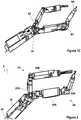
- FIGS. 40A-45depict various examples of such insertion devices.
- FIGS. 40A , 41A, and 41Bdepict an insertion device 800 having an insertion tube 802 defining an insertion chamber 804, an insertion port 806, and a proximal tube cover 808.
- a robotic device 810(such as, for example, any of the device embodiments discussed above), can be positioned inside the insertion chamber 804 and coupled to an insertion rod 812 that is positioned through the proximal tube cover 808.
- the device 800can be positioned against an incision in a patient that accesses the target cavity such that the insertion port 806 is positioned against or in the incision.
- a usercan use the insertion rod 812 to urge the device 810 out of the chamber 804 through the port 806 and into the patient's cavity.
- the robotic device 810can be positioned inside the insertion tube 802 and magnetically coupled to a handle 824 positioned along an external portion of the tube 802 (as shown in FIG. 40B-1 ).
- the handle 824can be used to introduce the robotic device 810 into the abdominal cavity and secure the device 810 to the abdominal wall through a magnetic coupling.
- the handle 824can be urged distally along the outer surface of the tube 802, thereby urging the device 810 via magnetic forces in a distal direction as well such that the device 810 is urged out of the distal end of the tube 802 as best shown in FIG.40B-2 .
- the handle 824can then be urged to the end of the tube 802 such that the arms of the device 810 fully exit the chamber 804 as best shown in FIG. 40B-3 and further such that the entire device 810 exits the chamber 804 and is positioned in the cavity using the handle 824 (wherein the handle 824 is positioned outside the patient's body) as best shown in FIG. 40B-4 .
- This insertion methodcan allow the orifice or insertion tube 802 to remain open for the duration of the surgical procedure.
- the orifice or insertion tube 802can be used by other surgical devices as well, such as for specimen removal, for example.
- the magnetic couplingcan allow the robotic device 810 to access a larger area of the abdominal cavity with different platform orientations.
- a channelcould be created within the orifice or insertion tube 802 that can pass the communication and power tether to the robotic device 810.
- the insertion tube 802is comprised of a single rigid and/or flexible tubular structure.
- the tube 802is not limited to a tubular configuration and could have any known shape that could contain a robotic device for insertion into a patient's cavity.
- the cross-section of the tube 802could have a rectangular or oval shape.
- the insertion tube 802can be flexible.
- the flexible tube 802(with the robotic device housed within) could be coupled to the port 806.
- the abdominal cavityis insufflated and the flexible tube 802 becomes semi-rigid as a result of the insufflation, like a balloon full of air.
- the robotic deviceis then inserted and, in one example, the flexible tube 802 collapses at a point parallel to the coupling of the insertion rod to the device, reducing the external size of the tube 802.
- a pressure release valvewould be needed to account for the change in volume.
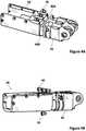
- FIGS. 42A and 42Bdepict the proximal tube cover 808.
- the cover 808has a tube mate 850 coupled to the insertion tube 802.
- the tube mate 850is geometrically and/or adhesively secured to the tube 802.
- the tube mate 850is coupled at its opposite end to a housing 852.
- the tube mate 850 and housing 852are coupled with screws 854.
- any known coupling mechanisms or methodscan be used.
- a gasket 856is positioned between the tube mate 850 and housing 852.
- a bushing 864is positioned in and secured to the housing 852.
- the bushing 864can be mated with the insertion rod 812 described above such that the rod 812 can move longitudinally with smooth linear motion.
- the housing 852is coupled to a seal cap 858 via screws 860, and a gasket 862 and a seal 866 are positioned between the housing 852 and cap 858.
- the seal 866creates a dynamic seal between the insertion rod 812 and the seal 866 to prevent the loss of insufflation of the abdominal cavity as the rod 812 is moved back and forth during a procedure.
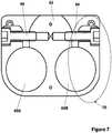
- FIG. 43depicts one implementation of the insertion port 806.
- the port 806includes a insertion cone 880 and a tube mate 882.
- the tube mate 882is coupled to the insertion tube 802.
- the tube mate 882can be geometrically and/or adhesively coupled to the tube 802.
- the tube mate 882is coupled to the insertion cone 880 with screws 884.
- a gasket 886is positioned between the tube mate 882 and the insertion cone 880.
- the insertion cone 880is not limited to conical geometry. That is, the insertion cone 880 could also have a tubular configuration or any other known configuration so long as the component could still operate as a port.
- any of the robotic devices disclosed or contemplated hereincan be manually inserted into the abdominal cavity through the advancement of an insertion rod (such as, for example, the insertion rods 40, 812 described above) or a magnet.
- any such robotic device(such as robotic device 8, 810) can be robotically inserted into the abdominal cavity through the use of a robotic arm.
- the insertion procedurecould be performed by the surgeon or autonomously.
- the robotic devices such as devices 8, 810have a "sweet spot or robotic workspace volume with high dexterity and manipulability. The use of a robotic arm can expand this workspace volume such that the volume includes the entire abdominal cavity.
- a "soft boundary"can be created between the workspace boundary, or limits, and the "sweet spot " of the workspace. That is, if the device crosses the soft boundary, the system has a sensor or other mechanism that is triggered such that the system actuates the external robotic arm to automatically and/or autonomously grossly position the robotic device back to the "sweet spot " of the workspace.
- Such repositioning operationcan also be done manually or robotically under surgeon supervision. Autonomous gross positioning could eliminate the bed side assistant and human errors that commonly occur between the surgeon and assistant relating to positioning of the robotic device.
- Various examples of the insertion device 800can have cameras (also referred to herein as “visualization devices ").
- the camera examples disclosed hereinallow the user to view the device during insertion into and use in the patient's cavity.
- a camera 814is housed within the insertion port 806.
- the camera 814is a 3 MM CMOS camera 814.
- the vision cone 820(the area captured by the camera 814 such that a user can see that area on the display) achieved by the camera 814 is shown.
- the camera 814is coupled to a connection component 816 that couples the camera 814 to a monitor 818 or other type of display.
- Lightin this example, is provided by LED lights 822 positioned on the distal end of the insertion port 806. Alternatively, any known lights that can be used with a medical device to illuminate a surgical space for viewing with a camera can be used.
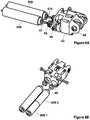
- FIGS. 44A-44Fdepict another example of a camera 890 for use with certain examples of the insertion device 800.
- the camera 890has lights 892 coupled to the camera 890.
- the camera 890is coupled to the device 800 with a four-bar linkage 896 made up of four bars (or "links ") 896A, 896B, 896C, 896D. That is, the four bars 896A, 896B, 896C, 896D can be manipulated by a user to move the camera 890 out of the cone 880 and position it to view the robotic device during insertion and use as shown in the figures.
- the vision cone 894provides a schematic depiction of the area captured by the camera 890 in one embodiment.
- This configurationallows for a larger camera (such as, for example, a high definition camera) to be housed in the insertion cone 880 prior to insertion of the device (when the device is not positioned in or through the cone 880) and then moved out of the cone 880 during use. That is, once the port 806 is attached to the incision site and the cavity is insufflated, the camera 890 can be deployed via the four-bar linkage 896. This positioning of the camera in the cone 880 and then moving it out of the cone allows for the robotic device to always be under visualization during insertion.
- a larger camerasuch as, for example, a high definition camera
- any other known actuation device or mechanismcould be used to deploy the camera.
- One such further exampleis a preformed shape memory alloy or the like.
- the camera 890is a USB webcam.
- FIGS. 45A-45Ddepict yet another camera implementation.
- the camera 900is coupled to a linkage 902 that is coupled to an exterior portion of the insertion cone 880. More specifically, the linkage 902 is made up of two links 902A, 902B, and the camera 900 is coupled to the link 9028.
- the link 902Ais pivotally coupled to the insertion cone 880, and the link 9028 is pivotally coupled to the link 902A.
- the links 902A, 9028are configured such that the camera 900 and links 902A, 9028 form a portion of the cone 880.
- the links 902A, 9028are extended so that the camera 900 is in a position to capture images of the surgical area.
- the lightscan be coupled to the link 9028 or link 902A (or both) to illuminate the viewing area.
- any of the camera examples disclosed abovecan also have a zoom lens package or mechanical translation parallel to the axis of the vision cone via a linear actuator.
Landscapes
- Health & Medical Sciences (AREA)
- Surgery (AREA)
- Engineering & Computer Science (AREA)
- Life Sciences & Earth Sciences (AREA)
- Biomedical Technology (AREA)
- Robotics (AREA)
- Nuclear Medicine, Radiotherapy & Molecular Imaging (AREA)
- Heart & Thoracic Surgery (AREA)
- Medical Informatics (AREA)
- Molecular Biology (AREA)
- Animal Behavior & Ethology (AREA)
- General Health & Medical Sciences (AREA)
- Public Health (AREA)
- Veterinary Medicine (AREA)
- Manipulator (AREA)
Description
- The embodiments and examples disclosed herein relate to various medical devices and related components, including robotic and/or in vivo medical devices and related components. Certain embodiments and examples include various robotic medical devices, including robotic devices that are disposed within a body cavity and positioned using a support component disposed through an orifice or opening in the body cavity. Further examples relate to methods of operating the above devices.
- Invasive surgical procedures are essential for addressing various medical conditions. When possible, minimally invasive procedures such as laparoscopy are preferred.
- However, known minimally invasive technologies such as laparoscopy are limited in scope and complexity due in part to 1) mobility restrictions resulting from using rigid tools inserted through access ports, and 2) limited visual feedback. Known robotic systems such as theda Vinci® Surgical System (available from Intuitive Surgical, Inc., located in Sunnyvale, CA) are also restricted by the access ports, as well as having the additional disadvantages of being very large, very expensive, unavailable in most hospitals, and having limited sensory and mobility capabilities.
WO 2011/118646 A1 discloses a robot hand and a robot device.EP 1 354 670 A1- There is a need in the art for improved surgical systems, and devices.
- Discussed herein are various embodiments and examples relating to robotic surgical devices, including robotic devices configured to be disposed within a cavity of a patient and positioned using a support or positioning component disposed through an orifice or opening in the cavity.
- In Example 1, a robotic device comprises a device body, a first arm, and a second arm. The device body has a motor housing and a gear housing. The motor housing comprises a first motor and a second motor. The gear housing has a first gear positioned at a distal end of the gear housing, the first gear operably coupled to the first motor, and a second gear positioned at a distal end of the gear housing, the second gear operably coupled to the second motor. The first arm is operably coupled to the first gear and positioned substantially within a longitudinal cross-section of the device body when the first arm is extended in a straight configuration. The second arm is operably coupled to the second gear and positioned substantially within the longitudinal cross-section of the device body when the second arm is extended in a straight configuration.
- Example 2 relates to the robotic device according to Example 1, wherein the gear housing comprises first, second, and third housing protrusions disposed at the distal end of the gear housing, wherein the first gear is disposed between the first and second housing protrusions and the second gear is disposed between the second and third housing protrusions.
- In Example 3, a robotic device comprises a device body, a first arm, and a second arm. The device body has a first gear and a second gear. The first gear is positioned at a distal end of the device body and configured to rotate around a first axis parallel to a length of the device body. The second gear is positioned at the distal end of the device body and configured to rotate around a second axis parallel to the length of the device body. The first arm is operably coupled to the first gear at a first shoulder joint, wherein the first shoulder Joint is positioned substantially within a longitudinal cross-section of the device body. The second arm is operably coupled to the second gear at a second shoulder joint, wherein the second shoulder joint is positioned substantially within the longitudinal cross-section of the device body.
- In Example 4, a robotic device comprises a device body, a first arm, and a second arm. The device body has a motor housing and a gear housing. The motor housing has a first motor and a second motor. The gear housing has a first gear and a second gear. The first gear is positioned at a distal end of the gear housing, is operably coupled to the first motor, and is positioned to rotate around a first axis parallel to a length of the device body. The second gear is positioned at a distal end of the gear housing, is operably coupled to the second motor, and is positioned to rotate around a second axis parallel to a length of the device body. The first arm is operably coupled to the first gear and has a first upper arm and a first forearm. The first arm is positioned substantially within a longitudinal cross-section of the device body when the first arm is extended in a straight configuration such that the first upper arm and the first forearm are collinear. The second arm is operably coupled to the second gear and has a second upper arm and a second forearm. The second arm is positioned substantially within the longitudinal cross-section of the device body when the second arm is extended in a straight configuration such that the second upper arm and the second forearm are collinear.
- While multiple embodiments are disclosed, still other embodiments of the present invention will become apparent to those skilled in the art from the following detailed description, which shows and describes illustrative embodiments of the invention. As will be realized, the invention is capable of modifications in various obvious aspects, all without departing from the scope of the present invention. Accordingly, the drawings and detailed description are to be regarded as illustrative in nature and not restrictive.
Claim 1 defines the scope of the invention and the dependent claims disclose the preferred embodiments.FIG. 1A is a perspective view a robotic medical device, according to one embodiment.FIG. 1B is a perspective view of the robotic medical device ofFIG. 1A .FIG. 1C is a perspective view of the robotic medical device ofFIG. 1A .FIG. 2 is a perspective view of the robotic medical device ofFIG. 1A .FIG. 3A is a perspective view of a device body of a robotic device, according to one embodiment.FIG. 3B is a different perspective view of the device body ofFIG. 3A .FIG. 4A is a different perspective view of the device body ofFIG. 3A .FIG. 4B is a side view of the device body ofFIG. 3A .FIG. 5A is a different perspective view of the device body ofFIG. 3A .FIG. 5B is a different perspective view of the device body ofFIG. 3A .FIG. 6A is a perspective view of some of the internal components of the device body ofFIG. 3A .FIG. 6B is a different perspective view of the internal components of the device body ofFIG. 6A .FIG. 7 is a cross-section view of the device body ofFIG. 3A .FIG 8A is a perspective view of a gear housing, according to one embodiment.FIG. 8B is a different perspective view of the gear housing ofFIG. 8A .FIG. 9A is a different perspective view of parts of the gear housing ofFIG. 8A .FIG. 9B is a different perspective view of parts of the gear housing ofFIG. 8A .FIG. 10A is a perspective view of an upper arm, according to one embodiment.FIG. 10B is a different perspective view of the upper arm ofFIG. 10A .FIG. 11A is a different perspective and cutaway view of the upper arm ofFIG. 10A .FIG. 11B is a side and cutaway view of the upper arm ofFIG. 10A .FIG. 11C is a cross-section view of the upper arm ofFIG. 10A .FIG. 12A is a side view of a portion of an upper arm, according to one embodiment.FIG. 12B is a cross-section view of the portion of the upper arm inFIG. 12A .FIG. 13A is a side view of a portion of an upper arm, according to one embodiment.FIG. 13B is a perspective view of the portion of the upper arm inFIG. 13A .FIG. 13C is a cross-section view of the portion of the upper arm inFIG. 13A .FIG. 13D is a cross-section view of the portion of the upper arm inFIG. 13A .FIG. 13E is a different perspective view of the portion of the upper arm inFIG. 13A .FIG. 14A is a perspective view of a portion of an upper arm, according to one embodiment.FIG. 14B is a side view of the portion of the upper arm inFIG. 14A .FIG. 15A is a side view of a portion of an upper arm, according to one embodiment.FIG. 15B is a perspective view of the portion of the upper arm inFIG. 15A .FIG. 16A is a side view of a portion of an upper arm, according to one embodiment.FIG. 16B is a perspective view of the portion of the upper arm inFIG. 16A .FIG. 17A is a side view of a portion of an upper arm, according to one embodiment.FIG. 17B is another side view of the portion of the upper arm inFIG. 17A .FIG. 17C is another side view of the portion of the upper arm inFIG. 17A .FIG. 18A is a perspective view of a forearm, according to one embodiment.FIG. 18B is a different perspective view of the forearm inFIG. 18A .FIG. 19A is a perspective view of a portion of a forearm, according to one embodiment.FIG. 19B is a different perspective view of the forearm inFIG. 19A .FIG. 20A is a perspective view of a portion of a forearm, according to one embodiment.FIG. 20B is a cross-section view of the forearm inFIG. 20A .FIG. 21A is a perspective view of a portion of a forearm, according to one embodiment.FIG. 21B is a different perspective view of the forearm inFIG. 21A .FIG. 21C is a different perspective view of the forearm inFIG. 21A .FIG. 22A is a perspective view of a forearm, according to one embodiment.FIG. 22B is a different perspective view of the forearm inFIG. 22A .FIG. 23A is a cross-section view of a forearm, according to one embodiment.FIG. 23B is an expanded cross-section view of the forearm inFIG. 23A .FIG. 24A is a perspective view of a portion of a forearm, according to one embodiment.FIG. 24B is a different perspective view of the portion of the forearm inFIG. 24A .FIG. 24C is a different perspective view of the portion of the forearm inFIG. 24A .FIG. 25 is an exploded view of a forearm, according to one embodiment.FIG. 26A is a cross-section view of a forearm, according to one embodiment.FIG. 26B is an expanded cross-section view of the forearm inFIG. 26A .FIG. 27A is a perspective view of a forearm, according to one embodiment.FIG. 27B is a different perspective view of the forearm inFIG. 27A .FIG. 27C is a different perspective view of the forearm inFIG. 27A .FIG. 28A is a perspective view of a portion of a forearm, according to one embodiment.FIG. 28B is a different perspective view of the portion of the forearm inFIG. 28A .FIG. 28C is a different perspective view of the portion of the forearm inFIG. 28A .FIG. 28D is a different perspective view of the portion of the forearm inFIG. 28A .FIG. 29A is a side view of a portion of a forearm, according to one embodiment.FIG. 29B is a perspective view of the portion of the forearm inFIG. 29A .FIG. 30 is a perspective view a robotic medical device, according to one embodiment.FIG. 31A is a top view of the medical device ofFIG. 30 .FIG. 31B is an expanded top view of a portion of the device inFIG. 31A .FIG. 31C is a side view of the portion of the device inFIG. 31B .FIG. 31D is a side view of a portion of a medical device, according to another embodiment.FIG. 32A is a perspective view of a joint of a medical device, according to one embodiment.FIG. 32B is a perspective view of a gear from the joint ofFIG. 32A .FIG. 33 is a perspective view of the medical device ofFIG. 30 .FIG. 34 is an exploded view of a forearm, according to one embodiment.FIG. 35 is an exploded view of a forearm, according to one embodiment.FIG. 36 is an exploded view of a forearm, according to one embodiment.FIG. 37 is an exploded view of a forearm, according to one embodiment.FIG. 38A is an expanded perspective view of a portion of the forearm ofFIG. 37 .FIG. 38B is an expanded perspective view of a portion of the forearm ofFIG. 37 .FIG. 39A is an expanded perspective view of a portion of the forearm ofFIG. 37 .FIG. 39B is an expanded perspective view of a portion of the forearm ofFIG. 37 .FIG. 40A is a perspective view of an access and insertion device, according to one embodiment.FIG.40B-1 is a perspective view of an access and insertion device in use, according to one embodiment.FIG. 40B-2 is a perspective view of the access and insertion device ofFIG. 40B-1 in use.FIG. 40B-3 is a perspective view of the access and insertion device ofFIG. 40B-1 in use.FIG. 40B-4 is a perspective view of the access and insertion device ofFIG. 40B-1 in use.FIG. 41A is a side view of an access and insertion device, according to one embodiment.FIG. 41B is a perspective view of the access and insertion device ofFIG. 41A .FIG. 42A is a exploded view of a portion of an access and insertion device, according to one embodiment.FIG. 42B is a perspective view of the portion of the access and insertion device ofFIG. 42A .FIG.43 is a side view of a portion of the access and insertion device ofFIG. 42A .FIG. 44A is a perspective view of an access and insertion device in use, according to one embodiment.FIG. 44B is a perspective view of the access and insertion device ofFIG. 44A in use.FIG. 44C is a perspective view of the access and insertion device ofFIG. 44A in use.FIG. 44D is a perspective view of the access and insertion device ofFIG. 44A in use.FIG. 44E is a perspective view of the access and insertion device ofFIG. 44A in use.FIG. 44F is a perspective view of the access and insertion device ofFIG. 44A in use.FIG. 45A is a side view of a portion of an access and insertion device, according to one embodiment.FIG. 45B is a cross-section view of the portion of the access and insertion device ofFIG. 45A FIG. 45C is a side view of the portion of the access and insertion device ofFIG. 45A .FIG. 45D is a side view of the portion of the access and insertion device ofFIG. 45A .- The various systems and devices disclosed herein relate to devices for use in medical procedures and systems. More specifically, various embodiments relate to various medical devices, including robotic devices and systems.
- It is understood that the various embodiments of robotic devices and systems disclosed herein can be incorporated into or used with any other known medical devices and systems.
For example, the various embodiments disclosed herein may be incorporated into or used with any of the medical devices and systems disclosed in copendingU.S. Applications 11/766,683 , published asUS2008-0004634 A1, (filed on June 21, 2007 and entitled"Magnetically Coupleable Robotic Devices and Related Methods"),11/766,720 US2008-0058835 A1, (filed on June 21, 2007 and entitled"Magnetically Coupleable Surgical Robotic Devices and Related Methods"),11/966,741 US2008-0221591 A1, (filed on December 28, 2007 and entitled"Methods, Systems, and Devices for Surgical Visualization and Device Manipulation"),61/030,588 (filed on February 22, 2008 12/171,413 US2009-0054909 A1, (filed on July 11, 2008 and entitled"Methods and Systems of Actuation in Robotic Devices"),12/192,663 US2009-0076536 A1, (filed August 15, 2008 and entitled"Medical Inflation, Attachment, and Delivery Devices and Related Methods"),12/192,779 US2009-0048612 A1, (filed on August 15, 2008 and entitled"Modular and Cooperative Medical Devices and Related Systems and Methods"),12/324,364 US2009-0171373 A1, (filed November 26, 2008 and entitled"Multifunctional Operational Component for Robotic Devices"),61/640,879 (filed on May 1, 2012 13/493,725 US2013-0041360 A1, (filed June 11, 2012 and entitled"Methods, Systems, and Devices Relating to Surgical End Effectors"),13/546,831 US2013-0178867 A1, (filed July 11, 2012 and entitled"Robotic Surgical Devices, Systems, and Related Methods"),61/680,809 (filed August 8, 2012 13/573,849 US2014-0100587 A1, (filed October 9, 2012 and entitled"Robotic Surgical Devices, Systems, and Related Methods"), and13/738,706 US2014-0058205 A1, (filed January 10, 2013 and entitled"Methods, Systems, and Devices for Surgical Access and Insertion"), andU.S. Patents 7,492,116 (filed on October 31, 2007 and entitled"Robot for Surgical Applications"),7,772,796 (filed on April 3, 2007 and entitled"Robot for Surgical Applications"), and8,179,073 (issued May 15, 2011 , and entitled"Robotic Devices with Agent Delivery Components and Related Methods"). - Certain device and system implementations disclosed in the applications listed above can be positioned within a body cavity of a patient in combination with a support component similar to those disclosed herein. An"in vivo device" as used herein means any device that can be positioned, operated, or controlled at least in part by a user while being positioned within a body cavity of a patient, including any device that is coupled to a support component such as a rod or other such component that is disposed through an opening or orifice of the body cavity, also including any device positioned substantially against or adjacent to a wall of a body cavity of a patient, further including any such device that is internally actuated (having no external source of motive force), and additionally including any device that may be used laparoscopically or endoscopically during a surgical procedure. As used herein, the terms"robot," and"robotic device" shall refer to any device that can perform a task either automatically or in response to a command.
- Certain embodiments provide for insertion of the present invention into the cavity while maintaining sufficient insufflation of the cavity. Further embodiments minimize the physical contact of the surgeon or surgical users with the present invention during the insertion process. Other implementations enhance the safety of the insertion process for the patient and the present invention. For example, some examples provide visualization of the present invention as it is being inserted into the patient's cavity to ensure that no damaging contact occurs between the system/device and the patient. In addition, certain embodiments allow for minimization of the incision size/length. Further implementations reduce the complexity of the access/insertion procedure and/or the steps required for the procedure. Other embodiments relate to devices that have minimal profiles, minimal size, or are generally minimal in function and appearance to enhance ease of handling and use.
- Certain embodiments herein relate to robotic devices (also referred to herein as"platforms") configured to be inserted into a patient cavity - such as an insufflated abdominal cavity - and related systems. In some exemplary systems, the systems include direct visualization of the device during the procedure. Other examples relate to various access or insertion devices that can be used to position the above robotic devices in the patient's cavity.
- One embodiment of a
robotic device 8 is depicted inFIGS. 1A-1C and2 . This embodiment has adevice body 10, aleft arm 20, and aright arm 30, as shown inFIGS. 1A and2 . Both the left andright arms FIG. 1B , theleft arm 20 has anupper arm 20A and aforearm 20B and theright arm 30 has anupper arm 30A and aforearm 30B. As also shown inFIGS. 1B and2 , the devicemain body 10 can, in some embodiments, be coupled to aninsertion rod 40. - As best shown in
FIG. 1C , the various joints in theright arm 30 provide for various degrees of freedom. More specifically, the right shoulder (the joint at which theupper arm 30A is coupled to the device body 10) provides two degrees of freedom: shoulder pitch 81 andshoulder yaw 82.
The elbow joint (the joint at which theforearm 30B is coupled to theupper arm 30A) provides elbow yaw 83, and the end effector on the distal end of theforearm 30B provides end effector roll 84. - As shown in
FIGS. 1A-1C and2 , thedevice 8 is configured to have a reduced profile and/or cross-section. That is, the shoulder joints (where theupper arms body 10 such that shoulder joints and the
proximal ends of theupper arms arms upper arms arms body 10. This minimal cross-section greatly simplifies insertion of thedevice 8 into an incision. For purposes of this application, the "longitudinal cross-section" is the cross-section of thebody 10 as viewed when looking at the distal end or the proximal end of thebody 10 such that one is looking along the longitudinal axis of thebody 10. - Various embodiments of the
device body 10 are depicted inFIGS. 3A-9B . As shown inFIGS. 3A and 3B , thedevice body 10 has amotor housing 50 that is configured to contain at least one motor (described below) and a master control board (not shown) or other processor configured to control various components and/or actions of the device. Thedevice body 10 also has agear housing 62 coupled to themotor housing 50. In addition, as best shown inFIGS. 3A and5A , thehousing 50 has ahousing cover 52 that is configured to be coupleable to thehousing 50 and to provide access to the at least one motor positioned within an internal portion of thehousing 50. - In one embodiment as shown in
FIGS. 3A and 3B , thehousing cover 52 has anopening 53 defined in the portion of thehousing cover 52 that covers the proximal end of thehousing 50. Theopening 53 is configured to receive an insertion rod 54 (also referred to as a "positioning rod" or "positioning component"). In accordance with one implementation, screws 56 or other fastening components are used to couple therod 54 to thecover 52 as shown. According to one implementation, theinsertion rod 54 is used to advance thedevice 8 during insertion. In other implementations, it can also be used to position thedevice 8 within the patient's cavity during the procedure. In accordance with certain embodiments, therod 54 will have communication and power wires (also referred to herein as "cables" or "connection components") disposed in one or more lumens defined in therod 54 that will operably couple thedevice 8 to an external controller (not shown). For example, the external controller can be a personal computer, a joystick-like controller, or any other known controller that allows a user to operate thedevice 8. In further embodiments in which thedevice 8 has at least one camera, the connection components can also include one or more camera and/or lighting wires. - As best shown in
FIGS. 4A and 4B , themotor housing 50 is coupled to thegear housing 62 such that a portion of each of themotor assemblies motor housing 50 and a portion is positioned in thegear housing 62. In one embodiment, themotor housing 50 is coupled to thegear housing 62 withscrews motor housing 50 and threadably coupled within holes in thegear housing 62. - As best shown in
FIGS. 5A and 5B , in one embodiment thehousing cover 52 is removably coupled to themotor housing 50 withscrews 48. Thescrews 48 are positioned through holes defined in thehousing 50 and threadably coupled within holes in thehousing cover 52. Alternatively, any known coupling mechanisms, such as bolts or snap or friction fit mechanisms, can be used to removably couple thecover 52 to thehousing 50. - As discussed above and depicted in
FIGS. 4A, 4B ,5A, and 5B , thedevice body 10 contains the twomotor assemblies motor assemblies right arms body 10 can also contain a master control board (not shown) and a stereoscopic camera (not shown). In one embodiment, the master control board controls themotors - In accordance with one embodiment, each of the two
motor assemblies left motor assembly 60A is the actuator for a drive train coupled to theleft arm 20, while theright motor assembly 60B is the actuator for a drive train coupled to theright arm 30. While the following description will focus on theright motor 60B and its drive train, it is understood that theleft motor assembly 60A and its drive train will have similar components and operate in a similar fashion. - In one implementation, as best shown in
FIGS. 6A, 6B ,8A, 8B ,9A, and 9B , the first stage of the three stage gear head is thegear head 60B-2 attached to themotor 60B-1 of themotor assembly 60B. The second stage is the spur gear set, which is made up of themotor gear 68 and the drivengear 96 as best shown inFIG. 9A . Themotor gear 68 and the drivengear 96 are rotationally coupled to each other in thegear housing 62. In one embodiment, themotor gear 68 and drivengear 96 are spur gears. Alternatively, they can be any known gears. Themotor gear 68 is also known as a "first gear," "drive gear," or "driving gear." The drivengear 96 is also known as a "second gear" or "coupling gear." The third stage is the bevel gear set, which is made up of thehousing bevel gear 92 and thelink bevel gear 102. Thehousing bevel gear 92 and thelink bevel gear 102 are rotationally coupled to each other as best shown inFIG. 9A . These components and gear sets will be discussed in detail below. Thehousing bevel gear 92 is also known as the "third gear," "housing gear," "second drive gear," or "first shoulder gear." Thelink bevel gear 102 is also know as the "fourth gear," "link gear," or "second shoulder gear." - As best shown in
FIGS. 6A, 6B , and7 , both the right and leftmotor assemblies gear housing 62. Theright motor assembly 60B has amotor 60B-1 and agearhead 60B-2. In this embodiment, thegearhead 60B-2 is the first stage gear head and is operably coupled to themotor 60B-1. Themotor assembly 60B has amotor shaft 67 operably coupled at the distal end of theassembly 60B. In one embodiment, themotor shaft 67 has aflat surface 67A that creates a "D" configuration that geometrically couples theshaft 67 to thespur gear 68. Theright motor assembly 60B is positioned in the right motor gear opening 69 of thegear housing 62, as best shown inFIG. 6B . In one embodiment, themotor assembly 60B has a configuration or structure that allows for theassembly 60B to be geometrically coupled within the rightmotor gear opening 69. Further, as best shown inFIG. 7 , thegear housing 62 has aclamp 70 that can be used to retain themotor assembly 60B within themotor gear opening 69. That is, a threadedscrew 66 or other coupling mechanism is positioned in theclamp 70 and threaded into theclamp 70, thereby urging theclamp 70 against theassembly 60B, thereby retaining it in place. Alternatively, theassemblies housing 62 via adhesive or any other known coupling or securement mechanisms or methods. - As best shown in
FIGS. 8A and 8B , thegear housing 62 is coupled to a bearinghousing 64. In one embodiment, the bearinghousing 64 is comprised of threehousing projections FIG. 8B in combination withFIGS. 9A and 9B , the right drivenspur gear assembly 96 is rotationally coupled to the bearinghousing 64. More specifically, the right drivenspur gear assembly 96 is rotationally retained in the bearing housing by thebearings FIG. 9A . Thebearings housing 64 and thegear housing 62. - As best shown in
FIGS. 8A and 8B in combination withFIGS. 9A and 9B , thespur gear assembly 96 is operably coupled to thehousing bevel gear 92 such that thespur gear 96 drives thebevel gear 92. More specifically, thespur gear 96 is positioned over the proximal portion of thebevel gear 92, with the proximal portion having a flat portion or other configuration that rotationally couples thespur gear 96 to thebevel gear 92 such that thespur gear 96 andbevel gear 92 are not rotatable in relation to each other. Further, thebevel gear 92 is positioned between the first andsecond housing projections bearings FIG. 9A , thebearings spur gear 96 are secured to thegear 92 byscrew 100, which is threadably coupled to thebevel gear 92. Further, thebevel gear 92 is rotationally coupled to the first andsecond projections spur gear 96 andbevel gear 92 are rotationally coupled tohousing 62 andhousing 64 byscrews 80, 82 (as best shown inFIG. 8A ), which are threadably coupled to thehousings housings - As mentioned above, the
bevel gear 92 is rotationally coupled to thelink 102, which is operably coupled to theright arm 30 of thedevice 8 as described in further detail below. Thus, thelink 102 couples thedevice body 10 to theright arm 30 such that actuation of themotor 60B results in actuation of some portion or component of theright arm 30. Thelink 102 is supported bybearings housing 64 as best shown inFIGS. 9A and 9B . - In one implementation, the right
upper arm 30A is coupled to thedevice body 10. And in certain embodiments, the rightupper arm 30A is more specifically coupled to thelink 102 discussed above. As best shown inFIGS. 10A and 10B , theupper arm 30A is coupled to thedevice body 10 at thelink 102. Theupper arm 30A has amotor housing 128 configured to hold at least one motor and ahousing cover 124 coupled to thehousing 128. Thehousing cover 124 is coupled to themotor housing 128 byscrews 126, which are threadably coupled to themotor housing 128 as shown. Alternatively, any mechanical coupling mechanisms can be used. Themotor housing 128 is operably coupled to aspur gear housing 120 at each end of themotor housing 128 such that there are twospur gear housings 120 coupled to themotor housing 128. - As best shown in
FIGS. 11A, 11B, and 11C , thehousing 128 contains two motor andgear head assemblies local control board 132, which will be described in further detail below. The twoassemblies housing 128 withscrews 130, which are threadably coupled tomotor housing 128 as best shown inFIG. 10B . - As best shown in
FIG. 11A , thelocal control board 132 is operably coupled to themotor housing 128 andhousing cover 124 and controls the twomotor assemblies housing 128. Theboard 132 is also operably connected to both of themotor assemblies housing 128 via flexible electrical ribbon cable (either FFC or FPC) 134, 136. Theboard 132 receives communications (such as commands and requests, for example) from the master control board (not shown) located in thedevice body 10 via the flexibleelectrical ribbon cable 134. Further, theboard 132 also transmits, passes, or relays communications (such as commands and requests) from the master board to the next device component, which - in this embodiment - is theright forearm 30B via the flexibleelectrical ribbon cable 136. - According to one implementation, each of the local boards disclosed herein is "daisy chained" or wired together in a sequence in the
device 8. In this context, "daisy chain" is intended to have its standard definition as understood in the art. The local boards are daisy chained together using flexible ribbon cable such as thecable - In one embodiment, the two
motor assemblies right arm 30 shoulder yaw and elbow pitch as best shown inFIG. 1C . Like the description of the motor assemblies in thedevice body 10 as discussed above, the twomotor assemblies upper arm 30A as best shown inFIGS. 11B and 11C are substantially similar, so theright motor assembly 142 will be discussed in detail herein. As best shown inFIGS. 12A and 12B , the motor drive train has a three stage gear head. The first stage is thegear head 142B attached to themotor 142A in the motor assembly 142 (as best shown inFIG. 11C ), the second stage is a spur gear set made up of themotor spur gear 138 and the drivenspur gear 156, and the third stage is a bevel gear set made up of thebevel gear 152 and the drivenbevel gear 170. All of these components will be described in further detail below. - As best shown in
FIG. 13A , themotor assembly 142 has adrive shaft 144 that is operably coupled to thespur gear 138. In one embodiment, thedrive shaft 144 has aflat portion 144A that results in a D-shaped shaft, which helps to rotationally couple thespur gear 138 to theshaft 144. In a further implementation, thespur gear 138 can be further coupled to theshaft 144 using a bonding material such as, for example, JB-Weld. Alternatively, thespur gear 138 can be coupled to theshaft 144 in any known fashion using any known mechanism. - As best shown in
FIGS. 13A, 13B, 13C, 13D, and 13E , themotor assembly 142 is positioned within alumen 145 defined in thespur gear housing 120. According to one embodiment, theassembly 142 can be coupled or otherwise retained within thelumen 145 using a clamping assembly 146 (as best shown inFIGS. 13C and 13D ). That is, once themotor assembly 142 is positioned within thelumen 145, thescrew 140 can be urged into the hole, thereby urging the clampingassembly 146 against themotor assembly 142, thereby frictionally retaining theassembly 142 in thelumen 145. Alternatively, theassembly 142 can be secured to thehousing 120 via adhesive or any other known coupling or securement mechanisms or methods. - As best shown in
FIGS. 12A, 12B ,14A, and 14B , the second stage spur gear set is made up of themotor spur gear 138 and the drivenspur gear 156. The twogears spur gear housing 120 as shown. Further, the drivingbevel gear 152 is operably coupled with the drivenspur gear 156, withbearings spur gear 156, thereby creating the spur/bevel assembly 150. Thespur gear 156 is rotationally coupled to thebevel gear 152 such that neither thespur gear 156 nor thebevel gear 152 can rotate in relation to each other. In one embodiment, the twogears spur gear 156 is translationally constrained by the supportingbearings screw 160. The fully assembledassembly 150 can be positioned in thelumen 151 inmotor housing 120. - As shown in
FIGS. 15A, 15B ,16A, 16B ,17A, 17B, and 17C , the third stage bevel gear set is made up of adrive bevel gear 152 and alink bevel gear 170. As discussed above, thedrive bevel gear 152 is part of the spur/bevel assembly 150 and thus is operably coupled to and driven by thespur gear 156. - Setting aside for a moment the focus on the
motor assembly 142 and related components coupled thereto (and the fact that the description relating to theassembly 142 and related components applies equally to the motor assembly 143), it is understood that there are twolink bevel gears upper arm 30A, as best shown inFIGS. 11A, 11B, and 11C . Thelink bevel gear 170A operably couples theupper arm 30A to thedevice body 10, while thelink bevel gear 170B operably couples theupper arm 30A to theforearm 30B. - Returning to
FIGS. 15A-17C , thebearings link bevel gear 170. As best shown inFIGS. 16A and 16B , thebearings housing projections bearings FIGS. 17A-17C , thehousing projections motor housing 120 byscrews motor housing 120 and into thehousing projections - As discussed above, it is understood that the above description relating to the
upper arm 30A also applies toupper arm 20A as well. That is, in certain embodiments, theupper arm 30A andupper arm 20A are substantially the same. FIGS. 18A-21C depict one implementation of a grasper forearm component 200 (which could, of course, be theforearm 30B discussed and depicted above) that can be coupled to theupper arm 30A. More specifically, theforearm 30B has anopening 218 defined at a proximal end of thearm 200 that is configured to be coupled to thelink bevel gear 170B as discussed above. Thisforearm 200 has a grasper end effector (also referred to herein as a "manipulation end effector") 256 discussed in further detail below.- As best shown in
FIGS. 18A and 18B , in this embodiment, thegrasper forearm 200 has amotor housing 202 coupled to agear housing 212. The twohousings motor assemblies grasper end effector 256 and opening/closing of thegrasper 256, as described in further detail below. Themotor housing 202 also contains thelocal control board 210 and has a housing cover (also referred to as a "cap") 204 configured to removably cover theopening 205 that provides access to the interior of themotor housing 202. Thecover 204 can be coupled to thehousing 202 withscrew 216. In addition, thescrew 216 is threadably positioned into theopening 218 and thus can be threadably coupled to thelink bevel gear 170 as discussed above, thereby rotationally coupling theforearm 200 to theupper arm 30A. Themotor housing 202 and cover 204 are coupled to thegear housing 212 withscrews 214, which are threadably coupled through openings in thehousing 202 and cover 204 and into thegear housing 212. In one implementation, thelocal control board 210 can be the same or similar to thelocal control board 132 in the upper arm as described above. Theboard 210 is coupled to thelocal control board 132 via the flexibleelectrical ribbon cable 136 in theupper arm 30A as described above. - As best shown in
FIGS. 19A-20B , the twomotor assemblies gear housing 212 viaclamps motor assembly 206 is coupled to thehousing 212 with theclamp 222 as best shown inFIGS. 19A and 19B , while themotor assembly 208 is coupled to the housing with theclamp 230 as best shown inFIGS. 20A and 20B . Alternatively, theassemblies housing 212 via adhesive or any other known coupling or securement mechanisms or methods. - As best shown in
FIGS. 19A and 19B , theclamp 222 is coupled to thegear housing 212 withscrews 224, which are threadably positioned through holes in theclamp 222 and into thegear housing 212. According to one embodiment, theclamp 222 secures themotor assembly 206 by frictional force applied by urging theclamp 222 against thehousing 212 with thescrews 224. As best shown inFIG. 19B , themotor assembly 206 contains two parts: amotor 206B andgear head 206A. In accordance with one implementation, thegear head 206A is operably coupled to themotor 206B. A drive gear (which is also a "spur gear") 220 is operably coupled to theshaft 207 extending from themotor assembly 206. In one embodiment, theshaft 207 has a flat portion resulting in a "D shaped" geometry, and thegear 220 has a hole that mates that geometry, thereby ensuring that theshaft 207 andgear 220 are not rotatable in relation to each other when they are coupled. In a further alternative, thegear 220 is also adhesively coupled to theshaft 207 with JB Weld or any known adhesive material. Alternatively, thegear 220 andshaft 207 can be coupled in any known fashion using any known coupling mechanism or configuration. - As best shown in
FIGS. 20A and 20B , theclamp 230 is urged toward thehousing 212 withscrew 232, thereby creating frictional retention of themotor assembly 208. As such, theclamp 230 can retain theassembly 208 in thehousing 212. - As best shown in
FIG. 21C , themotor assembly 208 has two parts: amotor 208A and agear head 208B coupled to themotor 208A. A drive gear (which is also a "spur gear") 264 is operably coupled to theshaft 209 extending from themotor assembly 208. In one embodiment, theshaft 209 has a flat portion resulting in a "d shaped" geometry, and thegear 264 has a hole that mates that geometry, thereby ensuring that theshaft 209 andgear 264 are not rotatable in relation to each other when they are coupled. In a further alternative, thegear 264 is also adhesively coupled to theshaft 209 with JB Weld or any known adhesive material. Alternatively, thegear 264 andshaft 209 can be coupled in any known fashion using any known coupling mechanism or configuration. - As best shown in
FIG. 21A , drivespur gear 264 is coupled in thegear housing 212 with drivenspur gear 250, and actuation of the drive spur gear 264 (and thus the driven spur gear 250) causes thegrasper end effector 256 to rotate. Further, as best shown inFIGS. 19B and21B , thedrive spur gear 220 is coupled in thegear housing 212 with drivenspur gear 248, and actuation of the drive spur gear 220 (and thus the drive spur gear 248) causes thegrasper end effector 256 to move between its open and closed positions. - Continuing with
FIG. 21A , thegear housing 212 has a bearing cover (also referred to as a "cap") 240, which is attached to thegear housing 212 byscrews 242 which are threadably coupled through holes in thecover 240 and into thegear housing 212. Thescrews 242 can also be configured to apply a preload force tobearings FIG. 21B , thebearings gear housing 212.Bearings spur gear 248 of the end effector actuationspur gear set - Continuing with
FIG. 21B , thespur gear 248 has a lumen with internal threads formed in the lumen and thus can be threadably coupled to thegrasper drive pin 254, which can be positioned at its proximal end in the lumen of thespur gear 248. As thespur gear 248 rotates, the threads in the lumen of thespur gear 248 coupled to the threads on thedrive pin 254 cause thedrive pin 254 to translate, thereby causing the grasper links 256 to move between open and closed positions. In this particular embodiment, translation of thedrive pin 254 is transferred through a four bar linkage made up oflinks grasper links grasper 256 can be accomplished through any other known mechanisms such as a pin and slot or worm gear drive train. Apin 266 secures the fourbar linkage spur gear 250. Thepin 266 is threadably coupled tospur gear 250. - The
bearings spur gear 250. The drivenspur gear 250 is coupled to thegrasper 256 such that whenspur gear 250 is rotated, thegrasper 256 is rotated. To rotate thegrasper 256 without also actuating the grasper to move between its open and closed positions, thespur gear 248 must rotate in the same direction and at the same speed as thespur gear 250. That is, as described above, thedrive pin 254 is rotationally coupled to spur gear 250 (otherwise translation of thepin 254 is not possible) such that whenspur gear 250 is rotated (to cause the end effector to rotate), thedrive pin 254 is also rotated. Hence, ifspur gear 248 is not also rotated in the same direction at the same speed as thespur gear 250, thedrive pin 254 will translate, thereby causing thegrasper 256 to open or close. As a result, to rotate thegrasper 256 without opening or closing it, the spur gears 250 and 248 must rotate together. Thespacer 258 can provide spacing between thebearings FIGS. 22A-24C depict an alternative embodiment relating to a cautery forearm component 300 (which could, of course, be theforearm 30B discussed and depicted above) that can be coupled to theupper arm 30A. More specifically, as best shown inFIG. 22A , theforearm 300 has anopening 306 defined at a proximal end of thearm 300 that is configured to be coupled to thelink bevel gear 170B as discussed above. In one implementation, ascrew 308 secures or threadably couples thelink bevel gear 170B tomotor housing 302A. Thisforearm 300 has acautery end effector 332 that can be a monopolar electrocautery device as discussed in further detail below.- As shown in
FIGS. 22A and 22B , theforearm 300 is made up amotor housing 302 that is coupled to agear housing 304. Amotor assembly 320 is positioned within themotor housing 302 andgear housing 304. Themotor housing 302 is actually made up of two housing components - a firstmotor housing component 302A and a secondmotor housing component 302B - that are coupled to each other to make up thehousing 302. Thefirst component 302A andsecond component 302B are secured to each other at least in part by thescrew 310, which is inserted through holes in bothcomponents motor housing 302 is secured to thegear housing 304 viascrews 312, which are positioned through holes in themotor housing 302 and into thegear housing 304. - As best shown in
FIGS. 23A-24C , themotor assembly 320 is comprised of two parts: amotor 320B and agear head 320A, which is operably coupled to themotor 320B. A drive gear (which is also a "spur gear") 324 is operably coupled to theshaft 322 extending from themotor assembly 320. In one embodiment, theshaft 322 has a flat portion resulting in a "d shaped" geometry, and thegear 324 has a hole that mates that geometry, thereby ensuring that theshaft 322 andgear 324 are not rotatable in relation to each other when they are coupled. In a further alternative, thegear 324 is also adhesively coupled to theshaft 322 with JB Weld or any known adhesive material. Alternatively, thegear 324 andshaft 322 can be coupled in any known fashion using any known coupling mechanism or configuration. - As best shown in
FIG. 24B , thegear housing 304 has a housing cover (also referred to as a "housing cap") 326 that is coupled to the distal portion of thegear housing 304 withscrews 328 that are threadably coupled through holes in thecover 326 and into thegear housing 304. Thehousing cover 326 andscrews 328 can, in some embodiments, apply a preload force tobearings FIG. 24C ). As best shown inFIGS. 23A and 23B , thedrive spur gear 324 is operably coupled in thegear housing 304 to the drivenspur gear 336. As shown inFIG. 24C , the drivenspur gear 336 is operably coupled to thecautery end effector 332 and is supported bybearings bearings spur gear 336 by anut 338 that is threadably coupled to thespur gear 336. Thenut 338 does not apply a preload to thebearings spacer 344 is included to provide bearing spacing. The monopolarelectrocautery end effector 332 is threadably coupled at a proximal end of theend effector 332 to thespur gear 336. - In use, electricity is transferred from the
proximal tip 334 of theend effector 332 to the distal portion of theend effector 332 through a slip ring (not pictured) that is secured to themotor housing 302. In one embodiment, the slip ring is secured to aconfiguration 314 formed in themotor housing 302 as shown inFIG. 22B . The distal end of theend effector 332 is used to cauterize tissue. - In the embodiment described herein, the
cautery forearm 300 has only onemotor assembly 320 that has a two-stage gearhead. The first stage is thegear head 320A coupled to themotor 320B, and the second stage is the spur gear set made up of thedrive spur gear 324 and the drivenspur gear 336. - In accordance with one implementation, the
cautery forearm component 300 does not contain a local control board. Instead, thecomponent 300 can have a flexible electrical ribbon cable (not shown) operably coupled to the motor that connects to the local control in the upper arm (such as thelocal control board 132 inFIG. 11A ). In one embodiment, the local control board in the upper arm (such asboard 132, for example) can have one or more extra components to facilitate an additional motor. The single motor (not shown) in thecautery forearm component 300 can actuate rotation of theend effector 332. FIGS. 25-29B depict yet another alternative embodiment of a cautery forearm component 400 (which could, of course, be theforearm 30B discussed and depicted above) that can be coupled to theupper arm 30A. Thisforearm 400 has acautery end effector 402 that has an "inline" configuration that minimizes the overall cross-section of theforearm 400 and ultimately the robotic device to which it is coupled, thereby aiding in both surgical visualization and insertion. As described in further detail below, according to one embodiment, the inline configuration has a direct-drive configuration that enables the size of theforearm 400 to be reduced by almost half.- As best shown in
FIGS. 25, 26A, 26B , and28A , according to one implementation, thecautery end effector 402 is aremovable cautery tip 402. Theend effector 402 is removably coupled to thearm 400 at thedrive rod 404. More specifically, in this embodiment, theend effector 402 has a lumen at its proximal end with threads formed on the inside of the lumen such that thethreads 404A on the distal portion of thedrive rod 404 can be threaded into the lumen in theend effector 402. The coupling of theend effector 402 and thedrive rod 404 results in an electrical connection between theend effector 402 and thedrive rod 404. - As best shown in
FIG. 26B , afirst slip ring 426 electrically couples the monopolar cautery generator (the power source for theend effector 402, which is not shown) to themotor coupler 410. More specifically, thefirst slip ring 426 is coupled to awire 429 that is coupled to the generator (not shown), thereby electrically coupling thering 426 to the generator. Further, theslip ring 426 is secured to thebody portions FIG. 25 and discussed in further detail below) such that thering 426 does not rotate in relation to the body 430. In contrast, theslip ring 426 is rotatably coupled to themotor coupler 410 such that thering 426 andcoupler 410 are electrically coupled and can rotate in relation to each other. Themotor coupler 410 is threadably and electrically coupled to thedrive rod 404. Thecautery end effector 402 is coupled to the electrical cautery interface (also referred to herein as a "pin") 412. Thispin 412 is coupled to thedrive rod 404 via a second slip ring, which is positioned generally in the area identified as 428 inFIG. 26B , thereby ultimately resulting in an electrical connection between theend effector 402 and thefirst slip ring 426. In one embodiment, thesecond slip ring 428 is secured to thedrive rod 404 or is a part of thedrive rod 404. Alternatively, theslip ring 428 can be a separate component. This electrical connection of thefirst slip ring 426 to theend effector 402 through themotor coupler 410 enables transfer of the electrical energy to theend effector 402 that is necessary for cauterization. This is explained further below. According to one embodiment, the coupling of theend effector 402 and thedrive rod 404 is maintained by the friction of the threadable coupling of the two components, along with the deformability of theend effector 402, which reduces the amount of force applied to that coupling. In accordance with one implementation, theend effector 402 has an o-ring at its distal end that helps to create a seal at the coupling to thedrive rod 404 that inhibits inflow of biological material. - Alternatively, the
end effector 402 can be non-removable. Instead, theend effector 402 can be integrated into the drive rod such that the need for the removable threaded connection would be eliminated. In such an embodiment, thesecond slip ring 428 could be replaced with a rigid electrical connection. - As best shown in
FIGS. 25 ,28A ,28B ,28C, and 28D , twobearings drive rod 404 and help to provide support to theend effector 402. Theshoulder 406 on thedrive rod 404 help to maintain the position of thebearings drive rod 404. In addition, themotor coupler 410 is threadably coupled tothreads 404B on the proximal end of thedrive rod 404 and thus also helps to retain thebearings drive rod 404. The electrical connection discussed above extends through all three components: themotor coupler 410, thedrive rod 404, and theend effector 402. According to one embodiment, as noted above, thepin 412 extending from the proximal portion of the end effector 402 (as best shown inFIGS. 25 and 26A ) makes the electrical connection of the three components possible. This configuration of the three components allows for easy removal of oneend effector 402 and replacement with anotherend effector 402 that is positioned such that the electrical connection is re-established by the simple threaded coupling of thenew end effector 402 to thedrive rod 404. - Alternatively, the
bearings - Continuing with
FIGS. 25 ,28C, and 28D , themotor coupler 410 couples themotor assembly 414 to theend effector 402 through thedrive rod 404. More specifically, themotor coupler 410 is coupled with themotor shaft 416 such that thecoupler 410 is positioned over theshaft 416. In one embodiment, themotor shaft 416 has aflat portion 416A on the shaft that creates a "D-shaped" configuration and themotor coupler 410 has a corresponding "D-shaped" configuration that mates with theshaft 416 such that theshaft 416 and coupled 410 are not rotatable in relation to each other when they are coupled. - In accordance with one embodiment as best shown in
FIGS. 28C and 28D , themotor coupler 410 has two portions with different diameters: alarge portion 410A and asmall portion 410B. Thesmall portion 410B is sized to receive thefirst slip ring 426 discussed above that creates the necessary electrical connection. That is, as discussed above, when positioned over thesmall portion 410B of themotor coupler 410, theslip ring 426 can provide a constant clamping force on themotor coupler 410 that maintains the electrical connection between themotor coupler 410 and themotor shaft 416 during rotation. This type of connection (the slip ring) allows for infinite rotation without twisting of any wires. With respect to the coupling of themotor coupler 410 with thedrive rod 404, the coupling in some implementations is reinforced or further secured with an adhesive. For example, the adhesive could be a Loctite® adhesive or any other known adhesive for use in medical device components. - As best shown in
FIGS. 29A and 29B , the proximal end of theforearm 400 has acoupling component 420 that allows for coupling theforearm 400 to the rest of the surgical system with which the forearm is incorporated. For example, in thedevice 10 depicted and discussed above, thecoupling component 420 would be coupled to theupper arm 30A. Thecoupling component 420 is coupled to the proximal portion of theforearm 400 with twoscrews 424 that are positioned through holes in theforearm 400 and into a portion of thecoupling component 420 as shown. - The
coupling component 420 has anopening 422 defined in the component 420 (as best shown inFIG. 29B ) that couples to the appropriate component of the surgical system. In this embodiment, theopening 422 is a rectangular-shapedopening 422, but it is understood that it could be any configuration of any type of coupling component or mechanism, depending on the system to which theforearm 400 is being coupled. - Alternatively, the
coupling component 420 can be eliminated in those embodiments in which theforearm 400 is an integral part of the upper arm of a device or in any embodiment in which there is no forearm. - Returning to
FIGS. 25 and 26A , the body 430 of theforearm 400 is made up of two body portions (also referred to as "shells") 430A, 430B. The twoportions screws 432 and the aforementioned screws 424. According to one embodiment, each of the twobody portions FIG. 26A that help to retain themotor assembly 414,bearings portions portions portions - Another embodiment of a robotic device 500 is depicted in
FIGS. 30-39B . This embodiment has adevice body 510, aleft arm 520, and aright arm 530, as shown inFigure 30 . Both the left andright arms left arm 520 has anupper arm 520A and aforearm 520B and theright arm 530 has anupper arm 530A and aforearm 530B. - In this embodiment, the robotic device 500 is similar in some respects to the device embodiment described above and depicted in
FIGS. 1A-2 . However, the current device 500 is unique because of its "clutch-like" joint configuration as described in detail below. To insert a device or platform in a NOTES procedure through a natural orifice, the device 500 needs to be very flexible to navigate the natural curvature of the natural orifice. The clutch-like joint configuration at each joint in this device 500 provides the device 500 with the necessary flexibility. According to one embodiment, this device 500 will be locally controlled by a control system similar to the system described above with respect to the previous embodiments. - The clutch-like configuration, according to one embodiment, is best shown in
FIGS. 32A and 32B . As can be seen in these figures, the overall joint design is fairly similar to the joint design of the embodiments described above. However, in this embodiment, thedrive bevel gear 560 has aportion 562 of thegear 560 that has no teeth. The tooth-free portion 562 creates the clutch-like configuration. That is, when thedrive bevel gear 560 is positioned such that the tooth-free portion 562 is in contact with or adjacent to the drivengear 564 such that no teeth are engaged, the overall joint 566 is free to move and thus has flexibility that can be helpful during insertion. - As best shown in
FIGS. 31A, 31B , and31C , this embodiment can also have one or more rubber band-like components (also referred to herein as "elastomers" or "elastic bands") 550 that can be used to keep each joint stabilized and thus each arm positioned to keep therobotic device 520 as compact as possible during insertion. In a further embodiment, the band(s) 550 can also keep the arms in the correct position for engagement of the bevel gears. More specifically, thedevice body 510 and the twoupper arms channel 552 formed on a top portion of each component as shown inFIG. 31B that is configured to receive the elastic band(s) 550. In certain embodiments, there are alsobolts 554 positioned at strategic locations - such as, for example, the locations shown inFIG. 31B - to which the elastic band(s) 550 can be attached. In one implementation, the elastic band (or bands) 550 applies forces to thearms arms FIG. 31B while also urging both arms upward as shown by the arrow inFIG. 31C . - In one alternative embodiment, this clutch-like configuration could also be used for homing if the positioning of the
arms - It is understood that other types of stabilization devices or mechanisms could also be used in place of the
elastic bands 550. For example, in one alternative embodiment, two torsion springs could be used that are positioned opposite of each other, resulting in equal and opposite rotational forces. Alternatively, other known clutch-like devices or mechanisms could be used, including, for example, any commercially available or custom made clutch. In further alternatives, flexible links could be used in combination with solid bevel gears (no teeth missing). In such embodiments, the flexibility of the flexible links could be activated thermally (thermo plastic), electrically (shape memory alloy), or mechanically (friction based).FIG. 31D depicts one exemplary embodiment of a mechanically-activatedlink 556. Thelink 556 becomes flexible when a small force F is applied to thecable 558, thereby reducing the friction between theballs 557 andsockets 559 in thelink 556 and thus creating flexibility in thelink 556. In contrast, when a large force F is applied to thecable 558, friction is increased between theballs 557 andsockets 559 and thelink 556 becomes more rigid. FIG. 33 depicts the various degrees of freedom of the various joints of the twoarms left arm 520 has four degrees of freedom, while theright arm 530 has five degrees of freedom. More specifically, moving from the proximal end of theright arm 530 to the distal end, theright arm 530 has shoulder pitch (θ1), shoulder yaw (θ2), elbow roll (θ3), elbow yaw (θ4), and end effector roll (θ5). In contrast, theleft arm 520 has shoulder pitch, shoulder yaw, elbow yaw, and end effector roll, but no elbow roll. Alternatively, any other known kinematic configuration could also be used. The multiple degrees of freedom for each arm results in more dexterous arms for more precision operations.FIG. 34 depicts the key components that make up the joint (also referred to as an "elbow joint") between theupper arm 530A and theforearm 530B of theright arm 530. Theupper arm 530A has amotor assembly 600 that includes a motor, an encoder, and a gearhead. The distal end of themotor assembly 600 is positioned in and coupled to thegear housing 602. In one embodiment, themotor assembly 600 has a flat portion along an exterior portion of theassembly 600 that creates a "D-shaped" configuration that matches a D-shaped configuration of a lumen in thegear housing 602 such that theassembly 600 andhousing 602 cannot rotate in relation to each other when theassembly 600 is positioned in the lumen. In a further implementation, an adhesive can also be used to further secure theassembly 600 andhousing 602.- The
motor assembly 600 has amotor shaft 600A extending from the distal end of theassembly 600. Theshaft 600A can be coupled to themotor spur gear 604 such that thespur gear 604 is positioned over theshaft 600A. In one embodiment, theshaft 600A has a flat portion that results in a "D-shaped configuration that matches a "D-shaped" configuration of the lumen in thespur gear 604 such that when thespur gear 604 is positioned over theshaft 600A, neither component can rotate in relation to the other. Themotor spur gear 604 couples or mates with the drivenspur gear 606 when the two gears are properly positioned in thegear housing 602 such that rotation of themotor spur gear 604 rotates the drivenspur gear 606. - The driven
spur gear 606 is coupled to theoutput link 608 such that actuation of themotor assembly 600 causes theoutput link 608 to rotate. More specifically, the drivengear 606 is positioned over the proximal end of theoutput link 608. In one embodiment, a portion of the proximal end of theoutput link 608 has a flat portion that results in a "D-shaped" configuration as described with respect to other components above, thereby resulting in theoutput link 608 andspur gear 606 being coupled such that they are not rotatable in relation to each other. Ascrew 610 is threadably coupled to theoutput link 608 and secures thespur gear 606 on theoutput link 608, along with thebearings output link 608. Thebearings output link 608 and are supported within thegear housing 602. The components are retained in thegear housing 602 with the help of thehousing cover 616, which is secured to thehousing 602 with the help ofscrews 618, which also apply a preload force through thegear housing cover 616. According to one embodiment, thescrew 620 helps to secure an elastic band between theupper arm 530A andforearm 530B, as described above. FIG. 35 depicts theforearm 530B andend effector 630 of theright arm 530. In this embodiment, theend effector 630 is another implementation of amonopolar electrocautery device 630. Theforearm 530B has amotor housing 632 that is configured to hold the motor assembly (not shown) and also contains theslip ring 638, which is secured in thehousing 632. It is understood that the motor assembly and associated drive train are substantially similar to the same components in the upper arm as described above.- The
motor spur gear 634 is operably coupled to the drivenspur gear 636 in themotor housing 632. The drivengear 636 is supported and constrained by bearing 640 andbushing 642, which prevents translation of the drivengear 636. The drivengear 636 is threadably coupled to theremovable end effector 630 via the threads on the distal portion of thegear 636. Theend effector 630 is electrically coupled to theslip ring 638. - In addition, according to one embodiment, the
forearm 530B is fluidically sealed such that external fluids (such as body fluids, for example) are prevented from entering the internal portions of theforearm 530B. One component that helps to fluidically seal theforearm 530B is agasket 644, which is positioned between thehousing 632 and thehousing cover 646 such that thescrews 648 that secure thehousing cover 646 to thehousing 632 also secures thegasket 644 to thebushing 642. In one embodiment, thegasket 644 is made of soft urethane or silicon. Alternatively, thegasket 644 is made of any material that can help to fluidically seal thehousing 632. FIGS. 36-39B depict theforearm 520B andend effector 650 of theleft arm 520. In this embodiment, theend effector 650 is another implementation of a grasper component (also referred to herein as a "tissue manipulation component" or "tissue manipulator") 650. As best shown inFIGS. 36 and37 , theforearm 520B has two motor assemblies: therotation motor assembly 652 and thegrasper motor assembly 654. As best shown inFIG. 36 , therotation motor assembly 652 can cause theforearm 520B to rotate. As best shown inFIG. 37 , thegrasper motor assembly 654 can cause thegrasper 650 to move between its open and closed positions.- Returning to
FIG. 36 , in one embodiment, therotation motor assembly 652 has a motor, an encoder, and an integrated gear head. Further, theassembly 652 has amotor shaft 656 that couples to themotor spur gear 658. According to one implementation, theshaft 656 has aflat portion 656A that results in theshaft 656 having a "D-shaped" configuration that mates with a "D-shaped" lumen defined in thespur gear 658. As such, theshaft 656 andgear 658 are coupled such that neither component can rotate in relation to the other. A portion of themotor assembly 652 and themotor spur gear 658 are positioned in theproximal gear housing 660, which also houses the drivenspur gear 662 such that themotor spur gear 658 and drivenspur gear 662 are rotatably coupled to each other when positioned in thehousing 660. In one embodiment, themotor assembly 652 is coupled to thehousing 660, and in certain implementations, theassembly 652 is geometrically and/or adhesively secured to thehousing 660. Actuation of themotor assembly 652 causes rotation of themotor spur gear 658, which causes rotation of the drivenspur gear 662. - The driven
spur gear 662 is operably coupled to theoutput link 664, which is coupled to theupper arm 520A and thus is part of the joint between theupper arm 520A andforearm 520B. As shown inFIG. 36 , the drivenspur gear 662 and twobearings output link 664 such that thebearings proximal gear housing 660 and provide some support and constraint to theoutput link 664. Ascrew 670 is coupled to theoutput link 664 and helps to secure thegear 662 andbearings link 664 while also translationally constraining thelink 664. In one embodiment, theoutput link 664 has aflat portion 664A that creates a "D-shaped" configuration that mates with a D-shaped lumen defined in the drivenspur gear 662 such that thegear 662 and link 664 cannot rotate in relation to each other when thegear 662 is positioned on thelink 664. - The
housing 660 also has ahousing cover 672 that is positioned over the opening in thehousing 660 that contains thegears cover 672 is secured in place byscrews 674 and thereby applies a preload force to thebearings additional screw 676 that can be used to secure or otherwise constrain an elastic band that is coupled to both theupper arm 520A and theforearm 520B to stabilize the arms as described above. - In one implementation, the
housing 660 is configured to be fluidically sealed such that no liquid can gain access to any interior portions of thehousing 660. - Returning to
FIG. 37 , in one embodiment, thegrasper motor assembly 654 has a motor, an encoder, and an integrated gear head. Further, theassembly 654 has amotor shaft 680 that couples to themotor spur gear 682. According to one implementation, theshaft 680 has aflat portion 680A that results in theshaft 680 having a "D-shaped" configuration that mates with a "D-shaped" lumen defined in thespur gear 682. As such, theshaft 680 andgear 682 are coupled such that neither component can rotate in relation to the other. A portion of themotor assembly 654 and themotor spur gear 682 are positioned in thedistal gear housing 684, which also houses the drivenspur gear 686 such that themotor spur gear 682 and drivenspur gear 686 are rotatably coupled to each other when positioned in thehousing 684. In one embodiment, themotor assembly 654 is coupled to thehousing 684, and in certain implementations, theassembly 654 is geometrically and/or adhesively secured to thehousing 684. Actuation of themotor assembly 654 causes thegrasper 650 to move between its open and closed positions, as described in detail below. - The driven
spur gear 686 is operably coupled to a push/pull mate 688, which is coupled to thegrasper 650. More specifically, the drivenspur gear 686 and twobearings rod 694 extending from the push/pull mate 688 such that thebearings distal gear housing 684 and provide some support and constraint to the drivengear 686. Thegear 686 is threadably coupled to therod 694. Ahousing cover 702 is configured to cover the opening in thegear housing 684 and thereby applies a preloading force tobearings screws cover 702 and into thehousing 684. Thehousing 684 also has a gasket or seal 710 that fluidically seals against the push/pull mate 688, thereby preventing any fluids from entering the interior of thehousing 684. In one embodiment, theseal 710 is made of soft urethane or silicon or any other known material for use in creating a fluidic seal. - When the driven
spur gear 686 rotates, the push/pull mate 688 translates, because the push/pull mate 688 is rotationally constrained to thegrasper housing 696. More specifically, as best shown inFIGS. 38A and 38B , the push/pull mate 688 has aprojection 689 that extends away from the push/pull mate 688 at 90 degrees in relation to the longitudinal axis of theforearm 520B. As such, theprojection 689 is positioned in thehousing 696 such that the push/pull mate 688 cannot rotate in relation to thehousing 696. - In one embodiment, as best shown in
FIGS. 37 ,38A , and39A , thegrasper 650 is removably coupled to the push/pull mate 688 via a ball and socket coupling, with theball 698 positioned at a proximal end of thereplaceable grasper 650. Through this coupling, the translational motion of the push/pull mate 688 is transferred to thegrasper 650 jaws such that the jaws move between open and closed positions. Thegrasper 650 is geometrically and adhesively constrained to thegrasper mate 700, which is geometrically constrained to thegrasper housing 696. - As best shown in
FIG. 38A ,39A, and 39B , thegrasper 650 and thegrasper mate 700 are configured to be removably mateable to the distal end of thegrasper housing 696 and the push/pull mate 688 as described above. As such, thegrasper 650 can be easily coupled for use and just as easily removed and replaced with another end effector. According to one implementation, thegrasper end effector 650 could be replaced with other known manipulation devices such as, but not limited to, other toothed graspers, bipolar electrocautery devices, clip appliers, shears, ultrasonic sealers, and the like. When the grasper 650 (or other end effector) has been coupled to thegrasper housing 696 and the push/pull mate 688 such that theball 698 is positioned in the socket of the push/pull mate 688, theend effector 650 can be secured to thehousing 696 with anelastic band 712 as shown inFIG. 39B . Alternatively, any other type of band or retention device or mechanism can be used. - The various in vivo robotic devices disclosed herein and other such devices are intended to be inserted into and positioned inside a cavity inside a patient, such as, for example, the peritoneal cavity. Various devices can be used to achieve the insertion of the device into the cavity.
FIGS. 40A-45 depict various examples of such insertion devices. FIGS. 40A ,41A, and 41B depict aninsertion device 800 having aninsertion tube 802 defining aninsertion chamber 804, aninsertion port 806, and aproximal tube cover 808. As shown inFIG. 40A , in use, a robotic device 810 (such as, for example, any of the device embodiments discussed above), can be positioned inside theinsertion chamber 804 and coupled to aninsertion rod 812 that is positioned through theproximal tube cover 808. Thedevice 800 can be positioned against an incision in a patient that accesses the target cavity such that theinsertion port 806 is positioned against or in the incision. Once thedevice 800 is correctly positioned, a user can use theinsertion rod 812 to urge thedevice 810 out of thechamber 804 through theport 806 and into the patient's cavity.- Alternatively, as best shown in
FIG. 40B (includingFIGS. 40B-1, 40B-2 ,40B-3, and 40B-4 ), therobotic device 810 can be positioned inside theinsertion tube 802 and magnetically coupled to ahandle 824 positioned along an external portion of the tube 802 (as shown inFIG. 40B-1 ). According to some implementations, thehandle 824 can be used to introduce therobotic device 810 into the abdominal cavity and secure thedevice 810 to the abdominal wall through a magnetic coupling. More specifically, once an opening is established between thechamber 804 and the patient's cavity, thehandle 824 can be urged distally along the outer surface of thetube 802, thereby urging thedevice 810 via magnetic forces in a distal direction as well such that thedevice 810 is urged out of the distal end of thetube 802 as best shown inFIG.40B-2 . Thehandle 824 can then be urged to the end of thetube 802 such that the arms of thedevice 810 fully exit thechamber 804 as best shown inFIG. 40B-3 and further such that theentire device 810 exits thechamber 804 and is positioned in the cavity using the handle 824 (wherein thehandle 824 is positioned outside the patient's body) as best shown inFIG. 40B-4 . This insertion method can allow the orifice orinsertion tube 802 to remain open for the duration of the surgical procedure. The orifice orinsertion tube 802 can be used by other surgical devices as well, such as for specimen removal, for example. Furthermore, the magnetic coupling can allow therobotic device 810 to access a larger area of the abdominal cavity with different platform orientations. According to one embodiment, a channel could be created within the orifice orinsertion tube 802 that can pass the communication and power tether to therobotic device 810. - According to one example, the
insertion tube 802 is comprised of a single rigid and/or flexible tubular structure. Alternatively, thetube 802 is not limited to a tubular configuration and could have any known shape that could contain a robotic device for insertion into a patient's cavity. For example, the cross-section of thetube 802 could have a rectangular or oval shape. - In a further alternative, the
insertion tube 802 can be flexible. In such an example, once theinsertion port 806 is secured to or otherwise coupled with the incision site, the flexible tube 802 (with the robotic device housed within) could be coupled to theport 806. At that point, the abdominal cavity is insufflated and theflexible tube 802 becomes semi-rigid as a result of the insufflation, like a balloon full of air. The robotic device is then inserted and, in one example, theflexible tube 802 collapses at a point parallel to the coupling of the insertion rod to the device, reducing the external size of thetube 802. A pressure release valve would be needed to account for the change in volume. FIGS. 42A and 42B depict theproximal tube cover 808. In this example, thecover 808 has atube mate 850 coupled to theinsertion tube 802. In one example, thetube mate 850 is geometrically and/or adhesively secured to thetube 802. Thetube mate 850 is coupled at its opposite end to ahousing 852. In this example, thetube mate 850 andhousing 852 are coupled withscrews 854. Alternatively, any known coupling mechanisms or methods can be used. In one implementation, agasket 856 is positioned between thetube mate 850 andhousing 852. Abushing 864 is positioned in and secured to thehousing 852. In accordance with one implementation, thebushing 864 can be mated with theinsertion rod 812 described above such that therod 812 can move longitudinally with smooth linear motion. Thehousing 852 is coupled to aseal cap 858 viascrews 860, and agasket 862 and a seal 866 are positioned between thehousing 852 andcap 858. In one embodiment, the seal 866 creates a dynamic seal between theinsertion rod 812 and the seal 866 to prevent the loss of insufflation of the abdominal cavity as therod 812 is moved back and forth during a procedure.FIG. 43 depicts one implementation of theinsertion port 806. As shown, theport 806 includes ainsertion cone 880 and atube mate 882. Thetube mate 882 is coupled to theinsertion tube 802. Thetube mate 882 can be geometrically and/or adhesively coupled to thetube 802. On the opposite end, thetube mate 882 is coupled to theinsertion cone 880 withscrews 884. In addition, agasket 886 is positioned between thetube mate 882 and theinsertion cone 880.- It is understood that the
insertion cone 880 is not limited to conical geometry. That is, theinsertion cone 880 could also have a tubular configuration or any other known configuration so long as the component could still operate as a port. - In certain alternative examples, any of the robotic devices disclosed or contemplated herein (including, for example, the
robotic devices 8, 810) can be manually inserted into the abdominal cavity through the advancement of an insertion rod (such as, for example, theinsertion rods robotic device 8, 810) can be robotically inserted into the abdominal cavity through the use of a robotic arm. In such an example, the insertion procedure could be performed by the surgeon or autonomously. It is understood that the robotic devices such asdevices - Various examples of the
insertion device 800 can have cameras (also referred to herein as"visualization devices"). The camera examples disclosed herein allow the user to view the device during insertion into and use in the patient's cavity. - Returning to
FIG. 40A , acamera 814 is housed within theinsertion port 806. According to one example, thecamera 814 is a 3MM CMOS camera 814. The vision cone 820 (the area captured by thecamera 814 such that a user can see that area on the display) achieved by thecamera 814 is shown. In one example, thecamera 814 is coupled to aconnection component 816 that couples thecamera 814 to amonitor 818 or other type of display. Light, in this example, is provided byLED lights 822 positioned on the distal end of theinsertion port 806. Alternatively, any known lights that can be used with a medical device to illuminate a surgical space for viewing with a camera can be used. FIGS. 44A-44F depict another example of acamera 890 for use with certain examples of theinsertion device 800. Thecamera 890 haslights 892 coupled to thecamera 890. In this example, thecamera 890 is coupled to thedevice 800 with a four-bar linkage 896 made up of four bars (or"links") 896A, 896B, 896C, 896D. That is, the fourbars camera 890 out of thecone 880 and position it to view the robotic device during insertion and use as shown in the figures. Thevision cone 894 provides a schematic depiction of the area captured by thecamera 890 in one embodiment. This configuration allows for a larger camera (such as, for example, a high definition camera) to be housed in theinsertion cone 880 prior to insertion of the device (when the device is not positioned in or through the cone 880) and then moved out of thecone 880 during use. That is, once theport 806 is attached to the incision site and the cavity is insufflated, thecamera 890 can be deployed via the four-bar linkage 896. This positioning of the camera in thecone 880 and then moving it out of the cone allows for the robotic device to always be under visualization during insertion.- In a further alternative, any other known actuation device or mechanism could be used to deploy the camera. One such further example is a preformed shape memory alloy or the like.
- In one example, the
camera 890 is a USB webcam. FIGS. 45A-45D depict yet another camera implementation. In this example, thecamera 900 is coupled to alinkage 902 that is coupled to an exterior portion of theinsertion cone 880. More specifically, thelinkage 902 is made up of twolinks camera 900 is coupled to the link 9028. Thelink 902A is pivotally coupled to theinsertion cone 880, and the link 9028 is pivotally coupled to thelink 902A. In an undeployed configuration as shown inFIGS. 45B, 45C, and 45D , thelinks 902A, 9028 are configured such that thecamera 900 andlinks 902A, 9028 form a portion of thecone 880. In the deployed configuration as shown inFIG. 45A , thelinks 902A, 9028 are extended so that thecamera 900 is in a position to capture images of the surgical area. The lights (not shown) can be coupled to the link 9028 or link 902A (or both) to illuminate the viewing area.- It is understood that any of the camera examples disclosed above can also have a zoom lens package or mechanical translation parallel to the axis of the vision cone via a linear actuator.
Claims (10)
- A robotic device (8), comprising:(a) a device body (10) configured to be positioned at least partially within a body cavity of a patient through an incision, the device body comprising:(i) a motor housing (50) comprising a first motor (60A) and a second motor (60B);(ii) a gear housing (62) comprising:(A) a first gear positioned at a distal end of the gear housing, the first gear operably coupled to the first motor; and(B) a second gear (60B-2) positioned at a distal end of the gear housing, the second gear operably coupled to the second motor;(b) a first arm (20/30) operably coupled to the first gear at a first shoulder joint, wherein the first shoulder joint is positioned substantially within a longitudinal cross-section of the device body, the first arm comprising:(i) a first upper arm segment (20A/30A) comprising a first arm motor housing (128) and a first local control board (132) disposed within the first arm motor housing;(ii) a first forearm segment (20B/30B);(iii) a first end effector (256); and(iv) at least two first arm motors (142, 143, 206, 208) disposed within the first arm motor housing and operably connected to the first local control board; and(c) a second arm (20/30) operably coupled to the second gear at a second shoulder joint, wherein the second shoulder joint is positioned substantially within the longitudinal cross-section of the device body, the second arm comprising:(i) a second upper arm segment (20A/30A) comprising a second arm motor housing (128) and a second local control board (132) disposed within the second arm motor housing;(ii) a second forearm segment (20B/30B);(iii) a second end effector (256); and(iv) at least two second arm motors (142, 143, 206, 208) disposed within the second arm motor housing and operably connected to the second local control board.
- The robotic device of claim 1, wherein the gear housing comprises first, second, and third housing protrusions (64A, 64B, 64C) disposed at the distal end of the gear housing, wherein the first gear is disposed between the first and second housing protrusions and the second gear is disposed between the second and third housing protrusions.
- The robotic device of claim 1, wherein the first arm (20/30) is positioned substantially within the longitudinal cross-section of the device body (10) when the first arm (20/30) is extended in a straight configuration, and wherein the second arm (20/30) is positioned substantially within the longitudinal cross-section of the device body (10) when the second arm (20/30) is extended in a straight configuration.
- The robotic device of claim 1, wherein the first gear is configured to rotate around a first axis parallel to a length of the device body and further wherein the second gear is configured to rotate around a second axis parallel to the length of the device body.
- The robotic device of claim 1, wherein the first upper arm and the first forearm are collinear when the first arm is extended in the straight configuration, and further wherein the second upper arm and the second forearm are collinear when the second arm is extended in the straight configuration.
- The robotic device of claim 1, wherein the device body is operably coupled to a support rod.
- The robotic device of claim 1, wherein the first gear (560) comprises a tooth-free portion (562) and the second gear comprises a tooth-free portion (562).
- The robotic device (520) of claim 7, further comprising an elastic band (550) operably coupled to the device body and the first (520A) and second (530A) arms, wherein the elastic band is configured to urge the first and second arms toward the straight configuration.
- The robotic device of claim 1, wherein the first forearm segment comprises a first forearm motor housing (204) and a first forearm local control board (210).
- The robotic device of claim 1, wherein the second forearm segment comprises a second forearm motor housing (204) and a second forearm local control board (210).
Priority Applications (4)
| Application Number | Priority Date | Filing Date | Title |
|---|---|---|---|
| EP20152984.9AEP3680071B1 (en) | 2012-06-22 | 2013-03-15 | Local control robotic surgical devices |
| EP23174114.1AEP4234185A3 (en) | 2012-06-22 | 2013-03-15 | Local control robotic surgical devices |
| EP18189171.4AEP3424651B1 (en) | 2012-06-22 | 2013-03-15 | Local control robotic surgical devices |
| EP21194189.3AEP3943255B1 (en) | 2012-06-22 | 2013-03-15 | Local control robotic surgical devices |
Applications Claiming Priority (3)
| Application Number | Priority Date | Filing Date | Title |
|---|---|---|---|
| US201261663194P | 2012-06-22 | 2012-06-22 | |
| EP13806521.4AEP2864086B1 (en) | 2012-06-22 | 2013-03-15 | Local control robotic surgical devices |
| PCT/US2013/032056WO2013191773A1 (en) | 2012-06-22 | 2013-03-15 | Local Control Robotic Surgical Devices and Related Methods |
Related Parent Applications (2)
| Application Number | Title | Priority Date | Filing Date |
|---|---|---|---|
| EP13806521.4ADivisionEP2864086B1 (en) | 2012-06-22 | 2013-03-15 | Local control robotic surgical devices |
| EP13806521.4ADivision-IntoEP2864086B1 (en) | 2012-06-22 | 2013-03-15 | Local control robotic surgical devices |
Related Child Applications (5)
| Application Number | Title | Priority Date | Filing Date |
|---|---|---|---|
| EP18189171.4ADivisionEP3424651B1 (en) | 2012-06-22 | 2013-03-15 | Local control robotic surgical devices |
| EP18189171.4ADivision-IntoEP3424651B1 (en) | 2012-06-22 | 2013-03-15 | Local control robotic surgical devices |
| EP23174114.1ADivisionEP4234185A3 (en) | 2012-06-22 | 2013-03-15 | Local control robotic surgical devices |
| EP20152984.9ADivisionEP3680071B1 (en) | 2012-06-22 | 2013-03-15 | Local control robotic surgical devices |
| EP21194189.3ADivisionEP3943255B1 (en) | 2012-06-22 | 2013-03-15 | Local control robotic surgical devices |
Publications (2)
| Publication Number | Publication Date |
|---|---|
| EP3189948A1 EP3189948A1 (en) | 2017-07-12 |
| EP3189948B1true EP3189948B1 (en) | 2018-10-17 |
Family
ID=49769187
Family Applications (6)
| Application Number | Title | Priority Date | Filing Date |
|---|---|---|---|
| EP17157604.4ANot-in-forceEP3189948B1 (en) | 2012-06-22 | 2013-03-15 | Local control robotic surgical devices |
| EP23174114.1APendingEP4234185A3 (en) | 2012-06-22 | 2013-03-15 | Local control robotic surgical devices |
| EP20152984.9AActiveEP3680071B1 (en) | 2012-06-22 | 2013-03-15 | Local control robotic surgical devices |
| EP21194189.3AActiveEP3943255B1 (en) | 2012-06-22 | 2013-03-15 | Local control robotic surgical devices |
| EP13806521.4ANot-in-forceEP2864086B1 (en) | 2012-06-22 | 2013-03-15 | Local control robotic surgical devices |
| EP18189171.4AActiveEP3424651B1 (en) | 2012-06-22 | 2013-03-15 | Local control robotic surgical devices |
Family Applications After (5)
| Application Number | Title | Priority Date | Filing Date |
|---|---|---|---|
| EP23174114.1APendingEP4234185A3 (en) | 2012-06-22 | 2013-03-15 | Local control robotic surgical devices |
| EP20152984.9AActiveEP3680071B1 (en) | 2012-06-22 | 2013-03-15 | Local control robotic surgical devices |
| EP21194189.3AActiveEP3943255B1 (en) | 2012-06-22 | 2013-03-15 | Local control robotic surgical devices |
| EP13806521.4ANot-in-forceEP2864086B1 (en) | 2012-06-22 | 2013-03-15 | Local control robotic surgical devices |
| EP18189171.4AActiveEP3424651B1 (en) | 2012-06-22 | 2013-03-15 | Local control robotic surgical devices |
Country Status (5)
| Country | Link |
|---|---|
| US (4) | US9010214B2 (en) |
| EP (6) | EP3189948B1 (en) |
| JP (4) | JP6228196B2 (en) |
| CA (1) | CA2876846C (en) |
| WO (1) | WO2013191773A1 (en) |
Families Citing this family (184)
| Publication number | Priority date | Publication date | Assignee | Title |
|---|---|---|---|---|
| US8219178B2 (en) | 2007-02-16 | 2012-07-10 | Catholic Healthcare West | Method and system for performing invasive medical procedures using a surgical robot |
| US10653497B2 (en) | 2006-02-16 | 2020-05-19 | Globus Medical, Inc. | Surgical tool systems and methods |
| US10357184B2 (en) | 2012-06-21 | 2019-07-23 | Globus Medical, Inc. | Surgical tool systems and method |
| US10893912B2 (en) | 2006-02-16 | 2021-01-19 | Globus Medical Inc. | Surgical tool systems and methods |
| WO2007149559A2 (en) | 2006-06-22 | 2007-12-27 | Board Of Regents Of The University Of Nebraska | Magnetically coupleable robotic devices and related methods |
| US8679096B2 (en) | 2007-06-21 | 2014-03-25 | Board Of Regents Of The University Of Nebraska | Multifunctional operational component for robotic devices |
| US8343171B2 (en) | 2007-07-12 | 2013-01-01 | Board Of Regents Of The University Of Nebraska | Methods and systems of actuation in robotic devices |
| JP2010536435A (en) | 2007-08-15 | 2010-12-02 | ボード オブ リージェンツ オブ ザ ユニバーシティ オブ ネブラスカ | Medical inflation, attachment and delivery devices and associated methods |
| US9308050B2 (en) | 2011-04-01 | 2016-04-12 | Ecole Polytechnique Federale De Lausanne (Epfl) | Robotic system and method for spinal and other surgeries |
| JP6174017B2 (en) | 2011-06-10 | 2017-08-02 | ボード オブ リージェンツ オブ ザ ユニバーシティ オブ ネブラスカ | In vivo vascular seal end effector and in vivo robotic device |
| WO2013009887A1 (en) | 2011-07-11 | 2013-01-17 | Board Of Regents Of The University Of Nebraska | Robotic surgical devices, systems and related methods |
| WO2013052137A2 (en) | 2011-10-03 | 2013-04-11 | Board Of Regents Of The University Of Nebraska | Robotic surgical devices, systems and related methods |
| WO2013106569A2 (en) | 2012-01-10 | 2013-07-18 | Board Of Regents Of The University Of Nebraska | Methods, systems, and devices for surgical access and insertion |
| EP2844181B1 (en) | 2012-05-01 | 2021-03-10 | Board of Regents of the University of Nebraska | Single site robotic device and related systems |
| US11864839B2 (en) | 2012-06-21 | 2024-01-09 | Globus Medical Inc. | Methods of adjusting a virtual implant and related surgical navigation systems |
| US12220120B2 (en) | 2012-06-21 | 2025-02-11 | Globus Medical, Inc. | Surgical robotic system with retractor |
| US10758315B2 (en) | 2012-06-21 | 2020-09-01 | Globus Medical Inc. | Method and system for improving 2D-3D registration convergence |
| US10624710B2 (en) | 2012-06-21 | 2020-04-21 | Globus Medical, Inc. | System and method for measuring depth of instrumentation |
| US12310683B2 (en) | 2012-06-21 | 2025-05-27 | Globus Medical, Inc. | Surgical tool systems and method |
| EP2863827B1 (en) | 2012-06-21 | 2022-11-16 | Globus Medical, Inc. | Surgical robot platform |
| US11116576B2 (en) | 2012-06-21 | 2021-09-14 | Globus Medical Inc. | Dynamic reference arrays and methods of use |
| US12004905B2 (en) | 2012-06-21 | 2024-06-11 | Globus Medical, Inc. | Medical imaging systems using robotic actuators and related methods |
| US11399900B2 (en) | 2012-06-21 | 2022-08-02 | Globus Medical, Inc. | Robotic systems providing co-registration using natural fiducials and related methods |
| US11857149B2 (en) | 2012-06-21 | 2024-01-02 | Globus Medical, Inc. | Surgical robotic systems with target trajectory deviation monitoring and related methods |
| US11298196B2 (en) | 2012-06-21 | 2022-04-12 | Globus Medical Inc. | Surgical robotic automation with tracking markers and controlled tool advancement |
| US10350013B2 (en) | 2012-06-21 | 2019-07-16 | Globus Medical, Inc. | Surgical tool systems and methods |
| US10136954B2 (en) | 2012-06-21 | 2018-11-27 | Globus Medical, Inc. | Surgical tool systems and method |
| US11607149B2 (en) | 2012-06-21 | 2023-03-21 | Globus Medical Inc. | Surgical tool systems and method |
| US12329593B2 (en) | 2012-06-21 | 2025-06-17 | Globus Medical, Inc. | Surgical robotic automation with tracking markers |
| US11974822B2 (en) | 2012-06-21 | 2024-05-07 | Globus Medical Inc. | Method for a surveillance marker in robotic-assisted surgery |
| US20150032164A1 (en) | 2012-06-21 | 2015-01-29 | Globus Medical, Inc. | Methods for Performing Invasive Medical Procedures Using a Surgical Robot |
| US11793570B2 (en) | 2012-06-21 | 2023-10-24 | Globus Medical Inc. | Surgical robotic automation with tracking markers |
| US11253327B2 (en) | 2012-06-21 | 2022-02-22 | Globus Medical, Inc. | Systems and methods for automatically changing an end-effector on a surgical robot |
| US11045267B2 (en) | 2012-06-21 | 2021-06-29 | Globus Medical, Inc. | Surgical robotic automation with tracking markers |
| US12262954B2 (en) | 2012-06-21 | 2025-04-01 | Globus Medical, Inc. | Surgical robotic automation with tracking markers |
| US11864745B2 (en) | 2012-06-21 | 2024-01-09 | Globus Medical, Inc. | Surgical robotic system with retractor |
| US11395706B2 (en) | 2012-06-21 | 2022-07-26 | Globus Medical Inc. | Surgical robot platform |
| US11317971B2 (en) | 2012-06-21 | 2022-05-03 | Globus Medical, Inc. | Systems and methods related to robotic guidance in surgery |
| US10231791B2 (en) | 2012-06-21 | 2019-03-19 | Globus Medical, Inc. | Infrared signal based position recognition system for use with a robot-assisted surgery |
| US11857266B2 (en) | 2012-06-21 | 2024-01-02 | Globus Medical, Inc. | System for a surveillance marker in robotic-assisted surgery |
| EP3189948B1 (en) | 2012-06-22 | 2018-10-17 | Board of Regents of the University of Nebraska | Local control robotic surgical devices |
| US9770305B2 (en) | 2012-08-08 | 2017-09-26 | Board Of Regents Of The University Of Nebraska | Robotic surgical devices, systems, and related methods |
| EP2882331A4 (en) | 2012-08-08 | 2016-03-23 | Univ Nebraska | ROBOTIC SURGICAL SYSTEMS AND DEVICES, AND ASSOCIATED METHODS |
| US12295680B2 (en) | 2012-08-08 | 2025-05-13 | Board Of Regents Of The University Of Nebraska | Robotic surgical devices, systems and related methods |
| CA2906672C (en) | 2013-03-14 | 2022-03-15 | Board Of Regents Of The University Of Nebraska | Methods, systems, and devices relating to force control surgical systems |
| CA2905948C (en) | 2013-03-14 | 2022-01-11 | Board Of Regents Of The University Of Nebraska | Methods, systems, and devices relating to robotic surgical devices, end effectors, and controllers |
| CA2906772C (en) | 2013-03-15 | 2021-09-21 | Board Of Regents Of The University Of Nebraska | Robotic surgical devices, systems and related methods |
| KR101418212B1 (en)* | 2013-03-26 | 2014-07-10 | 박일형 | Minimally invasive surgery apparatus having manipulator for treating fractures |
| ITMI20130666A1 (en)* | 2013-04-23 | 2014-10-24 | Valuebiotech S R L | ROBOT STRUCTURE, PARTICULARLY FOR MINI-INVASIVE SURGERY THROUGH SINGLE PARIETAL ENGRAVING OR NATURAL ORIFICE. |
| US10966700B2 (en)* | 2013-07-17 | 2021-04-06 | Virtual Incision Corporation | Robotic surgical devices, systems and related methods |
| US9283048B2 (en) | 2013-10-04 | 2016-03-15 | KB Medical SA | Apparatus and systems for precise guidance of surgical tools |
| US9241771B2 (en) | 2014-01-15 | 2016-01-26 | KB Medical SA | Notched apparatus for guidance of an insertable instrument along an axis during spinal surgery |
| WO2015121311A1 (en) | 2014-02-11 | 2015-08-20 | KB Medical SA | Sterile handle for controlling a robotic surgical system from a sterile field |
| US9549750B2 (en)* | 2014-03-31 | 2017-01-24 | Ethicon Endo-Surgery, Llc | Surgical devices with articulating end effectors and methods of using surgical devices with articulating end effectors |
| US20220378535A1 (en)* | 2014-04-22 | 2022-12-01 | Bio-Medical Engineering (HK) Limited | Surgical arm system with internally drive gear assemblies |
| US9855108B2 (en)* | 2014-04-22 | 2018-01-02 | Bio-Medical Engineering (HK) Limited | Robotic devices and systems for performing single incision procedures and natural orifice translumenal endoscopic surgical procedures, and methods of configuring robotic devices and systems |
| US9827058B1 (en)* | 2016-11-01 | 2017-11-28 | Bio-Medical Engineering (HK) Limited | Surgical robotic devices and systems for use in performing minimally invasive and natural orifice transluminal endoscopic surgical actions |
| US9895200B2 (en)* | 2014-04-22 | 2018-02-20 | Bio-Medical Engineering (HK) Limited | Robotic devices and systems for performing single incision procedures and natural orifice translumenal endoscopic surgical procedures, and methods of configuring robotic devices and systems |
| US9724168B2 (en)* | 2014-04-22 | 2017-08-08 | Bio-Medical Engineering (HK) Limited | Robotic devices and systems for performing single incision procedures and natural orifice translumenal endoscopic surgical procedures, and methods of configuring robotic devices and systems |
| US11801099B2 (en)* | 2014-04-22 | 2023-10-31 | Bio-Medical Engineering (HK) Limited | Robotic devices and systems for performing single incision procedures and natural orifice translumenal endoscopic surgical procedures, and methods of configuring robotic devices and systems |
| US10500008B2 (en)* | 2014-04-22 | 2019-12-10 | Bio-Medical Engineering (HK) Limited | Surgical arm system with internally driven gear assemblies |
| US10555785B2 (en)* | 2014-04-22 | 2020-02-11 | Bio-Medical Engineering (HK) Limited | Surgical arm system with internally driven gear assemblies |
| EP3134022B1 (en) | 2014-04-24 | 2018-01-10 | KB Medical SA | Surgical instrument holder for use with a robotic surgical system |
| JP2017514608A (en) | 2014-05-05 | 2017-06-08 | バイカリアス サージカル インク. | Virtual reality surgical device |
| US10094456B2 (en)* | 2014-05-13 | 2018-10-09 | Zhejiang Jiecang Linear Motion Technology Co., Ltd. | Actuator and applications of same |
| US10357257B2 (en) | 2014-07-14 | 2019-07-23 | KB Medical SA | Anti-skid surgical instrument for use in preparing holes in bone tissue |
| ES2848100T3 (en) | 2014-09-04 | 2021-08-05 | Memic Innovative Surgery Ltd | Device control including mechanical arms |
| CA2961213A1 (en) | 2014-09-12 | 2016-03-17 | Board Of Regents Of The University Of Nebraska | Quick-release end effectors and related systems and methods |
| EP3217890B1 (en) | 2014-11-11 | 2020-04-08 | Board of Regents of the University of Nebraska | Robotic device with compact joint design |
| EP3226781B1 (en) | 2014-12-02 | 2018-08-01 | KB Medical SA | Robot assisted volume removal during surgery |
| US10013808B2 (en) | 2015-02-03 | 2018-07-03 | Globus Medical, Inc. | Surgeon head-mounted display apparatuses |
| WO2016131903A1 (en) | 2015-02-18 | 2016-08-25 | KB Medical SA | Systems and methods for performing minimally invasive spinal surgery with a robotic surgical system using a percutaneous technique |
| WO2016152987A1 (en)* | 2015-03-25 | 2016-09-29 | ソニー・オリンパスメディカルソリューションズ株式会社 | Medical observation device, surgical observation device, and medical observation system |
| GB2540756B (en)* | 2015-07-22 | 2021-03-31 | Cmr Surgical Ltd | Gear packaging for robot arms |
| GB201512966D0 (en) | 2015-07-22 | 2015-09-02 | Cambridge Medical Robotics Ltd | Drive arrangements for robot arms |
| GB2541369B (en)* | 2015-07-22 | 2021-03-31 | Cmr Surgical Ltd | Drive mechanisms for robot arms |
| GB201512964D0 (en)* | 2015-07-22 | 2015-09-02 | Cambridge Medical Robotics Ltd | Communication paths for robot arms |
| CN108260350B (en) | 2015-07-22 | 2021-10-26 | Cmr外科有限公司 | Gear encapsulation for a robotic arm |
| US10058394B2 (en) | 2015-07-31 | 2018-08-28 | Globus Medical, Inc. | Robot arm and methods of use |
| US10646298B2 (en) | 2015-07-31 | 2020-05-12 | Globus Medical, Inc. | Robot arm and methods of use |
| WO2017024081A1 (en) | 2015-08-03 | 2017-02-09 | Board Of Regents Of The University Of Nebraska | Robotic surgical devices systems and related methods |
| US10080615B2 (en) | 2015-08-12 | 2018-09-25 | Globus Medical, Inc. | Devices and methods for temporary mounting of parts to bone |
| JP6894431B2 (en) | 2015-08-31 | 2021-06-30 | ケービー メディカル エスアー | Robotic surgical system and method |
| US10034716B2 (en) | 2015-09-14 | 2018-07-31 | Globus Medical, Inc. | Surgical robotic systems and methods thereof |
| DE202015009700U1 (en)* | 2015-09-21 | 2019-04-05 | Alexander Schier | Device for repacking packaged unit packaged goods |
| US9771092B2 (en) | 2015-10-13 | 2017-09-26 | Globus Medical, Inc. | Stabilizer wheel assembly and methods of use |
| ITUB20155057A1 (en) | 2015-10-16 | 2017-04-16 | Medical Microinstruments S R L | Robotic surgery set |
| US10842453B2 (en) | 2016-02-03 | 2020-11-24 | Globus Medical, Inc. | Portable medical imaging system |
| US10117632B2 (en) | 2016-02-03 | 2018-11-06 | Globus Medical, Inc. | Portable medical imaging system with beam scanning collimator |
| US11883217B2 (en) | 2016-02-03 | 2024-01-30 | Globus Medical, Inc. | Portable medical imaging system and method |
| US10448910B2 (en) | 2016-02-03 | 2019-10-22 | Globus Medical, Inc. | Portable medical imaging system |
| US11058378B2 (en) | 2016-02-03 | 2021-07-13 | Globus Medical, Inc. | Portable medical imaging system |
| US10463438B2 (en) | 2016-03-09 | 2019-11-05 | Memic Innovative Surgery Ltd. | Modular device comprising mechanical arms |
| US10866119B2 (en) | 2016-03-14 | 2020-12-15 | Globus Medical, Inc. | Metal detector for detecting insertion of a surgical device into a hollow tube |
| EP3241518B1 (en) | 2016-04-11 | 2024-10-23 | Globus Medical, Inc | Surgical tool systems |
| CA3024623A1 (en) | 2016-05-18 | 2017-11-23 | Virtual Incision Corporation | Robotic surgical devices, systems and related methods |
| CA3034671A1 (en) | 2016-08-25 | 2018-03-01 | Shane Farritor | Quick-release tool coupler and related systems and methods |
| WO2018045036A1 (en)* | 2016-08-30 | 2018-03-08 | Board Of Regents Of The University Of Nebraska | Robotic device with compact joint design and an additional degree of freedom and related systems and methods |
| CN115337111B (en) | 2016-11-22 | 2025-04-25 | 内布拉斯加大学董事会 | Improved coarse positioning device and related system and method |
| CN115553922A (en) | 2016-11-29 | 2023-01-03 | 虚拟切割有限公司 | User controller with user presence detection and related systems and methods |
| WO2018112199A1 (en) | 2016-12-14 | 2018-06-21 | Virtual Incision Corporation | Releasable attachment device for coupling to medical devices and related systems and methods |
| JP7233841B2 (en) | 2017-01-18 | 2023-03-07 | ケービー メディカル エスアー | Robotic Navigation for Robotic Surgical Systems |
| US10973592B2 (en) | 2017-03-09 | 2021-04-13 | Memie Innovative Surgery Ltd. | Control console for surgical device with mechanical arms |
| US11779410B2 (en) | 2017-03-09 | 2023-10-10 | Momentis Surgical Ltd | Control console including an input arm for control of a surgical mechanical arm |
| US11071594B2 (en) | 2017-03-16 | 2021-07-27 | KB Medical SA | Robotic navigation of robotic surgical systems |
| US11135015B2 (en) | 2017-07-21 | 2021-10-05 | Globus Medical, Inc. | Robot surgical platform |
| CN117017492A (en)* | 2017-09-27 | 2023-11-10 | 虚拟切割有限公司 | Robotic surgical device with tracking camera technology and related systems and methods |
| US11357548B2 (en) | 2017-11-09 | 2022-06-14 | Globus Medical, Inc. | Robotic rod benders and related mechanical and motor housings |
| US11794338B2 (en) | 2017-11-09 | 2023-10-24 | Globus Medical Inc. | Robotic rod benders and related mechanical and motor housings |
| EP3492032B1 (en) | 2017-11-09 | 2023-01-04 | Globus Medical, Inc. | Surgical robotic systems for bending surgical rods |
| US11134862B2 (en) | 2017-11-10 | 2021-10-05 | Globus Medical, Inc. | Methods of selecting surgical implants and related devices |
| CA3087672A1 (en) | 2018-01-05 | 2019-07-11 | Board Of Regents Of The University Of Nebraska | Single-arm robotic device with compact joint design and related systems and methods |
| US20190254753A1 (en) | 2018-02-19 | 2019-08-22 | Globus Medical, Inc. | Augmented reality navigation systems for use with robotic surgical systems and methods of their use |
| US10573023B2 (en) | 2018-04-09 | 2020-02-25 | Globus Medical, Inc. | Predictive visualization of medical imaging scanner component movement |
| CN109009449B (en)* | 2018-06-22 | 2020-08-11 | 深圳市精锋医疗科技有限公司 | Operation arm and slave operation device |
| US11337742B2 (en) | 2018-11-05 | 2022-05-24 | Globus Medical Inc | Compliant orthopedic driver |
| US11278360B2 (en) | 2018-11-16 | 2022-03-22 | Globus Medical, Inc. | End-effectors for surgical robotic systems having sealed optical components |
| US11602402B2 (en) | 2018-12-04 | 2023-03-14 | Globus Medical, Inc. | Drill guide fixtures, cranial insertion fixtures, and related methods and robotic systems |
| US11744655B2 (en) | 2018-12-04 | 2023-09-05 | Globus Medical, Inc. | Drill guide fixtures, cranial insertion fixtures, and related methods and robotic systems |
| WO2020146348A1 (en) | 2019-01-07 | 2020-07-16 | Virtual Incision Corporation | Robotically assisted surgical system and related devices and methods |
| US11918313B2 (en) | 2019-03-15 | 2024-03-05 | Globus Medical Inc. | Active end effectors for surgical robots |
| US11571265B2 (en) | 2019-03-22 | 2023-02-07 | Globus Medical Inc. | System for neuronavigation registration and robotic trajectory guidance, robotic surgery, and related methods and devices |
| US11419616B2 (en) | 2019-03-22 | 2022-08-23 | Globus Medical, Inc. | System for neuronavigation registration and robotic trajectory guidance, robotic surgery, and related methods and devices |
| US11382549B2 (en) | 2019-03-22 | 2022-07-12 | Globus Medical, Inc. | System for neuronavigation registration and robotic trajectory guidance, and related methods and devices |
| US11806084B2 (en) | 2019-03-22 | 2023-11-07 | Globus Medical, Inc. | System for neuronavigation registration and robotic trajectory guidance, and related methods and devices |
| US11317978B2 (en) | 2019-03-22 | 2022-05-03 | Globus Medical, Inc. | System for neuronavigation registration and robotic trajectory guidance, robotic surgery, and related methods and devices |
| US20200297357A1 (en) | 2019-03-22 | 2020-09-24 | Globus Medical, Inc. | System for neuronavigation registration and robotic trajectory guidance, robotic surgery, and related methods and devices |
| US11045179B2 (en) | 2019-05-20 | 2021-06-29 | Global Medical Inc | Robot-mounted retractor system |
| US11628023B2 (en) | 2019-07-10 | 2023-04-18 | Globus Medical, Inc. | Robotic navigational system for interbody implants |
| US20210038330A1 (en)* | 2019-07-17 | 2021-02-11 | Transenterix Surgical, Inc. | Method and apparatus for optimizing range of motion of two robotic arms in a robotic surgical system |
| US12396692B2 (en) | 2019-09-24 | 2025-08-26 | Globus Medical, Inc. | Compound curve cable chain |
| US11571171B2 (en) | 2019-09-24 | 2023-02-07 | Globus Medical, Inc. | Compound curve cable chain |
| US11426178B2 (en) | 2019-09-27 | 2022-08-30 | Globus Medical Inc. | Systems and methods for navigating a pin guide driver |
| US11864857B2 (en) | 2019-09-27 | 2024-01-09 | Globus Medical, Inc. | Surgical robot with passive end effector |
| US12408929B2 (en) | 2019-09-27 | 2025-09-09 | Globus Medical, Inc. | Systems and methods for navigating a pin guide driver |
| US11890066B2 (en) | 2019-09-30 | 2024-02-06 | Globus Medical, Inc | Surgical robot with passive end effector |
| US12329391B2 (en) | 2019-09-27 | 2025-06-17 | Globus Medical, Inc. | Systems and methods for robot-assisted knee arthroplasty surgery |
| EP4037875A1 (en)* | 2019-10-03 | 2022-08-10 | ABB Schweiz AG | Wrist device, industrial robot and method |
| US11510684B2 (en) | 2019-10-14 | 2022-11-29 | Globus Medical, Inc. | Rotary motion passive end effector for surgical robots in orthopedic surgeries |
| US12220176B2 (en) | 2019-12-10 | 2025-02-11 | Globus Medical, Inc. | Extended reality instrument interaction zone for navigated robotic |
| US11992373B2 (en) | 2019-12-10 | 2024-05-28 | Globus Medical, Inc | Augmented reality headset with varied opacity for navigated robotic surgery |
| US12133772B2 (en) | 2019-12-10 | 2024-11-05 | Globus Medical, Inc. | Augmented reality headset for navigated robotic surgery |
| US12064189B2 (en) | 2019-12-13 | 2024-08-20 | Globus Medical, Inc. | Navigated instrument for use in robotic guided surgery |
| US11382699B2 (en) | 2020-02-10 | 2022-07-12 | Globus Medical Inc. | Extended reality visualization of optical tool tracking volume for computer assisted navigation in surgery |
| US12414752B2 (en) | 2020-02-17 | 2025-09-16 | Globus Medical, Inc. | System and method of determining optimal 3-dimensional position and orientation of imaging device for imaging patient bones |
| US11207150B2 (en) | 2020-02-19 | 2021-12-28 | Globus Medical, Inc. | Displaying a virtual model of a planned instrument attachment to ensure correct selection of physical instrument attachment |
| US11911120B2 (en) | 2020-03-27 | 2024-02-27 | Verb Surgical Inc. | Training and feedback for a controller workspace boundary |
| US11253216B2 (en) | 2020-04-28 | 2022-02-22 | Globus Medical Inc. | Fixtures for fluoroscopic imaging systems and related navigation systems and methods |
| US11153555B1 (en) | 2020-05-08 | 2021-10-19 | Globus Medical Inc. | Extended reality headset camera system for computer assisted navigation in surgery |
| US11510750B2 (en) | 2020-05-08 | 2022-11-29 | Globus Medical, Inc. | Leveraging two-dimensional digital imaging and communication in medicine imagery in three-dimensional extended reality applications |
| US11382700B2 (en) | 2020-05-08 | 2022-07-12 | Globus Medical Inc. | Extended reality headset tool tracking and control |
| US11317973B2 (en) | 2020-06-09 | 2022-05-03 | Globus Medical, Inc. | Camera tracking bar for computer assisted navigation during surgery |
| US12070276B2 (en) | 2020-06-09 | 2024-08-27 | Globus Medical Inc. | Surgical object tracking in visible light via fiducial seeding and synthetic image registration |
| US11382713B2 (en) | 2020-06-16 | 2022-07-12 | Globus Medical, Inc. | Navigated surgical system with eye to XR headset display calibration |
| JP2023532977A (en) | 2020-07-06 | 2023-08-01 | バーチャル インシジョン コーポレイション | Surgical robotic positioning system and related apparatus and methods |
| US11877807B2 (en) | 2020-07-10 | 2024-01-23 | Globus Medical, Inc | Instruments for navigated orthopedic surgeries |
| US11793588B2 (en) | 2020-07-23 | 2023-10-24 | Globus Medical, Inc. | Sterile draping of robotic arms |
| US11737831B2 (en) | 2020-09-02 | 2023-08-29 | Globus Medical Inc. | Surgical object tracking template generation for computer assisted navigation during surgical procedure |
| US11523785B2 (en) | 2020-09-24 | 2022-12-13 | Globus Medical, Inc. | Increased cone beam computed tomography volume length without requiring stitching or longitudinal C-arm movement |
| US12076091B2 (en) | 2020-10-27 | 2024-09-03 | Globus Medical, Inc. | Robotic navigational system |
| US11911112B2 (en) | 2020-10-27 | 2024-02-27 | Globus Medical, Inc. | Robotic navigational system |
| US11941814B2 (en) | 2020-11-04 | 2024-03-26 | Globus Medical Inc. | Auto segmentation using 2-D images taken during 3-D imaging spin |
| US11717350B2 (en) | 2020-11-24 | 2023-08-08 | Globus Medical Inc. | Methods for robotic assistance and navigation in spinal surgery and related systems |
| US12161433B2 (en) | 2021-01-08 | 2024-12-10 | Globus Medical, Inc. | System and method for ligament balancing with robotic assistance |
| US12150728B2 (en) | 2021-04-14 | 2024-11-26 | Globus Medical, Inc. | End effector for a surgical robot |
| US12178523B2 (en) | 2021-04-19 | 2024-12-31 | Globus Medical, Inc. | Computer assisted surgical navigation system for spine procedures |
| US11857273B2 (en) | 2021-07-06 | 2024-01-02 | Globus Medical, Inc. | Ultrasonic robotic surgical navigation |
| US11439444B1 (en) | 2021-07-22 | 2022-09-13 | Globus Medical, Inc. | Screw tower and rod reduction tool |
| US12213745B2 (en) | 2021-09-16 | 2025-02-04 | Globus Medical, Inc. | Extended reality systems for visualizing and controlling operating room equipment |
| US12184636B2 (en) | 2021-10-04 | 2024-12-31 | Globus Medical, Inc. | Validating credential keys based on combinations of credential value strings and input order strings |
| US12238087B2 (en) | 2021-10-04 | 2025-02-25 | Globus Medical, Inc. | Validating credential keys based on combinations of credential value strings and input order strings |
| US20230368330A1 (en) | 2021-10-20 | 2023-11-16 | Globus Medical, Inc. | Interpolation of medical images |
| US20230165639A1 (en) | 2021-12-01 | 2023-06-01 | Globus Medical, Inc. | Extended reality systems with three-dimensional visualizations of medical image scan slices |
| US11911115B2 (en) | 2021-12-20 | 2024-02-27 | Globus Medical Inc. | Flat panel registration fixture and method of using same |
| EP4201602A1 (en) | 2021-12-21 | 2023-06-28 | Rolls-Royce plc | Continuum arm robot |
| US12103480B2 (en) | 2022-03-18 | 2024-10-01 | Globus Medical Inc. | Omni-wheel cable pusher |
| US12048493B2 (en) | 2022-03-31 | 2024-07-30 | Globus Medical, Inc. | Camera tracking system identifying phantom markers during computer assisted surgery navigation |
| US12394086B2 (en) | 2022-05-10 | 2025-08-19 | Globus Medical, Inc. | Accuracy check and automatic calibration of tracked instruments |
| US12161427B2 (en) | 2022-06-08 | 2024-12-10 | Globus Medical, Inc. | Surgical navigation system with flat panel registration fixture |
| US12226169B2 (en) | 2022-07-15 | 2025-02-18 | Globus Medical, Inc. | Registration of 3D and 2D images for surgical navigation and robotic guidance without using radiopaque fiducials in the images |
| US20240020840A1 (en) | 2022-07-15 | 2024-01-18 | Globus Medical, Inc. | REGISTRATION OF 3D and 2D IMAGES FOR SURGICAL NAVIGATION AND ROBOTIC GUIDANCE WITHOUT USING RADIOPAQUE FIDUCIALS IN THE IMAGES |
| US12318150B2 (en) | 2022-10-11 | 2025-06-03 | Globus Medical Inc. | Camera tracking system for computer assisted surgery navigation |
| CN116038754B (en)* | 2023-03-28 | 2023-07-07 | 之江实验室 | Robotic wrist joints, robotic arms and humanoid robots |
| EP4488010A1 (en)* | 2023-07-05 | 2025-01-08 | Kassow Robots ApS | Robotic arm |
Family Cites Families (419)
| Publication number | Priority date | Publication date | Assignee | Title |
|---|---|---|---|---|
| US2858947A (en)* | 1953-11-16 | 1958-11-04 | Garrett Corp | Remote control manipulating apparatus |
| US3021358A (en) | 1958-07-28 | 1962-02-13 | Bornstein Joseph | Insecticidal bis-halophenyl di-fluoroaliphatic compounds |
| US3058808A (en) | 1959-09-24 | 1962-10-16 | Allied Chem | Production of chlorine dioxide |
| US3870264A (en) | 1973-03-26 | 1975-03-11 | William I Robinson | Stand |
| DE2339827B2 (en) | 1973-08-06 | 1977-02-24 | A6 In 3-02 | DENTAL EQUIPMENT |
| JPS5115425A (en) | 1974-07-29 | 1976-02-06 | Yashica Co Ltd | DENJIRERIIZUSHIKISUCHIIRUKAMERANIOKERU MOOTADORAIBUSOCHI |
| US4258716A (en) | 1978-02-06 | 1981-03-31 | The University Of Melbourne | Microsurgical instruments |
| JPS5519124A (en) | 1978-07-27 | 1980-02-09 | Olympus Optical Co | Camera system for medical treatment |
| US4246661A (en)* | 1979-03-15 | 1981-01-27 | The Boeing Company | Digitally-controlled artificial hand |
| JPS58132490A (en) | 1982-01-29 | 1983-08-06 | 株式会社日立製作所 | Angle transmission mechanism |
| US5307447A (en) | 1982-10-29 | 1994-04-26 | Kabushiki Kaisha Toshiba | Control system of multi-joint arm robot apparatus |
| GB2130889B (en) | 1982-11-26 | 1986-06-18 | Wolf Gmbh Richard | Rectoscope |
| JPS6076986A (en) | 1983-09-30 | 1985-05-01 | 株式会社東芝 | Robot |
| DE3536747A1 (en) | 1984-10-15 | 1986-04-24 | Tokico Ltd., Kawasaki, Kanagawa | Joint mechanism |
| DE3525806A1 (en) | 1985-07-19 | 1987-01-29 | Kuka Schweissanlagen & Roboter | TRANSMISSION HEAD FOR MANIPULATORS |
| JPS6268293A (en) | 1985-09-20 | 1987-03-28 | 株式会社明電舎 | Manipulator shoulder mechanism |
| DE3545068A1 (en) | 1985-12-19 | 1987-06-25 | Kuka Schweissanlagen & Roboter | TRANSMISSION HEAD FOR MANIPULATORS |
| DE3612498A1 (en) | 1986-04-14 | 1987-10-29 | Norske Stats Oljeselskap | SELF-DRIVING VEHICLE FOR PIPELINES |
| JP2591968B2 (en) | 1987-12-28 | 1997-03-19 | 株式会社日立製作所 | Industrial robot wrist |
| US5187796A (en) | 1988-03-29 | 1993-02-16 | Computer Motion, Inc. | Three-dimensional vector co-processor having I, J, and K register files and I, J, and K execution units |
| US5019968A (en) | 1988-03-29 | 1991-05-28 | Yulan Wang | Three-dimensional vector processor |
| US5108140A (en)* | 1988-04-18 | 1992-04-28 | Odetics, Inc. | Reconfigurable end effector |
| US4896015A (en) | 1988-07-29 | 1990-01-23 | Refractive Laser Research & Development Program, Ltd. | Laser delivery system |
| US4897014A (en)* | 1988-09-06 | 1990-01-30 | Harbor Branch Oceanographic Institution, Inc. | Device for interchange of tools |
| US5201325A (en) | 1989-09-01 | 1993-04-13 | Andronic Devices Ltd. | Advanced surgical retractor |
| US5271384A (en) | 1989-09-01 | 1993-12-21 | Mcewen James A | Powered surgical retractor |
| US5562448A (en) | 1990-04-10 | 1996-10-08 | Mushabac; David R. | Method for facilitating dental diagnosis and treatment |
| JP2914388B2 (en) | 1990-04-17 | 1999-06-28 | 株式会社ユアサコーポレーション | Polymer solid electrolyte |
| IT1241622B (en) | 1990-10-04 | 1994-01-25 | Comau Spa | ROBOT WRIST |
| IT1241621B (en) | 1990-10-04 | 1994-01-25 | Comau Spa | ARTICULATED ROBOT |
| US5176649A (en) | 1991-01-28 | 1993-01-05 | Akio Wakabayashi | Insertion device for use with curved, rigid endoscopic instruments and the like |
| US5217003A (en) | 1991-03-18 | 1993-06-08 | Wilk Peter J | Automated surgical system and apparatus |
| US5172639A (en) | 1991-03-26 | 1992-12-22 | Gas Research Institute | Cornering pipe traveler |
| US5632761A (en) | 1991-05-29 | 1997-05-27 | Origin Medsystems, Inc. | Inflatable devices for separating layers of tissue, and methods of using |
| US5370134A (en) | 1991-05-29 | 1994-12-06 | Orgin Medsystems, Inc. | Method and apparatus for body structure manipulation and dissection |
| US5417210A (en) | 1992-05-27 | 1995-05-23 | International Business Machines Corporation | System and method for augmentation of endoscopic surgery |
| US5284096A (en) | 1991-08-06 | 1994-02-08 | Osaka Gas Company, Limited | Vehicle for use in pipes |
| US5674030A (en) | 1991-08-27 | 1997-10-07 | Sika Equipment Ag. | Device and method for repairing building branch lines in inacessible sewer mains |
| JP2526537B2 (en) | 1991-08-30 | 1996-08-21 | 日本電装株式会社 | Pipe energy supply system |
| JPH05115425A (en) | 1991-10-25 | 1993-05-14 | Olympus Optical Co Ltd | Endoscope |
| US5631973A (en) | 1994-05-05 | 1997-05-20 | Sri International | Method for telemanipulation with telepresence |
| CA2128606C (en) | 1992-01-21 | 2008-07-22 | Philip S. Green | Teleoperator system and method with telepresence |
| US6731988B1 (en) | 1992-01-21 | 2004-05-04 | Sri International | System and method for remote endoscopic surgery |
| US5624380A (en) | 1992-03-12 | 1997-04-29 | Olympus Optical Co., Ltd. | Multi-degree of freedom manipulator |
| US5263382A (en)* | 1992-04-13 | 1993-11-23 | Hughes Aircraft Company | Six Degrees of freedom motion device |
| US5297443A (en) | 1992-07-07 | 1994-03-29 | Wentz John D | Flexible positioning appendage |
| US5657429A (en) | 1992-08-10 | 1997-08-12 | Computer Motion, Inc. | Automated endoscope system optimal positioning |
| US5524180A (en) | 1992-08-10 | 1996-06-04 | Computer Motion, Inc. | Automated endoscope system for optimal positioning |
| US7074179B2 (en) | 1992-08-10 | 2006-07-11 | Intuitive Surgical Inc | Method and apparatus for performing minimally invasive cardiac procedures |
| US5515478A (en) | 1992-08-10 | 1996-05-07 | Computer Motion, Inc. | Automated endoscope system for optimal positioning |
| US5754741A (en) | 1992-08-10 | 1998-05-19 | Computer Motion, Inc. | Automated endoscope for optimal positioning |
| US5762458A (en) | 1996-02-20 | 1998-06-09 | Computer Motion, Inc. | Method and apparatus for performing minimally invasive cardiac procedures |
| US5588442A (en) | 1992-08-12 | 1996-12-31 | Scimed Life Systems, Inc. | Shaft movement control apparatus and method |
| US5297536A (en) | 1992-08-25 | 1994-03-29 | Wilk Peter J | Method for use in intra-abdominal surgery |
| US5458131A (en) | 1992-08-25 | 1995-10-17 | Wilk; Peter J. | Method for use in intra-abdominal surgery |
| US5769640A (en) | 1992-12-02 | 1998-06-23 | Cybernet Systems Corporation | Method and system for simulating medical procedures including virtual reality and control method and system for use therein |
| US5353807A (en) | 1992-12-07 | 1994-10-11 | Demarco Thomas J | Magnetically guidable intubation device |
| CA2112271A1 (en) | 1992-12-28 | 1994-06-29 | Kiichi Suyama | Intrapipe work robot apparatus and method of measuring position of intrapipe work robot |
| EP0683684B1 (en) | 1993-01-07 | 2001-08-08 | Medical Innovations Corporation | Gastrostomy catheter system |
| US6346074B1 (en) | 1993-02-22 | 2002-02-12 | Heartport, Inc. | Devices for less invasive intracardiac interventions |
| US6832996B2 (en) | 1995-06-07 | 2004-12-21 | Arthrocare Corporation | Electrosurgical systems and methods for treating tissue |
| US5363935A (en) | 1993-05-14 | 1994-11-15 | Carnegie Mellon University | Reconfigurable mobile vehicle with magnetic tracks |
| US5791231A (en) | 1993-05-17 | 1998-08-11 | Endorobotics Corporation | Surgical robotic system and hydraulic actuator therefor |
| JP3349197B2 (en) | 1993-06-30 | 2002-11-20 | テルモ株式会社 | Trocar tube |
| US5441494A (en) | 1993-07-29 | 1995-08-15 | Ethicon, Inc. | Manipulable hand for laparoscopy |
| CA2103626A1 (en) | 1993-08-09 | 1995-02-10 | Septimiu Edmund Salcudean | Motion scaling tele-operating system with force feedback suitable for microsurgery |
| US5728599A (en) | 1993-10-28 | 1998-03-17 | Lsi Logic Corporation | Printable superconductive leadframes for semiconductor device assembly |
| US5876325A (en) | 1993-11-02 | 1999-03-02 | Olympus Optical Co., Ltd. | Surgical manipulation system |
| JP3476878B2 (en) | 1993-11-15 | 2003-12-10 | オリンパス株式会社 | Surgical manipulator |
| US5458598A (en) | 1993-12-02 | 1995-10-17 | Cabot Technology Corporation | Cutting and coagulating forceps |
| AU7601094A (en) | 1993-12-15 | 1995-07-03 | Computer Motion, Inc. | Automated endoscope system for optimal positioning |
| US5471515A (en) | 1994-01-28 | 1995-11-28 | California Institute Of Technology | Active pixel sensor with intra-pixel charge transfer |
| US5436542A (en) | 1994-01-28 | 1995-07-25 | Surgix, Inc. | Telescopic camera mount with remotely controlled positioning |
| JPH07223180A (en)* | 1994-02-10 | 1995-08-22 | Tescon:Kk | Horizontal articulated robot |
| JP3226710B2 (en) | 1994-05-10 | 2001-11-05 | 株式会社東芝 | Inspection image processing device and method |
| US5620417A (en) | 1994-07-07 | 1997-04-15 | Cardiovascular Imaging Systems Incorporated | Rapid exchange delivery catheter |
| US5623582A (en) | 1994-07-14 | 1997-04-22 | Immersion Human Interface Corporation | Computer interface or control input device for laparoscopic surgical instrument and other elongated mechanical objects |
| US6646541B1 (en) | 1996-06-24 | 2003-11-11 | Computer Motion, Inc. | General purpose distributed operating room control system |
| US6463361B1 (en) | 1994-09-22 | 2002-10-08 | Computer Motion, Inc. | Speech interface for an automated endoscopic system |
| US7053752B2 (en) | 1996-08-06 | 2006-05-30 | Intuitive Surgical | General purpose distributed operating room control system |
| US5797538A (en) | 1994-10-05 | 1998-08-25 | United States Surgical Corporation | Articulating apparatus for applying surgical fasteners to body tissue |
| US6071274A (en) | 1996-12-19 | 2000-06-06 | Ep Technologies, Inc. | Loop structures for supporting multiple electrode elements |
| US5672168A (en) | 1994-10-07 | 1997-09-30 | De La Torre; Roger A. | Laparoscopic access port for surgical instruments or the hand |
| US5653705A (en) | 1994-10-07 | 1997-08-05 | General Surgical Innovations, Inc. | Laparoscopic access port for surgical instruments or the hand |
| US5645520A (en) | 1994-10-12 | 1997-07-08 | Computer Motion, Inc. | Shape memory alloy actuated rod for endoscopic instruments |
| US5814062A (en) | 1994-12-22 | 1998-09-29 | Target Therapeutics, Inc. | Implant delivery assembly with expandable coupling/decoupling mechanism |
| JP3610110B2 (en) | 1995-02-23 | 2005-01-12 | オリンパス株式会社 | Medical manipulator |
| GB2301187B (en) | 1995-05-22 | 1999-04-21 | British Gas Plc | Method of and apparatus for locating an anomaly in a duct |
| US5657584A (en) | 1995-07-24 | 1997-08-19 | Rensselaer Polytechnic Institute | Concentric joint mechanism |
| US6714841B1 (en) | 1995-09-15 | 2004-03-30 | Computer Motion, Inc. | Head cursor control interface for an automated endoscope system for optimal positioning |
| US5825982A (en) | 1995-09-15 | 1998-10-20 | Wright; James | Head cursor control interface for an automated endoscope system for optimal positioning |
| US6283951B1 (en) | 1996-10-11 | 2001-09-04 | Transvascular, Inc. | Systems and methods for delivering drugs to selected locations within the body |
| US5624398A (en) | 1996-02-08 | 1997-04-29 | Symbiosis Corporation | Endoscopic robotic surgical tools and methods |
| US6699177B1 (en) | 1996-02-20 | 2004-03-02 | Computer Motion, Inc. | Method and apparatus for performing minimally invasive surgical procedures |
| US5971976A (en) | 1996-02-20 | 1999-10-26 | Computer Motion, Inc. | Motion minimization and compensation system for use in surgical procedures |
| US5855583A (en) | 1996-02-20 | 1999-01-05 | Computer Motion, Inc. | Method and apparatus for performing minimally invasive cardiac procedures |
| US6436107B1 (en) | 1996-02-20 | 2002-08-20 | Computer Motion, Inc. | Method and apparatus for performing minimally invasive surgical procedures |
| US6063095A (en) | 1996-02-20 | 2000-05-16 | Computer Motion, Inc. | Method and apparatus for performing minimally invasive surgical procedures |
| US5895417A (en) | 1996-03-06 | 1999-04-20 | Cardiac Pathways Corporation | Deflectable loop design for a linear lesion ablation apparatus |
| US6544276B1 (en) | 1996-05-20 | 2003-04-08 | Medtronic Ave. Inc. | Exchange method for emboli containment |
| US5792135A (en) | 1996-05-20 | 1998-08-11 | Intuitive Surgical, Inc. | Articulated surgical instrument for performing minimally invasive surgery with enhanced dexterity and sensitivity |
| US5807377A (en) | 1996-05-20 | 1998-09-15 | Intuitive Surgical, Inc. | Force-reflecting surgical instrument and positioning mechanism for performing minimally invasive surgery with enhanced dexterity and sensitivity |
| US6652480B1 (en) | 1997-03-06 | 2003-11-25 | Medtronic Ave., Inc. | Methods for reducing distal embolization |
| US5797900A (en) | 1996-05-20 | 1998-08-25 | Intuitive Surgical, Inc. | Wrist mechanism for surgical instrument for performing minimally invasive surgery with enhanced dexterity and sensitivity |
| JP3794594B2 (en) | 1996-06-21 | 2006-07-05 | 本田技研工業株式会社 | Assembly work auxiliary table |
| US6911916B1 (en) | 1996-06-24 | 2005-06-28 | The Cleveland Clinic Foundation | Method and apparatus for accessing medical data over a network |
| US6496099B2 (en) | 1996-06-24 | 2002-12-17 | Computer Motion, Inc. | General purpose distributed operating room control system |
| US6642836B1 (en) | 1996-08-06 | 2003-11-04 | Computer Motion, Inc. | General purpose distributed operating room control system |
| US6364888B1 (en) | 1996-09-09 | 2002-04-02 | Intuitive Surgical, Inc. | Alignment of master and slave in a minimally invasive surgical apparatus |
| US6520951B1 (en) | 1996-09-13 | 2003-02-18 | Scimed Life Systems, Inc. | Rapid exchange catheter with detachable hood |
| CA2266016C (en) | 1996-09-13 | 2004-06-01 | Schering Corporation | Tricyclic inhibitors of farnesyl protein transferase |
| IT1285533B1 (en) | 1996-10-22 | 1998-06-08 | Scuola Superiore Di Studi Universitari E Di Perfezionamento Sant Anna | ENDOSCOPIC ROBOT |
| US6058323A (en) | 1996-11-05 | 2000-05-02 | Lemelson; Jerome | System and method for treating select tissue in a living being |
| US6293282B1 (en) | 1996-11-05 | 2001-09-25 | Jerome Lemelson | System and method for treating select tissue in living being |
| US6286514B1 (en) | 1996-11-05 | 2001-09-11 | Jerome Lemelson | System and method for treating select tissue in a living being |
| US5845646A (en) | 1996-11-05 | 1998-12-08 | Lemelson; Jerome | System and method for treating select tissue in a living being |
| US6132441A (en) | 1996-11-22 | 2000-10-17 | Computer Motion, Inc. | Rigidly-linked articulating wrist with decoupled motion transmission |
| US5993467A (en) | 1996-11-27 | 1999-11-30 | Yoon; Inbae | Suturing instrument with rotatably mounted spreadable needle holder |
| US6132368A (en) | 1996-12-12 | 2000-10-17 | Intuitive Surgical, Inc. | Multi-component telepresence system and method |
| US6331181B1 (en) | 1998-12-08 | 2001-12-18 | Intuitive Surgical, Inc. | Surgical robotic tools, data architecture, and use |
| US6332880B1 (en) | 1996-12-19 | 2001-12-25 | Ep Technologies, Inc. | Loop structures for supporting multiple electrode elements |
| US5910129A (en) | 1996-12-19 | 1999-06-08 | Ep Technologies, Inc. | Catheter distal assembly with pull wires |
| US6086529A (en) | 1997-05-13 | 2000-07-11 | Wisconsin Medical, Inc. | Bronchoscopic manifold with compressible diaphragmatic valve for simultaneous airway instrumentation |
| US6066090A (en) | 1997-06-19 | 2000-05-23 | Yoon; Inbae | Branched endoscope system |
| ATE253111T1 (en) | 1997-08-20 | 2003-11-15 | Univ California | NUCLEIC ACID SEQUENCES ENCODING THE CAPSAICIN RECEPTOR AND POLYPEPTIDES SIMILAR TO THE CAPSAICIN RECEPTOR AND USE THEREOF |
| US6714839B2 (en) | 1998-12-08 | 2004-03-30 | Intuitive Surgical, Inc. | Master having redundant degrees of freedom |
| US6139563A (en) | 1997-09-25 | 2000-10-31 | Allegiance Corporation | Surgical device with malleable shaft |
| JP3342021B2 (en) | 1997-10-17 | 2002-11-05 | サーコン コーポレーション | Medical device system that penetrates tissue |
| US6240312B1 (en) | 1997-10-23 | 2001-05-29 | Robert R. Alfano | Remote-controllable, micro-scale device for use in in vivo medical diagnosis and/or treatment |
| FR2771280B1 (en) | 1997-11-26 | 2001-01-26 | Albert P Alby | RESILIENT VERTEBRAL CONNECTION DEVICE |
| US6949106B2 (en) | 1998-02-24 | 2005-09-27 | Endovia Medical, Inc. | Surgical instrument |
| US6692485B1 (en) | 1998-02-24 | 2004-02-17 | Endovia Medical, Inc. | Articulated apparatus for telemanipulator system |
| US6810281B2 (en) | 2000-12-21 | 2004-10-26 | Endovia Medical, Inc. | Medical mapping system |
| US20020095175A1 (en) | 1998-02-24 | 2002-07-18 | Brock David L. | Flexible instrument |
| US7090683B2 (en) | 1998-02-24 | 2006-08-15 | Hansen Medical, Inc. | Flexible instrument |
| US6309403B1 (en) | 1998-06-01 | 2001-10-30 | Board Of Trustees Operating Michigan State University | Dexterous articulated linkage for surgical applications |
| US6030365A (en) | 1998-06-10 | 2000-02-29 | Laufer; Michael D. | Minimally invasive sterile surgical access device and method |
| US6352503B1 (en) | 1998-07-17 | 2002-03-05 | Olympus Optical Co., Ltd. | Endoscopic surgery apparatus |
| WO2000007503A1 (en) | 1998-08-04 | 2000-02-17 | Intuitive Surgical, Inc. | Manipulator positioning linkage for robotic surgery |
| US6659939B2 (en) | 1998-11-20 | 2003-12-09 | Intuitive Surgical, Inc. | Cooperative minimally invasive telesurgical system |
| US6951535B2 (en) | 2002-01-16 | 2005-10-04 | Intuitive Surgical, Inc. | Tele-medicine system that transmits an entire state of a subsystem |
| US6398726B1 (en) | 1998-11-20 | 2002-06-04 | Intuitive Surgical, Inc. | Stabilizer for robotic beating-heart surgery |
| US6459926B1 (en) | 1998-11-20 | 2002-10-01 | Intuitive Surgical, Inc. | Repositioning and reorientation of master/slave relationship in minimally invasive telesurgery |
| US6554790B1 (en) | 1998-11-20 | 2003-04-29 | Intuitive Surgical, Inc. | Cardiopulmonary bypass device and method |
| US6468265B1 (en) | 1998-11-20 | 2002-10-22 | Intuitive Surgical, Inc. | Performing cardiac surgery without cardioplegia |
| US6852107B2 (en) | 2002-01-16 | 2005-02-08 | Computer Motion, Inc. | Minimally invasive surgical training using robotics and tele-collaboration |
| US6162171A (en) | 1998-12-07 | 2000-12-19 | Wan Sing Ng | Robotic endoscope and an autonomous pipe robot for performing endoscopic procedures |
| US6799065B1 (en) | 1998-12-08 | 2004-09-28 | Intuitive Surgical, Inc. | Image shifting apparatus and method for a telerobotic system |
| US7125403B2 (en) | 1998-12-08 | 2006-10-24 | Intuitive Surgical | In vivo accessories for minimally invasive robotic surgery |
| US6522906B1 (en) | 1998-12-08 | 2003-02-18 | Intuitive Surgical, Inc. | Devices and methods for presenting and regulating auxiliary information on an image display of a telesurgical system to assist an operator in performing a surgical procedure |
| US6770081B1 (en) | 2000-01-07 | 2004-08-03 | Intuitive Surgical, Inc. | In vivo accessories for minimally invasive robotic surgery and methods |
| US6493608B1 (en) | 1999-04-07 | 2002-12-10 | Intuitive Surgical, Inc. | Aspects of a control system of a minimally invasive surgical apparatus |
| US6309397B1 (en) | 1999-12-02 | 2001-10-30 | Sri International | Accessories for minimally invasive robotic surgery and methods |
| USD441862S1 (en) | 1998-12-08 | 2001-05-08 | Intuitive Surgical, Inc. | Portion of an interface for a medical instrument |
| USD444555S1 (en) | 1998-12-08 | 2001-07-03 | Intuitive Surgical, Inc. | Interface for a medical instrument |
| USD438617S1 (en) | 1998-12-08 | 2001-03-06 | Intuitive Surgical, Inc. | Portion of an adaptor for a medical instrument |
| US6720988B1 (en) | 1998-12-08 | 2004-04-13 | Intuitive Surgical, Inc. | Stereo imaging system and method for use in telerobotic systems |
| USD441076S1 (en) | 1998-12-08 | 2001-04-24 | Intuitive Surgical, Inc. | Adaptor for a medical instrument |
| US6620173B2 (en) | 1998-12-08 | 2003-09-16 | Intuitive Surgical, Inc. | Method for introducing an end effector to a surgical site in minimally invasive surgery |
| US6451027B1 (en) | 1998-12-16 | 2002-09-17 | Intuitive Surgical, Inc. | Devices and methods for moving an image capture device in telesurgical systems |
| US6394998B1 (en) | 1999-01-22 | 2002-05-28 | Intuitive Surgical, Inc. | Surgical tools for use in minimally invasive telesurgical applications |
| US8636648B2 (en) | 1999-03-01 | 2014-01-28 | West View Research, Llc | Endoscopic smart probe |
| US6159146A (en) | 1999-03-12 | 2000-12-12 | El Gazayerli; Mohamed Mounir | Method and apparatus for minimally-invasive fundoplication |
| JP3596340B2 (en) | 1999-03-18 | 2004-12-02 | 株式会社日立製作所 | Surgical insertion device |
| US6594552B1 (en) | 1999-04-07 | 2003-07-15 | Intuitive Surgical, Inc. | Grip strength with tactile feedback for robotic surgery |
| US6424885B1 (en) | 1999-04-07 | 2002-07-23 | Intuitive Surgical, Inc. | Camera referenced control in a minimally invasive surgical apparatus |
| US6565554B1 (en) | 1999-04-07 | 2003-05-20 | Intuitive Surgical, Inc. | Friction compensation in a minimally invasive surgical apparatus |
| US6820653B1 (en) | 1999-04-12 | 2004-11-23 | Carnegie Mellon University | Pipe inspection and repair system |
| US6292678B1 (en) | 1999-05-13 | 2001-09-18 | Stereotaxis, Inc. | Method of magnetically navigating medical devices with magnetic fields and gradients, and medical devices adapted therefor |
| US7637905B2 (en) | 2003-01-15 | 2009-12-29 | Usgi Medical, Inc. | Endoluminal tool deployment system |
| US6788018B1 (en) | 1999-08-03 | 2004-09-07 | Intuitive Surgical, Inc. | Ceiling and floor mounted surgical robot set-up arms |
| US6454775B1 (en) | 1999-12-06 | 2002-09-24 | Bacchus Vascular Inc. | Systems and methods for clot disruption and retrieval |
| US6661571B1 (en) | 1999-09-21 | 2003-12-09 | Olympus Optical Co., Ltd. | Surgical microscopic system |
| US6936001B1 (en) | 1999-10-01 | 2005-08-30 | Computer Motion, Inc. | Heart stabilizer |
| US7217240B2 (en) | 1999-10-01 | 2007-05-15 | Intuitive Surgical, Inc. | Heart stabilizer |
| US6817972B2 (en) | 1999-10-01 | 2004-11-16 | Computer Motion, Inc. | Heart stabilizer |
| US6491691B1 (en) | 1999-10-08 | 2002-12-10 | Intuitive Surgical, Inc. | Minimally invasive surgical hook apparatus and method for using same |
| US6206903B1 (en) | 1999-10-08 | 2001-03-27 | Intuitive Surgical, Inc. | Surgical tool with mechanical advantage |
| US6312435B1 (en) | 1999-10-08 | 2001-11-06 | Intuitive Surgical, Inc. | Surgical instrument with extended reach for use in minimally invasive surgery |
| JP3326472B2 (en) | 1999-11-10 | 2002-09-24 | 独立行政法人 航空宇宙技術研究所 | Articulated robot |
| US6702805B1 (en) | 1999-11-12 | 2004-03-09 | Microdexterity Systems, Inc. | Manipulator |
| US6548982B1 (en) | 1999-11-19 | 2003-04-15 | Regents Of The University Of Minnesota | Miniature robotic vehicles and methods of controlling same |
| US6591239B1 (en) | 1999-12-09 | 2003-07-08 | Steris Inc. | Voice controlled surgical suite |
| US6817975B1 (en) | 2000-01-14 | 2004-11-16 | Intuitive Surgical, Inc. | Endoscope |
| AU2001233098A1 (en) | 2000-01-27 | 2001-08-07 | Sterilis, Inc. | Cavity enlarger method and apparatus |
| US7039453B2 (en) | 2000-02-08 | 2006-05-02 | Tarun Mullick | Miniature ingestible capsule |
| US6428539B1 (en) | 2000-03-09 | 2002-08-06 | Origin Medsystems, Inc. | Apparatus and method for minimally invasive surgery using rotational cutting tool |
| WO2001074260A1 (en) | 2000-03-24 | 2001-10-11 | Johns Hopkins University | Peritoneal cavity device and method |
| US6610007B2 (en) | 2000-04-03 | 2003-08-26 | Neoguide Systems, Inc. | Steerable segmented endoscope and method of insertion |
| US6468203B2 (en) | 2000-04-03 | 2002-10-22 | Neoguide Systems, Inc. | Steerable endoscope and improved method of insertion |
| US6837846B2 (en) | 2000-04-03 | 2005-01-04 | Neo Guide Systems, Inc. | Endoscope having a guide tube |
| US6984203B2 (en) | 2000-04-03 | 2006-01-10 | Neoguide Systems, Inc. | Endoscope with adjacently positioned guiding apparatus |
| US6974411B2 (en) | 2000-04-03 | 2005-12-13 | Neoguide Systems, Inc. | Endoscope with single step guiding apparatus |
| US6508413B2 (en) | 2000-04-06 | 2003-01-21 | Siemens Westinghouse Power Corporation | Remote spray coating of nuclear cross-under piping |
| US6450104B1 (en) | 2000-04-28 | 2002-09-17 | North Carolina State University | Modular observation crawler and sensing instrument and method for operating same |
| DE10025285A1 (en) | 2000-05-22 | 2001-12-06 | Siemens Ag | Fully automatic, robot-assisted camera guidance using position sensors for laparoscopic interventions |
| US6645196B1 (en) | 2000-06-16 | 2003-11-11 | Intuitive Surgical, Inc. | Guided tool change |
| FR2812067B1 (en) | 2000-07-18 | 2003-05-16 | Commissariat Energie Atomique | MOBILE ROBOT ABLE TO WORK IN PIPES OR OTHER NARROW PASSAGES |
| US6902560B1 (en) | 2000-07-27 | 2005-06-07 | Intuitive Surgical, Inc. | Roll-pitch-roll surgical tool |
| US6746443B1 (en) | 2000-07-27 | 2004-06-08 | Intuitive Surgical Inc. | Roll-pitch-roll surgical tool |
| US6726699B1 (en) | 2000-08-15 | 2004-04-27 | Computer Motion, Inc. | Instrument guide |
| US6860877B1 (en) | 2000-09-29 | 2005-03-01 | Computer Motion, Inc. | Heart stabilizer support arm |
| US6475215B1 (en) | 2000-10-12 | 2002-11-05 | Naim Erturk Tanrisever | Quantum energy surgical device and method |
| DE10055293A1 (en) | 2000-11-03 | 2002-05-29 | Storz Karl Gmbh & Co Kg | Device for holding and positioning an endoscopic instrument |
| EP1339326B1 (en) | 2000-11-27 | 2013-03-06 | Covidien LP | Tissue sampling and removal apparatus |
| WO2002043569A2 (en) | 2000-11-28 | 2002-06-06 | Intuitive Surgical, Inc. | Endoscopic beating-heart stabilizer and vessel occlusion fastener |
| AU2002218518A1 (en) | 2000-12-06 | 2002-06-18 | Honda Giken Kogyo Kabushiki Kaisha | Multi-finger hand device |
| JP4655175B2 (en) | 2000-12-19 | 2011-03-23 | ソニー株式会社 | MANIPULATOR SYSTEM, MASTER MANIPULATOR, SLAVE MANIPULATOR, CONTROL METHOD THEREOF, AND RECORDING MEDIUM |
| US6934589B2 (en) | 2000-12-29 | 2005-08-23 | Medtronic, Inc. | System and method for placing endocardial leads |
| US6840938B1 (en) | 2000-12-29 | 2005-01-11 | Intuitive Surgical, Inc. | Bipolar cauterizing instrument |
| US7519421B2 (en) | 2001-01-16 | 2009-04-14 | Kenergy, Inc. | Vagal nerve stimulation using vascular implanted devices for treatment of atrial fibrillation |
| KR100380181B1 (en) | 2001-02-10 | 2003-04-11 | 한국과학기술연구원 | Micro Robot for Test the Large Intestines |
| US6871563B2 (en) | 2001-02-26 | 2005-03-29 | Howie Choset | Orientation preserving angular swivel joint |
| CA2440344C (en) | 2001-03-07 | 2007-06-26 | Carnegie Mellon University | Gas main robotic inspection system |
| US6870343B2 (en) | 2001-03-30 | 2005-03-22 | The University Of Michigan | Integrated, proportionally controlled, and naturally compliant universal joint actuator with controllable stiffness |
| US6512345B2 (en) | 2001-03-30 | 2003-01-28 | The Regents Of The University Of Michigan | Apparatus for obstacle traversion |
| US6774597B1 (en) | 2001-03-30 | 2004-08-10 | The Regents Of The University Of Michigan | Apparatus for obstacle traversion |
| EP1383416A2 (en) | 2001-04-18 | 2004-01-28 | BBMS Ltd. | Navigating and maneuvering of an in vivo vechicle by extracorporeal devices |
| US6783524B2 (en) | 2001-04-19 | 2004-08-31 | Intuitive Surgical, Inc. | Robotic surgical tool with ultrasound cauterizing and cutting instrument |
| US6994708B2 (en) | 2001-04-19 | 2006-02-07 | Intuitive Surgical | Robotic tool with monopolar electro-surgical scissors |
| US6687571B1 (en) | 2001-04-24 | 2004-02-03 | Sandia Corporation | Cooperating mobile robots |
| KR100413058B1 (en) | 2001-04-24 | 2003-12-31 | 한국과학기술연구원 | Micro Robotic Colonoscope with Motor Locomotion |
| KR100426613B1 (en) | 2001-05-19 | 2004-04-08 | 한국과학기술연구원 | Micro robot driving system |
| KR100402920B1 (en) | 2001-05-19 | 2003-10-22 | 한국과학기술연구원 | Micro robot |
| US7607440B2 (en) | 2001-06-07 | 2009-10-27 | Intuitive Surgical, Inc. | Methods and apparatus for surgical planning |
| US9226699B2 (en) | 2002-04-19 | 2016-01-05 | Sanofi-Aventis Deutschland Gmbh | Body fluid sampling module with a continuous compression tissue interface surface |
| US6440085B1 (en) | 2001-06-12 | 2002-08-27 | Jacek Krzyzanowski | Method of assembling a non-metallic biopsy forceps jaw and a non-metallic biopsy forceps jaw |
| AU2002322374B2 (en) | 2001-06-29 | 2006-10-26 | Intuitive Surgical, Inc. | Platform link wrist mechanism |
| US6817974B2 (en) | 2001-06-29 | 2004-11-16 | Intuitive Surgical, Inc. | Surgical tool having positively positionable tendon-actuated multi-disk wrist joint |
| US20040243147A1 (en) | 2001-07-03 | 2004-12-02 | Lipow Kenneth I. | Surgical robot and robotic controller |
| US20050083460A1 (en) | 2001-07-16 | 2005-04-21 | Nippon Sheet Glass Co., Ltd. | Semi-transmitting mirror-possessing substrate, and semi-transmitting type liquid crystal display apparatus |
| JP4744026B2 (en) | 2001-07-30 | 2011-08-10 | オリンパス株式会社 | Capsule endoscope and capsule endoscope system |
| US6676684B1 (en) | 2001-09-04 | 2004-01-13 | Intuitive Surgical, Inc. | Roll-pitch-roll-yaw surgical tool |
| US6728599B2 (en) | 2001-09-07 | 2004-04-27 | Computer Motion, Inc. | Modularity system for computer assisted surgery |
| US6764441B2 (en) | 2001-09-17 | 2004-07-20 | Case Western Reserve University | Peristaltically self-propelled endoscopic device |
| US6587750B2 (en) | 2001-09-25 | 2003-07-01 | Intuitive Surgical, Inc. | Removable infinite roll master grip handle and touch sensor for robotic surgery |
| EP1437977B1 (en) | 2001-10-02 | 2014-05-21 | ArthroCare Corporation | Apparatus for electrosurgical removal and digestion of tissue |
| US6835173B2 (en) | 2001-10-05 | 2004-12-28 | Scimed Life Systems, Inc. | Robotic endoscope |
| US7182025B2 (en) | 2001-10-17 | 2007-02-27 | William Marsh Rice University | Autonomous robotic crawler for in-pipe inspection |
| AU2002356817A1 (en) | 2001-10-17 | 2003-04-28 | William Marsh Rice University | Autonomous robotic crawler for in-pipe inspection |
| US6730021B2 (en) | 2001-11-07 | 2004-05-04 | Computer Motion, Inc. | Tissue spreader with force measurement, force indication or force limitation |
| KR100417163B1 (en) | 2001-11-12 | 2004-02-05 | 한국과학기술연구원 | Micro capsule robot |
| US7294146B2 (en) | 2001-12-03 | 2007-11-13 | Xtent, Inc. | Apparatus and methods for delivery of variable length stents |
| US6839612B2 (en) | 2001-12-07 | 2005-01-04 | Institute Surgical, Inc. | Microwrist system for surgical procedures |
| US6793653B2 (en) | 2001-12-08 | 2004-09-21 | Computer Motion, Inc. | Multifunctional handle for a medical robotic system |
| US20030114731A1 (en) | 2001-12-14 | 2003-06-19 | Cadeddu Jeffrey A. | Magnetic positioning system for trocarless laparoscopic instruments |
| US6780191B2 (en) | 2001-12-28 | 2004-08-24 | Yacmur Llc | Cannula system |
| US6676660B2 (en) | 2002-01-23 | 2004-01-13 | Ethicon Endo-Surgery, Inc. | Feedback light apparatus and method for use with an electrosurgical instrument |
| US7967816B2 (en) | 2002-01-25 | 2011-06-28 | Medtronic, Inc. | Fluid-assisted electrosurgical instrument with shapeable electrode |
| US7637919B2 (en) | 2002-01-30 | 2009-12-29 | Olympus Corporation | Anastomosis system for performing anastomosis in body |
| WO2003068055A2 (en) | 2002-02-11 | 2003-08-21 | Arthrocare Corporation | Electrosurgical apparatus and methods for laparoscopy |
| DE50304179D1 (en) | 2002-03-05 | 2006-08-24 | Wagner Wilhelm Wiwa | Apparatus and method for internal coating of a pipe |
| US7831292B2 (en) | 2002-03-06 | 2010-11-09 | Mako Surgical Corp. | Guidance system and method for surgical procedures with improved feedback |
| TW200304608A (en) | 2002-03-06 | 2003-10-01 | Z Kat Inc | System and method for using a haptic device in combination with a computer-assisted surgery system |
| US8010180B2 (en) | 2002-03-06 | 2011-08-30 | Mako Surgical Corp. | Haptic guidance system and method |
| US20030179308A1 (en) | 2002-03-19 | 2003-09-25 | Lucia Zamorano | Augmented tracking using video, computed data and/or sensing technologies |
| JP3869291B2 (en) | 2002-03-25 | 2007-01-17 | オリンパス株式会社 | Capsule medical device |
| JP3917885B2 (en) | 2002-04-08 | 2007-05-23 | オリンパス株式会社 | Capsule endoscope system |
| US6860346B2 (en) | 2002-04-19 | 2005-03-01 | Regents Of The University Of Minnesota | Adjustable diameter wheel assembly, and methods and vehicles using same |
| US7674270B2 (en) | 2002-05-02 | 2010-03-09 | Laparocision, Inc | Apparatus for positioning a medical instrument |
| FR2839440B1 (en) | 2002-05-13 | 2005-03-25 | Perception Raisonnement Action | POSITIONING SYSTEM ON A PATIENT OF AN OBSERVATION AND / OR INTERVENTION DEVICE |
| US20030230372A1 (en) | 2002-06-13 | 2003-12-18 | Kurt Schmidt | Method for placing objects on the inner wall of a placed sewer pipe and device for carrying out said method |
| US6801325B2 (en) | 2002-06-25 | 2004-10-05 | Intuitive Surgical, Inc. | Method and devices for inspecting and calibrating of stereoscopic endoscopes |
| BR0313429A (en) | 2002-08-13 | 2007-07-31 | Wyeth Corp | peptides as solubilizing excipients for transforming growth factor beta proteins |
| EP1556509A2 (en) | 2002-08-19 | 2005-07-27 | Pharmacia Corporation | Antisense modulation of vegf co-regulated chemokine-1 expression |
| US6776165B2 (en) | 2002-09-12 | 2004-08-17 | The Regents Of The University Of California | Magnetic navigation system for diagnosis, biopsy and drug delivery vehicles |
| US7645510B2 (en) | 2002-09-13 | 2010-01-12 | Jds Uniphase Corporation | Provision of frames or borders around opaque flakes for covert security applications |
| JP4133188B2 (en) | 2002-10-07 | 2008-08-13 | 株式会社ハーモニック・ドライブ・システムズ | Robot hand finger unit |
| US7794494B2 (en) | 2002-10-11 | 2010-09-14 | Boston Scientific Scimed, Inc. | Implantable medical devices |
| JP3700848B2 (en) | 2002-10-23 | 2005-09-28 | Necエンジニアリング株式会社 | Micro light source position measuring device |
| US6936003B2 (en) | 2002-10-29 | 2005-08-30 | Given Imaging Ltd | In-vivo extendable element device and system, and method of use |
| JP4148763B2 (en) | 2002-11-29 | 2008-09-10 | 学校法人慈恵大学 | Endoscopic surgery robot |
| JP3686947B2 (en) | 2002-12-09 | 2005-08-24 | 国立大学法人 東京大学 | High-rigid forceps tip structure for active forceps and active forceps including the same |
| DE602004015729D1 (en) | 2003-02-11 | 2008-09-25 | Olympus Corp | ABOUT TUBE |
| US7083615B2 (en) | 2003-02-24 | 2006-08-01 | Intuitive Surgical Inc | Surgical tool having electrocautery energy supply conductor with inhibited current leakage |
| US7105000B2 (en) | 2003-03-25 | 2006-09-12 | Ethicon Endo-Surgery, Inc. | Surgical jaw assembly with increased mechanical advantage |
| JP3752494B2 (en) | 2003-03-31 | 2006-03-08 | 株式会社東芝 | Master-slave manipulator, control device and control method thereof |
| JP4329394B2 (en) | 2003-04-30 | 2009-09-09 | 株式会社島津製作所 | Small photographing device |
| DE10323216B3 (en) | 2003-05-22 | 2004-12-23 | Siemens Ag | Endoscope apparatus has cameras which are provided at respective ends of endoscope capsule, such that one of camera is tilted or rotated to change photography range |
| US7121781B2 (en) | 2003-06-11 | 2006-10-17 | Intuitive Surgical | Surgical instrument with a universal wrist |
| JP4532188B2 (en) | 2003-06-30 | 2010-08-25 | カール−ツアイス−スチフツング | Holding device, in particular for medical optical instruments, with means for compensating the load rotational moment |
| GB0315479D0 (en) | 2003-07-02 | 2003-08-06 | Paz Adrian | Virtual ports devices |
| US20080058989A1 (en) | 2006-04-13 | 2008-03-06 | Board Of Regents Of The University Of Nebraska | Surgical camera robot |
| US7126303B2 (en) | 2003-07-08 | 2006-10-24 | Board Of Regents Of The University Of Nebraska | Robot for surgical applications |
| US7042184B2 (en) | 2003-07-08 | 2006-05-09 | Board Of Regents Of The University Of Nebraska | Microrobot for surgical applications |
| US7960935B2 (en) | 2003-07-08 | 2011-06-14 | The Board Of Regents Of The University Of Nebraska | Robotic devices with agent delivery components and related methods |
| US7066879B2 (en) | 2003-07-15 | 2006-06-27 | The Trustees Of Columbia University In The City Of New York | Insertable device and system for minimal access procedure |
| US20100081875A1 (en) | 2003-07-15 | 2010-04-01 | EndoRobotics Inc. | Surgical Device For Minimal Access Surgery |
| WO2009058350A1 (en) | 2007-11-02 | 2009-05-07 | The Trustees Of Columbia University In The City Of New York | Insertable surgical imaging device |
| US20050021069A1 (en) | 2003-07-24 | 2005-01-27 | Gerald Feuer | Inflatable apparatus for accessing body cavity and methods of making |
| JP2005074031A (en) | 2003-09-01 | 2005-03-24 | Pentax Corp | Capsule endoscope |
| JP4128504B2 (en) | 2003-09-05 | 2008-07-30 | オリンパス株式会社 | Capsule endoscope |
| JP4128505B2 (en) | 2003-09-05 | 2008-07-30 | オリンパス株式会社 | Capsule endoscope |
| US7993384B2 (en) | 2003-09-12 | 2011-08-09 | Abbott Cardiovascular Systems Inc. | Delivery system for medical devices |
| DE10343494B4 (en) | 2003-09-19 | 2006-06-14 | Siemens Ag | Magnetically navigable device for use in the field of medical endoscopy |
| US7594815B2 (en) | 2003-09-24 | 2009-09-29 | Toly Christopher C | Laparoscopic and endoscopic trainer including a digital camera |
| US7789825B2 (en) | 2003-09-29 | 2010-09-07 | Ethicon Endo-Surgery, Inc. | Handle for endoscopic device |
| US20050096502A1 (en) | 2003-10-29 | 2005-05-05 | Khalili Theodore M. | Robotic surgical device |
| US7147650B2 (en) | 2003-10-30 | 2006-12-12 | Woojin Lee | Surgical instrument |
| WO2005046461A1 (en) | 2003-11-07 | 2005-05-26 | Carnegie Mellon University | Robot for minimally invasive interventions |
| US7429259B2 (en) | 2003-12-02 | 2008-09-30 | Cadeddu Jeffrey A | Surgical anchor and system |
| US7625338B2 (en) | 2003-12-31 | 2009-12-01 | Given Imaging, Ltd. | In-vivo sensing device with alterable fields of view |
| WO2006033671A2 (en) | 2004-04-15 | 2006-03-30 | Wilson-Cook Medical Inc. | Endoscopic surgical access devices and methods of articulating an external accessory channel |
| US20070244520A1 (en) | 2004-04-19 | 2007-10-18 | Searete Llc | Lumen-traveling biological interface device and method of use |
| US8512219B2 (en) | 2004-04-19 | 2013-08-20 | The Invention Science Fund I, Llc | Bioelectromagnetic interface system |
| US7998060B2 (en) | 2004-04-19 | 2011-08-16 | The Invention Science Fund I, Llc | Lumen-traveling delivery device |
| US8000784B2 (en) | 2004-04-19 | 2011-08-16 | The Invention Science Fund I, Llc | Lumen-traveling device |
| US8353897B2 (en) | 2004-06-16 | 2013-01-15 | Carefusion 2200, Inc. | Surgical tool kit |
| US7241290B2 (en) | 2004-06-16 | 2007-07-10 | Kinetic Surgical, Llc | Surgical tool kit |
| US7892230B2 (en) | 2004-06-24 | 2011-02-22 | Arthrocare Corporation | Electrosurgical device having planar vertical electrode and related methods |
| KR20070039065A (en) | 2004-06-24 | 2007-04-11 | 필립 엘. 길덴버그 | Anti-robot sealing device |
| US20050288555A1 (en) | 2004-06-28 | 2005-12-29 | Binmoeller Kenneth E | Methods and devices for illuminating, vievwing and monitoring a body cavity |
| WO2006005075A2 (en) | 2004-06-30 | 2006-01-12 | Amir Belson | Apparatus and methods for capsule endoscopy of the esophagus |
| US20060046226A1 (en) | 2004-08-27 | 2006-03-02 | Bergler Hans J | Dental imaging system and method of use |
| JP4541091B2 (en)* | 2004-10-04 | 2010-09-08 | 本田技研工業株式会社 | Processing transfer device |
| JP2008518731A (en) | 2004-11-08 | 2008-06-05 | ザ ジョンズ ホプキンス ユニバーシティー | Biopsy forceps |
| US8128680B2 (en) | 2005-01-10 | 2012-03-06 | Taheri Laduca Llc | Apparatus and method for deploying an implantable device within the body |
| US20060152591A1 (en) | 2005-01-13 | 2006-07-13 | Sheng-Feng Lin | Automatic focus mechanism of an image capturing device |
| US7763015B2 (en) | 2005-01-24 | 2010-07-27 | Intuitive Surgical Operations, Inc. | Modular manipulator support for robotic surgery |
| US20060241570A1 (en) | 2005-04-22 | 2006-10-26 | Wilk Patent, Llc | Intra-abdominal medical method |
| US7785251B2 (en) | 2005-04-22 | 2010-08-31 | Wilk Patent, Llc | Port extraction method for trans-organ surgery |
| US20110020779A1 (en) | 2005-04-25 | 2011-01-27 | University Of Washington | Skill evaluation using spherical motion mechanism |
| US7762960B2 (en) | 2005-05-13 | 2010-07-27 | Boston Scientific Scimed, Inc. | Biopsy forceps assemblies |
| US7708687B2 (en) | 2005-05-27 | 2010-05-04 | Bern M Jonathan | Endoscope propulsion system and method |
| WO2007011654A1 (en) | 2005-07-14 | 2007-01-25 | Enhanced Medical System Llc | Robot for minimally invasive interventions |
| JP2009507617A (en) | 2005-09-14 | 2009-02-26 | ネオガイド システムズ, インコーポレイテッド | Method and apparatus for performing transluminal and other operations |
| US20070106113A1 (en) | 2005-11-07 | 2007-05-10 | Biagio Ravo | Combination endoscopic operative delivery system |
| US7761137B2 (en) | 2005-12-16 | 2010-07-20 | Suros Surgical Systems, Inc. | Biopsy site marker deployment device |
| US7762825B2 (en) | 2005-12-20 | 2010-07-27 | Intuitive Surgical Operations, Inc. | Electro-mechanical interfaces to mount robotic surgical arms |
| US7930065B2 (en) | 2005-12-30 | 2011-04-19 | Intuitive Surgical Operations, Inc. | Robotic surgery system including position sensors using fiber bragg gratings |
| US7785333B2 (en) | 2006-02-21 | 2010-08-31 | Olympus Medical Systems Corp. | Overtube and operative procedure via bodily orifice |
| EP1815950A1 (en) | 2006-02-03 | 2007-08-08 | The European Atomic Energy Community (EURATOM), represented by the European Commission | Robotic surgical system for performing minimally invasive medical procedures |
| EP1815949A1 (en) | 2006-02-03 | 2007-08-08 | The European Atomic Energy Community (EURATOM), represented by the European Commission | Medical robotic system with manipulator arm of the cylindrical coordinate type |
| US20060253109A1 (en) | 2006-02-08 | 2006-11-09 | David Chu | Surgical robotic helping hand system |
| WO2007111571A1 (en) | 2006-03-27 | 2007-10-04 | Nanyang Technological University | Surgical robotic system for flexible endoscopy |
| US8585733B2 (en) | 2006-04-19 | 2013-11-19 | Vibrynt, Inc | Devices, tools and methods for performing minimally invasive abdominal surgical procedures |
| US7862573B2 (en) | 2006-04-21 | 2011-01-04 | Darois Roger E | Method and apparatus for surgical fastening |
| CA2650474A1 (en) | 2006-04-24 | 2007-11-08 | Synecor, Llc | Natural orifice surgical system |
| US7731727B2 (en) | 2006-04-26 | 2010-06-08 | Lsi Solutions, Inc. | Medical instrument to place a pursestring suture, open a hole and pass a guidewire |
| JP2009535161A (en) | 2006-04-29 | 2009-10-01 | ボード・オブ・リージエンツ,ザ・ユニバーシテイ・オブ・テキサス・システム | Device for use in transmural and intraluminal surgery |
| WO2007147232A1 (en) | 2006-06-19 | 2007-12-27 | Robarts Research Institute | Apparatus for guiding a medical tool |
| US8679096B2 (en) | 2007-06-21 | 2014-03-25 | Board Of Regents Of The University Of Nebraska | Multifunctional operational component for robotic devices |
| WO2007149559A2 (en) | 2006-06-22 | 2007-12-27 | Board Of Regents Of The University Of Nebraska | Magnetically coupleable robotic devices and related methods |
| US9579088B2 (en) | 2007-02-20 | 2017-02-28 | Board Of Regents Of The University Of Nebraska | Methods, systems, and devices for surgical visualization and device manipulation |
| CN101528146B (en) | 2006-07-13 | 2011-06-29 | 博维医药公司 | Surgical sealing and cutting apparatus |
| US8231610B2 (en) | 2006-09-06 | 2012-07-31 | National Cancer Center | Robotic surgical system for laparoscopic surgery |
| US8551114B2 (en) | 2006-11-06 | 2013-10-08 | Human Robotics S.A. De C.V. | Robotic surgical device |
| EP2549165B1 (en) | 2006-11-13 | 2014-03-12 | Raytheon Company | Serpentine robotic crawler |
| US7935130B2 (en) | 2006-11-16 | 2011-05-03 | Intuitive Surgical Operations, Inc. | Two-piece end-effectors for robotic surgical tools |
| EP2097029A1 (en) | 2006-12-27 | 2009-09-09 | Boston Scientific Limited | Rf ablation probe array advancing device |
| US7655004B2 (en) | 2007-02-15 | 2010-02-02 | Ethicon Endo-Surgery, Inc. | Electroporation ablation apparatus, system, and method |
| US8700213B2 (en) | 2007-03-01 | 2014-04-15 | Tokyo Institute Of Technology | Maneuvering system having inner force sense presenting function |
| US8591399B2 (en) | 2007-04-25 | 2013-11-26 | Karl Storz Endovision, Inc. | Surgical method utilizing transluminal endoscope and instruments |
| US9596980B2 (en) | 2007-04-25 | 2017-03-21 | Karl Storz Endovision, Inc. | Endoscope system with pivotable arms |
| US8444631B2 (en) | 2007-06-14 | 2013-05-21 | Macdonald Dettwiler & Associates Inc | Surgical manipulator |
| WO2009004616A2 (en) | 2007-07-02 | 2009-01-08 | M.S.T. Medical Surgery Technologies Ltd | System for positioning endoscope and surgical instruments |
| DE102007031957A1 (en) | 2007-07-10 | 2009-01-22 | Pierburg Gmbh | Combined non-return and control valve |
| US8343171B2 (en) | 2007-07-12 | 2013-01-01 | Board Of Regents Of The University Of Nebraska | Methods and systems of actuation in robotic devices |
| EP2626030A3 (en) | 2007-08-14 | 2017-03-08 | Koninklijke Philips N.V. | Robotic instrument systems and methods utilizing optical fiber sensors |
| CA2695619C (en) | 2007-08-15 | 2015-11-24 | Board Of Regents Of The University Of Nebraska | Modular and cooperative medical devices and related systems and methods |
| JP2010536435A (en) | 2007-08-15 | 2010-12-02 | ボード オブ リージェンツ オブ ザ ユニバーシティ オブ ネブラスカ | Medical inflation, attachment and delivery devices and associated methods |
| WO2009037945A1 (en)* | 2007-08-28 | 2009-03-26 | National University Corporation Chiba University | Laparoscopic surgery assisting robot |
| GB2454017A (en) | 2007-10-26 | 2009-04-29 | Prosurgics Ltd | A control assembly |
| JP5364255B2 (en) | 2007-10-31 | 2013-12-11 | テルモ株式会社 | Medical manipulator |
| US8758342B2 (en) | 2007-11-28 | 2014-06-24 | Covidien Ag | Cordless power-assisted medical cauterization and cutting device |
| US20100262162A1 (en) | 2007-12-28 | 2010-10-14 | Terumo Kabushiki Kaisha | Medical manipulator and medical robot system |
| WO2009114613A2 (en) | 2008-03-11 | 2009-09-17 | Health Research Inc. | System and method for robotic surgery simulation |
| US8020741B2 (en) | 2008-03-18 | 2011-09-20 | Barosense, Inc. | Endoscopic stapling devices and methods |
| US8328802B2 (en) | 2008-03-19 | 2012-12-11 | Covidien Ag | Cordless medical cauterization and cutting device |
| US8641663B2 (en) | 2008-03-27 | 2014-02-04 | St. Jude Medical, Atrial Fibrillation Division, Inc. | Robotic catheter system input device |
| US8727966B2 (en) | 2008-03-31 | 2014-05-20 | Intuitive Surgical Operations, Inc. | Endoscope with rotationally deployed arms |
| US9895813B2 (en) | 2008-03-31 | 2018-02-20 | Intuitive Surgical Operations, Inc. | Force and torque sensing in a surgical robot setup arm |
| WO2009144729A1 (en) | 2008-05-28 | 2009-12-03 | Technion Research & Development Foundation Ltd. | Laparoscopic camera array |
| US8864652B2 (en)* | 2008-06-27 | 2014-10-21 | Intuitive Surgical Operations, Inc. | Medical robotic system providing computer generated auxiliary views of a camera instrument for controlling the positioning and orienting of its tip |
| US20100010294A1 (en) | 2008-07-10 | 2010-01-14 | Ethicon Endo-Surgery, Inc. | Temporarily positionable medical devices |
| US8771270B2 (en) | 2008-07-16 | 2014-07-08 | Intuitive Surgical Operations, Inc. | Bipolar cautery instrument |
| WO2010009292A1 (en) | 2008-07-18 | 2010-01-21 | Boston Scientific Scimed, Inc. | Endoscope with guide |
| US8500728B2 (en) | 2008-08-18 | 2013-08-06 | Encision, Inc. | Enhanced control systems including flexible shielding and support systems for electrosurgical applications |
| KR101055112B1 (en) | 2008-08-28 | 2011-08-08 | 씨제이제일제당 (주) | Frozen rice bowl and manufacturing method thereof |
| US20100069710A1 (en) | 2008-09-02 | 2010-03-18 | Ken Yamatani | treatment method |
| US8834353B2 (en) | 2008-09-02 | 2014-09-16 | Olympus Medical Systems Corp. | Medical manipulator, treatment system, and treatment method |
| WO2010030850A2 (en) | 2008-09-12 | 2010-03-18 | Ethicon Endo-Surgery, Inc. | Ultrasonic device for fingertip control |
| JP5115425B2 (en) | 2008-09-24 | 2013-01-09 | 豊田合成株式会社 | Group III nitride semiconductor light emitting device |
| WO2010042611A1 (en) | 2008-10-07 | 2010-04-15 | The Trustees Of Columbia University In The City Of New York | Systems, devices, and method for providing insertable robotic sensory and manipulation platforms for single port surgery |
| ITFI20080201A1 (en) | 2008-10-20 | 2010-04-21 | Scuola Superiore Di Studi Universit Ari E Di Perfe | ENDOLUMINAL ROBOTIC SYSTEM |
| KR101075363B1 (en) | 2008-10-31 | 2011-10-19 | 정창욱 | Surgical Robot System Having Tool for Minimally Invasive Surgery |
| EP2324789B1 (en)* | 2008-11-14 | 2017-06-21 | Olympus Corporation | Medical system |
| EP2381873A2 (en)* | 2009-01-16 | 2011-11-02 | The Board Of Regents Of The University Of Texas System | Medical devices and methods |
| US8858547B2 (en) | 2009-03-05 | 2014-10-14 | Intuitive Surgical Operations, Inc. | Cut and seal instrument |
| EP2286756B1 (en) | 2009-08-21 | 2013-04-03 | Novineon Healthcare Technology Partners Gmbh | Surgical manipulator means |
| JP2011045500A (en) | 2009-08-26 | 2011-03-10 | Terumo Corp | Medical manipulator |
| US8465476B2 (en) | 2009-09-23 | 2013-06-18 | Intuitive Surgical Operations, Inc. | Cannula mounting fixture |
| US8545515B2 (en) | 2009-09-23 | 2013-10-01 | Intuitive Surgical Operations, Inc. | Curved cannula surgical system |
| US8888687B2 (en) | 2009-10-28 | 2014-11-18 | Boston Scientific Scimed, Inc. | Method and apparatus related to a flexible assembly at a distal end portion of a medical device |
| JP5499647B2 (en)* | 2009-11-10 | 2014-05-21 | 株式会社安川電機 | Robot and robot system |
| US8870759B2 (en) | 2009-12-04 | 2014-10-28 | Covidien Lp | Suspension system for minimally invasive surgery |
| WO2011075693A1 (en) | 2009-12-17 | 2011-06-23 | Board Of Regents Of The University Of Nebraska | Modular and cooperative medical devices and related systems and methods |
| CN102821918A (en)* | 2010-03-24 | 2012-12-12 | 株式会社安川电机 | Robot hand and robot device |
| US20110238080A1 (en) | 2010-03-25 | 2011-09-29 | Date Ranjit | Robotic Surgical Instrument System |
| US9498298B2 (en) | 2010-04-23 | 2016-11-22 | Kenneth I. Lipow | Ring form surgical effector |
| IT1399603B1 (en) | 2010-04-26 | 2013-04-26 | Scuola Superiore Di Studi Universitari E Di Perfez | ROBOTIC SYSTEM FOR MINIMUM INVASIVE SURGERY INTERVENTIONS |
| JP5311294B2 (en) | 2010-04-28 | 2013-10-09 | 株式会社安川電機 | Robot contact position detector |
| US9918787B2 (en) | 2010-05-05 | 2018-03-20 | St. Jude Medical, Atrial Fibrillation Division, Inc. | Monitoring, managing and/or protecting system and method for non-targeted tissue |
| JP5653073B2 (en)* | 2010-05-19 | 2015-01-14 | キヤノン株式会社 | Robot cell device and production system |
| JP5851499B2 (en) | 2010-06-25 | 2016-02-03 | マツィエイ ジェイ. チェトゥラキス, | Single-port laparoscopic access with laterally spaced virtual insertion points |
| US8437884B2 (en) | 2010-07-28 | 2013-05-07 | GM Global Technology Operations LLC | System and method for detecting vehicle motion |
| EP2600758A1 (en) | 2010-08-06 | 2013-06-12 | Board of Regents of the University of Nebraska | Methods and systems for handling or delivering materials for natural orifice surgery |
| DE102010040405B4 (en) | 2010-09-08 | 2017-07-27 | Siemens Healthcare Gmbh | Instrument system for an endoscopic robot |
| JP2012076193A (en)* | 2010-10-05 | 2012-04-19 | Yaskawa Electric Corp | Multi-finger hand unit and robot |
| JP6174017B2 (en) | 2011-06-10 | 2017-08-02 | ボード オブ リージェンツ オブ ザ ユニバーシティ オブ ネブラスカ | In vivo vascular seal end effector and in vivo robotic device |
| JP5582313B2 (en)* | 2011-06-28 | 2014-09-03 | 株式会社安川電機 | Robot system |
| WO2013009887A1 (en) | 2011-07-11 | 2013-01-17 | Board Of Regents Of The University Of Nebraska | Robotic surgical devices, systems and related methods |
| WO2013106569A2 (en) | 2012-01-10 | 2013-07-18 | Board Of Regents Of The University Of Nebraska | Methods, systems, and devices for surgical access and insertion |
| EP2844181B1 (en) | 2012-05-01 | 2021-03-10 | Board of Regents of the University of Nebraska | Single site robotic device and related systems |
| EP3189948B1 (en) | 2012-06-22 | 2018-10-17 | Board of Regents of the University of Nebraska | Local control robotic surgical devices |
| EP2882331A4 (en) | 2012-08-08 | 2016-03-23 | Univ Nebraska | ROBOTIC SURGICAL SYSTEMS AND DEVICES, AND ASSOCIATED METHODS |
| JP5549950B2 (en)* | 2012-11-19 | 2014-07-16 | 株式会社安川電機 | robot |
| CA2906772C (en) | 2013-03-15 | 2021-09-21 | Board Of Regents Of The University Of Nebraska | Robotic surgical devices, systems and related methods |
| US10966700B2 (en) | 2013-07-17 | 2021-04-06 | Virtual Incision Corporation | Robotic surgical devices, systems and related methods |
- 2013
- 2013-03-15EPEP17157604.4Apatent/EP3189948B1/ennot_activeNot-in-force
- 2013-03-15JPJP2015518393Apatent/JP6228196B2/ennot_activeExpired - Fee Related
- 2013-03-15EPEP23174114.1Apatent/EP4234185A3/enactivePending
- 2013-03-15WOPCT/US2013/032056patent/WO2013191773A1/enactiveApplication Filing
- 2013-03-15USUS13/834,792patent/US9010214B2/enactiveActive
- 2013-03-15EPEP20152984.9Apatent/EP3680071B1/enactiveActive
- 2013-03-15EPEP21194189.3Apatent/EP3943255B1/enactiveActive
- 2013-03-15EPEP13806521.4Apatent/EP2864086B1/ennot_activeNot-in-force
- 2013-03-15EPEP18189171.4Apatent/EP3424651B1/enactiveActive
- 2013-03-15CACA2876846Apatent/CA2876846C/enactiveActive
- 2015
- 2015-03-12USUS14/656,109patent/US10470828B2/ennot_activeExpired - Fee Related
- 2017
- 2017-10-12JPJP2017198524Apatent/JP6442021B2/ennot_activeExpired - Fee Related
- 2018
- 2018-11-22JPJP2018219352Apatent/JP6640959B2/ennot_activeExpired - Fee Related
- 2019
- 2019-10-08USUS16/596,034patent/US11484374B2/enactiveActive
- 2019-12-26JPJP2019236036Apatent/JP6831445B2/enactiveActive
- 2022
- 2022-10-11USUS17/963,438patent/US20230037962A1/enactivePending
Non-Patent Citations (1)
| Title |
|---|
| None* |
Also Published As
| Publication number | Publication date |
|---|---|
| US9010214B2 (en) | 2015-04-21 |
| EP3943255A1 (en) | 2022-01-26 |
| JP2019051356A (en) | 2019-04-04 |
| JP2018029990A (en) | 2018-03-01 |
| CA2876846A1 (en) | 2013-12-27 |
| US20200046440A1 (en) | 2020-02-13 |
| US11484374B2 (en) | 2022-11-01 |
| EP3680071A1 (en) | 2020-07-15 |
| EP3189948A1 (en) | 2017-07-12 |
| EP3424651B1 (en) | 2020-02-12 |
| WO2013191773A1 (en) | 2013-12-27 |
| JP6640959B2 (en) | 2020-02-05 |
| JP6228196B2 (en) | 2017-11-08 |
| EP4234185A3 (en) | 2023-09-20 |
| US20230037962A1 (en) | 2023-02-09 |
| EP2864086A1 (en) | 2015-04-29 |
| US20160256227A1 (en) | 2016-09-08 |
| JP6442021B2 (en) | 2018-12-19 |
| US10470828B2 (en) | 2019-11-12 |
| EP3943255B1 (en) | 2023-06-14 |
| EP2864086A4 (en) | 2015-12-30 |
| JP2015526126A (en) | 2015-09-10 |
| JP6831445B2 (en) | 2021-02-17 |
| EP2864086B1 (en) | 2017-04-19 |
| JP2020054861A (en) | 2020-04-09 |
| EP3424651A1 (en) | 2019-01-09 |
| CA2876846C (en) | 2021-04-06 |
| US20130345717A1 (en) | 2013-12-26 |
| EP3680071B1 (en) | 2021-09-01 |
| EP4234185A2 (en) | 2023-08-30 |
Similar Documents
| Publication | Publication Date | Title |
|---|---|---|
| US11484374B2 (en) | Local control robotic surgical devices and related methods | |
| JP7581276B2 (en) | Surgical Robot System | |
| US20210344554A1 (en) | Robotic Surgical Devices, Systems and Related Methods | |
| HK40070850A (en) | Robotic surgical devices and systems |
Legal Events
| Date | Code | Title | Description |
|---|---|---|---|
| PUAI | Public reference made under article 153(3) epc to a published international application that has entered the european phase | Free format text:ORIGINAL CODE: 0009012 | |
| STAA | Information on the status of an ep patent application or granted ep patent | Free format text:STATUS: THE APPLICATION HAS BEEN PUBLISHED | |
| AC | Divisional application: reference to earlier application | Ref document number:2864086 Country of ref document:EP Kind code of ref document:P | |
| AK | Designated contracting states | Kind code of ref document:A1 Designated state(s):AL AT BE BG CH CY CZ DE DK EE ES FI FR GB GR HR HU IE IS IT LI LT LU LV MC MK MT NL NO PL PT RO RS SE SI SK SM TR | |
| STAA | Information on the status of an ep patent application or granted ep patent | Free format text:STATUS: REQUEST FOR EXAMINATION WAS MADE | |
| 17P | Request for examination filed | Effective date:20180111 | |
| RBV | Designated contracting states (corrected) | Designated state(s):AL AT BE BG CH CY CZ DE DK EE ES FI FR GB GR HR HU IE IS IT LI LT LU LV MC MK MT NL NO PL PT RO RS SE SI SK SM TR | |
| RIC1 | Information provided on ipc code assigned before grant | Ipc:B25J 17/02 20060101ALI20180213BHEP Ipc:B25J 9/04 20060101ALI20180213BHEP Ipc:B25J 9/18 20060101AFI20180213BHEP Ipc:A61B 34/00 20160101ALN20180213BHEP | |
| RIC1 | Information provided on ipc code assigned before grant | Ipc:A61B 34/00 20160101ALN20180216BHEP Ipc:B25J 9/18 20060101AFI20180216BHEP Ipc:B25J 9/04 20060101ALI20180216BHEP Ipc:B25J 17/02 20060101ALI20180216BHEP | |
| GRAP | Despatch of communication of intention to grant a patent | Free format text:ORIGINAL CODE: EPIDOSNIGR1 | |
| STAA | Information on the status of an ep patent application or granted ep patent | Free format text:STATUS: GRANT OF PATENT IS INTENDED | |
| RIC1 | Information provided on ipc code assigned before grant | Ipc:B25J 17/02 20060101ALI20180312BHEP Ipc:B25J 9/18 20060101AFI20180312BHEP Ipc:B25J 9/04 20060101ALI20180312BHEP Ipc:A61B 34/00 20160101ALN20180312BHEP | |
| INTG | Intention to grant announced | Effective date:20180418 | |
| GRAS | Grant fee paid | Free format text:ORIGINAL CODE: EPIDOSNIGR3 | |
| GRAA | (expected) grant | Free format text:ORIGINAL CODE: 0009210 | |
| STAA | Information on the status of an ep patent application or granted ep patent | Free format text:STATUS: THE PATENT HAS BEEN GRANTED | |
| AC | Divisional application: reference to earlier application | Ref document number:2864086 Country of ref document:EP Kind code of ref document:P | |
| AK | Designated contracting states | Kind code of ref document:B1 Designated state(s):AL AT BE BG CH CY CZ DE DK EE ES FI FR GB GR HR HU IE IS IT LI LT LU LV MC MK MT NL NO PL PT RO RS SE SI SK SM TR | |
| REG | Reference to a national code | Ref country code:GB Ref legal event code:FG4D | |
| REG | Reference to a national code | Ref country code:CH Ref legal event code:EP | |
| REG | Reference to a national code | Ref country code:IE Ref legal event code:FG4D | |
| REG | Reference to a national code | Ref country code:CH Ref legal event code:NV Representative=s name:KIRKER AND CIE S.A., CH Ref country code:DE Ref legal event code:R096 Ref document number:602013045429 Country of ref document:DE Ref country code:AT Ref legal event code:REF Ref document number:1053444 Country of ref document:AT Kind code of ref document:T Effective date:20181115 | |
| REG | Reference to a national code | Ref country code:NL Ref legal event code:MP Effective date:20181017 | |
| REG | Reference to a national code | Ref country code:LT Ref legal event code:MG4D | |
| REG | Reference to a national code | Ref country code:AT Ref legal event code:MK05 Ref document number:1053444 Country of ref document:AT Kind code of ref document:T Effective date:20181017 | |
| PG25 | Lapsed in a contracting state [announced via postgrant information from national office to epo] | Ref country code:NL Free format text:LAPSE BECAUSE OF FAILURE TO SUBMIT A TRANSLATION OF THE DESCRIPTION OR TO PAY THE FEE WITHIN THE PRESCRIBED TIME-LIMIT Effective date:20181017 | |
| PG25 | Lapsed in a contracting state [announced via postgrant information from national office to epo] | Ref country code:ES Free format text:LAPSE BECAUSE OF FAILURE TO SUBMIT A TRANSLATION OF THE DESCRIPTION OR TO PAY THE FEE WITHIN THE PRESCRIBED TIME-LIMIT Effective date:20181017 Ref country code:LV Free format text:LAPSE BECAUSE OF FAILURE TO SUBMIT A TRANSLATION OF THE DESCRIPTION OR TO PAY THE FEE WITHIN THE PRESCRIBED TIME-LIMIT Effective date:20181017 Ref country code:PL Free format text:LAPSE BECAUSE OF FAILURE TO SUBMIT A TRANSLATION OF THE DESCRIPTION OR TO PAY THE FEE WITHIN THE PRESCRIBED TIME-LIMIT Effective date:20181017 Ref country code:HR Free format text:LAPSE BECAUSE OF FAILURE TO SUBMIT A TRANSLATION OF THE DESCRIPTION OR TO PAY THE FEE WITHIN THE PRESCRIBED TIME-LIMIT Effective date:20181017 Ref country code:NO Free format text:LAPSE BECAUSE OF FAILURE TO SUBMIT A TRANSLATION OF THE DESCRIPTION OR TO PAY THE FEE WITHIN THE PRESCRIBED TIME-LIMIT Effective date:20190117 Ref country code:LT Free format text:LAPSE BECAUSE OF FAILURE TO SUBMIT A TRANSLATION OF THE DESCRIPTION OR TO PAY THE FEE WITHIN THE PRESCRIBED TIME-LIMIT Effective date:20181017 Ref country code:BG Free format text:LAPSE BECAUSE OF FAILURE TO SUBMIT A TRANSLATION OF THE DESCRIPTION OR TO PAY THE FEE WITHIN THE PRESCRIBED TIME-LIMIT Effective date:20190117 Ref country code:IS Free format text:LAPSE BECAUSE OF FAILURE TO SUBMIT A TRANSLATION OF THE DESCRIPTION OR TO PAY THE FEE WITHIN THE PRESCRIBED TIME-LIMIT Effective date:20190217 Ref country code:FI Free format text:LAPSE BECAUSE OF FAILURE TO SUBMIT A TRANSLATION OF THE DESCRIPTION OR TO PAY THE FEE WITHIN THE PRESCRIBED TIME-LIMIT Effective date:20181017 Ref country code:AT Free format text:LAPSE BECAUSE OF FAILURE TO SUBMIT A TRANSLATION OF THE DESCRIPTION OR TO PAY THE FEE WITHIN THE PRESCRIBED TIME-LIMIT Effective date:20181017 | |
| PG25 | Lapsed in a contracting state [announced via postgrant information from national office to epo] | Ref country code:SE Free format text:LAPSE BECAUSE OF FAILURE TO SUBMIT A TRANSLATION OF THE DESCRIPTION OR TO PAY THE FEE WITHIN THE PRESCRIBED TIME-LIMIT Effective date:20181017 Ref country code:AL Free format text:LAPSE BECAUSE OF FAILURE TO SUBMIT A TRANSLATION OF THE DESCRIPTION OR TO PAY THE FEE WITHIN THE PRESCRIBED TIME-LIMIT Effective date:20181017 Ref country code:GR Free format text:LAPSE BECAUSE OF FAILURE TO SUBMIT A TRANSLATION OF THE DESCRIPTION OR TO PAY THE FEE WITHIN THE PRESCRIBED TIME-LIMIT Effective date:20190118 Ref country code:PT Free format text:LAPSE BECAUSE OF FAILURE TO SUBMIT A TRANSLATION OF THE DESCRIPTION OR TO PAY THE FEE WITHIN THE PRESCRIBED TIME-LIMIT Effective date:20190217 Ref country code:RS Free format text:LAPSE BECAUSE OF FAILURE TO SUBMIT A TRANSLATION OF THE DESCRIPTION OR TO PAY THE FEE WITHIN THE PRESCRIBED TIME-LIMIT Effective date:20181017 | |
| REG | Reference to a national code | Ref country code:DE Ref legal event code:R097 Ref document number:602013045429 Country of ref document:DE | |
| PG25 | Lapsed in a contracting state [announced via postgrant information from national office to epo] | Ref country code:CZ Free format text:LAPSE BECAUSE OF FAILURE TO SUBMIT A TRANSLATION OF THE DESCRIPTION OR TO PAY THE FEE WITHIN THE PRESCRIBED TIME-LIMIT Effective date:20181017 Ref country code:DK Free format text:LAPSE BECAUSE OF FAILURE TO SUBMIT A TRANSLATION OF THE DESCRIPTION OR TO PAY THE FEE WITHIN THE PRESCRIBED TIME-LIMIT Effective date:20181017 | |
| PLBE | No opposition filed within time limit | Free format text:ORIGINAL CODE: 0009261 | |
| STAA | Information on the status of an ep patent application or granted ep patent | Free format text:STATUS: NO OPPOSITION FILED WITHIN TIME LIMIT | |
| PG25 | Lapsed in a contracting state [announced via postgrant information from national office to epo] | Ref country code:SK Free format text:LAPSE BECAUSE OF FAILURE TO SUBMIT A TRANSLATION OF THE DESCRIPTION OR TO PAY THE FEE WITHIN THE PRESCRIBED TIME-LIMIT Effective date:20181017 Ref country code:RO Free format text:LAPSE BECAUSE OF FAILURE TO SUBMIT A TRANSLATION OF THE DESCRIPTION OR TO PAY THE FEE WITHIN THE PRESCRIBED TIME-LIMIT Effective date:20181017 Ref country code:EE Free format text:LAPSE BECAUSE OF FAILURE TO SUBMIT A TRANSLATION OF THE DESCRIPTION OR TO PAY THE FEE WITHIN THE PRESCRIBED TIME-LIMIT Effective date:20181017 Ref country code:SM Free format text:LAPSE BECAUSE OF FAILURE TO SUBMIT A TRANSLATION OF THE DESCRIPTION OR TO PAY THE FEE WITHIN THE PRESCRIBED TIME-LIMIT Effective date:20181017 | |
| 26N | No opposition filed | Effective date:20190718 | |
| PG25 | Lapsed in a contracting state [announced via postgrant information from national office to epo] | Ref country code:SI Free format text:LAPSE BECAUSE OF FAILURE TO SUBMIT A TRANSLATION OF THE DESCRIPTION OR TO PAY THE FEE WITHIN THE PRESCRIBED TIME-LIMIT Effective date:20181017 Ref country code:MC Free format text:LAPSE BECAUSE OF FAILURE TO SUBMIT A TRANSLATION OF THE DESCRIPTION OR TO PAY THE FEE WITHIN THE PRESCRIBED TIME-LIMIT Effective date:20181017 | |
| PG25 | Lapsed in a contracting state [announced via postgrant information from national office to epo] | Ref country code:LU Free format text:LAPSE BECAUSE OF NON-PAYMENT OF DUE FEES Effective date:20190315 | |
| REG | Reference to a national code | Ref country code:BE Ref legal event code:MM Effective date:20190331 | |
| PG25 | Lapsed in a contracting state [announced via postgrant information from national office to epo] | Ref country code:BE Free format text:LAPSE BECAUSE OF NON-PAYMENT OF DUE FEES Effective date:20190331 | |
| PG25 | Lapsed in a contracting state [announced via postgrant information from national office to epo] | Ref country code:TR Free format text:LAPSE BECAUSE OF FAILURE TO SUBMIT A TRANSLATION OF THE DESCRIPTION OR TO PAY THE FEE WITHIN THE PRESCRIBED TIME-LIMIT Effective date:20181017 | |
| PGFP | Annual fee paid to national office [announced via postgrant information from national office to epo] | Ref country code:IT Payment date:20200325 Year of fee payment:8 Ref country code:IE Payment date:20200323 Year of fee payment:8 Ref country code:DE Payment date:20200327 Year of fee payment:8 Ref country code:GB Payment date:20200323 Year of fee payment:8 | |
| PGFP | Annual fee paid to national office [announced via postgrant information from national office to epo] | Ref country code:CH Payment date:20200323 Year of fee payment:8 | |
| PG25 | Lapsed in a contracting state [announced via postgrant information from national office to epo] | Ref country code:MT Free format text:LAPSE BECAUSE OF NON-PAYMENT OF DUE FEES Effective date:20190315 | |
| PGFP | Annual fee paid to national office [announced via postgrant information from national office to epo] | Ref country code:FR Payment date:20200327 Year of fee payment:8 | |
| PG25 | Lapsed in a contracting state [announced via postgrant information from national office to epo] | Ref country code:CY Free format text:LAPSE BECAUSE OF FAILURE TO SUBMIT A TRANSLATION OF THE DESCRIPTION OR TO PAY THE FEE WITHIN THE PRESCRIBED TIME-LIMIT Effective date:20181017 | |
| PG25 | Lapsed in a contracting state [announced via postgrant information from national office to epo] | Ref country code:HU Free format text:LAPSE BECAUSE OF FAILURE TO SUBMIT A TRANSLATION OF THE DESCRIPTION OR TO PAY THE FEE WITHIN THE PRESCRIBED TIME-LIMIT; INVALID AB INITIO Effective date:20130315 | |
| REG | Reference to a national code | Ref country code:DE Ref legal event code:R119 Ref document number:602013045429 Country of ref document:DE | |
| REG | Reference to a national code | Ref country code:CH Ref legal event code:PL | |
| GBPC | Gb: european patent ceased through non-payment of renewal fee | Effective date:20210315 | |
| PG25 | Lapsed in a contracting state [announced via postgrant information from national office to epo] | Ref country code:LI Free format text:LAPSE BECAUSE OF NON-PAYMENT OF DUE FEES Effective date:20210331 Ref country code:DE Free format text:LAPSE BECAUSE OF NON-PAYMENT OF DUE FEES Effective date:20211001 Ref country code:CH Free format text:LAPSE BECAUSE OF NON-PAYMENT OF DUE FEES Effective date:20210331 Ref country code:FR Free format text:LAPSE BECAUSE OF NON-PAYMENT OF DUE FEES Effective date:20210331 Ref country code:IE Free format text:LAPSE BECAUSE OF NON-PAYMENT OF DUE FEES Effective date:20210315 Ref country code:GB Free format text:LAPSE BECAUSE OF NON-PAYMENT OF DUE FEES Effective date:20210315 | |
| PG25 | Lapsed in a contracting state [announced via postgrant information from national office to epo] | Ref country code:IT Free format text:LAPSE BECAUSE OF NON-PAYMENT OF DUE FEES Effective date:20210315 | |
| PG25 | Lapsed in a contracting state [announced via postgrant information from national office to epo] | Ref country code:MK Free format text:LAPSE BECAUSE OF FAILURE TO SUBMIT A TRANSLATION OF THE DESCRIPTION OR TO PAY THE FEE WITHIN THE PRESCRIBED TIME-LIMIT Effective date:20181017 |