EP3189944B1 - Stacking magazin with a transmission device - Google Patents
Stacking magazin with a transmission deviceDownload PDFInfo
- Publication number
- EP3189944B1 EP3189944B1EP16203933.3AEP16203933AEP3189944B1EP 3189944 B1EP3189944 B1EP 3189944B1EP 16203933 AEP16203933 AEP 16203933AEP 3189944 B1EP3189944 B1EP 3189944B1
- Authority
- EP
- European Patent Office
- Prior art keywords
- stacking
- container
- stack
- stacked
- stacking container
- Prior art date
- Legal status (The legal status is an assumption and is not a legal conclusion. Google has not performed a legal analysis and makes no representation as to the accuracy of the status listed.)
- Active
Links
- 230000005540biological transmissionEffects0.000titleclaimsdescription138
- 238000004891communicationMethods0.000claimsdescription56
- 238000004146energy storageMethods0.000claimsdescription50
- 239000003990capacitorSubstances0.000claimsdescription18
- 230000008878couplingEffects0.000claimsdescription18
- 238000010168coupling processMethods0.000claimsdescription18
- 238000005859coupling reactionMethods0.000claimsdescription18
- 230000001939inductive effectEffects0.000claimsdescription15
- 238000003780insertionMethods0.000claimsdescription2
- 230000037431insertionEffects0.000claimsdescription2
- 230000004308accommodationEffects0.000claims2
- 230000013011matingEffects0.000claims1
- 230000002093peripheral effectEffects0.000description15
- 238000009825accumulationMethods0.000description14
- 238000003860storageMethods0.000description7
- 239000000428dustSubstances0.000description4
- 230000006870functionEffects0.000description3
- 239000003082abrasive agentSubstances0.000description2
- 238000004026adhesive bondingMethods0.000description2
- 230000003750conditioning effectEffects0.000description2
- 238000000034methodMethods0.000description2
- 238000010248power generationMethods0.000description2
- 210000000352storage cellAnatomy0.000description2
- 239000000758substrateSubstances0.000description2
- 230000008901benefitEffects0.000description1
- 238000006243chemical reactionMethods0.000description1
- 150000001875compoundsChemical class0.000description1
- 238000005520cutting processMethods0.000description1
- 230000004907fluxEffects0.000description1
- 238000002347injectionMethods0.000description1
- 239000007924injectionSubstances0.000description1
- 239000000463materialSubstances0.000description1
- 238000010137moulding (plastic)Methods0.000description1
- 210000001331noseAnatomy0.000description1
- 238000002360preparation methodMethods0.000description1
- 230000008569processEffects0.000description1
Images


Classifications
- B—PERFORMING OPERATIONS; TRANSPORTING
- B25—HAND TOOLS; PORTABLE POWER-DRIVEN TOOLS; MANIPULATORS
- B25H—WORKSHOP EQUIPMENT, e.g. FOR MARKING-OUT WORK; STORAGE MEANS FOR WORKSHOPS
- B25H3/00—Storage means or arrangements for workshops facilitating access to, or handling of, work tools or instruments
- B25H3/02—Boxes
Definitions
- the inventionrelates to a stacking container with a transmission device according to the preamble of claim 1.
- a transmission device of this kindis for example in DE 10 2014 010 377 explained.
- DE 20 2010 017 022 U1relates to a tool case with at least one first coupling means, which is intended to mechanically couple with at least one other tool case for creating a jointly portable stack, wherein the tool case is characterized by a power transmission means, which is provided to at least one electrical energy to the other Tool case to transfer.
- DE 10 2011 086 826 A1relates to a system having at least one hand tool battery and at least one hand tool battery charger having at least one battery receiving area (18) receiving at least the hand tool battery during an inductive charging process.
- a stacking containeris provided according to the technical teaching of claim 1.
- a stack arrangementcomprising at least two stack elements, each with a transmission device.
- the stack elementscomprise, for example, stack containers which can be stacked on one another.
- one of the stacking elementscan also be a stacking base onto which a further stacking element, in particular a stacking container, can be stacked or under which another stacking element, in particular a stacking container, can be stacked.
- the line arrangementconnects the bus interfaces with each other.
- currentcan flow from one coil to the other coil.
- the machine interfacereceives electrical energy from the coils of the transmission device.
- the coil arrangement of the bus interfacesallows contactless or wireless transmission of energy from one stacking element to the next stacking element.
- no conversion of the current or voltage for retransmission of energy to an adjacent, for example stacked or stacked, stacking elementis necessary.
- a very simple structureis possible.
- the coils of the bus interfaces of the transmission deviceare electrically connected to one another without an intermediate inverter or rectifier.
- the coils of the bus interfacesare suitably connected to each other in series or in parallel with each other.
- An output voltage of the machine interfaceis preferably significantly smaller than a voltage present at the electrical coils of the bus interfaces.
- the voltage of the electric coilsis at least twice as large as the output voltage of the machine interface.
- the voltage range of the machine interfaceis about 20-22V, a typical charging voltage for charging battery packs, while the voltage of the bus interface coils is about 48V.
- a resonant inductive coupling between the stack elementsis realized.
- the electrical coils of the bus interfacesare connected to a capacitor such that a resonant circuit is formed with a resonant frequency.
- the coilsare connected in parallel with at least one electric capacitor.
- a serial circuit of the capacitorwould be possible with the coils.
- the resonant frequency of an inductive coupling of the transmission device with at least one stacked or stacked stacking elementcan correspond, for example, to the resonant frequency of only one stacked or stacked stack element, for example another stacking container or any other stackable or stackable stackable element, for example a plate.
- the resonance frequency of the transmission devicecorresponds to that of a corresponding coupling device for providing vibrations for the transmission device.
- the tuning to the resonance frequencycan refer not only to a respectively stacked or stacked stack element, but also to the arrangement of several or all stacked stack elements.
- an overall systemwhich contains a plurality of stack containers or stack elements, to have a predetermined resonant frequency to which the transmission device is tuned.
- the machine interfaceis suitably connected in series to the capacitor.
- the machine interfacedoes not have to be connected directly to the capacitor or the compensation circuit. It is also possible to provide energy conditioning, for example for the machine interface and / or the communication interface explained below.
- the transmission devicehas a communication interface configured in particular as a communication module for transmitting data from and / or to the handheld power tool or energy storage device and / or the machine interface accommodated in the stacking container.
- a communication interfaceconfigured in particular as a communication module for transmitting data from and / or to the handheld power tool or energy storage device and / or the machine interface accommodated in the stacking container.
- charging states, temperatures, powers, fault information, powercan be transmitted to the identification identifiers and the like, for example, to a stacking base of the stacking arrangement or another operating device.
- the communication interfacecan be designed, for example, for communication via the bus connection. However, it is preferred if the communication interface for wireless communication with a further stack element of the stack arrangement, for example the stack base of the stack arrangement, is designed independently of the bus connection. In particular, it is preferred if the wireless communication can take place at a low energy level or a low energy level. For example, the energy level of the wireless communication is preferably only a maximum of half the energy level on the bus connection. Thus, for example, via Bluetooth or other such wireless communication, for example, a state of charge may be transmitted from the energy storage device or handheld machine tool to the stacking base.
- the bus connectionis not burdened thereby and / or not required.
- the stacking baseexpediently has a power generating device for providing an alternating current for the electrical coil.
- the power generation devicecomprises an oscillator.
- the power generating deviceis preferably designed to generate the alternating current at a resonant frequency of the coil arrangement of the transmission device of the stacking container.
- a capacitor or compensation capacitor of the power generating deviceis connected in parallel or in series with the coil of the stack base.
- the respective resonance frequencies of the transmission devices and / or the stack baseare substantially the same, that is to say that a maximum of 5-10%, in particular only 1% to 3%, differ from each other, preferably identical.
- a resonant frequency of the power generating means of the stacking baseis preferably adapted or adaptable to the resonant frequency of the stacking container that communicates with the stacking base, and in particular is to be energized thereby.
- the resonance frequency of the stack basethus expediently corresponds to at least one stacked or stacked stacking container.
- the resonant frequency of the stacking baseis set or adjustable so that it corresponds to the resonant frequency of a plurality of stacking containers, for example, two or all stacked on the stack base and / or two or all under the stack base undergestapelter stack container.
- the resonance frequency of the stack basecan be matched to, for example, only one stacked or stacked stack element or also to a plurality of stack elements, in particular all stack elements of the stack, in or below or on which the stack base is arranged.
- the power generating deviceis expediently designed to adapt a current strength of the alternating current and / or to adapt a frequency of the alternating current as a function of a respective power consumption of the stacking containers of the stacking arrangement.
- itcan, for example, use the communication interface explained below, which communicates with, for example, a machine interface of the power consumer, namely the stack base.
- the communication interfacecan also communicate directly with a communication interface of the stacking container or the transmission device of the stacking container, for example, to obtain data on a state of charge of the energy storage device and / or hand-held machine tool.
- the stacking basepreferably has a communication interface for communication with a communication interface of the transmission device, which is provided for transmitting data from and to the handheld power tool or energy storage device and / or the machine interface accommodated in the stacking container. It is preferred that these communication interfaces do not communicate with each other via the bus connection, for example communicate directly with each other wirelessly (Bluetooth or the like). However, it is also possible for the communication interfaces of the stack base and the stack container to communicate with one another via the bus connection.
- the stack basemay also form a stack container or be provided by a stack container.
- the stacking basehas, for example, a congestion receiver, in which the hand-held machine tool or a hand-held machine tool as well as an energy storage device can be accommodated or which is provided for receiving a hand-held machine tool and / or an energy storage device.
- the electrical coils of the transmission deviceare arranged on the top side and the bottom side of the stacking container when the transmission device is arranged in the stacking container.
- the or at least one of the coilscan be integrated in the stacking container or the body of the stacking container, for example in its bottom wall or lid.
- the arrangement of the transmission device explained belowis preferred in or on a container insert which can be inserted into the actual stacking container. Therefore, it is thus possible for one coil to form part of a stack container while the other coil is arranged in the container insert.
- all components or all coils of the transmission devicecan also be arranged on or in the container insert
- a container body of the stacking containerhas a limited by a bottom wall on its underside and the bottom wall to its top peripheral walls limited storage space for receiving a container insert which a transport receptacle for transporting an electric or pneumatic hand-held power tool or an accessory having such hand tool machine
- the transfer deviceis advantageously held in the container insert or forms part of the container insert, so that the transfer device can be used together with the container insert as a transmission module in the congestion recording and the bus interfaces of the transfer device are held by the container insert with respect to the Be Strukturerkorpusses in position so that a Bus interface are arranged at the bottom of the stacking container to a stacked under the stacking container stacking element and a bus interface at the top of the stacking container to a stacked on top of the stacking container stacking element.
- the components of the transmission deviceare not components of the stacking container, but instead form a transmission module with the container insert.
- the stack containerso to speak be designed as a simple carrying container or hollow body, which does not need any electrical components or at least the bus interfaces not even has.
- the electrical equipment or the equipment with the bus interfacesis provided by the transfer module for the stack container.
- simple, so to speak conventional stacking containercan be used, which are so to speak through the container insert with the transmission device for the preparation of the bus connection, so to speak.
- the stacked or stacked stacking element of the stacking arrangementmay, for example, be a further stacking container in the sense of the invention, ie a stacking container, which is preferably equipped with a container insert and transfer device of the above type. But it is also possible that this further stacking container similar to the stacking container of the aforementioned earlier patent application DE 10 2014 010 377 is configured, ie that one or more bus interfaces are arranged directly on the container body or the lid of the container body.
- the stacked stacking elementcan also be formed by a stacking base, which is not provided for transporting hand-held machine tools or the like other goods.
- the stacking basecan be, for example, a vacuum cleaner or else a stacking element that can be arranged, for example, in a rack or other tray, onto which the stacking container equipped or designed according to the invention can be stacked up.
- the transport receptaclecan be provided in the simplest case that, for example, accessories or wearing parts of the hand-held machine tool can be transported.
- the transmission devicealso provides valuable services in this case because it can produce the bus connection to a stacked or stacked stack element.
- the transport receptacleis configured as a machine receptacle or has a machine receptacle, wherein the machine receptacle for at least partially positively receiving the hand-held machine tool or an electrical energy storage device for electrical power supply of the hand-held power tool is provided or designed.
- the hand-held power tool or the energy storage devicecan advantageously be transported on the basis of the container insert.
- the machine receptacleis provided for receiving the hand-held power tool with energy storage device arranged thereon.
- the energy storage deviceis, for example, a battery pack or other energy storage.
- the energy storage deviceexpediently has a plurality of storage cells.
- the transmission devicepreferably has a machine interface for transmitting data and / or energy to or from the hand-held power tool or the electrical energy storage device.
- the machine interfaceis preferably designed for a voltage adjustment.
- the machine interfaceincludes a power supply.
- the machine interfaceis connected to at least one of the bus interfaces, preferably both bus interfaces.
- This compoundis e.g. implemented via electrical lines.
- the connectioncan also be wireless.
- the machine interfaceexpediently has at least one electrical contact or a contact arrangement with a plurality of electrical contacts, for example sockets, plug-in projections or the like, for establishing an electrical connection with the hand-held power tool or the energy storage device.
- the machine interfacemay alternatively or additionally comprise transmission means for the wireless transmission of data and / or energy.
- the transmission meansfor example an electrical coil, for example, data from the hand-held power tool or the energy storage device can be received or transmitted to it.
- the machine interfaceis arranged stationarily on the machine mount, so that the energy storage device or manual machine tool accommodated in the machine mount is held in a stable relative position to the machine interface.
- electrical contacts of the machine interface and the hand-held power tool or the energy storage devicecan be held in position relative to one another. Even with a wireless transmission of data and / or energy between on the one hand the machine interface and on the other hand, the hand-held machine tool or the energy storage device, it is advantageous if the machine interface and the hand-held machine tool or energy storage device are in a stable position relative to each other.
- bus interfaces of the transmission deviceare wireless or contact variants, even in combination, possible: preferably comprises at least one bus interface provided for the wireless transmission of energy and / or data transmission means, for example a coil assembly or a coil and / or at least one electrical contact, for Example, a connector, an electrical contact surface or the like, for establishing an electrical connection to the bus interface of the stacked or the stacked stacking element.
- the bus interfacemay also be formed by the wireless transmission means or the at least one electrical contact or an electrical contact arrangement.
- the bus interfaceit is possible for the bus interface to be designed, for example, to transmit data as a wireless interface or to have correspondingly wirelessly operating transmission means, while at least one electrical contact is provided for transmitting energy.
- the transmission means of the bus interfacecomprises at least one coil.
- a coilis suitable for inductive transmission of data and / or energy.
- the coilpreferably has a flat shape, with a flat side of the coil running transversely to the stacking direction, for example at right angles.
- the coilmay be relatively flat, for example, on the bottom wall or later still present cover wall of the stacking container or be recorded there.
- the bus interfaces of the transmission deviceare aligned with one another in the stacking direction.
- the arrangement of the transmission device in the container insert or on the container insertis thus made such that the bus interfaces are arranged coaxially, for example, in a longitudinal axis or longitudinal direction parallel to the stacking direction.
- connectors of a bus interface of the inventively equipped stacking container with connectors of the stacked or the stacked stacking elementcan come into direct contact.
- wireless transmission meanssuch as inductive transmission means
- a bus interfaceit is advantageous if they are arranged based on the container insert on the stack container so that they are positioned in alignment with inductive or other wireless transmission means of a stacked or a stacked stacking element. As a result, they are transmission losses of the bus connection as small as possible.
- bus interfacesare configured identically, i. that, for example, the bus interface of the upper side and the bus interface of the underside of the stacking container are similar, in particular identical in shape.
- At least one bus interfaceis expediently arranged directly on a bottom wall of the underside of the stacking container or a top wall of the stacking container, in particular a top wall of a lid of the stacking container.
- at least one bus interfacecan also be arranged in a passage opening provided on the bottom wall or top wall of the stacking container. This configuration is in any case present when the container insert is included in the congestion recording.
- the stack containeris expediently provided in that the stack container does not rib or otherwise Has projections.
- a wall surface of the stacking containerhas a flat shape in the region of the at least one bus interface or is designed as a plane surface.
- the stack containerhas a passage opening or an opening for at least one bus interface.
- the passage openingis suitable, for example, for the bus interface of the stack container equipped according to the invention to be able to come into direct contact with a bus interface of the stacked or stacked stack element or, in any case, no wall is arranged between the bus interfaces.
- the aforementioned immediate arrangement of the bus interface on the bottom wall or top wallis advantageous.
- it is advantageous if a coil or another transmission means of the bus interfaceis provided flat against a top wall or a bottom wall of the stack container.
- thisis advantageous if the coil or the other transmission means of the bus interface has a flat shape.
- a bus interfaceis arranged on a cover of the stacking container for closing the accumulation receptacle when the container insert is arranged in the stowage receptacle and the accumulation receptacle is closed by the cover.
- a coil or other inductive or wireless transmitting transmission meanscan also be arranged above the congestion receiver or outside the congestion receiver. With the lid open, the bus interface protrudes upwards in front of the congestion receiver.
- the container insertis expediently adapted to the positive engagement with the bottom wall and / or fitting against at least one peripheral wall of the plug-in receptacle. On the bottom wall or at least one peripheral wall of the accumulation receiving the container insert is then applied when it is received in the accumulation receptacle.
- the container insertis designed as a plug-in component for releasable insertion into the accumulation receptacle.
- the container insertcan be inserted with the transmission device in the plug-in receptacle and there is already in an optimal position.
- the container insertis additionally or alternatively fixed to the positive-fit hold in the congestion receptacle, for example by a screw connection and / or gluing and / or clamping and / or latching.
- a further variant of the inventioncan provide that at least one bus interface is arranged in a foot of the stacking container or communicates with a transmission element, for example a metallic or magnetically conductive transmission element, in a foot of the stacking container when the transmission device is received in the stacking container.
- the footprotrudes, for example, in front of the outside or an outer wall of the stacking container.
- a transmission elementfor example a plate or the like, may be embedded in the foot.
- the transmission elementmay direct a magnetic or electrical flow of the bus interface to or from the stacked or stacked stacking element.
- the stacking container or the transfer device or the containerinsert a wireless or wired feed interface for feeding electrical energy and / or compressed air into the bus connection and / or a particular connector having a communication interface for wireless or wired connection of the bus connection to a communication network, for example, to a LAN (Local Area Network), and / or for communication with an HMI device.
- a wireless or wired feed interfacefor feeding electrical energy and / or compressed air into the bus connection and / or a particular connector having a communication interface for wireless or wired connection of the bus connection to a communication network, for example, to a LAN (Local Area Network), and / or for communication with an HMI device.
- the stack container or the transfer device or the container insertforms, so to speak, an interface for the bus to the outside.
- the feed-in interfacemay comprise an electrical supply line and / or electrical supply contacts for connection to an electrical energy network, for example with 230 V or 120 V.
- the transfer device and / or the container insert and / or the stack containerhas at least one sensor for detecting an operating status of the hand-held power tool or the accessory thereof.
- the sensormay serve to detect a number of operating hours and / or a service interval and / or a fault information.
- a state of charge of an energy store or of the aforementioned energy storage devicecan also advantageously be detected on the basis of the sensor.
- at least one sensor for detecting quantity information about consumable material present in the accumulation receiverforms part of the transfer device, the container insert or the stack container.
- Such a sensorcomprises, for example, a radio module for wireless communication with a controller or a memory of the hand-held machine tool or of the energy store.
- a locating deviceas part of the transfer device and / or the container insert and / or the stack container, wherein the locating device is provided for wireless location of the stack container or the hand-held machine tool or its accessory part based on an operating device.
- the locating devicedoes not necessarily have to form part of the stacking container, but is provided, for example, on the container insert or the transfer device.
- the stacking containerhas coupling means for the tensile strength connection with the stacking element stacked on the stacking container and / or the stacking element stacked under the stacking container with respect to the stacking direction.
- the stacking element and the stacking containercan be held together by the coupling means with respect to the stacking direction or along the stacking direction, so to speak.
- the stacking containeris designed for tensile connection with a stacked and also a stacked stacking element.
- the coupling meansinclude, for example Bar elements, tabs or the like other form-fitting connectable to the stacked or stacked stacking elements each elements.
- Form-fitting contourswhich are suitable, for example, hooks, latching noses or the like for tensile bonding with the stacked or stacked stacking element along the stacking direction or with respect to the stacking direction, can form components of the coupling means.
- the stacking containerhas form-fitting contours for positive engagement with counter-positive contours of the stacked on the stack container or under the stack container stacked element, wherein the stack container is held with respect to the stack element by these form-fitting contours transversely to the stacking direction in a stable relative position.
- the form-fitting contours and counter-form-fitting contoursinclude form-fitting projections and form-fitting receptacles, e.g. Feet at the bottom of the stacking container and suitable for the feet receptacles on the top of the stacking container, in particular its lid.
- the stacking containerhas no electrically active components with respect to the bus connection to the stacking element stacked on it or stacked under it.
- the stack containeritself, for example, the container carcases or lid or both, no electrical contacts, coils or the like necessary.
- the transfer deviceis preferably permanently integrated into the container insert.
- coils or the like other suitable for wireless transmission transmission meansare fixedly arranged on a body of the container insert.
- the container inserthas a receptacle, in particular a plug-in receptacle or clamping receptacle, for the transmission device.
- the transmission deviceadvantageously has a holding device or a holding body, on which the transmission means, in particular wirelessly transmitting transmission means, are arranged.
- the holding body or the holding device of the transmission devicecan be inserted, for example, in the receptacle of the container insert.
- the stack container and / or the container insertare preferably made of plastic.
- theyare each designed as plastic moldings.
- the stack containeris designed as a hollow molded body or injection molded part.
- the container insertwhich can be configured for example as a hollow molded body or molded body.
- the stack container designed according to the inventionexpediently forms part of a stack arrangement which comprises at least one further stacking element stacked in the stacking direction on the stack container or under the stack container, for example a further stack container.
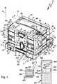
- a stack arrangement 10has a stack base 11 on which stack containers 12, 13 are stacked.
- a stack base 111 in the form of a vacuum cleaner 90can also be used, on which the stack containers 12, 13 can also be stacked in a stacking direction S.
- a carrying container 14can be stacked on each of the stack containers 12, 13 or also on the vacuum cleaner 90 or the stack base 11.
- the stack base 111 and the stack containers stacked thereon 12, 13form stacking elements 211, 212 and 213.
- the carrying container 14can be stacked onto these stack elements as a further stacking element 214.
- the stacking containers 12, 13 as well as the carrying container 14 in plan viewhave approximately the same circumferential contour and the same dimensions, so that such carrying containers and stacking containers can be stacked on top of each other.
- the carrying container 14 or the stacking container 12, 13in the height of each other tensile strength connected, which will become clear later.
- by stacking the carrying containers 12, 13 or other such carrying containersstable, as a whole from above tangible stack arrangements, which are widely used.
- stack container 12, 13have the same bottom surface contour, but are different heights. However, this plays for the linking of the stack container 12, 13 and other, not shown stack container in the stacking direction S. not essential.
- the stack containers 12, 13will therefore be explained below using the same reference numerals that stand for the same or similar components of the stack container 12, 13.
- the stack containers 12, 13have a container body 31.
- the container body 31forms, for example, a lower part 30.
- the container body 31comprises a bottom wall 32, projecting from the peripheral walls 33.
- the bottom wall 32 and the peripheral walls 33bound a storage receptacle 140, 40 of the stack container 12, 13th
- the peripheral walls 33include opposing longer side walls 34, 35, for example, a front wall and a rear wall, which are interconnected by shorter side walls 36. However, this should not be understood that the side walls 36 can not be longer than the side walls 34, 35.
- the accumulation receptacle 140 of the stacking container 12 and the stowing receptacle 40 of the stacking container 13have the same or at least substantially or approximately the same or similar inner peripheral contours or the same or approximately the same bottom cross-section from the side of their opening, but have different heights.
- the accumulation receptacle 40, 140 or the container body 31can be closed by a cover 41.
- the lid 41has a top wall 42 and peripheral walls 43.
- the peripheral walls 43comprise sidewalls 46 which are suitable for the sidewalls 36 and sidewalls 44, 45 which fit the sidewalls 34, 35.
- the cover 41can thus cover the container body 31 or the stowage receptacle 40 in the manner of a hood.
- the respective lid 41provides an upper side 18 of a stacking container 12, 13, onto which another similar stacking container, for example one of the stacking containers, is provided 12, 13, but also the carrying container 14, with its bottom 17 can be stacked.
- the carrying container 14also forms a stacking container which can be stacked up on the stack containers 12, 13.
- a container body 81 of the carrying container 14has a storage receptacle 80, for example, for transporting tools, in particular manually operated hand tools (screwdrivers or the like).
- a bottom wall 82 of the container body 81has the same cross-section as the bottom wall 32 of a stacking container 12 or 13.
- the carrying container 14matches the same shape on the stack containers 12, 13th
- peripheral walls 83which comprise a front and a rear side wall 84, 85 and between these side walls extending side walls 86.
- a length of the side walls 84, 85, 86corresponds to that of the side walls 34, 35, 36.
- an upwardly projecting carrying handle or handle 87is provided at the carrying container 14, which can be grasped in the manner of a handle.
- a receptacle 88is provided in the container body 81, into which a handle 87 of one of the under-stacked similar carrying container 14 fits in particular form-fitting manner.
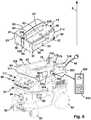
- the stack containers 12, 13 and the carrying container 14can be stacked on the vacuum cleaner 90, which also forms a system component in this respect.
- the vacuum cleaner 90has a housing 91 which is expediently movable on rollers 92 on a substrate.
- the housing 91is covered by a lid 93.
- a suction inlet 94On a front side of the housing 91 is a suction inlet 94, can be sucked through the dirt, dust or the like in a dust collecting space or dust collection container, for example, a dust filter bag, not specified.
- a schematically illustrated suction unit 95is provided.
- the suction unit 95can be supplied, for example via a power cable, a battery, an electric accumulator or other supply device 98 with electrical energy
- a container receptacle 96 for one of the stack container 12, 13 or the carrying container 14is provided.
- the container receptacle 96is a plug-in receptacle 97, so that the respective container 12-14 can be stacked on the housing 91 from above or inserted into it, so to speak.
- the stacking containers 12, 13 and the carrying container 14have at their bottom walls on the outside, ie opposite to the accumulation receptacle 80 or stowage receptacle 40, feet 37, 38, with which they can be parked on a substrate.
- the feet 37, 38form, in cooperation with receptacles 47, 48, in which the feet 37, 38 fit fit form fit contours 59 which intermesh form-fitting transversely to the stacking direction S, in this way the stack container 12, 13 or the transport container 14 across the Stacking direction S to keep in a stable relative position.
- the stack consisting of, for example, the stack elements or stack containers 12, 13can no longer slip or displace transversely to the stacking direction S and remain in a stable alignment along the stacking direction S.
- the receptacle 48 for the feet 38also receives a handle 15 which is adjustable by means of a pivot bearing 16 in a projecting in front of the lid 41 carrying position in which it can be used in the manner of a handle, or in a rest position in the he so far immersed in the receptacle 48 so that he does not project in front of the top wall 42 in the direction of stacking each transport container or stacking container, the stacks so does not hinder.
- the already explained plug-in receptacle 97 of the vacuum cleaner 90preferably forms such form-fitting contours 59, because it fixes the stack container 12, 13 or the carrying container 14 transversely to the stacking direction S form fit.
- a further form-fitting contour 59which acts in a form-fitting fixing manner transversely to the stacking direction S, is formed by a plug-in receptacle 21 of the stack base 11.
- the plug-in receptacle 21serves for the positive reception of a respective stacking container 12, 13 or the carrying container 14, wherein the respective container is fixed transversely to the stacking direction S form fit.
- the plug-in receptacle 21is bounded on the bottom side by a bottom wall 22 of the stack base 11, laterally by peripheral walls 23.
- the peripheral walls 23comprise a front and a rear side wall 24, 25, between which side walls 26 extend.
- An inner peripheral contour of the plug-in receptacle 21corresponds to the outer peripheral contour of the lower part 30 or of the container body 31 or of the container body 81 of the carrying container 14.
- the stacking arrangement 10can be coupled tensile strength along the stacking direction S, namely by means of coupling means 50.
- the coupling means 50comprise, for example, rear grip contours 39 protruding in front of the feet 38, which are provided for engaging behind gripping contours 49 in the area of the receptacles 48.
- the Hägreifkonturen 39, 49hook contours.
- the Schugreifkonturen 39, 49can be brought into engagement with each other, for example, in a kind of pan-sliding movement H.
- a respective upper stack container 12, 13 or the carrying container 14is moved approximately transversely to the stacking direction S relative to the lower stacking container 12, 13 and then pivoted in a pivot axis E, namely, when the hook contours or hook surfaces of the Schugreifkonturen 39, 49 face each other have come until the bottom walls 32, 82 rest on the top wall 42.
- This hook connection or rear-engagement connection of stacking containers or transport containersis additionally secured by a lock on the front side of the stack arrangement 10.
- This lockalso acts tensile strength in the direction of stacking direction S.
- locking elements 51 of the coupling means 50are provided on the covers 41, which are pivotable about pivot bearing 52.
- the locking elements 51have receptacles 55 which are pivotable past abutment contours 53, 54, until the locking elements 51 are in engagement with the abutment contours 53, 54.
- the abutment contours 53, 54 and the locking elements 51are provided on the front sides of the Be fiscalerkorpusse 31 and the lid 41.
- the abutment contours 53, 54protrude, for example, in front of the front side walls 34, 44.
- the abutment contours 53are provided, for example, on the lids 41, the abutment contours 54 on the container bodies 31.
- an abutment contour 54is provided near the bottom wall 32 and an abutment contour 54 near the lid 41.
- the locking element 51can, as in FIG. 1 shown below, the stack container 12, 13 tensile bond with each other, wherein the between the Be diligenterkorpusse 31 of the stack container 12, 13 interposed or stacked lid 41 remains without tensile load.
- the locking element 51is on the one hand with the on the front wall or side wall 34 upper abutment contour 54 or the abutment contour 54 of the stacked stacking container 12 and on the other hand with the abutment contour 54 of the stacked stacking container 13 at the same time engaged and connects this tensile.
- a locking element 51serves only as a closure for the lid, wherein it as in the stack container 13 according to FIG. 1
- the locking element 51is also still with one or more abutment contours 53 of the lid 41 of the upper stacking container 13 into engagement to hold the lid 41 fixed to the container body 31 or the lower part 30 of the stacking container 13.
- the coupling means 50may also include, for example, laterally to the stack container 12, 13 and / or the transport container 40 arranged abutment contours 56 and frontally provided on these containers abutment contours 57 include.
- the abutment contours 56, 57are designed, for example, in the manner of latching projections which can engage with lugs 58, 158, 258. In FIG. 1 the tabs 58 are shown only schematically.
- abutment contours 256for example, locking lugs similar to the abutment contours 56, approximately in alignment with the handles 87 on the respective container body 81 is provided.
- On the container body 81are also still brackets 256.
- the abutment contours 256are provided near the bottom wall 82, the tabs 258 close to the handle 87.
- the vacuum cleaner Swhich can also serve as a stack base
- a transport container 12, 13 or a carrying container 14also coupling means 50 are provided.
- 97 tabs 158are provided close to the plug-in receptacle, which are brought into engagement with the abutment contours 56, 57.
- the tabs 158 or retaining projections 158are pivotable or mounted transversely to the stacking direction S displaceable on the lid 93 and the housing 91 of the vacuum cleaner 90.
- tensile coupling means 50are further between the stack base 11 and a respective stack container 12, 13 or optionally also the carrying container 14 is present.
- a Deutschengreifability or Hintergreif contour 29is provided, in which the Deckgreifkonturen 39 of the feet 38 can engage, similar to the Hintergreifingn or Hintergreifkonturen 49th
- a respective stacking container 12, 13 or carrying container 14 with respect to the stacking direction Scan be secured to the stacking base 11 by means of a lock 27.
- the lock 27has, for example, a retaining projection not visible in the drawing, which can be brought into engagement with the abutment contours 57 when a stacking container 12, 13 or carrying container 14 is received in the plug-in receptacle 21.
- the stacking containers 12, 13are suitable for transporting hand-held machine tools, for example, grinding machines, saws, cutting devices, drills or screwdrivers.
- a hand-held power tool 500is received in the form of a drill or a screwdriver.
- the hand-held power tool 500has a housing 501 in which a drive motor 502, optionally a transmission and the like, other typical components for hand tools are added.
- the drive motor 502drives a tool holder 503, to which a tool, for example a screwing tool can be arranged.
- the handheld power tool 500can be conveniently gripped on a handle 504.
- the handheld power tool 500has an energy storage device 510 for wireless operation, which includes, for example, electrical storage cells 511.
- a housing 512 of the energy storage device 510can be detachably fastened, for example, to the handle 504.
- a hand-held machine toolfor example, the hand, machine tool 500 can be freely stored.
- the congestion recording 40, 140is correspondingly large.
- the respective hand-held machine toolis held in a form-fitting manner, that is, at least transversely to the stacking direction S, a certain hold is found.
- the hand-held power tool 500designed, for example, as a screwdriver.
- a respective container insert 60, 160has, for example, an insert body 61 which has a transport receptacle 62 for transporting a hand-held machine tool, for example the hand-held machine tool 500, and / or an energy storage device, for example the energy storage device 510.
- the transport receptacle 62comprises, for example, a machine receptacle 63, in which the hand-held power tool 500 is at least partially or in regions
- the transport receptacle 62may also include an energy storage receptacle 163, so to speak, a further machine receptacle, which is designed to hold the energy storage device 510.
- an energy storage receptacle 163 for the energy storage 163is present.
- the container inserts 60, 160are not freely movable in the jam seats 40, 140, but held stationary.
- a screw 264may be provided.
- one or more screwspenetrate the bottom wall 32 of the stack container 12 and penetrate into a bottom side of the container insert 160.
- the container inserts 60, 160it is advantageous for the container inserts 60, 160 to be received in a form-fitting manner in the stowage receivers 40, 140.
- theyhave front and rear side surfaces 64, 65 which bear against the inside of the side walls 24, 25 facing the accumulation receptacle 40, 140 at least in sections.
- the container inserts 60, 160preferably side surfaces 66 which are provided for at least partially positive or surface contact with the congestion receiving 40, 140 facing inner sides of the side walls 36.
- the container inserts 60, 160 and their korpusse 61are fixed transversely to the stacking direction S in the jam receivers 40, 140.
- the container inserts 60, 160can be inserted from the upper sides 18 of the container body 31 into the stowed receptacles 40, 41 configured as plug-in receptacles along a plug-in axis which corresponds to the stacking direction S and are held there.
- a fixation along the plug-in axis, that is to say in the present case the stacking direction S,can be achieved, for example, by means of an additional latching 265, adhesive bonding or the screw connection 264.
- the latching 265comprises, for example, a latching receptacle on the container insert 160 into which a latching projection which projects in front of the bottom wall 22 of the stacking container 12 in the direction of the accumulation receptacle 140 engages.
- a deadlockwill be for example realized in that the side surfaces 64, 65, 66 abut in the press fit on the inner sides of the accumulation receiving means 40, 140.
- the container inserts 60, 160are beyond their function as holding devices for hand tool machines, energy storage devices or other consumables, such as abrasives, grinding plates, screws, tools, such as screwdriver bits, saw blades or the like, electrically active components. They form transmission modules 75, 175 with which a bus connection B between the stack elements 211-214 can be realized.
- the container inserts 60, 160comprise, detachably or integrally, a transmission device 70 comprising transmission means 76 for wireless transmission of data and / or energy between the stacking elements 211-214.
- the transmission means 76include, for example, coils 176, which are provided for electrical energy transmission.
- the stack bases 11, 111have transmission means 76 suitable for the transmission means 76 or suitable for communication with the transmission means 76, for example likewise coils 176, so that the stack bases 11, 111 together with the stack elements 212, 213 can realize the bus connection B.
- the transmission means 76form bus interfaces 77, 78, which are arranged on the respective upper sides 18 and lower sides 17 of the stack containers 12, 13.
- the transmission means 76 arranged on the upper sides or the sides of the stack bases 11, 13 facing the stacking containers 12, 13form, for example, bus interfaces 178, in particular bus couplers.
- the bus interfaces 178, 78are designed for communication with the bus interfaces 77, for example for wireless, for example capacitive and / or inductive, transmission of data and / or energy.
- contact-based data transmission and / or energy transmissioncan also be part of the bus connection B or can be realized in the context of the bus connection B.
- Matching electrical contacts 179are preferably provided on the stack bases 11, 111.
- the contacts 79, 179include, for example, plug-in projections and plug-in receptacles, fixed contact surfaces and contact surfaces that are spring-biased in the direction of the fixed contact surfaces or the like.
- the electrical contacts 79, 179are positioned on the stacking members 211-213 so that they can contact each other in the stacked state of the stacking members 211-213.
- the electrical contacts 79, 179are aligned, for example, with axes parallel to the stacking direction S.
- the coils 176have a flat shape and are arranged directly on the upper sides 18 and the lower sides 17 of the stack containers 12, 13 and on the upper side on the stack bases 11, 111.
- the coils 176are preferably flat on the closed and uninterrupted walls, the respective bottom wall 32 and the respective top wall 42 at.
- corresponding openings for the electrical contacts 79are provided on the bottom wall 32 or the top wall 42. Namely, the contacts 79 are present directly on the container insert 60 or 160 and not on the stack container 12 or 13.
- the contacts 79are conveniently interconnected by electrical leads 79A. But even between the contacts 79 can within a stacking container 12, 13 or a container insert 60, 160 wirelessly working Communication means, such as inductive or capacitive operating communication means or means for wireless energy transmission may be provided.
- the transmission means 76 for the wireless transmission of data and / or energy of a container insert 60, 160 or of the respective transmission device 70 of a stacking container 12, 13can be interconnected by electrical lines of a line arrangement 76A. But it is also possible that the wireless transmission means 76 within a container insert 60, 160 and a stack member 12, 13 wirelessly communicate with each other and / or configured for wireless energy transmission.
- a power supply unit 302 of the stack base 11can be supplied with electric current.
- the vacuum cleaner 90can be connected via its supply device 98 as explained to an electrical power grid.
- the supply device 98in addition to the suction unit 95, also supplies a power supply unit 302, which can provide electrical energy for the bus connection B, which originates from the vacuum cleaner 90 or the stacking base 111.
- the power supply units 302provide a supply voltage or electrical energy for the bus connection B, which can be transmitted via the bus connection B to the container inserts 60, 160 and thus also to machine interfaces 71, 171, 271, 371.
- the energy transfer on the bus link Bis preferably inductive between the stacking elements 211-213.
- the contacts 79 of a stacking containerfor example the stacking container 13, comprise contacts for contacting a stacking element stacked on the stacking container 13 and a stacking element under the stacking container 13, for example the stacking base 11 and are preferably connected to one another via a line arrangement 79A.
- the machine interfaces 71, 171, 271, 371are supplied with electrical energy via the bus connection B.
- the machine interface 71comprises, for example, a transmission means 72, in particular a coil 172, with which wireless electrical energy can be transmitted to the manual power tool 500.
- a transmission means 505in particular likewise a coil 506.
- the coil 506 or the transmission means 505is arranged on a rear side of the housing 501.
- a wireless transmission with likewise a transmission means 72is provided for example at the machine interface 171 directly to the energy storage device 510.
- Thistoo, has a transmission means 505, in particular a coil 506, in order to obtain electrical energy from the coil 172 of the transmission means 72 in an inductive or magnetic manner.
- a so-called contact-type variantis realized in the machine interface 271.
- the energy storage device 510with its contacts, which are provided per se for establishing an electrical connection to the manual power tool 500, are connected directly. These contacts then enter into electrical connection with electrical contacts 73 provided on or in a receiving recess 269 of the machine interface 271.
- the machine interfaces 71, 171, 271are disposed directly on the receiving recesses 69 or 269 or 369.
- the transmission means 72 or the electrical contacts 73are optimally positioned with respect to the respective energy storage device 510 or manual power tool 500 to be supplied.
- the electrical contacts 73With the electrical contacts 73, the advantage of this configuration is obvious. But even with the inductive, capacitive or other wireless transmission between the transmission means 72 and 505 is an optimal positioning to avoid transmission losses appropriate.
- the receptacle depression 369 provided on the container insert 160forms or comprises, for example a charging tray for charging an energy storage device, in particular in the manner of the energy storage device 510.
- the bus interfaces 77, 78are held in position by the container inserts 60, 160 in relation to the stowing receivers 40, 140 such that they are arranged on the underside 17 and the top 18 when the container insert 60, 160 is received in the stowage receiver 40, 140.
- the coils 176 of the bus interfaces 77, 78are held on a holding device 74.
- the holding device 74, as it were the carrier for the bus interfaces 77, 78is cylindrical, for example.
- the holding device 74preferably forms an integral part of a container insert 60, 160.
- the coils 176are arranged, for example, on the respective end sides or upper sides and lower sides of the holding device 74.
- the lower end face of the holding device 74, on which the bus interface 77 is held,is directly opposite the bottom wall 32, for example, when the container insert 60, 160 is arranged in the accumulation receptacle 40, 140.
- the coil 176is arranged so that it rests with, for example, on the bottom wall 32 or at most a small distance from the same. It is also possible that the coil 176 penetrates into the unspecified, optional passage opening of the bottom wall 32.
- the holding device 74protrudes toward the upper side 18 in front of the accumulation receptacle 40, 140, so that the coil 176 arranged on the upper end face of the holding device 74 is arranged directly on the cover wall 42, for example in the recess or opening 42A. It can also be provided that the coil 176 is covered by the top wall 42, but they are in the closed state of the lid 41, that is, when he the storage receptacle 40, Covers 140, expediently placed at best with a small distance to the top wall 42 or rests against the top wall 42.
- a container insert equipped according to the inventionhas a communication interface and / or a feed interface directly.
- the transmission device 70 of the container insert 60may have a feed interface 201, in particular a power cable for connection to an electrical energy supply network, for example with 120 V or 230 V AC.
- the feed-in interface 201leads to a power supply unit 202 that, for example, adapts the voltage of the power supply network to a voltage level which is suitable for the bus connection B and / or the machine interfaces 71, 171, 271.
- a communication interfacecan also be on board a container insert or form part of a transmission device.
- a communication interface 260is provided at the container insert 60.
- the communication interface 260includes, for example, a Bluetooth interface, a WLAN interface or the like other wirelessly communicating interface.
- a communication interface 360is provided, for example, on board a respective stacking base 11 or 111.
- the communication interface 360also includes, for example, a Bluetooth interface, WLAN interface or the like. But even a wired interface, such as an Ethernet interface, is easily possible.
- the communication interfaces 260, 360are designed for communication with operating devices 400 and / or 450.
- the operating devices 400 or 450are, for example, computers, smartphones or the like other mobile operating devices.
- the operating devices 400, 450have, for example, a processor 401 and a memory 402 in which the program code of an operating program 403, 453 is stored.
- the program codecame to be executed by the processor 401.
- the HMIs 400, 450have For example, an input interface 405, 455, for example, a keyboard and an output interface 404, 454, for example, a display.
- the displaycan display and / or modify operating parameters, quantities and other information of the stacking elements 211, 212 or the handheld power tool, accessories or energy storage devices accommodated therein.
- symbols 460can be displayed on the output interfaces 404, 454 for the handheld machine tool 500 or another handheld machine tool respectively received in a stacking container 12, 13.
- the operating devices 400, 450include communication interfaces 456, which are compatible with the communication interface 260, 360, that is configured, for example, to a communication via Bluetooth, WLAN or the like.
- the communication interface 260, 360is advantageously connected to the bus connection B.
- a respective operating device 400 and / or 450for example via the communication interface 260, 360 with the hand-held power tool 500, but also, for example, with a recorded in the storage receptacle 140 of the stacking container 12 hand-tool machine, in particular an energy storage device communicate.
- a state of charge of an energy storefor example the energy storage device 510, can be queried via the bus connection B and the communication interface 260 and / or 360 via the operating device 400, 450.
- the transfer devices of a container insert or stack container equipped according to the inventionto include a locating device 261, for example to determine in this way whether a hand-held machine tool, in particular also which type of hand-held machine tool, has been received in a respective stacking container.
- a sensor 262may be a component of the transmission device 70, with which an operating status, for example the number of operating hours, a manual power tool 500 or the energy storage device 510 can be determined.
- the sensor 262may autonomously communicate by wireless or the like with another example wirelessly one of the HMI device 400 or 450.
- the sensor 262is connected to the bus connection B, in particular the line arrangement 79A.
- a respective congestion receptacle 40in particular a transport receptacle 62, but also consumables, for example, abrasive material or the like, can be recorded.
- the sensor 263may also communicate wirelessly with the HMIs 450 or 400 wirelessly. However, it is preferred if the sensor 263 is also coupled to the bus connection B, for example connected to the line arrangement 79A.
- the sensors 262, 263 connected to the bus connection B or coupled into the bus connection Bcan communicate with the operator devices 400, 450 via the communication interface 260, for example. Thus, for example, with one of the operating device 400 or 450, a respective sensor 262, 263 are queried.
- the locating device 261may also have a self-sufficient wireless interface, for example a Bluetooth interface, with which the operating devices 400 or 450 can communicate directly. However, it is advantageous if the locating device 261 is coupled into the bus connection B, for example connected to the line arrangement 79A.
- the carrying container 14 in the bus Bcan be coupled.
- the carrying container 14has a bus interface 77, which can communicate with the bus interface 78 of the stacking container 12, 13.
- a device stored in the carrying container 14, in particular a hand-held machine toolcan be connected to the bus connection B and thus operated, for example, using the operating device 400 or 450, in particular for retrieving data.
- a stack containercan also contribute at least passively to optimized data transmission or energy transmission between stack containers, for example by means of an inductively conductive transmission element 272 which is arranged in one of the feet 37 or 38. This may, for example, amplify or relay the magnetic flux of a coil or other transmission means 272 of a bus interface 277 suitable for establishing a bus connection to a stacked or stacked stacking container or stacking element, e.g. only an upper bus interface 278 is indicated.
- a stacking basefor example the stacking base 111, can also form or have an operating device.
- the vacuum cleaner 90has an output interface 354.
- a controller of the vacuum cleaner 90which includes, for example, a microprocessor and the like other components, or a separate microprocessor 401 provided for executing the operation program 353 explained below may be configured, for example, program code of an operating program Execute 353, which can communicate in particular on the basis of the communication interface 360 via the bus B to the stack containers 12, 13 and in particular the hand-held machine tools or energy storage devices housed therein, for example, to display their operating data.
- the stacking base 11has, for example, a power supply unit 702, which can be connected via a connecting cable 701 to an electrical energy supply network with, for example, 120 V or 230 V alternating current.
- the power supply unit 702has, for example, a power generating device 767 for providing an alternating current Iw for an electrical coil or a coil arrangement 776 of the bus interface 178.
- the power generating device 767it is also possible for the power generating device 767 to be supplied with energy on the input side, for example by an accumulator or another mobile energy storage device 703.
- the coil or coil arrangement 776is connected in series with a capacitor 775.
- the current generator 776is designed to generate an alternating current Iw with a fixed frequency or current or voltage, but preferably with variable frequency and / or variable current intensity and / or variable voltage for the coil arrangement 776.
- the transmission devices 70 of the stack containers 12, 13have the already explained coils 176 at their bus interfaces 77, 78. These coils 176 are interconnected by the conduit assembly 79A. It is preferably provided that the coils 176 of a respective transmission device 70 are connected in parallel. Furthermore, it is expedient if in each case a capacitor 675 is connected in parallel to the coils 176, so that the coils 176 together with the capacitor 675 form a resonant circuit.
- the power generating device 776preferably provides the alternating current Iw in the resonant frequency of the coils 176 in combination with the capacitor 675 of a respective transmission device 70.
- a power conditioning device 676is connected to the capacitors 675. For example, it prepares input voltage Ue provided by capacitor 675, which suitably corresponds to the voltage between the lines of line array 79A, and provides output voltage Ua, for example, to machine interface 71 and / or a communication interface 660.
- the output voltage Uais significantly smaller than the input voltage Ue, for example, only half as large.
- the transmission devices 70 of the stack containers 12, 13can in particular communicate wirelessly with a communication interface 760 of the stack base 11.
- the Transmission devices 70identify identifiers of each arranged in the congestion recording hand-held machine tool, current charging voltages or charging currents or the like.
- the communication interface 760informs the power generation device 767 of the current state of charge of handheld power tools or energy storage devices accommodated in the stacking containers and / or power consumption of the respective machine interface.
- the power generating device 767can adjust in this way, for example, the current level of the alternating current Iw and / or its frequency and / or its voltage to provide an optimal power supply of the stack container 12, 13.
- a frequency adjustmentserves, for example, to adapt the energy consumed or required in the stacking arrangement 10.
- the communication interface 660can also be designed to switch off the spool which is not required, for example in the topmost stack container or stack element of a stack arrangement, for example by means of a switch 678 in the stack container 13.
Landscapes
- Engineering & Computer Science (AREA)
- Mechanical Engineering (AREA)
- Stackable Containers (AREA)
Description
Translated fromGermanDie Erfindung betrifft einen Stapelbehälter mit einer Übertragungseinrichtung gemäß dem Oberbegriff des Anspruchs 1.The invention relates to a stacking container with a transmission device according to the preamble of claim 1.
Eine Übertragungseinrichtung dieser Art ist beispielsweise in
In
Demgegenüber soll ein verbessertes Konzept der Energieübertragung für Stapelbehälter vorgeschlagen werden.In contrast, an improved concept of energy transfer for stacking containers will be proposed.
Zur Lösung der Aufgabe ist ein Stapelbehälter gemäß der technischen Lehre des Anspruchs 1 vorgesehen.To solve the problem, a stacking container is provided according to the technical teaching of claim 1.
Zur Lösung der Aufgabe ist auch eine Stapelanordnung umfassend mindestens zwei Stapelelemente mit jeweils einer Übertragungseinrichtung vorgesehen. Die Stapelelemente umfassen beispielsweise Stapelbehälter, die aufeinander aufstapelbar sind. Eines der Stapelelemente kann aber auch eine Stapelbasis sein, auf die ein weiteres Stapelelement, insbesondere ein Stapelbehälter, aufstapelbar ist oder unter die ein weiteres Stapelelement, insbesondere ein Stapelbehälter, unterstapelbar ist.To achieve the object, a stack arrangement comprising at least two stack elements, each with a transmission device is provided. The stack elements comprise, for example, stack containers which can be stacked on one another. However, one of the stacking elements can also be a stacking base onto which a further stacking element, in particular a stacking container, can be stacked or under which another stacking element, in particular a stacking container, can be stacked.
Die Leitungsanordnung verbindet die Busschnittstellen miteinander. Somit kann beispielsweise Strom von der einen Spule zur andern Spule fließen.The line arrangement connects the bus interfaces with each other. Thus, for example, current can flow from one coil to the other coil.
Es ist dabei ein Grundgedanke, dass die Maschinenschnittstelle von den Spulen der Übertragungseinrichtung elektrische Energie erhält. Die Spulenanordnung der Busschnittstellen ermöglicht eine kontaktlose oder drahtlose Übertragung von Energie von einem Stapelelement zum nächsten Stapelelement. In dem Stapelelement selbst ist keine Umwandlung des Stromes oder der Spannung zur Weiterübertragung von Energie zu einem benachbarten, zum Beispiel aufgestapelten oder untergestapelten, Stapelelement notwendig. Somit ist ein sehr einfacher Aufbau möglich.It is a basic idea that the machine interface receives electrical energy from the coils of the transmission device. The coil arrangement of the bus interfaces allows contactless or wireless transmission of energy from one stacking element to the next stacking element. In the stacking element itself, no conversion of the current or voltage for retransmission of energy to an adjacent, for example stacked or stacked, stacking element is necessary. Thus, a very simple structure is possible.
Vorzugweise ist vorgesehen, dass die Spulen der Busschnittstellen der Übertragungseinrichtung ohne einen zwischengeschalteten Wechselrichter oder Gleichrichter miteinander elektrisch verbunden sind.It is preferably provided that the coils of the bus interfaces of the transmission device are electrically connected to one another without an intermediate inverter or rectifier.
Die Spulen der Busschnittstellen sind zweckmäßigerweise zueinander in Serie oder parallel miteinander geschaltet.The coils of the bus interfaces are suitably connected to each other in series or in parallel with each other.
Eine Ausgangsspannung der Maschinenschnittstelle ist vorzugsweise deutlich kleiner als eine an den elektrischen Spulen der Busschnittstellen vorhandene Spannung. Beispielsweise ist die Spannung der elektrischen Spulen mindestens doppelt so groß wie die Ausgangsspannung der Maschinenschnittstelle. Beispielsweise liegt der Spannungsbereich der Maschinenschnittstelle bei etwa 20-22 V, einer typischen Ladespannung zum Aufladen von Akkupacks, während die Spannung der Spulen der Busschnittstellen bei etwa 48 V liegt. Somit ist eine besonders effektive Energieübertragung von Stapelbehälter zu Stapelbehälter möglich, während für typische bei Handwerkzeugmaschinen übliche kleinere Spannungen an den Maschinenschnittstellen gesorgt ist.An output voltage of the machine interface is preferably significantly smaller than a voltage present at the electrical coils of the bus interfaces. For example, the voltage of the electric coils is at least twice as large as the output voltage of the machine interface. For example For example, the voltage range of the machine interface is about 20-22V, a typical charging voltage for charging battery packs, while the voltage of the bus interface coils is about 48V. Thus, a particularly effective energy transfer from stacking container to stacking container is possible while providing typical in manual power tools smaller voltages at the machine interfaces.
Bevorzugt ist es, wenn eine resonante induktive Kopplung zwischen den Stapelelementen realisiert ist. Beispielsweise ist vorgesehen, dass die elektrischen Spulen der Busschnittstellen mit einem Kondensator derart verschaltet sind, dass ein Schwingkreis mit einer Resonanzfrequenz gebildet ist.It is preferred if a resonant inductive coupling between the stack elements is realized. For example, it is provided that the electrical coils of the bus interfaces are connected to a capacitor such that a resonant circuit is formed with a resonant frequency.
Dabei ist es vorteilhaft, wenn die Spulen mit mindestens einem elektrischen Kondensator parallel geschaltet sind. Alternativ wäre auch eine serielle Schaltung des Kondensator mit den Spulen möglich.It is advantageous if the coils are connected in parallel with at least one electric capacitor. Alternatively, a serial circuit of the capacitor would be possible with the coils.
Die Resonanzfrequenz einer induktiven Kopplung der Übertragungseinrichtung mit mindestens einem auf den Stapelbehälter aufgestapelten oder untergestapelten Stapelelement kann beispielsweise der Resonanzfrequenz nur eines untergestapelten oder aufgestapelten Stapelelements, beispielsweise eines weiteren Stapelbehälters oder auch eines sonstigen unter den Stapelbehälter unterstapelbaren oder aufstapelbaren Stapelelements, beispielsweise einer Platte, entsprechen. So ist es beispielsweise möglich, dass die Resonanzfrequenz der Übertragungseinrichtung derjenigen einer entsprechenden Einkopplungsvorrichtung zur Bereitstellung von Schwingungen für die Übertragungseinrichtung entspricht.The resonant frequency of an inductive coupling of the transmission device with at least one stacked or stacked stacking element can correspond, for example, to the resonant frequency of only one stacked or stacked stack element, for example another stacking container or any other stackable or stackable stackable element, for example a plate. For example, it is possible that the resonance frequency of the transmission device corresponds to that of a corresponding coupling device for providing vibrations for the transmission device.
Die Abstimmung auf die Resonanzfrequenz kann sich aber nicht nur auf ein jeweils untergestapeltes oder aufgestapeltes Stapelelement beziehen, sondern auch auf die Anordnung mehrerer oder aller aufeinandergestapelter Stapelelemente. So ist es beispielsweise möglich, dass ein Gesamtsystem, das mehrere Stapelbehälter oder Stapelelemente enthält, eine vorbestimmte Resonanzfrequenz aufweist, auf die die Übertragungseinrichtung abgestimmt ist.However, the tuning to the resonance frequency can refer not only to a respectively stacked or stacked stack element, but also to the arrangement of several or all stacked stack elements. Thus, for example, it is possible for an overall system, which contains a plurality of stack containers or stack elements, to have a predetermined resonant frequency to which the transmission device is tuned.
Die Maschinenschnittstelle ist zweckmäßigerweise seriell an den Kondensator angeschlossen. Man könnte den Kondensator auch als einen Kompensationskondensator bezeichnen.The machine interface is suitably connected in series to the capacitor. One could also call the capacitor a compensation capacitor.
Die Maschinenschnittstelle muss allerdings nicht direkt an den Kondensator oder die Kompensationsschaltung angeschlossen sein. Es kann auch eine Energieaufbereitung beispielsweise für die Maschinenschnittstelle und/oder die nachfolgend noch erläutert Kommunikationsschnittstelle vorgesehen sein.However, the machine interface does not have to be connected directly to the capacitor or the compensation circuit. It is also possible to provide energy conditioning, for example for the machine interface and / or the communication interface explained below.
Bevorzugt ist es, wenn die Übertragungseinrichtung eine insbesondere als Kommunikationsmodul ausgestaltete Kommunikationsschnittstelle zur Übertragung von Daten von und/oder zu der in dem Stapelbehälter aufgenommenen Hand-Werkzeugmaschine oder Energiespeichereinrichtung und oder der Maschinenschnittstelle aufweist. Somit können beispielsweise Ladezustände, Temperaturen, Leistungen, Fehlerinformationen, Strom, in die Identifikationskennungen und dergleichen beispielsweise zu einer Stapelbasis der Stapelanordnung oder einem sonstigen Bediengerät übertragen werden.It is preferred if the transmission device has a communication interface configured in particular as a communication module for transmitting data from and / or to the handheld power tool or energy storage device and / or the machine interface accommodated in the stacking container. Thus, for example, charging states, temperatures, powers, fault information, power, can be transmitted to the identification identifiers and the like, for example, to a stacking base of the stacking arrangement or another operating device.
Die Kommunikationsschnittstelle kann beispielweise zur Kommunikation über die Busverbindung ausgestaltet sein. Bevorzugt ist es jedoch, wenn die Kommunikationsschnittstelle zur drahtlosen Kommunikation mit einem weiteren Stapelelement der Stapelanordnung, beispielsweise der Stapelbasis der Stapelanordnung, unabhängig von der Busverbindung ausgestaltet ist. Bevorzugt ist insbesondere, wenn die drahtlose Kommunikation auf einem kleinen Energieniveau oder einem niedrigen Energieniveau stattfinden kann. Bevorzugt ist das Energieniveau der drahtlosen Kommunikation beispielsweise nur maximal halb so groß wie das Energieniveau auf der Busverbindung. Somit kann beispielsweise über Bluetooth oder dergleichen andere drahtlose Kommunikation beispielsweise ein Ladezustand von der Energiespeichereinrichtung oder Hand-Werkzeugmaschine zu der Stapelbasis übertragen werden. Die Busverbindung wird dadurch nicht belastet und/oder dazu nicht benötigt.The communication interface can be designed, for example, for communication via the bus connection. However, it is preferred if the communication interface for wireless communication with a further stack element of the stack arrangement, for example the stack base of the stack arrangement, is designed independently of the bus connection. In particular, it is preferred if the wireless communication can take place at a low energy level or a low energy level. For example, the energy level of the wireless communication is preferably only a maximum of half the energy level on the bus connection. Thus, for example, via Bluetooth or other such wireless communication, for example, a state of charge may be transmitted from the energy storage device or handheld machine tool to the stacking base. The bus connection is not burdened thereby and / or not required.
Im Rahmen der Erfindung liegt auch eine Stapelbasis für eine Übertragungseinrichtung gemäß der Erfindung. Die Stapelbasis weist zweckmäßigerweise eine Stromerzeugungseinrichtung zur Bereitstellung eines Wechselstroms für die elektrische Spule auf. Beispielsweise umfasst die Stromerzeugungseinrichtung einen Oszillator.In the context of the invention is also a stacking base for a transmission device according to the invention. The stacking base expediently has a power generating device for providing an alternating current for the electrical coil. For example, the power generation device comprises an oscillator.
Die Stromerzeugungseinrichtung ist vorzugsweise zur Erzeugung des Wechselstroms in einer Resonanzfrequenz der Spulenanordnung der Übertragungseinrichtung des Stapelbehälters ausgestaltet. Beispielsweise ist ein Kondensator oder Kompensationskondensator der Stromerzeugungseinrichtung parallel oder seriell mit der Spule der Stapelbasis geschaltet.The power generating device is preferably designed to generate the alternating current at a resonant frequency of the coil arrangement of the transmission device of the stacking container. For example, a capacitor or compensation capacitor of the power generating device is connected in parallel or in series with the coil of the stack base.
Bevorzugt ist es, wenn die jeweiligen Resonanzfrequenzen der Übertragungseinrichtungen und/der Stapelbasis im Wesentlichen gleich sind, also maximal 5-10 %, insbesondere nur 1% bis 3 % voneinander abweichen, vorzugsweise identisch sind.It is preferred if the respective resonance frequencies of the transmission devices and / or the stack base are substantially the same, that is to say that a maximum of 5-10%, in particular only 1% to 3%, differ from each other, preferably identical.
Eine Resonanzfrequenz der Stromerzeugungseinrichtung der Stapelbasis ist vorzugsweise angepasst oder anpassbar an die Resonanzfrequenz des Stapelbehälters, der mit der Stapelbasis kommuniziert, insbesondere durch diese mit Energie versorgt werden soll. Die Resonanzfrequenz der Stapelbasis entspricht also zweckmäßigerweise mindestens eines aufgestapelten oder untergestapelten Stapelbehälters. Es ist aber auch möglich, dass die Resonanzfrequenz der Stapelbasis so eingestellt oder einstellbar ist, dass sie der Resonanzfrequenz mehrerer Stapelbehälter, beispielsweise zweier oder aller auf die Stapelbasis aufgestapelter und/oder zweier oder aller unter die Stapelbasis untergestapelter Stapelbehälter entspricht. Somit kann Resonanzfrequenz der Stapelbasis auf beispielsweise nur ein aufgestapeltes oder untergestapeltes Stapelelement oder auch auf mehrere Stapelelemente, insbesondere auf sämtliche Stapelelemente, des Stapels abgestimmt sein, in oder unter dem oder auf dem die Stapelbasis angeordnet ist.A resonant frequency of the power generating means of the stacking base is preferably adapted or adaptable to the resonant frequency of the stacking container that communicates with the stacking base, and in particular is to be energized thereby. The resonance frequency of the stack base thus expediently corresponds to at least one stacked or stacked stacking container. But it is also possible that the resonant frequency of the stacking base is set or adjustable so that it corresponds to the resonant frequency of a plurality of stacking containers, for example, two or all stacked on the stack base and / or two or all under the stack base untergestapelter stack container. Thus, the resonance frequency of the stack base can be matched to, for example, only one stacked or stacked stack element or also to a plurality of stack elements, in particular all stack elements of the stack, in or below or on which the stack base is arranged.
Bevorzugt ist eine Stapelanordnung, bei der die Spulenanordnungen mindestens zweier Stapelelemente, insbesondere zweier Stapelbehälter und/oder eines Stapelbehälters und einer Stapelbasis, im Wesentlichen dieselbe Resonanzfrequenz, insbesondere mit maximal der oben genannten Abweichung voneinander, aufweisen.Preference is given to a stack arrangement in which the coil arrangements of at least two stacking elements, in particular two stacking containers and / or a stacking container and a stack base, have substantially the same resonant frequency, in particular with a maximum of the above-mentioned deviation from each other.
Die Stromerzeugungseinrichtung ist zweckmäßigerweise zur Anpassung einer Stromstärke des Wechselstroms und/oder zur Anpassung einer Frequenz des Wechselstroms in Abhängigkeit eines jeweiligen Stromverbrauchs der Stapelbehälter der Stapelanordnung ausgestaltet. Dazu kann sie beispielsweise die nachfolgend erläuterte Kommunikationsschnittstelle nutzen, welche mit beispielsweise einer Maschinenschnittstelle des Stromverbrauchers, nämlich der Stapelbasis, kommuniziert. Die Kommunikationsschnittstelle kann aber auch direkt mit einer Kommunikationsschnittstelle des Stapelbehälters bzw. der Übertragungseinrichtung des Stapelbehälters kommunizieren, beispielsweise um Daten über einen Ladezustand der Energiespeichereinrichtung und/oder Hand-Werkzeugmaschine zu erhalten.The power generating device is expediently designed to adapt a current strength of the alternating current and / or to adapt a frequency of the alternating current as a function of a respective power consumption of the stacking containers of the stacking arrangement. For this purpose, it can, for example, use the communication interface explained below, which communicates with, for example, a machine interface of the power consumer, namely the stack base. The communication interface can also communicate directly with a communication interface of the stacking container or the transmission device of the stacking container, for example, to obtain data on a state of charge of the energy storage device and / or hand-held machine tool.
Die Stapelbasis weist nämlich vorzugsweise eine Kommunikationsschnittstelle zur Kommunikation mit einer Kommunikationsschnittstelle der Übertragungseinrichtung auf, die zur Übertragung von Daten von und zu der in dem Stapelbehälter aufgenommenen Hand-Werkzeugmaschine oder Energiespeichereinrichtung und/oder der Maschinenschnittstelle vorgesehen ist. Bevorzugt ist es, dass diese Kommunikationsschnittstellen nicht über die Busverbindung miteinander kommunizieren, beispielweise direkt drahtlos mit einander kommunizieren (Bluetooth oder dergleichen). Es ist aber auch möglich, dass die Kommunikationsschnittstellen der Stapelbasis und des Stapelbehälters über die Busverbindung miteinander kommunizieren.Namely, the stacking base preferably has a communication interface for communication with a communication interface of the transmission device, which is provided for transmitting data from and to the handheld power tool or energy storage device and / or the machine interface accommodated in the stacking container. It is preferred that these communication interfaces do not communicate with each other via the bus connection, for example communicate directly with each other wirelessly (Bluetooth or the like). However, it is also possible for the communication interfaces of the stack base and the stack container to communicate with one another via the bus connection.
Die Stapelbasis kann auch einen Stapelbehälter bilden oder durch einen Stapelbehälter bereitgestellt werden. In diesem Fall weist die Stapelbasis beispielsweise eine Stauaufnahme auf, in welcher die Hand-Werkzeugmaschine oder eine Hand-Werkzeugmaschine sowie eine Energiespeichereinrichtung aufgenommen sein kann bzw. die zur Aufnahme einer Hand-Werkzeugmaschine und/oder einer Energiespeichereinrichtung vorgesehen ist.The stack base may also form a stack container or be provided by a stack container. In this case, the stacking base has, for example, a congestion receiver, in which the hand-held machine tool or a hand-held machine tool as well as an energy storage device can be accommodated or which is provided for receiving a hand-held machine tool and / or an energy storage device.
Besonders günstig ist es, wenn die elektrischen Spulen der Übertragungseinrichtung an der Oberseite und der Unterseite des Stapelbehälters angeordnet sind, wenn die Übertragungseinrichtung in dem Stapelbehälter angeordnet ist. Die oder mindestens eine der Spulen können dabei in den Stapelbehälter bzw. den Korpus des Stapelbehälters integriert sein, beispielsweise in dessen Bodenwand oder Deckel. Bevorzugt ist jedoch die nachfolgend erläuterte Anordnung der Übertragungseinrichtung in oder an einem Behältereinsatz, der in den eigentlichen Stapelbehälter einsetzbar ist. Daher ist es also möglich, dass eine Spule einen Bestandteil eines Stapelbehälters bildet, während die andere Spule in dem Behältereinsatz angeordnet ist. Es können aber auch alle Komponenten oder alle Spulen der Übertragungseinrichtung am oder im Behältereinsatz angeordnet seinIt is particularly advantageous if the electrical coils of the transmission device are arranged on the top side and the bottom side of the stacking container when the transmission device is arranged in the stacking container. The or at least one of the coils can be integrated in the stacking container or the body of the stacking container, for example in its bottom wall or lid. However, the arrangement of the transmission device explained below is preferred in or on a container insert which can be inserted into the actual stacking container. Therefore, it is thus possible for one coil to form part of a stack container while the other coil is arranged in the container insert. However, all components or all coils of the transmission device can also be arranged on or in the container insert
Zweckmäßigerweise ist vorgesehen, dass ein Behälterkorpus des Stapelbehälters eine durch eine Bodenwand an seiner Unterseite und von der Bodenwand zu seiner Oberseite hin abstehende Umfangswände begrenzte Stauaufnahme zum Aufnehmen eines Behältereinsatzes aufweist, welcher eine Transportaufnahme zum Transportieren einer elektrischen oder pneumatischen Hand-Werkzeugmaschine oder eines Zubehörteils einer derartigen Hand-Werkzeugmaschine aufweistAppropriately, it is provided that a container body of the stacking container has a limited by a bottom wall on its underside and the bottom wall to its top peripheral walls limited storage space for receiving a container insert which a transport receptacle for transporting an electric or pneumatic hand-held power tool or an accessory having such hand tool machine
Die Übertragungseinrichtung ist vorteilhaft in dem Behältereinsatz gehalten oder bildet einen Bestandteil des Behältereinsatzes, so dass die Übertragungseinrichtung zusammen mit dem Behältereinsatz als ein Übertragungsmodul in die Stauaufnahme einsetzbar ist und die Busschnittstellen der Übertragungseinrichtung durch den Behältereinsatz bezüglich des Behälterkorpusses so in Lage gehalten werden, dass eine Busschnittstelle an der Unterseite des Stapelbehälters zu einem unter den Stapelbehälter untergestapelten Stapelelement und eine Busschnittstelle an der Oberseite des Stapelbehälters zu einem auf die Oberseite des Stapelbehälters aufgestapelten Stapelelement angeordnet sind.The transfer device is advantageously held in the container insert or forms part of the container insert, so that the transfer device can be used together with the container insert as a transmission module in the congestion recording and the bus interfaces of the transfer device are held by the container insert with respect to the Behälterkorpusses in position so that a Bus interface are arranged at the bottom of the stacking container to a stacked under the stacking container stacking element and a bus interface at the top of the stacking container to a stacked on top of the stacking container stacking element.
Ein Grundgedanke sieht dabei vor, dass die Komponenten der Übertragungseinrichtung nicht Bestandteile des Stapelbehälters sind, sondern mit dem Behältereinsatz ein Übertragungsmodul bilden. Somit kann der Stapelbehälter sozusagen als einfacher Tragebehälter oder Hohlformkörper ausgestaltet sein, der keine elektrischen Komponenten braucht oder jedenfalls die Busschnittstellen nicht selbst aufweist. Die elektrische Ausstattung oder die Ausstattung mit den Busschnittstellen wird durch das Übertragungsmodul für den Stapelbehälter bereitgestellt. Somit können einfache, sozusagen konventionelle Stapelbehälter verwendet werden, die durch den Behältereinsatz mit der Übertragungseinrichtung zur Herstellung der Busverbindung sozusagen ertüchtigt werden.A basic idea provides that the components of the transmission device are not components of the stacking container, but instead form a transmission module with the container insert. Thus, the stack container so to speak be designed as a simple carrying container or hollow body, which does not need any electrical components or at least the bus interfaces not even has. The electrical equipment or the equipment with the bus interfaces is provided by the transfer module for the stack container. Thus, simple, so to speak conventional stacking container can be used, which are so to speak through the container insert with the transmission device for the preparation of the bus connection, so to speak.
Das aufgestapelte oder untergestapelte Stapelelement der Stapelanordnung kann beispielsweise ein weiterer Stapelbehälter im Sinne der Erfindung sein, d.h. ein Stapelbehälter, der vorzugsweise mit einem Behältereinsatz und Übertragungseinrichtung der obigen Art ausgestattet ist. Es ist aber auch möglich, dass dieser weitere Stapelbehälter ähnlich wie der Stapelbehälter der eingangs genannten früheren Patentanmeldung
Die Transportaufnahme kann im einfachsten Fall dafür vorgesehen sein, dass beispielsweise Zubehörteile oder Verschleißteile der Hand-Werkzeugmaschine transportiert werden können. Die Übertragungseinrichtung leistet aber auch in diesem Fall wertvolle Dienste, weil sie nämlich die Busverbindung zu einem aufgestapelten oder untergestapelten Stapelelement herstellen kann.The transport receptacle can be provided in the simplest case that, for example, accessories or wearing parts of the hand-held machine tool can be transported. However, the transmission device also provides valuable services in this case because it can produce the bus connection to a stacked or stacked stack element.
Bevorzugt ist jedoch die Transportaufnahme als eine Maschinenaufnahme ausgestaltet oder weist eine Maschinenaufnahme auf, wobei die Maschinenaufnahme zum zumindest bereichsweise formschlüssigen Aufnehmen der Hand-Werkzeugmaschine oder einer elektrischen Energiespeichereinrichtung zur elektrischen Energieversorgung der Hand-Werkzeugmaschine vorgesehen oder ausgestaltet ist. Somit kann also anhand des Behältereinsatzes vorteilhaft die Hand-Werkzeugmaschine oder die Energiespeichereinrichtung transportiert werden. Es ist auch möglich, dass die Maschinenaufnahme zum Aufnehmen der Hand-Werkzeugmaschine mit daran angeordneter Energiespeichereinrichtung vorgesehen ist. Bei der Energiespeichereinrichtung handelt es sich beispielsweise um einen Akkupack oder einen sonstigen Energiespeicher. Die Energiespeichereinrichtung weist zweckmäßigerweise mehrere Speicherzellen auf.Preferably, however, the transport receptacle is configured as a machine receptacle or has a machine receptacle, wherein the machine receptacle for at least partially positively receiving the hand-held machine tool or an electrical energy storage device for electrical power supply of the hand-held power tool is provided or designed. Thus, therefore, the hand-held power tool or the energy storage device can advantageously be transported on the basis of the container insert. It is also possible that the machine receptacle is provided for receiving the hand-held power tool with energy storage device arranged thereon. In the energy storage device is, for example, a battery pack or other energy storage. The energy storage device expediently has a plurality of storage cells.
Die Übertragungseinrichtung weist vorzugsweise eine Maschinenschnittstelle zur Übertragung von Daten und/oder Energie zu oder von der Hand-Werkzeugmaschine oder der elektrischen Energiespeichereinrichtung auf. Die Maschinenschnittstelle ist vorzugsweise zu einer Spannungsanpassung ausgestaltet. Beispielsweise umfasst die Maschinenschnittstelle ein Netzteil.The transmission device preferably has a machine interface for transmitting data and / or energy to or from the hand-held power tool or the electrical energy storage device. The machine interface is preferably designed for a voltage adjustment. For example, the machine interface includes a power supply.
Die Maschinenschnittstelle ist mit mindestens einer der Busschnittstellen, vorzugsweise beiden Busschnittstellen, verbunden. Diese Verbindung ist z.B. über elektrische Leitungen realisiert. Die Verbindung kann aber auch drahtlos sein.The machine interface is connected to at least one of the bus interfaces, preferably both bus interfaces. This compound is e.g. implemented via electrical lines. The connection can also be wireless.
Die Maschinenschnittstelle weist zweckmäßigerweise mindestens einen elektrischen Kontakt oder eine Kontaktanordnung mit mehreren elektrischen Kontakten, zum Beispiel Steckbuchsen, Steckvorsprünge oder dergleichen, zur Herstellung einer elektrischen Verbindung mit der Hand-Werkzeugmaschine oder der Energiespeichereinrichtung auf. Die Maschinenschnittstelle kann aber auch alternativ oder ergänzend Übertragungsmittel zur drahtlosen Übertragung von Daten und/oder Energie aufweisen. Anhand der Übertragungsmittel, beispielsweise einer elektrischen Spule, können beispielsweise Daten von der Hand-Werkzeugmaschine oder der Energiespeichereinrichtung empfangen oder zu dieser übertragen werden. Weiterhin ist es möglich, elektrische Energie drahtlos anhand der Übertragungsmittel zu der Hand-Werkzeugmaschine oder der Energiespeichereinrichtung zu übertragen.The machine interface expediently has at least one electrical contact or a contact arrangement with a plurality of electrical contacts, for example sockets, plug-in projections or the like, for establishing an electrical connection with the hand-held power tool or the energy storage device. However, the machine interface may alternatively or additionally comprise transmission means for the wireless transmission of data and / or energy. On the basis of the transmission means, for example an electrical coil, for example, data from the hand-held power tool or the energy storage device can be received or transmitted to it. Furthermore, it is possible to transmit electrical energy wirelessly by means of the transmission means to the hand-held power tool or the energy storage device.
Bevorzugt ist es, wenn die Maschinenschnittstelle an der Maschinenaufnahme ortsfest angeordnet ist, sodass die in der Maschinenaufnahme aufgenommene Energiespeichereinrichtung oder Hand-Werkzeugmaschine in einer stabilen Relativposition zu der Maschinenschnittstelle gehalten ist. Dadurch können beispielweise elektrische Kontakte der Maschinenschnittstelle und der Hand-Werkzeugmaschine oder der Energiespeichereinrichtung relativ zueinander in Lage gehalten werden. Auch bei einer drahtlosen Übertragung von Daten und/oder Energie zwischen einerseits der Maschinenschnittstelle und andererseits der Hand-Werkzeugmaschine oder der Energiespeichereinrichtung ist es vorteilhaft, wenn die Maschinenschnittstelle und die Hand-Werkzeugmaschine oder Energiespeichereinrichtung relativ zueinander in einer stabilen Position sind.It is preferred if the machine interface is arranged stationarily on the machine mount, so that the energy storage device or manual machine tool accommodated in the machine mount is held in a stable relative position to the machine interface. As a result, for example, electrical contacts of the machine interface and the hand-held power tool or the energy storage device can be held in position relative to one another. Even with a wireless transmission of data and / or energy between on the one hand the machine interface and on the other hand, the hand-held machine tool or the energy storage device, it is advantageous if the machine interface and the hand-held machine tool or energy storage device are in a stable position relative to each other.
Bei den Busschnittstellen der Übertragungseinrichtung sind drahtlose oder kontaktbehaftete Varianten, auch in Kombination, möglich: vorzugsweise umfasst mindestens eine Busschnittstelle ein zur drahtlosen Übertragung von Energie und/oder Daten vorgesehenes Übertragungsmittel, beispielsweise eine Spulenanordnung oder eine Spule und/oder mindestens einen elektrischen Kontakt, zum Beispiel einen Steckverbinder, eine elektrische Kontaktfläche oder dergleichen, zur Herstellung einer elektrischen Verbindung zu der Busschnittstelle des aufgestapelten oder des untergestapelten Stapelelements. Die Busschnittstelle kann auch durch das drahtlos arbeitende Übertragungsmittel oder den mindestens einen elektrischen Kontakt oder eine elektrische Kontaktanordnung gebildet sein. Dabei ist es möglich, dass die Busschnittstelle beispielsweise zur Übertragung von Daten als eine drahtlose Schnittstelle ausgestaltet ist oder das entsprechend drahtlos arbeitende Übertragungsmittel aufweist, während zur Übertragung von Energie mindestens ein elektrischer Kontakt vorgesehen ist.In the bus interfaces of the transmission device are wireless or contact variants, even in combination, possible: preferably comprises at least one bus interface provided for the wireless transmission of energy and / or data transmission means, for example a coil assembly or a coil and / or at least one electrical contact, for Example, a connector, an electrical contact surface or the like, for establishing an electrical connection to the bus interface of the stacked or the stacked stacking element. The bus interface may also be formed by the wireless transmission means or the at least one electrical contact or an electrical contact arrangement. In this case, it is possible for the bus interface to be designed, for example, to transmit data as a wireless interface or to have correspondingly wirelessly operating transmission means, while at least one electrical contact is provided for transmitting energy.
Bevorzugt umfasst das Übertragungsmittel der Busschnittstelle mindestens eine Spule. Eine Spule eignet sich zu induktiven Übertragung von Daten und/oder Energie. Die Spule hat vorzugsweise eine Flachgestalt, wobei eine Flachseite der Spule quer zur Stapelrichtung, beispielsweise rechtwinkelig quer, verläuft. Somit kann die Spule relativ flach beispielsweise an der Bodenwand oder der später noch beschriebenen Deckwand des Stapelbehälters anliegen oder dort aufgenommen sein.Preferably, the transmission means of the bus interface comprises at least one coil. A coil is suitable for inductive transmission of data and / or energy. The coil preferably has a flat shape, with a flat side of the coil running transversely to the stacking direction, for example at right angles. Thus, the coil may be relatively flat, for example, on the bottom wall or later still present cover wall of the stacking container or be recorded there.
Es ist zweckmäßigerweise vorgesehen, dass die Busschnittstellen der Übertragungseinrichtung in der Stapelrichtung miteinander fluchten. Die Anordnung der Übertragungseinrichtung in dem Behältereinsatz oder an dem Behältereinsatz ist also so getroffen, dass die Busschnittstellen beispielsweise in einer zu der Stapelrichtung parallelen Längsachse oder Längsrichtung koaxial angeordnet sind. Somit können also beispielsweise Steckverbinder einer Busschnittstelle des erfindungsgemäß ausgestatteten Stapelbehälters mit Steckverbindern des aufgestapelten oder des untergestapelten Stapelelements direkt in Kontakt treten. Aber auch bei drahtlosen Übertragungsmitteln, beispielsweise induktiven Übertragungsmitteln, einer Busschnittstelle ist es vorteilhaft, wenn diese anhand des Behältereinsatzes an dem Stapelbehälter so angeordnet sind, dass sie mit induktiven oder sonstigen drahtlosen Übertragungsmitteln eines aufgestapelten oder eines untergestapelten Stapelelements fluchtend positioniert sind. Dadurch sind sie Übertragungsverluste der Busverbindung möglichst klein.It is expediently provided that the bus interfaces of the transmission device are aligned with one another in the stacking direction. The arrangement of the transmission device in the container insert or on the container insert is thus made such that the bus interfaces are arranged coaxially, for example, in a longitudinal axis or longitudinal direction parallel to the stacking direction. Thus, for example, connectors of a bus interface of the inventively equipped stacking container with connectors of the stacked or the stacked stacking element can come into direct contact. But even with wireless transmission means, such as inductive transmission means, a bus interface, it is advantageous if they are arranged based on the container insert on the stack container so that they are positioned in alignment with inductive or other wireless transmission means of a stacked or a stacked stacking element. As a result, they are transmission losses of the bus connection as small as possible.
An dieser Stelle sei ergänzend bemerkt, dass zweckmäßigerweise die Busschnittstellen gleichartig ausgestaltet sind, d.h. dass beispielsweise die Busschnittstelle der Oberseite und die Busschnittstelle der Unterseite des Stapelbehälters gleichartig, insbesondere konturgleich, sind.It should also be noted at this point that expediently the bus interfaces are configured identically, i. that, for example, the bus interface of the upper side and the bus interface of the underside of the stacking container are similar, in particular identical in shape.
Mindestens eine Busschnittstelle ist zweckmäßigerweise unmittelbar an einer Bodenwand der Unterseite des Stapelbehälters oder einer Deckwand des Stapelbehälters, insbesondere einer Deckwand eines Deckels des Stapelbehälters angeordnet. Mindestens eine Busschnittstelle kann aber auch in einer an der Bodenwand oder Deckwand des Stapelbehälters vorgesehenen Durchtrittsöffnung angeordnet sein. Diese Konfiguration ist jedenfalls dann vorhanden, wenn der Behältereinsatz in der Stauaufnahme aufgenommen ist.At least one bus interface is expediently arranged directly on a bottom wall of the underside of the stacking container or a top wall of the stacking container, in particular a top wall of a lid of the stacking container. However, at least one bus interface can also be arranged in a passage opening provided on the bottom wall or top wall of the stacking container. This configuration is in any case present when the container insert is included in the congestion recording.
Im Bereich der mindestens einen Busschnittstelle ist zweckmäßigerweise beim Stapelbehälter vorgesehen, dass der Stapelbehälter keine Verrippung oder sonstige Vorsprünge hat. Mithin ist es vorteilhaft, wenn eine Wandfläche des Stapelbehälters im Bereich der mindestens einen Busschnittstelle eine Flachgestalt aufweist oder als Planfläche ausgestaltet ist.In the area of the at least one bus interface, the stack container is expediently provided in that the stack container does not rib or otherwise Has projections. Thus, it is advantageous if a wall surface of the stacking container has a flat shape in the region of the at least one bus interface or is designed as a plane surface.
Vorzugsweise hat der Stapelbehälter eine Durchtrittsöffnung oder einen Durchbruch für mindestens eine Busschnittstelle. Die Durchtrittsöffnung eignet sich beispielsweise dazu, dass die Busschnittstelle des erfindungsgemäß ausgestatteten Stapelbehälters mit einer Busschnittstelle des aufgestapelten oder untergestapelten Stapelelements unmittelbar in Kontakt gelangen kann oder jedenfalls keine Wandung zwischen den Busschnittstellen angeordnet ist. Aber auch dann, wenn keine Durchtrittsöffnung vorhanden ist, ist die vorgenannte unmittelbare Anordnung der Busschnittstelle an der Bodenwand oder Deckwand vorteilhaft. Beispielsweise ist es vorteilhaft, wenn an einer Deckwand oder einer Bodenwand des Stapelbehälters flach anliegend eine Spule oder ein sonstiges Übertragungsmittel der Busschnittstelle vorgesehen ist. Insbesondere ist dies dann vorteilhaft, wenn die Spule oder das sonstige Übertragungsmittel der Busschnittstelle eine Flachgestalt aufweist.Preferably, the stack container has a passage opening or an opening for at least one bus interface. The passage opening is suitable, for example, for the bus interface of the stack container equipped according to the invention to be able to come into direct contact with a bus interface of the stacked or stacked stack element or, in any case, no wall is arranged between the bus interfaces. But even if no passage opening is present, the aforementioned immediate arrangement of the bus interface on the bottom wall or top wall is advantageous. For example, it is advantageous if a coil or another transmission means of the bus interface is provided flat against a top wall or a bottom wall of the stack container. In particular, this is advantageous if the coil or the other transmission means of the bus interface has a flat shape.
Bevorzugt ist es, wenn eine Busschnittstelle an einem Deckel des Stapelbehälters zum Verschließen der Stauaufnahme angeordnet ist, wenn der Behältereinsatz in der Stauaufnahme angeordnet und die Stauaufnahme durch den Deckel verschlossen ist. Beispielsweise befindet sich dort vorteilhaft eine Spule oder ein sonstiges induktives oder drahtlos übertragendes Übertragungsmittel. Die Busschnittstelle kann auch oberhalb der Stauaufnahme oder außerhalb der Stauaufnahme angeordnet sein. Bei offenem Deckel steht also die Busschnittstelle nach oben vor die Stauaufnahme vor.It is preferred if a bus interface is arranged on a cover of the stacking container for closing the accumulation receptacle when the container insert is arranged in the stowage receptacle and the accumulation receptacle is closed by the cover. For example, there is advantageously a coil or other inductive or wireless transmitting transmission means. The bus interface can also be arranged above the congestion receiver or outside the congestion receiver. With the lid open, the bus interface protrudes upwards in front of the congestion receiver.
Der Behältereinsatz ist zweckmäßigerweise zur formschlüssigen Anlage an der Bodenwand und/oder an mindestens einer Umfangswand der Steckaufnahme anliegend ausgestaltet. An der Bodenwand oder mindestens einen Umfangswand der Stauaufnahme liegt der Behältereinsatz dann an, wenn er in der Stauaufnahme aufgenommen ist.The container insert is expediently adapted to the positive engagement with the bottom wall and / or fitting against at least one peripheral wall of the plug-in receptacle. On the bottom wall or at least one peripheral wall of the accumulation receiving the container insert is then applied when it is received in the accumulation receptacle.
Bevorzugt ist es, wenn der Behältereinsatz als ein Steckbauteil zum lösbaren Einstecken in die Stauaufnahme ausgestaltet ist. Somit kann der Behältereinsatz mit der Übertragungseinrichtung in die Steckaufnahme eingesteckt werden und ist dort bereits in optimaler Position.It is preferred if the container insert is designed as a plug-in component for releasable insertion into the accumulation receptacle. Thus, the container insert can be inserted with the transmission device in the plug-in receptacle and there is already in an optimal position.
Grundsätzlich möglich ist es aber auch, dass der Behältereinsatz in der Stauaufnahme zusätzlich oder alternativ zu dem formschlüssigen Halt in sonstiger Weise fixiert ist, beispielsweise durch eine Verschraubung und/oder Verklebung und/oder Verklemmung und/oder Verrastung.In principle, however, it is also possible that the container insert is additionally or alternatively fixed to the positive-fit hold in the congestion receptacle, for example by a screw connection and / or gluing and / or clamping and / or latching.
Eine weitere Variante der Erfindung kann vorsehen, dass mindestens eine Busschnittstelle in einem Fuß des Stapelbehälters angeordnet ist oder mit einem Übertragungselement, beispielsweise einem metallischen oder magnetisch leitenden Übertragungselement, in einem Fuß des Stapelbehälters kommuniziert, wenn die Übertragungseinrichtung in dem Stapelbehälter aufgenommen ist. Der Fuß steht beispielsweise vor die Außenseite oder eine Außenwand des Stapelbehälters vor. In den Fuß kann ein Übertragungselement, zum Beispiel eine Platte oder dergleichen, eingebettet sein. Das Übertragungselement kann zum Beispiel einen magnetischen oder elektrischen Fluss der Busschnittstelle zu oder von dem aufgestapelten oder untergestapelten Stapelelement leiten.A further variant of the invention can provide that at least one bus interface is arranged in a foot of the stacking container or communicates with a transmission element, for example a metallic or magnetically conductive transmission element, in a foot of the stacking container when the transmission device is received in the stacking container. The foot protrudes, for example, in front of the outside or an outer wall of the stacking container. A transmission element, for example a plate or the like, may be embedded in the foot. For example, the transmission element may direct a magnetic or electrical flow of the bus interface to or from the stacked or stacked stacking element.
Bevorzugt ist es, wenn der Stapelbehälter oder die Übertragungseinrichtung oder der Behältereinsatz eine drahtlose oder leitungsgebundene Einspeiseschnittstelle zum Einspeisen von elektrischer Energie und/oder Druckluft in die Busverbindung und/oder eine insbesondere einen Steckverbinder aufweisende Kommunikationsschnittstelle zum drahtlosen oder leitungsgebundenen Anschluss der Busverbindung an ein Kommunikationsnetz, zum Beispiel an ein LAN (Local Area Network), und/oder zur Kommunikation mit einem Bediengeräts aufweist. Somit bildet der Stapelbehälter oder die Übertragungseinrichtung oder der Behältereinsatz sozusagen eine Schnittstelle für den Bus nach außen. Beispielsweise kann die Einspeiseschnittstelle eine elektrische Versorgungsleitung und/oder elektrische Versorgungskontakte zum Anschluss an ein elektrisches Energienetz, zum Beispiel mit 230 V oder 120 V, umfassen.It is preferred if the stacking container or the transfer device or the container insert a wireless or wired feed interface for feeding electrical energy and / or compressed air into the bus connection and / or a particular connector having a communication interface for wireless or wired connection of the bus connection to a communication network, for example, to a LAN (Local Area Network), and / or for communication with an HMI device. Thus, the stack container or the transfer device or the container insert forms, so to speak, an interface for the bus to the outside. By way of example, the feed-in interface may comprise an electrical supply line and / or electrical supply contacts for connection to an electrical energy network, for example with 230 V or 120 V.
Es ist aber auch möglich, dass die Übertragungseinrichtung und/oder der Behältereinsatz und/oder der Stapelbehälter mindestens einen Sensor zur Erfassung eines Betriebsstatus der Hand-Werkzeugmaschine oder des Zubehörteils derselben aufweist. Beispielweise kann der Sensor zur Erfassung einer Anzahl von Betriebsstunden und/oder eines Serviceintervalls und/oder einer Störungsinformation dienen. Auch ein Ladezustand eines Energiespeichers bzw. der vorgenannten Energiespeichereinrichtung kann anhand des Sensors vorteilhaft erfasst werden. Weiterhin ist es vorteilhaft, wenn mindestens ein Sensor zur Erfassung einer Mengeninformation über in der Stauaufnahme vorhandenes Verbrauchsmaterial einen Bestandteil der Übertragungseinrichtung, des Behältereinsatzes oder des Stapelbehälters bildet.But it is also possible that the transfer device and / or the container insert and / or the stack container has at least one sensor for detecting an operating status of the hand-held power tool or the accessory thereof. For example, the sensor may serve to detect a number of operating hours and / or a service interval and / or a fault information. A state of charge of an energy store or of the aforementioned energy storage device can also advantageously be detected on the basis of the sensor. Furthermore, it is advantageous if at least one sensor for detecting quantity information about consumable material present in the accumulation receiver forms part of the transfer device, the container insert or the stack container.
Ein derartiger Sensor umfasst beispielsweise ein Funkmodul zur drahtlosen Kommunikation mit einer Steuerung oder einem Speicher der Hand-Werkzeugmaschine oder des Energiespeichers.Such a sensor comprises, for example, a radio module for wireless communication with a controller or a memory of the hand-held machine tool or of the energy store.
Vorteilhaft ist auch eine Ortungseinrichtung als Bestandteil der Übertragungseinrichtung und/oder des Behältereinsatzes und/oder des Stapelbehälters, wobei die Ortungseinrichtung zur drahtlosen Ortung des Stapelbehälters oder der darin aufgenommenen Hand-Werkzeugmaschine oder deren Zubehörteil anhand eines Bediengeräts vorgesehen ist. Auch hier ist es wiederum vorteilhaft, dass die Ortungseinrichtung nicht unbedingt einen Bestandteil des Stapelbehälters bilden muss, sondern beispielsweise am Behältereinsatz oder der Übertragungseinrichtung vorgesehen ist.Also advantageous is a locating device as part of the transfer device and / or the container insert and / or the stack container, wherein the locating device is provided for wireless location of the stack container or the hand-held machine tool or its accessory part based on an operating device. Again, it is advantageous that the locating device does not necessarily have to form part of the stacking container, but is provided, for example, on the container insert or the transfer device.
Bevorzugt ist es, wenn der Stapelbehälter Koppelmittel zur zugfesten Verbindung mit dem auf den Stapelbehälter aufgestapelten Stapelelement und/oder dem unter den Stapelbehälter untergestapelten Stapelelement bezüglich der Stapelrichtung aufweist. Somit können das Stapelelement und der Stapelbehälter durch die Koppelmittel in Bezug auf die Stapelrichtung oder längs der Stapelrichtung sozusagen zusammengehalten werden. Vorzugsweise ist vorgesehen, dass der Stapelbehälter zur zugfesten Verbindung mit einem untergestapelten und zudem einem aufgestapelten Stapelelement ausgestaltet ist. Die Koppelmittel umfassen beispielsweise Riegelelemente, Laschen oder dergleichen andere formschlüssig mit dem jeweils aufgestapelten oder untergestapelten Stapelelement verbindbare Elemente. Auch Formschlusskonturen, die beispielsweise Haken, Rastnasen oder dergleichen zum zugfesten Verbinden mit dem aufgestapelten oder dem untergestapelten Stapelelement längs der Stapelrichtung oder bezüglich der Stapelrichtung geeignet sind, können Bestandteile der Koppelmittel bilden.It is preferred if the stacking container has coupling means for the tensile strength connection with the stacking element stacked on the stacking container and / or the stacking element stacked under the stacking container with respect to the stacking direction. Thus, the stacking element and the stacking container can be held together by the coupling means with respect to the stacking direction or along the stacking direction, so to speak. It is preferably provided that the stacking container is designed for tensile connection with a stacked and also a stacked stacking element. The coupling means include, for example Bar elements, tabs or the like other form-fitting connectable to the stacked or stacked stacking elements each elements. Form-fitting contours, which are suitable, for example, hooks, latching noses or the like for tensile bonding with the stacked or stacked stacking element along the stacking direction or with respect to the stacking direction, can form components of the coupling means.
Weiterhin ist es vorteilhaft, wenn der Stapelbehälter Formschlusskonturen zum formschlüssigen Eingriff mit Gegen-Formschlusskonturen des auf den Stapelbehälter aufgestapelten oder unter den Stapelbehälter untergestapelten Stapelelements aufweist, wobei der Stapelbehälter bezüglich des Stapelelements durch diese Formschlusskonturen quer zur Stapelrichtung in einer stabilen Relativposition gehalten wird. Beispielsweise umfassen die Formschlusskonturen und Gegen-Formschlusskonturen Formschlussvorsprünge und Formschlussaufnahmen, z.B. Füße an der Unterseite des Stapelbehälters und für die Füße geeignete Aufnahmen an der Oberseite des Stapelbehälters, insbesondere dessen Deckels.Furthermore, it is advantageous if the stacking container has form-fitting contours for positive engagement with counter-positive contours of the stacked on the stack container or under the stack container stacked element, wherein the stack container is held with respect to the stack element by these form-fitting contours transversely to the stacking direction in a stable relative position. For example, the form-fitting contours and counter-form-fitting contours include form-fitting projections and form-fitting receptacles, e.g. Feet at the bottom of the stacking container and suitable for the feet receptacles on the top of the stacking container, in particular its lid.
Ein bevorzugtes Konzept sieht vor, dass der Stapelbehälter keine in Bezug auf die Busverbindung zu dem auf ihn aufgestapelten oder unter ihn untergestapelten Stapelelement elektrisch wirksamen Komponenten aufweist. So sind beispielsweise am Stapelbehälter selbst, zum Beispiel dessen Behälterkorpussen oder Deckel oder beiden, keine elektrischen Kontakte, Spulen oder dergleichen notwendig. Diese Funktionen werden durch die Übertragungseinrichtung und den Behältereinsatz, an welchem die Übertragungseinrichtung angeordnet ist, geleistet.A preferred concept provides that the stacking container has no electrically active components with respect to the bus connection to the stacking element stacked on it or stacked under it. Thus, for example, on the stack container itself, for example, the container carcases or lid or both, no electrical contacts, coils or the like necessary. These functions are performed by the transfer device and the container insert on which the transfer device is arranged.
Die Übertragungseinrichtung ist vorzugsweise fest in den Behältereinsatz integriert. Beispielsweise sind Spulen oder dergleichen andere zur drahtlosen Übertragung geeignete Übertragungsmittel an einem Korpus des Behältereinsatzes fest angeordnet.The transfer device is preferably permanently integrated into the container insert. For example, coils or the like other suitable for wireless transmission transmission means are fixedly arranged on a body of the container insert.
Es ist aber auch möglich, dass der Behältereinsatz eine Aufnahme, insbesondere eine Steckaufnahme oder Klemmaufnahme, für die Übertragungseinrichtung aufweist. Die Übertragungseinrichtung weist in diesem Fall vorteilhaft eine Halteeinrichtung oder einen Haltekörper auf, an welchem die Übertragungsmittel, insbesondere drahtlos übertragendes Übertragungsmittel, angeordnet sind. Der Haltekörper oder die Halteeinrichtung der Übertragungseinrichtung kann beispielsweise in die Aufnahme des Behältereinsatzes eingesteckt werden.But it is also possible that the container insert has a receptacle, in particular a plug-in receptacle or clamping receptacle, for the transmission device. In this case, the transmission device advantageously has a holding device or a holding body, on which the transmission means, in particular wirelessly transmitting transmission means, are arranged. The holding body or the holding device of the transmission device can be inserted, for example, in the receptacle of the container insert.
Der Stapelbehälter und/oder der Behältereinsatz sind vorzugsweise aus Kunststoff. Beispielweise sind sie jeweils als Kunststoffformteile ausgestaltet. Beispielsweise ist der Stapelbehälter als ein Hohlformkörper oder Spritzgussteil ausgestaltet. Gleiches gilt auch für den Behältereinsatz, der beispielsweise als ein Hohlformkörper oder Formkörper ausgestaltet sein kann.The stack container and / or the container insert are preferably made of plastic. For example, they are each designed as plastic moldings. For example, the stack container is designed as a hollow molded body or injection molded part. The same applies to the container insert, which can be configured for example as a hollow molded body or molded body.
Der erfindungsgemäß ausgestaltete Stapelbehälter bildet zweckmäßigerweise einen Bestandteil einer Stapelanordnung, die mindestens ein weiteres in der Stapelrichtung auf den Stapelbehälter oder unter den Stapelbehälter gestapeltes Stapelelement, zum Beispiel einen weiteren Stapelbehälter, umfasst.The stack container designed according to the invention expediently forms part of a stack arrangement which comprises at least one further stacking element stacked in the stacking direction on the stack container or under the stack container, for example a further stack container.
Nachfolgend werden Ausführungsbeispiele der Erfindung anhand der Zeichnung erläutert. Es zeigen:
- Figur 1
- eine perspektivische Schrägansicht einer Stapelanordnung umfassend eine Stapelbasis sowie darauf aufgestapelt die Stapelbehälter,
- Figur 2
- einen unteren Teil der Stapelanordnung gemäß
Figur 1 , wobei ein inFigur 1 nicht sichtbarer Stapeleinsatz des oberen Stapelbehälters dargestellt ist, - Figur 3
- weitere Komponenten der Stapelanordnung gemäß vorstehender Figuren, wobei die Stapelbasis sowie elektrische Übertragungkomponenten und eine elektrische Hand-Werkzeugmaschine dargestellt sind,
- Figur 4
- einen Schnitt durch die Stapelanordnung gemäß
Figur 1 entlang einer Linie A-A, - Figur 5
- einen Schnitt durch die Stapelanordnung gemäß
Figur 1 entlang einer Linie B-B, - Figur 6
- einen Staubsauger als alternative Stapelbasis für die Stapelanordnung gemäß der vorstehenden Figuren sowie einen auf die Stapelbehälter aufstapelbaren Tragebehälter in perspektivischer Schrägansicht und
- Figur 7
- eine schematische Ansicht der Stapelanordnung gemäß vorstehender Figuren zur Darstellung eines effektiven induktiven Übertragungskonzepts.
- FIG. 1
- 3 is an oblique perspective view of a stacking arrangement comprising a stacking base and the stacking containers stacked thereon,
- FIG. 2
- a lower part of the stack arrangement according to
FIG. 1 , where a inFIG. 1 invisible stack insert of the upper stack container is shown - FIG. 3
- Further components of the stacking arrangement according to the preceding figures, wherein the stacking base and electrical transmission components and an electric hand-held power tool are shown,
- FIG. 4
- a section through the stack assembly according to
FIG. 1 along a line AA, - FIG. 5
- a section through the stack assembly according to
FIG. 1 along a line BB, - FIG. 6
- a vacuum cleaner as an alternative stacking base for the stacking arrangement according to the preceding figures and a stackable container stackable on the carrier in a perspective oblique view and
- FIG. 7
- a schematic view of the stacking arrangement according to the above figures to illustrate an effective inductive transmission concept.
Eine Stapelanordnung 10 weist eine Stapelbasis 11 auf, auf welcher Stapelbehälter 12, 13 aufgestapelt sind. Alternativ zur Stapelbasis 11 kann auch eine Stapelbasis 111 in Gestalt eines Staubsaugers 90 verwendet werden, auf welchen ebenfalls die Stapelbehälter 12, 13 in einer Stapelrichtung S aufstapelbar sind. Auf jeden der Stapelbehälter 12, 13 oder auch auf den Staubsauger 90 oder die Stapelbasis 11 kann zudem ein Tragebehälter 14 aufgestapelt werden.A
Beispielsweise bilden die Stapelbasis 111 sowie die darauf gestapelten Stapelbehälter 12, 13 Stapelelemente 211, 212 und 213. Auf diese Stapelelemente kann als weiteres Stapelelement 214 der Tragebehälter 14 aufgestapelt werden.By way of example, the
Die Stapelbehälter 12, 13 haben ebenso wie der Tragebehälter 14 in Draufsicht etwa die gleiche Umfangskontur und dasselbe Maß, sodass man derartige Tragebehälter und Stapelbehälter aufeinander stapeln kann. Zudem sind die Tragebehälter 14 oder die Stapelbehälter 12, 13 in der Höhe miteinander zugfest verbindbar, was nachfolgend noch deutlich wird. Jedenfalls erhält man durch Aufstapeln der Tragebehälter 12, 13 oder weiterer derartiger Tragebehälter stabile, als Ganzes von oben ergreifbare Stapelanordnungen, die vielfältig nutzbar sind.The stacking
Die Stapelbehälter 12, 13 haben zwar die gleiche Bodenflächenkontur, sind jedoch unterschiedlich hoch. Dies spielt jedoch für die Verknüpfung der Stapelbehälter 12, 13 sowie weiterer, nicht dargestellter Stapelbehälter in der Stapelrichtung S keine wesentliche Rolle. Die Stapelbehälter 12, 13 werden daher nachfolgend unter Verwendung derselben Bezugsziffern erläutert, die für gleiche oder gleichartige Komponenten der Stapelbehälter 12, 13 stehen.Although the
Die Stapelbehälter 12, 13 weisen einen Behälterkorpus 31 auf. Der Behälterkorpus 31 bildet beispielsweise ein Unterteil 30.The
Der Behälterkorpus 31 umfasst eine Bodenwand 32, von der Umfangswände 33 abstehen. Die Bodenwand 32 und die Umfangswände 33 begrenzen eine Stauaufnahme 140, 40 der Stapelbehälter 12, 13.The
Die Umfangswände 33 umfassen einander gegenüberliegende längere Seitenwände 34, 35, zum Beispiel eine Vorderwand und eine Hinterwand, die durch kürzere Seitenwände 36 miteinander verbunden sind. Dies soll aber nicht so verstanden werden, dass die Seitenwände 36 nicht länger als die Seitenwände 34, 35 sein können.The
Die Stauaufnahme 140 des Stapelbehälters 12 und die Stauaufnahme 40 des Stapelbehälters 13 haben von der Seite ihrer Öffnung her gesehen die gleichen oder zumindest im Wesentlichen oder annähernd die gleichen oder ähnliche Innenumfangskonturen bzw. den gleichen oder annähernd den gleichen Bodenquerschnitt, sind jedoch unterschiedlich hoch.The
Die Stauaufnahme 40, 140 bzw. der Behälterkorpus 31 ist durch einen Deckel 41 verschließbar. Der Deckel 41 weist eine Deckwand 42 sowie Umfangswände 43 auf. Die Umfangswände 43 umfassen zu den Seitenwänden 36 passende Seitenwände 46 sowie zu den Seitenwänden 34, 35 passende Seitenwände 44, 45. Mithin kann also der Deckel 41 den Behälterkorpus 31 bzw. die Stauaufnahme 40 in der Art einer Haube abdecken. Wenn der Deckel 41 geschlossen ist, fluchten die Umfangswände 33, 43 miteinander.The
Der jeweilige Deckel 41 stellt eine Oberseite 18 eines Stapelbehälters 12, 13 bereit, auf die ein weiterer gleichartiger Stapelbehälter, zum Beispiel einer der Stapelbehälter 12, 13, aber auch der Tragebehälter 14, mit seiner Unterseite 17 aufgestapelt werden kann.The
Der Tragebehälter 14 bildet ebenfalls einen Stapelbehälter, der jedenfalls auf die Stapelbehälter 12, 13 aufstapelbar ist. Ein Behälterkorpus 81 des Tragebehälters 14 hat eine Stauaufnahme 80 beispielsweise zum Transportieren von Werkzeugen, insbesondere manuell zu betätigenden Handwerkzeugen (Schraubendrehern oder dergleichen). Eine Bodenwand 82 des Behälterkorpusses 81 hat den gleichen Querschnitt wie die Bodenwand 32 eines Stapelbehälters 12 oder 13. Somit passt der Tragebehälter 14 konturgleich auf die Stapelbehälter 12, 13.The carrying
Von der Bodenwand 82 des Behälterkorpusses 81 stehen Umfangswände 83 ab, die eine vordere und eine hintere Seitenwand 84, 85 sowie sich zwischen diesen Seitenwänden erstreckende Seitenwände 86 umfassen. Eine Länge der Seitenwände 84, 85, 86 entspricht derjenigen der Seitenwände 34, 35, 36.From the
In der Stauaufnahme 80 ist beim Tragebehälter 14 ein nach oben abstehender Tragegriff oder Handgriff 87 vorgesehen, der in der Art eines Henkels ergriffen werden kann. Unterhalb des Handgriffs 87 ist eine Aufnahme 88 im Behälterkorpus 81 vorgesehen, in die ein Handgriff 87 eines der untergestapelten gleichartigen Tragebehälter 14 insbesondere formschlüssig passt.In the
Die Stapelbehälter 12, 13 sowie der Tragebehälter 14 können auf den Staubsauger 90 aufgestapelt werden, der insoweit ebenfalls einen Systembestandteil bildet. Der Staubsauger 90 hat ein Gehäuse 91, das zweckmäßigerweise auf Rollen 92 auf einem Untergrund verfahrbar ist. Das Gehäuse 91 ist durch einen Deckel 93 abgedeckt. An einer Frontseite des Gehäuses 91 befindet sich ein Saugeinlass 94, durch den Schmutz, Staub oder dergleichen in einen nicht näher bezeichneten Staubsammelraum oder Staubsammelbehälter, zum Beispiel einen Staubfilterbeutel, eingesaugt werden kann. Dazu ist ein schematisch dargestelltes Saugaggregat 95 vorgesehen. Das Saugaggregat 95 kann beispielsweise über ein Netzkabel, eine Batterie, einen elektrischen Akkumulator oder eine sonstige Versorgungseinrichtung 98 mit elektrischer Energie versorgt werdenThe
An der Oberseite des Staubsaugers 90, vorzugweise am Deckel 93, ist eine Behälter-Aufnahme 96 für einen der Stapelbehälter 12, 13 oder den Tragebehälter 14 vorgesehen. Beispielsweise handelt es sich bei der Behälter-Aufnahme 96 um eine Steckaufnahme 97, so dass der jeweilige Behälter 12-14 von oben her auf das Gehäuse 91 aufgestapelt bzw. in dieses sozusagen eingesteckt werden kann.At the top of the
Die Stapelbehälter 12, 13 sowie der Tragebehälter 14 haben an ihren Bodenwänden außenseitig, also entgegengesetzt zu der Stauaufnahme 80 oder Stauaufnahme 40, Füße 37,38, mit denen sie auf einem Untergrund abstellbar sind. Die Füße 37, 38 bilden in Zusammenwirkung mit Aufnahmen 47, 48, in die die Füße 37, 38 formschlüssig passen, Formschlusskonturen 59 , die quer zur Stapelrichtung S formschlüssig ineinandergreifen, um auf diese Weise die Stapelbehälter 12, 13 oder den Transportbehälter 14 quer zur Stapelrichtung S in einer stabilen Relativposition zu halten. Somit kann also der Stapel bestehend aus beispielsweise den Stapelelementen oder Stapelbehälter 12, 13 quer zur Stapelrichtung S nicht mehr verrutschen oder verrücken und bleibt in einer stabilen Flucht entlang der Stapelrichtung S.The stacking
Die Aufnahme 48 für die Füße 38 nimmt weiterhin einen Handgriff 15 auf, der anhand eines Schwenklagers 16 in eine vor den Deckel 41 vorstehende Trageposition, in der er in der Art eines Henkels genutzt werden kann, oder auch in eine Ruheposition verstellbar ist, in der er in die Aufnahme 48 so weit eintaucht, so dass er nicht vor die Deckwand 42 in Richtung des aufzustapelnden jeweiligen Transportbehälters oder Stapelbehälters vorsteht, dessen Aufstapeln also nicht behindert.The
Auch die bereits erläuterte Steckaufnahme 97 des Staubsaugers 90 bildet vorzugsweise derartige Formschlusskonturen 59, weil sie die Stapelbehälter 12, 13 oder den Tragebehälter 14 quer zur Stapelrichtung S formschlüssig fixiert.The already explained plug-in
Eine weitere Formschlusskontur 59, die quer zur Stapelrichtung S formschlüssig fixierend wirkt, wird durch eine Steckaufnahme 21 der Stapelbasis 11 gebildet. Die Steckaufnahme 21 dient zum formschlüssigen Aufnehmen eines jeweiligen Stapelbehälters 12, 13 oder des Tragebehälter 14, wobei der jeweilige Behälter quer zur Stapelrichtung S formschlüssig fixiert ist. Die Steckaufnahme 21 wird bodenseitig durch eine Bodenwand 22 der Stapelbasis 11 begrenzt, seitlich durch Umfangswände 23. Die Umfangswände 23 umfassen eine vordere und eine hintere Seitenwand 24, 25, zwischen denen sich Seitenwände 26 erstrecken. Eine Innenumfangskontur der Steckaufnahme 21 entspricht der Außenumfangskontur des Unterteils 30 bzw. des Behälterkorpusses 31 oder des Behälterkorpusses 81 des Tragebehälters 14.A further form-fitting
Die Stapelanordnung 10 ist ferner längs der Stapelrichtung S zugfest koppelbar, nämlich anhand von Koppelmitteln 50. Die Koppelmittel 50 umfassen beispielsweise vor die Füße 38 vorstehende Hintergreifkonturen 39, die zum Hintergreifen von Hintergreifkonturen 49 im Bereich der Aufnahmen 48 vorgesehen sind. Beispielsweise sind die Hintergreifkonturen 39, 49 Hakenkonturen. Die Hintergreifkonturen 39, 49 können beispielsweise in einer Art Schwenk-Schiebe-Bewegung H in Eingriff miteinander gebracht werden. Dazu wird beispielsweise ein jeweils oberer Stapelbehälter 12, 13 oder der Tragebehälter 14 etwa quer zur Stapelrichtung S relativ zum unteren Stapelbehälter 12, 13 bewegt und dann in einer Schwenkachse E geschwenkt, wenn nämlich die Hakenkonturen bzw. Hakenflächen der Hintergreifkonturen 39, 49 aufeinander zu liegen gekommen sind, bis die Bodenwände 32, 82 auf der Deckwand 42 aufliegen.Furthermore, the stacking
Diese Hakenverbindung bzw. Hintergreif-Verbindung von Stapelbehältern oder Transportbehältern wird zusätzlich durch eine Verriegelung an der Frontseite der Stapelanordnung 10 gesichert. Diese Verriegelung wirkt ebenfalls zugfest in Richtung der Stapelrichtung S. Beispielsweise sind an den Deckeln 41 Riegelelemente 51 der Koppelmittel 50 vorgesehen, die um Drehlager 52 schwenkbar sind. Die Riegelelemente 51 weisen Aufnahmen 55 auf, die an Widerlagerkonturen 53, 54 vorbei schwenkbar sind, bis die Riegelelemente 51 in Eingriff mit den Widerlagerkonturen 53, 54 sind.This hook connection or rear-engagement connection of stacking containers or transport containers is additionally secured by a lock on the front side of the
Die Widerlagerkonturen 53, 54 sowie die Riegelelemente 51 sind an den Frontseiten der Behälterkorpusse 31 sowie der Deckel 41 vorgesehen. Die Widerlagerkonturen 53, 54 stehen beispielsweise vor die vorderen Seitenwände 34, 44 vor. Die Widerlagerkonturen 53 sind beispielsweise an den Deckeln 41 vorgesehen, die Widerlagerkonturen 54 an den Behälterkorpussen 31. Beispielsweise ist jeweils eine Widerlagerkontur 54 nahe bei der Bodenwand 32 und eine Widerlagerkontur 54 nahe beim Deckel 41 vorgesehen. Das Riegelelement 51 kann wie in
Es ist auch möglich, dass ein Riegelelement 51 lediglich als Verschluss für den Deckel dient, wobei es wie beim Stapelbehälter 13 gemäß
Die Koppelmittel 50 können aber auch beispielsweise seitlich an den Stapelbehälter 12, 13 und/oder den Transportbehälter 40 angeordnete Widerlagerkonturen 56 sowie frontal an diesen Behältern vorgesehene Widerlagerkonturen 57 umfassen. Die Widerlagerkonturen 56, 57 sind beispielsweise in der Art von Rastvorsprüngen ausgestaltet, die in Eingriff mit Laschen 58, 158, 258 gelangen können. In
Beim Transportbehälter 14 sind Widerlagerkonturen 256, beispielsweise Rastnasen ähnlich wie die Widerlagerkonturen 56, etwa fluchtend mit den Handgriffen 87 am jeweiligen Behälterkorpus 81 vorgesehen. Am Behälterkorpus 81 befinden sich zudem noch Laschen 256. Die Widerlagerkonturen 256 sind nahe bei der Bodenwand 82, die Laschen 258 nahe bei dem Handgriff 87 vorgesehen. Wenn gleichartige Transportbehälter 14 aufeinander gestapelt sind, insbesondere ein Handgriff 87 in die Aufnahme 88 eines aufgestapelten Tragebehälters 14 eingreift, können die Laschen 256 des unteren Tragebehälters 14 in Eingriff mit den Widerlagerkonturen oder Rastnasen 256 des oberen Tragebehälters 14 gebracht werden. Dadurch ist ebenfalls eine zugfeste Koppelung bezüglich der Stapelrichtung S realisierbar.When
Zwischen dem Staubsauger S, der ebenfalls als Stapelbasis dienen kann, und einem Transportbehälter 12, 13 oder einem Tragebehälter 14 sind ebenfalls Koppelmittel 50 vorgesehen. Beispielsweise sind nahe bei der Steckaufnahme 97 Laschen 158 vorgesehen, die in Eingriff mit den Widerlagerkonturen 56, 57 gebracht werden. Beispielsweise sind die Laschen 158 oder Haltevorsprünge 158 verschwenkbar oder quer zur Stapelrichtung S verschieblich am Deckel 93 bzw. am Gehäuse 91 des Staubsaugers 90 gelagert.Between the vacuum cleaner S, which can also serve as a stack base, and a
In Bezug auf die Stapelrichtung S zugfest koppelnde Koppelmittel 50 sind weiterhin zwischen der Stapelbasis 11 und einem jeweiligen Stapelbehälter 12, 13 oder gegebenenfalls auch dem Tragebehälter 14 vorhanden. Beispielsweise ist an der Seitenwand 25 eine Hintergreifaufnahme oder Hintergreif-Kontur 29 vorgesehen, in die die Hintergreifkonturen 39 der Füße 38 eingreifen können, ähnlich wie bei den Hintergreifaufnahmen oder Hintergreifkonturen 49.In relation to the stacking direction S tensile coupling means 50 are further between the
Zudem kann ein jeweiliger Stapelbehälter 12, 13 oder Tragebehälter 14 in Bezug auf die Stapelrichtung S anhand eines Schlosses 27 an der Stapelbasis 11 gesichert werden. Das Schloss 27 hat beispielsweise einen in der Zeichnung nicht sichtbaren Haltevorsprung, der in Eingriff mit den Widerlagerkonturen 57 gebracht werden kann, wenn ein Stapelbehälter 12, 13 oder Tragebehälter 14 in der Steckaufnahme 21 aufgenommen ist.In addition, a respective stacking
Die Stapelbehälter 12, 13 eignen sich zum Transportieren von Hand-Werkzeugmaschinen, beispielsweise Schleifgeräten, Sägen, Trenngeräten, Bohrmaschinen oder Schraubgeräten. Im Stapelbehälter 13 ist beispielsweise eine Hand-Werkzeugmaschine 500 in Gestalt einer Bohrmaschine oder eines Schraubgeräts aufgenommen. Die Hand-Werkzeugmaschine 500 weist ein Gehäuse 501 auf, in welchem ein Antriebsmotor 502, optional ein Getriebe und dergleichen andere für Handwerkzeugmaschinen typische Komponenten aufgenommen sind. Der Antriebsmotor 502 treibt eine Werkzeugaufnahme 503 an, an welcher ein Werkzeug, zum Beispiel ein Schraubwerkzeug anordenbar ist. Die Hand-Werkzeugmaschine 500 kann bequem an einem Handgriff 504 ergriffen werden. Die Hand-Werkzeugmaschine 500 weist zu einem kabellosen Betrieb eine Energiespeichereinrichtung 510 auf, die beispielsweise elektrische Speicherzellen 511 umfasst. Ein Gehäuse 512 der Energiespeichereinrichtung 510 ist beispielsweise am Handgriff 504 lösbar befestigbar.The stacking
Prinzipiell möglich ist es, dass in einem Stapelbehälter 12, 13 eine Hand-Werkzeugmaschine, zum Beispiel die Hand, Werkzeugmaschine 500 frei abgelegt werden kann. Die Stauaufnahme 40, 140 ist entsprechend groß. Allerdings ist es vorteilhaft, wenn die jeweilige Hand-Werkzeugmaschine formschlüssig gehalten ist, also zumindest quer zur Stapelrichtung S einen gewissen Halt findet. Beispielhaft ist dies an der beispielweise als Schraubgerät ausgestalteten Hand-Werkzeugmaschine 500 dargestellt.In principle, it is possible that in a stacking
Zum zumindest bereichsweise formschlüssigen Halten einer jeweiligen Hand-Werkzeugmaschine und/oder einer Energiespeichereinrichtung sind Behältereinsätze 60, 160 in den Stapelbehältern 12, 13 vorgesehen. Ein jeweiliger Behältereinsatz 60, 160 weist beispielsweise einen Einsatzkorpus 61 auf, der eine Transportaufnahme 62 zum Transportieren einer Hand-Werkzeugmaschine, beispielsweise der Hand-Werkzeugmaschine 500, und/oder einer Energiespeichereinrichtung, zum Beispiel der Energiespeichereinrichtung 510, aufweist.For at least partially positive holding a respective hand-held machine tool and / or an energy storage device container inserts 60, 160 are provided in the stacking
Die Transportaufnahme 62 umfasst beispielsweise eine Maschinenaufnahme 63, in welcher die Hand-Werkzeugmaschine 500 zumindest abschnittsweise oder bereichsweise formschlüssig gehalten ist, beispielsweise in einer Aufnahmevertiefung 69. Die Transportaufnahme 62 kann auch eine Energiespeicheraufnahme 163, sozusagen also eine weitere Maschinenaufnahme, umfassen, die zum Halten der Energiespeichereinrichtung 510 ausgestaltet ist. Beispielsweise ist eine Energiespeicheraufnahme 163 für den Energiespeicher 163 vorhanden.The
Die Behältereinsätze 60, 160 sind in den Stauaufnahmen 40, 140 nicht frei beweglich, sondern ortsfest gehalten. Dazu kann beispielsweise eine Verschraubung 264 vorgesehen sein. Eine oder mehrere Schrauben durchdringen beispielsweise die Bodenwand 32 des Stapelbehälters 12 und dringen in eine Bodenseite des Behältereinsatzes 160 ein.The container inserts 60, 160 are not freely movable in the jam seats 40, 140, but held stationary. For this purpose, for example, a
Alternativ oder ergänzend zu einem derartigen Halt mittels beispielsweise einer Schraubverbindung, Klemmverbindung oder Rastverbindung ist es jedoch vorteilhaft, dass die Behältereinsätze 60, 160 formschlüssig in den Stauaufnahmen 40, 140 aufgenommen sind. Beispielsweise haben sie vordere und hintere Seitenflächen 64, 65, die an den der Stauaufnahme 40, 140 zugewandten Innenseite der Seitenwände 24, 25 zumindest abschnittsweise anliegen. Weiterhin haben die Behältereinsätze 60, 160 vorzugsweise Seitenflächen 66, die zur zumindest abschnittsweisen formschlüssigen oder flächigen Anlage an den der Stauaufnahme 40, 140 zugewandten Innenseiten der Seitenwände 36 vorgesehen sind. Somit sind also die Behältereinsätze 60, 160 bzw. deren Einsatzkorpusse 61 quer zur Stapelrichtung S in den Stauaufnahmen 40, 140 fixiert.Alternatively or in addition to such a hold by means of, for example, a screw connection, clamping connection or latching connection, however, it is advantageous for the container inserts 60, 160 to be received in a form-fitting manner in the
Die Behältereinsätze 60, 160 können von den Oberseiten 18 der Behälterkorpusses 31 her in die somit als Steckaufnahmen ausgestalteten Stauaufnahmen 40, 41 entlang einer Steckachse, die der Stapelrichtung S vorliegend entspricht, eingesteckt werden und finden dort Halt. Eine Fixierung längs der Steckachse, also vorliegend der Stapelrichtung S, kann zum Beispiel durch eine zusätzliche Verrastung 265, Verklebung oder die Verschraubung 264 geleistet werden. Die Verrastung 265 umfasst beispielsweise eine Rastaufnahme am Behältereinsatz 160, in die ein Rastvorsprung, der vor die Bodenwand 22 des Stapelbehälters 12 in Richtung der Stauaufnahme 140 vorsteht, eingreift. Eine Verklemmung wird zum Beispiel dadurch realisiert, dass die Seitenflächen 64, 65, 66 im Klemmsitz an den Innenseiten der Stauaufnahme 40, 140 anliegen.The container inserts 60, 160 can be inserted from the
Die Behältereinsätze 60, 160 sind jedoch über ihre Funktion als Halteeinrichtungen für Handwerkzeugmaschinen, Energiespeichereinrichtungen oder sonstiges Verbrauchsmaterial, beispielsweise Schleifmittel, Schleifteller, Schrauben, Werkzeuge, zum Beispiel Schrauberbits, Sägeblätter oder dergleichen, hinaus elektrisch aktive Komponenten. Sie bilden Übertragungsmodule 75, 175, mit denen eine Busverbindung B zwischen den Stapelelementen 211-214 realisierbar ist.However, the container inserts 60, 160 are beyond their function as holding devices for hand tool machines, energy storage devices or other consumables, such as abrasives, grinding plates, screws, tools, such as screwdriver bits, saw blades or the like, electrically active components. They form
Die Behältereinsätze 60, 160 umfassen nämlich lösbar oder integral eine Übertragungseinrichtung 70, die Übertragungsmittel 76 zur drahtlosen Übertragung von Daten und/oder Energie zwischen den Stapelelementen 211-214 umfasst. Die Übertragungsmittel 76 umfassen beispielsweise Spulen 176, die zur elektrischen Energieübertragung vorgesehen sind. Die Stapelbasen 11, 111 haben für die Übertragungsmittel 76 geeignete bzw. zur Kommunikation mit den Übertragungsmitteln 76 passende Übertragungsmittel 76, beispielsweise ebenfalls Spulen 176, so dass die Stapelbasen 11, 111 zusammen mit den Stapelelementen 212, 213 die Busverbindung B realisieren können.Namely, the container inserts 60, 160 comprise, detachably or integrally, a
Die Übertragungsmittel 76 bilden Busschnittstellen 77, 78, die an den jeweiligen Oberseiten 18 und Unterseiten 17 der Stapelbehälter 12, 13 angeordnet sind. Die an den Oberseiten bzw. den den Stapelbehältern 12, 13 zugewandten Seiten der Stapelbasen 11, 13 angeordneten Übertragungsmittel 76 bilden beispielsweise Busschnittstellen 178, insbesondere Buskoppler. Die Busschnittstellen 178, 78 sind zur Kommunikation mit den Busschnittstellen 77 ausgestaltet, beispielsweise zur drahtlosen, zum Beispiel kapazitiven und/oder induktiven, Übertragung von Daten und/oder Energie.The transmission means 76 form bus interfaces 77, 78, which are arranged on the respective
Alternativ und/oder ergänzend kann aber auch eine kontaktbehaftete Datenübertragung und/oder Energieübertragung Bestandteil der Busverbindung B sein oder im Rahmen der Busverbindung B realisiert werden. Dazu sind beispielsweise elektrische Kontakte 79 an den Unterseiten 17 und den Oberseiten 18 der Stapelbehälter 12, 13 vorgesehen. Dazu passende elektrische Kontakte 179 sind vorzugsweise an den Stapelbasen 11, 111 vorgesehen. Die Kontakte 79, 179 umfassen beispielsweise Steckvorsprünge und Steckaufnahmen, feststehende Kontaktflächen sowie Kontaktflächen, die in Richtung zu den feststehenden Kontaktflächen angefedert sind oder dergleichen. Jedenfalls sind die elektrischen Kontakte 79, 179 so an den Stapelelementen 211-213 positioniert, dass sie im aufgestapelten Zustand der Stapelelemente 211-213 miteinander in Kontakt treten können. Die elektrischen Kontakte 79, 179 fluchten beispielsweise mit zur Stapelrichtung S parallelen Achsen.Alternatively and / or additionally, however, contact-based data transmission and / or energy transmission can also be part of the bus connection B or can be realized in the context of the bus connection B. For this purpose, for example,
Die Spulen 176 haben eine Flachgestalt und sind unmittelbar an den Oberseiten 18 sowie den Unterseiten 17 der Stapelbehälter 12, 13 sowie oberseitig an den Stapelbasen 11, 111 angeordnet.The
Die Spulen 176 liegen vorzugsweise flächig an den geschlossenen und nicht unterbrochenen Wänden, der jeweiligen Bodenwand 32 und der jeweiligen Deckwand 42, an.The
Es ist aber auch möglich, dass zur leichteren Übertragung oder besseren Übertragung eines elektrischen oder magnetischen Feldes für eine drahtlose Datenübertragung oder Energieübertragung oder beides Durchbrüche 42A an der Deckwand 42 bzw. entsprechende Durchbrüche (nicht dargestellt) an der Bodenwand 32 an denjenigen Stellen vorgesehen sind, wo die Spulen 176 vorgesehen sind.But it is also possible that for ease of transmission or better transmission of an electric or magnetic field for wireless data transmission or energy transfer or both
Insbesondere sind zweckmäßigerweise für die elektrischen Kontakte 79 entsprechende Durchbrüche an der Bodenwand 32 oder der Deckwand 42 vorgesehen. Die Kontakte 79 sind nämlich unmittelbar am Behältereinsatz 60 oder 160 vorhanden und nicht am Stapelbehälter 12 oder 13.In particular, expediently corresponding openings for the
Die Kontakte 79 sind zweckmäßigerweise durch elektrische Leitungen 79A miteinander verbunden. Aber auch zwischen den Kontakte 79 können innerhalb eines Stapelbehälters 12, 13 oder eines Behältereinsatzes 60, 160 drahtlos arbeitende Kommunikationsmittel, beispielsweise induktive oder kapazitive arbeitende Kommunikationsmittel oder Mittel zur drahtlosen Energieübertragung vorgesehen sein.The
Die Übertragungsmittel 76 zur drahtlosen Übertragung von Daten und/oder Energie eines Behältereinsatzes 60, 160 bzw. der jeweiligen Übertragungseinrichtung 70 eines Stapelbehälters 12, 13 können durch elektrische Leitungen einer Leitungsanordnung 76A miteinander verbunden sein. Es ist aber auch möglich, dass die drahtlosen Übertragungsmittel 76 innerhalb eines Behältereinsatzes 60, 160 bzw. eines Stapelelements 12, 13 drahtlos miteinander kommunizieren und/oder zur drahtlosen Energieübertragung ausgestaltet sind.The transmission means 76 for the wireless transmission of data and / or energy of a
Über eine elektrische Versorgungsleitung 301 ist beispielsweise ein Netzgerät 302 der Stapelbasis 11 mit elektrischem Strom versorgbar.By way of an
Auch der Staubsauger 90 kann über seine Versorgungseinrichtung 98 wie erläutert an ein elektrisches Energieversorgungsnetz angeschlossen werden. Beispielsweise versorgt die Versorgungseinrichtung 98 zusätzlich zu dem Saugaggregat 95 noch ein Netzgerät 302, welches für die Busverbindung B, die vom Staubsauger 90 oder der Stapelbasis 111 ausgeht, elektrische Energie bereitstellen kann.Also, the
Die Netzgeräte 302 stellen eine Versorgungsspannung oder elektrische Energie für die Busverbindung B bereit, die über die Busverbindung B zu den Behältereinsätzen 60, 160 und somit auch zu Maschinenschnittstellen 71, 171, 271, 371 übertragbar ist. Die Energieübertragung auf der Busverbindung B ist vorzugweise zwischen den Stapelelementen 211-213 induktiv. Es ist aber auch möglich, die elektrische Energie für die Hand-Werkzeugmaschine 500 und/oder für die Energiespeichereinrichtung 505 über die Kontakte 79, 179 zwischen den Stapelelementen 211-213 zu übertragen. Die Kontakte 79 eines Stapelbehälters, beispielsweise des Stapelbehälters 13, umfassen Kontakte zur Kontaktierung eines auf den Stapelbehälter 13 aufgestapelten und eines unter den Stapelbehälter 13 untergestapelten Stapelelements, so zum Beispiel die Stapelbasis 11 und sind vorzugsweise über eine Leitungsanordnung 79A miteinander verbunden.The
Die Maschinenschnittstellen 71, 171, 271, 371 werden über die Busverbindung B mit elektrischer Energie versorgt.The machine interfaces 71, 171, 271, 371 are supplied with electrical energy via the bus connection B.
Die Maschinenschnittstelle 71 umfasst beispielsweise ein Übertragungsmittel 72, insbesondere eine Spule 172, mit der drahtlos elektrische Energie zu der Hand-Werkzeugmaschine 500 übertragen werden kann. Diese hat dazu beispielsweise ein Übertragungsmittel 505, insbesondere ebenfalls eine Spule 506. Beispielsweise ist die Spule 506 oder das Übertragungsmittel 505 an einer Rückseite des Gehäuses 501 angeordnet.The
Eine drahtlose Übertragung mit ebenfalls einem Übertragungsmittel 72 ist beispielsweise an der Maschinenschnittstelle 171 direkt zu der Energiespeichereinrichtung 510 vorgesehen. Auch diese hat ein Übertragungsmittel 505, insbesondere eine Spule 506, um von der Spule 172 des Übertragungsmittels 72 elektrische Energie auf induktivem beziehungsweise magnetischem Wege zu erhalten.A wireless transmission with likewise a transmission means 72 is provided for example at the
Eine sozusagen kontaktbehaftete Variante ist bei der Maschinenschnittstelle 271 realisiert. An die Maschinenschnittstelle 271 kann beispielsweise die Energiespeichereinrichtung 510 mit ihren Kontakten, die an sich zur Herstellung einer elektrischen Verbindung zu der Hand-Werkzeugmaschine 500 vorgesehen sind, unmittelbar angeschlossen werden. Diese Kontakte treten dann in eine elektrische Verbindung mit elektrischen Kontakten 73, die an oder in einer Aufnahmevertiefung 269 der Maschinenschnittstelle 271 vorgesehen sind.A so-called contact-type variant is realized in the
Die Maschinenschnittstellen 71, 171, 271 sind unmittelbar an den Aufnahmevertiefungen 69 oder 269 oder 369 angeordnet. Somit sind die Übertragungsmittel 72 oder die elektrischen Kontakte 73 optimal bezüglich der jeweils zu versorgenden Energiespeichereinrichtung 510 oder Hand-Werkzeugmaschine 500 positioniert. Bei den elektrischen Kontakten 73 ist der Vorteil dieser Konfiguration offensichtlich. Aber auch bei der induktiven, kapazitiven oder sonstigen drahtlosen Übertragung zwischen den Übertragungsmitteln 72 und 505 ist eine optimale Positionierung zur Vermeidung von Übertragungsverlusten zweckmäßig. Die am Behältereinsatz 160 vorgesehene Aufnahmevertiefung 369 bildet oder umfasst beispielsweise eine Ladeschale zum Aufladen einer Energiespeichereinrichtung, insbesondere in der Art der Energiespeichereinrichtung 510.The machine interfaces 71, 171, 271 are disposed directly on the receiving recesses 69 or 269 or 369. Thus, the transmission means 72 or the
Die Busschnittstellen 77, 78 werden durch die Behältereinsätze 60, 160 in Bezug auf die Stauaufnahmen 40, 140 in Lage gehalten derart, dass sie bei in der Stauaufnahme 40, 140 aufgenommenem Behältereinsatz 60, 160 an der Unterseite 17 und der Oberseite 18 angeordnet sind. Beispielsweise sind die Spulen 176 der Busschnittstellen 77, 78 an einer Halteeinrichtung 74 gehalten. Die Halteeinrichtung 74, sozusagen der Träger für die Busschnittstellen 77, 78 ist beispielsweise zylindrisch.The bus interfaces 77, 78 are held in position by the container inserts 60, 160 in relation to the stowing
Die Halteeinrichtung 74 bildet vorzugsweise einen integralen Bestandteil eines Behältereinsatzes 60, 160. Beispielsweise die Bestandteile der Halteeinrichtung 74 einstückig mit dem Einsatzkorpus 61. Es ist aber auch möglich, dass die Halteeinrichtung 74 beispielsweise in eine Aufnahme 74A des Behältereinsatzes 160 eingesteckt ist (
Die Spulen 176 sind beispielsweise an den jeweiligen Stirnseiten oder Oberseiten und Unterseiten der Halteeinrichtung 74 angeordnet. Die untere Stirnseite der Halteeinrichtung 74, an der die Busschnittstelle 77 gehalten ist, ist beispielsweise bei in der Stauaufnahme 40, 140 angeordnete Behältereinsatz 60, 160 unmittelbar der Bodenwand 32 gegenüberliegend. An der flachen unteren Stirnseite der Halteeinrichtung 74 ist die Spule 176 angeordnet, so dass diese mit beispielsweise an der Bodenwand 32 anliegt oder allenfalls einen geringen Abstand zu derselben hat. Es ist auch möglich, dass die Spule 176 in die nicht näher bezeichnete, optionale Durchtrittsöffnung der Bodenwand 32 eindringt.The
Die Halteeinrichtung 74 steht zur Oberseite 18 vor die Stauaufnahme 40, 140 vor, so dass die an der oberseitigen Stirnseite der Halteeinrichtung 74 angeordnete Spule 176 unmittelbar an der Deckwand 42, beispielsweise in der Aussparung oder dem Durchbruch 42A, angeordnet ist. Es kann auch vorgesehen sein, dass die Spule 176 durch die Deckwand 42 abgedeckt ist, wobei sie jedoch im geschlossenen Zustand des Deckels 41, das heißt wenn er die Stauaufnahme 40, 140 abdeckt, zweckmäßigerweise mit allenfalls einem geringen Abstand zur Deckwand 42 platziert ist oder an der Deckwand 42 anliegt.The holding
Es ist auch möglich, dass ein erfindungsgemäß ausgestatteter Behältereinsatz unmittelbar eine Kommunikationsschnittstelle und/oder eine Einspeiseschnittstelle aufweist. So kann beispielsweise die Übertragungseinrichtung 70 des Behältereinsatzes 60 eine Einspeiseschnittstelle 201, insbesondere ein Netzkabel zum Anschluss an ein elektrisches Energieversorgungsnetz, zum Beispiel mit 120 V oder 230 V Wechselstrom, aufweisen. Die Einspeiseschnittstelle 201 führt zu einem Netzgerät 202, dass beispielsweise die Spannung des Energieversorgungsnetzes auf eine Spannungsebene anpasst, die für die Busverbindung B und/oder die Maschinenschnittstellen 71, 171, 271 geeignet ist.It is also possible that a container insert equipped according to the invention has a communication interface and / or a feed interface directly. For example, the
Weiterhin kann auch eine Kommunikationsschnittstelle an Bord eines Behältereinsatzes sein oder einen Bestandteil einer Übertragungseinrichtung bilden. Beispielsweise ist eine Kommunikationsschnittstelle 260 bei dem Behältereinsatz 60 vorgesehen. Die Kommunikationsschnittstelle 260 umfasst beispielsweise eine Bluetooth-Schnittstelle, eine WLAN-Schnittstelle oder dergleichen andere drahtlos kommunizierende Schnittstelle.Furthermore, a communication interface can also be on board a container insert or form part of a transmission device. For example, a
Alternativ oder ergänzend ist eine Kommunikationsschnittstelle 360 beispielsweise an Bord einer jeweiligen Stapelbasis 11 oder 111 vorgesehen. Die Kommunikationsschnittstelle 360 umfasst beispielsweise ebenfalls eine Bluetooth-Schnittstelle, WLAN-Schnittstelle oder dergleichen. Aber auch eine drahtgebundene Schnittstelle, zum Beispiel eine Ethernet-Schnittstelle, ist ohne weiteres möglich.Alternatively or additionally, a
Die Kommunikationsschnittstellen 260, 360 sind zur Kommunikation mit Bediengeräten 400 und/oder 450 ausgestaltet.The communication interfaces 260, 360 are designed for communication with operating
Die Bediengeräte 400 oder 450 sind beispielsweise Computer, Smartphones oder dergleichen andere mobile Bediengeräte. Die Bediengeräts 400, 450 haben beispielsweise einen Prozessor 401 sowie einen Speicher 402, in welchem der Programmcode eines Bedienprogramms 403, 453 gespeichert ist. Der Programmcode kam vom Prozessor 401 ausgeführt werden. Die Bediengeräte 400, 450 haben beispielsweise eine Eingabeschnittstelle 405, 455, zum Beispiel eine Tastatur sowie eine Ausgabeschnittstelle 404, 454, zum Beispiel ein Display. An dem Display können Betriebsparameter, Mengenangaben und dergleichen andere Informationen der Stapelelemente 211, 212 bzw. der darin aufgenommenen Hand-Werkzeugmaschine, Zubehörteile oder Energiespeichereinrichtungen angezeigt und/oder modifiziert werden. Beispielsweise sind Symbole 460 an den Ausgabeschnittstellen 404, 454 für die jeweils in einem Stapelbehälter 12, 13 aufgenommene Hand-Werkzeugmaschine 500 oder eine andere Hand-Werkzeugmaschine anzeigbar.The operating
Die Bediengeräte 400, 450 umfassen Kommunikationsschnittstellen 456, die mit den Kommunikationsschnittstelle 260, 360 kompatibel sind, also beispielsweise zu einer Kommunikation über Bluetooth, WLAN oder dergleichen ausgestaltet sind.The operating
Die Kommunikationsschnittstelle 260, 360 ist vorteilhaft mit der Busverbindung B verbunden. Somit kann ein jeweiliges Bediengerät 400 und/oder 450 zum Beispiel über die Kommunikationsschnittstelle 260, 360 mit der Hand-Werkzeugmaschine 500, aber auch beispielsweise mit einem in der Stauaufnahme 140 des Stapelbehälters 12 aufgenommenen Hand-Werkzeugmaschine, insbesondere einer Energiespeichereinrichtung, kommunizieren. Auf diesem Wege kann beispielsweise ein Ladezustand eines Energiespeichers, zum Beispiel der Energiespeichereinrichtung 510, über die Busverbindung B und die Kommunikationsschnittstelle 260 und/oder 360 über die Bediengeräts 400, 450 abgefragt werden.The
Weiterhin ist es möglich, dass die Übertragungseinrichtungen eines erfindungsgemäß ausgestatteten Behältereinsatzes oder Stapelbehälters eine Ortungseinrichtung 261 umfassen, beispielsweise um auf diesem Wege festzustellen, ob eine Hand-Werkzeugmaschine, insbesondere auch welcher Typ einer Hand-Werkzeugmaschine, in einem jeweiligen Stapelbehälter aufgenommen ist.Furthermore, it is possible for the transfer devices of a container insert or stack container equipped according to the invention to include a
Weiterhin kann beispielsweise ein Sensor 262 ein Bestandteil der Übertragungseinrichtung 70 sein, mit welchem ein Betriebsstatus, beispielweise die Anzahl von Betriebsstunden, einer Hand-Werkzeugmaschine 500 oder der Energiespeichereinrichtung 510 ermittelbar ist. Der Sensor 262 kann autark über Funk oder dergleichen anders drahtlos mit Beispiel Weise einem der Bediengeräts 400 oder 450 kommunizieren. Es ist aber auch möglich, dass der Sensor 262 an die Busverbindung B, insbesondere die Leitungsanordnung 79A, angeschlossen ist.Furthermore, for example, a
In einer jeweiligen Stauaufnahme 40, insbesondere einer Transportaufnahme 62, können aber auch Verbrauchsmaterialien, zum Beispiel Schleifmaterial oder dergleichen, aufgenommen werden. Ein Sensor 263, der vorzugsweise einen Bestandteil der Übertragungseinrichtung 70 bildet, kann den Status der Verbrauchsmaterialien, zum Beispiel deren Menge und/oder Qualität, erfassen. Der Sensor 263 kann ebenfalls drahtlos direkt mit den Bediengeräten 450 oder 400 kommunizieren. Bevorzugt ist es jedoch, wenn auch der Sensor 263 mit der Busverbindung B gekoppelt ist, beispielweise mit der Leitungsanordnung 79A verbunden ist.In a
Die mit der Busverbindung B verbundenen oder in die Busverbindung B ein gekoppelten Sensoren 262, 263 können beispielsweise über die Kommunikationsschnittstelle 260 mit den Bediengeräten 400, 450 kommunizieren. Somit kann Beispielweise mit einem der Bediengerät 400 oder 450 ein jeweiliger Sensor 262, 263 abgefragt werden.The
Auch die Ortungseinrichtung 261 kann eine autarke drahtlose Schnittstelle, zum Beispiel eine Bluetooth-Schnittstelle, haben, mit der die Bediengeräte 400 oder 450 unmittelbar kommunizieren können. Es ist aber vorteilhaft, wenn auch die Ortungseinrichtung 261 in die Busverbindung B ein gekoppelt ist, beispielsweise mit der Leitungsanordnung 79A verbunden ist.The locating
Zweckmäßigerweise ist auch der Tragebehälter 14 in die Busverbindung B einkoppelbar. Beispielsweise hat der Tragebehälter 14 eine Busschnittstelle 77, die mit der Busschnittstelle 78 des Stapelbehälters 12, 13 kommunizieren kann. Über die Busschnittstelle 77 kann beispielsweise ein im Tragebehälter 14 abgelegtes Gerät, insbesondere eine Hand-Werkzeugmaschine, mit der Busverbindung B verbunden und somit zum Beispiel anhand des Bediengeräts 400 oder 450 bedienbar sein, insbesondere zur Abfrage von Daten.Conveniently, the carrying
Ein Stapelbehälter kann aber auch zur optimierten Datenübertragung oder Energieübertragung zwischen Stapelbehältern zumindest passiv beitragen, beispielsweise anhand eines induktiv leitenden Übertragungselements 272, welches in einem der Füße 37 oder 38 angeordnet ist. Dieses kann beispielsweise den magnetischen Fluss einer Spule oder eines sonstigen Übertragungsmittels 272 einer Busschnittstelle 277 verstärken oder weiterleiten, die zur Herstellung einer Busverbindung zu einem aufgestapelten oder untergestapelten Stapelbehälter oder Stapelelement geeignet ist, von dem z.B. nur eine obere Busschnittstelle 278 angedeutet ist.However, a stack container can also contribute at least passively to optimized data transmission or energy transmission between stack containers, for example by means of an inductively conductive transmission element 272 which is arranged in one of the
Auch eine Stapelbasis, zum Beispiel die Stapelbasis 111, kann ein Bediengerät bilden oder aufweisen. Beispielsweise hat der Staubsauger 90 eine Ausgabeschnittstelle 354. Eine Steuerung des Staubsaugers 90, die beispielsweise einen Mikroprozessor und dergleichen andere Komponenten umfasst, oder auch ein davon separater zur Ausführung des nachfolgend erläuterten Bedienprogramms 353 vorgesehener Mikroprozessor 401 kann zum Beispiel dazu ausgestaltet sein, Programmcode eines Bedienprogramms 353 auszuführen, welches insbesondere anhand der Kommunikationsschnittstelle 360 über die Busverbindung B mit den Stapelbehältern 12, 13 und insbesondere den darin aufgenommenen Hand-Werkzeugmaschinen oder Energiespeichereinrichtungen kommunizieren kann, beispielsweise um deren Betriebsdaten anzuzeigen.A stacking base, for example the stacking
Bei dem in
Bevorzugt ist es, wenn die Spule oder Spulenanordnung 776 in Serie mit einem Kondensator 775 geschaltet ist.It is preferred if the coil or
Die Stromerzeugungseinrichtung 776 ist zur Erzeugung eines Wechselstroms Iw mit einer festen Frequenz oder Stromstärke oder Spannung, bevorzugt jedoch mit variabler Frequenz und/oder variabler Stromstärke und/oder variabler Spannung für die Spulenanordnung 776 ausgestaltet.The
Die Übertragungseinrichtungen 70 der Stapelbehälter 12, 13 weisen die bereits erläuterten Spulen 176 an ihren Busschnittstellen 77, 78 auf. Diese Spulen 176 sind durch die Leitungsanordnung 79A miteinander verbunden. Dabei ist vorzugsweise vorgesehen, dass die Spulen 176 einer jeweiligen Übertragungseinrichtung 70 parallel zueinander geschaltet sind. Weiterhin ist es zweckmäßig, wenn parallel zu den Spulen 176 jeweils ein Kondensator 675 geschaltet ist, so dass die Spulen 176 zusammen mit dem Kondensator 675 einen Schwingkreis ausbilden.The
Die Stromerzeugungseinrichtung 776 stellt dabei vorzugsweise den Wechselstrom Iw in der Resonanzfrequenz der Spulen 176 in Kombination mit dem Kondensator 675 einer jeweiligen Übertragungseinrichtung 70 bereit. Somit ist eine optimale magnetische Kopplung zwischen der Stapelbasis 11 und den Stapelbehältern 12, 13 sowie den Stapelelementen 212-213 untereinander möglich.The
Eine Energieaufbereitungseinrichtung 676 ist an die Kondensatoren 675 angeschlossen. Sie bereitet beispielsweise Eingangsspannung Ue, die vom Kondensator 675 bereitgestellt wird und die zweckmäßigerweise der Spannung zwischen den Leitungen der Leitungsanordnung 79A entspricht, auf und stellt Ausgangsspannung Ua, beispielsweise für die Maschinenschnittstelle 71 und/oder eine Kommunikationsschnittstelle 660, bereit. Die Ausgangsspannung Ua ist deutlich kleiner als die Eingangsspannung Ue, zum Beispiel nur halb so groß.A
Über die Kommunikationsschnittstelle 660 können die Übertragungseinrichtungen 70 der Stapelbehälter 12, 13 mit einer Kommunikationsschnittstelle 760 der Stapelbasis 11 insbesondere drahtlos kommunizieren. Auf diesem Wege können die Übertragungseinrichtungen 70 beispielsweise Identifikationskennungen der jeweils in der Stauaufnahme angeordneten Hand-Werkzeugmaschine, aktuelle Ladespannungen oder Ladeströme oder dergleichen kommunizieren. Beispielweise ist es so möglich, dass die Kommunikationsschnittstelle 760 die Stromerzeugungseinrichtung 767 über den aktuellen Ladezustand von in den Stapelbehältern aufgenommenen Handwerkzeugmaschinen oder Energiespeichereinrichtungen und/oder Stromverbrauch der jeweiligen Maschinenschnittstelle informiert. Die Stromerzeugungseinrichtung 767 kann auf diesem Wege beispielsweise die Stromhöhe des Wechselstroms Iw und/oder dessen Frequenz und/oder dessen Spannung anpassen, um eine optimale Energieversorgung der Stapelbehälter 12, 13 bereitzustellen.Via the
Eine Frequenzanpassung dient beispielsweise dazu, um die in der Stapelanordnung 10 verbrauchte oder benötigte Energie anzupassen.A frequency adjustment serves, for example, to adapt the energy consumed or required in the stacking
Die Kommunikationsschnittstelle 660 kann auch dazu ausgebildet sein, beispielsweise im jeweils obersten Stapelbehälter oder Stapelelement einer Stapelanordnung die nicht benötigte Spule abzuschalten, beispielsweise anhand eines Schalters 678 beim Stapelbehälter 13.The
Claims (15)
- Stacking container (12, 13) with a transmission device (70), wherein the stacking container (12, 13) is, in order to form a stack assembly, designed with at least one further stacking element (211-213), which is in particular designed as a stacking container (12, 13) and on which the stacking container (12, 13) can be stacked by its underside or which can be stacked on the top side of the stacking container (12, 13), wherein the transmission device (70) has bus interfaces (77, 78) for the transmission of data and/or energy, which form a bus connection between the stacking containers (12, 13) in the stacked state of the stacking containers (12, 13), wherein each of the bus interfaces (77, 78) has at least one electric coil (176) for inductive energy transmission from or to a stacking element (211-213) stacked above the stacking container (12, 13) or below the stacking container (12, 13),characterised in that the transmission device (70) comprises a machine interface (71) connected to a line assembly (76A) between the bus interfaces (77, 78) for an electric energy supply of a hand-held power tool (500) or of an energy storage device (510) for a hand-held power tool (500) accommodated in the stacking container (12, 13).
- Stacking container (12, 13) according to claim 1,characterised in that an output voltage of the machine interface (71) is lower than a voltage present at the electric coils (176) of the bus interfaces (77, 78), and/orin that the machine interface (71) with at least one of the bus interfaces (77, 78) has transmission means (72) for establishing a wireless connection to the hand-held power tool (500) or to the energy storage device (510) and/or at least one electric contact (73), in particular a plug connector or plug contact, for establishing an electric connection to the hand-held power tool (500) or to the energy storage device (510).
- Stacking container according to claim 1 or 2,characterised in that, adjacent to or at the machine interface (71), there is located a machine receptacle (63) for the at least partially positive-locking reception of the hand-held power tool (500) or of an electric energy storage device (510) for the electric energy supply of the hand-held power tool (500).
- Stacking container according to any of the preceding claims,characterised in that the electric coils (176) of the bus interfaces are interconnected with at least one electric component, in particular with a capacitor (675), in such a way that an oscillating circuit with a resonant frequency is formed, wherein the resonant frequency expediently corresponds to the resonant frequency of a stacking element stacked below or above or to the resonant frequency of several or all stacked stacking elements, wherein the capacitor (675) is advantageously parallel- or series-connected to the coils (176) and/or the machine interface (71) is advantageously connected to the capacitor (675).
- Stacking container according to any of the preceding claims,characterised in that the transmission device (70) comprises a communication interface designed as a communication module in particular for transmitting data from and/or to the hand-held power tool (500) or the energy storage device accommodated in the stacking container (12, 13) and/or from and/or to the machine interface (71), wherein it is advantageously provided that the communication interface is designed for in particular wireless communication with a further stacking element (211-213) of the stack assembly, in particular with a stack base of the stack assembly, independent of the bus connection (B), in particular for the wireless communication at an energy level which is considerably lower than, in particular maximally half as high as, an energy level on the bus connection (B).
- Stacking container according to any of the preceding claims,characterised in that the electric coils (176) are located on the top side and on the underside of the stacking container (12, 13) if the transmission device is located in the stacking container (12, 13), and/orin that it comprises a switching element (678) for deactivating at least one coil (176) which is not used or does not communicate with a coil of an adjacent stacking element, and/orin that at least one coil (176) (176) has a flat shape with a flat side extending transversely, in particular at right angles, to the stacking direction (S), and/orin that the bus interfaces (77, 78) of the transmission device (70) are in alignment in the stacking direction (S).
- Stacking container according to any of the preceding claims,characterised in that the one bus interface (77, 78) is located on the underside (17) of the stacking container (12, 13) towards a stacking element (211-213) stacked below the stacking container (12, 13) and the other bus interface (77, 78) is located on the top side (18) of the stacking container (12, 13) towards a stacking element (211-213) stacked above the stacking container (12, 13).
- Stacking container according to any of the preceding claims,characterised in that a container body (31) of the stacking container (12, 13) comprises a stowage receptacle (40, 140) bounded by a base wall (32) on its underside (17) and by circumferential walls projecting from the base wall (32) towards its top side (18) for the accommodation of a container insert (60, 160) having a transport receptacle (62) for transporting the electric or pneumatic hand-held power tool (500) or an accessory of such a hand-held power tool (500),in that the transmission device (70) is held in the container insert (60, 160) or is a part of the container insert (60, 160), so that the transmission device (70) together with the container insert (60, 160) can be installed into the stowage receptacle (40, 140) as a transmission module (75, 175) and the bus interfaces (77, 78) of the transmission device (70) are held in position relative to the container body (31) by the container insert (60, 160), andin that one bus interface (77, 78) is located on the underside (17) of the stacking container (12, 13) towards a stacking element (211-214) stacked below the stacking container (12, 13) and one bus interface (77, 78) is located on the top side (18) of the stacking container (12, 13) towards a stacking element (211-214) stacked onto the top side (18) of the stacking container (12, 13).
- Stacking container according to any of the preceding claims,characterised in that at least one bus interface (77, 78) is directly located on a base wall (32) on the underside (17) of the stacking container (12, 13) or on a top wall (42) of the stacking container (12, 13) or in a through-opening provided in the base wall (32) or the top wall (42) of the stacking container (12, 13), if the container insert (60, 160) is in the stowage receptacle (40, 140), and/orin that a bus interface (77, 78) is located in a cover (41) of the stacking container (12, 13), in particular above the stowage receptacle (40, 140), for closing the stowage receptacle (40, 140), if the transmission device, in particular the container insert (60, 160), is located in the stowage receptacle (40, 140) and the stowage receptacle (40, 140) is closed by the cover (41).
- Stacking container according to any of the preceding claims,characterised in that the container insert (60, 160) is in positive-locking contact with the base wall (32) and/or with at least one circumferential wall of the stowage receptacle (40, 140), and/orin that the container insert (60, 160) is designed as a plug-in part for releasable insertion into the stowage receptacle (40, 140), and/orin that the container insert (60, 160) is held in the stowage receptacle (40, 140) by latching means and/or clamping means and/or a screw connection, and/orin that the transmission device together with the container insert (60, 160) forms a transmission module (75, 175).
- Stacking container according to any of the preceding claims,characterised in that the transmission device (70) is accommodated in a receptacle (74A) or a positive-locking receptacle, in particular in a plug-in receptacle, of the or of one container insert or of an insert body of a container insert.
- Stacking container according to any of the preceding claims,characterised in that it comprises a container body (31) having a stowage receptacle (40, 140) bounded by a base wall (32) on its underside (17) and by circumferential walls projecting from the base wall (32) towards its top side (18), in particular for the accommodation of a container insert (60, 160).
- Stacking container (12, 13) according to claim 12,characterised in that it comprises coupling means (50) for the tension-resistant connection to the stacking element (211-214) stacked onto the stacking container (12, 13) and/or to the stacking element (211-214) stacked below the stacking container (12, 13) with respect to the stacking direction (S) and/or positive-locking contours (59) for positive engagement with mating positive-locking contours (59) of the stacking element (211-214) stacked onto the stacking container (12, 13) or the stacking element (211-214) stacked below the stacking container (12, 13), wherein the stacking container (12, 13) is held in a stable position relative to the stacking element (211-214) transversely to the stacking direction (S) by the positive-locking contours (59), and/orin that it has no components which are electrically active in relation to the bus connection (B) to the stacking element (211-214) stacked above or below, and/orin that it is made of plastic, and/orin that it forms a part of a stack assembly (10) comprising at least one further stacking element (211-214) stacked onto the stacking container (12, 13) or below the stacking container (12, 13) in the stacking direction (S) and designed as a further stacking container (12, 13) in particular, and/orin that it has at least one opening for the at least one bus interface (77, 78), and/orin that it has no ribbing in the region of the at least one bus interface (77, 78), and/orin that it as a plane surface.
- Stack base for a stacking container with a transmission device according to any of the preceding claims,characterised in that it comprises an electric coil (776) for generating a magnetic field for one of the coils (176) of the transmission device (70) for inductive energy transmission into the stacking container (12, 13), andin that it comprises a power generating device (776) for providing an alternating current for the electric coil (776).
- Stack base according to claim 14,characterised in that it comprises a stowage receptacle for forming a stacking container, and/orin that is comprises a communication interface (760) for communication with a communication interface (660) of the transmission device (70), which communication interface (760) is provided for the transmission of data from or to the hand-held power tool (500) or energy storage device accommodated in the stacking container and/or the machine interface (71), and/orin that the power generating device (776) is designed for generating the alternating current in a resonant frequency, in particular of the coils (176) of the transmission device (70) of the stacking container, or of the transmission device of at least one stacking container stacked below or above, or of transmission devices of an assembly of several stacking containers forming a stack with the stack base, and/orin that the power generating device (776) is designed for adapting an amperage of the alternating current and/for adapting a frequency of the alternating current as a function of the respective power consumption of the stacking containers of the stack assembly.
Applications Claiming Priority (2)
| Application Number | Priority Date | Filing Date | Title |
|---|---|---|---|
| DE102016100229 | 2016-01-07 | ||
| DE102016105458.5ADE102016105458A1 (en) | 2016-01-07 | 2016-03-23 | Transfer device and thus equipped stacking container |
Publications (2)
| Publication Number | Publication Date |
|---|---|
| EP3189944A1 EP3189944A1 (en) | 2017-07-12 |
| EP3189944B1true EP3189944B1 (en) | 2018-06-27 |
Family
ID=57590324
Family Applications (1)
| Application Number | Title | Priority Date | Filing Date |
|---|---|---|---|
| EP16203933.3AActiveEP3189944B1 (en) | 2016-01-07 | 2016-12-14 | Stacking magazin with a transmission device |
Country Status (1)
| Country | Link |
|---|---|
| EP (1) | EP3189944B1 (en) |
Cited By (6)
| Publication number | Priority date | Publication date | Assignee | Title |
|---|---|---|---|---|
| US20220049890A1 (en)* | 2019-06-25 | 2022-02-17 | Ember Technologies, Inc. | Portable cooler |
| US11719480B2 (en) | 2019-06-25 | 2023-08-08 | Ember Technologies, Inc. | Portable container |
| US11927382B2 (en) | 2018-04-19 | 2024-03-12 | Ember Technologies, Inc. | Portable cooler with active temperature control |
| USD1025600S1 (en) | 2021-01-20 | 2024-05-07 | Techtronic Cordless Gp | Storage container |
| US12013157B2 (en) | 2020-04-03 | 2024-06-18 | Ember Lifesciences, Inc. | Portable cooler with active temperature control |
| US12195230B2 (en) | 2020-01-20 | 2025-01-14 | Techtronic Cordless Gp | Stackable storage system |
Family Cites Families (4)
| Publication number | Priority date | Publication date | Assignee | Title |
|---|---|---|---|---|
| DE102007017207A1 (en)* | 2006-08-17 | 2008-02-21 | Kb Knecht Gmbh | Tool e.g. flat wrench, detecting device for use in such as drawer, has evaluation unit comprising memory, where information about type and number of tools storable in storage unit is stored in memory |
| DE202010017022U1 (en)* | 2010-12-28 | 2011-03-24 | Robert Bosch Gmbh | tool box |
| DE102011086826A1 (en)* | 2011-11-22 | 2013-05-23 | Robert Bosch Gmbh | System with a hand tool battery and at least one hand tool battery charger |
| DE102014010377A1 (en) | 2014-07-12 | 2016-01-14 | Festool Gmbh | Stack arrangement and transport container with bus interfaces |
- 2016
- 2016-12-14EPEP16203933.3Apatent/EP3189944B1/enactiveActive
Non-Patent Citations (1)
| Title |
|---|
| None* |
Cited By (15)
| Publication number | Priority date | Publication date | Assignee | Title |
|---|---|---|---|---|
| US11927382B2 (en) | 2018-04-19 | 2024-03-12 | Ember Technologies, Inc. | Portable cooler with active temperature control |
| US12410964B2 (en) | 2018-04-19 | 2025-09-09 | Yeti Coolers, Llc | Portable cooler with active temperature control |
| US12146706B1 (en) | 2019-06-25 | 2024-11-19 | Ember Technologies, Inc. | Portable cooler |
| US11719480B2 (en) | 2019-06-25 | 2023-08-08 | Ember Technologies, Inc. | Portable container |
| US20220049890A1 (en)* | 2019-06-25 | 2022-02-17 | Ember Technologies, Inc. | Portable cooler |
| US12320584B2 (en) | 2019-06-25 | 2025-06-03 | Yeti Coolers, Llc | Portable cooler |
| US12331991B2 (en) | 2019-06-25 | 2025-06-17 | Yeti Coolers, Llc | Portable cooler |
| US12352493B2 (en) | 2019-06-25 | 2025-07-08 | Yeti Coolers, Llc | Portable container |
| US12366399B2 (en) | 2019-06-25 | 2025-07-22 | Yeti Coolers, Llc | Portable container |
| US12372288B2 (en) | 2019-06-25 | 2025-07-29 | Yeti Coolers, Llc | Portable cooler |
| US12379145B2 (en) | 2019-06-25 | 2025-08-05 | Yeti Coolers, Llc | Portable container |
| US11668508B2 (en)* | 2019-06-25 | 2023-06-06 | Ember Technologies, Inc. | Portable cooler |
| US12195230B2 (en) | 2020-01-20 | 2025-01-14 | Techtronic Cordless Gp | Stackable storage system |
| US12013157B2 (en) | 2020-04-03 | 2024-06-18 | Ember Lifesciences, Inc. | Portable cooler with active temperature control |
| USD1025600S1 (en) | 2021-01-20 | 2024-05-07 | Techtronic Cordless Gp | Storage container |
Also Published As
| Publication number | Publication date |
|---|---|
| EP3189944A1 (en) | 2017-07-12 |
Similar Documents
| Publication | Publication Date | Title |
|---|---|---|
| EP3189944B1 (en) | Stacking magazin with a transmission device | |
| EP3166758B1 (en) | Stack arrangement and transport container having bus interfaces | |
| EP3189943B1 (en) | Transmission device and stacking magazine provided with the same | |
| EP3233388B1 (en) | Case for a hand-held tool | |
| WO2014096037A2 (en) | Rechargeable hand tool induction battery device | |
| DE10124537A1 (en) | Cordless power tool employs rechargeable battery container section forming unit with handle and push button release for facilitating battery extraction | |
| DE102015207730A1 (en) | Charger for a battery pack of a hand tool | |
| WO2017017522A1 (en) | Holding apparatus having an integrated contactless charging station, for a strapping device | |
| DE102014010377A1 (en) | Stack arrangement and transport container with bus interfaces | |
| EP2782719A2 (en) | Casing for a hand-held tool | |
| EP2886006B1 (en) | Support system for modular battery unit | |
| EP3451888B1 (en) | Floor treatment system | |
| EP2782721B1 (en) | Casing for a hand-held tool | |
| DE202016106018U1 (en) | Coupling device for a hand tool | |
| EP2402123B1 (en) | Manually operated machine tool with an energy storage device | |
| EP4264765A1 (en) | Adapter for an exchangeable rechargeable battery pack | |
| EP3367464A1 (en) | Energy storage module and electrical device | |
| EP3560063A1 (en) | Hand tool system | |
| WO2011029663A2 (en) | Rechargeable battery for hand tool | |
| EP3292016A1 (en) | Battery inductive charging device | |
| DE102016105458A1 (en) | Transfer device and thus equipped stacking container | |
| DE102016105457A1 (en) | Transfer device and thus equipped stacking container | |
| EP2174749B1 (en) | Dust suction for a rechargeable electrical manual tool machine | |
| EP2431133B1 (en) | Control and method for an electric hand-held tool machine | |
| DE102019207587A1 (en) | Energy supply module for a transport system, functional unit, system, use and arrangement |
Legal Events
| Date | Code | Title | Description |
|---|---|---|---|
| PUAI | Public reference made under article 153(3) epc to a published international application that has entered the european phase | Free format text:ORIGINAL CODE: 0009012 | |
| AK | Designated contracting states | Kind code of ref document:A1 Designated state(s):AL AT BE BG CH CY CZ DE DK EE ES FI FR GB GR HR HU IE IS IT LI LT LU LV MC MK MT NL NO PL PT RO RS SE SI SK SM TR | |
| AX | Request for extension of the european patent | Extension state:BA ME | |
| 17P | Request for examination filed | Effective date:20180102 | |
| RBV | Designated contracting states (corrected) | Designated state(s):AL AT BE BG CH CY CZ DE DK EE ES FI FR GB GR HR HU IE IS IT LI LT LU LV MC MK MT NL NO PL PT RO RS SE SI SK SM TR | |
| GRAP | Despatch of communication of intention to grant a patent | Free format text:ORIGINAL CODE: EPIDOSNIGR1 | |
| INTG | Intention to grant announced | Effective date:20180228 | |
| GRAJ | Information related to disapproval of communication of intention to grant by the applicant or resumption of examination proceedings by the epo deleted | Free format text:ORIGINAL CODE: EPIDOSDIGR1 | |
| GRAR | Information related to intention to grant a patent recorded | Free format text:ORIGINAL CODE: EPIDOSNIGR71 | |
| GRAS | Grant fee paid | Free format text:ORIGINAL CODE: EPIDOSNIGR3 | |
| GRAA | (expected) grant | Free format text:ORIGINAL CODE: 0009210 | |
| INTG | Intention to grant announced | Effective date:20180516 | |
| AK | Designated contracting states | Kind code of ref document:B1 Designated state(s):AL AT BE BG CH CY CZ DE DK EE ES FI FR GB GR HR HU IE IS IT LI LT LU LV MC MK MT NL NO PL PT RO RS SE SI SK SM TR | |
| REG | Reference to a national code | Ref country code:GB Ref legal event code:FG4D Free format text:NOT ENGLISH | |
| REG | Reference to a national code | Ref country code:AT Ref legal event code:REF Ref document number:1011896 Country of ref document:AT Kind code of ref document:T Effective date:20180715 | |
| REG | Reference to a national code | Ref country code:IE Ref legal event code:FG4D Free format text:LANGUAGE OF EP DOCUMENT: GERMAN | |
| REG | Reference to a national code | Ref country code:DE Ref legal event code:R096 Ref document number:502016001351 Country of ref document:DE | |
| REG | Reference to a national code | Ref country code:FR Ref legal event code:PLFP Year of fee payment:3 | |
| PG25 | Lapsed in a contracting state [announced via postgrant information from national office to epo] | Ref country code:SE Free format text:LAPSE BECAUSE OF FAILURE TO SUBMIT A TRANSLATION OF THE DESCRIPTION OR TO PAY THE FEE WITHIN THE PRESCRIBED TIME-LIMIT Effective date:20180627 Ref country code:LT Free format text:LAPSE BECAUSE OF FAILURE TO SUBMIT A TRANSLATION OF THE DESCRIPTION OR TO PAY THE FEE WITHIN THE PRESCRIBED TIME-LIMIT Effective date:20180627 Ref country code:FI Free format text:LAPSE BECAUSE OF FAILURE TO SUBMIT A TRANSLATION OF THE DESCRIPTION OR TO PAY THE FEE WITHIN THE PRESCRIBED TIME-LIMIT Effective date:20180627 Ref country code:NO Free format text:LAPSE BECAUSE OF FAILURE TO SUBMIT A TRANSLATION OF THE DESCRIPTION OR TO PAY THE FEE WITHIN THE PRESCRIBED TIME-LIMIT Effective date:20180927 Ref country code:BG Free format text:LAPSE BECAUSE OF FAILURE TO SUBMIT A TRANSLATION OF THE DESCRIPTION OR TO PAY THE FEE WITHIN THE PRESCRIBED TIME-LIMIT Effective date:20180927 | |
| REG | Reference to a national code | Ref country code:NL Ref legal event code:MP Effective date:20180627 | |
| REG | Reference to a national code | Ref country code:LT Ref legal event code:MG4D | |
| PG25 | Lapsed in a contracting state [announced via postgrant information from national office to epo] | Ref country code:HR Free format text:LAPSE BECAUSE OF FAILURE TO SUBMIT A TRANSLATION OF THE DESCRIPTION OR TO PAY THE FEE WITHIN THE PRESCRIBED TIME-LIMIT Effective date:20180627 Ref country code:RS Free format text:LAPSE BECAUSE OF FAILURE TO SUBMIT A TRANSLATION OF THE DESCRIPTION OR TO PAY THE FEE WITHIN THE PRESCRIBED TIME-LIMIT Effective date:20180627 Ref country code:LV Free format text:LAPSE BECAUSE OF FAILURE TO SUBMIT A TRANSLATION OF THE DESCRIPTION OR TO PAY THE FEE WITHIN THE PRESCRIBED TIME-LIMIT Effective date:20180627 Ref country code:GR Free format text:LAPSE BECAUSE OF FAILURE TO SUBMIT A TRANSLATION OF THE DESCRIPTION OR TO PAY THE FEE WITHIN THE PRESCRIBED TIME-LIMIT Effective date:20180928 | |
| PG25 | Lapsed in a contracting state [announced via postgrant information from national office to epo] | Ref country code:NL Free format text:LAPSE BECAUSE OF FAILURE TO SUBMIT A TRANSLATION OF THE DESCRIPTION OR TO PAY THE FEE WITHIN THE PRESCRIBED TIME-LIMIT Effective date:20180627 | |
| PG25 | Lapsed in a contracting state [announced via postgrant information from national office to epo] | Ref country code:SK Free format text:LAPSE BECAUSE OF FAILURE TO SUBMIT A TRANSLATION OF THE DESCRIPTION OR TO PAY THE FEE WITHIN THE PRESCRIBED TIME-LIMIT Effective date:20180627 Ref country code:RO Free format text:LAPSE BECAUSE OF FAILURE TO SUBMIT A TRANSLATION OF THE DESCRIPTION OR TO PAY THE FEE WITHIN THE PRESCRIBED TIME-LIMIT Effective date:20180627 Ref country code:CZ Free format text:LAPSE BECAUSE OF FAILURE TO SUBMIT A TRANSLATION OF THE DESCRIPTION OR TO PAY THE FEE WITHIN THE PRESCRIBED TIME-LIMIT Effective date:20180627 Ref country code:PL Free format text:LAPSE BECAUSE OF FAILURE TO SUBMIT A TRANSLATION OF THE DESCRIPTION OR TO PAY THE FEE WITHIN THE PRESCRIBED TIME-LIMIT Effective date:20180627 Ref country code:EE Free format text:LAPSE BECAUSE OF FAILURE TO SUBMIT A TRANSLATION OF THE DESCRIPTION OR TO PAY THE FEE WITHIN THE PRESCRIBED TIME-LIMIT Effective date:20180627 Ref country code:IS Free format text:LAPSE BECAUSE OF FAILURE TO SUBMIT A TRANSLATION OF THE DESCRIPTION OR TO PAY THE FEE WITHIN THE PRESCRIBED TIME-LIMIT Effective date:20181027 | |
| PG25 | Lapsed in a contracting state [announced via postgrant information from national office to epo] | Ref country code:IT Free format text:LAPSE BECAUSE OF FAILURE TO SUBMIT A TRANSLATION OF THE DESCRIPTION OR TO PAY THE FEE WITHIN THE PRESCRIBED TIME-LIMIT Effective date:20180627 Ref country code:SM Free format text:LAPSE BECAUSE OF FAILURE TO SUBMIT A TRANSLATION OF THE DESCRIPTION OR TO PAY THE FEE WITHIN THE PRESCRIBED TIME-LIMIT Effective date:20180627 Ref country code:ES Free format text:LAPSE BECAUSE OF FAILURE TO SUBMIT A TRANSLATION OF THE DESCRIPTION OR TO PAY THE FEE WITHIN THE PRESCRIBED TIME-LIMIT Effective date:20180627 | |
| REG | Reference to a national code | Ref country code:DE Ref legal event code:R097 Ref document number:502016001351 Country of ref document:DE | |
| PLBE | No opposition filed within time limit | Free format text:ORIGINAL CODE: 0009261 | |
| STAA | Information on the status of an ep patent application or granted ep patent | Free format text:STATUS: NO OPPOSITION FILED WITHIN TIME LIMIT | |
| PG25 | Lapsed in a contracting state [announced via postgrant information from national office to epo] | Ref country code:DK Free format text:LAPSE BECAUSE OF FAILURE TO SUBMIT A TRANSLATION OF THE DESCRIPTION OR TO PAY THE FEE WITHIN THE PRESCRIBED TIME-LIMIT Effective date:20180627 | |
| 26N | No opposition filed | Effective date:20190328 | |
| PG25 | Lapsed in a contracting state [announced via postgrant information from national office to epo] | Ref country code:LU Free format text:LAPSE BECAUSE OF NON-PAYMENT OF DUE FEES Effective date:20181214 Ref country code:MC Free format text:LAPSE BECAUSE OF FAILURE TO SUBMIT A TRANSLATION OF THE DESCRIPTION OR TO PAY THE FEE WITHIN THE PRESCRIBED TIME-LIMIT Effective date:20180627 Ref country code:SI Free format text:LAPSE BECAUSE OF FAILURE TO SUBMIT A TRANSLATION OF THE DESCRIPTION OR TO PAY THE FEE WITHIN THE PRESCRIBED TIME-LIMIT Effective date:20180627 | |
| REG | Reference to a national code | Ref country code:IE Ref legal event code:MM4A | |
| REG | Reference to a national code | Ref country code:BE Ref legal event code:MM Effective date:20181231 | |
| PG25 | Lapsed in a contracting state [announced via postgrant information from national office to epo] | Ref country code:IE Free format text:LAPSE BECAUSE OF NON-PAYMENT OF DUE FEES Effective date:20181214 | |
| PG25 | Lapsed in a contracting state [announced via postgrant information from national office to epo] | Ref country code:BE Free format text:LAPSE BECAUSE OF NON-PAYMENT OF DUE FEES Effective date:20181231 Ref country code:AL Free format text:LAPSE BECAUSE OF FAILURE TO SUBMIT A TRANSLATION OF THE DESCRIPTION OR TO PAY THE FEE WITHIN THE PRESCRIBED TIME-LIMIT Effective date:20180627 | |
| PG25 | Lapsed in a contracting state [announced via postgrant information from national office to epo] | Ref country code:MT Free format text:LAPSE BECAUSE OF FAILURE TO SUBMIT A TRANSLATION OF THE DESCRIPTION OR TO PAY THE FEE WITHIN THE PRESCRIBED TIME-LIMIT Effective date:20180627 | |
| PG25 | Lapsed in a contracting state [announced via postgrant information from national office to epo] | Ref country code:TR Free format text:LAPSE BECAUSE OF FAILURE TO SUBMIT A TRANSLATION OF THE DESCRIPTION OR TO PAY THE FEE WITHIN THE PRESCRIBED TIME-LIMIT Effective date:20180627 | |
| PG25 | Lapsed in a contracting state [announced via postgrant information from national office to epo] | Ref country code:PT Free format text:LAPSE BECAUSE OF FAILURE TO SUBMIT A TRANSLATION OF THE DESCRIPTION OR TO PAY THE FEE WITHIN THE PRESCRIBED TIME-LIMIT Effective date:20180627 | |
| PG25 | Lapsed in a contracting state [announced via postgrant information from national office to epo] | Ref country code:MK Free format text:LAPSE BECAUSE OF NON-PAYMENT OF DUE FEES Effective date:20180627 Ref country code:HU Free format text:LAPSE BECAUSE OF FAILURE TO SUBMIT A TRANSLATION OF THE DESCRIPTION OR TO PAY THE FEE WITHIN THE PRESCRIBED TIME-LIMIT; INVALID AB INITIO Effective date:20161214 Ref country code:CY Free format text:LAPSE BECAUSE OF FAILURE TO SUBMIT A TRANSLATION OF THE DESCRIPTION OR TO PAY THE FEE WITHIN THE PRESCRIBED TIME-LIMIT Effective date:20180627 | |
| REG | Reference to a national code | Ref country code:CH Ref legal event code:PL | |
| PG25 | Lapsed in a contracting state [announced via postgrant information from national office to epo] | Ref country code:CH Free format text:LAPSE BECAUSE OF NON-PAYMENT OF DUE FEES Effective date:20191231 Ref country code:LI Free format text:LAPSE BECAUSE OF NON-PAYMENT OF DUE FEES Effective date:20191231 | |
| REG | Reference to a national code | Ref country code:AT Ref legal event code:MM01 Ref document number:1011896 Country of ref document:AT Kind code of ref document:T Effective date:20211214 | |
| PG25 | Lapsed in a contracting state [announced via postgrant information from national office to epo] | Ref country code:AT Free format text:LAPSE BECAUSE OF NON-PAYMENT OF DUE FEES Effective date:20211214 | |
| P01 | Opt-out of the competence of the unified patent court (upc) registered | Effective date:20230517 | |
| PGFP | Annual fee paid to national office [announced via postgrant information from national office to epo] | Ref country code:DE Payment date:20241114 Year of fee payment:9 | |
| PGFP | Annual fee paid to national office [announced via postgrant information from national office to epo] | Ref country code:GB Payment date:20241118 Year of fee payment:9 | |
| PGFP | Annual fee paid to national office [announced via postgrant information from national office to epo] | Ref country code:FR Payment date:20241113 Year of fee payment:9 |