EP3189787B1 - Medical procedures trays and related methods - Google Patents
Medical procedures trays and related methodsDownload PDFInfo
- Publication number
- EP3189787B1 EP3189787B1EP17154221.0AEP17154221AEP3189787B1EP 3189787 B1EP3189787 B1EP 3189787B1EP 17154221 AEP17154221 AEP 17154221AEP 3189787 B1EP3189787 B1EP 3189787B1
- Authority
- EP
- European Patent Office
- Prior art keywords
- coupler assembly
- disposed
- tray
- sterile
- powered driver
- Prior art date
- Legal status (The legal status is an assumption and is not a legal conclusion. Google has not performed a legal analysis and makes no representation as to the accuracy of the status listed.)
- Active
Links
- 238000000034methodMethods0.000titleclaimsdescription156
- 238000001574biopsyMethods0.000claimsdescription204
- 210000000988bone and boneAnatomy0.000claimsdescription120
- 210000001185bone marrowAnatomy0.000claimsdescription114
- 230000001681protective effectEffects0.000claimsdescription6
- 238000011109contaminationMethods0.000claims1
- 238000005520cutting processMethods0.000description46
- 230000000712assemblyEffects0.000description40
- 238000000429assemblyMethods0.000description40
- 238000003780insertionMethods0.000description37
- 230000037431insertionEffects0.000description37
- 230000007246mechanismEffects0.000description35
- 239000000463materialSubstances0.000description22
- 230000001012protectorEffects0.000description17
- 238000009583bone marrow aspirationMethods0.000description16
- 239000012530fluidSubstances0.000description14
- 230000035515penetrationEffects0.000description13
- 230000008901benefitEffects0.000description11
- 230000006378damageEffects0.000description7
- 238000003306harvestingMethods0.000description7
- 238000011160researchMethods0.000description7
- 238000012360testing methodMethods0.000description7
- 210000001519tissueAnatomy0.000description7
- 241001631457CannulaSpecies0.000description6
- 210000001981hip boneAnatomy0.000description6
- 210000003692iliumAnatomy0.000description6
- 210000004872soft tissueAnatomy0.000description6
- 210000000130stem cellAnatomy0.000description6
- RYGMFSIKBFXOCR-UHFFFAOYSA-NCopperChemical compound[Cu]RYGMFSIKBFXOCR-UHFFFAOYSA-N0.000description5
- 230000004888barrier functionEffects0.000description5
- 229910052802copperInorganic materials0.000description5
- 239000010949copperSubstances0.000description5
- 238000000227grindingMethods0.000description5
- 238000001990intravenous administrationMethods0.000description5
- 230000009467reductionEffects0.000description5
- 238000003466weldingMethods0.000description5
- 230000008878couplingEffects0.000description4
- 238000010168coupling processMethods0.000description4
- 238000005859coupling reactionMethods0.000description4
- 238000009760electrical discharge machiningMethods0.000description4
- 230000001954sterilising effectEffects0.000description4
- 238000004659sterilization and disinfectionMethods0.000description4
- 238000002054transplantationMethods0.000description4
- 206010028980NeoplasmDiseases0.000description3
- 210000004369bloodAnatomy0.000description3
- 239000008280bloodSubstances0.000description3
- 230000001054cortical effectEffects0.000description3
- 201000010099diseaseDiseases0.000description3
- 208000037265diseases, disorders, signs and symptomsDiseases0.000description3
- 230000036541healthEffects0.000description3
- 239000012212insulatorSubstances0.000description3
- 239000007788liquidSubstances0.000description3
- 230000000149penetrating effectEffects0.000description3
- 239000004033plasticSubstances0.000description3
- 230000002792vascularEffects0.000description3
- 239000000853adhesiveSubstances0.000description2
- 230000001070adhesive effectEffects0.000description2
- 239000000560biocompatible materialSubstances0.000description2
- 210000000038chestAnatomy0.000description2
- 230000000994depressogenic effectEffects0.000description2
- 238000005553drillingMethods0.000description2
- 239000003814drugSubstances0.000description2
- 229940079593drugDrugs0.000description2
- 239000006260foamSubstances0.000description2
- 238000001746injection mouldingMethods0.000description2
- 208000014674injuryDiseases0.000description2
- 238000009434installationMethods0.000description2
- 210000001930leg boneAnatomy0.000description2
- 238000003754machiningMethods0.000description2
- 230000003340mental effectEffects0.000description2
- 229910001092metal group alloyInorganic materials0.000description2
- 238000004806packaging method and processMethods0.000description2
- 239000013618particulate matterSubstances0.000description2
- 210000004197pelvisAnatomy0.000description2
- 239000004417polycarbonateSubstances0.000description2
- 229920000515polycarbonatePolymers0.000description2
- 239000000243solutionSubstances0.000description2
- 210000001562sternumAnatomy0.000description2
- 238000003860storageMethods0.000description2
- 210000002303tibiaAnatomy0.000description2
- 230000008733traumaEffects0.000description2
- 239000010963304 stainless steelSubstances0.000description1
- 206010000830Acute leukaemiaDiseases0.000description1
- 208000010392Bone FracturesDiseases0.000description1
- 208000003174Brain NeoplasmsDiseases0.000description1
- 206010006187Breast cancerDiseases0.000description1
- 208000026310Breast neoplasmDiseases0.000description1
- IAYPIBMASNFSPL-UHFFFAOYSA-NEthylene oxideChemical compoundC1CO1IAYPIBMASNFSPL-UHFFFAOYSA-N0.000description1
- 208000017604Hodgkin diseaseDiseases0.000description1
- 208000010747Hodgkins lymphomaDiseases0.000description1
- 206010069803Injury associated with deviceDiseases0.000description1
- 208000034578Multiple myelomasDiseases0.000description1
- 208000012266Needlestick injuryDiseases0.000description1
- 206010029260NeuroblastomaDiseases0.000description1
- 208000015914Non-Hodgkin lymphomasDiseases0.000description1
- 206010033128Ovarian cancerDiseases0.000description1
- 206010061535Ovarian neoplasmDiseases0.000description1
- 206010035226Plasma cell myelomaDiseases0.000description1
- 229910000589SAE 304 stainless steelInorganic materials0.000description1
- FAPWRFPIFSIZLT-UHFFFAOYSA-MSodium chlorideChemical compound[Na+].[Cl-]FAPWRFPIFSIZLT-UHFFFAOYSA-M0.000description1
- 208000024313Testicular NeoplasmsDiseases0.000description1
- 206010057644Testis cancerDiseases0.000description1
- 210000003484anatomyAnatomy0.000description1
- 210000001367arteryAnatomy0.000description1
- 238000005452bendingMethods0.000description1
- 210000000601blood cellAnatomy0.000description1
- 210000001124body fluidAnatomy0.000description1
- 239000010839body fluidSubstances0.000description1
- 210000002449bone cellAnatomy0.000description1
- 210000002798bone marrow cellAnatomy0.000description1
- -1but not limited toSubstances0.000description1
- 201000011510cancerDiseases0.000description1
- 230000001413cellular effectEffects0.000description1
- 238000004891communicationMethods0.000description1
- 230000006835compressionEffects0.000description1
- 238000007906compressionMethods0.000description1
- 210000002808connective tissueAnatomy0.000description1
- 239000002826coolantSubstances0.000description1
- 230000003247decreasing effectEffects0.000description1
- 230000001419dependent effectEffects0.000description1
- 230000000881depressing effectEffects0.000description1
- 238000001514detection methodMethods0.000description1
- 238000002405diagnostic procedureMethods0.000description1
- 230000005611electricityEffects0.000description1
- 238000000605extractionMethods0.000description1
- 208000014951hematologic diseaseDiseases0.000description1
- 238000002347injectionMethods0.000description1
- 239000007924injectionSubstances0.000description1
- 210000002239ischium boneAnatomy0.000description1
- 238000002955isolationMethods0.000description1
- 238000004519manufacturing processMethods0.000description1
- 239000002184metalSubstances0.000description1
- 229910052751metalInorganic materials0.000description1
- 239000000203mixtureSubstances0.000description1
- 238000013188needle biopsyMethods0.000description1
- 230000000399orthopedic effectEffects0.000description1
- 208000011932ovarian sarcomaDiseases0.000description1
- 238000012858packaging processMethods0.000description1
- 210000003689pubic boneAnatomy0.000description1
- 238000005070samplingMethods0.000description1
- 238000007789sealingMethods0.000description1
- 239000012945sealing adhesiveSubstances0.000description1
- 238000000926separation methodMethods0.000description1
- 210000003491skinAnatomy0.000description1
- 239000011780sodium chlorideSubstances0.000description1
- 239000010935stainless steelSubstances0.000description1
- 229910001220stainless steelInorganic materials0.000description1
- 238000012414sterilization procedureMethods0.000description1
- 238000007920subcutaneous administrationMethods0.000description1
- 238000006467substitution reactionMethods0.000description1
- 201000003120testicular cancerDiseases0.000description1
- 230000003685thermal hair damageEffects0.000description1
- 230000036346tooth eruptionEffects0.000description1
- 230000000472traumatic effectEffects0.000description1
- 210000003462veinAnatomy0.000description1
- 230000000007visual effectEffects0.000description1
- 239000011800void materialSubstances0.000description1
- XLYOFNOQVPJJNP-UHFFFAOYSA-NwaterSubstancesOXLYOFNOQVPJJNP-UHFFFAOYSA-N0.000description1
- 239000002023woodSubstances0.000description1
Images


Classifications
- A—HUMAN NECESSITIES
- A61—MEDICAL OR VETERINARY SCIENCE; HYGIENE
- A61B—DIAGNOSIS; SURGERY; IDENTIFICATION
- A61B46/00—Surgical drapes
- A61B46/10—Surgical drapes specially adapted for instruments, e.g. microscopes
- A—HUMAN NECESSITIES
- A61—MEDICAL OR VETERINARY SCIENCE; HYGIENE
- A61B—DIAGNOSIS; SURGERY; IDENTIFICATION
- A61B10/00—Instruments for taking body samples for diagnostic purposes; Other methods or instruments for diagnosis, e.g. for vaccination diagnosis, sex determination or ovulation-period determination; Throat striking implements
- A61B10/02—Instruments for taking cell samples or for biopsy
- A61B10/0233—Pointed or sharp biopsy instruments
- A61B10/025—Pointed or sharp biopsy instruments for taking bone, bone marrow or cartilage samples
- A—HUMAN NECESSITIES
- A61—MEDICAL OR VETERINARY SCIENCE; HYGIENE
- A61B—DIAGNOSIS; SURGERY; IDENTIFICATION
- A61B10/00—Instruments for taking body samples for diagnostic purposes; Other methods or instruments for diagnosis, e.g. for vaccination diagnosis, sex determination or ovulation-period determination; Throat striking implements
- A61B10/02—Instruments for taking cell samples or for biopsy
- A61B10/0233—Pointed or sharp biopsy instruments
- A61B10/0283—Pointed or sharp biopsy instruments with vacuum aspiration, e.g. caused by retractable plunger or by connected syringe
- A—HUMAN NECESSITIES
- A61—MEDICAL OR VETERINARY SCIENCE; HYGIENE
- A61B—DIAGNOSIS; SURGERY; IDENTIFICATION
- A61B17/00—Surgical instruments, devices or methods
- A61B17/16—Instruments for performing osteoclasis; Drills or chisels for bones; Trepans
- A61B17/1613—Component parts
- A61B17/162—Chucks or tool parts which are to be held in a chuck
- A—HUMAN NECESSITIES
- A61—MEDICAL OR VETERINARY SCIENCE; HYGIENE
- A61B—DIAGNOSIS; SURGERY; IDENTIFICATION
- A61B17/00—Surgical instruments, devices or methods
- A61B17/16—Instruments for performing osteoclasis; Drills or chisels for bones; Trepans
- A61B17/1637—Hollow drills or saws producing a curved cut, e.g. cylindrical
- A—HUMAN NECESSITIES
- A61—MEDICAL OR VETERINARY SCIENCE; HYGIENE
- A61B—DIAGNOSIS; SURGERY; IDENTIFICATION
- A61B46/00—Surgical drapes
- A—HUMAN NECESSITIES
- A61—MEDICAL OR VETERINARY SCIENCE; HYGIENE
- A61B—DIAGNOSIS; SURGERY; IDENTIFICATION
- A61B50/00—Containers, covers, furniture or holders specially adapted for surgical or diagnostic appliances or instruments, e.g. sterile covers
- A61B50/30—Containers specially adapted for packaging, protecting, dispensing, collecting or disposing of surgical or diagnostic appliances or instruments
- A61B50/33—Trays
- A—HUMAN NECESSITIES
- A61—MEDICAL OR VETERINARY SCIENCE; HYGIENE
- A61B—DIAGNOSIS; SURGERY; IDENTIFICATION
- A61B17/00—Surgical instruments, devices or methods
- A61B17/32—Surgical cutting instruments
- A61B17/320016—Endoscopic cutting instruments, e.g. arthroscopes, resectoscopes
- A61B17/32002—Endoscopic cutting instruments, e.g. arthroscopes, resectoscopes with continuously rotating, oscillating or reciprocating cutting instruments
- A—HUMAN NECESSITIES
- A61—MEDICAL OR VETERINARY SCIENCE; HYGIENE
- A61B—DIAGNOSIS; SURGERY; IDENTIFICATION
- A61B17/00—Surgical instruments, devices or methods
- A61B17/32—Surgical cutting instruments
- A61B17/3205—Excision instruments
- A61B17/32053—Punch like cutting instruments, e.g. using a cylindrical or oval knife
- A—HUMAN NECESSITIES
- A61—MEDICAL OR VETERINARY SCIENCE; HYGIENE
- A61B—DIAGNOSIS; SURGERY; IDENTIFICATION
- A61B10/00—Instruments for taking body samples for diagnostic purposes; Other methods or instruments for diagnosis, e.g. for vaccination diagnosis, sex determination or ovulation-period determination; Throat striking implements
- A61B10/02—Instruments for taking cell samples or for biopsy
- A61B10/0233—Pointed or sharp biopsy instruments
- A61B10/025—Pointed or sharp biopsy instruments for taking bone, bone marrow or cartilage samples
- A61B2010/0258—Marrow samples
- A—HUMAN NECESSITIES
- A61—MEDICAL OR VETERINARY SCIENCE; HYGIENE
- A61B—DIAGNOSIS; SURGERY; IDENTIFICATION
- A61B17/00—Surgical instruments, devices or methods
- A61B17/00234—Surgical instruments, devices or methods for minimally invasive surgery
- A61B2017/00362—Packages or dispensers for MIS instruments
- A—HUMAN NECESSITIES
- A61—MEDICAL OR VETERINARY SCIENCE; HYGIENE
- A61B—DIAGNOSIS; SURGERY; IDENTIFICATION
- A61B17/00—Surgical instruments, devices or methods
- A61B2017/0046—Surgical instruments, devices or methods with a releasable handle; with handle and operating part separable
- A—HUMAN NECESSITIES
- A61—MEDICAL OR VETERINARY SCIENCE; HYGIENE
- A61B—DIAGNOSIS; SURGERY; IDENTIFICATION
- A61B17/00—Surgical instruments, devices or methods
- A61B2017/00477—Coupling
- A—HUMAN NECESSITIES
- A61—MEDICAL OR VETERINARY SCIENCE; HYGIENE
- A61B—DIAGNOSIS; SURGERY; IDENTIFICATION
- A61B17/00—Surgical instruments, devices or methods
- A61B2017/00681—Aspects not otherwise provided for
- A61B2017/00685—Archimedes screw
- A—HUMAN NECESSITIES
- A61—MEDICAL OR VETERINARY SCIENCE; HYGIENE
- A61B—DIAGNOSIS; SURGERY; IDENTIFICATION
- A61B17/00—Surgical instruments, devices or methods
- A61B2017/00681—Aspects not otherwise provided for
- A61B2017/00734—Aspects not otherwise provided for battery operated
- A—HUMAN NECESSITIES
- A61—MEDICAL OR VETERINARY SCIENCE; HYGIENE
- A61B—DIAGNOSIS; SURGERY; IDENTIFICATION
- A61B17/00—Surgical instruments, devices or methods
- A61B17/32—Surgical cutting instruments
- A61B2017/320064—Surgical cutting instruments with tissue or sample retaining means
- A—HUMAN NECESSITIES
- A61—MEDICAL OR VETERINARY SCIENCE; HYGIENE
- A61B—DIAGNOSIS; SURGERY; IDENTIFICATION
- A61B50/00—Containers, covers, furniture or holders specially adapted for surgical or diagnostic appliances or instruments, e.g. sterile covers
- A61B50/30—Containers specially adapted for packaging, protecting, dispensing, collecting or disposing of surgical or diagnostic appliances or instruments
- A61B2050/3008—Containers specially adapted for packaging, protecting, dispensing, collecting or disposing of surgical or diagnostic appliances or instruments having multiple compartments
- A—HUMAN NECESSITIES
- A61—MEDICAL OR VETERINARY SCIENCE; HYGIENE
- A61B—DIAGNOSIS; SURGERY; IDENTIFICATION
- A61B90/00—Instruments, implements or accessories specially adapted for surgery or diagnosis and not covered by any of the groups A61B1/00 - A61B50/00, e.g. for luxation treatment or for protecting wound edges
- A61B90/06—Measuring instruments not otherwise provided for
- A61B2090/062—Measuring instruments not otherwise provided for penetration depth
- A—HUMAN NECESSITIES
- A61—MEDICAL OR VETERINARY SCIENCE; HYGIENE
- A61B—DIAGNOSIS; SURGERY; IDENTIFICATION
- A61B46/00—Surgical drapes
- A61B46/20—Surgical drapes specially adapted for patients
- A61B46/23—Surgical drapes specially adapted for patients with means to retain or hold surgical implements
- A—HUMAN NECESSITIES
- A61—MEDICAL OR VETERINARY SCIENCE; HYGIENE
- A61B—DIAGNOSIS; SURGERY; IDENTIFICATION
- A61B90/00—Instruments, implements or accessories specially adapted for surgery or diagnosis and not covered by any of the groups A61B1/00 - A61B50/00, e.g. for luxation treatment or for protecting wound edges
- A61B90/40—Apparatus fixed or close to patients specially adapted for providing an aseptic surgical environment
- Y—GENERAL TAGGING OF NEW TECHNOLOGICAL DEVELOPMENTS; GENERAL TAGGING OF CROSS-SECTIONAL TECHNOLOGIES SPANNING OVER SEVERAL SECTIONS OF THE IPC; TECHNICAL SUBJECTS COVERED BY FORMER USPC CROSS-REFERENCE ART COLLECTIONS [XRACs] AND DIGESTS
- Y10—TECHNICAL SUBJECTS COVERED BY FORMER USPC
- Y10T—TECHNICAL SUBJECTS COVERED BY FORMER US CLASSIFICATION
- Y10T29/00—Metal working
- Y10T29/49—Method of mechanical manufacture
- Y10T29/49826—Assembling or joining
Definitions
- the present disclosureis related generally to medical procedures such as aspiration and biopsy of bone marrow along with apparatus and methods associated with powered drivers, coupler assemblies, aspiration needles, biopsy needles, and associated medical procedure trays and kits.
- bone marrowThere are many clinical conditions where it is important to access and retrieve bone marrow. In some cases it may be necessary to treat diseases with bone marrow or stem cell transplants to restore functioning blood cells. Such conditions may include, but are not limited to, acute leukemia, brain tumors, breast cancer, Hodgkin's disease, multiple myeloma, neuroblastoma, non-Hodgkin's lymphomas, ovarian cancer, sarcoma and testicular cancer. In other cases it is necessary to access bone marrow to obtain a sample or specimen of the marrow for diagnostic testing. These conditions may include, but are not limited to, cancers of any type and hematologic disease of any origin.
- Gaining access to bone and associated bone marrow for a small biopsy specimen or aspiration of a larger quantity of bone marrowmay be difficult, traumatic and occasionally dangerous, depending on each selected target area for harvesting bone and/or associated bone marrow, operator expertise and patient anatomy.
- Currently available devices and techniques for gaining access to a bone and associated bone marrowmay include an intraosseous (IO) needle with a removable trocar disposed therein.
- IOintraosseous
- handlesmay be used to apply manual pressure and to manually rotate the IO needle and removable trocar as a set.
- Such manual IO devicesoften require substantial force to break through the outer cortex of a bone. Exertion of such force may cause pain to a patient and may sometimes damage the bone and/or IO device. Such force may cause damage when harvesting bone marrow from children with softer bone structures or any patient with bones deteriorated by disease (cancer).
- a core specimen of bone and/or bone marrowmay not be successfully retrieved using a standard biopsy needle.
- multiple insertions at different sitesmay be necessary to obtain a satisfactory bone and/or bone marrow biopsy specimen.
- Risks to health care personnelmay be higher because of increased handling of blood contaminated sharp instruments.
- Accidental needle sticks and missed target areasmay further complicate procedures and increase risks to health care personnel and/or patients.
- Conventional bone marrow transplant techniquesmay require multiple penetration sites (up to 20 per patient) in order to obtain enough bone marrow to perform a routine bone marrow transplant. This procedure is often labor intensive.
- Conventional biopsy needles and/or aspiration needlesare typically inserted with considerable manual force. This force may cause loss of control or operator fatigue.
- an associated trocaris generally removed and a syringe attached to one end of the needle to aspirate a few cubic centimeters of bone marrow.
- the biopsy or aspiration needleis then withdrawn.
- a new insertion sitemay be penetrated, often about a centimeter from the first insertion site. The procedure may be repeated multiple times.
- US2006/074425A1discloses devices and methods for removing body tissue involving the use of a brush member having a plurality of bristle members defining a capacity for carrying body tissue.
- the brush memberis capable of being manipulated within said body to thereby receive body tissue within said brush member such that said body tissue may be carried and thereafter removed from said body.
- protective devicesdimensioned to be positioned near an entrance into the target site, the protective devices for establishing a barrier between the brush member and at least a portion of the body tissue adjacent to the entrance.
- the protective devicesmay comprise one of a cannula assembly and a retractor assembly.
- US2001/034527A1discloses systems and methods for delivering material into bone by deploying a cannula through soft tissue to establish a subcutaneous path into bone. A material is introduced into bone through the cannula. The systems and methods advance a tamping instrument through the cannula to urge material residing in the cannula into bone.
- apparatus and methodsare provided for aspiration and/or biopsy of bone marrow. Such apparatus and methods may also be used during various types of stem cell transplant procedures.
- Various teaching of the present disclosuremay be used with other types of intraosseous devices and other types of medical procedures outside the field of providing vascular access for treatment of a patient. Examples of such procedures may include, but are not limited to, kyphoplasty, vertebral plasty, placement of wires and screws associated with replacement of joints and internal fixation of bone fractures and many other orthopedic procedures.
- teachings of the present disclosuremay also be incorporated into various gastroenterology-urology biopsy devices and procedures.
- the inventionis defined in independent claims 1 and 3. Preferred embodiments are defined in dependent claims 2 and 4-11.
- One aspect of the present disclosuremay include a bone marrow aspiration system having an aspiration needle set along with a powered driver and coupler assembly operable to insert the aspiration needle set into a bone and associated bone marrow.
- the aspiration needle setmay include a cannula having a single lumen and a trocar or stylet operable to be slidably disposed within the lumen of the cannula.
- Various types of connectionsincluding, but not limited to, Luer lock connections may be used to releasably engage the trocar within the cannula.
- Another aspect of the present disclosuremay include a bone and/or bone marrow biopsy system having a biopsy needle or biopsy needle set along with a powered driver or a manual driver.
- the powered driver and a coupler assemblymay be used to insert the biopsy needle or biopsy needle set into a bone and associated bone marrow.
- the biopsy needle setmay include a cannula having a single lumen and a trocar operable to be slidably or releasably disposed within the lumen of the cannula.
- Such needles and needle setsmay be used in connection with detection and/or treatment of various cancers and other disease indications.
- Still another aspect of the present disclosuremay include accessing bone marrow by inserting an intraosseous needle or needle set into a bone and associated bone marrow using a powered driver and coupler assembly operable to rotate the intraosseous needle or needle set at an optimum speed to obtain a biopsy specimen of the bone and/or associated bone marrow.
- a single helical threadmay be provided in one end of a biopsy needle to enhance capture of a biopsy specimen by screwing the single helical thread into associate cancellous bone to capture a bone marrow specimen or bone marrow core.
- One aspect of the present disclosuremay include placing a powered driver within a containment bag or sterile enclosure to provide isolation between the powered driver and an exterior environment.
- the containment bagmay be formed from relatively flexible, lightweight, clear plastic-type materials.
- the containment bagmay include a port assembly operable to be releasably engaged with one end of the powered driver and to maintain a fluid barrier with adjacent portions of a driver housing.
- An intraosseous devicemay be attached to one end of the port assembly.
- a drive shaft extending from the powered drivermay be releasably engage with another end of the port assembly.
- a further aspect of the present disclosuremay include a biopsy kit having a biopsy needle and an ejector or ejector rod operable to remove a bone and/or bone marrow specimen from a biopsy needle.
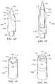
- a funnel(sometimes referred to as an "ejector funnel") may also be included within the biopsy kit. The funnel may accommodate insertion of the ejector into one end of the biopsy needle.
- the funnelmay include a reduced inside diameter portion formed in accordance with teachings of the present disclosure.
- interior portions of the funnelmay function as a "one way connector" which may allow the funnel to function as a sharps protector for one end of the biopsy needle disposed therein.
- a further aspect of the present disclosuremay include a coupler assembly operable to releasably engage an intraosseous device with portions of a drive shaft extending from one end of a powered driver.
- the coupler assemblymay allow the powered driver to insert the intraosseous device at an insertion site (power in.)
- the coupler assemblymay also allow the powered driver to "spin" the intraosseous device during removal from the insertion site (power out). This feature of the present disclosure may also be referred to as "power in and power out.”
- Apparatus and methods incorporating teachings of the present disclosuremay: Reduced physical requirements to insert an IO device into bone and associated bone marrow.
- FIGURES 1A-10Preferred embodiments of the disclosure and various advantages may be understood by reference to FIGURES 1A-10 , wherein like numbers refer to same and like parts.
- connection bagmay include any sterile sleeve, sterile envelope, sterile glove, sterile enclosure or any other device incorporating teachings of the present disclosure and operable to allow engaging a non-sterile device with a sterile device and conducting a medical procedure requiring a sterile field or sterile environment.
- a non-sterile powered drivermay be placed in a containment bag incorporating teachings of the present disclosure and engaged with a sterile intraosseous device for use during various medical procedures requiring a sterile field or sterile environment.
- Such containment bagsmay be attached to a coupler assembly or any other device incorporating teachings of the present disclosure to prevent the non-sterile powered driver from contaminating the sterile intraosseous (IO) device during and after engagement of the non-sterile powered driver with the IO device.
- IOsterile intraosseous
- drivermay include any type of powered driver satisfactory for inserting an intraosseous (IO) device into a selected portion of a patient's vascular system. Such powered drivers often rotate a drive shaft extending therefrom. However, various teachings of the present disclosure may be used with powered drivers that reciprocate an associated drive shaft (not expressly shown).
- IOintraosseous
- Various techniquesmay be satisfactorily used to releasably engage or attach an IO device with a powered driver in accordance with teachings of the present disclosure.
- a wide variety of coupler assemblies, port assemblies, connectors, receptacles, fittings, hubs, hub assemblies, latching mechanisms and/or other types of connecting devices incorporating teachings of the present disclosuremay be satisfactorily used to releasably engage an IO device with a powered driver.
- coupler assembliesincorporating teachings of the present disclosure may be satisfactorily used to releasably engage one end of a shaft extending from a driver with one end of an intraosseous device.
- the powered drivermay include a drive shaft having one end with a generally hexagonal cross section operable to be releasably engaged with a latch mechanism disposed in one end of a coupler assembly.
- a coupler assembly incorporating teachings of the present disclosuremay be referred to as a "hands free" coupler, a quick disconnect or quick release coupler and/or port assembly.
- Respective latch mechanismsmay be disposed proximate a first end and a second end of a coupler assembly in accordance with teachings of the present disclosure. Pushing one end of a drive shaft extending from a powered driver into the second end of the coupler assembly may result in an annular recess disposed in the one end of the drive shaft "snapping" into releasable engagement with the respective latch mechanism. Pushing one end of an intraosseous device into the first end of the coupler assembly may result in an annular recess in the one end of the intraosseous device "snapping" into releasable engagement with the respective latch mechanism.
- a coupler assembly or port assemblymay be engaged with a containment bag or sterile sleeve in accordance with teachings of the present disclosure.
- Coupler assemblies and/or hub assemblies incorporating teachings of the present disclosureallow easy separation of an associated powered driver from an IO device such that the IO device may remain in place in a patient to allow bone marrow aspiration or removal of bone and/or bone marrow biopsy specimens.
- Such coupler assemblies and/or port assembliesmay also allow an associated powered driver to "spin" or rotate an attached IO device while withdrawing an IO device from an insertion site or changing the depth of penetration of an IO device in a target area. Rotating the IO device during withdrawal or changing depth (power out) may substantially improve patient comfort and reduce potential trauma to bone and soft body tissue proximate an insertion site.
- a powered drivermay be used to insert an IO device incorporating teachings of the present disclosure into a selected target area or target site in ten seconds or less.
- various teachings of the present disclosureare not limited to use with powered drivers.
- Manual drivers and spring powered driversmay also be used with IO devices incorporating teachings of the present disclosure.
- fluidmay be used in this application to include liquids such as, but not limited to, blood, water, saline solutions, IV solutions, plasma or any mixture of liquids, particulate matter, dissolved medication and/or drugs associated with biopsy or aspiration of bone marrow or communication of fluids with bone marrow or other target sites.
- fluidmay also be used in this patent application to include any body fluids and/or liquids containing particulate matter such as bone marrow and/or cells which may be withdrawn from a target area.
- Bone and/or bone marrow biopsymay be generally described as removing a relatively small piece or specimen of bone and/or bone marrow from a selected target area for biopsy purposes.
- Bone marrow aspiration(sometimes referred to as “bone marrow sampling”) may be generally described as removing larger quantities of bone marrow from a selected target area. Relatively large quantities of bone marrow may be used for diagnostic, transplantation and/or research purposes. For example some stem cell research techniques may require relatively large quantities of bone marrow.
- Insertion sitemay be used in this application to describe a location on a bone at which an intraosseous device may be inserted or drilled into the bone and associated bone marrow. Insertion sites, penetration sites and installation sites are generally covered by skin and soft tissue.
- intraosseous (IO) devicemay be used in this application to include, but is not limited to, any hollow needle, hollow drill bit, penetrator assembly, bone penetrator, catheter, cannula, trocar, stylet, inner penetrator, outer penetrator, IO needle, biopsy needle, aspiration needle, IO needle set, biopsy needle set or aspiration needle set operable to provide access to an intraosseous space or interior portions of a bone.
- IO devicesmay be formed, at least in part, from metal alloys such as 304 stainless steel and other biocompatible materials associated with needles and similar medical devices.
- IO devicesmay be formed in accordance with teachings of the present disclosure.
- Examples of such IO devicesmay include, but are not limited to, biopsy needles, biopsy needle sets, aspiration needles and aspiration needle sets.
- IO devicesmay or may not include a trocar or stylet.
- a trocar or styletmay be inserted into a generally hollow, longitudinal bore or lumen in an associated catheter or cannula.
- the first end of the second hubmay be releasably engaged with second end of the first hub to releasably dispose the stylet or trocar within the longitudinal bore of the cannula or catheter.
- the present disclosureis not limited to aspiration needle sets 100 or biopsy needle sets 100a as discussed in this application.
- target areamay be used in this application to describe selected portions of a bone cavity or locations in a bone cavity from which associated bone marrow may be harvested in accordance with teachings of the present disclosure.
- Many currently available techniques for harvesting bone and/or bone marrowmay require more than one penetration into a bone and associated bone marrow to retrieve an adequate sample of bone and/or bone marrow.
- Multiple penetration sitesmay be required in the same bone if a biopsy specimen is not satisfactorily retrieved at the first penetration site.
- Medical personnelmay need to insert an IO needle into several different penetration sites on the same bone to obtain adequate quantities of bone marrow for transplant or stem cell research. For example obtaining sufficient quantities of bone marrow from a patient's pelvis may require six or more insertion sites.
- Multiple insertionsmay be extremely painful for a patient and may deter some people from donating bone marrow. Multiple insertions may also cause fatigue in medical personnel performing such procedures with manual IO devices.
- Bone marrow transplant procedures and various research procedures such as stem cell researchoften require relatively large quantities of bone and/or bone marrow.
- Hip bonesgenerally have a large bone cavity and are therefore frequently used as a target area for harvesting bone marrow for transplant procedures, stem cell research procedures or any other procedure requiring relatively large quantities of bone marrow.
- an IO needle or other IO devicemay be formed with a first end operable to penetrate bone and/or associated bone marrow.
- a connector or hubmay be attached to a second end of the IO needle or other IO device.
- Such connectors or hubsmay be operable to releasably engage the IO needle or IO device with a powered driver, a manual driver and/or a coupler assembly.
- IO needle sets and other IO devices incorporating teachings of the present disclosuremay include a first IO device such as a cannula, catheter or outer penetrator and a second IO device such as a stylet, trocar or inner penetrator.
- a first IO devicesuch as a cannula, catheter or outer penetrator
- a second IO devicesuch as a stylet, trocar or inner penetrator.
- Various types of cutting surfacesmay be formed proximate a first end of the first IO device and a first end of the second IO device.
- the cutting surface of the first IO device and the cutting surface of the second IO devicemay cooperate with each other to penetrate bone and/or associated bone marrow.
- a first connector or first hubmay be used to releasably engage the first IO needle or IO device with the second IO needle or IO device.
- an IO needle setmay include a first connector or a first hub with a generally hollow cannula, catheter or outer penetrator attached thereto and extending from a first end of the first hub.
- a second end of the first hubmay be operable to be releasably engaged with a first end of a second connector or a second hub.
- a stylet, trocar or inner penetratormay also be attached to and extend from the first end of the second hub.
- the second end of the first hubmay include an opening sized to allow inserting the stylet, trocar or inner penetrator through the opening and a lumen in the cannula, catheter or outer penetrator.
- a second end of the second hubmay be operable to be releasably engaged with a first end of a coupler assembly incorporating teachings of the present disclosure.
- One end of a shaft extending from a powered driver or a manual drivermay be releasably engaged with a second end of the coupler assembly.
- powered driver 200coupler assemblies 250, 250a, 250b and 250c, hub assemblies 130, 130a, 130b and 130c, IO needle sets 100, 100a and 100b , biopsy needle 100c and/or containment bag 170.
- present disclosureis not limited to such powered drivers, coupler assemblies, hub assemblies, IO needle sets, biopsy needles and/or containment bags.
- intraosseous devices, hub assemblies, coupler assemblies and/or containment bagsmay be formed in accordance with teachings of the present disclosure with various dimensions and/or configurations.
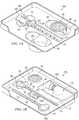
- FIGURES 1A-1Jshow some examples of medical procedure trays and/or kits which may contain one or more intraosseous devices and/or other components incorporating teachings of the present disclosure.
- medical procedure tray 20a as shown in FIGURE 1Amay include intraosseous needle set or aspiration needle set 100 incorporating various teachings of the present disclosure.
- Medical procedure tray 20b as shown in FIGURE 1Bmay include intraosseous needle set or biopsy needle set 100b, ejector 90, funnel 80 and/or containment bag or sterile sleeve 170.
- Medical procedure tray 20c as shown in FIGURES 1C-1Imay also include various IO devices and other components incorporating teachings of the present disclosure including, but not limited to, biopsy needle set 100b, coupler assembly 250, containment bag 170, ejector 90 and/or funnel 80a.
- Medical procedure trays and/or kits formed in accordance with teachings of the present disclosuremay provide a support or base for various components such as a coupler assembly, funnel and/or sharps protector to allow an operator or user to perform various functions without requiring that the operator or user hold or manipulate the respective component.
- medical procedure tray 20c as shown in FIGURE 1may position and support coupler assembly 250 such that one end of a powered driver may be inserted (pushed) into releasable engagement with second end 252 of coupler assembly 250. The powered driver may then be used to withdraw coupler assembly 250 from medical procedure tray 20c without requiring an operator or user to directly hold or manipulate coupler assembly 250.
- Funnel 80amay be positioned and supported within medical procedure tray 20c such that one end of an intraosseous device may be inserted (pushed) into funnel 80a. Funnel 80a may be withdrawn from medical procedure tray 20c without requiring that an operator or user directly hold or manipulate funnel 80a. Each sharps protector 64a may also be positioned and supported within medical procedure tray 20c to allow inserting (pushing) one end of an intraosseous device or any other medical device requiring sharps protection into sharps protector 64a without requiring that an operator or user to directly hold or manipulate the associated sharps protector 64a.
- Medical procedure trays, coupler assemblies and other components formed in accordance with teachings of the present disclosuremay substantially reduce the number of opportunities for an accidental "needle stick" and/or dropping, contaminating or other problems associated with handling and manipulating various components disposed within an associated medical procedure tray.
- Medical procedure trays and kits formed in accordance with teachings of the present disclosuremay have a wide variety of configurations and/or dimensions.
- a kit holding intraosseous devices in accordance with teachings of the present disclosuremay have an overall length of approximately four and one-half inches, a width of approximately three inches and a depth of approximately two inches.
- Various heat sealing techniquesmay be satisfactorily used to place a removable cover (not expressly shown) over a medical procedure tray or kit incorporating teachings of the present disclosure.
- Medical procedure trays 20a, 20b and/or 20cmay also contain a wide variety of other components including, but not limited to, one or more sharps protectors 64 as shown in FIGURES 1A and 1B or sharps protectors 64a as shown in FIGURES 1C , 1E and 1F .
- Sharps protectors 64 and 64amay include hard foam or claylike material 66 disposed therein.
- Intraosseous devicessuch as aspiration needle sets and biopsy needle sets typically have respective sharp tips and/or cutting surface operable to penetrate skin, soft tissue and bone. The sharp tips and/or cutting surface of such intraosseous devices may be inserted into hard foam or claylike material 66 after completion of a medical procedure using the respective intraosseous device.
- medical procedure tray 20amay be referred to as a "bone marrow aspiration tray,” “aspiration procedure tray” or “bone marrow aspiration kit”.
- medical procedure trays 20b and 20cmay sometimes be referred to as “bone and/or bone marrow biopsy procedure trays” or “biopsy procedure trays” or “bone marrow biopsy kits.”
- Medical procedure trays 20a, 20b and/or 20cmay be formed from various polymeric materials compatible with sterile packaging and storage of various components disposed within each medical procedure tray.
- ethylene oxide sterilization techniquesmay be used during assembly and packaging of medical procedure trays 20a, 20b and 20c. However, other sterilization procedures may be used as appropriate.
- Respective coversmay be placed over each medical procedure tray 20a, 20b and 20c as part of an associated sterilization and packaging process. Such covers may be removed prior to use of various components disposed within each medical procedure tray.
- Medical procedure tray or aspiration tray 20amay include elongated slot 22 with appropriate dimensions for an associated intraosseous device such as, but not limited to, aspiration needle set 100.
- the dimensions and configuration of slot 22may be selected to accommodate the combined length of hub assembly 130 and cannula 110a extending therefrom.
- One end of slot 22may be sized to accommodate the dimensions and configuration of hub assembly 130.
- Enlarged openings or finger slots 24may also be provided to accommodate inserting and removing aspiration needle set 100 from slot 22.
- Aspiration needle set 100will be discussed later with respect to FIGURE 3A .
- Sharps protector 64may be disposed within holder 26 of medical procedure tray 20a.
- a pair of finger slots 28may also be formed in tray 20a to accommodate inserting and removing sharps protector 64 from holder 26a.
- Holder 26bmay also be formed in tray 20a along with associated finger slots 28.
- An additional sharps protector or other componentsmay be disposed within holder 26b.
- the dimensions/configurations of slot 22 and holders 26a and 26bmay be varied as desired for respective components which will be disposed therein.
- Medical procedure tray or biopsy tray 20bmay include elongated slots 30 and 32.
- the dimensions and configuration of elongated slot 30may be selected to accommodate placing ejector 90 therein.
- the dimensions and configuration of elongated slot 32may be selected to accommodate placing intraosseous device or biopsy needle set 100b therein.
- One end of elongated slot 30may have configuration and dimensions selected to accommodate the configuration and dimensions of handle 96 disposed on second end 92 of injector rod 94.
- a pair of finger slots 34may be formed as part of elongated slot 30 to allow installing and removing ejector 90.
- One end of elongated slot 32may be operable to accommodate the configuration and dimensions associated with hub assembly 130a of biopsy needle set 100b.
- a pair of finger slots 36may also be provided as part of elongated slot 32 to accommodate inserting and removing biopsy needle set 100b from elongated slot 32.
- Tray 20bmay also include holder 38 disposed adjacent to elongated slot 30.
- Holder 38may have a configuration and dimensions compatible with releasably placing funnel 80 therein.
- Tray 20bmay also include compartment or holder 40 with dimensions compatible with placing containment bag 170 with coupler assembly 250 attached thereto.
- One or more specimen or sample containers or cupsmay be provided in biopsy tray 20b.
- Biopsy specimen or sample containersmay include a cavity sized to receive a biopsy specimen from biopsy needle set 100b.
- Funnel holders 38may be formed in biopsy procedure tray 20b adjacent to ejector 90 to ensure that funnel 80 is readily available to assist with removing a biopsy specimen from biopsy needle set 100b.
- Biopsy procedure tray 20cas shown in FIGURES 1C-1I represents another example of a medical procedure tray formed in accordance with teachings of the present disclosure.
- Biopsy procedure tray 20cmay include intraosseous device or biopsy needle set 100b releasably disposed in elongated slot 42 and ejector 90 disposed in elongated slot 44. Respective ends of elongated slots 42 and 44 may be disposed adjacent to each other so that finger slots 46a, 46b and 46c may be more easily manufactured.
- Biopsy procedure tray 20calso includes a pair of sharps protectors 64a disposed in respective holders 48. Each holder 48 includes a pair of finger slots 50.
- Funnel 80amay be slidably disposed in holder 56 in medical procedure tray 20c in a generally vertical position. See FIGURE 1D .
- first end 81a of funnel 80amay be oriented in a position to allow inserting one end of biopsy needle set 100b or outer cannula 110b therein.
- Longitudinal passageway 84 proximate first end 81amay include a sticking tapered portion operable to maintain contact with one end of biopsy needle set 100b or outer cannula 110b.
- Biopsy needle set 100b or cannula 110bmay then be manipulated to pull funnel 80a from holder 56.
- Funnel 80amay serve as a sharps protector for the one end of an intraosseous device inserted therein.
- One of the benefits of the present disclosuremay include being able to releasably engage one end of a powered driver with one end of a coupler assembly, releasably engage one end of a biopsy needle with an opposite end of the coupler assembly, insert another end of the biopsy needle into a selected target area, "power out" the biopsy needle with a high degree of confidence that a biopsy specimen will be disposed therein and insert the other end of the biopsy needle into a funnel to provide both sharps protection and removal of the biopsy specimen. Any direct contact between an operator and the biopsy needle may be limited to pushing the one end of the biopsy needle into a respective end of the coupler assembly.
- a pair of holders or clampsmay also be formed in medical procedure tray 20c adjacent to holder for coupler assembly 250. Such clamps may be designed to accommodate first end 181 and second end 182 of flexible stay 180 disposed on second opening 172 of containment bag 170. Coupler assembly 250 may also be installed in holder 58 of biopsy procedure tray 20c with first end 251 down and second end 252 looking up.
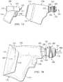
- FIGURES 1E and IFshow one procedure for placing a powered driver within a containment bag incorporating teachings of the present disclosure.
- Containment bag 170may be formed from generally flexible, fluid impervious material which may also be sterilized using conventional sterilization techniques. Containment bag 170 may be used to prevent a non-sterile powered driver from contaminating a sterile intraosseous device and/or an injection site, particularly during a bone marrow biopsy procedure or a bone marrow aspiration procedure. Containment bag 170 may be operable to form a fluid barrier with adjacent portions of housing assembly 270.
- coupler assembly 250may allow powered driver to rotate an intraosseous device releasably engaged with first end 251 of coupler assembly 250 without damage to containment bag 170.
- First opening 171may be formed along one edge of containment bag or sleeve 170.
- Second opening 172may be formed along an opposite edge of containment bag 170. The configuration and dimensions of second opening 172 may be selected to accommodate inserting and removing a powered driver or other non-sterile medical device therefrom.
- Coupler assembly 250may be securely engaged with and extend from first opening 171.
- the attachment between adjacent portions of first opening 171 and coupler assembly 250may be selected to allow rotation of an intraosseous device by an associated powered drive.
- Housing assembly 270 and/or housing segments 280 and 290 of coupler assembly 250may remain relatively stationary during rotation of elongated core 260. See FIGURE 5F .
- portions of housing assembly 270such as flange 254 extending from second end 252 of coupler assembly 250 may be attached to first opening 171 and remain relatively stationary while powered driver 200 rotates elongated core 260 and aspiration needle set 100 extending therefrom.
- powered driver 200may be directly placed into a containment bag and engaged with coupler assembly 250.
- a non-sterile powered drivermay be inserted into containment bag 170 in connection with removing coupler assembly 250 from a medical procedure tray.
- a protective cover(not expressly shown) may be removed from medical procedure tray 20c. End 224 extending from drive shaft 222 of powered driver 200 may then be inserted through second opening 172 of containment bag 170 and releasably engaged with second end 252 of coupler assembly 250.
- First end 181 and second end 182 of flexible stay 180may then be removed from respective clamps or holders in medical procedure tray 20c to allow manually lifting second opening 172 upwardly relative to powered driver 200. See FIGURE 1E .
- Containment bag 170may continue to be raised to a fully extended position with powered driver 200 disposed therein. See FIGURE 1F .
- Flap 174may then be placed over second opening 172.
- Containment bag 170 with powered driver 200 disposed therein and coupler assembly 250may then be removed from holder 58 of medical procedure tray 20c.
- FIGURES 1G-1Jshow another procedure incorporating teachings of the present disclosure to place a non-sterile powered driver into a containment bag with a coupler assembly or port assembly extending therefrom and enclosing the non-sterile powered driver within the containment bag to allow engaging the coupler assembly with a sterile intraosseous device.
- the same proceduremay be used to engage other non-sterile medical devices with sterile medical devices.
- medical procedure tray 20cmay be placed in second tray 20d with first drape 51 disposed therebetween. See FIGURE 1G and 1J .
- Second drape 52 with opening or fenestration 54may then be placed over medical procedure tray 20c with opening or fenestration 54 generally aligned with second opening 172 of containment bag 170 and second end 252 of coupler assembly 250.
- Second drape 52may also cover portions of first drape 51 extending outwardly from between medical procedure tray 20c and the second medical procedure tray (not expressly shown).
- portions of second drape 52 adjacent to fenestration 54may be releasably engaged with portions of containment bag 170 adjacent to second opening 172. See FIGURE 1J .
- Various commercially available low strength adhesive materialsmay be satisfactorily used to provide releasable engagement between second drape 52 proximate fenestration 54 and second opening 172 of containment bag 170.
- First drape 51 and second drape 52may then be folded with each other and covering the contents of medical procedure tray 20c such as shown in FIGURE 1G .
- a portion of second drape 52may be seen in FIGURE 1G between respective portions of first drape 51.
- a protective covermay then be placed over both medical procedure trays and any exposed portions of drapes 51 and 52.
- the combined medical procedure tray(not expressly shown) may then be sterilized.
- One benefit of such sterilizationinclude, but is not limited to, providing a sterilized containment bag which may be used to engage a non-sterile medical device with a sterile medical device in accordance with teachings of the present disclosure.
- First drape 51 and second drape 52may then be unfolded as shown in FIGURE 1H which will expose second opening 172 of containment bag 170 and second end 252 of coupler assembly 250 through fenestration 54 in second drape 52.
- a non-sterile person(not expressly shown) may next insert non-sterile powered driver 200 through opening or fenestration 54 and releasably engage end 224 of drive shaft 222 extending from non-sterile powered driver 200 with second end 252 of coupler assembly 250.
- the non-sterile personmay then lift second drape 52 to a position such as shown in FIGURE 1J with powered driver 200 disposed within containment bag 170.
- the non-sterile personmay continue to lift second drape 52 to release engagement between portions of second drape 52 adjacent to fenestration 54 and portions of containment bag 170 adjacent to second opening 172.
- Typical procedures associated with using a medical procedure tray or kit incorporating teachings of the present disclosuremay include the following steps.
- Medical procedure tray 20d at a desired location for performing an associated medical proceduremay be placed on a table or cart adjacent to a surgical table on which a bone marrow aspiration procedure or a bone marrow biopsy procedure may be performed.
- An associated covermay be removed from medical procedure tray 20d by a sterile person to expose folded drapes 51 and 52. Drapes 51 and 52 may then be unfolded by the sterile person such as shown in FIGURE 1H .
- a non-sterile personmay then pick up non-sterile powered driver 200 and insert powered driver 200 through fenestration 54 in second drape 52 such as shown in FIGURE 1H .
- End 224 of drive shaft 222 of powered driver 200may "snap" into place within second end 252 of coupler assembly 250.
- the non-sterile personmay then lift second drape 52 such as shown in FIGURE 1J which will result in lifting containment bag 170 up and over powered driver 200.
- the non-sterile personmay then remove second drape 52.
- a sterile personmay next close flap 174 over second end 172 of containment bag 170.
- the sterile personmay then grasp handle 214 of powered driver 200 through containment bag 170 and lift powered driver 200 with coupler assembly 250 attached thereto from holder 58 disposed in kit 20c.
- the sterile personmay then remove an intraosseous device such as biopsy needle set 100b from medical procedure kit 20c and insert second end 102 of biopsy needle set 100b into first end 251 of coupler assembly 250.
- a "snap"may be felt when second end 102 of biopsy needle set 100b (or any other intraosseous device incorporating teachings of the present disclosure) is releasably latched within first end 251 of coupler assembly 250.
- a needle safety cap(not expressly shown) may be removed from first end 101 of biopsy needle 100b after releasably engaging second end 102 with first end 251 of coupler assembly 250.
- Powered driver 200 disposed within containment bag 170 along with coupler assembly 250 and biopsy needle set 100b extending there frommay be held in one hand while a sterile person identifies the insertion site with the other hand.
- Powered driver 200may be positioned over the insertion site to introduce first end 101 of biopsy needle set 100b through the skin in the direction and towards the bone.
- the operatormay squeeze button or trigger 246 and apply relatively steady gentle pressure to handle 214 of powered driver 200.
- the operatormay release trigger 246 to stop further insertion of first end 101 of biopsy needle set 100b.
- First housing segment 280may then be activated to release second end 102 of biopsy needle set 100b from engagement with coupler assembly 250.
- Second hub 150amay then be rotated counterclockwise to disengage second hub 150a and associated stylet 120 from first hub 140a. See FIGURE 3B .
- Stylet 120may then be pulled out and removed from biopsy needle or cannula 110b.
- First end 121 of stylet 120may then be inserted into sharps protector 64a.
- second hub 150amay be reengaged with first hub 140a.
- First end 251 of coupler assembly 250may then be reengaged with second end 102 of biopsy needle set 100b to rotate or spin biopsy needle set 100b while withdrawing from the insertion site.
- second end 102 of biopsy needle set 100bmay be disengaged from coupler assembly 250.
- First end 101 of biopsy needle set 100bmay then be inserted into sharps container 64a.
- a sterile personmay close flap 174 to seal non-sterile powered driver therein.
- the sterile personmay then remove containment bag 170, powered driver 200 and coupler assembly 250 from holder 58.
- the sterile personmay then releasably engage first end 251 of coupler assembly 250 with one end of a sterile intraosseous device disposed within medical procedure tray 20c in accordance with teachings of the present disclosure.
- the sharp end or sharp tip of the intraosseous devicemay be inserted into material 66 in sharp protector 64a for further disposal in accordance with the appropriate procedures.
- first drape 51 and/or second drape 52may be formed from a wide variety of materials and may have a wide variety of configurations and/or dimensions.
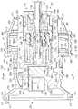
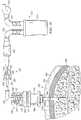
- Powered driver 200 as shown in FIGURES 1E, 1F , 1I , 2 , and 5A and powered driver 200a as shown in FIGURES 7A and 7Bmay be satisfactorily used to insert an intraosseous device incorporating teachings of the present disclosure into a bone and associated bone marrow.
- Powered drivers 200 and 200amay be substantially similar except for respective ends 224 and 224a of drive shaft 222 extending from first end 211 of housing 210. See for example FIGURES 2 and 7A . Therefore, only powered driver 200 will be described in more detail.
- Powered driver 200may include housing 210 having a general configuration similar to a small pistol defined in part by handle 214. Various components associated with powered driver 200 may be disposed within housing 210 including handle 214. For example a power source such as battery pack 216 may be disposed within handle 214. Battery pack 216 may have various configurations and dimensions.
- Housing 210 including handle 214may be formed from relatively strong, heavy duty polymeric materials such as polycarbonate or other satisfactory materials.
- housing 210may be formed in two halves (not expressly shown) which may be joined together with a fluid tight seal to protect various components of powered driver 200 disposed therein.
- Motor 218 and gear assembly 220may be disposed within portions of housing 210 adjacent to handle 214. Motor 218 and gear assembly 220 may be generally aligned with each other. Motor 218 may be rotatably engaged with one end of gear assembly 220. Drive shaft 222 may be rotatably engaged with and extend from another end of gear assembly 220 opposite from motor 218. For some applications both motor 218 and gear assembly 220 may have generally cylindrical configurations.
- Motors and gear assemblies satisfactory for use with powered driver 200may be obtained from various vendors. Such motor and gear assemblies may be ordered as “sets” with one end of each motor securely attached to an adjacent end of an associated gear assembly. A drive shaft having various dimensions and/or configurations may extend from the gear assembly opposite from the motor. Such gear assemblies may sometimes be referred to as “reduction gears” or “planetary gears”. The dimensions and/or configuration of housing 210 may be modified to accommodate an associated motor and gear assembly.
- Distal end or first end 211 of housing 210may include an opening (not expressly shown) with portions of drive shaft 222 extending therefrom.
- end 224 or the portion of drive shaft 222 extending from first end 211 of housing 210may have a generally hexagonal cross section with surfaces 226 disposed thereon.
- Receptacle 263 disposed in second end 252 of coupler assembly 250may have a matching generally hexagonal cross section. See FIGURE 5E .
- Surfaces 226may extend generally parallel with each other and parallel with respect to a longitudinal axis or rotational axis (not expressly shown) associated with drive shaft 222.
- One or more tapered surfaces 228may also be formed on end 224 to assist with releasably engaging powered driver 200 with coupler assembly 250. See FIGURES 5E and 5G .
- the end of a drive shaft extending from a powered drivermay have a wide variety of configurations. See for example FIGURES 6A and 6B .
- a drive shaft having desired dimensions and configurationmay extend from the gear assembly opposite from the motor.
- the drive shaftmay be provided as part of each motor and gear assembly set.
- the dimensions and/or configuration of an associated housingmay be modified in accordance with teachings of the present disclosure to accommodate various types of motors, gear assemblies and/or drive shafts.
- powered drivers used with aspiration needles and/or biopsy needlesmay include gear assemblies with larger dimensions required to accommodate larger speed reduction ratios, for example between 60:1 and 80:1, resulting in slower drive shaft RPM's.
- Powered drivers used to provide intraosseous access during emergency medical proceduresmay operate at a higher speed and may include gear assemblies having a smaller speed reduction ratio, for example between 10:1 and 30:1, resulting in higher drive shaft RPM's.
- the difference in size for gear assembliesmay result in increasing the inside diameter of an associated housing by approximately two to three millimeters to accommodate larger gear assemblies associated with powered drivers used to insert biopsy needles and/or aspiration needles.
- Coupler assemblies having corresponding openings or receptaclesmay be releasably engaged with end 224 extending from first end 211 of powered driver 200 or end 224a extending from first end 211 of powered driver 200a.
- end 224 extending from first end 211 of housing 210may be releasably engaged with receptacle 264 disposed proximate second end 252 of coupler assembly 250 as shown in FIGURES 1E, 1F , 5C and 5D .
- thrust bearing 241may be disposed between first end or distal end 211 of housing 210 and adjacent portions of gear assembly 220.
- Thrust bearing 242may be disposed between second end or proximal end 212 of housing 210 and adjacent portions of motor 218. Thrust bearings 241 and 242 may limit longitudinal movement of motor 218, gear assembly 220 and drive shaft 222 within associated portions of housing 210.
- Trigger assembly 244may also be disposed within housing 210 proximate handle 214. Trigger assembly 244 may include trigger or contact switch 246. Motor 218 may be energized and deenergized by alternately depressing and releasing trigger 246. Electrical circuit board 247 may also be disposed within housing 210. Electrical circuit board 247 may be electrically coupled with trigger assembly 244, motor 218, power supply 216 and indicator light 248.
- indicator light 248may be a light emitting diode (LED) or a small more conventional light bulb.
- indicator light 248may be activated when ninety percent (90%) of electrical storage capacity of battery pack 216 has been used.
- an intraosseous device formed in accordance with teachings of the present disclosuremay vary depending upon respective intended applications for each intraosseous device.
- the length of a biopsy needle formed in accordance with teachings of the present disclosuremay vary from approximately five (5) millimeters to thirty (30) millimeters.
- biopsy needles having other lengthsmay also be formed in accordance with teachings of the present disclosure.
- Aspiration needles formed in accordance with teachings of the present disclosuremay have lengths of approximately twenty five (25) millimeters, sixty (60) millimeters and ninety (90) millimeters.
- an aspiration needle having a length of ninety (90) millimeters or moremay also include one or more side ports.
- Intraosseous (IO) devices formed in accordance with teachings of the present disclosuremay have outside diameters and longitudinal bores or lumens corresponding generally with eighteen (18) gauge to ten (10) gauge needles. The configuration and dimensions of each IO device may depend upon the size of an associated bone and desired depth of penetration of associated bone marrow.
- Bone marrow aspiration systemsmay be capable of inserting an aspiration needle to a desired depth in cancellous bone in ten (10) to fifteen (15) seconds. This same capability may be used to obtain bone and/or bone marrow specimens depending upon the optimum speed for inserting a biopsy needle to obtain a reliable biopsy specimen in accordance with teachings of the present disclosure.
- Bone marrow aspiration systems incorporating teachings of the present disclosuremay provide a powered driver and a coupler assembly operable to insert an aspiration needle into cancellous bone and extract bone marrow.
- a trocar or styletmay be removed from the lumen of an associated catheter or cannula.
- a hub assembly incorporating teachings of the present disclosuremay be attached to the second end of the needle set allows relatively easy and quick removal of the trocar or stylet from the lumen of the cannula or catheter.
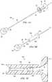
- a Luer lock fitting provided on a hub attached to the cannula or cathetermay then be connected to a bone marrow aspiration system. See FIGURE 10 .
- hubs and hub assembliesmay be formed using medical grade polycarbonate.
- the trocar or styletmay be reinserted into the lumen of the outer penetrator or cannula.
- the first end of a hub attached to the trocar or styletmay be reengaged with the second end of a hub attached to the cannula or catheter.
- a powered driver and coupler assemblyincorporating teachings of the present disclosure may then be used to insert the aspiration needle set to a second desired depth in the cancellous bone to obtain another bone marrow sample or the powered driver may be used to "power out" the aspiration needle set.
- Sharps safety capability for the stylet and/or cannulamay be provided as part of such aspiration systems.
- Intraosseous (IO) needle sets or aspiration needle sets 100 and 100a as shown in FIGURE 3A and FIGURE 3B and biopsy needle 100c as shown in FIGURE 3Crepresent only some examples of intraosseous devices formed in accordance with teachings of the present disclosure.
- Aspiration needle sets 100 and 100amay have similar outer penetrators or cannulas 110a and similar inner penetrators to stylets 120. See FIGURES 3A and 3B .
- IO needle set 100may include hub assembly 130 while IO needle set 100a may include hub assembly 130a.
- Biopsy needle 100cmay also include hub assembly 130a. See FIGURE 3C .
- first end 111a of cannula 110a and first end 121 of stylet 120may be operable to penetrate a bone and associated bone marrow.
- first end 111a of cannula 110a and first end 121 of stylet 120are shown in more detail in FIGURES 3D and 3F .
- First end 101 of IO needle sets 100 and 100amay correspond generally with first end 111a of cannula 110a and first end 121 of stylet 120.
- Cannula 110amay have a plurality of markings 104 disposed on exterior portions thereof. Markings 104 may sometimes be referred to as "positioning marks" or "depth indicators.” Markings 104 may be used to indicate the depth of penetration of aspiration needle set 100 or 100a into a bone and associated bone marrow. For some applications cannula 110a may have a length of approximately sixty (60) millimeters and may have a nominal outside diameter of approximately 0.017 inches corresponding generally with a sixteen (16) gauge needle. Cannula 110a may be formed from stainless steel or other suitable biocompatible materials. Positioning marks 104 may be spaced approximately one (1) centimeter from each other on exterior portions of cannula 110a. For some applications one or more side ports 106 may be formed in exterior portions of cannula 110a spaced from first end 111a.
- Hub assembly 130 as shown in FIGURE 3Amay be used to releasably dispose stylet 120 within longitudinal bore or lumen 118 of cannula 110a. See FIGURE 3E .
- Hub assembly 130may include first hub 140 and second hub 150.
- the second end of cannula 110a, opposite from first end 111a,may be securely engaged with the second end of cannula 110a.
- the second end of stylet 120, opposite from first end 121,may be securely engaged with the first end of hub 150.
- cannula 110amay extend longitudinally from first end 141 of hub 140. Stylet 120 may also extend from the first end of hub 150 (not expressly shown).
- the second end of hub 140may include a standard Luer lock fitting which may be releasably engaged with a corresponding Luer lock fitting disposed within the first end of second hub 150. Dotted lines 134 as shown in FIGURE 3A may represent the resulting threaded connection between the second end of first hub 140 and the first end of second hub 150. Examples of Luer lock connections and/or fittings are shown in more detail in FIGURES 3B, 3C , 5E , 5F , 5I and 10 .
- the Luer lock fitting disposed on the second end of hub 140may be operable to be releasably engaged with a standard syringe type fitting and/or a standard intravenous (IV) connection.
- IVintravenous
- Hub 150includes second end 152 which generally corresponds with second end 132 of hub assembly 130 and second end 102 of IO needle set 100.
- Hub 140may include first end 141 which may generally correspond with first end 131 of hub assembly 130.
- Cannula 110amay extend longitudinally from first end 141 of hub 140 and first end 131 of hub assembly 130.
- receptaclesmay be satisfactory disposed in second end 152 of hub 150 for use in releasably engaging hub assembly 130 with a powered driver.
- a receptacle having a generally tapered configuration corresponding with the tapered configuration of one end of a drive shaft extending from a powered drivermay be releasably engaged with second end 152 of hub 150.
- Powered driver 200a as shown in FIGURES 6A and 6Bmay represent one example of a powered driver having a drive shaft extending from a housing with a tapered portion operable to be releasably engaged with a receptacle having a corresponding generally tapered configuration.
- powered driversmay be secured to an intraosseous device by a magnet (not expressly shown) disposed on the end of the tapered shaft extending from the powered driver and a metal disk disposed within a corresponding receptacle in the intraosseous devices.
- a magnetnot expressly shown
- Such powered driversmay also be used with intraosseous devices used to obtain emergency vascular access (EVA).
- EVAemergency vascular access
- the second end of a hub assemblymay be operable to be disposed within a receptacle formed in a coupler assembly incorporating teachings of the present disclosure.
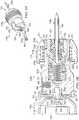
- One feature of the present disclosuremay include forming a hub assembly which may be releasably engaged within a first receptacle disposed in a first end of a coupler assembly. See for example receptacle 263 proximate first end 261 of elongated core 260 as shown in FIGURE 5E .
- the dimensions and configuration of receptacle 263may be selected to prevent rotation of hub 150a relative to hub 140a while inserting (rotating) an IO device into a bone and associated bone marrow.
- the powered drivermay be releasably engaged with a second receptacle disposed in a second end of the coupler assembly. See for example receptacle 264 proximate second end 262 of elongated core 260 as shown in FIGURE 5E .
- Intraosseous device or aspiration needle set 100ais shown in FIGURE 3B with first end 151 of hub 150a spaced from second end 142 of hub 140a. Portions of stylet 120 extending from first end 151 of hub 150a are shown slidably disposed within lumen or longitudinal bore 118 of cannula 110a.
- Hub assembly 130a as shown in FIGURE 3Bmay include first end 131 which may correspond generally with first end 141 of hub 140a. Hub assembly 130a may also include second end 132 which may correspond generally with second end 152 of hub 150a and second end 102 of hub assembly 130a. See FIGURE 3B . Cannula 110a may be attached to and extend from first end 141 of hub 140a.
- Second end 142 of hub 140amay include one-half a typical Luer lock connection or fitting operable to be releasably engaged with corresponding portions of a Luer lock connection or fitting disposed in first end 151 of second hub 150a.
- first end 131 of hub assembly 130amay correspond with first end 141 of first hub 140a.
- Second end 152 of second hub 150amay correspond with second end 132 of hub assembly 130a and second end 102 of aspiration needle set 100a.
- At least one portion of hub assembly 130amay have a generally hexagonal cross section operable to be received within the generally hexagonal cross section of receptacle 264 disposed proximate first end 251 of coupler assembly 250. See FIGURE 5E .
- portions of first hub 140a disposed adjacent to reduced outside diameter portion 143may have generally hexagonal cross sections. See FIGURES 3B and 3C .
- Various cross sections other than hexagonalmay be satisfactorily used to releasably engage a powered driver with one end of a coupler assembly and an intraosseous device with an opposite end of the coupler assembly.
- Aspiration needle setsmay often include a trocar, stylet or penetrator in combination with an associated cannula, catheter or outer penetrator.
- biopsy needles formed in accordance with teachings of the present disclosuremay or may not include a trocar, stylet or inner penetrator.
- biopsy needle 100cis shown in FIGURE 3C attached to first end of hub 140a.
- a stylet or inner penetratoris not attached to first end 151 of hub 150a.
- hub 140amay be used to releasably engage biopsy needle 100c in a receptacle formed in a coupler assembly incorporating teachings of the present disclosure.
- Hub 150amay be attached to close of end 141 of hub 140a.
- hub 140a without hub 150amay be connected with one end of a coupler assembly in accordance with teachings of the present disclosure.
- Biopsy needle 100cmay be used to capture a biopsy specimen of a bone and associated bone marrow. Placing a trocar within biopsy needle 100c may result in substantial damage to the bone specimen during penetration of the bone by the combined tips of the trocar and biopsy needle 100c.
- Hub 140amay include second end 142 with opening 144 formed therein.
- Passageway 146may extend from second end 142 towards first end 141 of hub 140a. See FIGURES 5E , 5F and 5I .
- Passageway 146may be operable to communicate fluids with lumen 118 of cannula 100a.
- Second end 142 of hub 140may include various features of a conventional Luer lock connection or fitting, including threads 148.
- Corresponding threads 158may be formed within first end 151 of hub 150a. See for example FIGURES 5E , 5F and 5I .
- receptacle 263 in first end 251 of coupler assembly 250may be selected to prevent relative movement between hub 140a and hub 150a during insertion (rotation) of an IO device into a bone and associated bone marrow. If such relative movement occurs, threads 148 and 158 may be disconnected.
- hub 140a and hub 150amay be formed using injection molding techniques.
- hub 140amay include reduced outside diameter portion 143 disposed between first end 141 and second end 142. See for example FIGURES 3B, 3C and 5C .
- a plurality of void spaces or cutouts 153may be formed in hub 150a adjacent to and extending from second end 152 in the direction of first end 151. See for example FIGURES 3B, 3C and 5A .
- the configuration and dimensions of reduced diameter portion 143 and/or cutouts 153may be varied to optimize associated injection molding techniques and at the same time provide required configurations, dimensions and material strength to allow associated hub assembly 130a to function in accordance with teachings of the present disclosure.
- FIGURES 3D and 3Eshow one example of cutting surfaces and tips which may be formed adjacent to the ends of a cannula and an associated trocar in accordance with teachings of the present disclosure.
- tip 123 of stylet 120may be disposed relatively close to tip 113 of cannula 110a.
- first end 121 of trocar 120 and first end 111a of cannula 110amay be ground at the same time to form adjacent cutting surfaces 114 and 124.
- Grinding ends 111a and 121 at the same timemay result in forming a single cutting unit to form generally matching cutting edges 124e and 114e such as shown in FIGURES 3D and 3E .
- Other types of cutting surfaces formed in accordance with teachings of the present disclosuremay be discussed later.
- First end 121 of trocar 120may extend through opening 144 in second end 142 of hub 140a. See FIGURE 3B .
- Hub 150a disposed on the second end of trocar 120may be releasably engaged with the second end of cannula 110a represented by hub 140a. See FIGURE 3B .
- Intraosseous devices incorporating teachings of the present disclosuremay substantially reduce or eliminate problems associated with obtaining a suitable specimen of bone and/or bone marrow.
- Various teachings of the present disclosuremay substantially increase the probability of obtaining a satisfactory biopsy specimen of cancellous bone and associated bone marrow.
- Human bonesmay generally be described as having a hard outer lamellae or layer of osseous tissue known as "cortical bone”.
- Cancellous bonealso known as trabecular or spongy bone
- Cancellous bonetypically fills an inner cavity associated with cortical bone.
- Cancellous boneis another type of osseous tissue with generally low density and strength but high surface area.
- Cancellous bonetypically includes spicules or trabeculae which form a latticework of interstices filled with connective tissue or bone marrow.
- Exterior portions of cancellous bonegenerally contain red bone marrow which produces blood cellular components. Most of the arteries and veins of a bone are located in the associated cancellous bone.
- One of the benefits of the present disclosuremay include providing various intraosseous devices including, but not limited to, biopsy needle sets and biopsy needles operable to reliably obtain biopsy specimens of cortical bone and/or cancellous bone without significant damage to associated biopsy specimens.
- forming a plurality of cutting surfaces on the extreme end of an outer penetrator or cannula in accordance with teachings of the present disclosuremay allow a resulting biopsy needle to more quickly penetrate a bone and associated bone marrow, may reduce the amount of time and force required to remove a bone and/or bone marrow specimen from a target area in accordance with teachings of the present disclosure.
- the configuration of the tip of a cannula or outer penetratormay be modified in accordance with teachings of the present disclosure to provide optimum torque during insertion of the cannula or outer penetrator by a powered driver to obtain a bone and/or bone marrow biopsy specimen.
- a controlled, steady feed rate when using a powered drivermay result in higher quality biopsy specimens as compared to manually inserted biopsy needles.
- At least one helical threadmay be disposed within a hollow cannula proximate an associate tip or first end to assist with capturing a bone and/or bone marrow biopsy specimen.
- the quality of a bone and/or bone marrow specimen and reliability of obtaining a bone and/or bone marrow specimen using a powered driver and biopsy needle incorporating teachings of the present disclosuremay be substantially improved by using an optimum feed rate for inserting the biopsy needle into a bone and associated bone marrow.
- Feed rate or speed of insertion of a biopsy needle incorporating teachings of the present disclosuremay be a function of the pitch of at least one thread disposed on an interior portion of the biopsy needle and revolutions per minute (RPM) of the biopsy needle.
- RPMFeed rate x Pitch of threads
- Helical thread 190 as shown in FIGURES 4C, 4D and 4Emay have a pitch of approximately twenty four (24) threads per inch.
- An optimum pitchmay vary based on factors such as reduction gear ratio (77:1 for some embodiments) and load placed on an associated motor.
- Further technical benefitsmay include reducing physical requirements and mental stress on users and decreasing pain and stress on patients by increasing speed and control of the needle set insertion during bone marrow biopsy and bone marrow aspiration procedures.
- Bone marrow biopsy systemsincorporating teachings of the present disclosure provide a powered alternative to current manual techniques for inserting biopsy needles into bone and bone marrow which are generally considered the industry standard.
- an aspiration needle or biopsy needle formed in accordance with teachings of the present disclosuremay include a hollow cannula or catheter having one end formed by electrical discharge machining (EDM) techniques, grinding techniques and/or other machining techniques.
- EDMelectrical discharge machining
- a plurality of teethmay be formed on one end of the cannula or catheter using EDM techniques, grinding techniques and/or other machining techniques.
- a stylet or trocarmay also be disposed within the cannula or catheter with a first end of the stylet extending from a first end of the cannula or catheter. Increasing the length of the first end of the stylet or trocar extending from the first end of the cannula or catheter may reduce the amount of torque or force required to penetrate a bone and may reduce time required for an associated aspiration needle set or biopsy needle set to penetrate the bone and associated bone marrow.
- a specific powered driver, intraosseous device and tip configurationwill generally produce the same torque when drilling in a hard bone or a soft bone.
- the time required to drill to a first depth in a hard bonewill generally be greater than the time required to drill to similar depth in a soft bone.
- teeth formed on one end of a cannula or cathetermay be bent radially outward to reduce the amount of time and/or force required to penetrate a bone and associated bone marrow using the cannula or catheter.
- a powered driver and aspiration needle set or biopsy needle set formed in accordance with teachings of the present disclosuremay provide access to a patient's bone marrow using a similar amount of torque.
- the length of time for penetrating a relatively hard bonemay be increased as compared with the length of time required to penetrate a relatively softer bone.
- the tips of several stylets and cannulas incorporating teachings of the present disclosurewere slowly ground with coolant to prevent possible thermal damage to metal alloys or spring material used to form the stylets and cannulas.
- the stylets and cannulaswere assembled into respective IO needle sets.
- the tips of each needle setwere inserted into sawbones blocks under controlled test conditions. Some testing was conducted with Pacific Research sawbones blocks.
- the tips of the needle setswere inserted to a depth of approximately two centimeters with ten pounds (10 lbs) of force and twelve volts direct current (12 VDC) applied to an associated powered driver. There was no measurable or visual wear of the stylet or cannula tips after completion of the testing.
- a generally hollow biopsy needlemay be substantially continuously rotated at an optimum speed or RPM during insertion into a selected target area to obtain a biopsy specimen.
- the biopsy needlemay include a longitudinal bore extending from a first, open end of the needle to a second, open end of the needle.
- a small helical threadmay be formed on interior portions of the longitudinal bore proximate the first end.
- the threadmay have a pitch similar to threads used on conventional wood screws.
- the rate of rotation or revolutions per minute (RPM) of the biopsy needlemay be selected by installing a gear assembly with a desired speed reduction ratio (typically between 60:1 and 80:1) between a motor and an associated drive shaft.
- the gear assemblymay reduce speed of rotation of an attached motor at a ratio of approximately 66:1 or 77:1.
- Outer penetrator or cannula 110f as shown in FIGURE 3Fmay include first end 111f having a plurality of cutting surfaces 114f formed adjacent to opening 116 in first end 111f. Opening 116 may communicate with and form a portion of an associated longitudinal bore or lumen 118. For some applications cutting surfaces 114f may be formed using electrical discharge machining (EDM) techniques.
- EDMelectrical discharge machining
- outer penetrator or cannula 110gmay include first end 111g having a generally tapered configuration or reduced outside diameter as compared with other portions of cannula 110g.
- a plurality of cutting surfaces 114gmay be disposed on end 111g adjacent to respective opening 116.
- cutting surfaces 114gmay be formed using machine grinding techniques.
- end 111g of cannula 110gmay include six ground cutting surfaces 114g with respective crowns 115 may be formed therebetween.
- Forming a biopsy needle set and/or biopsy needle with tapered end 111g and a plurality of cutting surfaces 114g and crowns 115may provide improved drilling performance when the resulting biopsy needle set and/or biopsy needle is used with a powered driver in accordance with teachings of the present disclosure.
- helical groove 117may be formed within longitudinal bore 118 proximate respective opening 116. Helical groove 117 may assist with retaining a biopsy specimen or a bone marrow specimen within longitudinal bore 118.
- testing conducted with cannulas or outer penetrators formed in accordance with teachings of the present disclosureindicated that forming cutting surfaces or cutting teeth with electrical discharge machining (EDM) sometimes resulted in the associated cannula or outer penetrator being able to drill through a bone and associated bone marrow slightly faster than a cannula or outer penetrator having cutting surfaces formed using grinding techniques.
- EDMelectrical discharge machining
- Some test resultsalso indicated that bending cutting surfaces formed on one end of a cannula or outer penetrator in accordance with teachings of the present disclosure may reduce the amount of time and/or the amount of force required to remove a bone and/or bone marrow specimen from a target area.
- Intraosseous needle set or biopsy needle set 100gis shown in FIGURES 3I and 3J .
- Biopsy needle set 100gmay include cannula or outer penetrator 110g with stylet or inner penetrator 120g slidably disposed therein.
- First end 101 of biopsy needle set 100gis shown in FIGURES 3I and 3J .
- first end 101 of biopsy needle set 100gmay minimize damage to skin and soft body tissue at an insertion site.
- inner penetrator or trocar 120gmay include first end 121 having a plurality of cutting surfaces 125 and 126 formed on exterior portions thereof extending from associated tip 123 towards second end of trocar or inner penetrator 120g.
- one or more cutting surfaces 125may be formed having length 127 extending from tip 123 to associated cutting surfaces 114g in associated cannula 110g.
- One or more cutting surfaces 126may be formed adjacent to each cutting surface 125 with second length 128.
- First length 127may be greater than second length 128.
- the ratio of first length 127 and second length 128may be varied in accordance with teachings of the present disclosure to provide optimum performance for penetrating a selected bone and associated bone marrow.
- a single threadmay be disposed within the longitudinal bore or lumen of a biopsy needle, cannula, catheter or outer penetrator in accordance with teachings of the present disclosure.
- Various techniques and proceduresmay be satisfactorily used to place the single thread within a generally hollow cannula or outer penetrator proximate one end of the cannula or outer penetrator having one end operable to penetrate a bone and/or associated bone marrow.
- a helical coil having a configuration and dimensions associated with the resulting single threadmay be placed on one end of a mandrel such as a spot welding electrode assembly.
- the mandrel or electrode assemblymay then be inserted through an opening in the one end of the cannula or outer penetrator operable to penetrate a bone and/or associated bone marrow.
- the helical coilmay then be bonded with adjacent portions of cannula. Coils having a wide variety of dimensions and configurations may be satisfactorily used to place a single thread in a biopsy needle.
- FIGURES 4A-4Eexamples of helical threads are shown disposed in biopsy needles or cannulas incorporating teachings of the present disclosure.
- Outer penetrator or cannula 110h as shown in FIGURE 4Amay be formed with longitudinal bore 118 or lumen 118 extending from open 116 through cannula 110h.
- Electrode assembly or mandrel 160may be used to install (spot weld) a single helical thread in lumen 118 proximate opening 116.
- Helical coil 192 as shown in FIGURE 4Bmay be placed on first end 161 of electrode assembly 160.
- Helical coil 192may have the cross section of a right triangle.
- First end or copper electrode 161may have an appropriate configuration and dimensions to be slidably received within opening 116 formed in first end 111 of cannula or outer penetrator 110h.
- First end or copper electrode 161 of mandrel 160may include corresponding groove 164 with a configuration and dimensions satisfactory to receive helical coil 192 therein.
- Groove 164may be formed with a desired pitch for resulting thread 190 when attached to or bonded with interior portions of cannula 110h.
- electrode assembly 160may include enlarged outside diameter portion or plastic insulator 194 disposed adjacent to first end 161.
- the dimensions and/or configuration of copper electrode 161 and plastic insulator 194may be selected to accommodate installing helical coil 192 at an optimum location relative to end 116 for retaining biopsy specimens in lumen 118.
- the dimensions and configuration of plastic insulator 194may be selected to contact the extreme end of outer penetrator or cannula 110h proximate crowns 115.
- Electrode assembly 160may be operable to conduct electricity to copper electrode 161 to accommodate spot welding helical coil 192 with adjacent interior portions of longitudinal bore 118 of cannula 110h.
- mandrel 160may be formed from materials compatible with laser welding helical coil 192 with interior portions of lumen or longitudinal bore 118 of cannula 110h.
- helical coil 192When attached to interior portions of a cannula or outer penetrator 110h, helical coil 192 may form a single thread having shoulder 191 extending generally perpendicular to adjacent interior portions of lumen 118. The resulting dimensions and configuration of helical thread 190 may be selected to optimize retaining a specimen of bone and/or bone marrow on shoulder 191 of thread 190 within lumen 118.
- Cannula 110c of biopsy needle 100cis shown in FIGURE 4C with helical thread 190 disposed therein.
- the combination of helical thread 190 with shoulder 191 extending substantially perpendicular to interior portions of lumen 118may increase the reliability of biopsy needle 100c to retain a specimen of bone and/or bone marrow.
- combining helical thread 190 with cutting surfaces 114 and crowns 115may substantially increase the reliability of obtaining a satisfactory bone specimen when using biopsy needle 100c with a powered driver in accordance with teachings of the present disclosure.
- Helical thread 190may be positioned at an optimum location relative to opening 116 in cannula 110c to begin capture of a bone marrow specimen or cancellous bone core. By inserting biopsy needle 100c at an optimum feed corresponding with the pitch of helical thread 190, helical thread 190 may be "screwed in" cancellous bone entering opening 116 to substantially increase the probability of capturing a satisfactory biopsy specimen or bone marrow core.
- cannula or outer penetrator 110dmay include first end 111d having a plurality of exterior cutting surfaces 114d formed thereon and extending therefrom.
- the length of cutting surfaces 114dmay be longer than the length of corresponding cutting surfaces 114.
- Respective crowns 115dmay be formed between adjacent cutting surfaces 114d and 114g.
- a helical thread having a generally "wedge shaped" cross section similar to an equilateral trianglemay be disposed within the longitudinal bore or lumen of an outer penetrator or cannula incorporating teachings of the present disclosure.
- cannula 110dmay include helical thread 190a having a generally wedge shaped cross section corresponding approximately with an equilateral triangle.
- Helical thread 190amay be installed within cannula 110d using apparatus and procedures as previously described with respect to helical thread 190.
- FIGURE 4Eshows an example of combining inner penetrator or stylet 120c with cannula or outer penetrator 110c having helical thread 190 disposed therein to form biopsy needle set 100c in accordance with teachings of the present disclosure.
- Biopsy needle 100cis shown in FIGURES 3C and 4C without a stylet or trocar.
- Biopsy needle set 100cis shown in FIGURE 4E with trocar or stylet 120c disposed in cannula 110c.
- Trocar 120cmay include end 121c with a pair of cutting surfaces 125 and a pair of cutting surface 126 as shown in FIGURE 3I .
- Surfaces 125 and 126may cooperate with each other to form a cutting tip on trocar or stylet 120c similar to a "chisel point" drill bit.
- the pair of cutting surfaces 125may be offset (relief angle) approximately eight degrees relative to the pair of cutting surfaces 126.
- the included angle of cutting surfaces 125may be approximately thirty four degrees (34°) plus or minus four degrees ( ⁇ 4°).
- the included angle of cutting surfaces 126may be approximately sixteen degrees (16°) plus or minus three degrees ( ⁇ 3°).
- end 121 of trocar 120cmay extend from end 111c of cannula 110c with respective cutting surfaces 114 of cannula 110g disposed adjacent to the end of each cutting surface 126 (short cutting surface) opposite from tip 123 of trocar 120c. See FIGURE 4E .
- each cutting surface 125 (long cutting surface) of trocar 120cmay be disposed within end 111 of cannula 110c. See FIGURE 4E .
- Placing portions of cutting surfaces 125 within end 111 of cannula 110cmay result in more uniform forces being applied to end 101 of intraosseous device 100c while penetrating the cortex of an associated bone using biopsy needle set 100c and a powered driver in accordance with teachings of the present disclosure.
- forces applied to end 101 of biopsy needle set 100cmay decrease sufficiently to indicate that end 101 has now entered associated bone marrow.
- An operatormay then withdraw trocar 120c from cannula 110c and position end 111c of cannula 110c at a desired target area to perform a bone marrow biopsy.
- threads 190 and 190amay extend approximately 0.005 inch from adjacent portions of an associated longitudinal bore or lumen 118.
- the outside diameter of an associated trocarsuch as trocar 120c as shown in FIGURE 4E may be reduced to accommodate the height of thread 190 or 190a.
- the following test resultswere obtained during insertion of intraosseous devices such as biopsy needle set 100c shown in FIGURE 4E into sawbones material or blocks with three millimeters (3mm) of fifty pound (50#) and forty millimeters (40mm) of forty pound (40#) material.
- the distance between the end of cutting surface 126 or trocar 120c and adjacent cutting surface 114 on cannula 110cwas approximately 0.14 inches. End 111 of cannula 110c had six (6) ground cutting surfaces 114. The outside diameter of trocar 120c was approximately 0.086 inches.
- Coupler assemblies incorporating teachings of the present disclosuremay function as "quick release mechanisms" operable to engage and disengage an IO device from a powered driver disposed within a flexible containment bag or sterile sleeve. Such coupler assemblies may allow rotation of an IO device without damage to the flexible containment bag or sterile sleeve.
- the IO devicemay be an aspiration needle or a biopsy needle.
- One end of the coupler assemblymay be operable to form a fluid seal or fluid barrier with adjacent portions of the containment bag or sterile sleeve.
- a coupler assembly incorporating teachings of the present disclosuremay also be described as a port assembly attached to a containment bag. Such port assemblies may allow easy engagement or disengagement of a powered driver from an IO device and at the same time allow the powered driver to "power in and power out" an IO device from an insertion site.
- a coupler assembly incorporating teachings of the present disclosuremay be used in "non-sterile" environments and/or medical procedures which do not require the use of a containment bag or sterile sleeve.
- FIGURES 5A-5I and 6A-6Bshow various examples of coupler assemblies or port assemblies incorporating teachings of the present disclosure.
- FIGURE 5A-5Iare schematic drawings showing various views of powered driver 200, coupler assemblies 250, 250a and 250b and intraosseous device 100b incorporating various teachings of the present disclosure.
- Coupler assemblies 250, 250a and 250amay each include respective first end 251 operable to be releasably engaged with one end of an intraosseous device such as, but not limited to, second end 102 of biopsy needle set 100b.
- Coupler assembly 250 as shown in FIGURES 5E-5Hmay include second end 252 operable to be releasably engaged with a portion of a drive shaft extending from a powered driver, such as, but not limited to, end 224 of drive shaft 222 extending from first end 211 of housing 210 of powered driver 200.
- second end 252 of coupler assembly 250may be securely engaged with an opening in a containment bag or sterile sleeve.
- Second end 252a of coupler assembly 250a and second end 252b of coupler assembly 250bdo not include similar features. As a result coupler assemblies 250a and 250b may primarily be used in applications which do not require a sterile environment.
- Coupler assemblies 250, 250a and 250bmay have substantially the same or similar components, functions and features except for second end 252a of coupler assembly 250a and associated second end 272a of housing assembly 270a and second end 250b of coupler assembly 250b and associated second end 272b of housing assembly 270b. Therefore, various features of the present disclosure may be described with respect to coupler assembly 250 since both coupler assemblies 250a and 250b have substantially the same characteristics and features except for attachment with a containment bag or sterile sleeve.
- Coupler assemblies incorporating various teachings of the present disclosuremay be placed in a medical procedure tray or kit with one end down and an opposite end looking up to allow "hands free” releasable engagement with a powered driver or a manual driver.
- coupler assembly 250may be disposed in medical procedure tray 20c with first end 251 insert into holders 58 and second end 252 looking up. See FIGURES 1C , 1E and 1F .
- end 224 of drive shaft 222 extending from powered driver 200may be inserted into and releasably engaged with second end 252 of coupler assembly 250 without requiring an operator or user (not expressly shown) to physically contact or manipulate any portion of coupler assembly 250.
- FIGURES 5E , 5F , 5G and 5HVarious features of associated "hands free" latching mechanisms will be discussed with respect to FIGURES 5E , 5F , 5G and 5H .
- coupler assembly 250may include elongated core 260 with housing assembly 270 slidably disposed on exterior portions of elongated core 260.
- Housing assembly 270may include first end 271 and second end 272 which may be generally aligned with respective first end 261 and respective second end 262 of elongated core 260.
- elongated core 260may have a generally cylindrical configuration defined in first exterior portion 260a and second exterior portion 260b with various shoulders and/or recesses formed thereon.
- first exterior portion 260amay have a larger diameter than second exterior portion 260b.
- Coupler assembly 250a and coupler assembly 250bmay include respective elongated cores 260 having similar features and functions as described with respect to coupler assembly 250.
- Coupler assembly 250amay include housing assembly 270a with substantially the same components, functions and features as described with respect to housing assembly 270 except for second end 272a of housing assembly 270a.
- Coupler assembly 250bmay include housing assembly 270b having substantially similar components, functions and features as described with respect to housing assembly 270 except for second end 272b of housing assembly 270b.
- Housing assembly 270may be described as having a generally hollow, cylindrical configuration defined in part by first housing segment 280 and second housing segment 290. See FIGURES 5E and 5F .
- the first end of housing segment 280may generally correspond with first end 271 of housing assembly 270.
- the second end of second housing segment 290may generally correspond with second end 272 of housing assembly 270.
- First end 291 of second housing segment 290may be described as having a generally cylindrical configuration with an outside diameter smaller than the adjacent inside diameter of second end 282 of first housing segment 280. First end 291 of second housing segment 290 may slide longitudinally from a first position (See FIGURE 5E ) to a second position (See FIGURE 5F ) within second end 282 of first housing segment 280 to release one end of a drive shaft engaged with second end 252 of coupler assembly 250.
- a biasing mechanismsuch as coiled spring 274 may be disposed around exterior portion 260a of generally elongated core 260. See for example FIGURES 5E and 5F .
- First end 275 of coiled spring 274may contact annular shoulder 284 formed on interior portions of first housing segment 280.
- Second end 276 of coiled spring 274may contact annular shoulder 278 disposed proximate first end 291 of second housing segment 290.
- Coil spring 274, annular shoulder 284 and annular shoulder 278may cooperate with each other to generally maintain first housing segment 280 and second housing segment 290 in a first extended position relative to each other. See FIGURES 5A, 5B , 5C , 5E and 5I .
- Other biasing mechanismssuch as, but not limited to, leaf springs and bellows (not expressly shown) may also be disposed between annular shoulder 284 and annular shoulder 278.
- Annular shoulder 278, associated with second end 276 of coiled spring 274,may extend radially outward from generally cylindrical ring 277.
- Generally cylindrical ring 277may be slidably and rotatably disposed on exterior portion 260a of elongated core 260.
- Annular shoulder 279may be disposed on interior portions of generally cylindrical ring 277 and may extend radially inward toward adjacent portions of elongated core 260.
- Annular shoulder 268may be formed on exterior portion 260a of elongated core 260 intermediate first end 261 and second end 262.
- the configuration and dimensions of annular shoulder 268 and annular shoulder 279are selected to be compatible with each other such that engagement between annular shoulder 279 of generally cylindrical ring 277 with annular shoulder 268 of elongated core 260 may limit movement of second housing segment 290 longitudinally in the direction of second end 262 of elongated core 260.
- a plurality of flexible collets or fingers 477may extend from generally cylindrical ring 277 opposite from annular shoulder 278.
- Respective collet heads 478may be formed on the end of each collet 477 opposite from annular shoulder 278.
- the dimensions and configuration of collet heads 478may be selected to be received within respective slots or openings 297 formed in second housing 290.
- each collet head 478may be disposed within respective slot or opening 297 to securely engage generally cylindrical ring 277 and annular shoulder 278 proximate first end 291 of second housing segment 290.
- second housing segment 290 and annular shoulder 278may generally move as a single unit relative to elongated core 260 and first housing segment 280.
- first housing segment 280may move or slide longitudinally toward second housing segment 290.
- second housing segment 290may move or slide longitudinally toward first housing segment 280 during disengagement of a powered driver from second end 252 of coupler assembly 250.
- Annular shoulder 267may be formed on exterior portions of elongated core 260 proximate first end 261. Annular shoulder 267 may engage portions of first end 271 of housing 270 to limit longitudinal movement of first housing segment 280 during longitudinal movement of second housing segment 290 towards first end 261 of elongated core 260 during disengagement of a powered driver from second end 252 of coupler assembly 250.
- annular shoulder 268may be formed on exterior portions of elongated core 260 between first end 261 and second end 262. Engagement between annular shoulder 268 and annular shoulder 279 of generally cylindrical ring 277 may limit movement of second housing segment 290 toward second end 262 of elongated core 260. Contact between spring 274 and annular shoulder 278 and annular shoulder 284 of first housing segment 280 may limit the longitudinal movement of first housing segment 280 in the direction of second end 262 of elongated core 260 during disengagement of an intraosseous device from first end 251 of coupler assembly 250.
- First housing segment 280may move longitudinally toward second end 262 of elongated core 260 to release one end of intraosseous device from engagement with first end 251 of coupler assembly 250.
- second housing segment 290may move longitudinally toward first end 261 of elongated core 260 to release one end of a drive shaft extending from a powered driver engaged with second end 252 of coupler assembly 250.
- a wide variety of latches and latch mechanismsmay be satisfactorily used to releasably engage one end of an intraosseous device within a first end of a coupler assembly incorporating teachings of the present disclosure.
- a wide variety of latches and latch mechanismsmay be satisfactorily used to releasably engage one end of a drive shaft extending from a powered driver or manual driver within a second end of the coupler assembly incorporating teachings of the present disclosure.
- first latch 410may be disposed on exterior portions of elongated core 260 proximate receptacle 263 adjacent to first end 261 to releasably engage one end of an IO device such as second end 102 of biopsy needle set 100b within receptacle 263 of coupler assembly 250, 250a and/or 250b.
- Second latch mechanism 420may be disposed on exterior portions of elongated core 260 proximate receptacle 264 adjacent to second end 262 to releasably engage one end of a drive shaft with second end 252 of coupler assembly 250. See FIGURES 5C , 5E and 5I .
- Second latch 420may be used to releasably engage one portion of a drive shaft such as end 224 of drive shaft 222 extending from powered driver 200 within second end 252 of coupler assembly 250, 250a and/or 250b.
- Latch 410may releasably engage an intraosseous device with first end 251 of coupler assembly 250 substantially the same latch 420 may releasably engage a powered driver with second end 252 of coupler assembly 250.
- latches 410 and 420may have similar configurations such as a general "omega" shape. See latch 420 in FIGURES 5G and 5H .
- latch 410may have larger dimensions corresponding generally with exterior portion 260a of elongated core 260.
- Latch 420may have smaller dimensions corresponding generally with exterior portion 260b of elongated core 260.
- FIGURES 5G and 5Halong with adjacent portions of second housing segment 290 and exterior portion 260b of elongated core 260.
- Respective detents 421 and 422may be formed on opposite ends of generally omega shaped latch 420. See FIGURES 5D , 5G and 5H . In a similar manner, respective detents (not expressly shown) may be formed on the ends of generally omega shaped latch 410. The configuration and dimensions of detents 421 and 422 may be compatible with placing each detent 421 and 422 in respective slot or opening 431 and 432 extending between exterior portion 260b of elongated core 260 to interior portions of receptacle 264 disposed proximate second end 252 of coupler assembly 250.
- Latch 420may have a first position such as shown in FIGURES 5D and 5G in which portions of detents 421 and 422 may extend through respective slots 431 and 432.
- the dimensions and configuration of detent 421 and 422may be operable to be securely engaged with annular groove 402 formed in end 224 of powered driver 200.
- respective detents on associated latch 410may be releasably engaged with annular groove 401 disposed in second end 102 of biopsy needle 100b.
- a plurality of tapered surfaces 403may be formed on exterior portions of hub 140a proximate first end 142 (See FIGURE 5C ) to radially expand detent mechanisms associated with omega shaped latch 410 radially outward while inserting second end 102 of biopsy needle 100b into first end 251 of coupler assembly 250, 250a or 250b.
- the detent mechanismmay "snap" into annular groove 401 when aligned therewith.
- a plurality of tapered surfaces 228may be formed on exterior portions of end 224 of drive shaft 222 extending from powered driver 200 to radially expand detent mechanisms 421 and 422 radially outward during the insertion of end 224 of powered driver 200 into second end 252 of coupler assembly 250. Detent mechanisms 421 and 422 will "snap" into annular groove 402 when aligned therewith. See FIGURE 5F .
- Engagement between detent mechanisms associated with latch 410 with annular groove 401 of hub assembly 130awill generally retain second end 102 of biopsy needle 100b securely engaged with first end 251 of coupler assembly 250. This engagement may allow powered driver 200 to rotate or spin cannula or biopsy needle 110b while withdrawing cannula or biopsy needle 110b from an insertion site.
- engagement between detent mechanisms 421 and 422 of omega shaped latch 420 and annular groove 402 of end 224 of powered driver 200will generally retain second end 252 of coupler assembly 250 engaged with powered driver 100 during withdrawal of cannula 110b from an insertion site.
- Biopsy needle set 100bmay be released from first end 251 of coupler assembly 250 by sliding first housing segment 280 longitudinally toward second end 262 of elongated core 260. Such movement of first housing segment 280 will result in interior tapered surface 286 contacting exterior portions of omega shaped latch 410 and compressing omega shaped latch 410 to radially expand associated detent mechanisms (not expressly shown) from engagement with annular groove 401 of hub assembly 130a. As a result, biopsy needle set 100b may be easily withdrawn from first end 251 of coupler assembly 250.
- Coupler assemblies 250 and 250amay have substantially the same overall configuration and dimensions including respective flange 254 extending radially from second end 252 and 252a.
- Flange 254may be generally described as having an enlarged funnel shaped or bell shaped configuration. The dimensions and configuration of flange 254 may be selected to be compatible with end 211 of powered driver 200.
- Coupler assembly 250bdoes not have a respective flange 254. See FIGURE 5I .
- Second end 272b of housing assembly 270bmay terminate proximate first end 262 of associated elongated core 260 and associated second end 252b of coupler assembly 250b.
- coupler assembly 250may be securely engaged with an opening formed in a containment bag or sterile sleeve in accordance with teachings of the present disclosure.
- second end 272 of housing 270 of coupler assembly 250may include annular ring 370 operable to be securely engaged with adjacent portions of flange 254.
- the outside diameter of annular ring 370may generally correspond with the outside diameter of adjacent portions of flange 254.
- the inside diameter of annular ring 370may also generally correspond with the inside diameter of adjacent portions of flange 254.
- a plurality of posts 372 and generally V shaped grooves 374may be alternatingly disposed on the extreme end of flange 254.
- Annular ring 370may include a plurality of holes 371 sized to received respective posts 372 therein.
- Annular ring 370may also include a plurality of generally V shaped projections 376 sized to be received within respective generally V shaped grooves 374 formed in adjacent portions of flange 254.
- portions of containment bag 170 adjacent to first opening 171may be disposed between annular ring 370 and adjacent portions of flange 254.
- post 372may be inserted through respective holes (not expressly shown) in containment bag 170 adjacent to the perimeter of opening 171.
- Holes 371 in annular ring 370may be aligned with respective posts 372.
- Other portions of bag 170 adjacent to opening 171may be trapped between respective V shaped projections 376 and V shaped grooves 374.
- Various welding techniquesincluding, but not limited to, laser welding may be applied to posts 372 to bond annular ring 370 with adjacent portions of flange 354.
- the perimeter of containment bag 170 adjacent to first opening 171may be securely engaged with second end 252 of coupler assembly 250. See FIGURES 7A and 7B .
- FIGURES 6A and 6Bare schematic drawings showing powered driver 200a, coupler assembly 250b and biopsy needle set 100b incorporating various teachings of the present disclosure.
- Coupler assembly 250bmay include first end 251 operable to be releasably engaged with second end 102 of intraosseous device 100b.
- Coupler assembly 250bmay also include second end 252 operable to be releasably engaged with end 224a of drive shaft 222a extending from first end 211 of powered driver 200a.
- second end 102 of biopsy needle set 100bmay be releasably disposed within first end 251 of coupler assembly 250b.
- End 224a of drive shaft 222a extending from end 211 of powered driver 220amay be releasably engaged with second end 252b of coupler assembly 250.
- second end 252 of coupler assembly 250bmay include tapered receptacle 264b having a configuration and dimensions corresponding generally with tapered end 224a of powered driver 220a.
- Coupler assembly 250bmay include generally elongated core 260b with housing assembly 270b slidably disposed on exterior portions of elongated core 260b adjacent to first end 251. Second end 272 of housing assembly 270b may be disposed adjacent to shoulder 278b formed on exterior portions of elongated core 260b.
- Coiled spring 274may be disposed on exterior portions of elongated core 260b between shoulder 284b of housing 270b and shoulder 278b of elongated core 260b. Coiled spring 274 may bias housing assembly 270b to a first position with first end 271 of housing 270b generally aligned with first end 261 of elongated core 260b. See FIGURE 6B .
- coupler assembly 250bmay include latch mechanism 430 disposed proximate second end 252 of coupler assembly 250b.
- Latch mechanism 430may be generally described as having an "L" shaped configuration defined in part by first segment 431 extending generally parallel with elongated core 260b and second segment 432 extending generally perpendicular with respect to elongated core 260b proximate second end 262.
- Second segment 432may include an enlarged opening 434 sized to allow inserting end 224a of powered driver 200a into receptacle 264b.
- Segment 432 of latch mechanism 430may also include detent mechanism 436 sized to be releasably engaged within annular groove 402 proximate end 224a of powered driver 200a. See FIGURE 6B .
- first segment 431may be manually depressed to compress spring 438 and to move detent mechanism 436 to allow full access to receptacle 264b disposed in second end 252b of coupler assembly 250b.
- End 224a of powered driver 200amay then be inserted through opening 434 into receptacle 264b.
- First segment 431 of latch mechanism 430may next be released, which will allow detent mechanism 436 to be securely engaged within annular groove 402 of end 224a of powered driver 200a.
- coupler assembly 250bwill remain securely engaged with powered driver 200a until first segment 431 is again depressed to disengage detent mechanism 436 from annular groove 402.
- Latch mechanism 410bmay be disposed on exterior portions of elongated core 260b proximate first end 261. Latch mechanism 410b may be operable to be releasably engaged with and disengaged from annular 401 in an associated intraosseous device such as annual groove 401 formed in second end 102 of biopsy needle 100b. See FIGURE 6B . Housing 270b may slide longitudinally from first end 271 toward second end 252 of coupler assembly 250b to release engagement between latch mechanism 410b and annular groove 401 formed in second end 102 of biopsy needle set 100b.
- annular ring 440may be disposed on exterior portions of coupler assembly 250b proximate second end 252. Annular ring 440 is shown in FIGURE 6B . Annular ring 440 is not shown in FIGURE 6A . Groove 442 may be formed in exterior portions of annular ring 440 to accommodate securely engaging the perimeter of a first opening in a containment bag therewith. The dimensions and configuration of annular ring 440 may be selected to allow rotation of coupler assembly 250b within annular ring 440. As a result a containment bag attached with annular ring 440 will generally not be damaged by rotation of coupler assembly 250b.
- FIGURES 7A and 7Bare schematic drawings showing one example of a containment bag or sterile sleeve engage with a coupler assembly in accordance with teachings of the present disclosure.
- FIGURE 7Ashows powered driver 200 prior to placing within containment bag 170.
- Containment bag 170may be generally described as having first opening 171 and second opening 172.
- containment bag 170may be formed from generally clear, flexible plastic-like material.
- First opening 171may be sized to securely engage second end 252 of coupler assembly 250 therewith.
- annular ring 370may be used to securely engage portions of containment bag 170 proximate first opening 171 with second end 252 of coupler assembly 250. See FIGURES 5E and 5F .
- a fluid barriermay be formed between portions of containment bag 170 adjacent to first opening 171 and adjacent portions of second end 252 of coupler assembly 250.
- second opening 172 of containment bag 170are preferably selected to allow inserting powered driver 200 therethrough.
- Various closure mechanismsmay be satisfactorily used to close second opening 172 after end 224 of powered driver 200 has been engaged with second end 252 of coupler assembly 250.
- flap 174may be folded over second opening 172.
- Various types of self sealing adhesive materialsmay be satisfactorily used to releasably engage portions of flap 174 with adjacent portions of containment bag 170. The present disclosure is not limited to using flaps and adhesive materials to close an opening in a containment bag.
- FIGURE 8is a schematic drawing showing an exploded isometric view of coupler assembly 250c and hub assembly 130c with intraosseous device 100d extending therefrom.
- First end 101 of intraosseous device 100dmay be operable to be inserted into a bone and associated bone marrow.
- Intraosseous device 100dmay include cannula 110c extending from hub 140c.
- Inner penetrator or trocar 120may extend from first end 151 of hub 150c.
- First end 151 of hub 150cmay be sized to be releasably inserted into second end 142 of hub 140c.
- First end 251 of coupler assembly 250cmay be releasably inserted into second end 152 of hub 150c.
- first end 251 of coupler assembly 250c, second end 152 of hub 150c, first end 151 of hub 150c and second end 142 of hub 140cmay be described as having generally rectangular configurations.
- Latch assembly 256may be satisfactorily used to releasably engage one end of a drive shaft within second end 252d of coupler assembly 250c.
- latch assembly 256may include detent 436 operable to engage annular groove 402 in end 224a powered driver 200a.
- manual drive shaft 99 extending from manual driver 98may also be releasably engaged with second end 152 of hub 150.
- funnels formed in accordance with teachings of the present disclosuremay include a respective first opening formed at a first end and a respective second opening at a second end of the funnel. The first opening and the second opening may have different inside diameters.
- the first openingmay be sized to accommodate inserting a biopsy needle therein while the second opening may have a reduced inside diameter which prevents inserting the biopsy needle therein.
- the second openingmay be sized to only accommodate one end of an associated ejector rod.
- a longitudinal passagewaymay extend between the first end and the second end of the funnel. Tapered surfaces may be formed within the longitudinal passageway adjacent to the first end. The tapered surfaces may function as a "one way" connector such that when a biopsy needle is inserted therein, the funnel will be securely engaged with the first end of the biopsy needle. The funnel may then function as a sharps protector for the first end of the biopsy needle.
- FIGURES 9A, 9B and 9Cshow some examples of apparatus and methods which may be used to remove a biopsy specimen from a generally hollow cannula or biopsy needle after inserting a first end of the generally hollow cannula or biopsy needle into a bone and/or associated bone marrow.
- Funnel 80 as shown in FIGURE 9Amay include first end 81 and second end 82 with a generally hollow, cylindrical portion 83 extending therebetween.
- Generally hollow, cylindrical portion 83may include a longitudinal passageway (not expressly shown) sized to accommodate one end of an associated intraosseous device and first end 91 of ejector 90.
- ejector 90may also be referred to as an "ejector rod".
- the length of ejector 90may be selected to be greater than the length of a lumen in an associated biopsy needle.
- Handle or hub 96may be disposed on second end 92 of ejector 90.
- the dimensions and configuration of first end 91 of ejector rod 90may be selected to be compatible with inserting first end 91 through an opening in the first end of an associated biopsy needle.
- First end 81a of funnel 80amay have a configuration and dimensions compatible with inserting the first end of an intraosseous device such as first end 101 of biopsy needle 100c therein.
- Second end 82amay have a modified configuration as compared with second end 82 of previously described funnel 80.
- the dimensions and configuration of second end 82amay be selected to be compatible with placing funnel 80a in a medical procedure tray with first end 81a oriented generally upward to allow inserting one end of an intraosseous device therein. See FIGURES 1C and 1D .
- funnel 80amay include first end 81a sized to be securely engaged with one end of an intraosseous device such as first end 101 of biopsy needle 100c.
- Funnel 80amay include second end 82a sized to slidably receive first end 91 of ejector 90 therein.
- Longitudinal passageway 84may be disposed in funnel 80a extending between first end 81a and second end 82a.
- first tapered opening 87may be formed proximate first end 81a.
- Second tapered opening 88may be formed proximate second end 82a.
- First tapered opening 87may be sized to allow inserting end 101 of biopsy needle 100c through and into first segment 84a of longitudinal passageway 84.
- Second tapered opening 88may be sized to only allow inserting end 91 of ejector 90 therethrough and into reduced diameter portion 84b of longitudinal passageway 84.
- Reduced diameter portion 84bmay be smaller than-the outside diameter of biopsy needle 100c or other intraosseous devices.
- longitudinal passageway 84may include tapered inside diameter portion 84a disposed adjacent to and extending from first opening 87.
- the tapered inside diameter portion 84amay limit movement of the first end 101 of biopsy needle 100c or other intraosseous device therethrough.
- the configuration and dimensions associated with tapered inside diameter portion 84amay be described as a "sticking taper" which will result in securely engaging funnel 80a with the first end of an intraosseous device inserted therein.
- funnel 80amay then be withdrawn from a respective holder in a medical procedure kit to allow inserting injector rod 80 through second end 82a.
- Funnel 80aalso may serve as a sharps protector since it is now securely engaged with the first end of the associated intraosseous device.
- One of the benefits of the present disclosuremay include the ability to securely engage one end of an intraosseous device with a funnel without requiring an operator to hold the funnel or the intraosseous device during such engagement.
- a powered driver and coupler assemblyincorporating teachings of the present disclosure may be satisfactorily used to insert the one end of the intraosseous device into the funnel. The coupler assembly may then be releasably disengaged from an opposite end of the intraosseous device.
- a bone marrow aspiration systemmay include a battery powered driver, a coupler assembly, a containment bag and an aspiration needle set.
- the powered driverwhile disposed in a sterile containment bag, may rotate the coupler assembly and attached aspiration needle set to penetrate the cortex of a bone and associated cancellous bone to a desired depth to extract bone marrow.
- the driver and connector assemblymay then be separated from the aspiration needle set.
- a hub assembly attached to one end of the aspiration needle setmay be manipulated to leave an aspiration needle or cannula securely seated in the bone.
- a standard Luer lock fitting(part of the hub assembly) may be attached with a standard syringe or flexible tubing extending from a bone marrow aspiration system.
- FIGURE 10is a schematic drawing showing an aspiration needle disposed in a portion of a hip bone often referred to as the ilium.
- One of the penetration sites or insertion sites frequently used to obtain bone marrow from a hip bonemay be the posterior iliac crest.
- Another insertion sitemay be the anterior iliac crest (not expressly shown).
- Bone marrowmay also be aspirated from the tibia (leg bone) and sternum (chest).
- Hip bone 300 as shown in FIGURE 10may include three segments - the ilium, the ischium and the pubis. These segments are generally distinct from each other in young patients but are generally fused together in adults. Skin and soft tissue 302 generally cover insertion sites in crest 304 of the ilium.
- Crest 304 OF HIP BONE 300typically includes cortex layer 306.
- FIGURE 10shows enlarged skin and soft tissue layer 302 and cortex layer 306 for illustration purposes only.
- a typical thickness for skin and soft tissue layer 302may be seven to eight millimeters (7 mm to 8 mm).
- a typical thickness for cortex layer 306may be approximately two millimeters (2 mm) .
- intraosseous (IO) device or aspiration needle set 100amay be inserted in the crest of the ilium or any other insertion site with minimum trauma to obtain bone and/or bone marrow samples in accordance with teachings of the present disclosure.
- FIGURE 10shows one example of a system for aspirating bone marrow from a bone using apparatus and methods incorporating teachings of the present disclosure.
- Samples of bone and/or bone marrowmay be obtained from any suitable bone including, but not limited to, tibia (leg bone), ilium (pelvis) or sternum (chest) using apparatus and methods incorporating teachings of the present disclosure.
- FIGURE 10shows cannula or aspiration needle 110a inserted into a target area in a patient's ilium.
- system 310may include a source of vacuum or low pressure 312, collection container 314, vacuum tubing 316 and collection tubing 318.
- Source of vacuum 312may be a pump such as shown in FIGURE 10 or may be a portion of a hospital or operating suite low pressure vacuum system (not expressly shown).
- Vacuum tubing 316may extend between vacuum source 312 and collection container 314.
- Various types of tubingmay be satisfactorily used to form vacuum tubing 316 and/or collection tubing 318.
- the length of vacuum tubing 316 and/or collection tubing 318may be varied depending upon each facility in which system 310 is used.
- Collection tubing 318may extend between collection container 314 and intraosseous (IO) connector assembly 320.
- IO connector assembly 320may be used to communicate fluids between an IO device such as aspiration needle 110a and collection tubing 318.
- IO connector assembly 320may include coupling or tubing connector 322 operable to be releasably engaged with one end of collection tubing 318 opposite from container 314.
- coupling or tubing connector 322operable to be releasably engaged with one end of collection tubing 318 opposite from container 314.
- Various types of couplings associated with IV tubingmay be satisfactorily used.
- flexible tubing 324may extend between tubing connector 322 and right angle connector 326.
- flow control device or tubing stop 328may be attached to flexible tubing 324 between coupling 322 and right angle connector 326.
- Flow control device 328may have a first, open position as shown in FIGURE 10 and a second, closed position (not expressly shown). Flow control device 328 may be used to prevent fluid flow from IO device 110a during engagement and disengagement with collection tubing 318 or any other apparatus such as IV tubing (not expressly shown) which may be attached to IO connector assembly 320.
- Flow control device 328may be formed from relatively flexible material which allows compressing or squeezing flow control device 328 to engage notch or hook 330 with end 332. Compression of flow control device 328 will preferably result in clamps 334 and 336 compressing or closing off fluid flow through the lumen of flexible tubing 324. Engagement of notch 330 with end 336 will hold flow control device 328 in its second, closed position.
- Right angle connector 326may be engaged with one end of flexible tubing 324 opposite from coupling 322.
- Right angle connector 326allows flexible tubing 324 to be connected to aspiration needle 110a at an angle that will generally not kink or pinch off the lumen of tubing 324.
- Right angle connector 326may also include Luer connector 340 operable to be releasably connected with second end 142 of first hub 140a. A tapered portion (not expressly shown) of Luer connector 340 may be inserted into tapered opening 144 formed in second end 142 of first hub 140a.
- Lock nut 342may be disposed on exterior portions of right angle connector 326 adjacent to Luer connector 340.
- Flange 344may also be formed on the exterior of right angle connector 326 adjacent Luer connector 340.
- Lock nut 342may be both rotatably and slidably disposed on the exterior portion of right angle connector 326 adjacent to Luer connector 340 with flange 344 disposed between lock nut 342 and Luer connector 340.
- Threads 346 formed on interior portions of lock nut 342may be used to releasably engage right angle connector 326 with threads 148 formed adjacent to second end 142 of first hub 140a.
- IC connector assembly 320may be disconnected from second end 142 of first hub 140a.
- Second hub 150a(with or without a trocar attached thereto) may be reconnected with second end 142 of first hub 140a.
- Powered driver 200 and coupler assembly 250may be reconnected to hub assembly 130a to remove (power out) aspiration needle 110a or insert aspiration needle 110a to another target area in hip bone 300.
Landscapes
- Health & Medical Sciences (AREA)
- Life Sciences & Earth Sciences (AREA)
- Surgery (AREA)
- Animal Behavior & Ethology (AREA)
- Public Health (AREA)
- Veterinary Medicine (AREA)
- General Health & Medical Sciences (AREA)
- Engineering & Computer Science (AREA)
- Biomedical Technology (AREA)
- Heart & Thoracic Surgery (AREA)
- Medical Informatics (AREA)
- Molecular Biology (AREA)
- Nuclear Medicine, Radiotherapy & Molecular Imaging (AREA)
- Orthopedic Medicine & Surgery (AREA)
- Pathology (AREA)
- Dentistry (AREA)
- Oral & Maxillofacial Surgery (AREA)
- Rheumatology (AREA)
- Immunology (AREA)
- Hematology (AREA)
- External Artificial Organs (AREA)
- Surgical Instruments (AREA)
- Infusion, Injection, And Reservoir Apparatuses (AREA)
- Medicines Containing Material From Animals Or Micro-Organisms (AREA)
- Medical Preparation Storing Or Oral Administration Devices (AREA)
Description
- This application claims the benefit of
U.S. Provisional Patent Application Serial No. 60/825,325 - This Application claims the benefit of
U. S. Provisional Patent Application Serial No. 60/910,122 - The present disclosure is related generally to medical procedures such as aspiration and biopsy of bone marrow along with apparatus and methods associated with powered drivers, coupler assemblies, aspiration needles, biopsy needles, and associated medical procedure trays and kits.
- There are many clinical conditions where it is important to access and retrieve bone marrow. In some cases it may be necessary to treat diseases with bone marrow or stem cell transplants to restore functioning blood cells. Such conditions may include, but are not limited to, acute leukemia, brain tumors, breast cancer, Hodgkin's disease, multiple myeloma, neuroblastoma, non-Hodgkin's lymphomas, ovarian cancer, sarcoma and testicular cancer. In other cases it is necessary to access bone marrow to obtain a sample or specimen of the marrow for diagnostic testing. These conditions may include, but are not limited to, cancers of any type and hematologic disease of any origin.
- Gaining access to bone and associated bone marrow for a small biopsy specimen or aspiration of a larger quantity of bone marrow may be difficult, traumatic and occasionally dangerous, depending on each selected target area for harvesting bone and/or associated bone marrow, operator expertise and patient anatomy. Currently available devices and techniques for gaining access to a bone and associated bone marrow may include an intraosseous (IO) needle with a removable trocar disposed therein. Various shapes and sizes of handles may be used to apply manual pressure and to manually rotate the IO needle and removable trocar as a set. Such manual IO devices often require substantial force to break through the outer cortex of a bone. Exertion of such force may cause pain to a patient and may sometimes damage the bone and/or IO device. Such force may cause damage when harvesting bone marrow from children with softer bone structures or any patient with bones deteriorated by disease (cancer).
- Occasionally a core specimen of bone and/or bone marrow may not be successfully retrieved using a standard biopsy needle. Thus, multiple insertions at different sites may be necessary to obtain a satisfactory bone and/or bone marrow biopsy specimen. Risks to health care personnel may be higher because of increased handling of blood contaminated sharp instruments. Accidental needle sticks and missed target areas may further complicate procedures and increase risks to health care personnel and/or patients.
- Conventional bone marrow transplant techniques may require multiple penetration sites (up to 20 per patient) in order to obtain enough bone marrow to perform a routine bone marrow transplant. This procedure is often labor intensive. Conventional biopsy needles and/or aspiration needles are typically inserted with considerable manual force. This force may cause loss of control or operator fatigue. When the biopsy needle or aspiration needle is in place, an associated trocar is generally removed and a syringe attached to one end of the needle to aspirate a few cubic centimeters of bone marrow. The biopsy or aspiration needle is then withdrawn. A new insertion site may be penetrated, often about a centimeter from the first insertion site. The procedure may be repeated multiple times.
US2006/074425A1 discloses devices and methods for removing body tissue involving the use of a brush member having a plurality of bristle members defining a capacity for carrying body tissue. The brush member is capable of being manipulated within said body to thereby receive body tissue within said brush member such that said body tissue may be carried and thereafter removed from said body. Also provided are protective devices dimensioned to be positioned near an entrance into the target site, the protective devices for establishing a barrier between the brush member and at least a portion of the body tissue adjacent to the entrance. The protective devices may comprise one of a cannula assembly and a retractor assembly.US2001/034527A1 discloses systems and methods for delivering material into bone by deploying a cannula through soft tissue to establish a subcutaneous path into bone. A material is introduced into bone through the cannula. The systems and methods advance a tamping instrument through the cannula to urge material residing in the cannula into bone.- In accordance with teachings of the present disclosure, apparatus and methods are provided for aspiration and/or biopsy of bone marrow. Such apparatus and methods may also be used during various types of stem cell transplant procedures. Various teaching of the present disclosure may be used with other types of intraosseous devices and other types of medical procedures outside the field of providing vascular access for treatment of a patient. Examples of such procedures may include, but are not limited to, kyphoplasty, vertebral plasty, placement of wires and screws associated with replacement of joints and internal fixation of bone fractures and many other orthopedic procedures. Teachings of the present disclosure may also be incorporated into various gastroenterology-urology biopsy devices and procedures. The invention is defined in independent claims 1 and 3. Preferred embodiments are defined in
dependent claims 2 and 4-11. - One aspect of the present disclosure may include a bone marrow aspiration system having an aspiration needle set along with a powered driver and coupler assembly operable to insert the aspiration needle set into a bone and associated bone marrow. The aspiration needle set may include a cannula having a single lumen and a trocar or stylet operable to be slidably disposed within the lumen of the cannula. Various types of connections including, but not limited to, Luer lock connections may be used to releasably engage the trocar within the cannula.
- Another aspect of the present disclosure may include a bone and/or bone marrow biopsy system having a biopsy needle or biopsy needle set along with a powered driver or a manual driver. The powered driver and a coupler assembly may be used to insert the biopsy needle or biopsy needle set into a bone and associated bone marrow. The biopsy needle set may include a cannula having a single lumen and a trocar operable to be slidably or releasably disposed within the lumen of the cannula. Such needles and needle sets may be used in connection with detection and/or treatment of various cancers and other disease indications.
- Still another aspect of the present disclosure may include accessing bone marrow by inserting an intraosseous needle or needle set into a bone and associated bone marrow using a powered driver and coupler assembly operable to rotate the intraosseous needle or needle set at an optimum speed to obtain a biopsy specimen of the bone and/or associated bone marrow. A single helical thread may be provided in one end of a biopsy needle to enhance capture of a biopsy specimen by screwing the single helical thread into associate cancellous bone to capture a bone marrow specimen or bone marrow core.
- One aspect of the present disclosure may include placing a powered driver within a containment bag or sterile enclosure to provide isolation between the powered driver and an exterior environment. The containment bag may be formed from relatively flexible, lightweight, clear plastic-type materials. The containment bag may include a port assembly operable to be releasably engaged with one end of the powered driver and to maintain a fluid barrier with adjacent portions of a driver housing. An intraosseous device may be attached to one end of the port assembly. A drive shaft extending from the powered driver may be releasably engage with another end of the port assembly.
- A further aspect of the present disclosure may include a biopsy kit having a biopsy needle and an ejector or ejector rod operable to remove a bone and/or bone marrow specimen from a biopsy needle. A funnel (sometimes referred to as an "ejector funnel") may also be included within the biopsy kit. The funnel may accommodate insertion of the ejector into one end of the biopsy needle. The funnel may include a reduced inside diameter portion formed in accordance with teachings of the present disclosure. For some embodiments, interior portions of the funnel may function as a "one way connector" which may allow the funnel to function as a sharps protector for one end of the biopsy needle disposed therein.
- A further aspect of the present disclosure may include a coupler assembly operable to releasably engage an intraosseous device with portions of a drive shaft extending from one end of a powered driver. The coupler assembly may allow the powered driver to insert the intraosseous device at an insertion site (power in.) The coupler assembly may also allow the powered driver to "spin" the intraosseous device during removal from the insertion site (power out). This feature of the present disclosure may also be referred to as "power in and power out."
- Apparatus and methods incorporating teachings of the present disclosure may:
Reduced physical requirements to insert an IO device into bone and associated bone marrow. - Better control of an IO device during insertion.
- Increased speed to complete an IO procedure.
- Reduced discomfort to patients.
- Simple, intuitive systems and procedures for an operator.
- This summary contains only a limited number of examples of various embodiments and features of the present disclosure. Additional examples of embodiments and features will be discussed in the Detailed Description of the Disclosure.
- A more complete and thorough understanding of the present embodiments and advantages thereof may be acquired by referring to the following description taken in conjunction with the accompanying drawings, in which like reference numbers indicate like features, and wherein:
FIGURE 1A is a schematic drawing showing an isometric view of one example of a aspiration needle set incorporating teachings of the present disclosure disposed in a kit;FIGURE 1B is a schematic drawing showing an isometric view of one example of a biopsy needle set incorporating teachings of the present disclosure disposed in a kit;FIGURE 1C is a schematic drawing showing an isometric view of one example of a medical procedure tray including a biopsy needle set and other components satisfactory for use with a powered driver in a sterile environment in accordance with teachings of the present disclosure;FIGURE 1D is a drawing in section taken along lines 1D-1D ofFIGURE 1C ;FIGURE 1E is a schematic drawing showing an isometric view of the medical procedure tray ofFIGURE 1D with a non-sterile medical device disposed in a containment bag in accordance with teachings of the present disclosure;FIGURE 1F is a schematic drawing showing still another isometric view of the medical procedure tray ofFIGURE 1D with the non-sterile medical device disposed in the containment bag in accordance with teachings of the present disclosure;FIGURE 1G is a schematic drawing showing a further isometric view of the medical procedure tray ofFIGURE 1C ;FIGURE 1H is a schematic drawing showing an isometric view of the medical procedure tray ofFIGURE 1G after unfolding a first drape and a second drape;FIGURE 1I is a schematic drawing showing an isometric view of the medical procedure tray ofFIGURE 1G after a powered driver has been engaged with a coupler assembly in accordance with teachings of the present disclosure;FIGURE 1J is a schematic showing an isometric view of the medical procedure tray ofFIGURE 1G after lifting the second drape to enclose the powered driver (one example of a non-sterile medical device) in the containment bag;FIGURE 2 is a schematic drawing showing one example of a powered driver operable for use with intraosseous (IO) devices incorporating teachings of the present disclosure;FIGURE 3A is a schematic drawing showing an isometric view of the aspiration needle ofFIGURE 1A ;FIGURE 3B is a schematic drawing showing an exploded view of the aspiration needle set ofFIGURE 3A ;FIGURE 3C is a schematic drawing showing an exploded, isometric view of one example of a biopsy needle incorporating teachings of the present disclosure;FIGURE 3D is a schematic drawing showing an isometric view of another example of an intraosseous needle set incorporating teachings of the present disclosure;FIGURE 3E is a schematic drawing showing an isometric view with portions broken away of the tips of the intraosseous needle set ofFIGURE 3A ;FIGURE 3F is a schematic drawing showing an isometric view of one embodiment of the tip of an intraosseous device or cannula incorporating teachings of the present disclosure;FIGURE 3G is a schematic drawing showing an isometric view of another embodiment of the tip of a biopsy needle incorporating teachings of the present disclosure;FIGURE 3H is a schematic drawing showing an isometric view of still another embodiment of the tip of an intraosseous device or catheter incorporating teachings of the present disclosure;FIGURE 3I is a schematic drawing showing an isometric view with portions broken away of a intraosseous needle set incorporating teachings of the present disclosure;FIGURE 3J is a schematic drawing showing an isometric view with portions broken away of another example of a biopsy needle set incorporating teachings of the present disclosure;FIGURE 4A is a schematic drawing partially in section and partially in elevation with portions broken away showing an exploded isometric view of a mandrel operable to install a thread insert within portions of a biopsy needle in accordance with teachings of the present disclosure;FIGURE 4B is a schematic drawing showing one example of a thread insert which may be disposed within the longitudinal bore of a biopsy needle in accordance with teachings of the present disclosure;FIGURE 4C is a schematic drawing in section with portions broken away showing one example of a biopsy needle with a single helical thread disposed within one end of the biopsy needle incorporating teachings of the present disclosure;FIGURE 4D is a schematic drawing in section with portions broken away showing another example of a biopsy needle with a single helical thread disposed within one end of the biopsy needle in accordance with teachings of the present disclosure;FIGURE 4E is a schematic drawing in section and in elevation with portions broken away showing a biopsy needle set including a trocar and a single helical thread disposed proximate one end of a generally hollow cannula in accordance with teachings of the present disclosure;FIGURE 5A is a schematic drawing showing an exploded, isometric view of a powered driver, coupler assembly and an intraosseous device incorporating teachings of the present disclosure;FIGURE 5B is a schematic drawing showing another exploded, isometric view of the coupler assembly and intraosseous device ofFIGURE 5A ;FIGURE 5C is a schematic drawing in section with portions broken away showing another exploded view of the powered driver, coupler assembly and intraosseous device ofFIGURE 5A ;FIGURE 5D is schematic drawing showing an end view of the coupler assembly taken alonglines 5D-5D ofFIGURE 5C prior to insert one end of a device shaft therein;FIGURE 5E is a schematic drawing in section with portions broken away showing the powered driver, coupler assembly and intraosseous device ofFIGURE 5A ;FIGURE 5F is a schematic drawing in section with portions broken away showing the coupler assembly ofFIGURE 5D in a second position allowing release of a powered driver from a receptacle disposed in the first end of the coupler assembly;FIGURE 5G is a schematic drawing in section showing various features of a coupler assembly and latch mechanism incorporating teachings of the present disclosure taken alonglines 5G-5G ofFIGURE 5E ;FIGURE 5H is a schematic drawing in section showing various features of a coupler assembly and latch mechanism incorporating teachings of the present disclosure taken alonglines 5H-5H ofFIGURE 5F ;FIGURE 5I is a schematic drawing in section with portions broken away showing another example of a coupler assembly incorporating teachings of the present disclosure;FIGURE 6A is a schematic drawing showing an alternative embodiment of a coupler assembly operable to releasably engage an intraosseous device with one end of a drive shaft extending from a powered driver in accordance with teachings of the present disclosure;FIGURE 6B is a schematic drawing in section with portions broken away showing portions of the powered driver, coupler assembly and intraosseous device ofFIGURE 6A ;FIGURE 7A is a schematic drawing showing an isometric view with portions broken away of a powered driver, containment bag or sterile sleeve and coupler assembly incorporating teachings of the present disclosure;FIGURE 7B is a schematic drawing showing another view of the powered driver disposed in the containment bag ofFIGURE 7A in accordance with teachings of the present disclosure;FIGURE 8 is a schematic drawing showing an exploded isometric view of an intraosseous device and a coupler assembly incorporating teachings of the present disclosure which may be satisfactorily used with a powered driver in accordance with teachings of the present disclosure or a manual driver;FIGURE 9A is a schematic drawing showing an exploded, isometric view of a biopsy specimen ejector and associated funnel incorporating teachings of the present disclosure;FIGURE 9B is a schematic drawing showing an isometric view of another example of a biopsy specimen ejector and associated funnel incorporating teachings of the present disclosure;FIGURE 9C is a schematic drawing in section of the funnel ofFIGURE 9B ; andFIGURE 10 is a schematic drawing in section and in elevation with portions broken away showing an aspiration needle disposed at a target site and communicating with a bone marrow aspiration system in accordance with teachings of the present disclosure.- Preferred embodiments of the disclosure and various advantages may be understood by reference to
FIGURES 1A-10 , wherein like numbers refer to same and like parts. - The term "containment bag" as used in this application may include any sterile sleeve, sterile envelope, sterile glove, sterile enclosure or any other device incorporating teachings of the present disclosure and operable to allow engaging a non-sterile device with a sterile device and conducting a medical procedure requiring a sterile field or sterile environment.
- For some applications a non-sterile powered driver may be placed in a containment bag incorporating teachings of the present disclosure and engaged with a sterile intraosseous device for use during various medical procedures requiring a sterile field or sterile environment. Such containment bags may be attached to a coupler assembly or any other device incorporating teachings of the present disclosure to prevent the non-sterile powered driver from contaminating the sterile intraosseous (IO) device during and after engagement of the non-sterile powered driver with the IO device.
- The term "driver" as used in this application may include any type of powered driver satisfactory for inserting an intraosseous (IO) device into a selected portion of a patient's vascular system. Such powered drivers often rotate a drive shaft extending therefrom. However, various teachings of the present disclosure may be used with powered drivers that reciprocate an associated drive shaft (not expressly shown).
- Various techniques may be satisfactorily used to releasably engage or attach an IO device with a powered driver in accordance with teachings of the present disclosure. For example a wide variety of coupler assemblies, port assemblies, connectors, receptacles, fittings, hubs, hub assemblies, latching mechanisms and/or other types of connecting devices incorporating teachings of the present disclosure may be satisfactorily used to releasably engage an IO device with a powered driver.
- Various types of coupler assemblies incorporating teachings of the present disclosure may be satisfactorily used to releasably engage one end of a shaft extending from a driver with one end of an intraosseous device. For some embodiments the powered driver may include a drive shaft having one end with a generally hexagonal cross section operable to be releasably engaged with a latch mechanism disposed in one end of a coupler assembly. For some embodiments a coupler assembly incorporating teachings of the present disclosure may be referred to as a "hands free" coupler, a quick disconnect or quick release coupler and/or port assembly.
- Respective latch mechanisms may be disposed proximate a first end and a second end of a coupler assembly in accordance with teachings of the present disclosure. Pushing one end of a drive shaft extending from a powered driver into the second end of the coupler assembly may result in an annular recess disposed in the one end of the drive shaft "snapping" into releasable engagement with the respective latch mechanism. Pushing one end of an intraosseous device into the first end of the coupler assembly may result in an annular recess in the one end of the intraosseous device "snapping" into releasable engagement with the respective latch mechanism.
- For some embodiments, a coupler assembly or port assembly may be engaged with a containment bag or sterile sleeve in accordance with teachings of the present disclosure. Coupler assemblies and/or hub assemblies incorporating teachings of the present disclosure allow easy separation of an associated powered driver from an IO device such that the IO device may remain in place in a patient to allow bone marrow aspiration or removal of bone and/or bone marrow biopsy specimens. Such coupler assemblies and/or port assemblies may also allow an associated powered driver to "spin" or rotate an attached IO device while withdrawing an IO device from an insertion site or changing the depth of penetration of an IO device in a target area. Rotating the IO device during withdrawal or changing depth (power out) may substantially improve patient comfort and reduce potential trauma to bone and soft body tissue proximate an insertion site.
- A powered driver may be used to insert an IO device incorporating teachings of the present disclosure into a selected target area or target site in ten seconds or less. However, various teachings of the present disclosure are not limited to use with powered drivers. Manual drivers and spring powered drivers may also be used with IO devices incorporating teachings of the present disclosure.
- Examples of manual drivers are shown in copending patent application serial No.
11/042,912 - The term "fluid" may be used in this application to include liquids such as, but not limited to, blood, water, saline solutions, IV solutions, plasma or any mixture of liquids, particulate matter, dissolved medication and/or drugs associated with biopsy or aspiration of bone marrow or communication of fluids with bone marrow or other target sites. The term "fluid" may also be used in this patent application to include any body fluids and/or liquids containing particulate matter such as bone marrow and/or cells which may be withdrawn from a target area.
- The terms "harvest" and "harvesting" may be used in this application to include bone and/or bone marrow biopsy and bone marrow aspiration. Bone and/or bone marrow biopsy (sometimes referred to as "needle biopsy") may be generally described as removing a relatively small piece or specimen of bone and/or bone marrow from a selected target area for biopsy purposes. Bone marrow aspiration (sometimes referred to as "bone marrow sampling") may be generally described as removing larger quantities of bone marrow from a selected target area. Relatively large quantities of bone marrow may be used for diagnostic, transplantation and/or research purposes. For example some stem cell research techniques may require relatively large quantities of bone marrow.
- The terms "insertion site," "penetration site," and "installation site" may be used in this application to describe a location on a bone at which an intraosseous device may be inserted or drilled into the bone and associated bone marrow. Insertion sites, penetration sites and installation sites are generally covered by skin and soft tissue.
- The term "intraosseous (IO) device" may be used in this application to include, but is not limited to, any hollow needle, hollow drill bit, penetrator assembly, bone penetrator, catheter, cannula, trocar, stylet, inner penetrator, outer penetrator, IO needle, biopsy needle, aspiration needle, IO needle set, biopsy needle set or aspiration needle set operable to provide access to an intraosseous space or interior portions of a bone. Such IO devices may be formed, at least in part, from metal alloys such as 304 stainless steel and other biocompatible materials associated with needles and similar medical devices.
- Various types of IO devices may be formed in accordance with teachings of the present disclosure. Examples of such IO devices may include, but are not limited to, biopsy needles, biopsy needle sets, aspiration needles and aspiration needle sets. However, a wide variety of other IO devices may be formed in accordance with one or more teachings of the present disclosure. Such IO devices may or may not include a trocar or stylet.
- For some applications, a trocar or stylet may be inserted into a generally hollow, longitudinal bore or lumen in an associated catheter or cannula. The first end of the second hub may be releasably engaged with second end of the first hub to releasably dispose the stylet or trocar within the longitudinal bore of the cannula or catheter. The present disclosure is not limited to aspiration needle sets 100 or biopsy needle sets 100a as discussed in this application.
- The term "target area" may be used in this application to describe selected portions of a bone cavity or locations in a bone cavity from which associated bone marrow may be harvested in accordance with teachings of the present disclosure.
- Many currently available techniques for harvesting bone and/or bone marrow may require more than one penetration into a bone and associated bone marrow to retrieve an adequate sample of bone and/or bone marrow. Multiple penetration sites may be required in the same bone if a biopsy specimen is not satisfactorily retrieved at the first penetration site. Medical personnel may need to insert an IO needle into several different penetration sites on the same bone to obtain adequate quantities of bone marrow for transplant or stem cell research. For example obtaining sufficient quantities of bone marrow from a patient's pelvis may require six or more insertion sites. Multiple insertions may be extremely painful for a patient and may deter some people from donating bone marrow. Multiple insertions may also cause fatigue in medical personnel performing such procedures with manual IO devices.
- Bone marrow transplant procedures and various research procedures such as stem cell research often require relatively large quantities of bone and/or bone marrow. Hip bones generally have a large bone cavity and are therefore frequently used as a target area for harvesting bone marrow for transplant procedures, stem cell research procedures or any other procedure requiring relatively large quantities of bone marrow.
- For some applications, an IO needle or other IO device may be formed with a first end operable to penetrate bone and/or associated bone marrow. A connector or hub may be attached to a second end of the IO needle or other IO device. Such connectors or hubs may be operable to releasably engage the IO needle or IO device with a powered driver, a manual driver and/or a coupler assembly.
- IO needle sets and other IO devices incorporating teachings of the present disclosure may include a first IO device such as a cannula, catheter or outer penetrator and a second IO device such as a stylet, trocar or inner penetrator. Various types of cutting surfaces may be formed proximate a first end of the first IO device and a first end of the second IO device. The cutting surface of the first IO device and the cutting surface of the second IO device may cooperate with each other to penetrate bone and/or associated bone marrow.
- A first connector or first hub may be used to releasably engage the first IO needle or IO device with the second IO needle or IO device. For example an IO needle set may include a first connector or a first hub with a generally hollow cannula, catheter or outer penetrator attached thereto and extending from a first end of the first hub. A second end of the first hub may be operable to be releasably engaged with a first end of a second connector or a second hub. A stylet, trocar or inner penetrator may also be attached to and extend from the first end of the second hub. The second end of the first hub may include an opening sized to allow inserting the stylet, trocar or inner penetrator through the opening and a lumen in the cannula, catheter or outer penetrator.
- A second end of the second hub may be operable to be releasably engaged with a first end of a coupler assembly incorporating teachings of the present disclosure. One end of a shaft extending from a powered driver or a manual driver may be releasably engaged with a second end of the coupler assembly.
- Additional details concerning powered drivers, connectors, hubs, and IO devices may be found in copending patent application entitled"Powered Driver Intraosseous Device and Methods To Access Bone Marrow" filed _ serial no. _ which claims priority from a provisional patent application with the same title filed on April 4, 2007.
- Various features of the present disclosure may be described with respect to
powered driver 200,coupler assemblies hub assemblies biopsy needle 100c and/orcontainment bag 170. However, the present disclosure is not limited to such powered drivers, coupler assemblies, hub assemblies, IO needle sets, biopsy needles and/or containment bags. A wide variety of intraosseous devices, hub assemblies, coupler assemblies and/or containment bags may be formed in accordance with teachings of the present disclosure with various dimensions and/or configurations. FIGURES 1A-1J show some examples of medical procedure trays and/or kits which may contain one or more intraosseous devices and/or other components incorporating teachings of the present disclosure. For example,medical procedure tray 20a as shown inFIGURE 1A may include intraosseous needle set or aspiration needle set 100 incorporating various teachings of the present disclosure.Medical procedure tray 20b as shown inFIGURE 1B may include intraosseous needle set or biopsy needle set 100b,ejector 90, funnel 80 and/or containment bag orsterile sleeve 170.Medical procedure tray 20c as shown inFIGURES 1C-1I may also include various IO devices and other components incorporating teachings of the present disclosure including, but not limited to, biopsy needle set 100b,coupler assembly 250,containment bag 170,ejector 90 and/or funnel 80a.- Medical procedure trays and/or kits formed in accordance with teachings of the present disclosure may provide a support or base for various components such as a coupler assembly, funnel and/or sharps protector to allow an operator or user to perform various functions without requiring that the operator or user hold or manipulate the respective component. For example
medical procedure tray 20c as shown inFIGURE 1 may position and supportcoupler assembly 250 such that one end of a powered driver may be inserted (pushed) into releasable engagement withsecond end 252 ofcoupler assembly 250. The powered driver may then be used to withdrawcoupler assembly 250 frommedical procedure tray 20c without requiring an operator or user to directly hold or manipulatecoupler assembly 250. Funnel 80a may be positioned and supported withinmedical procedure tray 20c such that one end of an intraosseous device may be inserted (pushed) intofunnel 80a.Funnel 80a may be withdrawn frommedical procedure tray 20c without requiring that an operator or user directly hold or manipulatefunnel 80a. Eachsharps protector 64a may also be positioned and supported withinmedical procedure tray 20c to allow inserting (pushing) one end of an intraosseous device or any other medical device requiring sharps protection intosharps protector 64a without requiring that an operator or user to directly hold or manipulate the associatedsharps protector 64a. Medical procedure trays, coupler assemblies and other components formed in accordance with teachings of the present disclosure may substantially reduce the number of opportunities for an accidental "needle stick" and/or dropping, contaminating or other problems associated with handling and manipulating various components disposed within an associated medical procedure tray.- Medical procedure trays and kits formed in accordance with teachings of the present disclosure may have a wide variety of configurations and/or dimensions. For some applications, a kit holding intraosseous devices in accordance with teachings of the present disclosure may have an overall length of approximately four and one-half inches, a width of approximately three inches and a depth of approximately two inches. Various heat sealing techniques may be satisfactorily used to place a removable cover (not expressly shown) over a medical procedure tray or kit incorporating teachings of the present disclosure.
Medical procedure trays more sharps protectors 64 as shown inFIGURES 1A and 1B orsharps protectors 64a as shown inFIGURES 1C ,1E and 1F .Sharps protectors claylike material 66 disposed therein. Intraosseous devices such as aspiration needle sets and biopsy needle sets typically have respective sharp tips and/or cutting surface operable to penetrate skin, soft tissue and bone. The sharp tips and/or cutting surface of such intraosseous devices may be inserted into hard foam orclaylike material 66 after completion of a medical procedure using the respective intraosseous device.- For some applications,
medical procedure tray 20a may be referred to as a "bone marrow aspiration tray," "aspiration procedure tray" or "bone marrow aspiration kit". For some applications,medical procedure trays Medical procedure trays medical procedure trays - Respective covers (not expressly shown) may be placed over each
medical procedure tray - Medical procedure tray or
aspiration tray 20a (seeFIGURE 1A ) may includeelongated slot 22 with appropriate dimensions for an associated intraosseous device such as, but not limited to, aspiration needle set 100. The dimensions and configuration ofslot 22 may be selected to accommodate the combined length ofhub assembly 130 andcannula 110a extending therefrom. One end ofslot 22 may be sized to accommodate the dimensions and configuration ofhub assembly 130. Enlarged openings orfinger slots 24 may also be provided to accommodate inserting and removing aspiration needle set 100 fromslot 22. Various details associated with aspiration needle set 100 will be discussed later with respect toFIGURE 3A . Sharps protector 64 may be disposed withinholder 26 ofmedical procedure tray 20a. A pair offinger slots 28 may also be formed intray 20a to accommodate inserting and removingsharps protector 64 from holder 26a.Holder 26b may also be formed intray 20a along with associatedfinger slots 28. An additional sharps protector or other components may be disposed withinholder 26b. The dimensions/configurations ofslot 22 andholders 26a and 26b may be varied as desired for respective components which will be disposed therein.- Medical procedure tray or
biopsy tray 20b (SeeFIGURE 1B ) may includeelongated slots elongated slot 30 may be selected to accommodate placingejector 90 therein. The dimensions and configuration ofelongated slot 32 may be selected to accommodate placing intraosseous device or biopsy needle set 100b therein. - One end of
elongated slot 30 may have configuration and dimensions selected to accommodate the configuration and dimensions ofhandle 96 disposed onsecond end 92 ofinjector rod 94. A pair offinger slots 34 may be formed as part ofelongated slot 30 to allow installing and removingejector 90. One end ofelongated slot 32 may be operable to accommodate the configuration and dimensions associated withhub assembly 130a of biopsy needle set 100b. A pair of finger slots 36 may also be provided as part ofelongated slot 32 to accommodate inserting and removing biopsy needle set 100b fromelongated slot 32. Tray 20b may also includeholder 38 disposed adjacent toelongated slot 30.Holder 38 may have a configuration and dimensions compatible with releasably placingfunnel 80 therein.Tray 20b may also include compartment orholder 40 with dimensions compatible with placingcontainment bag 170 withcoupler assembly 250 attached thereto. One or more specimen or sample containers or cups (not expressly shown) may be provided inbiopsy tray 20b. Biopsy specimen or sample containers may include a cavity sized to receive a biopsy specimen from biopsy needle set 100b.Funnel holders 38 may be formed inbiopsy procedure tray 20b adjacent toejector 90 to ensure thatfunnel 80 is readily available to assist with removing a biopsy specimen from biopsy needle set 100b.- Medical procedure tray or
biopsy tray 20c as shown inFIGURES 1C-1I represents another example of a medical procedure tray formed in accordance with teachings of the present disclosure.Biopsy procedure tray 20c may include intraosseous device or biopsy needle set 100b releasably disposed in elongated slot 42 andejector 90 disposed in elongated slot 44. Respective ends of elongated slots 42 and 44 may be disposed adjacent to each other so thatfinger slots Biopsy procedure tray 20c also includes a pair ofsharps protectors 64a disposed inrespective holders 48. Eachholder 48 includes a pair offinger slots 50. Funnel 80a may be slidably disposed inholder 56 inmedical procedure tray 20c in a generally vertical position. SeeFIGURE 1D . As a result,first end 81a offunnel 80a may be oriented in a position to allow inserting one end of biopsy needle set 100b orouter cannula 110b therein.Longitudinal passageway 84 proximatefirst end 81a may include a sticking tapered portion operable to maintain contact with one end of biopsy needle set 100b orouter cannula 110b. Biopsy needle set 100b orcannula 110b may then be manipulated to pullfunnel 80a fromholder 56.Funnel 80a may serve as a sharps protector for the one end of an intraosseous device inserted therein.- One of the benefits of the present disclosure may include being able to releasably engage one end of a powered driver with one end of a coupler assembly, releasably engage one end of a biopsy needle with an opposite end of the coupler assembly, insert another end of the biopsy needle into a selected target area, "power out" the biopsy needle with a high degree of confidence that a biopsy specimen will be disposed therein and insert the other end of the biopsy needle into a funnel to provide both sharps protection and removal of the biopsy specimen. Any direct contact between an operator and the biopsy needle may be limited to pushing the one end of the biopsy needle into a respective end of the coupler assembly.
- A pair of holders or clamps (not expressly shown) may also be formed in
medical procedure tray 20c adjacent to holder forcoupler assembly 250. Such clamps may be designed to accommodatefirst end 181 andsecond end 182 offlexible stay 180 disposed onsecond opening 172 ofcontainment bag 170.Coupler assembly 250 may also be installed inholder 58 ofbiopsy procedure tray 20c withfirst end 251 down andsecond end 252 looking up. FIGURES 1E and IF show one procedure for placing a powered driver within a containment bag incorporating teachings of the present disclosure.Containment bag 170 may be formed from generally flexible, fluid impervious material which may also be sterilized using conventional sterilization techniques.Containment bag 170 may be used to prevent a non-sterile powered driver from contaminating a sterile intraosseous device and/or an injection site, particularly during a bone marrow biopsy procedure or a bone marrow aspiration procedure.Containment bag 170 may be operable to form a fluid barrier with adjacent portions ofhousing assembly 270. At the same time,coupler assembly 250 may allow powered driver to rotate an intraosseous device releasably engaged withfirst end 251 ofcoupler assembly 250 without damage tocontainment bag 170.- First opening 171 may be formed along one edge of containment bag or
sleeve 170.Second opening 172 may be formed along an opposite edge ofcontainment bag 170. The configuration and dimensions ofsecond opening 172 may be selected to accommodate inserting and removing a powered driver or other non-sterile medical device therefrom. Coupler assembly 250 may be securely engaged with and extend from first opening 171. The attachment between adjacent portions of first opening 171 andcoupler assembly 250 may be selected to allow rotation of an intraosseous device by an associated powered drive.Housing assembly 270 and/orhousing segments coupler assembly 250 may remain relatively stationary during rotation ofelongated core 260. SeeFIGURE 5F . For example portions ofhousing assembly 270 such asflange 254 extending fromsecond end 252 ofcoupler assembly 250 may be attached to first opening 171 and remain relatively stationary whilepowered driver 200 rotates elongatedcore 260 and aspiration needle set 100 extending therefrom.- For some applications,
powered driver 200 may be directly placed into a containment bag and engaged withcoupler assembly 250. For other applications, a non-sterile powered driver may be inserted intocontainment bag 170 in connection with removingcoupler assembly 250 from a medical procedure tray. - For some applications, a protective cover (not expressly shown) may be removed from
medical procedure tray 20c.End 224 extending fromdrive shaft 222 ofpowered driver 200 may then be inserted throughsecond opening 172 ofcontainment bag 170 and releasably engaged withsecond end 252 ofcoupler assembly 250. First end 181 andsecond end 182 offlexible stay 180 may then be removed from respective clamps or holders inmedical procedure tray 20c to allow manually liftingsecond opening 172 upwardly relative topowered driver 200. SeeFIGURE 1E .Containment bag 170 may continue to be raised to a fully extended position withpowered driver 200 disposed therein. SeeFIGURE 1F .Flap 174 may then be placed oversecond opening 172.Containment bag 170 withpowered driver 200 disposed therein andcoupler assembly 250 may then be removed fromholder 58 ofmedical procedure tray 20c.FIGURES 1G-1J show another procedure incorporating teachings of the present disclosure to place a non-sterile powered driver into a containment bag with a coupler assembly or port assembly extending therefrom and enclosing the non-sterile powered driver within the containment bag to allow engaging the coupler assembly with a sterile intraosseous device. The same procedure may be used to engage other non-sterile medical devices with sterile medical devices.- For some applications,
medical procedure tray 20c may be placed insecond tray 20d withfirst drape 51 disposed therebetween. SeeFIGURE 1G and 1J .Second drape 52 with opening orfenestration 54 may then be placed overmedical procedure tray 20c with opening orfenestration 54 generally aligned withsecond opening 172 ofcontainment bag 170 andsecond end 252 ofcoupler assembly 250.Second drape 52 may also cover portions offirst drape 51 extending outwardly from betweenmedical procedure tray 20c and the second medical procedure tray (not expressly shown). - For some applications portions of
second drape 52 adjacent tofenestration 54 may be releasably engaged with portions ofcontainment bag 170 adjacent tosecond opening 172. SeeFIGURE 1J . Various commercially available low strength adhesive materials may be satisfactorily used to provide releasable engagement betweensecond drape 52proximate fenestration 54 andsecond opening 172 ofcontainment bag 170. First drape 51 andsecond drape 52 may then be folded with each other and covering the contents ofmedical procedure tray 20c such as shown inFIGURE 1G . A portion ofsecond drape 52 may be seen inFIGURE 1G between respective portions offirst drape 51.- A protective cover (not expressly shown) may then be placed over both medical procedure trays and any exposed portions of
drapes First drape 51 andsecond drape 52 may then be unfolded as shown inFIGURE 1H which will exposesecond opening 172 ofcontainment bag 170 andsecond end 252 ofcoupler assembly 250 throughfenestration 54 insecond drape 52. A non-sterile person (not expressly shown) may next insert non-sterilepowered driver 200 through opening orfenestration 54 and releasably engageend 224 ofdrive shaft 222 extending from non-sterilepowered driver 200 withsecond end 252 ofcoupler assembly 250. The non-sterile person may then liftsecond drape 52 to a position such as shown inFIGURE 1J withpowered driver 200 disposed withincontainment bag 170. The non-sterile person may continue to liftsecond drape 52 to release engagement between portions ofsecond drape 52 adjacent tofenestration 54 and portions ofcontainment bag 170 adjacent tosecond opening 172.- Typical procedures associated with using a medical procedure tray or kit incorporating teachings of the present disclosure may include the following steps.
Medical procedure tray 20d at a desired location for performing an associated medical procedure. For examplemedical procedure tray 20d may be placed on a table or cart adjacent to a surgical table on which a bone marrow aspiration procedure or a bone marrow biopsy procedure may be performed. - An associated cover may be removed from
medical procedure tray 20d by a sterile person to expose foldeddrapes Drapes FIGURE 1H . A non-sterile person may then pick up non-sterile powereddriver 200 and insertpowered driver 200 throughfenestration 54 insecond drape 52 such as shown inFIGURE 1H .End 224 ofdrive shaft 222 ofpowered driver 200 may "snap" into place withinsecond end 252 ofcoupler assembly 250. The non-sterile person may then liftsecond drape 52 such as shown inFIGURE 1J which will result in liftingcontainment bag 170 up and overpowered driver 200. The non-sterile person may then removesecond drape 52. - A sterile person may next
close flap 174 oversecond end 172 ofcontainment bag 170. The sterile person may then grasp handle 214 ofpowered driver 200 throughcontainment bag 170 and liftpowered driver 200 withcoupler assembly 250 attached thereto fromholder 58 disposed inkit 20c. The sterile person may then remove an intraosseous device such as biopsy needle set 100b frommedical procedure kit 20c and insertsecond end 102 of biopsy needle set 100b intofirst end 251 ofcoupler assembly 250. A "snap" may be felt whensecond end 102 of biopsy needle set 100b (or any other intraosseous device incorporating teachings of the present disclosure) is releasably latched withinfirst end 251 ofcoupler assembly 250. A needle safety cap (not expressly shown) may be removed fromfirst end 101 ofbiopsy needle 100b after releasably engagingsecond end 102 withfirst end 251 ofcoupler assembly 250. Powered driver 200 disposed withincontainment bag 170 along withcoupler assembly 250 and biopsy needle set 100b extending there from may be held in one hand while a sterile person identifies the insertion site with the other hand.Powered driver 200 may be positioned over the insertion site to introducefirst end 101 of biopsy needle set 100b through the skin in the direction and towards the bone. Upon contact with the bone the operator may squeeze button or trigger 246 and apply relatively steady gentle pressure to handle 214 ofpowered driver 200. Upon penetration of the bone cortex, the operator may release trigger 246 to stop further insertion offirst end 101 of biopsy needle set 100b.First housing segment 280 may then be activated to releasesecond end 102 of biopsy needle set 100b from engagement withcoupler assembly 250.Second hub 150a may then be rotated counterclockwise to disengagesecond hub 150a and associatedstylet 120 fromfirst hub 140a. SeeFIGURE 3B .Stylet 120 may then be pulled out and removed from biopsy needle orcannula 110b.First end 121 ofstylet 120 may then be inserted intosharps protector 64a. Upon completion of an appropriate biopsy proceduresecond hub 150a may be reengaged withfirst hub 140a.First end 251 ofcoupler assembly 250 may then be reengaged withsecond end 102 of biopsy needle set 100b to rotate or spin biopsy needle set 100b while withdrawing from the insertion site. After removal from the insertion site,second end 102 of biopsy needle set 100b may be disengaged fromcoupler assembly 250.First end 101 of biopsy needle set 100b may then be inserted intosharps container 64a.- After
second drape 52 has been removed from engagement withsecond opening 172, a sterile person (not expressly shown) may closeflap 174 to seal non-sterile powered driver therein. The sterile person may then removecontainment bag 170,powered driver 200 andcoupler assembly 250 fromholder 58. The sterile person may then releasably engagefirst end 251 ofcoupler assembly 250 with one end of a sterile intraosseous device disposed withinmedical procedure tray 20c in accordance with teachings of the present disclosure. After completion of a bone marrow aspiration procedure, bone and/or bone marrow biopsy procedure and/or other medical procedures using the intraosseous device, the sharp end or sharp tip of the intraosseous device may be inserted intomaterial 66 insharp protector 64a for further disposal in accordance with the appropriate procedures. - A wide variety of drapes may be satisfactory used with a medical procedure tray or kit incorporating teachings of the present disclosure. One example of a drape associated with medical procedures is shown in
U.S. Patent 4,553,539 . However,first drape 51 and/orsecond drape 52 may be formed from a wide variety of materials and may have a wide variety of configurations and/or dimensions. Powered driver 200 as shown inFIGURES 1E, 1F ,1I ,2 , and5A andpowered driver 200a as shown inFIGURES 7A and 7B may be satisfactorily used to insert an intraosseous device incorporating teachings of the present disclosure into a bone and associated bone marrow.Powered drivers respective ends drive shaft 222 extending fromfirst end 211 ofhousing 210. See for exampleFIGURES 2 and7A . Therefore, onlypowered driver 200 will be described in more detail.Powered driver 200 may includehousing 210 having a general configuration similar to a small pistol defined in part byhandle 214. Various components associated withpowered driver 200 may be disposed withinhousing 210 includinghandle 214. For example a power source such asbattery pack 216 may be disposed withinhandle 214.Battery pack 216 may have various configurations and dimensions.Housing 210 includinghandle 214 may be formed from relatively strong, heavy duty polymeric materials such as polycarbonate or other satisfactory materials. For someapplications housing 210 may be formed in two halves (not expressly shown) which may be joined together with a fluid tight seal to protect various components ofpowered driver 200 disposed therein.Motor 218 andgear assembly 220 may be disposed within portions ofhousing 210 adjacent to handle 214.Motor 218 andgear assembly 220 may be generally aligned with each other.Motor 218 may be rotatably engaged with one end ofgear assembly 220. Driveshaft 222 may be rotatably engaged with and extend from another end ofgear assembly 220 opposite frommotor 218. For some applications bothmotor 218 andgear assembly 220 may have generally cylindrical configurations.- Motors and gear assemblies satisfactory for use with
powered driver 200 may be obtained from various vendors. Such motor and gear assemblies may be ordered as "sets" with one end of each motor securely attached to an adjacent end of an associated gear assembly. A drive shaft having various dimensions and/or configurations may extend from the gear assembly opposite from the motor. Such gear assemblies may sometimes be referred to as "reduction gears" or "planetary gears". The dimensions and/or configuration ofhousing 210 may be modified to accommodate an associated motor and gear assembly. - Distal end or
first end 211 ofhousing 210 may include an opening (not expressly shown) with portions ofdrive shaft 222 extending therefrom. For some applications end 224 or the portion ofdrive shaft 222 extending fromfirst end 211 ofhousing 210 may have a generally hexagonal cross section withsurfaces 226 disposed thereon.Receptacle 263 disposed insecond end 252 ofcoupler assembly 250 may have a matching generally hexagonal cross section. SeeFIGURE 5E . Surfaces 226 may extend generally parallel with each other and parallel with respect to a longitudinal axis or rotational axis (not expressly shown) associated withdrive shaft 222. One or moretapered surfaces 228 may also be formed onend 224 to assist with releasably engagingpowered driver 200 withcoupler assembly 250. SeeFIGURES 5E and5G . The end of a drive shaft extending from a powered driver may have a wide variety of configurations. See for exampleFIGURES 6A and 6B .- A drive shaft having desired dimensions and configuration may extend from the gear assembly opposite from the motor. The drive shaft may be provided as part of each motor and gear assembly set. The dimensions and/or configuration of an associated housing may be modified in accordance with teachings of the present disclosure to accommodate various types of motors, gear assemblies and/or drive shafts. For example, powered drivers used with aspiration needles and/or biopsy needles may include gear assemblies with larger dimensions required to accommodate larger speed reduction ratios, for example between 60:1 and 80:1, resulting in slower drive shaft RPM's. Powered drivers used to provide intraosseous access during emergency medical procedures may operate at a higher speed and may include gear assemblies having a smaller speed reduction ratio, for example between 10:1 and 30:1, resulting in higher drive shaft RPM's. For some applications, the difference in size for gear assemblies may result in increasing the inside diameter of an associated housing by approximately two to three millimeters to accommodate larger gear assemblies associated with powered drivers used to insert biopsy needles and/or aspiration needles.
- Coupler assemblies having corresponding openings or receptacles may be releasably engaged with
end 224 extending fromfirst end 211 ofpowered driver 200 orend 224a extending fromfirst end 211 ofpowered driver 200a. For example, end 224 extending fromfirst end 211 ofhousing 210 may be releasably engaged withreceptacle 264 disposed proximatesecond end 252 ofcoupler assembly 250 as shown inFIGURES 1E, 1F ,5C and 5D . - For some applications thrust
bearing 241 may be disposed between first end ordistal end 211 ofhousing 210 and adjacent portions ofgear assembly 220.Thrust bearing 242 may be disposed between second end orproximal end 212 ofhousing 210 and adjacent portions ofmotor 218.Thrust bearings motor 218,gear assembly 220 and driveshaft 222 within associated portions ofhousing 210. Trigger assembly 244 may also be disposed withinhousing 210proximate handle 214.Trigger assembly 244 may include trigger orcontact switch 246.Motor 218 may be energized and deenergized by alternately depressing and releasingtrigger 246.Electrical circuit board 247 may also be disposed withinhousing 210.Electrical circuit board 247 may be electrically coupled withtrigger assembly 244,motor 218,power supply 216 andindicator light 248.- For some applications indicator light 248 may be a light emitting diode (LED) or a small more conventional light bulb. For some applications indicator light 248 may be activated when ninety percent (90%) of electrical storage capacity of
battery pack 216 has been used. - The configuration and dimensions of an intraosseous device formed in accordance with teachings of the present disclosure may vary depending upon respective intended applications for each intraosseous device. For example the length of a biopsy needle formed in accordance with teachings of the present disclosure may vary from approximately five (5) millimeters to thirty (30) millimeters. However, biopsy needles having other lengths may also be formed in accordance with teachings of the present disclosure. Aspiration needles formed in accordance with teachings of the present disclosure may have lengths of approximately twenty five (25) millimeters, sixty (60) millimeters and ninety (90) millimeters. For some applications an aspiration needle having a length of ninety (90) millimeters or more may also include one or more side ports. See for example
FIGURE 3A . Intraosseous (IO) devices formed in accordance with teachings of the present disclosure may have outside diameters and longitudinal bores or lumens corresponding generally with eighteen (18) gauge to ten (10) gauge needles. The configuration and dimensions of each IO device may depend upon the size of an associated bone and desired depth of penetration of associated bone marrow. - Combining a powered driver with a coupler assembly and an aspiration needle set in accordance with teachings of the present disclosure may allow rapid access to the iliac crest or other insertion sites to extract associated bone marrow. Bone marrow aspiration systems incorporating teachings of the present disclosure may be capable of inserting an aspiration needle to a desired depth in cancellous bone in ten (10) to fifteen (15) seconds. This same capability may be used to obtain bone and/or bone marrow specimens depending upon the optimum speed for inserting a biopsy needle to obtain a reliable biopsy specimen in accordance with teachings of the present disclosure.
- Bone marrow aspiration systems incorporating teachings of the present disclosure may provide a powered driver and a coupler assembly operable to insert an aspiration needle into cancellous bone and extract bone marrow. After an aspiration needle set has been inserted to a desired depth in a bone for extraction of bone marrow, a trocar or stylet may be removed from the lumen of an associated catheter or cannula. A hub assembly incorporating teachings of the present disclosure may be attached to the second end of the needle set allows relatively easy and quick removal of the trocar or stylet from the lumen of the cannula or catheter. A Luer lock fitting provided on a hub attached to the cannula or catheter may then be connected to a bone marrow aspiration system. See
FIGURE 10 . For some applications hubs and hub assemblies may be formed using medical grade polycarbonate. - Upon completing aspiration of a desired volume or sample of bone marrow at a first target area, the trocar or stylet may be reinserted into the lumen of the outer penetrator or cannula. The first end of a hub attached to the trocar or stylet may be reengaged with the second end of a hub attached to the cannula or catheter. A powered driver and coupler assembly incorporating teachings of the present disclosure may then be used to insert the aspiration needle set to a second desired depth in the cancellous bone to obtain another bone marrow sample or the powered driver may be used to "power out" the aspiration needle set. Sharps safety capability for the stylet and/or cannula may be provided as part of such aspiration systems.
- Intraosseous (IO) needle sets or aspiration needle sets 100 and 100a as shown in
FIGURE 3A andFIGURE 3B andbiopsy needle 100c as shown inFIGURE 3C represent only some examples of intraosseous devices formed in accordance with teachings of the present disclosure. Aspiration needle sets 100 and 100a may have similar outer penetrators orcannulas 110a and similar inner penetrators tostylets 120. SeeFIGURES 3A and3B . However, IO needle set 100 may includehub assembly 130 while IO needle set 100a may includehub assembly 130a. SeeFIGURES 3A and3B .Biopsy needle 100c may also includehub assembly 130a. SeeFIGURE 3C . - For embodiments represented by IO needle sets 100 and 100a,
first end 111a of cannula 110a andfirst end 121 ofstylet 120 may be operable to penetrate a bone and associated bone marrow. Various features offirst end 111a of cannula 110a andfirst end 121 ofstylet 120 are shown in more detail inFIGURES 3D and 3F .First end 101 of IO needle sets 100 and 100a may correspond generally withfirst end 111a of cannula 110a andfirst end 121 ofstylet 120. Cannula 110a may have a plurality ofmarkings 104 disposed on exterior portions thereof.Markings 104 may sometimes be referred to as "positioning marks" or "depth indicators."Markings 104 may be used to indicate the depth of penetration of aspiration needle set 100 or 100a into a bone and associated bone marrow. For some applications cannula 110a may have a length of approximately sixty (60) millimeters and may have a nominal outside diameter of approximately 0.017 inches corresponding generally with a sixteen (16) gauge needle.Cannula 110a may be formed from stainless steel or other suitable biocompatible materials. Positioning marks 104 may be spaced approximately one (1) centimeter from each other on exterior portions of cannula 110a. For some applications one ormore side ports 106 may be formed in exterior portions ofcannula 110a spaced fromfirst end 111a.Hub assembly 130 as shown inFIGURE 3A may be used to releasably disposestylet 120 within longitudinal bore orlumen 118 of cannula 110a. SeeFIGURE 3E .Hub assembly 130 may includefirst hub 140 andsecond hub 150. The second end of cannula 110a, opposite fromfirst end 111a, may be securely engaged with the second end of cannula 110a. The second end ofstylet 120, opposite fromfirst end 121, may be securely engaged with the first end ofhub 150.- As shown in
FIGURE 3A cannula 110a may extend longitudinally fromfirst end 141 ofhub 140.Stylet 120 may also extend from the first end of hub 150 (not expressly shown). The second end ofhub 140 may include a standard Luer lock fitting which may be releasably engaged with a corresponding Luer lock fitting disposed within the first end ofsecond hub 150.Dotted lines 134 as shown inFIGURE 3A may represent the resulting threaded connection between the second end offirst hub 140 and the first end ofsecond hub 150. Examples of Luer lock connections and/or fittings are shown in more detail inFIGURES 3B, 3C ,5E ,5F ,5I and10 . The Luer lock fitting disposed on the second end ofhub 140 may be operable to be releasably engaged with a standard syringe type fitting and/or a standard intravenous (IV) connection. Hub 150 includessecond end 152 which generally corresponds withsecond end 132 ofhub assembly 130 andsecond end 102 of IO needle set 100.Hub 140 may includefirst end 141 which may generally correspond withfirst end 131 ofhub assembly 130.Cannula 110a may extend longitudinally fromfirst end 141 ofhub 140 andfirst end 131 ofhub assembly 130.- Various types of receptacles may be satisfactory disposed in
second end 152 ofhub 150 for use in releasably engaginghub assembly 130 with a powered driver. For example, a receptacle having a generally tapered configuration corresponding with the tapered configuration of one end of a drive shaft extending from a powered driver may be releasably engaged withsecond end 152 ofhub 150.Powered driver 200a as shown inFIGURES 6A and 6B may represent one example of a powered driver having a drive shaft extending from a housing with a tapered portion operable to be releasably engaged with a receptacle having a corresponding generally tapered configuration. For some applications such powered drivers may be secured to an intraosseous device by a magnet (not expressly shown) disposed on the end of the tapered shaft extending from the powered driver and a metal disk disposed within a corresponding receptacle in the intraosseous devices. Such powered drivers may also be used with intraosseous devices used to obtain emergency vascular access (EVA). - For other embodiments which may be discussed later, in more detail, the second end of a hub assembly may be operable to be disposed within a receptacle formed in a coupler assembly incorporating teachings of the present disclosure. One feature of the present disclosure may include forming a hub assembly which may be releasably engaged within a first receptacle disposed in a first end of a coupler assembly. See for
example receptacle 263 proximatefirst end 261 ofelongated core 260 as shown inFIGURE 5E . The dimensions and configuration ofreceptacle 263 may be selected to prevent rotation ofhub 150a relative tohub 140a while inserting (rotating) an IO device into a bone and associated bone marrow. The powered driver may be releasably engaged with a second receptacle disposed in a second end of the coupler assembly. See forexample receptacle 264 proximatesecond end 262 ofelongated core 260 as shown inFIGURE 5E . - Intraosseous device or aspiration needle set 100a is shown in
FIGURE 3B withfirst end 151 ofhub 150a spaced fromsecond end 142 ofhub 140a. Portions ofstylet 120 extending fromfirst end 151 ofhub 150a are shown slidably disposed within lumen orlongitudinal bore 118 of cannula 110a. Hub assembly 130a as shown inFIGURE 3B may includefirst end 131 which may correspond generally withfirst end 141 ofhub 140a.Hub assembly 130a may also includesecond end 132 which may correspond generally withsecond end 152 ofhub 150a andsecond end 102 ofhub assembly 130a. SeeFIGURE 3B .Cannula 110a may be attached to and extend fromfirst end 141 ofhub 140a.Second end 142 ofhub 140a may include one-half a typical Luer lock connection or fitting operable to be releasably engaged with corresponding portions of a Luer lock connection or fitting disposed infirst end 151 ofsecond hub 150a. For embodiments such as shown inFIGURES 3B and 3C ,first end 131 ofhub assembly 130a may correspond withfirst end 141 offirst hub 140a.Second end 152 ofsecond hub 150a may correspond withsecond end 132 ofhub assembly 130a andsecond end 102 of aspiration needle set 100a.- At least one portion of
hub assembly 130a may have a generally hexagonal cross section operable to be received within the generally hexagonal cross section ofreceptacle 264 disposed proximatefirst end 251 ofcoupler assembly 250. SeeFIGURE 5E . For some embodiments portions offirst hub 140a disposed adjacent to reduced outsidediameter portion 143 may have generally hexagonal cross sections. SeeFIGURES 3B and 3C . Various cross sections other than hexagonal may be satisfactorily used to releasably engage a powered driver with one end of a coupler assembly and an intraosseous device with an opposite end of the coupler assembly. - Aspiration needle sets may often include a trocar, stylet or penetrator in combination with an associated cannula, catheter or outer penetrator. However, biopsy needles formed in accordance with teachings of the present disclosure may or may not include a trocar, stylet or inner penetrator. For example,
biopsy needle 100c is shown inFIGURE 3C attached to first end ofhub 140a. A stylet or inner penetrator is not attached tofirst end 151 ofhub 150a. - For embodiments represented by
biopsy needle 100c,hub 140a may be used to releasably engagebiopsy needle 100c in a receptacle formed in a coupler assembly incorporating teachings of the present disclosure.Hub 150a may be attached to close ofend 141 ofhub 140a. However, formany applications hub 140a withouthub 150a may be connected with one end of a coupler assembly in accordance with teachings of the present disclosure.Biopsy needle 100c may be used to capture a biopsy specimen of a bone and associated bone marrow. Placing a trocar withinbiopsy needle 100c may result in substantial damage to the bone specimen during penetration of the bone by the combined tips of the trocar andbiopsy needle 100c. Hub 140a may includesecond end 142 withopening 144 formed therein. Passageway 146 may extend fromsecond end 142 towardsfirst end 141 ofhub 140a. SeeFIGURES 5E ,5F and5I . Passageway 146 may be operable to communicate fluids withlumen 118 of cannula 100a.Second end 142 ofhub 140 may include various features of a conventional Luer lock connection or fitting, includingthreads 148. Correspondingthreads 158 may be formed withinfirst end 151 ofhub 150a. See for exampleFIGURES 5E ,5F and5I . The dimensions and configuration ofreceptacle 263 infirst end 251 ofcoupler assembly 250 may be selected to prevent relative movement betweenhub 140a andhub 150a during insertion (rotation) of an IO device into a bone and associated bone marrow. If such relative movement occurs,threads - For some
applications hub 140a andhub 150a may be formed using injection molding techniques. Forsuch embodiments hub 140a may include reduced outsidediameter portion 143 disposed betweenfirst end 141 andsecond end 142. See for exampleFIGURES 3B, 3C and5C . In a similar manner a plurality of void spaces orcutouts 153 may be formed inhub 150a adjacent to and extending fromsecond end 152 in the direction offirst end 151. See for exampleFIGURES 3B, 3C and5A . The configuration and dimensions of reduceddiameter portion 143 and/orcutouts 153 may be varied to optimize associated injection molding techniques and at the same time provide required configurations, dimensions and material strength to allow associatedhub assembly 130a to function in accordance with teachings of the present disclosure. FIGURES 3D and 3E show one example of cutting surfaces and tips which may be formed adjacent to the ends of a cannula and an associated trocar in accordance with teachings of the present disclosure. For embodiments represented by cannula orouter penetrator 110a and trocar or inner penetrator 120a, tip 123 ofstylet 120 may be disposed relatively close to tip 113 of cannula 110a. For some applications,first end 121 oftrocar 120 andfirst end 111a of cannula 110a may be ground at the same time to form adjacent cutting surfaces 114 and 124. Grinding ends 111a and 121 at the same time may result in forming a single cutting unit to form generally matchingcutting edges FIGURES 3D and 3E . Other types of cutting surfaces formed in accordance with teachings of the present disclosure may be discussed later.First end 121 oftrocar 120 may extend throughopening 144 insecond end 142 ofhub 140a. SeeFIGURE 3B .Hub 150a disposed on the second end oftrocar 120 may be releasably engaged with the second end ofcannula 110a represented byhub 140a. SeeFIGURE 3B .- Oncologists and other health care provides may be unable to successfully obtain a suitable specimen of bone and/or bone marrow because currently available biopsy needles sometimes fail to capture a satisfactory specimen of bone and/or bone marrow. When a specimen is obtained, the specimen may sometimes be damaged or contaminated. Intraosseous devices incorporating teachings of the present disclosure may substantially reduce or eliminate problems associated with obtaining a suitable specimen of bone and/or bone marrow. Various teachings of the present disclosure may substantially increase the probability of obtaining a satisfactory biopsy specimen of cancellous bone and associated bone marrow.
- Human bones may generally be described as having a hard outer lamellae or layer of osseous tissue known as "cortical bone". Cancellous bone (also known as trabecular or spongy bone) typically fills an inner cavity associated with cortical bone. Cancellous bone is another type of osseous tissue with generally low density and strength but high surface area. Cancellous bone typically includes spicules or trabeculae which form a latticework of interstices filled with connective tissue or bone marrow. Exterior portions of cancellous bone generally contain red bone marrow which produces blood cellular components. Most of the arteries and veins of a bone are located in the associated cancellous bone.
- One of the benefits of the present disclosure may include providing various intraosseous devices including, but not limited to, biopsy needle sets and biopsy needles operable to reliably obtain biopsy specimens of cortical bone and/or cancellous bone without significant damage to associated biopsy specimens. For example, forming a plurality of cutting surfaces on the extreme end of an outer penetrator or cannula in accordance with teachings of the present disclosure may allow a resulting biopsy needle to more quickly penetrate a bone and associated bone marrow, may reduce the amount of time and force required to remove a bone and/or bone marrow specimen from a target area in accordance with teachings of the present disclosure.
- The configuration of the tip of a cannula or outer penetrator may be modified in accordance with teachings of the present disclosure to provide optimum torque during insertion of the cannula or outer penetrator by a powered driver to obtain a bone and/or bone marrow biopsy specimen. A controlled, steady feed rate when using a powered driver may result in higher quality biopsy specimens as compared to manually inserted biopsy needles. At least one helical thread may be disposed within a hollow cannula proximate an associate tip or first end to assist with capturing a bone and/or bone marrow biopsy specimen.
- The quality of a bone and/or bone marrow specimen and reliability of obtaining a bone and/or bone marrow specimen using a powered driver and biopsy needle incorporating teachings of the present disclosure may be substantially improved by using an optimum feed rate for inserting the biopsy needle into a bone and associated bone marrow. Feed rate or speed of insertion of a biopsy needle incorporating teachings of the present disclosure may be a function of the pitch of at least one thread disposed on an interior portion of the biopsy needle and revolutions per minute (RPM) of the biopsy needle.

Helical thread 190 as shown inFIGURES 4C, 4D and 4E may have a pitch of approximately twenty four (24) threads per inch. An optimum pitch may vary based on factors such as reduction gear ratio (77:1 for some embodiments) and load placed on an associated motor.- Further technical benefits may include reducing physical requirements and mental stress on users and decreasing pain and stress on patients by increasing speed and control of the needle set insertion during bone marrow biopsy and bone marrow aspiration procedures.
- The combination of a powered driver and a biopsy needle set may be used to rapidly access the Iliac crest or other insertion sites to extract associated bone and/or bone marrow specimens. Bone marrow biopsy systems incorporating teachings of the present disclosure provide a powered alternative to current manual techniques for inserting biopsy needles into bone and bone marrow which are generally considered the industry standard.
- For some applications, an aspiration needle or biopsy needle formed in accordance with teachings of the present disclosure may include a hollow cannula or catheter having one end formed by electrical discharge machining (EDM) techniques, grinding techniques and/or other machining techniques. A plurality of teeth may be formed on one end of the cannula or catheter using EDM techniques, grinding techniques and/or other machining techniques.
- For some embodiments a stylet or trocar may also be disposed within the cannula or catheter with a first end of the stylet extending from a first end of the cannula or catheter. Increasing the length of the first end of the stylet or trocar extending from the first end of the cannula or catheter may reduce the amount of torque or force required to penetrate a bone and may reduce time required for an associated aspiration needle set or biopsy needle set to penetrate the bone and associated bone marrow.
- A specific powered driver, intraosseous device and tip configuration will generally produce the same torque when drilling in a hard bone or a soft bone. However, the time required to drill to a first depth in a hard bone will generally be greater than the time required to drill to similar depth in a soft bone.
- For still other embodiments, teeth formed on one end of a cannula or catheter may be bent radially outward to reduce the amount of time and/or force required to penetrate a bone and associated bone marrow using the cannula or catheter. For some applications a powered driver and aspiration needle set or biopsy needle set formed in accordance with teachings of the present disclosure may provide access to a patient's bone marrow using a similar amount of torque. The length of time for penetrating a relatively hard bone may be increased as compared with the length of time required to penetrate a relatively softer bone.
- The tips of several stylets and cannulas incorporating teachings of the present disclosure were slowly ground with coolant to prevent possible thermal damage to metal alloys or spring material used to form the stylets and cannulas. The stylets and cannulas were assembled into respective IO needle sets. The tips of each needle set were inserted into sawbones blocks under controlled test conditions. Some testing was conducted with Pacific Research sawbones blocks. The tips of the needle sets were inserted to a depth of approximately two centimeters with ten pounds (10 lbs) of force and twelve volts direct current (12 VDC) applied to an associated powered driver. There was no measurable or visual wear of the stylet or cannula tips after completion of the testing.
- For some embodiments a generally hollow biopsy needle may be substantially continuously rotated at an optimum speed or RPM during insertion into a selected target area to obtain a biopsy specimen. The biopsy needle may include a longitudinal bore extending from a first, open end of the needle to a second, open end of the needle. A small helical thread may be formed on interior portions of the longitudinal bore proximate the first end. For some embodiments the thread may have a pitch similar to threads used on conventional wood screws. The rate of rotation or revolutions per minute (RPM) of the biopsy needle may be selected by installing a gear assembly with a desired speed reduction ratio (typically between 60:1 and 80:1) between a motor and an associated drive shaft. For some applications the gear assembly may reduce speed of rotation of an attached motor at a ratio of approximately 66:1 or 77:1.
- Outer penetrator or
cannula 110f as shown inFIGURE 3F may includefirst end 111f having a plurality of cuttingsurfaces 114f formed adjacent to opening 116 infirst end 111f. Opening 116 may communicate with and form a portion of an associated longitudinal bore orlumen 118. For someapplications cutting surfaces 114f may be formed using electrical discharge machining (EDM) techniques. - For embodiments such as shown in
FIGURE 3G , outer penetrator orcannula 110g may includefirst end 111g having a generally tapered configuration or reduced outside diameter as compared with other portions ofcannula 110g. A plurality of cuttingsurfaces 114g may be disposed onend 111g adjacent torespective opening 116. For some applications, cuttingsurfaces 114g may be formed using machine grinding techniques. For embodiments end 111g ofcannula 110g may include sixground cutting surfaces 114g withrespective crowns 115 may be formed therebetween. Forming a biopsy needle set and/or biopsy needle withtapered end 111g and a plurality of cuttingsurfaces 114g andcrowns 115 may provide improved drilling performance when the resulting biopsy needle set and/or biopsy needle is used with a powered driver in accordance with teachings of the present disclosure. - For some applications,
helical groove 117 may be formed withinlongitudinal bore 118 proximaterespective opening 116.Helical groove 117 may assist with retaining a biopsy specimen or a bone marrow specimen withinlongitudinal bore 118. - Testing conducted with cannulas or outer penetrators formed in accordance with teachings of the present disclosure indicated that forming cutting surfaces or cutting teeth with electrical discharge machining (EDM) sometimes resulted in the associated cannula or outer penetrator being able to drill through a bone and associated bone marrow slightly faster than a cannula or outer penetrator having cutting surfaces formed using grinding techniques. Some test results also indicated that bending cutting surfaces formed on one end of a cannula or outer penetrator in accordance with teachings of the present disclosure may reduce the amount of time and/or the amount of force required to remove a bone and/or bone marrow specimen from a target area.
- Intraosseous needle set or biopsy needle set 100g is shown in
FIGURES 3I and 3J . Biopsy needle set 100g may include cannula orouter penetrator 110g with stylet orinner penetrator 120g slidably disposed therein.First end 101 of biopsy needle set 100g is shown inFIGURES 3I and 3J . For some applications first end 101 of biopsy needle set 100g may minimize damage to skin and soft body tissue at an insertion site. - For some applications inner penetrator or
trocar 120g may includefirst end 121 having a plurality of cuttingsurfaces tip 123 towards second end of trocar orinner penetrator 120g. For some applications one or more cutting surfaces 125 may be formed havinglength 127 extending fromtip 123 to associated cutting surfaces 114g in associatedcannula 110g. One or more cutting surfaces 126 may be formed adjacent to each cuttingsurface 125 withsecond length 128.First length 127 may be greater thansecond length 128. The ratio offirst length 127 andsecond length 128 may be varied in accordance with teachings of the present disclosure to provide optimum performance for penetrating a selected bone and associated bone marrow. - For some applications, a single thread may be disposed within the longitudinal bore or lumen of a biopsy needle, cannula, catheter or outer penetrator in accordance with teachings of the present disclosure. Various techniques and procedures may be satisfactorily used to place the single thread within a generally hollow cannula or outer penetrator proximate one end of the cannula or outer penetrator having one end operable to penetrate a bone and/or associated bone marrow. For some embodiments, a helical coil having a configuration and dimensions associated with the resulting single thread may be placed on one end of a mandrel such as a spot welding electrode assembly. The mandrel or electrode assembly may then be inserted through an opening in the one end of the cannula or outer penetrator operable to penetrate a bone and/or associated bone marrow. The helical coil may then be bonded with adjacent portions of cannula. Coils having a wide variety of dimensions and configurations may be satisfactorily used to place a single thread in a biopsy needle.
- For embodiments such as shown in
FIGURES 4A-4E , examples of helical threads are shown disposed in biopsy needles or cannulas incorporating teachings of the present disclosure. Outer penetrator orcannula 110h as shown inFIGURE 4A may be formed withlongitudinal bore 118 orlumen 118 extending from open 116 throughcannula 110h. Electrode assembly ormandrel 160 may be used to install (spot weld) a single helical thread inlumen 118proximate opening 116. Helical coil 192 as shown inFIGURE 4B may be placed onfirst end 161 ofelectrode assembly 160.Helical coil 192 may have the cross section of a right triangle. First end orcopper electrode 161 may have an appropriate configuration and dimensions to be slidably received withinopening 116 formed infirst end 111 of cannula orouter penetrator 110h. First end orcopper electrode 161 ofmandrel 160 may include correspondinggroove 164 with a configuration and dimensions satisfactory to receivehelical coil 192 therein. Groove 164 may be formed with a desired pitch for resultingthread 190 when attached to or bonded with interior portions ofcannula 110h.- For some
applications electrode assembly 160 may include enlarged outside diameter portion orplastic insulator 194 disposed adjacent tofirst end 161. The dimensions and/or configuration ofcopper electrode 161 andplastic insulator 194 may be selected to accommodate installinghelical coil 192 at an optimum location relative to end 116 for retaining biopsy specimens inlumen 118. For example, the dimensions and configuration ofplastic insulator 194 may be selected to contact the extreme end of outer penetrator or cannula 110h proximate crowns 115. Copper electrode 161 ofelectrode assembly 160 withhelical coil 192 attached thereto may be inserted intoopening 116 infirst end 111h ofcannula 110h.Electrode assembly 160 may be operable to conduct electricity tocopper electrode 161 to accommodate spot weldinghelical coil 192 with adjacent interior portions oflongitudinal bore 118 ofcannula 110h. For some embodiments mandrel 160 may be formed from materials compatible with laser weldinghelical coil 192 with interior portions of lumen orlongitudinal bore 118 ofcannula 110h. When attached to interior portions of a cannula orouter penetrator 110h,helical coil 192 may form a singlethread having shoulder 191 extending generally perpendicular to adjacent interior portions oflumen 118. The resulting dimensions and configuration ofhelical thread 190 may be selected to optimize retaining a specimen of bone and/or bone marrow onshoulder 191 ofthread 190 withinlumen 118.Cannula 110c ofbiopsy needle 100c is shown inFIGURE 4C withhelical thread 190 disposed therein. The combination ofhelical thread 190 withshoulder 191 extending substantially perpendicular to interior portions oflumen 118 may increase the reliability ofbiopsy needle 100c to retain a specimen of bone and/or bone marrow. For some applications combininghelical thread 190 with cuttingsurfaces 114 andcrowns 115 may substantially increase the reliability of obtaining a satisfactory bone specimen when usingbiopsy needle 100c with a powered driver in accordance with teachings of the present disclosure.Helical thread 190 may be positioned at an optimum location relative to opening 116 incannula 110c to begin capture of a bone marrow specimen or cancellous bone core. By insertingbiopsy needle 100c at an optimum feed corresponding with the pitch ofhelical thread 190,helical thread 190 may be "screwed in" cancellousbone entering opening 116 to substantially increase the probability of capturing a satisfactory biopsy specimen or bone marrow core.- For embodiments, such as shown in.
FIGURE 4D cannula orouter penetrator 110d may includefirst end 111d having a plurality of exterior cutting surfaces 114d formed thereon and extending therefrom. The length of cuttingsurfaces 114d may be longer than the length of corresponding cutting surfaces 114.Respective crowns 115d may be formed between adjacent cutting surfaces 114d and 114g. - For some applications a helical thread having a generally "wedge shaped" cross section similar to an equilateral triangle may be disposed within the longitudinal bore or lumen of an outer penetrator or cannula incorporating teachings of the present disclosure. For
example cannula 110d may includehelical thread 190a having a generally wedge shaped cross section corresponding approximately with an equilateral triangle.Helical thread 190a may be installed withincannula 110d using apparatus and procedures as previously described with respect tohelical thread 190. FIGURE 4E shows an example of combining inner penetrator orstylet 120c with cannula orouter penetrator 110c havinghelical thread 190 disposed therein to form biopsy needle set 100c in accordance with teachings of the present disclosure.Biopsy needle 100c is shown inFIGURES 3C and4C without a stylet or trocar. Biopsy needle set 100c is shown inFIGURE 4E with trocar orstylet 120c disposed incannula 110c.Trocar 120c may include end 121c with a pair of cuttingsurfaces 125 and a pair of cuttingsurface 126 as shown inFIGURE 3I .Surfaces stylet 120c similar to a "chisel point" drill bit. The pair of cuttingsurfaces 125 may be offset (relief angle) approximately eight degrees relative to the pair of cutting surfaces 126. The included angle of cuttingsurfaces 125 may be approximately thirty four degrees (34°) plus or minus four degrees (±4°). The included angle of cuttingsurfaces 126 may be approximately sixteen degrees (16°) plus or minus three degrees (±3°).- For some applications end 121 of
trocar 120c may extend from end 111c ofcannula 110c with respective cutting surfaces 114 ofcannula 110g disposed adjacent to the end of each cutting surface 126 (short cutting surface) opposite fromtip 123 oftrocar 120c. SeeFIGURE 4E . As a result portions of each cutting surface 125 (long cutting surface) oftrocar 120c may be disposed withinend 111 ofcannula 110c. SeeFIGURE 4E . - Placing portions of cutting
surfaces 125 withinend 111 ofcannula 110c may result in more uniform forces being applied to end 101 ofintraosseous device 100c while penetrating the cortex of an associated bone using biopsy needle set 100c and a powered driver in accordance with teachings of the present disclosure. When the cortex has been penetrated, forces applied to end 101 of biopsy needle set 100c may decrease sufficiently to indicate thatend 101 has now entered associated bone marrow. An operator may then withdrawtrocar 120c fromcannula 110c and position end 111c ofcannula 110c at a desired target area to perform a bone marrow biopsy. - For some
embodiments threads lumen 118. The outside diameter of an associated trocar such astrocar 120c as shown inFIGURE 4E may be reduced to accommodate the height ofthread FIGURE 4E into sawbones material or blocks with three millimeters (3mm) of fifty pound (50#) and forty millimeters (40mm) of forty pound (40#) material.Test # Motor Torque(g-cm) Time(s) 44 1101 2.23 45 1081 2.49 46 1071 2.36 47 1081 2.50 48 1030 2.46 49 1070 2.33 Average 1072 2.40 - The distance between the end of cutting
surface 126 ortrocar 120c andadjacent cutting surface 114 oncannula 110c was approximately 0.14 inches.End 111 ofcannula 110c had six (6) ground cutting surfaces 114. The outside diameter oftrocar 120c was approximately 0.086 inches. - Coupler assemblies incorporating teachings of the present disclosure may function as "quick release mechanisms" operable to engage and disengage an IO device from a powered driver disposed within a flexible containment bag or sterile sleeve. Such coupler assemblies may allow rotation of an IO device without damage to the flexible containment bag or sterile sleeve. For some applications the IO device may be an aspiration needle or a biopsy needle. One end of the coupler assembly may be operable to form a fluid seal or fluid barrier with adjacent portions of the containment bag or sterile sleeve. A coupler assembly incorporating teachings of the present disclosure may also be described as a port assembly attached to a containment bag. Such port assemblies may allow easy engagement or disengagement of a powered driver from an IO device and at the same time allow the powered driver to "power in and power out" an IO device from an insertion site.
- A coupler assembly incorporating teachings of the present disclosure may be used in "non-sterile" environments and/or medical procedures which do not require the use of a containment bag or sterile sleeve.
FIGURES 5A-5I and6A-6B show various examples of coupler assemblies or port assemblies incorporating teachings of the present disclosure.FIGURE 5A-5I are schematic drawings showing various views ofpowered driver 200,coupler assemblies intraosseous device 100b incorporating various teachings of the present disclosure.Coupler assemblies first end 251 operable to be releasably engaged with one end of an intraosseous device such as, but not limited to,second end 102 of biopsy needle set 100b.Coupler assembly 250 as shown inFIGURES 5E-5H may includesecond end 252 operable to be releasably engaged with a portion of a drive shaft extending from a powered driver, such as, but not limited to, end 224 ofdrive shaft 222 extending fromfirst end 211 ofhousing 210 ofpowered driver 200. As discussed later,second end 252 ofcoupler assembly 250 may be securely engaged with an opening in a containment bag or sterile sleeve.Second end 252a ofcoupler assembly 250a andsecond end 252b ofcoupler assembly 250b do not include similar features. As aresult coupler assemblies Coupler assemblies second end 252a ofcoupler assembly 250a and associatedsecond end 272a ofhousing assembly 270a andsecond end 250b ofcoupler assembly 250b and associatedsecond end 272b ofhousing assembly 270b. Therefore, various features of the present disclosure may be described with respect tocoupler assembly 250 since bothcoupler assemblies - Coupler assemblies incorporating various teachings of the present disclosure may be placed in a medical procedure tray or kit with one end down and an opposite end looking up to allow "hands free" releasable engagement with a powered driver or a manual driver. For example,
coupler assembly 250 may be disposed inmedical procedure tray 20c withfirst end 251 insert intoholders 58 andsecond end 252 looking up. SeeFIGURES 1C ,1E and 1F . As a result, end 224 ofdrive shaft 222 extending frompowered driver 200 may be inserted into and releasably engaged withsecond end 252 ofcoupler assembly 250 without requiring an operator or user (not expressly shown) to physically contact or manipulate any portion ofcoupler assembly 250. Various features of associated "hands free" latching mechanisms will be discussed with respect toFIGURES 5E ,5F ,5G and 5H . - As shown in
FIGURES 5E and5F ,coupler assembly 250 may includeelongated core 260 withhousing assembly 270 slidably disposed on exterior portions ofelongated core 260.Housing assembly 270 may includefirst end 271 andsecond end 272 which may be generally aligned with respectivefirst end 261 and respectivesecond end 262 ofelongated core 260. For some applications,elongated core 260 may have a generally cylindrical configuration defined infirst exterior portion 260a and secondexterior portion 260b with various shoulders and/or recesses formed thereon. For some embodimentsfirst exterior portion 260a may have a larger diameter than secondexterior portion 260b. Coupler assembly 250a andcoupler assembly 250b may include respectiveelongated cores 260 having similar features and functions as described with respect tocoupler assembly 250.Coupler assembly 250a may includehousing assembly 270a with substantially the same components, functions and features as described with respect tohousing assembly 270 except forsecond end 272a ofhousing assembly 270a.Coupler assembly 250b may includehousing assembly 270b having substantially similar components, functions and features as described with respect tohousing assembly 270 except forsecond end 272b ofhousing assembly 270b.Housing assembly 270 may be described as having a generally hollow, cylindrical configuration defined in part byfirst housing segment 280 andsecond housing segment 290. SeeFIGURES 5E and5F . The first end ofhousing segment 280 may generally correspond withfirst end 271 ofhousing assembly 270. The second end ofsecond housing segment 290 may generally correspond withsecond end 272 ofhousing assembly 270.First end 291 ofsecond housing segment 290 may be described as having a generally cylindrical configuration with an outside diameter smaller than the adjacent inside diameter ofsecond end 282 offirst housing segment 280.First end 291 ofsecond housing segment 290 may slide longitudinally from a first position (SeeFIGURE 5E ) to a second position (SeeFIGURE 5F ) withinsecond end 282 offirst housing segment 280 to release one end of a drive shaft engaged withsecond end 252 ofcoupler assembly 250.- A biasing mechanism such as coiled
spring 274 may be disposed aroundexterior portion 260a of generally elongatedcore 260. See for exampleFIGURES 5E and5F .First end 275 of coiledspring 274 may contactannular shoulder 284 formed on interior portions offirst housing segment 280.Second end 276 of coiledspring 274 may contactannular shoulder 278 disposed proximatefirst end 291 ofsecond housing segment 290.Coil spring 274,annular shoulder 284 andannular shoulder 278 may cooperate with each other to generally maintainfirst housing segment 280 andsecond housing segment 290 in a first extended position relative to each other. SeeFIGURES 5A, 5B ,5C ,5E and5I . Other biasing mechanisms such as, but not limited to, leaf springs and bellows (not expressly shown) may also be disposed betweenannular shoulder 284 andannular shoulder 278. Annular shoulder 278, associated withsecond end 276 of coiledspring 274, may extend radially outward from generallycylindrical ring 277. Generallycylindrical ring 277 may be slidably and rotatably disposed onexterior portion 260a ofelongated core 260.Annular shoulder 279 may be disposed on interior portions of generallycylindrical ring 277 and may extend radially inward toward adjacent portions ofelongated core 260.Annular shoulder 268 may be formed onexterior portion 260a ofelongated core 260 intermediatefirst end 261 andsecond end 262. The configuration and dimensions ofannular shoulder 268 andannular shoulder 279 are selected to be compatible with each other such that engagement betweenannular shoulder 279 of generallycylindrical ring 277 withannular shoulder 268 ofelongated core 260 may limit movement ofsecond housing segment 290 longitudinally in the direction ofsecond end 262 ofelongated core 260.- For some applications a plurality of flexible collets or
fingers 477 may extend from generallycylindrical ring 277 opposite fromannular shoulder 278. Respective collet heads 478 may be formed on the end of eachcollet 477 opposite fromannular shoulder 278. The dimensions and configuration of collet heads 478 may be selected to be received within respective slots oropenings 297 formed insecond housing 290. During manufacture ofcoupler assembly 250, eachcollet head 478 may be disposed within respective slot or opening 297 to securely engage generallycylindrical ring 277 andannular shoulder 278 proximatefirst end 291 ofsecond housing segment 290. As a result,second housing segment 290 andannular shoulder 278 may generally move as a single unit relative toelongated core 260 andfirst housing segment 280. - During disengagement of an intraosseous device from
first end 251 ofcoupler assembly 250,first housing segment 280 may move or slide longitudinally towardsecond housing segment 290. In a similar manner,second housing segment 290 may move or slide longitudinally towardfirst housing segment 280 during disengagement of a powered driver fromsecond end 252 ofcoupler assembly 250. Annular shoulder 267 may be formed on exterior portions ofelongated core 260 proximatefirst end 261.Annular shoulder 267 may engage portions offirst end 271 ofhousing 270 to limit longitudinal movement offirst housing segment 280 during longitudinal movement ofsecond housing segment 290 towardsfirst end 261 ofelongated core 260 during disengagement of a powered driver fromsecond end 252 ofcoupler assembly 250.- As previously noted,
annular shoulder 268 may be formed on exterior portions ofelongated core 260 betweenfirst end 261 andsecond end 262. Engagement betweenannular shoulder 268 andannular shoulder 279 of generallycylindrical ring 277 may limit movement ofsecond housing segment 290 towardsecond end 262 ofelongated core 260. Contact betweenspring 274 andannular shoulder 278 andannular shoulder 284 offirst housing segment 280 may limit the longitudinal movement offirst housing segment 280 in the direction ofsecond end 262 ofelongated core 260 during disengagement of an intraosseous device fromfirst end 251 ofcoupler assembly 250. - Generally
cylindrical ring 277 and attachedannular shoulder 279 may slide longitudinally on exterior portions ofannular core 260 betweenannual shoulder 268 andannular shoulder 267.First housing segment 280 may move longitudinally towardsecond end 262 ofelongated core 260 to release one end of intraosseous device from engagement withfirst end 251 ofcoupler assembly 250. In a similar manner,second housing segment 290 may move longitudinally towardfirst end 261 ofelongated core 260 to release one end of a drive shaft extending from a powered driver engaged withsecond end 252 ofcoupler assembly 250. - A wide variety of latches and latch mechanisms may be satisfactorily used to releasably engage one end of an intraosseous device within a first end of a coupler assembly incorporating teachings of the present disclosure. In a similar manner, a wide variety of latches and latch mechanisms may be satisfactorily used to releasably engage one end of a drive shaft extending from a powered driver or manual driver within a second end of the coupler assembly incorporating teachings of the present disclosure.
- For embodiments represented by
coupler assemblies first latch 410 may be disposed on exterior portions ofelongated core 260proximate receptacle 263 adjacent tofirst end 261 to releasably engage one end of an IO device such assecond end 102 of biopsy needle set 100b withinreceptacle 263 ofcoupler assembly Second latch mechanism 420 may be disposed on exterior portions ofelongated core 260proximate receptacle 264 adjacent tosecond end 262 to releasably engage one end of a drive shaft withsecond end 252 ofcoupler assembly 250. SeeFIGURES 5C ,5E and5I . Second latch 420 may be used to releasably engage one portion of a drive shaft such asend 224 ofdrive shaft 222 extending frompowered driver 200 withinsecond end 252 ofcoupler assembly Latch 410 may releasably engage an intraosseous device withfirst end 251 ofcoupler assembly 250 substantially thesame latch 420 may releasably engage a powered driver withsecond end 252 ofcoupler assembly 250.- For some applications, latches 410 and 420 may have similar configurations such as a general "omega" shape. See
latch 420 inFIGURES 5G and 5H . However, latch 410 may have larger dimensions corresponding generally withexterior portion 260a ofelongated core 260.Latch 420 may have smaller dimensions corresponding generally withexterior portion 260b ofelongated core 260. Various features of the present disclosure may be described with respect to latchmechanism 420 as shown inFIGURES 5G and 5H along with adjacent portions ofsecond housing segment 290 andexterior portion 260b ofelongated core 260. Respective detents latch 420. SeeFIGURES 5D ,5G and 5H . In a similar manner, respective detents (not expressly shown) may be formed on the ends of generally omega shapedlatch 410. The configuration and dimensions ofdetents detent opening exterior portion 260b ofelongated core 260 to interior portions ofreceptacle 264 disposed proximatesecond end 252 ofcoupler assembly 250.Latch 420 may have a first position such as shown inFIGURES 5D and5G in which portions ofdetents respective slots detent annular groove 402 formed inend 224 ofpowered driver 200. In a similar manner, respective detents on associatedlatch 410 may be releasably engaged withannular groove 401 disposed insecond end 102 ofbiopsy needle 100b.- For some applications, a plurality of tapered
surfaces 403 may be formed on exterior portions ofhub 140a proximate first end 142 (SeeFIGURE 5C ) to radially expand detent mechanisms associated with omega shapedlatch 410 radially outward while insertingsecond end 102 ofbiopsy needle 100b intofirst end 251 ofcoupler assembly annular groove 401 when aligned therewith. In a similar manner, a plurality of taperedsurfaces 228 may be formed on exterior portions ofend 224 ofdrive shaft 222 extending frompowered driver 200 to radially expanddetent mechanisms end 224 ofpowered driver 200 intosecond end 252 ofcoupler assembly 250.Detent mechanisms annular groove 402 when aligned therewith. SeeFIGURE 5F . - Engagement between detent mechanisms associated with
latch 410 withannular groove 401 ofhub assembly 130a will generally retainsecond end 102 ofbiopsy needle 100b securely engaged withfirst end 251 ofcoupler assembly 250. This engagement may allowpowered driver 200 to rotate or spin cannula orbiopsy needle 110b while withdrawing cannula orbiopsy needle 110b from an insertion site. In a similar manner, engagement betweendetent mechanisms latch 420 andannular groove 402 ofend 224 ofpowered driver 200 will generally retainsecond end 252 ofcoupler assembly 250 engaged withpowered driver 100 during withdrawal ofcannula 110b from an insertion site. - Biopsy needle set 100b may be released from
first end 251 ofcoupler assembly 250 by slidingfirst housing segment 280 longitudinally towardsecond end 262 ofelongated core 260. Such movement offirst housing segment 280 will result in interior taperedsurface 286 contacting exterior portions of omega shapedlatch 410 and compressing omega shapedlatch 410 to radially expand associated detent mechanisms (not expressly shown) from engagement withannular groove 401 ofhub assembly 130a. As a result, biopsy needle set 100b may be easily withdrawn fromfirst end 251 ofcoupler assembly 250. - In a similar manner, longitudinal movement of
second housing segment 290 towardfirst end 251 ofcoupler assembly 250 will result in interior taperedsurface 296 contacting exterior portions of omega shapedlatch 420 to compress generally omega shapedlatch 420 and withdraw or retractdetent mechanisms annular groove 402 ofend 224. SeeFIGURES 5F and5H . As a result,powered driver 200 andsecond end 222 ofcoupler assembly 250 may be easily disconnected from each other. Coupler assemblies respective flange 254 extending radially fromsecond end Flange 254 may be generally described as having an enlarged funnel shaped or bell shaped configuration. The dimensions and configuration offlange 254 may be selected to be compatible withend 211 ofpowered driver 200.Coupler assembly 250b does not have arespective flange 254. SeeFIGURE 5I .Second end 272b ofhousing assembly 270b may terminate proximatefirst end 262 of associatedelongated core 260 and associatedsecond end 252b ofcoupler assembly 250b.- As previously noted,
coupler assembly 250 may be securely engaged with an opening formed in a containment bag or sterile sleeve in accordance with teachings of the present disclosure. For embodiments such as shown inFIGURES 5E and5F second end 272 ofhousing 270 ofcoupler assembly 250 may includeannular ring 370 operable to be securely engaged with adjacent portions offlange 254. The outside diameter ofannular ring 370 may generally correspond with the outside diameter of adjacent portions offlange 254. The inside diameter ofannular ring 370 may also generally correspond with the inside diameter of adjacent portions offlange 254. - For some embodiments a plurality of
posts 372 and generally V shapedgrooves 374 may be alternatingly disposed on the extreme end offlange 254.Annular ring 370 may include a plurality ofholes 371 sized to receivedrespective posts 372 therein.Annular ring 370 may also include a plurality of generally V shapedprojections 376 sized to be received within respective generally V shapedgrooves 374 formed in adjacent portions offlange 254. - For embodiments such as shown in
FIGURES 1C ,1E ,1F ,7A and 7B portions ofcontainment bag 170 adjacent to first opening 171 may be disposed betweenannular ring 370 and adjacent portions offlange 254. For example, post 372 may be inserted through respective holes (not expressly shown) incontainment bag 170 adjacent to the perimeter of opening 171.Holes 371 inannular ring 370 may be aligned withrespective posts 372. Other portions ofbag 170 adjacent to opening 171 may be trapped between respective V shapedprojections 376 and V shapedgrooves 374. Various welding techniques including, but not limited to, laser welding may be applied toposts 372 to bondannular ring 370 with adjacent portions of flange 354. As a result, the perimeter ofcontainment bag 170 adjacent to first opening 171 may be securely engaged withsecond end 252 ofcoupler assembly 250. SeeFIGURES 7A and 7B . FIGURES 6A and 6B are schematic drawings showingpowered driver 200a,coupler assembly 250b and biopsy needle set 100b incorporating various teachings of the present disclosure.Coupler assembly 250b may includefirst end 251 operable to be releasably engaged withsecond end 102 ofintraosseous device 100b.Coupler assembly 250b may also includesecond end 252 operable to be releasably engaged withend 224a ofdrive shaft 222a extending fromfirst end 211 ofpowered driver 200a.- As shown in
FIGURE 6B ,second end 102 of biopsy needle set 100b may be releasably disposed withinfirst end 251 ofcoupler assembly 250b.End 224a ofdrive shaft 222a extending fromend 211 of powered driver 220a may be releasably engaged withsecond end 252b ofcoupler assembly 250. For embodiments represented bycoupler assembly 250b,second end 252 ofcoupler assembly 250b may include taperedreceptacle 264b having a configuration and dimensions corresponding generally withtapered end 224a of powered driver 220a. Coupler assembly 250b may include generally elongatedcore 260b withhousing assembly 270b slidably disposed on exterior portions ofelongated core 260b adjacent tofirst end 251.Second end 272 ofhousing assembly 270b may be disposed adjacent toshoulder 278b formed on exterior portions ofelongated core 260b.Coiled spring 274 may be disposed on exterior portions ofelongated core 260b betweenshoulder 284b ofhousing 270b andshoulder 278b ofelongated core 260b.Coiled spring 274 may biashousing assembly 270b to a first position withfirst end 271 ofhousing 270b generally aligned withfirst end 261 ofelongated core 260b. SeeFIGURE 6B .- For some applications,
coupler assembly 250b may includelatch mechanism 430 disposed proximatesecond end 252 ofcoupler assembly 250b.Latch mechanism 430 may be generally described as having an "L" shaped configuration defined in part byfirst segment 431 extending generally parallel withelongated core 260b andsecond segment 432 extending generally perpendicular with respect toelongated core 260b proximatesecond end 262.Second segment 432 may include anenlarged opening 434 sized to allow insertingend 224a ofpowered driver 200a intoreceptacle 264b.Segment 432 oflatch mechanism 430 may also includedetent mechanism 436 sized to be releasably engaged withinannular groove 402proximate end 224a ofpowered driver 200a. SeeFIGURE 6B . - During attachment of
coupler assembly 250b withend 224a ofpowered driver 200,first segment 431 may be manually depressed to compressspring 438 and to movedetent mechanism 436 to allow full access toreceptacle 264b disposed insecond end 252b ofcoupler assembly 250b.End 224a ofpowered driver 200a may then be inserted throughopening 434 intoreceptacle 264b.First segment 431 oflatch mechanism 430 may next be released, which will allowdetent mechanism 436 to be securely engaged withinannular groove 402 ofend 224a ofpowered driver 200a. As a result,coupler assembly 250b will remain securely engaged withpowered driver 200a untilfirst segment 431 is again depressed to disengagedetent mechanism 436 fromannular groove 402. Latch mechanism 410b may be disposed on exterior portions ofelongated core 260b proximatefirst end 261.Latch mechanism 410b may be operable to be releasably engaged with and disengaged from annular 401 in an associated intraosseous device such asannual groove 401 formed insecond end 102 ofbiopsy needle 100b. SeeFIGURE 6B .Housing 270b may slide longitudinally fromfirst end 271 towardsecond end 252 ofcoupler assembly 250b to release engagement betweenlatch mechanism 410b andannular groove 401 formed insecond end 102 of biopsy needle set 100b.- For some embodiments,
annular ring 440 may be disposed on exterior portions ofcoupler assembly 250b proximatesecond end 252.Annular ring 440 is shown inFIGURE 6B .Annular ring 440 is not shown inFIGURE 6A . Groove 442 may be formed in exterior portions ofannular ring 440 to accommodate securely engaging the perimeter of a first opening in a containment bag therewith. The dimensions and configuration ofannular ring 440 may be selected to allow rotation ofcoupler assembly 250b withinannular ring 440. As a result a containment bag attached withannular ring 440 will generally not be damaged by rotation ofcoupler assembly 250b. FIGURES 7A and 7B are schematic drawings showing one example of a containment bag or sterile sleeve engage with a coupler assembly in accordance with teachings of the present disclosure.FIGURE 7A showspowered driver 200 prior to placing withincontainment bag 170.Containment bag 170 may be generally described as having first opening 171 andsecond opening 172. For some applications,containment bag 170 may be formed from generally clear, flexible plastic-like material.- First opening 171 may be sized to securely engage
second end 252 ofcoupler assembly 250 therewith. For embodiments represented bycoupler assembly 250,annular ring 370 may be used to securely engage portions ofcontainment bag 170 proximate first opening 171 withsecond end 252 ofcoupler assembly 250. SeeFIGURES 5E and5F . A fluid barrier may be formed between portions ofcontainment bag 170 adjacent to first opening 171 and adjacent portions ofsecond end 252 ofcoupler assembly 250. - The dimensions and configuration of
second opening 172 ofcontainment bag 170 are preferably selected to allow insertingpowered driver 200 therethrough. Various closure mechanisms may be satisfactorily used to closesecond opening 172 afterend 224 ofpowered driver 200 has been engaged withsecond end 252 ofcoupler assembly 250. For some applications,flap 174 may be folded oversecond opening 172. Various types of self sealing adhesive materials may be satisfactorily used to releasably engage portions offlap 174 with adjacent portions ofcontainment bag 170. The present disclosure is not limited to using flaps and adhesive materials to close an opening in a containment bag. FIGURE 8 is a schematic drawing showing an exploded isometric view ofcoupler assembly 250c andhub assembly 130c with intraosseous device 100d extending therefrom.First end 101 of intraosseous device 100d may be operable to be inserted into a bone and associated bone marrow. Intraosseous device 100d may includecannula 110c extending fromhub 140c. Inner penetrator ortrocar 120 may extend fromfirst end 151 ofhub 150c.First end 151 ofhub 150c may be sized to be releasably inserted intosecond end 142 ofhub 140c.First end 251 ofcoupler assembly 250c may be releasably inserted intosecond end 152 ofhub 150c. For embodiments such as shown inFIGURE 8 ,first end 251 ofcoupler assembly 250c,second end 152 ofhub 150c,first end 151 ofhub 150c andsecond end 142 ofhub 140c may be described as having generally rectangular configurations.Latch assembly 256 may be satisfactorily used to releasably engage one end of a drive shaft within second end 252d ofcoupler assembly 250c. For other applications,latch assembly 256 may includedetent 436 operable to engageannular groove 402 inend 224apowered driver 200a. For other applicationsmanual drive shaft 99 extending frommanual driver 98 may also be releasably engaged withsecond end 152 ofhub 150.- Various types of ejectors, ejector rods, funnels and/or ejector funnels may also be used with a biopsy needle, biopsy needle sets and/or other intraosseous devices incorporating teachings of the present disclosure. For some applications, funnels formed in accordance with teachings of the present disclosure may include a respective first opening formed at a first end and a respective second opening at a second end of the funnel. The first opening and the second opening may have different inside diameters.
- For example, the first opening may be sized to accommodate inserting a biopsy needle therein while the second opening may have a reduced inside diameter which prevents inserting the biopsy needle therein. The second opening may be sized to only accommodate one end of an associated ejector rod. For some applications, a longitudinal passageway may extend between the first end and the second end of the funnel. Tapered surfaces may be formed within the longitudinal passageway adjacent to the first end. The tapered surfaces may function as a "one way" connector such that when a biopsy needle is inserted therein, the funnel will be securely engaged with the first end of the biopsy needle. The funnel may then function as a sharps protector for the first end of the biopsy needle.
FIGURES 9A, 9B and 9C show some examples of apparatus and methods which may be used to remove a biopsy specimen from a generally hollow cannula or biopsy needle after inserting a first end of the generally hollow cannula or biopsy needle into a bone and/or associated bone marrow.Funnel 80 as shown inFIGURE 9A may includefirst end 81 andsecond end 82 with a generally hollow,cylindrical portion 83 extending therebetween. Generally hollow,cylindrical portion 83 may include a longitudinal passageway (not expressly shown) sized to accommodate one end of an associated intraosseous device andfirst end 91 ofejector 90. For some applications ejector 90 may also be referred to as an "ejector rod".- The length of
ejector 90 may be selected to be greater than the length of a lumen in an associated biopsy needle. Handle orhub 96 may be disposed onsecond end 92 ofejector 90. The dimensions and configuration offirst end 91 ofejector rod 90 may be selected to be compatible with insertingfirst end 91 through an opening in the first end of an associated biopsy needle. Funnel 80a as shown inFIGURES 9B and 9C represents an alternative embodiment of the present disclosure.First end 81a offunnel 80a may have a configuration and dimensions compatible with inserting the first end of an intraosseous device such asfirst end 101 ofbiopsy needle 100c therein.Second end 82a may have a modified configuration as compared withsecond end 82 of previously describedfunnel 80. The dimensions and configuration ofsecond end 82a may be selected to be compatible with placingfunnel 80a in a medical procedure tray withfirst end 81a oriented generally upward to allow inserting one end of an intraosseous device therein. SeeFIGURES 1C and 1D .- For embodiments such as shown in
FIGURES 9B and 9C funnel 80a may includefirst end 81a sized to be securely engaged with one end of an intraosseous device such asfirst end 101 ofbiopsy needle 100c.Funnel 80a may includesecond end 82a sized to slidably receivefirst end 91 ofejector 90 therein.Longitudinal passageway 84 may be disposed infunnel 80a extending betweenfirst end 81a andsecond end 82a. - For some applications first tapered
opening 87 may be formed proximatefirst end 81a. Second taperedopening 88 may be formed proximatesecond end 82a. First taperedopening 87 may be sized to allow insertingend 101 ofbiopsy needle 100c through and intofirst segment 84a oflongitudinal passageway 84. Second taperedopening 88 may be sized to only allow insertingend 91 ofejector 90 therethrough and into reduceddiameter portion 84b oflongitudinal passageway 84. Reduceddiameter portion 84b may be smaller than-the outside diameter ofbiopsy needle 100c or other intraosseous devices. - For some applications
longitudinal passageway 84 may include tapered insidediameter portion 84a disposed adjacent to and extending fromfirst opening 87. The tapered insidediameter portion 84a may limit movement of thefirst end 101 ofbiopsy needle 100c or other intraosseous device therethrough. The configuration and dimensions associated with tapered insidediameter portion 84a may be described as a "sticking taper" which will result in securely engagingfunnel 80a with the first end of an intraosseous device inserted therein. As a result of providing a "sticking taper" withinlongitudinal passageway 84,funnel 80a may then be withdrawn from a respective holder in a medical procedure kit to allow insertinginjector rod 80 throughsecond end 82a.Funnel 80a also may serve as a sharps protector since it is now securely engaged with the first end of the associated intraosseous device. - One of the benefits of the present disclosure may include the ability to securely engage one end of an intraosseous device with a funnel without requiring an operator to hold the funnel or the intraosseous device during such engagement. A powered driver and coupler assembly incorporating teachings of the present disclosure may be satisfactorily used to insert the one end of the intraosseous device into the funnel. The coupler assembly may then be releasably disengaged from an opposite end of the intraosseous device.
- Benefits of the present disclosure may include reducing physical demands and mental stress on operators and patients by increasing speed and control of aspiration needle insertion during cancellous bone and bone marrow harvesting procedures. A bone marrow aspiration system incorporating teachings of the present disclosure may include a battery powered driver, a coupler assembly, a containment bag and an aspiration needle set. The powered driver, while disposed in a sterile containment bag, may rotate the coupler assembly and attached aspiration needle set to penetrate the cortex of a bone and associated cancellous bone to a desired depth to extract bone marrow. The driver and connector assembly may then be separated from the aspiration needle set. A hub assembly attached to one end of the aspiration needle set may be manipulated to leave an aspiration needle or cannula securely seated in the bone. A standard Luer lock fitting (part of the hub assembly) may be attached with a standard syringe or flexible tubing extending from a bone marrow aspiration system.
FIGURE 10 is a schematic drawing showing an aspiration needle disposed in a portion of a hip bone often referred to as the ilium. One of the penetration sites or insertion sites frequently used to obtain bone marrow from a hip bone may be the posterior iliac crest. Another insertion site may be the anterior iliac crest (not expressly shown). Bone marrow may also be aspirated from the tibia (leg bone) and sternum (chest).Hip bone 300 as shown inFIGURE 10 may include three segments - the ilium, the ischium and the pubis. These segments are generally distinct from each other in young patients but are generally fused together in adults. Skin andsoft tissue 302 generally cover insertion sites increst 304 of the ilium.- All bones generally include a tough, hard to penetrate layer of cortex. Crest 304 OF
HIP BONE 300 typically includescortex layer 306.FIGURE 10 shows enlarged skin andsoft tissue layer 302 andcortex layer 306 for illustration purposes only. A typical thickness for skin andsoft tissue layer 302 may be seven to eight millimeters (7 mm to 8 mm). A typical thickness forcortex layer 306 may be approximately two millimeters (2 mm) . - As previously discussed intraosseous (IO) device or aspiration needle set 100a may be inserted in the crest of the ilium or any other insertion site with minimum trauma to obtain bone and/or bone marrow samples in accordance with teachings of the present disclosure.
FIGURE 10 shows one example of a system for aspirating bone marrow from a bone using apparatus and methods incorporating teachings of the present disclosure. Samples of bone and/or bone marrow may be obtained from any suitable bone including, but not limited to, tibia (leg bone), ilium (pelvis) or sternum (chest) using apparatus and methods incorporating teachings of the present disclosure.FIGURE 10 shows cannula oraspiration needle 110a inserted into a target area in a patient's ilium.- For one embodiment,
system 310 may include a source of vacuum orlow pressure 312,collection container 314,vacuum tubing 316 andcollection tubing 318. Source ofvacuum 312 may be a pump such as shown inFIGURE 10 or may be a portion of a hospital or operating suite low pressure vacuum system (not expressly shown).Vacuum tubing 316 may extend betweenvacuum source 312 andcollection container 314. Various types of tubing may be satisfactorily used to formvacuum tubing 316 and/orcollection tubing 318. The length ofvacuum tubing 316 and/orcollection tubing 318 may be varied depending upon each facility in whichsystem 310 is used. Collection tubing 318 may extend betweencollection container 314 and intraosseous (IO)connector assembly 320. Various types of connections and connector assemblies including, but not limited to,IO connector assembly 320 may be used to communicate fluids between an IO device such asaspiration needle 110a andcollection tubing 318.IO connector assembly 320 may include coupling ortubing connector 322 operable to be releasably engaged with one end ofcollection tubing 318 opposite fromcontainer 314. Various types of couplings associated with IV tubing may be satisfactorily used. Relatively short,flexible tubing 324 may extend betweentubing connector 322 andright angle connector 326. For some applications, flow control device or tubing stop 328 may be attached toflexible tubing 324 betweencoupling 322 andright angle connector 326.Flow control device 328 may have a first, open position as shown inFIGURE 10 and a second, closed position (not expressly shown).Flow control device 328 may be used to prevent fluid flow fromIO device 110a during engagement and disengagement withcollection tubing 318 or any other apparatus such as IV tubing (not expressly shown) which may be attached toIO connector assembly 320.Flow control device 328 may be formed from relatively flexible material which allows compressing or squeezingflow control device 328 to engage notch or hook 330 withend 332. Compression offlow control device 328 will preferably result inclamps 334 and 336 compressing or closing off fluid flow through the lumen offlexible tubing 324. Engagement ofnotch 330 with end 336 will holdflow control device 328 in its second, closed position.Right angle connector 326 may be engaged with one end offlexible tubing 324 opposite fromcoupling 322.Right angle connector 326 allowsflexible tubing 324 to be connected toaspiration needle 110a at an angle that will generally not kink or pinch off the lumen oftubing 324.Right angle connector 326 may also includeLuer connector 340 operable to be releasably connected withsecond end 142 offirst hub 140a. A tapered portion (not expressly shown) ofLuer connector 340 may be inserted into taperedopening 144 formed insecond end 142 offirst hub 140a.Lock nut 342 may be disposed on exterior portions ofright angle connector 326 adjacent toLuer connector 340.Flange 344 may also be formed on the exterior ofright angle connector 326adjacent Luer connector 340.Lock nut 342 may be both rotatably and slidably disposed on the exterior portion ofright angle connector 326 adjacent toLuer connector 340 withflange 344 disposed betweenlock nut 342 andLuer connector 340. Threads 346 formed on interior portions oflock nut 342 may be used to releasably engageright angle connector 326 withthreads 148 formed adjacent tosecond end 142 offirst hub 140a.- After aspirating a desired bone marrow sample from the target area shown in
FIGURE 10 ,IC connector assembly 320 may be disconnected fromsecond end 142 offirst hub 140a.Second hub 150a (with or without a trocar attached thereto) may be reconnected withsecond end 142 offirst hub 140a.Powered driver 200 andcoupler assembly 250 may be reconnected tohub assembly 130a to remove (power out)aspiration needle 110a or insertaspiration needle 110a to another target area inhip bone 300. - Although the present disclosure and its advantages have been described in detail, it should be understood that various changes, substitutions and alternations can be made herein without departing from the
scope of the invention as defined by the following claims.

Claims (11)
- A method to releasably engage a non-sterile powered driver (200) with a sterile intraosseous device (100, 100a, 100b, 100c, 100d, 100e, 100f, 100g, 100h) having a first end operable to penetrate a bone and associated bone marrow and to avoid contamination of the sterile intraosseous device prior to performing a medical procedure with the sterile intraosseous device comprising:removing a cover from a sterile medical procedure tray (20, 20a, 20b, 20c, 20d) comprising a holder, the holder containing a sterile coupler assembly (250, 250a, 250b, 250c) having a first end (251) and a second end (252), the tray further containing a sterile containment bag (170) having a first opening (171) engaged proximate the second end (252) of the sterile coupler assembly (250, 250a, 250b, 250c) and the tray further containing the sterile intraosseous device (100, 100a, 100b, 100c, 100d, 100e, 100f, 100g, 100h);inserting one end of a drive shaft (222) extending from the non-sterile powered driver (200) through a fenestration (54) in a drape (51, 52) covering the coupler assembly (250, 250a, 250b, 250c);engaging the one end of the drive shaft (222) with a respective connector receptacle (264) disposed in the second end (252) of the coupler assembly (250, 250a, 250b, 250c);pulling the drape (51, 52) upwardly to move a second opening (172) of the containment bag (170) over the powered driver (200);continuing to pull the drape (51, 52) upwardly until the powered driver (200) is disposed within the containment bag (170);closing the second opening (172) of the containment bag (170) with the powered driver (200) disposed therein;removing the powered driver (200) and the coupler assembly (250, 250a, 250b, 250c) as a single unit from the medical procedure tray (20, 20a, 20b, 20c, 20d);removing the sterile intraosseous device (100, 100a, 100b, 100c, 100d, 100e, 100f, 100g, 100h) from the medical procedure tray (20, 20a, 20b, 20c, 20d); andinserting a second end of the intraosseous device (100, 100a, 100b, 100c, 100d, 100e, 100f, 100g, 100h) into a respective connector receptacle (263) disposed in the first end (251) of the coupler assembly (250, 250a, 250b, 250c).
- The method of claim 1, wherein:the engaging the one end of the drive shaft (222) with a respective connector receptacle (264) disposed in the second end (252) of the coupler assembly (250, 250a, 250b, 250c) is performed by a non-sterile person; andthe pulling the drape (51, 52) upwardly to move a second opening (172) of the containment bag (170) over the powered driver (200) and the closing the second opening (172) of the containment bag (170) with the powered driver (200) disposed therein is performed by a sterile person.
- A medical procedure kit comprising:a first tray (20a, 20b, 20c) having a plurality of slots and holders (22, 24, 26, 28, 30, 32, 34, 36, 38, 40, 42, 44, 46, 48, 56) disposed therein;a plurality of sterile intraosseous devices and associate components (100, 100a, 100b, 100c, 100d, 100e, 100f, 100g, 100h, 90) disposed within respective slots and holders of the first tray;the intraosseous devices including an intraosseous needle set (100, 100a, 100b) having a first end (101) operable to penetrate a bone and associated bone marrow;a coupler assembly (250, 250a, 250b, 250c) having a first end (251) operable to be releasably engaged with a second end (102) of the intraosseous needle set (100, 100a, 100b);the coupler assembly (250, 250a, 250b, 250c) having a second end (252) operable to be releasably engaged with one end of a drive shaft (222) extending from a driver (200); andcharacterized in that the second end (252) of the coupler assembly (250, 250a, 250b, 250c) is exposed from a holder in the tray for engagement with the one end of the drive shaft (222) extending from the powered driver (200), such that the coupler assembly (250, 250a, 250b, 250c) is operable to be removed from the first tray (20a, 20b, 20c) while attached to the driver (200).
- The medical procedure kit of claim 3, further comprising:an ejector (90) releasably disposed in one of the slots of the first tray (20a, 20b, 20c); andthe ejector (90) operable to remove a biopsy specimen from a generally hollow cannula of the intraosseous needle set (100, 100a, 100b).
- The medical procedure kit of claim 3, further comprising:a funnel (80, 80a) releasably disposed in a respective holder (56) of the first tray (20a, 20b, 20c); andthe funnel (80, 80a) operable to assist with inserting one end of the ejector (90) into a first end of the generally hollow cannula to remove the biopsy specimen from lumen of the cannula.
- The medical procedure kit of claim 3, further comprising:a holder (58) with the first end (251) of the coupler assembly (250, 250a, 250b, 250c) releasably disposed therein;a containment bag (170) having a first opening (171) engaged proximate the second end (252) of the coupler assembly (250, 250a, 250b, 250c); anda second opening (172) in the containment bag (170) placed in an inverted position relative to the respective holder (58) with the coupler assembly (250, 250a, 250b, 250c).
- The medical procedure kit of claim 3, further comprising:a second tray (20d) and a drape (51) with the first tray (20a, 20b, 20c) disposed in the second tray and the drape disposed between the first tray and the second tray.
- The medical procedure kit of claim 7, further comprising:
a second drape (52) placed over the first tray (20a, 20b, 20c), the second drape (52) having a fenestration (54) aligned with the second opening (172) of the containment bag (170) and the second end (252) of the coupler assembly (250, 250a, 250b, 250c). - The medical procedure kit of claim 8, wherein: the second drape (52) covers portions of the first drape (51) extending outwardly from between the first tray (20a, 20b, 20c) and the second tray (20d).
- The medical procedure kit of claims 8 or 9, wherein portions of the second drape (52) adjacent to the fenestration (54) are releasably engaged with portions of the containment bag (170) adjacent to the second opening (172).
- The medical procedure kit of any one of claims 8-10, further comprising a protective cover placed over the first and second trays (20a, 20b, 20c, 20d) and exposed portions of the first and second drapes (51,52).
Applications Claiming Priority (4)
| Application Number | Priority Date | Filing Date | Title |
|---|---|---|---|
| US82532506P | 2006-09-12 | 2006-09-12 | |
| US91012207P | 2007-04-04 | 2007-04-04 | |
| PCT/US2007/078205WO2008033873A2 (en) | 2006-09-12 | 2007-09-11 | Medical procedures trays and related methods |
| EP07842286.2AEP2068743B1 (en) | 2006-09-12 | 2007-09-11 | Medical procedures trays, kits and related methods |
Related Parent Applications (2)
| Application Number | Title | Priority Date | Filing Date |
|---|---|---|---|
| EP07842286.2ADivision-IntoEP2068743B1 (en) | 2006-09-12 | 2007-09-11 | Medical procedures trays, kits and related methods |
| EP07842286.2ADivisionEP2068743B1 (en) | 2006-09-12 | 2007-09-11 | Medical procedures trays, kits and related methods |
Publications (2)
| Publication Number | Publication Date |
|---|---|
| EP3189787A1 EP3189787A1 (en) | 2017-07-12 |
| EP3189787B1true EP3189787B1 (en) | 2019-01-09 |
Family
ID=39537098
Family Applications (5)
| Application Number | Title | Priority Date | Filing Date |
|---|---|---|---|
| EP17154221.0AActiveEP3189787B1 (en) | 2006-09-12 | 2007-09-11 | Medical procedures trays and related methods |
| EP07842288.8AActiveEP2066389B8 (en) | 2006-09-12 | 2007-09-11 | Bone marrow aspiration devices |
| EP16196168.5AActiveEP3167813B1 (en) | 2006-09-12 | 2007-09-11 | Bone marrow aspiration devices |
| EP16192247.1ARevokedEP3153116B1 (en) | 2006-09-12 | 2007-09-11 | Apparatus for biopsy and aspiration of bone marrow |
| EP19208602.3AActiveEP3659520B1 (en) | 2006-09-12 | 2007-09-11 | Bone marrow aspiration devices |
Family Applications After (4)
| Application Number | Title | Priority Date | Filing Date |
|---|---|---|---|
| EP07842288.8AActiveEP2066389B8 (en) | 2006-09-12 | 2007-09-11 | Bone marrow aspiration devices |
| EP16196168.5AActiveEP3167813B1 (en) | 2006-09-12 | 2007-09-11 | Bone marrow aspiration devices |
| EP16192247.1ARevokedEP3153116B1 (en) | 2006-09-12 | 2007-09-11 | Apparatus for biopsy and aspiration of bone marrow |
| EP19208602.3AActiveEP3659520B1 (en) | 2006-09-12 | 2007-09-11 | Bone marrow aspiration devices |
Country Status (5)
| Country | Link |
|---|---|
| US (2) | US9717564B2 (en) |
| EP (5) | EP3189787B1 (en) |
| CN (2) | CN102626344B (en) |
| ES (3) | ES2966743T3 (en) |
| WO (1) | WO2008033874A2 (en) |
Families Citing this family (97)
| Publication number | Priority date | Publication date | Assignee | Title |
|---|---|---|---|---|
| US8641715B2 (en) | 2002-05-31 | 2014-02-04 | Vidacare Corporation | Manual intraosseous device |
| US20070049945A1 (en) | 2002-05-31 | 2007-03-01 | Miller Larry J | Apparatus and methods to install, support and/or monitor performance of intraosseous devices |
| US10973532B2 (en) | 2002-05-31 | 2021-04-13 | Teleflex Life Sciences Limited | Powered drivers, intraosseous devices and methods to access bone marrow |
| US7811260B2 (en) | 2002-05-31 | 2010-10-12 | Vidacare Corporation | Apparatus and method to inject fluids into bone marrow and other target sites |
| US11337728B2 (en) | 2002-05-31 | 2022-05-24 | Teleflex Life Sciences Limited | Powered drivers, intraosseous devices and methods to access bone marrow |
| EP2039298B1 (en) | 2002-05-31 | 2017-10-25 | Vidacare LLC | Apparatus to access bone marrow |
| US9072543B2 (en) | 2002-05-31 | 2015-07-07 | Vidacare LLC | Vascular access kits and methods |
| US10973545B2 (en) | 2002-05-31 | 2021-04-13 | Teleflex Life Sciences Limited | Powered drivers, intraosseous devices and methods to access bone marrow |
| US7951089B2 (en) | 2002-05-31 | 2011-05-31 | Vidacare Corporation | Apparatus and methods to harvest bone and bone marrow |
| US8668698B2 (en) | 2002-05-31 | 2014-03-11 | Vidacare Corporation | Assembly for coupling powered driver with intraosseous device |
| WO2003101308A1 (en) | 2002-06-04 | 2003-12-11 | Office Of Technology Licensing Stanford University | Device and method for rapid aspiration and collection of body tissue from within an enclosed body space |
| US9504477B2 (en) | 2003-05-30 | 2016-11-29 | Vidacare LLC | Powered driver |
| US10022123B2 (en) | 2012-07-09 | 2018-07-17 | Covidien Lp | Surgical adapter assemblies for use between surgical handle assembly and surgical end effectors |
| US11311291B2 (en) | 2003-10-17 | 2022-04-26 | Covidien Lp | Surgical adapter assemblies for use between surgical handle assembly and surgical end effectors |
| US7815642B2 (en) | 2004-01-26 | 2010-10-19 | Vidacare Corporation | Impact-driven intraosseous needle |
| EP3189787B1 (en) | 2006-09-12 | 2019-01-09 | Teleflex Medical Devices S.à.r.l. | Medical procedures trays and related methods |
| US8944069B2 (en) | 2006-09-12 | 2015-02-03 | Vidacare Corporation | Assemblies for coupling intraosseous (IO) devices to powered drivers |
| US8974410B2 (en) | 2006-10-30 | 2015-03-10 | Vidacare LLC | Apparatus and methods to communicate fluids and/or support intraosseous devices |
| CN201384543Y (en)* | 2009-04-03 | 2010-01-20 | 邵卫星 | Puncture needle for bone surgery |
| WO2011130216A1 (en)* | 2010-04-14 | 2011-10-20 | Cook Incorporated | Full core biopsy needle with secondary cutting cannula |
| WO2011139876A1 (en)* | 2010-04-29 | 2011-11-10 | Cook Incorporated | Half cannula full core biopsy needle |
| US8413810B2 (en)* | 2010-09-15 | 2013-04-09 | Ethicon, Inc. | Packages for medical devices and methods therefor |
| ES2600924T3 (en) | 2011-01-31 | 2017-02-13 | St. Jude Medical, Inc. | Adjustable prosthetic anatomical device support element and handle for implantation of an annuloplasty ring |
| WO2012106351A1 (en) | 2011-01-31 | 2012-08-09 | St. Jude Medical, Inc. | Tool for the adjustment of a prosthetic anatomical device |
| EP3106130B1 (en)* | 2011-01-31 | 2018-09-05 | St. Jude Medical, LLC | An adjustment tool for a prosthetic device |
| US9211608B2 (en) | 2011-03-15 | 2015-12-15 | Medical Instrument Development Laboratories, Inc. | Laser welding of disc to close needle end |
| DE102011100450B8 (en) | 2011-04-27 | 2013-10-17 | Jörg Gerlach | Apparatus for spraying cells, making the apparatus, method for spraying with the apparatus and a cell suspension sprayed with the apparatus |
| US9364288B2 (en)* | 2011-07-06 | 2016-06-14 | Ethicon Endo-Surgery, Llc | Sterile battery containment |
| ITBO20110667A1 (en)* | 2011-11-23 | 2013-05-24 | Silvano Andreani | DEVICE FOR COLLECTION AND GRAFTING OF FABRICS |
| US9901328B2 (en)* | 2012-06-06 | 2018-02-27 | Carefusion 2200, Inc. | Vacuum assisted biopsy device |
| US10492814B2 (en) | 2012-07-09 | 2019-12-03 | Covidien Lp | Apparatus for endoscopic procedures |
| US9615816B2 (en)* | 2013-03-15 | 2017-04-11 | Vidacare LLC | Drivers and drive systems |
| US9883853B2 (en) | 2013-03-15 | 2018-02-06 | Teleflex Medical Devices S.À.R.L. | Intraosseous device couplers, drivers, kits, and methods |
| US10820913B2 (en)* | 2013-03-15 | 2020-11-03 | Teleflex Life Sciences Limited | Intraosseous device handles, systems, and methods |
| US10064630B2 (en) | 2013-03-15 | 2018-09-04 | Teleflex Medical Devices S.À R.L. | Driver assemblies, drivers, intraosseous devices, and methods for determining voltages and/or impedances in biological material |
| US9414815B2 (en) | 2013-03-15 | 2016-08-16 | Vidacare LLC | Intraosseous needle sets and kits |
| US20160242792A1 (en)* | 2013-10-16 | 2016-08-25 | Orthopaedic International, Inc. | A device for inserting a surgical pin into a bone structure |
| US9265578B2 (en) | 2013-11-04 | 2016-02-23 | Ethicon, Llc | Multi-component packages for medical devices |
| DE102013112471A1 (en)* | 2013-11-13 | 2015-05-13 | Agron Lumiani | Biopsy needle system for MR guided biopsy |
| FR3013958B1 (en)* | 2013-12-03 | 2017-11-03 | Thierry Masseglia | TROCART A BIOPSY. |
| US20150196363A1 (en)* | 2013-12-07 | 2015-07-16 | Insurgical Inc. | Limited-use tool disposable enclosure |
| CN106572845B (en) | 2014-02-07 | 2020-04-21 | 泰利福医疗工具有限公司 | Auxiliary devices and associated kits and methods for removing biological samples from intraosseous devices |
| JP6513099B2 (en)* | 2014-02-18 | 2019-05-15 | マサチューセッツ インスティテュート オブ テクノロジー | Tissue collection needle |
| USD740689S1 (en)* | 2014-03-14 | 2015-10-13 | Errecom S.R.L. | Packaged apparatus for injecting fluid in air conditioning or refrigeration systems |
| US9968370B2 (en)* | 2014-05-28 | 2018-05-15 | Kyphon SÀRL | Multi-tine cutting device |
| WO2016033016A1 (en)* | 2014-08-27 | 2016-03-03 | Vidacare LLC | Pumping apparatuses and methods for fluid infusion |
| JP2017213009A (en)* | 2014-10-10 | 2017-12-07 | パナソニックIpマネジメント株式会社 | Autonomous travel type cleaner |
| JP6835731B2 (en) | 2014-11-13 | 2021-02-24 | パヴメド・インコーポレイテッドPAVMed Inc. | Intraosseous infusion port and usage |
| US10898196B2 (en)* | 2014-11-21 | 2021-01-26 | Covidien Lp | Cleaning apparatus for surgical instruments |
| CN108697847A (en)* | 2016-01-27 | 2018-10-23 | 哈尔莫努斯有限公司 | Customized needle guide apparatus and method for manufacturing medical procedures |
| EP4628116A2 (en) | 2016-02-01 | 2025-10-08 | Regenmed Systems, Inc. | Cannula for tissue disruption |
| FR3047890B1 (en)* | 2016-02-22 | 2021-04-30 | Laurent Fumex | DEVICE FOR THE STERILE COUPLING OF A PERCUTANE SURGICAL INSTRUMENT AND A TRAINING TOOL AND METHOD FOR PERFORMING SUCH COUPLING |
| US10485627B2 (en) | 2016-04-07 | 2019-11-26 | Ethicon, Inc. | Containment sleeves for packages containing medical devices |
| EP3257464B1 (en)* | 2016-06-14 | 2020-09-30 | RenovaCare Sciences Corp. | Disposable apparatus and device with unsterile reusable apparatus for sterile application of a liquid |
| JP6907244B2 (en) | 2016-06-14 | 2021-07-21 | レノバケア・サイエンシズ・コーポレイション | Modular device for cell spraying |
| CN115252149A (en)* | 2016-07-14 | 2022-11-01 | 直观外科手术操作公司 | Surgical drape installation aids |
| WO2018075694A1 (en) | 2016-10-18 | 2018-04-26 | Piper Access, Llc | Intraosseous access devices, systems, and methods |
| EP3528723B1 (en) | 2016-10-27 | 2023-08-16 | C. R. Bard, Inc. | Intraosseous access device |
| US10722384B2 (en)* | 2017-03-01 | 2020-07-28 | Nordson Corporation | Medical material mixer and transfer apparatus and method for using the same |
| JP7169982B2 (en) | 2017-03-07 | 2022-11-11 | パイパー・アクセス、エルエルシー | Safety shields for elongated instruments and related systems and methods |
| CA3050963A1 (en) | 2017-03-10 | 2018-09-13 | Piper Access, Llc. | Securement devices, systems, and methods |
| US11655454B1 (en) | 2017-03-23 | 2023-05-23 | Elite IP, LLC | Method and apparatus for improved mesenchymal stem cell harvesting |
| EP3609428B1 (en)* | 2017-04-12 | 2024-01-24 | MAKO Surgical Corp. | Packaging systems and methods for mounting a tool on a surgical device |
| US11357515B2 (en) | 2017-09-09 | 2022-06-14 | June Access Ip, Llc | Intraosseous device having retractable motor/stylet assembly and automatic stylet point cover upon retraction operation |
| EP3678560A4 (en) | 2017-09-09 | 2021-05-19 | June Medical IP, LLC | Passive safety intraosseous device |
| WO2019103968A1 (en) | 2017-11-22 | 2019-05-31 | Harmonus Inc. | Needle guide system for use in a medical procedure |
| US11337682B2 (en) | 2017-12-20 | 2022-05-24 | C. R. Bard, Inc. | Biopsy device having a linear motor |
| US11304709B2 (en) | 2018-01-25 | 2022-04-19 | Medtronic Holdings Company Sarl | Adaptor and drill for use with a driver and a cannula for drilling into bone |
| US10980587B2 (en) | 2018-01-25 | 2021-04-20 | Medtronic Holding Company Sàrl | Adaptor for use with a driver, a drill, and a cannula for drilling into bone |
| CN108078633B (en)* | 2018-01-30 | 2021-01-19 | 芜湖东旭威宇医疗器械科技有限公司 | Storage device for interlocking intramedullary nail |
| JP7346461B2 (en) | 2018-02-08 | 2023-09-19 | リマカ メディカル リミテッド | biopsy device |
| ES2953372T3 (en) | 2018-02-20 | 2023-11-10 | Piper Access Llc | Drilling devices and related methods |
| JP7307085B2 (en) | 2018-03-05 | 2023-07-11 | パイパー・アクセス、エルエルシー | Bone biopsy device, system and method |
| JP7174886B2 (en)* | 2018-05-11 | 2022-11-18 | テレフレックス ライフ サイエンシズ リミテッド | Intraosseous space access device and method for accessing bone marrow |
| WO2019236042A2 (en)* | 2018-06-07 | 2019-12-12 | Matek Medikal Aygitlar Teknoloji Sanayi Ve Ticaret Anonim Sirketi | Intraosseous infusion device |
| US20200069437A1 (en)* | 2018-09-05 | 2020-03-05 | Thomas Zink | Graft Packing System for Medical Implants and Related Method |
| US20210080358A1 (en)* | 2019-08-28 | 2021-03-18 | Elite IP, LLC | Systems and methods for collecting, processing, optimizing, and preparing stem cells for further use |
| CN212879505U (en) | 2019-09-27 | 2021-04-06 | 巴德阿克塞斯系统股份有限公司 | Intraosseous access device |
| CN213156540U (en)* | 2019-09-27 | 2021-05-11 | 巴德阿克塞斯系统股份有限公司 | Intraosseous systems and intraosseous access devices |
| CN212879457U (en) | 2019-09-27 | 2021-04-06 | 巴德阿克塞斯系统股份有限公司 | Self-advancing intraosseous access device and intraosseous access device |
| US11759235B2 (en) | 2019-09-27 | 2023-09-19 | Bard Access Systems, Inc. | Constant-torque intraosseous access devices and methods thereof |
| US12295556B2 (en) | 2019-09-27 | 2025-05-13 | Merit Medical Systems, Inc. | Rotation biopsy system and handle |
| WO2021062215A1 (en) | 2019-09-27 | 2021-04-01 | Bard Access Systems, Inc. | Step needle for intraosseous access device |
| US12150627B2 (en) | 2019-12-11 | 2024-11-26 | Merit Medical Systems, Inc. | Bone biopsy device and related methods |
| CN113317840A (en) | 2020-02-28 | 2021-08-31 | 巴德阿克塞斯系统股份有限公司 | Flexible intra-osseous obturator |
| WO2021216521A1 (en) | 2020-04-21 | 2021-10-28 | Bard Access Systems , Inc. | Reusable push-activated intraosseous access device |
| CN113749724A (en) | 2020-06-03 | 2021-12-07 | 巴德阿克塞斯系统股份有限公司 | Intraosseous device including sensing obturator |
| US11582607B2 (en) | 2020-07-10 | 2023-02-14 | Western Digital Technologies, Inc. | Wireless security protocol |
| CN216167681U (en) | 2020-07-17 | 2022-04-05 | 巴德阿克塞斯系统股份有限公司 | Safety mechanism |
| CN216628654U (en) | 2020-08-25 | 2022-05-31 | 巴德阿克塞斯系统股份有限公司 | Angled intraosseous access system |
| CN215839325U (en) | 2020-09-09 | 2022-02-18 | 巴德阿克塞斯系统股份有限公司 | Suction device for an intraosseous access system |
| US11684443B2 (en) | 2020-12-30 | 2023-06-27 | Avent, Inc. | System and method for packaging and preparing a radiofrequency ablation kit |
| CN217960227U (en) | 2021-02-08 | 2022-12-06 | 巴德阿克塞斯系统股份有限公司 | Intraosseous access system |
| EP4112035B1 (en)* | 2021-06-29 | 2024-10-23 | Kairish Innotech Private Ltd. | Tray for positioning a medical vial together with a vial adapter in a fixed positional relationship relative to each other and packaging unit comprising the same |
| US20240285265A1 (en)* | 2023-02-28 | 2024-08-29 | Abul Bashar Mohammad Anwarul Islam | Bone marrow aspiration and trephine biopsy single needle assembly |
| USD1042108S1 (en)* | 2023-04-17 | 2024-09-17 | OralKleen, LLC | Toothbrush container |
| CN117122353B (en)* | 2023-10-26 | 2024-01-02 | 深圳市华晨阳科技有限公司 | Bone marrow stem cell draws with puncture sampling device |
Family Cites Families (437)
| Publication number | Priority date | Publication date | Assignee | Title |
|---|---|---|---|---|
| US1539637A (en) | 1923-06-04 | 1925-05-26 | Finn J Bronner | Dental instrument |
| US1954620A (en) | 1932-04-25 | 1934-04-10 | Edwin L Connell | Clutch |
| FR853349A (en) | 1939-04-22 | 1940-03-15 | Improvements to devices for removing pieces of tissue from human or animal organs | |
| US2317648A (en) | 1941-07-08 | 1943-04-27 | Ivar E Siqveland | Process and apparatus for producing intraosseous anesthesia |
| US2419045A (en) | 1947-01-04 | 1947-04-15 | Charles C Whittaker | Spring-driven rotatable surgical cutter with hand pressure speed control |
| US2773501A (en) | 1955-01-26 | 1956-12-11 | Harold S Young | Drill element for effecting intraosseous fluid injections and the like |
| US2860635A (en) | 1957-03-20 | 1958-11-18 | Edgar H Wilburn | Sterilizable and sterilized hypodermic syringe assemblies |
| US3120845A (en) | 1961-02-20 | 1964-02-11 | David B Horner | Self-powered surgical drill |
| US3173417A (en) | 1961-06-15 | 1965-03-16 | David B Horner | Self-powered sterilizable surgical drill |
| US3104448A (en) | 1961-09-21 | 1963-09-24 | Morrow | Mortician's body cavity injector |
| US3175554A (en) | 1963-03-26 | 1965-03-30 | Becton Dickinson Co | Split biopsy needle |
| US3507276A (en) | 1968-08-28 | 1970-04-21 | Murray B Burgess | Jet injector |
| US3543966A (en) | 1968-10-16 | 1970-12-01 | Mattel Inc | Mixing and dispensing device |
| US3529580A (en) | 1968-10-23 | 1970-09-22 | Foster Wheeler Corp | Start-up system |
| US3598108A (en)* | 1969-02-28 | 1971-08-10 | Khosrow Jamshidi | Biopsy technique and biopsy device |
| US3815605A (en) | 1971-05-19 | 1974-06-11 | Philips Corp | Device and holder therefor for inserting a hollow coupling member into bone marrow |
| US3734207A (en) | 1971-12-27 | 1973-05-22 | M Fishbein | Battery powered orthopedic cutting tool |
| US3750667A (en) | 1972-01-31 | 1973-08-07 | N Pshenichny | Device for intraosseous injection of liquid substances |
| US4021920A (en) | 1973-06-18 | 1977-05-10 | Horst Kirschner | Drilling or milling apparatus for the working of live bone, particularly for dentistry |
| US3835860A (en) | 1973-06-21 | 1974-09-17 | H Garretson | Surgical bone punch |
| US3850158A (en)* | 1973-07-09 | 1974-11-26 | E Elias | Bone biopsy instrument and method |
| JPS5048287U (en) | 1973-08-28 | 1975-05-13 | ||
| US4046254A (en)* | 1973-09-19 | 1977-09-06 | Kramer Steven G | Surgical trays |
| US3893445A (en) | 1974-01-09 | 1975-07-08 | Becton Dickinson Co | Bone marrow biopsy instrument |
| US3999110A (en) | 1975-02-06 | 1976-12-21 | The Black And Decker Manufacturing Company | Battery pack and latch |
| US3991765A (en) | 1975-04-09 | 1976-11-16 | Howard Cohen | Cricothyrotomy apparatus |
| US4189266A (en) | 1975-08-01 | 1980-02-19 | George Koslow | Rotary drill bit for hand-held power drills |
| CA1060744A (en) | 1975-09-05 | 1979-08-21 | Vernon H. Troutner | Wire inserter and sterile wire pack |
| US4185619A (en) | 1975-12-01 | 1980-01-29 | Atomic Products Corporation | Retractable shield for syringes |
| US4359052A (en) | 1976-01-26 | 1982-11-16 | Concept Inc. | Removable tip cautery |
| US4099518A (en)* | 1976-05-10 | 1978-07-11 | Baylis Shelby M | Biopsy apparatus |
| DE2621383A1 (en) | 1976-05-14 | 1977-12-01 | Gardner Denver Gmbh | METHOD OF PLACING IMPLANTS INTO BONE AND APPARATUS |
| US4142517A (en) | 1976-07-23 | 1979-03-06 | Contreras Guerrero De Stavropo | Apparatus for extracting bone marrow specimens |
| US4170993A (en) | 1978-03-13 | 1979-10-16 | Marcial Alvarez | Sliding I.V. needle carrier assembly |
| US4194505A (en) | 1978-09-15 | 1980-03-25 | Vac-O-Cast, Inc. | Containerized hypodermic module |
| JPS5541066A (en) | 1978-09-19 | 1980-03-22 | Sony Corp | Diaphragm for electroacoustic converter |
| US4258722A (en)* | 1978-12-15 | 1981-03-31 | Ferris Manufacturing Corp. | Disposable biopsy needle, particularly for bone marrow samplings |
| FR2457105A1 (en) | 1979-05-22 | 1980-12-19 | Villette Alain | Penetrating compact materials with injection syringe - rotary needle, used esp. for anaesthesia in dentistry |
| US4399723A (en) | 1979-07-11 | 1983-08-23 | Gilles Marleau | Compact combination tool set |
| US4262676A (en) | 1979-08-24 | 1981-04-21 | Khosrow Jamshidi | Biopsy needle having integral stylet locking device |
| US4266555A (en)* | 1979-11-09 | 1981-05-12 | Khosrow Jamshidi | Biopsy needle with stylet and cannula orientation |
| US4378053A (en)* | 1979-11-30 | 1983-03-29 | Black & Decker Inc. | Tool holder |
| FR2473318A1 (en) | 1980-01-14 | 1981-07-17 | Micro Mega Sa | SYRINGE WITH ALTERNATIVE ROTATION |
| DE8006721U1 (en) | 1980-03-12 | 1981-09-03 | Becker, Michael, 5020 Frechen | INJECTION DEVICE FOR INTRAMUSCULAR INJECTION OF A MEDICINE, IN PARTICULAR INSULIN |
| US4306570A (en) | 1980-08-20 | 1981-12-22 | Matthews Larry S | Counter rotating biopsy needle |
| US4373518A (en) | 1980-09-26 | 1983-02-15 | Zimmer, Inc. | Method of drilling living bone |
| US5279306B1 (en)* | 1981-03-16 | 1998-06-02 | Creative Res & Mfg | Biopsy needle |
| US4487209A (en)* | 1981-03-16 | 1984-12-11 | Creative Research And Manufacturing Inc. | Biopsy needle |
| US4922602A (en)* | 1981-03-16 | 1990-05-08 | Creative Research And Manufacturing, Inc. | Method of manufacturing a biopsy needle |
| US4334529A (en) | 1981-04-14 | 1982-06-15 | Caroline G. Wirth | Wirth's sterile, disposable surgical drape |
| GB2099703B (en)* | 1981-06-10 | 1985-01-23 | Downs Surgical Ltd | Biopsy needle |
| US4484577A (en) | 1981-07-23 | 1984-11-27 | Key Pharmaceuticals, Inc. | Drug delivery method and inhalation device therefor |
| US4595322A (en) | 1981-08-10 | 1986-06-17 | Burke Clement | Spade drill bit |
| US4461305A (en) | 1981-09-04 | 1984-07-24 | Cibley Leonard J | Automated biopsy device |
| US4441563A (en) | 1981-11-02 | 1984-04-10 | Black & Decker Inc. | Tool collet and control means |
| FR2516386A1 (en) | 1981-11-16 | 1983-05-20 | Walther Roger | Medical partic. dental anaesthetic syringe for penetrating bone etc. - has power driven rotary needle which revolves during insertion |
| US4469109A (en) | 1981-12-24 | 1984-09-04 | Creative Research And Manufacturing Inc. | Bone marrow aspiration needle |
| US4522196A (en)* | 1982-06-11 | 1985-06-11 | Cunningham Frank W | Reusable, sterile covering for a surgical camera |
| GB2130890B (en)* | 1982-11-30 | 1987-07-29 | Downs Surgical Plc | Aspiration needle |
| SE434332B (en) | 1983-03-23 | 1984-07-23 | Jan Ingemar Neslund | CELL SAMPLING DEVICE |
| US4620539A (en) | 1983-07-11 | 1986-11-04 | Andrews E Trent | Pistol grip, bone drill |
| US4553539A (en) | 1983-09-30 | 1985-11-19 | Surgikos, Inc. | Bilateral fenestrated drape |
| US4655226A (en)* | 1983-12-16 | 1987-04-07 | Southland Instruments, Inc. | Disposable biopsy needle unit |
| DE3413793A1 (en) | 1984-04-12 | 1985-10-24 | Brown, Boveri & Cie Ag, 6800 Mannheim | DRIVE FOR A SWITCH |
| ATE39057T1 (en) | 1984-05-03 | 1988-12-15 | Buender Glas Gmbh | INJECTION SYRINGE. |
| US4753345A (en)* | 1984-06-14 | 1988-06-28 | American Home Products Corporation | Hypodermic syringe tray |
| US4630616A (en) | 1984-06-15 | 1986-12-23 | Berkley And Company, Inc. | Bone marrow needle |
| US4659329A (en) | 1984-07-27 | 1987-04-21 | The Kendall Company | Liquid drainage system |
| GB8424436D0 (en) | 1984-09-27 | 1984-10-31 | Pratt Int Ltd Burnerd | Surgical appliance |
| US4692073A (en) | 1985-02-25 | 1987-09-08 | Martindell J Richard | Handle adapter and chuck apparatus for power bits |
| FR2581548B1 (en) | 1985-05-09 | 1990-07-20 | Villette Alain | DEVICE FOR INTRAOSUS INJECTION OF BIOCOMPATIBLE PRODUCTS |
| US4646731A (en) | 1985-05-20 | 1987-03-03 | Brower Arthur B | Self adhesive suture and bandage |
| US4670008A (en) | 1985-07-01 | 1987-06-02 | Albertini Beat | High flux threaded needle |
| US4711636A (en) | 1985-11-08 | 1987-12-08 | Bierman Steven F | Catheterization system |
| GB8527646D0 (en) | 1985-11-08 | 1985-12-11 | Cox J A | Devices for sampling drainage |
| US4654030A (en) | 1986-02-24 | 1987-03-31 | Endotherapeutics | Trocar |
| US4696308A (en)* | 1986-04-09 | 1987-09-29 | The Cleveland Clinic Foundation | Core sampling apparatus |
| US4713061A (en) | 1986-07-14 | 1987-12-15 | Survival Technology, Inc. | Cartridge with universal plastic hub |
| US4720881A (en) | 1986-09-08 | 1988-01-26 | Meyers William K | Anesthesia accessories |
| US4793363A (en) | 1986-09-11 | 1988-12-27 | Sherwood Medical Company | Biopsy needle |
| GB8627808D0 (en) | 1986-11-20 | 1986-12-17 | Cox J A | Sampling liquids from human/animal body |
| US4772261A (en) | 1987-01-29 | 1988-09-20 | Board Of Regents, The University Of Texas System | Intramedullary catheter |
| US4838282A (en)* | 1987-02-26 | 1989-06-13 | Manan Manufacturing Co., Inc. | Bone biopsy needle assembly |
| US5002546A (en) | 1987-04-13 | 1991-03-26 | Romano Jack W | Curved bore drilling apparatus |
| US4944677A (en) | 1987-06-29 | 1990-07-31 | Raymond Joseph Alexandre | Intraosseus dental anesthesia apparatus and method |
| US4867158A (en) | 1987-07-20 | 1989-09-19 | Sugg Winfred L | Hand held battery powered bone awl |
| US4762118A (en) | 1987-07-28 | 1988-08-09 | Welch Allyn, Inc. | Self-adjusting steering mechanism for borescope, endoscope, or guide tube |
| US5529580A (en) | 1987-10-30 | 1996-06-25 | Olympus Optical Co., Ltd. | Surgical resecting tool |
| US4844259A (en)* | 1987-12-22 | 1989-07-04 | Osteotech, Inc. | Medical and surgical procedure pack |
| US4940459A (en) | 1988-10-12 | 1990-07-10 | Mallinckrodt, Inc. | Inflation device for balloon catheter |
| US5601559A (en) | 1988-10-24 | 1997-02-11 | Cook Incorporated | Intraosseous needle |
| US5484442A (en) | 1988-10-24 | 1996-01-16 | Cook Incorporated | Intraosseous needle |
| US4919146A (en) | 1988-10-25 | 1990-04-24 | Medrad, Inc. | Biopsy device |
| US4986279A (en) | 1989-03-01 | 1991-01-22 | National-Standard Company | Localization needle assembly with reinforced needle assembly |
| US5025797A (en) | 1989-03-29 | 1991-06-25 | Baran Gregory W | Automated biopsy instrument |
| US5400798A (en) | 1989-03-29 | 1995-03-28 | Baran; Gregory W. | Automated biopsy instrument |
| US4969870A (en) | 1989-06-07 | 1990-11-13 | The Regents Of The University Of California | Method and apparatus for intraosseous infusions |
| USRE34056E (en) | 1989-07-31 | 1992-09-08 | C.R. Bard, Inc. | Tissue sampling device |
| US4921013A (en) | 1989-08-21 | 1990-05-01 | Aeroquip Corporation | Coupling adapter |
| US4976269A (en) | 1989-10-26 | 1990-12-11 | Creative Research & Manufacturing | Tissue needle |
| US5341816A (en)* | 1989-11-06 | 1994-08-30 | Allen William C | Biopsy device |
| US5172702A (en) | 1989-11-24 | 1992-12-22 | Medical Device Technologies, Inc. | Disposable spring-loaded soft tissue biopsy apparatus |
| US5057085A (en) | 1989-11-24 | 1991-10-15 | Medical Device Technologies, Inc. | Stabilized aspiration biopsy needle assembly |
| US5036860A (en) | 1989-11-24 | 1991-08-06 | Medical Device Technologies, Inc. | Disposable soft tissue biopsy apparatus |
| US5074311A (en) | 1989-12-06 | 1991-12-24 | Hasson Harrith M | Biopsy device |
| US5172701A (en) | 1990-02-28 | 1992-12-22 | Medical Device Technologies, Inc. | Single use automated soft tissue aspiration biopsy device |
| US5040542A (en) | 1990-03-05 | 1991-08-20 | Norman Gray | Bone biopsy needle |
| US5120312A (en) | 1990-04-20 | 1992-06-09 | Regents Of The University Of Minnesota | Method and apparatus for catheterization |
| US5145369A (en) | 1990-04-23 | 1992-09-08 | L. Paul Lustig | Dental tool driving apparatus having rotating and roto-reciprocating motions |
| US5195985A (en) | 1990-05-25 | 1993-03-23 | Hall John E | Syringe having a retractable needle |
| US5269785A (en) | 1990-06-28 | 1993-12-14 | Bonutti Peter M | Apparatus and method for tissue removal |
| US5990382A (en) | 1990-08-29 | 1999-11-23 | Biomedical Enterprises, Inc. | Method and implant for surgical manipulation of bone |
| US5030207A (en) | 1990-11-02 | 1991-07-09 | Becton, Dickinson And Company | Instantaneous vein entry indicator for intravenous needle |
| WO1992008410A1 (en) | 1990-11-14 | 1992-05-29 | Kedem, Hadar | Hard tissue biopsy instrument |
| IL96352A (en) | 1990-11-14 | 1994-11-11 | Du Kedem Tech Ltd | Hard tissue biopsy instrument |
| GB9100147D0 (en) | 1991-01-04 | 1991-02-20 | Smiths Industries Plc | Tracheal tube assemblies and liners |
| US5122114A (en) | 1991-02-01 | 1992-06-16 | Board Of Regents, University Of Texas System | Method of using intramedullary catheter |
| US5249583A (en) | 1991-02-01 | 1993-10-05 | Vance Products Incorporated | Electronic biopsy instrument with wiperless position sensors |
| US5868711A (en) | 1991-04-29 | 1999-02-09 | Board Of Regents, The University Of Texas System | Implantable intraosseous device for rapid vascular access |
| US5176643A (en) | 1991-04-29 | 1993-01-05 | George C. Kramer | System and method for rapid vascular drug delivery |
| US5451210A (en) | 1991-04-29 | 1995-09-19 | Lifequest Medical, Inc. | System and method for rapid vascular drug delivery |
| US5244619A (en) | 1991-05-03 | 1993-09-14 | Burnham Warren R | Method of making catheter with irregular inner and/or outer surfaces to reduce travelling friction |
| US5137500A (en) | 1991-05-22 | 1992-08-11 | The Chamberlain Group, Inc. | Sprocket conversion kit for garage door opener |
| DE4118732A1 (en) | 1991-06-07 | 1992-12-10 | Joka Kathetertechnik Gmbh | HOSE CLAMP FOR MEDICAL PURPOSES |
| US5207697A (en) | 1991-06-27 | 1993-05-04 | Stryker Corporation | Battery powered surgical handpiece |
| US5116324A (en) | 1991-07-15 | 1992-05-26 | Brierley Carol L | Protector for IV site |
| US5385553A (en) | 1991-07-18 | 1995-01-31 | Applied Medical Resources Corporation | Trocar with floating septum seal |
| US5261877A (en) | 1991-07-22 | 1993-11-16 | Dow Corning Wright | Method of performing a thrombectomy procedure |
| US5324300A (en) | 1991-10-25 | 1994-06-28 | Elias Elias G | Device for the controlled excision of tissue from a living body |
| US5320110A (en) | 1991-10-29 | 1994-06-14 | Wang Ko P | Pleural biopsy syringe-needles |
| US5361853A (en) | 1991-11-29 | 1994-11-08 | Ryobi Limited | Power tool |
| US5766221A (en) | 1991-12-03 | 1998-06-16 | Boston Scientific Technology, Inc. | Bone anchor implantation device |
| US5462062A (en) | 1991-12-13 | 1995-10-31 | Rubinstein; Daniel B. | Bone marrow biopsy needle with cutting and/or retaining device at distal end |
| US5332398A (en) | 1992-02-01 | 1994-07-26 | Board Of Regents, The University Of Texas System | Intramedullary catheter |
| US5290276A (en) | 1992-02-06 | 1994-03-01 | Sewell Jr Frank | Rotatable laparoscopic puncturing instrument |
| DE4204947A1 (en) | 1992-02-19 | 1993-08-26 | Scintilla Ag | POWERED HAND MACHINE |
| US5156399A (en)* | 1992-03-18 | 1992-10-20 | Robert Gauer | Golf glove-supported golf swing aid |
| SE470177B (en) | 1992-03-23 | 1993-11-29 | Radi Medical Systems | Device for punching in hard tissue and puncture needle |
| US5595186A (en) | 1992-04-06 | 1997-01-21 | Alan I. Rubinstein | Bone marrow biopsy needle |
| US5333790A (en) | 1992-04-20 | 1994-08-02 | Christopher Gilman O | Quick disconnect nozzle apparatus |
| US5334169A (en) | 1992-05-11 | 1994-08-02 | American Interventional Technologies, Inc. | Reinforced catheter with thin monolithic walls |
| WO1993025151A1 (en) | 1992-06-12 | 1993-12-23 | Larry Steven Nichter | Wire driver and method |
| US5257632A (en)* | 1992-09-09 | 1993-11-02 | Symbiosis Corporation | Coaxial bone marrow biopsy coring and aspirating needle assembly and method of use thereof |
| US5271414A (en) | 1992-09-30 | 1993-12-21 | Becton, Dickinson And Company | Biopsy cannula having non-cylindrical interior |
| AU4682093A (en)* | 1992-10-08 | 1994-05-09 | Abbott Laboratories | Laparoscopic jejunostomy instrumentation kit |
| US5312408A (en)* | 1992-10-21 | 1994-05-17 | Brown Byron L | Apparatus and method of cutting and suctioning the medullary canal of long bones prior to insertion of an endoprosthesis |
| US5372583A (en) | 1992-11-25 | 1994-12-13 | Cardiopulmonary Specialities, Inc. | Bone marrow infuser and method of use |
| US5331972A (en)* | 1992-12-03 | 1994-07-26 | Baxter International Inc. | Bone marrow biopsy, aspiration and transplant needles |
| US5257972A (en) | 1992-12-04 | 1993-11-02 | Simon Gurmarnik | Device for and method of length determination of epidural anesthesia catheter |
| US5356006A (en) | 1992-12-16 | 1994-10-18 | Ethicon, Inc. | Sterile package for surgical devices |
| US5405348A (en) | 1993-02-12 | 1995-04-11 | Anspach, Jr.; William E. | Surgical cutting instrument |
| US5330480A (en)* | 1993-03-03 | 1994-07-19 | Codman & Shurtleff, Inc. | Surgical drill |
| US5357974A (en) | 1993-03-04 | 1994-10-25 | Thomas F. Robinson | Bone marrow biopsy instrument |
| US5307924A (en) | 1993-03-26 | 1994-05-03 | Abbott Laboratories | Packaging for T-shaped tension devices |
| US5366445A (en) | 1993-03-30 | 1994-11-22 | Habley Medical Technology Corp. | Trocar with rotating safety shield |
| US5526821A (en) | 1993-06-03 | 1996-06-18 | Medical Biopsy, Inc. | Biopsy needle with sample retaining means |
| US6189704B1 (en) | 1993-07-12 | 2001-02-20 | Baxter International Inc. | Inline filter |
| US5549565A (en) | 1993-07-13 | 1996-08-27 | Symbiosis Corporation | Reusable surgical trocar with disposable valve assembly |
| US5312364A (en) | 1993-08-06 | 1994-05-17 | Pyng | Intraosseous infusion device |
| US6248110B1 (en) | 1994-01-26 | 2001-06-19 | Kyphon, Inc. | Systems and methods for treating fractured or diseased bone using expandable bodies |
| US6241734B1 (en) | 1998-08-14 | 2001-06-05 | Kyphon, Inc. | Systems and methods for placing materials into bone |
| US6716216B1 (en) | 1998-08-14 | 2004-04-06 | Kyphon Inc. | Systems and methods for treating vertebral bodies |
| US5526822A (en) | 1994-03-24 | 1996-06-18 | Biopsys Medical, Inc. | Method and apparatus for automated biopsy and collection of soft tissue |
| US5649547A (en) | 1994-03-24 | 1997-07-22 | Biopsys Medical, Inc. | Methods and devices for automated biopsy and collection of soft tissue |
| IL109294A (en) | 1994-04-12 | 1998-02-08 | Wais Med Ltd | Surgical instrument for impact insertion of an intraosseous trocar- needle |
| USD369858S (en) | 1994-06-14 | 1996-05-14 | Medical Device Technologies, Inc. | Combined biopsy stylet and biopsy cannula |
| US5476102A (en)* | 1994-06-29 | 1995-12-19 | Baxter International Inc. | Biopsy needle assembly and guide |
| GB9417399D0 (en) | 1994-08-30 | 1994-10-19 | Scherer Corp R P | Ocular treatment device |
| US5591119A (en)* | 1994-12-07 | 1997-01-07 | Adair; Edwin L. | Sterile surgical coupler and drape |
| US5533978A (en) | 1994-11-07 | 1996-07-09 | Teirstein; Paul S. | Method and apparatus for uninterrupted delivery of radiographic dye |
| CA2138842A1 (en) | 1994-12-22 | 1996-06-23 | David E. Gibbs | Catheterized intra-osseus delivery system |
| US5599302A (en) | 1995-01-09 | 1997-02-04 | Medi-Ject Corporation | Medical injection system and method, gas spring thereof and launching device using gas spring |
| US5556399A (en)* | 1995-02-14 | 1996-09-17 | Huebner; Randall J. | Bone-harvesting drill apparatus and method for its use |
| US5554154A (en) | 1995-03-03 | 1996-09-10 | Rosenberg; Norman | Intra-osseous needle drill |
| US5782835A (en) | 1995-03-07 | 1998-07-21 | Innovasive Devices, Inc. | Apparatus and methods for articular cartilage defect repair |
| US5632747A (en) | 1995-03-15 | 1997-05-27 | Osteotech, Inc. | Bone dowel cutter |
| CA2146585A1 (en) | 1995-04-07 | 1996-10-08 | David E. Gibbs | Catheterized, targeted infusion of medication |
| US5571133A (en) | 1995-06-01 | 1996-11-05 | Yoon; Inbae | Penetrating instrument with sequential indication of entry into anatomical cavities |
| US5586847A (en) | 1995-06-06 | 1996-12-24 | Mattern, Jr.; Charles J. | Power tool adapter |
| US6905486B2 (en) | 1995-06-06 | 2005-06-14 | David Gibbs | Device for targeted, catheterized delivery of medications |
| US6217561B1 (en) | 1995-06-06 | 2001-04-17 | David Gibbs | Medication injection device and method |
| US6468248B2 (en) | 1995-06-06 | 2002-10-22 | David Gibbs | Device for targeted, catherized delivery of medications |
| US5807275A (en)* | 1995-07-19 | 1998-09-15 | Medical Biopsy, Inc. | Biopsy needle |
| DE19527193A1 (en) | 1995-07-26 | 1997-01-30 | Hilti Ag | Screwdriver |
| US5704435A (en) | 1995-08-17 | 1998-01-06 | Milwaukee Electric Tool Corporation | Hand held power tool including inertia switch |
| US6071284A (en) | 1995-10-30 | 2000-06-06 | Biomedical Enterprises, Inc. | Materials collection system and uses thereof |
| US5769086A (en) | 1995-12-06 | 1998-06-23 | Biopsys Medical, Inc. | Control system and method for automated biopsy device |
| US5807277A (en) | 1995-12-15 | 1998-09-15 | Swaim; William R. | Biopsy hand tool for capturing tissue sample |
| US5624214A (en)* | 1995-12-15 | 1997-04-29 | Carroll; Stuart | Adjustable drill bit extension |
| US5817052A (en) | 1995-12-26 | 1998-10-06 | Pyng Medical Corp. | Apparatus for intraosseous infusion or aspiration |
| AUPN741996A0 (en) | 1996-01-04 | 1996-01-25 | Interfix Limited | A driver |
| US6749576B2 (en) | 1996-01-26 | 2004-06-15 | Allegiance Corporation | Biopsy device with adjustable sampling |
| US5916229A (en) | 1996-02-07 | 1999-06-29 | Evans; Donald | Rotating needle biopsy device and method |
| US5800389A (en) | 1996-02-09 | 1998-09-01 | Emx, Inc. | Biopsy device |
| FR2744629B1 (en) | 1996-02-13 | 1998-05-22 | Advanced Technical Fabrication | HIP PROSTHESIS INSTRUMENTATION |
| US5823970A (en) | 1996-03-22 | 1998-10-20 | Medical Device Technologies, Inc. | Biopsy needle set |
| US5733262A (en) | 1996-04-18 | 1998-03-31 | Paul; Kamaljit S. | Blood vessel cannulation device |
| JP3240923B2 (en) | 1996-05-10 | 2001-12-25 | 日立工機株式会社 | Multi-stroke driving machine |
| US5927976A (en) | 1996-05-10 | 1999-07-27 | Cyberdent, Inc. | Medication injection device and method |
| US5980545A (en) | 1996-05-13 | 1999-11-09 | United States Surgical Corporation | Coring device and method |
| US5672155A (en) | 1996-06-14 | 1997-09-30 | Riley; Robert Q. | Fluid transfer apparatus |
| US5762498A (en) | 1996-06-18 | 1998-06-09 | Gonzalez; Arnaldo | Dental drill bit |
| US5752923A (en) | 1996-06-24 | 1998-05-19 | Medical Device Technologies, Inc. | Biopsy instrument with handle and needle set |
| USD403405S (en) | 1996-06-24 | 1998-12-29 | Medical Device Technologies, Inc. | Biopsy needle set |
| US5724873A (en) | 1996-07-12 | 1998-03-10 | Hillinger; George | Composite magnetic-field screwdriver |
| US5941851A (en) | 1996-07-12 | 1999-08-24 | C.R. Bard, Inc. | Pulsed lavage handpiece with improved handle |
| US5919172A (en) | 1996-07-17 | 1999-07-06 | Becton, Dickinson And Company | Hypodermic needle having a differential surface finish |
| US5873499A (en) | 1996-08-14 | 1999-02-23 | Scientific Resources, Inc. | Pressure breakaway dispensing gun |
| US5779708A (en) | 1996-08-15 | 1998-07-14 | Cyberdent, Inc. | Intraosseous drug delivery device and method |
| US6017354A (en) | 1996-08-15 | 2000-01-25 | Stryker Corporation | Integrated system for powered surgical tools |
| US5921987A (en)* | 1996-09-13 | 1999-07-13 | Depuy Orthopaedic Technology, Inc. | Articular cartilage transplant instrument set |
| US5947989A (en) | 1996-12-12 | 1999-09-07 | United States Surgical Corporation | Method and apparatus for transmyocardial revascularization |
| US6027458A (en) | 1996-12-23 | 2000-02-22 | Janssens; Jacques Phillibert | Device for taking a tissue sample |
| US6007496A (en) | 1996-12-30 | 1999-12-28 | Brannon; James K. | Syringe assembly for harvesting bone |
| DE19711532C1 (en) | 1997-03-20 | 1998-10-22 | Philipp Dr Med Lubinus | Milling cutter tool for clearing the femoral medullary cavity and hip prosthesis to be inserted in this space |
| DE29720616U1 (en) | 1997-04-18 | 1998-08-20 | Kaltenbach & Voigt Gmbh & Co, 88400 Biberach | Handpiece for medical purposes, in particular for a medical or dental treatment facility, preferably for machining a tooth root canal |
| US5902306A (en) | 1997-05-01 | 1999-05-11 | Linvatec Corporation | Surgical wire driver with one-handed gripping attachment |
| US6761726B1 (en) | 1998-05-15 | 2004-07-13 | Pyng Medical Corp. | Method and apparatus for the intraosseous introduction of a device such as an infusion tube |
| US7347840B2 (en) | 2000-03-02 | 2008-03-25 | Pyng Medical Corp. | Patch for locating a target zone for penetration |
| EP0893185B1 (en) | 1997-05-29 | 2003-08-20 | Black & Decker Inc. | Twist drill |
| US5938636A (en) | 1997-06-20 | 1999-08-17 | The Bd Of Regents Of The University Of California | Autoinfuser for resuscitation and method of infusion fluid injection |
| US6846314B2 (en)* | 1997-07-01 | 2005-01-25 | Ira L. Shapira | Method and apparatus for extracting bone marrow |
| US5913859A (en) | 1997-07-01 | 1999-06-22 | Shapira; Ira L. | Apparatus for extracting bone marrow |
| US5858005A (en) | 1997-08-27 | 1999-01-12 | Science Incorporated | Subcutaneous infusion set with dynamic needle |
| US6050955A (en) | 1997-09-19 | 2000-04-18 | United States Surgical Corporation | Biopsy apparatus and method |
| US6716192B1 (en) | 1997-09-30 | 2004-04-06 | Charles F. Schroeder | Medical needle having a visibly marked tip |
| ES2196292T3 (en) | 1997-10-06 | 2003-12-16 | Pirelli | REINFORCEMENT FABRIC FOR AN ARTICLE MANUFACTURED FROM ELASTOMERIC MATERIAL AND CORRESPONDING ARTICLE UNDERSTANDED SUCH FABRIC. |
| US6033411A (en) | 1997-10-14 | 2000-03-07 | Parallax Medical Inc. | Precision depth guided instruments for use in vertebroplasty |
| US5941706A (en) | 1997-10-20 | 1999-08-24 | Ura; Robert S. | Variable depth medical drill and method of making the same |
| US5868750A (en)* | 1997-11-03 | 1999-02-09 | Spectrum Surgical Instruments, Inc. | Orthopedic pin insertion tool |
| US5951026A (en) | 1997-12-12 | 1999-09-14 | Black & Decker Inc. | Removable chuck |
| US6550786B2 (en)* | 1997-12-12 | 2003-04-22 | Black & Decker Inc. | Removable chuck |
| US6022324A (en) | 1998-01-02 | 2000-02-08 | Skinner; Bruce A. J. | Biopsy instrument |
| US5993417A (en) | 1998-01-06 | 1999-11-30 | Yerfino; Daniel Alberto | Disposable syringe with an automatically retractable hypodermic needle |
| US6468279B1 (en)* | 1998-01-27 | 2002-10-22 | Kyphon Inc. | Slip-fit handle for hand-held instruments that access interior body regions |
| US5911701A (en) | 1998-01-29 | 1999-06-15 | Sdgi Holidings, Inc. | Surgical cutting instrument |
| DE19806693A1 (en) | 1998-02-18 | 1999-08-19 | Daum Gmbh | Telescopically working needle and tube system for removal of tumor |
| US6193673B1 (en) | 1998-02-20 | 2001-02-27 | United States Surgical Corporation | Biopsy instrument driver apparatus |
| US6183442B1 (en) | 1998-03-02 | 2001-02-06 | Board Of Regents Of The University Of Texas System | Tissue penetrating device and methods for using same |
| JP3559441B2 (en)* | 1998-03-05 | 2004-09-02 | テルモ株式会社 | Tube unit system |
| US6247928B1 (en) | 1998-04-09 | 2001-06-19 | Moshe Meller | Disposable anesthesia delivery system |
| US5954671A (en) | 1998-04-20 | 1999-09-21 | O'neill; Michael J. | Bone harvesting method and apparatus |
| CA2236049C (en) | 1998-04-27 | 2006-07-25 | Computer Controlled Syringe Inc. | Syringe with detachable syringe barrel |
| US6159163A (en) | 1998-05-07 | 2000-12-12 | Cedars-Sinai Medical Center | System for attenuating pain during bone marrow aspiration and method |
| US6283925B1 (en) | 1998-05-12 | 2001-09-04 | Medical Device Technologies, Inc. | Biopsy needle handle |
| US6106484A (en) | 1998-05-12 | 2000-08-22 | Medical Device Technologies, Inc. | Reusable automated biopsy needle handle |
| US6083176A (en) | 1998-08-11 | 2000-07-04 | Medical Device Technologies, Inc. | Automated biopsy needle handle |
| US6086543A (en) | 1998-06-24 | 2000-07-11 | Rubicor Medical, Inc. | Fine needle and core biopsy devices and methods |
| US6110129A (en) | 1998-07-13 | 2000-08-29 | Medical Device Technologies, Inc. | Biopsy needle and surgical instrument |
| US6063037A (en)* | 1998-08-21 | 2000-05-16 | Manan Medical Products, Inc. | Bone marrow biopsy needle |
| US6033369A (en) | 1998-09-23 | 2000-03-07 | Goldenberg; Alec | Disposable handle and needle assembly |
| US5993454A (en)* | 1998-09-29 | 1999-11-30 | Stryker Corporation | Drill attachment for a surgical drill |
| US6015391A (en)* | 1998-10-06 | 2000-01-18 | Medsol, Corp. | Biopsy needle structure |
| US20010047183A1 (en) | 2000-04-05 | 2001-11-29 | Salvatore Privitera | Surgical device for the collection of soft tissue |
| CA2287087C (en) | 1998-10-23 | 2007-12-04 | Ethicon Endo-Surgery, Inc. | Surgical device for the collection of soft tissue |
| US6135769A (en) | 1998-11-20 | 2000-10-24 | Kwan; Danny Pak-Nam | Intraosseous injection system |
| US6110128A (en)* | 1998-12-11 | 2000-08-29 | Andelin; John B. | Bone marrow biopsy needle and method for using the same |
| US6126670A (en) | 1998-12-16 | 2000-10-03 | Medtronic, Inc. | Cordless surgical handpiece with disposable battery; and method |
| US6162203A (en) | 1999-01-11 | 2000-12-19 | Haaga; John R. | Cargo delivery needle |
| DE29901723U1 (en)* | 1999-02-02 | 2000-06-29 | Synthes AG Chur, Chur, Graubünden | Device for extracting bone chips |
| US7189206B2 (en) | 2003-02-24 | 2007-03-13 | Senorx, Inc. | Biopsy device with inner cutter |
| US6080115A (en) | 1999-02-24 | 2000-06-27 | Rubinstein; Alan I. | Bone marrow biopsy needle |
| AU3306500A (en)* | 1999-03-19 | 2000-10-09 | Paul Cervi | Biopsy needle |
| US6402701B1 (en) | 1999-03-23 | 2002-06-11 | Fna Concepts, Llc | Biopsy needle instrument |
| US6086544A (en) | 1999-03-31 | 2000-07-11 | Ethicon Endo-Surgery, Inc. | Control apparatus for an automated surgical biopsy device |
| US6120462A (en) | 1999-03-31 | 2000-09-19 | Ethicon Endo-Surgery, Inc. | Control method for an automated surgical biopsy device |
| US6210376B1 (en) | 1999-04-08 | 2001-04-03 | New York University | Cannulated delivery pin |
| US6221029B1 (en)* | 1999-05-13 | 2001-04-24 | Stryker Corporation | Universal biopsy system |
| IL130307A0 (en) | 1999-06-04 | 2000-06-01 | Influence Med Tech Ltd | Bone suturing device |
| US6626887B1 (en) | 1999-06-08 | 2003-09-30 | Intravantage, Inc. | Hard tissue drug delivery device and method |
| US6273715B1 (en) | 1999-06-09 | 2001-08-14 | X-Tip Technologies, Llc | Disposable anesthesia delivery system with shortened outer sleeve and inner hollow drill |
| US6547561B2 (en) | 1999-06-09 | 2003-04-15 | Tulsa Dental Products Inc. | Disposable anesthesia delivery system with shortened outer sleeve and inner hollow drill |
| US6287114B1 (en) | 1999-06-09 | 2001-09-11 | X-Tip Technologies, Llc | Disposable anesthesia delivery system with shortened outer sleeve and inner solid drill |
| US6257351B1 (en) | 1999-06-29 | 2001-07-10 | Microaire Surgical Instruments, Inc. | Powered surgical instrument having locking systems and a clutch mechanism |
| US6575919B1 (en) | 1999-10-19 | 2003-06-10 | Kyphon Inc. | Hand-held instruments that access interior body regions |
| US6500180B1 (en) | 1999-10-20 | 2002-12-31 | Sdgi Holdings, Inc. | Methods and instrumentation for distraction of a disc space |
| US6716215B1 (en)* | 1999-10-29 | 2004-04-06 | Image-Guided Neurologics | Cranial drill with sterile barrier |
| US6585622B1 (en) | 1999-12-03 | 2003-07-01 | Nike, Inc. | Interactive use an athletic performance monitoring and reward method, system, and computer program product |
| US6428487B1 (en) | 1999-12-17 | 2002-08-06 | Ethicon Endo-Surgery, Inc. | Surgical biopsy system with remote control for selecting an operational mode |
| DK176336B1 (en) | 1999-12-22 | 2007-08-20 | Asahi Optical Co Ltd | Endoscopic tissue collection instrument |
| US6382212B1 (en) | 2000-01-18 | 2002-05-07 | Medtronic, Inc. | Fenestrated surgical drape with in situ features |
| US6702761B1 (en) | 2000-03-06 | 2004-03-09 | Fonar Corporation | Vibration assisted needle device |
| WO2001072369A1 (en) | 2000-03-29 | 2001-10-04 | Bioaccess, Inc. | System and method for processing bone marrow |
| US7201722B2 (en)* | 2000-04-18 | 2007-04-10 | Allegiance Corporation | Bone biopsy instrument having improved sample retention |
| US6443910B1 (en) | 2000-04-18 | 2002-09-03 | Allegiance Corporation | Bone marrow biopsy needle |
| US6478751B1 (en) | 2000-04-18 | 2002-11-12 | Allegiance Corporation | Bone marrow aspiration needle |
| US6730043B2 (en) | 2000-04-18 | 2004-05-04 | Allegiance Corporation | Bone marrow biopsy needle |
| US6312394B1 (en)* | 2000-04-25 | 2001-11-06 | Manan Medical Products, Inc. | Bone marrow biopsy device |
| US6302852B1 (en) | 2000-04-25 | 2001-10-16 | Manan Medical Products, Inc. | Bone marrow biopsy device |
| US6537242B1 (en) | 2000-06-06 | 2003-03-25 | Becton, Dickinson And Company | Method and apparatus for enhancing penetration of a member for the intradermal sampling or administration of a substance |
| US6394979B1 (en) | 2000-06-09 | 2002-05-28 | Inviro Medical Devices Ltd. | Cannula for use with a medical syringe |
| US6450973B1 (en) | 2000-06-16 | 2002-09-17 | Kieran P. J. Murphy | Biopsy gun |
| DE10034079A1 (en) | 2000-07-13 | 2002-01-24 | Heidenhain Gmbh Dr Johannes | Device and method for controlling a machine tool |
| EP1175866B1 (en) | 2000-07-29 | 2006-12-06 | Worldwide Medical Technologies | Bone marrow extraction tool |
| US6641395B2 (en) | 2000-08-02 | 2003-11-04 | Nobel Biocare Ab | Endosseous implant drill |
| US6712773B1 (en) | 2000-09-11 | 2004-03-30 | Tyco Healthcare Group Lp | Biopsy system |
| US6656133B2 (en) | 2000-10-13 | 2003-12-02 | Ethicon Endo-Surgery, Inc. | Transmission assembly for a surgical biopsy device |
| US6730044B2 (en) | 2000-10-13 | 2004-05-04 | Ethicon Endo-Surgery, Inc. | Firing mechanism for use in a surgical biopsy device |
| US6540694B1 (en) | 2000-10-16 | 2003-04-01 | Sanarus Medical, Inc. | Device for biopsy tumors |
| AU2002211568B2 (en) | 2000-10-16 | 2005-11-17 | Sanarus Medical, Inc. | Device for biopsy of tumors |
| US6527736B1 (en) | 2000-10-23 | 2003-03-04 | Grieshaber & Co. Ag Schaffhausen | Device for use in ophthalmologic procedures |
| US6547511B1 (en) | 2000-10-30 | 2003-04-15 | Owens Corning Fiberglas Technology, Inc. | Process of loading rolls of roofing material onto a pallet |
| US7458940B2 (en) | 2000-11-06 | 2008-12-02 | Suros Surgical Systems, Inc. | Biopsy apparatus |
| WO2002069808A2 (en) | 2000-11-06 | 2002-09-12 | Suros Surgical Systems, Inc. | Biopsy apparatus |
| US6758824B1 (en) | 2000-11-06 | 2004-07-06 | Suros Surgical Systems, Inc. | Biopsy apparatus |
| AU2002245125A1 (en) | 2000-11-06 | 2002-07-08 | Francis C. Classe | Biopsy and coagulant device |
| DE10057931B4 (en) | 2000-11-22 | 2007-11-08 | Lell, Peter, Dr.-Ing. | Pyrotechnic surgical instrument (Pyronadel) |
| FR2816824B1 (en) | 2000-11-23 | 2003-05-23 | Michel Kurc | BONE RECOVERY BIT AND DRILLING DEVICE COMPRISING SUCH A BIT |
| CA2429572A1 (en) | 2000-11-24 | 2002-07-18 | Ckm Diagnostics, Inc. | Nerve stimulator output control needle with depth determination capability and method of use |
| EP1339326B1 (en) | 2000-11-27 | 2013-03-06 | Covidien LP | Tissue sampling and removal apparatus |
| DE10100027B4 (en)* | 2001-01-03 | 2005-07-14 | Schweiger, Bernd | Change holder for hollow drill |
| EP1363700A4 (en) | 2001-01-11 | 2005-11-09 | Rita Medical Systems Inc | Bone-treatment instrument and method |
| US6451023B1 (en)* | 2001-01-25 | 2002-09-17 | Linvatec Corporation | Guide bushing for coring reamer, storage package for reamer assembly, and method of use |
| US6419490B1 (en) | 2001-01-30 | 2002-07-16 | Arthur Kitchings Weathers, Jr. | Grooved intraosseous dental drill bit |
| BE1013974A3 (en) | 2001-02-16 | 2003-01-14 | Janssens Jacques Phillibert | Device for taking a tissue language. |
| US7544196B2 (en) | 2001-02-20 | 2009-06-09 | Orthovita, Inc. | System and kit for delivery of restorative materials |
| US20020138021A1 (en) | 2001-03-23 | 2002-09-26 | Devonrex, Inc. | Micro-invasive tissue removal device |
| US6626848B2 (en) | 2001-03-30 | 2003-09-30 | Eric M. Neuenfeldt | Method and device to reduce needle insertion force |
| US6595911B2 (en) | 2001-04-03 | 2003-07-22 | Lovuolo Michael | Method and device for anchor implantation and support of bodily structures |
| US6969373B2 (en) | 2001-04-13 | 2005-11-29 | Tricardia, Llc | Syringe system |
| WO2002083021A1 (en)* | 2001-04-13 | 2002-10-24 | I-Flow Corporation | Sterile container for medical applications |
| US6620111B2 (en) | 2001-04-20 | 2003-09-16 | Ethicon Endo-Surgery, Inc. | Surgical biopsy device having automatic rotation of the probe for taking multiple samples |
| US7225959B2 (en) | 2001-04-30 | 2007-06-05 | Black & Decker, Inc. | Portable, battery-powered air compressor for a pneumatic tool system |
| AUPR529101A0 (en) | 2001-05-29 | 2001-06-21 | Noble, David | The utilisation of the intraosseous route for gas exchange |
| US6796957B2 (en) | 2001-07-10 | 2004-09-28 | Myocardial Therapeutics, Inc. | Sterile aspiration/reinjection systems |
| US6595979B1 (en) | 2001-07-10 | 2003-07-22 | Myocardial Therapeutics, Inc. | Methods for sterile aspiration/reinjection of bodily fluid |
| US6554809B2 (en) | 2001-08-02 | 2003-04-29 | Teodulo Aves | Epidural catheter needle |
| US6849051B2 (en) | 2001-08-03 | 2005-02-01 | Stemsource Llc | Devices and methods for extraction of bone marrow |
| JP4058614B2 (en)* | 2001-08-09 | 2008-03-12 | 株式会社Jimro | Bone marrow needle |
| US6786897B2 (en) | 2001-08-16 | 2004-09-07 | Linvatec Corporation | Temperature indicator and insulator for powered surgical instruments |
| DK174792B1 (en) | 2001-09-07 | 2003-11-24 | Coloplast As | Packaging for an ostomy device |
| US7001342B2 (en)* | 2001-10-30 | 2006-02-21 | Movdice Holding, Inc. | Biopsy/access tool with integrated biopsy device and access cannula and use thereof |
| DE60112591T2 (en) | 2001-11-23 | 2006-05-18 | Nucletron B.V. | Automatic image-controlled device for introducing a cannula into a human or animal body for radiotherapy in this body |
| US6726649B2 (en) | 2001-12-28 | 2004-04-27 | Becton, Dickinson And Company | Medical needle assemblies |
| US20030125639A1 (en) | 2002-01-02 | 2003-07-03 | Fisher John S. | Biopsy needle having rotating core for shearing tissue |
| US7278972B2 (en)* | 2002-01-24 | 2007-10-09 | Worldwide Medical Technologies, Llc | Combined bone marrow aspiration and core biopsy device |
| US6887209B2 (en) | 2002-01-25 | 2005-05-03 | Advanced Medical Optics | Pulsed vacuum and/or flow method and apparatus for tissue removal |
| US20030149436A1 (en) | 2002-02-04 | 2003-08-07 | Mcdowell Charles L. | Fixation and compression fastener assembly for bone fractures |
| FR2835732B1 (en) | 2002-02-11 | 2004-11-12 | Spinevision | DEVICE FOR TRACKING THE PENETRATION OF A PENETRATION MEANS IN ANATOMICAL ELEMENTS |
| US8043287B2 (en) | 2002-03-05 | 2011-10-25 | Kimberly-Clark Inc. | Method of treating biological tissue |
| EP1524940B1 (en) | 2002-03-19 | 2011-08-24 | Bard Dublin ITC Limited | Biopsy device and biopsy needle module that can be inserted into the biopsy device |
| US8109885B2 (en) | 2002-03-19 | 2012-02-07 | C. R. Bard, Inc. | Biopsy device for removing tissue specimens using a vacuum |
| WO2003079907A1 (en) | 2002-03-20 | 2003-10-02 | Board Of Regents, The University Of Texas System | Biopsy needle |
| EP1492456B1 (en) | 2002-04-05 | 2012-10-24 | CareFusion 2200, Inc. | Improved biopsy needle and biopsy device containing the same |
| US20030195524A1 (en) | 2002-04-12 | 2003-10-16 | Gil Barner | Body tissue aspiration cannula |
| US6884245B2 (en)* | 2002-04-22 | 2005-04-26 | Spranza, Iii Joseph John | Hardware for cutting bone cores |
| US20050075581A1 (en) | 2002-04-23 | 2005-04-07 | Jeffrey Schwindt | Pneumatic circuit |
| US8690791B2 (en) | 2002-05-31 | 2014-04-08 | Vidacare Corporation | Apparatus and method to access the bone marrow |
| US7811260B2 (en) | 2002-05-31 | 2010-10-12 | Vidacare Corporation | Apparatus and method to inject fluids into bone marrow and other target sites |
| US8142365B2 (en) | 2002-05-31 | 2012-03-27 | Vidacare Corporation | Apparatus and method for accessing the bone marrow of the sternum |
| US9072543B2 (en) | 2002-05-31 | 2015-07-07 | Vidacare LLC | Vascular access kits and methods |
| US7850620B2 (en) | 2002-05-31 | 2010-12-14 | Vidacare Corporation | Biopsy devices and related methods |
| US8668698B2 (en) | 2002-05-31 | 2014-03-11 | Vidacare Corporation | Assembly for coupling powered driver with intraosseous device |
| US20070049945A1 (en) | 2002-05-31 | 2007-03-01 | Miller Larry J | Apparatus and methods to install, support and/or monitor performance of intraosseous devices |
| US9451968B2 (en) | 2002-05-31 | 2016-09-27 | Vidacare LLC | Powered drivers, intraosseous devices and methods to access bone marrow |
| US8641715B2 (en)* | 2002-05-31 | 2014-02-04 | Vidacare Corporation | Manual intraosseous device |
| US7951089B2 (en) | 2002-05-31 | 2011-05-31 | Vidacare Corporation | Apparatus and methods to harvest bone and bone marrow |
| US9314228B2 (en) | 2002-05-31 | 2016-04-19 | Vidacare LLC | Apparatus and method for accessing the bone marrow |
| EP2039298B1 (en) | 2002-05-31 | 2017-10-25 | Vidacare LLC | Apparatus to access bone marrow |
| WO2003101308A1 (en) | 2002-06-04 | 2003-12-11 | Office Of Technology Licensing Stanford University | Device and method for rapid aspiration and collection of body tissue from within an enclosed body space |
| US7081123B2 (en)* | 2002-06-18 | 2006-07-25 | Musculoskeletal Transplant Foundation | Bone marrow aspiration instrument |
| US6916292B2 (en) | 2002-07-12 | 2005-07-12 | Depuy Spine, Inc. | Bone marrow aspirator |
| US20060129082A1 (en) | 2002-08-13 | 2006-06-15 | Jacek Rozga | Selective plasma exchange therapy |
| WO2004024005A1 (en)* | 2002-09-11 | 2004-03-25 | Nuvasive, Inc. | Systems and methods for removing body tissue |
| US7326203B2 (en) | 2002-09-30 | 2008-02-05 | Depuy Acromed, Inc. | Device for advancing a functional element through tissue |
| US20040073139A1 (en) | 2002-10-11 | 2004-04-15 | Hirsch Joshua A. | Cannula for extracting and implanting material |
| US7740597B2 (en) | 2002-12-11 | 2010-06-22 | Ethicon Endo-Surgery, Inc. | Biopsy device with sample tube |
| US7351210B2 (en) | 2002-12-11 | 2008-04-01 | Ethicon-Endo-Surgery, Inc. | Biopsy device with piston advance |
| US20040127814A1 (en)* | 2002-12-12 | 2004-07-01 | Carlos Negroni | Biopsy assembly |
| US6790185B1 (en) | 2002-12-31 | 2004-09-14 | Biopsy Sciences, Llc | Sealant plug delivery methods |
| US7063672B2 (en) | 2003-01-31 | 2006-06-20 | Inter-V Manan | Integrated biopsy needle assembly |
| US7229419B2 (en) | 2003-02-11 | 2007-06-12 | Promex/U.S. Biosy Llc | Single-handed biopsy system |
| US6875219B2 (en) | 2003-02-14 | 2005-04-05 | Yves P. Arramon | Bone access system |
| CA2877504C (en) | 2003-02-25 | 2017-07-25 | Bennie Thompson | Biopsy device with variable speed cutter advance |
| JP4754474B2 (en) | 2003-02-25 | 2011-08-24 | エシコン・エンド−サージェリィ・インコーポレイテッド | Biopsy device with variable speed cutter |
| EP1613211B1 (en) | 2003-03-25 | 2018-05-09 | Path Scientific, LLC | Drill device for forming microconduits |
| US20040191897A1 (en)* | 2003-03-31 | 2004-09-30 | The Cleveland Clinic Foundation | Apparatus and method for harvesting bone marrow |
| US20040210198A1 (en)* | 2003-04-18 | 2004-10-21 | Life-Shield Products, Inc. | Safety retractable type syringe |
| US7311673B2 (en) | 2003-04-24 | 2007-12-25 | Acueity, Inc. | Biopsy device |
| US9504477B2 (en) | 2003-05-30 | 2016-11-29 | Vidacare LLC | Powered driver |
| US6890308B2 (en)* | 2003-06-03 | 2005-05-10 | Abul Bashar Mohammed Anwarul Islam | Bone marrow biopsy needle |
| US7186257B2 (en)* | 2003-06-09 | 2007-03-06 | Jun Hyun Kim | Auxiliary apparatus for inserting a pin into a broken bone |
| US7494473B2 (en) | 2003-07-30 | 2009-02-24 | Intact Medical Corp. | Electrical apparatus and system with improved tissue capture component |
| US6960164B2 (en) | 2003-08-01 | 2005-11-01 | Neosurg Technologies, Inc. | Obturator tip for a trocar |
| US7615043B2 (en) | 2003-08-20 | 2009-11-10 | Boston Scientific Scimed, Inc. | Medical device incorporating a polymer blend |
| US7137985B2 (en) | 2003-09-24 | 2006-11-21 | N Spine, Inc. | Marking and guidance method and system for flexible fixation of a spine |
| JP4463819B2 (en) | 2003-09-25 | 2010-05-19 | ヌヴァシヴ インコーポレイテッド | Surgical access system |
| US7419472B2 (en) | 2003-09-30 | 2008-09-02 | Ethicon Endo-Surgery, Inc. | Biopsy instrument with internal specimen collection mechanism |
| US9408592B2 (en) | 2003-12-23 | 2016-08-09 | Senorx, Inc. | Biopsy device with aperture orientation and improved tip |
| US7513722B2 (en)* | 2003-12-30 | 2009-04-07 | Greenberg Surgical Technologies, Llc | Collet collar stop for a drill bit |
| US7815642B2 (en) | 2004-01-26 | 2010-10-19 | Vidacare Corporation | Impact-driven intraosseous needle |
| CN101536926B (en) | 2004-01-26 | 2012-07-18 | 维达保健公司 | Manual interosseous device |
| US7402140B2 (en) | 2004-02-12 | 2008-07-22 | Sanarus Medical, Inc. | Rotational core biopsy device with liquid cryogen adhesion probe |
| US20050200087A1 (en) | 2004-03-15 | 2005-09-15 | Vasudeva Kailash C. | Rotary tool with quick connect means and attachments thereto |
| WO2005107525A2 (en) | 2004-04-22 | 2005-11-17 | Children's Medical Center Corporation | Medical procedure cart and method of customizing the same |
| WO2005112800A2 (en) | 2004-05-17 | 2005-12-01 | Tiax Llc | Intraosseous infusion device |
| US7722612B2 (en) | 2004-05-19 | 2010-05-25 | Sintea Biotech S.P.A. | Devices, kit and method for kyphoplasty |
| US9775553B2 (en) | 2004-06-03 | 2017-10-03 | Sanofi-Aventis Deutschland Gmbh | Method and apparatus for a fluid sampling device |
| US7308985B2 (en) | 2004-07-14 | 2007-12-18 | Scimed Life Systems, Inc. | Packaging for a kit, and related methods of use |
| US20060074345A1 (en) | 2004-09-29 | 2006-04-06 | Hibner John A | Biopsy apparatus and method |
| US20060079774A1 (en) | 2004-10-08 | 2006-04-13 | Wendell Anderson | Microwave biopsy probe |
| US7938830B2 (en) | 2004-10-15 | 2011-05-10 | Baxano, Inc. | Powered tissue modification devices and methods |
| US7329227B2 (en) | 2004-10-21 | 2008-02-12 | Inter-V-Manan | Forward-fired automatic tissue sampling apparatus with safety lock |
| US7331462B2 (en)* | 2004-10-26 | 2008-02-19 | Alcon, Inc. | Kit management system |
| US7828773B2 (en) | 2005-07-11 | 2010-11-09 | Covidien Ag | Safety reset key and needle assembly |
| US8998848B2 (en) | 2004-11-12 | 2015-04-07 | Vidacare LLC | Intraosseous device and methods for accessing bone marrow in the sternum and other target areas |
| US20060111724A1 (en)* | 2004-11-24 | 2006-05-25 | Yeung Research | Bone harvesting drill bit for oral surgery |
| US20060122535A1 (en) | 2004-12-08 | 2006-06-08 | Wolfgang Daum | Method and device to obtain percutaneous tissue samples |
| ES2314748T3 (en) | 2004-12-08 | 2009-03-16 | Laurane Medical | TROCAR PERFORADOR. |
| US7611474B2 (en) | 2004-12-29 | 2009-11-03 | Ethicon Endo-Surgery, Inc. | Core sampling biopsy device with short coupled MRI-compatible driver |
| US20060144548A1 (en)* | 2004-12-30 | 2006-07-06 | Beckman Andrew T | Method of manufacturing a needle assembly for use with a biopsy device |
| DE102005005007B3 (en)* | 2005-02-03 | 2006-09-07 | Lts Lohmann Therapie-Systeme Ag | Biopsy needle for histological examination of body tissue |
| US20060184063A1 (en) | 2005-02-15 | 2006-08-17 | Miller Michael E | Single motor handheld biopsy device |
| US20060189940A1 (en) | 2005-02-24 | 2006-08-24 | Kirsch Andrew J | Implant positioning system and method |
| US7510543B2 (en) | 2005-12-28 | 2009-03-31 | Smiths Medical Md, Inc. | Removable sharps device for accessing a portal reservoir |
| US7565935B1 (en) | 2006-03-06 | 2009-07-28 | Phillips Robert E | Powered tap driver with rotary control structure |
| EP2068743B1 (en) | 2006-09-12 | 2017-03-15 | Vidacare LLC | Medical procedures trays, kits and related methods |
| EP3189787B1 (en) | 2006-09-12 | 2019-01-09 | Teleflex Medical Devices S.à.r.l. | Medical procedures trays and related methods |
| EP2073728B1 (en) | 2006-09-12 | 2018-11-07 | Teleflex Medical Devices S.à.r.l. | Biopsy device |
| US8944069B2 (en) | 2006-09-12 | 2015-02-03 | Vidacare Corporation | Assemblies for coupling intraosseous (IO) devices to powered drivers |
| WO2008045316A2 (en) | 2006-10-06 | 2008-04-17 | Surgiquest, Incorporated | Visualization trocar |
| US8974410B2 (en) | 2006-10-30 | 2015-03-10 | Vidacare LLC | Apparatus and methods to communicate fluids and/or support intraosseous devices |
| EP2097028B1 (en) | 2006-12-18 | 2013-09-11 | Greatbatch Medical SA | Calibrated mechanical orthopedic driver with wear-compensated torque-limiting mechanism |
| IL180469A0 (en) | 2006-12-31 | 2007-06-03 | Gil Shetrit | Vascular access system and method |
| JP4576587B2 (en)* | 2007-01-23 | 2010-11-10 | 株式会社Jimro | Bone marrow drill |
| US8066717B2 (en) | 2007-03-19 | 2011-11-29 | Restoration Robotics, Inc. | Device and method for harvesting and implanting follicular units |
| US20080262383A1 (en)* | 2007-04-17 | 2008-10-23 | Needletech Products, Inc. | Needle assembly with separable handle |
| CN101720243A (en) | 2007-05-17 | 2010-06-02 | 维达保健公司 | Monitor patients and with the method and apparatus of treat with intraosseous fluids |
| US8192353B2 (en) | 2007-10-05 | 2012-06-05 | Tyco Healthcare Group Lp | Visual obturator |
| AR070764A1 (en) | 2007-12-07 | 2010-05-05 | Pyng Medical Corp | APPLIANCES AND METHODS TO ENTER OSEOS PORTALS |
| US8814935B2 (en) | 2008-03-31 | 2014-08-26 | The Lonnie and Shannon Paulos Trust | Interference screw driver assembly and method of use |
| ES2372665T3 (en) | 2009-02-06 | 2012-01-25 | Roberto Zambelli | DEVICE FOR BONE BIOPSY. |
| EP2401007A1 (en) | 2009-02-25 | 2012-01-04 | Joint Product Solutions, LLC | Surgical retention port and method of use |
| WO2011070593A1 (en) | 2009-12-11 | 2011-06-16 | Secretary, Department Of Biotechnology | Device for vascular access |
| CN102753782B (en) | 2010-01-07 | 2015-09-30 | 布莱克和戴克公司 | There is the electric screw driver rotating input control |
| US8894654B2 (en) | 2010-03-31 | 2014-11-25 | Smart Medical Devices, Inc. | Depth controllable and measurable medical driver devices and methods of use |
| CN106572845B (en) | 2014-02-07 | 2020-04-21 | 泰利福医疗工具有限公司 | Auxiliary devices and associated kits and methods for removing biological samples from intraosseous devices |
- 2007
- 2007-09-11EPEP17154221.0Apatent/EP3189787B1/enactiveActive
- 2007-09-11EPEP07842288.8Apatent/EP2066389B8/enactiveActive
- 2007-09-11EPEP16196168.5Apatent/EP3167813B1/enactiveActive
- 2007-09-11CNCN201210110577.9Apatent/CN102626344B/enactiveActive
- 2007-09-11CNCN201510050199.3Apatent/CN104814768B/enactiveActive
- 2007-09-11ESES19208602Tpatent/ES2966743T3/enactiveActive
- 2007-09-11ESES07842288.8Tpatent/ES2612955T3/enactiveActive
- 2007-09-11EPEP16192247.1Apatent/EP3153116B1/ennot_activeRevoked
- 2007-09-11WOPCT/US2007/078207patent/WO2008033874A2/enactiveApplication Filing
- 2007-09-11EPEP19208602.3Apatent/EP3659520B1/enactiveActive
- 2007-09-11ESES16192247Tpatent/ES2805203T3/enactiveActive
- 2010
- 2010-12-08USUS12/963,255patent/US9717564B2/ennot_activeExpired - Fee Related
- 2014
- 2014-02-25USUS14/189,809patent/US9510910B2/enactiveActive
Non-Patent Citations (1)
| Title |
|---|
| None* |
Also Published As
| Publication number | Publication date |
|---|---|
| ES2612955T3 (en) | 2017-05-19 |
| ES2805203T3 (en) | 2021-02-11 |
| EP3659520A2 (en) | 2020-06-03 |
| US9717564B2 (en) | 2017-08-01 |
| US9510910B2 (en) | 2016-12-06 |
| EP3153116B1 (en) | 2020-06-10 |
| ES2966743T3 (en) | 2024-04-24 |
| EP2066389B1 (en) | 2016-12-07 |
| US20140188001A1 (en) | 2014-07-03 |
| CN104814768B (en) | 2018-04-13 |
| EP3167813B1 (en) | 2019-11-13 |
| EP2066389B8 (en) | 2017-01-25 |
| EP2066389A2 (en) | 2009-06-10 |
| CN102626344B (en) | 2015-03-11 |
| EP3189787A1 (en) | 2017-07-12 |
| WO2008033874A3 (en) | 2008-06-26 |
| US20110082387A1 (en) | 2011-04-07 |
| EP3659520B1 (en) | 2023-11-08 |
| EP3153116A1 (en) | 2017-04-12 |
| EP2066389A4 (en) | 2011-04-13 |
| EP3167813A1 (en) | 2017-05-17 |
| CN104814768A (en) | 2015-08-05 |
| EP3659520A3 (en) | 2020-07-29 |
| WO2008033874A2 (en) | 2008-03-20 |
| CN102626344A (en) | 2012-08-08 |
Similar Documents
| Publication | Publication Date | Title |
|---|---|---|
| US20220202399A1 (en) | Assembly for coupling powered driver with intraosseous device | |
| US12089972B2 (en) | Apparatus and methods for biopsy and aspiration of bone marrow | |
| EP3189787B1 (en) | Medical procedures trays and related methods | |
| EP2068743B1 (en) | Medical procedures trays, kits and related methods | |
| EP2073728B1 (en) | Biopsy device | |
| EP2068725B1 (en) | Apparatus for biopsy and aspiration of bone marrow | |
| US11298202B2 (en) | Biopsy devices and related methods | |
| CN101516274B (en) | Biopsy device and related methods |
Legal Events
| Date | Code | Title | Description |
|---|---|---|---|
| PUAI | Public reference made under article 153(3) epc to a published international application that has entered the european phase | Free format text:ORIGINAL CODE: 0009012 | |
| STAA | Information on the status of an ep patent application or granted ep patent | Free format text:STATUS: THE APPLICATION HAS BEEN PUBLISHED | |
| AC | Divisional application: reference to earlier application | Ref document number:2068743 Country of ref document:EP Kind code of ref document:P | |
| AK | Designated contracting states | Kind code of ref document:A1 Designated state(s):AT BE BG CH CY CZ DE DK EE ES FI FR GB GR HU IE IS IT LI LT LU LV MC MT NL PL PT RO SE SI SK TR | |
| STAA | Information on the status of an ep patent application or granted ep patent | Free format text:STATUS: REQUEST FOR EXAMINATION WAS MADE | |
| 17P | Request for examination filed | Effective date:20180111 | |
| RBV | Designated contracting states (corrected) | Designated state(s):AT BE BG CH CY CZ DE DK EE ES FI FR GB GR HU IE IS IT LI LT LU LV MC MT NL PL PT RO SE SI SK TR | |
| GRAP | Despatch of communication of intention to grant a patent | Free format text:ORIGINAL CODE: EPIDOSNIGR1 | |
| STAA | Information on the status of an ep patent application or granted ep patent | Free format text:STATUS: GRANT OF PATENT IS INTENDED | |
| RAP1 | Party data changed (applicant data changed or rights of an application transferred) | Owner name:TITEFLEX MEDICAL DEVICES S.A.R.L. | |
| INTG | Intention to grant announced | Effective date:20180724 | |
| GRAS | Grant fee paid | Free format text:ORIGINAL CODE: EPIDOSNIGR3 | |
| GRAA | (expected) grant | Free format text:ORIGINAL CODE: 0009210 | |
| STAA | Information on the status of an ep patent application or granted ep patent | Free format text:STATUS: THE PATENT HAS BEEN GRANTED | |
| AC | Divisional application: reference to earlier application | Ref document number:2068743 Country of ref document:EP Kind code of ref document:P | |
| AK | Designated contracting states | Kind code of ref document:B1 Designated state(s):AT BE BG CH CY CZ DE DK EE ES FI FR GB GR HU IE IS IT LI LT LU LV MC MT NL PL PT RO SE SI SK TR | |
| REG | Reference to a national code | Ref country code:GB Ref legal event code:FG4D | |
| REG | Reference to a national code | Ref country code:CH Ref legal event code:EP Ref country code:AT Ref legal event code:REF Ref document number:1086329 Country of ref document:AT Kind code of ref document:T Effective date:20190115 | |
| REG | Reference to a national code | Ref country code:DE Ref legal event code:R096 Ref document number:602007057418 Country of ref document:DE | |
| REG | Reference to a national code | Ref country code:IE Ref legal event code:FG4D | |
| REG | Reference to a national code | Ref country code:NL Ref legal event code:MP Effective date:20190109 | |
| REG | Reference to a national code | Ref country code:LT Ref legal event code:MG4D | |
| PG25 | Lapsed in a contracting state [announced via postgrant information from national office to epo] | Ref country code:NL Free format text:LAPSE BECAUSE OF FAILURE TO SUBMIT A TRANSLATION OF THE DESCRIPTION OR TO PAY THE FEE WITHIN THE PRESCRIBED TIME-LIMIT Effective date:20190109 | |
| REG | Reference to a national code | Ref country code:AT Ref legal event code:MK05 Ref document number:1086329 Country of ref document:AT Kind code of ref document:T Effective date:20190109 | |
| PG25 | Lapsed in a contracting state [announced via postgrant information from national office to epo] | Ref country code:ES Free format text:LAPSE BECAUSE OF FAILURE TO SUBMIT A TRANSLATION OF THE DESCRIPTION OR TO PAY THE FEE WITHIN THE PRESCRIBED TIME-LIMIT Effective date:20190109 Ref country code:LT Free format text:LAPSE BECAUSE OF FAILURE TO SUBMIT A TRANSLATION OF THE DESCRIPTION OR TO PAY THE FEE WITHIN THE PRESCRIBED TIME-LIMIT Effective date:20190109 Ref country code:PL Free format text:LAPSE BECAUSE OF FAILURE TO SUBMIT A TRANSLATION OF THE DESCRIPTION OR TO PAY THE FEE WITHIN THE PRESCRIBED TIME-LIMIT Effective date:20190109 Ref country code:FI Free format text:LAPSE BECAUSE OF FAILURE TO SUBMIT A TRANSLATION OF THE DESCRIPTION OR TO PAY THE FEE WITHIN THE PRESCRIBED TIME-LIMIT Effective date:20190109 Ref country code:SE Free format text:LAPSE BECAUSE OF FAILURE TO SUBMIT A TRANSLATION OF THE DESCRIPTION OR TO PAY THE FEE WITHIN THE PRESCRIBED TIME-LIMIT Effective date:20190109 Ref country code:PT Free format text:LAPSE BECAUSE OF FAILURE TO SUBMIT A TRANSLATION OF THE DESCRIPTION OR TO PAY THE FEE WITHIN THE PRESCRIBED TIME-LIMIT Effective date:20190509 | |
| PG25 | Lapsed in a contracting state [announced via postgrant information from national office to epo] | Ref country code:GR Free format text:LAPSE BECAUSE OF FAILURE TO SUBMIT A TRANSLATION OF THE DESCRIPTION OR TO PAY THE FEE WITHIN THE PRESCRIBED TIME-LIMIT Effective date:20190410 Ref country code:BG Free format text:LAPSE BECAUSE OF FAILURE TO SUBMIT A TRANSLATION OF THE DESCRIPTION OR TO PAY THE FEE WITHIN THE PRESCRIBED TIME-LIMIT Effective date:20190409 Ref country code:LV Free format text:LAPSE BECAUSE OF FAILURE TO SUBMIT A TRANSLATION OF THE DESCRIPTION OR TO PAY THE FEE WITHIN THE PRESCRIBED TIME-LIMIT Effective date:20190109 Ref country code:IS Free format text:LAPSE BECAUSE OF FAILURE TO SUBMIT A TRANSLATION OF THE DESCRIPTION OR TO PAY THE FEE WITHIN THE PRESCRIBED TIME-LIMIT Effective date:20190509 | |
| REG | Reference to a national code | Ref country code:DE Ref legal event code:R097 Ref document number:602007057418 Country of ref document:DE | |
| PG25 | Lapsed in a contracting state [announced via postgrant information from national office to epo] | Ref country code:CZ Free format text:LAPSE BECAUSE OF FAILURE TO SUBMIT A TRANSLATION OF THE DESCRIPTION OR TO PAY THE FEE WITHIN THE PRESCRIBED TIME-LIMIT Effective date:20190109 Ref country code:RO Free format text:LAPSE BECAUSE OF FAILURE TO SUBMIT A TRANSLATION OF THE DESCRIPTION OR TO PAY THE FEE WITHIN THE PRESCRIBED TIME-LIMIT Effective date:20190109 Ref country code:EE Free format text:LAPSE BECAUSE OF FAILURE TO SUBMIT A TRANSLATION OF THE DESCRIPTION OR TO PAY THE FEE WITHIN THE PRESCRIBED TIME-LIMIT Effective date:20190109 Ref country code:SK Free format text:LAPSE BECAUSE OF FAILURE TO SUBMIT A TRANSLATION OF THE DESCRIPTION OR TO PAY THE FEE WITHIN THE PRESCRIBED TIME-LIMIT Effective date:20190109 Ref country code:AT Free format text:LAPSE BECAUSE OF FAILURE TO SUBMIT A TRANSLATION OF THE DESCRIPTION OR TO PAY THE FEE WITHIN THE PRESCRIBED TIME-LIMIT Effective date:20190109 Ref country code:DK Free format text:LAPSE BECAUSE OF FAILURE TO SUBMIT A TRANSLATION OF THE DESCRIPTION OR TO PAY THE FEE WITHIN THE PRESCRIBED TIME-LIMIT Effective date:20190109 Ref country code:IT Free format text:LAPSE BECAUSE OF FAILURE TO SUBMIT A TRANSLATION OF THE DESCRIPTION OR TO PAY THE FEE WITHIN THE PRESCRIBED TIME-LIMIT Effective date:20190109 | |
| PLBE | No opposition filed within time limit | Free format text:ORIGINAL CODE: 0009261 | |
| STAA | Information on the status of an ep patent application or granted ep patent | Free format text:STATUS: NO OPPOSITION FILED WITHIN TIME LIMIT | |
| 26N | No opposition filed | Effective date:20191010 | |
| PG25 | Lapsed in a contracting state [announced via postgrant information from national office to epo] | Ref country code:SI Free format text:LAPSE BECAUSE OF FAILURE TO SUBMIT A TRANSLATION OF THE DESCRIPTION OR TO PAY THE FEE WITHIN THE PRESCRIBED TIME-LIMIT Effective date:20190109 | |
| PG25 | Lapsed in a contracting state [announced via postgrant information from national office to epo] | Ref country code:TR Free format text:LAPSE BECAUSE OF FAILURE TO SUBMIT A TRANSLATION OF THE DESCRIPTION OR TO PAY THE FEE WITHIN THE PRESCRIBED TIME-LIMIT Effective date:20190109 | |
| PG25 | Lapsed in a contracting state [announced via postgrant information from national office to epo] | Ref country code:MC Free format text:LAPSE BECAUSE OF FAILURE TO SUBMIT A TRANSLATION OF THE DESCRIPTION OR TO PAY THE FEE WITHIN THE PRESCRIBED TIME-LIMIT Effective date:20190109 | |
| REG | Reference to a national code | Ref country code:CH Ref legal event code:PL | |
| PG25 | Lapsed in a contracting state [announced via postgrant information from national office to epo] | Ref country code:LI Free format text:LAPSE BECAUSE OF NON-PAYMENT OF DUE FEES Effective date:20190930 Ref country code:CH Free format text:LAPSE BECAUSE OF NON-PAYMENT OF DUE FEES Effective date:20190930 Ref country code:IE Free format text:LAPSE BECAUSE OF NON-PAYMENT OF DUE FEES Effective date:20190911 Ref country code:LU Free format text:LAPSE BECAUSE OF NON-PAYMENT OF DUE FEES Effective date:20190911 | |
| REG | Reference to a national code | Ref country code:BE Ref legal event code:MM Effective date:20190930 | |
| PG25 | Lapsed in a contracting state [announced via postgrant information from national office to epo] | Ref country code:BE Free format text:LAPSE BECAUSE OF NON-PAYMENT OF DUE FEES Effective date:20190930 | |
| PG25 | Lapsed in a contracting state [announced via postgrant information from national office to epo] | Ref country code:CY Free format text:LAPSE BECAUSE OF FAILURE TO SUBMIT A TRANSLATION OF THE DESCRIPTION OR TO PAY THE FEE WITHIN THE PRESCRIBED TIME-LIMIT Effective date:20190109 | |
| PG25 | Lapsed in a contracting state [announced via postgrant information from national office to epo] | Ref country code:HU Free format text:LAPSE BECAUSE OF FAILURE TO SUBMIT A TRANSLATION OF THE DESCRIPTION OR TO PAY THE FEE WITHIN THE PRESCRIBED TIME-LIMIT; INVALID AB INITIO Effective date:20070911 Ref country code:MT Free format text:LAPSE BECAUSE OF FAILURE TO SUBMIT A TRANSLATION OF THE DESCRIPTION OR TO PAY THE FEE WITHIN THE PRESCRIBED TIME-LIMIT Effective date:20190109 | |
| REG | Reference to a national code | Ref country code:GB Ref legal event code:732E Free format text:REGISTERED BETWEEN 20211111 AND 20211117 | |
| PGFP | Annual fee paid to national office [announced via postgrant information from national office to epo] | Ref country code:DE Payment date:20240927 Year of fee payment:18 | |
| PGFP | Annual fee paid to national office [announced via postgrant information from national office to epo] | Ref country code:GB Payment date:20240927 Year of fee payment:18 | |
| PGFP | Annual fee paid to national office [announced via postgrant information from national office to epo] | Ref country code:FR Payment date:20240925 Year of fee payment:18 |