EP3187697B1 - Gas turbine water wash methods and systems - Google Patents
Gas turbine water wash methods and systemsDownload PDFInfo
- Publication number
- EP3187697B1 EP3187697B1EP16205239.3AEP16205239AEP3187697B1EP 3187697 B1EP3187697 B1EP 3187697B1EP 16205239 AEP16205239 AEP 16205239AEP 3187697 B1EP3187697 B1EP 3187697B1
- Authority
- EP
- European Patent Office
- Prior art keywords
- water wash
- determining
- efficiency
- lpc
- range
- Prior art date
- Legal status (The legal status is an assumption and is not a legal conclusion. Google has not performed a legal analysis and makes no representation as to the accuracy of the status listed.)
- Active
Links
Images


Classifications
- F—MECHANICAL ENGINEERING; LIGHTING; HEATING; WEAPONS; BLASTING
- F01—MACHINES OR ENGINES IN GENERAL; ENGINE PLANTS IN GENERAL; STEAM ENGINES
- F01D—NON-POSITIVE DISPLACEMENT MACHINES OR ENGINES, e.g. STEAM TURBINES
- F01D25/00—Component parts, details, or accessories, not provided for in, or of interest apart from, other groups
- F01D25/002—Cleaning of turbomachines
- F—MECHANICAL ENGINEERING; LIGHTING; HEATING; WEAPONS; BLASTING
- F02—COMBUSTION ENGINES; HOT-GAS OR COMBUSTION-PRODUCT ENGINE PLANTS
- F02C—GAS-TURBINE PLANTS; AIR INTAKES FOR JET-PROPULSION PLANTS; CONTROLLING FUEL SUPPLY IN AIR-BREATHING JET-PROPULSION PLANTS
- F02C9/00—Controlling gas-turbine plants; Controlling fuel supply in air- breathing jet-propulsion plants
- B—PERFORMING OPERATIONS; TRANSPORTING
- B08—CLEANING
- B08B—CLEANING IN GENERAL; PREVENTION OF FOULING IN GENERAL
- B08B9/00—Cleaning hollow articles by methods or apparatus specially adapted thereto
- B08B9/08—Cleaning containers, e.g. tanks
- B08B9/093—Cleaning containers, e.g. tanks by the force of jets or sprays
- F—MECHANICAL ENGINEERING; LIGHTING; HEATING; WEAPONS; BLASTING
- F01—MACHINES OR ENGINES IN GENERAL; ENGINE PLANTS IN GENERAL; STEAM ENGINES
- F01D—NON-POSITIVE DISPLACEMENT MACHINES OR ENGINES, e.g. STEAM TURBINES
- F01D21/00—Shutting-down of machines or engines, e.g. in emergency; Regulating, controlling, or safety means not otherwise provided for
- F01D21/003—Arrangements for testing or measuring
- F—MECHANICAL ENGINEERING; LIGHTING; HEATING; WEAPONS; BLASTING
- F04—POSITIVE - DISPLACEMENT MACHINES FOR LIQUIDS; PUMPS FOR LIQUIDS OR ELASTIC FLUIDS
- F04D—NON-POSITIVE-DISPLACEMENT PUMPS
- F04D27/00—Control, e.g. regulation, of pumps, pumping installations or pumping systems specially adapted for elastic fluids
- F04D27/001—Testing thereof; Determination or simulation of flow characteristics; Stall or surge detection, e.g. condition monitoring
- F—MECHANICAL ENGINEERING; LIGHTING; HEATING; WEAPONS; BLASTING
- F04—POSITIVE - DISPLACEMENT MACHINES FOR LIQUIDS; PUMPS FOR LIQUIDS OR ELASTIC FLUIDS
- F04D—NON-POSITIVE-DISPLACEMENT PUMPS
- F04D29/00—Details, component parts, or accessories
- F04D29/70—Suction grids; Strainers; Dust separation; Cleaning
- F04D29/701—Suction grids; Strainers; Dust separation; Cleaning especially adapted for elastic fluid pumps
- F—MECHANICAL ENGINEERING; LIGHTING; HEATING; WEAPONS; BLASTING
- F05—INDEXING SCHEMES RELATING TO ENGINES OR PUMPS IN VARIOUS SUBCLASSES OF CLASSES F01-F04
- F05D—INDEXING SCHEME FOR ASPECTS RELATING TO NON-POSITIVE-DISPLACEMENT MACHINES OR ENGINES, GAS-TURBINES OR JET-PROPULSION PLANTS
- F05D2220/00—Application
- F05D2220/30—Application in turbines
- F05D2220/32—Application in turbines in gas turbines
- F—MECHANICAL ENGINEERING; LIGHTING; HEATING; WEAPONS; BLASTING
- F05—INDEXING SCHEMES RELATING TO ENGINES OR PUMPS IN VARIOUS SUBCLASSES OF CLASSES F01-F04
- F05D—INDEXING SCHEME FOR ASPECTS RELATING TO NON-POSITIVE-DISPLACEMENT MACHINES OR ENGINES, GAS-TURBINES OR JET-PROPULSION PLANTS
- F05D2260/00—Function
- F05D2260/80—Diagnostics
- F—MECHANICAL ENGINEERING; LIGHTING; HEATING; WEAPONS; BLASTING
- F05—INDEXING SCHEMES RELATING TO ENGINES OR PUMPS IN VARIOUS SUBCLASSES OF CLASSES F01-F04
- F05D—INDEXING SCHEME FOR ASPECTS RELATING TO NON-POSITIVE-DISPLACEMENT MACHINES OR ENGINES, GAS-TURBINES OR JET-PROPULSION PLANTS
- F05D2270/00—Control
- F05D2270/30—Control parameters, e.g. input parameters
- F05D2270/303—Temperature
- F—MECHANICAL ENGINEERING; LIGHTING; HEATING; WEAPONS; BLASTING
- F05—INDEXING SCHEMES RELATING TO ENGINES OR PUMPS IN VARIOUS SUBCLASSES OF CLASSES F01-F04
- F05D—INDEXING SCHEME FOR ASPECTS RELATING TO NON-POSITIVE-DISPLACEMENT MACHINES OR ENGINES, GAS-TURBINES OR JET-PROPULSION PLANTS
- F05D2270/00—Control
- F05D2270/50—Control logic embodiments
- F05D2270/54—Control logic embodiments by electronic means, e.g. electronic tubes, transistors or IC's within an electronic circuit
Definitions
- Gas turbine systemstypically include a compressor for compressing a working fluid, such as air.
- the compressed airis injected into a combustor which heats the fluid causing it to expand, and the expanded fluid is forced through a turbine.
- the compressorconsumes large quantities of air, small quantities of dust, aerosols and water pass through and deposit on the compressor (e.g., deposit onto blades of the compressor). These deposits may impede airflow through the compressor and degrade overall performance of the gas turbine system over time. Therefore, gas turbine engines may be periodically washed to clean and remove contaminants from the compressor; such operations are referred to as an offline wash operation or an online wash operation.
- EP 2 876 263 A1discloses an automated water wash system for a gas turbine engine and method of operation.
- a systemin a first embodiment, includes a control system for a gas turbine including a controller.
- the processoris configured to receive a plurality of signals from sensors disposed in a turbine system, wherein the turbine system comprises a compressor system.
- the processoris further configured to derive a compressor efficiency and a turbine heat rate based on the plurality of signals.
- the processoris additionally configured to determine if an online water wash, an offline water wash, or a combination thereof, should be executed. If the processor determines that the online water wash, the offline water wash, or the combination thereof, should be executed, then the processor is configured to execute the online water wash, the offline water wash, or the combination thereof.
- a second embodimentincludes a non-transitory computer-readable medium having computer executable code stored thereon, the code having instructions to derive a compressor efficiency and a turbine heat rate based on the plurality of signals.
- the processoris additionally configured to determine if an online water wash, an offline water wash, or a combination thereof, should be executed. If the code determines that the online water wash, the offline water wash, or the combination thereof, should be executed, then the code is configured to execute the online water wash, the offline water wash, or the combination thereof.
- a method for a gas turbine systemincludes receiving a plurality of signals from sensors disposed in a turbine system, wherein the turbine system comprises a compressor system. The method further includes deriving a compressor efficiency and a turbine heat rate based on the plurality of signals. The method also includes determining if an online water wash, an offline water wash, or a combination thereof, should be executed; and, if it is determined that the online water wash, the offline water wash, or the combination thereof, should be executed, then executing the online water wash, the offline water wash, or the combination thereof.
- the present disclosureis directed towards a system and method to control and to schedule both online and offline water wash systems of a compressor system on a gas turbine system.
- the compressor systemmay include a low pressure compressor (LPC) and a high pressure compressor (HPC).
- the systemmay include a controller for a gas turbine system or a computing device suitable for executing code or instructions.
- the controllermay be configured to calculate an LPC adiabatic efficiency.
- the controllermay be additionally configured to calculate an HPC adiabatic efficiency.
- the controllermay be further configured to calculate and engine heat rate. The controller may then determine when a LPC/HPC online water wash is desired based on the LPC and HPC adiabatic efficiencies and on the engine heat rate.
- the controllermay additionally determine when a LPC/HPC offline water wash is desired based on the LPC and HPC adiabatic efficiencies and on the engine heat rate. The controller may then save certain efficiencies (e.g., HPC, LPC adiabatic efficiencies) before and after the water wash(es) are performed, for further analysis and/or logging. By improving the water wash processes, the techniques described herein may increase turbine engine system efficiency, improve fuel consumption and reduce parts wear.
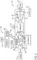
- FIG. 1is a schematic diagram of an embodiment of a power generation system 10 that includes a gas turbine system 12.
- the gas turbine system 12may receive an oxidant 14 (e.g., air, oxygen, oxygen-enriched air, or oxygen-reduced air) and a fuel 16 (e.g., gaseous or liquid fuel), such as natural gas, syngas, or petroleum distillates.
- the oxidant 14may be pressurized and combined with the fuel 16 to be combusted in a combustor 18.
- the combusted oxidantmay then be used to apply forces to blades of a turbine 20 to rotate a shaft 22 that provides power to a load 24 (e.g., electric generator).
- a load 24e.g., electric generator
- the gas turbine system 12may include one or more compressors that increase the pressure of the oxidant 14.
- the gas turbine system 12includes a lower pressure compressor (LPC) 26 connected to an intercooler 28 to couple the lower pressure compressor 26 to an inlet 30 of a high pressure compressor (HPC) 32.
- the oxidant 14enters the low pressure compressor 26 and is compressed into a compressed oxidant 34 (e.g., gas, liquid, or both).
- the compressed oxidant 34may include a compressed gas (e.g., air, oxygen, oxygen-enriched air, or oxygen-reduced air), a lubricant (e.g., oil), a coolant fluid, or any combination thereof.
- the compressed oxidant 34may include gas from exhaust gas recirculation (EGR). The compressed oxidant 34 then enters the intercooler 28. It is to be noted that, in some embodiments of the system 10, no intercooler 28 is used.
- the intercooler 28may be any intercooler 28 suitable for cooling the compressed oxidant 34, such as a spray intercooler (SPRINT) or an efficient spray intercooler (ESPRINT).
- the intercooler 28may cool the compressed oxidant 34 by using a fluid to increase the efficiency of the gas turbine system 12.
- the compressed and cooled oxidant 42is further compressed in the high pressure compressor 32 and combined with the fuel 16 into an oxidant-fuel mixture to be combusted in the combustor 18. As the oxidant-fuel mixture is combusted (e.g., burned and/or ignited), the oxidant-fuel mixture expands through one or more turbines 20.
- embodimentsmay include a high pressure turbine (HPT), intermediate pressure turbine (IPT), and a low pressure turbine (LPT) as depicted in FIG. 1 .
- the system 10may include HPT and LPT turbines. In other embodiments, there may be a single turbine, four, five, or more turbines.
- the turbine 20may be coupled to a shaft 22 that is coupled to one or more loads 24.
- the turbine 20may include one or more turbine blades that rotate causing the shaft 22 to provide rotational energy to the load 24.
- the load 24may include an electrical generator or a mechanical device in an industrial facility or power plant.
- the rotational energy of the shaft 22may be used by the load 24 to generate electrical power.
- the gas turbine system 12generates power, the combusted oxidant-fuel mixture is expelled as an exhaust 46.
- the exhaust 46may include one or more emissions, such as nitrogen oxides (NOx), hydrocarbons (HC), carbon monoxide (CO) and/or other pollutants.
- the exhaust 46may be treated in a variety of ways, such as with a catalyst system.
- the power generation system 10may also include a control system 48 to monitor and/or control various aspects of the gas turbine system 12, the load 24, and/or the intercooler 28.
- the control system 48may include a controller 50 having inputs and/or outputs to receive and/or transmit signals to one or more actuators 60, sensors 62, or other controls to control the gas turbine system 12 and/or the intercooler 28. While some examples are illustrated in FIG. 1 and described below, these are merely examples and any suitable sensors and/or signals may be positioned on the gas turbine system 12, the load 24, and/or the intercooler 28 to detect operational parameters to control the power generation system 10 with the controller 50.
- the controller 50may send and/or receive a signal from one or more actuators 60 and sensors 62 to control any number of aspects of the system 10, including fuel supply, speed, oxidant delivery, power production, and so forth.
- actuators 60may include valves, positioners, pumps, and the like.
- the sensors 62may sense temperature, pressure, speed, clearances (e.g., distance between a stationary and a moving component), flows, mass flows, and the like.
- the controller 50may include and/or communicate with a water wash optimization system 64.
- the water wash optimization system 64may calculate an LPC 26 adiabatic efficiency and an HPC 32 adiabatic efficiency, as well as an engine 12 heat rate.
- the water wash optimization system 64may then determine when a LPC/HPC online water wash is desired based on the LPC and HPC adiabatic efficiencies and on the engine heat rate.
- the water wash optimization system 64may additionally determine when a LPC/HPC offline water wash is desired based on the LPC and HPC adiabatic efficiencies and on the engine heat rate.
- the water wash optimization system 64may then interface with a water wash system 65 to initiate a water wash process.
- the water wash system 65may inject water and/or other fluids through the LPC 26 and/or HPC 32 to remove contaminants and build-up.
- the water wash optimization system 64may then save certain efficiencies (e.g., HPC, LPC adiabatic efficiencies) before and after the water wash(es) are performed, for further analysis and/or logging.
- the water wash optimization system 64may be a software and/or hardware component of the controller 50, or may be a standalone system.
- a computing device separate from the controller 50may host the water wash optimization system 64.
- the controller 50may include a processor 66 or multiple processors, memory 68, and inputs and/or outputs to send and/or receive signals from the one or more sensors 62 and/or actuators 60.
- the processor 66may be operatively coupled to the memory 68 to execute instructions for carrying out the presently disclosed techniques. These instructions may be encoded in programs or code stored in a tangible non-transitory computer-readable medium, such as the memory 68 and/or other storage.
- the processor 66may be a general purpose processor, system-on-chip (SoC) device, or application-specific integrated circuit, or some other processor configuration.
- SoCsystem-on-chip
- the processor 66may be part of an engine control unit that controls various aspects of the turbine system 12.
- Memory 68may include a computer readable medium, such as, without limitation, a hard disk drive, a solid state drive, a diskette, a flash drive, a compact disc, a digital video disc, random access memory (RAM), and/or any suitable storage device that enables processor 66 to store, retrieve, and/or execute instructions and/or data. Memory 68 may further include one or more local and/or remote storage devices. Further, the controller 50 may be operably connected to a human machine interface (HMI) 70 to allow an operator to read measurements, perform analysis, and/or adjust set points of operation.
- HMIhuman machine interface
- FIG. 2the figure illustrates and example of a process 100 suitable for deriving certain LPC and heat rate parameters.
- the LPC and heat rate parametersmay then be used, for example, to determine a desired time to perform an online and/or an offline water wash.
- the process 100may be implemented as computer code or instructions executable by the processor 66 and stored in memory 68.
- the process 100may first derive, for example, in real time, a heat rate 102, a LPC efficiency (e.g., adiabatic efficiency) 104, and an HPC efficiency (e.g., adiabatic efficiency) 106.
- the process 100may receive signals or data from the sensors 62 representative of pressures, temperatures, flows, mass flows, and the like.
- the following equationmay be used:
- Adiabatic efficiencyT s [P d /P s ) (k-1)/k - 1]/(T d - T s )
- T ssuction temperature
- T ddischarge temperature
- ka ratio of specific heats
- C p /C vconstant pressure
- C vconstant value
- the process 100may additionally derive certain estimated LPC efficiency 108, estimated HPC efficiency 110, and estimated Heat Rate 112.
- the estimated LPC efficiency 108, estimated HPC efficiency 110, and estimated Heat Rate 112may be derived, in one embodiment, by using a statistical model of a system 10 and/or system 10 components (e.g., gas turbine 12).
- the statistical modelmay uses statistical methods (e.g., linear regression, non-linear regression), data mining, and the like, to analyze historical data of a fleet of system 10 and/or system 10 components (e.g., gas turbines 12) to derive, given current sensor readings (e.g., pressures, temperatures, flows, mass flows, and the like) based on historical data.
- the process 100may additionally use historical data gathered via a fleet of systems 10 and/or system 10 components (e.g., gas turbines 12) to derive what estimated or expected parameters 108, 110, and 112 should be.
- system 10 componentse.g., gas turbines 12
- the process 100may then apply a deterioration percentage (block 114) to the LPC estimated efficiency 108 and to the HPC estimated efficiency 110.
- the deterioration percentage (block 114)may apply, for example, number of fired hours for the gas turbine 12 to estimate a percentage deterioration for the system 10 and/or system 10 components (e.g., gas turbine 12).
- a specific power system 10may no longer operate in a pristine condition due to use, so block 114 may derate or otherwise add a deterioration factor to the LPC estimated efficiency 108 and to the HPC estimated efficiency 110 to improve accuracy.
- other measuressuch as number of start ups, shut downs, trips, overall power supplied, and so on, may be used by the block 114 to add a deterioration percentage.
- a differentiator 116may then take a difference between the LPC efficiency 104 and the LPC estimate efficiency 108 (with deterioration) to derive an LPC efficiency difference (LPCDIF) 118.
- the differentiator 116may then take a difference between the HPC efficiency 106 and the HPC estimate efficiency 110 (with deterioration) to derive an HPC efficiency difference (HPCDIF) 120.
- a heat rate percentage (HRPCT) 122may be derived by dividing the heat rate 102 with the estimated heat rate 112, for example, via the divisor 124. In this manner, the process 100 may derive the LPC efficiency difference (LPCDIF) 118, the HPC efficiency difference (HPCDIF) 120, and the heat rate percentage (HRPCT) 122.
- a process 200may then use the LPC efficiency difference (LPCDIF) 118, the HPC efficiency difference (HPCDIF) 120, and the heat rate percentage (HRPCT) 122, to derive a more optimal time for execution of an online and/or offline water wash, as described in more detail below with respect to FIG. 3 .
- LPC efficiency differenceLPC efficiency difference
- HPCDIFHPC efficiency difference
- HRPCTheat rate percentage
- FIG. 3illustrates an embodiment of process 200 suitable for determining if an online and/or an offline water wash would improve operations of the power production system 10.
- the process 200may be implemented as computer code or instructions executable by the processor 66 and stored in memory 68.
- the process 200may derive a heat rate and certain efficiencies (block 202).
- the block 202may derive the LPC efficiency difference (LPCDIF) 118, the HPC efficiency difference (HPCDIF) 120, and the heat rate percentage (HRPCT) 122 by executing the process 100 described earlier.
- LPC efficiency differenceLPC efficiency difference
- HPCDIFHPC efficiency difference
- HRPCTheat rate percentage
- the process 200may then derive if an online water wash is desired (block 204), for example, based on the LPC efficiency difference (LPCDIF) 118, the HPC efficiency difference (HPCDIF) 120, and the heat rate percentage (HRPCT) 122.
- LPC efficiency differenceLPC efficiency difference
- HPCDIFHPC efficiency difference
- HRPCTheat rate percentage
- the process 200may then derive if an offline water wash is desired (block 206), for example, based on the LPC efficiency difference (LPCDIF) 118, the HPC efficiency difference (HPCDIF) 120, and the heat rate percentage (HRPCT) 122.
- LPC efficiency differenceLPC efficiency difference
- HPCDIFHPC efficiency difference
- HRPCTheat rate percentage
- the process 200may store certain before water wash data (block 208), for example in arrays.
- the before water wash datamay include the LPC efficiency difference (LPCDIF) 118, the HPC efficiency difference (HPCDIF) 120, and/or the heat rate percentage (HRPCT) 122 previously calculated, as well as other data such as speed, pressure, flow, flow mass, temperature, and the like.
- Storing the before water wash data before initiating the water washmay aid in tracking improvement measures in the power supply system 10, for example, due to executing the water wash.
- the process 200may then execute (block 210) either the online or the offline water wash.
- the online waterwas may be performed while the gas turbine 12 is still operational, while the offline water wash may more comprehensively clean the compressor(s) while the gas turbine 12 is not running.
- the water washmay remove build up and impurities from the LPC and/or HPC and thus improve power production system 10 performance.
- the process 200may store (block 212) certain after water wash data.
- the after water wash datamay include LPC efficiency difference (LPCDIF) 118, the HPC efficiency difference (HPCDIF) 120, speed, pressure, flow, flow mass, temperature, and the like gathered after the water wash is complete.
- the after water wash datamay then be compared to the before water wash data to gauge water wash efficiency, deterioration of equipment, and so on.
- the process 200may then iterate back to block 202 and continue execution.
- a processormay receive one or more operational parameters of a turbine to derive compressor efficiencies and a gas turbine heat rate. The processor may then derive if an online water wash or an offline water wash is desired, for example, by using a range of values of the derived compressor efficiencies and heat rate. Before and after water wash data may be collected for further analysis and logging. By improving the time at which the water wash is to be executed, as opposed to using a fixed schedule, the techniques described herein may improve power production system efficiency while minimizing down time. The water wash may then be performed.
Landscapes
- Engineering & Computer Science (AREA)
- Mechanical Engineering (AREA)
- General Engineering & Computer Science (AREA)
- Chemical & Material Sciences (AREA)
- Combustion & Propulsion (AREA)
- Engine Equipment That Uses Special Cycles (AREA)
Description
- The subject matter disclosed herein relates to gas turbines, and more particularly, to improving water wash methods and systems for gas turbines. Gas turbine systems typically include a compressor for compressing a working fluid, such as air. The compressed air is injected into a combustor which heats the fluid causing it to expand, and the expanded fluid is forced through a turbine. As the compressor consumes large quantities of air, small quantities of dust, aerosols and water pass through and deposit on the compressor (e.g., deposit onto blades of the compressor). These deposits may impede airflow through the compressor and degrade overall performance of the gas turbine system over time. Therefore, gas turbine engines may be periodically washed to clean and remove contaminants from the compressor; such operations are referred to as an offline wash operation or an online wash operation. The offline wash operation is performed while the gas turbine engine is shutdown. Contrarily, the on-line water wash operation allows the compressor wash to be performed while the engine is in operation, but degrades performance of the gas turbine system somewhat. There is a desire, therefore, for a water wash system that provides for more effective cleaning of turbine compressors, and improves water wash methods and systems.
EP 2 876 263 A1 discloses an automated water wash system for a gas turbine engine and method of operation. - The invention is defined in the independent claims. Certain embodiments commensurate in scope with the originally claimed disclosure are summarized below. These embodiments are not intended to limit the scope of the claimed disclosure, but rather these embodiments are intended only to provide a brief summary of possible forms of the disclosure.
- In a first embodiment, a system includes a control system for a gas turbine including a controller. The processor is configured to receive a plurality of signals from sensors disposed in a turbine system, wherein the turbine system comprises a compressor system. The processor is further configured to derive a compressor efficiency and a turbine heat rate based on the plurality of signals. The processor is additionally configured to determine if an online water wash, an offline water wash, or a combination thereof, should be executed. If the processor determines that the online water wash, the offline water wash, or the combination thereof, should be executed, then the processor is configured to execute the online water wash, the offline water wash, or the combination thereof.
- A second embodiment includes a non-transitory computer-readable medium having computer executable code stored thereon, the code having instructions to derive a compressor efficiency and a turbine heat rate based on the plurality of signals. The processor is additionally configured to determine if an online water wash, an offline water wash, or a combination thereof, should be executed. If the code determines that the online water wash, the offline water wash, or the combination thereof, should be executed, then the code is configured to execute the online water wash, the offline water wash, or the combination thereof.
- In a third embodiment, a method for a gas turbine system includes receiving a plurality of signals from sensors disposed in a turbine system, wherein the turbine system comprises a compressor system. The method further includes deriving a compressor efficiency and a turbine heat rate based on the plurality of signals. The method also includes determining if an online water wash, an offline water wash, or a combination thereof, should be executed; and, if it is determined that the online water wash, the offline water wash, or the combination thereof, should be executed, then executing the online water wash, the offline water wash, or the combination thereof.
- These and other features, aspects, and advantages of the present disclosure will become better understood when the following detailed description is read with reference to the accompanying drawings in which like characters represent like parts throughout the drawings, wherein:
FIG. 1 is a schematic diagram of an embodiment of a power generation system having water wash system;FIG. 2 is a flowchart of a process suitable for deriving certain efficiencies and a heat rate; andFIG. 3 is a flowchart of an embodiment of a process suitable for improving the use of the water wash system ofFIG. 1 .- One or more specific embodiments of the present disclosure will be described below. In an effort to provide a concise description of these embodiments, all features of an actual implementation may not be described in the specification. It should be appreciated that in the development of any such actual implementation, as in any engineering or design project, numerous implementation-specific decisions must be made to achieve the developers' specific goals, such as compliance with system-related and business-related constraints, which may vary from one implementation to another. Moreover, it should be appreciated that such a development effort might be complex and time consuming, but would nevertheless be a routine undertaking of design, fabrication, and manufacture for those of ordinary skill having the benefit of this disclosure.
- When introducing elements of various embodiments of the present disclosure, the articles "a," "an," "the," and "said" are intended to mean that there are one or more of the elements. The terms "comprising," "including," and "having" are intended to be inclusive and mean that there may be additional elements other than the listed elements.
- The present disclosure is directed towards a system and method to control and to schedule both online and offline water wash systems of a compressor system on a gas turbine system. The compressor system may include a low pressure compressor (LPC) and a high pressure compressor (HPC). The system may include a controller for a gas turbine system or a computing device suitable for executing code or instructions. The controller may be configured to calculate an LPC adiabatic efficiency. The controller may be additionally configured to calculate an HPC adiabatic efficiency. The controller may be further configured to calculate and engine heat rate. The controller may then determine when a LPC/HPC online water wash is desired based on the LPC and HPC adiabatic efficiencies and on the engine heat rate. The controller may additionally determine when a LPC/HPC offline water wash is desired based on the LPC and HPC adiabatic efficiencies and on the engine heat rate. The controller may then save certain efficiencies (e.g., HPC, LPC adiabatic efficiencies) before and after the water wash(es) are performed, for further analysis and/or logging. By improving the water wash processes, the techniques described herein may increase turbine engine system efficiency, improve fuel consumption and reduce parts wear.
- Turning to the figures,
FIG. 1 is a schematic diagram of an embodiment of apower generation system 10 that includes agas turbine system 12. Thegas turbine system 12 may receive an oxidant 14 (e.g., air, oxygen, oxygen-enriched air, or oxygen-reduced air) and a fuel 16 (e.g., gaseous or liquid fuel), such as natural gas, syngas, or petroleum distillates. Theoxidant 14 may be pressurized and combined with thefuel 16 to be combusted in acombustor 18. The combusted oxidant may then be used to apply forces to blades of aturbine 20 to rotate ashaft 22 that provides power to a load 24 (e.g., electric generator). - The
gas turbine system 12 may include one or more compressors that increase the pressure of theoxidant 14. As depicted inFIG. 1 , thegas turbine system 12 includes a lower pressure compressor (LPC) 26 connected to anintercooler 28 to couple thelower pressure compressor 26 to aninlet 30 of a high pressure compressor (HPC) 32. Theoxidant 14 enters thelow pressure compressor 26 and is compressed into a compressed oxidant 34 (e.g., gas, liquid, or both). The compressedoxidant 34 may include a compressed gas (e.g., air, oxygen, oxygen-enriched air, or oxygen-reduced air), a lubricant (e.g., oil), a coolant fluid, or any combination thereof. In certain embodiments, thecompressed oxidant 34 may include gas from exhaust gas recirculation (EGR). The compressedoxidant 34 then enters theintercooler 28. It is to be noted that, in some embodiments of thesystem 10, nointercooler 28 is used. - The
intercooler 28 may be anyintercooler 28 suitable for cooling thecompressed oxidant 34, such as a spray intercooler (SPRINT) or an efficient spray intercooler (ESPRINT). Theintercooler 28 may cool thecompressed oxidant 34 by using a fluid to increase the efficiency of thegas turbine system 12. The compressed and cooledoxidant 42 is further compressed in thehigh pressure compressor 32 and combined with thefuel 16 into an oxidant-fuel mixture to be combusted in thecombustor 18. As the oxidant-fuel mixture is combusted (e.g., burned and/or ignited), the oxidant-fuel mixture expands through one ormore turbines 20. For example, embodiments may include a high pressure turbine (HPT), intermediate pressure turbine (IPT), and a low pressure turbine (LPT) as depicted inFIG. 1 . In some embodiments, thesystem 10 may include HPT and LPT turbines. In other embodiments, there may be a single turbine, four, five, or more turbines. - The
turbine 20 may be coupled to ashaft 22 that is coupled to one or more loads 24. Theturbine 20 may include one or more turbine blades that rotate causing theshaft 22 to provide rotational energy to theload 24. For example, theload 24 may include an electrical generator or a mechanical device in an industrial facility or power plant. The rotational energy of theshaft 22 may be used by theload 24 to generate electrical power. As thegas turbine system 12 generates power, the combusted oxidant-fuel mixture is expelled as anexhaust 46. Theexhaust 46 may include one or more emissions, such as nitrogen oxides (NOx), hydrocarbons (HC), carbon monoxide (CO) and/or other pollutants. Theexhaust 46 may be treated in a variety of ways, such as with a catalyst system. - The
power generation system 10 may also include a control system 48 to monitor and/or control various aspects of thegas turbine system 12, theload 24, and/or theintercooler 28. The control system 48 may include acontroller 50 having inputs and/or outputs to receive and/or transmit signals to one ormore actuators 60,sensors 62, or other controls to control thegas turbine system 12 and/or theintercooler 28. While some examples are illustrated inFIG. 1 and described below, these are merely examples and any suitable sensors and/or signals may be positioned on thegas turbine system 12, theload 24, and/or theintercooler 28 to detect operational parameters to control thepower generation system 10 with thecontroller 50. For example, thecontroller 50 may send and/or receive a signal from one ormore actuators 60 andsensors 62 to control any number of aspects of thesystem 10, including fuel supply, speed, oxidant delivery, power production, and so forth. For example, actuators 60 may include valves, positioners, pumps, and the like. Thesensors 62 may sense temperature, pressure, speed, clearances (e.g., distance between a stationary and a moving component), flows, mass flows, and the like. - Further, the
controller 50 may include and/or communicate with a waterwash optimization system 64. The waterwash optimization system 64 may calculate anLPC 26 adiabatic efficiency and anHPC 32 adiabatic efficiency, as well as anengine 12 heat rate. The waterwash optimization system 64 may then determine when a LPC/HPC online water wash is desired based on the LPC and HPC adiabatic efficiencies and on the engine heat rate. The waterwash optimization system 64 may additionally determine when a LPC/HPC offline water wash is desired based on the LPC and HPC adiabatic efficiencies and on the engine heat rate. The waterwash optimization system 64 may then interface with awater wash system 65 to initiate a water wash process. Thewater wash system 65 may inject water and/or other fluids through theLPC 26 and/orHPC 32 to remove contaminants and build-up. The waterwash optimization system 64 may then save certain efficiencies (e.g., HPC, LPC adiabatic efficiencies) before and after the water wash(es) are performed, for further analysis and/or logging. It is to be understood that the waterwash optimization system 64 may be a software and/or hardware component of thecontroller 50, or may be a standalone system. For example, a computing device separate from thecontroller 50 may host the waterwash optimization system 64. - The
controller 50 may include aprocessor 66 or multiple processors,memory 68, and inputs and/or outputs to send and/or receive signals from the one ormore sensors 62 and/oractuators 60. Theprocessor 66 may be operatively coupled to thememory 68 to execute instructions for carrying out the presently disclosed techniques. These instructions may be encoded in programs or code stored in a tangible non-transitory computer-readable medium, such as thememory 68 and/or other storage. Theprocessor 66 may be a general purpose processor, system-on-chip (SoC) device, or application-specific integrated circuit, or some other processor configuration. For example, theprocessor 66 may be part of an engine control unit that controls various aspects of theturbine system 12. Memory 68 may include a computer readable medium, such as, without limitation, a hard disk drive, a solid state drive, a diskette, a flash drive, a compact disc, a digital video disc, random access memory (RAM), and/or any suitable storage device that enablesprocessor 66 to store, retrieve, and/or execute instructions and/or data.Memory 68 may further include one or more local and/or remote storage devices. Further, thecontroller 50 may be operably connected to a human machine interface (HMI) 70 to allow an operator to read measurements, perform analysis, and/or adjust set points of operation.- Turning now to
FIG. 2 , the figure illustrates and example of aprocess 100 suitable for deriving certain LPC and heat rate parameters. The LPC and heat rate parameters may then be used, for example, to determine a desired time to perform an online and/or an offline water wash. Theprocess 100 may be implemented as computer code or instructions executable by theprocessor 66 and stored inmemory 68. In the depicted embodiment, theprocess 100 may first derive, for example, in real time, aheat rate 102, a LPC efficiency (e.g., adiabatic efficiency) 104, and an HPC efficiency (e.g., adiabatic efficiency) 106. Theprocess 100 may receive signals or data from thesensors 62 representative of pressures, temperatures, flows, mass flows, and the like. In one example, to calculate heat rate, the following equation may be used: - Heat rate (e.g., gas turbine heat rate) = Input Energy (BTU/hr)/Output power (kW). Heat rate may be the inverse of efficiency.
- In one example, to calculate adiabatic efficiency for a compressor (e.g., LPC and/or HPC), the following formula may be used:
Adiabatic efficiency = Ts [Pd/Ps)(k-1)/k - 1]/(Td - Ts) where Ts = suction temperature, Td = discharge temperature and k is a ratio of specific heats, Cp/Cv. Cp is constant pressure and Cv is constant value. - The
process 100 may additionally derive certain estimatedLPC efficiency 108, estimatedHPC efficiency 110, and estimatedHeat Rate 112. The estimatedLPC efficiency 108, estimatedHPC efficiency 110, and estimatedHeat Rate 112 may be derived, in one embodiment, by using a statistical model of asystem 10 and/orsystem 10 components (e.g., gas turbine 12). The statistical model may uses statistical methods (e.g., linear regression, non-linear regression), data mining, and the like, to analyze historical data of a fleet ofsystem 10 and/orsystem 10 components (e.g., gas turbines 12) to derive, given current sensor readings (e.g., pressures, temperatures, flows, mass flows, and the like) based on historical data. That is, rather than using only thesensor 62 readings and the equations listed above for heat rate and adiabatic efficiency, theprocess 100 may additionally use historical data gathered via a fleet ofsystems 10 and/orsystem 10 components (e.g., gas turbines 12) to derive what estimated or expectedparameters - The
process 100 may then apply a deterioration percentage (block 114) to the LPC estimatedefficiency 108 and to the HPC estimatedefficiency 110. The deterioration percentage (block 114) may apply, for example, number of fired hours for thegas turbine 12 to estimate a percentage deterioration for thesystem 10 and/orsystem 10 components (e.g., gas turbine 12). In other words, aspecific power system 10 may no longer operate in a pristine condition due to use, so block 114 may derate or otherwise add a deterioration factor to the LPC estimatedefficiency 108 and to the HPC estimatedefficiency 110 to improve accuracy. It is to be noted that in addition to or in lieu of fired hours, other measures such as number of start ups, shut downs, trips, overall power supplied, and so on, may be used by theblock 114 to add a deterioration percentage. - A
differentiator 116 may then take a difference between theLPC efficiency 104 and the LPC estimate efficiency 108 (with deterioration) to derive an LPC efficiency difference (LPCDIF) 118. Likewise, thedifferentiator 116 may then take a difference between theHPC efficiency 106 and the HPC estimate efficiency 110 (with deterioration) to derive an HPC efficiency difference (HPCDIF) 120. A heat rate percentage (HRPCT) 122 may be derived by dividing theheat rate 102 with the estimatedheat rate 112, for example, via thedivisor 124. In this manner, theprocess 100 may derive the LPC efficiency difference (LPCDIF) 118, the HPC efficiency difference (HPCDIF) 120, and the heat rate percentage (HRPCT) 122. Aprocess 200 may then use the LPC efficiency difference (LPCDIF) 118, the HPC efficiency difference (HPCDIF) 120, and the heat rate percentage (HRPCT) 122, to derive a more optimal time for execution of an online and/or offline water wash, as described in more detail below with respect toFIG. 3 . FIG. 3 illustrates an embodiment ofprocess 200 suitable for determining if an online and/or an offline water wash would improve operations of thepower production system 10. Theprocess 200 may be implemented as computer code or instructions executable by theprocessor 66 and stored inmemory 68. In the depicted embodiment, theprocess 200 may derive a heat rate and certain efficiencies (block 202). For example, theblock 202 may derive the LPC efficiency difference (LPCDIF) 118, the HPC efficiency difference (HPCDIF) 120, and the heat rate percentage (HRPCT) 122 by executing theprocess 100 described earlier.- The
process 200 may then derive if an online water wash is desired (block 204), for example, based on the LPC efficiency difference (LPCDIF) 118, the HPC efficiency difference (HPCDIF) 120, and the heat rate percentage (HRPCT) 122. In one embodiment, if LPCDIF > 0.01 and <= 0.02 and HRPCT > 0.01 and <= 0.02 then an LPC online water wash is recommended. Likewise, if HPCDIF > 0.01 and <= 0.02 and HRPCT > 0.01 and <= 0.02 then an online HPC water wash is recommended. It is to be noted that while theblock 204, in one embodiment, utilizes a range between > 0.01 and <= 0.02, in other embodiments, the range may be determined by an analysis process to derive a more optimal range based ongas turbine 12 type. For example, the range may be between > 0.001 and <= 0.10. - The
process 200 may then derive if an offline water wash is desired (block 206), for example, based on the LPC efficiency difference (LPCDIF) 118, the HPC efficiency difference (HPCDIF) 120, and the heat rate percentage (HRPCT) 122. In one embodiment, if LPCDIF > 0.02 and HRPCT > 0.02 then a LPC offline water wash is recommend. Likewise, if HPCDIF > 0.02 and HRPCT > 0.02 then an offline HPC water wash is recommended. It is to be noted that while theblock 206, in one embodiment, utilizes a value of > 0.02, in other embodiments, the value may be determined by an analysis process to derive a more optimal range based ongas turbine 12 type. For example, the value may be > 0.01. - Before initiating the online or the offline water wash, the
process 200 may store certain before water wash data (block 208), for example in arrays. The before water wash data may include the LPC efficiency difference (LPCDIF) 118, the HPC efficiency difference (HPCDIF) 120, and/or the heat rate percentage (HRPCT) 122 previously calculated, as well as other data such as speed, pressure, flow, flow mass, temperature, and the like. Storing the before water wash data before initiating the water wash (block 208) may aid in tracking improvement measures in thepower supply system 10, for example, due to executing the water wash. - The
process 200 may then execute (block 210) either the online or the offline water wash. As mentioned above, the online water was may be performed while thegas turbine 12 is still operational, while the offline water wash may more comprehensively clean the compressor(s) while thegas turbine 12 is not running. The water wash may remove build up and impurities from the LPC and/or HPC and thus improvepower production system 10 performance. Once the water wash is complete, theprocess 200 may store (block 212) certain after water wash data. The after water wash data may include LPC efficiency difference (LPCDIF) 118, the HPC efficiency difference (HPCDIF) 120, speed, pressure, flow, flow mass, temperature, and the like gathered after the water wash is complete. The after water wash data may then be compared to the before water wash data to gauge water wash efficiency, deterioration of equipment, and so on. Theprocess 200 may then iterate back to block 202 and continue execution. - Technical effects of the present embodiments may include improving water wash systems and methods. In certain embodiments, a processor may receive one or more operational parameters of a turbine to derive compressor efficiencies and a gas turbine heat rate. The processor may then derive if an online water wash or an offline water wash is desired, for example, by using a range of values of the derived compressor efficiencies and heat rate. Before and after water wash data may be collected for further analysis and logging. By improving the time at which the water wash is to be executed, as opposed to using a fixed schedule, the techniques described herein may improve power production system efficiency while minimizing down time. The water wash may then be performed.
- This written description uses examples to disclose the embodiments and also to enable any person skilled in the art to practice the embodiments, including making and using any devices or systems and performing any incorporated methods.
Claims (12)
- A control system (48) for a gas turbine (12), comprising:
a controller (50) comprising a processor (66), wherein the processor (66) is configured to:receive a plurality of signals from sensors (62) disposed in a turbine system (12), wherein the turbine system (12) comprises a compressor system;derive a compressor efficiency and a turbine heat rate based on the plurality of signals;determine if an online water wash, an offline water wash, or a combination thereof, should be executed; andif it is determined that the online water wash, the offline water wash, or the combination thereof, should be executed, then executing the online water wash, the offline water wash, or the combination thereof, wherein the online water wash comprises a low pressure compressor, LPC, online water wash, wherein the compressor efficiency comprises a low pressure compressor, LPC, adiabatic efficiency, wherein determining if the online water wash should be executed comprises determining if a LPC efficiency difference, LPCDIF, is within a first range and determining if a heat range percentage, HRPCT, is within a second range, and executing the online water wash comprises executing a LPC online water wash. - The control system (48) of claim 1, wherein determining if the LPCDIF is within the first range comprises determing if the LPCDIF is > 0.01 and <= 0.02 and wherein determining if the HRPCT is within the second range comprises determining if the HRPCT > 0.01 and <= 0.02.
- The control system (48) of claim 1, comprising determining the LPCDIF by subtracting a current LPC efficiency from an addition comprising a deterioration percentage added to a LPC estimated efficiency, wherein the LPC estimated efficiency is derived by executing a statistical model of a fleet of gas turbine systems (12).
- The control system (48) of claim 1, wherein the online water wash comprises a high pressure compressor, HPC, online water wash, wherein the compressor efficiency comprises a high pressure compressor, HPC, adiabatic efficiency, wherein determining if the online water wash should be executed comprises determining if a HPC efficiency difference, HPCDIF, is within a first range and determining if a heat range percentage, HRPCT, is within a second range, and executing the online water wash comprises executing a LPC online water wash.
- The control system (48) of claim 1, wherein the offline water wash comprises a low pressure compressor, LPC, offline water wash, wherein the compressor efficiency comprises a low pressure compressor, LPC, adiabatic efficiency, wherein determining if the offline water wash should be executed comprises determining if a LPC efficiency difference, LPCDIF, is within a first range and determining if a heat range percentage, HRPCT, is within a second range, and executing the offline water wash comprises executing a LPC offline water wash.
- The control system (48) of claim 5, wherein determining if the LPCDIF is within the first range comprises determing if the LPCDIF is > 0.02 and wherein determining if the HRPCT is within the second range comprises determining if the HRPCT > 0.02.
- The control system (48) of claim 1, wherein the offline water wash comprises a high pressure compressor, HPC, offline water wash, wherein the compressor efficiency comprises a high pressure compressor, HPC, adiabatic efficiency, wherein determining if the offline water wash should be executed comprises determining if a HPC efficiency difference (HPCDIF) is within a first range and determining if a heat range percentage (HRPCT) is within a second range, and executing the offline water wash comprises executing a HPC offline water wash.
- A method for a gas turbine system (12), comprising:receiving a plurality of signals from sensors (62) disposed in a turbine system (12), wherein the turbine system (12) comprises a compressor system;deriving a compressor efficiency and a turbine heat rate based on the plurality of signals;determining if an online water wash, an offline water wash, or a combination thereof, should be executed; andif it is determined that the online water wash, the offline water wash, or the combination thereof, should be executed, then executing the online water wash, the offline water wash, or the combination thereof, wherein the online water wash comprises a low pressure compressor, LPC, online water wash, wherein the compressor efficiency comprises a low pressure compressor, LPC, adiabatic efficiency, wherein determining if the online water wash should be executed comprises determining if a LPC efficiency difference, LPCDIF, is within a first range and determining if a heat range percentage, HRPCT, is within a second range, and executing the online water wash comprises executing a LPC online water wash.
- The method of claim 8, wherein the online water wash comprises a high pressure compressor, HPC, online water wash, wherein the compressor efficiency comprises a high pressure compressor, HPC, adiabatic efficiency, wherein determining if the online water wash should be executed comprises determining if a HPC efficiency difference, HPCDIF, is within a first range and determining if a heat range percentage, HRPCT, is within a second range, and executing the online water wash comprises executing a LPC online water wash.
- The method of claim 8, wherein the offline water wash comprises a low pressure compressor, LPC, offline water wash, wherein the compressor efficiency comprises a low pressure compressor, LPC, adiabatic efficiency, wherein determining if the offline water wash should be executed comprises determining if a LPC efficiency difference, LPCDIF, is within a first range and determining if a heat range percentage, HRPCT, is within a second range, and executing the offline water wash comprises executing a LPC offline water wash.
- The method of claim 8, wherein the offline water wash comprises a high pressure compressor, HPC, offline water wash, wherein the compressor efficiency comprises a high pressure compressor, HPC, adiabatic efficiency, wherein determining if the offline water wash should be executed comprises determining if a HPC efficiency difference, HPCDIF, is within a first range and determining if a heat range percentage, HRPCT, is within a second range, and executing the offline water wash comprises executing a HPC offline water wash.
- A non-transitory computer-readable medium having computer executable code stored thereon to execute a method according to one of the claims 8-11.
Applications Claiming Priority (1)
| Application Number | Priority Date | Filing Date | Title |
|---|---|---|---|
| US14/985,799US10041373B2 (en) | 2015-12-31 | 2015-12-31 | Gas turbine water wash methods and systems |
Publications (2)
| Publication Number | Publication Date |
|---|---|
| EP3187697A1 EP3187697A1 (en) | 2017-07-05 |
| EP3187697B1true EP3187697B1 (en) | 2019-08-07 |
Family
ID=57754997
Family Applications (1)
| Application Number | Title | Priority Date | Filing Date |
|---|---|---|---|
| EP16205239.3AActiveEP3187697B1 (en) | 2015-12-31 | 2016-12-20 | Gas turbine water wash methods and systems |
Country Status (4)
| Country | Link |
|---|---|
| US (1) | US10041373B2 (en) |
| EP (1) | EP3187697B1 (en) |
| JP (1) | JP6890967B2 (en) |
| CN (1) | CN106948946B (en) |
Families Citing this family (13)
| Publication number | Priority date | Publication date | Assignee | Title |
|---|---|---|---|---|
| US20170298826A1 (en)* | 2016-04-18 | 2017-10-19 | John E. Ryznic | Industrial gas turbine engine with turbine airfoil cooling |
| US11112118B2 (en)* | 2016-06-27 | 2021-09-07 | General Electric Company | Gas turbine lower heating value methods and systems |
| US20180010481A1 (en)* | 2016-07-08 | 2018-01-11 | Ge Aviation Systems Llc | Engine performance modeling based on wash events |
| US11268449B2 (en) | 2017-09-22 | 2022-03-08 | General Electric Company | Contamination accumulation modeling |
| CN110513336B (en)* | 2019-09-05 | 2020-12-22 | 哈尔滨电气股份有限公司 | A method for determining off-line water washing time of gas turbine in power station |
| CN111027006B (en)* | 2019-12-17 | 2023-05-30 | 西安空天能源动力智能制造研究院有限公司 | Method for obtaining optimal washing cycle of gas turbine |
| CN112412630B (en)* | 2020-12-07 | 2024-07-02 | 华北电力科学研究院有限责任公司 | Gas turbine compressor water washing system and control method thereof |
| CN113027826B (en)* | 2021-02-26 | 2023-11-10 | 北京京能高安屯燃气热电有限责任公司 | Gas turbine compressor cleaning method and device |
| CN113153523B (en)* | 2021-04-02 | 2021-12-10 | 华能苏州热电有限责任公司 | A kind of compressor off-line washing control method and system |
| CN113417882B (en)* | 2021-06-29 | 2023-04-11 | 苏州浪潮智能科技有限公司 | Fan in-place detection device and method |
| GB2610200B (en) | 2021-08-25 | 2024-11-20 | Rolls Royce Plc | Computer-implemented methods of enabling optimisation of trajectory for a vehicle |
| GB2610199B (en) | 2021-08-25 | 2024-01-17 | Rolls Royce Plc | Computer-implemented methods for enabling optimisation of derate for a propulsion system of a vehicle |
| GB2627774A (en) | 2023-03-01 | 2024-09-04 | Siemens Energy Global Gmbh & Co Kg | Methods and system for optimizing scheduling of servicing events in turbine engines |
Family Cites Families (3)
| Publication number | Priority date | Publication date | Assignee | Title |
|---|---|---|---|---|
| JP2005133583A (en) | 2003-10-29 | 2005-05-26 | Hitachi Ltd | Gas turbine cleaning time determination device and determination method |
| US20130186435A1 (en)* | 2012-01-23 | 2013-07-25 | General Electric Companh | Gas Turbine Compressor Water Wash System |
| US9470105B2 (en)* | 2013-11-21 | 2016-10-18 | General Electric Company | Automated water wash system for a gas turbine engine |
- 2015
- 2015-12-31USUS14/985,799patent/US10041373B2/enactiveActive
- 2016
- 2016-12-20EPEP16205239.3Apatent/EP3187697B1/enactiveActive
- 2016-12-22JPJP2016248547Apatent/JP6890967B2/enactiveActive
- 2017
- 2017-01-03CNCN201710001057.7Apatent/CN106948946B/enactiveActive
Non-Patent Citations (1)
| Title |
|---|
| None* |
Also Published As
| Publication number | Publication date |
|---|---|
| JP6890967B2 (en) | 2021-06-18 |
| US10041373B2 (en) | 2018-08-07 |
| EP3187697A1 (en) | 2017-07-05 |
| CN106948946A (en) | 2017-07-14 |
| JP2017129131A (en) | 2017-07-27 |
| CN106948946B (en) | 2021-06-18 |
| US20170191375A1 (en) | 2017-07-06 |
Similar Documents
| Publication | Publication Date | Title |
|---|---|---|
| EP3187697B1 (en) | Gas turbine water wash methods and systems | |
| Rogalev et al. | Thermodynamic optimization and equipment development for a high efficient fossil fuel power plant with zero emissions | |
| US10508597B2 (en) | Systems and methods for icing detection of compressors | |
| Kurz et al. | Degradation effects on industrial gas turbines | |
| EP3051075B1 (en) | Wash timing based on turbine operating parameters | |
| CN107448299B (en) | Computing device, method, and computer-readable medium for determining a state of a filter housing | |
| Mendeleev et al. | Study of the work and efficiency improvement of combined-cycle gas turbine plants | |
| JP6878108B2 (en) | Systems and methods for modeling engine power output | |
| JP2014174993A5 (en) | ||
| Griffin et al. | Real-time on-line performance diagnostics of heavy-duty industrial gas turbines | |
| CN102680235A (en) | Method and system for analysis of turbines | |
| US9739199B2 (en) | Intercooled gas turbine optimization | |
| CN115618592A (en) | Gas circuit fault diagnosis method, system, equipment and terminal of a gas turbine in a power plant | |
| JP7032017B2 (en) | Systems and methods for cleaning gas turbine compressors | |
| EP3369895A2 (en) | System and method for monitoring a lubrication system of a turbomachine using a model | |
| US10487750B2 (en) | System and method for predicting and enhancing power plant startup time | |
| US11112118B2 (en) | Gas turbine lower heating value methods and systems | |
| EP3239614A1 (en) | Systems and methods of predicting physical parameters for a combustion fuel system | |
| JP2011256734A (en) | Diagnosis method and diagnosis apparatus for service life of high temperature component | |
| US11028784B2 (en) | Methods and systems for heavy fuel oil in gas turbines | |
| Ahmadyaningrat et al. | Optimasi efisiensi pltg pada kondisi keterbatasan bahan bakar | |
| Liang et al. | Research on Method for Monitoring Service Life of Hot-End Components in Gas Turbine based on Condition Analysis | |
| Zhang et al. | Selection of the optimal initial steam pressure for coal-fired power units | |
| Thomasson et al. | Initial Results of Adiabatic Compressed Air Energy Storage (CAES) Dynamic Process Model | |
| Bridgeman et al. | Instrumenting and acquiring data for the WR21 gas turbine development programme |
Legal Events
| Date | Code | Title | Description |
|---|---|---|---|
| PUAI | Public reference made under article 153(3) epc to a published international application that has entered the european phase | Free format text:ORIGINAL CODE: 0009012 | |
| STAA | Information on the status of an ep patent application or granted ep patent | Free format text:STATUS: THE APPLICATION HAS BEEN PUBLISHED | |
| AK | Designated contracting states | Kind code of ref document:A1 Designated state(s):AL AT BE BG CH CY CZ DE DK EE ES FI FR GB GR HR HU IE IS IT LI LT LU LV MC MK MT NL NO PL PT RO RS SE SI SK SM TR | |
| AX | Request for extension of the european patent | Extension state:BA ME | |
| STAA | Information on the status of an ep patent application or granted ep patent | Free format text:STATUS: REQUEST FOR EXAMINATION WAS MADE | |
| 17P | Request for examination filed | Effective date:20180105 | |
| RBV | Designated contracting states (corrected) | Designated state(s):AL AT BE BG CH CY CZ DE DK EE ES FI FR GB GR HR HU IE IS IT LI LT LU LV MC MK MT NL NO PL PT RO RS SE SI SK SM TR | |
| GRAP | Despatch of communication of intention to grant a patent | Free format text:ORIGINAL CODE: EPIDOSNIGR1 | |
| STAA | Information on the status of an ep patent application or granted ep patent | Free format text:STATUS: GRANT OF PATENT IS INTENDED | |
| INTG | Intention to grant announced | Effective date:20190329 | |
| GRAS | Grant fee paid | Free format text:ORIGINAL CODE: EPIDOSNIGR3 | |
| GRAA | (expected) grant | Free format text:ORIGINAL CODE: 0009210 | |
| STAA | Information on the status of an ep patent application or granted ep patent | Free format text:STATUS: THE PATENT HAS BEEN GRANTED | |
| AK | Designated contracting states | Kind code of ref document:B1 Designated state(s):AL AT BE BG CH CY CZ DE DK EE ES FI FR GB GR HR HU IE IS IT LI LT LU LV MC MK MT NL NO PL PT RO RS SE SI SK SM TR | |
| REG | Reference to a national code | Ref country code:GB Ref legal event code:FG4D | |
| REG | Reference to a national code | Ref country code:CH Ref legal event code:EP Ref country code:AT Ref legal event code:REF Ref document number:1164190 Country of ref document:AT Kind code of ref document:T Effective date:20190815 | |
| REG | Reference to a national code | Ref country code:DE Ref legal event code:R096 Ref document number:602016018040 Country of ref document:DE | |
| REG | Reference to a national code | Ref country code:IE Ref legal event code:FG4D | |
| REG | Reference to a national code | Ref country code:NL Ref legal event code:MP Effective date:20190807 | |
| REG | Reference to a national code | Ref country code:LT Ref legal event code:MG4D | |
| PG25 | Lapsed in a contracting state [announced via postgrant information from national office to epo] | Ref country code:NO Free format text:LAPSE BECAUSE OF FAILURE TO SUBMIT A TRANSLATION OF THE DESCRIPTION OR TO PAY THE FEE WITHIN THE PRESCRIBED TIME-LIMIT Effective date:20191107 Ref country code:PT Free format text:LAPSE BECAUSE OF FAILURE TO SUBMIT A TRANSLATION OF THE DESCRIPTION OR TO PAY THE FEE WITHIN THE PRESCRIBED TIME-LIMIT Effective date:20191209 Ref country code:NL Free format text:LAPSE BECAUSE OF FAILURE TO SUBMIT A TRANSLATION OF THE DESCRIPTION OR TO PAY THE FEE WITHIN THE PRESCRIBED TIME-LIMIT Effective date:20190807 Ref country code:BG Free format text:LAPSE BECAUSE OF FAILURE TO SUBMIT A TRANSLATION OF THE DESCRIPTION OR TO PAY THE FEE WITHIN THE PRESCRIBED TIME-LIMIT Effective date:20191107 Ref country code:FI Free format text:LAPSE BECAUSE OF FAILURE TO SUBMIT A TRANSLATION OF THE DESCRIPTION OR TO PAY THE FEE WITHIN THE PRESCRIBED TIME-LIMIT Effective date:20190807 Ref country code:LT Free format text:LAPSE BECAUSE OF FAILURE TO SUBMIT A TRANSLATION OF THE DESCRIPTION OR TO PAY THE FEE WITHIN THE PRESCRIBED TIME-LIMIT Effective date:20190807 Ref country code:HR Free format text:LAPSE BECAUSE OF FAILURE TO SUBMIT A TRANSLATION OF THE DESCRIPTION OR TO PAY THE FEE WITHIN THE PRESCRIBED TIME-LIMIT Effective date:20190807 Ref country code:SE Free format text:LAPSE BECAUSE OF FAILURE TO SUBMIT A TRANSLATION OF THE DESCRIPTION OR TO PAY THE FEE WITHIN THE PRESCRIBED TIME-LIMIT Effective date:20190807 | |
| REG | Reference to a national code | Ref country code:AT Ref legal event code:MK05 Ref document number:1164190 Country of ref document:AT Kind code of ref document:T Effective date:20190807 | |
| PG25 | Lapsed in a contracting state [announced via postgrant information from national office to epo] | Ref country code:ES Free format text:LAPSE BECAUSE OF FAILURE TO SUBMIT A TRANSLATION OF THE DESCRIPTION OR TO PAY THE FEE WITHIN THE PRESCRIBED TIME-LIMIT Effective date:20190807 Ref country code:LV Free format text:LAPSE BECAUSE OF FAILURE TO SUBMIT A TRANSLATION OF THE DESCRIPTION OR TO PAY THE FEE WITHIN THE PRESCRIBED TIME-LIMIT Effective date:20190807 Ref country code:AL Free format text:LAPSE BECAUSE OF FAILURE TO SUBMIT A TRANSLATION OF THE DESCRIPTION OR TO PAY THE FEE WITHIN THE PRESCRIBED TIME-LIMIT Effective date:20190807 Ref country code:RS Free format text:LAPSE BECAUSE OF FAILURE TO SUBMIT A TRANSLATION OF THE DESCRIPTION OR TO PAY THE FEE WITHIN THE PRESCRIBED TIME-LIMIT Effective date:20190807 Ref country code:GR Free format text:LAPSE BECAUSE OF FAILURE TO SUBMIT A TRANSLATION OF THE DESCRIPTION OR TO PAY THE FEE WITHIN THE PRESCRIBED TIME-LIMIT Effective date:20191108 Ref country code:IS Free format text:LAPSE BECAUSE OF FAILURE TO SUBMIT A TRANSLATION OF THE DESCRIPTION OR TO PAY THE FEE WITHIN THE PRESCRIBED TIME-LIMIT Effective date:20191207 | |
| PG25 | Lapsed in a contracting state [announced via postgrant information from national office to epo] | Ref country code:TR Free format text:LAPSE BECAUSE OF FAILURE TO SUBMIT A TRANSLATION OF THE DESCRIPTION OR TO PAY THE FEE WITHIN THE PRESCRIBED TIME-LIMIT Effective date:20190807 | |
| PG25 | Lapsed in a contracting state [announced via postgrant information from national office to epo] | Ref country code:IT Free format text:LAPSE BECAUSE OF FAILURE TO SUBMIT A TRANSLATION OF THE DESCRIPTION OR TO PAY THE FEE WITHIN THE PRESCRIBED TIME-LIMIT Effective date:20190807 Ref country code:DK Free format text:LAPSE BECAUSE OF FAILURE TO SUBMIT A TRANSLATION OF THE DESCRIPTION OR TO PAY THE FEE WITHIN THE PRESCRIBED TIME-LIMIT Effective date:20190807 Ref country code:EE Free format text:LAPSE BECAUSE OF FAILURE TO SUBMIT A TRANSLATION OF THE DESCRIPTION OR TO PAY THE FEE WITHIN THE PRESCRIBED TIME-LIMIT Effective date:20190807 Ref country code:PL Free format text:LAPSE BECAUSE OF FAILURE TO SUBMIT A TRANSLATION OF THE DESCRIPTION OR TO PAY THE FEE WITHIN THE PRESCRIBED TIME-LIMIT Effective date:20190807 Ref country code:AT Free format text:LAPSE BECAUSE OF FAILURE TO SUBMIT A TRANSLATION OF THE DESCRIPTION OR TO PAY THE FEE WITHIN THE PRESCRIBED TIME-LIMIT Effective date:20190807 Ref country code:RO Free format text:LAPSE BECAUSE OF FAILURE TO SUBMIT A TRANSLATION OF THE DESCRIPTION OR TO PAY THE FEE WITHIN THE PRESCRIBED TIME-LIMIT Effective date:20190807 | |
| PG25 | Lapsed in a contracting state [announced via postgrant information from national office to epo] | Ref country code:CZ Free format text:LAPSE BECAUSE OF FAILURE TO SUBMIT A TRANSLATION OF THE DESCRIPTION OR TO PAY THE FEE WITHIN THE PRESCRIBED TIME-LIMIT Effective date:20190807 Ref country code:IS Free format text:LAPSE BECAUSE OF FAILURE TO SUBMIT A TRANSLATION OF THE DESCRIPTION OR TO PAY THE FEE WITHIN THE PRESCRIBED TIME-LIMIT Effective date:20200224 Ref country code:SK Free format text:LAPSE BECAUSE OF FAILURE TO SUBMIT A TRANSLATION OF THE DESCRIPTION OR TO PAY THE FEE WITHIN THE PRESCRIBED TIME-LIMIT Effective date:20190807 Ref country code:SM Free format text:LAPSE BECAUSE OF FAILURE TO SUBMIT A TRANSLATION OF THE DESCRIPTION OR TO PAY THE FEE WITHIN THE PRESCRIBED TIME-LIMIT Effective date:20190807 | |
| REG | Reference to a national code | Ref country code:DE Ref legal event code:R097 Ref document number:602016018040 Country of ref document:DE | |
| PLBE | No opposition filed within time limit | Free format text:ORIGINAL CODE: 0009261 | |
| STAA | Information on the status of an ep patent application or granted ep patent | Free format text:STATUS: NO OPPOSITION FILED WITHIN TIME LIMIT | |
| PG2D | Information on lapse in contracting state deleted | Ref country code:IS | |
| REG | Reference to a national code | Ref country code:CH Ref legal event code:PL | |
| 26N | No opposition filed | Effective date:20200603 | |
| REG | Reference to a national code | Ref country code:BE Ref legal event code:MM Effective date:20191231 | |
| PG25 | Lapsed in a contracting state [announced via postgrant information from national office to epo] | Ref country code:SI Free format text:LAPSE BECAUSE OF FAILURE TO SUBMIT A TRANSLATION OF THE DESCRIPTION OR TO PAY THE FEE WITHIN THE PRESCRIBED TIME-LIMIT Effective date:20190807 Ref country code:MC Free format text:LAPSE BECAUSE OF FAILURE TO SUBMIT A TRANSLATION OF THE DESCRIPTION OR TO PAY THE FEE WITHIN THE PRESCRIBED TIME-LIMIT Effective date:20190807 | |
| PG25 | Lapsed in a contracting state [announced via postgrant information from national office to epo] | Ref country code:IE Free format text:LAPSE BECAUSE OF NON-PAYMENT OF DUE FEES Effective date:20191220 Ref country code:FR Free format text:LAPSE BECAUSE OF NON-PAYMENT OF DUE FEES Effective date:20191231 Ref country code:LU Free format text:LAPSE BECAUSE OF NON-PAYMENT OF DUE FEES Effective date:20191220 | |
| PG25 | Lapsed in a contracting state [announced via postgrant information from national office to epo] | Ref country code:CH Free format text:LAPSE BECAUSE OF NON-PAYMENT OF DUE FEES Effective date:20191231 Ref country code:BE Free format text:LAPSE BECAUSE OF NON-PAYMENT OF DUE FEES Effective date:20191231 Ref country code:LI Free format text:LAPSE BECAUSE OF NON-PAYMENT OF DUE FEES Effective date:20191231 | |
| PG25 | Lapsed in a contracting state [announced via postgrant information from national office to epo] | Ref country code:CY Free format text:LAPSE BECAUSE OF FAILURE TO SUBMIT A TRANSLATION OF THE DESCRIPTION OR TO PAY THE FEE WITHIN THE PRESCRIBED TIME-LIMIT Effective date:20190807 | |
| PG25 | Lapsed in a contracting state [announced via postgrant information from national office to epo] | Ref country code:MT Free format text:LAPSE BECAUSE OF FAILURE TO SUBMIT A TRANSLATION OF THE DESCRIPTION OR TO PAY THE FEE WITHIN THE PRESCRIBED TIME-LIMIT Effective date:20190807 Ref country code:HU Free format text:LAPSE BECAUSE OF FAILURE TO SUBMIT A TRANSLATION OF THE DESCRIPTION OR TO PAY THE FEE WITHIN THE PRESCRIBED TIME-LIMIT; INVALID AB INITIO Effective date:20161220 | |
| GBPC | Gb: european patent ceased through non-payment of renewal fee | Effective date:20201220 | |
| PG25 | Lapsed in a contracting state [announced via postgrant information from national office to epo] | Ref country code:GB Free format text:LAPSE BECAUSE OF NON-PAYMENT OF DUE FEES Effective date:20201220 | |
| PG25 | Lapsed in a contracting state [announced via postgrant information from national office to epo] | Ref country code:MK Free format text:LAPSE BECAUSE OF FAILURE TO SUBMIT A TRANSLATION OF THE DESCRIPTION OR TO PAY THE FEE WITHIN THE PRESCRIBED TIME-LIMIT Effective date:20190807 | |
| REG | Reference to a national code | Ref country code:DE Ref legal event code:R082 Ref document number:602016018040 Country of ref document:DE Ref country code:DE Ref legal event code:R081 Ref document number:602016018040 Country of ref document:DE Owner name:GENERAL ELECTRIC TECHNOLOGY GMBH, CH Free format text:FORMER OWNER: GENERAL ELECTRIC COMPANY, SCHENECTADY, NY, US | |
| PGFP | Annual fee paid to national office [announced via postgrant information from national office to epo] | Ref country code:DE Payment date:20241121 Year of fee payment:9 |