EP3185581B1 - Watching system, watching detection device, and watching notification device - Google Patents
Watching system, watching detection device, and watching notification deviceDownload PDFInfo
- Publication number
- EP3185581B1 EP3185581B1EP15834516.5AEP15834516AEP3185581B1EP 3185581 B1EP3185581 B1EP 3185581B1EP 15834516 AEP15834516 AEP 15834516AEP 3185581 B1EP3185581 B1EP 3185581B1
- Authority
- EP
- European Patent Office
- Prior art keywords
- watching
- detection device
- notification
- mobile phone
- ear
- Prior art date
- Legal status (The legal status is an assumption and is not a legal conclusion. Google has not performed a legal analysis and makes no representation as to the accuracy of the status listed.)
- Active
Links
- 238000001514detection methodMethods0.000titleclaimsdescription111
- 238000004891communicationMethods0.000claimsdescription64
- 210000000845cartilageAnatomy0.000claimsdescription60
- 210000000613ear canalAnatomy0.000claimsdescription53
- 210000000988bone and boneAnatomy0.000claimsdescription41
- 230000006870functionEffects0.000claimsdescription41
- 238000000034methodMethods0.000description60
- 230000008569processEffects0.000description60
- 230000018984masticationEffects0.000description38
- 238000010077masticationMethods0.000description38
- 238000012544monitoring processMethods0.000description26
- 230000000694effectsEffects0.000description22
- 241000746998TragusSpecies0.000description12
- 230000005856abnormalityEffects0.000description12
- 210000004728ear cartilageAnatomy0.000description11
- 238000005259measurementMethods0.000description10
- 238000012545processingMethods0.000description8
- 238000010586diagramMethods0.000description6
- 210000003454tympanic membraneAnatomy0.000description6
- 230000005540biological transmissionEffects0.000description4
- 230000004044responseEffects0.000description4
- 206010002953AphoniaDiseases0.000description2
- 208000033748Device issuesDiseases0.000description2
- 238000000605extractionMethods0.000description2
- 238000000926separation methodMethods0.000description2
- 230000008054signal transmissionEffects0.000description2
- 230000002159abnormal effectEffects0.000description1
- 230000001133accelerationEffects0.000description1
- 239000004973liquid crystal related substanceSubstances0.000description1
- 235000012054mealsNutrition0.000description1
- 238000012986modificationMethods0.000description1
- 230000004048modificationEffects0.000description1
- 238000012360testing methodMethods0.000description1
Images


Classifications
- H—ELECTRICITY
- H04—ELECTRIC COMMUNICATION TECHNIQUE
- H04R—LOUDSPEAKERS, MICROPHONES, GRAMOPHONE PICK-UPS OR LIKE ACOUSTIC ELECTROMECHANICAL TRANSDUCERS; DEAF-AID SETS; PUBLIC ADDRESS SYSTEMS
- H04R1/00—Details of transducers, loudspeakers or microphones
- H04R1/10—Earpieces; Attachments therefor ; Earphones; Monophonic headphones
- H04R1/1091—Details not provided for in groups H04R1/1008 - H04R1/1083
- H—ELECTRICITY
- H04—ELECTRIC COMMUNICATION TECHNIQUE
- H04R—LOUDSPEAKERS, MICROPHONES, GRAMOPHONE PICK-UPS OR LIKE ACOUSTIC ELECTROMECHANICAL TRANSDUCERS; DEAF-AID SETS; PUBLIC ADDRESS SYSTEMS
- H04R25/00—Deaf-aid sets, i.e. electro-acoustic or electro-mechanical hearing aids; Electric tinnitus maskers providing an auditory perception
- H04R25/55—Deaf-aid sets, i.e. electro-acoustic or electro-mechanical hearing aids; Electric tinnitus maskers providing an auditory perception using an external connection, either wireless or wired
- H04R25/554—Deaf-aid sets, i.e. electro-acoustic or electro-mechanical hearing aids; Electric tinnitus maskers providing an auditory perception using an external connection, either wireless or wired using a wireless connection, e.g. between microphone and amplifier or using Tcoils
- G—PHYSICS
- G08—SIGNALLING
- G08B—SIGNALLING OR CALLING SYSTEMS; ORDER TELEGRAPHS; ALARM SYSTEMS
- G08B21/00—Alarms responsive to a single specified undesired or abnormal condition and not otherwise provided for
- G08B21/02—Alarms for ensuring the safety of persons
- G—PHYSICS
- G08—SIGNALLING
- G08B—SIGNALLING OR CALLING SYSTEMS; ORDER TELEGRAPHS; ALARM SYSTEMS
- G08B25/00—Alarm systems in which the location of the alarm condition is signalled to a central station, e.g. fire or police telegraphic systems
- G08B25/01—Alarm systems in which the location of the alarm condition is signalled to a central station, e.g. fire or police telegraphic systems characterised by the transmission medium
- G08B25/04—Alarm systems in which the location of the alarm condition is signalled to a central station, e.g. fire or police telegraphic systems characterised by the transmission medium using a single signalling line, e.g. in a closed loop
- G—PHYSICS
- G08—SIGNALLING
- G08B—SIGNALLING OR CALLING SYSTEMS; ORDER TELEGRAPHS; ALARM SYSTEMS
- G08B25/00—Alarm systems in which the location of the alarm condition is signalled to a central station, e.g. fire or police telegraphic systems
- G08B25/01—Alarm systems in which the location of the alarm condition is signalled to a central station, e.g. fire or police telegraphic systems characterised by the transmission medium
- G08B25/10—Alarm systems in which the location of the alarm condition is signalled to a central station, e.g. fire or police telegraphic systems characterised by the transmission medium using wireless transmission systems
- G—PHYSICS
- G08—SIGNALLING
- G08B—SIGNALLING OR CALLING SYSTEMS; ORDER TELEGRAPHS; ALARM SYSTEMS
- G08B3/00—Audible signalling systems; Audible personal calling systems
- G08B3/02—Audible signalling systems; Audible personal calling systems using only mechanical transmission
- G—PHYSICS
- G08—SIGNALLING
- G08B—SIGNALLING OR CALLING SYSTEMS; ORDER TELEGRAPHS; ALARM SYSTEMS
- G08B6/00—Tactile signalling systems, e.g. personal calling systems
- H—ELECTRICITY
- H04—ELECTRIC COMMUNICATION TECHNIQUE
- H04M—TELEPHONIC COMMUNICATION
- H04M1/00—Substation equipment, e.g. for use by subscribers
- H—ELECTRICITY
- H04—ELECTRIC COMMUNICATION TECHNIQUE
- H04M—TELEPHONIC COMMUNICATION
- H04M1/00—Substation equipment, e.g. for use by subscribers
- H04M1/72—Mobile telephones; Cordless telephones, i.e. devices for establishing wireless links to base stations without route selection
- H04M1/724—User interfaces specially adapted for cordless or mobile telephones
- H04M1/72403—User interfaces specially adapted for cordless or mobile telephones with means for local support of applications that increase the functionality
- H04M1/72409—User interfaces specially adapted for cordless or mobile telephones with means for local support of applications that increase the functionality by interfacing with external accessories
- H04M1/72412—User interfaces specially adapted for cordless or mobile telephones with means for local support of applications that increase the functionality by interfacing with external accessories using two-way short-range wireless interfaces
- H—ELECTRICITY
- H04—ELECTRIC COMMUNICATION TECHNIQUE
- H04R—LOUDSPEAKERS, MICROPHONES, GRAMOPHONE PICK-UPS OR LIKE ACOUSTIC ELECTROMECHANICAL TRANSDUCERS; DEAF-AID SETS; PUBLIC ADDRESS SYSTEMS
- H04R1/00—Details of transducers, loudspeakers or microphones
- H—ELECTRICITY
- H04—ELECTRIC COMMUNICATION TECHNIQUE
- H04R—LOUDSPEAKERS, MICROPHONES, GRAMOPHONE PICK-UPS OR LIKE ACOUSTIC ELECTROMECHANICAL TRANSDUCERS; DEAF-AID SETS; PUBLIC ADDRESS SYSTEMS
- H04R1/00—Details of transducers, loudspeakers or microphones
- H04R1/02—Casings; Cabinets ; Supports therefor; Mountings therein
- H—ELECTRICITY
- H04—ELECTRIC COMMUNICATION TECHNIQUE
- H04R—LOUDSPEAKERS, MICROPHONES, GRAMOPHONE PICK-UPS OR LIKE ACOUSTIC ELECTROMECHANICAL TRANSDUCERS; DEAF-AID SETS; PUBLIC ADDRESS SYSTEMS
- H04R1/00—Details of transducers, loudspeakers or microphones
- H04R1/10—Earpieces; Attachments therefor ; Earphones; Monophonic headphones
- H—ELECTRICITY
- H04—ELECTRIC COMMUNICATION TECHNIQUE
- H04R—LOUDSPEAKERS, MICROPHONES, GRAMOPHONE PICK-UPS OR LIKE ACOUSTIC ELECTROMECHANICAL TRANSDUCERS; DEAF-AID SETS; PUBLIC ADDRESS SYSTEMS
- H04R25/00—Deaf-aid sets, i.e. electro-acoustic or electro-mechanical hearing aids; Electric tinnitus maskers providing an auditory perception
- H04R25/55—Deaf-aid sets, i.e. electro-acoustic or electro-mechanical hearing aids; Electric tinnitus maskers providing an auditory perception using an external connection, either wireless or wired
- H—ELECTRICITY
- H04—ELECTRIC COMMUNICATION TECHNIQUE
- H04R—LOUDSPEAKERS, MICROPHONES, GRAMOPHONE PICK-UPS OR LIKE ACOUSTIC ELECTROMECHANICAL TRANSDUCERS; DEAF-AID SETS; PUBLIC ADDRESS SYSTEMS
- H04R25/00—Deaf-aid sets, i.e. electro-acoustic or electro-mechanical hearing aids; Electric tinnitus maskers providing an auditory perception
- H04R25/60—Mounting or interconnection of hearing aid parts, e.g. inside tips, housings or to ossicles
- H04R25/604—Mounting or interconnection of hearing aid parts, e.g. inside tips, housings or to ossicles of acoustic or vibrational transducers
- H04R25/606—Mounting or interconnection of hearing aid parts, e.g. inside tips, housings or to ossicles of acoustic or vibrational transducers acting directly on the eardrum, the ossicles or the skull, e.g. mastoid, tooth, maxillary or mandibular bone, or mechanically stimulating the cochlea, e.g. at the oval window
- H—ELECTRICITY
- H04—ELECTRIC COMMUNICATION TECHNIQUE
- H04R—LOUDSPEAKERS, MICROPHONES, GRAMOPHONE PICK-UPS OR LIKE ACOUSTIC ELECTROMECHANICAL TRANSDUCERS; DEAF-AID SETS; PUBLIC ADDRESS SYSTEMS
- H04R3/00—Circuits for transducers, loudspeakers or microphones
- G—PHYSICS
- G08—SIGNALLING
- G08B—SIGNALLING OR CALLING SYSTEMS; ORDER TELEGRAPHS; ALARM SYSTEMS
- G08B21/00—Alarms responsive to a single specified undesired or abnormal condition and not otherwise provided for
- G08B21/02—Alarms for ensuring the safety of persons
- G08B21/04—Alarms for ensuring the safety of persons responsive to non-activity, e.g. of elderly persons
- G08B21/0407—Alarms for ensuring the safety of persons responsive to non-activity, e.g. of elderly persons based on behaviour analysis
- G08B21/0423—Alarms for ensuring the safety of persons responsive to non-activity, e.g. of elderly persons based on behaviour analysis detecting deviation from an expected pattern of behaviour or schedule
- G—PHYSICS
- G08—SIGNALLING
- G08B—SIGNALLING OR CALLING SYSTEMS; ORDER TELEGRAPHS; ALARM SYSTEMS
- G08B21/00—Alarms responsive to a single specified undesired or abnormal condition and not otherwise provided for
- G08B21/02—Alarms for ensuring the safety of persons
- G08B21/04—Alarms for ensuring the safety of persons responsive to non-activity, e.g. of elderly persons
- G08B21/0438—Sensor means for detecting
- G08B21/0453—Sensor means for detecting worn on the body to detect health condition by physiological monitoring, e.g. electrocardiogram, temperature, breathing
- G—PHYSICS
- G08—SIGNALLING
- G08B—SIGNALLING OR CALLING SYSTEMS; ORDER TELEGRAPHS; ALARM SYSTEMS
- G08B25/00—Alarm systems in which the location of the alarm condition is signalled to a central station, e.g. fire or police telegraphic systems
- G08B25/01—Alarm systems in which the location of the alarm condition is signalled to a central station, e.g. fire or police telegraphic systems characterised by the transmission medium
- G08B25/016—Personal emergency signalling and security systems
- H—ELECTRICITY
- H04—ELECTRIC COMMUNICATION TECHNIQUE
- H04M—TELEPHONIC COMMUNICATION
- H04M1/00—Substation equipment, e.g. for use by subscribers
- H04M1/02—Constructional features of telephone sets
- H04M1/04—Supports for telephone transmitters or receivers
- H04M1/05—Supports for telephone transmitters or receivers specially adapted for use on head, throat or breast
- H—ELECTRICITY
- H04—ELECTRIC COMMUNICATION TECHNIQUE
- H04M—TELEPHONIC COMMUNICATION
- H04M1/00—Substation equipment, e.g. for use by subscribers
- H04M1/60—Substation equipment, e.g. for use by subscribers including speech amplifiers
- H04M1/6033—Substation equipment, e.g. for use by subscribers including speech amplifiers for providing handsfree use or a loudspeaker mode in telephone sets
- H04M1/6041—Portable telephones adapted for handsfree use
- H04M1/6058—Portable telephones adapted for handsfree use involving the use of a headset accessory device connected to the portable telephone
- H04M1/6066—Portable telephones adapted for handsfree use involving the use of a headset accessory device connected to the portable telephone including a wireless connection
- H—ELECTRICITY
- H04—ELECTRIC COMMUNICATION TECHNIQUE
- H04M—TELEPHONIC COMMUNICATION
- H04M1/00—Substation equipment, e.g. for use by subscribers
- H04M1/72—Mobile telephones; Cordless telephones, i.e. devices for establishing wireless links to base stations without route selection
- H04M1/724—User interfaces specially adapted for cordless or mobile telephones
- H04M1/72403—User interfaces specially adapted for cordless or mobile telephones with means for local support of applications that increase the functionality
- H04M1/72409—User interfaces specially adapted for cordless or mobile telephones with means for local support of applications that increase the functionality by interfacing with external accessories
- H04M1/724094—Interfacing with a device worn on the user's body to provide access to telephonic functionalities, e.g. accepting a call, reading or composing a message
- H04M1/724097—Worn on the head
- H—ELECTRICITY
- H04—ELECTRIC COMMUNICATION TECHNIQUE
- H04R—LOUDSPEAKERS, MICROPHONES, GRAMOPHONE PICK-UPS OR LIKE ACOUSTIC ELECTROMECHANICAL TRANSDUCERS; DEAF-AID SETS; PUBLIC ADDRESS SYSTEMS
- H04R2225/00—Details of deaf aids covered by H04R25/00, not provided for in any of its subgroups
- H04R2225/023—Completely in the canal [CIC] hearing aids
- H—ELECTRICITY
- H04—ELECTRIC COMMUNICATION TECHNIQUE
- H04R—LOUDSPEAKERS, MICROPHONES, GRAMOPHONE PICK-UPS OR LIKE ACOUSTIC ELECTROMECHANICAL TRANSDUCERS; DEAF-AID SETS; PUBLIC ADDRESS SYSTEMS
- H04R2460/00—Details of hearing devices, i.e. of ear- or headphones covered by H04R1/10 or H04R5/033 but not provided for in any of their subgroups, or of hearing aids covered by H04R25/00 but not provided for in any of its subgroups
- H04R2460/13—Hearing devices using bone conduction transducers
Definitions
- the present inventionrelates to a watching system, a watching detection device, and a watching notification device.
- Patent Literature 1 listed belowproposes receiving data of detection both from a human detection sensor installed in a home of a person as a target to be watched and from an acceleration sensor that the resident wears, to make judgments on activities and conditions of the resident and events occurring in the home.
- Patent Literature 2 listed belowproposes a mastication movement detection device in which the number of mastication movements is counted based on a detected waveform received from a detector that is placed in an external auditory canal and detects an amount of deformation of the external auditory canal.
- Patent Literatures 3 and 4describe that vibration generated by a vibration source contacting an ear cartilage around the entrance part of an external auditory canal causes air-conducted sound to be generated from a cartilage surface inside the external auditory canal, and the generated air-conducted sound then proceeds through the inside of the external auditory canal to reach an tympanic membrane.
- Patent Literature 5 listed belowdiscloses an in-ear auditory device having a receiver sized to fit within an ear canal of a user, a transducer, an isolator disposed to substantially acoustically isolate the transducer from the receiver, a bone vibration sensor acoustically or mechanically coupled to the transducer to detect the user's speech, and a physiologic sensor to sense physiologic signals of the user.
- an object of the present inventionis to provide an effective watching system, watching detection device, and watching notification device.
- a watching detection device disclosed hereinis mountable to an ear of a watching-target person and includes a cartilage conduction vibration source and a short-range communication unit, and an air conduction microphone, and is mountable to the ear with an entrance of an external auditory canal open.
- the short-range communication unitcommunicates with a mobile phone.
- the watching detection devicefurther comprises a watching detection sensor.
- the watching detection sensorincludes a bone conduction microphone. In a case where the mobile phone makes a phone call and the phone call is answered, or in a case where the mobile phone receives a phone call and answers the phone call, the bone conduction microphone turns on and the air conduction microphone turns off (a first configuration).
- the watching detection device having the first configurationfurther includes the air conduction microphone, and may function as a hearing aid by vibrating the cartilage conduction vibration source in accordance with a voice signal picked up by the air conduction microphone (a second configuration).
- the watching detection device having the first configurationfurther includes the short-range communication unit that may be capable of communicating with a watching notification device, and makes the cartilage conduction vibration source vibrate in accordance with a voice signal received from the watching notification device via the short-range communication unit (a third configuration).
- the watching detection sensormay be a masticatory movement sensor (a fourth configuration).
- the masticatory movement sensormay serve also as the cartilage conduction vibration source (a fifth configuration).
- the bone conduction microphonemay serve also as the cartilage conduction vibration source (an eighth configuration).
- a watching system disclosed hereinincludes the watching detection device having the first configuration and a watching notification device that receives watching information from the watching detection sensor via short-range communication with the watching detection device (a tenth configuration).
- the watching notification devicemay issue a notification of whether a voice signal picked up by the bone conduction microphone is present, without issuing any notification of contents of the voice signal (an eleventh configuration).
- the watching notification devicemay make a judgment on urgency of the voice signal picked up by the bone conduction microphone and issue a notification of the contents of the voice signal exceptionally when the urgency is high (a twelfth configuration).
- the watching notification devicemay issue a notification when it has been impossible to receive a detection signal from the watching detection sensor for a predetermined period of time (a thirteenth configuration).
- the watching notification devicemay include a plurality of watching notification devices that each receive watching information from a same watching detection device, and the plurality of watching notification devices exchange with each other the watching information received (a fourteenth configuration).
- the watching notification devicemay be a mobile phone, and a voice signal of a call partner received by the mobile phone may be transmitted to the watching detection device via short-range communication to vibrate the cartilage conduction vibration source (a fifteenth configuration).
- a watching system disclosed hereinincludes a watching detection device and a plurality of watching notification devices that each receive watching information from the watching detection device via short-range communication with the watching detection device, and the plurality of watching notification devices exchange with each other the watching information received (a sixteenth configuration).
- the plurality of watching notification devicesissue different notifications based on the watching information (a seventeenth configuration).
- the plurality of watching notification devicesinclude a mobile phone and a notification device placed in a home (an eighteenth configuration).
- a watching notification device disclosed hereinincludes an acquisition unit which acquires watching information from a voice sensor and a notification unit which issues a notification of whether a voice signal acquired by the acquisition unit is present, without issuing any notification of contents of the voice signal (a nineteenth configuration).
- the notification unitmay make a judgment on urgency of the voice signal acquired by the acquisition unit and issue a notification of the contents of the voice signal exceptionally when the urgency is high (a twentieth configuration).
- an effective watching systemAs described above, according to the present invention, an effective watching system, watching detection device, and watching notification device are provided.
- FIG. 1is a diagram illustrating a system configuration of a first embodiment according to an aspect of the present invention.
- a watching systemthat performs watching inside a home 2 includes an ear-mounted unit 6 (indicated by a short-dashed line for distinction from a structure of an ear), which contacts a cartilage around a hole of an ear 4 of a watching-target person by being sandwiched between an antihelix and a tragus to fit in a cavum conchae, an in-home monitoring unit 8, and a mobile phone 10 of the watching-target person.
- the in-home monitoring unit 8 and the mobile phone 10exchange information with the ear-mounted unit 6 via short-range communication.
- the mobile phone 10exchanges information with the ear-mounted unit 6 and the in-house monitor unit 8 via short-range communication.
- the ear-mounted unit 6functions as a headset for the mobile phone 10 by performing the short-range communication with the mobile phone 10, and allows a phone call to be made with the mobile phone 10 kept in a clothes pocket.
- the ear-mounted unit 6also independently functions as a hearing aid. These functions as a headset and as a hearing aid are both achieved by making use of cartilage conduction, which will be described later.
- the ear-mounted unit 6further incudes a mastication sensor to detect movement of the tragus, etc., or deformation of the external auditory canal, caused by masticatory movement.
- the ear-mounted unit 6is ring-shaped with a hole 6a, so that the entrance of the external auditory canal is open even when the ear-mounted unit 6 is fitted in the external auditory canal. This makes it possible to hear external sound via the hole 6a, and contributes to a comfortable wear of the ear-mounted unit 6 without a feeling of blockage in the external auditory canal. Further, by closing the hole 6a with a finger or covering it with a palm as necessary as will be described later, it is possible to obtain an occlusion effect in the cartilage conduction to hear a larger sound.
- the in-home monitor unit 8has a short-range communication unit 12 for short-range communication with the ear-mounted unit 6 and the mobile phone 10, and a digital communication unit 14 which performs always-on-connection Internet communication with an external device.
- a control unit 16controls the entire in-home monitoring unit 8, which includes the short-range communication unit 12 and the digital communication unit 14.
- a storage unit 18stores therein a program necessary for the control performed by the control unit 16, and also temporarily stores therein various pieces of data related to the control, etc.
- the in-home monitoring unit 8receives a result of detection of masticatory movement from the ear-mounted unit 6 via the short-range communication. If no masticatory movement expected in daily life has been detected, the in-home monitor unit 8 judges that there is a possibility of an abnormality, and notifies a watching-service provider to that effect via the digital communication unit 14. Further, the in-home monitoring unit 8 receives information regarding presence/absence of voice of the watching-target person detected by the headset function of the ear-mounted unit 6.
- the in-home monitoring unit 8judges that there is a possibility of an abnormality, and notifies a watching-service provider to that effect via the digital communication unit 14.
- the mobile phone 10receives a result of detection of masticatory movement from the ear-mounted unit 6 via short-range communication. If no masticatory movement expected in daily life has been detected, the mobile phone 10 judges that there is a possibility of an abnormality, and makes an automatic phone call to a mobile phone of a member of family of the watching-target person or the like who lives remotely and has been registered in advance, and when an answer to the phone call is received, the mobile phone 10 notifies him/her to that effect in a form of an automatic voice message. Further, the mobile phone 10 receives information regarding presence/absence of voice of the watching-target person detected by the headset function of the ear-mounted unit 6.
- the mobile phone 10judges that there is a possibility of an abnormality, and makes an automatic phone call to the mobile phone of the member of family of the watching-target person or the like who lives remotely and has been registered in advance, and when an answer to the phone call is received, the mobile phone 10 issues a notification to that effect.
- the mobile phone 10makes an automatic phone call to the mobile phone of the member of family of the watching-target person or the like who lives remotely, and when an answer to the phone call is received, the mobile phone 10 notifies him/her to the effect that there is no abnormality occurring as an automatic voice message. Further, based on detection of a normal voice of the watching-target person, too, the mobile phone 10 makes an automatic phone call to the member of family of the watching-target person or the like who lives remotely as necessary, and when an answer to the phone call is received, the mobile phone 10 notifies him/her to the effect that there is no abnormality occurring in the form of an automatic voice message.
- the mobile phone 10makes an automatic phone call even when the watching-target person does not intend to, and thus contents of such conversations are to be undesirably heard by the member of family of the watching-target person or the like who lives remotely.
- FIG. 2is a block diagram illustrating a detailed configuration of the first embodiment of the present invention illustrated in FIG. 1 .
- the in-home monitoring unit 8which is configured as illustrated in FIG. 1 , includes a power supply unit 20 which supplies power to the entire in-home monitoring unit 8.
- the power supply unit 20receives power from a household power supply in the home 2.
- the mobile phone 10includes a mobile phone function unit 22 to perform phone communication by means of an antenna 24 via a wireless telephone network.
- a short-range communication unit 26communicates with the short-range communication units 36 and 12 of the ear-mounted unit 6 and the in-home monitoring unit 8, respectively.
- a GPS unit 28detects a location of the watching-target person wearing the ear-mounted unit 6 when he/she is out, and communicates with the mobile phone of the member of family of the watching-target person or the like who lives remotely or with the watching-service provider, who have been described above, to thereby provide them with information of the location of the watching-target person.
- a control unit 30performs entire control of the entire mobile phone 10, which includes the mobile phone function unit 22, the short-range communication unit 26, and the GPS unit 28.
- a storage unit 32stores therein a program necessary for the control performed by the control unit 30, and also, temporarily stores therein various pieces of data related to the control, etc.
- a power supply unit 34includes a rechargeable storage battery, and supplies power to the entire mobile phone 10. In FIG. 2 , for simplicity, such ones of the components of the mobile phone 10 as are typically included in mobile phones, such as a large-sized touch-panel liquid crystal display unit, a microphone, a speaker, a proximity sensor, and an inner camera, are not illustrated.
- the ear-mounted unit 6includes the short-range communication unit 36, which performs short-range communication with the short-range communication unit 26 of the mobile phone 10 and the short-range communication unit 12 of the in-home monitoring unit 8.
- a mastication sensor 38detects movement of the tragus, etc., or deformation of the external auditory canal of the watching-target person, caused by masticatory movement of the watching-target person, and thereby detects presence/absence of mastication of the watching-target person.
- the mastication sensor 38includes, for example, a strain gage, a piezoelectric element, or the like.
- a control unit 40When a masticatory movement is detected, a control unit 40 notifies the mobile phone 10 to that effect through the short-range communication unit 36 and the short-range communication unit 26. If no masticatory movement expected in daily life is detected, the control unit 40 judges that there is a possibility of an abnormality, and, by means of the short-range communication unit 36, notifies the mobile phone 10 and the in-home monitoring unit 8 to that effect through the short-range communication unit 26 and the short-range communication unit 36, respectively.
- the ear-mounted unit 6includes a cartilage conduction vibration source 42 (which is, for example, a piezoelectric bimorph element), which vibrates in accordance with a voice signal of a call partner received from the mobile phone 10 via short-range communication, and this vibration is transmitted to an ear cartilage in contact with the ear-mounted unit 6, and this makes it possible to hear the voice of the phone call partner by cartilage conduction, which will be described later.
- a bone conduction microphone 44catches bone-conducted own voice of the watching-target person and transmits a voice signal of the own voice to the mobile phone 10 via short-range communication, and this enables conversations to be conducted. In this manner, the ear-mounted unit 6 functions as a headset for the mobile phone 10.
- An air conduction sound microphone 46catches an air-conducted voice of an outside conversation partner located close to the watching-target person to obtain a voice signal of the conversation partner, which makes the cartilage conduction vibration source 42 vibrate.
- the ear-mounted unit 6also independently functions as a hearing aid.
- the control unit 40controls the ear-mounted unit 6 also with respect to the head-set and hearing-aid functions.
- the bone conduction microphone 44also functions as a voice sensor for watching whether or not the watching-target person utters voice expected in daily life.
- a power supply unit 48which includes a rechargeable storage battery, supplies power to the entire ear-mounted unit 6.
- Cartilage conductionis a phenomenon discovered by the present inventors, and denotes the phenomenon in which vibration conducted to the cartilage around an entrance part of the external auditory canal, such as that in the tragus, makes the surface of an external-auditory-canal cartilaginous part vibrate, producing air-conducted sound inside the external auditory canal.
- the air-conducted sound produced inside the external auditory canaltravels on deeper into the external auditory canal and reaches the tympanic membrane.
- the greater part of the sound heard by cartilage conductionis the sound heard via the tympanic membrane.
- the sound heard via the tympanic membraneis not ordinary air-conducted sound, i.e., sound that has entered the external auditory canal from outside, but air-conducted sound that is produced inside the external auditory canal.
- FIG. 3is a sectional view of an ear for illustrating the phenomenon of cartilage conduction mentioned just above, and illustrates a relationship between the structure of an ear 4 and the ear-mounted unit 6 used in the present invention.
- Arrows 52indicate transmission routes of vibration of the ear-mounted unit 6 which is made to vibrate by the cartilage conduction vibration source 42. Vibration generated from the ear-mounted unit 6 is, as indicated by the arrows 52, first conducted from a contact part to a cartilage 54 around the entrance part of the external auditory canal. The vibration of the cartilage 54 generates, from its surface (the external-auditory-canal cartilaginous part), air-conducted sound inside the external auditory canal.
- the air-conducted soundtravels on deeper into the external auditory canal and reaches a tympanic membrane 50 via an external auditory canal osseous part 56.
- air-conducted sound from outsideenters the external auditory canal via the hole 6a of the ear-mounted unit 6, and reaches the tympanic membrane 50. This contributes to comfortable wear of the ear-mounted unit 6 without a feeling of blockage in the external auditory canal.
- FIG. 4is a graph illustrating an example of measured data showing an effect of cartilage conduction.
- the graph of FIG. 4illustrates, in relation to frequency, sound pressure within the external auditory canal at a position 1 cm inside from the entrance part of the external auditory canal when, without contact with a helix, a surface of an outer wall of a vibration body that is caused to vibrate by a cartilage conduction vibration source is brought into contact with at least part of ear cartilage around the entrance part of the external auditory canal.
- a vertical axisindicates sound pressure (in dBSPL)
- a horizontal axisindicates frequency on a logarithmic scale (in Hz).
- the graphuses a solid line to illustrate the sound pressure during a non-contact state (in a state where only air-conducted sound generated from the surface of the outer wall of the vibration body can be heard), a short dashed line to illustrate the sound pressure under a contact pressure of 10 grams, a single-dotted chain line to illustrate the sound pressure under a contact pressure of 250 grams, and a double-dotted chain line to illustrate the sound pressure under a contact pressure of 500 grams.
- the sound pressureincreases as the contact pressure is increased from the non-contact state to the 10-gram contact pressure, and further increases as the contact pressure is increased to 250 grams, and then, the sound pressure increases even more as the contact pressure is further increased to 500 grams.
- the ear-mounted unit 6does not have a structure for generating air-conducted sound (such as a vibration plate included in typical earphones), it is possible to obtain sufficient sound pressure by transmitting vibration of the cartilage conduction vibration source 42 to the ear cartilage by bringing the cartilage conduction vibration source 42 into contact with the ear cartilage.
- the ear-mounted unit 6can be formed in a ring shape having the hole 6a, for example, and this makes it possible to hear outside sound through the hole 6a even when the ear-mounted unit 6 is mounted to an ear, and this contributes to comfortable wear of the ear-mounted unit 6 without a feeling of blockage in the external auditory canal.
- the measurement results of which are illustrated in FIG. 4was all conducted under a constant output of the cartilage conduction vibration source.
- the surface of the outer wall of the vibration bodycontacting at least part of the ear cartilage around the entrance part of the external auditory canal without contacting the helix, the surface of the outer wall of the vibration body was brought into contact with at least part of the ear cartilage from outside of the tragus.
- the closed state of the external auditory canalwas brought about by pressing the tragus from outside so strong as to bend the tragus as described above.
- the occlusion effect as described abovecan be achieved by closing the hole 6a and increasing the contact pressure of the ear-mounted unit 6 against the cartilage by pushing the ear-mounted unit 6 with a finger placed over the hole 6a.
- the occlusion effectcan be achieved by covering the entire ear 4 with a palm.
- the measurement graph of FIG. 4is merely an example; upon further scrutiny, there are individual differences. Also, for simplification and standardization of the phenomenon, the values illustrated in the measurement graph of FIG. 4 were obtained through measurement performed in a state where the surface of the outer wall of the vibration body was in contact only with a small surface area of the outside of the tragus.
- increase in sound pressure caused by the contact with the cartilagealso depends on the area of the contact, and in a case where the surface of the outer wall is in contact with the ear cartilage around the entrance part of the external auditory canal without contacting the helix, the increase in sound pressure is further elevated when the surface of the outer wall of the vibration body is in contact with a portion of the cartilage wider than around the entrance part of the external auditory canal.
- the values illustrated in the measurement graph of FIG. 4have generality in illustrating the configuration making use of cartilage conduction, and can be reproduced by many and unspecified subjects. Further, the measurement graph of FIG. 4 was drawn by plotting the values obtained by the measurement conducted with the tragus being pressed from the outside in closing the entrance part of the external auditory canal to thereby increase the contact pressure and fold the tragus over, but similar results can be obtained also in a case where the outer wall of the vibration body is pressed into the entrance part of the external auditory canal to close the external auditory canal.
- FIG. 5is a flowchart illustrating a function of the control unit 40 of the ear-mounted unit 6 in the watching system of the first embodiment.
- the flowstarts when the ear-mounted unit 6 connected to an unillustrated charger for charging is disconnected from the charger.
- Step S2it is checked whether or not pairing for short-range communication with the mobile phone 10 has been set, and when no pairing is found to have been set, pairing is automatically set.
- Step S4the air conduction microphone 46 and the bone conduction microphone 44 are turned on.
- the ear-mounted unit 6starts to function as a hearing aid, and also the bone conduction microphone 44 is brought into a standby state in which it stands by for detection of voice of the watching-target person.
- the mastication sensor 38is constantly in an ON state from the start to an end of the flow and in a standby state in which it stands by for detection of mastication.
- Step S6it is checked whether or not the mastication sensor 38 has detected a masticatory movement.
- Step S8a detection signal is transmitted to the mobile phone 10 via short-range communication, and then the process proceeds to Step S12.
- Step S12the process proceeds directly to Step S12.
- Step S12it is checked whether or not the bone conduction microphone 44 has detected voice of the watching-target person.
- voice of the watching-target personis found to have been detected, the process proceeds to Step S14, and a detected voice signal is transmitted to the mobile phone 10 via the short-range communication, and meanwhile, in Step S16, the detected voice signal is transmitted to the in-home monitoring unit 8 via the short-range communication.
- Step S16the detected voice signal is transmitted to the in-home monitoring unit 8 via the short-range communication.
- the steps from Step S12 to Step S16are illustrated in a simplified manner, in these steps, actually, for a predetermined period of time (10 seconds, for example) after voice starts to be detected by the bone conduction microphone 44, the voice signal continues to be transmitted from the bone conduction microphone 44 simultaneously to the mobile phone 10 and the in-home monitoring unit 8.
- Step S20the process proceeds directly to Step S20.
- Step S20it is checked whether the watching-target person has operated the mobile phone 10 to make a phone call and the other party has answered the phone call, or whether there has been an external incoming call received by the mobile phone 10 and the watching-target person has operated the mobile phone 10 to answer the incoming call. If whichever of the above is found to have occurred, the process proceeds to Step S22, where the air conduction microphone 46 is turned off and the bone conduction microphone 44 is maintained in an on state, and then the process proceeds to Step S24. Thereby, the ear-mounted unit 6 starts to function as a headset for the mobile phone 10, and prevents ambient noise from being picked up by the air conduction microphone 46 to disturb the phone call.
- Step S24it is checked whether the phone call started in Step S20 has been ended by hanging-up of the phone. Then, when it is detected that the phone call has been ended, the process proceeds to Step S26, where the air conduction microphone 46 is turned on and the bone conduction microphone 44 is maintained in an on state, and the process proceeds to Step S28. Thereby, the ear-mounted unit 6 starts to function as a hearing aid again, and the bone conduction microphone 44 is maintained in the standby state in which it stands by for detection of voice of the watching-target person. On the other hand, when it is found that the phone call has not been ended yet in Step S24, the Step S24 is repeated until end of the phone call is detected. Further, in a case where, in Step S20, neither making a phone call and answering the phone call nor receiving a phone call and answering the phone call is detected, the process proceeds directly to Step S28.
- Step S28it is checked whether the storage battery of the power supply unit 48 has been exhausted.
- the processproceeds to Step S30, where it is checked whether the ear-mounted unit 6 has been connected to the charger, which is not illustrated, to be charged. This step is provided to deal with a case of removing the ear-mounted unit 6 from the year 4 to be charged even though the storage battery has not been exhausted.
- Step S32ending processing is performed to end the flow. This is significant in that this helps prevent the ear-mounted unit 6 from being maintained in an operation state by mistake when it is removed from the ear 4 and thus its watching function is disabled.
- Step S30when no connection for charging is detected in Step S30, the process returns to Step S6 to repeat the steps from Step S6 to Step S30 until the storage battery becomes exhausted or connection is achieved for charging, and the ear-mounted unit 6 maintains, as necessary, its hearing-aid function, watching function, and headset function for the mobile phone 10.
- Step S28the storage battery has been exhausted
- the processproceeds to Step S32, where the ending processing is performed to end the flow.
- FIG. 6is a flowchart illustrating a function of the control unit 30 of the mobile phone 10 in the first embodiment. Note that FIG. 6 illustrates the flow by extracting operations of functions related to watching, and thus in the mobile phone 10, the control unit 30 has operations that are not described in the flow of FIG. 6 , such as operations related to a normal mobile phone function of the mobile phone 10.
- a hardware configuration itself of the mobile phone 10is one that is typically adopted in mobile phones, and the functions extracted in FIG. 6 are installed in the ear-mounted unit 6 as accessory software.
- Step S42a normal mobile phone mode is set.
- Step S44a check is performed for a state of pairing for the short-range communication with the ear-mounted unit 6.
- the pairingis found to have been achieved, watching can be performed by the mobile phone 10 in cooperation with the ear-mounted unit 6, and thus the process proceeds to Step S46.
- Step S46it is checked whether or not a new mastication detection signal has been received from the ear-mounted unit 6, and when it is found that there has been reception of a new mastication detection signal, the process proceeds to Step S48, where an e-mail notifying that the watching-target person is safe is automatically transmitted to a mobile phone of the member of family of the watching-target person or the like who lives remotely and has been registered in advance.
- Step S48instead of sending an e-mail, an automatic phone call is made to the mobile phone of the member of family of the watching-target person or the like who lives remotely and has been registered in advance, and on reception of a response from the mobile phone, an automatic voice message is transmitted to notify him/her that the watching-target person is safe. It is also possible to set such that both an e-mail and a phone call are to be sent and made.
- detecting masticationwhich basically takes place three times a day and thus can be regarded as not too often, each time a mastication detection signal is detected, the member of family of the watching-target person or the like who lives remotely is notified that the watching-target person is safe and thereby reassured.
- Step S48it is possible to set in advance such that Step S48 will be omitted.
- Step S50reception history of mastication detection signals stored in the storage unit 32 is updated, together with time and date information, based on the reception of the new mastication detection signal, and a GPS signal at that time point is also stored in the storage unit 32, and then the process proceeds to Step S52.
- Step S50reception history of mastication detection signals stored in the storage unit 32 is updated, together with time and date information, based on the reception of the new mastication detection signal, and a GPS signal at that time point is also stored in the storage unit 32, and then the process proceeds to Step S52.
- Step S50reception history of mastication detection signals stored in the storage unit 32 is updated, together with time and date information, based on the reception of the new mastication detection signal, and a GPS signal at that time point is also stored in the storage unit 32, and then the process proceeds to Step S52.
- reception of a mastication detection signalhas not been able to be confirmed in Step S46, the process proceeds directly to Step S52.
- Step S52based on the reception history stored in the storage unit 32, it is checked whether or not there has been reception of a new mastication detection signal within a predetermined period of time after the reception of the preceding mastication detection signal.
- the processproceeds to Step S54, where an automatic phone call is made to the mobile phone of the member of family of the watching-target person or the like who lives remotely and has been registered in advance, and on reception of a response to the phone call, an automatic voice message is transmitted to the effect that there is a possibility of an abnormality, and the process proceeds to Step S56.
- Step S54another automatic voice message is transmitted to notify a current location of the watching-target person based on GPS information obtained then.
- Step S52when it is confirmed from the reception history that there has been reception of a new mastication detection signal, the process proceeds to Step S56.
- Step S56it is checked whether or not there has been reception of a voice signal picked up by the bone conduction microphone 44 of the ear-mounted unit 6.
- the processproceeds to Step S58, where it is checked whether or not the received voice is a scream or begging for help (urgency) based on recognized contents of the voice signal (such as words included in the voice signal), intensity of the voice signal, a tone pattern, etc.
- Step S60an automatic phone call is made to the mobile phone of the member of family of the watching-target person or the like who lives remotely and has been registered in advance, and on reception of a response to the phone call, the received voice itself is transmitted to the mobile phone, and then the process proceeds to Step S62.
- Step S58it is judged that the received voice is not a scream or begging for help but merely voice of an ordinary conversation (of low urgency)
- the processproceeds directly to Step S62.
- Step S62it is checked whether or not the received voice signal has been received in a time zone (for example, a time zone when the watching-target usually goes shopping, a time zone when the watching-target person usually chants a sutra) previously set based on a regular life pattern.
- a time zonefor example, a time zone when the watching-target usually goes shopping, a time zone when the watching-target person usually chants a sutra
- the processproceeds to Step S64, where an e-mail is automatically transmitted to the mobile phone of the member of family of the watching-target person or the like who lives remotely and has been registered in advance to notify him/her that the watching-target person is safe, and the process proceeds to Step S66.
- Step S62when the received voice signal is found not to have been received in the previously set time zone, the process proceeds directly to Step S66.
- Step S48a setting same as in Step S48 is also possible, that is, instead of or together with an e-mail, an automatic phone call may be made and automatic voice message may be transmitted.
- Step S62 and S64it is possible to set in advance such that Steps S62 and S64 will be omitted.
- the message to be transmitted in Step S64is not the voice signal actually picked up by the bone conduction microphone 44, but a message notifying merely the fact that there has been reception of a voice signal.
- Step S60contents of conversation of the watching-target person are not heard and thus privacy of the watching-target person is preserved.
- Step S66reception history of voice signals stored in the storage unit 32 is updated, together with time and date information, based on the reception of the new voice signal, and a GPS signal at that time point is also stored in the storage unit 32, and then the process proceeds to Step S68.
- Step S68reception history of voice signals stored in the storage unit 32 is updated, together with time and date information, based on the reception of the new voice signal, and a GPS signal at that time point is also stored in the storage unit 32, and then the process proceeds to Step S68.
- the processproceeds directly to Step S68.
- Step S68based on the reception history stored in the storage unit 32, it is checked whether or not there has been reception of a new voice signal within a predetermined period of time after the reception of the preceding voice signal.
- the processproceeds to Step S70, where an automatic phone call is made to the mobile phone of the member of family of the watching-target person or the like who lives remotely and has been registered in advance, and on reception of a response to the phone call, an automatic voice message is transmitted to the effect that there is a possibility of an abnormality, and then the process proceeds to Step S72.
- Step S70too, another automatic voice message is transmitted to notify a current location of the watching-target person based on GPS information obtained then.
- Step S68when it is confirmed in Step S68 that there has been reception of a new voice signal within the predetermined period of time, the process proceeds directly to Step S72.
- Step S72in a case where setting of pairing with the ear-mounted unit 6 is not confirmed in Step S44, the process proceeds directly to Step S72, the steps for watching are not performed, and the mobile phone 10 functions as an ordinary mobile phone.
- Step S72it is checked whether or not the storage battery of the power supply unit 34 has been exhausted.
- the processreturns to Step S44, and then, the steps from Step S44 to Step S 72 are repeated until exhaustion of the storage battery is detected, such that the mobile phone 10 deals with various situations in watching.
- Step S74ending processing is performed to end the flow.
- FIG. 7is a flowchart illustrating a function of the control unit 16 of the in-home monitoring unit 16 in the first embodiment.
- the flowstarts when the in-home monitoring unit 8 is placed and connected to the household power supply or the power supply of the in-home monitoring unit 8 is turned on. Then, in Step S82, always-on connection to the Internet is automatically set for communication with the watching service provider, and an automatic test is performed to check cooperation, such as the short-range communication, with the ear-mounted unit 6, and the process proceeds to Step S84.
- Step S84it is checked whether or not the state of the short-range communication with the ear-mounted unit 6 has been shifted from an enabled state to a disabled state. This is equivalent to checking whether or not the watching-target person has gone out into a range where the short-range communication is not available.
- Step S86it is checked whether or not the state of the short-range communication with the ear-mounted unit 6 has shifted from the disabled state to the enabled state. This is equivalent to checking whether or not the watching-target person has come back into the short-range communication range.
- Step S88an e-mail is automatically transmitted to the mobile phone of the member of family of the watching-target person or the like who lives remotely and has been registered in advance to notify him /her that the watching-target person has come home.
- Step S90automatic short-range communication is performed with the mobile phone 10, and processing is performed to confirm that the state of short-range communication has been shifted back into the state of system configuration as illustrated in FIG. 2 .
- This processingis performed because it can be presumed that when the watching-target person is out, the mobile phone 10 is carried by him/her into a range where the short-range communication is not available.
- Step S90if by any chance it cannot be confirmed that the short-range communication is possible with the mobile phone 10, notification to that effect is issued to the watching service provider and to the mobile phone of the member of family of the watching-target person or the like who lives remotely.
- Step S90further, a cross check of the history of reception from the ear-mounted unit 6 and information exchange are performed between the storage unit 18 of the in-home monitoring unit 8 and the storage unit 32 of the mobile phone 10 to match the information in the storage unit 18 and the information in the storage unit 32 with each other.
- Thisis applicable mainly to a case where the watching-target person is out and the in-home monitoring unit 8 cannot receive signals from ear-mounted unit 6, during which information cannot be received from the in-home monitoring unit 8 and thus information is received from the mobile phone 10 instead.
- the function of matching information in the two storage units by the cross check as described aboveis also useful as a measure to deal with a case where the storage battery of the mobile phone 10 has been exhausted when the mobile phone 10 is in the home 2 and thus information is not received from the ear-mounted unit 6 until the storage battery is recharged.
- Step S92the process proceeds to Step S92, where it is checked whether or not there has been reception of a new mastication detection signal from the ear-mounted unit 6.
- Step S94reception history of mastication detection signals stored in the storage unit 18 is updated, together with time and date information, based on the reception of the new mastication detection signal, and the process proceeds to Step S96.
- Step S96reception history of mastication detection signals stored in the storage unit 18 is updated, together with time and date information, based on the reception of the new mastication detection signal.
- Step S96based on the reception history stored in the storage unit 18, it is checked whether or not there has been reception of a new mastication detection signal within a predetermined period of time after the reception of the preceding mastication detection signal.
- Step S98an automatic notification is issued to the watching service provider, with whom a contract has been made in advance, to the effect that there is a possibility of an abnormality, and then the process proceeds to Step S100.
- Step S96from the reception history of mastication detection signals, that there has been reception of a new mastication detection signal within the predetermined period of time, it is judged that there is no abnormality occurring, and the process proceeds directly to Step S100.
- Step S100it is checked whether or not there has been reception of a voice signal picked up by the bone conduction microphone 44 of the ear-mounted unit 6.
- Step S102it is checked whether or not the received voice is a scream, a cry for help, or the like, based on identification of voice in the contents (words and the like included therein) of the voice signal, intensity pattern, tone, and the like of the voice signal, etc.
- Step S104the received voice itself is transferred to the watching-service provider, and the process proceeds to Step S106.
- Step S106On the other hand, when, in Step S102, it is judged that the received voice is neither a scream nor a cry for help, but voice of an ordinary conversation, the process proceeds directly to Step S106.
- Step S106reception history of voice signals stored in the storage unit 18 is updated, together with time and data information, based on the reception of the new voice signal, and the process proceeds to Step S108.
- Step S108reception history of voice signals stored in the storage unit 18 is updated, together with time and data information, based on the reception of the new voice signal, and the process proceeds to Step S108.
- the processproceeds directly to Step S108.
- Step S108based on the reception history of voice signals stored in the storage unit 18, it is checked whether or not there has been reception of a new voice signal within a predetermined period of time after the reception of the preceding voice signal.
- Step S110an automatic notification is issued to the watching service provider to the effect that there is a possibility of an abnormality, and then the process proceeds to Step S112.
- Step S110an automatic notification is issued to the watching service provider to the effect that there is a possibility of an abnormality
- Step S112On the other hand, when it is confirmed in Step S108 that there has been reception of a new voice signal within the predetermined period of time based on the reception history, the process proceeds directly to Step S112.
- Step S84when it is detected in Step S84 that the state of the short-range communication with the ear-mounted unit 6 has been shifted from an enabled state to a disabled state, the process proceeds to Step S114, where an e-mail is automatically transmitted to the mobile phone of the member of family of the watching-target person or the like who lives remotely and has been registered in advance to notify him/her that the watching-target person has gone out, and then the step proceeds to Step S112.
- the mobile phone 10 that the watching-target person carriesis charged with execution of the watching function, and the in-home monitoring unit 8 does not executes the watching function.
- Step S112it is checked whether or not power of the in-home monitoring unit 8 has been turned off. Turning off of the power of the in-home monitoring unit 8 includes power-supply disconnection caused by power failure or the like. When it is found that there has been no turning off of the power, the process returns to Step S84, and then the steps of from Step S84 to Step S114 are repeated as long as the power is not turned off, and the in-home monitoring unit 8 deals with various situations in watching. On the other hand, when turning off of the power is detected in Step S112, the process proceeds to Step S116, where ending processing is performed to end the flow.
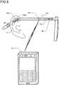
- FIG. 8is a diagram illustrating a system configuration of a second embodiment according to an aspect of the present invention.
- a watching system for watching inside a homeincludes an eyeglass type ear-mounted unit 106.
- the other featuresare the same as the first embodiment illustrated in FIGS. 1 and 2 , and thus the common features are denoted by the same reference numerals and overlapping descriptions thereof will not be repeated.
- a home 2 and an in-home monitoring unit 8are not illustrated, but configurations thereof are common to those of the first embodiment described in FIGS. 1 and 2 .
- a cartilage conduction vibration source, a bone conduction microphone, and a mastication sensorcan each be formed with a piezoelectric element, and thus, one piezoelectric element can serve as a cartilage conduction vibration source, a bone conduction microphone, and a mastication sensor.
- a piezoelectric bimorph element 142which serves as a cartilage conduction vibration source, a bone conduction microphone, and a mastication sensor are formed in such part of a temple of eyeglasses as is laid on a cartilage in a base of an ear 4 when the eyeglasses are worn.
- vibration of the piezoelectric bimorph element 142is conducted to the cartilage at the base of the ear 4 to cause cartilage conduction. Further, voice by bone conduction is picked up by the piezoelectric bimorph element 142. Further, movement caused by mastication in part close to the base of the ear 4 is also detected by the piezoelectric bimorph element 142.
- extraction and separation of signals fed to and outputted from the piezoelectric bimorph element 142are achieved by means of signal processing performed by a control unit 140.
- an air conduction microphone 46which is originally provided for the purpose of picking up voice of a conversation partner for the function of hearing aid, is used to pick up voice of a watching-target person himself or herself by air conduction, and the picked up voice is used as information for the extraction and separation of signals fed to and outputted from the piezoelectric bimorph element 142.
- the entrance of an external auditory canalis left open, and thus it is possible to hear external sound and to achieve comfortable wear of an ear-mounted unit 106 without a feeling of blockage in the external auditory canal. Further, by closing the entrance of the external auditory canal with a finger or completely covering the ear 4 with a palm, it is possible to obtain the occlusion effect in cartilage conduction, to thereby hear a larger sound.
- one piezoelectric bimorph elementmay be used for the functions of the cartilage conduction vibration source, the bone conduction microphone, and the mastication sensor as in the second embodiment.
- the cartilage conduction vibration source, the bone conduction microphone, and the mastication sensormay be formed as optimum separate elements to be optimally disposed at scattered positions.
- a bone conduction microphoneis adopted to pick up voice of a watching-target person, but an air-conducted sound microphone may be used for this purpose (for example, the air conduction microphone 46 serving for this purpose, too).
- a watching systemincluding a watching detection device and a watching notification device.
- the watching detection devicehas a cartilage conduction vibration source and a watching detection sensor, and is mountable to an ear with an entrance of an external auditory canal open.
- the watching notification devicereceives watching information from the watching detection sensor by performing short-range communication with the watching detection device. This contributes to comfortable wear of the watching detection device.
- the watching detection devicehas an air conduction microphone, and functions as a hearing aid by vibrating the cartilage conduction vibration source in accordance with a voice signal picked up by the air conduction microphone. This makes it possible to perform watch by using a hearing aid which is used daily.
- the watching detection devicemakes the cartilage conduction vibration source vibrate in accordance with a voice signal received from the watching notification device via short-range communication. This makes it possible to perform watch by using a device, such as a mobile phone, through which it is possible to hear a voice signal received from another device.
- the watching detection sensoris a masticatory movement sensor.
- the watching detection sensoris a voice sensor.
- the voice sensoris a bone conduction microphone or an air-conducted sound microphone.
- the watching notification deviceissues a notification when it has been impossible to receive a detection signal for a predetermined period of time.
- a watching systemincluding a watching detection device, and a plurality of watching notification devices which each receive watching information from the watching detection device via short-range communication with the watching detection device.
- the plurality of watching notification devicesexchange with each other the watching information received. This makes it possible to deal with a missing part in the watching information received by one watching notification device by sharing the watching information received by the other watching notification devices, and thus to prevent confusion from occurring among the plurality of watching notification devices.
- a watching systemincluding a watching detection device, and a plurality of watching notification devices which each receive watching information from the watching detection device via short-range communication with the watching detection device.
- the plurality of watching notification devicesissue different notifications based on the watching information. This makes it possible to perform watch in a manner suitable to each of the plurality of watching notification devices, which are different from each other in properties.
- the plurality of watching notification devicesinclude a mobile phone and a notification device placed in a home.
- a watching systemincluding a watching detection device having a voice sensor, and a watching notification device that receives watching information from the watching detection sensor via short-range communication with the watching detection device.
- the watching notification deviceissues a notification of whether a voice signal picked up by the voice sensor is present, without issuing any notification of the contents of the voice signal. This helps protect privacy of a watching-target person.
- the watching notification devicemakes a judgment on urgency of the voice signal picked up by the voice sensor, and when the urgency is high, the contents of the voice signal is exceptionally notified. This makes it possible to obtain a specific notification in raw voice in a case where a scream or a cry for help has been received.
- a watching detection deviceincluding a cartilage conduction vibration source and a watching detection sensor, and the watching detection device is mountable to an ear with an entrance of an external auditory canal open. This contributes to comfortable wear of the watching detection device.
- the watching detection devicehas an air conduction microphone, and functions as a hearing aid by vibrating the cartilage conduction vibration source in accordance with a voice signal picked up by the air conduction microphone.
- the watching detection devicevibrates the cartilage conduction vibration source in accordance with a voice signal received from the watching notification device via short-range communication, to thereby function as a device, such as a mobile phone, through which it is possible to hear a voice signal received from another device.
- the watching detection sensoris a masticatory movement sensor.
- the masticatory movement sensorcan serve also as the cartilage conduction vibration source.
- the watching detection sensoris a voice sensor. More specifically, the voice sensor is a bone conduction microphone. Still more specifically, the bone conduction microphone can serve also as the cartilage conduction vibration source.
- the watching detection sensorincludes an air-conducted sound microphone for a hearing aid, and the air-conducted sound microphone is turned off when the bone conduction microphone is used.
- the voice sensoris an air-conducted sound microphone.
- a watching notification devicehaving an acquisition unit that acquires watching information from a voice sensor and a notification unit that issues a notification of whether a voice signal acquired by the acquisition unit is present, without issuing any notification of contents of the voice signal. This helps protect privacy of a watching-target person.
- the notification unitmakes a judgment on urgency of the voice signal picked up by the voice sensor, and the contents of the voice signal is notified exceptionally when the urgency is high.
- the present inventionis applicable to a watching system, a watching detection device, and a watching notification device.
Landscapes
- Engineering & Computer Science (AREA)
- Physics & Mathematics (AREA)
- Signal Processing (AREA)
- Acoustics & Sound (AREA)
- Computer Networks & Wireless Communication (AREA)
- Health & Medical Sciences (AREA)
- General Health & Medical Sciences (AREA)
- Otolaryngology (AREA)
- General Physics & Mathematics (AREA)
- Neurosurgery (AREA)
- Emergency Management (AREA)
- Business, Economics & Management (AREA)
- Human Computer Interaction (AREA)
- Telephone Function (AREA)
- Alarm Systems (AREA)
- Headphones And Earphones (AREA)
- Details Of Audible-Bandwidth Transducers (AREA)
- Circuit For Audible Band Transducer (AREA)
- Emergency Alarm Devices (AREA)
Description
- The present invention relates to a watching system, a watching detection device, and a watching notification device.
- As for a watching system, Patent Literature 1 listed below proposes receiving data of detection both from a human detection sensor installed in a home of a person as a target to be watched and from an acceleration sensor that the resident wears, to make judgments on activities and conditions of the resident and events occurring in the home. On the other hand,
Patent Literature 2 listed below proposes a mastication movement detection device in which the number of mastication movements is counted based on a detected waveform received from a detector that is placed in an external auditory canal and detects an amount of deformation of the external auditory canal. Also, as for cartilage conduction, which has been discovered by one of the inventors of the present application as a third conduction route in addition to the long-known air conduction and bone conduction,Patent Literatures 3 and 4, by the same inventors as in the present application, listed below describe that vibration generated by a vibration source contacting an ear cartilage around the entrance part of an external auditory canal causes air-conducted sound to be generated from a cartilage surface inside the external auditory canal, and the generated air-conducted sound then proceeds through the inside of the external auditory canal to reach an tympanic membrane. Further inPatent Literature 5 listed below discloses an in-ear auditory device having a receiver sized to fit within an ear canal of a user, a transducer, an isolator disposed to substantially acoustically isolate the transducer from the receiver, a bone vibration sensor acoustically or mechanically coupled to the transducer to detect the user's speech, and a physiologic sensor to sense physiologic signals of the user. - Patent Literature 1: Japanese Patent Application Publication No.
2014-89494 - Patent Literature 2: Japanese Patent Application Publication No.
2011-10791 - Patent Literature 3: Japanese Patent Application Publication No.
2013-81047 - Patent Literature 4:
US 2012/244917 - Patent Literature 5:
US 2008/205679 - However, there are many problems that require further consideration regarding watching systems, watching detection devices, and watching notification devices.
- In view of the above background, an object of the present invention is to provide an effective watching system, watching detection device, and watching notification device.
- A watching detection device disclosed herein is mountable to an ear of a watching-target person and includes a cartilage conduction vibration source and a short-range communication unit, and an air conduction microphone, and is mountable to the ear with an entrance of an external auditory canal open. The short-range communication unit communicates with a mobile phone. The watching detection device further comprises a watching detection sensor. The watching detection sensor includes a bone conduction microphone. In a case where the mobile phone makes a phone call and the phone call is answered, or in a case where the mobile phone receives a phone call and answers the phone call, the bone conduction microphone turns on and the air conduction microphone turns off (a first configuration).
- Here, the watching detection device having the first configuration further includes the air conduction microphone, and may function as a hearing aid by vibrating the cartilage conduction vibration source in accordance with a voice signal picked up by the air conduction microphone (a second configuration).
- The watching detection device having the first configuration further includes the short-range communication unit that may be capable of communicating with a watching notification device, and makes the cartilage conduction vibration source vibrate in accordance with a voice signal received from the watching notification device via the short-range communication unit (a third configuration).
- In the watching detection device having the first configuration, the watching detection sensor may be a masticatory movement sensor (a fourth configuration). In the watching detection device having the fourth configuration, the masticatory movement sensor may serve also as the cartilage conduction vibration source (a fifth configuration).
- In the watching detection device having the first configuration, the bone conduction microphone may serve also as the cartilage conduction vibration source (an eighth configuration).
- A watching system disclosed herein includes the watching detection device having the first configuration and a watching notification device that receives watching information from the watching detection sensor via short-range communication with the watching detection device (a tenth configuration).
- In the watching system having the tenth configuration, the watching notification device may issue a notification of whether a voice signal picked up by the bone conduction microphone is present, without issuing any notification of contents of the voice signal (an eleventh configuration). In the watching system having the eleventh configuration, the watching notification device may make a judgment on urgency of the voice signal picked up by the bone conduction microphone and issue a notification of the contents of the voice signal exceptionally when the urgency is high (a twelfth configuration).
- In the watching system having the tenth configuration, the watching notification device may issue a notification when it has been impossible to receive a detection signal from the watching detection sensor for a predetermined period of time (a thirteenth configuration). In the watching system having the tenth configuration, the watching notification device may include a plurality of watching notification devices that each receive watching information from a same watching detection device, and the plurality of watching notification devices exchange with each other the watching information received (a fourteenth configuration). In the watching system having the tenth configuration, the watching notification device may be a mobile phone, and a voice signal of a call partner received by the mobile phone may be transmitted to the watching detection device via short-range communication to vibrate the cartilage conduction vibration source (a fifteenth configuration).
- A watching system disclosed herein includes a watching detection device and a plurality of watching notification devices that each receive watching information from the watching detection device via short-range communication with the watching detection device, and the plurality of watching notification devices exchange with each other the watching information received (a sixteenth configuration).
- In the watching system having the sixteenth configuration, the plurality of watching notification devices issue different notifications based on the watching information (a seventeenth configuration). In the watching system having the sixteenth configuration, the plurality of watching notification devices include a mobile phone and a notification device placed in a home (an eighteenth configuration).
- A watching notification device disclosed herein includes an acquisition unit which acquires watching information from a voice sensor and a notification unit which issues a notification of whether a voice signal acquired by the acquisition unit is present, without issuing any notification of contents of the voice signal (a nineteenth configuration).
- In the watching detection device having the nineteenth configuration, the notification unit may make a judgment on urgency of the voice signal acquired by the acquisition unit and issue a notification of the contents of the voice signal exceptionally when the urgency is high (a twentieth configuration).
- As described above, according to the present invention, an effective watching system, watching detection device, and watching notification device are provided.
FIG. 1 is a diagram illustrating a system configuration of a first embodiment of the present invention (first embodiment);FIG. 2 is a block diagram illustrating a detailed configuration of the first embodiment described inFIG. 1 ;FIG. 3 is a sectional view of an ear for describing cartilage conduction;FIG. 4 is a graph illustrating an example of measured data which shows an effect of the cartilage conduction;FIG. 5 is a flowchart illustrating a function of an ear-mounted unit in the first embodiment;FIG. 6 is a flowchart illustrating a function of a mobile phone in the first embodiment;FIG. 7 is a flowchart illustrating a function of an in-home monitoring unit in the first embodiment; andFIG. 8 is a diagram illustrating a system configuration of a second embodiment of the present invention (second embodiment).FIG. 1 is a diagram illustrating a system configuration of a first embodiment according to an aspect of the present invention. According to the first embodiment, a watching system that performs watching inside ahome 2 includes an ear-mounted unit 6 (indicated by a short-dashed line for distinction from a structure of an ear), which contacts a cartilage around a hole of anear 4 of a watching-target person by being sandwiched between an antihelix and a tragus to fit in a cavum conchae, an in-home monitoring unit 8, and amobile phone 10 of the watching-target person. The in-home monitoring unit 8 and themobile phone 10 exchange information with the ear-mountedunit 6 via short-range communication. Themobile phone 10 exchanges information with the ear-mountedunit 6 and the in-house monitor unit 8 via short-range communication.- The ear-mounted
unit 6 functions as a headset for themobile phone 10 by performing the short-range communication with themobile phone 10, and allows a phone call to be made with themobile phone 10 kept in a clothes pocket. The ear-mountedunit 6 also independently functions as a hearing aid. These functions as a headset and as a hearing aid are both achieved by making use of cartilage conduction, which will be described later. The ear-mountedunit 6 further incudes a mastication sensor to detect movement of the tragus, etc., or deformation of the external auditory canal, caused by masticatory movement. Here, the ear-mountedunit 6 is ring-shaped with ahole 6a, so that the entrance of the external auditory canal is open even when the ear-mountedunit 6 is fitted in the external auditory canal. This makes it possible to hear external sound via thehole 6a, and contributes to a comfortable wear of the ear-mountedunit 6 without a feeling of blockage in the external auditory canal. Further, by closing thehole 6a with a finger or covering it with a palm as necessary as will be described later, it is possible to obtain an occlusion effect in the cartilage conduction to hear a larger sound. - The in-
home monitor unit 8 has a short-range communication unit 12 for short-range communication with the ear-mountedunit 6 and themobile phone 10, and adigital communication unit 14 which performs always-on-connection Internet communication with an external device. Acontrol unit 16 controls the entire in-home monitoring unit 8, which includes the short-range communication unit 12 and thedigital communication unit 14. Astorage unit 18 stores therein a program necessary for the control performed by thecontrol unit 16, and also temporarily stores therein various pieces of data related to the control, etc. - With this configuration, the in-
home monitoring unit 8 receives a result of detection of masticatory movement from the ear-mountedunit 6 via the short-range communication. If no masticatory movement expected in daily life has been detected, the in-home monitor unit 8 judges that there is a possibility of an abnormality, and notifies a watching-service provider to that effect via thedigital communication unit 14. Further, the in-home monitoring unit 8 receives information regarding presence/absence of voice of the watching-target person detected by the headset function of the ear-mountedunit 6. In a case where there is no voice detected within a predetermined period of time, or in a case where a voice signal conveying urgency, such as a scream, has been detected, the in-home monitoring unit 8 judges that there is a possibility of an abnormality, and notifies a watching-service provider to that effect via thedigital communication unit 14. - Further, the
mobile phone 10 receives a result of detection of masticatory movement from the ear-mountedunit 6 via short-range communication. If no masticatory movement expected in daily life has been detected, themobile phone 10 judges that there is a possibility of an abnormality, and makes an automatic phone call to a mobile phone of a member of family of the watching-target person or the like who lives remotely and has been registered in advance, and when an answer to the phone call is received, themobile phone 10 notifies him/her to that effect in a form of an automatic voice message. Further, themobile phone 10 receives information regarding presence/absence of voice of the watching-target person detected by the headset function of the ear-mountedunit 6. In a case where there is no voice detected within a predetermined period of time, or in a case where a signal of voice conveying urgency, such as a scream, has been detected, themobile phone 10 judges that there is a possibility of an abnormality, and makes an automatic phone call to the mobile phone of the member of family of the watching-target person or the like who lives remotely and has been registered in advance, and when an answer to the phone call is received, themobile phone 10 issues a notification to that effect. - Here, in a case where masticatory movement expected in daily life is detected, too, the
mobile phone 10 makes an automatic phone call to the mobile phone of the member of family of the watching-target person or the like who lives remotely, and when an answer to the phone call is received, themobile phone 10 notifies him/her to the effect that there is no abnormality occurring as an automatic voice message. Further, based on detection of a normal voice of the watching-target person, too, themobile phone 10 makes an automatic phone call to the member of family of the watching-target person or the like who lives remotely as necessary, and when an answer to the phone call is received, themobile phone 10 notifies him/her to the effect that there is no abnormality occurring in the form of an automatic voice message. This makes it possible for the member of family of the watching-target person or the like who lives remotely to know that the watching-target person regularly has three meals a day, and presence of conversation that the watching-target person is expected to usually have or a state of voice to be regularly uttered in a previously set time zone (for example, conversation in daily shopping, daily sutra chanting), and to rest reassured knowing that the watching-target person is all right. In this case, however, themobile phone 10 makes an automatic phone call even when the watching-target person does not intend to, and thus contents of such conversations are to be undesirably heard by the member of family of the watching-target person or the like who lives remotely. Even though it is his or her own family member that hears the contents of such conversations, this is not desirable to the watching-target person in terms of privacy, and thus, as will be described later, what is notified is just whether or not voice has been uttered so that the contents of a conversation cannot be heard. FIG. 2 is a block diagram illustrating a detailed configuration of the first embodiment of the present invention illustrated inFIG. 1 . Such elements inFIG. 2 having counterparts inFIG. 1 are given the same reference numbers as their counterparts, and descriptions thereof will be omitted unless necessary. The in-home monitoring unit 8, which is configured as illustrated inFIG. 1 , includes apower supply unit 20 which supplies power to the entire in-home monitoring unit 8. Thepower supply unit 20 receives power from a household power supply in thehome 2.- On the other hand, as illustrated in
FIG. 2 , themobile phone 10 includes a mobilephone function unit 22 to perform phone communication by means of anantenna 24 via a wireless telephone network. A short-range communication unit 26 communicates with the short-range communication units unit 6 and the in-home monitoring unit 8, respectively. AGPS unit 28 detects a location of the watching-target person wearing the ear-mountedunit 6 when he/she is out, and communicates with the mobile phone of the member of family of the watching-target person or the like who lives remotely or with the watching-service provider, who have been described above, to thereby provide them with information of the location of the watching-target person. Acontrol unit 30 performs entire control of the entiremobile phone 10, which includes the mobilephone function unit 22, the short-range communication unit 26, and theGPS unit 28. Astorage unit 32 stores therein a program necessary for the control performed by thecontrol unit 30, and also, temporarily stores therein various pieces of data related to the control, etc. Apower supply unit 34 includes a rechargeable storage battery, and supplies power to the entiremobile phone 10. InFIG. 2 , for simplicity, such ones of the components of themobile phone 10 as are typically included in mobile phones, such as a large-sized touch-panel liquid crystal display unit, a microphone, a speaker, a proximity sensor, and an inner camera, are not illustrated. - As illustrated in
FIG. 2 , the ear-mountedunit 6 includes the short-range communication unit 36, which performs short-range communication with the short-range communication unit 26 of themobile phone 10 and the short-range communication unit 12 of the in-home monitoring unit 8. Amastication sensor 38 detects movement of the tragus, etc., or deformation of the external auditory canal of the watching-target person, caused by masticatory movement of the watching-target person, and thereby detects presence/absence of mastication of the watching-target person. Themastication sensor 38 includes, for example, a strain gage, a piezoelectric element, or the like. When a masticatory movement is detected, acontrol unit 40 notifies themobile phone 10 to that effect through the short-range communication unit 36 and the short-range communication unit 26. If no masticatory movement expected in daily life is detected, thecontrol unit 40 judges that there is a possibility of an abnormality, and, by means of the short-range communication unit 36, notifies themobile phone 10 and the in-home monitoring unit 8 to that effect through the short-range communication unit 26 and the short-range communication unit 36, respectively. - The ear-mounted
unit 6 includes a cartilage conduction vibration source 42 (which is, for example, a piezoelectric bimorph element), which vibrates in accordance with a voice signal of a call partner received from themobile phone 10 via short-range communication, and this vibration is transmitted to an ear cartilage in contact with the ear-mountedunit 6, and this makes it possible to hear the voice of the phone call partner by cartilage conduction, which will be described later. Abone conduction microphone 44 catches bone-conducted own voice of the watching-target person and transmits a voice signal of the own voice to themobile phone 10 via short-range communication, and this enables conversations to be conducted. In this manner, the ear-mountedunit 6 functions as a headset for themobile phone 10. An air conductionsound microphone 46 catches an air-conducted voice of an outside conversation partner located close to the watching-target person to obtain a voice signal of the conversation partner, which makes the cartilageconduction vibration source 42 vibrate. In this manner, the ear-mountedunit 6 also independently functions as a hearing aid. Thecontrol unit 40 controls the ear-mountedunit 6 also with respect to the head-set and hearing-aid functions. In the headset function, as described above, thebone conduction microphone 44 also functions as a voice sensor for watching whether or not the watching-target person utters voice expected in daily life. Apower supply unit 48, which includes a rechargeable storage battery, supplies power to the entire ear-mountedunit 6. - Now, cartilage conduction will be explained. Cartilage conduction is a phenomenon discovered by the present inventors, and denotes the phenomenon in which vibration conducted to the cartilage around an entrance part of the external auditory canal, such as that in the tragus, makes the surface of an external-auditory-canal cartilaginous part vibrate, producing air-conducted sound inside the external auditory canal. The air-conducted sound produced inside the external auditory canal travels on deeper into the external auditory canal and reaches the tympanic membrane. Thus, the greater part of the sound heard by cartilage conduction is the sound heard via the tympanic membrane. Here, however, the sound heard via the tympanic membrane is not ordinary air-conducted sound, i.e., sound that has entered the external auditory canal from outside, but air-conducted sound that is produced inside the external auditory canal.
FIG. 3 is a sectional view of an ear for illustrating the phenomenon of cartilage conduction mentioned just above, and illustrates a relationship between the structure of anear 4 and the ear-mountedunit 6 used in the present invention.Arrows 52 indicate transmission routes of vibration of the ear-mountedunit 6 which is made to vibrate by the cartilageconduction vibration source 42. Vibration generated from the ear-mountedunit 6 is, as indicated by thearrows 52, first conducted from a contact part to acartilage 54 around the entrance part of the external auditory canal. The vibration of thecartilage 54 generates, from its surface (the external-auditory-canal cartilaginous part), air-conducted sound inside the external auditory canal. Then the air-conducted sound travels on deeper into the external auditory canal and reaches atympanic membrane 50 via an external auditory canalosseous part 56. Here, as indicated by an arrow 58 (which indicates a route of ordinary audible sound), air-conducted sound from outside enters the external auditory canal via thehole 6a of the ear-mountedunit 6, and reaches thetympanic membrane 50. This contributes to comfortable wear of the ear-mountedunit 6 without a feeling of blockage in the external auditory canal.FIG. 4 is a graph illustrating an example of measured data showing an effect of cartilage conduction. The graph ofFIG. 4 illustrates, in relation to frequency, sound pressure within the external auditory canal at a position 1 cm inside from the entrance part of the external auditory canal when, without contact with a helix, a surface of an outer wall of a vibration body that is caused to vibrate by a cartilage conduction vibration source is brought into contact with at least part of ear cartilage around the entrance part of the external auditory canal. In the graph, a vertical axis indicates sound pressure (in dBSPL), and a horizontal axis indicates frequency on a logarithmic scale (in Hz). In terms of contact pressure relationship between the surface of the outer wall of the vibration body and the cartilage around the entrance part of the external auditory canal, the graph uses a solid line to illustrate the sound pressure during a non-contact state (in a state where only air-conducted sound generated from the surface of the outer wall of the vibration body can be heard), a short dashed line to illustrate the sound pressure under a contact pressure of 10 grams, a single-dotted chain line to illustrate the sound pressure under a contact pressure of 250 grams, and a double-dotted chain line to illustrate the sound pressure under a contact pressure of 500 grams. As illustrated in the figure, the sound pressure increases as the contact pressure is increased from the non-contact state to the 10-gram contact pressure, and further increases as the contact pressure is increased to 250 grams, and then, the sound pressure increases even more as the contact pressure is further increased to 500 grams.- As can be readily understood from the graph of
FIG. 4 , when the surface of the outer wall of the vibration body is brought into contact with at least part of the ear cartilage around the entrance part of the external auditory canal without contacting the helix, the sound pressure at the position 1 cm inside from the entrance part of the external auditory canal increases by at least 10 dB in a main frequency range of voice (500 Hz to 2,300 Hz), compared to in the non-contact state. (See and compare the non-contact state indicated by the solid line with the state indicated by the single-dotted chain line.) - As can also be readily understood from the graph of
FIG. 4 , when the surface of the outer wall of the vibration body is brought into contact with at least part of the ear cartilage around the entrance part of the external auditory canal without contacting the helix, the sound pressure at the position 1 cm inside from the entrance part of the external auditory canal changes by at least 5 dB in the main frequency range of voice (500 Hz to 2,500 Hz) as the contact pressure changes. (See and compare the slightly contacting state indicated by the short-dashed line with the state indicated by the single-dotted chain line). - As is clear from the above description, even when the ear-mounted
unit 6 does not have a structure for generating air-conducted sound (such as a vibration plate included in typical earphones), it is possible to obtain sufficient sound pressure by transmitting vibration of the cartilageconduction vibration source 42 to the ear cartilage by bringing the cartilageconduction vibration source 42 into contact with the ear cartilage. As is also clear from the above description, since there is no need of providing a structure for generating air-conducted sound, the ear-mountedunit 6 can be formed in a ring shape having thehole 6a, for example, and this makes it possible to hear outside sound through thehole 6a even when the ear-mountedunit 6 is mounted to an ear, and this contributes to comfortable wear of the ear-mountedunit 6 without a feeling of blockage in the external auditory canal. - Further, as can be readily understood from the graph of
FIG. 4 , when the entrance part of the external auditory canal is closed by bringing the surface of the outer wall of the vibration body into firm contact with at least part of the ear cartilage (the data ofFIG. 4 was actually obtained by measurement performed in a state where the entrance of the external auditory canal was closed with the tragus bent with the surface of the outer wall of the vibration body pressed against the tragus from outside), the sound pressure at the position 1 cm inside from the entrance portion of the external auditory canal increases by at least 20 dB in the main frequency range of voice (300 Hz to 1800 Hz). This is caused by the occlusion effect. (See and compare the non-contact state indicated by the solid line with the state where the external auditory canal is closed indicated by the double-dotted chain line). - The measurement results of which are illustrated in
FIG. 4 was all conducted under a constant output of the cartilage conduction vibration source. RegardingFIG. 4 , for the measurement conducted with the surface of the outer wall of the vibration body contacting at least part of the ear cartilage around the entrance part of the external auditory canal without contacting the helix, the surface of the outer wall of the vibration body was brought into contact with at least part of the ear cartilage from outside of the tragus. Also, for the measurement conducted with the external auditory canal closed, the closed state of the external auditory canal was brought about by pressing the tragus from outside so strong as to bend the tragus as described above. - In the first embodiment, the occlusion effect as described above can be achieved by closing the
hole 6a and increasing the contact pressure of the ear-mountedunit 6 against the cartilage by pushing the ear-mountedunit 6 with a finger placed over thehole 6a. Or, instead, the occlusion effect can be achieved by covering theentire ear 4 with a palm. Thus, clearly, in the first embodiment, too, it is possible to hear a larger sound by closing thehole 6a with a finger or entirely covering the ear with a palm. - The measurement graph of
FIG. 4 is merely an example; upon further scrutiny, there are individual differences. Also, for simplification and standardization of the phenomenon, the values illustrated in the measurement graph ofFIG. 4 were obtained through measurement performed in a state where the surface of the outer wall of the vibration body was in contact only with a small surface area of the outside of the tragus. However, increase in sound pressure caused by the contact with the cartilage also depends on the area of the contact, and in a case where the surface of the outer wall is in contact with the ear cartilage around the entrance part of the external auditory canal without contacting the helix, the increase in sound pressure is further elevated when the surface of the outer wall of the vibration body is in contact with a portion of the cartilage wider than around the entrance part of the external auditory canal. In consideration of the above facts, the values illustrated in the measurement graph ofFIG. 4 have generality in illustrating the configuration making use of cartilage conduction, and can be reproduced by many and unspecified subjects. Further, the measurement graph ofFIG. 4 was drawn by plotting the values obtained by the measurement conducted with the tragus being pressed from the outside in closing the entrance part of the external auditory canal to thereby increase the contact pressure and fold the tragus over, but similar results can be obtained also in a case where the outer wall of the vibration body is pressed into the entrance part of the external auditory canal to close the external auditory canal. FIG. 5 is a flowchart illustrating a function of thecontrol unit 40 of the ear-mountedunit 6 in the watching system of the first embodiment. The flow starts when the ear-mountedunit 6 connected to an unillustrated charger for charging is disconnected from the charger. When the flow starts, in Step S2, it is checked whether or not pairing for short-range communication with themobile phone 10 has been set, and when no pairing is found to have been set, pairing is automatically set. Next, in Step S4, theair conduction microphone 46 and thebone conduction microphone 44 are turned on. Thereby, the ear-mountedunit 6 starts to function as a hearing aid, and also thebone conduction microphone 44 is brought into a standby state in which it stands by for detection of voice of the watching-target person. Here, although omitted in the flow, themastication sensor 38 is constantly in an ON state from the start to an end of the flow and in a standby state in which it stands by for detection of mastication.- Next, in Step S6, it is checked whether or not the
mastication sensor 38 has detected a masticatory movement. When a mastication movement is found to have been detected, the process proceeds to Step S8, where a detection signal is transmitted to themobile phone 10 via short-range communication, and then the process proceeds to Step S12. On the other hand, when no mastication movement is found to have been detected in Step S6, the process proceeds directly to Step S12. - In Step S12, it is checked whether or not the
bone conduction microphone 44 has detected voice of the watching-target person. When voice of the watching-target person is found to have been detected, the process proceeds to Step S14, and a detected voice signal is transmitted to themobile phone 10 via the short-range communication, and meanwhile, in Step S16, the detected voice signal is transmitted to the in-home monitoring unit 8 via the short-range communication. Although the steps from Step S12 to Step S16 are illustrated in a simplified manner, in these steps, actually, for a predetermined period of time (10 seconds, for example) after voice starts to be detected by thebone conduction microphone 44, the voice signal continues to be transmitted from thebone conduction microphone 44 simultaneously to themobile phone 10 and the in-home monitoring unit 8. At this time, even when the voice continues to be detected for a predetermined period of time or longer, the transmission is stopped as soon as the predetermined period of time elapses, whereas even though the voice disappears before the predetermined period of time elapses, the transmission of output of thebone conduction microphone 44 continues to be performed until the predetermined period of time elapses. The above-described transmission of the voice signal continued for a predetermined period of time through the steps from Step S12 to Step S16 is finished, the process proceeds to Step S20. On the other hand, when no voice signal is detected in Step S12, the process proceeds directly to Step S20. - In Step S20, it is checked whether the watching-target person has operated the
mobile phone 10 to make a phone call and the other party has answered the phone call, or whether there has been an external incoming call received by themobile phone 10 and the watching-target person has operated themobile phone 10 to answer the incoming call. If whichever of the above is found to have occurred, the process proceeds to Step S22, where theair conduction microphone 46 is turned off and thebone conduction microphone 44 is maintained in an on state, and then the process proceeds to Step S24. Thereby, the ear-mountedunit 6 starts to function as a headset for themobile phone 10, and prevents ambient noise from being picked up by theair conduction microphone 46 to disturb the phone call. - In Step S24, it is checked whether the phone call started in Step S20 has been ended by hanging-up of the phone. Then, when it is detected that the phone call has been ended, the process proceeds to Step S26, where the
air conduction microphone 46 is turned on and thebone conduction microphone 44 is maintained in an on state, and the process proceeds to Step S28. Thereby, the ear-mountedunit 6 starts to function as a hearing aid again, and thebone conduction microphone 44 is maintained in the standby state in which it stands by for detection of voice of the watching-target person. On the other hand, when it is found that the phone call has not been ended yet in Step S24, the Step S24 is repeated until end of the phone call is detected. Further, in a case where, in Step S20, neither making a phone call and answering the phone call nor receiving a phone call and answering the phone call is detected, the process proceeds directly to Step S28. - In Step S28, it is checked whether the storage battery of the
power supply unit 48 has been exhausted. When the storage battery is found not to have been exhausted, the process proceeds to Step S30, where it is checked whether the ear-mountedunit 6 has been connected to the charger, which is not illustrated, to be charged. This step is provided to deal with a case of removing the ear-mountedunit 6 from theyear 4 to be charged even though the storage battery has not been exhausted. When connection for charging is detected in Step S30, the process proceeds to Step S32, where ending processing is performed to end the flow. This is significant in that this helps prevent the ear-mountedunit 6 from being maintained in an operation state by mistake when it is removed from theear 4 and thus its watching function is disabled. On the other hand, when no connection for charging is detected in Step S30, the process returns to Step S6 to repeat the steps from Step S6 to Step S30 until the storage battery becomes exhausted or connection is achieved for charging, and the ear-mountedunit 6 maintains, as necessary, its hearing-aid function, watching function, and headset function for themobile phone 10. Here, in a case where it is detected in Step S28 that the storage battery has been exhausted, too, the process proceeds to Step S32, where the ending processing is performed to end the flow. FIG. 6 is a flowchart illustrating a function of thecontrol unit 30 of themobile phone 10 in the first embodiment. Note thatFIG. 6 illustrates the flow by extracting operations of functions related to watching, and thus in themobile phone 10, thecontrol unit 30 has operations that are not described in the flow ofFIG. 6 , such as operations related to a normal mobile phone function of themobile phone 10. A hardware configuration itself of themobile phone 10 is one that is typically adopted in mobile phones, and the functions extracted inFIG. 6 are installed in the ear-mountedunit 6 as accessory software.- The flow of
FIG. 6 starts when a power switch of themobile phone 10 is turned on, and in Step S42, a normal mobile phone mode is set. Next, in Step S44, a check is performed for a state of pairing for the short-range communication with the ear-mountedunit 6. When the pairing is found to have been achieved, watching can be performed by themobile phone 10 in cooperation with the ear-mountedunit 6, and thus the process proceeds to Step S46. - In Step S46, it is checked whether or not a new mastication detection signal has been received from the ear-mounted
unit 6, and when it is found that there has been reception of a new mastication detection signal, the process proceeds to Step S48, where an e-mail notifying that the watching-target person is safe is automatically transmitted to a mobile phone of the member of family of the watching-target person or the like who lives remotely and has been registered in advance. Further, it may be set in advance that in Step S48, instead of sending an e-mail, an automatic phone call is made to the mobile phone of the member of family of the watching-target person or the like who lives remotely and has been registered in advance, and on reception of a response from the mobile phone, an automatic voice message is transmitted to notify him/her that the watching-target person is safe. It is also possible to set such that both an e-mail and a phone call are to be sent and made. As for detecting mastication, which basically takes place three times a day and thus can be regarded as not too often, each time a mastication detection signal is detected, the member of family of the watching-target person or the like who lives remotely is notified that the watching-target person is safe and thereby reassured. Here, in a case where the member of family of the watching-target person or the like who lives remotely feels annoyed by such safety notifications, it is possible to set in advance such that Step S48 will be omitted. - Next, the process proceeds to Step S50, where reception history of mastication detection signals stored in the
storage unit 32 is updated, together with time and date information, based on the reception of the new mastication detection signal, and a GPS signal at that time point is also stored in thestorage unit 32, and then the process proceeds to Step S52. On the other hand, when reception of a mastication detection signal has not been able to be confirmed in Step S46, the process proceeds directly to Step S52. - In Step S52, based on the reception history stored in the
storage unit 32, it is checked whether or not there has been reception of a new mastication detection signal within a predetermined period of time after the reception of the preceding mastication detection signal. When it is found that there has not been reception of a new mastication detection signal within the predetermined period of time, the process proceeds to Step S54, where an automatic phone call is made to the mobile phone of the member of family of the watching-target person or the like who lives remotely and has been registered in advance, and on reception of a response to the phone call, an automatic voice message is transmitted to the effect that there is a possibility of an abnormality, and the process proceeds to Step S56. Further, in Step S54, another automatic voice message is transmitted to notify a current location of the watching-target person based on GPS information obtained then. On the other hand, in Step S52, when it is confirmed from the reception history that there has been reception of a new mastication detection signal, the process proceeds to Step S56. - In Step S56, it is checked whether or not there has been reception of a voice signal picked up by the
bone conduction microphone 44 of the ear-mountedunit 6. When it is found that there has been reception of such a voice signal, the process proceeds to Step S58, where it is checked whether or not the received voice is a scream or begging for help (urgency) based on recognized contents of the voice signal (such as words included in the voice signal), intensity of the voice signal, a tone pattern, etc. When there is a high possibility that the voice is a scream or begging for help (when it is judged that it is a highly urgent situation), the process proceeds to Step S60, where an automatic phone call is made to the mobile phone of the member of family of the watching-target person or the like who lives remotely and has been registered in advance, and on reception of a response to the phone call, the received voice itself is transmitted to the mobile phone, and then the process proceeds to Step S62. On the other hand, when, in Step S58, it is judged that the received voice is not a scream or begging for help but merely voice of an ordinary conversation (of low urgency), the process proceeds directly to Step S62. - In Step S62, it is checked whether or not the received voice signal has been received in a time zone (for example, a time zone when the watching-target usually goes shopping, a time zone when the watching-target person usually chants a sutra) previously set based on a regular life pattern. When the result of the check is in the affirmative, the process proceeds to Step S64, where an e-mail is automatically transmitted to the mobile phone of the member of family of the watching-target person or the like who lives remotely and has been registered in advance to notify him/her that the watching-target person is safe, and the process proceeds to Step S66. On the other hand, in Step S62, when the received voice signal is found not to have been received in the previously set time zone, the process proceeds directly to Step S66. Here, a setting same as in Step S48 is also possible, that is, instead of or together with an e-mail, an automatic phone call may be made and automatic voice message may be transmitted. Further, in a case where the member of family of the watching-target person or the like who lives remotely feels annoyed by such safety notifications, it is possible to set in advance such that Steps S62 and S64 will be omitted. The message to be transmitted in Step S64 is not the voice signal actually picked up by the
bone conduction microphone 44, but a message notifying merely the fact that there has been reception of a voice signal. Thus, in contrast to in Step S60, contents of conversation of the watching-target person are not heard and thus privacy of the watching-target person is preserved. - In Step S66, reception history of voice signals stored in the
storage unit 32 is updated, together with time and date information, based on the reception of the new voice signal, and a GPS signal at that time point is also stored in thestorage unit 32, and then the process proceeds to Step S68. On the other hand, in a case where reception of a voice signal picked up by thebone conduction microphone 44 has not been confirmed in Step S56, the process proceeds directly to Step S68. - In Step S68, based on the reception history stored in the
storage unit 32, it is checked whether or not there has been reception of a new voice signal within a predetermined period of time after the reception of the preceding voice signal. When there has been no reception of a new voice signal within the predetermined period of time, the process proceeds to Step S70, where an automatic phone call is made to the mobile phone of the member of family of the watching-target person or the like who lives remotely and has been registered in advance, and on reception of a response to the phone call, an automatic voice message is transmitted to the effect that there is a possibility of an abnormality, and then the process proceeds to Step S72. In Step S70, too, another automatic voice message is transmitted to notify a current location of the watching-target person based on GPS information obtained then. On the other hand, when it is confirmed in Step S68 that there has been reception of a new voice signal within the predetermined period of time, the process proceeds directly to Step S72. Here, in a case where setting of pairing with the ear-mountedunit 6 is not confirmed in Step S44, the process proceeds directly to Step S72, the steps for watching are not performed, and themobile phone 10 functions as an ordinary mobile phone. - In Step S72, it is checked whether or not the storage battery of the
power supply unit 34 has been exhausted. When the storage battery is found not to have been exhausted, the process returns to Step S44, and then, the steps from Step S44 to Step S 72 are repeated until exhaustion of the storage battery is detected, such that themobile phone 10 deals with various situations in watching. On the other hand, in a case where, in Step S72, the storage battery is found to have been exhausted, the process proceeds to Step S74, where ending processing is performed to end the flow. FIG. 7 is a flowchart illustrating a function of thecontrol unit 16 of the in-home monitoring unit 16 in the first embodiment. The flow starts when the in-home monitoring unit 8 is placed and connected to the household power supply or the power supply of the in-home monitoring unit 8 is turned on. Then, in Step S82, always-on connection to the Internet is automatically set for communication with the watching service provider, and an automatic test is performed to check cooperation, such as the short-range communication, with the ear-mountedunit 6, and the process proceeds to Step S84.- In Step S84, it is checked whether or not the state of the short-range communication with the ear-mounted
unit 6 has been shifted from an enabled state to a disabled state. This is equivalent to checking whether or not the watching-target person has gone out into a range where the short-range communication is not available. When such shift of the state is found not to have taken place, the process proceeds to Step S86, where it is checked whether or not the state of the short-range communication with the ear-mountedunit 6 has shifted from the disabled state to the enabled state. This is equivalent to checking whether or not the watching-target person has come back into the short-range communication range. When such shift of the state is found to have taken place, the process proceeds to Step S88, where an e-mail is automatically transmitted to the mobile phone of the member of family of the watching-target person or the like who lives remotely and has been registered in advance to notify him /her that the watching-target person has come home. - Further, in Step S90, automatic short-range communication is performed with the
mobile phone 10, and processing is performed to confirm that the state of short-range communication has been shifted back into the state of system configuration as illustrated inFIG. 2 . This processing is performed because it can be presumed that when the watching-target person is out, themobile phone 10 is carried by him/her into a range where the short-range communication is not available. In Step S90, if by any chance it cannot be confirmed that the short-range communication is possible with themobile phone 10, notification to that effect is issued to the watching service provider and to the mobile phone of the member of family of the watching-target person or the like who lives remotely. - In Step S90, further, a cross check of the history of reception from the ear-mounted
unit 6 and information exchange are performed between thestorage unit 18 of the in-home monitoring unit 8 and thestorage unit 32 of themobile phone 10 to match the information in thestorage unit 18 and the information in thestorage unit 32 with each other. This is applicable mainly to a case where the watching-target person is out and the in-home monitoring unit 8 cannot receive signals from ear-mountedunit 6, during which information cannot be received from the in-home monitoring unit 8 and thus information is received from themobile phone 10 instead. This helps prevent inconvenience of, for example, the in-home monitoring unit 8 erroneously recognizing an abnormal state without any signal transmission from the ear-mountedunit 6 for a predetermined period of time or longer, although there has been a transmission of a signal from the ear-mountedunit 6. The function of matching information in the two storage units by the cross check as described above is also useful as a measure to deal with a case where the storage battery of themobile phone 10 has been exhausted when themobile phone 10 is in thehome 2 and thus information is not received from the ear-mountedunit 6 until the storage battery is recharged. - When the processing in Step S90 is completed, the process proceeds to Step S92, where it is checked whether or not there has been reception of a new mastication detection signal from the ear-mounted
unit 6. When it is found that there has been reception of a new mastication detection signal, the process proceeds to Step S94, where reception history of mastication detection signals stored in thestorage unit 18 is updated, together with time and date information, based on the reception of the new mastication detection signal, and the process proceeds to Step S96. On the other hand, when reception of a new mastication detection signal has been unable to be confirmed in Step S92, the process proceeds directly to Step S96. - In Step S96, based on the reception history stored in the
storage unit 18, it is checked whether or not there has been reception of a new mastication detection signal within a predetermined period of time after the reception of the preceding mastication detection signal. When there is no reception of a new mastication detection signal within the predetermined period of time, the process proceeds to Step S98, where an automatic notification is issued to the watching service provider, with whom a contract has been made in advance, to the effect that there is a possibility of an abnormality, and then the process proceeds to Step S100. On the other hand, when it is confirmed, in Step S96, from the reception history of mastication detection signals, that there has been reception of a new mastication detection signal within the predetermined period of time, it is judged that there is no abnormality occurring, and the process proceeds directly to Step S100. - In Step S100, it is checked whether or not there has been reception of a voice signal picked up by the
bone conduction microphone 44 of the ear-mountedunit 6. When it is found that there has been reception of such a voice signal, the process proceeds to Step S102, where it is checked whether or not the received voice is a scream, a cry for help, or the like, based on identification of voice in the contents (words and the like included therein) of the voice signal, intensity pattern, tone, and the like of the voice signal, etc. When there is a high possibility that the voice is a scream or a cry for help, the process proceeds to Step S104, where the received voice itself is transferred to the watching-service provider, and the process proceeds to Step S106. On the other hand, when, in Step S102, it is judged that the received voice is neither a scream nor a cry for help, but voice of an ordinary conversation, the process proceeds directly to Step S106. - In Step S106, reception history of voice signals stored in the
storage unit 18 is updated, together with time and data information, based on the reception of the new voice signal, and the process proceeds to Step S108. On the other hand, when reception of a voice signal picked up by thebone conduction microphone 44 has not been confirmed in Step S100, the process proceeds directly to Step S108. - In Step S108, based on the reception history of voice signals stored in the
storage unit 18, it is checked whether or not there has been reception of a new voice signal within a predetermined period of time after the reception of the preceding voice signal. When it is found that there has been no reception of a new voice signal within the predetermined period of time, the process proceeds to Step S110, where an automatic notification is issued to the watching service provider to the effect that there is a possibility of an abnormality, and then the process proceeds to Step S112. On the other hand, when it is confirmed in Step S108 that there has been reception of a new voice signal within the predetermined period of time based on the reception history, the process proceeds directly to Step S112. Here, when it is detected in Step S84 that the state of the short-range communication with the ear-mountedunit 6 has been shifted from an enabled state to a disabled state, the process proceeds to Step S114, where an e-mail is automatically transmitted to the mobile phone of the member of family of the watching-target person or the like who lives remotely and has been registered in advance to notify him/her that the watching-target person has gone out, and then the step proceeds to Step S112. In this case, since it is impossible to receive signals from the ear-mountedunit 6 and thus to perform watching, themobile phone 10 that the watching-target person carries is charged with execution of the watching function, and the in-home monitoring unit 8 does not executes the watching function. - In Step S112, it is checked whether or not power of the in-
home monitoring unit 8 has been turned off. Turning off of the power of the in-home monitoring unit 8 includes power-supply disconnection caused by power failure or the like. When it is found that there has been no turning off of the power, the process returns to Step S84, and then the steps of from Step S84 to Step S114 are repeated as long as the power is not turned off, and the in-home monitoring unit 8 deals with various situations in watching. On the other hand, when turning off of the power is detected in Step S112, the process proceeds to Step S116, where ending processing is performed to end the flow. FIG. 8 is a diagram illustrating a system configuration of a second embodiment according to an aspect of the present invention. According to the second embodiment, a watching system for watching inside a home includes an eyeglass type ear-mountedunit 106. The other features are the same as the first embodiment illustrated inFIGS. 1 and2 , and thus the common features are denoted by the same reference numerals and overlapping descriptions thereof will not be repeated. InFIG. 8 , for the sake of simplicity, ahome 2 and an in-home monitoring unit 8 are not illustrated, but configurations thereof are common to those of the first embodiment described inFIGS. 1 and2 .- According to the present invention, a cartilage conduction vibration source, a bone conduction microphone, and a mastication sensor can each be formed with a piezoelectric element, and thus, one piezoelectric element can serve as a cartilage conduction vibration source, a bone conduction microphone, and a mastication sensor. In the second embodiment illustrated in
FIG. 8 , apiezoelectric bimorph element 142 which serves as a cartilage conduction vibration source, a bone conduction microphone, and a mastication sensor are formed in such part of a temple of eyeglasses as is laid on a cartilage in a base of anear 4 when the eyeglasses are worn. With this configuration, vibration of thepiezoelectric bimorph element 142 is conducted to the cartilage at the base of theear 4 to cause cartilage conduction. Further, voice by bone conduction is picked up by thepiezoelectric bimorph element 142. Further, movement caused by mastication in part close to the base of theear 4 is also detected by thepiezoelectric bimorph element 142. In using thepiezoelectric bimorph element 142 for the plurality of functions, extraction and separation of signals fed to and outputted from thepiezoelectric bimorph element 142 are achieved by means of signal processing performed by acontrol unit 140. When thepiezoelectric bimorph element 142 is used for the plurality of functions, anair conduction microphone 46, which is originally provided for the purpose of picking up voice of a conversation partner for the function of hearing aid, is used to pick up voice of a watching-target person himself or herself by air conduction, and the picked up voice is used as information for the extraction and separation of signals fed to and outputted from thepiezoelectric bimorph element 142. In the second embodiment, too, the entrance of an external auditory canal is left open, and thus it is possible to hear external sound and to achieve comfortable wear of an ear-mountedunit 106 without a feeling of blockage in the external auditory canal. Further, by closing the entrance of the external auditory canal with a finger or completely covering theear 4 with a palm, it is possible to obtain the occlusion effect in cartilage conduction, to thereby hear a larger sound. - The various features of the embodiments described above can be implemented not only in those specific embodiments but also in any other embodiment so long as they provide their advantages. Moreover, the various features of the embodiments can be implemented with various modifications. Modified features can be implemented in appropriate combinations with each other and with unmodified features.
- For example, in the configuration of the first embodiment, one piezoelectric bimorph element may be used for the functions of the cartilage conduction vibration source, the bone conduction microphone, and the mastication sensor as in the second embodiment. Or, conversely, in the second embodiment, the cartilage conduction vibration source, the bone conduction microphone, and the mastication sensor may be formed as optimum separate elements to be optimally disposed at scattered positions.
- Further, in the above embodiments, a bone conduction microphone is adopted to pick up voice of a watching-target person, but an air-conducted sound microphone may be used for this purpose (for example, the
air conduction microphone 46 serving for this purpose, too). - Conclusive Descriptions: The following is conclusive descriptions of the features of the embodiments disclosed herein.
- According to one embodiment disclosed herein, there is provided a watching system including a watching detection device and a watching notification device. The watching detection device has a cartilage conduction vibration source and a watching detection sensor, and is mountable to an ear with an entrance of an external auditory canal open. The watching notification device receives watching information from the watching detection sensor by performing short-range communication with the watching detection device. This contributes to comfortable wear of the watching detection device.
- According to a specific feature, the watching detection device has an air conduction microphone, and functions as a hearing aid by vibrating the cartilage conduction vibration source in accordance with a voice signal picked up by the air conduction microphone. This makes it possible to perform watch by using a hearing aid which is used daily. According to another specific feature, the watching detection device makes the cartilage conduction vibration source vibrate in accordance with a voice signal received from the watching notification device via short-range communication. This makes it possible to perform watch by using a device, such as a mobile phone, through which it is possible to hear a voice signal received from another device.
- According to another specific feature, the watching detection sensor is a masticatory movement sensor. According to another specific feature, the watching detection sensor is a voice sensor. For example, the voice sensor is a bone conduction microphone or an air-conducted sound microphone.
- According to another specific feature, the watching notification device issues a notification when it has been impossible to receive a detection signal for a predetermined period of time.
- According to another embodiment disclosed herein, there is provided a watching system including a watching detection device, and a plurality of watching notification devices which each receive watching information from the watching detection device via short-range communication with the watching detection device. The plurality of watching notification devices exchange with each other the watching information received. This makes it possible to deal with a missing part in the watching information received by one watching notification device by sharing the watching information received by the other watching notification devices, and thus to prevent confusion from occurring among the plurality of watching notification devices.
- According to another embodiment disclosed herein, there is provided a watching system including a watching detection device, and a plurality of watching notification devices which each receive watching information from the watching detection device via short-range communication with the watching detection device. The plurality of watching notification devices issue different notifications based on the watching information. This makes it possible to perform watch in a manner suitable to each of the plurality of watching notification devices, which are different from each other in properties. According to a specific feature, the plurality of watching notification devices include a mobile phone and a notification device placed in a home.
- According to another embodiment disclosed herein, there is provided a watching system including a watching detection device having a voice sensor, and a watching notification device that receives watching information from the watching detection sensor via short-range communication with the watching detection device. The watching notification device issues a notification of whether a voice signal picked up by the voice sensor is present, without issuing any notification of the contents of the voice signal. This helps protect privacy of a watching-target person. According to a specific feature, the watching notification device makes a judgment on urgency of the voice signal picked up by the voice sensor, and when the urgency is high, the contents of the voice signal is exceptionally notified. This makes it possible to obtain a specific notification in raw voice in a case where a scream or a cry for help has been received.
- According to another embodiment disclosed herein, there is provided a watching detection device including a cartilage conduction vibration source and a watching detection sensor, and the watching detection device is mountable to an ear with an entrance of an external auditory canal open. This contributes to comfortable wear of the watching detection device.
- According to a specific feature, the watching detection device has an air conduction microphone, and functions as a hearing aid by vibrating the cartilage conduction vibration source in accordance with a voice signal picked up by the air conduction microphone. According to another specific feature, the watching detection device vibrates the cartilage conduction vibration source in accordance with a voice signal received from the watching notification device via short-range communication, to thereby function as a device, such as a mobile phone, through which it is possible to hear a voice signal received from another device.
- According to another specific feature, the watching detection sensor is a masticatory movement sensor. According to a more specific feature, the masticatory movement sensor can serve also as the cartilage conduction vibration source. According to another specific feature, the watching detection sensor is a voice sensor. More specifically, the voice sensor is a bone conduction microphone. Still more specifically, the bone conduction microphone can serve also as the cartilage conduction vibration source.
- According to another specific feature, the watching detection sensor includes an air-conducted sound microphone for a hearing aid, and the air-conducted sound microphone is turned off when the bone conduction microphone is used. According to another specific feature, the voice sensor is an air-conducted sound microphone.
- According to another embodiment disclosed herein, there is provided a watching notification device having an acquisition unit that acquires watching information from a voice sensor and a notification unit that issues a notification of whether a voice signal acquired by the acquisition unit is present, without issuing any notification of contents of the voice signal. This helps protect privacy of a watching-target person. According to a specific feature, the notification unit makes a judgment on urgency of the voice signal picked up by the voice sensor, and the contents of the voice signal is notified exceptionally when the urgency is high.
- The present invention is applicable to a watching system, a watching detection device, and a watching notification device.
- 42 cartilage conduction vibration source
- 38, 44, 46 watching detection sensor
- 6, 106 watching detection device
- 12, 26, 36 short-range communication unit
- 8, 10 watching notification device
- 46 air conduction microphone
- 38 masticatory movement sensor
- 44, 46 voice sensor
- 44 bone conduction microphone
- 46 air-conducted sound microphone
- 8, 10 a plurality of watching notification devices
- 10 mobile phone
- 8 a notification device placed in a home
- 142 masticatory movement sensor serving also as cartilage conduction vibration source
- 142 bone conduction microphone serving also as cartilage conduction vibration source
Claims (13)
- A watching detection device (6, 106) mountable to an ear of a watching-target person, the watching detection device including
a cartilage conduction vibration source (42, 142),
a short-range communication unit (36), and
an air conduction microphone (46),
the watching detection device (6, 106) being mountable to the ear with an entrance of an external auditory canal open,
the short-range communication unit (36) communicating with a mobile phone (10), wherein
the watching detection device (6, 106) further comprises a watching detection sensor (38, 44, 142),
the watching detection sensor (38, 44, 142) includes a bone conduction microphone (44, 142), and
in a case where the mobile phone (10) makes a phone call and the phone call is answered, or in a case where the mobile phone (10) receives a phone call and answers the phone call, the watching detection device is configured to turn on the bone conduction microphone (44, 142) and to turn off the air conduction microphone (46). - The watching detection device (6, 106) according to claim 1 , wherein
the watching detection device (6, 106) functions as a hearing aid by vibrating the cartilage conduction vibration source (42, 142) in accordance with a voice signal picked up by the air conduction microphone (46). - The watching detection device (6, 106) according to claim 1 or 2, wherein
the short-range communication unit (36) communicates with a watching notification device, and
the watching detection device (6, 106) makes the cartilage conduction vibration source (42, 142) vibrate in accordance with a voice signal received from the watching notification device via the short-range communication unit (36). - The watching detection device (6, 106) according to any one of claims 1 to 3, wherein
the watching detection sensor (38, 44, 142) includes a masticatory movement sensor (38). - The watching detection device (6, 106) according to claim 4, wherein
the masticatory movement sensor (38) is a strain gauge. - The watching detection device (6, 106) according to claim 5, wherein
the masticatory movement sensor (38) serves also as the cartilage conduction vibration source (42, 142). - The watching detection device (6, 106) according to any of claims 1 to 6, wherein
the bone conduction microphone serves (44) also as the cartilage conduction vibration source (42). - A watching system comprising;
the watching detection device (6, 106) according to any one of claims 1 to 7; and
a watching notification device (8, 10) which receives watching information from the watching detection sensor (38, 44, 142) via short-range communication with the watching detection device (6, 106). - The watching system according to claim 8, wherein
the watching notification device (8, 10) issues a notification of whether a voice signal picked up by the bone conduction microphone (44, 142) is present, without issuing any notification of contents of the voice signal. - The watching system according to claim 9, wherein
the watching notification device (8, 10) makes a judgment on urgency of the voice signal picked up by the bone conduction microphone (44, 142), and issues a notification of the contents of the voice signal exceptionally when the urgency is high. - The watching system according to any one of claims 8 to 10, wherein
the watching notification device (8, 10) issues a notification when it has been impossible to receive a detection signal from the watching detection sensor (38, 44, 142) for a predetermined period of time. - The watching system according to any one of claims 8 to 11, wherein
the watching notification device (8, 10) includes a plurality of watching notification devices (8, 10) which each receive watching information from a same watching detection device (6, 106), and the plurality of watching notification devices (8, 10) exchange with each other the watching information received. - The watching system according to any one of claims 10 to 11, wherein
the watching notification device (10) is a mobile phone (10), and a voice signal of a call partner received by the mobile phone (10) is transmitted, via short-range communication (26), to the watching detection device (6, 106) to vibrate the cartilage conduction vibration source (42, 142).
Applications Claiming Priority (2)
| Application Number | Priority Date | Filing Date | Title |
|---|---|---|---|
| JP2014167610AJP6551919B2 (en) | 2014-08-20 | 2014-08-20 | Watch system, watch detection device and watch notification device |
| PCT/JP2015/071490WO2016027632A1 (en) | 2014-08-20 | 2015-07-29 | Watching system, watching detection device, and watching notification device |
Publications (3)
| Publication Number | Publication Date |
|---|---|
| EP3185581A1 EP3185581A1 (en) | 2017-06-28 |
| EP3185581A4 EP3185581A4 (en) | 2018-04-11 |
| EP3185581B1true EP3185581B1 (en) | 2021-01-13 |
Family
ID=55350578
Family Applications (1)
| Application Number | Title | Priority Date | Filing Date |
|---|---|---|---|
| EP15834516.5AActiveEP3185581B1 (en) | 2014-08-20 | 2015-07-29 | Watching system, watching detection device, and watching notification device |
Country Status (7)
| Country | Link |
|---|---|
| US (2) | US10013862B2 (en) |
| EP (1) | EP3185581B1 (en) |
| JP (1) | JP6551919B2 (en) |
| KR (1) | KR102001320B1 (en) |
| CN (1) | CN106664474B (en) |
| TW (1) | TWI610274B (en) |
| WO (1) | WO2016027632A1 (en) |
Families Citing this family (11)
| Publication number | Priority date | Publication date | Assignee | Title |
|---|---|---|---|---|
| EP3550858B1 (en)* | 2015-12-30 | 2023-05-31 | GN Hearing A/S | A head-wearable hearing device |
| KR101772007B1 (en)* | 2017-02-22 | 2017-08-28 | 주식회사 블루웨일 | Hearing impairment device with safety sensing function |
| US10757501B2 (en)* | 2018-05-01 | 2020-08-25 | Facebook Technologies, Llc | Hybrid audio system for eyewear devices |
| DE102018209822A1 (en)* | 2018-06-18 | 2019-12-19 | Sivantos Pte. Ltd. | Method for controlling the data transmission between at least one hearing aid and a peripheral device of a hearing aid system and hearing aid |
| CN113196803A (en)* | 2018-10-15 | 2021-07-30 | 奥康科技有限公司 | Hearing aid system and method |
| US10658995B1 (en) | 2019-01-15 | 2020-05-19 | Facebook Technologies, Llc | Calibration of bone conduction transducer assembly |
| JP7354646B2 (en)* | 2019-07-24 | 2023-10-03 | 株式会社Jvcケンウッド | Radio equipment, wireless communication system, and wireless communication method |
| US11006197B1 (en)* | 2019-10-30 | 2021-05-11 | Facebook Technologies, Llc | Ear-plug device with in-ear cartilage conduction transducer |
| EP4322556A4 (en)* | 2021-05-31 | 2024-10-09 | Samsung Electronics Co., Ltd. | ELECTRONIC DEVICE COMPRISING AN INTEGRATED INERTIAL SENSOR AND METHOD OF OPERATING THE SAME |
| US11678103B2 (en) | 2021-09-14 | 2023-06-13 | Meta Platforms Technologies, Llc | Audio system with tissue transducer driven by air conduction transducer |
| CN116112857A (en)* | 2023-02-08 | 2023-05-12 | 深圳市冠标科技发展有限公司 | Detection method, detection device, electronic equipment and computer storage medium |
Family Cites Families (564)
| Publication number | Priority date | Publication date | Assignee | Title |
|---|---|---|---|---|
| US2045404A (en) | 1933-05-24 | 1936-06-23 | Sonotone Corp | Piezoelectric vibrator device |
| JPS6010823B2 (en) | 1974-07-11 | 1985-03-20 | 東芝タンガロイ株式会社 | How to make golf spikes |
| JPS5194220A (en) | 1975-02-15 | 1976-08-18 | Denkishingo shindohenkansochi | |
| JPS5588497A (en) | 1978-12-25 | 1980-07-04 | Matsushita Electric Ind Co Ltd | Ear receiver |
| JPS5821267Y2 (en) | 1979-07-16 | 1983-05-06 | 松下電器産業株式会社 | telephone receiver |
| JPS5617780A (en) | 1979-07-25 | 1981-02-19 | Mitsubishi Heavy Ind Ltd | Hatch cover device |
| JPS5676003A (en) | 1979-11-28 | 1981-06-23 | Fuji Electric Co Ltd | Measuring device for stroke of breaker |
| JPS5690018U (en) | 1979-12-14 | 1981-07-18 | ||
| JPS5689086A (en) | 1979-12-20 | 1981-07-20 | Seiko Epson Corp | Display device for digital watch |
| JPS5690018A (en) | 1979-12-21 | 1981-07-21 | Ihara Chem Ind Co Ltd | Preparation of organic bromide |
| US4351166A (en) | 1980-11-10 | 1982-09-28 | Juliette Belin | Ring |
| JPS58182398A (en) | 1982-04-19 | 1983-10-25 | Takeshi Yoshii | Magnetic bone conduction and eardrum oscillation microphone in common use of transmission and reception |
| JPS60116800A (en) | 1983-11-29 | 1985-06-24 | Naganoken | Degreasing and activation method using high-speed current reversal electrolysis |
| JPS60116800U (en) | 1984-01-17 | 1985-08-07 | イ−スタンエレクトリツク株式会社 | hearing aid |
| JPS62208680A (en) | 1986-03-07 | 1987-09-12 | Murata Mfg Co Ltd | Laminar bymorph |
| JPS63115728A (en) | 1986-11-05 | 1988-05-20 | Toyota Motor Corp | Manufacture of core material of steering wheel |
| US4736250A (en) | 1986-11-28 | 1988-04-05 | Tektronix, Inc. | Digital camera frame capture circuit |
| JPS63140753A (en) | 1986-11-30 | 1988-06-13 | Chuo Denki Kogyo Kk | Production of porous heat radiator |
| JPS63115728U (en) | 1987-01-22 | 1988-07-26 | ||
| JPS63140753U (en) | 1987-03-06 | 1988-09-16 | ||
| FR2629624B1 (en) | 1988-04-05 | 1990-11-16 | Framatome Sa | METHOD FOR DETERMINING AND EVALUATING THE RETURN CAPACITY OF A PRESSURIZED WATER NUCLEAR REACTOR |
| JPH0262199A (en) | 1988-08-02 | 1990-03-02 | B Shriver Simeon | Bone-conductive sound catching device and method |
| JPH02182098A (en) | 1989-01-07 | 1990-07-16 | Hiroshi Osada | Headphone for stereophonic |
| JPH0329424A (en) | 1989-06-27 | 1991-02-07 | Oki Electric Ind Co Ltd | Echo canceller circuit for hand-free telephone call |
| JPH03117995A (en) | 1989-09-29 | 1991-05-20 | Mitsubishi Electric Corp | Color signal contour correction device |
| JPH03117995U (en) | 1990-03-14 | 1991-12-05 | ||
| GB9008887D0 (en) | 1990-04-20 | 1990-06-20 | Rothmans Benson & Hedges | Cigarette smoke filter |
| JPH0490298A (en) | 1990-08-02 | 1992-03-24 | Matsushita Electric Ind Co Ltd | Hearing aid |
| JP3009206B2 (en) | 1990-11-05 | 2000-02-14 | 株式会社日立製作所 | Video camera equipment |
| JP3003950B2 (en) | 1990-12-26 | 2000-01-31 | 多摩川精機株式会社 | Rotating disk plate for encoder |
| JP3235865B2 (en) | 1991-06-03 | 2001-12-04 | パイオニア株式会社 | Ear speakers |
| US5956682A (en) | 1991-06-06 | 1999-09-21 | Lj Laboratories, Llc | Picture frame with associated audio messages and position sensitive or speech recognition device |
| JPH0541297A (en) | 1991-07-31 | 1993-02-19 | Ishikawajima Harima Heavy Ind Co Ltd | Vacuum exhaust device for SOR device |
| JP3064055B2 (en) | 1991-08-29 | 2000-07-12 | 昭和アルミニウム株式会社 | Heat exchanger manufacturing method |
| JP2894035B2 (en) | 1991-09-18 | 1999-05-24 | 日産自動車株式会社 | Active noise control device |
| JPH05183618A (en) | 1991-12-27 | 1993-07-23 | Sony Corp | Telephone set |
| US5295193A (en) | 1992-01-22 | 1994-03-15 | Hiroshi Ono | Device for picking up bone-conducted sound in external auditory meatus and communication device using the same |
| JP3070222B2 (en) | 1992-02-21 | 2000-07-31 | 松下電器産業株式会社 | Flow control device |
| JPH05292167A (en) | 1992-04-13 | 1993-11-05 | Sony Corp | Telephone set |
| US5323468A (en) | 1992-06-30 | 1994-06-21 | Bottesch H Werner | Bone-conductive stereo headphones |
| JP3101842B2 (en) | 1992-07-06 | 2000-10-23 | アツデン株式会社 | Directional microphone device |
| JPH0739150A (en) | 1993-07-16 | 1995-02-07 | Nec Field Service Ltd | Power supply |
| HU212134B (en) | 1993-07-27 | 1998-06-29 | László Holakovszky | An image, preferably a TV-imaging device, attached to glasses |
| JP2698320B2 (en) | 1993-08-31 | 1998-01-19 | 日本電信電話株式会社 | Permanent input system, Permanent intention communication system, Permanent music keyboard system, Permanent Braille input / output system |
| JPH07107146A (en) | 1993-10-05 | 1995-04-21 | Mitsubishi Electric Corp | Cordless telephone device using bone conduction earphone microphone |
| JPH07131268A (en) | 1993-10-29 | 1995-05-19 | Casio Comput Co Ltd | Telephone |
| JPH0739150U (en) | 1993-12-14 | 1995-07-14 | アツデン株式会社 | Mobile phone |
| JP3907215B2 (en) | 1994-01-18 | 2007-04-18 | 富士通テン株式会社 | Noise control device |
| JP3003950U (en) | 1994-05-09 | 1994-11-01 | 株式会社京浜特殊印刷 | Amplifier for learning foreign language |
| CN2198618Y (en) | 1994-05-19 | 1995-05-24 | 刘瓒澄 | Stereo TV glass |
| KR970008927B1 (en) | 1994-06-21 | 1997-05-30 | Lg Electronics Inc | The power saving apparatus of cellular phone |
| JPH0833026A (en) | 1994-07-15 | 1996-02-02 | Nitsuko Corp | Battery support for radio equipment |
| JPH0879338A (en) | 1994-08-30 | 1996-03-22 | Sanyo Electric Co Ltd | Portable telephone set |
| JP3009206U (en) | 1994-09-19 | 1995-04-04 | リオン電子株式会社 | Piezoelectric drive type transport device |
| JPH0890986A (en) | 1994-09-28 | 1996-04-09 | Pilot Corp:The | Writing utensil |
| JPH08102780A (en) | 1994-09-30 | 1996-04-16 | Nippon Telegr & Teleph Corp <Ntt> | Hearing aid for telephone |
| JPH08111703A (en) | 1994-10-07 | 1996-04-30 | Matsushita Electric Ind Co Ltd | Mobile radio telephone |
| JP3418808B2 (en) | 1995-02-27 | 2003-06-23 | 富士通株式会社 | Mobile communication terminals |
| JPH08242273A (en) | 1995-03-02 | 1996-09-17 | Tdk Corp | Incoming call vibrator |
| JPH08256080A (en) | 1995-03-16 | 1996-10-01 | Sharp Corp | Portable information equipment |
| JPH0923256A (en) | 1995-07-07 | 1997-01-21 | Oki Electric Ind Co Ltd | Structure for telephone set |
| KR0161916B1 (en) | 1995-07-14 | 1998-12-01 | 구자홍 | Circuit of correcting carrier frequency error in bs receiver |
| CN1141856A (en) | 1995-08-02 | 1997-02-05 | 楚树湘 | Photoelectric sculpturing method |
| JP3050147B2 (en) | 1995-12-20 | 2000-06-12 | 東ソー株式会社 | Adsorbent for air separation, production method thereof and air separation method using the same |
| US5687244A (en) | 1996-03-28 | 1997-11-11 | Stanton Magnetics, Inc. | Bone conduction speaker and mounting system |
| JP2888287B2 (en) | 1996-07-25 | 1999-05-10 | 日本電気株式会社 | Telephone |
| WO1998005148A1 (en) | 1996-07-29 | 1998-02-05 | Nihon Velbon Seiki Kogyo Kabushiki Kaisha | Wristwatchlike telephone set |
| KR100229033B1 (en) | 1996-09-24 | 1999-11-01 | 윤종용 | Apparatus and method for saving power in a nonvolatile memory |
| TW353164B (en) | 1996-10-04 | 1999-02-21 | Compaq Computer Corp | Computer system wake-up mechanism |
| JP3172827B2 (en) | 1996-10-28 | 2001-06-04 | 正雄 遠藤 | Sound recognition method and apparatus for hearing impaired |
| KR19980022845U (en) | 1996-10-29 | 1998-07-25 | 배순훈 | Extension pipe connection structure of vacuum cleaner |
| JPH10200608A (en) | 1997-01-10 | 1998-07-31 | Shuichi Osawa | Portable telephone set |
| KR19980063410A (en) | 1997-08-19 | 1998-10-07 | 양승택 | Telephone with handcuffs for both bone and airway hearing |
| JPH11112672A (en) | 1997-09-30 | 1999-04-23 | Mitsubishi Electric Corp | Multipoint communication device |
| JPH11163980A (en) | 1997-12-01 | 1999-06-18 | Daisan Kikaku Kk | Incoming call sensor accessory for portable telephone |
| JP2589555Y2 (en) | 1997-12-04 | 1999-01-27 | 日本電気株式会社 | Battery storage structure |
| JP3050147U (en) | 1997-12-24 | 1998-06-30 | 嘉正 平田 | Simplified mobile phone for the hearing impaired |
| US6912287B1 (en) | 1998-03-18 | 2005-06-28 | Nippon Telegraph And Telephone Corporation | Wearable communication device |
| JP3067762B2 (en) | 1998-03-18 | 2000-07-24 | 日本電信電話株式会社 | Wearable communication device |
| JP3298578B2 (en) | 1998-03-18 | 2002-07-02 | 日本電信電話株式会社 | Wearable command input device |
| JPH11298595A (en) | 1998-04-10 | 1999-10-29 | Mitsubishi Electric Corp | Communication device |
| JP3207158B2 (en) | 1998-05-11 | 2001-09-10 | 株式会社テムコジャパン | Headset with bone-conducting speaker and microphone |
| JPH11352138A (en) | 1998-06-04 | 1999-12-24 | Seiko Instruments Inc | Magnetic force microscope |
| JP2000013294A (en) | 1998-06-24 | 2000-01-14 | Nippon Telegr & Teleph Corp <Ntt> | Wireless handset |
| JP3160714B2 (en) | 1998-07-08 | 2001-04-25 | 株式会社シコー技研 | Portable wireless communication device |
| JP3144392B2 (en) | 1998-09-18 | 2001-03-12 | 日本電気株式会社 | Method and apparatus for designing semiconductor integrated circuit |
| US6463157B1 (en) | 1998-10-06 | 2002-10-08 | Analytical Engineering, Inc. | Bone conduction speaker and microphone |
| JP4281182B2 (en) | 1998-11-19 | 2009-06-17 | 株式会社ニコン | Camera with communication function |
| US6950126B1 (en) | 1998-11-19 | 2005-09-27 | Nikon Corporation | Camera capable of communicating with other communication device |
| JP3064055U (en) | 1999-02-08 | 1999-12-14 | 照美 森屋 | Thin mobile phone with an appropriate distance between earpiece and mouthpiece |
| JP3537128B2 (en) | 1999-04-01 | 2004-06-14 | 日本電信電話株式会社 | headphone |
| JP2000324217A (en) | 1999-05-07 | 2000-11-24 | Ntt Docomo Inc | Sound information transmission device in portable device and portable device |
| JP4142836B2 (en) | 1999-10-29 | 2008-09-03 | 株式会社インターナショナル インテリジェント インフォメーション | Penphone PDA |
| JP3750910B2 (en) | 1999-12-13 | 2006-03-01 | セイコーインスツル株式会社 | Information processing apparatus and information processing method |
| JP3541765B2 (en) | 1999-12-21 | 2004-07-14 | 日本電気株式会社 | Videophone equipment |
| CA2396260C (en) | 2000-01-07 | 2007-09-11 | Lewis Athanas | Mechanical-to-acoustical transformer and multi-media flat film speaker |
| JP3070222U (en) | 2000-01-11 | 2000-07-28 | 勲 伊藤 | Bone conduction receiver |
| JP2001287183A (en) | 2000-01-31 | 2001-10-16 | Matsushita Electric Works Ltd | Automatic conveyance robot |
| JP2001268211A (en) | 2000-03-21 | 2001-09-28 | Xanavi Informatics Corp | Hands-free device for telephone |
| JP3556151B2 (en) | 2000-05-09 | 2004-08-18 | 株式会社テムコジャパン | Transmitter / receiver using bone conduction speaker |
| JP2001333161A (en) | 2000-05-18 | 2001-11-30 | Nec Corp | Portable terminal |
| JP2001339504A (en) | 2000-05-26 | 2001-12-07 | Sharp Corp | Wireless communication equipment |
| JP2001352395A (en) | 2000-06-07 | 2001-12-21 | Sony Corp | Mobile terminal |
| EP1292913B1 (en) | 2000-06-12 | 2005-08-17 | United Parcel Service Of America, Inc. | System and method for real-time tracking of packages |
| JP2002084575A (en) | 2000-06-21 | 2002-03-22 | Seiko Epson Corp | Wearable wireless communication device, mobile phone device, control method thereof, control method of wireless communication system, control program, and recording medium |
| WO2001099392A1 (en) | 2000-06-21 | 2001-12-27 | Seiko Epson Corporation | Mobile telephone and radio communication device cooperatively processing incoming call |
| JP2002016720A (en) | 2000-06-29 | 2002-01-18 | Matsushita Electric Ind Co Ltd | Information communication equipment |
| US20040105566A1 (en) | 2000-07-27 | 2004-06-03 | International Business Machines Corporation | Body set type speaker unit |
| JP2002036158A (en) | 2000-07-27 | 2002-02-05 | Yamaha Motor Co Ltd | Electronic appliance having autonomous function |
| JP3745602B2 (en) | 2000-07-27 | 2006-02-15 | インターナショナル・ビジネス・マシーンズ・コーポレーション | Body set type speaker device |
| JP2002041411A (en) | 2000-07-28 | 2002-02-08 | Nippon Telegr & Teleph Corp <Ntt> | Text-to-speech robot, control method thereof, and recording medium storing text-to-speech robot control program |
| JP4059618B2 (en) | 2000-07-31 | 2008-03-12 | 株式会社ケンウッド | Communication terminal |
| JP3949912B2 (en) | 2000-08-08 | 2007-07-25 | 株式会社エヌ・ティ・ティ・ドコモ | Portable electronic device, electronic device, vibration generator, notification method by vibration and notification control method |
| AU2001282620A1 (en) | 2000-09-04 | 2002-03-22 | Applied Electronics Laboratories, Inc. | Display window having voice input/output function |
| JP3831190B2 (en) | 2000-10-02 | 2006-10-11 | 株式会社エヌ・ティ・ティ・ドコモ | Actuator support device and body-worn type transmission / reception device including the actuator support device |
| JP3312902B2 (en) | 2000-11-24 | 2002-08-12 | 株式会社テムコジャパン | Mobile phone attachment for the hearing impaired |
| JP2002171321A (en) | 2000-11-30 | 2002-06-14 | Toshiba Corp | Mobile wireless terminal |
| JP2002223475A (en) | 2001-01-25 | 2002-08-09 | Nec Telecom Syst Ltd | Mobile communication terminal, wrist watch and call reception system, and call reception method |
| TW510139B (en) | 2001-01-26 | 2002-11-11 | Kirk Acoustics As | An electroacoustic transducer and a coil and a magnet circuit therefor |
| JP3404384B2 (en) | 2001-02-09 | 2003-05-06 | 太平洋セメント株式会社 | Piezoelectric transformer inverter |
| JP2002262377A (en) | 2001-02-28 | 2002-09-13 | Taiyo Yuden Co Ltd | Bone conduction pickup element and its unit |
| US7616771B2 (en) | 2001-04-27 | 2009-11-10 | Virginia Commonwealth University | Acoustic coupler for skin contact hearing enhancement devices |
| JP3532535B2 (en) | 2001-05-31 | 2004-05-31 | 株式会社テムコジャパン | Handset device |
| JP2002368839A (en) | 2001-06-06 | 2002-12-20 | Matsushita Electric Ind Co Ltd | Telephone and method of correcting audio signal frequency of the telephone |
| JP3763570B2 (en) | 2001-06-28 | 2006-04-05 | 松下電器産業株式会社 | Speaker system, portable terminal device, and electronic device |
| EP1407511B1 (en) | 2001-07-05 | 2007-10-03 | ETA SA Manufacture Horlogère Suisse | Wrist-worn electronic instrument with antenna |
| JP2003101625A (en) | 2001-07-05 | 2003-04-04 | Mieko Tsuyusaki | Portable telephone set, and telephone set |
| JP2003032343A (en) | 2001-07-17 | 2003-01-31 | Mitsubishi Electric Corp | Mobile phone |
| JP2003032768A (en) | 2001-07-19 | 2003-01-31 | Matsushita Electric Ind Co Ltd | headphone |
| JP3699018B2 (en) | 2001-07-25 | 2005-09-28 | 埼玉日本電気株式会社 | Automatic volume control device for telephone |
| JP3834494B2 (en) | 2001-09-19 | 2006-10-18 | 株式会社ケンウッド | Piezoelectric speaker device |
| JP2003174495A (en) | 2001-09-28 | 2003-06-20 | Nec Corp | Folding portable information terminal |
| JP2003173375A (en)* | 2001-09-28 | 2003-06-20 | Toshiba Corp | Life management terminal device, life management method and life management system |
| JP2003103220A (en) | 2001-09-28 | 2003-04-08 | Nec Tokin Corp | Living body conductive actuator |
| JP2003111175A (en) | 2001-10-01 | 2003-04-11 | Yukio Masuda | Speech transmission and receiving system |
| JP2003125473A (en) | 2001-10-10 | 2003-04-25 | Nec Tokin Corp | Housing case vibration piezoelectric actuator and portable electronic apparatus |
| JP4313560B2 (en) | 2001-10-31 | 2009-08-12 | パナソニック株式会社 | mobile phone |
| JP3678694B2 (en) | 2001-11-02 | 2005-08-03 | Necビューテクノロジー株式会社 | Interactive terminal device, call control method thereof, and program thereof |
| JP2003145048A (en) | 2001-11-16 | 2003-05-20 | Nec Tokin Corp | Bone conduction vibrating actuator and portable electronic apparatus |
| JP2003169115A (en) | 2001-11-29 | 2003-06-13 | Kyocera Corp | Foldable mobile phone |
| US6639987B2 (en) | 2001-12-11 | 2003-10-28 | Motorola, Inc. | Communication device with active equalization and method therefor |
| JP2003188985A (en) | 2001-12-20 | 2003-07-04 | Matsushita Electric Ind Co Ltd | Wireless headset, helmet using the same, internet telephone system, vehicle hands-free system, communication system, credit processing system, and cash service system |
| JP4202640B2 (en) | 2001-12-25 | 2008-12-24 | 株式会社東芝 | Short range wireless communication headset, communication system using the same, and acoustic processing method in short range wireless communication |
| US20030119566A1 (en) | 2001-12-26 | 2003-06-26 | E-Lead Electronic Co., Ltd. | Hand-free device equipped with expansion function modules |
| JP2003211087A (en) | 2002-01-22 | 2003-07-29 | Nec Tokin Corp | Vibration actuator and display device |
| JP2003218989A (en) | 2002-01-24 | 2003-07-31 | Fdk Corp | Incoming device |
| KR20040081470A (en) | 2002-01-25 | 2004-09-21 | 소니온 호르젠스 에이/에스 | Flexible diaphragm with integrated coil |
| US20030174856A1 (en) | 2002-01-25 | 2003-09-18 | Leif Johannsen | Flexible diaphragm with integrated coil |
| JP4203246B2 (en) | 2002-03-14 | 2008-12-24 | 京セラ株式会社 | Portable communication device |
| JP2003274470A (en) | 2002-03-19 | 2003-09-26 | Denso Corp | Bone conduction voice vibration detecting element, manufacturing method of bone conduction voice vibration detecting element, and voice recognition system |
| GB0207732D0 (en) | 2002-04-03 | 2002-05-15 | Ttpcomm Ltd | Wireless communication terminals |
| JP2003300015A (en) | 2002-04-05 | 2003-10-21 | Nec Tokin Corp | Method for driving vibration actuator, and portable device |
| JP2003319022A (en) | 2002-04-26 | 2003-11-07 | Sanyo Electric Co Ltd | Portable telephone device |
| WO2003093950A2 (en) | 2002-05-06 | 2003-11-13 | David Goldberg | Localized audio networks and associated digital accessories |
| JP2003348208A (en) | 2002-05-29 | 2003-12-05 | Temuko Japan:Kk | Portable telephone set provided with bone-conduction speaker |
| JP3090729U (en) | 2002-06-13 | 2002-12-26 | 蕃夫 鈴木 | Pen-type separate handset for writing |
| JP3535143B2 (en) | 2002-07-01 | 2004-06-07 | 日立マクセル株式会社 | Ear-mounted sound information transmitter |
| AU2003245868A1 (en) | 2002-07-25 | 2004-02-16 | Sonion Horsens A/S | Mobile handset and assembly having multi-loudspeaker system |
| BR0312909A (en) | 2002-07-26 | 2005-07-12 | Oakley Inc | Portable, wireless audio interfaces, audio interface systems, eyeglasses, eyepieces and interactive audio devices and methods of receiving telephone calls, signal handling in a wireless network and menu navigation |
| JP3985094B2 (en) | 2002-07-30 | 2007-10-03 | 透 加藤 | Bone-conduction speaker device and communication system |
| JP3937982B2 (en) | 2002-08-29 | 2007-06-27 | ソニー株式会社 | INPUT / OUTPUT DEVICE AND ELECTRONIC DEVICE HAVING INPUT / OUTPUT DEVICE |
| DE60333200D1 (en) | 2002-08-30 | 2010-08-12 | Nat Univ Corp Nara Inst | Microphone and communication interface system |
| JP3889342B2 (en) | 2002-10-03 | 2007-03-07 | 日本電信電話株式会社 | Wearable communication device |
| JP4348706B2 (en) | 2002-10-08 | 2009-10-21 | 日本電気株式会社 | Array device and portable terminal |
| JP3875178B2 (en) | 2002-11-05 | 2007-01-31 | 日本電信電話株式会社 | Headphone device |
| JP4244130B2 (en) | 2002-11-07 | 2009-03-25 | ソニー・エリクソン・モバイルコミュニケーションズ株式会社 | Mobile terminal system and mobile terminal device |
| JP4712294B2 (en) | 2002-11-08 | 2011-06-29 | 株式会社半導体エネルギー研究所 | Display device |
| SG143934A1 (en) | 2002-11-08 | 2008-07-29 | Semiconductor Energy Lab | Display appliance |
| JP2004173018A (en) | 2002-11-20 | 2004-06-17 | Toshiba Life Engineering Kk | Communication system for helmet |
| JP2004187031A (en) | 2002-12-04 | 2004-07-02 | Temuko Japan:Kk | Mobile phone using bone conduction speaker |
| JP2004190699A (en) | 2002-12-06 | 2004-07-08 | Sony Corp | Clip and clip clamping method |
| CN2575916Y (en) | 2002-12-13 | 2003-09-24 | 深圳市天霆实业发展有限公司 | Digital distributing frame for communication |
| JP2004205839A (en) | 2002-12-25 | 2004-07-22 | Fuji Iryoki:Kk | Hearing aid |
| JP4069294B2 (en) | 2002-12-26 | 2008-04-02 | Tdk株式会社 | Earphone, audio transmission device |
| JP2004266321A (en) | 2003-01-22 | 2004-09-24 | Hitachi Maxell Ltd | Ear-mounted communication device |
| JP2004233316A (en) | 2003-02-03 | 2004-08-19 | Matsushita Electric Ind Co Ltd | Clock with wireless communication function |
| JP2004252626A (en) | 2003-02-19 | 2004-09-09 | Tokyo Shinyu:Kk | Message transmission method to information terminal device |
| US7409234B2 (en) | 2003-03-07 | 2008-08-05 | Cardo Systems, Inc. | Wireless communication headset with exchangeable attachments |
| JP4121398B2 (en) | 2003-03-10 | 2008-07-23 | ソフトバンクモバイル株式会社 | Mobile phone |
| JP2004289443A (en) | 2003-03-20 | 2004-10-14 | Tdk Corp | Vibrating device and cell phone using the same |
| US7098776B2 (en) | 2003-04-16 | 2006-08-29 | Massachusetts Institute Of Technology | Methods and apparatus for vibrotactile communication |
| JP2004357198A (en) | 2003-05-30 | 2004-12-16 | Sharp Corp | earphone |
| KR100548357B1 (en) | 2003-06-23 | 2006-02-02 | 엘지전자 주식회사 | Receiving signal amplification level automatic control device and method of portable terminal |
| JP2005020234A (en) | 2003-06-25 | 2005-01-20 | Nec Commun Syst Ltd | Mobile phone |
| US7442164B2 (en) | 2003-07-23 | 2008-10-28 | Med-El Elektro-Medizinische Gerate Gesellschaft M.B.H. | Totally implantable hearing prosthesis |
| JP4380246B2 (en) | 2003-08-22 | 2009-12-09 | パイオニア株式会社 | earphone |
| JP2005080135A (en) | 2003-09-02 | 2005-03-24 | Toshiba Corp | Bone conduction speaker built-in pad |
| US20070053530A1 (en) | 2003-09-02 | 2007-03-08 | Toshiba Ha Products Co., Ltd | Bone-conduction speaker device |
| GB0321617D0 (en) | 2003-09-10 | 2003-10-15 | New Transducers Ltd | Audio apparatus |
| US7257372B2 (en)* | 2003-09-30 | 2007-08-14 | Sony Ericsson Mobile Communications Ab | Bluetooth enabled hearing aid |
| JP2005142729A (en) | 2003-11-05 | 2005-06-02 | Casio Comput Co Ltd | Wristwatch type communication device |
| JP4542328B2 (en) | 2003-11-06 | 2010-09-15 | 京セラ株式会社 | Foldable mobile terminal |
| JP2005151292A (en) | 2003-11-18 | 2005-06-09 | Tdk Corp | Bone conduction speaker and glasses employing the same |
| JP4272040B2 (en) | 2003-11-28 | 2009-06-03 | 京セラ株式会社 | Mobile communication terminal |
| JP3958739B2 (en) | 2003-12-12 | 2007-08-15 | Necトーキン株式会社 | Acoustic vibration generator |
| JP3965383B2 (en) | 2003-12-17 | 2007-08-29 | 松下電器産業株式会社 | Mobile terminal device |
| US7079876B2 (en) | 2003-12-23 | 2006-07-18 | Isaac Levy | Wireless telephone headset built into eyeglasses |
| US20070098200A1 (en) | 2003-12-26 | 2007-05-03 | Ryuichi Takei | Acoustic apparatus using bone-conduction speaker |
| WO2005069586A1 (en) | 2004-01-16 | 2005-07-28 | Temco Japan Co., Ltd. | Portable telephone using bone conduction device |
| CN1843019A (en) | 2004-01-16 | 2006-10-04 | 株式会社坦姆科日本 | Portable telephone using bone conduction device |
| JP2005223717A (en) | 2004-02-06 | 2005-08-18 | Sharp Corp | Audio amplifier |
| JP2005229324A (en) | 2004-02-13 | 2005-08-25 | Hiroshi Fukamizu | Bone conduction speaker |
| US7443283B2 (en) | 2004-02-19 | 2008-10-28 | Massachusetts Institute Of Technology | Methods and apparatus for connecting an intimate group by exchanging awareness cues and text, voice instant messages, and two-way voice communications |
| US7499686B2 (en) | 2004-02-24 | 2009-03-03 | Microsoft Corporation | Method and apparatus for multi-sensory speech enhancement on a mobile device |
| CN1930520B (en) | 2004-03-09 | 2010-12-29 | Hoya株式会社 | Method for supporting mask manufacture, method for providing mask blank and mask blank dealing system |
| WO2005091670A1 (en) | 2004-03-19 | 2005-09-29 | Temco Japan Co., Ltd. | Bone conduction device unit, and portable telephone and headset using the same |
| WO2005096664A1 (en) | 2004-03-31 | 2005-10-13 | Temco Japan Co., Ltd. | Hybrid speaker and hybrid speaker unit |
| EP1732292A4 (en) | 2004-03-31 | 2007-05-09 | Temco Japan | Talking device using bone conduction speaker |
| JP4073890B2 (en) | 2004-04-22 | 2008-04-09 | シャープ株式会社 | Thin film circuit board, piezoelectric speaker device and display device including the same, and sound source built-in display device |
| US8526646B2 (en) | 2004-05-10 | 2013-09-03 | Peter V. Boesen | Communication device |
| JP2005328125A (en) | 2004-05-12 | 2005-11-24 | Nec Tokin Corp | Earphone |
| JP2005340927A (en) | 2004-05-24 | 2005-12-08 | Toyota Industries Corp | Mobile radio receiver with self power generating function |
| JP2005348193A (en) | 2004-06-04 | 2005-12-15 | Nec Tokin Corp | Receiver |
| JP2005352024A (en) | 2004-06-09 | 2005-12-22 | Murata Mfg Co Ltd | Glasses type interface device and security system |
| US20050276164A1 (en) | 2004-06-12 | 2005-12-15 | Scott Amron | Watch adapted to rotate a displayed image so as to appear in a substantially constant upright orientation |
| JP2006005625A (en) | 2004-06-17 | 2006-01-05 | Nec Tokin Corp | Acoustic vibration generating device |
| JP2006011591A (en) | 2004-06-23 | 2006-01-12 | Denso Corp | Individual authentication system |
| JP4126291B2 (en) | 2004-06-23 | 2008-07-30 | 三菱重工業株式会社 | Robot control program updating method and system |
| JP2006007919A (en) | 2004-06-24 | 2006-01-12 | Mazda Motor Corp | Operating unit for vehicle |
| US7555136B2 (en) | 2004-06-25 | 2009-06-30 | Victorion Technology Co., Ltd. | Nasal bone conduction wireless communication transmitting device |
| JP2006019812A (en) | 2004-06-30 | 2006-01-19 | Panasonic Mobile Communications Co Ltd | Mobile phone and method for molding casing of mobile phone |
| JP2006021133A (en) | 2004-07-08 | 2006-01-26 | Magnetec Japan Ltd | Safety type bar magnet and its assembling method |
| CN100596189C (en) | 2004-07-08 | 2010-03-24 | 松下电器产业株式会社 | mobile terminal device |
| TWI241831B (en) | 2004-07-28 | 2005-10-11 | Dbtel Inc | Caller identification device and method thereof |
| WO2006011604A1 (en) | 2004-07-30 | 2006-02-02 | Matsushita Electric Industrial Co., Ltd. | Loudspeaker system, mobile terminal device, an electronic device |
| JP2006050056A (en) | 2004-08-02 | 2006-02-16 | Matsushita Electric Ind Co Ltd | Foldable portable radio |
| JP2006051300A (en) | 2004-08-09 | 2006-02-23 | Tadao Sato | Method for observing biological blood flow |
| JP2006066972A (en) | 2004-08-24 | 2006-03-09 | Nec Tokin Corp | Speaker device |
| JP2006067049A (en) | 2004-08-25 | 2006-03-09 | Nec Tokin Corp | Composite speaker |
| WO2006021133A1 (en) | 2004-08-27 | 2006-03-02 | Victorion Technology Co., Ltd. | The nasal bone conduction wireless communication transmission equipment |
| CN1791283B (en) | 2004-12-16 | 2010-06-23 | 致胜科技股份有限公司 | Nasal bone conduction hearing aid |
| KR100640891B1 (en) | 2004-09-02 | 2006-11-02 | 엘지전자 주식회사 | Wireless TV power on / off device and method |
| JP2006074671A (en) | 2004-09-06 | 2006-03-16 | Taiyo Yuden Co Ltd | Headset |
| WO2006028045A1 (en)* | 2004-09-07 | 2006-03-16 | Temco Japan Co., Ltd. | Spectacle type communication device |
| JP2006086581A (en) | 2004-09-14 | 2006-03-30 | Nec Tokin Corp | Wireless communication function attached headset, wireless communication system, and computer program |
| JP4535819B2 (en) | 2004-09-24 | 2010-09-01 | Necアクセステクニカ株式会社 | Drive circuit and portable device including the drive circuit |
| JP2006109326A (en) | 2004-10-08 | 2006-04-20 | Nec Corp | Security system for portable terminal and security method therefor |
| US7283850B2 (en) | 2004-10-12 | 2007-10-16 | Microsoft Corporation | Method and apparatus for multi-sensory speech enhancement on a mobile device |
| JP2006115060A (en) | 2004-10-13 | 2006-04-27 | Makitekku:Kk | Ear insertion type earphone |
| US7522065B2 (en) | 2004-10-15 | 2009-04-21 | Microsoft Corporation | Method and apparatus for proximity sensing in a portable electronic device |
| JP4267554B2 (en) | 2004-10-29 | 2009-05-27 | ホシデン株式会社 | Display structure of electronic device and electronic device provided with the same |
| JP4462011B2 (en) | 2004-11-01 | 2010-05-12 | 日本電気株式会社 | Mobile terminal device with TV function and TV antenna / input pen |
| JP4541111B2 (en) | 2004-11-17 | 2010-09-08 | Necトーキン株式会社 | Method of using bone conduction speaker and method of using bone conduction receiver |
| JP4188304B2 (en) | 2004-11-26 | 2008-11-26 | ホシデン株式会社 | Piezoelectric actuator, flat panel speaker |
| JP2006155734A (en) | 2004-11-29 | 2006-06-15 | Kyocera Corp | Portable device, portable device set, and disk drive device protection method |
| JP2006157318A (en) | 2004-11-29 | 2006-06-15 | Nec Tokin Corp | Bone conduction speaker unit |
| CN1617632A (en) | 2004-11-30 | 2005-05-18 | 陈奚平 | Head acoustic device and sound track reproducing method |
| JP2006165702A (en) | 2004-12-02 | 2006-06-22 | Taiyo Yuden Co Ltd | Piezoelectric sounder and electronic apparatus |
| US20060158064A1 (en) | 2004-12-02 | 2006-07-20 | Kazuo Asakawa | Piezoelectric sounding body and electronic device |
| JP4649971B2 (en) | 2004-12-08 | 2011-03-16 | 日本電気株式会社 | Headset and mobile communication system |
| JP2006166300A (en) | 2004-12-10 | 2006-06-22 | Ricoh Co Ltd | Mobile terminal, communication system, audio silencing method, program, and recording medium in mobile terminal |
| FI20041625L (en) | 2004-12-17 | 2006-06-18 | Nokia Corp | Method for converting an ear canal signal, ear canal converter and headphones |
| JP4266923B2 (en) | 2004-12-27 | 2009-05-27 | 埼玉日本電気株式会社 | Flat panel speaker mounting method, electronic device assembling method, gasket member, diaphragm, and flat panel speaker |
| JP4355652B2 (en) | 2004-12-27 | 2009-11-04 | 埼玉日本電気株式会社 | Electronic equipment and dustproof structure |
| JPWO2006075440A1 (en) | 2005-01-11 | 2008-06-12 | 日本電気株式会社 | Piezoelectric actuator and electronic device |
| JP2006197267A (en) | 2005-01-13 | 2006-07-27 | Toshiba Corp | Bone conduction speaker built-in pillow |
| JP4715208B2 (en) | 2005-01-14 | 2011-07-06 | 日本電気株式会社 | Mobile phone |
| JP4558526B2 (en) | 2005-01-28 | 2010-10-06 | Necトーキン株式会社 | Bone conduction speaker |
| KR20070119613A (en) | 2005-01-31 | 2007-12-20 | 가부시키가이샤 아키타덴시시스테무즈 | Bone conduction speaker sets, electronic devices, electronic translation systems, hearing support systems, navigation devices and mobile phones |
| JP2006217088A (en) | 2005-02-01 | 2006-08-17 | Sharp Corp | Auditory transmission system |
| JP2006217321A (en) | 2005-02-04 | 2006-08-17 | Matsushita Electric Ind Co Ltd | Headset and communication system |
| JP2006229647A (en) | 2005-02-18 | 2006-08-31 | Nec Tokin Corp | Acoustic vibrator for bone conduction |
| JP4346567B2 (en) | 2005-02-21 | 2009-10-21 | シャープ株式会社 | Portable information terminal |
| SE528279C2 (en) | 2005-02-21 | 2006-10-10 | Entific Medical Systems Ab | Vibrator for bone conductive hearing aid |
| JP2006238072A (en) | 2005-02-25 | 2006-09-07 | Nec Tokin Corp | Acoustic vibration generating piezoelectric bimorph element |
| JP3798799B2 (en) | 2005-03-18 | 2006-07-19 | 松下電器産業株式会社 | Video phone equipment |
| DE502005003191D1 (en) | 2005-03-21 | 2008-04-24 | Delphi Tech Inc | steering wheel assembly |
| KR100703402B1 (en) | 2005-03-24 | 2007-04-03 | 삼성전자주식회사 | Handheld terminal with camera lens module for shooting in multiple directions |
| JP2006283541A (en) | 2005-04-03 | 2006-10-19 | Kaiji Suzuki | Backing member body of sticking finishing material and finishing construction method using backing member body of its sticking finishing material |
| JP2005341543A (en) | 2005-04-04 | 2005-12-08 | Noriyuki Sugimoto | Portable telephone set with power saving type automatic video recording function |
| US8448326B2 (en) | 2005-04-08 | 2013-05-28 | Microsoft Corporation | Method of manufacturing an accelerometer |
| JP2006295786A (en) | 2005-04-14 | 2006-10-26 | Matsushita Electric Ind Co Ltd | Data transmission / reception system, data transmission method, and wireless communication terminal device |
| JP2006303618A (en) | 2005-04-15 | 2006-11-02 | Hosiden Corp | Speaker driving system |
| JP4308799B2 (en) | 2005-05-09 | 2009-08-05 | ホシデン株式会社 | Piezoelectric actuator and flat panel speaker using the same |
| CN2800681Y (en) | 2005-05-16 | 2006-07-26 | 郁令友 | Watch type blue tooth earphone structure |
| KR100633052B1 (en) | 2005-05-23 | 2006-10-12 | 삼성전자주식회사 | Magnetic field generating device for the hearing impaired in mobile communication terminal |
| KR100690767B1 (en) | 2005-05-24 | 2007-03-09 | 엘지전자 주식회사 | Mobile communication terminal |
| JP2006333058A (en) | 2005-05-26 | 2006-12-07 | Takao Kanbe | Bone conduction mobile phone |
| JP2006339914A (en) | 2005-05-31 | 2006-12-14 | Sharp Corp | Electronics |
| US8331603B2 (en) | 2005-06-03 | 2012-12-11 | Nokia Corporation | Headset |
| JP2006345025A (en) | 2005-06-07 | 2006-12-21 | Matsushita Electric Ind Co Ltd | Telephone device and voice processing method thereof |
| JP2007003702A (en) | 2005-06-22 | 2007-01-11 | Ntt Docomo Inc | Noise removal apparatus, communication terminal, and noise removal method |
| JP2007006369A (en) | 2005-06-27 | 2007-01-11 | Pioneer Electronic Corp | Remote controller and viewing system including the same |
| JP2007010518A (en) | 2005-06-30 | 2007-01-18 | Canon Inc | Target substance detection method and detection apparatus using cantilever sensor |
| US7822215B2 (en) | 2005-07-07 | 2010-10-26 | Face International Corp | Bone-conduction hearing-aid transducer having improved frequency response |
| JP4548783B2 (en) | 2005-07-08 | 2010-09-22 | Necトーキン株式会社 | headphone |
| JP2007019898A (en) | 2005-07-08 | 2007-01-25 | Toshiba Corp | Mobile phone |
| JP2007020051A (en) | 2005-07-11 | 2007-01-25 | Hitachi Ltd | Electronic equipment and sensor network system |
| US20070127757A2 (en) | 2005-07-18 | 2007-06-07 | Soundquest, Inc. | Behind-The-Ear-Auditory Device |
| US20080205679A1 (en) | 2005-07-18 | 2008-08-28 | Darbut Alexander L | In-Ear Auditory Device and Methods of Using Same |
| JP2007028469A (en) | 2005-07-21 | 2007-02-01 | Nec Tokin Corp | Acoustic vibration generating element, manufacturing method thereof, and acoustic vibration generating apparatus |
| JP2007051395A (en) | 2005-08-18 | 2007-03-01 | Nippon Mmi Technology Kk | Communication system for helmet |
| JP4072864B2 (en) | 2005-09-05 | 2008-04-09 | アイテック株式会社 | Eyeglass frames for modern |
| JP4511437B2 (en) | 2005-09-09 | 2010-07-28 | Necトーキン株式会社 | Piezoelectric device for generating acoustic signals |
| JP2007081276A (en) | 2005-09-16 | 2007-03-29 | Ariose Electronics Co Ltd | Piezoelectric ceramic composite and piezoelectric actuator, piezoelectric wrapper, or piezoelectric buzzer composed thereof |
| WO2007034739A1 (en) | 2005-09-20 | 2007-03-29 | Temco Japan Co., Ltd. | Bone conduction speaker holder and bone conduction speaker unit using this |
| JP2007096386A (en) | 2005-09-27 | 2007-04-12 | Akita Denshi Systems:Kk | Speaker |
| JP4683635B2 (en) | 2005-09-30 | 2011-05-18 | Necトーキン株式会社 | Receiver |
| JP2007104548A (en) | 2005-10-07 | 2007-04-19 | Nec Tokin Corp | Ear receiving device |
| JP2007104603A (en) | 2005-10-07 | 2007-04-19 | Sony Corp | Portable sound driver |
| US11428937B2 (en) | 2005-10-07 | 2022-08-30 | Percept Technologies | Enhanced optical and perceptual digital eyewear |
| JP2007133698A (en) | 2005-11-10 | 2007-05-31 | Sony Ericsson Mobilecommunications Japan Inc | Portable terminal |
| JP2007165938A (en) | 2005-11-18 | 2007-06-28 | Nec Tokin Corp | Earphone device |
| JP2007142920A (en) | 2005-11-21 | 2007-06-07 | Hosiden Corp | Flat panel speaker and electronic device using the same |
| CN1984505A (en) | 2005-12-16 | 2007-06-20 | 株式会社坦姆科日本 | Bone conduction receiver |
| JP2007180827A (en) | 2005-12-27 | 2007-07-12 | Citizen Electronics Co Ltd | Panel-type speaker |
| JP2007189578A (en) | 2006-01-16 | 2007-07-26 | Nec Tokin Corp | Receiving device and portable telephone |
| JP2007214883A (en) | 2006-02-09 | 2007-08-23 | Nec Tokin Corp | Receiving device |
| CN101022678A (en) | 2006-02-13 | 2007-08-22 | 致胜科技股份有限公司 | Osteoacusis multi-sound channel device |
| WO2007099908A1 (en) | 2006-02-27 | 2007-09-07 | Matsushita Electric Industrial Co., Ltd. | Wearable terminal, mobile imaging sound collecting device, and device, method, and program for implementing them |
| JP2007228508A (en) | 2006-02-27 | 2007-09-06 | Nec Tokin Corp | Receiver |
| EP1991028A1 (en) | 2006-02-28 | 2008-11-12 | Temco Japan Co., Ltd. | Glasses type sound/communication device |
| CN101536549B (en) | 2006-03-22 | 2013-04-24 | 骨声通信有限公司 | Method and system for bone conduction sound propagation |
| US8469712B2 (en) | 2006-03-31 | 2013-06-25 | Research In Motion | Handheld electronic device including indication of a selected data source, and associated method |
| JP4849319B2 (en) | 2006-03-31 | 2012-01-11 | 株式会社国際電気通信基礎技術研究所 | Magnetic resonance imaging device |
| JP2007281916A (en) | 2006-04-07 | 2007-10-25 | Nittetsu Elex Co Ltd | Earphone microphone |
| JP4761459B2 (en) | 2006-04-10 | 2011-08-31 | Necトーキン株式会社 | Piezoelectric vibration unit and piezoelectric speaker |
| KR101128170B1 (en) | 2006-05-10 | 2012-03-23 | 엘지전자 주식회사 | Portable terminal having acoustic transducer and the control method |
| JP3833243B1 (en) | 2006-05-15 | 2006-10-11 | 真一 坂本 | Incoming call notification method for mobile phones |
| JP2007307124A (en) | 2006-05-18 | 2007-11-29 | Azden Corp | Speech communication device used in mri system |
| JP4471958B2 (en) | 2006-06-15 | 2010-06-02 | ツインバード工業株式会社 | Waterproof case |
| JP4771475B2 (en) | 2006-06-19 | 2011-09-14 | Necトーキン株式会社 | Bone conduction speaker |
| JP2008000709A (en) | 2006-06-23 | 2008-01-10 | Mitsubishi Rayon Co Ltd | Method for producing heteropolyacid catalyst for methacrylic acid production |
| JP4886392B2 (en) | 2006-06-30 | 2012-02-29 | シナノケンシ株式会社 | Power assist device |
| JP4587991B2 (en) | 2006-07-07 | 2010-11-24 | 株式会社エヌ・ティ・ティ・ドコモ | Mobile phone |
| JP4861079B2 (en) | 2006-07-10 | 2012-01-25 | Necトーキン株式会社 | Bone conduction receiver |
| KR20080009602A (en) | 2006-07-24 | 2008-01-29 | 엘지전자 주식회사 | Bone conduction audio transceiver and method |
| JP2008042324A (en) | 2006-08-02 | 2008-02-21 | Toyota Motor Corp | Vibration generator and speaker device |
| JP4358846B2 (en) | 2006-08-15 | 2009-11-04 | 株式会社エヌ・ティ・ティ・ドコモ | Mobile terminal device and operation support method thereof |
| JP4553879B2 (en) | 2006-08-30 | 2010-09-29 | 富士通株式会社 | Electronics |
| AU2007292796A1 (en) | 2006-09-07 | 2008-03-13 | Temco Japan Co., Ltd. | Bone conduction speaker |
| KR100857877B1 (en) | 2006-09-14 | 2008-09-17 | 유메디칼 주식회사 | Pure sound hearing inspection device that can be closed |
| JP2008085417A (en) | 2006-09-26 | 2008-04-10 | Yamaha Corp | Speaker sound enhancing apparatus |
| JP2008092164A (en) | 2006-09-29 | 2008-04-17 | Sharp Corp | Mobile device |
| JP2008092313A (en) | 2006-10-03 | 2008-04-17 | Kyocera Corp | Bone conduction audio output device |
| KR100829811B1 (en) | 2006-11-06 | 2008-05-19 | 주식회사 바이오사운드랩 | Wireless headset detachable from glasses |
| JP2008124531A (en) | 2006-11-08 | 2008-05-29 | Nec Electronics Corp | Semiconductor device and audio processor chip |
| JP2008121796A (en) | 2006-11-13 | 2008-05-29 | Jtekt Corp | Hydraulically actuated clutch device and driving force transmission device using the clutch device as a clutch mechanism |
| US20080123893A1 (en) | 2006-11-27 | 2008-05-29 | Inter Brands Co. | Eyeglass frame assembly |
| JP2008135991A (en) | 2006-11-28 | 2008-06-12 | Kyocera Corp | Mobile phone and audio output control method |
| JP4899096B2 (en) | 2006-12-04 | 2012-03-21 | 並木精密宝石株式会社 | Mobile phone with bone conduction speaker |
| JP2008141687A (en) | 2006-12-05 | 2008-06-19 | Funai Electric Co Ltd | Portable terminal equipment |
| JP4281791B2 (en) | 2006-12-11 | 2009-06-17 | 株式会社日立製作所 | Information communication terminal system |
| JP2008148086A (en) | 2006-12-12 | 2008-06-26 | Wecom Kenkyusho:Kk | Cartilage conduction speaker |
| JP2008153783A (en) | 2006-12-14 | 2008-07-03 | Hitachi Ltd | Wireless communication system and wireless terminal device |
| JP4786519B2 (en) | 2006-12-19 | 2011-10-05 | 三菱重工業株式会社 | Method for acquiring information necessary for service for moving object by robot, and object movement service system by robot using the method |
| JP4401396B2 (en) | 2007-01-16 | 2010-01-20 | 株式会社エヌ・ティ・ティ・ドコモ | Sound output device |
| JP5401759B2 (en) | 2007-01-16 | 2014-01-29 | ソニー株式会社 | Audio output device, audio output method, audio output system, and audio output processing program |
| JP4282721B2 (en)* | 2007-01-31 | 2009-06-24 | 株式会社東芝 | Mobile terminal device |
| JP2008227806A (en) | 2007-03-12 | 2008-09-25 | Yamaha Corp | Bone conduction speaker system |
| JP2008227123A (en) | 2007-03-13 | 2008-09-25 | Seiko Epson Corp | Method and apparatus for manufacturing piezoelectric vibrator |
| KR101353417B1 (en) | 2007-03-16 | 2014-01-22 | 엘지전자 주식회사 | Portable terminal |
| JP2008229531A (en) | 2007-03-22 | 2008-10-02 | Citizen Electronics Co Ltd | Driving method of magnetic driving type plane vibrator |
| JP5034595B2 (en) | 2007-03-27 | 2012-09-26 | ソニー株式会社 | Sound reproduction apparatus and sound reproduction method |
| US20080239061A1 (en) | 2007-03-30 | 2008-10-02 | Cok Ronald S | First portable communication device |
| CN201035260Y (en) | 2007-04-02 | 2008-03-12 | 严世熙 | Glasses with integrated bone conduction technology |
| JP2008263383A (en) | 2007-04-11 | 2008-10-30 | Sony Ericsson Mobilecommunications Japan Inc | Apparatus and method for canceling generated sound |
| US20100098269A1 (en) | 2008-10-16 | 2010-04-22 | Sonitus Medical, Inc. | Systems and methods to provide communication, positioning and monitoring of user status |
| JP5010985B2 (en) | 2007-05-30 | 2012-08-29 | 株式会社日立製作所 | Sensor node |
| GB0710378D0 (en) | 2007-05-31 | 2007-07-11 | New Transducers Ltd | Audio apparatus |
| JP2009010593A (en) | 2007-06-27 | 2009-01-15 | Yamaha Corp | Portable communication terminal |
| US8340310B2 (en) | 2007-07-23 | 2012-12-25 | Asius Technologies, Llc | Diaphonic acoustic transduction coupler and ear bud |
| JP2009022261A (en) | 2007-07-23 | 2009-02-05 | Masanori Okihiro | Globefish freezing tightening |
| JP2009044510A (en) | 2007-08-09 | 2009-02-26 | Ntt Docomo Inc | Mobile device, server, and video playback method in mobile device |
| US8433080B2 (en) | 2007-08-22 | 2013-04-30 | Sonitus Medical, Inc. | Bone conduction hearing device with open-ear microphone |
| TW200913653A (en) | 2007-09-12 | 2009-03-16 | da-peng Zheng | Watch-type body-temperature-charged interruption-free mobile phone device |
| JP4914319B2 (en)* | 2007-09-18 | 2012-04-11 | 日本電信電話株式会社 | COMMUNICATION VOICE PROCESSING METHOD, DEVICE THEREOF, AND PROGRAM THEREOF |
| JP2009077260A (en) | 2007-09-21 | 2009-04-09 | Pioneer Electronic Corp | Information processing apparatus, information processing method and the like |
| JP2009088942A (en) | 2007-09-28 | 2009-04-23 | Cosmo Gear Kk | Earphone apparatus |
| KR100954562B1 (en) | 2007-10-01 | 2010-04-22 | (주)디오컴 | Multichannel headset |
| JP2009094986A (en) | 2007-10-12 | 2009-04-30 | Nec Tokin Corp | Telephone receiver |
| JP2009111820A (en) | 2007-10-31 | 2009-05-21 | Nippon Mmi Technology Kk | Bone conduction earphone |
| JP4882113B2 (en) | 2007-11-02 | 2012-02-22 | Necカシオモバイルコミュニケーションズ株式会社 | Vibrator structure of casing and portable electronic device |
| JP2009118396A (en) | 2007-11-09 | 2009-05-28 | Nec Tokin Corp | Transceiver apparatus |
| TW200922261A (en) | 2007-11-09 | 2009-05-16 | Chi Mei Comm Systems Inc | Portable electronic device and a noise suppressing method thereof |
| SG152939A1 (en) | 2007-11-22 | 2009-06-29 | Creative Tech Ltd | An ear bud earphone with variable noise isolation, a cushion for an ear bud earphone and a corresponding method |
| JP2009147680A (en) | 2007-12-14 | 2009-07-02 | Yamatatsugumi:Kk | Mobile phone |
| KR100922337B1 (en) | 2007-12-15 | 2009-10-21 | 구연영 | Earphones with rubber shocks |
| GB0725111D0 (en) | 2007-12-21 | 2008-01-30 | Wolfson Microelectronics Plc | Lower rate emulation |
| JP2009159577A (en) | 2007-12-25 | 2009-07-16 | Haruo Matsuda | Solid sonic speaker system |
| JP5024035B2 (en) | 2007-12-27 | 2012-09-12 | コスモギア株式会社 | PTT remote control device, hands-free call system, and hands-free call method |
| JP2009171249A (en) | 2008-01-16 | 2009-07-30 | Sony Corp | Sound collection device, recording device, and recording method |
| JP5088150B2 (en) | 2008-01-18 | 2012-12-05 | トヨタ自動車株式会社 | Robot and robot control method |
| JP5526042B2 (en) | 2008-02-11 | 2014-06-18 | ボーン・トーン・コミュニケイションズ・リミテッド | Acoustic system and method for providing sound |
| WO2009104437A1 (en) | 2008-02-22 | 2009-08-27 | 日本電気株式会社 | Biometric authentication device, biometric authentication method and biometric authentication program |
| JP2009246954A (en) | 2008-02-22 | 2009-10-22 | Nec Tokin Corp | Earphone device |
| JP2009232443A (en) | 2008-02-29 | 2009-10-08 | Nec Tokin Corp | Receiver |
| JP5019615B2 (en) | 2008-02-29 | 2012-09-05 | Necトーキン株式会社 | Vibration generator |
| US20090226020A1 (en) | 2008-03-04 | 2009-09-10 | Sonitus Medical, Inc. | Dental bone conduction hearing appliance |
| US8150075B2 (en) | 2008-03-04 | 2012-04-03 | Sonitus Medical, Inc. | Dental bone conduction hearing appliance |
| WO2009116272A1 (en) | 2008-03-17 | 2009-09-24 | 株式会社テムコジャパン | Bone conduction speaker and listening device using same |
| US8363871B2 (en) | 2008-03-31 | 2013-01-29 | Cochlear Limited | Alternative mass arrangements for bone conduction devices |
| JP2009260883A (en) | 2008-04-21 | 2009-11-05 | Three S Denki Seisakusho:Kk | Earphone for person with hearing loss |
| JP2009267616A (en) | 2008-04-23 | 2009-11-12 | Asahi Kasei Electronics Co Ltd | Acoustic transducer, and method of manufacturing the same |
| WO2009133873A1 (en) | 2008-04-30 | 2009-11-05 | Sato Kenji | Acoustic device |
| JPWO2009136498A1 (en) | 2008-05-08 | 2011-09-08 | 株式会社テムコジャパン | Anti-vibration support method and anti-vibration support structure for microphone |
| KR101039090B1 (en) | 2008-05-21 | 2011-06-20 | 박의봉 | Speaker device |
| WO2009141912A1 (en) | 2008-05-23 | 2009-11-26 | 日本エムエムアイテクノロジー株式会社 | Earphone apparatus |
| JP3144392U (en) | 2008-06-16 | 2008-08-28 | 真幸電機株式会社 | Bone conduction device attached to headphones |
| JP5146147B2 (en)* | 2008-06-25 | 2013-02-20 | コスモギア株式会社 | Bone conduction microphone / speaker communication device |
| JP4631939B2 (en) | 2008-06-27 | 2011-02-16 | ソニー株式会社 | Noise reducing voice reproducing apparatus and noise reducing voice reproducing method |
| WO2010005045A1 (en) | 2008-07-09 | 2010-01-14 | Hiroshige Hatsunori | Thin microphone and helmet with microphone |
| CN201216023Y (en) | 2008-07-18 | 2009-04-01 | 航宇救生装备有限公司 | Bone conduction type earphone |
| JP5206234B2 (en) | 2008-08-27 | 2013-06-12 | 富士通株式会社 | Noise suppression device, mobile phone, noise suppression method, and computer program |
| AU2009287904B2 (en) | 2008-09-04 | 2015-02-12 | Temco Japan Co., Ltd. | Ear muff-type headset for two-way communication |
| US8265329B2 (en) | 2008-09-05 | 2012-09-11 | Apple Inc. | Compact housing for portable electronic device with internal speaker |
| JP2010068299A (en) | 2008-09-11 | 2010-03-25 | Yamaha Corp | Earphone |
| CN101355823A (en) | 2008-09-18 | 2009-01-28 | 陈奚平 | Insert earphone using bone conduction loudspeaker |
| KR101006207B1 (en) | 2008-09-25 | 2011-01-07 | 김형호 | Headset with noise blocking means |
| JP2010087810A (en) | 2008-09-30 | 2010-04-15 | Wecom Kenkyusho:Kk | Ear canal type bone conduction receiver |
| KR101014077B1 (en) | 2008-10-14 | 2011-02-10 | 엘지이노텍 주식회사 | Wireless headset |
| JP2010094799A (en) | 2008-10-17 | 2010-04-30 | Littleisland Inc | Humanoid robot |
| US8872775B2 (en) | 2008-10-27 | 2014-10-28 | Nec Corporation | Information processing apparatus |
| JP4680291B2 (en) | 2008-10-31 | 2011-05-11 | 哲郎 渡邊 | Multifunctional vibration generator |
| TW201018982A (en) | 2008-11-04 | 2010-05-16 | Neovictory Technology Co Ltd | Sphenoid temporal bone conduction communication and/or hearing aid device |
| KR20110099693A (en) | 2008-11-10 | 2011-09-08 | 본 톤 커뮤니케이션즈 엘티디. | Earpieces and methods for reproducing stereo and mono signals |
| JP2010124287A (en) | 2008-11-20 | 2010-06-03 | Sharp Corp | Cellular phone |
| US8301443B2 (en) | 2008-11-21 | 2012-10-30 | International Business Machines Corporation | Identifying and generating audio cohorts based on audio data input |
| CN101753221A (en) | 2008-11-28 | 2010-06-23 | 新兴盛科技股份有限公司 | Butterfly temporal bone conduction communication and/or hearing aid device |
| TWI391880B (en) | 2008-12-05 | 2013-04-01 | Univ Chang Gung | Wearable motion sensing device and method thereof |
| US8630425B2 (en) | 2008-12-12 | 2014-01-14 | Cisco Technology, Inc. | Apparatus, system, and method for audio communications |
| JP2010147727A (en) | 2008-12-17 | 2010-07-01 | Scalar Corp | Mounting instrument for head-mounted display, head-mounted display, and endoscopic surgery system |
| JP5269618B2 (en) | 2009-01-05 | 2013-08-21 | 株式会社オーディオテクニカ | Bone conduction microphone built-in headset |
| US20100178957A1 (en) | 2009-01-13 | 2010-07-15 | Chao Chen | Mobile device having an impact resistant input |
| JP5228932B2 (en) | 2009-01-16 | 2013-07-03 | 沖電気工業株式会社 | SOUND SIGNAL ADJUSTMENT DEVICE, PROGRAM AND METHOD, AND TELEPHONE DEVICE |
| US8290546B2 (en) | 2009-02-23 | 2012-10-16 | Apple Inc. | Audio jack with included microphone |
| EP2401865B1 (en)* | 2009-02-27 | 2020-07-15 | Foundation Productions, Llc | Headset-based telecommunications platform |
| JP2010207963A (en) | 2009-03-10 | 2010-09-24 | Nippon Telegr & Teleph Corp <Ntt> | Attached device of robot hand |
| JP2010224665A (en) | 2009-03-19 | 2010-10-07 | Sony Corp | Light-tactility conversion system, and method for providing tactile feedback |
| JP2010232755A (en) | 2009-03-26 | 2010-10-14 | Kddi Corp | Hands-free communication device, directivity adjustment method, directivity adjustment program |
| JP5433280B2 (en) | 2009-04-07 | 2014-03-05 | 日立オムロンターミナルソリューションズ株式会社 | Information processing apparatus, portable terminal, and function control program |
| WO2010116510A1 (en) | 2009-04-09 | 2010-10-14 | 日本エムエムアイテクノロジー株式会社 | Microphone device, and headset device |
| JP2010258701A (en) | 2009-04-23 | 2010-11-11 | Ntt Docomo Inc | Communication terminal and volume level adjustment method |
| JP2010268336A (en) | 2009-05-18 | 2010-11-25 | Panasonic Corp | Information terminal with touch panel |
| EP2438765A1 (en) | 2009-06-02 | 2012-04-11 | Koninklijke Philips Electronics N.V. | Earphone arrangement and method of operation therefor |
| JP2010283541A (en) | 2009-06-03 | 2010-12-16 | Fujitsu Ltd | Portable wireless communication device and control method thereof |
| JP5257262B2 (en) | 2009-06-18 | 2013-08-07 | 富士通モバイルコミュニケーションズ株式会社 | Mobile communication device |
| DE102009030070A1 (en) | 2009-06-22 | 2010-12-23 | Sennheiser Electronic Gmbh & Co. Kg | Transport and / or storage containers for rechargeable wireless handset |
| JP2011008503A (en) | 2009-06-25 | 2011-01-13 | Denso Wave Inc | Security terminal equipment |
| JP2011010791A (en)* | 2009-07-01 | 2011-01-20 | Infoscience Corp | Device for recognizing mastication condition |
| JP2011015193A (en) | 2009-07-02 | 2011-01-20 | Funai Electric Co Ltd | Voice output device |
| JP5246455B2 (en) | 2009-07-09 | 2013-07-24 | 日本電気株式会社 | Event notification device, event notification method, program, and recording medium |
| JP5104820B2 (en) | 2009-07-10 | 2012-12-19 | 株式会社島津製作所 | Display device |
| JP5611550B2 (en) | 2009-07-13 | 2014-10-22 | シャープ株式会社 | Mobile phone, mobile phone control method, and program |
| KR20110006838A (en) | 2009-07-15 | 2011-01-21 | (주)본웨이브 | Bone conduction vibrator |
| US20110169622A1 (en) | 2009-07-16 | 2011-07-14 | Patent Navigation Inc. | Enhanced communication through vibration |
| JP2011035560A (en) | 2009-07-30 | 2011-02-17 | Fujitsu Toshiba Mobile Communications Ltd | Loudspeaker |
| AU2010288620B2 (en) | 2009-08-25 | 2014-10-09 | Vusiongroup | High efficiency regulated charge pump |
| JP5368911B2 (en) | 2009-08-27 | 2013-12-18 | 京セラ株式会社 | Electronics |
| JP5306944B2 (en) | 2009-08-31 | 2013-10-02 | 日本写真印刷株式会社 | Mounting structure of speaker touch panel |
| CN102483665B (en) | 2009-08-31 | 2014-12-10 | 日本写真印刷株式会社 | Mount structure of touch panel with vibrating function |
| TWI554076B (en) | 2009-09-04 | 2016-10-11 | 普露諾洛股份有限公司 | Remote phone manager |
| JP2011059376A (en) | 2009-09-10 | 2011-03-24 | Pioneer Electronic Corp | Headphone with noise reduction device |
| JP2011087142A (en) | 2009-10-15 | 2011-04-28 | Prefectural Univ Of Hiroshima | Stick type bone conduction hearing aid |
| US8831934B2 (en) | 2009-10-27 | 2014-09-09 | Phonak Ag | Speech enhancement method and system |
| JP5434521B2 (en) | 2009-11-25 | 2014-03-05 | 株式会社Jvcケンウッド | headphone |
| US20110143769A1 (en) | 2009-12-16 | 2011-06-16 | Microsoft Corporation | Dual display mobile communication device |
| JP5531605B2 (en) | 2009-12-21 | 2014-06-25 | 明子 中谷 | Bone conduction speaker and bone conduction headphone device |
| JP5407848B2 (en) | 2009-12-25 | 2014-02-05 | 富士通株式会社 | Microphone directivity control device |
| EP2360943B1 (en) | 2009-12-29 | 2013-04-17 | GN Resound A/S | Beamforming in hearing aids |
| TW201123815A (en) | 2009-12-31 | 2011-07-01 | C Media Electronics Inc | Method for providing background sound to communication device and system applying the method |
| US20110180542A1 (en) | 2010-01-22 | 2011-07-28 | Ryan Drollinger | Methods for reducing fluid loss in fluid-bearing systems |
| JP2011223556A (en) | 2010-03-25 | 2011-11-04 | Kyocera Corp | Portable terminal device |
| JP5382204B2 (en) | 2010-03-30 | 2014-01-08 | 富士通株式会社 | Telephone and voice adjustment method for telephone |
| JP2011212167A (en)* | 2010-03-31 | 2011-10-27 | Japan Health Science Foundation | Transducer for inputting biological information, biological information transmitter, biological information monitoring device and biological information monitoring system |
| JP5650431B2 (en) | 2010-04-14 | 2015-01-07 | ラピスセミコンダクタ株式会社 | Charge pump type boosting circuit and boosting method |
| JP5465076B2 (en) | 2010-04-23 | 2014-04-09 | 京セラ株式会社 | Mobile terminal device |
| US20110263200A1 (en) | 2010-04-26 | 2011-10-27 | Sony Ericsson Mobile Communications Ab | Vibrating motor disposed external to electronic device |
| JP4843721B2 (en) | 2010-04-30 | 2011-12-21 | 株式会社東芝 | Television apparatus, electronic device, and swing support mechanism |
| KR20110121012A (en) | 2010-04-30 | 2011-11-07 | 이동원 | Hearing loss prevention headset |
| KR101688139B1 (en) | 2010-05-14 | 2016-12-20 | 엘지전자 주식회사 | Mobile terminal |
| CN102065357B (en) | 2010-05-25 | 2014-06-04 | 瑞声声学科技(深圳)有限公司 | Electromagnetic loudspeaker |
| US8515089B2 (en) | 2010-06-04 | 2013-08-20 | Apple Inc. | Active noise cancellation decisions in a portable audio device |
| US9099077B2 (en) | 2010-06-04 | 2015-08-04 | Apple Inc. | Active noise cancellation decisions using a degraded reference |
| WO2011159349A1 (en) | 2010-06-14 | 2011-12-22 | Audiotoniq, Inc. | Hearing aid system |
| US8761421B2 (en) | 2011-01-14 | 2014-06-24 | Audiotoniq, Inc. | Portable electronic device and computer-readable medium for remote hearing aid profile storage |
| US9167339B2 (en) | 2010-07-07 | 2015-10-20 | Iii Holdings 4, Llc | Hearing damage limiting headphones |
| US20120010735A1 (en) | 2010-07-09 | 2012-01-12 | Eyal Gilboa | Earpiece attaching system and method |
| JP5655683B2 (en) | 2010-07-15 | 2015-01-21 | ヤマハ株式会社 | Electrostatic speaker and method of manufacturing electrostatic speaker |
| JP5685771B2 (en) | 2010-07-20 | 2015-03-18 | 株式会社Wecom研究所 | Ear hole type bone conduction receiver that can also be used as an earphone for healthy people |
| JP2012034064A (en) | 2010-07-28 | 2012-02-16 | Kyocera Corp | Portable electronic apparatus |
| CA2807808A1 (en) | 2010-08-09 | 2012-02-16 | #3248362 Nova Scotia Limited | Personal listening device |
| CN201845183U (en) | 2010-09-03 | 2011-05-25 | 康佳集团股份有限公司 | Wireless wrist watch matched with mobile phone for use |
| JP4880059B1 (en) | 2010-09-24 | 2012-02-22 | 西日本高速道路メンテナンス関西株式会社 | Headphone for helmet and helmet having the headphone |
| US8515110B2 (en) | 2010-09-30 | 2013-08-20 | Audiotoniq, Inc. | Hearing aid with automatic mode change capabilities |
| JP2012109663A (en) | 2010-11-15 | 2012-06-07 | Sharp Corp | Bone conduction transmitting/receiving apparatus |
| US10687150B2 (en) | 2010-11-23 | 2020-06-16 | Audiotoniq, Inc. | Battery life monitor system and method |
| US8816536B2 (en) | 2010-11-24 | 2014-08-26 | Georgia-Pacific Consumer Products Lp | Apparatus and method for wirelessly powered dispensing |
| JP6282025B2 (en) | 2011-10-03 | 2018-02-21 | 株式会社ファインウェル | mobile phone |
| JP2013128161A (en) | 2011-12-16 | 2013-06-27 | Hitachi Media Electoronics Co Ltd | Module used for mobile communication terminal and mobile communication terminal |
| JP5663735B2 (en) | 2011-02-14 | 2015-02-04 | 株式会社ファインウェル | Mobile phone, mobile phone system, and transmission / reception unit |
| US9313306B2 (en) | 2010-12-27 | 2016-04-12 | Rohm Co., Ltd. | Mobile telephone cartilage conduction unit for making contact with the ear cartilage |
| JP5837368B2 (en) | 2011-09-02 | 2015-12-24 | 株式会社ファインウェル | mobile phone |
| US8521239B2 (en)* | 2010-12-27 | 2013-08-27 | Rohm Co., Ltd. | Mobile telephone |
| KR101789401B1 (en) | 2010-12-27 | 2017-10-23 | 로무 가부시키가이샤 | Transmitter/receiver unit and receiver unit |
| US8918149B2 (en) | 2010-12-27 | 2014-12-23 | Rohm Co., Ltd. | Mobile telephone |
| JP5215377B2 (en) | 2010-12-27 | 2013-06-19 | 裕司 細井 | mobile phone |
| JP2012142679A (en) | 2010-12-28 | 2012-07-26 | Sanyo Electric Co Ltd | Video telephone apparatus |
| WO2012093319A1 (en) | 2011-01-06 | 2012-07-12 | Koninklijke Philips Electronics N.V. | Patient monitoring system and method for monitoring the physiological status of a patient |
| US8525868B2 (en) | 2011-01-13 | 2013-09-03 | Qualcomm Incorporated | Variable beamforming with a mobile platform |
| JP5648490B2 (en) | 2011-01-19 | 2015-01-07 | 凸版印刷株式会社 | Anti-counterfeit label |
| JP2012156781A (en) | 2011-01-26 | 2012-08-16 | Nec Casio Mobile Communications Ltd | Portable communication terminal |
| CN102075633B (en) | 2011-02-11 | 2013-11-06 | 华为终端有限公司 | Information prompt method and mobile terminal |
| JP5687331B2 (en) | 2011-02-24 | 2015-03-18 | 京セラ株式会社 | Waterproof electronic equipment |
| JP5783352B2 (en) | 2011-02-25 | 2015-09-24 | 株式会社ファインウェル | Conversation system, conversation system ring, mobile phone ring, ring-type mobile phone, and voice listening method |
| JP2012182553A (en) | 2011-02-28 | 2012-09-20 | Toshiba Corp | Reproduction device, audio data correction device, and reproduction method |
| JP5742340B2 (en)* | 2011-03-18 | 2015-07-01 | ソニー株式会社 | Mastication detection device and mastication detection method |
| US20120253236A1 (en) | 2011-04-04 | 2012-10-04 | Snow Buddy L | Methods and apparatuses for delivering external therapeutic stimulation to animals and humans |
| US20120283746A1 (en) | 2011-05-02 | 2012-11-08 | Hstar Technologies | Mobile Medical Robotic System |
| JP5482730B2 (en) | 2011-05-23 | 2014-05-07 | 株式会社Jvcケンウッド | Hanger hanger, earphone, and method of manufacturing earphone |
| JP2012249097A (en) | 2011-05-27 | 2012-12-13 | Kyocera Corp | Speech output device |
| JP5689751B2 (en) | 2011-06-09 | 2015-03-25 | Kddi株式会社 | Mobile terminal device |
| JP2013005212A (en) | 2011-06-16 | 2013-01-07 | Kddi Corp | Portable terminal device |
| US9020168B2 (en) | 2011-08-30 | 2015-04-28 | Nokia Corporation | Apparatus and method for audio delivery with different sound conduction transducers |
| JP5838676B2 (en) | 2011-09-12 | 2016-01-06 | セイコーエプソン株式会社 | Arm-mounted electronic device and control method thereof |
| JP2013255212A (en) | 2011-09-13 | 2013-12-19 | Kddi Corp | Telephone call device |
| JP5918660B2 (en) | 2011-09-13 | 2016-05-18 | Kddi株式会社 | Audio transmission device |
| WO2013047609A1 (en) | 2011-09-30 | 2013-04-04 | 京セラ株式会社 | Portable electronic apparatus |
| US8631357B2 (en) | 2011-10-31 | 2014-01-14 | Apple Inc. | Dual function scroll wheel input |
| JP2013105272A (en) | 2011-11-11 | 2013-05-30 | Canon Inc | Display control device and method, program, and storage medium |
| JP2013115638A (en) | 2011-11-29 | 2013-06-10 | Sanyo Electric Co Ltd | Television telephone device |
| JP5464674B2 (en) | 2011-12-20 | 2014-04-09 | Necインフロンティア株式会社 | Proximity sensor false detection prevention method, false detection prevention device, false detection prevention program, and terminal including false detection prevention device |
| JP2013128896A (en) | 2011-12-22 | 2013-07-04 | Kddi Corp | Vibration device |
| US20130177188A1 (en)* | 2012-01-06 | 2013-07-11 | Audiotoniq, Inc. | System and method for remote hearing aid adjustment and hearing testing by a hearing health professional |
| US9208146B2 (en) | 2012-01-17 | 2015-12-08 | Sin El Gim | System for providing universal communication that employs a dictionary database |
| JP2014229991A (en) | 2013-05-20 | 2014-12-08 | 裕司 細井 | Earphone |
| CN106879080B (en) | 2012-01-20 | 2020-09-29 | 株式会社精好 | Mobile phone, cartilage conduction vibration source device, listening device and talking device |
| JP5901374B2 (en) | 2012-03-22 | 2016-04-06 | 株式会社ファインウェル | mobile phone |
| JP5590345B2 (en) | 2012-02-01 | 2014-09-17 | シャープ株式会社 | Input/output device, input/output method, and input/output program |
| JP2013168775A (en) | 2012-02-15 | 2013-08-29 | Nec Saitama Ltd | Mobile phone |
| JP5822396B2 (en) | 2012-03-23 | 2015-11-24 | シャープ株式会社 | Mobile phone device and control method |
| WO2013145739A1 (en) | 2012-03-29 | 2013-10-03 | 京セラ株式会社 | Electronic apparatus and panel unit |
| US9571615B2 (en) | 2012-03-29 | 2017-02-14 | Kyocera Corporation | Electronic apparatus, panel unit, and unit for electronic apparatus |
| TW201342313A (en) | 2012-04-10 | 2013-10-16 | Nat Univ Tsing Hua | Voice recognition nursing method and system thereof |
| JP5973218B2 (en) | 2012-04-26 | 2016-08-23 | 京セラ株式会社 | Electronics |
| US9998836B2 (en) | 2012-05-01 | 2018-06-12 | Kyocera Corporation | Electronic device, control method, and control program |
| JP6017828B2 (en) | 2012-05-02 | 2016-11-02 | 京セラ株式会社 | Electronic device, control method, and control program |
| JP5108161B1 (en) | 2012-05-07 | 2012-12-26 | 勝男 人見 | Safety confirmation system for singles |
| JP5995519B2 (en) | 2012-05-14 | 2016-09-21 | 京セラ株式会社 | Electronics |
| JP5972042B2 (en) | 2012-05-16 | 2016-08-17 | 京セラ株式会社 | Electronics |
| JP5952092B2 (en) | 2012-05-29 | 2016-07-13 | 京セラ株式会社 | Electronics |
| JP2013255091A (en) | 2012-06-07 | 2013-12-19 | Kyocera Corp | Acoustic transmission device |
| JP2014003488A (en) | 2012-06-19 | 2014-01-09 | Kyocera Corp | Acoustic transmission device |
| TWI645722B (en) | 2012-06-29 | 2018-12-21 | 日商精良股份有限公司 | Mobile phone |
| WO2014020877A1 (en) | 2012-07-30 | 2014-02-06 | 京セラ株式会社 | Electronic apparatus |
| KR101358881B1 (en)* | 2012-09-21 | 2014-02-06 | 주식회사 라비오텍 | Bone conduction pillow with sleep function and sleep guide function |
| US9351090B2 (en)* | 2012-10-02 | 2016-05-24 | Sony Corporation | Method of checking earphone wearing state |
| JP6091842B2 (en) | 2012-10-29 | 2017-03-08 | 株式会社システムクラフト | Resident monitoring device, resident monitoring program and resident monitoring method |
| TWM452360U (en) | 2012-11-02 | 2013-05-01 | Univ Southern Taiwan Sci & Tec | Hearing disorder people feel watch |
| CN203039851U (en) | 2012-11-08 | 2013-07-03 | 长春芬达电子有限公司 | Bone conduction hearing aid earphone |
| US9055366B2 (en) | 2013-01-22 | 2015-06-09 | Apple Inc. | Multi-driver earbud |
| JP5941427B2 (en) | 2013-03-28 | 2016-06-29 | ビッグローブ株式会社 | Information processing apparatus, wearing state detection method, and program |
| CN203181220U (en)* | 2013-04-25 | 2013-09-04 | 中国人民解放军总医院 | Combination-glasses-type single-channel or double-channel piezoelectric ceramics bone conduction hearing aid |
| KR102179812B1 (en) | 2013-07-18 | 2020-11-17 | 엘지전자 주식회사 | Watch type mobile terminal |
| KR101972290B1 (en) | 2013-08-23 | 2019-04-24 | 파인웰 씨오., 엘티디 | Portable telephone |
| JP2015061285A (en) | 2013-09-20 | 2015-03-30 | 株式会社ファインウェル | Call transmission/reception device and call transmission/reception method |
| JP6298641B2 (en) | 2014-01-23 | 2018-03-20 | 株式会社ファインウェル | Notification device |
| CN105684401B (en) | 2013-10-24 | 2018-11-06 | 罗姆股份有限公司 | Wristband type hand-held device |
| JP6315434B2 (en) | 2013-10-24 | 2018-04-25 | 株式会社ファインウェル | Transmitter / receiver |
| JP6108551B2 (en) | 2013-10-28 | 2017-04-05 | 俊道 妻木 | Operation assistance device |
| US10254804B2 (en) | 2014-02-11 | 2019-04-09 | Apple Inc. | Detecting the limb wearing a wearable electronic device |
| US10827268B2 (en) | 2014-02-11 | 2020-11-03 | Apple Inc. | Detecting an installation position of a wearable electronic device |
| US9565285B2 (en)* | 2014-02-20 | 2017-02-07 | Apple Inc. | Cellular network communications wireless headset and mobile device |
| KR101973486B1 (en) | 2014-12-18 | 2019-04-29 | 파인웰 씨오., 엘티디 | Cartilage conduction hearing device using an electromagnetic vibration unit, and electromagnetic vibration unit |
- 2014
- 2014-08-20JPJP2014167610Apatent/JP6551919B2/enactiveActive
- 2015
- 2015-07-29WOPCT/JP2015/071490patent/WO2016027632A1/enactiveApplication Filing
- 2015-07-29CNCN201580044713.0Apatent/CN106664474B/enactiveActive
- 2015-07-29USUS15/500,575patent/US10013862B2/enactiveActive
- 2015-07-29KRKR1020177004700Apatent/KR102001320B1/enactiveActive
- 2015-07-29EPEP15834516.5Apatent/EP3185581B1/enactiveActive
- 2015-08-18TWTW104126874Apatent/TWI610274B/enactive
- 2018
- 2018-05-31USUS15/993,695patent/US10380864B2/enactiveActive
Non-Patent Citations (1)
| Title |
|---|
| None* |
Also Published As
| Publication number | Publication date |
|---|---|
| CN106664474B (en) | 2019-05-28 |
| EP3185581A1 (en) | 2017-06-28 |
| US10013862B2 (en) | 2018-07-03 |
| US20170228995A1 (en) | 2017-08-10 |
| KR20170033400A (en) | 2017-03-24 |
| JP6551919B2 (en) | 2019-07-31 |
| TWI610274B (en) | 2018-01-01 |
| US20180276967A1 (en) | 2018-09-27 |
| US10380864B2 (en) | 2019-08-13 |
| KR102001320B1 (en) | 2019-07-17 |
| WO2016027632A1 (en) | 2016-02-25 |
| EP3185581A4 (en) | 2018-04-11 |
| JP2016046576A (en) | 2016-04-04 |
| CN106664474A (en) | 2017-05-10 |
| TW201610932A (en) | 2016-03-16 |
Similar Documents
| Publication | Publication Date | Title |
|---|---|---|
| US10380864B2 (en) | Watching system, watching detection device, and watching notification device | |
| DK2472907T3 (en) | Listening system comprising an alarm device and a listening device | |
| CN108377453B (en) | Method for operating a hearing device and hearing device | |
| TWI648653B (en) | Bracelet type speaking device | |
| KR101135064B1 (en) | Hearing aid and operating method thereof, and hearing aid system | |
| CA2577397A1 (en) | Wireless communications adapter for a hearing assistance device | |
| WO2010046504A2 (en) | Method for monitoring a link between a hearing device and a further device as well as a hearing system | |
| JP6229970B2 (en) | Information sharing earphone system | |
| US10967521B2 (en) | Robot and robot system | |
| KR100779145B1 (en) | Multifunction wrist watch | |
| KR20080088217A (en) | Pulse-sensing earphone with alarm | |
| KR20120135504A (en) | Safety protector system of using the accessory terminal and method thereof | |
| HK1234569A1 (en) | Watching system, watching detection device, and watching notification device | |
| JP6285836B2 (en) | Mobile device | |
| CN210469734U (en) | Behind-the-ear hearing aid | |
| KR101672947B1 (en) | A Smart Hearing Device Having a Function of Circumstance Notice and a Method for Noticing a Circumstance Using the Same | |
| US11522991B2 (en) | Medical alert device | |
| US20240114298A1 (en) | System for operating a hearing device | |
| HK1225196A1 (en) | Bracelet-type transmission/reception device |
Legal Events
| Date | Code | Title | Description |
|---|---|---|---|
| STAA | Information on the status of an ep patent application or granted ep patent | Free format text:STATUS: THE INTERNATIONAL PUBLICATION HAS BEEN MADE | |
| PUAI | Public reference made under article 153(3) epc to a published international application that has entered the european phase | Free format text:ORIGINAL CODE: 0009012 | |
| STAA | Information on the status of an ep patent application or granted ep patent | Free format text:STATUS: REQUEST FOR EXAMINATION WAS MADE | |
| 17P | Request for examination filed | Effective date:20170209 | |
| AK | Designated contracting states | Kind code of ref document:A1 Designated state(s):AL AT BE BG CH CY CZ DE DK EE ES FI FR GB GR HR HU IE IS IT LI LT LU LV MC MK MT NL NO PL PT RO RS SE SI SK SM TR | |
| AX | Request for extension of the european patent | Extension state:BA ME | |
| DAV | Request for validation of the european patent (deleted) | ||
| DAX | Request for extension of the european patent (deleted) | ||
| A4 | Supplementary search report drawn up and despatched | Effective date:20180312 | |
| RIC1 | Information provided on ipc code assigned before grant | Ipc:H04R 25/00 20060101ALI20180306BHEP Ipc:H04R 1/10 20060101AFI20180306BHEP Ipc:H04R 1/02 20060101ALI20180306BHEP Ipc:H04R 1/00 20060101ALI20180306BHEP Ipc:G08B 25/04 20060101ALI20180306BHEP Ipc:G08B 21/02 20060101ALI20180306BHEP Ipc:H04M 1/00 20060101ALI20180306BHEP Ipc:H04R 3/00 20060101ALI20180306BHEP | |
| STAA | Information on the status of an ep patent application or granted ep patent | Free format text:STATUS: EXAMINATION IS IN PROGRESS | |
| RAP1 | Party data changed (applicant data changed or rights of an application transferred) | Owner name:FINEWELL CO., LTD. | |
| 17Q | First examination report despatched | Effective date:20190111 | |
| GRAP | Despatch of communication of intention to grant a patent | Free format text:ORIGINAL CODE: EPIDOSNIGR1 | |
| STAA | Information on the status of an ep patent application or granted ep patent | Free format text:STATUS: GRANT OF PATENT IS INTENDED | |
| INTG | Intention to grant announced | Effective date:20200824 | |
| GRAS | Grant fee paid | Free format text:ORIGINAL CODE: EPIDOSNIGR3 | |
| GRAA | (expected) grant | Free format text:ORIGINAL CODE: 0009210 | |
| STAA | Information on the status of an ep patent application or granted ep patent | Free format text:STATUS: THE PATENT HAS BEEN GRANTED | |
| AK | Designated contracting states | Kind code of ref document:B1 Designated state(s):AL AT BE BG CH CY CZ DE DK EE ES FI FR GB GR HR HU IE IS IT LI LT LU LV MC MK MT NL NO PL PT RO RS SE SI SK SM TR | |
| REG | Reference to a national code | Ref country code:GB Ref legal event code:FG4D | |
| REG | Reference to a national code | Ref country code:CH Ref legal event code:EP | |
| REG | Reference to a national code | Ref country code:IE Ref legal event code:FG4D | |
| REG | Reference to a national code | Ref country code:DE Ref legal event code:R096 Ref document number:602015064813 Country of ref document:DE | |
| REG | Reference to a national code | Ref country code:AT Ref legal event code:REF Ref document number:1355434 Country of ref document:AT Kind code of ref document:T Effective date:20210215 | |
| REG | Reference to a national code | Ref country code:NL Ref legal event code:FP | |
| REG | Reference to a national code | Ref country code:AT Ref legal event code:MK05 Ref document number:1355434 Country of ref document:AT Kind code of ref document:T Effective date:20210113 | |
| REG | Reference to a national code | Ref country code:LT Ref legal event code:MG9D | |
| PG25 | Lapsed in a contracting state [announced via postgrant information from national office to epo] | Ref country code:PT Free format text:LAPSE BECAUSE OF FAILURE TO SUBMIT A TRANSLATION OF THE DESCRIPTION OR TO PAY THE FEE WITHIN THE PRESCRIBED TIME-LIMIT Effective date:20210513 Ref country code:NO Free format text:LAPSE BECAUSE OF FAILURE TO SUBMIT A TRANSLATION OF THE DESCRIPTION OR TO PAY THE FEE WITHIN THE PRESCRIBED TIME-LIMIT Effective date:20210413 Ref country code:LT Free format text:LAPSE BECAUSE OF FAILURE TO SUBMIT A TRANSLATION OF THE DESCRIPTION OR TO PAY THE FEE WITHIN THE PRESCRIBED TIME-LIMIT Effective date:20210113 Ref country code:BG Free format text:LAPSE BECAUSE OF FAILURE TO SUBMIT A TRANSLATION OF THE DESCRIPTION OR TO PAY THE FEE WITHIN THE PRESCRIBED TIME-LIMIT Effective date:20210413 Ref country code:FI Free format text:LAPSE BECAUSE OF FAILURE TO SUBMIT A TRANSLATION OF THE DESCRIPTION OR TO PAY THE FEE WITHIN THE PRESCRIBED TIME-LIMIT Effective date:20210113 Ref country code:GR Free format text:LAPSE BECAUSE OF FAILURE TO SUBMIT A TRANSLATION OF THE DESCRIPTION OR TO PAY THE FEE WITHIN THE PRESCRIBED TIME-LIMIT Effective date:20210414 Ref country code:HR Free format text:LAPSE BECAUSE OF FAILURE TO SUBMIT A TRANSLATION OF THE DESCRIPTION OR TO PAY THE FEE WITHIN THE PRESCRIBED TIME-LIMIT Effective date:20210113 | |
| PG25 | Lapsed in a contracting state [announced via postgrant information from national office to epo] | Ref country code:SE Free format text:LAPSE BECAUSE OF FAILURE TO SUBMIT A TRANSLATION OF THE DESCRIPTION OR TO PAY THE FEE WITHIN THE PRESCRIBED TIME-LIMIT Effective date:20210113 Ref country code:LV Free format text:LAPSE BECAUSE OF FAILURE TO SUBMIT A TRANSLATION OF THE DESCRIPTION OR TO PAY THE FEE WITHIN THE PRESCRIBED TIME-LIMIT Effective date:20210113 Ref country code:RS Free format text:LAPSE BECAUSE OF FAILURE TO SUBMIT A TRANSLATION OF THE DESCRIPTION OR TO PAY THE FEE WITHIN THE PRESCRIBED TIME-LIMIT Effective date:20210113 Ref country code:PL Free format text:LAPSE BECAUSE OF FAILURE TO SUBMIT A TRANSLATION OF THE DESCRIPTION OR TO PAY THE FEE WITHIN THE PRESCRIBED TIME-LIMIT Effective date:20210113 Ref country code:AT Free format text:LAPSE BECAUSE OF FAILURE TO SUBMIT A TRANSLATION OF THE DESCRIPTION OR TO PAY THE FEE WITHIN THE PRESCRIBED TIME-LIMIT Effective date:20210113 | |
| PG25 | Lapsed in a contracting state [announced via postgrant information from national office to epo] | Ref country code:IS Free format text:LAPSE BECAUSE OF FAILURE TO SUBMIT A TRANSLATION OF THE DESCRIPTION OR TO PAY THE FEE WITHIN THE PRESCRIBED TIME-LIMIT Effective date:20210513 | |
| REG | Reference to a national code | Ref country code:DE Ref legal event code:R097 Ref document number:602015064813 Country of ref document:DE | |
| PG25 | Lapsed in a contracting state [announced via postgrant information from national office to epo] | Ref country code:EE Free format text:LAPSE BECAUSE OF FAILURE TO SUBMIT A TRANSLATION OF THE DESCRIPTION OR TO PAY THE FEE WITHIN THE PRESCRIBED TIME-LIMIT Effective date:20210113 Ref country code:CZ Free format text:LAPSE BECAUSE OF FAILURE TO SUBMIT A TRANSLATION OF THE DESCRIPTION OR TO PAY THE FEE WITHIN THE PRESCRIBED TIME-LIMIT Effective date:20210113 Ref country code:SM Free format text:LAPSE BECAUSE OF FAILURE TO SUBMIT A TRANSLATION OF THE DESCRIPTION OR TO PAY THE FEE WITHIN THE PRESCRIBED TIME-LIMIT Effective date:20210113 | |
| PLBE | No opposition filed within time limit | Free format text:ORIGINAL CODE: 0009261 | |
| STAA | Information on the status of an ep patent application or granted ep patent | Free format text:STATUS: NO OPPOSITION FILED WITHIN TIME LIMIT | |
| PG25 | Lapsed in a contracting state [announced via postgrant information from national office to epo] | Ref country code:DK Free format text:LAPSE BECAUSE OF FAILURE TO SUBMIT A TRANSLATION OF THE DESCRIPTION OR TO PAY THE FEE WITHIN THE PRESCRIBED TIME-LIMIT Effective date:20210113 Ref country code:SK Free format text:LAPSE BECAUSE OF FAILURE TO SUBMIT A TRANSLATION OF THE DESCRIPTION OR TO PAY THE FEE WITHIN THE PRESCRIBED TIME-LIMIT Effective date:20210113 Ref country code:RO Free format text:LAPSE BECAUSE OF FAILURE TO SUBMIT A TRANSLATION OF THE DESCRIPTION OR TO PAY THE FEE WITHIN THE PRESCRIBED TIME-LIMIT Effective date:20210113 | |
| 26N | No opposition filed | Effective date:20211014 | |
| PG25 | Lapsed in a contracting state [announced via postgrant information from national office to epo] | Ref country code:ES Free format text:LAPSE BECAUSE OF FAILURE TO SUBMIT A TRANSLATION OF THE DESCRIPTION OR TO PAY THE FEE WITHIN THE PRESCRIBED TIME-LIMIT Effective date:20210113 Ref country code:AL Free format text:LAPSE BECAUSE OF FAILURE TO SUBMIT A TRANSLATION OF THE DESCRIPTION OR TO PAY THE FEE WITHIN THE PRESCRIBED TIME-LIMIT Effective date:20210113 | |
| PG25 | Lapsed in a contracting state [announced via postgrant information from national office to epo] | Ref country code:SI Free format text:LAPSE BECAUSE OF FAILURE TO SUBMIT A TRANSLATION OF THE DESCRIPTION OR TO PAY THE FEE WITHIN THE PRESCRIBED TIME-LIMIT Effective date:20210113 | |
| REG | Reference to a national code | Ref country code:CH Ref legal event code:PL | |
| GBPC | Gb: european patent ceased through non-payment of renewal fee | Effective date:20210729 | |
| PG25 | Lapsed in a contracting state [announced via postgrant information from national office to epo] | Ref country code:MC Free format text:LAPSE BECAUSE OF FAILURE TO SUBMIT A TRANSLATION OF THE DESCRIPTION OR TO PAY THE FEE WITHIN THE PRESCRIBED TIME-LIMIT Effective date:20210113 | |
| REG | Reference to a national code | Ref country code:BE Ref legal event code:MM Effective date:20210731 | |
| PG25 | Lapsed in a contracting state [announced via postgrant information from national office to epo] | Ref country code:LI Free format text:LAPSE BECAUSE OF NON-PAYMENT OF DUE FEES Effective date:20210731 Ref country code:IT Free format text:LAPSE BECAUSE OF FAILURE TO SUBMIT A TRANSLATION OF THE DESCRIPTION OR TO PAY THE FEE WITHIN THE PRESCRIBED TIME-LIMIT Effective date:20210113 Ref country code:GB Free format text:LAPSE BECAUSE OF NON-PAYMENT OF DUE FEES Effective date:20210729 Ref country code:CH Free format text:LAPSE BECAUSE OF NON-PAYMENT OF DUE FEES Effective date:20210731 | |
| PG25 | Lapsed in a contracting state [announced via postgrant information from national office to epo] | Ref country code:IS Free format text:LAPSE BECAUSE OF FAILURE TO SUBMIT A TRANSLATION OF THE DESCRIPTION OR TO PAY THE FEE WITHIN THE PRESCRIBED TIME-LIMIT Effective date:20210513 Ref country code:LU Free format text:LAPSE BECAUSE OF NON-PAYMENT OF DUE FEES Effective date:20210729 | |
| PG25 | Lapsed in a contracting state [announced via postgrant information from national office to epo] | Ref country code:IE Free format text:LAPSE BECAUSE OF NON-PAYMENT OF DUE FEES Effective date:20210729 Ref country code:BE Free format text:LAPSE BECAUSE OF NON-PAYMENT OF DUE FEES Effective date:20210731 | |
| PGFP | Annual fee paid to national office [announced via postgrant information from national office to epo] | Ref country code:NL Payment date:20220720 Year of fee payment:8 | |
| PGFP | Annual fee paid to national office [announced via postgrant information from national office to epo] | Ref country code:DE Payment date:20220628 Year of fee payment:8 | |
| PG25 | Lapsed in a contracting state [announced via postgrant information from national office to epo] | Ref country code:HU Free format text:LAPSE BECAUSE OF FAILURE TO SUBMIT A TRANSLATION OF THE DESCRIPTION OR TO PAY THE FEE WITHIN THE PRESCRIBED TIME-LIMIT; INVALID AB INITIO Effective date:20150729 | |
| PG25 | Lapsed in a contracting state [announced via postgrant information from national office to epo] | Ref country code:CY Free format text:LAPSE BECAUSE OF FAILURE TO SUBMIT A TRANSLATION OF THE DESCRIPTION OR TO PAY THE FEE WITHIN THE PRESCRIBED TIME-LIMIT Effective date:20210113 | |
| REG | Reference to a national code | Ref country code:DE Ref legal event code:R119 Ref document number:602015064813 Country of ref document:DE | |
| REG | Reference to a national code | Ref country code:NL Ref legal event code:MM Effective date:20230801 | |
| PG25 | Lapsed in a contracting state [announced via postgrant information from national office to epo] | Ref country code:NL Free format text:LAPSE BECAUSE OF NON-PAYMENT OF DUE FEES Effective date:20230801 | |
| PG25 | Lapsed in a contracting state [announced via postgrant information from national office to epo] | Ref country code:NL Free format text:LAPSE BECAUSE OF NON-PAYMENT OF DUE FEES Effective date:20230801 Ref country code:MK Free format text:LAPSE BECAUSE OF FAILURE TO SUBMIT A TRANSLATION OF THE DESCRIPTION OR TO PAY THE FEE WITHIN THE PRESCRIBED TIME-LIMIT Effective date:20210113 Ref country code:DE Free format text:LAPSE BECAUSE OF NON-PAYMENT OF DUE FEES Effective date:20240201 | |
| PG25 | Lapsed in a contracting state [announced via postgrant information from national office to epo] | Ref country code:MT Free format text:LAPSE BECAUSE OF FAILURE TO SUBMIT A TRANSLATION OF THE DESCRIPTION OR TO PAY THE FEE WITHIN THE PRESCRIBED TIME-LIMIT Effective date:20210113 | |
| PGFP | Annual fee paid to national office [announced via postgrant information from national office to epo] | Ref country code:FR Payment date:20240730 Year of fee payment:10 |