EP3184064A1 - Bone plate with guiding channels or spacer members - Google Patents
Bone plate with guiding channels or spacer membersDownload PDFInfo
- Publication number
- EP3184064A1 EP3184064A1EP15003672.1AEP15003672AEP3184064A1EP 3184064 A1EP3184064 A1EP 3184064A1EP 15003672 AEP15003672 AEP 15003672AEP 3184064 A1EP3184064 A1EP 3184064A1
- Authority
- EP
- European Patent Office
- Prior art keywords
- bone
- bone plate
- plate
- guiding channel
- guiding
- Prior art date
- Legal status (The legal status is an assumption and is not a legal conclusion. Google has not performed a legal analysis and makes no representation as to the accuracy of the status listed.)
- Granted
Links
Images

Classifications
- A—HUMAN NECESSITIES
- A61—MEDICAL OR VETERINARY SCIENCE; HYGIENE
- A61B—DIAGNOSIS; SURGERY; IDENTIFICATION
- A61B17/00—Surgical instruments, devices or methods
- A61B17/56—Surgical instruments or methods for treatment of bones or joints; Devices specially adapted therefor
- A61B17/58—Surgical instruments or methods for treatment of bones or joints; Devices specially adapted therefor for osteosynthesis, e.g. bone plates, screws or setting implements
- A61B17/68—Internal fixation devices, including fasteners and spinal fixators, even if a part thereof projects from the skin
- A61B17/80—Cortical plates, i.e. bone plates; Instruments for holding or positioning cortical plates, or for compressing bones attached to cortical plates
- A61B17/8028—Cushions, i.e. elements forming interface between bone plate and bone
- A—HUMAN NECESSITIES
- A61—MEDICAL OR VETERINARY SCIENCE; HYGIENE
- A61B—DIAGNOSIS; SURGERY; IDENTIFICATION
- A61B17/00—Surgical instruments, devices or methods
- A61B17/56—Surgical instruments or methods for treatment of bones or joints; Devices specially adapted therefor
- A61B17/58—Surgical instruments or methods for treatment of bones or joints; Devices specially adapted therefor for osteosynthesis, e.g. bone plates, screws or setting implements
- A61B17/68—Internal fixation devices, including fasteners and spinal fixators, even if a part thereof projects from the skin
- A61B17/80—Cortical plates, i.e. bone plates; Instruments for holding or positioning cortical plates, or for compressing bones attached to cortical plates
- A61B17/8052—Cortical plates, i.e. bone plates; Instruments for holding or positioning cortical plates, or for compressing bones attached to cortical plates immobilised relative to screws by interlocking form of the heads and plate holes, e.g. conical or threaded
- A61B17/8057—Cortical plates, i.e. bone plates; Instruments for holding or positioning cortical plates, or for compressing bones attached to cortical plates immobilised relative to screws by interlocking form of the heads and plate holes, e.g. conical or threaded the interlocking form comprising a thread
- A—HUMAN NECESSITIES
- A61—MEDICAL OR VETERINARY SCIENCE; HYGIENE
- A61B—DIAGNOSIS; SURGERY; IDENTIFICATION
- A61B17/00—Surgical instruments, devices or methods
- A61B17/56—Surgical instruments or methods for treatment of bones or joints; Devices specially adapted therefor
- A61B17/58—Surgical instruments or methods for treatment of bones or joints; Devices specially adapted therefor for osteosynthesis, e.g. bone plates, screws or setting implements
- A61B17/68—Internal fixation devices, including fasteners and spinal fixators, even if a part thereof projects from the skin
- A61B17/80—Cortical plates, i.e. bone plates; Instruments for holding or positioning cortical plates, or for compressing bones attached to cortical plates
- A61B17/809—Cortical plates, i.e. bone plates; Instruments for holding or positioning cortical plates, or for compressing bones attached to cortical plates with bone-penetrating elements, e.g. blades or prongs
- A—HUMAN NECESSITIES
- A61—MEDICAL OR VETERINARY SCIENCE; HYGIENE
- A61B—DIAGNOSIS; SURGERY; IDENTIFICATION
- A61B17/00—Surgical instruments, devices or methods
- A61B17/56—Surgical instruments or methods for treatment of bones or joints; Devices specially adapted therefor
- A61B17/58—Surgical instruments or methods for treatment of bones or joints; Devices specially adapted therefor for osteosynthesis, e.g. bone plates, screws or setting implements
- A61B17/68—Internal fixation devices, including fasteners and spinal fixators, even if a part thereof projects from the skin
- A61B17/82—Internal fixation devices, including fasteners and spinal fixators, even if a part thereof projects from the skin for bone cerclage
Definitions
- the present disclosuregenerally relates to bone plates.
- a bone plateas well as a bone plate system and a surgical kit assembly comprising the bone plate are described.
- bone platesare commonly attached to an outside surface of the bone.
- the bone platesact as stabilizing elements for the damaged area. In addition, they may help to position fragmented bone sections relative to one another.
- a bone plateFor attaching a bone plate to a bone, various fixation techniques have been suggested. For example, screws may be applied which are inserted in through-holes of the bone plate and then screwed into an adjacent bone portion. Likewise, circumferential wires can be wound around a cross-section of the bone and a bone plate arranged at the bone. The wires are then tightened to secure the bone plate at the bone and to avoid a relative movement therebetween.
- US 5,190,545discloses an elongated bone plate which is configured to be arranged at an outer surface of a fragmented bone.
- the bone plateis fixed by winding a circumferential wire around a cross-section of the bone and through positioning inserts of the bone plate which receive and accommodate the circumferential wire.
- the wireis then tightened by means of a crimp sleeve.
- US 5,665,089discloses a similar bone plate which is held at the bone by means of circumferential wires.
- the wiresare inserted into through-holes extending between different lateral regions of the bone plate.
- a bone platecomprising a bone facing side, a front side being arranged substantially opposite to and facing away from the bone facing side, and at least a first and a second elongated guiding channel, the first and second guiding channel each being configured to receive a flexible elongated member, the first and second guiding channel each further being configured to guide said elongated member along a respective first and second guiding channel axis from a first to a second lateral region of the bone plate, and the first and second guiding channel axes crossing each other in at least one region of the bone plate.
- the bone platemay be configured with a generally rectangular, oval or circular out-line, said outline confining and/or being defined by at least one of the front side or the bone facing side.
- the bone platecan be anatomically pre-shaped.
- the bone platehas a convexly curved and/or outwardly bulged shape with the front side forming a radially outer portion and the bone facing side forming a radially inner portion of the bone plate.
- the bone platemay further comprise at least one through-hole which is configured to receive a screw for fixing the bone plate to an adjacent bone.
- the through-holemay comprise a thread for engaging with the screw (e.g., with a complementary thread at a screw head). Additionally, or as an alternative, the through-hole may comprise a feature (e.g., a circumferential lip or circumferential protrusions) that permit to lock the screw with the plate at a desired oblique relationship.
- the first and second guiding channelscan be configured as a free space being provided inside of and/or at the bone plate.
- the guiding channelsmay comprise elongated through-holes extending through the bone plate. In one variant, said through-holes extend close to or just below of the front side.
- the guiding channelscan also comprise at least one section that is directly formed in or at the front side.
- the guiding channelscan also be configured different from one another. Also, they can be configured with varying cross-sectional shapes and/or dimensions along their respective guiding channel axis.
- any member or section of the bone plate which provides and/or confines a free space through which the first and second guiding channel axes extendcan be considered as forming at least a portion of the guiding channels.
- the guiding channelsmay largely be formed in a main body of the bone plate.
- the main bodymay, for example, be formed as a one-piece member.
- additional members attached to said main bodymay define at least a portion of the guiding channels, such as an additional cap member as described below.
- the flexible elongated membercan be provided in form of a wire or thread.
- the guiding channelsmay be configured to receive, accommodate and/or guide said elongated member with a predefined course across the bone plate.
- the first and second lateral regions of the bone plate between which the guiding channels extendcan be arranged substantially opposite to one another.
- the bone plateis configured with a substantially rectangular or oval outline comprising two oppositely arranged longer sides and two oppositely arranged shorter sides.
- the first and second lateral regionsmay be positioned at or adjacent to the respective longer sides of said rectangular outline.
- the bone platecan have an outline with at least a first and second axis of symmetry, the extension along one of said axes of symmetry being larger than an extension along the respective other axis.
- the outline having a "short" and a "long" axis of symmetrywill be referred to as the outline having a "short" and a "long" axis of symmetry in the following. This may apply, for example, to a bone plate having a substantially oval or elliptical outline.
- the first and second lateral regionsmay be provided at or adjacent to regions of the outline that extend along (e.g., substantially parallel to) the longer axis of symmetry.
- the region in which the first and second guiding channel axes cross each othermay be provided in or at the front side or at least close to a respective surface portion thereof.
- the guiding channel axesmay cross each other without actually intersecting, for example when extending at different height levels through the bone plate.
- the guiding channel axesmay cross each other in a common channel portion of the first and second guiding channels.
- the first and second guiding channelscomprise a common portion for receiving and guiding the flexible elongated member therethrough.
- the first and second guiding channelsmay merge into each other in at least one region for forming the common channel portion.
- the guiding channel axescan also intersect one another.
- the common channel portioncan be configured as a recess at the front side.
- the recessmay take any shape and is for example configured with a substantially rectangular, oval or circular outline. Also, it can be substantially centrally located at the front side.
- the recessis configured as a through-hole.
- the recessis closed at one end (e.g., it may be pot-shaped).
- the recessmay connect the two guiding channels by forming a common free space in the form of the common channel portion through which both of the first and second guiding channel axes extend.
- each guiding channelmay comprise at least two elongated channel segments extending from different positions of the recess to the first and second lateral region of the bone plate, respectively. Therefore, the guiding channels may comprise at least one segment leading into and one segment leading out of the recess.
- the positions at which the two channel segments extend from the recess and/or merge therewithmay be arranged substantially opposite to one another. For example, said positions may be located at opposite lateral regions of the recess.
- the bone platemay comprise a cap member which is rotatably received in the recess.
- the cap membercan be received by means of a press- and/or form-fit which allows for a rotation in the recess.
- the cap membermay be rotatable about an axis extending transverse to the bone plate and/or at least one of the bone facing side and front side (e.g., extending substantially orthogonal thereto).
- the cap membermay be configured to maintain its position within the recess after being rotated to a particular angular position (e.g., with help of a respective form- and/or press-fit).
- the cap membermay be formed of a plastics or polymer material.
- the bone platemay generally comprise metallic materials, such as titanium or titanium foam.
- the cap memberfurther may comprise at least one guiding opening which is selectively alignable with one of the guiding channels axes.
- the guiding openingcan be configured as a channel, an aperture or a cut-out within the cap member.
- the guiding openingmay at least partially be formed in a sidewall portion of the cap member which is received in and/or abuts against the recess.
- the cap membercomprises two guiding openings which are, for example, positioned substantially opposite to one another.
- the at least one guiding openingcan be selectively aligned with one of the segments of the guiding channels extending from the recess.
- a flexible elongated member received in the respective guiding channelcan extend through said guiding opening.
- the cap membermay be configured to block the passage through other guiding channel segments which are not aligned with the guiding opening.
- the cap membermay be removably mounted in the recess. In this manner, the bone plate can selectively be configured with our without the cap member depending on current needs. For doing so, a snap-in connection or a screw connection may be provided.
- Each guiding channel axismay have a substantially continuously curved course or a substantially straight course. Accordingly, the guiding channels can be configured to guide the elongated member between the lateral regions of the bone plate in a substantially continuously curved or a substantially straight manner.
- At least one of the guiding channelscomprises a groove in the front side of the bone plate.
- the groovecan be configured with a tapered cross-section.
- each guiding channelcomprises two grooves extending from different and, preferably, opposite positions of a recess at the front side as discussed above.
- Two neighbouring guiding channel axesmay enclose an angle with one another of between approximately 10° and approximately 170°.
- said guiding channelsmay enclose an angle of between approximately 30° and 120° or, preferably, of between approximately 45° and 90°. Said angle can generally be measured between respective guiding channel segments extending from the same lateral region of the bone plate and towards the region of crossing each other.
- the bone platemay also comprise a third elongated guiding channel extending between the first to the second lateral region of the bone plate and comprising at least one segment extending in a region between the first and second guiding channel.
- the third guiding channelcan have a third guiding channel axis that crosses the first and second guiding channel axes in the same region as they cross each other.
- the third guiding channelcan extend in a region of the bone plate (e.g., of the front side) being located between the first and second guiding channel.
- the third guiding channel axisencloses a substantially similar angle with each of the first and second guiding channel axes, for example, an angle of between approximately 20° and 80°. Accordingly, the third guiding channel can generally extend in the middle between the first and second guiding channel.
- the bone facing sidemay comprise a base portion and a plurality of spacer members protruding therefrom, the spacer members each being configured with a distal end portion facing the bone.
- the spacer memberscan be configured as substantially cylindrical and/or pillar-shaped members protruding transversely from the base portion towards an adjacent bone at which the bone plate is to be arranged. In one variant, the spacer members protrude substantially orthogonally from the base portion.
- the spacer memberscan be integrally formed with any of the base portion and/or the bone facing side and/or the bone plate.
- the distal end portioncan be arranged substantially opposite to that portion of the spacer members which is connected to and/or merges into the base portion (i.e., said end portion being "distal" with respect to the base portion).
- the distal end portionis configured as a free end portion of the spacer members (e.g., to directly contact the bone).
- the distal end portioncan be connected to further members which are actually provided for directly contacting the bone, such as an additional plate member. Said connection can be achieved by forming the distal end portions integrally with the additional bone contacting members.
- the distal end portionseach comprise a spike.
- the spikescan hence form the actual free distal end portions of the spacer members.
- the spikescan be integrally formed with said distal end portions and/or spacer members.
- the spikesmay be configured to at least partially penetrate an adjacent bone surface to secure the position of the bone plate thereat.
- a stepmay be provided between each distal end portion and an adjacent portion of the associated spacer member.
- the adjacent portionmay be configured with larger cross-sectional dimensions compared to the distal end portions (or vice versa), said difference in terms of cross-sectional dimensions resulting in the formation of the step.
- the adjacent portionmay be configured with a larger diameter than the distal end portion.
- the stepmay form a stop face for contacting an adjacent bone surface. In this manner, the step may be configured to limit the penetration depth of the distal end portions into said bone surface, for example, in case the distal end portions comprise or are configured as a spike.
- the bone facing sidemay comprise a porous material.
- the porous materialmay generally be arranged in a region of the bone facing side which is configured to contact the bone or at least be arranged adjacent thereto.
- the porous materialmay comprise a foamed material and/or an as such solid material being provided with dedicated cut-outs, apertures or the like for creating the porosity.
- the porositycan be provided in a substantially regular or irregular manner within the material, for example, with a substantially regular or irregular distribution and/or density of pores. Also, the porosity of said material may be selected so as to promote an in-growth of bone tissue.
- any of the base portion, the spacer members and/or their distal end portionsmay comprise a respective porous material.
- said spikesmay comprise or be made of the porous material.
- a bone plate systemcomprising a first bone plate as described above and configured to be arranged at a region of bone, and further comprising a second plate configured to be arranged at an opposite circumferential region of the bone.
- the bone plate systemmay further comprise a flexible elongated member configured to be wound around the first and second bone plate so as to keep both bone plates in a fixed relative position to each other and to the bone.
- a bone platecomprising a bone facing side comprising a base portion and one or more spacer members protruding therefrom, a front side being arranged substantially opposite to and facing away from the bone facing side, and a porous plate member connected by the one or more spacer members to the bone facing side.
- the bone facing side, the front side, the spacer members as well as the bone plate as suchcan be configured as discussed above.
- the connection between the spacer members and the porous plate membercan be achieved by forming said members integrally with one another.
- the bone facing side and/or the porous plate membermay be configured with (e.g., stepped) spikes for contacting the bone.
- the porous plate membercan be configured to extend substantially in parallel to the bone facing side and/or the front side.
- the porous plate memberis substantially congruent with the bone facing side and/or the front side.
- the size or, more specifically, the area covered by said porous plate membermay at least be approximately 30 % and, preferably, between approximately 60 % to 100 % of the area covered by the bone facing side and/or the front side.
- the term "covered area”may generally refer to the bone area that can be covered when placing the bone plate at a bone or, in other words, be defined as the footprint of the respective portions of the bone plate.
- the porous plate membercan be configured by a plurality of single plate members and/or single plate member sections which, taken together, define an area of any of the above discussed sizes.
- Each spacer membermay be configured to be severed by a separation tool.
- each spacer membermay have along its axial extension a weakened portion (e.g., of a reduced diameter).
- a surgical kit assemblycomprising a bone plate with a porous plate member as presented herein, and a separation tool configured to be insertable into the space between the porous plate member and the base portion of the bone facing side, the separation tool being configured to separate the porous plate member from the base portion.
- the separation toolcan be specifically sized and/or shaped to be insertable into the space between the porous plate member and the respective base portion. Said space can at least partially be defined by an axial length of the spacer members. Specifically, the thickness or material strength of the separation tool may be adapted to said space as well as a possible bend or curved shape thereof. Of course, the separation tool may be integrally formed with or connected to further members and/or portions which are not insertable into the relevant space, such as additional handling or gripping portions.
- the separation toolcan be configured as plate-type member and/or chisel-type tool and be manually insertable into the relevant space. Following that, a force can be exerted by manually pushing the separation tool against the spacer members. Alternatively, a hammer or the like can be used. In this way, the spacer members can be severed (e.g., cut and/or broken), thereby separating the porous plate member from the base portion.
- the separation toolmay further comprise a cutting edge for severing the spacer members.
- the cutting edgemay be provided at a lateral region of the separation tool (e.g., formed by a tapered side face thereof).
- the cutting edgemay be positioned at the separation tool so as to contact the spacer members substantially in or adjacent to a region in which they are connected to the porous plate member, e.g. at their distal end portions.
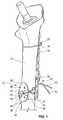
- Fig. 1shows a perspective view of a bone plate 10 according to an embodiment with the bone plate 10 being positioned at a fragmented thigh bone 12. As can be gathered from Fig. 1 , the bone plate 10 is directly positioned at a fragmented region 14 and contacts an outer circumferential surface of the bone 12.
- a partially visible second bone plate in form of a primary plate 16is provided.
- the primary plate 16extends along a significantly longer portion of the bone 12 as compared to the bone plate 10.
- the bone plate 10 and the primary plate 16define an embodiment of a bone plate system. They are arranged at opposite circumferential regions of the bone 12, thus facing in different and oppositely oriented directions. In this way, the bone plate 10 and the primary plate 16 are arranged so that they clamp the fragmented region 14 of the bone 12 between each other.
- the primary plate 16is held at the bone 12 by means of an upper circumferential wire 18.
- the circumferential wire 18is connected to the primary plate 16 in a known manner, for example by means of a crimping member 20. Also, the circumferential wire 18 is tightened to hold the primary plate 16 in close contact with the adjacent bone surface. Furthermore, the primary plate 16 is connected to the bone 12 by means of one or more bone screws 22 inserted via a through-hole of the primary plate 16 into the bone 12.
- the bone plate 10is configured with an oval main body 24 having a front side 26 facing away from the bone 12 and towards the viewer.
- the main body 24further comprises a bone facing side 28 which faces towards and contacts the bone 12 (not visible in Fig. 1 ).
- four through-holes 30are provided in the bone plate 10 which are configured to receive a bone screw similar to the screw 22 penetrating the primary plate 16.
- the bone plate 10further comprises a first, second and third guiding channel 32, 34, 33.
- a cap member 36is provided which is inserted into a central recess being formed by a through-hole 38 in the front side 26 of the bone plate 10 (said through-hole 38 not being visible in Fig. 1 ).
- the cap member 36further comprises two guiding openings 40 being arranged oppositely to one another, only one of which can be seen in Fig. 1 .
- the guiding openings 40are aligned with the third guiding channel 33 so that a further circumferential wire 42 can be inserted into to the guiding channel 33 and guided through the cap member 36.
- the circumferential wire 42can thus be wound around a cross-section of the bone 12 as well as an opposite portion of the primary plate 16.
- the circumferential wire 42can be tightened by connecting its free end portions 44 in a known manner (e.g., using an additional crimping member 20 or by making a knot).
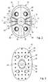
- Fig. 2shows a view of the front side 26 of the bone plate 10 according to Fig. 1 from above.
- the oval outline of the main body 24can be seen having a longer axis of symmetry Z and a shorter axis of symmetry Y.
- Two lateral regions 46, 48being opposite to one another extend substantially parallel to said longer axis of symmetry Z.
- the guiding channels 32, 33, 34each extend between the lateral regions 46, 48 and each define a guiding channel axis A, B, C extending across the front side 26 from above. More specifically, the first guiding channel 32 defines the guiding channel axis A, the second guiding channel 34 defines the guiding channel axis B and the third guiding channel 33 defines guiding channel axis C.
- the guiding channel axes A, B, Ccross each other in the region of the central through-hole 38 (obstructed by the cap member 36 in Fig. 2 ).
- each of the guiding channels 32, 33, 34comprises two channel portions being configured as grooves 35 in the front side 26.
- the grooves 35each extend from opposite positions of the through-hole 38 to one of the lateral regions 46, 48. Note that in Fig. 2 , only the grooves 35 of the first guiding channel 32 are indicated by respective reference signs.
- the grooves 35merge into the through-hole 38, so that - at least without the optional cap member 36 detailed below - the wire 42 of Fig. 1 can generally be guided along any of the guiding channel axes A, B, C from one lateral region 46, 48 to the other while extending across the through-hole 38.
- the through-hole 38thus defines a common channel portion of the guiding channels 32, 33, 34.
- the guiding channels 32, 33, 34are each formed as a free space in the front side 26, said space being defined in each case by the above-described arrangement of two grooves 35 merging into the central through-hole 38.
- the guiding channels 32, 33, 34can also partially be formed in or be obstructed by the cap member 36 depending on its rotational position within the central through-hole 38.
- the first and second guiding channels 32, 34extend from positions P1 and P2 of the lateral regions 46, 48 which are spaced apart from the shorter axis of symmetry Y. Also, with respect to the respective axes of symmetry Y, Z, the first and second guiding channels 32, 34 generally extend diagonally across the front side 26.
- the third guiding channel 33extends from a position P3 being located on the shorter axis of symmetry Y. Also, its guiding channel axis C is parallel with said axis of symmetry Y and in the given case even coincides therewith.
- the third guiding channel axis Cthus extends across the front side 26 and the central through-hole 38 from one lateral region 46, 48 to the other with the shortest possible length.
- the groove segments 35 of the third guiding channel 33extend in a region of the front side 26 being located between the first and second guiding channels 32, 34.
- Fig. 2shows that the first and second guiding channel axes A, B enclose an angle ⁇ with one another of 60°. This angle ⁇ is measured between respective groove segments 35 of these channels 32, 34 being arranged at the same side of the through-hole 38 or, with reference to Fig. 2 , extending from the same lateral region 48.
- the third guiding channel axis Cencloses an angle ⁇ with each of the first and second guiding channel axis A, B of 30°.
- the groove segments 35 of the third guiding channel 33are thus arranged in the middle between the respective groove segments 35 of the first and second guiding channels 32, 34.
- the arrangement of the crossing guiding channels 32, 33, 34 according to this embodimentthus allows for a compact design of the bone plate 10, while offering various possibilities for fixing the bone plate 10 with a circumferential wire 42.
- the cap member 36is positioned within the through-hole 38 so that its guiding openings 40 are aligned with each of the groove segments 35 of the third guiding channel 33.
- a free space in form of a non-illustrated slot 60is provided in the cap member 36 and connects the two guiding openings 40 with one another.
- the wire 42 of Fig. 1can hence be guided along the third guiding channel axis C by inserting it into the left groove segment 35 of the third guiding channel 33, through the guiding openings 40 and slot 60 of the cap member 36 and thus across the central through-hole 38 and finally into the right groove segment 35 for guiding it towards the second lateral region 48.
- the cap member 36obstructs said remaining guiding channels 32, 34 or, in other words, intersects the respective channel axes A, B by means of a solid sidewall section 71 (not depicted in Fig. 2 ).
- a circumferential wire 42examples include guiding the wire 42 twice around the bone 12 and bone plate 10 to form a cross.
- the cap member 36 of Fig. 2may be omitted.
- the wire 42is inserted into the left groove segment 35 of the first guiding channel 32 at position P1, guided along the first channel axis A while crossing the central through hole 38, to then exit the first guiding channel 32 at the opposite lateral region 48.
- the wireis circumferentially wrapped around the bone 12 and brought back to the bone plate 10 at position P2 for entering the second guiding channel 34.
- the wire 42is then guiding along the respective guiding channel axis B towards the opposite lateral region 48.
- a further alternativeincludes using two or even three separate circumferential wires 42, each being guided through one of the guiding channels 32, 33, 34.
- a second wire 42can be guided through the first guiding channel 32 and crimped or knotted at a similar position at the primary plate 16.
- the cap member 36 of Fig. 2may again be omitted in this case.
- a third wire 42may be guided through the second guiding channel 34 and be secured in a similar manner. Again, the crossing portions of the wires 42 are accommodated in the central through-hole 38, thus limiting bulges or protrusions.
- any of the guiding channels 32, 33, 34may be selected and combined for accommodating one of a respective plurality of separate circumferential wires 42.
- Fig. 3shows a rear view of the bone plate 10 according to Figs. 1 and 2 onto the bone facing side 28.
- the bone facing side 28comprises a base portion 50 with a plurality of spacer members 52 protruding therefrom towards an adjacent bone surface at which the bone plate 10 is to be arranged.
- the spacer members 52are provided with spikes 54 at distal end portions thereof (see also following discussion).
- the portion of the cap member 36 facing the bone 12 of Fig. 1can be seen. As previously discussed, said portion is configured with an elongated straight slot 60 which connects the guiding openings 40 with one another.
- Fig. 4shows a side view of the bone plate 10 with the longer axis of symmetry Z of Fig. 2 extending directly towards the viewer.
- the main body 24 of the bone plate 10is convexly curved with the bone facing side 28 being arranged at a radially inner portion and the front side 26 being arranged in a radially outer portion thereof.
- the spacer members 52are configured with spikes 54 at their distal end portions 53. More specifically, the spacer members 52 comprise a cylindrical base 56 protruding from the base portion 50 of the bone facing side 28 and towards the non-illustrated bone 12 (cf. Fig. 1 ).
- the diameter of said base 56generally exceeds the largest diameter of the spikes 54, such that a step 58 is formed between these portions.
- the step 58acts as a stop face when arranging the bone plate 10 at the bone 12 and pushing the spikes 54 into the adjacent bone surface.
- a section B-Bis indicated which is depicted as a corresponding sectional view B-B in Fig. 5 .
- the trough-hole 38is provided with a diameter step 62 close to the bone facing side 28.
- This step 62results from providing a first section 64 of the trough-hole 38 in the region of the front side 26 with a smaller diameter compared to a second section 66 in the region of the bone facing side 28.
- the resulting diameter step 62thus provides an undercut for snapping the cap member 36 into the through-hole 38.
- the cap member 36is provided with two flexible leg portions 68 which are separated by the above-discussed slot 60.
- the leg portions 68are connected by a dome-shaped top portion 70 of the cap member 36, said portion 70 being arranged at the front side 26 of the bone plate 10.
- the leg portions 68are configured with protruding sections 72.
- the cap member 36can be rotated about a rotational axis R extending orthogonally to an adjacent region of the front side 26 and bone facing side 28.
- a rotational position of the cap member 36 within the trough-hole 38can be maintained by means of the above-discussed frictional contact.
- the slot 60 and the receiving openings 40can be selectively aligned with one of the guiding channel axes A, B, C as explained above. Similar to the previous drawings, in the depicted state the slot 60 is aligned with the third guiding channel axis C, so that a wire can be guided through the third guiding channel 33.
- Fig. 6shows the sectional view A-A as indicated in Fig. 4 .
- the through-holes 30 for receiving bone fixation screws 22are configured with a thread 74 for cooperating with a complementary thread (not shown) that is provided at the head of a bone screw to be inserted into the bone 12 via a particular one of the through-holes 30.
- the groove segments 35 of the guiding channels 32, 33, 34are configured with a tapered cross section or, in other words, with an increasing width towards an outer face of front side 26. This helps to securely hold the wire 42 in place.
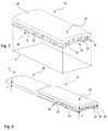
- Fig. 7depicts a bone plate 10 according to a further embodiment.
- the bone plate 10again comprises a plate-type main body 24 with a front side 26 which, although not specifically illustrated, is configured with a similar guiding channel arrangement as previously discussed.
- the bone plate 10can be arranged at a bone 12 in a similar manner as discussed with reference to Fig. 1 and may form a bone plate system with a further bone plate (reference numeral 16 in Fig. 1 ).
- the bone plate 10further comprises a bone facing side 28 with a base portion 50, the latter also forming part of the main body 24. Also, several cylindrical spacer members 52 protrude from said base portion 50. Yet, instead of being configured with spikes 54, the distal end portions 53 of the spacer members 52 are connected to a common porous plate member 78. Said porous plate member 78 is shaped and sized similarly to the main body 24 and the front portion 26. Specifically, it is provided with a similar convex curvature and covers a similar area F. Also, the porous plate member 78 generally extends in parallel with the front side 26 and main body 24. Note that the porosity of the porous plate member 78 is provided by means of several dedicated cut-outs 77 and apertures 79.
- the bone plate 10is to be arranged at a bone 12 so that the porous plate member 78 directly contacts the adjacent bone surface.
- the porosity of the plate member 78is selected to promote an in-growth of bone tissue. This further promotes the stabilization and thus the healing process of a respectively fragmented bone section 14.
- the bone plate 10 of this embodimentis generally configured to be separable into at least two parts.
- a surgical assembly kitcomprising the bone plate 10 of Fig. 6 and a separation tool 80.
- the separation tool 80is configured as a plate-type member having a convex curvature that corresponds to the shape of the main body 24 and porous plate member 78 of the bone plate 10.
- the thickness T of the separation tool 80is smaller than a distance D between the plate member 78 and the main body 24 as defined by the spacer members 52.
- the main body 24 or, more specifically, the base portion 50 of the bone facing side 28, and the porous plate member 78are positioned at a distance D to one another, thus defining a space between them into which the separation tool 80 can be inserted.
- the separation tool 80is provided with a tapered front face 82 defining a cutting edge 84.
- the cutting edge 84is arranged close to a region in which the spacer members 52 merge into the porous plate member 78, i.e., close to the distal end portions 53 of the spacer members 52. Therefore, when exerting a pushing force P onto the separation tool 80, the cutting edge 84 is pushed against the spacer members 52, thus being able to cut through and sever them.
- the porous plate member 78can be separated from the base portion 50 and the main body 24. In consequence, the main body 24 as well as large parts of the spacer members 52 can be removed from the bone 12, whereas the partially in-grown porous plate member 78 can remain thereat.
Landscapes
- Health & Medical Sciences (AREA)
- Orthopedic Medicine & Surgery (AREA)
- Surgery (AREA)
- Life Sciences & Earth Sciences (AREA)
- Heart & Thoracic Surgery (AREA)
- Nuclear Medicine, Radiotherapy & Molecular Imaging (AREA)
- Engineering & Computer Science (AREA)
- Biomedical Technology (AREA)
- Neurology (AREA)
- Medical Informatics (AREA)
- Molecular Biology (AREA)
- Animal Behavior & Ethology (AREA)
- General Health & Medical Sciences (AREA)
- Public Health (AREA)
- Veterinary Medicine (AREA)
- Surgical Instruments (AREA)
Abstract
Description
- The present disclosure generally relates to bone plates. In particular, a bone plate as well as a bone plate system and a surgical kit assembly comprising the bone plate are described.
- To promote the healing process of a damaged or fragmented bone, bone plates are commonly attached to an outside surface of the bone. The bone plates act as stabilizing elements for the damaged area. In addition, they may help to position fragmented bone sections relative to one another.
- For attaching a bone plate to a bone, various fixation techniques have been suggested. For example, screws may be applied which are inserted in through-holes of the bone plate and then screwed into an adjacent bone portion. Likewise, circumferential wires can be wound around a cross-section of the bone and a bone plate arranged at the bone. The wires are then tightened to secure the bone plate at the bone and to avoid a relative movement therebetween.
US 5,190,545 discloses an elongated bone plate which is configured to be arranged at an outer surface of a fragmented bone. The bone plate is fixed by winding a circumferential wire around a cross-section of the bone and through positioning inserts of the bone plate which receive and accommodate the circumferential wire. The wire is then tightened by means of a crimp sleeve.US 5,665,089 discloses a similar bone plate which is held at the bone by means of circumferential wires. In this case, the wires are inserted into through-holes extending between different lateral regions of the bone plate.- There is a need for a bone plate which is easy to use and can be reliably attached to a bone.
- According to one aspect, a bone plate is provided, comprising a bone facing side, a front side being arranged substantially opposite to and facing away from the bone facing side, and at least a first and a second elongated guiding channel, the first and second guiding channel each being configured to receive a flexible elongated member, the first and second guiding channel each further being configured to guide said elongated member along a respective first and second guiding channel axis from a first to a second lateral region of the bone plate, and the first and second guiding channel axes crossing each other in at least one region of the bone plate.
- The bone plate may be configured with a generally rectangular, oval or circular out-line, said outline confining and/or being defined by at least one of the front side or the bone facing side. The bone plate can be anatomically pre-shaped. In one variant, the bone plate has a convexly curved and/or outwardly bulged shape with the front side forming a radially outer portion and the bone facing side forming a radially inner portion of the bone plate.
- The bone plate may further comprise at least one through-hole which is configured to receive a screw for fixing the bone plate to an adjacent bone. The through-hole may comprise a thread for engaging with the screw (e.g., with a complementary thread at a screw head). Additionally, or as an alternative, the through-hole may comprise a feature (e.g., a circumferential lip or circumferential protrusions) that permit to lock the screw with the plate at a desired oblique relationship.
- The first and second guiding channels can be configured as a free space being provided inside of and/or at the bone plate. For example, the guiding channels may comprise elongated through-holes extending through the bone plate. In one variant, said through-holes extend close to or just below of the front side. The guiding channels can also comprise at least one section that is directly formed in or at the front side. Of course, the guiding channels can also be configured different from one another. Also, they can be configured with varying cross-sectional shapes and/or dimensions along their respective guiding channel axis.
- In general, any member or section of the bone plate which provides and/or confines a free space through which the first and second guiding channel axes extend can be considered as forming at least a portion of the guiding channels. For example, the guiding channels may largely be formed in a main body of the bone plate. The main body may, for example, be formed as a one-piece member. Similarly, additional members attached to said main body may define at least a portion of the guiding channels, such as an additional cap member as described below.
- The flexible elongated member can be provided in form of a wire or thread. The guiding channels may be configured to receive, accommodate and/or guide said elongated member with a predefined course across the bone plate.
- The first and second lateral regions of the bone plate between which the guiding channels extend can be arranged substantially opposite to one another. In one example, the bone plate is configured with a substantially rectangular or oval outline comprising two oppositely arranged longer sides and two oppositely arranged shorter sides. In this case, the first and second lateral regions may be positioned at or adjacent to the respective longer sides of said rectangular outline.
- Similarly, the bone plate can have an outline with at least a first and second axis of symmetry, the extension along one of said axes of symmetry being larger than an extension along the respective other axis. For reasons of brevity, such a design will be referred to as the outline having a "short" and a "long" axis of symmetry in the following. This may apply, for example, to a bone plate having a substantially oval or elliptical outline. In these cases, the first and second lateral regions may be provided at or adjacent to regions of the outline that extend along (e.g., substantially parallel to) the longer axis of symmetry.
- The region in which the first and second guiding channel axes cross each other may be provided in or at the front side or at least close to a respective surface portion thereof. Generally, the guiding channel axes may cross each other without actually intersecting, for example when extending at different height levels through the bone plate. The guiding channel axes may cross each other in a common channel portion of the first and second guiding channels. In this case, the first and second guiding channels comprise a common portion for receiving and guiding the flexible elongated member therethrough. In other words, the first and second guiding channels may merge into each other in at least one region for forming the common channel portion. In this case, the guiding channel axes can also intersect one another.
- In this context, the common channel portion can be configured as a recess at the front side. The recess may take any shape and is for example configured with a substantially rectangular, oval or circular outline. Also, it can be substantially centrally located at the front side. According to one variant, the recess is configured as a through-hole. According to another variant, the recess is closed at one end (e.g., it may be pot-shaped). In general, the recess may connect the two guiding channels by forming a common free space in the form of the common channel portion through which both of the first and second guiding channel axes extend.
- In addition, each guiding channel may comprise at least two elongated channel segments extending from different positions of the recess to the first and second lateral region of the bone plate, respectively. Therefore, the guiding channels may comprise at least one segment leading into and one segment leading out of the recess. The positions at which the two channel segments extend from the recess and/or merge therewith may be arranged substantially opposite to one another. For example, said positions may be located at opposite lateral regions of the recess.
- The bone plate may comprise a cap member which is rotatably received in the recess. For doing so, the cap member can be received by means of a press- and/or form-fit which allows for a rotation in the recess. Specifically, the cap member may be rotatable about an axis extending transverse to the bone plate and/or at least one of the bone facing side and front side (e.g., extending substantially orthogonal thereto). The cap member may be configured to maintain its position within the recess after being rotated to a particular angular position (e.g., with help of a respective form- and/or press-fit).
- The cap member may be formed of a plastics or polymer material. The bone plate may generally comprise metallic materials, such as titanium or titanium foam.
- The cap member further may comprise at least one guiding opening which is selectively alignable with one of the guiding channels axes. The guiding opening can be configured as a channel, an aperture or a cut-out within the cap member. Also, the guiding opening may at least partially be formed in a sidewall portion of the cap member which is received in and/or abuts against the recess. In one example, the cap member comprises two guiding openings which are, for example, positioned substantially opposite to one another.
- By rotating the cap member within the recess, the at least one guiding opening can be selectively aligned with one of the segments of the guiding channels extending from the recess. Hence, a flexible elongated member received in the respective guiding channel can extend through said guiding opening. At the same time, the cap member may be configured to block the passage through other guiding channel segments which are not aligned with the guiding opening.
- The cap member may be removably mounted in the recess. In this manner, the bone plate can selectively be configured with our without the cap member depending on current needs. For doing so, a snap-in connection or a screw connection may be provided.
- Each guiding channel axis may have a substantially continuously curved course or a substantially straight course. Accordingly, the guiding channels can be configured to guide the elongated member between the lateral regions of the bone plate in a substantially continuously curved or a substantially straight manner.
- In one design, at least one of the guiding channels comprises a groove in the front side of the bone plate. The groove can be configured with a tapered cross-section. In one example, each guiding channel comprises two grooves extending from different and, preferably, opposite positions of a recess at the front side as discussed above.
- Two neighbouring guiding channel axes may enclose an angle with one another of between approximately 10° and approximately 170°. In case only two guiding channels are provided, said guiding channels may enclose an angle of between approximately 30° and 120° or, preferably, of between approximately 45° and 90°. Said angle can generally be measured between respective guiding channel segments extending from the same lateral region of the bone plate and towards the region of crossing each other.
- The bone plate may also comprise a third elongated guiding channel extending between the first to the second lateral region of the bone plate and comprising at least one segment extending in a region between the first and second guiding channel. The third guiding channel can have a third guiding channel axis that crosses the first and second guiding channel axes in the same region as they cross each other. Other than that, the third guiding channel can extend in a region of the bone plate (e.g., of the front side) being located between the first and second guiding channel. In one example, the third guiding channel axis encloses a substantially similar angle with each of the first and second guiding channel axes, for example, an angle of between approximately 20° and 80°. Accordingly, the third guiding channel can generally extend in the middle between the first and second guiding channel.
- The bone facing side may comprise a base portion and a plurality of spacer members protruding therefrom, the spacer members each being configured with a distal end portion facing the bone. The spacer members can be configured as substantially cylindrical and/or pillar-shaped members protruding transversely from the base portion towards an adjacent bone at which the bone plate is to be arranged. In one variant, the spacer members protrude substantially orthogonally from the base portion. The spacer members can be integrally formed with any of the base portion and/or the bone facing side and/or the bone plate.
- The distal end portion can be arranged substantially opposite to that portion of the spacer members which is connected to and/or merges into the base portion (i.e., said end portion being "distal" with respect to the base portion). In one variant, the distal end portion is configured as a free end portion of the spacer members (e.g., to directly contact the bone). Alternatively, the distal end portion can be connected to further members which are actually provided for directly contacting the bone, such as an additional plate member. Said connection can be achieved by forming the distal end portions integrally with the additional bone contacting members.
- According to one design, the distal end portions each comprise a spike. The spikes can hence form the actual free distal end portions of the spacer members. Again, the spikes can be integrally formed with said distal end portions and/or spacer members. Furthermore, the spikes may be configured to at least partially penetrate an adjacent bone surface to secure the position of the bone plate thereat.
- A step may be provided between each distal end portion and an adjacent portion of the associated spacer member. Specifically, the adjacent portion may be configured with larger cross-sectional dimensions compared to the distal end portions (or vice versa), said difference in terms of cross-sectional dimensions resulting in the formation of the step. For example, the adjacent portion may be configured with a larger diameter than the distal end portion. The step may form a stop face for contacting an adjacent bone surface. In this manner, the step may be configured to limit the penetration depth of the distal end portions into said bone surface, for example, in case the distal end portions comprise or are configured as a spike.
- The bone facing side may comprise a porous material. The porous material may generally be arranged in a region of the bone facing side which is configured to contact the bone or at least be arranged adjacent thereto. The porous material may comprise a foamed material and/or an as such solid material being provided with dedicated cut-outs, apertures or the like for creating the porosity. The porosity can be provided in a substantially regular or irregular manner within the material, for example, with a substantially regular or irregular distribution and/or density of pores. Also, the porosity of said material may be selected so as to promote an in-growth of bone tissue.
- Any of the base portion, the spacer members and/or their distal end portions may comprise a respective porous material. Specifically, in case the distal end portions comprise spikes, said spikes may comprise or be made of the porous material.
- Also provided in a bone plate system comprising a first bone plate as described above and configured to be arranged at a region of bone, and further comprising a second plate configured to be arranged at an opposite circumferential region of the bone. The bone plate system may further comprise a flexible elongated member configured to be wound around the first and second bone plate so as to keep both bone plates in a fixed relative position to each other and to the bone.
- According to a further aspect, a bone plate is provided, comprising a bone facing side comprising a base portion and one or more spacer members protruding therefrom, a front side being arranged substantially opposite to and facing away from the bone facing side, and a porous plate member connected by the one or more spacer members to the bone facing side. The bone facing side, the front side, the spacer members as well as the bone plate as such (e.g., its shape or material) can be configured as discussed above. Furthermore, the connection between the spacer members and the porous plate member can be achieved by forming said members integrally with one another. Moreover, the bone facing side and/or the porous plate member may be configured with (e.g., stepped) spikes for contacting the bone.
- The porous plate member can be configured to extend substantially in parallel to the bone facing side and/or the front side. In one example, the porous plate member is substantially congruent with the bone facing side and/or the front side. In general, the size or, more specifically, the area covered by said porous plate member may at least be approximately 30 % and, preferably, between approximately 60 % to 100 % of the area covered by the bone facing side and/or the front side. Note that the term "covered area" may generally refer to the bone area that can be covered when placing the bone plate at a bone or, in other words, be defined as the footprint of the respective portions of the bone plate. As a general matter, the porous plate member can be configured by a plurality of single plate members and/or single plate member sections which, taken together, define an area of any of the above discussed sizes.
- Each spacer member may be configured to be severed by a separation tool. For example, each spacer member may have along its axial extension a weakened portion (e.g., of a reduced diameter).
- According to a further aspect, a surgical kit assembly is provided, comprising a bone plate with a porous plate member as presented herein, and a separation tool configured to be insertable into the space between the porous plate member and the base portion of the bone facing side, the separation tool being configured to separate the porous plate member from the base portion.
- The separation tool can be specifically sized and/or shaped to be insertable into the space between the porous plate member and the respective base portion. Said space can at least partially be defined by an axial length of the spacer members. Specifically, the thickness or material strength of the separation tool may be adapted to said space as well as a possible bend or curved shape thereof. Of course, the separation tool may be integrally formed with or connected to further members and/or portions which are not insertable into the relevant space, such as additional handling or gripping portions.
- The separation tool can be configured as plate-type member and/or chisel-type tool and be manually insertable into the relevant space. Following that, a force can be exerted by manually pushing the separation tool against the spacer members. Alternatively, a hammer or the like can be used. In this way, the spacer members can be severed (e.g., cut and/or broken), thereby separating the porous plate member from the base portion.
- The separation tool may further comprise a cutting edge for severing the spacer members. The cutting edge may be provided at a lateral region of the separation tool (e.g., formed by a tapered side face thereof). The cutting edge may be positioned at the separation tool so as to contact the spacer members substantially in or adjacent to a region in which they are connected to the porous plate member, e.g. at their distal end portions.
- Further details, advantages and aspects of the present disclosure will become apparent from the following embodiments taken in conjunction with the drawings, wherein:
- Fig. 1
- shows a schematic illustration of a first embodiment of the bone plate being arranged at a fragmented bone;
- Fig. 2
- shows a view of the front side of the bone plate according to
Fig. 1 ; - Fig. 3
- shows a view of the bone facing side of the bone plate according to
Fig. 1 ; - Fig. 4
- shows a side view of the bone plate according to
Fig. 1 indicating the position of the sectional views B-B and A-A according toFigs. 5 and 6 ; - Fig. 5
- shows a view according to section B-B of
Fig. 4 ; - Fig. 6
- shows a view according to section A-A of
Fig. 4 ; - Fig. 7
- shows a perspective view of a bone plate according to a second embodiment; and
- Fig. 8
- shows a view of a surgical kit assembly comprising the bone plate according to
Fig. 6 as well as a separation tool. - In the following, embodiments of a bone plate and of a bone plate system as well as a surgical assembly kit comprising said bone plate will be described. The same reference numerals will be used to denote the same or similar structural features.
Fig. 1 shows a perspective view of abone plate 10 according to an embodiment with thebone plate 10 being positioned at afragmented thigh bone 12. As can be gathered fromFig. 1 , thebone plate 10 is directly positioned at afragmented region 14 and contacts an outer circumferential surface of thebone 12.- Furthermore, a partially visible second bone plate in form of a
primary plate 16 is provided. Theprimary plate 16 extends along a significantly longer portion of thebone 12 as compared to thebone plate 10. Thebone plate 10 and theprimary plate 16 define an embodiment of a bone plate system. They are arranged at opposite circumferential regions of thebone 12, thus facing in different and oppositely oriented directions. In this way, thebone plate 10 and theprimary plate 16 are arranged so that they clamp thefragmented region 14 of thebone 12 between each other. - The
primary plate 16 is held at thebone 12 by means of an uppercircumferential wire 18. Thecircumferential wire 18 is connected to theprimary plate 16 in a known manner, for example by means of a crimpingmember 20. Also, thecircumferential wire 18 is tightened to hold theprimary plate 16 in close contact with the adjacent bone surface. Furthermore, theprimary plate 16 is connected to thebone 12 by means of one or more bone screws 22 inserted via a through-hole of theprimary plate 16 into thebone 12. - The
bone plate 10 is configured with an ovalmain body 24 having afront side 26 facing away from thebone 12 and towards the viewer. Themain body 24 further comprises abone facing side 28 which faces towards and contacts the bone 12 (not visible inFig. 1 ). Furthermore, four through-holes 30 are provided in thebone plate 10 which are configured to receive a bone screw similar to thescrew 22 penetrating theprimary plate 16. - As will be described below, the
bone plate 10 further comprises a first, second and third guidingchannel cap member 36 is provided which is inserted into a central recess being formed by a through-hole 38 in thefront side 26 of the bone plate 10 (said through-hole 38 not being visible inFig. 1 ). Thecap member 36 further comprises two guidingopenings 40 being arranged oppositely to one another, only one of which can be seen inFig. 1 . - In the depicted state, the guiding
openings 40 are aligned with thethird guiding channel 33 so that a furthercircumferential wire 42 can be inserted into to the guidingchannel 33 and guided through thecap member 36. As indicated inFig. 1 , thecircumferential wire 42 can thus be wound around a cross-section of thebone 12 as well as an opposite portion of theprimary plate 16. Following that, thecircumferential wire 42 can be tightened by connecting itsfree end portions 44 in a known manner (e.g., using an additional crimpingmember 20 or by making a knot). Fig. 2 shows a view of thefront side 26 of thebone plate 10 according toFig. 1 from above. Again, the oval outline of themain body 24 can be seen having a longer axis of symmetry Z and a shorter axis of symmetry Y. Twolateral regions channels lateral regions front side 26 from above. More specifically, the first guidingchannel 32 defines the guiding channel axis A, thesecond guiding channel 34 defines the guiding channel axis B and thethird guiding channel 33 defines guiding channel axis C. The guiding channel axes A, B, C cross each other in the region of the central through-hole 38 (obstructed by thecap member 36 inFig. 2 ).- In more detail, each of the guiding
channels grooves 35 in thefront side 26. Thegrooves 35 each extend from opposite positions of the through-hole 38 to one of thelateral regions Fig. 2 , only thegrooves 35 of the first guidingchannel 32 are indicated by respective reference signs. - The
grooves 35 merge into the through-hole 38, so that - at least without theoptional cap member 36 detailed below - thewire 42 ofFig. 1 can generally be guided along any of the guiding channel axes A, B, C from onelateral region hole 38. The through-hole 38 thus defines a common channel portion of the guidingchannels channels front side 26, said space being defined in each case by the above-described arrangement of twogrooves 35 merging into the central through-hole 38. As detailed below, the guidingchannels cap member 36 depending on its rotational position within the central through-hole 38. - As further indicated in
Fig. 2 , the first andsecond guiding channels lateral regions second guiding channels front side 26. - The
third guiding channel 33, on the other hand, extends from a position P3 being located on the shorter axis of symmetry Y. Also, its guiding channel axis C is parallel with said axis of symmetry Y and in the given case even coincides therewith. The third guiding channel axis C thus extends across thefront side 26 and the central through-hole 38 from onelateral region groove segments 35 of thethird guiding channel 33 extend in a region of thefront side 26 being located between the first andsecond guiding channels - Moreover,
Fig. 2 shows that the first and second guiding channel axes A, B enclose an angle α with one another of 60°. This angle α is measured betweenrespective groove segments 35 of thesechannels hole 38 or, with reference toFig. 2 , extending from the samelateral region 48. Similarly, the third guiding channel axis C encloses an angle β with each of the first and second guiding channel axis A, B of 30°. Thegroove segments 35 of thethird guiding channel 33 are thus arranged in the middle between therespective groove segments 35 of the first andsecond guiding channels - Overall, the arrangement of the
crossing guiding channels bone plate 10, while offering various possibilities for fixing thebone plate 10 with acircumferential wire 42. - In
Fig. 2 , thecap member 36 is positioned within the through-hole 38 so that its guidingopenings 40 are aligned with each of thegroove segments 35 of thethird guiding channel 33. As described below, a free space in form of anon-illustrated slot 60 is provided in thecap member 36 and connects the two guidingopenings 40 with one another. - Starting from the left
lateral region 46 inFig. 2 , thewire 42 ofFig. 1 can hence be guided along the third guiding channel axis C by inserting it into theleft groove segment 35 of thethird guiding channel 33, through the guidingopenings 40 andslot 60 of thecap member 36 and thus across the central through-hole 38 and finally into theright groove segment 35 for guiding it towards the secondlateral region 48. - At the same time, since the guiding
openings 40 are not aligned with any of thegroove segments 35 of the first or second guidingchannel wire 42 along the respective first and second channel axes A, B. Rather, thecap member 36 obstructs said remaining guidingchannels Fig. 2 ). - Other possibilities for applying a
circumferential wire 42 include guiding thewire 42 twice around thebone 12 andbone plate 10 to form a cross. In this case, thecap member 36 ofFig. 2 may be omitted. Instead, thewire 42 is inserted into theleft groove segment 35 of the first guidingchannel 32 at position P1, guided along the first channel axis A while crossing the central throughhole 38, to then exit the first guidingchannel 32 at the oppositelateral region 48. Following that, the wire is circumferentially wrapped around thebone 12 and brought back to thebone plate 10 at position P2 for entering thesecond guiding channel 34. Again, thewire 42 is then guiding along the respective guiding channel axis B towards the oppositelateral region 48. Note that in this process, it crosses the wire section that is accomated in the first guidingchannel 32 in the region of the central through-hole 38. Said throughhole 38 hence defines a free space for accommodating the crossing wire sections, thus limiting a formation of bulges or protrusions by said wire sections at thefront side 26. After forming the cross, the free-ends of thewire 42 are secured to each other in the region of theprimary plate 16 inFig. 1 , for example, by crimping. - Of course, it is also possible to form a similar cross by guiding the
wire 42 through twodifferent guiding channels channels bone 12. - A further alternative includes using two or even three separate
circumferential wires 42, each being guided through one of the guidingchannels circumferential wire 42 ofFig. 1 which is accommodated in thethird guiding channel 33, asecond wire 42 can be guided through the first guidingchannel 32 and crimped or knotted at a similar position at theprimary plate 16. Thecap member 36 ofFig. 2 may again be omitted in this case. Also, athird wire 42 may be guided through thesecond guiding channel 34 and be secured in a similar manner. Again, the crossing portions of thewires 42 are accommodated in the central through-hole 38, thus limiting bulges or protrusions. Also, any of the guidingchannels circumferential wires 42. Fig. 3 shows a rear view of thebone plate 10 according toFigs. 1 and2 onto thebone facing side 28. Thebone facing side 28 comprises abase portion 50 with a plurality ofspacer members 52 protruding therefrom towards an adjacent bone surface at which thebone plate 10 is to be arranged. In the depicted embodiment, thespacer members 52 are provided withspikes 54 at distal end portions thereof (see also following discussion). Furthermore, the portion of thecap member 36 facing thebone 12 ofFig. 1 can be seen. As previously discussed, said portion is configured with an elongatedstraight slot 60 which connects the guidingopenings 40 with one another.Fig. 4 shows a side view of thebone plate 10 with the longer axis of symmetry Z ofFig. 2 extending directly towards the viewer. It can be seen that themain body 24 of thebone plate 10 is convexly curved with thebone facing side 28 being arranged at a radially inner portion and thefront side 26 being arranged in a radially outer portion thereof. Furthermore, it can be seen that thespacer members 52 are configured withspikes 54 at theirdistal end portions 53. More specifically, thespacer members 52 comprise acylindrical base 56 protruding from thebase portion 50 of thebone facing side 28 and towards the non-illustrated bone 12 (cf.Fig. 1 ). The diameter of saidbase 56 generally exceeds the largest diameter of thespikes 54, such that astep 58 is formed between these portions. Thestep 58 acts as a stop face when arranging thebone plate 10 at thebone 12 and pushing thespikes 54 into the adjacent bone surface.- In
Fig. 4 , a section B-B is indicated which is depicted as a corresponding sectional view B-B inFig. 5 . In this view, the central trough-hole 38 for receiving thecap member 36 can clearly be seen. The trough-hole 38 is provided with adiameter step 62 close to thebone facing side 28. Thisstep 62 results from providing afirst section 64 of the trough-hole 38 in the region of thefront side 26 with a smaller diameter compared to asecond section 66 in the region of thebone facing side 28. The resultingdiameter step 62 thus provides an undercut for snapping thecap member 36 into the through-hole 38. - For doing so, the
cap member 36 is provided with twoflexible leg portions 68 which are separated by the above-discussedslot 60. Theleg portions 68 are connected by a dome-shapedtop portion 70 of thecap member 36, saidportion 70 being arranged at thefront side 26 of thebone plate 10. At their free end portions remote from the dome-shapedtop portion 70, theleg portions 68 are configured with protrudingsections 72. By elastically deforming thecap member 36, for example, by pushing theleg portions 68 slightly towards each other, the protrudingsections 72 can be inserted into the trough-hole 38 and engage with the undercut 62. Thecap member 36 is thus releasably held in the trough-hole 38. Furthermore, asidewall section 71 of eachleg portion 68 is pushed against thefirst section 64 of the trough-hole 38, thus producing a frictional contact. - As a result, the
cap member 36 can be rotated about a rotational axis R extending orthogonally to an adjacent region of thefront side 26 andbone facing side 28. A rotational position of thecap member 36 within the trough-hole 38 can be maintained by means of the above-discussed frictional contact. This way, theslot 60 and the receivingopenings 40 can be selectively aligned with one of the guiding channel axes A, B, C as explained above. Similar to the previous drawings, in the depicted state theslot 60 is aligned with the third guiding channel axis C, so that a wire can be guided through thethird guiding channel 33. Fig. 6 shows the sectional view A-A as indicated inFig. 4 . It is shown that the through-holes 30 for receiving bone fixation screws 22 are configured with athread 74 for cooperating with a complementary thread (not shown) that is provided at the head of a bone screw to be inserted into thebone 12 via a particular one of the through-holes 30. Furthermore, it can be seen thegroove segments 35 of the guidingchannels front side 26. This helps to securely hold thewire 42 in place.Fig. 7 depicts abone plate 10 according to a further embodiment. Thebone plate 10 again comprises a plate-typemain body 24 with afront side 26 which, although not specifically illustrated, is configured with a similar guiding channel arrangement as previously discussed. Also, thebone plate 10 can be arranged at abone 12 in a similar manner as discussed with reference toFig. 1 and may form a bone plate system with a further bone plate (reference numeral 16 inFig. 1 ).- The
bone plate 10 further comprises abone facing side 28 with abase portion 50, the latter also forming part of themain body 24. Also, severalcylindrical spacer members 52 protrude from saidbase portion 50. Yet, instead of being configured withspikes 54, thedistal end portions 53 of thespacer members 52 are connected to a commonporous plate member 78. Saidporous plate member 78 is shaped and sized similarly to themain body 24 and thefront portion 26. Specifically, it is provided with a similar convex curvature and covers a similar area F. Also, theporous plate member 78 generally extends in parallel with thefront side 26 andmain body 24. Note that the porosity of theporous plate member 78 is provided by means of several dedicated cut-outs 77 andapertures 79. - According to this embodiment, the
bone plate 10 is to be arranged at abone 12 so that theporous plate member 78 directly contacts the adjacent bone surface. The porosity of theplate member 78 is selected to promote an in-growth of bone tissue. This further promotes the stabilization and thus the healing process of a respectivelyfragmented bone section 14. Yet, to avoid damages when removing thebone plate 10 from thebone 12, thebone plate 10 of this embodiment is generally configured to be separable into at least two parts. - This is accordingly depicted in
Fig. 7 showing a surgical assembly kit, comprising thebone plate 10 ofFig. 6 and aseparation tool 80. Theseparation tool 80 is configured as a plate-type member having a convex curvature that corresponds to the shape of themain body 24 andporous plate member 78 of thebone plate 10. Furthermore, the thickness T of theseparation tool 80 is smaller than a distance D between theplate member 78 and themain body 24 as defined by thespacer members 52. In other words, with help of thespacer members 52, themain body 24 or, more specifically, thebase portion 50 of thebone facing side 28, and theporous plate member 78 are positioned at a distance D to one another, thus defining a space between them into which theseparation tool 80 can be inserted. - As further illustrated in
Fig. 7 , theseparation tool 80 is provided with a taperedfront face 82 defining acutting edge 84. In the depicted state, thecutting edge 84 is arranged close to a region in which thespacer members 52 merge into theporous plate member 78, i.e., close to thedistal end portions 53 of thespacer members 52. Therefore, when exerting a pushing force P onto theseparation tool 80, thecutting edge 84 is pushed against thespacer members 52, thus being able to cut through and sever them. This way, theporous plate member 78 can be separated from thebase portion 50 and themain body 24. In consequence, themain body 24 as well as large parts of thespacer members 52 can be removed from thebone 12, whereas the partially in-grownporous plate member 78 can remain thereat. - In the forgoing, embodiments and variants of embodiments have exemplarily been described. The present invention should not be construed as being limited to the particular embodiments and their variants as discussed herein. Rather, it will be appreciated that various changes and modifications may be made by a person skilled in the art without departing from the scope of the present invention as defined in the claims that follow.
Claims (20)
- A bone plate (10), comprising:a bone facing side (28),a front side (26) being arranged substantially opposite to and facing away from the bone facing side (28), andat least a first and a second elongated guiding channel (32, 34), the first and second guiding channel (32, 34) each being configured to receive a flexible elongated member (42),the first and second guiding channel (32, 34) each further being configured to guide said elongated member (42) along a respective first and second guiding channel axis (A, B) from a first to a second lateral region (46, 48) of the bone plate (10),the first and second guiding channel axes (A, B) crossing each other in at least one region of the bone plate (10).
- The bone plate (10) according to claim 1,
wherein the guiding channel axes (A, B) cross each other in a common channel portion of the first and second guiding channels (32, 34). - The bone plate(10) according to claim 2,
wherein the common channel portion is configured as a recess (38) at the front side (26). - The bone plate (10) according to claim 3,
wherein each guiding channel (32, 34) comprises at least two elongated channel segments (35) extending from different positions of the recess (38) to the first and second lateral region (46, 48) of the bone plate (10), respectively. - The bone plate (10) according to any of claim 3 or 4,
wherein the bone plate (10) further comprises a cap member (36) which is rotatably received in the recess (38). - The bone plate (10) according to claim 5,
wherein the cap member (36) comprises at least one guiding opening (40) which is selectively alignable with one of the guiding channel axes (A, B). - The bone plate (10) according to any of claims 5 or 6,
wherein the cap member (36) is removably mounted in the recess (38). - The bone plate (10) according to any of the previous claims,
wherein each guiding channel axis (A, B) has a substantially continuously curved course or a substantially straight course. - The bone plate (10) according to any of the previous claims,
wherein at least one of the guiding channels (32, 34) comprises a groove (35) in the front side (26) of the bone plate (10). - The bone plate (10) according to any of the previous claims,
wherein two neighboring guiding channel axes (A, B) enclose an angle with one another of between approximately 10° and approximately 170°. - The bone plate (10) according to any of the previous claims,
wherein the bone plate (10) comprises a third elongated guiding channel (33) extending between the first and the second lateral region (46, 48) of the bone plate (10) and comprising at least one segment extending in a region between the first and second guiding channel (32, 34). - The bone plate (10) according any of the previous claims,
wherein the bone facing side (26) comprises a base portion (50) and plurality of spacer members (52) protruding therefrom, the spacer members (52) each being configured with a distal end portion (53) facing the bone (12). - The bone plate (10) according to claim 12,
wherein the distal end portions (53) each comprise a spike (54). - The bone plate (10) according to claims 12 or 13,
wherein a step (58) is provided between each distal end portion (53) and an adjacent portion of the associated spacer member (52). - The bone plate (10) according to any of the previous claims,
wherein the bone facing side (26) comprises a porous material. - A bone plate system, comprising
a first bone plate (10) according to any of the previous claims and configured to be arranged at a region of bone (12); and
a second bone plate (16) configured to be arranged at an opposite circumferential region of the bone (12). - A bone plate (10), comprising:a bone facing side (28) comprising a base portion (50) and one or more spacer members (52) protruding therefrom,a front side (26) being arranged substantially opposite to and facing away from the bone facing side (28), anda porous plate member (78) connected by the one or more spacer members (52) to the bone facing side (28).
- The bone plate (10) according to claim 1,
wherein each spacer member (52) is configured to be severed by a separation tool (80). - A surgical kit assembly, comprising:a bone plate (10) according to claim 17 or 18, anda separation tool (80) configured to be insertable into the space between the porous plate member (78) and the base portion (50) of the bone facing side (28),the separation tool (80) being configured to separate the porous plate member (78) from the base portion (50).
- The surgical kit assembly according to claim 19,
wherein the separation tool (80) comprises a cutting edge (84) for severing the spacer members (52).
Priority Applications (2)
| Application Number | Priority Date | Filing Date | Title |
|---|---|---|---|
| EP15003672.1AEP3184064B1 (en) | 2015-12-23 | 2015-12-23 | Bone plate with guiding channels |
| US15/389,644US10517658B2 (en) | 2015-12-23 | 2016-12-23 | Bone plate with elongated guiding channels |
Applications Claiming Priority (1)
| Application Number | Priority Date | Filing Date | Title |
|---|---|---|---|
| EP15003672.1AEP3184064B1 (en) | 2015-12-23 | 2015-12-23 | Bone plate with guiding channels |
Publications (2)
| Publication Number | Publication Date |
|---|---|
| EP3184064A1true EP3184064A1 (en) | 2017-06-28 |
| EP3184064B1 EP3184064B1 (en) | 2019-05-01 |
Family
ID=55072401
Family Applications (1)
| Application Number | Title | Priority Date | Filing Date |
|---|---|---|---|
| EP15003672.1AActiveEP3184064B1 (en) | 2015-12-23 | 2015-12-23 | Bone plate with guiding channels |
Country Status (2)
| Country | Link |
|---|---|
| US (1) | US10517658B2 (en) |
| EP (1) | EP3184064B1 (en) |
Cited By (1)
| Publication number | Priority date | Publication date | Assignee | Title |
|---|---|---|---|---|
| IT201800009065A1 (en)* | 2018-10-01 | 2020-04-01 | Medico Nilli Del | Device for the cerclage of fractured bones and a cerclage system using such a device |
Families Citing this family (7)
| Publication number | Priority date | Publication date | Assignee | Title |
|---|---|---|---|---|
| US10596660B2 (en) | 2015-12-15 | 2020-03-24 | Howmedica Osteonics Corp. | Porous structures produced by additive layer manufacturing |
| EP3184064B1 (en)* | 2015-12-23 | 2019-05-01 | Stryker European Holdings I, LLC | Bone plate with guiding channels |
| EP3479798B1 (en) | 2017-11-03 | 2023-06-21 | Howmedica Osteonics Corp. | Flexible construct for femoral reconstruction |
| EP3692939B1 (en) | 2019-02-07 | 2021-07-14 | Stryker European Operations Limited | Surgical systems for facilitating tissue treatment |
| GB2586181A (en) | 2019-06-24 | 2021-02-10 | Nextremity Solutions Inc | Fracture fixation system and method |
| US11925397B2 (en) | 2020-06-25 | 2024-03-12 | Medartis Ag | System and method for bone fixation |
| US11998252B2 (en) | 2020-11-18 | 2024-06-04 | Medartis Ag | System and method for bone fixation |
Citations (14)
| Publication number | Priority date | Publication date | Assignee | Title |
|---|---|---|---|---|
| US5190545A (en) | 1991-08-27 | 1993-03-02 | Pfizer Hospital Products Group, Inc. | Cerclage wire positioning insert |
| US5324291A (en) | 1992-12-21 | 1994-06-28 | Smith & Nephew Richards, Inc. | Bone section reattachment apparatus and method |
| US5665089A (en) | 1992-03-19 | 1997-09-09 | Dall; Desmond Meiring | Bone fixation system |
| US5741259A (en) | 1996-02-22 | 1998-04-21 | Chan; Kwan-Ho | Surgical fastener device for use in bone fracture fixation |
| DE20109273U1 (en)* | 2001-06-02 | 2001-08-30 | Merete Medical GmbH, 12247 Berlin | Device for stabilizing fractures |
| WO2007047467A1 (en)* | 2005-10-13 | 2007-04-26 | Synthes (U.S.A.) | Cable and crimp for bone surgery |
| US20100004691A1 (en)* | 2008-07-02 | 2010-01-07 | Amato Matthew F | Growth control device |
| US20100100131A1 (en)* | 2008-10-21 | 2010-04-22 | K2M, Inc. | Spinal buttress plate |
| CH701346A2 (en)* | 2009-06-23 | 2010-12-31 | Robert Mathys Stiftung | Device for guiding e.g. intersecting cables on curved bone surface for osteosynthetic cerclage during surgery, has base body comprising two receiving- and guiding units for receiving and guiding two intersecting cables, respectively |
| WO2011006228A1 (en)* | 2009-07-16 | 2011-01-20 | Dosta Anatoli D | Bone implants |
| US8343155B2 (en) | 2008-05-15 | 2013-01-01 | Zimmer, Inc. | Cable button |
| US20130304133A1 (en)* | 2012-05-14 | 2013-11-14 | Kenneth B. Trauner | Cable anchor systems and methods |
| CN103829995A (en)* | 2012-11-20 | 2014-06-04 | 苏芳庆 | Bone fixing plate |
| US9119682B2 (en)* | 2010-03-03 | 2015-09-01 | Lanx, Inc. | Bone plating system and method |
Family Cites Families (22)
| Publication number | Priority date | Publication date | Assignee | Title |
|---|---|---|---|---|
| US6127596A (en)* | 1998-01-23 | 2000-10-03 | Sulzer Orthopedics Inc. | Implantable orthopedic prosthesis having tissue attachment surface and method of manufacture |
| US6338734B1 (en)* | 2000-03-14 | 2002-01-15 | Biomet, Inc. | Method and apparatus for trochanter fixation |
| EP1464295A3 (en)* | 2003-04-01 | 2006-04-26 | Zimmer GmbH | Implant |
| US7070600B2 (en)* | 2003-07-16 | 2006-07-04 | Silverman Barry J | Device for treatment of orthopedic fractures |
| CA2661444C (en)* | 2006-08-15 | 2015-12-29 | Swissmedtechsolutions Ag | Trochanter retention plate |
| US8142434B2 (en) | 2007-10-17 | 2012-03-27 | Stryker Trauma Gmbh | Cam-locking of cable for fracture plate |
| US9033985B2 (en)* | 2008-05-01 | 2015-05-19 | Linares Medical Devices, Llc | Composite and surface mounted brace, kit and assembly for supporting a fractured bone |
| US8894693B2 (en)* | 2008-06-12 | 2014-11-25 | Valorisation Recherche Hscm, Limited Partnership | Orthopaedic fixation component and method |
| US8808333B2 (en)* | 2009-07-06 | 2014-08-19 | Zimmer Gmbh | Periprosthetic bone plates |
| JP6105055B2 (en)* | 2012-04-30 | 2017-03-29 | アキュート・イノヴェーションズ・エルエルシー | System for joining bones |
| US9138268B2 (en)* | 2013-02-27 | 2015-09-22 | Biomet C.V. | Periprosthetic fracture repair system including discrete stabilized crimp lugs for cerclage cable and tool therefor |
| US9707025B2 (en)* | 2013-02-27 | 2017-07-18 | Biomet C.V. | Cable tensioner for a periprosthetic repair system |
| US9131968B2 (en)* | 2013-02-27 | 2015-09-15 | Biomet C.V. | Periprosthetic plating system including plate with system for retaining tension on a cable |
| US9138244B2 (en)* | 2013-02-27 | 2015-09-22 | Biomet C.V. | Dynamic compression plate |
| US9138245B2 (en)* | 2013-02-27 | 2015-09-22 | Biomet C.V. | Jig with guide adapted to lock relative to both of threaded holes and non-threaded slots in a bone plate |
| US9549768B2 (en)* | 2014-04-17 | 2017-01-24 | Biomet Manufacturing, Llc | Medical implant system for securing bone fragments |
| US20160143663A1 (en)* | 2014-11-24 | 2016-05-26 | Stryker European Holdings I, Llc | Strut plate and cabling system |
| EP3184064B1 (en)* | 2015-12-23 | 2019-05-01 | Stryker European Holdings I, LLC | Bone plate with guiding channels |
| EP3405131B1 (en)* | 2016-01-22 | 2023-07-19 | A&E Advanced Closure Systems, LLC | Bone plate having a connector and a connector for a surgical loop |
| KR101604668B1 (en)* | 2016-02-01 | 2016-03-18 | 주식회사 아이피컨텍 | Variable implant for fixing the femoral |
| DE102017101882A1 (en)* | 2016-02-02 | 2017-08-03 | Özlem Catikkaya | Work equipment for the stabilization of bone fractures |
| US10952781B2 (en)* | 2016-12-08 | 2021-03-23 | DePuy Synthes Products, Inc. | Cable saddle |
- 2015
- 2015-12-23EPEP15003672.1Apatent/EP3184064B1/enactiveActive
- 2016
- 2016-12-23USUS15/389,644patent/US10517658B2/enactiveActive
Patent Citations (14)
| Publication number | Priority date | Publication date | Assignee | Title |
|---|---|---|---|---|
| US5190545A (en) | 1991-08-27 | 1993-03-02 | Pfizer Hospital Products Group, Inc. | Cerclage wire positioning insert |
| US5665089A (en) | 1992-03-19 | 1997-09-09 | Dall; Desmond Meiring | Bone fixation system |
| US5324291A (en) | 1992-12-21 | 1994-06-28 | Smith & Nephew Richards, Inc. | Bone section reattachment apparatus and method |
| US5741259A (en) | 1996-02-22 | 1998-04-21 | Chan; Kwan-Ho | Surgical fastener device for use in bone fracture fixation |
| DE20109273U1 (en)* | 2001-06-02 | 2001-08-30 | Merete Medical GmbH, 12247 Berlin | Device for stabilizing fractures |
| WO2007047467A1 (en)* | 2005-10-13 | 2007-04-26 | Synthes (U.S.A.) | Cable and crimp for bone surgery |
| US8343155B2 (en) | 2008-05-15 | 2013-01-01 | Zimmer, Inc. | Cable button |
| US20100004691A1 (en)* | 2008-07-02 | 2010-01-07 | Amato Matthew F | Growth control device |
| US20100100131A1 (en)* | 2008-10-21 | 2010-04-22 | K2M, Inc. | Spinal buttress plate |
| CH701346A2 (en)* | 2009-06-23 | 2010-12-31 | Robert Mathys Stiftung | Device for guiding e.g. intersecting cables on curved bone surface for osteosynthetic cerclage during surgery, has base body comprising two receiving- and guiding units for receiving and guiding two intersecting cables, respectively |
| WO2011006228A1 (en)* | 2009-07-16 | 2011-01-20 | Dosta Anatoli D | Bone implants |
| US9119682B2 (en)* | 2010-03-03 | 2015-09-01 | Lanx, Inc. | Bone plating system and method |
| US20130304133A1 (en)* | 2012-05-14 | 2013-11-14 | Kenneth B. Trauner | Cable anchor systems and methods |
| CN103829995A (en)* | 2012-11-20 | 2014-06-04 | 苏芳庆 | Bone fixing plate |
Cited By (1)
| Publication number | Priority date | Publication date | Assignee | Title |
|---|---|---|---|---|
| IT201800009065A1 (en)* | 2018-10-01 | 2020-04-01 | Medico Nilli Del | Device for the cerclage of fractured bones and a cerclage system using such a device |
Also Published As
| Publication number | Publication date |
|---|---|
| EP3184064B1 (en) | 2019-05-01 |
| US20170181780A1 (en) | 2017-06-29 |
| US10517658B2 (en) | 2019-12-31 |
Similar Documents
| Publication | Publication Date | Title |
|---|---|---|
| US10517658B2 (en) | Bone plate with elongated guiding channels | |
| US9445847B2 (en) | Polyaxial bone anchoring device | |
| US8048077B2 (en) | Sternum closure device | |
| US9668792B2 (en) | Pectus bar stabilizer | |
| EP1884213B1 (en) | A bone plate | |
| US6929646B2 (en) | Implantable bone fracture reduction apparatus having a polymeric applicator | |
| EP1603468B1 (en) | A bone connection device | |
| US20140303674A1 (en) | Parallel rod connector | |
| EP3005961B1 (en) | Spinal implant and device for spinal fixing | |
| CN105615971B (en) | Receiving part for coupling a bone anchor to a rod and bone anchoring device having such a receiving part | |
| US20060122611A1 (en) | Sternum closure device | |
| US20150327897A1 (en) | Device for Osteosynthesis | |
| US20200297402A1 (en) | Load Distributor For A Sternum Closure Device And Tool For Cutting The Load Distributor | |
| JP4336076B2 (en) | Surgical cable crimp | |
| EP3766443B1 (en) | Bone anchoring device | |
| CN102274068A (en) | Receiving part for receiving a rod for coupling the rod to a bone anchoring element, bone anchoring device, method and tool for assembling the same | |
| US9457180B2 (en) | Electrode clamp | |
| US20060033066A1 (en) | Cock comprising indexable rotating key | |
| US20070043372A1 (en) | Bone screw | |
| US7008391B2 (en) | Tool for corrective treatment of ingrown toenail | |
| US20140148863A1 (en) | Orthopaedic fixation apparatus and method | |
| JP7208736B2 (en) | Instruments for use with receivers of bone fixation devices and systems comprising receivers and instruments | |
| CN108567478B (en) | Cable retention insert and bone plate assembly having such a cable retention insert | |
| US20180317969A1 (en) | Cranial Burr Hole Cover | |
| US10675060B2 (en) | Cranial burr hole cover |
Legal Events
| Date | Code | Title | Description |
|---|---|---|---|
| PUAI | Public reference made under article 153(3) epc to a published international application that has entered the european phase | Free format text:ORIGINAL CODE: 0009012 | |
| STAA | Information on the status of an ep patent application or granted ep patent | Free format text:STATUS: REQUEST FOR EXAMINATION WAS MADE | |
| 17P | Request for examination filed | Effective date:20170103 | |
| AK | Designated contracting states | Kind code of ref document:A1 Designated state(s):AL AT BE BG CH CY CZ DE DK EE ES FI FR GB GR HR HU IE IS IT LI LT LU LV MC MK MT NL NO PL PT RO RS SE SI SK SM TR | |
| AX | Request for extension of the european patent | Extension state:BA ME | |
| GRAP | Despatch of communication of intention to grant a patent | Free format text:ORIGINAL CODE: EPIDOSNIGR1 | |
| STAA | Information on the status of an ep patent application or granted ep patent | Free format text:STATUS: GRANT OF PATENT IS INTENDED | |
| INTG | Intention to grant announced | Effective date:20181130 | |
| GRAS | Grant fee paid | Free format text:ORIGINAL CODE: EPIDOSNIGR3 | |
| GRAA | (expected) grant | Free format text:ORIGINAL CODE: 0009210 | |
| STAA | Information on the status of an ep patent application or granted ep patent | Free format text:STATUS: THE PATENT HAS BEEN GRANTED | |
| AK | Designated contracting states | Kind code of ref document:B1 Designated state(s):AL AT BE BG CH CY CZ DE DK EE ES FI FR GB GR HR HU IE IS IT LI LT LU LV MC MK MT NL NO PL PT RO RS SE SI SK SM TR | |
| REG | Reference to a national code | Ref country code:GB Ref legal event code:FG4D | |
| REG | Reference to a national code | Ref country code:CH Ref legal event code:EP Ref country code:AT Ref legal event code:REF Ref document number:1125871 Country of ref document:AT Kind code of ref document:T Effective date:20190515 | |
| REG | Reference to a national code | Ref country code:DE Ref legal event code:R096 Ref document number:602015029137 Country of ref document:DE | |
| REG | Reference to a national code | Ref country code:IE Ref legal event code:FG4D | |
| REG | Reference to a national code | Ref country code:NL Ref legal event code:MP Effective date:20190501 | |
| REG | Reference to a national code | Ref country code:LT Ref legal event code:MG4D | |
| PG25 | Lapsed in a contracting state [announced via postgrant information from national office to epo] | Ref country code:LT Free format text:LAPSE BECAUSE OF FAILURE TO SUBMIT A TRANSLATION OF THE DESCRIPTION OR TO PAY THE FEE WITHIN THE PRESCRIBED TIME-LIMIT Effective date:20190501 Ref country code:ES Free format text:LAPSE BECAUSE OF FAILURE TO SUBMIT A TRANSLATION OF THE DESCRIPTION OR TO PAY THE FEE WITHIN THE PRESCRIBED TIME-LIMIT Effective date:20190501 Ref country code:NL Free format text:LAPSE BECAUSE OF FAILURE TO SUBMIT A TRANSLATION OF THE DESCRIPTION OR TO PAY THE FEE WITHIN THE PRESCRIBED TIME-LIMIT Effective date:20190501 Ref country code:SE Free format text:LAPSE BECAUSE OF FAILURE TO SUBMIT A TRANSLATION OF THE DESCRIPTION OR TO PAY THE FEE WITHIN THE PRESCRIBED TIME-LIMIT Effective date:20190501 Ref country code:HR Free format text:LAPSE BECAUSE OF FAILURE TO SUBMIT A TRANSLATION OF THE DESCRIPTION OR TO PAY THE FEE WITHIN THE PRESCRIBED TIME-LIMIT Effective date:20190501 Ref country code:PT Free format text:LAPSE BECAUSE OF FAILURE TO SUBMIT A TRANSLATION OF THE DESCRIPTION OR TO PAY THE FEE WITHIN THE PRESCRIBED TIME-LIMIT Effective date:20190901 Ref country code:NO Free format text:LAPSE BECAUSE OF FAILURE TO SUBMIT A TRANSLATION OF THE DESCRIPTION OR TO PAY THE FEE WITHIN THE PRESCRIBED TIME-LIMIT Effective date:20190801 Ref country code:FI Free format text:LAPSE BECAUSE OF FAILURE TO SUBMIT A TRANSLATION OF THE DESCRIPTION OR TO PAY THE FEE WITHIN THE PRESCRIBED TIME-LIMIT Effective date:20190501 Ref country code:AL Free format text:LAPSE BECAUSE OF FAILURE TO SUBMIT A TRANSLATION OF THE DESCRIPTION OR TO PAY THE FEE WITHIN THE PRESCRIBED TIME-LIMIT Effective date:20190501 | |
| PG25 | Lapsed in a contracting state [announced via postgrant information from national office to epo] | Ref country code:LV Free format text:LAPSE BECAUSE OF FAILURE TO SUBMIT A TRANSLATION OF THE DESCRIPTION OR TO PAY THE FEE WITHIN THE PRESCRIBED TIME-LIMIT Effective date:20190501 Ref country code:GR Free format text:LAPSE BECAUSE OF FAILURE TO SUBMIT A TRANSLATION OF THE DESCRIPTION OR TO PAY THE FEE WITHIN THE PRESCRIBED TIME-LIMIT Effective date:20190802 Ref country code:RS Free format text:LAPSE BECAUSE OF FAILURE TO SUBMIT A TRANSLATION OF THE DESCRIPTION OR TO PAY THE FEE WITHIN THE PRESCRIBED TIME-LIMIT Effective date:20190501 Ref country code:BG Free format text:LAPSE BECAUSE OF FAILURE TO SUBMIT A TRANSLATION OF THE DESCRIPTION OR TO PAY THE FEE WITHIN THE PRESCRIBED TIME-LIMIT Effective date:20190801 | |
| REG | Reference to a national code | Ref country code:AT Ref legal event code:MK05 Ref document number:1125871 Country of ref document:AT Kind code of ref document:T Effective date:20190501 | |
| PG25 | Lapsed in a contracting state [announced via postgrant information from national office to epo] | Ref country code:IS Free format text:LAPSE BECAUSE OF FAILURE TO SUBMIT A TRANSLATION OF THE DESCRIPTION OR TO PAY THE FEE WITHIN THE PRESCRIBED TIME-LIMIT Effective date:20190901 | |
| PG25 | Lapsed in a contracting state [announced via postgrant information from national office to epo] | Ref country code:CZ Free format text:LAPSE BECAUSE OF FAILURE TO SUBMIT A TRANSLATION OF THE DESCRIPTION OR TO PAY THE FEE WITHIN THE PRESCRIBED TIME-LIMIT Effective date:20190501 Ref country code:RO Free format text:LAPSE BECAUSE OF FAILURE TO SUBMIT A TRANSLATION OF THE DESCRIPTION OR TO PAY THE FEE WITHIN THE PRESCRIBED TIME-LIMIT Effective date:20190501 Ref country code:SK Free format text:LAPSE BECAUSE OF FAILURE TO SUBMIT A TRANSLATION OF THE DESCRIPTION OR TO PAY THE FEE WITHIN THE PRESCRIBED TIME-LIMIT Effective date:20190501 Ref country code:AT Free format text:LAPSE BECAUSE OF FAILURE TO SUBMIT A TRANSLATION OF THE DESCRIPTION OR TO PAY THE FEE WITHIN THE PRESCRIBED TIME-LIMIT Effective date:20190501 Ref country code:DK Free format text:LAPSE BECAUSE OF FAILURE TO SUBMIT A TRANSLATION OF THE DESCRIPTION OR TO PAY THE FEE WITHIN THE PRESCRIBED TIME-LIMIT Effective date:20190501 Ref country code:EE Free format text:LAPSE BECAUSE OF FAILURE TO SUBMIT A TRANSLATION OF THE DESCRIPTION OR TO PAY THE FEE WITHIN THE PRESCRIBED TIME-LIMIT Effective date:20190501 | |
| REG | Reference to a national code | Ref country code:DE Ref legal event code:R097 Ref document number:602015029137 Country of ref document:DE | |
| PG25 | Lapsed in a contracting state [announced via postgrant information from national office to epo] | Ref country code:IT Free format text:LAPSE BECAUSE OF FAILURE TO SUBMIT A TRANSLATION OF THE DESCRIPTION OR TO PAY THE FEE WITHIN THE PRESCRIBED TIME-LIMIT Effective date:20190501 Ref country code:SM Free format text:LAPSE BECAUSE OF FAILURE TO SUBMIT A TRANSLATION OF THE DESCRIPTION OR TO PAY THE FEE WITHIN THE PRESCRIBED TIME-LIMIT Effective date:20190501 | |
| PLBE | No opposition filed within time limit | Free format text:ORIGINAL CODE: 0009261 | |
| STAA | Information on the status of an ep patent application or granted ep patent | Free format text:STATUS: NO OPPOSITION FILED WITHIN TIME LIMIT | |
| PG25 | Lapsed in a contracting state [announced via postgrant information from national office to epo] | Ref country code:TR Free format text:LAPSE BECAUSE OF FAILURE TO SUBMIT A TRANSLATION OF THE DESCRIPTION OR TO PAY THE FEE WITHIN THE PRESCRIBED TIME-LIMIT Effective date:20190501 | |
| 26N | No opposition filed | Effective date:20200204 | |
| PG25 | Lapsed in a contracting state [announced via postgrant information from national office to epo] | Ref country code:PL Free format text:LAPSE BECAUSE OF FAILURE TO SUBMIT A TRANSLATION OF THE DESCRIPTION OR TO PAY THE FEE WITHIN THE PRESCRIBED TIME-LIMIT Effective date:20190501 | |
| PG25 | Lapsed in a contracting state [announced via postgrant information from national office to epo] | Ref country code:SI Free format text:LAPSE BECAUSE OF FAILURE TO SUBMIT A TRANSLATION OF THE DESCRIPTION OR TO PAY THE FEE WITHIN THE PRESCRIBED TIME-LIMIT Effective date:20190501 | |
| REG | Reference to a national code | Ref country code:BE Ref legal event code:MM Effective date:20191231 | |
| PG25 | Lapsed in a contracting state [announced via postgrant information from national office to epo] | Ref country code:MC Free format text:LAPSE BECAUSE OF FAILURE TO SUBMIT A TRANSLATION OF THE DESCRIPTION OR TO PAY THE FEE WITHIN THE PRESCRIBED TIME-LIMIT Effective date:20190501 | |
| PG25 | Lapsed in a contracting state [announced via postgrant information from national office to epo] | Ref country code:LU Free format text:LAPSE BECAUSE OF NON-PAYMENT OF DUE FEES Effective date:20191223 Ref country code:IE Free format text:LAPSE BECAUSE OF NON-PAYMENT OF DUE FEES Effective date:20191223 | |
| PG25 | Lapsed in a contracting state [announced via postgrant information from national office to epo] | Ref country code:BE Free format text:LAPSE BECAUSE OF NON-PAYMENT OF DUE FEES Effective date:20191231 | |
| PG25 | Lapsed in a contracting state [announced via postgrant information from national office to epo] | Ref country code:CY Free format text:LAPSE BECAUSE OF FAILURE TO SUBMIT A TRANSLATION OF THE DESCRIPTION OR TO PAY THE FEE WITHIN THE PRESCRIBED TIME-LIMIT Effective date:20190501 | |
| PG25 | Lapsed in a contracting state [announced via postgrant information from national office to epo] | Ref country code:HU Free format text:LAPSE BECAUSE OF FAILURE TO SUBMIT A TRANSLATION OF THE DESCRIPTION OR TO PAY THE FEE WITHIN THE PRESCRIBED TIME-LIMIT; INVALID AB INITIO Effective date:20151223 Ref country code:MT Free format text:LAPSE BECAUSE OF FAILURE TO SUBMIT A TRANSLATION OF THE DESCRIPTION OR TO PAY THE FEE WITHIN THE PRESCRIBED TIME-LIMIT Effective date:20190501 | |
| REG | Reference to a national code | Ref country code:GB Ref legal event code:732E Free format text:REGISTERED BETWEEN 20211111 AND 20211117 | |
| REG | Reference to a national code | Ref country code:DE Ref legal event code:R081 Ref document number:602015029137 Country of ref document:DE Owner name:STRYKER EUROPEAN OPERATIONS HOLDINGS LLC (N.D., US Free format text:FORMER OWNER: STRYKER EUROPEAN HOLDINGS I, LLC, KALAMAZOO, MICH., US | |
| PGFP | Annual fee paid to national office [announced via postgrant information from national office to epo] | Ref country code:GB Payment date:20211104 Year of fee payment:7 Ref country code:FR Payment date:20211116 Year of fee payment:7 | |
| PG25 | Lapsed in a contracting state [announced via postgrant information from national office to epo] | Ref country code:MK Free format text:LAPSE BECAUSE OF FAILURE TO SUBMIT A TRANSLATION OF THE DESCRIPTION OR TO PAY THE FEE WITHIN THE PRESCRIBED TIME-LIMIT Effective date:20190501 | |
| P01 | Opt-out of the competence of the unified patent court (upc) registered | Effective date:20230522 | |
| GBPC | Gb: european patent ceased through non-payment of renewal fee | Effective date:20221223 | |
| PG25 | Lapsed in a contracting state [announced via postgrant information from national office to epo] | Ref country code:GB Free format text:LAPSE BECAUSE OF NON-PAYMENT OF DUE FEES Effective date:20221223 | |
| PG25 | Lapsed in a contracting state [announced via postgrant information from national office to epo] | Ref country code:FR Free format text:LAPSE BECAUSE OF NON-PAYMENT OF DUE FEES Effective date:20221231 | |
| PGFP | Annual fee paid to national office [announced via postgrant information from national office to epo] | Ref country code:DE Payment date:20241029 Year of fee payment:10 | |
| PGFP | Annual fee paid to national office [announced via postgrant information from national office to epo] | Ref country code:CH Payment date:20250101 Year of fee payment:10 |