EP3182390B1 - Autonomous safety and security device on an unmanned platform under command and control of a cellular phone - Google Patents
Autonomous safety and security device on an unmanned platform under command and control of a cellular phoneDownload PDFInfo
- Publication number
- EP3182390B1 EP3182390B1EP16202230.5AEP16202230AEP3182390B1EP 3182390 B1EP3182390 B1EP 3182390B1EP 16202230 AEP16202230 AEP 16202230AEP 3182390 B1EP3182390 B1EP 3182390B1
- Authority
- EP
- European Patent Office
- Prior art keywords
- user
- uav
- safety
- block
- cellular telephone
- Prior art date
- Legal status (The legal status is an assumption and is not a legal conclusion. Google has not performed a legal analysis and makes no representation as to the accuracy of the status listed.)
- Active
Links
- 230000001413cellular effectEffects0.000titleclaimsdescription72
- 230000003287optical effectEffects0.000claimsdescription25
- 239000007921spraySubstances0.000claimsdescription24
- 230000007246mechanismEffects0.000claimsdescription20
- 238000003032molecular dockingMethods0.000claimsdescription17
- 238000000926separation methodMethods0.000claimsdescription11
- 238000010304firingMethods0.000claimsdescription7
- 235000002566CapsicumNutrition0.000claimsdescription6
- 239000006002PepperSubstances0.000claimsdescription6
- 241000722363PiperSpecies0.000claimsdescription6
- 235000016761Piper aduncumNutrition0.000claimsdescription6
- 235000017804Piper guineenseNutrition0.000claimsdescription6
- 235000008184Piper nigrumNutrition0.000claimsdescription6
- 230000004913activationEffects0.000claimsdescription6
- 230000001473noxious effectEffects0.000claimsdescription6
- 238000005516engineering processMethods0.000claimsdescription3
- 238000000034methodMethods0.000description18
- 230000006870functionEffects0.000description15
- 238000004891communicationMethods0.000description13
- 230000001939inductive effectEffects0.000description12
- 238000012544monitoring processMethods0.000description11
- 230000009471actionEffects0.000description8
- 230000033001locomotionEffects0.000description8
- 238000001514detection methodMethods0.000description7
- 238000012545processingMethods0.000description7
- 230000006378damageEffects0.000description6
- 230000002093peripheral effectEffects0.000description6
- 230000001681protective effectEffects0.000description5
- 238000005507sprayingMethods0.000description5
- 241000271566AvesSpecies0.000description4
- 241000287531PsittacidaeSpecies0.000description4
- 229910001416lithium ionInorganic materials0.000description4
- 230000000007visual effectEffects0.000description4
- 238000013459approachMethods0.000description3
- 230000008901benefitEffects0.000description3
- 230000005540biological transmissionEffects0.000description3
- 230000009429distressEffects0.000description3
- 230000001815facial effectEffects0.000description3
- 230000011664signalingEffects0.000description3
- 241000282412HomoSpecies0.000description2
- HBBGRARXTFLTSG-UHFFFAOYSA-NLithium ionChemical compound[Li+]HBBGRARXTFLTSG-UHFFFAOYSA-N0.000description2
- 230000003213activating effectEffects0.000description2
- 238000004458analytical methodMethods0.000description2
- 230000008878couplingEffects0.000description2
- 238000010168coupling processMethods0.000description2
- 238000005859coupling reactionMethods0.000description2
- 230000008260defense mechanismEffects0.000description2
- 238000013461designMethods0.000description2
- 238000010586diagramMethods0.000description2
- 239000011521glassSubstances0.000description2
- 230000036541healthEffects0.000description2
- 239000002085irritantSubstances0.000description2
- 231100000021irritantToxicity0.000description2
- 230000004048modificationEffects0.000description2
- 238000012986modificationMethods0.000description2
- 229920000642polymerPolymers0.000description2
- 230000008569processEffects0.000description2
- 230000004044responseEffects0.000description2
- 238000010025steamingMethods0.000description2
- 239000000126substanceSubstances0.000description2
- 230000001960triggered effectEffects0.000description2
- RZVHIXYEVGDQDX-UHFFFAOYSA-N9,10-anthraquinoneChemical compoundC1=CC=C2C(=O)C3=CC=CC=C3C(=O)C2=C1RZVHIXYEVGDQDX-UHFFFAOYSA-N0.000description1
- 206010061619DeformityDiseases0.000description1
- 241001465754MetazoaSpecies0.000description1
- 239000002253acidSubstances0.000description1
- 238000003491arrayMethods0.000description1
- 230000003190augmentative effectEffects0.000description1
- 230000033228biological regulationEffects0.000description1
- OJIJEKBXJYRIBZ-UHFFFAOYSA-Ncadmium nickelChemical compound[Ni].[Cd]OJIJEKBXJYRIBZ-UHFFFAOYSA-N0.000description1
- 238000013481data captureMethods0.000description1
- 230000007423decreaseEffects0.000description1
- 230000001419dependent effectEffects0.000description1
- 230000001066destructive effectEffects0.000description1
- 230000000694effectsEffects0.000description1
- 230000003203everyday effectEffects0.000description1
- 210000003608feceAnatomy0.000description1
- 238000005286illuminationMethods0.000description1
- 230000000977initiatory effectEffects0.000description1
- 230000010354integrationEffects0.000description1
- 238000011835investigationMethods0.000description1
- 231100000518lethalToxicity0.000description1
- 230000001665lethal effectEffects0.000description1
- 238000013507mappingMethods0.000description1
- 229910052987metal hydrideInorganic materials0.000description1
- 239000000203mixtureSubstances0.000description1
- 229910052759nickelInorganic materials0.000description1
- PXHVJJICTQNCMI-UHFFFAOYSA-NnickelSubstances[Ni]PXHVJJICTQNCMI-UHFFFAOYSA-N0.000description1
- -1nickel metal hydrideChemical class0.000description1
- 230000002085persistent effectEffects0.000description1
- IMACFCSSMIZSPP-UHFFFAOYSA-Nphenacyl chlorideChemical compoundClCC(=O)C1=CC=CC=C1IMACFCSSMIZSPP-UHFFFAOYSA-N0.000description1
- 238000010079rubber tappingMethods0.000description1
- 239000004065semiconductorSubstances0.000description1
- 238000010561standard procedureMethods0.000description1
- 230000035882stressEffects0.000description1
- 239000003491tear gasSubstances0.000description1
- 230000036642wellbeingEffects0.000description1
- 230000003245working effectEffects0.000description1
Images


Classifications
- G—PHYSICS
- G08—SIGNALLING
- G08B—SIGNALLING OR CALLING SYSTEMS; ORDER TELEGRAPHS; ALARM SYSTEMS
- G08B25/00—Alarm systems in which the location of the alarm condition is signalled to a central station, e.g. fire or police telegraphic systems
- G08B25/01—Alarm systems in which the location of the alarm condition is signalled to a central station, e.g. fire or police telegraphic systems characterised by the transmission medium
- G08B25/016—Personal emergency signalling and security systems
- F—MECHANICAL ENGINEERING; LIGHTING; HEATING; WEAPONS; BLASTING
- F41—WEAPONS
- F41H—ARMOUR; ARMOURED TURRETS; ARMOURED OR ARMED VEHICLES; MEANS OF ATTACK OR DEFENCE, e.g. CAMOUFLAGE, IN GENERAL
- F41H11/00—Defence installations; Defence devices
- F—MECHANICAL ENGINEERING; LIGHTING; HEATING; WEAPONS; BLASTING
- F41—WEAPONS
- F41H—ARMOUR; ARMOURED TURRETS; ARMOURED OR ARMED VEHICLES; MEANS OF ATTACK OR DEFENCE, e.g. CAMOUFLAGE, IN GENERAL
- F41H9/00—Equipment for attack or defence by spreading flame, gas or smoke or leurres; Chemical warfare equipment
- F41H9/10—Hand-held or body-worn self-defence devices using repellant gases or chemicals
- G—PHYSICS
- G08—SIGNALLING
- G08B—SIGNALLING OR CALLING SYSTEMS; ORDER TELEGRAPHS; ALARM SYSTEMS
- G08B13/00—Burglar, theft or intruder alarms
- G08B13/18—Actuation by interference with heat, light, or radiation of shorter wavelength; Actuation by intruding sources of heat, light, or radiation of shorter wavelength
- G08B13/189—Actuation by interference with heat, light, or radiation of shorter wavelength; Actuation by intruding sources of heat, light, or radiation of shorter wavelength using passive radiation detection systems
- G08B13/194—Actuation by interference with heat, light, or radiation of shorter wavelength; Actuation by intruding sources of heat, light, or radiation of shorter wavelength using passive radiation detection systems using image scanning and comparing systems
- G08B13/196—Actuation by interference with heat, light, or radiation of shorter wavelength; Actuation by intruding sources of heat, light, or radiation of shorter wavelength using passive radiation detection systems using image scanning and comparing systems using television cameras
- G08B13/19639—Details of the system layout
- G08B13/19647—Systems specially adapted for intrusion detection in or around a vehicle
- G08B13/1965—Systems specially adapted for intrusion detection in or around a vehicle the vehicle being an aircraft
- G—PHYSICS
- G08—SIGNALLING
- G08B—SIGNALLING OR CALLING SYSTEMS; ORDER TELEGRAPHS; ALARM SYSTEMS
- G08B15/00—Identifying, scaring or incapacitating burglars, thieves or intruders, e.g. by explosives
- H—ELECTRICITY
- H04—ELECTRIC COMMUNICATION TECHNIQUE
- H04W—WIRELESS COMMUNICATION NETWORKS
- H04W4/00—Services specially adapted for wireless communication networks; Facilities therefor
- H04W4/90—Services for handling of emergency or hazardous situations, e.g. earthquake and tsunami warning systems [ETWS]
- B—PERFORMING OPERATIONS; TRANSPORTING
- B64—AIRCRAFT; AVIATION; COSMONAUTICS
- B64U—UNMANNED AERIAL VEHICLES [UAV]; EQUIPMENT THEREFOR
- B64U10/00—Type of UAV
- B64U10/60—Tethered aircraft
- B—PERFORMING OPERATIONS; TRANSPORTING
- B64—AIRCRAFT; AVIATION; COSMONAUTICS
- B64U—UNMANNED AERIAL VEHICLES [UAV]; EQUIPMENT THEREFOR
- B64U2101/00—UAVs specially adapted for particular uses or applications
- B—PERFORMING OPERATIONS; TRANSPORTING
- B64—AIRCRAFT; AVIATION; COSMONAUTICS
- B64U—UNMANNED AERIAL VEHICLES [UAV]; EQUIPMENT THEREFOR
- B64U2101/00—UAVs specially adapted for particular uses or applications
- B64U2101/30—UAVs specially adapted for particular uses or applications for imaging, photography or videography
- B64U2101/31—UAVs specially adapted for particular uses or applications for imaging, photography or videography for surveillance
- B—PERFORMING OPERATIONS; TRANSPORTING
- B64—AIRCRAFT; AVIATION; COSMONAUTICS
- B64U—UNMANNED AERIAL VEHICLES [UAV]; EQUIPMENT THEREFOR
- B64U2201/00—UAVs characterised by their flight controls
- B64U2201/20—Remote controls
- B—PERFORMING OPERATIONS; TRANSPORTING
- B64—AIRCRAFT; AVIATION; COSMONAUTICS
- B64U—UNMANNED AERIAL VEHICLES [UAV]; EQUIPMENT THEREFOR
- B64U50/00—Propulsion; Power supply
- B64U50/30—Supply or distribution of electrical power
- B64U50/34—In-flight charging
- B—PERFORMING OPERATIONS; TRANSPORTING
- B64—AIRCRAFT; AVIATION; COSMONAUTICS
- B64U—UNMANNED AERIAL VEHICLES [UAV]; EQUIPMENT THEREFOR
- B64U80/00—Transport or storage specially adapted for UAVs
- B64U80/20—Transport or storage specially adapted for UAVs with arrangements for servicing the UAV
- B64U80/25—Transport or storage specially adapted for UAVs with arrangements for servicing the UAV for recharging batteries; for refuelling
- G—PHYSICS
- G08—SIGNALLING
- G08B—SIGNALLING OR CALLING SYSTEMS; ORDER TELEGRAPHS; ALARM SYSTEMS
- G08B21/00—Alarms responsive to a single specified undesired or abnormal condition and not otherwise provided for
- G08B21/02—Alarms for ensuring the safety of persons
- G08B21/0202—Child monitoring systems using a transmitter-receiver system carried by the parent and the child
- G08B21/0241—Data exchange details, e.g. data protocol
- G08B21/0247—System arrangements wherein the alarm criteria uses signal strength
Definitions
- the present inventionrelates to a modular safety and security device (SASD) controlled by a cellular phone that can be used in conjunction with an unmanned platform or its docking-station peripherals.
- the unmanned platformwill be an aerial vehicle (UAV) but it can, in fact, be any autonomous device.
- UAVaerial vehicle
- the present inventionhas particular usefulness in deterring damage, defacement, and destruction of public and private property.
- NoGraf Networka national consortium of police agencies dedicated to ending vandalism, monitoring, detecting, removing and repairing graffiti damage is estimated to cost $15 billion to $18 billion a year.
- Similar disfigurement of watercraft, buildings, and machinery by avian droppingsis a persistent problem annually costing tens of millions of dollars to clean up as well as posing significant health threats.
- While on-site camerasare often deployed in such locations to communicate incidents, their fields of view are limited and fixed.
- a UAV with appropriate defense mechanismsis capable of addressing the threat in real time while simultaneously streaming video of vandals and frequency/location of attacks to appropriate authorities.
- the present inventionis in the field of safety and threat deterrence and more particularly for personal and property protective devices that can be mounted and/or integrated on an unmanned aerial vehicle or its docking station peripherals, particularly as combined with cellular telephones, wearable computing, or other computing devices. Its particular functionality is achieved when a cellular phone is wirelessly connected to a suite of safety and security devices, mounted or integrated on an unmanned aerial vehicle (UAV) or onto its docking station.
- UAVunmanned aerial vehicle
- the envisioned deviceprovides wireless detection, warnings, notifications, alarms, and self-defense mechanisms to deter crime, vandalism and/or defacement of property by humans or wildlife.
- the prior art known to Applicantstakes advantage of the latest technology made available by battery-powered cellular phones. This includes telephony, the ability to capture pictures, videos and audio, Global Positioning System (GPS) location capabilities, and the ability to run software applications on built-in processing units.
- GPSGlobal Positioning System
- Some prior art inventionsdisclose holders, attachments and cases for cellular phones that allow additional personal safety devices to be physically linked to the cellular phone. This makes the combined device bulkier, heavier and less useful as a cellular phone. Some of them provide for personal safety device activation once a panic button is pushed, but the integration is incomplete.
- Other disclosuresinclude voice-activated panic buttons but, as is well known, human voice under stress cannot always be understood, even by voice recognition software.
- U.S. Published Patent Application 2008/0064339, March 13, 2008, to Cavalierdescribes a personal safety device formed by combining a modified cellular telephone with a personal protective spray, such as pepper spray. Activation of the spray causes the cellular telephone to automatically alert emergency response personnel and provides them with cellular phone location via GPS in the phone. It requires modification of the cellular phone and does not work in conjunction with other personal safety devices over a local network or in conjunction with an UAV.
- U.S. Patent 8,472,915, June 25, 2013, to DiPerna et al.also describes a cellular phone with personal protective spray and a panic button.
- the buttonWhen the button is activated, the personal protective spray is released and the phone records audio and/or video for transmission, transmits the data to emergency response personnel, and provides them with cellular phone location via GPS in the phone. It requires attaching devices to the phone or modification of the cellular phone and does not work in conjunction with other personal safety devices over a local network or in conjunction with an UAV.
- U.S. Published Patent Application 2007/0293186, December 20, 2007, to Lehmanndescribes a portable device that includes the ability to biometrically identify the user.
- the portable devicecan be a cellular phone with integrated cameras, sound recorders, and/or biometric authentication mechanisms and utilizes GPS to determine geographic location.
- Data communication in the form of GPS location data, messages, videos, pictures, etc.can be performed over many types of networks including local area networks (LANs).
- LANslocal area networks however, are not meant for personal area network use.
- Lehmann's inventiondoes not work in conjunction with other personal safety devices over a personal area network or in conjunction with an UAV.
- U.S. Published Patent Application 2012/0299711, November 29, 2012, to Manningdescribes a personal safety and alarm system including a siren/strobe light, and a pepper spray container in a holder.
- the holdercan be detached.
- the holdercan reside on a stand or be placed in a pocket. Manning's invention does not work in conjunction with other personal safety devices over a personal area network or in conjunction with an UAV.
- the cellular phonehas a panic button that can activate audio and video recording, start a siren, flash lights and contact emergency personnel with GPS location data. These capabilities can also be deployed in an attachable cellular phone case.
- the Hagenstad inventiondoes not work in conjunction with other personal safety devices over a personal area network or in conjunction with an UAV.
- U.S. Patent 8,466,795, June 18, 2013 , U.S. Patent 8,149,124, April 3, 2012 , U.S. Patent 6,624,754, September 23, 2003 and U.S. Patent 6,239,700, May 29, 2001 to Hoffman et al.describe a signaling system that provides an alarm for an individual in distress, combined with a locating and tracking system, possibly by cellular phone, to alert and direct appropriate personnel to the needs of the individual in distress and to monitor the location of that individual.
- the systemincludes a portable signaling unit, a remote alarm switch device, a central dispatch station, and makes use of a wireless communication system.
- the portable signaling unit and the remote alarm switchmay be adapted to be worn at different locations on the person's body.
- the remote alarm switchmay be concealed in the form of a wristband or in the form of any other object such as a broach, pendant, or keychain. Even though a wireless remote is described that is separate from the cellular phone, nowhere is it mentioned that the wireless remote contains other personal safety devices nor do these devices work over a personal area network or in conjunction with an UAV.
- U.S. Published Patent Application 2014/0254896discloses a system and method for delivering mail and goods using a mobile robot UAV system.
- the methodmay comprise self-moving the mobile robot drone system to a mail or goods receiving location.
- the robotmay offer security for the delivered goods. It does not provide personal security or property protection.
- WO2014080387discloses a rescue UAV for rescuing an idle UAV consisting of an adjustable length hook to engage with the idle UAV, to carry it away, an L- shaped metallic tool to push the idle drone away from the middle of the road, or to help in repositioning it so a hook can be engaged, along with an emergency light to assist while hovering over the idle UAV located in a road, an electric shock stick, deployable against a person approaching the idle UAV with intent to steal it, a speaker and camera to assist a security person in a command center to assess the case, talk with and warn any person with intent to steal the idle UAV, or to advise and guide a volunteer who is trying to help and assist in rescuing the idle UAV. It does not provide personal security or property protection.
- U.S. Published Patent Application 2010/0279649discloses multiple devices combined together and connected by a cellular phone for security and law enforcement purposes. It does not describe an UAV-based personal safety device.
- Japanese published patent application JP2015207149discloses a system for monitoring a person and exert deterrence for a criminal. The system comprises an information terminal device that obtains its present position as monitoring positional information, a drone device that obtains its present position as drone positional information, the information terminal device is adapted to transmit the monitoring positional information to the drone device via a dedicated management server.
- the present inventionis defined by a safety and security device on an aerial platform as claimed in claim 1. Preferred embodiments are set out in the dependent claims.
- the present inventionrelates to a modular, expandable safety and security device mounted or integrated on an UAV, pre-programmed to autonomously follow, hover or circle, indoors or outdoors, above its user, and able to provide local area surveillance and security when the same device is tethered to its docking station. Additionally, the present invention provides a means to provide both indoor and outdoor premises security and protection.
- the combination cellular phone and safety/security device, integrated with an unmanned aerial vehicle, according to the present inventionsubstantially departs from the conventional concepts and designs of the prior art, and in so doing provides a single apparatus primarily developed for the purpose of providing a means of communication and control for a self-defense system integrated with an UAV platform or its docking mechanism.
- the present inventionincludes the following interrelated objects, aspects and features:
- UAVunmanned aerial vehicle
- offensive weaponssuch as a shocking mechanism, a method of blinding, a spraying apparatus designed to spray a noxious spray onto an assailant or a projectile firing or energy releasing mechanism designed to deter or disable an assailant.
- the devicecan be installed on an unobtrusive, convenient platform on the property to be protected.
- the SASD equipped UAVcan inform the user so that the user can take appropriate defensive steps, or the UAV can automatically launch and deploy one or more defensive measures to deter the threat, scare off wildlife, and, where appropriate, identify the perpetrator while communicating its activation and purpose to a cellular telephone before returning to its docking station.
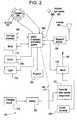
- Fig. 1represents the main components of the deployable Safety and Security System (SASS) invention.
- the safety and security device (SASD) 1is typically contained in a housing 801 ( Fig. 10 ) and mounted on or integrated with a powered, unmanned aerial vehicle (UAV) 800 with energy for operations stored in a battery (220) and containing self-defense mechanisms, such as a shocking mechanism (140) and a spray mechanism (110) and/or other disabling weaponry to subdue or discourage a would-be attacker such as a projectile dart 803 ( Fig. 11 ) or an energy device 805 ( Fig. 12 ), a camera (295) and a light (120).
- a powered, unmanned aerial vehicle (UAV) 800with energy for operations stored in a battery (220) and containing self-defense mechanisms, such as a shocking mechanism (140) and a spray mechanism (110) and/or other disabling weaponry to subdue or discourage a would-be attacker such as a projectile dart 803 ( Fig
- the UAV and mounted or integrated safety and security device (SASD) 1also contains a camera component used to identify and track potential assailants approaching from any direction within its field of view. It can further be used as part of the "follow me” function. Also, as is known in the art, GPS 8 and IMU 9 are usually available to the UAV. Other sensors for guidance, identification and deterrence can be incorporated.
- the SASD 1is "tethered" to either a cellular phone 2 via Bluetooth link 6 and 7 through RF link 10 and GPS 3 that provides location information of the whereabouts of the cellular phone, and therefore presumably of the cellular phone owner, sometimes aided by location information obtained by triangulation involving cellular phone towers.
- U.S. Patent 5,515,419discloses this aspect.
- the cellular phone 2communicates over a cellular phone network 4 to provide interconnectedness to the phone network and the Internet 5.
- the phone network 4allows the user to summon help over the phone network (calling 911 or calling another person directly).
- the Internet 5also has linkages to various social media for summoning help over social media, such as, for example, Facebook.
- the SASDcan be replicated multiple times, allowing for a fleet of SASD-based UAVs.
- FIG. 2there is shown a block diagram of the deployable SASD 100.
- An embedded processing system 290such as a processor, memory and software, controls the workings of the SASD 100.
- the embedded processing system 290communicates with the cell phone 2 via Bluetooth 291 and its antenna 292.
- the antenna 292facilitates transmission of wireless signals from the SASD to a cellular telephone.
- Other devicessuch as gate arrays, etc., as known in the art, could also be used for SASD control.
- Processing system 290may also connect to the UAV flight processor 250 or be part of it. Communication may be wired or wireless between block 290 and the UAV flight processor.
- the UAV flight processor 250controls the UAV.
- the flight processormay contain GPS and IMU devices to allow for autonomous flight, as is known in the art.
- the IMUusing an incorporated barometric pressure capability, can be used to implement a flight altitude limiter.
- the SASD 100contains a self-defense mechanism comprising a pepper spray package 110 or other equivalent noxious spray/sprayer that can be attached to the SASD 100.
- a self-defense mechanismcomprising a pepper spray package 110 or other equivalent noxious spray/sprayer that can be attached to the SASD 100.
- pre-packaged units of spray 110are available commercially.
- a custom version of the contained spraymay be employed that integrates specifically with the SASD.
- Block 130shows a power on/off switch and can be either a mechanical or software based switch and is enabled by the SASD's digital data link or Bluetooth functionality.
- Block 140is an electric shock device, such as a stun gun or taser, with electrodes 150.
- a description of a stun gunis disclosed in U.S. Patent 4,688,140 .
- a more lethal defense mechanismsuch as a projectile 803 ( Fig. 11 ) or an energy device ( Fig. 12 ) may be deployed and activated.
- Block 210is a charging circuit that allows the SASD 100 battery 220 to be charged for use.
- the input to this charging circuitcan be, for example, from a wall-mounted transformer, USB cable or inductive charging pad. It may also be solar charged, depending on the application. Solar charging, for instance, would be more useful when the SASD/UAV is used outdoors. Which input is used depends on the design of charging circuit 210 and, as known in the art, this can take on numerous forms, e.g., AC-DC converter using a direct or transformer coupled AC input, DC regulation using an unregulated DC input, etc.
- Battery 220is a rechargeable type battery, preferably using lead-acid, nickel cadmium (NiCd), nickel metal hydride (NiMH), lithium ion (Li-ion), and lithium ion polymer (Li-ion polymer) technology, as is known in the art.
- Battery 220can also be a non-chargeable type, eliminating the need for charging circuit 210. Whichever battery is used, it must be sized appropriately. It is also possible to split the battery: one specifically for powering the aerial platform and another for the SASD. Battery 220 is used to power the SASD via block 170 and the AC-DC converter 240 that converts the low battery voltage to a high voltage potential across electrodes 150 for shocking.
- the camera 295is a standard or infrared (IR) camera, where the IR camera is useful for viewing in darkness with IR light.
- IR LEDs 294provide IR light. This light is invisible to humans, thereby also concealing the fact that the aerial device is active. While color cameras can be used, the IR and monochrome camera provide less data to process, simplifying the detection of an assailant from any direction within the camera's field of view.
- the camera informationcan also be used for assisting in autonomous aerial device flight and for docking on a inductive charging pad.
- Ambient light sensor 293is a semiconductor device that senses the ambient light level.
- This informationis incorporated in the camera interface/logic module 292 to control the intensity of the IR LEDs 294.
- the IR LEDs 294When daylight is sensed, the IR LEDs 294 are turned off. As the ambient light decreases, the IR LEDs 294 are slowly turned up in intensity so that the IR camera 295 always has adequate light for camera use.
- Image data from the camera 295is suitably processed by interface 292 where it can be used for assailant determination, navigation, or can be sent to a digital data link or Bluetooth module 291, where it is transmitted to the cellular phone 2 for further image processing and analysis.
- information from the cellular phone 2can also provide some control over the camera 295 such as camera update rate, aperture, etc.
- the camera datacan also be combined with inertial and GPS data to assist in autonomous flight control.
- Block 120is a light that can be used to illuminate an area below the UAV. It can be turned on and off via the cellular phone or adjusted based on light sensor 293. It can be used to illuminate the user or light the way slightly ahead of the user. It can also be used to illuminate a possible assailant or to flash as a warning signal. Finally, if comprised of multiple lights or variable intensity, the light could be used as a flash, blinding the assailant and providing time for the user to escape.
- Block 130is a speaker or other such sound generator capable of being turned on via the embedded processing system. It can provide a warning sound to a possible assailant, or a prerecorded message, such as a warning that the authorities have been contacted.
- Block 125is a projector that can be used to project a map or direction onto the ground to assist in fleeing an area.
- Small projectorsare readily available, such as the Cellulon PicoPro.
- Map data capabilitiescan be part of the UAV software, accessing the GPS form the flight processor 250 or obtaining map directions from the cellular phone over the Bluetooth interface, blocks 6, 7 and 10.
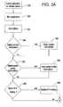
- Fig. 3consists of Figs. 3A and 3B combined together at the circled "A"s.
- Block 310represents the user installing the application on the cellular phone. As is known in the art, this is accomplished by downloading the application from one of the various vendors' software repositories, such as the Apple store or Google Play. Once the application is installed, the user runs the application in Block 320.
- Block 340the user is asked if he would like to enter/add contact information.
- Such informationcan be a phone number, cellular and/or landline, an address, either physical and/or e-mail, etc. If the answer is yes, the user enters the desired data in Block 345.
- Block 350the user is next asked if he would like to enter social media contact information. Such information can be links for posting to Facebook, Twitter, and other social media sharing sites. If the answer is yes, the user enters the desired data in Block 355.
- Block 360the user is asked if he would like to add 911 emergency calling. If the answer is yes, the information is saved in Block 365.
- Block 370the user is asked whether to enable the separation sensor and alarm. This alarm is triggered when the deployed SASD and the cellular phone are separated by a certain distance. This distance is based on the received signal strength indicator (RSSI) indicator. There is no standardized relationship between range and the RSSI reading, so this can only be used as an approximate distance measure, but it is sufficient. If enabled, the approximate distance is entered in Block 375. Additionally, related timing information can be entered, such as how long the devices are separated before enabling the alarm, giving the owner time to bring the deployed SASD and cellular phone together again. In Block 380, the user is asked what capture methods should be enabled to capture audio, video and location information. If selected, the user enters or checks the various methods.
- RSSIreceived signal strength indicator
- Block 390asks the user whether location sharing should be enabled.
- Location sharingis a feature that allows you to let people know your position. Both Wi-Fi positioning system and GPS are used to pinpoint the user's location as accurately as possible. If desired, it is then enabled in Block 395.
- Block 400is then reached where the digital data link and Bluetooth interconnection are enabled in the cellular phone. Once enabled, the user is asked to turn on the SASD and/or the UAV so that the cellular phone can be paired to the appropriate devices in Block 410. This is a standard method of using digital data links and Bluetooth interconnection, as is known in the art.
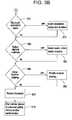
- Fig. 4there is shown a flowchart of the software running on the deployed SASD enhanced UAV. It is also possible that the SASD is always "on", listening for commands. In that case, main power is enabled via the digital data link and processor 290 to control switch 160.
- the userturns on the SASD using an embedded power switch 160, the digital data link or Bluetooth interconnection switch on his cellular phone 130 ( Fig. 2 ).
- the data link or Bluetooth linksare enabled in Block 420 and the SASD connects to the cellular phone in Block 430.
- Block 440is where the user selects the various modes for the SASD.
- Various scenarioscan be set based on the selection of the various features turned on/off in block 450.
- the SASDstays in this state of usefulness by monitoring in block 460 whether the system is turned off. The system continues to stay enabled with choices available for selection or de-selection until powered off and disabled in Block 470.
- Fig. 5there is shown further details of block 450 in Fig 4 .
- One of the functionsis "follow me," which uses both the RF link and optical tracking to keep the UAV above and around the user.
- the RF link signal strengthis used to keep the UAV within a certain radius of the user.
- SASD processor 290communicates this signal strength to the UAV flight processor 250. As the signal strength drops the aerial device takes the appropriate action to raise the signal strength. This may be by a random search or coupled with the optical tracking. Other following techniques may also be applied, such as those in the AirDog product line (https://www.airdog.com).
- Optical imagesare streamed to the SASD processor 290 as shown in block 494.
- the optical systemcan use a number of algorithms in block 495, including a CAMSHIFT algorithm, such as one described in "People Tracking via a Modified CAMSHIFT Algorithm,".
- CAMSHIFT algorithmsuch as one described in "People Tracking via a Modified CAMSHIFT Algorithm”
- OpenCVan open source computer vision library
- Facial recognitioncan be found in open CV, Facereclib (https://pypi.python.org/pypi/facereclib),http://www.face-rec.org/algorithms/ and commercial facial recognition software (http://www.luxand.com/facesdk/). These functions can be used to keep the UAV near the user.
- the results from block 495are then processed in block 496 to detect the approach of people or assailants. This is used to detect potential threats as stated in block 450.
- Thiscan be accomplished using an optical flow algorithm such as the Lucas-Kanade Algorithm.
- This algorithmis a widely used differential method for optical flow estimation, a version of which can be found in openCV. It assumes that the flow is essentially constant in a local neighborhood of the pixel under consideration, and solves the basic optical flow equations for all the pixels in that neighborhood using a least squares criterion. By combining information from several nearby pixels, the Lucas-Kanade method can often overcome vagaries of the optical flow equation.
- Block 496may also be used for collision avoidance and avoidance of capture with further manipulation of the camera images.
- the light area functionis used to provide a light 120 from above. It can also be part of the projector 125.
- the light 120is activated in block 440 and can be controlled from the cellular phone. Some of the modes available include a random motion, diffuse lighting and lighting the path ahead. The light can be aimed mechanically or by using individual lights pointed in different directions. The light intensity can be turned up and directed at an assailant to temporary blind him, gaining time for the user to flee the area. If provided by projector 125, the light can also be steered by micro mirrors (Digital Light Processing). Additionally, if enabled, a map or directions or arrows indicating the nearest friend, police station or other public place of safety can be displayed on the ground to assist the user in finding a safe haven.
- micro mirrorsDigital Light Processing
- the spray 110 and/or Taser 140 functionsare, where allowed by law, used for disabling an assailant. While these functions could be performed autonomously, the more likely scenario occurs when the user has determined with reasonable certainty that there is an assailant and needs to take protective measures.
- the phonecould be used for initiating the release of noxious sprays or for firing stun gun darts and this can be done using controls in the SASD application or by issuing voice commands to the SASD, as is known in the art.
- the amount of spray and the charge available for stunningcan be read back from the mounted/integrated SASD. The user could also be notified when to replace the noxious cartridge or recharge the battery.
- the take off and land functionsput the UAV into those respective modes. Take off causes the aerial device to assume its position overhead, as set by the other functions, e.g., "follow me.” This can cause the aerial device to take off from a fixed location or to enable flight when it is tossed in the air, as is known in the art. Landing can be accomplished near the user using the optical data to prevent collision with the user or nearby objects.
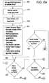
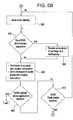
- Fig. 6consists of Figs. 6A , 6B and 6C combined together at the circled "B"s, "C”s and “D”s to comprise a flowchart. Therein, additional details of the invention are shown in a flowchart of the software running on the cellular phone.
- Block 500signifies that the user has enabled the SASS application. This can be performed in various user-friendly ways, including double tapping an icon, using speech recognition, etc.
- the first thing that happens upon startupis a reminder to the user to check the level of the irritant spray in Block 510. The user is then reminded, if required, to check battery charge in Block 512. Once the reminders are cleared, a number of actions occur in Block 515.
- Block 570This includes enabling the received signal strength indicator (used for separation determination in Block 570), starting the text application for contacting purposes, starting social media applications for constant contact updates, placing on standby audio and video recording applications, enabling locations services and/or child tracking and enabling the optical tracking algorithm that runs concurrently with the other PSS systems.
- Block 533receives input from the assailant tracking algorithm described in Fig. 5 , block 496. While in this loop, other actions are monitored.
- Block 550the state of the SASS is checked. If it is turned off the SASS applications are terminated. If not turned off, the loop is repeated.
- Block 560the cellular phone and/or the SASD mounted or integrated with the UAV or in the docking station issues a loud audio warning to the perpetrator. If the warning is to be issued by the aerial SASD via block 130, the UAV will first descend to a low altitude for maximum effect. The warning can take the form of a brief announcement that events are being recorded; emergency personnel are being contacted, etc.
- Block 580If the level indicates separation (a weak signal indicates a larger than expected separation distance) between UAV and cell phone, as programmed in Block 375 for a specified time, an elevation of the threat assessment is made in Block 580. All information sent to contacts, social media, etc. in Block 590 are tagged to indicate that the threat has progressed to a more serious level. This can be done, as appropriate, with stressor words, numeric levels or color-coding.
- Block 600checks if the cellular phone application is disabled or not. If so, the application exits. Otherwise Block 610 is executed to see if the panic button has been disabled. If so, control is returned to Block 530. Otherwise the loop is closed by returning to Block 560.
- Block 660the cellular phone or the UAV SASD issues a loud audio warning to the user and possible assailant, indicating someone is approaching. This can take the form of a warning that events are being recorded; emergency personnel are being contacted, etc.
- the capturing and sending of the datacannot be reversed or canceled by the user or potential assailant.
- the assailantis notified using a pre-recorded message broadcast via built in cellular phone 2 speaker that his data has been captured by the electronic device, thereby discouraging him from proceeding with the crime.
- Block 670a check is made concerning the received signal strength indicator (RSSI) level. If the level indicates separation of the OSD (a weak signal indicates a larger than expected separation distance), as programmed in Block 375 for a specified time, an elevation of the threat assessment is made in Block 680. All information sent to contacts, social media, etc. in Block 690 are tagged to indicate that the threat has progressed to a more serious level. This can be done, as appropriate, with stressor words, numeric levels or color-coding.
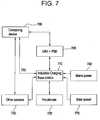
- Block 700( Fig. 7 ) checks if the cellular phone application is disabled or not. If so, the application exits. Otherwise the loop is closed by returning to Block 530.
- the mounted or integrated SASD on the UAVcan perform as a home or building security system.
- block 700represents the aforementioned SASD and UAV, block 1.
- This aerial devicerests on an inductive charging/base, block 710.
- the housing 801 for the SASDis attached to the UAV 800.
- Block 710provides a method of coupling to the battery of block 700 via block 210. This may be a mechanical or inductive coupling that allows the battery to be charged once the aerial device lands on the inductive charging/home base, similar to iRobot Roomba® docking and recharging, as is known in the art.
- Landing on the base 710can be accomplished using the optical system of the SASD, coupled with the GPS and inertial functions of the UAV. Other beaconing could also be used for navigating the aerial device to the base.
- the base itselfwould typically be powered from the mains, block 740.
- the charging/home basecan also contain additional peripherals, 720, such as ultrasonic motion detectors, thermal and glass breakage detectors, extra cameras, vibration sensors and other devices known in the art used for home and building security.
- Block 730represents other sensors that may already be present on the premises. These may be ultrasonic motion detectors, thermal detectors, additional cameras, vibration sensors, door and window sensors and other devices used for home and building security. These devices may be able to interface easily to the charging/home base station if they are coded in an open source manner. Alternatively, they may connect to computing device 760 via an appropriate interface, such as Bluetooth, USB or Ethernet.
- inductive charging/home base 710is connected to a computing device 760 via an interface 750.
- Interface 750may be wired or wireless, including USB, Ethernet and Bluetooth, or other custom, proprietary or open standard interface.
- Computing device 760can be a mobile, wireless device, a desktop PC, a tablet, a notebook or any number of computing devices such as Raspberry Pi, iOS, and other computing hardware.
- Computing device 760may also connect to other sensors 730, such as ultrasonic motion detectors, thermal detectors, additional cameras, vibration sensors, door and window sensors and other devices known in the art over the appropriate interface.
- Software running on the computing devicecontrols the other sensors 730 directly or indirectly through the charging/home base. It can also control the UAV and SASD 700 directly or through block 710.
- drone controlcan be found among the various drone manufacturers, for example Parrot (http://ardrone2.parrot.com/).
- Other peripherals 720are controlled indirectly from computing device through inductive charging/home base 710.
- the computing device softwarewill certainly contain much of the functionality of the cell phone application noted previously ( Figs. 3 and 5 ), plus allow for additional timing, arming, and disarming various sensors and peripherals. It will also be able to communicate to the outside world as the cell phone did, providing a means of contacting police, social media, etc.
- the SASD/UAVcan make surveillance runs throughout the premises, flying a fixed, random or learned path as required. Navigation is again performed optically in conjunction with the IMU 9. Beacons for navigation could also be used as is known in the art. Other following techniques may also be applied, such as those in the AirDog product line (https://www.airdog.com). Multiple UAVs can be utilized to cover a larger volume or to take turns between battery charges. When the battery is low, the SASD/UAV will navigate to the inductive charging/home base station for charging, similar to robotic lawnmowers and vacuums.
- the SASD/UAVcan be tethered to a building using a physical cable, as shown in Fig 8a .
- UAV 800communicates and is powered over tether 820, which is attached to residence 810.
- the tetherconnects to a base station, or other computing device that provides the same functions as the cellular phone.
- Residence 810can have a sheltered landing zoned for protecting the UAV when not in use.
- the UAV 800can provide videos of the premises, searching for vandals who might "tag" (block 830) the building, or burglars. When found, the same defensive devices noted previously such as spray 110, light 120, sound 130 and Taser 150 can be used to dissuade an assailant or vandal.
- the SASD/UAV 800has a base station on boat 840 or on a nearby dock.
- the SASS systemis programed to detect bird 850 on boat 840 using its camera and possibly other sensors on boat 840.
- the SASD/UAVis programmed to scare the bird 850 away by using its light 120, projector 125 and sound 130 and also by flying towards the bird 850. This could be performed in a mechanically or RF tethered mode.
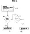
- Block 900is the setup portion of the control software running on a PC.
- the userwould set defaults, such as which additional sensors should be used with the system, how they should be communicated with, alert methods such as email or text, and time to perform rounds, etc.
- the userwould select whether the system is mechanically or RF tethered in block 910. If indoors and RF tethered, the user is asked whether the SASD/UAV should follow a predefined path or fly autonomously around the base station in block 920. If a predefined path is selected, the SASD/UAV is taught the path in block 930 by placing it in a mapping mode and walking it along the desired path.
- the UAV sensorsare used to prevent collisions with objects and for navigation. If outdoor, then the user selects how the SASD/UAV should behave. If frightening birds, the SASD/UAV would try to scare the birds. If protecting against vandals and burglars the SASD/UAV would be set to observe, capture data, and report.
Landscapes
- Engineering & Computer Science (AREA)
- General Physics & Mathematics (AREA)
- Physics & Mathematics (AREA)
- Business, Economics & Management (AREA)
- General Engineering & Computer Science (AREA)
- Emergency Management (AREA)
- Computer Security & Cryptography (AREA)
- Aviation & Aerospace Engineering (AREA)
- Health & Medical Sciences (AREA)
- Environmental & Geological Engineering (AREA)
- Public Health (AREA)
- Computer Networks & Wireless Communication (AREA)
- Signal Processing (AREA)
- Alarm Systems (AREA)
Description
- The present invention relates to a modular safety and security device (SASD) controlled by a cellular phone that can be used in conjunction with an unmanned platform or its docking-station peripherals. In most instances, the unmanned platform will be an aerial vehicle (UAV) but it can, in fact, be any autonomous device.
- Everyday, people are exposed to circumstances in which personal safety may be jeopardized: strolling on city sidewalks, hurrying to one's car at night, looking for one's car in a parking garage, jogging on an isolated road, walking the dog at night, getting lost outdoors, taking a short cut on a deserted road, getting waylaid by a vicious dog, hearing footsteps behind you, being stalked, waiting for help after a car breaks down, making a wrong turn in a dangerous neighborhood, or simply being alone or unprotected at home or in a building. Private property is similarly exposed to criminal acts ranging from thievery and vandalism to defacement and destruction-all of which exact a toll on one's sense of well-being. The frequency of crime in unexpected venues cannot be underestimated. Statistically 33% of women in the USA will be violently victimized at least once in their lifetimes. Another 8% will be stalked. The Justice Department counted 4.9 million violent crimes involving over 2.7 million victims in 2010. The FBI's Bureau of Justice Statistics reports that 3 million persons experienced at least one violent attack in 2013. The Justice Department estimates there were over 467,000 firearm victims in 2011.Kids Fighting Chance, a children's advocacy group, reports one child is abducted or reported missing every 40 minutes or 800,000 times per year. In addition,Safeguard the World, a home security company, estimates there are presently 2.5 million home intrusions a year in the USA, and that one-third of residential burglaries results in a personal assault. Thieves are rarely caught in the act; 13% of burglaries result in a conviction. While home security systems are a proven deterrent, only 17% of U.S. households use them.
- According to criminal deterrence theory, an attack occurs after the criminal makes a risk-reward benefit analysis. He will act if the benefit outweighs expected consequence. Personal security statistics confirm this finding: criminals typically bypass an intended victim who raises attention or can identify them. Criminals also know the chances that the police will be in earshot during an attack are low.
- Calls to the police are insufficient for deterrence. Most callers assume that law enforcement will respond before a criminal act occurs. Statistics indicate otherwise. Law enforcement rarely breaks up a street crime. The U.S. Justice Department estimates that just 12% of stalkers and 6% of rapists are caught in the act. More often than not, the police role is pursuit, investigation and witness for prosecution of the criminal act. For these reasons and more, people today need a personal security companion.
- The present invention has particular usefulness in deterring damage, defacement, and destruction of public and private property. According to NoGraf Network, a national consortium of police agencies dedicated to ending vandalism, monitoring, detecting, removing and repairing graffiti damage is estimated to cost $15 billion to $18 billion a year. Similar disfigurement of watercraft, buildings, and machinery by avian droppings is a persistent problem annually costing tens of millions of dollars to clean up as well as posing significant health threats. While on-site cameras are often deployed in such locations to communicate incidents, their fields of view are limited and fixed. On the other hand, a UAV with appropriate defense mechanisms is capable of addressing the threat in real time while simultaneously streaming video of vandals and frequency/location of attacks to appropriate authorities.
- The present invention is in the field of safety and threat deterrence and more particularly for personal and property protective devices that can be mounted and/or integrated on an unmanned aerial vehicle or its docking station peripherals, particularly as combined with cellular telephones, wearable computing, or other computing devices. Its particular functionality is achieved when a cellular phone is wirelessly connected to a suite of safety and security devices, mounted or integrated on an unmanned aerial vehicle (UAV) or onto its docking station. No matter where housed, the envisioned device provides wireless detection, warnings, notifications, alarms, and self-defense mechanisms to deter crime, vandalism and/or defacement of property by humans or wildlife.
- The prior art known to Applicants takes advantage of the latest technology made available by battery-powered cellular phones. This includes telephony, the ability to capture pictures, videos and audio, Global Positioning System (GPS) location capabilities, and the ability to run software applications on built-in processing units. Some prior art inventions disclose holders, attachments and cases for cellular phones that allow additional personal safety devices to be physically linked to the cellular phone. This makes the combined device bulkier, heavier and less useful as a cellular phone. Some of them provide for personal safety device activation once a panic button is pushed, but the integration is incomplete. Other disclosures include voice-activated panic buttons but, as is well known, human voice under stress cannot always be understood, even by voice recognition software.
U.S. Published Patent Application 2008/0064339, March 13, 2008, to Cavalier , describes a personal safety device formed by combining a modified cellular telephone with a personal protective spray, such as pepper spray. Activation of the spray causes the cellular telephone to automatically alert emergency response personnel and provides them with cellular phone location via GPS in the phone. It requires modification of the cellular phone and does not work in conjunction with other personal safety devices over a local network or in conjunction with an UAV.U.S. Patent 8,472,915, June 25, 2013, to DiPerna et al. , also describes a cellular phone with personal protective spray and a panic button. When the button is activated, the personal protective spray is released and the phone records audio and/or video for transmission, transmits the data to emergency response personnel, and provides them with cellular phone location via GPS in the phone. It requires attaching devices to the phone or modification of the cellular phone and does not work in conjunction with other personal safety devices over a local network or in conjunction with an UAV.U.S. Published Patent Application 2007/0293186, December 20, 2007, to Lehmann , describes a portable device that includes the ability to biometrically identify the user. The portable device can be a cellular phone with integrated cameras, sound recorders, and/or biometric authentication mechanisms and utilizes GPS to determine geographic location. Data communication in the form of GPS location data, messages, videos, pictures, etc. can be performed over many types of networks including local area networks (LANs). LANs however, are not meant for personal area network use. Lehmann's invention does not work in conjunction with other personal safety devices over a personal area network or in conjunction with an UAV.U.S. Published Patent Application 2010/0283609, November 11, 2010, to Remer , describes a personal safety system that provides image, audio, and data capture of a perpetrator of a crime against the user. Data is stored at a secure remote location. The device alerts the perpetrator that the information has been captured, thus discouraging the crime. Remer's invention does not work in conjunction with other personal safety devices over a personal area network or in conjunction with an UAV.U.S. Published Patent Application 2012/0299711, November 29, 2012, to Manning , describes a personal safety and alarm system including a siren/strobe light, and a pepper spray container in a holder. The holder can be detached. The holder can reside on a stand or be placed in a pocket. Manning's invention does not work in conjunction with other personal safety devices over a personal area network or in conjunction with an UAV.U.S. Published Patent Application 2013/0040596, February 14, 2013, to Paim et al. , describes a method that allows a smartphone user to easily and properly share his status during distress situations with people who can better help him contextually and reliably. The Paim et al. invention, while utilizing many network methods, does not work in conjunction with other personal safety devices over a personal area network or in conjunction with an UAV.U.S. Published Patent Application 2013/0257612, October 3, 2013, to Finet , describes a personal alert/safety system worn by a user. An accelerometer in the system detects movement and controls an alarm device. The Finet invention does not use a cellular device and does not work in conjunction with other personal safety devices over a personal area network or in conjunction with an UAV.U.S. Published Patent Application 2013/0260825, October 3, 2013, to Hagenstad , describes many of the previously described components. The cellular phone has a panic button that can activate audio and video recording, start a siren, flash lights and contact emergency personnel with GPS location data. These capabilities can also be deployed in an attachable cellular phone case. The Hagenstad invention does not work in conjunction with other personal safety devices over a personal area network or in conjunction with an UAV.U.S. Patent 4,982,645, January 8, 1991, to Abboud , describes a stun gun and irritant ejecting spray combination. The Abboud invention does not work over a personal area network or in conjunction with an UAV.U.S. Patent 8,466,795, June 18, 2013 ,U.S. Patent 8,149,124, April 3, 2012 ,U.S. Patent 6,624,754, September 23, 2003 andU.S. Patent 6,239,700, May 29, 2001 to Hoffman et al. , describe a signaling system that provides an alarm for an individual in distress, combined with a locating and tracking system, possibly by cellular phone, to alert and direct appropriate personnel to the needs of the individual in distress and to monitor the location of that individual. The system includes a portable signaling unit, a remote alarm switch device, a central dispatch station, and makes use of a wireless communication system. The portable signaling unit and the remote alarm switch may be adapted to be worn at different locations on the person's body. The remote alarm switch may be concealed in the form of a wristband or in the form of any other object such as a broach, pendant, or keychain. Even though a wireless remote is described that is separate from the cellular phone, nowhere is it mentioned that the wireless remote contains other personal safety devices nor do these devices work over a personal area network or in conjunction with an UAV.U.S. Published Patent Application 2014/0254896 discloses a system and method for delivering mail and goods using a mobile robot UAV system. The method may comprise self-moving the mobile robot drone system to a mail or goods receiving location. The robot may offer security for the delivered goods. It does not provide personal security or property protection.- Published Application No.
WO2014080387 discloses a rescue UAV for rescuing an idle UAV consisting of an adjustable length hook to engage with the idle UAV, to carry it away, an L- shaped metallic tool to push the idle drone away from the middle of the road, or to help in repositioning it so a hook can be engaged, along with an emergency light to assist while hovering over the idle UAV located in a road, an electric shock stick, deployable against a person approaching the idle UAV with intent to steal it, a speaker and camera to assist a security person in a command center to assess the case, talk with and warn any person with intent to steal the idle UAV, or to advise and guide a volunteer who is trying to help and assist in rescuing the idle UAV. It does not provide personal security or property protection. U.S. Published Patent Application 2010/0279649 discloses multiple devices combined together and connected by a cellular phone for security and law enforcement purposes. It does not describe an UAV-based personal safety device.
Japanese published patent applicationJP2015207149 - The present invention is defined by a safety and security device on an aerial platform as claimed in
claim 1. Preferred embodiments are set out in the dependent claims. - The present invention relates to a modular, expandable safety and security device mounted or integrated on an UAV, pre-programmed to autonomously follow, hover or circle, indoors or outdoors, above its user, and able to provide local area surveillance and security when the same device is tethered to its docking station. Additionally, the present invention provides a means to provide both indoor and outdoor premises security and protection. In these respects, the combination cellular phone and safety/security device, integrated with an unmanned aerial vehicle, according to the present invention, substantially departs from the conventional concepts and designs of the prior art, and in so doing provides a single apparatus primarily developed for the purpose of providing a means of communication and control for a self-defense system integrated with an UAV platform or its docking mechanism.
- The present invention includes the following interrelated objects, aspects and features:
- (1) In a first aspect, the present invention contemplates a safety and security device (SASD), capable of operation from above or within a structure, which is self-contained and, when activated, communicates with a cellular telephone to also provide self-defense capability. A dedicated communication device may also be used in place of the cell phone.
- (2) In the preferred embodiment, the SASD integrated with an UAV or its docking station includes any or all of the following: an alarm and visual warning instrument, a shocking mechanism, and a sprayer designed to squirt a substance for self-defense purposes, such as pepper spray or tear gas, and a light for illumination of the area or blinding an assailant. It may also include, where allowable by law, one or more destructive means of disabling an assailant such as an energy release weapon or a projectile that can be fired. It may further include a means to communicate directly with emergency responders as well as autonomously providing live streaming video for deterrence purposes. When sitting in its docking station, it may also provide a wireless, indoor premises monitoring system without the necessity of hard mounting sensors on perimeter doors, walls, and windows. It may also leave its docking station to provide reconnaissance. In addition to its video, audio, flashing and alarm capability, it may also be augmented or communicate with motion detection, glass breakage, and similar devices, well known by purveyors of home security systems. Outdoor premises monitoring, using cameras and other sensors, can also provide reconnaissance and deterrence by being visibly present and buzzing/frightening away criminals, mischief makers and nuisance wildlife. There may be multiple stand-alone or networked UAVs deployed with safety and security devices.
- (3) In order to operate the present invention, the personal safety device software application, which includes command, control and communication with the aerial platform, is downloaded into a user's cellular telephone (cell phone) or similar wearable or portable computing device. It should be understood, moreover, that, for premises monitoring, a PC, table or similar computing device can also be used. Among other things, a variety of user settable software options may be selected such as: contact information for the user, social media contact information, enabling 911 emergency calling, as well as existing and emerging cellular phone apps for drones, such as auto takeoff and landing, activation of automatic "follow-me" with obstacle sensing and avoidance controls, real-time two-way video communications, solar charging batteries, and other useful functions rapidly becoming available in the burgeoning UAV marketplace.
- (4) In another aspect, the software provides the capability of activating a separation alarm. Thus, if the cell phone and the aerial or docked safety/security drone are separated by a preset distance, and/or for a pre-set time, an alarm can be triggered allowing the user or a third party site, such as a police station, to be alerted.
- (5) The SASD, whether on an unmanned aerial vehicle or at its docking station may also be provided with an autonomous panic switch that, when activated, notifies the cell phone via a radio link, Bluetooth or other communication methods as may become available. Optical recognition software, home security sensors, a separation alarm, and similar devices, can all be used to trigger this switch.
- (6) The system may include means for monitoring various capabilities such as, for example, checking of the level of the spraying substance as well as the level of charge of the SASD battery, which impacts the amount of voltage that may be applied by the shocking mechanism, and, in general, monitoring the health/state of the UAV power source. Additionally, the user can monitor the strength of signal between the UAV/SASD and the associated cell phone to make sure that signals sent by the UAV/SASD may be effectively received by the cell phone and that, as required, the UAV does not stray beyond prescribed limits. This monitoring of signal strength may also be used to keep the UAV within a prescribed offset from the cell phone to enable autonomous "follow me" capabilities. A built in altitude flight limit can also be incorporated to prevent the UAV from flying above approved FAA limits.
- (7) In another aspect, the present invention contemplates an optical camera on the UAV or at its docking station that is self-contained but, when activated, communicates with a cellular telephone while also providing assailant detection capabilities. The optical capabilities can be used with the "follow me" capability to enable autonomous overhead tracking of the drone's user and to help differentiate between the user and an assailant. After identifying a potential assailant(s), the system can notify the user of a threatening approach, before an attack occurs, and activate self-defense mechanisms.
- (8) In another aspect, the present invention provides premises security. Indoors it can navigate a route, checking for intruders, broken windows and doors that are ajar. It can also monitor an area from a fixed home base. Outdoors it can secure the perimeter of a property, check for vandals or uninvited guests. It can also be used as a "scarecrow" to scare birds or wild animals from a property, such as a car, boat or home. It may also be tethered to the property such that a supply of constant power and a wired communication link are available
- (9) Through use of the present invention, a user may feel secure: 1) while being autonomously followed by the envisioned device contained on/in an UAV or while being monitored within a building. Such a device cannot only provide audio/visual warnings and alarms, but also self-help by disabling an assailant through shocking, spraying or firing mechanisms. These functions are controllable by two-way communication with a user's cell phone in such a way that permit authorities to quickly locate a crime victim, protect him from further harm while simultaneously aiding police apprehension through steaming video, audio, and still images of the assailant's likeness; 2) while his premises is autonomously monitored. Such a device can provide audio/visual warnings and alarms based on optical observations and querying of sensors. Intruders can be disabled through shocking, spraying or firing mechanisms. These functions are controllable by two-way communication with a user's cell phone in such a way so as to permit authorities to quickly locate a crime victim, protect him from further harm while simultaneously aiding police apprehension through steaming video, audio, and still images of the assailant's likeness and; 3) while assured that his premises are protected from human and non-human vandals known to deface personal property. Such a device can provide audio/visual surveillance based on optical observations. Vandals can be disabled through shocking, spraying or firing mechanisms or chased from the premises. They can also be instructed to leave before such defensive actions are undertaken. These functions are controllable by two-way communication with a user's cell phone in such a way that aids police apprehension of the vandals through streaming video, audio, and still images, or by simply chasing intruders away before property damage occurs.
- As such, it is a first object of the present invention to provide a safety and security enhanced unmanned aerial vehicle (UAV).
- It is a further object of the present invention to provide such a device that can be activated within a building while hovering/circling in an aerial security mode or while residing in its stationary docking/inductive recharging station.
- It is a further object of the present invention to provide such a device that can be activated outside a building in an aerial security mode or while in its stationary docking/inductive recharging station.
- It is a further object of the present invention to provide such a device that wirelessly communicates with a cell phone to enable transmission of information concerning an attack to authorities and social media.
- It is a further object of the present invention to provide such a system in which the SASD may be equipped with offensive weapons such as a shocking mechanism, a method of blinding, a spraying apparatus designed to spray a noxious spray onto an assailant or a projectile firing or energy releasing mechanism designed to deter or disable an assailant.
- It is a further object of the present invention to provide such a system in which the SASD device may detect a potential attack or intrusion before it occurs and alert the user.
- It is a further object of the present invention to provide such a device that may include a panic switch for activating notification.
- It is a yet further object of the present invention to provide such a device in which a sensor can sense the spacing between an aerial personal safety drone and an associated cell phone and trigger remote notification when the spacing exceeds a pre-set distance or time between the device and cell phone.
- It is a still further object of the present invention to provide a wireless optical camera that mounts on the UAV or in its docking station.
- It is a yet further object of the present invention to provide an aerial or docked camera that is self-contained but, when activated, communicates with a cellular telephone while also providing assailant detection capabilities.
- It is a yet further object of the present invention to provide a means of protecting the outside of a premises, including deterring nuisance wildlife or vandals from defacing, damaging or destroying public and private property, including, but not limited to, watercraft, docks, statues, buildings, walls, overpasses, transportation vehicles and other valued sites, etc. In such instances, the device can be installed on an unobtrusive, convenient platform on the property to be protected. When audio, video, or movement detects a threat to said property, the SASD equipped UAV can inform the user so that the user can take appropriate defensive steps, or the UAV can automatically launch and deploy one or more defensive measures to deter the threat, scare off wildlife, and, where appropriate, identify the perpetrator while communicating its activation and purpose to a cellular telephone before returning to its docking station.
- These and other objects, aspects and features of the present invention will be better understood from the following detailed description of the preferred embodiment when read in conjunction with the appended drawing figures.
Fig. 1 is a schematic of the main components associated with the Safety and Security System (SASS). It consists of a Safety and Security Device (SASD) mounted or integrated into an unmanned aerial vehicle, capable of following a user and capable of sensing, identifying, and deterring an intruder inside or outside of a building.Fig. 2 is a schematic of the deployable Safety and Security Device of the present invention.Figs. 3A and3B combine together at the circled "A"s to comprise a flowchart of the application installer software on the cellular phone.Fig. 4 is a flowchart of the optical software running on the Safety and Security Device (SASD).Fig. 5 is a flowchart of the optical software running on the UAV.Figs. 6A ,6B and6C combine together as the circled "B"s, "C"s and "D"s to comprise a flowchart of the runtime software on the cellular phone.Fig. 7 is a block diagram of the inductive charging/base system and components.Fig. 8A shows a schematic representation of the SASD/UAV system tethered to a building using a physical cable.Fig. 8B shows the SASD/UAV system being used to deter wildlife from a premises, for example, a boat.Fig. 9 shows details of a software interface for premises protection.Fig. 10 shows a schematic representation of an embodiment employed for building security.Fig. 11 shows a projectile that can be fired from the housing.Fig. 12 shows an energy device for emitting energy from the housing.Fig. 1 represents the main components of the deployable Safety and Security System (SASS) invention. The safety and security device (SASD) 1 is typically contained in a housing 801 (Fig. 10 ) and mounted on or integrated with a powered, unmanned aerial vehicle (UAV) 800 with energy for operations stored in a battery (220) and containing self-defense mechanisms, such as a shocking mechanism (140) and a spray mechanism (110) and/or other disabling weaponry to subdue or discourage a would-be attacker such as a projectile dart 803 (Fig. 11 ) or an energy device 805 (Fig. 12 ), a camera (295) and a light (120). The UAV and mounted or integrated safety and security device (SASD) 1 also contains a camera component used to identify and track potential assailants approaching from any direction within its field of view. It can further be used as part of the "follow me" function. Also, as is known in the art,GPS 8 andIMU 9 are usually available to the UAV. Other sensors for guidance, identification and deterrence can be incorporated.- The
SASD 1 is "tethered" to either acellular phone 2 viaBluetooth link RF link 10 andGPS 3 that provides location information of the whereabouts of the cellular phone, and therefore presumably of the cellular phone owner, sometimes aided by location information obtained by triangulation involving cellular phone towers.U.S. Patent 5,515,419 discloses this aspect. Thecellular phone 2 communicates over a cellular phone network 4 to provide interconnectedness to the phone network and theInternet 5. The phone network 4 allows the user to summon help over the phone network (calling 911 or calling another person directly). TheInternet 5 also has linkages to various social media for summoning help over social media, such as, for example, Facebook. The SASD can be replicated multiple times, allowing for a fleet of SASD-based UAVs. - Referring now to the invention in more detail, in
Fig. 2 there is shown a block diagram of thedeployable SASD 100. An embeddedprocessing system 290, such as a processor, memory and software, controls the workings of theSASD 100. The embeddedprocessing system 290 communicates with thecell phone 2 viaBluetooth 291 and itsantenna 292. Theantenna 292 facilitates transmission of wireless signals from the SASD to a cellular telephone. Other devices, such as gate arrays, etc., as known in the art, could also be used for SASD control.Processing system 290 may also connect to theUAV flight processor 250 or be part of it. Communication may be wired or wireless betweenblock 290 and the UAV flight processor. TheUAV flight processor 250 controls the UAV. Examples of drone control can be found among the documentation of many drone manufacturers, for example Parrot (http://ardrone2.parrot.com/). The flight processor may contain GPS and IMU devices to allow for autonomous flight, as is known in the art. The IMU, using an incorporated barometric pressure capability, can be used to implement a flight altitude limiter. - The
SASD 100 contains a self-defense mechanism comprising apepper spray package 110 or other equivalent noxious spray/sprayer that can be attached to theSASD 100. Off the shelf, pre-packaged units ofspray 110 are available commercially. Alternatively, a custom version of the contained spray may be employed that integrates specifically with the SASD.Block 130 shows a power on/off switch and can be either a mechanical or software based switch and is enabled by the SASD's digital data link or Bluetooth functionality.Block 140 is an electric shock device, such as a stun gun or taser, withelectrodes 150. A description of a stun gun is disclosed inU.S. Patent 4,688,140 . Alternatively, where allowable by law, a more lethal defense mechanism such as a projectile 803 (Fig. 11 ) or an energy device (Fig. 12 ) may be deployed and activated. Block 210 is a charging circuit that allows theSASD 100battery 220 to be charged for use. The input to this charging circuit can be, for example, from a wall-mounted transformer, USB cable or inductive charging pad. It may also be solar charged, depending on the application. Solar charging, for instance, would be more useful when the SASD/UAV is used outdoors. Which input is used depends on the design of chargingcircuit 210 and, as known in the art, this can take on numerous forms, e.g., AC-DC converter using a direct or transformer coupled AC input, DC regulation using an unregulated DC input, etc.Battery 220 is a rechargeable type battery, preferably using lead-acid, nickel cadmium (NiCd), nickel metal hydride (NiMH), lithium ion (Li-ion), and lithium ion polymer (Li-ion polymer) technology, as is known in the art.Battery 220 can also be a non-chargeable type, eliminating the need for chargingcircuit 210. Whichever battery is used, it must be sized appropriately. It is also possible to split the battery: one specifically for powering the aerial platform and another for the SASD.Battery 220 is used to power the SASD viablock 170 and the AC-DC converter 240 that converts the low battery voltage to a high voltage potential acrosselectrodes 150 for shocking.- With further reference to
Fig. 2 , thecamera 295 is a standard or infrared (IR) camera, where the IR camera is useful for viewing in darkness with IR light. For nighttime use,IR LEDs 294 provide IR light. This light is invisible to humans, thereby also concealing the fact that the aerial device is active. While color cameras can be used, the IR and monochrome camera provide less data to process, simplifying the detection of an assailant from any direction within the camera's field of view. The camera information can also be used for assisting in autonomous aerial device flight and for docking on a inductive charging pad. Ambientlight sensor 293 is a semiconductor device that senses the ambient light level. This information is incorporated in the camera interface/logic module 292 to control the intensity of theIR LEDs 294. When daylight is sensed, theIR LEDs 294 are turned off. As the ambient light decreases, theIR LEDs 294 are slowly turned up in intensity so that theIR camera 295 always has adequate light for camera use. Image data from thecamera 295 is suitably processed byinterface 292 where it can be used for assailant determination, navigation, or can be sent to a digital data link orBluetooth module 291, where it is transmitted to thecellular phone 2 for further image processing and analysis. As shown by the arrows, information from thecellular phone 2 can also provide some control over thecamera 295 such as camera update rate, aperture, etc. As noted, the camera data can also be combined with inertial and GPS data to assist in autonomous flight control. Block 120 is a light that can be used to illuminate an area below the UAV. It can be turned on and off via the cellular phone or adjusted based onlight sensor 293. It can be used to illuminate the user or light the way slightly ahead of the user. It can also be used to illuminate a possible assailant or to flash as a warning signal. Finally, if comprised of multiple lights or variable intensity, the light could be used as a flash, blinding the assailant and providing time for the user to escape.Block 130 is a speaker or other such sound generator capable of being turned on via the embedded processing system. It can provide a warning sound to a possible assailant, or a prerecorded message, such as a warning that the authorities have been contacted.Block 125 is a projector that can be used to project a map or direction onto the ground to assist in fleeing an area. Small projectors are readily available, such as the Cellulon PicoPro. Map data capabilities can be part of the UAV software, accessing the GPS form theflight processor 250 or obtaining map directions from the cellular phone over the Bluetooth interface, blocks 6, 7 and 10.- Referring now to the invention in more detail,
Fig. 3 consists ofFigs. 3A and3B combined together at the circled "A"s. Therein is shown a flowchart of the software installer used to install the SASS application onto the cellular phone for use as a personal safety/security device.Block 310 represents the user installing the application on the cellular phone. As is known in the art, this is accomplished by downloading the application from one of the various vendors' software repositories, such as the Apple store or Google Play. Once the application is installed, the user runs the application inBlock 320. The user is then prompted to set various features and options that control how the cellular phone connects with other users of the network and how the cellular phone interacts with the SASD, as denoted byBlock 330 and UAV's command, control and communication module. Various options are now selected. InBlock 340, the user is asked if he would like to enter/add contact information. Such information can be a phone number, cellular and/or landline, an address, either physical and/or e-mail, etc. If the answer is yes, the user enters the desired data inBlock 345. InBlock 350, the user is next asked if he would like to enter social media contact information. Such information can be links for posting to Facebook, Twitter, and other social media sharing sites. If the answer is yes, the user enters the desired data inBlock 355. InBlock 360, the user is asked if he would like to add 911 emergency calling. If the answer is yes, the information is saved inBlock 365. - In
Block 370, the user is asked whether to enable the separation sensor and alarm. This alarm is triggered when the deployed SASD and the cellular phone are separated by a certain distance. This distance is based on the received signal strength indicator (RSSI) indicator. There is no standardized relationship between range and the RSSI reading, so this can only be used as an approximate distance measure, but it is sufficient. If enabled, the approximate distance is entered inBlock 375. Additionally, related timing information can be entered, such as how long the devices are separated before enabling the alarm, giving the owner time to bring the deployed SASD and cellular phone together again. InBlock 380, the user is asked what capture methods should be enabled to capture audio, video and location information. If selected, the user enters or checks the various methods.Block 390 asks the user whether location sharing should be enabled. Location sharing is a feature that allows you to let people know your position. Both Wi-Fi positioning system and GPS are used to pinpoint the user's location as accurately as possible. If desired, it is then enabled inBlock 395.Block 400 is then reached where the digital data link and Bluetooth interconnection are enabled in the cellular phone. Once enabled, the user is asked to turn on the SASD and/or the UAV so that the cellular phone can be paired to the appropriate devices inBlock 410. This is a standard method of using digital data links and Bluetooth interconnection, as is known in the art. - Referring now to the invention in more detail, in
Fig. 4 there is shown a flowchart of the software running on the deployed SASD enhanced UAV. It is also possible that the SASD is always "on", listening for commands. In that case, main power is enabled via the digital data link andprocessor 290 to controlswitch 160. InBlock 410, the user turns on the SASD using an embeddedpower switch 160, the digital data link or Bluetooth interconnection switch on his cellular phone 130 (Fig. 2 ). Once the SASD is on, the data link or Bluetooth links are enabled inBlock 420 and the SASD connects to the cellular phone inBlock 430.Block 440 is where the user selects the various modes for the SASD. Various scenarios can be set based on the selection of the various features turned on/off inblock 450. Some of these are more UAV related while others are more SASD related. The SASD stays in this state of usefulness by monitoring inblock 460 whether the system is turned off. The system continues to stay enabled with choices available for selection or de-selection until powered off and disabled inBlock 470. - Referring now to the invention in more detail, in
Fig. 5 there is shown further details ofblock 450 inFig 4 . One of the functions is "follow me," which uses both the RF link and optical tracking to keep the UAV above and around the user. The RF link signal strength is used to keep the UAV within a certain radius of the user.SASD processor 290 communicates this signal strength to theUAV flight processor 250. As the signal strength drops the aerial device takes the appropriate action to raise the signal strength. This may be by a random search or coupled with the optical tracking. Other following techniques may also be applied, such as those in the AirDog product line (https://www.airdog.com). - Optical images are streamed to the
SASD processor 290 as shown inblock 494. The optical system can use a number of algorithms inblock 495, including a CAMSHIFT algorithm, such as one described in "People Tracking via a Modified CAMSHIFT Algorithm,". This in turn makes use of OpenCV, an open source computer vision library, to supply an implementation of the Gaussian Mixture Model. There are many other ways to perform the same function, as is known in the art, including the use of facial recognition instead of people recognition. Facial recognition can be found in open CV, Facereclib (https://pypi.python.org/pypi/facereclib),http://www.face-rec.org/algorithms/ and commercial facial recognition software (http://www.luxand.com/facesdk/). These functions can be used to keep the UAV near the user. - The results from
block 495 are then processed inblock 496 to detect the approach of people or assailants. This is used to detect potential threats as stated inblock 450. This can be accomplished using an optical flow algorithm such as the Lucas-Kanade Algorithm. This algorithm is a widely used differential method for optical flow estimation, a version of which can be found in openCV. It assumes that the flow is essentially constant in a local neighborhood of the pixel under consideration, and solves the basic optical flow equations for all the pixels in that neighborhood using a least squares criterion. By combining information from several nearby pixels, the Lucas-Kanade method can often overcome vagaries of the optical flow equation. Other motion detection algorithms can be used, as is known in the art, such as found at http://blog.cedric.ws/opencv-simple-motion-detection. When a potential threat is noted, it is communicated to the user over the RF link. It can also trigger awarning light 120 or sound 130 from the PASD. The user can also enable light and sound over the RF link.Block 496 may also be used for collision avoidance and avoidance of capture with further manipulation of the camera images. - The light area function is used to provide a light 120 from above. It can also be part of the
projector 125. The light 120 is activated inblock 440 and can be controlled from the cellular phone. Some of the modes available include a random motion, diffuse lighting and lighting the path ahead. The light can be aimed mechanically or by using individual lights pointed in different directions. The light intensity can be turned up and directed at an assailant to temporary blind him, gaining time for the user to flee the area. If provided byprojector 125, the light can also be steered by micro mirrors (Digital Light Processing). Additionally, if enabled, a map or directions or arrows indicating the nearest friend, police station or other public place of safety can be displayed on the ground to assist the user in finding a safe haven. - The
spray 110 and/orTaser 140 functions are, where allowed by law, used for disabling an assailant. While these functions could be performed autonomously, the more likely scenario occurs when the user has determined with reasonable certainty that there is an assailant and needs to take protective measures. The phone could be used for initiating the release of noxious sprays or for firing stun gun darts and this can be done using controls in the SASD application or by issuing voice commands to the SASD, as is known in the art. The amount of spray and the charge available for stunning can be read back from the mounted/integrated SASD. The user could also be notified when to replace the noxious cartridge or recharge the battery. - The take off and land functions put the UAV into those respective modes. Take off causes the aerial device to assume its position overhead, as set by the other functions, e.g., "follow me." This can cause the aerial device to take off from a fixed location or to enable flight when it is tossed in the air, as is known in the art. Landing can be accomplished near the user using the optical data to prevent collision with the user or nearby objects.
Fig. 6 consists ofFigs. 6A ,6B and6C combined together at the circled "B"s, "C"s and "D"s to comprise a flowchart. Therein, additional details of the invention are shown in a flowchart of the software running on the cellular phone.Block 500 signifies that the user has enabled the SASS application. This can be performed in various user-friendly ways, including double tapping an icon, using speech recognition, etc. The first thing that happens upon startup is a reminder to the user to check the level of the irritant spray inBlock 510. The user is then reminded, if required, to check battery charge inBlock 512. Once the reminders are cleared, a number of actions occur inBlock 515. This includes enabling the received signal strength indicator (used for separation determination in Block 570), starting the text application for contacting purposes, starting social media applications for constant contact updates, placing on standby audio and video recording applications, enabling locations services and/or child tracking and enabling the optical tracking algorithm that runs concurrently with the other PSS systems. After enabling these processes, a loop is entered where thepanic button 120 is constantly monitored inBlock 530 and rear assailant approach is noted inBlock 533.Block 533 receives input from the assailant tracking algorithm described inFig. 5 , block 496. While in this loop, other actions are monitored. InBlock 550, the state of the SASS is checked. If it is turned off the SASS applications are terminated. If not turned off, the loop is repeated.- However, if the panic button is pressed or activated by voice command in
Block 530, or a potential assailant is approaching from behind inBlock 533, a different set of actions is initiated. These actions form a loop that continues until the user decides that a threatening situation is over. InBlock 560, the cellular phone and/or the SASD mounted or integrated with the UAV or in the docking station issues a loud audio warning to the perpetrator. If the warning is to be issued by the aerial SASD viablock 130, the UAV will first descend to a low altitude for maximum effect. The warning can take the form of a brief announcement that events are being recorded; emergency personnel are being contacted, etc. The capturing and sending of the data cannot be reversed or canceled by the user or potential assailant. The perpetrator is notified using a pre-recorded message broadcast via a speaker built intocellular phone 2 speaker or fromblock 130 of the SASD that his data has been captured by the electronic device, thereby discouraging him from proceeding with the crime. Concurrently or sequentially, this warning may also be followed by a strobing or similarly intense flashing light fromblock 120 sufficiently powerful to illuminate the potential crime scene and the assailant. Next, inBlock 570, a check is made concerning the received signal strength indicator (RSSI) level. If the level indicates separation (a weak signal indicates a larger than expected separation distance) between UAV and cell phone, as programmed inBlock 375 for a specified time, an elevation of the threat assessment is made inBlock 580. All information sent to contacts, social media, etc. inBlock 590 are tagged to indicate that the threat has progressed to a more serious level. This can be done, as appropriate, with stressor words, numeric levels or color-coding.Block 600 checks if the cellular phone application is disabled or not. If so, the application exits. OtherwiseBlock 610 is executed to see if the panic button has been disabled. If so, control is returned toBlock 530. Otherwise the loop is closed by returning toBlock 560. - If someone is approaching from behind as discovered in
Block 533, a different set of actions is initiated. These actions are part of the loop that continues until the user decides that a threatening situation is over. InBlock 660, the cellular phone or the UAV SASD issues a loud audio warning to the user and possible assailant, indicating someone is approaching. This can take the form of a warning that events are being recorded; emergency personnel are being contacted, etc. The capturing and sending of the data cannot be reversed or canceled by the user or potential assailant. The assailant is notified using a pre-recorded message broadcast via built incellular phone 2 speaker that his data has been captured by the electronic device, thereby discouraging him from proceeding with the crime. Concurrently or sequentially, this warning may also be followed by a strobing or similarly intense flashing light fromblock 120 sufficiently powerful to illuminate the potential crime scene and the assailant. Next, inBlock 670, a check is made concerning the received signal strength indicator (RSSI) level. If the level indicates separation of the OSD (a weak signal indicates a larger than expected separation distance), as programmed inBlock 375 for a specified time, an elevation of the threat assessment is made inBlock 680. All information sent to contacts, social media, etc. inBlock 690 are tagged to indicate that the threat has progressed to a more serious level. This can be done, as appropriate, with stressor words, numeric levels or color-coding. Block 700 (Fig. 7 ) checks if the cellular phone application is disabled or not. If so, the application exits. Otherwise the loop is closed by returning toBlock 530. - In a further embodiment, the mounted or integrated SASD on the UAV can perform as a home or building security system. Referring to
Figs. 7 and10 , block 700 represents the aforementioned SASD and UAV,block 1. This aerial device rests on an inductive charging/base, block 710. Thehousing 801 for the SASD is attached to theUAV 800.Block 710 provides a method of coupling to the battery ofblock 700 viablock 210. This may be a mechanical or inductive coupling that allows the battery to be charged once the aerial device lands on the inductive charging/home base, similar to iRobot Roomba® docking and recharging, as is known in the art. Landing on the base 710 can be accomplished using the optical system of the SASD, coupled with the GPS and inertial functions of the UAV. Other beaconing could also be used for navigating the aerial device to the base. The base itself would typically be powered from the mains, block 740. The charging/home base can also contain additional peripherals, 720, such as ultrasonic motion detectors, thermal and glass breakage detectors, extra cameras, vibration sensors and other devices known in the art used for home and building security. Block 730 represents other sensors that may already be present on the premises. These may be ultrasonic motion detectors, thermal detectors, additional cameras, vibration sensors, door and window sensors and other devices used for home and building security. These devices may be able to interface easily to the charging/home base station if they are coded in an open source manner. Alternatively, they may connect tocomputing device 760 via an appropriate interface, such as Bluetooth, USB or Ethernet.- Referring to
Fig. 10 , inductive charging/home base 710 is connected to acomputing device 760 via aninterface 750.Interface 750 may be wired or wireless, including USB, Ethernet and Bluetooth, or other custom, proprietary or open standard interface.Computing device 760 can be a mobile, wireless device, a desktop PC, a tablet, a notebook or any number of computing devices such as Raspberry Pi, Arduino, and other computing hardware.Computing device 760 may also connect toother sensors 730, such as ultrasonic motion detectors, thermal detectors, additional cameras, vibration sensors, door and window sensors and other devices known in the art over the appropriate interface. Software running on the computing device controls theother sensors 730 directly or indirectly through the charging/home base. It can also control the UAV andSASD 700 directly or throughblock 710. Examples of drone control can be found among the various drone manufacturers, for example Parrot (http://ardrone2.parrot.com/).Other peripherals 720 are controlled indirectly from computing device through inductive charging/home base 710. The computing device software will certainly contain much of the functionality of the cell phone application noted previously (Figs. 3 and5 ), plus allow for additional timing, arming, and disarming various sensors and peripherals. It will also be able to communicate to the outside world as the cell phone did, providing a means of contacting police, social media, etc. - One typical scenario for the SASD/UAV is with the inductive charging/home base as a fixed platform for mounted peripherals such as those in
block 100. In addition, based on programing from thecomputing device 760 by the user, the SASD/UAV can make surveillance runs throughout the premises, flying a fixed, random or learned path as required. Navigation is again performed optically in conjunction with theIMU 9. Beacons for navigation could also be used as is known in the art. Other following techniques may also be applied, such as those in the AirDog product line (https://www.airdog.com). Multiple UAVs can be utilized to cover a larger volume or to take turns between battery charges. When the battery is low, the SASD/UAV will navigate to the inductive charging/home base station for charging, similar to robotic lawnmowers and vacuums. - In a further embodiment, the SASD/UAV can be tethered to a building using a physical cable, as shown in
Fig 8a .UAV 800 communicates and is powered overtether 820, which is attached toresidence 810. The tether connects to a base station, or other computing device that provides the same functions as the cellular phone.Residence 810 can have a sheltered landing zoned for protecting the UAV when not in use. TheUAV 800 can provide videos of the premises, searching for vandals who might "tag" (block 830) the building, or burglars. When found, the same defensive devices noted previously such asspray 110, light 120,sound 130 andTaser 150 can be used to dissuade an assailant or vandal.Fig. 8B shows the SASD being used to deter wildlife from a premises, in thiscase boat 840. The SASD/UAV 800 has a base station onboat 840 or on a nearby dock. The SASS system is programed to detectbird 850 onboat 840 using its camera and possibly other sensors onboat 840. The SASD/UAV is programmed to scare thebird 850 away by using itslight 120,projector 125 andsound 130 and also by flying towards thebird 850. This could be performed in a mechanically or RF tethered mode. Figure 9 details the software interface for premise protection.Block 900 is the setup portion of the control software running on a PC. The user would set defaults, such as which additional sensors should be used with the system, how they should be communicated with, alert methods such as email or text, and time to perform rounds, etc. Depending on the premises, the user would select whether the system is mechanically or RF tethered inblock 910. If indoors and RF tethered, the user is asked whether the SASD/UAV should follow a predefined path or fly autonomously around the base station inblock 920. If a predefined path is selected, the SASD/UAV is taught the path inblock 930 by placing it in a mapping mode and walking it along the desired path. In either case, the UAV sensors are used to prevent collisions with objects and for navigation. If outdoor, then the user selects how the SASD/UAV should behave. If frightening birds, the SASD/UAV would try to scare the birds. If protecting against vandals and burglars the SASD/UAV would be set to observe, capture data, and report.- While the foregoing written description of the invention enables one of ordinary skill to make and use what is considered presently to be the best mode thereof, those of ordinary skill will understand and appreciate the existence of variations, combinations, and equivalents of the specific embodiment, method, and examples herein. The invention should therefore not be limited by the above described embodiment, method, and examples, but solely by the terms of the appended claims.
Claims (14)
- A safety and security device on an aerial platform, comprising:a) a self-contained aerial-capable safety device having a housing (801) and including at least one self-defense mechanism;b) said aerial-capable safety device including a transmitter for wirelessly transmitting signals to a cellular telephone (2, 130) carried by a user and programmed with software facilitating operation of said safety and security device;c) said transmitter being activated through operation of said software to transmit said signals to said cellular telephone (2, 130) responsive to either (i) activation of said at least one self-defense mechanism responsive to a sensed threat, or (ii) manual activation of said at least one self-defense mechanism by said user;d) said signals informing said cellular telephone that a user of said safety and security device requires assistance;e) said device including a "follow me" function that recognizes said user and tracks position of said user, and, responsive thereto, causes said aerial platform to move to stay in proximity with said user;f) said device further including an optical safety device including an optical sensor for detecting proximity of a potential assailant; and wherein responsive to said optical sensor on the aerial platform detecting proximity of a potential assailant, said transmitter is activated to wirelessly transmit signals to said cellular telephone (2, 130) notifying of need for assistance; andg) a light (120) controllable by said cellular telephone and movable to illuminate said potential assailant.
- The device of Claim 1, wherein said at least one self-defense mechanism is chosen from the group consisting of a noxious spray, a stunning device, a projectile firing, and an energy release weapon.
- The device of Claim 2, wherein said stunning device comprises a battery-powered stun gun incorporated into said housing.
- The device of Claim 1, wherein said transmitter incorporates digital data link technology.
- The device of Claim 1, wherein at least one self-defense mechanism includes a projectile firing (803) or energy release weapon (805).
- The device of Claim 1, wherein said safety device includes a separation sensor and alarm which senses separation distance from said cellular telephone and activates an alarm when said distance exceeds a pre-set threshold, said separation distance being determined by measuring signal strength.
- The device of Claim 1, further including a global positioning system, GPS (3, 8) in said safety device that sends signals to said cellular telephone as to the physical location of said safety device.
- The device of Claim 2, wherein said noxious spray comprises pepper spray, said personal safety device including a monitor of remaining volume of pepper spray within a reservoir contained within said housing.
- The device of Claim 1, wherein said safety device is battery powered.
- The device of Claim 1, further including a speaker and a pre-recorded warning message that may be activated and broadcast via said speaker.
- The device of Claim 1, further wherein said light (120) may flash and is sufficiently powerful enough to illuminate a potential crime scene and an assailant from said aerial platform.
- The device of Claim 11, wherein responsive to said optical sensor on the aerial platform detecting proximity of a potential assailant, said transmitter is activated to wirelessly transmit signals to said cellular telephone notifying of need for assistance.
- The device of Claim 1, wherein said safety device is received in a docking station, and wherein responsive to said optical sensor detecting proximity of a potential assailant, said transmitter is activated to wirelessly transmit signals to said cellular telephone notifying others of the need for assistance.
- The device of Claim 1, wherein said safety device is flying or hovering within a building, and wherein responsive to said optical sensor detecting proximity of a potential assailant, said transmitter is activated to wirelessly transmit signals to said cellular telephone notifying of need for assistance.
Applications Claiming Priority (1)
| Application Number | Priority Date | Filing Date | Title |
|---|---|---|---|
| US14/962,492US9589448B1 (en) | 2015-12-08 | 2015-12-08 | Autonomous safety and security device on an unmanned platform under command and control of a cellular phone |
Publications (2)
| Publication Number | Publication Date |
|---|---|
| EP3182390A1 EP3182390A1 (en) | 2017-06-21 |
| EP3182390B1true EP3182390B1 (en) | 2018-09-26 |
Family
ID=57796094
Family Applications (1)
| Application Number | Title | Priority Date | Filing Date |
|---|---|---|---|
| EP16202230.5AActiveEP3182390B1 (en) | 2015-12-08 | 2016-12-05 | Autonomous safety and security device on an unmanned platform under command and control of a cellular phone |
Country Status (3)
| Country | Link |
|---|---|
| US (1) | US9589448B1 (en) |
| EP (1) | EP3182390B1 (en) |
| CA (1) | CA2950603C (en) |
Families Citing this family (102)
| Publication number | Priority date | Publication date | Assignee | Title |
|---|---|---|---|---|
| US9384668B2 (en) | 2012-05-09 | 2016-07-05 | Singularity University | Transportation using network of unmanned aerial vehicles |
| WO2015019360A1 (en)* | 2013-08-05 | 2015-02-12 | Tejas Girish Shah | Wearable multi-sensory personal safety and tracking device |
| US9900177B2 (en) | 2013-12-11 | 2018-02-20 | Echostar Technologies International Corporation | Maintaining up-to-date home automation models |
| US9769522B2 (en) | 2013-12-16 | 2017-09-19 | Echostar Technologies L.L.C. | Methods and systems for location specific operations |
| US9989507B2 (en) | 2014-09-25 | 2018-06-05 | Echostar Technologies International Corporation | Detection and prevention of toxic gas |
| US9511259B2 (en) | 2014-10-30 | 2016-12-06 | Echostar Uk Holdings Limited | Fitness overlay and incorporation for home automation system |
| US10068336B1 (en)* | 2015-04-20 | 2018-09-04 | Hrl Laboratories, Llc | Generic frontal and side doorway detection with line tracking and vanishing point based verification |
| US9948477B2 (en) | 2015-05-12 | 2018-04-17 | Echostar Technologies International Corporation | Home automation weather detection |
| US9994315B2 (en)* | 2015-07-16 | 2018-06-12 | Physio-Control, Inc. | Unmanned aerial vehicles in medical applications |
| US9960980B2 (en) | 2015-08-21 | 2018-05-01 | Echostar Technologies International Corporation | Location monitor and device cloning |
| US10370118B1 (en) | 2015-10-31 | 2019-08-06 | Simon Saito Nielsen | Lighting apparatus for remote controlled device |
| EP3374263A4 (en)* | 2015-11-10 | 2019-05-08 | Matternet, Inc. | METHODS AND TRANSPORT SYSTEMS USING PILOT-FREE AIR VEHICLES |
| US9996066B2 (en) | 2015-11-25 | 2018-06-12 | Echostar Technologies International Corporation | System and method for HVAC health monitoring using a television receiver |
| US10101717B2 (en) | 2015-12-15 | 2018-10-16 | Echostar Technologies International Corporation | Home automation data storage system and methods |
| US20170187993A1 (en)* | 2015-12-29 | 2017-06-29 | Echostar Technologies L.L.C. | Unmanned aerial vehicle integration with home automation systems |
| US10091017B2 (en) | 2015-12-30 | 2018-10-02 | Echostar Technologies International Corporation | Personalized home automation control based on individualized profiling |
| US10073428B2 (en) | 2015-12-31 | 2018-09-11 | Echostar Technologies International Corporation | Methods and systems for control of home automation activity based on user characteristics |
| US10060644B2 (en) | 2015-12-31 | 2018-08-28 | Echostar Technologies International Corporation | Methods and systems for control of home automation activity based on user preferences |
| US20170193306A1 (en)* | 2016-01-04 | 2017-07-06 | Michael Robil | Wearable Camera Activated Security Accessory |
| CN106954168B (en)* | 2016-01-06 | 2020-06-12 | 络达科技股份有限公司 | Wireless sound amplifying system |
| US10165171B2 (en) | 2016-01-22 | 2018-12-25 | Coban Technologies, Inc. | Systems, apparatuses, and methods for controlling audiovisual apparatuses |
| US10005555B2 (en)* | 2016-05-02 | 2018-06-26 | Qualcomm Incorporated | Imaging using multiple unmanned aerial vehicles |
| US10370102B2 (en)* | 2016-05-09 | 2019-08-06 | Coban Technologies, Inc. | Systems, apparatuses and methods for unmanned aerial vehicle |
| US10789840B2 (en) | 2016-05-09 | 2020-09-29 | Coban Technologies, Inc. | Systems, apparatuses and methods for detecting driving behavior and triggering actions based on detected driving behavior |
| US10152858B2 (en) | 2016-05-09 | 2018-12-11 | Coban Technologies, Inc. | Systems, apparatuses and methods for triggering actions based on data capture and characterization |
| US10768639B1 (en) | 2016-06-30 | 2020-09-08 | Snap Inc. | Motion and image-based control system |
| US10118698B2 (en)* | 2016-07-06 | 2018-11-06 | At&T Intellectual Property I, L.P. | Remote forensic investigation |
| US10294600B2 (en) | 2016-08-05 | 2019-05-21 | Echostar Technologies International Corporation | Remote detection of washer/dryer operation/fault condition |
| CA3032939A1 (en)* | 2016-08-05 | 2018-02-08 | Christopher Wilkinson | Law enforcement drone |
| US10049515B2 (en) | 2016-08-24 | 2018-08-14 | Echostar Technologies International Corporation | Trusted user identification and management for home automation systems |
| WO2018048706A1 (en) | 2016-09-08 | 2018-03-15 | Wal-Mart Stores, Inc. | Systems and methods for dispensing an insecticide via unmanned vehicles to defend a crop-containing area against pests |
| KR101765235B1 (en)* | 2016-11-28 | 2017-08-04 | 한국건설기술연구원 | FACILITY MAINTENANCE SYSTEM USING INTERNET OF THINGS (IoT) BASED SENSOR AND UNMANNED AIR VEHICLE (UAV), AND METHOD FOR THE SAME |
| US10926875B2 (en)* | 2016-12-14 | 2021-02-23 | Sanmina Corporation | Devices and methods for facilitating capture of unmanned aerial vehicles |
| EP3568842B1 (en) | 2017-01-10 | 2022-06-29 | Alarm.com Incorporated | Emergency drone guidance device |
| WO2018136510A1 (en)* | 2017-01-17 | 2018-07-26 | Babak Rezvani | Dynamic drone navigation |
| ES2686086B1 (en)* | 2017-03-15 | 2019-09-04 | Redondo Javier Melendez | Autonomous private security system, capable of providing passive and active services and in the fight against gender violence. |
| US11470784B2 (en)* | 2017-03-21 | 2022-10-18 | Paul Richard GAUVREAU, Jr. | Unmanned aerial vehicle for augmenting plant pollination |
| US10455520B2 (en) | 2017-03-30 | 2019-10-22 | At&T Intellectual Property I, L.P. | Altitude based device management in a wireless communications system |
| US11856938B1 (en) | 2017-03-31 | 2024-01-02 | Alarm.Com Incorporated | Robotic rover |
| US10600295B2 (en) | 2017-05-05 | 2020-03-24 | Tg-17, Inc. | System and method for threat monitoring, detection, and response |
| DE102017215008A1 (en)* | 2017-08-28 | 2019-02-28 | Audi Ag | Method and system for protecting a person from danger |
| US10725483B2 (en) | 2017-09-01 | 2020-07-28 | Qualcomm Incorporated | Personal security robotic vehicle |
| US11348265B1 (en) | 2017-09-15 | 2022-05-31 | Snap Inc. | Computing a point cloud from stitched images |
| US11753142B1 (en) | 2017-09-29 | 2023-09-12 | Snap Inc. | Noise modulation for unmanned aerial vehicles |
| US11531357B1 (en) | 2017-10-05 | 2022-12-20 | Snap Inc. | Spatial vector-based drone control |
| CN107968932A (en)* | 2017-10-31 | 2018-04-27 | 易瓦特科技股份公司 | The method, system and device being identified based on earth station to destination object |
| CN107948581A (en)* | 2017-10-31 | 2018-04-20 | 易瓦特科技股份公司 | The method, system and device being identified based on unmanned plane to destination object |
| CN107948580A (en)* | 2017-10-31 | 2018-04-20 | 易瓦特科技股份公司 | The method, system and device being identified based on earth station to destination object |
| CN107948583A (en)* | 2017-10-31 | 2018-04-20 | 易瓦特科技股份公司 | The method, system and device being identified based on unmanned plane to destination object |
| CN107992796A (en)* | 2017-10-31 | 2018-05-04 | 易瓦特科技股份公司 | The method, system and device being identified for destination object |
| CN107943100A (en)* | 2017-10-31 | 2018-04-20 | 易瓦特科技股份公司 | The method, system and device of powderject are carried out based on unmanned plane |
| CN107948579A (en)* | 2017-10-31 | 2018-04-20 | 易瓦特科技股份公司 | The method, system and device of powderject are carried out based on earth station |
| CN107872649A (en)* | 2017-10-31 | 2018-04-03 | 易瓦特科技股份公司 | The method, system and device being identified for destination object |
| US11822346B1 (en) | 2018-03-06 | 2023-11-21 | Snap Inc. | Systems and methods for estimating user intent to launch autonomous aerial vehicle |
| JP6988637B2 (en)* | 2018-03-28 | 2022-01-05 | トヨタ自動車株式会社 | Automatic driving course determination device |
| US11216954B2 (en)* | 2018-04-18 | 2022-01-04 | Tg-17, Inc. | Systems and methods for real-time adjustment of neural networks for autonomous tracking and localization of moving subject |
| US10860953B2 (en) | 2018-04-27 | 2020-12-08 | DISH Technologies L.L.C. | IoT drone fleet |
| CA3099044A1 (en)* | 2018-05-09 | 2019-12-26 | Valqari Holdings, Llc | Autonomous virtual wall |
| US11879705B2 (en)* | 2018-07-05 | 2024-01-23 | Mikael Bror Taveniku | System and method for active shooter defense |
| US20200027326A1 (en)* | 2018-07-23 | 2020-01-23 | Amcrest Global Holdings Limited | Security drone with non-lethal deterrent |
| US10922982B2 (en) | 2018-08-10 | 2021-02-16 | Guardian Robotics, Inc. | Active shooter response drone |
| US11113964B1 (en) | 2018-10-31 | 2021-09-07 | Khalil Siddiq | Unmanned aerial vehicle for traffic management and surveillance |
| WO2020107006A1 (en)* | 2018-11-21 | 2020-05-28 | Frederick Newton | Methods and apparatus for a public area defense system |
| US11741807B2 (en)* | 2018-11-21 | 2023-08-29 | Frederick Lee Newton | Methods and apparatus for a public area defense system |
| US11250159B2 (en) | 2018-11-29 | 2022-02-15 | International Business Machines Corporation | Secure data monitoring utilizing secure private set intersection |
| EP3667629B1 (en) | 2018-12-14 | 2022-12-07 | Carrier Corporation | Apparatus and method for testing a glass break detection system |
| US11879706B2 (en) | 2019-01-28 | 2024-01-23 | Frederick Lee Newton | Methods and apparatus for non-lethal weapons comprising a power amplifier to produce a nonlethal beam of energy |
| US11346938B2 (en) | 2019-03-15 | 2022-05-31 | Msa Technology, Llc | Safety device for providing output to an individual associated with a hazardous environment |
| US12071228B1 (en) | 2019-03-28 | 2024-08-27 | Snap Inc. | Drone with propeller guard configured as an airfoil |
| CN110190924A (en)* | 2019-05-17 | 2019-08-30 | 中科融通物联科技无锡有限公司 | A kind of frequency hopping unmanned plane defence method and device |
| US11597515B2 (en)* | 2019-08-19 | 2023-03-07 | Epazz, Inc. | Charging/re-charging drone assembly system and apparatus |
| US11322033B2 (en)* | 2019-08-27 | 2022-05-03 | International Business Machines Corporation | Remote surface condition assessment |
| US12056917B2 (en) | 2019-10-02 | 2024-08-06 | Intelligent Dynamics, Llc | Distributed management and control in autonomous conveyances |
| EP4592189A3 (en)* | 2019-10-09 | 2025-09-03 | Kitty Hawk Corporation | Hybrid power systems for different modes of flight |
| US11438886B2 (en)* | 2020-02-27 | 2022-09-06 | Psj International Ltd. | System for establishing positioning map data and method for the same |
| US11934981B2 (en) | 2020-10-06 | 2024-03-19 | Dish Network L.L.C. | Systems and methods for drones as a service |
| US20220171412A1 (en)* | 2020-11-30 | 2022-06-02 | At&T Intellectual Property I, L.P. | Autonomous aerial vehicle outdoor exercise companion |
| US11679875B2 (en)* | 2020-12-03 | 2023-06-20 | Saudi Arabian Oil Company | Mechanism for docking a magnetic crawler into a UAV |
| JP7416009B2 (en)* | 2021-04-05 | 2024-01-17 | トヨタ自動車株式会社 | Vehicle control device, vehicle control method, and vehicle control computer program |
| KR102583405B1 (en)* | 2021-07-05 | 2023-09-27 | 주식회사 아르고스다인 | Drone Station |
| JP2023098482A (en)* | 2021-12-28 | 2023-07-10 | 富士通株式会社 | Information processing program, information processing method, and information processing apparatus |
| KR20230119051A (en)* | 2022-02-04 | 2023-08-16 | 현대자동차주식회사 | Control Method of Aero Wind Power Generation Device |
| CN117897545A (en)* | 2022-03-09 | 2024-04-16 | 深圳市大疆创新科技有限公司 | UAV base station and UAV system |
| US12181945B2 (en) | 2022-04-27 | 2024-12-31 | Snap Inc. | Boot time for autonomous drones |
| US12300275B2 (en) | 2022-04-27 | 2025-05-13 | Snap Inc. | Editing video captured by electronic devices |
| US12287647B2 (en) | 2022-04-27 | 2025-04-29 | Snap Inc. | Autonomous drone navigation based on vision |
| US12372975B2 (en) | 2022-04-27 | 2025-07-29 | Snap Inc. | Unlocking an autonomous drone for takeoff |
| US12344409B2 (en) | 2022-04-27 | 2025-07-01 | Snap Inc. | Fully autonomous drone flights |
| US12367606B2 (en) | 2022-04-27 | 2025-07-22 | Snap Inc. | Automatically cropping of landscape videos |
| US12360531B2 (en) | 2022-04-27 | 2025-07-15 | Snap Inc. | Stabilization and navigation of an autonomous drone |
| US12190739B2 (en) | 2022-04-27 | 2025-01-07 | Snap Inc. | Navigation correction for excessive wind |
| US12145753B2 (en)* | 2022-08-09 | 2024-11-19 | Pete Bitar | Compact and lightweight drone delivery device called an ArcSpear electric jet drone system having an electric ducted air propulsion system and being relatively difficult to track in flight |
| US12267482B2 (en) | 2022-08-31 | 2025-04-01 | Snap Inc. | Controlling and editing presentation of volumetric content |
| US12282604B2 (en) | 2022-08-31 | 2025-04-22 | Snap Inc. | Touch-based augmented reality experience |
| US12417593B2 (en) | 2022-08-31 | 2025-09-16 | Snap Inc. | Generating immersive augmented reality experiences from existing images and videos |
| US11972521B2 (en) | 2022-08-31 | 2024-04-30 | Snap Inc. | Multisensorial presentation of volumetric content |
| US12322052B2 (en) | 2022-08-31 | 2025-06-03 | Snap Inc. | Mixing and matching volumetric contents for new augmented reality experiences |
| JP7697435B2 (en)* | 2022-09-01 | 2025-06-24 | トヨタ自動車株式会社 | Take-off and landing assistance equipment |
| EP4602321A1 (en)* | 2022-10-12 | 2025-08-20 | Contineo Marine Robotics, LLC | Hybrid system for adaptive artificial intelligence/machine learning-enabled detection of maritime safety and security concerns |
| US12298768B2 (en) | 2023-04-18 | 2025-05-13 | Snap Inc. | Image capturing while circumnavigating objects using mobile devices |
| US12299557B1 (en) | 2023-12-22 | 2025-05-13 | GovernmentGPT Inc. | Response plan modification through artificial intelligence applied to ambient data communicated to an incident commander |
| US12392583B2 (en) | 2023-12-22 | 2025-08-19 | John Bridge | Body safety device with visual sensing and haptic response using artificial intelligence |
Family Cites Families (35)
| Publication number | Priority date | Publication date | Assignee | Title |
|---|---|---|---|---|
| US4688140A (en) | 1985-10-28 | 1987-08-18 | John Hammes | Electronic defensive weapon |
| US4982645A (en) | 1990-01-23 | 1991-01-08 | Abboud Joseph G | Irritant ejecting stun gun |
| US5515419A (en) | 1992-06-01 | 1996-05-07 | Trackmobile | Tracking system and method for tracking a movable object carrying a cellular phone unit, and integrated personal protection system incorporating the tracking system |
| US6239700B1 (en) | 1997-01-21 | 2001-05-29 | Hoffman Resources, Inc. | Personal security and tracking system |
| US8466795B2 (en) | 1997-01-21 | 2013-06-18 | Pragmatus Mobile LLC | Personal security and tracking system |
| US6624754B1 (en) | 1998-01-20 | 2003-09-23 | Hoffman Resources Llc | Personal security and tracking system |
| US20140254896A1 (en) | 2011-07-18 | 2014-09-11 | Tiger T G Zhou | Unmanned drone, robot system for delivering mail, goods, humanoid security, crisis negotiation, mobile payments, smart humanoid mailbox and wearable personal exoskeleton heavy load flying machine |
| US20070293186A1 (en) | 2004-02-11 | 2007-12-20 | Ctl Analyzers, Llc | Systems and Methods for a Personal Safety Device |
| US7333047B2 (en)* | 2004-05-28 | 2008-02-19 | Time Domain Corporation | System and method for spatially diverse radar signal processing |
| US8472915B2 (en) | 2005-01-14 | 2013-06-25 | Samantha DiPerna | Emergency personal protection system integrated with mobile devices |
| US7542828B2 (en)* | 2005-07-01 | 2009-06-02 | Lockheed Martin Corporation | Unmanned air vehicle, integrated weapon platform, avionics system and control method |
| US7581702B2 (en)* | 2006-06-09 | 2009-09-01 | Insitu, Inc. | Wirelessly controlling unmanned aircraft and accessing associated surveillance data |
| US20080064339A1 (en) | 2006-09-07 | 2008-03-13 | Cavalier Richard E | Personal protective cellular telephone with GPS system |
| US20100279649A1 (en) | 2008-10-23 | 2010-11-04 | Michael Robert Thomas | Personal Security and Law Enforcement Evidence Documenting and Criminal Apprehension Coordinated Improved System |
| US9177455B2 (en) | 2009-05-07 | 2015-11-03 | Perpcast, Inc. | Personal safety system, method, and apparatus |
| US20150226530A1 (en)* | 2009-10-29 | 2015-08-13 | Felix M. Batts | Device for generating large volumes of smoke |
| US20120019522A1 (en)* | 2010-07-25 | 2012-01-26 | Raytheon Company | ENHANCED SITUATIONAL AWARENESS AND TARGETING (eSAT) SYSTEM |
| US8636247B2 (en)* | 2011-04-19 | 2014-01-28 | Raytheon Company | Closed gas generator and micro power unit including the same |
| US8779906B2 (en) | 2011-05-23 | 2014-07-15 | Robert Douglas Manning | Personal safety and alarm system |
| US20130040596A1 (en) | 2011-08-12 | 2013-02-14 | Invit Information Services Ltda | Method for using smartphones as public and personal security devices based on trusted social networks |
| US9451061B2 (en) | 2012-03-29 | 2016-09-20 | Erik N. Hagenstad | Cell phone personal safety alarm |
| US9691259B2 (en) | 2012-03-29 | 2017-06-27 | Honeywell International, Inc. | Method to activate emergency alarm on a personal alarm safety system device |
| WO2015029007A1 (en)* | 2013-08-31 | 2015-03-05 | Gabbay Ronen Izidor | Robotic system and method for complex indoor combat |
| US20150134143A1 (en)* | 2013-10-04 | 2015-05-14 | Jim Willenborg | Novel tracking system using unmanned aerial vehicles |
| EP3060479A4 (en)* | 2013-10-21 | 2017-05-17 | Kespry Inc. | System and methods for execution of recovery actions on an unmanned aerial vehicle |
| US9158304B2 (en)* | 2013-11-10 | 2015-10-13 | Google Inc. | Methods and systems for alerting and aiding an emergency situation |
| WO2014080387A2 (en) | 2014-03-25 | 2014-05-30 | Alshdaifat, Wasfi | Rescue drone |
| US9407881B2 (en)* | 2014-04-10 | 2016-08-02 | Smartvue Corporation | Systems and methods for automated cloud-based analytics for surveillance systems with unmanned aerial devices |
| JP6469962B2 (en)* | 2014-04-21 | 2019-02-13 | 薫 渡部 | Monitoring system and monitoring method |
| EP3155493B1 (en)* | 2014-06-13 | 2020-08-05 | Twitter, Inc. | Messaging-enabled unmanned aerial vehicle |
| JP6278539B2 (en)* | 2014-09-05 | 2018-02-14 | エスゼット ディージェイアイ テクノロジー カンパニー リミテッドSz Dji Technology Co.,Ltd | Flight mode selection based on situation |
| WO2016065343A1 (en)* | 2014-10-23 | 2016-04-28 | Dezso Molnar | Unmanned aerial vehicle with lighting and cooling therefor |
| CN107077113B (en)* | 2014-10-27 | 2020-10-20 | 深圳市大疆创新科技有限公司 | Unmanned aerial vehicle flight display |
| US9371133B2 (en)* | 2014-11-07 | 2016-06-21 | Paccar Inc | Drone systems for pre-trip inspection and assisted backing |
| US10963749B2 (en)* | 2014-12-12 | 2021-03-30 | Cox Automotive, Inc. | Systems and methods for automatic vehicle imaging |
- 2015
- 2015-12-08USUS14/962,492patent/US9589448B1/enactiveActive
- 2016
- 2016-12-05EPEP16202230.5Apatent/EP3182390B1/enactiveActive
- 2016-12-05CACA2950603Apatent/CA2950603C/enactiveActive
Non-Patent Citations (1)
| Title |
|---|
| None* |
Also Published As
| Publication number | Publication date |
|---|---|
| US9589448B1 (en) | 2017-03-07 |
| CA2950603A1 (en) | 2017-06-08 |
| CA2950603C (en) | 2024-02-20 |
| EP3182390A1 (en) | 2017-06-21 |
Similar Documents
| Publication | Publication Date | Title |
|---|---|---|
| EP3182390B1 (en) | Autonomous safety and security device on an unmanned platform under command and control of a cellular phone | |
| US10514237B2 (en) | Public safety smart belt | |
| US11029127B2 (en) | Public safety smart belt | |
| US10155587B1 (en) | Unmanned aerial vehicle system and method for use | |
| US9922537B2 (en) | Wearable multi-sensory personal safety and tracking device | |
| US10249177B2 (en) | Response system and method | |
| US20160192164A1 (en) | Wireless personal safety device | |
| US20100279649A1 (en) | Personal Security and Law Enforcement Evidence Documenting and Criminal Apprehension Coordinated Improved System | |
| US10046732B2 (en) | Public safety smart belt | |
| US20120319842A1 (en) | Systems and methods to activate a security protocol using an object with embedded safety technology | |
| US9715805B1 (en) | Wireless personal safety device | |
| US10112575B2 (en) | Public safety smart belt | |
| US20240111305A1 (en) | Unmanned aerial vehicle event response system and method | |
| US10757379B2 (en) | Public safety smart belt | |
| US12073701B2 (en) | Public safety smart belt | |
| US11900778B1 (en) | System for improving safety in schools | |
| US20210070441A1 (en) | Autonomous Virtual Wall | |
| US12099374B2 (en) | Drone-based, attacker neutralization | |
| US20130234851A1 (en) | Systems and methods to track multiple devices for safety and monitoring purposes | |
| US8994530B2 (en) | Systems and methods to activate a security protocol using an object with embedded safety technology | |
| WO2018167349A2 (en) | Autonomous private safety system capable of providing passive and active services and combatting gender violence | |
| EP3255619B1 (en) | Wireless personal safety device | |
| WO2023223251A1 (en) | Security system and method | |
| AU2021101242A4 (en) | Women safety hidden malicious chip using deep learning and iot based tracking technology | |
| US20240371249A1 (en) | Public Safety Smart Belt |
Legal Events
| Date | Code | Title | Description |
|---|---|---|---|
| PUAI | Public reference made under article 153(3) epc to a published international application that has entered the european phase | Free format text:ORIGINAL CODE: 0009012 | |
| AK | Designated contracting states | Kind code of ref document:A1 Designated state(s):AL AT BE BG CH CY CZ DE DK EE ES FI FR GB GR HR HU IE IS IT LI LT LU LV MC MK MT NL NO PL PT RO RS SE SI SK SM TR | |
| AX | Request for extension of the european patent | Extension state:BA ME | |
| 17P | Request for examination filed | Effective date:20171220 | |
| RBV | Designated contracting states (corrected) | Designated state(s):AL AT BE BG CH CY CZ DE DK EE ES FI FR GB GR HR HU IE IS IT LI LT LU LV MC MK MT NL NO PL PT RO RS SE SI SK SM TR | |
| GRAP | Despatch of communication of intention to grant a patent | Free format text:ORIGINAL CODE: EPIDOSNIGR1 | |
| INTG | Intention to grant announced | Effective date:20180410 | |
| GRAS | Grant fee paid | Free format text:ORIGINAL CODE: EPIDOSNIGR3 | |
| GRAA | (expected) grant | Free format text:ORIGINAL CODE: 0009210 | |
| AK | Designated contracting states | Kind code of ref document:B1 Designated state(s):AL AT BE BG CH CY CZ DE DK EE ES FI FR GB GR HR HU IE IS IT LI LT LU LV MC MK MT NL NO PL PT RO RS SE SI SK SM TR | |
| REG | Reference to a national code | Ref country code:GB Ref legal event code:FG4D | |
| REG | Reference to a national code | Ref country code:CH Ref legal event code:EP | |
| REG | Reference to a national code | Ref country code:AT Ref legal event code:REF Ref document number:1046935 Country of ref document:AT Kind code of ref document:T Effective date:20181015 | |
| REG | Reference to a national code | Ref country code:IE Ref legal event code:FG4D | |
| REG | Reference to a national code | Ref country code:DE Ref legal event code:R096 Ref document number:602016006022 Country of ref document:DE | |
| REG | Reference to a national code | Ref country code:NL Ref legal event code:MP Effective date:20180926 | |
| PG25 | Lapsed in a contracting state [announced via postgrant information from national office to epo] | Ref country code:GR Free format text:LAPSE BECAUSE OF FAILURE TO SUBMIT A TRANSLATION OF THE DESCRIPTION OR TO PAY THE FEE WITHIN THE PRESCRIBED TIME-LIMIT Effective date:20181227 Ref country code:FI Free format text:LAPSE BECAUSE OF FAILURE TO SUBMIT A TRANSLATION OF THE DESCRIPTION OR TO PAY THE FEE WITHIN THE PRESCRIBED TIME-LIMIT Effective date:20180926 Ref country code:RS Free format text:LAPSE BECAUSE OF FAILURE TO SUBMIT A TRANSLATION OF THE DESCRIPTION OR TO PAY THE FEE WITHIN THE PRESCRIBED TIME-LIMIT Effective date:20180926 Ref country code:BG Free format text:LAPSE BECAUSE OF FAILURE TO SUBMIT A TRANSLATION OF THE DESCRIPTION OR TO PAY THE FEE WITHIN THE PRESCRIBED TIME-LIMIT Effective date:20181226 Ref country code:NO Free format text:LAPSE BECAUSE OF FAILURE TO SUBMIT A TRANSLATION OF THE DESCRIPTION OR TO PAY THE FEE WITHIN THE PRESCRIBED TIME-LIMIT Effective date:20181226 Ref country code:LT Free format text:LAPSE BECAUSE OF FAILURE TO SUBMIT A TRANSLATION OF THE DESCRIPTION OR TO PAY THE FEE WITHIN THE PRESCRIBED TIME-LIMIT Effective date:20180926 | |
| REG | Reference to a national code | Ref country code:LT Ref legal event code:MG4D | |
| PG25 | Lapsed in a contracting state [announced via postgrant information from national office to epo] | Ref country code:AL Free format text:LAPSE BECAUSE OF FAILURE TO SUBMIT A TRANSLATION OF THE DESCRIPTION OR TO PAY THE FEE WITHIN THE PRESCRIBED TIME-LIMIT Effective date:20180926 Ref country code:HR Free format text:LAPSE BECAUSE OF FAILURE TO SUBMIT A TRANSLATION OF THE DESCRIPTION OR TO PAY THE FEE WITHIN THE PRESCRIBED TIME-LIMIT Effective date:20180926 Ref country code:LV Free format text:LAPSE BECAUSE OF FAILURE TO SUBMIT A TRANSLATION OF THE DESCRIPTION OR TO PAY THE FEE WITHIN THE PRESCRIBED TIME-LIMIT Effective date:20180926 | |
| REG | Reference to a national code | Ref country code:AT Ref legal event code:MK05 Ref document number:1046935 Country of ref document:AT Kind code of ref document:T Effective date:20180926 | |
| PG25 | Lapsed in a contracting state [announced via postgrant information from national office to epo] | Ref country code:IS Free format text:LAPSE BECAUSE OF FAILURE TO SUBMIT A TRANSLATION OF THE DESCRIPTION OR TO PAY THE FEE WITHIN THE PRESCRIBED TIME-LIMIT Effective date:20190126 Ref country code:NL Free format text:LAPSE BECAUSE OF FAILURE TO SUBMIT A TRANSLATION OF THE DESCRIPTION OR TO PAY THE FEE WITHIN THE PRESCRIBED TIME-LIMIT Effective date:20180926 Ref country code:AT Free format text:LAPSE BECAUSE OF FAILURE TO SUBMIT A TRANSLATION OF THE DESCRIPTION OR TO PAY THE FEE WITHIN THE PRESCRIBED TIME-LIMIT Effective date:20180926 Ref country code:PL Free format text:LAPSE BECAUSE OF FAILURE TO SUBMIT A TRANSLATION OF THE DESCRIPTION OR TO PAY THE FEE WITHIN THE PRESCRIBED TIME-LIMIT Effective date:20180926 Ref country code:CZ Free format text:LAPSE BECAUSE OF FAILURE TO SUBMIT A TRANSLATION OF THE DESCRIPTION OR TO PAY THE FEE WITHIN THE PRESCRIBED TIME-LIMIT Effective date:20180926 Ref country code:ES Free format text:LAPSE BECAUSE OF FAILURE TO SUBMIT A TRANSLATION OF THE DESCRIPTION OR TO PAY THE FEE WITHIN THE PRESCRIBED TIME-LIMIT Effective date:20180926 Ref country code:IT Free format text:LAPSE BECAUSE OF FAILURE TO SUBMIT A TRANSLATION OF THE DESCRIPTION OR TO PAY THE FEE WITHIN THE PRESCRIBED TIME-LIMIT Effective date:20180926 Ref country code:RO Free format text:LAPSE BECAUSE OF FAILURE TO SUBMIT A TRANSLATION OF THE DESCRIPTION OR TO PAY THE FEE WITHIN THE PRESCRIBED TIME-LIMIT Effective date:20180926 Ref country code:EE Free format text:LAPSE BECAUSE OF FAILURE TO SUBMIT A TRANSLATION OF THE DESCRIPTION OR TO PAY THE FEE WITHIN THE PRESCRIBED TIME-LIMIT Effective date:20180926 | |
| PG25 | Lapsed in a contracting state [announced via postgrant information from national office to epo] | Ref country code:SM Free format text:LAPSE BECAUSE OF FAILURE TO SUBMIT A TRANSLATION OF THE DESCRIPTION OR TO PAY THE FEE WITHIN THE PRESCRIBED TIME-LIMIT Effective date:20180926 Ref country code:PT Free format text:LAPSE BECAUSE OF FAILURE TO SUBMIT A TRANSLATION OF THE DESCRIPTION OR TO PAY THE FEE WITHIN THE PRESCRIBED TIME-LIMIT Effective date:20190126 Ref country code:SK Free format text:LAPSE BECAUSE OF FAILURE TO SUBMIT A TRANSLATION OF THE DESCRIPTION OR TO PAY THE FEE WITHIN THE PRESCRIBED TIME-LIMIT Effective date:20180926 | |
| REG | Reference to a national code | Ref country code:DE Ref legal event code:R097 Ref document number:602016006022 Country of ref document:DE | |
| PG25 | Lapsed in a contracting state [announced via postgrant information from national office to epo] | Ref country code:DK Free format text:LAPSE BECAUSE OF FAILURE TO SUBMIT A TRANSLATION OF THE DESCRIPTION OR TO PAY THE FEE WITHIN THE PRESCRIBED TIME-LIMIT Effective date:20180926 | |
| PLBE | No opposition filed within time limit | Free format text:ORIGINAL CODE: 0009261 | |
| STAA | Information on the status of an ep patent application or granted ep patent | Free format text:STATUS: NO OPPOSITION FILED WITHIN TIME LIMIT | |
| PG25 | Lapsed in a contracting state [announced via postgrant information from national office to epo] | Ref country code:MC Free format text:LAPSE BECAUSE OF FAILURE TO SUBMIT A TRANSLATION OF THE DESCRIPTION OR TO PAY THE FEE WITHIN THE PRESCRIBED TIME-LIMIT Effective date:20180926 Ref country code:LU Free format text:LAPSE BECAUSE OF NON-PAYMENT OF DUE FEES Effective date:20181205 | |
| 26N | No opposition filed | Effective date:20190627 | |
| REG | Reference to a national code | Ref country code:IE Ref legal event code:MM4A | |
| REG | Reference to a national code | Ref country code:BE Ref legal event code:MM Effective date:20181231 | |
| PG25 | Lapsed in a contracting state [announced via postgrant information from national office to epo] | Ref country code:SI Free format text:LAPSE BECAUSE OF FAILURE TO SUBMIT A TRANSLATION OF THE DESCRIPTION OR TO PAY THE FEE WITHIN THE PRESCRIBED TIME-LIMIT Effective date:20180926 Ref country code:IE Free format text:LAPSE BECAUSE OF NON-PAYMENT OF DUE FEES Effective date:20181205 | |
| PG25 | Lapsed in a contracting state [announced via postgrant information from national office to epo] | Ref country code:BE Free format text:LAPSE BECAUSE OF NON-PAYMENT OF DUE FEES Effective date:20181231 | |
| PG25 | Lapsed in a contracting state [announced via postgrant information from national office to epo] | Ref country code:MT Free format text:LAPSE BECAUSE OF NON-PAYMENT OF DUE FEES Effective date:20181205 | |
| PG25 | Lapsed in a contracting state [announced via postgrant information from national office to epo] | Ref country code:TR Free format text:LAPSE BECAUSE OF FAILURE TO SUBMIT A TRANSLATION OF THE DESCRIPTION OR TO PAY THE FEE WITHIN THE PRESCRIBED TIME-LIMIT Effective date:20180926 | |
| PG25 | Lapsed in a contracting state [announced via postgrant information from national office to epo] | Ref country code:SE Free format text:LAPSE BECAUSE OF FAILURE TO SUBMIT A TRANSLATION OF THE DESCRIPTION OR TO PAY THE FEE WITHIN THE PRESCRIBED TIME-LIMIT Effective date:20180926 Ref country code:CY Free format text:LAPSE BECAUSE OF FAILURE TO SUBMIT A TRANSLATION OF THE DESCRIPTION OR TO PAY THE FEE WITHIN THE PRESCRIBED TIME-LIMIT Effective date:20180926 Ref country code:HU Free format text:LAPSE BECAUSE OF FAILURE TO SUBMIT A TRANSLATION OF THE DESCRIPTION OR TO PAY THE FEE WITHIN THE PRESCRIBED TIME-LIMIT; INVALID AB INITIO Effective date:20161205 Ref country code:MK Free format text:LAPSE BECAUSE OF NON-PAYMENT OF DUE FEES Effective date:20180926 | |
| REG | Reference to a national code | Ref country code:CH Ref legal event code:PL | |
| PG25 | Lapsed in a contracting state [announced via postgrant information from national office to epo] | Ref country code:CH Free format text:LAPSE BECAUSE OF NON-PAYMENT OF DUE FEES Effective date:20191231 Ref country code:LI Free format text:LAPSE BECAUSE OF NON-PAYMENT OF DUE FEES Effective date:20191231 | |
| P01 | Opt-out of the competence of the unified patent court (upc) registered | Effective date:20230530 | |
| PGFP | Annual fee paid to national office [announced via postgrant information from national office to epo] | Ref country code:DE Payment date:20241008 Year of fee payment:9 | |
| PGFP | Annual fee paid to national office [announced via postgrant information from national office to epo] | Ref country code:GB Payment date:20241017 Year of fee payment:9 | |
| PGFP | Annual fee paid to national office [announced via postgrant information from national office to epo] | Ref country code:FR Payment date:20241008 Year of fee payment:9 |