EP3181063B1 - Surgical device - Google Patents
Surgical deviceDownload PDFInfo
- Publication number
- EP3181063B1 EP3181063B1EP17154834.0AEP17154834AEP3181063B1EP 3181063 B1EP3181063 B1EP 3181063B1EP 17154834 AEP17154834 AEP 17154834AEP 3181063 B1EP3181063 B1EP 3181063B1
- Authority
- EP
- European Patent Office
- Prior art keywords
- motor
- anvil
- staple
- stapler
- switch
- Prior art date
- Legal status (The legal status is an assumption and is not a legal conclusion. Google has not performed a legal analysis and makes no representation as to the accuracy of the status listed.)
- Active
Links
Images


Classifications
- A—HUMAN NECESSITIES
- A61—MEDICAL OR VETERINARY SCIENCE; HYGIENE
- A61B—DIAGNOSIS; SURGERY; IDENTIFICATION
- A61B17/00—Surgical instruments, devices or methods
- A61B17/068—Surgical staplers, e.g. containing multiple staples or clamps
- A61B17/072—Surgical staplers, e.g. containing multiple staples or clamps for applying a row of staples in a single action, e.g. the staples being applied simultaneously
- A—HUMAN NECESSITIES
- A61—MEDICAL OR VETERINARY SCIENCE; HYGIENE
- A61B—DIAGNOSIS; SURGERY; IDENTIFICATION
- A61B17/00—Surgical instruments, devices or methods
- A61B17/11—Surgical instruments, devices or methods for performing anastomosis; Buttons for anastomosis
- A61B17/115—Staplers for performing anastomosis, e.g. in a single operation
- A61B17/1155—Circular staplers comprising a plurality of staples
- A—HUMAN NECESSITIES
- A61—MEDICAL OR VETERINARY SCIENCE; HYGIENE
- A61B—DIAGNOSIS; SURGERY; IDENTIFICATION
- A61B90/00—Instruments, implements or accessories specially adapted for surgery or diagnosis and not covered by any of the groups A61B1/00 - A61B50/00, e.g. for luxation treatment or for protecting wound edges
- A61B90/90—Identification means for patients or instruments, e.g. tags
- A61B90/98—Identification means for patients or instruments, e.g. tags using electromagnetic means, e.g. transponders
- A—HUMAN NECESSITIES
- A61—MEDICAL OR VETERINARY SCIENCE; HYGIENE
- A61B—DIAGNOSIS; SURGERY; IDENTIFICATION
- A61B17/00—Surgical instruments, devices or methods
- A61B2017/00017—Electrical control of surgical instruments
- A61B2017/00137—Details of operation mode
- A61B2017/00154—Details of operation mode pulsed
- A—HUMAN NECESSITIES
- A61—MEDICAL OR VETERINARY SCIENCE; HYGIENE
- A61B—DIAGNOSIS; SURGERY; IDENTIFICATION
- A61B17/00—Surgical instruments, devices or methods
- A61B2017/00367—Details of actuation of instruments, e.g. relations between pushing buttons, or the like, and activation of the tool, working tip, or the like
- A61B2017/00398—Details of actuation of instruments, e.g. relations between pushing buttons, or the like, and activation of the tool, working tip, or the like using powered actuators, e.g. stepper motors, solenoids
- A—HUMAN NECESSITIES
- A61—MEDICAL OR VETERINARY SCIENCE; HYGIENE
- A61B—DIAGNOSIS; SURGERY; IDENTIFICATION
- A61B17/00—Surgical instruments, devices or methods
- A61B2017/00477—Coupling
- A61B2017/00482—Coupling with a code
- A—HUMAN NECESSITIES
- A61—MEDICAL OR VETERINARY SCIENCE; HYGIENE
- A61B—DIAGNOSIS; SURGERY; IDENTIFICATION
- A61B17/00—Surgical instruments, devices or methods
- A61B2017/00681—Aspects not otherwise provided for
- A61B2017/00734—Aspects not otherwise provided for battery operated
- A—HUMAN NECESSITIES
- A61—MEDICAL OR VETERINARY SCIENCE; HYGIENE
- A61B—DIAGNOSIS; SURGERY; IDENTIFICATION
- A61B17/00—Surgical instruments, devices or methods
- A61B17/068—Surgical staplers, e.g. containing multiple staples or clamps
- A61B17/072—Surgical staplers, e.g. containing multiple staples or clamps for applying a row of staples in a single action, e.g. the staples being applied simultaneously
- A61B2017/07214—Stapler heads
- A61B2017/07278—Stapler heads characterised by its sled or its staple holder
- A—HUMAN NECESSITIES
- A61—MEDICAL OR VETERINARY SCIENCE; HYGIENE
- A61B—DIAGNOSIS; SURGERY; IDENTIFICATION
- A61B17/00—Surgical instruments, devices or methods
- A61B17/28—Surgical forceps
- A61B17/29—Forceps for use in minimally invasive surgery
- A61B17/2909—Handles
- A61B2017/2912—Handles transmission of forces to actuating rod or piston
- A61B2017/2923—Toothed members, e.g. rack and pinion
- A—HUMAN NECESSITIES
- A61—MEDICAL OR VETERINARY SCIENCE; HYGIENE
- A61B—DIAGNOSIS; SURGERY; IDENTIFICATION
- A61B17/00—Surgical instruments, devices or methods
- A61B17/28—Surgical forceps
- A61B17/29—Forceps for use in minimally invasive surgery
- A61B2017/2926—Details of heads or jaws
- A61B2017/2932—Transmission of forces to jaw members
- A61B2017/2943—Toothed members, e.g. rack and pinion
- A—HUMAN NECESSITIES
- A61—MEDICAL OR VETERINARY SCIENCE; HYGIENE
- A61B—DIAGNOSIS; SURGERY; IDENTIFICATION
- A61B90/00—Instruments, implements or accessories specially adapted for surgery or diagnosis and not covered by any of the groups A61B1/00 - A61B50/00, e.g. for luxation treatment or for protecting wound edges
- A61B90/06—Measuring instruments not otherwise provided for
- A61B2090/064—Measuring instruments not otherwise provided for for measuring force, pressure or mechanical tension
- A61B2090/065—Measuring instruments not otherwise provided for for measuring force, pressure or mechanical tension for measuring contact or contact pressure
- A—HUMAN NECESSITIES
- A61—MEDICAL OR VETERINARY SCIENCE; HYGIENE
- A61B—DIAGNOSIS; SURGERY; IDENTIFICATION
- A61B90/00—Instruments, implements or accessories specially adapted for surgery or diagnosis and not covered by any of the groups A61B1/00 - A61B50/00, e.g. for luxation treatment or for protecting wound edges
- A61B90/08—Accessories or related features not otherwise provided for
- A61B2090/0803—Counting the number of times an instrument is used
- A—HUMAN NECESSITIES
- A61—MEDICAL OR VETERINARY SCIENCE; HYGIENE
- A61B—DIAGNOSIS; SURGERY; IDENTIFICATION
- A61B90/00—Instruments, implements or accessories specially adapted for surgery or diagnosis and not covered by any of the groups A61B1/00 - A61B50/00, e.g. for luxation treatment or for protecting wound edges
- A61B90/08—Accessories or related features not otherwise provided for
- A61B2090/0804—Counting number of instruments used; Instrument detectors
- A61B2090/0806—Instrument detectors with a removable part, e.g. working tip
- A—HUMAN NECESSITIES
- A61—MEDICAL OR VETERINARY SCIENCE; HYGIENE
- A61B—DIAGNOSIS; SURGERY; IDENTIFICATION
- A61B90/00—Instruments, implements or accessories specially adapted for surgery or diagnosis and not covered by any of the groups A61B1/00 - A61B50/00, e.g. for luxation treatment or for protecting wound edges
- A61B90/08—Accessories or related features not otherwise provided for
- A61B2090/0807—Indication means
- A61B2090/0811—Indication means for the position of a particular part of an instrument with respect to the rest of the instrument, e.g. position of the anvil of a stapling instrument
- A—HUMAN NECESSITIES
- A61—MEDICAL OR VETERINARY SCIENCE; HYGIENE
- A61B—DIAGNOSIS; SURGERY; IDENTIFICATION
- A61B90/00—Instruments, implements or accessories specially adapted for surgery or diagnosis and not covered by any of the groups A61B1/00 - A61B50/00, e.g. for luxation treatment or for protecting wound edges
- A61B90/03—Automatic limiting or abutting means, e.g. for safety
- H—ELECTRICITY
- H01—ELECTRIC ELEMENTS
- H01M—PROCESSES OR MEANS, e.g. BATTERIES, FOR THE DIRECT CONVERSION OF CHEMICAL ENERGY INTO ELECTRICAL ENERGY
- H01M10/00—Secondary cells; Manufacture thereof
- H01M10/05—Accumulators with non-aqueous electrolyte
- H01M10/052—Li-accumulators
- H01M10/0525—Rocking-chair batteries, i.e. batteries with lithium insertion or intercalation in both electrodes; Lithium-ion batteries
- H—ELECTRICITY
- H01—ELECTRIC ELEMENTS
- H01M—PROCESSES OR MEANS, e.g. BATTERIES, FOR THE DIRECT CONVERSION OF CHEMICAL ENERGY INTO ELECTRICAL ENERGY
- H01M10/00—Secondary cells; Manufacture thereof
- H01M10/42—Methods or arrangements for servicing or maintenance of secondary cells or secondary half-cells
- H01M10/46—Accumulators structurally combined with charging apparatus
- H—ELECTRICITY
- H01—ELECTRIC ELEMENTS
- H01M—PROCESSES OR MEANS, e.g. BATTERIES, FOR THE DIRECT CONVERSION OF CHEMICAL ENERGY INTO ELECTRICAL ENERGY
- H01M16/00—Structural combinations of different types of electrochemical generators
- H—ELECTRICITY
- H01—ELECTRIC ELEMENTS
- H01M—PROCESSES OR MEANS, e.g. BATTERIES, FOR THE DIRECT CONVERSION OF CHEMICAL ENERGY INTO ELECTRICAL ENERGY
- H01M6/00—Primary cells; Manufacture thereof
- H01M6/14—Cells with non-aqueous electrolyte
- Y—GENERAL TAGGING OF NEW TECHNOLOGICAL DEVELOPMENTS; GENERAL TAGGING OF CROSS-SECTIONAL TECHNOLOGIES SPANNING OVER SEVERAL SECTIONS OF THE IPC; TECHNICAL SUBJECTS COVERED BY FORMER USPC CROSS-REFERENCE ART COLLECTIONS [XRACs] AND DIGESTS
- Y02—TECHNOLOGIES OR APPLICATIONS FOR MITIGATION OR ADAPTATION AGAINST CLIMATE CHANGE
- Y02E—REDUCTION OF GREENHOUSE GAS [GHG] EMISSIONS, RELATED TO ENERGY GENERATION, TRANSMISSION OR DISTRIBUTION
- Y02E60/00—Enabling technologies; Technologies with a potential or indirect contribution to GHG emissions mitigation
- Y02E60/10—Energy storage using batteries
Definitions
- the present inventionlies in the field of surgical instruments, in particular but not necessarily, stapling devices.
- the stapling device described in the present applicationis a hand-held, fully electrically powered and controlled surgical stapler.
- Ethicon Endo-Surgery, Inc.manufactures and sells such stapling devices.
- Circular stapling devices manufactured by Ethiconare referred to under the trade names PROXIMATE® PPH, CDH, and ILS and linear staplers are manufactured by Ethicon under the trade names CONTOUR and PROXIMATE.
- tissueis compressed between a staple cartridge and an anvil and, when the staples are ejected, the compressed tissue is also cut.
- the tissuecan be compressed too little (where blood color is still visibly present in the tissue), too much (where tissue is crushed), or correctly (where the liquid is removed from the tissue, referred to as dessicating or blanching).
- Staples to be deliveredhave a given length and the cartridge and anvil need to be within an acceptable staple firing distance so that the staples close properly upon firing. Therefore, these staplers have devices indicating the relative distance between the two planes and whether or not this distance is within the staple length firing range. Such an indicator is mechanical and takes the form of a sliding bar behind a window having indicated thereon a safe staple-firing range.
- These staplersare all hand-powered, in other words, they require physical actuations by the user/physician to position the anvil and stapler cartridge about the tissue to be stapled and/or cut, to close the anvil and stapler cartridge with respect to one another, and to fire and secure the staples at the tissue (and/or cut the tissue).
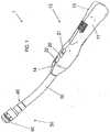
- FIG. 7One hand-powered, intraluminal anastomotic circular stapler is depicted, for example, in U.S. Patent No. 5,104,025 to Main et al. , and assigned to Ethicon.
- a trocar shaft 22has a distal indentation 21, some recesses 28 for aligning the trocar shaft 22 to serrations 29 in the anvil and, thereby, align the staples with the anvils 34.
- a trocar tip 26is capable of puncturing through tissue when pressure is applied thereto.
- FIGS. 3 to 6 in Main et al.show how the circular stapler 10 functions to join two pieces of tissue together.
- the interposed tissuecan be subject to a range of acceptable compressing force during surgery. This range is known and referred to as optimal tissue compression or OTC, and is dependent upon the type of tissue being stapled. While the stapler shown in Main et al. does have a bar indicator that displays to the user a safe staple-firing distance between the anvil and the staple cartridge, it cannot indicate to the user any level of compressive force being imparted upon the tissue prior to stapling. It would be desirable to provide such an indication so that over-compression of the tissue can be avoided.
- WO 95/18572 A1discloses a surgical stapler according to the preamble of claim 1 for sequentially applying a plurality of surgical fasteners to body tissue.
- the staplermakes use of a motor, which drives a helical screw gear, causing a linear movement of a follower.
- the followeris linked to an assembly which causes closure of the stapling head. Completion of a stapling operation is detected by a limit switch, which initiates a reversal of the motor, bringing the system to the starting position, which may be detected by a second limit switch.
- the closing and opening actionare automatically determined.
- EP 0 634 144 A1discloses a further surgical stapler for sequentially applying a plurality of surgical fasteners to body tissue.
- a rotation of a main shaft in a (counter-)clockwise directionincreases (decreases) a staple forming gap in a head of the stapler.
- a closing motionis stopped by a limit switch within the head when a predetermined and controllable staple forming gap is reached. Once the proper and predetermined staple forming gap has been reached, a fire switch is made operable by the same limit switch and associated circuitry.
- US 6,887,244 B1discloses a surgical saw having a handpiece and a disposable battery with mating sets of electrical contacts which can be mechanically and conductively locked together.
- US 2005/222616 A1discloses another surgical stapler for sequentially applying a plurality of surgical fasteners to body tissue.
- the apparatusincludes a replaceable cartridge assembly receivable in a distal end portion of a cartridge receiving half-section, the cartridge assembly including a safety lockout pivotably disposed along the upper surface of the cartridge assembly and movable from an unlocked orientation permitting assembly of an anvil half-section to the cartridge receiving half-section, to a locked orientation preventing assembly of the anvil half-section to the cartridge receiving-half section.
- EP 1 040 790 A1discloses a biopsy instrument for automatic removal of at least one tissue sample from a surgical patient.
- the inventionovercomes the above-noted and other deficiencies of the prior art by providing a hand-held, electrically powered and controlled surgical device according to claim 1.
- Preferred or advantageous embodiments of the inventionare set forth in the dependent claims.
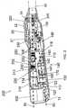
- FIGS. 1 to 2there is shown an exemplary embodiment of an electric surgical circular stapler 1.
- the present applicationapplies the electrically powered handle to a circular surgical staple head for ease of understanding only.
- the inventionis not limited to circular staplers and can be applied to any surgical stapling head, such as a linear stapling device, for example.
- the powered stapler 1has a handle body 10 containing three switches: an anvil open switch 20, an anvil close switch 21, and a staple firing switch 22. Each of these switches is electrically connected to a circuit board 500 (see FIG. 12 ) having circuitry programmed to carry out the stapling functions of the stapler 1.
- the circuit board 500is electrically connected to a power supply 600 contained within the handle body 10.
- One exemplary embodimentutilizes 2 to 6 Lithium CR123 or CR2 cells as the power supply 600.
- Other power supply embodimentsare possible, such as rechargeable batteries or a power converter that is connected to an electric mains (in the latter embodiment, the stapler would not be self-powered or self-contained).
- the terms self-powered or self-contained when used with regard to the electric power supply (600)are interchangeable and mean that the power supply is a complete and independent unit in and of itself and can operate under its own power without the use of external power sources.
- a power supply having an electric cord that is plugged into an electric mains during useis not self-powered or self-contained.
- Insulated conductive wires or conductor tracks on the circuit board 500connect all of the electronic parts of the stapler 1, such as an on/off switch 12, a tissue compression indicator 14, the anvil and firing switches 20, 21, 22, the circuit board 500, and the power supply 600, for example. But these wires and conductors are not shown in the figures of the drawings for ease of understanding and clarity.
- the distal end of the handle body 10is connected to a proximal end of a rigid anvil neck 30.
- a coupling device 40for removably attaching a staple cartridge 50 and an anvil 60 thereto.
- the staple cartridge 50can be non-removable in a single-use configuration of the stapler 1.
- FIG. 2shows the handle body 10 with the right half 13 of the handle body 10 and the circuit board 500 removed.
- a proximal backbone plate 70is also removed from the view of FIG. 2 to allow viewing of the internal components inside the handle body 10 from the right side thereof.
- a first of these axesis the staple control axis 80, which is relatively horizontal in the view of FIG. 2 .
- the staple control axis 80is the centerline on which lie the components for controlling staple actuation.
- the second of these axesis the anvil control axis 90 and is disposed at an angle to the staple control axis 80.
- the anvil control axis 90is the centerline on which lie the components for controlling anvil actuation. It is this separation of axes 80, 90 that allows the electric stapler 1 to be powered using a handle body 10 that is small enough to fit in a physician's hand and that does not take up so much space that the physician becomes restricted from movement in all necessary directions and orientations.
- the on/off switch 12e.g., a grenade pin
- powere.g., battery power
- the tissue compression indicator 14indicates to the physician that the tissue being compressed between the anvil 60 and the staple cartridge 50 has or has not been compressed with greater than a pre-set compressive force, which will be described in further detail below.
- This indicator 14is associated with a force switch 400 that has been described in co-pending U.S. Patent Provisional Application Serial No. 60/801,989 filed May 19, 2006 , and titled "Force Switch".
- An anvil control frame 110is aligned along the anvil control axis 90 to house and/or fix various part of the anvil control assembly 100 thereto.
- the anvil control frame 110has a proximal mount 112, an intermediate mount 114, and a distal mount 116. Each of these mounts 112, 114, 116 can be attached to or integral with the control frame 110.
- the proximal mount 112has two halves and is separate from the frame 110 and the intermediate mount 114 is separate from the frame 110.
- the anvil motor 120includes the drive motor and any gearbox that would be needed to convert the native motor revolution speed to a desired output axle revolution speed.
- the drive motorhas a native speed of approximately 166.67 revolutions/s (10,000 rpm) and the gearbox converts the speed down to between approximately 0.83 revolutions/s (50 rpm) and 1.17 revolutions/s (70 rpm) at an axle 122 extending out from a distal end of the anvil motor 120.
- the anvil motor 120is secured both longitudinally and rotationally inside the proximal mount 112.
- a motor-shaft coupler 130is rotationally fixed to the axle 122 so that rotation of the axle 122 translates into a corresponding rotation of the motor coupler 130.
- the nut assembly 140is, in this embodiment, a two part device having a proximal nut half 141 and a distal nut half 142 rotationally and longitudinally fixed to the proximal nut half 141. It is noted that these nut halves 141, 142 can be integral if desired. Here, they are illustrated in two halves for ease of manufacturing.
- the proximal end of the nut assembly 140is rotationally fixed to the distal end of the coupler 130. Longitudinal and rotational support throughout the length of these two connected parts is assisted by the intermediate 114 and distal 116 mounts.
- a proximal nut bushing 150(see FIG. 3 ) is interposed between the intermediate mount 114 and the proximal nut half 141 and a distal nut bushing 160 is interposed between the distal mount 116 and the distal nut half 142 to have these parts spin efficiently and substantially without friction within the handle body 10 and the anvil control frame 110.
- the bushings 150, 160can be of any suitable bearing material, for example, they can be of metal such as bronze or a polymer such as nylon.
- a thrust washer 170is disposed between the proximal bushing 150 and the proximal nut half 141.
- Rotation of the coupler 130 and nut assembly 140is used to advance or retract a threaded rod 180, which is the mechanism through which the anvil 60 is extended or retracted.
- the threaded rod 180is shown in further detail in the exploded view of FIGS. 3 to 4 and is described in further detail below.
- a rod support 190is attached to a distal end of the anvil control frame 110 for extending the supporting surfaces inside the nut assembly 140 that keep the rod 180 aligned along the anvil control axis 90.
- the rod support 190has a smooth interior shape corresponding to an external shape of the portion of the rod 180 that passes therethrough. This mating of shapes allows the rod 180 to move proximally and distally through the support 190 substantially without friction.
- a cylindrical rod bushing 192is disposed between the support 190 and the rod 180.
- the rod bushing 192is not visible in FIG. 2 because it rests inside the support 190. However, the rod bushing 192 is visible in the exploded view of FIGS. 3 to 4 .
- the internal shape of the support 190corresponds to the external shape of the rod bushing 192 and the internal shape of the rod bushing 192 corresponds to the external shape of the portion of the rod 180 that passes therethrough.
- the rod bushing 192can be, for example, of metal such as bronze or a polymer such as nylon.
- the components along the staple control axis 80form the staple control assembly 200.
- the staple control assembly 200is illustrated in FIG. 5 viewed from a proximal upper and side perspective.
- the proximal end of the staple control assembly 200includes a stapling motor 210.
- the stapling motor 210includes the drive motor and any gearbox that would be needed to convert the native motor revolution speed to a desired revolution speed.
- the drive motorhas a native speed of approximately 333.33 revolutions/s (20,000 rpm) and the gearbox converts the speed to approximately 3.33 revolutions/s (200 rpm) at an output axle 212 at the distal end of the gearbox.
- the axle 212cannot be seen in the view of FIG. 5 but can be seen in the exploded view of FIGS. 6 to 7 .
- the stapling motor 210is rotationally and longitudinally fixed to a motor mount 220. Distal of the motor mount 220 is an intermediate coupling mount 230.
- This coupling mount 230has a distal plate 232 that is shown, for example in FIG. 6 .
- the distal plate 232is removable from the coupling mount 230 so that a rotating screw 250 can be held therebetween. It is this rotating screw 250 that acts as the drive for ejecting the staples out of the staple cartridge 50.
- the efficiency in transferring the rotational movement of axle 212 to the rotating screw 250is a factor that can substantially decrease the ability of the stapler 1 to deliver the necessary staple ejection longitudinal force of up to 113.40 kg (250 pounds).
- an exemplary screw 250has an acme profile thread.
- the stapling motor 210can be housed “loosely” within a chamber defined by the handle body 10 so that it is rotationally stable but has play to move radially and so that it is longitudinally stable but has play to move. In such a configuration, the stapling motor 210 will "find its own center” to align the axis of the axle 212 to the axis of the screw 250, which, in the exemplary embodiment, is also the staple control axis 80.
- FIGS. 1 to 5A second exemplary embodiment for aligning the axle 212 and the screw 250 is illustrated in FIGS. 1 to 5 , for example.
- a proximal end of a flexible coupling 240is fixed (both rotationally and longitudinally) to the axle 212.
- This connectionis formed by fitting the distal end of the axle 212 inside a proximal bore 241 of the flexible coupling 240. See FIG. 12 .
- the axle 212is, then, secured therein with a proximal setscrew 213.
- the screw 250has a proximal extension 251 that fits inside a distal bore 242 of the flexible coupling 240 and is secured therein by a distal setscrew 252.
- the figures of the drawingsshow the flexible coupling 240 with ridges in the middle portion thereof.
- the partis of aluminum or molded plastic and has a spiral or helixed cut-out around the circumference of the center portion thereof.
- one end of the coupling 240can move in any radial direction (360 degrees) with respect to the other end (as in a gimbal), thus providing the desired flex to efficiently align the central axes of the axle 212 and the screw 250.
- the proximal extension 251 of the screw 250is substantially smaller in diameter than the diameter of the bore 231 that exists in and through the intermediate coupling mount 230.
- This bore 231has two increasing steps in diameter on the distal side thereof.
- the first increasing step in diameteris sized to fit a proximal radius screw bushing 260, which is formed of a material that is softer than the intermediate coupling mount 230.
- the proximal radius screw bushing 260only keeps the screw 250 axially aligned and does not absorb or transmit any of the longitudinal thrust.
- the second increasing step in diameteris sized to fit a proximal thrust bearing 270 for the screw 250.
- proximal and distal platessandwich a bearing ball retainer plate and bearing balls therebetween.
- This thrust bearing 270absorbs all of the longitudinal thrust that is imparted towards the axle 212 while the up to 113,40 kg (250 pounds) of longitudinal force is being applied to eject the staples in the staple cartridge 50.
- the proximal extension 251 of the screw 250has different sized diameters for each of the interiors of the screw bushing 260 and the thrust bearing 270.
- the motor mount 220 and the coupling mount 230therefore, form the two devices that hold the flexible coupling 240 therebetween.
- the rotating screw 250is held inside the distal plate 232 with a distal radius screw bushing 280 similar to the proximal radius screw bushing 260.
- the screw 250rotates freely within the distal plate 232.
- the screw 250is threaded within a moving nut 290. Movement of the nut 290 is limited to the amount of movement that is needed for complete actuation of the staples; in other words, the nut 290 only needs to move through a distance sufficient to form closed staples between the staple cartridge 50 and the anvil 60 and to extend the cutting blade, if any, within the staple cartridge 50, and then retract the same.
- the staplesare at rest and ready to be fired.
- the staplesare stapled through and around the tissue interposed between the staple cartridge 50 and the anvil, and the knife, if any, is passed entirely through the tissue to be cut.
- the distal-most position of the nut 290is limited by the location of the distal plate 232.
- the longitudinal length of the threads of the screw 250 and the location of the distal plate 232limit the distal movement of the nut 290.
- Frictional losses between the screw 250 and the nut 290contribute to a significant reduction in the total pounds of force that can be transmitted to the staple cartridge 50 through the cartridge plunger 320. Therefore, it is desirable to select the materials of the screw 250 and the nut 290 and the pitch of the threads of the screw 250 in an optimized way. It has been found that use of a low-friction polymer for manufacturing the nut 290 will decrease the friction enough to transmit the approximately 113,40 kg (250 pounds) of longitudinal force to the distal end of the cartridge plunger 320 -- the amount of force that is needed to effectively deploy the staples.
- DELRIN® AF Blend Acetala thermoplastic material combining TEFLON® fibers uniformly dispersed in DELRIN® acetal resin
- RULON®a compounded form of TFE fluorocarbon
- a nut coupling bracket 300is longitudinally fixed to the nut 290 so that it moves along with the nut 290.
- the nut coupling bracket 300provides support for the relatively soft, lubricious nut material.
- the bracket 300has an interior cavity having a shape corresponding to the exterior shape of the nut 290.
- the nut 290fits snugly into the coupling bracket 300 and movement of the nut 290 translates into a corresponding movement of the nut coupling bracket 300.
- the shape of the nut coupling bracket 300is, in the exemplary embodiment, dictated by the components surrounding it and by the longitudinal forces that it has to bear. For example, there is an interior cavity 302 distal of the nut 290 that is shaped to receive the distal plate 232 therein.
- the nut coupling bracket 300also has a distal housing 304 for receiving therein a stiffening rod 310.
- the stiffening rod 310increases the longitudinal support and forms a portion of the connection between the nut 290 and a cartridge plunger 320 (see, i.e., FIG. 5 ), which is the last moving link between elements in the handle body 10 and the staple cartridge 50.
- a firing bracket 330disposed between the distal end of the nut coupling bracket 300 and the stiffening rod 310, strengthens the connection between the nut coupling bracket 300 and the rod 310.
- This backboneis a frame providing multi-directional stability and is made up of four primary parts (in order from proximal to distal): the anvil control frame 110, the proximal backbone plate 70 (shown in FIGS. 3 to 4 and 6 to 7 ), a distal backbone plate 340, and the anvil neck 30.
- Each of these four partsis longitudinally and rotationally fixed to one another in this order and forms the skeleton on which the remainder of the handle components is attached in some way.
- Lateral support to the componentsis provided by contours on the inside surfaces of the handle body 10, which in an exemplary embodiment is formed of two halves, a left half 11 and a right half 13. Alternatively, support could be single frame, stamped, or incorporated into the handle halves 11, 13.
- anvil control assembly 100Functionality of the anvil control assembly 100 is described with regard to FIGS. 17 to 27 .
- the anvil open switch 20is depressed to extend the distal end of the trocar tip 410 housed within the staple cartridge and which is longitudinally fixedly connected to the screw 250.
- the point of the trocar tip 410can, now, be passed through or punctured through tissue that is to be stapled.
- the usercan, at this point, replace the anvil 60 onto the trocar tip 410 from the opposite side of the tissue (see FIG. 18 ) and, thereby, lock the anvil 60 thereon.
- the anvil closed switch 22can be actuated to begin closing the anvil 60 against the staple cartridge 50 and pinch the tissue therebetween within an anvil-cartridge gap 62.
- FIGS. 8 to 10 , 14 to 15 , and 18To describe how the trocar tip controlling movement of the anvil 60 occurs, reference is made to FIGS. 8 to 10 , 14 to 15 , and 18 .
- a rod-guiding pin 143is positioned within the central bore 144 of the distal nut half 142.
- the pin 143catches the proximal end of the thread 182 to surround the pin 143 therein.
- rotation of the nut 140 with the pin 143 inside the thread 182will cause proximal or distal movement of the rod 180, depending on the direction of nut rotation.
- the thread 182has a variable pitch, as shown in FIGS.
- the pin 143moves longitudinally faster. In comparison, when the pin 143 is inside the shorter (higher) pitched thread portion 184, the anvil 60 moves longitudinally slower. It is noted that the pin 143 is the only portion contacting the thread 182 when in the longer pitched thread portion 183. Thus, the pin 143 is exposed to the entire longitudinal force that is acting on the rod 180 at this point in time. The pin 143 is strong enough to bear such forces but may not be sufficient to withstand all longitudinal force that could occur with anvil 60 closure about interposed tissue.
- the rod 180is provided with a shorter pitched thread portion 184 to engage in a corresponding internal thread 145 at the proximal end of the central bore 144 of the proximal nut half 141.
- the shorter pitched thread portion 184engages the internal thread 145, the entire transverse surface of the thread portion 184 contacts the internal thread 145.
- This surface contactis much larger than the contact between the pin 143 and any portion of the thread 182 and, therefore, can withstand all the longitudinal force that occurs with respect to anvil 60 closure, especially when the anvil 60 is closing about tissue during the staple firing state.
- the pin 143bears up to approximately 13.61 kg (30 pounds) to 22.68 kg (50 pounds) of longitudinal force. This is compared to the threads, which can hold up to 181.44 kg (400 pounds) of longitudinal force - an almost 10-to-1 difference.
- An alternative exemplary anvil control assembly 100can entirely remove the complex threading of the rod 180.
- the rod 180has a single thread pitch and the anvil motor 120 is driven (through corresponding programming in the circuit board 500) at different speeds dependent upon the longitudinal position of the single-thread rod 180.
- the control programmingcan take many forms.
- the microcontroller on the battery powered circuit board 500can apply pulse modulation (e.g., pulse-width, pulse-frequency) to drive either or both of the motors.
- pulse modulatione.g., pulse-width, pulse-frequency
- the stapler 1is a device that has a low duty cycle, or is a one-use device, components can be driven to exceed acceptable manufacturers' specifications.
- a gear boxcan be torqued beyond its specified rating.
- a drive motorfor example, a 6 volt motor, can be overpowered, for example, with 12 volts.
- the longer-pitched thread portion 183allows the user to quickly close the anvil 60 to the tissue in a tissue pre-compressing state. Thereafter, it is desirable to compress the tissue slowly so that the user has control to avoid over-compression of the tissue. As such, the shorter pitched thread portion 184 is used over this latter range of movement and provides the user with a greater degree of control.
- 60/801,989can be used to indicate to the user through the tissue compression indicator 14 (and/or to the control circuitry of the circuit board 500) that the tissue is being compressed with a force that is greater than the pre-load of the spring 420 inside the force switch 400.
- FIG. 18illustrates the force switch 400 in the normally-open configuration described as the first exemplary embodiment of U.S. Patent Provisional Application Serial No. 60/801,989 .
- a strain gaugecan also be used for measuring tissue compression.
- FIGS. 19 to 23illustrate movement of the rod 180 from an anvil-extended position (see FIGS. 19 to 20 ), to a 1-cm-closure-distance position (see FIG. 21 ), to a staple-fire-ready position (see FIG. 22 ), and, finally, to an anvil fully closed position (see FIG. 23 ).
- Movement of the rod 180is controlled electrically (via the circuit board 500) by contact between a portion of a cam surface actuator 185 on the rod 180 and actuating levers or buttons of a series of micro-switches positioned in the handle body 10.
- a rod-fully-extended switch 610(see FIG. 19 ) is positioned distal in the handle body 10 to have the actuator 185 compress the activation lever of the rod-fully-extended switch 610 when the rod 180 (and, thereby, the anvil 60) is in the fully extended position.
- A1-cm switch 612is positioned in an intermediate position within the handle body 10 (see FIGS. 20 to 21 ) to prevent a 1-cm cam surface portion 186 of the rod 180 from pressing the activation button of the 1-cm switch 612 when the rod 180 (and, thereby, the anvil 60) is within 1 cm of the fully closed position. After passing the 1-cm closure distance, as shown in FIG. 22 , the cam surface actuator 185 engages a staple-fire-ready switch 614.
- the lower end of the actuator 185 as viewed in FIGS. 22 to 23has a bevel on both the forward and rear sides with respect to the button of the staple-fire-ready switch 614 and the distance between the portion on the two bevels that actuates the button (or, only the flat portion thereof) corresponds to the acceptable staple forming range (i.e., safe firing length) of the staples in the staple cartridge 50.
- the acceptable staple forming rangei.e., safe firing length
- FIG. 23show the rod 180 in the proximal-most position, which is indicated by the top end of the actuator 185 closing the lever of a rod fully-retracted switch 616.
- the programming in the circuit board 500prevents the motor 120 from turning in a rod-retraction direction; in other words, it is a stop switch for retracting the rod 180 in the proximal direction.
- FIGS. 2 to 3 , 11 to 12 , and 16illustrate the distal end of the rod 180 not being connected to another device at its distal end (which would then contact the proximal end of the force switch 400).
- the connection band or bands between the distal end of the rod 180 and the proximal end of the force switch 400are not shown in the drawings only for clarity purposes.
- the pull-bandsare flat and flexible to traverse the curved underside of the cartridge plunger 320 through the anvil neck 30 and up to the proximal end of the force switch 400.
- the bandswould be connected to the proximal end of the trocar tip 410 that releasably connects to the proximal end of the anvil 60.
- the stapling motor 210is held between a motor bearing 222 and a motor shaft cover 224.
- the axle 212 of the stapling motor 210is rotationally connected to the proximal end of the flexible coupling 240 and the distal end of the flexible coupling 240 is rotationally connected to the proximal end of the screw 250, which rotates on bearings 260, 270, 280 that are disposed within the intermediate coupling mount 230 and the distal plate 232.
- the longitudinally translating nut 290is threaded onto the screw 250 between the coupling mount 230 and the distal plate 232. Therefore, rotation of the axle 212 translates into a corresponding rotation of the screw 250.
- the nut coupling bracket 300is longitudinally fixed to the nut 290 and to the stiffening rod 310 and the firing bracket 330.
- the firing bracket 330is longitudinally fixed to the cartridge plunger 320, which extends (through a non-illustrated staple driver) up to the staple cartridge 50 (or to the staples). With such a connection, longitudinal movement of the nut 290 translates into a corresponding longitudinal movement of the cartridge plunger 320. Accordingly, when the staple firing switch 22 is activated, the stapling motor 210 is caused to rotate a sufficient number of times so that the staples are completely fired from the staple cartridge 50 (and the cutting blade, if present, is extended to completely cut the tissue between the anvil 60 and the staple cartridge 50). Programming in the circuitry, as described below, then causes the cartridge plunger 320 to retract after firing and remove any portion of the staple firing parts and/or the blade within the staple cartridge 50 from the anvil-cartridge gap 62.
- Control of this stapling movementoccurs through micro-switches connected to the circuit board 500 through electrical connections, such as wires.
- an actuation plate 306is attached, in an adjustable manner, to a side of the nut coupling bracket 300. See, e.g., FIGS. 6 and 24 .
- a second of the switches for controlling movement of the staple control assembly 200is located opposite a distal transverse surface of the stiffening rod 310. See, e.g. FIG. 27 . At this surface is disposed a longitudinally adjustable cam member 312 that contacts a distal staple switch 620.
- the cam member 312is a screw that is threaded into a distal bore of the stiffening rod 310. Accordingly, when the nut 290 moves distally to cause the cam member 312 of the stiffening rod 310 to activate the distal staple switch 620, power to the stapling motor 210 is removed to stop further distally directed movement of the staple control assembly 200.
- FIGS. 28 and 29illustrate a removable connection assembly to permit replacement of a different staple cartridge 60 on the distal end of the anvil 30.
- the proximal-most chamber of the handle body 10defines a cavity for holding therein a power supply 600.
- This power supply 600is connected through the circuit board 500 to the motors 120, 210 and to the other electrical components of the stapler 1.
- the electric stapler 1includes, as set forth above in an exemplary embodiment, two drive motors 120, 210 powered by batteries and controlled through pushbuttons 20, 21, 22.
- the ranges of travel of each motor 120, 210are controlled by limit switches 610, 616, 618, 620 at the ends of travel and at intermediary locations 612, 614 along the travel.
- the logic by which the motors 120, 210 are controlledcan be accomplished in several ways. For example, relay, or ladder logic, can be used to define the control algorithm for the motors 120, 210 and switches 610, 612, 614, 616, 618, 620. Such a configuration is a simple but limited control method.
- a more flexible methodemploys a microprocessor-based control system that senses switch inputs, locks switches out, activates indicator lights, records data, provides audible feedback, drives a visual display, queries identification devices (e.g., radio frequency identification devices (RFIDs) or cryptographic identification devices), senses forces, communicates with external devices, monitors battery life, etc.
- RFIDsradio frequency identification devices
- the microprocessorcan be part of an integrated circuit constructed specifically for the purpose of interfacing with and controlling complex electro-mechanical systems. Examples of such chips include those offered by Atmel, such as the Mega 128, and by PIC, such as the PIC 16F684.
- a software programis required to provide control instructions to such a processor. Once fully developed, the program can be written to the processor and stored indefinitely. Such a system makes changes to the control algorithm relatively simple; changes to the software that are uploaded to the processor adjust the control and user interface without changing the wiring or mechanical layout of the device.
- a power-on eventis a one time occurrence.
- the power-oncan be accomplished by pulling a tab or a release that is permanently removed from the device. The removal enables battery contact, thus powering on the device.
- the control programwhen the device is powered on, the control program begins to execute and, prior to enabling the device for use, goes through a routine that ensures awareness of actual positions of the extend/retract and firing sub-assemblies, referred to as a homing routine.
- the homing routinemay be executed at the manufacturer prior to shipping to the user. In such a case, the homing routine is performed, the positions of the assemblies are set, and the device is shipped to the user in a ready-to-use condition. Upon power-up, the device verifies its positions and is ready to use.
- Visual indicatorse.g., LEDs
- the pushbutton switches 20, 21, 22they can be lit (or backlit) when active and unlit when not active.
- the indicatorscan blink to convey additional information to the user.
- a given lightcan blink at an ever-increasing rate as the response becomes imminent, for example.
- the indicatorscan also light with different colors to indicate various states.
- Camsare used in various locations at the stapler 1 to activate limit switches that provide position information to the processor. By using linear cams of various lengths, position ranges can be set. Alternatively, encoders can be used instead of limit switches (absolute and incremental positioning). Limit switches are binary: off or on. Instead of binary input for position information, encoders (such as optical encoders) can be used to provide position information. Another way to provide position feedback includes mounting pulse generators on the end of the motors that drive the sub-assemblies. By counting pulses, and by knowing the ratio of motor turns to linear travel, absolute position can be derived.
- processorscreates the ability to store data. For example, vital, pre-loaded information, such as the device serial number and software revision can be stored. Memory can also be used to record data while the stapler 1 is in use. Every button press, every limit switch transition, every aborted fire, every completed fire, etc., can be stored for later retrieval and diagnosis. Data can be retrieved through a programming port or wirelessly.
- the devicecan be put into diagnostic mode through a series of button presses. In this diagnostic mode, a technician can query the stapler 1 for certain data or to transmit/output certain data.
- Response from the stapler 1 to such a querycan be in the form of blinking LEDs, or, in the case of a device with a display, visual character data, or can be electronic data.
- a strain gaugecan be used for analog output and to provide an acceptable strain band.
- addition of a second spring and support componentscan set this band mechanically.
- An exemplary control algorithm for a single fire stapler 1can include the following steps:
- the stapleris a one-way device.
- the test userneeds to have the ability to move the trocar 410 and anvil 60 back and forth as desired.
- the power-on featurepermits entry by the user into a manual mode for testing purposes. This test mode can be disengaged and the stapler reset to the use mode for packaging and shipment.
- a homing sequencecan be programmed to place the anvil 60 one centimeter (for example) away from the staple cartridge 50 before powering down for packaging and shipment.
- the userturns the stapler on (switch 12). Staples should not be allowed to fire at any time prior to being in a proper staple-firing position and a desired tissue compression state.
- the anvil/trocar extend/retract functionis the only function that is enabled. In this state, the extend and retract buttons 20, 21 are lit and the staple firing switch 22 is not lit (i.e., disabled).
- the trocar 410Before use inside the patient, the trocar 410 is extended and the anvil 60 is removed. If the stapler is being used to anastomose a colon, for example, the trocar 410 is retracted back into the anvil neck 30 and the staple cartridge 50 and anvil neck 30 are inserted trans-anally into the colon to a downstream side of the dissection.
- the anvil 60in contrast, is inserted through an upstream laparoscopic incision and placed at the upstream side of the dissection.
- the anvil 60is attached to the trocar 410 and the two parts are retracted towards the staple cartridge 50 until a staple ready condition occurs. As set forth above, the anvil is moved to a distance that does not substantially compress and, specifically, does not desiccate, the tissue therebetween. At this point, staple firing can occur when desired.
- the staple firing sequenceis started by activating the staple fire switch 22. Staple firing can be aborted anytime during the firing sequence, whether prior to movement (during the blanching cycle) or during movement (whether the staples have started to form or not).
- the softwareis programmed to begin a staple firing countdown sequence because it is understood that the tissue needs to be compressed and allowed to desiccate before staple firing should occur.
- the anvil 60closes upon the interposed tissue and begins to compress the tissue.
- the staple firing sequenceincludes an optimal tissue compression (OTC) measurement and a feedback control mechanism that causes staples to be fired only when the compression is in a desired pressure range, referred to as the OTC range, and a sufficient time period has elapsed to allow fluid removal from the compressed tissue.
- OTC rangeis known beforehand based upon known characteristics of the tissue that is to be compressed between the anvil 60 and the staple cartridge 50 (the force switch can be tuned for different tissue OTC ranges). It is the force switch 400 that provides the OTC measurement and supplies the microprocessor with information indicating that the OTC for that particular tissue has been reached.
- the OTC statecan be indicated to the user with an LED, for example.
- the staple fire switch 22can be made to blink at a given rate and then proceed to blink faster and faster, for example, until firing occurs. If no abort is triggered during this wait time, the OTC state will remain for the preprogrammed desiccation duration arid staple filing will occur after the countdown concludes.
- stapling of the dissectionoccurs simultaneously with a cutting of tissue at the center of the dissection. This cutting guarantees a clear opening in the middle of the circular ring of staples sufficient to create an opening for normal colon behavior after the surgery is concluded.
- the programincludes closed-loop anvil-compression control that is dependent upon continuous measurements provided by the force switch 400. With this feedback, the compressed tissue is kept within the OTC range throughout the procedure and even after being desiccated
- any actuation of a control switch by the usercan be programmed to abort the staple fire routine. If an abort occurs before the staple firing motor 210 is activated, the firing cycle stops, the anvil 60 is extended to a home position, and the staple fire switch 22 remains active and ready for a re-fire attempt, if desired. Alternatively, if the abort occurs during movement of the staple firing motor 210, the firing cycle stops and the staple firing motor 210 is caused to extend the anvil 60 to its home position. At this point, the staple firing switch 22 is rendered inactive. Accordingly, the stapler (or that particular staple cartridge) can no longer be used (unless the staple cartridge is replaced).
- a staple range limit switchis queried for relative position of the staple cartridge 50 and anvil 60. If the staple range limit switch is activated -- meaning that anvil 60 is within an acceptable staple firing range -- then the staple firing motor 210 can be made active and the firing cycle can be allowed to proceed If the staple range limit switch is not activated, then the firing cycle is aborted, the anvil 60 is returned to the home position, and the staple firing switch 22 remains active and ready for a re-fire attempt.
- Poweringalso referred to as actuating, powering, controlling, or activating of the motor and/or the drive train of any portion of the end effector (e.g., anvil or stapler/cutter) is described herein. It is to be understood that such powering need not be limited to a single press of an actuation button by the user nor is the powering of a motor limited to a single energizing of the motor by the power supply. Control of any motor in the device can require the user to press an actuation button a number of times, for example, a first time to actuate a portion of the end effector for a first third of movement, a second time for a second third of movement, and a third time for a last third of movement.
- a first exemplary actuationcan move the staple sled or blade past the lock-out
- a second exemplary actuationcan move the part up to the tissue
- a third exemplary actuationcan move the sled past all staples to the end of the staple cartridge.
- powering of a motorneed not be constant, for example, where the motor is energized constantly from the time that the blade begins movement until it reaches the end point of its movement. Instead, the motor can be operated in a pulsed mode, a first example of which includes periodically switching on and off the power supplied by the power supply to the motor during actuation of an end effector function.
- the motorcan be pulsed ten times/second as the staple/cutter moves from its proximal/start position to its distal-most position.
- This pulsingcan be directly controlled or controlled by microprocessor, either of which can have an adjustable pulse rate.
- the motorcan be operated with a pulse modulation (pulse-width or pulse-frequency), with pulses occurring at very short time periods (e.g., tenths, hundredths, thousandths, or millionths of a second). Accordingly, when the power supply, the motor, and/or the drive train are described herein as being powered, any of these and other possible modes of operation are envisioned and included.
- the anvil 60After a completed staple firing, the anvil 60 remains in the closed position and only the extend switch 20 remains active (all other switches are deactivated). Once the anvil 60 is extended to at least the home position, both the extend and retract switches 20, 21 are made active but the retraction switch 21 does not permit closure of the anvil 60 past the home position.
- the staple fire switch 22remains inactive after a completed staple firing.
- the anvil neck 30houses a linear force switch 400 connected to the trocar 410.
- This switch 400is calibrated to activate when a given tensile load is applied.
- the given loadis set to correspond to a desired pressure that is to be applied to the particular tissue before stapling can occur. Interfacing this switch 400 with the processor can ensure that the firing of staples only occurs within the OTC range.
- identification deviceswith removable and/or interchangeable portions of the end effector.
- Such identification devicescan be used to track usage and inventory.
- One exemplary identification deviceemploys radio-frequency and is referred to as an RFID.
- an RFIDcan be placed in the staple cartridge to ensure compatibility with the particular stapler and an RFID reader for sensing compatible staple cartridges can be associated with the handle.
- the readerinterrogates the RFID mounted in the cartridge.
- the RFIDresponds with a unique code that the stapler verifies. If the stapler cartridge is labeled as verified, the stapler becomes active and ready for use. If the cartridge is rejected, however, the stapler gives a rejected indication (e.g., a blinking LED, an audible cue, a visual indicator).
- the antenna of the RFID readercan be constructed to only read the RFID when the staple cartridge is installed in the stapler or is very nearby (optimally, at the distal end of the device).
- Use of the RFIDcan be combined with a mechanical lockout to ensure that only one fire cycle is allowed per staple cartridge.
- RFIDshave drawbacks because the readers are expensive, the antennas are required to be relatively large, and the distance for reading is relatively close, typically measured in centimeters.
- Another exemplary identification deviceemploys encryption.
- encryptioncomes the need for processing numbers and, associated with such calculations, is use of processing chips (e.g., a microprocessor), one of which is to be placed on the interchangeable part, such as a staple cartridge or a replaceable end effector shaft.
- processing chipse.g., a microprocessor
- Such encryption chipshave certain characteristics that can be analyzed for optimization with the surgical instrument of the present invention.
- a separate power source for the interchangeable partis not desired. Not only would such a power source add cost, it would also add undesirable weight and take up space that is needed for other features or is just not available.
- power supply to the partshould come from the already existing power supply within the handle. Also, supply of power should be insured at all times. Because the interchangeable part is relatively small, the encryption chip should be correspondingly small.
- both the handle and the interchangeable partare configured to be disposable, therefore, both encryption processors should have a cost that allows disposability.
- connections between the encryption device on the interchangeable part and the corresponding encryption device on the handleshould be minimized.
- the encryption deviceprovides all of these desirable characteristics and limits the undesirable ones.
- DS2432 chipDevices for encrypted identification are commercially available.
- One of such encryption devicesis produced by Dallas Semiconductor and is referred to as the DS2432 chip.
- the DS2432 chipnot only provides encrypted identification between a reader and a transponder, but it also has a memory that can be used to store device-specific information, which information and its uses will be described in further detail below.
- One beneficial characteristic of the DS2432is that it is a 1-wire device. This means that the power and both of the input and output signals travel on the same line. With a 1-wire device such as the DS2432, there is only the need for a single wire to traverse the distance from the handle body 10 through the anvil neck 30 to the interchangeable staple cartridge 50 in order to make a connection between the handle and the end effector.
- One exemplary encryption circuit configurationplaces a first encryption chip on the interchangeable part (e.g., the staple cartridge).
- Ground for the first encryption chipis electrically connected to a metallic portion of the interchangeable part which, in turn, is electrically connected to ground of the device, for example, to the neck 30.
- the 1-wire connection of the DS2432 chipis electrically connected to a contact pad that is somewhere on the interchangeable part but is electrically disconnected from ground.
- the interchangeable partis a linear 60 mm staple cartridge
- the DS2432can be attached to or embedded within the electrically insulated distal end of the cartridge distal of the last staple set.
- the encryption chipcan be embedded on a side of the cartridge opposite the staple ejection face so that it is neither exposed to the working surfaces nor to the exposed tissue when in use.
- the ground lead of the DS2432 chipcan be electrically connected to the metallic outer frame of the staple cartridge, which is electrically connected to ground of the stapler.
- the 1-wire leadis electrically connected to a first conductive device (such as a pad, a lead, or a boss) that is electrically insulated from the metallic frame of the cartridge.
- a single electrically conductive but insulated wireis connected at the proximal end to the circuit board or to the appropriate control electronics within the handle of the device.
- This wireis insulated from electrical contact with any other part of the stapler, especially the grounded frame, and travels from the handle, through the neck and up to the receiving chamber for the interchangeable part.
- the insulated wireis exposed and electrically connected to a second conductive device (such as a pad, a lead, or a boss) that is shaped to positively contact the first conductive device on the cartridge when the cartridge is locked into place in the end effector.
- the two conductive devicesform a direct electrical connection every time that the interchangeable part (e.g., the staple cartridge) is inserted within the end effector; in one particular embodiment, contact can be made only when the part is correctly inserted.
- the DS2432is also only a few square millimeters in area, making the chip easy to install on a small interchangeable part, such as a staple cartridge, while simultaneously satisfying the minimal size requirement. It is noted that the DS2432 chip is relatively inexpensive. To keep all communication with the DS2432 chip hidden from outside examination, a DS2460 (also manufactured by Dallas Semiconductor) can be used to perform a comparison of an encrypted transmission received from a DS2432 with an expected result calculated internally. The characteristics of both of these chips are explained, for example, by Dallas Semiconductors' Application Note 3675. The DS2460 chip costs significantly more than the DS2432 chip, but is still inexpensive enough to be disposed along with the handle.
- the number of disposable interchangeable parts of medical devicestypically outnumber the handle that receives the interchangeable parts by a significant amount. Accordingly, if the DS2432 chip is placed in the interchangeable part and the DS2460 chip is placed in the handle, the low cost encryption characteristic is satisfied.
- FIG. 2 of Application Note 3675There exists an alternative circuit configuration using two DS2432 chips that is explained in FIG. 2 of Application Note 3675, which circuit eliminates the need of the more expensive DS2460 chip by performing the comparison with a local microprocessor (e.g., microprocessor 2000). In such a configuration, the cost for adding encryption into the device 1 is reduced, however, as explained, the configuration gives up some aspects of security by making available to inspection both numbers that are to be compared.
- the process for electronically verifying the identity of an interchangeable part on a medical device using encryptionis described with an example having one DS2432 chip and one DS2460 chip.
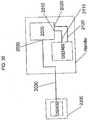
- the exemplary control circuit for the encryption deviceis shown in FIG. 30 .
- This exampleis described using a linear stapler having a handle containing therein a circuit board with a microprocessor 2000.
- One free I/O pin 2010 of the microprocessor 2000is connected to a first lead 2110 of the DS2460 and another I/O pin 2020 is connected to a second lead 2120.
- Each interchangeable part 2200is provided with a DS2432 chip and the 1-wire lead is connected to a third I/O pin 2030 of the microprocessor 2000.
- an interchangeable part 2200is connected to the device, making electrical contact with ground and with the 1-wire lead.
- the microprocessor 2000detects that a new part 2200 has been connected to the device 1, it runs an authentication routine.
- the microprocessor 2000initiates a random number request to the DS2460 over the first communication pin 2010.
- the DS2460has a pre-programmed secret number that is the same as the pre-programmed secret numbers stored in each of the DS2432 chips contained on the interchangeable parts 2200. Therefore, when the same random number is provided to both the DS2432 and the DS2460 chips, the output result from each of the two chips will be identical.
- the DS2460generates a random number and supplies it, via the second pin 2020, to the microprocessor 2000 for forwarding, via pin 2030, on to the DS2432 over the 1-wire lead.
- the DS2432applies its SHA-1 algorithm (developed by the National Institute of Standards and Technology (NIST)) to cryptographically generate a hash code reply.
- This hash code replyis transmitted back over the 1-wire lead to the microprocessor 2000 and is forwarded, via either pin 2010 or 2020 to the DS2460.
- the DS2460is also calculating its own a hash code reply.
- the DS2460internally applies the same random number sent to the DS2432 to its own SHA-1 algorithm and stores, internally, the generated hash code reply.
- the DS2460also stores the hash code reply transmitted from the DS2432 through the microprocessor 2000. Both of the hash code replies are compared and, if they are identical, the interchangeable part 2200 is confirmed as authenticated. If there is a difference between the hash code replies, then the part 2200 is rejected and the device is placed in a state where the part 2200 either cannot be used or can be used, but only after certain safeguards are met. For example, data regarding the time, date, environment, etc.
- the unauthenticated partcan be stored for later or simultaneous transmission to the manufacturer (or its agent) to inform the manufacturer that the user is attempting to use or has used an unauthorized part 2200 with the device. If there was no encryption in the messages, the authentication messages could be intercepted and counterfeit, pirated, or unauthorized parts 2200 could be used without having to purchase the parts 2200 from an authorized distributor.
- the only information that is transmitted across lines that can be examinedis a single random number and a single hash code reply. It is understood that it would take hundreds of years to decrypt this SHA-1-generated reply, thus reducing any incentive for reverse engineering.
- the chips used in this exampleeach have secure memories that can only be accessed after authentication occurs, they can be programmed to employ multiple secret keys each stored within the memory. For example, if the DS2460 has multiple keys stored therein and the parts 2200 each have only one key selected from this stored set of multiple keys, the DS2460 can act as a "master" key to the "general" single keys of the parts 2200.
- the instrument manufacturercan prevent a user from using unauthorized parts, thereby insuring use of only authorized parts. Not only does this guarantee that the manufacturer can receive royalties from sales of the interchangeable part, but it also allows the manufacture to insure that the quality of the surgical parts remains high.
- Having the encryption circuitry contain memorydramatically enhances the benefits provided by the present invention. For example, if a single end effector of a linear stapler can receive 30 mm, 60 mm, and 120 mm staple cartridges, for example, each size of the cartridges could be provided with an individualized key and the handle can be programmed to store and use each of these three keys.
- the handleUpon receiving a hash code reply that corresponds to one, but not the other two internally calculated hash code replies, the handle would know what kind of cartridge has been inserted in the device. Each cartridge could also contain in its memory cartridge-specific parameters, such as staple sled movement length, that are different among the various sized cartridges and, therefore, cause the handle to behave differently dependent upon the cartridge detected. The parameters examined can also account for revision levels in the particular part. For example, a revision 1 cartridge could have certain parameters for use and, by detecting that particular cartridge, programming could cause the handle to not allow use of revision 1 cartridges but allow use of revision 2 cartridges, or vice-versa.
- the cartridgecan store the identity of each handle to which it was connected, the identity of the handle that fired the cartridge, the time, date and other temporal data when use and/or connection occurred, how long it took to fire the cartridge, how many times the firing trigger was actuated during staple firing, and many other similar parameters.
- One parameter in particularcould record data when the cartridge misfires. This would allow the manufacturer to determine if the cartridge was faulty or if user-error occurred, for example, the latter being investigated to assist the user with remedial measures or other training.
- handle-relevant parameterscould be stored, for example, duration of each procedure, speed of each staple firing, torque generated at each firing, and/or load experienced throughout each firing.
- the memorycould be powered for years merely from the lithium-based power cells already present in the handle. Thus, longevity of handle data can be ensured.
- the memorycan be used to store all uses of a particular handle, along with relevant calendar data. For example, if a handle is only certified for use in a single surgical procedure but the handle has data indicating that staple cartridges were fired days or weeks apart, then, when it was finally returned to the manufacturer for recycling, the manufacturer could detect that the user (hospital, doctor, clinic, etc.) was improperly and, possibly, unsafely, using the handle.
- Encrypted authenticationcan be used with removable battery packs as well.
- sensorscan be added to any portion of the device for communicating information to be stored within the memory of the encryption chips.
- temperature sensorscan transmit operating room temperature existing when the cartridge was fired. This temperature reading can be used to determine if later infection was caused by improper temperature control existing during the procedure (e.g., in countries where air-conditioning is not available).
- bail-outIn the unlikely event that the stapler becomes inoperable during use, a mechanical override or bail-out is provided to allow manual removal of the device from the patient. All bailout uses can be recorded with the memory existing on these encryption chips. Furthermore, data that could indicate why bailout was necessary could be stored for later examination. For quality assurance, when bailout is detected, the handle can be programmed to indicate that a certified letter should be sent to the customer/user informing them of the bailout use.
- the present inventionis not limited to a circular stapler, which has been used as an exemplary embodiment above, and can be applied to any surgical stapling head, such as a linear stapling device, for example. Accordingly, a linear stapler is being used in the text that follows for various exemplary embodiment. However, use of a linear stapler in this context should not be considered as limited only thereto.
- the required force for proper staple ejection and tissue cuttingcan be over 90.72 kg (200 pounds) and, possibly, up to 113.40 kg (250 pounds). It has been determined that minimum requirements for carrying out the desired stapling and cutting functions with a linear electric surgical stapler for human tissue (such as colon tissue, for example) are:
- the maximum power (in watts) of the mechanical assemblyneeds to be calculated based upon the maximum limits of these requirements: 82 kg over 60 mm in 3 seconds.
- Mathematical conversion of these figuresgenerates an approximate maximum of 16 Watts of mechanical power needed at the output of the drive train. Conversion of the electrical power into mechanical power is not 1:1 because the motor has less than 100% efficiency and because the drive train also has less than 100% efficiency. The product of these two efficiency ratings forms the overall efficiency.
- the electrical power required to produce the 16 Watts of mechanical poweris greater than the 16 Watts by an inverse product of the overall efficiency.
- Matching or optimizing the power source and the motorinvolves looking into the individual characteristics of both.
- larger motorscan perform a given amount work with greater efficiency than smaller motors.
- motors with rare-earth magnets or with coreless constructioncan deliver the same power in a smaller size, but at higher cost.
- larger motorscost less than smaller motors if both are designed to deliver the same power over a given period of time.
- Larger motorshave an undesirable characteristic when used in surgical stapling devices because the handle in which they are to be placed is limited by the size of an operator's hand. Physicians desire to use devices that are smaller and lighter, not larger and heavier. Based upon these considerations, cost, size, and weight are factors that can be optimized for use in the surgical stapler handle of the present invention.
- Ceramic magnet motorscan be selected for use in the handle.
- Exemplary motorscome in standard sizes (diameter) of 27.5 mm or 24 mm, for example. These motors have a rated efficiency of approximately 60% (which decreases to 30% or below depending upon the size of the load).
- Such motorsoperate at speeds of approximately 500 revolutions/s (30,000 rpm) (between 333.33 revolutions/s (20,000 rpm) and 666.67 revolutions/s (40,000 rpm)) when unloaded.
- coreless, brush-type, DC motorsproduce similar power output but with a significant reduction in size.
- a 17 mm diameter coreless motorcan output approximately the same power as a standard 24 mm diameter motor.
- the coreless motorcan have an efficiency of up to 80%.
- Coreless motorsalmost all use rare earth magnets.
- a rack and pinion assemblyas the final drive train control stage places a high-efficiency end stage in the drive train as compared to a screw drive because, in general, the rack and pinion has an approximate 95% efficiency, and the screw drive has a maximum of about 80% efficiency.
- the linear electric staplerthere is a 60 mm travel range for the stapling/cutting mechanism when the stapler has a 60 mm cartridge (cartridges ranging from 30 mm to 100 mm can be used but 60 mm is used in this example for illustrative purposes).
- a 3-second, full travel durationplaces the rack and pinion extension rate at 0.02032 m (0.8 inches) per second.
- a gear trainshould reduce the motor output to approximately 1 revolution/s (60 rpm). With a motor output speed of approximately 500 revolutions/s (30,000 rpm), the reduction in speed for the drive train becomes approximately 500:1.
- a 5-stage drive trainis selected. It is known that such drive trains have an approximate 97% efficiency for each stage. Thus, combined with an approximate 95% efficiency of the rack and pinion, the overall efficiency of the drive train is (0.95)(0.97) 5 or 82%.
- the power (in watts) of the mechanical assemblycan be calculated based upon the 82 kg over 60 mm in 3 seconds to be approximately 16 Watts. It is known that the overall mechanical efficiency is 49.2%, so 32.5 Watts is needed from the power supply (16 mech. watts ⁇ 32.5 elec. Watts ⁇ 0.492 overall efficiency.). With this minimum requirement for electrical power, the kind of cells available to power the stapler can be identified, which, in this case, include high-power Lithium Primary cells. A known characteristic of high-power Lithium cells (e.g., CR123 or CR2 cells) is that they produce about 5 peak watts of power per cell.
- high-power Lithium cellse.g., CR123 or CR2 cells
- At least six cells in serieswill generate the required approximate amount of 32.5 watts of electrical power, which translates into 16 watts of mechanical power. This does not end the optimization process because each type of high-power Lithium cell manufactured has different characteristics for delivering peak power and these characteristics differ for the load that is to be applied.
- the power source of an electric stapling deviceis only used for a short duration and for a small number of times.
- the motorneeds to be ready for a peak load and needs to perform without error.
- the stapling/cutting featurewill be carried out during only one medical procedure, which has cycle counts of between 10 and 20 uses at most, with each use needing to address a possible peak load of the device. After the one procedure, the device is taken out of commission and discarded. Therefore, the power source for the present invention needs to be constructed unlike any other traditional power supply.
- the device according to the present inventionis constructed to have a limited useful life of a power cell as compared to an expected useful life of the power cell when not used in the device. When so configured, the device is intended to work few times after this defined "life span.” It is known that self-contained power supplies, such as batteries, have the ability to recover after some kind of use. For optimization with the present invention, the device is constructed within certain parameters that, for a defined procedure, will perform accordingly but will be limited or unable to continue performance if the time of use extends past the procedure. Even though the device might recover and possibly be used again in a different procedure, the device is designed to use the power cells such that they will most likely not be able to perform at the enhanced level much outside the range of intended single use periods or outside the range of aggregate use time.
- a useful life or clinical life of the power supply or of the deviceis defined, which life can also be described as an intended use. It is understood that this useful/clinical life does not include periods or occurrences of use during a testing period thereof to make sure that the device works as intended. The life also does not include other times that the device is activated outside the intended procedure, i.e., when it is not activated in accordance with a surgical procedure.
- the PTC deviceprotects batteries and/or circuits from overcurrent and overtemperature conditions. Significantly, the PTC device protects a battery from external short circuits while still allowing the battery to continue functioning after the short circuit is removed. Some batteries provide short-circuit and/or overtemperature protection using a one-time fuse. However, an accidental short-circuit of such a fused battery causes the fuse to open, rendering the battery useless. PTC-protected batteries have an advantage over fused batteries because they are able to automatically "reset" when the short circuit is removed, allowing the battery to resume its normal operation. Understanding characteristics of the PTC device is particularly important in the present invention because the motor will be drawing several times greater current than would ever be seen in a typical high-drain application.
- the PTC deviceis provided in series with the anode and cathode and is made of a partially conducting layer sandwiched between two conductive layers, for example.
- the deviceis in a low-resistance condition at a temperature during a normal operation (depending on circuit conditions in which the device is used, for example, from room temperature to 40° C.).
- the PTC deviceswitches into an extremely high-resistance mode.
- the devicewhen a PTC device is included in a circuit and an abnormal current passes through the circuit, the device enters the higher temperature condition and, thereby, switches into the higher resistance condition to decrease the current passing through the circuit to a minimal level and, thus, protect electric elements of the circuit and the battery/ies.
- the minimal levele.g., about 20% of peak current
- the batterycan cool off to a "safe" level at which time greater power can be supplied.
- the partially conducting layer of the PTC deviceis, for example, a composite of carbon powder and polyolefin plastic. Further description of such devices is unnecessary, as these devices are described and are well known in the art.
- the present inventiontakes advantage of this feature and provides a process for optimizing the selection of a particular battery to match a particular motor and a particular use.
- An examination of the time when the PTC device switches to the higher resistance conditioncan be used as this indicator for optimizing a particular motor and drive train to a battery. It is desirable to know when the PTC device makes this switch so that, during normal stapler use, the PTC device does not make this change.
- Exemplary batterieswere loaded with various levels from approximately 3 amps to approximately 8 amps.
- the PTC devicechanged to the high-resistance state almost immediately, making this current level too high for standard CR123 cells. It was determined that, for between 4 and 6 amps, one manufacturer's cell had PTC activation sooner than another manufacturer's cell.
- the longest PTC changeover duration for the second manufacturerwas >3 minutes for 4 amps, approximately 2 minutes for 5 amps, and almost 50 seconds for 6 amps. Each of these durations was significantly greater than the 8-second peak load requirement. Accordingly, it was determined that the second manufacturer's cells would be optimal for use at peak amps as compared to the first manufacturer's cells.
- the peak voltagecould be 18 volts with a peak current of only 6 amps. Placing cells in parallel, in theory, should allow a higher peak amperage and a 3x2 configuration (two parallel set of three cells in series) could have a 9 volt peak with up to a 12 amp peak.
- the windings of the motorare matched to the anticipated voltage at which the motor will be run. This matching takes into account the duration of individual cycles and the desired overall life of the product. In a case of an electric stapling device the motor will only be used for very short cycles and for a very short life, traditional matching methods yield results that are below optimal.
- Manufacturers of the motorsgive a voltage rating on a motor that corresponds to the number of turns of the windings. The lower the number of turns, the lower the rated voltage. Within a given size of motor winding, a lower number of turns allows larger wire to be used, such that a lower number of turns results in a lower resistance in the windings, and a higher number of turns results in a higher resistance.
- a desirable configurationwill have the lowest winding resistance to draw the most current from the power supply (i.e., battery pack).
- the power supplyi.e., battery pack
- By running the motor at a voltage much higher than the motor ratingsignificantly greater power can be drawn from similarly sized motors.
- This traitwas verified with testing of nearly identical coreless motors that only varied in winding resistance (and, hence, the number of turns). For example, 12-volt and 6-volt rated motors were run with 6 cells (i.e., at 19.2 volts). The motors rated for 12 volts output peak power of 4 Watts with the battery voltage only falling slightly to 18 volts when drawing 0.7 amps.
- the motors rated for 6 voltsoutput 15 Watts of power with the voltage dropping to 15 volts but drawing 2 amps of current. Therefore, the lower resistance windings were selected to draw enough power out of the batteries. It is noted that the motor windings should be balanced to the particular battery pack so that, in a stall condition, the motor does not draw current from the cells sufficient to activate the PTC, which condition would impermissibly delay use of an electric surgical stapler during an operation.
- the 6x1 power cell configurationappeared to be more than sufficient to meet the requirements of the electric stapling device. Nonetheless, at this point, the power cell can be further optimized to determine if six cells are necessary to perform the required work. Four cells were, then, tested and it was determined that, under the 54.43 kg (120#) load, the motor/drive train could not move the rack over the 60 mm span within 3 seconds. Six cells were tested and it was determined that, under the 54.43 kg (120#) load, the motor/drive train could move the rack over the 60 mm span in 2.1 seconds - much faster than the 3-second requirement.
- the gear reduction ratio and the drive systemneed to be optimized to keep the motor near peak efficiency during the firing stroke.
- the desired stroke of 60 mm in 3 secondsmeans a minimum rack velocity of 20 mm/sec ( ⁇ 0.8 inches/second).
- a basic reduction of 333:1is set in the gear box. This leaves the final reduction to be performed by the gears present between the output shaft 214 of the gear box and the rack 217, which gears include, for example, a bevel gear 215 and the pinion 216 (which drives the rack), a simplified example of which is illustrated in FIG. 32 .
- the battery packcan be reexamined to determine if six cells could be reduced to five or even four cells, which would save cost and considerably decrease the volume needed for the power supply within the handle.
- a constant load of approximately 54.43 kg (120#)was used with the optimized motor, drive train, bevel gear, and rack and pinion and it was discovered that use of 4 cells resulted in an almost 5 second time period for moving the rack 60 mm. With 5 cells, the time was reduced to approximately 3.5 seconds. With a 6-cell configuration, the time was 2.5 seconds. Thus, interpolating this curve resulted in a minimum cell configuration of 5.5 cells. Due to the fact that cells only can be supplied in integer amounts, it was discovered that the 6-cell configuration was needed to meet the requirements provided for the electric stapling device.
- the minimum power source volumecould be calculated as a fixed value, unless different sized cells could be used that provided the same electrical power characteristics.
- Lithium cells referred as CR2shave similar electrical power characteristics as have CR123s but are smaller. Therefore, using a 6-cell power supply of CR2s reduced the space requirement by more than 17%.
- the power sourcei.e., batteries
- drive train, and motorare optimized for total efficiency to deliver the desired output force within the required window of time for completing the surgical procedure.
- the efficiency of each kind of power source, drive train, and motorwas examined and, thereafter, the type of power source, drive train, and motor was selected based upon this examination to deliver the maximum power over the desired time period.
- the maximum-power condition(voltage and current) is examined that can exist for a given period of time without activating the PTC (e.g., approximately 15 seconds).
- the present inventionlocates the voltage-current-power value that optimizes the way in which power is extracted from the cells to drive the motor. Even after such optimization, other changes can be made to improve upon the features of the electric stapler 1.
- a rechargeable Lithium-ion or Lithium-polymer cellis connected to one or more of the optimized cells mentioned above (or perhaps another primary cell of smaller size but of a similar or higher voltage).
- the Li-ion cellwould power the stapling/cutting motor because the total energy contained within one CR2 cell is sufficient to recharge the Li ion cell many times, however, the primary cells are limited as to delivery.
- Li-ion and Li-Polymer cellshave very low internal resistance and are capable of very high currents over short durations.
- a primary celle.g., CR123, CR2, or another cell
- a primary cellcould take 10 to 30 seconds to charge up the secondary cell, which would form an additional power source for the motor during firing.
- An alternative example Li-ion cellis the use of a capacitor; however, capacitors are volume inefficient. Even so, a super capacitor may be put into the motor powering system; it may be disconnected electrically therefrom until the operator determines that additional power is required. At such a time, the operator would connect the capacitor for an added "boost" of energy.
- a multi-ratio transmissioncan be used to change the delivered power over the desired time period.
- a multi-ratio transmissioncan be used to switch the gear ration to return the motor to the higher efficiency point, at which, for example, at least a 81.65 kg 180 pounds) force can be supplied.
- the motor of the present inventionneeds to operate in both forward and reverse directions. In the latter operating mode, the motor must be able to disengage the stapling/cutting instrument from out of a "jammed" tissue clamping situation. Thus, it would be beneficial for the reverse gearing to generate more force than the forward gearing.
- the inventioncan include a speed governing device.
- Possible governing devicesinclude dissipative (active) governors and passive governors.
- One exemplary passive governoris a flywheel, such as the energy storage element 56, 456 disclosed in U.S. Patent Application No. 2005/0277955 to Palmer et al.
- Another passive governor that can be usedis a "fly" paddlewheel.
- Such an assemblyuses wind resistance to govern speed because it absorbs more force as it spins faster and, therefore, provides a speed governing characteristic when the motor is moving too fast.
- a further exemplary governorcan be a compression spring that the motor compresses slowly to a compressed state. When actuation is desired, the compressed spring is released, allowing all of the energy to be transferred to the drive in a relatively short amount of time.
- a further exemplary governorcan include a multi-stage switch having stages that are connected respectively to various sub-sets of the battery cells. When low force is desired, a first switch or first part of a switch can be activated to place only a few of the cells in the power supply circuit. As more power is desired, the user (or an automated computing device) can place successive additional cells into the power supply circuit. For example, in a 6-cell configuration, the first 4 cells can be connected to the power supply circuit with a first position of a switch, the fifth cell can be connected with a second position of the switch, and the sixth cell can be connected with a third position of the switch.
- a dampening materialis disposed between the handle body and both of motor and the drive train.
- the materialcan be foam, such as latex, polyester, plant-based, polyether, polyetherimide, polyimide, polyolefin, polypropylene, phenolic, polyisocyanates, polyurethane, silicone, vinyl, ethylene copolymer, expanded polyethylene, fluoropolymer, or styrofoam.
- the materialcan be an elastomer, such as silicone, polyurethane, chloroprene, butyl, polybutadiene, neoprene, natural rubber, or isoprene.
- the foamcan be closed cellular, open cellular, flexible, reticular, or syntactic, for example.
- the materialcan be placed at given positions between the handle and motor/gear box or can entirely fill the chamber surrounding the motor/gear box.
- the motor and drive trainare isolated within a nested box configuration, sometimes referred to as a "Chinese Box” or "Russian nesting doll.”
- a nested box configurationsometimes referred to as a "Chinese Box” or "Russian nesting doll.”
- the dampening materialis placed around the motor/gear box and the two are placed within a first box with the gear box shaft protruding therefrom. Then, the first box is mounted within the “second box” - the handle body - and the dampening material is place between the first box and the handle interior.
- the electric stapler of the present inventioncan be used in surgical applications. Most stapling devices are one-time use. They can be disposed after one medical procedure because the cost is relatively low. The electric surgical stapler, however, has a greater cost and it may be desirable to use at least the handle for more than one medical procedure. Accordingly, sterilization of the handle components after use becomes an issue. Sterilization before use is also significant. Because the electric stapler includes electronic components that typically do not go through standard sterilization processes (i.e., steam or gamma radiation), the stapler needs to be sterilized by other, possibly more expensive, means such as ethylene-oxide gas. It would be desirable, however, to make the stapler available to gamma radiation sterilization to reduce the cost associated with gas sterilization.
- standard sterilization processesi.e., steam or gamma radiation
- the memorybecomes permanent and resistant to the gamma sterilization.
- the memorycan be mask-programmed. If the memory is hard programmed using masks, gamma radiation at the level for medical sterilization will not adversely affect the programming.
- the sterilizationcan be performed while the volatile memory is empty and, after sterilization, the memory can be programmed through various measures, for example, a wireless link including infrared, radio, ultrasound, or Bluetooth communication can be used. Alternatively, or additionally, external electrodes can be contacted in a clean environment and these conductors can program the memory.
- a radiopaque shield(made from molybdenum or tungsten, for example) can be provided around the gamma radiation sensitive components to prevent exposure of these components to the potentially damaging radiation.
- characteristics of the battery, drive train, and motorare examined and optimized for an electric stapling application.
- the particular design (i.e., chemistry and PTC) of a batterywill determine the amount of current that can be supplied and/or the amount of power that can be generated over a period of time. It has been determined that standard alkaline cells do not have the ability to generate the high power needed over the short period of time to effect actuation of the electric stapling device. It was also determined that some lithium-manganese dioxide cells also were unable to meet the needs for actuating the stapling device. Therefore, characteristics of certain lithium-manganese dioxide cell configurations were examined, such as the electrolyte and the positive temperature coefficient device.
- conventional lithium-manganese dioxide cellse.g., CR123 and CR2
- SUREFIRE®markets flashlights and such cells and states that the cells will last for from 20 minutes to a few hours (3 to 6) at the maximum lumen output of the flashlight.
- Load upon the cells(s) during this period of timeis not close to the power capacity of the battery(ies) and, therefore, the critical current rate of the battery(ies) is not reached and there is no danger of overheating or explosion. If such use is not continuous, the batteries can last through many cycles (i.e., hundreds) at this same full power output.
- Such batteriesare not designed for loads over a period of 10 seconds or less, for example, five seconds, and are also not designed for a small number of uses, for example, ten to fifteen.
- What the present invention doesis to configure the power supply, drive train, and motor to optimize the power supply (i.e., battery) for a small number of uses with each use occurring over a period of less than ten seconds and at a load that is significantly higher than rated.
- the present inventionconfigures the power supply to operate in a range above the critical current rate, referred to herein as the "Super-Critical Current Rate.” It is noted within the definition of Super-Critical Current Rate also is an averaging of a modulated current supplied by the power supply that is above the critical current rate. Because the cells cannot last long while supplying power at the Super-Critical Current Rate, the time period of their use is shortened.
- the Super-Critical Pulse Discharge Periodis a time that is less than or equal to the Pulse Discharge Period, during which time the current rate is greater than the critical current rate of the cells.
- the Super-Critical Pulse Discharge Period for the present inventionis less than about 16 seconds, in other words, in a range of about one-half to fifteen seconds, for example, between two and four seconds and, more particularly, at about three seconds.
- the power supplymay be subjected to the Super-Critical Current Rate over the Pulse Discharge Period for at least one time and less than twenty times within the time of a clinical procedure, for example, between approximately five and fifteen times, in particular, between ten and fifteen times within a period of five minutes. Therefore, in comparison to the hours of use for standard applications of the power supply, the present invention will have an aggregate use, referred to as the Aggregate Pulse Time, of, at most, approximately 200 to 300 seconds, in particular, approximately 225 seconds.
- the devicemay not be required to exceed or to always exceed the Super-Critical Current Rate in a given procedure because the load presented to the instrument is dependent upon the specific clinical application (i.e., some tissue is denser than others and increased tissue density will increase load presented to device).
- the stapleris designed to be able to exceed the Super-Critical Current Rate for a number of times during the intended use of the surgical procedure. Acting in this Super-Critical Pulse Discharge Period, the device can operate a sufficient amount of times to complete the desired surgical procedure, but not many more because the power supply is asked to perform at an increased current.
- the force generated by the devicee.g., the electric stapler 1
- the motor and drive assembliescan be operated to the detriment of the knife blade lock-out feature -- the safety that prevents the knife blade 1060 from advancing when there is no staple cartridge or a previously fired staple cartridge in the staple cartridge holder 1030. This feature is illustrated in FIG. 33 .
- the knife blade 1060should be allowed to move distally only when the staple sled 102 is present at the firing-ready position, i.e., when the sled 102 is in the position illustrated in FIG. 33 .
- the sled 102is not present in this position, this can mean one of two things, either there is no staple cartridge in the holder 1030 or the sled 102 has already been moved distally - in other words, a partial or full firing has already occurred with the loaded staple cartridge.
- the blade 1060should not be allowed to move, or should be restricted in its movement. Accordingly, to insure that the sled 102 can prop up the blade 1060 when in a firing state, the sled 102 is provided with a lock-out contact surface 104 and the blade 1060 is provided with a correspondingly shaped contact nose 1069.
- the lower guide wings 1065do not rest against a floor 1034 in the cartridge holder 1030 until the blade 1060 has moved distally past an edge 1035.
- the sled 102is not present at the distal end of the blade 1060 to prop up the nose 1069, then the lower guide wings 1065 will follow the depression 1037 just proximal of the edge 1035 and, instead of advancing on the floor 1034, will hit the edge 1035 and prevent further forward movement of the blade 1060.
- the staple cartridge 1030has a plate spring 1090 (attached thereto by at least one rivet 1036) for biasing the blade 1060.
- a plate spring 1090attached thereto by at least one rivet 1036 for biasing the blade 1060.
- the plate spring 1090flexed upward and pressing downward against the flange 1067 (at least until the flange 1067 is distal of the distal end of the plate spring 1090)
- a downwardly directed forceis imparted against the blade 1060 to press the wings 1065 down into the depression 1037.
- the wings 1065follow the lower curve of the depression 1037 and are stopped from further distal movement when the distal edge of the wings 1065 hit the edge 1035.
- This safety featureoperates as described so long as the force transmitted by the knife blades 1062 to the blade 1060 is not great enough to tear off the lower guide wings 1065 from the blade 1060.
- the blade 1060With the forces able to be generated by the power supply, motor and drive train of the present invention, the blade 1060 can be pushed distally so strongly that the wings 1065 are torn away. If this occurs, there is no way to prevent distal movement of the blade 1060 or the sled 102. Accordingly, the present invention provides a way to lower the forces able to be imparted upon the wings 1065 prior to their passage past the edge 1035.
- a first exemplary two-part force generation limitertakes the form of a circuit in which only one or a few of the cells in the power supply are connected to the motor during the first part of the stapling/cutting stroke and, in the second part of the stapling/cutting stroke, most or all of the cells in the power supply are connected to the motor.
- a first exemplary form of such a circuitis illustrated in FIG. 34 .
- the motore.g., stapling motor 210
- the motoris only powered with one power cell 602 (of a possible four in this example).
- the switch 1100is in the "B" position, the motor is powered with all four of the cells 602 of the power supply 600, thereby increasing the amount of force that can be supplied to the blade 1060.
- Control of the switch 1100 between the A and B positionscan occur by positioning a second switch somewhere along the blade control assembly or along the sled 102, the second switch sending a signal to a controller after the wings 1065 have passed the edge 1035.
- this first example of the control circuitis only exemplary and any similarly performing assembly can provide the lock-out protection for the device, see, for example, the second example illustrated in FIG. 36 .
- FIG. 35A first exemplary form of a forward and reverse motor control circuit is illustrated in FIG. 35 .
- This first exemplary formuses a double-throw, double pole switch 1200.
- the switch 1200is normally spring-biased to a center position in which both poles are off.
- the motor M illustratedcan, for example, represent the stapling motor 210 of the present invention.
- the power-on switch 1210must be closed to turn on the device. Of course, this switch is optional.
- the switch 1200is placed in the right position as viewed in FIG. 35 , in which power is supplied to the motor to run the motor in a first direction, defined as the forward direction here because the "+" of the battery is connected to the "+” of the motor M.
- the motor Mcan power the blade 1060 in a distal direction.
- Placement of an appropriate sensor or switch to indicate the forward-most desired position of the blade 1060 or the sled 102can be used to control a forward travel limit switch 1220 that interrupts power supply to the motor M and prevents further forward travel, at least as long as the switch 1220 remains open.
- Circuitrycan be programmed to never allow this switch 1220 to close and complete the circuit or to only allow resetting of the switch 1220 when a new staple cartridge, for example, is loaded.
- the switch 1200When a reverse movement of the motor M is desired, the switch 1200 is placed in the left position as viewed in FIG. 35 , in which power is supplied to the motor to run the motor in a second direction, defined as the reverse direction here because the "-" of the battery is connected to the "+” of the motor M. In this reverse switching position, the motor M can power the blade 1060 in a proximal direction. Placement of an appropriate sensor or switch to indicate the rearward-most desired position of the blade 1060 or the sled 102 can be used to control a rearward travel limit switch 1230 that interrupts power supply to the motor M and prevents further rearward travel, at least as long as the switch 1230 remains open. It is noted that other switches (indicated with dotted arrows) can be provided in the circuit to selectively prevent movement in either direction independent of the limit switches 1220, 1230.
- the motorcan power the gear train with a significant amount of force, which translates into a high rotational inertia.
- the gearsmay not just stop. Instead, the rotational inertia continues to propel, for example, the rack 217 in the direction it was traveling when power to the motor was terminated.
- Such movementcan be disadvantageous for many reasons.
- a circuitcan be formed to substantially eliminate such post-termination movement, thereby giving the user more control over actuation.
- FIG. 36illustrates an example where the motor (for example, stapling motor 210) is arrested from further rotation when forward or reverse control is terminated.
- FIG. 36also illustrates alternative examples of the forward/reverse control and of the multi-stage power supply.
- the circuit of FIG. 36has a motor arrest sub-circuit utilizing a short-circuit property of an electrical motor. More specifically, the electrical motor M is placed into a short-circuit so that an electrically generated magnetic field is created in opposition to the permanent magnetic field, thus slowing the still-spinning motor at a rate that substantially prevents inertia-induced overstroke.
- the forward/reverse switch 1300is provided.
- the forward/reverse switch 1300has three positions, just like the switch 1200 of FIG. 35 .
- the motor MWhen placed in the right position, the motor M is actuated in a forward rotation direction.
- the motor MWhen placed in the left position, the motor M is actuated in a rearward rotation direction.
- the switch 1300When the switch 1300 is not actuated - as shown in FIG. 36 - the motor M is short circuited. This short circuit is diagrammatically illustrated by the upper portion of the switch 1300. It is noted that the switching processes in a braking switch is desired to take place in a time-delayed manner, which is also referred to as a break-before-make switching configuration.
- the double-pole, double throw portion of the forward/reverse switch 1300is opened before the motor short circuit is effected. Conversely, when switching over from braking the motor M to operating the motor M, the short circuit is opened before the switch 1300 can cause motor actuation. Therefore, in operation, when the user releases the 3-way switch 1300 from either the forward or reverse positions, the motor M is short-circuited and brakes quickly.
- an on/off switch 1210is provided. Also present is the power lock-out switch 1100 that only powers the motor with one power cell 602' in a given portion of the actuation (which can occur at the beginning or at any other desired part of the stroke) and powers the motor M with all of the power cells 602 (here, for example, six power cells) in another portion of the actuation.
- a new feature of the reverse and forward limit switches 1320, 1330prevents any further forward movement of the motor M after the forward limit switch 1320 is actuated.
- the forward limit switch 1320is actuated and the switch moves to the second position. In this state, no power can get to the motor for forward movement but power can be delivered to the motor for reverse movement.
- the forward limit switchcan be programmed to toggle or be a one-time use for a given staple cartridge. More specifically, the switch 1320 will remain in the second position until a reset occurs by replacing the staple cartridge with a new one. Thus, until the replacement occurs, the motor M can only be powered in the reverse direction. If the switch is merely a toggle, then power can be restored for additional further movement only when the movement has retreated the part away from actuating the switch 1320.
- the reverse limit switch 1330can be configured similarly. When the reverse limit is reached, the switch 1330 moves to the second position and stays there until a reset occurs. It is noted that, in this position, the motor M is in a short-circuit, which prevents motor movement in either direction. With such a configuration, the operation of the stapler can be limited to a single stroke up to the forward limit and a single retreat up to the rear limit. When both have occurred, the motor M is disabled until the two switches 1320 are reset.
- An optimal tissue compression surgical devicewhich comprises a handle having therein a compression controller adapted to be electrically coupled to a power supply selectively supplying power therefrom; and a surgical end effector connected to the handle.
- the surgical end effectorhas an electrically controlled tissue-compressing device operable to compress tissue disposed therein, the tissue-compressing device being electrically coupled with the compression controller and being powered thereby to selectively control compression of the tissue disposed within the tissue-compressing device; and a mechanical binary-output electrical switch disposed in line with the tissue-compressing device to place a force upon the mechanical binary-output electrical switch that corresponds to a compressing force directed upon the compressed tissue.
- the mechanical binary-output electrical switchhas: first and second electrical switching states initiated and changed solely by mechanical movements; a biasing device retaining the switch in the first switching state with a bias force until a force imparted upon the switch overcomes the bias force to change the switch to the second switching state; and a switching-state-status output communicatively coupled to the compression controller and operable to provide information identifying a current one of the switching states, the compression controller being operable to selectively control compression of the tissue disposed within the tissue-compressing device based upon the information.
Landscapes
- Health & Medical Sciences (AREA)
- Life Sciences & Earth Sciences (AREA)
- Surgery (AREA)
- Molecular Biology (AREA)
- General Health & Medical Sciences (AREA)
- Biomedical Technology (AREA)
- Heart & Thoracic Surgery (AREA)
- Medical Informatics (AREA)
- Nuclear Medicine, Radiotherapy & Molecular Imaging (AREA)
- Animal Behavior & Ethology (AREA)
- Engineering & Computer Science (AREA)
- Public Health (AREA)
- Veterinary Medicine (AREA)
- Physics & Mathematics (AREA)
- Electromagnetism (AREA)
- Oral & Maxillofacial Surgery (AREA)
- Pathology (AREA)
- Surgical Instruments (AREA)
Description
- The present invention lies in the field of surgical instruments, in particular but not necessarily, stapling devices. The stapling device described in the present application is a hand-held, fully electrically powered and controlled surgical stapler.
- Medical stapling devices exist in the art. Ethicon Endo-Surgery, Inc. (a Johnson & Johnson company; hereinafter "Ethicon") manufactures and sells such stapling devices. Circular stapling devices manufactured by Ethicon are referred to under the trade names PROXIMATE® PPH, CDH, and ILS and linear staplers are manufactured by Ethicon under the trade names CONTOUR and PROXIMATE. In each of these exemplary surgical staplers, tissue is compressed between a staple cartridge and an anvil and, when the staples are ejected, the compressed tissue is also cut. Depending upon the particular tissue engaged by the physician, the tissue can be compressed too little (where blood color is still visibly present in the tissue), too much (where tissue is crushed), or correctly (where the liquid is removed from the tissue, referred to as dessicating or blanching).
- Staples to be delivered have a given length and the cartridge and anvil need to be within an acceptable staple firing distance so that the staples close properly upon firing. Therefore, these staplers have devices indicating the relative distance between the two planes and whether or not this distance is within the staple length firing range. Such an indicator is mechanical and takes the form of a sliding bar behind a window having indicated thereon a safe staple-firing range. These staplers are all hand-powered, in other words, they require physical actuations by the user/physician to position the anvil and stapler cartridge about the tissue to be stapled and/or cut, to close the anvil and stapler cartridge with respect to one another, and to fire and secure the staples at the tissue (and/or cut the tissue). No prior art staplers are electrically powered to carry out each of these operations because the longitudinal force necessary to effect staple firing is typically on the order of 113.40 kg (250 pounds) at the staple cartridge. Further, such staplers do not have any kind of active compression indicator that would optimizes the force acting upon the tissue that is to be stapled so that tissue degradation does not occur.
- One hand-powered, intraluminal anastomotic circular stapler is depicted, for example, in
U.S. Patent No. 5,104,025 to Main et al. , and assigned to Ethicon. As can be seen most clearly in the exploded view ofFIG. 7 in Main et al., atrocar shaft 22 has adistal indentation 21, some recesses 28 for aligning thetrocar shaft 22 to serrations 29 in the anvil and, thereby, align the staples with the anvils 34. A trocar tip 26 is capable of puncturing through tissue when pressure is applied thereto.FIGS. 3 to 6 in Main et al. show how thecircular stapler 10 functions to join two pieces of tissue together. As theanvil 30 is moved closer to thehead 20, interposed tissue is compressed therebetween, as particularly shown inFIGS. 5 and6 . If this tissue is overcompressed, the surgical stapling procedure might not succeed. Thus, it is desirable to not exceed the maximum acceptable tissue compression force. The interposed tissue can be subject to a range of acceptable compressing force during surgery. This range is known and referred to as optimal tissue compression or OTC, and is dependent upon the type of tissue being stapled. While the stapler shown in Main et al. does have a bar indicator that displays to the user a safe staple-firing distance between the anvil and the staple cartridge, it cannot indicate to the user any level of compressive force being imparted upon the tissue prior to stapling. It would be desirable to provide such an indication so that over-compression of the tissue can be avoided. WO 95/18572 A1 claim 1 for sequentially applying a plurality of surgical fasteners to body tissue. The stapler makes use of a motor, which drives a helical screw gear, causing a linear movement of a follower. The follower is linked to an assembly which causes closure of the stapling head. Completion of a stapling operation is detected by a limit switch, which initiates a reversal of the motor, bringing the system to the starting position, which may be detected by a second limit switch. Thus, the closing and opening action are automatically determined.EP 0 634 144 A1US 6,887,244 B1 discloses a surgical saw having a handpiece and a disposable battery with mating sets of electrical contacts which can be mechanically and conductively locked together.US 2005/222616 A1 discloses another surgical stapler for sequentially applying a plurality of surgical fasteners to body tissue. The apparatus includes a replaceable cartridge assembly receivable in a distal end portion of a cartridge receiving half-section, the cartridge assembly including a safety lockout pivotably disposed along the upper surface of the cartridge assembly and movable from an unlocked orientation permitting assembly of an anvil half-section to the cartridge receiving half-section, to a locked orientation preventing assembly of the anvil half-section to the cartridge receiving-half section.EP 1 040 790 A1- The invention overcomes the above-noted and other deficiencies of the prior art by providing a hand-held, electrically powered and controlled surgical device according to
claim 1. Preferred or advantageous embodiments of the invention are set forth in the dependent claims. - Although the invention is illustrated and described herein as embodied in an electrical surgical instrument with optimized power supply and drive, it is, nevertheless, not intended to be limited to the details shown because various modifications and structural changes may be made within the scope and range of equivalents of the claims.
- The construction and method of operation of the invention, however, together with additional objects and advantages thereof, will be best understood from the following description of specific embodiments when read in connection with the accompanying drawings.
- Advantages of embodiments of the present invention will be apparent from the following detailed description of the preferred embodiments thereof, which description should be considered in conjunction with the accompanying drawings in which:
FIG. 1 is a perspective view from a side of an exemplary embodiment of an electric stapler according to the invention;FIG. 2 is a fragmentary side elevational view of the stapler ofFIG. 1 with a right half of a handle body and with a proximal backbone plate removed;FIG. 3 is an exploded, perspective view of an anvil control assembly of the stapler ofFIG. 1 ;FIG. 4 is an enlarged, fragmentary, exploded, perspective view of the anvil control assembly ofFIG. 3 ;FIG. 5 is a fragmentary, perspective view of a staple firing control assembly of the stapler ofFIG. 1 from a rear side thereof;FIG. 6 is an exploded, perspective view of the staple firing control assembly of the stapler ofFIG. 1 ;FIG. 7 is an enlarged, fragmentary, exploded, perspective view of the staple firing control assembly ofFIG. 6 ;FIG. 8 is a fragmentary, horizontally cross-sectional view of the anvil control assembly from below the handle body portion of the stapler ofFIG. 1 ;FIG. 9 is a fragmentary, enlarged, horizontally cross-sectional view from below a proximal portion of the anvil control assemblyFIG. 8 ;FIG. 10 is a fragmentary, enlarged, horizontally cross-sectional view from below an intermediate portion of the anvil control assembly ofFIG. 8 ;FIG. 11 is a fragmentary, enlarged, horizontally cross-sectional view from below a distal portion of the anvil control assembly ofFIG. 8 ;FIG. 12 is a fragmentary, vertically cross-sectional view from a right side of a handle body portion of the stapler ofFIG. 1 ;FIG. 13 is a fragmentary, enlarged, vertically cross-sectional view from the right side of a proximal handle body portion of the stapler ofFIG. 12 ;FIG. 14 is a fragmentary, enlarged, vertically cross-sectional view from the right side of an intermediate handle body portion of the stapler ofFIG. 12 ;FIG. 15 is a fragmentary, further enlarged, vertically cross-sectional view from the right side of the intermediate handle body portion of the stapler ofFIG. 14 ;FIG. 16 is a fragmentary, enlarged, vertically cross-sectional view from the right side of a distal handle body portion of the stapler ofFIG. 12 ;FIG. 17 is a perspective view of a portion of an anvil of the stapler ofFIG. 1 ;FIG. 18 is a fragmentary, cross-sectional view of a removable stapling assembly including the anvil, a stapler cartridge, a force switch, and a removable cartridge connecting assembly of the stapler ofFIG. 1 ;FIG. 19 is a fragmentary, horizontally cross-sectional view of the anvil control assembly from above the handle body portion of the stapler ofFIG. 1 with the anvil rod in a fully extended position;FIG. 20 is a fragmentary, side elevational view of the handle body portion of the stapler ofFIG. 1 from a left side of the handle body portion with the left handle body and the circuit board removed and with the anvil rod in a fully extended position;FIG. 21 is a fragmentary, side elevational view of the handle body portion of the stapler ofFIG. 20 with the anvil rod in a 1-cm anvil closure position;FIG. 22 is a fragmentary, horizontally cross-sectional view of the anvil control assembly from above the handle body portion of the stapler ofFIG. 1 with the anvil rod in a safe staple firing position;FIG. 23 is a fragmentary, horizontally cross-sectional view of the anvil control assembly from above the handle body portion of the stapler ofFIG. 1 with the anvil rod in a fully retracted position;FIG. 24 is a fragmentary, horizontally cross-sectional view of the firing control assembly from above the handle body portion of the stapler ofFIG. 1 ;FIG. 25 is a fragmentary, enlarged, horizontally cross-sectional view from above a proximal portion of the firing control assembly ofFIG. 24 ;FIG. 26 is a fragmentary, enlarged, horizontally cross-sectional view from above an intermediate portion of the firing control assembly ofFIG. 24 ;FIG. 27 is a fragmentary, enlarged, horizontally cross-sectional view from above a distal portion of the firing control assembly ofFIG. 24 ;FIGS. 28 and 29 are shaded, fragmentary, enlarged, partially transparent perspective views of a staple cartridge removal assembly of the stapler ofFIG. 1 ;FIG. 30 is a schematic circuit diagram of an exemplary encryption circuit for interchangeable parts of the medical device according to the invention;FIG. 31 is a bar graph illustrating a speed that a pinion moves a rack shown inFIG. 32 for various loads;FIG. 32 is a fragmentary, perspective view of a simplified, exemplary portion of a gear train according to the present invention between a gear box and a rack;FIG. 33 is a fragmentary, vertically longitudinal, cross-sectional view of a distal end of an articulating portion of an exemplary end effector with the inner tube, the pushrod-blade support, the anvil, the closure ring, and the near half of the staple sled removed;FIG. 34 is a schematic circuit diagram of an exemplary switching assembly for a power supply;FIG. 35 is a schematic circuit diagram of an exemplary switching assembly for forward and reverse control of a motor; andFIG. 36 is a schematic circuit diagram of another exemplary switching assembly for the power supply and the forward and reverse control of the motor.- Aspects of the invention are disclosed in the following description and related drawings directed to specific embodiments of the invention. Alternate embodiments may be devised without departing from the scope of the invention. Additionally, well-known elements of exemplary embodiments of the invention will not be described in detail or will be omitted so as not to obscure the relevant details of the invention.
- Before the present invention is disclosed and described, it is to be understood that the terminology used herein is for the purpose of describing particular embodiments only and is not intended to be limiting.
- While the specification concludes with claims defining the features of the invention that are regarded as novel, it is believed that the invention will be better understood from a consideration of the following description in conjunction with the drawing figures, in which like reference numerals are carried forward. The figures of the drawings are not drawn to scale. Further, it is noted that the figures have been created using a computer-aided design computer program. This program at times removes certain structural lines and/or surfaces when switching from a shaded or colored view to a wireframe view. Accordingly, the drawings should be treated as approximations and be used as illustrative of the features of the present invention.
- Referring now to the figures of the drawings in detail and first, particularly to
FIGS. 1 to 2 thereof, there is shown an exemplary embodiment of an electric surgicalcircular stapler 1. The present application applies the electrically powered handle to a circular surgical staple head for ease of understanding only. The invention is not limited to circular staplers and can be applied to any surgical stapling head, such as a linear stapling device, for example. - The
powered stapler 1 has ahandle body 10 containing three switches: an anvilopen switch 20, an anvilclose switch 21, and astaple firing switch 22. Each of these switches is electrically connected to a circuit board 500 (seeFIG. 12 ) having circuitry programmed to carry out the stapling functions of thestapler 1. Thecircuit board 500 is electrically connected to apower supply 600 contained within thehandle body 10. One exemplary embodiment utilizes 2 to 6 Lithium CR123 or CR2 cells as thepower supply 600. Other power supply embodiments are possible, such as rechargeable batteries or a power converter that is connected to an electric mains (in the latter embodiment, the stapler would not be self-powered or self-contained). As used herein, the terms self-powered or self-contained when used with regard to the electric power supply (600) are interchangeable and mean that the power supply is a complete and independent unit in and of itself and can operate under its own power without the use of external power sources. For example, a power supply having an electric cord that is plugged into an electric mains during use is not self-powered or self-contained. - Insulated conductive wires or conductor tracks on the
circuit board 500 connect all of the electronic parts of thestapler 1, such as an on/offswitch 12, atissue compression indicator 14, the anvil and firingswitches circuit board 500, and thepower supply 600, for example. But these wires and conductors are not shown in the figures of the drawings for ease of understanding and clarity. - The distal end of the
handle body 10 is connected to a proximal end of arigid anvil neck 30. Opposite this connection, at the distal end of theanvil neck 30, is acoupling device 40 for removably attaching astaple cartridge 50 and ananvil 60 thereto. Alternatively, thestaple cartridge 50 can be non-removable in a single-use configuration of thestapler 1. These connections will be described in further detail below. FIG. 2 shows thehandle body 10 with theright half 13 of thehandle body 10 and thecircuit board 500 removed. As will be discussed below, aproximal backbone plate 70 is also removed from the view ofFIG. 2 to allow viewing of the internal components inside thehandle body 10 from the right side thereof. What can be seen from the view ofFIG. 2 is that there exist two internal component axes within thehandle body 10. A first of these axes is thestaple control axis 80, which is relatively horizontal in the view ofFIG. 2 . Thestaple control axis 80 is the centerline on which lie the components for controlling staple actuation. The second of these axes is theanvil control axis 90 and is disposed at an angle to thestaple control axis 80. Theanvil control axis 90 is the centerline on which lie the components for controlling anvil actuation. It is this separation ofaxes electric stapler 1 to be powered using ahandle body 10 that is small enough to fit in a physician's hand and that does not take up so much space that the physician becomes restricted from movement in all necessary directions and orientations.- Shown inside the
handle body 10 is the on/off switch 12 (e.g., a grenade pin) for controlling power (e.g., battery power) to all of the electrical components and thetissue compression indicator 14. Thetissue compression indicator 14 indicates to the physician that the tissue being compressed between theanvil 60 and thestaple cartridge 50 has or has not been compressed with greater than a pre-set compressive force, which will be described in further detail below. Thisindicator 14 is associated with aforce switch 400 that has been described in co-pendingU.S. Patent Provisional Application Serial No. 60/801,989 filed May 19, 2006 - The components along the
anvil control axis 90 make up theanvil control assembly 100. Ananvil control frame 110 is aligned along theanvil control axis 90 to house and/or fix various part of theanvil control assembly 100 thereto. Theanvil control frame 110 has aproximal mount 112, anintermediate mount 114, and adistal mount 116. Each of thesemounts control frame 110. In the exemplary embodiment, for ease of manufacturing, theproximal mount 112 has two halves and is separate from theframe 110 and theintermediate mount 114 is separate from theframe 110. - At the proximal end of the
anvil control assembly 100 is ananvil motor 120. Theanvil motor 120 includes the drive motor and any gearbox that would be needed to convert the native motor revolution speed to a desired output axle revolution speed. In the present case, the drive motor has a native speed of approximately 166.67 revolutions/s (10,000 rpm) and the gearbox converts the speed down to between approximately 0.83 revolutions/s (50 rpm) and 1.17 revolutions/s (70 rpm) at anaxle 122 extending out from a distal end of theanvil motor 120. Theanvil motor 120 is secured both longitudinally and rotationally inside theproximal mount 112. - A motor-
shaft coupler 130 is rotationally fixed to theaxle 122 so that rotation of theaxle 122 translates into a corresponding rotation of themotor coupler 130. - Positioned distal of the
coupler 130 is arotating nut assembly 140. Thenut assembly 140 is, in this embodiment, a two part device having aproximal nut half 141 and adistal nut half 142 rotationally and longitudinally fixed to theproximal nut half 141. It is noted that thesenut halves nut assembly 140 is rotationally fixed to the distal end of thecoupler 130. Longitudinal and rotational support throughout the length of these two connected parts is assisted by the intermediate 114 and distal 116 mounts. - A proximal nut bushing 150 (see
FIG. 3 ) is interposed between theintermediate mount 114 and theproximal nut half 141 and adistal nut bushing 160 is interposed between thedistal mount 116 and thedistal nut half 142 to have these parts spin efficiently and substantially without friction within thehandle body 10 and theanvil control frame 110. Thebushings rotating nut assembly 140 and thecoupler 130, athrust washer 170 is disposed between theproximal bushing 150 and theproximal nut half 141. - Rotation of the
coupler 130 andnut assembly 140 is used to advance or retract a threadedrod 180, which is the mechanism through which theanvil 60 is extended or retracted. The threadedrod 180 is shown in further detail in the exploded view ofFIGS. 3 to 4 and is described in further detail below. Arod support 190 is attached to a distal end of theanvil control frame 110 for extending the supporting surfaces inside thenut assembly 140 that keep therod 180 aligned along theanvil control axis 90. Therod support 190 has a smooth interior shape corresponding to an external shape of the portion of therod 180 that passes therethrough. This mating of shapes allows therod 180 to move proximally and distally through thesupport 190 substantially without friction. To improve frictionless movement of therod 180 through thesupport 190, in the exemplary embodiment, acylindrical rod bushing 192 is disposed between thesupport 190 and therod 180. Therod bushing 192 is not visible inFIG. 2 because it rests inside thesupport 190. However, therod bushing 192 is visible in the exploded view ofFIGS. 3 to 4 . With therod bushing 192 in place, the internal shape of thesupport 190 corresponds to the external shape of therod bushing 192 and the internal shape of therod bushing 192 corresponds to the external shape of the portion of therod 180 that passes therethrough. Therod bushing 192 can be, for example, of metal such as bronze or a polymer such as nylon. - The components along the
staple control axis 80 form thestaple control assembly 200. Thestaple control assembly 200 is illustrated inFIG. 5 viewed from a proximal upper and side perspective. The proximal end of thestaple control assembly 200 includes astapling motor 210. The staplingmotor 210 includes the drive motor and any gearbox that would be needed to convert the native motor revolution speed to a desired revolution speed. In the present case, the drive motor has a native speed of approximately 333.33 revolutions/s (20,000 rpm) and the gearbox converts the speed to approximately 3.33 revolutions/s (200 rpm) at anoutput axle 212 at the distal end of the gearbox. Theaxle 212 cannot be seen in the view ofFIG. 5 but can be seen in the exploded view ofFIGS. 6 to 7 . - The stapling
motor 210 is rotationally and longitudinally fixed to amotor mount 220. Distal of themotor mount 220 is anintermediate coupling mount 230. Thiscoupling mount 230 has adistal plate 232 that is shown, for example inFIG. 6 . Thedistal plate 232 is removable from thecoupling mount 230 so that arotating screw 250 can be held therebetween. It is thisrotating screw 250 that acts as the drive for ejecting the staples out of thestaple cartridge 50. The efficiency in transferring the rotational movement ofaxle 212 to therotating screw 250 is a factor that can substantially decrease the ability of thestapler 1 to deliver the necessary staple ejection longitudinal force of up to 113.40 kg (250 pounds). Thus, anexemplary screw 250 has an acme profile thread. - There are two exemplary ways described herein for efficiently coupling the rotation of the
axle 212 to thescrew 250. First, the staplingmotor 210 can be housed "loosely" within a chamber defined by thehandle body 10 so that it is rotationally stable but has play to move radially and so that it is longitudinally stable but has play to move. In such a configuration, the staplingmotor 210 will "find its own center" to align the axis of theaxle 212 to the axis of thescrew 250, which, in the exemplary embodiment, is also thestaple control axis 80. - A second exemplary embodiment for aligning the
axle 212 and thescrew 250 is illustrated inFIGS. 1 to 5 , for example. In this embodiment, a proximal end of aflexible coupling 240 is fixed (both rotationally and longitudinally) to theaxle 212. This connection is formed by fitting the distal end of theaxle 212 inside aproximal bore 241 of theflexible coupling 240. SeeFIG. 12 . Theaxle 212 is, then, secured therein with aproximal setscrew 213. Thescrew 250 has aproximal extension 251 that fits inside adistal bore 242 of theflexible coupling 240 and is secured therein by adistal setscrew 252. It is noted that the figures of the drawings show theflexible coupling 240 with ridges in the middle portion thereof. In anexemplary coupling 240, the part is of aluminum or molded plastic and has a spiral or helixed cut-out around the circumference of the center portion thereof. In such a configuration, one end of thecoupling 240 can move in any radial direction (360 degrees) with respect to the other end (as in a gimbal), thus providing the desired flex to efficiently align the central axes of theaxle 212 and thescrew 250. - The
proximal extension 251 of thescrew 250 is substantially smaller in diameter than the diameter of thebore 231 that exists in and through theintermediate coupling mount 230. This bore 231 has two increasing steps in diameter on the distal side thereof. The first increasing step in diameter is sized to fit a proximalradius screw bushing 260, which is formed of a material that is softer than theintermediate coupling mount 230. The proximalradius screw bushing 260 only keeps thescrew 250 axially aligned and does not absorb or transmit any of the longitudinal thrust. The second increasing step in diameter is sized to fit aproximal thrust bearing 270 for thescrew 250. In anexemplary thrust bearing 270, proximal and distal plates sandwich a bearing ball retainer plate and bearing balls therebetween. This thrust bearing 270 absorbs all of the longitudinal thrust that is imparted towards theaxle 212 while the up to 113,40 kg (250 pounds) of longitudinal force is being applied to eject the staples in thestaple cartridge 50. Theproximal extension 251 of thescrew 250 has different sized diameters for each of the interiors of thescrew bushing 260 and thethrust bearing 270. Themotor mount 220 and thecoupling mount 230, therefore, form the two devices that hold theflexible coupling 240 therebetween. - The
rotating screw 250 is held inside thedistal plate 232 with a distalradius screw bushing 280 similar to the proximalradius screw bushing 260. Thus, thescrew 250 rotates freely within thedistal plate 232. To translate the rotation of thescrew 250 into a linear distal movement, thescrew 250 is threaded within a movingnut 290. Movement of thenut 290 is limited to the amount of movement that is needed for complete actuation of the staples; in other words, thenut 290 only needs to move through a distance sufficient to form closed staples between thestaple cartridge 50 and theanvil 60 and to extend the cutting blade, if any, within thestaple cartridge 50, and then retract the same. When thenut 290 is in the proximal-most position (see, e.g.,FIG. 12 ), the staples are at rest and ready to be fired. When thenut 290 is in the distal-most position, the staples are stapled through and around the tissue interposed between thestaple cartridge 50 and the anvil, and the knife, if any, is passed entirely through the tissue to be cut. The distal-most position of thenut 290 is limited by the location of thedistal plate 232. Thus, the longitudinal length of the threads of thescrew 250 and the location of thedistal plate 232 limit the distal movement of thenut 290. - Frictional losses between the
screw 250 and thenut 290 contribute to a significant reduction in the total pounds of force that can be transmitted to thestaple cartridge 50 through thecartridge plunger 320. Therefore, it is desirable to select the materials of thescrew 250 and thenut 290 and the pitch of the threads of thescrew 250 in an optimized way. It has been found that use of a low-friction polymer for manufacturing thenut 290 will decrease the friction enough to transmit the approximately 113,40 kg (250 pounds) of longitudinal force to the distal end of thecartridge plunger 320 -- the amount of force that is needed to effectively deploy the staples. Two particular exemplary materials provide the desired characteristics and are referred to in the art as DELRIN® AF Blend Acetal (a thermoplastic material combining TEFLON® fibers uniformly dispersed in DELRIN® acetal resin) and RULON® (a compounded form of TFE fluorocarbon) or other similar low-friction polymers. - A
nut coupling bracket 300 is longitudinally fixed to thenut 290 so that it moves along with thenut 290. Thenut coupling bracket 300 provides support for the relatively soft, lubricious nut material. In the exemplary embodiment shown, thebracket 300 has an interior cavity having a shape corresponding to the exterior shape of thenut 290. Thus, thenut 290 fits snugly into thecoupling bracket 300 and movement of thenut 290 translates into a corresponding movement of thenut coupling bracket 300. The shape of thenut coupling bracket 300 is, in the exemplary embodiment, dictated by the components surrounding it and by the longitudinal forces that it has to bear. For example, there is aninterior cavity 302 distal of thenut 290 that is shaped to receive thedistal plate 232 therein. Thenut coupling bracket 300 also has adistal housing 304 for receiving therein astiffening rod 310. The stiffeningrod 310 increases the longitudinal support and forms a portion of the connection between thenut 290 and a cartridge plunger 320 (see, i.e.,FIG. 5 ), which is the last moving link between elements in thehandle body 10 and thestaple cartridge 50. Afiring bracket 330, disposed between the distal end of thenut coupling bracket 300 and thestiffening rod 310, strengthens the connection between thenut coupling bracket 300 and therod 310. - Various components of the
stapler 1 are connected to one another to form a backbone or spine. This backbone is a frame providing multi-directional stability and is made up of four primary parts (in order from proximal to distal): theanvil control frame 110, the proximal backbone plate 70 (shown inFIGS. 3 to 4 and6 to 7 ), adistal backbone plate 340, and theanvil neck 30. Each of these four parts is longitudinally and rotationally fixed to one another in this order and forms the skeleton on which the remainder of the handle components is attached in some way. Lateral support to the components is provided by contours on the inside surfaces of thehandle body 10, which in an exemplary embodiment is formed of two halves, aleft half 11 and aright half 13. Alternatively, support could be single frame, stamped, or incorporated into the handle halves 11, 13. - Functionality of the
anvil control assembly 100 is described with regard toFIGS. 17 to 27 . To carry out a stapling procedure with thestapler 1, theanvil 60 is removed entirely from thestapler 1 as shown inFIG. 17 . The anvilopen switch 20 is depressed to extend the distal end of thetrocar tip 410 housed within the staple cartridge and which is longitudinally fixedly connected to thescrew 250. The point of thetrocar tip 410 can, now, be passed through or punctured through tissue that is to be stapled. The user can, at this point, replace theanvil 60 onto thetrocar tip 410 from the opposite side of the tissue (seeFIG. 18 ) and, thereby, lock theanvil 60 thereon. The anvil closedswitch 22 can be actuated to begin closing theanvil 60 against thestaple cartridge 50 and pinch the tissue therebetween within an anvil-cartridge gap 62. - To describe how the trocar tip controlling movement of the
anvil 60 occurs, reference is made toFIGS. 8 to 10 ,14 to 15 , and18 . As shown in dashed lines inFIG. 15 , a rod-guidingpin 143 is positioned within thecentral bore 144 of thedistal nut half 142. As the threadedrod 180 is screwed into therotating nut pin 143 catches the proximal end of thethread 182 to surround thepin 143 therein. Thus, rotation of thenut 140 with thepin 143 inside thethread 182 will cause proximal or distal movement of therod 180, depending on the direction of nut rotation. Thethread 182 has a variable pitch, as shown inFIGS. 14 to 15 , to move theanvil 60 at different longitudinal speeds. When thepin 143 is inside the longer (lower) pitchedthread portion 183, theanvil 60 moves longitudinally faster. In comparison, when thepin 143 is inside the shorter (higher) pitchedthread portion 184, theanvil 60 moves longitudinally slower. It is noted that thepin 143 is the only portion contacting thethread 182 when in the longer pitchedthread portion 183. Thus, thepin 143 is exposed to the entire longitudinal force that is acting on therod 180 at this point in time. Thepin 143 is strong enough to bear such forces but may not be sufficient to withstand all longitudinal force that could occur withanvil 60 closure about interposed tissue. - As shown in
FIG. 14 , therod 180 is provided with a shorterpitched thread portion 184 to engage in a correspondinginternal thread 145 at the proximal end of thecentral bore 144 of theproximal nut half 141. When the shorter pitchedthread portion 184 engages theinternal thread 145, the entire transverse surface of thethread portion 184 contacts theinternal thread 145. This surface contact is much larger than the contact between thepin 143 and any portion of thethread 182 and, therefore, can withstand all the longitudinal force that occurs with respect toanvil 60 closure, especially when theanvil 60 is closing about tissue during the staple firing state. For example, in the exemplary embodiment, thepin 143 bears up to approximately 13.61 kg (30 pounds) to 22.68 kg (50 pounds) of longitudinal force. This is compared to the threads, which can hold up to 181.44 kg (400 pounds) of longitudinal force - an almost 10-to-1 difference. - An alternative exemplary
anvil control assembly 100 can entirely remove the complex threading of therod 180. In such a case, therod 180 has a single thread pitch and theanvil motor 120 is driven (through corresponding programming in the circuit board 500) at different speeds dependent upon the longitudinal position of the single-thread rod 180. - In any example for driving the
motors circuit board 500 can apply pulse modulation (e.g., pulse-width, pulse-frequency) to drive either or both of the motors. Further, because thestapler 1 is a device that has a low duty cycle, or is a one-use device, components can be driven to exceed acceptable manufacturers' specifications. For example, a gear box can be torqued beyond its specified rating. Also, a drive motor, for example, a 6 volt motor, can be overpowered, for example, with 12 volts. - Closure of the
anvil 60 from an extended position to a position in which the tissue is not compressed or is just slightly compressed can occur rapidly without causing damage to the interposed tissue. Thus, the longer-pitchedthread portion 183 allows the user to quickly close theanvil 60 to the tissue in a tissue pre-compressing state. Thereafter, it is desirable to compress the tissue slowly so that the user has control to avoid over-compression of the tissue. As such, the shorter pitchedthread portion 184 is used over this latter range of movement and provides the user with a greater degree of control. During such compression, theforce switch 400 seen inFIG. 18 and described in co-pendingU.S. Patent Provisional Application Serial No. 60/801,989 can be used to indicate to the user through the tissue compression indicator 14 (and/or to the control circuitry of the circuit board 500) that the tissue is being compressed with a force that is greater than the pre-load of thespring 420 inside theforce switch 400. It is noted thatFIG. 18 illustrates theforce switch 400 in the normally-open configuration described as the first exemplary embodiment ofU.S. Patent Provisional Application Serial No. 60/801,989 . A strain gauge can also be used for measuring tissue compression. FIGS. 19 to 23 illustrate movement of therod 180 from an anvil-extended position (seeFIGS. 19 to 20 ), to a 1-cm-closure-distance position (seeFIG. 21 ), to a staple-fire-ready position (seeFIG. 22 ), and, finally, to an anvil fully closed position (seeFIG. 23 ). Movement of therod 180 is controlled electrically (via the circuit board 500) by contact between a portion of acam surface actuator 185 on therod 180 and actuating levers or buttons of a series of micro-switches positioned in thehandle body 10.- A rod-fully-extended switch 610 (see
FIG. 19 ) is positioned distal in thehandle body 10 to have theactuator 185 compress the activation lever of the rod-fully-extendedswitch 610 when the rod 180 (and, thereby, the anvil 60) is in the fully extended position. A1-cm switch 612 is positioned in an intermediate position within the handle body 10 (seeFIGS. 20 to 21 ) to prevent a 1-cmcam surface portion 186 of therod 180 from pressing the activation button of the 1-cm switch 612 when the rod 180 (and, thereby, the anvil 60) is within 1 cm of the fully closed position. After passing the 1-cm closure distance, as shown inFIG. 22 , thecam surface actuator 185 engages a staple-fire-ready switch 614. The lower end of theactuator 185 as viewed inFIGS. 22 to 23 has a bevel on both the forward and rear sides with respect to the button of the staple-fire-ready switch 614 and the distance between the portion on the two bevels that actuates the button (or, only the flat portion thereof) corresponds to the acceptable staple forming range (i.e., safe firing length) of the staples in thestaple cartridge 50. Thus, when the button of the staple-fire-ready switch 614 is depressed for the first time, the distance between theanvil 60 and thestaple cartridge 50 is at the longest range for successfully firing and closing the staples. While the button is depressed, theseparation distance 62 of the anvil 60 (seeFIG. 18 ) remains within a safe staple-firing range. However, when the button of the staple-fire-ready switch 614 is no longer depressed - because theactuator 185 is positioned proximally of the button, then staples will not fire because the distance is too short for therapeutic stapling.FIG. 23 show therod 180 in the proximal-most position, which is indicated by the top end of theactuator 185 closing the lever of a rod fully-retractedswitch 616. When thisswitch 616 is actuated, the programming in thecircuit board 500 prevents themotor 120 from turning in a rod-retraction direction; in other words, it is a stop switch for retracting therod 180 in the proximal direction. - It is noted that
FIGS. 2 to 3 ,11 to 12 , and16 illustrate the distal end of therod 180 not being connected to another device at its distal end (which would then contact the proximal end of the force switch 400). The connection band or bands between the distal end of therod 180 and the proximal end of theforce switch 400 are not shown in the drawings only for clarity purposes. In an exemplary embodiment, the pull-bands are flat and flexible to traverse the curved underside of thecartridge plunger 320 through theanvil neck 30 and up to the proximal end of theforce switch 400. Of course, if theforce switch 400 is not present, the bands would be connected to the proximal end of thetrocar tip 410 that releasably connects to the proximal end of theanvil 60. - Functionality of the
staple control assembly 200 is described with regard toFIGS. 12 to 16 and24 to 27 , in particular, toFIG. 24 . The staplingmotor 210 is held between amotor bearing 222 and amotor shaft cover 224. Theaxle 212 of the staplingmotor 210 is rotationally connected to the proximal end of theflexible coupling 240 and the distal end of theflexible coupling 240 is rotationally connected to the proximal end of thescrew 250, which rotates onbearings intermediate coupling mount 230 and thedistal plate 232. Thelongitudinally translating nut 290 is threaded onto thescrew 250 between thecoupling mount 230 and thedistal plate 232. Therefore, rotation of theaxle 212 translates into a corresponding rotation of thescrew 250. - The
nut coupling bracket 300 is longitudinally fixed to thenut 290 and to thestiffening rod 310 and thefiring bracket 330. Thefiring bracket 330 is longitudinally fixed to thecartridge plunger 320, which extends (through a non-illustrated staple driver) up to the staple cartridge 50 (or to the staples). With such a connection, longitudinal movement of thenut 290 translates into a corresponding longitudinal movement of thecartridge plunger 320. Accordingly, when thestaple firing switch 22 is activated, the staplingmotor 210 is caused to rotate a sufficient number of times so that the staples are completely fired from the staple cartridge 50 (and the cutting blade, if present, is extended to completely cut the tissue between theanvil 60 and the staple cartridge 50). Programming in the circuitry, as described below, then causes thecartridge plunger 320 to retract after firing and remove any portion of the staple firing parts and/or the blade within thestaple cartridge 50 from the anvil-cartridge gap 62. - Control of this stapling movement, again, occurs through micro-switches connected to the
circuit board 500 through electrical connections, such as wires. A first of these control switches, theproximal staple switch 618, controls retraction of thestaple control assembly 200 and defines the proximal-most position of thisassembly 200. To actuate this switch, anactuation plate 306 is attached, in an adjustable manner, to a side of thenut coupling bracket 300. See, e.g.,FIGS. 6 and24 . As such, when thenut 290 moves proximally to cause theplate 306 on thenut coupling bracket 300 to activate theproximal staple switch 618, power to thestapling motor 210 is removed to stop further proximally directed movement of thestaple control assembly 200. - A second of the switches for controlling movement of the
staple control assembly 200 is located opposite a distal transverse surface of the stiffeningrod 310. See, e.g.FIG. 27 . At this surface is disposed a longitudinallyadjustable cam member 312 that contacts adistal staple switch 620. In an exemplary embodiment, thecam member 312 is a screw that is threaded into a distal bore of the stiffeningrod 310. Accordingly, when thenut 290 moves distally to cause thecam member 312 of the stiffeningrod 310 to activate thedistal staple switch 620, power to thestapling motor 210 is removed to stop further distally directed movement of thestaple control assembly 200. FIGS. 28 and 29 illustrate a removable connection assembly to permit replacement of adifferent staple cartridge 60 on the distal end of theanvil 30.- The proximal-most chamber of the
handle body 10 defines a cavity for holding therein apower supply 600. Thispower supply 600 is connected through thecircuit board 500 to themotors stapler 1. - The electronic components of the
stapler 1 have been described in general with respect to control through thecircuit board 500. Theelectric stapler 1 includes, as set forth above in an exemplary embodiment, two drivemotors pushbuttons motor limit switches intermediary locations motors motors - A software program is required to provide control instructions to such a processor. Once fully developed, the program can be written to the processor and stored indefinitely. Such a system makes changes to the control algorithm relatively simple; changes to the software that are uploaded to the processor adjust the control and user interface without changing the wiring or mechanical layout of the device.
- For a disposable device, a power-on event is a one time occurrence. In this case, the power-on can be accomplished by pulling a tab or a release that is permanently removed from the device. The removal enables battery contact, thus powering on the device.
- In any embodiment of the device, when the device is powered on, the control program begins to execute and, prior to enabling the device for use, goes through a routine that ensures awareness of actual positions of the extend/retract and firing sub-assemblies, referred to as a homing routine. The homing routine may be executed at the manufacturer prior to shipping to the user. In such a case, the homing routine is performed, the positions of the assemblies are set, and the device is shipped to the user in a ready-to-use condition. Upon power-up, the device verifies its positions and is ready to use.
- Visual indicators (e.g., LEDs) are used to provide feedback to the user. In the case of the pushbutton switches 20, 21, 22, they can be lit (or backlit) when active and unlit when not active. The indicators can blink to convey additional information to the user. In the case of a delayed response after a button press, a given light can blink at an ever-increasing rate as the response becomes imminent, for example. The indicators can also light with different colors to indicate various states.
- Cams are used in various locations at the
stapler 1 to activate limit switches that provide position information to the processor. By using linear cams of various lengths, position ranges can be set. Alternatively, encoders can be used instead of limit switches (absolute and incremental positioning). Limit switches are binary: off or on. Instead of binary input for position information, encoders (such as optical encoders) can be used to provide position information. Another way to provide position feedback includes mounting pulse generators on the end of the motors that drive the sub-assemblies. By counting pulses, and by knowing the ratio of motor turns to linear travel, absolute position can be derived. - Use of a processor creates the ability to store data. For example, vital, pre-loaded information, such as the device serial number and software revision can be stored. Memory can also be used to record data while the
stapler 1 is in use. Every button press, every limit switch transition, every aborted fire, every completed fire, etc., can be stored for later retrieval and diagnosis. Data can be retrieved through a programming port or wirelessly. In an exemplary embodiment, the device can be put into diagnostic mode through a series of button presses. In this diagnostic mode, a technician can query thestapler 1 for certain data or to transmit/output certain data. Response from thestapler 1 to such a query can be in the form of blinking LEDs, or, in the case of a device with a display, visual character data, or can be electronic data. As set forth above, a strain gauge can be used for analog output and to provide an acceptable strain band. Alternatively, addition of a second spring and support components can set this band mechanically. - An exemplary control algorithm for a
single fire stapler 1 can include the following steps: - ∘ Power on.
- ∘ Verify home position and go to home position, if necessary/desired.
- ∘ Enable extend/retract buttons (lit) and disable (unlit) staple fire button.
- ∘ Enable staple fire button only after full extension (anvil removal) and subsequent retraction with extend/retract buttons remaining enabled.
- ∘ Upon actuation of staple fire button, retract anvil until force switch is activated.
- ∘ Begin countdown by blinking fire button LED and increase blink rate as firing cycle becomes imminent. Continue monitoring of force switch and retract anvil so that force switch remains activated.
- ∘ During staple fire cycle, any button press aborts staple fire routine.
- ∘ If abort occurs before staple firing motor is activated, firing cycle stops, anvil is extended to home position, and staple fire button remains active and ready for a re-fire.
- ∘ Alternatively, if the abort occurs during movement of firing motor, firing cycle stops, firing motor is retracted, anvil is returned to home position, and firing button is rendered inactive. Accordingly, stapler (or that staple cartridge) cannot be used.
- ∘ After countdown to fire is complete, staple range limit switch is queried for position. If staple range limit switch is activated -- meaning that anvil is within an acceptable staple firing range -- then staple firing motor is activated and firing cycle proceeds. If staple range limit switch is not activated, then firing cycle is aborted, anvil is returned to home position, and staple firing button remains active ready for a re-fire attempt.
- ∘ After a completed staple firing, anvil remains in closed position and only the extend button remains active. Once anvil is extended to at least the home position, both extend and retract buttons are made active. Staple fire button remains inactive after a completed staple firing.
- In a surgical procedure, the stapler is a one-way device. In the test mode, however, the test user needs to have the ability to move the
trocar 410 andanvil 60 back and forth as desired. The power-on feature permits entry by the user into a manual mode for testing purposes. This test mode can be disengaged and the stapler reset to the use mode for packaging and shipment. - For packaging, it is desirable (but not necessary) to have the
anvil 60 be disposed at a distance from thestaple cartridge 50. Therefore, a homing sequence can be programmed to place theanvil 60 one centimeter (for example) away from thestaple cartridge 50 before powering down for packaging and shipment. - When the electric stapler is unpackaged and ready to be used for surgery, the user turns the stapler on (switch 12). Staples should not be allowed to fire at any time prior to being in a proper staple-firing position and a desired tissue compression state. Thus, the anvil/trocar extend/retract function is the only function that is enabled. In this state, the extend and retract
buttons staple firing switch 22 is not lit (i.e., disabled). - Before use inside the patient, the
trocar 410 is extended and theanvil 60 is removed. If the stapler is being used to anastomose a colon, for example, thetrocar 410 is retracted back into theanvil neck 30 and thestaple cartridge 50 andanvil neck 30 are inserted trans-anally into the colon to a downstream side of the dissection. Theanvil 60, in contrast, is inserted through an upstream laparoscopic incision and placed at the upstream side of the dissection. Theanvil 60 is attached to thetrocar 410 and the two parts are retracted towards thestaple cartridge 50 until a staple ready condition occurs. As set forth above, the anvil is moved to a distance that does not substantially compress and, specifically, does not desiccate, the tissue therebetween. At this point, staple firing can occur when desired. - The staple firing sequence is started by activating the
staple fire switch 22. Staple firing can be aborted anytime during the firing sequence, whether prior to movement (during the blanching cycle) or during movement (whether the staples have started to form or not). The software is programmed to begin a staple firing countdown sequence because it is understood that the tissue needs to be compressed and allowed to desiccate before staple firing should occur. Thus, after thestaple firing switch 22 is activated, theanvil 60 closes upon the interposed tissue and begins to compress the tissue. The staple firing sequence includes an optimal tissue compression (OTC) measurement and a feedback control mechanism that causes staples to be fired only when the compression is in a desired pressure range, referred to as the OTC range, and a sufficient time period has elapsed to allow fluid removal from the compressed tissue. The OTC range is known beforehand based upon known characteristics of the tissue that is to be compressed between theanvil 60 and the staple cartridge 50 (the force switch can be tuned for different tissue OTC ranges). It is theforce switch 400 that provides the OTC measurement and supplies the microprocessor with information indicating that the OTC for that particular tissue has been reached. The OTC state can be indicated to the user with an LED, for example. - When the firing sequence begins, the
staple fire switch 22 can be made to blink at a given rate and then proceed to blink faster and faster, for example, until firing occurs. If no abort is triggered during this wait time, the OTC state will remain for the preprogrammed desiccation duration arid staple filing will occur after the countdown concludes. In the example of colon anastomosis with a circular stapler, stapling of the dissection occurs simultaneously with a cutting of tissue at the center of the dissection. This cutting guarantees a clear opening in the middle of the circular ring of staples sufficient to create an opening for normal colon behavior after the surgery is concluded. - As the liquid from the interposed compressed tissue is removed, the compressive force on the tissue naturally reduces. In some instances, this reduction can be outside the OTC range. Therefore, the program includes closed-loop anvil-compression control that is dependent upon continuous measurements provided by the
force switch 400. With this feedback, the compressed tissue is kept within the OTC range throughout the procedure and even after being desiccated - During the staple firing cycle, any actuation of a control switch by the user can be programmed to abort the staple fire routine. If an abort occurs before the
staple firing motor 210 is activated, the firing cycle stops, theanvil 60 is extended to a home position, and thestaple fire switch 22 remains active and ready for a re-fire attempt, if desired. Alternatively, if the abort occurs during movement of thestaple firing motor 210, the firing cycle stops and thestaple firing motor 210 is caused to extend theanvil 60 to its home position. At this point, thestaple firing switch 22 is rendered inactive. Accordingly, the stapler (or that particular staple cartridge) can no longer be used (unless the staple cartridge is replaced). - It is noted that before a staple firing can occur, a staple range limit switch is queried for relative position of the
staple cartridge 50 andanvil 60. If the staple range limit switch is activated -- meaning thatanvil 60 is within an acceptable staple firing range -- then thestaple firing motor 210 can be made active and the firing cycle can be allowed to proceed If the staple range limit switch is not activated, then the firing cycle is aborted, theanvil 60 is returned to the home position, and thestaple firing switch 22 remains active and ready for a re-fire attempt. - Powering (also referred to as actuating, powering, controlling, or activating) of the motor and/or the drive train of any portion of the end effector (e.g., anvil or stapler/cutter) is described herein. It is to be understood that such powering need not be limited to a single press of an actuation button by the user nor is the powering of a motor limited to a single energizing of the motor by the power supply. Control of any motor in the device can require the user to press an actuation button a number of times, for example, a first time to actuate a portion of the end effector for a first third of movement, a second time for a second third of movement, and a third time for a last third of movement. More specifically for a surgical stapler, a first exemplary actuation can move the staple sled or blade past the lock-out, a second exemplary actuation can move the part up to the tissue, and a third exemplary actuation can move the sled past all staples to the end of the staple cartridge. Similarly, powering of a motor need not be constant, for example, where the motor is energized constantly from the time that the blade begins movement until it reaches the end point of its movement. Instead, the motor can be operated in a pulsed mode, a first example of which includes periodically switching on and off the power supplied by the power supply to the motor during actuation of an end effector function. More specifically for a stapler, the motor can be pulsed ten times/second as the staple/cutter moves from its proximal/start position to its distal-most position. This pulsing can be directly controlled or controlled by microprocessor, either of which can have an adjustable pulse rate. Alternatively, or additionally, the motor can be operated with a pulse modulation (pulse-width or pulse-frequency), with pulses occurring at very short time periods (e.g., tenths, hundredths, thousandths, or millionths of a second). Accordingly, when the power supply, the motor, and/or the drive train are described herein as being powered, any of these and other possible modes of operation are envisioned and included.
- After a completed staple firing, the
anvil 60 remains in the closed position and only the extendswitch 20 remains active (all other switches are deactivated). Once theanvil 60 is extended to at least the home position, both the extend and retractswitches retraction switch 21 does not permit closure of theanvil 60 past the home position. Thestaple fire switch 22 remains inactive after a completed staple firing. - As set forth above, the
anvil neck 30 houses alinear force switch 400 connected to thetrocar 410. Thisswitch 400 is calibrated to activate when a given tensile load is applied. The given load is set to correspond to a desired pressure that is to be applied to the particular tissue before stapling can occur. Interfacing thisswitch 400 with the processor can ensure that the firing of staples only occurs within the OTC range. - The following text is an exemplary embodiment of a program listing for carrying out the methods according to the invention as described herein. The text that follows is only submitted as exemplary and those of skill in the art can appreciate that programming the methods according to the invention can take many different forms to achieve the same functionality.


- Also mentioned above is the possibility of using identification devices with removable and/or interchangeable portions of the end effector. Such identification devices, for example, can be used to track usage and inventory.
- One exemplary identification device employs radio-frequency and is referred to as an RFID. In an exemplary embodiment where a medical stapler uses re-loadable, interchangeable staple cartridges, such as the
stapler 1 described herein, an RFID can be placed in the staple cartridge to ensure compatibility with the particular stapler and an RFID reader for sensing compatible staple cartridges can be associated with the handle. In such a configuration, the reader interrogates the RFID mounted in the cartridge. The RFID responds with a unique code that the stapler verifies. If the stapler cartridge is labeled as verified, the stapler becomes active and ready for use. If the cartridge is rejected, however, the stapler gives a rejected indication (e.g., a blinking LED, an audible cue, a visual indicator). To avoid accidental or improper reading of a nearby staple cartridge, the antenna of the RFID reader can be constructed to only read the RFID when the staple cartridge is installed in the stapler or is very nearby (optimally, at the distal end of the device). Use of the RFID can be combined with a mechanical lockout to ensure that only one fire cycle is allowed per staple cartridge. RFIDs have drawbacks because the readers are expensive, the antennas are required to be relatively large, and the distance for reading is relatively close, typically measured in centimeters. - Other wireless authentication measures can be employed. Active RFIDs can be used. Similarly, infrared (IR) transmission devices can be used. However, both of these require the generation of power at the receiving end, which is a cost and size disadvantage.
- Another exemplary identification device employs encryption. With encryption comes the need for processing numbers and, associated with such calculations, is use of processing chips (e.g., a microprocessor), one of which is to be placed on the interchangeable part, such as a staple cartridge or a replaceable end effector shaft. Such encryption chips have certain characteristics that can be analyzed for optimization with the surgical instrument of the present invention. First, a separate power source for the interchangeable part is not desired. Not only would such a power source add cost, it would also add undesirable weight and take up space that is needed for other features or is just not available. Thus, power supply to the part should come from the already existing power supply within the handle. Also, supply of power should be insured at all times. Because the interchangeable part is relatively small, the encryption chip should be correspondingly small. Further, both the handle and the interchangeable part are configured to be disposable, therefore, both encryption processors should have a cost that allows disposability. Finally, connections between the encryption device on the interchangeable part and the corresponding encryption device on the handle should be minimized. As will be discussed below, the encryption device provides all of these desirable characteristics and limits the undesirable ones.
- Devices for encrypted identification are commercially available. One of such encryption devices is produced by Dallas Semiconductor and is referred to as the DS2432 chip. The DS2432 chip not only provides encrypted identification between a reader and a transponder, but it also has a memory that can be used to store device-specific information, which information and its uses will be described in further detail below. One beneficial characteristic of the DS2432 is that it is a 1-wire device. This means that the power and both of the input and output signals travel on the same line. With a 1-wire device such as the DS2432, there is only the need for a single wire to traverse the distance from the
handle body 10 through theanvil neck 30 to theinterchangeable staple cartridge 50 in order to make a connection between the handle and the end effector. This configuration satisfies the characteristic of having a minimal amount of electrical connections and has a correspondingly reduced cost for manufacture. It is true that the DS2432 chip requires ground, however, themetallic anvil neck 30 is electrically conducting and is connected to ground of thedevice 1, therefore, an exemplary ground connection of the DS2432 chip is made by direct electrical contact through a lead to theneck 30 or by directly connecting the chip's ground to theneck 30. - One exemplary encryption circuit configuration places a first encryption chip on the interchangeable part (e.g., the staple cartridge). Ground for the first encryption chip is electrically connected to a metallic portion of the interchangeable part which, in turn, is electrically connected to ground of the device, for example, to the
neck 30. The 1-wire connection of the DS2432 chip is electrically connected to a contact pad that is somewhere on the interchangeable part but is electrically disconnected from ground. For example, if the interchangeable part is a linear 60 mm staple cartridge, the DS2432 can be attached to or embedded within the electrically insulated distal end of the cartridge distal of the last staple set. The encryption chip can be embedded on a side of the cartridge opposite the staple ejection face so that it is neither exposed to the working surfaces nor to the exposed tissue when in use. The ground lead of the DS2432 chip can be electrically connected to the metallic outer frame of the staple cartridge, which is electrically connected to ground of the stapler. The 1-wire lead is electrically connected to a first conductive device (such as a pad, a lead, or a boss) that is electrically insulated from the metallic frame of the cartridge. A single electrically conductive but insulated wire is connected at the proximal end to the circuit board or to the appropriate control electronics within the handle of the device. This wire is insulated from electrical contact with any other part of the stapler, especially the grounded frame, and travels from the handle, through the neck and up to the receiving chamber for the interchangeable part. At the distal end, the insulated wire is exposed and electrically connected to a second conductive device (such as a pad, a lead, or a boss) that is shaped to positively contact the first conductive device on the cartridge when the cartridge is locked into place in the end effector. In such a configuration, the two conductive devices form a direct electrical connection every time that the interchangeable part (e.g., the staple cartridge) is inserted within the end effector; in one particular embodiment, contact can be made only when the part is correctly inserted. - The DS2432 is also only a few square millimeters in area, making the chip easy to install on a small interchangeable part, such as a staple cartridge, while simultaneously satisfying the minimal size requirement. It is noted that the DS2432 chip is relatively inexpensive. To keep all communication with the DS2432 chip hidden from outside examination, a DS2460 (also manufactured by Dallas Semiconductor) can be used to perform a comparison of an encrypted transmission received from a DS2432 with an expected result calculated internally. The characteristics of both of these chips are explained, for example, by Dallas Semiconductors' Application Note 3675. The DS2460 chip costs significantly more than the DS2432 chip, but is still inexpensive enough to be disposed along with the handle. It is noted that the number of disposable interchangeable parts of medical devices (such as the surgical instrument of the present invention) typically outnumber the handle that receives the interchangeable parts by a significant amount. Accordingly, if the DS2432 chip is placed in the interchangeable part and the DS2460 chip is placed in the handle, the low cost encryption characteristic is satisfied. There exists an alternative circuit configuration using two DS2432 chips that is explained in
FIG. 2 of Application Note 3675, which circuit eliminates the need of the more expensive DS2460 chip by performing the comparison with a local microprocessor (e.g., microprocessor 2000). In such a configuration, the cost for adding encryption into thedevice 1 is reduced, however, as explained, the configuration gives up some aspects of security by making available to inspection both numbers that are to be compared. - The process for electronically verifying the identity of an interchangeable part on a medical device using encryption is described with an example having one DS2432 chip and one DS2460 chip. The exemplary control circuit for the encryption device is shown in
FIG. 30 . This example is described using a linear stapler having a handle containing therein a circuit board with amicroprocessor 2000. One free I/O pin 2010 of themicroprocessor 2000 is connected to afirst lead 2110 of the DS2460 and another I/O pin 2020 is connected to asecond lead 2120. Eachinterchangeable part 2200 is provided with a DS2432 chip and the 1-wire lead is connected to a third I/O pin 2030 of themicroprocessor 2000. - To start the process, an
interchangeable part 2200 is connected to the device, making electrical contact with ground and with the 1-wire lead. When themicroprocessor 2000 detects that anew part 2200 has been connected to thedevice 1, it runs an authentication routine. First, themicroprocessor 2000 initiates a random number request to the DS2460 over thefirst communication pin 2010. The DS2460 has a pre-programmed secret number that is the same as the pre-programmed secret numbers stored in each of the DS2432 chips contained on theinterchangeable parts 2200. Therefore, when the same random number is provided to both the DS2432 and the DS2460 chips, the output result from each of the two chips will be identical. The DS2460 generates a random number and supplies it, via thesecond pin 2020, to themicroprocessor 2000 for forwarding, viapin 2030, on to the DS2432 over the 1-wire lead. When the DS2432 receives the random number, it applies its SHA-1 algorithm (developed by the National Institute of Standards and Technology (NIST)) to cryptographically generate a hash code reply. This hash code reply is transmitted back over the 1-wire lead to themicroprocessor 2000 and is forwarded, via eitherpin microprocessor 2000. Both of the hash code replies are compared and, if they are identical, theinterchangeable part 2200 is confirmed as authenticated. If there is a difference between the hash code replies, then thepart 2200 is rejected and the device is placed in a state where thepart 2200 either cannot be used or can be used, but only after certain safeguards are met. For example, data regarding the time, date, environment, etc. and characteristics of the unauthenticated part can be stored for later or simultaneous transmission to the manufacturer (or its agent) to inform the manufacturer that the user is attempting to use or has used anunauthorized part 2200 with the device. If there was no encryption in the messages, the authentication messages could be intercepted and counterfeit, pirated, orunauthorized parts 2200 could be used without having to purchase theparts 2200 from an authorized distributor. In the exemplary encryption described herein, the only information that is transmitted across lines that can be examined is a single random number and a single hash code reply. It is understood that it would take hundreds of years to decrypt this SHA-1-generated reply, thus reducing any incentive for reverse engineering. - Because the chips used in this example each have secure memories that can only be accessed after authentication occurs, they can be programmed to employ multiple secret keys each stored within the memory. For example, if the DS2460 has multiple keys stored therein and the
parts 2200 each have only one key selected from this stored set of multiple keys, the DS2460 can act as a "master" key to the "general" single keys of theparts 2200. - By authenticating the interchangeable part of the surgical instrument of the present invention, many positive results are obtained. First, the instrument manufacturer can prevent a user from using unauthorized parts, thereby insuring use of only authorized parts. Not only does this guarantee that the manufacturer can receive royalties from sales of the interchangeable part, but it also allows the manufacture to insure that the quality of the surgical parts remains high. Having the encryption circuitry contain memory dramatically enhances the benefits provided by the present invention. For example, if a single end effector of a linear stapler can receive 30 mm, 60 mm, and 120 mm staple cartridges, for example, each size of the cartridges could be provided with an individualized key and the handle can be programmed to store and use each of these three keys. Upon receiving a hash code reply that corresponds to one, but not the other two internally calculated hash code replies, the handle would know what kind of cartridge has been inserted in the device. Each cartridge could also contain in its memory cartridge-specific parameters, such as staple sled movement length, that are different among the various sized cartridges and, therefore, cause the handle to behave differently dependent upon the cartridge detected. The parameters examined can also account for revision levels in the particular part. For example, a
revision 1 cartridge could have certain parameters for use and, by detecting that particular cartridge, programming could cause the handle to not allow use ofrevision 1 cartridges but allow use of revision 2 cartridges, or vice-versa. - Having memory on the encryption chips can also allow the cartridge to keep track of other kinds of data. For example, the cartridge can store the identity of each handle to which it was connected, the identity of the handle that fired the cartridge, the time, date and other temporal data when use and/or connection occurred, how long it took to fire the cartridge, how many times the firing trigger was actuated during staple firing, and many other similar parameters. One parameter in particular could record data when the cartridge misfires. This would allow the manufacturer to determine if the cartridge was faulty or if user-error occurred, for example, the latter being investigated to assist the user with remedial measures or other training. By having memory available at the handle, other handle-relevant parameters could be stored, for example, duration of each procedure, speed of each staple firing, torque generated at each firing, and/or load experienced throughout each firing. The memory could be powered for years merely from the lithium-based power cells already present in the handle. Thus, longevity of handle data can be ensured. The memory can be used to store all uses of a particular handle, along with relevant calendar data. For example, if a handle is only certified for use in a single surgical procedure but the handle has data indicating that staple cartridges were fired days or weeks apart, then, when it was finally returned to the manufacturer for recycling, the manufacturer could detect that the user (hospital, doctor, clinic, etc.) was improperly and, possibly, unsafely, using the handle. Encrypted authentication can be used with removable battery packs as well. Moreover, sensors can be added to any portion of the device for communicating information to be stored within the memory of the encryption chips. For example, temperature sensors can transmit operating room temperature existing when the cartridge was fired. This temperature reading can be used to determine if later infection was caused by improper temperature control existing during the procedure (e.g., in countries where air-conditioning is not available).
- In the unlikely event that the stapler becomes inoperable during use, a mechanical override or bail-out is provided to allow manual removal of the device from the patient. All bailout uses can be recorded with the memory existing on these encryption chips. Furthermore, data that could indicate why bailout was necessary could be stored for later examination. For quality assurance, when bailout is detected, the handle can be programmed to indicate that a certified letter should be sent to the customer/user informing them of the bailout use.
- As described above, the present invention is not limited to a circular stapler, which has been used as an exemplary embodiment above, and can be applied to any surgical stapling head, such as a linear stapling device, for example. Accordingly, a linear stapler is being used in the text that follows for various exemplary embodiment. However, use of a linear stapler in this context should not be considered as limited only thereto.
- Described above are components that exist along the
staple control axis 80 of linear and circular staplers and these components form thestaple control assembly 200. As set forth therein, the required force for proper staple ejection and tissue cutting can be over 90.72 kg (200 pounds) and, possibly, up to 113.40 kg (250 pounds). It has been determined that minimum requirements for carrying out the desired stapling and cutting functions with a linear electric surgical stapler for human tissue (such as colon tissue, for example) are: - 1) delivering approximately 54.5 kg (120 pounds) of force over a stroke of about 60 mm (∼2.4") in approximately 3 seconds; or
- 2) delivering approximately 82 kg (180 pounds) of force over a stroke of about 60 mm (∼2.4") in approximately 8 seconds.
- To generate the force necessary to meet the above-mentioned requirements, the maximum power (in watts) of the mechanical assembly needs to be calculated based upon the maximum limits of these requirements: 82 kg over 60 mm in 3 seconds. Mathematical conversion of these figures generates an approximate maximum of 16 Watts of mechanical power needed at the output of the drive train. Conversion of the electrical power into mechanical power is not 1:1 because the motor has less than 100% efficiency and because the drive train also has less than 100% efficiency. The product of these two efficiency ratings forms the overall efficiency. The electrical power required to produce the 16 Watts of mechanical power is greater than the 16 Watts by an inverse product of the overall efficiency. Once the required electrical power can be determined, an examination of available power supplies can be made to meet the minimum power requirements. Thereafter, an examination and optimization of the different power supplies can be made. This analysis is described in detail in the following text.
- Matching or optimizing the power source and the motor involves looking into the individual characteristics of both. When examining the characteristics of an electric motor, larger motors can perform a given amount work with greater efficiency than smaller motors. Also motors with rare-earth magnets or with coreless construction can deliver the same power in a smaller size, but at higher cost. Further, in general, larger motors cost less than smaller motors if both are designed to deliver the same power over a given period of time. Larger motors, however, have an undesirable characteristic when used in surgical stapling devices because the handle in which they are to be placed is limited by the size of an operator's hand. Physicians desire to use devices that are smaller and lighter, not larger and heavier. Based upon these considerations, cost, size, and weight are factors that can be optimized for use in the surgical stapler handle of the present invention.
- Available motors for use within a physician's hand include motors with relatively inexpensive ceramic magnets and motors with relatively expensive rare earth (i.e., neodymium) magnets. However, the power increase of the latter as compared to the former is not sufficiently large to warrant the substantial increase in cost of the latter. Thus, ceramic magnet motors can be selected for use in the handle. Exemplary motors come in standard sizes (diameter) of 27.5 mm or 24 mm, for example. These motors have a rated efficiency of approximately 60% (which decreases to 30% or below depending upon the size of the load). Such motors operate at speeds of approximately 500 revolutions/s (30,000 rpm) (between 333.33 revolutions/s (20,000 rpm) and 666.67 revolutions/s (40,000 rpm)) when unloaded.
- Even though such conventional motors could be used, it would be desirable to reduce the size even further. To that effect, the inventors have discovered that coreless, brush-type, DC motors produce similar power output but with a significant reduction in size. For example, a 17 mm diameter coreless motor can output approximately the same power as a standard 24 mm diameter motor. Unlike a standard motor, the coreless motor can have an efficiency of up to 80%. Coreless motors almost all use rare earth magnets.
- With such a limited volume and mechanical power available, it is desirable to select a mechanical gear train having the greatest efficiency. Placing a rack and pinion assembly as the final drive train control stage places a high-efficiency end stage in the drive train as compared to a screw drive because, in general, the rack and pinion has an approximate 95% efficiency, and the screw drive has a maximum of about 80% efficiency. For the linear electric stapler, there is a 60 mm travel range for the stapling/cutting mechanism when the stapler has a 60 mm cartridge (cartridges ranging from 30 mm to 100 mm can be used but 60 mm is used in this example for illustrative purposes). With this travel range, a 3-second, full travel duration places the rack and pinion extension rate at 0.02032 m (0.8 inches) per second. To accomplish this with a reasonably sized rack and pinion assembly, a gear train should reduce the motor output to approximately 1 revolution/s (60 rpm). With a motor output speed of approximately 500 revolutions/s (30,000 rpm), the reduction in speed for the drive train becomes approximately 500:1. To achieve this reduction with the motor, a 5-stage drive train is selected. It is known that such drive trains have an approximate 97% efficiency for each stage. Thus, combined with an approximate 95% efficiency of the rack and pinion, the overall efficiency of the drive train is (0.95)(0.97)5 or 82%. Combining the 60% motor efficiency with the 82% drive train efficiency yields an overall electrical to final mechanical efficiency of approximately 49.2%. Knowing this overall efficiency rating, when determining the amount of electrical power required for operating the stapler within the desired requirements, the actual electrical power needed is almost twice the value that is calculated for producing the stapling/cutting force.
- To generate the force necessary to meet the above-mentioned requirements, the power (in watts) of the mechanical assembly can be calculated based upon the 82 kg over 60 mm in 3 seconds to be approximately 16 Watts. It is known that the overall mechanical efficiency is 49.2%, so 32.5 Watts is needed from the power supply (16 mech. watts ≈ 32.5 elec. Watts × 0.492 overall efficiency.). With this minimum requirement for electrical power, the kind of cells available to power the stapler can be identified, which, in this case, include high-power Lithium Primary cells. A known characteristic of high-power Lithium cells (e.g., CR123 or CR2 cells) is that they produce about 5 peak watts of power per cell. Thus, at least six cells in series will generate the required approximate amount of 32.5 watts of electrical power, which translates into 16 watts of mechanical power. This does not end the optimization process because each type of high-power Lithium cell manufactured has different characteristics for delivering peak power and these characteristics differ for the load that is to be applied.
- Various battery characteristics exist that differentiate one battery of a first manufacturer from another battery of a second manufacturer. Significant battery characteristics to compare are those that limit the power that can be obtained from a battery, a few of which include:
- type of electrolyte in the cell;
- electrolyte concentration and chemistry;
- how the anode and cathode are manufactured (both in chemistry and in mechanical construction); and
- type and construction of the PTC (positive temperature coefficient of resistance) device.
- Most power sources are required to perform, with relative certainty and efficiency, many times throughout a long period of time. When designing and constructing a power source, it is not typical to select the power source for short-duration use combined with a low number of uses. However, the power source of an electric stapling device is only used for a short duration and for a small number of times. In each use, the motor needs to be ready for a peak load and needs to perform without error. This means that, for surgical staplers, the stapling/cutting feature will be carried out during only one medical procedure, which has cycle counts of between 10 and 20 uses at most, with each use needing to address a possible peak load of the device. After the one procedure, the device is taken out of commission and discarded. Therefore, the power source for the present invention needs to be constructed unlike any other traditional power supply.
- The device according to the present invention is constructed to have a limited useful life of a power cell as compared to an expected useful life of the power cell when not used in the device. When so configured, the device is intended to work few times after this defined "life span." It is known that self-contained power supplies, such as batteries, have the ability to recover after some kind of use. For optimization with the present invention, the device is constructed within certain parameters that, for a defined procedure, will perform accordingly but will be limited or unable to continue performance if the time of use extends past the procedure. Even though the device might recover and possibly be used again in a different procedure, the device is designed to use the power cells such that they will most likely not be able to perform at the enhanced level much outside the range of intended single use periods or outside the range of aggregate use time. With this in mind, a useful life or clinical life of the power supply or of the device is defined, which life can also be described as an intended use. It is understood that this useful/clinical life does not include periods or occurrences of use during a testing period thereof to make sure that the device works as intended. The life also does not include other times that the device is activated outside the intended procedure, i.e., when it is not activated in accordance with a surgical procedure.
- Conventional batteries available in the market are designed to be used in two ways: (1) provide a significant amount of power for a short duration (such as in a high-drain digital device like cameras) or (2) provide a small amount of power over a long duration (such as a computer's clock backup). If either of these operations is not followed, then the battery begins to heat up. If left unchecked, the battery could heat to a point where the chemicals could cause significant damage, such as an explosion. As is apparent, battery explosion is to be avoided. These extremes are prevented in conventional batteries with the presence of the PTC device - a device that is constructed to limit conduction of the battery as the battery increases in temperature (i.e., a positive temperature coefficient of resistance). The PTC device protects batteries and/or circuits from overcurrent and overtemperature conditions. Significantly, the PTC device protects a battery from external short circuits while still allowing the battery to continue functioning after the short circuit is removed. Some batteries provide short-circuit and/or overtemperature protection using a one-time fuse. However, an accidental short-circuit of such a fused battery causes the fuse to open, rendering the battery useless. PTC-protected batteries have an advantage over fused batteries because they are able to automatically "reset" when the short circuit is removed, allowing the battery to resume its normal operation. Understanding characteristics of the PTC device is particularly important in the present invention because the motor will be drawing several times greater current than would ever be seen in a typical high-drain application.
- The PTC device is provided in series with the anode and cathode and is made of a partially conducting layer sandwiched between two conductive layers, for example. The device is in a low-resistance condition at a temperature during a normal operation (depending on circuit conditions in which the device is used, for example, from room temperature to 40° C.). On exposure to high temperature due to, for example, unusually large current resulting from the formation of a short circuit or excessive discharge (depending on circuit conditions in which the device is used, for example, from 60° to 130° C), the PTC device switches into an extremely high-resistance mode. Simply put, when a PTC device is included in a circuit and an abnormal current passes through the circuit, the device enters the higher temperature condition and, thereby, switches into the higher resistance condition to decrease the current passing through the circuit to a minimal level and, thus, protect electric elements of the circuit and the battery/ies. At the minimal level (e.g., about 20% of peak current), the battery can cool off to a "safe" level at which time greater power can be supplied. The partially conducting layer of the PTC device is, for example, a composite of carbon powder and polyolefin plastic. Further description of such devices is unnecessary, as these devices are described and are well known in the art.
- Because PTC circuits of different manufacturers operate with different characteristic behaviors, the present invention takes advantage of this feature and provides a process for optimizing the selection of a particular battery to match a particular motor and a particular use. An examination of the time when the PTC device switches to the higher resistance condition can be used as this indicator for optimizing a particular motor and drive train to a battery. It is desirable to know when the PTC device makes this switch so that, during normal stapler use, the PTC device does not make this change.
- Exemplary batteries were loaded with various levels from approximately 3 amps to approximately 8 amps. At the high end, the PTC device changed to the high-resistance state almost immediately, making this current level too high for standard CR123 cells. It was determined that, for between 4 and 6 amps, one manufacturer's cell had PTC activation sooner than another manufacturer's cell. The longest PTC changeover duration for the second manufacturer was >3 minutes for 4 amps, approximately 2 minutes for 5 amps, and almost 50 seconds for 6 amps. Each of these durations was significantly greater than the 8-second peak load requirement. Accordingly, it was determined that the second manufacturer's cells would be optimal for use at peak amps as compared to the first manufacturer's cells.
- Initially, it was surmised that higher amperes with lower or constant voltage would generate higher power out of the power cell(s). Based upon the configuration of 6 cells in series, the peak voltage could be 18 volts with a peak current of only 6 amps. Placing cells in parallel, in theory, should allow a higher peak amperage and a 3x2 configuration (two parallel set of three cells in series) could have a 9 volt peak with up to a 12 amp peak.
- Different single cells were investigated and it was confirmed that a relatively low voltage (about 1.5 to 2 volts) and approximately 4 to 6 amperes produces the highest power in Watts. Two six-cell configurations were examined: a 6x1 series connection and a 3x2 parallel connection. The 3x2 configuration produced the greatest peak amperes of approximately 10 amps. The 6x1 configuration produced about 6 amps peak and the single cell was able to peak at 5-6 amps before the PTC device changed state. This information indicated the state at which any single cell in the series group would be activating its PTC device and, thus, limiting current through the entire group of cells. Thus, the tentative conclusion of yielding peak amps at lower voltage with a 3x2 configuration was maintained.
- Three different CR123 battery configurations were tested: 4x1, 6x1, and 3x2, to see how fast the pinion would move the rack (in m/s and inches per second ("IPS")) for the 54.43 kg (120#) and 81.65 kg (180#) loads and for a given typical gearing. The results of this real world dynamic loading test are shown in the chart of
FIG. 31 , for both the 54.43 kg (120#) load: - the 4x1 battery pack was able to move the load at about 0.01524 m/s (0.6 IPS) at approximately 2.5 amps but at approximately 8 volts;
- the 6x1 battery pack was able to move the load at about 0.02286 m/s (0.9 IPS) at approximately 2.5 amps but at approximately 13 volts; and
- the 3x2 battery pack was able to move the load at about 0.01016 m/s (0.4 IPS) at approximately 2.5 amps but at approximately 6 volts;
- the 4x1 battery pack was able to move the load at about 0.01651 m/s (0.65 IPS) at approximately 4 amps but at approximately 7.5 volts;
- the 6x1 battery pack was able to move the load at about 0.02286 m/s (0.9 IPS) at approximately 4 amps but at approximately 12 volts; and
- the 3x2 battery pack was able to move the load at about 0.01016 m/s (0.4 IPS) at approximately 4 amps but at approximately 7 volts.
- Traditionally, when designing specifications for a motor, the windings of the motor are matched to the anticipated voltage at which the motor will be run. This matching takes into account the duration of individual cycles and the desired overall life of the product. In a case of an electric stapling device the motor will only be used for very short cycles and for a very short life, traditional matching methods yield results that are below optimal. Manufacturers of the motors give a voltage rating on a motor that corresponds to the number of turns of the windings. The lower the number of turns, the lower the rated voltage. Within a given size of motor winding, a lower number of turns allows larger wire to be used, such that a lower number of turns results in a lower resistance in the windings, and a higher number of turns results in a higher resistance. These characteristics limit the maximum current that the motor will draw, which is what creates most of the heat and damage when the motor is overdriven. For the present invention, a desirable configuration will have the lowest winding resistance to draw the most current from the power supply (i.e., battery pack). By running the motor at a voltage much higher than the motor rating, significantly greater power can be drawn from similarly sized motors. This trait was verified with testing of nearly identical coreless motors that only varied in winding resistance (and, hence, the number of turns). For example, 12-volt and 6-volt rated motors were run with 6 cells (i.e., at 19.2 volts). The motors rated for 12 volts output peak power of 4 Watts with the battery voltage only falling slightly to 18 volts when drawing 0.7 amps. In comparison, the motors rated for 6
volts output 15 Watts of power with the voltage dropping to 15 volts but drawing 2 amps of current. Therefore, the lower resistance windings were selected to draw enough power out of the batteries. It is noted that the motor windings should be balanced to the particular battery pack so that, in a stall condition, the motor does not draw current from the cells sufficient to activate the PTC, which condition would impermissibly delay use of an electric surgical stapler during an operation. - The 6x1 power cell configuration appeared to be more than sufficient to meet the requirements of the electric stapling device. Nonetheless, at this point, the power cell can be further optimized to determine if six cells are necessary to perform the required work. Four cells were, then, tested and it was determined that, under the 54.43 kg (120#) load, the motor/drive train could not move the rack over the 60 mm span within 3 seconds. Six cells were tested and it was determined that, under the 54.43 kg (120#) load, the motor/drive train could move the rack over the 60 mm span in 2.1 seconds - much faster than the 3-second requirement. It was further determined that, under the 81.65 kg (180#) load, the motor/drive train could move the rack over the 60 mm span in less than 2.5 seconds - much quicker than the 8-second requirement. At this point, it is desirable to optimize the power source and mechanical layout to make sure that there is no "runaway" stapling/cutting; in other words, if the load is significantly less than the required 81.65 kg (180#) maximum, or even the 54.43 kg (120#) maximum, then it would not be desirable to have the rack move too fast.
- The gear reduction ratio and the drive system need to be optimized to keep the motor near peak efficiency during the firing stroke. The desired stroke of 60 mm in 3 seconds means a minimum rack velocity of 20 mm/sec (∼0.8 inches/second). To reduce the number of variables in the optimization process, a basic reduction of 333:1 is set in the gear box. This leaves the final reduction to be performed by the gears present between the
output shaft 214 of the gear box and therack 217, which gears include, for example, abevel gear 215 and the pinion 216 (which drives the rack), a simplified example of which is illustrated inFIG. 32 . - These variables can be combined into the number of inches of rack travel with a single revolution of the
output shaft 214 of the 333:1 gearbox. If the gearbox output (in rpm) never changed, it would be a simple function to match the inches of rack travel per output shaft revolution ("IPR") to the output rpm to get a desired velocity as follows:
(60 rpm → 1 revolution/second (rps); 1 rps @ 0.8IPR → 0,02032 m/s (0.8 in/sec)).
In such an idealized case, if the IPR is plotted against velocity, a straight line would be produced. Velocity over a fixed distance can be further reduced to Firing Time. Thus, a plot of Firing Time versus IPR would also be a straight line in this idealized case. However, output of the motor (in rpm) and, therefore, of the gearbox, is not fixed because this speed varies with the load. The degree of load determines the amount of power the motor can put out. As the load increases, the rpms decrease and the efficiency changes. Based upon an examination of efficiency with differing loads, it has been determined that efficiency peaks at just over 60%. However, the corresponding voltage and amperes at this efficiency peak are not the same as at the point of peak power. Power continues to increase as the load increases until the efficiency is falling faster than the power is increasing. As the IPR increases, an increase in velocity is expected, but a corresponding increase in IPR lowers the mechanical advantage and, therefore, increases the load. This increasing load, with the corresponding decrease in efficiency at progressively higher loads, means that a point will exist when greater velocity out of the rack is no longer possible with greater IPR. This behavior is reflected as a deviation from a predicted straight line in the plot of Firing Time (in sec) versus IPR. Experimentation of the system of the present invention reveals that the boundary between unnecessary mechanical advantage and insufficient mechanical advantage occurs at approximately 0.4 IPR. - From this IPR value, it is possible to, now, select the final gear ratio of the
bevel gear 215 to be approximately three times greater (3:1) than the sprocket of the output shaft. This ratio translates into an approximate IPR of 0.4. - Now that the
bevel gear 215 has been optimized, the battery pack can be reexamined to determine if six cells could be reduced to five or even four cells, which would save cost and considerably decrease the volume needed for the power supply within the handle. A constant load of approximately 54.43 kg (120#) was used with the optimized motor, drive train, bevel gear, and rack and pinion and it was discovered that use of 4 cells resulted in an almost 5 second time period for moving therack 60 mm. With 5 cells, the time was reduced to approximately 3.5 seconds. With a 6-cell configuration, the time was 2.5 seconds. Thus, interpolating this curve resulted in a minimum cell configuration of 5.5 cells. Due to the fact that cells only can be supplied in integer amounts, it was discovered that the 6-cell configuration was needed to meet the requirements provided for the electric stapling device. - From this, the minimum power source volume could be calculated as a fixed value, unless different sized cells could be used that provided the same electrical power characteristics. Lithium cells referred as CR2s have similar electrical power characteristics as have CR123s but are smaller. Therefore, using a 6-cell power supply of CR2s reduced the space requirement by more than 17%.
- As set forth in detail above, the power source (i.e., batteries), drive train, and motor are optimized for total efficiency to deliver the desired output force within the required window of time for completing the surgical procedure. The efficiency of each kind of power source, drive train, and motor was examined and, thereafter, the type of power source, drive train, and motor was selected based upon this examination to deliver the maximum power over the desired time period. In other words, the maximum-power condition (voltage and current) is examined that can exist for a given period of time without activating the PTC (e.g., approximately 15 seconds). The present invention locates the voltage-current-power value that optimizes the way in which power is extracted from the cells to drive the motor. Even after such optimization, other changes can be made to improve upon the features of the
electric stapler 1. - Another kind of power supply can be used and is referred to herein as a "hybrid" cell. In such a configuration, a rechargeable Lithium-ion or Lithium-polymer cell is connected to one or more of the optimized cells mentioned above (or perhaps another primary cell of smaller size but of a similar or higher voltage). In such a configuration, the Li-ion cell would power the stapling/cutting motor because the total energy contained within one CR2 cell is sufficient to recharge the Li ion cell many times, however, the primary cells are limited as to delivery. Li-ion and Li-Polymer cells have very low internal resistance and are capable of very high currents over short durations. To harness this beneficial behavior, a primary cell (e.g., CR123, CR2, or another cell) could take 10 to 30 seconds to charge up the secondary cell, which would form an additional power source for the motor during firing. An alternative example Li-ion cell is the use of a capacitor; however, capacitors are volume inefficient. Even so, a super capacitor may be put into the motor powering system; it may be disconnected electrically therefrom until the operator determines that additional power is required. At such a time, the operator would connect the capacitor for an added "boost" of energy.
- As mentioned above, if the load on the motor increases past a given point, the efficiency begins to decrease. In such a situation, a multi-ratio transmission can be used to change the delivered power over the desired time period. When the load becomes too great such that efficiency decreases, a multi-ratio transmission can be used to switch the gear ration to return the motor to the higher efficiency point, at which, for example, at least a 81.65
kg 180 pounds) force can be supplied. It is noted, however, that the motor of the present invention needs to operate in both forward and reverse directions. In the latter operating mode, the motor must be able to disengage the stapling/cutting instrument from out of a "jammed" tissue clamping situation. Thus, it would be beneficial for the reverse gearing to generate more force than the forward gearing. - With significantly varying loads, e.g., from low kg (pounds) up to 81.65 kg (180 pounds), there is the possibility of the drive assembly being too powerful in the lower end of the load range. Thus, the invention can include a speed governing device. Possible governing devices include dissipative (active) governors and passive governors. One exemplary passive governor is a flywheel, such as the energy storage element 56, 456 disclosed in
U.S. Patent Application No. 2005/0277955 to Palmer et al. Another passive governor that can be used is a "fly" paddlewheel. Such an assembly uses wind resistance to govern speed because it absorbs more force as it spins faster and, therefore, provides a speed governing characteristic when the motor is moving too fast. Another kind of governor can be a compression spring that the motor compresses slowly to a compressed state. When actuation is desired, the compressed spring is released, allowing all of the energy to be transferred to the drive in a relatively short amount of time. A further exemplary governor can include a multi-stage switch having stages that are connected respectively to various sub-sets of the battery cells. When low force is desired, a first switch or first part of a switch can be activated to place only a few of the cells in the power supply circuit. As more power is desired, the user (or an automated computing device) can place successive additional cells into the power supply circuit. For example, in a 6-cell configuration, the first 4 cells can be connected to the power supply circuit with a first position of a switch, the fifth cell can be connected with a second position of the switch, and the sixth cell can be connected with a third position of the switch. - Electric motors and the associated gear box produce a certain amount of noise when used. The stapler of the present invention isolates the motor and/or the motor drive train from the handle to decrease both the acoustic and vibration characteristics and, thereby, the overall noise produced during operation. In a first embodiment, a dampening material is disposed between the handle body and both of motor and the drive train. The material can be foam, such as latex, polyester, plant-based, polyether, polyetherimide, polyimide, polyolefin, polypropylene, phenolic, polyisocyanates, polyurethane, silicone, vinyl, ethylene copolymer, expanded polyethylene, fluoropolymer, or styrofoam. The material can be an elastomer, such as silicone, polyurethane, chloroprene, butyl, polybutadiene, neoprene, natural rubber, or isoprene. The foam can be closed cellular, open cellular, flexible, reticular, or syntactic, for example. The material can be placed at given positions between the handle and motor/gear box or can entirely fill the chamber surrounding the motor/gear box. In a second embodiment, the motor and drive train are isolated within a nested box configuration, sometimes referred to as a "Chinese Box" or "Russian nesting doll." In such a configuration, the dampening material is placed around the motor/gear box and the two are placed within a first box with the gear box shaft protruding therefrom. Then, the first box is mounted within the "second box" - the handle body - and the dampening material is place between the first box and the handle interior.
- The electric stapler of the present invention can be used in surgical applications. Most stapling devices are one-time use. They can be disposed after one medical procedure because the cost is relatively low. The electric surgical stapler, however, has a greater cost and it may be desirable to use at least the handle for more than one medical procedure. Accordingly, sterilization of the handle components after use becomes an issue. Sterilization before use is also significant. Because the electric stapler includes electronic components that typically do not go through standard sterilization processes (i.e., steam or gamma radiation), the stapler needs to be sterilized by other, possibly more expensive, means such as ethylene-oxide gas. It would be desirable, however, to make the stapler available to gamma radiation sterilization to reduce the cost associated with gas sterilization. It is known that electronics are usable in space, which is an environment where such electronics are exposed to gamma radiation. In such applications, however, the electronics need to work while being exposed. In contrast, the electric stapler does not need to work while being exposed to the gamma sterilization radiation. When semiconductors are employed, even if the power to the electronics is turned off, gamma radiation will adversely affect the stored memory. These components only need to withstand such radiation and, only after exposure ceases, need to be ready for use. Knowing this, there are various measures that can be taken to gamma-harden the electronic components within the handle. First, instead of use MOSFET memory, for example, fusable link memories can be used. For such memories, once the fuses are programmed (i.e., burnt), the memory becomes permanent and resistant to the gamma sterilization. Second, the memory can be mask-programmed. If the memory is hard programmed using masks, gamma radiation at the level for medical sterilization will not adversely affect the programming. Third, the sterilization can be performed while the volatile memory is empty and, after sterilization, the memory can be programmed through various measures, for example, a wireless link including infrared, radio, ultrasound, or Bluetooth communication can be used. Alternatively, or additionally, external electrodes can be contacted in a clean environment and these conductors can program the memory. Finally, a radiopaque shield (made from molybdenum or tungsten, for example) can be provided around the gamma radiation sensitive components to prevent exposure of these components to the potentially damaging radiation.
- As set forth herein, characteristics of the battery, drive train, and motor are examined and optimized for an electric stapling application. The particular design (i.e., chemistry and PTC) of a battery will determine the amount of current that can be supplied and/or the amount of power that can be generated over a period of time. It has been determined that standard alkaline cells do not have the ability to generate the high power needed over the short period of time to effect actuation of the electric stapling device. It was also determined that some lithium-manganese dioxide cells also were unable to meet the needs for actuating the stapling device. Therefore, characteristics of certain lithium-manganese dioxide cell configurations were examined, such as the electrolyte and the positive temperature coefficient device.
- It is understood that conventional lithium-manganese dioxide cells (e.g., CR123 and CR2) are designed for loads over a long period of time. For example, SUREFIRE® markets flashlights and such cells and states that the cells will last for from 20 minutes to a few hours (3 to 6) at the maximum lumen output of the flashlight. Load upon the cells(s) during this period of time is not close to the power capacity of the battery(ies) and, therefore, the critical current rate of the battery(ies) is not reached and there is no danger of overheating or explosion. If such use is not continuous, the batteries can last through many cycles (i.e., hundreds) at this same full power output.
- Simply put, such batteries are not designed for loads over a period of 10 seconds or less, for example, five seconds, and are also not designed for a small number of uses, for example, ten to fifteen. What the present invention does is to configure the power supply, drive train, and motor to optimize the power supply (i.e., battery) for a small number of uses with each use occurring over a period of less than ten seconds and at a load that is significantly higher than rated.
- All of the primary lithium cells that were examined possess a critical current rate defined by the respective PTC device and/or the chemistry and internal construction. If used above the critical current rate for a period of time, the cells can overheat and, possibly, explode. When exposed to a very high power demand (close to the PTC threshold) with a low number of cycles, the voltage and amperage profiles do not behave the same as in prior art standard uses. It has been found that some cells have PTC devices that prevent generation of power required by the stapler of the present invention, but that other cells are able to generate the desired power (can supply the current an voltage) for powering the electric stapling device. This means that the critical current rate is different depending upon the particular chemistry, construction, and/or PTC of the cell.
- The present invention configures the power supply to operate in a range above the critical current rate, referred to herein as the "Super-Critical Current Rate." It is noted within the definition of Super-Critical Current Rate also is an averaging of a modulated current supplied by the power supply that is above the critical current rate. Because the cells cannot last long while supplying power at the Super-Critical Current Rate, the time period of their use is shortened. This shortened time period where the cells are able to operate at the Super-Critical Current Rate is referred to herein as the "Super-Critical Pulse Discharge Period," whereas the entire time when the power supply is activated is referred to as a "Pulse Discharge Period." In other words, the Super-Critical Pulse Discharge Period is a time that is less than or equal to the Pulse Discharge Period, during which time the current rate is greater than the critical current rate of the cells. The Super-Critical Pulse Discharge Period for the present invention is less than about 16 seconds, in other words, in a range of about one-half to fifteen seconds, for example, between two and four seconds and, more particularly, at about three seconds. During the life of the stapling device, the power supply may be subjected to the Super-Critical Current Rate over the Pulse Discharge Period for at least one time and less than twenty times within the time of a clinical procedure, for example, between approximately five and fifteen times, in particular, between ten and fifteen times within a period of five minutes. Therefore, in comparison to the hours of use for standard applications of the power supply, the present invention will have an aggregate use, referred to as the Aggregate Pulse Time, of, at most, approximately 200 to 300 seconds, in particular, approximately 225 seconds. It is noted that, during an activation, the device may not be required to exceed or to always exceed the Super-Critical Current Rate in a given procedure because the load presented to the instrument is dependent upon the specific clinical application (i.e., some tissue is denser than others and increased tissue density will increase load presented to device). However, the stapler is designed to be able to exceed the Super-Critical Current Rate for a number of times during the intended use of the surgical procedure. Acting in this Super-Critical Pulse Discharge Period, the device can operate a sufficient amount of times to complete the desired surgical procedure, but not many more because the power supply is asked to perform at an increased current.
- When performing in the increased range, the force generated by the device, e.g., the
electric stapler 1, is significantly greater than existed in a hand-powered stapler. In fact, the force is so much greater that it could damage the stapler itself. In one exemplary use, the motor and drive assemblies can be operated to the detriment of the knife blade lock-out feature -- the safety that prevents theknife blade 1060 from advancing when there is no staple cartridge or a previously fired staple cartridge in thestaple cartridge holder 1030. This feature is illustrated inFIG. 33 . As discussed, theknife blade 1060 should be allowed to move distally only when thestaple sled 102 is present at the firing-ready position, i.e., when thesled 102 is in the position illustrated inFIG. 33 . If thesled 102 is not present in this position, this can mean one of two things, either there is no staple cartridge in theholder 1030 or thesled 102 has already been moved distally - in other words, a partial or full firing has already occurred with the loaded staple cartridge. Thus, theblade 1060 should not be allowed to move, or should be restricted in its movement. Accordingly, to insure that thesled 102 can prop up theblade 1060 when in a firing state, thesled 102 is provided with a lock-outcontact surface 104 and theblade 1060 is provided with a correspondingly shapedcontact nose 1069. It is noted at this point that, thelower guide wings 1065 do not rest against afloor 1034 in thecartridge holder 1030 until theblade 1060 has moved distally past anedge 1035. With such a configuration, if thesled 102 is not present at the distal end of theblade 1060 to prop up thenose 1069, then thelower guide wings 1065 will follow thedepression 1037 just proximal of theedge 1035 and, instead of advancing on thefloor 1034, will hit theedge 1035 and prevent further forward movement of theblade 1060. To assist with such contact when thesled 102 is not present (referred to as a "lock out"), thestaple cartridge 1030 has a plate spring 1090 (attached thereto by at least one rivet 1036) for biasing theblade 1060. With theplate spring 1090 flexed upward and pressing downward against the flange 1067 (at least until theflange 1067 is distal of the distal end of the plate spring 1090), a downwardly directed force is imparted against theblade 1060 to press thewings 1065 down into thedepression 1037. Thus, as theblade 1060 advances distally without thesled 102 being present, thewings 1065 follow the lower curve of thedepression 1037 and are stopped from further distal movement when the distal edge of thewings 1065 hit theedge 1035. - This safety feature operates as described so long as the force transmitted by the
knife blades 1062 to theblade 1060 is not great enough to tear off thelower guide wings 1065 from theblade 1060. With the forces able to be generated by the power supply, motor and drive train of the present invention, theblade 1060 can be pushed distally so strongly that thewings 1065 are torn away. If this occurs, there is no way to prevent distal movement of theblade 1060 or thesled 102. Accordingly, the present invention provides a way to lower the forces able to be imparted upon thewings 1065 prior to their passage past theedge 1035. In other words, the upper limit of force able to be applied to theblade 1060 is reduced in the first part of blade travel (past the edge 1035) and increases after thewings 1065 have cleared theedge 1035 and rest on thefloor 1034. More specifically, a first exemplary two-part force generation limiter takes the form of a circuit in which only one or a few of the cells in the power supply are connected to the motor during the first part of the stapling/cutting stroke and, in the second part of the stapling/cutting stroke, most or all of the cells in the power supply are connected to the motor. A first exemplary form of such a circuit is illustrated inFIG. 34 . In this first form, when theswitch 1100 is in the "A" position, the motor (e.g., stapling motor 210) is only powered with one power cell 602 (of a possible four in this example). However, when theswitch 1100 is in the "B" position, the motor is powered with all four of thecells 602 of thepower supply 600, thereby increasing the amount of force that can be supplied to theblade 1060. Control of theswitch 1100 between the A and B positions can occur by positioning a second switch somewhere along the blade control assembly or along thesled 102, the second switch sending a signal to a controller after thewings 1065 have passed theedge 1035. It is noted that this first example of the control circuit is only exemplary and any similarly performing assembly can provide the lock-out protection for the device, see, for example, the second example illustrated inFIG. 36 . - A first exemplary form of a forward and reverse motor control circuit is illustrated in
FIG. 35 . This first exemplary form uses a double-throw,double pole switch 1200. Theswitch 1200 is normally spring-biased to a center position in which both poles are off. The motor M illustrated can, for example, represent the staplingmotor 210 of the present invention. As can be seen, the power-onswitch 1210 must be closed to turn on the device. Of course, this switch is optional. When a forward movement of the motor M is desired, theswitch 1200 is placed in the right position as viewed inFIG. 35 , in which power is supplied to the motor to run the motor in a first direction, defined as the forward direction here because the "+" of the battery is connected to the "+" of the motor M. In this forward switching position, the motor M can power theblade 1060 in a distal direction. Placement of an appropriate sensor or switch to indicate the forward-most desired position of theblade 1060 or thesled 102 can be used to control a forwardtravel limit switch 1220 that interrupts power supply to the motor M and prevents further forward travel, at least as long as theswitch 1220 remains open. Circuitry can be programmed to never allow thisswitch 1220 to close and complete the circuit or to only allow resetting of theswitch 1220 when a new staple cartridge, for example, is loaded. - When a reverse movement of the motor M is desired, the
switch 1200 is placed in the left position as viewed inFIG. 35 , in which power is supplied to the motor to run the motor in a second direction, defined as the reverse direction here because the "-" of the battery is connected to the "+" of the motor M. In this reverse switching position, the motor M can power theblade 1060 in a proximal direction. Placement of an appropriate sensor or switch to indicate the rearward-most desired position of theblade 1060 or thesled 102 can be used to control a rearwardtravel limit switch 1230 that interrupts power supply to the motor M and prevents further rearward travel, at least as long as theswitch 1230 remains open. It is noted that other switches (indicated with dotted arrows) can be provided in the circuit to selectively prevent movement in either direction independent of thelimit switches - It is noted that the motor can power the gear train with a significant amount of force, which translates into a high rotational inertia. As such, when any switch mentioned with respect to
FIGS. 34 and 35 is used to turn off the motor, the gears may not just stop. Instead, the rotational inertia continues to propel, for example, therack 217 in the direction it was traveling when power to the motor was terminated. Such movement can be disadvantageous for many reasons. By configuring the power supply and motor appropriately, a circuit can be formed to substantially eliminate such post-termination movement, thereby giving the user more control over actuation. FIG. 36 illustrates an example where the motor (for example, stapling motor 210) is arrested from further rotation when forward or reverse control is terminated.FIG. 36 also illustrates alternative examples of the forward/reverse control and of the multi-stage power supply. The circuit ofFIG. 36 has a motor arrest sub-circuit utilizing a short-circuit property of an electrical motor. More specifically, the electrical motor M is placed into a short-circuit so that an electrically generated magnetic field is created in opposition to the permanent magnetic field, thus slowing the still-spinning motor at a rate that substantially prevents inertia-induced overstroke. To explain how the circuit ofFIG. 36 can brake the motor M, an explanation of the forward/reverse switch 1300 is provided. As can be seen, the forward/reverse switch 1300 has three positions, just like theswitch 1200 ofFIG. 35 . When placed in the right position, the motor M is actuated in a forward rotation direction. When placed in the left position, the motor M is actuated in a rearward rotation direction. When theswitch 1300 is not actuated - as shown inFIG. 36 - the motor M is short circuited. This short circuit is diagrammatically illustrated by the upper portion of theswitch 1300. It is noted that the switching processes in a braking switch is desired to take place in a time-delayed manner, which is also referred to as a break-before-make switching configuration. When switching over from operating the motor M to braking the motor M, the double-pole, double throw portion of the forward/reverse switch 1300 is opened before the motor short circuit is effected. Conversely, when switching over from braking the motor M to operating the motor M, the short circuit is opened before theswitch 1300 can cause motor actuation. Therefore, in operation, when the user releases the 3-way switch 1300 from either the forward or reverse positions, the motor M is short-circuited and brakes quickly.- Other features of the circuit in
FIG. 36 have been explained with regard toFIG. 35 . For example, an on/offswitch 1210 is provided. Also present is the power lock-out switch 1100 that only powers the motor with one power cell 602' in a given portion of the actuation (which can occur at the beginning or at any other desired part of the stroke) and powers the motor M with all of the power cells 602 (here, for example, six power cells) in another portion of the actuation. - A new feature of the reverse and
forward limit switches forward limit switch 1320 is actuated. When this limit is reached, theforward limit switch 1320 is actuated and the switch moves to the second position. In this state, no power can get to the motor for forward movement but power can be delivered to the motor for reverse movement. The forward limit switch can be programmed to toggle or be a one-time use for a given staple cartridge. More specifically, theswitch 1320 will remain in the second position until a reset occurs by replacing the staple cartridge with a new one. Thus, until the replacement occurs, the motor M can only be powered in the reverse direction. If the switch is merely a toggle, then power can be restored for additional further movement only when the movement has retreated the part away from actuating theswitch 1320. - The
reverse limit switch 1330 can be configured similarly. When the reverse limit is reached, theswitch 1330 moves to the second position and stays there until a reset occurs. It is noted that, in this position, the motor M is in a short-circuit, which prevents motor movement in either direction. With such a configuration, the operation of the stapler can be limited to a single stroke up to the forward limit and a single retreat up to the rear limit. When both have occurred, the motor M is disabled until the twoswitches 1320 are reset. - According to further examples, the following is provided: An optimal tissue compression surgical device, which comprises a handle having therein a compression controller adapted to be electrically coupled to a power supply selectively supplying power therefrom; and a surgical end effector connected to the handle. The surgical end effector has an electrically controlled tissue-compressing device operable to compress tissue disposed therein, the tissue-compressing device being electrically coupled with the compression controller and being powered thereby to selectively control compression of the tissue disposed within the tissue-compressing device; and a mechanical binary-output electrical switch disposed in line with the tissue-compressing device to place a force upon the mechanical binary-output electrical switch that corresponds to a compressing force directed upon the compressed tissue. The mechanical binary-output electrical switch has: first and second electrical switching states initiated and changed solely by mechanical movements; a biasing device retaining the switch in the first switching state with a bias force until a force imparted upon the switch overcomes the bias force to change the switch to the second switching state; and a switching-state-status output communicatively coupled to the compression controller and operable to provide information identifying a current one of the switching states, the compression controller being operable to selectively control compression of the tissue disposed within the tissue-compressing device based upon the information.


Claims (6)
- A hand-held, electrically powered and controlled surgical device (1), comprising:a surgical end effector operable to effect a stapling procedure and having:an anvil (60);a staple cartridge (50);at least one actuation assembly (50, 60, 1060) that is operatively coupled to the anvil (60) and operable to at least advance the anvil (60) in a distal direction towards the staple cartridge (50) when actuated, wherein the at least one actuation assembly (50, 60, 1060) has a start position anda fully-actuated position; anda handle (10, 11, 13) containing therein:a self-contained electric power supply (600) having at least one battery cell (602); andan electric motor (120; 210; M) having a drive train operatively coupled to the at least one actuation assembly (50, 60, 1060) to actuate the at least one actuation assembly (50, 60, 1060) when the motor (120; 210; M) is supplied with power,wherein the handle (10, 11, 13) further contains therein at least one limit switch (612)characterized in that the at least one limit switch is operable to detect an intermediate position of the at least one actuation assembly (50, 60, 1060), that is located between the start position and the fully-actuated position.
- The surgical device (1) according to claim 1, wherein the battery cell (602) is a lithium-based battery cell.
- The surgical device (1) according to claim 1 or claim 2, wherein the battery cell (602) is a lithium-manganese dioxide battery cell.
- The surgical device (1) according to any one of claims 1-3, wherein the end effector is a circular surgical stapler.
- The surgical device (1) according to any one of claims 1-4, wherein the end effector is a linear surgical stapler having a stapler cartridge between approximately 30 mm and approximately 100 mm in length.
- The surgical device (1) according to claim 5, wherein the power supply (600) actuates the linear surgical stapler at a linear cutting rate of approximately 20 mm/sec.
Applications Claiming Priority (11)
| Application Number | Priority Date | Filing Date | Title |
|---|---|---|---|
| US80198906P | 2006-05-19 | 2006-05-19 | |
| US81027206P | 2006-06-02 | 2006-06-02 | |
| US85811206P | 2006-11-09 | 2006-11-09 | |
| US11/705,246US8028885B2 (en) | 2006-05-19 | 2007-02-12 | Electric surgical instrument with optimized power supply and drive |
| US11/705,381US8038046B2 (en) | 2006-05-19 | 2007-02-12 | Electrical surgical instrument with optimized power supply and drive |
| US11/705,334US8573462B2 (en) | 2006-05-19 | 2007-02-12 | Electrical surgical instrument with optimized power supply and drive |
| US90253407P | 2007-02-21 | 2007-02-21 | |
| EP07784247.4AEP2023825B1 (en) | 2006-05-19 | 2007-05-31 | Electrical surgical instrument |
| EP12001588.8AEP2486869B1 (en) | 2006-05-19 | 2007-05-31 | Tissue compression surgical device |
| PCT/US2007/070085WO2007137304A2 (en) | 2006-05-19 | 2007-05-31 | Electrical surgical instrument |
| EP14190271.8AEP2842500B1 (en) | 2006-05-19 | 2007-05-31 | Surgical device |
Related Parent Applications (5)
| Application Number | Title | Priority Date | Filing Date |
|---|---|---|---|
| EP14190271.8ADivisionEP2842500B1 (en) | 2006-05-19 | 2007-05-31 | Surgical device |
| EP14190271.8ADivision-IntoEP2842500B1 (en) | 2006-05-19 | 2007-05-31 | Surgical device |
| EP12001588.8ADivisionEP2486869B1 (en) | 2006-05-19 | 2007-05-31 | Tissue compression surgical device |
| EP12001588.8ADivision-IntoEP2486869B1 (en) | 2006-05-19 | 2007-05-31 | Tissue compression surgical device |
| EP07784247.4ADivisionEP2023825B1 (en) | 2006-05-19 | 2007-05-31 | Electrical surgical instrument |
Publications (2)
| Publication Number | Publication Date |
|---|---|
| EP3181063A1 EP3181063A1 (en) | 2017-06-21 |
| EP3181063B1true EP3181063B1 (en) | 2019-09-11 |
Family
ID=52440967
Family Applications (3)
| Application Number | Title | Priority Date | Filing Date |
|---|---|---|---|
| EP17154834.0AActiveEP3181063B1 (en) | 2006-05-19 | 2007-05-31 | Surgical device |
| EP14190271.8AActiveEP2842500B1 (en) | 2006-05-19 | 2007-05-31 | Surgical device |
| EP17154832.4AWithdrawnEP3192463A1 (en) | 2006-06-02 | 2007-05-31 | Surgical device |
Family Applications After (2)
| Application Number | Title | Priority Date | Filing Date |
|---|---|---|---|
| EP14190271.8AActiveEP2842500B1 (en) | 2006-05-19 | 2007-05-31 | Surgical device |
| EP17154832.4AWithdrawnEP3192463A1 (en) | 2006-06-02 | 2007-05-31 | Surgical device |
Country Status (2)
| Country | Link |
|---|---|
| EP (3) | EP3181063B1 (en) |
| JP (5) | JP6045048B2 (en) |
Families Citing this family (418)
| Publication number | Priority date | Publication date | Assignee | Title |
|---|---|---|---|---|
| US9060770B2 (en) | 2003-05-20 | 2015-06-23 | Ethicon Endo-Surgery, Inc. | Robotically-driven surgical instrument with E-beam driver |
| US20070084897A1 (en) | 2003-05-20 | 2007-04-19 | Shelton Frederick E Iv | Articulating surgical stapling instrument incorporating a two-piece e-beam firing mechanism |
| US9072535B2 (en) | 2011-05-27 | 2015-07-07 | Ethicon Endo-Surgery, Inc. | Surgical stapling instruments with rotatable staple deployment arrangements |
| US11890012B2 (en) | 2004-07-28 | 2024-02-06 | Cilag Gmbh International | Staple cartridge comprising cartridge body and attached support |
| US11998198B2 (en) | 2004-07-28 | 2024-06-04 | Cilag Gmbh International | Surgical stapling instrument incorporating a two-piece E-beam firing mechanism |
| US8215531B2 (en) | 2004-07-28 | 2012-07-10 | Ethicon Endo-Surgery, Inc. | Surgical stapling instrument having a medical substance dispenser |
| US11484312B2 (en) | 2005-08-31 | 2022-11-01 | Cilag Gmbh International | Staple cartridge comprising a staple driver arrangement |
| US10159482B2 (en) | 2005-08-31 | 2018-12-25 | Ethicon Llc | Fastener cartridge assembly comprising a fixed anvil and different staple heights |
| US9237891B2 (en) | 2005-08-31 | 2016-01-19 | Ethicon Endo-Surgery, Inc. | Robotically-controlled surgical stapling devices that produce formed staples having different lengths |
| US7669746B2 (en) | 2005-08-31 | 2010-03-02 | Ethicon Endo-Surgery, Inc. | Staple cartridges for forming staples having differing formed staple heights |
| US7934630B2 (en) | 2005-08-31 | 2011-05-03 | Ethicon Endo-Surgery, Inc. | Staple cartridges for forming staples having differing formed staple heights |
| US11246590B2 (en) | 2005-08-31 | 2022-02-15 | Cilag Gmbh International | Staple cartridge including staple drivers having different unfired heights |
| US20070106317A1 (en) | 2005-11-09 | 2007-05-10 | Shelton Frederick E Iv | Hydraulically and electrically actuated articulation joints for surgical instruments |
| US11793518B2 (en) | 2006-01-31 | 2023-10-24 | Cilag Gmbh International | Powered surgical instruments with firing system lockout arrangements |
| US7753904B2 (en) | 2006-01-31 | 2010-07-13 | Ethicon Endo-Surgery, Inc. | Endoscopic surgical instrument with a handle that can articulate with respect to the shaft |
| US11278279B2 (en) | 2006-01-31 | 2022-03-22 | Cilag Gmbh International | Surgical instrument assembly |
| US8820603B2 (en) | 2006-01-31 | 2014-09-02 | Ethicon Endo-Surgery, Inc. | Accessing data stored in a memory of a surgical instrument |
| US20120292367A1 (en) | 2006-01-31 | 2012-11-22 | Ethicon Endo-Surgery, Inc. | Robotically-controlled end effector |
| US20110024477A1 (en) | 2009-02-06 | 2011-02-03 | Hall Steven G | Driven Surgical Stapler Improvements |
| US8708213B2 (en) | 2006-01-31 | 2014-04-29 | Ethicon Endo-Surgery, Inc. | Surgical instrument having a feedback system |
| US7845537B2 (en) | 2006-01-31 | 2010-12-07 | Ethicon Endo-Surgery, Inc. | Surgical instrument having recording capabilities |
| US11224427B2 (en) | 2006-01-31 | 2022-01-18 | Cilag Gmbh International | Surgical stapling system including a console and retraction assembly |
| US20110295295A1 (en) | 2006-01-31 | 2011-12-01 | Ethicon Endo-Surgery, Inc. | Robotically-controlled surgical instrument having recording capabilities |
| US8186555B2 (en) | 2006-01-31 | 2012-05-29 | Ethicon Endo-Surgery, Inc. | Motor-driven surgical cutting and fastening instrument with mechanical closure system |
| US8992422B2 (en) | 2006-03-23 | 2015-03-31 | Ethicon Endo-Surgery, Inc. | Robotically-controlled endoscopic accessory channel |
| EP3181063B1 (en)* | 2006-05-19 | 2019-09-11 | Ethicon Endo-Surgery, Inc. | Surgical device |
| US8322455B2 (en) | 2006-06-27 | 2012-12-04 | Ethicon Endo-Surgery, Inc. | Manually driven surgical cutting and fastening instrument |
| US7506791B2 (en) | 2006-09-29 | 2009-03-24 | Ethicon Endo-Surgery, Inc. | Surgical stapling instrument with mechanical mechanism for limiting maximum tissue compression |
| US10568652B2 (en) | 2006-09-29 | 2020-02-25 | Ethicon Llc | Surgical staples having attached drivers of different heights and stapling instruments for deploying the same |
| US11980366B2 (en) | 2006-10-03 | 2024-05-14 | Cilag Gmbh International | Surgical instrument |
| US8632535B2 (en) | 2007-01-10 | 2014-01-21 | Ethicon Endo-Surgery, Inc. | Interlock and surgical instrument including same |
| US8684253B2 (en) | 2007-01-10 | 2014-04-01 | Ethicon Endo-Surgery, Inc. | Surgical instrument with wireless communication between a control unit of a robotic system and remote sensor |
| US11291441B2 (en) | 2007-01-10 | 2022-04-05 | Cilag Gmbh International | Surgical instrument with wireless communication between control unit and remote sensor |
| US8652120B2 (en) | 2007-01-10 | 2014-02-18 | Ethicon Endo-Surgery, Inc. | Surgical instrument with wireless communication between control unit and sensor transponders |
| US11039836B2 (en) | 2007-01-11 | 2021-06-22 | Cilag Gmbh International | Staple cartridge for use with a surgical stapling instrument |
| US20080169333A1 (en) | 2007-01-11 | 2008-07-17 | Shelton Frederick E | Surgical stapler end effector with tapered distal end |
| US7673782B2 (en) | 2007-03-15 | 2010-03-09 | Ethicon Endo-Surgery, Inc. | Surgical stapling instrument having a releasable buttress material |
| US8893946B2 (en) | 2007-03-28 | 2014-11-25 | Ethicon Endo-Surgery, Inc. | Laparoscopic tissue thickness and clamp load measuring devices |
| US11564682B2 (en) | 2007-06-04 | 2023-01-31 | Cilag Gmbh International | Surgical stapler device |
| US8931682B2 (en) | 2007-06-04 | 2015-01-13 | Ethicon Endo-Surgery, Inc. | Robotically-controlled shaft based rotary drive systems for surgical instruments |
| US7753245B2 (en) | 2007-06-22 | 2010-07-13 | Ethicon Endo-Surgery, Inc. | Surgical stapling instruments |
| US11849941B2 (en) | 2007-06-29 | 2023-12-26 | Cilag Gmbh International | Staple cartridge having staple cavities extending at a transverse angle relative to a longitudinal cartridge axis |
| US9179912B2 (en) | 2008-02-14 | 2015-11-10 | Ethicon Endo-Surgery, Inc. | Robotically-controlled motorized surgical cutting and fastening instrument |
| US8573465B2 (en) | 2008-02-14 | 2013-11-05 | Ethicon Endo-Surgery, Inc. | Robotically-controlled surgical end effector system with rotary actuated closure systems |
| JP5410110B2 (en) | 2008-02-14 | 2014-02-05 | エシコン・エンド−サージェリィ・インコーポレイテッド | Surgical cutting / fixing instrument with RF electrode |
| US8758391B2 (en) | 2008-02-14 | 2014-06-24 | Ethicon Endo-Surgery, Inc. | Interchangeable tools for surgical instruments |
| US7866527B2 (en) | 2008-02-14 | 2011-01-11 | Ethicon Endo-Surgery, Inc. | Surgical stapling apparatus with interlockable firing system |
| US7819298B2 (en) | 2008-02-14 | 2010-10-26 | Ethicon Endo-Surgery, Inc. | Surgical stapling apparatus with control features operable with one hand |
| US11986183B2 (en) | 2008-02-14 | 2024-05-21 | Cilag Gmbh International | Surgical cutting and fastening instrument comprising a plurality of sensors to measure an electrical parameter |
| US8636736B2 (en) | 2008-02-14 | 2014-01-28 | Ethicon Endo-Surgery, Inc. | Motorized surgical cutting and fastening instrument |
| US9585657B2 (en) | 2008-02-15 | 2017-03-07 | Ethicon Endo-Surgery, Llc | Actuator for releasing a layer of material from a surgical end effector |
| US11272927B2 (en) | 2008-02-15 | 2022-03-15 | Cilag Gmbh International | Layer arrangements for surgical staple cartridges |
| US8210411B2 (en) | 2008-09-23 | 2012-07-03 | Ethicon Endo-Surgery, Inc. | Motor-driven surgical cutting instrument |
| US9005230B2 (en) | 2008-09-23 | 2015-04-14 | Ethicon Endo-Surgery, Inc. | Motorized surgical instrument |
| US11648005B2 (en) | 2008-09-23 | 2023-05-16 | Cilag Gmbh International | Robotically-controlled motorized surgical instrument with an end effector |
| US9386983B2 (en) | 2008-09-23 | 2016-07-12 | Ethicon Endo-Surgery, Llc | Robotically-controlled motorized surgical instrument |
| US8608045B2 (en) | 2008-10-10 | 2013-12-17 | Ethicon Endo-Sugery, Inc. | Powered surgical cutting and stapling apparatus with manually retractable firing system |
| US8517239B2 (en) | 2009-02-05 | 2013-08-27 | Ethicon Endo-Surgery, Inc. | Surgical stapling instrument comprising a magnetic element driver |
| RU2525225C2 (en) | 2009-02-06 | 2014-08-10 | Этикон Эндо-Серджери, Инк. | Improvement of drive surgical suturing instrument |
| US8444036B2 (en) | 2009-02-06 | 2013-05-21 | Ethicon Endo-Surgery, Inc. | Motor driven surgical fastener device with mechanisms for adjusting a tissue gap within the end effector |
| US8851354B2 (en) | 2009-12-24 | 2014-10-07 | Ethicon Endo-Surgery, Inc. | Surgical cutting instrument that analyzes tissue thickness |
| US8220688B2 (en) | 2009-12-24 | 2012-07-17 | Ethicon Endo-Surgery, Inc. | Motor-driven surgical cutting instrument with electric actuator directional control assembly |
| US8783543B2 (en) | 2010-07-30 | 2014-07-22 | Ethicon Endo-Surgery, Inc. | Tissue acquisition arrangements and methods for surgical stapling devices |
| US9386988B2 (en) | 2010-09-30 | 2016-07-12 | Ethicon End-Surgery, LLC | Retainer assembly including a tissue thickness compensator |
| US9629814B2 (en) | 2010-09-30 | 2017-04-25 | Ethicon Endo-Surgery, Llc | Tissue thickness compensator configured to redistribute compressive forces |
| US10945731B2 (en) | 2010-09-30 | 2021-03-16 | Ethicon Llc | Tissue thickness compensator comprising controlled release and expansion |
| US9351730B2 (en) | 2011-04-29 | 2016-05-31 | Ethicon Endo-Surgery, Llc | Tissue thickness compensator comprising channels |
| US11812965B2 (en) | 2010-09-30 | 2023-11-14 | Cilag Gmbh International | Layer of material for a surgical end effector |
| US9364233B2 (en) | 2010-09-30 | 2016-06-14 | Ethicon Endo-Surgery, Llc | Tissue thickness compensators for circular surgical staplers |
| US11298125B2 (en) | 2010-09-30 | 2022-04-12 | Cilag Gmbh International | Tissue stapler having a thickness compensator |
| US11925354B2 (en) | 2010-09-30 | 2024-03-12 | Cilag Gmbh International | Staple cartridge comprising staples positioned within a compressible portion thereof |
| US12213666B2 (en) | 2010-09-30 | 2025-02-04 | Cilag Gmbh International | Tissue thickness compensator comprising layers |
| US9232941B2 (en) | 2010-09-30 | 2016-01-12 | Ethicon Endo-Surgery, Inc. | Tissue thickness compensator comprising a reservoir |
| US9788834B2 (en) | 2010-09-30 | 2017-10-17 | Ethicon Llc | Layer comprising deployable attachment members |
| US9016542B2 (en) | 2010-09-30 | 2015-04-28 | Ethicon Endo-Surgery, Inc. | Staple cartridge comprising compressible distortion resistant components |
| US8695866B2 (en) | 2010-10-01 | 2014-04-15 | Ethicon Endo-Surgery, Inc. | Surgical instrument having a power control circuit |
| AU2012250197B2 (en) | 2011-04-29 | 2017-08-10 | Ethicon Endo-Surgery, Inc. | Staple cartridge comprising staples positioned within a compressible portion thereof |
| US11207064B2 (en) | 2011-05-27 | 2021-12-28 | Cilag Gmbh International | Automated end effector component reloading system for use with a robotic system |
| US9044230B2 (en) | 2012-02-13 | 2015-06-02 | Ethicon Endo-Surgery, Inc. | Surgical cutting and fastening instrument with apparatus for determining cartridge and firing motion status |
| MX358135B (en) | 2012-03-28 | 2018-08-06 | Ethicon Endo Surgery Inc | Tissue thickness compensator comprising a plurality of layers. |
| BR112014024098B1 (en) | 2012-03-28 | 2021-05-25 | Ethicon Endo-Surgery, Inc. | staple cartridge |
| JP6224070B2 (en) | 2012-03-28 | 2017-11-01 | エシコン・エンド−サージェリィ・インコーポレイテッドEthicon Endo−Surgery,Inc. | Retainer assembly including tissue thickness compensator |
| US9101358B2 (en) | 2012-06-15 | 2015-08-11 | Ethicon Endo-Surgery, Inc. | Articulatable surgical instrument comprising a firing drive |
| US20140001231A1 (en) | 2012-06-28 | 2014-01-02 | Ethicon Endo-Surgery, Inc. | Firing system lockout arrangements for surgical instruments |
| US12383267B2 (en) | 2012-06-28 | 2025-08-12 | Cilag Gmbh International | Robotically powered surgical device with manually-actuatable reversing system |
| US20140005718A1 (en) | 2012-06-28 | 2014-01-02 | Ethicon Endo-Surgery, Inc. | Multi-functional powered surgical device with external dissection features |
| US9408606B2 (en) | 2012-06-28 | 2016-08-09 | Ethicon Endo-Surgery, Llc | Robotically powered surgical device with manually-actuatable reversing system |
| US9282974B2 (en) | 2012-06-28 | 2016-03-15 | Ethicon Endo-Surgery, Llc | Empty clip cartridge lockout |
| US11278284B2 (en) | 2012-06-28 | 2022-03-22 | Cilag Gmbh International | Rotary drive arrangements for surgical instruments |
| BR112014032776B1 (en) | 2012-06-28 | 2021-09-08 | Ethicon Endo-Surgery, Inc | SURGICAL INSTRUMENT SYSTEM AND SURGICAL KIT FOR USE WITH A SURGICAL INSTRUMENT SYSTEM |
| JP6290201B2 (en) | 2012-06-28 | 2018-03-07 | エシコン・エンド−サージェリィ・インコーポレイテッドEthicon Endo−Surgery,Inc. | Lockout for empty clip cartridge |
| US9289256B2 (en) | 2012-06-28 | 2016-03-22 | Ethicon Endo-Surgery, Llc | Surgical end effectors having angled tissue-contacting surfaces |
| RU2672520C2 (en) | 2013-03-01 | 2018-11-15 | Этикон Эндо-Серджери, Инк. | Hingedly turnable surgical instruments with conducting ways for signal transfer |
| BR112015021082B1 (en) | 2013-03-01 | 2022-05-10 | Ethicon Endo-Surgery, Inc | surgical instrument |
| US9629629B2 (en) | 2013-03-14 | 2017-04-25 | Ethicon Endo-Surgey, LLC | Control systems for surgical instruments |
| US9808244B2 (en) | 2013-03-14 | 2017-11-07 | Ethicon Llc | Sensor arrangements for absolute positioning system for surgical instruments |
| BR112015026109B1 (en) | 2013-04-16 | 2022-02-22 | Ethicon Endo-Surgery, Inc | surgical instrument |
| US9826976B2 (en) | 2013-04-16 | 2017-11-28 | Ethicon Llc | Motor driven surgical instruments with lockable dual drive shafts |
| MX369362B (en) | 2013-08-23 | 2019-11-06 | Ethicon Endo Surgery Llc | Firing member retraction devices for powered surgical instruments. |
| US9775609B2 (en) | 2013-08-23 | 2017-10-03 | Ethicon Llc | Tamper proof circuit for surgical instrument battery pack |
| US9962161B2 (en) | 2014-02-12 | 2018-05-08 | Ethicon Llc | Deliverable surgical instrument |
| JP6462004B2 (en) | 2014-02-24 | 2019-01-30 | エシコン エルエルシー | Fastening system with launcher lockout |
| US10004497B2 (en) | 2014-03-26 | 2018-06-26 | Ethicon Llc | Interface systems for use with surgical instruments |
| US12232723B2 (en) | 2014-03-26 | 2025-02-25 | Cilag Gmbh International | Systems and methods for controlling a segmented circuit |
| BR112016021943B1 (en) | 2014-03-26 | 2022-06-14 | Ethicon Endo-Surgery, Llc | SURGICAL INSTRUMENT FOR USE BY AN OPERATOR IN A SURGICAL PROCEDURE |
| US20150272580A1 (en) | 2014-03-26 | 2015-10-01 | Ethicon Endo-Surgery, Inc. | Verification of number of battery exchanges/procedure count |
| US10013049B2 (en) | 2014-03-26 | 2018-07-03 | Ethicon Llc | Power management through sleep options of segmented circuit and wake up control |
| CN106456159B (en) | 2014-04-16 | 2019-03-08 | 伊西康内外科有限责任公司 | Fastener Cartridge Assembly and Nail Retainer Cover Arrangement |
| BR112016023825B1 (en) | 2014-04-16 | 2022-08-02 | Ethicon Endo-Surgery, Llc | STAPLE CARTRIDGE FOR USE WITH A SURGICAL STAPLER AND STAPLE CARTRIDGE FOR USE WITH A SURGICAL INSTRUMENT |
| US10327764B2 (en) | 2014-09-26 | 2019-06-25 | Ethicon Llc | Method for creating a flexible staple line |
| US10470768B2 (en) | 2014-04-16 | 2019-11-12 | Ethicon Llc | Fastener cartridge including a layer attached thereto |
| CN106456176B (en) | 2014-04-16 | 2019-06-28 | 伊西康内外科有限责任公司 | Fastener Cartridge Including Extensions With Different Configurations |
| US20150297225A1 (en) | 2014-04-16 | 2015-10-22 | Ethicon Endo-Surgery, Inc. | Fastener cartridges including extensions having different configurations |
| US10135242B2 (en) | 2014-09-05 | 2018-11-20 | Ethicon Llc | Smart cartridge wake up operation and data retention |
| US11311294B2 (en) | 2014-09-05 | 2022-04-26 | Cilag Gmbh International | Powered medical device including measurement of closure state of jaws |
| BR112017004361B1 (en) | 2014-09-05 | 2023-04-11 | Ethicon Llc | ELECTRONIC SYSTEM FOR A SURGICAL INSTRUMENT |
| US10105142B2 (en) | 2014-09-18 | 2018-10-23 | Ethicon Llc | Surgical stapler with plurality of cutting elements |
| CN107427300B (en) | 2014-09-26 | 2020-12-04 | 伊西康有限责任公司 | Surgical suture buttresses and auxiliary materials |
| US11523821B2 (en) | 2014-09-26 | 2022-12-13 | Cilag Gmbh International | Method for creating a flexible staple line |
| US10076325B2 (en) | 2014-10-13 | 2018-09-18 | Ethicon Llc | Surgical stapling apparatus comprising a tissue stop |
| US9924944B2 (en) | 2014-10-16 | 2018-03-27 | Ethicon Llc | Staple cartridge comprising an adjunct material |
| US11141153B2 (en) | 2014-10-29 | 2021-10-12 | Cilag Gmbh International | Staple cartridges comprising driver arrangements |
| US10517594B2 (en) | 2014-10-29 | 2019-12-31 | Ethicon Llc | Cartridge assemblies for surgical staplers |
| US9844376B2 (en) | 2014-11-06 | 2017-12-19 | Ethicon Llc | Staple cartridge comprising a releasable adjunct material |
| US10736636B2 (en) | 2014-12-10 | 2020-08-11 | Ethicon Llc | Articulatable surgical instrument system |
| US9943309B2 (en) | 2014-12-18 | 2018-04-17 | Ethicon Llc | Surgical instruments with articulatable end effectors and movable firing beam support arrangements |
| US9844374B2 (en) | 2014-12-18 | 2017-12-19 | Ethicon Llc | Surgical instrument systems comprising an articulatable end effector and means for adjusting the firing stroke of a firing member |
| US9987000B2 (en) | 2014-12-18 | 2018-06-05 | Ethicon Llc | Surgical instrument assembly comprising a flexible articulation system |
| US10085748B2 (en) | 2014-12-18 | 2018-10-02 | Ethicon Llc | Locking arrangements for detachable shaft assemblies with articulatable surgical end effectors |
| US9844375B2 (en) | 2014-12-18 | 2017-12-19 | Ethicon Llc | Drive arrangements for articulatable surgical instruments |
| MX389118B (en) | 2014-12-18 | 2025-03-20 | Ethicon Llc | SURGICAL INSTRUMENT WITH AN ANVIL THAT CAN BE SELECTIVELY MOVED ON A DISCRETE, NON-MOBILE AXIS RELATIVE TO A STAPLE CARTRIDGE. |
| US11154301B2 (en) | 2015-02-27 | 2021-10-26 | Cilag Gmbh International | Modular stapling assembly |
| US10159483B2 (en) | 2015-02-27 | 2018-12-25 | Ethicon Llc | Surgical apparatus configured to track an end-of-life parameter |
| US10687806B2 (en)* | 2015-03-06 | 2020-06-23 | Ethicon Llc | Adaptive tissue compression techniques to adjust closure rates for multiple tissue types |
| US10548504B2 (en) | 2015-03-06 | 2020-02-04 | Ethicon Llc | Overlaid multi sensor radio frequency (RF) electrode system to measure tissue compression |
| US10245033B2 (en) | 2015-03-06 | 2019-04-02 | Ethicon Llc | Surgical instrument comprising a lockable battery housing |
| US9808246B2 (en) | 2015-03-06 | 2017-11-07 | Ethicon Endo-Surgery, Llc | Method of operating a powered surgical instrument |
| US9924961B2 (en) | 2015-03-06 | 2018-03-27 | Ethicon Endo-Surgery, Llc | Interactive feedback system for powered surgical instruments |
| US10617412B2 (en) | 2015-03-06 | 2020-04-14 | Ethicon Llc | System for detecting the mis-insertion of a staple cartridge into a surgical stapler |
| JP2020121162A (en) | 2015-03-06 | 2020-08-13 | エシコン エルエルシーEthicon LLC | Time dependent evaluation of sensor data to determine stability element, creep element and viscoelastic element of measurement |
| US10441279B2 (en) | 2015-03-06 | 2019-10-15 | Ethicon Llc | Multiple level thresholds to modify operation of powered surgical instruments |
| US9901342B2 (en) | 2015-03-06 | 2018-02-27 | Ethicon Endo-Surgery, Llc | Signal and power communication system positioned on a rotatable shaft |
| US9993248B2 (en) | 2015-03-06 | 2018-06-12 | Ethicon Endo-Surgery, Llc | Smart sensors with local signal processing |
| US10433844B2 (en) | 2015-03-31 | 2019-10-08 | Ethicon Llc | Surgical instrument with selectively disengageable threaded drive systems |
| US10835249B2 (en) | 2015-08-17 | 2020-11-17 | Ethicon Llc | Implantable layers for a surgical instrument |
| US10105139B2 (en) | 2015-09-23 | 2018-10-23 | Ethicon Llc | Surgical stapler having downstream current-based motor control |
| US10327769B2 (en) | 2015-09-23 | 2019-06-25 | Ethicon Llc | Surgical stapler having motor control based on a drive system component |
| US10238386B2 (en) | 2015-09-23 | 2019-03-26 | Ethicon Llc | Surgical stapler having motor control based on an electrical parameter related to a motor current |
| US10363036B2 (en) | 2015-09-23 | 2019-07-30 | Ethicon Llc | Surgical stapler having force-based motor control |
| US10299878B2 (en) | 2015-09-25 | 2019-05-28 | Ethicon Llc | Implantable adjunct systems for determining adjunct skew |
| US10980539B2 (en) | 2015-09-30 | 2021-04-20 | Ethicon Llc | Implantable adjunct comprising bonded layers |
| US10478188B2 (en) | 2015-09-30 | 2019-11-19 | Ethicon Llc | Implantable layer comprising a constricted configuration |
| US11890015B2 (en) | 2015-09-30 | 2024-02-06 | Cilag Gmbh International | Compressible adjunct with crossing spacer fibers |
| US10433846B2 (en) | 2015-09-30 | 2019-10-08 | Ethicon Llc | Compressible adjunct with crossing spacer fibers |
| US10292704B2 (en) | 2015-12-30 | 2019-05-21 | Ethicon Llc | Mechanisms for compensating for battery pack failure in powered surgical instruments |
| US10265068B2 (en) | 2015-12-30 | 2019-04-23 | Ethicon Llc | Surgical instruments with separable motors and motor control circuits |
| US10368865B2 (en) | 2015-12-30 | 2019-08-06 | Ethicon Llc | Mechanisms for compensating for drivetrain failure in powered surgical instruments |
| BR112018016098B1 (en) | 2016-02-09 | 2023-02-23 | Ethicon Llc | SURGICAL INSTRUMENT |
| US11213293B2 (en) | 2016-02-09 | 2022-01-04 | Cilag Gmbh International | Articulatable surgical instruments with single articulation link arrangements |
| US10413291B2 (en) | 2016-02-09 | 2019-09-17 | Ethicon Llc | Surgical instrument articulation mechanism with slotted secondary constraint |
| US11224426B2 (en) | 2016-02-12 | 2022-01-18 | Cilag Gmbh International | Mechanisms for compensating for drivetrain failure in powered surgical instruments |
| US10258331B2 (en) | 2016-02-12 | 2019-04-16 | Ethicon Llc | Mechanisms for compensating for drivetrain failure in powered surgical instruments |
| US10448948B2 (en) | 2016-02-12 | 2019-10-22 | Ethicon Llc | Mechanisms for compensating for drivetrain failure in powered surgical instruments |
| US10617413B2 (en) | 2016-04-01 | 2020-04-14 | Ethicon Llc | Closure system arrangements for surgical cutting and stapling devices with separate and distinct firing shafts |
| US10413297B2 (en) | 2016-04-01 | 2019-09-17 | Ethicon Llc | Surgical stapling system configured to apply annular rows of staples having different heights |
| US10335145B2 (en) | 2016-04-15 | 2019-07-02 | Ethicon Llc | Modular surgical instrument with configurable operating mode |
| US10405859B2 (en) | 2016-04-15 | 2019-09-10 | Ethicon Llc | Surgical instrument with adjustable stop/start control during a firing motion |
| US10456137B2 (en) | 2016-04-15 | 2019-10-29 | Ethicon Llc | Staple formation detection mechanisms |
| US10828028B2 (en) | 2016-04-15 | 2020-11-10 | Ethicon Llc | Surgical instrument with multiple program responses during a firing motion |
| US10357247B2 (en) | 2016-04-15 | 2019-07-23 | Ethicon Llc | Surgical instrument with multiple program responses during a firing motion |
| US10492783B2 (en) | 2016-04-15 | 2019-12-03 | Ethicon, Llc | Surgical instrument with improved stop/start control during a firing motion |
| US11179150B2 (en) | 2016-04-15 | 2021-11-23 | Cilag Gmbh International | Systems and methods for controlling a surgical stapling and cutting instrument |
| US10426467B2 (en) | 2016-04-15 | 2019-10-01 | Ethicon Llc | Surgical instrument with detection sensors |
| US11607239B2 (en) | 2016-04-15 | 2023-03-21 | Cilag Gmbh International | Systems and methods for controlling a surgical stapling and cutting instrument |
| US11317917B2 (en) | 2016-04-18 | 2022-05-03 | Cilag Gmbh International | Surgical stapling system comprising a lockable firing assembly |
| US10363037B2 (en) | 2016-04-18 | 2019-07-30 | Ethicon Llc | Surgical instrument system comprising a magnetic lockout |
| US20170296173A1 (en) | 2016-04-18 | 2017-10-19 | Ethicon Endo-Surgery, Llc | Method for operating a surgical instrument |
| US10500000B2 (en) | 2016-08-16 | 2019-12-10 | Ethicon Llc | Surgical tool with manual control of end effector jaws |
| CN110087565A (en) | 2016-12-21 | 2019-08-02 | 爱惜康有限责任公司 | Surgical stapling system |
| US10542982B2 (en) | 2016-12-21 | 2020-01-28 | Ethicon Llc | Shaft assembly comprising first and second articulation lockouts |
| JP7010957B2 (en) | 2016-12-21 | 2022-01-26 | エシコン エルエルシー | Shaft assembly with lockout |
| US10813638B2 (en) | 2016-12-21 | 2020-10-27 | Ethicon Llc | Surgical end effectors with expandable tissue stop arrangements |
| JP2020501815A (en) | 2016-12-21 | 2020-01-23 | エシコン エルエルシーEthicon LLC | Surgical stapling system |
| US11090048B2 (en) | 2016-12-21 | 2021-08-17 | Cilag Gmbh International | Method for resetting a fuse of a surgical instrument shaft |
| US10426471B2 (en) | 2016-12-21 | 2019-10-01 | Ethicon Llc | Surgical instrument with multiple failure response modes |
| US20180168615A1 (en) | 2016-12-21 | 2018-06-21 | Ethicon Endo-Surgery, Llc | Method of deforming staples from two different types of staple cartridges with the same surgical stapling instrument |
| JP6983893B2 (en) | 2016-12-21 | 2021-12-17 | エシコン エルエルシーEthicon LLC | Lockout configuration for surgical end effectors and replaceable tool assemblies |
| US10758229B2 (en) | 2016-12-21 | 2020-09-01 | Ethicon Llc | Surgical instrument comprising improved jaw control |
| US10695055B2 (en) | 2016-12-21 | 2020-06-30 | Ethicon Llc | Firing assembly comprising a lockout |
| US20180168625A1 (en) | 2016-12-21 | 2018-06-21 | Ethicon Endo-Surgery, Llc | Surgical stapling instruments with smart staple cartridges |
| US11419606B2 (en) | 2016-12-21 | 2022-08-23 | Cilag Gmbh International | Shaft assembly comprising a clutch configured to adapt the output of a rotary firing member to two different systems |
| US11134942B2 (en) | 2016-12-21 | 2021-10-05 | Cilag Gmbh International | Surgical stapling instruments and staple-forming anvils |
| US10898186B2 (en) | 2016-12-21 | 2021-01-26 | Ethicon Llc | Staple forming pocket arrangements comprising primary sidewalls and pocket sidewalls |
| JP7010956B2 (en) | 2016-12-21 | 2022-01-26 | エシコン エルエルシー | How to staple tissue |
| US10485543B2 (en) | 2016-12-21 | 2019-11-26 | Ethicon Llc | Anvil having a knife slot width |
| MX2019007295A (en) | 2016-12-21 | 2019-10-15 | Ethicon Llc | Surgical instrument system comprising an end effector lockout and a firing assembly lockout. |
| US10973516B2 (en) | 2016-12-21 | 2021-04-13 | Ethicon Llc | Surgical end effectors and adaptable firing members therefor |
| US10568625B2 (en) | 2016-12-21 | 2020-02-25 | Ethicon Llc | Staple cartridges and arrangements of staples and staple cavities therein |
| US10582928B2 (en) | 2016-12-21 | 2020-03-10 | Ethicon Llc | Articulation lock arrangements for locking an end effector in an articulated position in response to actuation of a jaw closure system |
| US10980536B2 (en) | 2016-12-21 | 2021-04-20 | Ethicon Llc | No-cartridge and spent cartridge lockout arrangements for surgical staplers |
| JP6995500B2 (en)* | 2017-05-25 | 2022-02-04 | フクダ電子株式会社 | Biological signal recording device and its control method |
| US10624633B2 (en) | 2017-06-20 | 2020-04-21 | Ethicon Llc | Systems and methods for controlling motor velocity of a surgical stapling and cutting instrument |
| US10646220B2 (en) | 2017-06-20 | 2020-05-12 | Ethicon Llc | Systems and methods for controlling displacement member velocity for a surgical instrument |
| US10327767B2 (en) | 2017-06-20 | 2019-06-25 | Ethicon Llc | Control of motor velocity of a surgical stapling and cutting instrument based on angle of articulation |
| USD890784S1 (en) | 2017-06-20 | 2020-07-21 | Ethicon Llc | Display panel with changeable graphical user interface |
| USD879809S1 (en) | 2017-06-20 | 2020-03-31 | Ethicon Llc | Display panel with changeable graphical user interface |
| US10779820B2 (en) | 2017-06-20 | 2020-09-22 | Ethicon Llc | Systems and methods for controlling motor speed according to user input for a surgical instrument |
| US10813639B2 (en) | 2017-06-20 | 2020-10-27 | Ethicon Llc | Closed loop feedback control of motor velocity of a surgical stapling and cutting instrument based on system conditions |
| US10888321B2 (en) | 2017-06-20 | 2021-01-12 | Ethicon Llc | Systems and methods for controlling velocity of a displacement member of a surgical stapling and cutting instrument |
| US11071554B2 (en) | 2017-06-20 | 2021-07-27 | Cilag Gmbh International | Closed loop feedback control of motor velocity of a surgical stapling and cutting instrument based on magnitude of velocity error measurements |
| US10368864B2 (en) | 2017-06-20 | 2019-08-06 | Ethicon Llc | Systems and methods for controlling displaying motor velocity for a surgical instrument |
| US10881396B2 (en) | 2017-06-20 | 2021-01-05 | Ethicon Llc | Surgical instrument with variable duration trigger arrangement |
| US11653914B2 (en) | 2017-06-20 | 2023-05-23 | Cilag Gmbh International | Systems and methods for controlling motor velocity of a surgical stapling and cutting instrument according to articulation angle of end effector |
| US11517325B2 (en) | 2017-06-20 | 2022-12-06 | Cilag Gmbh International | Closed loop feedback control of motor velocity of a surgical stapling and cutting instrument based on measured displacement distance traveled over a specified time interval |
| US11090046B2 (en) | 2017-06-20 | 2021-08-17 | Cilag Gmbh International | Systems and methods for controlling displacement member motion of a surgical stapling and cutting instrument |
| USD879808S1 (en) | 2017-06-20 | 2020-03-31 | Ethicon Llc | Display panel with graphical user interface |
| US10980537B2 (en) | 2017-06-20 | 2021-04-20 | Ethicon Llc | Closed loop feedback control of motor velocity of a surgical stapling and cutting instrument based on measured time over a specified number of shaft rotations |
| US10881399B2 (en) | 2017-06-20 | 2021-01-05 | Ethicon Llc | Techniques for adaptive control of motor velocity of a surgical stapling and cutting instrument |
| US11382638B2 (en) | 2017-06-20 | 2022-07-12 | Cilag Gmbh International | Closed loop feedback control of motor velocity of a surgical stapling and cutting instrument based on measured time over a specified displacement distance |
| US10307170B2 (en) | 2017-06-20 | 2019-06-04 | Ethicon Llc | Method for closed loop control of motor velocity of a surgical stapling and cutting instrument |
| US11266405B2 (en) | 2017-06-27 | 2022-03-08 | Cilag Gmbh International | Surgical anvil manufacturing methods |
| US11324503B2 (en) | 2017-06-27 | 2022-05-10 | Cilag Gmbh International | Surgical firing member arrangements |
| US10993716B2 (en) | 2017-06-27 | 2021-05-04 | Ethicon Llc | Surgical anvil arrangements |
| US10772629B2 (en) | 2017-06-27 | 2020-09-15 | Ethicon Llc | Surgical anvil arrangements |
| US10856869B2 (en) | 2017-06-27 | 2020-12-08 | Ethicon Llc | Surgical anvil arrangements |
| US11090049B2 (en) | 2017-06-27 | 2021-08-17 | Cilag Gmbh International | Staple forming pocket arrangements |
| US10758232B2 (en) | 2017-06-28 | 2020-09-01 | Ethicon Llc | Surgical instrument with positive jaw opening features |
| US11564686B2 (en) | 2017-06-28 | 2023-01-31 | Cilag Gmbh International | Surgical shaft assemblies with flexible interfaces |
| USD906355S1 (en) | 2017-06-28 | 2020-12-29 | Ethicon Llc | Display screen or portion thereof with a graphical user interface for a surgical instrument |
| US10716614B2 (en) | 2017-06-28 | 2020-07-21 | Ethicon Llc | Surgical shaft assemblies with slip ring assemblies with increased contact pressure |
| US10765427B2 (en) | 2017-06-28 | 2020-09-08 | Ethicon Llc | Method for articulating a surgical instrument |
| US11246592B2 (en) | 2017-06-28 | 2022-02-15 | Cilag Gmbh International | Surgical instrument comprising an articulation system lockable to a frame |
| USD854151S1 (en) | 2017-06-28 | 2019-07-16 | Ethicon Llc | Surgical instrument shaft |
| US11259805B2 (en) | 2017-06-28 | 2022-03-01 | Cilag Gmbh International | Surgical instrument comprising firing member supports |
| EP3420947B1 (en) | 2017-06-28 | 2022-05-25 | Cilag GmbH International | Surgical instrument comprising selectively actuatable rotatable couplers |
| USD851762S1 (en) | 2017-06-28 | 2019-06-18 | Ethicon Llc | Anvil |
| US10903685B2 (en) | 2017-06-28 | 2021-01-26 | Ethicon Llc | Surgical shaft assemblies with slip ring assemblies forming capacitive channels |
| US11484310B2 (en) | 2017-06-28 | 2022-11-01 | Cilag Gmbh International | Surgical instrument comprising a shaft including a closure tube profile |
| US10932772B2 (en) | 2017-06-29 | 2021-03-02 | Ethicon Llc | Methods for closed loop velocity control for robotic surgical instrument |
| US10398434B2 (en) | 2017-06-29 | 2019-09-03 | Ethicon Llc | Closed loop velocity control of closure member for robotic surgical instrument |
| US10258418B2 (en) | 2017-06-29 | 2019-04-16 | Ethicon Llc | System for controlling articulation forces |
| US11007022B2 (en) | 2017-06-29 | 2021-05-18 | Ethicon Llc | Closed loop velocity control techniques based on sensed tissue parameters for robotic surgical instrument |
| US10898183B2 (en) | 2017-06-29 | 2021-01-26 | Ethicon Llc | Robotic surgical instrument with closed loop feedback techniques for advancement of closure member during firing |
| US11304695B2 (en) | 2017-08-03 | 2022-04-19 | Cilag Gmbh International | Surgical system shaft interconnection |
| US11471155B2 (en) | 2017-08-03 | 2022-10-18 | Cilag Gmbh International | Surgical system bailout |
| US11944300B2 (en) | 2017-08-03 | 2024-04-02 | Cilag Gmbh International | Method for operating a surgical system bailout |
| US11974742B2 (en) | 2017-08-03 | 2024-05-07 | Cilag Gmbh International | Surgical system comprising an articulation bailout |
| USD907647S1 (en) | 2017-09-29 | 2021-01-12 | Ethicon Llc | Display screen or portion thereof with animated graphical user interface |
| US10796471B2 (en) | 2017-09-29 | 2020-10-06 | Ethicon Llc | Systems and methods of displaying a knife position for a surgical instrument |
| USD917500S1 (en) | 2017-09-29 | 2021-04-27 | Ethicon Llc | Display screen or portion thereof with graphical user interface |
| US10765429B2 (en) | 2017-09-29 | 2020-09-08 | Ethicon Llc | Systems and methods for providing alerts according to the operational state of a surgical instrument |
| US11399829B2 (en) | 2017-09-29 | 2022-08-02 | Cilag Gmbh International | Systems and methods of initiating a power shutdown mode for a surgical instrument |
| US10729501B2 (en) | 2017-09-29 | 2020-08-04 | Ethicon Llc | Systems and methods for language selection of a surgical instrument |
| USD907648S1 (en) | 2017-09-29 | 2021-01-12 | Ethicon Llc | Display screen or portion thereof with animated graphical user interface |
| US10743872B2 (en) | 2017-09-29 | 2020-08-18 | Ethicon Llc | System and methods for controlling a display of a surgical instrument |
| US11090075B2 (en) | 2017-10-30 | 2021-08-17 | Cilag Gmbh International | Articulation features for surgical end effector |
| US11134944B2 (en) | 2017-10-30 | 2021-10-05 | Cilag Gmbh International | Surgical stapler knife motion controls |
| US10842490B2 (en) | 2017-10-31 | 2020-11-24 | Ethicon Llc | Cartridge body design with force reduction based on firing completion |
| US10779903B2 (en) | 2017-10-31 | 2020-09-22 | Ethicon Llc | Positive shaft rotation lock activated by jaw closure |
| US10779826B2 (en) | 2017-12-15 | 2020-09-22 | Ethicon Llc | Methods of operating surgical end effectors |
| US11071543B2 (en) | 2017-12-15 | 2021-07-27 | Cilag Gmbh International | Surgical end effectors with clamping assemblies configured to increase jaw aperture ranges |
| US11033267B2 (en) | 2017-12-15 | 2021-06-15 | Ethicon Llc | Systems and methods of controlling a clamping member firing rate of a surgical instrument |
| US10966718B2 (en) | 2017-12-15 | 2021-04-06 | Ethicon Llc | Dynamic clamping assemblies with improved wear characteristics for use in connection with electromechanical surgical instruments |
| US10779825B2 (en) | 2017-12-15 | 2020-09-22 | Ethicon Llc | Adapters with end effector position sensing and control arrangements for use in connection with electromechanical surgical instruments |
| US10869666B2 (en) | 2017-12-15 | 2020-12-22 | Ethicon Llc | Adapters with control systems for controlling multiple motors of an electromechanical surgical instrument |
| US11006955B2 (en) | 2017-12-15 | 2021-05-18 | Ethicon Llc | End effectors with positive jaw opening features for use with adapters for electromechanical surgical instruments |
| US10743874B2 (en) | 2017-12-15 | 2020-08-18 | Ethicon Llc | Sealed adapters for use with electromechanical surgical instruments |
| US10687813B2 (en) | 2017-12-15 | 2020-06-23 | Ethicon Llc | Adapters with firing stroke sensing arrangements for use in connection with electromechanical surgical instruments |
| US10828033B2 (en) | 2017-12-15 | 2020-11-10 | Ethicon Llc | Handheld electromechanical surgical instruments with improved motor control arrangements for positioning components of an adapter coupled thereto |
| US11197670B2 (en) | 2017-12-15 | 2021-12-14 | Cilag Gmbh International | Surgical end effectors with pivotal jaws configured to touch at their respective distal ends when fully closed |
| US10743875B2 (en) | 2017-12-15 | 2020-08-18 | Ethicon Llc | Surgical end effectors with jaw stiffener arrangements configured to permit monitoring of firing member |
| US11020112B2 (en) | 2017-12-19 | 2021-06-01 | Ethicon Llc | Surgical tools configured for interchangeable use with different controller interfaces |
| USD910847S1 (en) | 2017-12-19 | 2021-02-16 | Ethicon Llc | Surgical instrument assembly |
| US10729509B2 (en) | 2017-12-19 | 2020-08-04 | Ethicon Llc | Surgical instrument comprising closure and firing locking mechanism |
| US10716565B2 (en) | 2017-12-19 | 2020-07-21 | Ethicon Llc | Surgical instruments with dual articulation drivers |
| US11045270B2 (en) | 2017-12-19 | 2021-06-29 | Cilag Gmbh International | Robotic attachment comprising exterior drive actuator |
| US10835330B2 (en) | 2017-12-19 | 2020-11-17 | Ethicon Llc | Method for determining the position of a rotatable jaw of a surgical instrument attachment assembly |
| US12336705B2 (en) | 2017-12-21 | 2025-06-24 | Cilag Gmbh International | Continuous use self-propelled stapling instrument |
| US11129680B2 (en) | 2017-12-21 | 2021-09-28 | Cilag Gmbh International | Surgical instrument comprising a projector |
| US11311290B2 (en) | 2017-12-21 | 2022-04-26 | Cilag Gmbh International | Surgical instrument comprising an end effector dampener |
| US11076853B2 (en) | 2017-12-21 | 2021-08-03 | Cilag Gmbh International | Systems and methods of displaying a knife position during transection for a surgical instrument |
| US11179151B2 (en) | 2017-12-21 | 2021-11-23 | Cilag Gmbh International | Surgical instrument comprising a display |
| US10856870B2 (en) | 2018-08-20 | 2020-12-08 | Ethicon Llc | Switching arrangements for motor powered articulatable surgical instruments |
| US20200054321A1 (en) | 2018-08-20 | 2020-02-20 | Ethicon Llc | Surgical instruments with progressive jaw closure arrangements |
| US11039834B2 (en) | 2018-08-20 | 2021-06-22 | Cilag Gmbh International | Surgical stapler anvils with staple directing protrusions and tissue stability features |
| US11253256B2 (en) | 2018-08-20 | 2022-02-22 | Cilag Gmbh International | Articulatable motor powered surgical instruments with dedicated articulation motor arrangements |
| US11083458B2 (en) | 2018-08-20 | 2021-08-10 | Cilag Gmbh International | Powered surgical instruments with clutching arrangements to convert linear drive motions to rotary drive motions |
| US11045192B2 (en) | 2018-08-20 | 2021-06-29 | Cilag Gmbh International | Fabricating techniques for surgical stapler anvils |
| US11291440B2 (en) | 2018-08-20 | 2022-04-05 | Cilag Gmbh International | Method for operating a powered articulatable surgical instrument |
| US10842492B2 (en) | 2018-08-20 | 2020-11-24 | Ethicon Llc | Powered articulatable surgical instruments with clutching and locking arrangements for linking an articulation drive system to a firing drive system |
| US11324501B2 (en) | 2018-08-20 | 2022-05-10 | Cilag Gmbh International | Surgical stapling devices with improved closure members |
| US11207065B2 (en) | 2018-08-20 | 2021-12-28 | Cilag Gmbh International | Method for fabricating surgical stapler anvils |
| USD914878S1 (en) | 2018-08-20 | 2021-03-30 | Ethicon Llc | Surgical instrument anvil |
| US10779821B2 (en) | 2018-08-20 | 2020-09-22 | Ethicon Llc | Surgical stapler anvils with tissue stop features configured to avoid tissue pinch |
| US10912559B2 (en) | 2018-08-20 | 2021-02-09 | Ethicon Llc | Reinforced deformable anvil tip for surgical stapler anvil |
| US11147551B2 (en) | 2019-03-25 | 2021-10-19 | Cilag Gmbh International | Firing drive arrangements for surgical systems |
| US11172929B2 (en) | 2019-03-25 | 2021-11-16 | Cilag Gmbh International | Articulation drive arrangements for surgical systems |
| US11696761B2 (en) | 2019-03-25 | 2023-07-11 | Cilag Gmbh International | Firing drive arrangements for surgical systems |
| US11147553B2 (en) | 2019-03-25 | 2021-10-19 | Cilag Gmbh International | Firing drive arrangements for surgical systems |
| US11253254B2 (en) | 2019-04-30 | 2022-02-22 | Cilag Gmbh International | Shaft rotation actuator on a surgical instrument |
| US11648009B2 (en) | 2019-04-30 | 2023-05-16 | Cilag Gmbh International | Rotatable jaw tip for a surgical instrument |
| US11432816B2 (en) | 2019-04-30 | 2022-09-06 | Cilag Gmbh International | Articulation pin for a surgical instrument |
| US11452528B2 (en) | 2019-04-30 | 2022-09-27 | Cilag Gmbh International | Articulation actuators for a surgical instrument |
| US11471157B2 (en) | 2019-04-30 | 2022-10-18 | Cilag Gmbh International | Articulation control mapping for a surgical instrument |
| US11426251B2 (en) | 2019-04-30 | 2022-08-30 | Cilag Gmbh International | Articulation directional lights on a surgical instrument |
| US11903581B2 (en) | 2019-04-30 | 2024-02-20 | Cilag Gmbh International | Methods for stapling tissue using a surgical instrument |
| US11426167B2 (en) | 2019-06-28 | 2022-08-30 | Cilag Gmbh International | Mechanisms for proper anvil attachment surgical stapling head assembly |
| US11660163B2 (en) | 2019-06-28 | 2023-05-30 | Cilag Gmbh International | Surgical system with RFID tags for updating motor assembly parameters |
| US11241235B2 (en)* | 2019-06-28 | 2022-02-08 | Cilag Gmbh International | Method of using multiple RFID chips with a surgical assembly |
| US11771419B2 (en) | 2019-06-28 | 2023-10-03 | Cilag Gmbh International | Packaging for a replaceable component of a surgical stapling system |
| US11259803B2 (en) | 2019-06-28 | 2022-03-01 | Cilag Gmbh International | Surgical stapling system having an information encryption protocol |
| US11291451B2 (en) | 2019-06-28 | 2022-04-05 | Cilag Gmbh International | Surgical instrument with battery compatibility verification functionality |
| US11638587B2 (en) | 2019-06-28 | 2023-05-02 | Cilag Gmbh International | RFID identification systems for surgical instruments |
| US11051807B2 (en) | 2019-06-28 | 2021-07-06 | Cilag Gmbh International | Packaging assembly including a particulate trap |
| US11684434B2 (en) | 2019-06-28 | 2023-06-27 | Cilag Gmbh International | Surgical RFID assemblies for instrument operational setting control |
| US11627959B2 (en) | 2019-06-28 | 2023-04-18 | Cilag Gmbh International | Surgical instruments including manual and powered system lockouts |
| US11497492B2 (en) | 2019-06-28 | 2022-11-15 | Cilag Gmbh International | Surgical instrument including an articulation lock |
| US11246678B2 (en) | 2019-06-28 | 2022-02-15 | Cilag Gmbh International | Surgical stapling system having a frangible RFID tag |
| US12004740B2 (en) | 2019-06-28 | 2024-06-11 | Cilag Gmbh International | Surgical stapling system having an information decryption protocol |
| US11399837B2 (en) | 2019-06-28 | 2022-08-02 | Cilag Gmbh International | Mechanisms for motor control adjustments of a motorized surgical instrument |
| US11553971B2 (en) | 2019-06-28 | 2023-01-17 | Cilag Gmbh International | Surgical RFID assemblies for display and communication |
| US11464601B2 (en) | 2019-06-28 | 2022-10-11 | Cilag Gmbh International | Surgical instrument comprising an RFID system for tracking a movable component |
| US11298132B2 (en) | 2019-06-28 | 2022-04-12 | Cilag GmbH Inlernational | Staple cartridge including a honeycomb extension |
| US11219455B2 (en) | 2019-06-28 | 2022-01-11 | Cilag Gmbh International | Surgical instrument including a lockout key |
| US11298127B2 (en) | 2019-06-28 | 2022-04-12 | Cilag GmbH Interational | Surgical stapling system having a lockout mechanism for an incompatible cartridge |
| US11523822B2 (en) | 2019-06-28 | 2022-12-13 | Cilag Gmbh International | Battery pack including a circuit interrupter |
| US11376098B2 (en) | 2019-06-28 | 2022-07-05 | Cilag Gmbh International | Surgical instrument system comprising an RFID system |
| US11224497B2 (en) | 2019-06-28 | 2022-01-18 | Cilag Gmbh International | Surgical systems with multiple RFID tags |
| US11478241B2 (en) | 2019-06-28 | 2022-10-25 | Cilag Gmbh International | Staple cartridge including projections |
| US11931033B2 (en) | 2019-12-19 | 2024-03-19 | Cilag Gmbh International | Staple cartridge comprising a latch lockout |
| US11446029B2 (en) | 2019-12-19 | 2022-09-20 | Cilag Gmbh International | Staple cartridge comprising projections extending from a curved deck surface |
| US11844520B2 (en) | 2019-12-19 | 2023-12-19 | Cilag Gmbh International | Staple cartridge comprising driver retention members |
| US11504122B2 (en) | 2019-12-19 | 2022-11-22 | Cilag Gmbh International | Surgical instrument comprising a nested firing member |
| US12035913B2 (en) | 2019-12-19 | 2024-07-16 | Cilag Gmbh International | Staple cartridge comprising a deployable knife |
| US11304696B2 (en) | 2019-12-19 | 2022-04-19 | Cilag Gmbh International | Surgical instrument comprising a powered articulation system |
| US11576672B2 (en) | 2019-12-19 | 2023-02-14 | Cilag Gmbh International | Surgical instrument comprising a closure system including a closure member and an opening member driven by a drive screw |
| US11911032B2 (en) | 2019-12-19 | 2024-02-27 | Cilag Gmbh International | Staple cartridge comprising a seating cam |
| US11529137B2 (en) | 2019-12-19 | 2022-12-20 | Cilag Gmbh International | Staple cartridge comprising driver retention members |
| US11607219B2 (en) | 2019-12-19 | 2023-03-21 | Cilag Gmbh International | Staple cartridge comprising a detachable tissue cutting knife |
| US11464512B2 (en) | 2019-12-19 | 2022-10-11 | Cilag Gmbh International | Staple cartridge comprising a curved deck surface |
| US11701111B2 (en) | 2019-12-19 | 2023-07-18 | Cilag Gmbh International | Method for operating a surgical stapling instrument |
| US11529139B2 (en) | 2019-12-19 | 2022-12-20 | Cilag Gmbh International | Motor driven surgical instrument |
| US11291447B2 (en) | 2019-12-19 | 2022-04-05 | Cilag Gmbh International | Stapling instrument comprising independent jaw closing and staple firing systems |
| US11559304B2 (en) | 2019-12-19 | 2023-01-24 | Cilag Gmbh International | Surgical instrument comprising a rapid closure mechanism |
| DE102020103307A1 (en)* | 2020-02-10 | 2021-08-12 | Olympus Winter & Ibe Gmbh | Electrosurgical system, electrosurgical controller, electrosurgical instrument, and method of operating an electrosurgical system |
| USD967421S1 (en) | 2020-06-02 | 2022-10-18 | Cilag Gmbh International | Staple cartridge |
| USD976401S1 (en) | 2020-06-02 | 2023-01-24 | Cilag Gmbh International | Staple cartridge |
| USD966512S1 (en) | 2020-06-02 | 2022-10-11 | Cilag Gmbh International | Staple cartridge |
| USD975278S1 (en) | 2020-06-02 | 2023-01-10 | Cilag Gmbh International | Staple cartridge |
| USD975851S1 (en) | 2020-06-02 | 2023-01-17 | Cilag Gmbh International | Staple cartridge |
| USD975850S1 (en) | 2020-06-02 | 2023-01-17 | Cilag Gmbh International | Staple cartridge |
| USD974560S1 (en) | 2020-06-02 | 2023-01-03 | Cilag Gmbh International | Staple cartridge |
| US20220022878A1 (en)* | 2020-07-27 | 2022-01-27 | Covidien Lp | Systems and methods for controlling a surgical stapling instrument |
| US11871925B2 (en) | 2020-07-28 | 2024-01-16 | Cilag Gmbh International | Surgical instruments with dual spherical articulation joint arrangements |
| US11517390B2 (en) | 2020-10-29 | 2022-12-06 | Cilag Gmbh International | Surgical instrument comprising a limited travel switch |
| US11617577B2 (en) | 2020-10-29 | 2023-04-04 | Cilag Gmbh International | Surgical instrument comprising a sensor configured to sense whether an articulation drive of the surgical instrument is actuatable |
| US12053175B2 (en) | 2020-10-29 | 2024-08-06 | Cilag Gmbh International | Surgical instrument comprising a stowed closure actuator stop |
| US11779330B2 (en) | 2020-10-29 | 2023-10-10 | Cilag Gmbh International | Surgical instrument comprising a jaw alignment system |
| US11534259B2 (en) | 2020-10-29 | 2022-12-27 | Cilag Gmbh International | Surgical instrument comprising an articulation indicator |
| US11717289B2 (en) | 2020-10-29 | 2023-08-08 | Cilag Gmbh International | Surgical instrument comprising an indicator which indicates that an articulation drive is actuatable |
| US11844518B2 (en) | 2020-10-29 | 2023-12-19 | Cilag Gmbh International | Method for operating a surgical instrument |
| USD1013170S1 (en) | 2020-10-29 | 2024-01-30 | Cilag Gmbh International | Surgical instrument assembly |
| US11896217B2 (en) | 2020-10-29 | 2024-02-13 | Cilag Gmbh International | Surgical instrument comprising an articulation lock |
| US11452526B2 (en) | 2020-10-29 | 2022-09-27 | Cilag Gmbh International | Surgical instrument comprising a staged voltage regulation start-up system |
| USD980425S1 (en) | 2020-10-29 | 2023-03-07 | Cilag Gmbh International | Surgical instrument assembly |
| US11931025B2 (en) | 2020-10-29 | 2024-03-19 | Cilag Gmbh International | Surgical instrument comprising a releasable closure drive lock |
| US11653915B2 (en) | 2020-12-02 | 2023-05-23 | Cilag Gmbh International | Surgical instruments with sled location detection and adjustment features |
| US11944296B2 (en) | 2020-12-02 | 2024-04-02 | Cilag Gmbh International | Powered surgical instruments with external connectors |
| US11849943B2 (en) | 2020-12-02 | 2023-12-26 | Cilag Gmbh International | Surgical instrument with cartridge release mechanisms |
| US11678882B2 (en) | 2020-12-02 | 2023-06-20 | Cilag Gmbh International | Surgical instruments with interactive features to remedy incidental sled movements |
| US11627960B2 (en) | 2020-12-02 | 2023-04-18 | Cilag Gmbh International | Powered surgical instruments with smart reload with separately attachable exteriorly mounted wiring connections |
| US11737751B2 (en) | 2020-12-02 | 2023-08-29 | Cilag Gmbh International | Devices and methods of managing energy dissipated within sterile barriers of surgical instrument housings |
| US11744581B2 (en) | 2020-12-02 | 2023-09-05 | Cilag Gmbh International | Powered surgical instruments with multi-phase tissue treatment |
| US11890010B2 (en) | 2020-12-02 | 2024-02-06 | Cllag GmbH International | Dual-sided reinforced reload for surgical instruments |
| US11653920B2 (en) | 2020-12-02 | 2023-05-23 | Cilag Gmbh International | Powered surgical instruments with communication interfaces through sterile barrier |
| US11701113B2 (en) | 2021-02-26 | 2023-07-18 | Cilag Gmbh International | Stapling instrument comprising a separate power antenna and a data transfer antenna |
| US12108951B2 (en) | 2021-02-26 | 2024-10-08 | Cilag Gmbh International | Staple cartridge comprising a sensing array and a temperature control system |
| US11980362B2 (en) | 2021-02-26 | 2024-05-14 | Cilag Gmbh International | Surgical instrument system comprising a power transfer coil |
| US11696757B2 (en) | 2021-02-26 | 2023-07-11 | Cilag Gmbh International | Monitoring of internal systems to detect and track cartridge motion status |
| US11812964B2 (en) | 2021-02-26 | 2023-11-14 | Cilag Gmbh International | Staple cartridge comprising a power management circuit |
| US12324580B2 (en) | 2021-02-26 | 2025-06-10 | Cilag Gmbh International | Method of powering and communicating with a staple cartridge |
| US11925349B2 (en) | 2021-02-26 | 2024-03-12 | Cilag Gmbh International | Adjustment to transfer parameters to improve available power |
| US11950777B2 (en) | 2021-02-26 | 2024-04-09 | Cilag Gmbh International | Staple cartridge comprising an information access control system |
| US11730473B2 (en) | 2021-02-26 | 2023-08-22 | Cilag Gmbh International | Monitoring of manufacturing life-cycle |
| US11751869B2 (en) | 2021-02-26 | 2023-09-12 | Cilag Gmbh International | Monitoring of multiple sensors over time to detect moving characteristics of tissue |
| US11793514B2 (en) | 2021-02-26 | 2023-10-24 | Cilag Gmbh International | Staple cartridge comprising sensor array which may be embedded in cartridge body |
| US11950779B2 (en) | 2021-02-26 | 2024-04-09 | Cilag Gmbh International | Method of powering and communicating with a staple cartridge |
| US11749877B2 (en) | 2021-02-26 | 2023-09-05 | Cilag Gmbh International | Stapling instrument comprising a signal antenna |
| US11723657B2 (en) | 2021-02-26 | 2023-08-15 | Cilag Gmbh International | Adjustable communication based on available bandwidth and power capacity |
| US11744583B2 (en) | 2021-02-26 | 2023-09-05 | Cilag Gmbh International | Distal communication array to tune frequency of RF systems |
| US11717291B2 (en) | 2021-03-22 | 2023-08-08 | Cilag Gmbh International | Staple cartridge comprising staples configured to apply different tissue compression |
| US11723658B2 (en) | 2021-03-22 | 2023-08-15 | Cilag Gmbh International | Staple cartridge comprising a firing lockout |
| US11806011B2 (en) | 2021-03-22 | 2023-11-07 | Cilag Gmbh International | Stapling instrument comprising tissue compression systems |
| US11737749B2 (en) | 2021-03-22 | 2023-08-29 | Cilag Gmbh International | Surgical stapling instrument comprising a retraction system |
| US11826012B2 (en) | 2021-03-22 | 2023-11-28 | Cilag Gmbh International | Stapling instrument comprising a pulsed motor-driven firing rack |
| US11826042B2 (en) | 2021-03-22 | 2023-11-28 | Cilag Gmbh International | Surgical instrument comprising a firing drive including a selectable leverage mechanism |
| US11759202B2 (en) | 2021-03-22 | 2023-09-19 | Cilag Gmbh International | Staple cartridge comprising an implantable layer |
| US11849944B2 (en) | 2021-03-24 | 2023-12-26 | Cilag Gmbh International | Drivers for fastener cartridge assemblies having rotary drive screws |
| US11744603B2 (en) | 2021-03-24 | 2023-09-05 | Cilag Gmbh International | Multi-axis pivot joints for surgical instruments and methods for manufacturing same |
| US11832816B2 (en) | 2021-03-24 | 2023-12-05 | Cilag Gmbh International | Surgical stapling assembly comprising nonplanar staples and planar staples |
| US11793516B2 (en) | 2021-03-24 | 2023-10-24 | Cilag Gmbh International | Surgical staple cartridge comprising longitudinal support beam |
| US11786243B2 (en) | 2021-03-24 | 2023-10-17 | Cilag Gmbh International | Firing members having flexible portions for adapting to a load during a surgical firing stroke |
| US11786239B2 (en) | 2021-03-24 | 2023-10-17 | Cilag Gmbh International | Surgical instrument articulation joint arrangements comprising multiple moving linkage features |
| US11896218B2 (en) | 2021-03-24 | 2024-02-13 | Cilag Gmbh International | Method of using a powered stapling device |
| US11903582B2 (en) | 2021-03-24 | 2024-02-20 | Cilag Gmbh International | Leveraging surfaces for cartridge installation |
| US11944336B2 (en) | 2021-03-24 | 2024-04-02 | Cilag Gmbh International | Joint arrangements for multi-planar alignment and support of operational drive shafts in articulatable surgical instruments |
| US11857183B2 (en) | 2021-03-24 | 2024-01-02 | Cilag Gmbh International | Stapling assembly components having metal substrates and plastic bodies |
| US12102323B2 (en) | 2021-03-24 | 2024-10-01 | Cilag Gmbh International | Rotary-driven surgical stapling assembly comprising a floatable component |
| US11849945B2 (en) | 2021-03-24 | 2023-12-26 | Cilag Gmbh International | Rotary-driven surgical stapling assembly comprising eccentrically driven firing member |
| US11896219B2 (en) | 2021-03-24 | 2024-02-13 | Cilag Gmbh International | Mating features between drivers and underside of a cartridge deck |
| US11826047B2 (en) | 2021-05-28 | 2023-11-28 | Cilag Gmbh International | Stapling instrument comprising jaw mounts |
| US12239317B2 (en) | 2021-10-18 | 2025-03-04 | Cilag Gmbh International | Anvil comprising an arrangement of forming pockets proximal to tissue stop |
| US11877745B2 (en) | 2021-10-18 | 2024-01-23 | Cilag Gmbh International | Surgical stapling assembly having longitudinally-repeating staple leg clusters |
| US11957337B2 (en) | 2021-10-18 | 2024-04-16 | Cilag Gmbh International | Surgical stapling assembly with offset ramped drive surfaces |
| US11980363B2 (en) | 2021-10-18 | 2024-05-14 | Cilag Gmbh International | Row-to-row staple array variations |
| US12432790B2 (en) | 2021-10-28 | 2025-09-30 | Cilag Gmbh International | Method and device for transmitting UART communications over a security short range wireless communication |
| US12089841B2 (en) | 2021-10-28 | 2024-09-17 | Cilag CmbH International | Staple cartridge identification systems |
| US11937816B2 (en) | 2021-10-28 | 2024-03-26 | Cilag Gmbh International | Electrical lead arrangements for surgical instruments |
Family Cites Families (27)
| Publication number | Priority date | Publication date | Assignee | Title |
|---|---|---|---|---|
| US4294254A (en)* | 1977-12-08 | 1981-10-13 | Chamness Dale L | Surgical apparatus |
| US5431645A (en)* | 1990-05-10 | 1995-07-11 | Symbiosis Corporation | Remotely activated endoscopic tools such as endoscopic biopsy forceps |
| US5104025A (en) | 1990-09-28 | 1992-04-14 | Ethicon, Inc. | Intraluminal anastomotic surgical stapler with detached anvil |
| US5433721A (en)* | 1992-01-17 | 1995-07-18 | Ethicon, Inc. | Endoscopic instrument having a torsionally stiff drive shaft for applying fasteners to tissue |
| JPH06304175A (en)* | 1993-04-27 | 1994-11-01 | Olympus Optical Co Ltd | Suturing and ligating device |
| US5503320A (en)* | 1993-08-19 | 1996-04-02 | United States Surgical Corporation | Surgical apparatus with indicator |
| US5782397A (en)* | 1994-01-04 | 1998-07-21 | Alpha Surgical Technologies, Inc. | Stapling device |
| EP0705571A1 (en)* | 1994-10-07 | 1996-04-10 | United States Surgical Corporation | Self-contained powered surgical apparatus |
| US6626901B1 (en)* | 1997-03-05 | 2003-09-30 | The Trustees Of Columbia University In The City Of New York | Electrothermal instrument for sealing and joining or cutting tissue |
| US8075570B2 (en)* | 2001-11-28 | 2011-12-13 | Aptus Endosystems, Inc. | Intraluminal prosthesis attachment systems and methods |
| US6887244B1 (en)* | 1998-12-16 | 2005-05-03 | Medtronic, Inc. | Cordless surgical handpiece with disposable battery; and method |
| JP2000271137A (en)* | 1999-03-19 | 2000-10-03 | Olympus Optical Co Ltd | Medical treatment implement |
| US6120462A (en)* | 1999-03-31 | 2000-09-19 | Ethicon Endo-Surgery, Inc. | Control method for an automated surgical biopsy device |
| US6264087B1 (en)* | 1999-07-12 | 2001-07-24 | Powermed, Inc. | Expanding parallel jaw device for use with an electromechanical driver device |
| US7951071B2 (en)* | 1999-06-02 | 2011-05-31 | Tyco Healthcare Group Lp | Moisture-detecting shaft for use with an electro-mechanical surgical device |
| US6443973B1 (en)* | 1999-06-02 | 2002-09-03 | Power Medical Interventions, Inc. | Electromechanical driver device for use with anastomosing, stapling, and resecting instruments |
| JP4447196B2 (en)* | 2000-02-22 | 2010-04-07 | パワー メディカル インターベンションズ, エルエルシー | Telesurgical instrument attachment with electromechanical driver and computer control capability |
| US7334717B2 (en)* | 2001-10-05 | 2008-02-26 | Tyco Healthcare Group Lp | Surgical fastener applying apparatus |
| US6908472B2 (en)* | 2000-10-20 | 2005-06-21 | Ethicon Endo-Surgery, Inc. | Apparatus and method for altering generator functions in an ultrasonic surgical system |
| US6494694B2 (en)* | 2001-04-25 | 2002-12-17 | Abbott Laboratories | Disposable infusion cassette with low air bubble retention and improved valves |
| CA2814279C (en) | 2001-06-22 | 2015-12-29 | Tyco Healthcare Group Lp | Electro-mechanical surgical device with data memory unit |
| US7331968B2 (en) | 2004-06-14 | 2008-02-19 | Ethicon Endo-Surgery, Inc. | Endoscopic clip applier with threaded clip |
| WO2003090630A2 (en)* | 2002-04-25 | 2003-11-06 | Tyco Healthcare Group, Lp | Surgical instruments including micro-electromechanical systems (mems) |
| JP4472395B2 (en)* | 2003-08-07 | 2010-06-02 | オリンパス株式会社 | Ultrasonic surgery system |
| US20060095096A1 (en)* | 2004-09-09 | 2006-05-04 | Debenedictis Leonard C | Interchangeable tips for medical laser treatments and methods for using same |
| EP3181063B1 (en)* | 2006-05-19 | 2019-09-11 | Ethicon Endo-Surgery, Inc. | Surgical device |
| EP2486862B1 (en)* | 2006-05-19 | 2019-03-27 | Ethicon Endo-Surgery, Inc. | Electrical surgical instrument |
- 2007
- 2007-05-31EPEP17154834.0Apatent/EP3181063B1/enactiveActive
- 2007-05-31EPEP14190271.8Apatent/EP2842500B1/enactiveActive
- 2007-05-31EPEP17154832.4Apatent/EP3192463A1/ennot_activeWithdrawn
- 2015
- 2015-06-10JPJP2015117110Apatent/JP6045048B2/enactiveActive
- 2016
- 2016-09-05JPJP2016172810Apatent/JP6231174B2/enactiveActive
- 2016-11-10JPJP2016219401Apatent/JP6798857B2/enactiveActive
- 2017
- 2017-10-18JPJP2017201483Apatent/JP6676024B2/enactiveActive
- 2020
- 2020-05-15JPJP2020086286Apatent/JP7291667B2/enactiveActive
Non-Patent Citations (1)
| Title |
|---|
| None* |
Also Published As
| Publication number | Publication date |
|---|---|
| JP7291667B2 (en) | 2023-06-15 |
| EP3181063A1 (en) | 2017-06-21 |
| JP2015178018A (en) | 2015-10-08 |
| EP3192463A1 (en) | 2017-07-19 |
| JP2020179176A (en) | 2020-11-05 |
| JP2017000808A (en) | 2017-01-05 |
| EP2842500B1 (en) | 2020-09-09 |
| EP2842500A1 (en) | 2015-03-04 |
| JP2018033980A (en) | 2018-03-08 |
| JP6676024B2 (en) | 2020-04-08 |
| JP6045048B2 (en) | 2016-12-14 |
| JP6798857B2 (en) | 2020-12-09 |
| JP6231174B2 (en) | 2017-11-15 |
| JP2017070759A (en) | 2017-04-13 |
Similar Documents
| Publication | Publication Date | Title |
|---|---|---|
| EP3181063B1 (en) | Surgical device | |
| EP2475063B1 (en) | Electrical surgical instrument | |
| CA2847464C (en) | Electrical surgical instrument | |
| EP2878274A1 (en) | Electrically self-powered surgical instrument with cryptographic identification of interchangeable part | |
| AU2014202303B2 (en) | Electrical surgical instrument |
Legal Events
| Date | Code | Title | Description |
|---|---|---|---|
| PUAI | Public reference made under article 153(3) epc to a published international application that has entered the european phase | Free format text:ORIGINAL CODE: 0009012 | |
| STAA | Information on the status of an ep patent application or granted ep patent | Free format text:STATUS: THE APPLICATION HAS BEEN PUBLISHED | |
| AC | Divisional application: reference to earlier application | Ref document number:2486869 Country of ref document:EP Kind code of ref document:P Ref document number:2023825 Country of ref document:EP Kind code of ref document:P Ref document number:2842500 Country of ref document:EP Kind code of ref document:P | |
| AK | Designated contracting states | Kind code of ref document:A1 Designated state(s):AT BE BG CH CY CZ DE DK EE ES FI FR GB GR HU IE IS IT LI LT LU LV MC MT NL PL PT RO SE SI SK TR | |
| STAA | Information on the status of an ep patent application or granted ep patent | Free format text:STATUS: REQUEST FOR EXAMINATION WAS MADE | |
| 17P | Request for examination filed | Effective date:20171113 | |
| RBV | Designated contracting states (corrected) | Designated state(s):AT BE BG CH CY CZ DE DK EE ES FI FR GB GR HU IE IS IT LI LT LU LV MC MT NL PL PT RO SE SI SK TR | |
| STAA | Information on the status of an ep patent application or granted ep patent | Free format text:STATUS: EXAMINATION IS IN PROGRESS | |
| 17Q | First examination report despatched | Effective date:20180329 | |
| GRAP | Despatch of communication of intention to grant a patent | Free format text:ORIGINAL CODE: EPIDOSNIGR1 | |
| STAA | Information on the status of an ep patent application or granted ep patent | Free format text:STATUS: GRANT OF PATENT IS INTENDED | |
| INTG | Intention to grant announced | Effective date:20190404 | |
| INTG | Intention to grant announced | Effective date:20190411 | |
| GRAS | Grant fee paid | Free format text:ORIGINAL CODE: EPIDOSNIGR3 | |
| GRAA | (expected) grant | Free format text:ORIGINAL CODE: 0009210 | |
| STAA | Information on the status of an ep patent application or granted ep patent | Free format text:STATUS: THE PATENT HAS BEEN GRANTED | |
| AC | Divisional application: reference to earlier application | Ref document number:2842500 Country of ref document:EP Kind code of ref document:P Ref document number:2023825 Country of ref document:EP Kind code of ref document:P Ref document number:2486869 Country of ref document:EP Kind code of ref document:P | |
| AK | Designated contracting states | Kind code of ref document:B1 Designated state(s):AT BE BG CH CY CZ DE DK EE ES FI FR GB GR HU IE IS IT LI LT LU LV MC MT NL PL PT RO SE SI SK TR | |
| REG | Reference to a national code | Ref country code:GB Ref legal event code:FG4D | |
| REG | Reference to a national code | Ref country code:CH Ref legal event code:EP | |
| REG | Reference to a national code | Ref country code:AT Ref legal event code:REF Ref document number:1177469 Country of ref document:AT Kind code of ref document:T Effective date:20190915 | |
| REG | Reference to a national code | Ref country code:DE Ref legal event code:R096 Ref document number:602007059218 Country of ref document:DE | |
| REG | Reference to a national code | Ref country code:IE Ref legal event code:FG4D | |
| REG | Reference to a national code | Ref country code:NL Ref legal event code:MP Effective date:20190911 | |
| REG | Reference to a national code | Ref country code:LT Ref legal event code:MG4D | |
| PG25 | Lapsed in a contracting state [announced via postgrant information from national office to epo] | Ref country code:BG Free format text:LAPSE BECAUSE OF FAILURE TO SUBMIT A TRANSLATION OF THE DESCRIPTION OR TO PAY THE FEE WITHIN THE PRESCRIBED TIME-LIMIT Effective date:20191211 Ref country code:LT Free format text:LAPSE BECAUSE OF FAILURE TO SUBMIT A TRANSLATION OF THE DESCRIPTION OR TO PAY THE FEE WITHIN THE PRESCRIBED TIME-LIMIT Effective date:20190911 Ref country code:FI Free format text:LAPSE BECAUSE OF FAILURE TO SUBMIT A TRANSLATION OF THE DESCRIPTION OR TO PAY THE FEE WITHIN THE PRESCRIBED TIME-LIMIT Effective date:20190911 Ref country code:SE Free format text:LAPSE BECAUSE OF FAILURE TO SUBMIT A TRANSLATION OF THE DESCRIPTION OR TO PAY THE FEE WITHIN THE PRESCRIBED TIME-LIMIT Effective date:20190911 | |
| PG25 | Lapsed in a contracting state [announced via postgrant information from national office to epo] | Ref country code:GR Free format text:LAPSE BECAUSE OF FAILURE TO SUBMIT A TRANSLATION OF THE DESCRIPTION OR TO PAY THE FEE WITHIN THE PRESCRIBED TIME-LIMIT Effective date:20191212 Ref country code:LV Free format text:LAPSE BECAUSE OF FAILURE TO SUBMIT A TRANSLATION OF THE DESCRIPTION OR TO PAY THE FEE WITHIN THE PRESCRIBED TIME-LIMIT Effective date:20190911 Ref country code:ES Free format text:LAPSE BECAUSE OF FAILURE TO SUBMIT A TRANSLATION OF THE DESCRIPTION OR TO PAY THE FEE WITHIN THE PRESCRIBED TIME-LIMIT Effective date:20190911 | |
| REG | Reference to a national code | Ref country code:AT Ref legal event code:MK05 Ref document number:1177469 Country of ref document:AT Kind code of ref document:T Effective date:20190911 | |
| PG25 | Lapsed in a contracting state [announced via postgrant information from national office to epo] | Ref country code:RO Free format text:LAPSE BECAUSE OF FAILURE TO SUBMIT A TRANSLATION OF THE DESCRIPTION OR TO PAY THE FEE WITHIN THE PRESCRIBED TIME-LIMIT Effective date:20190911 Ref country code:EE Free format text:LAPSE BECAUSE OF FAILURE TO SUBMIT A TRANSLATION OF THE DESCRIPTION OR TO PAY THE FEE WITHIN THE PRESCRIBED TIME-LIMIT Effective date:20190911 Ref country code:AT Free format text:LAPSE BECAUSE OF FAILURE TO SUBMIT A TRANSLATION OF THE DESCRIPTION OR TO PAY THE FEE WITHIN THE PRESCRIBED TIME-LIMIT Effective date:20190911 Ref country code:PT Free format text:LAPSE BECAUSE OF FAILURE TO SUBMIT A TRANSLATION OF THE DESCRIPTION OR TO PAY THE FEE WITHIN THE PRESCRIBED TIME-LIMIT Effective date:20200113 Ref country code:PL Free format text:LAPSE BECAUSE OF FAILURE TO SUBMIT A TRANSLATION OF THE DESCRIPTION OR TO PAY THE FEE WITHIN THE PRESCRIBED TIME-LIMIT Effective date:20190911 Ref country code:NL Free format text:LAPSE BECAUSE OF FAILURE TO SUBMIT A TRANSLATION OF THE DESCRIPTION OR TO PAY THE FEE WITHIN THE PRESCRIBED TIME-LIMIT Effective date:20190911 | |
| PG25 | Lapsed in a contracting state [announced via postgrant information from national office to epo] | Ref country code:CZ Free format text:LAPSE BECAUSE OF FAILURE TO SUBMIT A TRANSLATION OF THE DESCRIPTION OR TO PAY THE FEE WITHIN THE PRESCRIBED TIME-LIMIT Effective date:20190911 Ref country code:IS Free format text:LAPSE BECAUSE OF FAILURE TO SUBMIT A TRANSLATION OF THE DESCRIPTION OR TO PAY THE FEE WITHIN THE PRESCRIBED TIME-LIMIT Effective date:20200224 Ref country code:SK Free format text:LAPSE BECAUSE OF FAILURE TO SUBMIT A TRANSLATION OF THE DESCRIPTION OR TO PAY THE FEE WITHIN THE PRESCRIBED TIME-LIMIT Effective date:20190911 | |
| REG | Reference to a national code | Ref country code:DE Ref legal event code:R097 Ref document number:602007059218 Country of ref document:DE | |
| PLBE | No opposition filed within time limit | Free format text:ORIGINAL CODE: 0009261 | |
| STAA | Information on the status of an ep patent application or granted ep patent | Free format text:STATUS: NO OPPOSITION FILED WITHIN TIME LIMIT | |
| PG2D | Information on lapse in contracting state deleted | Ref country code:IS | |
| PG25 | Lapsed in a contracting state [announced via postgrant information from national office to epo] | Ref country code:DK Free format text:LAPSE BECAUSE OF FAILURE TO SUBMIT A TRANSLATION OF THE DESCRIPTION OR TO PAY THE FEE WITHIN THE PRESCRIBED TIME-LIMIT Effective date:20190911 Ref country code:IS Free format text:LAPSE BECAUSE OF FAILURE TO SUBMIT A TRANSLATION OF THE DESCRIPTION OR TO PAY THE FEE WITHIN THE PRESCRIBED TIME-LIMIT Effective date:20200112 | |
| 26N | No opposition filed | Effective date:20200615 | |
| PG25 | Lapsed in a contracting state [announced via postgrant information from national office to epo] | Ref country code:SI Free format text:LAPSE BECAUSE OF FAILURE TO SUBMIT A TRANSLATION OF THE DESCRIPTION OR TO PAY THE FEE WITHIN THE PRESCRIBED TIME-LIMIT Effective date:20190911 | |
| PG25 | Lapsed in a contracting state [announced via postgrant information from national office to epo] | Ref country code:MC Free format text:LAPSE BECAUSE OF FAILURE TO SUBMIT A TRANSLATION OF THE DESCRIPTION OR TO PAY THE FEE WITHIN THE PRESCRIBED TIME-LIMIT Effective date:20190911 Ref country code:LI Free format text:LAPSE BECAUSE OF NON-PAYMENT OF DUE FEES Effective date:20200531 Ref country code:CH Free format text:LAPSE BECAUSE OF NON-PAYMENT OF DUE FEES Effective date:20200531 | |
| REG | Reference to a national code | Ref country code:BE Ref legal event code:MM Effective date:20200531 | |
| PG25 | Lapsed in a contracting state [announced via postgrant information from national office to epo] | Ref country code:LU Free format text:LAPSE BECAUSE OF NON-PAYMENT OF DUE FEES Effective date:20200531 | |
| PG25 | Lapsed in a contracting state [announced via postgrant information from national office to epo] | Ref country code:IE Free format text:LAPSE BECAUSE OF NON-PAYMENT OF DUE FEES Effective date:20200531 | |
| PG25 | Lapsed in a contracting state [announced via postgrant information from national office to epo] | Ref country code:BE Free format text:LAPSE BECAUSE OF NON-PAYMENT OF DUE FEES Effective date:20200531 | |
| PG25 | Lapsed in a contracting state [announced via postgrant information from national office to epo] | Ref country code:TR Free format text:LAPSE BECAUSE OF FAILURE TO SUBMIT A TRANSLATION OF THE DESCRIPTION OR TO PAY THE FEE WITHIN THE PRESCRIBED TIME-LIMIT Effective date:20190911 Ref country code:MT Free format text:LAPSE BECAUSE OF FAILURE TO SUBMIT A TRANSLATION OF THE DESCRIPTION OR TO PAY THE FEE WITHIN THE PRESCRIBED TIME-LIMIT Effective date:20190911 Ref country code:CY Free format text:LAPSE BECAUSE OF FAILURE TO SUBMIT A TRANSLATION OF THE DESCRIPTION OR TO PAY THE FEE WITHIN THE PRESCRIBED TIME-LIMIT Effective date:20190911 | |
| PGFP | Annual fee paid to national office [announced via postgrant information from national office to epo] | Ref country code:DE Payment date:20250529 Year of fee payment:19 | |
| PGFP | Annual fee paid to national office [announced via postgrant information from national office to epo] | Ref country code:GB Payment date:20250527 Year of fee payment:19 | |
| PGFP | Annual fee paid to national office [announced via postgrant information from national office to epo] | Ref country code:IT Payment date:20250521 Year of fee payment:19 | |
| PGFP | Annual fee paid to national office [announced via postgrant information from national office to epo] | Ref country code:FR Payment date:20250526 Year of fee payment:19 |