EP3180111B1 - Element intended for separation via tangential flow and having built-in flow obstacles, and manufacture method - Google Patents
Element intended for separation via tangential flow and having built-in flow obstacles, and manufacture methodDownload PDFInfo
- Publication number
- EP3180111B1 EP3180111B1EP15753395.1AEP15753395AEP3180111B1EP 3180111 B1EP3180111 B1EP 3180111B1EP 15753395 AEP15753395 AEP 15753395AEP 3180111 B1EP3180111 B1EP 3180111B1
- Authority
- EP
- European Patent Office
- Prior art keywords
- channel
- support
- flow
- right section
- powder
- Prior art date
- Legal status (The legal status is an assumption and is not a legal conclusion. Google has not performed a legal analysis and makes no representation as to the accuracy of the status listed.)
- Active
Links
Images


Classifications
- B—PERFORMING OPERATIONS; TRANSPORTING
- B01—PHYSICAL OR CHEMICAL PROCESSES OR APPARATUS IN GENERAL
- B01D—SEPARATION
- B01D46/00—Filters or filtering processes specially modified for separating dispersed particles from gases or vapours
- B01D46/24—Particle separators, e.g. dust precipitators, using rigid hollow filter bodies
- B01D46/2403—Particle separators, e.g. dust precipitators, using rigid hollow filter bodies characterised by the physical shape or structure of the filtering element
- B01D46/2418—Honeycomb filters
- B01D46/2451—Honeycomb filters characterized by the geometrical structure, shape, pattern or configuration or parameters related to the geometry of the structure
- B01D46/247—Honeycomb filters characterized by the geometrical structure, shape, pattern or configuration or parameters related to the geometry of the structure of the cells
- B—PERFORMING OPERATIONS; TRANSPORTING
- B01—PHYSICAL OR CHEMICAL PROCESSES OR APPARATUS IN GENERAL
- B01D—SEPARATION
- B01D46/00—Filters or filtering processes specially modified for separating dispersed particles from gases or vapours
- B01D46/24—Particle separators, e.g. dust precipitators, using rigid hollow filter bodies
- B01D46/2403—Particle separators, e.g. dust precipitators, using rigid hollow filter bodies characterised by the physical shape or structure of the filtering element
- B01D46/2418—Honeycomb filters
- B01D46/2451—Honeycomb filters characterized by the geometrical structure, shape, pattern or configuration or parameters related to the geometry of the structure
- B01D46/2474—Honeycomb filters characterized by the geometrical structure, shape, pattern or configuration or parameters related to the geometry of the structure of the walls along the length of the honeycomb
- B—PERFORMING OPERATIONS; TRANSPORTING
- B01—PHYSICAL OR CHEMICAL PROCESSES OR APPARATUS IN GENERAL
- B01D—SEPARATION
- B01D46/00—Filters or filtering processes specially modified for separating dispersed particles from gases or vapours
- B01D46/24—Particle separators, e.g. dust precipitators, using rigid hollow filter bodies
- B01D46/2403—Particle separators, e.g. dust precipitators, using rigid hollow filter bodies characterised by the physical shape or structure of the filtering element
- B01D46/2418—Honeycomb filters
- B01D46/2451—Honeycomb filters characterized by the geometrical structure, shape, pattern or configuration or parameters related to the geometry of the structure
- B01D46/2476—Monolithic structures
- B—PERFORMING OPERATIONS; TRANSPORTING
- B01—PHYSICAL OR CHEMICAL PROCESSES OR APPARATUS IN GENERAL
- B01D—SEPARATION
- B01D46/00—Filters or filtering processes specially modified for separating dispersed particles from gases or vapours
- B01D46/24—Particle separators, e.g. dust precipitators, using rigid hollow filter bodies
- B01D46/2403—Particle separators, e.g. dust precipitators, using rigid hollow filter bodies characterised by the physical shape or structure of the filtering element
- B01D46/2418—Honeycomb filters
- B01D46/2451—Honeycomb filters characterized by the geometrical structure, shape, pattern or configuration or parameters related to the geometry of the structure
- B01D46/2482—Thickness, height, width, length or diameter
- B—PERFORMING OPERATIONS; TRANSPORTING
- B01—PHYSICAL OR CHEMICAL PROCESSES OR APPARATUS IN GENERAL
- B01D—SEPARATION
- B01D46/00—Filters or filtering processes specially modified for separating dispersed particles from gases or vapours
- B01D46/24—Particle separators, e.g. dust precipitators, using rigid hollow filter bodies
- B01D46/2403—Particle separators, e.g. dust precipitators, using rigid hollow filter bodies characterised by the physical shape or structure of the filtering element
- B01D46/2418—Honeycomb filters
- B01D46/2451—Honeycomb filters characterized by the geometrical structure, shape, pattern or configuration or parameters related to the geometry of the structure
- B01D46/2484—Cell density, area or aspect ratio
- B—PERFORMING OPERATIONS; TRANSPORTING
- B01—PHYSICAL OR CHEMICAL PROCESSES OR APPARATUS IN GENERAL
- B01D—SEPARATION
- B01D63/00—Apparatus in general for separation processes using semi-permeable membranes
- B01D63/06—Tubular membrane modules
- B—PERFORMING OPERATIONS; TRANSPORTING
- B01—PHYSICAL OR CHEMICAL PROCESSES OR APPARATUS IN GENERAL
- B01D—SEPARATION
- B01D63/00—Apparatus in general for separation processes using semi-permeable membranes
- B01D63/06—Tubular membrane modules
- B01D63/062—Tubular membrane modules with membranes on a surface of a support tube
- B01D63/063—Tubular membrane modules with membranes on a surface of a support tube on the inner surface thereof
- B—PERFORMING OPERATIONS; TRANSPORTING
- B01—PHYSICAL OR CHEMICAL PROCESSES OR APPARATUS IN GENERAL
- B01D—SEPARATION
- B01D63/00—Apparatus in general for separation processes using semi-permeable membranes
- B01D63/06—Tubular membrane modules
- B01D63/066—Tubular membrane modules with a porous block having membrane coated passages
- B—PERFORMING OPERATIONS; TRANSPORTING
- B01—PHYSICAL OR CHEMICAL PROCESSES OR APPARATUS IN GENERAL
- B01D—SEPARATION
- B01D65/00—Accessories or auxiliary operations, in general, for separation processes or apparatus using semi-permeable membranes
- B01D65/08—Prevention of membrane fouling or of concentration polarisation
- B—PERFORMING OPERATIONS; TRANSPORTING
- B01—PHYSICAL OR CHEMICAL PROCESSES OR APPARATUS IN GENERAL
- B01J—CHEMICAL OR PHYSICAL PROCESSES, e.g. CATALYSIS OR COLLOID CHEMISTRY; THEIR RELEVANT APPARATUS
- B01J35/00—Catalysts, in general, characterised by their form or physical properties
- B01J35/50—Catalysts, in general, characterised by their form or physical properties characterised by their shape or configuration
- B01J35/56—Foraminous structures having flow-through passages or channels, e.g. grids or three-dimensional monoliths
- B01J35/57—Honeycombs
- C—CHEMISTRY; METALLURGY
- C04—CEMENTS; CONCRETE; ARTIFICIAL STONE; CERAMICS; REFRACTORIES
- C04B—LIME, MAGNESIA; SLAG; CEMENTS; COMPOSITIONS THEREOF, e.g. MORTARS, CONCRETE OR LIKE BUILDING MATERIALS; ARTIFICIAL STONE; CERAMICS; REFRACTORIES; TREATMENT OF NATURAL STONE
- C04B35/00—Shaped ceramic products characterised by their composition; Ceramics compositions; Processing powders of inorganic compounds preparatory to the manufacturing of ceramic products
- C—CHEMISTRY; METALLURGY
- C04—CEMENTS; CONCRETE; ARTIFICIAL STONE; CERAMICS; REFRACTORIES
- C04B—LIME, MAGNESIA; SLAG; CEMENTS; COMPOSITIONS THEREOF, e.g. MORTARS, CONCRETE OR LIKE BUILDING MATERIALS; ARTIFICIAL STONE; CERAMICS; REFRACTORIES; TREATMENT OF NATURAL STONE
- C04B38/00—Porous mortars, concrete, artificial stone or ceramic ware; Preparation thereof
- C04B38/0006—Honeycomb structures
- C04B38/0009—Honeycomb structures characterised by features relating to the cell walls, e.g. wall thickness or distribution of pores in the walls
- B—PERFORMING OPERATIONS; TRANSPORTING
- B01—PHYSICAL OR CHEMICAL PROCESSES OR APPARATUS IN GENERAL
- B01D—SEPARATION
- B01D2321/00—Details relating to membrane cleaning, regeneration, sterilization or to the prevention of fouling
- B01D2321/20—By influencing the flow
- B01D2321/2008—By influencing the flow statically
- B01D2321/2016—Static mixers; Turbulence generators
- C—CHEMISTRY; METALLURGY
- C04—CEMENTS; CONCRETE; ARTIFICIAL STONE; CERAMICS; REFRACTORIES
- C04B—LIME, MAGNESIA; SLAG; CEMENTS; COMPOSITIONS THEREOF, e.g. MORTARS, CONCRETE OR LIKE BUILDING MATERIALS; ARTIFICIAL STONE; CERAMICS; REFRACTORIES; TREATMENT OF NATURAL STONE
- C04B2111/00—Mortars, concrete or artificial stone or mixtures to prepare them, characterised by specific function, property or use
- C04B2111/00474—Uses not provided for elsewhere in C04B2111/00
- C04B2111/00793—Uses not provided for elsewhere in C04B2111/00 as filters or diaphragms
Definitions
- the present inventionrelates to the technical field of elements for the separation by tangential flow of a fluid medium to be treated into a filtrate and a retentate, commonly called filtration membranes. More precisely, the invention relates to novel geometries of multichannel porous support making it possible to reduce, or even eliminate, clogging problems, as well as a method of manufacturing by additive method such supports and separation elements by tangential flow comprising them.
- Separation processes using membranesare used in many sectors, especially in the environment for the production of drinking water and the treatment of industrial effluents, in the chemical, petrochemical, pharmaceutical, agrifood industry and in the field. of biotechnology.
- a membraneconstitutes a selective barrier and allows, under the action of a transfer force, the passage or the stopping of certain components of the medium to be treated.
- the passage or the stopping of the componentsresults from their size compared to the size of the pores of the membrane which then behaves like a filter.
- these techniquesare called microfiltration, ultrafiltration or nanofiltration.
- the membranesare, in general, made of a porous support which ensures the mechanical resistance of the membrane and also gives the shape and therefore determines the filtering surface of the membrane.
- On this supportone or more layers of a few microns thick ensuring the separation and called separating layers, filtration layers, separation layers, or active layers, are deposited.
- This fluidspreads in the porous texture of the support to move towards the outer surface of the porous support.
- This part of the fluid to be treated which has passed through the separation layer and the porous supportis called permeate or filtrate and is recovered by a collection chamber surrounding the membrane.
- the other partis called retentate and is most often reinjected into the fluid to be treated upstream of the membrane, thanks to a circulation loop.
- the supportis first fabricated into the desired shape by extrusion, then sintered at a temperature and for a time sufficient to provide the required strength, while maintaining in the ceramic obtained the desired open and interconnected porous texture.
- This processmakes it necessary to obtain one or more rectilinear channels inside which the separating layer or layers are then deposited and sintered.
- the supportsare traditionally tubular in shape and include one or more rectilinear channels arranged parallel to the central axis of the support. In general, the internal surface of the channels is smooth and has no irregularities.
- the filtration membranes manufactured from supports having such geometriescome up against clogging problems and therefore have limited performance in terms of flow rate.
- the small particles and the macromoleculescan be adsorbed on the surface of the separating layer or be deposited there by forming a gel or a deposit, they can even penetrate into the porosity and block certain pores.
- the principle of any tangential separation using filtration elementslies in a selective transfer, the efficiency of which depends on the selectivity of the membrane (the active layer) and on the permeability (flow) of the filter element considered in its integer (support + active layer).
- Selectivity and permeabilityare not only determined by the characteristics of the active layer and the filter element as they can be reduced or limited by the occurrence of concentration polarization, deposition and deposition. blocking pores.
- the concentration polarization phenomenonoperates during a filtration operation when the macromolecules present in the liquid to be treated concentrate at the membrane / solution interface where they exert an osmotic back pressure opposite to the separation force or backscatter in the heart of the liquid to be treated according to Fick's law.
- the concentration polarization phenomenonresults from the accumulation of the compounds retained in the vicinity of the membrane due to the permeation of the solvent.
- the depositappears during a filtration operation when the concentration of particles at the surface of the membrane increases until it causes the appearance of a condensed phase in the form of a gel or a cohesive deposit inducing hydraulic resistance. additional to that of the membrane.
- the pore blockingoperates when there is intrusion of particles of sizes smaller than or equal to those of the pores, which results in a reduction of the filtering surface.
- Clogging, its reversibility or its irreversibility,are complex phenomena which depend on the filtration element and in particular on the separating layers, on the liquid to be treated and on the operating parameters.
- Cloggingis a major brake on the economic attractiveness of filtration because, when sizing filtration installations, it leads to an increase in the areas installed in order to meet the volume requirements to be treated on the one hand and it makes it necessary to implementation of specific technical means to remedy it a posteriori, such as cleaning cycles using detergents or periodic retro-filtration on the other hand.
- the patent FR 2 503 615describes cylindrical tubes for the filtration of gas mixtures introduced under pressure, the internal wall of which has indentations intended to create turbulences which prevent the accumulation of one of the gas phases on the wall of the tube and improve the separation by gas diffusion. These impressions are formed by passing the tubes leaving the extrusion die, between rollers or tools which locally deform the tube over the entire thickness of its wall.
- the patent FR 2 503 616describes a method based on the same principle, consisting in deforming the wall of the tube at the outlet of the extrusion die by applying rollers arranged face to face, on either side of the tube, or in alternate positions.
- a final shaping stepis therefore implemented by plastic deformation to obtain imprints inside the single-channel by the pressure of a rotary punch or the like on the outer surface of the tube.
- imprintswill be more or less easy depending on the ductility of the material, that is to say its ability to undergo permanent deformation without breaking.
- the pastes used for the manufacture of ceramic membranesdo not exhibit good ductility: they are easily shaped by extrusion but generally exhibit an elongation at break of less than 5%. Moreover, with such techniques, only imprints of small dimensions can be obtained.
- the deformations carried out over the entire thickness of the tubelead to significant stresses in the material and risks of cracking, which therefore greatly affects the mechanical strength.
- the porous tubeis shaped, by means of an extrusion die which comprises a cylindrical spindle arranged along its axis, the spindle or the output die of the die being mounted to rotate and of non-circular section.
- this manufacturing techniqueis limited to certain types of imprint, namely imprints which are continuous from one end of the separation element to the other and which cannot give rise to any variation in the passage section of the channel.
- itcannot be transposed to the manufacture of a separation element comprising a series of internal channels.
- multichannel separation elementsare increasingly sought after because they make it possible to increase the filtering surface and thus improve performance.
- the patent EP 0 813 445describes a filter element with one or more channels each having a single, double or triple pitch helical groove.
- This filtration elementhas the same drawbacks as the filtration element described by the document FR 2 736 843 .
- GB 2 223 690describes monolithic structures with a star-shaped channel cross section in a spiral configuration that can be up to 500 turns per meter.
- the present inventionproposes to provide new filtration elements and a manufacturing technique suitable for their production, which have a single-channel or multi-channel structure and a geometry suitable for reducing, or even eliminating, clogging phenomena.
- the object of the inventionis to provide new filtration elements, the geometry of which can be customized to create strong wall shear stresses and intense turbulence inside the channels, without exhibiting the drawbacks of previous solutions.
- the inventionrelates to a monolith element for separation by tangential flow of a fluid medium to be treated into a filtrate and a retentate defined in claims 1 to 10, said separation element comprising a support porous rigid rectilinear three-dimensional structure inside which is arranged at least one channel for the circulation of the fluid medium to be treated in order to recover a filtrate at the outer surface of the support, the outer surface of the support having a constant profile.
- the monolithic rigid porous supportcomprises, starting from the internal wall of the channel or channels, obstacles to the circulation of the fluid to be filtered, having an identity and continuity of material and porous texture with the support, these obstacles hindering or disturbing the passage of the fluid, forcing their bypassing, appearing between a first and second positions taken along the longitudinal axis of the channel.
- Another object of the inventionis to provide a method making it possible to produce the monolithic separation elements in accordance with the invention.
- the method of manufacturing a separation element by tangential flow according to the inventionis defined in claims 11 to 17 and consists in producing the three-dimensional structure of the support by forming elementary layers superimposed and successively linked together, so as to make gradually grow to the desired three-dimensional shape.
- the tangential flow separation elements obtained by the process defined in the context of the inventionleads to a growth of the three-dimensional structure of the support. It should be noted that this structure can be demonstrated by visualizing the different strata by optical microscopy or scanning electron microscopy. Of course, it will be sought for the demarcation between the different strata to be as fine as possible.
- mean pore diameteris understood to mean the value d50 of a volume distribution for which 50% of the total volume of the pores corresponds to the volume of pores with a diameter less than this d50.
- the volume distributionis the curve (analytical function) representing the frequencies of the volumes of the pores as a function of their diameter.
- the d50corresponds to the median separating into two equal parts, the area under the frequency curve obtained by penetration of mercury, for average diameters of the order of a few nm or, in the case of smaller pore diameter, by adsorption of gas, and in particular of N 2 , these two techniques being used as references in the context of the invention for the measurement of the mean diameter of the pores.
- the inventionprovides elements for the separation by tangential flow of a fluid medium to be treated into a filtrate and a retentate, which comprises a single-channel or multi-channel monolithic porous support, the geometry of which is selected to define, from the internal walls of the channels, obstacles to the circulation of the fluid to be filtered.
- a fluid medium to be treated into a filtrate and a retentatewhich comprises a single-channel or multi-channel monolithic porous support, the geometry of which is selected to define, from the internal walls of the channels, obstacles to the circulation of the fluid to be filtered.
- Such monolithic supports the obstacles of which are an integral part of the monolithic porous structureare produced by additive techniques as will be explained in the remainder of the description.
- the objectis to separate elements of a fluid medium by tangential filtration, commonly called filtration membranes.
- Such separation elementscomprise a porous support in which one or more circulation channels for the fluid to be filtered are arranged.
- the supportis tubular in shape.
- These circulation channelshave an entrance and an exit.
- the entry of the circulation channelsis positioned at one end, this end playing the role of entry zone for the fluid medium to be treated and their exit is positioned at the other end of the support playing the role exit zone for the retentate.
- the body constituting the supporthas a porous texture.
- This porous textureis characterized by the mean diameter of the pores deduced from their distribution measured by porometry by penetration of mercury.
- the porous texture of the supportis open and forms a network of interconnected pores, which allows the fluid filtered by the separating filtration layer to pass through the porous support and be collected at the periphery. It is customary to measure the water permeability of the support to qualify the hydraulic resistance of the support. Indeed, in a porous medium, the stationary flow of an incompressible viscous fluid is governed by Darcy's law. The speed of the fluid is proportional to the pressure gradient and inversely proportional to the dynamic viscosity of the fluid, via a characteristic parameter called permeability which can be measured, for example, according to the French standard NF X 45-101 of December 1996.
- the permeateis therefore recovered on the peripheral surface of the porous support.
- the wall of the channelsis continuously covered by at least one separating filtration layer which filters the fluid medium to be treated.
- Separator filtration layersby definition, must have an average pore diameter smaller than that of the support. The separating layers delimit the surface of the tangential flow separation element intended to be in contact with the fluid to be treated and over which the fluid to be treated will circulate,
- the Fig. 1illustrates an example of such a tangential flow separation element 1 of tubular geometry in which a channel has been arranged, but many other shapes could be constructed with the method according to the invention.
- the tangential flow separation element 1comprises a porous support 2 produced in an elongated form extending along a longitudinal central axis A , this is why the structure of this porous support is qualified as rectilinear.
- the porous support 2 shown on Fig. 1has a circular transverse cross section and thus has a cylindrical outer surface 5, but the cross section may be any one or polygonal.
- sectionis meant the figure determined by the intersection of a volume by a plane, the cross section of a cylinder being the figure determined by the intersection of a plane perpendicular to the longitudinal central axis.
- the outer or peripheral surface 5 of the supporthas a constant profile.
- the profilecorresponds to the external shape of the porous support 2 taken along a transverse plane containing the longitudinal central axis A.
- the profile of the support 2is rectilinear and constant from the inlet to the outlet.
- a constant profilemeans that all the external generating lines parallel to the central axis of the support are straight lines that are all parallel to each other.
- the outer surface 5exhibits no surface irregularity other than that generated by the intrinsic porosity of the material or that generated by a surface roughness inherent in the shaping process itself. Thus, the outer surface 5 does not have any deformation or indentations.
- the porous support 2is arranged to include at least one channel 3 and, in the example illustrated in Fig. 1 , a channel 3 and, in the example shown in Fig. 2 , two channels 3.
- Each channel 3runs parallel to the axis A of the support along a longitudinal axis T which is advantageously coincident with the axis A of the support in the case of a single-channel support.
- the channels 3each have a surface covered by at least one separating layer 4 , intended to be in contact with the fluid medium to be treated, circulating inside the channels 3 .
- a part of the fluid mediumpasses through the separating layer 4 and the porous support 2 , so that this treated part of the fluid, called permeate, flows through the outer surface 5 of the porous support.
- the fluid to be filteredcirculates between an inlet zone and an outlet zone in a direction of circulation represented by the arrow f .
- the inlet zone 6is located at one end of the tubular support and the outlet zone 7 at the other end.
- the thicknesses of the separating filtration layerstypically vary between 1 ⁇ m and 100 ⁇ m in thickness.
- the separating layershave an average pore diameter smaller than the average pore diameter of the support.
- the average pore diameter of the separating filtration layersis at least a factor of 3 , and preferably at least a factor of 5, smaller than that of the support.
- this micro or ultrafiltration layeris deposited directly on the porous support (in the case of a single-layer separation layer), or even on an intermediate layer with a smaller average pore diameter, it- even deposited directly on the porous support (case of a single layer separation layer).
- the separation layermay, for example, be based on, or consist exclusively, of one or more metal oxides, carbides or nitrides or other ceramics; ceramics comprising all inorganic non-metallic materials.
- the separation layerwill be based on, or consist exclusively of TiO 2 , Al 2 O 3 and ZrO 2 , alone or as a mixture.
- the separation layermay also, for example, be based on, or consist exclusively, of a collodion of a polymer deposited on a porous support of organic nature.
- the separation layermay also, for example, be based on, or consist exclusively, of a metal deposited on a porous support of a metallic nature.
- the supportis shaped to include at least one and in general a series of obstacles 9 starting from the internal walls 3 1 of the channels and which are capable of generating disturbances in the flow. and shear forces of sufficient amplitude to cause recirculations to appear, thus limiting, or even completely avoiding, the phenomena of clogging.
- the obstaclesform an integral part of the monolithic porous support, that is to say that it results from the geometry itself given to the porous support and are in no way added elements.
- the support and obstacles assemblyforms a single porous monolith, without connection, interface, or joint of any kind.
- the obstacles 9are mechanically and chemically solid of equal strength as the support.
- the obstacles 9are completely covered by the separating layer, so that they do not reduce, but on the contrary increase the filtering surface of the separation element.
- the identity of materials between the obstacles 9 and the support 2is understood to be of a chemical nature that is identical in all respects, that is to say identical in the porous support and the obstacles.
- the porous texture identitymeans the porosity, tortuosity, size and distribution of the pores at all identical points of the element, namely in the obstacles and the porous support.
- the continuity of materialmeans the chemical nature at all points of the identical element, that is to say that there is no chemical discontinuity between the obstacle and the porous support.
- the continuity of porous texturemeans the porosity, tortuosity, size and distribution of the pores at all identical points of the element so that no discontinuity of porous texture appears between the obstacle and the porous support.
- the role of the obstaclesis to be in the path of the fluid which circulates inside the channels.
- the obstacles 9impede or disturb the passage of the fluid to be treated, forcing their bypassing, by appearing between a first position P1 and a second position P2 taken along the longitudinal axis T of the channel.
- the first position P1as defined by the section view CC of the channel ( Fig. 1 C )
- the second position P2as defined by the section view BB of the channel ( Fig. 1B ) is taken at the location of the obstacle 9 , located downstream of the first position P1 , according to the direction of flow f of the fluid to be treated.
- the obstacles 9thus lead to increases in the speed of circulation of the liquid in line with each of them, generating strong wall shear stresses and zones of turbulence where the clogging phenomena are reduced or even eliminated. Obstacles play the role of promoters of turbulence.
- Barriers 9show in general a length L taken along the longitudinal axis A of the channel and a height h taken along a direction perpendicular to the longitudinal axis A and from the inner wall 3 1 channel.
- the channel 3has the same diameter D upstream and downstream of the obstacle 9 .
- the obstacles 9can be present at regular or irregular intervals.
- the new support geometries contemplated in this The inventionpresents a repetition of one or more obstacles starting from the wall of each channel to which they are integral.
- the internal walls of the channels integrating the obstaclesmay include reliefs such as hollows, bumps, grooves, ridges and / or any other morphology capable of acting as so many obstacles playing the role of turbulence promoters. during the flow of fluid inside said channels.
- an obstacle 9generates a cross section of passage locally modified in terms of its shape, its area, its wetted perimeter or its hydraulic diameter or locally offset or even undergoing a rotation at the location of the channel 3 relative to portions of the channel situated downstream and upstream of said obstacle, this straight section of passage for the fluid being taken perpendicular to the longitudinal axis T of said channel.
- an obstacle 9generates, in the direction of circulation of the fluid in the channel represented by the arrow f , a sudden narrowing or a convergent as illustrated in the channels respectively top and bottom of the Fig. 2 .
- the sudden narrowinghas a radial wall 9a extending perpendicularly to the longitudinal axis T, from the inner wall of the channel.
- the convergenthas a wall 9 a inclined relative to the longitudinal axis T , at an angle ⁇ strictly greater than 0 ° and less than 90 °.
- this radial or inclined wall 9 acan be connected to the internal wall of the channel with or without the help of connecting fillets.
- the obstacles 9can have very diverse geometries in order to hinder or disturb the passage of the fluid.
- the following examplesdescribe various geometries of the obstacles 9 appearing between a portion of the channel located upstream of the smallest or narrowest straight section of passage and said smallest or narrowest straight section of passage, corresponding respectively to a first position and to a second position.
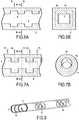
- the Fig. 3A and 3Billustrate a first variant embodiment in which the shape of the passage section of the channel varies between the first and second positions while the area of the passage section remains invariable.
- the channelhas a square cross section of side a so that the area of this straight section is equal to a 2 ( Fig. 3A ).
- the channelhas at the level of the second position, a square obstacle 9 1 side a / 2 and a complementary obstacle 9 2 hollow ( Fig. 3B ).
- the area of the cross section of the canaldoes not vary.
- Fig. 4A and 4Billustrate a second variant embodiment in which the shape of the passage section of the channel varies while the wetted perimeter P remains invariable, the hydraulic diameter Dh and the area A of the passage section of the channel being variable.
- the channel 3has at the second position, an obstacle constituted by four parts 9 1 of square cross-section side is located at each corner of the channel section. ( Fig. 4B ).
- Fig. 5A and 5Billustrate a third variant embodiment in which the shape of the passage section of the channel varies while the hydraulic diameter Dh does not vary, although the area A and the perimeter wet P of the channel section vary.
- the hydraulic diameterremains invariable while the shape of the section of the channel varies. It should be noted that between the first and second positions, the dimensions vary without rotation of the section and without eccentricity with respect to the central axis of the support, but it is clear that a rotation of the section and / or an eccentricity with respect to the central axis of the support.
- the Fig. 6A , 6Billustrate a fourth variant embodiment according to which the shape of the section of the channel is invariable while the area, the wetted perimeter and the hydraulic diameter of the section of the channel vary.
- the channelhas in a first position P1 , a rectangular shape and in a second position P2 , a reduced cross section of rectangular shape. It should be noted that between the first and second positions, the dimensions vary without rotation of the section and without eccentricity with respect to the central axis of the support, but it is clear that a rotation of the section and / or an eccentricity with respect to the central axis of the support.
- one of the criteria taken from the following listremains invariable while the other criteria vary, the criteria being taken from the shape, the area, the wetted perimeter and the hydraulic diameter.
- the shape of the passage section of the channel 3remains invariable as well as the wetted perimeter and the hydraulic diameter of the passage section of the channel.
- the channelhas in a first position P1 , a circular shape and in a second position P2 , a circular shape of the same size but offset by relative to the passage section taken at the first position.
- the obstacle 9is generated by the eccentricity of the circular passage section.
- the shape of the passage sectioncan be any. The obstacle 9 thus generates an abrupt narrowing.
- the area of the passage sectionvaries.
- the area of the passage section of the channel 3remains invariable except at the level of the intersection between two eccentric passage section parts.
- the passage section of the channelis a disk.
- the same function of generating an obstacle 9can be obtained by the rotation of a non-circular passage section.
- a passage section of the channel 3produced in the form of an isosceles triangle, the shape of which remains invariable as well as the area, the wetted perimeter and the hydraulic diameter of the passage section of the channel.
- the channelthus has, in a first position, a triangular shape and in a second position, a triangular shape but angularly offset by a given value, for example equal to 90 °.
- the Fig. 8illustrates another exemplary embodiment in which the orientation of the obstacle 9 inside the channel 3 occurs.
- the obstacle 9has a straight passage section perpendicular to the longitudinal axis T of the channel, this straight passage section rotating about the longitudinal axis T of the channel, between two positions P1 , P2, taken according to this longitudinal axis T.
- This straight section of passagerotates discontinuously between the ends of the channel, ie the length of the obstacle is less than the length of the channel.
- the obstacle 9is in the form of at least one parietal helix so that sections of the helix appear between the entry and exit of the channel.
- the cross section of the channel 3by its shape and its area in particular varies between the inlet and the outlet of the channel 3 .
- at least one such obstaclegenerates a sudden narrowing in the direction of circulation of the fluid to be treated.
- the manufacture of the porous support, or even of the separation element by tangential flow in its entiretyis carried out using an additive technique.
- the method according to the inventionconsists in producing the three-dimensional structure of the support by forming elementary layers superimposed and successively linked to one another so as to progressively grow the three-dimensional structure of the support.
- the methodhas the advantage, compared to the prior techniques, of producing the support in a single production step requiring no tooling or machining, and therefore allowing access to a greater range of geometries. support and allows the shapes and dimensions of the obstacles in the channels to be varied.
- the thickness of the powder bed and therefore of each successively consolidated stratumis relatively small to allow its connection to the lower stratum, by application of the contribution energy or liquid projection.
- a thickness of 20 ⁇ m to 200 ⁇ m of powderwill be deposited, this thickness being a function of the additive technique selected.
- the pattern of consolidationmay vary from one stratum to another.
- the growth of the desired three-dimensional shapeis carried out along a chosen growth axis.
- the particle size of the powder depositedis one of the factors which determines the minimum thickness of each bed of powder, as well as the average final pore diameter obtained.
- a powder of the material intended to constitute the supportwill be used, for example a metal oxide powder, or even a powder of one of its precursors.
- the powder depositedwill have, for example, an average grain size of the order of 35 ⁇ m for obtaining an average diameter of pores in the ceramic support of the order of 10 ⁇ m.
- the Applicanthas observed that the adjustment of various parameters such as the choice of material and, for a given material, the average size of the grains of the powder used, and, for a material and a given granularity, the thickness of the powder bed repeated layer after layer on the one hand and the adjustment of various parameters specific to the technology chosen for the consolidation allows the obtaining and control of a residual porous texture interconnected within the monolith consolidated.
- This residual porous textureis the result of controlled sintering of the powder grains leaving interconnected inter-granular voids.
- the main parameters, on which it is possible to actare its focusing, i.e. the diameter of the beam at the level of the impact with the powder bed, the scanning speed of the powder bed by the beam of photons or electrons or the rate of coverage of the impact surfaces of the energy beam during the formation of a stratum.
- the main parameters on which it is possible to actare the weight of the drops, their frequency, the speed of sweeping of the powder bed by the "jet" of drops. or the recovery rate for each pass.
- the Applicanthas also observed that it was possible, by modulating the various parameters described above, to adjust the size distribution of the pores and, for each given population of pores, to control their number and their tortuosity.
- the non-agglomerated materialis removed by any suitable technique.
- the initial fluidity of the powder usedfacilitates this operation. It is also possible to use water jet techniques or vibrations to get rid of the last traces of powder remaining on the surface of the formed shape.
- the final consolidation of the filter element and the final state of the porous textureare most often obtained by one or more thermal post-treatments which have the objective of removing binders (debinding) and / or sintering the actual material.
- the temperature chosen for such a final sinteringwill depend on the nature of the inorganic material used and on the average grain size of the powder used.
- the support, or even the tangential flow separation element in its entirety,is thus produced layer after layer.
- the three-dimensional structure of the support or of the tangential flow separation element to be producedis cut into slices.
- the three-dimensional virtual object to be producedis thus cut into two-dimensional slices of very thin thickness. These thin slices will then be made one by one, in the form of elementary layers superimposed and linked together, so as to progressively grow the desired three-dimensional shape.
- the material usedis either solid or liquid and the consolidation of the elementary strata is achieved by supplying energy or by spraying a liquid in fine droplets.
- the localized energy inputcan be done with a directed beam of light (LED or LASER) or a directed electron beam, or with any energy source allowing its focusing and scanning of the powder bed according to the pattern. selected by CAD.
- the energy-matter interactionthen leads either to sintering, or to melting / solidification of the material, or even to photo-polymerization or photo-crosslinking of the material, depending on its nature and that of the energy source. used.
- the localized supply of liquid on a bed of powdercan be done with microdroplets created using a piezoelectric system, possibly charged and directed in an electrostatic field.
- the liquidwill be a binder or an activating agent for the binder previously added to the ceramic powder.
- SLSSelective Laser Sintering
- SLMSelective Laser Melting
- a powder of the material intended to constitute the support or the separation element by tangential flowan organic powder or, preferably, a powder of an inorganic metallic or ceramic material of the oxide, nitride or carbide type, or even a powder of one of its precursors is deposited to form a continuous bed.
- the beam of a powerful laseris then applied locally according to the selected pattern and allows the powder to be agglomerated to form the layer corresponding to the support or to the separating element, by tangential flow and to link it to the preceding layer by sintering. Under the effect of the localized energy input, the grains of the powder partially merge and weld together, which gives the stratum its cohesion, thus carrying out a pre-sintering of the shape being produced. A new bed of powder is then spread and the process begins again.
- the laser beamscans the surface of the powder so as to consolidate the material in the desired pattern, layer by layer. This scanning can be achieved by moving the laser along parallel paths. It may be advantageous for there to be an overlap of the impact surface of the laser between two successive parallel paths.
- the quantity of energy received by the bed of powder at the point of impact of the laser beammust be such that the fusion of the powder grains remains partial or in any case that each grain merges sufficiently to bind with its most close neighbors without closing the porous texture.
- the settings of the machinewill therefore depend, in particular, on the intrinsic characteristics of the powder bed and on the nature of the material determining the efficiency of the photon / matter interaction.
- the sinteringis carried out as the support or the separation element is designed by tangential flow, by application of the laser, a final sintering step can advantageously be carried out, once the support has grown. the tangential flow separation element completed, in order to release the residual mechanical stresses and to homogenize the porous texture.
- the temperature chosen for such a final sinteringwill depend on the nature of the inorganic material used and on the average grain size of the powder used; for example, a temperature of 1300 ° C to 1500 ° C will be used in the case of titanium oxide.
- the layers depositedmay correspond to a mixture of organic or inorganic, ceramic or metallic powder, of the material constituting the support, or even of one of its precursors, with a binder itself. in the form of a powder or coating the inorganic powder itself.
- this mixturewill be homogeneous and the powder particles of the material constituting the support, or even one of its precursors, and those of the binder will have similar sizes.
- bindersmention may be made of furan and phenolic resins and other aminoplasts. The percentage by mass of binder will be between 1 and 25% depending on its nature and the average diameter of the powder used.
- an activating agent for the binderis sprayed in the form of very fine droplets according to the selected pattern and locally causes the powder to agglomerate.
- the activating agentcan be a solvent for the binder, which, after almost instantaneous drying, allows the inorganic particles to be bonded together or imprison them inside a solid network.
- the projection of binder or activating agent which is in liquid formis carried out using any suitable device, in particular a piezoelectric system used in printers of the inkjet type with a scan which can be carried out by moving the head of the device. printing along parallel paths. It may be advantageous for there to be an overlap of the impact surface of the drops between two successive parallel paths.
- the binderAfter removal of the non-agglomerated powder, the binder is removed during the sintering heat treatment, this debinding usually being completed before 500 ° C.
- 3D printingallows, with average grain sizes of ceramic powder between 30 and 100 ⁇ m to achieve powder bed thicknesses between 80 and 300 ⁇ m and to achieve linear construction speeds of the desired shape between 25 and 100 mm / hour.
- LCMis a technique in which ceramic powder is pre-mixed with a photopolymerizable resin, consolidation by polymerization being obtained with an LED or LASER light source.
- a photopolymerizable resina photopolymerizable resin
- consolidation by polymerizationbeing obtained with an LED or LASER light source.
- LCMLCM
- FDMis a technique using a thermo-fusible solid organic polymer to which is optionally added an inorganic powder. This technique aims to create successive deposits of cords of material from a wire or a ribbon.
- the bead of materialis produced by continuous (extrusion) or discontinuous (drop) softening or melting of the end of the wire or tape. Unlike the previous techniques, there is no formation of a bed of prior material. The consolidation of the strata or cords of material is carried out by heating.
- provisionmay be made to project an inorganic powder to ensure the successive creation of beads of material, this powder projected in a beam of a laser merging before the impact.
- Stereolithography(Stereolithography Apparatus SLA )
- This techniqueuses a liquid material such as a photocurable liquid precursor in which an inorganic powder is incorporated.
- the beam of photons(LED or laser) scans the layer of liquid and polymerizes it locally.
- the separating filtration layer (s)will be deposited once the support has been formed, after the final sintering operation.
- the deposition of a separating layer, in particular on the surface of the channels and of the obstacles in these channels of the supportwill consist in depositing on the latter a suspension containing at least one sinterable composition intended, after firing, to constitute a filter layer.
- a suspension containing at least one sinterable composition intended, after firingto constitute a filter layer.
- Such a compositionhas a constitution conventionally used in the production of inorganic filtration membranes.
- This compositioncontains at least one oxide, nitride, carbide, or other ceramic material or a mixture thereof, metal oxides, nitrides and carbides being preferred.
- the sinterable compositionis suspended, for example, in water.
- the suspension obtainedis crushed, in order to destroy the aggregates and obtain a composition composed mainly of elementary particles.
- the rheology of the suspensionis then adjusted with organic additives to meet the hydrodynamic requirements of penetration into the channels of the supports.
- the separator filtration layer (s)can be generated simultaneously with the growth of the support or else deposited subsequently according to the conventional deposition methods used in membrane production.
- the separating filtration layer (s)can be deposited from suspensions of particles of the inorganic material to be deposited, or from one of its precursors. Such suspensions are conventionally used in the production of ceramic filter elements. This or these layers are subjected, after drying, to a sintering operation which makes it possible to consolidate them and to bind them to the surface on which they are deposited.
- the particle size distribution of the particles present in the suspensionwill depend on the porous texture ultimately desired for the separating filtration layer.
- Tubular elements for separation by tangential floware manufactured in accordance with the invention.
- the supportis in the form of a tube 300 mm to 1200 mm long, the cross section of which is circular, and has a diameter of 10 mm to 42 mm and in which one or more rectilinear channels parallel to the axis of the tube are arranged.
- Example 1SLS / support only
- a microfiltration separating layer having a cut-off threshold of 1.4 ⁇ mis obtained after direct deposition on the support in the following manner.
- the suspensionis pumped into the channels to bring it into contact with the surface of the channels.
- the driving mechanism of the depositis the attraction of the liquid from the suspension by the porosity of the porous support.
- the thickness of the deposit of titanium oxide particles on the surface and therefore the mass deposited per unit areadepends on the residence time of the suspension in the channels of the support. Residence time of the suspension in the channels 30 seconds Deposited mass 50 to 60 g / m 2
- separation elementsby tangential flow of microfiltration with cut-off thresholds less than 1.4 ⁇ m and separation elements, by tangential flow of ultrafiltration and nanofiltration will be obtained by successive deposits on such a first layer from finer suspensions with adapted thermal cycles.
Landscapes
- Chemical & Material Sciences (AREA)
- Chemical Kinetics & Catalysis (AREA)
- Engineering & Computer Science (AREA)
- Ceramic Engineering (AREA)
- Geometry (AREA)
- Physics & Mathematics (AREA)
- Organic Chemistry (AREA)
- Materials Engineering (AREA)
- Structural Engineering (AREA)
- Manufacturing & Machinery (AREA)
- Separation Using Semi-Permeable Membranes (AREA)
- Cyclones (AREA)
- Filtering Materials (AREA)
Description
Translated fromFrenchLa présente invention concerne le domaine technique des éléments de séparation par flux tangentiel d'un milieu fluide à traiter en un filtrat et un rétentat, communément appelés membranes de filtration. Plus précisément, l'invention concerne de nouvelles géométries de support poreux multicanaux permettant de réduire, voire supprimer, les problèmes de colmatage, ainsi qu'un procédé de fabrication par méthode additive de tels supports et éléments de séparation par flux tangentiel les comprenant.The present invention relates to the technical field of elements for the separation by tangential flow of a fluid medium to be treated into a filtrate and a retentate, commonly called filtration membranes. More precisely, the invention relates to novel geometries of multichannel porous support making it possible to reduce, or even eliminate, clogging problems, as well as a method of manufacturing by additive method such supports and separation elements by tangential flow comprising them.
Les procédés de séparation utilisant des membranes sont utilisés dans de nombreux secteurs, notamment dans l'environnement pour la production d'eau potable et le traitement des effluents industriels, dans l'industrie chimique, pétrochimique, pharmaceutique, agro-alimentaire et dans le domaine de la biotechnologie.Separation processes using membranes are used in many sectors, especially in the environment for the production of drinking water and the treatment of industrial effluents, in the chemical, petrochemical, pharmaceutical, agrifood industry and in the field. of biotechnology.
Une membrane constitue une barrière sélective et permet, sous l'action d'une force de transfert, le passage ou l'arrêt de certains composants du milieu à traiter. Le passage ou l'arrêt des composants résulte de leur taille par rapport à la taille des pores de la membrane qui se comporte alors comme un filtre. En fonction de la taille des pores, ces techniques sont nommées microfiltration, ultrafiltration ou nanofiltration.A membrane constitutes a selective barrier and allows, under the action of a transfer force, the passage or the stopping of certain components of the medium to be treated. The passage or the stopping of the components results from their size compared to the size of the pores of the membrane which then behaves like a filter. Depending on the size of the pores, these techniques are called microfiltration, ultrafiltration or nanofiltration.
Il existe des membranes de structures et textures différentes. Les membranes sont, en général, constituées d'un support poreux qui assure la résistance mécanique de la membrane et donne également la forme et donc détermine la surface filtrante de la membrane. Sur ce support, une ou plusieurs couches de quelques microns d'épaisseur assurant la séparation et dites couches séparatrices, couches de filtration, couches de séparation, ou couches actives, sont déposées. Durant la séparation, le transfert du fluide filtré s'effectue à travers la couche séparatrice, puis ce fluide se répand dans la texture poreuse du support pour se diriger vers la surface extérieure du support poreux. Cette partie du fluide à traiter ayant traversé la couche de séparation et le support poreux est appelée perméat ou filtrat et se trouve récupérée par une chambre de collecte entourant la membrane. L'autre partie est appelée rétentat et est, le plus souvent, réinjectée dans le fluide à traiter en amont de la membrane, grâce à une boucle de circulation.There are membranes of different structures and textures. The membranes are, in general, made of a porous support which ensures the mechanical resistance of the membrane and also gives the shape and therefore determines the filtering surface of the membrane. On this support, one or more layers of a few microns thick ensuring the separation and called separating layers, filtration layers, separation layers, or active layers, are deposited. During separation, the transfer of the filtered fluid takes place through the separating layer, then this fluid spreads in the porous texture of the support to move towards the outer surface of the porous support. This part of the fluid to be treated which has passed through the separation layer and the porous support is called permeate or filtrate and is recovered by a collection chamber surrounding the membrane. The other part is called retentate and is most often reinjected into the fluid to be treated upstream of the membrane, thanks to a circulation loop.
De manière classique, le support est d'abord fabriqué selon la forme souhaitée par extrusion, puis fritté à une température et pendant un temps suffisant pour assurer la solidité requise, tout en conservant dans la céramique obtenue la texture poreuse ouverte et interconnectée voulue. Ce procédé contraint à l'obtention d'un ou plusieurs canaux rectilignes à l'intérieur desquels sont ensuite déposées et frittées la ou les couches séparatrices. Les supports sont traditionnellement de forme tubulaire et comportent un ou plusieurs canaux rectilignes aménagés parallèlement à l'axe central du support. En général, la surface interne des canaux est lisse et ne présente aucune irrégularité.Conventionally, the support is first fabricated into the desired shape by extrusion, then sintered at a temperature and for a time sufficient to provide the required strength, while maintaining in the ceramic obtained the desired open and interconnected porous texture. This process makes it necessary to obtain one or more rectilinear channels inside which the separating layer or layers are then deposited and sintered. The supports are traditionally tubular in shape and include one or more rectilinear channels arranged parallel to the central axis of the support. In general, the internal surface of the channels is smooth and has no irregularities.
Or, il a été constaté que les membranes de filtration fabriquées à partir de supports ayant de telles géométries se heurtent à des problèmes de colmatage et présentent, de ce fait, des performances limitées en termes de débit. En effet, les petites particules et les macromolécules peuvent être adsorbées sur la surface de la couche séparatrice ou s'y déposer en formant un gel ou un dépôt, elles peuvent même pénétrer dans la porosité et bloquer certains pores.However, it has been observed that the filtration membranes manufactured from supports having such geometries come up against clogging problems and therefore have limited performance in terms of flow rate. Indeed, the small particles and the macromolecules can be adsorbed on the surface of the separating layer or be deposited there by forming a gel or a deposit, they can even penetrate into the porosity and block certain pores.
Le principe de toute séparation tangentielle mettant en œuvre des éléments de filtration réside dans un transfert sélectif dont l'efficacité est dépendante de la sélectivité de la membrane (la couche active) et de la perméabilité (flux) de l'élément de filtration considéré dans son entier (support + couche active). La sélectivité et la perméabilité ne sont pas seulement déterminées par les caractéristiques de la couche active et de l'élément de filtration car elles peuvent être réduites ou limitées par l'apparition d'une polarisation de concentration, d'un dépôt et d'un blocage des pores.The principle of any tangential separation using filtration elements lies in a selective transfer, the efficiency of which depends on the selectivity of the membrane (the active layer) and on the permeability (flow) of the filter element considered in its integer (support + active layer). Selectivity and permeability are not only determined by the characteristics of the active layer and the filter element as they can be reduced or limited by the occurrence of concentration polarization, deposition and deposition. blocking pores.
Le phénomène de polarisation de concentration opère lors d'une opération de filtration lorsque les macromolécules présentes dans le liquide à traiter se concentrent à l'interface membrane/solution où elles exercent une contre-pression osmotique opposée à la force de séparation ou rétrodiffusent dans le cœur du liquide à traiter selon la loi de Fick. Le phénomène de polarisation de concentration résulte de l'accumulation des composés retenus au voisinage de la membrane du fait de la perméation du solvant.The concentration polarization phenomenon operates during a filtration operation when the macromolecules present in the liquid to be treated concentrate at the membrane / solution interface where they exert an osmotic back pressure opposite to the separation force or backscatter in the heart of the liquid to be treated according to Fick's law. The concentration polarization phenomenon results from the accumulation of the compounds retained in the vicinity of the membrane due to the permeation of the solvent.
Le dépôt apparaît lors d'une opération de filtration lorsque la concentration en particules à la surface de la membrane augmente jusqu'à provoquer l'apparition d'une phase condensée sous forme d'un gel ou d'un dépôt cohésif induisant une résistance hydraulique additionnelle à celle de la membrane.The deposit appears during a filtration operation when the concentration of particles at the surface of the membrane increases until it causes the appearance of a condensed phase in the form of a gel or a cohesive deposit inducing hydraulic resistance. additional to that of the membrane.
Le blocage des pores opère lorsqu'il y a intrusion de particules de tailles inférieures ou égales à celles des pores, ce qui entraîne une réduction de la surface filtrante.The pore blocking operates when there is intrusion of particles of sizes smaller than or equal to those of the pores, which results in a reduction of the filtering surface.
Le colmatage, sa réversibilité ou son irréversibilité, sont des phénomènes complexes qui dépendent de l'élément de filtration et en particulier des couches séparatrices, du liquide à traiter et des paramètres opératoires.Clogging, its reversibility or its irreversibility, are complex phenomena which depend on the filtration element and in particular on the separating layers, on the liquid to be treated and on the operating parameters.
Le colmatage est un frein important à l'attractivité économique de la filtration car il conduit, lors du dimensionnement des installations de filtration, à accroître les surfaces installées afin de satisfaire les besoins en volumes à traiter d'une part et il rend nécessaire la mise en œuvre de moyens techniques spécifiques pour y remédiera postériori, tels des cycles de nettoyage utilisant des détergents ou des rétro-filtrations périodiques d'autre part.Clogging is a major brake on the economic attractiveness of filtration because, when sizing filtration installations, it leads to an increase in the areas installed in order to meet the volume requirements to be treated on the one hand and it makes it necessary to implementation of specific technical means to remedy ita posteriori, such as cleaning cycles using detergents or periodic retro-filtration on the other hand.
Dans l'art antérieur, il a déjà été proposé de réduire le phénomène de colmatage par la création d'un régime d'écoulement turbulent à l'intérieur du canal d'un élément filtrant.In the prior art, it has already been proposed to reduce the clogging phenomenon by creating a turbulent flow regime inside the channel of a filter element.
Tout d'abord, il a été proposé d'introduire dans les éléments tubulaires de filtration des dispositifs destinés à créer des turbulences. On peut notamment se référer à
D'autres systèmes assez complexes ont également été proposés par
D'autres solutions consistent à modifier la géométrie de l'élément tubulaire. Le brevet
Dans ces deux documents, après l'étape préalable d'extrusion du tube monocanal, une étape de mise en forme finale est donc mise en œuvre par déformation plastique pour l'obtention d'empreintes à l'intérieur du monocanal par la pression d'un poinçon rotatif ou autre sur la surface externe du tube. L'obtention de ces « empreintes » sera plus ou moins facile selon la ductilité du matériau, c'est-à-dire son aptitude à subir une déformation permanente sans se rompre. Or, les pâtes utilisées pour la fabrication de membranes céramiques ne présentent pas une bonne ductilité : elles sont facilement mises en forme par extrusion mais présentent en général un allongement à la rupture inférieur à 5%. De plus, avec de telles techniques, seules des empreintes de faibles dimensions peuvent être obtenues. Enfin, les déformations réalisées sur toute l'épaisseur du tube entraînent des contraintes importantes dans le matériau et des risques de fissuration, ce qui nuit donc fortement à la résistance mécanique. On peut également citer la demande
Dans le même ordre d'idées, le brevet
Dans ce contexte, la présente invention se propose de fournir de nouveaux éléments de filtration et une technique de fabrication adaptée à leur élaboration, qui présentent une structure monocanale ou multicanale et une géométrie adaptée pour réduire, voire supprimer, les phénomènes de colmatage. L'invention a pour but de fournir de nouveaux éléments de filtration dont la géométrie peut être modulée à façon, pour créer de fortes contraintes de cisaillement pariétales et d'intenses turbulences à l'intérieur des canaux, sans présenter les inconvénients des solutions antérieures.In this context, the present invention proposes to provide new filtration elements and a manufacturing technique suitable for their production, which have a single-channel or multi-channel structure and a geometry suitable for reducing, or even eliminating, clogging phenomena. The object of the invention is to provide new filtration elements, the geometry of which can be customized to create strong wall shear stresses and intense turbulence inside the channels, without exhibiting the drawbacks of previous solutions.
Pour atteindre un tel objectif, l'invention concerne un élément monolithe de séparation par flux tangentiel d'un milieu fluide à traiter en un filtrat et un rétentat défini dans les revendications 1 à 10, ledit élément de séparation comportant un support poreux rigide rectiligne de structure tridimensionnelle à l'intérieur duquel est aménagé au moins un canal pour la circulation du milieu fluide à traiter en vue de récupérer un filtrat à la surface extérieure du support, la surface extérieure du support présentant un profil constant.To achieve such an objective, the invention relates to a monolith element for separation by tangential flow of a fluid medium to be treated into a filtrate and a retentate defined in
Selon l'invention, le support poreux rigide monolithique comporte à partir de la paroi interne du ou des canaux, des obstacles à la circulation du fluide à filtrer, ayant une identité et une continuité de matériau et de texture poreuse avec le support, ces obstacles gênant ou perturbant le passage du fluide, obligeant leur contournement, en apparaissant entre une première et deuxième positions prises selon l'axe longitudinal du canal.According to the invention, the monolithic rigid porous support comprises, starting from the internal wall of the channel or channels, obstacles to the circulation of the fluid to be filtered, having an identity and continuity of material and porous texture with the support, these obstacles hindering or disturbing the passage of the fluid, forcing their bypassing, appearing between a first and second positions taken along the longitudinal axis of the channel.
De plus, l'élément selon l'invention peut présenter en outre en combinaison au moins l'une et/ou l'autre des caractéristiques additionnelles suivantes :
- au moins un obstacle d'un canal génère un rétrécissement brusque ou un convergent dans le sens de circulation du fluide à traiter dans ledit cana! ;
- au moins un obstacle d'un canal engendre une section droite de passage localement la plus étroite à l'endroit dudit obstacle, cette section droite de passage étant perpendiculaire à l'axe longitudinal dudit canal et présentant une forme différente par rapport à des portions du canal situées en aval et en amont dudit obstacle ;
- entre une portion du canal située en amont de la section droite de passage la plus étroite et la section droite de passage la plus étroite, l'un des critères pris parmi la liste suivante reste invariable tandis que les autres critères varient, les critères étant pris parmi la forme, l'aire, le périmètre mouillé et le diamètre hydraulique ;
- entre une portion du canal située en amont de la section droite de passage la plus étroite et la section de passage la plus étroite, tous les critères pris parmi la liste suivante restent invariables à savoir la forme, l'aire, le périmètre mouillé et le diamètre hydraulique ;
- au moins un obstacle d'un canal présente une section de passage droite perpendiculaire à l'axe longitudinal dudit canal, cette section de passage droite tournant autour de l'axe longitudinal dudit canal, entre deux positions prises selon cet axe longitudinal du canal ;
- au moins un obstacle d'un canal présente une section de passage droite tournant autour de l'axe longitudinal dudit canal, de façon discontinue entre les extrémités dudit canal ;
- l'élément comporte au moins une couche séparatrice continûment déposée sur les parois internes des canaux et venant recouvrir entièrement les obstacles ;
- le support poreux est réalisé en un matériau organique ou inorganique ;
- les couches séparatrices voire des couches intermédiaires sont réalisées en un matériau organique ou inorganique ;
- la structure tridimensionnelle du support poreux présente différentes strates pouvant être mises en évidence par microscopie optique ou microscopie électronique à balayage.
- at least one obstacle of a channel generates an abrupt narrowing or a convergent in the direction of circulation of the fluid to be treated in said cana! ;
- at least one obstacle of a channel generates a locally narrowest straight section of passage at the location of said obstacle, this straight section of passage being perpendicular to the longitudinal axis of said channel and having a different shape with respect to portions of the channel located downstream and upstream of said obstacle;
- between a portion of the channel located upstream of the narrowest straight section of passage and the narrowest straight section of passage, one of the criteria taken from the following list remains invariable while the other criteria vary, the criteria being taken among shape, area, wetted perimeter and hydraulic diameter;
- between a portion of the channel located upstream of the narrowest straight section of passage and the narrowest section of passage, all the criteria taken from the following list remain invariable, namely the shape, the area, the wetted perimeter and the hydraulic diameter;
- at least one obstacle of a channel has a straight passage section perpendicular to the longitudinal axis of said channel, this section of straight passage rotating around the longitudinal axis of said channel, between two positions taken along this longitudinal axis of the channel;
- at least one obstacle of a channel has a straight passage section rotating around the longitudinal axis of said channel, discontinuously between the ends of said channel;
- the element comprises at least one separating layer continuously deposited on the internal walls of the channels and completely covering the obstacles;
- the porous support is made of an organic or inorganic material;
- the separating layers or even intermediate layers are made of an organic or inorganic material;
- the three-dimensional structure of the porous support has different layers which can be demonstrated by optical microscopy or scanning electron microscopy.
Un autre objet de l'invention est de proposer un procédé permettant de réaliser les éléments monolithes de séparation conformes à l'invention.Another object of the invention is to provide a method making it possible to produce the monolithic separation elements in accordance with the invention.
Le procédé de fabrication d'un élément de séparation par flux tangentiel selon l'invention est défini dans les revendications 11 à 17 et consiste à réaliser la structure tridimensionnelle du support par formation de strates élémentaires superposées et liées successivement entre elles, de manière à faire croître progressivement la forme tridimensionnelle souhaitée.The method of manufacturing a separation element by tangential flow according to the invention is defined in claims 11 to 17 and consists in producing the three-dimensional structure of the support by forming elementary layers superimposed and successively linked together, so as to make gradually grow to the desired three-dimensional shape.
De plus, le procédé selon l'invention peut consister en outre en combinaison au moins l'une et/ou l'autre des caractéristiques additionnelles suivantes :
- à réaliser la structure dimensionnelle, par répétition des étapes suivantes :
- réalisation d'un lit continu d'une matière destinée à former le support poreux, le lit étant d'épaisseur constante selon une surface supérieure à la section dudit support poreux prise au niveau de la strate ;
- consolidation localisée selon un motif déterminé pour chaque strate, d'une partie de matière réalisée pour créer la strate élémentaire, et liaison simultanée de la strate élémentaire ainsi formée à la strate précédente ;
- à réaliser des lits continus de matière solide se présentant sous la forme d'une poudre ou de matière liquide tels que des résines photopolymérisables ;
- à réaliser un lit continu d'une matière solide se présentant sous la forme d'une poudre organique ou inorganique ;
- à réaliser un lit continu d'un milieu se présentant sous la forme d'un précurseur liquide photopolymérisable dans lequel a été disposée une poudre inorganique ;
- en ce que chaque strate est réalisée par fusion continue ou discontinue d'un fil d'un précurseur solide thermofusible qui est soit un polymère organique thermofusible utilisé seul pour réaliser un support organique et une couche organique, ou soit un mélange pour réaliser un polymère organique thermofusible et d'une poudre inorganique céramique, avec un support de nature inorganique ;
- à créer successivement des cordons de matière par projection d'une poudre fondue dans le faisceau d'un laser.
- to achieve the dimensional structure, by repeating the following steps:
- making a continuous bed of a material intended to form the porous support, the bed being of constant thickness along a surface greater than the section of said porous support taken at the level of the stratum;
- localized consolidation according to a pattern determined for each stratum, of a part of material produced to create the elementary stratum, and simultaneous connection of the elementary stratum thus formed to the preceding stratum;
- in making continuous beds of solid material in the form of a powder or of a liquid material such as photopolymerizable resins;
- providing a continuous bed of a solid material in the form of an organic or inorganic powder;
- in producing a continuous bed of a medium in the form of a photopolymerizable liquid precursor in which an inorganic powder has been placed;
- in that each stratum is produced by continuous or discontinuous melting of a wire of a hot-melt solid precursor which is either a hot-melt organic polymer used alone to make an organic support and an organic layer, or a mixture to make an organic polymer hot-melt and an inorganic ceramic powder, with a support of inorganic nature;
- in successively creating beads of material by projecting a molten powder into the beam of a laser.
Les éléments de séparation par flux tangentiel obtenus par le procédé défini dans le cadre de l'invention conduit à une croissance de la structure tridimensionnelle du support. Il est à noter que cette structure peut être mise en évidence par la visualisation des différentes strates par microscopie optique ou microscopie électronique à balayage. Bien entendu, il sera recherché que la démarcation entre les différentes strates soit la plus ténue possible.The tangential flow separation elements obtained by the process defined in the context of the invention leads to a growth of the three-dimensional structure of the support. It should be noted that this structure can be demonstrated by visualizing the different strata by optical microscopy or scanning electron microscopy. Of course, it will be sought for the demarcation between the different strata to be as fine as possible.
Diverses autres caractéristiques ressortent de la description faite ci-dessous en référence aux dessins annexés qui montrent, à titre d'exemples non limitatifs, des formes de réalisation de l'objet de l'invention.
- La
Figure 1A est une vue en coupe longitudinale d'un support illustrant un exemple de réalisation d'un obstacle. - Les
Figures 1B et1C sont des coupes transversales du support prises respectivement au niveau de l'obstacle et en amont de l'obstacle en considération du sens de circulation du fluide. - La
Figure 2 est une coupe longitudinale d'un support montrant un obstacle générant un rétrécissement brusque et un convergent. - Les
Figures 3A et3B sont les coupes transversales d'un support prises respectivement en amont et au niveau de l'obstacle, illustrant la variation de la section de passage d'un canal alors que son aire ne varie pas, - Les
Figures 4A et 4B sont les coupes transversales d'un support prises respectivement en amont et au niveau de l'obstacle, illustrant la variation de la section de passage d'un canal alors que le périmètre mouillé ne varie pas. - Les
Figures 5A et 5B sont les coupes transversales d'un support prises respectivement en amont et au niveau de l'obstacle, illustrant la variation de la section de passage d'un canal alors que le diamètre hydraulique ne varie pas. - Les
Figures 6A et6B sont des vues en coupe respectivement longitudinale et transversale d'un support illustrant le caractère invariable de la forme de la section de passage du canal alors que ses dimensions varient. - Les
Figures 7A et7B sont des vues en coupe respectivement longitudinale et transversale d'un support illustrant le caractère invariable de la section de passage du canal avec des dimensions invariables. - La
Figure 8 est une vue en coupe partielle longitudinale d'un support illustrant la rotation d'une section de passage localement invariable.
- The
Figure 1A is a longitudinal sectional view of a support illustrating an embodiment of an obstacle. - The
Figures 1B and1C are cross sections of the support taken respectively at the level of the obstacle and upstream of the obstacle in consideration of the direction of flow of the fluid. - The
Figure 2 is a longitudinal section of a support showing an obstacle generating a sudden narrowing and a convergent one. - The
Figures 3A and3B are the transverse sections of a support taken respectively upstream and at the level of the obstacle, illustrating the variation of the passage section of a channel while its area does not vary, - The
Figures 4A and 4B are the transverse sections of a support taken respectively upstream and at the level of the obstacle, illustrating the variation of the passage section of a channel while the wetted perimeter does not vary. - The
Figures 5A and 5B are the cross sections of a support taken respectively upstream and at the level of the obstacle, illustrating the variation in the passage section of a channel while the hydraulic diameter does not vary. - The
Figures 6A and6B are views in respectively longitudinal and transverse section of a support illustrating the invariable nature of the shape of the passage section of the channel while its dimensions vary. - The
Figures 7A and7B are views in respectively longitudinal and transverse section of a support illustrating the invariability of the passage section of the channel with invariable dimensions. - The
Figure 8 is a partial longitudinal sectional view of a support illustrating the rotation of a locally invariable passage section.
En préliminaire, quelques définitions des termes utilisés dans le cadre de l'invention vont être données.As a preliminary, some definitions of the terms used in the context of the invention will be given.
Par taille moyenne des grains, on entend la valeur d50 d'une distribution volumique pour laquelle 50% du volume total des grains correspondent au volume des grains de diamètre inférieur à ce d50. La distribution volumique est la courbe (fonction analytique) représentant les fréquences des volumes des grains en fonction de leur diamètre. Le d50 correspond à la médiane séparant en deux parties égales, l'aire située sous la courbe des fréquences obtenue par granulométrie, par diffraction laser qui est la technique de référence retenue dans le cadre de l'invention pour la mesure du diamètre moyen des grains. On se réfèrera, en particulier, pour la technique de mesure du d50 :
- à la norme ISO 13320:2009, pour ce qui concerne la technique de mesure par granulométrie laser ;
- à la norme ISO 14488:2007, pour ce qui concerne les techniques d'échantillonnage de la poudre analysée ;
- à la norme ISO 14887:2000, pour ce qui concerne une mise en dispersion reproductible de l'échantillon de poudre dans le liquide avant la mesure par granulométrie laser.
- to the ISO 13320: 2009 standard, with regard to the laser granulometry measurement technique;
- to the ISO 14488: 2007 standard, regarding the techniques for sampling the analyzed powder;
- to the ISO 14887: 2000 standard, with regard to reproducible dispersing of the powder sample in the liquid before measurement by laser particle size distribution.
Par diamètre moyen de pores, on entend la valeur d50 d'une distribution volumique pour laquelle 50% du volume total des pores correspondent au volume des pores de diamètre inférieur à ce d50. La distribution volumique est la courbe (fonction analytique) représentant les fréquences des volumes des pores en fonction de leur diamètre. Le d50 correspond à la médiane séparant en deux parties égales, l'aire située sous la courbe des fréquences obtenue par pénétration de mercure, pour des diamètres moyens de l'ordre de quelques nm ou, dans le cas de diamètre de pores plus faibles, par adsorption de gaz, et notamment de N2, ces deux techniques étant retenues comme références dans le cadre de l'invention pour la mesure du diamètre moyen des pores.The term “mean pore diameter” is understood to mean the value d50 of a volume distribution for which 50% of the total volume of the pores corresponds to the volume of pores with a diameter less than this d50. The volume distribution is the curve (analytical function) representing the frequencies of the volumes of the pores as a function of their diameter. The d50 corresponds to the median separating into two equal parts, the area under the frequency curve obtained by penetration of mercury, for average diameters of the order of a few nm or, in the case of smaller pore diameter, by adsorption of gas, and in particular of N2 , these two techniques being used as references in the context of the invention for the measurement of the mean diameter of the pores.
En particulier, on pourra utiliser les techniques décrites dans :
- la norme ISO 15901-1 :2005, pour ce qui concerne la technique de mesure par pénétration de mercure ;
- les normes ISO 15901-2 :2006 et ISO 15901-3 :2007, pour ce qui concerne la technique de mesure par adsorption de gaz.
- the ISO 15901-1: 2005 standard, regarding the mercury penetration measurement technique;
- ISO 15901-2: 2006 and ISO 15901-3: 2007 standards, with regard to gas adsorption measurement technique.
L'invention propose des éléments de séparation par flux tangentiel d'un milieu fluide à traiter en un filtrat et un rétentat, qui comporte un support poreux monolithique monocanal ou multicanaux dont la géométrie est sélectionnée pour délimiter, à partir des parois internes des canaux, des obstacles à la circulation du fluide à filtrer. De tels supports monolithiques dont les obstacles font partie intégrante de la structure poreuse monolithique sont réalisés, par les techniques additives comme cela sera expliqué dans la suite de la description.The invention provides elements for the separation by tangential flow of a fluid medium to be treated into a filtrate and a retentate, which comprises a single-channel or multi-channel monolithic porous support, the geometry of which is selected to define, from the internal walls of the channels, obstacles to the circulation of the fluid to be filtered. Such monolithic supports the obstacles of which are an integral part of the monolithic porous structure are produced by additive techniques as will be explained in the remainder of the description.
Dans le cadre de l'invention, on vise des éléments de séparation d'un milieu fluide par filtration tangentielle, communément appelés membranes de filtration. De tels éléments de séparation comportent un support poreux dans lequel un ou plusieurs canaux de circulation pour le fluide à filtrer sont aménagés. Classiquement, le support est de forme tubulaire. Ces canaux de circulation présentent une entrée et une sortie. En général, l'entrée des canaux de circulation est positionnée à l'une des extrémités, cette extrémité jouant le rôle de zone d'entrée pour le milieu fluide à traiter et leur sortie est positionnée à l'autre extrémité du support jouant le rôle de zone de sortie pour le rétentat.In the context of the invention, the object is to separate elements of a fluid medium by tangential filtration, commonly called filtration membranes. Such separation elements comprise a porous support in which one or more circulation channels for the fluid to be filtered are arranged. Conventionally, the support is tubular in shape. These circulation channels have an entrance and an exit. In general, the entry of the circulation channels is positioned at one end, this end playing the role of entry zone for the fluid medium to be treated and their exit is positioned at the other end of the support playing the role exit zone for the retentate.
Dans de tels éléments de séparation, le corps constituant le support présente une texture poreuse. Cette texture poreuse est caractérisée par le diamètre moyen des pores déduit de leur distribution mesurée par porométrie par pénétration de mercure.In such separation elements, the body constituting the support has a porous texture. This porous texture is characterized by the mean diameter of the pores deduced from their distribution measured by porometry by penetration of mercury.
La texture poreuse du support est ouverte et forme un réseau de pores interconnectés, ce qui permet au fluide filtré par la couche séparatrice de filtration de traverser le support poreux et d'être récupéré en périphérie. Il est d'usage de mesurer la perméabilité à l'eau du support pour qualifier la résistance hydraulique du support. En effet, dans un milieu poreux, l'écoulement stationnaire d'un fluide visqueux incompressible est régi par la loi de Darcy. La vitesse du fluide est proportionnelle au gradient de la pression et inversement proportionnelle à la viscosité dynamique du fluide, via un paramètre caractéristique appelé perméabilité qui peut être mesurée, par exemple, selon la norme française NF X 45-101 de Décembre 1996.The porous texture of the support is open and forms a network of interconnected pores, which allows the fluid filtered by the separating filtration layer to pass through the porous support and be collected at the periphery. It is customary to measure the water permeability of the support to qualify the hydraulic resistance of the support. Indeed, in a porous medium, the stationary flow of an incompressible viscous fluid is governed by Darcy's law. The speed of the fluid is proportional to the pressure gradient and inversely proportional to the dynamic viscosity of the fluid, via a characteristic parameter called permeability which can be measured, for example, according to the French standard NF X 45-101 of December 1996.
Le perméat est donc, quant à lui, récupéré sur la surface périphérique du support poreux. La paroi des canaux est continûment recouverte par, au moins, une couche séparatrice de filtration qui assure la filtration du milieu fluide à traiter. Les couches séparatrices de filtration, par définition, se doivent d'avoir un diamètre moyen de pores inférieur à celui du support. Les couches séparatrices délimitent la surface de l'élément de séparation par flux tangentiel destinée à être en contact avec le fluide à traiter et sur laquelle va circuler le fluide à traiter,The permeate is therefore recovered on the peripheral surface of the porous support. The wall of the channels is continuously covered by at least one separating filtration layer which filters the fluid medium to be treated. Separator filtration layers, by definition, must have an average pore diameter smaller than that of the support. The separating layers delimit the surface of the tangential flow separation element intended to be in contact with the fluid to be treated and over which the fluid to be treated will circulate,
La
Selon une caractéristique de l'invention, la surface extérieure ou périphérique5 du support présente un profil constant. Pour rappel, le profil correspond à la forme extérieure du support poreux2 pris selon un plan transversal contenant l'axe central longitudinalA. Dans l'exemple illustré, le profil du support2 est rectiligne et constant de l'entrée à la sortie. En d'autres termes, un profil constant signifie que toutes les lignes génératrices extérieures parallèles à l'axe central du support sont des droites toutes parallèles entre elles.According to one characteristic of the invention, the outer or
En d'autres termes, la surface extérieure5 ne présente aucune irrégularité de surface autre que celle engendrée par la porosité intrinsèque du matériau ou que celle engendrée par une rugosité de surface inhérente au procédé de mise en forme proprement dit. Ainsi, la surface extérieure5 ne possède pas de déformation ou d'empreintes.In other words, the
Le support poreux2 est aménagé pour comporter au moins un canal3 et, dans l'exemple illustré à la
Les épaisseurs des couches séparatrices de filtration varient typiquement entre 1 µm et 100 µm d'épaisseur. Bien entendu, pour assurer sa fonction de séparation, et servir de couche active, les couches séparatrices présentent un diamètre moyen de pores inférieur au diamètre moyen de pores du support. Le plus souvent, le diamètre moyen de pores des couches séparatrices de filtration est au moins inférieur d'un facteur3, et de préférence, d'au moins un facteur5 par rapport à celui du support.The thicknesses of the separating filtration layers typically vary between 1 μm and 100 μm in thickness. Of course, to ensure its function of separation, and to serve as an active layer, the separating layers have an average pore diameter smaller than the average pore diameter of the support. Most often, the average pore diameter of the separating filtration layers is at least a factor of3 , and preferably at least a factor of5, smaller than that of the support.
Les notions de couche séparatrice de microfiltration, ultrafiltration et nanofiltration sont bien connues de l'homme de l'art. Il est généralement admis que :
- les couches séparatrices de microfiitration présentent un diamètre moyen de pores compris
entre 0,1 et 2 µm ; - les couches séparatrices d'ultrafiltration présentent un diamètre moyen de pores compris
entre 0,1 et 0,01 µm ; - les couches séparatrices de nanofiltration présentent un diamètre moyen de pores compris
entre 0,5 et 2 nm.
- the separating microfitration layers have an average pore diameter of between 0.1 and 2 μm;
- the ultrafiltration separating layers have an average pore diameter of between 0.1 and 0.01 μm;
- the nanofiltration separating layers have an average pore diameter of between 0.5 and 2 nm.
Il est possible que cette couche de micro ou d'ultrafiltration, dite couche active, soit déposée directement sur le support poreux (cas d'une couche de séparation monocouche), ou encore sur une couche intermédiaire de diamètre moyen de pores moindre, elle-même déposée directement sur le support poreux (cas d'une couche de séparation monocouche).It is possible that this micro or ultrafiltration layer, called the active layer, is deposited directly on the porous support (in the case of a single-layer separation layer), or even on an intermediate layer with a smaller average pore diameter, it- even deposited directly on the porous support (case of a single layer separation layer).
La couche de séparation peut, par exemple, être à base de, ou constituée exclusivement, d'un ou plusieurs oxydes métalliques, carbures ou nitrures ou autres céramiques ; les céramiques regroupant tous les matériaux inorganiques non métalliques. En particulier, la couche de séparation sera à base de, ou constituée exclusivement de TiO2, Al2O3 et ZrO2, seul ou en mélange.The separation layer may, for example, be based on, or consist exclusively, of one or more metal oxides, carbides or nitrides or other ceramics; ceramics comprising all inorganic non-metallic materials. In particular, the separation layer will be based on, or consist exclusively of TiO2 , Al2 O3 and ZrO2 , alone or as a mixture.
La couche de séparation peut aussi, par exemple, être à base de, ou constituée exclusivement, d'un collodion d'un polymère déposé sur un support poreux de nature organique. La couche de séparation peut encore, par exemple, être à base de, ou constituée exclusivement, d'un métal déposé sur un support poreux de nature métallique.The separation layer may also, for example, be based on, or consist exclusively, of a collodion of a polymer deposited on a porous support of organic nature. The separation layer may also, for example, be based on, or consist exclusively, of a metal deposited on a porous support of a metallic nature.
Selon une caractéristique essentielle de l'invention, le support est façonné pour comporter au moins un et d'une manière générale une série d'obstacles9 partant des parois internes31 des canaux et qui sont aptes à générer des perturbations dans l'écoulement et des forces de cisaillement d'amplitude suffisante pour faire apparaître des recirculations, limitant ainsi, voire même évitant totalement, les phénomènes de colmatage. Les obstacles font partie intégrante du support poreux monolithique, c'est-à-dire qu'il résulte de la géométrie même donnée au support poreux et ne sont nullement des éléments rapportés. L'ensemble support et obstacles forme un même monolithique poreux, sans liaison, ni interface, ni joint d'aucune sorte.According to an essential characteristic of the invention, the support is shaped to include at least one and in general a series of
Il existe une identité de matériau et de texture poreuse entre les obstacles9 et le support poreux2 ainsi qu'une continuité de matériau et de texture poreuse entre les obstacles9 et le support poreux2. Ainsi, les obstacles9 sont solides mécaniquement et chimiquement d'égale résistance que le support. Les obstacles9 sont recouverts entièrement par la couche séparatrice, de sorte qu'ils ne réduisent pas, mais au contraire augmentent la surface filtrante de l'élément de séparation.There is an identity of material and porous texture between the
L'identité de matériaux entre les obstacles9 et le support2 s'entend d'une nature chimique en tous points identiques, c'est-à-dire identique dans le support poreux et les obstacles.The identity of materials between the
L'identité de texture poreuse s'entend de la porosité, de la tortuosité, taille et distribution des pores en tous points identiques de l'élément, à savoir dans les obstacles et le support poreux.The porous texture identity means the porosity, tortuosity, size and distribution of the pores at all identical points of the element, namely in the obstacles and the porous support.
La continuité de matériau s'entend de la nature chimique en tous points de l'élément identique c'est-à-dire qu'il n'existe aucune discontinuité chimique entre l'obstacle et le support poreux.The continuity of material means the chemical nature at all points of the identical element, that is to say that there is no chemical discontinuity between the obstacle and the porous support.
La continuité de texture poreuse s'entend de la porosité, tortuosité, taille et distribution des pores en tous points identiques de l'élément de sorte que n'apparaît aucune discontinuité de texture poreuse entre l'obstacle et le support poreux.The continuity of porous texture means the porosity, tortuosity, size and distribution of the pores at all identical points of the element so that no discontinuity of porous texture appears between the obstacle and the porous support.
Les obstacles ont pour rôle de se trouver sur le trajet du fluide qui circule à l'intérieur des canaux. Les obstacles9 gênent ou perturbent le passage du fluide à traiter, obligeant leur contournement, en apparaissant entre une première positionP1 et une deuxième positionP2 prise selon l'axe longitudinalT du canal. Ainsi, la première positionP1, telle que définie par la vue en coupe C-C du canal (
Les obstacles9 présentent d'une manière générale, une longueurL prise selon l'axe longitudinalA du canal et une hauteurh prise selon une direction perpendiculaire à l'axe longitudinalA et à partir de la paroi intérieure31 du canal. Dans l'exemple illustré à la
Les obstacles9 peuvent être présents à intervalles réguliers ou irréguliers. Les nouvelles géométries de support envisagées dans la présente invention présentent une répétition d'un ou de plusieurs obstacles démarrant de la paroi de chaque canal dont ils sont solidaires.The
En particulier, les parois internes des canaux intégrant les obstacles peuvent comporter des reliefs tels que des creux, des bosses, des cannelures, des stries et/ou toutes autres morphologies capables d'agir comme autant d'obstacles jouant le rôle de promoteurs de turbulences lors de l'écoulement du fluide à l'intérieur desdits canaux.In particular, the internal walls of the channels integrating the obstacles may include reliefs such as hollows, bumps, grooves, ridges and / or any other morphology capable of acting as so many obstacles playing the role of turbulence promoters. during the flow of fluid inside said channels.
D'une manière générale, il doit être considéré qu'un obstacle9 engendre une section droite de passage localement modifiée pour ce qui est de sa forme, de son aire, de son périmètre mouillé ou de son diamètre hydraulique ou localement décalée ou encore subissant une rotation à l'endroit du canal3 par rapport à des portions du canal situées en aval et en amont dudit obstacle, cette section droite de passage pour le fluide étant prise perpendiculairement à l'axe longitudinalT dudit canal.In general, it must be considered that an
Tel que cela ressort plus précisément de la
Bien entendu, les obstacles9 peuvent présenter des géométries très diversifiées pour gêner ou perturber le passage du fluide. Les exemples qui suivent décrivent diverses géométries des obstacles9 apparaissant entre une portion du canal situé en amont de la section droite de passage la plus réduite ou étroite et ladite section droite de passage la plus réduite ou étroite, correspondant respectivement à une première position et à une deuxième position.Obviously, the
Les
Au niveau de la première position, le canal présente une section droite carrée de côtéa de sorte que l'aire de cette section droite est égale àa2 (
Le canal possède au niveau de la deuxième position, un obstacle carré91 de côté a/2 et un obstacle complémentaire92 en creux (
Les
Le canal3 possède au niveau de la deuxième position, un obstacle constitué par quatre parties91 de section droite carrée de côtéa placés à chaque coin de la section du canal. (
Les
Le canal possède au niveau de la deuxième position (
Ainsi, le diamètre hydraulique reste invariable tandis que la forme de la section du canal varie. Il est à noter qu'entre les premières et deuxième positions, les dimensions varient sans rotation de la section et sans excentration par rapport à l'axe central du support mais il clair qu'il peut être prévu une rotation de la section et/ou une excentration par rapport à l'axe central du support.Thus, the hydraulic diameter remains invariable while the shape of the section of the channel varies. It should be noted that between the first and second positions, the dimensions vary without rotation of the section and without eccentricity with respect to the central axis of the support, but it is clear that a rotation of the section and / or an eccentricity with respect to the central axis of the support.
Les
Dans les exemples qui précèdent, l'un des critères pris parmi la liste suivante reste invariable tandis que les autres critères varient, les critères étant pris parmi la forme, l'aire, le périmètre mouillé et le diamètre hydraulique.In the preceding examples, one of the criteria taken from the following list remains invariable while the other criteria vary, the criteria being taken from the shape, the area, the wetted perimeter and the hydraulic diameter.
Dans l'exemple illustré aux
Il est à noter que la même fonction de génération d'un obstacle9 peut être obtenue par la rotation d'une section de passage non circulaire. Tel est le cas, par exemple pour une section de passage du canal3 réalisée sous la forme d'un triangle isocèle dont la forme reste invariable ainsi que l'aire, le périmètre mouillé et le diamètre hydraulique de la section de passage du canal. Le canal présente ainsi, en une première position, une forme triangulaire et en une deuxième position, une forme triangulaire mais décalée angulairement d'une valeur donnée, par exemple égale à 90°.It should be noted that the same function of generating an
La
Dans le cadre de l'invention, la fabrication du support poreux, voire de l'élément de séparation par flux tangentiel dans son entier, est réalisée grâce à une technique additive. Le procédé selon l'invention consiste à réaliser la structure tridimensionnelle du support par formation de strates élémentaires superposées et liées successivement entre elles de manière à faire croître progressivement la structure tridimensionnelle du support.In the context of the invention, the manufacture of the porous support, or even of the separation element by tangential flow in its entirety, is carried out using an additive technique. The method according to the invention consists in producing the three-dimensional structure of the support by forming elementary layers superimposed and successively linked to one another so as to progressively grow the three-dimensional structure of the support.
Le procédé a l'avantage, par rapport aux techniques antérieures, de réaliser le support en une seule étape de production ne nécessitant pas d'outillage, ni d'usinage, et donc de permettre l'accès à une plus grande gamme de géométries de support et permet de faire varier les formes et dimensions des obstacles dans les canaux.The method has the advantage, compared to the prior techniques, of producing the support in a single production step requiring no tooling or machining, and therefore allowing access to a greater range of geometries. support and allows the shapes and dimensions of the obstacles in the channels to be varied.
Dans le cas de l'utilisation d'une matière solide telle qu'une poudre, l'épaisseur du lit de poudre et donc de chaque strate successivement consolidée est relativement faible pour permettre sa liaison à la strate inférieure, par application de l'apport d'énergie ou projection du liquide. En particulier, une épaisseur de 20 µm à 200 µm de poudre sera déposée, cette épaisseur étant fonction de la technique additive sélectionnée.In the case of the use of a solid material such as a powder, the thickness of the powder bed and therefore of each successively consolidated stratum is relatively small to allow its connection to the lower stratum, by application of the contribution energy or liquid projection. In particular, a thickness of 20 μm to 200 μm of powder will be deposited, this thickness being a function of the additive technique selected.
C'est la répétition de la séquence binaire qui permet, strate après strate, de construire la forme tridimensionnelle souhaitée, Le motif de consolidation peut varier d'une strate à l'autre. La croissance de la forme tridimensionnelle souhaitée est réalisée selon un axe de croissance choisi.It is the repetition of the binary sequence which makes it possible, stratum after stratum, to construct the desired three-dimensional shape. The pattern of consolidation may vary from one stratum to another. The growth of the desired three-dimensional shape is carried out along a chosen growth axis.
La granulométrie de la poudre déposée est un des facteurs qui détermine l'épaisseur minimum de chaque lit de poudre, ainsi que le diamètre moyen des pores final obtenu. En particulier, on utilisera une poudre de la matière destinée à constituer le support, par exemple une poudre d'oxyde métallique, voire une poudre de l'un de ses précurseurs. La poudre déposée présentera, par exemple, une taille moyenne de grains de l'ordre de 35 µm pour l'obtention d'un diamètre moyen de pores dans le support en céramique de l'ordre de 10 µm.The particle size of the powder deposited is one of the factors which determines the minimum thickness of each bed of powder, as well as the average final pore diameter obtained. In particular, a powder of the material intended to constitute the support will be used, for example a metal oxide powder, or even a powder of one of its precursors. The powder deposited will have, for example, an average grain size of the order of 35 μm for obtaining an average diameter of pores in the ceramic support of the order of 10 μm.
La demanderesse a constaté que le réglage de différents paramètres tels que le choix du matériau et, pour un matériau donné, la taille moyenne des grains de la poudre mise en œuvre, et, pour un matériau et une granularité donnés, l'épaisseur du lit de poudre répété couche après couche d'une part et le réglage de différents paramètres propres à la technologie choisie pour la consolidation permet l'obtention et la maîtrise d'une texture poreuse résiduelle interconnectée au sein du monolithe consolidé. Cette texture poreuse résiduelle est le résultat d'un frittage contrôlé des grains de poudre laissant des vides inter-granulaires interconnectés.The Applicant has observed that the adjustment of various parameters such as the choice of material and, for a given material, the average size of the grains of the powder used, and, for a material and a given granularity, the thickness of the powder bed repeated layer after layer on the one hand and the adjustment of various parameters specific to the technology chosen for the consolidation allows the obtaining and control of a residual porous texture interconnected within the monolith consolidated. This residual porous texture is the result of controlled sintering of the powder grains leaving interconnected inter-granular voids.
Dans le cas de l'utilisation d'un faisceau d'énergie, les principaux paramètres, sur lesquels il est possible d'agir, sont sa focalisation c'est-à-dire le diamètre du faisceau au niveau de l'impact avec le lit de poudre, la vitesse de balayage du lit de poudre par le faisceau de photons ou d'électrons ou encore le taux de recouvrement des surfaces d'impact du faisceau d'énergie lors de la constitution d'une strate.In the case of the use of an energy beam, the main parameters, on which it is possible to act, are its focusing, i.e. the diameter of the beam at the level of the impact with the powder bed, the scanning speed of the powder bed by the beam of photons or electrons or the rate of coverage of the impact surfaces of the energy beam during the formation of a stratum.
Dans le cas de l'utilisation d'une projection de liquide, les principaux paramètres sur lesquels il est possible d'agir, sont le poids des gouttes, leur fréquence, la vitesse de balayage du lit de poudre par le « jet » de gouttes ou encore le taux de recouvrement lors de chaque passage.In the case of the use of a liquid projection, the main parameters on which it is possible to act, are the weight of the drops, their frequency, the speed of sweeping of the powder bed by the "jet" of drops. or the recovery rate for each pass.
La demanderesse a également constaté qu'il était possible, en modulant les différents paramètres précédemment décrits, d'ajuster la distribution en taille des pores et, pour chaque population de pores donnée, de maîtriser leur nombre et leur tortuosité.The Applicant has also observed that it was possible, by modulating the various parameters described above, to adjust the size distribution of the pores and, for each given population of pores, to control their number and their tortuosity.
Une fois la poudre agglomérée dans les zones sélectionnées, la matière non agglomérée est éliminée par toute technique appropriée. La fluidité initiale de la poudre utilisée facilite cette opération. Il est possible également d'utiliser des techniques de jet d'eau ou des vibrations pour se débarrasser des dernières traces de poudre restant en surface de la forme réalisée.Once the powder has agglomerated in the selected areas, the non-agglomerated material is removed by any suitable technique. The initial fluidity of the powder used facilitates this operation. It is also possible to use water jet techniques or vibrations to get rid of the last traces of powder remaining on the surface of the formed shape.
La consolidation finale de l'élément filtrant et l'état final de la texture poreuse sont, le plus souvent, obtenus par un ou plusieurs post-traitements thermiques qui ont pour objectif l'élimination des liants (déliantage) et/ou le frittage du matériau proprement dit. La température choisie pour un tel frittage final sera fonction de la nature du matériau inorganique utilisé et de la taille moyenne des grains de la poudre utilisée.The final consolidation of the filter element and the final state of the porous texture are most often obtained by one or more thermal post-treatments which have the objective of removing binders (debinding) and / or sintering the actual material. The temperature chosen for such a final sintering will depend on the nature of the inorganic material used and on the average grain size of the powder used.
Le support, voire l'élément de séparation par flux tangentiel dans son entier, est ainsi réalisé strate après strate. Pour cela, en amont, grâce à un logiciel de conception par ordinateur, la structure tridimensionnelle du support ou de l'élément de séparation par flux tangentiel à réaliser, est découpée en tranches. L'objet virtuel en trois dimensions à réaliser est ainsi découpé en tranches bidimensionnelles de très fine épaisseur. Ces fines tranches vont alors être réalisées une à une, sous forme de strates élémentaires superposées et liées entre elles, de manière à faire croître progressivement la forme tridimensionnelle souhaitée.The support, or even the tangential flow separation element in its entirety, is thus produced layer after layer. For this, upstream, using computer design software, the three-dimensional structure of the support or of the tangential flow separation element to be produced is cut into slices. The three-dimensional virtual object to be produced is thus cut into two-dimensional slices of very thin thickness. These thin slices will then be made one by one, in the form of elementary layers superimposed and linked together, so as to progressively grow the desired three-dimensional shape.
Cette structure tridimensionnelle est réalisée :
- soit par la répétition des étapes suivantes :
- réalisation d'un lit d'une matière solide (poudre organique ou inorganique) ou liquide (précurseur organique ou liquide dans lequel est dispersée une poudre qui peut être organique ou inorganique) destinée à former le support poreux, le lit étant d'épaisseur constante selon une surface supérieure à la section dudit support poreux prise au niveau de la strate ;
- consolidation localisée selon un motif déterminé pour chaque strate, d'une partie de matière réalisée pour créer la strate élémentaire, et liaison simultanée de la strate élémentaire ainsi formée à la strate précédente ;
- soit par la création successive de cordons de matière formés suite à la fusion d'une poudre organique ou inorganique projetée dans le faisceau d'un laser selon le motif prédéterminé pour chaque strate ;
- soit par fusion continue ou discontinue (goutte) d'un fil d'un précurseur solide thermofusible. Quand le précurseur est un polymère organique thermofusible utilisé seul le support est de nature organique et immédiatement utilisable pour le dépôt d'une couche de nature organique, Quand le précurseur est un mélange d'un polymère organique thermofusible et d'une poudre inorganique céramique ou métallique, le support est, après élimination du polymère servant de liant et après frittage des grains de la poudre inorganique, de nature inorganique.
- either by repeating the following steps:
- production of a bed of a solid material (organic or inorganic powder) or liquid (organic or liquid precursor in which a powder which may be organic or inorganic is dispersed) intended to form the porous support, the bed being of constant thickness along a surface greater than the section of said porous support taken at the level of the stratum;
- localized consolidation according to a pattern determined for each stratum, of a part of material produced to create the elementary stratum, and simultaneous connection of the elementary stratum thus formed to the preceding stratum;
- either by the successive creation of beads of material formed following the melting of an organic or inorganic powder projected into the beam of a laser according to the predetermined pattern for each stratum;
- or by continuous or discontinuous melting (drop) of a wire of a solid hot-melt precursor. When the precursor is a hot-melt organic polymer used alone, the support is organic in nature and immediately usable for depositing a layer of organic nature, When the precursor is a mixture of a hot-melt organic polymer and an inorganic ceramic powder or metallic, the support is, after elimination of the polymer serving as binder and after sintering of the grains of the inorganic powder, of inorganic nature.
D'une manière générale dans le premier cas la matière utilisée est soit solide ou liquide et la consolidation des strates élémentaires est réalisée par un apport d'énergie ou par projection d'un liquide en fines gouttelettes. L'apport localisé d'énergie peut se faire avec un faisceau de lumière dirigé (LED ou LASER) ou un faisceau d'électrons dirigés, ou encore avec toute source d'énergie autorisant sa focalisation et un balayage du lit de poudre selon le motif sélectionné par CAO. L'interaction énergie-matière conduit alors, soit à un frittage, soit à une fusion/solidification de la matière, soit encore à une photo-polymérisation ou photo-réticulation de la matière, selon sa nature et celle de la source d'énergie utilisée.In general, in the first case, the material used is either solid or liquid and the consolidation of the elementary strata is achieved by supplying energy or by spraying a liquid in fine droplets. The localized energy input can be done with a directed beam of light (LED or LASER) or a directed electron beam, or with any energy source allowing its focusing and scanning of the powder bed according to the pattern. selected by CAD. The energy-matter interaction then leads either to sintering, or to melting / solidification of the material, or even to photo-polymerization or photo-crosslinking of the material, depending on its nature and that of the energy source. used.
L'apport localisé de liquide sur un lit de poudre peut se faire avec des microgouttelettes créées à l'aide d'un système piézo-électrique, éventuellement chargées et dirigées dans un champ électrostatique. Le liquide sera un liant ou un agent activateur du liant préalablement ajouté à la poudre céramique.The localized supply of liquid on a bed of powder can be done with microdroplets created using a piezoelectric system, possibly charged and directed in an electrostatic field. The liquid will be a binder or an activating agent for the binder previously added to the ceramic powder.
L'utilisation d'une technique additive envisagée dans le cadre de l'invention permet d'obtenir, par rapport aux techniques antérieures, d'une part, un gain en termes de fiabilité et cadence de production, et d'autre part une grande variabilité quant au choix des formes du support et des formes et reliefs qui peuvent être conformés dans le ou les canaux à l'intérieur du support.The use of an additive technique envisaged in the context of the invention makes it possible to obtain, compared with the prior techniques, on the one hand, a gain in terms of reliability and production rate, and on the other hand a large variability in the choice of the shapes of the support and of the shapes and reliefs which can be shaped in the channel or channels inside the support.
Différentes techniques additives pouvant être utilisées, dans le cadre de l'invention, pour la conception de la forme tridimensionnelle, sont détaillées ci-après :Different additive techniques that can be used, within the framework of the invention, for the design of the three-dimensional shape, are detailed below:
Avec cette technique, une poudre de la matière destinée à constituer le support ou l'élément de séparation par flux tangentiel, une poudre organique ou, de préférence, une poudre d'un matériau inorganique métallique ou céramique du type oxyde, nitrure ou carbure, voire une poudre de l'un de ses précurseurs, est déposée pour former un lit continu. Le faisceau d'un laser puissant est alors appliqué localement selon le motif sélectionné et permet d'agglomérer la poudre pour former la strate correspondant au support ou à l'élément de séparation, par flux tangentiel et la lier à la strate précédente par frittage. Sous l'effet de l'apport d'énergie localisé, les grains de la poudre fusionnent partiellement et se soudent entre eux, ce qui donne sa cohésion à la strate, réalisant ainsi un pré-frittage de la forme en cours de réalisation. Un nouveau lit de poudre est ensuite étalé et le processus recommence.With this technique, a powder of the material intended to constitute the support or the separation element by tangential flow, an organic powder or, preferably, a powder of an inorganic metallic or ceramic material of the oxide, nitride or carbide type, or even a powder of one of its precursors is deposited to form a continuous bed. The beam of a powerful laser is then applied locally according to the selected pattern and allows the powder to be agglomerated to form the layer corresponding to the support or to the separating element, by tangential flow and to link it to the preceding layer by sintering. Under the effect of the localized energy input, the grains of the powder partially merge and weld together, which gives the stratum its cohesion, thus carrying out a pre-sintering of the shape being produced. A new bed of powder is then spread and the process begins again.
Le faisceau du laser balaye la surface de la poudre de manière à consolider la matière selon le motif souhaité, strate par strate. Ce balayage peut être réalisé en déplaçant le laser selon des trajectoires parallèles. Il peut être avantageux qu'il y ait un recouvrement de la surface d'impact du laser entre deux trajectoires parallèles successives. La quantité d'énergie reçue par le lit de poudre à l'endroit de l'impact du faisceau laser doit être telle que la fusion des grains de poudre reste partielle ou dans tous les cas que chaque grain fusionne suffisamment pour se lier avec ses plus proches voisins sans fermer la texture poreuse.The laser beam scans the surface of the powder so as to consolidate the material in the desired pattern, layer by layer. This scanning can be achieved by moving the laser along parallel paths. It may be advantageous for there to be an overlap of the impact surface of the laser between two successive parallel paths. The quantity of energy received by the bed of powder at the point of impact of the laser beam must be such that the fusion of the powder grains remains partial or in any case that each grain merges sufficiently to bind with its most close neighbors without closing the porous texture.
Les réglages de la machine dépendront donc, notamment, des caractéristiques intrinsèques du lit de poudre et de la nature du matériau déterminant l'efficience de l'interaction photons/matière.The settings of the machine will therefore depend, in particular, on the intrinsic characteristics of the powder bed and on the nature of the material determining the efficiency of the photon / matter interaction.
A titre indicatif, les conditions correspondant aux gammes présentées dans leTABLEAU 1 ci-dessous pourront être utilisées :
En ajustant localement la focalisation du faisceau laser et/ou la vitesse de déplacement du faisceau, il est possible d'ajuster la quantité d'énergie reçue par le lit de poudre et donc d'ajuster la densification du matériau céramique obtenu et, de ce fait, sa texture poreuse. Il est ainsi possible d'obtenir, à certains endroits, une texture poreuse correspondant à celle souhaitée pour la couche séparatrice de filtration, et à d'autres, celle souhaitée pour le support.By locally adjusting the focus of the laser beam and / or the speed of movement of the beam, it is possible to adjust the amount of energy received by the powder bed and therefore to adjust the densification of the material. ceramic obtained and, therefore, its porous texture. It is thus possible to obtain, in certain places, a porous texture corresponding to that desired for the separating filtration layer, and in others, that desired for the support.
Bien que le frittage soit réalisé au fur et à mesure de la conception du support ou de l'élément de séparation par flux tangentiel, par application du laser, une étape finale de frittage pourra être avantageusement réalisée, une fois la croissance du support ou de l'élément de séparation par flux tangentiel achevée, afin de libérer les contraintes mécaniques résiduelles et d'homogénéiser la texture poreuse. La température choisie pour un tel frittage final sera fonction de la nature du matériau inorganique utilisé et de la taille moyenne des grains de la poudre utilisée; par exemple, une température de 1300°C à 1500°C sera utilisée dans le cas de l'oxyde de titane.Although the sintering is carried out as the support or the separation element is designed by tangential flow, by application of the laser, a final sintering step can advantageously be carried out, once the support has grown. the tangential flow separation element completed, in order to release the residual mechanical stresses and to homogenize the porous texture. The temperature chosen for such a final sintering will depend on the nature of the inorganic material used and on the average grain size of the powder used; for example, a temperature of 1300 ° C to 1500 ° C will be used in the case of titanium oxide.
Il est à noter que la fusion sélective de la poudre décrite ci-dessus peut être obtenue de manière analogue par un faisceau d'électrons correspondant à la technique EBM (Electron Beam Melting).It should be noted that the selective melting of the powder described above can be obtained in a similar manner by an electron beam corresponding to the EBM (Electron Beam Melting) technique.
Le principe reste le même, mais dans ce cas, les strates déposées peuvent correspondre à un mélange de poudre organique ou inorganique, céramique ou métallique, de la matière constitutive du support, voire d'un de ses précurseurs, avec un liant lui-même sous la forme d'une poudre ou enrobant la poudre inorganique elle-même. De préférence, ce mélange sera homogène et les particules de poudre de la matière constitutive du support, voire d'un de ses précurseurs, et celles du liant présenteront des tailles proches. A titre d'exemples de liants, on peut citer les résines furaniques, phénoliques et autres aminoplastes. Le pourcentage massique de liant sera compris entre 1 et 25% selon sa nature et le diamètre moyen de la poudre utilisé. Ensuite, un agent activateur du liant est projeté sous la forme de très fines gouttelettes selon le motif sélectionné et entraîne localement l'agglomération de la poudre. L'agent activateur peut être un solvant du liant, qui après séchage quasi-instantané, permet de lier par collage les particules inorganiques entre elles ou les emprisonne à l'intérieur d'un réseau solide.The principle remains the same, but in this case, the layers deposited may correspond to a mixture of organic or inorganic, ceramic or metallic powder, of the material constituting the support, or even of one of its precursors, with a binder itself. in the form of a powder or coating the inorganic powder itself. Preferably, this mixture will be homogeneous and the powder particles of the material constituting the support, or even one of its precursors, and those of the binder will have similar sizes. As examples of binders, mention may be made of furan and phenolic resins and other aminoplasts. The percentage by mass of binder will be between 1 and 25% depending on its nature and the average diameter of the powder used. Then, an activating agent for the binder is sprayed in the form of very fine droplets according to the selected pattern and locally causes the powder to agglomerate. The activating agent can be a solvent for the binder, which, after almost instantaneous drying, allows the inorganic particles to be bonded together or imprison them inside a solid network.
Il est également possible de déposer uniquement une poudre organique ou inorganique, céramique ou métallique, de la matière destinée à constituer le support, voire une poudre de l'un de ses précurseurs, pour former un lit continu et ensuite de projeter localement un liant qui sera alors une colle liquide à séchage rapide ou une résine liquide thermodurcissable.It is also possible to deposit only an organic or inorganic, ceramic or metallic powder, of the material intended to constitute the support, or even a powder of one of its precursors, to form a continuous bed and then to locally spray a binder which will then be a quick-drying liquid glue or a thermosetting liquid resin.
La projection de liant ou d'agent activateur qui se trouve sous forme liquide est réalisée selon tout dispositif approprié, notamment un système piézo-électrique utilisé dans les imprimantes du type jet d'encre avec un balayage qui peut être réalisé en déplaçant la tête d'impression selon des trajectoires parallèles. Il peut être avantageux qu'il y ait un recouvrement de la surface d'impact des gouttes entre deux trajectoires parallèles successives.The projection of binder or activating agent which is in liquid form is carried out using any suitable device, in particular a piezoelectric system used in printers of the inkjet type with a scan which can be carried out by moving the head of the device. printing along parallel paths. It may be advantageous for there to be an overlap of the impact surface of the drops between two successive parallel paths.
Après élimination de la poudre non agglomérée, le liant est éliminé lors du traitement thermique de frittage, ce déliantage étant terminé le plus souvent avant 500°C.After removal of the non-agglomerated powder, the binder is removed during the sintering heat treatment, this debinding usually being completed before 500 ° C.
L'impression 3D permet, avec des tailles moyennes des grains de la poudre céramique comprises entre 30 et 100 µm de réaliser des épaisseurs du lit de poudre entre 80 et 300 µm et d'atteindre des vitesses de construction linéaire de la forme souhaitée comprises entre 25 et 100 mm/heure.3D printing allows, with average grain sizes of ceramic powder between 30 and 100 µm to achieve powder bed thicknesses between 80 and 300 µm and to achieve linear construction speeds of the desired shape between 25 and 100 mm / hour.
La LCM est une technique pour laquelle la poudre céramique est pré-mélangée à une résine photo-polymérisable, la consolidation par polymérisation étant obtenue avec une source de lumière LED ou LASER. Comme pour les techniques précédemment décrites, il est nécessaire de supprimer la poudre non réticulée avant le cycle thermique de frittage qui permet le déliantage c'est-à-dire l'élimination de la résine photo-polymérisable puis le frittage proprement dit.LCM is a technique in which ceramic powder is pre-mixed with a photopolymerizable resin, consolidation by polymerization being obtained with an LED or LASER light source. As for the techniques described above, it is necessary to remove the uncrosslinked powder before the thermal sintering cycle which allows debinding, that is to say the elimination of the photopolymerizable resin and then the actual sintering.
L'utilisation de la LCM est limitée, de par le fait que, les grains de poudre doivent être transparents aux longueurs d'ondes considérées pour une polymérisation en volume sous et autour de l'impact lumineux.The use of LCM is limited in that the powder grains must be transparent at the wavelengths considered for bulk polymerization under and around light impact.
Le FDM est une technique utilisant un polymère organique solide thermo fusible auquel est ajoutée éventuellement une poudre inorganique. Cette technique vise à créer des dépôts successifs de cordons de matière à partir d'un fil ou d'un ruban. Le cordon de matière est réalisé par ramollissement ou fusion continue (extrusion) ou discontinue (goutte) de l'extrémité du fil ou du ruban. A l'inverse des techniques précédentes, il n'y a pas formation d'un lit de matière préalable. La consolidation des strates ou cordons de matière est réalisée par chauffage.FDM is a technique using a thermo-fusible solid organic polymer to which is optionally added an inorganic powder. This technique aims to create successive deposits of cords of material from a wire or a ribbon. The bead of material is produced by continuous (extrusion) or discontinuous (drop) softening or melting of the end of the wire or tape. Unlike the previous techniques, there is no formation of a bed of prior material. The consolidation of the strata or cords of material is carried out by heating.
Selon une variante à cette technique, il peut être prévu de projeter une poudre inorganique pour assurer la création successive de cordons de matière, cette poudre projetée dans un faisceau d'un laser fusionnant avant l'impactAccording to a variant of this technique, provision may be made to project an inorganic powder to ensure the successive creation of beads of material, this powder projected in a beam of a laser merging before the impact.
Cette technique, similaire dans le principe aux techniques précédentes, utilise une matière liquide tel un précurseur liquide photodurcissable dans lequel est incorporée une poudre inorganique. Le faisceau de photons (LED ou laser) balaye la couche de liquide et la polymérise localement.This technique, similar in principle to the previous techniques, uses a liquid material such as a photocurable liquid precursor in which an inorganic powder is incorporated. The beam of photons (LED or laser) scans the layer of liquid and polymerizes it locally.
Dans le cas de l'impression 3D ou de la LCM, la ou les couches séparatrices de filtration seront déposées une fois le support constitué, après l'opération finale de frittage. Le dépôt d'une couche séparatrice, notamment à la surface des canaux et des obstacles dans ces canaux du support consistera à déposer sur ce dernier une suspension contenant au moins une composition frittable destinée, après cuisson, à constituer une couche filtrante. Une telle composition présente une constitution classiquement utilisée dans la production des membranes inorganiques de filtration. Cette composition contient au moins un oxyde, un nitrure, un carbure, ou un autre matériau céramique ou un de leur mélange, les oxydes, nitrures et carbures métalliques étant préférés. La composition frittable est mise en suspension, par exemple, dans de l'eau. Pour éliminer le risque de présence d'agrégats et pour optimiser la dispersion des grains dans le liquide, la suspension obtenue est broyée, afin de détruire les agrégats et obtenir une composition composée essentiellement de particules élémentaires. La rhéologie de la suspension est ensuite ajustée avec des additifs organiques pour satisfaire aux exigences hydrodynamiques de pénétration dans les canaux des supports. La couche une fois déposée, celle-ci est séchée, puis frittée à une température qui dépend de sa nature, de la taille moyenne de ses grains et du seuil de coupure visé.In the case of 3D printing or LCM, the separating filtration layer (s) will be deposited once the support has been formed, after the final sintering operation. The deposition of a separating layer, in particular on the surface of the channels and of the obstacles in these channels of the support will consist in depositing on the latter a suspension containing at least one sinterable composition intended, after firing, to constitute a filter layer. Such a composition has a constitution conventionally used in the production of inorganic filtration membranes. This composition contains at least one oxide, nitride, carbide, or other ceramic material or a mixture thereof, metal oxides, nitrides and carbides being preferred. The sinterable composition is suspended, for example, in water. To eliminate the risk of the presence of aggregates and to optimize the dispersion of the grains in the liquid, the suspension obtained is crushed, in order to destroy the aggregates and obtain a composition composed mainly of elementary particles. The rheology of the suspension is then adjusted with organic additives to meet the hydrodynamic requirements of penetration into the channels of the supports. Once the layer has been deposited, it is dried and then sintered at a temperature which depends on its nature, on the average size of its grains and on the target cutoff threshold.
Dans le cas de la SLS ou de la SLM, la ou les couches séparatrices de filtration peuvent être générées simultanément avec la croissance du support ou bien déposées ultérieurement selon les méthodes de dépôt classiques utilisées dans la production de membrane. Là encore, la ou les couches séparatrices de filtration peuvent être déposées à partir de suspensions de particules de la matière inorganique à déposer, ou d'un de ses précurseurs. De telles suspensions sont classiquement utilisées dans la production des éléments de filtration céramiques. Cette ou ces couches sont soumises après séchage à une opération de frittage qui permet de les consolider et de les lier à la surface sur laquelle elles sont déposées. La granulométrie des particules présentes dans la suspension sera fonction de la texture poreuse souhaitée au final pour la couche séparatrice de filtration.In the case of SLS or SLM, the separator filtration layer (s) can be generated simultaneously with the growth of the support or else deposited subsequently according to the conventional deposition methods used in membrane production. Here again, the separating filtration layer (s) can be deposited from suspensions of particles of the inorganic material to be deposited, or from one of its precursors. Such suspensions are conventionally used in the production of ceramic filter elements. This or these layers are subjected, after drying, to a sintering operation which makes it possible to consolidate them and to bind them to the surface on which they are deposited. The particle size distribution of the particles present in the suspension will depend on the porous texture ultimately desired for the separating filtration layer.
Les exemples, ci-après, illustrent l'invention, mais n'ont aucun caractère limitatif.The examples below illustrate the invention, but are in no way limiting.
Des éléments tubulaires de séparation par flux tangentiel, du type de celui présenté sur les figures, sont fabriqués conformément à l'invention. Le support se présente sous la forme d'un tube de 300 mm à 1200 mm de long, dont la section droite transversale est circulaire, et présente un diamètre de 10 mm à 42 mm et dans lequel un ou plusieurs canaux rectilignes parallèles à l'axe du tube sont aménagés.Tubular elements for separation by tangential flow, of the type shown in the figures, are manufactured in accordance with the invention. The support is in the form of a tube 300 mm to 1200 mm long, the cross section of which is circular, and has a diameter of 10 mm to 42 mm and in which one or more rectilinear channels parallel to the axis of the tube are arranged.
Dans ce cas, aucun frittage final n'est nécessaire.In this case, no final sintering is necessary.
Dans le cas des exemples 1, 3 et 4, la fabrication de l'élément de séparation par flux tangentiel est complétée par le dépôt d'une couche séparatrice à la surface des canaux réalisée à partir de la suspension suivante.In the case of Examples 1, 3 and 4, the manufacture of the separation element by tangential flow is completed by the deposition of a separating layer on the surface of the channels produced from the following suspension.
Une couche séparatrice de microfiltration ayant un seuil de coupure de 1,4 µm est obtenue après un dépôt direct sur le support de la manière suivante.A microfiltration separating layer having a cut-off threshold of 1.4 μm is obtained after direct deposition on the support in the following manner.
On fait pénétrer, par pompage, la suspension dans les canaux pour la mettre en contact avec la surface des canaux. Le mécanisme moteur du dépôt est l'attraction du liquide de la suspension par la porosité du support poreux.The suspension is pumped into the channels to bring it into contact with the surface of the channels. The driving mechanism of the deposit is the attraction of the liquid from the suspension by the porosity of the porous support.
L'épaisseur du dépôt de particules d'oxyde de titane en surface et donc la masse déposée par unité de surface dépend du temps de séjour de la suspension dans les canaux du support.
L'opération est répétée deux fois pour une masse déposée finale de 110 g/m2 environ.The operation is repeated twice for a final deposited mass of approximately110 g / m 2.
La fabrication d'éléments de séparation par flux tangentiel de microfiltration avec des seuils de coupures inférieurs à 1,4 µm et des éléments de séparation, par flux tangentiel d'ultrafiltration et de nanofiltration seront obtenus par dépôts successifs sur une telle première couche à partir de suspensions plus fines avec des cycles thermiques adaptés.The manufacture of separation elements by tangential flow of microfiltration with cut-off thresholds less than 1.4 μm and separation elements, by tangential flow of ultrafiltration and nanofiltration will be obtained by successive deposits on such a first layer from finer suspensions with adapted thermal cycles.
L'invention n'est pas limitée aux exemples décrits et représentés car diverses modifications peuvent y être apportées sans sortir de son cadre.The invention is not limited to the examples described and shown because various modifications can be made to it without going beyond its scope.
Claims (17)
- A monolithic tangential flow separator element for separating a fluid medium for treatment into a filtrate and a retentate, said separator element comprising a rectilinear rigid porous support (2) of three-dimensional structure having arranged therein at least one channel (3) for passing a flow of a fluid medium for treatment in order to recover a filtrate from the outside surface (5) of the support, the outside surface (5) of the support presenting a profile that is constant such that all of the outside generator lines parallel to the central axis of the support are straight lines that are all parallel to one another,characterized in that the monolithic rigid porous support (2) includes obstacles (9) to the flow of the fluid for filtering starting from the inside wall(s) of the channel(s), the obstacles (9) having identity of material and of porous texture with the support and having continuity of material and of porous texture with the support, these obstacles (9), by appearing between a first and a second positions (P1, P2) taken along the longitudinal axis (T) of the channel, generating a sudden narrowing or a converging nozzle in the flow direction of the fluid for treatment in said channel in order to impede or disturb the flow of the fluid, this sudden narrowing or this convergent nozzle being formed respectively by a radial wall (9a) that extends perpendicularly to the longitudinal axis (T) or by a wall (9a) that slopes relative to the longitudinal axis (T) at an angle α that is strictly greater than 0° and less than 90°, the at least one channel (3) provided with obstacles (9) presenting between its inlet (6) and its outlet (7) a flow right section of varying shape and/or area and/or wetted perimeter and/or hydraulic diameter.
- A monolithic tangential flow separator element according to claim 1, wherein at least one obstacle (9) of a channel (3) generates a flow right section that is locally narrower at the location of said obstacle, said flow right section being perpendicular to the longitudinal axis (T) of said channel and presenting a shape that is different from portions of the channel situated upstream and downstream from said obstacle.
- A monolithic tangential flow separator element according to claim 1 or 2, wherein between a first position situated upstream from the narrowest flow right section and a second position situated at the narrowest flow right section, one of the criteria of the flow right section of the channel taken from the following list remains invariable, while the other criteria of the flow right section of the channel vary, the criteria being taken from: the shape, the area, the wetted perimeter, and the hydraulic diameter of the flow right section of the channel.
- A monolithic tangential flow separator element according to claim 1, wherein between a first position situated upstream from the narrowest flow right section and a second position situated at the narrowest flow right section, all of the criteria of the flow right section of the channel taken from the following list remain invariable, namely: the shape, the area, the wetted perimeter, and the hydraulic diameter considering that the flow section is not circular and turns.
- A monolithic tangential flow separator element according to any one of claims 1 to 4, wherein at least one obstacle (9) of the channel (3) presents a flow right section perpendicular to the longitudinal axis (T) of said channel, said flow right section turning about the longitudinal axis of said channel between two positions taken along the longitudinal axis of the channel.
- A monolithic tangential flow separator element according to claim 5, wherein at least one obstacle (9) of the channel (3) presents a flow right section that turns about the longitudinal axis of said channel in discontinuous manner between the ends of said channel.
- A monolithic tangential flow separator element according to any one of claims 1 to 6, including at least one separator layer (4) deposited continuously on the inside walls (31) of the channels (3) and completely covering the obstacles (9).
- A monolithic tangential flow separator element according to any one of claims 1 to 7, wherein the porous support (2) is made of a material that is organic or inorganic.
- A monolithic tangential flow separator element according to claim 7 or claim 8, wherein the separator layers or intermediate layers are made of a material that is organic or inorganic.
- A monolithic tangential flow separator element according to any one of claims 1 to 9, wherein the three-dimensional structure of the porous support (2) presents different plies of material that can be observed by optical microscopy or by scanning electron microscopy, the thickness of the different plies corresponding to the thickness of the successively bonded consolidated beds of material.
- A method of fabricating a tangential flow separator element (1) according to any one of claims 1 to 10, wherein the three-dimensional structure of the support is made thanks to additive techniques by forming individual plies that are superposed and successively bonded to one another so as to build up the desired three-dimensional shape progressively.
- A method according to claim 11, consisting in making the three-dimensional structure by repeating the following steps:• making a continuous bed of a material that is to form the porous support, the bed being of constant thickness over an area greater than the section of said porous support at the ply;• locally consolidating some of the material to form a pattern that is determined for each ply, so as to create the individual ply while simultaneously bonding the individual ply as made in this way to the preceding ply.
- A fabrication method according to claim 12, consisting in making continuous beds of solid material in the form of a powder or of liquid material such as photopolymerizable resins.
- A fabrication method according to any one of claims 11 to 13, consisting in making a continuous bed of a solid material in the form of an organic or inorganic powder.
- A fabrication method according to claim 11, consisting in making a continuous bed of a medium in the form of a photopolymerizable liquid precursor having an inorganic powder disposed therein.
- A fabrication method according to claim 11, wherein each ply is made by continuous or discontinuous melting of a string of a thermofusible solid precursor that is either a thermofusible organic polymer used on its own to make an organic support and an organic layer, or else a mixture of a thermofusible organic polymer and of a ceramic inorganic powder, to make a support of inorganic nature.
- A fabrication method according to claim 11, consisting in creating successive beads of material by spraying a powder that is melted in a laser beam.
Priority Applications (1)
| Application Number | Priority Date | Filing Date | Title |
|---|---|---|---|
| PL15753395TPL3180111T3 (en) | 2014-08-11 | 2015-07-21 | ELEMENT TO BE SEPARATED BY Tangential FLOW AND WITH BUILT-IN FLOW OBSTACLES AND MANUFACTURING METHOD |
Applications Claiming Priority (2)
| Application Number | Priority Date | Filing Date | Title |
|---|---|---|---|
| FR1457745AFR3024665B1 (en) | 2014-08-11 | 2014-08-11 | TANGENTIAL FLOW SEPARATION ELEMENT INCLUDING TRAFFIC OBSTACLES AND MANUFACTURING METHOD |
| PCT/FR2015/052000WO2016024058A1 (en) | 2014-08-11 | 2015-07-21 | Element intended for separation via tangential flow and having built-in flow obstacles, and manufacture method |
Publications (2)
| Publication Number | Publication Date |
|---|---|
| EP3180111A1 EP3180111A1 (en) | 2017-06-21 |
| EP3180111B1true EP3180111B1 (en) | 2021-02-24 |
Family
ID=51862460
Family Applications (1)
| Application Number | Title | Priority Date | Filing Date |
|---|---|---|---|
| EP15753395.1AActiveEP3180111B1 (en) | 2014-08-11 | 2015-07-21 | Element intended for separation via tangential flow and having built-in flow obstacles, and manufacture method |
Country Status (20)
| Country | Link |
|---|---|
| US (1) | US10293307B2 (en) |
| EP (1) | EP3180111B1 (en) |
| JP (1) | JP6783226B2 (en) |
| KR (1) | KR102406910B1 (en) |
| CN (1) | CN107155311B (en) |
| AU (1) | AU2015303084B2 (en) |
| BR (1) | BR112017002656B1 (en) |
| CA (1) | CA2957159C (en) |
| DK (1) | DK3180111T3 (en) |
| ES (1) | ES2865110T3 (en) |
| FR (1) | FR3024665B1 (en) |
| HU (1) | HUE054157T2 (en) |
| MX (1) | MX391705B (en) |
| MY (1) | MY184860A (en) |
| NZ (1) | NZ729464A (en) |
| PH (1) | PH12017500256A1 (en) |
| PL (1) | PL3180111T3 (en) |
| PT (1) | PT3180111T (en) |
| RU (1) | RU2693159C2 (en) |
| WO (1) | WO2016024058A1 (en) |
Families Citing this family (16)
| Publication number | Priority date | Publication date | Assignee | Title |
|---|---|---|---|---|
| FR3024665B1 (en)* | 2014-08-11 | 2020-05-08 | Technologies Avancees Et Membranes Industrielles | TANGENTIAL FLOW SEPARATION ELEMENT INCLUDING TRAFFIC OBSTACLES AND MANUFACTURING METHOD |
| FR3024663B1 (en)* | 2014-08-11 | 2020-05-08 | Technologies Avancees Et Membranes Industrielles | NOVEL GEOMETRIES OF TANGULAR FLOW SEPARATION SINGLE-CHANNEL TUBULAR ELEMENTS INCLUDING TURBULENCE PROMOTERS AND MANUFACTURING METHOD |
| FR3060410B1 (en)* | 2016-12-21 | 2019-05-24 | Technologies Avancees Et Membranes Industrielles | TANGENTIAL FLOW SEPARATION ELEMENT INTEGRATING FLEXIBLE CHANNELS |
| EP3737493A4 (en)* | 2018-01-12 | 2021-04-21 | Formulatrix, Inc. | Tangential flow filtration (tff) system and disposable tff unit that includes an integrated pump apparatus |
| FR3078330B1 (en)* | 2018-02-27 | 2020-03-13 | Dassault Aviation | HONEYCOMB STRUCTURE IN CERAMIC MATERIAL AND MANUFACTURING METHOD THEREOF |
| KR20220128673A (en) | 2018-03-08 | 2022-09-21 | 리플리겐 코포레이션 | Tangential flow depth filtration system and filtration method using same |
| EP3553533B1 (en)* | 2018-04-12 | 2021-09-29 | Technische Universität Berlin | Boundary layer probe, measuring device and method for determining a fluid flow |
| CN112423914B (en)* | 2018-05-24 | 2023-06-16 | Gkn 动力传动系统国际有限责任公司 | Blank for a circuit assembly, in particular for an electrical inductor |
| JP7519912B2 (en) | 2018-05-25 | 2024-07-22 | レプリゲン・コーポレイション | Tangential flow filtration systems and methods |
| FR3088831B1 (en)* | 2018-11-27 | 2020-12-04 | Tech Avancees Et Membranes Industrielles | Manufacturing process by adding material from inorganic filtration media from a hot-melt filament and membrane obtained |
| FR3088832B1 (en)* | 2018-11-27 | 2022-01-14 | Tech Avancees Et Membranes Industrielles | Process for the manufacture by addition of material of inorganic filtration supports and membrane obtained |
| NL2025523B1 (en)* | 2020-05-07 | 2021-11-23 | Berghof Membrane Tech Gmbh | Tubular polymeric membrane, membrane module and device comprising such membrane and method and device for manufacturing |
| DE102020121549A1 (en)* | 2020-08-17 | 2022-02-17 | InnoSpire Technologies GmbH | Monolithic membrane filter |
| WO2022038093A1 (en)* | 2020-08-17 | 2022-02-24 | InnoSpire Technologies GmbH | Monolithic membrane filter |
| DE102020121547A1 (en)* | 2020-08-17 | 2022-02-17 | InnoSpire Technologies GmbH | Monolithic ceramic membrane filters |
| FR3116446B1 (en)* | 2020-11-23 | 2022-11-25 | Tech Avancees Et Membranes Industrielles | Separation element of a liquid medium with high parietal shear stress |
Family Cites Families (26)
| Publication number | Priority date | Publication date | Assignee | Title |
|---|---|---|---|---|
| US2687997A (en)* | 1949-12-10 | 1954-08-31 | Marchand John Felix | Dialyzers |
| FR2503616A1 (en)* | 1978-11-27 | 1982-10-15 | Commissariat Energie Atomique | Ceramic tubes with irregular flow cross=section - produced by indentation of extruded tube |
| FR2503615B1 (en)* | 1978-11-27 | 1985-10-11 | Commissariat Energie Atomique | METHOD FOR MANUFACTURING CERAMIC CYLINDRICAL TUBES HAVING LOCALIZED FOOTPRINTS AND DEVICE FOR CARRYING OUT SAID METHOD |
| JPS6220601U (en)* | 1985-07-23 | 1987-02-07 | ||
| FR2586362A1 (en)* | 1985-08-22 | 1987-02-27 | Sames Sa | DEVICE FOR FILTERING A GAS CHARGED WITH SOLID PARTICLES COMPRISING IMPROVED DECOLMATOUS MEANS |
| JPS62273008A (en)* | 1986-05-22 | 1987-11-27 | Kubota Ltd | Membrane module |
| GB8725636D0 (en)* | 1987-11-02 | 1987-12-09 | Bellhouse Brian John | Transfer membrane apparatus |
| GB2223690B (en)* | 1988-10-17 | 1991-05-01 | Roger Stanley White | Filtration systems |
| GB9504908D0 (en)* | 1995-03-10 | 1995-04-26 | Bellhouse Brian John | Filter |
| FR2736843B1 (en) | 1995-07-19 | 1997-09-26 | Centre Nat Rech Scient | POROUS IMPRESSION TUBE FOR TANGENTIAL FILTRATION |
| US5785851A (en)* | 1996-08-23 | 1998-07-28 | Vesuvius Crucible Company | High capacity filter |
| JP2004000896A (en)* | 2002-03-25 | 2004-01-08 | Ngk Insulators Ltd | Honeycomb filter |
| FR2846255B1 (en)* | 2002-10-25 | 2005-01-28 | Tech Avancees & Membranes Ind | TANGENTIAL FILTRATION MEMBRANE AND METHOD OF MANUFACTURING THE SAME |
| US7469557B2 (en)* | 2004-06-12 | 2008-12-30 | Teresanne Griffin | Method for forming a capillary column for filtering, separation and concentration |
| US7261813B2 (en)* | 2004-08-10 | 2007-08-28 | Clemson University | Monolithic structures comprising polymeric fibers for chemical separation by liquid chromatography |
| RU2287358C1 (en)* | 2005-06-08 | 2006-11-20 | Николай Яковлевич ЗАЙЦЕВ | Separating filter element for cleaning and drying gases |
| US20090110907A1 (en)* | 2007-10-29 | 2009-04-30 | Jiang Dayue D | Membranes Based On Poly (Vinyl Alcohol-Co-Vinylamine) |
| RU2472092C2 (en)* | 2008-04-18 | 2013-01-10 | Свен Мелькер НИЛЬССОН | System of channels |
| KR20110114542A (en)* | 2008-12-23 | 2011-10-19 | 생-고뱅 생트레 드 레체르체 에 데투드 유로삐엔 | Filter structure with different plugging material and inlet and outlet surfaces |
| GB201014950D0 (en)* | 2010-09-08 | 2010-10-20 | Johnson Matthey Plc | Catalyst manufacturing method |
| CN202036928U (en)* | 2011-04-22 | 2011-11-16 | 吴克宏 | Single-channel low-voltage ceramic membrane component |
| EP2714354B1 (en)* | 2011-06-01 | 2019-04-17 | BAM Bundesanstalt für Materialforschung und -prüfung | Method for producing a moulded body and device |
| ES2427715B1 (en)* | 2012-03-30 | 2014-05-09 | Asociación De Investigación De La Industria Del Juguete, Conexas Y Afines | Procedure for the manufacture of monolithic systems of a ceramic or carbonaceous nature |
| CN105451855A (en)* | 2013-08-14 | 2016-03-30 | 住友化学株式会社 | Particulate filter |
| FR3024664B1 (en)* | 2014-08-11 | 2020-05-08 | Technologies Avancees Et Membranes Industrielles | NOVEL GEOMETRIES OF TANGENTIAL FLOW SEPARATION MULTI-CHANNEL TUBULAR ELEMENTS INCLUDING TURBULENCE PROMOTERS AND MANUFACTURING METHOD |
| FR3024665B1 (en)* | 2014-08-11 | 2020-05-08 | Technologies Avancees Et Membranes Industrielles | TANGENTIAL FLOW SEPARATION ELEMENT INCLUDING TRAFFIC OBSTACLES AND MANUFACTURING METHOD |
- 2014
- 2014-08-11FRFR1457745Apatent/FR3024665B1/enactiveActive
- 2015
- 2015-07-21KRKR1020177006919Apatent/KR102406910B1/enactiveActive
- 2015-07-21CACA2957159Apatent/CA2957159C/enactiveActive
- 2015-07-21DKDK15753395.1Tpatent/DK3180111T3/enactive
- 2015-07-21WOPCT/FR2015/052000patent/WO2016024058A1/enactiveApplication Filing
- 2015-07-21AUAU2015303084Apatent/AU2015303084B2/enactiveActive
- 2015-07-21MYMYPI2017700456Apatent/MY184860A/enunknown
- 2015-07-21PTPT157533951Tpatent/PT3180111T/enunknown
- 2015-07-21NZNZ729464Apatent/NZ729464A/enunknown
- 2015-07-21ESES15753395Tpatent/ES2865110T3/enactiveActive
- 2015-07-21MXMX2017001785Apatent/MX391705B/enunknown
- 2015-07-21PLPL15753395Tpatent/PL3180111T3/enunknown
- 2015-07-21BRBR112017002656-2Apatent/BR112017002656B1/enactiveIP Right Grant
- 2015-07-21RURU2017107791Apatent/RU2693159C2/enactive
- 2015-07-21CNCN201580043489.3Apatent/CN107155311B/enactiveActive
- 2015-07-21USUS15/502,267patent/US10293307B2/enactiveActive
- 2015-07-21HUHUE15753395Apatent/HUE054157T2/enunknown
- 2015-07-21EPEP15753395.1Apatent/EP3180111B1/enactiveActive
- 2015-07-21JPJP2017507694Apatent/JP6783226B2/enactiveActive
- 2017
- 2017-02-10PHPH12017500256Apatent/PH12017500256A1/enunknown
Non-Patent Citations (1)
| Title |
|---|
| None* |
Also Published As
| Publication number | Publication date |
|---|---|
| FR3024665A1 (en) | 2016-02-12 |
| BR112017002656B1 (en) | 2021-11-30 |
| PH12017500256A1 (en) | 2017-07-03 |
| MY184860A (en) | 2021-04-27 |
| JP6783226B2 (en) | 2020-11-11 |
| KR20170071476A (en) | 2017-06-23 |
| CA2957159C (en) | 2023-05-16 |
| BR112017002656A2 (en) | 2017-12-12 |
| RU2017107791A3 (en) | 2019-01-28 |
| US20170239622A1 (en) | 2017-08-24 |
| CN107155311A (en) | 2017-09-12 |
| KR102406910B1 (en) | 2022-06-10 |
| JP2017523915A (en) | 2017-08-24 |
| DK3180111T3 (en) | 2021-05-17 |
| AU2015303084A1 (en) | 2017-03-16 |
| EP3180111A1 (en) | 2017-06-21 |
| MX2017001785A (en) | 2017-05-23 |
| NZ729464A (en) | 2022-07-01 |
| AU2015303084B2 (en) | 2020-04-30 |
| WO2016024058A1 (en) | 2016-02-18 |
| ES2865110T3 (en) | 2021-10-15 |
| PT3180111T (en) | 2021-05-06 |
| PL3180111T3 (en) | 2021-08-09 |
| US10293307B2 (en) | 2019-05-21 |
| FR3024665B1 (en) | 2020-05-08 |
| RU2693159C2 (en) | 2019-07-01 |
| HUE054157T2 (en) | 2021-08-30 |
| CA2957159A1 (en) | 2016-02-18 |
| MX391705B (en) | 2025-03-21 |
| RU2017107791A (en) | 2018-09-13 |
| CN107155311B (en) | 2019-12-20 |
Similar Documents
| Publication | Publication Date | Title |
|---|---|---|
| EP3180111B1 (en) | Element intended for separation via tangential flow and having built-in flow obstacles, and manufacture method | |
| EP3180109B1 (en) | Novel geometries of multichannel tubular elements intended for separation via tangential flow and having built-in turbulence promoters, and manufacturing method | |
| EP3180110B1 (en) | Novel geometries of single-channel tubular elements intended for separation via tangential flow and having built-in turbulence promoters, and manufacture method | |
| EP3007808B1 (en) | Method for manufacturing filtering membranes by additive technique and resulting membranes | |
| EP3558499B1 (en) | Tangential flow separation element incorporating flexuous channels | |
| EP3887337B1 (en) | Method for material additive manufacturing of an inorganic filter support from a hot-melt composition and resulting membrane | |
| EP3887336A1 (en) | Method for material additive manufacturing of an inorganic filter support and resulting membrane | |
| HK1236152B (en) | Tangential flow separation element integrated with flow obstacles, and manufacture method | |
| HK1236152A1 (en) | Tangential flow separation element integrated with flow obstacles, and manufacture method |
Legal Events
| Date | Code | Title | Description |
|---|---|---|---|
| STAA | Information on the status of an ep patent application or granted ep patent | Free format text:STATUS: THE INTERNATIONAL PUBLICATION HAS BEEN MADE | |
| PUAI | Public reference made under article 153(3) epc to a published international application that has entered the european phase | Free format text:ORIGINAL CODE: 0009012 | |
| STAA | Information on the status of an ep patent application or granted ep patent | Free format text:STATUS: REQUEST FOR EXAMINATION WAS MADE | |
| 17P | Request for examination filed | Effective date:20170221 | |
| AK | Designated contracting states | Kind code of ref document:A1 Designated state(s):AL AT BE BG CH CY CZ DE DK EE ES FI FR GB GR HR HU IE IS IT LI LT LU LV MC MK MT NL NO PL PT RO RS SE SI SK SM TR | |
| AX | Request for extension of the european patent | Extension state:BA ME | |
| DAV | Request for validation of the european patent (deleted) | ||
| DAX | Request for extension of the european patent (deleted) | ||
| STAA | Information on the status of an ep patent application or granted ep patent | Free format text:STATUS: EXAMINATION IS IN PROGRESS | |
| 17Q | First examination report despatched | Effective date:20191128 | |
| GRAP | Despatch of communication of intention to grant a patent | Free format text:ORIGINAL CODE: EPIDOSNIGR1 | |
| STAA | Information on the status of an ep patent application or granted ep patent | Free format text:STATUS: GRANT OF PATENT IS INTENDED | |
| INTG | Intention to grant announced | Effective date:20200731 | |
| GRAJ | Information related to disapproval of communication of intention to grant by the applicant or resumption of examination proceedings by the epo deleted | Free format text:ORIGINAL CODE: EPIDOSDIGR1 | |
| STAA | Information on the status of an ep patent application or granted ep patent | Free format text:STATUS: EXAMINATION IS IN PROGRESS | |
| GRAS | Grant fee paid | Free format text:ORIGINAL CODE: EPIDOSNIGR3 | |
| STAA | Information on the status of an ep patent application or granted ep patent | Free format text:STATUS: GRANT OF PATENT IS INTENDED | |
| GRAS | Grant fee paid | Free format text:ORIGINAL CODE: EPIDOSNIGR3 | |
| INTC | Intention to grant announced (deleted) | ||
| GRAP | Despatch of communication of intention to grant a patent | Free format text:ORIGINAL CODE: EPIDOSNIGR1 | |
| INTG | Intention to grant announced | Effective date:20210104 | |
| GRAA | (expected) grant | Free format text:ORIGINAL CODE: 0009210 | |
| STAA | Information on the status of an ep patent application or granted ep patent | Free format text:STATUS: THE PATENT HAS BEEN GRANTED | |
| INTG | Intention to grant announced | Effective date:20210113 | |
| AK | Designated contracting states | Kind code of ref document:B1 Designated state(s):AL AT BE BG CH CY CZ DE DK EE ES FI FR GB GR HR HU IE IS IT LI LT LU LV MC MK MT NL NO PL PT RO RS SE SI SK SM TR | |
| REG | Reference to a national code | Ref country code:GB Ref legal event code:FG4D Free format text:NOT ENGLISH | |
| REG | Reference to a national code | Ref country code:CH Ref legal event code:EP | |
| REG | Reference to a national code | Ref country code:AT Ref legal event code:REF Ref document number:1363747 Country of ref document:AT Kind code of ref document:T Effective date:20210315 | |
| REG | Reference to a national code | Ref country code:IE Ref legal event code:FG4D Free format text:LANGUAGE OF EP DOCUMENT: FRENCH | |
| REG | Reference to a national code | Ref country code:DE Ref legal event code:R096 Ref document number:602015066016 Country of ref document:DE | |
| REG | Reference to a national code | Ref country code:CH Ref legal event code:NV Representative=s name:BOVARD AG PATENT- UND MARKENANWAELTE, CH | |
| REG | Reference to a national code | Ref country code:PT Ref legal event code:SC4A Ref document number:3180111 Country of ref document:PT Date of ref document:20210506 Kind code of ref document:T Free format text:AVAILABILITY OF NATIONAL TRANSLATION Effective date:20210430 | |
| REG | Reference to a national code | Ref country code:RO Ref legal event code:EPE | |
| REG | Reference to a national code | Ref country code:FI Ref legal event code:FGE | |
| REG | Reference to a national code | Ref country code:DK Ref legal event code:T3 Effective date:20210510 | |
| REG | Reference to a national code | Ref country code:NL Ref legal event code:FP | |
| REG | Reference to a national code | Ref country code:SE Ref legal event code:TRGR | |
| REG | Reference to a national code | Ref country code:GR Ref legal event code:EP Ref document number:20210401236 Country of ref document:GR Effective date:20210614 | |
| REG | Reference to a national code | Ref country code:LT Ref legal event code:MG9D | |
| REG | Reference to a national code | Ref country code:NO Ref legal event code:T2 Effective date:20210224 | |
| PG25 | Lapsed in a contracting state [announced via postgrant information from national office to epo] | Ref country code:HR Free format text:LAPSE BECAUSE OF FAILURE TO SUBMIT A TRANSLATION OF THE DESCRIPTION OR TO PAY THE FEE WITHIN THE PRESCRIBED TIME-LIMIT Effective date:20210224 Ref country code:LT Free format text:LAPSE BECAUSE OF FAILURE TO SUBMIT A TRANSLATION OF THE DESCRIPTION OR TO PAY THE FEE WITHIN THE PRESCRIBED TIME-LIMIT Effective date:20210224 | |
| REG | Reference to a national code | Ref country code:SK Ref legal event code:T3 Ref document number:E 37423 Country of ref document:SK | |
| REG | Reference to a national code | Ref country code:HU Ref legal event code:AG4A Ref document number:E054157 Country of ref document:HU | |
| PG25 | Lapsed in a contracting state [announced via postgrant information from national office to epo] | Ref country code:LV Free format text:LAPSE BECAUSE OF FAILURE TO SUBMIT A TRANSLATION OF THE DESCRIPTION OR TO PAY THE FEE WITHIN THE PRESCRIBED TIME-LIMIT Effective date:20210224 Ref country code:RS Free format text:LAPSE BECAUSE OF FAILURE TO SUBMIT A TRANSLATION OF THE DESCRIPTION OR TO PAY THE FEE WITHIN THE PRESCRIBED TIME-LIMIT Effective date:20210224 | |
| PG25 | Lapsed in a contracting state [announced via postgrant information from national office to epo] | Ref country code:IS Free format text:LAPSE BECAUSE OF FAILURE TO SUBMIT A TRANSLATION OF THE DESCRIPTION OR TO PAY THE FEE WITHIN THE PRESCRIBED TIME-LIMIT Effective date:20210624 | |
| REG | Reference to a national code | Ref country code:ES Ref legal event code:FG2A Ref document number:2865110 Country of ref document:ES Kind code of ref document:T3 Effective date:20211015 | |
| PG25 | Lapsed in a contracting state [announced via postgrant information from national office to epo] | Ref country code:SM Free format text:LAPSE BECAUSE OF FAILURE TO SUBMIT A TRANSLATION OF THE DESCRIPTION OR TO PAY THE FEE WITHIN THE PRESCRIBED TIME-LIMIT Effective date:20210224 Ref country code:EE Free format text:LAPSE BECAUSE OF FAILURE TO SUBMIT A TRANSLATION OF THE DESCRIPTION OR TO PAY THE FEE WITHIN THE PRESCRIBED TIME-LIMIT Effective date:20210224 | |
| REG | Reference to a national code | Ref country code:DE Ref legal event code:R097 Ref document number:602015066016 Country of ref document:DE | |
| PLBE | No opposition filed within time limit | Free format text:ORIGINAL CODE: 0009261 | |
| STAA | Information on the status of an ep patent application or granted ep patent | Free format text:STATUS: NO OPPOSITION FILED WITHIN TIME LIMIT | |
| PG25 | Lapsed in a contracting state [announced via postgrant information from national office to epo] | Ref country code:AL Free format text:LAPSE BECAUSE OF FAILURE TO SUBMIT A TRANSLATION OF THE DESCRIPTION OR TO PAY THE FEE WITHIN THE PRESCRIBED TIME-LIMIT Effective date:20210224 | |
| 26N | No opposition filed | Effective date:20211125 | |
| PG25 | Lapsed in a contracting state [announced via postgrant information from national office to epo] | Ref country code:SI Free format text:LAPSE BECAUSE OF FAILURE TO SUBMIT A TRANSLATION OF THE DESCRIPTION OR TO PAY THE FEE WITHIN THE PRESCRIBED TIME-LIMIT Effective date:20210224 | |
| PG25 | Lapsed in a contracting state [announced via postgrant information from national office to epo] | Ref country code:MC Free format text:LAPSE BECAUSE OF FAILURE TO SUBMIT A TRANSLATION OF THE DESCRIPTION OR TO PAY THE FEE WITHIN THE PRESCRIBED TIME-LIMIT Effective date:20210224 | |
| REG | Reference to a national code | Ref country code:AT Ref legal event code:UEP Ref document number:1363747 Country of ref document:AT Kind code of ref document:T Effective date:20210224 | |
| REG | Reference to a national code | Ref country code:DE Ref legal event code:R082 Ref document number:602015066016 Country of ref document:DE Representative=s name:CBDL PATENTANWAELTE GBR, DE Ref country code:DE Ref legal event code:R082 Ref document number:602015066016 Country of ref document:DE Representative=s name:CBDL PATENTANWAELTE EGBR, DE | |
| P01 | Opt-out of the competence of the unified patent court (upc) registered | Effective date:20230509 | |
| PG25 | Lapsed in a contracting state [announced via postgrant information from national office to epo] | Ref country code:CY Free format text:LAPSE BECAUSE OF FAILURE TO SUBMIT A TRANSLATION OF THE DESCRIPTION OR TO PAY THE FEE WITHIN THE PRESCRIBED TIME-LIMIT Effective date:20210224 | |
| PG25 | Lapsed in a contracting state [announced via postgrant information from national office to epo] | Ref country code:MK Free format text:LAPSE BECAUSE OF FAILURE TO SUBMIT A TRANSLATION OF THE DESCRIPTION OR TO PAY THE FEE WITHIN THE PRESCRIBED TIME-LIMIT Effective date:20210224 | |
| PGFP | Annual fee paid to national office [announced via postgrant information from national office to epo] | Ref country code:TR Payment date:20240611 Year of fee payment:10 | |
| PG25 | Lapsed in a contracting state [announced via postgrant information from national office to epo] | Ref country code:MT Free format text:LAPSE BECAUSE OF FAILURE TO SUBMIT A TRANSLATION OF THE DESCRIPTION OR TO PAY THE FEE WITHIN THE PRESCRIBED TIME-LIMIT Effective date:20210224 | |
| PGFP | Annual fee paid to national office [announced via postgrant information from national office to epo] | Ref country code:BG Payment date:20240709 Year of fee payment:10 | |
| PGFP | Annual fee paid to national office [announced via postgrant information from national office to epo] | Ref country code:DE Payment date:20240712 Year of fee payment:10 | |
| PGFP | Annual fee paid to national office [announced via postgrant information from national office to epo] | Ref country code:GB Payment date:20240729 Year of fee payment:10 | |
| PGFP | Annual fee paid to national office [announced via postgrant information from national office to epo] | Ref country code:BE Payment date:20240726 Year of fee payment:10 | |
| PGFP | Annual fee paid to national office [announced via postgrant information from national office to epo] | Ref country code:FR Payment date:20240717 Year of fee payment:10 | |
| PGFP | Annual fee paid to national office [announced via postgrant information from national office to epo] | Ref country code:CH Payment date:20240805 Year of fee payment:10 | |
| PGFP | Annual fee paid to national office [announced via postgrant information from national office to epo] | Ref country code:AT Payment date:20240621 Year of fee payment:10 | |
| PGFP | Annual fee paid to national office [announced via postgrant information from national office to epo] | Ref country code:RO Payment date:20240715 Year of fee payment:10 Ref country code:SE Payment date:20240726 Year of fee payment:10 Ref country code:IT Payment date:20240708 Year of fee payment:10 | |
| PGFP | Annual fee paid to national office [announced via postgrant information from national office to epo] | Ref country code:FI Payment date:20250626 Year of fee payment:11 | |
| PGFP | Annual fee paid to national office [announced via postgrant information from national office to epo] | Ref country code:PL Payment date:20250612 Year of fee payment:11 | |
| PGFP | Annual fee paid to national office [announced via postgrant information from national office to epo] | Ref country code:DK Payment date:20250627 Year of fee payment:11 | |
| PGFP | Annual fee paid to national office [announced via postgrant information from national office to epo] | Ref country code:NO Payment date:20250627 Year of fee payment:11 | |
| PGFP | Annual fee paid to national office [announced via postgrant information from national office to epo] | Ref country code:NL Payment date:20250630 Year of fee payment:11 Ref country code:LU Payment date:20250630 Year of fee payment:11 | |
| PGFP | Annual fee paid to national office [announced via postgrant information from national office to epo] | Ref country code:PT Payment date:20250620 Year of fee payment:11 | |
| PGFP | Annual fee paid to national office [announced via postgrant information from national office to epo] | Ref country code:GR Payment date:20250623 Year of fee payment:11 | |
| PGFP | Annual fee paid to national office [announced via postgrant information from national office to epo] | Ref country code:SK Payment date:20250616 Year of fee payment:11 | |
| PGFP | Annual fee paid to national office [announced via postgrant information from national office to epo] | Ref country code:CZ Payment date:20250616 Year of fee payment:11 | |
| PGFP | Annual fee paid to national office [announced via postgrant information from national office to epo] | Ref country code:IE Payment date:20250620 Year of fee payment:11 | |
| PGFP | Annual fee paid to national office [announced via postgrant information from national office to epo] | Ref country code:HU Payment date:20250619 Year of fee payment:11 | |
| PGFP | Annual fee paid to national office [announced via postgrant information from national office to epo] | Ref country code:ES Payment date:20250811 Year of fee payment:11 |