EP3180071B1 - External pulse generator device and associated system for trial nerve stimulation - Google Patents
External pulse generator device and associated system for trial nerve stimulationDownload PDFInfo
- Publication number
- EP3180071B1 EP3180071B1EP15831621.6AEP15831621AEP3180071B1EP 3180071 B1EP3180071 B1EP 3180071B1EP 15831621 AEP15831621 AEP 15831621AEP 3180071 B1EP3180071 B1EP 3180071B1
- Authority
- EP
- European Patent Office
- Prior art keywords
- pulse generator
- patient
- lead
- neurostimulation
- implantable
- Prior art date
- Legal status (The legal status is an assumption and is not a legal conclusion. Google has not performed a legal analysis and makes no representation as to the accuracy of the status listed.)
- Active
Links
Images


Classifications
- A—HUMAN NECESSITIES
- A61—MEDICAL OR VETERINARY SCIENCE; HYGIENE
- A61N—ELECTROTHERAPY; MAGNETOTHERAPY; RADIATION THERAPY; ULTRASOUND THERAPY
- A61N1/00—Electrotherapy; Circuits therefor
- A61N1/18—Applying electric currents by contact electrodes
- A61N1/32—Applying electric currents by contact electrodes alternating or intermittent currents
- A61N1/36—Applying electric currents by contact electrodes alternating or intermittent currents for stimulation
- A61N1/372—Arrangements in connection with the implantation of stimulators
- A61N1/37211—Means for communicating with stimulators
- A61N1/37235—Aspects of the external programmer
- A61N1/37241—Aspects of the external programmer providing test stimulations
- A—HUMAN NECESSITIES
- A61—MEDICAL OR VETERINARY SCIENCE; HYGIENE
- A61N—ELECTROTHERAPY; MAGNETOTHERAPY; RADIATION THERAPY; ULTRASOUND THERAPY
- A61N1/00—Electrotherapy; Circuits therefor
- A61N1/18—Applying electric currents by contact electrodes
- A61N1/32—Applying electric currents by contact electrodes alternating or intermittent currents
- A61N1/36—Applying electric currents by contact electrodes alternating or intermittent currents for stimulation
- A61N1/36007—Applying electric currents by contact electrodes alternating or intermittent currents for stimulation of urogenital or gastrointestinal organs, e.g. for incontinence control
- A—HUMAN NECESSITIES
- A61—MEDICAL OR VETERINARY SCIENCE; HYGIENE
- A61N—ELECTROTHERAPY; MAGNETOTHERAPY; RADIATION THERAPY; ULTRASOUND THERAPY
- A61N1/00—Electrotherapy; Circuits therefor
- A61N1/18—Applying electric currents by contact electrodes
- A61N1/32—Applying electric currents by contact electrodes alternating or intermittent currents
- A61N1/36—Applying electric currents by contact electrodes alternating or intermittent currents for stimulation
- A61N1/36014—External stimulators, e.g. with patch electrodes
- A61N1/36017—External stimulators, e.g. with patch electrodes with leads or electrodes penetrating the skin
- A—HUMAN NECESSITIES
- A61—MEDICAL OR VETERINARY SCIENCE; HYGIENE
- A61N—ELECTROTHERAPY; MAGNETOTHERAPY; RADIATION THERAPY; ULTRASOUND THERAPY
- A61N1/00—Electrotherapy; Circuits therefor
- A61N1/02—Details
- A61N1/04—Electrodes
- A61N1/05—Electrodes for implantation or insertion into the body, e.g. heart electrode
- A61N1/0551—Spinal or peripheral nerve electrodes
- A61N1/0558—Anchoring or fixation means therefor
- A—HUMAN NECESSITIES
- A61—MEDICAL OR VETERINARY SCIENCE; HYGIENE
- A61N—ELECTROTHERAPY; MAGNETOTHERAPY; RADIATION THERAPY; ULTRASOUND THERAPY
- A61N1/00—Electrotherapy; Circuits therefor
- A61N1/18—Applying electric currents by contact electrodes
- A61N1/32—Applying electric currents by contact electrodes alternating or intermittent currents
- A61N1/36—Applying electric currents by contact electrodes alternating or intermittent currents for stimulation
- A61N1/3605—Implantable neurostimulators for stimulating central or peripheral nerve system
- A61N1/3606—Implantable neurostimulators for stimulating central or peripheral nerve system adapted for a particular treatment
- A61N1/36107—Sexual dysfunction
- A—HUMAN NECESSITIES
- A61—MEDICAL OR VETERINARY SCIENCE; HYGIENE
- A61N—ELECTROTHERAPY; MAGNETOTHERAPY; RADIATION THERAPY; ULTRASOUND THERAPY
- A61N1/00—Electrotherapy; Circuits therefor
- A61N1/18—Applying electric currents by contact electrodes
- A61N1/32—Applying electric currents by contact electrodes alternating or intermittent currents
- A61N1/36—Applying electric currents by contact electrodes alternating or intermittent currents for stimulation
- A61N1/3605—Implantable neurostimulators for stimulating central or peripheral nerve system
- A61N1/36128—Control systems
- A61N1/36132—Control systems using patient feedback
- A—HUMAN NECESSITIES
- A61—MEDICAL OR VETERINARY SCIENCE; HYGIENE
- A61N—ELECTROTHERAPY; MAGNETOTHERAPY; RADIATION THERAPY; ULTRASOUND THERAPY
- A61N1/00—Electrotherapy; Circuits therefor
- A61N1/18—Applying electric currents by contact electrodes
- A61N1/32—Applying electric currents by contact electrodes alternating or intermittent currents
- A61N1/36—Applying electric currents by contact electrodes alternating or intermittent currents for stimulation
- A61N1/372—Arrangements in connection with the implantation of stimulators
- A61N1/375—Constructional arrangements, e.g. casings
Definitions
- US 2011/125214 A1discloses medical electrical stimulation with external simulated case electrode.
- US 2010/036445 A1discloses portable assemblies, systems, and methods for providing functional or therapeutic neurostimulation.
- US 2012/290055 A1discloses systems and methods to place one or more leads in tissue to electrically stimulate nerves to treat pain.
- US 2003/120323 A1discloses a rechargeable spinal cord stimulator system.
- WO 2013/162709 A1discloses trial stimulation systems.
- US 2013/096641 A1discloses systems and methods for providing percutaneous electrical stimulation.
- the present inventionprovides a neurostimulation system as defined in claim 1.
- Preferred embodimentsare defined by the dependent claims.
- the present disclosurerelates to neurostimulation treatment systems, and in particular a neurostimulation treatment having a partly implanted neurostimulation lead extending to an external pulse generator for conducting a trial neurostimulation treatment for assessing viability of a fully implanted system.
- the systemincludes a partly implanted neurostimulation lead that extends from one or more implanted neurostimulation electrodes to an external pulse generator (EPG) supported in an adherent patch affixed to the patient's skin.
- EPGexternal pulse generator
- the EPGis sealed within a laminated flexible patch adhered to the patient so as to allow the patient to partake in normal everyday activities, including showering.
- the adherent patchmay utilize a skin-compatible adhesive of sufficient strength to maintain adherence for the duration of the trial period.
- the trial periodmay be as little as 4-7 days, while in other aspects the trial period may extend two weeks or more, typically about four weeks.
- the systemmay further use additional adherent patches to seal the percutaneous incision through which the partly implanted lead extends and to maintain a position of the lead extending outside the body and prevent migration of the percutaneous portion of the lead. This is advantageous since often, during the trial period, the anchor portion of the lead may not be deployed so as to allow adjustment of the neurostimulation electrodes during the trial period.
- a neurostimulation systemincludes an implantable neurostimulation lead having one or more conductors disposed within a lead body, the one or more conductors extending from a proximal end of the lead to one or more neurostimulation electrodes disposed at or near a distal end of the lead; an EPG electrically coupleable to the implantable lead, the pulse generator being electrically coupled with the one or more neurostimulation electrodes when electrically coupled with the implantable lead, wherein the pulse generator is configured to generate a plurality of electrical impulses for delivering a neurostimulation treatment to a patient through the one or more neurostimulation electrodes when implanted at a target location; and an adherent patch adapted to substantially cover the EPG and adhere to a skin of the patient so as to support the EPG on the skin of the patient for a duration of a trial period to assess efficacy of the neurostimulation treatment.
- the adherent patchcomprises a flexible laminated patch, wherein the EPG is sealed within the laminated patch so as to be water resistant.
- the adherent patchincludes a skin-compatible adhesive and material so as to be suitable for continuous adherence to the patient skin for the duration of the trial period, which can be anywhere from 4 days to 4 weeks or more.
- the systemmay include a neurostimulation lead extension connected at one end to the proximal end of the implantable neurostimulation lead and coupleable with the EPG.
- the implantable neurostimulation leadis of a length suitable for implantation within a fully implanted neurostimulation system without removal of the distal portion from the target location after the trial period, wherein in the fully implanted neurostimulation system, the implantable pulse generator is implanted in a lower back region.
- the lead extensionmay of sufficient length to position the EPG patch in a desired location, such a patient's abdomen.
- the lead extensionmay be coupled to the proximal end of the lead by a connector.
- the connectormay operate in a similar manner as the interface on the IPG such that the lead can be disconnected from the lead extension and directly connected to the IPG during conversion to a permanent system.
- the EPGis a modified version of the IPG such that they operate in a similar manner in delivering electrical pulses to the neurostimulation pulses.
- the EPGis typically smaller and/or lighter than the implantable pulse generator such as by removing certain components of the IPG, such as replacing wireless charging coils and associated components of the IPG with a battery, or utilizing lighter, thinner housing materials such that the EPG is disposable.
- the EPGmay be configured to be compatible with external control devices used with the IPG to allow easy transition between the devices during conversion to a permanently implanted system.
- a neurostimulation systemin another aspect, includes an implantable lead having one or more conductors disposed within a lead body, the one or more conductors extending from a proximal end of the lead to one or more neurostimulation electrodes disposed at or near a distal end of the lead; an EPG coupled to the proximal end of the implantable lead and sealed within an adherent patch attached to the patient, typically in a lower abdominal region.
- the EPGis configured to generate a plurality of electrical impulses to the implantable lead, the pulse generator being configured to generate a plurality of electrical impulses for delivering a neurostimulation treatment to a patient through the one or more neurostimulation electrodes when implanted at a target location; and an anchor coupled with the lead body just proximal of the electrodes.
- the present disclosurerelates to an anchoring body having a plurality of tines disposed along the anchoring body.
- the plurality of tinesare biased toward a deployed position in which the tines extend laterally outward from the anchor body so as to engage tissue sufficiently to inhibit axial displacement of the implanted lead.
- the tinesare constructed so as to be resiliently deflectable toward the helical body during implantation so as to fold inward toward the helical anchoring body when constrained by a delivery sheath to facilitate delivery to the target location during implantation.
- the sheathis disposed over the plurality of tines and the position of the neurostimulation lead is maintained by the additional adherent patches covering the portion of the lead extending outside the body to the EPG patch.
- the outer sheathcan be withdrawn and the tines deployed so as to anchor the lead in position, after which the lead can be fully implanted along with an IPG.
- Neurostimulationhas been used for many years to treat a variety of conditions, from chronic pain, to erectile dysfunction and various urinary dysfunctions. While neurostimulation has proven effective in many applications, effective therapy often relies on consistently delivering therapeutic activation by one or more neurostimulation electrodes to particular nerves or targeted regions with a pulse generator. In recent years, fully implantable neurostimulation have become increasingly more commonplace. Although such implantable systems provide patients with greater freedom and mobility, the neurostimulation electrodes of such systems are more difficult to adjust once they are implanted.
- the neurostimulation electrodesare typically provided on a distal end of an implantable lead that is advanced through a tunnel formed in a patient tissue.
- FIG. 1schematically illustrates a use of a trial neurostimulation system utilizing an EPG patch.
- a trial neurostimulation systemcan be used to assess viability of a fully implantable neurostimulation system.
- Implantable neurostimulation systemscan be used in treating patients with, for example, chronic, severe, refractory neuropathic pain originating from peripheral nerves or various urinary and bowel dysfunctions.
- Implantable neurostimulation systemscan be used to either stimulate a target peripheral nerve or the posterior epidural space of the spine.
- An implantable neurostimulation systemincludes an implanted pulse generator, typically implanted in a lower back region.
- the pulse generatorcan generate one or more non-ablative electrical pulses that are delivered to a nerve to control pain or cause some other desired effect.
- the pulseshaving a pulse amplitude of between 0-1,000 mA, 0-100 mA, 0-50 mA, 0-25 mA, and/or any other or intermediate range of amplitudes may be used.
- One or more of the pulse generatorscan include a processor and/or memory adapted to provide instructions to and receive information from the other components of the implantable neurostimulation system.
- the processorcan include a microprocessor, such as a microprocessor from Intel® or Advanced Micro Devices, Inc.®, or the like.
- An implantable pulse generatormay implement an energy storage feature, such as one or more capacitors or a battery, and typically includes a wireless charging unit.
- the electrical pulses generated by the pulse generatorare delivered to one or more nerves and/or to a target location via one or more leads that include one or more neurostimulation electrodes at or near the distal end.
- the leadscan have a variety of shapes, can be a variety of sizes, and can be made from a variety of materials, which size, shape, and materials can be dictated by the application or other factors.
- the leadsmay be implanted to extend along the spine or through one of the foramen of the sacrum, such as shown in FIG. 1 , such as in sacral nerve stimulation.
- the leadsmay be implanted in a peripheral portion of the patient's body, such as in the arms or legs, and can be configured to deliver one or more electrical pulses to the peripheral nerve such as may be used to relieve chronic pain.
- One or more properties of the electrical pulsescan be controlled via a controller of the implanted pulse generator.
- these propertiescan include, for example, the frequency, strength, pattern, duration, or other aspects of the timing and magnitude of the electrical pulses.
- These propertiescan include, for example, a voltage, a current, or the like.
- This control of the electrical pulsescan include the creation of one or more electrical pulse programs, plans, or patterns, and in some embodiments, this can include the selection of one or more pre-existing electrical pulse programs, plans, or patterns.
- the implantable neurostimulation system 100includes a controller in the implantable pulse generator having one or more pulse programs, plans, or patterns and/or to select one or more of the created pulse programs, plans, or patterns.
- Sacral nerve neuromodulationalso known as sacral nerve stimulation (SNS) is defined as the implantation of a permanent device that modulates the neural pathways controlling bladder or rectal function. This policy addresses use of SNM in the treatment of urinary or fecal incontinence, urinary or fecal nonobstructive retention, or chronic pelvic pain in patients with intact neural innervation of the bladder and/or rectum.
- SNMSNM
- Urge incontinenceis defined as leakage of urine when there is a strong urge to void.
- Urgency-frequencyis an uncontrollable urge to urinate, resulting in very frequent, small volumes and is a prominent symptom of interstitial cystitis (also called bladder pain syndrome).
- Urinary retentionis the inability to completely empty the bladder of urine.
- Fecal incontinencecan result from a variety of mechanisms, including rectal wall compliance, neural pathways, nervous system, and voluntary and involuntary muscles. Incontinence is more common in women, often associated with muscular and neural damage that may occur during vaginal child delivery.
- the SNM deviceconsists of an implantable pulse generator that delivers controlled electrical impulses.
- This pulse generatoris attached to wire leads that connect to the sacral nerves, most commonly the S3 nerve root.
- Two external components of the systemhelp control the electrical stimulation.
- a patient remote controlis kept by the patient and can be used to turn the device on or off or to adjust stimulation intensity.
- a console programmeris kept by the physician and used to adjust the settings of the pulse generator.
- PNEpercutaneous nerve evaluation
- This procedureis done under local anesthesia, using a test needle to identify the appropriate sacral nerve(s).
- a temporary wire leadis inserted through the test needle and left in place for 4 to 7 days.
- This leadis connected to an external stimulator, which is carried by patients in their pocket or on their belt.
- the results of this test phaseare used to determine whether patients are appropriate candidates for the permanent device, For example, for overactive bladder, if patients show a 50 percent or greater reduction in symptom frequency, they are deemed eligible for the permanent device.
- the second type of testingis a 2-stage surgical procedure.
- Stage 1a quadripolartined lead is implanted (stage 1).
- the testing phasecan last as long as several weeks, and if patients show a specified reduction in symptom frequency, they can proceed to Stage 2 of the surgery, which is permanent implantation of the neuromodulation device.
- the 2-stage surgical procedurehas been used in various ways. These include its use instead of PNE, for patients who failed PNE, for patients with an inconclusive PNE, or for patients who had a successful PNE to further refine patient selection.
- the permanent deviceis implanted under local or general anesthesia. An incision is made over the lower back and the electrical leads are placed in contact with the sacral nerve root(s). The wire leads are extended underneath the skin to a pocket incision where the pulse generator is inserted and connected to the wire leads. Following implantation, the physician programs the pulse generator to the optimal settings for that patient.
- a trial period of sacral nerve neuromodulation with either percutaneous nerve stimulation or a temporarily implanted leadmay be considered medically necessary (at least for purposed of insurance coverage) in patients that meet all of the following criteria: (1) a diagnosis of at least one of the following: urge incontinence: urgency-frequency syndrome; non-obstructive urinary retention; and overactive bladder, (2) there is documented failure or intolerance to at least two conventional therapies (e.g., behavioral training such as bladder training, prompted voiding, or pelvic muscle exercise training, pharmacologic treatment for at least a sufficient duration to fully assess its efficacy, and/or surgical corrective therapy); (3) the patient is an appropriate surgical candidate; and (4) incontinence is not related to a neurologic condition.
- Permanent implantation of a sacral nerve neuromodulation devicemay be considered medically necessary in patients who meet all of the following criteria: (1) all of the criteria (1) through (4) in the previous paragraph are met; and (2) trial stimulation period demonstrates at least 50% improvement in symptoms over a period of at least one week.
- sacral nerve neuromodulationOther urinary/voiding applications of sacral nerve neuromodulation are considered investigational, including but not limited to treatment of stress incontinence or urge incontinence due to a neurologic condition, e.g., detrusor hyperreflexia, multiple sclerosis, spinal cord injury, or other types of chronic voiding dysfunction.
- a neurologic conditione.g., detrusor hyperreflexia, multiple sclerosis, spinal cord injury, or other types of chronic voiding dysfunction.
- trial conversion rateswhich is the rate at which patients convert a trial system to a permanently implanted system
- PNE trialsresulted in a trial conversion rate of 40-50%
- Stage 1 trialsresulted in 70-90 % conversion, suggesting that Stage 1 generally provides a better indication of effectiveness of treatments.
- peripheral neurostimulationa similar method is used in peripheral neurostimulation (PNS) treatment systems.
- PNSperipheral neurostimulation
- candidates for peripheral neurostimulationare assessed to determine their suitability for undergoing the PNS procedure.
- the patientPrior to the surgery, the patient will undergo pre-surgical testing that includes routine blood tests as well as neuropsychological evaluation.
- the PNS procedureitself is typically performed in two separate stages. Each stage takes about one hour, and the patient can go home the same day.
- Stage 1involves implanting of trial electrodes, via small needles, which are connected to an external pulse generator (EPG), typically worn on a belt of the patient. A number of stimulation programs are administered over the next few days. If this trial demonstrates a significant improvement in the patient's headache or facial pain, permanent implantation can take place.
- EPGexternal pulse generator
- Stage 2a new set of electrodes, the width of angel-hair pasta, are implanted under the skin. These are connected to a smaller implantable pulse generator implanted under the skin in the chest, abdomen, or back.
- the system of the present disclosureallows for improved assessment of efficacy during trial periods by providing a trial system having improved patient comfort so that patients can more easily recognize the benefits and effectiveness of treatment.
- the trial systemprovides a better indication of effectiveness of treatment by utilizing the same implanted neurostimulation lead to deliver the therapy in the permanent system as was used to deliver the therapy in the trial system and further reduces the trauma associated with converting the trial system to the permanent system.
- the portions of the EPG delivering the therapyare substantially the same as the IPG in the permanent system such that the effects in permanent treatment should be more consistent with those seen in the trial system.
- the present disclosureprovides an EPG patch worn on a skin of the patient so as to improve patient comfort.
- the EPG used in Stage 1may be smaller than the IPG used in the corresponding Stage 2 so that the EPG can easily be supported by and sealed against contamination by an adherent patch that covers the EPG.
- the EPGis a modified version of the implantable IPG used in Stage 2.
- the IPGmay be modified by removal of one or more components, such as removal of a remote charging coil with a smaller battery and associated components.
- the EPGmay use a thinner, lighter housing than the IPG, since the EPG is not required to last for many years, such as the IPG would be.
- the EPGtherefore, may be configured to be disposable.
- FIG. 1illustrates an example trial neurostimulation system 100 having an EPG patch 10.
- the neurostimulation systemis adapted to stimulate a ventral sacral nerve root.
- the neurostimulation system 100includes an implantable pulse generator (IPG) implanted in a lower back region, from which a neurostimulation lead 20 extends through a foramen of the sacrum to electrodes (not shown) disposed near the sacral ventral root.
- IPGimplantable pulse generator
- the neurostimulation lead 20further includes an anchor 10 disposed on a dorsal side of the sacrum. It is appreciated, however, that the anchor may be disposed on a ventral side of the sacrum as well, or within the foramen itself.
- the EPG 40is disposable and discarded after the trial is complete.
- the trialmay last anywhere from 4 days to 8 weeks.
- an initial assessmentmay be obtained after 4-7 days and, if needed, effectiveness of treatment may be examined after a few weeks, typically about 4 weeks.
- the EPG 40 of the EPG patch 10is of a substantially similar design as the IPG that would be implanted if the trial proves successful, expect one or more components are removed to allow the EPG to be smaller in size and/or differing materials are used since the device may be intended for one time use.
- FIG. 2illustrates a neurostimulation system 100, similar to that in FIG. 1 , in more detail.
- the neurostimulation lead 20includes a plurality of neurostimulation electrodes 30 at a distal end of the lead and an anchor 50 having a plurality of tines disposed just proximal of the electrodes 30.
- the anchoris disposed near and proximal of the plurality of electrodes so as to provide anchoring of the lead relatively close to the electrodes.
- the EPG 40is supported within an adherent patch 12 when attached to a skin of the patient. In one aspect, the EPG 40 used in the trial period is smaller than the corresponding IPG that would be implanted in a permanent system.
- the EPG 40may utilize a battery thereby allowing the device to be smaller and lighter so as to allow the EPG to be supported by an adherent patch and worn by a patient with minimal discomfort.
- additional adherent patches 16may be used to cover and seal the percutaneous incision in the skin of the patient through which the percutaneous portion of the neurostimulation lead is inserted.
- the leadmay be secured at the percutaneous incision with surgical tape 17 and further secured and sealed with an adherent patch covering the lead and percutaneous incision.
- the percutaneous incisioncan be sealed and protected from contamination or infection and its position maintained by the additional adherent patches 16. This configuration reduces the likelihood of infection and prevents movement of the lead, both internal and external, such that the patient's awareness of the patch and lead is minimized, thereby allowing the patient to resume relatively normal daily activities.
- the systemmay use a lead extension 22 coupled with the lead 20 by an external connector 21.
- the lead extension 22may be hardwired into the EPG so as to eliminate potential disconnection and allow the connection to be sealed or encapsulated within the adherent patch so as to be water resistant or water proof. This allows the patient to perform routine daily activities, such as showering without removing the device.
- the length of lead 20may be a suitable length for the permanently implanted system, while the length of extension 22 allows the lead to EPG patch to be positioned in a location that provide improved comfort and minimized interference with daily activities.
- FIG. 3illustrates an alternate configuration in which the lead is sufficiently long to allow the EPG patch 10 to be adhered to the patient's abdomen. This configuration is advantageous as such placement allows the patient more mobility and freedom to resume daily activities and does not interfere with sitting or sleeping. Excess lead can be secured by an additional adherent patch 16, as shown by the center patch in FIG. 3 .
- the leadis hardwired to the EPG, while in another the lead is removable connected to the EPG through a port or aperture in the top surface of the flexible patch 12.
- the EPG patchis disposable such that the lead can be disconnected and used in a permanently implanted system without removing the distal end of the lead from the target location.
- the entire systemcan be disposable and replaced with a lead and IPG.
- the EPG unitmay be wirelessly controlled by a patient remote in a similar or identical manner as the IPG of a permanently implanted system would be.
- the physician or patientmay alter treatment provided by the EPG through use of a portable clinician unit and the treatments delivered are recorded on a memory of the device for use in determining a treatment suitable for use in a permanently implanted system.
- FIG. 4illustrates an alternate configuration in which the lead 20 is connected to a lead extension 21 through a connector 21.
- Thisallows the lead to be extended so that the EPG patch can be placed on the abdomen.
- Thisalso allows the lead 20 of a length suitable for implantation in a permanent system to be used.
- This approachmay utilize two percutaneous incisions, the connector 21 provided in the first incision and the lead extensions 12 extending through the second percutaneous incision, there being a short tunneling distance (about 10 cm) therebetween. This approach minimized movement of the implanted lead 20 during conversion of the trial system to a permanently implanted system.
- the lead extension 22can be removed along with the connector 21 and the implanted lead 20 attached to an IPG that is placed permanently implanted in a location at or near the site of the first percutaneous incision.
- the connector 21may include a connector similar in design to the connector on the IPG. This allows the proximal end of the lead 20 to be coupled to the lead extension 22 through the connector 21 and easily detached and coupled to the IPG during conversion to a permanently implanted system.
- FIG. 5illustrates a detailed view of an EPG patch adhered to the skin of the patient, an additional adherent patch 16 disposed over the percutaneous incision through the lead extends into the patient and another additional patch 16 covering a loop of excess lead, the patch overlapping the first additional patch and the edge of the EPG patch 10.
- This configurationis advantageous as it substantially covers and seals the EPG and the lead from contamination and prevents accidental disconnection or migration of the lead by the patient, and streamlines the external portions of the system so as to improve patient comfort and allow a patient's subjective experience to more closely match what the patient would experience in a permanently implanted system.
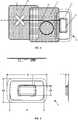
- FIG. 6illustrates an overhead view and side views of the EPG patch 10.
- the EPGis smaller than the IPG in the corresponding fully implantable permanent system.
- the outside width ( w2 ) of the adherent patch 12is between 2 and 5 inches, preferably about 2.5 inches, while the outside length ( l2 ) of the patch 12 is between 3 and 6 inches, preferably about 4 inches; the width of the EPG ( w1 ) is between 0.5 and 2 inches, preferably about 1 inch, while the length ( l1 ) is between 1 and 3 inches, preferably about 2 inches; and the thickness ( t ) of the entire EPG patch 10 is less than 1 inches, preferably 0.8 inches or less.
- This designis considerably smaller than EPGs in conventional systems and thus interferes less with the daily activities of the patient during the trial period.
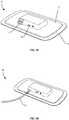
- FIGS. 7A-7Billustrate perspective views of two example EPG patches 10.
- the top surface of the flexible laminated patch 12provides access to a connection port 42 of the EPG encased inside the patch.
- the patchmay further include an "on/off" button 44 with a molded tactile detail to allow the patient to turn the EPG on and off through the outside surface of the adherent patch 12.
- the laminated surface of the patch 12may also be partly transmissive to light such that an LED "on” indicator can be visible through the patch (the glow of the LED light can be seen to the right of the on/off button 44).
- the underside of the patch 14is covered with a skin-compatible adhesive.
- the adhesive surfacemay be configured with any adhesive or adherent material suitable for continuous adhesion to a patient for the direction of the trial period.
- a breathable strip having skin-compatible adhesivewould allow the patch 12 to remain attached to the patient continuously for over a week, typically two weeks to four weeks, or even longer.
- the EPG of the EPG patchis hardwired to the lead extension 22. This allows the entire lead extension 22 and EPG to be sealed, thereby improving the water resistance of the system.
- the advantages associated with embodiments of the EPG patch 10 described aboveinclude: disposability; increased patient mobility, including the ability to shower; improved patient comfort; lower infection of risk; and less tunneling through tissues required. These aspects increase the likelihood of trial period success and that patients will convert from the trial system to a permanently implanted system.
- FIG. 7Cis an exploded view illustration of an example EPG patch 300.
- the EPG patch 300can include a top surface of the patch 306 and a bottom surface of the patch 314 which can be bonded together to encase an EPG 304. Either or both of the top surface of the patch 306 and the bottom surface of the patch 314 can be replaceable and removable, such that both parts are removably bound to each other.
- the bottom surface of the patch 314can further include a peel-off liner.
- the EPG 304can be constructed of a thin plastic housing forming a shell, having a EPG shell top 316 and an EPG shell bottom 318.
- the EPG 304can include internal circuitry 322 for generating pulses and other functionality.
- FIG. 8illustrates a schematic of a trial system 100 and a permanent system 200.
- each of the trial and permanent systemare compatible for use with a wireless clinician programmer and a patient remote.
- the clinician programmercan be used in lead placement, programming and stimulation control in each of the trial and permanent systems.
- eachallows the patient to control stimulation or monitor battery status with the patient remote.
- This configurationis advantageous as it allows for an almost seamless transition between the trial system and the permanent system. From the patient's viewpoint, the systems will operate in the same manner and be controlled in the same manner, such that the patient's subjective experience in using the trial system more closely matches what would be experienced in using the permanently implanted system. Thus, this configuration reduces any uncertainties the patient may have as to how the system will operate and be controlled such that the patient will be more likely to convert a trial system to a permanent system.
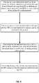
- FIGS. 9-10illustrate methods of treatment that may use an EPG patch.
- the method of FIG. 9includes steps of: advancing a neurostimulation lead to a target location in a patient, electrically connecting the lead to an EPG and securing the EPG by adhering an adherent patch supporting the EPG to a skin surface of the patient (or optionally to securing the EPG to a belt worn by the patient) for a trial treatment; performing one or more neurostimulation therapies with the EPG in a trial treatment to assess viability of treatment in the patient; removing the implanted trial lead and replacing it with a permanently implanted lead, and connecting the permanent lead to the IPG and implanting the neurostimulation lead and IPG entirely within the body lead entirely within the patient; and performing therapy with the fully implanted system and IPG based on the trial treatment performed with the EPG.
- the method of FIG. 10includes steps of: advancing a distal end of a neurostimulation lead to a target location in a patient, electrically connecting the lead to an EPG through a lead extension and securing the EPG by adhering an adherent patch supporting the EPG to a skin surface of the patient's skin (or optionally to securing the EPG to a belt worn by the patient) for a trial treatment of limited duration; performing one or more trial neurostimulation therapies with the partly implanted lead and attached EPG to assess viability of treatment in the patient; removing the lead extension and electrically coupling the neurostimulation lead with an IPG without removing the distal end of the lead implanted at the target location and implanting the lead and IPG entirely within the patient; and performing therapy with the fully implanted lead and attached IPG based on the trial treatment performed with the EPG.
Landscapes
- Health & Medical Sciences (AREA)
- Life Sciences & Earth Sciences (AREA)
- General Health & Medical Sciences (AREA)
- Nuclear Medicine, Radiotherapy & Molecular Imaging (AREA)
- Radiology & Medical Imaging (AREA)
- Engineering & Computer Science (AREA)
- Animal Behavior & Ethology (AREA)
- Public Health (AREA)
- Veterinary Medicine (AREA)
- Biomedical Technology (AREA)
- Heart & Thoracic Surgery (AREA)
- Gastroenterology & Hepatology (AREA)
- Biophysics (AREA)
- Electrotherapy Devices (AREA)
- Neurology (AREA)
- Neurosurgery (AREA)
- Orthopedic Medicine & Surgery (AREA)
- Cardiology (AREA)
- Magnetic Treatment Devices (AREA)
Description
- Treatments with implanted neurostimulation systems have become increasingly more common in recent years. While such systems have shown promise in treating a number of chronic conditions, effectiveness of treatment may vary considerably between patients and viability of treatment can be difficult to determine before implantation. Although conventional methods of implantation often utilize preliminary testing with a temporary, partly implanted neurostimulation systems to assess viability of treatment, such systems may not provide an accurate representation of treatment with a fully implanted device. In addition, such systems are often bulky, uncomfortable and limit patient mobility, such that many patients elect not to receive a temporary system or a fully implanted system. In addition, many such temporary partly implanted systems may not operate in the same manner as their fully implanted counterparts due to differences between pulse generators or changes in position of the neurostimulation leads during conversion. Therefore, it is desirable to provide devices for providing trial treatment systems that provide a more accurate representation of treatment, improve patient comfort and provide consistent treatment outcomes as compared to fully implanted neurostimulation systems.
US 2011/125214 A1 discloses medical electrical stimulation with external simulated case electrode.US 2010/036445 A1 discloses portable assemblies, systems, and methods for providing functional or therapeutic neurostimulation.US 2012/290055 A1 discloses systems and methods to place one or more leads in tissue to electrically stimulate nerves to treat pain.US 2003/120323 A1 discloses a rechargeable spinal cord stimulator system.WO 2013/162709 A1 discloses trial stimulation systems.US 2013/096641 A1 discloses systems and methods for providing percutaneous electrical stimulation.- The present invention provides a neurostimulation system as defined in
claim 1. Preferred embodiments are defined by the dependent claims. - Aspects, embodiments and examples of the present disclosure which do not fall within the scope of the appended claims are not part of the present invention. Methods disclosed herein after are also not part of the present invention.
- The present disclosure relates to neurostimulation treatment systems, and in particular a neurostimulation treatment having a partly implanted neurostimulation lead extending to an external pulse generator for conducting a trial neurostimulation treatment for assessing viability of a fully implanted system. In one aspect, the system includes a partly implanted neurostimulation lead that extends from one or more implanted neurostimulation electrodes to an external pulse generator (EPG) supported in an adherent patch affixed to the patient's skin. In certain embodiments, the EPG is sealed within a laminated flexible patch adhered to the patient so as to allow the patient to partake in normal everyday activities, including showering. The adherent patch may utilize a skin-compatible adhesive of sufficient strength to maintain adherence for the duration of the trial period. In some aspects, the trial period may be as little as 4-7 days, while in other aspects the trial period may extend two weeks or more, typically about four weeks. The system may further use additional adherent patches to seal the percutaneous incision through which the partly implanted lead extends and to maintain a position of the lead extending outside the body and prevent migration of the percutaneous portion of the lead. This is advantageous since often, during the trial period, the anchor portion of the lead may not be deployed so as to allow adjustment of the neurostimulation electrodes during the trial period.
- In one aspect, a neurostimulation system includes an implantable neurostimulation lead having one or more conductors disposed within a lead body, the one or more conductors extending from a proximal end of the lead to one or more neurostimulation electrodes disposed at or near a distal end of the lead; an EPG electrically coupleable to the implantable lead, the pulse generator being electrically coupled with the one or more neurostimulation electrodes when electrically coupled with the implantable lead, wherein the pulse generator is configured to generate a plurality of electrical impulses for delivering a neurostimulation treatment to a patient through the one or more neurostimulation electrodes when implanted at a target location; and an adherent patch adapted to substantially cover the EPG and adhere to a skin of the patient so as to support the EPG on the skin of the patient for a duration of a trial period to assess efficacy of the neurostimulation treatment. The adherent patch comprises a flexible laminated patch, wherein the EPG is sealed within the laminated patch so as to be water resistant. The adherent patch includes a skin-compatible adhesive and material so as to be suitable for continuous adherence to the patient skin for the duration of the trial period, which can be anywhere from 4 days to 4 weeks or more.
- In another aspect, the system may include a neurostimulation lead extension connected at one end to the proximal end of the implantable neurostimulation lead and coupleable with the EPG. The implantable neurostimulation lead is of a length suitable for implantation within a fully implanted neurostimulation system without removal of the distal portion from the target location after the trial period, wherein in the fully implanted neurostimulation system, the implantable pulse generator is implanted in a lower back region. The lead extension may of sufficient length to position the EPG patch in a desired location, such a patient's abdomen. In one aspect, the lead extension may be coupled to the proximal end of the lead by a connector. The connector may operate in a similar manner as the interface on the IPG such that the lead can be disconnected from the lead extension and directly connected to the IPG during conversion to a permanent system.
- In certain aspects, the EPG is a modified version of the IPG such that they operate in a similar manner in delivering electrical pulses to the neurostimulation pulses. The EPG is typically smaller and/or lighter than the implantable pulse generator such as by removing certain components of the IPG, such as replacing wireless charging coils and associated components of the IPG with a battery, or utilizing lighter, thinner housing materials such that the EPG is disposable. The EPG may be configured to be compatible with external control devices used with the IPG to allow easy transition between the devices during conversion to a permanently implanted system.
- In another aspect, a neurostimulation system includes an implantable lead having one or more conductors disposed within a lead body, the one or more conductors extending from a proximal end of the lead to one or more neurostimulation electrodes disposed at or near a distal end of the lead; an EPG coupled to the proximal end of the implantable lead and sealed within an adherent patch attached to the patient, typically in a lower abdominal region. The EPG is configured to generate a plurality of electrical impulses to the implantable lead, the pulse generator being configured to generate a plurality of electrical impulses for delivering a neurostimulation treatment to a patient through the one or more neurostimulation electrodes when implanted at a target location; and an anchor coupled with the lead body just proximal of the electrodes.
- In one aspect, the present disclosure relates to an anchoring body having a plurality of tines disposed along the anchoring body. The plurality of tines are biased toward a deployed position in which the tines extend laterally outward from the anchor body so as to engage tissue sufficiently to inhibit axial displacement of the implanted lead. The tines are constructed so as to be resiliently deflectable toward the helical body during implantation so as to fold inward toward the helical anchoring body when constrained by a delivery sheath to facilitate delivery to the target location during implantation. Typically, during the trial period, the sheath is disposed over the plurality of tines and the position of the neurostimulation lead is maintained by the additional adherent patches covering the portion of the lead extending outside the body to the EPG patch. This allows the lead position to be altered as needed during the trial to determine the most suitable lead position for treatment. If the trial proves successful, then the outer sheath can be withdrawn and the tines deployed so as to anchor the lead in position, after which the lead can be fully implanted along with an IPG. Methods of providing a trial treatment with such devices are also provided herein.
- Further areas of applicability of the present disclosure will become apparent from the detailed description provided hereinafter.
FIG. 1 is a schematic illustration of a trial neurostimulation system having a partly implanted lead extending to an EPG patch adhered to the skin of the patient.FIG. 2 is an overview of the neurostimulation system ofFIG. 1 .FIG. 3 is an alternative configuration of a trial neurostimulation system.FIG. 4 is yet another alternative configuration of a trial neurostimulation system.FIG. 5 is a detail of the neurostimulation system inFIG. 3 .FIG. 6 is an overhead and side views of an example EPG patch.FIGS. 7A-7B illustrate an example EPG patch.FIG. 7C is an exploded view illustration of an example EPG patch.FIG. 8 schematically illustrates a use of a trial neurostimulation system utilizing an EPG patch.FIGS 9-10 illustrate methods of performing a trial neurostimulation therapy.- Neurostimulation has been used for many years to treat a variety of conditions, from chronic pain, to erectile dysfunction and various urinary dysfunctions. While neurostimulation has proven effective in many applications, effective therapy often relies on consistently delivering therapeutic activation by one or more neurostimulation electrodes to particular nerves or targeted regions with a pulse generator. In recent years, fully implantable neurostimulation have become increasingly more commonplace. Although such implantable systems provide patients with greater freedom and mobility, the neurostimulation electrodes of such systems are more difficult to adjust once they are implanted. The neurostimulation electrodes are typically provided on a distal end of an implantable lead that is advanced through a tunnel formed in a patient tissue.
FIG. 1 schematically illustrates a use of a trial neurostimulation system utilizing an EPG patch. Such a trial neurostimulation system can be used to assess viability of a fully implantable neurostimulation system. Implantable neurostimulation systems can be used in treating patients with, for example, chronic, severe, refractory neuropathic pain originating from peripheral nerves or various urinary and bowel dysfunctions. Implantable neurostimulation systems can be used to either stimulate a target peripheral nerve or the posterior epidural space of the spine. An implantable neurostimulation system includes an implanted pulse generator, typically implanted in a lower back region. In some embodiments, the pulse generator can generate one or more non-ablative electrical pulses that are delivered to a nerve to control pain or cause some other desired effect. In some applications, the pulses having a pulse amplitude of between 0-1,000 mA, 0-100 mA, 0-50 mA, 0-25 mA, and/or any other or intermediate range of amplitudes may be used. One or more of the pulse generators can include a processor and/or memory adapted to provide instructions to and receive information from the other components of the implantable neurostimulation system. The processor can include a microprocessor, such as a microprocessor from Intel® or Advanced Micro Devices, Inc.®, or the like. An implantable pulse generator may implement an energy storage feature, such as one or more capacitors or a battery, and typically includes a wireless charging unit.- The electrical pulses generated by the pulse generator are delivered to one or more nerves and/or to a target location via one or more leads that include one or more neurostimulation electrodes at or near the distal end. The leads can have a variety of shapes, can be a variety of sizes, and can be made from a variety of materials, which size, shape, and materials can be dictated by the application or other factors. In some applications, the leads may be implanted to extend along the spine or through one of the foramen of the sacrum, such as shown in
FIG. 1 , such as in sacral nerve stimulation. In other applications, the leads may be implanted in a peripheral portion of the patient's body, such as in the arms or legs, and can be configured to deliver one or more electrical pulses to the peripheral nerve such as may be used to relieve chronic pain. - One or more properties of the electrical pulses can be controlled via a controller of the implanted pulse generator. In some embodiments, these properties can include, for example, the frequency, strength, pattern, duration, or other aspects of the timing and magnitude of the electrical pulses. These properties can include, for example, a voltage, a current, or the like. This control of the electrical pulses can include the creation of one or more electrical pulse programs, plans, or patterns, and in some embodiments, this can include the selection of one or more pre-existing electrical pulse programs, plans, or patterns. In the embodiment depicted in
FIG. 1 , theimplantable neurostimulation system 100 includes a controller in the implantable pulse generator having one or more pulse programs, plans, or patterns and/or to select one or more of the created pulse programs, plans, or patterns. - Sacral nerve neuromodulation (SNM), also known as sacral nerve stimulation (SNS), is defined as the implantation of a permanent device that modulates the neural pathways controlling bladder or rectal function. This policy addresses use of SNM in the treatment of urinary or fecal incontinence, urinary or fecal nonobstructive retention, or chronic pelvic pain in patients with intact neural innervation of the bladder and/or rectum.
- Treatment using SNM, also known as SNS, is one of several alternative modalities for patients with fecal or urinary incontinence (urge incontinence, significant symptoms of urgency-frequency, or nonobstructive urinary retention) who have failed behavioral (e.g., prompted voiding) and/or pharmacologic therapies. Urge incontinence is defined as leakage of urine when there is a strong urge to void. Urgency-frequency is an uncontrollable urge to urinate, resulting in very frequent, small volumes and is a prominent symptom of interstitial cystitis (also called bladder pain syndrome). Urinary retention is the inability to completely empty the bladder of urine. Fecal incontinence can result from a variety of mechanisms, including rectal wall compliance, neural pathways, nervous system, and voluntary and involuntary muscles. Incontinence is more common in women, often associated with muscular and neural damage that may occur during vaginal child delivery.
- The SNM device consists of an implantable pulse generator that delivers controlled electrical impulses. This pulse generator is attached to wire leads that connect to the sacral nerves, most commonly the S3 nerve root. Two external components of the system help control the electrical stimulation. A patient remote control is kept by the patient and can be used to turn the device on or off or to adjust stimulation intensity. A console programmer is kept by the physician and used to adjust the settings of the pulse generator.
- In a conventional approach, prior to implantation of the permanent device, patients undergo an initial testing phase to estimate potential response to treatment. The first type of testing developed was percutaneous nerve evaluation (PNE). This procedure is done under local anesthesia, using a test needle to identify the appropriate sacral nerve(s). Once identified, a temporary wire lead is inserted through the test needle and left in place for 4 to 7 days. This lead is connected to an external stimulator, which is carried by patients in their pocket or on their belt. The results of this test phase are used to determine whether patients are appropriate candidates for the permanent device, For example, for overactive bladder, if patients show a 50 percent or greater reduction in symptom frequency, they are deemed eligible for the permanent device.
- The second type of testing is a 2-stage surgical procedure. In
Stage 1, a quadripolartined lead is implanted (stage 1). The testing phase can last as long as several weeks, and if patients show a specified reduction in symptom frequency, they can proceed to Stage 2 of the surgery, which is permanent implantation of the neuromodulation device. The 2-stage surgical procedure has been used in various ways. These include its use instead of PNE, for patients who failed PNE, for patients with an inconclusive PNE, or for patients who had a successful PNE to further refine patient selection. - The permanent device is implanted under local or general anesthesia. An incision is made over the lower back and the electrical leads are placed in contact with the sacral nerve root(s). The wire leads are extended underneath the skin to a pocket incision where the pulse generator is inserted and connected to the wire leads. Following implantation, the physician programs the pulse generator to the optimal settings for that patient.
- In the instance of bladder dysfunction, a trial period of sacral nerve neuromodulation with either percutaneous nerve stimulation or a temporarily implanted lead may be considered medically necessary (at least for purposed of insurance coverage) in patients that meet all of the following criteria: (1) a diagnosis of at least one of the following: urge incontinence: urgency-frequency syndrome; non-obstructive urinary retention; and overactive bladder, (2) there is documented failure or intolerance to at least two conventional therapies (e.g., behavioral training such as bladder training, prompted voiding, or pelvic muscle exercise training, pharmacologic treatment for at least a sufficient duration to fully assess its efficacy, and/or surgical corrective therapy); (3) the patient is an appropriate surgical candidate; and (4) incontinence is not related to a neurologic condition.
- Permanent implantation of a sacral nerve neuromodulation device may be considered medically necessary in patients who meet all of the following criteria: (1) all of the criteria (1) through (4) in the previous paragraph are met; and (2) trial stimulation period demonstrates at least 50% improvement in symptoms over a period of at least one week.
- Other urinary/voiding applications of sacral nerve neuromodulation are considered investigational, including but not limited to treatment of stress incontinence or urge incontinence due to a neurologic condition, e.g., detrusor hyperreflexia, multiple sclerosis, spinal cord injury, or other types of chronic voiding dysfunction. (See policy description of sacral nerve neuromodulation/stimulation coverage provided by Blue Cross Blue Shield available online at:
- http://www.bcbsms.com/com/bcbsms/apps/PolicySearch/views/ViewPolicy.
- php?&noprint=yes&path=%2Fpolicy%2Femed%2FSacral_Nerve_Stimulation.html)
- Studies have shown that trial conversion rates, which is the rate at which patients convert a trial system to a permanently implanted system, are higher for
Stage 1 trials than for PNE, For example, one study found that PNE trials resulted in a trial conversion rate of 40-50%, whileStage 1 trials resulted in 70-90 % conversion, suggesting thatStage 1 generally provides a better indication of effectiveness of treatments. (See1 Baster and Kim (2010). Curr urol Rep). - In another conventional approach, a similar method is used in peripheral neurostimulation (PNS) treatment systems. Generally, candidates for peripheral neurostimulation are assessed to determine their suitability for undergoing the PNS procedure. Prior to the surgery, the patient will undergo pre-surgical testing that includes routine blood tests as well as neuropsychological evaluation. The PNS procedure itself is typically performed in two separate stages. Each stage takes about one hour, and the patient can go home the same day.
- In this aspect,
Stage 1involves implanting of trial electrodes, via small needles, which are connected to an external pulse generator (EPG), typically worn on a belt of the patient. A number of stimulation programs are administered over the next few days. If this trial demonstrates a significant improvement in the patient's headache or facial pain, permanent implantation can take place. InStage 2, a new set of electrodes, the width of angel-hair pasta, are implanted under the skin. These are connected to asmaller implantable pulse generator implanted under the skin in the chest, abdomen, or back. - Among the drawbacks associated with these conventional approaches, is the discomfort associated with wearing an EPG, the risk of infection, as well as the additional procedures associated with removal of the implanted test leads and implantable of the permanent leads in
Stage 2. In addition, often the EPG provided is different than the IPG that is eventually implanted. Given that efficacy of treatment often relies on precise placement of the neurostimulation electrodes at target tissue locations and consistent, repeatable delivery of neurostimulation therapy with the devices, the effectiveness of a trial period such as in PNE andStage 1 trial periods are not always indicative of effective treatment with a permanent implanted system. In one aspect, since effectiveness of treatment in a trial period may rely, in part, on a patient's subjective experience, it is desirable if the discomfort and inconvenience of wearing an EPG by the patient can be minimized so that the patient can resume ordinary daily activities without constant awareness of the presence of the EPG and treatment system. This aspect can be of particular importance in treatment of urge-frequency, overactive bladder and erectile dysfunction, where a patient's awareness of the device could interfere with the patient's experience of symptoms associated with these conditions. - In one aspect, the system of the present disclosure allows for improved assessment of efficacy during trial periods by providing a trial system having improved patient comfort so that patients can more easily recognize the benefits and effectiveness of treatment. In another aspect, the trial system provides a better indication of effectiveness of treatment by utilizing the same implanted neurostimulation lead to deliver the therapy in the permanent system as was used to deliver the therapy in the trial system and further reduces the trauma associated with converting the trial system to the permanent system. In another aspect, the portions of the EPG delivering the therapy are substantially the same as the IPG in the permanent system such that the effects in permanent treatment should be more consistent with those seen in the trial system.
- The present disclosure provides an EPG patch worn on a skin of the patient so as to improve patient comfort. Optionally, the EPG used in
Stage 1 may be smaller than the IPG used in thecorresponding Stage 2 so that the EPG can easily be supported by and sealed against contamination by an adherent patch that covers the EPG. In one aspect, the EPG is a modified version of the implantable IPG used inStage 2. The IPG may be modified by removal of one or more components, such as removal of a remote charging coil with a smaller battery and associated components. In addition, the EPG may use a thinner, lighter housing than the IPG, since the EPG is not required to last for many years, such as the IPG would be. The EPG therefore, may be configured to be disposable. These aspects allow the EPG to be supported within a patch worn on a skin of the patient at a convenient location, such as on the abdomen or side of the patient, as desired. FIG. 1 illustrates an exampletrial neurostimulation system 100 having anEPG patch 10. As shown, the neurostimulation system is adapted to stimulate a ventral sacral nerve root. Theneurostimulation system 100 includes an implantable pulse generator (IPG) implanted in a lower back region, from which aneurostimulation lead 20 extends through a foramen of the sacrum to electrodes (not shown) disposed near the sacral ventral root. Theneurostimulation lead 20 further includes ananchor 10 disposed on a dorsal side of the sacrum. It is appreciated, however, that the anchor may be disposed on a ventral side of the sacrum as well, or within the foramen itself. In one aspect, theEPG 40 is disposable and discarded after the trial is complete. Typically, the trial may last anywhere from 4 days to 8 weeks. Typically, an initial assessment may be obtained after 4-7 days and, if needed, effectiveness of treatment may be examined after a few weeks, typically about 4 weeks. In one aspect, theEPG 40 of theEPG patch 10 is of a substantially similar design as the IPG that would be implanted if the trial proves successful, expect one or more components are removed to allow the EPG to be smaller in size and/or differing materials are used since the device may be intended for one time use.FIG. 2 illustrates aneurostimulation system 100, similar to that inFIG. 1 , in more detail. As can be seen, theneurostimulation lead 20 includes a plurality ofneurostimulation electrodes 30 at a distal end of the lead and ananchor 50 having a plurality of tines disposed just proximal of theelectrodes 30. Typically, the anchor is disposed near and proximal of the plurality of electrodes so as to provide anchoring of the lead relatively close to the electrodes. TheEPG 40 is supported within anadherent patch 12 when attached to a skin of the patient. In one aspect, theEPG 40 used in the trial period is smaller than the corresponding IPG that would be implanted in a permanent system. This is made possible by removal of components that may not be necessary during a trial period or for an external device, for example the wireless charging coils and associated components. TheEPG 40 may utilize a battery thereby allowing the device to be smaller and lighter so as to allow the EPG to be supported by an adherent patch and worn by a patient with minimal discomfort.- In one aspect, additional
adherent patches 16 may be used to cover and seal the percutaneous incision in the skin of the patient through which the percutaneous portion of the neurostimulation lead is inserted. The lead may be secured at the percutaneous incision withsurgical tape 17 and further secured and sealed with an adherent patch covering the lead and percutaneous incision. In this manner, the percutaneous incision can be sealed and protected from contamination or infection and its position maintained by the additionaladherent patches 16. This configuration reduces the likelihood of infection and prevents movement of the lead, both internal and external, such that the patient's awareness of the patch and lead is minimized, thereby allowing the patient to resume relatively normal daily activities. - In another aspect, since the EPG patch may be worn in a different location, such as on the abdomen, than the IPG would be implanted, to allow the IPG to use the same percutaneous portion of the
neurostimulation lead 20, the system may use alead extension 22 coupled with thelead 20 by anexternal connector 21. Thelead extension 22 may be hardwired into the EPG so as to eliminate potential disconnection and allow the connection to be sealed or encapsulated within the adherent patch so as to be water resistant or water proof. This allows the patient to perform routine daily activities, such as showering without removing the device. The length oflead 20 may be a suitable length for the permanently implanted system, while the length ofextension 22 allows the lead to EPG patch to be positioned in a location that provide improved comfort and minimized interference with daily activities. FIG. 3 illustrates an alternate configuration in which the lead is sufficiently long to allow theEPG patch 10 to be adhered to the patient's abdomen. This configuration is advantageous as such placement allows the patient more mobility and freedom to resume daily activities and does not interfere with sitting or sleeping. Excess lead can be secured by an additionaladherent patch 16, as shown by the center patch inFIG. 3 . In one aspect, the lead is hardwired to the EPG, while in another the lead is removable connected to the EPG through a port or aperture in the top surface of theflexible patch 12. In one aspect, the EPG patch is disposable such that the lead can be disconnected and used in a permanently implanted system without removing the distal end of the lead from the target location. In another aspect, the entire system can be disposable and replaced with a lead and IPG.- In one aspect, the EPG unit may be wirelessly controlled by a patient remote in a similar or identical manner as the IPG of a permanently implanted system would be. The physician or patient may alter treatment provided by the EPG through use of a portable clinician unit and the treatments delivered are recorded on a memory of the device for use in determining a treatment suitable for use in a permanently implanted system.
FIG. 4 illustrates an alternate configuration in which thelead 20 is connected to alead extension 21 through aconnector 21. This allows the lead to be extended so that the EPG patch can be placed on the abdomen. This also allows thelead 20 of a length suitable for implantation in a permanent system to be used. This approach may utilize two percutaneous incisions, theconnector 21 provided in the first incision and thelead extensions 12 extending through the second percutaneous incision, there being a short tunneling distance (about 10 cm) therebetween. This approach minimized movement of the implantedlead 20 during conversion of the trial system to a permanently implanted system. During conversion, thelead extension 22 can be removed along with theconnector 21 and the implantedlead 20 attached to an IPG that is placed permanently implanted in a location at or near the site of the first percutaneous incision. In one aspect, theconnector 21 may include a connector similar in design to the connector on the IPG. This allows the proximal end of thelead 20 to be coupled to thelead extension 22 through theconnector 21 and easily detached and coupled to the IPG during conversion to a permanently implanted system.FIG. 5 illustrates a detailed view of an EPG patch adhered to the skin of the patient, an additionaladherent patch 16 disposed over the percutaneous incision through the lead extends into the patient and anotheradditional patch 16 covering a loop of excess lead, the patch overlapping the first additional patch and the edge of theEPG patch 10. This configuration is advantageous as it substantially covers and seals the EPG and the lead from contamination and prevents accidental disconnection or migration of the lead by the patient, and streamlines the external portions of the system so as to improve patient comfort and allow a patient's subjective experience to more closely match what the patient would experience in a permanently implanted system.FIG. 6 illustrates an overhead view and side views of theEPG patch 10. In one aspect, the EPG is smaller than the IPG in the corresponding fully implantable permanent system. In certain embodiments, the outside width (w2) of theadherent patch 12 is between 2 and 5 inches, preferably about 2.5 inches, while the outside length (l2) of thepatch 12 is between 3 and 6 inches, preferably about 4 inches; the width of the EPG (w1) is between 0.5 and 2 inches, preferably about 1 inch, while the length (l1) is between 1 and 3 inches, preferably about 2 inches; and the thickness (t) of theentire EPG patch 10 is less than 1 inches, preferably 0.8 inches or less. This design is considerably smaller than EPGs in conventional systems and thus interferes less with the daily activities of the patient during the trial period.FIGS. 7A-7B illustrate perspective views of twoexample EPG patches 10. InFIG. 7A , the top surface of the flexiblelaminated patch 12 provides access to aconnection port 42 of the EPG encased inside the patch. The patch may further include an "on/off"button 44 with a molded tactile detail to allow the patient to turn the EPG on and off through the outside surface of theadherent patch 12. The laminated surface of thepatch 12 may also be partly transmissive to light such that an LED "on" indicator can be visible through the patch (the glow of the LED light can be seen to the right of the on/off button 44). The underside of thepatch 14 is covered with a skin-compatible adhesive. The adhesive surface may be configured with any adhesive or adherent material suitable for continuous adhesion to a patient for the direction of the trial period. For example, a breathable strip having skin-compatible adhesive would allow thepatch 12 to remain attached to the patient continuously for over a week, typically two weeks to four weeks, or even longer. InFIG. 7B , the EPG of the EPG patch is hardwired to thelead extension 22. This allows theentire lead extension 22 and EPG to be sealed, thereby improving the water resistance of the system. The advantages associated with embodiments of theEPG patch 10 described above include: disposability; increased patient mobility, including the ability to shower; improved patient comfort; lower infection of risk; and less tunneling through tissues required. These aspects increase the likelihood of trial period success and that patients will convert from the trial system to a permanently implanted system.FIG. 7C is an exploded view illustration of anexample EPG patch 300. As illustrated, theEPG patch 300 can include a top surface of thepatch 306 and a bottom surface of thepatch 314 which can be bonded together to encase anEPG 304. Either or both of the top surface of thepatch 306 and the bottom surface of thepatch 314 can be replaceable and removable, such that both parts are removably bound to each other. The bottom surface of thepatch 314 can further include a peel-off liner. TheEPG 304 can be constructed of a thin plastic housing forming a shell, having aEPG shell top 316 and anEPG shell bottom 318. Within the shell of theEPG 304 one or moreprimary cells 320 can be contained, which individually or in combination can provide sufficient power for operation of theEPG 304 for about 14 days of use. Further, theEPG 304 can includeinternal circuitry 322 for generating pulses and other functionality.FIG. 8 illustrates a schematic of atrial system 100 and apermanent system 200. As can be seen, each of the trial and permanent system are compatible for use with a wireless clinician programmer and a patient remote. The clinician programmer can be used in lead placement, programming and stimulation control in each of the trial and permanent systems. In addition, each allows the patient to control stimulation or monitor battery status with the patient remote. This configuration is advantageous as it allows for an almost seamless transition between the trial system and the permanent system. From the patient's viewpoint, the systems will operate in the same manner and be controlled in the same manner, such that the patient's subjective experience in using the trial system more closely matches what would be experienced in using the permanently implanted system. Thus, this configuration reduces any uncertainties the patient may have as to how the system will operate and be controlled such that the patient will be more likely to convert a trial system to a permanent system.FIGS. 9-10 illustrate methods of treatment that may use an EPG patch. The method ofFIG. 9 includes steps of: advancing a neurostimulation lead to a target location in a patient, electrically connecting the lead to an EPG and securing the EPG by adhering an adherent patch supporting the EPG to a skin surface of the patient (or optionally to securing the EPG to a belt worn by the patient) for a trial treatment; performing one or more neurostimulation therapies with the EPG in a trial treatment to assess viability of treatment in the patient; removing the implanted trial lead and replacing it with a permanently implanted lead, and connecting the permanent lead to the IPG and implanting the neurostimulation lead and IPG entirely within the body lead entirely within the patient; and performing therapy with the fully implanted system and IPG based on the trial treatment performed with the EPG.- The method of
FIG. 10 includes steps of: advancing a distal end of a neurostimulation lead to a target location in a patient, electrically connecting the lead to an EPG through a lead extension and securing the EPG by adhering an adherent patch supporting the EPG to a skin surface of the patient's skin (or optionally to securing the EPG to a belt worn by the patient) for a trial treatment of limited duration; performing one or more trial neurostimulation therapies with the partly implanted lead and attached EPG to assess viability of treatment in the patient; removing the lead extension and electrically coupling the neurostimulation lead with an IPG without removing the distal end of the lead implanted at the target location and implanting the lead and IPG entirely within the patient; and performing therapy with the fully implanted lead and attached IPG based on the trial treatment performed with the EPG. - In the foregoing specification, the invention is described with reference to specific embodiments thereof, but those skilled in the art will recognize that the invention is not limited thereto. The specification and drawings are, accordingly, to be regarded as illustrative rather than restrictive. The scope of the present invention is defined by the appended claims.
Claims (15)
- A neurostimulation system comprising:an implantable neurostimulation lead (20) having one or more conductors disposed within a lead body, the one or more conductors extending from a proximal end of the implantable neurostimulation lead to one or more neurostimulation electrodes (30) disposed at or near a distal end of the implantable neurostimulation lead;an external pulse generator (40) electrically coupleable to the implantable neurostimulation lead (20), the external pulse generator being electrically coupled with the one or more neurostimulation electrodes (30) when electrically coupled with the implantable neurostimulation lead (20), wherein the external pulse generator (40) is associated with a trial system (100) and configured to generate a plurality of electrical impulses for delivering a neurostimulation treatment to a patient through the one or more neurostimulation electrodes (30) when implanted at a target location;an implantable pulse generator configured for implantation within the patient so as to deliver a neurostimulation therapy to the patient through the implantable neurostimulation lead (20), wherein the implantable pulse generator is associated with a permanent system (200);a patient remote configured to wirelessly couple directly to each of the external pulse generator (40) and the implantable pulse generator, wherein the patient remote is configured to turn the respective device on or off or to adjust stimulation intensity;wherein each of the trial and permanent systems is configured to allow a patient to control stimulation or monitor a battery status with the patient remote, wherein the trial and permanent systems are configured to operate in the same manner and be controlled in the same manner.
- The system of claim 1, further comprising:
an adherent patch (10) or tape adapted to substantially cover the external pulse generator (40) and adhere to a skin of the patient so as to support the external pulse generator (30) on the skin of the patient for a duration of a trial period to assess efficacy of the neurostimulation treatment. - The system of claim 2, wherein the adherent patch (10) comprises a flexible laminated patch (12), wherein the external pulse generator (40) is sealed within the laminated patch (12) so as to be water resistant.
- The system of claim 2, wherein the adherent patch (10) comprises a layer of a skin-compatible adhesive and/or breathable tape having sufficient adhesive strength to support the external pulse generator (40) on the skin of the patient continuously for the duration of the trial period.
- The system of claim 4, wherein the duration of the trial period is at least one week.
- The system of claim 1, further comprising:
a neurostimulation lead extension (22) connectable at one end to the proximal end of the implantable neurostimulation lead (20) and coupleable at the opposite end with the external pulse generator (40). - The system of claim 6, wherein the lead extension (22) connects to the proximal end of the implantable neurostimulation lead (20) at a removable connector (21), the lead extension (22) being of sufficient length so as to support the external pulse generator (40) at a desired location on the patient while the distal end is positioned at the target location.
- The system of claim 7, wherein the lead extension (22) is removably coupleable with the external pulse generator (40).
- The system of claim 7, wherein the lead extension (22) is hardwired with the external pulse generator (40).
- The system of claim 1, wherein the external pulse generator (40) is smaller and/or lighter than the implantable pulse generator.
- The system of claim 10, wherein the implantable pulse generator includes a coil and associated components for wireless charging through a skin of the patient while implanted, and wherein the external pulse generator (40) is of a substantially similar configuration of components as the implantable pulse generator but is modified to omit the coil and associated components for wireless charging and to include a battery source.
- The system of claim 10, wherein the implantable pulse generator is configured to operate while implanted for one or more years, while the external pulse generator (40) is configured to be disposable.
- The system of claim 1, wherein the external pulse generator (40) is configured such that any adjustment of stimulation by the patient is performed wirelessly with the patient remote.
- The system of claim 1, further comprising an adherent patch (10) adapted to substantially cover the external pulse generator (40) and adhere to a skin of the patient so as to support the external pulse generator (30) on the skin of the patient for a duration of a trial period to assess efficacy of the neurostimulation treatment, wherein the adherent patch (10) includes an ON/OFF button with a molded tactile detail to allow the patient to turn the external pulse generator ON or OFF through an outside surface of the adherent patch.
- The system of claim 1, further comprising:a clinician programmer configured to wirelessly couple directly to each of the external pulse generator (40) and the implantable pulse generator, wherein the clinician programmer is configured for use in lead placement, programming and stimulation control in each of the trial and permanent systems,wherein each of the trial and permanent systems are compatible for use with the clinician programmer and the patient remote.
Applications Claiming Priority (3)
| Application Number | Priority Date | Filing Date | Title |
|---|---|---|---|
| US201462038131P | 2014-08-15 | 2014-08-15 | |
| US201462041611P | 2014-08-25 | 2014-08-25 | |
| PCT/US2015/045400WO2016025909A1 (en) | 2014-08-15 | 2015-08-14 | External pulse generator device and associated methods for trial nerve stimulation |
Publications (3)
| Publication Number | Publication Date |
|---|---|
| EP3180071A1 EP3180071A1 (en) | 2017-06-21 |
| EP3180071A4 EP3180071A4 (en) | 2018-03-14 |
| EP3180071B1true EP3180071B1 (en) | 2021-09-22 |
Family
ID=55301376
Family Applications (1)
| Application Number | Title | Priority Date | Filing Date |
|---|---|---|---|
| EP15831621.6AActiveEP3180071B1 (en) | 2014-08-15 | 2015-08-14 | External pulse generator device and associated system for trial nerve stimulation |
Country Status (7)
| Country | Link |
|---|---|
| US (4) | US9802051B2 (en) |
| EP (1) | EP3180071B1 (en) |
| JP (1) | JP6795490B2 (en) |
| CN (1) | CN107148294B (en) |
| AU (1) | AU2015301489B2 (en) |
| CA (2) | CA3208375A1 (en) |
| WO (1) | WO2016025909A1 (en) |
Cited By (1)
| Publication number | Priority date | Publication date | Assignee | Title |
|---|---|---|---|---|
| US11848090B2 (en) | 2019-05-24 | 2023-12-19 | Axonics, Inc. | Trainer for a neurostimulator programmer and associated methods of use with a neurostimulation system |
Families Citing this family (22)
| Publication number | Priority date | Publication date | Assignee | Title |
|---|---|---|---|---|
| ES2782556T3 (en) | 2014-08-15 | 2020-09-15 | Axonics Modulation Tech Inc | System for neurostimulation electrode configurations based on neuronal location |
| AU2015301401B2 (en) | 2014-08-15 | 2020-01-16 | Axonics Modulation Technologies, Inc. | Electromyographic lead positioning and stimulation titration in a nerve stimulation system for treatment of overactive bladder |
| CA3208375A1 (en) | 2014-08-15 | 2016-02-18 | Axonics, Inc. | External pulse generator device and associated methods for trial nerve stimulation |
| WO2017139784A1 (en) | 2016-02-12 | 2017-08-17 | Axonics Modulation Technologies, Inc. | External pulse generator device and associated methods for trial nerve stimulation |
| US11612749B2 (en) | 2016-04-01 | 2023-03-28 | Livanova Usa, Inc. | Vagus nerve stimulation patient selection |
| USD855807S1 (en)* | 2017-05-09 | 2019-08-06 | Axonics Modulation Technologies, Inc. | External pulse generator |
| EP3648833B1 (en)* | 2017-06-29 | 2021-08-04 | Hemoref, Inc. | Device using electrotherapy for the relief of hemorrhoid inflammation |
| US10589089B2 (en) | 2017-10-25 | 2020-03-17 | Epineuron Technologies Inc. | Systems and methods for delivering neuroregenerative therapy |
| CA3079849A1 (en) | 2017-10-25 | 2019-05-02 | Epineuron Technologies Inc. | Systems and methods for delivering neuroregenerative therapy |
| CN107952171A (en)* | 2017-12-19 | 2018-04-24 | 北京品驰医疗设备有限公司 | A kind of neuromodulation external pulse generator |
| WO2019165108A1 (en)* | 2018-02-22 | 2019-08-29 | Axonics Modulation Technologies, Inc. | Neurostimulation leads for trial nerve stimulation and methods of use |
| JP2021531070A (en)* | 2018-08-02 | 2021-11-18 | バイオトロニック エスエー アンド カンパニー カーゲーBIOTRONIK SE & Co. KG | Remote follow-up of nerve stimulation system |
| US10894166B2 (en) | 2019-01-23 | 2021-01-19 | Advanced Neuromodulation Systems, Inc. | Stimulation therapy lead trial cable connector |
| US11439829B2 (en) | 2019-05-24 | 2022-09-13 | Axonics, Inc. | Clinician programmer methods and systems for maintaining target operating temperatures |
| ES2804080B2 (en)* | 2019-08-02 | 2021-08-05 | Miralles Raimundo Vicente | Clamping system for electrical stimulation generator |
| US11247043B2 (en) | 2019-10-01 | 2022-02-15 | Epineuron Technologies Inc. | Electrode interface devices for delivery of neuroregenerative therapy |
| EP4048370A4 (en) | 2019-10-21 | 2023-11-29 | Merit Medical Systems, Inc. | DEVICES AND METHODS FOR RETENTION OF TEMPORARY PACEMAKER LEADS |
| CN114760912B (en)* | 2019-12-04 | 2025-07-04 | 丹参生物电子私人有限责任公司 | Implantable stimulator with electrode array and conformable substrate |
| EP4087644B1 (en) | 2020-01-09 | 2024-06-19 | Cardiac Pacemakers, Inc. | Temporary pacemaker |
| CN116440408B (en)* | 2023-03-17 | 2024-01-09 | 上海杉翎医疗科技有限公司 | Implantable stimulation systems, methods, implantable devices, and storage media |
| CN118649350B (en)* | 2024-08-21 | 2024-12-10 | 北京智冉医疗科技有限公司 | Percutaneous minimally invasive type flexible electrode, assembly and system |
| CN119548756A (en)* | 2025-01-24 | 2025-03-04 | 北京智冉医疗科技有限公司 | Flexible neural electrode and preparation method thereof |
Family Cites Families (485)
| Publication number | Priority date | Publication date | Assignee | Title |
|---|---|---|---|---|
| US3057356A (en) | 1960-07-22 | 1962-10-09 | Wilson Greatbatch Inc | Medical cardiac pacemaker |
| US3348548A (en) | 1965-04-26 | 1967-10-24 | William M Chardack | Implantable electrode with stiffening stylet |
| US3646940A (en) | 1969-07-15 | 1972-03-07 | Univ Minnesota | Implantable electronic stimulator electrode and method |
| US3888260A (en) | 1972-06-28 | 1975-06-10 | Univ Johns Hopkins | Rechargeable demand inhibited cardiac pacer and tissue stimulator |
| US3825015A (en) | 1972-12-14 | 1974-07-23 | American Optical Corp | Single catheter for atrial and ventricular stimulation |
| US3824129A (en) | 1973-03-14 | 1974-07-16 | Mallory & Co Inc P R | Heart pacer rechargeable cell and protective control system |
| US3902501A (en) | 1973-06-21 | 1975-09-02 | Medtronic Inc | Endocardial electrode |
| US3970912A (en) | 1973-08-28 | 1976-07-20 | Hoffman Philip A | Battery charging circuit |
| US3942535A (en) | 1973-09-27 | 1976-03-09 | G. D. Searle & Co. | Rechargeable tissue stimulating system |
| US3939843A (en) | 1974-03-04 | 1976-02-24 | Medtronic, Inc. | Transvenous electrode |
| US3995623A (en) | 1974-12-23 | 1976-12-07 | American Hospital Supply Corporation | Multipurpose flow-directed catheter |
| US4019518A (en) | 1975-08-11 | 1977-04-26 | Medtronic, Inc. | Electrical stimulation system |
| US4044774A (en) | 1976-02-23 | 1977-08-30 | Medtronic, Inc. | Percutaneously inserted spinal cord stimulation lead |
| US4082097A (en) | 1976-05-20 | 1978-04-04 | Pacesetter Systems Inc. | Multimode recharging system for living tissue stimulators |
| US4141365A (en) | 1977-02-24 | 1979-02-27 | The Johns Hopkins University | Epidural lead electrode and insertion needle |
| US4166469A (en) | 1977-12-13 | 1979-09-04 | Littleford Philip O | Apparatus and method for inserting an electrode |
| US4340062A (en) | 1978-11-06 | 1982-07-20 | Medtronic, Inc. | Body stimulator having selectable stimulation energy levels |
| US4285347A (en) | 1979-07-25 | 1981-08-25 | Cordis Corporation | Stabilized directional neural electrode lead |
| US4269198A (en) | 1979-12-26 | 1981-05-26 | Medtronic, Inc. | Body implantable lead |
| DE3015260A1 (en) | 1980-04-21 | 1981-10-22 | Siemens AG, 1000 Berlin und 8000 München | ENDOCARD ELECTRODE ARRANGEMENT |
| US4379462A (en) | 1980-10-29 | 1983-04-12 | Neuromed, Inc. | Multi-electrode catheter assembly for spinal cord stimulation |
| US4721118A (en) | 1981-04-20 | 1988-01-26 | Cordis Leads, Inc. | Pervenous electrical pacing lead with foldable fins |
| US4437475A (en) | 1981-08-28 | 1984-03-20 | Medtronic, Inc. | Transvenous cardiovascular integrated lead anchoring sleeve, protector, and permanent lead introducer stop gap |
| DE3146182C2 (en) | 1981-11-21 | 1984-03-29 | Peter Dr. 7889 Grenzach-Wyhlen Osypka | Electrode arrangement for a cardiac pacemaker that can be inserted transvenously into the heart |
| US4512351A (en) | 1982-11-19 | 1985-04-23 | Cordis Corporation | Percutaneous lead introducing system and method |
| US4558702A (en) | 1983-01-21 | 1985-12-17 | Cordis Corporation | Cardiac pacer having input/output circuit programmable for use with unipolar and bipolar pacer leads |
| DE3490016T1 (en) | 1983-01-21 | 1985-02-07 | Ramm Associates, Creve Coeur, Mo. | Implantable hyperthermia device and system |
| US4961422A (en) | 1983-01-21 | 1990-10-09 | Marchosky J Alexander | Method and apparatus for volumetric interstitial conductive hyperthermia |
| US4800898A (en) | 1983-10-07 | 1989-01-31 | Cordis Corporation | Neural stimulator electrode element and lead |
| US4654880A (en) | 1983-12-09 | 1987-03-31 | Minnesota Mining And Manufacturing Company | Signal transmission system |
| US4550731A (en) | 1984-03-07 | 1985-11-05 | Cordis Corporation | Acquisition circuit for cardiac pacer |
| US4662382A (en) | 1985-01-16 | 1987-05-05 | Intermedics, Inc. | Pacemaker lead with enhanced sensitivity |
| US4722353A (en) | 1985-09-16 | 1988-02-02 | Intermedics, Inc. | Stabilizer for implantable electrode |
| US4848352A (en) | 1987-02-13 | 1989-07-18 | Telectronics, N.V. | Method for cardiac pacing and sensing using combination of electrodes |
| US4744371A (en) | 1987-04-27 | 1988-05-17 | Cordis Leads, Inc. | Multi-conductor lead assembly for temporary use |
| US4957118A (en) | 1988-01-15 | 1990-09-18 | Jay Erlebacher | Electrode lead |
| US4979517A (en) | 1988-02-01 | 1990-12-25 | Physio-Control Corporation | Disposable stimulation electrode with long shelf life and improved current density profile |
| US4860446A (en) | 1988-02-16 | 1989-08-29 | Medtronic, Inc. | Medical electrical lead and method of manufacture |
| US5052407A (en) | 1988-04-14 | 1991-10-01 | Mieczyslaw Mirowski | Cardiac defibrillation/cardioversion spiral patch electrode |
| US4989617A (en) | 1989-07-14 | 1991-02-05 | Case Western Reserve University | Intramuscular electrode for neuromuscular stimulation system |
| US5012176A (en) | 1990-04-03 | 1991-04-30 | Baxter International, Inc. | Apparatus and method for calorimetrically determining battery charge state |
| CA2038160C (en) | 1991-03-13 | 1996-10-22 | Jiri K. Nor | Charging circuits for rechargeable batteries and cells |
| US5255691A (en) | 1991-11-13 | 1993-10-26 | Medtronic, Inc. | Percutaneous epidural lead introducing system and method |
| GB9211085D0 (en) | 1992-05-23 | 1992-07-08 | Tippey Keith E | Electrical stimulation |
| US5257634A (en) | 1992-07-16 | 1993-11-02 | Angeion Corporation | Low impedence defibrillation catheter electrode |
| US5676651A (en) | 1992-08-06 | 1997-10-14 | Electric Boat Corporation | Surgically implantable pump arrangement and method for pumping body fluids |
| US5374279A (en) | 1992-10-30 | 1994-12-20 | Medtronic, Inc. | Switchable connector block for implantable defibrillator |
| US5342408A (en) | 1993-01-07 | 1994-08-30 | Incontrol, Inc. | Telemetry system for an implantable cardiac device |
| JP3384027B2 (en) | 1993-05-14 | 2003-03-10 | ソニー株式会社 | Charging method and charger |
| US5386084A (en) | 1993-07-22 | 1995-01-31 | Ii Morrow Inc. | Electronic device enclosure |
| US5864220A (en) | 1993-09-16 | 1999-01-26 | Chartec Laboratories A/S | Method and apparatus for controlling the charging of a rechargeable battery to ensure that full charge is achieved without damaging the battery |
| US5439485A (en) | 1993-09-24 | 1995-08-08 | Ventritex, Inc. | Flexible defibrillation electrode of improved construction |
| US5484445A (en) | 1993-10-12 | 1996-01-16 | Medtronic, Inc. | Sacral lead anchoring system |
| SE9304031D0 (en) | 1993-12-03 | 1993-12-03 | Siemens Elema Ab | electrode System |
| JPH07222370A (en) | 1994-01-28 | 1995-08-18 | Sanyo Electric Co Ltd | Charger with temperature sensor |
| US6249703B1 (en) | 1994-07-08 | 2001-06-19 | Medtronic, Inc. | Handheld patient programmer for implantable human tissue stimulator |
| US5571148A (en) | 1994-08-10 | 1996-11-05 | Loeb; Gerald E. | Implantable multichannel stimulator |
| US5518155A (en) | 1994-10-11 | 1996-05-21 | Gallagher; Richard N. | Holster lock |
| US6035237A (en) | 1995-05-23 | 2000-03-07 | Alfred E. Mann Foundation | Implantable stimulator that prevents DC current flow without the use of discrete output coupling capacitors |
| US5690693A (en) | 1995-06-07 | 1997-11-25 | Sulzer Intermedics Inc. | Transcutaneous energy transmission circuit for implantable medical device |
| US5702431A (en) | 1995-06-07 | 1997-12-30 | Sulzer Intermedics Inc. | Enhanced transcutaneous recharging system for battery powered implantable medical device |
| US5712795A (en) | 1995-10-02 | 1998-01-27 | Alaris Medical Systems, Inc. | Power management system |
| US5669790A (en) | 1995-12-07 | 1997-09-23 | Ventritex, Inc. | Lead lumen sealing device |
| US6898454B2 (en) | 1996-04-25 | 2005-05-24 | The Johns Hopkins University | Systems and methods for evaluating the urethra and the periurethral tissues |
| DE19623788A1 (en) | 1996-06-04 | 1997-12-11 | Biotronik Mess & Therapieg | Implantable stimulation device |
| US6609031B1 (en) | 1996-06-07 | 2003-08-19 | Advanced Neuromodulation Systems, Inc. | Multiprogrammable tissue stimulator and method |
| US5733313A (en) | 1996-08-01 | 1998-03-31 | Exonix Corporation | RF coupled, implantable medical device with rechargeable back-up power source |
| US5713939A (en) | 1996-09-16 | 1998-02-03 | Sulzer Intermedics Inc. | Data communication system for control of transcutaneous energy transmission to an implantable medical device |
| SE9604143D0 (en) | 1996-11-13 | 1996-11-13 | Pacesetter Ab | Implantable electrode cable |
| US5741316A (en) | 1996-12-02 | 1998-04-21 | Light Sciences Limited Partnership | Electromagnetic coil configurations for power transmission through tissue |
| US5735887A (en) | 1996-12-10 | 1998-04-07 | Exonix Corporation | Closed-loop, RF-coupled implanted medical device |
| JP3954177B2 (en) | 1997-01-29 | 2007-08-08 | 日本碍子株式会社 | Bonding structure between metal member and ceramic member and method for manufacturing the same |
| US8555894B2 (en) | 1997-02-26 | 2013-10-15 | Alfred E. Mann Foundation For Scientific Research | System for monitoring temperature |
| US7460911B2 (en) | 1997-02-26 | 2008-12-02 | Alfred E. Mann Foundation For Scientific Research | System and method suitable for treatment of a patient with a neurological deficit by sequentially stimulating neural pathways using a system of discrete implantable medical devices |
| US8684009B2 (en) | 1997-02-26 | 2014-04-01 | Alfred E. Mann Foundation For Scientific Research | System for determining relative distance(s) and/or angle(s) between at least two points |
| US6208894B1 (en) | 1997-02-26 | 2001-03-27 | Alfred E. Mann Foundation For Scientific Research And Advanced Bionics | System of implantable devices for monitoring and/or affecting body parameters |
| US5957965A (en) | 1997-03-03 | 1999-09-28 | Medtronic, Inc. | Sacral medical electrical lead |
| CA2230930A1 (en) | 1997-04-25 | 1998-10-25 | Dale Gathergood | Exterior rear view mirror integral warning light |
| US5871513A (en) | 1997-04-30 | 1999-02-16 | Medtronic Inc. | Centerless ground feedthrough pin for an electrical power source in an implantable medical device |
| US6191365B1 (en) | 1997-05-02 | 2001-02-20 | General Science And Technology Corp | Medical devices incorporating at least one element made from a plurality of twisted and drawn wires |
| US5871532A (en) | 1997-05-22 | 1999-02-16 | Sulzer Intermedics Inc. | Epicardial lead for minimally invasive implantation |
| IT1292016B1 (en) | 1997-05-28 | 1999-01-25 | Valerio Cigaina | IMPLANT DEVICE PARTICULARLY FOR ELECTROSTIMULATION AND / OR ELECTRO-REGISTRATION OF ENDOABDOMINAL VISCERS |
| ES2224420T3 (en) | 1997-08-01 | 2005-03-01 | Alfred E. Mann Foundation For Scientific Research | IMPLANTABLE DEVICE WITH IMPROVED POWER AND BATTERY RECHARGE CONFIGURATION. |
| US5991665A (en) | 1997-09-18 | 1999-11-23 | Sulzer Intermedics Inc. | Self-cooling transcutaneous energy transfer system for battery powered implantable device |
| US6138681A (en) | 1997-10-13 | 2000-10-31 | Light Sciences Limited Partnership | Alignment of external medical device relative to implanted medical device |
| JP3887828B2 (en) | 1997-11-20 | 2007-02-28 | セイコーエプソン株式会社 | Electronics |
| US6306100B1 (en) | 1997-12-16 | 2001-10-23 | Richard L. Prass | Intraoperative neurophysiological monitoring system |
| US6169387B1 (en) | 1997-12-22 | 2001-01-02 | Lifecor, Inc. | Battery management apparatus for portable electronic devices |
| DE19800416C2 (en) | 1998-01-08 | 2002-09-19 | Storz Karl Gmbh & Co Kg | Device for the treatment of body tissue, in particular soft tissue close to the surface, by means of ultrasound |
| US6081097A (en) | 1998-01-19 | 2000-06-27 | Matsushita Electric Industrial Co., Ltd. | Method for charging lithium secondary battery |
| US6305381B1 (en) | 1998-02-02 | 2001-10-23 | Medtronic Inc. | System for locating implantable medical device |
| EP1056510B1 (en) | 1998-02-23 | 2005-05-11 | Medtronic, Inc. | Rf coupled, implantable medical device with rechargeable back-up power source |
| US5974344A (en) | 1998-03-02 | 1999-10-26 | Shoemaker, Ii; Charles | Wound care electrode |
| US5902331A (en) | 1998-03-10 | 1999-05-11 | Medtronic, Inc. | Arrangement for implanting an endocardial cardiac lead |
| JP3826407B2 (en) | 1998-03-24 | 2006-09-27 | セイコーエプソン株式会社 | Electronic device, electronic device control method, secondary battery capacity estimation method, and secondary battery charge control method |
| US6065154A (en) | 1998-04-07 | 2000-05-23 | Lifecor, Inc. | Support garments for patient-worn energy delivery apparatus |
| US6221513B1 (en) | 1998-05-12 | 2001-04-24 | Pacific Coast Technologies, Inc. | Methods for hermetically sealing ceramic to metallic surfaces and assemblies incorporating such seals |
| US6002965A (en) | 1998-06-10 | 1999-12-14 | Katz; Amiram | Self applied device and method for prevention of deep vein thrombosis |
| US6243608B1 (en) | 1998-06-12 | 2001-06-05 | Intermedics Inc. | Implantable device with optical telemetry |
| US6735474B1 (en) | 1998-07-06 | 2004-05-11 | Advanced Bionics Corporation | Implantable stimulator system and method for treatment of incontinence and pain |
| US6941171B2 (en) | 1998-07-06 | 2005-09-06 | Advanced Bionics Corporation | Implantable stimulator methods for treatment of incontinence and pain |
| US6027456A (en) | 1998-07-10 | 2000-02-22 | Advanced Neuromodulation Systems, Inc. | Apparatus and method for positioning spinal cord stimulation leads |
| US6104960A (en) | 1998-07-13 | 2000-08-15 | Medtronic, Inc. | System and method for providing medical electrical stimulation to a portion of the nervous system |
| US6178353B1 (en) | 1998-07-27 | 2001-01-23 | Advanced Bionics Corporation | Laminated magnet keeper for implant device |
| US7231254B2 (en) | 1998-08-05 | 2007-06-12 | Bioneuronics Corporation | Closed-loop feedback-driven neuromodulation |
| US6083247A (en) | 1998-08-10 | 2000-07-04 | Medtronic, Inc. | Perpendicular atrial fixation/stimulation loop |
| US6104957A (en) | 1998-08-21 | 2000-08-15 | Alo; Kenneth M. | Epidural nerve root stimulation with lead placement method |
| DE19838137A1 (en) | 1998-08-21 | 2000-03-02 | Implex Hear Tech Ag | Charger arrangement for rechargeable Ni Cd, Ni-metal hydride, or Lithium batteries in implant, has current source which provides high initial current |
| US6212431B1 (en) | 1998-09-08 | 2001-04-03 | Advanced Bionics Corporation | Power transfer circuit for implanted devices |
| US7142925B1 (en) | 1998-09-16 | 2006-11-28 | Axon Engineering, Inc. | Combined stimulation of ventral and dorsal sacral roots for control of bladder function |
| US6652449B1 (en) | 1998-10-06 | 2003-11-25 | Bio Control Medical, Ltd. | Control of urge incontinence |
| IL127481A (en) | 1998-10-06 | 2004-05-12 | Bio Control Medical Ltd | Incontinence treatment device |
| US5948006A (en) | 1998-10-14 | 1999-09-07 | Advanced Bionics Corporation | Transcutaneous transmission patch |
| US6275737B1 (en) | 1998-10-14 | 2001-08-14 | Advanced Bionics Corporation | Transcutaneous transmission pouch |
| US7076307B2 (en) | 2002-05-09 | 2006-07-11 | Boveja Birinder R | Method and system for modulating the vagus nerve (10th cranial nerve) with electrical pulses using implanted and external components, to provide therapy neurological and neuropsychiatric disorders |
| US20030212440A1 (en) | 2002-05-09 | 2003-11-13 | Boveja Birinder R. | Method and system for modulating the vagus nerve (10th cranial nerve) using modulated electrical pulses with an inductively coupled stimulation system |
| US6836684B1 (en) | 1998-10-30 | 2004-12-28 | Neurocon Aps | Method to control an overactive bladder |
| US5949632A (en) | 1998-12-01 | 1999-09-07 | Exonix Corporation | Power supply having means for extending the operating time of an implantable medical device |
| US6052624A (en) | 1999-01-07 | 2000-04-18 | Advanced Bionics Corporation | Directional programming for implantable electrode arrays |
| US7555346B1 (en) | 1999-01-07 | 2009-06-30 | Boston Scientific Neuromodulation Corporation | Implantable pulse generator having current steering means |
| US6393325B1 (en) | 1999-01-07 | 2002-05-21 | Advanced Bionics Corporation | Directional programming for implantable electrode arrays |
| US6321118B1 (en) | 1999-01-28 | 2001-11-20 | Advanced Bionics Corporation | Method and apparatus for power link detection with implantable medical devices |
| AU772100B2 (en) | 1999-02-08 | 2004-04-08 | Cochlear Limited | Offset coils for radio frequency transcutaneous links |
| US6172556B1 (en) | 1999-03-04 | 2001-01-09 | Intersil Corporation, Inc. | Feedback-controlled low voltage current sink/source |
| US7131996B2 (en) | 1999-03-18 | 2006-11-07 | Helmut Wasserman | Artificial urinary diversion device |
| AU4020300A (en) | 1999-03-24 | 2000-10-09 | Advanced Bionics, Inc. | Method and apparatus of a strong metal-ceramic braze bond |
| JP5021119B2 (en) | 1999-03-24 | 2012-09-05 | セカンド サイト メディカル プロダクツ インコーポレイテッド | Retina artificial color prosthesis for color vision recovery |
| US6166518A (en) | 1999-04-26 | 2000-12-26 | Exonix Corporation | Implantable power management system |
| US6181105B1 (en) | 1999-04-26 | 2001-01-30 | Exonix Corporation | Self contained transportable power source maintenance and charge |
| US6055456A (en) | 1999-04-29 | 2000-04-25 | Medtronic, Inc. | Single and multi-polar implantable lead for sacral nerve electrical stimulation |
| US6212430B1 (en) | 1999-05-03 | 2001-04-03 | Abiomed, Inc. | Electromagnetic field source with detection of position of secondary coil in relation to multiple primary coils |
| US6505075B1 (en) | 1999-05-29 | 2003-01-07 | Richard L. Weiner | Peripheral nerve stimulation method |
| US7177690B2 (en) | 1999-07-27 | 2007-02-13 | Advanced Bionics Corporation | Implantable system having rechargeable battery indicator |
| US6516227B1 (en) | 1999-07-27 | 2003-02-04 | Advanced Bionics Corporation | Rechargeable spinal cord stimulator system |
| US7295878B1 (en) | 1999-07-30 | 2007-11-13 | Advanced Bionics Corporation | Implantable devices using rechargeable zero-volt technology lithium-ion batteries |
| US6553263B1 (en) | 1999-07-30 | 2003-04-22 | Advanced Bionics Corporation | Implantable pulse generators using rechargeable zero-volt technology lithium-ion batteries |
| US7047082B1 (en) | 1999-09-16 | 2006-05-16 | Micronet Medical, Inc. | Neurostimulating lead |
| US6654642B2 (en) | 1999-09-29 | 2003-11-25 | Medtronic, Inc. | Patient interactive neurostimulation system and method |
| US6381496B1 (en) | 1999-10-01 | 2002-04-30 | Advanced Bionics Corporation | Parameter context switching for an implanted device |
| US6442434B1 (en) | 1999-10-19 | 2002-08-27 | Abiomed, Inc. | Methods and apparatus for providing a sufficiently stable power to a load in an energy transfer system |
| US6521309B1 (en) | 1999-11-11 | 2003-02-18 | Tyco Adhesives Lp | Double-sided single-liner pressure-sensitive adhesive tape |
| US6466817B1 (en) | 1999-11-24 | 2002-10-15 | Nuvasive, Inc. | Nerve proximity and status detection system and method |
| WO2001037728A1 (en) | 1999-11-24 | 2001-05-31 | Nuvasive, Inc. | Electromyography system |
| US6438423B1 (en) | 2000-01-20 | 2002-08-20 | Electrocore Technique, Llc | Method of treating complex regional pain syndromes by electrical stimulation of the sympathetic nerve chain |
| US6473652B1 (en) | 2000-03-22 | 2002-10-29 | Nac Technologies Inc. | Method and apparatus for locating implanted receiver and feedback regulation between subcutaneous and external coils |
| US6662051B1 (en) | 2000-03-31 | 2003-12-09 | Stephen A. Eraker | Programmable pain reduction device |
| CA2406158A1 (en) | 2000-04-20 | 2001-11-01 | Cochlear Limited | Transcutaneous power optimization circuit for cochlear implant |
| US7167756B1 (en) | 2000-04-28 | 2007-01-23 | Medtronic, Inc. | Battery recharge management for an implantable medical device |
| US6453198B1 (en) | 2000-04-28 | 2002-09-17 | Medtronic, Inc. | Power management for an implantable medical device |
| US6725096B2 (en) | 2000-05-05 | 2004-04-20 | Advanced Bionics Corporation | Multiple in-line contact connector |
| US6327504B1 (en) | 2000-05-10 | 2001-12-04 | Thoratec Corporation | Transcutaneous energy transfer with circuitry arranged to avoid overheating |
| US6505077B1 (en) | 2000-06-19 | 2003-01-07 | Medtronic, Inc. | Implantable medical device with external recharging coil electrical connection |
| US7305268B2 (en) | 2000-07-13 | 2007-12-04 | Northstar Neurscience, Inc. | Systems and methods for automatically optimizing stimulus parameters and electrode configurations for neuro-stimulators |
| DE60040698D1 (en) | 2000-07-26 | 2008-12-11 | Boston Scient Neuromodulation | stimulation system |
| IT1316598B1 (en) | 2000-08-07 | 2003-04-24 | Caen Microelettronica E Sistem | TEXTILE MANUFACTURE WITH ILLUMINATED FIBERS, ITEM OF CLOTHING OBTAINED AND PRODUCTION METHOD OF THE MANUFACTURE. |
| US6510347B2 (en) | 2000-08-17 | 2003-01-21 | William N. Borkan | Spinal cord stimulation leads |
| US7054689B1 (en) | 2000-08-18 | 2006-05-30 | Advanced Bionics Corporation | Fully implantable neurostimulator for autonomic nerve fiber stimulation as a therapy for urinary and bowel dysfunction |
| DE10041728A1 (en) | 2000-08-25 | 2002-03-21 | Implex Hear Tech Ag | Implantable medicinal device with hermetically sealed housing has storage device accommodated directly within hermetically sealed housing without housing of its own |
| DE10041727C2 (en) | 2000-08-25 | 2003-04-10 | Cochlear Ltd | Implantable hermetically sealed housing for an implantable medical device |
| US6745077B1 (en) | 2000-10-11 | 2004-06-01 | Advanced Bionics Corporation | Electronic impedance transformer for inductively-coupled load stabilization |
| US6542846B1 (en) | 2000-11-09 | 2003-04-01 | Koninklijke Philips Electronics N.V. | Thermal management system for a portable ultrasound imaging device |
| US6847849B2 (en) | 2000-11-15 | 2005-01-25 | Medtronic, Inc. | Minimally invasive apparatus for implanting a sacral stimulation lead |
| US6971393B1 (en) | 2000-11-15 | 2005-12-06 | George Mamo | Minimally invasive method for implanting a sacral stimulation lead |
| US6600954B2 (en) | 2001-01-25 | 2003-07-29 | Biocontrol Medical Bcm Ltd. | Method and apparatus for selective control of nerve fibers |
| US6975906B2 (en) | 2001-02-08 | 2005-12-13 | Wilson Greatbatch Ltd. | One piece header assembly over molded to an implantable medical device |
| US6609945B2 (en) | 2001-02-08 | 2003-08-26 | Plexus, Inc. | Radio-controlled toy blimp with infrared beam weapons for staging a gun battle |
| US6901287B2 (en) | 2001-02-09 | 2005-05-31 | Medtronic, Inc. | Implantable therapy delivery element adjustable anchor |
| US6708065B2 (en) | 2001-03-02 | 2004-03-16 | Cardiac Pacemakers, Inc. | Antenna for an implantable medical device |
| WO2002078592A2 (en) | 2001-03-30 | 2002-10-10 | Case Western Reserve University | Systems and methods for selectively stimulating components in, on, or near the pudendal nerve or its branches to achieve selective physiologic responses |
| US6584355B2 (en) | 2001-04-10 | 2003-06-24 | Cardiac Pacemakers, Inc. | System and method for measuring battery current |
| US20070088416A1 (en) | 2001-04-13 | 2007-04-19 | Surgi-Vision, Inc. | Mri compatible medical leads |
| US8145324B1 (en) | 2001-04-13 | 2012-03-27 | Greatbatch Ltd. | Implantable lead bandstop filter employing an inductive coil with parasitic capacitance to enhance MRI compatibility of active medical devices |
| US6892098B2 (en) | 2001-04-26 | 2005-05-10 | Biocontrol Medical Ltd. | Nerve stimulation for treating spasticity, tremor, muscle weakness, and other motor disorders |
| KR100606307B1 (en) | 2001-05-23 | 2006-07-28 | 안태영 | Contactless power train for human implant |
| US6687543B1 (en) | 2001-06-06 | 2004-02-03 | Pacesetter, Inc. | Implantable cardiac stimulation device having reduced shelf current consumption and method |
| EP1417000B1 (en) | 2001-07-11 | 2018-07-11 | Nuvasive, Inc. | System for determining nerve proximity during surgery |
| US6675049B2 (en) | 2001-07-17 | 2004-01-06 | Medtronic, Inc. | Method and apparatus for automatic implantable medical lead recognition and configuration |
| US6456256B1 (en) | 2001-08-03 | 2002-09-24 | Cardiac Pacemakers, Inc. | Circumferential antenna for an implantable medical device |
| US7151914B2 (en) | 2001-08-21 | 2006-12-19 | Medtronic, Inc. | Transmitter system for wireless communication with implanted devices |
| US6999819B2 (en) | 2001-08-31 | 2006-02-14 | Medtronic, Inc. | Implantable medical electrical stimulation lead fixation method and apparatus |
| US7734355B2 (en) | 2001-08-31 | 2010-06-08 | Bio Control Medical (B.C.M.) Ltd. | Treatment of disorders by unidirectional nerve stimulation |
| JP2005503857A (en) | 2001-09-25 | 2005-02-10 | ヌバシブ, インコーポレイテッド | Systems and methods for performing surgical procedures and surgical diagnosis |
| US7187978B2 (en) | 2001-11-01 | 2007-03-06 | Medtronic, Inc. | Method and apparatus for programming an implantable medical device |
| US6894456B2 (en) | 2001-11-07 | 2005-05-17 | Quallion Llc | Implantable medical power module |
| US6721603B2 (en) | 2002-01-25 | 2004-04-13 | Cyberonics, Inc. | Nerve stimulation as a treatment for pain |
| WO2009021080A2 (en) | 2007-08-06 | 2009-02-12 | Great Lakes Biosciences, Llc | Methods and apparatus for electrical stimulation of tissues using signals that minimize the effects of tissue impedance |
| US8233991B2 (en)* | 2002-02-04 | 2012-07-31 | Boston Scientific Neuromodulation Corporation | Method for programming implantable device |
| US7317948B1 (en) | 2002-02-12 | 2008-01-08 | Boston Scientific Scimed, Inc. | Neural stimulation system providing auto adjustment of stimulus output as a function of sensed impedance |
| JP3731881B2 (en) | 2002-05-23 | 2006-01-05 | 有限会社ティーエム | Non-invasive charging system for artificial organs, power storage device used in this system, and power supply device |
| US7860570B2 (en) | 2002-06-20 | 2010-12-28 | Boston Scientific Neuromodulation Corporation | Implantable microstimulators and methods for unidirectional propagation of action potentials |
| US7582058B1 (en) | 2002-06-26 | 2009-09-01 | Nuvasive, Inc. | Surgical access system and related methods |
| ES2426255T3 (en) | 2002-06-28 | 2013-10-22 | Boston Scientific Neuromodulation Corporation | Microstimulator that has a built-in power source and a two-way telemetry system |
| US8386048B2 (en) | 2002-06-28 | 2013-02-26 | Boston Scientific Neuromodulation Corporation | Systems and methods for communicating with or providing power to an implantable stimulator |
| AU2002951217A0 (en) | 2002-09-04 | 2002-09-19 | Cochlear Limited | Method and apparatus for measurement of transmitter/receiver separation |
| US7328068B2 (en) | 2003-03-31 | 2008-02-05 | Medtronic, Inc. | Method, system and device for treating disorders of the pelvic floor by means of electrical stimulation of the pudendal and associated nerves, and the optional delivery of drugs in association therewith |
| US7369894B2 (en) | 2002-09-06 | 2008-05-06 | Medtronic, Inc. | Method, system and device for treating disorders of the pelvic floor by electrical stimulation of the sacral and/or pudendal nerves |
| US20040055610A1 (en) | 2002-09-25 | 2004-03-25 | Peter Forsell | Detection of implanted wireless energy receiving device |
| AU2002951739A0 (en) | 2002-09-30 | 2002-10-17 | Cochlear Limited | Feedthrough with multiple conductive pathways extending therethrough |
| US7076302B2 (en) | 2002-10-10 | 2006-07-11 | Cardiac Pacemakers, Inc. | Connection verification apparatus, systems, and methods |
| US7127298B1 (en) | 2002-10-18 | 2006-10-24 | Advanced Bionics Corporation | Switched-matrix output for multi-channel implantable stimulator |
| US7181286B2 (en) | 2002-10-31 | 2007-02-20 | Medtronic, Inc. | Distributed system for neurostimulation therapy programming |
| US7933655B2 (en) | 2002-10-31 | 2011-04-26 | Medtronic, Inc. | Neurostimulation therapy manipulation |
| EP1572292B1 (en) | 2002-10-31 | 2010-09-29 | Medtronic, Inc. | Method and device for applying filter information to identify combinations of electrodes |
| EP1417986A1 (en) | 2002-11-05 | 2004-05-12 | Wilson Greatbatch Technologies, Inc. | One piece header assembly for an implantable medical device |
| US20040098065A1 (en) | 2002-11-19 | 2004-05-20 | Alliance Health Products, Llc | Transcutaneous nerve and muscle stimulator and method of using the same |
| US6990376B2 (en) | 2002-12-06 | 2006-01-24 | The Regents Of The University Of California | Methods and systems for selective control of bladder function |
| US7952349B2 (en) | 2002-12-09 | 2011-05-31 | Ferro Solutions, Inc. | Apparatus and method utilizing magnetic field |
| TR200202651A2 (en) | 2002-12-12 | 2004-07-21 | Met�N�Tulgar | the vücutádışındanádirekátedaviásinyaliátransferliáábeyinápil |
| US6685638B1 (en) | 2002-12-23 | 2004-02-03 | Codman & Shurtleff, Inc. | Acoustic monitoring system |
| US7742821B1 (en) | 2003-06-11 | 2010-06-22 | Boston Scientific Neutomodulation Corporation | Remote control for implantable medical device |
| US9446229B2 (en) | 2003-04-08 | 2016-09-20 | Omar Omar-Pasha | Catheter |
| US7463928B2 (en) | 2003-04-25 | 2008-12-09 | Medtronic, Inc. | Identifying combinations of electrodes for neurostimulation therapy |
| US20070213795A1 (en) | 2003-05-08 | 2007-09-13 | Kerry Bradley | Implantable medical lead |
| US7444184B2 (en) | 2003-05-11 | 2008-10-28 | Neuro And Cardial Technologies, Llc | Method and system for providing therapy for bulimia/eating disorders by providing electrical pulses to vagus nerve(s) |
| US20050187590A1 (en) | 2003-05-11 | 2005-08-25 | Boveja Birinder R. | Method and system for providing therapy for autism by providing electrical pulses to the vagus nerve(s) |
| US7317947B2 (en) | 2003-05-16 | 2008-01-08 | Medtronic, Inc. | Headset recharger for cranially implantable medical devices |
| US20040267137A1 (en) | 2003-06-27 | 2004-12-30 | Michael Peszynski | Apparatus and method for IC-based ultrasound transducer temperature sensing |
| US7617002B2 (en) | 2003-09-15 | 2009-11-10 | Medtronic, Inc. | Selection of neurostimulator parameter configurations using decision trees |
| US8140168B2 (en) | 2003-10-02 | 2012-03-20 | Medtronic, Inc. | External power source for an implantable medical device having an adjustable carrier frequency and system and method related therefore |
| US8265770B2 (en) | 2003-10-02 | 2012-09-11 | Medtronic, Inc. | Driver circuitry switchable between energy transfer and telemetry for an implantable medical device |
| US7286881B2 (en) | 2003-10-02 | 2007-10-23 | Medtronic, Inc. | External power source having an adjustable magnetic core and method of use |
| US7515967B2 (en) | 2003-10-02 | 2009-04-07 | Medtronic, Inc. | Ambulatory energy transfer system for an implantable medical device and method therefore |
| US7225032B2 (en) | 2003-10-02 | 2007-05-29 | Medtronic Inc. | External power source, charger and system for an implantable medical device having thermal characteristics and method therefore |
| US20050075696A1 (en) | 2003-10-02 | 2005-04-07 | Medtronic, Inc. | Inductively rechargeable external energy source, charger, system and method for a transcutaneous inductive charger for an implantable medical device |
| US7286880B2 (en) | 2003-10-02 | 2007-10-23 | Medtronic, Inc. | System and method for transcutaneous energy transfer achieving high efficiency |
| US6989200B2 (en) | 2003-10-30 | 2006-01-24 | Alfred E. Mann Foundation For Scientific Research | Ceramic to noble metal braze and method of manufacture |
| US7979137B2 (en)* | 2004-02-11 | 2011-07-12 | Ethicon, Inc. | System and method for nerve stimulation |
| ATE520440T1 (en) | 2004-02-12 | 2011-09-15 | Ndi Medical Llc | WEARABLE ARRANGEMENTS AND SYSTEMS FOR FUNCTIONAL OR THERAPEUTIC NEUROMUSCULAR STIMULATION |
| US20080132969A1 (en) | 2004-02-12 | 2008-06-05 | Ndi Medical, Inc. | Systems and methods for bilateral stimulation of left and right branches of the dorsal genital nerves to treat urologic dysfunctions |
| US7120499B2 (en) | 2004-02-12 | 2006-10-10 | Ndi Medical, Llc | Portable percutaneous assemblies, systems and methods for providing highly selective functional or therapeutic neuromuscular stimulation |
| US8467875B2 (en) | 2004-02-12 | 2013-06-18 | Medtronic, Inc. | Stimulation of dorsal genital nerves to treat urologic dysfunctions |
| US8086318B2 (en) | 2004-02-12 | 2011-12-27 | Ndi Medical, Llc | Portable assemblies, systems, and methods for providing functional or therapeutic neurostimulation |
| US20080161874A1 (en)* | 2004-02-12 | 2008-07-03 | Ndi Medical, Inc. | Systems and methods for a trial stage and/or long-term treatment of disorders of the body using neurostimulation |
| WO2005082453A1 (en) | 2004-02-25 | 2005-09-09 | Advanced Neuromodulation Systems, Inc. | System and method for neurological stimulation of peripheral nerves to treat low back pain |
| US7738963B2 (en) | 2004-03-04 | 2010-06-15 | Advanced Neuromodulation Systems, Inc. | System and method for programming an implantable pulse generator |
| JP2005261662A (en)* | 2004-03-18 | 2005-09-29 | Shinji Hirose | Electrotherapy equipment |
| US7844343B2 (en) | 2004-03-30 | 2010-11-30 | Medtronic, Inc. | MRI-safe implantable medical device |
| US7212110B1 (en) | 2004-04-19 | 2007-05-01 | Advanced Neuromodulation Systems, Inc. | Implantable device and system and method for wireless communication |
| US7532936B2 (en) | 2004-04-20 | 2009-05-12 | Advanced Neuromodulation Systems, Inc. | Programmable switching device for implantable device |
| US7245972B2 (en) | 2004-04-29 | 2007-07-17 | Alfred E. Mann Foundation For Scientific Research | Electrical treatment to treat shoulder subluxation |
| US7359751B1 (en) | 2004-05-05 | 2008-04-15 | Advanced Neuromodulation Systems, Inc. | Clinician programmer for use with trial stimulator |
| US7225028B2 (en) | 2004-05-28 | 2007-05-29 | Advanced Bionics Corporation | Dual cochlear/vestibular stimulator with control signals derived from motion and speech signals |
| US7450991B2 (en) | 2004-05-28 | 2008-11-11 | Advanced Neuromodulation Systems, Inc. | Systems and methods used to reserve a constant battery capacity |
| US7539538B2 (en) | 2004-05-28 | 2009-05-26 | Boston Science Neuromodulation Corporation | Low power loss current digital-to-analog converter used in an implantable pulse generator |
| US9308382B2 (en) | 2004-06-10 | 2016-04-12 | Medtronic Urinary Solutions, Inc. | Implantable pulse generator systems and methods for providing functional and/or therapeutic stimulation of muscles and/or nerves and/or central nervous system tissue |
| US7761167B2 (en) | 2004-06-10 | 2010-07-20 | Medtronic Urinary Solutions, Inc. | Systems and methods for clinician control of stimulation systems |
| US9205255B2 (en) | 2004-06-10 | 2015-12-08 | Medtronic Urinary Solutions, Inc. | Implantable pulse generator systems and methods for providing functional and/or therapeutic stimulation of muscles and/or nerves and/or central nervous system tissue |
| US7239918B2 (en) | 2004-06-10 | 2007-07-03 | Ndi Medical Inc. | Implantable pulse generator for providing functional and/or therapeutic stimulation of muscles and/or nerves and/or central nervous system tissue |
| US7878207B2 (en) | 2004-07-20 | 2011-02-01 | Medtronic, Inc. | Locating an implanted object based on external antenna loading |
| US7373204B2 (en) | 2004-08-19 | 2008-05-13 | Lifestim, Inc. | Implantable device and method for treatment of hypertension |
| US7771838B1 (en) | 2004-10-12 | 2010-08-10 | Boston Scientific Neuromodulation Corporation | Hermetically bonding ceramic and titanium with a Ti-Pd braze interface |
| US7578819B2 (en) | 2005-05-16 | 2009-08-25 | Baxano, Inc. | Spinal access and neural localization |
| WO2006070313A2 (en)* | 2004-12-27 | 2006-07-06 | Koninklijke Philips Electronics, N.V. | Otc automatic external defibrillator with quick install battery |
| US8744585B2 (en) | 2005-02-23 | 2014-06-03 | Medtronics, Inc. | Implantable medical device providing adaptive neurostimulation therapy for incontinence |
| US8768452B2 (en) | 2005-02-23 | 2014-07-01 | Medtronic, Inc. | Implantable neurostimulator supporting trial and chronic modes |
| US8774912B2 (en) | 2005-02-23 | 2014-07-08 | Medtronic, Inc. | Implantable neurostimulator supporting trial and chronic modes |
| US20060200205A1 (en) | 2005-03-01 | 2006-09-07 | Haller Matthew I | Systems and methods for treating a patient with multiple stimulation therapies |
| US7603178B2 (en) | 2005-04-14 | 2009-10-13 | Advanced Neuromodulation Systems, Inc. | Electrical stimulation lead, system, and method |
| US7979119B2 (en) | 2005-04-26 | 2011-07-12 | Boston Scientific Neuromodulation Corporation | Display graphics for use in stimulation therapies |
| US7406351B2 (en) | 2005-04-28 | 2008-07-29 | Medtronic, Inc. | Activity sensing for stimulator control |
| US7774069B2 (en) | 2005-04-29 | 2010-08-10 | Medtronic, Inc. | Alignment indication for transcutaneous energy transfer |
| WO2006124068A1 (en) | 2005-05-13 | 2006-11-23 | Ndi Medical, Llc | Systems for electrical stimulation of nerves in adipose tissue regions |
| EP1893278A2 (en) | 2005-06-03 | 2008-03-05 | Trans-Dermal Patents Company, LLC | Agent delivery system |
| US7890166B2 (en) | 2005-06-09 | 2011-02-15 | Medtronic, Inc. | Regional therapies for treatment of pain |
| US7680540B2 (en) | 2005-07-29 | 2010-03-16 | Medtronic, Inc. | Multi-application trial stimulator |
| US7769460B2 (en) | 2005-07-29 | 2010-08-03 | Medtronic, Inc. | Transmembrane sensing device for sensing bladder condition |
| KR100792311B1 (en) | 2005-07-30 | 2008-01-07 | 엘에스전선 주식회사 | Charging power supply, charging device, battery unit, contactless charging system and contactless charging method |
| US8175717B2 (en) | 2005-09-06 | 2012-05-08 | Boston Scientific Neuromodulation Corporation | Ultracapacitor powered implantable pulse generator with dedicated power supply |
| US7551960B2 (en) | 2005-09-08 | 2009-06-23 | Medtronic, Inc. | External presentation of electrical stimulation parameters |
| US7640059B2 (en) | 2005-09-08 | 2009-12-29 | Medtronic, Inc. | External presentation of electrical stimulation parameters |
| CN100469401C (en)* | 2005-10-28 | 2009-03-18 | 清华大学 | An implantable electrical nerve impulse stimulation system |
| US7650192B2 (en) | 2005-12-02 | 2010-01-19 | Medtronic, Inc. | Passive charge of implantable medical device utilizing external power source and method |
| CN101370486B (en) | 2005-12-09 | 2012-12-05 | 北京康倍得医药技术开发有限公司 | Transdermal patch containing Isosorbide Dinitrate and bisoprolol |
| US7444181B2 (en) | 2005-12-14 | 2008-10-28 | Boston Scientific Neuromodulation Corporation | Techniques for sensing and adjusting a compliance voltage in an implantable stimulator device |
| US7720547B2 (en) | 2006-01-04 | 2010-05-18 | Kenergy, Inc. | Extracorporeal power supply with a wireless feedback system for an implanted medical device |
| US7809443B2 (en) | 2006-01-31 | 2010-10-05 | Medtronic, Inc. | Electrical stimulation to alleviate chronic pelvic pain |
| US8019423B2 (en) | 2006-02-17 | 2011-09-13 | Marc Possover | Laparoscopic implantation of neurostimulators |
| US7747330B2 (en) | 2006-03-09 | 2010-06-29 | Medtronic, Inc. | Global parameter adjustment for multiple stimulation programs |
| US8447402B1 (en) | 2006-03-31 | 2013-05-21 | Alfred E. Mann Foundation For Scientific Research | Zirconia to platinum assembly using a titanium connector |
| US7715920B2 (en) | 2006-04-28 | 2010-05-11 | Medtronic, Inc. | Tree-based electrical stimulator programming |
| US7761166B2 (en) | 2006-04-28 | 2010-07-20 | Medtronic, Inc. | Electrical stimulation of iliohypogastric nerve to alleviate chronic pelvic pain |
| US8892214B2 (en) | 2006-04-28 | 2014-11-18 | Medtronic, Inc. | Multi-electrode peripheral nerve evaluation lead and related system and method of use |
| US8219202B2 (en) | 2006-04-28 | 2012-07-10 | Medtronic, Inc. | Electrical stimulation of ilioinguinal nerve to alleviate chronic pelvic pain |
| US7738965B2 (en) | 2006-04-28 | 2010-06-15 | Medtronic, Inc. | Holster for charging pectorally implanted medical devices |
| US20070265675A1 (en) | 2006-05-09 | 2007-11-15 | Ams Research Corporation | Testing Efficacy of Therapeutic Mechanical or Electrical Nerve or Muscle Stimulation |
| US9480846B2 (en) | 2006-05-17 | 2016-11-01 | Medtronic Urinary Solutions, Inc. | Systems and methods for patient control of stimulation systems |
| US7668598B2 (en)* | 2006-05-18 | 2010-02-23 | Uroplasty, Inc. | Method and apparatus for stimulating a nerve of a patient |
| AU2007258756B2 (en) | 2006-06-05 | 2012-03-01 | Ams Research Corporation | Electrical muscle stimulation to treat fecal incontinence and/or pelvic prolapse |
| US20070282376A1 (en) | 2006-06-06 | 2007-12-06 | Shuros Allan C | Method and apparatus for neural stimulation via the lymphatic system |
| US8116862B2 (en) | 2006-06-08 | 2012-02-14 | Greatbatch Ltd. | Tank filters placed in series with the lead wires or circuits of active medical devices to enhance MRI compatibility |
| US8892217B2 (en) | 2006-08-03 | 2014-11-18 | Medtronic, Inc. | Implantable medical lead with proximal retrieval wire |
| AU2007284422B2 (en) | 2006-08-18 | 2011-06-02 | Second Sight Medical Products, Inc. | Package for an implantable neural stimulation device |
| US7797046B2 (en) | 2006-10-11 | 2010-09-14 | Cardiac Pacemakers, Inc. | Percutaneous neurostimulator for modulating cardiovascular function |
| US7979126B2 (en) | 2006-10-18 | 2011-07-12 | Boston Scientific Neuromodulation Corporation | Orientation-independent implantable pulse generator |
| US20100076534A1 (en) | 2006-10-25 | 2010-03-25 | William Alan Mock | Malleable needle having a plurality of electrodes for facilitating implantation of stimulation lead and method of implanting an electrical stimulation lead |
| US9713706B2 (en) | 2006-10-31 | 2017-07-25 | Medtronic, Inc. | Implantable medical elongated member including intermediate fixation |
| US20080103572A1 (en) | 2006-10-31 | 2008-05-01 | Medtronic, Inc. | Implantable medical lead with threaded fixation |
| US9643004B2 (en) | 2006-10-31 | 2017-05-09 | Medtronic, Inc. | Implantable medical elongated member with adhesive elements |
| US9827415B2 (en) | 2006-11-09 | 2017-11-28 | Greatbatch Ltd. | Implantable lead having multi-planar spiral inductor filter |
| JP5562648B2 (en) | 2007-01-29 | 2014-07-30 | スパイナル・モデュレーション・インコーポレイテッド | Non-stitched top retaining mechanism |
| US9615744B2 (en) | 2007-01-31 | 2017-04-11 | Medtronic, Inc. | Chopper-stabilized instrumentation amplifier for impedance measurement |
| US7391257B1 (en) | 2007-01-31 | 2008-06-24 | Medtronic, Inc. | Chopper-stabilized instrumentation amplifier for impedance measurement |
| US8549015B2 (en) | 2007-05-01 | 2013-10-01 | Giancarlo Barolat | Method and system for distinguishing nociceptive pain from neuropathic pain |
| US7932696B2 (en) | 2007-05-14 | 2011-04-26 | Boston Scientific Neuromodulation Corporation | Charger alignment indicator with adjustable threshold |
| US20100198044A1 (en) | 2007-07-06 | 2010-08-05 | Koninklijke Philips Electronics N.V. | Shielded biomedical electrode patch |
| US9427573B2 (en) | 2007-07-10 | 2016-08-30 | Astora Women's Health, Llc | Deployable electrode lead anchor |
| WO2009026588A2 (en) | 2007-08-23 | 2009-02-26 | Bioness Inc. | System for transmitting electrical current to a bodily tissue |
| EP2207589A2 (en) | 2007-09-13 | 2010-07-21 | Medtronic, Inc. | Medical electrical lead with jacketed conductive elements |
| WO2009036321A1 (en)* | 2007-09-14 | 2009-03-19 | Corventis, Inc. | Adherent device for cardiac rhythm management |
| WO2009055203A1 (en) | 2007-10-26 | 2009-04-30 | Medtronic, Inc. | Method and apparatus for dynamic adjustment of recharge parameters |
| US8170683B2 (en)* | 2007-12-14 | 2012-05-01 | Ethicon, Inc. | Dermatome stimulation devices and methods |
| US8452409B2 (en) | 2008-01-07 | 2013-05-28 | Empi Inc. | Systems and methods for therapeutic electrical stimulation |
| US20090182216A1 (en) | 2008-01-14 | 2009-07-16 | Roushey Iii William James | Moisture control in a transdermal blood alcohol monitor |
| EP2254654B1 (en) | 2008-01-31 | 2014-09-03 | Medtronic, Inc. | Characterization of electrical stimulation electrodes using postimplant imaging |
| US9199075B1 (en) | 2008-02-07 | 2015-12-01 | Respicardia, Inc. | Transvascular medical lead |
| US8332040B1 (en) | 2008-03-10 | 2012-12-11 | Advanced Neuromodulation Systems, Inc. | External charging device for charging an implantable medical device and methods of regulating duty of cycle of an external charging device |
| CN102037528A (en) | 2008-03-20 | 2011-04-27 | 格瑞巴奇有限公司 | Shielded three-terminal flat-through EMI/energy dissipating filter |
| US8019443B2 (en) | 2008-04-01 | 2011-09-13 | Boston Scientific Neuromodulation Corporation | Anchoring units for leads of implantable electric stimulation systems and methods of making and using |
| EP2262442B1 (en) | 2008-04-11 | 2015-03-25 | BAL Seal Engineering | Connector cartridge stack for electrical transmission |
| US9238135B2 (en) | 2008-04-30 | 2016-01-19 | Medtronic, Inc. | Flagging of electrodes of an implantable medical device, controller, system and method therefore |
| US8314594B2 (en) | 2008-04-30 | 2012-11-20 | Medtronic, Inc. | Capacity fade adjusted charge level or recharge interval of a rechargeable power source of an implantable medical device, system and method |
| US8103360B2 (en) | 2008-05-09 | 2012-01-24 | Foster Arthur J | Medical lead coil conductor with spacer element |
| US7890182B2 (en) | 2008-05-15 | 2011-02-15 | Boston Scientific Neuromodulation Corporation | Current steering for an implantable stimulator device involving fractionalized stimulation pulses |
| EP2138203B1 (en) | 2008-06-26 | 2013-01-30 | Greatbatch Ltd. | Stimulation lead design |
| WO2010011721A1 (en) | 2008-07-24 | 2010-01-28 | Boston Scientific Neuromodulation Corporation | System and method for maintaining a distribution of currents in an electrode array using independent voltage sources |
| US8700177B2 (en)* | 2008-08-01 | 2014-04-15 | Ndi Medical, Llc | Systems and methods for providing percutaneous electrical stimulation |
| WO2010014259A1 (en)* | 2008-08-01 | 2010-02-04 | Ndi Medical, Llc | Portable assemblies, systems, and methods for providing functional or therapeutic neurostimulation |
| US8382059B2 (en) | 2008-09-09 | 2013-02-26 | Zero Chroma, LLC | Holder for electronic device with support |
| US20100072334A1 (en) | 2008-09-09 | 2010-03-25 | Zero Chroma, LLC | Holder for Electronic Device with Support |
| US8280515B2 (en)* | 2008-09-16 | 2012-10-02 | Joshua Greenspan | Occipital neuromodulation |
| US9833569B2 (en) | 2008-10-10 | 2017-12-05 | Deka Products Limited Partnership | Infusion pump assembly |
| US8260424B2 (en) | 2008-10-24 | 2012-09-04 | Boston Scientific Neuromodulation Corporation | Systems and methods for detecting a loss of electrical connectivity between components of implantable medical lead systems |
| US9987493B2 (en) | 2008-10-28 | 2018-06-05 | Medtronic, Inc. | Medical devices and methods for delivery of current-based electrical stimulation therapy |
| US8219196B2 (en) | 2008-10-31 | 2012-07-10 | Medtronic, Inc. | Determination of stimulation output capabilities throughout power source voltage range |
| US8255057B2 (en) | 2009-01-29 | 2012-08-28 | Nevro Corporation | Systems and methods for producing asynchronous neural responses to treat pain and/or other patient conditions |
| US8311639B2 (en) | 2009-07-08 | 2012-11-13 | Nevro Corporation | Systems and methods for adjusting electrical therapy based on impedance changes |
| US8538530B1 (en) | 2008-11-19 | 2013-09-17 | Advanced Bionics | Hermetically sealed feedthrough case |
| US8712540B2 (en) | 2008-11-26 | 2014-04-29 | Medtronic, Inc. | Patient programmer with automated MRI compatibility verification for active implantable medical device |
| US10668285B2 (en)* | 2008-12-05 | 2020-06-02 | Spr Therapeutics, Inc. | Systems and methods to place one or more leads in tissue to electrically stimulate nerves to treat pain |
| US9370664B2 (en)* | 2009-01-15 | 2016-06-21 | Boston Scientific Neuromodulation Corporation | Signaling error conditions in an implantable medical device system using simple charging coil telemetry |
| CA3051810A1 (en) | 2009-02-10 | 2010-08-19 | Nevro Corporation | Systems and methods for delivering neural therapy correlated with patient status |
| JP5350016B2 (en) | 2009-02-27 | 2013-11-27 | 国立大学法人 東京医科歯科大学 | Jaw movement measurement system |
| US9561366B2 (en) | 2009-03-27 | 2017-02-07 | Medtronic, Inc. | Conditional electrical stimulation |
| WO2010123704A2 (en) | 2009-04-24 | 2010-10-28 | Medtronic, Inc. | Incontinence therapy |
| US9764147B2 (en) | 2009-04-24 | 2017-09-19 | Medtronic, Inc. | Charge-based stimulation intensity programming with pulse amplitude and width adjusted according to a function |
| US8214042B2 (en) | 2009-05-26 | 2012-07-03 | Boston Scientific Neuromodulation Corporation | Techniques for controlling charging of batteries in an external charger and an implantable medical device |
| US8498710B2 (en) | 2009-07-28 | 2013-07-30 | Nevro Corporation | Linked area parameter adjustment for spinal cord stimulation and associated systems and methods |
| US9468755B2 (en) | 2009-09-30 | 2016-10-18 | Respicardia, Inc. | Medical lead with preformed bias |
| US8571677B2 (en) | 2009-10-21 | 2013-10-29 | Medtronic, Inc. | Programming techniques for stimulation with utilization of case electrode |
| US8676308B2 (en)* | 2009-11-03 | 2014-03-18 | Boston Scientific Neuromodulation Corporation | System and method for mapping arbitrary electric fields to pre-existing lead electrodes |
| US8577474B2 (en) | 2009-11-11 | 2013-11-05 | Boston Scientific Neuromodulation Corporation | Minimizing interference between charging and telemetry coils in an implantable medical device |
| US8457756B2 (en) | 2009-11-11 | 2013-06-04 | Boston Scientific Neuromodulation Corporation | Using the case of an implantable medical device to broaden communication bandwidth |
| US8543202B2 (en)* | 2009-11-25 | 2013-09-24 | Steven M. Goetz | Medical electrical stimulation with external simulated case electrode |
| US9220885B2 (en)* | 2009-12-18 | 2015-12-29 | Ethicon, Inc. | Placement devices that enable patients to accurately position medical patches at target locations and methods therefor |
| EP2515996B1 (en) | 2009-12-23 | 2019-09-18 | Setpoint Medical Corporation | Neural stimulation devices and systems for treatment of chronic inflammation |
| US20110179637A1 (en) | 2010-01-24 | 2011-07-28 | Kevin Wilmot Eberman | Slurry coating method for making batteries |
| US8478431B2 (en) | 2010-04-13 | 2013-07-02 | Medtronic, Inc. | Slidable fixation device for securing a medical implant |
| US9314616B2 (en) | 2010-04-14 | 2016-04-19 | Medtronic, Inc. | Temporary implantable medical electrical leads |
| US9901284B2 (en) | 2010-04-16 | 2018-02-27 | Medtronic, Inc. | Coordination of functional MRI scanning and electrical stimulation therapy |
| US9020589B2 (en) | 2010-04-27 | 2015-04-28 | Medtronic, Inc. | Electrical stimulator with voltage mode emulation using regulated current |
| US8843200B2 (en) | 2010-04-29 | 2014-09-23 | Medtronic, Inc. | Neurological screening connector |
| JP5774683B2 (en) | 2010-05-11 | 2015-09-09 | カーディアック ペースメイカーズ, インコーポレイテッド | Implantable medical device with means to automatically recover from interrupted therapy |
| US8938303B1 (en) | 2010-06-01 | 2015-01-20 | Brandie Matsen | Restless leg therapeutic device |
| WO2011156286A2 (en) | 2010-06-07 | 2011-12-15 | Medtronic, Inc. | Stimulation therapy for bladder dysfunction |
| US20120123496A1 (en) | 2010-11-12 | 2012-05-17 | Medtronic, Inc. | Connectivity detection and type identification of an implanted lead for an implantable medical device |
| DE102010053213B4 (en) | 2010-12-03 | 2014-10-30 | Gerromed Pflege- Und Medizintechnik Gmbh | Wound dressing for electrostimulation and method for producing such a wound dressing |
| US9293741B1 (en) | 2010-12-29 | 2016-03-22 | Greatbatch Ltd. | Mechanical conditioning by bead blasting lithium iodine cell case |
| CA2831062A1 (en) | 2011-01-28 | 2012-08-02 | Stimwave Technologies Incorporated | Neural stimulator system |
| US9168374B2 (en) | 2011-01-28 | 2015-10-27 | Medtronic, Inc. | Intra-burst pulse variation for stimulation therapy |
| WO2012116214A1 (en) | 2011-02-24 | 2012-08-30 | Boston Scientific Neuromodulation Corporation | Implantable neurostimulator with a circuit board and a connector |
| US9757558B2 (en) | 2011-03-01 | 2017-09-12 | Greatbatch Ltd. | RF filter for an active medical device (AMD) for handling high RF power induced in an associated implanted lead from an external RF field |
| US9931514B2 (en) | 2013-06-30 | 2018-04-03 | Greatbatch Ltd. | Low impedance oxide resistant grounded capacitor for an AIMD |
| US8543223B2 (en) | 2011-03-11 | 2013-09-24 | Greatbach Ltd. | Implantable lead with braided conductors |
| US9166321B2 (en) | 2011-03-22 | 2015-10-20 | Greatbatch Ltd. | Thin profile stacked layer contact |
| US9931513B2 (en) | 2011-03-29 | 2018-04-03 | Nuvectra Corporation | Feed-through connector assembly for implantable pulse generator and method of use |
| US8996117B2 (en) | 2011-04-07 | 2015-03-31 | Greatbatch, Ltd. | Arbitrary waveform generator and neural stimulation application with scalable waveform feature |
| US9656076B2 (en) | 2011-04-07 | 2017-05-23 | Nuvectra Corporation | Arbitrary waveform generator and neural stimulation application with scalable waveform feature and charge balancing |
| US8738141B2 (en) | 2011-04-07 | 2014-05-27 | Greatbatch, Ltd. | Contact assembly for implantable pulse generator and method of use |
| US9623257B2 (en) | 2011-04-18 | 2017-04-18 | Medtronic, Inc. | Recharge tuning techniques for an implantable device |
| US9240630B2 (en) | 2011-04-29 | 2016-01-19 | Cyberonics, Inc. | Antenna shield for an implantable medical device |
| US8515545B2 (en) | 2011-04-29 | 2013-08-20 | Greatbatch Ltd. | Current steering neurostimulator device with unidirectional current sources |
| US9089712B2 (en) | 2011-04-29 | 2015-07-28 | Cyberonics, Inc. | Implantable medical device without antenna feedthrough |
| US9259582B2 (en) | 2011-04-29 | 2016-02-16 | Cyberonics, Inc. | Slot antenna for an implantable device |
| US9789307B2 (en) | 2011-04-29 | 2017-10-17 | Medtronic, Inc. | Dual prophylactic and abortive electrical stimulation |
| US9265958B2 (en) | 2011-04-29 | 2016-02-23 | Cyberonics, Inc. | Implantable medical device antenna |
| US10448889B2 (en) | 2011-04-29 | 2019-10-22 | Medtronic, Inc. | Determining nerve location relative to electrodes |
| US9592389B2 (en) | 2011-05-27 | 2017-03-14 | Boston Scientific Neuromodulation Corporation | Visualization of relevant stimulation leadwire electrodes relative to selected stimulation information |
| US9227074B2 (en) | 2012-08-28 | 2016-01-05 | Boston Scientific Neuromodulation Corporation | Parameter visualization, selection, and annotation interface |
| US9144680B2 (en) | 2011-05-31 | 2015-09-29 | Greatbatch Ltd. | System and method of establishing a protocol for providing electrical stimulation with a stimulation system to treat a patient |
| US9375574B2 (en) | 2011-05-31 | 2016-06-28 | Nuvectra Corporation | System and method of providing computer assisted stimulation programming (CASP) |
| US20130006330A1 (en) | 2011-06-28 | 2013-01-03 | Greatbatch, Ltd. | Dual patient controllers |
| US8954148B2 (en) | 2011-06-28 | 2015-02-10 | Greatbatch, Ltd. | Key fob controller for an implantable neurostimulator |
| US8571667B2 (en) | 2011-07-01 | 2013-10-29 | Greatbatch Ltd. | Active current control using the enclosure of an implanted pulse generator |
| US9399135B2 (en) | 2011-07-12 | 2016-07-26 | Astora Women's Health, Llc | Electronic stimulator device pulse generator circuit |
| US9675809B2 (en) | 2011-07-14 | 2017-06-13 | Cyberonics, Inc. | Circuit, system and method for far-field radiative powering of an implantable medical device |
| US9492678B2 (en) | 2011-07-14 | 2016-11-15 | Cyberonics, Inc. | Far field radiative powering of implantable medical therapy delivery devices |
| US8700175B2 (en) | 2011-07-19 | 2014-04-15 | Greatbatch Ltd. | Devices and methods for visually indicating the alignment of a transcutaneous energy transfer device over an implanted medical device |
| US9393433B2 (en) | 2011-07-20 | 2016-07-19 | Boston Scientific Neuromodulation Corporation | Battery management for an implantable medical device |
| US9517333B2 (en) | 2011-08-31 | 2016-12-13 | Nuvectra Corporation | Lead identification system |
| US9814884B2 (en) | 2011-11-04 | 2017-11-14 | Nevro Corp. | Systems and methods for detecting faults and/or adjusting electrical therapy based on impedance changes |
| EP2773423B1 (en) | 2011-11-04 | 2024-01-10 | Nevro Corporation | Medical device communication and charding assemblies for use with implantable signal generators |
| EP2788073B1 (en) | 2011-11-10 | 2018-03-21 | Medtronic Inc. | Introduction and anchoring tool for an implantable medical device element |
| US10328253B2 (en) | 2011-11-30 | 2019-06-25 | Medtronic, Inc. | Medical electrical stimulation lead including expandable coiled fixation element |
| US8515546B2 (en)* | 2011-12-28 | 2013-08-20 | Advanced Neuromodulation Systems, Inc. | Method and apparatus for controlling stimulation pulses during the programming of an implantable pulse generator |
| EP2628504A1 (en) | 2012-01-16 | 2013-08-21 | Greatbatch Ltd. | EMI filtered co-connected hermetic feedthrough, feedthrough capacitor and leadwire assembly for an active implantable medical device |
| US9889306B2 (en) | 2012-01-16 | 2018-02-13 | Greatbatch Ltd. | Hermetically sealed feedthrough with co-fired filled via and conductive insert for an active implantable medical device |
| US9270134B2 (en) | 2012-01-27 | 2016-02-23 | Medtronic, Inc. | Adaptive rate recharging system |
| US9981137B2 (en) | 2012-01-27 | 2018-05-29 | Nuvectra Corporation | Heat dispersion for implantable medical devices |
| US9974108B2 (en) | 2012-02-06 | 2018-05-15 | Nuvectra Corporation | Paired communication between an implanted medical device and an external control device |
| US9522282B2 (en) | 2012-03-29 | 2016-12-20 | Cyberonics, Inc. | Powering multiple implantable medical therapy delivery devices using far field radiative powering at multiple frequencies |
| US10086191B2 (en) | 2012-04-19 | 2018-10-02 | Medtronic, Inc. | Medical leads having a distal body and an openly coiled filar |
| US9653935B2 (en) | 2012-04-20 | 2017-05-16 | Medtronic, Inc. | Sensing temperature within medical devices |
| US9436481B2 (en) | 2012-04-23 | 2016-09-06 | Medtronic, Inc. | Restoration of medical device programming |
| WO2013162709A1 (en)* | 2012-04-26 | 2013-10-31 | Medtronic, Inc. | Trial stimulation systems |
| EP2841156A1 (en) | 2012-04-26 | 2015-03-04 | Medtronic, Inc. | Trial stimulation systems |
| US10369370B2 (en) | 2012-04-26 | 2019-08-06 | Medtronic, Inc. | Trial stimulation systems |
| US9149635B2 (en) | 2012-04-27 | 2015-10-06 | Medtronic, Inc. | Stimulation waveform generator for an implantable medical device |
| US9358039B2 (en) | 2012-05-08 | 2016-06-07 | Greatbatch Ltd. | Transseptal needle apparatus |
| US10195419B2 (en) | 2012-06-13 | 2019-02-05 | Mainstay Medical Limited | Electrode leads for use with implantable neuromuscular electrical stimulator |
| US9833614B1 (en) | 2012-06-22 | 2017-12-05 | Nevro Corp. | Autonomic nervous system control via high frequency spinal cord modulation, and associated systems and methods |
| US9089693B2 (en) | 2012-06-29 | 2015-07-28 | Greatbatch Ltd. | Lead positioning and finned fixation system |
| US9427571B2 (en) | 2012-06-29 | 2016-08-30 | Nuvectra Corporation | Dynamic coil for implantable stimulation leads |
| CN102921105B (en)* | 2012-07-13 | 2015-08-26 | 北京品驰医疗设备有限公司 | In-vitro test stimulator |
| US9592395B2 (en)* | 2012-07-23 | 2017-03-14 | Cochlear Limited | Electrical isolation in an implantable device |
| US9507912B2 (en) | 2012-08-31 | 2016-11-29 | Nuvectra Corporation | Method and system of simulating a pulse generator on a clinician programmer |
| US9259577B2 (en) | 2012-08-31 | 2016-02-16 | Greatbatch Ltd. | Method and system of quick neurostimulation electrode configuration and positioning |
| US8761897B2 (en) | 2012-08-31 | 2014-06-24 | Greatbatch Ltd. | Method and system of graphical representation of lead connector block and implantable pulse generators on a clinician programmer |
| US8903496B2 (en) | 2012-08-31 | 2014-12-02 | Greatbatch Ltd. | Clinician programming system and method |
| US9375582B2 (en) | 2012-08-31 | 2016-06-28 | Nuvectra Corporation | Touch screen safety controls for clinician programmer |
| US9471753B2 (en) | 2012-08-31 | 2016-10-18 | Nuvectra Corporation | Programming and virtual reality representation of stimulation parameter Groups |
| US9767255B2 (en) | 2012-09-05 | 2017-09-19 | Nuvectra Corporation | Predefined input for clinician programmer data entry |
| US9209634B2 (en) | 2012-09-07 | 2015-12-08 | Greatbatch Ltd. | Method of improving battery recharge efficiency by statistical analysis |
| US9225190B2 (en) | 2012-09-07 | 2015-12-29 | Manufacturers And Traders Trust Company | Implant current controlled battery charging based on temperature |
| WO2014087337A1 (en)* | 2012-12-06 | 2014-06-12 | Bluewind Medical Ltd. | Delivery of implantable neurostimulators |
| WO2014089392A1 (en) | 2012-12-07 | 2014-06-12 | Medtronic, Inc. | Minimally invasive implantable neurostimulation system |
| US9308022B2 (en) | 2012-12-10 | 2016-04-12 | Nevro Corporation | Lead insertion devices and associated systems and methods |
| WO2014093178A2 (en) | 2012-12-14 | 2014-06-19 | Boston Scientific Neuromodulation Corporation | Method for automation of therapy-based programming in a tissue stimulator user interface |
| US9352148B2 (en) | 2013-02-27 | 2016-05-31 | Greatbatch Ltd. | Header block for an AIMD with an abandoned lead connector cavity |
| CN203280903U (en)* | 2013-03-04 | 2013-11-13 | 北京华科恒生医疗科技有限公司 | Transcutaneous vagus nerve stimulation system |
| US20140275968A1 (en) | 2013-03-13 | 2014-09-18 | Greatbatch Ltd. | Surrogate implanted medical device for energy dissipation of existing implanted leads during mri scans |
| US9472916B2 (en) | 2013-03-14 | 2016-10-18 | Medtronic, Inc. | Distal connector assemblies for medical lead extensions |
| US9002447B2 (en) | 2013-03-14 | 2015-04-07 | Medtronic, Inc. | Implantable medical device having power supply for generating a regulated power supply |
| US9440076B2 (en)* | 2013-03-15 | 2016-09-13 | Globus Medical, Inc. | Spinal cord stimulator system |
| WO2014179685A1 (en) | 2013-05-03 | 2014-11-06 | Nevro Corporation | Molded headers for implantable signal generators, and associated systems and methods |
| US9931511B2 (en) | 2013-05-16 | 2018-04-03 | Nuvectra Corporation | Method and apparatus for visualizing a migration history of pain maps and stimulation maps |
| US9265935B2 (en) | 2013-06-28 | 2016-02-23 | Nevro Corporation | Neurological stimulation lead anchors and associated systems and methods |
| US9539422B2 (en) | 2013-07-02 | 2017-01-10 | Greatbatch Ltd. | Neurostimulator interconnection apparatus, system, and method |
| AU2014296322B2 (en) | 2013-07-29 | 2020-01-16 | Alfred E. Mann Foundation For Scientific Research | High efficiency magnetic link for implantable devices |
| US9068587B2 (en) | 2013-09-20 | 2015-06-30 | Greatbach Ltd. | Set screw apparatus |
| US9205258B2 (en) | 2013-11-04 | 2015-12-08 | ElectroCore, LLC | Nerve stimulator system |
| EP2870979B1 (en) | 2013-11-08 | 2021-01-06 | Nuvectra Corporation | Implantable medical lead for stimulation of multiple nerves |
| CN103638599B (en)* | 2013-12-25 | 2016-12-07 | 苏州景昱医疗器械有限公司 | Implantable neural electrical stimulation control method, Apparatus and system |
| US9502754B2 (en) | 2014-01-24 | 2016-11-22 | Medtronic, Inc. | Implantable medical devices having cofire ceramic modules and methods of fabricating the same |
| US9707402B2 (en) | 2014-02-14 | 2017-07-18 | Boston Scientific Neuromodulation Corporation | Plug-in accessory for configuring a mobile device into an external controller for an implantable medical device |
| WO2015134327A2 (en) | 2014-03-03 | 2015-09-11 | Boston Scientific Neuromodulation Corporation | Electrical stimulation leads with multiple anchoring units and methods of making and using |
| US9457188B2 (en) | 2014-03-03 | 2016-10-04 | Medtronic, Inc. | Therapeutic window determination |
| US9757555B2 (en) | 2014-04-24 | 2017-09-12 | Medtronic, Inc. | Pre-molded sub-assemblies for implantable medical leads |
| US9981121B2 (en) | 2014-04-28 | 2018-05-29 | Medtronic, Inc. | Implantable medical devices, systems and components thereof |
| AU2015252868B2 (en) | 2014-05-02 | 2020-01-02 | Nevro Corporation | MRI compatible medical devices |
| CN110665114B (en) | 2014-05-12 | 2022-12-06 | 斯蒂维科技公司 | Remote RF power system with small size transmit antenna |
| WO2015179177A1 (en) | 2014-05-20 | 2015-11-26 | Nevro Corporation | Implanted pulse generators with reduced power consumption via signal strength/duration characteristics, and associated systems and methods |
| US9775984B2 (en) | 2014-08-01 | 2017-10-03 | Nuvectra Corporation | Apparatus with unencapsulated reinforcement |
| CA3208375A1 (en) | 2014-08-15 | 2016-02-18 | Axonics, Inc. | External pulse generator device and associated methods for trial nerve stimulation |
| CA2958210C (en) | 2014-08-15 | 2023-09-26 | Axonics Modulation Technologies, Inc. | Integrated electromyographic clinician programmer for use with an implantable neurostimulator |
| US9924904B2 (en) | 2014-09-02 | 2018-03-27 | Medtronic, Inc. | Power-efficient chopper amplifier |
| EP3191176B1 (en) | 2014-10-22 | 2024-04-10 | Nevro Corp. | Systems and methods for extending the life of an implanted pulse generator battery |
| US9597507B2 (en) | 2014-10-31 | 2017-03-21 | Medtronic, Inc. | Paired stimulation pulses based on sensed compound action potential |
| US9498628B2 (en) | 2014-11-21 | 2016-11-22 | Medtronic, Inc. | Electrode selection for electrical stimulation therapy |
| US10095837B2 (en) | 2014-11-21 | 2018-10-09 | Medtronic, Inc. | Real-time phase detection of frequency band |
| US9907955B2 (en) | 2014-11-25 | 2018-03-06 | Medtronic Bakken Research Center B.V. | Disturbing magnetic resonance imaging (MRI) images using implantable medical device |
| US10183162B2 (en) | 2015-01-02 | 2019-01-22 | Greatbatch Ltd. | Coiled, closed-loop RF current attenuator configured to be placed about an implantable lead conductor |
| EP3136544A1 (en) | 2015-02-26 | 2017-03-01 | Electrochem Solutions, Inc. | Battery wireless charging system |
| EP3285867B1 (en) | 2015-04-24 | 2019-02-27 | Medtronic Inc. | Managing recharge power for implantable medical devices |
| US10076667B2 (en) | 2015-06-09 | 2018-09-18 | Nuvectra Corporation | System and method of performing computer assisted stimulation programming (CASP) with a non-zero starting value customized to a patient |
| US10052490B2 (en) | 2015-06-09 | 2018-08-21 | Nuvectra Corporation | Systems, methods, and devices for performing electronically controlled test stimulation |
| US9872988B2 (en) | 2015-06-09 | 2018-01-23 | Nuvectra Corporation | Systems, methods, and devices for evaluating lead placement based on patient physiological responses |
| US9974949B2 (en) | 2015-10-16 | 2018-05-22 | Cyberonics, Inc. | MRI-safe implantable lead assembly |
| AU2016382867B2 (en) | 2015-12-31 | 2021-12-23 | Nevro Corp. | Controller for nerve stimulation circuit and associated systems and methods |
| WO2017124082A1 (en) | 2016-01-15 | 2017-07-20 | Richard Lebaron | An implantable relay module |
| US10195423B2 (en) | 2016-01-19 | 2019-02-05 | Axonics Modulation Technologies, Inc. | Multichannel clip device and methods of use |
| US10244956B2 (en) | 2016-02-12 | 2019-04-02 | Nuvectra Corporation | Stimulation needle apparatus and method |
| US10236709B2 (en) | 2016-05-05 | 2019-03-19 | Greatbatch Ltd. | Apparatus, system, and method for wireless charging of a device within a sterilizable vessel |
| US10109844B2 (en) | 2016-11-02 | 2018-10-23 | Greatbatch Ltd. | Dual weld plug for an electrochemical cell |
| US10493287B2 (en) | 2017-02-27 | 2019-12-03 | Medtronic, Inc. | Facilitating trusted pairing of an implantable device and an external device |
| AT520440B1 (en) | 2018-01-31 | 2019-04-15 | Ing Josef Scharmueller | STRIPPER PLATE |
- 2015
- 2015-08-14CACA3208375Apatent/CA3208375A1/enactivePending
- 2015-08-14CACA2958197Apatent/CA2958197C/enactiveActive
- 2015-08-14AUAU2015301489Apatent/AU2015301489B2/enactiveActive
- 2015-08-14EPEP15831621.6Apatent/EP3180071B1/enactiveActive
- 2015-08-14USUS14/827,081patent/US9802051B2/enactiveActive
- 2015-08-14JPJP2017508020Apatent/JP6795490B2/enactiveActive
- 2015-08-14WOPCT/US2015/045400patent/WO2016025909A1/enactiveApplication Filing
- 2015-08-14CNCN201580043692.0Apatent/CN107148294B/enactiveActive
- 2017
- 2017-09-28USUS15/719,461patent/US10589103B2/enactiveActive
- 2020
- 2020-03-03USUS16/808,270patent/US11389659B2/enactiveActive
- 2022
- 2022-06-30USUS17/854,702patent/US20230158312A1/enactivePending
Cited By (1)
| Publication number | Priority date | Publication date | Assignee | Title |
|---|---|---|---|---|
| US11848090B2 (en) | 2019-05-24 | 2023-12-19 | Axonics, Inc. | Trainer for a neurostimulator programmer and associated methods of use with a neurostimulation system |
Also Published As
| Publication number | Publication date |
|---|---|
| US20180117344A1 (en) | 2018-05-03 |
| CA2958197A1 (en) | 2016-02-18 |
| CN107148294A (en) | 2017-09-08 |
| AU2015301489A1 (en) | 2017-03-02 |
| US20160045745A1 (en) | 2016-02-18 |
| CA2958197C (en) | 2023-09-26 |
| JP6795490B2 (en) | 2020-12-02 |
| US9802051B2 (en) | 2017-10-31 |
| CA3208375A1 (en) | 2016-02-18 |
| US11389659B2 (en) | 2022-07-19 |
| AU2015301489B2 (en) | 2020-01-23 |
| WO2016025909A1 (en) | 2016-02-18 |
| EP3180071A1 (en) | 2017-06-21 |
| US10589103B2 (en) | 2020-03-17 |
| US20200254267A1 (en) | 2020-08-13 |
| EP3180071A4 (en) | 2018-03-14 |
| US20230158312A1 (en) | 2023-05-25 |
| CN107148294B (en) | 2021-08-24 |
| JP2017523867A (en) | 2017-08-24 |
Similar Documents
| Publication | Publication Date | Title |
|---|---|---|
| US20230158312A1 (en) | External Pulse Generator Device and Associated Methods for Trial Nerve Stimulation | |
| US11484723B2 (en) | Attachment devices and associated methods of use with a nerve stimulation charging device | |
| US12042662B2 (en) | Neurostimulation leads for trial nerve stimulation and methods of use | |
| US10682521B2 (en) | Attachment devices and associated methods of use with a nerve stimulation charging device | |
| CN107949421B (en) | Systems and methods for treating urinary dysfunction | |
| EP3131622B1 (en) | Device to treat incontinence | |
| US20100274310A1 (en) | Systems and methods for the treatment of bladder dysfunctions using neuromodulation |
Legal Events
| Date | Code | Title | Description |
|---|---|---|---|
| STAA | Information on the status of an ep patent application or granted ep patent | Free format text:STATUS: THE INTERNATIONAL PUBLICATION HAS BEEN MADE | |
| PUAI | Public reference made under article 153(3) epc to a published international application that has entered the european phase | Free format text:ORIGINAL CODE: 0009012 | |
| STAA | Information on the status of an ep patent application or granted ep patent | Free format text:STATUS: REQUEST FOR EXAMINATION WAS MADE | |
| 17P | Request for examination filed | Effective date:20170228 | |
| AK | Designated contracting states | Kind code of ref document:A1 Designated state(s):AL AT BE BG CH CY CZ DE DK EE ES FI FR GB GR HR HU IE IS IT LI LT LU LV MC MK MT NL NO PL PT RO RS SE SI SK SM TR | |
| AX | Request for extension of the european patent | Extension state:BA ME | |
| DAV | Request for validation of the european patent (deleted) | ||
| DAX | Request for extension of the european patent (deleted) | ||
| A4 | Supplementary search report drawn up and despatched | Effective date:20180208 | |
| RIC1 | Information provided on ipc code assigned before grant | Ipc:A61N 1/05 20060101ALN20180202BHEP Ipc:A61N 1/36 20060101ALI20180202BHEP Ipc:A61N 1/372 20060101AFI20180202BHEP Ipc:A61N 1/375 20060101ALN20180202BHEP | |
| RAP1 | Party data changed (applicant data changed or rights of an application transferred) | Owner name:AXONICS MODULATION TECHNOLOGIES, INC. | |
| STAA | Information on the status of an ep patent application or granted ep patent | Free format text:STATUS: EXAMINATION IS IN PROGRESS | |
| 17Q | First examination report despatched | Effective date:20190409 | |
| REG | Reference to a national code | Ref country code:DE Ref legal event code:R079 Ref document number:602015073570 Country of ref document:DE Free format text:PREVIOUS MAIN CLASS: A61N0001040000 Ipc:A61N0001372000 | |
| GRAP | Despatch of communication of intention to grant a patent | Free format text:ORIGINAL CODE: EPIDOSNIGR1 | |
| STAA | Information on the status of an ep patent application or granted ep patent | Free format text:STATUS: GRANT OF PATENT IS INTENDED | |
| RIC1 | Information provided on ipc code assigned before grant | Ipc:A61N 1/372 20060101AFI20210226BHEP Ipc:A61N 1/05 20060101ALN20210226BHEP Ipc:A61N 1/375 20060101ALN20210226BHEP Ipc:A61N 1/36 20060101ALI20210226BHEP | |
| INTG | Intention to grant announced | Effective date:20210322 | |
| GRAS | Grant fee paid | Free format text:ORIGINAL CODE: EPIDOSNIGR3 | |
| RAP3 | Party data changed (applicant data changed or rights of an application transferred) | Owner name:AXONICS, INC. | |
| GRAA | (expected) grant | Free format text:ORIGINAL CODE: 0009210 | |
| STAA | Information on the status of an ep patent application or granted ep patent | Free format text:STATUS: THE PATENT HAS BEEN GRANTED | |
| AK | Designated contracting states | Kind code of ref document:B1 Designated state(s):AL AT BE BG CH CY CZ DE DK EE ES FI FR GB GR HR HU IE IS IT LI LT LU LV MC MK MT NL NO PL PT RO RS SE SI SK SM TR | |
| REG | Reference to a national code | Ref country code:GB Ref legal event code:FG4D | |
| REG | Reference to a national code | Ref country code:DE Ref legal event code:R096 Ref document number:602015073570 Country of ref document:DE | |
| REG | Reference to a national code | Ref country code:IE Ref legal event code:FG4D | |
| REG | Reference to a national code | Ref country code:CH Ref legal event code:EP Ref country code:AT Ref legal event code:REF Ref document number:1431838 Country of ref document:AT Kind code of ref document:T Effective date:20211015 | |
| REG | Reference to a national code | Ref country code:LT Ref legal event code:MG9D | |
| REG | Reference to a national code | Ref country code:NL Ref legal event code:FP | |
| PG25 | Lapsed in a contracting state [announced via postgrant information from national office to epo] | Ref country code:FI Free format text:LAPSE BECAUSE OF FAILURE TO SUBMIT A TRANSLATION OF THE DESCRIPTION OR TO PAY THE FEE WITHIN THE PRESCRIBED TIME-LIMIT Effective date:20210922 Ref country code:NO Free format text:LAPSE BECAUSE OF FAILURE TO SUBMIT A TRANSLATION OF THE DESCRIPTION OR TO PAY THE FEE WITHIN THE PRESCRIBED TIME-LIMIT Effective date:20211222 Ref country code:LT Free format text:LAPSE BECAUSE OF FAILURE TO SUBMIT A TRANSLATION OF THE DESCRIPTION OR TO PAY THE FEE WITHIN THE PRESCRIBED TIME-LIMIT Effective date:20210922 Ref country code:BG Free format text:LAPSE BECAUSE OF FAILURE TO SUBMIT A TRANSLATION OF THE DESCRIPTION OR TO PAY THE FEE WITHIN THE PRESCRIBED TIME-LIMIT Effective date:20211222 Ref country code:HR Free format text:LAPSE BECAUSE OF FAILURE TO SUBMIT A TRANSLATION OF THE DESCRIPTION OR TO PAY THE FEE WITHIN THE PRESCRIBED TIME-LIMIT Effective date:20210922 Ref country code:SE Free format text:LAPSE BECAUSE OF FAILURE TO SUBMIT A TRANSLATION OF THE DESCRIPTION OR TO PAY THE FEE WITHIN THE PRESCRIBED TIME-LIMIT Effective date:20210922 Ref country code:RS Free format text:LAPSE BECAUSE OF FAILURE TO SUBMIT A TRANSLATION OF THE DESCRIPTION OR TO PAY THE FEE WITHIN THE PRESCRIBED TIME-LIMIT Effective date:20210922 | |
| REG | Reference to a national code | Ref country code:AT Ref legal event code:MK05 Ref document number:1431838 Country of ref document:AT Kind code of ref document:T Effective date:20210922 | |
| PG25 | Lapsed in a contracting state [announced via postgrant information from national office to epo] | Ref country code:LV Free format text:LAPSE BECAUSE OF FAILURE TO SUBMIT A TRANSLATION OF THE DESCRIPTION OR TO PAY THE FEE WITHIN THE PRESCRIBED TIME-LIMIT Effective date:20210922 Ref country code:GR Free format text:LAPSE BECAUSE OF FAILURE TO SUBMIT A TRANSLATION OF THE DESCRIPTION OR TO PAY THE FEE WITHIN THE PRESCRIBED TIME-LIMIT Effective date:20211223 | |
| PG25 | Lapsed in a contracting state [announced via postgrant information from national office to epo] | Ref country code:AT Free format text:LAPSE BECAUSE OF FAILURE TO SUBMIT A TRANSLATION OF THE DESCRIPTION OR TO PAY THE FEE WITHIN THE PRESCRIBED TIME-LIMIT Effective date:20210922 | |
| PG25 | Lapsed in a contracting state [announced via postgrant information from national office to epo] | Ref country code:IS Free format text:LAPSE BECAUSE OF FAILURE TO SUBMIT A TRANSLATION OF THE DESCRIPTION OR TO PAY THE FEE WITHIN THE PRESCRIBED TIME-LIMIT Effective date:20220122 Ref country code:SK Free format text:LAPSE BECAUSE OF FAILURE TO SUBMIT A TRANSLATION OF THE DESCRIPTION OR TO PAY THE FEE WITHIN THE PRESCRIBED TIME-LIMIT Effective date:20210922 Ref country code:RO Free format text:LAPSE BECAUSE OF FAILURE TO SUBMIT A TRANSLATION OF THE DESCRIPTION OR TO PAY THE FEE WITHIN THE PRESCRIBED TIME-LIMIT Effective date:20210922 Ref country code:PT Free format text:LAPSE BECAUSE OF FAILURE TO SUBMIT A TRANSLATION OF THE DESCRIPTION OR TO PAY THE FEE WITHIN THE PRESCRIBED TIME-LIMIT Effective date:20220124 Ref country code:PL Free format text:LAPSE BECAUSE OF FAILURE TO SUBMIT A TRANSLATION OF THE DESCRIPTION OR TO PAY THE FEE WITHIN THE PRESCRIBED TIME-LIMIT Effective date:20210922 Ref country code:ES Free format text:LAPSE BECAUSE OF FAILURE TO SUBMIT A TRANSLATION OF THE DESCRIPTION OR TO PAY THE FEE WITHIN THE PRESCRIBED TIME-LIMIT Effective date:20210922 Ref country code:EE Free format text:LAPSE BECAUSE OF FAILURE TO SUBMIT A TRANSLATION OF THE DESCRIPTION OR TO PAY THE FEE WITHIN THE PRESCRIBED TIME-LIMIT Effective date:20210922 Ref country code:CZ Free format text:LAPSE BECAUSE OF FAILURE TO SUBMIT A TRANSLATION OF THE DESCRIPTION OR TO PAY THE FEE WITHIN THE PRESCRIBED TIME-LIMIT Effective date:20210922 Ref country code:AL Free format text:LAPSE BECAUSE OF FAILURE TO SUBMIT A TRANSLATION OF THE DESCRIPTION OR TO PAY THE FEE WITHIN THE PRESCRIBED TIME-LIMIT Effective date:20210922 | |
| REG | Reference to a national code | Ref country code:DE Ref legal event code:R097 Ref document number:602015073570 Country of ref document:DE | |
| PG25 | Lapsed in a contracting state [announced via postgrant information from national office to epo] | Ref country code:DK Free format text:LAPSE BECAUSE OF FAILURE TO SUBMIT A TRANSLATION OF THE DESCRIPTION OR TO PAY THE FEE WITHIN THE PRESCRIBED TIME-LIMIT Effective date:20210922 | |
| PLBE | No opposition filed within time limit | Free format text:ORIGINAL CODE: 0009261 | |
| STAA | Information on the status of an ep patent application or granted ep patent | Free format text:STATUS: NO OPPOSITION FILED WITHIN TIME LIMIT | |
| 26N | No opposition filed | Effective date:20220623 | |
| PG25 | Lapsed in a contracting state [announced via postgrant information from national office to epo] | Ref country code:SI Free format text:LAPSE BECAUSE OF FAILURE TO SUBMIT A TRANSLATION OF THE DESCRIPTION OR TO PAY THE FEE WITHIN THE PRESCRIBED TIME-LIMIT Effective date:20210922 | |
| PG25 | Lapsed in a contracting state [announced via postgrant information from national office to epo] | Ref country code:IT Free format text:LAPSE BECAUSE OF FAILURE TO SUBMIT A TRANSLATION OF THE DESCRIPTION OR TO PAY THE FEE WITHIN THE PRESCRIBED TIME-LIMIT Effective date:20210922 | |
| PG25 | Lapsed in a contracting state [announced via postgrant information from national office to epo] | Ref country code:MC Free format text:LAPSE BECAUSE OF FAILURE TO SUBMIT A TRANSLATION OF THE DESCRIPTION OR TO PAY THE FEE WITHIN THE PRESCRIBED TIME-LIMIT Effective date:20210922 | |
| REG | Reference to a national code | Ref country code:CH Ref legal event code:PL | |
| PG25 | Lapsed in a contracting state [announced via postgrant information from national office to epo] | Ref country code:LU Free format text:LAPSE BECAUSE OF NON-PAYMENT OF DUE FEES Effective date:20220814 Ref country code:LI Free format text:LAPSE BECAUSE OF NON-PAYMENT OF DUE FEES Effective date:20220831 Ref country code:CH Free format text:LAPSE BECAUSE OF NON-PAYMENT OF DUE FEES Effective date:20220831 | |
| REG | Reference to a national code | Ref country code:BE Ref legal event code:MM Effective date:20220831 | |
| PG25 | Lapsed in a contracting state [announced via postgrant information from national office to epo] | Ref country code:IE Free format text:LAPSE BECAUSE OF NON-PAYMENT OF DUE FEES Effective date:20220814 Ref country code:FR Free format text:LAPSE BECAUSE OF NON-PAYMENT OF DUE FEES Effective date:20220831 | |
| PG25 | Lapsed in a contracting state [announced via postgrant information from national office to epo] | Ref country code:BE Free format text:LAPSE BECAUSE OF NON-PAYMENT OF DUE FEES Effective date:20220831 | |
| PG25 | Lapsed in a contracting state [announced via postgrant information from national office to epo] | Ref country code:HU Free format text:LAPSE BECAUSE OF FAILURE TO SUBMIT A TRANSLATION OF THE DESCRIPTION OR TO PAY THE FEE WITHIN THE PRESCRIBED TIME-LIMIT; INVALID AB INITIO Effective date:20150814 | |
| PG25 | Lapsed in a contracting state [announced via postgrant information from national office to epo] | Ref country code:SM Free format text:LAPSE BECAUSE OF FAILURE TO SUBMIT A TRANSLATION OF THE DESCRIPTION OR TO PAY THE FEE WITHIN THE PRESCRIBED TIME-LIMIT Effective date:20210922 Ref country code:CY Free format text:LAPSE BECAUSE OF FAILURE TO SUBMIT A TRANSLATION OF THE DESCRIPTION OR TO PAY THE FEE WITHIN THE PRESCRIBED TIME-LIMIT Effective date:20210922 | |
| PG25 | Lapsed in a contracting state [announced via postgrant information from national office to epo] | Ref country code:MK Free format text:LAPSE BECAUSE OF FAILURE TO SUBMIT A TRANSLATION OF THE DESCRIPTION OR TO PAY THE FEE WITHIN THE PRESCRIBED TIME-LIMIT Effective date:20210922 | |
| PG25 | Lapsed in a contracting state [announced via postgrant information from national office to epo] | Ref country code:TR Free format text:LAPSE BECAUSE OF FAILURE TO SUBMIT A TRANSLATION OF THE DESCRIPTION OR TO PAY THE FEE WITHIN THE PRESCRIBED TIME-LIMIT Effective date:20210922 | |
| PG25 | Lapsed in a contracting state [announced via postgrant information from national office to epo] | Ref country code:MT Free format text:LAPSE BECAUSE OF FAILURE TO SUBMIT A TRANSLATION OF THE DESCRIPTION OR TO PAY THE FEE WITHIN THE PRESCRIBED TIME-LIMIT Effective date:20210922 | |
| PGFP | Annual fee paid to national office [announced via postgrant information from national office to epo] | Ref country code:DE Payment date:20240828 Year of fee payment:10 | |
| PGFP | Annual fee paid to national office [announced via postgrant information from national office to epo] | Ref country code:GB Payment date:20240827 Year of fee payment:10 | |
| REG | Reference to a national code | Ref country code:DE Ref legal event code:R082 Ref document number:602015073570 Country of ref document:DE Representative=s name:VOSSIUS & PARTNER PATENTANWAELTE RECHTSANWAELT, DE | |
| PGFP | Annual fee paid to national office [announced via postgrant information from national office to epo] | Ref country code:NL Payment date:20250723 Year of fee payment:11 |