EP3179941B1 - Articulating rod inserter - Google Patents
Articulating rod inserterDownload PDFInfo
- Publication number
- EP3179941B1 EP3179941B1EP15831753.7AEP15831753AEP3179941B1EP 3179941 B1EP3179941 B1EP 3179941B1EP 15831753 AEP15831753 AEP 15831753AEP 3179941 B1EP3179941 B1EP 3179941B1
- Authority
- EP
- European Patent Office
- Prior art keywords
- rod
- inserter
- rod holder
- shaft
- longitudinal axis
- Prior art date
- Legal status (The legal status is an assumption and is not a legal conclusion. Google has not performed a legal analysis and makes no representation as to the accuracy of the status listed.)
- Active
Links
- 230000007246mechanismEffects0.000claimsdescription40
- 230000000295complement effectEffects0.000claimsdescription11
- 230000007704transitionEffects0.000claimsdescription11
- 238000013519translationMethods0.000claimsdescription3
- 238000000034methodMethods0.000description19
- 238000004873anchoringMethods0.000description15
- 210000000988bone and boneAnatomy0.000description10
- 239000007943implantSubstances0.000description6
- 238000003780insertionMethods0.000description6
- 230000037431insertionEffects0.000description6
- 230000008878couplingEffects0.000description5
- 238000010168coupling processMethods0.000description5
- 238000005859coupling reactionMethods0.000description5
- 238000001356surgical procedureMethods0.000description5
- 210000003484anatomyAnatomy0.000description4
- 238000002513implantationMethods0.000description4
- 241001631457CannulaSpecies0.000description3
- 230000002159abnormal effectEffects0.000description3
- 230000003213activating effectEffects0.000description3
- 238000013459approachMethods0.000description3
- 238000000926separation methodMethods0.000description3
- 230000006641stabilisationEffects0.000description3
- 238000011105stabilizationMethods0.000description3
- 238000013461designMethods0.000description2
- 208000037265diseases, disorders, signs and symptomsDiseases0.000description2
- 230000004927fusionEffects0.000description2
- 238000003384imaging methodMethods0.000description2
- 208000014674injuryDiseases0.000description2
- 238000012986modificationMethods0.000description2
- 230000004048modificationEffects0.000description2
- 210000003205muscleAnatomy0.000description2
- 238000002360preparation methodMethods0.000description2
- 230000000717retained effectEffects0.000description2
- 210000001519tissueAnatomy0.000description2
- 230000008733traumaEffects0.000description2
- 208000032544CicatrixDiseases0.000description1
- 241000755266Kathetostoma giganteumSpecies0.000description1
- 206010029174Nerve compressionDiseases0.000description1
- 208000000875Spinal CurvaturesDiseases0.000description1
- 208000020307Spinal diseaseDiseases0.000description1
- 208000002847Surgical WoundDiseases0.000description1
- RTAQQCXQSZGOHL-UHFFFAOYSA-NTitaniumChemical compound[Ti]RTAQQCXQSZGOHL-UHFFFAOYSA-N0.000description1
- 239000006096absorbing agentSubstances0.000description1
- 230000009471actionEffects0.000description1
- 239000000853adhesiveSubstances0.000description1
- 230000001070adhesive effectEffects0.000description1
- 230000003190augmentative effectEffects0.000description1
- 238000005452bendingMethods0.000description1
- 239000008280bloodSubstances0.000description1
- 210000004369bloodAnatomy0.000description1
- 206010008129cerebral palsyDiseases0.000description1
- 230000008859changeEffects0.000description1
- 239000003638chemical reducing agentSubstances0.000description1
- 230000006835compressionEffects0.000description1
- 238000007906compressionMethods0.000description1
- 230000007850degenerationEffects0.000description1
- 230000001419dependent effectEffects0.000description1
- 201000010099diseaseDiseases0.000description1
- 208000035475disorderDiseases0.000description1
- 230000004064dysfunctionEffects0.000description1
- 210000000968fibrocartilageAnatomy0.000description1
- 210000003041ligamentAnatomy0.000description1
- 210000004705lumbosacral regionAnatomy0.000description1
- 239000000463materialSubstances0.000description1
- 230000003278mimic effectEffects0.000description1
- 210000005036nerveAnatomy0.000description1
- 208000018360neuromuscular diseaseDiseases0.000description1
- 230000000399orthopedic effectEffects0.000description1
- 230000002980postoperative effectEffects0.000description1
- 230000008569processEffects0.000description1
- 238000011084recoveryMethods0.000description1
- 231100000241scarToxicity0.000description1
- 230000037387scarsEffects0.000description1
- 206010039722scoliosisDiseases0.000description1
- 238000007493shaping processMethods0.000description1
- 230000035939shockEffects0.000description1
- 210000003625skullAnatomy0.000description1
- 210000000278spinal cordAnatomy0.000description1
- 229910052715tantalumInorganic materials0.000description1
- GUVRBAGPIYLISA-UHFFFAOYSA-Ntantalum atomChemical compound[Ta]GUVRBAGPIYLISA-UHFFFAOYSA-N0.000description1
- 210000000115thoracic cavityAnatomy0.000description1
- 230000000451tissue damageEffects0.000description1
- 231100000827tissue damageToxicity0.000description1
- 229910052719titaniumInorganic materials0.000description1
- 239000010936titaniumSubstances0.000description1
- 210000002517zygapophyseal jointAnatomy0.000description1
Images


Classifications
- A—HUMAN NECESSITIES
- A61—MEDICAL OR VETERINARY SCIENCE; HYGIENE
- A61B—DIAGNOSIS; SURGERY; IDENTIFICATION
- A61B17/00—Surgical instruments, devices or methods
- A61B17/56—Surgical instruments or methods for treatment of bones or joints; Devices specially adapted therefor
- A61B17/58—Surgical instruments or methods for treatment of bones or joints; Devices specially adapted therefor for osteosynthesis, e.g. bone plates, screws or setting implements
- A61B17/68—Internal fixation devices, including fasteners and spinal fixators, even if a part thereof projects from the skin
- A61B17/70—Spinal positioners or stabilisers, e.g. stabilisers comprising fluid filler in an implant
- A61B17/7074—Tools specially adapted for spinal fixation operations other than for bone removal or filler handling
- A61B17/7083—Tools for guidance or insertion of tethers, rod-to-anchor connectors, rod-to-rod connectors, or longitudinal elements
- A61B17/7085—Tools for guidance or insertion of tethers, rod-to-anchor connectors, rod-to-rod connectors, or longitudinal elements for insertion of a longitudinal element down one or more hollow screw or hook extensions, i.e. at least a part of the element within an extension has a component of movement parallel to the extension's axis
- A—HUMAN NECESSITIES
- A61—MEDICAL OR VETERINARY SCIENCE; HYGIENE
- A61B—DIAGNOSIS; SURGERY; IDENTIFICATION
- A61B17/00—Surgical instruments, devices or methods
- A61B17/56—Surgical instruments or methods for treatment of bones or joints; Devices specially adapted therefor
- A61B17/58—Surgical instruments or methods for treatment of bones or joints; Devices specially adapted therefor for osteosynthesis, e.g. bone plates, screws or setting implements
- A61B17/68—Internal fixation devices, including fasteners and spinal fixators, even if a part thereof projects from the skin
- A61B17/70—Spinal positioners or stabilisers, e.g. stabilisers comprising fluid filler in an implant
- A61B17/7074—Tools specially adapted for spinal fixation operations other than for bone removal or filler handling
- A61B17/7076—Tools specially adapted for spinal fixation operations other than for bone removal or filler handling for driving, positioning or assembling spinal clamps or bone anchors specially adapted for spinal fixation
- A61B17/7077—Tools specially adapted for spinal fixation operations other than for bone removal or filler handling for driving, positioning or assembling spinal clamps or bone anchors specially adapted for spinal fixation for moving bone anchors attached to vertebrae, thereby displacing the vertebrae
- A61B17/708—Tools specially adapted for spinal fixation operations other than for bone removal or filler handling for driving, positioning or assembling spinal clamps or bone anchors specially adapted for spinal fixation for moving bone anchors attached to vertebrae, thereby displacing the vertebrae with tubular extensions coaxially mounted on the bone anchors
- A—HUMAN NECESSITIES
- A61—MEDICAL OR VETERINARY SCIENCE; HYGIENE
- A61B—DIAGNOSIS; SURGERY; IDENTIFICATION
- A61B17/00—Surgical instruments, devices or methods
- A61B17/56—Surgical instruments or methods for treatment of bones or joints; Devices specially adapted therefor
- A61B17/58—Surgical instruments or methods for treatment of bones or joints; Devices specially adapted therefor for osteosynthesis, e.g. bone plates, screws or setting implements
- A61B17/68—Internal fixation devices, including fasteners and spinal fixators, even if a part thereof projects from the skin
- A61B17/70—Spinal positioners or stabilisers, e.g. stabilisers comprising fluid filler in an implant
- A61B17/7074—Tools specially adapted for spinal fixation operations other than for bone removal or filler handling
- A61B17/7076—Tools specially adapted for spinal fixation operations other than for bone removal or filler handling for driving, positioning or assembling spinal clamps or bone anchors specially adapted for spinal fixation
- A61B17/7082—Tools specially adapted for spinal fixation operations other than for bone removal or filler handling for driving, positioning or assembling spinal clamps or bone anchors specially adapted for spinal fixation for driving, i.e. rotating, screws or screw parts specially adapted for spinal fixation, e.g. for driving polyaxial or tulip-headed screws
- A—HUMAN NECESSITIES
- A61—MEDICAL OR VETERINARY SCIENCE; HYGIENE
- A61B—DIAGNOSIS; SURGERY; IDENTIFICATION
- A61B17/00—Surgical instruments, devices or methods
- A61B17/56—Surgical instruments or methods for treatment of bones or joints; Devices specially adapted therefor
- A61B17/58—Surgical instruments or methods for treatment of bones or joints; Devices specially adapted therefor for osteosynthesis, e.g. bone plates, screws or setting implements
- A61B17/68—Internal fixation devices, including fasteners and spinal fixators, even if a part thereof projects from the skin
- A61B17/70—Spinal positioners or stabilisers, e.g. stabilisers comprising fluid filler in an implant
- A61B17/7074—Tools specially adapted for spinal fixation operations other than for bone removal or filler handling
- A61B17/7083—Tools for guidance or insertion of tethers, rod-to-anchor connectors, rod-to-rod connectors, or longitudinal elements
- A—HUMAN NECESSITIES
- A61—MEDICAL OR VETERINARY SCIENCE; HYGIENE
- A61B—DIAGNOSIS; SURGERY; IDENTIFICATION
- A61B17/00—Surgical instruments, devices or methods
- A61B17/56—Surgical instruments or methods for treatment of bones or joints; Devices specially adapted therefor
- A61B2017/564—Methods for bone or joint treatment
Definitions
- the present disclosuregenerally relates to the field of spinal orthopedics, and more particularly to a device for introducing a rod to a fixation system through a minimally invasive approach.
- the spineis a flexible structure that extends from the base of the skull to the tailbone. The weight of the upper body is transferred through the spine to the hips and the legs.
- the spinecontains a plurality of bones called vertebrae.
- the vertebraeare hollow and stacked one upon the other, forming a strong hollow column for support.
- the hollow core of the spinehouses and protects the nerves of the spinal cord.
- the spineis held upright through the work of the back muscles, which are attached to the vertebrae. While the normal spine has no side-to-side curve, it does have a series of front-to-back curves, giving it a gentle "S" shape.
- intervertebral discEach vertebra is separated from the vertebra above or below by a cushion-like, fibrocartilage called an intervertebral disc.
- the discsact as shock absorbers, cushioning the spine, and preventing individual bones from contacting each other.
- intervertebral discsact as a ligament that holds vertebrae together.
- Intervertebral discsalso work with the facet joint to allow for slight movement of the spine. Together, these structures allow the spine to bend, rotate and/or twist.
- the spinal structurecan become damaged as a result of degeneration, dysfunction, disease and/or trauma. More specifically, the spine may exhibit disc collapse, abnormal curvature, asymmetrical disc space collapse, abnormal alignment of the vertebrae and/or general deformity, which may lead to imbalance and tilt in the vertebrae. This may result in nerve compression, disability and overall instability and pain. If the proper shaping and/or curvature are not present due to scoliosis, neuromuscular disease, cerebral palsy, or other disorder, it may be necessary to straighten or adjust the spine into a proper curvature with surgery to correct these spinal disorders.
- Fixationis a surgical method wherein two or more vertebrae are held together by the placement of implants to stabilize the vertebrae.
- Surgical treatmentsmay involve manipulation of the spinal column by attaching corrective implants, such as rods, wires, hooks, screws, and the like, to straighten abnormal curvatures, appropriately align vertebrae of the spinal column and/or reduce further rotation of the spinal column.
- the correct curvaturecan be obtained by manipulating the vertebrae into their proper position and securing that position with a rigid system of screws and rods.
- the screwscan be inserted into the pedicles of the vertebrae to act as bone anchors, and the rods may be inserted into heads of the screws.
- Two rodsmay run substantially parallel to the spine and secure the spine in the desired shape and curvature.
- the rodswhich are shaped to mimic the correct spinal curvature, force the spine into proper alignment.
- the fixationis augmented by a process called fusion, whereby an interbody implant is positioned in the intervertebral space between two or more vertebrae to join the vertebrae together.
- Bone graftscan be placed between the vertebrae and aid in fusion of the individual vertebrae together to form a correctly aligned spine.
- Minimally invasive surgical techniqueshave been used on the spine to access the spine through small incisions.
- Minimally invasive spine surgeryoffers multiple advantages as compared to open surgery. The advantages may include minimal tissue damage, minimal blood loss, smaller incisions and scars, minimal post-operative discomfort, and relative quick recovery time and return to normal function.
- US2007173831discloses an instrument adapted for placing a cross-member between a pair of bone screws.
- the instrumentincludes an actuator and a housing that contains the cross-member in a pre-deployed state such that the cross-member is at least partially enclosed within the housing.
- a mechanismcouples the actuator to the cross-member. Actuation of the actuator causes the mechanism to rotate the cross-member out of the housing and to further translate the cross-member in a direction toward engagement with a bone screw.
- US2011022088provides systems for inserting a spinal stabilization rod.
- a rod insertion toolcan include a body defining a passage, a pivot rod disposed in the passage and a rod retaining member. Movement of the pivot rod can cause the rod retaining member to rotate and consequently the spinal stabilization rod to rotate.
- the rod insertion toolcan be sized to fit through channels in sleeves used during implantation of a spinal stabilization system.
- the present inventionrelates to a rod inserter as claimed hereafter.
- Preferred embodiments of the inventionare set forth in the dependent claims
- An aspect of at least one of the embodiments disclosed hereinincludes a rod inserter for delivering a spinal fixation rod through an access channel, the rod inserter including a first member having an elongate tube with a proximal end and a distal end, with a passage extending from the proximal end to the distal end.
- the rod inserterincludes a second member having an elongate shaft configured to move along the passage of the first member and a third member having a first end and a second end, the first end coupled to the second member.
- the rod inserterfurther includes a rod holder having a leading end coupled to the distal end of the first member and a trailing end coupled to the second end of the third member, the rod holder configured to transition from an aligned configuration, wherein a longitudinal axis of the rod holder is generally parallel with a longitudinal axis of the second member, to an angled configuration wherein the longitudinal axis of the rod holder is at an angle to the longitudinal axis of the second member, the rod holder configured to releasably couple with a rod.
- An actuator toward the proximal end of the first membercan be configured to translate the second member, wherein translation of the second member transitions the rod holder between the aligned configuration and the angled configuration.
- the rod holdercan automatically release the rod when the rod holder is transitioned toward the aligned configuration.
- the rod holderhas a protrusion configured to be received by a complementary cutout on the rod.
- the rod holderincludes a mechanism for changing the rod holder between a clamping configuration and a release configuration.
- the second memberhas a longitudinal channel for accessing the mechanism from the proximal end with a drive tool.
- the actuatoris a rotating handle.
- the rotating handlecan have threads that engage complementary threads on the second member to move the second member longitudinally.
- the rod insertercan have an indicator corresponding to the orientation of the rod holder relative to the second member.
- the rod inserterhas an alignment feature configured to cooperate with an access tower, the alignment feature configured to prevent rotation of the rod inserter about its longitudinal axis.
- An aspect of at least another of the embodiments disclosed hereinincludes a rod inserter having a shaft extending between a proximal end and a distal end of the rod inserter, the shaft having a longitudinal axis and configured to move along the longitudinal axis.
- the rod inserterincludes a rod holder toward the distal end configured to rotate from an aligned configuration wherein a longitudinal axis of the rod holder is generally parallel with the longitudinal axis of the shaft, to an angled configuration wherein the longitudinal axis of the rod holder is at an angle to the longitudinal axis of the shaft, the rod holder configured to releasably couple with a rod.
- An actuator toward the proximal endis configured to transition the rod holder between the aligned configuration and angled configuration.
- the rod holderhas a leading end pivotally coupled to the distal end of the rod inserter and a trailing end coupled to the shaft.
- the shaftcan be connected to the rod holder by one or more linkages.
- the rod holdercan automatically releases the rod when the rod holder is transitioned toward the aligned configuration.
- the rod holderhas a protrusion configured to be received by a complementary cutout on the rod.
- the rod holderincludes a mechanism for changing the rod holder between a clamping configuration and a release configuration.
- the shaft 2.has a longitudinal channel for accessing the mechanism from the proximal end with a drive tool.
- the actuatoris a rotating handle.
- the rotating handlecan have threads that engage complementary threads on the shaft to move the shaft longitudinally.
- the rod insertercan have an indicator corresponding to the orientation of the rod holder relative to the shaft.
- the rod inserterhas an alignment feature configured to cooperate with an access tower, the alignment feature configured to prevent rotation of the rod inserter about its longitudinal axis.
- a not claimed method of delivering a rod onto a fixation systemincluding providing a rod inserter having a rod holder configured to rotate from an aligned configuration wherein a longitudinal axis of the rod holder is generally parallel with a longitudinal axis of the rod inserter, to an angled configuration wherein the longitudinal axis of the rod holder is at an angle to the longitudinal axis of the rod inserter, and further providing a rod releasably coupled to the rod holder.
- the methodcan further include inserting the rod longitudinally through an access channel of a first anchoring device and activating an actuator on the rod inserter to transition the rod holder from the aligned configuration to the angled configuration, such that a trailing end of the rod is near the first anchoring device and a leading end of the rod is near a second anchoring device.
- the methodfurther includes activating the actuator to transition the rod holder from the angled configuration to the aligned configuration, wherein the rod holder automatically releases the rod.
- the methodcan further include moving a mechanism that releases the rod from the rod holder.
- the methodcan further include securing the rod to the first or second anchoring device.
- Securing the rod to the first or second anchoring devicecan include fastening a threaded cap onto the first or second anchoring device.
- the first and second anchoring devicesare pedicle screws with heads adapted to receive the rod.
- proximal and distalare applied herein to denote specific ends of components of the instrument described herein.
- a proximal endrefers to the end of a component nearer to an operator of the instrument when the instrument is being used.
- a distal endrefers to the end of a component further from the operator and extending towards the surgical area of a patient and/or the implant.
- top, bottom, left, right, upper and lowerare used herein to refer to sides of the device from the described point of view. These reference descriptions are not intended to limit the orientation of the implant tool and the device can be used in any functional orientation.
- FIGS. 1 and 2illustrate a rod inserter 100 having a rod 200 attached.
- the illustrated rod inserter 100is an elongate tool used to deliver, and in some situations reduce, a rod onto a spinal fixation system.
- the rod inserter 100has a proximal end 102 and a distal end 104.
- the proximal end 102can have a handle 110 and the distal end 104 can have a rod holder 120 that is configured to releasably couple with the rod 200.
- An elongate tube 130can extend from the handle 110 to the rod holder 120.
- An alignment feature 136can be disposed on the rod inserter 100 to help with proper orientation of the rod inserter 100 during insertion into the towers, as described below.
- the rod 200can be an elongate member configured to extend between two or more bone anchors that are fixed to two or more vertebrae.
- the rod 200has an elongate cylindrical shape with a trailing end 202 and a leading end 204.
- the rodcan have other shapes, such as elongate members with an oval, square, rectangular, or polygonal cross-sectional shape.
- the illustrated rod 200has a slight bend or curve, which may help the fixation system to preserve the natural shape of the spinal anatomy.
- the rodcan be substantially straight, have a greater curve than the illustrated embodiment, or have multiple bends.
- the trailing end 202 of the rod 200can have a coupling feature to accept a complementary feature on the rod holder 120.
- the illustrated rod 200has a cutout 206 with a round shape that is complementary to the shape of a protrusion 122 or clip on the rod holder 120, as shown in FIG. 5 .
- the protrusion 122can have a slot through the middle that allows the sides of the protrusion to deflect in order to release from the cutout 206 of the rod 200.
- the protrusioncan have a different release design, such as the protrusion being made of a compressible material that compresses to release from the cutout.
- the protrusion 122can be customized so that it releases from the rod 200 at a predetermined amount of separation force.
- the coupling feature between the rod and rod holdercan be any functional coupler that disconnects with a predetermined amount of separation force.
- the position of the protrusion 122 on the rod holder 120can be tailored so that the rod has a predetermined amount of overhang from the fixation device when implanted. The amount of overhang can be selected for optimized efficacy.
- a first end of the rod holder 120is hingedly coupled to the distal end of the tube 130.
- a second end of the rod holder 120is hingedly coupled to a distal end of a linkage 150.
- the hinged couplingscomprise pins.
- the hinged couplingcan be any functional hinge, such as screws, ball and sockets, bending joints, friction connections, and the like.
- the linkage 150 in the illustrated examplecomprises two struts 152 attached to either side of the rod holder 120, leaving space between the struts 152 to accommodate the rod holder 120 when rotated.
- a middle piececan be disposed between the two struts 152 for increased structural strength.
- the linkage 150can be a single component with a forked distal end to accommodate the rod holder.
- the proximal end of the linkage 150is hingedly coupled to a distal end of a shaft 140.
- the hinged couplingcan include pins or other functional coupler, as discussed above.
- the shaft 140is an elongate member that extends through the middle of the tube 130 to transition the rod holder, and thus the rod, from an aligned configuration to an angled configuration, as discussed further below.
- the rod 200can be releasably coupled with the rod holder 120 such that the rod 200 can be automatically separated from rod inserter 100.
- automatically separatedmeans separation without directly releasing the rod 200. For example, when the rod is secured to the fixation system and the rod holder 120 is retracted, the rod holder 120 and rod 200 are pulled apart until the protrusion 122 is separated from the cutout 206. The rod 200 is released automatically as a result of the retraction of the rod holder 120, without having to directly uncouple the rod 200 or have a secondary release mechanism.
- the rod and rod holdercan have other suitable shapes or configurations that allow releasable attachment of the rod to the rod holder.
- the rod 200 and rod holder 120can be releasably attached with adhesives, clips, magnets, snaps, compression joints or other suitable releasable connections.
- the cutoutcan be disposed on the rod holder and the protrusion can be disposed on the rod.
- the leading end 204 of the rod 200can be bulleted with an angled surface 208 to help the rod move through the patient's tissue and muscle.
- the tip of the leading end 204is blunt to minimize trauma to the surrounding tissue as the rod 200 is positioned onto the bone anchors.
- the leading end 204can have a hole 210 that helps visualize the rod 200 during the implantation procedure, such as when using X-ray or fluoroscopic imaging techniques.
- the hole 210can produce a contrasting image compared to the surrounding rod so that surgeons can visualize the location of the leading end 204.
- the rodcan include radiopaque markers (e.g., tantalum, titanium, etc.) that can be seen in X-ray or other imaging techniques.
- FIG. 7illustrates the distal end 104 of the rod inserter 100 with the tube 130 shown as transparent.
- the shaft 140is shown extending through the middle of the tube 130.
- the proximal end of the shaft 140is coupled to an actuator on the handle and the shaft 140 is configured to slide longitudinally through the tube 130 when the actuator is activated.
- the shaft 140pushes the proximal end of the linkage 150, causing the distal end of the linkage 150 to pivot out at least partially in the lateral direction, transitioning the rod holder 120 between an aligned configuration and an angled configuration, as described in further detail below.
- the shaft 140can be configured to move in the longitudinal direction, but constrained from rotating about the longitudinal axis.
- the shaft 140 and the linkage 150are rotatably connected with a pin 142.
- the pin 142extends beyond the connection between the shaft 140 and linkage 150 and through a slot 132 in the tube 130.
- the slot 132is an elongate cutout extending longitudinally in the side walls of the tube 130.
- the shaft 140can be constrained from rotating by the pin 142 in the slot 132, but allowed to move longitudinally along the length of the slot 132.
- the shaft 140may have a separate protrusion or pin apart from pin 142 that is configured to slide within the slot 132.
- the shaftcan have other configurations that permit longitudinal movement and constrain rotational movement.
- the shaftcan have a non-circular cross-sectional shape, such as an oval, square, or polygon, and the inner cavity of the tube can have a complementary shape, such that the tube blocks rotation of the shaft.
- FIG. 8illustrates a cross-sectional view of the proximal portion of a rod inserter 100 according to some embodiments.
- the handle 110can comprise a fixed portion 112 and an actuator portion 114.
- the fixed portion 112is rigidly connected to the tube 130 and the actuator portion 114 can rotate or otherwise move relative to the fixed portion 112.
- the actuator portion 114can be activated to drive the shaft 140 in the longitudinal direction.
- the shaft 140has a proximal end 144 that is engageable with the actuator portion 114 of the handle 110.
- the proximal end 144 of the shaft 140can have external threads 146 that engage with internal threads 116 on the actuator portion 114.
- the internal threads 116cooperate with the external threads 146 of the proximal end 144 to move the proximal end 144 and the shaft 140 in the proximal-distal direction.
- the shaft 140can be constrained from rotating by the pin 142 in the slot 132, but allowed to move longitudinally along the length of the slot 132.
- the proximal portion of the rod insertercan have other actuation mechanisms for translating the shaft 140, such as a ratcheting handle or a trigger style mechanism or any other suitable translation mechanism.
- the shaft 140can be moved in the proximal-distal direction to transition the rod 200 between an aligned configuration, wherein the longitudinal axis 201 of the rod 200 and the longitudinal axis 106 of the rod inserter 100 are generally aligned, to an angled configuration, wherein the longitudinal axis 201 of the rod 200 is at an angle to the longitudinal axis 106 of the rod inserter 100.
- the actuator portion 114 of the handle 110 shown in FIG. 8is activated, the shaft 140 moves in the longitudinal direction and acts upon the proximal end of the linkage 150.
- the proximal end of the linkage 150also moves in the distal direction causing the distal end of the linkage 150 to swing out laterally.
- the distal end of the linkage 150is attached to the second end of the rod holder 120, which also swings out laterally, transitioning the rod holder 120 from an aligned configuration to an angled configuration shown in FIG. 9 . Since the rod 200 is releasably coupled to the rod holder 120, the rod 200 is also transitioned from an aligned configuration to an angled configuration by activating the actuator portion 114 of the handle 110.
- the tube 130can have a window 134 with a display that indicates the position of the rod 200.
- the window 134is configured to be visible from outside the incision so that the surgeon can know the orientation of the rod 200 without directly viewing inside the implant site.
- the shaft 140can be marked along the longitudinal length with angle indicators that correspond to the angle of the rod 200 relative to the tube 130. As the shaft 140 moves in the longitudinal direction, the indicated angle displayed through the window changes with the angle of the rod 200.
- the indicated anglecan start from 0 degrees, indicating that the rod 200 is generally longitudinally aligned with the tube 130, to about 90 degrees, indicating that the rod 200 is generally perpendicular to the tube 130. In some embodiments, the indicated angle can go higher than 90 degrees, indicating that the rod 200 is oriented beyond perpendicular to the tube 130.
- the displaycan simply be sequential numbers, letters, symbols, or other markings that indicate the orientation of the rod.
- the vertebral columnis accessed and one or more vertebrae are identified and accessed.
- the upper cervical spineis accessed.
- the lower cervical spine, cervicothoracic junction, thoracic spine, thoracolumbar junction, lumbar region, lumbosacral junction, sacrum or combination of the above regionsare accessed.
- Two or more vertebraeare accessed and in some embodiments, two or more adjacent vertebrae are accessed.
- the vertebraecan be accessed through two small incisions that are made near the selected vertebrae.
- the incisionscan be just large enough to accommodate access cannulas or towers.
- the vertebral columncan be accessed through an incision that is large enough to access the two or more vertebrae in an open procedure.
- a first pedicle screw 300can be implanted in a first vertebra.
- a first tower 400can be attached to the pedicle screw 300 before being implanted or after implantation.
- a second pedicle screw 310, or other anchoring devicecan be implanted in a second vertebra.
- a second tower 410can be attached to the second pedicle screw 310 before being implanted or after implantation.
- the towers 400, 410can be elongate tubes or cannulas with an inner channel through which devices and instruments can be inserted to reach the pedicle screws 300, 310 from a remote proximal location outside the incision.
- the pedicle screwscan have threaded shanks that are configured to be screwed into and retained by vertebral bone.
- the heads of the pedicle screwscan be configured to accept a rod.
- the illustrated embodiment of the pedicle screw headsinclude a U-shaped structure with internal threads, wherein the rod is held in the U-shaped cutout and retained by a threaded cap or a nut with external threads.
- the rod inserter 100 with the rod 200 attachedcan be positioned above one of the towers.
- the rod 200is generally longitudinally aligned with the rod inserter 100 in preparation for insertion in the first tower 400.
- the rod inserter 100is oriented such that the rod 200 can be angled toward the second tower 410.
- the rod inserter 100can have alignment features 136 that engage with features on the towers to help orient the rod inserter 100 in the desired direction.
- the alignment features 136are protrusions on the tube 130 that are inserted into longitudinal slots on the towers.
- the illustrated embodimenthas two elongate protrusions on opposite sides of the rod inserter 100, however, in other embodiments the alignment feature can be any suitable feature, such as directional indicators on the handle 110 tip or tube 130.
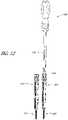
- FIG. 12illustrates the rod 200 being inserted into the first tower 400.
- the rod 200is generally longitudinally aligned with the first tower 400 as it is inserted into the tower 400.
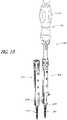
- FIG. 13illustrates the rod 200 and rod inserter 100 advanced further down the first tower 400.
- the alignment feature 136is coupled with slots in the tower 400, which helps orient the rod inserter 100 in the proper direction for advancing the rod 200 to the second tower 410.
- the alignment feature 136can also help prevent the rod 200 from being inadvertently misaligned or rotated about the longitudinal axis of the tower 400.
- the rod 200is shown nearing the bottom of the first tower 400 and top of the first pedicle screw 300.
- the actuator portion 114 of the handle 110can be activated (e.g., rotated) to start angling the rod 200 relative to the longitudinal axis of the first tower 400 and rod inserter 100, as illustrated in FIG. 14 .
- the leading end 204 of the rod 200can move out of the tower 400 through openings that are disposed on the sides of the towers.
- the leading end 204 of the rod 200continues to move toward the second tower 410.
- the rod inserter 100can be moved further distally down the first tower 400 as the rod 200 is angled relative to the tube 130.
- the leading end 204 of the rod 200can move through openings in the second tower 410 and through the channel of the second tower 410.
- FIG. 16illustrates the rod 200 seated in the heads of the pedicle screws 300, 310.
- the rod 200is generally perpendicular to the tube 130, or generally parallel with the spinal column. In other embodiments, the rod 200 can be at other angles to suit the positions of the pedicle screws and/or anatomy of the patient.
- the amount of rod overhang from the pedicle screwscan be controlled when using the rod inserter 100.
- a set length of the rodextends beyond the longitudinal axis of the rod inserter 100. This set length becomes the overhang from the pedicle screws once the rod 200 is attached to the pedicle screw. Therefore, a predetermined overhang can be achieved with the rod inserter 100 by tailoring the design of the rod holder 120 to control the set length that the rod 200 extends beyond the longitudinal axis of the rod inserter 100 when in the angled configuration.
- FIG. 17illustrates the rod inserter 100 in the first tower 400, and a fastener driver 500 and/or reducer in the second tower 410.
- the fastener driver 500is an elongate tool that is configured for insertion through the tower to deliver and couple a fastener, such as a threaded cap, to the head of a pedicle screw.
- a fastenersuch as a threaded cap
- the fastener driver 500is positioned through the second tower 410 and a threaded cap is fastened to the second pedicle screw 310, which tightens against the rod 200 to fix the leading end 204 of the rod 200.
- the actuator portion 114can be activated in reverse to retract the rod holder 120 back into the tube 130, as illustrated in FIG. 18 . Since the rod 200 is held in place on the second pedicle screw by the threaded cap, other fastener or tool, when the rod holder 120 is retracted it separates from the rod 200. As described above, the releasable mechanism holding the rod 200 and rod holder 120 together disconnects when the two components are separated with sufficient force.
- the rod inserter 100can be removed from the first tower 400, as illustrated in FIG. 19 .
- the fastener driver 500can be inserted into the first tower 400 to attach a fastener to the first pedicle screw to secure the trailing end 202 of the rod 200.
- the towers 400 and 410can be removed and the one or more incisions closed.
- a second set of anchoring devicesis attached to the same vertebrae on the other side of the posterior arch. In other configurations, the second set of anchoring devices can be attached to different vertebrae.
- a second elongate member or rod 200can be used to couple the second set of anchoring devices. In some configurations, the two rods 200 are generally parallel to each other. In other configurations, the two rods 200 can be at an angle to each other and/or different distances along the posterior-anterior direction.
- the embodiment according to the invention of a rod inserter 600is illustrated in FIG. 20 with another embodiment of a rod holder 620.
- the rod holder 620can have a mechanism 660 that is actuated to transition the rod holder 620 from a first configuration to a second configuration. In the first configuration, the rod holder 620 can grasp the rod and in the second configuration the rod holder can release the rod.
- the mechanism 660is a screw that is disposed between a first arm 621 and a second arm 622 and is configured to bring the arms 622, 622 toward each other, as described further below.
- the mechanismcan have a cam connection, angled surfaces, or other configuration to bring the arms together.
- the handle, tube 630 and linkage 650can be similar to other embodiments of the rod inserter described above.
- the first arm 621 and second arm 622can be configured to overlap each other and can be pivotally linked toward the center such that the arms 621, 622 move in a scissor-like motion.
- the arms 621, 622are connected by a hinge having a pin 626 with a longitudinal axis parallel with the axis of rotation of the arms 621, 622.
- the armscan have any functional joint that provides pivotal movement, such as for example a ball-and-socket.
- the arms 621, 622can have a leading engagement portion 624 and a trailing engagement portion 625 that are configured to couple with a rod.
- the leading engagement portion 624is comprised of side walls configured to extend around the rod 700.
- the inner surface of the leading engagement portion 624can be curved to correspond to the curvature of the rod to help engage and secure the rod.
- the trailing engagement portion 625is comprised of side walls with an opening between the walls configured to engage the trailing end 702 of the rod 700.
- the rod 700is an elongate member configured to extend between two or more bone anchors that are fixed to two or more vertebrae.
- the rod 700has an elongate cylindrical shape with a trailing end 702 and a leading end 704.
- the rodcan have other shapes, such as elongate members with an oval, square, rectangular, or polygonal cross-sectional shape.
- the rodcan be substantially straight or have a curve, which may help the fixation system to conform with the natural shape of the spinal anatomy.
- the trailing end 702has a reduced thickness that fits between the side walls of the trailing engagement portion 625 of the rod holder 620.
- the trailing end 702can have a knob 706 that couples with a cavity 627 in the trailing engagement portion 625 to help retain the rod 700 on the rod holder 620.
- the knob 706has flanges 708 that are configured to engage with shoulders 628 (see FIG. 25 ) in the cavity 627 of the trailing engagement portion 625 to help prevent the rod from falling out of the trailing engagement portion 625.
- the knob 706can also have a projection 710 that blocks the rod 700 from moving longitudinally when coupled to the cavity 627 of the trailing engagement portion 625.
- the knobcan have other features to help secure the rod to a complementary cavity in the trailing engagement portion, such as for example hooks, magnets, textured surfaces, and the like.
- Actuating the mechanism 660can close the arms 621, 622 to a first configuration wherein the arms 621, 622 clamp around the rod 700.
- the leading engagement portion 624clamps onto the middle portion of rod 700 and the trailing engagement portion 625 clamps onto the trailing end 702 of the rod 700.
- the first arm 621 and the second arm 622have a hole with internal threads 665.
- a dome 667 with sloped sides 669can be disposed at the bottom of the hole and can be configured to engage the mechanism 660.
- the mechanism 660can be a setscrew having a drive feature 662 on top and an aperture on the bottom with an angled bottom surface 668.
- the drive feature 662is illustrated as a hex drive, but can be any of a plurality of different types of drive features, such as a Torx drive, slotted drive, and the like.
- the sides of the mechanism 660can have external threads 664 that are complementary to the internal threads 665 of the arms 621, 622. When the mechanism 660 is screwed into the arms 621, 622, the angled bottom surface 668 of the mechanism 660 contacts the angled sides 669 of the dome 667.
- the angled surfacescooperate to squeeze the first arm 621 and second arm 622 together and close the leading engagement portion 624 in the first configuration.
- the hinging action of the two arms 621, 622closes the trailing engagement portion 625 in the first configuration.
- the mechanismcan be any of a plurality of different types of engagement devices configured to draw the two arms together, such as for example a clamp, a cam mechanism, or a fastener.
- the armscan clamp in other ways.
- the rod holdermay pivot along its longitudinal axis and a wedge inserted in the top portion of the rod holder can close the engagement portions on the bottom portion of the rod holder.
- advancing a mechanismcan drive a wedge between the rod holder and the rod to secure the rod.
- Other arrangements for securing the rodare also contemplated.
- the drive feature 662 of the mechanism 660is generally aligned with the longitudinal axis of the shaft 640.
- the shaft 640can have a channel 648 that extends through the longitudinal length of the shaft 640.
- the channel 648is configured to provide access to the mechanism 660 from the top of the rod inserter 600.
- a drive toolcan be inserted through the channel 648 to engage the mechanism 660 and change the rod holder 620 between the first and second configurations.
- the mechanism 660can be accessed and actuated through a cutout 638 on the side of the tube 630, as illustrated in FIGS. 27 and 28 .
- FIG. 29illustrates an embodiment of a rod inserter 600 with a drive tool 680 inserted through the rod inserter 600 to actuate the mechanism 660.
- the drive tool 680protrudes proximally from the handle of the rod inserter 600 and can be conveniently manipulated from outside of the surgical incision.
- the drive tool 680extends through the channel 648 of the shaft 640 and the distal end of the drive tool 680 is configured to engage the drive feature 662 of the mechanism 660.
- the drive feature 662can be a hex drive, a Torx drive, slotted, or any other functional drive feature.
- the distal end of the drive tool 680has a complementarily shaped hex head, Torx head, flathead, etc. to engage the drive feature 662.
- the vertebral columnis accessed and one or more vertebrae are identified and accessed.
- the vertebraecan be accessed through two small incisions that are made near the selected vertebrae. The incisions can be just large enough to accommodate access cannulas or towers.
- the vertebral columncan be accessed through a single incision that is large enough to access the two or more vertebrae in an open procedure.
- a first pedicle screw and a first towercan be attached to a first vertebra.
- a second pedicle screw and a second towercan be attached to a second vertebra.
- the rod inserter 600 with the rod 700 attachedcan be positioned above one of the towers.
- the rod 700is generally longitudinally aligned with the rod inserter 600 in preparation for insertion in the first tower.
- the rod inserter 600is oriented such that the rod 700 can be angled toward the second tower.
- the rod inserter 600can have alignment features that engage with features on the towers to help orient the rod inserter 600 in the desired direction, as described above in other embodiments.
- the alignment featurecouples with slots in the tower, which help orient the rod inserter 600 in the proper direction for advancing the rod 700 toward the second tower.
- the alignment featurecan also help prevent the rod 700 from being inadvertently misaligned or rotated about the longitudinal axis of the tower.
- the actuator portion of the handlecan be activated (e.g., rotated) to start angling the rod 700 relative to the longitudinal axis of the first tower and rod inserter 600.
- the leading end 704 of the rod 700can move out of the tower through openings that are disposed on the sides of the towers.
- the actuator portionis further activated, the leading end 704 of the rod 700 continued to move toward the second tower.
- the rod inserter 600can be moved further distally down the first tower as the rod 700 is angled.
- the leading end 704 of the rod 700can move through side openings in the second tower and through the channel of the second tower.
- the rod 700can be seated in the heads of the pedicle screws, where the rod 700 can be generally perpendicular to the tube of the rod inserter 600, or generally parallel with the spinal column. In other embodiments, the rod 700 can be at other angles to suit the positions of the pedicle screws and/or anatomy of the patient.
- a fastener driveris inserted in the second tower to deliver and couple a fastener, such as a threaded cap, to the head of a pedicle screw. The fastener is tightened against the rod 700 to fix the leading end 704 of the rod 700.
- a drive tool 680can be inserted through the channel 648 of the rod inserter 600 from the proximal end to the rod holder 620 at the distal end.
- the drive tool 680is configured to engage and actuate the mechanism 660. As described above, actuating the mechanism 660 releases the rod 700 from the rod holder 620. After the rod 700 is released from the rod holder 620, the drive tool 680 can be removed from the rod inserter 600.
- the actuator portioncan be activated in reverse to retract the rod holder 620 back into the tube. Once the rod holder 620 is retracted, the rod inserter 600 can be removed from the first tower.
- a fastener drivercan be inserted into the first tower to attach a fastener to the first pedicle screw to secure the trailing end 702 of the rod 700. After the rod 700 is secured, the towers can be removed and the one or more incisions closed.
- a second set of anchoring devicesis attached to the same vertebrae on the other side of the posterior arch. In other configurations, the second set of anchoring devices can be attached to different vertebrae.
- a second elongate member or rod 700can be used to couple the second set of anchoring devices. In some configurations, the two rods 700 are generally parallel to each other. In other configurations, the two rods 700 are at an angle to each other.
Landscapes
- Health & Medical Sciences (AREA)
- Orthopedic Medicine & Surgery (AREA)
- Neurology (AREA)
- Life Sciences & Earth Sciences (AREA)
- Surgery (AREA)
- Heart & Thoracic Surgery (AREA)
- Engineering & Computer Science (AREA)
- Biomedical Technology (AREA)
- Nuclear Medicine, Radiotherapy & Molecular Imaging (AREA)
- Medical Informatics (AREA)
- Molecular Biology (AREA)
- Animal Behavior & Ethology (AREA)
- General Health & Medical Sciences (AREA)
- Public Health (AREA)
- Veterinary Medicine (AREA)
- Surgical Instruments (AREA)
- Prostheses (AREA)
Description
- The present disclosure generally relates to the field of spinal orthopedics, and more particularly to a device for introducing a rod to a fixation system through a minimally invasive approach.
- The spine is a flexible structure that extends from the base of the skull to the tailbone. The weight of the upper body is transferred through the spine to the hips and the legs. The spine contains a plurality of bones called vertebrae. The vertebrae are hollow and stacked one upon the other, forming a strong hollow column for support. The hollow core of the spine houses and protects the nerves of the spinal cord. The spine is held upright through the work of the back muscles, which are attached to the vertebrae. While the normal spine has no side-to-side curve, it does have a series of front-to-back curves, giving it a gentle "S" shape.
- Each vertebra is separated from the vertebra above or below by a cushion-like, fibrocartilage called an intervertebral disc. The discs act as shock absorbers, cushioning the spine, and preventing individual bones from contacting each other. In addition, intervertebral discs act as a ligament that holds vertebrae together. Intervertebral discs also work with the facet joint to allow for slight movement of the spine. Together, these structures allow the spine to bend, rotate and/or twist.
- The spinal structure can become damaged as a result of degeneration, dysfunction, disease and/or trauma. More specifically, the spine may exhibit disc collapse, abnormal curvature, asymmetrical disc space collapse, abnormal alignment of the vertebrae and/or general deformity, which may lead to imbalance and tilt in the vertebrae. This may result in nerve compression, disability and overall instability and pain. If the proper shaping and/or curvature are not present due to scoliosis, neuromuscular disease, cerebral palsy, or other disorder, it may be necessary to straighten or adjust the spine into a proper curvature with surgery to correct these spinal disorders.
- Fixation is a surgical method wherein two or more vertebrae are held together by the placement of implants to stabilize the vertebrae. Surgical treatments may involve manipulation of the spinal column by attaching corrective implants, such as rods, wires, hooks, screws, and the like, to straighten abnormal curvatures, appropriately align vertebrae of the spinal column and/or reduce further rotation of the spinal column. The correct curvature can be obtained by manipulating the vertebrae into their proper position and securing that position with a rigid system of screws and rods. The screws can be inserted into the pedicles of the vertebrae to act as bone anchors, and the rods may be inserted into heads of the screws. Two rods may run substantially parallel to the spine and secure the spine in the desired shape and curvature. Thus the rods, which are shaped to mimic the correct spinal curvature, force the spine into proper alignment.
- In many cases, the fixation is augmented by a process called fusion, whereby an interbody implant is positioned in the intervertebral space between two or more vertebrae to join the vertebrae together. Bone grafts can be placed between the vertebrae and aid in fusion of the individual vertebrae together to form a correctly aligned spine.
- In addition, minimally invasive surgical techniques have been used on the spine to access the spine through small incisions. Minimally invasive spine surgery offers multiple advantages as compared to open surgery. The advantages may include minimal tissue damage, minimal blood loss, smaller incisions and scars, minimal post-operative discomfort, and relative quick recovery time and return to normal function.
US2007173831 discloses an instrument adapted for placing a cross-member between a pair of bone screws. The instrument includes an actuator and a housing that contains the cross-member in a pre-deployed state such that the cross-member is at least partially enclosed within the housing. A mechanism couples the actuator to the cross-member. Actuation of the actuator causes the mechanism to rotate the cross-member out of the housing and to further translate the cross-member in a direction toward engagement with a bone screw.US2011022088 provides systems for inserting a spinal stabilization rod. A rod insertion tool can include a body defining a passage, a pivot rod disposed in the passage and a rod retaining member. Movement of the pivot rod can cause the rod retaining member to rotate and consequently the spinal stabilization rod to rotate. The rod insertion tool can be sized to fit through channels in sleeves used during implantation of a spinal stabilization system.- The present invention relates to a rod inserter as claimed hereafter. Preferred embodiments of the invention are set forth in the dependent claims An aspect of at least one of the embodiments disclosed herein includes a rod inserter for delivering a spinal fixation rod through an access channel, the rod inserter including a first member having an elongate tube with a proximal end and a distal end, with a passage extending from the proximal end to the distal end. The rod inserter includes a second member having an elongate shaft configured to move along the passage of the first member and a third member having a first end and a second end, the first end coupled to the second member. The rod inserter further includes a rod holder having a leading end coupled to the distal end of the first member and a trailing end coupled to the second end of the third member, the rod holder configured to transition from an aligned configuration, wherein a longitudinal axis of the rod holder is generally parallel with a longitudinal axis of the second member, to an angled configuration wherein the longitudinal axis of the rod holder is at an angle to the longitudinal axis of the second member, the rod holder configured to releasably couple with a rod. An actuator toward the proximal end of the first member can be configured to translate the second member, wherein translation of the second member transitions the rod holder between the aligned configuration and the angled configuration.
- The rod holder can automatically release the rod when the rod holder is transitioned toward the aligned configuration. In some embodiments, the rod holder has a protrusion configured to be received by a complementary cutout on the rod.
- The rod holder includes a mechanism for changing the rod holder between a clamping configuration and a release configuration. The second member has a longitudinal channel for accessing the mechanism from the proximal end with a drive tool.
- In some embodiments, the actuator is a rotating handle. The rotating handle can have threads that engage complementary threads on the second member to move the second member longitudinally.
- The rod inserter can have an indicator corresponding to the orientation of the rod holder relative to the second member. In some embodiments, the rod inserter has an alignment feature configured to cooperate with an access tower, the alignment feature configured to prevent rotation of the rod inserter about its longitudinal axis.
- An aspect of at least another of the embodiments disclosed herein includes a rod inserter having a shaft extending between a proximal end and a distal end of the rod inserter, the shaft having a longitudinal axis and configured to move along the longitudinal axis. The rod inserter includes a rod holder toward the distal end configured to rotate from an aligned configuration wherein a longitudinal axis of the rod holder is generally parallel with the longitudinal axis of the shaft, to an angled configuration wherein the longitudinal axis of the rod holder is at an angle to the longitudinal axis of the shaft, the rod holder configured to releasably couple with a rod. An actuator toward the proximal end is configured to transition the rod holder between the aligned configuration and angled configuration.
- In some embodiments, the rod holder has a leading end pivotally coupled to the distal end of the rod inserter and a trailing end coupled to the shaft. The shaft can be connected to the rod holder by one or more linkages.
- The rod holder can automatically releases the rod when the rod holder is transitioned toward the aligned configuration. In some embodiments, the rod holder has a protrusion configured to be received by a complementary cutout on the rod.
- The rod holder includes a mechanism for changing the rod holder between a clamping configuration and a release configuration. The shaft 2. has a longitudinal channel for accessing the mechanism from the proximal end with a drive tool.
- In some embodiments, the actuator is a rotating handle. The rotating handle can have threads that engage complementary threads on the shaft to move the shaft longitudinally.
- The rod inserter can have an indicator corresponding to the orientation of the rod holder relative to the shaft. In some embodiments, the rod inserter has an alignment feature configured to cooperate with an access tower, the alignment feature configured to prevent rotation of the rod inserter about its longitudinal axis.
- It is also described herein a not claimed method of delivering a rod onto a fixation system, the method including providing a rod inserter having a rod holder configured to rotate from an aligned configuration wherein a longitudinal axis of the rod holder is generally parallel with a longitudinal axis of the rod inserter, to an angled configuration wherein the longitudinal axis of the rod holder is at an angle to the longitudinal axis of the rod inserter, and further providing a rod releasably coupled to the rod holder. The method can further include inserting the rod longitudinally through an access channel of a first anchoring device and activating an actuator on the rod inserter to transition the rod holder from the aligned configuration to the angled configuration, such that a trailing end of the rod is near the first anchoring device and a leading end of the rod is near a second anchoring device.
- In some examples, the method further includes activating the actuator to transition the rod holder from the angled configuration to the aligned configuration, wherein the rod holder automatically releases the rod. The method can further include moving a mechanism that releases the rod from the rod holder.
- The method can further include securing the rod to the first or second anchoring device. Securing the rod to the first or second anchoring device can include fastening a threaded cap onto the first or second anchoring device.
- In some examples , the first and second anchoring devices are pedicle screws with heads adapted to receive the rod.
- Specific embodiments and modifications thereof will become apparent to those skilled in the art from the detailed description herein having reference to the figures that follow, of which:
FIG. 1 is a perspective view of a rod inserter with a rod attached.FIG. 2 is a side view of the rod inserter and rod ofFIG. 1 .FIG. 3 is a perspective view of the rod ofFIG. 1 .FIG. 4 is a side view of the rod ofFIG. 3 .FIG. 5 is a close-up perspective view showing the rod holder of the rod inserter ofFIG. 1 without a rod.FIG. 6 is a close-up perspective view showing the rod holder of the rod inserter ofFIG. 1 with a rod attached.FIG. 7 is a close-up perspective view showing the rod holder of the rod inserter ofFIG. 1 with a rod attached, shown with portions of the rod inserter as transparent.FIG. 8 is a cross-sectional side view of the proximal end of the rod inserter ofFIG. 1 .FIG. 9 is a cross-sectional side view of the distal end of the rod inserter and rod ofFIG. 1 .FIG. 10 is a close-up side view of the rod inserter ofFIG. 1 showing an angle indicator window.FIG. 11 is a perspective view of the rod inserter ofFIG. 1 positioned above pedicle screws with towers attached.FIG. 12 is a perspective view of the rod inserter ofFIG. 1 being inserted into a tower.FIG. 13 is a perspective view of the rod inserter ofFIG. 1 inserted into a tower and a leading end of the rod near the pedicle screw.FIG. 14 is a perspective view of the rod inserter ofFIG. 1 inserted into a tower and being actuated to move the rod partially toward a second tower.FIG. 15 is a perspective view of the rod inserter ofFIG. 1 inserted into a tower and a leading end of the rod positioned in a second tower.FIG. 16 is a perspective view of the rod inserter ofFIG. 1 inserted into a tower and the rod extending between two towers.FIG. 17 is a perspective view of the rod inserter ofFIG. 1 inserted into a tower and a fastener driver inserted into another tower.FIG. 18 is a perspective view of the rod inserter ofFIG. 1 inserted into a tower and being actuated to retract the rod holder.FIG. 19 is a perspective view of the rod inserter ofFIG. 1 removed from a tower.FIG. 20 is a close-up perspective view of a rod holder of a rod inserter, according to an embodiment of the present disclosure.FIG. 21 is a close-up perspective view of the rod holder ofFIG. 20 , shown with a rod.FIG. 22 is a perspective view of the rod ofFIG. 21 .FIG. 23 is a side view of the rod ofFIG. 21 .FIG. 24 is a perspective view of the first arm of the rod holder ofFIG. 20 .FIG. 25 is a perspective view of the second arm of the rod holder ofFIG. 20 .FIG. 26 is a perspective cross-sectional view of a mechanism of the rod holder ofFIG. 20 .FIG. 27 is a close-up perspective view of the rod holder ofFIG. 20 , shown with a rod and portions of the rod inserter as transparent.FIG. 28 is a close-up cross-sectional side view of the rod holder ofFIG. 27 .FIG. 29 is a perspective view of the rod inserter ofFIG. 20 , shown with a drive tool and a rod.FIG. 30 is a close-up cross-sectional side view of the rod holder ofFIG. 29 , with the drive tool and rod.- Devices of fixing two or more vertebrae are disclosed herein and in some embodiments can involve minimally invasive techniques. Several non-limiting embodiments will now be described with reference to the figures, wherein like numerals reflect like elements throughout. The terminology used in the description presented herein is not intended to be interpreted in any limited or restrictive way, simply because it is being utilized in conjunction with a detailed description of certain specific embodiments. Furthermore, some embodiments may include several novel features, no single one of which is solely responsible for its desirable attributes or which is essential to the devices described herein.
- The words proximal and distal are applied herein to denote specific ends of components of the instrument described herein. A proximal end refers to the end of a component nearer to an operator of the instrument when the instrument is being used. A distal end refers to the end of a component further from the operator and extending towards the surgical area of a patient and/or the implant. The words top, bottom, left, right, upper and lower are used herein to refer to sides of the device from the described point of view. These reference descriptions are not intended to limit the orientation of the implant tool and the device can be used in any functional orientation.
FIGS. 1 and2 illustrate arod inserter 100 having arod 200 attached. The illustratedrod inserter 100 is an elongate tool used to deliver, and in some situations reduce, a rod onto a spinal fixation system. Therod inserter 100 has aproximal end 102 and adistal end 104. Theproximal end 102 can have ahandle 110 and thedistal end 104 can have arod holder 120 that is configured to releasably couple with therod 200. Anelongate tube 130 can extend from thehandle 110 to therod holder 120. Analignment feature 136 can be disposed on therod inserter 100 to help with proper orientation of therod inserter 100 during insertion into the towers, as described below.- As illustrated in
FIGS. 3 and 4 , therod 200 can be an elongate member configured to extend between two or more bone anchors that are fixed to two or more vertebrae. In the illustrated embodiment, therod 200 has an elongate cylindrical shape with a trailingend 202 and aleading end 204. In other embodiments, the rod can have other shapes, such as elongate members with an oval, square, rectangular, or polygonal cross-sectional shape. The illustratedrod 200 has a slight bend or curve, which may help the fixation system to preserve the natural shape of the spinal anatomy. In other embodiments, the rod can be substantially straight, have a greater curve than the illustrated embodiment, or have multiple bends. - The trailing
end 202 of therod 200 can have a coupling feature to accept a complementary feature on therod holder 120. For example, the illustratedrod 200 has acutout 206 with a round shape that is complementary to the shape of aprotrusion 122 or clip on therod holder 120, as shown inFIG. 5 . Theprotrusion 122 can have a slot through the middle that allows the sides of the protrusion to deflect in order to release from thecutout 206 of therod 200. In some examples, the protrusion can have a different release design, such as the protrusion being made of a compressible material that compresses to release from the cutout. Theprotrusion 122 can be customized so that it releases from therod 200 at a predetermined amount of separation force. In other examples, the coupling feature between the rod and rod holder can be any functional coupler that disconnects with a predetermined amount of separation force. The position of theprotrusion 122 on therod holder 120 can be tailored so that the rod has a predetermined amount of overhang from the fixation device when implanted. The amount of overhang can be selected for optimized efficacy. - A first end of the
rod holder 120 is hingedly coupled to the distal end of thetube 130. A second end of therod holder 120 is hingedly coupled to a distal end of alinkage 150. In the illustrated example, the hinged couplings comprise pins. In other examples , the hinged coupling can be any functional hinge, such as screws, ball and sockets, bending joints, friction connections, and the like. - With continued reference to
FIG. 5 , thelinkage 150 in the illustrated example comprises twostruts 152 attached to either side of therod holder 120, leaving space between thestruts 152 to accommodate therod holder 120 when rotated. A middle piece can be disposed between the twostruts 152 for increased structural strength. In some examples, thelinkage 150 can be a single component with a forked distal end to accommodate the rod holder. The proximal end of thelinkage 150 is hingedly coupled to a distal end of ashaft 140. The hinged coupling can include pins or other functional coupler, as discussed above. Theshaft 140 is an elongate member that extends through the middle of thetube 130 to transition the rod holder, and thus the rod, from an aligned configuration to an angled configuration, as discussed further below. - With reference to
FIG. 6 , therod 200 can be releasably coupled with therod holder 120 such that therod 200 can be automatically separated fromrod inserter 100. As used herein, automatically separated means separation without directly releasing therod 200. For example, when the rod is secured to the fixation system and therod holder 120 is retracted, therod holder 120 androd 200 are pulled apart until theprotrusion 122 is separated from thecutout 206. Therod 200 is released automatically as a result of the retraction of therod holder 120, without having to directly uncouple therod 200 or have a secondary release mechanism. - In some examples, the rod and rod holder can have other suitable shapes or configurations that allow releasable attachment of the rod to the rod holder. For example, the
rod 200 androd holder 120 can be releasably attached with adhesives, clips, magnets, snaps, compression joints or other suitable releasable connections. In some embodiments, the cutout can be disposed on the rod holder and the protrusion can be disposed on the rod. - The
leading end 204 of therod 200 can be bulleted with anangled surface 208 to help the rod move through the patient's tissue and muscle. Preferably, the tip of theleading end 204 is blunt to minimize trauma to the surrounding tissue as therod 200 is positioned onto the bone anchors. Theleading end 204 can have ahole 210 that helps visualize therod 200 during the implantation procedure, such as when using X-ray or fluoroscopic imaging techniques. Thehole 210 can produce a contrasting image compared to the surrounding rod so that surgeons can visualize the location of theleading end 204. In some embodiments, the rod can include radiopaque markers (e.g., tantalum, titanium, etc.) that can be seen in X-ray or other imaging techniques. FIG. 7 illustrates thedistal end 104 of therod inserter 100 with thetube 130 shown as transparent. Theshaft 140 is shown extending through the middle of thetube 130. The proximal end of theshaft 140 is coupled to an actuator on the handle and theshaft 140 is configured to slide longitudinally through thetube 130 when the actuator is activated. As theshaft 140 moves along the longitudinal direction, theshaft 140 pushes the proximal end of thelinkage 150, causing the distal end of thelinkage 150 to pivot out at least partially in the lateral direction, transitioning therod holder 120 between an aligned configuration and an angled configuration, as described in further detail below.- The
shaft 140 can be configured to move in the longitudinal direction, but constrained from rotating about the longitudinal axis. In the illustrated embodiment, theshaft 140 and thelinkage 150 are rotatably connected with apin 142. Thepin 142 extends beyond the connection between theshaft 140 andlinkage 150 and through aslot 132 in thetube 130. Theslot 132 is an elongate cutout extending longitudinally in the side walls of thetube 130. As the actuator is activated, theshaft 140 can be constrained from rotating by thepin 142 in theslot 132, but allowed to move longitudinally along the length of theslot 132. In other embodiments, theshaft 140 may have a separate protrusion or pin apart frompin 142 that is configured to slide within theslot 132. In some embodiments, the shaft can have other configurations that permit longitudinal movement and constrain rotational movement. For example, the shaft can have a non-circular cross-sectional shape, such as an oval, square, or polygon, and the inner cavity of the tube can have a complementary shape, such that the tube blocks rotation of the shaft. FIG. 8 illustrates a cross-sectional view of the proximal portion of arod inserter 100 according to some embodiments. Thehandle 110 can comprise a fixedportion 112 and anactuator portion 114. The fixedportion 112 is rigidly connected to thetube 130 and theactuator portion 114 can rotate or otherwise move relative to the fixedportion 112. Theactuator portion 114 can be activated to drive theshaft 140 in the longitudinal direction. In the illustrated example, theshaft 140 has aproximal end 144 that is engageable with theactuator portion 114 of thehandle 110. For example, theproximal end 144 of theshaft 140 can haveexternal threads 146 that engage withinternal threads 116 on theactuator portion 114. When the illustratedactuator portion 114 is rotated, theinternal threads 116 cooperate with theexternal threads 146 of theproximal end 144 to move theproximal end 144 and theshaft 140 in the proximal-distal direction. As mentioned above, theshaft 140 can be constrained from rotating by thepin 142 in theslot 132, but allowed to move longitudinally along the length of theslot 132. In other embodiments, the proximal portion of the rod inserter can have other actuation mechanisms for translating theshaft 140, such as a ratcheting handle or a trigger style mechanism or any other suitable translation mechanism.- With reference to
FIG. 9 , theshaft 140 can be moved in the proximal-distal direction to transition therod 200 between an aligned configuration, wherein thelongitudinal axis 201 of therod 200 and thelongitudinal axis 106 of therod inserter 100 are generally aligned, to an angled configuration, wherein thelongitudinal axis 201 of therod 200 is at an angle to thelongitudinal axis 106 of therod inserter 100. As theactuator portion 114 of thehandle 110 shown inFIG. 8 is activated, theshaft 140 moves in the longitudinal direction and acts upon the proximal end of thelinkage 150. When theshaft 140 is moved in the distal direction, the proximal end of thelinkage 150 also moves in the distal direction causing the distal end of thelinkage 150 to swing out laterally. The distal end of thelinkage 150 is attached to the second end of therod holder 120, which also swings out laterally, transitioning therod holder 120 from an aligned configuration to an angled configuration shown inFIG. 9 . Since therod 200 is releasably coupled to therod holder 120, therod 200 is also transitioned from an aligned configuration to an angled configuration by activating theactuator portion 114 of thehandle 110. - As illustrated in
FIG. 10 , in some embodiments, thetube 130 can have awindow 134 with a display that indicates the position of therod 200. Thewindow 134 is configured to be visible from outside the incision so that the surgeon can know the orientation of therod 200 without directly viewing inside the implant site. For example, theshaft 140 can be marked along the longitudinal length with angle indicators that correspond to the angle of therod 200 relative to thetube 130. As theshaft 140 moves in the longitudinal direction, the indicated angle displayed through the window changes with the angle of therod 200. The indicated angle can start from 0 degrees, indicating that therod 200 is generally longitudinally aligned with thetube 130, to about 90 degrees, indicating that therod 200 is generally perpendicular to thetube 130. In some embodiments, the indicated angle can go higher than 90 degrees, indicating that therod 200 is oriented beyond perpendicular to thetube 130. In other embodiments, the display can simply be sequential numbers, letters, symbols, or other markings that indicate the orientation of the rod. - In a method not claimed of using the
rod inserter 100, the vertebral column is accessed and one or more vertebrae are identified and accessed. In some embodiments, the upper cervical spine is accessed. In other embodiments, the lower cervical spine, cervicothoracic junction, thoracic spine, thoracolumbar junction, lumbar region, lumbosacral junction, sacrum or combination of the above regions are accessed. Two or more vertebrae are accessed and in some embodiments, two or more adjacent vertebrae are accessed. - In a minimally invasive technique, the vertebrae can be accessed through two small incisions that are made near the selected vertebrae. The incisions can be just large enough to accommodate access cannulas or towers. In some embodiments, the vertebral column can be accessed through an incision that is large enough to access the two or more vertebrae in an open procedure.
- With reference to
FIG. 11 , afirst pedicle screw 300, or other anchoring device, can be implanted in a first vertebra. Afirst tower 400 can be attached to thepedicle screw 300 before being implanted or after implantation. Asecond pedicle screw 310, or other anchoring device, can be implanted in a second vertebra. Asecond tower 410 can be attached to thesecond pedicle screw 310 before being implanted or after implantation. Thetowers - After the two or more pedicle screws are implanted in the vertebrae, the
rod inserter 100 with therod 200 attached can be positioned above one of the towers. In the embodiment illustrated inFIG. 11 , therod 200 is generally longitudinally aligned with therod inserter 100 in preparation for insertion in thefirst tower 400. Therod inserter 100 is oriented such that therod 200 can be angled toward thesecond tower 410. In some embodiments, therod inserter 100 can have alignment features 136 that engage with features on the towers to help orient therod inserter 100 in the desired direction. In the illustrated embodiment, the alignment features 136 are protrusions on thetube 130 that are inserted into longitudinal slots on the towers. The illustrated embodiment has two elongate protrusions on opposite sides of therod inserter 100, however, in other embodiments the alignment feature can be any suitable feature, such as directional indicators on thehandle 110 tip ortube 130. FIG. 12 illustrates therod 200 being inserted into thefirst tower 400. Therod 200 is generally longitudinally aligned with thefirst tower 400 as it is inserted into thetower 400.FIG. 13 illustrates therod 200 androd inserter 100 advanced further down thefirst tower 400. Thealignment feature 136 is coupled with slots in thetower 400, which helps orient therod inserter 100 in the proper direction for advancing therod 200 to thesecond tower 410. Thealignment feature 136 can also help prevent therod 200 from being inadvertently misaligned or rotated about the longitudinal axis of thetower 400. Therod 200 is shown nearing the bottom of thefirst tower 400 and top of thefirst pedicle screw 300. As therod 200 approaches or reaches the top of thefirst pedicle screw 300, theactuator portion 114 of thehandle 110 can be activated (e.g., rotated) to start angling therod 200 relative to the longitudinal axis of thefirst tower 400 androd inserter 100, as illustrated inFIG. 14 . Theleading end 204 of therod 200 can move out of thetower 400 through openings that are disposed on the sides of the towers.- With reference to
FIG. 15 , as theactuator portion 114 is further activated, theleading end 204 of therod 200 continues to move toward thesecond tower 410. Therod inserter 100 can be moved further distally down thefirst tower 400 as therod 200 is angled relative to thetube 130. Theleading end 204 of therod 200 can move through openings in thesecond tower 410 and through the channel of thesecond tower 410. FIG. 16 illustrates therod 200 seated in the heads of the pedicle screws 300, 310. In the illustrated embodiments, therod 200 is generally perpendicular to thetube 130, or generally parallel with the spinal column. In other embodiments, therod 200 can be at other angles to suit the positions of the pedicle screws and/or anatomy of the patient. Advantageously, the amount of rod overhang from the pedicle screws can be controlled when using therod inserter 100. When therod 200 is generally perpendicular to thetube 130, a set length of the rod extends beyond the longitudinal axis of therod inserter 100. This set length becomes the overhang from the pedicle screws once therod 200 is attached to the pedicle screw. Therefore, a predetermined overhang can be achieved with therod inserter 100 by tailoring the design of therod holder 120 to control the set length that therod 200 extends beyond the longitudinal axis of therod inserter 100 when in the angled configuration.FIG. 17 illustrates therod inserter 100 in thefirst tower 400, and afastener driver 500 and/or reducer in thesecond tower 410. Thefastener driver 500 is an elongate tool that is configured for insertion through the tower to deliver and couple a fastener, such as a threaded cap, to the head of a pedicle screw. In the illustrated embodiment, thefastener driver 500 is positioned through thesecond tower 410 and a threaded cap is fastened to thesecond pedicle screw 310, which tightens against therod 200 to fix theleading end 204 of therod 200.- After the
leading end 204 of therod 200 is fixed to thesecond pedicle screw 310, theactuator portion 114 can be activated in reverse to retract therod holder 120 back into thetube 130, as illustrated inFIG. 18 . Since therod 200 is held in place on the second pedicle screw by the threaded cap, other fastener or tool, when therod holder 120 is retracted it separates from therod 200. As described above, the releasable mechanism holding therod 200 androd holder 120 together disconnects when the two components are separated with sufficient force. - Once the
rod holder 120 is fully retracted, therod inserter 100 can be removed from thefirst tower 400, as illustrated inFIG. 19 . In some embodiments, thefastener driver 500 can be inserted into thefirst tower 400 to attach a fastener to the first pedicle screw to secure the trailingend 202 of therod 200. After therod 200 is secured, thetowers - In some configurations, a second set of anchoring devices is attached to the same vertebrae on the other side of the posterior arch. In other configurations, the second set of anchoring devices can be attached to different vertebrae. A second elongate member or
rod 200 can be used to couple the second set of anchoring devices. In some configurations, the tworods 200 are generally parallel to each other. In other configurations, the tworods 200 can be at an angle to each other and/or different distances along the posterior-anterior direction. - The embodiment according to the invention of a
rod inserter 600 is illustrated inFIG. 20 with another embodiment of arod holder 620. Therod holder 620 can have amechanism 660 that is actuated to transition therod holder 620 from a first configuration to a second configuration. In the first configuration, therod holder 620 can grasp the rod and in the second configuration the rod holder can release the rod. In some embodiments, themechanism 660 is a screw that is disposed between afirst arm 621 and asecond arm 622 and is configured to bring thearms tube 630 andlinkage 650 can be similar to other embodiments of the rod inserter described above. - With reference to
FIGS. 20 and21 , thefirst arm 621 andsecond arm 622 can be configured to overlap each other and can be pivotally linked toward the center such that thearms arms pin 626 with a longitudinal axis parallel with the axis of rotation of thearms FIGS. 20 ,24 and 25 , thearms leading engagement portion 624 and a trailingengagement portion 625 that are configured to couple with a rod. The leadingengagement portion 624 is comprised of side walls configured to extend around therod 700. The inner surface of the leadingengagement portion 624 can be curved to correspond to the curvature of the rod to help engage and secure the rod. The trailingengagement portion 625 is comprised of side walls with an opening between the walls configured to engage the trailingend 702 of therod 700. - With reference to
FIGS. 22 and 23 , therod 700 is an elongate member configured to extend between two or more bone anchors that are fixed to two or more vertebrae. In the illustrated embodiment, therod 700 has an elongate cylindrical shape with a trailingend 702 and aleading end 704. In other embodiments, the rod can have other shapes, such as elongate members with an oval, square, rectangular, or polygonal cross-sectional shape. In some embodiments, the rod can be substantially straight or have a curve, which may help the fixation system to conform with the natural shape of the spinal anatomy. - In the illustrated embodiment, the trailing
end 702 has a reduced thickness that fits between the side walls of the trailingengagement portion 625 of therod holder 620. The trailingend 702 can have aknob 706 that couples with acavity 627 in the trailingengagement portion 625 to help retain therod 700 on therod holder 620. In the illustrated embodiment, theknob 706 hasflanges 708 that are configured to engage with shoulders 628 (seeFIG. 25 ) in thecavity 627 of the trailingengagement portion 625 to help prevent the rod from falling out of the trailingengagement portion 625. Theknob 706 can also have aprojection 710 that blocks therod 700 from moving longitudinally when coupled to thecavity 627 of the trailingengagement portion 625. In other embodiments, the knob can have other features to help secure the rod to a complementary cavity in the trailing engagement portion, such as for example hooks, magnets, textured surfaces, and the like. - Actuating the
mechanism 660 can close thearms arms rod 700. With reference toFIG. 21 , the leadingengagement portion 624 clamps onto the middle portion ofrod 700 and the trailingengagement portion 625 clamps onto the trailingend 702 of therod 700. In the embodiment illustrated inFIG. 24 , thefirst arm 621 and thesecond arm 622 have a hole withinternal threads 665. Adome 667 with slopedsides 669 can be disposed at the bottom of the hole and can be configured to engage themechanism 660. - With reference to
FIG. 26 , themechanism 660 can be a setscrew having adrive feature 662 on top and an aperture on the bottom with anangled bottom surface 668. Thedrive feature 662 is illustrated as a hex drive, but can be any of a plurality of different types of drive features, such as a Torx drive, slotted drive, and the like. The sides of themechanism 660 can haveexternal threads 664 that are complementary to theinternal threads 665 of thearms mechanism 660 is screwed into thearms angled bottom surface 668 of themechanism 660 contacts theangled sides 669 of thedome 667. As themechanism 660 is advanced further, the angled surfaces cooperate to squeeze thefirst arm 621 andsecond arm 622 together and close the leadingengagement portion 624 in the first configuration. At the same time, the hinging action of the twoarms engagement portion 625 in the first configuration. - The mechanism can be any of a plurality of different types of engagement devices configured to draw the two arms together, such as for example a clamp, a cam mechanism, or a fastener. In some embodiments, the arms can clamp in other ways. For example, the rod holder may pivot along its longitudinal axis and a wedge inserted in the top portion of the rod holder can close the engagement portions on the bottom portion of the rod holder. In another example, advancing a mechanism can drive a wedge between the rod holder and the rod to secure the rod. Other arrangements for securing the rod are also contemplated.
- With reference to
FIGS. 27 and28 , when the rod holder is generally perpendicular to the longitudinal axis of theshaft 640, thedrive feature 662 of themechanism 660 is generally aligned with the longitudinal axis of theshaft 640. As illustrated inFIG. 28 , theshaft 640 can have achannel 648 that extends through the longitudinal length of theshaft 640. Thechannel 648 is configured to provide access to themechanism 660 from the top of therod inserter 600. A drive tool can be inserted through thechannel 648 to engage themechanism 660 and change therod holder 620 between the first and second configurations. When the rod holder is generally parallel to the longitudinal axis of theshaft 640, themechanism 660 can be accessed and actuated through a cutout 638 on the side of thetube 630, as illustrated inFIGS. 27 and28 . FIG. 29 illustrates an embodiment of arod inserter 600 with adrive tool 680 inserted through therod inserter 600 to actuate themechanism 660. Thedrive tool 680 protrudes proximally from the handle of therod inserter 600 and can be conveniently manipulated from outside of the surgical incision. As illustrated inFIG. 30 , thedrive tool 680 extends through thechannel 648 of theshaft 640 and the distal end of thedrive tool 680 is configured to engage thedrive feature 662 of themechanism 660. As discussed above, thedrive feature 662 can be a hex drive, a Torx drive, slotted, or any other functional drive feature. The distal end of thedrive tool 680 has a complementarily shaped hex head, Torx head, flathead, etc. to engage thedrive feature 662.- Methods of using the alternative embodiments of the rod inserter are similar to as described above for other embodiments. The vertebral column is accessed and one or more vertebrae are identified and accessed. In a minimally invasive technique, the vertebrae can be accessed through two small incisions that are made near the selected vertebrae. The incisions can be just large enough to accommodate access cannulas or towers. In some embodiments, the vertebral column can be accessed through a single incision that is large enough to access the two or more vertebrae in an open procedure.
- As described above, a first pedicle screw and a first tower can be attached to a first vertebra. A second pedicle screw and a second tower can be attached to a second vertebra. Then, the
rod inserter 600 with therod 700 attached can be positioned above one of the towers. Therod 700 is generally longitudinally aligned with therod inserter 600 in preparation for insertion in the first tower. Therod inserter 600 is oriented such that therod 700 can be angled toward the second tower. - The
rod inserter 600 can have alignment features that engage with features on the towers to help orient therod inserter 600 in the desired direction, as described above in other embodiments. In the illustrated embodiments, the alignment feature couples with slots in the tower, which help orient therod inserter 600 in the proper direction for advancing therod 700 toward the second tower. The alignment feature can also help prevent therod 700 from being inadvertently misaligned or rotated about the longitudinal axis of the tower. - As the
rod 700 approaches or reaches the top of the first pedicle screw, the actuator portion of the handle can be activated (e.g., rotated) to start angling therod 700 relative to the longitudinal axis of the first tower androd inserter 600. Theleading end 704 of therod 700 can move out of the tower through openings that are disposed on the sides of the towers. As the actuator portion is further activated, theleading end 704 of therod 700 continued to move toward the second tower. Therod inserter 600 can be moved further distally down the first tower as therod 700 is angled. Theleading end 704 of therod 700 can move through side openings in the second tower and through the channel of the second tower. - The
rod 700 can be seated in the heads of the pedicle screws, where therod 700 can be generally perpendicular to the tube of therod inserter 600, or generally parallel with the spinal column. In other embodiments, therod 700 can be at other angles to suit the positions of the pedicle screws and/or anatomy of the patient. In some embodiments, a fastener driver is inserted in the second tower to deliver and couple a fastener, such as a threaded cap, to the head of a pedicle screw. The fastener is tightened against therod 700 to fix theleading end 704 of therod 700. - A
drive tool 680 can be inserted through thechannel 648 of therod inserter 600 from the proximal end to therod holder 620 at the distal end. Thedrive tool 680 is configured to engage and actuate themechanism 660. As described above, actuating themechanism 660 releases therod 700 from therod holder 620. After therod 700 is released from therod holder 620, thedrive tool 680 can be removed from therod inserter 600. - The actuator portion can be activated in reverse to retract the
rod holder 620 back into the tube. Once therod holder 620 is retracted, therod inserter 600 can be removed from the first tower. In some embodiments, a fastener driver can be inserted into the first tower to attach a fastener to the first pedicle screw to secure the trailingend 702 of therod 700. After therod 700 is secured, the towers can be removed and the one or more incisions closed. - In some configurations, a second set of anchoring devices is attached to the same vertebrae on the other side of the posterior arch. In other configurations, the second set of anchoring devices can be attached to different vertebrae. A second elongate member or
rod 700 can be used to couple the second set of anchoring devices. In some configurations, the tworods 700 are generally parallel to each other. In other configurations, the tworods 700 are at an angle to each other. - Although certain embodiments, features, and examples have been described herein, it will be understood by those skilled in the art that many aspects of the methods and devices illustrated and described in the present disclosure may be differently combined and/or modified to form still further embodiments. For example, any one component of the device illustrated and described above can be used alone or with other components without departing from the spirit of the present disclosure. Additionally, it will be recognized that the methods described herein may be practiced in different sequences, and/or with additional devices as desired. Such alternative embodiments and/or uses of the methods and devices described above and obvious modifications and equivalents thereof are intended to be included within the scope of the present disclosure. Thus, it is intended that the scope of the present disclosure should not be limited by the particular embodiments described above, but should be determined only by a fair reading of the claims that follow.
Claims (14)
- A rod inserter (600) for delivering a spinal fixation rod through an access channel, the rod inserter comprising:a first member (630) comprising an elongate tube with a proximal end and a distal end, with a passage extending from the proximal end to the distal end;a second member (640) comprising an elongate shaft configured to move along the passage of the first member;a third member (650) comprising a first end and a second end, the first end coupled to the second member;a rod holder (620) comprising a leading end coupled to the distal end of the first member and a trailing end coupled to the second end of the third member, the rod holder configured to transition from an aligned configuration, wherein a longitudinal axis of the rod holder is generally parallel with a longitudinal axis of the second member, to an angled configuration wherein the longitudinal axis of the rod holder is at an angle to the longitudinal axis of the second member, the rod holder configured to releasably couple with a rod (700); andan actuator toward the proximal end of the first member configured to translate the second member, wherein translation of the second member transitions the rod holder between the aligned configuration and the angled configuration;wherein the rod holder comprises a mechanism (660) for changing the rod holder between a clamping configuration and a release configuration; wherein the second member comprises a longitudinal channel (648) for accessing the mechanism from the proximal end.
- The rod inserter of claim 1, further comprising a drive tool (680) for actuating the mechanism through the longitudinal channel.
- The rod inserter of claim 1, further comprising an indicator corresponding to the orientation of the rod holder relative to the second member.
- The rod inserter of claim 1, wherein the actuator is a rotating handle.
- The rod inserter of claim 4. wherein the rotating handle comprises threads that engage complementary threads on the second member to move the second member longitudinally.
- The rod inserter of claim 3, further comprising an alignment feature configured to cooperate with an access tower, the alignment feature configured to prevent rotation of the rod inserter about its longitudinal axis.
- A rod inserter (600) comprising:
an elongate tube (630) comprising a passage extending from a proximal end to a distal end;a shaft (640) disposed in the passage of the elongate tube, the shaft comprising a longitudinal axis and configured to move along the longitudinal axis;a rod holder (620) toward the distal end configured to rotate from an aligned configuration wherein a longitudinal axis of the rod holder is generally parallel with the longitudinal axis of the shaft, to an angled configuration wherein the longitudinal axis of the rod holder is at an angle to the longitudinal axis of the shaft, the rod holder configured to releasably couple with a rod (700); andan actuator toward the proximal end configured to transition the rod holder between the aligned configuration and angled configuration;wherein the rod holder comprises a mechanism (660) for changing the rod holder between a clamping configuration and a release configuration; and wherein the shaft comprises a longitudinal channel (648) for accessing the mechanism from the proximal end. - The rod inserter of claim 7, wherein the rod holder comprises a leading end pivotally coupled to the distal end of the rod inserter and a trailing end coupled to the shaft.
- The rod inserter of claim 7, wherein the shaft is connected to the rod holder by one or more linkages (650).
- The rod inserter of claim 7, further comprising a drive tool (680) for actuating the mechanism through the longitudinal channel.
- The rod inserter of claim 7, wherein the actuator is a rotating handle.
- The rod inserter of claim 11, wherein the rotating handle comprises threads that engage complementary threads on the shaft to move the shaft longitudinally.
- The rod inserter of claim 7, further comprising an indicator corresponding to the orientation of the rod holder relative to the shaft.
- The rod inserter of claim 13, further comprising an alignment feature configured to cooperate with an access tower, the alignment feature configured to prevent rotation of the rod inserter about its longitudinal axis.
Priority Applications (1)
| Application Number | Priority Date | Filing Date | Title |
|---|---|---|---|
| EP22180757.1AEP4122410A1 (en) | 2014-08-11 | 2015-08-10 | Articulating rod inserter |
Applications Claiming Priority (2)
| Application Number | Priority Date | Filing Date | Title |
|---|---|---|---|
| US201462036053P | 2014-08-11 | 2014-08-11 | |
| PCT/US2015/044527WO2016025408A2 (en) | 2014-08-11 | 2015-08-10 | Articulating rod inserter |
Related Child Applications (1)
| Application Number | Title | Priority Date | Filing Date |
|---|---|---|---|
| EP22180757.1ADivisionEP4122410A1 (en) | 2014-08-11 | 2015-08-10 | Articulating rod inserter |
Publications (3)
| Publication Number | Publication Date |
|---|---|
| EP3179941A2 EP3179941A2 (en) | 2017-06-21 |
| EP3179941A4 EP3179941A4 (en) | 2018-04-11 |
| EP3179941B1true EP3179941B1 (en) | 2022-07-06 |
Family
ID=55266536
Family Applications (2)
| Application Number | Title | Priority Date | Filing Date |
|---|---|---|---|
| EP15831753.7AActiveEP3179941B1 (en) | 2014-08-11 | 2015-08-10 | Articulating rod inserter |
| EP22180757.1AWithdrawnEP4122410A1 (en) | 2014-08-11 | 2015-08-10 | Articulating rod inserter |
Family Applications After (1)
| Application Number | Title | Priority Date | Filing Date |
|---|---|---|---|
| EP22180757.1AWithdrawnEP4122410A1 (en) | 2014-08-11 | 2015-08-10 | Articulating rod inserter |
Country Status (6)
| Country | Link |
|---|---|
| US (3) | US9750546B2 (en) |
| EP (2) | EP3179941B1 (en) |
| JP (2) | JP7025207B2 (en) |
| AU (2) | AU2015301959B2 (en) |
| CA (1) | CA2957241A1 (en) |
| WO (1) | WO2016025408A2 (en) |
Families Citing this family (7)
| Publication number | Priority date | Publication date | Assignee | Title |
|---|---|---|---|---|
| US8206395B2 (en)* | 2010-06-18 | 2012-06-26 | Spine Wave, Inc. | Surgical instrument and method for the distraction or compression of bones |
| WO2014074389A1 (en)* | 2012-11-06 | 2014-05-15 | Alphatec Spine, Inc. | Instrument and method for in situ rod adjustment |
| FR3018678B1 (en)* | 2014-03-20 | 2016-03-11 | Spineway | SURGICAL ASSEMBLY, BONE ANCHORING SCREW AND DEVICE FOR EXTENSION OF SUCH SCREWS FORMING PART OF SAID SURGICAL ASSEMBLY |
| US9795422B2 (en)* | 2016-01-06 | 2017-10-24 | Aesculap Implant Systems, Llc | Rod inserter, system and method |
| US9987053B2 (en)* | 2016-03-29 | 2018-06-05 | Stryker European Holdings I, Llc | Surgical instruments and methods |
| DE102016011521A1 (en)* | 2016-09-23 | 2018-03-29 | Silony Medical International AG | Stabeinbringinstrument with adjustable rod angulation |
| WO2022050304A1 (en)* | 2020-09-02 | 2022-03-10 | 京セラ株式会社 | Grip holder for medical instrument, and instrument for spinal operation |
Family Cites Families (69)
| Publication number | Priority date | Publication date | Assignee | Title |
|---|---|---|---|---|
| DE29806563U1 (en)* | 1998-04-09 | 1998-06-18 | Howmedica GmbH, 24232 Schönkirchen | Pedicle screw and assembly aid for it |
| US6660022B1 (en) | 1999-06-01 | 2003-12-09 | Smith & Nephew, Inc. | Rotor blade anchor and tool for installing same |
| US6530929B1 (en) | 1999-10-20 | 2003-03-11 | Sdgi Holdings, Inc. | Instruments for stabilization of bony structures |
| US6736829B1 (en) | 1999-11-11 | 2004-05-18 | Linvatec Corporation | Toggle anchor and tool for insertion thereof |
| DE10011678B4 (en) | 2000-03-10 | 2007-07-26 | Richard Wolf Gmbh | Surgical instrument for applying implants |
| US7322979B2 (en) | 2000-03-15 | 2008-01-29 | Warsaw Orthopedic, Inc. | Multidirectional pivoting bone screw and fixation system |
| US6342057B1 (en) | 2000-04-28 | 2002-01-29 | Synthes (Usa) | Remotely aligned surgical drill guide |
| US6916323B2 (en) | 2001-08-21 | 2005-07-12 | Depuy Products, Inc. | Method and apparatus for percutaneously securing a bone screw and a bone plate to a bone of a patient |
| US7824410B2 (en) | 2001-10-30 | 2010-11-02 | Depuy Spine, Inc. | Instruments and methods for minimally invasive spine surgery |
| US7572276B2 (en) | 2002-05-06 | 2009-08-11 | Warsaw Orthopedic, Inc. | Minimally invasive instruments and methods for inserting implants |
| EP1534157A2 (en) | 2002-07-10 | 2005-06-01 | Joseph Aferzon | Spinal support coupling device |
| US7306603B2 (en) | 2002-08-21 | 2007-12-11 | Innovative Spinal Technologies | Device and method for percutaneous placement of lumbar pedicle screws and connecting rods |
| ES2236422T3 (en) | 2002-10-25 | 2005-07-16 | Brainlab Ag | APPARATUS AND PROCEDURE TO CALIBRATE AN ELEMENT. |
| AU2003287273C1 (en) | 2002-10-30 | 2010-01-07 | Zimmer Spine, Inc. | Spinal stabilization system insertion and methods |
| US7083612B2 (en) | 2003-01-15 | 2006-08-01 | Cryodynamics, Llc | Cryotherapy system |
| US7473267B2 (en) | 2003-04-25 | 2009-01-06 | Warsaw Orthopedic, Inc. | System and method for minimally invasive posterior fixation |
| US8002798B2 (en) | 2003-09-24 | 2011-08-23 | Stryker Spine | System and method for spinal implant placement |
| US7588588B2 (en) | 2003-10-21 | 2009-09-15 | Innovative Spinal Technologies | System and method for stabilizing of internal structures |
| US7967826B2 (en) | 2003-10-21 | 2011-06-28 | Theken Spine, Llc | Connector transfer tool for internal structure stabilization systems |
| US7588575B2 (en) | 2003-10-21 | 2009-09-15 | Innovative Spinal Technologies | Extension for use with stabilization systems for internal structures |
| WO2005039392A2 (en)* | 2003-10-22 | 2005-05-06 | Endius Incorporated | Method and surgical tool for inserting a longitudinal member |
| US7179261B2 (en)* | 2003-12-16 | 2007-02-20 | Depuy Spine, Inc. | Percutaneous access devices and bone anchor assemblies |
| US7648507B2 (en) | 2003-12-16 | 2010-01-19 | Depuy Acromed, Inc. | Pivoting implant holder |
| US7527638B2 (en) | 2003-12-16 | 2009-05-05 | Depuy Spine, Inc. | Methods and devices for minimally invasive spinal fixation element placement |
| US7648506B2 (en) | 2003-12-16 | 2010-01-19 | Depuy Acromed, Inc. | Pivoting implant holder |
| US7597694B2 (en) | 2004-01-30 | 2009-10-06 | Warsaw Orthopedic, Inc. | Instruments and methods for minimally invasive spinal stabilization |
| US7476240B2 (en) | 2004-02-06 | 2009-01-13 | Depuy Spine, Inc. | Devices and methods for inserting a spinal fixation element |
| US7871413B2 (en) | 2004-07-21 | 2011-01-18 | Solco Biomedical Co., Ltd. | Pedicle screw and operating device thereof |
| US7666189B2 (en) | 2004-09-29 | 2010-02-23 | Synthes Usa, Llc | Less invasive surgical system and methods |
| WO2006057837A1 (en)* | 2004-11-23 | 2006-06-01 | Jackson Roger P | Spinal fixation tool attachment structure |
| EP1858422A4 (en) | 2005-02-23 | 2011-12-28 | Pioneer Surgical Technology Inc | Minimally invasive surgical system |
| US9314273B2 (en) | 2005-04-27 | 2016-04-19 | Globus Medical, Inc. | Percutaneous vertebral stabilization system |
| US7758617B2 (en) | 2005-04-27 | 2010-07-20 | Globus Medical, Inc. | Percutaneous vertebral stabilization system |
| US7871424B2 (en) | 2005-05-23 | 2011-01-18 | Custom Spine, Inc. | Spinal rod inserter |
| US7749232B2 (en) | 2005-05-24 | 2010-07-06 | Anthony Salerni | Electromagnetically guided spinal rod system and related methods |
| US7909830B2 (en) | 2005-08-25 | 2011-03-22 | Synthes Usa, Llc | Methods of spinal fixation and instrumentation |
| US7695475B2 (en) | 2005-08-26 | 2010-04-13 | Warsaw Orthopedic, Inc. | Instruments for minimally invasive stabilization of bony structures |
| US20070173831A1 (en)* | 2005-11-14 | 2007-07-26 | Abdou M S | Device and method for the placement of spinal fixators |
| CN101365392B (en) | 2005-11-17 | 2011-02-02 | K·R·秦 | Systems and methods for implanting a spinal stabilization device |
| US7951152B2 (en) | 2005-11-23 | 2011-05-31 | Trinity Orthopedics, Llc | Spinal distractor, compressor, and rod engaging system and method |
| US7497869B2 (en) | 2006-01-27 | 2009-03-03 | Warsaw Orthopedic, Inc. | Methods and devices for a minimally invasive placement of a rod within a patient |
| US7520879B2 (en) | 2006-02-07 | 2009-04-21 | Warsaw Orthopedic, Inc. | Surgical instruments and techniques for percutaneous placement of spinal stabilization elements |
| US8333771B2 (en)* | 2006-08-04 | 2012-12-18 | Magrod, Llc | System for pushing and pulling surgical implants into position in vivo via a tether |
| US7976546B2 (en) | 2006-08-04 | 2011-07-12 | Magrod, Llc | Magnetic targeting system for facilitating navigation |
| US7686809B2 (en) | 2006-09-25 | 2010-03-30 | Stryker Spine | Rod inserter and rod with reduced diameter end |
| US8162952B2 (en) | 2006-09-26 | 2012-04-24 | Ebi, Llc | Percutaneous instrument assembly |
| US7998144B2 (en) | 2006-12-22 | 2011-08-16 | Aesculap Ag | Surgical instrument and osteosynthesis device |
| US7922731B2 (en) | 2006-12-22 | 2011-04-12 | Aesculap Ag | Surgical instrument and osteosynthesis device |
| US8460300B2 (en) | 2007-06-12 | 2013-06-11 | Zimmer Spine, Inc. | Instrumentation and associated techniques for minimally invasive vertebral rod installation |
| US8048129B2 (en) | 2007-08-15 | 2011-11-01 | Zimmer Spine, Inc. | MIS crosslink apparatus and methods for spinal implant |
| US8414588B2 (en) | 2007-10-04 | 2013-04-09 | Depuy Spine, Inc. | Methods and devices for minimally invasive spinal connection element delivery |
| US8366714B2 (en) | 2007-10-23 | 2013-02-05 | K2M, Inc. | Rod insertion instrument and method of use |
| WO2009055026A1 (en) | 2007-10-23 | 2009-04-30 | Alphatec Spine, Inc. | Systems and methods for spinal fixation |
| US8105362B2 (en) | 2008-06-30 | 2012-01-31 | Duarte Luis E | Percutaneous spinal rod insertion system and related methods |
| US9750545B2 (en) | 2009-03-27 | 2017-09-05 | Globus Medical, Inc. | Devices and methods for inserting a vertebral fixation member |
| US8900238B2 (en)* | 2009-03-27 | 2014-12-02 | Globus Medical, Inc. | Devices and methods for inserting a vertebral fixation member |
| US8246624B2 (en)* | 2009-07-23 | 2012-08-21 | Zimmer Spine, Inc. | Spinal rod insertion tool and method |
| US8435245B2 (en) | 2009-12-17 | 2013-05-07 | Custom Spine, Inc. | Surgical implant insertion apparatus and method |
| US8795283B2 (en)* | 2009-12-28 | 2014-08-05 | Safe Orthopaedics Sas | Instrument kit for performing spinal stabilization |
| US8460301B2 (en) | 2010-01-27 | 2013-06-11 | Warsaw Orthopedic, Inc. | Systems and methods for minimally invasive stabilization of bony structures |
| US8540719B2 (en) | 2010-02-09 | 2013-09-24 | Aesculap Implant Systems, Llc | Percutaneous rod insertion system and method |
| US8323286B2 (en)* | 2010-03-02 | 2012-12-04 | Warsaw Orthopedic, Inc. | Systems and methods for minimally invasive surgical procedures |
| KR101001539B1 (en)* | 2010-06-14 | 2010-12-17 | 주식회사 디오메디칼 | Chiropractic rod insertion device and chiropractic device |
| US8414590B2 (en)* | 2011-04-14 | 2013-04-09 | Custom Spine, Inc. | Pivoting insertion apparatus and method |
| KR101419807B1 (en)* | 2012-09-12 | 2014-07-21 | 주식회사 지에스메디칼 | working tower for minimally invasive surgery system |
| US9526536B2 (en)* | 2013-10-16 | 2016-12-27 | Spineology Inc. | Articulating rod holder |
| EP2881052A1 (en)* | 2013-12-09 | 2015-06-10 | Biedermann Technologies GmbH & Co. KG | Rod insertion device for inserting a rod into a bone anchor, in particular for minimally invasive surgery |
| KR101434333B1 (en)* | 2013-12-13 | 2014-08-29 | 주식회사 지에스메디칼 | Rod reducer for minimally invasive surgery system |
| US20160058482A1 (en)* | 2014-08-07 | 2016-03-03 | Jeffrey Scott Smith | Rod delivery tool for use in pedicle screw systems |
- 2015
- 2015-08-10WOPCT/US2015/044527patent/WO2016025408A2/enactiveApplication Filing
- 2015-08-10USUS14/822,780patent/US9750546B2/enactiveActive
- 2015-08-10EPEP15831753.7Apatent/EP3179941B1/enactiveActive
- 2015-08-10EPEP22180757.1Apatent/EP4122410A1/ennot_activeWithdrawn
- 2015-08-10AUAU2015301959Apatent/AU2015301959B2/ennot_activeCeased
- 2015-08-10JPJP2017507745Apatent/JP7025207B2/enactiveActive
- 2015-08-10CACA2957241Apatent/CA2957241A1/enactivePending
- 2017
- 2017-09-01USUS15/694,668patent/US10925649B2/enactiveActive
- 2020
- 2020-09-22AUAU2020239651Apatent/AU2020239651B2/ennot_activeCeased
- 2020-09-24JPJP2020159628Apatent/JP7137736B2/enactiveActive
- 2021
- 2021-01-21USUS17/154,211patent/US20210137570A1/ennot_activeAbandoned
Also Published As
| Publication number | Publication date |
|---|---|
| AU2020239651B2 (en) | 2022-09-08 |
| JP7025207B2 (en) | 2022-02-24 |
| AU2015301959A1 (en) | 2017-02-23 |
| AU2020239651A1 (en) | 2020-10-15 |
| US9750546B2 (en) | 2017-09-05 |
| CA2957241A1 (en) | 2016-02-18 |
| EP3179941A4 (en) | 2018-04-11 |
| JP2017523860A (en) | 2017-08-24 |
| AU2015301959B2 (en) | 2020-06-25 |
| WO2016025408A3 (en) | 2016-04-07 |
| US10925649B2 (en) | 2021-02-23 |
| US20170360486A1 (en) | 2017-12-21 |
| WO2016025408A2 (en) | 2016-02-18 |
| US20210137570A1 (en) | 2021-05-13 |
| US20160038197A1 (en) | 2016-02-11 |
| EP4122410A1 (en) | 2023-01-25 |
| JP2020199388A (en) | 2020-12-17 |
| JP7137736B2 (en) | 2022-09-15 |
| EP3179941A2 (en) | 2017-06-21 |
Similar Documents
| Publication | Publication Date | Title |
|---|---|---|
| AU2020239651B2 (en) | Articulating rod inserter | |
| EP2460483B1 (en) | Surgical instrument | |
| US7967848B2 (en) | Spring-loaded dynamic pedicle screw assembly | |
| US8016832B2 (en) | Installation systems for spinal stabilization system and related methods | |
| US8992536B2 (en) | Coplanar deformity correction system | |
| EP2645949B1 (en) | Rod holding device | |
| EP2568897B1 (en) | Bone fixation rod and implantation device for insertion thereof | |
| US20160183933A1 (en) | Spondylolisthesis reduction system | |
| CN112312851A (en) | Modular screw system with adjustable length | |
| US20050085813A1 (en) | System and method for stabilizing of internal structures | |
| US20150100098A1 (en) | Rod reducer | |
| US20160128732A1 (en) | Supplemental Fixation Screw | |
| US9050147B2 (en) | System and methods for minimally invasive spine surgery | |
| US9173687B2 (en) | Fulcrum cap for spinal constructs | |
| EP3097879A1 (en) | Surgical system for bone screw insertion and rod reduction | |
| US20200022734A1 (en) | Apparatus, system, and method for spinal vertebrae stabilization |
Legal Events
| Date | Code | Title | Description |
|---|---|---|---|
| STAA | Information on the status of an ep patent application or granted ep patent | Free format text:STATUS: THE INTERNATIONAL PUBLICATION HAS BEEN MADE | |
| PUAI | Public reference made under article 153(3) epc to a published international application that has entered the european phase | Free format text:ORIGINAL CODE: 0009012 | |
| STAA | Information on the status of an ep patent application or granted ep patent | Free format text:STATUS: REQUEST FOR EXAMINATION WAS MADE | |
| 17P | Request for examination filed | Effective date:20170210 | |
| AK | Designated contracting states | Kind code of ref document:A2 Designated state(s):AL AT BE BG CH CY CZ DE DK EE ES FI FR GB GR HR HU IE IS IT LI LT LU LV MC MK MT NL NO PL PT RO RS SE SI SK SM TR | |
| AX | Request for extension of the european patent | Extension state:BA ME | |
| DAV | Request for validation of the european patent (deleted) | ||
| DAX | Request for extension of the european patent (deleted) | ||
| A4 | Supplementary search report drawn up and despatched | Effective date:20180308 | |
| RIC1 | Information provided on ipc code assigned before grant | Ipc:A61B 17/70 20060101AFI20180303BHEP | |
| GRAP | Despatch of communication of intention to grant a patent | Free format text:ORIGINAL CODE: EPIDOSNIGR1 | |
| STAA | Information on the status of an ep patent application or granted ep patent | Free format text:STATUS: GRANT OF PATENT IS INTENDED | |
| INTG | Intention to grant announced | Effective date:20220126 | |
| RAP1 | Party data changed (applicant data changed or rights of an application transferred) | Owner name:SPINAL ELEMENTS, INC. | |
| GRAS | Grant fee paid | Free format text:ORIGINAL CODE: EPIDOSNIGR3 | |
| GRAA | (expected) grant | Free format text:ORIGINAL CODE: 0009210 | |
| STAA | Information on the status of an ep patent application or granted ep patent | Free format text:STATUS: THE PATENT HAS BEEN GRANTED | |
| AK | Designated contracting states | Kind code of ref document:B1 Designated state(s):AL AT BE BG CH CY CZ DE DK EE ES FI FR GB GR HR HU IE IS IT LI LT LU LV MC MK MT NL NO PL PT RO RS SE SI SK SM TR | |
| REG | Reference to a national code | Ref country code:AT Ref legal event code:REF Ref document number:1502300 Country of ref document:AT Kind code of ref document:T Effective date:20220715 Ref country code:CH Ref legal event code:EP | |
| REG | Reference to a national code | Ref country code:DE Ref legal event code:R096 Ref document number:602015079789 Country of ref document:DE | |
| REG | Reference to a national code | Ref country code:IE Ref legal event code:FG4D | |
| REG | Reference to a national code | Ref country code:LT Ref legal event code:MG9D | |
| PGFP | Annual fee paid to national office [announced via postgrant information from national office to epo] | Ref country code:GB Payment date:20220919 Year of fee payment:8 Ref country code:DE Payment date:20220629 Year of fee payment:8 | |
| REG | Reference to a national code | Ref country code:NL Ref legal event code:MP Effective date:20220706 | |
| PGFP | Annual fee paid to national office [announced via postgrant information from national office to epo] | Ref country code:FR Payment date:20220709 Year of fee payment:8 | |
| PG25 | Lapsed in a contracting state [announced via postgrant information from national office to epo] | Ref country code:SE Free format text:LAPSE BECAUSE OF FAILURE TO SUBMIT A TRANSLATION OF THE DESCRIPTION OR TO PAY THE FEE WITHIN THE PRESCRIBED TIME-LIMIT Effective date:20220706 Ref country code:RS Free format text:LAPSE BECAUSE OF FAILURE TO SUBMIT A TRANSLATION OF THE DESCRIPTION OR TO PAY THE FEE WITHIN THE PRESCRIBED TIME-LIMIT Effective date:20220706 Ref country code:PT Free format text:LAPSE BECAUSE OF FAILURE TO SUBMIT A TRANSLATION OF THE DESCRIPTION OR TO PAY THE FEE WITHIN THE PRESCRIBED TIME-LIMIT Effective date:20221107 Ref country code:NO Free format text:LAPSE BECAUSE OF FAILURE TO SUBMIT A TRANSLATION OF THE DESCRIPTION OR TO PAY THE FEE WITHIN THE PRESCRIBED TIME-LIMIT Effective date:20221006 Ref country code:NL Free format text:LAPSE BECAUSE OF FAILURE TO SUBMIT A TRANSLATION OF THE DESCRIPTION OR TO PAY THE FEE WITHIN THE PRESCRIBED TIME-LIMIT Effective date:20220706 Ref country code:LV Free format text:LAPSE BECAUSE OF FAILURE TO SUBMIT A TRANSLATION OF THE DESCRIPTION OR TO PAY THE FEE WITHIN THE PRESCRIBED TIME-LIMIT Effective date:20220706 Ref country code:LT Free format text:LAPSE BECAUSE OF FAILURE TO SUBMIT A TRANSLATION OF THE DESCRIPTION OR TO PAY THE FEE WITHIN THE PRESCRIBED TIME-LIMIT Effective date:20220706 Ref country code:FI Free format text:LAPSE BECAUSE OF FAILURE TO SUBMIT A TRANSLATION OF THE DESCRIPTION OR TO PAY THE FEE WITHIN THE PRESCRIBED TIME-LIMIT Effective date:20220706 Ref country code:ES Free format text:LAPSE BECAUSE OF FAILURE TO SUBMIT A TRANSLATION OF THE DESCRIPTION OR TO PAY THE FEE WITHIN THE PRESCRIBED TIME-LIMIT Effective date:20220706 | |
| REG | Reference to a national code | Ref country code:AT Ref legal event code:MK05 Ref document number:1502300 Country of ref document:AT Kind code of ref document:T Effective date:20220706 | |
| PG25 | Lapsed in a contracting state [announced via postgrant information from national office to epo] | Ref country code:PL Free format text:LAPSE BECAUSE OF FAILURE TO SUBMIT A TRANSLATION OF THE DESCRIPTION OR TO PAY THE FEE WITHIN THE PRESCRIBED TIME-LIMIT Effective date:20220706 Ref country code:IS Free format text:LAPSE BECAUSE OF FAILURE TO SUBMIT A TRANSLATION OF THE DESCRIPTION OR TO PAY THE FEE WITHIN THE PRESCRIBED TIME-LIMIT Effective date:20221106 Ref country code:HR Free format text:LAPSE BECAUSE OF FAILURE TO SUBMIT A TRANSLATION OF THE DESCRIPTION OR TO PAY THE FEE WITHIN THE PRESCRIBED TIME-LIMIT Effective date:20220706 Ref country code:GR Free format text:LAPSE BECAUSE OF FAILURE TO SUBMIT A TRANSLATION OF THE DESCRIPTION OR TO PAY THE FEE WITHIN THE PRESCRIBED TIME-LIMIT Effective date:20221007 | |
| REG | Reference to a national code | Ref country code:CH Ref legal event code:PL | |
| REG | Reference to a national code | Ref country code:DE Ref legal event code:R097 Ref document number:602015079789 Country of ref document:DE | |
| PG25 | Lapsed in a contracting state [announced via postgrant information from national office to epo] | Ref country code:SM Free format text:LAPSE BECAUSE OF FAILURE TO SUBMIT A TRANSLATION OF THE DESCRIPTION OR TO PAY THE FEE WITHIN THE PRESCRIBED TIME-LIMIT Effective date:20220706 Ref country code:RO Free format text:LAPSE BECAUSE OF FAILURE TO SUBMIT A TRANSLATION OF THE DESCRIPTION OR TO PAY THE FEE WITHIN THE PRESCRIBED TIME-LIMIT Effective date:20220706 Ref country code:MC Free format text:LAPSE BECAUSE OF FAILURE TO SUBMIT A TRANSLATION OF THE DESCRIPTION OR TO PAY THE FEE WITHIN THE PRESCRIBED TIME-LIMIT Effective date:20220706 Ref country code:LU Free format text:LAPSE BECAUSE OF NON-PAYMENT OF DUE FEES Effective date:20220810 Ref country code:LI Free format text:LAPSE BECAUSE OF NON-PAYMENT OF DUE FEES Effective date:20220831 Ref country code:DK Free format text:LAPSE BECAUSE OF FAILURE TO SUBMIT A TRANSLATION OF THE DESCRIPTION OR TO PAY THE FEE WITHIN THE PRESCRIBED TIME-LIMIT Effective date:20220706 Ref country code:CZ Free format text:LAPSE BECAUSE OF FAILURE TO SUBMIT A TRANSLATION OF THE DESCRIPTION OR TO PAY THE FEE WITHIN THE PRESCRIBED TIME-LIMIT Effective date:20220706 Ref country code:CH Free format text:LAPSE BECAUSE OF NON-PAYMENT OF DUE FEES Effective date:20220831 Ref country code:AT Free format text:LAPSE BECAUSE OF FAILURE TO SUBMIT A TRANSLATION OF THE DESCRIPTION OR TO PAY THE FEE WITHIN THE PRESCRIBED TIME-LIMIT Effective date:20220706 | |
| REG | Reference to a national code | Ref country code:BE Ref legal event code:MM Effective date:20220831 | |
| PLBE | No opposition filed within time limit | Free format text:ORIGINAL CODE: 0009261 | |
| STAA | Information on the status of an ep patent application or granted ep patent | Free format text:STATUS: NO OPPOSITION FILED WITHIN TIME LIMIT | |
| PG25 | Lapsed in a contracting state [announced via postgrant information from national office to epo] | Ref country code:SK Free format text:LAPSE BECAUSE OF FAILURE TO SUBMIT A TRANSLATION OF THE DESCRIPTION OR TO PAY THE FEE WITHIN THE PRESCRIBED TIME-LIMIT Effective date:20220706 Ref country code:EE Free format text:LAPSE BECAUSE OF FAILURE TO SUBMIT A TRANSLATION OF THE DESCRIPTION OR TO PAY THE FEE WITHIN THE PRESCRIBED TIME-LIMIT Effective date:20220706 | |
| 26N | No opposition filed | Effective date:20230411 | |
| PG25 | Lapsed in a contracting state [announced via postgrant information from national office to epo] | Ref country code:AL Free format text:LAPSE BECAUSE OF FAILURE TO SUBMIT A TRANSLATION OF THE DESCRIPTION OR TO PAY THE FEE WITHIN THE PRESCRIBED TIME-LIMIT Effective date:20220706 | |
| PG25 | Lapsed in a contracting state [announced via postgrant information from national office to epo] | Ref country code:IE Free format text:LAPSE BECAUSE OF NON-PAYMENT OF DUE FEES Effective date:20220810 | |
| PG25 | Lapsed in a contracting state [announced via postgrant information from national office to epo] | Ref country code:SI Free format text:LAPSE BECAUSE OF FAILURE TO SUBMIT A TRANSLATION OF THE DESCRIPTION OR TO PAY THE FEE WITHIN THE PRESCRIBED TIME-LIMIT Effective date:20220706 | |
| PG25 | Lapsed in a contracting state [announced via postgrant information from national office to epo] | Ref country code:BE Free format text:LAPSE BECAUSE OF NON-PAYMENT OF DUE FEES Effective date:20220831 | |
| PG25 | Lapsed in a contracting state [announced via postgrant information from national office to epo] | Ref country code:IT Free format text:LAPSE BECAUSE OF FAILURE TO SUBMIT A TRANSLATION OF THE DESCRIPTION OR TO PAY THE FEE WITHIN THE PRESCRIBED TIME-LIMIT Effective date:20220706 | |
| REG | Reference to a national code | Ref country code:DE Ref legal event code:R119 Ref document number:602015079789 Country of ref document:DE | |
| PG25 | Lapsed in a contracting state [announced via postgrant information from national office to epo] | Ref country code:HU Free format text:LAPSE BECAUSE OF FAILURE TO SUBMIT A TRANSLATION OF THE DESCRIPTION OR TO PAY THE FEE WITHIN THE PRESCRIBED TIME-LIMIT; INVALID AB INITIO Effective date:20150810 | |
| GBPC | Gb: european patent ceased through non-payment of renewal fee | Effective date:20230810 | |
| PG25 | Lapsed in a contracting state [announced via postgrant information from national office to epo] | Ref country code:CY Free format text:LAPSE BECAUSE OF FAILURE TO SUBMIT A TRANSLATION OF THE DESCRIPTION OR TO PAY THE FEE WITHIN THE PRESCRIBED TIME-LIMIT Effective date:20220706 | |
| PG25 | Lapsed in a contracting state [announced via postgrant information from national office to epo] | Ref country code:MK Free format text:LAPSE BECAUSE OF FAILURE TO SUBMIT A TRANSLATION OF THE DESCRIPTION OR TO PAY THE FEE WITHIN THE PRESCRIBED TIME-LIMIT Effective date:20220706 | |
| PG25 | Lapsed in a contracting state [announced via postgrant information from national office to epo] | Ref country code:GB Free format text:LAPSE BECAUSE OF NON-PAYMENT OF DUE FEES Effective date:20230810 | |
| PG25 | Lapsed in a contracting state [announced via postgrant information from national office to epo] | Ref country code:GB Free format text:LAPSE BECAUSE OF NON-PAYMENT OF DUE FEES Effective date:20230810 Ref country code:FR Free format text:LAPSE BECAUSE OF NON-PAYMENT OF DUE FEES Effective date:20230831 Ref country code:DE Free format text:LAPSE BECAUSE OF NON-PAYMENT OF DUE FEES Effective date:20240301 Ref country code:BG Free format text:LAPSE BECAUSE OF FAILURE TO SUBMIT A TRANSLATION OF THE DESCRIPTION OR TO PAY THE FEE WITHIN THE PRESCRIBED TIME-LIMIT Effective date:20220706 | |
| PG25 | Lapsed in a contracting state [announced via postgrant information from national office to epo] | Ref country code:MT Free format text:LAPSE BECAUSE OF FAILURE TO SUBMIT A TRANSLATION OF THE DESCRIPTION OR TO PAY THE FEE WITHIN THE PRESCRIBED TIME-LIMIT Effective date:20220706 |