EP3179897B1 - Endoscope system, image processing device, image processing method, and program - Google Patents
Endoscope system, image processing device, image processing method, and programDownload PDFInfo
- Publication number
- EP3179897B1 EP3179897B1EP15794320.0AEP15794320AEP3179897B1EP 3179897 B1EP3179897 B1EP 3179897B1EP 15794320 AEP15794320 AEP 15794320AEP 3179897 B1EP3179897 B1EP 3179897B1
- Authority
- EP
- European Patent Office
- Prior art keywords
- endoscope
- image
- objective lens
- endoscope device
- image signal
- Prior art date
- Legal status (The legal status is an assumption and is not a legal conclusion. Google has not performed a legal analysis and makes no representation as to the accuracy of the status listed.)
- Not-in-force
Links
Images


Classifications
- A—HUMAN NECESSITIES
- A61—MEDICAL OR VETERINARY SCIENCE; HYGIENE
- A61B—DIAGNOSIS; SURGERY; IDENTIFICATION
- A61B1/00—Instruments for performing medical examinations of the interior of cavities or tubes of the body by visual or photographical inspection, e.g. endoscopes; Illuminating arrangements therefor
- A61B1/00002—Operational features of endoscopes
- A61B1/00004—Operational features of endoscopes characterised by electronic signal processing
- A61B1/00009—Operational features of endoscopes characterised by electronic signal processing of image signals during a use of endoscope
- A61B1/000095—Operational features of endoscopes characterised by electronic signal processing of image signals during a use of endoscope for image enhancement
- A—HUMAN NECESSITIES
- A61—MEDICAL OR VETERINARY SCIENCE; HYGIENE
- A61B—DIAGNOSIS; SURGERY; IDENTIFICATION
- A61B1/00—Instruments for performing medical examinations of the interior of cavities or tubes of the body by visual or photographical inspection, e.g. endoscopes; Illuminating arrangements therefor
- A61B1/00002—Operational features of endoscopes
- A61B1/00043—Operational features of endoscopes provided with output arrangements
- A61B1/00045—Display arrangement
- A—HUMAN NECESSITIES
- A61—MEDICAL OR VETERINARY SCIENCE; HYGIENE
- A61B—DIAGNOSIS; SURGERY; IDENTIFICATION
- A61B1/00—Instruments for performing medical examinations of the interior of cavities or tubes of the body by visual or photographical inspection, e.g. endoscopes; Illuminating arrangements therefor
- A61B1/00163—Optical arrangements
- A61B1/00174—Optical arrangements characterised by the viewing angles
- A61B1/00179—Optical arrangements characterised by the viewing angles for off-axis viewing
- H—ELECTRICITY
- H04—ELECTRIC COMMUNICATION TECHNIQUE
- H04N—PICTORIAL COMMUNICATION, e.g. TELEVISION
- H04N23/00—Cameras or camera modules comprising electronic image sensors; Control thereof
- H04N23/60—Control of cameras or camera modules
- H04N23/68—Control of cameras or camera modules for stable pick-up of the scene, e.g. compensating for camera body vibrations
- H04N23/681—Motion detection
- H04N23/6812—Motion detection based on additional sensors, e.g. acceleration sensors
- H—ELECTRICITY
- H04—ELECTRIC COMMUNICATION TECHNIQUE
- H04N—PICTORIAL COMMUNICATION, e.g. TELEVISION
- H04N23/00—Cameras or camera modules comprising electronic image sensors; Control thereof
- H04N23/60—Control of cameras or camera modules
- H04N23/68—Control of cameras or camera modules for stable pick-up of the scene, e.g. compensating for camera body vibrations
- H04N23/682—Vibration or motion blur correction
- H04N23/683—Vibration or motion blur correction performed by a processor, e.g. controlling the readout of an image memory
- H—ELECTRICITY
- H04—ELECTRIC COMMUNICATION TECHNIQUE
- H04N—PICTORIAL COMMUNICATION, e.g. TELEVISION
- H04N23/00—Cameras or camera modules comprising electronic image sensors; Control thereof
- H04N23/60—Control of cameras or camera modules
- H04N23/698—Control of cameras or camera modules for achieving an enlarged field of view, e.g. panoramic image capture
- H—ELECTRICITY
- H04—ELECTRIC COMMUNICATION TECHNIQUE
- H04N—PICTORIAL COMMUNICATION, e.g. TELEVISION
- H04N25/00—Circuitry of solid-state image sensors [SSIS]; Control thereof
- H04N25/50—Control of the SSIS exposure
- H04N25/53—Control of the integration time
- H04N25/531—Control of the integration time by controlling rolling shutters in CMOS SSIS
- H—ELECTRICITY
- H04—ELECTRIC COMMUNICATION TECHNIQUE
- H04N—PICTORIAL COMMUNICATION, e.g. TELEVISION
- H04N23/00—Cameras or camera modules comprising electronic image sensors; Control thereof
- H04N23/50—Constructional details
- H04N23/555—Constructional details for picking-up images in sites, inaccessible due to their dimensions or hazardous conditions, e.g. endoscopes or borescopes
Definitions
- an oblique-view scopewhich includes a rigid scope whose optical axis is disposed obliquely to an axis of a barrel, in addition to an ordinary direct-view rigid endoscope.
- image stabilizationis effective only when a shift amount for image stabilization is calculated in consideration of an angle formed by the barrel axis of the oblique-view scope and the optical axis of the optical system, and a rotation angle of the barrel from a reference position, as well as the subject distance and the rotation radius.
- An endoscope system 10includes the endoscope device 11, an image correction device (image processing device) 12, and a display device 13.
- a shift amount of a pinhole camera modelis initially discussed herein as an example of the shift amount of the oblique-view scope so as to describe the shift amount of the oblique-view scope type endoscope device 11.
- a point light source P corresponding to a subjectis reflected at the center of the image surface of the imaging unit 25 included in the head unit 24 at a time t-1. It is also assumed that the head unit 24 shifts to the position of the head unit 24' rotated (shaken) by ⁇ [radian] around a center point C during a period from the time t-1 to a time t. It is determined in this condition where the point light source P is reflected on an image surface of the head unit 24' at the time t. More specifically, a distance u between the position of the point light source on an image obtained by the head unit 24' at the time t, and the center of the image corresponds to the shift amount for image stabilization desired to be calculated.
- Equation (6)becomes equivalent to Equation (3) used for calculating the shift amount for image stabilization in case of the direct-view scope.
- the programs executed by the computer 100may be recorded on a removable medium 111 as a package media, or the like, and provided in the form of the removable medium 111, for example.
- the programsmay be presented via a wired or wireless transmission medium, such as a local area network, the Internet, and digital satellite broadcasting.
Landscapes
- Health & Medical Sciences (AREA)
- Life Sciences & Earth Sciences (AREA)
- Engineering & Computer Science (AREA)
- Surgery (AREA)
- Signal Processing (AREA)
- Multimedia (AREA)
- Biomedical Technology (AREA)
- Molecular Biology (AREA)
- Optics & Photonics (AREA)
- Pathology (AREA)
- Radiology & Medical Imaging (AREA)
- Biophysics (AREA)
- Physics & Mathematics (AREA)
- Heart & Thoracic Surgery (AREA)
- Medical Informatics (AREA)
- Nuclear Medicine, Radiotherapy & Molecular Imaging (AREA)
- Animal Behavior & Ethology (AREA)
- General Health & Medical Sciences (AREA)
- Public Health (AREA)
- Veterinary Medicine (AREA)
- Endoscopes (AREA)
- Instruments For Viewing The Inside Of Hollow Bodies (AREA)
- Studio Devices (AREA)
- Adjustment Of Camera Lenses (AREA)
- Closed-Circuit Television Systems (AREA)
- Exposure Control For Cameras (AREA)
Description
- The present technology relates to an endoscope system, an image processing device, an image processing method, and a program, and more particularly to an endoscope system, an image processing device, an image processing method, and a program that allow implementing image stabilization even when a so-called oblique-view endoscope, among other endoscope devices used in an endoscopic surgery.
- There has been disclosed, in the field of imaging devices such as a video camera, a technology which corrects a camera shake of an image by using a gyroscope provided on an imaging device for detecting a camera shake amount (see PTL 1).
- The technology in PTL 1 describes correction of a camera shake by a shift of image data in a direction direct to an optical axis by ftanθ or fθ based on a shake amount detected by a sensor such as a gyroscope.
- In the description, f is a focal distance of an imaging optical system, while θ is a rotation angle of the imaging device rotating around an axis direct to the optical axis, as an angle detected and calculated by the sensor such as a gyroscope.
US 2005/154260 describes a method for presenting an endoscopic image in an upright orientation. An electronic rotation pick-up means is fixed to the housing of an endoscope. The electronic rotation pick-up means produces signals indicating rotations of the endoscope. A microprocessor uses these signals to calculate a necessary amount of rotational correction for the endoscopic view orientation. The calculation includes factors to account for endoscope roll, endoscope pitch, and endoscope viewing direction. An image rotator rotates the endoscopic image by the calculated correction amount. The rotated image is displayed on a video display device.US 2008/159653 describes an image processing system arranged to provide rotation compensation and image stabilization in a video scope system such as in endoscopy and laparoscopy systems. The image processing functions may operate at real-time frame rates so that the resulting processed image is observable with no time lag. A rotation sensor is included in the system to sense the position of scope. The sensed scope rotation may be used to cause rotation of the collected image and/or an image displayed on a video monitor. The sensed rotation may be used to identify or calculate a coordinate transformation matrix that is used for processing the image data. The system may include a horizon lock mechanism that can be user-actuated to engage rotation compensation. When the horizon lock mechanism is not engaged, the output image is locked to the scope tip and rotates with rotation of the scope.EP 2 664 272- [PTL 1]
JP 2013-113962 A - In general, a video camera images a target object present several meters to several tens of meters away. In this case, a distance between the optical system of the imaging device and the target object (hereinafter referred to as "subject distance") is sufficiently longer than a distance between a rotation center of rotation produced by a camera shake and the optical system of the imaging device (hereinafter referred to as "rotation radius").
- According to the method described in PTL 1 or others, therefore, a shift amount for image stabilization is calculated on the assumption that the rotation radius is short enough to be in an ignorable level in comparison with the subject distance.
- On the other hand, a rigid endoscope device images a target object present several millimeters to several centimeters away. In an endoscopic surgery, a rigid scope is inserted through a cylinder called a trocar, and introduced into the abdominal cavity.
- In this case, the rigid scope rotates with a fulcrum located at the trocar. According to the rigid endoscope device, the rotation radius is not small enough to be in an ignorable level with respect to the subject distance, and therefore, the image stabilization method described in PTL 1 or others is not effective.
- In addition, there is a rigid endoscope called an oblique-view scope, which includes a rigid scope whose optical axis is disposed obliquely to an axis of a barrel, in addition to an ordinary direct-view rigid endoscope. In a case of the oblique-view scope, image stabilization is effective only when a shift amount for image stabilization is calculated in consideration of an angle formed by the barrel axis of the oblique-view scope and the optical axis of the optical system, and a rotation angle of the barrel from a reference position, as well as the subject distance and the rotation radius.
- The present technology has been developed in the light of the aforementioned circumstances. The present technology implements image stabilization in consideration of a subject distance, a rotation radius, an angle formed by a barrel axis of an oblique-view scope and an optical axis of an optical system, and a rotation angle of the oblique-view scope from a reference position.
- Particular and preferred aspects of the present invention are described in the appended claims.
- The endoscope system and the image processing device according to the one aspect of the present technology may be either independent devices, or included in a block functioning as both the endoscope system and the image processing device.
- According to the one aspect of the present technology, image stabilization is achievable in consideration of a subject distance, a rotation radius, an angle formed by a barrel axis of an oblique-view scope and an optical axis of an optical system, and a rotation angle of the oblique-view scope from a reference position.
- [
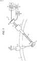
Fig. 1] Fig. 1 is a view illustrating an outline of a laparoscopic surgery. - [
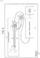
Fig. 2] Fig. 2 is a block diagram illustrating a configuration example of an endoscope system to which the present disclosure has been applied. - [
Fig. 3] Fig. 3 is a block diagram illustrating another configuration example of the endoscope device illustrated inFig. 2 . - [
Fig. 4] Fig. 4 is a view illustrating an outline of a correction process performed by a figure image correction device. - [
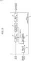
fig.5]Fig. 5 is a block diagram illustrating a configuration example of the image correction device. - [
fig.6]Fig. 6 is a view illustrating differences in image stabilization between a video camera and an endoscope device. - [
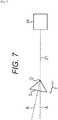
fig.7]Fig. 7 is a view illustrating a configuration of an oblique-view scope using a pinhole camera model. - [
fig.8]Fig. 8 is a view illustrating image stabilization by a direct-view scope. - [
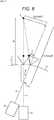
fig.9]Fig. 9 is a view illustrating a camera shake direction of an oblique-view scope. - [
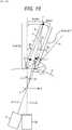
fig.10]Fig. 10 is a view illustrating image stabilization by an oblique-view scope. - [
fig.11]Fig. 11 is a flowchart showing an image correction process. - [
fig.12]Fig. 12 is a view illustrating stitching-synthesis using images subjected to image stabilization. - [
fig.13]Fig. 13 is a block diagram illustrating a configuration example of a computer. - A best mode for carrying out the present technology (hereinafter referred to as embodiment) is hereinafter described in detail with reference to the drawings.
Fig. 1 is a view illustrating an outline of an endoscope system to which the present technology has been applied.- This endoscope system is used in a laparoscopic surgery conducted in recent years in the medical practice, in place of a conventional open abdominal surgery.
- More specifically, in case of a laparoscopic surgery in an abdominal region, for example, opening tools called
trocars 2 are attached to several points of an abdominal wall as illustrated inFig. 1 . In this condition, a laparoscope (hereinafter also referred to as "endoscope device" or "endoscope") 21, and a treatment device 3 are inserted through holes formed in thetrocars 2 and introduced into the body, instead of cutting the abdominal wall 1 as in the conventional open abdominal surgery. Then, treatments such as cutting off a diseased part (such as tumor) 5 by using the treatment device 4 are performed with a real-time view of a video image of the diseased part 4 captured by anendoscope device 11. - In a case of video image captured by the
endoscope device 11, an image shake may be produced in an obtained image, and therefore, a mechanism for correcting the image shake is necessary. - According to the linear bar-
shaped endoscope device 11 illustrated inFig. 1 , ahead unit 24 is held by an operator, an assistant, a scopist, a robot, or the like. When the hand or the like holding thehead unit 24 shakes, motion of this shake is conducted to anobjective lens 22 with a fulcrum (rotation center) located at thetrocar 2. Accordingly, an image shake may be produced as a result of the shake of the hand holding thehead unit 24. - The endoscope system according to an embodiment of the present technology is a system capable of implementing so-called image stabilization for correcting image distortion produced by an image shake.
- A configuration example of the endoscope system according to an embodiment of the present technology is hereinafter described with referent to
Fig. 2 . Anendoscope system 10 according to the present embodiment includes theendoscope device 11, an image correction device (image processing device) 12, and adisplay device 13. - The
endoscope device 11 and theimage correction device 12 may be connected with each other not only via a cable but also by radio. Theimage correction device 12 may be placed at a position away from an operating room and connected via a network such as a premises LAN or the Internet. This structure is applicable to connection between theimage correction device 12 and thedisplay device 13. - The
endoscope device 11 includes a linear bar-shapedbarrel unit 21, and thehead unit 24. Thebarrel unit 21 is called a telescopic tube or rigid tube as well, and is approximately several tens of centimeters in length. Theobjective lens 22 is provided at one end of thebarrel unit 21 on the side inserted into the body, while the other end is connected with thehead unit 24. Anoptical lens unit 23 of a relay optical system is housed within thebarrel unit 21. The shape of thebarrel unit 21 is not limited to the linear bar shape. - The endoscope system can be arranged such that the barrel unit (endoscope device) and head unit (endoscope head) are detachable, and information of the barrel unit (e.g. type of the scope(direct-view scope/oblique-view scope) and oblique view angle) can be sent to the head unit by contact or contactless transmission there-between. In this case, the lens barrel unit includes memory that stores basic information of the lens barrel (e.g. type of endoscope, oblique view angle, diameter of the scope and focus range, etc.)
- The types of the
barrel unit 21 are roughly divided into: a direct-view scope type in which barrel axis A and optical axis B illustrated inFig. 2 agree with each other; and an oblique-view scope type in which barrel axis A and optical axis B form a predetermined angle. Thebarrel unit 21 illustrated inFig. 2 is an example of the oblique-view scope of the two types. In the oblique-view scope, the predetermined angle formed by the barrel axis A and the optical axis B is called an oblique-view angle as well, and generally set to 30 degrees or 70 degrees, for example. However, oblique-view scopes having other angles are present and available to allow arbitrary setting of the oblique-view angle. - The
head unit 24 accommodates animaging unit 25 and agyro unit 26. Theimaging unit 25 contains an image sensor such as CMOS (Complementary Metal Oxide Semiconductor), and converts an optical image of the diseased part input from thebarrel unit 21 into an image signal having a predetermined frame rate. Thehead unit 24 further connects with alight source device 14, and receives supply of a light source necessary for imaging from thelight source device 14 to illuminate the diseased part 4 via theoptical lens unit 23. In this case, thelight source device 14 is capable of emitting lights having a variety of wavelengths as switchable lights, and also generating special light for specifically identifying the diseased part 4 in addition to ordinary light. Accordingly, theimaging unit 25 is capable of generating an image from an image signal of special light as well as an image signal of ordinary light. - The
gyro unit 26 detects an angular velocity of movement of thehead unit 24, and outputs the detection result to the subsequentimage correction device 12. - According to the
endoscope device 11, an optical image of the diseased part, where light is concentrated by theobjective lens 22, enters theimaging unit 25 of thehead unit 24 via theoptical lens unit 23. The optical image having entered theimaging unit 25 is converted into an image signal having the predetermined frame rate, and output to the subsequentimage correction device 12. In addition, according to theendoscope device 11, the angular velocity of the movement of thehead unit 24 is detected by thegyro unit 26, and output to the subsequentimage correction device 12. Fig. 3 illustrates another configuration example of theendoscope device 11. As illustrated in this figure, theimaging unit 25 may be disposed immediately behind theobjective lens 22 to eliminate theoptical lens unit 23 within thebarrel unit 21.- An outline of a correction process performed by the
image correction device 12 is hereinafter described with reference toFig. 4 . Theimage correction device 12 cuts out an area from the entire area of an image signal (effective pixel area) having a predetermined frame rate and input from theimaging unit 25 of theendoscope device 11 as a cut-out area in a size smaller than the effective pixel area, and outputs an image signal generated based on the cut-out area to thesubsequent display device 13. During this process, a camera shake is correctable by shifting the position of the cut-out area by a shift amount corresponding to the camera shake. In addition, when a rolling shutter is provided as a shutter mechanism of theimaging unit 25 of theendoscope device 11, rolling shutter distortion produced by the configuration can be removable. - A configuration example of the
image correction device 12 is hereinafter described with reference toFig. 5 . Theimage correction device 12 includes an angularvelocity leveling unit 31, a shiftamount determination unit 32, an image cut-outunit 33, adistortion removal unit 34, and animage output unit 35. - The angular
velocity leveling unit 31 levels angular velocities of thehead unit 24 detected by thegyro unit 26 of theendoscope device 11, based on integration of the angular velocities in a time direction. Thereafter, the angularvelocity leveling unit 31 removes instantaneous errors from the leveled angular velocity, and outputs the resultant angular velocity to the shiftamount determination unit 32 and thedistortion removal unit 34. - The shift
amount determination unit 32 calculates a shift amount of theobjective lens 22 based on the leveled angular velocity, determines a shift amount of an image cut-out area based on the shift amount of the calculatedobjective lens 22, and notifies the image cut-outunit 33 of the shift amount of the image cut-out area. The shift amount of the image cut-out area corresponding to the shift amount of theobjective lens 22 varies in accordance with magnification of theobjective lens 22. Accordingly, the shiftamount determination unit 32 retains a function for calculating the shift amount based on the magnification and shift amount of theobjective lens 22, or retains a table showing the respective correspondences beforehand. - The image cut-out
unit 33 cuts out pixels of the cut-out area from the image signal having the predetermined frame rate and sequentially input from theimaging unit 25 of theendoscope device 11. The position of the cut-out area is adjusted in accordance with the shift amount obtained from the shiftamount determination unit 32. The image cut-outunit 33 generates a stabilization image signal based on the cut-out area, and outputs the stabilization image signal to thedistortion removal unit 34. - The
distortion removal unit 34 removes rolling shutter distortion (possibly produced when a rolling shutter is provided as the shutter mechanism of the imaging unit 25) from the stabilization image signal received from the image cut-outunit 33, if any, and outputs the resultant stabilization image signal to theimage output unit 35. Rolling shutter distortion may be removed by using an existing arbitrary method. - The
image output unit 35 outputs the stabilization image signal received from thedistortion removal unit 34 to the subsequent unit (display device 13 in this case). - A method for determining the shift amount is hereinafter described.
- In general, a video camera images a target object present several meters to several tens of meters away, as illustrated in the left part of
Fig. 6 . In this case, a distance between an optical system of animaging device 101 and the target object (hereinafter referred to as "subject distance") d2 is sufficiently longer than a distance between a rotation center c2 of rotation produced by a camera shake and the optical system of the imaging device 101 (hereinafter referred to as "rotation radius"). Accordingly, the method described in PTL 1 or others calculates a shift amount for image stabilization on the assumption that a rotation radius r2 is short enough to be in an ignorable level in comparison with the subject distance d2. The left part ofFig. 6 illustrates theimaging device 101 at a position when an imaging device 101' is shifted by a camera shake by a deviation angle θ2 around the rotation center c2. - On the other hand, an endoscope device images a target object at a subject distance d1 of several millimeters to several centimeters, as illustrated in the right part of
Fig. 6 . In case of a laparoscopic surgery, theendoscope device 11 is inserted through a cylinder called thetrocar 2, and introduced into the abdominal cavity. In this case, theendoscope device 11 rotates with a fulcrum c1 located at thetrocar 2. In a case of theendoscope device 11, a rotation radius r1 is not short enough to be in an ignorable level with respect to the subject distance d1, and therefore, the image stabilization method described in PTL 1 or the like is not effective. The right part ofFig. 6 illustrates a head unit 24' of theendoscope device 11 at a position when thehead unit 24 is shifted by a camera shake by adeviation angle 01 around the rotation center c1. - In a case of an oblique-view scope such as the
endoscope device 11 employed in the present embodiment, image stabilization is effective only when the shift amount is calculated in consideration of an angle formed by a barrel axis of the oblique-view scope and the optical axis of the optical system, and a rotation angle of the barrel from a reference position, as well as the subject distance and the rotation radius. - Accordingly, a shift amount of a pinhole camera model is initially discussed herein as an example of the shift amount of the oblique-view scope so as to describe the shift amount of the oblique-view scope
type endoscope device 11. - For example, according to the pinhole camera model illustrated in
Fig. 7 , a point O corresponds to an optical center (pinhole) on which light is concentrated. In this condition, an image (picture) is formed on an image surface S. In the actual configuration of theendoscope device 11, theimaging unit 25 is included in thehead unit 24. However, for simplifying the explanation, it is considered herein that the image surface S is positioned in front the optical center O inFig. 7 . Herein, the distance between the optical center O and the image surface S is regarded as a focal distance f. - Discussed next with reference to
Fig. 8 is a method for calculating a shift amount for image stabilization in consideration of the subject distance and the rotation radius at the time of use of a direct-view scope whose barrel axis A and optical axis B agree with each other. - It is assumed that a point light source P corresponding to a subject is reflected at the center of the image surface of the
imaging unit 25 included in thehead unit 24 at a time t-1. It is also assumed that thehead unit 24 shifts to the position of the head unit 24' rotated (shaken) by θ [radian] around a center point C during a period from the time t-1 to a time t. It is determined in this condition where the point light source P is reflected on an image surface of the head unit 24' at the time t. More specifically, a distance u between the position of the point light source on an image obtained by the head unit 24' at the time t, and the center of the image corresponds to the shift amount for image stabilization desired to be calculated. The shift amount u for image stabilization is defined by following Equation (1) based on a geometrical relationship illustrated inFig. 8 .
[Math.1]
- In this equation, d indicates the subject distance, r indicates the rotation radius, and f indicates the focal distance. In general, a camera shake amount (rotation angle θ) during a micro time (one frame) is extremely short, and therefore, approximations of sinθ ≒ tanθ ≒ θ and cosθ ≒ 1 are allowed. Accordingly, Equation (1) may be approximated as following Equation (2).
[Math.2]
- In addition, when the rotation radius r is short enough to be in an ignorable level in comparison with the subject distance d (d >> r) in Equation (2), an approximation of d + r ≒ d is allowed. Accordingly, Equation (2) may be approximated as following Equation (3).
[Math.3]
- The shift amount for image stabilization shown in this equation is equivalent to the shift amount for image stabilization of an ordinary imaging device such as a video camera described in PTL 1 or others.
- In the case of the
endoscope device 11, the rotation radius r is not ignorable with respect to the subject distance d as illustrated inFig. 6 . Accordingly, Equation (2) considering the rotation radius r and the subject distance d is used for implementing more effective image stabilization than that of the conventional method. - Discussed next is the case of an oblique-view scope including a rigid scope whose optical axis A is oblique to the axis B of the barrel.
- Parameters appearing in the following description are initially touched upon with reference to
Fig. 9 . InFig. 9 , an angle formed by the optical axis B of the oblique-view scope and the barrel axis (Z axis (= A)) is regarded as Φ [radian] when the oblique-view scope is located at a reference position (θz = 0). An angle formed by the barrel axis Z of the oblique-view scope and a line of an optical axis B' of the oblique-view scope projected on the X-Z plane is regarded as Φy after the oblique-view scope is rotated from the reference position by θz. An angle formed by the optical axis of the oblique-view scope and the line of the optical axis of the oblique-view scope projected on the X-Z plane is regarded as Φx after the oblique-view scope is rotated from the reference position by θz. Rotation of theendoscope device 11 around the X axis is regarded as θx, and rotation of theendoscope device 11 around the Y axis is regarded as θy. - In this case, Φx and Φy as angular components of Φ in the X axis direction and the Y axis direction, respectively, are expressed, using Φ and θz, as following Equation (4) and Equation (5).
[Math.4]
[Math.5]
- Discussed next is the shift amount u for image stabilization in the horizontal direction of the
imaging unit 25 included in thehead unit 24 with reference toFig. 10 . - In
Fig. 10 , it is assumed that thehead unit 24 is rotated by θz from the reference position. In this case, the angle Φy formed by the barrel axis Z (= A) and the line of the optical axis B projected on the X-Z plane is expressed as Equation (5). It is assumed herein that the point light source P corresponding to the subject is reflected at the center of the image surface of theimaging unit 25 included in thehead unit 24 at the time t-1. It is also assumed that thehead unit 24 is rotated (shaken) by θy [radian] around the Y axis with the center located at the rotation center C during the period from the time t-1 to the time t. It is determined in this condition where the point light source P is reflected on the image surface of theimaging unit 25 at the time t. More specifically, the distance u between the position of the point light source P on an image obtained by theimaging unit 25 at the time t and the center of this image corresponds to the shift amount to be used for image stabilization. InFig. 10 , r indicates the rotation radius, d indicates the subject distance between the optical center of the camera and the point light source P at the time t-1, and f indicates the focal distance. - As can be understood from the geometrical relationship illustrated in
Fig. 10 , the shift amount u for image stabilization is expressed by following Equation (6).
[Math.6]
- In this equation, αy indicates an angle formed by the barrel axis Z and a line connecting the point light source P and the optical center of the
head unit 24 at the time t, and is defined by following Equation (7).
[Math.7]
- In this equation, h indicates a line connecting the point light source P and the rotation center C. The length of h is defined by following Equation (8).
[Math. 8]
- In Equation (7), ωy indicates an angle formed by the line h and the barrel axis Z at the time t, and is defined by following Equation (9).
[Math.9]
- Accordingly, the shift amount for image stabilization in consideration of the direction of the optical axis of the oblique-view scope is defined by Equation (6) noted above.
- A shift amount v for image stabilization in the vertical direction of the
imaging unit 25 is defined in a completely similar manner. - In a case of the direct-view scope, the angle Φ formed by the optical axis and the barrel axis is 0, and therefore, Φy = 0 holds in Equation (5). Accordingly, when Φy = 0 is substituted into Equation (6), Equation (6) becomes equivalent to Equation (3) used for calculating the shift amount for image stabilization in case of the direct-view scope.
- The angle θy in Equation (6) produced by a camera shake, which is an angle of rotation around the Y axis with the rotation center located at the rotation center C, is detected by the
gyro unit 26. - The subject distance d in Equation (6) may be given manually, or may be obtained by image analysis performed by the
imaging unit 25 when theimaging unit 25 is configured to function as a distance sensor for detecting distances by using a time-of-flight method, for example. - The rotation radius r in Equation (6) may be given manually, or may be obtained by a sensor (such as a pressure sensor) attached to the
imaging unit 25 or thetrocar 2 or by image analysis, for example. - The angle formed by the optical axis of the rigid scope and the barrel axis (oblique-view angle) Φ in Equation (6) may be given manually, or may be obtained by image analysis, for example.
- The Φ oblique view angle may be sent from the lens barrel to the head by contact or contactless transmission there-between.
- The rotation angle θz of the
endoscope device 11 from a reference value in Equation (6) may be given manually, or may be obtained by an angle detection sensor or by image analysis, for example. - The image correction process performed by the
image correction device 12 is hereinafter described with reference to a flowchart shown inFig. 11 . It is assumed herein that each of the subject distance d, the rotation radius r, and the angle Φ has been set beforehand by manual input, image analysis, or other methods, during calibration or other processing. The rotation angle θz is a value measured by thegyro unit 26. - In step S1, inputs of an image signal having a predetermined frame rate and an angular velocity signal indicating movement of the
head unit 24 are started from theendoscope device 11 to theimage correction device 12. The image signal is input to the image cut-outunit 33, while the angular velocity signal is input to the angularvelocity leveling unit 31. - In step S2, the angular
velocity leveling unit 31 integrates angular velocities of thehead unit 24 detected by thegyro unit 26 of theendoscope device 11 in the time direction in order to level the angular velocities, and outputs the leveled angular velocity to the shiftamount determination unit 32 and thedistortion removal unit 34. - In step S3, the shift
amount determination unit 32 calculates a shift amount of theobjective lens 22 based on the leveled angular velocity by using Equation (6) noted above, determines the shift amount of an image cut-out area based on the calculated shift amount of theobjective lens 22, and notifies the image cut-outunit 33 of the shift amount of the image cut-out area. - In step S4, the image cut-out
unit 33 cuts out pixels of the cut-out area from the image signal having the predetermined frame rate and sequentially input from theendoscope device 11, while adjusting the position of the cut-out area in accordance with the shift amount received from the shiftamount determination unit 32. The image cut-outunit 33 generates a stabilization image signal based on the cut-out area, and outputs the stabilization image signal to thedistortion removal unit 34. - In step S5, the
distortion removal unit 34 removes rolling shutter distortion from the stabilization image signal received from the image cut-outunit 33, if any, and outputs the resultant stabilization image signal to theimage output unit 35. Theimage output unit 35 outputs the stabilization image signal, which is input via thedistortion removal unit 34, to thedisplay device 13. - As described above, the
endoscope system 10 according to the present embodiment is capable of correcting a camera shake which may be produced in a video image captured by theendoscope device 11. - Note that, for example, a plurality of images may be obtained by widely moving the
endoscope device 11 around the trocar serving as the rotation center, and be synthesized by stitching synthesis based on the position of the rotation sensor and the angular velocity as illustrated inFig. 12 . In this case, a highly accurate and wide view angle image can be obtainable only by a relatively small volume of processing. - According to the method discussed above, successive images formed at positions varied due to camera shakes are aligned and displayed for implementation of image stabilization. This method is also applicable to generation of a single image from a plurality of images by overlapping these images at the same position. When this method is applied, noise removal is achievable.
- A shift amount calculated for correcting a camera shake is usable as an index for indicating the degree of a camera shake as well. In this case, a larger shift amount can be considered as a larger degree of a camera shake. Accordingly, the degree of fatigue of a user is measurable based on a shift amount considered as an index indicating the degree of fatigue of the user, for example.
- A series of processes carried out by the
image correction device 12 described herein may be performed either by hardware or by software. When the series of processes are performed by software, programs included in the software are installed in a computer. Examples of the computer used herein include a computer incorporated in dedicated hardware, and a computer, for example, a general-purpose personal computer, capable of performing various types of functions under various types of programs installed in the computer. Fig. 13 is a block diagram illustrating a configuration example of hardware of a computer which performs the series of processes described above under the programs.- A CPU (Central Processing Unit) 101, a ROM (Read Only Memory) 102, and a RAM (Random Access Memory) 103 of a
computer 100 are connected with each other via abus 104. - An input/
output interface 105 is further connected with thebus 104. Aninput unit 106, anoutput unit 107, astorage unit 108, acommunication unit 109, and adrive 110 are connected with the input/output interface 105. - The
input unit 106 includes a keyboard, a mouse, a microphone, and others. Theoutput unit 107 includes a display, a speaker, and others. Thestorage unit 108 includes a hard disk, a non-volatile memory, and others. Thecommunication unit 109 includes a network interface, and others. Thedrive 110 drives aremovable medium 111, such as a magnetic disk, an optical disk, a magneto-optical disk, and a semiconductor memory. - According to the
computer 100 having this structure, theCPU 101 performs the series of processes described herein by, for example, loading the programs stored in thestorage unit 108 into theRAM 103 via the input/output interface 105 and thebus 104 and executing the loaded programs. - The programs executed by the computer 100 (CPU 101) may be recorded on a
removable medium 111 as a package media, or the like, and provided in the form of theremovable medium 111, for example. In addition, the programs may be presented via a wired or wireless transmission medium, such as a local area network, the Internet, and digital satellite broadcasting. - The programs executed by the
computer 100 may be programs under which processes are performed in time series in the order described herein, or may be programs under which processes are performed in parallel, or at necessary timing such as occasions of calls. - Embodiments of the present technology are not limited to the specific embodiment described herein. Various modifications and changes may be made without departing from the subject matters of the present technology.


Claims (14)
- An endoscope system (10) comprising:an endoscope device (11) that includesan objective lens (22) provided at a distal end of the endoscope device, the objective lens being disposed such that an optical axis of the objective lens and a longitudinal axis of the objective lens intersect at a predetermined angle,an endoscope head (24) provided at a proximal end of the endoscope device, and comprising an imaging unit (25) configured to generate an image signal from the image light passing through the objective lens;a gyro sensor (26) provided on the endoscope head and configured to detect an angular velocity of movement of the endoscope head; andimage processing circuitry (12) configured to implement image stabilization of an image signal input from the endoscope device based on the detected angular velocity,characterized in thatthe image processing circuitry is further configured to implement the image stabilization of the image signal by determining a shift amount of an image cut-out area based on the angular velocity and by subsequently cutting out the cut-out area and adjusting the position of the cut-out area in accordance with the determined shift amount.
- The endoscope system (10) according to claim 1, wherein the endoscope device (11) is an oblique-view endoscope.
- The endoscope system (10) according to claim 2, wherein an oblique-view angle of the oblique-view endoscope is selected from an angle of 30 degrees or an angle of 70 degrees.
- The endoscope system (10) according to claim 1, wherein the image processing circuitry (12) is configured to measure the oblique-view angle based on the image signal.
- The endoscope system (10) according to claim 1, wherein the image processing circuitry (12) is configured to level the detected angular velocities in a time direction.
- The endoscope system (10) according to claim 1, wherein the image processing circuitry (12) is further configured to remove rolling shutter distortion from the image signal having been subjected to image stabilization.
- The endoscope system (10) according to claim 1, wherein the image processing circuitry (12) is further configured to generate wide view angle image based on plurality of images obtained by moving the endoscope device (11).
- The endoscope system (10) according to claim 1, wherein the image processing circuitry (12) is further configured to measure an index indicating fatigue of a user based on a shift amount.
- The endoscope system (10) according to claim 1, wherein the endoscope device (11) is detachable from the endoscope head and the endoscope head receives scope information transmitted from the endoscope device.
- The endoscope system (10) according to claim 9, wherein the scope information includes an oblique view angle.
- The endoscope system (10) according to claim 9, wherein the scope information includes scope type information.
- An image processing device (12) for image stabilization of an image signal input from an endoscope device (11) including an objective lens (22) provided at a distal end of the endoscope device, the objective lens being disposed such that an optical axis of the objective lens and longitudinal axis of the objective lens intersect a predetermined angle, an endoscope head (24) provided at a proximal end of the endoscope device and comprising an imaging unit (25) configured to generate an image signal from the image light passing through the objective lens;
a gyro sensor (26) provided on the endoscope head and configured to detect an angular velocity of movement of the endoscope head, comprising:
circuitry configured to implement the image stabilization of the image signal input from the endoscope device based on the angular velocity of movement of the endoscope head of the endoscope device detected by the endoscope device,characterized in that the image processing device is further configured to implement the image stabilization of the image signal by determining a shift amount of an image cut-out area based on the angular velocity and by subsequently cutting out the cut-out area and adjusting the position of the cut-out area in accordance with the determined shift amount. - An image processing method implemented by image processing circuitry (12) configured to process an image signal input from an endoscope device (11), the endoscope device including an objective lens (22) provided at a distal end of the endoscope device, the objective lens being disposed such that an optical axis of the objective lens and longitudinal axis of the objective lens intersect at a predetermined angle, an endoscope head (24) provided at a proximal end of the endoscope device, and comprising an imaging unit (25) configured to generate an image signal from the image light passing through the objective lens, and a gyro sensor (26) provided on the endoscope head and configured to detect an angular velocity of movement of the endoscope head, the method comprising:implementing (S4) image stabilization of the image signal based on the detected angular velocity of movement of the endoscope head of the endoscope device,wherein said implementing image stabilization of the image signal comprises determining a shift amount of an image cut-out area based on the angular velocity and subsequently cutting out the cut-out area and adjusting the position of the cut-out area in accordance with the determined shift amount.
- A non-transitory computer readable medium having stored thereon a program which when executed by a computer causes the computer to implement a method implemented by image processing circuitry (12) configured to process an image signal input from an endoscope device (11), the endoscope device including an objective lens (22) provided at a distal end of the endoscope device, the objective lens being disposed such that an optical axis of the objective lens and longitudinal axis of the objective lens intersect at a predetermined angle, an endoscope head (24) provided at a proximal end of the endoscope device, and comprising an imaging unit (25) configured to generate an image signal from the image light passing through the objective lens;
a gyro sensor (26) provided on the endoscope head and configured to detect an angular velocity of movement of the endoscope head, the method comprising:implementing (S4) image stabilization of the image signal based on the detected angular velocity of movement of the endoscope head of the endoscope device,wherein said implementing image stabilization of the image signal comprises determining a shift amount of an image cut-out area based on the angular velocity and subsequently cutting out the cut-out area and adjusting the position of the cut-out area in accordance with the determined shift amount.
Applications Claiming Priority (2)
| Application Number | Priority Date | Filing Date | Title |
|---|---|---|---|
| JP2014226055AJP6519144B2 (en) | 2014-11-06 | 2014-11-06 | Endoscope system, image processing apparatus, image processing method, and program |
| PCT/JP2015/005379WO2016072059A1 (en) | 2014-11-06 | 2015-10-27 | Endoscope system, image processing device, image processing method, and program |
Publications (2)
| Publication Number | Publication Date |
|---|---|
| EP3179897A1 EP3179897A1 (en) | 2017-06-21 |
| EP3179897B1true EP3179897B1 (en) | 2021-01-13 |
Family
ID=54541139
Family Applications (1)
| Application Number | Title | Priority Date | Filing Date |
|---|---|---|---|
| EP15794320.0ANot-in-forceEP3179897B1 (en) | 2014-11-06 | 2015-10-27 | Endoscope system, image processing device, image processing method, and program |
Country Status (5)
| Country | Link |
|---|---|
| US (1) | US10368725B2 (en) |
| EP (1) | EP3179897B1 (en) |
| JP (1) | JP6519144B2 (en) |
| CN (1) | CN107079097B (en) |
| WO (1) | WO2016072059A1 (en) |
Cited By (1)
| Publication number | Priority date | Publication date | Assignee | Title |
|---|---|---|---|---|
| US20210369351A1 (en)* | 2017-11-01 | 2021-12-02 | Sony Corporation | Surgical arm system and surgical arm control system |
Families Citing this family (18)
| Publication number | Priority date | Publication date | Assignee | Title |
|---|---|---|---|---|
| US11422346B2 (en)* | 2016-03-31 | 2022-08-23 | Sony Olympus Medical Solutions Inc. | Medical observation device, image movement correcting method, and medical observation system |
| US10620424B1 (en)* | 2016-09-16 | 2020-04-14 | Precision Optics Corporation, Inc. | Lens for use with imaging sensors |
| JP7031118B2 (en)* | 2016-12-09 | 2022-03-08 | ソニーグループ株式会社 | Image processing device and image processing method |
| EP3339714A1 (en)* | 2016-12-20 | 2018-06-27 | Nokia Technologies Oy | An apparatus and associated methods for virtual reality image capture |
| EP3590406A4 (en)* | 2017-02-28 | 2020-04-01 | Sony Corporation | MEDICAL OBSERVATION SYSTEM, CONTROL DEVICE AND CONTROL METHOD |
| JP7151109B2 (en)* | 2018-03-19 | 2022-10-12 | ソニーグループ株式会社 | Medical imaging device and medical observation system |
| JP2021097720A (en) | 2018-03-20 | 2021-07-01 | ソニーグループ株式会社 | Endoscope and arm system |
| WO2020020958A1 (en)* | 2018-07-24 | 2020-01-30 | Sony Corporation | Video routing in an operating theater |
| US11625825B2 (en) | 2019-01-30 | 2023-04-11 | Covidien Lp | Method for displaying tumor location within endoscopic images |
| JP2020162633A (en) | 2019-03-28 | 2020-10-08 | ソニー株式会社 | Imaging control device, imaging control method, program and imaging system |
| CN112104817B (en)* | 2019-05-29 | 2023-02-10 | 惠州拓邦电气技术有限公司 | Endoscope and method for rotating image collected by endoscope |
| CN110584573A (en)* | 2019-09-12 | 2019-12-20 | 济南科众医疗科技有限公司 | Miniature endoscope and instrument with image stabilization function |
| JP7455547B2 (en)* | 2019-10-18 | 2024-03-26 | Hoya株式会社 | endoscope system |
| TWI782409B (en)* | 2020-03-09 | 2022-11-01 | 陳階曉 | Endoscopic image correction system and method thereof |
| US12310564B2 (en)* | 2021-02-22 | 2025-05-27 | Panasonic Intellectual Property Management Co., Ltd. | Intraoral camera system and image display method |
| CN114863317A (en)* | 2022-04-02 | 2022-08-05 | 上海微觅医疗器械有限公司 | Endoscopic image processing method, image platform, computer equipment and medium |
| CN118021446A (en)* | 2024-02-07 | 2024-05-14 | 常州市康辉医疗器械有限公司 | Navigation method, electronic equipment, navigation system and robot system for optical hard lens surgery |
| CN117796755A (en)* | 2024-03-01 | 2024-04-02 | 科弛医疗科技(北京)有限公司 | Wireless laparoscopy system and methods performed therewith and wireless laparoscopy |
Citations (1)
| Publication number | Priority date | Publication date | Assignee | Title |
|---|---|---|---|---|
| JP2013113962A (en)* | 2011-11-28 | 2013-06-10 | Nidec Sankyo Corp | Imaging device with shake correction function |
Family Cites Families (14)
| Publication number | Priority date | Publication date | Assignee | Title |
|---|---|---|---|---|
| JPH0549599A (en)* | 1991-08-23 | 1993-03-02 | Olympus Optical Co Ltd | Electronic endoscope apparatus |
| US8723936B2 (en)* | 2002-03-12 | 2014-05-13 | Karl Storz Imaging, Inc. | Wireless camera coupling with rotatable coupling |
| WO2004103167A1 (en)* | 2003-05-22 | 2004-12-02 | Olympus Corporation | Image recording device |
| US7134992B2 (en)* | 2004-01-09 | 2006-11-14 | Karl Storz Development Corp. | Gravity referenced endoscopic image orientation |
| DE102004023024B4 (en)* | 2004-05-06 | 2007-03-01 | Olympus Winter & Ibe Gmbh | Endoscope optics with lateral fiber optic bundle |
| JP2006218129A (en)* | 2005-02-10 | 2006-08-24 | Olympus Corp | Surgery supporting system |
| JP5226195B2 (en)* | 2006-07-28 | 2013-07-03 | オリンパスメディカルシステムズ株式会社 | Endoscope apparatus and method for operating endoscope apparatus |
| US7783133B2 (en)* | 2006-12-28 | 2010-08-24 | Microvision, Inc. | Rotation compensation and image stabilization system |
| JP2009254736A (en)* | 2008-04-21 | 2009-11-05 | Hoya Corp | Endoscope control unit and endoscope system |
| EP2301411B1 (en)* | 2009-01-15 | 2012-12-12 | Olympus Medical Systems Corp. | Endoscope system |
| US9463081B2 (en) | 2011-01-11 | 2016-10-11 | Kabushiki Kaisya Advance | Intraoral video camera and display system |
| JP5864880B2 (en) | 2011-04-07 | 2016-02-17 | オリンパス株式会社 | Endoscope apparatus and method for operating endoscope apparatus |
| EP2742484B1 (en)* | 2011-07-25 | 2016-08-31 | Universidade de Coimbra | Method and apparatus for automatic camera calibration using one or more images of a checkerboard pattern |
| JP2013153813A (en)* | 2012-01-27 | 2013-08-15 | Olympus Corp | Endoscope apparatus, image processing method and program |
- 2014
- 2014-11-06JPJP2014226055Apatent/JP6519144B2/ennot_activeExpired - Fee Related
- 2015
- 2015-10-27CNCN201580057264.3Apatent/CN107079097B/ennot_activeExpired - Fee Related
- 2015-10-27WOPCT/JP2015/005379patent/WO2016072059A1/enactiveApplication Filing
- 2015-10-27USUS15/327,062patent/US10368725B2/ennot_activeExpired - Fee Related
- 2015-10-27EPEP15794320.0Apatent/EP3179897B1/ennot_activeNot-in-force
Patent Citations (1)
| Publication number | Priority date | Publication date | Assignee | Title |
|---|---|---|---|---|
| JP2013113962A (en)* | 2011-11-28 | 2013-06-10 | Nidec Sankyo Corp | Imaging device with shake correction function |
Cited By (2)
| Publication number | Priority date | Publication date | Assignee | Title |
|---|---|---|---|---|
| US20210369351A1 (en)* | 2017-11-01 | 2021-12-02 | Sony Corporation | Surgical arm system and surgical arm control system |
| US11612306B2 (en)* | 2017-11-01 | 2023-03-28 | Sony Corporation | Surgical arm system and surgical arm control system |
Also Published As
| Publication number | Publication date |
|---|---|
| EP3179897A1 (en) | 2017-06-21 |
| WO2016072059A1 (en) | 2016-05-12 |
| US10368725B2 (en) | 2019-08-06 |
| US20170135563A1 (en) | 2017-05-18 |
| CN107079097B (en) | 2019-11-29 |
| CN107079097A (en) | 2017-08-18 |
| JP6519144B2 (en) | 2019-05-29 |
| JP2016087141A (en) | 2016-05-23 |
Similar Documents
| Publication | Publication Date | Title |
|---|---|---|
| EP3179897B1 (en) | Endoscope system, image processing device, image processing method, and program | |
| JP6150130B2 (en) | Endoscope system, endoscope image processing apparatus, image processing method, and program | |
| JP6413026B2 (en) | Projection mapping device | |
| EP2888991B1 (en) | Endoscope system | |
| US10702346B2 (en) | Image integration and robotic endoscope control in X-ray suite | |
| US20130281821A1 (en) | Intraoperative camera calibration for endoscopic surgery | |
| JP2006288775A (en) | System for supporting endoscopic surgery | |
| JP5750669B2 (en) | Endoscope system | |
| JP2015139646A5 (en) | Endoscope system, endoscope image processing apparatus, image processing method, and program | |
| JP2017185254A (en) | Endoscope system, endoscope image processing apparatus, and image processing method | |
| WO2021171465A1 (en) | Endoscope system and method for scanning lumen using endoscope system | |
| JP4607043B2 (en) | Endoscopic image forming method with display of gravity direction | |
| JP2006320427A (en) | Endoscopic operation support system | |
| Behrens et al. | Inertial navigation system for bladder endoscopy | |
| EP4544978A1 (en) | System and method for real-time, intra-procedural, endoscopic shaft motion tracking | |
| KR101640930B1 (en) | Image processing apparatus for capsule endoscope | |
| JP4776919B2 (en) | Medical image processing device | |
| JP2025072849A (en) | Systems and methods for real-time intraprocedural endoscope shaft motion tracking | |
| US20220378278A1 (en) | Information processing device, generation method, and generation program |
Legal Events
| Date | Code | Title | Description |
|---|---|---|---|
| STAA | Information on the status of an ep patent application or granted ep patent | Free format text:STATUS: THE INTERNATIONAL PUBLICATION HAS BEEN MADE | |
| PUAI | Public reference made under article 153(3) epc to a published international application that has entered the european phase | Free format text:ORIGINAL CODE: 0009012 | |
| STAA | Information on the status of an ep patent application or granted ep patent | Free format text:STATUS: REQUEST FOR EXAMINATION WAS MADE | |
| 17P | Request for examination filed | Effective date:20170301 | |
| AK | Designated contracting states | Kind code of ref document:A1 Designated state(s):AL AT BE BG CH CY CZ DE DK EE ES FI FR GB GR HR HU IE IS IT LI LT LU LV MC MK MT NL NO PL PT RO RS SE SI SK SM TR | |
| AX | Request for extension of the european patent | Extension state:BA ME | |
| STAA | Information on the status of an ep patent application or granted ep patent | Free format text:STATUS: EXAMINATION IS IN PROGRESS | |
| 17Q | First examination report despatched | Effective date:20180105 | |
| DAV | Request for validation of the european patent (deleted) | ||
| DAX | Request for extension of the european patent (deleted) | ||
| GRAP | Despatch of communication of intention to grant a patent | Free format text:ORIGINAL CODE: EPIDOSNIGR1 | |
| STAA | Information on the status of an ep patent application or granted ep patent | Free format text:STATUS: GRANT OF PATENT IS INTENDED | |
| INTG | Intention to grant announced | Effective date:20200820 | |
| GRAS | Grant fee paid | Free format text:ORIGINAL CODE: EPIDOSNIGR3 | |
| GRAA | (expected) grant | Free format text:ORIGINAL CODE: 0009210 | |
| STAA | Information on the status of an ep patent application or granted ep patent | Free format text:STATUS: THE PATENT HAS BEEN GRANTED | |
| AK | Designated contracting states | Kind code of ref document:B1 Designated state(s):AL AT BE BG CH CY CZ DE DK EE ES FI FR GB GR HR HU IE IS IT LI LT LU LV MC MK MT NL NO PL PT RO RS SE SI SK SM TR | |
| REG | Reference to a national code | Ref country code:GB Ref legal event code:FG4D | |
| REG | Reference to a national code | Ref country code:CH Ref legal event code:EP | |
| REG | Reference to a national code | Ref country code:IE Ref legal event code:FG4D | |
| REG | Reference to a national code | Ref country code:DE Ref legal event code:R096 Ref document number:602015064782 Country of ref document:DE | |
| REG | Reference to a national code | Ref country code:AT Ref legal event code:REF Ref document number:1353917 Country of ref document:AT Kind code of ref document:T Effective date:20210215 | |
| REG | Reference to a national code | Ref country code:AT Ref legal event code:MK05 Ref document number:1353917 Country of ref document:AT Kind code of ref document:T Effective date:20210113 | |
| REG | Reference to a national code | Ref country code:NL Ref legal event code:MP Effective date:20210113 | |
| REG | Reference to a national code | Ref country code:LT Ref legal event code:MG9D | |
| RAP4 | Party data changed (patent owner data changed or rights of a patent transferred) | Owner name:SONY GROUP CORPORATION | |
| PG25 | Lapsed in a contracting state [announced via postgrant information from national office to epo] | Ref country code:PT Free format text:LAPSE BECAUSE OF FAILURE TO SUBMIT A TRANSLATION OF THE DESCRIPTION OR TO PAY THE FEE WITHIN THE PRESCRIBED TIME-LIMIT Effective date:20210513 Ref country code:NO Free format text:LAPSE BECAUSE OF FAILURE TO SUBMIT A TRANSLATION OF THE DESCRIPTION OR TO PAY THE FEE WITHIN THE PRESCRIBED TIME-LIMIT Effective date:20210413 Ref country code:LT Free format text:LAPSE BECAUSE OF FAILURE TO SUBMIT A TRANSLATION OF THE DESCRIPTION OR TO PAY THE FEE WITHIN THE PRESCRIBED TIME-LIMIT Effective date:20210113 Ref country code:FI Free format text:LAPSE BECAUSE OF FAILURE TO SUBMIT A TRANSLATION OF THE DESCRIPTION OR TO PAY THE FEE WITHIN THE PRESCRIBED TIME-LIMIT Effective date:20210113 Ref country code:HR Free format text:LAPSE BECAUSE OF FAILURE TO SUBMIT A TRANSLATION OF THE DESCRIPTION OR TO PAY THE FEE WITHIN THE PRESCRIBED TIME-LIMIT Effective date:20210113 Ref country code:GR Free format text:LAPSE BECAUSE OF FAILURE TO SUBMIT A TRANSLATION OF THE DESCRIPTION OR TO PAY THE FEE WITHIN THE PRESCRIBED TIME-LIMIT Effective date:20210414 Ref country code:BG Free format text:LAPSE BECAUSE OF FAILURE TO SUBMIT A TRANSLATION OF THE DESCRIPTION OR TO PAY THE FEE WITHIN THE PRESCRIBED TIME-LIMIT Effective date:20210413 Ref country code:NL Free format text:LAPSE BECAUSE OF FAILURE TO SUBMIT A TRANSLATION OF THE DESCRIPTION OR TO PAY THE FEE WITHIN THE PRESCRIBED TIME-LIMIT Effective date:20210113 | |
| PG25 | Lapsed in a contracting state [announced via postgrant information from national office to epo] | Ref country code:RS Free format text:LAPSE BECAUSE OF FAILURE TO SUBMIT A TRANSLATION OF THE DESCRIPTION OR TO PAY THE FEE WITHIN THE PRESCRIBED TIME-LIMIT Effective date:20210113 Ref country code:PL Free format text:LAPSE BECAUSE OF FAILURE TO SUBMIT A TRANSLATION OF THE DESCRIPTION OR TO PAY THE FEE WITHIN THE PRESCRIBED TIME-LIMIT Effective date:20210113 Ref country code:LV Free format text:LAPSE BECAUSE OF FAILURE TO SUBMIT A TRANSLATION OF THE DESCRIPTION OR TO PAY THE FEE WITHIN THE PRESCRIBED TIME-LIMIT Effective date:20210113 Ref country code:AT Free format text:LAPSE BECAUSE OF FAILURE TO SUBMIT A TRANSLATION OF THE DESCRIPTION OR TO PAY THE FEE WITHIN THE PRESCRIBED TIME-LIMIT Effective date:20210113 Ref country code:SE Free format text:LAPSE BECAUSE OF FAILURE TO SUBMIT A TRANSLATION OF THE DESCRIPTION OR TO PAY THE FEE WITHIN THE PRESCRIBED TIME-LIMIT Effective date:20210113 | |
| PG25 | Lapsed in a contracting state [announced via postgrant information from national office to epo] | Ref country code:IS Free format text:LAPSE BECAUSE OF FAILURE TO SUBMIT A TRANSLATION OF THE DESCRIPTION OR TO PAY THE FEE WITHIN THE PRESCRIBED TIME-LIMIT Effective date:20210513 | |
| REG | Reference to a national code | Ref country code:DE Ref legal event code:R097 Ref document number:602015064782 Country of ref document:DE | |
| PG25 | Lapsed in a contracting state [announced via postgrant information from national office to epo] | Ref country code:EE Free format text:LAPSE BECAUSE OF FAILURE TO SUBMIT A TRANSLATION OF THE DESCRIPTION OR TO PAY THE FEE WITHIN THE PRESCRIBED TIME-LIMIT Effective date:20210113 Ref country code:CZ Free format text:LAPSE BECAUSE OF FAILURE TO SUBMIT A TRANSLATION OF THE DESCRIPTION OR TO PAY THE FEE WITHIN THE PRESCRIBED TIME-LIMIT Effective date:20210113 Ref country code:SM Free format text:LAPSE BECAUSE OF FAILURE TO SUBMIT A TRANSLATION OF THE DESCRIPTION OR TO PAY THE FEE WITHIN THE PRESCRIBED TIME-LIMIT Effective date:20210113 | |
| PLBE | No opposition filed within time limit | Free format text:ORIGINAL CODE: 0009261 | |
| STAA | Information on the status of an ep patent application or granted ep patent | Free format text:STATUS: NO OPPOSITION FILED WITHIN TIME LIMIT | |
| PG25 | Lapsed in a contracting state [announced via postgrant information from national office to epo] | Ref country code:DK Free format text:LAPSE BECAUSE OF FAILURE TO SUBMIT A TRANSLATION OF THE DESCRIPTION OR TO PAY THE FEE WITHIN THE PRESCRIBED TIME-LIMIT Effective date:20210113 Ref country code:SK Free format text:LAPSE BECAUSE OF FAILURE TO SUBMIT A TRANSLATION OF THE DESCRIPTION OR TO PAY THE FEE WITHIN THE PRESCRIBED TIME-LIMIT Effective date:20210113 Ref country code:RO Free format text:LAPSE BECAUSE OF FAILURE TO SUBMIT A TRANSLATION OF THE DESCRIPTION OR TO PAY THE FEE WITHIN THE PRESCRIBED TIME-LIMIT Effective date:20210113 | |
| PGFP | Annual fee paid to national office [announced via postgrant information from national office to epo] | Ref country code:GB Payment date:20210922 Year of fee payment:7 | |
| 26N | No opposition filed | Effective date:20211014 | |
| PG25 | Lapsed in a contracting state [announced via postgrant information from national office to epo] | Ref country code:ES Free format text:LAPSE BECAUSE OF FAILURE TO SUBMIT A TRANSLATION OF THE DESCRIPTION OR TO PAY THE FEE WITHIN THE PRESCRIBED TIME-LIMIT Effective date:20210113 Ref country code:AL Free format text:LAPSE BECAUSE OF FAILURE TO SUBMIT A TRANSLATION OF THE DESCRIPTION OR TO PAY THE FEE WITHIN THE PRESCRIBED TIME-LIMIT Effective date:20210113 | |
| PGFP | Annual fee paid to national office [announced via postgrant information from national office to epo] | Ref country code:DE Payment date:20210921 Year of fee payment:7 | |
| PG25 | Lapsed in a contracting state [announced via postgrant information from national office to epo] | Ref country code:SI Free format text:LAPSE BECAUSE OF FAILURE TO SUBMIT A TRANSLATION OF THE DESCRIPTION OR TO PAY THE FEE WITHIN THE PRESCRIBED TIME-LIMIT Effective date:20210113 | |
| PG25 | Lapsed in a contracting state [announced via postgrant information from national office to epo] | Ref country code:IT Free format text:LAPSE BECAUSE OF FAILURE TO SUBMIT A TRANSLATION OF THE DESCRIPTION OR TO PAY THE FEE WITHIN THE PRESCRIBED TIME-LIMIT Effective date:20210113 | |
| REG | Reference to a national code | Ref country code:CH Ref legal event code:PL | |
| PG25 | Lapsed in a contracting state [announced via postgrant information from national office to epo] | Ref country code:IS Free format text:LAPSE BECAUSE OF FAILURE TO SUBMIT A TRANSLATION OF THE DESCRIPTION OR TO PAY THE FEE WITHIN THE PRESCRIBED TIME-LIMIT Effective date:20210513 | |
| REG | Reference to a national code | Ref country code:BE Ref legal event code:MM Effective date:20211031 | |
| PG25 | Lapsed in a contracting state [announced via postgrant information from national office to epo] | Ref country code:MC Free format text:LAPSE BECAUSE OF FAILURE TO SUBMIT A TRANSLATION OF THE DESCRIPTION OR TO PAY THE FEE WITHIN THE PRESCRIBED TIME-LIMIT Effective date:20210113 | |
| PG25 | Lapsed in a contracting state [announced via postgrant information from national office to epo] | Ref country code:LU Free format text:LAPSE BECAUSE OF NON-PAYMENT OF DUE FEES Effective date:20211027 Ref country code:BE Free format text:LAPSE BECAUSE OF NON-PAYMENT OF DUE FEES Effective date:20211031 | |
| PG25 | Lapsed in a contracting state [announced via postgrant information from national office to epo] | Ref country code:LI Free format text:LAPSE BECAUSE OF NON-PAYMENT OF DUE FEES Effective date:20211031 Ref country code:CH Free format text:LAPSE BECAUSE OF NON-PAYMENT OF DUE FEES Effective date:20211031 | |
| PG25 | Lapsed in a contracting state [announced via postgrant information from national office to epo] | Ref country code:FR Free format text:LAPSE BECAUSE OF NON-PAYMENT OF DUE FEES Effective date:20211031 | |
| PG25 | Lapsed in a contracting state [announced via postgrant information from national office to epo] | Ref country code:IE Free format text:LAPSE BECAUSE OF NON-PAYMENT OF DUE FEES Effective date:20211027 | |
| REG | Reference to a national code | Ref country code:DE Ref legal event code:R119 Ref document number:602015064782 Country of ref document:DE | |
| PG25 | Lapsed in a contracting state [announced via postgrant information from national office to epo] | Ref country code:HU Free format text:LAPSE BECAUSE OF FAILURE TO SUBMIT A TRANSLATION OF THE DESCRIPTION OR TO PAY THE FEE WITHIN THE PRESCRIBED TIME-LIMIT; INVALID AB INITIO Effective date:20151027 | |
| GBPC | Gb: european patent ceased through non-payment of renewal fee | Effective date:20221027 | |
| PG25 | Lapsed in a contracting state [announced via postgrant information from national office to epo] | Ref country code:CY Free format text:LAPSE BECAUSE OF FAILURE TO SUBMIT A TRANSLATION OF THE DESCRIPTION OR TO PAY THE FEE WITHIN THE PRESCRIBED TIME-LIMIT Effective date:20210113 | |
| PG25 | Lapsed in a contracting state [announced via postgrant information from national office to epo] | Ref country code:DE Free format text:LAPSE BECAUSE OF NON-PAYMENT OF DUE FEES Effective date:20230503 | |
| PG25 | Lapsed in a contracting state [announced via postgrant information from national office to epo] | Ref country code:GB Free format text:LAPSE BECAUSE OF NON-PAYMENT OF DUE FEES Effective date:20221027 | |
| PG25 | Lapsed in a contracting state [announced via postgrant information from national office to epo] | Ref country code:MK Free format text:LAPSE BECAUSE OF FAILURE TO SUBMIT A TRANSLATION OF THE DESCRIPTION OR TO PAY THE FEE WITHIN THE PRESCRIBED TIME-LIMIT Effective date:20210113 | |
| PG25 | Lapsed in a contracting state [announced via postgrant information from national office to epo] | Ref country code:TR Free format text:LAPSE BECAUSE OF FAILURE TO SUBMIT A TRANSLATION OF THE DESCRIPTION OR TO PAY THE FEE WITHIN THE PRESCRIBED TIME-LIMIT Effective date:20210113 | |
| PG25 | Lapsed in a contracting state [announced via postgrant information from national office to epo] | Ref country code:MT Free format text:LAPSE BECAUSE OF FAILURE TO SUBMIT A TRANSLATION OF THE DESCRIPTION OR TO PAY THE FEE WITHIN THE PRESCRIBED TIME-LIMIT Effective date:20210113 |