EP3179711B1 - Method and apparatus for preventing photograph from being shielded - Google Patents
Method and apparatus for preventing photograph from being shieldedDownload PDFInfo
- Publication number
- EP3179711B1 EP3179711B1EP16202972.2AEP16202972AEP3179711B1EP 3179711 B1EP3179711 B1EP 3179711B1EP 16202972 AEP16202972 AEP 16202972AEP 3179711 B1EP3179711 B1EP 3179711B1
- Authority
- EP
- European Patent Office
- Prior art keywords
- predetermined
- image characteristic
- image
- edge region
- region satisfies
- Prior art date
- Legal status (The legal status is an assumption and is not a legal conclusion. Google has not performed a legal analysis and makes no representation as to the accuracy of the status listed.)
- Active
Links
Images


Classifications
- H—ELECTRICITY
- H04—ELECTRIC COMMUNICATION TECHNIQUE
- H04N—PICTORIAL COMMUNICATION, e.g. TELEVISION
- H04N23/00—Cameras or camera modules comprising electronic image sensors; Control thereof
- H04N23/60—Control of cameras or camera modules
- H04N23/64—Computer-aided capture of images, e.g. transfer from script file into camera, check of taken image quality, advice or proposal for image composition or decision on when to take image
- G—PHYSICS
- G06—COMPUTING OR CALCULATING; COUNTING
- G06T—IMAGE DATA PROCESSING OR GENERATION, IN GENERAL
- G06T7/00—Image analysis
- G06T7/0002—Inspection of images, e.g. flaw detection
- G—PHYSICS
- G06—COMPUTING OR CALCULATING; COUNTING
- G06T—IMAGE DATA PROCESSING OR GENERATION, IN GENERAL
- G06T7/00—Image analysis
- G06T7/10—Segmentation; Edge detection
- G06T7/13—Edge detection
- G—PHYSICS
- G06—COMPUTING OR CALCULATING; COUNTING
- G06T—IMAGE DATA PROCESSING OR GENERATION, IN GENERAL
- G06T7/00—Image analysis
- G06T7/20—Analysis of motion
- G—PHYSICS
- G06—COMPUTING OR CALCULATING; COUNTING
- G06T—IMAGE DATA PROCESSING OR GENERATION, IN GENERAL
- G06T7/00—Image analysis
- G06T7/90—Determination of colour characteristics
- G—PHYSICS
- G06—COMPUTING OR CALCULATING; COUNTING
- G06V—IMAGE OR VIDEO RECOGNITION OR UNDERSTANDING
- G06V40/00—Recognition of biometric, human-related or animal-related patterns in image or video data
- G06V40/10—Human or animal bodies, e.g. vehicle occupants or pedestrians; Body parts, e.g. hands
- G06V40/12—Fingerprints or palmprints
- G06V40/1347—Preprocessing; Feature extraction
- G—PHYSICS
- G08—SIGNALLING
- G08B—SIGNALLING OR CALLING SYSTEMS; ORDER TELEGRAPHS; ALARM SYSTEMS
- G08B7/00—Signalling systems according to more than one of groups G08B3/00 - G08B6/00; Personal calling systems according to more than one of groups G08B3/00 - G08B6/00
- G08B7/06—Signalling systems according to more than one of groups G08B3/00 - G08B6/00; Personal calling systems according to more than one of groups G08B3/00 - G08B6/00 using electric transmission, e.g. involving audible and visible signalling through the use of sound and light sources
- H—ELECTRICITY
- H04—ELECTRIC COMMUNICATION TECHNIQUE
- H04N—PICTORIAL COMMUNICATION, e.g. TELEVISION
- H04N23/00—Cameras or camera modules comprising electronic image sensors; Control thereof
- H04N23/60—Control of cameras or camera modules
- H04N23/63—Control of cameras or camera modules by using electronic viewfinders
- H04N23/631—Graphical user interfaces [GUI] specially adapted for controlling image capture or setting capture parameters
- H—ELECTRICITY
- H04—ELECTRIC COMMUNICATION TECHNIQUE
- H04N—PICTORIAL COMMUNICATION, e.g. TELEVISION
- H04N23/00—Cameras or camera modules comprising electronic image sensors; Control thereof
- H04N23/70—Circuitry for compensating brightness variation in the scene
- H04N23/71—Circuitry for evaluating the brightness variation
- H—ELECTRICITY
- H04—ELECTRIC COMMUNICATION TECHNIQUE
- H04N—PICTORIAL COMMUNICATION, e.g. TELEVISION
- H04N23/00—Cameras or camera modules comprising electronic image sensors; Control thereof
- H04N23/80—Camera processing pipelines; Components thereof
- G—PHYSICS
- G06—COMPUTING OR CALCULATING; COUNTING
- G06T—IMAGE DATA PROCESSING OR GENERATION, IN GENERAL
- G06T2207/00—Indexing scheme for image analysis or image enhancement
- G06T2207/30—Subject of image; Context of image processing
- G06T2207/30241—Trajectory
Definitions
- the present disclosuregenerally relates to the communication technology, and more particularly, to a method and an apparatus for preventing a photograph from being shielded.
- An existing smart phoneis provided with a camera function internally, such that a user may use the camera function in the smart phone to take a picture.
- the low brightness area of a position which does not changehas an overlapped portion with the peripheral portion at the left end or the peripheral portion at the right end of the image
- the low brightness areamay be determined as a finger area.
- the ratio of the number of pixels of flesh color to all of pixels in the low brightness area which does not shiftexceeds a predetermined value
- the low brightness areamay be determined as the finger area. That is, with the low brightness area, by determining whether the overlapped region exists or based on the hue information of the low brightness area, the finger area may be determined.
- the present applicationrelates to a method for preventing a photograph from being shielded according to independent claim 1, an apparatus for preventing a photograph from being shielded according to independent claim 5, a device for preventing a photograph from being shielded according to independent claim 9 and a computer-readable storage medium according to independent claim 10. Further aspects of the present application are defined by the dependent claims.
- Fig. 1shows a flow chart of steps in a method for preventing a photograph from being shielded according to an example embodiment of the present disclosure. As shown in Fig. 1 , the method is applied in a terminal and includes the following.
- an image characteristic of an edge region in a picture captured by a camerais acquired.
- the image characteristicat least includes image color and an area of a continuous image with same image color.
- the edge regionmeans a region formed by extending a preset distance towards the interior of the picture captured by the camera from a boundary of the picture.
- the preset distancenay be distinct.
- the lower edge of the picture captured by the camerais more prone to be shielded inadvertently, such that the preset distance for the lower edge may be set to be bigger.
- the lower edgemay be determined according to an angle at which the smart phone is, and the angle at which the smart phone is may be detected by sensing of gravitational forces (e.g. using a gravity sensor of the smart phone). If the terminal is in a horizontal mode, it may be determined by gravitational sensing whether the left side or right side of the terminal is at the lower edge.
- images in the picture captured by the camerahave some common characteristics.
- the color of these imagesis in accordance with a specific color, and these images with color in accordance with the specific color may form a continuous region.
- the images formed when the hand shields the camerahave regular characteristics, when the camera captures the picture, it may be judged whether the image of an edge region matches with the predetermined image characteristic condition with some regular characteristics.
- the terminalmay provide the prompt image to the user in time, for example, popping out a prompt message or making a prompt sound, such that the user may adjust operational postures in time so as to ensure a photograph having desired visual effect can be taken.
- the image characteristic of the edge region in the picture captured by the camerais acquired and compared with the predetermined image characteristic condition, and if the image characteristic matches with the predetermined image characteristic condition, it may be determined that the picture is shielded, and then the user is reminded to adjust operational postures timely so as to ensure that the desired effect of the photograph is not adversely affected.
- Fig. 2shows a flow chart of other steps in the method for preventing a photograph from being shielded according to the present example embodiment of the present disclosure.
- the above block S102specifically includes the following.
- images in the picture captured by the camerahave some common characteristics.
- the color of these imagesis in accordance with a specific color, and these images with color in accordance with the specific color may form a continuous region.
- the terminalfirst judges whether in the edge region there are the pixels with color values equal to the predetermined color value, in which the predetermined color value may, for example, be a color value corresponding to pink or corresponding to gray.
- the continuous regionis formed by splicing (connecting) adjacent pixels, and the color values of these pixels are equal to the predetermined color value, i.e., the continuous region cannot contain a pixel with another color value.
- the area of the continuous regionis an area formed by the adjacent pixels with color values equal to the predetermined color value. If the area reaches or exceeds a preset area, it may be considered that the picture is shielded.
- the predetermined area rangemay be set to be distinct. For example, for the lower edge, the predetermined area range may be set to be bigger than for the upper edge.
- the edge regioncontains the predetermined color value and whether the area of the region formed by the predetermined color value reaches a predetermined area, it may be determined whether the picture is shielded, thus improving the accuracy of identifying the shielding object.
- Fig. 3shows a flow chart of yet more steps of the method for preventing a photograph from being shielded according to the present example embodiment of the present disclosure. As shown in Fig. 3 , based on the determining method shown in Fig. 2 , the following determining method may be added.
- the edge of the sub image formed when the picture is shieldedexhibits a diffraction optical characteristic, i.e., the specific optical parameter here is existence of a diffraction effect.
- the edge of the continuous regionsatisfies the predetermined optical parameter.
- the terminalunder the prerequisite of satisfying the predetermined color value and the predetermined area range, the terminal further determines whether the image of the edge region satisfies the predetermined optical parameter, and if yes, it is considered that the picture is shielded. In this way, the accuracy of identifying the shielding object is further improved.
- Fig. 4shows a flow chart of a method for preventing a photograph from being inadvertently shielded according to yet another example embodiment of the present disclosure. As shown in Fig. 4 , based on the determining method shown in Fig. 2 , the following determining method may be added.
- the scene to be photographedmay be in a static state, or may have a movement trajectory different from the movement trajectory of the terminal. If the movement trajectory of the edge region in the picture is consistent with the movement trajectory of the terminal, it may be considered that the edge region is shielded by the user's hand.
- the movement trajectory of the continuous regionis consistent with the movement trajectory of the terminal, i.e., the continuous region moves with the movement of the terminal, it may be determined that the continuous region is shielded.
- the terminalunder the prerequisite of satisfying the predetermined color value and the predetermined area range, the terminal further determines whether the movement trajectory of the edge region is consistent with the movement trajectory of the terminal, and if yes, it is considered that the picture is shielded. In this way, the accuracy of identifying the shielding object is further improved.
- Fig. 5shows a flow chart of a method for preventing a photograph from being shielded according to still another example embodiment of the present disclosure. As shown in Fig. 5 , based on the determining method shown in Fig. 2 , the following determining method may be added.
- the picture captured by the camerawould have a uniform brightness, or a brightness in a certain close range. If the picture is shielded, the part which is shielded has a brightness clearly distinguished from the picture which is captured now. In this block, by detecting the difference between the brightness value of the continuous region and the brightness value of the other part in the picture captured by the camera, it is judged whether the continuous region is shielded.
- the predetermined valuemay be acquired by experiments or according to experience data.
- the differenceis greater than the predetermined value, it may be determined that the picture is shielded.
- the terminalunder the prerequisite of satisfying the predetermined color value and the predetermined area range, the terminal further determines the difference between the brightness value of the edge region and the brightness value of the other part in the picture, and if the difference is too big, it is considered that the picture is shielded. In this way, the accuracy of identifying the shielding object is further improved.
- Fig. 6shows a flow chart of a method for preventing a photograph from being shielded according to still yet another example embodiment of the present disclosure. As shown in Fig. 6 , based on the determining method shown in Fig. 2 , the following determining method may be added.
- an image in accordance with the fingerprint characteristicmay appear. By detecting whether the fingerprint characteristic is contained in the image content, it may be judged whether the continuous region is shielded.
- the terminalunder the prerequisite of satisfying the predetermined color value and the predetermined area range, the terminal further determines whether the fingerprint characteristic is contained in the image content of the edge region, and if yes, it is considered that the picture is shielded. In this way, the accuracy of identifying the shielding object is further improved.
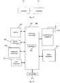
- Fig. 7is a block diagram showing certain main elements of an apparatus for preventing a photograph from being inadvertently shielded according to an example embodiment of the present disclosure.
- the apparatusincludes an acquiring module 701, a judging module 702 and a determining module 703.
- the acquiring module 701is configured to acquire an image characteristic of an edge region in a picture captured by a camera, in which the image characteristic at least includes image color and an area of a continuous image with same image color.
- the judging module 702is configured to judge whether the image characteristic of the edge region satisfies a predetermined image characteristic condition.
- the determining module 703is configured to determine that the picture captured by the camera contains a shielding object and to issue a prompt message, if the image characteristic of the edge region satisfies the predetermined image characteristic condition.
- Fig. 8is a block diagram showing more detail of the apparatus for preventing a photograph from being shielded, according to the present example embodiment of the present disclosure.
- the judging module 702includes a first judging unit 7021, a first acquiring unit 7022, a second judging unit 7023 and a first determining unit 7024.
- the first judging unit 7021is configured to judge whether in the edge region there are pixels with color values equal to a predetermined color value.
- the first acquiring unit 7022is configured to acquire an area of a continuous region formed by the pixels with color values equal to the predetermined color value in the edge region, if there are the pixels with color values equal to the predetermined color value in the edge region.
- the second judging unit 7023is configured to judge whether the area of the continuous region satisfies a predetermined area range.
- the first determining unit 7024is configured to determine that the image characteristic of the edge region satisfies the predetermined image characteristic condition, if the area of the continuous region satisfies the predetermined area range.
- Fig. 9is a block diagram showing yet more details of the apparatus for preventing a photograph from being shielded, according to the present example embodiment of the present disclosure.
- the judging module 702further includes a third judging unit 7025 and a second determining unit 7026.
- the third judging unit 7025is configured to judge whether an edge of the continuous region satisfies a predetermined optical parameter, if the area of the continuous region satisfies the predetermined area range.
- the second determining unit 7026is configured to determine that the image characteristic of the edge region satisfies the predetermined image characteristic condition, if the edge of the continuous region satisfies the predetermined optical parameter.
- Fig. 10shows a block diagram of an apparatus for preventing a photograph from being shielded, according to another example embodiment of the present disclosure.
- the judging module 702further includes a fourth judging unit 7027 and a third determining unit 7028.
- the fourth judging unit 7027is configured to judge whether a movement trajectory of the continuous region is consistent with a movement trajectory of a terminal, if the area of the continuous region satisfies the predetermined area range.
- the third determining unit 7028is configured to determine that the image characteristic of the edge region satisfies the predetermined image characteristic condition, if the movement trajectory of the continuous region is consistent with the movement trajectory of the terminal.
- Fig. 11shows a block diagram of an apparatus for preventing a photograph from being shielded, according to still another example embodiment of the present disclosure.
- the judging module 702further includes a fifth judging unit 7029 and a fourth determining unit 70210.
- the fifth judging unit 7029is configured to judge whether a difference between a brightness value of the continuous region and a brightness value of an image region except the continuous region in the picture captured by the camera is greater than a predetermined value, if the area of the continuous region satisfies the predetermined area range.
- the fourth determining unit 70210is configured to determine that the image characteristic of the edge region satisfies the predetermined image characteristic condition, if the difference is greater than the predetermined value.
- Fig. 12shows a block diagram of an apparatus for preventing a photograph from being shielded, according to yet another example embodiment of the present disclosure.
- the judging module 702further includes a sixth judging unit 70211 and a fifth determining unit 70212.
- the sixth judging unit 70211is configured to judge whether a fingerprint characteristic is contained in image content of the continuous region, if the area of the continuous region satisfies the predetermined area range.
- the fifth determining unit 70212is configured to determine that the image characteristic of the edge region satisfies the predetermined image characteristic condition, if the fingerprint characteristic is contained in the image content of the continuous region.
- Fig. 13shows a block diagram of a terminal according to an example embodiment of the present disclosure. As shown in Fig. 13 , the terminal includes a memory 71 and a processor 72.
- the memory 71is configured to store an instruction executable by the processor.
- the processor 72is configured, when executing the instruction stored in the memory 71, to: acquire an image characteristic of an edge region in a picture captured by a camera, in which the image characteristic at least includes image color and an area of a continuous image with same image color; judge whether the image characteristic of the edge region satisfies a predetermined image characteristic condition; and determine that the picture captured by the camera contains a shielding object and issue a prompt message, if the image characteristic of the edge region satisfies the predetermined image characteristic condition.
- the processor 72may be a central processing unit (CPU), or may be another general processor, a digital signal processor (DSP), an application specific integrated circuit (ASIC), etc.
- the general processormay be a microprocessor, or may be other regular processors, etc.
- the above memorymay be a read-only memory (ROM), a random access memory (RAM), a flash memory, a disk or a solid state disk.
- ROMread-only memory
- RAMrandom access memory
- a SIM cardis known as a user identification card, an intelligent card, and a digital mobile phone provided with the SIM card can be used. That is, the computer chip stores information of a user of the digital mobile phone and content such as an encrypted cipher code and a telephone dictionary etc.
- the steps in a method obtained by combining embodiments of the present disclosuremay be implemented by a hardware processor or a combination of hardware and software modules in the processor.
- Fig. 14shows a block diagram of a device 800 for preventing a photograph from being shielded, according to an example embodiment of the present disclosure.
- the device 800may be a mobile phone, a computer, a digital broadcasting terminal, a messaging device, a game console, a tablet device, a medical device, exercise equipment, and a personal digital assistant, etc.
- the device 800may include one or more of following components: a processing component 802, a memory 804, a power component 806, a multimedia component 808, an audio component 810, an input/output (I/O) interface 812, a sensor component 814, and a communication component 816.
- a processing component 802a memory 804, a power component 806, a multimedia component 808, an audio component 810, an input/output (I/O) interface 812, a sensor component 814, and a communication component 816.
- the processing component 802typically controls overall operations of the device 800, such as the operations associated with display, telephone calls, data communications, camera operations, and recording operations.
- the processing component 802may include one or more processors 820 to execute instructions to perform all or part of the steps in the above described methods.
- the processing component 802may include one or more modules which facilitate the interaction between the processing component 802 and other components.
- the processing component 802may include a multimedia module to facilitate the interaction between the multimedia component 808 and the processing component 802.
- the memory 804is configured to store various types of data to support the operation of the device 800. Examples of such data include instructions for any applications or methods operated on the device 800, contact data, phonebook data, messages, pictures, video, etc.
- the memory 804may be implemented using any type of volatile or non-volatile memory devices, or a combination thereof, such as a static random access memory (SRAM), an electrically erasable programmable read-only memory (EEPROM), an erasable programmable read-only memory (EPROM), a programmable read-only memory (PROM), a read-only memory (ROM), a magnetic memory, a flash memory, a magnetic or optical disk.
- SRAMstatic random access memory
- EEPROMelectrically erasable programmable read-only memory
- EPROMerasable programmable read-only memory
- PROMprogrammable read-only memory
- ROMread-only memory
- magnetic memorya magnetic memory
- flash memorya flash memory
- magnetic or optical diska magnetic or optical
- the power component 806provides power to various components of the device 800.
- the power component 806may include a power management system, one or more power sources, and any other components associated with the generation, management, and distribution of power in the device 800.
- the multimedia component 808includes a screen providing an output interface between the device 800 and the user.
- the screenmay include a liquid crystal display (LCD) and a touch panel (TP). If the screen includes the touch panel, the screen may be implemented as a touch screen to receive input signals from the user.
- the touch panelincludes one or more touch sensors to sense touches, swipes, and other gestures on the touch panel. The touch sensors may not only sense a boundary of a touch or swipe action, but also sense a duration time and a pressure associated with the touch or swipe action.
- the multimedia component 808includes a front camera and/or a rear camera. The front camera and the rear camera may receive external multimedia data while the device 800 is in an operation mode, such as a photographing mode or a video mode. Each of the front camera and the rear camera may be a fixed optical lens system or have focus and optical zoom capability.
- the audio component 810is configured to output and/or input audio signals.
- the audio component 810includes a microphone (MIC) configured to receive an external audio signal when the device 800 is in an operation mode, such as a call mode, a recording mode, and a voice recognition mode.
- the received audio signalmay be further stored in the memory 804 or transmitted via the communication component 816.
- the audio component 810further includes a speaker to output audio signals.
- the I/O interface 812provides an interface between the processing component 802 and peripheral interface modules, such as a keyboard, a click wheel, buttons, and the like.
- the buttonsmay include, but are not limited to, a home button, a volume button, a starting button, and a locking button.
- the sensor component 814includes one or more sensors to provide status assessments of various aspects of the device 800. For instance, the sensor component 814 may detect an open/closed status of the device 800 and relative positioning of components (e.g., the display and the keypad of the device 800). The sensor component 814 may also detect a change in position of the device 800 or of a component in the device 800, a presence or absence of user contact with the device 800, an orientation or an acceleration/deceleration of the device 800, and a change in temperature of the device 800. The sensor component 814 may include a proximity sensor configured to detect the presence of nearby objects without any physical contact. The sensor component 814 may also include a light sensor, such as a CMOS or CCD image sensor, for use in imaging applications. In some embodiments, the sensor component 814 may also include an accelerometer sensor, a gyroscope sensor, a magnetic sensor, a pressure sensor, or a temperature sensor.
- the communication component 816is configured to facilitate wired or wireless communication between the device 800 and other devices.
- the device 800can access a wireless network based on a communication standard, such as WIFI, 2G, or 3G, or a combination thereof.
- the communication component 816receives a broadcast signal or broadcast associated information from an external broadcast management system via a broadcast channel.
- the communication component 816further includes a near field communication (NFC) module to facilitate short-range communications.
- the NFC modulemay be implemented based on a radio frequency identification (RFID) technology, an infrared data association (IrDA) technology, an ultra-wideband (UWB) technology, a Bluetooth (BT) technology, and other technologies.
- RFIDradio frequency identification
- IrDAinfrared data association
- UWBultra-wideband
- BTBluetooth
- the device 800may be implemented with one or more application specific integrated circuits (ASICs), digital signal processors (DSPs), digital signal processing devices (DSPDs), programmable logic devices (PLDs), field programmable gate arrays (FPGAs), controllers, micro-controllers, microprocessors, or other electronic components, for performing the above described methods.
- ASICsapplication specific integrated circuits
- DSPsdigital signal processors
- DSPDsdigital signal processing devices
- PLDsprogrammable logic devices
- FPGAsfield programmable gate arrays
- controllersmicro-controllers, microprocessors, or other electronic components, for performing the above described methods.
- non-transitory computer-readable storage mediumincluding instructions, such as the memory 804 including instructions.
- the above instructionsare executable by the processor 820 in the device 800, for performing the above-described methods.
- the non-transitory computer-readable storage mediummay be a ROM, a RAM, a CD-ROM, a magnetic tape, a floppy disc, an optical data storage device, and the like.
Landscapes
- Engineering & Computer Science (AREA)
- Multimedia (AREA)
- Signal Processing (AREA)
- Physics & Mathematics (AREA)
- General Physics & Mathematics (AREA)
- Computer Vision & Pattern Recognition (AREA)
- Theoretical Computer Science (AREA)
- Human Computer Interaction (AREA)
- Quality & Reliability (AREA)
- Studio Devices (AREA)
- Image Analysis (AREA)
- Telephone Function (AREA)
Description
- The present disclosure generally relates to the communication technology, and more particularly, to a method and an apparatus for preventing a photograph from being shielded.
- An existing smart phone is provided with a camera function internally, such that a user may use the camera function in the smart phone to take a picture.
- In the related art, when the user uses the smart phone to take a picture, since the hand may shield the camera (i.e. part of the hand may be in front of the camera) and the user may not be aware at this time that the camera is shielded in some cases, for example in a case of snap shooting, the photographic effect of the picture may be affected.
US 2004/012682 A1 , relates to an image capturing apparatus. According to paragraphs [0066], [0079]-[0080]and [0100], it is determined whether a low brightness area of a position which does not shift exists only in the peripheral portions and not the center portion of an image. In an example, when the low brightness area of a position which does not change has an overlapped portion with the peripheral portion at the left end or the peripheral portion at the right end of the image, the low brightness area may be determined as a finger area. In another example, when the ratio of the number of pixels of flesh color to all of pixels in the low brightness area which does not shift exceeds a predetermined value, the low brightness area may be determined as the finger area. That is, with the low brightness area, by determining whether the overlapped region exists or based on the hue information of the low brightness area, the finger area may be determined. - The present application relates to a method for preventing a photograph from being shielded according to independent claim 1, an apparatus for preventing a photograph from being shielded according to independent claim 5, a device for preventing a photograph from being shielded according to independent claim 9 and a computer-readable storage medium according to independent claim 10. Further aspects of the present application are defined by the dependent claims.
- It should be understood that, the general description above and the following detailed description are merely illustrative and explanatory, and shall not be construed to limit the present disclosure. The scope of the invention is defined by the appended claims.
- The drawings shown herein, which are incorporated in and constitute a part of the specification, illustrate embodiments of the present disclosure and used for explaining the principle of the present disclosure together with the specification.
Fig. 1 shows a flow chart of steps in a method for preventing a photograph from being shielded according to an example embodiment of the present disclosure.Fig. 2 shows a flow chart of other steps in the method for preventing a photograph from being shielded according to the example embodiment of the present disclosure.Fig. 3 shows a flow chart of yet other steps in the method for preventing a photograph from being shielded according to the example embodiment of the present disclosure.Fig. 4 shows a flow chart of a method for preventing a photograph from being shielded according to still another example embodiment of the present disclosure.Fig. 5 shows a flow chart of a method for preventing a photograph from being shielded according to still yet another example embodiment of the present disclosure.Fig. 6 shows a flow chart of a method for preventing a photograph from being shielded according to still yet another example embodiment of the present disclosure.Fig. 7 is a block diagram showing certain main elements of an apparatus for preventing a photograph from being shielded according to an example embodiment of the present disclosure.Fig. 8 is a block diagram showing more details of the apparatus for preventing a photograph from being shielded according to the example embodiment of the present disclosure.Fig. 9 is a block diagram showing yet more details of the apparatus for preventing a photograph from being shielded according to the example embodiment of the present disclosure.Fig. 10 shows a block diagram of an apparatus for preventing a photograph from being shielded according to another example embodiment of the present disclosure.Fig. 11 shows a block diagram of an apparatus for preventing a photograph from being shielded according to still another example embodiment of the present disclosure.Fig. 12 shows a block diagram of an apparatus for preventing a photograph from being shielded according to yet another example embodiment of the present disclosure.Fig. 13 shows a block diagram of a terminal according to an example embodiment of the present disclosure.Fig. 14 shows a block diagram of adevice 800 for preventing a photograph from being shielded according to an example embodiment of the present disclosure.- Now the example embodiments will be described in detail, in which the examples are shown in the accompanying drawings. In the specification with reference to the drawings, unless specified or limited otherwise, the same or similar elements and the elements having same or similar functions are denoted by like reference numerals. The implementations described in the following example embodiments do not represent all implementations of the present disclosure. Instead, they are merely examples of the apparatus and method consistent with some aspects of the present disclosure described by the appended claims.
Fig. 1 shows a flow chart of steps in a method for preventing a photograph from being shielded according to an example embodiment of the present disclosure. As shown inFig. 1 , the method is applied in a terminal and includes the following.- In block S101, an image characteristic of an edge region in a picture captured by a camera is acquired. The image characteristic at least includes image color and an area of a continuous image with same image color.
- The edge region means a region formed by extending a preset distance towards the interior of the picture captured by the camera from a boundary of the picture. For different edges, the preset distance nay be distinct. For example, in general, the lower edge of the picture captured by the camera is more prone to be shielded inadvertently, such that the preset distance for the lower edge may be set to be bigger. And the lower edge may be determined according to an angle at which the smart phone is, and the angle at which the smart phone is may be detected by sensing of gravitational forces (e.g. using a gravity sensor of the smart phone). If the terminal is in a horizontal mode, it may be determined by gravitational sensing whether the left side or right side of the terminal is at the lower edge.
- When a hand of the user shields the camera, images in the picture captured by the camera have some common characteristics. For example, the color of these images is in accordance with a specific color, and these images with color in accordance with the specific color may form a continuous region.
- In block S102, it is judged whether the image characteristic of the edge region satisfies a predetermined image characteristic condition.
- Since the images formed when the hand shields the camera have regular characteristics, when the camera captures the picture, it may be judged whether the image of an edge region matches with the predetermined image characteristic condition with some regular characteristics.
- In block S103, if the image characteristic of the edge region satisfies the predetermined image characteristic condition, it is determined that the picture captured by the camera contains a shielding object and a prompt message is issued.
- If the image of edge region is in accordance with the predetermined image characteristic condition, it may be determined that the picture is shielded, and the terminal may provide the prompt image to the user in time, for example, popping out a prompt message or making a prompt sound, such that the user may adjust operational postures in time so as to ensure a photograph having desired visual effect can be taken.
- In this embodiment, the image characteristic of the edge region in the picture captured by the camera is acquired and compared with the predetermined image characteristic condition, and if the image characteristic matches with the predetermined image characteristic condition, it may be determined that the picture is shielded, and then the user is reminded to adjust operational postures timely so as to ensure that the desired effect of the photograph is not adversely affected.
Fig. 2 shows a flow chart of other steps in the method for preventing a photograph from being shielded according to the present example embodiment of the present disclosure. As shown inFig. 2 , the above block S102 specifically includes the following.- In block S201, it is judged whether in the edge region there are pixels with color values equal to a predetermined color value.
- As described above, if the hand of the user shields the camera, images in the picture captured by the camera have some common characteristics. For example, the color of these images is in accordance with a specific color, and these images with color in accordance with the specific color may form a continuous region.
- In this block S201, the terminal first judges whether in the edge region there are the pixels with color values equal to the predetermined color value, in which the predetermined color value may, for example, be a color value corresponding to pink or corresponding to gray.
- In block S202, if there are the pixels with color values equal to the predetermined color value in the edge region, an area of a continuous region formed by the pixels with color values equal to the predetermined color value in the edge region is acquired.
- The continuous region is formed by splicing (connecting) adjacent pixels, and the color values of these pixels are equal to the predetermined color value, i.e., the continuous region cannot contain a pixel with another color value.
- In block S203, it is judged whether the area of the continuous region satisfies a predetermined area range.
- The area of the continuous region is an area formed by the adjacent pixels with color values equal to the predetermined color value. If the area reaches or exceeds a preset area, it may be considered that the picture is shielded.
- For different edges, the predetermined area range may be set to be distinct. For example, for the lower edge, the predetermined area range may be set to be bigger than for the upper edge.
- In block S204, if the area of the continuous region satisfies the predetermined area range, it is determined that the image characteristic of the edge region satisfies the predetermined image characteristic condition.
- In this embodiment, by determining whether the edge region contains the predetermined color value and whether the area of the region formed by the predetermined color value reaches a predetermined area, it may be determined whether the picture is shielded, thus improving the accuracy of identifying the shielding object.
Fig. 3 shows a flow chart of yet more steps of the method for preventing a photograph from being shielded according to the present example embodiment of the present disclosure. As shown inFig. 3 , based on the determining method shown inFig. 2 , the following determining method may be added.- In block S301, if the area of the continuous region satisfies the predetermined area range, it is judged whether an edge of the continuous region satisfies a predetermined optical parameter.
- If the picture is shielded by the user's hand, the edge of the sub image formed when the picture is shielded exhibits a diffraction optical characteristic, i.e., the specific optical parameter here is existence of a diffraction effect. In this block, it is judged whether the edge of the continuous region satisfies the predetermined optical parameter.
- In block S302, if the edge of the continuous region satisfies the predetermined optical parameter, it is determined that the image characteristic of the edge region satisfies the predetermined image characteristic condition.
- In this embodiment, under the prerequisite of satisfying the predetermined color value and the predetermined area range, the terminal further determines whether the image of the edge region satisfies the predetermined optical parameter, and if yes, it is considered that the picture is shielded. In this way, the accuracy of identifying the shielding object is further improved.
Fig. 4 shows a flow chart of a method for preventing a photograph from being inadvertently shielded according to yet another example embodiment of the present disclosure. As shown inFig. 4 , based on the determining method shown inFig. 2 , the following determining method may be added.- In block S401, if the area of the continuous region satisfies the predetermined area range, it is judged whether a movement trajectory of the continuous region is consistent with a movement trajectory of a terminal.
- When the user takes a picture, the scene to be photographed may be in a static state, or may have a movement trajectory different from the movement trajectory of the terminal. If the movement trajectory of the edge region in the picture is consistent with the movement trajectory of the terminal, it may be considered that the edge region is shielded by the user's hand.
- It may be determined whether the movement trajectory of the continuous region is consistent with that of the terminal by a positioning method or the like.
- In block S402, if the movement trajectory of the continuous region is consistent with the movement trajectory of the terminal, it is determined that the image characteristic of the edge region satisfies the predetermined image characteristic condition.
- If the movement trajectory of the continuous region is consistent with the movement trajectory of the terminal, i.e., the continuous region moves with the movement of the terminal, it may be determined that the continuous region is shielded.
- In this embodiment, under the prerequisite of satisfying the predetermined color value and the predetermined area range, the terminal further determines whether the movement trajectory of the edge region is consistent with the movement trajectory of the terminal, and if yes, it is considered that the picture is shielded. In this way, the accuracy of identifying the shielding object is further improved.
Fig. 5 shows a flow chart of a method for preventing a photograph from being shielded according to still another example embodiment of the present disclosure. As shown inFig. 5 , based on the determining method shown inFig. 2 , the following determining method may be added.- In block S501, if the area of the continuous region satisfies the predetermined area range, it is judged whether a difference between a brightness value of the continuous region and a brightness value of an image region except the continuous region in the picture captured by the camera is greater than a predetermined value.
- When the user takes a picture, the picture captured by the camera would have a uniform brightness, or a brightness in a certain close range. If the picture is shielded, the part which is shielded has a brightness clearly distinguished from the picture which is captured now. In this block, by detecting the difference between the brightness value of the continuous region and the brightness value of the other part in the picture captured by the camera, it is judged whether the continuous region is shielded.
- In block S502, if the difference is greater than the predetermined value, it is determined that the image characteristic of the edge region satisfies the predetermined image characteristic condition.
- The predetermined value may be acquired by experiments or according to experience data.
- If the difference is greater than the predetermined value, it may be determined that the picture is shielded.
- In this embodiment, under the prerequisite of satisfying the predetermined color value and the predetermined area range, the terminal further determines the difference between the brightness value of the edge region and the brightness value of the other part in the picture, and if the difference is too big, it is considered that the picture is shielded. In this way, the accuracy of identifying the shielding object is further improved.
Fig. 6 shows a flow chart of a method for preventing a photograph from being shielded according to still yet another example embodiment of the present disclosure. As shown inFig. 6 , based on the determining method shown inFig. 2 , the following determining method may be added.- In block S601, if the area of the continuous region satisfies the predetermined area range, it is judged whether a fingerprint characteristic is contained in image content of the continuous region.
- If the continuous region is shielded by the user's hand, an image in accordance with the fingerprint characteristic may appear. By detecting whether the fingerprint characteristic is contained in the image content, it may be judged whether the continuous region is shielded.
- In block S602, if the fingerprint characteristic is contained in the image content of the continuous region, it is determined that the image characteristic of the edge region satisfies the predetermined image characteristic condition.
- In this embodiment, under the prerequisite of satisfying the predetermined color value and the predetermined area range, the terminal further determines whether the fingerprint characteristic is contained in the image content of the edge region, and if yes, it is considered that the picture is shielded. In this way, the accuracy of identifying the shielding object is further improved.
Fig. 7 is a block diagram showing certain main elements of an apparatus for preventing a photograph from being inadvertently shielded according to an example embodiment of the present disclosure. Referring toFig. 7 , the apparatus includes an acquiringmodule 701, a judgingmodule 702 and a determiningmodule 703.- The acquiring
module 701 is configured to acquire an image characteristic of an edge region in a picture captured by a camera, in which the image characteristic at least includes image color and an area of a continuous image with same image color. - The judging
module 702 is configured to judge whether the image characteristic of the edge region satisfies a predetermined image characteristic condition. - The determining
module 703 is configured to determine that the picture captured by the camera contains a shielding object and to issue a prompt message, if the image characteristic of the edge region satisfies the predetermined image characteristic condition. Fig. 8 is a block diagram showing more detail of the apparatus for preventing a photograph from being shielded, according to the present example embodiment of the present disclosure. Referring toFig. 8 , the judgingmodule 702 includes afirst judging unit 7021, a first acquiringunit 7022, asecond judging unit 7023 and a first determiningunit 7024.- The
first judging unit 7021 is configured to judge whether in the edge region there are pixels with color values equal to a predetermined color value. - The first acquiring
unit 7022 is configured to acquire an area of a continuous region formed by the pixels with color values equal to the predetermined color value in the edge region, if there are the pixels with color values equal to the predetermined color value in the edge region. - The
second judging unit 7023 is configured to judge whether the area of the continuous region satisfies a predetermined area range. - The first determining
unit 7024 is configured to determine that the image characteristic of the edge region satisfies the predetermined image characteristic condition, if the area of the continuous region satisfies the predetermined area range. Fig. 9 is a block diagram showing yet more details of the apparatus for preventing a photograph from being shielded, according to the present example embodiment of the present disclosure. Referring toFig. 9 , the judgingmodule 702 further includes athird judging unit 7025 and a second determiningunit 7026.- The
third judging unit 7025 is configured to judge whether an edge of the continuous region satisfies a predetermined optical parameter, if the area of the continuous region satisfies the predetermined area range. - The second determining
unit 7026 is configured to determine that the image characteristic of the edge region satisfies the predetermined image characteristic condition, if the edge of the continuous region satisfies the predetermined optical parameter. Fig. 10 shows a block diagram of an apparatus for preventing a photograph from being shielded, according to another example embodiment of the present disclosure. Referring toFig. 10 , the judgingmodule 702 further includes afourth judging unit 7027 and a third determiningunit 7028.- The
fourth judging unit 7027 is configured to judge whether a movement trajectory of the continuous region is consistent with a movement trajectory of a terminal, if the area of the continuous region satisfies the predetermined area range. - The third determining
unit 7028 is configured to determine that the image characteristic of the edge region satisfies the predetermined image characteristic condition, if the movement trajectory of the continuous region is consistent with the movement trajectory of the terminal. Fig. 11 shows a block diagram of an apparatus for preventing a photograph from being shielded, according to still another example embodiment of the present disclosure. Referring toFig. 11 , the judgingmodule 702 further includes afifth judging unit 7029 and a fourth determiningunit 70210.- The
fifth judging unit 7029 is configured to judge whether a difference between a brightness value of the continuous region and a brightness value of an image region except the continuous region in the picture captured by the camera is greater than a predetermined value, if the area of the continuous region satisfies the predetermined area range. - The fourth determining
unit 70210 is configured to determine that the image characteristic of the edge region satisfies the predetermined image characteristic condition, if the difference is greater than the predetermined value. Fig. 12 shows a block diagram of an apparatus for preventing a photograph from being shielded, according to yet another example embodiment of the present disclosure. Referring toFig. 12 , the judgingmodule 702 further includes asixth judging unit 70211 and a fifth determiningunit 70212.- The
sixth judging unit 70211 is configured to judge whether a fingerprint characteristic is contained in image content of the continuous region, if the area of the continuous region satisfies the predetermined area range. - The fifth determining
unit 70212 is configured to determine that the image characteristic of the edge region satisfies the predetermined image characteristic condition, if the fingerprint characteristic is contained in the image content of the continuous region. - With respect to the apparatus in the above embodiments, the specific operation modes of individual modules therein have been described in detail in the embodiments regarding the processing methods, which will not be elaborated herein.
- The internal functional modules and structure of the apparatus for preventing a photograph from being shielded have been described above.
Fig. 13 shows a block diagram of a terminal according to an example embodiment of the present disclosure. As shown inFig. 13 , the terminal includes amemory 71 and aprocessor 72. - The
memory 71 is configured to store an instruction executable by the processor. - The
processor 72 is configured, when executing the instruction stored in thememory 71, to: acquire an image characteristic of an edge region in a picture captured by a camera, in which the image characteristic at least includes image color and an area of a continuous image with same image color; judge whether the image characteristic of the edge region satisfies a predetermined image characteristic condition; and determine that the picture captured by the camera contains a shielding object and issue a prompt message, if the image characteristic of the edge region satisfies the predetermined image characteristic condition. - In the above embodiment of the terminal, it should be understood that, the
processor 72 may be a central processing unit (CPU), or may be another general processor, a digital signal processor (DSP), an application specific integrated circuit (ASIC), etc. The general processor may be a microprocessor, or may be other regular processors, etc. And the above memory may be a read-only memory (ROM), a random access memory (RAM), a flash memory, a disk or a solid state disk. A SIM card is known as a user identification card, an intelligent card, and a digital mobile phone provided with the SIM card can be used. That is, the computer chip stores information of a user of the digital mobile phone and content such as an encrypted cipher code and a telephone dictionary etc. The steps in a method obtained by combining embodiments of the present disclosure may be implemented by a hardware processor or a combination of hardware and software modules in the processor. Fig. 14 shows a block diagram of adevice 800 for preventing a photograph from being shielded, according to an example embodiment of the present disclosure. For example, thedevice 800 may be a mobile phone, a computer, a digital broadcasting terminal, a messaging device, a game console, a tablet device, a medical device, exercise equipment, and a personal digital assistant, etc.- Referring to
Fig. 14 , thedevice 800 may include one or more of following components: aprocessing component 802, amemory 804, apower component 806, amultimedia component 808, anaudio component 810, an input/output (I/O)interface 812, asensor component 814, and acommunication component 816. - The
processing component 802 typically controls overall operations of thedevice 800, such as the operations associated with display, telephone calls, data communications, camera operations, and recording operations. Theprocessing component 802 may include one ormore processors 820 to execute instructions to perform all or part of the steps in the above described methods. Moreover, theprocessing component 802 may include one or more modules which facilitate the interaction between theprocessing component 802 and other components. For instance, theprocessing component 802 may include a multimedia module to facilitate the interaction between themultimedia component 808 and theprocessing component 802. - The
memory 804 is configured to store various types of data to support the operation of thedevice 800. Examples of such data include instructions for any applications or methods operated on thedevice 800, contact data, phonebook data, messages, pictures, video, etc. Thememory 804 may be implemented using any type of volatile or non-volatile memory devices, or a combination thereof, such as a static random access memory (SRAM), an electrically erasable programmable read-only memory (EEPROM), an erasable programmable read-only memory (EPROM), a programmable read-only memory (PROM), a read-only memory (ROM), a magnetic memory, a flash memory, a magnetic or optical disk. - The
power component 806 provides power to various components of thedevice 800. Thepower component 806 may include a power management system, one or more power sources, and any other components associated with the generation, management, and distribution of power in thedevice 800. - The
multimedia component 808 includes a screen providing an output interface between thedevice 800 and the user. In some embodiments, the screen may include a liquid crystal display (LCD) and a touch panel (TP). If the screen includes the touch panel, the screen may be implemented as a touch screen to receive input signals from the user. The touch panel includes one or more touch sensors to sense touches, swipes, and other gestures on the touch panel. The touch sensors may not only sense a boundary of a touch or swipe action, but also sense a duration time and a pressure associated with the touch or swipe action. In some embodiments, themultimedia component 808 includes a front camera and/or a rear camera. The front camera and the rear camera may receive external multimedia data while thedevice 800 is in an operation mode, such as a photographing mode or a video mode. Each of the front camera and the rear camera may be a fixed optical lens system or have focus and optical zoom capability. - The
audio component 810 is configured to output and/or input audio signals. For example, theaudio component 810 includes a microphone (MIC) configured to receive an external audio signal when thedevice 800 is in an operation mode, such as a call mode, a recording mode, and a voice recognition mode. The received audio signal may be further stored in thememory 804 or transmitted via thecommunication component 816. In some embodiments, theaudio component 810 further includes a speaker to output audio signals. - The I/
O interface 812 provides an interface between theprocessing component 802 and peripheral interface modules, such as a keyboard, a click wheel, buttons, and the like. The buttons may include, but are not limited to, a home button, a volume button, a starting button, and a locking button. - The
sensor component 814 includes one or more sensors to provide status assessments of various aspects of thedevice 800. For instance, thesensor component 814 may detect an open/closed status of thedevice 800 and relative positioning of components (e.g., the display and the keypad of the device 800). Thesensor component 814 may also detect a change in position of thedevice 800 or of a component in thedevice 800, a presence or absence of user contact with thedevice 800, an orientation or an acceleration/deceleration of thedevice 800, and a change in temperature of thedevice 800. Thesensor component 814 may include a proximity sensor configured to detect the presence of nearby objects without any physical contact. Thesensor component 814 may also include a light sensor, such as a CMOS or CCD image sensor, for use in imaging applications. In some embodiments, thesensor component 814 may also include an accelerometer sensor, a gyroscope sensor, a magnetic sensor, a pressure sensor, or a temperature sensor. - The
communication component 816 is configured to facilitate wired or wireless communication between thedevice 800 and other devices. Thedevice 800 can access a wireless network based on a communication standard, such as WIFI, 2G, or 3G, or a combination thereof. In one exemplary embodiment, thecommunication component 816 receives a broadcast signal or broadcast associated information from an external broadcast management system via a broadcast channel. In one exemplary embodiment, thecommunication component 816 further includes a near field communication (NFC) module to facilitate short-range communications. For example, the NFC module may be implemented based on a radio frequency identification (RFID) technology, an infrared data association (IrDA) technology, an ultra-wideband (UWB) technology, a Bluetooth (BT) technology, and other technologies. - In example embodiments, the
device 800 may be implemented with one or more application specific integrated circuits (ASICs), digital signal processors (DSPs), digital signal processing devices (DSPDs), programmable logic devices (PLDs), field programmable gate arrays (FPGAs), controllers, micro-controllers, microprocessors, or other electronic components, for performing the above described methods. - In example embodiments, there is also provided a non-transitory computer-readable storage medium including instructions, such as the
memory 804 including instructions. The above instructions are executable by theprocessor 820 in thedevice 800, for performing the above-described methods. For example, the non-transitory computer-readable storage medium may be a ROM, a RAM, a CD-ROM, a magnetic tape, a floppy disc, an optical data storage device, and the like.
Claims (9)
- A method for preventing a photograph from being shielded, comprising:(S101) acquiring an image characteristic of an edge region in one picture captured by a camera, wherein the image characteristic at least comprises image color and an area of a continuous image with same image color;(S102) judging whether the image characteristic of the edge region satisfies a predetermined image characteristic condition; and(S103) determining that the picture captured by the camera contains a shielding object and issuing a prompt message, if the image characteristic of the edge region satisfies the predetermined image characteristic condition,wherein (102) judging whether the image characteristic of the edge region satisfies a predetermined image characteristic condition comprises:(S201) judging whether in the edge region there are pixels with color values equal to a predetermined color value;(S202) acquiring an area of a continuous region formed by the pixels with color values equal to the predetermined color value in the edge region, if there are the pixels with color values equal to the predetermined color value in the edge region;(S203) judging whether the area of the continuous region satisfies a predetermined area range; and(S204) determining that the image characteristic of the edge region satisfies the predetermined image characteristic condition, if the area of the continuous region satisfies the predetermined area range,characterized by (S102) judging whether the image characteristic of the edge region satisfies a predetermined image characteristic condition further comprises:(S301) judging whether an edge of the continuous region satisfies a predetermined optical characteristic, if the area of the continuous region satisfies the predetermined area range; and(S302) determining that the image characteristic of the edge region satisfies the predetermined image characteristic condition, if the edge of the continuous region satisfies the predetermined optical characteristic, wherein the optical characteristic comprises a diffraction characteristic.
- The method according to claim 1, wherein (S102) judging whether the image characteristic of the edge region satisfies a predetermined image characteristic condition further comprises:(S401) judging whether a movement trajectory of the continuous region is consistent with a movement trajectory of a terminal, if the area of the continuous region satisfies the predetermined area range; and(S402) determining that the image characteristic of the edge region satisfies the predetermined image characteristic condition, if the movement trajectory of the continuous region is consistent with the movement trajectory of the terminal.
- The method according to claim 1, wherein (S102) judging whether the image characteristic of the edge region satisfies a predetermined image characteristic condition further comprises:(S501) judging whether a difference between a brightness value of the continuous region and a brightness value of an image region except the continuous region in the picture captured by the camera is greater than a predetermined value, if the area of the continuous region satisfies the predetermined area range; and(S502) determining that the image characteristic of the edge region satisfies the predetermined image characteristic condition, if the difference is greater than the predetermined value.
- The method according to claim 1, wherein (S102) judging whether the image characteristic of the edge region satisfies a predetermined image characteristic condition further comprises:(S601) judging whether a fingerprint characteristic is contained in image content of the continuous region, if the area of the continuous region satisfies the predetermined area range; and(S602) determining that the image characteristic of the edge region satisfies the predetermined image characteristic condition, if the fingerprint characteristic is contained in the image content of the continuous region.
- An apparatus for preventing a photograph from being shielded, comprising:an acquiring module (701), configured to acquire an image characteristic of an edge region in one picture captured by a camera, wherein the image characteristic at least comprises image color and an area of a continuous image with same image color;a judging module (702), configured to judge whether the image characteristic of the edge region satisfies a predetermined image characteristic condition; anda determining module (703), configured to determine that the picture captured by the camera contains a shielding object and to issue a prompt message, if the image characteristic of the edge region satisfies the predetermined image characteristic condition,wherein the judging module (702) comprises:a first judging unit (7021), configured to judge whether in the edge region there are pixels with color values equal to a predetermined color value;a first acquiring unit (7022), configured to acquire an area of a continuous region formed by the pixels with color values equal to the predetermined color value in the edge region, if there are the pixels with color values equal to the predetermined color value in the edge region;a second judging unit (7023), configured to judge whether the area of the continuous region satisfies a predetermined area range; anda first determining unit (7024), configured to determine that the image characteristic of the edge region satisfies the predetermined image characteristic condition, if the area of the continuous region satisfies the predetermined area range,characterized by the judging module (702) further comprising:a third judging unit (7025), configured to judge whether an edge of the continuous region satisfies a predetermined optical characteristic, if the area of the continuous region satisfies the predetermined area range; anda second determining unit (7026), configured to determine that the image characteristic of the edge region satisfies the predetermined image characteristic condition, if the edge of the continuous region satisfies the predetermined optical characteristic, wherein the optical characteristic comprises a diffraction characteristic.
- The apparatus according to claim 5, wherein the judging module (702) further comprises:a fourth judging unit (7027), configured to judge whether a movement trajectory of the continuous region is consistent with a movement trajectory of a terminal, if the area of the continuous region satisfies the predetermined area range; anda third determining unit (7028), configured to determine that the image characteristic of the edge region satisfies the predetermined image characteristic condition, if the movement trajectory of the continuous region is consistent with the movement trajectory of the terminal.
- The apparatus according to claim 5, wherein the judging module (702) further comprises:a fifth judging unit (7029), configured to judge whether a difference between a brightness value of the continuous region and a brightness value of an image region except the continuous region in the picture captured by the camera is greater than a predetermined value, if the area of the continuous region satisfies the predetermined area range; anda fourth determining unit (70210), configured to determine that the image characteristic of the edge region satisfies the predetermined image characteristic condition, if the difference is greater than the predetermined value.
- The apparatus according to claim 5, wherein the judging module (702) further comprises:a sixth judging unit (70211), configured to judge whether a fingerprint characteristic is contained in image content of the continuous region, if the area of the continuous region satisfies the predetermined area range; anda fifth determining unit (70212), configured to determine that the image characteristic of the edge region satisfies the predetermined image characteristic condition, if the fingerprint characteristic is contained in the image content of the continuous region.
- A computer-readable storage medium having stored therein instructions that, when executed by a processor of a terminal, causes the terminal to perform the method for preventing a photograph from being shielded according to any one of claims 1-4.
Applications Claiming Priority (1)
| Application Number | Priority Date | Filing Date | Title |
|---|---|---|---|
| CN201510897800.2ACN105491289B (en) | 2015-12-08 | 2015-12-08 | Prevent from taking pictures the method and device blocked |
Publications (3)
| Publication Number | Publication Date |
|---|---|
| EP3179711A2 EP3179711A2 (en) | 2017-06-14 |
| EP3179711A3 EP3179711A3 (en) | 2017-06-21 |
| EP3179711B1true EP3179711B1 (en) | 2021-07-07 |
Family
ID=55677975
Family Applications (1)
| Application Number | Title | Priority Date | Filing Date |
|---|---|---|---|
| EP16202972.2AActiveEP3179711B1 (en) | 2015-12-08 | 2016-12-08 | Method and apparatus for preventing photograph from being shielded |
Country Status (4)
| Country | Link |
|---|---|
| US (1) | US10284773B2 (en) |
| EP (1) | EP3179711B1 (en) |
| CN (1) | CN105491289B (en) |
| WO (1) | WO2017096782A1 (en) |
Families Citing this family (18)
| Publication number | Priority date | Publication date | Assignee | Title |
|---|---|---|---|---|
| CN105491289B (en)* | 2015-12-08 | 2019-10-01 | 小米科技有限责任公司 | Prevent from taking pictures the method and device blocked |
| CN107347151B (en)* | 2016-05-04 | 2018-12-18 | 南昌黑鲨科技有限公司 | Binocular camera occlusion detection method and device |
| CN105744268A (en)* | 2016-05-04 | 2016-07-06 | 深圳众思科技有限公司 | Camera shielding detection method and device |
| CN106210522B (en)* | 2016-07-15 | 2019-06-14 | Oppo广东移动通信有限公司 | An image processing method, device, mobile terminal and readable storage medium |
| CN106454336B (en)* | 2016-11-23 | 2019-10-25 | 北京小米移动软件有限公司 | Method and device for detecting blocked terminal camera and terminal |
| CN110265121A (en)* | 2017-04-23 | 2019-09-20 | 奥康科技有限公司 | Wearable device and to wearable device positioning method and medium |
| CN108765380A (en)* | 2018-05-14 | 2018-11-06 | Oppo广东移动通信有限公司 | Image processing method, device, storage medium and mobile terminal |
| CN109359572A (en)* | 2018-09-30 | 2019-02-19 | 联想(北京)有限公司 | Information processing method, device and electronic equipment |
| CN109377884B (en)* | 2018-12-06 | 2020-12-11 | 厦门天马微电子有限公司 | Display panel, display device and driving method of display panel |
| CN110766745B (en)* | 2018-12-18 | 2023-11-03 | 极米科技股份有限公司 | Method for detecting interference before projector lens, projector and storage medium |
| CN112116551B (en)* | 2019-06-20 | 2025-02-14 | 腾讯科技(深圳)有限公司 | Camera occlusion detection method, device, electronic device and storage medium |
| CN111368785B (en)* | 2020-03-17 | 2023-08-25 | 广东智媒云图科技股份有限公司 | Camera shielding judgment method, device, equipment and storage medium |
| CN111753783B (en)* | 2020-06-30 | 2024-05-28 | 北京小米松果电子有限公司 | Finger shielding image detection method, device and medium |
| CN112037127B (en)* | 2020-07-27 | 2024-08-02 | 浙江大华技术股份有限公司 | Privacy shielding method and device for video monitoring, storage medium and electronic device |
| CN112598628A (en)* | 2020-12-08 | 2021-04-02 | 影石创新科技股份有限公司 | Image occlusion detection method and device, shooting equipment and medium |
| CN112597952A (en)* | 2020-12-28 | 2021-04-02 | 深圳市捷顺科技实业股份有限公司 | Method, device and system for identifying monitoring state of camera and storage medium |
| CN113902677A (en)* | 2021-09-08 | 2022-01-07 | 九天创新(广东)智能科技有限公司 | A camera occlusion detection method, device and intelligent robot |
| US11683598B1 (en)* | 2022-02-24 | 2023-06-20 | Omnivision Technologies, Inc. | Image sensor with on-chip occlusion detection and methods thereof |
Family Cites Families (11)
| Publication number | Priority date | Publication date | Assignee | Title |
|---|---|---|---|---|
| JP2004040712A (en)* | 2002-07-08 | 2004-02-05 | Minolta Co Ltd | Imaging apparatus |
| JP2007323517A (en)* | 2006-06-02 | 2007-12-13 | Oki Electric Ind Co Ltd | Automatic transaction device |
| JP4462305B2 (en) | 2007-08-17 | 2010-05-12 | ソニー株式会社 | Imaging apparatus, method, and program |
| JP4957850B2 (en)* | 2010-02-04 | 2012-06-20 | カシオ計算機株式会社 | Imaging apparatus, warning method, and program |
| CN102111532B (en)* | 2010-05-27 | 2013-03-27 | 周渝斌 | Camera lens occlusion detecting system and method |
| JP2012023546A (en) | 2010-07-14 | 2012-02-02 | Jvc Kenwood Corp | Control device, stereoscopic video pickup device, and control method |
| JP5750693B2 (en)* | 2011-03-22 | 2015-07-22 | オリンパス株式会社 | Photography equipment |
| KR101590334B1 (en)* | 2011-08-30 | 2016-02-02 | 삼성전자 주식회사 | Image photographing device and control method for the same |
| CN103139547B (en)* | 2013-02-25 | 2016-02-10 | 昆山南邮智能科技有限公司 | The method of pick-up lens occlusion state is judged based on video signal |
| US10142522B2 (en)* | 2013-12-03 | 2018-11-27 | Ml Netherlands C.V. | User feedback for real-time checking and improving quality of scanned image |
| CN105491289B (en)* | 2015-12-08 | 2019-10-01 | 小米科技有限责任公司 | Prevent from taking pictures the method and device blocked |
- 2015
- 2015-12-08CNCN201510897800.2Apatent/CN105491289B/enactiveActive
- 2016
- 2016-06-28WOPCT/CN2016/087490patent/WO2017096782A1/ennot_activeCeased
- 2016-12-07USUS15/372,029patent/US10284773B2/enactiveActive
- 2016-12-08EPEP16202972.2Apatent/EP3179711B1/enactiveActive
Non-Patent Citations (1)
| Title |
|---|
| None* |
Also Published As
| Publication number | Publication date |
|---|---|
| US20170163883A1 (en) | 2017-06-08 |
| EP3179711A3 (en) | 2017-06-21 |
| WO2017096782A1 (en) | 2017-06-15 |
| EP3179711A2 (en) | 2017-06-14 |
| CN105491289B (en) | 2019-10-01 |
| CN105491289A (en) | 2016-04-13 |
| US10284773B2 (en) | 2019-05-07 |
Similar Documents
| Publication | Publication Date | Title |
|---|---|---|
| EP3179711B1 (en) | Method and apparatus for preventing photograph from being shielded | |
| US9674395B2 (en) | Methods and apparatuses for generating photograph | |
| RU2665217C2 (en) | Image processing method and apparatus | |
| US20170034409A1 (en) | Method, device, and computer-readable medium for image photographing | |
| EP3032821B1 (en) | Method and device for shooting a picture | |
| US10452890B2 (en) | Fingerprint template input method, device and medium | |
| CN106454336B (en) | Method and device for detecting blocked terminal camera and terminal | |
| EP3046016A1 (en) | Method and apparatus for switching display mode | |
| EP3496391B1 (en) | Method and device for capturing image and storage medium | |
| US20170123587A1 (en) | Method and device for preventing accidental touch of terminal with touch screen | |
| EP3136699A1 (en) | Method and device for connecting external equipment | |
| US9924090B2 (en) | Method and device for acquiring iris image | |
| US20170344177A1 (en) | Method and device for determining operation mode of terminal | |
| US10318069B2 (en) | Method for controlling state of touch screen, and electronic device and medium for implementing the same | |
| EP3232301B1 (en) | Mobile terminal and virtual key processing method | |
| CN105446616A (en) | Screen display control method, apparatus and device | |
| CN115033121A (en) | Anti-mistouch method, device, equipment and storage medium | |
| EP3974953A1 (en) | Icon position determination method and device | |
| US9641737B2 (en) | Method and device for time-delay photographing | |
| CN107656616B (en) | Input interface display method and device and electronic equipment | |
| CN105391942B (en) | Automatic photographing method and device | |
| CN104954683B (en) | Determine the method and device of photographic device | |
| US20160195992A1 (en) | Mobile terminal and method for processing signals generated from touching virtual keys | |
| CN110876015B (en) | Method and device for determining image resolution, electronic device and storage medium | |
| CN110876013B (en) | Method and device for determining image resolution, electronic equipment and storage medium |
Legal Events
| Date | Code | Title | Description |
|---|---|---|---|
| PUAI | Public reference made under article 153(3) epc to a published international application that has entered the european phase | Free format text:ORIGINAL CODE: 0009012 | |
| STAA | Information on the status of an ep patent application or granted ep patent | Free format text:STATUS: THE APPLICATION HAS BEEN PUBLISHED | |
| PUAL | Search report despatched | Free format text:ORIGINAL CODE: 0009013 | |
| AK | Designated contracting states | Kind code of ref document:A2 Designated state(s):AL AT BE BG CH CY CZ DE DK EE ES FI FR GB GR HR HU IE IS IT LI LT LU LV MC MK MT NL NO PL PT RO RS SE SI SK SM TR | |
| AX | Request for extension of the european patent | Extension state:BA ME | |
| AK | Designated contracting states | Kind code of ref document:A3 Designated state(s):AL AT BE BG CH CY CZ DE DK EE ES FI FR GB GR HR HU IE IS IT LI LT LU LV MC MK MT NL NO PL PT RO RS SE SI SK SM TR | |
| AX | Request for extension of the european patent | Extension state:BA ME | |
| RIC1 | Information provided on ipc code assigned before grant | Ipc:H04N 5/217 20110101AFI20170517BHEP Ipc:H04N 5/232 20060101ALI20170517BHEP | |
| STAA | Information on the status of an ep patent application or granted ep patent | Free format text:STATUS: REQUEST FOR EXAMINATION WAS MADE | |
| 17P | Request for examination filed | Effective date:20171221 | |
| RBV | Designated contracting states (corrected) | Designated state(s):AL AT BE BG CH CY CZ DE DK EE ES FI FR GB GR HR HU IE IS IT LI LT LU LV MC MK MT NL NO PL PT RO RS SE SI SK SM TR | |
| STAA | Information on the status of an ep patent application or granted ep patent | Free format text:STATUS: EXAMINATION IS IN PROGRESS | |
| 17Q | First examination report despatched | Effective date:20191125 | |
| REG | Reference to a national code | Ref country code:DE Ref legal event code:R079 Ref document number:602016060250 Country of ref document:DE Free format text:PREVIOUS MAIN CLASS: H04N0005217000 Ipc:H04N0005235000 | |
| RIC1 | Information provided on ipc code assigned before grant | Ipc:H04N 5/232 20060101ALI20210127BHEP Ipc:H04N 5/235 20060101AFI20210127BHEP | |
| GRAP | Despatch of communication of intention to grant a patent | Free format text:ORIGINAL CODE: EPIDOSNIGR1 | |
| STAA | Information on the status of an ep patent application or granted ep patent | Free format text:STATUS: GRANT OF PATENT IS INTENDED | |
| INTG | Intention to grant announced | Effective date:20210311 | |
| GRAS | Grant fee paid | Free format text:ORIGINAL CODE: EPIDOSNIGR3 | |
| GRAA | (expected) grant | Free format text:ORIGINAL CODE: 0009210 | |
| STAA | Information on the status of an ep patent application or granted ep patent | Free format text:STATUS: THE PATENT HAS BEEN GRANTED | |
| AK | Designated contracting states | Kind code of ref document:B1 Designated state(s):AL AT BE BG CH CY CZ DE DK EE ES FI FR GB GR HR HU IE IS IT LI LT LU LV MC MK MT NL NO PL PT RO RS SE SI SK SM TR | |
| REG | Reference to a national code | Ref country code:GB Ref legal event code:FG4D | |
| REG | Reference to a national code | Ref country code:AT Ref legal event code:REF Ref document number:1409743 Country of ref document:AT Kind code of ref document:T Effective date:20210715 | |
| REG | Reference to a national code | Ref country code:DE Ref legal event code:R096 Ref document number:602016060250 Country of ref document:DE | |
| REG | Reference to a national code | Ref country code:IE Ref legal event code:FG4D | |
| REG | Reference to a national code | Ref country code:LT Ref legal event code:MG9D | |
| REG | Reference to a national code | Ref country code:NL Ref legal event code:MP Effective date:20210707 | |
| REG | Reference to a national code | Ref country code:AT Ref legal event code:MK05 Ref document number:1409743 Country of ref document:AT Kind code of ref document:T Effective date:20210707 | |
| PG25 | Lapsed in a contracting state [announced via postgrant information from national office to epo] | Ref country code:HR Free format text:LAPSE BECAUSE OF FAILURE TO SUBMIT A TRANSLATION OF THE DESCRIPTION OR TO PAY THE FEE WITHIN THE PRESCRIBED TIME-LIMIT Effective date:20210707 Ref country code:RS Free format text:LAPSE BECAUSE OF FAILURE TO SUBMIT A TRANSLATION OF THE DESCRIPTION OR TO PAY THE FEE WITHIN THE PRESCRIBED TIME-LIMIT Effective date:20210707 Ref country code:SE Free format text:LAPSE BECAUSE OF FAILURE TO SUBMIT A TRANSLATION OF THE DESCRIPTION OR TO PAY THE FEE WITHIN THE PRESCRIBED TIME-LIMIT Effective date:20210707 Ref country code:AT Free format text:LAPSE BECAUSE OF FAILURE TO SUBMIT A TRANSLATION OF THE DESCRIPTION OR TO PAY THE FEE WITHIN THE PRESCRIBED TIME-LIMIT Effective date:20210707 Ref country code:BG Free format text:LAPSE BECAUSE OF FAILURE TO SUBMIT A TRANSLATION OF THE DESCRIPTION OR TO PAY THE FEE WITHIN THE PRESCRIBED TIME-LIMIT Effective date:20211007 Ref country code:LT Free format text:LAPSE BECAUSE OF FAILURE TO SUBMIT A TRANSLATION OF THE DESCRIPTION OR TO PAY THE FEE WITHIN THE PRESCRIBED TIME-LIMIT Effective date:20210707 Ref country code:NO Free format text:LAPSE BECAUSE OF FAILURE TO SUBMIT A TRANSLATION OF THE DESCRIPTION OR TO PAY THE FEE WITHIN THE PRESCRIBED TIME-LIMIT Effective date:20211007 Ref country code:PT Free format text:LAPSE BECAUSE OF FAILURE TO SUBMIT A TRANSLATION OF THE DESCRIPTION OR TO PAY THE FEE WITHIN THE PRESCRIBED TIME-LIMIT Effective date:20211108 Ref country code:NL Free format text:LAPSE BECAUSE OF FAILURE TO SUBMIT A TRANSLATION OF THE DESCRIPTION OR TO PAY THE FEE WITHIN THE PRESCRIBED TIME-LIMIT Effective date:20210707 Ref country code:FI Free format text:LAPSE BECAUSE OF FAILURE TO SUBMIT A TRANSLATION OF THE DESCRIPTION OR TO PAY THE FEE WITHIN THE PRESCRIBED TIME-LIMIT Effective date:20210707 Ref country code:ES Free format text:LAPSE BECAUSE OF FAILURE TO SUBMIT A TRANSLATION OF THE DESCRIPTION OR TO PAY THE FEE WITHIN THE PRESCRIBED TIME-LIMIT Effective date:20210707 | |
| PG25 | Lapsed in a contracting state [announced via postgrant information from national office to epo] | Ref country code:PL Free format text:LAPSE BECAUSE OF FAILURE TO SUBMIT A TRANSLATION OF THE DESCRIPTION OR TO PAY THE FEE WITHIN THE PRESCRIBED TIME-LIMIT Effective date:20210707 Ref country code:LV Free format text:LAPSE BECAUSE OF FAILURE TO SUBMIT A TRANSLATION OF THE DESCRIPTION OR TO PAY THE FEE WITHIN THE PRESCRIBED TIME-LIMIT Effective date:20210707 Ref country code:GR Free format text:LAPSE BECAUSE OF FAILURE TO SUBMIT A TRANSLATION OF THE DESCRIPTION OR TO PAY THE FEE WITHIN THE PRESCRIBED TIME-LIMIT Effective date:20211008 | |
| REG | Reference to a national code | Ref country code:DE Ref legal event code:R097 Ref document number:602016060250 Country of ref document:DE | |
| PG25 | Lapsed in a contracting state [announced via postgrant information from national office to epo] | Ref country code:DK Free format text:LAPSE BECAUSE OF FAILURE TO SUBMIT A TRANSLATION OF THE DESCRIPTION OR TO PAY THE FEE WITHIN THE PRESCRIBED TIME-LIMIT Effective date:20210707 | |
| PLBE | No opposition filed within time limit | Free format text:ORIGINAL CODE: 0009261 | |
| STAA | Information on the status of an ep patent application or granted ep patent | Free format text:STATUS: NO OPPOSITION FILED WITHIN TIME LIMIT | |
| PG25 | Lapsed in a contracting state [announced via postgrant information from national office to epo] | Ref country code:SM Free format text:LAPSE BECAUSE OF FAILURE TO SUBMIT A TRANSLATION OF THE DESCRIPTION OR TO PAY THE FEE WITHIN THE PRESCRIBED TIME-LIMIT Effective date:20210707 Ref country code:SK Free format text:LAPSE BECAUSE OF FAILURE TO SUBMIT A TRANSLATION OF THE DESCRIPTION OR TO PAY THE FEE WITHIN THE PRESCRIBED TIME-LIMIT Effective date:20210707 Ref country code:RO Free format text:LAPSE BECAUSE OF FAILURE TO SUBMIT A TRANSLATION OF THE DESCRIPTION OR TO PAY THE FEE WITHIN THE PRESCRIBED TIME-LIMIT Effective date:20210707 Ref country code:EE Free format text:LAPSE BECAUSE OF FAILURE TO SUBMIT A TRANSLATION OF THE DESCRIPTION OR TO PAY THE FEE WITHIN THE PRESCRIBED TIME-LIMIT Effective date:20210707 Ref country code:CZ Free format text:LAPSE BECAUSE OF FAILURE TO SUBMIT A TRANSLATION OF THE DESCRIPTION OR TO PAY THE FEE WITHIN THE PRESCRIBED TIME-LIMIT Effective date:20210707 Ref country code:AL Free format text:LAPSE BECAUSE OF FAILURE TO SUBMIT A TRANSLATION OF THE DESCRIPTION OR TO PAY THE FEE WITHIN THE PRESCRIBED TIME-LIMIT Effective date:20210707 | |
| 26N | No opposition filed | Effective date:20220408 | |
| PG25 | Lapsed in a contracting state [announced via postgrant information from national office to epo] | Ref country code:MC Free format text:LAPSE BECAUSE OF FAILURE TO SUBMIT A TRANSLATION OF THE DESCRIPTION OR TO PAY THE FEE WITHIN THE PRESCRIBED TIME-LIMIT Effective date:20210707 Ref country code:IT Free format text:LAPSE BECAUSE OF FAILURE TO SUBMIT A TRANSLATION OF THE DESCRIPTION OR TO PAY THE FEE WITHIN THE PRESCRIBED TIME-LIMIT Effective date:20210707 | |
| REG | Reference to a national code | Ref country code:CH Ref legal event code:PL | |
| REG | Reference to a national code | Ref country code:BE Ref legal event code:MM Effective date:20211231 | |
| PG25 | Lapsed in a contracting state [announced via postgrant information from national office to epo] | Ref country code:LU Free format text:LAPSE BECAUSE OF NON-PAYMENT OF DUE FEES Effective date:20211208 Ref country code:IE Free format text:LAPSE BECAUSE OF NON-PAYMENT OF DUE FEES Effective date:20211208 | |
| REG | Reference to a national code | Ref country code:DE Ref legal event code:R079 Ref document number:602016060250 Country of ref document:DE Free format text:PREVIOUS MAIN CLASS: H04N0005235000 Ipc:H04N0023700000 | |
| PG25 | Lapsed in a contracting state [announced via postgrant information from national office to epo] | Ref country code:BE Free format text:LAPSE BECAUSE OF NON-PAYMENT OF DUE FEES Effective date:20211231 | |
| PG25 | Lapsed in a contracting state [announced via postgrant information from national office to epo] | Ref country code:LI Free format text:LAPSE BECAUSE OF NON-PAYMENT OF DUE FEES Effective date:20211231 Ref country code:CH Free format text:LAPSE BECAUSE OF NON-PAYMENT OF DUE FEES Effective date:20211231 | |
| REG | Reference to a national code | Ref country code:DE Ref legal event code:R082 Ref document number:602016060250 Country of ref document:DE Representative=s name:CBDL PATENTANWAELTE GBR, DE Ref country code:DE Ref legal event code:R082 Ref document number:602016060250 Country of ref document:DE Representative=s name:CBDL PATENTANWAELTE EGBR, DE | |
| PG25 | Lapsed in a contracting state [announced via postgrant information from national office to epo] | Ref country code:HU Free format text:LAPSE BECAUSE OF FAILURE TO SUBMIT A TRANSLATION OF THE DESCRIPTION OR TO PAY THE FEE WITHIN THE PRESCRIBED TIME-LIMIT; INVALID AB INITIO Effective date:20161208 | |
| P01 | Opt-out of the competence of the unified patent court (upc) registered | Effective date:20230523 | |
| PG25 | Lapsed in a contracting state [announced via postgrant information from national office to epo] | Ref country code:CY Free format text:LAPSE BECAUSE OF FAILURE TO SUBMIT A TRANSLATION OF THE DESCRIPTION OR TO PAY THE FEE WITHIN THE PRESCRIBED TIME-LIMIT Effective date:20210707 | |
| PG25 | Lapsed in a contracting state [announced via postgrant information from national office to epo] | Ref country code:MK Free format text:LAPSE BECAUSE OF FAILURE TO SUBMIT A TRANSLATION OF THE DESCRIPTION OR TO PAY THE FEE WITHIN THE PRESCRIBED TIME-LIMIT Effective date:20210707 | |
| PG25 | Lapsed in a contracting state [announced via postgrant information from national office to epo] | Ref country code:TR Free format text:LAPSE BECAUSE OF FAILURE TO SUBMIT A TRANSLATION OF THE DESCRIPTION OR TO PAY THE FEE WITHIN THE PRESCRIBED TIME-LIMIT Effective date:20210707 | |
| PG25 | Lapsed in a contracting state [announced via postgrant information from national office to epo] | Ref country code:MT Free format text:LAPSE BECAUSE OF FAILURE TO SUBMIT A TRANSLATION OF THE DESCRIPTION OR TO PAY THE FEE WITHIN THE PRESCRIBED TIME-LIMIT Effective date:20210707 | |
| PGFP | Annual fee paid to national office [announced via postgrant information from national office to epo] | Ref country code:DE Payment date:20241210 Year of fee payment:9 | |
| PGFP | Annual fee paid to national office [announced via postgrant information from national office to epo] | Ref country code:GB Payment date:20241224 Year of fee payment:9 | |
| PGFP | Annual fee paid to national office [announced via postgrant information from national office to epo] | Ref country code:FR Payment date:20241224 Year of fee payment:9 |