EP3179624B1 - Position sensorless permanent magnet electrical machine - Google Patents
Position sensorless permanent magnet electrical machineDownload PDFInfo
- Publication number
- EP3179624B1 EP3179624B1EP17150395.6AEP17150395AEP3179624B1EP 3179624 B1EP3179624 B1EP 3179624B1EP 17150395 AEP17150395 AEP 17150395AEP 3179624 B1EP3179624 B1EP 3179624B1
- Authority
- EP
- European Patent Office
- Prior art keywords
- velocity
- signals
- operatively connected
- inverter
- electrical machine
- Prior art date
- Legal status (The legal status is an assumption and is not a legal conclusion. Google has not performed a legal analysis and makes no representation as to the accuracy of the status listed.)
- Active
Links
Images


Classifications
- H—ELECTRICITY
- H02—GENERATION; CONVERSION OR DISTRIBUTION OF ELECTRIC POWER
- H02P—CONTROL OR REGULATION OF ELECTRIC MOTORS, ELECTRIC GENERATORS OR DYNAMO-ELECTRIC CONVERTERS; CONTROLLING TRANSFORMERS, REACTORS OR CHOKE COILS
- H02P9/00—Arrangements for controlling electric generators for the purpose of obtaining a desired output
- H02P9/14—Arrangements for controlling electric generators for the purpose of obtaining a desired output by variation of field
- H02P9/26—Arrangements for controlling electric generators for the purpose of obtaining a desired output by variation of field using discharge tubes or semiconductor devices
- H02P9/30—Arrangements for controlling electric generators for the purpose of obtaining a desired output by variation of field using discharge tubes or semiconductor devices using semiconductor devices
- H02P9/302—Brushless excitation
- H—ELECTRICITY
- H02—GENERATION; CONVERSION OR DISTRIBUTION OF ELECTRIC POWER
- H02P—CONTROL OR REGULATION OF ELECTRIC MOTORS, ELECTRIC GENERATORS OR DYNAMO-ELECTRIC CONVERTERS; CONTROLLING TRANSFORMERS, REACTORS OR CHOKE COILS
- H02P21/00—Arrangements or methods for the control of electric machines by vector control, e.g. by control of field orientation
- H02P21/24—Vector control not involving the use of rotor position or rotor speed sensors
- H—ELECTRICITY
- H02—GENERATION; CONVERSION OR DISTRIBUTION OF ELECTRIC POWER
- H02P—CONTROL OR REGULATION OF ELECTRIC MOTORS, ELECTRIC GENERATORS OR DYNAMO-ELECTRIC CONVERTERS; CONTROLLING TRANSFORMERS, REACTORS OR CHOKE COILS
- H02P6/00—Arrangements for controlling synchronous motors or other dynamo-electric motors using electronic commutation dependent on the rotor position; Electronic commutators therefor
- H02P6/14—Electronic commutators
- H02P6/16—Circuit arrangements for detecting position
- H02P6/18—Circuit arrangements for detecting position without separate position detecting elements
- H02P6/183—Circuit arrangements for detecting position without separate position detecting elements using an injected high frequency signal
- H—ELECTRICITY
- H02—GENERATION; CONVERSION OR DISTRIBUTION OF ELECTRIC POWER
- H02P—CONTROL OR REGULATION OF ELECTRIC MOTORS, ELECTRIC GENERATORS OR DYNAMO-ELECTRIC CONVERTERS; CONTROLLING TRANSFORMERS, REACTORS OR CHOKE COILS
- H02P2203/00—Indexing scheme relating to controlling arrangements characterised by the means for detecting the position of the rotor
- H02P2203/09—Motor speed determination based on the current and/or voltage without using a tachogenerator or a physical encoder
Definitions
- the present inventionrelates to electrical machines such as motors and generators, and more particularly to angular position and velocity estimation of permanent magnet (PM) synchronous machines.
- PMpermanent magnet
- PM machinescan be classified based on the flux distribution or back-electromagnetic force (EMF) waveform as square-wave brushless dc machines (BLDCM) and sine-wave or synchronous machines (PMSM).
- EMFelectromagnettic force
- BLDCMsquare-wave brushless dc machines
- PMSMsine-wave or synchronous machines
- the BLDCMutilizes a trapezoidal back-EMF waveform and supplied by rectangular current waveforms with conduction duration of 120°.
- the commutationis based on the rotor position with 60° resolution typically provided by Hall sensors.
- the PMSMutilizes sinusoidal back-EMF and supplied by sinusoidal current waveforms properly phased with respect to the back-EMF.
- the rotor position informationis typically provided by resolvers or encoders.
- a combination methodutilizes a resolver at zero and low speed and a sensorless algorithm based on extended rotor flux at medium and high speed. See U.S. Patent No. 7,072,790 to Hu et al.
- the reason to use sensorless algorithms at medium and high speedis to reduce negative effect of non-ideal resolver characteristics such as an amplitude imbalance, imperfect quadrature, and inductive harmonics on the current controller and motoring torque.
- U.S. Patent No. 5,329,195 to Horber et al.describes utilizing a PM motor with the stator pole elements wound with two coils. One coil on each pole element includes a sensor winding, and the other includes a power winding. As a result, all pole elements of the stator are utilized both to produce rotor drive torque and also to generate electrical signals that provide accurate rotor position information.
- This approachis useful for small size PM machines because of elimination of a somewhat similar sized resolver. However, for the larger size PM machines this approach considerably penalizes the power density of the machine, and, therefore, may not be attractive in applications such as aerospace or ground vehicles.
- a new and useful electrical machineincludes a stator including a stator winding and a primary transformer coil.
- a rotoris operatively connected to rotate relative to the stator, wherein the rotor includes a plurality of embedded permanent magnets.
- An excitation coilis wound on the rotor and is operatively connected to form a rotating transformer with the primary transformer coil.
- An inverter/active rectifier componentis operatively connected to the stator winding and the primary transformer coil to control the stator winding based on excitation in the stator winding from the excitation coil and permanent magnets.
- the inverter/active rectifier componentcan be configured to direct external power through the stator to drive the rotor in a motoring mode and to deliver power from the stator to an external DC load in a generate mode.
- An AC power sourceis operatively connected between the inverter/active rectifier component and the primary transformer coil to control power to the rotating transformer.
- An RC damperis connected in parallel with the excitation coil.
- the inverter/active rectifier componentincludes a position and velocity decoder configured and adapted to receive inverter voltage signals and to output position and velocity feedback.
- the inverter/active rectifier componentalso includes a proportional and integral regulator with a first switch for switching between a velocity reference input for the motoring mode and a DC voltage reference for a generate mode, and a second switch for switching between the velocity feedback and a DC voltage feedback input.
- the proportional and integral regulatoris configured to output a torque reference signal in the motoring mode and a flux reference signal in the generate mode.
- a field oriented controlis operatively connected to receive the reference signals from the proportional and integral regulator, the position feedback from the position and velocity decoder, and inverter current signals and to output stationary frame command signals.
- a quadrature generatorcan be operatively connected to an AC power source to inject quadrature (sine and cosine) into the excitation coil.
- the position and velocity decodercan include a Clark's Transformation component operatively connected to convert three phase inverter voltage signals into two phase voltage signals.
- a pair of synchronous filterscan each be operatively connected to receive a respective one of the two phase voltage signals.
- Each synchronous filtercan also be operatively connected to receive sine and cosine signals from a quadrature generator and to output VF_alpha and VF_beta signals phase-shifted by 90 electrical degrees that contain rotor position information.
- a second Clark's Transformation componentis operatively connected to convert three phase inverter current signals into two phase current signals and an extended rotor flux estimator is operatively connected to receive the two phase current signals and the two phase voltage signals and to output Fext_alpha and Fext_beta signals phase-shifted by 90 electrical degrees that contain extended rotor flux information.
- a position velocity estimatorcan be included with a first switch for switching between Fext_alpha input in a high speed mode and VF_alpha input in a low speed mode and a second switch for switching between Fext beta input in a high speed mode and VF_beta in a low speed mode.
- the position velocity estimatoris configured to output the position feedback and the velocity feedback.
- An estimated mode selectorcan be operatively connected to receive the velocity feedback and control the first and second switches of the position velocity estimator for selection between the high and low speed modes.
- a method of controlling an electrical machineincludes separating an excitation coil signal and a permanent magnet signal from a combined feedback signal from an electrical machine such as described above. The method also includes estimating position and velocity of the rotor based on the excitation coil signal and the permanent magnet signal and using estimated position and velocity of the rotor to control the electrical machine. Using estimated position and velocity of the rotor to control the electrical machine can include controlling rotor toque in a motoring mode and controlling rotor flux in a generate mode.
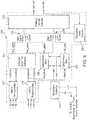
- FIG. 1a partial view of an exemplary embodiment of an electrical machine is shown in Fig. 1 and is designated generally by reference character 100.
- Other embodiments of electrical machines, or aspects thereof,are provided in Figs. 2-8 , as will be described.
- the systems and methods of the inventioncan be used, for example, to completely eliminate the resolver as a position sensor for electric engine start and active rectification commutation to improve system reliability, complexity, and cost without necessarily reducing power density.
- Fig. 1is a sensor PM electrical machine diagram showing a sense winding or excitation coil wired around two or more rotor poles.
- the excitation coilis a secondary winding of a single phase high frequency rotating transformer (HFRT).
- HFRThigh frequency rotating transformer
- the excitation coilis terminated by a series RC circuit for damping purposes and reducing losses in the excitation coil due to higher harmonic magnetic field in the air gap produced by the stator winding.
- Electrical machine 100is a sensor PM electrical machine in that uses a sensor in addition to permanent magnets to provide feedback for motor control.
- Electrical machine 100includes a stator 102 including a stator winding 104 and a primary transformer coil 106, which is shown in Fig. 3 .
- a rotor 108is operatively connected to rotate relative to stator 102.
- Rotor 108includes a plurality of embedded permanent magnets indicated schematically in Fig. 2 .
- the exemplary configuration in Fig. 2has a four-pole rotor construction with two excitation coils 110.
- An excitation coil 110is wound on rotor 108 and is operatively connected to form a rotating transformer with primary transformer coil 106.
- an inverter/active rectifier component 112is operatively connected to stator winding 104 and primary transformer coil 106 to control stator winding 104 based on excitation in stator winding 104 from both excitation coil 110 and from the permanent magnets of rotor 108.
- Inverter/active rectifier component 112is connected to direct external power through stator 102 to drive rotor 108 in a motoring mode and to deliver power from stator 102 to an external DC load in a generate mode.
- An AC power source 114is operatively connected between inverter/active rectifier component 112 and primary transformer coil 106 to control power to the rotating transformer or HFRT.
- the HFRTcan be designed to operate from 1.0 - 40 kHz, or any other suitable frequency range subject to transformer size and EMI filter design considerations.
- An RC damper 116is connected in parallel with the excitation coil. AC power source controls the excitation frequency in excitation coil 110.
- inverter/active rectifier component 112includes a position and velocity decoder 118 connected to receive inverter voltage signals V a , V b , and V c and to output position and velocity feedback, designated pos_est and vel_est in Fig. 4 , respectively.
- a proportional and integral regulator, designated PI in Fig. 4is included with a first switch 120 for switching between a velocity reference input for the motoring mode and a DC voltage reference for a generate mode.
- the PIalso has a second switch 122 for switching between the velocity feedback and a DC voltage feedback input.
- the PIis configured to output a torque reference signal, designated trq_ref in Fig.
- a field oriented control(FOC) is operatively connected to receive the reference signals from the PI, the position feedback from position and velocity decoder 118, and inverter current signals I a , I b , and I c and to output stationary frame command signals Valpha_ref and Vbeta_ref.
- Quadrature generator 124is connected to an AC power source to inject quadrature signal (sine and cosine) into the excitation coil.
- the PWM converter shown in Fig. 4operates as an engine start inverter during motoring mode and as an active rectifier during the generate mode.
- FIG. 4is a high level block diagram of an electric engine start controller, which includes a speed control function using a field-oriented controller (FOC) to control motor torque in response to the estimated rotor position.
- FOCfield-oriented controller
- position and velocity decoder 118includes a Clark's Transformation component 126 operatively connected to convert the three phase inverter voltage signals V a , V b , and V c into two phase voltage signals Valpha and Vbeta.
- a pair of synchronous filters 128 and 130are connected each to receive a respective one of the two phase voltage signals Valpha and Vbeta.
- Each of the synchronous filters 128 and 130is also connected to receive sine and cosine signals from quadrature generator 124 and to output respective VF alpha and VF_beta signals phase-shifted by 90 electrical degrees that contain rotor position information to position velocity estimator 132.
- Position velocity estimator 132in turn outputs the position and velocity feedback, labeled pos_est and vel_est in Fig. 5 , which are also shown in Fig. 4 .
- Fig. 5illustrates an embodiment using resolver-based signal processing to estimate rotor position from zero to high generator speed.
- Another embodiment that utilizes a zero/low speed position estimator and high speed position estimator based extended rotor fluxis shown in Fig. 6 .
- Position and velocity decoder 218includes a Clark's Transformation component 216 and synchronous filters 228 and 230 connected as described above with respect to Fig. 5 .
- position and velocity decoder 218includes a second Clark's Transformation component 217 connected to convert the three phase/inverter current signals I a , I b , and I c , into two phase current signals Ialpha and Ibeta.
- An extended rotor flux estimator 234is connected to receive the two phase current signals Ialpha and Ibeta and the two phase voltage signals Valpha and Vbeta and to output Fext_alpha and Fext_beta signals phase-shifted by 90 electrical degrees that contain extended rotor flux information.
- a position velocity estimator 232is included with a first switch 236 for switching between Fext_alpha input in a high speed mode and VF_alpha input in a low speed mode and a second switch 238 for switching between Fext_beta input in a high speed mode and VF beta in a low speed mode.
- Position/velocity estimator 232is configured to output the position feedback and the velocity feedback as described above.
- An estimated mode selector 240is connected to receive the velocity feedback, labeled vel_est in Fig. 6 , and control the switches 236 and 238 of position/velocity estimator 232 for selection between the high and low speed modes.
- position and velocity decoder 218operates the same as position and velocity decoder 118 of Fig. 5 .
- position and velocity decoder 218can switch to operate based on extended rotor flux.
- FIG. 7Details of a synchronous filter implementation and resolver-based signal processing for position and velocity estimation are shown in Figure 7 and Figure 8 . Additional details can be found in U.S. Patent No. 7,072,790 .
- Fig. 7a block diagram of a synchronous filter 128 is shown.
- Synchronous filters 128, 130, 228, and 230can all be of the same configuration as that shown in Fig. 7 .
- Synchronous filtersselect voltage components Valpha and Vbeta that contain rotor position information and are synchronized with the signals from the quadrature generator.
- Fig. 8a block diagram of the position/velocity estimator 132 of Fig. 5 is shown.
- the same phase-locked loop configurationcan be used for the position velocity/estimator 232 of Fig. 6 , the difference being that position velocity/estimator 232 connects to its inputs through switches 236 and 238.
- An exemplary method of controlling an electrical machineincludes separating an excitation coil signal and a permanent magnet signal from a combined feedback signal from the electrical machine.
- the combined feedback signalcan be picked up from the stator coils, and includes the signal from the permanent magnets passing the stator coil as well as the signal from the excitation coil, e.g., excitation coil 110.
- the position and velocity of the rotorcan be estimated by separating the excitation coil signal and the permanent magnet signal and using estimated position and velocity of the rotor to control the electrical machine using an inverter/active rectifier component, e.g., inverter/active rectifier component 112 described above in Figs. 3-8 .
- Using estimated position and velocity of the rotor to control the electrical machinecan include controlling rotor toque in a motoring mode and controlling rotor flux in a generate mode.
- the methods and systems described hereinoffer potential benefits including improved system performance and reliability when operating as an active rectifier due to improved position sensing accuracy. Additional potential benefits include improved system complexity and cost, potential damping of rotor oscillations at variable load and improved stability, improved power density when a smaller size machine is used for electric pumps or actuators, and potential reduction in size of power semiconductors when used as electric engine start due to improved accuracy in rotor position sensing.
Landscapes
- Engineering & Computer Science (AREA)
- Power Engineering (AREA)
- Control Of Motors That Do Not Use Commutators (AREA)
- Control Of Ac Motors In General (AREA)
- Synchronous Machinery (AREA)
Description
- The present invention relates to electrical machines such as motors and generators, and more particularly to angular position and velocity estimation of permanent magnet (PM) synchronous machines.
- PM machines can be classified based on the flux distribution or back-electromagnetic force (EMF) waveform as square-wave brushless dc machines (BLDCM) and sine-wave or synchronous machines (PMSM). The BLDCM utilizes a trapezoidal back-EMF waveform and supplied by rectangular current waveforms with conduction duration of 120°. The commutation is based on the rotor position with 60° resolution typically provided by Hall sensors. The PMSM utilizes sinusoidal back-EMF and supplied by sinusoidal current waveforms properly phased with respect to the back-EMF. The rotor position information is typically provided by resolvers or encoders.
- Most of sensorless motor controllers utilize position estimation techniques for both BLDCM and PMSM using back-EMF. The initial rotor position information at standstill is not available using back-EMF methods. The possible initial starting methods can be classified based on the following:
- Starting from predetermined rotor position established by proper feeding;
- Open-loop start up; and
- Estimation of the rotor position at zero speed based on state observers utilizing machine parameters.
- See,M. Tursini, R. Petrella, F. Parasiliti, "Initial Rotor Position Estimation Method for PM Motors", IEEE Transactions On Industy Applications, Vol.39, No.6, November/December 2003, pp.1630-1640, and
- Vasile Corban-Schrame1 et al: "Active-Flux-Based Motion-Sensorless Vector Control of Biaxial Excitation Generator/Motor for Automobiles",IEEE transactions On Industry Applications, vol. 47, no. 2, 1 March 2011 (2011-03-01), pages 812-819, XP011363478,ISSN.
- The above techniques may not guarantee good accuracy in rotor position estimation at zero and low speed. A combination method utilizes a resolver at zero and low speed and a sensorless algorithm based on extended rotor flux at medium and high speed. See
U.S. Patent No. 7,072,790 to Hu et al. The reason to use sensorless algorithms at medium and high speed is to reduce negative effect of non-ideal resolver characteristics such as an amplitude imbalance, imperfect quadrature, and inductive harmonics on the current controller and motoring torque. U.S. Patent No. 5,329,195 to Horber et al. describes utilizing a PM motor with the stator pole elements wound with two coils. One coil on each pole element includes a sensor winding, and the other includes a power winding. As a result, all pole elements of the stator are utilized both to produce rotor drive torque and also to generate electrical signals that provide accurate rotor position information. This approach is useful for small size PM machines because of elimination of a somewhat similar sized resolver. However, for the larger size PM machines this approach considerably penalizes the power density of the machine, and, therefore, may not be attractive in applications such as aerospace or ground vehicles.- Such conventional methods and systems have generally been considered satisfactory for their intended purpose. However, there is still a need in the art for systems and methods that allow for improved performance such as reliability, complexity, and cost. There also remains a need in the art for such systems and methods that are easy to make and use. At least the preferred embodiments of the present invention provide a solution for these problems.
- The present invention provides solution to the above problems by an electrical machine as defined in the
independent claim 1. Preferred embodiments are defined by the dependent claims. - A new and useful electrical machine includes a stator including a stator winding and a primary transformer coil. A rotor is operatively connected to rotate relative to the stator, wherein the rotor includes a plurality of embedded permanent magnets. An excitation coil is wound on the rotor and is operatively connected to form a rotating transformer with the primary transformer coil. An inverter/active rectifier component is operatively connected to the stator winding and the primary transformer coil to control the stator winding based on excitation in the stator winding from the excitation coil and permanent magnets.
- The inverter/active rectifier component can be configured to direct external power through the stator to drive the rotor in a motoring mode and to deliver power from the stator to an external DC load in a generate mode. An AC power source is operatively connected between the inverter/active rectifier component and the primary transformer coil to control power to the rotating transformer. An RC damper is connected in parallel with the excitation coil.
- In the embodiments, the inverter/active rectifier component includes a position and velocity decoder configured and adapted to receive inverter voltage signals and to output position and velocity feedback. The inverter/active rectifier component also includes a proportional and integral regulator with a first switch for switching between a velocity reference input for the motoring mode and a DC voltage reference for a generate mode, and a second switch for switching between the velocity feedback and a DC voltage feedback input. The proportional and integral regulator is configured to output a torque reference signal in the motoring mode and a flux reference signal in the generate mode. A field oriented control is operatively connected to receive the reference signals from the proportional and integral regulator, the position feedback from the position and velocity decoder, and inverter current signals and to output stationary frame command signals.
- It is contemplated that a quadrature generator can be operatively connected to an AC power source to inject quadrature (sine and cosine) into the excitation coil. The position and velocity decoder can include a Clark's Transformation component operatively connected to convert three phase inverter voltage signals into two phase voltage signals. A pair of synchronous filters can each be operatively connected to receive a respective one of the two phase voltage signals. Each synchronous filter can also be operatively connected to receive sine and cosine signals from a quadrature generator and to output VF_alpha and VF_beta signals phase-shifted by 90 electrical degrees that contain rotor position information.
- In certain embodiments a second Clark's Transformation component is operatively connected to convert three phase inverter current signals into two phase current signals and an extended rotor flux estimator is operatively connected to receive the two phase current signals and the two phase voltage signals and to output Fext_alpha and Fext_beta signals phase-shifted by 90 electrical degrees that contain extended rotor flux information. A position velocity estimator can be included with a first switch for switching between Fext_alpha input in a high speed mode and VF_alpha input in a low speed mode and a second switch for switching between Fext beta input in a high speed mode and VF_beta in a low speed mode. The position velocity estimator is configured to output the position feedback and the velocity feedback. An estimated mode selector can be operatively connected to receive the velocity feedback and control the first and second switches of the position velocity estimator for selection between the high and low speed modes.
- A method of controlling an electrical machine includes separating an excitation coil signal and a permanent magnet signal from a combined feedback signal from an electrical machine such as described above. The method also includes estimating position and velocity of the rotor based on the excitation coil signal and the permanent magnet signal and using estimated position and velocity of the rotor to control the electrical machine. Using estimated position and velocity of the rotor to control the electrical machine can include controlling rotor toque in a motoring mode and controlling rotor flux in a generate mode.
- These and other features of the systems and methods of the subject invention will become more readily apparent to those skilled in the art from the following detailed description of the preferred embodiments taken in conjunction with the drawings.
- So that those skilled in the art to which the subject invention appertains will readily understand how to make and use the devices and methods of the subject invention without undue experimentation, preferred embodiments thereof will be described in detail herein below by way of example only and with reference to certain figures, wherein:
Fig. 1 is a schematic view of an exemplary embodiment of a sensor PM electrical machine, showing the excitation coil of the rotor;Fig. 2 is a schematic end elevation view of the rotor ofFig. 1 , showing the excitation coils and embedded magnets;Fig. 3 is a block diagram of an exemplary embodiment of a system for controlling the electrical machine ofFig. 1 for in a motoring mode and a generate mode, schematically showing the rotor, stator winding, and an excitation coil as well as the inverter/active rectifier component;Fig. 4 is a block diagram of an exemplary embodiment of the inverter/active rectifier component ofFig. 3 , showing the inputs and outputs for use determining rotor position and velocity for the motoring and generate modes, and also showing the position and velocity decoder;Fig. 5 is a block diagram of an exemplary embodiment of the position and velocity decoder ofFig. 4 , showing the synchronous filters and the position and velocity estimator;Fig. 6 is a block diagram of another exemplary embodiment of a position and velocity decoder ofFig. 4 , showing an extended rotor flux estimator;Fig. 7 is a block diagram of an exemplary embodiment of one of the synchronous filters shown inFigs. 5 and6 ; andFig. 8 is a block diagram of an exemplary embodiment of a position and velocity estimator shown inFig. 5 .- Reference will now be made to the drawings wherein like reference numerals identify similar structural features or aspects of the subject invention. For purposes of explanation and illustration, and not limitation, a partial view of an exemplary embodiment of an electrical machine is shown in
Fig. 1 and is designated generally byreference character 100. Other embodiments of electrical machines, or aspects thereof, are provided inFigs. 2-8 , as will be described. The systems and methods of the invention can be used, for example, to completely eliminate the resolver as a position sensor for electric engine start and active rectification commutation to improve system reliability, complexity, and cost without necessarily reducing power density. Fig. 1 is a sensor PM electrical machine diagram showing a sense winding or excitation coil wired around two or more rotor poles. The excitation coil is a secondary winding of a single phase high frequency rotating transformer (HFRT). The excitation coil is terminated by a series RC circuit for damping purposes and reducing losses in the excitation coil due to higher harmonic magnetic field in the air gap produced by the stator winding.Electrical machine 100 is a sensor PM electrical machine in that uses a sensor in addition to permanent magnets to provide feedback for motor control.Electrical machine 100 includes astator 102 including a stator winding 104 and aprimary transformer coil 106, which is shown inFig. 3 . Arotor 108 is operatively connected to rotate relative tostator 102.Rotor 108 includes a plurality of embedded permanent magnets indicated schematically inFig. 2 . The exemplary configuration inFig. 2 has a four-pole rotor construction with two excitation coils 110. Anexcitation coil 110 is wound onrotor 108 and is operatively connected to form a rotating transformer withprimary transformer coil 106.- With reference now to
Fig. 3 , an inverter/active rectifier component 112 is operatively connected to stator winding 104 andprimary transformer coil 106 to control stator winding 104 based on excitation in stator winding 104 from bothexcitation coil 110 and from the permanent magnets ofrotor 108. Inverter/active rectifier component 112 is connected to direct external power throughstator 102 to driverotor 108 in a motoring mode and to deliver power fromstator 102 to an external DC load in a generate mode. - An
AC power source 114 is operatively connected between inverter/active rectifier component 112 andprimary transformer coil 106 to control power to the rotating transformer or HFRT. The HFRT can be designed to operate from 1.0 - 40 kHz, or any other suitable frequency range subject to transformer size and EMI filter design considerations. AnRC damper 116 is connected in parallel with the excitation coil. AC power source controls the excitation frequency inexcitation coil 110. - Referring now to
Fig. 4 , inverter/active rectifier component 112 includes a position andvelocity decoder 118 connected to receive inverter voltage signals Va, Vb, and Vc and to output position and velocity feedback, designated pos_est and vel_est inFig. 4 , respectively. A proportional and integral regulator, designated PI inFig. 4 , is included with afirst switch 120 for switching between a velocity reference input for the motoring mode and a DC voltage reference for a generate mode. The PI also has asecond switch 122 for switching between the velocity feedback and a DC voltage feedback input. The PI is configured to output a torque reference signal, designated trq_ref inFig. 4 , in the motoring mode and a flux reference signal, flux_ref inFig. 4 , in the generate mode. A field oriented control (FOC) is operatively connected to receive the reference signals from the PI, the position feedback from position andvelocity decoder 118, and inverter current signals Ia, Ib, and Ic and to output stationary frame command signals Valpha_ref and Vbeta_ref.Quadrature generator 124 is connected to an AC power source to inject quadrature signal (sine and cosine) into the excitation coil. The PWM converter shown inFig. 4 operates as an engine start inverter during motoring mode and as an active rectifier during the generate mode. Electrical machine 100 with the AC signal injected in theexcitation coil 110 operates as a synchro at the injected frequency. The 3-wire synchro output can be easily converted into the resolver-equivalent format using Clark's 3-phase to 2-phase transformation (ABC to α β stationary reference frames). The AC signal that contains rotor position information can be selected using synchronous filters which are synchronized with the quadrature generator that is used to inject ac signal into field winding.Fig. 4 is a high level block diagram of an electric engine start controller, which includes a speed control function using a field-oriented controller (FOC) to control motor torque in response to the estimated rotor position.- Referring now to
Fig. 5 , position andvelocity decoder 118 includes a Clark'sTransformation component 126 operatively connected to convert the three phase inverter voltage signals Va, Vb, and Vc into two phase voltage signals Valpha and Vbeta. A pair ofsynchronous filters synchronous filters quadrature generator 124 and to output respective VF alpha and VF_beta signals phase-shifted by 90 electrical degrees that contain rotor position information to positionvelocity estimator 132.Position velocity estimator 132 in turn outputs the position and velocity feedback, labeled pos_est and vel_est inFig. 5 , which are also shown inFig. 4 . Fig. 5 illustrates an embodiment using resolver-based signal processing to estimate rotor position from zero to high generator speed. Another embodiment that utilizes a zero/low speed position estimator and high speed position estimator based extended rotor flux is shown inFig. 6 .- Making reference now to
Fig. 6 , a second embodiment of a position andvelocity decoder 218 is shown, which can be used in inverter/active rectifier component 112 ofFig. 4 in lieu of position andvelocity decoder 118. Position andvelocity decoder 218 includes a Clark'sTransformation component 216 andsynchronous filters Fig. 5 . In addition, position andvelocity decoder 218 includes a second Clark'sTransformation component 217 connected to convert the three phase/inverter current signals Ia, Ib, and Ic, into two phase current signals Ialpha and Ibeta. An extendedrotor flux estimator 234 is connected to receive the two phase current signals Ialpha and Ibeta and the two phase voltage signals Valpha and Vbeta and to output Fext_alpha and Fext_beta signals phase-shifted by 90 electrical degrees that contain extended rotor flux information. - A
position velocity estimator 232 is included with afirst switch 236 for switching between Fext_alpha input in a high speed mode and VF_alpha input in a low speed mode and a second switch 238 for switching between Fext_beta input in a high speed mode and VF beta in a low speed mode. Position/velocity estimator 232 is configured to output the position feedback and the velocity feedback as described above. An estimatedmode selector 240 is connected to receive the velocity feedback, labeled vel_est inFig. 6 , and control theswitches 236 and 238 of position/velocity estimator 232 for selection between the high and low speed modes. In the low speed mode, position andvelocity decoder 218 operates the same as position andvelocity decoder 118 ofFig. 5 . In the high speed mode, position andvelocity decoder 218 can switch to operate based on extended rotor flux. - Details of a synchronous filter implementation and resolver-based signal processing for position and velocity estimation are shown in
Figure 7 and Figure 8 . Additional details can be found inU.S. Patent No. 7,072,790 . Referring toFig. 7 , a block diagram of asynchronous filter 128 is shown.Synchronous filters Fig. 7 . Synchronous filters select voltage components Valpha and Vbeta that contain rotor position information and are synchronized with the signals from the quadrature generator. With reference toFig. 8 , a block diagram of the position/velocity estimator 132 ofFig. 5 is shown. The same phase-locked loop configuration can be used for the position velocity/estimator 232 ofFig. 6 , the difference being that position velocity/estimator 232 connects to its inputs throughswitches 236 and 238. - An exemplary method of controlling an electrical machine, e.g.,
electrical machine 100, includes separating an excitation coil signal and a permanent magnet signal from a combined feedback signal from the electrical machine. The combined feedback signal can be picked up from the stator coils, and includes the signal from the permanent magnets passing the stator coil as well as the signal from the excitation coil, e.g.,excitation coil 110. The position and velocity of the rotor can be estimated by separating the excitation coil signal and the permanent magnet signal and using estimated position and velocity of the rotor to control the electrical machine using an inverter/active rectifier component, e.g., inverter/active rectifier component 112 described above inFigs. 3-8 . Using estimated position and velocity of the rotor to control the electrical machine can include controlling rotor toque in a motoring mode and controlling rotor flux in a generate mode. - The methods and systems described herein offer potential benefits including improved system performance and reliability when operating as an active rectifier due to improved position sensing accuracy. Additional potential benefits include improved system complexity and cost, potential damping of rotor oscillations at variable load and improved stability, improved power density when a smaller size machine is used for electric pumps or actuators, and potential reduction in size of power semiconductors when used as electric engine start due to improved accuracy in rotor position sensing.
- The methods and systems as described above and shown in the drawings, provide for electrical machine systems and methods with superior properties including, for example, improved system reliability, complexity, and cost without necessarily reducing power density.
Claims (7)
- An electrical machine (100) comprising:a stator (102) including a stator winding (104) and a primary transformer coil (106);a rotor (108) operatively connected to rotate relative to the stator, wherein the rotor includes a plurality of embedded permanent magnets;an excitation coil (110) wound on the rotor and operatively connected to form a rotating transformer with the primary transformer coil (106);an inverter/active rectifier component (112) operatively connected to the stator winding (104) for directing external power through the electrical machine stator (102) to drive the rotor (108) in a motoring mode and to deliver power from the stator to an external DC load in a generate mode, the inverter/active rectifier component comprising:a position and velocity decoder (118) configured and adapted to receive inverter voltage signals (Va,Vb,Vc) and to output position and velocity feedback (pos_est and vel_est);a proportional and integral regulator (PI) with a first switch (120) for switching between a velocity reference input for the motoring mode and a DC voltage reference for a generate mode, and a second switch (122) for switching between the velocity feedback and a DC voltage feedback input, wherein the proportional and integral regulator is configured to output a torque reference signal (trq_ref) in the motoring mode and a flux reference signal (flux_ref) in the generate mode; anda field oriented control (FOC) operatively connected to receive the reference signals from the proportional and integral regulator, the position feedback from the position and velocity decoder, and inverter current signals and to output stationary frame command signals (Valpha_ref and Vbeta_ref);the electrical machine (100) ischaracterised in thatan RC damper (116) is connected in parallel with the excitation coil (110).
- An electrical machine as recited in claim 1, wherein the inverter/active rectifier component further comprises a quadrature generator (124) operatively connected to an AC power source to inject sine and cosine quadrature signals into an excitation coil.
- An electrical machine as recited in claims 1 or 2, wherein the position and velocity decoder includes a Clark's Transformation component (126) operatively connected to convert three phase inverter voltage signals (Va,Vb,Vc) into two phase voltage signals (Valpha, Vbeta), with a pair of synchronous filters (128,130) each operatively connected to receive a respective one of the two phase voltage signals, each synchronous filter being operatively connected to receive sine and cosine signals from a quadrature generator and to output VF_alpha and VFbeta signals phase-shifted by 90 electrical degrees that include rotor position information.
- An electrical machine as recited in claim 3, wherein the inverter/active rectifier component further comprises a position velocity estimator (132) operatively connected to receive VF_alpha and VF_beta signals from the synchronous filters and to output the position feedback (pos_est) and the velocity feedback (vel_est).
- An electrical machine as recited in claim 3 or 4, wherein the inverter/active rectifier component further comprises:a second Clark's Transformation component (217) operatively connected to convert three phase inverter current signals into two phase current signals; andan extended rotor flux estimator operatively connected to receive the two phase current signals and the two phase voltage signals and to output Fext_alpha and Fext_beta signals phase-shifted by 90 electrical degrees that include extended rotor flux information.
- An electrical machine as recited in claim 5, wherein the inverter/active rectifier component further comprises a position/velocity estimator (232) with a first switch for switching between Fext_alpha input in a high speed mode and VF_alpha input in a low speed mode and a second switch for switching between Fext_beta input in a high speed mode and VF_beta in a low speed mode, wherein the position/velocity estimator is configured to output the position feedback and the velocity feedback.
- An electrical machine as recited in claim 6, wherein the inverter/active rectifier component further comprises an estimated mode selector (240) operatively connected to receive the velocity feedback and control the first and second switches of the position velocity/estimator for selection between the high and low speed modes.
Applications Claiming Priority (2)
| Application Number | Priority Date | Filing Date | Title |
|---|---|---|---|
| US13/914,341US8866449B1 (en) | 2013-06-10 | 2013-06-10 | Sensor PM electrical machines |
| EP14171746.2AEP2819298B1 (en) | 2013-06-10 | 2014-06-10 | Position sensorless permanent magnet electrical machine |
Related Parent Applications (2)
| Application Number | Title | Priority Date | Filing Date |
|---|---|---|---|
| EP14171746.2ADivision-IntoEP2819298B1 (en) | 2013-06-10 | 2014-06-10 | Position sensorless permanent magnet electrical machine |
| EP14171746.2ADivisionEP2819298B1 (en) | 2013-06-10 | 2014-06-10 | Position sensorless permanent magnet electrical machine |
Publications (2)
| Publication Number | Publication Date |
|---|---|
| EP3179624A1 EP3179624A1 (en) | 2017-06-14 |
| EP3179624B1true EP3179624B1 (en) | 2021-12-08 |
Family
ID=50884805
Family Applications (2)
| Application Number | Title | Priority Date | Filing Date |
|---|---|---|---|
| EP14171746.2AActiveEP2819298B1 (en) | 2013-06-10 | 2014-06-10 | Position sensorless permanent magnet electrical machine |
| EP17150395.6AActiveEP3179624B1 (en) | 2013-06-10 | 2014-06-10 | Position sensorless permanent magnet electrical machine |
Family Applications Before (1)
| Application Number | Title | Priority Date | Filing Date |
|---|---|---|---|
| EP14171746.2AActiveEP2819298B1 (en) | 2013-06-10 | 2014-06-10 | Position sensorless permanent magnet electrical machine |
Country Status (2)
| Country | Link |
|---|---|
| US (1) | US8866449B1 (en) |
| EP (2) | EP2819298B1 (en) |
Families Citing this family (10)
| Publication number | Priority date | Publication date | Assignee | Title |
|---|---|---|---|---|
| DE102012201319A1 (en)* | 2011-02-02 | 2012-08-02 | Robert Bosch Gmbh | Method, apparatus and computer program for determining an offset angle in an electric machine |
| US9225225B2 (en)* | 2013-08-02 | 2015-12-29 | Hamilton Sundstrand Corporation | Sensing PM electrical machine position |
| US8928293B1 (en)* | 2013-08-02 | 2015-01-06 | Hamilton Sundstrand Corporation | Systems for wound field synchronous machines with zero speed rotor position detection during start for motoring and improved transient response for generation |
| US20170174085A1 (en)* | 2015-12-18 | 2017-06-22 | Hamilton Sundstrand Corporation | Permanent magnet synchronous generator based direct current power generating system |
| JP6614986B2 (en)* | 2016-02-02 | 2019-12-04 | 株式会社エクセディ | Power transmission device with rotating electric machine |
| US10541634B2 (en) | 2017-03-17 | 2020-01-21 | Hamilton Sundstrand Corporation | Generator arrangements and methods of controlling generator arrangements |
| CN109495039A (en)* | 2019-01-03 | 2019-03-19 | 田振荣 | Electronics increase-volume generator |
| CN112468056A (en)* | 2020-09-23 | 2021-03-09 | 深圳供电局有限公司 | Magnetic pole coil excitation adjusting device, system and magnetic pole coil system |
| RU2750334C1 (en)* | 2020-10-07 | 2021-06-28 | федеральное государственное автономное образовательное учреждение высшего образования "Национальный исследовательский университет ИТМО" (Университет ИТМО) | Method for determining angle of rotation of rotor of permanent magnet synchronous electric motor |
| US12009772B2 (en)* | 2021-12-07 | 2024-06-11 | Hamilton Sundstrand Corporation | Parallel excitation of motor start function for three stage synchronous generator |
Family Cites Families (15)
| Publication number | Priority date | Publication date | Assignee | Title |
|---|---|---|---|---|
| US5329195A (en) | 1992-11-02 | 1994-07-12 | Seiberco Incorporated | Sensor motor |
| US5512813A (en)* | 1992-12-24 | 1996-04-30 | Mitsubishi Denki Kabushiki Kaisha | AC generator output controlling apparatus and method |
| US5594322A (en)* | 1993-05-12 | 1997-01-14 | Sundstrand Corporation | Starter/generator system with variable-frequency exciter control |
| EP0709944A1 (en)* | 1994-10-31 | 1996-05-01 | STMicroelectronics S.r.l. | Charge voltage regulator for a battery |
| US5493201A (en)* | 1994-11-15 | 1996-02-20 | Sundstrand Corporation | Starter/generator system and method utilizing a low voltage source |
| JP3415326B2 (en)* | 1995-04-28 | 2003-06-09 | 株式会社デンソー | Output control device for vehicle generator |
| US6111390A (en)* | 1998-01-20 | 2000-08-29 | Kokusan Kenki Co., Ltd. | Magneto-equipped power device |
| US6069467A (en)* | 1998-11-16 | 2000-05-30 | General Electric Company | Sensorless rotor tracking of induction machines with asymmetrical rotor resistance |
| US6188204B1 (en)* | 1999-08-05 | 2001-02-13 | Joseph Vithayathil | Brushless AC field system for stable frequency variable speed alternators |
| US6809496B2 (en)* | 2002-09-16 | 2004-10-26 | Honeywell International Inc. | Position sensor emulator for a synchronous motor/generator |
| US7184927B2 (en)* | 2004-03-26 | 2007-02-27 | Honeywell International Inc. | Adaptive position sensing method and apparatus for synchronous motor generator system |
| US7072790B2 (en) | 2004-08-12 | 2006-07-04 | Hamilton Sundstrand Corporation | Shaft sensorless angular position and velocity estimation for a dynamoelectric machine based on extended rotor flux |
| JP5233239B2 (en)* | 2007-10-19 | 2013-07-10 | 国産電機株式会社 | Power generator |
| US8269445B2 (en)* | 2009-10-20 | 2012-09-18 | GM Global Technology Operations LLC | Limp home operational mode for an electric vehicle |
| US8659923B2 (en)* | 2011-02-15 | 2014-02-25 | Drs Test & Energy Management, Llc | System and method for converting AC power to DC power using sensorless field oriented control |
- 2013
- 2013-06-10USUS13/914,341patent/US8866449B1/enactiveActive
- 2014
- 2014-06-10EPEP14171746.2Apatent/EP2819298B1/enactiveActive
- 2014-06-10EPEP17150395.6Apatent/EP3179624B1/enactiveActive
Non-Patent Citations (1)
| Title |
|---|
| None* |
Also Published As
| Publication number | Publication date |
|---|---|
| EP2819298A3 (en) | 2016-06-15 |
| EP2819298B1 (en) | 2023-05-31 |
| EP3179624A1 (en) | 2017-06-14 |
| US8866449B1 (en) | 2014-10-21 |
| EP2819298A2 (en) | 2014-12-31 |
Similar Documents
| Publication | Publication Date | Title |
|---|---|---|
| EP3179624B1 (en) | Position sensorless permanent magnet electrical machine | |
| EP2840702B1 (en) | Systems for wound field synchronous machines with zero speed rotor position detection during start for motoring and improved transient response for generation | |
| US9317019B2 (en) | Sinusoidal modulation control methods and circuits for permanent magnet synchronous motors | |
| Feng et al. | Scheme based on buck‐converter with three‐phase H‐bridge combinations for high‐speed BLDC motors in aerospace applications | |
| KR20130106505A (en) | Sensorless control method and apparatus thereof | |
| EP2840701B1 (en) | Sensing PM electrical machine position | |
| KR102331849B1 (en) | Method and Apparatus for Controlling BLDC Motor | |
| US7583046B2 (en) | Rotor position detection at standstill and low speeds using a low power permanent magnet machine | |
| JP2014110708A5 (en) | ||
| Ichikawa et al. | Sensorless control of an interior permanent magnet synchronous motor on the rotating coordinate using an extended electromotive force | |
| JP5618854B2 (en) | Synchronous motor drive system | |
| Semenov et al. | Position estimation for sensorless FOC of five-phase PMSM in electric vehicles | |
| Krishnan et al. | A back-EMF based sensorless speed control of permanent magnet synchronous machine | |
| CN207010470U (en) | A kind of drive circuit of magneto | |
| Kang et al. | Initial rotor position estimation of single-phase permanent magnet synchronous motor with asymmetric air-gap | |
| CN114365414B (en) | Sensorless controller for electrostatic machines | |
| Srivastava et al. | PM ENHANCED SENSING OF INTERNAL EMF VARIATIONA TOOL TO STUDY PMBLDC/AC MOTORS. | |
| Iwaji et al. | Low-speed position sensorless drive for highly efficient permanent magnet synchronous motor without rare-earth metals | |
| Shi et al. | Sensorless Control Method for Wound-Field Doubly Salient Starter/Generator with Two-section Interlaced-Rotor Structure | |
| Nguyen et al. | Improvement of sensorless speed control for nonsalient type axial gap self-bearing motor using sliding mode observer | |
| Rocha et al. | Speed and position observer for non-sinusoidal pmsm based on a psd+ pll structure | |
| Li et al. | Implementation of sensorless control with improved flux integrator for wound field synchronous motor | |
| Kar et al. | Direct torque control of permanent magnet synchronous motor drive with a sensorless initial rotor position estimation scheme | |
| Kisck et al. | Rotor-flux model for sensorless vector-control of super-high-speed IPMSM | |
| Kanjhani et al. | Review of different control topologies for the permanent magnet brushless DC motor drives |
Legal Events
| Date | Code | Title | Description |
|---|---|---|---|
| PUAI | Public reference made under article 153(3) epc to a published international application that has entered the european phase | Free format text:ORIGINAL CODE: 0009012 | |
| STAA | Information on the status of an ep patent application or granted ep patent | Free format text:STATUS: THE APPLICATION HAS BEEN PUBLISHED | |
| AC | Divisional application: reference to earlier application | Ref document number:2819298 Country of ref document:EP Kind code of ref document:P | |
| AK | Designated contracting states | Kind code of ref document:A1 Designated state(s):AL AT BE BG CH CY CZ DE DK EE ES FI FR GB GR HR HU IE IS IT LI LT LU LV MC MK MT NL NO PL PT RO RS SE SI SK SM TR | |
| AX | Request for extension of the european patent | Extension state:BA ME | |
| STAA | Information on the status of an ep patent application or granted ep patent | Free format text:STATUS: REQUEST FOR EXAMINATION WAS MADE | |
| 17P | Request for examination filed | Effective date:20171213 | |
| RBV | Designated contracting states (corrected) | Designated state(s):AL AT BE BG CH CY CZ DE DK EE ES FI FR GB GR HR HU IE IS IT LI LT LU LV MC MK MT NL NO PL PT RO RS SE SI SK SM TR | |
| REG | Reference to a national code | Ref country code:DE Ref legal event code:R079 Ref document number:602014081694 Country of ref document:DE Free format text:PREVIOUS MAIN CLASS: H02P0006180000 Ipc:H02P0009300000 | |
| RIC1 | Information provided on ipc code assigned before grant | Ipc:H02P 21/24 20160101ALI20201126BHEP Ipc:H02P 6/18 20160101ALI20201126BHEP Ipc:H02P 9/30 20060101AFI20201126BHEP | |
| GRAP | Despatch of communication of intention to grant a patent | Free format text:ORIGINAL CODE: EPIDOSNIGR1 | |
| STAA | Information on the status of an ep patent application or granted ep patent | Free format text:STATUS: GRANT OF PATENT IS INTENDED | |
| INTG | Intention to grant announced | Effective date:20210118 | |
| GRAJ | Information related to disapproval of communication of intention to grant by the applicant or resumption of examination proceedings by the epo deleted | Free format text:ORIGINAL CODE: EPIDOSDIGR1 | |
| STAA | Information on the status of an ep patent application or granted ep patent | Free format text:STATUS: REQUEST FOR EXAMINATION WAS MADE | |
| INTC | Intention to grant announced (deleted) | ||
| GRAP | Despatch of communication of intention to grant a patent | Free format text:ORIGINAL CODE: EPIDOSNIGR1 | |
| STAA | Information on the status of an ep patent application or granted ep patent | Free format text:STATUS: GRANT OF PATENT IS INTENDED | |
| INTG | Intention to grant announced | Effective date:20210709 | |
| GRAS | Grant fee paid | Free format text:ORIGINAL CODE: EPIDOSNIGR3 | |
| GRAA | (expected) grant | Free format text:ORIGINAL CODE: 0009210 | |
| STAA | Information on the status of an ep patent application or granted ep patent | Free format text:STATUS: THE PATENT HAS BEEN GRANTED | |
| AC | Divisional application: reference to earlier application | Ref document number:2819298 Country of ref document:EP Kind code of ref document:P | |
| AK | Designated contracting states | Kind code of ref document:B1 Designated state(s):AL AT BE BG CH CY CZ DE DK EE ES FI FR GB GR HR HU IE IS IT LI LT LU LV MC MK MT NL NO PL PT RO RS SE SI SK SM TR | |
| REG | Reference to a national code | Ref country code:GB Ref legal event code:FG4D | |
| REG | Reference to a national code | Ref country code:AT Ref legal event code:REF Ref document number:1454509 Country of ref document:AT Kind code of ref document:T Effective date:20211215 Ref country code:CH Ref legal event code:EP | |
| REG | Reference to a national code | Ref country code:DE Ref legal event code:R096 Ref document number:602014081694 Country of ref document:DE | |
| REG | Reference to a national code | Ref country code:IE Ref legal event code:FG4D | |
| REG | Reference to a national code | Ref country code:LT Ref legal event code:MG9D | |
| REG | Reference to a national code | Ref country code:NL Ref legal event code:MP Effective date:20211208 | |
| PG25 | Lapsed in a contracting state [announced via postgrant information from national office to epo] | Ref country code:RS Free format text:LAPSE BECAUSE OF FAILURE TO SUBMIT A TRANSLATION OF THE DESCRIPTION OR TO PAY THE FEE WITHIN THE PRESCRIBED TIME-LIMIT Effective date:20211208 Ref country code:LT Free format text:LAPSE BECAUSE OF FAILURE TO SUBMIT A TRANSLATION OF THE DESCRIPTION OR TO PAY THE FEE WITHIN THE PRESCRIBED TIME-LIMIT Effective date:20211208 Ref country code:FI Free format text:LAPSE BECAUSE OF FAILURE TO SUBMIT A TRANSLATION OF THE DESCRIPTION OR TO PAY THE FEE WITHIN THE PRESCRIBED TIME-LIMIT Effective date:20211208 Ref country code:BG Free format text:LAPSE BECAUSE OF FAILURE TO SUBMIT A TRANSLATION OF THE DESCRIPTION OR TO PAY THE FEE WITHIN THE PRESCRIBED TIME-LIMIT Effective date:20220308 | |
| REG | Reference to a national code | Ref country code:AT Ref legal event code:MK05 Ref document number:1454509 Country of ref document:AT Kind code of ref document:T Effective date:20211208 | |
| PG25 | Lapsed in a contracting state [announced via postgrant information from national office to epo] | Ref country code:SE Free format text:LAPSE BECAUSE OF FAILURE TO SUBMIT A TRANSLATION OF THE DESCRIPTION OR TO PAY THE FEE WITHIN THE PRESCRIBED TIME-LIMIT Effective date:20211208 Ref country code:NO Free format text:LAPSE BECAUSE OF FAILURE TO SUBMIT A TRANSLATION OF THE DESCRIPTION OR TO PAY THE FEE WITHIN THE PRESCRIBED TIME-LIMIT Effective date:20220308 Ref country code:LV Free format text:LAPSE BECAUSE OF FAILURE TO SUBMIT A TRANSLATION OF THE DESCRIPTION OR TO PAY THE FEE WITHIN THE PRESCRIBED TIME-LIMIT Effective date:20211208 Ref country code:HR Free format text:LAPSE BECAUSE OF FAILURE TO SUBMIT A TRANSLATION OF THE DESCRIPTION OR TO PAY THE FEE WITHIN THE PRESCRIBED TIME-LIMIT Effective date:20211208 Ref country code:GR Free format text:LAPSE BECAUSE OF FAILURE TO SUBMIT A TRANSLATION OF THE DESCRIPTION OR TO PAY THE FEE WITHIN THE PRESCRIBED TIME-LIMIT Effective date:20220309 Ref country code:ES Free format text:LAPSE BECAUSE OF FAILURE TO SUBMIT A TRANSLATION OF THE DESCRIPTION OR TO PAY THE FEE WITHIN THE PRESCRIBED TIME-LIMIT Effective date:20211208 | |
| PG25 | Lapsed in a contracting state [announced via postgrant information from national office to epo] | Ref country code:NL Free format text:LAPSE BECAUSE OF FAILURE TO SUBMIT A TRANSLATION OF THE DESCRIPTION OR TO PAY THE FEE WITHIN THE PRESCRIBED TIME-LIMIT Effective date:20211208 | |
| PG25 | Lapsed in a contracting state [announced via postgrant information from national office to epo] | Ref country code:SM Free format text:LAPSE BECAUSE OF FAILURE TO SUBMIT A TRANSLATION OF THE DESCRIPTION OR TO PAY THE FEE WITHIN THE PRESCRIBED TIME-LIMIT Effective date:20211208 Ref country code:SK Free format text:LAPSE BECAUSE OF FAILURE TO SUBMIT A TRANSLATION OF THE DESCRIPTION OR TO PAY THE FEE WITHIN THE PRESCRIBED TIME-LIMIT Effective date:20211208 Ref country code:RO Free format text:LAPSE BECAUSE OF FAILURE TO SUBMIT A TRANSLATION OF THE DESCRIPTION OR TO PAY THE FEE WITHIN THE PRESCRIBED TIME-LIMIT Effective date:20211208 Ref country code:PT Free format text:LAPSE BECAUSE OF FAILURE TO SUBMIT A TRANSLATION OF THE DESCRIPTION OR TO PAY THE FEE WITHIN THE PRESCRIBED TIME-LIMIT Effective date:20220408 Ref country code:EE Free format text:LAPSE BECAUSE OF FAILURE TO SUBMIT A TRANSLATION OF THE DESCRIPTION OR TO PAY THE FEE WITHIN THE PRESCRIBED TIME-LIMIT Effective date:20211208 Ref country code:CZ Free format text:LAPSE BECAUSE OF FAILURE TO SUBMIT A TRANSLATION OF THE DESCRIPTION OR TO PAY THE FEE WITHIN THE PRESCRIBED TIME-LIMIT Effective date:20211208 | |
| PG25 | Lapsed in a contracting state [announced via postgrant information from national office to epo] | Ref country code:PL Free format text:LAPSE BECAUSE OF FAILURE TO SUBMIT A TRANSLATION OF THE DESCRIPTION OR TO PAY THE FEE WITHIN THE PRESCRIBED TIME-LIMIT Effective date:20211208 Ref country code:AT Free format text:LAPSE BECAUSE OF FAILURE TO SUBMIT A TRANSLATION OF THE DESCRIPTION OR TO PAY THE FEE WITHIN THE PRESCRIBED TIME-LIMIT Effective date:20211208 | |
| REG | Reference to a national code | Ref country code:DE Ref legal event code:R097 Ref document number:602014081694 Country of ref document:DE | |
| PG25 | Lapsed in a contracting state [announced via postgrant information from national office to epo] | Ref country code:IS Free format text:LAPSE BECAUSE OF FAILURE TO SUBMIT A TRANSLATION OF THE DESCRIPTION OR TO PAY THE FEE WITHIN THE PRESCRIBED TIME-LIMIT Effective date:20220408 | |
| PLBE | No opposition filed within time limit | Free format text:ORIGINAL CODE: 0009261 | |
| STAA | Information on the status of an ep patent application or granted ep patent | Free format text:STATUS: NO OPPOSITION FILED WITHIN TIME LIMIT | |
| PG25 | Lapsed in a contracting state [announced via postgrant information from national office to epo] | Ref country code:DK Free format text:LAPSE BECAUSE OF FAILURE TO SUBMIT A TRANSLATION OF THE DESCRIPTION OR TO PAY THE FEE WITHIN THE PRESCRIBED TIME-LIMIT Effective date:20211208 Ref country code:AL Free format text:LAPSE BECAUSE OF FAILURE TO SUBMIT A TRANSLATION OF THE DESCRIPTION OR TO PAY THE FEE WITHIN THE PRESCRIBED TIME-LIMIT Effective date:20211208 | |
| 26N | No opposition filed | Effective date:20220909 | |
| PG25 | Lapsed in a contracting state [announced via postgrant information from national office to epo] | Ref country code:SI Free format text:LAPSE BECAUSE OF FAILURE TO SUBMIT A TRANSLATION OF THE DESCRIPTION OR TO PAY THE FEE WITHIN THE PRESCRIBED TIME-LIMIT Effective date:20211208 | |
| PG25 | Lapsed in a contracting state [announced via postgrant information from national office to epo] | Ref country code:MC Free format text:LAPSE BECAUSE OF FAILURE TO SUBMIT A TRANSLATION OF THE DESCRIPTION OR TO PAY THE FEE WITHIN THE PRESCRIBED TIME-LIMIT Effective date:20211208 | |
| REG | Reference to a national code | Ref country code:CH Ref legal event code:PL | |
| REG | Reference to a national code | Ref country code:BE Ref legal event code:MM Effective date:20220630 | |
| PG25 | Lapsed in a contracting state [announced via postgrant information from national office to epo] | Ref country code:LU Free format text:LAPSE BECAUSE OF NON-PAYMENT OF DUE FEES Effective date:20220610 Ref country code:LI Free format text:LAPSE BECAUSE OF NON-PAYMENT OF DUE FEES Effective date:20220630 Ref country code:IE Free format text:LAPSE BECAUSE OF NON-PAYMENT OF DUE FEES Effective date:20220610 Ref country code:CH Free format text:LAPSE BECAUSE OF NON-PAYMENT OF DUE FEES Effective date:20220630 | |
| PG25 | Lapsed in a contracting state [announced via postgrant information from national office to epo] | Ref country code:IT Free format text:LAPSE BECAUSE OF FAILURE TO SUBMIT A TRANSLATION OF THE DESCRIPTION OR TO PAY THE FEE WITHIN THE PRESCRIBED TIME-LIMIT Effective date:20211208 Ref country code:BE Free format text:LAPSE BECAUSE OF NON-PAYMENT OF DUE FEES Effective date:20220630 | |
| P01 | Opt-out of the competence of the unified patent court (upc) registered | Effective date:20230522 | |
| PG25 | Lapsed in a contracting state [announced via postgrant information from national office to epo] | Ref country code:HU Free format text:LAPSE BECAUSE OF FAILURE TO SUBMIT A TRANSLATION OF THE DESCRIPTION OR TO PAY THE FEE WITHIN THE PRESCRIBED TIME-LIMIT; INVALID AB INITIO Effective date:20140610 | |
| PG25 | Lapsed in a contracting state [announced via postgrant information from national office to epo] | Ref country code:MK Free format text:LAPSE BECAUSE OF FAILURE TO SUBMIT A TRANSLATION OF THE DESCRIPTION OR TO PAY THE FEE WITHIN THE PRESCRIBED TIME-LIMIT Effective date:20211208 Ref country code:CY Free format text:LAPSE BECAUSE OF FAILURE TO SUBMIT A TRANSLATION OF THE DESCRIPTION OR TO PAY THE FEE WITHIN THE PRESCRIBED TIME-LIMIT Effective date:20211208 | |
| PG25 | Lapsed in a contracting state [announced via postgrant information from national office to epo] | Ref country code:MT Free format text:LAPSE BECAUSE OF FAILURE TO SUBMIT A TRANSLATION OF THE DESCRIPTION OR TO PAY THE FEE WITHIN THE PRESCRIBED TIME-LIMIT Effective date:20211208 | |
| PGFP | Annual fee paid to national office [announced via postgrant information from national office to epo] | Ref country code:DE Payment date:20250520 Year of fee payment:12 | |
| PGFP | Annual fee paid to national office [announced via postgrant information from national office to epo] | Ref country code:GB Payment date:20250520 Year of fee payment:12 | |
| PGFP | Annual fee paid to national office [announced via postgrant information from national office to epo] | Ref country code:FR Payment date:20250520 Year of fee payment:12 |