EP3179049B1 - Steam turbine rotor assembly with sliding key member for retaining circumferential seal - Google Patents
Steam turbine rotor assembly with sliding key member for retaining circumferential sealDownload PDFInfo
- Publication number
- EP3179049B1 EP3179049B1EP16201568.9AEP16201568AEP3179049B1EP 3179049 B1EP3179049 B1EP 3179049B1EP 16201568 AEP16201568 AEP 16201568AEP 3179049 B1EP3179049 B1EP 3179049B1
- Authority
- EP
- European Patent Office
- Prior art keywords
- rotor
- slot
- circumferential
- steam turbine
- rotor assembly
- Prior art date
- Legal status (The legal status is an assumption and is not a legal conclusion. Google has not performed a legal analysis and makes no representation as to the accuracy of the status listed.)
- Active
Links
- 239000000463materialSubstances0.000claimsdescription7
- 230000000295complement effectEffects0.000claimsdescription4
- 229910000831SteelInorganic materials0.000claimsdescription2
- 239000010959steelSubstances0.000claimsdescription2
- 230000000717retained effectEffects0.000description6
- 239000012530fluidSubstances0.000description3
- 241000282472Canis lupus familiarisSpecies0.000description2
- 238000013459approachMethods0.000description2
- 230000000712assemblyEffects0.000description2
- 238000000429assemblyMethods0.000description2
- NPURPEXKKDAKIH-UHFFFAOYSA-Niodoimino(oxo)methaneChemical compoundIN=C=ONPURPEXKKDAKIH-UHFFFAOYSA-N0.000description2
- VYZAMTAEIAYCRO-UHFFFAOYSA-NChromiumChemical compound[Cr]VYZAMTAEIAYCRO-UHFFFAOYSA-N0.000description1
- 238000010276constructionMethods0.000description1
- 238000001816coolingMethods0.000description1
- 230000001419dependent effectEffects0.000description1
- 230000014759maintenance of locationEffects0.000description1
- 239000002184metalSubstances0.000description1
- 238000007789sealingMethods0.000description1
- 230000003068static effectEffects0.000description1
Images


Classifications
- F—MECHANICAL ENGINEERING; LIGHTING; HEATING; WEAPONS; BLASTING
- F01—MACHINES OR ENGINES IN GENERAL; ENGINE PLANTS IN GENERAL; STEAM ENGINES
- F01D—NON-POSITIVE DISPLACEMENT MACHINES OR ENGINES, e.g. STEAM TURBINES
- F01D11/00—Preventing or minimising internal leakage of working-fluid, e.g. between stages
- F01D11/08—Preventing or minimising internal leakage of working-fluid, e.g. between stages for sealing space between rotor blade tips and stator
- F—MECHANICAL ENGINEERING; LIGHTING; HEATING; WEAPONS; BLASTING
- F01—MACHINES OR ENGINES IN GENERAL; ENGINE PLANTS IN GENERAL; STEAM ENGINES
- F01D—NON-POSITIVE DISPLACEMENT MACHINES OR ENGINES, e.g. STEAM TURBINES
- F01D11/00—Preventing or minimising internal leakage of working-fluid, e.g. between stages
- F01D11/001—Preventing or minimising internal leakage of working-fluid, e.g. between stages for sealing space between stator blade and rotor
- F—MECHANICAL ENGINEERING; LIGHTING; HEATING; WEAPONS; BLASTING
- F01—MACHINES OR ENGINES IN GENERAL; ENGINE PLANTS IN GENERAL; STEAM ENGINES
- F01D—NON-POSITIVE DISPLACEMENT MACHINES OR ENGINES, e.g. STEAM TURBINES
- F01D5/00—Blades; Blade-carrying members; Heating, heat-insulating, cooling or antivibration means on the blades or the members
- F01D5/02—Blade-carrying members, e.g. rotors
- F—MECHANICAL ENGINEERING; LIGHTING; HEATING; WEAPONS; BLASTING
- F16—ENGINEERING ELEMENTS AND UNITS; GENERAL MEASURES FOR PRODUCING AND MAINTAINING EFFECTIVE FUNCTIONING OF MACHINES OR INSTALLATIONS; THERMAL INSULATION IN GENERAL
- F16J—PISTONS; CYLINDERS; SEALINGS
- F16J15/00—Sealings
- F16J15/44—Free-space packings
- F16J15/447—Labyrinth packings
- F16J15/4472—Labyrinth packings with axial path
- F—MECHANICAL ENGINEERING; LIGHTING; HEATING; WEAPONS; BLASTING
- F01—MACHINES OR ENGINES IN GENERAL; ENGINE PLANTS IN GENERAL; STEAM ENGINES
- F01D—NON-POSITIVE DISPLACEMENT MACHINES OR ENGINES, e.g. STEAM TURBINES
- F01D11/00—Preventing or minimising internal leakage of working-fluid, e.g. between stages
- F01D11/02—Preventing or minimising internal leakage of working-fluid, e.g. between stages by non-contact sealings, e.g. of labyrinth type
- F—MECHANICAL ENGINEERING; LIGHTING; HEATING; WEAPONS; BLASTING
- F05—INDEXING SCHEMES RELATING TO ENGINES OR PUMPS IN VARIOUS SUBCLASSES OF CLASSES F01-F04
- F05D—INDEXING SCHEME FOR ASPECTS RELATING TO NON-POSITIVE-DISPLACEMENT MACHINES OR ENGINES, GAS-TURBINES OR JET-PROPULSION PLANTS
- F05D2220/00—Application
- F05D2220/30—Application in turbines
- F05D2220/31—Application in turbines in steam turbines
- F—MECHANICAL ENGINEERING; LIGHTING; HEATING; WEAPONS; BLASTING
- F05—INDEXING SCHEMES RELATING TO ENGINES OR PUMPS IN VARIOUS SUBCLASSES OF CLASSES F01-F04
- F05D—INDEXING SCHEME FOR ASPECTS RELATING TO NON-POSITIVE-DISPLACEMENT MACHINES OR ENGINES, GAS-TURBINES OR JET-PROPULSION PLANTS
- F05D2260/00—Function
- F05D2260/30—Retaining components in desired mutual position
Definitions
- the subject matter disclosed hereinrelates to steam turbines. Specifically, the subject matter disclosed herein relates to seal devices in steam turbines.
- Steam turbinesinclude static nozzle assemblies that direct flow of a working fluid into turbine buckets connected to a rotating rotor.
- the nozzle construction(including a plurality of nozzles, or “airfoils") is sometimes referred to as a "diaphragm" or “nozzle assembly stage.”
- Steam turbine diaphragmsinclude two halves, which are assembled around the rotor, creating horizontal joints between these two halves. Each turbine diaphragm stage is vertically supported by support bars, support lugs or support screws on each side of the diaphragm at the respective horizontal joints.
- the horizontal joints of the diaphragmalso correspond to horizontal joints of the turbine casing, which surrounds the steam turbine diaphragm.
- Steam turbinesutilize seals between rotor components and stator components, typically radially outward of the rotor bucket tip and radially inward of the diaphragm nozzle cover (stator). While some seals are formed as teeth on the rotor and/or stator, other configurations include a circumferential (or, rotating) seal that is located within a circumferential dovetail slot in the rotor. These rotating (circumferential) seals present unique design constraints, including, radial retention, rotation control, circumferential locking, and consistency of sealing across the circumference.
- a rotor assemblyincludes a disk having an axially extending, unbroken annular spigot.
- the spigotsupports a plurality of radially extending lugs which are juxtaposed with a corresponding plurality of dogs integral with an annular sideplate .
- a smooth keyfits within the opening formed between adjacent engaged dogs and lugs and is retained axially by a sheet metal retainer received through a slot disposed in the key.
- EP 0 921 272discloses a rotary assembly of a turbine stage of a gas turbine engine comprises a disc carrying internally air cooled blades around its periphery has a cover late of one face of the disc to create a plenum for a cooling air supply to the blades.
- the cover plateis fitted to the disc by means of an annulus of bayonet connections at a first radius and is retained at a second radius, less than the first radius, by a split ring arrangement.
- the split ringis fitted into a groove in the disc and engages an inner rim on the cover plate to restrain axial movement.
- An anti-rotation keyis engaged in a slot in the cover plate and in the disc and is also retained by the split ring.
- EP 1 584 794relates to a device having an annular flange whose internal radial edge is mounted in an annular groove of a disk and an external radial edge is supported on a foot of a blade.
- a circular boltimmobilizes the flange in rotation of the groove. The bolt is movable in rotation of the groove between a locking position of the flange, and mounting and demounting position of the flange in the groove.
- the present inventionis related to a steam turbine rotor assembly with the features of claim 1. Further preferred embodiments are defined by the dependent claims.
- the subject matter disclosed hereinrelates to steam turbines. Specifically, the subject matter disclosed herein relates to rotating seals in steam turbines.
- a devicee.g., key member
- a circumferential (rotatable) sealin a steam turbine, both radially retaining that seal as well as preventing rotation.
- Conventional approaches to retain circumferential sealsallow for unwanted rotation, and are also susceptible to slipping and creep, which can both diminish the effectiveness of the seal and wear on the seal and adjacent components.
- various embodimentsinclude a radial key member sized to engage a key slot within the rotor body and radially retain an adjacent circumferential seal. In some cases, the radial key member is located between circumferentially disposed seal retaining members.
- a second key memberis used to lock the radial key member in place and retain the rotating seal in the circumferential dimension.
- the radial key membercan include at least one axially extending hook sized to engage the slot in the rotor body.
- the radial key memberhas a sufficient axial width to contact both the circumferential seal and the axially facing wall of the key slot in the rotor body.
- the "A" axisrepresents axial orientation (along the axis of the turbine rotor, sometimes referred to as the turbine centerline, omitted for clarity).
- the terms “axial” and/or “axially”refer to the relative position/direction of objects along axis A, which is substantially parallel with the axis of rotation of the turbomachine (in particular, the rotor section).
- the terms “radial” and/or “radially”refer to the relative position/direction of objects along axis (r), which is substantially perpendicular with axis A and intersects axis A at only one location.
- circumferential and/or circumferentiallyrefer to the relative position/direction of objects along a circumference (c) which surrounds axis A but does not intersect the axis A at any location.
- Identically labeled elements in the Figuresdepict substantially similar (e.g., identical) components.
- FIG. 1a partial cross-sectional schematic view of steam turbine 2 (e.g., a high-pressure / intermediate-pressure steam turbine) is shown.
- Steam turbine 2may include, for example, a low pressure (LP) section 4 and a high pressure (HP) section 6 (it is understood that either LP section 4 or HP section 6 can include an intermediate pressure (IP) section, as is known in the art).
- the LP section 4 and HP section 6are at least partially encased in casing 7. Steam may enter the HP section 6 and LP section 4 via one or more inlets 8 in casing 7, and flow axially downstream from the inlet(s) 8.
- HP section 6 and LP section 4are joined by a common shaft 10, which may contact bearings 12, allowing for rotation of the shaft 10, as working fluid (steam) forces rotation of the blades within each of LP section 4 and HP section 6.
- working fluide.g., steam
- the center line (CL) 16 of HP section 6 and LP section 4is shown as a reference point.
- Both LP section 4 and HP section 6can include diaphragm assemblies, which are contained within segments of casing 7.
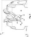
- FIG. 2shows a schematic three-dimensional perspective view of a rotor key member 20 according to various embodiments of the disclosure.
- FIG. 3shows a schematic cut-away perspective view of a steam turbine rotor assembly (or simply, rotor assembly) 22 including key member 20, according to various embodiments.
- FIG. 4shows a schematic cut-away view of rotor assembly 22, through an intersection which does not display key member 20.
- FIGS. 2-4are referred to simultaneously.
- rotor key member 20is sized (configured) to retain (e.g., circumferentially) a circumferential seal 24 in a steam turbine rotor body 46 (e.g., in a rotor assembly 22 within a steam turbine, such as steam turbine 2).
- the rotor assembly 22can be a component within an HP, IP and/or LP section of a steam turbine (e.g., HP 6, LP 4, etc. section of steam turbine 2).
- Rotor key member 20can include: a main body 26 sized to contact an axial face 56 (axially facing surface) of the circumferential seal 24, and a locking member 28 extending from main body 26 in a direction axially toward circumferential seal 24.
- Locking member 28has at least one circumferential edge 29 (facing in circumferential direction, two shown in FIG. 2 ) sized to substantially (e.g., completely or nearly completely) complement (e.g., fit flush with, or nearly flush with) a corresponding circumferentially extending slot 30 (see also, FIGS.
- Locking member 28in some cases extends (e.g., in some cases, substantially perpendicularly (e.g., perpendicular within an acceptable margin of deviation, such as 1-3% deviation) from main body 26.
- the at least one circumferential edge 29includes two distinct circumferential edges 29 sized to engage corresponding circumferentially facing walls 32 ( FIGS. 6 , 7 , 8 ) within slot 30.
- the at least one circumferential edge 29includes a rounded, bulbous or otherwise curved surface, however, it is understood that the at least one circumferential edge 29 can take any shape or form capable of performing the functions described herein.
- main body 26 and locking member 28form a ledge 34 ( FIG. 2 ) sized to complement (e.g., fit flush with, or nearly flush with) a corresponding shelf 36 in slot 30 ( FIG. 3 ).
- locking member 28has a circumferential length lc approximately equal to a circumferential length lc of the main body 26.
- both main body 26 and locking member 28can be substantially unitary and formed of a common material.
- This materialcould include a steel, for example, including approximately 2.5 percent to approximately 12 percent chrome (e.g., INCO 615 or INCO 718).
- rotor key member 20can be made of a single piece of material, e.g., forged, cast, molded or otherwise formed from a common material.
- FIG. 5shows a schematic perspective view of a portion of rotor assembly 22, excluding circumferential seal 24 and rotor key 20.
- rotor assembly 22can include rotor body 46 having a slot 48 extending substantially entirely circumferentially about a primary axis (A) of the rotor body 46 (primary axis A corresponding with axis of rotation of steam turbine).
- Slot 48can include a primary slot 50 extending substantially an entire circumferential distance about rotor body 46, and a secondary slot 52 ( FIGS. 3 , 5 ) extending axially from primary slot 50 and spanning only a portion of the circumferential distance about rotor body 46.
- rotor assembly 22can further include circumferential seal 24 within primary slot 50, spanning substantially the entire circumferential distance about rotor body 46 (e.g., in sections or as one continuous piece of material).
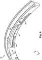
- FIG. 6shows a schematic perspective view of circumferential seal 24.
- FIGS. 7 and 8show schematic perspective views of a portion of rotor assembly 22, including circumferential seal 24 and rotor key member 20 in a first (unlocked) position ( FIG. 7 ), and rotor key member 20 in a second (locked) position ( FIG. 8 ) according to various embodiments.
- circumferential seal 24includes a protrusion 60 extending axially from axial face 56 (of circumferential seal 24) toward rotor key member 20.
- protrusion 60is located radially inward of circumferentially extending slot 30, and can act as a guide for rotor key member 20 when radially inserted into rotor assembly 22 through secondary slot 52 (in first position, shown in FIG. 7 ).
- rotor key member 20is sized to pass radially into secondary slot 52, and when rotor key member 20 rotates with rotor body 46 (e.g., clockwise rotation, as in startup or initial loading of turbine, as shown in FIGS. 7-8 ), locking member 28 slides within circumferentially extending slot 30 to engage one of circumferentially facing walls 32 (within slot 30).
- Rotor key member 20By engaging walls 32 (and shelf 36), rotor key member 20 effectively locks circumferential seal 24 circumferentially, because rotor key member 20 is retained within secondary slot 52, while circumferential seal is retained by locking member 28 (via slot 30). Rotor key member 20 rotates with rotor body 46 (retained within secondary slot 52), meaning that it leads the locking mechanism, thereby retaining circumferential seal 24 while moving forward (e.g., in clockwise direction shown in this example).
- rotor key member 20(and rotor assembly 22) can be utilized in a plurality of stages within a steam turbine (e.g., steam turbine 2), and can aid in both assembly/disassembly of circumferential seal components, as well as reduce wear and complications from component failure.
- circumferential seal 24can include a plurality (e.g., one or more) slots 30, and a plurality of rotor key members 22 can be utilized to correspond with the number of slots and retain circumferential seal 24 as described herein.
Landscapes
- Engineering & Computer Science (AREA)
- General Engineering & Computer Science (AREA)
- Mechanical Engineering (AREA)
- Turbine Rotor Nozzle Sealing (AREA)
- Sealing Devices (AREA)
- Sealing Using Fluids, Sealing Without Contact, And Removal Of Oil (AREA)
Description
- The subject matter disclosed herein relates to steam turbines. Specifically, the subject matter disclosed herein relates to seal devices in steam turbines.
- Steam turbines include static nozzle assemblies that direct flow of a working fluid into turbine buckets connected to a rotating rotor. The nozzle construction (including a plurality of nozzles, or "airfoils") is sometimes referred to as a "diaphragm" or "nozzle assembly stage." Steam turbine diaphragms include two halves, which are assembled around the rotor, creating horizontal joints between these two halves. Each turbine diaphragm stage is vertically supported by support bars, support lugs or support screws on each side of the diaphragm at the respective horizontal joints. The horizontal joints of the diaphragm also correspond to horizontal joints of the turbine casing, which surrounds the steam turbine diaphragm.
- Steam turbines utilize seals between rotor components and stator components, typically radially outward of the rotor bucket tip and radially inward of the diaphragm nozzle cover (stator). While some seals are formed as teeth on the rotor and/or stator, other configurations include a circumferential (or, rotating) seal that is located within a circumferential dovetail slot in the rotor. These rotating (circumferential) seals present unique design constraints, including, radial retention, rotation control, circumferential locking, and consistency of sealing across the circumference.
- According to
US 4,846,628 , a rotor assembly includes a disk having an axially extending, unbroken annular spigot. The spigot supports a plurality of radially extending lugs which are juxtaposed with a corresponding plurality of dogs integral with an annular sideplate . A smooth key fits within the opening formed between adjacent engaged dogs and lugs and is retained axially by a sheet metal retainer received through a slot disposed in the key.EP 0 921 272 discloses a rotary assembly of a turbine stage of a gas turbine engine comprises a disc carrying internally air cooled blades around its periphery has a cover late of one face of the disc to create a plenum for a cooling air supply to the blades. The cover plate is fitted to the disc by means of an annulus of bayonet connections at a first radius and is retained at a second radius, less than the first radius, by a split ring arrangement. The split ring is fitted into a groove in the disc and engages an inner rim on the cover plate to restrain axial movement. An anti-rotation key is engaged in a slot in the cover plate and in the disc and is also retained by the split ring.EP 1 584 794 relates to a device having an annular flange whose internal radial edge is mounted in an annular groove of a disk and an external radial edge is supported on a foot of a blade. A circular bolt immobilizes the flange in rotation of the groove. The bolt is movable in rotation of the groove between a locking position of the flange, and mounting and demounting position of the flange in the groove. - The present invention is related to a steam turbine rotor assembly with the features of claim 1. Further preferred embodiments are defined by the dependent claims.
- These and other features of this invention will be more readily understood from the following detailed description of the various aspects of the invention taken in conjunction with the accompanying drawings that depict various embodiments of the disclosure, in which:
FIG. 1 shows a partial cross-sectional schematic view of steam turbine according to various embodiments.FIG. 2 shows a schematic three-dimensional perspective view of a rotor key member according to various embodiments of the disclosure.FIG. 3 shows a schematic cut-away perspective view of a steam turbine rotor assembly (or simply, rotor assembly) including a key member, according to various embodiments of the disclosure.FIG. 4 shows a schematic cut-away view of a rotor assembly, through an intersection which does not display the key member ofFIGS. 2 and3 , according to various embodiments of the disclosure.FIG. 5 shows a three-dimensional perspective view of a portion of a rotor assembly according to various embodiments of the disclosure.FIG. 6 shows a schematic three-dimensional perspective view of a circumferential seal member according to various embodiments of the disclosure.FIG. 7 shows a three-dimensional perspective view of a portion of a rotor assembly in a first position, according to various embodiments of the disclosure.FIG. 8 shows a three-dimensional perspective view of a portion of a rotor assembly in a second position, according to various embodiments of the disclosure.- It is noted that the drawings of the invention are not necessarily to scale. The drawings are intended to depict only typical aspects of the invention, and therefore should not be considered as limiting the scope of the invention. In the drawings, like numbering represents like elements between the drawings.
- The subject matter disclosed herein relates to steam turbines. Specifically, the subject matter disclosed herein relates to rotating seals in steam turbines.
- According to various embodiments of the disclosure, a device (e.g., key member) is configured to lock/unlock a circumferential (rotatable) seal in a steam turbine, both radially retaining that seal as well as preventing rotation. Conventional approaches to retain circumferential seals allow for unwanted rotation, and are also susceptible to slipping and creep, which can both diminish the effectiveness of the seal and wear on the seal and adjacent components. In contrast to these conventional approaches, various embodiments include a radial key member sized to engage a key slot within the rotor body and radially retain an adjacent circumferential seal. In some cases, the radial key member is located between circumferentially disposed seal retaining members. In additional embodiments, a second key member is used to lock the radial key member in place and retain the rotating seal in the circumferential dimension. The radial key member can include at least one axially extending hook sized to engage the slot in the rotor body. The radial key member has a sufficient axial width to contact both the circumferential seal and the axially facing wall of the key slot in the rotor body.
- As denoted in these Figures, the "A" axis represents axial orientation (along the axis of the turbine rotor, sometimes referred to as the turbine centerline, omitted for clarity). As used herein, the terms "axial" and/or "axially" refer to the relative position/direction of objects along axis A, which is substantially parallel with the axis of rotation of the turbomachine (in particular, the rotor section). As further used herein, the terms "radial" and/or "radially" refer to the relative position/direction of objects along axis (r), which is substantially perpendicular with axis A and intersects axis A at only one location. Additionally, the terms "circumferential" and/or "circumferentially" refer to the relative position/direction of objects along a circumference (c) which surrounds axis A but does not intersect the axis A at any location. Identically labeled elements in the Figures depict substantially similar (e.g., identical) components.
- Turning to
FIG. 1 , a partial cross-sectional schematic view of steam turbine 2 (e.g., a high-pressure / intermediate-pressure steam turbine) is shown.Steam turbine 2 may include, for example, a low pressure (LP)section 4 and a high pressure (HP) section 6 (it is understood that eitherLP section 4 orHP section 6 can include an intermediate pressure (IP) section, as is known in the art). TheLP section 4 and HPsection 6 are at least partially encased incasing 7. Steam may enter the HPsection 6 andLP section 4 via one ormore inlets 8 incasing 7, and flow axially downstream from the inlet(s) 8. In some embodiments, HPsection 6 andLP section 4 are joined by acommon shaft 10, which may contactbearings 12, allowing for rotation of theshaft 10, as working fluid (steam) forces rotation of the blades within each ofLP section 4 andHP section 6. After performing mechanical work on the blades withinLP section 4 andHP section 6, working fluid (e.g., steam) may exit throughoutlet 14 incasing 7. The center line (CL) 16 ofHP section 6 andLP section 4 is shown as a reference point. BothLP section 4 andHP section 6 can include diaphragm assemblies, which are contained within segments ofcasing 7. FIG. 2 shows a schematic three-dimensional perspective view of arotor key member 20 according to various embodiments of the disclosure.FIG. 3 shows a schematic cut-away perspective view of a steam turbine rotor assembly (or simply, rotor assembly) 22 includingkey member 20, according to various embodiments.FIG. 4 shows a schematic cut-away view ofrotor assembly 22, through an intersection which does not displaykey member 20.FIGS. 2-4 are referred to simultaneously. As shown inFIG. 2 andFIG. 3 ,rotor key member 20 is sized (configured) to retain (e.g., circumferentially) acircumferential seal 24 in a steam turbine rotor body 46 (e.g., in arotor assembly 22 within a steam turbine, such as steam turbine 2). It is understood that the rotor assembly 22 (including circumferential seal 24) can be a component within an HP, IP and/or LP section of a steam turbine (e.g.,HP 6,LP 4, etc. section of steam turbine 2).Rotor key member 20 can include: amain body 26 sized to contact an axial face 56 (axially facing surface) of thecircumferential seal 24, and a lockingmember 28 extending frommain body 26 in a direction axially towardcircumferential seal 24. Lockingmember 28 has at least one circumferential edge 29 (facing in circumferential direction, two shown inFIG. 2 ) sized to substantially (e.g., completely or nearly completely) complement (e.g., fit flush with, or nearly flush with) a corresponding circumferentially extending slot 30 (see also,FIGS. 6 ,7 and8 ) incircumferential seal 24 to restrict movement ofcircumferential seal 24 relative to the rotor body 46 (e.g., to restrict circumferential, axial and/or radial movement of circumferential seal 24). Lockingmember 28 in some cases extends (e.g., in some cases, substantially perpendicularly (e.g., perpendicular within an acceptable margin of deviation, such as 1-3% deviation) frommain body 26. In various embodiments, the at least onecircumferential edge 29 includes two distinctcircumferential edges 29 sized to engage corresponding circumferentially facing walls 32 (FIGS. 6 ,7 ,8 ) withinslot 30. In some cases, the at least onecircumferential edge 29 includes a rounded, bulbous or otherwise curved surface, however, it is understood that the at least onecircumferential edge 29 can take any shape or form capable of performing the functions described herein. In various embodiments,main body 26 and lockingmember 28 form a ledge 34 (FIG. 2 ) sized to complement (e.g., fit flush with, or nearly flush with) acorresponding shelf 36 in slot 30 (FIG. 3 ). According to various embodiments, lockingmember 28 has a circumferential length lc approximately equal to a circumferential length lc of themain body 26.- In various embodiments, both
main body 26 and locking member 28 (in rotor key members 20) can be substantially unitary and formed of a common material. This material could include a steel, for example, including approximately 2.5 percent to approximately 12 percent chrome (e.g., INCO 615 or INCO 718). In some cases, rotorkey member 20 can be made of a single piece of material, e.g., forged, cast, molded or otherwise formed from a common material. FIG. 5 shows a schematic perspective view of a portion ofrotor assembly 22, excludingcircumferential seal 24 androtor key 20. According to various embodiments, e.g., as shown inFIGS. 3 ,4 and5 ,rotor assembly 22 can includerotor body 46 having aslot 48 extending substantially entirely circumferentially about a primary axis (A) of the rotor body 46 (primary axis A corresponding with axis of rotation of steam turbine).Slot 48 can include aprimary slot 50 extending substantially an entire circumferential distance aboutrotor body 46, and a secondary slot 52 (FIGS. 3 ,5 ) extending axially fromprimary slot 50 and spanning only a portion of the circumferential distance aboutrotor body 46. As shown inFIG. 3 ,rotor assembly 22 can further includecircumferential seal 24 withinprimary slot 50, spanning substantially the entire circumferential distance about rotor body 46 (e.g., in sections or as one continuous piece of material).FIG. 6 shows a schematic perspective view ofcircumferential seal 24.FIGS. 7 and8 show schematic perspective views of a portion ofrotor assembly 22, includingcircumferential seal 24 and rotorkey member 20 in a first (unlocked) position (FIG. 7 ), and rotorkey member 20 in a second (locked) position (FIG. 8 ) according to various embodiments. As shown inFIGS. 6 ,7 and8 , in some cases,circumferential seal 24 includes aprotrusion 60 extending axially from axial face 56 (of circumferential seal 24) toward rotorkey member 20. In some cases,protrusion 60 is located radially inward of circumferentially extendingslot 30, and can act as a guide for rotorkey member 20 when radially inserted intorotor assembly 22 through secondary slot 52 (in first position, shown inFIG. 7 ). As can be seen inFIG. 8 , viewed in conjunction withFIG. 3 , rotorkey member 20 is sized to pass radially intosecondary slot 52, and when rotorkey member 20 rotates with rotor body 46 (e.g., clockwise rotation, as in startup or initial loading of turbine, as shown inFIGS. 7-8 ), lockingmember 28 slides within circumferentially extendingslot 30 to engage one of circumferentially facing walls 32 (within slot 30). By engaging walls 32 (and shelf 36), rotorkey member 20 effectively lockscircumferential seal 24 circumferentially, because rotorkey member 20 is retained withinsecondary slot 52, while circumferential seal is retained by locking member 28 (via slot 30).Rotor key member 20 rotates with rotor body 46 (retained within secondary slot 52), meaning that it leads the locking mechanism, thereby retainingcircumferential seal 24 while moving forward (e.g., in clockwise direction shown in this example).- It is understood that according to various embodiments, rotor key member 20 (and rotor assembly 22) can be utilized in a plurality of stages within a steam turbine (e.g., steam turbine 2), and can aid in both assembly/disassembly of circumferential seal components, as well as reduce wear and complications from component failure. Further, according to various embodiments,
circumferential seal 24 can include a plurality (e.g., one or more)slots 30, and a plurality of rotorkey members 22 can be utilized to correspond with the number of slots and retaincircumferential seal 24 as described herein. - The terminology used herein is for the purpose of describing particular embodiments only and is not intended to be limiting of the disclosure. As used herein, the singular forms "a", "an" and "the" are intended to include the plural forms as well, unless the context clearly indicates otherwise. It will be further understood that the terms "comprises" and/or "comprising," when used in this specification, specify the presence of stated features, integers, steps, operations, elements, and/or components, but do not preclude the presence or addition of one or more other features, integers, steps, operations, elements, components, and/or groups thereof.
Claims (9)
- A steam turbine (2) rotor assembly (22) comprising:
a rotor body (46) having a slot (48) extending entirely circumferentially about a primary axis of the rotor body (46), the slot (48) including:a primary slot (50) extending an entire circumferential distance about the rotor body (46); anda secondary slot (52) extending axially from the primary slot (50) and spanning only a portion of the circumferential distance about the rotor body (46);a circumferential seal (24) within the primary slot (50) spanning the entire circumferential distance about the rotor body (46), the circumferential seal (24) including at least one circumferentially extending slot (30), the slot (30) comprising circumferentially facing walls (32); the circumferential seal (24) further comprising an axial face (56); anda rotor key member (20) having:a main body (26) sized to contact the axial face (56) of the circumferential seal (24); anda locking member (28) extending from the main body (26) in a direction axially toward the circumferential seal (24), the locking member (28) having at least one circumferential edge (29) sized to complement the circumferentially extending slot (30) in the circumferential seal (24) to restrict movement of the circumferential seal (24) relative to the rotor body (46),wherein the circumferential seal further includes a protrusion (60) extending axially from the axial face (56) of the circumferential seal (24) the steam turbine rotor assembly (22) beingcharacterised in that the protrusion is located radially inward of the circumferentially extending slot (30), and wherein the rotor key member (20) is sized to pass radially into the secondary slot (52), and when the rotor key member (20) rotates with the rotor body (46), the locking member (28) slides within the circumferentially extending slot (30) to engage one of the circumferentially facing walls (32). - The steam turbine (2) rotor assembly (22) of claim 1, wherein the at least one circumferential edge (29) includes two distinct circumferential edges (29) sized to engage corresponding circumferentially facing walls (32) within the slot (30) in the circumferential seal (24).
- The steam turbine (2) rotor assembly (22) of claim 1 or claim 2, wherein the main body (26) and the locking member (28) form a ledge (34) sized to complement a corresponding shelf (36) in the slot (30).
- The steam turbine (2) rotor assembly (22) of any preceding claim, wherein the main body (26) and the locking member (28) are unitary and formed of a common material.
- The steam turbine (2) rotor assembly (22) of the preceding claim, wherein the common material includes steel.
- The steam turbine (2) rotor assembly (22) of any preceding claim, wherein the locking member (28) has a circumferential length equal to a circumferential length of the main body (26).
- The steam turbine (2) rotor assembly (22) of any preceding claim, wherein the secondary slot (52) is axially closed.
- A steam turbine (2) comprising:a casing (7); anda rotor assembly (22) at least partially contained within the casing (7),characterized in that the rotor assembly (22) is a rotor assembly according to any of the preceding claims.
- The steam turbine (2) of the preceding claim, wherein the circumferentially extending slot (30) only extends a portion of the circumferential distance about the rotor body (46).
Priority Applications (1)
| Application Number | Priority Date | Filing Date | Title |
|---|---|---|---|
| PL16201568TPL3179049T3 (en) | 2015-12-07 | 2016-11-30 | Steam turbine rotor assembly with sliding key member for retaining circumferential seal |
Applications Claiming Priority (1)
| Application Number | Priority Date | Filing Date | Title |
|---|---|---|---|
| US14/960,948US10036268B2 (en) | 2015-12-07 | 2015-12-07 | Steam turbine rotor seal sliding key member, related assembly and steam turbine |
Publications (2)
| Publication Number | Publication Date |
|---|---|
| EP3179049A1 EP3179049A1 (en) | 2017-06-14 |
| EP3179049B1true EP3179049B1 (en) | 2020-02-12 |
Family
ID=57442605
Family Applications (1)
| Application Number | Title | Priority Date | Filing Date |
|---|---|---|---|
| EP16201568.9AActiveEP3179049B1 (en) | 2015-12-07 | 2016-11-30 | Steam turbine rotor assembly with sliding key member for retaining circumferential seal |
Country Status (5)
| Country | Link |
|---|---|
| US (1) | US10036268B2 (en) |
| EP (1) | EP3179049B1 (en) |
| JP (1) | JP6856368B2 (en) |
| CN (1) | CN107013258B (en) |
| PL (1) | PL3179049T3 (en) |
Families Citing this family (1)
| Publication number | Priority date | Publication date | Assignee | Title |
|---|---|---|---|---|
| US10036270B2 (en)* | 2015-12-07 | 2018-07-31 | General Electric Company | Steam turbine rotor seal key member, related assembly and steam turbine |
Family Cites Families (17)
| Publication number | Priority date | Publication date | Assignee | Title |
|---|---|---|---|---|
| GB928349A (en)* | 1960-12-06 | 1963-06-12 | Rolls Royce | Improvements in or relating to bladed rotors of fluid flow machines |
| US4304523A (en)* | 1980-06-23 | 1981-12-08 | General Electric Company | Means and method for securing a member to a structure |
| US4846628A (en) | 1988-12-23 | 1989-07-11 | United Technologies Corporation | Rotor assembly for a turbomachine |
| US5236302A (en) | 1991-10-30 | 1993-08-17 | General Electric Company | Turbine disk interstage seal system |
| US5318405A (en)* | 1993-03-17 | 1994-06-07 | General Electric Company | Turbine disk interstage seal anti-rotation key through disk dovetail slot |
| US5622475A (en) | 1994-08-30 | 1997-04-22 | General Electric Company | Double rabbet rotor blade retention assembly |
| GB2332024B (en)* | 1997-12-03 | 2000-12-13 | Rolls Royce Plc | Rotary assembly |
| FR2868808B1 (en) | 2004-04-09 | 2008-08-29 | Snecma Moteurs Sa | DEVICE FOR THE AXIAL RETENTION OF AUBES ON A ROTOR DISC OF A TURBOMACHINE |
| CN101258305B (en)* | 2005-09-07 | 2011-06-15 | 西门子公司 | Device for axially securing moving blades in a rotor, seal for such a device and use of such a device |
| US7566201B2 (en)* | 2007-01-30 | 2009-07-28 | Siemens Energy, Inc. | Turbine seal plate locking system |
| EP2218873A1 (en) | 2009-02-17 | 2010-08-18 | Siemens Aktiengesellschaft | Rotor section for a rotor of a turbo machine, rotor blade for a turbo machine and blocking element |
| US9121297B2 (en) | 2011-03-28 | 2015-09-01 | General Electric Company | Rotating brush seal |
| US9255486B2 (en) | 2011-03-28 | 2016-02-09 | General Electric Company | Rotating brush seal |
| US9327368B2 (en)* | 2012-09-27 | 2016-05-03 | United Technologies Corporation | Full ring inner air-seal with locking nut |
| US9169737B2 (en) | 2012-11-07 | 2015-10-27 | United Technologies Corporation | Gas turbine engine rotor seal |
| US9835253B2 (en) | 2014-06-09 | 2017-12-05 | Doosan Heavy Industries & Construction Co., Ltd. | Brush seal assembly |
| US9963992B2 (en) | 2015-09-29 | 2018-05-08 | General Electric Company | Centrifugally activatable seal for a rotary machine and method of assembling same |
- 2015
- 2015-12-07USUS14/960,948patent/US10036268B2/ennot_activeExpired - Fee Related
- 2016
- 2016-11-30PLPL16201568Tpatent/PL3179049T3/enunknown
- 2016-11-30EPEP16201568.9Apatent/EP3179049B1/enactiveActive
- 2016-12-01JPJP2016233750Apatent/JP6856368B2/ennot_activeExpired - Fee Related
- 2016-12-07CNCN201611115186.0Apatent/CN107013258B/ennot_activeExpired - Fee Related
Non-Patent Citations (1)
| Title |
|---|
| None* |
Also Published As
| Publication number | Publication date |
|---|---|
| CN107013258A (en) | 2017-08-04 |
| CN107013258B (en) | 2021-05-04 |
| PL3179049T3 (en) | 2020-07-27 |
| US20170159476A1 (en) | 2017-06-08 |
| JP6856368B2 (en) | 2021-04-07 |
| US10036268B2 (en) | 2018-07-31 |
| EP3179049A1 (en) | 2017-06-14 |
| JP2017106457A (en) | 2017-06-15 |
Similar Documents
| Publication | Publication Date | Title |
|---|---|---|
| EP3002410B1 (en) | A bladed rotor arrangement with lock plates and seal plates | |
| EP2660426B1 (en) | Turbine assembly | |
| JP6888907B2 (en) | gas turbine | |
| EP3042043B1 (en) | Turbomachine bucket having angel wing seal for differently sized discouragers and related fitting method | |
| JP2011149424A (en) | Seal plate and bucket retention pin assembly | |
| CA2372875A1 (en) | Turbomachine with a sealing system for a rotor | |
| EP3179050B1 (en) | Steam turbine rotor assembly comprising a circumferential seal, seal retaining members and a rotor key member | |
| EP1918523B1 (en) | Rotor blade and corresponding turbine engine | |
| US10450884B2 (en) | Impeller having a radial seal for a turbine engine turbine | |
| CN107614948B (en) | Sealing device and rotary machine | |
| US9957896B2 (en) | Unlockable device for axially arresting a sealing ring with which an aircraft turbomachine module rotor wheel makes contact | |
| EP3179049B1 (en) | Steam turbine rotor assembly with sliding key member for retaining circumferential seal | |
| US11499437B2 (en) | Sealing apparatus for a turbomachine, seal-carrier ring element for a sealing apparatus, and turbomachine | |
| EP2372085A2 (en) | Internal reaction steam turbine cooling arrangement | |
| RU2762016C2 (en) | Sealing device between rotor and stator of gas turbine engine | |
| EP3184752B1 (en) | Steam turbine rotor seal key member | |
| EP3088662A1 (en) | Multi-stage turbine interstage seal and method of assembly | |
| JP6877962B2 (en) | Manufacturing method of steam turbine partition plate, steam turbine and steam turbine partition plate | |
| US20160281519A1 (en) | Nozzle assembly and stationary nozzle therefor | |
| CN113544361B (en) | Gas turbine for twin-rotor aircraft | |
| EP3179051B1 (en) | Key member for retention of circumferential seal of a steam turbine rotor |
Legal Events
| Date | Code | Title | Description |
|---|---|---|---|
| PUAI | Public reference made under article 153(3) epc to a published international application that has entered the european phase | Free format text:ORIGINAL CODE: 0009012 | |
| STAA | Information on the status of an ep patent application or granted ep patent | Free format text:STATUS: THE APPLICATION HAS BEEN PUBLISHED | |
| AK | Designated contracting states | Kind code of ref document:A1 Designated state(s):AL AT BE BG CH CY CZ DE DK EE ES FI FR GB GR HR HU IE IS IT LI LT LU LV MC MK MT NL NO PL PT RO RS SE SI SK SM TR | |
| AX | Request for extension of the european patent | Extension state:BA ME | |
| STAA | Information on the status of an ep patent application or granted ep patent | Free format text:STATUS: REQUEST FOR EXAMINATION WAS MADE | |
| 17P | Request for examination filed | Effective date:20171214 | |
| RBV | Designated contracting states (corrected) | Designated state(s):AL AT BE BG CH CY CZ DE DK EE ES FI FR GB GR HR HU IE IS IT LI LT LU LV MC MK MT NL NO PL PT RO RS SE SI SK SM TR | |
| STAA | Information on the status of an ep patent application or granted ep patent | Free format text:STATUS: EXAMINATION IS IN PROGRESS | |
| 17Q | First examination report despatched | Effective date:20180611 | |
| GRAP | Despatch of communication of intention to grant a patent | Free format text:ORIGINAL CODE: EPIDOSNIGR1 | |
| STAA | Information on the status of an ep patent application or granted ep patent | Free format text:STATUS: GRANT OF PATENT IS INTENDED | |
| INTG | Intention to grant announced | Effective date:20190813 | |
| RIN1 | Information on inventor provided before grant (corrected) | Inventor name:BURDGICK, STEVEN SEBASTIAN Inventor name:MORRISSEY, SEAN CHRISTOPHER | |
| GRAS | Grant fee paid | Free format text:ORIGINAL CODE: EPIDOSNIGR3 | |
| GRAA | (expected) grant | Free format text:ORIGINAL CODE: 0009210 | |
| STAA | Information on the status of an ep patent application or granted ep patent | Free format text:STATUS: THE PATENT HAS BEEN GRANTED | |
| AK | Designated contracting states | Kind code of ref document:B1 Designated state(s):AL AT BE BG CH CY CZ DE DK EE ES FI FR GB GR HR HU IE IS IT LI LT LU LV MC MK MT NL NO PL PT RO RS SE SI SK SM TR | |
| REG | Reference to a national code | Ref country code:GB Ref legal event code:FG4D | |
| REG | Reference to a national code | Ref country code:CH Ref legal event code:EP | |
| REG | Reference to a national code | Ref country code:AT Ref legal event code:REF Ref document number:1232369 Country of ref document:AT Kind code of ref document:T Effective date:20200215 | |
| REG | Reference to a national code | Ref country code:IE Ref legal event code:FG4D | |
| REG | Reference to a national code | Ref country code:DE Ref legal event code:R096 Ref document number:602016029444 Country of ref document:DE | |
| PG25 | Lapsed in a contracting state [announced via postgrant information from national office to epo] | Ref country code:FI Free format text:LAPSE BECAUSE OF FAILURE TO SUBMIT A TRANSLATION OF THE DESCRIPTION OR TO PAY THE FEE WITHIN THE PRESCRIBED TIME-LIMIT Effective date:20200212 Ref country code:NO Free format text:LAPSE BECAUSE OF FAILURE TO SUBMIT A TRANSLATION OF THE DESCRIPTION OR TO PAY THE FEE WITHIN THE PRESCRIBED TIME-LIMIT Effective date:20200512 Ref country code:RS Free format text:LAPSE BECAUSE OF FAILURE TO SUBMIT A TRANSLATION OF THE DESCRIPTION OR TO PAY THE FEE WITHIN THE PRESCRIBED TIME-LIMIT Effective date:20200212 | |
| REG | Reference to a national code | Ref country code:LT Ref legal event code:MG4D | |
| REG | Reference to a national code | Ref country code:NL Ref legal event code:MP Effective date:20200212 | |
| PG25 | Lapsed in a contracting state [announced via postgrant information from national office to epo] | Ref country code:HR Free format text:LAPSE BECAUSE OF FAILURE TO SUBMIT A TRANSLATION OF THE DESCRIPTION OR TO PAY THE FEE WITHIN THE PRESCRIBED TIME-LIMIT Effective date:20200212 Ref country code:GR Free format text:LAPSE BECAUSE OF FAILURE TO SUBMIT A TRANSLATION OF THE DESCRIPTION OR TO PAY THE FEE WITHIN THE PRESCRIBED TIME-LIMIT Effective date:20200513 Ref country code:IS Free format text:LAPSE BECAUSE OF FAILURE TO SUBMIT A TRANSLATION OF THE DESCRIPTION OR TO PAY THE FEE WITHIN THE PRESCRIBED TIME-LIMIT Effective date:20200612 Ref country code:LV Free format text:LAPSE BECAUSE OF FAILURE TO SUBMIT A TRANSLATION OF THE DESCRIPTION OR TO PAY THE FEE WITHIN THE PRESCRIBED TIME-LIMIT Effective date:20200212 Ref country code:SE Free format text:LAPSE BECAUSE OF FAILURE TO SUBMIT A TRANSLATION OF THE DESCRIPTION OR TO PAY THE FEE WITHIN THE PRESCRIBED TIME-LIMIT Effective date:20200212 Ref country code:BG Free format text:LAPSE BECAUSE OF FAILURE TO SUBMIT A TRANSLATION OF THE DESCRIPTION OR TO PAY THE FEE WITHIN THE PRESCRIBED TIME-LIMIT Effective date:20200512 | |
| PG25 | Lapsed in a contracting state [announced via postgrant information from national office to epo] | Ref country code:NL Free format text:LAPSE BECAUSE OF FAILURE TO SUBMIT A TRANSLATION OF THE DESCRIPTION OR TO PAY THE FEE WITHIN THE PRESCRIBED TIME-LIMIT Effective date:20200212 | |
| PG25 | Lapsed in a contracting state [announced via postgrant information from national office to epo] | Ref country code:CZ Free format text:LAPSE BECAUSE OF FAILURE TO SUBMIT A TRANSLATION OF THE DESCRIPTION OR TO PAY THE FEE WITHIN THE PRESCRIBED TIME-LIMIT Effective date:20200212 Ref country code:ES Free format text:LAPSE BECAUSE OF FAILURE TO SUBMIT A TRANSLATION OF THE DESCRIPTION OR TO PAY THE FEE WITHIN THE PRESCRIBED TIME-LIMIT Effective date:20200212 Ref country code:RO Free format text:LAPSE BECAUSE OF FAILURE TO SUBMIT A TRANSLATION OF THE DESCRIPTION OR TO PAY THE FEE WITHIN THE PRESCRIBED TIME-LIMIT Effective date:20200212 Ref country code:LT Free format text:LAPSE BECAUSE OF FAILURE TO SUBMIT A TRANSLATION OF THE DESCRIPTION OR TO PAY THE FEE WITHIN THE PRESCRIBED TIME-LIMIT Effective date:20200212 Ref country code:EE Free format text:LAPSE BECAUSE OF FAILURE TO SUBMIT A TRANSLATION OF THE DESCRIPTION OR TO PAY THE FEE WITHIN THE PRESCRIBED TIME-LIMIT Effective date:20200212 Ref country code:PT Free format text:LAPSE BECAUSE OF FAILURE TO SUBMIT A TRANSLATION OF THE DESCRIPTION OR TO PAY THE FEE WITHIN THE PRESCRIBED TIME-LIMIT Effective date:20200705 Ref country code:SM Free format text:LAPSE BECAUSE OF FAILURE TO SUBMIT A TRANSLATION OF THE DESCRIPTION OR TO PAY THE FEE WITHIN THE PRESCRIBED TIME-LIMIT Effective date:20200212 Ref country code:DK Free format text:LAPSE BECAUSE OF FAILURE TO SUBMIT A TRANSLATION OF THE DESCRIPTION OR TO PAY THE FEE WITHIN THE PRESCRIBED TIME-LIMIT Effective date:20200212 Ref country code:SK Free format text:LAPSE BECAUSE OF FAILURE TO SUBMIT A TRANSLATION OF THE DESCRIPTION OR TO PAY THE FEE WITHIN THE PRESCRIBED TIME-LIMIT Effective date:20200212 | |
| REG | Reference to a national code | Ref country code:DE Ref legal event code:R097 Ref document number:602016029444 Country of ref document:DE | |
| REG | Reference to a national code | Ref country code:AT Ref legal event code:MK05 Ref document number:1232369 Country of ref document:AT Kind code of ref document:T Effective date:20200212 | |
| PLBE | No opposition filed within time limit | Free format text:ORIGINAL CODE: 0009261 | |
| STAA | Information on the status of an ep patent application or granted ep patent | Free format text:STATUS: NO OPPOSITION FILED WITHIN TIME LIMIT | |
| 26N | No opposition filed | Effective date:20201113 | |
| PG25 | Lapsed in a contracting state [announced via postgrant information from national office to epo] | Ref country code:AT Free format text:LAPSE BECAUSE OF FAILURE TO SUBMIT A TRANSLATION OF THE DESCRIPTION OR TO PAY THE FEE WITHIN THE PRESCRIBED TIME-LIMIT Effective date:20200212 Ref country code:IT Free format text:LAPSE BECAUSE OF FAILURE TO SUBMIT A TRANSLATION OF THE DESCRIPTION OR TO PAY THE FEE WITHIN THE PRESCRIBED TIME-LIMIT Effective date:20200212 | |
| PGFP | Annual fee paid to national office [announced via postgrant information from national office to epo] | Ref country code:GB Payment date:20201021 Year of fee payment:5 Ref country code:DE Payment date:20201020 Year of fee payment:5 | |
| PG25 | Lapsed in a contracting state [announced via postgrant information from national office to epo] | Ref country code:SI Free format text:LAPSE BECAUSE OF FAILURE TO SUBMIT A TRANSLATION OF THE DESCRIPTION OR TO PAY THE FEE WITHIN THE PRESCRIBED TIME-LIMIT Effective date:20200212 | |
| PGFP | Annual fee paid to national office [announced via postgrant information from national office to epo] | Ref country code:PL Payment date:20201102 Year of fee payment:5 | |
| PG25 | Lapsed in a contracting state [announced via postgrant information from national office to epo] | Ref country code:MC Free format text:LAPSE BECAUSE OF FAILURE TO SUBMIT A TRANSLATION OF THE DESCRIPTION OR TO PAY THE FEE WITHIN THE PRESCRIBED TIME-LIMIT Effective date:20200212 | |
| REG | Reference to a national code | Ref country code:CH Ref legal event code:PL | |
| PG25 | Lapsed in a contracting state [announced via postgrant information from national office to epo] | Ref country code:LU Free format text:LAPSE BECAUSE OF NON-PAYMENT OF DUE FEES Effective date:20201130 | |
| REG | Reference to a national code | Ref country code:BE Ref legal event code:MM Effective date:20201130 | |
| PG25 | Lapsed in a contracting state [announced via postgrant information from national office to epo] | Ref country code:LI Free format text:LAPSE BECAUSE OF NON-PAYMENT OF DUE FEES Effective date:20201130 Ref country code:CH Free format text:LAPSE BECAUSE OF NON-PAYMENT OF DUE FEES Effective date:20201130 | |
| REG | Reference to a national code | Ref country code:IE Ref legal event code:MM4A | |
| PG25 | Lapsed in a contracting state [announced via postgrant information from national office to epo] | Ref country code:FR Free format text:LAPSE BECAUSE OF NON-PAYMENT OF DUE FEES Effective date:20201130 Ref country code:IE Free format text:LAPSE BECAUSE OF NON-PAYMENT OF DUE FEES Effective date:20201130 | |
| PG25 | Lapsed in a contracting state [announced via postgrant information from national office to epo] | Ref country code:TR Free format text:LAPSE BECAUSE OF FAILURE TO SUBMIT A TRANSLATION OF THE DESCRIPTION OR TO PAY THE FEE WITHIN THE PRESCRIBED TIME-LIMIT Effective date:20200212 Ref country code:MT Free format text:LAPSE BECAUSE OF FAILURE TO SUBMIT A TRANSLATION OF THE DESCRIPTION OR TO PAY THE FEE WITHIN THE PRESCRIBED TIME-LIMIT Effective date:20200212 Ref country code:CY Free format text:LAPSE BECAUSE OF FAILURE TO SUBMIT A TRANSLATION OF THE DESCRIPTION OR TO PAY THE FEE WITHIN THE PRESCRIBED TIME-LIMIT Effective date:20200212 | |
| REG | Reference to a national code | Ref country code:DE Ref legal event code:R119 Ref document number:602016029444 Country of ref document:DE | |
| PG25 | Lapsed in a contracting state [announced via postgrant information from national office to epo] | Ref country code:MK Free format text:LAPSE BECAUSE OF FAILURE TO SUBMIT A TRANSLATION OF THE DESCRIPTION OR TO PAY THE FEE WITHIN THE PRESCRIBED TIME-LIMIT Effective date:20200212 Ref country code:AL Free format text:LAPSE BECAUSE OF FAILURE TO SUBMIT A TRANSLATION OF THE DESCRIPTION OR TO PAY THE FEE WITHIN THE PRESCRIBED TIME-LIMIT Effective date:20200212 | |
| GBPC | Gb: european patent ceased through non-payment of renewal fee | Effective date:20211130 | |
| PG25 | Lapsed in a contracting state [announced via postgrant information from national office to epo] | Ref country code:BE Free format text:LAPSE BECAUSE OF NON-PAYMENT OF DUE FEES Effective date:20201130 | |
| PG25 | Lapsed in a contracting state [announced via postgrant information from national office to epo] | Ref country code:GB Free format text:LAPSE BECAUSE OF NON-PAYMENT OF DUE FEES Effective date:20211130 Ref country code:DE Free format text:LAPSE BECAUSE OF NON-PAYMENT OF DUE FEES Effective date:20220601 | |
| PG25 | Lapsed in a contracting state [announced via postgrant information from national office to epo] | Ref country code:PL Free format text:LAPSE BECAUSE OF NON-PAYMENT OF DUE FEES Effective date:20211130 |